JP6370569B2 - Articulated surgical instrument with firing drive - Google Patents
Articulated surgical instrument with firing driveDownload PDFInfo
- Publication number
- JP6370569B2 JP6370569B2JP2014051408AJP2014051408AJP6370569B2JP 6370569 B2JP6370569 B2JP 6370569B2JP 2014051408 AJP2014051408 AJP 2014051408AJP 2014051408 AJP2014051408 AJP 2014051408AJP 6370569 B2JP6370569 B2JP 6370569B2
- Authority
- JP
- Japan
- Prior art keywords
- shaft
- driver
- end effector
- joint
- proximal
- Prior art date
- Legal status (The legal status is an assumption and is not a legal conclusion. Google has not performed a legal analysis and makes no representation as to the accuracy of the status listed.)
- Active
Links
Images


Classifications
- A—HUMAN NECESSITIES
- A61—MEDICAL OR VETERINARY SCIENCE; HYGIENE
- A61B—DIAGNOSIS; SURGERY; IDENTIFICATION
- A61B18/00—Surgical instruments, devices or methods for transferring non-mechanical forms of energy to or from the body
- A61B18/04—Surgical instruments, devices or methods for transferring non-mechanical forms of energy to or from the body by heating
- A61B18/12—Surgical instruments, devices or methods for transferring non-mechanical forms of energy to or from the body by heating by passing a current through the tissue to be heated, e.g. high-frequency current
- A61B18/14—Probes or electrodes therefor
- A61B18/1442—Probes having pivoting end effectors, e.g. forceps
- A61B18/1445—Probes having pivoting end effectors, e.g. forceps at the distal end of a shaft, e.g. forceps or scissors at the end of a rigid rod
- A—HUMAN NECESSITIES
- A61—MEDICAL OR VETERINARY SCIENCE; HYGIENE
- A61B—DIAGNOSIS; SURGERY; IDENTIFICATION
- A61B17/00—Surgical instruments, devices or methods
- A61B17/068—Surgical staplers, e.g. containing multiple staples or clamps
- A—HUMAN NECESSITIES
- A61—MEDICAL OR VETERINARY SCIENCE; HYGIENE
- A61B—DIAGNOSIS; SURGERY; IDENTIFICATION
- A61B17/00—Surgical instruments, devices or methods
- A61B17/10—Surgical instruments, devices or methods for applying or removing wound clamps, e.g. containing only one clamp or staple; Wound clamp magazines
- A61B17/105—Wound clamp magazines
- A—HUMAN NECESSITIES
- A61—MEDICAL OR VETERINARY SCIENCE; HYGIENE
- A61B—DIAGNOSIS; SURGERY; IDENTIFICATION
- A61B17/00—Surgical instruments, devices or methods
- A61B17/064—Surgical staples, i.e. penetrating the tissue
- A—HUMAN NECESSITIES
- A61—MEDICAL OR VETERINARY SCIENCE; HYGIENE
- A61B—DIAGNOSIS; SURGERY; IDENTIFICATION
- A61B17/00—Surgical instruments, devices or methods
- A61B17/068—Surgical staplers, e.g. containing multiple staples or clamps
- A61B17/0682—Surgical staplers, e.g. containing multiple staples or clamps for applying U-shaped staples or clamps, e.g. without a forming anvil
- A61B17/0686—Surgical staplers, e.g. containing multiple staples or clamps for applying U-shaped staples or clamps, e.g. without a forming anvil having a forming anvil staying below the tissue during stapling
- A—HUMAN NECESSITIES
- A61—MEDICAL OR VETERINARY SCIENCE; HYGIENE
- A61B—DIAGNOSIS; SURGERY; IDENTIFICATION
- A61B17/00—Surgical instruments, devices or methods
- A61B17/068—Surgical staplers, e.g. containing multiple staples or clamps
- A61B17/072—Surgical staplers, e.g. containing multiple staples or clamps for applying a row of staples in a single action, e.g. the staples being applied simultaneously
- A61B17/07207—Surgical staplers, e.g. containing multiple staples or clamps for applying a row of staples in a single action, e.g. the staples being applied simultaneously the staples being applied sequentially
- A—HUMAN NECESSITIES
- A61—MEDICAL OR VETERINARY SCIENCE; HYGIENE
- A61B—DIAGNOSIS; SURGERY; IDENTIFICATION
- A61B17/00—Surgical instruments, devices or methods
- A61B17/28—Surgical forceps
- A61B17/29—Forceps for use in minimally invasive surgery
- A—HUMAN NECESSITIES
- A61—MEDICAL OR VETERINARY SCIENCE; HYGIENE
- A61B—DIAGNOSIS; SURGERY; IDENTIFICATION
- A61B17/00—Surgical instruments, devices or methods
- A61B17/32—Surgical cutting instruments
- A—HUMAN NECESSITIES
- A61—MEDICAL OR VETERINARY SCIENCE; HYGIENE
- A61B—DIAGNOSIS; SURGERY; IDENTIFICATION
- A61B34/00—Computer-aided surgery; Manipulators or robots specially adapted for use in surgery
- A—HUMAN NECESSITIES
- A61—MEDICAL OR VETERINARY SCIENCE; HYGIENE
- A61B—DIAGNOSIS; SURGERY; IDENTIFICATION
- A61B34/00—Computer-aided surgery; Manipulators or robots specially adapted for use in surgery
- A61B34/30—Surgical robots
- A—HUMAN NECESSITIES
- A61—MEDICAL OR VETERINARY SCIENCE; HYGIENE
- A61B—DIAGNOSIS; SURGERY; IDENTIFICATION
- A61B17/00—Surgical instruments, devices or methods
- A61B2017/00017—Electrical control of surgical instruments
- A—HUMAN NECESSITIES
- A61—MEDICAL OR VETERINARY SCIENCE; HYGIENE
- A61B—DIAGNOSIS; SURGERY; IDENTIFICATION
- A61B17/00—Surgical instruments, devices or methods
- A61B2017/00017—Electrical control of surgical instruments
- A61B2017/00115—Electrical control of surgical instruments with audible or visual output
- A61B2017/00119—Electrical control of surgical instruments with audible or visual output alarm; indicating an abnormal situation
- A61B2017/00123—Electrical control of surgical instruments with audible or visual output alarm; indicating an abnormal situation and automatic shutdown
- A—HUMAN NECESSITIES
- A61—MEDICAL OR VETERINARY SCIENCE; HYGIENE
- A61B—DIAGNOSIS; SURGERY; IDENTIFICATION
- A61B17/00—Surgical instruments, devices or methods
- A61B2017/00367—Details of actuation of instruments, e.g. relations between pushing buttons, or the like, and activation of the tool, working tip, or the like
- A61B2017/00389—Button or wheel for performing multiple functions, e.g. rotation of shaft and end effector
- A61B2017/00393—Button or wheel for performing multiple functions, e.g. rotation of shaft and end effector with means for switching between functions
- A—HUMAN NECESSITIES
- A61—MEDICAL OR VETERINARY SCIENCE; HYGIENE
- A61B—DIAGNOSIS; SURGERY; IDENTIFICATION
- A61B17/00—Surgical instruments, devices or methods
- A61B2017/00367—Details of actuation of instruments, e.g. relations between pushing buttons, or the like, and activation of the tool, working tip, or the like
- A61B2017/00398—Details of actuation of instruments, e.g. relations between pushing buttons, or the like, and activation of the tool, working tip, or the like using powered actuators, e.g. stepper motors, solenoids
- A—HUMAN NECESSITIES
- A61—MEDICAL OR VETERINARY SCIENCE; HYGIENE
- A61B—DIAGNOSIS; SURGERY; IDENTIFICATION
- A61B17/00—Surgical instruments, devices or methods
- A61B2017/0046—Surgical instruments, devices or methods with a releasable handle; with handle and operating part separable
- A—HUMAN NECESSITIES
- A61—MEDICAL OR VETERINARY SCIENCE; HYGIENE
- A61B—DIAGNOSIS; SURGERY; IDENTIFICATION
- A61B17/00—Surgical instruments, devices or methods
- A61B2017/0046—Surgical instruments, devices or methods with a releasable handle; with handle and operating part separable
- A61B2017/00464—Surgical instruments, devices or methods with a releasable handle; with handle and operating part separable for use with different instruments
- A—HUMAN NECESSITIES
- A61—MEDICAL OR VETERINARY SCIENCE; HYGIENE
- A61B—DIAGNOSIS; SURGERY; IDENTIFICATION
- A61B17/00—Surgical instruments, devices or methods
- A61B2017/0046—Surgical instruments, devices or methods with a releasable handle; with handle and operating part separable
- A61B2017/00473—Distal part, e.g. tip or head
- A—HUMAN NECESSITIES
- A61—MEDICAL OR VETERINARY SCIENCE; HYGIENE
- A61B—DIAGNOSIS; SURGERY; IDENTIFICATION
- A61B17/00—Surgical instruments, devices or methods
- A61B2017/00477—Coupling
- A—HUMAN NECESSITIES
- A61—MEDICAL OR VETERINARY SCIENCE; HYGIENE
- A61B—DIAGNOSIS; SURGERY; IDENTIFICATION
- A61B17/00—Surgical instruments, devices or methods
- A61B2017/00681—Aspects not otherwise provided for
- A61B2017/00707—Dummies, phantoms; Devices simulating patient or parts of patient
- A61B2017/00716—Dummies, phantoms; Devices simulating patient or parts of patient simulating physical properties
- A—HUMAN NECESSITIES
- A61—MEDICAL OR VETERINARY SCIENCE; HYGIENE
- A61B—DIAGNOSIS; SURGERY; IDENTIFICATION
- A61B17/00—Surgical instruments, devices or methods
- A61B2017/00681—Aspects not otherwise provided for
- A61B2017/00734—Aspects not otherwise provided for battery operated
- A—HUMAN NECESSITIES
- A61—MEDICAL OR VETERINARY SCIENCE; HYGIENE
- A61B—DIAGNOSIS; SURGERY; IDENTIFICATION
- A61B17/00—Surgical instruments, devices or methods
- A61B17/068—Surgical staplers, e.g. containing multiple staples or clamps
- A61B17/072—Surgical staplers, e.g. containing multiple staples or clamps for applying a row of staples in a single action, e.g. the staples being applied simultaneously
- A61B2017/07214—Stapler heads
- A61B2017/07271—Stapler heads characterised by its cartridge
- A—HUMAN NECESSITIES
- A61—MEDICAL OR VETERINARY SCIENCE; HYGIENE
- A61B—DIAGNOSIS; SURGERY; IDENTIFICATION
- A61B17/00—Surgical instruments, devices or methods
- A61B17/068—Surgical staplers, e.g. containing multiple staples or clamps
- A61B17/072—Surgical staplers, e.g. containing multiple staples or clamps for applying a row of staples in a single action, e.g. the staples being applied simultaneously
- A61B2017/07214—Stapler heads
- A61B2017/07278—Stapler heads characterised by its sled or its staple holder
- A—HUMAN NECESSITIES
- A61—MEDICAL OR VETERINARY SCIENCE; HYGIENE
- A61B—DIAGNOSIS; SURGERY; IDENTIFICATION
- A61B17/00—Surgical instruments, devices or methods
- A61B17/28—Surgical forceps
- A61B17/29—Forceps for use in minimally invasive surgery
- A61B2017/2901—Details of shaft
- A61B2017/2902—Details of shaft characterized by features of the actuating rod
- A61B2017/2903—Details of shaft characterized by features of the actuating rod transferring rotary motion
- A—HUMAN NECESSITIES
- A61—MEDICAL OR VETERINARY SCIENCE; HYGIENE
- A61B—DIAGNOSIS; SURGERY; IDENTIFICATION
- A61B17/00—Surgical instruments, devices or methods
- A61B17/28—Surgical forceps
- A61B17/29—Forceps for use in minimally invasive surgery
- A61B17/2909—Handles
- A61B2017/2912—Handles transmission of forces to actuating rod or piston
- A61B2017/2913—Handles transmission of forces to actuating rod or piston cams or guiding means
- A—HUMAN NECESSITIES
- A61—MEDICAL OR VETERINARY SCIENCE; HYGIENE
- A61B—DIAGNOSIS; SURGERY; IDENTIFICATION
- A61B17/00—Surgical instruments, devices or methods
- A61B17/28—Surgical forceps
- A61B17/29—Forceps for use in minimally invasive surgery
- A61B17/2909—Handles
- A61B2017/2912—Handles transmission of forces to actuating rod or piston
- A61B2017/2923—Toothed members, e.g. rack and pinion
- A—HUMAN NECESSITIES
- A61—MEDICAL OR VETERINARY SCIENCE; HYGIENE
- A61B—DIAGNOSIS; SURGERY; IDENTIFICATION
- A61B17/00—Surgical instruments, devices or methods
- A61B17/28—Surgical forceps
- A61B17/29—Forceps for use in minimally invasive surgery
- A61B17/2909—Handles
- A61B2017/2925—Pistol grips
- A—HUMAN NECESSITIES
- A61—MEDICAL OR VETERINARY SCIENCE; HYGIENE
- A61B—DIAGNOSIS; SURGERY; IDENTIFICATION
- A61B17/00—Surgical instruments, devices or methods
- A61B17/28—Surgical forceps
- A61B17/29—Forceps for use in minimally invasive surgery
- A61B2017/2926—Details of heads or jaws
- A61B2017/2927—Details of heads or jaws the angular position of the head being adjustable with respect to the shaft
- A—HUMAN NECESSITIES
- A61—MEDICAL OR VETERINARY SCIENCE; HYGIENE
- A61B—DIAGNOSIS; SURGERY; IDENTIFICATION
- A61B17/00—Surgical instruments, devices or methods
- A61B17/28—Surgical forceps
- A61B17/29—Forceps for use in minimally invasive surgery
- A61B2017/2926—Details of heads or jaws
- A61B2017/2931—Details of heads or jaws with releasable head
- A—HUMAN NECESSITIES
- A61—MEDICAL OR VETERINARY SCIENCE; HYGIENE
- A61B—DIAGNOSIS; SURGERY; IDENTIFICATION
- A61B17/00—Surgical instruments, devices or methods
- A61B17/28—Surgical forceps
- A61B17/29—Forceps for use in minimally invasive surgery
- A61B2017/2926—Details of heads or jaws
- A61B2017/2932—Transmission of forces to jaw members
- A61B2017/2943—Toothed members, e.g. rack and pinion
- A—HUMAN NECESSITIES
- A61—MEDICAL OR VETERINARY SCIENCE; HYGIENE
- A61B—DIAGNOSIS; SURGERY; IDENTIFICATION
- A61B18/00—Surgical instruments, devices or methods for transferring non-mechanical forms of energy to or from the body
- A61B2018/00053—Mechanical features of the instrument of device
- A61B2018/00172—Connectors and adapters therefor
- A—HUMAN NECESSITIES
- A61—MEDICAL OR VETERINARY SCIENCE; HYGIENE
- A61B—DIAGNOSIS; SURGERY; IDENTIFICATION
- A61B18/00—Surgical instruments, devices or methods for transferring non-mechanical forms of energy to or from the body
- A61B2018/00053—Mechanical features of the instrument of device
- A61B2018/00297—Means for providing haptic feedback
- A61B2018/00303—Means for providing haptic feedback active, e.g. with a motor creating vibrations
- A—HUMAN NECESSITIES
- A61—MEDICAL OR VETERINARY SCIENCE; HYGIENE
- A61B—DIAGNOSIS; SURGERY; IDENTIFICATION
- A61B18/00—Surgical instruments, devices or methods for transferring non-mechanical forms of energy to or from the body
- A61B18/04—Surgical instruments, devices or methods for transferring non-mechanical forms of energy to or from the body by heating
- A61B18/12—Surgical instruments, devices or methods for transferring non-mechanical forms of energy to or from the body by heating by passing a current through the tissue to be heated, e.g. high-frequency current
- A61B18/14—Probes or electrodes therefor
- A61B18/1442—Probes having pivoting end effectors, e.g. forceps
- A61B2018/1452—Probes having pivoting end effectors, e.g. forceps including means for cutting
- A61B2018/1455—Probes having pivoting end effectors, e.g. forceps including means for cutting having a moving blade for cutting tissue grasped by the jaws
- A—HUMAN NECESSITIES
- A61—MEDICAL OR VETERINARY SCIENCE; HYGIENE
- A61B—DIAGNOSIS; SURGERY; IDENTIFICATION
- A61B34/00—Computer-aided surgery; Manipulators or robots specially adapted for use in surgery
- A61B34/20—Surgical navigation systems; Devices for tracking or guiding surgical instruments, e.g. for frameless stereotaxis
- A61B2034/2046—Tracking techniques
- A61B2034/2059—Mechanical position encoders
- A—HUMAN NECESSITIES
- A61—MEDICAL OR VETERINARY SCIENCE; HYGIENE
- A61B—DIAGNOSIS; SURGERY; IDENTIFICATION
- A61B90/00—Instruments, implements or accessories specially adapted for surgery or diagnosis and not covered by any of the groups A61B1/00 - A61B50/00, e.g. for luxation treatment or for protecting wound edges
- A61B90/06—Measuring instruments not otherwise provided for
- A61B2090/064—Measuring instruments not otherwise provided for for measuring force, pressure or mechanical tension
- A—HUMAN NECESSITIES
- A61—MEDICAL OR VETERINARY SCIENCE; HYGIENE
- A61B—DIAGNOSIS; SURGERY; IDENTIFICATION
- A61B90/00—Instruments, implements or accessories specially adapted for surgery or diagnosis and not covered by any of the groups A61B1/00 - A61B50/00, e.g. for luxation treatment or for protecting wound edges
- A61B90/06—Measuring instruments not otherwise provided for
- A61B2090/067—Measuring instruments not otherwise provided for for measuring angles
- A—HUMAN NECESSITIES
- A61—MEDICAL OR VETERINARY SCIENCE; HYGIENE
- A61B—DIAGNOSIS; SURGERY; IDENTIFICATION
- A61B90/00—Instruments, implements or accessories specially adapted for surgery or diagnosis and not covered by any of the groups A61B1/00 - A61B50/00, e.g. for luxation treatment or for protecting wound edges
- A61B90/08—Accessories or related features not otherwise provided for
- A61B2090/0807—Indication means
- A61B2090/0808—Indication means for indicating correct assembly of components, e.g. of the surgical apparatus
- A—HUMAN NECESSITIES
- A61—MEDICAL OR VETERINARY SCIENCE; HYGIENE
- A61B—DIAGNOSIS; SURGERY; IDENTIFICATION
- A61B90/00—Instruments, implements or accessories specially adapted for surgery or diagnosis and not covered by any of the groups A61B1/00 - A61B50/00, e.g. for luxation treatment or for protecting wound edges
- A61B90/08—Accessories or related features not otherwise provided for
- A61B2090/0807—Indication means
- A61B2090/0811—Indication means for the position of a particular part of an instrument with respect to the rest of the instrument, e.g. position of the anvil of a stapling instrument
- A—HUMAN NECESSITIES
- A61—MEDICAL OR VETERINARY SCIENCE; HYGIENE
- A61B—DIAGNOSIS; SURGERY; IDENTIFICATION
- A61B90/00—Instruments, implements or accessories specially adapted for surgery or diagnosis and not covered by any of the groups A61B1/00 - A61B50/00, e.g. for luxation treatment or for protecting wound edges
- A61B90/08—Accessories or related features not otherwise provided for
- A61B2090/0814—Preventing re-use
- A—HUMAN NECESSITIES
- A61—MEDICAL OR VETERINARY SCIENCE; HYGIENE
- A61B—DIAGNOSIS; SURGERY; IDENTIFICATION
- A61B34/00—Computer-aided surgery; Manipulators or robots specially adapted for use in surgery
- A61B34/70—Manipulators specially adapted for use in surgery
- A61B34/76—Manipulators having means for providing feel, e.g. force or tactile feedback
- G—PHYSICS
- G01—MEASURING; TESTING
- G01D—MEASURING NOT SPECIALLY ADAPTED FOR A SPECIFIC VARIABLE; ARRANGEMENTS FOR MEASURING TWO OR MORE VARIABLES NOT COVERED IN A SINGLE OTHER SUBCLASS; TARIFF METERING APPARATUS; MEASURING OR TESTING NOT OTHERWISE PROVIDED FOR
- G01D5/00—Mechanical means for transferring the output of a sensing member; Means for converting the output of a sensing member to another variable where the form or nature of the sensing member does not constrain the means for converting; Transducers not specially adapted for a specific variable
- G01D5/12—Mechanical means for transferring the output of a sensing member; Means for converting the output of a sensing member to another variable where the form or nature of the sensing member does not constrain the means for converting; Transducers not specially adapted for a specific variable using electric or magnetic means
- G01D5/14—Mechanical means for transferring the output of a sensing member; Means for converting the output of a sensing member to another variable where the form or nature of the sensing member does not constrain the means for converting; Transducers not specially adapted for a specific variable using electric or magnetic means influencing the magnitude of a current or voltage
- G01D5/142—Mechanical means for transferring the output of a sensing member; Means for converting the output of a sensing member to another variable where the form or nature of the sensing member does not constrain the means for converting; Transducers not specially adapted for a specific variable using electric or magnetic means influencing the magnitude of a current or voltage using Hall-effect devices
- G01D5/145—Mechanical means for transferring the output of a sensing member; Means for converting the output of a sensing member to another variable where the form or nature of the sensing member does not constrain the means for converting; Transducers not specially adapted for a specific variable using electric or magnetic means influencing the magnitude of a current or voltage using Hall-effect devices influenced by the relative movement between the Hall device and magnetic fields
Landscapes
- Health & Medical Sciences (AREA)
- Surgery (AREA)
- Life Sciences & Earth Sciences (AREA)
- Engineering & Computer Science (AREA)
- Heart & Thoracic Surgery (AREA)
- Biomedical Technology (AREA)
- Nuclear Medicine, Radiotherapy & Molecular Imaging (AREA)
- Medical Informatics (AREA)
- Molecular Biology (AREA)
- Animal Behavior & Ethology (AREA)
- General Health & Medical Sciences (AREA)
- Public Health (AREA)
- Veterinary Medicine (AREA)
- Robotics (AREA)
- Ophthalmology & Optometry (AREA)
- Plasma & Fusion (AREA)
- Otolaryngology (AREA)
- Physics & Mathematics (AREA)
- Surgical Instruments (AREA)
- User Interface Of Digital Computer (AREA)
- Manipulator (AREA)
- Control Of Position Or Direction (AREA)
- Dental Tools And Instruments Or Auxiliary Dental Instruments (AREA)
- Control Of Position, Course, Altitude, Or Attitude Of Moving Bodies (AREA)
- Dicing (AREA)
- Microwave Tubes (AREA)
- Measurement Of Length, Angles, Or The Like Using Electric Or Magnetic Means (AREA)
- Transmission And Conversion Of Sensor Element Output (AREA)
Description
Translated fromJapanese本発明は手術器具に関し、また様々な実施形態において、組織を切断及びステープル留めするように設計された手術用切断及びステープル留め器具並びにそのステープルカートリッジに関する。 The present invention relates to surgical instruments and, in various embodiments, to surgical cutting and stapling instruments designed to cut and staple tissue and staple cartridges thereof.
添付の図面と関連してなされる本発明の実施形態の以下の説明を参照すれば、本発明の特徴及び利点、並びにそれらを達成する方式がより明らかとなり、また本発明自体がより理解されよう。
対応する参照符号は、複数の図を通じて、対応する部品を示している。本明細書に記載する事例は、ある形態において、本発明の特定の実施形態を示しており、そのような事例は、いかなる方式においても本発明の範囲を限定するものと見なされるべきではない。 Corresponding reference characters indicate corresponding parts throughout the several views. The examples set forth herein illustrate certain embodiments of the present invention in certain forms, and such examples should not be considered as limiting the scope of the invention in any way.
本願の出願人は、2013年3月1日に出願され、各々のすべての内容が参照によって本明細書に組み込まれる以下の特許出願、
「信号通信用の導電路を備えた関節屈曲式手術器具(ARTICULATABLE SURGICAL INSTRUMENTS WITH CONDUCTIVE PATHWAYS FOR SIGNAL COMMUNICATION)」と題された米国特許出願第13/782,295号、
「手術器具用の回転電源式関節継手(ROTARY POWERED ARTICULATION JOINTS FOR SURGICAL INSTRUMENTS)」と題された米国特許出願第13/782,323号、
「手術器具用のサムホイールスイッチ装置(THUMBWHEEL SWITCH ARRANGEMENTS FOR SURGICAL INSTRUMENTS)」と題された米国特許出願第13/782,338号、
「信号リレー装置を備えた電気機械式手術装置(ELECTROMECHANICAL SURGICAL DEVICE WITH SIGNAL RELAY ARRANGEMENT)」と題された米国特許出願第13/782,499号、
「モジュラー手術器具の多重プロセッサモータ制御(MULTIPLE PROCESSOR MOTOR CONTROL FOR MODULAR SURGICAL INSTRUMENTS)」と題された米国特許出願第13/782,460号、
「手術器具用のジョイスティックスイッチ組立体(JOYSTICK SWITCH ASSEMBLIES FOR SURGICAL INSTRUMENTS)」と題された米国特許出願第13/782,358号、
「トロカールを用いた除去術におけるセンサ整直式エンドエフェクタ(SENSOR STRAIGHTENED END EFFECTOR DURING REMOVAL THROUGH TROCAR)」と題された米国特許出願第13/782,481号、
「取外し式の用具部分を備えた手術器具の制御方法(CONTROL METHODS FOR SURGICAL INSTRUMENTS WITH REMOVABLE IMPLEMENT PORTIONS)」と題された米国特許出願第13/782,518号、
「多自由度を有する回転電源式手術器具(ROTARY POWERED SURGICAL INSTRUMENTS WITH MULTIPLE DEGREES OF FREEDOM)」と題された米国特許出願第13/782,375号、並びに、
「手術器具のソフトストップ(SURGICAL INSTRUMENT SOFT STOP)」と題された米国特許出願第13/782,536号が、参照によってそれらすべての内容が本明細書に組み込まれる、を所有している。The applicant of this application is filed on March 1, 2013, the following patent applications, the entire contents of each of which are incorporated herein by reference:
US Patent Application No. 13 / 782,295 entitled "ARTICULATABLE SURGICAL INSTRUMENTS WITH CONDUCTIVE PATHWAYS FOR SIGNAL COMMUNICATION",
US patent application Ser. No. 13 / 782,323 entitled “ROTARY POWERED ARTICULATION JOINTS FOR SURGICAL INSTRUMENTS”,
US patent application Ser. No. 13 / 782,338 entitled “THUMBWHEEL SWITCH ARRANGEMENTS FOR SURGICAL INSTRUMENTS”;
US patent application Ser. No. 13 / 782,499 entitled “ELECTROMECHANICAL SURGICAL DEVICE WITH SIGNAL RELAY ARRANGEMENT”
US patent application Ser. No. 13 / 782,460 entitled “MULTIPLE PROCESSOR MOTOR CONTROL FOR MODULAR SURGICAL INSTRUMENTS”;
US patent application Ser. No. 13 / 782,358 entitled “JOYSTICK SWITCH ASSEMBLIES FOR SURGICAL INSTRUMENTS”;
US patent application Ser. No. 13 / 782,481, entitled “SENSOR STRAIGHTENED END EFFECTOR DURING REMOVAL THROUGH TROCAR” in removal procedures using trocars;
US patent application Ser. No. 13 / 782,518 entitled “CONTROL METHODS FOR SURGICAL INSTRUMENTS WITH REMOVABLE IMPLEMENT PORTIONS”;
US patent application Ser. No. 13 / 782,375 entitled “ROTARY POWERED SURGICAL INSTRUMENTS WITH MULTIPLE DEGREES OF FREEDOM”;
US patent application Ser. No. 13 / 782,536 entitled “SURGICAL INSTRUMENT SOFT STOP” is incorporated by reference herein in its entirety.
本願の出願人はまた、本願と同日に出願され、各々のすべての内容が参照によって本明細書に組み込まれる以下の特許出願、
「手術器具用の駆動部材の制御装置(CONTROL ARRANGEMENTS FOR A DRIVE MEMBER OF A SURGICAL INSTRUMENT)」と題された米国特許出願(代理人整理番号END7261USNP/130029)、
「手術器具で使用するための交換式シャフト組立体(INTERCHANGEABLE SHAFT ASSEMBLIES FOR USE WITH A SURGICAL INSTRUMENT)」と題された米国特許出願(代理人整理番号END7259USNP/130030)、
「関節屈曲ロックを備えた関節屈曲式手術器具(ARTICULATABLE SURGICAL INSTRUMENT COMPRISING AN ARTICULATION LOCK)」と題された米国特許出願(代理人整理番号END7260USNP/130031)、
「手術器具用の絶対位置調整システムのためのセンサ装置(SENSOR ARRANGEMENTS FOR ABSOLUTE POSITIONING SYSTEM FOR SURGICAL INSTRUMENTS)」と題された米国特許出願(代理人整理番号END7262USNP/130032)、
「手術器具用の多機能モータ(MULTI-FUNCTION MOTOR FOR A SURGICAL INSTRUMENT)」と題された米国特許出願(代理人整理番号END7257USNP/130033)、
「モジュール手術器具用の駆動システムロックアウト装置(DRIVE SYSTEM LOCKOUT ARRANGEMENTS FOR MODULAR SURGICAL INSTRUMENTS)」と題された米国特許出願(代理人整理番号END7254USNP/130034)、
「関節屈曲式手術器具用の関節制御システム(ARTICULATION CONTROL SYSTEM FOR ARTICULATABLE SURGICAL INSTRUMENTS)」と題された米国特許出願(代理人整理番号END7258USNP/130035)、
「モジュール手術器具用の駆動トレーン制御装置(DRIVE TRAIN CONTROL ARRANGEMENTS FOR MODULAR SURGICAL INSTRUMENTS)」と題された米国特許出願(代理人整理番号END7255USNP/130036)、並びに
「手術器具を操作するための方法及びシステム(METHOD AND SYSTEM FOR OPERATING A SURGICAL INSTRUMENT)」と題された米国特許出願(代理人整理番号END7256USNP/130037)。Applicant also filed on the same date as the present application, the following patent applications, the entire contents of each of which are incorporated herein by reference:
US patent application entitled “CONTROL ARRANGEMENTS FOR A DRIVE MEMBER OF A SURGICAL INSTRUMENT” (Attorney Docket No. END7261USNP / 130029),
US patent application entitled “INTERCHANGEABLE SHAFT ASSEMBLIES FOR USE WITH A SURGICAL INSTRUMENT” (Attorney Docket No. END7259USNP / 130030),
US patent application entitled “ARTICULATABLE SURGICAL INSTRUMENT COMPRISING AN ARTICULATION LOCK” (Attorney Docket No. END7260USNP / 130031),
US patent application entitled “SENSOR ARRANGEMENTS FOR ABSOLUTE POSITIONING SYSTEM FOR SURGICAL INSTRUMENTS” (Attorney Docket No. END7262USNP / 130032),
US patent application entitled “MULTI-FUNCTION MOTOR FOR A SURGICAL INSTRUMENT” (Attorney Docket No. END7257USNP / 130033),
US patent application entitled “DRIVE SYSTEM LOCKOUT ARRANGEMENTS FOR MODULAR SURGICAL INSTRUMENTS” (Attorney Docket No. END7254USNP / 130034),
US patent application entitled “ARTICULATION CONTROL SYSTEM FOR ARTICULATABLE SURGICAL INSTRUMENTS” (Attorney Docket No. END7258USNP / 130035),
US patent application entitled “DRIVE TRAIN CONTROL ARRANGEMENTS FOR MODULAR SURGICAL INSTRUMENTS” (Attorney Docket No. END7255USNP / 130036), and “Method and System for Operating Surgical Instruments” US patent application entitled “METHOD AND SYSTEM FOR OPERATING A SURGICAL INSTRUMENT” (Attorney Docket No. END7256USNP / 130037).
本明細書で開示する装置及び方法の構造、機能、製造、及び使用の原理が総括的に理解されるように、特定の例示的な実施形態について、これから説明することにする。これらの実施形態の1つ又は2つ以上の例が添付の図面に示されている。本明細書で詳細に説明し、添付の図面に示す装置及び方法は、非限定的な例示的実施形態であること、並びに、本発明の各種の実施形態の範囲は、「特許請求の範囲」によってのみ定義されることは、当業者には理解されよう。ある例示的な実施形態に関連して例示又は説明した特徴は、他の実施形態の特徴と組み合わされてもよい。そのような修正及び変形は、本発明の範囲に含まれることが意図されている。 Certain exemplary embodiments will now be described to provide a comprehensive understanding of the principles of structure, function, manufacture, and use of the devices and methods disclosed herein. One or more examples of these embodiments are illustrated in the accompanying drawings. The devices and methods described in detail herein and illustrated in the accompanying drawings are non-limiting exemplary embodiments, and the scope of the various embodiments of the present invention is set forth in the following claims. Those skilled in the art will understand that it is only defined by The features illustrated or described in connection with one exemplary embodiment may be combined with the features of other embodiments. Such modifications and variations are intended to be included within the scope of the present invention.
本明細書の全体を通じて、「様々な実施形態」、「いくつかの実施形態」、「一実施形態」、又は「ある実施形態」などについて言及しているが、これは、その実施形態と関連させて説明した特定の機構、構造、又は特徴が少なくとも1つの実施形態に含められることを意味している。したがって、本明細書の全体を通じた各所で、「様々な実施形態において」、「いくつかの実施形態において」、「一実施形態において」、又は「ある実施形態において」などの語句が出現するが、これらは必ずしもすべてが同じ実施形態を指すわけではない。更に、特定の機構、構造、又は特徴が、1つ又は2つ以上の実施形態において任意の好適な方式で組み合わされてもよい。したがって、1つの実施形態と関連させて説明又は記述した特定の機構、構造、又は特徴は、無制限に、1つ又は2つ以上の他の実施形態の機構、構造、又は特徴と、全部又は一部が組み合わされてもよい。そのような修正及び変形は、本発明の範囲内に含まれることが意図されている。 Throughout this specification, reference is made to “various embodiments,” “some embodiments,” “one embodiment,” or “an embodiment,” which relates to that embodiment. It is meant that the particular features, structures, or characteristics described above are included in at least one embodiment. Thus, throughout the specification, phrases such as “in various embodiments”, “in some embodiments”, “in one embodiment”, or “in an embodiment” appear. These are not necessarily all referring to the same embodiment. Furthermore, the particular features, structures, or characteristics may be combined in any suitable manner in one or more embodiments. Thus, a particular mechanism, structure, or feature described or described in connection with one embodiment is not limited in any way to the mechanism, structure, or feature of one or more other embodiments. Parts may be combined. Such modifications and variations are intended to be included within the scope of the present invention.
「近位」及び「遠位」という用語は、本明細書において、外科用器具のハンドル部分を操作する臨床医を基準にして用いられている。「近位」という用語は、臨床医に最も近い部分を指し、「遠位」という用語は、臨床医から離れた位置にある部分を指す。便宜のため、また明確にするために、「垂直」、「水平」、「上」、及び「下」などの空間に関する用語は、本明細書において、図面を基準にして用いられ得ることが更に理解されよう。しかしながら、外科用器具は、多くの向き及び位置で使用されるものであり、これらの用語は、限定的及び/又は絶対的となることを意図したものではない。 The terms “proximal” and “distal” are used herein with reference to the clinician operating the handle portion of the surgical instrument. The term “proximal” refers to the portion closest to the clinician, and the term “distal” refers to the portion that is remote from the clinician. For convenience and clarity, terms relating to spaces such as “vertical”, “horizontal”, “top”, and “bottom” may further be used herein with reference to the drawings. It will be understood. However, surgical instruments are used in many orientations and positions, and these terms are not intended to be limiting and / or absolute.
腹腔鏡下及び最小侵襲の外科手技を実施するための様々な例示的な装置及び方法が提供される。しかしながら、本明細書で開示する様々な方法及び装置が、例えば開放的な外科手技を含めて、多数の外科手技及び用途で用いられ得ることが、当業者には容易に理解されよう。この詳細な説明を読み進めると、本明細書で開示する様々な器具が、天然の開口部を通じて、組織内に形成された切込み又は穿刺孔を通じてなど、任意の方式で身体の中に挿入され得ることが、当業者には更に明らかとなろう。器具の作業部分又はエンドエフェクタ部分は、直接患者の身体の中に挿入されることができ、あるいは、手術器具のエンドエフェクタ及び細長いシャフトが前進され得る作業チャネルを有するアクセス装置を通じて挿入されることができる。 Various exemplary devices and methods are provided for performing laparoscopic and minimally invasive surgical procedures. However, one of ordinary skill in the art will readily appreciate that the various methods and devices disclosed herein can be used in numerous surgical procedures and applications, including, for example, open surgical procedures. Upon reading this detailed description, the various devices disclosed herein may be inserted into the body in any manner, such as through natural openings, through cuts or puncture holes formed in tissue. This will become more apparent to those skilled in the art. The working or end effector portion of the instrument can be inserted directly into the patient's body or can be inserted through an access device having a working channel through which the end effector and elongated shaft of the surgical instrument can be advanced. it can.
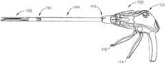
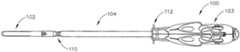
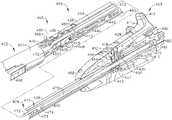
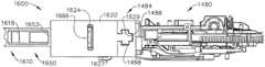
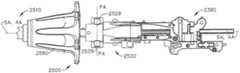
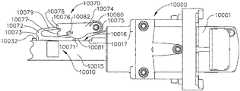
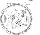
図1〜3は例示的な手術器具100を示しており、この手術器具100は、ハンドル103と、シャフト104と、関節継手110にてシャフト104に旋回式で連結された関節屈曲型エンドエフェクタ102とを有することができる。関節継手110を中心としたエンドエフェクタ102の回転を達成するために、関節制御部112が設けられている。エンドエフェクタ102は、組織をクランプ締め、切断、及びステープル留めするためのエンドカッターとして働くように構成されて示されているが、理解されたいこととして、様々な実施形態には、例えば、グラスパ、カッター、ステープラ、クリップアプライヤ、アクセス装置、薬物/遺伝子治療用送達装置、超音波、RF、及び/又はレーザーエネルギー装置などを含む他の手術装置として働くように構成されたエンドエフェクタを挙げることができる。手術器具100のハンドル103は、エンドエフェクタ102を作動させるための閉鎖トリガ114と発射トリガ116とを有することができる。理解されたいこととして、種々の手術作業を対象としたエンドエフェクタを有する器具が、エンドエフェクタを操作するための多種多様なトリガ又は他の好適な制御部を有することができる。エンドエフェクタ102は、シャフト104によってハンドル103に連結されている。以下で更に詳細に説明するように、臨床医は、関節制御部112を利用することにより、シャフト104に対してエンドエフェクタ102を関節屈曲させることができる。 1-3 illustrate an exemplary
理解されたいこととして、垂直、水平、右、左などの空間に関する用語は、トリガ114、116がハンドル103の底部から鋭角をなして下方に延びる状態で、手術器具100の長手軸がシャフト104の中心軸と同軸であると想定して、本明細書において図に関連させて用いられている。実際の診療においては、しかしながら、手術器具100は様々な角度に方向付けられることができ、したがって、これらの空間に関する用語は、手術器具100自体に対して用いられる。更に、近位は、ハンドル103の後方にいて、エンドエフェクタ102を遠位側に、つまり自身から遠ざけて置く臨床医の視野を示すために用いられる。本明細書で用いられるとき、「長手軸に実質的に直角」という語句(「長手軸」はシャフトの軸である)は、長手軸にほぼ垂直な方向を指す。しかしながら、理解されたいこととして、長手軸に対する垂直からいくぶんか逸脱する方向もまた、長手軸に実質的に直角である。 It should be understood that terms relating to space such as vertical, horizontal, right, left, etc. are such that the longitudinal axis of
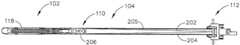
本明細書で開示される種々の実施形態は、曲げケーブル又はバンドによって駆動される関節継手を有する器具に関するものである。図4及び5は、細長シャフト104及びエンドエフェクタ102の横断平面図であり、エンドエフェクタ102は、エンドエフェクタ102から延びるボス206に機械的に結合されたバンド205を有している。バンド205はバンド部分202及び204を有してもよく、このバンド部分202及び204は、ボス206から近位側に、細長シャフト104に沿って、関節制御部112を通じて延びている。バンド205及びバンド部分202、204は、固定長を有することができる。バンド205は、例えば接着剤、溶接などを含めた任意の好適な固着方法を用いて、図示のようにボス206に機械的に結合されてよい。様々な実施形態において、各バンド部分202、204は、別々のバンドとして設けられてもよく、別々のバンドはそれぞれ、ボス206に機械的に結合された一方の端部と、シャフト104及び関節コントローラ112を通じて延びるもう一方の端部とを有する。別々のバンドは、上述のようにボス206に機械的に結合されてもよい。 Various embodiments disclosed herein relate to an instrument having an articulation joint driven by a bending cable or band. 4 and 5 are transverse plan views of the
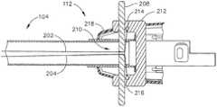
上記に加えて、バンド部分202、204は、ボス206から、関節継手110を通じて、シャフト104に沿って、図6に示す関節制御部112へと延びてもよい。関節制御部112は、関節スライド208と、フレーム212と、エンクロージャ218とを有することができる。バンド部分202、204は、スロット210又は他のアパーチャによって関節スライド208を通過することができるが、理解されたいこととして、バンド部分202、204は、任意の好適な手段でスライド208に結合されてよい。関節スライド208は、図6に示すように1つの部品であってもよく、あるいは、2つの部品を有し、2つの部品の境界面がスロット210を画定してもよい。非限定的な一実施形態において、関節スライド208は、複数のスロットを有してもよく、例えば、各スロットはバンド部分202、204の一方を受容するように構成される。エンクロージャ218は、関節制御部112の種々の構成要素を被覆して、細片が関節制御部112に浸入するのを防止することができる。 In addition to the above, the
再び図6を参照すると、バンド部分202、204はそれぞれ、スロット210から近位側に位置する連結点214、216にてフレーム212に係留されることができる。理解されたいこととして、バンド部分202、204は、ハンドル103を含めて、スロット210から近位側に位置する、器具10の任意の箇所に係留されることができる。図6の非限定的な実施形態が示すこととして、バンド部分202、204は、連結点214、216と、シャフト104の長手軸付近に位置するスロット210との間で、折れ曲がりの形態を有することができる。バンド部分202、204が直線的である他の実施形態も考えられる。 Referring again to FIG. 6, the
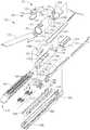
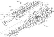
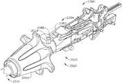
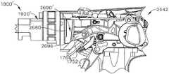
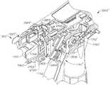
図7〜9は、図5に示す関節継手110を含んだ、器具100のエンドエフェクタ102及び細長シャフト104の図を示している。図7は、様々な内部構成要素を含んだ、エンドエフェクタ102及び細長シャフト104の分解図を示している。少なくとも1つの実施形態において、エンドエフェクタフレーム150とシャフトフレーム154は、関節継手110にて接合されるように構成される。ボス206は、エンドエフェクタフレーム150と一体であってもよく、バンド205は図示のようにボス206と作用し合う。シャフトフレーム154は、アパーチャ304を画定する遠位指向タング302を備えてもよい。アパーチャ304は、エンドエフェクタフレーム150内に備えられた関節ピン(図示せず)と作用し合うように定置され、エンドエフェクタフレーム150をシャフトフレーム154に対して旋回させ、したがってエンドエフェクタ102をシャフト104に対して旋回させることができる。組み立てられると、種々の構成要素は、図9及び10に示す関節軸306にて関節継手110を中心として旋回することができる。 7-9 illustrate views of the
図7はまたアンビル120を示している。この非限定的な実施形態において、アンビル120は細長チャネル198に結合されている。例えば、アパーチャ199が細長チャネル198内に画定されることができ、このアパーチャ199は、アンビル120から延びるピン152を受容し、細長チャネル198及びステープルカートリッジ118に対してアンビル120を開位置から閉位置へと旋回させることができる。加えて、図7は発射バー172を示しており、この発射バー172は、シャフトフレーム154を通じて、柔軟クロージャ及び旋回フレーム関節継手110を通じて、そして遠位フレーム150内の発射スロット176を通じてエンドエフェクタ102へと長手方向に並進するように構成されている。発射バー172は、1つの中実の区間から構成されてもよく、あるいは種々の実施形態において、例えば鋼板のスタックを備える積層材を有してもよい。理解されたいこととして、積層材から作製された発射バー172は、エンドエフェクタ102を関節屈曲させるのに必要な力を低減することができる。様々な実施形態において、発射バー172を下向きに付勢するために、ばねクリップ158がエンドエフェクタフレーム150に装着されることができる。エンドエフェクタフレーム150の上部に形成された遠位及び近位の方形アパーチャ164、168がそれらの間に、クリップばね158の上部アーム162を受容するクリップバー170を画定してもよく、クリップばね158の下部の遠位延出アーム160は、以下で議論するように発射バー172の隆起部分174に、下向きの力を及ぼす。 FIG. 7 also shows the
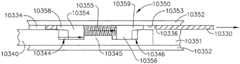
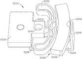
発射バー172の遠位突出端部は、E型梁178に取り付けられることができ、このE型梁178はとりわけ、アンビル120が閉位置にあるときに、細長チャネル198内に定置されたステープルカートリッジ118からアンビル120を離間させるのを支援することができる。E型梁178はまた、先鋭化された切断縁部182を有することができ、この切断縁部182は、E型梁178が発射バー172によって遠位側に前進されるときに、組織を切断するために使用されることができる。動作中、E型梁178はまた、ステープルカートリッジ118を作動、つまり発射させることもできる。ステープルカートリッジ118は、成形されたカートリッジ本体194を有することができ、このカートリッジ本体194は、ステープル駆動部192の上に載っている複数のステープル191を、上向きに開口したそれぞれのステープル穴195内に保持する。楔形スレッド190がE型梁178によって遠位側に駆動され、交換式ステープルカートリッジ118の種々の構成要素を一緒に保持するカートリッジトレー196の上でスライドする。クランプ締めされた組織をE型梁178の切断表面182が切断する間、楔形スレッド190は、ステープル駆動器192を上向きにカム駆動して、ステープル191を追い出してアンビル120と変形接触させる。 The distal protruding end of the firing
上記に加えて、E型梁178は、発射の際にアンビル120と係合する上部ピン180を有することができる。E型梁178は、中央ピン184と底部フット186とを更に有することができ、底部フット186は、カートリッジ本体194、カートリッジトレー196、及び細長チャネル198の様々な部分と係合することができる。ステープルカートリッジ118が細長チャネル198内に定置されると、カートリッジ本体194内に画定されたスロット193が、カートリッジトレー196内に画定されたスロット197及び細長チャネル198内に画定されたスロット189と整合されることができる。使用の際、E型梁178は、整合したスロット193、197、及び189を通じてスライドすることができ、図7に示すように、E型梁178の底部フット186は、チャネル198の底面に沿って延びる溝と、スロット189の全長に沿って係合することができ、中央ピン184は、カートリッジトレー196の上面と、長手スロット197の全長に沿って係合することができ、上部ピン180はアンビル120と係合することができる。そのような状況において、発射バー172が遠位側に移動されてステープルをステープルカートリッジ118から発射し、かつ/又は、アンビル120とステープルカートリッジ118との間に捕捉された組織を切開するとき、E型梁178は、アンビル120とステープルカートリッジ118とを離間させるか、あるいはそれらの間の相対運動を制限することができる。その後、発射バー172及びE型梁178は近位側に後退されて、アンビル120を開口させて、ステープル留めされ切断された2つの組織部分(図示せず)を解放することができる。 In addition to the above, the
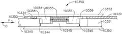
また、図7〜9は、種々の実施形態による二重旋回閉鎖スリーブ組立体121を示している。特に図7を参照すると、二重旋回閉鎖スリーブ組立体121は、上部及び下部遠位突出タング146、148を有するシャフト閉鎖チューブ区間128を備えている。エンドエフェクタ閉鎖チューブ区間126は、馬蹄形アパーチャ124と、アンビル120上の開口タブ122と係合するためのタブ123とを備えている。馬蹄形アパーチャ124及びタブ123は、アンビル120が開口されると、タブ122と係合する。閉鎖チューブ区間126は、上部近位突出タング144と下部(不可視)近位突出タングとを有して示されている。上部二重旋回リンク130は、上向きに突出する遠位及び近位旋回ピン134、136を備え、これら遠位及び近位旋回ピン134、136はそれぞれ、上部近位突出タング144内の上部遠位ピンホール138、及び上部遠位突出タング146の上部近位ピンホール140と係合する。下部二重旋回リンク132は、下向きに突出する遠位及び近位旋回ピン(図7には図示されないが、図8を参照)を備え、これら遠位及び近位旋回ピンはそれぞれ、下部近位突出タングの下部遠位ピンホール、及び下部遠位突出タング148の下部近位ピンホール142と係合する。 7-9 also illustrate a double swivel
使用の際、閉鎖スリーブ組立体121は、例えば閉鎖トリガ114の作動に反応してアンビル120を閉鎖するために遠位側に並進される。アンビル120は、閉鎖チューブ区間126を、したがってスリーブ組立体121を遠位側に並進させて、図9Aにおいてタブ122の左側に位置するアンビル120の近位表面と衝突させることによって閉鎖される。図8及び9に更に明確に示すように、アンビル120は、チューブ区間126を、そしてスリーブ組立体121を近位側に並進させて、タブ123及び馬蹄形アパーチャ124をタブ122と接触させ、タブ122に押し当ててアンビル120を持ち上げることによって開放される。アンビル開放位置において、二重旋回閉鎖スリーブ組立体121はその近位位置に移動される。 In use, the
操作の際、臨床医は、制御部112を側方に押すことによって、シャフト104に対して器具100のエンドエフェクタ102を旋回軸110を中心として関節屈曲させることができる。中立位置から、臨床医は、制御部112の左側に側方力を与えることによって、シャフト104に対してエンドエフェクタ102を左に関節屈曲させることができる。力に反応して、関節スライド208はフレーム212の中に少なくとも部分的に押し込まれることができる。スライド208がフレーム212の中に押し込まれるとき、スロット210、及びバンド部分204は、横断方向、例えばシャフト104の長手軸に対して実質的に横又は垂直の方向に、細長シャフト104を横断して並進されることができる。したがって、バンド部分204に力が加えられ、バンド部分204は、その初期の予め曲がった姿勢から、シャフト104の反対側に向かって、弾性的に曲がり、かつ/又は変位することになる。その結果、バンド部分202は、その初期の予め曲がった姿勢から弛緩する。バンド部分204のそのような運動が、バンド部分202の整直と相まって、反時計回りの回転力をボス206に加えることができ、次にそれによって、ボス206及びエンドエフェクタ102は、図12に示すように、シャフト104の軸に対して所望の角度まで、関節旋回軸110を中心として左に旋回することになる。バンド部分202が弛緩することで、このバンド部分にかかる張力が低減し、バンド部分204は、バンド部分202から実質的に干渉を受けることなく、エンドエフェクタ102を関節屈曲させることができる。明らかとなるように、臨床医はまた、制御部112の右側に側方力を与えることによって、シャフト104に対してエンドエフェクタ102を右に関節屈曲させることができる。これによってケーブル部分202が曲がり、時計回りの回転力がボス206に生じ、次にそれによって、ボス206及びエンドエフェクタは、関節旋回軸110を中心として右に旋回することになる。上記と同様に、バンド部分204が同時に弛緩されて、そのような運動が可能となる。 In operation, the clinician can articulate the
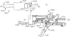
図12及び13は、電動式の手術用切断及び締結器具310を示している。この図示の実施形態は内視鏡用の器具を示しており、概して、器具310は本明細書において、内視鏡手術用の切断及び締結器具として記載されているが、留意されたいこととして、本発明はそのように限定されるものではなく、また他の実施形態によれば、本明細書に開示される任意の器具が、非内視鏡手術用の切断及び締結器具を含み得る。図12及び13に示す手術器具310は、ハンドル306と、シャフト308と、シャフト308に連結されたエンドエフェクタ312とを備えている。種々の実施形態において、エンドエフェクタ312は、関節継手314を中心としてシャフト308に対して関節屈曲されることができる。エンドエフェクタ312を関節屈曲させるための種々の手段、及び/又はシャフト308に対してエンドエフェクタ312を関節屈曲させるための種々の手段が、2010年7月13日発行の米国特許第7,753,245号、名称「手術用ステープル留め器具(SURGICAL STAPLING INSTRUMENTS)」、及び2010年3月2日発行の米国特許第7,670,334号、名称「関節屈曲式エンドエフェクタを有する手術用器具(SURGICAL INSTRUMENT HAVING AN ARTICULATING END EFFECTOR)」に開示されており、これらの特許のすべての開示内容が参照によって本明細書に組み込まれる。エンドエフェクタ312を関節屈曲させるための種々の他の手段については、以下で更に詳細に議論する。上記と同様に、エンドエフェクタ312は、組織をクランプ締め、切断、及び/又はステープル留めするためのエンドカッターとして働くように構成されているが、他の実施形態においては、他の種類の手術装置用のエンドカッター、グラスパ、カッター、ステープラ、クリップアプライヤ、アクセス装置、薬物/遺伝子治療用装置、超音波、RF、及び/又はレーザー装置など、様々な種類のエンドエフェクタが使用されることができる。いくつかのRF装置が、1995年4月4日発行の米国特許第5,403,312号、名称「電気手術止血装置(ELECTROSURGICAL HEMOSTATIC DEVICE)」、及び2008年2月14日出願の米国特許出願第12/031,573号、名称「RF電極を有する手術用切断及び締結器具(SURGICAL CUTTING AND FASTENING INSTRUMENT HAVING RF ELECTRODES)」に見出され、これらのすべての開示内容が参照によって本明細書に組み込まれる。 12 and 13 show a motorized surgical cutting and
理解されたいこととして、「近位」及び「遠位」という用語は、本明細書において、器具310のハンドル306を握持する臨床医を基準として用いられている。したがって、エンドエフェクタ312は、より近位側のハンドル306に対して遠位側にある。更に理解されたいこととして、便宜のため、また明確にするために、「垂直」及び「水平」などの空間に関する用語は、本明細書において、図面を基準にして用いられている。しかしながら、手術器具は、多数の向き及び姿勢で使用されるものであり、これらの用語は、限定的及び絶対的とすることを意図したものではない。 It should be understood that the terms “proximal” and “distal” are used herein with reference to the clinician holding the
エンドエフェクタ312は、とりわけ、ステープルチャネル322と、例えばアンビル324などの旋回並進式クランプ締め部材とを備えることができる。器具310のハンドル306は、エンドエフェクタ312を作動させるための閉鎖トリガ318と発射トリガ320とを有することができる。理解されたいこととして、種々の手術作業を対象としたエンドエフェクタを有する器具が、エンドエフェクタ312を操作するための多種多様なトリガ又は他の好適な制御部を有することができる。ハンドル306は、下向きに延びるピストルグリップ326を備えることができ、このピストルグリップ326に向かって閉鎖トリガ318が臨床医によって旋回式で引き寄せられて、エンドエフェクタ312のステープルチャネル322に向かってアンビル324のクランプ締め又は閉鎖が生じ、それによって、アンビル324とチャネル322との間に位置する組織がクランプ締めされる。他の実施形態において、種々のクランプ締め部材が、アンビル324に加えてあるいはそれに代わって使用されることができる。ハンドル306は、閉鎖トリガ318を閉位置に解放可能に保持するように構成されることができるロックを更に有することができる。閉鎖トリガ318を後退させることによってエンドエフェクタ312のアンビル324を閉鎖(又はクランプ締め)する例示的な閉鎖システムの実施形態に関する更なる詳細が、2006年2月21日発行の米国特許第7,000,818号、名称「個別の閉鎖及び発射システムを有する手術用ステープル留め器具(SURGICAL STAPLING INSTRUMENT HAVING SEPARATE DISTINCT CLOSING AND FIRING SYSTEMS)」、2008年9月9日発行の米国特許第7,422,139号、名称「位置感覚フィードバックを備えた電動式手術用切断及び締結器具(MOTOR-DRIVEN SURGICAL CUTTING AND FASTENING INSTRUMENT WITH TACTILE POSITION FEEDBACK)」、並びに、2008年12月16日発行の米国特許第7,464,849号、名称「閉鎖システム及びアンビル整合構成要素を備えた電気機械式手術器具(ELECTRO-MECHANICAL SURGICAL INSTRUMENT WITH CLOSURE SYSTEM AND ANVIL ALIGNMENT COMPONENTS)」に示されており、これらの特許のすべての開示内容が参照によって本明細書に組み込まれる。 The
臨床医がエンドエフェクタ312の位置決めに満足すると、臨床医は、ピストルグリップ326の近位側の完全閉鎖ロック位置に、閉鎖トリガ318を引き寄せることができる。次いで、発射トリガ320が作動又は発射されることができる。少なくとも1つのそのような実施形態において、発射トリガ320は、閉鎖トリガ318の更に外側にあってもよく、閉鎖トリガ318を閉じることで、発射トリガ320をピストルグリップ326に向かって移動又は回転させることができ、そのため、発射トリガ320に、様々な状況下で操作者が片手で触れることができる。その後、操作者は、ピストルグリップ312に向かって発射トリガ320を旋回式で引き寄せて、エンドエフェクタ312内のクランプ締めされた組織をステープル留め及び切断することができる。その後、発射トリガ320は、発射トリガ320に加えられている力を臨床医が軽減又は解放した後に、非作動又は非発射位置(図1及び2に示す)に復帰されることができる。ハンドル306上の解放ボタンは、押下されると、ロックした閉鎖トリガ318を解放することができる。解放ボタンは、例えば、参照によってすべての開示内容が本明細書に組み込まれる、2006年1月31日出願の米国特許出願公開第2007/0175955号、名称「閉鎖トリガロック機構を備えた手術用切断及び締結器具(SURGICAL CUTTING AND FASTENING INSTRUMENT WITH CLOSURE TRIGGER LOCKING MECHANISM)」に開示されているものなど、様々形態で実装されることができる。 When the clinician is satisfied with the positioning of the
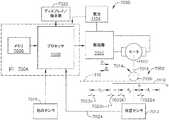
上記に加えて、エンドエフェクタ312は、例えば、発射トリガ320がユーザによって後退されたときに、エンドエフェクタ312にクランプ締めされた組織を切断するために、ナイフなどの切断器具を備えてもよい。更に上記に加えて、エンドエフェクタ312はまた、例えば、ステープル、RF電極、及び/又は接着剤など、切断器具によって切断された組織を締結するための手段を備えてもよい。器具310のシャフト308内に設置された、縦移動式駆動シャフトが、エンドエフェクタ312内で切断器具及び締結手段を駆動/作動させることができる。本明細書で更に説明するように、駆動シャフトを駆動するために、器具310のハンドル306内に設置された電気モータが使用されてもよい。様々な実施形態において、モータは、例えば約25,000RPMの最大回転数を有するブラシ付きDC駆動モータであってもよい。他の実施形態において、モータには、ブラシレスモータ、コードレスモータ、同期モータ、ステッパモータ、又は任意の他の好適な電気モータを挙げることができる。例えばリチウムイオン電池などの電池(又は「電源」又は「電源函」)が、モータに隣接させてハンドル6のピストルグリップ部分26内に設けられてもよく、この電池はモータ制御回路を介してモータに電力を供給することができる。種々の実施形態によれば、モータに給電するために、直列に接続された多数の電池が電源として使用されてもよい。加えて、電源は交換可能及び/又は再充電可能であってもよい。 In addition to the above, the
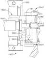
上に概説したように、器具310のハンドル306内の電気モータは、シャフト308内に定置された縦移動式駆動部材と動作可能に係合されることができる。ここで図14〜16を参照すると、電気モータ342は、ハンドル306のピストルグリップ部分326内に装着及び定置されることができる。電気モータ342は、歯車減速機組立体370と動作可能に結合された回転式シャフトを有することができ、歯車減速機組立体370はとりわけ、ハウジング374と、出力ピニオンギア372とを備えることができる。特定の実施形態において、出力ピニオンギア372は、縦移動式駆動部材382と直接、動作可能に係合されることができ、あるいはそれに代わって、1つ又は2つ以上の中間歯車386を介して駆動部材382と動作可能に係合されることができる。中間歯車386は、少なくとも1つのそのような実施形態において、駆動部材382に画定された駆動歯384の組又はラックと、噛合い係合することができる。使用の際、電気モータ342は、電気モータ342が中間歯車386を回転させる方向に応じて、矢印D(図15)で示される遠位方向及び/又は矢印D(図16)で示される近位方向に、駆動部材を駆動することができる。使用の際、電池によって与えられる電圧極性により、電気モータ342を時計回りに動作させることができるが、電池によって電気モータに加えられる電圧極性は、電気モータ342を反時計回りに動作させるために、逆転されることができる。ハンドル306は、電池によって電気モータ342に加えられる極性を逆転させるように構成されることができるスイッチを備えることができる。ハンドル306はまた、駆動部材382の位置及び/又は駆動部材382が移動されている方向を検出するように構成されたセンサ330を有することもできる。 As outlined above, the electric motor in the
上に示したように、手術器具310は、エンドエフェクタ312が関節屈曲されることができる中心となる関節継手314を有することができる。器具310は、エンドエフェクタ312を所定位置に選択的にロックするように構成及び操作されることができる関節屈曲ロックを更に有することができる。少なくとも1つのそのような実施形態において、関節屈曲ロックは、シャフト308の近位端部からシャフト308の遠位端部に延びることができ、関節屈曲ロックの遠位端部は、エンドエフェクタ312と係合してエンドエフェクタ312を所定位置にロックすることができる。再び図12及び13を参照すると、器具310は、関節制御部316を更に有することができ、関節制御部316は、関節屈曲ロックの近位端部と係合されることができ、ロック状態とロック解除状態との間で関節屈曲ロックを操作するように構成されることができる。使用の際、関節制御部316は、近位側に引っ張られてエンドエフェクタ312をロック解除し、関節継手314を中心としてエンドエフェクタ312を回転させることができる。エンドエフェクタ312が好適に関節屈曲された後、関節制御部316は遠位側に移動されて、エンドエフェクタ312を所定位置に再びロックすることができる。少なくとも1つのそのような実施形態において、ハンドル306は、関節制御部316を遠位側に付勢するように、また関節屈曲ロックを付勢してエンドエフェクタ312とのロック形態をなすように構成されたばね及び/又は他の好適な付勢要素を更に有することができる。臨床医が望む場合、臨床医は再び関節制御部316を後方に、つまり近位側に引いて、エンドエフェクタ312をロック解除し、エンドエフェクタ312を関節屈曲させ、次いで関節制御部316を再びロック状態へと移動させることができる。そのようなロック状態において、エンドエフェクタ312は、シャフト308に対して関節屈曲することができない。 As indicated above, the
上に概説したように、手術器具310は、エンドエフェクタ312をシャフト308に対して所定位置に保持するように構成された関節屈曲ロックを有することができる。また、上に概説したように、エンドエフェクタ312は、関節屈曲ロックがロック解除状態にあるとき、シャフト308に対して回転又は関節屈曲されることができる。そのようなロック解除状態において、エンドエフェクタ312をシャフト308に対して関節屈曲させるために、エンドエフェクタ312は、例えば、患者の体内の手術部位の周囲にある軟組織及び/又は骨に隣接され、押し当てられることができる。特定の実施形態において、関節制御部316は関節スイッチを備えることができ、あるいは、発射トリガ320が電気モータ342を動作させるのを選択的に許可及び/又は防止することができる関節スイッチを操作するように構成されることができる。例えば、そのような関節スイッチは、電気モータ342、及び発射トリガ320と動作可能に結合された発射スイッチと直列に配置されることができ、関節スイッチは、関節制御部316がロック状態にあるとき、閉鎖状態にあることができる。関節制御部316が移動されてロック解除状態となると、関節制御部316は関節スイッチを開放し、それにより、発射トリガ320の動作と電気モータ342の動作を電気的に分離することができる。そのような状況において、エンドエフェクタ312がロック解除状態にあり、シャフト308に対して関節屈曲可能である間、器具310の発射駆動部は発射され得ない。関節制御部316がロック状態に復帰されると、関節制御部316は関節スイッチを再閉鎖することができ、関節スイッチは次いで、発射トリガ320の動作を電気モータ342と電気的に結合することができる。1つ又は2つ以上の手術用ステープル留め器具の様々な詳細が、特許出願第12/647,100号、名称「電気アクチュエータ方向制御組立体を備えた電動式手術用切断器具(MOTOR-DRIVEN SURGICAL CUTTING INSTRUMENT WITH ELECTRIC ACTUATOR DIRECTIONAL CONTROL ASSEMBLY)」に開示されており、この特許出願は、2009年12月24日に出願され、2011年6月30日に、米国特許出願公開第2011/0155785号として公開されたものであり、そのすべての開示内容が参照によって本明細書に組み込まれる。 As outlined above, the
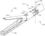
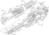
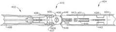
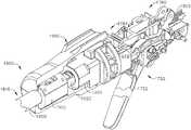
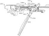
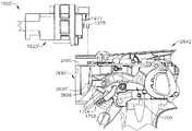
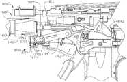
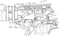
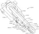
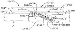
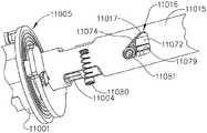
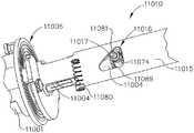
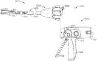
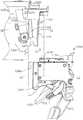
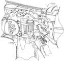
ここで図17〜29を参照するが、手術器具400が、ハンドル403と、ハンドル403から延びるシャフト404と、シャフト404から延びるエンドエフェクタ402とを備えることができる。読者に留意されたいこととして、ハンドル403の一部分が説明のために取り除かれているが、ハンドル403は、例えば、図1に示す閉鎖トリガ114及び発射トリガ116と同様の閉鎖トリガと発射トリガとを有することができる。以下で更に詳細に説明するように、発射トリガ116は、シャフト404を通じて延びる発射部材470を有する発射駆動部と動作可能に結合されることができ、発射トリガ116の操作により、発射部材470はエンドエフェクタ402に向かって遠位側に前進することができる。以下でも更に詳細に説明するように、手術器具400は、発射部材470と選択的に結合されることができる関節駆動部を更に有することができ、そのため、例えば、発射トリガ116によってかつ/又は別個の関節トリガ及び/若しくはボタンによって発射部材470が発動されると、関節駆動部は発射部材470によって駆動されることができ、また関節駆動部は、関節継手410を中心としてエンドエフェクタ402を関節屈曲させることができるようになっている。 With reference now to FIGS. 17-29, the
ここで図17を参照するが、読者に留意されたいこととして、手術器具400のエンドエフェクタ402は開放形態に示されている。より具体的には、アンビル420を備えたエンドエフェクタ402の第1のジョーが、エンドエフェクタ402の第2のジョーのチャネル498に対して、開位置に示されている。上記と同様に、チャネル498はその中にステープルカートリッジを受容し固定するように構成されることができる。ここで、同様にエンドエフェクタ420を開放形態に示す図20を参照するが、手術器具400のハンドル403は関節屈曲ロックアクチュエータ409を有することができ、この関節屈曲ロックアクチュエータ409は、エンドエフェクタ402がシャフト404に対して位置をロックされる、遠位又はロック位置と、エンドエフェクタ402が関節継手410を中心としてシャフト404に対して関節屈曲されることができる、近位又はロック解除位置との間で移動されることができる。エンドエフェクタ402とシャフト404は図20において、直線的な形態をなして整合されたものとして示されているが、関節屈曲ロックアクチュエータ409は、後退したロック解除位置に示されており、その結果、エンドエフェクタ402はシャフト404に対して関節屈曲されることができる。図19、24A及び24Bを参照するが、関節屈曲ロックアクチュエータ409(図21)は、関節屈曲ロック443と動作可能に結合されることができ、関節屈曲ロックアクチュエータ409は、関節屈曲ロック443がエンドエフェクタ402の近位ロック部材407と係合される遠位位置(図24A)と、関節屈曲ロック443がエンドエフェクタ402から分離される近位位置(図24B)との間で、関節屈曲ロック443を移動させることができる。読者に理解されたいこととして、関節屈曲ロックアクチュエータ409の遠位ロック位置は、関節屈曲ロック443の遠位位置に対応し、関節屈曲ロックアクチュエータ409の近位ロック解除位置は、関節屈曲ロック443の近位位置に対応している。ここで図19を参照するが、関節屈曲ロック443は、関節屈曲ロックバー440によって関節屈曲ロックアクチュエータ409に結合されており、関節屈曲ロックバー440は、図24Aに最良に示されるように関節屈曲ロック443と係合される遠位端部442と、図22に最良に示されるように関節屈曲ロックアクチュエータ409と係合される近位端部441とを備えている。図24A及び24Bに示すように、関節屈曲ロック443は1つ又は2つ以上の歯445を備えることができ、1つ又は2つ以上の歯445は、例えば、近位ロック部材407の周囲に画定された1つ又は2つ以上の歯446と噛合い係合するように構成されることができる。主として図19を参照するが、シャフト404は、例えばばね444などの付勢部材を更に備えることができ、その付勢部材は、関節屈曲ロック443の歯445を付勢して、エンドエフェクタ402の近位ロック部材407の歯446と係合させるように構成されることができる。同様に、ハンドル403は、関節屈曲ロックアクチュエータ409とフレーム480との間に画定された空洞488(図23)内に定置された付勢部材を更に備えることができ、そのため、付勢部材は関節屈曲ロックアクチュエータ409を遠位ロック位置に向かって押圧することができる。 Referring now to FIG. 17, it should be noted that the
図17に示すように、関節屈曲ロックアクチュエータ409は、2つのノズル半部又は部分411a及び411bから構成されてよく、読者に留意されたいこととして、ノズル部分411bは、説明の目的で、図18〜27から取り除かれている。また図17に示すように、関節屈曲ロックアクチュエータ409は、複数のフィンガフック413を備えることができ、フィンガフック413は、関節屈曲ロックアクチュエータ409を近位ロック解除形態に後退させるために、外科医又は他の臨床医に握持されることができる。再び図20を参照するが、関節屈曲ロックアクチュエータ409は、移動止め組立体452を更に有することができ、移動止め組立体452は、シャフト404のフレーム又はハンドル403のフレームに対して移動止め部材457を付勢するように構成されることができる。より具体的には、シャフト404は、ハンドルフレーム480から延びるシャフトフレーム454を備えることができ、移動止め組立体452は、シャフトフレーム454に対して移動止め部材457を付勢するように構成されることができる。図19を参照するが、シャフトフレーム454は、その中に画定された移動止めチャネル453を有することができ、移動止めチャネル453は、関節屈曲ロックアクチュエータ409が上述のロック位置とロック解除位置との間にスライドされるとき、移動止め部材457が移動止めチャネル453内でスライドできるように、移動止め部材457と整合されることができる。再び図20を参照するが、移動止め組立体452は、固定フレーム部分485を有することができ、固定フレーム部分458は、調節式ねじ付き部材459を受容するように構成されたねじ付きアパーチャを画定することができる。調節式ねじ付き部材459は内部アパーチャを有することができ、移動止め部材457の少なくとも一部分は、内部アパーチャ内に定置されることができ、移動止め部材457は、例えば、移動止め部材457と内部アパーチャの閉鎖端部との中間に定置されたばねによって、内部アパーチャの端部に付勢されることができる。図19に示すように、移動止めチャネル453の近位端部は移動止めシート455を備えることができ、移動止めシート455は、関節屈曲ロックアクチュエータ409が近位ロック解除位置に到達したときに移動止め部材457を着脱可能に受容するように構成されることができる。様々な状況下で、移動止め部材457、移動止めシート455、及び調節式ねじ付き部材459内に定置される付勢ばねは、移動止め組立体452が関節屈曲ロックアクチュエータ409を近位ロック解除位置に解放可能に保持できるように寸法を定められ、構成されることができる。以下により詳細に説明するように、関節屈曲ロックアクチュエータ409は、エンドエフェクタ402が好適に関節屈曲されるまで、近位ロック解除位置に保持されることができる。そのような点で、関節屈曲ロックアクチュエータ409は前方に押されて、移動止め部材457を移動止めシート455から分離することができる。読者に理解されたいこととして、主として図20を参照すると、調節式ねじ付き部材459は、移動止め部材457を移動止めシート455から離脱させるのに必要な力を増大させるために、シャフトフレーム454に向かって下向きに回転されることができるが、調節式ねじ付き部材459は、移動止め部材457を移動止めシート455から離脱させるのに必要な力を低減させるために、シャフトフレーム454から離れて下向きに回転されることができる。また図20に示すように、関節屈曲ロックアクチュエータ409はアクセスポート418を備えることができ、アクセスポート418は、ねじ付き部材459にアクセスし、ねじ付き部材459を回転させるために利用されることができる。 As shown in FIG. 17, the
上で議論したように、関節屈曲ロックアクチュエータ409は、図20において、後退ロック解除位置にあるが、エンドエフェクタ402は、図24Bに示すように、ロック解除形態をなす。ここで図19及び20を参照するが、手術器具400は関節駆動器460を更に備え、関節駆動器460は、図21に示すように、遠位側に押されると、関節継手410を中心としてエンドエフェクタ402を第1の方向に回転させることができ、また、近位側に引かれると、関節継手を中心としてエンドエフェクタ402を第2の、つまり反対の方向に回転させることができる。図20と21を比較して、読者に留意されたいこととして、関節駆動器460は発射部材470によって近位側に引かれている。より具体的には、発射部材470の中間部分475が、その中に画定されたノッチ又はスロット476を備えることができ、そのノッチ又はスロット476は、関節駆動器460の近位端部461を受容するように構成されることができ、そのため、発射部材470が近位側に引かれると、発射部材470は同様に関節駆動器460を近位側に引くことができる。同様に、発射部材470が遠位側に押されると、発射部材470は関節駆動器460を遠位側に押すことができる。また図20及び21に示すように、関節駆動器460は、例えば、近位ロック部材407から延びる突起414と係合する遠位端部462を備えることができ、近位ロック部材407は、関節駆動器460の近位方向及び遠位方向の関節屈曲運動をエンドエフェクタ102に伝達するように構成されることができる。主として図18〜20を参照するが、ハンドル404は、発射部材470の近位発射部材部分482を更に備えることができ、近位発射部材部分482は、発射部材470の中間部分475の近位端部477と係合する遠位端部481を有している。上記と同様に、ハンドル403は、出力シャフトと、その出力シャフトと動作可能に係合される歯車とを備えた電気モータを有することができ、その歯車は、発射部材482の表面に画定された、長手の一連の歯484と動作可能に係合されることができる。使用の際、上記に加えて、電気モータは、発射部材470を遠位側に前進させるためには第1の方向に、発射部材470を近位側に後退させるためには、第2の、つまり反対の方向に動作されることができる。図示しないが、ハンドル403は、電気モータを第1の方向に動作させる第1の状態、電気モータを第2の方向に動作させる第2の状態、及び/又は、電気モータがいずれの方向にも動作されない中立の状態に位置付けられることができるスイッチを更に備えることができる。少なくとも1つのそのような実施形態において、スイッチは、例えばばねなど、少なくとも1つの付勢部材を有することができ、その付勢部材は、例えばスイッチを中立の状態に付勢するように構成されることができる。また、少なくとも1つのそのような実施形態において、関節スイッチの第1の状態は、例えば、中立位置の第1の側にあるスイッチトグルの第1の位置を含むことができ、関節スイッチの第2の状態は、中立位置の第2の、つまり反対の側にあるスイッチトグルの第2の位置を含むことができる。 As discussed above, the
様々な状況下で、上記に加えて、関節スイッチは、エンドエフェクタ402の位置にわずかな調節を行うために使用されることができる。例えば、外科医は、エンドエフェクタ402が所望の位置に定置されるまで、関節スイッチを第1の方向に移動させて、関節継手を中心としてエンドエフェクタ402を第1の方向に回転させ、次いで、関節スイッチを第2の方向に移動させることによってエンドエフェクタ402の移動を逆転させること、及び/又は、第1及び第2の方向への移動の任意の他の好適な組み合わせが可能である。主として図19、24A、及び24Bを参照するが、関節継手410は、シャフトフレーム部材451から延びる旋回ピン405を、またそれに加えて、近位ロック部材407に画定されたアパーチャ408を有することができ、アパーチャ408は、その中に旋回ピン405を緊密に受容するように構成されており、そのため、エンドエフェクタ402の回転は、例えば、関節軸406を中心とした回転に制約されている。主として図19を参照するが、シャフトフレーム454の遠位端部は、その中にシャフトフレーム部材451を受容するように構成された凹部456を有することができる。以下で更に詳細に説明するように、シャフト404は、アンビル420を閉鎖するために、シャフトフレーム454に対してスライドされることができる外側スリーブスイッチを有することができる。主として図19〜21を参照するが、シャフト410の外側スリーブは、関節リンク430及び432によって互いに連結されることができる近位部分428及び遠位部分426を備えることができる。外側スリーブが関節継手410に対してスライドされると、関節リンク430は、図21に示すように、エンドエフェクタ402が関節屈曲されるとき、外側スリーブの遠位部分426と近位部分428との斜行する相対運動に適応することができる。様々な状況下で、関節リンク430及び432は、エンドエフェクタ402の関節屈曲に適応するために、2又は3以上の自由度を関節継手410にもたらすことができる。また読者に留意されたいこととして、関節継手410はガイド401を更に有することができ、ガイド401は、その中に発射部材470の遠位切断部分472を受容し、関節継手410の中でかつ/又は関節継手410に対して遠位切断部分472が遠位側に前進されかつ/又は近位側に後退されるときに遠位切断部分472を案内するように構成されることができる。 Under various circumstances, in addition to the above, the articulation switch can be used to make slight adjustments to the position of the
上に概説したように、発射部材470は、関節駆動器460を遠位側に前進させ、その結果としてエンドエフェクタ402を第1の方向に回転させるために、遠位側に前進されることができ、同様に、発射部材470は、関節駆動器460を近位側に後退させ、その結果としてエンドエフェクタ402を反対方向に回転させるために、近位側に後退されることができる。状況によっては、しかしながら、エンドエフェクタ402を関節屈曲させるために発射部材470が利用されているとき、発射部材470の遠位切断部分472を移動させるか、又は少なくとも実質的に移動させることが望ましくない場合もある。ここで図19〜21を参照するが、発射部材470の中間部分475は、その遠位端部に画定された長手スロット474を備えることができ、この長手スロット474は、遠位切断部分472の近位端部473を受容するように構成されることができる。長手スロット474及び近位端部473は、それら同士の相対運動が可能となるように寸法を定められ、構成されることができ、またスリップ継手471を備えることができる。スリップ継手471は、遠位切断部分472を移動させることなく、又は少なくとも実質的に移動させることなく、発射駆動部470の中間部分475を移動させてエンドエフェクタ402を関節屈曲させることができる。以下で更に詳細に説明するように、エンドエフェクタ402が好適に方向付けられると、遠位切断部分472を前進させ、チャネル498内に定置されたステープルカートリッジを発射するために、長手スロット474の近位側壁が近位端部473と接触するまで、中間部分475は、遠位側に前進されることができる。主として図19を参照するが、シャフトフレーム454は、関節駆動器460をスライド可能に受容するように構成されることができる、シャフトフレーム454内に画定された長手スロット469を備えることができ、同様に、外側シャフトスリーブの近位部分428は、関節駆動器460と上述のシャフト404の外側スリーブとの相対運動に適応するように構成された長手開口部425を備えることができる。 As outlined above, the firing
上記に加えて、関節屈曲ロックアクチュエータ409は、関節屈曲ロックアクチュエータ409が近位ロック解除位置にあるときに、関節駆動器460の近位部分461を駆動部材470に向かって付勢するように構成されることができる。より具体的には、少なくとも1つのそのような実施形態において、関節屈曲ロック409の内表面はカムを備えることができ、そのカムは、近位部分461の外側部466と係合し、近位部分461を付勢して、駆動部材470の中間部分475に画定されたスロット476と係合させることができる。関節屈曲ロックアクチュエータ409が再び遠位ロック位置に移動されると、関節屈曲ロックアクチュエータ409は、駆動部材470に向かって近位部分461を内向きに付勢できなくなる。少なくとも1つのそのような実施形態において、ハンドル403及び/又はシャフト404は、例えばばねなどの弾性部材を備えることができ、この弾性部材は、近位部分461を外向きに付勢して発射部材470から離すように構成されることができ、そのため、上述のように、関節屈曲ロックアクチュエータ409がロック解除位置へと近位側に移動されるとき、弾性部材の付勢力が関節屈曲ロックアクチュエータによって克服されない限り、近位部分461はスロット476と動作可能に係合されないようになっている。様々な状況下で、近位部分461及びスロット476は力制限クラッチを備えることができる。 In addition to the above, the
エンドエフェクタ402が、所望の向きに関節屈曲されると、上記に加えて、閉鎖トリガ114は、図22に示すように、アンビル420を閉位置に移動させるように作動されることができる。より具体的には、例えば、閉鎖トリガ114は、シャフト410の外側スリーブを遠位側に前進させることができ、そのため、外側スリーブの遠位部分426はアンビル420を遠位側にかつ下向きに押すことができる。アンビル420は、アンビル420の両側から延びる突起497を備えることができ、突起497はそれぞれ、カートリッジチャネル498内に画定された細長スロット499内でスライド及び回転するように構成されることができる。アンビル420は、アンビル420から上向きに延びる突起496を更に備えることができ、突起496は、外側スリーブの遠位部分426に画定されたアパーチャ495内に定置されることができ、アパーチャ495の側壁は、遠位部分426が遠位側に前進されてアンビル420をカートリッジチャネル498に向かって移動させるとき、突起496と接触することができる。上記に加えて、閉鎖駆動部の作動によっても、関節屈曲ロックアクチュエータ409を近位ロック解除位置(図20〜22)から遠位ロック位置(図23)に移動させることができる。より具体的には、図22に示すように、閉鎖駆動部は、閉鎖駆動キャリッジ415を遠位側に前進させるように構成されることができ、閉鎖駆動キャリッジ415は、関節アクチュエータ409内に装着されたカラー450と接触することができる。図19及び22に示すように、カラー450は、シャフト404を囲繞できるように互いに組み立てられることができる対向部分、又は半部を備えることができる。カラー450はまた、上で議論した移動止め組立体452を支持することができ、また、同様に上で議論した関節屈曲ロックバー440の近位端部441と係合する装着部分を有することができる。いずれにせよ、図23に示すように、閉鎖駆動キャリッジ415は、カラー450と接触し、関節屈曲ロックアクチュエータ409を遠位側にスライドさせることができ、また上記に加えて、移動止め部材457を移動止めシート455から移動止めチャネル453へと変位させることができ(図19を参照)、そのため、関節屈曲ロックアクチュエータ409はロック位置へと押されることができ、関節屈曲ロック443は、移動され近位ロック部分407と係合されて、エンドエフェクタ402を所定位置にロックすることができる。そのような点で、以下で更に詳細に説明するように、閉鎖駆動部及びアンビル420が再び開放され、閉鎖駆動キャリッジ415が近位側に移動されるまで、閉鎖駆動キャリッジ415は、エンドエフェクタ402がロック解除され関節屈曲されるのを防止することができる。 Once the
ここで図25を参照するが、閉鎖駆動アクチュエータ114によって閉鎖駆動部が作動されること、及びシャフト410の外側スリーブ428が遠位側に前進することにより、関節駆動器460を発射駆動部470から動作可能に分離することもできる。図20及び21をもう一度、確認すると、読者に留意されたいこととして、外側スリーブ428は、その中に画定された窓424を有しており、この窓424の中に回転式カム部材465が定置されることができる。カム部材465は、シャフトフレーム454に回転可能にピン留め又は結合された第1の端部と、カム部材465のピン留めされた端部に対して回転するように構成された第2の端部とを備えることができる一方で、他の実施形態において、カム部材465は任意の好適な形状を有することができる。外側スリーブ428が近位位置にあり、アンビル420が開放形態にあるとき、カム部材465は、関節駆動器460の近位端部461を発射部材470に画定されたスロット476と係合させる第1の位置にあることができるが、外側スリーブ428が遠位側に前進されるとき、窓424の側壁がカム部材465と係合し、カム部材465の第2の端部を持ち上げてシャフトフレーム454から離して第2の位置に入れることができる。この第2の位置において、カム部材465は、関節駆動器460の近位端部461を移動させて発射駆動部470から離すことができ、そのため、近位端部461は、発射駆動部470に画定されたスロット476内に位置しなくなる。したがって、閉鎖駆動部が作動されてアンビル420が閉鎖されるとき、閉鎖駆動部は関節屈曲ロックアクチュエータ409を押して遠位ロック形態にすることができ、関節屈曲ロックアクチュエータ409は、関節屈曲ロック445を押してエンドエフェクタ402とのロック形態にすることができ、加えて、閉鎖駆動部は関節駆動器460を発射駆動部470から動作可能に分離することができる。そのような点で、手術器具400の操作において、発射駆動部470の作動は、エンドエフェクタ402を関節屈曲させることにならず、また発射駆動部470は関節駆動器460とは独立に移動することができる。 Referring now to FIG. 25, the
ここで図26を参照するが、上述のように、発射駆動部470は遠位側に前進されて、エンドエフェクタ402のチャネル498内に定置されたステープルカートリッジからステープルを排出し、ステープルをアンビル420に押し当てて変形させることができる。上に概説したように、発射駆動部470は、エンドエフェクタ402内に捕捉された組織を横切開するように構成されることができる切断部材を更に備えることができる。同様に上述したように、ハンドル403内の電気モータは、発射部材470を遠位側に前進させるために、発射アクチュエータ116によって動作されることができ、様々な状況下で、電気モータは、ステープルカートリッジの遠位端部及び/又はステープルカートリッジ内の任意の他の好適な位置に発射部材470の遠位切断部分472が到達するまで動作されることができる。いずれにせよ、図27に示すように、電気モータの回転が逆転されて、発射部材470を近位側に後退させることができる。様々な状況下で、電気モータは、中間部分475に画定された長手スロット474の遠位側壁が遠位切断部材472の近位端部473と接触するまで、近位駆動部分482及び中間部分475を後退させることができる。そのような点で、近位駆動部分482及び中間部分475の更なる後退により、遠位切断部材472が近位側に後退されることになる。様々な状況下で、電気モータは、発射部材470の中間部分475に画定されたスロット476が関節駆動器460の近位部分461と再び整合されるまで動作されることができるが、閉鎖スリーブ428は依然として遠位側に前進した位置にあるため、カム部材465は依然として、発射部材470との係合を外すように関節駆動部460を付勢することができる。関節駆動器460を発射部材470と再び係合させるために、そのような状況下で、カム部材465が第1の位置へとシャフトフレーム454に向かって内向きに旋回されることができるように、閉鎖駆動部は、外側スリーブ部分428に画定された窓424をカム部材465と整合させるように、再び開放されなければならない。様々な状況下で、関節駆動器460は、弾性的に屈曲されて発射部材470との係合から逃れることができ、そのため、カム部材465が再び第1の位置に移動できるようにされると、関節駆動器460はシャフトフレーム454に向かって内向きに弾性的に屈曲して、関節駆動器460の近位部分461を、駆動部材470の中間部分475に画定されたスロット476と再び係合させることができる。様々な実施形態において、手術器具400は、近位部分461を付勢して中間部分475と再び係合させるように構成されることができる付勢部材を更に備えることができる。 Referring now to FIG. 26, as described above, firing
読者に留意されたいこととして、発射部材470の中間部分475は図27において近位側に後退されており、そのため、中間部分475に画定されたスロット476は、関節駆動器460の近位部分461に対して近位側に定置されている。そのような状況下で、結果として、近位部分461は、中間部分475が遠位側に前進されてスロット476を近位部分461と整合させるまで、発射部材470に動作可能に再び連結されなくてもよい。そのような状況は、スリップ継手471で発生される、発射部材470の中間部分475と切断部材部分472との間の相対的なスリップの結果として生じ得るものであり、このスリップは、例えば、電気モータを第1の方向に一時的に再作動させることによって対処されることができる。 It should be noted that the
再び図27を参照すると、発射部材470は、後退又はリセット位置にあってもよいが、閉鎖駆動部は依然として、作動又は閉鎖形態にあり、それにより、アンビル420が再び開放されること、及びエンドエフェクタ402が再び関節屈曲されることを防止することができる。ここで図28を参照するが、閉鎖駆動部が開放されると、閉鎖駆動キャリッジ415は、部分426及び428を含む閉鎖スリーブが同様に近位側に引かれる近位位置へと後退されることができる。再び図19を参照すると、近位スリーブ部分428は、閉鎖駆動キャリッジ415と係合されることができる近位端部417を有することができ、そのため、近位スリーブ部分428と閉鎖駆動キャリッジ415が共に遠位方向及び/又は近位方向に移動するようになっている。いずれにせよ、上記に加えて、遠位スリーブ部分426が近位側に移動することにより、図29に示すように、アンビル420を開位置に旋回させるために、アパーチャ495の遠位側壁を、アンビル420から延びる突起496と係合させることができる。更に、閉鎖駆動キャリッジ415が近位側に移動することにより、関節屈曲ロックアクチュエータ409をロック解除することができ、そのため、関節屈曲ロックアクチュエータ409は近位ロック解除位置に移動されることができ、これにより、結果として、関節屈曲ロック443を近位側に引いてばね444を圧縮し、エンドエフェクタ402をロック解除することができる。上述のように、エンドエフェクタ402は次いで、関節継手410を中心として関節屈曲されることができ、上述した手術器具400の操作が反復されることができる。主として図18〜20を参照するが、ハンドル404は、ハンドルフレーム480に装着されたスイッチ408を更に備えることができ、スイッチ408は、関節屈曲ロックアクチュエータ409が近位ロック解除位置にあるか否かを検知するように構成されることができる。いくつかの実施形態において、スイッチ408は、例えばライトなどのハンドル404内の指示器と動作可能に結合されることができ、その指示器は、例えば、エンドエフェクタ402がロック解除状態にあること、そして操作者が関節スイッチを利用してエンドエフェクタ402を関節屈曲させてもよいことを、手術器具400の操作者に指示することができる。 Referring again to FIG. 27, the firing
図17の実施形態に関連して上で説明したように、手術器具400は、エンドエフェクタ402をロック及びロック解除するように構成された関節屈曲ロックシステムと、エンドエフェクタ402のアンビル420を開放及び閉鎖するように構成された閉鎖駆動部とを備えることができる。手術器具400のこれら2つのシステムは、上述したいくつかの点で相互作用するが、他の点では互いに独立に作動されることができる。例えば、関節屈曲ロックアクチュエータ409及びエンドエフェクタロック443は、アンビル420を閉鎖することなく作動されることができる。手術器具400のこの実施形態において、閉鎖駆動部は独立に操作されてアンビル420を閉鎖する。ここで図30〜32を参照すると、手術器具400は、(1)アンビル420を閉鎖し、(2)エンドエフェクタ402を所定位置にロックするために閉鎖駆動部が作動される代替的な構成を有することができる。主として図31及び32を参照するが、シャフト404は関節屈曲ロックバー540を備えることができ、関節屈曲ロックバー540は、エンドエフェクタ402が関節継手410を中心として関節屈曲されることができる近位ロック解除位置(図31)と、エンドエフェクタ402が所定位置にロックされることができる遠位ロック位置(図32)との間で移動されることができる。関節屈曲ロックバー440と同様に、関節屈曲ロックバー540は、関節屈曲ロック443と動作可能に係合される遠位端部542を有することができ、そのため、関節屈曲ロックバー540が近位側に引かれると、関節屈曲ロック443が近位側に引かれることができる。同様に、関節屈曲ロックバー540が遠位側に押されると、関節屈曲ロック443も同様に遠位側に押されることができる。上述のように、関節屈曲ロックアクチュエータ409によって遠位側に押され、また近位側に引かれる関節屈曲ロックバー440とは対照的に、関節屈曲ロックバー540は、閉鎖スリーブ428によって遠位側に押され、また近位側に引かれることができる。より具体的には、関節屈曲ロックバー540の近位端部541はフック547を備えることができ、フック547は、閉鎖スリーブ428が近位側に引かれると、閉鎖スリーブ428の一部分を捕捉し、閉鎖スリーブ428と共に近位側に引かれることができる。そのような状況下で、スリーブ428は関節屈曲ロックバー540をロック解除状態へと引くことができる。読者に留意されたいこととして、閉鎖スリーブ428は窓549を有することができ、この窓549内に関節屈曲ロックバー540の近位端部541が定置されることができる。上記に加えて、閉鎖スリーブ428が遠位側に引かれると、エンドエフェクタ402を所定位置にロックするために、窓549の近位側壁548が、近位端部541と接触し、関節屈曲ロックバー540及び関節屈曲ロック443を遠位側に押すことができる。 As described above in connection with the embodiment of FIG. 17,
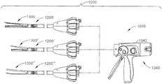
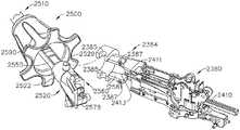
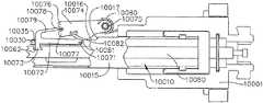
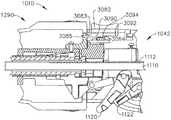
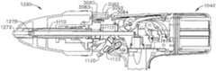
本明細書で説明するように、交換式の手術用部品と共に使用されるように構成された再使用可能な部分を含むことができる手術システム及び装置を用いることが望ましい場合がある。例えば、図33を参照すると、全体として1000で示される手術システムが示されており、この手術システムは、少なくとも1つの形態において手術器具1010を備え、手術器具1010は再使用されてもされなくてもよい。手術器具1010は、複数の交換式シャフト組立体1200、1200’、1200’’と共に用いられることができる。交換式シャフト組立体1200、1200’、1200’’は、それらに動作可能に結合された手術用エンドエフェクタ1300、1300’、1300’’を有してもよく、手術用エンドエフェクタ1300、1300’、1300’’は、1つ又は2つ以上の手術作業又は手技を実施するように構成されている。例えば、手術用エンドエフェクタ1300、1300’、1300’’の各々は、その中に手術用ステープルカートリッジを動作可能に支持するように構成された手術用切断及び締結装置を備えてもよい。シャフト組立体の各々は、種々の寸法及び種類のステープルカートリッジを支持するように適合されたエンドエフェクタを用いてよく、種々のシャフト長さ、寸法、及び種類などを有してよい。これらの図は、組織を切断及びステープル留めするように構成されたエンドエフェクタを示しているが、様々な態様の手術システム1000がまた、様々な手術用途及び手技で使用される交換式シャフト装着型エンドエフェクタ装置に、例えば、高周波(RF)エネルギー、超音波エネルギー及び/又は運動など、他の運動及び形態のエネルギーを加えるように構成された手術器具と共に、効果的に用いられることができる。更に、エンドエフェクタ、シャフト組立体、ハンドル、手術器具、及び/又は手術器具システムは、任意の好適な締結具を利用して組織を締結することができる。例えば、中に着脱可能に格納された複数のファスナを備えるファスナカートリッジが、シャフト組立体のエンドエフェクタに着脱可能に挿入及び/又は装着されることができる。様々な状況下で、シャフト組立体が、手術器具のハンドルに装着されるように選択されることができ、ファスナカートリッジがシャフト組立体に装着されるように選択されることができる。 As described herein, it may be desirable to use a surgical system and apparatus that can include a reusable portion configured for use with replaceable surgical components. For example, referring to FIG. 33, there is shown a surgical system, generally designated 1000, which includes a
図33に示す手術器具1010は、ハンドル1042からなるハウジング1040を備え、ハンドル1042は、臨床医によって握持、操作、及び作動されるように構成されている。しかしながら、この詳細な説明が進むとき、理解されたいこととして、本明細書で開示する様々な形態の交換式シャフト組立体の、様々な独自で新規な構成が、ロボット制御される手術システムと関連させて効果的に用いられることができる。したがって、「ハウジング」という用語はまた、本明細書で開示する交換式シャフト組立体及びそれらに対応する等価物を作動させるために利用できる少なくとも1つの制御運動を生成し加えるように構成された少なくとも1つの駆動システムを収容するか、ないしは別様に支持するロボットシステムのハウジング又は類似の部分を包含することができる。「フレーム」という用語は、手持型手術器具の一部分を指すことができる。「フレーム」という用語はまた、ロボット制御式の手術器具の一部分及び/又は手術器具を動作可能に制御するために利用できるロボットシステムの一部分を表すことができる。例えば、本明細書で開示する交換式シャフト組立体は、米国特許出願公開第2012/0298719号に開示されている様々なロボットシステム、器具、構成要素及び方法と共に用いられることができる。米国特許出願第13/118,241号、名称「回転式ステープル配備装置を備えた手術用ステープル留め器具(SURGICAL STAPLING INSTRUMENTS WITH ROTATABLE STAPLE DEPLOYMENT ARRANGEMENTS)」、現在の米国特許出願公開第2012/0298719号は、参照によってすべての内容が本明細書に組み込まれる。 The
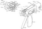
図34は、交換式シャフト組立体1200を動作可能に結合された手術器具1010を示している。図示の形態において、手術器具はハンドル1042を有している。少なくとも1つの形態において、ハンドル1042は、ねじ、スナップ機構、接着剤などで相互連結されることができる1対の相互連結式ハウジング分割部1044、1046を備えることができる。図35を参照されたい。図示の構成において、ハンドルハウジング分割部1044、1046は、臨床医に握持及び操作されることができるピストルグリップ部分1048を形成するように協働する。以下で更に詳細に議論するように、ハンドル1042は、その中に複数の駆動システムを動作可能に支持し、それら駆動システムは、ハンドル1042に動作可能に装着された交換式シャフト組立体の対応部分に、様々な制御動作を生成して加えるように構成されている。 FIG. 34 shows a
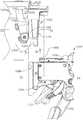
ハンドル1042は、複数の駆動システムを動作可能に支持するフレーム1080を更に有してもよい。例えば、フレーム1080は、全体として1050と示される第1の、つまり閉鎖駆動システムを動作可能に支持することができ、この閉鎖駆動システムは、ハンドル1042に動作可能に装着又は結合される交換式シャフト組立体1200に閉鎖及び開放運動を加えるために用いられることができる。少なくとも1つの形態において、閉鎖駆動システム1050は、フレーム1080によって旋回式で支持される閉鎖トリガ1052の形態をなすアクチュエータを含んでもよい。更に詳しくは、図35に示すように、閉鎖トリガ1052はフレーム1080によって旋回式で支持されてもよく、そのため、臨床医がハンドル1042のピストルグリップ部分1048を握持するとき、閉鎖トリガ1052は開始又は非作動位置から作動位置へ、より具体的には完全圧縮又は完全作動位置へと容易に旋回できるようになっている。閉鎖トリガ1052は、ばね又は他の付勢装置(図示せず)によって、非作動位置へと付勢されてもよい。様々な形態において、閉鎖駆動システム1050は、閉鎖トリガ1052に旋回式で結合された閉鎖リンク機構組立体1060を更に有する。図35で分かるように、閉鎖リンク機構組立体1060は、閉鎖リンク1064に旋回式で結合される閉鎖トリガ1052を有してもよく、閉鎖リンク1064は、それから突出する1対の側方延出装着ラグ又は部分1066を有している。閉鎖リンク1064はまた、本明細書において「装着部材」とも呼ばれることがある。 The
依然として図35を参照するが、閉鎖トリガ1052は、フレーム1080に旋回式で結合される閉鎖解放組立体1070と協働するように構成されたロック壁1068を有してもよいことが観察できる。少なくとも1つの形態において、閉鎖解放組立体1070は解放ボタン組立体1072を備えてもよく、解放ボタン組立体1072は、その上に形成された遠位突出カム従動アーム1074を有する。解放ボタン組立体1072は、解放ばね1076によって反時計回りの方向に旋回されてもよい。臨床医が閉鎖トリガ1052を非作動位置からハンドル1042のピストルグリップ部分1048に向かって押下すると、カム従動アーム1072が閉鎖リンク1062上のロック壁1068との保持係合に移る点に向かって、閉鎖リンク1062が上向きに旋回し、それによって、閉鎖トリガ1052が非作動位置に復帰することが防止される。したがって、閉鎖解放組立体1070は、閉鎖トリガ1052を完全作動位置にロックするように働く。臨床医が閉鎖トリガ1052をロック解除して非作動位置に付勢するように望むとき、臨床医は単純に、カム従動アーム1074が移動して閉鎖トリガ1052上のロック壁1068との係合から逃れるように、閉鎖解放ボタン組立体1072を旋回させる。カム従動アーム1074が移動されて閉鎖トリガ1052との係合から逃れると、閉鎖トリガ1052は再び非作動位置に旋回することができる。他の閉鎖トリガロック及び解放装置が用いられてよい。 Still referring to FIG. 35, it can be observed that the
少なくとも1つの形態において、ハンドル1042及びフレーム1080は、本明細書で発射駆動システム1100と呼ばれる別の駆動システムを動作可能に支持してもよく、この発射駆動システム1100は、それに装着された交換式シャフト組立体のうちの対応する部分に発射動作を加えるように構成されている。発射駆動システムはまた、本明細書において「第2の駆動システム」と呼ばれることもある。発射駆動システム1100は、ハンドル1042のピストルグリップ部分1048に設置された電気モータ1102を用いてもよい。様々な形態において、モータ1102は、例えば約25,000RPMの最大回転数を有するブラシ付きDC駆動モータであってもよい。他の構成において、モータには、ブラシレスモータ、コードレスモータ、同期モータ、ステッパモータ、又は任意の他の好適な電気モータを挙げることができる。制御回路基板組立体1106に、そして最終的にモータ1102に電力を供給するために、例えばリチウムイオン電池などの電池1104(又は「電源」又は「電源函」)がハンドル1042に結合されてもよい。図34は電池パックハウジング1104を示しており、電池パックハウジング1104は、制御電力を手術器具1010に供給するために、ハンドル1042に解放可能に取り付けられるように構成されている。モータに給電するために、直列に接続された多数の電池が電源として使用されてもよい。加えて、電源は交換可能及び/又は再充電可能であってもよい。 In at least one form, the
他の様々な形態に関連して上に概説したように、電気モータ1102は、回転式シャフト(図示せず)を有することができ、その回転式シャフトは、縦移動式駆動部材1110上の駆動歯1112の組又はラックとの噛合い係合をなして取り付けられる歯車減速機組立体1108と動作可能に連係する。使用の際、電池によって与えられる電圧極性により、電気モータ1102を時計回りに動作させることができるが、電池によって電気モータに加えられる電圧極性は、電気モータ1102を反時計回りに動作させるために、逆転されることができる。電気モータ1102がある方向に回転されるとき、駆動部材1110は遠位方向「D」に軸方向に駆動される。モータ1102が反対の回転方向に駆動されるとき、駆動部材1110は近位方向「P」に軸方向に駆動される。例えば図35を参照されたい。ハンドル1042は、電池によって電気モータ1102に加えられる極性を逆転させるように構成されることができるスイッチを備えることができる。本明細書で説明する他の形態と同様に、ハンドル1042はまた、駆動部材1110の位置及び/又は駆動部材1110が移動されている方向を検出するように構成されたセンサを有することもできる。 As outlined above in connection with various other configurations, the
モータ1102の作動は、ハンドル1042上に旋回式で支持される発射トリガ1120によって制御されることができる。発射トリガ1120は、非作動位置と作動位置との間で旋回されることができる。発射トリガ1120は、ばね(図示せず)又は他の付勢装置によって非作動位置へと付勢されてもよく、そのため、臨床医が発射トリガ1120を解放すると、発射トリガ1120は、ばね又は付勢装置によって非作動位置に旋回されるか、又は別様に復帰されることができる。少なくとも1つの形態において、発射トリガ1120は、上で議論したように、閉鎖トリガ1052の「外側」に定置されることができる。少なくとも1つの形態において、発射トリガ安全ボタン1122が閉鎖トリガ1052に旋回式で取り付けられてもよい。図35及び36で分かるように、例えば、安全ボタン1122は、発射トリガ1120と閉鎖トリガ1052との間に定置され、安全ボタン1122から突出する旋回アーム1124を有してもよい。図38に示すように、閉鎖トリガ1052が非作動位置にあるとき、安全ボタン1122はハンドルハウジング内で拘束され、臨床医は容易には安全ボタン1122に触れることができず、発射トリガ1120の作動を防止する安全位置と、発射トリガ1120が発射され得る発射位置との間で移動することもできない。臨床医が閉鎖トリガ1052を押下すると、安全ボタン1122及び発射トリガ1120が下に旋回し、それらは次いで臨床医によって操作されることが可能となる。 Operation of the
上に示したように、少なくとも1つの形態において、縦移動式駆動部材1110はその上に、歯車減速機組立体1108の対応する歯車1114と噛合い係合するための歯1112のラックを有している。また、モータが故障した場合に臨床医が手動で縦移動式駆動部材1110を後退させられるように構成された手動作動式「脱出」組立体1130が、少なくとも1つの形態に含まれてもよい。この脱出組立体1130は、手動で旋回されて駆動部材1110内の歯1112とのラチェット係合をなすように構成されたレバー又は脱出ハンドル組立体1132を有してもよい。したがって、臨床医は、脱出ハンドル組立体1132を使用して駆動部材を近位方向「P」にラチェットで駆動させることによって、駆動部材1110を手動でラチェットで駆動させることができる。米国特許出願公開第2010/0089970号には、本明細書で開示する様々な器具と共に同様に用いられることもできる脱出装置、並びに他の構成要素、装置、及びシステムが開示されている。米国特許出願第12/249,117号、名称「手動後退式発射システムを備えた電動式手術用切断及びステープル留め器具(POWERED SURGICAL CUTTING AND STAPLING APPARATUS WITH MANUALLY RETRACTABLE FIRING SYSTEM)」、現在の米国特許出願公開第2010/0089970号は、参照によってそのすべての内容が本明細書に組み込まれる。 As indicated above, in at least one form,
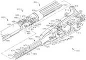
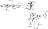
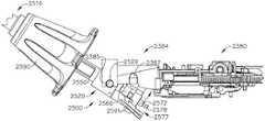
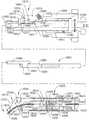
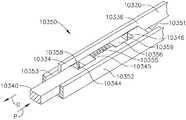
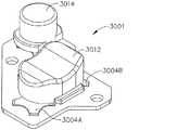
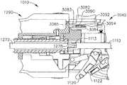
図34及び37は、例えば動作可能に装着された手術用エンドエフェクタ1300を有する交換式シャフト組立体1200の一形態を示している。これらの図に示されているようなエンドエフェクタ1300は、本明細書で開示する様々な方式で組織を切断及びステープル留めするように構成されることができる。例えば、エンドエフェクタ1300は、手術用ステープルカートリッジ1304を支持するように構成されたチャネル1302を有してもよい。ステープルカートリッジ1304は、着脱式ステープルカートリッジ1304を備えてもよく、そのため、使用後に交換されることができる。しかしながら、ステープルカートリッジは、他の装置において、チャネル1302内に据え付けられると、チャネル1302から取り外されることがないように構成されてもよい。チャネル1032及びステープルカートリッジ1304は総称で、エンドエフェクタ1300の「第1のジョー部分」と呼ばれてもよい。様々な形態において、エンドエフェクタ1300は、アンビル1310の形態をなす「第2のジョー部分」を有してもよく、この第2のジョー部分は、本明細書で議論した様々な方式でチャネル1302上に移動可能に又は旋回式で支持される。 FIGS. 34 and 37 illustrate one form of a
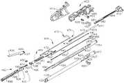
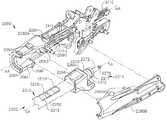
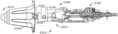
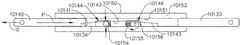
交換式シャフト組立体1200はシャフト1210を更に有することができ、シャフト1210は、シャフト装着モジュール又はシャフト装着部分1220に結合されるシャフトフレーム1212を有している。少なくとも1つの形態において、シャフトフレーム1212の近位端部1214は、シャフト装着モジュール1220上に形成された中空カラー部分1222を通じて延び、中空カラー部分1222に回転可能に装着されることができる。例えば、シャフト装着モジュール1220のスロット1224を通じて延びるU形保持器1226と係合するための環状溝1216が、シャフトフレーム1212の近位端部1214に設けられてもよい。そのような構成により、シャフトフレーム1212は、シャフト装着モジュール1220に対して回転することが可能となる。 The
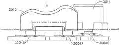
シャフト組立体1200は、中空の外側スリーブ又は閉鎖チューブ1250を更に備えてもよく、その外側スリーブ又は閉鎖チューブ1250を通じてシャフト1212が延びる。外側スリーブ1250はまた、本明細書において「第1のシャフト」及び/又は「第1のシャフト組立体」と呼ばれることもある。外側スリーブ1250は、閉鎖チューブ装着ヨーク1260に回転可能に結合されるように適合された近位端部1252を有する。図37で分かるように、外側スリーブ1250の近位端部1252は、閉鎖チューブ装着ヨーク1260内でクレードル1262の中に受容されるように構成されている。U形コネクタ1266が、閉鎖チューブ装着ヨーク1260内でスロット1264を通じて延びて、外側スリーブ1250の近位端部1252の環状溝1254に受容されるようになっている。そのような構成は、外側スリーブ1250を閉鎖チューブ装着ヨーク1260に回転可能に結合するように働き、そのため、外側スリーブ1250は閉鎖チューブ装着ヨーク1260に対して回転することができる。 The
図38及び39で分かるように、シャフトフレーム1214の近位端部1214は、外側スリーブ1250の近位端部1252から近位側に突出しており、U形保持器1226(図38に示す)によってシャフト装着モジュール1220に回転可能に結合されている。閉鎖チューブ装着ヨーク1260は、シャフト装着モジュール1220の通路1268内にスライド可能に受容されるように構成されている。そのような構成により、外側スリーブ1250は、以下で更に詳細に議論するように、シャフト装着モジュール1220に対して、シャフトフレーム1212上の近位方向「P」及び遠位方向「D」に、軸方向に移動されることが可能となる。 As can be seen in FIGS. 38 and 39, the
少なくとも1つの形態において、交換式シャフト組立体1200は、関節継手1350を更に有してもよい。しかしながら、他の交換式シャフト組立体が、関節屈曲可能でなくてもよい。図37で分かるように、例えば、関節継手1350は二重旋回閉鎖スリーブ組立体1352を有する。種々の形態によれば、二重旋回閉鎖スリーブ組立体1352は、上部及び下部遠位突出タング1356、1358を有するシャフト閉鎖スリーブ組立体1354を含む。エンドエフェクタ閉鎖スリーブ組立体1354は、馬蹄形アパーチャ1360と、上述した方式でアンビル1310上の開放タブと係合するためのタブ1362とを有している。上述のように、馬蹄形アパーチャ1360及びタブ1362は、アンビル1310が開放されているとき、アンビルタブと係合する。上部二重旋回リンク1364は、上向きに突出する遠位及び近位旋回ピンを備え、これら遠位及び近位旋回ピンはそれぞれ、外側スリーブ1250上で、上部近位突出タング1356内の上部遠位ピンホール、及び上部遠位突出タング1256内の上部近位ピンホールと係合する。下部二重旋回リンク1366は、下向きに突出する遠位及び近位旋回ピンを備え、これら遠位及び近位旋回ピンはそれぞれ、下部近位突出タング1358の下部遠位ピンホール、及び下部遠位突出タング1258の下部近位ピンホールと係合する。 In at least one form, the
使用の際、閉鎖スリーブ組立体1354は、例えば閉鎖トリガ1052の作動に反応してアンビル1310を閉鎖するために遠位側(方向「D」)に並進される。アンビル1310は、外側スリーブ1250を、したがってシャフト閉鎖スリーブ組立体1354を遠位側に並進させて、上述した方式でアンビル1310の近位表面に衝突させることによって閉鎖される。同様に上述したように、アンビル1310は、外側スリーブ1250及びシャフト閉鎖スリーブ組立体1354を近位側に並進させて、タブ1362及び馬蹄形アパーチャ1360をアンビルタブに対して接触及び押圧させてアンビル1310を持ち上げることによって開放される。アンビル開放位置において、シャフト閉鎖スリーブ組立体1352はその近位位置に移動される。 In use, the
少なくとも1つの形態において、交換式シャフト組立体1200は、シャフトフレーム1212内での軸方向移動に関して支持される発射部材1270を更に含む。発射部材1270は、遠位切断部分1280に装着されるように構成された中間発射シャフト部分1272を含む。発射部材1270はまた、本明細書において「第2のシャフト」及び/又は「第2のシャフト組立体」と呼ばれることもある。図37で分かるように、中間発射シャフト部分1272は、その遠位端部に長手スロット1274を有してもよく、長手スロット1274は、遠位切断部分1280の近位端部1282を受容するように構成されることができる。長手スロット1274及び近位端部1282は、それら同士の相対運動が可能となるように寸法を定められ、構成されることができ、またスリップ継手1276を備えることができる。スリップ継手1276は、遠位切断部分1280を移動させることなく、又は少なくとも実質的に移動させることなく、発射駆動部1270の中間発射シャフト部分1272を移動させてエンドエフェクタ1300を関節屈曲させることができる。本明細書で説明するように、エンドエフェクタ1300が好適に方向付けられると、遠位切断部分1280を前進させ、チャネル1302内に定置されたステープルカートリッジを発射するために、長手スロット1272の近位側壁が近位端部1282と接触するまで、中間発射シャフト部分1272は遠位側に前進されることができる。図37で更に分かるように、シャフトフレーム1212は細長い開口部又は窓1213を有して、中間発射シャフト部分1272をシャフトフレーム1212に組み付け、挿入するのを容易にしている。中間発射シャフト部分1272がシャフトフレーム1212に挿入されると、頂部フレーム分割部1215がシャフトフレーム1212と係合されて、それらの中に中間発射シャフト部分1272及び遠位切断部分1280を封入することができる。また読者に留意されたいこととして、関節継手1350はガイド1368を更に有することができ、ガイド1368は、その中に発射部材1270の遠位切断部分1280を受容し、関節継手1350の中でかつ/又は関節継手1350に対して遠位切断部分1280が遠位側に前進されかつ/又は近位側に後退されるときに遠位切断部分1280を案内するように構成されることができる。 In at least one form, the
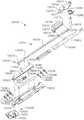
図37で分かるように、シャフト装着モジュール1220はラッチアクチュエータ組立体1230を更に有してもよく、ラッチアクチュエータ組立体1230は、押さえねじ(図示せず)又は他の好適な締結具によってシャフト装着モジュールに着脱可能に装着されることができる。ラッチアクチュエータ組立体1230は、ロックヨーク1240と協働するように構成されており、ロックヨーク1240は、シャフト装着モジュール1220に対して選択的に旋回移動をなすように、シャフト装着モジュール1220に旋回式で結合される。図41を参照されたい。図39を参照するが、以下で更に詳細に議論するように、ロックヨーク1240は、2つの近位突出ロックラグ1242(図37)を有してもよく、これら近位突出ロックラグ1242は、フレーム1080のフレーム装着モジュール部分1084に形成された、対応するロック移動止め又は溝1086と解放可能に係合するように構成されている。ロックヨーク1240は実質的にU形であり、ラッチアクチュエータ組立体1230がシャフト装着モジュール1220に結合された後に、ラッチアクチュエータ組立体1230の上に据え付けられるものである。ラッチアクチュエータ組立体1230は弓形本体部分1234を有してもよく、この弓形本体部分1234は、ロックヨーク1240がラッチ位置とラッチ解除位置との間でシャフト装着モジュール1220に対して旋回するための十分なクリアランスをもたらす。 As can be seen in FIG. 37, the
様々な形態において、ロックヨーク1240はばね又は付勢部材(図示せず)によって近位方向に付勢される。換言すれば、ロックヨーク1240は、ラッチ位置(図40)へと付勢されており、ラッチアクチュエータ組立体1230上に移動可能に支持されるラッチボタン1236によって、ラッチ解除位置(図41)に旋回されることができる。少なくとも1つの構成において、例えば、ラッチボタン1236は、ラッチハウジング部分1235内でスライド可能に保持され、ラッチばね又は付勢部材(図示せず)によって近位方向「P」に付勢される。以下で更に詳細に議論するように、ラッチボタン1236は遠位突出解放ラグ1237を有しており、遠位突出解放ラグ1237は、ラッチボタン1236が作動すると、ロックヨーク1240と係合し、ロックヨーク1240をラッチ位置から図41に示すラッチ解除位置へと旋回させるように設計されている。 In various configurations, the
交換式シャフト組立体1200は、シャフト装着モジュール1220上に回転可能に支持されるノズル組立体1290を更に含んでもよい。少なくとも1つの形態において、例えば、ノズル組立体1290は、ねじ、スナップ機構、接着剤などによって相互連結されることができる2つのノズル半部又は部分1292、1294からなってもよい。シャフト装着モジュール1220上に取り付けられると、ノズル組立体1290は、外側スリーブ1250及びシャフトフレーム1212と作用し合うことができ、例えば発射部材組立体1270の軸と規定されることができるシャフト軸SA−SAを中心としてシャフト1210をシャフト装着モジュール1220に対して臨床医が選択的に回転させることができるようにしている。特に、ノズル組立体1290の一部分が外側スリーブの窓1253を通じて延びて、シャフトフレーム1212のノッチ1218と係合する。図37を参照されたい。したがって、ノズル組立体1290が回転することで、結果として、シャフトフレーム1212及び外側スリーブ1250が軸A−Aを中心としてシャフト装着モジュール1220に対して回転することになる。 The
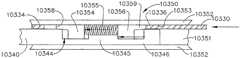
ここで図42及び43を参照すると、フレーム1080のフレーム取付けモジュール部分1084が、内向きに面する2つのダブテール形受容スロット1088を備えて形成されていることが、読者に認められよう。各ダブテール受容スロット1088は先細にされてもよく、あるいは換言すれば、いくぶんかV形をなしてもよい。例えば図36及び38を参照されたい(各スロット1088の一方のみが示されている)。ダブテール受容スロット1088は、シャフト装着モジュール1220の近位延出コネクタ部分1228の対応する先細装着又はラグ部分1229を解放可能に受容するように構成されている。図37〜39から更に分かるように、シャフト装着ラグ1278が、中間発射シャフト1272の近位端部1277に形成されている。以下で更に詳細に議論するように、交換式シャフト組立体1200がハンドル1042に結合されると、シャフト装着ラグ1278は、長手駆動部材1110の遠位端部1111に形成された発射シャフト装着クレードル1113に受容される。また、閉鎖チューブ装着ヨーク1260は近位延出ヨーク部分1265を有し、この近位延出ヨーク部分1265は、閉鎖装着バー1064の装着ラグ1066を捕捉するように下向きに開口している2つの捕捉スロット1267を有している。 42 and 43, the reader will appreciate that the frame mounting
ハンドル1042への交換式シャフト組立体1220の装着について、これから、図44〜48を参照して説明する。様々な形態において、フレーム1080又は駆動システムのうちの少なくとも1つは、作動軸AA−AAを規定する。例えば、作動軸AA−AAは、縦移動式駆動部材1110の軸によって規定されてもよい。したがって、中間発射シャフト1272が縦移動式駆動部材1110に動作可能に結合されると、図48に示すように、作動軸AA−AAはシャフト軸SA−SAと同軸となる。 The mounting of the
結合プロセスを開始するために、臨床医は、交換式シャフト組立体1200のシャフト装着モジュール1220をフレーム1080のフレーム装着モジュール部分1084の上に又はそれに隣接させて配置することができ、図45に示すように、シャフト装着モジュール1220のコネクタ部分1228上に形成された装着ラグ1229が装着モジュール部分1084のダブテールスロット1088と整合するようにすることができる。臨床医は次いで、作動軸AA−AAに対して実質的に直角な据付け軸IA−IAに沿ってシャフト装着モジュール1220を移動させることができる。換言すれば、コネクタ部分1228の装着ラグ1229が、対応するダブテール受容スロット1088との「動作可能な係合」をなして着座されるまで、シャフト装着モジュール1220は、作動軸AA−AAに対して実質的に直角な据付け方向「ID」に移動される。図44及び46を参照されたい。図47は、中間発射シャフト1272上のシャフト装着ラグ1278が縦移動式駆動部材1110のクレードル1113に侵入し、閉鎖装着バー1064上の装着ラグ1066が、閉鎖チューブ装着ヨーク1260のヨーク部分1265の対応するスロット1267に侵入する前の、シャフト装着モジュール1220の位置を示している。図48は、装着プロセスが完了した後のシャフト装着モジュール1220の位置を示している。この図で分かるように、ラグ1066(1つのみ示す)は、閉鎖チューブ装着ヨーク1260のヨーク部分1265の対応するスロット1267に、動作可能な係合をなして着座されている。本明細書で用いられるとき、2つの構成要素の状況における「動作可能な係合」という用語は、それら2つの構成要素が互いに十分に係合し、そのため、作動運動をそれらに加えると、それらの構成要素が目的の行為、機能及び/又は手順を実行できることを意味する。 To initiate the coupling process, the clinician can place the
上で議論したように、再び図44〜49を参照するが、交換式シャフト組立体1200の少なくとも5つのシステムが、ハンドル1042の少なくとも5つの対応するシステムと動作可能に結合されることができる。第1のシステムは、シャフト組立体1200のフレームをハンドル1042のフレームと結合及び/又は整合するフレームシステムを含むことができる。上で概説したように、シャフト組立体1200のコネクタ部分1228は、ハンドルフレーム1080の装着モジュール部分1084と係合されることができる。第2のシステムは、ハンドル1042の閉鎖トリガ1052と、閉鎖チューブ1250と、シャフト組立体1200のアンビル1310とを動作可能に連結することができる閉鎖駆動システムを含むことができる。上で概説したように、シャフト組立体1200の閉鎖チューブ装着ヨーク1260は、ハンドル1042の装着ラグ1066と係合されることができる。第3のシステムは、ハンドル1042の発射トリガ1120をシャフト組立体1200の中間発射シャフト1272と動作可能に連結することができる発射駆動システムを含むことができる。上で概説したように、シャフト装着ラグ1278は、長手駆動部材1110のクレードル1113に動作可能に連結されることができる。第4のシステムは、(1)例えばシャフト組立体1200などのシャフト組立体がハンドル1042と動作可能に係合されていることを、例えばマイクロコントローラ7004などのハンドル1042内のコントローラに伝えることができ、かつ/又は(2)電力及び/若しくは通信信号をシャフト組立体1200とハンドル1042との間で伝達することができる電気システムを含むことができる。例えば、シャフト組立体1200が6つの電気接点を有することができ、電気コネクタ4000もまた6つの電気接点を有することができ、ここで、シャフト組立体1200がハンドル1042に組み付けられるとき、シャフト組立体1200の各電気接点は、電気コネクタ4000の電気接点と対にされ、嵌合されることができる。シャフト組立体1200はまたラッチ1236を有することができ、ラッチ1236は、シャフト組立体1200をハンドル1042に解放可能にロックすることができる、ロックシステムなどの第5のシステムの一部であってもよい。様々な状況下で、ラッチ1236は、例えば、ラッチ1236がハンドル1042と係合されるとき、ハンドル1042内の回路を閉鎖することができる。 As discussed above, referring again to FIGS. 44-49, at least five systems of
上記に加えて、シャフト組立体1200のフレームシステム、閉鎖駆動システム、発射駆動システム、及び電気システムが、例えば、横断方向に、すなわち軸IA−IAに沿って、ハンドル1042の対応するシステムに組み付けられることができる。様々な状況下で、シャフト組立体1200のフレームシステム、閉鎖駆動システム、及び発射駆動システムは、ハンドル1042の対応するシステムに同時に結合されることができる。特定の状況下で、シャフト組立体1200のフレームシステム、閉鎖駆動システム、及び発射駆動システムのうちの2つが、ハンドル1042の対応するシステムに同時に結合されることができる。少なくとも1つの状況下で、フレームシステムは、閉鎖駆動システムと発射駆動システムが結合される前に、少なくとも初期に結合されることができる。そのような状況下で、フレームシステムは、閉鎖駆動システムと発射駆動システムの対応する構成要素を、それらが上で概説したように結合される前に整合するように構成されることができる。様々な状況下で、ハウジング組立体1200及びハンドル1042の電気システム部分は、フレームシステム、閉鎖駆動システム、及び/又は発射駆動システムが最終的に又は完全に着座されるのと同時に結合されるように構成されることができる。特定の状況下で、ハウジング組立体1200及びハンドル1042の電気システム部分は、フレームシステム、閉鎖駆動システム、及び/又は発射駆動システムが最終的に又は完全に着座される前に結合されるように構成されることができる。いくつかの状況下で、ハウジング組立体1200及びハンドル1042の電気システム部分は、フレームシステムが少なくとも部分的に結合された後に、かつ閉鎖駆動システム及び/又は発射駆動システムが結合される前に結合されるように構成されることができる。様々な状況下で、ロックシステムは、係合される最後のシステムとなるように、すなわち、フレームシステム、閉鎖駆動システム、発射駆動システム、及び電気システムがすべて係合された後に係合されるように構成されることができる。 In addition to the above, the frame system, closure drive system, firing drive system, and electrical system of the
上で概説したように、再び図44〜49を参照するが、ハンドル1042の電気コネクタ4000は複数の電気接点を備えることができる。ここで図197を参照するが、電気コネクタ4000は例えば、第1の接点4001aと、第2の接点4001bと、第3の接点4001cと、第4の接点4001dと、第5の接点4001eと、第6の接点4001fとを備えることができる。図示の実施形態は6つの接点を利用しているが、6つを超える接点又は6つ未満の接点を利用できる他の実施形態も考えられる。図197に示すように、第1の接点4001aはトランジスタ4008と電気通信することができ、接点4001b〜4001eはマイクロコントローラ7004と電気通信することができ、第6の接点4001fはアースと電気通信することができる。マイクロコントローラ7004については以下で更に詳細に議論する。特定の状況下で、ハンドル1042が通電状態にあるとき、電気接点4001b〜4001eのうちの1又は2つ以上が、マイクロコントローラ7004の1つ又は2つ以上の出力チャネルと電気通信してもよく、また、給電されるか、電位を印加されることができる。いくつかの状況下で、電気接点4001b〜4001eのうちの1つ又は2つ以上が、マイクロコントローラ7004の1つ又は2つ以上の入力チャネルと電気通信してもよく、また、ハンドル1042が給電状態にあるとき、マイクロコントローラ7004は、そのような電気接点に電位が印加されたことを検知するように構成されることができる。例えばシャフト組立体1200などのシャフト組立体がハンドル1042に組み付けられるとき、電気接点4001a〜4001fは互いに通信しなくてもよい。しかしながら、シャフト組立体がハンドル1042に組み付けられていない場合、電気コネクタ4000の電気接点4001a〜4001fは露出していてもよく、またいくつかの状況下で、接点4001a〜4001fのうちの1つ又は2つ以上が、偶然に互いに電気通信状態にされることもある。そのような状況は、例えば接点4001a〜4001fのうちの1つ又は2つ以上が導電性材料と接触する場合に生じ得る。これが生じると、例えば、マイクロコントローラ7004が誤り入力を受信することがあり、かつ/又はシャフト組立体1200が誤り出力を受信することがある。この問題に対処するために、様々な状況下で、ハンドル1042は、例えばシャフト組立体1200などのシャフト組立体がハンドル1042に装着されていないとき、給電されなくてもよい。他の状況下で、ハンドル1042は、例えばシャフト組立体1200などのシャフト組立体がハンドル1042に装着されていないときに給電されることができる。そのような状況下で、マイクロコントローラ7004は、シャフト組立体がハンドル1042に装着されるまで、例えば、マイクロコントローラ7004、すなわち接点4001b〜4001eと電気通信する接点に加えられる入力又は電位を無視するように構成されることができる。マイクロコントローラ7004は、そのような状況下でハンドル1042の他の機能を操作するために電力を供給されてもよいが、ハンドル1042は非給電状態にあってもよい。ある意味で、電気接点4001b〜4001eに加えられる電位がハンドル1042の操作に影響することがないので、電気コネクタ4000は非給電状態にあってもよい。読者に理解されたいこととして、接点4001b〜4001eは非給電状態にあってもよいが、マイクロコントローラ7004と電気通信していない電気接点4001a及び4001fは、非給電状態にあってもなくてもよい。例えば、6つの接点4001fは、ハンドル1042が給電状態にあるか非給電状態にあるかに関わらず、アースと依然として電気通信することができる。更に、トランジスタ4008、及び/又は例えばトランジスタ4010などの任意の他の好適なトランジスタの配列、及び/又はスイッチは、上で概説したようにハンドル1042が給電状態にあるか非給電状態にあるかに関わらず、例えばハンドル1042内の電池1104などの電源4004から第1の電気接点4001aへの電力の供給を制御するように構成されることができる。様々な状況下で、シャフト組立体1200のラッチ1236は例えば、ラッチ1236がハンドル1042と係合されたときにトランジスタ4008の状態を変化させるように構成されることができる。様々な状況において、本明細書の他の箇所で説明するように、ラッチ1236は、ハンドル1042と係合したときに回路を閉鎖し、その結果トランジスタ4008の状態に影響を与えるように構成されることができる。特定の状況下で、以下に加えて、ホール効果センサ4002が、トランジスタ4010の状態を切り替えるように構成されることができ、トランジスタ4010はその結果として、トランジスタ4008の状態を切り替え、最終的に電源4004から第1の接点4001aに電力を供給することができる。このようにして、上記に加えて、電力回路とコネクタ4000までの信号回路の両方が、シャフト組立体がハンドル1042に据え付けられていないときには給電停止され、シャフト組立体がハンドル1042に据え付けられているときには給電されることができる。 As outlined above, referring again to FIGS. 44-49, the
図197を再び参照するが、様々な状況下で、ハンドル1042は、例えばホール効果センサ4002を有することができ、ホール効果センサ4002は、シャフト組立体がハンドル1042に結合されるとき、例えばシャフト組立体1200などのシャフト組立体上の、例えば磁気要素などの検知可能な要素を検知するように構成されることができる。ホール効果センサ4002は、例えば電池などの電源4006によって給電されることができ、電源4006は実際に、ホール効果センサ4002の検知信号を増幅し、図197に示す回路を介してマイクロコントローラ7004の入力チャネルと通信する。シャフト組立体がハンドル1042に少なくとも部分的に結合されていること、そしてその結果として、電気接点4001a〜4001fが露出されなくなっていることを示す入力をマイクロコントローラ7004が受信すると、マイクロコントローラ7004は、通常の、つまり給電動作状態に入ることができる。そのような動作状態において、マイクロコントローラ7004は、その通常の使用時に、シャフト組立体から接点4001b〜4001eのうちの1つ又は2つ以上に伝送された信号を評価し、かつ/又は、接点4001b〜4001eのうちの1つ又は2つ以上を通じてシャフト組立体に信号を伝送する。様々な状況下で、ホール効果センサ4002が磁気要素を検知できるまでに、シャフト組立体1200が完全に着座されなければならない場合がある。ホール効果センサ4002は、シャフト組立体1200の存在を検知するために利用されることができるが、例えば、シャフト組立体がハンドル1042に組み付けられているか否かを検知するために、センサ及び/又はスイッチの任意の好適なシステムが利用されることができる。このようにして、上記に加えて、電力回路とコネクタ4000までの信号回路の両方が、シャフト組立体がハンドル1042に据え付けられていないときには給電停止され、シャフト組立体がハンドル1042に据え付けられているときには給電されることができる。 Referring again to FIG. 197, under various circumstances, the
様々な実施形態において、例えば、シャフト組立体がハンドル1042に組み付けられているか否かを検知するために、任意の個数の磁気検出要素が用いられてよい。例えば、磁場検出に用いられる技術にはとりわけ、探りコイル、フラックスゲート、光ポンピング、核摂動(nuclear precession)、SQUID、ホール効果、異方性磁気抵抗、巨大磁気抵抗、磁気トンネル接合、巨大磁気インピーダンス、磁歪/圧電複合材、磁気ダイオード、磁気トランジスタ、光ファイバ、光磁気、及び微小電気機械システム系の磁気センサが挙げられる。 In various embodiments, any number of magnetic sensing elements may be used, for example, to detect whether the shaft assembly is assembled to the
交換式シャフト組立体1200がハンドル1042に動作可能に結合された後、閉鎖トリガ1052の作動により、結果として、外側スリーブ1250及びそれに結合されたシャフト閉鎖スリーブ組立体1354が遠位側へ軸方向に前進して、本明細書に開示する様々な方式でアンビル1310が作動することになる。また図48で分かるように、交換式シャフト組立体1200内の発射部材1270は、ハンドル1042内の縦移動式駆動部材1110に結合されている。より具体的に言えば、交換式発射シャフト1272の近位端部1277に形成されたシャフト装着ラグ1278は、縦移動式駆動部材1110の遠位端部1111に形成された発射シャフト装着クレードル1113内に受容される。したがって、発射トリガ1120が作動すると、結果としてモータ1102に給電して縦移動式駆動部材1110を軸方向に前進させることになるが、同様に、発射部材1270をシャフトフレーム1212内で軸方向に移動させることにもなる。そのような動作により、遠位切断部分1280が、本明細書で開示する様々な方式で、エンドエフェクタ1300にクランプ締めされた組織を通じて前進することになる。図48では確認できないが、同様に当業者に理解されたいこととして、図48に示す結合位置にあるとき、シャフト組立体モジュール1220の装着ラグ部分1229は、フレーム1080の装着モジュール部分1084の各ダブテール受容スロット1088内に着座される。このようにして、シャフト装着モジュール1220はフレーム1080に結合される。加えて、図48には示されていないが(図40で確認することはできる)、シャフト装着モジュール1220がフレーム1080に結合されているとき、ロックヨーク1240上のロックラグ1242が、フレーム1080の装着モジュール部分1084の対応するロック溝1086(図40では1つのみ示されている)内に着座されて、シャフト装着モジュール1220を、フレーム1080と結合し動作可能な係合をなす状態で解放可能に維持する。 After the
交換式シャフト組立体1220をフレーム1080から取り外すために、臨床医はラッチボタン1236を遠位方向「D」に押して、ロックヨーク1240を図41に示すように旋回させる。そのようなロックヨーク1240の旋回運動により、ロックヨーク1240上のロックラグ1242が移動してロック溝1086との保持係合から逃れることになる。臨床医は次いで、シャフト装着モジュール1220を、図49に示すように切離し方向「DD」にハンドルから離して移動させる。 To remove the
当業者に理解されたいこととして、シャフト装着モジュール1220はまた、不動に保持されてもよく、ハンドル1042は、コネクタ部分1228のラグ1229をダブテールスロット1088と着座係合させるために、シャフト軸SA−SAに対して実質的に直角な据付け軸IA−IAに沿って移動されてもよい。更に理解されたいこととして、シャフト装着モジュール1220及びハンドル1042は、シャフト軸SA−SA及び作動軸AA−AAに対して実質的に直角な据付け軸IA−IAに沿って、互いに向かって同時に移動されてもよい。 As will be appreciated by those skilled in the art, the
本明細書で用いるとき、「作動軸に対してかつ/又はシャフト軸に対して実質的に直角」とは、作動軸及び/又はシャフト軸に対してほぼ垂直な方向を指す。しかしながら、理解されたいこととして、作動軸及び/又はシャフト軸に対する垂直からいくぶんか逸脱する方向もまた、それらの軸に実質的に直角である。 As used herein, “substantially perpendicular to the actuation axis and / or the shaft axis” refers to a direction that is substantially perpendicular to the actuation axis and / or the shaft axis. However, it should be understood that directions that deviate somewhat from normal to the actuation and / or shaft axes are also substantially perpendicular to those axes.
図50〜57は、交換式シャフト組立体1600をハンドル(図示せず)のフレーム1480に結合するための別の装置を示しており、このハンドルは他の点では、本明細書で詳細に議論したハンドル1042と同様に機能するものである。したがって、シャフト組立体1600の独自で新規な結合機構を理解するのに必要な細部についてのみ、更に詳細に議論することにする。しかしながら、当業者に理解されたいこととして、フレームはロボットシステムのハウジング内で支持されてもよく、そのハウジングは他の点では、複数の駆動システムを動作可能に支持又は収容するものである。他の装置において、フレームは、ロボットシステムのうちの、交換式シャフト組立体をフレームに動作可能に固定するための部分を備えてもよい。 50-57 illustrate another apparatus for coupling the
少なくとも1つの形態において、シャフト組立体1600はシャフト1610を含み、シャフト1610は、上述したシャフト1210の他の構成要素すべてを含んでもよく、また、シャフト1210に動作可能に装着される、上述した種類のエンドエフェクタ(図示せず)を有してもよい。図57を参照すると、図示の構成において、シャフト組立体1600は閉鎖チューブ装着ヨーク1660を含み、閉鎖チューブ装着ヨーク1660は、閉鎖チューブヨーク組立体1260が外側スリーブ1250に回転可能に結合される方式で、外側スリーブ1650に回転可能に結合されることができる。 In at least one form, the
様々な形態において、シャフト組立体1600は、開放底部1621を有するシャフト装着モジュール又はシャフト装着部分1620を有する。シャフト1610は、シャフト装着モジュール1620の開口部1622を通じてシャフト1610の近位端部を挿入することによって、シャフト装着モジュール1620に結合される。閉鎖チューブ装着ヨーク1660は、外側スリーブ1650の近位端部1652が閉鎖チューブ装着ヨーク1660のクレードル1662内に受容されるように、開放底部部分1621を通じてシャフト装着モジュール1620に挿入されることができる。上述した方式で、外側スリーブ1650を閉鎖チューブ装着ヨーク1660に固定するために、U形コネクタ1666がシャフト装着モジュール1620のスロット1624に通されて、外側スリーブ1250の近位端部1652の環状溝1654及び閉鎖チューブ装着ヨーク1660のスロット1664と係合する。上で議論したように、そのような構成により、外側スリーブ1650はシャフト装着モジュール1620に対して回転することが可能となる。 In various configurations, the
少なくとも1つの形態において、閉鎖チューブ装着ヨーク1660は、シャフト装着モジュール1620内で支持されるように構成され、そのため、閉鎖チューブ装着ヨーク1660はシャフト装着モジュール1620内で遠位及び近位方向へ軸方向に移動することができる。少なくとも1つの形態において、閉鎖ばね1625がシャフト装着モジュール内に設けられて、閉鎖チューブヨーク組立体1660を近位方向「P」に付勢する。図57を参照されたい。上述したシャフト組立体1210と同様に、シャフトフレーム1612の近位端部1614は、外側スリーブ1650の近位端部1652から近位側に突出する。図57で分かるように、保持カラー1617がシャフトフレーム1612の近位端部1614に形成されてもよい。外側スリーブ1650をシャフト装着モジュール1620に対して回転させる一方で外側スリーブの近位端部1652をその軸方向位置に保持するために、U字形状の保持部材1627がシャフト装着モジュール1620の側方スロット1633を通じて挿入される。そのような構成により、臨床医はシャフト装着モジュール1620に対してシャフト軸SA−SAを中心としてシャフト1610を回転させることができる。当業者に理解されたいこととして、シャフト1610は、上述したものと同じ又は類似のノズル構成によって回転されてもよい。例えば、ノズル部分(図示せず)は、外側スリーブ1650を囲んで組み付けられ、外側スリーブ1650の窓1653を通じてシャフトフレーム1612のノッチ1618と係合してもよい。図53を参照されたい。 In at least one form, the closure
少なくとも1つの形態において、フレーム1480は、その上に形成されるか、又はそれに装着されたフレーム装着モジュール又はフレーム装着部分1484を有する。フレーム装着モジュール1484は、対向するダブテール受容スロット1488を備えて形成されてもよい。各ダブテール受容スロット1488は先細にされてもよく、あるいは換言すれば、いくぶんかV形をなしてもよい。スロット1488は、シャフト装着モジュール1620の近位端部から突出する、ダブテールコネクタ1629の対応部分を解放可能に受容するように構成されている。図52で分かるように、中間発射シャフト1672の近位端部1677は、シャフト装着モジュール1620から近位側に突出しており、近位端部1677に形成されたシャフト装着ラグ1678を有している。中間発射シャフト1672の近位端部1677は、フレーム装着モジュール1484の端部壁1485同士の間の空間を通じて延びることができ、近位端部1677に形成されたシャフト装着ラグ1678が、縦移動式駆動部材1510の遠位端部1511に形成された発射シャフト装着クレードル1513内に受容されるようになっている。図57を参照されたい。交換式シャフト組立体1600が、手術器具、装置、ロボットシステムなどのハンドル又はハウジング又はフレームに結合されるとき、シャフト装着ラグ1678は、縦移動式駆動部材1510の遠位端部1511に形成された発射シャフト装着クレードル1513内に受容される。 In at least one form, the
同様に図52〜55で分かるように、フレーム装着モジュール1484は、遠位突出底部部材1490を有してもよく、遠位突出底部部材1490は、シャフト装着モジュール1620がフレーム装着モジュール1484に動作可能に結合されるとき、シャフト装着モジュールの開放底部1621の少なくとも一部分を囲むように適合されている。一形態において、閉鎖チューブ装着ヨーク1660は、それから突出する1対の近位延出離間ヨークアーム1661を有する。横断ヨーク装着ピン1663が近位延出離間ヨークアーム1661の間に延びていてもよい。図57を参照されたい。シャフト装着モジュール1620が、フレーム装着モジュール1484と動作可能に係合されるとき、ヨーク装着ピン1663は、閉鎖駆動システム1450の閉鎖リンク1467に形成されたフック1469によってフック式で係合されるように構成されている。閉鎖駆動システム1450は、上述した閉鎖駆動システム1050と類似していてもよく、閉鎖トリガ1452と閉鎖リンク機構組立体1460とを有してもよい。閉鎖リンク機構組立体1460は、閉鎖装着バー1464に旋回式で結合される閉鎖リンク1462を有してもよい。閉鎖装着バー1464は、閉鎖リンク1467に旋回式で結合される。図54を参照されたい。 Similarly, as can be seen in FIGS. 52-55, the
シャフト組立体1600をフレーム1480に結合するための方法が、図53及び54を参照することで理解されよう。本明細書で開示した他の構成と同様に、シャフト組立体1600はシャフト軸SA−SAを規定することができ、フレーム1480は作動軸AA−AAを規定することができる。例えば、シャフト軸SA−SAは発射部材1670によって規定されることができ、作動軸AA−AAは縦移動式駆動部材1510によって規定されることができる。結合プロセスを開始するために、図53に示すように、臨床医は、シャフト装着モジュール1620のダブテールコネクタ1629がフレーム装着モジュール1484のダブテールスロット1488と整合されるように、交換式シャフト組立体1600のシャフト装着モジュール1620をフレーム1480のフレーム装着モジュール1484の上に又はそれに隣接させて定置することができる。臨床医は次いで、作動軸AA−AAに対して実質的に直角な据付け軸IA−IAに沿ってシャフト装着モジュール1620を移動させることができる。換言すれば、ダブテールコネクタ1629がフレームモジュール1484のダブテールスロット1488に着座されるまで、シャフト装着モジュール1620は、作動軸AA−AAに実質的に直角な据付け方向「ID」に移動される。図55〜図57を参照されたい。シャフト装着モジュール1620がフレーム装着モジュール1484と動作可能に係合されているとき、閉鎖チューブ装着ヨーク1665は閉鎖駆動システム1450と動作可能に係合され、閉鎖トリガ1452の作動により、結果として、外側スリーブ1650及びそれに結合されたシャフト閉鎖チューブが遠位側へ軸方向に前進して、本明細書で開示する様々な方式でアンビルが作動することになる。同様に、発射部材1270は縦移動式駆動部材1510と動作可能に係合されることになる。図57を参照されたい。このようにして、発射駆動システム1500のモータ(図示せず)の作動により、結果として、縦移動式駆動部材1510も発射部材1670も軸方向に前進することになる。そのような動作により、発射部材の遠位切断部分(図示せず)が、本明細書で開示する様々な方式で、エンドエフェクタにクランプ締めされた組織を通じて前進することになる。 A method for coupling the
図58〜62は、交換式シャフト組立体1900をハンドル(図示せず)のフレーム1780に結合するための別の構成を示しており、このハンドルは他の点では、本明細書で詳細に議論したハンドル1042と同様に機能するものである。したがって、シャフト組立体1900の独自で新規な結合機構を理解するのに必要な細部についてのみ、更に詳細に議論することにする。しかしながら、当業者に理解されたいこととして、フレームは、別様に複数の駆動システムを動作可能に支持又は収容するロボットシステムのハウジング又は他の部分の中で支持されてもよい。他の装置において、フレームは、ロボットシステムのうちの、交換式シャフト組立体をフレームに動作可能に固定するための部分を備えてもよい。 58-62 show another configuration for coupling the
少なくとも1つの形態において、シャフト組立体1900はシャフト1910を含み、シャフト1910は、上述したシャフト1210の他の構成要素すべてを含んでもよく、また、例えば、シャフト1910に動作可能に装着される(図示せず)、上述した種類のエンドエフェクタを有してもよい。図62を参照すると、図示の構成において、シャフト組立体1900は閉鎖チューブ装着ヨーク1960を含み、閉鎖チューブ装着ヨーク1960は、閉鎖チューブヨーク組立体1260が外側スリーブ1250に回転可能に結合される方式で、外側スリーブ1950に回転可能に結合されることができる。 In at least one form,
様々な形態において、シャフト組立体1900は、開放底部1921を有するシャフト装着モジュール又はシャフト装着部分1920を有してもよい。シャフト1910は、シャフト装着モジュール1920の開口部1922を通じてシャフト1910の近位端部を挿入することによって、シャフト装着モジュール1920に結合される。閉鎖チューブ装着ヨーク1960は、外側スリーブ1950の近位端部1952が閉鎖チューブ装着ヨーク1660のクレードル1962内に受容されるように、開放底部部分1921を通じてシャフト装着モジュール1920に挿入されることができる。上述した方式で、U字形状のコネクタ1966が、外側スリーブ1950の近位端部1952の環状溝(図示せず)及び閉鎖チューブ装着ヨーク1960のスロット1964と係合して、外側スリーブ1950を閉鎖チューブ装着ヨーク1960に固定する。上で議論したように、そのような構成により、外側スリーブ1950はシャフト装着モジュール1920に対して回転することが可能となる。 In various configurations, the
少なくとも1つの形態において、閉鎖チューブ装着ヨーク1960は、閉鎖チューブヨーク1960が遠位(「D」)及び近位(「P」)方向へ軸方向に移動できるよう、シャフト装着モジュール1920内で支持されるように構成される。上述したシャフト組立体1210と同様に、シャフトフレームの近位端部は、外側スリーブ1950の近位端部1952から近位側に突出する。図62で分かるように、保持カラー1917がシャフトフレームの近位端部に形成されてもよい。シャフトフレームをシャフト装着モジュール1920に対して回転できるようにする一方で、シャフトフレームの近位端部をその軸方向位置に保持するために、U字形状の保持部材1927が用いられてもよい。そのような構成により、臨床医はシャフト軸SA−SAを中心としてシャフト1910をシャフト装着モジュール1920に対して回転させることができる。シャフト装着モジュール1920に対するシャフト1910の回転を容易にするために、本明細書で議論する様々な方式でノズル組立体1990が用いられてもよい。 In at least one form, the closure
交換式シャフト組立体1900は、シャフト装着モジュール1920上に回転可能に支持されるノズル組立体1990を更に含んでもよい。少なくとも1つの形態において、例えば、ノズル組立体1990は、ねじ、スナップ機構、接着剤などによって相互連結されることができる2つのノズル半部又は部分からなってもよい。シャフト装着モジュール1920上に取り付けられると、ノズル組立体1990はシャフト回転アダプタ1995と作用し合うことができ、シャフト回転アダプタ1995は、外側スリーブ1950及びシャフトフレーム1912と係合して、臨床医が、例えば発射部材組立体の軸と規定されることができるシャフト軸SA−SAを中心としてシャフト1910をシャフト装着モジュール1920に対して選択的に回転させることができるように構成されている。したがって、ノズル組立体1990が回転することで、結果として、シャフトフレーム及び外側スリーブ1950が軸A−Aを中心としてシャフト装着モジュール1920に対して回転することになる。 The
少なくとも1つの形態において、フレーム1780は、その上に形成されるかあるいはそれに装着されたフレーム装着モジュール又はフレーム装着部分1784を有する。フレーム装着モジュール1784は、外向きのダブテール受容スロット1788を備えて形成されてもよい。各ダブテール受容スロット1788は先細にされてもよく、あるいは換言すれば、いくぶんかV形をなしてもよい。図60を参照されたい。スロット1788は、シャフト装着モジュール1920に形成された、対応する内向きのダブテールコネクタ部分1929と解放可能かつ動作可能に係合するように構成されている。図60で分かるように、中間発射シャフト1972の近位端部1977は、シャフト装着モジュール1920から近位側に突出しており、その上に形成されたシャフト装着ラグ1978を有している。シャフト装着ラグ1978は、縦移動式駆動装置1810の遠位端部1811に形成された発射シャフト装着クレードル1813内に受容されるように構成されている。図62を参照されたい。交換式シャフト組立体1900が、手術器具、装置、ロボットシステムなどのフレーム又はハウジングと動作可能な結合をなすとき、シャフト装着ラグ1978は、縦移動式駆動部材1810の遠位端部1811に形成された発射シャフト装着クレードル1813内に、動作可能な係合をなして受容される。 In at least one form, the
少なくとも1つの形態において、閉鎖チューブ装着ヨーク1960は、それから突出する近位延出ヨークアーム1961を有し、近位延出ヨークアーム1961は、閉鎖駆動システム1750の閉鎖装着バー1764に形成された装着ラグ1766と係合するように形成された下向き開放フック1963を有する。図62を参照されたい。シャフト装着モジュール1920が、フレーム装着モジュール1784と動作可能に係合されるとき、装着ラグ1766は、閉鎖チューブヨークアーム1961に形成されたフック1963によってフック式で係合される。閉鎖駆動システム1750は、上述した閉鎖駆動システム1050と類似していてもよく、閉鎖トリガ1752と閉鎖リンク機構組立体1760とを有してもよい。閉鎖リンク機構組立体1760は、閉鎖装着バー1764に旋回式で結合される閉鎖リンク1762を有してもよい。図62を参照されたい。閉鎖トリガ1752が作動すると、結果として、閉鎖装着バー1764が遠位方向「D」に軸方向へ移動することになる。 In at least one form, the closure
本明細書で開示した他の構成と同様に、シャフト組立体1900はシャフト軸SA−SAを規定することができ、フレーム1780は作動軸AA−AAを規定することができる。例えば、シャフト軸SA−SAは発射部材1970によって規定されることができ、作動軸AA−AAは、フレーム1780によって動作可能に支持される縦移動式駆動部材1810によって規定されることができる。結合プロセスを開始するために、臨床医は、シャフト装着モジュール1920のダブテールコネクタ部分1929がそれぞれフレーム装着モジュール1784の対応するダブテールスロット1788と整合されるように、交換式シャフト組立体1900のシャフト装着モジュール1920をフレーム1780のフレーム装着モジュール1784の上に又はそれに隣接させて定置することができる。臨床医は次いで、作動軸AA−AAに対して実質的に直角な据付け軸に沿ってシャフト装着モジュール1920を移動させることができる。換言すれば、ダブテールコネクタ1929がフレームモジュール1784の対応するダブテールスロット1788に、動作可能な係合をなして着座されるまで、シャフト装着モジュール1920は、作動軸AA−AAに実質的に直角な据付け方向に移動される。シャフト装着モジュール1920がフレーム装着モジュール1784に装着されているとき、閉鎖チューブ装着ヨーク1960は閉鎖駆動システム1750と動作可能に係合され、閉鎖トリガ1752の作動により、結果として、外側スリーブ1950及びそれに結合されたシャフト閉鎖チューブ組立体が遠位側へ軸方向に前進して、本明細書で開示する様々な方式でアンビルを作動させることになる。同様に、発射部材は、縦移動式駆動部材1810と動作可能な係合をなして結合されることになる。図62を参照されたい。このようにして、発射駆動システム1800のモータ(図示せず)の作動により、結果として、縦移動式駆動部材1810も発射部材1970も軸方向に前進することになる。そのような動作により、発射部材の遠位切断部分(図示せず)が、本明細書で開示する様々な方式で、エンドエフェクタにクランプ締めされた組織を通じて前進することになる。 As with the other configurations disclosed herein, the
図63〜66は、交換式シャフト組立体2200をハンドル(図示せず)のフレーム2080に結合するための別の構成を示しており、このハンドルは、本明細書で詳細に議論したハンドル1042と同様に機能することができる。したがって、シャフト組立体2200の独自で新規な結合機構を理解するのに必要な細部についてのみ、更に詳細に議論することにする。しかしながら、当業者に理解されたいこととして、フレームは、別様に複数の駆動システムを動作可能に支持又は収容するロボットシステムのハウジング又は他の部分の中で支持されてもよい。他の装置において、フレームは、ロボットシステムのうちの、交換式シャフト組立体をフレームに動作可能に固定するための部分を備えてもよい。 FIGS. 63-66 show another configuration for coupling the
少なくとも1つの形態において、シャフト組立体2200はシャフト2210を含み、シャフト2210は、上述したシャフト1210の他の構成要素すべてを含んでもよく、また、シャフト1210に動作可能に装着される、上述した種類のエンドエフェクタ(図示せず)を有してもよい。これらの機構の様々な構造及び動作については上で説明した。図示の構成において、シャフト組立体2200は閉鎖チューブ装着ヨーク2260を有し、閉鎖チューブ装着ヨーク2260は、閉鎖チューブ装着ヨーク1260が外側スリーブ1250に回転可能に結合される方式で、外側スリーブ2250に回転可能に結合されることができる。シャフト組立体2200はしかしながら、上述したようにシャフト装着モジュールを有さない。 In at least one form,
図63〜65で分かるように、フレーム2080は、第1のフレーム部2080A及び第2のフレーム部2080Bに形成されてもよい。フレーム2080がハンドルと共に用いられる用途において、第1及び第2のフレーム部2080A及び2080Bはそれぞれ、ハンドルハウジング部分に関連付けられることができる。したがって、臨床医が、異なるシャフト組立体2200を装着することを望む場合、臨床医は、ハンドルハウジング部を互いから分離しなければならないことがある。そのような構成において、例えば、ハウジング部分は、ハウジング部分の容易な分離を促進する着脱式締結具又は他の装置によって互いに連結されてもよい。他の実施形態において、シャフト組立体2200は、使い捨て用に構成されてもよい。図示の構成において、第1のフレーム部2080Aは、その中に様々な駆動システムを動作可能に支持することができ、第2のフレーム部2080Bは、シャフト組立体2200の様々な構成要素を、第1のフレーム部2080Aによって支持される、対応する駆動システム構成要素と動作可能な係合をなして保持するフレーム部分を備えることができる。 63 to 65, the
少なくとも1つの形態において、閉鎖チューブ装着ヨーク2260は、フレーム2080の通路2081内で支持されるように構成され、そのため、閉鎖チューブ装着ヨーク2260は通路2081内で遠位及び近位方向へ軸方向に移動することができる。上述したシャフト組立体1210と同様に、シャフトフレーム2212の近位端部2214は、外側スリーブ2250の近位端部2252から近位側に突出する。図63で分かるように、保持カラー2217がシャフトフレーム2212の近位端部2214に形成されてもよい。保持カラー2217は、フレーム2080に形成された環状溝2083内に回転可能に受容されるように適合されることができる。そのような構成は、シャフトフレーム2212をフレーム2080に動作可能に結合して、これらの構成要素同士の相対的な軸方向運動を防止する一方で、シャフトフレーム2212をフレーム2080に対して回転させるようにするのに役立つ。この構成により、臨床医は更に、フレームに対してシャフト軸SA−SAを中心としてシャフト2210を回転させることができる。当業者に理解されたいこととして、上述したノズル構成は、シャフト軸SA−SAを中心としてシャフト2210をフレーム2080に対して回転させるために用いられてもよい。例えば、ノズル部分(図示せず)は、外側スリーブ2250を囲んで組み付けられ、外側スリーブ2250の窓2253を通じてシャフトフレーム2212のノッチ2218と係合してもよい。図64を参照されたい。 In at least one form, the closure
図64で分かるように、中間発射シャフト2272の近位端部2277は、シャフトフレーム2212の近位端部2214から近位側に突出しており、近位端部2277に形成されたシャフト装着ラグ2278を有している。縦移動式駆動部材2110の遠位端部2111に形成された発射シャフト装着クレードル2113は、発射シャフト装着ラグ2278を側方から装填できるように形成されている。組立の際にシャフト組立体2220並びに第1及び第2のフレーム部分2080A及び2080Bの各構成要素を整合させる上で臨床医を支援する目的で、第2のフレーム部分2080Bは、第1のフレーム部分2080Aに形成された対応するホール又はポケット2091に受容されるように構成されたラグ2090を設けられてもよく、またその逆であってもよい。シャフト組立体2200をフレーム2080から分離できることが望まれない、使い捨ての用途において、ポケット2090は、その中に挿入されたラグ2090を永久的に把持又は係合するように構成されてもよい。 As can be seen in FIG. 64, the proximal end 2277 of the
第1のフレーム部分2080A及び/又は第1のフレーム部分2080Aによって移動可能に支持される縦移動式駆動部材2110は作動軸A−Aを規定することができ、シャフト組立体2200はシャフト軸SA−SAを規定する。図64で分かるように、結合プロセスを開始するために、シャフト組立体2200及び第1のフレーム部分2080Aは、シャフト軸SA−SAが作動軸AA−AAに対して実質的に平行となるように、また、カラー2217が、作動軸に対して実質的に直角な据付け軸IAに沿って、環状溝2083と横方向に整合され、シャフト装着ラグ2278が、同様に作動軸AA−AAに対して実質的に直角な別の据付け軸IA−IAに沿って、横方向に整合されるように、互いに対して方向付けられることができる。シャフト組立体2200は次いで、通路2081のうちの第1のフレーム部分2080Aに形成された部分に閉鎖チューブ装着ヨーク2260が着座し、環状溝2083のうちの第1のフレーム部分2080Aに形成された部分にカラー2217が着座し、縦移動式駆動部材2110に形成されたシャフト装着クレードル2113にシャフト装着ラグ2278が着座するまで、作動軸AA−AAに対して実質的に直角な据付け方向「ID」に移動される。別の構成において、シャフト組立体2200と第1のフレーム部分2080Aは、上述の構成要素部分が互いに動作可能に着座されるまで、シャフト組立体2200を不動に保持し、第1のフレーム部分2080Aをハンドル組立体2200に向かって移動させることによって、類似の方式で互いに合わせられることができ、あるいは、ハンドル組立体2200と第1のフレーム部分2080Aはそれぞれ、互いに着座されるまで互いに向かって移動されることができる。図63に示すようにハンドル組立体2200が第1のフレーム部分2080A内に動作可能に着座されると、第2のフレーム部分2080Bは、ポスト2090をそれらに対応するホール又はポケット2091と整合させ、それら構成要素を互いに接合することによって、第1のフレーム部分2080Aと接合されることができる。第1のフレーム部分2080Aと第2のフレーム部分2080Bは、締結具(例えば、ねじ、ボルトなど)、接着剤、及び/又はスナップ機構によって互いに保持されることができる。更に他の構成において、第1のフレーム部分2080Aと第2のフレーム部分2080Bは、それぞれのハウジング分割部が互いに接合されるとき、結合係合をなして互いに保持されることができる。 The
第1及び第2のフレーム部分2080A、2080Bが、図65及び66に示すように互いに接合されると、臨床医は次いで、閉鎖駆動システム2050を閉鎖チューブ装着ヨーク2260に結合することができる。閉鎖駆動システム2050は、上述した閉鎖駆動システム1050と類似していてもよく、閉鎖トリガ2052と閉鎖リンク機構組立体2060とを有してもよい。閉鎖リンク機構組立体は、閉鎖装着バー2064に旋回式で結合される閉鎖リンク2062を有してもよい。加えて、別の閉鎖リンク2067が閉鎖装着バー2064に旋回式で結合される。閉鎖リンク2067は、閉鎖チューブ装着ヨーク2260のアーム2261にピン2269によって旋回式で装着されるように構成されることができる。図66を参照されたい。 Once the first and
図68〜74は、交換式シャフト組立体2500をフレーム2380に結合するための別の構成を示している。フレーム2380は、本明細書で説明するようにハンドルと共に用いられてもよく、あるいはロボットシステムと関連させて用いられてもよい。少なくとも1つの形態において、シャフト組立体2500はシャフト2510を含み、シャフト2510は、上述したシャフト1210の他の構成要素すべてを含んでもよく、また、シャフト2510に動作可能に装着される、上述した種類のエンドエフェクタ(図示せず)を有してもよい。これらの機構の様々な構造及び動作については上で説明した。図68〜74で分かるように、シャフト組立体2500は、以下で更に詳細に議論するように、フレーム2380のフレーム装着モジュール部分2384と旋回式で係合するように構成されたシャフト装着モジュール又はシャフト装着部分2520を有している。シャフト装着モジュール2520は例えば、カラー部分2522を有してもよく、このカラー部分2522を通じてシャフト2510の近位端部が延びる。シャフト装着モジュール2520は、フレーム2380のフレーム装着モジュール部分2384と協働してそれらの中に、閉鎖チューブ装着ヨーク2560を中に移動可能に支持するための通路2581を形成する。閉鎖チューブヨーク組立体2560は、シャフト装着モジュール2520の一部分で支持されることができ、通路2581内で支持されるように構成されており、閉鎖チューブヨーク組立体2560が通路2581内で遠位及び近位方向へ軸方向に移動できるようになっている。上述したシャフト組立体と同様に、シャフトフレーム2512の近位端部は、シャフト装着モジュール2520に回転可能に結合され、シャフト装着モジュール2520に対して回転できるようになっている。外側スリーブ2550の近位端部は、上述の方式で閉鎖チューブ装着ヨーク2560に回転可能に結合され、閉鎖チューブ装着ヨーク2560に対して回転できるようになっている。様々な形式において、シャフト軸SA−SAを中心としてシャフト2510をフレームシャフト装着モジュール2520に対して回転させるために、ノズル2590が上述の方式で用いられてもよい。 68-74 illustrate another configuration for coupling the
図68〜70で分かるように、中間発射シャフト2572の近位端部2577は、閉鎖チューブ装着ヨーク2560から近位側に突出しており、近位端部2577の上に形成されたシャフト装着ラグ2578を有している。縦移動式駆動部材2410の遠位端部2411に形成された発射シャフト装着クレードル2413は、発射シャフト装着ラグ2578を側方から旋回式で装填できるように形成されている。 As can be seen in FIGS. 68-70, the
図69で分かるように、フレーム装着モジュール部分2384は、そこに形成された1対の旋回クレードル2385を有し、旋回クレードル2385は、シャフト装着モジュール2520に形成された対応する旋回ラグ2529を受容するように適合されている。ラグ2529が旋回クレードル2385内で支持されるとき、シャフト装着モジュール2520は、図70に示すように、旋回されてフレーム装着モジュール2384との動作可能な係合をなすことができる。特に、ラグ2529は旋回軸PA−PAを規定することができ、旋回軸PA−PAは、作動軸AA−AAに対して実質的に直角であってもよい。図73を参照されたい。シャフト装着モジュール2520は、側方に突出するラッチピン2591を有してもよく、ラッチピン2591は、フレーム装着モジュール2384の対応するラッチポケット2387にラッチ式で係合するように構成されている。結合プロセスを開始するために、中間発射シャフト2572は、作動軸AA−AAに対して実質的に直角な方向に、縦移動式駆動部材と動作可能に係合される。 As can be seen in FIG. 69, the frame mounting
シャフト装着モジュール2520が図72及び73に示すようにフレーム装着モジュール2384にラッチ係合されると、臨床医は次いで、閉鎖駆動システム(本明細書で説明した閉鎖駆動システムと同様のものであってもよい)を閉鎖チューブ装着ヨーク2560に結合することができる。 When the
本明細書で開示する様々な交換式シャフト構成は、専用のシャフトを用いる従来の手術器具の構成に対して、格段の改善を表している。例えば、1つのシャフト構成が、複数のハンドル構成にかつ/又はロボット制御式の手術システムで用いられることができる。また、シャフト構成を結合する方法も、結合プロセスの間に回転運動をシャフト及び/又はハンドル若しくはハウジングに加える必要があるバヨネット結合及び他の構造を用いる従来のシャフト構成とは異なるものである。本明細書で開示するシャフト組立体に用いられる結合プロセスの様々な例示的な説明には、作動軸に対して実質的に直角な方向又は向きに、交換式シャフト組立体の一部分を、ハウジング、ハンドル、及び/又はフレームの対応部分と結合係合させることが含まれる。これらの結合プロセスは、結合プロセスの間に、シャフト組立体と、ハウジング、ハンドル、及び/又はフレームとの一方又は両方の移動を含むことを意図したものである。例えば、ある方法は、ハンドル、ハウジング及び/又はフレームを不動に保持する一方で、シャフト組立体を移動させてハンドル、ハウジング及び/又はフレームと結合係合させることを含んでもよい。別の方法が、シャフト組立体を不動に保持する一方で、ハンドル、ハウジング及び/又はフレームを移動させてシャフト組立体と結合係合させることを含んでもよい。更に別の方法が、シャフト組立体と、ハンドル、ハウジング及び/又はフレームとを同時に移動させて結合係合させることを含んでもよい。理解されたいこととして、本明細書で開示する様々なシャフト組立体を結合するために用いられる結合プロセスは、そのような変形の1つ又は2つ以上の(すべてを含む)を含んでもよい。 The various interchangeable shaft configurations disclosed herein represent a significant improvement over conventional surgical instrument configurations using dedicated shafts. For example, a single shaft configuration can be used for multiple handle configurations and / or in robotic controlled surgical systems. Also, the method of coupling the shaft configuration is different from conventional shaft configurations that use bayonet coupling and other structures that require rotational motion to be applied to the shaft and / or handle or housing during the coupling process. Various exemplary descriptions of the coupling process used in the shaft assemblies disclosed herein include a portion of a replaceable shaft assembly in a direction or orientation substantially perpendicular to an actuation axis, a housing, Coupling engagement with a handle and / or a corresponding portion of the frame is included. These coupling processes are intended to include movement of one or both of the shaft assembly and the housing, handle, and / or frame during the coupling process. For example, one method may include moving the shaft assembly into mating engagement with the handle, housing and / or frame while holding the handle, housing and / or frame stationary. Another method may include moving the handle, housing and / or frame into mating engagement with the shaft assembly while holding the shaft assembly stationary. Yet another method may include simultaneously moving the shaft assembly and the handle, housing, and / or frame into mating engagement. It should be understood that the coupling process used to couple the various shaft assemblies disclosed herein may include one or more (including all) of such variations.
図75〜80を参照すると、ハンドル2642が示されているが、このハンドル2642は、フレーム2680のフレーム装着モジュール又はフレーム装着部分2684が、閉鎖駆動システム1750の偶発的な作動を防止するためのロックアウト組立体2690を有するという点を除き、上述のハンドル1042と実質的に同一であってもよい。図75及び76で分かるように、例えば、近位ロックアウトスロット分割部2692が、フレーム装着モジュール2684に形成されており、交換式シャフト組立体1900’をハンドル2642に装着するのに先立って、閉鎖装着バー1764の対応する装着ラグ1066がハンドル2642内にスライド可能に受容されるようになっている。したがって、閉鎖装着バー1764がこの位置にあるとき、臨床医は閉鎖駆動システムを作動させることができない。換言すれば、作動ラグ1766が近位ロックアウトスロット分割部2692内に受容されているとき、臨床医は閉鎖トリガ1752を作動させることができない。様々な形態において、近位ロックアウトスロット分割部2692が1つのみ用いられてもよい。他の形態において、2つの近位ロックアウトスロット分割部2692が設けられ、そのため、各装着ラグ1766が、対応する近位ロックアウトスロット分割部2692に受容されることができる。様々な形態において、ロックアウトばね2695が、リンク機構組立体1760を付勢するために用いられてもよく、そのため、閉鎖トリガ1752が非作動位置にあるとき、閉鎖装着バー1764は、装着ラグ1766のうちの少なくとも1つが近位ロックアウトスロット分割部2692に受容される位置に付勢される。 Referring to FIGS. 75-80, a
図77及び78で分かるように、ロックアウト組立体2690は遠位ラグスロット2694を更に有することができ、遠位ラグスロット2694は、シャフト装着モジュール1920’に形成されており、シャフト装着モジュール1920’がフレーム2680に完全に装着されているときに、図77及び78に示すように遠位ラグスロット2694が近位ロックアウトスロット分割部2692に通じるように設置されている。 As can be seen in FIGS. 77 and 78, the
閉鎖ロックアウト組立体2690の動作は、図76〜80を参照することで理解されよう。図76は、閉鎖トリガ1752が作動されていないときの閉鎖装着バー1764の位置を示している。この図で分かるように、この位置にあるとき、装着ラグ1766は近位ロックアウトスロット分割部2692内に受容される。したがって、臨床医が、この位置にあるときの(すなわち、交換式シャフト組立体1900’をフレーム2680に動作可能に装着して、動作可能な係合をなす前の)閉鎖トリガ1752を作動させようと試みても、臨床医は閉鎖駆動システム1750を作動させることができない。臨床医が交換式シャフト組立体1900’を、十分に着座しかつ完全に装着されて動作可能な係合をなすように、フレーム2684に装着した後、シャフト装着モジュール1920’’の遠位ロックアウトスロット分割部2694は、図77及び78に示すように、近位ロックアウトスロット分割部2692に通じることになる。シャフト装着モジュール1920’が挿入されてフレーム装着モジュール2684と動作可能な係合をなすとき、閉鎖チューブ装着ヨーク1960から近位側に突出するヨークアーム1961は、図79に示すように、装着ラグ1766を下向き開口スロット1963内に捕捉し、その装着ラグ1766を近位ロックアウトスロット2692の底部に押しやる。その後、臨床医が、閉鎖トリガ1752を作動させることによって閉鎖駆動システム1750を作動させようと望むとき、閉鎖リンク機構組立体1760は遠位方向「D」に駆動される。閉鎖装着バー1764が遠位側に前進されるとき、装着ラグ1766は、例えば結果としてアンビルを閉鎖するか、あるいはエンドエフェクタシャフト組立体1900’に動作可能に結合されたエンドエフェクタに、対応する作動運動を加えるのに必要な距離にわたって、遠位ロックアウトスロット2694へと遠位側に前進できるようになる。図80は、閉鎖駆動システム1750が完全に作動されているとき、例えば閉鎖トリガ1752が完全に押下されているときの、閉鎖装着バー1764の位置を示している。 The operation of
図81〜85は別のロックアウト組立体2690’を示しており、このロックアウト組立体2690’は、交換式シャフト組立体1900’がフレーム2680と動作可能な係合をなして結合されるまで、閉鎖駆動システム1750の偶発的な作動を防止するためものである。少なくとも1つの形態において、ロックアウトショルダ2696がフレーム装着モジュール又はフレーム装着部分2684’に形成され、そのため、交換式シャフト組立体1900’がフレーム2680と動作可能な係合をなして結合されているとき、閉鎖装着バー1764はショルダ2696によって遠位方向「D」に移動することを防止される。図81を参照されたい。シャフト装着モジュール1920’が挿入されてフレーム装着モジュール2684’と動作可能な係合をなすとき、閉鎖チューブ装着ヨーク1960から近位側に突出するヨークアーム1961は、閉鎖装着バー1764の装着ラグ1766を捕捉し、その閉鎖装着ラグ1766を図82及び83に示す「ロック解除」位置に移動させる。特に図82で分かるように、ロック解除位置にあるとき、閉鎖装着バー1764は、フレーム装着モジュール2684’のショルダ2696の下方に位置する。閉鎖装着バーがロック解除位置にあるとき、その閉鎖装着バーは、作動トリガ1752を押下することによって閉鎖駆動システム1750が作動されると、遠位側に前進されることができる。 FIGS. 81-85 show another
図86〜91は別の交換式シャフト組立体1900’’及びハンドル2642を示しており、ハンドル2642は、閉鎖駆動システム1750’’の偶発的な作動を防止するためのロックアウト組立体2700を用いている。図88及び89で分かるように、ロックアウト組立体2700の一形態がアクチュエータスライド部材2720を有し、アクチュエータスライド部材2720は、フレーム装着モジュール又はフレーム装着部分2684’’に形成された遠位延出ロックフット2710内にスライド可能に支承されている。具体的に言えば、少なくとも1つの形態において、アクチュエータスライド部材2720は、ロックフット2710に形成された対応するスロット2712内に受容される2つの側方突出スライドタブ2722を有する。図86を参照されたい。アクチュエータスライド部材2720は、閉鎖駆動システム1750’’の閉鎖装着バー1764’’に旋回式で結合されており、アクチュエータスライド部材2720に形成されたアクチュエータポケット2724を有し、アクチュエータポケット2724は、閉鎖チューブ装着ヨーク1960’の下方突出アクチュエータタブ2702を受容するように適合されている。上述した閉鎖チューブ装着ヨーク1960と同様に、閉鎖チューブ装着ヨーク1960’は、本明細書で説明した様々な方式で外側スリーブ1950に回転可能に固定され、外側スリーブ1950はシャフト装着モジュール1920’内で軸方向に移動可能である。 86-91 show another
図88〜89で分かるように、ロックアウト組立体2700は、ロックフット2710に形成された空洞2714内に受容される可動ロック部材2730を更に有してもよい。ロック部材2730は、アクチュエータポケット2724の中に延びるように寸法を定められたロック部分2732を有しており、そのため、その「ロック」位置にあるとき、ロック部材2730は、ロックフット2710に対してアクチュエータスライド部材2720が遠位側に移動するのを防止する。図89で最も具体的に分かるように、ロック部材2730をロック位置に付勢するために、ロックばね2734が空洞2714に設けられる。 As can be seen in FIGS. 88-89, the
図89は、ロック位置にあるロックアウト組立体2700を示している。この位置にあるとき、ロック部分2732は、アクチュエータポケット2724内に位置し、それによってアクチュエータスライド部材2720が遠位側に移動するのを防止する。したがって、臨床医が閉鎖トリガ1752を押下することによって閉鎖駆動システム1750’’を作動させようと試みた場合、ロック部分2732がスライド部材2720の前進を防止する。図90は、閉鎖チューブヨーク1960’の作動タブ2702がアクチュエータポケット2724に挿入され、ロック部材2370を空洞2714の底部の「ロック解除」位置へと付勢した後のロック部材2730の位置を示しており、この「ロック解除」位置でアクチュエータスライド部材2720は遠位側に前進されることができる。図91は、閉鎖トリガ1752が完全に押下され、それによって閉鎖チューブ装着ヨーク1960’及びそれに装着された外側スリーブ1950を軸方向に前進させた後の、アクチュエータスライド2720の位置を示している。 FIG. 89 shows the
図92〜98は別の交換式シャフト組立体1900’’及びハンドル2642’’を示しており、ハンドル2642’’は、閉鎖駆動システム1750’’の偶発的な作動を防止するためのロックアウト組立体2800を用いている。閉鎖駆動システム1750’’は、上述した閉鎖駆動システム1050及び1750と類似していてもよく、閉鎖トリガ1752と閉鎖リンク機構組立体1760’とを有してもよい。閉鎖リンク機構組立体1760’は、閉鎖装着バー1764に旋回式で結合される閉鎖リンク1762’を有してもよい。加えて、アクチュエータスライド部材2720が閉鎖装着バー1764に旋回式で装着されてもよく、更にまた、フレーム装着モジュール2684’’に形成された遠位延出ロックフット2710’にスライド可能に支承されてもよい。具体的に言えば、少なくとも1つの形態において、アクチュエータスライド部材2720は、ロックフット2710に形成された対応するスロット2712内に受容される2つの側方突出スライドタブ2722を有する。図92を参照されたい。アクチュエータスライド部材2720は、閉鎖駆動システム1750’’の閉鎖装着バー1764に旋回式で結合されており、アクチュエータスライド部材2720に形成されたアクチュエータポケット2724を有しており、アクチュエータポケット2724は、閉鎖チューブ装着ヨーク1960’の下方突出アクチュエータタブ2702を受容するように適合されている。上述した閉鎖チューブ装着ヨーク1960と同様に、閉鎖チューブ装着ヨーク1960’は、本明細書で説明した様々な方式で外側スリーブ1950に回転可能に固定され、外側スリーブ1950はシャフト装着モジュール1920’’内で軸方向に移動可能である。 FIGS. 92-98 show another
様々な形態において、ロックアウト組立体2800は、フレーム装着モジュール2684’’に旋回式で装着される可動ロックバー又はロック部材2802を更に有してもよい。例えば、ロックバー2802は、フレーム装着モジュール2684’’の側方突出ピン2804に旋回式で取り付けられてもよい。ロックバー2802は、ロックバー2802の近位部分から突出するロックピン2806を更に有してもよく、そのロックピン2806は、閉鎖駆動システム1750’’が非作動状態にあるとき、閉鎖リンク1762’に設けられたロックスロット2808の中に延びるように構成されている。図94を参照されたい。ロックピン2806は、フレーム2680’に装着されたサイドプレート2810に設けられたロックスロット2812を通じて延びてもよい。ロックスロット2812は、ロック位置(図92〜94)とロック解除位置(図95〜98)との間でロックピン2806を案内するように働くことができる。 In various configurations, the
ロックアウト組立体がロック位置にあるとき、ロックピン2806は閉鎖リンク1762’のロックスロット2808内に受容される。その位置にあるとき、ロックピンは、閉鎖リンク機構組立体1760’の移動を防止する。したがって、臨床医が閉鎖トリガ1752を押下することによって閉鎖駆動システム1750’’を作動させようと試みた場合、ロックピン2806が閉鎖リンク1762の移動を防止し、最終的にはスライド部材2720の前進を防止する。図95〜98は、シャフト装着モジュール1920’’がフレーム装着モジュール2684’’と動作可能な係合をなして結合された後の、ロックバー2602の位置を示している。その位置にあるとき、フレーム装着モジュール2684’’のロック解放部分2820がロックバー2802と接触し、ロックバー2802を旋回させ、それによって閉鎖リンク1762’のロックスロット2808からロックピン2806を移動させる。図97及び98でも分かるように、シャフト装着モジュール1920’’がフレーム装着モジュール2684’’と動作可能な係合をなして結合されているとき、閉鎖チューブヨーク1960’のアクチュエータタブ2702がアクチュエータスライド部材2720のアクチュエータポケット2724内に着座される。図98は、閉鎖トリガ1752が完全に押下され、それによって閉鎖チューブ装着ヨーク1960’及びそれに装着された外側スリーブ1950を遠位方向「D」へ軸方向に前進させた後の、アクチュエータスライド部材2720の位置を示している。 When the lockout assembly is in the locked position, the
ここで図99〜101を参照すると、シャフトロック組立体2900が示されており、このシャフトロック組立体2900は、交換式シャフト組立体が手術器具と動作可能な係合をなして結合されていない限り、発射部材1270の軸方向の移動を防止するように構成されている。より具体的には、シャフトロック組立体2900は、発射部材が縦移動式駆動部材1110(縦移動式駆動部材1110は図88で確認されることができる)と動作可能な係合をなして結合されていない限り、発射部材1270の軸方向の移動を防止することができる。少なくとも1つの形態において、シャフトロック組立体2900はシャフトロック部材又はロックプレート2902を備えてもよく、そのシャフトロック部材又はロックプレート2902は、それを貫くシャフトクリアランスホール2904を有し、シャフト軸SA−SAに対して実質的に直角な方向「LD」にスライド可能に移動するように、シャフト装着フレーム又はモジュール1920’’の一部分によって支持される。図99を参照されたい。シャフトロックプレート2902は、例えば、図100に示すロック位置との間で移動することができ、このロック位置において、シャフトロックプレート2902は、中間発射シャフト部分1272の装着ラグ1278と近位端部1277との間のくぼみ領域1279の中に延びる。そのロック位置にあるとき、シャフトロックプレート2902は、中間発射シャフト部分1272のいかなる軸方向運動をも防止する。シャフトロックプレート2902は、ロックばね2906又は他の付勢装置によってロック位置に付勢されてもよい。留意されたいこととして、図99は、明確にする目的で、ロック解除構成にあるロックプレート2902を示している。交換式シャフト組立体が手術器具に装着されていないとき、ロックプレート2902は図100に示すようにロック位置に付勢される。理解されたいこととして、そのような構成により、交換式シャフト組立体が手術器具(例えば、手持型器具、ロボットシステムなど)と動作可能な係合をなして装着されていないとき、発射部材1270の偶発的ないかなる軸方向の移動も防止される。 Referring now to FIGS. 99-101, a
上で詳細に議論したように、交換式シャフト組立体を手術器具に結合する間、中間発射シャフト部分1272の端部の装着ラグ1278は、縦移動式駆動部材1110の遠位端部のクレードル1113に侵入する。図88を参照されたい。装着ラグ1278がクレードル1113に侵入するとき、縦移動式駆動部材1110の遠位端部はシャフトロックプレート2902に接触し、シャフトロックプレート2902をロック解除位置に移動させ(図101)、縦移動式駆動部材1110の遠位端部及び中間発射シャフト部分1272の近位端部1277は、縦移動式駆動部材1110に加えられた作動運動に反応して、シャフトクリアランスホール2904内で軸方向に移動することができる。 As discussed in detail above, the mounting
ここで図102〜112を参照するが、例えば、手術器具10000などの手術器具、及び/又は手術器具システム1000などの任意の他の手術器具が、シャフト10010とエンドエフェクタ10020とを備えることができ、エンドエフェクタ10020はシャフト10010に対して関節屈曲されることができる。上記に加えて、手術器具10000は、シャフト10010とエンドエフェクタ10020とを備えるシャフト組立体を備えることができ、シャフト組立体は、手術器具10000のハンドルに着脱可能に装着されることができる。主として図102〜104を参照するが、シャフト10010はシャフトフレーム10012を備えることができ、エンドエフェクタ10020はエンドエフェクタフレーム10022を備えることができ、エンドエフェクタフレーム10022は、関節継手10090を中心としてシャフトフレーム10012に回転可能に結合されることができる。関節継手10090に関して言えば、少なくとも1つの例において、シャフトフレーム10012は旋回ピン10014を備えることができ、旋回ピン10014は、エンドエフェクタフレーム10022に画定された旋回アパーチャ10024内に受容されることができる。エンドエフェクタフレーム10022は、それから延びる駆動ピン10021を更に備えることができ、駆動ピン10021は関節駆動器と動作可能に係合されることができる。駆動ピン10021は、それに加えられた力を受容するように構成されることができ、また、その力が駆動ピン10021に加えられる方向に応じて、第1の方向、又はその反対の第2の方向にエンドエフェクタ10020を回転させることができる。より具体的には、例えば、力が関節駆動器によって遠位方向へ駆動ピン10021に加えられると、関節駆動器は駆動ピン10021を旋回ピン10014の周りで押すことができ、また同様に、力が関節駆動器によって近位方向へ駆動ピン10021に加えられると、関節駆動器は、駆動ピン10021を旋回ピン10014の周りで反対方向に引くことができる。例えば、駆動ピン10021が関節継手10090の反対側に置かれる限りにおいて、関節駆動器が遠位側及び近位側に移動することで、反対の効果がエンドエフェクタ10020に生じる。 Referring now to FIGS. 102-112, for example, a surgical instrument such as
上記に加えて、再び図102〜104を参照するが、手術器具10000は、近位関節駆動器10030と遠位関節駆動器10040とを有する関節駆動器システムを備えることができる。駆動力が近位関節駆動器10030に伝達されると、近位方向か遠位方向かに関わらず、以下で更に詳細に説明するように、駆動力は関節屈曲ロック10050を通じて遠位関節駆動器10040に伝達されることができる。様々な状況において、上記に加えて、手術器具10000の発射部材10060が、そのような駆動力を近位関節駆動器10040に付与するために利用されることができる。例えば、主として図102〜112を参照するが、手術器具10000はクラッチシステム10070を備えることができ、クラッチシステム10070は、発射部材10060の移動を近位関節駆動器10030に付与できるようにするため、近位関節駆動器10030を発射部材10060に選択的に連結するように構成されることができる。使用の際、クラッチシステム10070は、近位関節駆動器10030が発射部材10060と動作可能に係合される係合状態(図102〜108及び図111)と、近位関節駆動器10030が発射部材10060と動作可能に係合されない分離状態(図109、110、及び112)との間で移動可能となることができる。様々な状況下で、クラッチシステム10070は係合部材10072を備えることができ、係合部材10072は、近位関節駆動器10030を発射部材10060に直接、連結するように構成されることができる。係合部材10072は少なくとも1つの駆動歯10073を備えることができ、駆動歯10073は、クラッチシステム10070が係合状態にあるとき、発射部材10060に画定された駆動くぼみ10062内に受容されることができる。主として図28及び31を参照するが、特定の状況において、係合部材10072は、発射部材10060に画定された駆動くぼみ10062に係合するために、近位関節駆動器10030の一方の側に延びる第1の駆動歯10073と、近位関節駆動器10030のもう一方の側に延びる第2の駆動歯10073とを備えることができる。 In addition to the above, referring again to FIGS. 102-104, the
上記に加えて、再び図102〜112を参照するが、クラッチシステム10070はアクチュエータ部材10074を更に備えることができ、アクチュエータ部材10074は、近位関節駆動器10030の近位端部10039(図104A)に取り付けられた旋回ピン10071を中心として係合部材10072を回転又は旋回させるように構成されることができる。アクチュエータ部材10074は、第1の、つまり外側の突起10076と、第2の、つまり内側の突起10077とを備えることができ、それらの間に、係合部材10072に画定された制御アーム10079を受容するように構成されたくぼみ10078が画定されることができる。アクチュエータ部材10074が回転されて発射部材10060から離れる、すなわちシャフト10010の長手軸から離れると、内側の突起10077は、係合部材10072の制御アーム10079と接触し、係合部材10072を回転させ発射部材10060から離して、駆動歯10073を駆動ノッチ10062から追い出し、結果として係合部材10072を発射部材10060から分離することができる。それと同時に、係合部材10072はまた、近位関節駆動器10030から分離されることができる。少なくとも1つの状況において、近位関節駆動器10030は、その中に画定された駆動ノッチ10035を備えることができ、駆動ノッチ10035はまた、係合部材10072が係合位置にあるときに駆動歯10073の一部分を受容するように構成されることができ、上記と同様に、駆動歯10073は、係合部材10072がその分離位置へと移動されるとき、駆動ノッチ10035から外されることができる。主として図108を参照するが、他の特定の状況において、駆動歯10073はその間にくぼみ10083を画定することができ、くぼみ10083は駆動ノッチ10035内に受容されることができる。いずれにせよ、ある意味で、係合部材10072は、(1)係合部材10072が係合位置にあるとき、近位関節駆動器10030の駆動ノッチ10035、及び発射部材10060の駆動ノッチ10062と同時に係合し、(2)係合部材10072が分離位置へと移動されるとき、駆動ノッチ10035及び駆動ノッチ10062から同時に分離されるように構成されることができる。引き続き図102〜104を参照するが、アクチュエータ部材10074は、少なくとも部分的にシャフト10010を囲むハウジングに、旋回ピン10075によって回転可能又は旋回可能に取り付けられることができる。いくつかの状況下で、旋回ピン10075は、例えば、ハンドルフレーム10001、並びに/又は、図131に示すように部分11002及び11003を有するハンドルハウジングなど、ハンドルフレーム10001を囲むハンドルハウジングに取り付けられることができる。手術器具10000は、前記旋回ピン10075を少なくとも部分的に囲むねじりばね10080を更に備えることができ、ねじりばね10080は、アクチュエータ10074及び係合部材10072を発射部材10060に向かって付勢するために、また係合部材10072を係合位置へと付勢するために、回転付勢力をアクチュエータ部材10074に付与するように構成されることができる。この目的で、アクチュエータ部材10074の外側の突起10076は、係合部材10072の制御アーム10079と接触し、旋回ピン10071を中心として係合部材10072を内向きに旋回させることができる。 In addition to the above, referring again to FIGS. 102-112, the
上記に加えて、図108と109を比較すると、読者に留意されたいこととして、クラッチシステム10070は係合状態(図108)と分離状態(図109)との間で移動されている。同様の比較が図111と112との間でなされることができ、ここで読者に理解されたいこととして、シャフト10010の閉鎖チューブ10015が近位位置(図111)から遠位位置(図112)へと前進されて、クラッチシステム10070を係合状態(図111)と分離状態(図112)との間で移動させている。より具体的には、アクチュエータ部材10074はカムフォロア部分10081を有することができ、カムフォロア部分10081は、閉鎖チューブ10015に接触されることができ、また、閉鎖チューブ10015が遠位側へ前進されてエンドエフェクタ10020の例えばアンビルを閉鎖するとき、分離位置へと変位されることができる。閉鎖チューブとアンビルとの相互作用については、本出願の他の箇所で議論されており、本明細書では簡潔にするために繰り返されない。主として図107を参照するが、様々な状況において、アクチュエータ部材10074のカムフォロア部分10081は、閉鎖チューブ10015に画定された窓10016内に配置されることができる。クラッチシステム10070が係合状態にあるとき、窓10016の縁部又は側壁10017はカムフォロア部分10081と接触し、旋回ピン10075を中心としてアクチュエータ部材10074を旋回させることができる。実質的に、窓10016の側壁10017は、閉鎖チューブ10015がその遠位、つまり閉鎖位置へと移動されるとき、カムとして作用することができる。少なくとも1つの状況において、アクチュエータ部材10074は、それから延びる止め子を備えることができ、その止め子は、例えばハンドルのハウジングと係合し、アクチュエータ部材10074の移動を制限するように構成されることができる。特定の状況において、シャフト組立体は、シャフト組立体とアクチュエータ部材10074から延びるレッジ10082との中間に配置されたばねを有することができ、そのばねは、アクチュエータ部材10074を係合位置へと付勢するように構成されることができる。上で議論した閉鎖チューブ10015の遠位、つまり閉鎖位置において、閉鎖チューブ10015は、カムフォロア部分10081の下方に配置された状態を維持して、クラッチシステム10070を分離状態に保つことができる。そのような分離状態において、発射部材10060の移動は、近位関節駆動器10030及び/又は関節駆動器システムの他の部分に伝達されない。閉鎖チューブ10015が再び近位の、つまり開放位置へと後退されると、閉鎖チューブ10015は、アクチュエータ部材10074のカムフォロア部分10081の下方から外されることができ、そのため、ばね10080はアクチュエータ部材10074を再び窓10016の中へと付勢し、クラッチシステム10070を再び係合状態に移行させることができる。 In addition to the above, comparing FIGS. 108 and 109, it should be noted that the
近位関節駆動器10030がクラッチシステム10070を介して発射部材10060と動作可能に係合されているとき、上記に加えて、発射部材10060は近位関節駆動器10030を近位側及び/又は遠位側に移動させることができる。例えば、発射部材10060が近位側に移動することにより、近位関節駆動器10030を近位側に移動させることができ、同様に、発射部材10060が遠位側に移動することにより、近位関節駆動器10030を遠位側に移動させることができる。主として図102〜104を参照するが、近位側か遠位側かに関わらず、近位関節駆動器10030が移動することにより、以下で更に詳細に説明するように、関節屈曲ロック10050をロック解除することができる。主に図102を参照するが、関節屈曲ロック10050は、遠位関節駆動器10040のフレーム10042と同一の広がりを持つフレームを備えることができる。総じて、関節屈曲ロック10050のフレームとフレーム10042は、本明細書においてはフレーム10042と総称され得る。フレーム10042は、その中に画定された、第1の又は遠位のロック空洞10044と、第2の又は近位のロック空洞10046とを備えることができ、第1のロック空洞10044と第2のロック空洞10046は中間フレーム部材10045によって分離されることができる。関節屈曲ロック10050は、少なくとも部分的に第1のロック空洞10044の中に配置された少なくとも1つの第1のロック要素10054を更に有することができ、この第1のロック要素10054は、遠位関節駆動器10040が近位側に移動することを抑制又は防止するように構成されることができる。図102〜104に示す特定の実施形態に関して言えば、第1のロック空洞10044内に配置された第1のロック要素10054が少なくとも3つあり、これら第1のロック要素10054は、すべて同様の並列方式で作用することができ、また単一のロック要素として協働的に作用することができる。4つ以上又は2つ以下の第1のロック部材10054を利用できる他の実施形態も考えられる。同様に、関節屈曲ロック10050は、少なくとも部分的に第2のロック空洞10046の中に配置された少なくとも1つの第2のロック要素10056を更に有することができ、この第2のロック要素10056は、遠位関節駆動器10040が遠位側に移動することを抑制又は防止するように構成されることができる。図102〜104に示す特定の実施形態に関して言えば、第2のロック空洞10046内に配置された第2のロック要素10056が3つあり、これら第2のロック要素10056は、すべて同様の並列方式で作用することができ、また単一のロック要素として協働的に作用することができる。4つ以上又は2つ以下の第2のロック部材10056を利用できる他の実施形態も考えられる。 In addition to the above, when the proximal
上記に加えて、主として図104Aを参照すると、各第1のロック要素10054は、ロックアパーチャ10052とロックタング10053とを備えることができる。ロックタング10053は第1のロック空洞10044内に配設されることができ、ロックアパーチャ10052は、シャフトフレーム10012に取り付けられたフレームレール10011とスライド可能に係合されることができる。再び図102を参照すると、フレームレール10011は第1のロック要素10054のアパーチャ10052を通じて延びている。読者に留意されたいこととして、図102を更に参照すると、第1のロック要素10054は、フレームレール10011との垂直な構成をなして方向付けられておらず、むしろ、第1のロック要素10054は、フレームレール10011に対して垂直でない角度をなして構成及び整合されており、そのため、ロックアパーチャ10052の縁部又は側壁がフレームレール10011と係合されるようになっている。更に、ロックアパーチャ10052の側壁とフレームレール10011との相互作用が、それらの間に抵抗力又は摩擦力を生じさせることができ、その摩擦力は、第1のロック要素10054とフレームレール10011との相対運動を抑制し、結果として、遠位関節駆動器10040に加えられる近位押力Pに抵抗することができる。換言すれば、第1のロック要素10054は、エンドエフェクタ10020が矢印10002で示す方向に回転するのを防止するか、又は少なくとも抑制することができる。矢印10002の方向にトルクがエンドエフェクタ10020に加えられる場合、近位押力Pが、エンドエフェクタ10024のフレーム10022から遠位関節駆動器10040のフレーム10042に延びる駆動ピン10021から伝達される。様々な状況下で、駆動ピン10021は、遠位関節駆動器10040の遠位端部10041に画定されたピンスロット10043内に緊密に受容されることができ、駆動ピン10021がピンスロット10043の近位側壁に当接し、近位押力Pを遠位関節駆動器10040に伝達できるようになっている。しかしながら、上記に加えて、近位応力Pは、第1のロック要素10054とフレームレール10011とのロック係合を増強するようにのみ働くことになる。より具体的には、近位押力Pは第1のロック要素10054のタング10053に伝達されることができ、タング10053は、第1のロック要素10054を回転させ、第1のロック要素10054とフレームレール10011との間に規定される角度を減少させ、その結果、ロックアパーチャ10052の側壁とフレームレール10011との間の食い込みを増加させることができる。最終的には、次いで第1のロック要素10054は、一方向において遠位関節駆動器10040の移動をロックすることができる。 In addition to the above, referring primarily to FIG. 104A, each
ここで図103を参照するが、第1のロック要素10054を解放し、エンドエフェクタ10020を矢印10002で示される方向に回転させるために、近位関節駆動器10030は、第1のロック要素10054を垂直、又は少なくとも実質的に垂直な位置へと整直するか、あるいは少なくとも実質的に整直するように、近位側に引かれることができる。そのような位置において、ロックアパーチャ10052の側壁とフレームレール10011との間の食い込み又は抵抗力は十分に低減又は排除されることができ、そのため遠位関節駆動器10040は近位側に移動されることができる。第1のロック要素10054を図103に示す位置へと整直するために、近位関節駆動器10030は近位側に引かれることができ、そのため、近位関節駆動器10030の遠位アーム10034が第1のロック要素10054と接触して、第1のロック要素10054を整直位置へと引っ張り、回転させる。様々な状況において、近位関節駆動器10030は、それから延びる近位アーム10036がフレーム10042の近位駆動壁10052に接触又は当接し、フレーム10042を近位側に引いてエンドエフェクタ10002を関節屈曲させるまで、引き続き近位側に引かれることができる。本質的に、近位側への引張り力は、近位アーム10036と近位駆動壁10052との相互作用を通じて近位関節駆動器10030から遠位関節駆動器10040に加えられることができ、そのような引張力がフレーム10042を通じて駆動ピン10021に伝達されて、エンドエフェクタ10020を矢印10002で示される方向に関節屈曲させることができる。エンドエフェクタ10020が矢印10002の方向に好適に関節屈曲された後、関節屈曲ロック10050が遠位関節部材10040を、そしてエンドエフェクタ10020を所定位置に再びロックできるように、近位関節駆動器10040は様々な状況において解放されることができる。様々な状況において、関節屈曲ロック10050は、上で議論したように、第1のロック要素10054の群と第2のロック要素10056の群との中間に配置されたばね10055を備えることができ、このばね10055は、第1のロック要素10054が整直されて遠位関節駆動器10040の近位側への移動がロック解除されているときに圧縮されることができる。近位関節駆動器10030が解放されると、ばね10055は弾性的に再び展開して、第1のロック要素10054を図102に示す斜行位置に押しやることができる。 Referring now to FIG. 103, in order to release the
上記と同時に、図102及び103を再び参照するが、第2のロック要素10056は、第1のロック要素10054が上述のようにロック及びロック解除されている間、依然として斜行位置に留まることができる。読者に理解されたいこととして、第2のロック要素10056はシャフトレール10011に対して斜行位置に配列及び整合されているが、第2のロック要素10056は、遠位関節駆動器10040の近位側への運動を妨害するか、又は少なくとも実質的に妨害するように構成されていない。遠位関節駆動器10040及び関節屈曲ロック10050が上述のように近位側にスライドされるとき、第2のロック要素10056は、様々な状況においてフレームレール10011に対する斜行した整合を変化させるか、又は少なくとも実質的に変化させることなく、フレームレール10011に沿って遠位側にスライドすることができる。第2のロック要素10056は遠位関節駆動器10040及び関節屈曲ロック10050が近位側に移動することを許容するが、第2のロック要素10056は、更に以下でより詳細に議論するように、遠位関節駆動器10040が遠位方向に移動することを選択的に防止するか、又は少なくとも抑制するように構成されることができる。 At the same time as above, referring again to FIGS. 102 and 103, the
上記と同様に、主として図104Aを参照すると、各第2のロック要素10056は、ロックアパーチャ10057とロックタング10058とを備えることができる。ロックタング10058は第2のロック空洞10046内に配設されることができ、ロックアパーチャ10057は、シャフトフレーム10012に取り付けられたフレームレール10011とスライド可能に係合されることができる。再び図102を参照すると、フレームレール10011は第2のロック要素10056のアパーチャ10057を通じて延びている。読者には気付かれるように、図102を更に参照すると、第2のロック要素10056は、フレームレール10011との垂直な構成をなして方向付けられておらず、むしろ、第2のロック要素10056は、フレームレール10011に対して垂直でない角度をなして構成及び整合されており、そのため、ロックアパーチャ10057の縁部又は側壁がフレームレール10011と係合されるようになっている。更に、ロックアパーチャ10057の側壁とフレームレール10011との相互作用が、それらの間に抵抗力又は摩擦力を生じさせることができ、その摩擦力は、第2のロック要素10056とフレームレール10011との相対運動を抑制し、結果として、遠位関節駆動器10040に加えられる遠位力Dに抵抗することができる。換言すれば、第2のロック要素10056は、エンドエフェクタ10020が矢印10003で示す方向に回転するのを防止するか、又は少なくとも抑制することができる。矢印10003の方向にトルクがエンドエフェクタ10020に加えられる場合、遠位引張力Dが、エンドエフェクタ10024のフレーム10022から遠位関節駆動器10040のフレーム10042に延びる駆動ピン10021から伝達される。様々な状況下において、駆動ピン10021は、遠位関節駆動器10040の遠位端部10041に画定されたピンスロット10043内に緊密に受容されることができ、駆動ピン10021がピンスロット10043の遠位側壁に当接し、遠位引張力Dを遠位関節駆動器10040に伝達できるようになっている。しかしながら、上記に加えて、遠位引張力Dは第2のロック要素10056とフレームレール10011とのロック係合を増強するようにのみ働くことになる。より具体的には、遠位引張力Dは第2のロック要素10056のタング10058に伝達されることができ、タング10058は、第2のロック要素10056を回転させ、第2のロック要素10056とフレームレール10011との間に規定される角度を減少させ、その結果、ロックアパーチャ10057の側壁とフレームレール10011との間の食い込みを増加させることができる。最終的には、次いで第2のロック要素10056は、一方向において遠位関節駆動器10040の移動をロックすることができる。 Similar to the above, referring primarily to FIG. 104A, each
ここで図104を参照するが、第2のロック要素10056を解放し、エンドエフェクタ10020を矢印10003で示される方向に回転させるために、近位関節駆動器10030は、第2のロック要素10056を垂直、又は少なくとも実質的に垂直な位置へと整直するか、あるいは少なくとも実質的に整直するように、遠位側に押されることができる。そのような位置において、ロックアパーチャ10057の側壁とフレームレール10011との間の食い込み又は抵抗力は十分に低減又は排除されることができ、そのため遠位関節駆動器10040は遠位側に移動されることができる。第2のロック要素10056を図104に示す位置へと整直するために、近位関節駆動器10030は遠位側に押されることができ、そのため、近位関節駆動器10030の近位アーム10036が第2のロック要素10056と接触して、第2のロック要素10056を整直位置へと押しやり、回転させる。様々な状況下において、近位関節駆動器10030は、それから延びる遠位アーム10034がフレーム10042の遠位駆動壁10051に接触又は当接し、フレーム10042を遠位側に押してエンドエフェクタ10020を関節屈曲させるまで、引き続き遠位側に押されることができる。本質的に、遠位押力は、遠位アーム10034と遠位駆動壁10051との相互作用を通じて近位関節駆動器10030から遠位関節駆動器10040に加えられることができ、そのような押力がフレーム10042を通じて駆動ピン10021に伝達されて、エンドエフェクタ10020を矢印10003で示される方向に関節屈曲させることができる。エンドエフェクタ10020が矢印10003の方向に好適に関節屈曲された後、関節屈曲ロック10050が遠位関節部材10040を、そしてエンドエフェクタ10020を所定位置に再びロックできるように、近位関節駆動器10040は様々な状況において解放されることができる。様々な状況において、上記と同様に、第1のロック要素10054の群と第2のロック要素10056の群との中間に配置されたばね10055は、上で議論したように、第2のロック要素10056が整直されて遠位関節駆動器10040の遠位側への移動がロック解除されているときに圧縮されることができる。近位関節駆動器10040が解放されると、ばね10055は弾性的に再び展開して、第2のロック要素10056を図102に示す斜行位置に押しやることができる。 Referring now to FIG. 104, in order to release the
上記と同時に、図102及び104を再び参照するが、第1のロック要素10054は、第2のロック要素10056が上述のようにロック及びロック解除されている間、依然として斜行位置に留まることができる。読者に理解されたいこととして、第1のロック要素10054はシャフトレール10011に対して斜行位置に配列及び整合されているが、第1のロック要素10054は、遠位関節駆動器10040の遠位側への運動を妨害するか、又は少なくとも実質的に妨害するように構成されていない。遠位関節駆動器10040及び関節屈曲ロック10050が上述のように遠位側にスライドされるとき、第1のロック要素10054は、様々な状況においてフレームレール10011に対する斜行した整合を変化させるか、又は少なくとも実質的に変化させることなく、フレームレール10011に沿って遠位側にスライドすることができる。第1のロック要素10054は遠位関節駆動器10040及び関節屈曲ロック10050が遠位側に移動することを許容するが、第1のロック要素10054は、上で議論したように、遠位関節駆動器10040が近位側に移動することを選択的に防止するか、又は少なくとも抑制するように構成されることができる。 At the same time as above, referring again to FIGS. 102 and 104, the
上記を鑑みると、関節屈曲ロック10050は、ロック状態にて、遠位関節駆動器10040の近位側及び遠位側への移動に抵抗するように構成されることができる。抵抗に関して言えば、関節屈曲ロック10050は、遠位関節駆動器10040の近位側及び遠位側への移動を防止するか、又は少なくとも実質的に防止するように構成されることができる。総じて、上述のように、遠位関節駆動器10040の近位側への運動は、第1のロック要素10054がロック方向にあるときに、第1のロック要素10054によって抵抗を受け、遠位関節駆動器10040の遠位側への運動は、第2のロック要素10056がロック方向にあるときに、第2のロック要素10056によって抵抗を受ける。換言すれば、第1のロック要素10054は第1の一方向ロックを備え、第2のロック要素10056は、その反対方向にロックする第2の一方向ロックを備える。 In view of the above, the
第1のロック要素10054がロック形態にあるとき、再び図102を参照するが、上で議論したように、遠位関節駆動器10040を近位側に移動させようとする試みは、第1のロック要素10054とフレームレール10011との角度を更に減少させるようにしか作用することができない。様々な状況において、第1のロック要素10054は、少なくともいくつかの状況においては、第1のロック空洞10044に画定された遠位ショルダ10047に第1のロック要素10054が当接することができる間、屈曲することができる。より正確には、最外方の第1のロック要素10054は、他の第1のロック要素10054が隣接する第1のロック要素10054に当接することができる間、遠位ショルダ10047に当接することができる。いくつかの状況において、遠位ショルダ10047は第1のロック要素10054の移動を阻止することができる。特定の状況において、遠位ショルダ10047は歪みの解放をもたらすことができる。例えば、遠位ショルダ10047が第1のロック要素10054と接触すると、遠位ショルダ10047は、ロックレール10011に隣接するか、又は少なくとも実質的に隣接する位置で第1のロック要素10054を支持することができ、そのため、小さなレバーアーム又はトルクアームのみで、第1のロック要素10054を通じて伝達される対向する力が、種々の位置で分離されるようになる。そのような状況において、実質的に、第1のロック要素10054のタング10053を通じて伝達される力は低減又は除去されることができる。 When the
上記と同様に、第2のロック要素10056がロック形態にあるとき、再び図102を参照するが、上で議論したように、遠位関節駆動器10040を遠位側に移動させようとする試みは、第2のロック要素10056とフレームレール10011との間の角度を更に減少させるようにしか作用することができない。様々な状況において、第2のロック要素10056は、少なくともいくつかの状況下においては、第2のロック空洞10046に画定された近位ショルダ10048に第2のロック要素10056が当接することができる間、屈曲することができる。より正確には、最外方の第2のロック要素10056は、他の第2のロック要素10056が、隣接する第2のロック要素10056に当接することができる間、近位ショルダ10048に当接することができる。いくつかの状況下で、近位ショルダ10048は第2のロック要素10056の移動を阻止することができる。特定の状況において、近位ショルダ10048は歪みの解放をもたらすことができる。例えば、近位ショルダ10048が第2のロック要素10056と接触すると、近位ショルダ10048は、ロックレール10011に隣接するか、又は少なくとも実質的に隣接する位置で第2のロック要素10056を支持することができ、そのため、小さなレバーアーム又はトルクアームのみで、第2のロック要素10056を通じて伝達される対向する力が、種々の位置で分離されるようになる。そのような状況において、実質的に、第2のロック要素10056のタング10058を通じて伝達される力は低減又は除去されることができる。 As above, referring to FIG. 102 again when the
図102〜112に示した例示的な実施形態に関連して議論したが、近位関節駆動器10030の初期の近位側への移動により、遠位関節駆動器10040及び関節屈曲ロック10050の近位側への移動をロック解除することができる一方で、近位関節駆動器10030の更なる近位側への移動により、遠位関節駆動器10040及び関節屈曲ロック10050を近位側に駆動することができる。同様に、近位関節駆動器10030の初期の遠位側への移動により、遠位関節駆動器10040及び関節屈曲ロック10050の遠位側への移動をロック解除することができる一方で、近位関節駆動器10030の更なる遠位側への移動により、遠位関節駆動器10040及び関節屈曲ロック10050を遠位側に駆動することができる。そのような全体的な構想については、以下で開示するいくつかの更なる例示的な実施形態と関連させて議論する。そのような議論が、図102〜112に開示した例示的な実施形態に関連させて示した議論と同じであるか、又は概ね重複する限りにおいて、簡潔にするためにそのような議論を再現しない。 Although discussed in connection with the exemplary embodiment shown in FIGS. 102-112, the proximal proximal movement of the proximal
ここで図113及び114を参照するが、例えば、手術器具10000などの手術器具、及び/又は任意の他の手術器具システムが、近位関節駆動器10130と、遠位関節駆動器10140と、関節屈曲ロック10150とを備えることができる。関節屈曲ロック10150はフレーム10152を備えることができ、フレーム10152は、その中に画定されたスロット又はロックチャネル10151を有することができ、そのスロット又はロックチャネル10151は、近位関節駆動器10130の少なくとも一部分及び遠位関節駆動器10140の少なくとも一部分を受容するように構成されている。関節屈曲ロック10150は、第1の又は遠位のロック空洞10144内に配置される第1のロック要素10154と、第2の又は近位のロック空洞10146内に配置される第2のロック要素10155とを更に備えることができる。上記と同様に、第1のロック要素10154は、遠位関節駆動器10140を通じて伝達される近位押力Pに抵抗するように構成されることができる。この目的で、遠位関節駆動器10140は、それに画定されたロックくぼみ10145を有することができ、ロックくぼみ10145は、第1のロック要素10154と係合し、ロックフレーム10152に対する遠位関節駆動器10140の移動を防止するように構成された1つ又は2つ以上のロック表面を有することができる。より具体的には、ロックくぼみ10145の側壁は、第1の又は遠位ロック表面10141を備えることができ、この第1の又は遠位ロック表面10141は、ロックチャネル10151の側壁又はロック壁10153に対して第1のロック要素10154を押し付けるように構成されることができ、この押付けの関係により、遠位関節駆動器10140を、第1のロック要素10154とロックチャネル10151の対向する側壁10157との間で移動できなくすることができる。読者に理解されたいこととして、ロックくぼみ10145は、ロックくぼみ10145の遠位端部に向かって深さを徐々に低減させるように形作られており、それに対応して、遠位関節駆動器10140は、ロックくぼみ10145の遠位端部に向かって徐々に厚さを増加させている。結果として、遠位関節駆動器10140に加えられる近位押力Pは、遠位関節駆動器10140を所定位置に保つ抵抗力又は押付け力を更に増加させるようにしか作用することができない。 Referring now to FIGS. 113 and 114, for example, a surgical instrument, such as
遠位関節駆動器10140を近位側に引くために、近位関節駆動器10130は、(1)遠位ロック要素10154を近位側に変位させて関節屈曲ロック10150を近位方向にロック解除し、(2)直接、遠位関節駆動器10140と係合し、それに近位引張力を加えるように構成されることができる。より具体的には、上記に加えて、近位関節駆動器10130は、まず第1のロック要素10154と係合するように構成された遠位アーム10134と、次いでロックくぼみ10145の近位端部に画定された近位駆動壁10147と係合し、遠位関節駆動器10140を近位側に引くように構成されることができる近位アーム10136とを備えることができる。上記と同様に、遠位関節駆動器10140の近位側への移動は、手術器具のエンドエフェクタを関節屈曲させるように構成されることができる。エンドエフェクタが好適に関節屈曲されると、近位関節駆動器10130が様々な状況において解放されて、第1のロック要素10154と第2のロック要素10156との中間に配置されたばね10155を伸張させ、第1のロック要素10154を第1のロック表面10141に対して十分に再配置し、遠位関節駆動器10140及びエンドエフェクタを所定位置に再びロックすることができる。 To pull the distal
上記と同時に、第2のロック要素10156は、遠位関節駆動器10140の近位側への移動に抵抗しなくてもよく、又は少なくとも実質的に抵抗しなくてもよい。関節屈曲ロック10150がロック状態にあるとき、第2のロック要素10156が、ロックくぼみ10145の第2の又は近位ロック表面10143とロックチャネル10151のロック壁10153との間に配置されることができる。遠位関節駆動器10140が近位関節駆動器10130によって近位側に引かれると、上記に加えて、ロックくぼみ10145のドエル部分10142が第2のロック要素10156の上を移動することができる。様々な状況下で、ロックくぼみ10145のドエル部分10142は、くぼみ10145の最大幅部分を備えることができ、この最大幅部分は、結果として、遠位関節駆動器10140が近位側に引かれるとき、遠位関節駆動器10140と第2のロック要素10156との相対的なスライド移動を可能にする。いくつかの状況下で、第2のロック要素10156は、ドエル部分10142内で転動し、それによって遠位関節駆動器10140と第2のロック要素10156との間の抵抗力を低減するように構成されることができる。読者に理解されたいこととして、第2のロック要素10156は、遠位関節駆動器10140の近位側への移動を許容してもよいが、以下で更に詳細に議論するように、遠位関節駆動器10140の遠位側への移動に選択的に抵抗するように構成されることができる。 Concurrently with the above, the
上記と同様に、第2のロック要素10156は、遠位関節部材10140を通じて伝達される遠位引張力Dに抵抗するように構成されることができる。この目的で、ロックくぼみ10145の第2のロック表面10143は、ロックチャネル10151のロック壁10153に対して第2のロック要素10156を押し付けるように構成されることができ、この押付けの関係により、遠位関節駆動器10140を、第2のロック要素10156とロックチャネル10151の対向する側壁10157との間で移動できなくすることができる。読者に理解されたいこととして、ロックくぼみ10145は、ロックくぼみ10145の近位端部に向かって深さを徐々に低減させるように形作られており、それに対応して、遠位関節駆動器10140は、ロックくぼみ10145の近位端部に向かって徐々に厚さを増加させている。結果として、遠位関節駆動器10140に加えられる遠位引張力Dは、遠位関節駆動器10140を所定位置に保つ抵抗力又は押付け力を更に増加させるようにしか作用することができない。 Similar to above, the
遠位関節駆動器10140を遠位側に押すために、近位関節駆動器10130は、(1)第2のロック要素10156を遠位側に変位させて関節屈曲ロック10150を遠位方向にロック解除し、(2)直接、遠位関節駆動器10140と係合し、それに遠位押力を加えるように構成されることができる。より具体的には、上記に加えて、近位関節駆動器10130の近位アーム10136は、まず第2のロック要素10156と係合するように構成されることができ、遠位アーム10134は次いで、ロックくぼみ10145の遠位端部に画定された遠位駆動壁10148と係合し、遠位関節駆動器10140を遠位側に押すことができる。上記と同様に、遠位関節駆動器10140の遠位側への移動は、手術器具のエンドエフェクタを関節屈曲させるように構成されることができる。エンドエフェクタが好適に関節屈曲されると、近位関節駆動器10130が様々な状況下で解放されて、遠位関節駆動器10140及びエンドエフェクタを所定位置に再びロックするために、ばね10155を伸張させ、第2のロック要素10156を第2のロック表面10143に対して十分に再配置することができる。 To push the distal
上記と同時に、第1のロック要素10154は、遠位関節駆動器10140の遠位側への移動に抵抗しなくてもよく、又は少なくとも実質的に抵抗しなくてもよい。上で議論したように、関節屈曲ロック10150がロック状態にあるとき、第1のロック要素10154が、ロックくぼみ10145の第1のロック表面10141とロックチャネル10151のロック壁10153との間に配置されることができる。遠位関節駆動器10140が近位関節駆動器10130によって遠位側に押されると、上記に加えて、ロックくぼみ10145のドエル部分10142が第1のロック要素10154の上を移動する。様々な状況下で、ドエル部分10142は、遠位関節駆動器10140が遠位側に押されるとき、遠位関節駆動器10140と第1のロック要素10154との相対的なスライド移動を可能にすることができる。いくつかの状況下で、第1のロック要素10154は、ドエル部分10142内で転動し、それによって遠位関節駆動器10140と第1のロック要素10154との間の抵抗力を低減するように構成されることができる。読者に理解されたいこととして、第1のロック要素10154は、上で議論したように、遠位関節駆動器10140の遠位側への移動を許容してもよいが、遠位関節駆動器10140の近位側への移動に選択的に抵抗することができる。 Concurrently with the above, the
上記に加えて、ロックくぼみ10145の第1のロック表面10141、ドエル10142、及び第2のロック表面10143は、好適な外形を画定することができる。そのような外形は、第1のロック表面10141、ドエル10142、及び第2のロック表面10143をそれぞれ備える第1、第2、及び第3の平坦面によって画定されることができる。そのような状況下で、第1のロック表面10141と、ドエル10142と、第2のロック表面10143との間の明確な変わり目を確認することができる。様々な状況下で、第1のロック表面10141、ドエル10142、及び第2のロック表面10143は、例えば円弧状の表面など、連続的な表面を備えることができ、第1のロック表面10141と、ドエル10142と、第2のロック表面10143との間の明確な変わり目が存在しなくてもよい。 In addition to the above, the
ここで図115及び116を参照するが、例えば、手術器具10000などの手術器具及び/又は任意の他の手術器具システムが、シャフト10210と、近位関節駆動器10230と遠位関節駆動器10240とを備える関節駆動器システムと、遠位関節駆動器10240を所定位置に解放可能に保持するように構成された関節屈曲ロック10250とを備えることができる。関節駆動システムの全体的な動作は、図113及び114に開示する実施形態と関連させて議論した関節駆動器システムと同じか、又は少なくとも実質的に同様であり、そのため、そのような議論は簡潔にするためここでは繰り返されない。読者に理解されるように、図115及び116を参照するが、関節屈曲ロック10250は、遠位関節駆動器10240の近位側への移動を解放可能に抑制するように構成された一方向ロックを設けることができる第1のロック要素10254と、遠位関節駆動器10240の遠位方向への移動を解放可能に抑制するように構成された第2の一方向ロックを設けることができる第2のロック要素10256とを備えることができる。上記と同様に、第1のロック要素10254及び第2のロック要素10256は、遠位関節駆動器10240に画定されたロックくぼみ10245内に配置されることができ、付勢部材、又は例えばばね10255によってロック状態へと付勢されることができる。第1のロック要素10254をロック解除するために、上記と同様に、近位関節駆動器10230は近位側に引かれることができ、遠位フック10234が第1のロック要素10254と接触し、第1のロック要素10254を近位側に引くようになっている。その後、上述した実施形態と同様に、近位関節駆動器10230は、更に近位側に引かれることができ、やがて、遠位フック10234は遠位関節駆動器のフレーム10242と接触し、遠位関節駆動器10240を近位側に引き、エンドエフェクタ10020を関節屈曲させる。第2のロック要素10256をロック解除するために、上記と同様に、近位関節駆動器10230は遠位側に押されることができ、近位フック10236が第2のロック要素10256と接触し、第2のロック要素10256を遠位側に押すようになっている。その後、上述した実施形態と同様に、近位関節駆動器10230は、更に遠位側に押されることができ、やがて、近位フック10236は遠位関節駆動器のフレーム10242と接触し、遠位関節駆動器10240を遠位側に押し、エンドエフェクタ10020を反対方向に関節屈曲させる。様々な状況下で、第1のロック要素10254及び第2のロック要素10256はそれぞれ、例えば、回転可能な球状要素、つまりベアリングを備えることができ、そのベアリングは、ロック要素10254、10256、シャフトフレーム10212、近位関節駆動器10230、及び/又は遠位関節駆動器10240の間の滑り摩擦を低減するように構成されることができる。 Referring now to FIGS. 115 and 116, for example, a surgical instrument such as
ここで図125〜130を参照するが、例えば、手術器具10000などの手術器具及び/又は任意の他の手術器具システムが、近位関節駆動器10330及び遠位関節駆動器10340を備える関節駆動器システムと、遠位関節駆動器10340を所定位置に解放可能に保持するように構成された関節屈曲ロック10350とを備えることができる。多数の態様において、関節駆動システムの全体的な動作は、上に開示する実施形態と関連させて議論した関節駆動器システムと同じか、又は少なくとも実質的に同様であり、そのため、そのような態様は簡潔にするためここでは繰り返されない。読者には理解されるように、主として図125及び126を参照するが、関節屈曲ロック10350は、遠位関節駆動器10340の近位側への移動を解放可能に抑制するように構成された一方向ロックを設けることができる第1のロック要素10354と、遠位関節駆動器10340の遠位側への移動を解放可能に抑制するように構成された第2の一方向ロックを設けることができる第2のロック要素10356とを備えることができる。上記と同様に、第1のロック要素10354は、第1の又は遠位ロックくぼみ10344内に配置されることができ、第2のロック要素10356は、遠位関節駆動器10340に画定された第2の又は近位ロックくぼみ10346内に配置されることができ、例えば付勢部材、又はばね10355によって、ロック状態へと付勢されることができる。概して図129を参照するが、第1のロック要素10354をロック解除するために、近位関節駆動器10330は近位側に引かれることができ、遠位フック10334が第1のロック要素10354と接触し、第1のロック要素10354を近位側に引くようになっている。その後、図129に示すように、上述した実施形態と同様、近位関節駆動器10330は、更に近位側に引かれることができ、やがて、第1のロック要素10354は、関節駆動器フレーム10340のフレーム10342から延びる中間ショルダ10345と接触し、遠位関節駆動器10340を近位側に引いて、エンドエフェクタを関節屈曲させる。エンドエフェクタが十分に関節屈曲されると、近位関節駆動器10330が解放されることができ、それにより、図130に示すように、付勢ばね10355がロック要素10354及び10356を変位させて互いから離し、ロック要素10354及び10356をロック状態で着座させることができる。概して図127を参照するが、第2のロック要素10356をロック解除するために、近位関節駆動器10330は遠位側に押されることができ、近位フック10336が第2のロック要素10356と接触し、第2のロック要素10356を遠位側に押すようになっている。その後、上述した実施形態と同様に、近位関節駆動器10330は、更に遠位側に押されることができ、やがて、第2のロック要素10356は遠位関節駆動器フレーム10342の中間ショルダ10345と接触し、遠位関節駆動器10340を遠位側に押して、エンドエフェクタを反対方向に関節屈曲させる。上記と同様に、エンドエフェクタが十分に関節屈曲されると、近位関節駆動器10330が解放されることができ、それにより、図128に示すように、付勢ばね10355がロック要素10354及び10356を変位させて互いから離し、ロック要素10354及び10356をロック状態で着座させることができる。 Referring now to FIGS. 125-130, for example, a surgical instrument such as
様々な状況下で、上記に加えて、第1のロック要素10354及び第2のロック要素10356はそれぞれ、例えば楔を備えることができ、その楔は、遠位関節駆動器10340を所定位置にロックするように構成されることができる。主として再び図125及び126を参照するが、関節屈曲ロック10350はフレーム10352を備えることができ、フレーム10352は、その中に画定されたロックチャネル10351を有し、そのロックチャネル10351は、近位関節駆動器10330の少なくとも一部分及び遠位関節駆動器10340の少なくとも一部分を受容するように構成されることができる。第1のロック空洞10344は、上記に加えて、遠位関節駆動器10340とロックチャネル10351のロック壁10353との間に画定されることができる。近位負荷Pがエンドエフェクタから遠位関節駆動器10340に伝達されると、遠位関節駆動器10340は第1のロック要素10354の楔部分10358と係合し、第1のロック要素10354をロック壁10353に対して付勢することができる。そのような状況下で、近位負荷Pは、第1のロック要素10354を所定位置に保持する押付け力を増加させることしかできない。実質的に、第1のロック要素10354は、上述のように、第1のロック要素10354がロック解除されるまで、遠位関節駆動器10340の近位側への移動を抑制することができる一方向ロックを備えることができる。第1のロック要素がロック解除され、遠位関節駆動器10340が近位側に移動されているとき、第2のロック要素10356は、遠位関節駆動器10340の近位側への移動に抵抗しなくてもよく、又は少なくとも実質的に抵抗しなくてもよい。上記と同様に、第2のロック空洞10346は、上記に加えて、遠位関節駆動器10340とロック壁10353との間に画定されることができる。遠位負荷Dがエンドエフェクタから遠位関節駆動器10340に伝達されると、遠位関節駆動器10340は第2のロック要素10356の楔部分10359と係合し、第2のロック要素10356をロック壁10353に対して付勢することができる。そのような状況下で、遠位負荷Dは、第2のロック要素10356を所定位置に保持する押付け力を増加させることしかできない。実質的に、第2のロック要素10356は、上述のように、第2のロック要素10356がロック解除されるまで、遠位関節駆動器10340の遠位側への移動を抑制することができる一方向ロックを備えることができる。第2のロック要素10356がロック解除され、遠位関節駆動器10340が遠位側に移動されているとき、第1のロック要素10354は、遠位関節駆動器10340の遠位側への移動に抵抗しなくてもよく、又は少なくとも実質的に抵抗しなくてもよい。 Under various circumstances, in addition to the above, the
ここで図117〜124を参照するが、例えば、手術器具10000などの手術器具及び/又は任意の他の手術器具システムが、近位関節駆動器10430と遠位関節駆動器10440とを備える関節駆動器システムと、遠位関節駆動器10440を所定位置に解放可能に保持するように構成された関節屈曲ロック10450とを備えることができる。読者には理解されるように、主として図117及び118を参照するが、関節屈曲ロック10450は、遠位関節駆動器10440の遠位側への移動を解放可能に抑制するように構成された一方向ロックを設けることができる第1のロック要素10454と、遠位関節駆動器10440の近位側への移動を解放可能に抑制するように構成された第2の一方向ロックを設けることができる第2のロックカム10456とを備えることができる。第1のロックカム10454は、遠位関節駆動器10440に回転可能に取り付けられることができ、遠位関節駆動器10440に画定された旋回アパーチャ10447内に回転可能に配置された突起10457を有することができる。同様に、第2のロックカム10456は、遠位関節駆動器10440に回転可能に取り付けられることができ、同様に遠位関節駆動器10440に画定された旋回アパーチャ10448内に回転可能に配置された突起10458を有することができる。関節屈曲ロック10450はフレーム10452を更に備えることができ、フレーム10452はそれに画定されたロックチャネル10451を有し、ロックチャネル10451は、近位関節駆動器10430の少なくとも一部分、遠位関節駆動器10440の少なくとも一部分、第1のロックカム10454、及び第2のロックカム10456を受容するように構成されることができる。ロックチャネル10451は、第1のロック壁10453と第2のロック壁10459とを備えることができ、関節屈曲ロック10450がロック状態にあるとき、第1のロックカム10454は付勢されて第1のロック壁10453と係合することができ、第2のロックカム10456は付勢されて第2のロック壁10459と係合することができる。第1のロックカム10454は、第1のロックカム10454がロック位置にあるとき、遠位関節駆動器10440の第1の支持点10445を第2のロック壁10459に対して付勢するように構成されることができる。同様に、第2のロックカム10456は、第2のロックカム10454がロック位置にあるとき、遠位関節駆動器10440の第2の支持点10446を第1のロック壁10453に対して付勢するように構成されることができる。そのようなロック状態が図119に示されている。同様に図119に示すように、関節屈曲ロック10450は、ばね10455によってロック状態へと付勢されることができる。ばね10455は、第1のロックカム10454をその突起10457を中心として回転させて、第1のロックカム10454のローブが第1のロック壁10453と係合するように、また同様に、第2のロックカム10456をその突起10458を中心として回転させて、第2のロックカム10456のローブが第2のロック壁10459と係合するように構成されることができる。様々な状況下で、第1のロックカム10454及び第2のロックカム10456はそれぞれ、それらに画定されたばねアパーチャ10449を備えることができ、ばねアパーチャ10449は、ばね10455の端部を受容して、上で議論した付勢力をばね10455が加えることができるように構成されることができる。 Referring now to FIGS. 117-124, for example, a surgical instrument such as
概して図120を参照するが、第1のロックカム10454をロック解除するために、近位関節駆動器10430は遠位側に押されることができ、近位関節駆動器10430の遠位駆動ショルダ10434が第1のロックカム10454と接触し、第1のロックカム10454を遠位側に押すようになっている。様々な状況下で、第1のロックカム10454は、それから延びる駆動ピン10437を備えることができ、駆動ピン10437は、遠位駆動ショルダ10434に接触されることができ、そのため、近位関節駆動器10430が遠位側に押されると、第1のロックカム10454及び遠位関節駆動器10440が第1のロック表面10451に対して遠位側にスライドされることができる。いくつかの状況下で、第1のロックカム10454は、そのような移動に対処するために、突起10447を中心として回転することができる。いずれの場合も、上記と同様に、遠位関節駆動器10440が遠位側へ移動することにより、エンドエフェクタを関節屈曲させることができる。図119に示すように、エンドエフェクタが十分に関節屈曲されると、近位関節駆動器10430は解放されることができ、それにより、付勢ばね10455がロックカム10454及び10456をそれぞれ変位させてロック表面10453及び10459と係合させ、関節屈曲ロック10450をロック状態にすることができる。概して図121を参照するが、第2のロック要素10456をロック解除するために、近位関節駆動器10430は近位側に引かれることができ、近位駆動ショルダ10436が第2のロックカム10456と接触し、第2のロックカム10456を近位側に引くようになっている。様々な状況において、第2のロックカム10456は、それから延びる駆動ピン10438を備えることができ、駆動ピン10438は、近位駆動ショルダ10436に接触されることができ、そのため、近位関節駆動器10430が近位側に引かれると、第2のロックカム10456及び遠位関節駆動器10440が第2のロック表面10459に対して近位側にスライドされることができる。いくつかの状況下で、第2のロックカム10456は、そのような移動に対処するために、突起10458を中心として回転することができる。いずれの場合も、上記と同様に、遠位関節駆動器10440が近位側へ移動することにより、エンドエフェクタを反対方向に関節屈曲させることができる。上記と同様、図119に示すように、エンドエフェクタが十分に関節屈曲されると、近位関節駆動器10430は解放されることができ、それにより、付勢ばね10455がロックカム10454及び10456をそれぞれ変位させてロック表面10453及び10459と係合させ、関節屈曲ロック10450をロック状態にすることができる。 Referring generally to FIG. 120, in order to unlock the
上記に加えて、関節屈曲ロック10450がロック状態にあるときに、近位負荷Pがエンドエフェクタから遠位関節駆動器10440に伝達されると、第2のロックカム10456は更に付勢されてロック壁10459と係合する。そのような状況下で、近位負荷Pは、第2のロックカム10456を所定位置に保持する押付け力を増加させることしかできない。実質的に、第2のロック要素10456は、上述のように、第2のロックカム10456がロック解除されるまで、遠位関節駆動器10440の近位側への移動を抑制することができる一方向ロックを備えることができる。第2のロックカム10456がロック解除され、遠位関節駆動器10440が近位側に移動されているとき、第1のロックカム10454は、遠位関節駆動器10440の近位側への移動に抵抗しなくてもよく、又は少なくとも実質的に抵抗しなくてもよい。関節屈曲ロック10450がロック状態にあるときに、遠位負荷Dがエンドエフェクタから遠位関節駆動器10440に伝達されると、第1のロックカム10454は更に付勢されてロック壁10453と係合する。そのような状況下で、遠位負荷Dは、第1のロックカム10454を所定位置に保持する押付け力を増加させることしかできない。実質的に、第1のロックカム10454は、上述のように、第1のロックカム10454がロック解除されるまで、遠位関節駆動器10440の遠位側への移動を抑制することができる一方向ロックを備えることができる。第1のロックカム10454がロック解除され、遠位関節駆動器10440が遠位側に移動されているとき、第2のロックカム10454は、遠位関節駆動器10440の遠位側への移動に抵抗しなくてもよく、又は少なくとも実質的に抵抗しなくてもよい。 In addition to the above, if the proximal load P is transmitted from the end effector to the distal
上で議論したように、手術器具は、手術器具のエンドエフェクタ内に捕捉された組織を治療するための発射駆動部と、関節継手を中心としてエンドエフェクタを関節屈曲させるための関節駆動部と、関節駆動部を発射駆動部と選択的に係合させるために利用されることができるクラッチ組立体とを備えることができる。例示的なクラッチ組立体10070について上で議論しているが、別の例示的なクラッチ組立体、すなわちクラッチ組立体11070について以下で議論する。様々な状況において、本明細書で開示する手術器具はいずれのクラッチ組立体をも利用することができる。 As discussed above, the surgical instrument includes a firing drive for treating tissue captured within the end effector of the surgical instrument, a joint drive for articulating the end effector about the joint joint, A clutch assembly that can be utilized to selectively engage the articulation drive with the firing drive. Although an exemplary
ここで図131〜149を参照するが、手術器具がシャフト組立体11010を利用することができ、シャフト組立体11010は、エンドエフェクタ10020と、関節継手10090と、エンドエフェクタ10020を所定位置に解放可能に保持するように構成されることができる関節屈曲ロック10050とを有することができる。読者には理解されたいこととして、エンドエフェクタ10020の一部分は説明の目的で図131〜133において取り除かれているが、エンドエフェクタ10020は、その中に配置されたステープルカートリッジ及び/又はそのステープルカートリッジを支持するチャネルに回転可能に結合されたアンビルを有することができる。エンドエフェクタ10020、関節継手10090、及び関節屈曲ロック10050の動作については上で議論されており、簡潔にするためにここでは繰り返さない。シャフト組立体11010は、例えば、ハウジング部分11002及び11003からなる近位ハウジングを更に有することができ、ハウジング部分11002及び11003はシャフト組立体11010を手術器具のハンドルに連結することができる。シャフト組立体11010は、閉鎖チューブ11015を更に有することができ、閉鎖チューブ11015はエンドエフェクタ10020のアンビルを閉鎖及び/又は開放するために利用されることができる。ここで主として図132〜134を参照するが、シャフト組立体11010はスパイン11004を有することができ、スパイン11004は、関節屈曲ロック10050に関連して上で議論したシャフトフレーム部分10012を固定可能に支持するように構成されることができる。スパイン11004は、(1)その中に発射部材11060をスライド可能に支持し、(2)スパイン11004の周りに延びる閉鎖チューブ11015をスライド可能に支持するように構成されることができる。スパイン11004はまた、近位関節駆動器11030をスライド可能に支持するように構成されることができる。様々な状況下で、スパイン11004は、フレーム部分11001によって支持される近位端部11009を備えることができ、フレーム部分11001は、スパイン11004をその長手軸を中心として回転させるように構成されることができる。 Referring now to FIGS. 131-149, a surgical instrument can utilize the
上記に加えて、シャフト組立体11010はクラッチ組立体11070を有することができ、クラッチ組立体11070は、近位関節駆動器11030を発射部材11060に選択的にかつ解放可能に結合するように構成されることができる。クラッチ組立体11070は、発射部材11060の周りに配置されたロックカラー又はスリーブ11072を備えることができ、ロックスリーブ11072は、ロックスリーブ11072が近位関節駆動器11030を発射部材11060に結合する係合位置と、近位関節駆動器11030が発射部材11060に動作可能に結合されない分離位置との間で回転されることができる。ロックスリーブ11072が係合位置(図135、136、138、139、141、及び145〜149)にあるとき、上記に加えて、発射部材11060が遠位側に移動することにより、近位関節駆動器11030を遠位側に移動させることができ、またそれに対応して、発射部材11060が近位側に移動することにより、近位関節駆動器11030を近位側に移動させることができる。ロックスリーブ11072が分離位置(図142〜144)にあるとき、発射部材11060の移動は近位関節駆動器11030に伝達されず、その結果、発射部材11060は近位関節駆動器11030とは独立に移動することができる。様々な状況下で、近位関節駆動器11030が発射部材11060によって近位又は遠位方向に移動されていないとき、近位関節駆動器11030は関節屈曲ロック11050によって所定位置に保持されることができる。 In addition to the above, the
主として図134を参照するが、ロックスリーブ11072は、円筒状の、又は少なくとも実質的に円筒状の本体を備えることができ、この本体は、その中に画定された長手アパーチャを有し、その長手アパーチャは発射部材11060を受容するように構成されている。ロックスリーブ11072は、内向きの第1のロック部材11073と、外向きの第2のロック部材11078とを備えることができる。第1のロック部材11073は、発射部材11060と選択的に係合されるように構成されることができる。より具体的には、ロックスリーブ11072が係合位置にあるとき、第1のロック部材11073は、発射部材11060に画定された駆動ノッチ11062内に配置されることができ、遠位押力及び/又は近位引張力が発射部材11060からロックスリーブ11072に伝達され得るようになっている。ロックスリーブ11072が係合位置にあるとき、第2のロック部材11078は、近位関節駆動器11035に画定された駆動ノッチ11035内に配置されることができ、ロックスリーブ11072に加えられた遠位押力及び/又は近位引張力が近位関節駆動器11030に伝達され得るようになっている。実質的に、発射部材11060、ロックスリーブ11072、及び近位関節駆動器11030は、ロックスリーブ11072が係合位置にあるとき、互いに移動することになる。他方で、ロックスリーブ11072が分離位置にあるとき、第1のロック部材11073は、発射部材11060の駆動ノッチ11062内に配置されることができ、その結果、遠位押力及び/又は近位引張力が発射部材11060からロックスリーブ11072に伝達されることができない。それに応じて、遠位押力及び/又は近位引張力は近位関節駆動器11030に伝達されなくてもよい。そのような状況において、発射部材11060は、ロックスリーブ11072及び近位関節駆動器11030に対して近位側及び/又は遠位側にスライドされることができる。そのような相対的な移動に対処するために、そのような状況において、発射部材11060は、それに画定された長手スロット又は溝11061を有することができ、その長手スロット又は溝11061は、ロックスリーブ11072が分離位置にあるとき、ロックスリーブ11072の第1のロック部材11073を受容し、更には、ロックスリーブ11072に対する発射部材11060の長手方向の移動に対処するように構成されることができる。様々な状況において、第2のロック部材11078は、ロックスリーブ11072が係合位置にあるか分離位置にあるかに関わらず、近位関節駆動器11030の駆動ノッチ11035と係合された状態を維持することができる。 Referring primarily to FIG. 134, the locking
上記に加えて、クラッチ組立体11070は、回転式ロックアクチュエータ11074を更に備えることができ、その回転式ロックアクチュエータ11074は、ロックスリーブ11072を係合位置と分離位置との間で回転させるように構成されることができる。様々な状況において、ロックアクチュエータ11074は、ロックスリーブ11072を囲むことができるカラーと、そのカラーを通じて延びる長手アパーチャと、内向きに延びる駆動要素11077(主として図135を参照)とを備えることができ、駆動要素11077はロックスリーブ11072と係合される。再び図134を参照するが、ロックスリーブ11072は、それに画定された長手スロット11079を備えることができ、その長手スロット11079内に、ロックアクチュエータ11074の駆動要素11077が受容されることができる。上記と同様に、ロックアクチュエータ11074は、ロックアクチュエータ11074がロックスリーブ11072を係合位置に配置することができる係合位置と、ロックアクチュエータ11074がロックスリーブ11072を分離位置に配置することができる分離位置との間で移動されることができる。ロックスリーブ11072を係合位置と分離位置との間で移動させるために、ロックアクチュエータ11074は長手軸を中心として回転されることができ、ロックアクチュエータ11074から延びる駆動要素11077はスロット11079の側壁と係合して、ロックスリーブ11072に回転力を付与するようになっている。様々な状況下で、ロックアクチュエータ11074は、ロックスリーブ11072と共に長手方向に移動しないように拘束されることができる。そのような状況において、ロックアクチュエータ11074は、シャフトスパイン11004に画定された少なくとも部分的に環状の窓11089内で回転することができる。ロックスリーブ11072が係合位置にあるときに、ロックスリーブ11072の長手方向への移動に対処するために、ロックスリーブ11072は長手開口部11079を更に有することができ、この長手開口部11079内で駆動要素11077は進行することができる。様々な状況において、長手開口部11079は中心ノッチ11076を有することができ、中心ノッチ11076は、エンドエフェクタ10020の非関節屈曲位置に対応することができる。そのような状況において、中心ノッチ11076は、例えば、エンドエフェクタ10020を解放可能に保持するか、又はエンドエフェクタ10020が中心に方向付けられていることを示すように構成された移動止めとして働くことができる。 In addition to the above, the
上記に加えて、主として図134を参照するが、ロックアクチュエータ11074は、上述のように、それから外向きに延びるカム従動子11081を更に備えることができ、カム従動子11081は、上述のように、ロックスリーブ11072を回転させるために、加えられた力を受容するように構成されることができる。様々な状況において、シャフト組立体11010はスイッチドラム11075を更に備えることができ、スイッチドラム11075は、回転力をカム従動子11081に加えるように構成されることができる。スイッチドラム11075はロックアクチュエータ11074を囲んで延び、スイッチドラム11075に画定された長手スロット11083を有することができ、長手スロット11083内にはカム従動子11081が配設されることができる。スイッチドラム11075が回転されると、上で概説したように、スロット11083の側壁がカム従動子11081と接触し、ロックアクチュエータ11074を回転させることができる。スイッチドラム11075は、それに画定された、少なくとも部分的に環状の開口部11085を更に備えることができ、その開口部11085は、図137を参照すると、ハウジング半部11002及び11003を備えるシャフトハウジングから延びる環状マウント11007を受容し、スイッチドラム11075とシャフトハウジングとの間の相対的な回転は許容するが、並進は許容しないように構成されることができる。再び図134を参照するが、スイッチドラム11075は、ロックアクチュエータ11074及びロックスリーブ11072をそれらの係合位置と分離位置との間で回転させるために利用されることができる。様々な状況において、シャフト組立体11010は、例えばばね11080などの付勢部材を更に備えることができ、その付勢部材は、ロックアクチュエータ11074及びロックスリーブ11072がそれらの係合位置へと付勢される方向に、スイッチドラム11075を付勢するように構成されることができる。このようにして、本質的に、ばね11080及びスイッチドラム11075は、関節駆動システムを付勢して発射駆動システムと動作可能に係合させるように構成されることができる。同様に図134に示すように、スイッチドラム11075は、スリップリング組立体11005のうちの、エンドエフェクタ10020にかつ/若しくはエンドエフェクタ10020から電力を導き、及び/又はエンドエフェクタ10020にかつ/若しくはエンドエフェクタ10020から信号を伝えるように構成され得る部分を備えることができる。スリップリング組立体11005は、その対向側部に、同心の又は少なくとも実質的に同心の複数の導体11008を備えることができ、導体11008は、それらの間の導電性の通路を依然として維持する一方でスリップリング組立体11005の半部同士の相対的な回転を許容するように構成されることができる。2013年3月13日出願の米国特許出願第13/800,067号、名称「ステープルカートリッジ型組織厚さセンサシステム(STAPLE CARTRIDGE TISSUE THICKNESS SENSOR SYSTEM)」は、参照によってすべての内容が本明細書に組み込まれる。2013年3月13日出願の米国特許出願第13/800,025号、名称「ステープルカートリッジ型組織厚さセンサシステム(STAPLE CARTRIDGE TISSUE THICKNESS SENSOR SYSTEM)」は、参照によってすべての内容が本明細書に組み込まれる。 In addition to the above, primarily referring to FIG. 134, the
様々な状況において、上記に加えて、シャフト組立体11010の閉鎖機構は、クラッチ組立体11070を分離状態へと付勢するように構成されることができる。例えば、主として図134及び144〜147を参照するが、閉鎖チューブ11015は、上で議論したように、遠位側に前進されてエンドエフェクタ10020のアンビルを閉鎖することができ、またそうする際に、ロックアクチュエータ11074を、そしてそれに応じてロックスリーブ11072を、それらの分離位置へとカム駆動することができる。この目的で、閉鎖チューブ11015はカム窓11016を備えることができ、ロックアクチュエータ11074から延びるカム従動子11081は、このカム窓11016を通じて延びることができる。カム窓11016は、斜行する側壁又はカム縁部11017を有することができ、この側壁又はカム縁部11017は、閉鎖チューブ11015が開放又はロック解除位置(図145〜149)から閉鎖位置(図142〜144)の間で遠位側に移動されるときにカム従動子11081と係合し、ロックアクチュエータ11074を係合位置(図145〜149)から分離位置(図142〜144)へと回転させるように構成されることができる。図144と149を比較して、読者に理解されたいこととして、カム従動子11081とロックアクチュエータ11074がそれらの分離位置へとカム駆動されると、カム従動子11081はスイッチドラム11075を回転させ、ばね11080をスイッチドラムとシャフトハウジングとの間で圧縮することができる。閉鎖チューブ11015が前進閉鎖位置に残る限り、関節駆動部は発射駆動部から切断される。関節駆動部を発射駆動部と再び係合させるために、閉鎖チューブ11015は、その非作動位置へと後退されることができ、それによってエンドエフェクタ10020を開放することができ、またその結果として、カム縁部11017を近位側に引き、ばね11080によってロックアクチュエータ11074及びロックスリーブ11072をそれらの係合位置へと再び付勢することができる。 In various situations, in addition to the above, the closure mechanism of the
他の箇所で更に詳細に説明するように、手術器具1010は、少なくとも部分的にシャフト1210を通じて延び、エンドエフェクタ1300と動作可能な係合をなす、いくつかの動作可能なシステムを有してもよい。例えば、手術器具1010は、開放形態と閉鎖形態との間でエンドエフェクタ1300を遷移させることができる閉鎖組立体、エンドエフェクタ1300をシャフト1210に対して関節屈曲させることができる関節組立体、並びに/又は、エンドエフェクタ1300によって捕捉された組織を締結及び/若しくは切断することができる発射組立体を有してもよい。加えて、手術器具1010は、シャフト1210に分離可能に結合自在となることができる、例えばハンドル1042などのハウジングを有してもよく、また、ハンドル1042がシャフト1210に結合されるときに、シャフト1210のそれぞれ閉鎖組立体、関節屈曲組立体、及び発射組立体に動作可能に結合されることができる、相補的な閉鎖システム、関節屈曲システム、及び/又は発射駆動システムを有してもよい。 As will be described in more detail elsewhere, the
使用の際、手術器具1010の操作者は、手術器具1010をリセットし、手術器具1010の各組立体のうちの1つ又は2つ以上を初期の姿勢(default position)に復帰させることを望む場合がある。例えば、操作者は、アクセス孔を通じて患者の体内の手術部位へとエンドエフェクタ1300を挿入することができ、次いでエンドエフェクタ1300を関節屈曲及び/又は閉鎖して腔内の組織を捕捉することができる。操作者は次いで、これまでの処置のうちの一部又はすべてを元に戻すことができ、手術器具1010を腔から取り出すことを選択することができる。手術器具1010は、操作者による最小限の労力で、上述した組立体のうちの1つ又は2つ以上をホーム状態に確実に復帰させることを容易にするように構成されたもう1つのシステムを有してもよく、それにより、操作者は手術器具を腔から取り出すことができる。 In use, if the operator of
図150を参照するが、手術器具1010は関節制御システム3000を有してもよい。術者が関節制御システム3000を利用して、関節ホーム状態位置と関節屈曲位置との間でエンドエフェクタ1300をシャフト1210に対して関節屈曲させることができる。加えて、術者は関節制御システム3000を利用して、関節屈曲したエンドエフェクタ1300を関節ホーム状態位置にリセット又は復帰させることができる。関節制御システム3000は、少なくとも部分的にハンドル1042内に配置されることができる。加えて、図151の例示的な概略ブロック図に示すように、関節制御システム3000は、例えばコントローラ3002などのコントローラを備えてもよく、コントローラ3002は、入力信号を受信し、それに反応して、例えばモータ1102などのモータを起動させて、そのような入力信号に応じてエンドエフェクタ1300を関節屈曲させるように構成されることができる。好適なコントローラの例は、本書の他の箇所で説明されており、限定するものではないがマイクロコントローラ7004(図185を参照)が挙げられる。 Referring to FIG. 150, the
上記に加えて、エンドエフェクタ1300は、本明細書において非関節屈曲姿勢とも呼ばれる、関節ホーム状態位置で、シャフト1210と十分に整合して配置されることができ、そのため、エンドエフェクタ1300及びシャフト1210の少なくとも一部分は、軸方向の孔(axis port)に損傷を与えることなく、例えば内腔の壁に配置されたトロカールなどのアクセス孔を通じて、患者の内腔に挿入され、又はその内腔から後退されることができる。特定の実施形態において、エンドエフェクタ1300は、図150に示すように、エンドエフェクタ1300が関節ホーム状態位置にあるとき、シャフト1210を通過する長手軸「LL」と整合されるか、又は少なくとも実質的に整合されることができる。少なくとも1つの実施形態において、関節ホーム状態位置は、長手軸のいずれの側でも長手軸に対して、例えば5°を含むそれ以下の任意の角度をなすことができる。別の実施形態において、関節ホーム状態位置は、長手軸のいずれの側でも長手軸に対して、例えば3°を含むそれ以下の任意の角度をなすことができる。更に別の実施形態において、関節ホーム状態位置は、長手軸のいずれの側でも長手軸に対して、例えば7°を含むそれ以下の任意の角度をなすことができる。 In addition to the above, the
関節制御システム3000は、例えば時計回りなどの第1の方向、及び/又は例えば反時計回りなどの、第1の方向と反対の第2の方向に、長手軸と交差する平面内で、シャフト1210に対してエンドエフェクタ1300を関節屈曲させるように操作されることができる。少なくとも1つの例において、関節制御システム3000は、例えば、関節ホーム状態位置から、長手軸の右側に長手軸に対して10°の角度をなす関節屈曲位置へと、エンドエフェクタ1300を時計回りの方向に関節屈曲させるように操作されることができる。別の例において、関節制御システム3000は、長手軸に対して10°の角度をなす関節屈曲位置から、関節ホーム状態位置へと、エンドエフェクタ1300を反時計回りの方向に関節屈曲させるように操作されることができる。更に別の例において、関節制御システム3000は、関節ホーム状態位置から、長手軸の左側に長手軸に対して10°の角度をなす関節屈曲位置へと、シャフト1210に対してエンドエフェクタ1300を反時計回りの方向に関節屈曲させるように操作されることができる。読者に理解されたいこととして、エンドエフェクタは、操作者の指令に反応して、時計回りの方向及び/又は反時計回りの方向に、種々の角度へ関節屈曲されることができる。 The
図150を参照するが、手術器具1010のハンドル1042はインターフェイス3001を備えてもよく、インターフェイス3001は、上述のように、いくぶんかシャフト1210に対してエンドエフェクタ1300を関節屈曲させるために操作者に利用されることができる複数の入力部を有してもよい。特定の実施形態において、インターフェイス3001は、例えば電気回路を介してコントローラ3002に結合されることができる複数のスイッチを備えてもよい。図151に示す実施形態において、インターフェイス3001は、3つのスイッチ3004A〜Cを備え、スイッチ3004A〜Cの各々はそれぞれ、3つの電気回路3006A〜Cのうちの1つによってコントローラ3002に結合されている。読者に理解されたいこととして、スイッチと回路との他の組み合わせが、インターフェイス3001と共に利用されることができる。 Referring to FIG. 150, the
上記に加えて、コントローラ3002は、プロセッサ3008及び/又は1つ又は2つ以上のメモリ装置3010を備えてもよい。メモリ3010に記憶された命令コードを実行することにより、プロセッサ3008は、モータ1102及び/又はユーザディスプレイなど、手術器具1の様々な構成要素を制御することができる。コントローラ3002は、集積型及び/若しくは個別のハードウェア要素、ソフトウェア要素、並びに/又はそれら両者の組み合わせを用いて実装されることができる。集積型のハードウェア要素の例には、プロセッサ、マイクロプロセッサ、マイクロコントローラ、集積回路、専用集積回路(ASIC)、プログラマブル論理デバイス(PLD)、デジタル信号プロセッサ(DSP)、フィールドプログラマブルゲートアレー(FPGA)、ロジックゲート、レジスタ、半導体素子、チップ、マイクロチップ、チップセット、マイクロコントローラ、システムオンチップ(SoC)、及び/又はシステムインパッケージ(SIP)を挙げることができる。個別のハードウェア要素の例には、回路及び/又は回路素子(例えば、ロジックゲート、電界効果トランジスタ、バイポーラトランジスタ、レジスタ、コンデンサ、インダクタ、リレーなど)を挙げることができる。他の実施形態において、コントローラ3002は、例えば1枚又は2枚以上の基板上に個別の回路素子又は部品と集積型の回路素子又は部品とを備えるハイブリッド回路を有してもよい。 In addition to the above, the
再び図151を参照すると、手術器具1010は、コントローラ3002と動作可能に通信するモータコントローラ3005を有してもよい。モータコントローラ3005は、モータ1102の回転方向を制御するように構成されることができる。例えば、モータ1102は、例えば電池1104などの電池から給電されることができ、モータコントローラ3002は、電池1104からモータ1102に加えられる電圧極性を、そしてモータ1102の回転方向を、コントローラ3002からの入力に基づいて判断するように構成されてもよい。例えば、電池1104によってモータ1102に加えられる電圧極性が、コントローラ3002からの入力に基づいてモータコントローラ3005によって逆転されるとき、モータ1102は、その回転方向を時計回りの方向から反時計回りの方向へと逆転させることができる。好適なモータコントローラの例が、本書の他の箇所で説明されており、限定するものではないが駆動器7010(図185)が挙げられる。 Referring again to FIG. 151, the
加えて、本書の他の箇所で更に詳細に説明するように、モータ1102は、例えば近位関節駆動部10030(図37)などの関節駆動部に動作可能に結合されることができる。使用の際、モータ1102は、モータ1102が回転する方向に応じて、近位関節駆動部10030を遠位側に又は近位側に駆動することができる。更に、近位関節駆動部10030はエンドエフェクタ1300に動作可能に結合されることができ、例えば、近位関節駆動部10030が近位側へ軸方向に並進することで、例えばエンドエフェクタ1300を反時計回りの方向に関節屈曲させることができ、かつ/又は、近位関節駆動部10030が遠位側へ軸方向に並進することで、例えばエンドエフェクタ1300を時計回りの方向に関節屈曲させることができるようになっている。 In addition, as described in further detail elsewhere herein, the
上記に加えて、再び図151を参照するが、インターフェイス3001は、スイッチ3004Aをエンドエフェクタ1300の時計回りの関節屈曲用にすることができ、スイッチ3004Bをエンドエフェクタ1300の反時計回りの関節屈曲用にすることができるように構成されることができる。例えば、操作者は、スイッチ3004Aを閉じることによってエンドエフェクタ1300を時計回りの方向に関節屈曲させることができ、スイッチ3004Aは、モータ1102を時計回りの方向に回転させるようにコントローラ3002に信号を送ることができ、それにより、結果として、近位関節駆動部10030は遠位側に前進され、エンドエフェクタ1300は時計回りの方向に関節屈曲されることになる。別の例において、操作者は、スイッチ3004Bを閉じることによってエンドエフェクタ1300を反時計回りの方向に関節屈曲させることができ、スイッチ3004Bは、例えばモータ1102を反時計回りの方向に回転させ、近位関節駆動部10030を近位側に後退させて、反時計回りの方向にエンドエフェクタ1300を関節屈曲させることができる。 In addition to the above, referring again to FIG. 151, the
上記に加えて、スイッチ3004A〜Cは、図154に示すように、開放付勢式のドームスイッチを備えることができる。例えば容量性スイッチなど、他の種類のスイッチも用いられることができる。図154に示す実施形態において、ドームスイッチ3004A及び3004Bはロッカー3012によって制御される。スイッチ3004A及び3004Bを制御するための他の手段も本開示の範囲内で企図される。図154に示す中立位置において、スイッチ3004Aと3004Bの両方が開放位置にて付勢されている。図155に示すように、操作者は例えば、ロッカーを前方に傾斜させ、それによってドームスイッチ3004Aを押下することによって、エンドエフェクタ1300を時計回りの方向に関節屈曲させることができる。その結果、上述したように、回路3006A(図151)が閉鎖されて、モータ1102を起動してエンドエフェクタ1300を時計回りの方向に関節屈曲させるように、コントローラ3002に信号を送ることができる。操作者がロッカー3012を解放し、それによってドームスイッチ3004を開放位置に、ロッカー3012を中立位置に復帰させるまで、モータ1102は、引き続きエンドエフェクタ1300を関節屈曲させることができる。いくつかの状況において、コントローラ3002は、所定の最大関節屈曲度にエンドエフェクタ1300がいつ到達したかを確認し、そのような時点で、ドームスイッチ3004Aが押下されているか否かに関わらずモータ1102への給電を中断することが可能となっていてもよい。ある意味では、コントローラ3002は、最大安全関節屈曲度が達成されたときに、操作者の入力を無効にし、モータ1102を停止するように構成されることができる。それに代わって、操作者は、例えば、ロッカーを後方に傾斜させ、それによってドームスイッチ3004Bを押下することによって、エンドエフェクタ1300を反時計回りの方向に関節屈曲させることができる。その結果、上述したように、回路3006Bが閉鎖されて、モータ1102を起動してエンドエフェクタ1300を反時計回りの方向に関節屈曲させるように、コントローラ3002に信号を送ることができる。操作者がロッカー3012を解放し、それによってドームスイッチ3004Bを開放位置に、ロッカー3012を中立位置に復帰させるまで、モータ1102は、引き続きエンドエフェクタ1300を関節屈曲させることができる。いくつかの状況において、コントローラ3002は、所定の最大関節屈曲度にエンドエフェクタ1300がいつ到達したかを確認し、そのような時点で、ドームスイッチ3004Bが押下されているか否かに関わらずモータ1102への給電を中断することが可能となっていてもよい。ある意味では、コントローラ3002は、最大安全関節屈曲度が達成されたときに、操作者の入力を無効にし、モータ1102を停止するように構成されることができる。 In addition to the above, the
特定の実施形態において、関節制御システム3000は、エンドエフェクタが関節ホーム状態位置に到達したことを操作者に知らせることができる仮想的な移動止めを有してもよい。例えば、操作者はロッカー3012を傾斜させて、エンドエフェクタ1300を関節屈曲位置から関節ホーム状態位置へと関節屈曲させてもよい。関節ホーム状態位置に到達すると、コントローラ3002は、エンドエフェクタ1300の関節屈曲を停止させてもよい。引き続き関節ホーム状態位置を越えるために、操作者はロッカー3012を解放し、次いでロッカー3012を再び傾斜させて関節屈曲を再始動させてもよい。それに代わって、エンドエフェクタが関節ホーム状態位置に達したという触覚フィードバックを操作者に与えるために、機械的な移動止めを使用することもできる。例えば聴覚フィードバックなど、他の形式のフィードバックが利用されてもよい。 In certain embodiments, the
上記に加えて、関節制御システム3000は、エンドエフェクタ1300が関節屈曲位置にある場合にエンドエフェクタ1300を関節ホーム状態位置にリセット又は復帰させることができる、リセット入力を有してもよい。例えば、図160に示すように、リセット入力信号を受信すると、コントローラ3002はエンドエフェクタ1300の関節位置を判断することができ、エンドエフェクタ1300が関節ホーム状態位置にある場合、コントローラ3002は何の処置も行わなくてよい。しかしながら、エンドエフェクタ1300が、リセット入力信号を受信したときに関節屈曲位置にある場合、コントローラはモータ1102を起動して、エンドエフェクタ1300を関節ホーム状態位置に復帰させることができる。図156に示すように、操作者はロッカー3012を下向きに押下してドームスイッチ3004A及び3004Bを、同時に又は互いに対して短い間隔で閉鎖することができ、それにより、リセット入力信号をコントローラ3002に伝送して、エンドエフェクタ1300を関節ホーム状態位置にリセット又は復帰させることができる。操作者は次いでロッカー3012を解放し、それによってロッカー3012を中立位置に、スイッチ3004A及び3004Bを開放位置に復帰させることができる。それに代わって、関節制御システム3000のインターフェイス3001は、操作者によって独立に閉鎖されてリセット入力信号をコントローラ3002に伝送することができる、例えば別のドームスイッチなどの別個のリセットスイッチを有してもよい。 In addition to the above, the
図157〜159を参照するが、特定の実施形態において、手術器具1010のインターフェイス3001は、図157に示すように、インターフェイスロッカー3012Aを有してもよく、インターフェイスロッカー3012Aは、ロッカー3012Aを中立位置に追いやるのを支援するように構成されることができる接触部材3013を有してもよい。接触部材3013は円弧状の表面3017を備えることができ、この円弧状の表面は、付勢部材によって、並びに/又はドームスイッチ3004A及び3004Bからそれに加えられる付勢力によって、インターフェイスハウジング3011に対して付勢されることができる。接触部材3013は、操作者が、エンドエフェクタ1300をそれぞれ時計回りの方向又は反時計回りの方向に関節屈曲させるために、ロッカー3012Aを、図158に示すように前方へ、又は後方へ傾斜させると、揺動又は回転するように構成されてもよい。ロッカー3012Aが解放されると、ロッカー3012Aの円弧状の表面は、それに加えられる付勢力によって、インターフェイスハウジング3011に逆らって再びその中立位置へと回転されることができる。様々な状況において、上で議論したように、接触部材3013は、図159に示すように操作者がロッカー3012Aを下向きに押下して、ドームスイッチ3004A及び3004Bを同時に又は互いに対して短い間隔で押下すると、インターフェイスハウジング3011から離れる方向に変位されることができ、それにより、リセット入力信号をコントローラ3002に伝送して、エンドエフェクタ1300を関節ホーム状態位置にリセット又は復帰させることができる。 Referring to FIGS. 157-159, in certain embodiments, the
上述のように、コントローラ3002は、エンドエフェクタ1300の関節位置を判断するように構成されることができる。エンドエフェクタ1300の関節位置を知ることにより、コントローラ3002は、モータ1102を起動してエンドエフェクタ1300を関節ホーム状態位置に復帰させる必要があるか否かを判断し、またその必要がある場合に、エンドエフェクタ1300を関節ホーム状態位置に復帰させるのに必要なモータ1102の回転方向と回転量を決定することができる。特定の実施形態において、コントローラ3002は、エンドエフェクタ1300の関節屈曲を追跡し、エンドエフェクタ1300の関節位置を例えばメモリ3010に記憶してもよい。例えば、コントローラ3002は、エンドエフェクタ1300を関節屈曲させるためにモータ1102が使用されるとき、モータ1102の回転方向、回転速度、及び回転時間を追跡することができる。いくつかの状況において、コントローラ3002は、関節システムを駆動するために発射システムが使用されるとき、その発射システムの変位を評価するように構成されることができる。より具体的には、関節駆動部が発射駆動部に結合されているとき、コントローラ3002は、関節駆動部の変位を判断するために、発射駆動部を監視することができる。プロセッサ3008は、例えば、これらのパラメータに基づいてエンドエフェクタ1300の関節位置を算出し、関節駆動部の変位位置をメモリ3010に記憶することができる。読者に理解されたいこととして、他のパラメータも追跡されることができ、また、エンドエフェクタ1300の関節位置を算出するために、他のアルゴリズムがプロセッサ3010によって利用されることができ、これらはすべて本開示で企図される。エンドエフェクタ1300の記憶された関節位置は、エンドエフェクタ1300が関節屈曲されると、絶えず更新されることができる。それに代わって、記憶された関節位置は、個別の時点で、例えば、操作者がドームスイッチ3004A又はスイッチ3004Bを押下してエンドエフェクタ1300を関節屈曲させた後に、その同じスイッチを解放するときに、更新されることができる。 As described above, the
いずれにせよ、リセット入力信号を受信すると、プロセッサ3008は、メモリ3010にアクセスして、記憶されたエンドエフェクタ1300の最新の関節位置を回復することができる。記憶された最新の位置が関節ホーム状態位置でない場合、プロセッサ3008は、記憶された最新の関節位置に基づいて、エンドエフェクタ1300を関節ホーム状態位置に復帰させるのに必要なモータ1102の回転方向及び回転時間を算出することができる。いくつかの状況において、プロセッサ3008は、関節駆動部をホーム状態位置に位させるために、発射駆動部を変位させる必要のある距離及び方向を算出することができる。いずれの場合にも、コントローラ3002は、モータ1102を起動してそれに応じて回転させて、エンドエフェクタ1300を関節ホーム状態位置に復帰させることができる。更に、プロセッサ3008はまた、記憶された関節位置を更新して、関節ホーム状態位置を示すことができる。しかしながら、最後に記憶された関節位置が関節ホーム状態位置である場合、コントローラ3002は何の処置も行わなくてよい。いくつかの状況において、コントローラ3002は、何らかの形式のフィードバックを通じて、エンドエフェクタ及び関節システムがホーム状態位置にあることをユーザに知らせてもよい。例えば、コントローラ3002は、音及び/又は光信号を発して、エンドエフェクタ1300が関節ホーム状態位置にあることを操作者に知らせるように構成されることができる。 In any case, upon receiving a reset input signal, the
特定の実施形態において、手術器具1010は、エンドエフェクタ1300の関節位置を検知し、その関節位置をコントローラ3002に通信するように構成されたセンサを有してもよい。上記と同様に、例えば、検知されたエンドエフェクタ1300の関節位置はメモリ3010に記憶されることができ、またエンドエフェクタ1300が関節屈曲されるときに絶えず更新されることができ、あるいは、操作者がドームスイッチ3004Aを解放したとき又はドームスイッチを押下してエンドエフェクタ1300を関節屈曲させた後に更新されることができる。 In certain embodiments,
特定の実施形態において、誤りによるリセットスイッチの起動を正す機会を操作者が得られるように、エンドエフェクタ1300を関節ホーム状態位置にリセット又は復帰させる前に警告工程を含めることが望ましい場合がある。例えば、コントローラ3002は、ロッカー3012が押下されていることを操作者に知らせる光及び/又は音信号を発することによって、コントローラ3002へのリセット入力信号の第1の伝送に反応するように構成されることができる。加えて、コントローラ3002はまた、モータ1102を起動してエンドエフェクタ1300を関節ホーム状態位置に復帰させることによって、第1の伝送から所定の期間内に、コントローラ3002へのリセット入力信号の第2の伝送に反応するように構成されることができる。換言すれば、ロッカー3012を最初に下向きに押下することによって、操作者に警告を発することができ、その最初の下向きの押下から所定の期間内に、ロッカー3012を2回目に下向きに押下することによって、コントローラ3002がモータ1102を起動させて、エンドエフェクタ1300を関節ホーム状態位置に復帰させることができる。 In certain embodiments, it may be desirable to include a warning step before resetting or returning the
上記に加えて、インターフェイス3001はディスプレイを有してもよく、コントローラ3002はそのディスプレイを使用して、ロッカー3012が最初に下向きに押下されたことに反応して、操作者に警告メッセージを通信することができる。例えば、ロッカー3012が最初に下向きに押下されたことに反応して、コントローラ3002は、操作者がエンドエフェクタ1300を関節ホーム状態位置に復帰させるよう望んでいることを確認するように、ディスプレイを通じて操作者に催促してもよい。操作者が、所定の期間内にロッカー3012を2回目に押下することによって応答した場合、コントローラ3012は、モータ1102を起動してエンドエフェクタ1300を関節ホーム状態位置に復帰させることで反応することができる。 In addition to the above, the
他の箇所で更に詳細に説明するように、手術器具1010のエンドエフェクタ1300は、例えばアンビル1310などのアンビルを備える第1のジョーと、複数のステープルを有することができる、例えばステープルカートリッジ1304などのステープルカートリッジを受容するように構成されたチャネルを備える第2のジョーとを有することができる。加えて、エンドエフェクタ1300は、開放形態と閉鎖形態との間で遷移されることができる。更に、手術器具1010は閉鎖ロックを有することができ、ハンドル1042は、例えば解放部材1072など、閉鎖ロック用の解放部材を有することができ、解放部材1072は操作者によって押下されて閉鎖ロックを解放し、それによってエンドエフェクタ1300を開放形態に復帰させることができる。加えて、コントローラ3002は、解放部材1272によって閉鎖ロックが解放されたことを検知するように構成されたセンサ3014に結合されることができる。更に、手術器具1010は、例えば発射駆動部1110などの発射駆動部を有することができ、発射駆動部1110は、例えば発射部材10060などの発射部材に動作可能に結合されることができる。コントローラ3002は、発射駆動部1110の位置を検知するように構成されたセンサ3015に結合されることができる。エンドエフェクタ1300が閉鎖形態にあるときに、ステープルをステープルカートリッジ1304から配備し、かつ/又はアンビル1310とステープルカートリッジ1304との間に捕捉された組織を切断するために、発射駆動部1110は、軸方向に前進されて発射部材10060を発射ホーム状態位置から発射位置に前進させることができる。 As described in more detail elsewhere, the
また、他の箇所で更に詳細に説明するように、手術器具1010の近位関節駆動部10030は、発射駆動部1110と選択的に結合されることができ、そのため、上述のように、発射駆動部1110がモータ1102によって発動されると、近位駆動部10030が発射駆動部1110によって駆動されることができ、次に近位関節駆動部10030がエンドエフェクタ1300をシャフト1210に対して関節屈曲させることができるようになっている。更に、発射駆動部1110は、エンドエフェクタ1300が閉鎖形態にあるとき、近位関節駆動部10030から分離されることができる。この構成により、モータ1102は発射駆動部1110を発動させて、近位関節駆動部10030とは独立に、発射部材10060をホーム状態位置と発射位置との間で移動させることができる。 Also, as will be described in more detail elsewhere, the proximal
上記に加えて、他の箇所で更に詳細に説明するように、手術器具1010はクラッチシステム10070(図37を参照)を有することができ、クラッチシステム10070は、エンドエフェクタ1300が開放形態から閉鎖形態へと遷移されるときに係合され、エンドエフェクタ1300が閉鎖形態から開放形態へと遷移されるときに分離されることができる。係合されたとき、クラッチシステム10070は、発射駆動部1110を近位駆動部材10030に動作可能に結合することができ、また、クラッチ部材が分離されるとき、発射駆動部1110は近位関節駆動部から分離されることができる。発射駆動部1110は、独立に近位関節駆動部10030から分離及び移動されることができるので、コントローラ3002は、発射駆動部1110を案内して近位関節駆動部10030を位置決めし、近位関節駆動部10030を発射駆動部1110に再び結合するように構成されることができる。近位関節駆動部10030の位置を判断し、例えばメモリ3010に記憶するために、コントローラ3002は、発射駆動部1110が近位関節駆動部10030に結合されているとき、モータ1102の回転方向、回転速度、及び回転時間を追跡してもよい。コントローラ3002は、本明細書の他の箇所で説明したように、関節システムを駆動するために使用される発射システムの変位を監視してもよい。近位関節駆動部10030の位置を判断するために、他のパラメータ及びアルゴリズムが利用されることもできる。特定の実施形態において、発射駆動部1110は、発射駆動部1110が近位関節駆動部10030に結合されていることを検知し、そのことをコントローラ3002に通信して発射駆動部1110と近位関節駆動部10030との結合係合を確認するように構成されたセンサを有してもよい。特定の実施形態において、コントローラ3002がエンドエフェクタ1300の関節位置を記憶し、それにアクセスするように構成されていない場合、コントローラは、発射駆動部1110が近位関節駆動部10030と結合構成をなすまで、モータ1102を起動して発射駆動部1110をその全可動域に沿って発動させてもよい。 In addition to the above, as described in more detail elsewhere, the
上記に加えて、特定の実施形態において、発射部材10060の発射ホーム状態位置は、エンドエフェクタ1300の近位部分に設置されることができる。それに代わって、発射部材10060の発射ホーム状態位置は、エンドエフェクタ1300の遠位部分に設置されることができる。特定の実施形態において、発射ホーム状態位置は、発射部材10060がエンドエフェクタ1300に対して十分に後退される位置に定義されてもよく、そのため、エンドエフェクタ1300は開放形態と閉鎖形態との間で自在に移動されることができる。他の状況において、発射部材10060の発射ホーム状態位置は、関節駆動システム及びエンドエフェクタを関節屈曲したホーム状態位置に配置する、発射部材の位置として認識されることができる。 In addition to the above, in certain embodiments, the firing home state position of firing
再び図151を参照するが、手術器具1010のインターフェイス3001がホーム状態入力部を有することができる。操作者は、ホーム状態入力部を利用してホーム状態入力信号をコントローラ3002に伝送し、手術器具1010をホーム状態に復帰させてもよく、これには、エンドエフェクタ1300を関節ホーム状態位置に、かつ/又は発射部材10060を発射ホーム状態位置に復帰させることが含まれてもよい。図154に示すように、ホーム状態入力部は、例えばスイッチ3004Cなどのスイッチを有してもよく、このスイッチ3004Cは電気回路3006Cを介してコントローラ3002に結合されることができる。図152及び153に示すように、ホーム状態入力部は、例えばカバー3014などのキャップ又はカバーを有してもよく、このキャップ又はカバーが操作者によって押下されると、スイッチ3004Cを閉鎖し、回路3006Cを通じてホーム状態入力信号をコントローラ3002に伝送することができる。 Referring again to FIG. 151, the
再び図161を参照するが、コントローラ3002は、ホーム状態入力信号を受信すると、センサ3015を通じて発射駆動部1110の位置を確認することができ、また最後に更新された関節位置についてメモリ3010を確認することができる。エンドエフェクタ1300が関節ホーム状態位置にあり、発射駆動部1110が近位関節駆動部10030に結合されるように配置されていると、コントローラ3002が判断した場合、コントローラ3002は何の処置も行わなくてよい。それに代わって、コントローラ3002は、手術器具1010がホーム状態にあるというフィードバックを操作者に与えてもよい。例えば、コントローラ3002は、音及び/又は光信号を発するか、又はディスプレイを通じてメッセージを伝送して、手術器具1010がホーム状態にあることを操作者に知らせるように構成されることができる。しかしながら、エンドエフェクタ1300が関節ホーム状態位置になく、発射駆動部1110が近位関節駆動部10030に結合されるように配置されているとコントローラ3002が判断した場合、コントローラ3002は、モータ1102を起動して発射駆動部1110を発動し、近位関節駆動部10030を移動させてもよく、それによって、シャフト1210に対してエンドエフェクタ1300を再び関節ホーム状態位置へと関節屈曲させることができる。それに代わって、エンドエフェクタ1300は関節ホーム状態位置にあるが、発射駆動部1110は近位関節駆動部10030に結合されるように配置されていないとコントローラ3002が判断した場合、コントローラ3002はモータ1102を起動して、発射駆動部1110が関節駆動部10030に結合される位置へ発射駆動部1110を移動させてもよい。そのようにする際、モータ1102は発射部材10060を発射ホーム状態位置に後退させてもよい。 Referring again to FIG. 161, when the
図162を参照するが、特定の実施形態において、コントローラ3002は、ホーム状態入力信号を受信すると、エンドエフェクタ1300が開放形態にあるか否かをセンサ3016を通じて確認してもよい。エンドエフェクタ1300が開放形態にあるか否かを判断するための他の手段が用いられることもできる。エンドエフェクタ1300が開放形態にあるとコントローラ3002が判断した場合、コントローラ3002は上述のように進んでもよい。しかしながら、コントローラ3002が、ホーム状態入力信号を受信したとき、エンドエフェクタ1300が閉鎖形態にあると判断した場合、コントローラ3002は、操作者が手術器具1010をホーム状態に復帰させるよう望んでいることを確認するように操作者に催促してもよい。この工程は、例えば、操作者が手術中にエンドエフェクタ1300を偶然に開放することを防止するための予防工程であってもよい。特定の実施形態において、コントロール3002は、例えば、解放部材1072を押下することによってエンドエフェクタ1300を開放形態に復帰させるよう操作者に要求するメッセージを、コントローラ3002に結合されたディスプレイ上に表示することによって、操作者に催促してもよい。操作者がエンドエフェクタ1300を開放形態へと解放しない場合、コントローラ3002は何の処置も行わなくてよい。他の実施形態において、コントローラ3002は、エラーメッセージを表示するか、あるいは音又は光を発することによって、操作者に知らせてもよい。しかしながら、操作者がエンドエフェクタ1300を開放形態へ解放した場合、コントローラ3002は上述のように手術器具をリセットしてもよい。 Referring to FIG. 162, in certain embodiments, the
図163を参照するが、発射部材10060は、別の発射リセット入力部を備えてもよく、その発射リセット入力部は、スイッチと、そのスイッチをコントローラ3002に結合する電気回路とを有してよく、そのスイッチは、回路を閉鎖し、発射リセット入力信号をコントローラ3002に伝送するように構成されることができる。コントローラ3002は、発射リセット入力信号を受信すると、発射部材10060が発射ホーム状態位置にあるか否かを確認してもよい。他の箇所で更に詳細に説明するように、発射部材10060は、発射駆動部1110に動作可能に結合されてもよく、発射駆動部1110は、発射駆動部1110の位置をコントローラ3002に伝送することができる、例えばセンサ3015(図151を参照)などのセンサを備えてもよい。したがって、コントローラ3002は、発射駆動部1110の位置を監視することによって、発射部材10060の位置を判断することができる。いずれにせよ、発射部材10060が発射ホーム状態位置にあるとコントローラ3002が判断した場合、コントローラは何の処置も行わなくてよく、あるいは、発射部材10060が既に発射ホーム状態位置にあることを、音及び/又は光を発することによって操作者に知らせてもよい。他方で、発射部材10060が発射ホーム状態位置にないとコントローラ3002が判断した場合、コントローラ3002は、モータ1102を起動して発射駆動部1110を発動し、発射部材10060を発射ホーム状態位置に復帰させてもよい。 Referring to FIG. 163, the firing
他の箇所で更に詳細に説明するように、手術器具1010は、少なくとも部分的にシャフト1210を通じて延び、エンドエフェクタ1300と動作可能な係合をなすことができる、いくつかの組立体を有してもよい。例えば、手術器具1010は、開放形態と閉鎖形態との間でエンドエフェクタ1300を遷移させることができる閉鎖組立体、エンドエフェクタ1300をシャフト1210に対して関節屈曲させることができる関節組立体、並びに/又は、エンドエフェクタ1300によって捕捉された組織を締結及び/若しくは切断することができる発射組立体を有してもよい。加えて、手術器具1010は、シャフト1210に分離可能に結合可能となることができる、例えばハンドル1042などのハウジングを有してもよく、また、ハンドル1042がシャフト1210に結合されるときに、シャフト1210のそれぞれ閉鎖組立体、関節屈曲組立体、及び/又は発射組立体に動作可能に結合されることができる、相補的な閉鎖システム、関節屈曲システム、及び/又は発射駆動システムを有してもよい。 As will be described in more detail elsewhere, the
使用の際、上記の組立体とそれらに対応する駆動システムが動作可能に連結されてもよい。手術器具1010の操作中にハンドル1042をシャフト1210から分離しようと試みると、これらの組立体のうちの1つ又は2つ以上とそれらに対応する駆動システムを不整合にさせ得る方式で、組立体とそれらに対応する駆動システムとの間の連結を切り離すことができる。他方で、ユーザが操作中にハンドル1042をシャフト1210から分離することを防止することで、混乱、フラストレーション、及び/又は手術器具が正しく動作していないという誤った憶測を引き起こすことがある。 In use, the assemblies described above and their corresponding drive systems may be operably coupled. Any attempt to separate
手術器具1010は安全解放システム3080を有してもよく、この安全解放システム3080は、手術器具1010の組立体のうちの1つ又は2つ以上及び/又はそれに対応する駆動システムをホーム状態に復帰させ、それによって操作者がハンドル1042をシャフト1210から安全に分離できるように構成されてもよい。ホーム状態という用語は、本明細書で用いられるとき、手術器具1010の組立体のうちの1つ又は2つ以上及び/又はそれらに対応する駆動システムが、例えばハンドル1042がシャフト1210と結合される前の位置などの初期位置に存してもよく、あるいはその初期位置に復帰されてもよい初期状態を指す。 The
図150を参照するが、手術器具1010の安全解放システム3080は、例えばロック部材3082などのロック部材を有してもよく、ロック部材3082は、ロック形態とロック解除形態との間で移動されることができる。図164に示すように、また他の箇所で更に詳細に説明するように、シャフト1210は手術器具1010のハンドル1042と整合及び結合されてもよい。加えて、ロック部材3082は、ロック解除形態からロック形態へと移動されて、ハンドルをシャフト1210と結合係合させてロックすることができる。ロック部材3082は、図166に示すように、シャフト1210の近位部分に配置されることができ、またラッチ部材3083を有してもよく、ラッチ部材3083は、ロック部材3082がロック形態へと移動され、ハンドル1042がシャフト1210に結合されるとき、ハンドル1042に配置された受容スロット3085の中へと前進されることができる。加えて、図167に示すように、ラッチ部材3083は、ロック部材3082がロック解除形態に移動されるとき、受容スロット3085から後退されることができ、それにより、ハンドル1042をシャフト1210から分離することを可能にしている。 Referring to FIG. 150, the
図151を参照するが、安全解放システム3080はインターロックスイッチ3084を更に有してもよく、インターロックスイッチ3084は、ホーム状態入力信号をコントローラ3002に伝送するように構成されることができる電気回路3086を介して、コントローラ3002に結合されることができる。加えて、インターロックスイッチ3084は、ロック部材3082に動作可能に結合されてもよい。例えば、スイッチ3086は、図167に示すように、ロック部材がロック解除形態へ移動されるとき、回路3086を閉鎖するように移動されることができ、また、図166に示すように、ロック部材3082がロック形態へ移動されるとき、回路3086を開放するように移動されることができる。この例において、コントローラ3002は、回路3086が閉鎖されることをホーム状態入力信号が伝送されることとして認識するように構成されることができる。それに代わって、別の例において、スイッチ3086は、ロック部材がロック解除形態へ移動されるとき、回路3086を開放するように移動されることができ、また、ロック部材3082がロック形態へ移動されるとき、回路3086を閉鎖するように移動されることができる。この例において、コントローラ3002は、回路3086が開放されることをホーム状態入力信号が伝送されることとして認識するように構成されることができる。 Referring to FIG. 151, the
再び図166及び図167を参照するが、ロック部材3082は、ランプ3094によって分離されることができる第1の表面3090と第2の表面3092とを有してもよく、ロック部材3082は、ハンドル1042がシャフト1210に結合されるとき、第1の表面3090と第2の表面3092がスイッチ3084に対してスライド可能に移動可能となることができるように、スイッチ3084に対して配置されることができる。更に、図166に示すように、第1の表面3090は第1の平面内で延びていてもよく、第2の表面3092は第2の平面内で延びていてもよく、スイッチ3084は、第2の平面よりも第1の平面に接近することができる。更に、図166に示すように、スイッチ3084は、ロック部材3082がロック形態にあるときに、第1の表面3090によって押下されてもよく、ラッチ部材3083は、受容スロット3085内に受容され、それによって回路3086(図151)を閉鎖し、ホーム状態入力信号をコントローラ3002に伝送する。しかしながら、図166に示すように、ロック部材3082がロック解除形態に移動され、ラッチ部材3083が受容スロット3085から後退されるとき、スイッチ3084は、ランプ3094に沿ってスライドして、第2の表面3092に面することができ、それにより、付勢されたスイッチ3084に、開放位置に復帰するのに十分な余地を与えることができる。 Referring again to FIGS. 166 and 167, the locking
特定の実施形態において、図151及び165に示すように、スイッチ3084の第1の端部3084aが、ハンドル1042内の、例えばそのハンドル1042の遠位部分に配置されることができ、スイッチ3084の第2の端部3084bが、シャフト1210内の、例えばそのシャフト1210の近位部分に配置されることができ、ロック部材3082と動作可能に結合されることができる。これらの実施形態において、ハンドル1042がシャフト1210に結合されて、ロック部材3082がスイッチ3084の第2の端部3084bを第1の端部3084aと接触させ、それによって回路3086を閉鎖し、ホーム状態入力信号をコントローラ3002に伝送するまで、スイッチ3084は回路3086を閉鎖しなくてもよい。他の実施形態において、例えば、シャフト1210がハンドル1042に結合されるとき、発射駆動システムをその初期位置に復帰させて、発射組立体との適切な整合を確実にするために、ロック部材3082、スイッチ3084の第1の端部3084a及び第2の端部3084bは、ハンドル1042の結合に先立って、回路3086の閉鎖及びコントローラ3002へのホーム状態入力信号の伝送が可能となるようにハンドル1042内に定置されることができる。 In certain embodiments, as shown in FIGS. 151 and 165, the first end 3084a of the
他の箇所で更に詳細に説明するように、手術器具1010のエンドエフェクタ1300は、例えばアンビル1310などのアンビルを備える第1のジョーと、複数のステープルを有することができる、例えばステープルカートリッジ1304などのステープルカートリッジを受容するように構成されたチャネルを備える第2のジョーとを有することができる。加えて、エンドエフェクタ1300は、開放形態と閉鎖形態との間で遷移されることができる。例えば、手術器具1010は、エンドエフェクタ1300を閉鎖形態にロックするための閉鎖ロックを有することができ、ハンドル1042は、例えば解放部材1072など、閉鎖ロック用の解放部材を有することができ、解放部材1072は操作者によって押下されて閉鎖ロックを解放し、それによってエンドエフェクタ1300を開放形態に復帰させることができる。加えて、コントローラ3002は、解放部材1072によって閉鎖ロックが解放されたことを検知するように構成されたセンサ3014に結合されることができる。更に、手術器具1010は、例えば発射駆動部1110などの発射駆動部を有することができ、発射駆動部1110は、例えば発射部材10060などの発射部材に動作可能に結合されることができる。コントローラ3002は、発射駆動部1110の位置を検知するように構成されたセンサ3015に結合されることができる。加えて、エンドエフェクタ1300が閉鎖形態にあるときに、ステープルカートリッジ1304のステープルを配備し、かつ/又はアンビル1310とステープルカートリッジ1304との間に捕捉された組織を切断するために、発射駆動部1110は、図167Aに示すように、軸方向に前進されて発射部材10060を非発射位置と発射位置との間で進行させることができる。更に、ロック部材3082が閉鎖形態から開放形態へ移動されるとき、発射駆動部は、モータ1102によって前進位置、例えば図167Aに示す位置から、図167Bに示すような初期の又は後退位置に後退されることができる。 As described in more detail elsewhere, the
上記に加えて、他の箇所で更に詳細に説明するように、手術器具1010の近位関節駆動部10030は、発射駆動部1110と選択的に結合されることができ、そのため、上述のように、発射駆動部1110がモータ5によって発動されると、近位関節駆動部10030が発射駆動部1110によって駆動されることができ、次に近位関節駆動部10030が、エンドエフェクタ1300をシャフト1210に対して、関節ホーム状態位置と関節屈曲位置との間で関節屈曲させることができるようになっている。更に、発射駆動部1110は、例えばエンドエフェクタ1300が閉鎖形態にあるとき、近位関節駆動部10030から分離されることができる。この構成により、モータ1102は発射駆動部1110を発動させて、近位関節駆動部10030とは独立に、発射部材10060を非発射位置と発射位置との間で移動させることができる。発射駆動部1110は、近位関節駆動部10030から分離され、近位関節駆動部10030とは独立に移動されることができるので、コントローラ3002は、発射駆動部1110を案内して近位関節駆動部10030の位置を検出し、近位関節駆動部10030と再連結するように構成されてもよい。ある意味で、コントローラ3002は、近位関節駆動部10030から去った場所を記憶することができる。より具体的に言えば、コントローラ3002は、(1)近位関節駆動部10030が発射駆動部1110から分離されるときに発射駆動部1110の位置を評価することができ、(2)発射駆動部1110を近位関節駆動部10030と再連結するようにコントローラ3002が指示されたときに近位関節駆動部10030が位する場所を記憶することができる。そのような状況において、コントローラ3002は、例えばクラッチ組立体10070が近位関節駆動部10030を発射駆動部1110に再連結することができる位置へ、発射駆動部1110を移動させることができる。近位関節駆動部10030の位置を判断し、例えばメモリ3010に記憶するために、コントローラ3002は、発射駆動部1110が近位関節駆動部10030に結合されているとき、モータ1102の回転方向、回転速度、及び回転時間を追跡してもよい。近位関節駆動部10030の位置を判断するために、他のパラメータ及びアルゴリズムが利用されることもできる。特定の実施形態において、発射駆動部1110は、発射駆動部1110が近位関節駆動部10030に結合されていることを検知し、そのことをコントローラ3002に通信して発射駆動部1110と近位関節駆動部10030との結合係合を確認するように構成されたセンサを有してもよい。特定の実施形態において、コントローラ3002が近位関節駆動部10030を記憶し、それにアクセスするように構成されていない場合、コントローラは、発射駆動部1110が近位関節駆動部10030と結合構成をなすまで、モータ1102を起動して、発射駆動部1110を発動させてその全可動域に沿って進行させてもよい。 In addition to the above, as described in more detail elsewhere, the
ここで図151及び165を参照するが、操作者がロック部材3082をロック形態からロック解除形態へと移動させるとすぐに、安全解放システム3080は、例えば、手術器具1010をホーム状態にリセットすることによって、ハンドル1042をシャフト1210から分離しようとする操作者の試みに反応してもよい。上述のように、スイッチ3084は、ロック部材3082に動作可能に結合されることができ、そのため、ロック部材3082がロック形態からロック解除形態へと移動されるとき、スイッチ3084は移動されて回路3086を開放し、それによってホーム状態入力信号をコントローラ3002に伝送することができる。それに代わって、スイッチ3084がロック形態からロック解除形態へと移動することにより、回路3086を閉鎖し、それによってホーム状態入力信号をコントローラ3002に伝送することができる。 Referring now to FIGS. 151 and 165, as soon as the operator moves the locking
再び図168を参照するが、コントローラ3002は、ホーム状態入力信号を受信すると、センサ3015を通じて発射駆動部1110の位置を確認することができ、また最後に更新されたエンドエフェクタの関節位置について、そしてそれに応じて近位関節駆動部10030の最新の位置について、メモリ3010を確認することができる。エンドエフェクタ1300が関節ホーム状態位置にあり、発射駆動部1110が近位関節駆動部10030に結合されるように配置されていると、コントローラ3002が判断した場合、コントローラ3002は何の処置も行わなくてよく、ユーザはシャフト組立体をハンドルから取り外すことができる。それに代わって、コントローラ3002は、手術器具1010がホーム状態にあり、かつ/又はハンドル1042をシャフト1210から分離しても安全であるというフィードバックを操作者に与えてもよい。例えば、手術器具1010がホーム状態にあり、かつ/又はハンドル1042をシャフト1210から分離しても安全であることを操作者に知らせるために、コントローラ3002は、音及び/又は光信号を発し、かつ/又はコントローラ3002に結合されたディスプレイ(図示せず)を通じてメッセージを伝送するように構成されることができる。しかしながら、エンドエフェクタ1300が関節ホーム状態位置になく、発射駆動部1110は近位関節駆動部10030に結合されるように配置されているとコントローラ3002が判断した場合、コントローラ3002は、モータ1102を起動して発射駆動部1110を発動し、近位関節駆動部10030を移動させてもよく、それによって、シャフト1210に対してエンドエフェクタ1300を再び関節ホーム状態位置へと関節屈曲させることができる。それに代わって、エンドエフェクタ1300は関節ホーム状態位置にあるが、発射駆動部1110は近位関節駆動部10030に結合されるように配置されていないとコントローラ3002が判断した場合、コントローラ3002はモータ1102を起動して、発射駆動部1110が関節駆動部9に結合可能となる位置へ発射駆動部1110を移動させてもよい。そのようにする際、発射部材9は発射部材10060を発射ホーム状態位置に後退させてもよい。上述のように、コントローラ3002は、手術器具1010がホーム状態にあり、かつハンドル1042をシャフト1210から分離しても安全であるというフィードバックを任意選択により操作者に与えてもよい。 Referring again to FIG. 168, upon receiving the home status input signal, the
図169を参照するが、特定の実施形態において、コントローラ3002は、ホーム状態入力信号を受信すると、エンドエフェクタ1300が開放形態にあるか否かをセンサ3016を通じて確認してもよい。エンドエフェクタ1300が開放形態にあるか否かを判断するための他の手段が用いられることもできる。エンドエフェクタ1300が開放形態にあるとコントローラ3002が判断した場合、コントローラ3002は、上述のように、手術器具1010をホーム状態にリセットするように進んでもよい。しかしながら、コントローラ3002が、ホーム状態入力信号を受信したとき、エンドエフェクタ1300が閉鎖形態にあると判断した場合、コントローラ3002は、操作者がハンドル1042をシャフト1210から分離するよう望んでいることを確認するように操作者に催促してもよい。この工程は、例えば、エンドエフェクタ1300が使用されており、組織をクランプ締めしている間に、操作者が偶然にロック部材3082を移動させ、それによって誤ってホーム状態入力信号をコントローラ3002に伝送した場合に、手術器具1010をリセットすることを防止するための予防工程であってもよい。特定の実施形態において、コントローラ3002は、例えば、解放部材1072を押下することによってエンドエフェクタ1300を開放形態に復帰させるよう操作者に要求するメッセージを、コントローラ3002に結合されたディスプレイ上に表示することによって、操作者に催促してもよい。機械的なロック部材3082に加えて、安全解放システム3080はまた、コントローラ3002によって制御されることができる電子的なロック(図示せず)を有してもよい。電子的なロックは、操作者が解放部材1072を押下するまで、操作者がハンドル1042とシャフト1210を分離するのを防止するように構成されることができる。操作者がエンドエフェクタ1300を開放形態へと解放しない場合、コントローラ3002は何の処置も行わなくてよい。他の実施形態において、コントローラ3002は、エラーメッセージを表示するか、あるいは音及び/又は光を発することによって、操作者に知らせてもよい。他方で、操作者がエンドエフェクタ1300を開放形態へ解放した場合、コントローラ3002は上述のように手術器具1010をリセットしてもよい。電子的なロックが使用される場合、コントローラ3002は次いで、電子ロックを解放して、操作者がハンドル1042をシャフト1210から分離できるようにしてもよい。それに加えて、コントローラ3002は次いで、上述のように、ハンドル1042をシャフト1210から今や安全に取り外せるようになったことを操作者に知らせてもよい。 Referring to FIG. 169, in certain embodiments, the
特定の実施形態において、ロック部材3082を偶発的にロック解除したことを正す機会を操作者に与えるために、ホーム状態入力信号に反応して手術器具1010をホーム状態にリセットする前に、警告工程を含めることが望ましい場合がある。例えば、コントローラ3002は、手術器具1010をリセットすることを操作者が望んでいることを確認するよう操作者に、例えばディスプレイを通じて求めることによって、ホーム状態入力信号の最初の伝送に反応するように構成されることができる。特定の実施形態において、操作者は、ロック部材3082を2度目にロック及びロック解除することによって、第1のホーム状態入力信号から所定の期間内に、第2のホーム状態入力信号をコントローラ3002に伝送してもよい。コントローラ3002は、上述のように、手術器具1010をホーム状態にリセットすることによって、ホーム状態入力信号の2度目の伝送に、最初の伝送から所定の期間内に伝送された場合に反応するように構成されることができる。 In certain embodiments, a warning step prior to resetting the
本明細書で説明する手術器具用の電気モータは、複数の機能を実行することができる。例えば、多機能電気モータは、発射シーケンスの間に発射要素を前進及び後退させることができる。複数の機能を実行するために、多機能電気モータは種々の動作状態の間で切り替わることができる。電気モータは、例えば、第1の動作状態において第1の機能を実行することができ、その後に、例えば、第2の動作状態に切り替わって第2の機能を実行することができる。様々な状況において、電気モータは、第1の動作状態、例えば前進状態の間に、発射要素を遠位側に駆動させることができ、また、第2の動作状態、例えば後退状態の間に、発射要素を近位側に後退させることができる。特定の状況において、電気モータは、第1の動作状態の間には第1の方向に回転することができ、第2の動作状態の間には第2の方向に回転することができる。例えば、電気モータが時計回りに回転することにより、発射要素を遠位側に前進させることができ、電気モータが反時計回りに回転することにより、発射要素を近位側に後退させることができる。電気モータは、暗振動の触覚フィードバック又は電気モータが発生する「ノイズ」が最小化されるように、第1及び第2の動作状態の間に、平衡化されるか又は実質的に平衡化されることができる。触覚フィードバックは、第1及び第2の動作状態の間に最小化されることができるが、特定の状況において完全に除去されなくてもよい。実際に、そのような「ノイズ」は、手術器具を通常に操作する間、操作者に予期され得るものであり、したがって、手術器具の特定の状態を示すフィードバック信号をなさないこともある。 The electric motor for surgical instruments described herein can perform multiple functions. For example, a multi-function electric motor can advance and retract the firing element during the firing sequence. To perform multiple functions, the multifunction electric motor can be switched between various operating states. For example, the electric motor can execute the first function in the first operation state, and then can switch to the second operation state and execute the second function, for example. In various situations, the electric motor can drive the firing element distally during a first operating state, e.g., an advanced state, and during a second operating state, e.g., a retracted state, The firing element can be retracted proximally. In certain situations, the electric motor can rotate in a first direction during a first operating state and can rotate in a second direction during a second operating state. For example, rotating the electric motor clockwise can advance the firing element distally, and rotating the electric motor counterclockwise can retract the firing element proximally. . The electric motor is balanced or substantially balanced during the first and second operating states so that dark noise tactile feedback or “noise” generated by the electric motor is minimized. Can. Tactile feedback can be minimized during the first and second operating states, but may not be completely removed in certain situations. In fact, such “noise” can be expected by the operator during normal operation of the surgical instrument and therefore may not provide a feedback signal indicative of a particular state of the surgical instrument.
様々な状況において、多機能電気モータは、更なる動作状態の間に更なる機能を実行することができる。例えば、第3の動作状態、例えばフィードバック状態の間、電気モータは、手術器具の特定の状態をその手術器具の操作者に伝えるために、増幅された触覚又は触知性フィードバックを発生させることができる。換言すれば、多機能電気モータは、発射シーケンス、例えば第1の動作状態及び第2の動作状態の間に、発射要素をそれぞれ遠位側及び近位側に駆動することができ、また、増幅触覚フィードバックを発生させて、例えば第3の動作状態の間に手術器具の操作者に伝えることもできる。第3の動作状態の間に発生される増幅触覚フィードバックは、第1及び第2の動作状態の間に発生される暗振動の触覚フィードバック又は「ノイズ」を実質的に超えることができる。様々な実施形態において、第3の動作状態の間に発生される増幅触覚フィードバックは、手術器具の特定の状態を示す、操作者へのフィードバック信号をなすことができる。例えば、電気モータは、所定の閾力が発射要素上で検知されたときに増幅触覚フィードバックを発生させることができる。そのような実施形態において、増幅触覚フィードバックは、例えば潜在的な過負荷の警告など、操作者への警告信号をなすことができる。他の実施形態において、増幅触覚フィードバックは、例えば発射要素が最遠位側の位置に到達しかつ/又は正常に発射行程を完了したという合図など、状況の最新情報を操作者に伝えることができる。様々な実施形態において、電気モータは、第3の動作状態の間に時計回りの回転と反時計回りの回転との間で揺動することができる。本明細書で説明するように、電気モータに取り付けられた共振器又は増幅器が、電気モータと共に揺動して、電気モータで発生される触覚フィードバックを最適化又は増幅することができる。共振器は第3の動作状態の間に触覚フィードバックを増幅することができるが、共振器は、例えば、暗振動の触覚フィードバック又は「ノイズ」が第1及び第2の動作状態の間に依然として最小化されるように、共振器の回転軸に対して平衡化されることができる。 In various situations, the multi-function electric motor can perform additional functions during further operating states. For example, during a third operating state, such as a feedback state, the electric motor can generate an amplified tactile or tactile feedback to communicate a particular state of the surgical instrument to the operator of the surgical instrument. . In other words, the multi-function electric motor can drive the firing element distally and proximally, respectively, during the firing sequence, eg, the first operating state and the second operating state, and the amplification Tactile feedback can also be generated and communicated to the operator of the surgical instrument, for example during the third operating state. The amplified haptic feedback generated during the third operating state can substantially exceed the dark vibration haptic feedback or “noise” generated during the first and second operating states. In various embodiments, the amplified haptic feedback generated during the third operating state can provide a feedback signal to the operator that indicates a particular state of the surgical instrument. For example, the electric motor can generate amplified haptic feedback when a predetermined threshold force is detected on the firing element. In such embodiments, the amplified haptic feedback can provide a warning signal to the operator, such as a potential overload warning. In other embodiments, the amplified haptic feedback can communicate to the operator status updates such as, for example, a cue that the firing element has reached the most distal position and / or has successfully completed the firing stroke. . In various embodiments, the electric motor can oscillate between clockwise and counterclockwise rotation during the third operating state. As described herein, a resonator or amplifier attached to an electric motor can swing with the electric motor to optimize or amplify haptic feedback generated by the electric motor. While the resonator can amplify haptic feedback during the third operating state, the resonator can still minimize, for example, dark vibration haptic feedback or “noise” between the first and second operating states. Can be balanced with respect to the axis of rotation of the resonator.
様々な状況において、多機能電気モータは種々の動作状態の間で切り替わることができる。例えば、電気モータは、発射要素をエンドエフェクタ内の遠位位置から後退させるために、第1の動作状態から第2の動作状態へと切り替わることができる。更に、電気モータは第3の動作状態に切り替わって、手術器具の特定の状態を示す信号を操作者に伝えることができる。例えば、臨床的に重要な状態が検知されたとき、電気モータは、その臨床的に重要な状態を操作者に伝えるために、第1の動作状態から第3の動作状態に切り替わることができる。特定の実施形態において、電気モータは、増幅触覚フィードバックを発生させてその臨床的に重要な状態を操作者に伝えることができる。電気モータが第3の動作状態に切り替わるとき、発射要素の前進は停止されることができる。様々な実施形態において、増幅触覚フィードバックを受け取ると、操作者は、(A)第1の動作状態を再開させるか、又は(B)第2の動作状態を開始するかを決定することができる。例えば、臨床的に重要な状態が、強い力が発射要素にかかることである場合、このことは、手術器具が過負荷を受ける可能性があることを示唆するものであり、操作者は、(A)発射要素を遠位側に前進させることを再開するか、又は(B)潜在的な過負荷の警告に留意し、発射要素を近位側に後退させるかを決定することができる。操作者が、手術器具に過負荷を与える可能性があるにもかかわらず、第1の動作状態を再開するように決定した場合、その器具は故障の可能性を伴うことがある。様々な実施形態において、異なる電気モータがフィードバックを発生させて、臨床的に重要な状態を操作者に伝えることができる。例えば、第2の電気モータが、例えばノイズ、光、及び/又は触知性信号などの感覚フィードバックを発生させて、臨床的に重要な状態を操作者に伝えることができる。 In various situations, the multi-function electric motor can switch between various operating states. For example, the electric motor can switch from a first operating state to a second operating state to retract the firing element from a distal position within the end effector. Furthermore, the electric motor can switch to the third operating state and transmit a signal to the operator indicating the specific state of the surgical instrument. For example, when a clinically important condition is detected, the electric motor can switch from a first operating state to a third operating state to communicate the clinically important condition to the operator. In certain embodiments, the electric motor can generate amplified haptic feedback to communicate its clinically important condition to the operator. When the electric motor switches to the third operating state, the advancement of the firing element can be stopped. In various embodiments, upon receiving amplified haptic feedback, the operator can determine whether to (A) resume the first operating state or (B) initiate the second operating state. For example, if a clinically important condition is that a strong force is exerted on the firing element, this suggests that the surgical instrument may be overloaded, It can be determined whether A) resume the advancement of the firing element distally, or (B) be aware of the potential overload warning and decide to retract the firing element proximally. If the operator decides to resume the first operating state despite the possibility of overloading the surgical instrument, the instrument may be prone to failure. In various embodiments, different electric motors can generate feedback to communicate clinically significant conditions to the operator. For example, a second electric motor can generate sensory feedback, such as noise, light, and / or tactile signals, to communicate a clinically important condition to the operator.
ここで図170を参照するが、手術器具(他の箇所に示す)の電気モータ5002が、モータハウジング5004と、そのモータハウジング5004から延びるシャフト5006とを備えることができる。電気モータ5002は本明細書に一例として記載されているが、例えばモータ1102などの他の電気モータに、本明細書で開示する教示を取り入れることができる。シャフト5006は、モータハウジング5004内に配置されたロータ(図示せず)に固定されることができ、シャフト5006は、ロータが回転するときに回転することができる。シャフト5006は、例えば第1の動作状態の間に、ある方向に回転することができ、また例えば第2の動作状態の間に、第2の方向に回転することができる。更に、電気モータ5002がある方向に回転することで第1の手術機能を実施することができ、電気モータ5002が別の方向に回転することで第2の手術機能を実施することができる。様々な実施形態において、電気モータ5002及び/又はそのシャフト5006は、発射要素(他の箇所に示す)に動作可能に結合されることができ、発射シーケンスの間に発射要素を駆動することができる。例えば、電気モータ5002が時計回りに回転することにより、発射要素を遠位側に駆動することができ、電気モータ5002が反時計回りに回転することにより、発射要素を近位側に駆動することができる。それに代わって、電気モータ5002が反時計回りに回転することにより、発射要素を遠位側に駆動することができ、電気モータ5002が時計回りに回転することにより、発射要素を近位側に駆動することができる。換言すれば、電気モータは、第1の動作状態の間には発射要素を前進させ、第2の動作状態の間には発射要素を後退させることができ、あるいはその逆にすることができる。他の実施形態において、電気モータ5002は関節機構(他の箇所に示す)に動作可能に結合されることができ、エンドエフェクタを手術器具のハンドルに対して関節屈曲させることができる。例えば、電気モータ5002が時計回りに回転することにより、エンドエフェクタを第1の方向に関節屈曲させることができ、電気モータ5002が反時計回りに回転することにより、エンドエフェクタを第2の方向に関節屈曲させることができる。 Referring now to FIG. 170, an
様々な実施形態において、共振器又は増幅器5020が電気モータ5002のシャフト5006上に取り付けられることができる。例えば、ワッシャ5008で共振器5020をシャフト5006に対して固定することができる。更に、共振器5020は、シャフト5006と共に回転及び/又は移動するように、シャフト5006に不動に固定されることができる。様々な実施形態において、共振器5020及び/又はその各部分は例えば、シャフト5006に固着されることができ、かつ/又はシャフト5006と一体に形成されることができる。 In various embodiments, a resonator or
ここで図170〜172を参照するが、共振器5020は、シャフト5006(図170)を受容するための取付けボア5040(図171及び172)を備えた本体5022を備えることができる。例えば、シャフト5006は、共振器5020がシャフト5006に固定されるとき、取付けボア5040を通じて延びることができる。例えば、取付けボア5040とシャフト5006は同軸となることができる。様々な実施形態において、例えば、共振器5020の本体5022は取付けボア5040に対して平衡化され、かつ/又は対称となることができ、また本体5022の質量中心は、取付けボア5040の中心軸に沿って配置されることができる。そのような実施形態において、例えば、本体5022の質量中心は、シャフト5006の回転軸に沿って配置されることができ、本体5022はシャフト5006に対して平衡化されることができる。 Referring now to FIGS. 170-172, the
様々な状況において、共振器5020は、本体5022から延びる振り子5030を更に備えることができる。例えば、振り子5030は、本体5022から延びるばね又はバー5032と、そのばね5032から延びる重り5034とを備えることができる。特定の状況において、共振器5020及び/又はその振り子5030は、最適化された固有周波数を有するように設計されることができる。本明細書で説明するように、最適化された固有周波数は、電気モータ5002が例えば第3の動作状態の間に時計回りの回転と反時計回りの回転との間で揺動するときに発生する触覚フィードバックを増幅し得るものである。様々な状況において、共振器5020は、本体5022から延びる釣合い重り5024を更に備えることができる。主として図172を参照するが、振り子5030は本体5022から第1の方向Xに延びることができ、釣合い重り5024は本体5022から第2の方向Yに延びることができる。第2の方向Yは、例えば、第1の方向と異なり、かつ/又は反対となることができる。様々な実施形態において、釣合い重り5024は、本体5022全体にわたって取付けボア5040(図171及び172)に対する振り子5030の質量を平衡化するように設計されることができる。例えば、釣合い重り5024の幾何学的形状及び材質は、共振器5020全体の質量中心5028(図172)が本体5022の取付けボア5040の中心軸に沿って、したがって共振器5020及びシャフト5006(図170)の回転軸に沿って配置されるように選択されることができる。 In various situations, the
共振器5020(CMR)の質量中心5028は、以下の関係から決定されることができる。The center of

様々な状況において、共振器5020の質量中心5028が、取付けホール5040の中心軸に沿って、したがってシャフト5006(図170)の回転軸に沿って中心に位する場合、共振器5020はその回転軸に対して平衡化されることができる。そのような実施形態において、共振器5020は平衡化されるため、暗振動の触覚フィードバックは第1及び第2の動作状態の間に最小化されることができる。様々な状況において、共振器5020は、付加的な又はより少数の構成要素を有することができる。共振器5020の種々の構成要素は、共振器5020全体の質量中心5028が共振器5020の回転軸に対して平衡化されるように平衡化されることができる。それに加えて、いくつかの実施形態において、共振器5020の種々の構成要素の材質及び/又は密度は、共振器5020の他の種々の構成要素と異なっていてもよい。種々の構成要素の材質及び/又は密度は、本明細書で説明するように、共振器5020の質量を回転軸に対して平衡化するように、かつ/又は、共振器5020及び/又はその振り子5030の固有周波数を最適化するように選択されることができる。 In various circumstances, if the center of
依然として図170〜172を参照するが、振り子5030のばね5032は屈曲可能及び/又は変形可能であってもよい。例えば、共振器5020の回転により、振り子5030のばね5032を屈曲させることができる。ばね5032は、共振器5020の初期の回転で屈曲することができ、共振器5020が同じ方向にかつ同じ回転速度で回転し続けるときに、屈曲した状態を維持することができる。ばね5032の屈曲は、共振器5020がある方向に引き続き実質的に一定に回転する間、依然として少なくとも実質的に一定であるため、暗振動の触覚フィードバックは、第1及び第2の動作状態の間も、最小化された状態を維持することができる。共振器5020の回転方向が変化すると、ばね5032は異なる方向に屈曲することができる。例えば、ばね5032は、共振器5020が時計回りに回転するときには第1の方向に屈曲することができ、共振器5020が反時計回りに回転するときには第2の方向に屈曲することができる。第2の方向は、例えば第1の方向と反対側であってもよい。換言すれば、電気モータ5020が時計回りの回転と反時計回りの回転との間で揺動するとき、ばね5032は、この回転方向の変化に反応して、種々の方向に繰り返し屈曲することができる。ばね5032が反対方向に繰り返し屈曲すること、すなわち屈曲揺動することにより、増幅触覚フィードバックを発生させることができる。例えば、揺動型モータ5002(図170)によって駆動される揺動型共振器5020で発生される触覚フィードバックは、手術器具の特定の状態を示唆する信号を操作者に与えるように、十分に増幅されることができる。揺動型共振器5020とモータ5002によって発生された増幅触覚フィードバックは、同じ方向に共振器5020とモータ5002が持続的に回転する間に発生する暗振動の触覚フィードバックよりも、相当に強いものとなることができる。 Still referring to FIGS. 170-172, the
使用の際、振り子5030の回転によって重り5034に遠心力を発生させることができ、振り子5030のばね5032は、その遠心力に反応して伸張することができる。様々な実施形態において、共振器5020及び/又はモータ5002は、ばね5032が半径方向に伸張するのを制限するリテーナを備えることができる。そのようなリテーナは、所定の半径方向の境界5050(図170)内に振り子5030を支持することができる。様々な状況下で、第3の動作状態の間に重り5034に及ぼされる遠心力は、所定の(redefined)半径方向の境界5050を越えて振り子5030を伸張させるには不十分なものとなり得る。 In use, the
様々な状況において、共振器5020は、第3の動作状態の間に電気モータ5002(図170)によって発生された触覚フィードバックを増幅するように設計されることができる。換言すれば、共振器5020は、共振器5020の固有周波数が最適化されるように設計されることができ、電気モータ5002は、共振器5020をその最適化された固有周波数で揺動させるように駆動する周波数で揺動することができる。様々な実施形態において、共振器5020の最適化された固有周波数は、電気モータ5002の揺動の周波数に関連付けられることができる。共振器5020の最適化された固有周波数は、例えば、電気モータ5002の揺動周波数と一致し、かつ/又はその揺動周波数に対応していてもよい。様々な状況において、共振器5020の最適化された固有周波数は、例えば、電気モータ5002の揺動周波数からずれていてもよい。 In various situations, the
特定の実施形態において、共振器5020の固有周波数は、振り子5030の固有周波数で近似されることができる。例えば、実質的に揺動しない構成要素は、固有周波数の近似において無視されてよい。特定の実施形態において、本体5022及び釣合い重り5024は、共振器5020のうちの、実質的に揺動しない構成要素であると想定され、したがって、共振器5020の固有周波数に対しては、無視できるか又は重要でない影響を持つと想定されることができる。したがって、共振器5020のうちの揺動する構成要素、例えば振り子5030は、第3の動作状態の間に電気モータ5002(図170)によって発生された触覚フィードバックを増幅するように設計されることができる。ここで、ばね5032の質量は、重り5034の質量よりも相当に軽いものであり、振り子5030の固有周波数(fP)は以下の関係によって近似されることができる。In certain embodiments, the natural frequency of
依然として図170〜172を参照するが、共振器5020及び/又はその振り子5030の固有周波数は、最適な触覚フィードバックを操作者に与える周波数に最適化されることができる。例えば、共振器5020の固有周波数は、操作者が体感するフィードバックを向上させるために、約50Hz〜約300Hz最適化されることができる。いくつかの実施形態において、共振器5020の固有周波数は、例えば約50Hz未満の周波数に最適化されることができ、また他の実施形態において、共振器5020は、例えば約300Hzを超える周波数に対して最適化されることができる。更に、電気モータ5002(図170)は、共振器5020をその固有周波数で又はその近くで揺動するように駆動する周波数で揺動することができる。特定の実施形態において、電気モータ5002は、共振器5020の固有周波数を含む増幅周波数の範囲内で揺動するように、共振器5020を駆動することができる。 Still referring to FIGS. 170-172, the natural frequency of the
様々な実施形態において、電気モータ5002の揺動周波数は、共振器5020をその固有周波数で又はその近くで駆動するために、共振器5020の固有周波数と一致しかつ/又はその固有周波数に対応してもよい。特定の実施形態において、電気モータ5002の揺動周波数は、共振器5002の固有周波数であっても又はその近くにあってもよく、また他の実施形態において、電気モータ5020の揺動周波数は、共振器5020の固有周波数とずれていてもよい。様々な実施形態において、電気モータ5002の揺動周波数は、共振器5020の固有周波数と一致するように最適化されることができる。更に、特定の実施形態において、電気モータ5002の揺動周波数と共振器5020の固有周波数は、第3の動作状態の間に電気モータ5002によって発生される触覚フィードバックを増幅するように、協働的に選択、設計、及び/又は最適化されることができる。 In various embodiments, the oscillation frequency of
主として図170を参照するが、電気モータ5002は、電気モータ5002が第3の動作状態の間に時計回りの方向と反時計回りの方向との間で揺動するとき、増幅触覚フィードバックを発生させることができる。それに加えて、第1及び第2の動作状態の間に電気モータ5002が回転することにより、発射行程の間に発射部材(他の箇所に示す)を駆動することができる。例えば、電気モータ5002が時計回りに回転することにより、発射要素を遠位側に前進させることができ、電気モータ5002が反時計回りに回転することにより、発射要素を近位側に後退させることができる。したがって、電気モータ5002が時計回りの方向と反時計回りの方向との間で揺動するとき、発射要素の遠位端部は、わずかにより遠位側の位置とわずかにより近位側の位置との間で移動することができる。しかしながら、電気モータ5002は、第3の動作状態の間における電気モータ5002の揺動によって発射要素の遠位端部が微小かつ/又は微細な距離だけ移動するように、大幅に減速されることができる。様々な実施形態において、そのギア比は、例えば約200:1〜約800:1であってよい。特定の実施形態において、発射要素は、第3の動作状態の間、依然として不動となることができる。例えば、モータ5002と発射要素の遠位端部との間の遊びが、電気モータ5002の揺動を吸収することができる。例えば、図102〜104を参照すると、そのような遊びが発射部材10060とナイフバー10066との間に存在する。様々な状況において、ナイフバー10066は、発射部材10060に画定された駆動スロット10064の中に延びる駆動タブ10065を備えることができ、駆動スロット10064の、その遠位端部10067と近位端部10069との間の長さは、駆動タブ10065よりも長くてもよい。使用の際、遠位端部10067又は近位端部10069が駆動タブ10065と接触するまでに、発射部材10060の十分な移動が生じなければならない。 Referring primarily to FIG. 170, the
ここで図173〜176を参照するが、電気モータ5002(図173及び174)は、手術器具5100(図173)のハンドル5101(図173)内に配置されることができる。様々な実施形態において、共振器又は増幅器5120が電気モータ5002のシャフト5006上に取り付けられることができる。シャフト5006は、モータハウジング5004内に配置されたロータ(図示せず)に固定されることができ、シャフト5006は、ロータが回転するときに回転することができる。例えば、ワッシャ5008で共振器5120をシャフト5006に対して固定することができる。更に、共振器5120は、シャフト5006と共に回転及び/又は移動するように、シャフト5006に固定されることができる。いくつかの状況において、例えば、シャフト5006の回転運動を共振器5120に伝達するために、キーが利用されてもよい。様々な状況において、共振器5120及び/又はその各部分は例えば、シャフト5006に固着されることができ、かつ/又はシャフト5006と一体に形成されることができる。 Referring now to FIGS. 173-176, the electric motor 5002 (FIGS. 173 and 174) can be disposed within the handle 5101 (FIG. 173) of the surgical instrument 5100 (FIG. 173). In various embodiments, a resonator or
主として図175及び176を参照するが、共振器5020と同様に、共振器5120は、電気モータ5002(図173及び174)のシャフト5006(図173及び174)を受容する取付けボア5140を備える本体5122を備えることができる。例えば、シャフト5006は、共振器5120がシャフト5006に固定されるとき、取付けボア5140を通じて延びることができる。様々な実施形態において、例えば、共振器5120の本体5122は取付けボア5140に対して平衡化されかつ対称となることができ、また本体5122の質量中心は、取付けボア5140の中心軸に沿って配置されることができる。更に、例えば、本体5122の質量中心は、共振器5120及びシャフト5006の回転軸に沿って配置されることができ、本体5122がシャフト5006に対して平衡化されるようになっている。 Referring primarily to FIGS. 175 and 176, similar to the
様々な実施形態において、共振器5120は、本体5122から延びる振り子5130を更に備えることができる。例えば、振り子5130は、本体5122から延びるばね又はバー5132と、そのばね5132から延びる重り5134とを備えることができる。特定の実施形態において、ばね5132は、本体5122と重り5134との少なくとも一方の輪郭を規定する軸に沿って延びることができる。ばね5132は、例えば、巻くこと、曲がること、捻れること、旋回すること、交差すること、及び/又はジグザグをなすことができる。ばね5132の幾何学的形状は、例えば、ばね定数に影響を及ぼし得る。少なくとも1つの実施形態において、ばね5132は、共振器5120の第1の外側部の第1のループ5137と、共振器5120の第2の外側部の第2のループ5138とを形成することができる。例えば、ばね5132の中間部分5139が第1のループ5137と第2のループ5138との間で横行することができる。ばね5032と同様に、ばね5132は屈曲可能であってもよく、共振器5120の回転及び/又は揺動に反応して屈曲することができる。更に、特定の実施形態において、例えば、重り5134はピン5136を有することができ、ピン5136は更なる質量を重り5134に与えることができる。本明細書で説明するように、重り5134の質量並びにばね5132の幾何学的形状及び特徴は、例えば、振り子5130の固有周波数を、したがって共振器5120全体の固有周波数を最適化するように選択されることができる。 In various embodiments, the
依然として、図175及び176を参照するが、共振器5120は、本体5122から延びる釣合い重り5124を更に備えることができる。特定の実施形態において、例えば、ピン5126が釣合い重り5124から延びていてもよく、また釣合い重り5124に更なる質量を与えることができる。振り子5130は本体5122から第1の方向Xに延びることができ、釣合い重り5124は本体5122から第2の方向Yに延びることができる。第2の方向Yは、例えば、第1の方向と異なり、かつ/又は反対となることができる。様々な実施形態において、釣合い重り5124は、本体5120全体にわたって取付けボア5140に対する振り子5130の質量を平衡化するように設計されることができる。例えば、釣合い重り5124の幾何学的形状及び材質は、共振器5120の質量中心5128が本体5122の取付けボア5140の中心軸に沿って、したがって共振器5120の回転軸A(図173)に沿って配置されるように選択されることができる。 Still referring to FIGS. 175 and 176, the
共振器5020と同様に、共振器5120は、第3の動作状態の間に電気モータ5002(図173及び174)によって発生された触覚フィードバックを増幅するように設計されることができる。換言すれば、共振器5120は、共振器5120の固有周波数が最適化されるように設計されることができ、電気モータ5002は、共振器5120をその最適化された固有周波数で又はその近くで揺動させるように駆動する周波数で揺動することができる。例えば、電気モータ5002は、共振器5120の固有周波数を含む増幅周波数の範囲内で揺動するように、共振器5120を駆動することができる。特定の実施形態において、共振器5120の固有周波数は、振り子5130の固有周波数で近似されることができる。そのような実施形態において、振り子5130は、第3の動作状態の間に電気モータ5002によって発生された触覚フィードバックを増幅するように設計されることができる。例えば、振り子5130は、最適化された固有周波数を有するように設計されることができ、電気モータ5002は、第3の動作状態の間に発生された触覚フィードバックを増幅するために、振り子5130の最適化された固有周波数で又はその近くで揺動するように共振器5120を駆動することができる。 Similar to
ここで図177〜180を参照するが、電気モータ5002(図177及び178)は、手術器具5100(図177)のハンドル5101(図177)内に配置されることができる。様々な実施形態において、共振器又は増幅器5220が電気モータ5002のシャフト5006(図170)上に取り付けられることができる。シャフト5006は、ハウジング5004内に配置されたロータ(図示せず)に固定されることができ、シャフト5006は、ロータが回転するときに回転することができる。例えば、ワッシャ5008(図170)は共振器5220をシャフト5006に対して固定することができる。更に、共振器5220は、シャフト5006と共に回転及び/又は移動するように、シャフト5006に固定されることができる。様々な実施形態において、共振器5220及び/又はその各部分は例えば、シャフト5006に固着されることができ、かつ/又はシャフト5006と一体に形成されることができる。 Referring now to FIGS. 177-180, the electric motor 5002 (FIGS. 177 and 178) can be disposed within the handle 5101 (FIG. 177) of the surgical instrument 5100 (FIG. 177). In various embodiments, a resonator or
主として図179及び180を参照するが、共振器5020、5120と同様に、共振器5220は、電気モータ5002(図176及び177)のシャフト5006(図176及び177)を受容する取付けボア5240を備える本体5222を備えることができる。例えば、シャフト5006は、共振器5220がシャフト5006に固定されるとき、取付けボア5240を通じて延びることができる。様々な実施形態において、例えば、共振器5220の本体5222は取付けボア5240に対して平衡化されかつ対称となることができ、また本体5222の質量中心は、取付けボア5240の中心軸に沿って配置されることができる。更に、例えば、本体5222の質量中心は、シャフト5006の回転軸に沿って配置されることができ、本体5222がシャフト5006に対して平衡化されるようになっている。 Referring primarily to FIGS. 179 and 180, similar to the
様々な実施形態において、共振器5220は、本体5222から延びる振り子5230を更に備えることができる。例えば、振り子5230は、本体5222から延びるばね又はバー5232と、そのばね5232から延びる重り5234とを備えることができる。様々な実施形態において、ばね5232は、本体5222と重り5234との間で、湾曲すること、巻くこと、曲がること、捻れること、旋回すること、交差すること、及び/又はジグザグをなすことができる。更に、特定の実施形態において、例えば、重り5234はピン5236を有することができ、ピン5236は更なる質量を重り5234に与えることができる。本明細書で説明するように、重り5234の質量並びにばね5232の幾何学的形状及び特徴は、例えば、振り子5230の固有周波数を、したがって共振器5220全体の固有周波数を最適化するように選択されることができる。 In various embodiments, the
様々な実施形態において、回転及び/又は揺動の間にばね5232及び/又は振り子5230が半径方向に伸張するのを、リテーナが制限又は制約することができる。例えば、リテーナは、振り子5230の少なくとも一部分の周りの隔壁又は支持壁を備えることができる。例えば、第1及び第2の動作状態の間、ばね5232は、重り5234をその隔壁に向かって変形及び延長させることができ、それによってばね5232の更なる伸張を防止することができる。例えば、主として図179及び180を参照するが、共振器5220はリテーナ5244を備えることができる。リテーナ5244は第1のレッグ5246を備えることができ、この第1のレッグ5246は、共振器5220の本体5222及び/又は釣合い重り5224に固定されることができる。例えば、第1のレッグ5246は共振器5220に固定されることができ、また、共振器5220と一体の部品として形成され、かつ/又は共振器5220に締結されることができる。リテーナ5244は第2のレッグ又は隔壁レッグ5248を更に備えることができ、この第2のレッグ又は隔壁レッグ5248は、ばね5232が変形していないとき、振り子5230の重り5234を越えて延びることができる。隔壁レッグ5248は、振り子5230が越えることができない、半径方向の境界5050を画定することができる。換言すれば、隔壁レッグ5248は、振り子5230が半径方向に延びるのを阻止することができる。例えば、振り子5230は半径方向の境界5050内に配置されることができるため、隔壁レッグ5248は、ばね5232が変形していないときに振り子5230との接触から逃れることができる。換言すれば、ばね5234が変形していないとき、重り5234と隔壁レッグ5248との間に間隙5249(図180)が画定されることができる。更に、隔壁レッグ5248は、第3の動作状態の間に共振器5220が揺動するとき、振り子5230との接触から依然として逃れることができる。例えば、第3の動作状態の間に、揺動する振り子5230にかかる遠心力は、モータ5002の所定の半径方向の境界5050を越えて振り子5230の重り5234を延長させるには不十分となり得る。例えば、間隙5249は第3の動作状態の間に縮小されることがあるが、重り5234は依然として隔壁レッグ5248との接触を逃れることができる。そのような実施形態において、振り子5230の固有周波数は、第3の動作状態の間、リテーナ5244による影響を実質的に受けないことが可能である。 In various embodiments, the retainer can limit or constrain the
様々な実施形態において、共振器5220が第1及び第2の動作状態の間に回転するとき、振り子5230のばね5232は実質的に変形及び/又は伸張されることができる。例えば、共振器5220の回転により、ばね5232にかかる遠心力を発生させることができ、ばね5232はその遠心力に反応して伸張してもよい。特定の実施形態において、振り子5230の重り5234は、リテーナ5244の隔壁レッグ5248に向かって移動して、隔壁レッグ5248と当接することができる。そのような実施形態において、隔壁5248は、第1及び第2の動作状態の間、ばね5232が更に半径方向に伸張するのを制限又は制約することができる。 In various embodiments, the
様々な実施形態において、リテーナ5244は実質的に硬質であってもよく、そのためリテーナ5244は変形及び/又は伸張に抗するようになる。特定の実施形態において、リテーナ5244は、共振器5220と一体に形成され、かつ/又は共振器5220に対して固定されることができる。いくつかの実施形態において、リテーナ5244は、モータ5002(図177及び178I)に固定されることができる。例えば、リテーナ5244は、モータ5002のロータ及び/又はシャフト5006(図177及び178)に対して固定されることができ、それらと共に回転及び/又は移動することができる。そのような実施形態において、例えば、リテーナ5244は共振器5220と共に回転することができる。様々な実施形態において、例えば、リテーナ5244はモータ5002に締結されることができ、かつ/又はモータ5002と一体に形成されることができる。特定の実施形態において、例えば、リテーナ5244は、回転するシャフト5008及び/又は共振器5220に対して依然として不動となることができる。 In various embodiments, the
依然として図179及び180を参照するが、共振器5220は、本体5222から延びる釣合い重り5224を更に備えることができる。特定の実施形態において、例えば、ピン5226が釣合い重り5224から延びていてもよく、釣合い重り5224に更なる質量を与えることができる。振り子5230は本体5222から第1の方向に延びることができ、釣合い重り5224は本体5222から第2の方向に延びることができる。第2の方向は、例えば、振り子5230の第1の方向と異なり、かつ/又は反対であってもよい。様々な実施形態において、釣合い重り5224は、共振器5220の本体5220全体にわたって取付けボア5240に対する振り子5230及びリテーナ5244の質量を平衡化するように設計されることができる。例えば、釣合い重り5224の幾何学的形状及び材質は、共振器5220の質量中心5228が本体5222の取付けボア5240の中心軸に沿って、したがってシャフト5008(図177及び178)及び共振器5220の回転軸A(図177)に沿って配置されるように選択されることができる。 Still referring to FIGS. 179 and 180, the
共振器5020、5120と同様に、共振器5220は、第3の動作状態の間に電気モータ5002によって発生された触覚フィードバックを増幅するように設計されることができる。換言すれば、共振器5220は、共振器5220の固有周波数が最適化されるように設計されることができ、電気モータ5002は、共振器5220をその最適化された固有周波数であるいはその近くで揺動させるように駆動する周波数で揺動することができる。例えば、電気モータ5002は、共振器5220の固有周波数を含む増幅周波数の範囲内で揺動するように、共振器5220を駆動することができる。特定の実施形態において、共振器5220の固有周波数は、振り子5230の固有周波数で近似されることができる。そのような実施形態において、共振器5230は、第3の動作状態の間に電気モータ5002によって発生された触覚フィードバックを増幅するように設計されることができる。例えば、振り子5230は、最適化された固有周波数を有するように設計されることができ、電気モータ5002は、第3の動作状態の間に発生された触覚フィードバックを増幅するために、振り子5230の最適化された固有周波数で又はその近くで揺動するように共振器5220を駆動することができる。 Similar to
ここで図181を参照するが、電気モータ5002は、手術器具5100のハンドル5101内に配置されることができる。様々な実施形態において、例えば、共振器又は増幅器5320が、共振器5220と同様に、電気モータ5002のシャフト5006(図170)上に取り付けられることができる。共振器5320は、例えば取付けボア5340を備えた本体5322と、例えばばね5332、重り5334、及びピン5336を備えた振り子5330と、例えばピン5326を備えた釣合い重り5324とを備えることができる。様々な実施形態において、共振器5320の質量中心は、回転軸Aに沿って存在することができ、共振器5320の幾何学的形状及び材質は、共振器5230の固有周波数を最適化するように選択されることができる。 Referring now to FIG. 181, the
様々な実施形態において、支持リング5344は、リテーナ5244と同様に、回転及び/又は揺動の間にばね5332及び/又は振り子5230が半径方向に伸張するのを制限又は制約することができる。様々な実施形態において、支持リング5344は、振り子5330の少なくとも一部分を囲む隔壁又は支持壁を備えることができる。特定の実施形態において、例えば、支持リング5344は、共振器5320を包囲するリングを備えることができる。様々な実施形態において、支持リング5344は、例えば、モータハウジング5004など、電気モータ5002に装着されることができる。他の実施形態において、支持リング5344は、例えば、手術器具5100のハンドル5101に装着されることができる。更に他の実施形態において、支持リング5344は、例えば、電気モータ5002のロータ及び/又はシャフト5006(図170)に装着されることができ、そのため保持リング5344はシャフト5006及び/又は共振器5320と共に回転するようになっている。様々な実施形態において、支持リング5344は実質的に硬質であってもよく、そのため支持リング5344は変形及び/又は伸張に抗するようになっている。 In various embodiments, the
支持リング5344は、振り子5330が越えることができない、半径方向の境界を画定することができる。例えば、振り子5330は、ばね5332が変形していないとき、支持リング5344との接触から逃れることができる。換言すれば、ばね5334が変形していないとき、振り子5330の重り5334と支持リング5344との間に間隙が画定されることができる。更に、振り子5330は、第3の動作状態の間に共振器5320が揺動するとき、支持リング5344との接触から依然として逃れることができる。例えば、第3の動作状態の間に、揺動する振り子5330にかかる遠心力は、所定の半径方向の境界を越えて振り子5330の重り5334を延長させるには不十分となり得る。例えば、重り5334と支持リング5344との間に画定された間隙は第3の動作状態の間に縮小されることがあるが、重り5334は依然として、支持リング5344との接触から逃れることができる。そのような実施形態において、振り子5330の固有周波数は、第3の動作状態の間、支持リング5344による影響を実質的に受けないことが可能である。 The
様々な実施形態において、共振器5320が第1及び第2の動作状態の間に回転するとき、振り子5330のばね5332は実質的に変形及び/又は伸張されることができる。例えば、共振器5320の回転により、ばね5332にかかる遠心力を発生させることができ、ばね5332はその遠心力に反応して伸張してもよい。特定の実施形態において、振り子5330の重り5334は、支持リング5344に向かって移動して、支持リング5344と当接することができる。そのような実施形態において、支持リング5344は、第1及び第2の動作状態の間、ばね5332が更に半径方向に伸張するのを制限又は制約することができる。 In various embodiments, the spring 5332 of the
様々な実施形態において、手術器具5100(図177)は制御システム(図示せず)を備えることができ、その制御システムは電気モータ5002を制御することができる。様々な実施形態において、制御システムは、例えば、1台又は2台以上のコンピュータ、プロセッサ、マイクロプロセッサ、回路、回路素子(例えば、トランジスタ、抵抗器、コンデンサ、インダクタなど)、集積回路、専用集積回路(ASIC)、プログラマブル論理デバイス(PLD)、デジタル信号プロセッサ(DSP)、フィールドプログラマブルゲートアレー(FPGA)、ロジックゲート、レジスタ、半導体素子、チップ、マイクロチップ、及び/又はチップセットを含むことができる。制御システムは、電気モータ5002の様々な動作状態を開始、停止、再開、及び/又は終了することができる。例えば、電気モータ5002は、第1の動作状態の間に、第1の機能、例えば遠位側への発射要素の前進を実施することができ、その後に、第2の動作状態に切り替えて、第2の機能、例えば近位側への発射要素の後退を実施することができる。発射要素は、例えば、所定の長さの組織を横切開するように、かつ/又は、所定の個数のステープル(他の箇所に示す)を排出及び/若しくは成形するように遠位側に前進されることができる。様々な実施形態において、所定の長さの組織が横切開され、かつ/又は所定の個数のステープルが排出及び/若しくは成形されているとき、制御システムは電気モータ5002を制御して第2の動作状態に切り替わることができる。発射要素は、例えば、後の発射行程に備えるために、第2の動作状態の間に近位側に後退されることができる。特定の実施形態において、電気モータ5002は、所定の横切開長さ及び/又は所定の個数のステープルの排出及び/若しくは成形を発射要素が完了する前に、第3の動作状態に切り替わることができる。例えば、電気モータ5002は、早期に第1の動作状態から第3の動作状態に切り替わって、手術器具の状態を示す信号を操作者に伝えることができる。様々な実施形態において、電気モータ5002は第3の動作状態に切り替わって、潜在的な過負荷の警告信号を操作者に伝えることができる。他の実施形態において、増幅触覚フィードバックは、例えば発射要素が最遠位側の位置に到達しかつ/又は正常に発射行程を完了したという合図など、状況の最新情報を操作者に伝えることができる。 In various embodiments, the surgical instrument 5100 (FIG. 177) can include a control system (not shown) that can control the
様々な実施形態において、手術器具5100は、組織を横切開するために、最大閾力を克服するように設計されてもよい。発射要素に加えられた力が最大閾力を超えた場合、手術器具5100は、意図された通りに動作しないこともある。例えば、発射要素が、より厚い組織及び/又はより強靱な組織を横切開するように試みるとき、そのより厚い組織及び/又はより強靱な組織は、最大閾力を超える力を発射要素に及ぼすことがある。したがって、発射要素は、そのより厚い組織及び/又はより強靱な組織を横切開できないこともある。そのような実施形態において、電気モータ5002は、手術器具5100の過負荷及び/又は故障が起こり得ることを操作者に警告するために、第3の動作状態に切り替わることができる。様々な実施形態において、手術器具5100はセンサ(図示せず)を備えることができる。センサは、例えばエンドエフェクタ(他の箇所に示す)内に配置されることができ、発射シーケンスの間に発射要素に加えられる力を検知するように構成されることができる。特定の実施形態において、センサと制御システムは、信号通信をなすことができる。そのような実施形態において、センサによって検知された力が最大閾力を超えたとき、制御システムは電気モータ5002を第3の動作状態に切り替えることができる。第3の動作状態において、本明細書で説明したように、発射要素の前進が停止されることができ、電気モータは増幅触覚フィードバックを発生させて、潜在的な過負荷の警告を操作者に伝えることができる。 In various embodiments, the
増幅触覚フィードバックを受け取ると、操作者は、第1の動作状態を再開させるか、又は第2の動作状態を開始するかを決定することができる。例えば、操作者は、遠位側への発射要素の前進を再開する、すなわち警告後の動作状態で手術器具を操作するように、あるいは、潜在的な過負荷の警告に留意して、発射要素を近位側に後退させる、すなわち、変更後の動作状態で手術器具を操作するように決定することができる。操作者が、警告後の動作状態で手術器具を操作するように決定した場合、手術器具5100は故障の危険を伴うことがある。様々な実施形態において、手術器具5100は、例えば複数のレバー及び/又はボタンなどの入力キー(図示せず)を備えることができる。様々な実施形態において、入力キーは、制御システムと信号通信をなすことができる。操作者は、入力キーを介して入力することによって、手術器具を制御することができる。例えば、操作者は、入力キーの第1のボタンを選択すると、発射要素の前進を再開する、すなわち警告後の動作状態に移行することができ、あるいは、入力キーの第2のボタンを選択すると、発射要素を後退させる、すなわち変更後の動作状態に移行することができる。様々な実施形態において、操作者は、付加的なボタン及び/又はレバーを選択して、更に異なる動作状態を選択することができる。 Upon receiving the amplified haptic feedback, the operator can decide whether to resume the first operating state or start the second operating state. For example, the operator may resume advancement of the firing element distally, i.e., to operate the surgical instrument in a post-warning operating state, or to be aware of potential overload warnings, Can be retracted proximally, i.e., to operate the surgical instrument in the modified operating state. If the operator decides to operate the surgical instrument in the operating state after the warning, the
手術器具5100は、警告後の動作状態で動作されると故障することがあるが、手術器具5100の操作者は、手術機能の必要性及び/又は緊急性が故障の可能性よりも重要であると判断することもできる。例えば、時間が重要である場合、操作者は、外科的な横切開及び/又はステープル留めを迅速に完了する(又は完了しようと試みる)重大な必要性が、器具が故障する危険性よりも重要であると判断してもよい。更に、操作者に方策を決定させることにより、操作者の包括的な知識が外科手技に適用されることができ、操作者は、手術器具5100に関して混乱及び/又は困惑することが少なくなる。 Although the
様々な実施形態において、異なるモータがフィードバックを発生させて操作者に伝えることができる。例えば、第1のモータが発射シーケンスの間に発射部材を駆動することができ、第2のモータがフィードバックを発生させることができる。様々な実施形態において、第2のモータは、例えば、ノイズ、光、及び/又は触知性信号などの感覚フィードバックを発生させて、操作者に伝えることができる。更に、特定の実施形態において、制御システムは、手術器具の複数のモータを制御することができる。 In various embodiments, different motors can generate feedback to communicate to the operator. For example, a first motor can drive a firing member during a firing sequence, and a second motor can generate feedback. In various embodiments, the second motor can generate sensory feedback, such as noise, light, and / or tactile signals, to communicate to the operator. Further, in certain embodiments, the control system can control a plurality of motors of the surgical instrument.
主として図180を参照するが、手術システム又は手術器具を操作する方法が、手術器具の複数の動作状態を含むことができる。例えば、手術器具は、まず初期の動作状態5402において動作することができ、続いて第2の動作状態5412又は5414の一方で動作することができる。第2の動作状態は、例えば警告後の動作状態5412であっても、又は例えば変更後の動作状態5414であってもよい。手術器具が初期の動作状態5402で動作するとき、初期の手術機能は工程5404で開始されることができる。初期の手術機能は、例えば、エンドエフェクタの各ジョーの間に組織をクランプ締めすること、エンドエフェクタを関節屈曲させること、発射部材を前進させること、発射部材を後退させること、エンドエフェクタジョーを開放すること、並びに/又は、様々な機能を反復及び/若しくは結合することなど、手術器具の様々な機能のうちの1つ又は2つ以上であってよい。初期の手術機能が開始された後、手術器具は、工程5406にて手術器具の状態を検知することができる。例えば、初期の手術機能が、発射部材を前進させることである場合、センサは、例えば、閾力を超える力が前進する発射部材にかかることなど、臨床的に重大な状態を検知することができる。 Referring primarily to FIG. 180, a surgical system or method for operating a surgical instrument can include multiple operating states of the surgical instrument. For example, the surgical instrument can initially operate in the initial operating state 5402 and subsequently operate in one of the second operating states 5412 or 5414. The second operation state may be, for example, the
依然として図180を参照するが、検知された状態に反応して、手術器具は、工程5408にて初期の手術機能を停止させることができる。更に、工程5410にて、手術器具は手術器具の操作者にフィードバックを与えることができる。フィードバックは、例えば、ノイズ、光、及び/又は触知性信号などの感覚フィードバックであってもよい。特定の実施形態において、第1のモータが初期の手術機能を停止させることができ、第2のモータが感覚フィードバックを発生させることができる。それに代わって、本明細書で説明するように、例えば電気モータ5002などの多機能電気モータが、第1の動作状態、つまり前進状態から、第3の動作状態、つまりフィードバック状態へと切り替わることができ、このフィードバック状態において、電気モータは揺動して増幅触覚フィードバックを発生させる。多機能電気モータが揺動して増幅触覚フィードバックを発生させると、発射要素の前進及び/若しくは後退は停止され、かつ/又は、電気モータと発射部材との歯車比が高いがために微小及び/若しくは微細な程度に減じられることができる。多機能モータが第1の動作状態から第3の動作状態に切り替わる、そのような実施形態において、例えば、工程5408で初期の手術機能を停止することと、工程5410で操作者にフィードバックを与えることは、同時に又は実質的に同時に生じることができる。 Still referring to FIG. 180, in response to the detected condition, the surgical instrument can stop the initial surgical function at
特定の実施形態において、手術器具が、特定の状況を示すフィードバックを操作者に伝えた後、操作者は、いかに続行するかについて決定することができる。例えば、操作者は、考えられる複数の動作状態から決定することができる。様々な実施形態において、操作者は、警告後の動作状態5412又は変更後の動作状態5414に移行するように決定することができる。例えば、依然として図180を参照するが、操作者は、工程5416において初期の手術機能を選択することができ、あるいは工程5418において、変更後の手術機能を選択することができる。様々な実施形態において、操作者は、例えばキー、ボタン、及び/又はレバーと連係して、第2の動作状態のうちの1つを選択することができる。操作者が工程5416にて初期の手術機能を選択した場合、手術器具は、工程5418にて初期の手術機能を再開することができる。操作者が工程5420にて変更後の手術機能を選択した場合、手術器具は、工程5422にて変更後の手術機能を再開することができる。 In certain embodiments, after the surgical instrument communicates feedback indicative of a particular situation to the operator, the operator can decide how to proceed. For example, the operator can determine from a plurality of possible operating states. In various embodiments, the operator can decide to transition to a post-warning
図183〜192は、回転又は直線駆動式エンドカッターに対する絶対位置検出のための装置、システム、及び方法の様々な実施形態を示している。マイクロコントローラ制御式のエンドカッターは、関節屈曲、発射、及び他の手術機能を適切に制御することを可能にするために、位置及び速度値を必要とする。これは従来、駆動モータに装着された回転エンコーダを使用することで達成されてきたことであり、回転エンコーダにより、マイクロコントローラは、モータが後方及び前方に経たステップ数をカウントすることで位置を推測することができる。様々な状況において、駆動バー又はナイフの取り得る各位置に関する固有の位置信号をマイクロコントローラに与える小型の構成で、このシステムを置き換えることが好ましい。回転又は直線駆動式エンドカッターに対するそのような絶対位置センサ構成の様々な例示的実現形態について、ここで特に図183〜192に関連して説明する。 FIGS. 183 through 192 illustrate various embodiments of apparatus, systems, and methods for absolute position detection for rotary or linear drive end cutters. Microcontroller-controlled end cutters require position and velocity values to allow proper control of articulation, firing, and other surgical functions. This has been achieved in the past by using a rotary encoder attached to the drive motor, which allows the microcontroller to estimate the position by counting the number of steps the motor has passed backwards and forwards. can do. In various situations, it is preferable to replace the system with a compact configuration that provides the microcontroller with a unique position signal for each possible position of the drive bar or knife. Various exemplary implementations of such absolute position sensor configurations for rotary or linear drive end cutters will now be described with particular reference to FIGS.
図183は、一実施形態による、絶対位置調整システム7000用のセンサ装置7002の一部分を示す、図34の手術器具ハンドル1042の分解斜視図である。図34の手術器具ハンドル1042は、図34に関連して詳細に説明されている。したがって、開示を簡潔かつ明確にするために、絶対位置調整システム7000用のセンサ装置7002に関連する要素について説明する以外には、図34の手術器具ハンドル1042のそのような詳細な説明についてここでは繰り返さない。したがって、図183に示すように、ハウジング1040の手術器具ハンドル1042は、発射駆動システム1100を動作可能に支持しており、発射駆動システム1100は、交換式シャフト組立体のうちの対応する部分に発射動作を加えるように構成されている。発射駆動システム1100は電気モータ1102を用いてもよい。様々な形態において、モータ1102は、例えば約25,000RPMの最大回転数を有するブラシ付きDC駆動モータであってもよい。他の構成において、モータには、ブラシレスモータ、コードレスモータ、同期モータ、ステッパモータ、又は任意の他の好適な電気モータを挙げることができる。制御回路基板組立体1106に、そして最終的にモータ1102に電力を供給するために、例えばリチウムイオン電池などの電池1104(又は「電源」又は「電源函」)がハンドル1042に結合されてもよい。電池パックハウジング1104は、制御電力を手術器具1010(図33)に供給するために、ハンドル1042に解放可能に取り付けられるように構成されていてもよい。モータに給電するために、直列に接続された多数の電池が電源として使用されてもよい。加えて、電源は交換可能及び/又は再充電可能であってもよい。 FIG. 183 is an exploded perspective view of the surgical instrument handle 1042 of FIG. 34 showing a portion of a
他の様々な形態に関連して上に概説したように、電気モータ1102は、回転式シャフト(図示せず)を有することができ、その回転式シャフトは、縦移動式駆動部材1110上の駆動歯1112の組又はラックとの噛合い係合をなして取り付けられる歯車減速機組立体1108と動作可能に連係する。使用の際、電池によって与えられる電圧極性により、電気モータ1102を時計回りに動作させることができるが、電池によって電気モータに加えられる電圧極性は、電気モータ1102を反時計回りに動作させるために、逆転されることができる。電気モータ1102がある方向に回転されるとき、駆動部材1110は遠位方向「D」に軸方向に駆動される。モータ1102が反対の回転方向に駆動されるとき、駆動部材1110は近位方向「P」に軸方向に駆動される。ハンドル1042は、電池によって電気モータ1102に加えられる極性を逆転させるように構成されることができるスイッチを備えることができる。本明細書で説明する他の形態と同様に、ハンドル1042はまた、駆動部材1110の位置及び/又は駆動部材1110が移動されている方向を検出するように構成されたセンサを有することもできる。 As outlined above in connection with various other configurations, the
図184は、一実施形態による、絶対位置調整システム7000用のセンサ装置7002の一部分を示す、ハンドルハウジングの一部分を取り除いた図183のハンドルの側面図である。ハンドル1042のハウジング1040は、制御回路基板組立体1106を支持しており、制御回路基板組立体1106は、絶対位置調整システム7000を実装するために、必要なロジック及び他の回路部品を備えている。 184 is a side view of the handle of FIG. 183 with a portion of the handle housing removed showing a portion of the
図185は、一実施形態による、センサ装置7002を備えた、マイクロコントローラ7004で制御されるモータ駆動回路装置を備える絶対位置調整システム7000の概略図である。絶対位置調整システム7000及び/又はセンサ装置7002に関連付けられる電気及び電子回路素子は、制御回路基板組立体1106によって支持されている。マイクロコントローラ7004は一般に、メモリ7006と、それに動作可能に結合されたマイクロプロセッサ7008(「プロセッサ」)とを備える。プロセッサ7008は、モータ駆動器7010の回路を制御してモータ1102の位置及び速度を制御する。モータ1102は、センサ装置7002及び絶対位置センサ装置7012に動作可能に結合されており、これらセンサ装置7002及び絶対位置センサ装置7012は、手術器具1010(図33)の駆動バー又はナイフの取り得る各位置に関する固有の位置信号をマイクロコントローラ7004に与えるためのものである。固有の位置信号は、フィードバック要素7024を介してマイクロコントローラ7004に与えられる。理解されたいこととして、固有の位置信号は、位置センサ7012とマイクロコントローラ7004との間のインターフェイスに応じて、アナログ信号であってもデジタル値であってもよい。以下で説明する一実施形態において、位置センサ7012とマイクロコントローラ7004との間のインターフェイスは、標準的なシリアル周辺装置インターフェイス(SPI)であり、固有の位置信号は、1回転にわたるセンサ要素7026の位置を表すデジタル値である。1回転にわたるセンサ要素7026の絶対位置を表す値は、メモリ7006に記憶されることができる。センサ要素7026の絶対位置フィードバック値は、関節及びナイフ要素の位置に対応する。したがって、センサ要素7026の絶対位置フィードバック値は、関節及びナイフ要素の位置フィードバック制御をもたらす。 FIG. 185 is a schematic diagram of an absolute
電池1104又は他のエネルギー源は、絶対位置調整システム7000に電力を供給する。加えて、絶対位置調整システム7000に関連付けられる他のパラメータを測定するために、他のセンサ7018が設けられてもよい。また、1つ又は2つ以上のディスプレイ指示器7020が設けられてもよく、そのディスプレイ指示器7020には音響式の構成要素が含まれてもよい。 A
図185に示すように、センサ装置7002は、縦移動式駆動部材1110の位置に対応する固有の位置信号を与える。電気モータ1102は回転式シャフト7016を有することができ、回転式シャフト7016は、縦移動式駆動部材1110の駆動歯1112(図183)の組又はラックとの噛合い係合をなして取り付けられる歯車組立体と動作可能に連係する。以下で更に詳細に説明するように、センサ要素7026は、センサ要素7026の1回転が、縦移動式駆動部材1110のいくぶんかの直線的な縦移動に対応するように、歯車組立体7104に動作可能に結合されてもよい。一実施形態において、歯車及びセンサの装置が、ラックピニオン装置によって直線アクチュエータに、あるいは平歯車又は他の連結によって回転アクチュエータに連結されることができる。多数回の旋回が必要となる回転ねじ式駆動構成を備えた実施形態の場合、ウォーム及びホイールなど、駆動部材とセンサとの間の高度な減速装置が用いられてもよい。 As shown in FIG. 185, the
本開示の一実施形態によれば、絶対位置調整システム7000のセンサ装置7002は、手術装置と共に使用するための、より頑健な位置センサ7012を設ける。取り得る各アクチュエータの位置に関する固有の位置信号又は値を与えることにより、そのような装置は、零点調整又は較正工程の必要性を排除し、ノイズ又は電力低下の状態によって通常の回転エンコーダ構成と同様に位置検知の誤差が生じ得る場合に、設計の悪影響が生じる可能性を低減する。 According to one embodiment of the present disclosure, the
一実施形態において、絶対位置調整システム7000のセンサ装置7002は、通常はモータのロータに装着される従来の回転エンコーダに代わるものであり、従来の回転エンコーダを位置センサ7012で置き換えており、位置センサ7012は、位置センサ7012に関連付けられたセンサ要素の1回転で、各回転位置に対する固有の位置信号を発生させる。したがって、位置センサ7012に関連付けられたセンサ要素の1回転は、縦移動式駆動部材1110の長手方向の直線変位d1と等価である。換言すれば、d1は、縦移動式駆動部材1110に結合されたセンサ要素が1回転した後の、縦移動式駆動部材1110が点aから点bに移動した長手方向の直線距離である。センサ装置7002は、減速装置を介して連結されてもよく、減速装置により、位置センサ7012は、縦移動式駆動部材1110の全行程にわたって、1回転のみすることになる。好適な歯車比を用いると、縦移動式駆動部材1110の全行程が位置センサ7012の1回転で表現されることができる。 In one embodiment, the
位置センサ7012の複数の回転に対する固有の位置信号を与えるために、一連のスイッチ7022a〜7022n(ここでnは1より大きい整数である)が、単独で用いられても、減速装置と共に用いられてよい。スイッチ7022a〜7022nの状態はマイクロコントローラ7004にフィードバックされ、マイクロコントローラ7004はロジックを適用して、縦移動式駆動部材1110の長手方向の直線変位d1+d2+...dnに対応する固有の位置信号を決定する。 To provide a unique position signal for multiple rotations of position sensor 7012, a series of switches 7022a-7022n (where n is an integer greater than 1) can be used alone or with a speed reducer. Good. The states of the switches 7022a to 7022n are fed back to the
したがって、絶対位置調整システム7000は、モータが前方又は後方に経たステップの数を単純にカウントして装置アクチュエータ、駆動バー、ナイフなどの位置を推測する、従来の回転エンコーダで必要となり得るように、縦移動式駆動部材1110をリセット(ゼロ又はホーム)位置へ後退又は前進させることなく、器具の電源投入後に縦移動式駆動部材1110の絶対位置を与える。 Thus, the absolute
様々な実施形態において、センサ装置7002の位置センサ7012は例えば、とりわけ、1つ又は2つ以上の磁気センサ、電位差計などのアナログ回転センサ、アナログホール効果要素の配列を備えてもよく、アナログホール効果要素は、位置信号又は値の固有の組み合わせを出力するものである。 In various embodiments, the position sensor 7012 of the
様々な実施形態において、マイクロコントローラ7004は、ナイフ及び関節屈曲システムの速度及び位置に対する精密制御など、様々な機能を実施するようにプログラムされてもよい。既知の物理特性を用いて、マイクロコントローラ7004は、実システムの反応をコントローラ7004のソフトウェアでシミュレートするように設計されることができる。シミュレーションによる反応は、(ノイズを伴う離散的な)測定による実システムの反応と比較されて、「観測」反応が取得され、これが実際のフィードバックの決定に用いられる。観測反応は、シミュレーションによる反応の平滑で連続的な性質と、システムに及ぼす外部の影響を検知できる、測定による反応との釣り合いを取る、好都合な同調された値である。 In various embodiments, the
様々な実施形態において、絶対位置調整システム7000は、以下の機能性を更に備えてもよく、かつ/又は以下の機能性を実現するようにプログラムされてもよい。フィードバックコントローラは、限定するものではないが、PID、状態フィードバック、及び適応コントローラを含む任意のフィードバックコントローラのうちの1つであってよい。電源が、フィードバックコントローラからの信号を、システムへの物理的入力、この場合は電圧へと変換する。他の例には、限定するものではないが、パルス幅変調された(PWMed)電圧、電流、及び力が挙げられる。モータ1102は、関節屈曲又はナイフシステムへの歯車箱及び機械的リンクを備えたブラシ付きDCモータであってもよい。位置センサ7012で測定される位置に加えて、物理的システムの物理パラメータを測定するために、他のセンサ(7018)が設けられてもよい。これはデジタル信号である(又は、デジタルデータ取得システムに接続される)ので、その出力は有限の解像度とサンプリング周波数を有することになる。限定するものではないが、シミュレーションによる反応を測定による反応に近づける重み付き平均及び理論的制御ループなどのアルゴリズムを用いて、シミュレーションによる反応を測定による反応と結び付けるために、比較及び結合回路が設けられてもよい。入力を知ることによって物理的システムの状態及び出力がどのようになるかを予測するために、物理的システムのシミュレーションでは、質量、慣性、粘性摩擦、誘導抵抗などの特性が考慮される。 In various embodiments, the
一実施形態において、マイクロコントローラ7004は、例えばテキサスインスツルメンツ社(Texas Instruments)から入手可能なLM 4F230H5QRであってもよい。一実施形態において、テキサスインスツルメンツ社のLM 4F230H5QRは、製品データシートから容易に確認可能な他の特徴の中でも、最大40MHz、256KBの単一サイクルフラッシュメモリ若しくは他の不揮発性メモリのオンチップメモリ7006と、40MHz超の性能を改善するためのプリフェッチバッファと、32KBの単一サイクルシリアルランダムアクセスメモリ(SRAM)と、StellarisWareソフトウェアを搭載した内部リードオンリメモリ(ROM)と、2KBの電気的消去可能なPROM(EEPROM)と、運動及びエネルギー用途に合計で16の最新PWM出力を備えた、2つのパルス幅変調(PWM)モジュールと、2つのアナログ直交エンコーダ入力部(QEI)と、12のアナログ入力チャネルを備えた、2つの12ビットアナログデジタル変換器(ADC)とを備えたARM Cortex−M4Fプロセッサコアである絶対位置調整システム7000で使用するために、他のマイクロコントローラが容易に代用されることができる。したがって、本開示はこの状況に限定されるべきではない。 In one embodiment, the
一実施形態において、駆動器7010は、アレグロマイクロシステムズ社(Allegro Microsystems, Inc.)から入手可能なA3941であってもよい。A3941駆動器7010は、ブラシ付きDCモータなどの誘導負荷に合わせて特別に設計された外部のNチャネルパワー金属酸化膜半導体電界効果トランジスタ(MOSFET)と共に使用するフルブリッジコントローラである。駆動器7010は、固有の電荷ポンプレギュレータを備え、電池電圧が7Vに下がるまで完全な(>10V)ゲート駆動をもたらし、5.5Vに下がるまでA3941を低減ゲート駆動で動作させる。NチャネルMOSFETに必要な上記の電池供給電圧を与えるために、ブートストラップコンデンサが用いられてもよい。ハイサイド駆動用の内部電荷ポンプにより、DC(100%デューティサイクル)動作が可能となる。フルブリッジは、ダイオード又は同期整流を用いて高速又は低速減衰モードで駆動されることができる。低速減衰モードにおいて、電流の再循環は、ハイサイドのFETによっても、ローサイドのFETによっても可能である。電力FETは、抵抗器で調節可能なデッドタイムによって、シュートスルーから保護される。統合診断は、低電圧、温度過昇、及びパワーブリッジの異常を指示するものであり、ほとんどの短絡状態下でパワーMOSFETを保護するように構成されることができる。絶対位置調整システム7000で使用するために、他のモータ駆動器が容易に代用されることができる。したがって、本開示はこの状況に限定されるべきではない。 In one embodiment, the
センサ装置7002の絶対位置調整システム7000の様々な実施形態を実現するための一般的なアーキテクチャについて説明したので、絶対位置調整システム7000のセンサ装置の一実施形態について説明するために、本開示ではここで図186〜192を参照することにする。図186に示す実施形態において、センサ装置7002は、磁気位置センサ7100と、双極磁石7102のセンサ要素と、縦移動式駆動部材1110(図183〜185)の全行程ごとに1回転する磁石ホルダ7104と、減速するための歯車組立体7106とを備えている。歯車組立体7106、磁石ホルダ7104、及び磁石7102を支持するために、ブラケット7116などの構造要素が設けられている。磁気位置センサ7100は、ホール素子などの1つ又は2つ以上の磁気検出素子を備えており、磁石7102に近接して定置されている。したがって、磁石7102が回転すると、磁気位置センサ7100の磁気検出素子は、1回転にわたって磁石7102の絶対角度位置を測定する。 Having described a general architecture for implementing various embodiments of the absolute
様々な実施形態において、例えば、全磁場を測定するか磁場のベクトル成分を測定するかによって分類される磁気センサなど、任意の個数の磁気検出素子が絶対位置調整システム7000に用いられてよい。両タイプの磁気センサを生産するために用いられる技術は、物理学及び電子工学の多数の側面を含んでいる。磁場検出に用いられる技術にはとりわけ、探りコイル、フラックスゲート、光ポンピング、核摂動、SQUID、ホール効果、異方性磁気抵抗、巨大磁気抵抗、磁気トンネル接合、巨大磁気インピーダンス、磁歪/圧電複合材、磁気ダイオード、磁気トランジスタ、光ファイバ、光磁気、及び微小電気機械システム系の磁気センサが挙げられる。 In various embodiments, any number of magnetic sensing elements may be used in the
図示の実施形態において、歯車組立体7106は、3:1の歯車比で連結するように噛合い係合をなす第1の歯車7108と第2の歯車7110とを備えている。第3の歯車7112がシャフト7114を中心として回転する。第3の歯車は、縦移動式駆動部材1110と噛合い係合をなし、縦移動式駆動部材1110が遠位方向D(図183)に前進するときには第1の方向に回転し、縦移動式駆動部材1110が近位方向P(図183)に後退するときには第2の方向に回転する。第2の歯車7110は、同じシャフト7114を中心として回転し、したがって、第2の歯車7110がシャフト7114を中心として回転することは、縦移動式駆動部材1110が縦方向に並進することに対応する。したがって、遠位方向D又は近位方向Pのいずれかにおける縦移動式駆動部材1110の完全な1行程は、第2の歯車7110の3回転、及び第1の歯車7108の1回転に対応する。磁石ホルダ7104は第1の歯車7108に結合されているので、磁石ホルダ7104は、縦移動式駆動部材1110の全行程ごとに完全に1回転する。 In the illustrated embodiment, the
図187は、一実施形態による、制御回路基板組立体1106及びセンサ装置7002の各要素の相対的な整合を示す、絶対位置調整システム7000のセンサ装置7002の分解斜視図である。位置センサ7100(この図には示さない)は、アパーチャ7120を画定する位置センサホルダ7118によって支持されており、アパーチャ7120は、下方の回転磁石7102と正確に整合させて位置センサ7100を収容するのに好適なものである。固定具7120が、ブラケット7116に、そして制御回路基板組立体1106に結合されており、磁石7102が磁石ホルダ7104と共に回転する間も依然として不動となる。ハブ7122が、第1の歯車7108/磁石ホルダ7104の組立体と嵌合するように設けられている。 187 is an exploded perspective view of the
図188〜190は、一実施形態によるセンサ装置7002の更なる図を示している。具体的に言えば、図188は、作動モードで配置されたセンサ装置7002全体を示している。位置センサホルダ7118は、制御回路基板組立体1106の下方に位置し、磁石ホルダ7104及び磁石7102を封入している。図189は、位置センサホルダ7118に画定されたアパーチャ7120の下方に位置する磁石7102を示している。位置センサ7100及び制御回路基板組立体1106は、明確にするため示されていない。図190は、磁石7102を受容するアパーチャ7124を示すために、制御回路基板組立体1106、位置センサホルダ7118、位置センサ7100、及び磁石7102を取り除いて、センサ装置7002を示している。 188-190 illustrate a further view of a
図191は、一実施形態による、位置センサ7100と回路部品7126との相対位置が分かるように制御回路基板1106は取り除くが、電子部品は依然として可視に示したセンサ装置7002の平面図である。図186〜191に関連して説明する実施形態において、第1の歯車7108と第2の歯車7110とから構成される歯車組立体7106は3:1の歯車比を有しており、そのため、第2の歯車7110が3回転すると、第1の歯車7108が、したがって磁石ホルダ7104が1回転するようになっている。先に議論したように、位置センサ7100は、磁石ホルダ7104/磁石7102の組立体が回転する間も依然として不動である。 FIG. 191 is a top view of the
上で議論したように、歯車組立体は、磁石ホルダ7104及び磁石7102を駆動するために利用されることができる。歯車組立体内のある歯車と歯車組立体内の別の歯車との相対的な回転を確実に予測できるので、歯車組立体は様々な状況で有用となることができる。様々な他の状況において、モータの出力と磁石7102の回転との関係を確実に予測できる限りは、ホルダ7104及び磁石7102を駆動するために、任意の好適な駆動手段が利用されてよい。例えば、そのような手段には、例えばプラスチックホイール及び/又はエラストマーホイールなど、それらの間で運動を伝達できる少なくとも2つの接触ホイールを有するホイール組立体を挙げることができる。そのような手段にはまた、例えば、ホイール及びベルト組立体を挙げることができる。 As discussed above, the gear assembly can be utilized to drive the
図192は、一実施形態による、磁気ロータリ型絶対位置調整システムを含んだ絶対位置調整システム7000用の位置センサ7100の一実施形態の概略図である。一実施形態において、位置センサ7100は、オーストリアマイクロシステムズ社(austriamicrosystems, AG)から入手可能なAS5055EQFTシングルチップ磁気回転位置センサとして実装されてもよい。位置センサ7100は、マイクロコントローラ7004と連係して絶対位置調整システム7000を設けている。位置センサ7100は、低電圧低電力の構成要素であり、磁石7104(図186、187)の上方に位置する位置センサ7100の領域7130に、4つの集積ホール効果素子7128A、7128B、7128C、7128Dを有している。また、高解像度ADC 7132及びスマート電力管理コントローラ7138がチップ上に設けられている。加算、減算、ビットシフト、及びテーブル参照演算のみを必要とする、双曲線関数及び三角関数を計算する簡潔かつ効率的なアルゴリズムを実装するために、1桁毎の方法とボルダーアルゴリズム(Volder’s algorithm)でも知られる、CORDIC(座標回転デジタルコンピュータの略)プロセッサ7136が設けられる。角度位置、アラームビット、及び磁場情報が、標準的なSPIインターフェイス7134を介してホストプロセッサであるマイクロコントローラ7004に伝送される。位置センサ7100は、12ビット又は14ビットの解像度を提供する。図191に示す実施形態において、位置センサ7100は、4mm×4mm×0.85mmの小型のQFN 16ピンパッケージに設けられたAS5055チップである。 FIG. 192 is a schematic diagram of one embodiment of a
ホール効果素子7128A、7128B、7128C、7128Dは、直接回転磁石の上方に設置されている。ホール効果は、周知の効果であり、開示を簡潔かつ明確にするために、本明細書では詳細に説明しない。一般に、ホール効果とは、電気導体に流れる電流と、その電流に垂直な磁場に直交して、電気導体にかかる電位差(ホール電圧)が発生することである。これは、エドウィン・ホール(Edwin Hall)によって1879年に発見された。ホール係数は、誘導電場と、電流密度に印加磁場を掛けたものとの比として定義される。その値は、電流をなす電荷キャリアの種類、個数、及び特性に依存するので、ホール係数は、導体を作る材料の特徴を示す。AS5055位置センサ7100において、ホール効果素子7128A、7128B、7128C、7128Dは、磁石7104(図186、187)の絶対位置を磁石7104の1回転にわたって角度で示す電圧信号を発生させることが可能である。この角度値は固有の位置信号であり、CORDICプロセッサ7136によって算出され、AS5055位置センサ7100にオンボードでレジスタ又はメモリ内に格納される。1回転にわたる磁石7104の位置を示す角度値は、様々な技術で、例えば電源投入時に、又はホストプロセッサ7004によって要求された時に、ホストプロセッサ7004に与えられる。
AS5055位置センサ7100は、ホストのマイクロコントローラ7004に接続されているとき、動作するのに少数の外部構成要素のみを必要とする。単一の電源を用いた簡潔な用途には6本の電線が必要となり、2本の電線は電力用であり、4本の電線7140は、ホストのマイクロコントローラ7004とのSPIシリアル通信インターフェイス7134用である。割り込みをホストのマイクロコントローラ7004に送信して、新たな有効な角度が読まれ得ることを知らせるために、7番目の接続が加えられてもよい。 The AS 5055
電源投入時に、AS5055位置センサ7100は、1回の角度測定を含めて、すべての電源投入シーケンスを実施する。このサイクルの完了は、出力ピン7142におけるINT要求として示され、角度値は内部レジスタに記憶される。この出力が設定されると、AS5055位置センサ7100は一時停止してスリープモードに移る。外部のマイクロコントローラ7004は、SPIインターフェイス7134を介してAS5055位置センサ7100から角度値を読み取ることによって、7142におけるINT要求に応答することができる。角度値がマイクロコントローラ7004によって読み取られると、INT出力7142が再びクリアされる。また、マイクロコントローラ7004によってSPIインターフェイス7134で「角度読取り」コマンドを位置センサ7100に送信すると、自動的にチップに給電され、別の角度測定が開始される。マイクロコントローラ7004が角度値の読取りを完了すると、直ちに、INT出力7142がクリアされ、新たな結果が角度レジスタに記憶される。角度測定の完了はここでも、INT出力7142及びステータスレジスタの対応するフラグを設定することによって示される。 At power-on, the
AS5055位置センサ7100の測定原理により、単一の角度測定のみが、各電源投入シーケンス後のごく短い時間で(〜600μs)実施される。1つの角度の測定が完了すると、直ちに、AS5055位置センサ7100は一時停止して電源オフ状態に移る。デジタル平均化による角度値のオンチップフィルタリングは、複数回の角度測定を必要とし、その結果、電源投入時間がより長くなり、低電力用途には望ましくなくなるので、このオンチップフィルタリングは実施されない。角度のジッターは、外部のマイクロコントローラ7004で複数の角度サンプルを平均化することによって低減されることができる。例えば、4つのサンプルを平均化すると、ジッターは6dB(50%)低減する。 Due to the measurement principle of the
上で議論したように、エンドエフェクタ1300内に捕捉された組織をステープル留め及び/又は切開するために、手術器具システム1000のハンドル1042内に配置されたモータ1102を利用することで、例えば発射部材1272及び1280を含めて、シャフト組立体1200の発射システムを、シャフト組立体1200のエンドエフェクタ1300に対して前進及び/又は後退させることができる。様々な状況において、発射部材1272及び1280を所望の速度で、又は所望の速度の範囲内で前進させることが望ましい場合がある。同様に、発射部材1272及び1280を所望の速度で、又は所望の速度の範囲内で後退させることが望ましい場合がある。様々な状況において、例えばハンドル1042のマイクロコントローラ7004、及び/又は任意の他の好適なコントローラが、発射部材1272及び1280の速度を制御するように構成されることができる。いくつかの状況において、コントローラは例えば、電圧及び/若しくは電流など、モータ1102に供給される電源の様々なパラメータ、並びに/又はモータ1102の他の動作パラメータに基づいて、発射部材1272及び1280の速度を予測するように構成されることができる。コントローラはまた、モータ1102に供給される電流及び/若しくは電圧の以前の値、並びに/又は、速度、加速度、及び/若しくは位置など、システムの以前の状態に基づいて、発射部材1272及び1280の現在の速度を予想するように構成されることができる。更に、コントローラはまた、例えば上述した絶対位置調整センサシステムを利用して、発射部材1272及び1280の速度を感知するように構成されることができる。様々な状況下で、コントローラは、発射部材1272及び1280の予想速度と、発射部材1272及び1280の感知速度とを比較して、モータ1102への電力を、発射部材1272及び1280の速度を増加させるために増加させ、かつ/又は発射部材1272及び1280の速度を低下させるために減少させるべきか否かを判断するように構成されることができる。米国特許出願第12/235,782号、名称「モータ駆動式手術用切断器具(MOTOR-DRIVEN SURGICAL CUTTING INSTRUMENT)」、現在の米国特許第8,210,411号は、参照によってそのすべての内容が本明細書に組み込まれる。米国特許出願第11/343,803号、名称「記録能力を有する手術器具(SURGICAL INSTRUMENT HAVING RECORDING CAPABILITIES)」は、参照によってそのすべての内容が本明細書に組み込まれる。 As discussed above, utilizing a
ここで図198及び199を参照するが、本明細書で開示する器具の物理的性質を用いて、例えばマイクロコントローラ7004などのコントローラが、器具の実際のシステムの反応をコントローラのソフトウェアでシミュレートするように設計されることができる。シミュレーションによる反応は、(ノイズを伴う離散的な)測定による実際のシステムの反応と比較されて、「観測」反応が取得され、これが実際のフィードバックの決定に用いられる。観測反応は、シミュレーションによる反応の平滑で連続的な性質と、システムに及ぼす外部の影響を検知できる、測定による反応との釣り合いを取る、好都合な同調された値である。図198及び199に関連するが、シャフト組立体1200のエンドエフェクタ1300の発射要素又は切断要素が、目標の速さ又は速度であるいはその近くで移動されることができる。図198及び199に開示するシステムは、切断要素を目標の速さで移動させるために利用されることができる。システムはフィードバックコントローラ4200を有することができ、フィードバックコントローラ4200は、限定するものではないが、例えば、PID、状態フィードバック、LQR、及び/又は適応コントローラを含む、任意のフィードバックコントローラのうちのいずれかであってよい。システムは電源を更に有することができる。電源は例えば、フィードバックコントローラ4200からの信号を、システムへの物理的入力、この場合は電圧へと変換する。他の例には、限定するものではないが、例えば、パルス幅変調された(PWM)電圧、周波数変調された電圧、電流、トルク、及び/又は力が挙げられる。 Referring now to FIGS. 198 and 199, using the instrument physical properties disclosed herein, a controller, such as a
引き続き図198及び199を参照するが、これらで参照する物理的システムは、発射部材又は切断部材を駆動するように構成された器具の実際の駆動システムである。一例が、関節及び/又はナイフシステムへの歯車箱及び機械的リンクを備えたブラシ付きDCモータである。もう1つの例が、本明細書で開示するモータ1102であり、このモータ1102は、交換式シャフト組立体の、例えば発射部材10060及び関節駆動器10030を操作する。図198及び199で参照される外的影響4201は、例えば、身体を囲む組織及び物理的システムにかかる摩擦などの事物の、測定されない予測不能な影響である。そのような外的影響は、抗力と呼ばれてもよく、例えばモータ1102に逆らって作用するモータ4202によって表されることができる。様々な状況下で、抗力などの外的影響は、物理的システムのシミュレーションが実際の物理的システムから逸脱する主因となっている。図198及び199に示し、以下で更に議論するシステムは、発射部材又は切断部材の予想される挙動と、発射部材又は切断部材の実際の挙動との差に対処することができる。 With continued reference to FIGS. 198 and 199, the physical system referred to in these is the actual drive system of the instrument configured to drive the firing member or cutting member. An example is a brushed DC motor with a gearbox and mechanical link to a joint and / or knife system. Another example is the
図198及び199を引き続き参照するが、それらで参照される個別のセンサは、実際の物理的システムの物理的パラメータを測定する。そのような個別のセンサの一実施形態が、絶対位置調整センサ7102と、本明細書で説明するシステムとを有することができる。そのような個別のセンサの出力はデジタル信号であっても(又はデジタルデータ取得システムに接続されても)よいので、その出力は有限の解像度とサンプリング周波数を有してもよい。個別のセンサの出力は、例えばマイクロコントローラ7004などのマイクロコントローラに供給されることができる。様々な状況において、マイクロコントローラは、シミュレートされた、つまり推定された反応を、測定された反応と組み合わせることができる。特定の状況において、観測された反応をノイズが多く利用できないものにすることなく、外的影響が考慮されるようにするため、十分に測定された反応を用いることが有用となることがある。そのように行うアルゴリズムの例には、例えば、シミュレーションによる反応を測定による反応に近づける重み付き平均及び/又は理論的制御ループが挙げられる。上記に加えて、最終的には、例えば、入力を知ることによって物理的システムの状態及び出力がどのようになるかを予測するために、物理的システムのシミュレーションでは、質量、慣性、粘性摩擦、及び/又は誘導抵抗などの特性が考慮される。図199は、実際のシステムを動作させるために供給される電流の評価及び測定が追加されているところを示しており、この電流は、例えば、シャフト組立体1200の切断部材又は発射部材の速度を制御するために評価されることができる、更に別のパラメータである。特定の状況において電圧を測定することに加えて、あるいはそれに代わって電流を測定することにより、物理的システムをより正確なものにすることができる。それでもなお、本明細書で開示する構想は、他の物理的システムの他の状態パラメータの測定に拡張されることができる。 With continued reference to FIGS. 198 and 199, the individual sensors referenced in them measure the physical parameters of the actual physical system. One embodiment of such a separate sensor can have an absolute
関節屈曲及び発射に関連する各要素の固有の絶対位置に対応するセンサ要素の絶対位置信号/値を決定するための、絶対位置調整システム7000の様々な実施形態について説明したので、本開示ではここで、電動関節屈曲式手術器具1010(図33)におけるナイフバンドの斜めの伸びを補正するために、絶対位置/値を位置フィードバックシステムで用いて関節及びナイフの位置を制御するいくつかの技術の説明に移る。絶対位置調整システム7000は、ステープルカートリッジの全長にわたる駆動バー又はナイフの取り得る各位置ごとの固有の位置信号/値をマイクロコントローラに与える。 Having described various embodiments of the absolute
関節継手1350の動作については図37に関連して説明しており、この節では開示を簡潔かつ明確にするために詳細については繰り返さない。関節継手10090の動作については図102に関連して説明しており、この節では開示を簡潔かつ明確にするために詳細については繰り返さない。図193は、一実施形態による、直線姿勢をなす、すなわち長手軸L−Aとして示す長手方向に対してゼロの角度θ0をなす関節継手8000を示している。図195は、一実施形態による、長手軸L−Aと関節軸A−Aとの間に規定される第1の角度θ1をなしてある方向に関節屈曲した、図193の関節継手8000を示している。図195は、一実施形態による、長手軸L−Aと関節軸A’−Aとの間に規定される第2の角度θ2をなして別の方向に関節屈曲した、図194の関節継手8000を示している。The operation of articulation joint 1350 has been described in connection with FIG. 37, and details are not repeated in this section for the sake of brevity and clarity of disclosure. The operation of the articulation joint 10090 has been described in connection with FIG. 102, and details are not repeated in this section for the sake of brevity and clarity of disclosure. FIG. 193 illustrates an articulation joint 8000 that is in a linear orientation, ie, has a zero angle θ0 with respect to the longitudinal direction shown as longitudinal axis LA, according to one embodiment. FIG. 195 illustrates the joint joint 8000 of FIG. 193 articulated in a direction with afirst angle θ1 defined between the longitudinal axis LA and the joint axis AA, according to one embodiment. Show. 195 is a joint joint of FIG. 194 articulated in another direction at asecond angle θ2 defined between the longitudinal axis LA and the joint axis A′-A, according to one embodiment. 8000 is shown.
本開示による手術器具は、エンドエフェクタ1300(図37)のカートリッジ(図示せず)内のナイフ要素を並進させるために、複数の可撓性ナイフバンド8002を利用して圧縮力を伝達する。可撓性ナイフバンド8002は、多様な角度θにわたってエンドエフェクタ1300(図33)が関節屈曲できるようにしている。関節屈曲の作用はしかしながら、可撓性ナイフバンド8002を斜めに伸ばすことになる。可撓性ナイフバンド8002が斜めに伸びることで、長手方向における有効横切開長さTlが変化する。したがって、可撓性ナイフバンド8002がθ=0の角度を越えて関節屈曲されるとき、関節継手8000を越えたナイフの正確な位置を測定することは困難である。先に議論したように、関節及びナイフ要素の位置は、関節角度が図194に示すようにゼロのθ0であるとき、絶対位置調整システム7000からの絶対位置フィードバック信号/値を用いて、直接決定されることができる。しかしながら、可撓性ナイフバンド8002が、長手軸L−Aに対してゼロの角度θ0から逸脱するとき、カートリッジ内におけるナイフの絶対位置は、関節角度θが分からなければ、絶対位置調整システム7000によってマイクロコントローラ7004に与えられる絶対位置信号/値に基づいて正確に測定されることができない。A surgical instrument according to the present disclosure utilizes a plurality of
一実施形態において、関節角度θは、手術器具の発射駆動部に基づいて相当に正確に測定されることができる。上で概説したように、発射部材10060の移動は、絶対位置調整システム7000によって追跡されることができ、例えば、関節駆動部がクラッチシステム10070によって発射部材10060に動作可能に結合されるとき、絶対位置調整システム7000は実質的に、発射部材10060を介して関節システムの移動を追跡することができる。関節システムの移動を追跡する結果として、手術器具のコントローラは、例えばエンドエフェクタ10020などのエンドエフェクタの関節角度θを追跡することができる。様々な状況において、結果として、関節角度θは、可撓性ナイフバンド8002の長手変位DLの関数として決定されることができる。可撓性ナイフバンド8002の長手変位DLは、絶対位置調整システム7000によって与えられる絶対位置信号/値に基づいて正確に決定されることができるので、関節継手8000に続くナイフの変位の誤差を補正するためのアルゴリズムが用いられてもよい。In one embodiment, the joint angle θ can be measured fairly accurately based on the firing drive of the surgical instrument. As outlined above, the movement of the firing
別の実施形態において、関節角度θは、関節継手8000に対して遠位側Dにある可撓性ナイフバンド8002上にセンサを配置することによって測定されることができる。センサは、関節屈曲された可撓性ナイフバンド8002の張力又は圧縮力の大きさを感知するように構成されることができる。測定された張力又は圧縮力の結果がマイクロコントローラ7004に与えられ、ナイフバンド8002において測定された張力又は圧縮力の大きさに基づいて、関節角度θが算出される。微小電気機械システム(MEMS)の装置及び歪みゲージなどの好適なセンサが、そのような測定をなすように容易に適応されることができる。他の技術では、関節角度θを測定するために、傾きセンサ、傾斜計、加速計、又は角度を測定するための任意の好適な装置が関節継手8000に含められる。 In another embodiment, the joint angle θ can be measured by placing a sensor on a
様々な実施形態において、電動関節屈曲式手術器具1010(図33)における可撓性ナイフバンド8002の斜めの伸びを補正するいくつかの技術について、絶対位置調整システム7000と、メモリ7006などのデータ記憶能力を備えたマイクロコントローラ7004とを備える電動手術器具1010と照らし合わせて、以下で説明する。 In various embodiments, an
図196は、可撓性ナイフバンド8002が斜めに伸びることが横切開長さTlに与える影響を補正する方法に関する論理図8100の一実施形態を示している。この方法について、図185及び192〜196と関連させて説明することにする。したがって、可撓性ナイフバンド8002が斜めに伸びることが横切開長さTlに与える影響を補正する方法8100の一実施形態において、例えばエンドエフェクタ1300(図37)又はエンドエフェクタ10020(図102)の関節角度θと、関節継手8000の有効横切開長さTlとの関係が最初に特徴付けされ、その特徴データが手術器具1010(図33)のメモリ7006に記憶される。一実施形態において、メモリ7006は、フラッシュメモリ、EEPROMなどの不揮発性メモリである。マイクロコントローラ7004のプロセッサ7008の部分は、メモリ7006に記憶された特徴データにアクセスする(8102)。プロセッサ7008は、手術器具1010の使用中に、エンドエフェクタ1300の関節角度を追跡する(8104)。プロセッサ7008は、既知の関節角度θMと、関節角度θSと横切開長さTlとの関係を表す、記憶された特徴データとに基づいて、手術器具1010による目的の横切開長さTlを調節する(8106)。Figure 196 is a
様々な実施形態において、エンドエフェクタ1300(図37)の関節角度θと有効横切開長さTlとの関係を表す特徴データは、製造時に手術器具1010(図33)のシャフトに関して完備されてもよい。一実施形態において、特徴付けプロセス8102の出力は、メモリ7006に実現されたルックアップテーブルである。したがって、一実施形態において、プロセッサ7008は、メモリ7006に実現されたルックアップテーブルから特徴データにアクセスする。一態様において、ルックアップテーブルは、実行時の計算をより簡潔な配列索引操作で置き換える配列を備える。プロセッサ7008によってメモリ7006から値を取得することは一般に、「不経済な」計算又は入力/出力操作を経るよりも迅速になされるので、処理時間の節減は重要となることがある。ルックアップテーブルは、事前に計算され、静的な記憶装置に記憶されても、プログラムの初期化段階(メモ化)の一部として計算(又は「先取り」)されても、更には特定要素向けのプラットフォームでハードウェアに記憶されてもよい。緊急の用途において、ルックアップテーブルは、エンドエフェクタ1300(図37)の関節角度と有効横切開長さとの関係の特徴付けの出力値を記憶する。ルックアップテーブルは、これらの出力値を配列に記憶し、またいくつかのプログラミング言語で、マッチングする入力を処理するポインタ関数(又はラベルへのオフセット)を含んでもよい。したがって、直線変位DLの各固有の値ごとに、対応する関節角度θが存在する。関節角度θは、例えば、関節継手8000、関節継手1350、又は関節継手10090の遠位側への、対応する横切開長さTlの変位を算出するために用いられる。対応する横切開長さTlの変位はルックアップテーブルに記憶され、関節継手を越えたナイフの位置を測定するためにマイクロコントローラ7004によって用いられる。他のルックアップテーブル技術も本開示の範囲内で企図される。In various embodiments, the feature data representing the relationship between the joint angle θ of the end effector 1300 (FIG. 37) and the effective transverse incision length T1 may be complete for the shaft of the surgical instrument 1010 (FIG. 33) at the time of manufacture. Good. In one embodiment, the output of
一実施形態において、特徴付けプロセス8102の出力は、線形か非線形にかかわらず、最良曲線適合式である。したがって、一実施形態において、プロセッサ7008は、コンピュータ可読命令を実行して、特徴データに基づいて最良曲線適合式を実現するように動作可能である。曲線適合は、おそらくは拘束を受ける一連のデータ点に最良に適合する曲線又は数学関数を構築するプロセスである。曲線適合は、データへの正確な適合が要求される場合、いずれかの補間を伴うことがある。本開示において、この曲線は、関節屈曲した関節継手8000(図37)の遠位側Dへの可撓性ナイフバンド8002の横切開長さTlの変位を関節角度θに基づいて表すものであり、関節角度θは、関節継手1350の近位側Pへの可撓性ナイフバンド8002の直線変位DLに依存する。関節継手1350の近位側への可撓性ナイフバンド8002の直線変位DL、関節屈曲した関節継手1350の遠位側への可撓性ナイフバンド8002の変位Tl、及び関節角度θなどのデータ点が測定され、n次多項式(通常、3次多項式が測定データに対して、好適な曲線適合をもたらす)の形式で最良適合曲線を生成するために使用されることができる。マイクロコントローラ7004は、n次多項式を実現するようにプログラムされることができる。使用の際、n次多項式の入力は、絶対位置調整システム7000によって与えられる固有の絶対位置信号/値から逸脱する、可撓性ナイフバンド8002の直線変位である。In one embodiment, the output of the
一実施形態において、特徴付けプロセス8102は、関節角度θ及びナイフバンド8002にかかる圧縮力を取り扱う。 In one embodiment, the
一実施形態において、有効横切開長さは、ナイフブレードの最遠位表面と、手術器具1010のハンドル内の所定の基準点との距離である。 In one embodiment, the effective transverse incision length is the distance between the most distal surface of the knife blade and a predetermined reference point within the handle of the
様々な実施形態において、特徴を記憶するメモリ7006は、手術器具1010(図33)のシャフト、ハンドル、又はそれら両方に設置された不揮発性メモリであってもよい。 In various embodiments, the
様々な実施形態において、関節角度θは、手術器具1010(図33)のシャフトに設置されたセンサによって追跡されることができる。他の実施形態において、関節角度θは、手術器具1010のハンドル上のセンサによって追跡されてもよく、あるいは関節角度θは、手術器具1010用の制御ソフトウェア内の変数によって追跡されてもよい。 In various embodiments, the joint angle θ can be tracked by a sensor located on the shaft of the surgical instrument 1010 (FIG. 33). In other embodiments, the joint angle θ may be tracked by a sensor on the handle of the
一実施形態において、特徴付けは、特徴付けにアクセスする不揮発性メモリ7006と通信するマイクロコントローラ7004の制御ソフトウェアによって利用される。 In one embodiment, the characterization is utilized by the control software of
本明細書で説明した様々な実施形態は、手術用ステープル留め器具で使用するためのステープルカートリッジ内に着脱可能に格納されたステープルと関連させて説明されている。いくつかの状況において、ステープルは、手術用ステープラのアンビルと接触すると変形するワイヤを有してもよい。そのようなワイヤは、例えばステンレス鋼などの金属、及び/又は任意の他の好適な材料から構成されたものでよい。そのような実施形態及びその教示は、任意の好適な締結器具と共に使用するためのファスナカートリッジ内に着脱可能に格納されるファスナを有する実施形態に適用されることができる。 The various embodiments described herein are described in the context of staples removably stored within a staple cartridge for use with a surgical stapling instrument. In some situations, the staple may have a wire that deforms upon contact with the anvil of the surgical stapler. Such a wire may be composed of a metal, such as stainless steel, and / or any other suitable material. Such embodiments and their teachings can be applied to embodiments having fasteners removably stored within a fastener cartridge for use with any suitable fastener.
本明細書で説明した各種の実施形態は、線形エンドエフェクタ及び/又は線形ファスナカートリッジとの関連で説明されている。そのような実施形態及びその教示は、例えば円形の及び/又は起伏のあるエンドエフェクタなど、非線形エンドエフェクタ及び/又は非線形ファスナカートリッジに適用されることができる。例えば、非線形エンドエフェクタを含めて様々なエンドエフェクタが、2011年2月28日出願の米国特許出願第13/036,647号、名称「手術用ステープル留め器具(SURGICAL STAPLING INSTRUMENT)」、現在の米国特許出願公開第2011/0226837号に開示されており、参照によってすべての内容が本明細書に組み込まれる。加えて、2012年9月29日出願の米国特許出願第12/893,461号、名称「ステープルカートリッジ(STAPLE CARTRIDGE)」、現在の米国特許出願公開第2012/0074198号は、そのすべての内容が参照によって本明細書に組み込まれる。2008年2月15日出願の米国特許出願第12/031,873号、名称「手術用切断及びステープル留め器具のエンドエフェクタ(END EFFECTORS FOR A SURGICAL CUTTING AND STAPLING INSTRUMENT)」、現在の米国特許第7,980,443号はまた、参照によってそのすべての内容が本明細書に組み込まれる。2013年3月12日発行の米国特許第8,393,514号、名称「選択的に方向付け可能な移植用ファスナカートリッジ(SELECTIVELY ORIENTABLE IMPLANTABLE FASTENER CARTRIDGE)」はまた、参照によってそのすべての内容が本明細書に組み込まれる。 The various embodiments described herein are described in the context of a linear end effector and / or a linear fastener cartridge. Such embodiments and their teachings can be applied to non-linear end effectors and / or non-linear fastener cartridges, such as, for example, circular and / or undulating end effectors. For example, various end effectors, including non-linear end effectors, are described in US patent application Ser. No. 13 / 036,647, filed Feb. 28, 2011, entitled “SURGICAL STAPLING INSTRUMENT”, current US No. 2011/0226837, the entire contents of which are incorporated herein by reference. In addition, US patent application Ser. No. 12 / 893,461, filed Sep. 29, 2012, entitled “STAPLE CARTRIDGE”, current US Patent Application Publication No. 2012/0074198, has all the contents Which is incorporated herein by reference. US patent application Ser. No. 12 / 031,873, filed Feb. 15, 2008, entitled “END EFFECTORS FOR A SURGICAL CUTTING AND STAPLING INSTRUMENT”, current US Pat. No. 7 980,443 is also hereby incorporated by reference in its entirety. US Patent No. 8,393,514, issued March 12, 2013, entitled "SELECTIVELY ORIENTABLE IMPLANTABLE FASTENER CARTRIDGE" is also hereby incorporated by reference in its entirety. Incorporated in the description.
組織を治療するための手術器具が、トリガを有するハンドルと、そのハンドルから延びるシャフトと、エンドエフェクタと、関節継手とを備えることができ、エンドエフェクタは関節継手によってシャフトに回転可能に結合される。この手術器具は、トリガに動作可能に結合された発射部材であって、トリガの動作が、発射部材をエンドエフェクタに向かって前進させるように構成される、発射部材と、エンドエフェクタと動作可能に結合された関節部材とを更に備えることができる。関節部材は、発射部材と選択的に係合可能であり、そのため、関節部材は、係合形態では発射部材と動作可能に係合されるように、また、関節部材は、分離形態では発射部材から動作可能に分離されるようになっており、発射部材は、関節部材と発射部材が係合形態をなすとき、関節部材をエンドエフェクタに向かって関節屈曲させて、関節継手を中心としてエンドエフェクタを回転させる。手術器具は、例えばばねなどの付勢部材を更に有することができ、その付勢部材は、エンドエフェクタが関節屈曲された後、エンドエフェクタを再び中心に配置し、エンドエフェクタを長手軸に沿ってシャフトと再び整合させるように構成されることができる。 A surgical instrument for treating tissue can include a handle having a trigger, a shaft extending from the handle, an end effector, and an articulation joint, the end effector being rotatably coupled to the shaft by the articulation joint. . The surgical instrument is a firing member operably coupled to a trigger, the operation of the trigger being configured to advance the firing member toward the end effector and the end effector operatively The joint member may be further provided. The articulation member is selectively engageable with the firing member so that the articulation member is operatively engaged with the firing member in the engaged configuration and the articulation member is in the separated configuration with the firing member. The firing member is configured to bend the joint member toward the end effector when the joint member and the firing member are in the engagement form, and the end effector about the joint joint. Rotate. The surgical instrument can further include a biasing member, such as a spring, for example, that after the end effector is articulated, repositioning the end effector along the longitudinal axis. It can be configured to realign with the shaft.
組織を治療するための手術器具が、電気モータと、シャフトと、エンドエフェクタと、関節継手とを備えることができ、エンドエフェクタは関節継手によってシャフトに回転可能に結合される。手術器具は、電気モータと動作可能に係合可能な発射駆動部を更に備えることができ、発射駆動部は、電気モータによって、前進されてエンドエフェクタに向かい、後退されてエンドエフェクタから離れるように構成されている。手術器具はまた、エンドエフェクタと動作可能に結合された関節駆動部を更に備えることができ、関節駆動部は、関節駆動部が遠位側に押されてエンドエフェクタに向かうとき、エンドエフェクタを第1の方向に回転させるように構成され、関節駆動部は、関節駆動部が近位側に引かれてエンドエフェクタから離れるとき、エンドエフェクタを第2の方向に回転させるように構成され、発射駆動部は、関節駆動部と選択的に係合可能であり、発射駆動部が関節駆動部と動作可能に係合されているとき、少なくとも、関節駆動部をエンドエフェクタに向かって遠位側に押すか、関節駆動部をエンドエフェクタから離して引くように構成され、発射駆動部は、発射駆動部が関節駆動部から動作可能に分離されているとき、関節駆動部とは独立に動作することができる。 A surgical instrument for treating tissue can include an electric motor, a shaft, an end effector, and an articulation joint, the end effector being rotatably coupled to the shaft by the articulation joint. The surgical instrument may further comprise a firing drive operably engageable with the electric motor, the firing drive being advanced by the electric motor toward the end effector and retracted away from the end effector. It is configured. The surgical instrument can also include a joint drive operably coupled to the end effector, wherein the joint drive moves the end effector when the joint drive is pushed distally toward the end effector. The joint drive is configured to rotate in the first direction and the joint drive is configured to rotate the end effector in the second direction when the joint drive is pulled proximally away from the end effector. The portion is selectively engageable with the articulation drive and pushes the articulation drive distally toward the end effector at least when the firing drive is operatively engaged with the articulation drive Alternatively, the joint drive is configured to be pulled away from the end effector, and the firing drive moves independently of the joint drive when the firing drive is operably separated from the joint drive. It can be.
組織を治療するための手術器具が、シャフトと、シャフトに回転可能に結合されるエンドエフェクタと、エンドエフェクタに対して移動されるように構成された発射部材とを備えることができる。手術器具は、エンドエフェクタと動作可能に結合された関節部材を更に備えることができ、関節部材は発射部材と選択的に係合可能であり、そのため、関節部材は係合形態では発射部材と動作可能に係合されるように、また関節部材は分離形態では発射部材から動作可能に分離されるようになっており、発射部材は、関節部材と発射部材が係合形態をなしているとき、関節部材をエンドエフェクタに対して移動させてエンドエフェクタを回転させるように構成されている。手術器具は、ロック形態及びロック解除形態に構成可能なエンドエフェクタロックを更に備えることができ、エンドエフェクタロックは、エンドエフェクタロックがロック解除形態をなしているとき、関節部材を発射部材と動作可能に係合させるように構成される。 A surgical instrument for treating tissue can include a shaft, an end effector rotatably coupled to the shaft, and a firing member configured to be moved relative to the end effector. The surgical instrument can further comprise an articulation member operably coupled with the end effector, the articulation member being selectively engageable with the firing member, so that the articulation member operates with the firing member in the engaged configuration. And the articulation member is operatively separated from the firing member in a separated configuration, and the firing member is configured such that when the articulating member and the firing member are in the engaged configuration, The joint member is moved relative to the end effector to rotate the end effector. The surgical instrument can further comprise an end effector lock configurable in a locked configuration and an unlocked configuration, wherein the end effector lock can operate the articulation member with the firing member when the end effector lock is in the unlocked configuration. Configured to engage.
手術器具は、少なくとも1つの駆動システムを有することができ、その駆動システムは、制御運動を発生させるように構成されたものであり、作動軸を画定する。手術器具は、少なくとも1つの交換式シャフト組立体を更に備えてもよく、その交換式シャフト組立体は、作動軸に実質的に直角な方向に、少なくとも1つの駆動システムに着脱可能に結合されるように構成されるものであり、少なくとも1つの駆動システムから、交換式シャフト組立体に動作可能に結合された手術用エンドエフェクタに、制御運動を伝達する。加えて、手術器具はロックアウト組立体を更に有してもよく、そのロックアウト組立体は、少なくとも1つの交換式シャフト組立体が少なくとも1つの駆動システムに動作可能に結合されていない限り、駆動システムの作動を防止するように少なくとも1つの駆動システムと連係する。 The surgical instrument can have at least one drive system that is configured to generate a control motion and defines an actuation axis. The surgical instrument may further comprise at least one replaceable shaft assembly, the replaceable shaft assembly being detachably coupled to the at least one drive system in a direction substantially perpendicular to the actuation axis. Configured to transfer control motion from at least one drive system to a surgical end effector operably coupled to the replaceable shaft assembly. In addition, the surgical instrument may further include a lockout assembly that is driven unless the at least one replaceable shaft assembly is operably coupled to the at least one drive system. In conjunction with at least one drive system to prevent system operation.
手術器具は、エンドエフェクタを有するシャフト組立体を備える。エンドエフェクタは、手術用ステープルカートリッジと、手術用ステープルカートリッジに対して移動可能に支持されるアンビルとを備えることができる。シャフト組立体は、移動可能な閉鎖シャフト組立体を更に備えてもよく、その閉鎖シャフト組立体は、開放及び閉鎖運動をアンビルに加えるように構成されたものである。シャフト装着フレームが、その上に、移動可能な閉鎖シャフト組立体の一部分を動作可能に支持してもよい。手術器具は、シャフト装着フレームと着脱可能に動作可能な係合をなすように構成されたフレーム部材と、フレーム部材によって動作可能に支持され、作動軸を規定する閉鎖駆動システムとを更に備えてもよい。閉鎖駆動システムは、シャフト装着フレームがフレーム部材と動作可能な係合をなしているとき、作動軸に実質的に直角な方向に、閉鎖シャフト組立体と動作可能に係合するように構成されてもよい。閉鎖シャフト組立体が閉鎖駆動システムと動作可能に係合をなさない限り、ロックアウト組立体は、閉鎖駆動システムの作動を防止するように閉鎖駆動システムと連係してもよい。 The surgical instrument includes a shaft assembly having an end effector. The end effector can include a surgical staple cartridge and an anvil that is movably supported relative to the surgical staple cartridge. The shaft assembly may further comprise a movable closing shaft assembly that is configured to apply an opening and closing motion to the anvil. A shaft mounting frame may operably support a portion of the movable closure shaft assembly thereon. The surgical instrument further comprises a frame member configured to be detachably operable with the shaft mounting frame, and a closed drive system operatively supported by the frame member and defining an actuation axis. Good. The closure drive system is configured to operably engage the closure shaft assembly in a direction substantially perpendicular to the actuation axis when the shaft mounting frame is in operative engagement with the frame member. Also good. As long as the closure shaft assembly is not in operative engagement with the closure drive system, the lockout assembly may be associated with the closure drive system to prevent operation of the closure drive system.
手術システムは、少なくとも1つの駆動システムを動作可能に支持するフレームを備えてもよく、その駆動システムは、制御アクチュエータの作動時に制御運動を発生させるためのものである。駆動システムのうちの少なくとも1つが作動軸を規定する。手術システムは、複数の交換式シャフト組立体を更に備えてもよく、各交換式シャフト組立体は、作動軸に対して実質的に直角な方向に、フレームの一部分と着脱可能に動作可能に係合するように構成されたシャフト装着フレームを備えてもよい。第1のシャフト組立体は、シャフト装着フレームによって動作可能に支持され、作動軸に対して実質的に直角な方向に、少なくとも1つの駆動システムのうちの対応する駆動システムと動作可能な係合をなすように構成されてもよい。シャフト装着フレームがフレーム部分と動作可能な係合をなし、第1のシャフト組立体が少なくとも1つの駆動システムのうちの1つと動作可能な係合をなすまで、ロックアウト組立体は、少なくとも1つの駆動システムのうちの対応する駆動システムの一部分と機械的に係合し、制御アクチュエータと協働して制御アクチュエータの作動を防止する。 The surgical system may include a frame that operably supports at least one drive system, the drive system for generating a control motion upon actuation of the control actuator. At least one of the drive systems defines an actuation axis. The surgical system may further comprise a plurality of replaceable shaft assemblies, each replaceable shaft assembly being detachably operable with a portion of the frame in a direction substantially perpendicular to the actuation axis. A shaft mounting frame configured to match may be provided. The first shaft assembly is operably supported by the shaft mounting frame and is operatively engaged with a corresponding drive system of at least one drive system in a direction substantially perpendicular to the actuation axis. You may comprise. Until the shaft mounting frame is in operative engagement with the frame portion and the first shaft assembly is in operative engagement with one of the at least one drive system, the lockout assembly includes at least one Mechanically engages a portion of the corresponding drive system of the drive system and cooperates with the control actuator to prevent actuation of the control actuator.
交換式シャフト組立体は、手術器具と共に使用されることができる。少なくとも1つの形態において、手術器具は、複数の駆動システムを動作可能に支持し作動軸を規定するフレームを有する。一形態において、シャフト組立体は、シャフト組立体に動作可能に結合された手術用エンドエフェクタに第1の作動運動を加えるように構成された第1のシャフトを備え、第1のシャフトの近位端部は、作動軸に対して実質的に直角な方向に、フレームによって支持される駆動システムのうちの第1の駆動システムに動作可能に着脱可能に結合されるように構成される。 The interchangeable shaft assembly can be used with a surgical instrument. In at least one form, the surgical instrument has a frame that operably supports a plurality of drive systems and defines an actuation axis. In one form, the shaft assembly includes a first shaft configured to apply a first actuation motion to a surgical end effector operably coupled to the shaft assembly, the proximal of the first shaft. The end is configured to be operably and detachably coupled to a first one of the drive systems supported by the frame in a direction substantially perpendicular to the actuation axis.
交換式シャフト組立体は手術器具と共に使用されることができる。少なくとも1つの形態において、手術器具は、作動軸を規定し複数の駆動システムを動作可能に支持するフレームを有する。様々な形態のシャフト組立体がシャフトフレームを備えてもよく、シャフトフレームは、その近位端部に装着されたシャフト装着モジュールを有し、作動軸に対して実質的に直角な方向にフレームの一部分に着脱可能に結合されるように構成される。シャフト組立体は、シャフトフレームの遠位端部に動作可能に結合されるエンドエフェクタロックを更に備えてもよい。少なくとも1つの形態において、エンドエフェクタは、手術用ステープルカートリッジと、手術用ステープルカートリッジに対して移動可能に支持されるアンビルとを備える。シャフト組立体は、制御動作をアンビルに加えるように構成された遠位端部を有する外側シャフト組立体を更に備えてもよい。外側シャフト組立体は、作動軸に対して実質的に直角な方向に、フレームによって支持される駆動システムのうちの第1の駆動システムに動作可能に着脱可能に結合されるように構成された近位端部を有してもよい。シャフト組立体はまた、遠位切断部分を有する発射シャフト組立体を更に備えてもよく、遠位切断部分は、エンドエフェクタ内で開始位置と終了位置との間で移動するように構成される。発射シャフト組立体は、作動軸に対して実質的に直角な方向に、フレームによって支持される発射駆動システムに動作可能に着脱可能に結合されるように構成された近位端部を有してもよい。 The interchangeable shaft assembly can be used with a surgical instrument. In at least one form, the surgical instrument has a frame that defines an actuation axis and operably supports a plurality of drive systems. Various forms of shaft assemblies may include a shaft frame, the shaft frame having a shaft mounting module mounted at a proximal end thereof, the frame frame in a direction substantially perpendicular to the actuation axis. It is configured to be detachably coupled to a portion. The shaft assembly may further comprise an end effector lock operably coupled to the distal end of the shaft frame. In at least one form, the end effector comprises a surgical staple cartridge and an anvil that is movably supported relative to the surgical staple cartridge. The shaft assembly may further comprise an outer shaft assembly having a distal end configured to apply a control action to the anvil. The outer shaft assembly is configured to be operatively detachably coupled to a first one of the drive systems supported by the frame in a direction substantially perpendicular to the actuation axis. You may have a rear end part. The shaft assembly may also further include a firing shaft assembly having a distal cutting portion, the distal cutting portion configured to move between a start position and an end position within the end effector. The firing shaft assembly has a proximal end configured to be operably removably coupled to a firing drive system supported by the frame in a direction substantially perpendicular to the actuation axis. Also good.
手術システムは、複数の駆動システムを支持し作動軸を規定するフレームを備えてもよい。システムは、複数の交換式シャフト組立体を更に備えてもよい。各シャフト組立体は、シャフト組立体に動作可能に結合された手術用エンドエフェクタに第1の作動運動を加えるように構成された細長シャフトを備え、細長シャフトの近位端部は、作動軸に対して実質的に直角な方向に、フレームによって支持される各駆動システムのうちの第1の駆動システムに動作可能に着脱可能に結合されるように構成される。各交換式シャフト組立体は制御シャフト組立体を更に備えてもよく、制御シャフト組立体は、細長シャフト内で動作可能に支持され、制御運動をエンドエフェクタに加えるように構成され、制御シャフト組立体の近位端部は、作動軸に対して実質的に直角な方向に、フレームによって支持される各駆動システムのうちの第2の駆動システムに動作可能に着脱可能に結合されるように構成され、手術用エンドエフェクタのうちの少なくとも1つは、手術用エンドエフェクタのうちの別のものとは異なる。 The surgical system may include a frame that supports a plurality of drive systems and defines an actuation axis. The system may further comprise a plurality of interchangeable shaft assemblies. Each shaft assembly includes an elongate shaft configured to apply a first actuating motion to a surgical end effector operably coupled to the shaft assembly, the proximal end of the elongate shaft being connected to the actuating axis. It is configured to be operably and detachably coupled to a first of the drive systems supported by the frame in a direction substantially perpendicular to the frame. Each replaceable shaft assembly may further comprise a control shaft assembly, the control shaft assembly being operably supported within the elongate shaft and configured to apply control motion to the end effector. The proximal end of the drive system is operatively detachably coupled to a second drive system of each drive system supported by the frame in a direction substantially perpendicular to the actuation axis. At least one of the surgical end effectors is different from another of the surgical end effectors.
当業者に理解されたいこととして、本明細書で開示する様々な手術器具装置は、交換式シャフト組立体を、手持型の器具かロボット制御式の器具かに関わらず、手術器具のうちの対応する部分に確実に整合しかつ確実にロック及びロック解除するための様々な機構及び構造を有している。例えば、器具の準備中の不適当なときに、又は手術手技で使用されている間に、駆動システムのうちの1つ又は2つ以上(すべても含む)が作動するのを防止するように、器具を構成することが望ましい場合もある。 It should be understood by those skilled in the art that the various surgical instrument devices disclosed herein are compatible with surgical instruments, whether they are hand-held instruments or robot-controlled instruments. It has various mechanisms and structures to securely align and securely lock and unlock. For example, to prevent one or more (including all) of the drive systems from operating at an inappropriate time during instrument preparation or while being used in a surgical procedure, It may be desirable to construct the instrument.
手術器具と共に使用するためのハウジングはシャフトとエンドエフェクタとを有し、手術器具は、エンドエフェクタをシャフトに対して移動させるように構成された関節組立体を有する。ハウジングは、ハウジングによって動作可能に支持されるモータと、少なくとも1つの関節屈曲運動を関節組立体に伝達してエンドエフェクタを関節ホーム状態位置と関節屈曲位置との間で移動させるように構成された関節駆動部と、モータと通信するコントローラと、第1の入力信号をコントローラに伝送するように構成された第1の入力部であって、コントローラは、第1の入力信号に反応して、モータを起動して少なくとも1つの関節屈曲運動を発生させ、エンドエフェクタを関節屈曲位置に移動させるように構成されている、第1の入力部と、リセット入力信号をコントローラに伝送するように構成されたリセット入力部であって、コントローラは、リセット入力信号に反応して、モータを起動して少なくとも1つのリセット運動を発生させ、エンドエフェクタを関節ホーム状態位置に移動させるように構成されている、リセット入力部とを備える。 A housing for use with a surgical instrument has a shaft and an end effector, and the surgical instrument has a joint assembly configured to move the end effector relative to the shaft. The housing is configured to operably support the housing and to transmit at least one articulation motion to the articulation assembly to move the end effector between the articulated home state position and the articulated position. A joint drive unit, a controller communicating with the motor, and a first input unit configured to transmit a first input signal to the controller, wherein the controller is responsive to the first input signal to Is configured to transmit at least one joint bending motion to move the end effector to a joint bending position, and to transmit a reset input signal to the controller. A reset input, wherein the controller is responsive to the reset input signal to activate the motor to perform at least one reset motion. Raised, and is configured to end effector to move the articulation home state position, and a reset input.
手術器具が、シャフトと、シャフトから遠位側に延びるエンドエフェクタとを備え、エンドエフェクタは、関節ホーム状態位置と関節屈曲位置との間でシャフトに対して移動可能である。エンドエフェクタは、複数のステープルを有するステープルカートリッジと、その複数のステープルを発射するように構成された発射部材とを備え、発射部材は発射ホーム状態位置と発射位置との間で移動可能である。加えて、手術器具は、シャフトから近位側に延びるハウジングを備えている。ハウジングは、ハウジングによって動作可能に支持されるモータと、モータと通信するコントローラと、ホーム状態入力信号をコントローラに伝送するように構成されたホーム状態入力部とを備え、コントローラは、ホーム状態入力信号に反応してモータを起動して、エンドエフェクタを関節ホーム状態位置に復帰させること、及び発射部材を発射ホーム状態位置に復帰させることを達成するように構成されている。 The surgical instrument includes a shaft and an end effector extending distally from the shaft, the end effector being movable relative to the shaft between a joint home state position and a joint bending position. The end effector includes a staple cartridge having a plurality of staples and a firing member configured to fire the plurality of staples, the firing member being movable between a firing home state position and a firing position. In addition, the surgical instrument includes a housing extending proximally from the shaft. The housing includes a motor operatively supported by the housing, a controller in communication with the motor, and a home state input configured to transmit a home state input signal to the controller, the controller including the home state input signal In response to activating the motor to return the end effector to the articulated home state position and to return the firing member to the firing home state position.
手術器具が、エンドエフェクタと、エンドエフェクタから近位側に延びるシャフトと、関節屈曲組立体とを備え、関節屈曲組立体は、非関節屈曲位置、つまり非屈曲位置の第1の側の第1の関節屈曲位置と、非関節屈曲位置の第2の側の第2の関節屈曲位置との間で、エンドエフェクタをシャフトに対して移動させるように構成されており、ここで第1の側は第2の側の反対側である。加えて、手術器具は、モータと、そのモータと通信するコントローラと、第1の入力信号をコントローラに伝送するように構成された第1の入力部であって、コントローラは、第1の入力信号に反応して、モータを起動してエンドエフェクタを第1の関節屈曲位置に移動させるように構成されている、第1の入力部と、第2の入力信号をコントローラに伝送するように構成された第2の入力部であって、コントローラは、第2の入力信号に反応して、モータを起動してエンドエフェクタを第2の関節屈曲位置に移動させるように構成されている、第2の入力部と、リセット入力信号をコントローラに伝送するように構成されたリセット入力部であって、コントローラは、リセット入力信号に反応して、モータを起動してエンドエフェクタを非関節屈曲位置に移動させるように構成されている、リセット入力部とを更に備える。 The surgical instrument includes an end effector, a shaft extending proximally from the end effector, and an articulation assembly, the articulation assembly being a non-articulation position, i.e., a first side of the first side of the non-flexion position. The end effector is configured to move with respect to the shaft between a joint bending position of the first joint bending position and a second joint bending position on the second side of the non-joint bending position, wherein the first side is Opposite the second side. In addition, the surgical instrument is a motor, a controller in communication with the motor, and a first input configured to transmit a first input signal to the controller, the controller including the first input signal The first input unit configured to start the motor and move the end effector to the first joint bending position and to transmit the second input signal to the controller in response to A second input unit configured to activate the motor to move the end effector to the second joint bending position in response to the second input signal. An input unit and a reset input unit configured to transmit a reset input signal to the controller, wherein the controller activates the motor to de-activate the end effector in response to the reset input signal. And it is configured to move the section bending position, further comprising a reset input.
手術器具が、エンドエフェクタと、エンドエフェクタから近位側に延びるシャフトと、複数のステープルを発射するように構成された発射組立体と、エンドエフェクタをシャフトに対して関節屈曲させるように構成された関節組立体と、ロック形態とロック解除形態との間で移動可能なロック部材と、シャフトから近位側に延びるハウジングであって、ロック部材がロック解除形態をなすとき、シャフトに着脱可能に結合される、ハウジングとを備える。ハウジングは、発射組立体と関節組立体の少なくとも一方を駆動するように構成されたモータと、モータと通信するコントローラとを備え、コントローラは、ロック部材がロック形態とロック解除形態との間で移動されるとき、モータを起動して発射組立体と関節組立体の少なくとも一方をホーム状態にリセットするように構成される。 The surgical instrument is configured to articulate the end effector relative to the shaft, a shaft extending proximally from the end effector, a firing assembly configured to fire a plurality of staples. A joint assembly, a locking member movable between a locking configuration and an unlocking configuration, and a housing extending proximally from the shaft, wherein the locking member is detachably coupled to the shaft when in the unlocking configuration. And a housing. The housing includes a motor configured to drive at least one of the firing assembly and the joint assembly, and a controller in communication with the motor, the controller moving the locking member between a locked configuration and an unlocked configuration. When configured, the motor is activated and configured to reset at least one of the firing assembly and the joint assembly to a home state.
手術器具が、エンドエフェクタと、エンドエフェクタから近位側に延びるシャフトと、複数のステープルを発射するように構成された発射組立体と、エンドエフェクタをシャフトに対して関節屈曲させるように構成された関節組立体と、ロック形態とロック解除形態との間で移動可能なロック部材と、シャフトから近位側に延びるハウジングであって、ロック部材がロック解除形態をなすとき、シャフトに着脱可能に結合される、ハウジングとを備える。ハウジングは、発射組立体と関節組立体の少なくとも一方を駆動するように構成されたモータと、モータと通信するコントローラと、ロック部材に動作可能に結合されたホーム状態入力部とを備え、ホーム状態入力部はホーム状態入力信号をコントローラに伝送するように構成され、コントローラは、ホーム状態入力信号に反応して、モータを起動して発射組立体と関節組立体の少なくとも一方をホーム状態にリセットするように構成される。 The surgical instrument is configured to articulate the end effector relative to the shaft, a shaft extending proximally from the end effector, a firing assembly configured to fire a plurality of staples. A joint assembly, a locking member movable between a locking configuration and an unlocking configuration, and a housing extending proximally from the shaft, wherein the locking member is detachably coupled to the shaft when in the unlocking configuration. And a housing. The housing includes a motor configured to drive at least one of the firing assembly and the joint assembly, a controller in communication with the motor, and a home state input operably coupled to the locking member. The input unit is configured to transmit a home state input signal to the controller, and the controller activates the motor to reset at least one of the firing assembly and the joint assembly to the home state in response to the home state input signal. Configured as follows.
手術器具が、エンドエフェクタと、エンドエフェクタから近位側に延びるシャフトと、ホーム状態位置と関節屈曲位置との間でエンドエフェクタをシャフトに対して関節屈曲させるように構成された関節組立体と、ロック形態とロック解除形態との間で移動可能なロック部材と、シャフトから近位側に延びるハウジングであって、ロック部材がロック解除形態をなすとき、シャフトに着脱可能に結合可能である、ハウジングとを備える。ハウジングは、関節組立体を駆動するように構成されたモータと、モータと通信するコントローラとを備え、コントローラは、ロック部材がロック形態とロック解除形態との間で移動されるとき、モータを起動してエンドエフェクタをホーム状態位置に復帰させることを達成するように構成される。 A surgical instrument, an end effector, a shaft extending proximally from the end effector, and a joint assembly configured to articulate the end effector relative to the shaft between a home state position and a joint bending position; A locking member movable between a locking configuration and an unlocking configuration, and a housing extending proximally from the shaft, the housing being detachably connectable to the shaft when the locking member is in the unlocking configuration With. The housing includes a motor configured to drive the joint assembly and a controller in communication with the motor, wherein the controller activates the motor when the locking member is moved between the locked configuration and the unlocked configuration. Thus, the end effector is configured to be returned to the home state position.
手術器具用の絶対位置センサシステムが、(1)手術器具の移動式駆動部材に動作可能に結合されたセンサ要素と、(2)センサ要素に動作可能に結合された位置センサとを備えることができ、位置センサは、センサ要素の絶対位置を感知するように構成されている。 An absolute position sensor system for a surgical instrument comprises (1) a sensor element operably coupled to a mobile drive member of the surgical instrument, and (2) a position sensor operably coupled to the sensor element. The position sensor can be configured to sense the absolute position of the sensor element.
手術器具が、(1)手術器具の移動式駆動部材に動作可能に結合されたセンサ要素と、センサ要素に動作可能に結合された位置センサとを備える絶対位置センサシステムであって、位置センサは、センサ要素の絶対位置を感知するように構成された、絶対位置センサシステムと、(2)移動式駆動部材に動作可能に結合されたモータとを備えることができる。 The surgical instrument comprises an absolute position sensor system comprising (1) a sensor element operably coupled to a mobile drive member of the surgical instrument and a position sensor operably coupled to the sensor element, the position sensor comprising: An absolute position sensor system configured to sense the absolute position of the sensor element, and (2) a motor operably coupled to the mobile drive member.
手術器具用の絶対位置センサシステムが、(1)手術器具の移動式駆動部材に動作可能に結合されたセンサ要素と、(2)センサ要素を保持するためのホルダであって、ホルダとセンサ要素は回転式で結合される、ホルダと、(3)センサ要素に動作可能に結合された位置センサであって、センサ要素の絶対位置を感知するように構成され、ホルダ及びセンサ要素の回転に対して固定される、位置センサとを備えることができる。 An absolute position sensor system for a surgical instrument includes: (1) a sensor element operably coupled to a mobile drive member of the surgical instrument; and (2) a holder for holding the sensor element, the holder and the sensor element Is a rotationally coupled holder, and (3) a position sensor operably coupled to the sensor element, configured to sense the absolute position of the sensor element, with respect to rotation of the holder and the sensor element And a position sensor that is fixed in place.
可撓性ナイフバンドが斜めに伸びることが、プロセッサとメモリとを備える手術器具の横切開長さに与える影響を補正する方法であって、手術器具は、エンドエフェクタの関節角度と関節継手の遠位側の有効横切開長さとの関係を表す特徴データをメモリに記憶しており、この方法は、(1)プロセッサによって、手術器具のメモリから特徴データにアクセスすることと、(2)プロセッサによって、手術器具の使用中にエンドエフェクタの関節角度を追跡することと、(3)プロセッサによって、追跡された関節角度及び記憶された特徴データに基づいて手術器具による目標横切開長さを調節することとを含む、方法である。 A method of correcting the influence of the oblique extension of the flexible knife band on the transverse incision length of a surgical instrument comprising a processor and a memory, the surgical instrument comprising: Feature data representing the relationship with the effective lateral incision length on the distal side is stored in memory, the method comprising: (1) accessing the feature data from the surgical instrument memory by a processor; and (2) by the processor. Tracking the end effector joint angle during use of the surgical instrument; and (3) adjusting the target transverse incision length by the surgical instrument based on the tracked joint angle and stored feature data by the processor. A method comprising:
手術器具がマイクロコントローラを備えることができ、マイクロコントローラは、コンピュータ可読命令を実行するように構成されたプロセッサと、マイクロコントローラに結合されたメモリとを備え、プロセッサは、(1)エンドエフェクタの関節角度と関節継手の遠位側の有効横切開長さとの関係を表す特徴データにメモリからアクセスし、(2)手術器具の使用中にエンドエフェクタの関節角度を追跡し、(3)追跡された関節角度及び記憶された特徴データに基づいて目標横切開長さを調節するように動作可能である。 The surgical instrument may comprise a microcontroller, the microcontroller comprising a processor configured to execute computer readable instructions and a memory coupled to the microcontroller, the processor comprising: (1) an end effector joint Feature data representing the relationship between the angle and the effective transverse incision length distal to the joint joint is accessed from memory, (2) the end effector joint angle is tracked during use of the surgical instrument, and (3) tracked It is operable to adjust the target transverse incision length based on the joint angle and stored feature data.
手術器具が、関節継手を備えるエンドエフェクタと、関節継手の近位側の位置から関節継手の遠位側の位置に並進するように構成された可撓性ナイフバンドと、コンピュータ可読命令を実行するように動作可能なプロセッサを備えるマイクロコントローラと、マイクロコントローラに結合されたメモリとを備える。プロセッサは、(1)エンドエフェクタの関節角度と関節継手の遠位側の有効横切開長さとの関係を表す特徴データにメモリからアクセスし、(2)手術器具の使用中にエンドエフェクタの関節角度を追跡し、(3)既知の関節角度及び記憶された特徴データに基づいて目標横切開長さを調節するように動作可能である。 A surgical instrument executes an end effector with an articulation joint, a flexible knife band configured to translate from a proximal position of the articulation joint to a distal position of the articulation joint, and computer readable instructions A microcontroller comprising a processor operable in such a manner and a memory coupled to the microcontroller. The processor accesses (1) feature data representing the relationship between the joint angle of the end effector and the effective transverse incision length distal to the joint joint from memory, and (2) the joint angle of the end effector during use of the surgical instrument. And (3) adjust the target transverse incision length based on the known joint angle and stored feature data.
手術器具と共に使用するためのシャフト組立体が、シャフトと、エンドエフェクタと、エンドエフェクタをシャフトに連結する関節継手と、エンドエフェクタに対して移動可能な発射駆動部と、関節継手を中心としてエンドエフェクタを関節屈曲させるように構成された関節駆動器と、関節駆動器を発射駆動器に選択的に係合させて、発射駆動器の運動を関節駆動器に付与するように構成されたクラッチカラーとを備えることができる。 A shaft assembly for use with a surgical instrument includes a shaft, an end effector, an articulation coupling the end effector to the shaft, a firing drive movable relative to the end effector, and an end effector about the articulation joint. A joint driver configured to articulate the joint, and a clutch collar configured to selectively engage the joint driver with the firing driver to impart movement of the firing driver to the joint driver; Can be provided.
手術器具が、ハンドルと、ハンドル内に配置された電気モータと、ハンドルに装着可能なシャフトと、エンドエフェクタと、エンドエフェクタをシャフトに連結する関節継手と、エンドエフェクタに向かって移動可能な発射駆動器であって、電気モータは発射運動を発射駆動器に付与するように構成されている、発射駆動器と、関節継手を中心としてエンドエフェクタを関節屈曲させるように構成された関節駆動器と、関節駆動器を発射駆動器に選択的に係合させて、発射運動を関節駆動器に付与するように構成された回転式クラッチとを備えることができる。 A surgical instrument includes a handle, an electric motor disposed within the handle, a shaft attachable to the handle, an end effector, an articulation coupling the end effector to the shaft, and a firing drive movable toward the end effector A firing driver configured to impart a firing motion to the firing driver, and a joint driver configured to articulate the end effector about the joint joint; A rotary clutch can be provided that is configured to selectively engage the articulation driver with the firing driver to impart firing motion to the articulation driver.
手術器具と共に使用するためのシャフト組立体が、シャフトと、エンドエフェクタと、エンドエフェクタをシャフトに連結する関節継手と、エンドエフェクタに対して移動可能な発射駆動部と、関節継手を中心としてエンドエフェクタを関節屈曲させるように構成された関節駆動器と、関節駆動器を発射駆動器に選択的に係合させて、発射駆動器の運動を関節駆動器に付与するように構成された縦クラッチとを備えることができる。 A shaft assembly for use with a surgical instrument includes a shaft, an end effector, an articulation coupling the end effector to the shaft, a firing drive movable relative to the end effector, and an end effector about the articulation joint. And a longitudinal clutch configured to selectively engage the joint driver with the firing driver to impart movement of the firing driver to the joint driver. Can be provided.
手術器具のハンドルに装着可能なシャフト組立体が、シャフトをハンドルに動作可能に連結するように構成されたコネクタ部分を備えるシャフトと、エンドエフェクタと、エンドエフェクタをシャフトに連結する関節継手と、発射運動が発射駆動器に加えられたときにエンドエフェクタに対して移動可能である発射駆動器と、関節屈曲運動が関節駆動器に加えられたときに関節継手を中心としてエンドエフェクタを関節屈曲させるように構成された関節駆動器と、関節駆動器を所定位置に解放可能に保持するように構成された関節屈曲ロックであって、関節屈曲運動は関節屈曲ロックをロック解除するように構成される、関節屈曲ロックとを備える。 A shaft assembly attachable to a handle of a surgical instrument includes a shaft with a connector portion configured to operably couple the shaft to the handle, an end effector, an articulation coupling the end effector to the shaft, and a firing A firing drive that is movable relative to the end effector when motion is applied to the firing drive, and an articulation of the end effector about the joint joint when articulation motion is applied to the joint drive And a joint flex lock configured to releasably hold the joint drive in place, wherein the articulation movement is configured to unlock the joint flex lock, And an articulation lock.
手術器具のハンドルに装着可能なシャフト組立体が、(1)シャフトをハンドルに動作可能に連結するように構成されたコネクタ部分と、(2)近位端部とを有するシャフトと、遠位端部を備えるエンドエフェクタと、エンドエフェクタをシャフトに連結する関節継手と、発射運動によってエンドエフェクタに対して移動可能な発射駆動器と、関節屈曲運動が関節駆動器に加えられたときに関節継手を中心としてエンドエフェクタを関節屈曲させるように構成された関節駆動器と、(1)関節駆動器の近位側への移動に解放可能に抵抗するように構成された第1の一方向ロックと、(2)関節駆動器の遠位側への移動に解放可能に抵抗するように構成された第2の一方向ロックとを備える関節屈曲ロックとを備える。 A shaft assembly attachable to a handle of a surgical instrument includes: (1) a connector portion configured to operably couple the shaft to the handle; (2) a shaft having a proximal end; and a distal end. An end effector comprising a portion, an articulation joint coupling the end effector to the shaft, a firing drive movable relative to the end effector by a firing motion, and an articulation joint when a joint flexion motion is applied to the joint drive. A joint driver configured to articulate the end effector as a center; and (1) a first one-way lock configured to releasably resist movement of the joint driver proximally; (2) an articulation lock comprising a second one-way lock configured to releasably resist movement of the joint driver to the distal side.
手術器具のハンドルに装着可能なシャフト組立体が、(1)シャフトをハンドルに動作可能に連結するように構成されたコネクタ部分と、(2)近位端部とを有するシャフトと、遠位端部を備えるエンドエフェクタと、エンドエフェクタをシャフトに連結する関節継手と、発射運動によってエンドエフェクタに対して移動可能な発射駆動器と、(1)近位関節駆動器と、(2)エンドエフェクタと動作可能に係合された遠位関節駆動器とを備える関節駆動器システムと、遠位関節駆動器を所定位置に解放可能に保持するように構成された関節屈曲ロックであって、近位関節駆動器の運動は、関節屈曲ロックをロック解除し遠位関節駆動器を駆動するように構成される、関節屈曲ロックとを備える。 A shaft assembly attachable to a handle of a surgical instrument includes: (1) a connector portion configured to operably couple the shaft to the handle; (2) a shaft having a proximal end; and a distal end. An end effector comprising a portion, an articulation coupling the end effector to the shaft, a firing driver movable relative to the end effector by a firing motion, (1) a proximal joint driver, (2) an end effector A joint driver system comprising an operatively engaged distal joint driver and a joint flex lock configured to releasably hold the distal joint driver in place, the proximal joint The drive motion comprises an articulation lock configured to unlock the articulation lock and drive the distal articulation drive.
手術器具のハンドルに装着可能なシャフト組立体が、(1)シャフトをハンドルに動作可能に連結するように構成されたコネクタ部分と、(2)近位端部とを有するシャフトと、遠位端部を備えるエンドエフェクタと、エンドエフェクタをシャフトに連結する関節継手と、発射運動によってエンドエフェクタに対して移動可能な発射駆動器と、(1)第1の関節駆動器と、(2)エンドエフェクタと動作可能に係合された第2の関節駆動器とを備える関節駆動器システムと、第2の関節駆動器を所定位置に解放可能に保持するように構成された関節屈曲ロックであって、第1の関節駆動器の初期の運動は、第2の関節駆動器をロック解除するように構成され、第1の関節駆動器のそれに続く運動は、第2の関節駆動器を駆動するように構成される、関節屈曲ロックとを備える。 A shaft assembly attachable to a handle of a surgical instrument includes: (1) a connector portion configured to operably couple the shaft to the handle; (2) a shaft having a proximal end; and a distal end. An end effector including a portion, an articulation joint connecting the end effector to the shaft, a firing driver movable with respect to the end effector by a firing motion, (1) a first joint driver, and (2) an end effector A joint drive system comprising: a second joint drive operably engaged with the joint drive system; and a joint flexion lock configured to releasably hold the second joint drive in place, The initial movement of the first joint driver is configured to unlock the second joint driver, and the subsequent movement of the first joint driver drives the second joint driver. Composed That, and a articulation lock.
手術用ステープラが、ハンドルと、発射部材と、電気モータとを備えることができる。電気モータは、第1の動作状態の間に発射部材を前進させ、第2の動作状態の間に発射部材を後退させ、第3の動作状態の間にフィードバックをハンドルに伝送することができる。更に、電気モータは、シャフトと、シャフト上に取り付けられた共振器とを備えることができる。共振器はある本体を備えることができ、その本体は取付けホールを備えることができる。取付けホール及びシャフトは共振器の中心軸と共軸をなすことができ、共振器の質量中心は中心軸に沿って配置されることができる。共振器はまた、本体から延びるばねと、ばねから延びる重りと、本体から延びる釣合い重りとを備えることができる。 The surgical stapler can include a handle, a firing member, and an electric motor. The electric motor can advance the firing member during the first operating state, retract the firing member during the second operating state, and transmit feedback to the handle during the third operating state. Furthermore, the electric motor can comprise a shaft and a resonator mounted on the shaft. The resonator can comprise a body, which can comprise a mounting hole. The mounting hole and shaft can be coaxial with the center axis of the resonator, and the center of mass of the resonator can be disposed along the center axis. The resonator may also include a spring extending from the body, a weight extending from the spring, and a counterweight extending from the body.
組織を切断及びステープル留めするための手術器具が、ハンドルと、ハンドルから延びる発射部材と、ハンドル内に配置された電気モータと、ある質量中心を備える増幅器とを備えることができる。電気モータは、複数の状態で動作するように構成されることができ、モータシャフトを備えることができる。更に、増幅器は、質量中心にてモータシャフトに取り付けられることができる。増幅器は、電気モータが発射状態にあるときに、第1の方向に回転することができ、また増幅器は、電気モータがフィードバック状態にあるときに、第1の方向と第2の方向との間で揺動することができる。 A surgical instrument for cutting and stapling tissue can include a handle, a firing member extending from the handle, an electric motor disposed within the handle, and an amplifier having a center of mass. The electric motor can be configured to operate in multiple states and can include a motor shaft. Furthermore, the amplifier can be attached to the motor shaft at the center of mass. The amplifier can rotate in a first direction when the electric motor is in a firing state, and the amplifier can be between a first direction and a second direction when the electric motor is in a feedback state. Can be swung.
組織を切断及びステープル留めするための手術器具が、手術器具を保持するための保持手段と、発射部材と、複数の動作状態で動作するためのモータ手段とを備えることができる。複数の動作状態は、発射状態とフィードバック状態とを含むことができる。モータ手段は、発射状態の間に第1の方向に回転することができ、またフィードバック状態の間に第1の方向と第2の方向との間で揺動することができる。手術器具は、触覚的フィードバックを発生させるためのフィードバック発生手段を更に備えることができる。フィードバック発生手段は、モータ手段に取り付けられることができる。 A surgical instrument for cutting and stapling tissue may comprise holding means for holding the surgical instrument, a firing member, and motor means for operating in a plurality of operating states. The plurality of operating states can include a firing state and a feedback state. The motor means can rotate in a first direction during the firing state and can swing between a first direction and a second direction during the feedback state. The surgical instrument may further comprise feedback generating means for generating tactile feedback. The feedback generating means can be attached to the motor means.
組織を切断及びステープル留めするための手術器具が、ハンドルと、ハンドルから延びる発射部材と、ハンドル内に配置された電気モータとを備えることができる。電気モータは、複数の状態で動作するように構成されることができ、また電気モータはモータシャフトを備えることができる。手術器具は、ある質量中心を備える共振器を更に備えることができる。共振器は、質量中心にてモータシャフトに取り付けられることができる。更に、共振器は、電気モータが前進状態にあるときに平衡化されることができ、また共振器は、電気モータがフィードバック状態にあるときに非平衡化されることができる。 A surgical instrument for cutting and stapling tissue can include a handle, a firing member extending from the handle, and an electric motor disposed within the handle. The electric motor can be configured to operate in a plurality of states, and the electric motor can comprise a motor shaft. The surgical instrument can further comprise a resonator with a center of mass. The resonator can be attached to the motor shaft at the center of mass. Furthermore, the resonator can be balanced when the electric motor is in the forward state, and the resonator can be unbalanced when the electric motor is in the feedback state.
手術用ステープラを操作するための方法が、初期の動作状態を開始することを含むことができる。切断要素が初期の動作状態の間に遠位側に駆動されることができる。この方法はまた、切断要素における閾条件を検出することと、閾条件を手術用ステープラの操作者に伝えることと、複数の入力のうちの1つを操作者から受信することとを含むことができる。複数の入力は、第1の入力と第2の入力とを含むことができる。この方法はまた、操作者からの入力に反応して、第2の動作状態を開始することを含むことができる。切断要素は、第1の入力に反応して遠位側に駆動されることができ、また第2の入力に反応して近位側に後退されることができる。 A method for operating a surgical stapler can include initiating an initial operational state. The cutting element can be driven distally during the initial operating state. The method may also include detecting a threshold condition in the cutting element, communicating the threshold condition to an operator of the surgical stapler, and receiving one of a plurality of inputs from the operator. it can. The plurality of inputs can include a first input and a second input. The method can also include initiating a second operating state in response to input from an operator. The cutting element can be driven distally in response to the first input and can be retracted proximally in response to the second input.
手術器具を操作するための方法が、初期の手術機能を開始することと、臨床的に重要な状態を検出することと、臨床的に重要な状態を手術器具の操作者に伝えることと、入力を操作者から受け取ることと、操作者からの入力に基づいて第2の手術機能を実施することとを含むことができる。第2の手術機能は、初期の手術機能を継続すること、又は変更後の手術機能を開始することのいずれかを含むことができる。 A method for operating a surgical instrument initiates an initial surgical function, detects a clinically significant condition, communicates a clinically significant condition to the operator of the surgical instrument, and inputs Receiving from the operator and performing the second surgical function based on input from the operator. The second surgical function can include either continuing the initial surgical function or starting the modified surgical function.
手術器具を制御するためのシステムがモータを備えることができ、モータは発射行程の間に発射部材を駆動することができる。そのシステムはまた、モータを制御するためのコントローラを備えることができ、コントローラは、発射行程の間に複数の動作状態で動作するように構成されることができる。複数の動作状態は、前進状態と後退状態とを含むことができる。そのシステムはまた、発射部材にかかる力を検知するように構成されたセンサを備えることができ、センサとコントローラは信号通信をなすことができる。コントローラは、発射部材にかかる、閾力を超える力をセンサが検知すると、発射行程を停止することができる。そのシステムはまた、複数の入力キーを備えることができ、入力キーとコントローラは信号通信をなすことができる。コントローラは、第1の入力キーが作動されたとき、前進状態を再開することができ、またコントローラは、第2のキーが作動されたとき、後退状態を開始することができる。 A system for controlling a surgical instrument can include a motor that can drive a firing member during a firing stroke. The system can also include a controller for controlling the motor, and the controller can be configured to operate in multiple operating states during the firing stroke. The plurality of operating states can include a forward state and a reverse state. The system can also include a sensor configured to sense a force on the firing member, and the sensor and the controller can be in signal communication. The controller can stop the firing stroke when the sensor detects a force on the firing member that exceeds the threshold force. The system can also include a plurality of input keys, and the input keys and the controller can be in signal communication. The controller can resume the forward state when the first input key is activated, and the controller can initiate the reverse state when the second key is activated.
手術器具が、発射部材と、発射部材を駆動するように構成されたモータと、モータを制御するためのコントローラとを備えることができる。コントローラは、手術器具を複数の動作状態で動作させるように構成されることができ、複数の動作状態は、発射部材を駆動するための発射状態と、発射部材を駆動するための警告後の発射状態とを含むことができる。手術器具はまた、手術器具を警告後の発射状態で動作させるための手段を備えることができる。 The surgical instrument can include a firing member, a motor configured to drive the firing member, and a controller for controlling the motor. The controller may be configured to operate the surgical instrument in a plurality of operating states, the operating states being a firing state for driving the firing member and a post-warning launch for driving the firing member. Status. The surgical instrument can also include means for operating the surgical instrument in a fired state after the warning.
手術器具が、ハンドルと、ハンドルから延びるシャフトと、エンドエフェクタと、エンドエフェクタをシャフトに連結する関節継手とを備えることができる。手術器具は、発射運動が発射駆動器に加えられたときにエンドエフェクタに対して移動可能である発射駆動器と、関節屈曲運動が関節駆動器に加えられたときに関節継手を中心としてエンドエフェクタを関節屈曲させるように構成された関節駆動器と、関節駆動器を所定位置に解放可能に保持するように構成された関節屈曲ロックであって、関節屈曲運動は関節屈曲ロックをロック解除するように構成される、関節屈曲ロックとを更に備えることができる。 The surgical instrument can include a handle, a shaft extending from the handle, an end effector, and an articulation coupling coupling the end effector to the shaft. The surgical instrument includes a firing drive that is movable relative to the end effector when a firing motion is applied to the firing drive, and an end effector centered on the joint joint when a joint flexion motion is applied to the joint drive. A joint drive configured to articulate the joint and a joint flex lock configured to releasably hold the joint drive in place so that the joint flexion movement unlocks the joint flex lock And an articulation lock.
手術器具が、作動時に制御運動を発生させるように構成された少なくとも1つの駆動システムであって、作動軸を画定する、駆動システムと、少なくとも1つの交換式シャフト組立体であって、作動軸に実質的に直角な方向に、少なくとも1つの駆動システムに着脱可能に結合され、少なくとも1つの駆動システムから、前記交換式シャフト組立体に動作可能に結合された手術用エンドエフェクタに、制御運動を伝達するように構成された、交換式シャフト組立体と、連係する手段を備えたロックアウト組立体であって、少なくとも1つの駆動システムと連係するためのものであり、少なくとも1つの交換式シャフト組立体が少なくとも1つの駆動システムに動作可能に結合されていなければ、駆動システムの作動を防止するためのものである、ロックアウト組立体とを備えることができる。 The surgical instrument is at least one drive system configured to generate a control motion upon actuation, the drive system defining at least one actuation axis, and at least one interchangeable shaft assembly, wherein the actuation axis is on the actuation axis Transfer control motion from at least one drive system to a surgical end effector operatively coupled to the replaceable shaft assembly in a substantially perpendicular direction and removably coupled to the at least one drive system. A lockout assembly comprising a replaceable shaft assembly and means for coordinating, wherein the lockout assembly is for coordinating with at least one drive system, wherein at least one replaceable shaft assembly is configured to Is not operably coupled to at least one drive system to prevent actuation of the drive system It can include a lockout assembly.
シャフト組立体を有する手術器具が、手術用ステープルカートリッジとアンビルとを備えたエンドエフェクタを備えることができ、アンビルと手術用ステープルカートリッジの一方は、開放運動及び閉鎖運動が加えられると、アンビルと手術用ステープルカートリッジの他方に対して移動可能である。その手術器具は、開放運動及び閉鎖運動を加えるように構成された移動式閉鎖シャフト組立体と、その上に移動式閉鎖シャフト組立体の一部分を動作可能に支持するシャフト装着フレームと、シャフト装着フレームと着脱可能に動作可能な係合をなすように構成されたフレーム部材と、フレーム部材によって動作可能に支持され、作動軸を規定する閉鎖駆動システムであって、シャフト装着フレームがフレーム部材と動作可能な係合をなすとき、作動軸に対して実質的に直角な方向に、閉鎖シャフト組立体と動作可能な係合をなすように構成された、閉鎖駆動システムと、閉鎖シャフト組立体が閉鎖駆動システムと動作可能な係合をなさない限り、閉鎖駆動システムの作動を防止するように閉鎖駆動システムと連係するロックアウト組立体とを更に備えることができる。 A surgical instrument having a shaft assembly can include an end effector with a surgical staple cartridge and an anvil, where one of the anvil and the surgical staple cartridge is subjected to an opening and closing movement, and the anvil and the surgery. Moveable with respect to the other staple cartridge. The surgical instrument includes a mobile closure shaft assembly configured to apply an opening motion and a closing motion, a shaft mounting frame operably supporting a portion of the mobile closure shaft assembly thereon, and a shaft mounting frame A frame member configured to be detachably operable and a closed drive system operably supported by the frame member to define an operating axis, wherein the shaft mounting frame is operable with the frame member A closing drive system configured to make an operable engagement with the closing shaft assembly in a direction substantially perpendicular to the actuation axis when the engagement is made, and the closing shaft assembly is a closing drive A lockout assembly associated with the closed drive system to prevent actuation of the closed drive system unless in operable engagement with the system; It may further comprise.
ある手術器具が、エンドエフェクタと、エンドエフェクタから近位側に延びるシャフトと、関節屈曲組立体とを備え、関節屈曲組立体は、非関節屈曲位置、つまり非関節屈曲位置の第1の側の第1の範囲の関節屈曲位置と、非関節屈曲位置の第2の側の第2の範囲の関節屈曲位置との間で、エンドエフェクタをシャフトに対して移動させるように構成されており、第1の側は第2の側の反対側である。その手術器具は、モータと、モータと通信するコントローラと、第1の入力信号をコントローラに伝送するように構成された第1の入力部であって、コントローラは、第1の入力信号に反応して、モータを起動してエンドエフェクタを第1の範囲の関節屈曲位置内の関節屈曲位置に移動させるように構成された、第1の入力部と、第2の入力信号をコントローラに伝送するように構成された第2の入力部であって、コントローラは、第2の入力信号に反応して、モータを起動してエンドエフェクタを第2の範囲の関節屈曲位置内の関節屈曲位置に移動させるように構成された、第2の入力部と、リセット入力信号をコントローラに伝送するように構成されたリセット入力部であって、コントローラは、リセット入力信号に反応して、モータを起動してエンドエフェクタを非関節屈曲位置に移動させるように構成された、リセット入力部とを更に備えることができる。 A surgical instrument includes an end effector, a shaft extending proximally from the end effector, and an articulation assembly, the articulation assembly being in a non-articulation position, i.e., a first side of the non-articulation position. The end effector is configured to move relative to the shaft between a joint bending position in the first range and a joint bending position in the second range on the second side of the non-joint bending position; One side is the opposite side of the second side. The surgical instrument is a motor, a controller in communication with the motor, and a first input configured to transmit a first input signal to the controller, the controller responsive to the first input signal. A first input unit configured to activate the motor to move the end effector to a joint bending position within the joint bending position in the first range, and to transmit a second input signal to the controller. A controller configured to activate a motor to move the end effector to a joint bending position within a joint bending position within a second range in response to the second input signal. A second input unit configured to transmit a reset input signal to the controller, the controller responding to the reset input signal to drive the motor Moving to is configured to move the end effector to the unarticulated position, it can further comprise a reset input.
上記の説明において様々な細部について記述したが、各種の実施形態はこれらの細部を伴わずに実施されてもよい。例えば、簡潔かつ明確にするために、選択された態様は、詳細に示すのではなく、ブロック図で示されている。本明細書に示した詳細な説明のうちのいくつかの部分は、コンピュータメモリに記憶されたデータに対して動作する命令という点で提示されることができる。そのような説明及び表現は、当業者によって、自身の仕事の内容を当該技術分野の他者に説明及び伝達するために使用されているものである。一般に、アルゴリズムとは、所望の結果につながる工程の自己無撞着シーケンスを指し、「工程」とは、必ずしも必要ではないが、記憶、伝達、結合、比較、及び別様に操作されることが可能な電気又は磁気信号の形態をなすことができる物理量の操作を指す。これらの信号を、ビット、値、要素、記号、文字、用語、番号などで参照することが一般的な扱い方である。これらの及び類似の用語は、適切な物理量と関連付けられてもよく、また単に、これらの物理量に当てはめられる便利なラベルである。 Although various details have been described in the above description, various embodiments may be practiced without these details. For example, for simplicity and clarity, selected aspects are shown in block diagram form, rather than in detail. Some portions of the detailed description presented herein may be presented in terms of instructions that operate on data stored in computer memory. Such descriptions and representations are those used by those skilled in the art to describe and convey the substance of their work to others in the art. In general, an algorithm refers to a self-consistent sequence of steps that leads to a desired result, and a “step” is not necessarily required, but can be stored, communicated, combined, compared, and otherwise manipulated Refers to manipulation of physical quantities that can take the form of electrical or magnetic signals. It is common to refer to these signals by bits, values, elements, symbols, characters, terms, numbers, and the like. These and similar terms may be associated with appropriate physical quantities, and are simply convenient labels applied to these physical quantities.
別段の明確な定めがない限り、以下の議論から明らかなように、説明の全体を通じて、「処理する」又は「計算する」又は「算出する」又は「決定する」又は「表示する」などの用語を利用する議論は、コンピュータシステムのレジスタ及びメモリ内で物理(電子的)量として表現されるデータを、コンピュータシステムのメモリ若しくはレジスタ、又はそのような情報記憶、伝送、若しくは表示装置内で物理量として同様に表現される他のデータへと操作し変換する、コンピュータシステム又は類似の電子計算装置の動作及び処理を指していることが理解されよう。 Unless otherwise specified, terms such as “process” or “calculate” or “calculate” or “determine” or “display” throughout the description, as will be clear from the discussion below. The discussion that utilizes data is represented as physical (electronic) quantities in computer system registers and memories as physical quantities in computer system memory or registers, or in such information storage, transmission, or display devices. It will be understood that it refers to the operation and processing of a computer system or similar electronic computing device that manipulates and transforms into other data that is similarly represented.
一般的な意味で、当業者に理解されたいこととして、多様なハードウェア、ソフトウェア、ファームウェア、又はそれらの任意の組み合わせによって、個別にかつ/又は共同に実現され得る、本明細書で説明する様々な態様を、様々な種類の「電気回路」から構成されるものと見なすことができる。その結果として、本明細書で用いられるとき、「電気回路」は、限定するものではないが、少なくとも1つの個別の電気回路を有する電気回路、少なくとも1つの集積回路を有する電気回路、少なくとも1つの専用集積回路を有する電気回路、コンピュータプログラムで構成された汎用計算装置(例えば、本明細書で説明したプロセス及び/若しくは装置を少なくとも部分的に実行するコンピュータプログラムで構成された汎用計算機、又は、本明細書で説明したプロセス及び/若しくは装置を少なくとも部分的に実行するコンピュータプログラムで構成されたマイクロプロセッサ)を形成する電気回路、メモリ装置を形成する(例えばランダムアクセスメモリを形成する)電気回路、及び/又は、通信装置(例えばモデム、通信スイッチ、又は光学的−電気的設備)を形成する電気回路を含む。当業者に理解されたいこととして、本明細書で述べた主題は、アナログ若しくはデジタルの形式又はそれらのいくつかの組み合わせで実現されることができる。 In a general sense, it should be understood by those skilled in the art that the various types described herein may be implemented individually and / or jointly by a variety of hardware, software, firmware, or any combination thereof. Such an embodiment can be regarded as composed of various types of “electrical circuits”. Consequently, as used herein, an “electrical circuit” includes, but is not limited to, an electric circuit having at least one individual electric circuit, an electric circuit having at least one integrated circuit, at least one An electric circuit having a dedicated integrated circuit, a general-purpose computing device configured with a computer program (for example, a general-purpose computer configured with a computer program that at least partially executes the processes and / or devices described herein, or a book An electrical circuit forming a microprocessor, comprising a computer program that at least partially executes the processes and / or devices described herein, an electrical circuit forming a memory device (eg, forming a random access memory), and Or communication device (eg modem, communication switch, Optically - including electrical circuitry for an electrical equipment). As will be appreciated by those skilled in the art, the subject matter described herein can be implemented in analog or digital form, or some combination thereof.
前述の詳細な説明では、ブロック図、流れ図、及び/又は実施例によって、装置及び/又はプロセスの様々な実施形態が記述されている。そのようなブロック図、流れ図、及び/又は実施例が、1つ又は2つ以上の機能及び/又は動作を含む限り、当業者に理解されたいこととして、そのようなブロック図、流れ図、又は実施例に含まれる各機能及び/又は動作は、多様なハードウェア、ソフトウェア、ファームウェア、又はそれらの事実上、任意の組み合わせによって、個別にかつ/又は共同に実現されることができる。一実施形態において、本明細書に記載された主題のいくつかの部分は、専用集積回路(ASIC)、フィールドプログラマブルゲートアレー(FPGA)、デジタル信号プロセッサ(DSP)、又は他の集積型の形式で実現されることができる。しかしながら、当業者に理解されたいこととして、その全部か一部かを問わず、本明細書で開示される実施形態のいくつかの態様は、1台又は2台以上のコンピュータ上で稼働する1つ又は2つ以上のコンピュータプログラムとして(例えば、1台又は2台以上のコンピュータシステム上で稼働する1つ又は2つ以上のプログラムとして)、1つ又は2つ以上のプロセッサ上で稼働する1つ又は2つ以上のプログラムとして(例えば、1つ又は2つ以上のマイクロプロセッサ上で稼働する1つ又は2つ以上のプログラムとして)、ファームウェアとして、あるいは、それらの実質的に任意の組み合わせとして、集積回路において等価に実現されることができ、また、回路を設計すること、並びに/又はソフトウェア及び/若しくはファームウェアのコードを記述することは、本開示を鑑みれば当業者の技能の範囲内に含まれる。加えて、当業者に明らかとなることとして、本明細書に記載した主題の機構は、多様な形式でプログラム製品として配布されることが可能であり、本明細書に記載した主題の具体的な実施形態は、配布を実際に行うために使用される信号搬送媒体の特定の種類に関わらず用いられる。信号搬送媒体の例には、限定するものではないが、フロッピーディスク、ハードディスクドライブ、コンパクトディスク(CD)、デジタルビデオディスク(DVD)、デジタルテープ、コンピュータメモリなどの記録可能なタイプの媒体、並びに、デジタル及び/又はアナログ通信媒体(例えば、光ファイバーケーブル、導波管、有線通信リンク、無線通信リンク(例えば、送信機、受信器、送信ロジック、受信ロジックなど)など)の送信タイプの媒体が含まれる。 In the foregoing detailed description, various embodiments of devices and / or processes are described by way of block diagrams, flowcharts, and / or examples. It should be understood by those skilled in the art that such block diagrams, flowcharts, and / or embodiments include one or more functions and / or operations, as such block diagrams, flowcharts, or implementations. Each function and / or operation included in the examples may be implemented individually and / or jointly by a variety of hardware, software, firmware, or virtually any combination thereof. In one embodiment, some portions of the subject matter described herein may be in a dedicated integrated circuit (ASIC), field programmable gate array (FPGA), digital signal processor (DSP), or other integrated form. Can be realized. However, it should be understood by one of ordinary skill in the art that some or all of the embodiments disclosed herein may run on one or more computers, whether in whole or in part. One running on one or more processors, eg as one or more computer programs (eg as one or more programs running on one or more computer systems) Or integrated as two or more programs (eg, as one or more programs running on one or more microprocessors), as firmware, or virtually any combination thereof Can be equivalently implemented in the circuit, and can be designed and / or software and / or firmware It is within the scope of the skill of the ordinary artisan in view of the present disclosure to describe the code A. In addition, it will be apparent to those skilled in the art that the mechanisms of the subject matter described herein can be distributed as program products in a variety of formats, and are specific to the subject matter described herein. Embodiments are used regardless of the particular type of signal carrying medium used to actually perform the distribution. Examples of signal carrying media include, but are not limited to, recordable type media such as floppy disks, hard disk drives, compact disks (CDs), digital video disks (DVDs), digital tapes, computer memory, and Includes transmission-type media such as digital and / or analog communication media (eg, fiber optic cable, waveguide, wired communication link, wireless communication link (eg, transmitter, receiver, transmission logic, reception logic, etc.)) .
当業者に理解されたいこととして、本明細書に記載した構成要素(例えば動作)、装置、目的、及びそれらに関連する議論は、構想を明らかにするための例として用いられており、様々な構成の変更が企図される。結果として、本明細書で用いるとき、記載した特定の例及びそれらに伴う議論は、より一般的な種類を代表することを意図したものである。一般に、特定の代表例を用いることは、その種類を代表することを意図したものであり、また、特定の構成要素(例えば動作)、装置、及び目的を含めないことは、限定するものとみなされるべきではない。 It should be appreciated by those skilled in the art that the components (e.g., operations), devices, purposes, and associated discussions described herein are used as examples to clarify concepts and are described in various ways. Configuration changes are contemplated. As a result, as used herein, the specific examples described and their accompanying discussion are intended to represent a more general type. In general, use of a particular representative example is intended to be representative of that type, and not including a particular component (eg, operation), device, and purpose is considered limiting. Should not be.
実質的に任意の複数及び/又は単数の用語を本明細書で用いることに関して言えば、当業者は、状況及び/又は用途に適切となるように、複数から単数へ、かつ/又は単数から複数へ置き換えることができる。様々な単数/複数の置換えは、簡潔にするため、本明細書では明示的には記述されない。 With respect to the use of substantially any plural and / or singular terms herein, one of ordinary skill in the art will recognize from plural to singular and / or singular to plural as appropriate to the situation and / or application. Can be replaced. The various singular / plural permutations are not explicitly described herein for the sake of brevity.
本明細書に記載する主題はときに、種々の他の構成要素の中に含められた、又はそれらと連結された種々の構成要素を示している。理解されたいこととして、そのように表現したアーキテクチャは単に例示的なものであり、実際に、同じ機能性を達成する多数の他のアーキテクチャが実現されることができる。構想の意味で、同じ機能性を達成する構成要素の任意の配列が、所望の機能性を達成するように効果的に「関連付け」られる。したがって、特定の機能性を達成するように結合された任意の2つの構成要素は、アーキテクチャ又は中間の構成要素に関わらず、所望の機能性を達成するように互いに「関連付け」られたと見なされることができる。同様に、そのように関連付けられた任意の2つの構成要素はまた、所望の機能性を達成するように互いに「動作可能に連結」又は「動作可能に結合」されていると見なされることができ、また、そのように関連付けられることが可能な任意の2つの構成要素はまた、所望の機能性を達成するように互いに「動作可能に結合可能」であると見なされることができる。動作可能に結合可能である特定の例には、限定するものではないが、物理的に嵌合可能及び/若しくは物理的に相互作用する構成要素、並びに/又は、無線式で相互作用可能及び/若しくは無線式で相互作用可能な構成要素、並びに/又は、論理的に相互作用する、及び/若しくは論理的に相互作用可能な構成要素が挙げられる。 The subject matter described herein sometimes indicates various components that are included in or otherwise coupled with various other components. It should be understood that the architecture so expressed is merely exemplary, and indeed many other architectures that achieve the same functionality can be implemented. In the context of an idea, any arrangement of components that achieve the same functionality is effectively “associated” to achieve the desired functionality. Thus, any two components combined to achieve a particular functionality should be considered “associated” to achieve the desired functionality, regardless of architecture or intermediate components. Can do. Similarly, any two components so associated may also be considered “operably coupled” or “operably coupled” to each other to achieve the desired functionality. Also, any two components that can be so associated can also be considered “operably coupleable” to each other to achieve the desired functionality. Specific examples that are operably coupleable include, but are not limited to, physically matable and / or physically interacting components, and / or wirelessly interactable and / or Or wirelessly interactable components and / or components that interact logically and / or logically interactable.
場合によっては、1つ又は2つ以上の構成要素が、本明細書において、「ように構成される」、「ように構成可能である」、「ように動作可能である/動作する」、「適合される/適合可能である」、「ことが可能である」、「ように適合可能である/適合される」などと呼ばれることがある。当業者に理解されたいこととして、「ように構成される」は一般に、文脈上他の意味に解釈すべき場合を除き、アクティブ状態の構成要素及び/又は非アクティブ状態の構成要素及び/又はスタンドバイ状態の構成要素を包含することができる。 In some cases, one or more components herein may be “configured as”, “configurable as”, “operable / operable as”, “ May be referred to as “adapted / adaptable”, “can be”, “can be adapted / adapted” and the like. It should be understood by those skilled in the art that “configured as” is generally an active component and / or an inactive component and / or stand, unless the context requires otherwise. Bi-state components can be included.
添付の「特許請求の範囲」に関して言えば、当業者に明らかとなることとして、本明細書における引用した動作は一般に、任意の順序で実施されてよい。また、様々な動作上の流れがシーケンスで示されているが、理解されたいこととして、様々な動作は、図示した以外の順序で実施されてもよく、あるいは同時に実施されてもよい。そのような別の順序付けの例には、文脈上他の意味に解釈すべき場合を除き、重複、交互配置、割込み、再順序付け、増加的、予備的、追加的、同時、逆、又は他の異なる順序付けを挙げることができる。更に、「に応答する」、「に関連する」、又は他の過去時制の形容詞は一般に、文脈上他の意味に解釈すべき場合を除き、そのような変化形を除外するように意図するものではない。 As will become apparent to those skilled in the art when referring to the appended claims, the operations cited herein may generally be performed in any order. Also, although various operational flows are shown in sequence, it should be understood that the various operations may be performed in an order other than that shown, or may be performed simultaneously. Examples of such other ordering include duplication, interleaving, interrupting, reordering, incremental, preliminary, additional, simultaneous, reverse, or other, unless the context requires otherwise Different ordering can be mentioned. In addition, adjectives “responding to”, “related to”, or other past tense are generally intended to exclude such variations unless the context requires otherwise. is not.
様々な実施形態について本明細書で説明してきたが、これらの実施形態に対する多数の修正例、変形例、置換例、変更例、及び等価物が当業者に実施されることができ、また思い付くものとなろう。また、各材料が特定の構成要素に関して開示されているが、他の材料が使用されてもよい。したがって、理解されたいこととして、上述の説明及び添付の「特許請求の範囲」では、そのようなすべての修正例及び変形例を、開示する実施形態の範囲に含まれるものとして網羅することが意図されている。以下の「特許請求の範囲」は、そのようなすべての修正例及び変形例を網羅することを意図したものである。 While various embodiments have been described herein, many modifications, variations, substitutions, alterations, and equivalents to these embodiments can be made and are contemplated by those skilled in the art. It will be. Also, although each material is disclosed with respect to specific components, other materials may be used. Accordingly, it is to be understood that the foregoing description and the appended claims are intended to cover all such modifications and variations as falling within the scope of the disclosed embodiments. Has been. The following “claims” are intended to cover all such modifications and variations.
2010年4月22日出願の米国特許出願公開第2010/0264194号、名称「関節屈曲式エンドエフェクタを備えた手術用ステープル留め器具(SURGICAL STAPLING INSTRUMENT WITH AN ARTICULATABLE END EFFECTOR)」のすべての開示内容が、参照によって本明細書に組み込まれる。2012年6月15日出願の米国特許出願第13/524,049号、名称「発射駆動部を備えた関節屈曲式手術器具(ARTICULATABLE SURGICAL INSTRUMENT COMPRISING A FIRING DRIVE)」のすべての開示内容が、参照によって本明細書に組み込まれる。 No. 2010/0264194 filed Apr. 22, 2010, entitled “SURGICAL STAPLING INSTRUMENT WITH AN ARTICULATABLE END EFFECTOR”. , Incorporated herein by reference. Reference is made to US patent application Ser. No. 13 / 524,049 filed Jun. 15, 2012, entitled “ARTICULATABLE SURGICAL INSTRUMENT COMPRISING A FIRING DRIVE”. Is incorporated herein by reference.
本明細書で開示した装置は、1回の使用後に処分されるように設計されることができ、あるいは、それらの装置は、複数回使用されるように設計されることもできる。しかしながら、いずれの場合も、装置は少なくとも1回の使用後に再利用のために再調整されることができる。再調整することは、装置を分解する工程、それに続いて特定の部片を洗浄又は交換する工程、及びその後に再組み立てする工程の任意の組み合わせを含むことができる。特に、装置は分解されることができ、また、装置の任意の個数の特定の部片又は部品が、任意の組み合わせで選択的に交換されるか、又は取り外されることができる。特定の部品の洗浄及び/又は交換の際、装置は、再調整用の施設で、又は外科的手技の直前に外科チームによって、後の使用のために再組み立てされることができる。装置の再調整では、分解、洗浄/交換、及び再組み立てのための様々な技術が利用され得ることは、当業者には理解されよう。そのような技術の利用、及びその結果として得られる再調整された装置はすべて、本願の範囲内に含まれる。 The devices disclosed herein can be designed to be disposed of after a single use, or they can be designed to be used multiple times. In either case, however, the device can be reconditioned for reuse after at least one use. Reconditioning can include any combination of the steps of disassembling the device, followed by cleaning or replacing certain pieces, and subsequent reassembly. In particular, the device can be disassembled and any number of specific pieces or parts of the device can be selectively replaced or removed in any combination. Upon cleaning and / or replacement of particular parts, the device can be reassembled for later use either at a reconditioning facility or by a surgical team immediately prior to a surgical procedure. Those skilled in the art will appreciate that various techniques for disassembly, cleaning / replacement, and reassembly can be utilized in reconditioning the device. The use of such techniques, and the resulting reconditioned device, are all within the scope of this application.
好ましくは、本明細書で説明した本発明は、外科手術の前に処理される。まず、新品の又は使用済みの器具が入手され、必要に応じて洗浄される。器具は次いで、滅菌されることができる。ある滅菌技術において、器具は、プラスチック製又はタイベック(TYVEK)製のバックなど、閉じられた密封容器内に置かれる。次いで、容器と器具は、γ放射線、X線、又は高エネルギー電子など、容器を透過し得る放射線の場に置かれる。放射線により、器具上及び容器内の細菌が死滅される。次いで、滅菌された器具は、滅菌容器に保管されることができる。密封された容器は、医療施設で開けられるまで、器具を滅菌状態に保つ。 Preferably, the invention described herein is processed before surgery. First, a new or used instrument is obtained and cleaned as necessary. The instrument can then be sterilized. In one sterilization technique, the instrument is placed in a closed and sealed container, such as a plastic or TYVEK bag. The container and instrument are then placed in a field of radiation that can penetrate the container, such as gamma radiation, x-rays, or high energy electrons. Radiation kills bacteria on the instrument and in the container. The sterilized instrument can then be stored in a sterile container. The sealed container keeps the instrument sterile until it is opened in the medical facility.
参照によって本願に組み込まれると述べられた任意の特許、公報、又は他の開示要素は、部分的に又は全体的に、その組み込まれた文献が既存の定義、記載内容、又は本開示に示した他の開示要素と矛盾しない範囲でのみ本明細書に組み込まれる。したがって、必要な範囲で、本明細書に明示的に示した開示内容は、参照によって本明細書に組み込まれる、矛盾するいかなる文献にも優先する。参照によって本明細書に組み込まれると述べられた要素又はその一部分であっても、既存の定義、記載内容、又は本明細書に示された他の開示要素と矛盾するものは、その組み込まれる要素と既存の開示要素との間に矛盾が生じない範囲でのみ組み込まれる。 Any patents, publications, or other disclosure elements stated to be incorporated herein by reference are partially or wholly indicated in the existing definitions, descriptions, or present disclosures It is incorporated herein only to the extent that it does not conflict with other disclosed elements. Accordingly, to the extent necessary, the disclosure explicitly set forth herein prevails over any conflicting documents incorporated herein by reference. An element stated to be incorporated herein by reference or a portion thereof that is inconsistent with an existing definition, description, or other disclosed element presented herein is incorporated into that element. To the extent that there is no discrepancy between the existing disclosure elements.
手短に言えば、本明細書に記述した構想を用いる結果として得られる多数の利点について説明した。1つ又は複数の実施形態の上述の説明は、例示及び説明を目的として提示されたものである。網羅的なものにすること、又は、開示した厳密な形に限定することは意図されていない。上記の教示を鑑みれば、修正又は変形が可能である。1つ又は複数の実施形態は、原理及び実際の応用を説明し、それによって、様々な実施形態を様々な修正例と共に、企図される特定の用途に適するものとして当業者が利用できるようにするものである。本明細書と共に提示される「特許請求の範囲」が全体的な範囲を規定することが意図される。 In short, a number of advantages have been described that result from using the concepts described herein. The foregoing description of one or more embodiments has been presented for purposes of illustration and description. It is not intended to be exhaustive or to limit to the precise form disclosed. In view of the above teachings, modifications or variations are possible. The one or more embodiments illustrate the principles and practical applications, thereby making the various embodiments available to those skilled in the art as being suitable for the particular application contemplated, with various modifications. Is. It is intended that the “claims” presented with this specification define the overall scope.
〔実施の態様〕
(1) 手術器具と共に使用するためのシャフト組立体であって、
シャフトと、
エンドエフェクタと、
前記エンドエフェクタを前記シャフトに連結する関節継手と、
前記エンドエフェクタに対して移動可能な発射駆動器と、
前記関節継手を中心として前記エンドエフェクタを関節屈曲させる(articulate)ように構成された関節駆動器と、
前記関節駆動器を前記発射駆動器に選択的に係合させて、前記発射駆動器の運動を前記関節駆動器に付与するように構成されたクラッチカラーと、を備える、シャフト組立体。
(2) 前記クラッチカラーは前記発射駆動器の周りに延び、前記クラッチカラーは、係合位置と分離位置との間で前記発射駆動器を中心として回転可能であり、前記クラッチカラーは、前記クラッチカラーが前記係合位置にあるとき、前記発射駆動器と前記関節駆動器とを動作可能に結合し、前記関節駆動器は、前記クラッチカラーが前記分離位置にあるとき、前記発射駆動器と動作可能に結合されない、実施態様1に記載のシャフト組立体。
(3) 前記エンドエフェクタは開放位置と閉鎖位置との間で移動可能であり、前記手術器具は、閉鎖運動を前記エンドエフェクタに付与するように構成された閉鎖駆動器を更に備え、前記閉鎖駆動器は、前記閉鎖運動の間に前記クラッチカラーを前記係合位置から前記分離位置へと移動させるように構成されている、実施態様2に記載のシャフト組立体。
(4) 前記閉鎖駆動器は窓を備え、前記クラッチカラーは前記窓を通じて延びるカムフォロアを備え、前記窓は、前記カムフォロアと係合し、前記クラッチカラーを前記係合位置から前記分離位置へと移動させるように構成されたカム型の側壁を備える、実施態様3に記載のシャフト組立体。
(5) 前記クラッチカラーを前記係合位置に向かって付勢するように構成された付勢部材を更に備える、実施態様2に記載のシャフト組立体。Embodiment
(1) A shaft assembly for use with a surgical instrument,
A shaft,
An end effector;
An articulation coupling connecting the end effector to the shaft;
A firing driver movable relative to the end effector;
A joint driver configured to articulate the end effector about the joint joint;
And a clutch collar configured to selectively engage the articulation driver with the firing driver to impart movement of the firing driver to the articulation driver.
(2) The clutch collar extends around the firing driver, and the clutch collar is rotatable about the firing driver between an engagement position and a separation position, and the clutch collar is The firing driver and the joint driver are operably coupled when a collar is in the engaged position, and the joint driver operates with the firing driver when the clutch collar is in the disengaged position. Embodiment 2. The shaft assembly of
(3) The end effector is movable between an open position and a closed position, and the surgical instrument further comprises a closure driver configured to impart a closing motion to the end effector, the closure drive 3. A shaft assembly according to embodiment 2, wherein the device is configured to move the clutch collar from the engaged position to the disengaged position during the closing movement.
(4) The closing driver includes a window, the clutch collar includes a cam follower extending through the window, the window engages with the cam follower, and moves the clutch collar from the engagement position to the separation position. 4. The shaft assembly of embodiment 3, comprising a cam-shaped side wall configured to cause
(5) The shaft assembly according to embodiment 2, further comprising a biasing member configured to bias the clutch collar toward the engagement position.
(6) 前記クラッチカラーは、
前記クラッチカラーが前記係合位置にあるときに前記発射駆動器と選択的に係合可能である第1のロック部材と、
前記クラッチカラーが前記係合位置及び前記分離位置にあるときに前記関節駆動器と係合される第2のロック部材と、を備える、実施態様2に記載のシャフト組立体。
(7) 前記発射駆動器は、前記クラッチカラーが前記分離位置にあるとき、前記第1のロック部材をスライド可能に受容するように構成された長手凹部を備える、実施態様6に記載のシャフト組立体。
(8) フレームを更に備え、前記クラッチカラーは、
前記関節駆動器と係合される第1の部分であって、前記関節駆動器と共に並進するように構成されている、第1の部分と、
前記第1の部分とスライド可能に係合される第2の部分であって、前記フレームと回転可能に係合され、前記第1の部分を回転させるように構成されており、前記第1の部分は前記第2の部分に対して並進するように構成されている、第2の部分と、を備える、実施態様1に記載のシャフト組立体。
(9) 前記第1の部分は長手凹部を備え、前記第2の部分は前記長手凹部内にスライド可能に配置されたカラー駆動器を備え、前記駆動器は、前記第1の部分が前記第2の部分に対して並進するとき、前記長手凹部内でスライドするように構成されている、実施態様8に記載のシャフト組立体。
(10) 前記クラッチカラーを中立位置に解放可能に保持するように構成された、前記長手凹部内に画定された移動止めを更に備え、前記中立位置は、前記エンドエフェクタの非関節屈曲位置と関連付けられる、実施態様9に記載のシャフト組立体。(6) The clutch collar is
A first locking member that is selectively engageable with the firing driver when the clutch collar is in the engaged position;
The shaft assembly according to claim 2, further comprising a second locking member engaged with the joint driver when the clutch collar is in the engaged position and the disengaged position.
(7) The shaft assembly according to embodiment 6, wherein the firing driver includes a longitudinal recess configured to slidably receive the first locking member when the clutch collar is in the disengaged position. Solid.
(8) A frame is further provided, and the clutch collar is
A first portion engaged with the joint driver, the first portion configured to translate with the joint driver;
A second portion slidably engaged with the first portion, wherein the second portion is rotatably engaged with the frame and configured to rotate the first portion; 2. The shaft assembly of
(9) The first portion includes a longitudinal recess, the second portion includes a collar driver slidably disposed in the longitudinal recess, and the driver includes the first portion of the first portion. Embodiment 9. The shaft assembly of embodiment 8, wherein the shaft assembly is configured to slide within the longitudinal recess when translated relative to the two portions.
(10) further comprising a detent defined in the longitudinal recess configured to releasably hold the clutch collar in a neutral position, wherein the neutral position is associated with a non-articulated position of the end effector.
(11) 前記エンドエフェクタはステープルカートリッジを備え、該ステープルカートリッジは、その中に着脱可能に格納された複数のステープルを有する、実施態様1に記載のシャフト組立体。
(12) 手術器具であって、
ハンドルと、
前記ハンドル内に配置された電気モータと、
前記ハンドルに装着可能なシャフトと、
エンドエフェクタと、
前記エンドエフェクタを前記シャフトに連結する関節継手と、
前記エンドエフェクタに向かって移動可能な発射駆動器であって、前記電気モータは、発射運動を前記発射駆動器に付与するように構成されている、発射駆動器と、
前記関節継手を中心として前記エンドエフェクタを関節屈曲させるように構成された関節駆動器と、
前記関節駆動器を前記発射駆動器に選択的に係合させて、前記発射運動を前記関節駆動器に付与するように構成された回転式クラッチと、を備える、手術器具。
(13) 前記クラッチは前記発射駆動器の周りに延び、前記クラッチは、係合位置と分離位置との間で前記発射駆動器を中心として回転可能であり、前記クラッチは、前記クラッチが前記係合位置にあるとき、前記発射駆動器と前記関節駆動器とを動作可能に結合し、前記関節駆動器は、前記クラッチが前記分離位置にあるとき、前記発射駆動器と動作可能に結合されない、実施態様12に記載の手術器具。
(14) 前記エンドエフェクタは開放位置と閉鎖位置との間で移動可能であり、前記手術器具は、閉鎖運動を前記エンドエフェクタに付与するように構成された閉鎖駆動器を更に備え、前記閉鎖駆動器は、前記閉鎖運動の間に前記クラッチを前記係合位置から前記分離位置へと移動させるように構成されている、実施態様13に記載の手術器具。
(15) 前記閉鎖駆動器は窓を備え、前記クラッチは前記窓を通じて延びるカムフォロアを備え、前記窓は、前記カムフォロアと係合し、前記クラッチを前記係合位置から前記分離位置へと移動させるように構成されたカム型の側壁を備える、実施態様14に記載の手術器具。11. The shaft assembly of
(12) a surgical instrument,
A handle,
An electric motor disposed within the handle;
A shaft attachable to the handle;
An end effector;
An articulation coupling connecting the end effector to the shaft;
A firing driver movable toward the end effector, wherein the electric motor is configured to impart firing motion to the firing driver;
A joint driver configured to articulate the end effector about the joint joint;
A surgical clutch configured to selectively engage the joint driver with the firing driver to impart the firing motion to the joint driver.
(13) The clutch extends around the firing driver, the clutch is rotatable about the firing driver between an engagement position and a separation position, and the clutch is engaged with the clutch. Operatively coupling the firing driver and the joint driver when in the mated position, the joint driver not operatively coupled with the firing driver when the clutch is in the disengaged position; The surgical instrument according to embodiment 12.
(14) The end effector is movable between an open position and a closed position, and the surgical instrument further comprises a closure driver configured to impart a closing motion to the end effector, the closure drive The surgical instrument of embodiment 13, wherein the instrument is configured to move the clutch from the engaged position to the disengaged position during the closing movement.
(15) The closing driver includes a window, the clutch includes a cam follower extending through the window, the window engages with the cam follower, and moves the clutch from the engagement position to the separation position. Embodiment 15. The surgical instrument of embodiment 14, comprising a cam-shaped side wall configured to.
(16) 前記クラッチを前記係合位置に向かって付勢するように構成された付勢部材を更に備える、実施態様13に記載の手術器具。
(17) 前記クラッチは、
前記クラッチが前記係合位置にあるときに前記発射駆動器と選択的に係合可能である第1のロック部材と、
前記クラッチが前記係合位置及び前記分離位置にあるときに前記関節駆動器と係合される第2のロック部材と、を備える、実施態様13に記載の手術器具。
(18) 前記発射駆動器は、前記クラッチが前記分離位置にあるとき、前記第1のロック部材をスライド可能に受容するように構成された長手凹部を備える、実施態様17に記載の手術器具。
(19) フレームを更に備え、前記クラッチは、
前記関節駆動器と係合される第1の部分であって、前記関節駆動器と共に並進するように構成されている、第1の部分と、
前記第1の部分とスライド可能に係合される第2の部分であって、前記フレームと回転可能に係合され、前記第1の部分を回転させるように構成されており、前記第1の部分は前記第2の部分に対して並進するように構成されている、第2の部分と、を備える、実施態様12に記載の手術器具。
(20) 前記第1の部分は長手凹部を備え、前記第2の部分は前記長手凹部内にスライド可能に配置されたカラー駆動器を備え、前記駆動器は、前記第1の部分が前記第2の部分に対して並進するとき、前記長手凹部内でスライドするように構成されている、実施態様19に記載の手術器具。(16) The surgical instrument according to embodiment 13, further comprising a biasing member configured to bias the clutch toward the engagement position.
(17) The clutch is
A first locking member that is selectively engageable with the firing driver when the clutch is in the engaged position;
The surgical instrument according to claim 13, comprising a second locking member engaged with the joint driver when the clutch is in the engaged position and the disengaged position.
18. The surgical instrument of
(19) Further comprising a frame, wherein the clutch is
A first portion engaged with the joint driver, the first portion configured to translate with the joint driver;
A second portion slidably engaged with the first portion, wherein the second portion is rotatably engaged with the frame and configured to rotate the first portion; The surgical instrument of claim 12, wherein the portion comprises a second portion configured to translate relative to the second portion.
(20) The first part includes a longitudinal recess, the second part includes a collar driver slidably disposed in the longitudinal recess, and the driver includes the first part in the first part. The surgical instrument of embodiment 19, wherein the surgical instrument is configured to slide within the longitudinal recess when translated relative to the two portions.
(21) 前記クラッチを中立位置に解放可能に保持するように構成された、前記長手凹部内に画定された移動止めを更に備え、前記中立位置は、前記エンドエフェクタの非関節屈曲位置と関連付けられる、実施態様20に記載の手術器具。
(22) 前記エンドエフェクタはステープルカートリッジを備え、該ステープルカートリッジは、その中に着脱可能に格納された複数のステープルを有する、実施態様12に記載の手術器具。
(23) 手術器具と共に使用するためのシャフト組立体であって、
シャフトと、
エンドエフェクタと、
前記エンドエフェクタを前記シャフトに連結する関節継手と、
前記エンドエフェクタに対して移動可能な発射駆動器と、
前記関節継手を中心として前記エンドエフェクタを関節屈曲させるように構成された関節駆動器と、
前記関節駆動器を前記発射駆動器に選択的に係合させて、前記発射駆動器の運動を前記関節駆動器に付与するように構成された長手クラッチと、を備える、シャフト組立体。(21) further comprising a detent defined in the longitudinal recess configured to releasably hold the clutch in a neutral position, wherein the neutral position is associated with a non-articulated position of the end effector. The surgical instrument according to embodiment 20.
22. The surgical instrument of embodiment 12, wherein the end effector comprises a staple cartridge, the staple cartridge having a plurality of staples removably stored therein.
(23) A shaft assembly for use with a surgical instrument,
A shaft,
An end effector;
An articulation coupling connecting the end effector to the shaft;
A firing driver movable relative to the end effector;
A joint driver configured to articulate the end effector about the joint joint;
A longitudinal clutch configured to selectively engage the articulation driver with the firing driver to impart movement of the firing driver to the articulation driver.
Claims (23)
Translated fromJapaneseシャフトと、
エンドエフェクタと、
前記エンドエフェクタを前記シャフトに連結する関節継手と、
前記エンドエフェクタに対して移動可能な発射駆動器と、
前記関節継手を中心として前記エンドエフェクタを関節屈曲させるように構成された関節駆動器と、
前記関節駆動器を前記発射駆動器に選択的に係合させて、前記発射駆動器の運動を前記関節駆動器に付与するように構成されたクラッチカラーと、を備える、シャフト組立体。A shaft assembly for use with a surgical instrument,
A shaft,
An end effector;
An articulation coupling connecting the end effector to the shaft;
A firing driver movable relative to the end effector;
A joint driver configured to articulate the end effector about the joint joint;
And a clutch collar configured to selectively engage the articulation driver with the firing driver to impart movement of the firing driver to the articulation driver.
前記クラッチカラーが前記係合位置にあるときに前記発射駆動器と選択的に係合可能である第1のロック部材と、
前記クラッチカラーが前記係合位置及び前記分離位置にあるときに前記関節駆動器と係合される第2のロック部材と、を備える、請求項2に記載のシャフト組立体。The clutch collar is
A first locking member that is selectively engageable with the firing driver when the clutch collar is in the engaged position;
The shaft assembly according to claim 2, further comprising: a second locking member engaged with the joint driver when the clutch collar is in the engaged position and the disengaged position.
前記関節駆動器と係合される第1の部分であって、前記関節駆動器と共に並進するように構成されている、第1の部分と、
前記第1の部分とスライド可能に係合される第2の部分であって、前記フレームと回転可能に係合され、前記第1の部分を回転させるように構成されており、前記第1の部分は前記第2の部分に対して並進するように構成されている、第2の部分と、を備える、請求項1に記載のシャフト組立体。The clutch collar further comprises a frame,
A first portion engaged with the joint driver, the first portion configured to translate with the joint driver;
A second portion slidably engaged with the first portion, wherein the second portion is rotatably engaged with the frame and configured to rotate the first portion; The shaft assembly of claim 1, wherein the portion comprises a second portion configured to translate relative to the second portion.
ハンドルと、
前記ハンドル内に配置された電気モータと、
前記ハンドルに装着可能なシャフトと、
エンドエフェクタと、
前記エンドエフェクタを前記シャフトに連結する関節継手と、
前記エンドエフェクタに向かって移動可能な発射駆動器であって、前記電気モータは、発射運動を前記発射駆動器に付与するように構成されている、発射駆動器と、
前記関節継手を中心として前記エンドエフェクタを関節屈曲させるように構成された関節駆動器と、
前記関節駆動器を前記発射駆動器に選択的に係合させて、前記発射運動を前記関節駆動器に付与するように構成された回転式クラッチと、を備える、手術器具。A surgical instrument,
A handle,
An electric motor disposed within the handle;
A shaft attachable to the handle;
An end effector;
An articulation coupling connecting the end effector to the shaft;
A firing driver movable toward the end effector, wherein the electric motor is configured to impart firing motion to the firing driver;
A joint driver configured to articulate the end effector about the joint joint;
A surgical clutch configured to selectively engage the joint driver with the firing driver to impart the firing motion to the joint driver.
前記クラッチが前記係合位置にあるときに前記発射駆動器と選択的に係合可能である第1のロック部材と、
前記クラッチが前記係合位置及び前記分離位置にあるときに前記関節駆動器と係合される第2のロック部材と、を備える、請求項13に記載の手術器具。The clutch is
A first locking member that is selectively engageable with the firing driver when the clutch is in the engaged position;
The surgical instrument according to claim 13, further comprising a second lock member engaged with the joint driver when the clutch is in the engaged position and the disengaged position.
前記関節駆動器と係合される第1の部分であって、前記関節駆動器と共に並進するように構成されている、第1の部分と、
前記第1の部分とスライド可能に係合される第2の部分であって、前記フレームと回転可能に係合され、前記第1の部分を回転させるように構成されており、前記第1の部分は前記第2の部分に対して並進するように構成されている、第2の部分と、を備える、請求項12に記載の手術器具。The clutch further comprising:
A first portion engaged with the joint driver, the first portion configured to translate with the joint driver;
A second portion slidably engaged with the first portion, wherein the second portion is rotatably engaged with the frame and configured to rotate the first portion; The surgical instrument of claim 12, wherein the portion comprises a second portion configured to translate relative to the second portion.
シャフトと、
エンドエフェクタと、
前記エンドエフェクタを前記シャフトに連結する関節継手と、
前記エンドエフェクタに対して移動可能な発射駆動器と、
前記関節継手を中心として前記エンドエフェクタを関節屈曲させるように構成された関節駆動器と、
前記関節駆動器を前記発射駆動器に選択的に係合させて、前記発射駆動器の運動を前記関節駆動器に付与するように構成された長手クラッチと、を備える、シャフト組立体。A shaft assembly for use with a surgical instrument,
A shaft,
An end effector;
An articulation coupling connecting the end effector to the shaft;
A firing driver movable relative to the end effector;
A joint driver configured to articulate the end effector about the joint joint;
A longitudinal clutch configured to selectively engage the articulation driver with the firing driver to impart movement of the firing driver to the articulation driver.
Applications Claiming Priority (11)
| Application Number | Priority Date | Filing Date | Title |
|---|---|---|---|
| US13/803,148US10470762B2 (en) | 2013-03-14 | 2013-03-14 | Multi-function motor for a surgical instrument |
| US13/803,053US9883860B2 (en) | 2013-03-14 | 2013-03-14 | Interchangeable shaft assemblies for use with a surgical instrument |
| US13/803,086US20140263541A1 (en) | 2013-03-14 | 2013-03-14 | Articulatable surgical instrument comprising an articulation lock |
| US13/803,210US9808244B2 (en) | 2013-03-14 | 2013-03-14 | Sensor arrangements for absolute positioning system for surgical instruments |
| US13/803,159US9888919B2 (en) | 2013-03-14 | 2013-03-14 | Method and system for operating a surgical instrument |
| US13/803,066US9629623B2 (en) | 2013-03-14 | 2013-03-14 | Drive system lockout arrangements for modular surgical instruments |
| US13/803,193US9332987B2 (en) | 2013-03-14 | 2013-03-14 | Control arrangements for a drive member of a surgical instrument |
| US13/803,097 | 2013-03-14 | ||
| US13/803,130US9351727B2 (en) | 2013-03-14 | 2013-03-14 | Drive train control arrangements for modular surgical instruments |
| US13/803,117US9351726B2 (en) | 2013-03-14 | 2013-03-14 | Articulation control system for articulatable surgical instruments |
| US13/803,097US9687230B2 (en) | 2013-03-14 | 2013-03-14 | Articulatable surgical instrument comprising a firing drive |
Publications (2)
| Publication Number | Publication Date |
|---|---|
| JP2014176702A JP2014176702A (en) | 2014-09-25 |
| JP6370569B2true JP6370569B2 (en) | 2018-08-08 |
Family
ID=74557387
Family Applications (9)
| Application Number | Title | Priority Date | Filing Date |
|---|---|---|---|
| JP2016500648AActiveJP6682425B2 (en) | 2013-03-14 | 2014-03-05 | Sensor device of an absolute positioning system for surgical instruments |
| JP2014050137AActiveJP6452945B2 (en) | 2013-03-14 | 2014-03-13 | Articulated surgical instrument with articulated lock |
| JP2014051432AActiveJP6411039B2 (en) | 2013-03-14 | 2014-03-14 | Joint control system for articulating surgical instruments |
| JP2014051399AActiveJP6452946B2 (en) | 2013-03-14 | 2014-03-14 | Replaceable shaft assembly for use with surgical instruments |
| JP2014051425AExpired - Fee RelatedJP6362888B2 (en) | 2013-03-14 | 2014-03-14 | Multifunctional motor for surgical instruments |
| JP2014051392AActiveJP6444603B2 (en) | 2013-03-14 | 2014-03-14 | Method and system for operating a surgical instrument |
| JP2014051408AActiveJP6370569B2 (en) | 2013-03-14 | 2014-03-14 | Articulated surgical instrument with firing drive |
| JP2014051421AActiveJP6396048B2 (en) | 2013-03-14 | 2014-03-14 | Drive system lockout device for modular surgical instruments |
| JP2014051389AExpired - Fee RelatedJP6419443B2 (en) | 2013-03-14 | 2014-03-14 | Drive system controller for modular surgical instruments |
Family Applications Before (6)
| Application Number | Title | Priority Date | Filing Date |
|---|---|---|---|
| JP2016500648AActiveJP6682425B2 (en) | 2013-03-14 | 2014-03-05 | Sensor device of an absolute positioning system for surgical instruments |
| JP2014050137AActiveJP6452945B2 (en) | 2013-03-14 | 2014-03-13 | Articulated surgical instrument with articulated lock |
| JP2014051432AActiveJP6411039B2 (en) | 2013-03-14 | 2014-03-14 | Joint control system for articulating surgical instruments |
| JP2014051399AActiveJP6452946B2 (en) | 2013-03-14 | 2014-03-14 | Replaceable shaft assembly for use with surgical instruments |
| JP2014051425AExpired - Fee RelatedJP6362888B2 (en) | 2013-03-14 | 2014-03-14 | Multifunctional motor for surgical instruments |
| JP2014051392AActiveJP6444603B2 (en) | 2013-03-14 | 2014-03-14 | Method and system for operating a surgical instrument |
Family Applications After (2)
| Application Number | Title | Priority Date | Filing Date |
|---|---|---|---|
| JP2014051421AActiveJP6396048B2 (en) | 2013-03-14 | 2014-03-14 | Drive system lockout device for modular surgical instruments |
| JP2014051389AExpired - Fee RelatedJP6419443B2 (en) | 2013-03-14 | 2014-03-14 | Drive system controller for modular surgical instruments |
Country Status (12)
| Country | Link |
|---|---|
| US (12) | US9808244B2 (en) |
| EP (15) | EP2777537B1 (en) |
| JP (9) | JP6682425B2 (en) |
| CN (10) | CN105142541B (en) |
| AU (2) | AU2014242023B2 (en) |
| BR (3) | BR112015022883B1 (en) |
| CA (2) | CA2905698C (en) |
| IN (5) | IN2014DE00763A (en) |
| MX (9) | MX361800B (en) |
| PL (6) | PL2786714T3 (en) |
| RU (9) | RU2684021C2 (en) |
| WO (2) | WO2014158636A1 (en) |
Families Citing this family (1347)
| Publication number | Priority date | Publication date | Assignee | Title |
|---|---|---|---|---|
| US5865361A (en)* | 1997-09-23 | 1999-02-02 | United States Surgical Corporation | Surgical stapling apparatus |
| US11229472B2 (en)* | 2001-06-12 | 2022-01-25 | Cilag Gmbh International | Modular battery powered handheld surgical instrument with multiple magnetic position sensors |
| US20070084897A1 (en) | 2003-05-20 | 2007-04-19 | Shelton Frederick E Iv | Articulating surgical stapling instrument incorporating a two-piece e-beam firing mechanism |
| US9060770B2 (en) | 2003-05-20 | 2015-06-23 | Ethicon Endo-Surgery, Inc. | Robotically-driven surgical instrument with E-beam driver |
| US10041822B2 (en) | 2007-10-05 | 2018-08-07 | Covidien Lp | Methods to shorten calibration times for powered devices |
| US11890012B2 (en) | 2004-07-28 | 2024-02-06 | Cilag Gmbh International | Staple cartridge comprising cartridge body and attached support |
| US8215531B2 (en) | 2004-07-28 | 2012-07-10 | Ethicon Endo-Surgery, Inc. | Surgical stapling instrument having a medical substance dispenser |
| US9072535B2 (en) | 2011-05-27 | 2015-07-07 | Ethicon Endo-Surgery, Inc. | Surgical stapling instruments with rotatable staple deployment arrangements |
| US11998198B2 (en) | 2004-07-28 | 2024-06-04 | Cilag Gmbh International | Surgical stapling instrument incorporating a two-piece E-beam firing mechanism |
| CA2809110A1 (en) | 2004-10-08 | 2006-04-20 | Tyco Healthcare Group Lp | Apparatus for applying surgical clips |
| EP2641548B1 (en) | 2004-10-08 | 2015-08-19 | Covidien LP | Endoscopic surgical clip applier |
| US11291443B2 (en)* | 2005-06-03 | 2022-04-05 | Covidien Lp | Surgical stapler with timer and feedback display |
| US10159482B2 (en) | 2005-08-31 | 2018-12-25 | Ethicon Llc | Fastener cartridge assembly comprising a fixed anvil and different staple heights |
| US7934630B2 (en) | 2005-08-31 | 2011-05-03 | Ethicon Endo-Surgery, Inc. | Staple cartridges for forming staples having differing formed staple heights |
| US7673781B2 (en) | 2005-08-31 | 2010-03-09 | Ethicon Endo-Surgery, Inc. | Surgical stapling device with staple driver that supports multiple wire diameter staples |
| US7669746B2 (en) | 2005-08-31 | 2010-03-02 | Ethicon Endo-Surgery, Inc. | Staple cartridges for forming staples having differing formed staple heights |
| US11484312B2 (en) | 2005-08-31 | 2022-11-01 | Cilag Gmbh International | Staple cartridge comprising a staple driver arrangement |
| US11246590B2 (en) | 2005-08-31 | 2022-02-15 | Cilag Gmbh International | Staple cartridge including staple drivers having different unfired heights |
| US9237891B2 (en) | 2005-08-31 | 2016-01-19 | Ethicon Endo-Surgery, Inc. | Robotically-controlled surgical stapling devices that produce formed staples having different lengths |
| US20070106317A1 (en) | 2005-11-09 | 2007-05-10 | Shelton Frederick E Iv | Hydraulically and electrically actuated articulation joints for surgical instruments |
| US11278279B2 (en) | 2006-01-31 | 2022-03-22 | Cilag Gmbh International | Surgical instrument assembly |
| US8186555B2 (en) | 2006-01-31 | 2012-05-29 | Ethicon Endo-Surgery, Inc. | Motor-driven surgical cutting and fastening instrument with mechanical closure system |
| US20110024477A1 (en) | 2009-02-06 | 2011-02-03 | Hall Steven G | Driven Surgical Stapler Improvements |
| US20120292367A1 (en) | 2006-01-31 | 2012-11-22 | Ethicon Endo-Surgery, Inc. | Robotically-controlled end effector |
| US8708213B2 (en) | 2006-01-31 | 2014-04-29 | Ethicon Endo-Surgery, Inc. | Surgical instrument having a feedback system |
| US11793518B2 (en) | 2006-01-31 | 2023-10-24 | Cilag Gmbh International | Powered surgical instruments with firing system lockout arrangements |
| US7845537B2 (en) | 2006-01-31 | 2010-12-07 | Ethicon Endo-Surgery, Inc. | Surgical instrument having recording capabilities |
| US9861359B2 (en) | 2006-01-31 | 2018-01-09 | Ethicon Llc | Powered surgical instruments with firing system lockout arrangements |
| US8820603B2 (en) | 2006-01-31 | 2014-09-02 | Ethicon Endo-Surgery, Inc. | Accessing data stored in a memory of a surgical instrument |
| US11224427B2 (en) | 2006-01-31 | 2022-01-18 | Cilag Gmbh International | Surgical stapling system including a console and retraction assembly |
| US7753904B2 (en) | 2006-01-31 | 2010-07-13 | Ethicon Endo-Surgery, Inc. | Endoscopic surgical instrument with a handle that can articulate with respect to the shaft |
| US20110295295A1 (en) | 2006-01-31 | 2011-12-01 | Ethicon Endo-Surgery, Inc. | Robotically-controlled surgical instrument having recording capabilities |
| US8236010B2 (en) | 2006-03-23 | 2012-08-07 | Ethicon Endo-Surgery, Inc. | Surgical fastener and cutter with mimicking end effector |
| US8992422B2 (en) | 2006-03-23 | 2015-03-31 | Ethicon Endo-Surgery, Inc. | Robotically-controlled endoscopic accessory channel |
| EP2018248B1 (en) | 2006-05-19 | 2015-11-04 | Applied Medical Resources Corporation | Surgical stapler |
| US8322455B2 (en) | 2006-06-27 | 2012-12-04 | Ethicon Endo-Surgery, Inc. | Manually driven surgical cutting and fastening instrument |
| US10568652B2 (en) | 2006-09-29 | 2020-02-25 | Ethicon Llc | Surgical staples having attached drivers of different heights and stapling instruments for deploying the same |
| US7506791B2 (en) | 2006-09-29 | 2009-03-24 | Ethicon Endo-Surgery, Inc. | Surgical stapling instrument with mechanical mechanism for limiting maximum tissue compression |
| US10130359B2 (en) | 2006-09-29 | 2018-11-20 | Ethicon Llc | Method for forming a staple |
| US11980366B2 (en) | 2006-10-03 | 2024-05-14 | Cilag Gmbh International | Surgical instrument |
| CA2605135C (en) | 2006-10-17 | 2014-12-30 | Tyco Healthcare Group Lp | Apparatus for applying surgical clips |
| US11291441B2 (en) | 2007-01-10 | 2022-04-05 | Cilag Gmbh International | Surgical instrument with wireless communication between control unit and remote sensor |
| US8684253B2 (en) | 2007-01-10 | 2014-04-01 | Ethicon Endo-Surgery, Inc. | Surgical instrument with wireless communication between a control unit of a robotic system and remote sensor |
| US8632535B2 (en) | 2007-01-10 | 2014-01-21 | Ethicon Endo-Surgery, Inc. | Interlock and surgical instrument including same |
| US8652120B2 (en) | 2007-01-10 | 2014-02-18 | Ethicon Endo-Surgery, Inc. | Surgical instrument with wireless communication between control unit and sensor transponders |
| US11039836B2 (en) | 2007-01-11 | 2021-06-22 | Cilag Gmbh International | Staple cartridge for use with a surgical stapling instrument |
| US20080169333A1 (en) | 2007-01-11 | 2008-07-17 | Shelton Frederick E | Surgical stapler end effector with tapered distal end |
| US7673782B2 (en) | 2007-03-15 | 2010-03-09 | Ethicon Endo-Surgery, Inc. | Surgical stapling instrument having a releasable buttress material |
| EP2157920B1 (en) | 2007-03-26 | 2017-09-27 | Covidien LP | Endoscopic surgical clip applier |
| US8893946B2 (en) | 2007-03-28 | 2014-11-25 | Ethicon Endo-Surgery, Inc. | Laparoscopic tissue thickness and clamp load measuring devices |
| CN102327136B (en) | 2007-04-11 | 2014-04-23 | 柯惠Lp公司 | Surgical clip applier |
| US11564682B2 (en) | 2007-06-04 | 2023-01-31 | Cilag Gmbh International | Surgical stapler device |
| US8931682B2 (en) | 2007-06-04 | 2015-01-13 | Ethicon Endo-Surgery, Inc. | Robotically-controlled shaft based rotary drive systems for surgical instruments |
| US7753245B2 (en) | 2007-06-22 | 2010-07-13 | Ethicon Endo-Surgery, Inc. | Surgical stapling instruments |
| US8408439B2 (en) | 2007-06-22 | 2013-04-02 | Ethicon Endo-Surgery, Inc. | Surgical stapling instrument with an articulatable end effector |
| US11849941B2 (en) | 2007-06-29 | 2023-12-26 | Cilag Gmbh International | Staple cartridge having staple cavities extending at a transverse angle relative to a longitudinal cartridge axis |
| US8012170B2 (en)* | 2009-04-27 | 2011-09-06 | Tyco Healthcare Group Lp | Device and method for controlling compression of tissue |
| US10271844B2 (en) | 2009-04-27 | 2019-04-30 | Covidien Lp | Surgical stapling apparatus employing a predictive stapling algorithm |
| US8561870B2 (en) | 2008-02-13 | 2013-10-22 | Ethicon Endo-Surgery, Inc. | Surgical stapling instrument |
| US8636736B2 (en) | 2008-02-14 | 2014-01-28 | Ethicon Endo-Surgery, Inc. | Motorized surgical cutting and fastening instrument |
| US7819298B2 (en) | 2008-02-14 | 2010-10-26 | Ethicon Endo-Surgery, Inc. | Surgical stapling apparatus with control features operable with one hand |
| US9179912B2 (en) | 2008-02-14 | 2015-11-10 | Ethicon Endo-Surgery, Inc. | Robotically-controlled motorized surgical cutting and fastening instrument |
| JP5410110B2 (en) | 2008-02-14 | 2014-02-05 | エシコン・エンド−サージェリィ・インコーポレイテッド | Surgical cutting / fixing instrument with RF electrode |
| US8573465B2 (en) | 2008-02-14 | 2013-11-05 | Ethicon Endo-Surgery, Inc. | Robotically-controlled surgical end effector system with rotary actuated closure systems |
| US8758391B2 (en) | 2008-02-14 | 2014-06-24 | Ethicon Endo-Surgery, Inc. | Interchangeable tools for surgical instruments |
| US7866527B2 (en) | 2008-02-14 | 2011-01-11 | Ethicon Endo-Surgery, Inc. | Surgical stapling apparatus with interlockable firing system |
| US11986183B2 (en) | 2008-02-14 | 2024-05-21 | Cilag Gmbh International | Surgical cutting and fastening instrument comprising a plurality of sensors to measure an electrical parameter |
| US8657174B2 (en) | 2008-02-14 | 2014-02-25 | Ethicon Endo-Surgery, Inc. | Motorized surgical cutting and fastening instrument having handle based power source |
| US11272927B2 (en) | 2008-02-15 | 2022-03-15 | Cilag Gmbh International | Layer arrangements for surgical staple cartridges |
| US9585657B2 (en) | 2008-02-15 | 2017-03-07 | Ethicon Endo-Surgery, Llc | Actuator for releasing a layer of material from a surgical end effector |
| US20090206131A1 (en) | 2008-02-15 | 2009-08-20 | Ethicon Endo-Surgery, Inc. | End effector coupling arrangements for a surgical cutting and stapling instrument |
| US9089360B2 (en) | 2008-08-06 | 2015-07-28 | Ethicon Endo-Surgery, Inc. | Devices and techniques for cutting and coagulating tissue |
| US8465502B2 (en) | 2008-08-25 | 2013-06-18 | Covidien Lp | Surgical clip applier and method of assembly |
| US8409223B2 (en) | 2008-08-29 | 2013-04-02 | Covidien Lp | Endoscopic surgical clip applier with clip retention |
| US8267944B2 (en) | 2008-08-29 | 2012-09-18 | Tyco Healthcare Group Lp | Endoscopic surgical clip applier with lock out |
| US9358015B2 (en) | 2008-08-29 | 2016-06-07 | Covidien Lp | Endoscopic surgical clip applier with wedge plate |
| US7954686B2 (en) | 2008-09-19 | 2011-06-07 | Ethicon Endo-Surgery, Inc. | Surgical stapler with apparatus for adjusting staple height |
| PL3476312T3 (en) | 2008-09-19 | 2024-03-11 | Ethicon Llc | Surgical stapler with apparatus for adjusting staple height |
| US9386983B2 (en) | 2008-09-23 | 2016-07-12 | Ethicon Endo-Surgery, Llc | Robotically-controlled motorized surgical instrument |
| US11648005B2 (en) | 2008-09-23 | 2023-05-16 | Cilag Gmbh International | Robotically-controlled motorized surgical instrument with an end effector |
| US9005230B2 (en) | 2008-09-23 | 2015-04-14 | Ethicon Endo-Surgery, Inc. | Motorized surgical instrument |
| US8210411B2 (en) | 2008-09-23 | 2012-07-03 | Ethicon Endo-Surgery, Inc. | Motor-driven surgical cutting instrument |
| US8608045B2 (en) | 2008-10-10 | 2013-12-17 | Ethicon Endo-Sugery, Inc. | Powered surgical cutting and stapling apparatus with manually retractable firing system |
| US20100114081A1 (en) | 2008-11-05 | 2010-05-06 | Spectranetics | Biasing laser catheter: monorail design |
| US8702773B2 (en) | 2008-12-17 | 2014-04-22 | The Spectranetics Corporation | Eccentric balloon laser catheter |
| US8517239B2 (en) | 2009-02-05 | 2013-08-27 | Ethicon Endo-Surgery, Inc. | Surgical stapling instrument comprising a magnetic element driver |
| RU2525225C2 (en) | 2009-02-06 | 2014-08-10 | Этикон Эндо-Серджери, Инк. | Improvement of drive surgical suturing instrument |
| US8453907B2 (en) | 2009-02-06 | 2013-06-04 | Ethicon Endo-Surgery, Inc. | Motor driven surgical fastener device with cutting member reversing mechanism |
| US8444036B2 (en) | 2009-02-06 | 2013-05-21 | Ethicon Endo-Surgery, Inc. | Motor driven surgical fastener device with mechanisms for adjusting a tissue gap within the end effector |
| US8663220B2 (en) | 2009-07-15 | 2014-03-04 | Ethicon Endo-Surgery, Inc. | Ultrasonic surgical instruments |
| US20110022331A1 (en) | 2009-07-27 | 2011-01-27 | Meso Scale Technologies, Llc | Assay Information Management Methods and Devices |
| US8733612B2 (en)* | 2009-08-17 | 2014-05-27 | Covidien Lp | Safety method for powered surgical instruments |
| US9050093B2 (en) | 2009-10-09 | 2015-06-09 | Ethicon Endo-Surgery, Inc. | Surgical generator for ultrasonic and electrosurgical devices |
| US11090104B2 (en) | 2009-10-09 | 2021-08-17 | Cilag Gmbh International | Surgical generator for ultrasonic and electrosurgical devices |
| US10441345B2 (en) | 2009-10-09 | 2019-10-15 | Ethicon Llc | Surgical generator for ultrasonic and electrosurgical devices |
| CA2994889C (en) | 2009-12-07 | 2019-01-22 | Meso Scale Technologies, Llc | Assay cartridges and methods of using the same |
| US8545486B2 (en) | 2009-12-15 | 2013-10-01 | Covidien Lp | Surgical clip applier |
| US8220688B2 (en) | 2009-12-24 | 2012-07-17 | Ethicon Endo-Surgery, Inc. | Motor-driven surgical cutting instrument with electric actuator directional control assembly |
| US8851354B2 (en) | 2009-12-24 | 2014-10-07 | Ethicon Endo-Surgery, Inc. | Surgical cutting instrument that analyzes tissue thickness |
| US8608046B2 (en) | 2010-01-07 | 2013-12-17 | Ethicon Endo-Surgery, Inc. | Test device for a surgical tool |
| US8469981B2 (en) | 2010-02-11 | 2013-06-25 | Ethicon Endo-Surgery, Inc. | Rotatable cutting implement arrangements for ultrasonic surgical instruments |
| US8403945B2 (en) | 2010-02-25 | 2013-03-26 | Covidien Lp | Articulating endoscopic surgical clip applier |
| GB2480498A (en) | 2010-05-21 | 2011-11-23 | Ethicon Endo Surgery Inc | Medical device comprising RF circuitry |
| US8795327B2 (en) | 2010-07-22 | 2014-08-05 | Ethicon Endo-Surgery, Inc. | Electrosurgical instrument with separate closure and cutting members |
| US9192431B2 (en) | 2010-07-23 | 2015-11-24 | Ethicon Endo-Surgery, Inc. | Electrosurgical cutting and sealing instrument |
| US8968337B2 (en) | 2010-07-28 | 2015-03-03 | Covidien Lp | Articulating clip applier |
| US8783543B2 (en) | 2010-07-30 | 2014-07-22 | Ethicon Endo-Surgery, Inc. | Tissue acquisition arrangements and methods for surgical stapling devices |
| US8360296B2 (en) | 2010-09-09 | 2013-01-29 | Ethicon Endo-Surgery, Inc. | Surgical stapling head assembly with firing lockout for a surgical stapler |
| US8632525B2 (en) | 2010-09-17 | 2014-01-21 | Ethicon Endo-Surgery, Inc. | Power control arrangements for surgical instruments and batteries |
| US9289212B2 (en) | 2010-09-17 | 2016-03-22 | Ethicon Endo-Surgery, Inc. | Surgical instruments and batteries for surgical instruments |
| US8733613B2 (en) | 2010-09-29 | 2014-05-27 | Ethicon Endo-Surgery, Inc. | Staple cartridge |
| US9629814B2 (en) | 2010-09-30 | 2017-04-25 | Ethicon Endo-Surgery, Llc | Tissue thickness compensator configured to redistribute compressive forces |
| US9301752B2 (en) | 2010-09-30 | 2016-04-05 | Ethicon Endo-Surgery, Llc | Tissue thickness compensator comprising a plurality of capsules |
| US9232941B2 (en) | 2010-09-30 | 2016-01-12 | Ethicon Endo-Surgery, Inc. | Tissue thickness compensator comprising a reservoir |
| US9788834B2 (en) | 2010-09-30 | 2017-10-17 | Ethicon Llc | Layer comprising deployable attachment members |
| US11298125B2 (en) | 2010-09-30 | 2022-04-12 | Cilag Gmbh International | Tissue stapler having a thickness compensator |
| US12213666B2 (en) | 2010-09-30 | 2025-02-04 | Cilag Gmbh International | Tissue thickness compensator comprising layers |
| RU2013119928A (en) | 2010-09-30 | 2014-11-10 | Этикон Эндо-Серджери, Инк. | A STAPLING SYSTEM CONTAINING A RETAINING MATRIX AND A LEVELING MATRIX |
| US9307989B2 (en) | 2012-03-28 | 2016-04-12 | Ethicon Endo-Surgery, Llc | Tissue stapler having a thickness compensator incorportating a hydrophobic agent |
| US9386988B2 (en) | 2010-09-30 | 2016-07-12 | Ethicon End-Surgery, LLC | Retainer assembly including a tissue thickness compensator |
| US9016542B2 (en) | 2010-09-30 | 2015-04-28 | Ethicon Endo-Surgery, Inc. | Staple cartridge comprising compressible distortion resistant components |
| US9301753B2 (en) | 2010-09-30 | 2016-04-05 | Ethicon Endo-Surgery, Llc | Expandable tissue thickness compensator |
| US9220501B2 (en) | 2010-09-30 | 2015-12-29 | Ethicon Endo-Surgery, Inc. | Tissue thickness compensators |
| US11925354B2 (en) | 2010-09-30 | 2024-03-12 | Cilag Gmbh International | Staple cartridge comprising staples positioned within a compressible portion thereof |
| US11812965B2 (en) | 2010-09-30 | 2023-11-14 | Cilag Gmbh International | Layer of material for a surgical end effector |
| US9364233B2 (en) | 2010-09-30 | 2016-06-14 | Ethicon Endo-Surgery, Llc | Tissue thickness compensators for circular surgical staplers |
| US9314246B2 (en) | 2010-09-30 | 2016-04-19 | Ethicon Endo-Surgery, Llc | Tissue stapler having a thickness compensator incorporating an anti-inflammatory agent |
| US9351730B2 (en) | 2011-04-29 | 2016-05-31 | Ethicon Endo-Surgery, Llc | Tissue thickness compensator comprising channels |
| US10945731B2 (en) | 2010-09-30 | 2021-03-16 | Ethicon Llc | Tissue thickness compensator comprising controlled release and expansion |
| US9332974B2 (en) | 2010-09-30 | 2016-05-10 | Ethicon Endo-Surgery, Llc | Layered tissue thickness compensator |
| US9055941B2 (en) | 2011-09-23 | 2015-06-16 | Ethicon Endo-Surgery, Inc. | Staple cartridge including collapsible deck |
| US9277919B2 (en) | 2010-09-30 | 2016-03-08 | Ethicon Endo-Surgery, Llc | Tissue thickness compensator comprising fibers to produce a resilient load |
| EP2622594B1 (en) | 2010-10-01 | 2018-08-22 | Applied Medical Resources Corporation | Portable laparoscopic trainer |
| US8695866B2 (en) | 2010-10-01 | 2014-04-15 | Ethicon Endo-Surgery, Inc. | Surgical instrument having a power control circuit |
| US12402960B2 (en) | 2010-10-11 | 2025-09-02 | Ecole Polytechnique Federale De Lausanne (Epfl) | Mechanical manipulator for surgical instruments |
| WO2013014621A2 (en) | 2011-07-27 | 2013-01-31 | Ecole Polytechnique Federale De Lausanne (Epfl) | Mechanical teleoperated device for remote manipulation |
| EP2627278B1 (en) | 2010-10-11 | 2015-03-25 | Ecole Polytechnique Fédérale de Lausanne (EPFL) | Mechanical manipulator for surgical instruments |
| US9186153B2 (en) | 2011-01-31 | 2015-11-17 | Covidien Lp | Locking cam driver and jaw assembly for clip applier |
| US9211122B2 (en) | 2011-03-14 | 2015-12-15 | Ethicon Endo-Surgery, Inc. | Surgical access devices with anvil introduction and specimen retrieval structures |
| AU2012250197B2 (en) | 2011-04-29 | 2017-08-10 | Ethicon Endo-Surgery, Inc. | Staple cartridge comprising staples positioned within a compressible portion thereof |
| US11207064B2 (en) | 2011-05-27 | 2021-12-28 | Cilag Gmbh International | Automated end effector component reloading system for use with a robotic system |
| US9259265B2 (en) | 2011-07-22 | 2016-02-16 | Ethicon Endo-Surgery, Llc | Surgical instruments for tensioning tissue |
| US9050084B2 (en) | 2011-09-23 | 2015-06-09 | Ethicon Endo-Surgery, Inc. | Staple cartridge including collapsible deck arrangement |
| US9218753B2 (en) | 2011-10-21 | 2015-12-22 | Applied Medical Resources Corporation | Simulated tissue structure for surgical training |
| US9333025B2 (en) | 2011-10-24 | 2016-05-10 | Ethicon Endo-Surgery, Llc | Battery initialization clip |
| US20130131697A1 (en) | 2011-11-21 | 2013-05-23 | Covidien Lp | Surgical clip applier |
| KR101953187B1 (en) | 2011-12-20 | 2019-02-28 | 어플라이드 메디컬 리소시스 코포레이션 | Advanced surgical simulation |
| US9364216B2 (en) | 2011-12-29 | 2016-06-14 | Covidien Lp | Surgical clip applier with integrated clip counter |
| WO2013119545A1 (en) | 2012-02-10 | 2013-08-15 | Ethicon-Endo Surgery, Inc. | Robotically controlled surgical instrument |
| US9044230B2 (en) | 2012-02-13 | 2015-06-02 | Ethicon Endo-Surgery, Inc. | Surgical cutting and fastening instrument with apparatus for determining cartridge and firing motion status |
| US9078653B2 (en) | 2012-03-26 | 2015-07-14 | Ethicon Endo-Surgery, Inc. | Surgical stapling device with lockout system for preventing actuation in the absence of an installed staple cartridge |
| BR112014024098B1 (en) | 2012-03-28 | 2021-05-25 | Ethicon Endo-Surgery, Inc. | staple cartridge |
| MX358135B (en) | 2012-03-28 | 2018-08-06 | Ethicon Endo Surgery Inc | Tissue thickness compensator comprising a plurality of layers. |
| US9198662B2 (en) | 2012-03-28 | 2015-12-01 | Ethicon Endo-Surgery, Inc. | Tissue thickness compensator having improved visibility |
| JP6224070B2 (en) | 2012-03-28 | 2017-11-01 | エシコン・エンド−サージェリィ・インコーポレイテッドEthicon Endo−Surgery,Inc. | Retainer assembly including tissue thickness compensator |
| US9439668B2 (en) | 2012-04-09 | 2016-09-13 | Ethicon Endo-Surgery, Llc | Switch arrangements for ultrasonic surgical instruments |
| US9408610B2 (en) | 2012-05-04 | 2016-08-09 | Covidien Lp | Surgical clip applier with dissector |
| US11871901B2 (en) | 2012-05-20 | 2024-01-16 | Cilag Gmbh International | Method for situational awareness for surgical network or surgical network connected device capable of adjusting function based on a sensed situation or usage |
| US9532787B2 (en) | 2012-05-31 | 2017-01-03 | Covidien Lp | Endoscopic clip applier |
| US9101358B2 (en) | 2012-06-15 | 2015-08-11 | Ethicon Endo-Surgery, Inc. | Articulatable surgical instrument comprising a firing drive |
| US20140005718A1 (en) | 2012-06-28 | 2014-01-02 | Ethicon Endo-Surgery, Inc. | Multi-functional powered surgical device with external dissection features |
| JP6290201B2 (en) | 2012-06-28 | 2018-03-07 | エシコン・エンド−サージェリィ・インコーポレイテッドEthicon Endo−Surgery,Inc. | Lockout for empty clip cartridge |
| US9028494B2 (en) | 2012-06-28 | 2015-05-12 | Ethicon Endo-Surgery, Inc. | Interchangeable end effector coupling arrangement |
| US9125662B2 (en) | 2012-06-28 | 2015-09-08 | Ethicon Endo-Surgery, Inc. | Multi-axis articulating and rotating surgical tools |
| US20140001231A1 (en) | 2012-06-28 | 2014-01-02 | Ethicon Endo-Surgery, Inc. | Firing system lockout arrangements for surgical instruments |
| US9561038B2 (en) | 2012-06-28 | 2017-02-07 | Ethicon Endo-Surgery, Llc | Interchangeable clip applier |
| US9282974B2 (en) | 2012-06-28 | 2016-03-15 | Ethicon Endo-Surgery, Llc | Empty clip cartridge lockout |
| US9101385B2 (en) | 2012-06-28 | 2015-08-11 | Ethicon Endo-Surgery, Inc. | Electrode connections for rotary driven surgical tools |
| US9408606B2 (en) | 2012-06-28 | 2016-08-09 | Ethicon Endo-Surgery, Llc | Robotically powered surgical device with manually-actuatable reversing system |
| US12383267B2 (en) | 2012-06-28 | 2025-08-12 | Cilag Gmbh International | Robotically powered surgical device with manually-actuatable reversing system |
| US11278284B2 (en) | 2012-06-28 | 2022-03-22 | Cilag Gmbh International | Rotary drive arrangements for surgical instruments |
| BR112014032776B1 (en) | 2012-06-28 | 2021-09-08 | Ethicon Endo-Surgery, Inc | SURGICAL INSTRUMENT SYSTEM AND SURGICAL KIT FOR USE WITH A SURGICAL INSTRUMENT SYSTEM |
| US9289256B2 (en) | 2012-06-28 | 2016-03-22 | Ethicon Endo-Surgery, Llc | Surgical end effectors having angled tissue-contacting surfaces |
| US9072536B2 (en) | 2012-06-28 | 2015-07-07 | Ethicon Endo-Surgery, Inc. | Differential locking arrangements for rotary powered surgical instruments |
| US9119657B2 (en) | 2012-06-28 | 2015-09-01 | Ethicon Endo-Surgery, Inc. | Rotary actuatable closure arrangement for surgical end effector |
| US20140005705A1 (en) | 2012-06-29 | 2014-01-02 | Ethicon Endo-Surgery, Inc. | Surgical instruments with articulating shafts |
| US20140005702A1 (en) | 2012-06-29 | 2014-01-02 | Ethicon Endo-Surgery, Inc. | Ultrasonic surgical instruments with distally positioned transducers |
| US9408622B2 (en) | 2012-06-29 | 2016-08-09 | Ethicon Endo-Surgery, Llc | Surgical instruments with articulating shafts |
| US9226767B2 (en) | 2012-06-29 | 2016-01-05 | Ethicon Endo-Surgery, Inc. | Closed feedback control for electrosurgical device |
| US9198714B2 (en) | 2012-06-29 | 2015-12-01 | Ethicon Endo-Surgery, Inc. | Haptic feedback devices for surgical robot |
| US9393037B2 (en) | 2012-06-29 | 2016-07-19 | Ethicon Endo-Surgery, Llc | Surgical instruments with articulating shafts |
| US9351754B2 (en) | 2012-06-29 | 2016-05-31 | Ethicon Endo-Surgery, Llc | Ultrasonic surgical instruments with distally positioned jaw assemblies |
| US9326788B2 (en) | 2012-06-29 | 2016-05-03 | Ethicon Endo-Surgery, Llc | Lockout mechanism for use with robotic electrosurgical device |
| CA2880277A1 (en) | 2012-08-03 | 2014-02-06 | Applied Medical Resources Corporation | Simulated stapling and energy based ligation for surgical training |
| JP2015532450A (en) | 2012-09-26 | 2015-11-09 | アプライド メディカル リソーシーズ コーポレイション | Surgical training model for laparoscopic procedures |
| US9959786B2 (en) | 2012-09-27 | 2018-05-01 | Applied Medical Resources Corporation | Surgical training model for laparoscopic procedures |
| US10679520B2 (en) | 2012-09-27 | 2020-06-09 | Applied Medical Resources Corporation | Surgical training model for laparoscopic procedures |
| WO2014052612A1 (en) | 2012-09-27 | 2014-04-03 | Applied Medical Resources Corporation | Surgical training model for laparoscopic procedures |
| CA2885314C (en) | 2012-09-28 | 2021-01-19 | Applied Medical Resources Corporation | Surgical training model for transluminal laparoscopic procedures |
| EP2901439A1 (en) | 2012-09-28 | 2015-08-05 | Applied Medical Resources Corporation | Surgical training model for laparoscopic procedures |
| EP2900158B1 (en) | 2012-09-28 | 2020-04-15 | Ethicon LLC | Multi-function bi-polar forceps |
| US9386985B2 (en) | 2012-10-15 | 2016-07-12 | Ethicon Endo-Surgery, Llc | Surgical cutting instrument |
| US9095367B2 (en) | 2012-10-22 | 2015-08-04 | Ethicon Endo-Surgery, Inc. | Flexible harmonic waveguides/blades for surgical instruments |
| US20140135804A1 (en) | 2012-11-15 | 2014-05-15 | Ethicon Endo-Surgery, Inc. | Ultrasonic and electrosurgical devices |
| US9113892B2 (en) | 2013-01-08 | 2015-08-25 | Covidien Lp | Surgical clip applier |
| US9750500B2 (en) | 2013-01-18 | 2017-09-05 | Covidien Lp | Surgical clip applier |
| US9386984B2 (en) | 2013-02-08 | 2016-07-12 | Ethicon Endo-Surgery, Llc | Staple cartridge comprising a releasable cover |
| US9468438B2 (en) | 2013-03-01 | 2016-10-18 | Eticon Endo-Surgery, LLC | Sensor straightened end effector during removal through trocar |
| BR112015021082B1 (en) | 2013-03-01 | 2022-05-10 | Ethicon Endo-Surgery, Inc | surgical instrument |
| RU2672520C2 (en) | 2013-03-01 | 2018-11-15 | Этикон Эндо-Серджери, Инк. | Hingedly turnable surgical instruments with conducting ways for signal transfer |
| AU2014224004B2 (en) | 2013-03-01 | 2018-04-05 | Applied Medical Resources Corporation | Advanced surgical simulation constructions and methods |
| US9345481B2 (en) | 2013-03-13 | 2016-05-24 | Ethicon Endo-Surgery, Llc | Staple cartridge tissue thickness sensor system |
| US9808244B2 (en) | 2013-03-14 | 2017-11-07 | Ethicon Llc | Sensor arrangements for absolute positioning system for surgical instruments |
| EP2967564B1 (en) | 2013-03-14 | 2018-09-12 | Applied Medical Resources Corporation | Surgical stapler with partial pockets |
| US9629629B2 (en) | 2013-03-14 | 2017-04-25 | Ethicon Endo-Surgey, LLC | Control systems for surgical instruments |
| US9820742B2 (en) | 2013-03-15 | 2017-11-21 | Applied Medical Resources Corporation | Surgical stapler with expandable jaw |
| KR102526549B1 (en) | 2013-03-15 | 2023-04-27 | 어플라이드 메디컬 리소시스 코포레이션 | Surgical stapler having actuation mechanism with rotatable shaft |
| US9795384B2 (en) | 2013-03-27 | 2017-10-24 | Ethicon Llc | Fastener cartridge comprising a tissue thickness compensator and a gap setting element |
| US9332984B2 (en) | 2013-03-27 | 2016-05-10 | Ethicon Endo-Surgery, Llc | Fastener cartridge assemblies |
| US9572577B2 (en) | 2013-03-27 | 2017-02-21 | Ethicon Endo-Surgery, Llc | Fastener cartridge comprising a tissue thickness compensator including openings therein |
| US9826976B2 (en) | 2013-04-16 | 2017-11-28 | Ethicon Llc | Motor driven surgical instruments with lockable dual drive shafts |
| BR112015026109B1 (en) | 2013-04-16 | 2022-02-22 | Ethicon Endo-Surgery, Inc | surgical instrument |
| CA3139494A1 (en) | 2013-05-15 | 2014-11-20 | Applied Medical Resources Corporation | Hernia model |
| US9574644B2 (en) | 2013-05-30 | 2017-02-21 | Ethicon Endo-Surgery, Llc | Power module for use with a surgical instrument |
| KR102607634B1 (en) | 2013-06-18 | 2023-11-29 | 어플라이드 메디컬 리소시스 코포레이션 | Gallbladder model for teaching and practicing surgical procedures |
| US10117654B2 (en)* | 2013-06-18 | 2018-11-06 | Covidien Lp | Method of emergency retraction for electro-mechanical surgical devices and systems |
| US20140367445A1 (en)* | 2013-06-18 | 2014-12-18 | Covidien Lp | Emergency retraction for electro-mechanical surgical devices and systems |
| US10085746B2 (en)* | 2013-06-28 | 2018-10-02 | Covidien Lp | Surgical instrument including rotating end effector and rotation-limiting structure |
| AU2014293036B2 (en) | 2013-07-24 | 2017-12-21 | Applied Medical Resources Corporation | First entry model |
| US10198966B2 (en) | 2013-07-24 | 2019-02-05 | Applied Medical Resources Corporation | Advanced first entry model for surgical simulation |
| JP6120715B2 (en)* | 2013-07-26 | 2017-04-26 | オリンパス株式会社 | Medical system |
| JP6091370B2 (en)* | 2013-07-26 | 2017-03-08 | オリンパス株式会社 | Medical system and medical instrument control method |
| MX369362B (en) | 2013-08-23 | 2019-11-06 | Ethicon Endo Surgery Llc | Firing member retraction devices for powered surgical instruments. |
| BR112016003391B1 (en) | 2013-08-23 | 2021-12-28 | Ethicon Endo-Surgery, Llc | SURGICAL STAPLER |
| US9775609B2 (en) | 2013-08-23 | 2017-10-03 | Ethicon Llc | Tamper proof circuit for surgical instrument battery pack |
| US9775624B2 (en) | 2013-08-27 | 2017-10-03 | Covidien Lp | Surgical clip applier |
| US9814514B2 (en) | 2013-09-13 | 2017-11-14 | Ethicon Llc | Electrosurgical (RF) medical instruments for cutting and coagulating tissue |
| JP6366708B2 (en) | 2013-11-04 | 2018-08-01 | コヴィディエン リミテッド パートナーシップ | Surgical fastener application device |
| CN105682567B (en) | 2013-11-04 | 2021-09-10 | 柯惠Lp公司 | Surgical fastener applying apparatus |
| CN105682568B (en) | 2013-11-04 | 2018-10-23 | 柯惠Lp公司 | Surgical fasteners bringing device |
| US9265926B2 (en) | 2013-11-08 | 2016-02-23 | Ethicon Endo-Surgery, Llc | Electrosurgical devices |
| US10368892B2 (en)* | 2013-11-22 | 2019-08-06 | Ethicon Llc | Features for coupling surgical instrument shaft assembly with instrument body |
| ES2755485T3 (en)* | 2013-12-09 | 2020-04-22 | Covidien Lp | Adapter assembly for the interconnection of electromechanical surgical devices and surgical load units, and surgical systems thereof |
| US9918713B2 (en)* | 2013-12-09 | 2018-03-20 | Covidien Lp | Adapter assembly for interconnecting electromechanical surgical devices and surgical loading units, and surgical systems thereof |
| GB2521228A (en) | 2013-12-16 | 2015-06-17 | Ethicon Endo Surgery Inc | Medical device |
| US20150173749A1 (en) | 2013-12-23 | 2015-06-25 | Ethicon Endo-Surgery, Inc. | Surgical staples and staple cartridges |
| US9681870B2 (en) | 2013-12-23 | 2017-06-20 | Ethicon Llc | Articulatable surgical instruments with separate and distinct closing and firing systems |
| US9724092B2 (en) | 2013-12-23 | 2017-08-08 | Ethicon Llc | Modular surgical instruments |
| US20150173756A1 (en) | 2013-12-23 | 2015-06-25 | Ethicon Endo-Surgery, Inc. | Surgical cutting and stapling methods |
| US9642620B2 (en) | 2013-12-23 | 2017-05-09 | Ethicon Endo-Surgery, Llc | Surgical cutting and stapling instruments with articulatable end effectors |
| US9839428B2 (en) | 2013-12-23 | 2017-12-12 | Ethicon Llc | Surgical cutting and stapling instruments with independent jaw control features |
| US9795436B2 (en) | 2014-01-07 | 2017-10-24 | Ethicon Llc | Harvesting energy from a surgical generator |
| CN106659540B (en) | 2014-02-03 | 2019-03-05 | 迪斯塔莫申股份公司 | Mechanical teleoperated devices including interchangeable distal instruments |
| US9962161B2 (en) | 2014-02-12 | 2018-05-08 | Ethicon Llc | Deliverable surgical instrument |
| JP6462004B2 (en) | 2014-02-24 | 2019-01-30 | エシコン エルエルシー | Fastening system with launcher lockout |
| US20140166724A1 (en) | 2014-02-24 | 2014-06-19 | Ethicon Endo-Surgery, Inc. | Staple cartridge including a barbed staple |
| US9554854B2 (en) | 2014-03-18 | 2017-01-31 | Ethicon Endo-Surgery, Llc | Detecting short circuits in electrosurgical medical devices |
| US20180132850A1 (en) | 2014-03-26 | 2018-05-17 | Ethicon Llc | Surgical instrument comprising a sensor system |
| US10013049B2 (en) | 2014-03-26 | 2018-07-03 | Ethicon Llc | Power management through sleep options of segmented circuit and wake up control |
| BR112016021815B1 (en)* | 2014-03-26 | 2022-07-19 | Ethicon Endo-Surgery, Llc. | METHOD TO CONTROL A SURGICAL INSTRUMENT |
| BR112016021943B1 (en) | 2014-03-26 | 2022-06-14 | Ethicon Endo-Surgery, Llc | SURGICAL INSTRUMENT FOR USE BY AN OPERATOR IN A SURGICAL PROCEDURE |
| US10004497B2 (en) | 2014-03-26 | 2018-06-26 | Ethicon Llc | Interface systems for use with surgical instruments |
| US12232723B2 (en) | 2014-03-26 | 2025-02-25 | Cilag Gmbh International | Systems and methods for controlling a segmented circuit |
| US9913642B2 (en) | 2014-03-26 | 2018-03-13 | Ethicon Llc | Surgical instrument comprising a sensor system |
| ES2891756T3 (en) | 2014-03-26 | 2022-01-31 | Applied Med Resources | Simulated dissectable tissue |
| US20150272580A1 (en) | 2014-03-26 | 2015-10-01 | Ethicon Endo-Surgery, Inc. | Verification of number of battery exchanges/procedure count |
| US10092310B2 (en) | 2014-03-27 | 2018-10-09 | Ethicon Llc | Electrosurgical devices |
| US10463421B2 (en) | 2014-03-27 | 2019-11-05 | Ethicon Llc | Two stage trigger, clamp and cut bipolar vessel sealer |
| US9737355B2 (en) | 2014-03-31 | 2017-08-22 | Ethicon Llc | Controlling impedance rise in electrosurgical medical devices |
| US9913680B2 (en) | 2014-04-15 | 2018-03-13 | Ethicon Llc | Software algorithms for electrosurgical instruments |
| CN106456159B (en) | 2014-04-16 | 2019-03-08 | 伊西康内外科有限责任公司 | Fastener Cartridge Assembly and Nail Retainer Cover Arrangement |
| BR112016023825B1 (en) | 2014-04-16 | 2022-08-02 | Ethicon Endo-Surgery, Llc | STAPLE CARTRIDGE FOR USE WITH A SURGICAL STAPLER AND STAPLE CARTRIDGE FOR USE WITH A SURGICAL INSTRUMENT |
| US10470768B2 (en) | 2014-04-16 | 2019-11-12 | Ethicon Llc | Fastener cartridge including a layer attached thereto |
| CN106456176B (en) | 2014-04-16 | 2019-06-28 | 伊西康内外科有限责任公司 | Fastener Cartridge Including Extensions With Different Configurations |
| US10327764B2 (en) | 2014-09-26 | 2019-06-25 | Ethicon Llc | Method for creating a flexible staple line |
| US20150297225A1 (en) | 2014-04-16 | 2015-10-22 | Ethicon Endo-Surgery, Inc. | Fastener cartridges including extensions having different configurations |
| EP3142569B1 (en) | 2014-05-15 | 2023-12-27 | Covidien LP | Surgical fastener applying apparatus |
| ES2861258T3 (en) | 2014-06-11 | 2021-10-06 | Applied Med Resources | Circumferential Shot Surgical Stapler |
| US10045781B2 (en) | 2014-06-13 | 2018-08-14 | Ethicon Llc | Closure lockout systems for surgical instruments |
| US20150374372A1 (en)* | 2014-06-26 | 2015-12-31 | Covidien Lp | Hand held surgical handle assembly, surgical adapters for use between surgical handle assembly and surgical end effectors, and methods of use |
| US9730694B2 (en)* | 2014-07-01 | 2017-08-15 | Covidien Lp | Loading unit including shipping assembly |
| US10285724B2 (en) | 2014-07-31 | 2019-05-14 | Ethicon Llc | Actuation mechanisms and load adjustment assemblies for surgical instruments |
| EP3185808B1 (en) | 2014-08-27 | 2022-02-23 | DistalMotion SA | Surgical system for microsurgical techniques |
| US11311294B2 (en) | 2014-09-05 | 2022-04-26 | Cilag Gmbh International | Powered medical device including measurement of closure state of jaws |
| BR112017004361B1 (en) | 2014-09-05 | 2023-04-11 | Ethicon Llc | ELECTRONIC SYSTEM FOR A SURGICAL INSTRUMENT |
| US10135242B2 (en) | 2014-09-05 | 2018-11-20 | Ethicon Llc | Smart cartridge wake up operation and data retention |
| KR102773368B1 (en) | 2014-09-15 | 2025-02-27 | 어플라이드 메디컬 리소시스 코포레이션 | Surgical stapler with self-adjusting staple height |
| US10105142B2 (en) | 2014-09-18 | 2018-10-23 | Ethicon Llc | Surgical stapler with plurality of cutting elements |
| CN107155297B (en)* | 2014-09-25 | 2019-11-05 | 柯惠有限合伙公司 | Surgical instrument to assist in disposable component replacement and/or sterilization of reusable components |
| US11207127B2 (en) | 2014-09-25 | 2021-12-28 | Covidien Lp | Surgical instruments facilitating replacement of disposable components and/or sterilization of reusable components |
| US11523821B2 (en) | 2014-09-26 | 2022-12-13 | Cilag Gmbh International | Method for creating a flexible staple line |
| CN107427300B (en) | 2014-09-26 | 2020-12-04 | 伊西康有限责任公司 | Surgical suture buttresses and auxiliary materials |
| US10076325B2 (en) | 2014-10-13 | 2018-09-18 | Ethicon Llc | Surgical stapling apparatus comprising a tissue stop |
| US9974539B2 (en) | 2014-10-15 | 2018-05-22 | Ethicon Llc | Surgical instrument battery pack with voltage polling |
| EP3010080B1 (en) | 2014-10-15 | 2022-02-23 | Ethicon Endo-Surgery, Inc. | Surgical instrument battery pack with voltage polling |
| US9924944B2 (en) | 2014-10-16 | 2018-03-27 | Ethicon Llc | Staple cartridge comprising an adjunct material |
| US10517594B2 (en) | 2014-10-29 | 2019-12-31 | Ethicon Llc | Cartridge assemblies for surgical staplers |
| WO2016069754A1 (en) | 2014-10-29 | 2016-05-06 | The Spectranetics Corporation | Laser energy delivery devices including laser transmission detection systems and methods |
| US10136938B2 (en)* | 2014-10-29 | 2018-11-27 | Ethicon Llc | Electrosurgical instrument with sensor |
| US11141153B2 (en) | 2014-10-29 | 2021-10-12 | Cilag Gmbh International | Staple cartridges comprising driver arrangements |
| US10492863B2 (en) | 2014-10-29 | 2019-12-03 | The Spectranetics Corporation | Laser energy delivery devices including laser transmission detection systems and methods |
| US11504192B2 (en) | 2014-10-30 | 2022-11-22 | Cilag Gmbh International | Method of hub communication with surgical instrument systems |
| US9844376B2 (en) | 2014-11-06 | 2017-12-19 | Ethicon Llc | Staple cartridge comprising a releasable adjunct material |
| AU2015347077B2 (en) | 2014-11-13 | 2021-08-12 | Applied Medical Resources Corporation | Simulated tissue models and methods |
| WO2016086028A1 (en)* | 2014-11-24 | 2016-06-02 | The Board Of Regents Of The University Of Oklahoma | Surgical cleaning tool, system, and method |
| US10702278B2 (en) | 2014-12-02 | 2020-07-07 | Covidien Lp | Laparoscopic surgical ligation clip applier |
| US10639092B2 (en) | 2014-12-08 | 2020-05-05 | Ethicon Llc | Electrode configurations for surgical instruments |
| CN104367352B (en)* | 2014-12-09 | 2016-07-06 | 郭学奎 | Adjustable Surgical Cannula Pusher |
| US10736636B2 (en) | 2014-12-10 | 2020-08-11 | Ethicon Llc | Articulatable surgical instrument system |
| US10188385B2 (en)* | 2014-12-18 | 2019-01-29 | Ethicon Llc | Surgical instrument system comprising lockable systems |
| US10085748B2 (en) | 2014-12-18 | 2018-10-02 | Ethicon Llc | Locking arrangements for detachable shaft assemblies with articulatable surgical end effectors |
| US10117649B2 (en)* | 2014-12-18 | 2018-11-06 | Ethicon Llc | Surgical instrument assembly comprising a lockable articulation system |
| MX389118B (en) | 2014-12-18 | 2025-03-20 | Ethicon Llc | SURGICAL INSTRUMENT WITH AN ANVIL THAT CAN BE SELECTIVELY MOVED ON A DISCRETE, NON-MOBILE AXIS RELATIVE TO A STAPLE CARTRIDGE. |
| US9844374B2 (en)* | 2014-12-18 | 2017-12-19 | Ethicon Llc | Surgical instrument systems comprising an articulatable end effector and means for adjusting the firing stroke of a firing member |
| US9844375B2 (en)* | 2014-12-18 | 2017-12-19 | Ethicon Llc | Drive arrangements for articulatable surgical instruments |
| US9943309B2 (en) | 2014-12-18 | 2018-04-17 | Ethicon Llc | Surgical instruments with articulatable end effectors and movable firing beam support arrangements |
| US9987000B2 (en) | 2014-12-18 | 2018-06-05 | Ethicon Llc | Surgical instrument assembly comprising a flexible articulation system |
| EP3653145B1 (en) | 2014-12-19 | 2024-01-24 | DistalMotion SA | Reusable surgical instrument for minimally invasive procedures |
| WO2016097873A2 (en) | 2014-12-19 | 2016-06-23 | Distalmotion Sa | Articulated handle for mechanical telemanipulator |
| EP3232951B1 (en) | 2014-12-19 | 2023-10-25 | DistalMotion SA | Surgical instrument with articulated end-effector |
| WO2016097871A1 (en) | 2014-12-19 | 2016-06-23 | Distalmotion Sa | Docking system for mechanical telemanipulator |
| WO2016097861A1 (en) | 2014-12-19 | 2016-06-23 | Distalmotion Sa | Sterile interface for articulated surgical instruments |
| US10159524B2 (en) | 2014-12-22 | 2018-12-25 | Ethicon Llc | High power battery powered RF amplifier topology |
| US9931124B2 (en) | 2015-01-07 | 2018-04-03 | Covidien Lp | Reposable clip applier |
| CN107205747B (en) | 2015-01-15 | 2020-09-08 | 柯惠有限合伙公司 | Reusable endoscopic surgical clip applier |
| US10292712B2 (en) | 2015-01-28 | 2019-05-21 | Covidien Lp | Surgical clip applier with integrated cutter |
| US10245095B2 (en) | 2015-02-06 | 2019-04-02 | Ethicon Llc | Electrosurgical instrument with rotation and articulation mechanisms |
| KR102586607B1 (en) | 2015-02-19 | 2023-10-10 | 어플라이드 메디컬 리소시스 코포레이션 | Simulated tissue structures and methods |
| US10039545B2 (en) | 2015-02-23 | 2018-08-07 | Covidien Lp | Double fire stapling |
| US10285698B2 (en) | 2015-02-26 | 2019-05-14 | Covidien Lp | Surgical apparatus |
| US10085749B2 (en) | 2015-02-26 | 2018-10-02 | Covidien Lp | Surgical apparatus with conductor strain relief |
| US10180463B2 (en) | 2015-02-27 | 2019-01-15 | Ethicon Llc | Surgical apparatus configured to assess whether a performance parameter of the surgical apparatus is within an acceptable performance band |
| US10159483B2 (en) | 2015-02-27 | 2018-12-25 | Ethicon Llc | Surgical apparatus configured to track an end-of-life parameter |
| US11154301B2 (en) | 2015-02-27 | 2021-10-26 | Cilag Gmbh International | Modular stapling assembly |
| US9993258B2 (en) | 2015-02-27 | 2018-06-12 | Ethicon Llc | Adaptable surgical instrument handle |
| US9901342B2 (en) | 2015-03-06 | 2018-02-27 | Ethicon Endo-Surgery, Llc | Signal and power communication system positioned on a rotatable shaft |
| US10548504B2 (en) | 2015-03-06 | 2020-02-04 | Ethicon Llc | Overlaid multi sensor radio frequency (RF) electrode system to measure tissue compression |
| JP2020121162A (en) | 2015-03-06 | 2020-08-13 | エシコン エルエルシーEthicon LLC | Time dependent evaluation of sensor data to determine stability element, creep element and viscoelastic element of measurement |
| US10245033B2 (en) | 2015-03-06 | 2019-04-02 | Ethicon Llc | Surgical instrument comprising a lockable battery housing |
| US9895148B2 (en)* | 2015-03-06 | 2018-02-20 | Ethicon Endo-Surgery, Llc | Monitoring speed control and precision incrementing of motor for powered surgical instruments |
| US9808246B2 (en) | 2015-03-06 | 2017-11-07 | Ethicon Endo-Surgery, Llc | Method of operating a powered surgical instrument |
| US9993248B2 (en) | 2015-03-06 | 2018-06-12 | Ethicon Endo-Surgery, Llc | Smart sensors with local signal processing |
| US10687806B2 (en) | 2015-03-06 | 2020-06-23 | Ethicon Llc | Adaptive tissue compression techniques to adjust closure rates for multiple tissue types |
| US10441279B2 (en) | 2015-03-06 | 2019-10-15 | Ethicon Llc | Multiple level thresholds to modify operation of powered surgical instruments |
| US10045776B2 (en) | 2015-03-06 | 2018-08-14 | Ethicon Llc | Control techniques and sub-processor contained within modular shaft with select control processing from handle |
| US9924961B2 (en) | 2015-03-06 | 2018-03-27 | Ethicon Endo-Surgery, Llc | Interactive feedback system for powered surgical instruments |
| US10617412B2 (en) | 2015-03-06 | 2020-04-14 | Ethicon Llc | System for detecting the mis-insertion of a staple cartridge into a surgical stapler |
| CN104758020B (en)* | 2015-03-09 | 2017-03-22 | 盈甲医疗器械制造(天津)有限公司 | Rotatable stapling device capable of being operated with one hand |
| CN104739470B (en)* | 2015-03-09 | 2017-03-08 | 天津万和医疗器械有限公司 | A kind of hysteroscope Endo-GIA of one-hand operation |
| US10159491B2 (en) | 2015-03-10 | 2018-12-25 | Covidien Lp | Endoscopic reposable surgical clip applier |
| US10190888B2 (en)* | 2015-03-11 | 2019-01-29 | Covidien Lp | Surgical stapling instruments with linear position assembly |
| US10321950B2 (en) | 2015-03-17 | 2019-06-18 | Ethicon Llc | Managing tissue treatment |
| US10342602B2 (en) | 2015-03-17 | 2019-07-09 | Ethicon Llc | Managing tissue treatment |
| US10595929B2 (en) | 2015-03-24 | 2020-03-24 | Ethicon Llc | Surgical instruments with firing system overload protection mechanisms |
| AU2016243292B2 (en) | 2015-03-27 | 2020-12-24 | Sonitrack Systems, Inc. | Rapidly repositionable powered support arm |
| US10433844B2 (en) | 2015-03-31 | 2019-10-08 | Ethicon Llc | Surgical instrument with selectively disengageable threaded drive systems |
| CA2980685A1 (en)* | 2015-04-01 | 2016-10-06 | Artack Medical (2013) Ltd. | Articulating medical device |
| EP3280337B1 (en) | 2015-04-09 | 2019-11-13 | DistalMotion SA | Articulated hand-held instrument |
| US10568709B2 (en) | 2015-04-09 | 2020-02-25 | Distalmotion Sa | Mechanical teleoperated device for remote manipulation |
| US10463368B2 (en) | 2015-04-10 | 2019-11-05 | Covidien Lp | Endoscopic stapler |
| US10881408B2 (en)* | 2015-04-22 | 2021-01-05 | Covidien Lp | Interlock assembly for replaceable loading units |
| US10159471B2 (en)* | 2015-05-13 | 2018-12-25 | C.R. Bard, Inc. | Actuation lockout for a surgical instrument |
| ES2716924T3 (en) | 2015-05-14 | 2019-06-18 | Applied Med Resources | Synthetic tissue structures for training and electrosurgical stimulation |
| CN111803215B (en)* | 2015-05-15 | 2025-01-24 | 直观外科手术操作公司 | System and method for reducing blade exposure |
| CN107635481B (en) | 2015-05-25 | 2021-01-05 | 柯惠有限合伙公司 | Minor diameter surgical suturing device |
| US10349941B2 (en) | 2015-05-27 | 2019-07-16 | Covidien Lp | Multi-fire lead screw stapling device |
| US10172615B2 (en) | 2015-05-27 | 2019-01-08 | Covidien Lp | Multi-fire push rod stapling device |
| AU2016276771B2 (en) | 2015-06-09 | 2022-02-03 | Applied Medical Resources Corporation | Hysterectomy model |
| CN107771060B (en) | 2015-06-18 | 2021-06-04 | 伊西康有限责任公司 | Dual-articulation drive system structure for articulating surgical instruments |
| CN107750142B (en)* | 2015-06-18 | 2021-04-16 | 伊西康有限责任公司 | Composite firing beam structure articulatable surgical instrument having a central firing support member for articulation support |
| JP6862364B2 (en)* | 2015-06-18 | 2021-04-21 | エシコン エルエルシーEthicon LLC | Push / pull joint motion drive system for joint motion surgical instruments |
| US10154841B2 (en) | 2015-06-18 | 2018-12-18 | Ethicon Llc | Surgical stapling instruments with lockout arrangements for preventing firing system actuation when a cartridge is spent or missing |
| JP6697487B2 (en)* | 2015-06-19 | 2020-05-20 | コヴィディエン リミテッド パートナーシップ | Robotic surgery assembly |
| US10265066B2 (en)* | 2015-06-26 | 2019-04-23 | Ethicon Llc | Surgical stapler with incomplete firing indicator |
| US10456134B2 (en)* | 2015-06-26 | 2019-10-29 | Ethicon Llc | Surgical stapler with reversible motor |
| US10226253B2 (en)* | 2015-06-26 | 2019-03-12 | Ethicon Llc | Firing assembly for circular stapler |
| US10517602B2 (en) | 2015-06-26 | 2019-12-31 | Ethicon Llc | Surgical stapler with reversible polarity |
| US10034704B2 (en) | 2015-06-30 | 2018-07-31 | Ethicon Llc | Surgical instrument with user adaptable algorithms |
| US11129669B2 (en) | 2015-06-30 | 2021-09-28 | Cilag Gmbh International | Surgical system with user adaptable techniques based on tissue type |
| US10898256B2 (en) | 2015-06-30 | 2021-01-26 | Ethicon Llc | Surgical system with user adaptable techniques based on tissue impedance |
| US11051873B2 (en) | 2015-06-30 | 2021-07-06 | Cilag Gmbh International | Surgical system with user adaptable techniques employing multiple energy modalities based on tissue parameters |
| US11141213B2 (en) | 2015-06-30 | 2021-10-12 | Cilag Gmbh International | Surgical instrument with user adaptable techniques |
| US10001531B2 (en)* | 2015-07-15 | 2018-06-19 | Indian Oil Corporation Limited | Giant magneto-impedance (GMI) based sensing device for the detection of carburization in austenitic stainless steel |
| KR102697097B1 (en) | 2015-07-16 | 2024-08-21 | 어플라이드 메디컬 리소시스 코포레이션 | Simulated exciseable tissue |
| WO2017015438A1 (en) | 2015-07-22 | 2017-01-26 | Applied Medical Resources Corporation | Appendectomy model |
| US10064622B2 (en) | 2015-07-29 | 2018-09-04 | Covidien Lp | Surgical stapling loading unit with stroke counter and lockout |
| US11154300B2 (en) | 2015-07-30 | 2021-10-26 | Cilag Gmbh International | Surgical instrument comprising separate tissue securing and tissue cutting systems |
| US10194913B2 (en)* | 2015-07-30 | 2019-02-05 | Ethicon Llc | Surgical instrument comprising systems for assuring the proper sequential operation of the surgical instrument |
| US10045782B2 (en) | 2015-07-30 | 2018-08-14 | Covidien Lp | Surgical stapling loading unit with stroke counter and lockout |
| EP3331455B1 (en) | 2015-08-06 | 2019-10-09 | Applied Medical Resources Corporation | Surgical stapler having locking articulation joint |
| JP6885923B2 (en)* | 2015-08-12 | 2021-06-16 | ヴェサテック エルエルシー | Systems and methods for operating long medical devices |
| US10835249B2 (en) | 2015-08-17 | 2020-11-17 | Ethicon Llc | Implantable layers for a surgical instrument |
| EP3147631B1 (en)* | 2015-08-25 | 2019-10-23 | IDT Europe GmbH | 360° magnetic rotary position sensor system and method for calculating high precision 360-degrees absolute angle of a rotating body |
| MX2022009705A (en) | 2015-08-26 | 2022-11-07 | Ethicon Llc | Surgical staples comprising hardness variations for improved fastening of tissue. |
| US10980538B2 (en) | 2015-08-26 | 2021-04-20 | Ethicon Llc | Surgical stapling configurations for curved and circular stapling instruments |
| RU2725081C2 (en) | 2015-08-26 | 2020-06-29 | ЭТИКОН ЭлЭлСи | Strips with surgical staples allowing the presence of staples with variable properties and providing simple loading of the cartridge |
| MX2018002392A (en) | 2015-08-26 | 2018-08-01 | Ethicon Llc | Staple cartridge assembly comprising various tissue compression gaps and staple forming gaps. |
| WO2017037532A1 (en) | 2015-08-28 | 2017-03-09 | Distalmotion Sa | Surgical instrument with increased actuation force |
| US10238390B2 (en) | 2015-09-02 | 2019-03-26 | Ethicon Llc | Surgical staple cartridges with driver arrangements for establishing herringbone staple patterns |
| MX2022006189A (en) | 2015-09-02 | 2022-06-16 | Ethicon Llc | Surgical staple configurations with camming surfaces located between portions supporting surgical staples. |
| US10363036B2 (en) | 2015-09-23 | 2019-07-30 | Ethicon Llc | Surgical stapler having force-based motor control |
| US10076326B2 (en) | 2015-09-23 | 2018-09-18 | Ethicon Llc | Surgical stapler having current mirror-based motor control |
| US10238386B2 (en) | 2015-09-23 | 2019-03-26 | Ethicon Llc | Surgical stapler having motor control based on an electrical parameter related to a motor current |
| US10327769B2 (en) | 2015-09-23 | 2019-06-25 | Ethicon Llc | Surgical stapler having motor control based on a drive system component |
| US10085751B2 (en) | 2015-09-23 | 2018-10-02 | Ethicon Llc | Surgical stapler having temperature-based motor control |
| US10105139B2 (en) | 2015-09-23 | 2018-10-23 | Ethicon Llc | Surgical stapler having downstream current-based motor control |
| US20170079642A1 (en) | 2015-09-23 | 2017-03-23 | Ethicon Endo-Surgery, Llc | Surgical stapler having magnetic field-based motor control |
| AU2016326371B2 (en) | 2015-09-25 | 2020-07-23 | Covidien Lp | Robotic surgical assemblies and instrument drive connectors thereof |
| US10299878B2 (en) | 2015-09-25 | 2019-05-28 | Ethicon Llc | Implantable adjunct systems for determining adjunct skew |
| US10182813B2 (en)* | 2015-09-29 | 2019-01-22 | Ethicon Llc | Surgical stapling instrument with shaft release, powered firing, and powered articulation |
| US10314578B2 (en) | 2015-09-29 | 2019-06-11 | Ethicon Llc | Battery drain circuit for surgical instrument |
| US10478188B2 (en) | 2015-09-30 | 2019-11-19 | Ethicon Llc | Implantable layer comprising a constricted configuration |
| US10433846B2 (en) | 2015-09-30 | 2019-10-08 | Ethicon Llc | Compressible adjunct with crossing spacer fibers |
| US10194973B2 (en) | 2015-09-30 | 2019-02-05 | Ethicon Llc | Generator for digitally generating electrical signal waveforms for electrosurgical and ultrasonic surgical instruments |
| US10980539B2 (en) | 2015-09-30 | 2021-04-20 | Ethicon Llc | Implantable adjunct comprising bonded layers |
| US11890015B2 (en) | 2015-09-30 | 2024-02-06 | Cilag Gmbh International | Compressible adjunct with crossing spacer fibers |
| KR20250099424A (en) | 2015-10-02 | 2025-07-01 | 어플라이드 메디컬 리소시스 코포레이션 | Hysterectomy Model |
| US10213204B2 (en) | 2015-10-02 | 2019-02-26 | Covidien Lp | Micro surgical instrument and loading unit for use therewith |
| US10660652B2 (en) | 2015-10-10 | 2020-05-26 | Covidien Lp | Endoscopic surgical clip applier |
| US10595930B2 (en) | 2015-10-16 | 2020-03-24 | Ethicon Llc | Electrode wiping surgical device |
| US10959771B2 (en) | 2015-10-16 | 2021-03-30 | Ethicon Llc | Suction and irrigation sealing grasper |
| US10548655B2 (en) | 2015-10-16 | 2020-02-04 | Ethicon Llc | Control and electrical connections for electrode endocutter device |
| DE102015013923A1 (en)* | 2015-10-21 | 2017-04-27 | Karl Storz Gmbh & Co. Kg | Microsurgical instrument, handle and motor block for a microsurgical instrument |
| US10772632B2 (en) | 2015-10-28 | 2020-09-15 | Covidien Lp | Surgical stapling device with triple leg staples |
| CN108348259B (en) | 2015-11-03 | 2020-12-11 | 柯惠有限合伙公司 | Endoscopic Surgical Fixture Applicator |
| US10390831B2 (en) | 2015-11-10 | 2019-08-27 | Covidien Lp | Endoscopic reposable surgical clip applier |
| US10905425B2 (en) | 2015-11-10 | 2021-02-02 | Covidien Lp | Endoscopic reposable surgical clip applier |
| JP6886975B2 (en) | 2015-11-20 | 2021-06-16 | アプライド メディカル リソーシーズ コーポレイション | Simulated incisable tissue |
| US10595864B2 (en) | 2015-11-24 | 2020-03-24 | Covidien Lp | Adapter assembly for interconnecting electromechanical surgical devices and surgical loading units, and surgical systems thereof |
| US10111660B2 (en) | 2015-12-03 | 2018-10-30 | Covidien Lp | Surgical stapler flexible distal tip |
| US10292704B2 (en) | 2015-12-30 | 2019-05-21 | Ethicon Llc | Mechanisms for compensating for battery pack failure in powered surgical instruments |
| US10959806B2 (en)* | 2015-12-30 | 2021-03-30 | Ethicon Llc | Energized medical device with reusable handle |
| US10368865B2 (en) | 2015-12-30 | 2019-08-06 | Ethicon Llc | Mechanisms for compensating for drivetrain failure in powered surgical instruments |
| US10265068B2 (en) | 2015-12-30 | 2019-04-23 | Ethicon Llc | Surgical instruments with separable motors and motor control circuits |
| US10179022B2 (en) | 2015-12-30 | 2019-01-15 | Ethicon Llc | Jaw position impedance limiter for electrosurgical instrument |
| US10575892B2 (en) | 2015-12-31 | 2020-03-03 | Ethicon Llc | Adapter for electrical surgical instruments |
| US10966717B2 (en) | 2016-01-07 | 2021-04-06 | Covidien Lp | Surgical fastener apparatus |
| CN108472044B (en) | 2016-01-11 | 2021-04-16 | 柯惠有限合伙公司 | endoscope-reserved surgical clip applier |
| JP7590072B2 (en)* | 2016-01-12 | 2024-11-26 | インテュイティブ サージカル オペレーションズ, インコーポレイテッド | Gradual force-feedback transitions between control states |
| US12193698B2 (en) | 2016-01-15 | 2025-01-14 | Cilag Gmbh International | Method for self-diagnosing operation of a control switch in a surgical instrument system |
| US11129670B2 (en) | 2016-01-15 | 2021-09-28 | Cilag Gmbh International | Modular battery powered handheld surgical instrument with selective application of energy based on button displacement, intensity, or local tissue characterization |
| US10660623B2 (en) | 2016-01-15 | 2020-05-26 | Covidien Lp | Centering mechanism for articulation joint |
| US10716615B2 (en) | 2016-01-15 | 2020-07-21 | Ethicon Llc | Modular battery powered handheld surgical instrument with curved end effectors having asymmetric engagement between jaw and blade |
| US20170202595A1 (en) | 2016-01-15 | 2017-07-20 | Ethicon Endo-Surgery, Llc | Modular battery powered handheld surgical instrument with a plurality of control programs |
| US11051840B2 (en) | 2016-01-15 | 2021-07-06 | Ethicon Llc | Modular battery powered handheld surgical instrument with reusable asymmetric handle housing |
| US11229471B2 (en) | 2016-01-15 | 2022-01-25 | Cilag Gmbh International | Modular battery powered handheld surgical instrument with selective application of energy based on tissue characterization |
| AU2016388454A1 (en) | 2016-01-18 | 2018-07-19 | Covidien Lp | Endoscopic surgical clip applier |
| US10413291B2 (en) | 2016-02-09 | 2019-09-17 | Ethicon Llc | Surgical instrument articulation mechanism with slotted secondary constraint |
| BR112018016098B1 (en) | 2016-02-09 | 2023-02-23 | Ethicon Llc | SURGICAL INSTRUMENT |
| US11213293B2 (en) | 2016-02-09 | 2022-01-04 | Cilag Gmbh International | Articulatable surgical instruments with single articulation link arrangements |
| US10349937B2 (en) | 2016-02-10 | 2019-07-16 | Covidien Lp | Surgical stapler with articulation locking mechanism |
| US10420559B2 (en)* | 2016-02-11 | 2019-09-24 | Covidien Lp | Surgical stapler with small diameter endoscopic portion |
| US10258331B2 (en) | 2016-02-12 | 2019-04-16 | Ethicon Llc | Mechanisms for compensating for drivetrain failure in powered surgical instruments |
| US10448948B2 (en)* | 2016-02-12 | 2019-10-22 | Ethicon Llc | Mechanisms for compensating for drivetrain failure in powered surgical instruments |
| US11224426B2 (en) | 2016-02-12 | 2022-01-18 | Cilag Gmbh International | Mechanisms for compensating for drivetrain failure in powered surgical instruments |
| US10555769B2 (en) | 2016-02-22 | 2020-02-11 | Ethicon Llc | Flexible circuits for electrosurgical instrument |
| CA2958160A1 (en) | 2016-02-24 | 2017-08-24 | Covidien Lp | Endoscopic reposable surgical clip applier |
| US10118696B1 (en) | 2016-03-31 | 2018-11-06 | Steven M. Hoffberg | Steerable rotating projectile |
| US10413297B2 (en) | 2016-04-01 | 2019-09-17 | Ethicon Llc | Surgical stapling system configured to apply annular rows of staples having different heights |
| US10617413B2 (en) | 2016-04-01 | 2020-04-14 | Ethicon Llc | Closure system arrangements for surgical cutting and stapling devices with separate and distinct firing shafts |
| JP6942720B2 (en)* | 2016-04-01 | 2021-09-29 | エシコン エルエルシーEthicon LLC | Replaceable surgical tool assembly with surgical end effectors that can selectively rotate around the shaft axis |
| CN109310435B (en)* | 2016-04-01 | 2021-07-13 | 伊西康有限责任公司 | Surgical stapling system including tissue compression lockout |
| US10531874B2 (en) | 2016-04-01 | 2020-01-14 | Ethicon Llc | Surgical cutting and stapling end effector with anvil concentric drive member |
| US11284890B2 (en) | 2016-04-01 | 2022-03-29 | Cilag Gmbh International | Circular stapling system comprising an incisable tissue support |
| US10420552B2 (en) | 2016-04-01 | 2019-09-24 | Ethicon Llc | Surgical stapling system configured to provide selective cutting of tissue |
| JP7010838B2 (en) | 2016-04-01 | 2022-01-26 | エシコン エルエルシー | Surgical staple fasteners |
| CN109219405B (en)* | 2016-04-01 | 2022-05-24 | 伊西康有限责任公司 | Surgical Suture System |
| US10405876B2 (en)* | 2016-04-05 | 2019-09-10 | Ethicon Llc | Articulation joint for surgical instrument |
| AU2017250206B2 (en)* | 2016-04-12 | 2022-03-24 | Applied Medical Resources Corporation | Surgical stapler having a powered handle |
| WO2017180706A1 (en) | 2016-04-12 | 2017-10-19 | Applied Medical Resources Corporation | Surgical stapler having articulation mechanism |
| KR102388183B1 (en)* | 2016-04-12 | 2022-04-19 | 어플라이드 메디컬 리소시스 코포레이션 | Reload Shaft Assembly for Surgical Stapler |
| US11179150B2 (en) | 2016-04-15 | 2021-11-23 | Cilag Gmbh International | Systems and methods for controlling a surgical stapling and cutting instrument |
| US10456137B2 (en) | 2016-04-15 | 2019-10-29 | Ethicon Llc | Staple formation detection mechanisms |
| US10357247B2 (en) | 2016-04-15 | 2019-07-23 | Ethicon Llc | Surgical instrument with multiple program responses during a firing motion |
| US10492783B2 (en) | 2016-04-15 | 2019-12-03 | Ethicon, Llc | Surgical instrument with improved stop/start control during a firing motion |
| US11607239B2 (en) | 2016-04-15 | 2023-03-21 | Cilag Gmbh International | Systems and methods for controlling a surgical stapling and cutting instrument |
| US10426467B2 (en) | 2016-04-15 | 2019-10-01 | Ethicon Llc | Surgical instrument with detection sensors |
| US10405859B2 (en) | 2016-04-15 | 2019-09-10 | Ethicon Llc | Surgical instrument with adjustable stop/start control during a firing motion |
| US10828028B2 (en) | 2016-04-15 | 2020-11-10 | Ethicon Llc | Surgical instrument with multiple program responses during a firing motion |
| US10335145B2 (en) | 2016-04-15 | 2019-07-02 | Ethicon Llc | Modular surgical instrument with configurable operating mode |
| US10363037B2 (en) | 2016-04-18 | 2019-07-30 | Ethicon Llc | Surgical instrument system comprising a magnetic lockout |
| US11317917B2 (en) | 2016-04-18 | 2022-05-03 | Cilag Gmbh International | Surgical stapling system comprising a lockable firing assembly |
| US20170296173A1 (en) | 2016-04-18 | 2017-10-19 | Ethicon Endo-Surgery, Llc | Method for operating a surgical instrument |
| US10987156B2 (en) | 2016-04-29 | 2021-04-27 | Ethicon Llc | Electrosurgical instrument with electrically conductive gap setting member and electrically insulative tissue engaging members |
| US10702329B2 (en) | 2016-04-29 | 2020-07-07 | Ethicon Llc | Jaw structure with distal post for electrosurgical instruments |
| US10485607B2 (en) | 2016-04-29 | 2019-11-26 | Ethicon Llc | Jaw structure with distal closure for electrosurgical instruments |
| US10646269B2 (en) | 2016-04-29 | 2020-05-12 | Ethicon Llc | Non-linear jaw gap for electrosurgical instruments |
| US10856934B2 (en) | 2016-04-29 | 2020-12-08 | Ethicon Llc | Electrosurgical instrument with electrically conductive gap setting and tissue engaging members |
| US10456193B2 (en) | 2016-05-03 | 2019-10-29 | Ethicon Llc | Medical device with a bilateral jaw configuration for nerve stimulation |
| US10561419B2 (en) | 2016-05-04 | 2020-02-18 | Covidien Lp | Powered end effector assembly with pivotable channel |
| CN109069172B (en)* | 2016-05-05 | 2021-09-24 | 柯惠有限合伙公司 | Surgical forceps for treating and cutting tissue |
| US11065022B2 (en) | 2016-05-17 | 2021-07-20 | Covidien Lp | Cutting member for a surgical instrument |
| US20170340325A1 (en)* | 2016-05-31 | 2017-11-30 | Covidien Lp | Endoscopic reposable surgical clip applier |
| CN106073840B (en)* | 2016-06-08 | 2019-02-19 | 宁波维尔凯迪医疗器械有限公司 | A kind of hysteroscope stapler |
| CN105919641B (en)* | 2016-06-08 | 2019-07-12 | 宁波维尔凯迪医疗器械有限公司 | A kind of electronic hysteroscope stapler |
| CN105816214B (en)* | 2016-06-08 | 2019-04-09 | 宁波维尔凯迪医疗器械有限公司 | A kind of insurance system and the stapler with the insurance system |
| JP6957532B2 (en) | 2016-06-24 | 2021-11-02 | エシコン エルエルシーEthicon LLC | Staple cartridges including wire staples and punched staples |
| JP6980705B2 (en) | 2016-06-24 | 2021-12-15 | エシコン エルエルシーEthicon LLC | Stapling system for use with wire staples and punched staples |
| USD847989S1 (en) | 2016-06-24 | 2019-05-07 | Ethicon Llc | Surgical fastener cartridge |
| US10893863B2 (en) | 2016-06-24 | 2021-01-19 | Ethicon Llc | Staple cartridge comprising offset longitudinal staple rows |
| USD850617S1 (en) | 2016-06-24 | 2019-06-04 | Ethicon Llc | Surgical fastener cartridge |
| USD826405S1 (en) | 2016-06-24 | 2018-08-21 | Ethicon Llc | Surgical fastener |
| USD822206S1 (en) | 2016-06-24 | 2018-07-03 | Ethicon Llc | Surgical fastener |
| ES2946810T3 (en) | 2016-06-27 | 2023-07-26 | Applied Med Resources | simulated abdominal wall |
| DK3488031T3 (en) | 2016-07-22 | 2024-09-16 | Meso Scale Technologies Llc | INTEGRATED CONSUMABLE DATA MANAGEMENT SYSTEM AND PLATFORM |
| GB201615616D0 (en)* | 2016-09-14 | 2016-10-26 | Cambridge Medical Robotics Ltd | Interfacing a surgical robotic arm and instrument |
| US10376305B2 (en) | 2016-08-05 | 2019-08-13 | Ethicon Llc | Methods and systems for advanced harmonic energy |
| WO2018027788A1 (en) | 2016-08-11 | 2018-02-15 | Covidien Lp | Endoscopic surgical clip applier and clip applying systems |
| US10500000B2 (en) | 2016-08-16 | 2019-12-10 | Ethicon Llc | Surgical tool with manual control of end effector jaws |
| CN109640844B (en)* | 2016-08-25 | 2021-08-06 | 柯惠Lp公司 | Endoscopic Surgical Clip Appliers and Applicator Systems |
| CN106264673A (en)* | 2016-08-30 | 2017-01-04 | 苏州品诺维新医疗科技有限公司 | A kind of method monitoring power output and a kind of processor |
| US10751117B2 (en) | 2016-09-23 | 2020-08-25 | Ethicon Llc | Electrosurgical instrument with fluid diverter |
| US10639044B2 (en) | 2016-10-31 | 2020-05-05 | Covidien Lp | Ligation clip module and clip applier |
| US10660651B2 (en)* | 2016-10-31 | 2020-05-26 | Covidien Lp | Endoscopic reposable surgical clip applier |
| US10492795B2 (en) | 2016-11-01 | 2019-12-03 | Covidien Lp | Endoscopic surgical clip applier |
| US10426489B2 (en) | 2016-11-01 | 2019-10-01 | Covidien Lp | Endoscopic reposable surgical clip applier |
| US10610236B2 (en) | 2016-11-01 | 2020-04-07 | Covidien Lp | Endoscopic reposable surgical clip applier |
| US11642126B2 (en) | 2016-11-04 | 2023-05-09 | Covidien Lp | Surgical stapling apparatus with tissue pockets |
| US10631857B2 (en) | 2016-11-04 | 2020-04-28 | Covidien Lp | Loading unit for surgical instruments with low profile pushers |
| US10492784B2 (en) | 2016-11-08 | 2019-12-03 | Covidien Lp | Surgical tool assembly with compact firing assembly |
| US10463371B2 (en) | 2016-11-29 | 2019-11-05 | Covidien Lp | Reload assembly with spent reload indicator |
| US11266430B2 (en) | 2016-11-29 | 2022-03-08 | Cilag Gmbh International | End effector control and calibration |
| US10398460B2 (en) | 2016-12-20 | 2019-09-03 | Ethicon Llc | Robotic endocutter drivetrain with bailout and manual opening |
| US10987177B2 (en)* | 2016-12-20 | 2021-04-27 | Ethicon Llc | Robotic endocutter drivetrain with bailout and manual opening |
| US10485543B2 (en) | 2016-12-21 | 2019-11-26 | Ethicon Llc | Anvil having a knife slot width |
| US10898186B2 (en) | 2016-12-21 | 2021-01-26 | Ethicon Llc | Staple forming pocket arrangements comprising primary sidewalls and pocket sidewalls |
| US10993715B2 (en) | 2016-12-21 | 2021-05-04 | Ethicon Llc | Staple cartridge comprising staples with different clamping breadths |
| US20180168648A1 (en) | 2016-12-21 | 2018-06-21 | Ethicon Endo-Surgery, Llc | Durability features for end effectors and firing assemblies of surgical stapling instruments |
| JP7062662B2 (en)* | 2016-12-21 | 2022-05-06 | エシコン エルエルシー | Surgical tool assembly with clutch configuration for shifting between a closure system with a closure stroke reduction mechanism and a joint motion and launch system |
| US10426471B2 (en) | 2016-12-21 | 2019-10-01 | Ethicon Llc | Surgical instrument with multiple failure response modes |
| JP7080890B2 (en)* | 2016-12-21 | 2022-06-06 | エシコン エルエルシー | Launch assembly with multiple fault condition fuses |
| US10980536B2 (en) | 2016-12-21 | 2021-04-20 | Ethicon Llc | No-cartridge and spent cartridge lockout arrangements for surgical staplers |
| JP7010956B2 (en) | 2016-12-21 | 2022-01-26 | エシコン エルエルシー | How to staple tissue |
| JP2020501815A (en) | 2016-12-21 | 2020-01-23 | エシコン エルエルシーEthicon LLC | Surgical stapling system |
| CN110099638B (en) | 2016-12-21 | 2022-08-02 | 爱惜康有限责任公司 | Firing member pin configuration |
| US10945727B2 (en) | 2016-12-21 | 2021-03-16 | Ethicon Llc | Staple cartridge with deformable driver retention features |
| US10758229B2 (en) | 2016-12-21 | 2020-09-01 | Ethicon Llc | Surgical instrument comprising improved jaw control |
| US20180168615A1 (en) | 2016-12-21 | 2018-06-21 | Ethicon Endo-Surgery, Llc | Method of deforming staples from two different types of staple cartridges with the same surgical stapling instrument |
| CN110099631B (en) | 2016-12-21 | 2022-08-26 | 爱惜康有限责任公司 | Articulatable surgical end effector with asymmetric shaft arrangement |
| US10542982B2 (en) | 2016-12-21 | 2020-01-28 | Ethicon Llc | Shaft assembly comprising first and second articulation lockouts |
| JP6983893B2 (en) | 2016-12-21 | 2021-12-17 | エシコン エルエルシーEthicon LLC | Lockout configuration for surgical end effectors and replaceable tool assemblies |
| CN110099644B (en)* | 2016-12-21 | 2022-08-09 | 爱惜康有限责任公司 | Articulation locking arrangement for locking an end effector in an articulated position in response to actuation of a jaw closure system |
| MX2019007424A (en)* | 2016-12-21 | 2019-11-18 | Ethicon Llc | Laterally actuatable articulation lock arrangements for locking an end effector of a surgical instrument in an articulated configuration. |
| JP7098620B2 (en)* | 2016-12-21 | 2022-07-11 | エシコン エルエルシー | Range of motion surgical instrument with range of motion stroke amplification mechanism |
| JP6968886B2 (en)* | 2016-12-21 | 2021-11-17 | エシコン エルエルシーEthicon LLC | Surgical system with rotatable launcher in articulated state for articulation to the end effector of the surgical system |
| CN110087565A (en) | 2016-12-21 | 2019-08-02 | 爱惜康有限责任公司 | Surgical stapling system |
| US11419606B2 (en) | 2016-12-21 | 2022-08-23 | Cilag Gmbh International | Shaft assembly comprising a clutch configured to adapt the output of a rotary firing member to two different systems |
| US11090048B2 (en) | 2016-12-21 | 2021-08-17 | Cilag Gmbh International | Method for resetting a fuse of a surgical instrument shaft |
| JP7010957B2 (en) | 2016-12-21 | 2022-01-26 | エシコン エルエルシー | Shaft assembly with lockout |
| US10695055B2 (en) | 2016-12-21 | 2020-06-30 | Ethicon Llc | Firing assembly comprising a lockout |
| US20180168625A1 (en) | 2016-12-21 | 2018-06-21 | Ethicon Endo-Surgery, Llc | Surgical stapling instruments with smart staple cartridges |
| MX2019007299A (en)* | 2016-12-21 | 2019-10-15 | Ethicon Llc | Method for attaching a shaft assembly to a surgical instrument and, alternatively, to a surgical robot. |
| US10568625B2 (en) | 2016-12-21 | 2020-02-25 | Ethicon Llc | Staple cartridges and arrangements of staples and staple cavities therein |
| US10813638B2 (en) | 2016-12-21 | 2020-10-27 | Ethicon Llc | Surgical end effectors with expandable tissue stop arrangements |
| US11684367B2 (en) | 2016-12-21 | 2023-06-27 | Cilag Gmbh International | Stepped assembly having and end-of-life indicator |
| MX2019007295A (en) | 2016-12-21 | 2019-10-15 | Ethicon Llc | Surgical instrument system comprising an end effector lockout and a firing assembly lockout. |
| US11134942B2 (en) | 2016-12-21 | 2021-10-05 | Cilag Gmbh International | Surgical stapling instruments and staple-forming anvils |
| US10973516B2 (en) | 2016-12-21 | 2021-04-13 | Ethicon Llc | Surgical end effectors and adaptable firing members therefor |
| US10582928B2 (en) | 2016-12-21 | 2020-03-10 | Ethicon Llc | Articulation lock arrangements for locking an end effector in an articulated position in response to actuation of a jaw closure system |
| US10687810B2 (en) | 2016-12-21 | 2020-06-23 | Ethicon Llc | Stepped staple cartridge with tissue retention and gap setting features |
| CN106725680B (en)* | 2016-12-29 | 2019-01-22 | 江苏风和医疗器材股份有限公司 | Shaft member and surgical instruments for surgical instruments |
| US10709901B2 (en) | 2017-01-05 | 2020-07-14 | Covidien Lp | Implantable fasteners, applicators, and methods for brachytherapy |
| DE102017101093A1 (en)* | 2017-01-20 | 2018-07-26 | Karl Storz Se & Co. Kg | Surgical instrument, in particular for neurosurgery |
| US10357270B2 (en)* | 2017-02-02 | 2019-07-23 | Ethicon Llc | Resisting torque in articulating surgical tools |
| US10709455B2 (en) | 2017-02-02 | 2020-07-14 | Covidien Lp | Endoscopic surgical clip applier |
| US10758244B2 (en) | 2017-02-06 | 2020-09-01 | Covidien Lp | Endoscopic surgical clip applier |
| US11116514B2 (en) | 2017-02-06 | 2021-09-14 | Covidien Lp | Surgical clip applier with user feedback feature |
| US10952767B2 (en) | 2017-02-06 | 2021-03-23 | Covidien Lp | Connector clip for securing an introducer to a surgical fastener applying apparatus |
| US10660725B2 (en) | 2017-02-14 | 2020-05-26 | Covidien Lp | Endoscopic surgical clip applier including counter assembly |
| ES3004046T3 (en) | 2017-02-14 | 2025-03-11 | Applied Med Resources | Laparoscopic training system |
| US11033325B2 (en) | 2017-02-16 | 2021-06-15 | Cilag Gmbh International | Electrosurgical instrument with telescoping suction port and debris cleaner |
| US20180235618A1 (en) | 2017-02-22 | 2018-08-23 | Covidien Lp | Loading unit for surgical instruments with low profile pushers |
| US10603038B2 (en) | 2017-02-22 | 2020-03-31 | Covidien Lp | Surgical clip applier including inserts for jaw assembly |
| US11350915B2 (en) | 2017-02-23 | 2022-06-07 | Covidien Lp | Surgical stapler with small diameter endoscopic portion |
| US11583291B2 (en) | 2017-02-23 | 2023-02-21 | Covidien Lp | Endoscopic surgical clip applier |
| US10849621B2 (en) | 2017-02-23 | 2020-12-01 | Covidien Lp | Surgical stapler with small diameter endoscopic portion |
| US10548602B2 (en) | 2017-02-23 | 2020-02-04 | Covidien Lp | Endoscopic surgical clip applier |
| US10847057B2 (en) | 2017-02-23 | 2020-11-24 | Applied Medical Resources Corporation | Synthetic tissue structures for electrosurgical training and simulation |
| US10299790B2 (en) | 2017-03-03 | 2019-05-28 | Covidien Lp | Adapter with centering mechanism for articulation joint |
| US10799284B2 (en) | 2017-03-15 | 2020-10-13 | Ethicon Llc | Electrosurgical instrument with textured jaws |
| US10660641B2 (en) | 2017-03-16 | 2020-05-26 | Covidien Lp | Adapter with centering mechanism for articulation joint |
| US11207092B2 (en)* | 2017-03-27 | 2021-12-28 | RELIGN Corporation | Arthroscopic devices and methods |
| US11497546B2 (en) | 2017-03-31 | 2022-11-15 | Cilag Gmbh International | Area ratios of patterned coatings on RF electrodes to reduce sticking |
| US10433842B2 (en) | 2017-04-07 | 2019-10-08 | Lexington Medical, Inc. | Surgical handle assembly |
| US10932845B2 (en)* | 2017-04-27 | 2021-03-02 | Ethicon Llc | Detent feature for articulation control in surgical instrument |
| US11324502B2 (en) | 2017-05-02 | 2022-05-10 | Covidien Lp | Surgical loading unit including an articulating end effector |
| US10603035B2 (en) | 2017-05-02 | 2020-03-31 | Covidien Lp | Surgical loading unit including an articulating end effector |
| EP4018946A1 (en)* | 2017-05-03 | 2022-06-29 | Medtronic Vascular, Inc. | Tissue-removing catheter |
| AU2018202813A1 (en)* | 2017-05-03 | 2018-11-22 | Covidien Lp | Surgical stapling apparatus employing a predictive stapling algorithm |
| US10524784B2 (en) | 2017-05-05 | 2020-01-07 | Covidien Lp | Surgical staples with expandable backspan |
| US10390826B2 (en) | 2017-05-08 | 2019-08-27 | Covidien Lp | Surgical stapling device with elongated tool assembly and methods of use |
| US11058503B2 (en) | 2017-05-11 | 2021-07-13 | Distalmotion Sa | Translational instrument interface for surgical robot and surgical robot systems comprising the same |
| US10420551B2 (en) | 2017-05-30 | 2019-09-24 | Covidien Lp | Authentication and information system for reusable surgical instruments |
| US10478185B2 (en) | 2017-06-02 | 2019-11-19 | Covidien Lp | Tool assembly with minimal dead space |
| US10813639B2 (en) | 2017-06-20 | 2020-10-27 | Ethicon Llc | Closed loop feedback control of motor velocity of a surgical stapling and cutting instrument based on system conditions |
| US11090046B2 (en) | 2017-06-20 | 2021-08-17 | Cilag Gmbh International | Systems and methods for controlling displacement member motion of a surgical stapling and cutting instrument |
| US20180360456A1 (en)* | 2017-06-20 | 2018-12-20 | Ethicon Llc | Surgical instrument having controllable articulation velocity |
| US11517325B2 (en)* | 2017-06-20 | 2022-12-06 | Cilag Gmbh International | Closed loop feedback control of motor velocity of a surgical stapling and cutting instrument based on measured displacement distance traveled over a specified time interval |
| US10368864B2 (en) | 2017-06-20 | 2019-08-06 | Ethicon Llc | Systems and methods for controlling displaying motor velocity for a surgical instrument |
| US10624633B2 (en) | 2017-06-20 | 2020-04-21 | Ethicon Llc | Systems and methods for controlling motor velocity of a surgical stapling and cutting instrument |
| US10307170B2 (en) | 2017-06-20 | 2019-06-04 | Ethicon Llc | Method for closed loop control of motor velocity of a surgical stapling and cutting instrument |
| US11071554B2 (en)* | 2017-06-20 | 2021-07-27 | Cilag Gmbh International | Closed loop feedback control of motor velocity of a surgical stapling and cutting instrument based on magnitude of velocity error measurements |
| US10779820B2 (en) | 2017-06-20 | 2020-09-22 | Ethicon Llc | Systems and methods for controlling motor speed according to user input for a surgical instrument |
| USD890784S1 (en) | 2017-06-20 | 2020-07-21 | Ethicon Llc | Display panel with changeable graphical user interface |
| US11653914B2 (en) | 2017-06-20 | 2023-05-23 | Cilag Gmbh International | Systems and methods for controlling motor velocity of a surgical stapling and cutting instrument according to articulation angle of end effector |
| USD879809S1 (en) | 2017-06-20 | 2020-03-31 | Ethicon Llc | Display panel with changeable graphical user interface |
| US10888321B2 (en) | 2017-06-20 | 2021-01-12 | Ethicon Llc | Systems and methods for controlling velocity of a displacement member of a surgical stapling and cutting instrument |
| US10881396B2 (en) | 2017-06-20 | 2021-01-05 | Ethicon Llc | Surgical instrument with variable duration trigger arrangement |
| US10980537B2 (en) | 2017-06-20 | 2021-04-20 | Ethicon Llc | Closed loop feedback control of motor velocity of a surgical stapling and cutting instrument based on measured time over a specified number of shaft rotations |
| US10646220B2 (en) | 2017-06-20 | 2020-05-12 | Ethicon Llc | Systems and methods for controlling displacement member velocity for a surgical instrument |
| US10881399B2 (en) | 2017-06-20 | 2021-01-05 | Ethicon Llc | Techniques for adaptive control of motor velocity of a surgical stapling and cutting instrument |
| US10327767B2 (en) | 2017-06-20 | 2019-06-25 | Ethicon Llc | Control of motor velocity of a surgical stapling and cutting instrument based on angle of articulation |
| USD879808S1 (en) | 2017-06-20 | 2020-03-31 | Ethicon Llc | Display panel with graphical user interface |
| US10390841B2 (en) | 2017-06-20 | 2019-08-27 | Ethicon Llc | Control of motor velocity of a surgical stapling and cutting instrument based on angle of articulation |
| US11382638B2 (en) | 2017-06-20 | 2022-07-12 | Cilag Gmbh International | Closed loop feedback control of motor velocity of a surgical stapling and cutting instrument based on measured time over a specified displacement distance |
| US10835218B2 (en) | 2017-06-27 | 2020-11-17 | Ethicon Llc | Apparatus and method to determine end of life of battery powered surgical instrument |
| US10090616B1 (en) | 2017-06-27 | 2018-10-02 | Ethicon Llc | Surgical instrument handle assembly with feature to clean electrical contacts at modular shaft interface |
| US11090049B2 (en) | 2017-06-27 | 2021-08-17 | Cilag Gmbh International | Staple forming pocket arrangements |
| US10667812B2 (en)* | 2017-06-27 | 2020-06-02 | Ethicon Llc | Modular powered electrical connection for surgical instrument with features to prevent electrical discharge |
| US10856869B2 (en) | 2017-06-27 | 2020-12-08 | Ethicon Llc | Surgical anvil arrangements |
| US11071548B2 (en) | 2017-06-27 | 2021-07-27 | Cilag Gmbh International | Powered circular stapler with reciprocating drive member to provide independent stapling and cutting of tissue |
| US10639018B2 (en) | 2017-06-27 | 2020-05-05 | Ethicon Llc | Battery pack with integrated circuit providing sleep mode to battery pack and associated surgical instrument |
| US10163309B1 (en) | 2017-06-27 | 2018-12-25 | Ethicon Llc | Surgical instrument with integrated and independently powered displays |
| US10888324B2 (en)* | 2017-06-27 | 2021-01-12 | Ethicon Llc | Powered surgical instrument with independent selectively applied rotary and linear drivetrains |
| WO2019003031A1 (en) | 2017-06-27 | 2019-01-03 | Ethicon Llc | Surgical anvil arrangements |
| US10828029B2 (en) | 2017-06-27 | 2020-11-10 | Ethicon Llc | Surgical stapler with independently actuated drivers to provide varying staple heights |
| US10511065B2 (en) | 2017-06-27 | 2019-12-17 | Ethicon Llc | Battery powered surgical instrument with dual power utilization circuits for dual modes |
| US11266405B2 (en) | 2017-06-27 | 2022-03-08 | Cilag Gmbh International | Surgical anvil manufacturing methods |
| US10772629B2 (en) | 2017-06-27 | 2020-09-15 | Ethicon Llc | Surgical anvil arrangements |
| US11324503B2 (en) | 2017-06-27 | 2022-05-10 | Cilag Gmbh International | Surgical firing member arrangements |
| US10987103B2 (en) | 2017-06-27 | 2021-04-27 | Ethicon Llc | Powered surgical instrument with latching feature preventing removal of battery pack |
| US10993716B2 (en) | 2017-06-27 | 2021-05-04 | Ethicon Llc | Surgical anvil arrangements |
| US10888369B2 (en) | 2017-06-28 | 2021-01-12 | Ethicon Llc | Systems and methods for controlling control circuits for independent energy delivery over segmented sections |
| US10813640B2 (en) | 2017-06-28 | 2020-10-27 | Ethicon Llc | Method of coating slip rings |
| JP7196115B2 (en)* | 2017-06-28 | 2022-12-26 | エシコン エルエルシー | Surgical instrument with openable and closable jaws and an axially movable firing member initially positioned adjacent the jaws prior to firing |
| US10765427B2 (en) | 2017-06-28 | 2020-09-08 | Ethicon Llc | Method for articulating a surgical instrument |
| US10603117B2 (en) | 2017-06-28 | 2020-03-31 | Ethicon Llc | Articulation state detection mechanisms |
| CN110831517B (en)* | 2017-06-28 | 2023-04-25 | 爱惜康有限责任公司 | Surgical instrument including articulation system lockable by closure system |
| US11129666B2 (en) | 2017-06-28 | 2021-09-28 | Cilag Gmbh International | Shaft module circuitry arrangements |
| US11103301B2 (en) | 2017-06-28 | 2021-08-31 | Cilag Gmbh International | Surgical system coupleable with staple cartridge and radio frequency cartridge, and having a plurality of radio-frequency energy return paths |
| US11272976B2 (en) | 2017-06-28 | 2022-03-15 | Cilag Gmbh International | Surgical end effector for applying electrosurgical energy to different electrodes on different time periods |
| US11160604B2 (en) | 2017-06-28 | 2021-11-02 | Cilag Gmbh International | Surgical end effector to adjust jaw compression |
| US10716614B2 (en) | 2017-06-28 | 2020-07-21 | Ethicon Llc | Surgical shaft assemblies with slip ring assemblies with increased contact pressure |
| USD869655S1 (en) | 2017-06-28 | 2019-12-10 | Ethicon Llc | Surgical fastener cartridge |
| US10265120B2 (en) | 2017-06-28 | 2019-04-23 | Ethicon Llc | Systems and methods for controlling control circuits for an independent energy delivery over segmented sections |
| US11065048B2 (en) | 2017-06-28 | 2021-07-20 | Cilag Gmbh International | Flexible circuit arrangement for surgical fastening instruments |
| US11013552B2 (en) | 2017-06-28 | 2021-05-25 | Cilag Gmbh International | Electrosurgical cartridge for use in thin profile surgical cutting and stapling instrument |
| US11246592B2 (en) | 2017-06-28 | 2022-02-15 | Cilag Gmbh International | Surgical instrument comprising an articulation system lockable to a frame |
| US10903685B2 (en) | 2017-06-28 | 2021-01-26 | Ethicon Llc | Surgical shaft assemblies with slip ring assemblies forming capacitive channels |
| US10888325B2 (en) | 2017-06-28 | 2021-01-12 | Ethicon Llc | Cartridge arrangements for surgical cutting and fastening instruments with lockout disablement features |
| CN110868943B (en)* | 2017-06-28 | 2022-11-25 | 爱惜康有限责任公司 | Surgical Instruments with Articulation System Ratio |
| US11298128B2 (en) | 2017-06-28 | 2022-04-12 | Cilag Gmbh International | Surgical system couplable with staple cartridge and radio frequency cartridge, and method of using same |
| USD851762S1 (en) | 2017-06-28 | 2019-06-18 | Ethicon Llc | Anvil |
| US11564686B2 (en)* | 2017-06-28 | 2023-01-31 | Cilag Gmbh International | Surgical shaft assemblies with flexible interfaces |
| USD893717S1 (en) | 2017-06-28 | 2020-08-18 | Ethicon Llc | Staple cartridge for surgical instrument |
| USD908216S1 (en) | 2017-06-28 | 2021-01-19 | Ethicon Llc | Surgical instrument |
| US11259805B2 (en)* | 2017-06-28 | 2022-03-01 | Cilag Gmbh International | Surgical instrument comprising firing member supports |
| US10758232B2 (en) | 2017-06-28 | 2020-09-01 | Ethicon Llc | Surgical instrument with positive jaw opening features |
| US11058477B2 (en) | 2017-06-28 | 2021-07-13 | Cilag Gmbh International | Surgical cutting and fastening instruments with dual power sources |
| USD854151S1 (en) | 2017-06-28 | 2019-07-16 | Ethicon Llc | Surgical instrument shaft |
| US11278346B2 (en) | 2017-06-28 | 2022-03-22 | Cilag Gmbh International | Systems and methods of displaying surgical instrument status |
| USD906355S1 (en) | 2017-06-28 | 2020-12-29 | Ethicon Llc | Display screen or portion thereof with a graphical user interface for a surgical instrument |
| US10211586B2 (en) | 2017-06-28 | 2019-02-19 | Ethicon Llc | Surgical shaft assemblies with watertight housings |
| EP3420947B1 (en) | 2017-06-28 | 2022-05-25 | Cilag GmbH International | Surgical instrument comprising selectively actuatable rotatable couplers |
| US11484310B2 (en) | 2017-06-28 | 2022-11-01 | Cilag Gmbh International | Surgical instrument comprising a shaft including a closure tube profile |
| USD865175S1 (en) | 2017-06-28 | 2019-10-29 | Ethicon Llc | Staple cartridge for surgical instrument |
| US10258418B2 (en) | 2017-06-29 | 2019-04-16 | Ethicon Llc | System for controlling articulation forces |
| US10932772B2 (en) | 2017-06-29 | 2021-03-02 | Ethicon Llc | Methods for closed loop velocity control for robotic surgical instrument |
| US10398434B2 (en) | 2017-06-29 | 2019-09-03 | Ethicon Llc | Closed loop velocity control of closure member for robotic surgical instrument |
| US11007022B2 (en) | 2017-06-29 | 2021-05-18 | Ethicon Llc | Closed loop velocity control techniques based on sensed tissue parameters for robotic surgical instrument |
| US10898183B2 (en) | 2017-06-29 | 2021-01-26 | Ethicon Llc | Robotic surgical instrument with closed loop feedback techniques for advancement of closure member during firing |
| US11304695B2 (en) | 2017-08-03 | 2022-04-19 | Cilag Gmbh International | Surgical system shaft interconnection |
| US11974742B2 (en) | 2017-08-03 | 2024-05-07 | Cilag Gmbh International | Surgical system comprising an articulation bailout |
| US11944300B2 (en) | 2017-08-03 | 2024-04-02 | Cilag Gmbh International | Method for operating a surgical system bailout |
| US11471155B2 (en)* | 2017-08-03 | 2022-10-18 | Cilag Gmbh International | Surgical system bailout |
| US10675112B2 (en) | 2017-08-07 | 2020-06-09 | Covidien Lp | Endoscopic surgical clip applier including counter assembly |
| US10932790B2 (en) | 2017-08-08 | 2021-03-02 | Covidien Lp | Geared actuation mechanism and surgical clip applier including the same |
| US10786262B2 (en) | 2017-08-09 | 2020-09-29 | Covidien Lp | Endoscopic reposable surgical clip applier |
| US10786263B2 (en) | 2017-08-15 | 2020-09-29 | Covidien Lp | Endoscopic reposable surgical clip applier |
| US10695073B2 (en)* | 2017-08-22 | 2020-06-30 | Arthrex, Inc. | Control system for retrograde drill medical device |
| US10624636B2 (en) | 2017-08-23 | 2020-04-21 | Covidien Lp | Surgical stapling device with floating staple cartridge |
| US10806452B2 (en) | 2017-08-24 | 2020-10-20 | Covidien Lp | Loading unit for a surgical stapling instrument |
| US10772677B2 (en) | 2017-08-29 | 2020-09-15 | Ethicon Llc | Electrically-powered surgical systems |
| US10898219B2 (en) | 2017-08-29 | 2021-01-26 | Ethicon Llc | Electrically-powered surgical systems for cutting and welding solid organs |
| US10905417B2 (en) | 2017-08-29 | 2021-02-02 | Ethicon Llc | Circular stapler |
| WO2019043507A1 (en) | 2017-08-29 | 2019-03-07 | Ethicon Llc | Circular stapler |
| US10675082B2 (en) | 2017-08-29 | 2020-06-09 | Ethicon Llc | Control of surgical field irrigation by electrosurgical tool |
| US10881403B2 (en) | 2017-08-29 | 2021-01-05 | Ethicon Llc | Endocutter control system |
| US11160602B2 (en) | 2017-08-29 | 2021-11-02 | Cilag Gmbh International | Control of surgical field irrigation |
| US11504126B2 (en) | 2017-08-29 | 2022-11-22 | Cilag Gmbh International | Control system for clip applier |
| US10912567B2 (en) | 2017-08-29 | 2021-02-09 | Ethicon Llc | Circular stapler |
| US10925602B2 (en) | 2017-08-29 | 2021-02-23 | Ethicon Llc | Endocutter control system |
| US10925682B2 (en) | 2017-08-29 | 2021-02-23 | Ethicon Llc | Electrically-powered surgical systems employing variable compression during treatment |
| US10912581B2 (en) | 2017-08-29 | 2021-02-09 | Ethicon Llc | Electrically-powered surgical systems with articulation-compensated ultrasonic energy delivery |
| US10888370B2 (en) | 2017-08-29 | 2021-01-12 | Ethicon Llc | Methods, systems, and devices for controlling electrosurgical tools |
| US10905421B2 (en) | 2017-08-29 | 2021-02-02 | Ethicon Llc | Electrically-powered surgical box staplers |
| US10470758B2 (en) | 2017-08-29 | 2019-11-12 | Ethicon Llc | Suturing device |
| US10548601B2 (en) | 2017-08-29 | 2020-02-04 | Ethicon Llc | Control system for clip applier |
| US10856928B2 (en) | 2017-08-29 | 2020-12-08 | Ethicon Llc | Electrically-powered surgical systems |
| US11013528B2 (en) | 2017-08-29 | 2021-05-25 | Ethicon Llc | Electrically-powered surgical systems providing fine clamping control during energy delivery |
| WO2019043508A2 (en)* | 2017-08-29 | 2019-03-07 | Ethicon Llc | Endocutter control system |
| US10485527B2 (en) | 2017-08-29 | 2019-11-26 | Ethicon Llc | Control system for clip applier |
| US10905493B2 (en) | 2017-08-29 | 2021-02-02 | Ethicon Llc | Methods, systems, and devices for controlling electrosurgical tools |
| US10932808B2 (en) | 2017-08-29 | 2021-03-02 | Ethicon Llc | Methods, systems, and devices for controlling electrosurgical tools |
| US10695060B2 (en) | 2017-09-01 | 2020-06-30 | RevMedica, Inc. | Loadable power pack for surgical instruments |
| US10966720B2 (en) | 2017-09-01 | 2021-04-06 | RevMedica, Inc. | Surgical stapler with removable power pack |
| US11331099B2 (en) | 2017-09-01 | 2022-05-17 | Rev Medica, Inc. | Surgical stapler with removable power pack and interchangeable battery pack |
| US10835341B2 (en) | 2017-09-12 | 2020-11-17 | Covidien Lp | Endoscopic surgical clip applier and handle assemblies for use therewith |
| US10758245B2 (en) | 2017-09-13 | 2020-09-01 | Covidien Lp | Clip counting mechanism for surgical clip applier |
| US10835260B2 (en) | 2017-09-13 | 2020-11-17 | Covidien Lp | Endoscopic surgical clip applier and handle assemblies for use therewith |
| US10653429B2 (en) | 2017-09-13 | 2020-05-19 | Covidien Lp | Endoscopic surgical clip applier |
| USD917500S1 (en) | 2017-09-29 | 2021-04-27 | Ethicon Llc | Display screen or portion thereof with graphical user interface |
| US10729501B2 (en) | 2017-09-29 | 2020-08-04 | Ethicon Llc | Systems and methods for language selection of a surgical instrument |
| USD907647S1 (en) | 2017-09-29 | 2021-01-12 | Ethicon Llc | Display screen or portion thereof with animated graphical user interface |
| US11484358B2 (en) | 2017-09-29 | 2022-11-01 | Cilag Gmbh International | Flexible electrosurgical instrument |
| US10743872B2 (en) | 2017-09-29 | 2020-08-18 | Ethicon Llc | System and methods for controlling a display of a surgical instrument |
| US10796471B2 (en) | 2017-09-29 | 2020-10-06 | Ethicon Llc | Systems and methods of displaying a knife position for a surgical instrument |
| US11399829B2 (en) | 2017-09-29 | 2022-08-02 | Cilag Gmbh International | Systems and methods of initiating a power shutdown mode for a surgical instrument |
| US11490951B2 (en) | 2017-09-29 | 2022-11-08 | Cilag Gmbh International | Saline contact with electrodes |
| US11033323B2 (en) | 2017-09-29 | 2021-06-15 | Cilag Gmbh International | Systems and methods for managing fluid and suction in electrosurgical systems |
| USD907648S1 (en) | 2017-09-29 | 2021-01-12 | Ethicon Llc | Display screen or portion thereof with animated graphical user interface |
| US10765429B2 (en) | 2017-09-29 | 2020-09-08 | Ethicon Llc | Systems and methods for providing alerts according to the operational state of a surgical instrument |
| GB2567435B (en)* | 2017-10-10 | 2021-11-03 | Gyrus Medical Ltd | Bipolar surgical instruments |
| CN107550526B (en)* | 2017-10-16 | 2020-07-03 | 吉林大学 | Handheld minimally invasive surgical instrument with self-locking property |
| CN107693068B (en)* | 2017-10-25 | 2020-09-08 | 宁波维尔凯迪医疗器械有限公司 | Angle changing mechanism and anastomat with same |
| US11801098B2 (en) | 2017-10-30 | 2023-10-31 | Cilag Gmbh International | Method of hub communication with surgical instrument systems |
| US10736616B2 (en) | 2017-10-30 | 2020-08-11 | Ethicon Llc | Surgical instrument with remote release |
| US11564756B2 (en) | 2017-10-30 | 2023-01-31 | Cilag Gmbh International | Method of hub communication with surgical instrument systems |
| WO2019089305A1 (en)* | 2017-10-30 | 2019-05-09 | Ethicon Llc | Surgical suturing instrument configured to manipulate tissue using mechanical and electrical power |
| US11026687B2 (en) | 2017-10-30 | 2021-06-08 | Cilag Gmbh International | Clip applier comprising clip advancing systems |
| US11317919B2 (en) | 2017-10-30 | 2022-05-03 | Cilag Gmbh International | Clip applier comprising a clip crimping system |
| US11134944B2 (en) | 2017-10-30 | 2021-10-05 | Cilag Gmbh International | Surgical stapler knife motion controls |
| US11911045B2 (en) | 2017-10-30 | 2024-02-27 | Cllag GmbH International | Method for operating a powered articulating multi-clip applier |
| US11291510B2 (en) | 2017-10-30 | 2022-04-05 | Cilag Gmbh International | Method of hub communication with surgical instrument systems |
| US11229436B2 (en) | 2017-10-30 | 2022-01-25 | Cilag Gmbh International | Surgical system comprising a surgical tool and a surgical hub |
| US11129634B2 (en) | 2017-10-30 | 2021-09-28 | Cilag Gmbh International | Surgical instrument with rotary drive selectively actuating multiple end effector functions |
| US10932804B2 (en) | 2017-10-30 | 2021-03-02 | Ethicon Llc | Surgical instrument with sensor and/or control systems |
| US11925373B2 (en) | 2017-10-30 | 2024-03-12 | Cilag Gmbh International | Surgical suturing instrument comprising a non-circular needle |
| US11311342B2 (en) | 2017-10-30 | 2022-04-26 | Cilag Gmbh International | Method for communicating with surgical instrument systems |
| US11090075B2 (en) | 2017-10-30 | 2021-08-17 | Cilag Gmbh International | Articulation features for surgical end effector |
| US11510741B2 (en) | 2017-10-30 | 2022-11-29 | Cilag Gmbh International | Method for producing a surgical instrument comprising a smart electrical system |
| US10842490B2 (en) | 2017-10-31 | 2020-11-24 | Ethicon Llc | Cartridge body design with force reduction based on firing completion |
| US10779903B2 (en) | 2017-10-31 | 2020-09-22 | Ethicon Llc | Positive shaft rotation lock activated by jaw closure |
| EP3703602A4 (en) | 2017-11-02 | 2021-01-13 | Intuitive Surgical Operations, Inc. | SYSTEMS AND PROCEDURES FOR CORRECTING THE SET POINT OF AN ENDEFFECTOR POSITION |
| US10945734B2 (en) | 2017-11-03 | 2021-03-16 | Covidien Lp | Rotation knob assemblies and surgical instruments including the same |
| US11376015B2 (en) | 2017-11-03 | 2022-07-05 | Covidien Lp | Endoscopic surgical clip applier and handle assemblies for use therewith |
| US10828036B2 (en) | 2017-11-03 | 2020-11-10 | Covidien Lp | Endoscopic surgical clip applier and handle assemblies for use therewith |
| US10932791B2 (en) | 2017-11-03 | 2021-03-02 | Covidien Lp | Reposable multi-fire surgical clip applier |
| US11116513B2 (en) | 2017-11-03 | 2021-09-14 | Covidien Lp | Modular surgical clip cartridge |
| US10925603B2 (en) | 2017-11-14 | 2021-02-23 | Covidien Lp | Reload with articulation stabilization system |
| US10863987B2 (en) | 2017-11-16 | 2020-12-15 | Covidien Lp | Surgical instrument with imaging device |
| CN107951521B (en)* | 2017-11-30 | 2023-08-29 | 北京派尔特医疗科技股份有限公司 | An electric endoscopic stapler and its clutch safety device |
| US10987175B2 (en) | 2017-12-06 | 2021-04-27 | Medtech S.A. | Robotic shoulder repair and reconstruction |
| US10722236B2 (en) | 2017-12-12 | 2020-07-28 | Covidien Lp | Endoscopic reposable surgical clip applier |
| US10959737B2 (en) | 2017-12-13 | 2021-03-30 | Covidien Lp | Reposable multi-fire surgical clip applier |
| US10743887B2 (en) | 2017-12-13 | 2020-08-18 | Covidien Lp | Reposable multi-fire surgical clip applier |
| US10849630B2 (en) | 2017-12-13 | 2020-12-01 | Covidien Lp | Reposable multi-fire surgical clip applier |
| US11071543B2 (en) | 2017-12-15 | 2021-07-27 | Cilag Gmbh International | Surgical end effectors with clamping assemblies configured to increase jaw aperture ranges |
| US10966718B2 (en) | 2017-12-15 | 2021-04-06 | Ethicon Llc | Dynamic clamping assemblies with improved wear characteristics for use in connection with electromechanical surgical instruments |
| US10779826B2 (en) | 2017-12-15 | 2020-09-22 | Ethicon Llc | Methods of operating surgical end effectors |
| US10828033B2 (en) | 2017-12-15 | 2020-11-10 | Ethicon Llc | Handheld electromechanical surgical instruments with improved motor control arrangements for positioning components of an adapter coupled thereto |
| US10743874B2 (en) | 2017-12-15 | 2020-08-18 | Ethicon Llc | Sealed adapters for use with electromechanical surgical instruments |
| US10687813B2 (en) | 2017-12-15 | 2020-06-23 | Ethicon Llc | Adapters with firing stroke sensing arrangements for use in connection with electromechanical surgical instruments |
| US11033267B2 (en) | 2017-12-15 | 2021-06-15 | Ethicon Llc | Systems and methods of controlling a clamping member firing rate of a surgical instrument |
| US11006955B2 (en) | 2017-12-15 | 2021-05-18 | Ethicon Llc | End effectors with positive jaw opening features for use with adapters for electromechanical surgical instruments |
| US10743875B2 (en) | 2017-12-15 | 2020-08-18 | Ethicon Llc | Surgical end effectors with jaw stiffener arrangements configured to permit monitoring of firing member |
| US10869666B2 (en)* | 2017-12-15 | 2020-12-22 | Ethicon Llc | Adapters with control systems for controlling multiple motors of an electromechanical surgical instrument |
| US10779825B2 (en)* | 2017-12-15 | 2020-09-22 | Ethicon Llc | Adapters with end effector position sensing and control arrangements for use in connection with electromechanical surgical instruments |
| US11197670B2 (en) | 2017-12-15 | 2021-12-14 | Cilag Gmbh International | Surgical end effectors with pivotal jaws configured to touch at their respective distal ends when fully closed |
| US10716565B2 (en) | 2017-12-19 | 2020-07-21 | Ethicon Llc | Surgical instruments with dual articulation drivers |
| US10729509B2 (en) | 2017-12-19 | 2020-08-04 | Ethicon Llc | Surgical instrument comprising closure and firing locking mechanism |
| US11045270B2 (en) | 2017-12-19 | 2021-06-29 | Cilag Gmbh International | Robotic attachment comprising exterior drive actuator |
| US10835330B2 (en) | 2017-12-19 | 2020-11-17 | Ethicon Llc | Method for determining the position of a rotatable jaw of a surgical instrument attachment assembly |
| USD910847S1 (en) | 2017-12-19 | 2021-02-16 | Ethicon Llc | Surgical instrument assembly |
| US11020112B2 (en)* | 2017-12-19 | 2021-06-01 | Ethicon Llc | Surgical tools configured for interchangeable use with different controller interfaces |
| US11076853B2 (en) | 2017-12-21 | 2021-08-03 | Cilag Gmbh International | Systems and methods of displaying a knife position during transection for a surgical instrument |
| US11129680B2 (en) | 2017-12-21 | 2021-09-28 | Cilag Gmbh International | Surgical instrument comprising a projector |
| US12336705B2 (en) | 2017-12-21 | 2025-06-24 | Cilag Gmbh International | Continuous use self-propelled stapling instrument |
| US11311290B2 (en) | 2017-12-21 | 2022-04-26 | Cilag Gmbh International | Surgical instrument comprising an end effector dampener |
| US11179151B2 (en) | 2017-12-21 | 2021-11-23 | Cilag Gmbh International | Surgical instrument comprising a display |
| US11132462B2 (en) | 2017-12-28 | 2021-09-28 | Cilag Gmbh International | Data stripping method to interrogate patient records and create anonymized record |
| JP7322030B2 (en) | 2017-12-28 | 2023-08-07 | エシコン エルエルシー | Variable output cartridge sensor assembly |
| US11998193B2 (en) | 2017-12-28 | 2024-06-04 | Cilag Gmbh International | Method for usage of the shroud as an aspect of sensing or controlling a powered surgical device, and a control algorithm to adjust its default operation |
| US11857152B2 (en) | 2017-12-28 | 2024-01-02 | Cilag Gmbh International | Surgical hub spatial awareness to determine devices in operating theater |
| US10892899B2 (en) | 2017-12-28 | 2021-01-12 | Ethicon Llc | Self describing data packets generated at an issuing instrument |
| US11818052B2 (en) | 2017-12-28 | 2023-11-14 | Cilag Gmbh International | Surgical network determination of prioritization of communication, interaction, or processing based on system or device needs |
| WO2019130083A1 (en) | 2017-12-28 | 2019-07-04 | Ethicon Llc | Controlling a surgical instrument according to sensed closure parameters |
| US11432885B2 (en) | 2017-12-28 | 2022-09-06 | Cilag Gmbh International | Sensing arrangements for robot-assisted surgical platforms |
| US11311306B2 (en) | 2017-12-28 | 2022-04-26 | Cilag Gmbh International | Surgical systems for detecting end effector tissue distribution irregularities |
| US11317937B2 (en) | 2018-03-08 | 2022-05-03 | Cilag Gmbh International | Determining the state of an ultrasonic end effector |
| US11051876B2 (en) | 2017-12-28 | 2021-07-06 | Cilag Gmbh International | Surgical evacuation flow paths |
| US11464559B2 (en) | 2017-12-28 | 2022-10-11 | Cilag Gmbh International | Estimating state of ultrasonic end effector and control system therefor |
| WO2019130085A1 (en) | 2017-12-28 | 2019-07-04 | Ethicon Llc | Safety systems for smart powered surgical stapling |
| US11304763B2 (en) | 2017-12-28 | 2022-04-19 | Cilag Gmbh International | Image capturing of the areas outside the abdomen to improve placement and control of a surgical device in use |
| CN111526816B (en)* | 2017-12-28 | 2024-03-08 | 爱惜康有限责任公司 | Detecting presence of end effector in liquid |
| US11786245B2 (en) | 2017-12-28 | 2023-10-17 | Cilag Gmbh International | Surgical systems with prioritized data transmission capabilities |
| US11696760B2 (en) | 2017-12-28 | 2023-07-11 | Cilag Gmbh International | Safety systems for smart powered surgical stapling |
| US11559307B2 (en) | 2017-12-28 | 2023-01-24 | Cilag Gmbh International | Method of robotic hub communication, detection, and control |
| US11969142B2 (en) | 2017-12-28 | 2024-04-30 | Cilag Gmbh International | Method of compressing tissue within a stapling device and simultaneously displaying the location of the tissue within the jaws |
| US20190200987A1 (en) | 2017-12-28 | 2019-07-04 | Ethicon Llc | Variable output cartridge sensor assembly |
| US11419667B2 (en) | 2017-12-28 | 2022-08-23 | Cilag Gmbh International | Ultrasonic energy device which varies pressure applied by clamp arm to provide threshold control pressure at a cut progression location |
| US10695081B2 (en) | 2017-12-28 | 2020-06-30 | Ethicon Llc | Controlling a surgical instrument according to sensed closure parameters |
| US20190201039A1 (en) | 2017-12-28 | 2019-07-04 | Ethicon Llc | Situational awareness of electrosurgical systems |
| US20190201142A1 (en) | 2017-12-28 | 2019-07-04 | Ethicon Llc | Automatic tool adjustments for robot-assisted surgical platforms |
| US11109866B2 (en) | 2017-12-28 | 2021-09-07 | Cilag Gmbh International | Method for circular stapler control algorithm adjustment based on situational awareness |
| US11147607B2 (en) | 2017-12-28 | 2021-10-19 | Cilag Gmbh International | Bipolar combination device that automatically adjusts pressure based on energy modality |
| US12127729B2 (en) | 2017-12-28 | 2024-10-29 | Cilag Gmbh International | Method for smoke evacuation for surgical hub |
| US20190206569A1 (en) | 2017-12-28 | 2019-07-04 | Ethicon Llc | Method of cloud based data analytics for use with the hub |
| US11937769B2 (en) | 2017-12-28 | 2024-03-26 | Cilag Gmbh International | Method of hub communication, processing, storage and display |
| US11069012B2 (en) | 2017-12-28 | 2021-07-20 | Cilag Gmbh International | Interactive surgical systems with condition handling of devices and data capabilities |
| US10987178B2 (en) | 2017-12-28 | 2021-04-27 | Ethicon Llc | Surgical hub control arrangements |
| US11424027B2 (en) | 2017-12-28 | 2022-08-23 | Cilag Gmbh International | Method for operating surgical instrument systems |
| US11304720B2 (en) | 2017-12-28 | 2022-04-19 | Cilag Gmbh International | Activation of energy devices |
| US12096916B2 (en) | 2017-12-28 | 2024-09-24 | Cilag Gmbh International | Method of sensing particulate from smoke evacuated from a patient, adjusting the pump speed based on the sensed information, and communicating the functional parameters of the system to the hub |
| US11257589B2 (en) | 2017-12-28 | 2022-02-22 | Cilag Gmbh International | Real-time analysis of comprehensive cost of all instrumentation used in surgery utilizing data fluidity to track instruments through stocking and in-house processes |
| US11446052B2 (en) | 2017-12-28 | 2022-09-20 | Cilag Gmbh International | Variation of radio frequency and ultrasonic power level in cooperation with varying clamp arm pressure to achieve predefined heat flux or power applied to tissue |
| JP7263367B2 (en) | 2017-12-28 | 2023-04-24 | エシコン エルエルシー | surgical instrument cartridge sensor assembly |
| US11903601B2 (en) | 2017-12-28 | 2024-02-20 | Cilag Gmbh International | Surgical instrument comprising a plurality of drive systems |
| US11464535B2 (en)* | 2017-12-28 | 2022-10-11 | Cilag Gmbh International | Detection of end effector emersion in liquid |
| US20190201090A1 (en) | 2017-12-28 | 2019-07-04 | Ethicon Llc | Capacitive coupled return path pad with separable array elements |
| US11529187B2 (en) | 2017-12-28 | 2022-12-20 | Cilag Gmbh International | Surgical evacuation sensor arrangements |
| US10892995B2 (en) | 2017-12-28 | 2021-01-12 | Ethicon Llc | Surgical network determination of prioritization of communication, interaction, or processing based on system or device needs |
| US20190201034A1 (en) | 2017-12-28 | 2019-07-04 | Ethicon Llc | Powered stapling device configured to adjust force, advancement speed, and overall stroke of cutting member based on sensed parameter of firing or clamping |
| JP7225249B2 (en) | 2017-12-28 | 2023-02-20 | エシコン エルエルシー | Surgical system for detecting irregularities in end effector tissue distribution |
| CN111787865B (en)* | 2017-12-28 | 2024-12-03 | 爱惜康有限责任公司 | Surgical instrument including push button circuit |
| US11284936B2 (en) | 2017-12-28 | 2022-03-29 | Cilag Gmbh International | Surgical instrument having a flexible electrode |
| US11410259B2 (en) | 2017-12-28 | 2022-08-09 | Cilag Gmbh International | Adaptive control program updates for surgical devices |
| US11179208B2 (en) | 2017-12-28 | 2021-11-23 | Cilag Gmbh International | Cloud-based medical analytics for security and authentication trends and reactive measures |
| US11786251B2 (en) | 2017-12-28 | 2023-10-17 | Cilag Gmbh International | Method for adaptive control schemes for surgical network control and interaction |
| US11266468B2 (en) | 2017-12-28 | 2022-03-08 | Cilag Gmbh International | Cooperative utilization of data derived from secondary sources by intelligent surgical hubs |
| US11376002B2 (en) | 2017-12-28 | 2022-07-05 | Cilag Gmbh International | Surgical instrument cartridge sensor assemblies |
| WO2019130088A1 (en) | 2017-12-28 | 2019-07-04 | Ethicon Llc | Systems for detecting proximity of surgical end effector to cancerous tissue |
| US11179175B2 (en) | 2017-12-28 | 2021-11-23 | Cilag Gmbh International | Controlling an ultrasonic surgical instrument according to tissue location |
| US11633237B2 (en) | 2017-12-28 | 2023-04-25 | Cilag Gmbh International | Usage and technique analysis of surgeon / staff performance against a baseline to optimize device utilization and performance for both current and future procedures |
| JP2021509311A (en) | 2017-12-28 | 2021-03-25 | エシコン エルエルシーEthicon LLC | Surgical instrument with tissue marking assembly |
| US11304745B2 (en) | 2017-12-28 | 2022-04-19 | Cilag Gmbh International | Surgical evacuation sensing and display |
| US11304699B2 (en) | 2017-12-28 | 2022-04-19 | Cilag Gmbh International | Method for adaptive control schemes for surgical network control and interaction |
| US10932872B2 (en) | 2017-12-28 | 2021-03-02 | Ethicon Llc | Cloud-based medical analytics for linking of local usage trends with the resource acquisition behaviors of larger data set |
| US11364075B2 (en) | 2017-12-28 | 2022-06-21 | Cilag Gmbh International | Radio frequency energy device for delivering combined electrical signals |
| US10898622B2 (en) | 2017-12-28 | 2021-01-26 | Ethicon Llc | Surgical evacuation system with a communication circuit for communication between a filter and a smoke evacuation device |
| US11602393B2 (en) | 2017-12-28 | 2023-03-14 | Cilag Gmbh International | Surgical evacuation sensing and generator control |
| US11576677B2 (en) | 2017-12-28 | 2023-02-14 | Cilag Gmbh International | Method of hub communication, processing, display, and cloud analytics |
| US11096693B2 (en) | 2017-12-28 | 2021-08-24 | Cilag Gmbh International | Adjustment of staple height of at least one row of staples based on the sensed tissue thickness or force in closing |
| US11419630B2 (en) | 2017-12-28 | 2022-08-23 | Cilag Gmbh International | Surgical system distributed processing |
| US11324557B2 (en) | 2017-12-28 | 2022-05-10 | Cilag Gmbh International | Surgical instrument with a sensing array |
| US11832899B2 (en) | 2017-12-28 | 2023-12-05 | Cilag Gmbh International | Surgical systems with autonomously adjustable control programs |
| US11540855B2 (en) | 2017-12-28 | 2023-01-03 | Cilag Gmbh International | Controlling activation of an ultrasonic surgical instrument according to the presence of tissue |
| US11291495B2 (en) | 2017-12-28 | 2022-04-05 | Cilag Gmbh International | Interruption of energy due to inadvertent capacitive coupling |
| US10918310B2 (en) | 2018-01-03 | 2021-02-16 | Biosense Webster (Israel) Ltd. | Fast anatomical mapping (FAM) using volume filling |
| US10943454B2 (en) | 2017-12-28 | 2021-03-09 | Ethicon Llc | Detection and escalation of security responses of surgical instruments to increasing severity threats |
| US11612444B2 (en) | 2017-12-28 | 2023-03-28 | Cilag Gmbh International | Adjustment of a surgical device function based on situational awareness |
| US20190201112A1 (en) | 2017-12-28 | 2019-07-04 | Ethicon Llc | Computer implemented interactive surgical systems |
| US11278281B2 (en) | 2017-12-28 | 2022-03-22 | Cilag Gmbh International | Interactive surgical system |
| US11253315B2 (en) | 2017-12-28 | 2022-02-22 | Cilag Gmbh International | Increasing radio frequency to create pad-less monopolar loop |
| US11744604B2 (en) | 2017-12-28 | 2023-09-05 | Cilag Gmbh International | Surgical instrument with a hardware-only control circuit |
| US11166772B2 (en) | 2017-12-28 | 2021-11-09 | Cilag Gmbh International | Surgical hub coordination of control and communication of operating room devices |
| WO2019130116A1 (en) | 2017-12-28 | 2019-07-04 | Ethicon Llc | Surgical systems with prioritized data transmission capabilities |
| US11160605B2 (en) | 2017-12-28 | 2021-11-02 | Cilag Gmbh International | Surgical evacuation sensing and motor control |
| US11100631B2 (en) | 2017-12-28 | 2021-08-24 | Cilag Gmbh International | Use of laser light and red-green-blue coloration to determine properties of back scattered light |
| US10758310B2 (en) | 2017-12-28 | 2020-09-01 | Ethicon Llc | Wireless pairing of a surgical device with another device within a sterile surgical field based on the usage and situational awareness of devices |
| WO2019133144A1 (en) | 2017-12-28 | 2019-07-04 | Ethicon Llc | Detection and escalation of security responses of surgical instruments to increasing severity threats |
| US11571234B2 (en) | 2017-12-28 | 2023-02-07 | Cilag Gmbh International | Temperature control of ultrasonic end effector and control system therefor |
| US12396806B2 (en) | 2017-12-28 | 2025-08-26 | Cilag Gmbh International | Adjustment of a surgical device function based on situational awareness |
| US10755813B2 (en) | 2017-12-28 | 2020-08-25 | Ethicon Llc | Communication of smoke evacuation system parameters to hub or cloud in smoke evacuation module for interactive surgical platform |
| US11896443B2 (en) | 2017-12-28 | 2024-02-13 | Cilag Gmbh International | Control of a surgical system through a surgical barrier |
| US11389164B2 (en) | 2017-12-28 | 2022-07-19 | Cilag Gmbh International | Method of using reinforced flexible circuits with multiple sensors to optimize performance of radio frequency devices |
| US11234756B2 (en) | 2017-12-28 | 2022-02-01 | Cilag Gmbh International | Powered surgical tool with predefined adjustable control algorithm for controlling end effector parameter |
| US12062442B2 (en) | 2017-12-28 | 2024-08-13 | Cilag Gmbh International | Method for operating surgical instrument systems |
| US11559308B2 (en) | 2017-12-28 | 2023-01-24 | Cilag Gmbh International | Method for smart energy device infrastructure |
| US11423007B2 (en) | 2017-12-28 | 2022-08-23 | Cilag Gmbh International | Adjustment of device control programs based on stratified contextual data in addition to the data |
| US11273001B2 (en) | 2017-12-28 | 2022-03-15 | Cilag Gmbh International | Surgical hub and modular device response adjustment based on situational awareness |
| US10944728B2 (en) | 2017-12-28 | 2021-03-09 | Ethicon Llc | Interactive surgical systems with encrypted communication capabilities |
| US11896322B2 (en) | 2017-12-28 | 2024-02-13 | Cilag Gmbh International | Sensing the patient position and contact utilizing the mono-polar return pad electrode to provide situational awareness to the hub |
| US11308075B2 (en) | 2017-12-28 | 2022-04-19 | Cilag Gmbh International | Surgical network, instrument, and cloud responses based on validation of received dataset and authentication of its source and integrity |
| US11659023B2 (en) | 2017-12-28 | 2023-05-23 | Cilag Gmbh International | Method of hub communication |
| US11969216B2 (en) | 2017-12-28 | 2024-04-30 | Cilag Gmbh International | Surgical network recommendations from real time analysis of procedure variables against a baseline highlighting differences from the optimal solution |
| US11832840B2 (en) | 2017-12-28 | 2023-12-05 | Cilag Gmbh International | Surgical instrument having a flexible circuit |
| US11589888B2 (en) | 2017-12-28 | 2023-02-28 | Cilag Gmbh International | Method for controlling smart energy devices |
| US10849697B2 (en) | 2017-12-28 | 2020-12-01 | Ethicon Llc | Cloud interface for coupled surgical devices |
| US10966791B2 (en) | 2017-12-28 | 2021-04-06 | Ethicon Llc | Cloud-based medical analytics for medical facility segmented individualization of instrument function |
| US11013563B2 (en) | 2017-12-28 | 2021-05-25 | Ethicon Llc | Drive arrangements for robot-assisted surgical platforms |
| US11076921B2 (en) | 2017-12-28 | 2021-08-03 | Cilag Gmbh International | Adaptive control program updates for surgical hubs |
| US11026751B2 (en) | 2017-12-28 | 2021-06-08 | Cilag Gmbh International | Display of alignment of staple cartridge to prior linear staple line |
| JP7342004B2 (en) | 2017-12-28 | 2023-09-11 | エシコン エルエルシー | Safety system for smart electric surgical stapling |
| US11056244B2 (en) | 2017-12-28 | 2021-07-06 | Cilag Gmbh International | Automated data scaling, alignment, and organizing based on predefined parameters within surgical networks |
| US11864728B2 (en) | 2017-12-28 | 2024-01-09 | Cilag Gmbh International | Characterization of tissue irregularities through the use of mono-chromatic light refractivity |
| US12376855B2 (en) | 2017-12-28 | 2025-08-05 | Cilag Gmbh International | Safety systems for smart powered surgical stapling |
| US11666331B2 (en) | 2017-12-28 | 2023-06-06 | Cilag Gmbh International | Systems for detecting proximity of surgical end effector to cancerous tissue |
| US11202570B2 (en) | 2017-12-28 | 2021-12-21 | Cilag Gmbh International | Communication hub and storage device for storing parameters and status of a surgical device to be shared with cloud based analytics systems |
| US11678881B2 (en) | 2017-12-28 | 2023-06-20 | Cilag Gmbh International | Spatial awareness of surgical hubs in operating rooms |
| WO2019136127A1 (en)* | 2018-01-05 | 2019-07-11 | Medrobotics Corporation | Introducer for articulatable probe |
| US11134928B2 (en)* | 2018-01-10 | 2021-10-05 | C.R. Bard, Inc. | Articulating surgical instruments |
| US11051827B2 (en) | 2018-01-16 | 2021-07-06 | Covidien Lp | Endoscopic surgical instrument and handle assemblies for use therewith |
| US10945732B2 (en) | 2018-01-17 | 2021-03-16 | Covidien Lp | Surgical stapler with self-returning assembly |
| AU2019218707B2 (en) | 2018-02-07 | 2024-10-24 | Distalmotion Sa | Surgical robot systems comprising robotic telemanipulators and integrated laparoscopy |
| US12376927B2 (en) | 2018-02-07 | 2025-08-05 | Distalmotion Sa | Surgical robot systems comprising robotic telemanipulators and integrated laparoscopy |
| KR20250038836A (en) | 2018-02-27 | 2025-03-19 | 어플라이드 메디컬 리소시스 코포레이션 | Surgical stapler having a powered handle |
| CA3090020A1 (en) | 2018-03-02 | 2019-09-06 | Covidien Lp | Surgical stapling instrument |
| US11259830B2 (en) | 2018-03-08 | 2022-03-01 | Cilag Gmbh International | Methods for controlling temperature in ultrasonic device |
| EP3536255B1 (en) | 2018-03-08 | 2022-10-05 | Ethicon LLC | Adjustment of complex impedance to compensate for lost power in an articulating ultrasonic device |
| US11986233B2 (en) | 2018-03-08 | 2024-05-21 | Cilag Gmbh International | Adjustment of complex impedance to compensate for lost power in an articulating ultrasonic device |
| US11534196B2 (en) | 2018-03-08 | 2022-12-27 | Cilag Gmbh International | Using spectroscopy to determine device use state in combo instrument |
| US12303159B2 (en) | 2018-03-08 | 2025-05-20 | Cilag Gmbh International | Methods for estimating and controlling state of ultrasonic end effector |
| USD878585S1 (en) | 2018-03-12 | 2020-03-17 | Zimmer Biomet CMF and Thoracic, LLC | End effector coupler stem |
| US10687792B2 (en) | 2018-03-12 | 2020-06-23 | Zimmer Biomet CMF and Thoracic, LLC | End effector coupler for surgical arm |
| US10835345B2 (en) | 2018-03-12 | 2020-11-17 | Zimmer Biomet CMF and Thoracic, LLC | End effector coupler for surgical arm |
| EP3764933A1 (en)* | 2018-03-12 | 2021-01-20 | Zimmer Biomet CMF And Thoracic, LLC | End effector coupler for surgical arm |
| US10772704B2 (en) | 2018-03-12 | 2020-09-15 | Zimmer Biomet CMF and Thoracic, LLC | End effector coupler for surgical arm |
| US10631861B2 (en) | 2018-03-23 | 2020-04-28 | Ethicon Llc | Slip ring assembly for surgical instrument |
| US10631860B2 (en) | 2018-03-23 | 2020-04-28 | Ethicon Llc | Surgical instrument with electrical contact under membrane |
| US10799257B2 (en) | 2018-03-23 | 2020-10-13 | Ethicon Llc | Seal for surgical instrument |
| US10779828B2 (en) | 2018-03-23 | 2020-09-22 | Ethicon Llc | Surgical instrument with capacitive electrical interface |
| US11712637B1 (en) | 2018-03-23 | 2023-08-01 | Steven M. Hoffberg | Steerable disk or ball |
| US10639038B2 (en) | 2018-03-23 | 2020-05-05 | Ethicon Llc | Staple cartridge with short circuit prevention features |
| US11026681B2 (en) | 2018-03-23 | 2021-06-08 | Cilag Gmbh International | Surgical instrument with recessed contacts and electrically insulating barriers |
| US10842517B2 (en) | 2018-03-23 | 2020-11-24 | Ethicon Llc | Surgical instrument with compressible electrical connector |
| US11090047B2 (en) | 2018-03-28 | 2021-08-17 | Cilag Gmbh International | Surgical instrument comprising an adaptive control system |
| EP3545862A3 (en) | 2018-03-28 | 2019-12-25 | Ethicon LLC | Method of compressing tissue within a stapling device and simultaneously displaying the location of the tissue within the jaws |
| US11207067B2 (en) | 2018-03-28 | 2021-12-28 | Cilag Gmbh International | Surgical stapling device with separate rotary driven closure and firing systems and firing member that engages both jaws while firing |
| US11471156B2 (en) | 2018-03-28 | 2022-10-18 | Cilag Gmbh International | Surgical stapling devices with improved rotary driven closure systems |
| US11096688B2 (en) | 2018-03-28 | 2021-08-24 | Cilag Gmbh International | Rotary driven firing members with different anvil and channel engagement features |
| US10973520B2 (en) | 2018-03-28 | 2021-04-13 | Ethicon Llc | Surgical staple cartridge with firing member driven camming assembly that has an onboard tissue cutting feature |
| US11219453B2 (en) | 2018-03-28 | 2022-01-11 | Cilag Gmbh International | Surgical stapling devices with cartridge compatible closure and firing lockout arrangements |
| US11213294B2 (en) | 2018-03-28 | 2022-01-04 | Cilag Gmbh International | Surgical instrument comprising co-operating lockout features |
| US20190298353A1 (en) | 2018-03-28 | 2019-10-03 | Ethicon Llc | Surgical stapling devices with asymmetric closure features |
| US11278280B2 (en) | 2018-03-28 | 2022-03-22 | Cilag Gmbh International | Surgical instrument comprising a jaw closure lockout |
| US11589865B2 (en) | 2018-03-28 | 2023-02-28 | Cilag Gmbh International | Methods for controlling a powered surgical stapler that has separate rotary closure and firing systems |
| BR112020019898A2 (en) | 2018-03-30 | 2021-01-05 | Ethicon Llc | METHOD OF COMPRESSING TISSUE INSIDE A STAPLING DEVICE AND SIMULTANEOUSLY DISPLAY THE TISSUE LOCATION INSIDE THE CLAWS |
| US11051841B2 (en)* | 2018-04-12 | 2021-07-06 | Ethicon Llc | Mechanical lockout for ultrasonic surgical instrument |
| US10993721B2 (en) | 2018-04-25 | 2021-05-04 | Covidien Lp | Surgical clip applier |
| EP4595919A3 (en) | 2018-05-15 | 2025-08-13 | The Regents of the University of California | System for automated image-guided robotic intraocular surgery |
| TWI669887B (en)* | 2018-06-01 | 2019-08-21 | 張勛 | Magnetic motor structure |
| US10849622B2 (en) | 2018-06-21 | 2020-12-01 | Covidien Lp | Articulated stapling with fire lock |
| US11497490B2 (en)* | 2018-07-09 | 2022-11-15 | Covidien Lp | Powered surgical devices including predictive motor control |
| US11272948B2 (en) | 2018-07-10 | 2022-03-15 | Covidien Lp | Hand-held surgical instruments |
| US10786273B2 (en) | 2018-07-13 | 2020-09-29 | Covidien Lp | Rotation knob assemblies for handle assemblies |
| US10736631B2 (en) | 2018-08-07 | 2020-08-11 | Covidien Lp | End effector with staple cartridge ejector |
| US11344316B2 (en) | 2018-08-13 | 2022-05-31 | Covidien Lp | Elongated assemblies for surgical clip appliers and surgical clip appliers incorporating the same |
| US11219463B2 (en) | 2018-08-13 | 2022-01-11 | Covidien Lp | Bilateral spring for surgical instruments and surgical instruments including the same |
| US11246601B2 (en) | 2018-08-13 | 2022-02-15 | Covidien Lp | Elongated assemblies for surgical clip appliers and surgical clip appliers incorporating the same |
| US11051828B2 (en) | 2018-08-13 | 2021-07-06 | Covidien Lp | Rotation knob assemblies and surgical instruments including same |
| US11278267B2 (en) | 2018-08-13 | 2022-03-22 | Covidien Lp | Latch assemblies and surgical instruments including the same |
| US11039834B2 (en) | 2018-08-20 | 2021-06-22 | Cilag Gmbh International | Surgical stapler anvils with staple directing protrusions and tissue stability features |
| US20200054321A1 (en) | 2018-08-20 | 2020-02-20 | Ethicon Llc | Surgical instruments with progressive jaw closure arrangements |
| US10856870B2 (en) | 2018-08-20 | 2020-12-08 | Ethicon Llc | Switching arrangements for motor powered articulatable surgical instruments |
| US10912559B2 (en) | 2018-08-20 | 2021-02-09 | Ethicon Llc | Reinforced deformable anvil tip for surgical stapler anvil |
| US11291440B2 (en) | 2018-08-20 | 2022-04-05 | Cilag Gmbh International | Method for operating a powered articulatable surgical instrument |
| US10779821B2 (en) | 2018-08-20 | 2020-09-22 | Ethicon Llc | Surgical stapler anvils with tissue stop features configured to avoid tissue pinch |
| USD914878S1 (en) | 2018-08-20 | 2021-03-30 | Ethicon Llc | Surgical instrument anvil |
| US11045192B2 (en) | 2018-08-20 | 2021-06-29 | Cilag Gmbh International | Fabricating techniques for surgical stapler anvils |
| US11083458B2 (en) | 2018-08-20 | 2021-08-10 | Cilag Gmbh International | Powered surgical instruments with clutching arrangements to convert linear drive motions to rotary drive motions |
| US11324501B2 (en) | 2018-08-20 | 2022-05-10 | Cilag Gmbh International | Surgical stapling devices with improved closure members |
| US10842492B2 (en) | 2018-08-20 | 2020-11-24 | Ethicon Llc | Powered articulatable surgical instruments with clutching and locking arrangements for linking an articulation drive system to a firing drive system |
| US11253256B2 (en) | 2018-08-20 | 2022-02-22 | Cilag Gmbh International | Articulatable motor powered surgical instruments with dedicated articulation motor arrangements |
| US11207065B2 (en) | 2018-08-20 | 2021-12-28 | Cilag Gmbh International | Method for fabricating surgical stapler anvils |
| US10849620B2 (en) | 2018-09-14 | 2020-12-01 | Covidien Lp | Connector mechanisms for surgical stapling instruments |
| US11871924B2 (en) | 2018-09-21 | 2024-01-16 | Covidien Lp | Hand-held surgical instruments |
| US11510669B2 (en) | 2020-09-29 | 2022-11-29 | Covidien Lp | Hand-held surgical instruments |
| US11395655B2 (en) | 2019-12-06 | 2022-07-26 | Covidien Lp | Hand-held surgical instruments |
| CN109124740B (en)* | 2018-09-26 | 2020-07-14 | 上海联影医疗科技有限公司 | Mammary machine and puncture device thereof |
| US11147566B2 (en) | 2018-10-01 | 2021-10-19 | Covidien Lp | Endoscopic surgical clip applier |
| US11090051B2 (en) | 2018-10-23 | 2021-08-17 | Covidien Lp | Surgical stapling device with floating staple cartridge |
| CA3111088A1 (en)* | 2018-10-30 | 2020-05-07 | Covidien Lp | Binding and non-binding articulation limits for robotic surgical systems |
| US11197673B2 (en) | 2018-10-30 | 2021-12-14 | Covidien Lp | Surgical stapling instruments and end effector assemblies thereof |
| US11065005B2 (en)* | 2018-11-07 | 2021-07-20 | Covidien Lp | Reload assembly for a circular stapling device |
| US10912563B2 (en) | 2019-01-02 | 2021-02-09 | Covidien Lp | Stapling device including tool assembly stabilizing member |
| US10856871B2 (en) | 2019-01-16 | 2020-12-08 | Lexington Medical, Inc. | Advancing a toothed rack of a surgical handle assembly |
| US11464511B2 (en) | 2019-02-19 | 2022-10-11 | Cilag Gmbh International | Surgical staple cartridges with movable authentication key arrangements |
| US11369377B2 (en) | 2019-02-19 | 2022-06-28 | Cilag Gmbh International | Surgical stapling assembly with cartridge based retainer configured to unlock a firing lockout |
| US11317915B2 (en) | 2019-02-19 | 2022-05-03 | Cilag Gmbh International | Universal cartridge based key feature that unlocks multiple lockout arrangements in different surgical staplers |
| US11331100B2 (en) | 2019-02-19 | 2022-05-17 | Cilag Gmbh International | Staple cartridge retainer system with authentication keys |
| US11357503B2 (en) | 2019-02-19 | 2022-06-14 | Cilag Gmbh International | Staple cartridge retainers with frangible retention features and methods of using same |
| EP3930588B1 (en) | 2019-02-27 | 2025-09-03 | Applied Medical Resources Corporation | Surgical stapling instrument having a two-position lockout mechanism |
| US11344297B2 (en) | 2019-02-28 | 2022-05-31 | Covidien Lp | Surgical stapling device with independently movable jaws |
| RU192867U1 (en)* | 2019-03-13 | 2019-10-03 | Общество с ограниченной ответственностью Научно-производственная фирма "Сосны" | TV device |
| US11259808B2 (en) | 2019-03-13 | 2022-03-01 | Covidien Lp | Tool assemblies with a gap locking member |
| US11524398B2 (en) | 2019-03-19 | 2022-12-13 | Covidien Lp | Gear drive mechanisms for surgical instruments |
| US11147553B2 (en) | 2019-03-25 | 2021-10-19 | Cilag Gmbh International | Firing drive arrangements for surgical systems |
| US11147551B2 (en) | 2019-03-25 | 2021-10-19 | Cilag Gmbh International | Firing drive arrangements for surgical systems |
| US11696761B2 (en) | 2019-03-25 | 2023-07-11 | Cilag Gmbh International | Firing drive arrangements for surgical systems |
| US11172929B2 (en) | 2019-03-25 | 2021-11-16 | Cilag Gmbh International | Articulation drive arrangements for surgical systems |
| KR102310177B1 (en)* | 2019-03-28 | 2021-10-08 | 가톨릭대학교 산학협력단 | Needle holder apparatus capable of multi-axis controlling |
| KR20210145248A (en) | 2019-03-29 | 2021-12-01 | 어플라이드 메디컬 리소시스 코포레이션 | Reload cover for surgical stapling system |
| US11284892B2 (en) | 2019-04-02 | 2022-03-29 | Covidien Lp | Loading unit and adapter with modified coupling assembly |
| US11284893B2 (en) | 2019-04-02 | 2022-03-29 | Covidien Lp | Stapling device with articulating tool assembly |
| US11241228B2 (en) | 2019-04-05 | 2022-02-08 | Covidien Lp | Surgical instrument including an adapter assembly and an articulating surgical loading unit |
| US20200345359A1 (en) | 2019-04-30 | 2020-11-05 | Ethicon Llc | Tissue stop for a surgical instrument |
| US20200345357A1 (en) | 2019-04-30 | 2020-11-05 | Ethicon Llc | Intelligent firing associated with a surgical instrument |
| US11452528B2 (en) | 2019-04-30 | 2022-09-27 | Cilag Gmbh International | Articulation actuators for a surgical instrument |
| US11903581B2 (en) | 2019-04-30 | 2024-02-20 | Cilag Gmbh International | Methods for stapling tissue using a surgical instrument |
| US11253254B2 (en) | 2019-04-30 | 2022-02-22 | Cilag Gmbh International | Shaft rotation actuator on a surgical instrument |
| US11648009B2 (en) | 2019-04-30 | 2023-05-16 | Cilag Gmbh International | Rotatable jaw tip for a surgical instrument |
| US11432816B2 (en) | 2019-04-30 | 2022-09-06 | Cilag Gmbh International | Articulation pin for a surgical instrument |
| US11426251B2 (en) | 2019-04-30 | 2022-08-30 | Cilag Gmbh International | Articulation directional lights on a surgical instrument |
| US20200345356A1 (en) | 2019-04-30 | 2020-11-05 | Ethicon Llc | Intelligent firing associated with a surgical instrument |
| US11471157B2 (en) | 2019-04-30 | 2022-10-18 | Cilag Gmbh International | Articulation control mapping for a surgical instrument |
| US20200375596A1 (en) | 2019-05-28 | 2020-12-03 | Ethicon Llc | Nozzle Fluid Ingress Prevention Features for Surgical Stapler |
| US11219495B2 (en)* | 2019-05-31 | 2022-01-11 | Ethicon Llc | Disabling surgical tools due to manual bailout |
| US11690624B2 (en)* | 2019-06-21 | 2023-07-04 | Covidien Lp | Reload assembly injection molded strain gauge |
| USD950728S1 (en) | 2019-06-25 | 2022-05-03 | Cilag Gmbh International | Surgical staple cartridge |
| USD952144S1 (en) | 2019-06-25 | 2022-05-17 | Cilag Gmbh International | Surgical staple cartridge retainer with firing system authentication key |
| USD964564S1 (en) | 2019-06-25 | 2022-09-20 | Cilag Gmbh International | Surgical staple cartridge retainer with a closure system authentication key |
| US11259803B2 (en) | 2019-06-28 | 2022-03-01 | Cilag Gmbh International | Surgical stapling system having an information encryption protocol |
| US11627959B2 (en)* | 2019-06-28 | 2023-04-18 | Cilag Gmbh International | Surgical instruments including manual and powered system lockouts |
| US11246678B2 (en) | 2019-06-28 | 2022-02-15 | Cilag Gmbh International | Surgical stapling system having a frangible RFID tag |
| US11298132B2 (en) | 2019-06-28 | 2022-04-12 | Cilag GmbH Inlernational | Staple cartridge including a honeycomb extension |
| US11523822B2 (en) | 2019-06-28 | 2022-12-13 | Cilag Gmbh International | Battery pack including a circuit interrupter |
| US11376098B2 (en) | 2019-06-28 | 2022-07-05 | Cilag Gmbh International | Surgical instrument system comprising an RFID system |
| US20200405306A1 (en)* | 2019-06-28 | 2020-12-31 | Ethicon Llc | Surgical instrument including a firing system bailout |
| US11298127B2 (en) | 2019-06-28 | 2022-04-12 | Cilag GmbH Interational | Surgical stapling system having a lockout mechanism for an incompatible cartridge |
| US11241235B2 (en) | 2019-06-28 | 2022-02-08 | Cilag Gmbh International | Method of using multiple RFID chips with a surgical assembly |
| US20200405307A1 (en)* | 2019-06-28 | 2020-12-31 | Ethicon Llc | Control circuit comprising a coating |
| US11219455B2 (en) | 2019-06-28 | 2022-01-11 | Cilag Gmbh International | Surgical instrument including a lockout key |
| US11660163B2 (en) | 2019-06-28 | 2023-05-30 | Cilag Gmbh International | Surgical system with RFID tags for updating motor assembly parameters |
| US11399837B2 (en) | 2019-06-28 | 2022-08-02 | Cilag Gmbh International | Mechanisms for motor control adjustments of a motorized surgical instrument |
| US11464601B2 (en) | 2019-06-28 | 2022-10-11 | Cilag Gmbh International | Surgical instrument comprising an RFID system for tracking a movable component |
| US11051807B2 (en) | 2019-06-28 | 2021-07-06 | Cilag Gmbh International | Packaging assembly including a particulate trap |
| US11224497B2 (en) | 2019-06-28 | 2022-01-18 | Cilag Gmbh International | Surgical systems with multiple RFID tags |
| US12004740B2 (en) | 2019-06-28 | 2024-06-11 | Cilag Gmbh International | Surgical stapling system having an information decryption protocol |
| US11684434B2 (en) | 2019-06-28 | 2023-06-27 | Cilag Gmbh International | Surgical RFID assemblies for instrument operational setting control |
| US11497492B2 (en) | 2019-06-28 | 2022-11-15 | Cilag Gmbh International | Surgical instrument including an articulation lock |
| US11291451B2 (en) | 2019-06-28 | 2022-04-05 | Cilag Gmbh International | Surgical instrument with battery compatibility verification functionality |
| US11426167B2 (en) | 2019-06-28 | 2022-08-30 | Cilag Gmbh International | Mechanisms for proper anvil attachment surgical stapling head assembly |
| US11553971B2 (en) | 2019-06-28 | 2023-01-17 | Cilag Gmbh International | Surgical RFID assemblies for display and communication |
| US11638587B2 (en) | 2019-06-28 | 2023-05-02 | Cilag Gmbh International | RFID identification systems for surgical instruments |
| US11478241B2 (en) | 2019-06-28 | 2022-10-25 | Cilag Gmbh International | Staple cartridge including projections |
| US11771419B2 (en) | 2019-06-28 | 2023-10-03 | Cilag Gmbh International | Packaging for a replaceable component of a surgical stapling system |
| US11344309B2 (en) | 2019-07-05 | 2022-05-31 | Covidien Lp | Circular stapling instruments |
| AU2020315615A1 (en) | 2019-07-15 | 2022-02-17 | Stryker Corporation | Robotic hand-held surgical instrument systems and methods |
| US12290257B2 (en) | 2019-07-19 | 2025-05-06 | RevMedica, Inc. | Surgical clip applier with removable power pack |
| US12357307B2 (en) | 2022-05-13 | 2025-07-15 | RevMedica, Inc. | Power pack for activating surgical instruments and providing user feedback |
| EP3998960A4 (en) | 2019-07-19 | 2022-12-14 | Revmedica, Inc. | Surgical stapler with removable power pack |
| US12279770B2 (en) | 2019-07-19 | 2025-04-22 | RevMedica, Inc. | Power pack for activating surgical instruments and providing user feedback |
| US12279771B2 (en) | 2019-07-19 | 2025-04-22 | RevMedica, Inc. | Power pack for activating surgical instruments and providing user feedback |
| US11224424B2 (en) | 2019-08-02 | 2022-01-18 | Covidien Lp | Linear stapling device with vertically movable knife |
| CN112401959B (en)* | 2019-08-23 | 2022-11-18 | 江苏风和医疗器材股份有限公司 | End effector driving device for surgical instrument and surgical instrument |
| CN110638498B (en)* | 2019-09-06 | 2021-04-02 | 湖北理工学院 | Circular cutting anastomat |
| US11406385B2 (en) | 2019-10-11 | 2022-08-09 | Covidien Lp | Stapling device with a gap locking member |
| US11123068B2 (en) | 2019-11-08 | 2021-09-21 | Covidien Lp | Surgical staple cartridge |
| US11076850B2 (en) | 2019-11-26 | 2021-08-03 | Covidien Lp | Surgical instrument including an adapter assembly and an articulating surgical loading unit |
| US11974743B2 (en) | 2019-12-02 | 2024-05-07 | Covidien Lp | Linear stapling device with a gap locking member |
| US11707274B2 (en) | 2019-12-06 | 2023-07-25 | Covidien Lp | Articulating mechanism for surgical instrument |
| US11109862B2 (en) | 2019-12-12 | 2021-09-07 | Covidien Lp | Surgical stapling device with flexible shaft |
| US11540827B2 (en) | 2019-12-13 | 2023-01-03 | Covidien Lp | Hand-held electromechanical surgical instruments |
| US12383260B2 (en) | 2019-12-13 | 2025-08-12 | Covidien Lp | Surgical stapler with universal tip reload |
| US11737747B2 (en) | 2019-12-17 | 2023-08-29 | Covidien Lp | Hand-held surgical instruments |
| US11291446B2 (en) | 2019-12-18 | 2022-04-05 | Covidien Lp | Surgical instrument including an adapter assembly and an articulating surgical loading unit |
| US11291447B2 (en) | 2019-12-19 | 2022-04-05 | Cilag Gmbh International | Stapling instrument comprising independent jaw closing and staple firing systems |
| US11234698B2 (en) | 2019-12-19 | 2022-02-01 | Cilag Gmbh International | Stapling system comprising a clamp lockout and a firing lockout |
| US11844520B2 (en) | 2019-12-19 | 2023-12-19 | Cilag Gmbh International | Staple cartridge comprising driver retention members |
| US11931033B2 (en) | 2019-12-19 | 2024-03-19 | Cilag Gmbh International | Staple cartridge comprising a latch lockout |
| US11559304B2 (en) | 2019-12-19 | 2023-01-24 | Cilag Gmbh International | Surgical instrument comprising a rapid closure mechanism |
| US11607219B2 (en) | 2019-12-19 | 2023-03-21 | Cilag Gmbh International | Staple cartridge comprising a detachable tissue cutting knife |
| US11529137B2 (en) | 2019-12-19 | 2022-12-20 | Cilag Gmbh International | Staple cartridge comprising driver retention members |
| US11446029B2 (en) | 2019-12-19 | 2022-09-20 | Cilag Gmbh International | Staple cartridge comprising projections extending from a curved deck surface |
| US12035913B2 (en) | 2019-12-19 | 2024-07-16 | Cilag Gmbh International | Staple cartridge comprising a deployable knife |
| CN110974422B (en)* | 2019-12-19 | 2022-03-25 | 上海钛米机器人股份有限公司 | Puncture abnormality detection method, puncture abnormality detection device, puncture apparatus, and computer storage medium |
| US11304696B2 (en) | 2019-12-19 | 2022-04-19 | Cilag Gmbh International | Surgical instrument comprising a powered articulation system |
| US11911032B2 (en) | 2019-12-19 | 2024-02-27 | Cilag Gmbh International | Staple cartridge comprising a seating cam |
| US11701111B2 (en) | 2019-12-19 | 2023-07-18 | Cilag Gmbh International | Method for operating a surgical stapling instrument |
| US11464512B2 (en) | 2019-12-19 | 2022-10-11 | Cilag Gmbh International | Staple cartridge comprising a curved deck surface |
| US11529139B2 (en) | 2019-12-19 | 2022-12-20 | Cilag Gmbh International | Motor driven surgical instrument |
| US11576672B2 (en) | 2019-12-19 | 2023-02-14 | Cilag Gmbh International | Surgical instrument comprising a closure system including a closure member and an opening member driven by a drive screw |
| US11504122B2 (en) | 2019-12-19 | 2022-11-22 | Cilag Gmbh International | Surgical instrument comprising a nested firing member |
| WO2021128088A1 (en)* | 2019-12-25 | 2021-07-01 | 北京博辉瑞进生物科技有限公司 | Intelligent driven surgical stapler |
| US12262937B2 (en) | 2019-12-30 | 2025-04-01 | Cilag Gmbh International | User interface for surgical instrument with combination energy modality end-effector |
| US11944366B2 (en) | 2019-12-30 | 2024-04-02 | Cilag Gmbh International | Asymmetric segmented ultrasonic support pad for cooperative engagement with a movable RF electrode |
| US11812957B2 (en) | 2019-12-30 | 2023-11-14 | Cilag Gmbh International | Surgical instrument comprising a signal interference resolution system |
| US11950797B2 (en) | 2019-12-30 | 2024-04-09 | Cilag Gmbh International | Deflectable electrode with higher distal bias relative to proximal bias |
| US11937863B2 (en) | 2019-12-30 | 2024-03-26 | Cilag Gmbh International | Deflectable electrode with variable compression bias along the length of the deflectable electrode |
| US11779329B2 (en) | 2019-12-30 | 2023-10-10 | Cilag Gmbh International | Surgical instrument comprising a flex circuit including a sensor system |
| US12076006B2 (en) | 2019-12-30 | 2024-09-03 | Cilag Gmbh International | Surgical instrument comprising an orientation detection system |
| US11696776B2 (en) | 2019-12-30 | 2023-07-11 | Cilag Gmbh International | Articulatable surgical instrument |
| US20210196362A1 (en) | 2019-12-30 | 2021-07-01 | Ethicon Llc | Electrosurgical end effectors with thermally insulative and thermally conductive portions |
| US11779387B2 (en) | 2019-12-30 | 2023-10-10 | Cilag Gmbh International | Clamp arm jaw to minimize tissue sticking and improve tissue control |
| US11684412B2 (en) | 2019-12-30 | 2023-06-27 | Cilag Gmbh International | Surgical instrument with rotatable and articulatable surgical end effector |
| US11937866B2 (en) | 2019-12-30 | 2024-03-26 | Cilag Gmbh International | Method for an electrosurgical procedure |
| US11786291B2 (en) | 2019-12-30 | 2023-10-17 | Cilag Gmbh International | Deflectable support of RF energy electrode with respect to opposing ultrasonic blade |
| US12023086B2 (en) | 2019-12-30 | 2024-07-02 | Cilag Gmbh International | Electrosurgical instrument for delivering blended energy modalities to tissue |
| US12114912B2 (en) | 2019-12-30 | 2024-10-15 | Cilag Gmbh International | Non-biased deflectable electrode to minimize contact between ultrasonic blade and electrode |
| US12336747B2 (en) | 2019-12-30 | 2025-06-24 | Cilag Gmbh International | Method of operating a combination ultrasonic / bipolar RF surgical device with a combination energy modality end-effector |
| US12053224B2 (en) | 2019-12-30 | 2024-08-06 | Cilag Gmbh International | Variation in electrode parameters and deflectable electrode to modify energy density and tissue interaction |
| US12064109B2 (en) | 2019-12-30 | 2024-08-20 | Cilag Gmbh International | Surgical instrument comprising a feedback control circuit |
| US12082808B2 (en) | 2019-12-30 | 2024-09-10 | Cilag Gmbh International | Surgical instrument comprising a control system responsive to software configurations |
| US20210196270A1 (en) | 2019-12-30 | 2021-07-01 | Ethicon Llc | Surgical instrument comprising a flex circuit |
| US11660089B2 (en) | 2019-12-30 | 2023-05-30 | Cilag Gmbh International | Surgical instrument comprising a sensing system |
| US12343063B2 (en) | 2019-12-30 | 2025-07-01 | Cilag Gmbh International | Multi-layer clamp arm pad for enhanced versatility and performance of a surgical device |
| US11986201B2 (en) | 2019-12-30 | 2024-05-21 | Cilag Gmbh International | Method for operating a surgical instrument |
| US11911063B2 (en) | 2019-12-30 | 2024-02-27 | Cilag Gmbh International | Techniques for detecting ultrasonic blade to electrode contact and reducing power to ultrasonic blade |
| US11786294B2 (en) | 2019-12-30 | 2023-10-17 | Cilag Gmbh International | Control program for modular combination energy device |
| US11452525B2 (en) | 2019-12-30 | 2022-09-27 | Cilag Gmbh International | Surgical instrument comprising an adjustment system |
| US20210196357A1 (en) | 2019-12-30 | 2021-07-01 | Ethicon Llc | Electrosurgical instrument with asynchronous energizing electrodes |
| US11963711B2 (en) | 2019-12-31 | 2024-04-23 | Applied Medical Resources Corporation | Electrosurgical system with tissue and maximum current identification |
| US11779340B2 (en) | 2020-01-02 | 2023-10-10 | Covidien Lp | Ligation clip loading device |
| US11723669B2 (en) | 2020-01-08 | 2023-08-15 | Covidien Lp | Clip applier with clip cartridge interface |
| CN111198581B (en)* | 2020-01-17 | 2021-02-12 | 同济大学 | Speed adjusting method and device for virtual passive walking robot and storage medium terminal |
| CN111214266B (en)* | 2020-01-17 | 2020-12-08 | 盈甲医疗科技(北京)有限公司 | Firing and turning switching device for electric stapler and electric stapler |
| US11452524B2 (en) | 2020-01-31 | 2022-09-27 | Covidien Lp | Surgical stapling device with lockout |
| US11278282B2 (en) | 2020-01-31 | 2022-03-22 | Covidien Lp | Stapling device with selective cutting |
| US12156651B2 (en) | 2020-02-03 | 2024-12-03 | Covidien Lp | Surgical stapling device |
| EP3861920A1 (en) | 2020-02-05 | 2021-08-11 | Erbe Elektromedizin GmbH | Surgical instrument with a position detection device |
| CN115103642A (en) | 2020-02-14 | 2022-09-23 | 柯惠有限合伙公司 | surgical stapler |
| JP2023523507A (en) | 2020-02-14 | 2023-06-06 | コヴィディエン リミテッド パートナーシップ | A cartridge holder for surgical staples and having ridges on the peripheral wall for gripping tissue |
| US11344301B2 (en) | 2020-03-02 | 2022-05-31 | Covidien Lp | Surgical stapling device with replaceable reload assembly |
| US11234704B2 (en)* | 2020-03-03 | 2022-02-01 | Covidien Lp | Cable-actuated adapter for surgical stapling instrument |
| US11344302B2 (en) | 2020-03-05 | 2022-05-31 | Covidien Lp | Articulation mechanism for surgical stapling device |
| US11707278B2 (en) | 2020-03-06 | 2023-07-25 | Covidien Lp | Surgical stapler tool assembly to minimize bleeding |
| US11246593B2 (en) | 2020-03-06 | 2022-02-15 | Covidien Lp | Staple cartridge |
| US11317911B2 (en) | 2020-03-10 | 2022-05-03 | Covidien Lp | Tool assembly with replaceable cartridge assembly |
| US11357505B2 (en) | 2020-03-10 | 2022-06-14 | Covidien Lp | Surgical stapling apparatus with firing lockout mechanism |
| US11406383B2 (en) | 2020-03-17 | 2022-08-09 | Covidien Lp | Fire assisted powered EGIA handle |
| US12108953B2 (en) | 2020-03-24 | 2024-10-08 | Covidien Lp | Surgical stapling device with replaceable staple cartridge |
| US12114866B2 (en) | 2020-03-26 | 2024-10-15 | Covidien Lp | Interoperative clip loading device |
| US11331098B2 (en) | 2020-04-01 | 2022-05-17 | Covidien Lp | Sled detection device |
| US11426159B2 (en) | 2020-04-01 | 2022-08-30 | Covidien Lp | Sled detection device |
| US11504117B2 (en) | 2020-04-02 | 2022-11-22 | Covidien Lp | Hand-held surgical instruments |
| GB2593921B (en)* | 2020-04-09 | 2024-08-07 | Gyrus Medical Ltd | Electrosurgical Device |
| JP7476654B2 (en)* | 2020-04-30 | 2024-05-01 | マックス株式会社 | Electric stapler, post-processing device and image forming system |
| CN113440194B (en)* | 2020-05-09 | 2024-01-02 | 麦德莱(苏州)医疗科技有限公司 | Stapler with indication |
| US11937794B2 (en) | 2020-05-11 | 2024-03-26 | Covidien Lp | Powered handle assembly for surgical devices |
| US11191537B1 (en) | 2020-05-12 | 2021-12-07 | Covidien Lp | Stapling device with continuously parallel jaws |
| US11406387B2 (en) | 2020-05-12 | 2022-08-09 | Covidien Lp | Surgical stapling device with replaceable staple cartridge |
| US11534167B2 (en) | 2020-05-28 | 2022-12-27 | Covidien Lp | Electrotaxis-conducive stapling |
| WO2021245763A1 (en)* | 2020-06-01 | 2021-12-09 | オリンパス株式会社 | Treatment instrument |
| USD974560S1 (en) | 2020-06-02 | 2023-01-03 | Cilag Gmbh International | Staple cartridge |
| USD975851S1 (en) | 2020-06-02 | 2023-01-17 | Cilag Gmbh International | Staple cartridge |
| USD975850S1 (en) | 2020-06-02 | 2023-01-17 | Cilag Gmbh International | Staple cartridge |
| USD975278S1 (en) | 2020-06-02 | 2023-01-10 | Cilag Gmbh International | Staple cartridge |
| USD976401S1 (en) | 2020-06-02 | 2023-01-24 | Cilag Gmbh International | Staple cartridge |
| USD967421S1 (en) | 2020-06-02 | 2022-10-18 | Cilag Gmbh International | Staple cartridge |
| USD966512S1 (en) | 2020-06-02 | 2022-10-11 | Cilag Gmbh International | Staple cartridge |
| US11191538B1 (en) | 2020-06-08 | 2021-12-07 | Covidien Lp | Surgical stapling device with parallel jaw closure |
| CN111671479B (en)* | 2020-06-12 | 2022-02-11 | 妙思医疗科技(上海)有限公司 | Rigid segment of endoscopic stapling device for performing fundoplication |
| CN111616753B (en)* | 2020-06-12 | 2025-01-14 | 妙思医疗科技(上海)有限公司 | Endoscopic stapling device with angle deflection tracking guidance and ultrasound positioning function |
| US11844517B2 (en) | 2020-06-25 | 2023-12-19 | Covidien Lp | Linear stapling device with continuously parallel jaws |
| US11324500B2 (en) | 2020-06-30 | 2022-05-10 | Covidien Lp | Surgical stapling device |
| US12023027B2 (en) | 2020-07-02 | 2024-07-02 | Covidien Lp | Surgical stapling device with compressible staple cartridge |
| US11446028B2 (en) | 2020-07-09 | 2022-09-20 | Covidien Lp | Tool assembly with pivotable clamping beam |
| US11517305B2 (en) | 2020-07-09 | 2022-12-06 | Covidien Lp | Contoured staple pusher |
| US12349902B2 (en) | 2020-07-09 | 2025-07-08 | Covidien Lp | Powered handle assembly for surgical devices |
| WO2022006795A1 (en) | 2020-07-09 | 2022-01-13 | Covidien Lp | Powered handle assembly for surgical devices |
| EP4185215A4 (en) | 2020-07-21 | 2024-04-03 | Covidien LP | Shipping cover for staple cartridge |
| US11871925B2 (en) | 2020-07-28 | 2024-01-16 | Cilag Gmbh International | Surgical instruments with dual spherical articulation joint arrangements |
| US11266402B2 (en) | 2020-07-30 | 2022-03-08 | Covidien Lp | Sensing curved tip for surgical stapling instruments |
| US11439392B2 (en) | 2020-08-03 | 2022-09-13 | Covidien Lp | Surgical stapling device and fastener for pathological exam |
| US11395654B2 (en) | 2020-08-07 | 2022-07-26 | Covidien Lp | Surgical stapling device with articulation braking assembly |
| US11602342B2 (en) | 2020-08-27 | 2023-03-14 | Covidien Lp | Surgical stapling device with laser probe |
| CN114176689B (en)* | 2020-09-14 | 2024-04-19 | 苏州英途康医疗科技有限公司 | Positioning method and device for electric anastomat and driving mechanism of electric anastomat and storage medium |
| US11678878B2 (en) | 2020-09-16 | 2023-06-20 | Covidien Lp | Articulation mechanism for surgical stapling device |
| US20220175441A1 (en)* | 2020-09-17 | 2022-06-09 | Flexdex, Inc. | Detachable surgical tool configured as a finite state machine |
| US11660092B2 (en) | 2020-09-29 | 2023-05-30 | Covidien Lp | Adapter for securing loading units to handle assemblies of surgical stapling instruments |
| US11883052B2 (en) | 2020-10-02 | 2024-01-30 | Cilag Gmbh International | End effector updates |
| US11911030B2 (en) | 2020-10-02 | 2024-02-27 | Cilag Gmbh International | Communication capability of a surgical device with component |
| US11963683B2 (en) | 2020-10-02 | 2024-04-23 | Cilag Gmbh International | Method for operating tiered operation modes in a surgical system |
| US11877897B2 (en) | 2020-10-02 | 2024-01-23 | Cilag Gmbh International | Situational awareness of instruments location and individualization of users to control displays |
| US11992372B2 (en) | 2020-10-02 | 2024-05-28 | Cilag Gmbh International | Cooperative surgical displays |
| US11672534B2 (en) | 2020-10-02 | 2023-06-13 | Cilag Gmbh International | Communication capability of a smart stapler |
| US11748924B2 (en) | 2020-10-02 | 2023-09-05 | Cilag Gmbh International | Tiered system display control based on capacity and user operation |
| US12016566B2 (en) | 2020-10-02 | 2024-06-25 | Cilag Gmbh International | Surgical instrument with adaptive function controls |
| US11883022B2 (en) | 2020-10-02 | 2024-01-30 | Cilag Gmbh International | Shared situational awareness of the device actuator activity to prioritize certain aspects of displayed information |
| US11830602B2 (en) | 2020-10-02 | 2023-11-28 | Cilag Gmbh International | Surgical hub having variable interconnectivity capabilities |
| US12064293B2 (en) | 2020-10-02 | 2024-08-20 | Cilag Gmbh International | Field programmable surgical visualization system |
| US12213801B2 (en) | 2020-10-02 | 2025-02-04 | Cilag Gmbh International | Surgical visualization and particle trend analysis system |
| US11877792B2 (en) | 2020-10-02 | 2024-01-23 | Cilag Gmbh International | Smart energy combo control options |
| US11406384B2 (en) | 2020-10-05 | 2022-08-09 | Covidien Lp | Stapling device with drive assembly stop member |
| US11801050B2 (en) | 2020-10-06 | 2023-10-31 | Covidien Lp | Hand-held surgical instruments |
| US11576674B2 (en) | 2020-10-06 | 2023-02-14 | Covidien Lp | Surgical stapling device with articulation lock assembly |
| USD980425S1 (en) | 2020-10-29 | 2023-03-07 | Cilag Gmbh International | Surgical instrument assembly |
| US11452526B2 (en) | 2020-10-29 | 2022-09-27 | Cilag Gmbh International | Surgical instrument comprising a staged voltage regulation start-up system |
| US11896217B2 (en) | 2020-10-29 | 2024-02-13 | Cilag Gmbh International | Surgical instrument comprising an articulation lock |
| USD1013170S1 (en) | 2020-10-29 | 2024-01-30 | Cilag Gmbh International | Surgical instrument assembly |
| US11534259B2 (en) | 2020-10-29 | 2022-12-27 | Cilag Gmbh International | Surgical instrument comprising an articulation indicator |
| US11517390B2 (en)* | 2020-10-29 | 2022-12-06 | Cilag Gmbh International | Surgical instrument comprising a limited travel switch |
| US11730475B2 (en) | 2020-10-29 | 2023-08-22 | Applied Medical Resources Corporation | Surgical stapler having a powered handle |
| US11931025B2 (en) | 2020-10-29 | 2024-03-19 | Cilag Gmbh International | Surgical instrument comprising a releasable closure drive lock |
| US11779330B2 (en) | 2020-10-29 | 2023-10-10 | Cilag Gmbh International | Surgical instrument comprising a jaw alignment system |
| US11617577B2 (en) | 2020-10-29 | 2023-04-04 | Cilag Gmbh International | Surgical instrument comprising a sensor configured to sense whether an articulation drive of the surgical instrument is actuatable |
| KR20230096077A (en) | 2020-10-29 | 2023-06-29 | 어플라이드 메디컬 리소시스 코포레이션 | Working Shaft Retaining Mechanism for Surgical Stapler |
| US11717289B2 (en) | 2020-10-29 | 2023-08-08 | Cilag Gmbh International | Surgical instrument comprising an indicator which indicates that an articulation drive is actuatable |
| US20220133303A1 (en) | 2020-10-29 | 2022-05-05 | Ethicon Llc | Surgical instrument comprising sealable interface |
| EP4236819A1 (en) | 2020-10-29 | 2023-09-06 | Applied Medical Resources Corporation | Material combinations and processing methods for a surgical instrument |
| US11844518B2 (en) | 2020-10-29 | 2023-12-19 | Cilag Gmbh International | Method for operating a surgical instrument |
| US12053175B2 (en) | 2020-10-29 | 2024-08-06 | Cilag Gmbh International | Surgical instrument comprising a stowed closure actuator stop |
| EP4236851A1 (en) | 2020-10-30 | 2023-09-06 | MAKO Surgical Corp. | Robotic surgical system with slingshot prevention |
| US11890007B2 (en) | 2020-11-18 | 2024-02-06 | Covidien Lp | Stapling device with flex cable and tensioning mechanism |
| US11744581B2 (en) | 2020-12-02 | 2023-09-05 | Cilag Gmbh International | Powered surgical instruments with multi-phase tissue treatment |
| US11849943B2 (en) | 2020-12-02 | 2023-12-26 | Cilag Gmbh International | Surgical instrument with cartridge release mechanisms |
| US11627960B2 (en) | 2020-12-02 | 2023-04-18 | Cilag Gmbh International | Powered surgical instruments with smart reload with separately attachable exteriorly mounted wiring connections |
| US11653920B2 (en) | 2020-12-02 | 2023-05-23 | Cilag Gmbh International | Powered surgical instruments with communication interfaces through sterile barrier |
| US11890010B2 (en) | 2020-12-02 | 2024-02-06 | Cllag GmbH International | Dual-sided reinforced reload for surgical instruments |
| US11678882B2 (en) | 2020-12-02 | 2023-06-20 | Cilag Gmbh International | Surgical instruments with interactive features to remedy incidental sled movements |
| US11737751B2 (en) | 2020-12-02 | 2023-08-29 | Cilag Gmbh International | Devices and methods of managing energy dissipated within sterile barriers of surgical instrument housings |
| US11944296B2 (en) | 2020-12-02 | 2024-04-02 | Cilag Gmbh International | Powered surgical instruments with external connectors |
| US11653915B2 (en) | 2020-12-02 | 2023-05-23 | Cilag Gmbh International | Surgical instruments with sled location detection and adjustment features |
| US11737774B2 (en) | 2020-12-04 | 2023-08-29 | Covidien Lp | Surgical instrument with articulation assembly |
| US11819200B2 (en) | 2020-12-15 | 2023-11-21 | Covidien Lp | Surgical instrument with articulation assembly |
| US11553914B2 (en) | 2020-12-22 | 2023-01-17 | Covidien Lp | Surgical stapling device with parallel jaw closure |
| WO2022140080A1 (en) | 2020-12-23 | 2022-06-30 | Covidien Lp | Surgical instrument including a decoupling mechanism |
| US12070287B2 (en)* | 2020-12-30 | 2024-08-27 | Cilag Gmbh International | Robotic surgical tools having dual articulation drives |
| US11744582B2 (en) | 2021-01-05 | 2023-09-05 | Covidien Lp | Surgical stapling device with firing lockout mechanism |
| US11759206B2 (en) | 2021-01-05 | 2023-09-19 | Covidien Lp | Surgical stapling device with firing lockout mechanism |
| CN116669636A (en)* | 2021-01-08 | 2023-08-29 | 直观外科手术操作公司 | Surgical stapling instrument |
| US12279767B2 (en) | 2021-01-14 | 2025-04-22 | Applied Medical Resources Corporation | Surgical stapler having shaft recognition mechanism |
| US20220233253A1 (en) | 2021-01-22 | 2022-07-28 | Ethicon Llc | Situation adaptable surgical instrument control |
| US11694533B2 (en) | 2021-01-22 | 2023-07-04 | Cilag Gmbh International | Predictive based system adjustments based on biomarker trending |
| US12100496B2 (en) | 2021-01-22 | 2024-09-24 | Cilag Gmbh International | Patient biomarker monitoring with outcomes to monitor overall healthcare delivery |
| US12011163B2 (en) | 2021-01-22 | 2024-06-18 | Cilag Gmbh International | Prediction of tissue irregularities based on biomarker monitoring |
| US20220233241A1 (en) | 2021-01-22 | 2022-07-28 | Ethicon Llc | Surgical procedure monitoring |
| US11682487B2 (en) | 2021-01-22 | 2023-06-20 | Cilag Gmbh International | Active recognition and pairing sensing systems |
| US12239407B2 (en) | 2021-01-22 | 2025-03-04 | Cilag Gmbh International | Adaptable surgical instrument control |
| US11517313B2 (en) | 2021-01-27 | 2022-12-06 | Covidien Lp | Surgical stapling device with laminated drive member |
| US11759207B2 (en) | 2021-01-27 | 2023-09-19 | Covidien Lp | Surgical stapling apparatus with adjustable height clamping member |
| CN112947293B (en)* | 2021-02-22 | 2022-07-01 | 中国矿业大学 | Sliding mode-based safe trajectory tracking control method for manipulators |
| US11925349B2 (en) | 2021-02-26 | 2024-03-12 | Cilag Gmbh International | Adjustment to transfer parameters to improve available power |
| US11980362B2 (en) | 2021-02-26 | 2024-05-14 | Cilag Gmbh International | Surgical instrument system comprising a power transfer coil |
| US11793514B2 (en) | 2021-02-26 | 2023-10-24 | Cilag Gmbh International | Staple cartridge comprising sensor array which may be embedded in cartridge body |
| US11950779B2 (en) | 2021-02-26 | 2024-04-09 | Cilag Gmbh International | Method of powering and communicating with a staple cartridge |
| US11696757B2 (en) | 2021-02-26 | 2023-07-11 | Cilag Gmbh International | Monitoring of internal systems to detect and track cartridge motion status |
| US11950777B2 (en) | 2021-02-26 | 2024-04-09 | Cilag Gmbh International | Staple cartridge comprising an information access control system |
| US11723657B2 (en) | 2021-02-26 | 2023-08-15 | Cilag Gmbh International | Adjustable communication based on available bandwidth and power capacity |
| US11744583B2 (en) | 2021-02-26 | 2023-09-05 | Cilag Gmbh International | Distal communication array to tune frequency of RF systems |
| US11749877B2 (en) | 2021-02-26 | 2023-09-05 | Cilag Gmbh International | Stapling instrument comprising a signal antenna |
| US11751869B2 (en) | 2021-02-26 | 2023-09-12 | Cilag Gmbh International | Monitoring of multiple sensors over time to detect moving characteristics of tissue |
| US11812964B2 (en) | 2021-02-26 | 2023-11-14 | Cilag Gmbh International | Staple cartridge comprising a power management circuit |
| US11701113B2 (en) | 2021-02-26 | 2023-07-18 | Cilag Gmbh International | Stapling instrument comprising a separate power antenna and a data transfer antenna |
| US12108951B2 (en) | 2021-02-26 | 2024-10-08 | Cilag Gmbh International | Staple cartridge comprising a sensing array and a temperature control system |
| US11730473B2 (en) | 2021-02-26 | 2023-08-22 | Cilag Gmbh International | Monitoring of manufacturing life-cycle |
| US12324580B2 (en) | 2021-02-26 | 2025-06-10 | Cilag Gmbh International | Method of powering and communicating with a staple cartridge |
| US12178535B2 (en) | 2021-03-01 | 2024-12-31 | RevMedica, Inc. | Power pack for activating surgical instruments |
| US11717300B2 (en) | 2021-03-11 | 2023-08-08 | Covidien Lp | Surgical stapling apparatus with integrated visualization |
| US12415273B2 (en) | 2021-03-12 | 2025-09-16 | University Of South Florida | Control of robotic arms through hybrid inverse kinematics and intuitive reference frame |
| US11826042B2 (en) | 2021-03-22 | 2023-11-28 | Cilag Gmbh International | Surgical instrument comprising a firing drive including a selectable leverage mechanism |
| US11717291B2 (en) | 2021-03-22 | 2023-08-08 | Cilag Gmbh International | Staple cartridge comprising staples configured to apply different tissue compression |
| US11737749B2 (en) | 2021-03-22 | 2023-08-29 | Cilag Gmbh International | Surgical stapling instrument comprising a retraction system |
| US11826012B2 (en) | 2021-03-22 | 2023-11-28 | Cilag Gmbh International | Stapling instrument comprising a pulsed motor-driven firing rack |
| US11723658B2 (en) | 2021-03-22 | 2023-08-15 | Cilag Gmbh International | Staple cartridge comprising a firing lockout |
| US11759202B2 (en) | 2021-03-22 | 2023-09-19 | Cilag Gmbh International | Staple cartridge comprising an implantable layer |
| US11806011B2 (en) | 2021-03-22 | 2023-11-07 | Cilag Gmbh International | Stapling instrument comprising tissue compression systems |
| US11857183B2 (en) | 2021-03-24 | 2024-01-02 | Cilag Gmbh International | Stapling assembly components having metal substrates and plastic bodies |
| US11793516B2 (en) | 2021-03-24 | 2023-10-24 | Cilag Gmbh International | Surgical staple cartridge comprising longitudinal support beam |
| US11849944B2 (en) | 2021-03-24 | 2023-12-26 | Cilag Gmbh International | Drivers for fastener cartridge assemblies having rotary drive screws |
| US11786239B2 (en) | 2021-03-24 | 2023-10-17 | Cilag Gmbh International | Surgical instrument articulation joint arrangements comprising multiple moving linkage features |
| US11896218B2 (en) | 2021-03-24 | 2024-02-13 | Cilag Gmbh International | Method of using a powered stapling device |
| US11896219B2 (en) | 2021-03-24 | 2024-02-13 | Cilag Gmbh International | Mating features between drivers and underside of a cartridge deck |
| US11944336B2 (en) | 2021-03-24 | 2024-04-02 | Cilag Gmbh International | Joint arrangements for multi-planar alignment and support of operational drive shafts in articulatable surgical instruments |
| US11832816B2 (en) | 2021-03-24 | 2023-12-05 | Cilag Gmbh International | Surgical stapling assembly comprising nonplanar staples and planar staples |
| US11903582B2 (en) | 2021-03-24 | 2024-02-20 | Cilag Gmbh International | Leveraging surfaces for cartridge installation |
| US12102323B2 (en) | 2021-03-24 | 2024-10-01 | Cilag Gmbh International | Rotary-driven surgical stapling assembly comprising a floatable component |
| US11849945B2 (en) | 2021-03-24 | 2023-12-26 | Cilag Gmbh International | Rotary-driven surgical stapling assembly comprising eccentrically driven firing member |
| US11786243B2 (en) | 2021-03-24 | 2023-10-17 | Cilag Gmbh International | Firing members having flexible portions for adapting to a load during a surgical firing stroke |
| US11744603B2 (en) | 2021-03-24 | 2023-09-05 | Cilag Gmbh International | Multi-axis pivot joints for surgical instruments and methods for manufacturing same |
| US11974750B2 (en) | 2021-03-26 | 2024-05-07 | Covidien Lp | Surgical staple cartridge |
| US11497495B2 (en) | 2021-03-31 | 2022-11-15 | Covidien Lp | Continuous stapler strip for use with a surgical stapling device |
| US11666330B2 (en) | 2021-04-05 | 2023-06-06 | Covidien Lp | Surgical stapling device with lockout mechanism |
| US20220346860A1 (en) | 2021-04-30 | 2022-11-03 | Cilag Gmbh International | Surgical systems configured to control therapeutic energy application to tissue based on cartridge and tissue parameters |
| US20220346784A1 (en) | 2021-04-30 | 2022-11-03 | Cilag Gmbh International | Surgical instrument comprising a closure bar and a firing bar |
| US20220346859A1 (en) | 2021-04-30 | 2022-11-03 | Cilag Gmbh International | Surgical instrument comprising independently activatable segmented electrodes |
| US20220346786A1 (en) | 2021-04-30 | 2022-11-03 | Cilag Gmbh International | Shaft system for surgical instrument |
| US11944295B2 (en) | 2021-04-30 | 2024-04-02 | Cilag Gmbh International | Surgical instrument comprising end effector with longitudinal sealing step |
| US11826043B2 (en) | 2021-04-30 | 2023-11-28 | Cilag Gmbh International | Staple cartridge comprising formation support features |
| US20220346785A1 (en) | 2021-04-30 | 2022-11-03 | Cilag Gmbh International | Surgical instrument comprising end effector with energy sensitive resistance elements |
| US20220346773A1 (en) | 2021-04-30 | 2022-11-03 | Cilag Gmbh International | Surgical staple for use with combination electrosurgical instruments |
| US20220346787A1 (en) | 2021-04-30 | 2022-11-03 | Cilag Gmbh International | Interchangeable end effector reloads |
| US12232796B2 (en) | 2021-04-30 | 2025-02-25 | Cilag Gmbh International | Electrosurgical techniques for sealing, short circuit detection, and system determination of power level |
| US20220346861A1 (en) | 2021-04-30 | 2022-11-03 | Cilag Gmbh International | Surgical systems configured to cooperatively control end effector function and application of therapeutic energy |
| US11857184B2 (en) | 2021-04-30 | 2024-01-02 | Cilag Gmbh International | Surgical instrument comprising a rotation-driven and translation-driven tissue cutting knife |
| US20220346781A1 (en) | 2021-04-30 | 2022-11-03 | Cilag Gmbh International | Staple cartridge comprising staple drivers and stability supports |
| US11931035B2 (en) | 2021-04-30 | 2024-03-19 | Cilag Gmbh International | Articulation system for surgical instrument |
| US11918275B2 (en) | 2021-04-30 | 2024-03-05 | Cilag Gmbh International | Electrosurgical adaptation techniques of energy modality for combination electrosurgical instruments based on shorting or tissue impedance irregularity |
| WO2022235625A1 (en) | 2021-05-03 | 2022-11-10 | Covidien Lp | Motor position control and methods for robotic assisted sealing instrument |
| US11576670B2 (en) | 2021-05-06 | 2023-02-14 | Covidien Lp | Surgical stapling device with optimized drive assembly |
| US20220354487A1 (en) | 2021-05-10 | 2022-11-10 | Cilag Gmbh International | Method for implementing a staple system |
| US20220370065A1 (en) | 2021-05-10 | 2022-11-24 | Cilag Gmbh International | Dissimilar staple cartridges with different bioabsorbable components |
| BR112023023389A2 (en) | 2021-05-10 | 2024-01-23 | Cilag Gmbh Int | ABSORBABLE SURGICAL CLIP COMPRISING A COATING |
| WO2022238841A2 (en) | 2021-05-10 | 2022-11-17 | Cilag Gmbh International | Packaging assemblies for surgical staple cartridges containing bioabsorbable staples |
| EP4178458A1 (en) | 2021-05-10 | 2023-05-17 | Cilag GmbH International | System of surgical staple cartridges comprising absorbable staples |
| EP4188238A1 (en) | 2021-05-10 | 2023-06-07 | Cilag GmbH International | Bioabsorbable staple comprising mechanisms for slowing the absorption of the staple |
| US11812956B2 (en) | 2021-05-18 | 2023-11-14 | Covidien Lp | Dual firing radial stapling device |
| US11696755B2 (en) | 2021-05-19 | 2023-07-11 | Covidien Lp | Surgical stapling device with reload assembly removal lockout |
| CN117337154A (en) | 2021-05-21 | 2024-01-02 | 柯惠有限合伙公司 | Articulated assemblies for surgical devices |
| US11771423B2 (en) | 2021-05-25 | 2023-10-03 | Covidien Lp | Powered stapling device with manual retraction |
| US11510673B1 (en) | 2021-05-25 | 2022-11-29 | Covidien Lp | Powered stapling device with manual retraction |
| US11701119B2 (en) | 2021-05-26 | 2023-07-18 | Covidien Lp | Powered stapling device with rack release |
| WO2022249088A1 (en) | 2021-05-28 | 2022-12-01 | Cilag Gmbh International | Stapling instrument comprising a staple cartridge insertion stop |
| BR112023023286A2 (en) | 2021-05-28 | 2024-01-30 | Cilag Gmbh Int | CLIPPING INSTRUMENT COMPRISING A MOUNTED DRIVE AXIS ORIENTATION SENSOR |
| JP2024520515A (en) | 2021-05-28 | 2024-05-24 | シラグ・ゲーエムベーハー・インターナショナル | Stapling instrument with articulation control display - Patents.com |
| US11826047B2 (en) | 2021-05-28 | 2023-11-28 | Cilag Gmbh International | Stapling instrument comprising jaw mounts |
| BR112023022500A2 (en) | 2021-05-28 | 2024-01-16 | Cilag Gmbh Int | CLIPPING INSTRUMENT COMPRISING A SHOT LOCK |
| WO2022249094A1 (en) | 2021-05-28 | 2022-12-01 | Cilag Gmbh International | Stapling instrument comprising a control system that controls a firiing stroke length |
| EP4167872A1 (en) | 2021-05-28 | 2023-04-26 | Cilag GmbH International | Stapling instrument comprising jaw mounts |
| US11576675B2 (en) | 2021-06-07 | 2023-02-14 | Covidien Lp | Staple cartridge with knife |
| US12343009B2 (en)* | 2021-06-07 | 2025-07-01 | Lexington Medical, Inc. | Motorized surgical handle assembly |
| US11707275B2 (en) | 2021-06-29 | 2023-07-25 | Covidien Lp | Asymmetrical surgical stapling device |
| US11617579B2 (en) | 2021-06-29 | 2023-04-04 | Covidien Lp | Ultra low profile surgical stapling instrument for tissue resections |
| US11602344B2 (en) | 2021-06-30 | 2023-03-14 | Covidien Lp | Surgical stapling apparatus with firing lockout assembly |
| CN113418637B (en)* | 2021-07-22 | 2023-05-12 | 珠海市钧兴机电有限公司 | Torsion sensor for electric power-assisted vehicle |
| USD1044829S1 (en) | 2021-07-29 | 2024-10-01 | Mako Surgical Corp. | Display screen or portion thereof with graphical user interface |
| US11540831B1 (en) | 2021-08-12 | 2023-01-03 | Covidien Lp | Staple cartridge with actuation sled detection |
| US11779332B2 (en)* | 2021-08-16 | 2023-10-10 | Cilag Gmbh International | Powered surgical stapler having independently operable closure and firing systems |
| US11779334B2 (en) | 2021-08-19 | 2023-10-10 | Covidien Lp | Surgical stapling device including a manual retraction assembly |
| US12023028B2 (en) | 2021-08-20 | 2024-07-02 | Covidien Lp | Articulating surgical stapling apparatus with pivotable knife bar guide assembly |
| US11707277B2 (en) | 2021-08-20 | 2023-07-25 | Covidien Lp | Articulating surgical stapling apparatus with pivotable knife bar guide assembly |
| US11576671B1 (en) | 2021-08-20 | 2023-02-14 | Covidien Lp | Small diameter linear surgical stapling apparatus |
| WO2023037273A1 (en) | 2021-09-13 | 2023-03-16 | Distalmotion Sa | Instruments for surgical robotic system and interfaces for the same |
| CN114533268A (en)* | 2021-09-13 | 2022-05-27 | 广西大学 | Sterile adapter and power output part |
| US11864761B2 (en) | 2021-09-14 | 2024-01-09 | Covidien Lp | Surgical instrument with illumination mechanism |
| US11660094B2 (en) | 2021-09-29 | 2023-05-30 | Covidien Lp | Surgical fastening instrument with two-part surgical fasteners |
| US11653922B2 (en) | 2021-09-29 | 2023-05-23 | Covidien Lp | Surgical stapling device with firing lockout mechanism |
| US11849949B2 (en) | 2021-09-30 | 2023-12-26 | Covidien Lp | Surgical stapling device with firing lockout member |
| US12035909B2 (en) | 2021-10-13 | 2024-07-16 | Covidien Lp | Surgical stapling device with firing lockout mechanism |
| US11877745B2 (en) | 2021-10-18 | 2024-01-23 | Cilag Gmbh International | Surgical stapling assembly having longitudinally-repeating staple leg clusters |
| US12279845B2 (en) | 2021-10-18 | 2025-04-22 | Cilag Gmbh International | Cable-driven actuation system for robotic surgical tool attachment |
| US11957337B2 (en) | 2021-10-18 | 2024-04-16 | Cilag Gmbh International | Surgical stapling assembly with offset ramped drive surfaces |
| US11980363B2 (en) | 2021-10-18 | 2024-05-14 | Cilag Gmbh International | Row-to-row staple array variations |
| US12239317B2 (en) | 2021-10-18 | 2025-03-04 | Cilag Gmbh International | Anvil comprising an arrangement of forming pockets proximal to tissue stop |
| US12251105B2 (en) | 2021-10-20 | 2025-03-18 | Cilag Gmbh International | Lockout arrangements for surgical instruments |
| US12089841B2 (en) | 2021-10-28 | 2024-09-17 | Cilag CmbH International | Staple cartridge identification systems |
| US12432790B2 (en) | 2021-10-28 | 2025-09-30 | Cilag Gmbh International | Method and device for transmitting UART communications over a security short range wireless communication |
| US20230134883A1 (en) | 2021-10-28 | 2023-05-04 | Cilag Gmbh International | Alternate means to establish resistive load force |
| US11937816B2 (en) | 2021-10-28 | 2024-03-26 | Cilag Gmbh International | Electrical lead arrangements for surgical instruments |
| US20230138314A1 (en) | 2021-10-28 | 2023-05-04 | Cilag Gmbh International | Surgical device with internal communication that combines multiple signals per wire |
| US20230135811A1 (en) | 2021-10-28 | 2023-05-04 | Cilag Gmbh International | Surgical instrument cartridge with unique resistor for surgical instrument identification |
| US11957342B2 (en) | 2021-11-01 | 2024-04-16 | Cilag Gmbh International | Devices, systems, and methods for detecting tissue and foreign objects during a surgical operation |
| US12268389B2 (en) | 2021-11-12 | 2025-04-08 | Covidien Lp | Surgical stapling device with firing lockout |
| CN113940716B (en)* | 2021-11-29 | 2023-04-11 | 苏州法兰克曼医疗器械有限公司 | Electric endoscope anastomat convenient to adjust bending state |
| US12137905B2 (en) | 2022-05-16 | 2024-11-12 | Covidien Lp | Gas-powered continuous feed surgical fastening device |
| US12193666B2 (en) | 2022-05-27 | 2025-01-14 | Covidien Lp | Replaceable staple cartridge with retractable knife |
| DE102022116372B4 (en)* | 2022-06-30 | 2024-10-31 | Karl Storz Se & Co. Kg | SURGICAL INSTRUMENT AND METHOD FOR DISASSEMBLY THEREOF |
| US12419648B2 (en) | 2022-09-26 | 2025-09-23 | Covidien Lp | Two-part fasteners for surgical clip appliers and surgical clip appliers for deploying the same |
| WO2024069565A1 (en) | 2022-09-29 | 2024-04-04 | Cilag Gmbh International | Surgical algorithms with incremental sensory actions |
| WO2024069557A1 (en) | 2022-09-29 | 2024-04-04 | Cilag Gmbh International | Monitoring one drive system to adapt the motor driven aspect of a second drive system |
| WO2024069567A1 (en) | 2022-09-29 | 2024-04-04 | Cilag Gmbh International | Surgical system with motor relative capacity interrogations |
| EP4453953A1 (en) | 2022-09-29 | 2024-10-30 | Cilag GmbH International | Surgical systems with synchronized distributed processing capabilities |
| CN120265218A (en) | 2022-09-29 | 2025-07-04 | 西拉格国际有限公司 | Utilizing local firing parameters to enable motor control regulation in surgical systems |
| WO2024069560A1 (en) | 2022-09-29 | 2024-04-04 | Cilag Gmbh International | Surgical systems with dynamic force to fire adjustments |
| US12239319B2 (en) | 2022-09-29 | 2025-03-04 | Cilag Gmbh International | Adjustment of a motor control command signal to adapt to system changes |
| EP4398812A1 (en) | 2022-09-29 | 2024-07-17 | Cilag GmbH International | Adapting tissue treatment motion parameters based on situational parameters |
| CN120187363A (en) | 2022-09-29 | 2025-06-20 | 西拉格国际有限公司 | Adaptation of independent firing and closing electric suturing system |
| WO2024069568A1 (en) | 2022-09-29 | 2024-04-04 | Cilag Gmbh International | Motor control of surgical instrument systems |
| WO2024069556A1 (en) | 2022-09-29 | 2024-04-04 | Cilag Gmbh International | Motor adjustments in absence of motor drive signal |
| EP4452094A1 (en)* | 2022-09-29 | 2024-10-30 | Cilag GmbH International | Adjustment of a motor control command signal to adapt to system changes |
| EP4447821A2 (en) | 2022-09-29 | 2024-10-23 | Cilag GmbH International | Systems and methods for adjustment of the motor control program based on detection of individual device drive train properties |
| CN120265216A (en) | 2022-09-29 | 2025-07-04 | 西拉格国际有限公司 | Surgical system with amplitude and pulse width modulation regulation |
| WO2024069571A1 (en) | 2022-09-29 | 2024-04-04 | Cilag Gmbh International | Adaptive firing control algorithm based on mechanical actuation of user controls |
| CN115337069B (en)* | 2022-10-18 | 2023-01-10 | 苏州英途康医疗科技有限公司 | Clamping mechanism and clamping device thereof |
| US12254977B2 (en) | 2022-12-30 | 2025-03-18 | Cilag Gmbh International | Detection of knock-off or counterfeit surgical devices |
| US12315617B2 (en) | 2022-12-30 | 2025-05-27 | Cilag Gmbh International | Surgical data processing associated with multiple system hierarchy levels |
| US11844585B1 (en)* | 2023-02-10 | 2023-12-19 | Distalmotion Sa | Surgical robotics systems and devices having a sterile restart, and methods thereof |
| CN116549041A (en)* | 2023-04-13 | 2023-08-08 | 江苏风和医疗器材股份有限公司 | Surgical instrument |
| CN116172637B (en)* | 2023-04-18 | 2023-12-01 | 弘福瑞昇(苏州)微创医疗科技有限公司 | Linear type cutting anastomat and anastomosis system for endoscope |
| WO2024238529A1 (en)* | 2023-05-15 | 2024-11-21 | American Sterilizer Company | Surgical table with integrated absolute sensors |
| US20250025169A1 (en)* | 2023-07-21 | 2025-01-23 | Cilag Gmbh International | Robotic stapling and cutting systems and methods |
| US12433589B2 (en)* | 2023-10-13 | 2025-10-07 | Cilag Gmbh International | Learned triggers for adaptive control of surgical stapling systems |
| US20250196373A1 (en) | 2023-12-15 | 2025-06-19 | Cilag Gmbh International | Immersible and corrosion resistant shaft assemblies |
| CN117694952B (en)* | 2024-02-01 | 2024-04-16 | 以诺康医疗科技(苏州)有限公司 | Emergency switching device, electric stapler and medical equipment |
| CN118121252B (en)* | 2024-03-06 | 2025-04-29 | 北京德益达美医疗科技有限公司 | Meniscus stitching instrument |
| CN119856982B (en)* | 2025-03-25 | 2025-09-09 | 哈尔滨思哲睿智能医疗设备股份有限公司 | Surgical robot, slide control device and storage medium |
Family Cites Families (5239)
| Publication number | Priority date | Publication date | Assignee | Title |
|---|---|---|---|---|
| US1306107A (en) | 1919-06-10 | Assigotob to amebxcak | ||
| US1314601A (en) | 1919-09-02 | Flexible shaft | ||
| US60052A (en) | 1866-11-27 | Dewey phillips | ||
| DE273689C (en) | 1913-08-07 | 1914-05-08 | ||
| US66052A (en) | 1867-06-25 | smith | ||
| US662587A (en) | 1900-05-18 | 1900-11-27 | Charles Chandler Blake | Insulated support for electric conductors. |
| US670748A (en) | 1900-10-25 | 1901-03-26 | Paul Weddeler | Flexible shafting. |
| US719487A (en) | 1901-09-16 | 1903-02-03 | William E Minor | Dilator. |
| US804229A (en) | 1904-07-27 | 1905-11-14 | Thomas C Hutchinson | Forceps and the like. |
| US951393A (en) | 1909-04-06 | 1910-03-08 | John N Hahn | Staple. |
| FR459743A (en) | 1912-09-14 | 1913-11-12 | Bariquant Et Marre Des Atel | Flexible transmission |
| US1188721A (en) | 1915-05-05 | 1916-06-27 | Frank Bittner | Pipe-wrench. |
| US1677337A (en) | 1924-09-27 | 1928-07-17 | Thomas E Grove | Antrum drill |
| US1849427A (en) | 1927-10-17 | 1932-03-15 | Westminster Tool And Electric | Handle of tools driven by flexible shafts |
| US1794907A (en) | 1929-07-19 | 1931-03-03 | Joseph N Kelly | Worm and gear |
| US1944116A (en) | 1930-05-26 | 1934-01-16 | Edward A Stratman | Lever locking device |
| US1954048A (en) | 1931-01-06 | 1934-04-10 | Jeffrey Mfg Co | Tool holder |
| US2037727A (en) | 1934-12-27 | 1936-04-21 | United Shoe Machinery Corp | Fastening |
| US2132295A (en) | 1937-05-05 | 1938-10-04 | Hawkins Earl | Stapling device |
| US2113246A (en)* | 1937-05-17 | 1938-04-05 | Wappler Frederick Charles | Endoscopic forceps |
| US2211117A (en) | 1937-09-06 | 1940-08-13 | Rieter Joh Jacob & Cie Ag | Device for drawing rovings in speeders and spinning machines |
| US2161632A (en) | 1937-12-20 | 1939-06-06 | Martin L Nattenheimer | Fastening device |
| US2214870A (en) | 1938-08-10 | 1940-09-17 | William J West | Siding cutter |
| US2224882A (en) | 1939-08-01 | 1940-12-17 | Herbert G Peck | Umbrella |
| US2329440A (en) | 1941-04-02 | 1943-09-14 | Bocjl Corp | Fastener |
| US2318379A (en) | 1941-04-17 | 1943-05-04 | Walter S Davis | Suture package |
| US2406389A (en) | 1942-11-30 | 1946-08-27 | Lee Engineering Res Corp | Electric motor |
| US2377581A (en) | 1944-03-09 | 1945-06-05 | Matthew J Shaffrey | Divided nut construction |
| US2441096A (en) | 1944-09-04 | 1948-05-04 | Singer Mfg Co | Control means for portable electric tools |
| US2448741A (en) | 1945-04-25 | 1948-09-07 | American Cystoscope Makers Inc | Endoscopic surgical instrument |
| US2578686A (en) | 1945-04-27 | 1951-12-18 | Tubing Appliance Co Inc | Open-sided-socket ratchet wrench |
| US2450527A (en) | 1945-10-27 | 1948-10-05 | P & V Quicklocking Co | Semiautomatic coupling |
| US2507872A (en) | 1946-01-18 | 1950-05-16 | Unsinger Ap Corp | Implement or toolholder |
| US2526902A (en) | 1947-07-31 | 1950-10-24 | Norman C Rublee | Insulating staple |
| US2527256A (en) | 1947-11-07 | 1950-10-24 | Earle R Jackson | Connector for brushes, brooms, and the like |
| FR999646A (en) | 1949-11-16 | 1952-02-04 | Cable clamp device | |
| US2742955A (en) | 1951-01-13 | 1956-04-24 | Richard A Dominguez | Collapsible seat structure |
| US2638901A (en) | 1951-07-30 | 1953-05-19 | Everett D Sugarbaker | Surgical clamp |
| US2701489A (en) | 1951-09-12 | 1955-02-08 | Leonard C Osborn | Cam-actuated slidable jaw wrench |
| US2674149A (en) | 1952-03-01 | 1954-04-06 | Jerry S Benson | Multiple pronged fastener device with spreading means |
| US2711461A (en) | 1953-12-24 | 1955-06-21 | Singer Mfg Co | Portable electric tool handle assemblies |
| US2804848A (en) | 1954-09-30 | 1957-09-03 | Chicago Pneumatic Tool Co | Drilling apparatus |
| FR1112936A (en) | 1954-10-20 | 1956-03-20 | Electric motor and three-speed control enclosed in a sheath | |
| US2887004A (en) | 1954-11-04 | 1959-05-19 | William H Stewart | Staple having flat depressed head with reinforcing ridge |
| US2808482A (en) | 1956-04-12 | 1957-10-01 | Miniature Switch Corp | Toggle switch construction |
| US2853074A (en) | 1956-06-15 | 1958-09-23 | Edward A Olson | Stapling instrument for surgical purposes |
| US2856192A (en) | 1956-10-29 | 1958-10-14 | Hi Shear Rivet Tool Company | Collet with spring jaws |
| US3060972A (en) | 1957-08-22 | 1962-10-30 | Bausch & Lomb | Flexible tube structures |
| US3972734A (en) | 1957-12-27 | 1976-08-03 | Catalyst Research Corporation | Thermal deferred action battery |
| US2959974A (en) | 1958-05-28 | 1960-11-15 | Melvin H Emrick | Forward and reverse friction drive tapping attachment |
| DE1775926U (en) | 1958-06-11 | 1958-10-16 | Rudolf W Dipl Ing Ihmig | BALLPOINT REFILL. |
| US2957353A (en) | 1958-08-26 | 1960-10-25 | Teleflex Inc | Connector |
| US3032769A (en) | 1959-08-18 | 1962-05-08 | John R Palmer | Method of making a bracket |
| US3078465A (en) | 1959-09-09 | 1963-02-26 | Bobrov Boris Sergueevitch | Instrument for stitching gastric stump |
| US3080564A (en) | 1959-09-10 | 1963-03-12 | Strekopitov Alexey Alexeevich | Instrument for stitching hollow organs |
| GB939929A (en) | 1959-10-30 | 1963-10-16 | Vasilii Fedotovich Goodov | Instrument for stitching blood vessels, intestines, bronchi and other soft tissues |
| US3079606A (en) | 1960-01-04 | 1963-03-05 | Bobrov Boris Sergeevich | Instrument for placing lateral gastrointestinal anastomoses |
| US3075062A (en) | 1960-02-02 | 1963-01-22 | J B T Instr Inc | Toggle switch |
| US4034143A (en) | 1960-02-24 | 1977-07-05 | Catalyst Research Corporation | Thermal deferred action battery with interconnecting, foldable electrodes |
| SU143738A1 (en) | 1960-06-15 | 1960-11-30 | А.А. Стрекопытов | Method of suturing lung tissue by double-sided immersion sutures |
| US3204731A (en) | 1961-05-26 | 1965-09-07 | Gardner Denver Co | Positive engaging jaw clutch or brake |
| US3187308A (en) | 1961-07-03 | 1965-06-01 | Gen Electric | Information storage system for microwave computer |
| US3157308A (en) | 1961-09-05 | 1964-11-17 | Clark Mfg Co J L | Canister type container and method of making the same |
| US3196869A (en) | 1962-06-13 | 1965-07-27 | William M Scholl | Buttress pad and method of making the same |
| US3166072A (en) | 1962-10-22 | 1965-01-19 | Jr John T Sullivan | Barbed clips |
| US3180236A (en) | 1962-12-20 | 1965-04-27 | Beckett Harcum Co | Fluid motor construction |
| US3266494A (en) | 1963-08-26 | 1966-08-16 | Possis Machine Corp | Powered forceps |
| US3317105A (en) | 1964-03-25 | 1967-05-02 | Niiex Khirurgicheskoi Apparatu | Instrument for placing lateral intestinal anastomoses |
| US3269630A (en) | 1964-04-30 | 1966-08-30 | Fleischer Harry | Stapling instrument |
| US3269631A (en) | 1964-06-19 | 1966-08-30 | Takaro Timothy | Surgical stapler |
| US3359978A (en) | 1964-10-26 | 1967-12-26 | Jr Raymond M Smith | Guide needle for flexible catheters |
| US3317103A (en) | 1965-05-03 | 1967-05-02 | Cullen | Apparatus for handling hose or similar elongate members |
| US3275211A (en) | 1965-05-10 | 1966-09-27 | United States Surgical Corp | Surgical stapler with replaceable cartridge |
| US3357296A (en) | 1965-05-14 | 1967-12-12 | Keuneth W Lefever | Staple fastener |
| US3726755A (en) | 1966-09-29 | 1973-04-10 | Owens Corning Fiberglass Corp | High-strength foam material |
| US3509629A (en) | 1966-10-01 | 1970-05-05 | Mitsubishi Electric Corp | Portable and adjustable contra-angle dental instrument |
| US3490675A (en) | 1966-10-10 | 1970-01-20 | United States Surgical Corp | Instrument for placing lateral gastrointestinal anastomoses |
| US3494533A (en) | 1966-10-10 | 1970-02-10 | United States Surgical Corp | Surgical stapler for stitching body organs |
| GB1210522A (en) | 1966-10-10 | 1970-10-28 | United States Surgical Corp | Instrument for placing lateral gastro-intestinal anastomoses |
| US3377893A (en) | 1967-03-06 | 1968-04-16 | John A. Shorb | Wrench having pivoted jaws adjustable by a lockable exterior camming sleeve |
| US3499591A (en) | 1967-06-23 | 1970-03-10 | United States Surgical Corp | Instrument for placing lateral gastro-intestinal anastomoses |
| US3480193A (en) | 1967-09-15 | 1969-11-25 | Robert E Ralston | Power-operable fastener applying device |
| DE1791114B1 (en) | 1967-09-19 | 1971-12-02 | Vnii Chirurgitscheskoj Apparat | Surgical device for stapling tissues |
| US3503396A (en) | 1967-09-21 | 1970-03-31 | American Hospital Supply Corp | Atraumatic surgical clamp |
| GB1217159A (en) | 1967-12-05 | 1970-12-31 | Coventry Gauge & Tool Co Ltd | Torque limiting device |
| US3583393A (en) | 1967-12-26 | 1971-06-08 | Olympus Optical Co | Bendable tube assembly |
| JPS4711908Y1 (en) | 1968-01-18 | 1972-05-02 | ||
| DE1775926A1 (en) | 1968-08-28 | 1972-01-27 | Ver Deutsche Metallwerke Ag | Verfaerkungen for plastic Bowden cable guide hoses without wire reinforcement |
| US3568675A (en) | 1968-08-30 | 1971-03-09 | Clyde B Harvey | Fistula and penetrating wound dressing |
| US3551987A (en) | 1968-09-12 | 1971-01-05 | Jack E Wilkinson | Stapling clamp for gastrointestinal surgery |
| US4369013A (en) | 1969-02-13 | 1983-01-18 | Velo-Bind, Inc. | Bookbinding strips |
| US3640317A (en) | 1969-03-21 | 1972-02-08 | Jack Panfili | Clip for closing fragile stuffed casings |
| US3572159A (en) | 1969-06-12 | 1971-03-23 | Teleflex Inc | Motion transmitting remote control assembly |
| US3643851A (en) | 1969-08-25 | 1972-02-22 | United States Surgical Corp | Skin stapler |
| US3688966A (en) | 1969-11-10 | 1972-09-05 | Spotnails | Magazine and feed assembly for a fastener-driving tool |
| US3709221A (en) | 1969-11-21 | 1973-01-09 | Pall Corp | Microporous nonadherent surgical dressing |
| US3598943A (en) | 1969-12-01 | 1971-08-10 | Illinois Tool Works | Actuator assembly for toggle switch |
| US3744495A (en) | 1970-01-02 | 1973-07-10 | M Johnson | Method of securing prolapsed vagina in cattle |
| US3608549A (en) | 1970-01-15 | 1971-09-28 | Merrill Edward Wilson | Method of administering drugs and capsule therefor |
| US3662939A (en) | 1970-02-26 | 1972-05-16 | United States Surgical Corp | Surgical stapler for skin and fascia |
| FR2084475A5 (en) | 1970-03-16 | 1971-12-17 | Brumlik George | |
| US3618842A (en) | 1970-03-20 | 1971-11-09 | United States Surgical Corp | Surgical stapling cartridge with cylindrical driving cams |
| US3902247A (en) | 1970-05-15 | 1975-09-02 | Siemens Ag | Device for operating dental hand pieces |
| US3638652A (en) | 1970-06-01 | 1972-02-01 | James L Kelley | Surgical instrument for intraluminal anastomosis |
| US3695646A (en) | 1970-06-18 | 1972-10-03 | Metal Matic Inc | Ball and socket pipe joint with clip spring |
| US3661666A (en) | 1970-08-06 | 1972-05-09 | Philip Morris Inc | Method for making swab applicators |
| US3650453A (en) | 1970-08-13 | 1972-03-21 | United States Surgical Corp | Staple cartridge with drive belt |
| US3740994A (en) | 1970-10-13 | 1973-06-26 | Surgical Corp | Three stage medical instrument |
| US3717294A (en) | 1970-12-14 | 1973-02-20 | Surgical Corp | Cartridge and powering instrument for stapling skin and fascia |
| US3837555A (en) | 1970-12-14 | 1974-09-24 | Surgical Corp | Powering instrument for stapling skin and fascia |
| US3799151A (en) | 1970-12-21 | 1974-03-26 | Olympus Optical Co | Controllably bendable tube of an endoscope |
| US3727904A (en) | 1971-03-12 | 1973-04-17 | E Gabbey | Concentricity coil for screw threads |
| US3746002A (en) | 1971-04-29 | 1973-07-17 | J Haller | Atraumatic surgical clamp |
| US3836171A (en) | 1971-07-07 | 1974-09-17 | Tokai Rika Co Ltd | Safety belt locking device |
| CA960189A (en) | 1971-07-12 | 1974-12-31 | Hilti Aktiengesellschaft | Nail holder assembly |
| US3752161A (en) | 1971-08-02 | 1973-08-14 | Minnesota Mining & Mfg | Fluid operated surgical tool |
| US3747692A (en) | 1971-08-30 | 1973-07-24 | Parrott Bell Seltzer Park & Gi | Stonesetter{40 s hand tool |
| US3851196A (en) | 1971-09-08 | 1974-11-26 | Xynetics Inc | Plural axis linear motor structure |
| US3747603A (en) | 1971-11-03 | 1973-07-24 | B Adler | Cervical dilators |
| US3883624A (en) | 1971-11-18 | 1975-05-13 | Grandview Ind Limited | Recovery and utilization of scrap in production of foamed thermoplastic polymeric products |
| US3734207A (en) | 1971-12-27 | 1973-05-22 | M Fishbein | Battery powered orthopedic cutting tool |
| US3940844A (en) | 1972-02-22 | 1976-03-02 | Pci Group, Inc. | Method of installing an insulating sleeve on a staple |
| US3751902A (en) | 1972-02-22 | 1973-08-14 | Emhart Corp | Apparatus for installing insulation on a staple |
| US4198734A (en) | 1972-04-04 | 1980-04-22 | Brumlik George C | Self-gripping devices with flexible self-gripping means and method |
| GB1339394A (en) | 1972-04-06 | 1973-12-05 | Vnii Khirurgicheskoi Apparatur | Dies for surgical stapling instruments |
| USRE28932E (en) | 1972-09-29 | 1976-08-17 | United States Surgical Corporation | Surgical stapling instrument |
| US3819100A (en) | 1972-09-29 | 1974-06-25 | United States Surgical Corp | Surgical stapling instrument |
| US3892228A (en) | 1972-10-06 | 1975-07-01 | Olympus Optical Co | Apparatus for adjusting the flexing of the bending section of an endoscope |
| US3821919A (en) | 1972-11-10 | 1974-07-02 | Illinois Tool Works | Staple |
| US3959879A (en) | 1973-02-26 | 1976-06-01 | Rockwell International Corporation | Electrically powered grass trimmer |
| US3944163A (en) | 1973-03-24 | 1976-03-16 | Kabushiki Kaisha Tokai Rika Denki Seisakusho | Seat belt retractor |
| US3826978A (en) | 1973-04-03 | 1974-07-30 | Dynalysis Of Princeton | Waveguide refractometer |
| US3863940A (en) | 1973-04-04 | 1975-02-04 | Philip T Cummings | Wide opening collet |
| US3808452A (en) | 1973-06-04 | 1974-04-30 | Gte Automatic Electric Lab Inc | Power supply system having redundant d. c. power supplies |
| SU511939A1 (en) | 1973-07-13 | 1976-04-30 | Центральная Научно-Исследовательская Лаборатория При 4-М Главном Управлении | Apparatus for imposing arcuate suture on the greater curvature of the stomach |
| JPS5033988U (en) | 1973-07-21 | 1975-04-11 | ||
| US3885491A (en) | 1973-12-21 | 1975-05-27 | Illinois Tool Works | Locking staple |
| JPS552966Y2 (en) | 1974-02-08 | 1980-01-24 | ||
| JPS543B2 (en) | 1974-02-28 | 1979-01-05 | ||
| US3952747A (en) | 1974-03-28 | 1976-04-27 | Kimmell Jr Garman O | Filter and filter insertion instrument |
| US3863639A (en) | 1974-04-04 | 1975-02-04 | Richard N Kleaveland | Disposable visceral retainer |
| CA1015829A (en) | 1974-05-23 | 1977-08-16 | Kurt Pokrandt | Current sensing circuitry |
| US4459519A (en) | 1974-06-24 | 1984-07-10 | General Electric Company | Electronically commutated motor systems and control therefor |
| US4169990A (en) | 1974-06-24 | 1979-10-02 | General Electric Company | Electronically commutated motor |
| US3894174A (en) | 1974-07-03 | 1975-07-08 | Emhart Corp | Insulated staple and method of making the same |
| DE2442260A1 (en) | 1974-09-04 | 1976-03-18 | Bosch Gmbh Robert | CRAFT MACHINE |
| US3955581A (en) | 1974-10-18 | 1976-05-11 | United States Surgical Corporation | Three-stage surgical instrument |
| DE2530261C2 (en) | 1974-10-22 | 1986-10-23 | Asea S.p.A., Mailand/Milano | Programming device for a manipulator |
| US4129059A (en) | 1974-11-07 | 1978-12-12 | Eck William F Van | Staple-type fastener |
| US3950686A (en) | 1974-12-11 | 1976-04-13 | Trw Inc. | Series redundant drive system |
| GB1491083A (en) | 1975-03-19 | 1977-11-09 | Newage Kitchens Ltd | Joint assemblies |
| US4108211A (en) | 1975-04-28 | 1978-08-22 | Fuji Photo Optical Co., Ltd. | Articulated, four-way bendable tube structure |
| SU566574A1 (en) | 1975-05-04 | 1977-07-30 | Всесоюзный научно-исследовательский и испытательный институт медицинской техники | Apparatus for applying linear agraffe suture on organs and tissue |
| US4185701A (en) | 1975-05-19 | 1980-01-29 | Sps Technologies, Inc. | Tightening apparatus |
| US4060089A (en) | 1975-09-03 | 1977-11-29 | United States Surgical Corporation | Surgical fastening method and device therefor |
| US4027746A (en) | 1975-09-05 | 1977-06-07 | Shimano Industrial Company, Limited | Center-pull type caliper brake for a bicycle |
| US4085337A (en) | 1975-10-07 | 1978-04-18 | Moeller Wolfgang W | Electric drill multi-functional apparatus |
| DE2628508A1 (en) | 1976-06-25 | 1977-12-29 | Hilti Ag | SWIVEL NUT WITH TWO U-SHAPED DISCS |
| US4054108A (en) | 1976-08-02 | 1977-10-18 | General Motors Corporation | Internal combustion engine |
| US4100820A (en) | 1976-09-13 | 1978-07-18 | Joel Evett | Shift lever and integral handbrake apparatus |
| AU518664B2 (en) | 1976-10-08 | 1981-10-15 | K. Jarvik Robert | Surgical' clip applicator |
| US4226242A (en) | 1977-09-13 | 1980-10-07 | United States Surgical Corporation | Repeating hemostatic clip applying instruments and multi-clip cartridges therefor |
| US4127227A (en) | 1976-10-08 | 1978-11-28 | United States Surgical Corporation | Wide fascia staple cartridge |
| SU674747A1 (en) | 1976-11-24 | 1979-07-25 | Всесоюзный научно-исследовательский и испытательный институт медицинской техники | Apparatus for mechanical suturing of tissues |
| FR2446509A1 (en) | 1977-04-29 | 1980-08-08 | Garret Roger | PROGRAMMER |
| SU728848A1 (en) | 1977-05-24 | 1980-04-25 | Всесоюзный научно-исследовательский и испытательный институт медицинской техники | Surgical suturing arrangement |
| US4304236A (en) | 1977-05-26 | 1981-12-08 | United States Surgical Corporation | Stapling instrument having an anvil-carrying part of particular geometric shape |
| US4573468A (en) | 1977-05-26 | 1986-03-04 | United States Surgical Corporation | Hollow body organ stapling instrument and disposable cartridge employing relief vents |
| SU733670A1 (en)* | 1977-05-27 | 1980-05-15 | За витель | Surgical tool |
| US4135517A (en) | 1977-07-21 | 1979-01-23 | Minnesota Mining And Manufacturing Company | Femoral prosthesis trial fitting device |
| CA1124605A (en) | 1977-08-05 | 1982-06-01 | Charles H. Klieman | Surgical stapler |
| US4452376A (en) | 1977-08-05 | 1984-06-05 | Charles H. Klieman | Hemostatic clip applicator |
| USD261356S (en) | 1977-09-07 | 1981-10-20 | Ofrex Group Limited | Strip of insulated cable clips |
| US5133727A (en) | 1990-05-10 | 1992-07-28 | Symbiosis Corporation | Radial jaw biopsy forceps |
| US6264617B1 (en) | 1977-09-12 | 2001-07-24 | Symbiosis Corporation | Radial jaw biopsy forceps |
| US4154122A (en) | 1977-09-16 | 1979-05-15 | Severin Hubert J | Hand-powered tool |
| US4106620A (en) | 1977-10-03 | 1978-08-15 | Brimmer Frances M | Surgical blade dispenser |
| JPS6060024B2 (en) | 1977-10-19 | 1985-12-27 | 株式会社日立製作所 | Engine control method |
| US4241861A (en) | 1977-12-20 | 1980-12-30 | Fleischer Harry N | Scissor-type surgical stapler |
| US4900303A (en) | 1978-03-10 | 1990-02-13 | Lemelson Jerome H | Dispensing catheter and method |
| US4190042A (en) | 1978-03-16 | 1980-02-26 | Manfred Sinnreich | Surgical retractor for endoscopes |
| US4207898A (en) | 1978-03-27 | 1980-06-17 | Senco Products, Inc. | Intralumenal anastomosis surgical stapling instrument |
| US4321002A (en) | 1978-03-27 | 1982-03-23 | Minnesota Mining And Manufacturing Company | Medical stapling device |
| US4274304A (en) | 1978-03-29 | 1981-06-23 | Cooper Industries, Inc. | In-line reversing mechanism |
| SU1036324A1 (en) | 1978-03-31 | 1983-08-23 | Всесоюзный научно-исследовательский и испытательный институт медицинской техники | Surgical suturing device |
| US4198982A (en) | 1978-03-31 | 1980-04-22 | Memorial Hospital For Cancer And Allied Diseases | Surgical stapling instrument and method |
| GB2024012B (en) | 1978-04-10 | 1982-07-28 | Johnson & Johnson | Oxygen-generating surgical dressing |
| US4180285A (en) | 1978-05-11 | 1979-12-25 | Reneau Bobby J | Articulated ball connector for use with pipeline |
| DE2839990C2 (en) | 1978-09-14 | 1980-05-14 | Audi Nsu Auto Union Ag, 7107 Neckarsulm | Method for remelt hardening the surface of a workpiece rotating about its axis of rotation, which surface is at a different distance from the axis of rotation |
| US4321746A (en) | 1978-11-01 | 1982-03-30 | White Consolidated Industries, Inc. | Tool changer for vertical boring machine |
| SU886897A1 (en) | 1978-12-25 | 1981-12-07 | Всесоюзный Научно-Исследовательский Институт Медицинской Техники | Surgical apparatus for applying side gastroenterostomy |
| SE419421B (en) | 1979-03-16 | 1981-08-03 | Ove Larson | RESIDENTIAL ARM IN SPECIAL ROBOT ARM |
| US4340331A (en) | 1979-03-26 | 1982-07-20 | Savino Dominick J | Staple and anviless stapling apparatus therefor |
| SU886900A1 (en) | 1979-03-26 | 1981-12-07 | Всесоюзный научно-исследовательский и испытательный институт медицинской техники | Surgical apparatus for applying line sutures |
| JPS55138634A (en) | 1979-04-16 | 1980-10-29 | Kansai Electric Power Co Inc:The | Fault diagnosis apparatus of apparatus |
| US4512038A (en) | 1979-04-27 | 1985-04-23 | University Of Medicine And Dentistry Of New Jersey | Bio-absorbable composite tissue scaffold |
| US4274398A (en) | 1979-05-14 | 1981-06-23 | Scott Jr Frank B | Surgical retractor utilizing elastic tubes frictionally held in spaced notches |
| US4261244A (en) | 1979-05-14 | 1981-04-14 | Senco Products, Inc. | Surgical staple |
| US4289131A (en) | 1979-05-17 | 1981-09-15 | Ergo Instruments, Inc. | Surgical power tool |
| US4272662A (en) | 1979-05-21 | 1981-06-09 | C & K Components, Inc. | Toggle switch with shaped wire spring contact |
| US4275813A (en) | 1979-06-04 | 1981-06-30 | United States Surgical Corporation | Coherent surgical staple array |
| US4272002A (en) | 1979-07-23 | 1981-06-09 | Lawrence M. Smith | Internal surgical stapler |
| US4296654A (en) | 1979-08-20 | 1981-10-27 | Mercer Albert E | Adjustable angled socket wrench extension |
| US4250436A (en) | 1979-09-24 | 1981-02-10 | The Singer Company | Motor braking arrangement and method |
| US4357940A (en) | 1979-12-13 | 1982-11-09 | Detroit Neurosurgical Foundation | Tissue pneumatic separator structure |
| SU1022703A1 (en) | 1979-12-20 | 1983-06-15 | Всесоюзный научно-исследовательский и испытательный институт медицинской техники | Device for correcting and fixing vertebral column of patients ill with scoliosis surgical apparatus for applying compression sutures |
| US4278091A (en) | 1980-02-01 | 1981-07-14 | Howmedica, Inc. | Soft tissue retainer for use with bone implants, especially bone staples |
| CA1205525A (en) | 1980-02-01 | 1986-06-03 | Russell H. Taggart | Current detector |
| US4429695A (en) | 1980-02-05 | 1984-02-07 | United States Surgical Corporation | Surgical instruments |
| AU534210B2 (en) | 1980-02-05 | 1984-01-12 | United States Surgical Corporation | Surgical staples |
| US4376380A (en) | 1980-02-05 | 1983-03-15 | John D. Brush & Co., Inc. | Combination lock |
| JPS56112235A (en) | 1980-02-07 | 1981-09-04 | Vnii Ispytatel Med Tech | Surgical suturing implement for suturing staple |
| SU1042742A1 (en)* | 1980-02-08 | 1983-09-23 | Всесоюзный Научно-Исследовательский Институт Клинической И Экспериментальной Хирургии | Surgical suturing apparatus for application of linear suture |
| US4368731A (en) | 1980-02-12 | 1983-01-18 | Schramm Heinrich W | Pistol-type syringe |
| US4396139A (en) | 1980-02-15 | 1983-08-02 | Technalytics, Inc. | Surgical stapling system, apparatus and staple |
| US4317451A (en) | 1980-02-19 | 1982-03-02 | Ethicon, Inc. | Plastic surgical staple |
| US4312363A (en) | 1980-02-26 | 1982-01-26 | Senco Products, Inc. | Surgical tissue thickness measuring instrument |
| US4319576A (en) | 1980-02-26 | 1982-03-16 | Senco Products, Inc. | Intralumenal anastomosis surgical stapling instrument |
| US4361057A (en) | 1980-02-28 | 1982-11-30 | John Sigan | Handlebar adjusting device |
| US4289133A (en) | 1980-02-28 | 1981-09-15 | Senco Products, Inc. | Cut-through backup washer for the scalpel of an intraluminal surgical stapling instrument |
| US4296881A (en) | 1980-04-03 | 1981-10-27 | Sukoo Lee | Surgical stapler using cartridge |
| US4428376A (en) | 1980-05-02 | 1984-01-31 | Ethicon Inc. | Plastic surgical staple |
| US4331277A (en) | 1980-05-23 | 1982-05-25 | United States Surgical Corporation | Self-contained gas powered surgical stapler |
| US5445604A (en) | 1980-05-22 | 1995-08-29 | Smith & Nephew Associated Companies, Ltd. | Wound dressing with conformable elastomeric wound contact layer |
| US4293604A (en) | 1980-07-11 | 1981-10-06 | Minnesota Mining And Manufacturing Company | Flocked three-dimensional network mat |
| US4380312A (en) | 1980-07-17 | 1983-04-19 | Minnesota Mining And Manufacturing Company | Stapling tool |
| US4606343A (en) | 1980-08-18 | 1986-08-19 | United States Surgical Corporation | Self-powered surgical fastening instrument |
| US4328839A (en) | 1980-09-19 | 1982-05-11 | Drilling Development, Inc. | Flexible drill pipe |
| US4353371A (en) | 1980-09-24 | 1982-10-12 | Cosman Eric R | Longitudinally, side-biting, bipolar coagulating, surgical instrument |
| DE3036217C2 (en) | 1980-09-25 | 1986-12-18 | Siemens AG, 1000 Berlin und 8000 München | Remote-controlled medical device |
| US4349028A (en) | 1980-10-03 | 1982-09-14 | United States Surgical Corporation | Surgical stapling apparatus having self-contained pneumatic system for completing manually initiated motion sequence |
| AU542936B2 (en) | 1980-10-17 | 1985-03-28 | United States Surgical Corporation | Self centering staple |
| JPS5778844A (en) | 1980-11-04 | 1982-05-17 | Kogyo Gijutsuin | Lasre knife |
| US4430997A (en) | 1980-11-19 | 1984-02-14 | Ethicon, Inc. | Multiple clip applier |
| US4500024A (en) | 1980-11-19 | 1985-02-19 | Ethicon, Inc. | Multiple clip applier |
| US4347450A (en) | 1980-12-10 | 1982-08-31 | Colligan Wallace M | Portable power tool |
| SU1235495A1 (en) | 1980-12-29 | 1986-06-07 | Всесоюзный научно-исследовательский и испытательный институт медицинской техники | Apparatus for placing compression anastomoses |
| US4451743A (en) | 1980-12-29 | 1984-05-29 | Citizen Watch Company Limited | DC-to-DC Voltage converter |
| US4394613A (en) | 1981-01-19 | 1983-07-19 | California Institute Of Technology | Full-charge indicator for battery chargers |
| US4409057A (en) | 1981-01-19 | 1983-10-11 | Minnesota Mining & Manufacturing Company | Staple supporting and removing strip |
| US4382326A (en) | 1981-01-19 | 1983-05-10 | Minnesota Mining & Manufacturing Company | Staple supporting and staple removing strip |
| US4348603A (en) | 1981-01-29 | 1982-09-07 | Black & Decker Inc. | Printed-circuit board and trigger-switch arrangement for a portable electric tool |
| FR2499395A1 (en) | 1981-02-10 | 1982-08-13 | Amphoux Andre | DEFORMABLE CONDUIT SUCH AS GAS FLUID SUCTION ARM |
| FR2499782A1 (en) | 1981-02-11 | 1982-08-13 | Faiveley Sa | METHOD FOR ADJUSTING THE POWER SUPPLY OF A DC MOTOR AND DEVICE FOR IMPLEMENTING SAID METHOD |
| US4379457A (en) | 1981-02-17 | 1983-04-12 | United States Surgical Corporation | Indicator for surgical stapler |
| US4350151A (en) | 1981-03-12 | 1982-09-21 | Lone Star Medical Products, Inc. | Expanding dilator |
| SU1009439A1 (en) | 1981-03-24 | 1983-04-07 | Предприятие П/Я Р-6094 | Surgical suturing device for application of anastomosis on digestive tract |
| US4526174A (en) | 1981-03-27 | 1985-07-02 | Minnesota Mining And Manufacturing Company | Staple and cartridge for use in a tissue stapling device and a tissue closing method |
| SU982676A1 (en) | 1981-04-07 | 1982-12-23 | Всесоюзный научно-исследовательский и испытательный институт медицинской техники | Surgical cramp |
| DE3115192C2 (en) | 1981-04-15 | 1983-05-19 | Christian Prof. Dr.med. 2400 Lübeck Krüger | Medical instrument |
| JPS57171207A (en)* | 1981-04-15 | 1982-10-21 | Mitsubishi Heavy Ind Ltd | Position detector |
| US4406621A (en) | 1981-05-04 | 1983-09-27 | Young Dental Manufacturing Company, Inc. | Coupling ensemble for dental handpiece |
| US4383634A (en) | 1981-05-26 | 1983-05-17 | United States Surgical Corporation | Surgical stapler apparatus with pivotally mounted actuator assemblies |
| JPS57211361A (en) | 1981-06-23 | 1982-12-25 | Terumo Corp | Liquid injecting apparatus |
| US4485816A (en) | 1981-06-25 | 1984-12-04 | Alchemia | Shape-memory surgical staple apparatus and method for use in surgical suturing |
| FR2509490B1 (en) | 1981-07-09 | 1985-02-22 | Tractel Sa | RELEASE MECHANISM FOR TRACTION EQUIPMENT ACTING ON A CABLE THROUGH IT |
| US4486928A (en) | 1981-07-09 | 1984-12-11 | Magnavox Government And Industrial Electronics Company | Apparatus for tool storage and selection |
| US4373147A (en) | 1981-07-23 | 1983-02-08 | General Signal Corporation | Torque compensated electric motor |
| US4475679A (en) | 1981-08-07 | 1984-10-09 | Fleury Jr George J | Multi-staple cartridge for surgical staplers |
| US4417890A (en) | 1981-08-17 | 1983-11-29 | Baxter Travenol Laboratories, Inc. | Antibacterial closure |
| US4632290A (en) | 1981-08-17 | 1986-12-30 | United States Surgical Corporation | Surgical stapler apparatus |
| US4576167A (en) | 1981-09-03 | 1986-03-18 | United States Surgical Corporation | Surgical stapler apparatus with curved shaft |
| US4461305A (en) | 1981-09-04 | 1984-07-24 | Cibley Leonard J | Automated biopsy device |
| JPS5844033A (en) | 1981-09-11 | 1983-03-14 | 富士写真光機株式会社 | Adaptor type treating tool introducing apparatus for endoscope |
| US4402445A (en) | 1981-10-09 | 1983-09-06 | United States Surgical Corporation | Surgical fastener and means for applying same |
| JPS5861747A (en) | 1981-10-08 | 1983-04-12 | 馬渕 健一 | Beauty tool |
| EP0077526B1 (en) | 1981-10-15 | 1987-09-16 | Olympus Optical Co., Ltd. | Endoscope system with an electric bending mechanism |
| US4483562A (en) | 1981-10-16 | 1984-11-20 | Arnold Schoolman | Locking flexible shaft device with live distal end attachment |
| US4809695A (en) | 1981-10-21 | 1989-03-07 | Owen M. Gwathmey | Suturing assembly and method |
| US4416276A (en) | 1981-10-26 | 1983-11-22 | Valleylab, Inc. | Adaptive, return electrode monitoring system |
| US4415112A (en) | 1981-10-27 | 1983-11-15 | United States Surgical Corporation | Surgical stapling assembly having resiliently mounted anvil |
| JPS5878639A (en) | 1981-11-04 | 1983-05-12 | オリンパス光学工業株式会社 | Endoscope |
| US4423456A (en) | 1981-11-13 | 1983-12-27 | Medtronic, Inc. | Battery reversal protection |
| JPS5887494U (en) | 1981-12-05 | 1983-06-14 | 株式会社モリタ製作所 | Speed control device for small medical motors |
| US4442964A (en) | 1981-12-07 | 1984-04-17 | Senco Products, Inc. | Pressure sensitive and working-gap controlled surgical stapling instrument |
| US4724840A (en) | 1982-02-03 | 1988-02-16 | Ethicon, Inc. | Surgical fastener applier with rotatable front housing and laterally extending curved needle for guiding a flexible pusher |
| US4471781A (en) | 1982-02-03 | 1984-09-18 | Ethicon, Inc. | Surgical instrument with rotatable front housing and latch mechanism |
| US4586502A (en) | 1982-02-03 | 1986-05-06 | Ethicon, Inc. | Surgical instrument actuator with non-collinear hydraulic pistons |
| US4448194A (en) | 1982-02-03 | 1984-05-15 | Ethicon, Inc. | Full stroke compelling mechanism for surgical instrument with drum drive |
| US4480641A (en) | 1982-02-05 | 1984-11-06 | Ethicon, Inc. | Tip configuration for a ligating clip applier |
| US4478220A (en) | 1982-02-05 | 1984-10-23 | Ethicon, Inc. | Ligating clip cartridge |
| US4471780A (en) | 1982-02-05 | 1984-09-18 | Ethicon, Inc. | Multiple ligating clip applier instrument |
| DE3204532C2 (en) | 1982-02-10 | 1983-12-08 | B. Braun Melsungen Ag, 3508 Melsungen | Surgical skin staple |
| SU1114405A1 (en) | 1982-02-23 | 1984-09-23 | Всесоюзный научно-исследовательский и испытательный институт медицинской техники | Surgical suturing apparatus for placing compression anastomoses on the organs of digestive tract |
| DE3210466A1 (en) | 1982-03-22 | 1983-09-29 | Peter Dipl.-Kfm. Dr. 6230 Frankfurt Gschaider | Method and device for carrying out handling processes |
| USD278081S (en) | 1982-04-02 | 1985-03-19 | United States Surgical Corporation | Linear anastomosis surgical staple cartridge |
| US4408692A (en) | 1982-04-12 | 1983-10-11 | The Kendall Company | Sterile cover for instrument |
| US4664305A (en) | 1982-05-04 | 1987-05-12 | Blake Joseph W Iii | Surgical stapler |
| US4473077A (en) | 1982-05-28 | 1984-09-25 | United States Surgical Corporation | Surgical stapler apparatus with flexible shaft |
| US4485817A (en) | 1982-05-28 | 1984-12-04 | United States Surgical Corporation | Surgical stapler apparatus with flexible shaft |
| US4467805A (en) | 1982-08-25 | 1984-08-28 | Mamoru Fukuda | Skin closure stapling device for surgical procedures |
| US4488523A (en) | 1982-09-24 | 1984-12-18 | United States Surgical Corporation | Flexible, hydraulically actuated device for applying surgical fasteners |
| FR2534801A1 (en) | 1982-10-21 | 1984-04-27 | Claracq Michel | DEVICE FOR PARTIALLY OCCLUDING A VESSEL, PARTICULARLY OF THE CAUDAL CAVE VEIN, AND CONSTITUENT PART THEREOF |
| US4604786A (en) | 1982-11-05 | 1986-08-12 | The Grigoleit Company | Method of making a composite article including a body having a decorative metal plate attached thereto |
| US4790225A (en) | 1982-11-24 | 1988-12-13 | Panduit Corp. | Dispenser of discrete cable ties provided on a continuous ribbon of cable ties |
| US4676245A (en) | 1983-02-09 | 1987-06-30 | Mamoru Fukuda | Interlocking surgical staple assembly |
| JPS59163608A (en) | 1983-03-08 | 1984-09-14 | Hitachi Koki Co Ltd | jigsaw |
| JPS59168848A (en) | 1983-03-11 | 1984-09-22 | エチコン・インコ−ポレ−テツド | Antiseptic surgical apparatus made of nonmetal having affinity to organism |
| US4652820A (en) | 1983-03-23 | 1987-03-24 | North American Philips Corporation | Combined position sensor and magnetic motor or bearing |
| US4506671A (en) | 1983-03-30 | 1985-03-26 | United States Surgical Corporation | Apparatus for applying two-part surgical fasteners |
| US4556058A (en) | 1983-08-17 | 1985-12-03 | United States Surgical Corporation | Apparatus for ligation and division with fixed jaws |
| US4569346A (en) | 1983-03-30 | 1986-02-11 | United States Surgical Corporation | Safety apparatus for surgical occluding and cutting device |
| US4530357A (en) | 1983-04-18 | 1985-07-23 | Pawloski James A | Fluid actuated orthopedic tool |
| GB2138298B (en) | 1983-04-21 | 1986-11-05 | Hundon Forge Ltd | Pellet implanter |
| US4522327A (en) | 1983-05-18 | 1985-06-11 | United States Surgical Corporation | Surgical fastener applying apparatus |
| US4527724A (en) | 1983-06-10 | 1985-07-09 | Senmed, Inc. | Disposable linear surgical stapling instrument |
| US4573469A (en) | 1983-06-20 | 1986-03-04 | Ethicon, Inc. | Two-piece tissue fastener with coinable leg staple and retaining receiver and method and instrument for applying same |
| US4548202A (en) | 1983-06-20 | 1985-10-22 | Ethicon, Inc. | Mesh tissue fasteners |
| US4531522A (en) | 1983-06-20 | 1985-07-30 | Ethicon, Inc. | Two-piece tissue fastener with locking top and method for applying same |
| GR81919B (en) | 1983-06-20 | 1984-12-12 | Ethicon Inc | |
| US4693248A (en) | 1983-06-20 | 1987-09-15 | Ethicon, Inc. | Two-piece tissue fastener with deformable retaining receiver |
| US4532927A (en) | 1983-06-20 | 1985-08-06 | Ethicon, Inc. | Two-piece tissue fastener with non-reentry bent leg staple and retaining receiver |
| JPS607357A (en) | 1983-06-28 | 1985-01-16 | Tokuyama Soda Co Ltd | Membrane for electrodes |
| DE3325282C2 (en) | 1983-07-13 | 1986-09-25 | Howmedica International, Inc., 2301 Schönkirchen | Procedure for charging an accumulator |
| SU1175891A1 (en) | 1983-08-16 | 1985-08-30 | Предприятие П/Я А-7840 | Device for moulding articles |
| US4944443A (en) | 1988-04-22 | 1990-07-31 | Innovative Surgical Devices, Inc. | Surgical suturing instrument and method |
| US4669647A (en) | 1983-08-26 | 1987-06-02 | Technalytics, Inc. | Surgical stapler |
| US4667674A (en) | 1983-10-04 | 1987-05-26 | United States Surgical Corporation | Surgical fastener exhibiting improved hemostasis |
| US4589416A (en) | 1983-10-04 | 1986-05-20 | United States Surgical Corporation | Surgical fastener retainer member assembly |
| US4530453A (en) | 1983-10-04 | 1985-07-23 | United States Surgical Corporation | Surgical fastener applying apparatus |
| US4505414A (en) | 1983-10-12 | 1985-03-19 | Filipi Charles J | Expandable anvil surgical stapler |
| US4610383A (en) | 1983-10-14 | 1986-09-09 | Senmed, Inc. | Disposable linear surgical stapler |
| US4571213A (en) | 1983-11-17 | 1986-02-18 | Nikko Co., Ltd. | Direction-converting device for a toy car |
| JPS60113007A (en) | 1983-11-24 | 1985-06-19 | Nissan Motor Co Ltd | Internal combustion engine intake/exhaust valve control device |
| US4565109A (en) | 1983-12-27 | 1986-01-21 | Tsay Chi Chour | Instantaneous direction changing rotation mechanism |
| US4576165A (en) | 1984-01-23 | 1986-03-18 | United States Surgical Corporation | Surgical ligation and cutting device with safety means |
| US4635638A (en) | 1984-02-07 | 1987-01-13 | Galil Advanced Technologies Ltd. | Power-driven gripping tool particularly useful as a suturing device |
| US4589870A (en) | 1984-02-21 | 1986-05-20 | Indicon, Inc. | Incremental actuator for syringe |
| USD287278S (en) | 1984-02-21 | 1986-12-16 | Senmed, Inc. | Flexible surgical stapler |
| JPS60137406U (en) | 1984-02-24 | 1985-09-11 | シ−アイ化成株式会社 | magnetic sheet |
| US4600037A (en) | 1984-03-19 | 1986-07-15 | Texas Eastern Drilling Systems, Inc. | Flexible drill pipe |
| US4612933A (en) | 1984-03-30 | 1986-09-23 | Senmed, Inc. | Multiple-load cartridge assembly for a linear surgical stapling instrument |
| US4619391A (en) | 1984-04-18 | 1986-10-28 | Acme United Corporation | Surgical stapling instrument |
| US4607638A (en) | 1984-04-20 | 1986-08-26 | Design Standards Corporation | Surgical staples |
| JPS60232124A (en) | 1984-05-04 | 1985-11-18 | 旭光学工業株式会社 | Endoscope bending device |
| US4894051A (en) | 1984-05-14 | 1990-01-16 | Surgical Systems & Instruments, Inc. | Atherectomy system with a biasing sleeve and method of using the same |
| US5002553A (en) | 1984-05-14 | 1991-03-26 | Surgical Systems & Instruments, Inc. | Atherectomy system with a clutch |
| US4628636A (en) | 1984-05-18 | 1986-12-16 | Holmes-Hally Industries, Inc. | Garage door operator mechanism |
| US5464013A (en) | 1984-05-25 | 1995-11-07 | Lemelson; Jerome H. | Medical scanning and treatment system and method |
| US4781186A (en) | 1984-05-30 | 1988-11-01 | Devices For Vascular Intervention, Inc. | Atherectomy device having a flexible housing |
| GB8417562D0 (en) | 1984-07-10 | 1984-08-15 | Surgical Design Services | Fasteners |
| US4605004A (en) | 1984-07-16 | 1986-08-12 | Ethicon, Inc. | Surgical instrument for applying fasteners said instrument including force supporting means (case IV) |
| US4585153A (en) | 1984-07-16 | 1986-04-29 | Ethicon, Inc. | Surgical instrument for applying two-piece fasteners comprising frictionally held U-shaped staples and receivers (Case III) |
| US4741336A (en) | 1984-07-16 | 1988-05-03 | Ethicon, Inc. | Shaped staples and slotted receivers (case VII) |
| IN165375B (en) | 1984-07-16 | 1989-10-07 | Ethicon Inc | |
| US4591085A (en) | 1984-07-16 | 1986-05-27 | Ethicon, Inc. | Surgical instrument for applying fasteners, said instrument having an improved trigger interlocking mechanism (Case VI) |
| US4607636A (en) | 1984-07-16 | 1986-08-26 | Ethicon, Inc. | Surgical instrument for applying fasteners having tissue locking means for maintaining the tissue in the instrument while applying the fasteners (case I) |
| DE3427329A1 (en) | 1984-07-25 | 1986-01-30 | Mannesmann Kienzle GmbH, 7730 Villingen-Schwenningen | METHOD FOR POSITIONING A SWITCH ASSOCIATED WITH A SPEED LIMITER |
| US4655222A (en) | 1984-07-30 | 1987-04-07 | Ethicon, Inc. | Coated surgical staple |
| US4754909A (en) | 1984-08-09 | 1988-07-05 | Barker John M | Flexible stapler |
| US4671445A (en) | 1984-08-09 | 1987-06-09 | Baxter Travenol Laboratories, Inc. | Flexible surgical stapler assembly |
| US4589582A (en) | 1984-08-23 | 1986-05-20 | Senmed, Inc. | Cartridge and driver assembly for a surgical stapling instrument |
| US4560915A (en) | 1984-08-23 | 1985-12-24 | Wen Products, Inc. | Electronic charging circuit for battery operated appliances |
| IL73079A (en) | 1984-09-26 | 1989-01-31 | Porat Michael | Gripper means for medical instruments |
| USD286180S (en) | 1984-10-16 | 1986-10-14 | United States Surgical Corporation | Surgical fastener |
| US4767044A (en) | 1984-10-19 | 1988-08-30 | United States Surgical Corporation | Surgical fastener applying apparatus |
| US4633861A (en) | 1984-10-19 | 1987-01-06 | Senmed, Inc. | Surgical stapling instrument with jaw clamping mechanism |
| US4633874A (en) | 1984-10-19 | 1987-01-06 | Senmed, Inc. | Surgical stapling instrument with jaw latching mechanism and disposable staple cartridge |
| US4608981A (en) | 1984-10-19 | 1986-09-02 | Senmed, Inc. | Surgical stapling instrument with staple height adjusting mechanism |
| US4573622A (en) | 1984-10-19 | 1986-03-04 | United States Surgical Corporation | Surgical fastener applying apparatus with variable fastener arrays |
| US4566620A (en) | 1984-10-19 | 1986-01-28 | United States Surgical Corporation | Articulated surgical fastener applying apparatus |
| US4605001A (en) | 1984-10-19 | 1986-08-12 | Senmed, Inc. | Surgical stapling instrument with dual staple height mechanism |
| US4580712A (en) | 1984-10-19 | 1986-04-08 | United States Surgical Corporation | Surgical fastener applying apparatus with progressive application of fastener |
| IT1180106B (en) | 1984-11-05 | 1987-09-23 | Olivetti & Co Spa | CIRCUIT FOR PILOTING ELECTRIC MOTORS OF TABULATION SELECTION AND INTERLINE OF A ELECTRONIC WRITING MACHINE |
| US4949707A (en) | 1984-11-08 | 1990-08-21 | Minnesota Scientific, Inc. | Retractor apparatus |
| US4787387A (en) | 1984-11-08 | 1988-11-29 | American Cyanamid Company | Surgical closure element |
| DE3543096A1 (en) | 1984-12-05 | 1986-06-05 | Olympus Optical Co., Ltd., Tokio/Tokyo | DEVICE FOR THE CRUSHING OF STONES, LIKE KIDNEY AND GALLET STONES OR THE LIKE |
| US4646722A (en) | 1984-12-10 | 1987-03-03 | Opielab, Inc. | Protective endoscope sheath and method of installing same |
| SU1271497A1 (en) | 1985-01-07 | 1986-11-23 | Научно-производственное объединение "Мединструмент" | Apparatus for bringing together the wound edges |
| US4828542A (en) | 1986-08-29 | 1989-05-09 | Twin Rivers Engineering | Foam substrate and micropackaged active ingredient particle composite dispensing materials |
| US4671278A (en) | 1985-01-14 | 1987-06-09 | Thomas J. Fogarty | Scalp hemostatic clip and dispenser therefor |
| US4705038A (en) | 1985-01-23 | 1987-11-10 | Dyonics, Inc. | Surgical system for powered instruments |
| US4641076A (en) | 1985-01-23 | 1987-02-03 | Hall Surgical-Division Of Zimmer, Inc. | Method and apparatus for sterilizing and charging batteries |
| US4643173A (en) | 1985-01-29 | 1987-02-17 | Bell John H | Heated traction belt |
| JPS61129692U (en) | 1985-02-02 | 1986-08-14 | ||
| US4651734A (en) | 1985-02-08 | 1987-03-24 | The United States Of America As Represented By The United States Department Of Energy | Electrosurgical device for both mechanical cutting and coagulation of bleeding |
| US4569469A (en) | 1985-02-15 | 1986-02-11 | Minnesota Mining And Manufacturing Company | Bone stapler cartridge |
| JPS61209647A (en) | 1985-03-14 | 1986-09-17 | 須广 久善 | Incision opening retractor for connecting blood vessel |
| JPS635697Y2 (en) | 1985-04-04 | 1988-02-17 | ||
| JPS61235446A (en) | 1985-04-11 | 1986-10-20 | Karupu Kogyo Kk | Jacket tube for industrial robot |
| JPH0339685Y2 (en) | 1985-04-11 | 1991-08-21 | ||
| SU1377052A1 (en) | 1985-04-17 | 1988-02-28 | Всесоюзный онкологический научный центр | Arrangement for connecting hollow organs |
| US4833937A (en) | 1985-04-22 | 1989-05-30 | Shimano Industrial Company Limited | Adjusting device for a control cable for a bicycle |
| US4807628A (en) | 1985-04-26 | 1989-02-28 | Edward Weck & Company, Inc. | Method and apparatus for storing, dispensing, and applying surgical staples |
| DE3515659C1 (en) | 1985-05-02 | 1986-08-28 | Goetze Ag, 5093 Burscheid | Piston ring |
| US4671280A (en) | 1985-05-13 | 1987-06-09 | Ethicon, Inc. | Surgical fastening device and method for manufacture |
| US4642618A (en) | 1985-07-23 | 1987-02-10 | Ibm Corporation | Tool failure detector |
| US5012411A (en) | 1985-07-23 | 1991-04-30 | Charles J. Policastro | Apparatus for monitoring, storing and transmitting detected physiological information |
| US4665916A (en) | 1985-08-09 | 1987-05-19 | United States Surgical Corporation | Surgical stapler apparatus |
| US4643731A (en) | 1985-08-16 | 1987-02-17 | Alza Corporation | Means for providing instant agent from agent dispensing system |
| US4750902A (en) | 1985-08-28 | 1988-06-14 | Sonomed Technology, Inc. | Endoscopic ultrasonic aspirators |
| US4750488A (en) | 1986-05-19 | 1988-06-14 | Sonomed Technology, Inc. | Vibration apparatus preferably for endoscopic ultrasonic aspirator |
| US4728020A (en) | 1985-08-30 | 1988-03-01 | United States Surgical Corporation | Articulated surgical fastener applying apparatus |
| CH670753A5 (en) | 1985-09-10 | 1989-07-14 | Vnii Ispytatel Med Tech | |
| SU1377053A1 (en) | 1985-10-02 | 1988-02-28 | В. Г. Сахаутдинов, Р. А. Талипов, Р. М. Халиков и 3. X. Гарифуллин | Surgical suturing apparatus |
| US4610250A (en) | 1985-10-08 | 1986-09-09 | United States Surgical Corporation | Two-part surgical fastener for fascia wound approximation |
| US4715520A (en) | 1985-10-10 | 1987-12-29 | United States Surgical Corporation | Surgical fastener applying apparatus with tissue edge control |
| US4721099A (en) | 1985-10-30 | 1988-01-26 | Kabushiki Kaisha Machida Seisakusho | Operating mechanism for bendable section of endoscope |
| US4729260A (en) | 1985-12-06 | 1988-03-08 | Desoutter Limited | Two speed gearbox |
| SU1333319A2 (en) | 1985-12-10 | 1987-08-30 | Петрозаводский государственный университет им.О.В.Куусинена | Suture appliance for hollow organs |
| US4634419A (en) | 1985-12-13 | 1987-01-06 | Cooper Lasersonics, Inc. | Angulated ultrasonic surgical handpieces and method for their production |
| USD297764S (en) | 1985-12-18 | 1988-09-20 | Ethicon, Inc. | Surgical staple cartridge |
| US4679719A (en) | 1985-12-27 | 1987-07-14 | Senco Products, Inc. | Electronic control for a pneumatic fastener driving tool |
| USD286442S (en) | 1985-12-31 | 1986-10-28 | United States Surgical Corporation | Surgical fastener |
| US4763669A (en) | 1986-01-09 | 1988-08-16 | Jaeger John C | Surgical instrument with adjustable angle of operation |
| US4728876A (en) | 1986-02-19 | 1988-03-01 | Minnesota Mining And Manufacturing Company | Orthopedic drive assembly |
| US4672964A (en) | 1986-02-21 | 1987-06-16 | Dee Robert N | Scalpel with universally adjustable blade |
| US4662555A (en) | 1986-03-11 | 1987-05-05 | Edward Weck & Company, Inc. | Surgical stapler |
| US4675944A (en) | 1986-03-17 | 1987-06-30 | Wells Daryl F | Pneumatic meat saw |
| JPS62221897A (en) | 1986-03-24 | 1987-09-29 | Mitsubishi Electric Corp | Motor control apparatus |
| US4700703A (en) | 1986-03-27 | 1987-10-20 | Semion Resnick | Cartridge assembly for a surgical stapling instrument |
| US4903697A (en) | 1986-03-27 | 1990-02-27 | Semion Resnick | Cartridge assembly for a surgical stapling instrument |
| US4909789A (en) | 1986-03-28 | 1990-03-20 | Olympus Optical Co., Ltd. | Observation assisting forceps |
| US4827911A (en) | 1986-04-02 | 1989-05-09 | Cooper Lasersonics, Inc. | Method and apparatus for ultrasonic surgical fragmentation and removal of tissue |
| US4747820A (en) | 1986-04-09 | 1988-05-31 | Cooper Lasersonics, Inc. | Irrigation/aspiration manifold and fittings for ultrasonic surgical aspiration system |
| US4988334A (en) | 1986-04-09 | 1991-01-29 | Valleylab, Inc. | Ultrasonic surgical system with aspiration tubulation connector |
| JPS62170011U (en) | 1986-04-16 | 1987-10-28 | ||
| US4817847A (en) | 1986-04-21 | 1989-04-04 | Finanzaktiengesellschaft Globe Control | Instrument and a procedure for performing an anastomosis |
| SU1561964A1 (en) | 1986-04-24 | 1990-05-07 | Благовещенский государственный медицинский институт | Surgical suturing apparatus |
| US4691703A (en) | 1986-04-25 | 1987-09-08 | Board Of Regents, University Of Washington | Thermal cautery system |
| US4688555A (en) | 1986-04-25 | 1987-08-25 | Circon Corporation | Endoscope with cable compensating mechanism |
| FR2598905B1 (en) | 1986-05-22 | 1993-08-13 | Chevalier Jean Michel | DEVICE FOR INTERRUPTING THE CIRCULATION OF A FLUID IN A FLEXIBLE WALL CONDUIT, IN PARTICULAR A HOLLOW VISCERE AND CLIP ASSEMBLY COMPRISING THIS DEVICE |
| US4709120A (en) | 1986-06-06 | 1987-11-24 | Pearson Dean C | Underground utility equipment vault |
| USD298967S (en) | 1986-06-09 | 1988-12-13 | Ethicon, Inc. | Surgical staple cartridge |
| US5190544A (en) | 1986-06-23 | 1993-03-02 | Pfizer Hospital Products Group, Inc. | Modular femoral fixation system |
| JPS635976A (en) | 1986-06-27 | 1988-01-11 | Matsushita Electric Ind Co Ltd | Thermal transfer recording device |
| US4744363A (en) | 1986-07-07 | 1988-05-17 | Hasson Harrith M | Intra-abdominal organ stabilizer, retractor and tissue manipulator |
| DE8620714U1 (en) | 1986-08-01 | 1986-11-20 | C. & E. Fein GmbH & Co KG, 70176 Stuttgart | Sterilizable battery |
| US4727308A (en) | 1986-08-28 | 1988-02-23 | International Business Machines Corporation | FET power converter with reduced switching loss |
| US4743214A (en) | 1986-09-03 | 1988-05-10 | Tai Cheng Yang | Steering control for toy electric vehicles |
| US4875486A (en) | 1986-09-04 | 1989-10-24 | Advanced Techtronics, Inc. | Instrument and method for non-invasive in vivo testing for body fluid constituents |
| US4890613A (en) | 1986-09-19 | 1990-01-02 | Ethicon, Inc. | Two piece internal organ fastener |
| US4893622A (en) | 1986-10-17 | 1990-01-16 | United States Surgical Corporation | Method of stapling tubular body organs |
| US4752024A (en) | 1986-10-17 | 1988-06-21 | Green David T | Surgical fastener and surgical stapling apparatus |
| CH674058A5 (en) | 1986-10-22 | 1990-04-30 | Festo Kg | |
| US4933843A (en) | 1986-11-06 | 1990-06-12 | Storz Instrument Company | Control system for ophthalmic surgical instruments |
| US4954960A (en) | 1986-11-07 | 1990-09-04 | Alcon Laboratories | Linear power control for ultrasonic probe with tuned reactance |
| US4970656A (en) | 1986-11-07 | 1990-11-13 | Alcon Laboratories, Inc. | Analog drive for ultrasonic probe with tunable phase angle |
| JPH0418209Y2 (en) | 1986-11-14 | 1992-04-23 | ||
| JPH0755222B2 (en) | 1986-12-12 | 1995-06-14 | オリンパス光学工業株式会社 | Treatment tool |
| SE457680B (en) | 1987-01-15 | 1989-01-16 | Toecksfors Verkstads Ab | ELECTRONIC SWITCH INCLUDING ONE IN A MUCH MOVABLE MANUAL |
| US4832158A (en) | 1987-01-20 | 1989-05-23 | Delaware Capital Formation, Inc. | Elevator system having microprocessor-based door operator |
| US4865030A (en) | 1987-01-21 | 1989-09-12 | American Medical Systems, Inc. | Apparatus for removal of objects from body passages |
| CA1322314C (en) | 1987-02-10 | 1993-09-21 | Paul Mulhauser | Venous cuff applicator |
| US4873977A (en) | 1987-02-11 | 1989-10-17 | Odis L. Avant | Stapling method and apparatus for vesicle-urethral re-anastomosis following retropubic prostatectomy and other tubular anastomosis |
| US4719917A (en) | 1987-02-17 | 1988-01-19 | Minnesota Mining And Manufacturing Company | Surgical staple |
| US5217478A (en) | 1987-02-18 | 1993-06-08 | Linvatec Corporation | Arthroscopic surgical instrument drive system |
| DE3807004A1 (en) | 1987-03-02 | 1988-09-15 | Olympus Optical Co | ULTRASONIC TREATMENT DEVICE |
| DE3709067A1 (en) | 1987-03-19 | 1988-09-29 | Ewald Hensler | Medical, especially surgical, instrument |
| US5001649A (en) | 1987-04-06 | 1991-03-19 | Alcon Laboratories, Inc. | Linear power control for ultrasonic probe with tuned reactance |
| US4777780A (en) | 1987-04-21 | 1988-10-18 | United States Surgical Corporation | Method for forming a sealed sterile package |
| US4730726A (en) | 1987-04-21 | 1988-03-15 | United States Surgical Corporation | Sealed sterile package |
| SU1443874A1 (en) | 1987-04-23 | 1988-12-15 | Всесоюзный научно-исследовательский и испытательный институт медицинской техники | Surgical apparatus for applying compression anastomoses |
| JPS63270040A (en) | 1987-04-28 | 1988-11-08 | Haruo Takase | Suturing method and device in surgical operation |
| US4941623A (en) | 1987-05-12 | 1990-07-17 | United States Surgical Corporation | Stapling process and device for use on the mesentery of the abdomen |
| US5542949A (en) | 1987-05-14 | 1996-08-06 | Yoon; Inbae | Multifunctional clip applier instrument |
| US4928699A (en) | 1987-05-18 | 1990-05-29 | Olympus Optical Co., Ltd. | Ultrasonic diagnosis device |
| US4838859A (en) | 1987-05-19 | 1989-06-13 | Steve Strassmann | Steerable catheter |
| US5285944A (en) | 1987-05-26 | 1994-02-15 | United States Surgical Corporation | Surgical stapler apparatus |
| US5158222A (en) | 1987-05-26 | 1992-10-27 | United States Surgical Corp. | Surgical stapler apparatus |
| USD309350S (en) | 1987-06-01 | 1990-07-17 | Pfizer Hospital Products Group, Inc. | Surgical sternotomy band tightening instrument |
| US4844068A (en) | 1987-06-05 | 1989-07-04 | Ethicon, Inc. | Bariatric surgical instrument |
| US4761326A (en) | 1987-06-09 | 1988-08-02 | Precision Fabrics Group, Inc. | Foam coated CSR/surgical instrument wrap fabric |
| SU1475611A1 (en) | 1987-06-10 | 1989-04-30 | Предприятие П/Я А-3697 | Device for joining tubular organs |
| US5027834A (en) | 1987-06-11 | 1991-07-02 | United States Surgical Corporation | Stapling process for use on the mesenteries of the abdomen |
| US4848637A (en) | 1987-06-11 | 1989-07-18 | Pruitt J Crayton | Staple device for use on the mesenteries of the abdomen |
| US4930503A (en) | 1987-06-11 | 1990-06-05 | Pruitt J Crayton | Stapling process and device for use on the mesenteries of the abdomen |
| US4773420A (en) | 1987-06-22 | 1988-09-27 | U.S. Surgical Corporation | Purse string applicator |
| DE3723310A1 (en) | 1987-07-15 | 1989-01-26 | John Urquhart | PHARMACEUTICAL PREPARATION AND METHOD FOR THE PRODUCTION THEREOF |
| US4817643A (en) | 1987-07-30 | 1989-04-04 | Olson Mary Lou C | Chinese finger cuff dental floss |
| US4821939A (en) | 1987-09-02 | 1989-04-18 | United States Surgical Corporation | Staple cartridge and an anvilless surgical stapler |
| US5158567A (en) | 1987-09-02 | 1992-10-27 | United States Surgical Corporation | One-piece surgical staple |
| SU1509051A1 (en) | 1987-09-14 | 1989-09-23 | Институт прикладной физики АН СССР | Appliance for suturing organs |
| GB2209673B (en) | 1987-09-15 | 1991-06-12 | Wallace Ltd H G | Catheter and cannula assembly |
| US5025559A (en) | 1987-09-29 | 1991-06-25 | Food Industry Equipment International, Inc. | Pneumatic control system for meat trimming knife |
| US4931047A (en) | 1987-09-30 | 1990-06-05 | Cavitron, Inc. | Method and apparatus for providing enhanced tissue fragmentation and/or hemostasis |
| US5015227A (en) | 1987-09-30 | 1991-05-14 | Valleylab Inc. | Apparatus for providing enhanced tissue fragmentation and/or hemostasis |
| US4921479A (en) | 1987-10-02 | 1990-05-01 | Joseph Grayzel | Catheter sheath with longitudinal seam |
| US4805617A (en) | 1987-11-05 | 1989-02-21 | Ethicon, Inc. | Surgical fastening systems made from polymeric materials |
| US4830855A (en) | 1987-11-13 | 1989-05-16 | Landec Labs, Inc. | Temperature-controlled active agent dispenser |
| FR2622429A1 (en) | 1987-11-16 | 1989-05-05 | Blagoveschensky G | SURGICAL SUTURE APPARATUS |
| US5106627A (en) | 1987-11-17 | 1992-04-21 | Brown University Research Foundation | Neurological therapy devices |
| US5018515A (en) | 1987-12-14 | 1991-05-28 | The Kendall Company | See through absorbent dressing |
| US5062491A (en) | 1987-12-23 | 1991-11-05 | Honda Giken Kogyo Kabushiki Kaisha | Apparatus for controlling nut runner |
| US4834720A (en) | 1987-12-24 | 1989-05-30 | Becton, Dickinson And Company | Implantable port septum |
| US4951860A (en) | 1987-12-28 | 1990-08-28 | Edward Weck & Co. | Method and apparatus for storing, dispensing and applying surgical staples |
| US4819853A (en) | 1987-12-31 | 1989-04-11 | United States Surgical Corporation | Surgical fastener cartridge |
| US5100420A (en) | 1989-07-18 | 1992-03-31 | United States Surgical Corporation | Apparatus and method for applying surgical clips in laparoscopic or endoscopic procedures |
| US5084057A (en) | 1989-07-18 | 1992-01-28 | United States Surgical Corporation | Apparatus and method for applying surgical clips in laparoscopic or endoscopic procedures |
| US5030226A (en) | 1988-01-15 | 1991-07-09 | United States Surgical Corporation | Surgical clip applicator |
| GB8800909D0 (en) | 1988-01-15 | 1988-02-17 | Ethicon Inc | Gas powered surgical stapler |
| US5383881A (en) | 1989-07-18 | 1995-01-24 | United States Surgical Corporation | Safety device for use with endoscopic instrumentation |
| US5197970A (en) | 1988-01-15 | 1993-03-30 | United States Surgical Corporation | Surgical clip applicator |
| JPH01182196A (en) | 1988-01-18 | 1989-07-20 | Sanshin Ind Co Ltd | Auxiliary shift device |
| DE3805179A1 (en) | 1988-02-19 | 1989-08-31 | Wolf Gmbh Richard | DEVICE WITH A ROTATING DRIVEN SURGICAL INSTRUMENT |
| US5060658A (en) | 1988-02-23 | 1991-10-29 | Vance Products Incorporated | Fine-needle aspiration cell sampling apparatus |
| US4860644A (en) | 1988-02-29 | 1989-08-29 | Donaldson Company, Inc. | Articulatable fume exhauster trunk |
| US4862891A (en) | 1988-03-14 | 1989-09-05 | Canyon Medical Products | Device for sequential percutaneous dilation |
| FR2628488B1 (en) | 1988-03-14 | 1990-12-28 | Ecia Equip Composants Ind Auto | QUICK ATTACHMENT OF THE IMPROVED BAYONET TYPE |
| US4790314A (en) | 1988-03-16 | 1988-12-13 | Kenneth Weaver | Orifice dilator |
| US4805823A (en) | 1988-03-18 | 1989-02-21 | Ethicon, Inc. | Pocket configuration for internal organ staplers |
| US4856078A (en) | 1988-03-23 | 1989-08-08 | Zenith Electronics Corporation | DC fan speed control |
| US4880015A (en) | 1988-06-03 | 1989-11-14 | Nierman David M | Biopsy forceps |
| US4933800A (en) | 1988-06-03 | 1990-06-12 | Yang Tai Her | Motor overload detection with predetermined rotation reversal |
| GB2220919B (en) | 1988-06-10 | 1992-04-08 | Seikosha Kk | Automatic feeder |
| JPH01313783A (en) | 1988-06-14 | 1989-12-19 | Philips Kk | Measuring circuit for capacity of battery |
| US5193731A (en) | 1988-07-01 | 1993-03-16 | United States Surgical Corporation | Anastomosis surgical stapling instrument |
| KR920001244Y1 (en) | 1988-07-06 | 1992-02-20 | 이재희 | Stapler |
| US5185717A (en) | 1988-08-05 | 1993-02-09 | Ryoichi Mori | Tamper resistant module having logical elements arranged in multiple layers on the outer surface of a substrate to protect stored information |
| US5444113A (en) | 1988-08-08 | 1995-08-22 | Ecopol, Llc | End use applications of biodegradable polymers |
| ES2011110A6 (en) | 1988-09-02 | 1989-12-16 | Lopez Hervas Pedro | Hydraulic device with flexible body for surgical anastomosts |
| CA1327424C (en) | 1988-09-16 | 1994-03-08 | James C. Armour | Compact tampon applicator |
| DE3831607A1 (en) | 1988-09-17 | 1990-03-22 | Haubold Kihlberg Gmbh | STRIKE DEVICE OPERATED BY COMPRESSED AIR WITH BLEEDING VALVE FOR THE MAIN VALVE |
| US5024671A (en) | 1988-09-19 | 1991-06-18 | Baxter International Inc. | Microporous vascular graft |
| US5071052A (en) | 1988-09-22 | 1991-12-10 | United States Surgical Corporation | Surgical fastening apparatus with activation lockout |
| US5024652A (en) | 1988-09-23 | 1991-06-18 | Dumenek Vladimir A | Ophthalmological device |
| DE3832528C1 (en) | 1988-09-24 | 1989-11-16 | Fresenius Ag, 6380 Bad Homburg, De | |
| US4869415A (en) | 1988-09-26 | 1989-09-26 | Ethicon, Inc. | Energy storage means for a surgical stapler |
| US4948327A (en) | 1988-09-28 | 1990-08-14 | Crupi Jr Theodore P | Towing apparatus for coupling to towed vehicle undercarriage |
| CA1308782C (en) | 1988-10-13 | 1992-10-13 | Gyrus Medical Limited | Screening and monitoring instrument |
| US4892244A (en) | 1988-11-07 | 1990-01-09 | Ethicon, Inc. | Surgical stapler cartridge lockout device |
| DE68924692T2 (en) | 1988-11-11 | 1996-04-25 | United States Surgical Corp | Surgical instrument. |
| US5197648A (en) | 1988-11-29 | 1993-03-30 | Gingold Bruce S | Surgical stapling apparatus |
| US4915100A (en) | 1988-12-19 | 1990-04-10 | United States Surgical Corporation | Surgical stapler apparatus with tissue shield |
| US4986808A (en) | 1988-12-20 | 1991-01-22 | Valleylab, Inc. | Magnetostrictive transducer |
| US4978333A (en) | 1988-12-20 | 1990-12-18 | Valleylab, Inc. | Resonator for surgical handpiece |
| US5098360A (en) | 1988-12-26 | 1992-03-24 | Tochigifujisangyo Kabushiki Kaisha | Differential gear with limited slip and locking mechanism |
| US5108368A (en) | 1990-01-04 | 1992-04-28 | Pilot Cardiovascular System, Inc. | Steerable medical device |
| US5111987A (en) | 1989-01-23 | 1992-05-12 | Moeinzadeh Manssour H | Semi-disposable surgical stapler |
| US5089606A (en) | 1989-01-24 | 1992-02-18 | Minnesota Mining And Manufacturing Company | Water-insoluble polysaccharide hydrogel foam for medical applications |
| US4919679A (en) | 1989-01-31 | 1990-04-24 | Osteonics Corp. | Femoral stem surgical instrument system |
| US5077506A (en) | 1989-02-03 | 1991-12-31 | Dyonics, Inc. | Microprocessor controlled arthroscopic surgical system |
| US5061269A (en) | 1989-02-07 | 1991-10-29 | Joseph J. Berke | Surgical rongeur power grip structure and method |
| EP0389102B1 (en) | 1989-02-22 | 1995-05-10 | United States Surgical Corporation | Skin fastener |
| US4930674A (en) | 1989-02-24 | 1990-06-05 | Abiomed, Inc. | Surgical stapler |
| US5186711A (en) | 1989-03-07 | 1993-02-16 | Albert Einstein College Of Medicine Of Yeshiva University | Hemostasis apparatus and method |
| US5522817A (en) | 1989-03-31 | 1996-06-04 | United States Surgical Corporation | Absorbable surgical fastener with bone penetrating elements |
| US5062563A (en) | 1989-04-10 | 1991-11-05 | United States Surgical Corporation | Fascia stapler |
| US5104397A (en) | 1989-04-14 | 1992-04-14 | Codman & Shurtleff, Inc. | Multi-position latching mechanism for forceps |
| US5038247A (en) | 1989-04-17 | 1991-08-06 | Delco Electronics Corporation | Method and apparatus for inductive load control with current simulation |
| US5119009A (en) | 1989-04-20 | 1992-06-02 | Motorola, Inc. | Lithium battery deactivator |
| US5009661A (en) | 1989-04-24 | 1991-04-23 | Michelson Gary K | Protective mechanism for surgical rongeurs |
| US6200320B1 (en) | 1989-04-24 | 2001-03-13 | Gary Karlin Michelson | Surgical rongeur |
| JP2722132B2 (en) | 1989-05-03 | 1998-03-04 | 日機装株式会社 | Device and method for alleviating stenosis from the lumen |
| US5222976A (en) | 1989-05-16 | 1993-06-29 | Inbae Yoon | Suture devices particularly useful in endoscopic surgery |
| SU1708312A1 (en) | 1989-05-16 | 1992-01-30 | Всесоюзный научно-исследовательский и испытательный институт медицинской техники | Surgical apparatus for suturing bone tissue |
| US5031814A (en) | 1989-05-26 | 1991-07-16 | United States Surgical Corporation | Locking mechanism for surgical fastening apparatus |
| US5040715B1 (en) | 1989-05-26 | 1994-04-05 | United States Surgical Corp | Apparatus and method for placing staples in laparoscopic or endoscopic procedures |
| US5505363A (en) | 1989-05-26 | 1996-04-09 | United States Surgical Corporation | Surgical staples with plated anvils |
| US5413268A (en) | 1989-05-26 | 1995-05-09 | United States Surgical Corporation | Apparatus and method for placing stables in laparoscopic or endoscopic procedures |
| US4978049A (en) | 1989-05-26 | 1990-12-18 | United States Surgical Corporation | Three staple drive member |
| US4955959A (en) | 1989-05-26 | 1990-09-11 | United States Surgical Corporation | Locking mechanism for a surgical fastening apparatus |
| US5318221A (en) | 1989-05-26 | 1994-06-07 | United States Surgical Corporation | Apparatus and method for placing staples in laparoscopic or endoscopic procedures |
| US5104400A (en) | 1989-05-26 | 1992-04-14 | Impra, Inc. | Blood vessel patch |
| US5106008A (en) | 1989-05-26 | 1992-04-21 | United States Surgical Corporation | Locking mechanism for a surgical fastening apparatus |
| US5035040A (en) | 1989-05-30 | 1991-07-30 | Duo-Fast Corporation | Hog ring fastener, tool and methods |
| JPH034831A (en) | 1989-06-01 | 1991-01-10 | Toshiba Corp | endoscope equipment |
| US4946067A (en) | 1989-06-07 | 1990-08-07 | Wickes Manufacturing Company | Inflation valve with actuating lever interlock |
| US4987049A (en) | 1989-07-21 | 1991-01-22 | Konica Corporation | Image-receiving element for heat transfer type dye image |
| USD327323S (en) | 1989-08-02 | 1992-06-23 | Ethicon,Inc. | Combination skin stapler and rotating head |
| US6004330A (en) | 1989-08-16 | 1999-12-21 | Medtronic, Inc. | Device or apparatus for manipulating matter |
| US4932960A (en) | 1989-09-01 | 1990-06-12 | United States Surgical Corporation | Absorbable surgical fastener |
| DE3929575A1 (en) | 1989-09-06 | 1991-03-07 | Vascomed Kathetertech | DILATATION CATHETER FOR EXTENDING BLOOD VESSELS WITH MOTOR DRIVE |
| US5155941A (en) | 1989-09-18 | 1992-10-20 | Olympus Optical Co., Ltd. | Industrial endoscope system having a rotary treatment member |
| US4965709A (en) | 1989-09-25 | 1990-10-23 | General Electric Company | Switching converter with pseudo-resonant DC link |
| US4984564A (en) | 1989-09-27 | 1991-01-15 | Frank Yuen | Surgical retractor device |
| CH677728A5 (en) | 1989-10-17 | 1991-06-28 | Bieffe Medital Sa | |
| US5264218A (en) | 1989-10-25 | 1993-11-23 | C. R. Bard, Inc. | Modifiable, semi-permeable, wound dressing |
| GB8924806D0 (en) | 1989-11-03 | 1989-12-20 | Neoligaments Ltd | Prosthectic ligament system |
| US5239981A (en) | 1989-11-16 | 1993-08-31 | Effner Biomet Gmbh | Film covering to protect a surgical instrument and an endoscope to be used with the film covering |
| US5176677A (en) | 1989-11-17 | 1993-01-05 | Sonokinetics Group | Endoscopic ultrasonic rotary electro-cauterizing aspirator |
| JPH0737603Y2 (en) | 1989-11-30 | 1995-08-30 | 晴夫 高瀬 | Surgical suture instrument |
| JPH0527929Y2 (en) | 1989-12-19 | 1993-07-16 | ||
| US5098004A (en) | 1989-12-19 | 1992-03-24 | Duo-Fast Corporation | Fastener driving tool |
| US5156609A (en) | 1989-12-26 | 1992-10-20 | Nakao Naomi L | Endoscopic stapling device and method |
| US5109722A (en) | 1990-01-12 | 1992-05-05 | The Toro Company | Self-detenting transmission shift key |
| US5195968A (en) | 1990-02-02 | 1993-03-23 | Ingemar Lundquist | Catheter steering mechanism |
| US6033378A (en) | 1990-02-02 | 2000-03-07 | Ep Technologies, Inc. | Catheter steering mechanism |
| AU7082091A (en) | 1990-02-13 | 1991-08-15 | Ethicon Inc. | Rotating head skin stapler |
| US5100042A (en) | 1990-03-05 | 1992-03-31 | United States Surgical Corporation | Surgical fastener apparatus |
| US5217457A (en) | 1990-03-15 | 1993-06-08 | Valleylab Inc. | Enhanced electrosurgical apparatus |
| US5088997A (en) | 1990-03-15 | 1992-02-18 | Valleylab, Inc. | Gas coagulation device |
| US5244462A (en) | 1990-03-15 | 1993-09-14 | Valleylab Inc. | Electrosurgical apparatus |
| US5014899A (en) | 1990-03-30 | 1991-05-14 | United States Surgical Corporation | Surgical stapling apparatus |
| SU1722476A1 (en) | 1990-04-02 | 1992-03-30 | Свердловский Филиал Научно-Производственного Объединения "Фтизиопульмонология" | Appliance for temporary occlusion of tubular organs |
| US5005754A (en) | 1990-04-04 | 1991-04-09 | Ethicon, Inc. | Bladder and mandrel for use with surgical stapler |
| US5002543A (en) | 1990-04-09 | 1991-03-26 | Bradshaw Anthony J | Steerable intramedullary fracture reduction device |
| US5343391A (en) | 1990-04-10 | 1994-08-30 | Mushabac David R | Device for obtaining three dimensional contour data and for operating on a patient and related method |
| US5124990A (en) | 1990-05-08 | 1992-06-23 | Caterpillar Inc. | Diagnostic hardware for serial datalink |
| US5613499A (en) | 1990-05-10 | 1997-03-25 | Symbiosis Corporation | Endoscopic biopsy forceps jaws and instruments incorporating same |
| US5331971A (en) | 1990-05-10 | 1994-07-26 | Symbiosis Corporation | Endoscopic surgical instruments |
| US5454378A (en) | 1993-02-11 | 1995-10-03 | Symbiosis Corporation | Biopsy forceps having a detachable proximal handle and distal jaws |
| CA2042006C (en) | 1990-05-11 | 1995-08-29 | Morito Idemoto | Surgical ultrasonic horn |
| US5086401A (en) | 1990-05-11 | 1992-02-04 | International Business Machines Corporation | Image-directed robotic system for precise robotic surgery including redundant consistency checking |
| US5290271A (en) | 1990-05-14 | 1994-03-01 | Jernberg Gary R | Surgical implant and method for controlled release of chemotherapeutic agents |
| US5116349A (en) | 1990-05-23 | 1992-05-26 | United States Surgical Corporation | Surgical fastener apparatus |
| US5396635A (en) | 1990-06-01 | 1995-03-07 | Vadem Corporation | Power conservation apparatus having multiple power reduction levels dependent upon the activity of the computer system |
| US5074454A (en) | 1990-06-04 | 1991-12-24 | Peters Ronald L | Surgical stapler |
| US5342395A (en) | 1990-07-06 | 1994-08-30 | American Cyanamid Co. | Absorbable surgical repair devices |
| NL9001564A (en) | 1990-07-09 | 1992-02-03 | Optische Ind De Oude Delft Nv | BODY CONTAINABLE TUBE EQUIPPED WITH A MANIPULATOR. |
| SU1752361A1 (en) | 1990-07-10 | 1992-08-07 | Производственное Объединение "Челябинский Тракторный Завод Им.В.И.Ленина" | Surgical sutural material |
| RU2008830C1 (en) | 1990-07-13 | 1994-03-15 | Константин Алексеевич Додонов | Electrosurgical apparatus |
| US5163598A (en) | 1990-07-23 | 1992-11-17 | Rudolph Peters | Sternum stapling apparatus |
| US5234447A (en) | 1990-08-28 | 1993-08-10 | Robert L. Kaster | Side-to-end vascular anastomotic staple apparatus |
| US5094247A (en) | 1990-08-31 | 1992-03-10 | Cordis Corporation | Biopsy forceps with handle having a flexible coupling |
| US5389102A (en) | 1990-09-13 | 1995-02-14 | United States Surgical Corporation | Apparatus and method for subcuticular stapling of body tissue |
| US5156614A (en) | 1990-09-17 | 1992-10-20 | United States Surgical Corporation | Apparatus for applying two-part surgical fasteners |
| US5156315A (en) | 1990-09-17 | 1992-10-20 | United States Surgical Corporation | Arcuate apparatus for applying two-part surgical fasteners |
| US5653373A (en) | 1990-09-17 | 1997-08-05 | United States Surgical Corporation | Arcuate apparatus for applying two-part surgical fasteners |
| US5253793A (en) | 1990-09-17 | 1993-10-19 | United States Surgical Corporation | Apparatus for applying two-part surgical fasteners |
| US5080556A (en) | 1990-09-28 | 1992-01-14 | General Electric Company | Thermal seal for a gas turbine spacer disc |
| US5104025A (en) | 1990-09-28 | 1992-04-14 | Ethicon, Inc. | Intraluminal anastomotic surgical stapler with detached anvil |
| EP0484677B2 (en) | 1990-10-05 | 2000-07-05 | United States Surgical Corporation | Apparatus for placing staples in laparoscopic or endoscopic procedures |
| US5088979A (en) | 1990-10-11 | 1992-02-18 | Wilson-Cook Medical Inc. | Method for esophageal invagination and devices useful therein |
| US5042707A (en) | 1990-10-16 | 1991-08-27 | Taheri Syde A | Intravascular stapler, and method of operating same |
| USD330699S (en) | 1990-10-19 | 1992-11-03 | W. W. Cross, Inc. | Insulated staple |
| FR2668361A1 (en) | 1990-10-30 | 1992-04-30 | Mai Christian | OSTEOSYNTHESIS CLIP AND PLATE WITH SELF-RETENTIVE DYNAMIC COMPRESSION. |
| US5344454A (en) | 1991-07-24 | 1994-09-06 | Baxter International Inc. | Closed porous chambers for implanting tissue in a host |
| US5658307A (en) | 1990-11-07 | 1997-08-19 | Exconde; Primo D. | Method of using a surgical dissector instrument |
| GB9025131D0 (en) | 1990-11-19 | 1991-01-02 | Ofrex Group Holdings Plc | Improvements in or relating to a stapling machine |
| US5129570A (en) | 1990-11-30 | 1992-07-14 | Ethicon, Inc. | Surgical stapler |
| CA2055943C (en) | 1990-12-06 | 2003-09-23 | Daniel P. Rodak | Surgical fastening apparatus with locking mechanism |
| US5470009A (en) | 1990-12-06 | 1995-11-28 | United States Surgical Corporation | Surgical fastening apparatus with locking mechanism |
| USRE36720E (en) | 1990-12-13 | 2000-05-30 | United States Surgical Corporation | Apparatus and method for applying latchless surgical clips |
| US5209747A (en) | 1990-12-13 | 1993-05-11 | Knoepfler Dennis J | Adjustable angle medical forceps |
| US7384417B2 (en) | 1990-12-14 | 2008-06-10 | Cucin Robert L | Air-powered tissue-aspiration instrument system employing curved bipolar-type electro-cauterizing dual cannula assembly |
| US5122156A (en) | 1990-12-14 | 1992-06-16 | United States Surgical Corporation | Apparatus for securement and attachment of body organs |
| BR9107241A (en) | 1990-12-18 | 1994-02-16 | Minnesota Mining & Mfg | CLAMP CARTRIDGE SET ADAPTED FOR USE IN A SURGICAL STAPLER |
| US5141144A (en) | 1990-12-18 | 1992-08-25 | Minnesota Mining And Manufacturing Company | Stapler and firing device |
| US5083695A (en) | 1990-12-18 | 1992-01-28 | Minnesota Mining And Manufacturing Company | Stapler and firing device |
| CA2055985A1 (en) | 1990-12-20 | 1992-06-21 | Daniel Shichman | Fascia clip |
| US5195505A (en) | 1990-12-27 | 1993-03-23 | United States Surgical Corporation | Surgical retractor |
| EP0566694A1 (en) | 1991-01-09 | 1993-10-27 | EndoMedix Corporation | Method and device for intracorporeal liquidization of tissue and/or intracorporeal fragmentation of calculi during endoscopic surgical procedures |
| US5354303A (en) | 1991-01-09 | 1994-10-11 | Endomedix Corporation | Devices for enclosing, manipulating, debulking and removing tissue through minimal incisions |
| US5222963A (en) | 1991-01-17 | 1993-06-29 | Ethicon, Inc. | Pull-through circular anastomosic intraluminal stapler with absorbable fastener means |
| US5188111A (en) | 1991-01-18 | 1993-02-23 | Catheter Research, Inc. | Device for seeking an area of interest within a body |
| US5425355A (en) | 1991-01-28 | 1995-06-20 | Laserscope | Energy discharging surgical probe and surgical process having distal energy application without concomitant proximal movement |
| US5342385A (en) | 1991-02-05 | 1994-08-30 | Norelli Robert A | Fluid-expandable surgical retractor |
| CA2060635A1 (en) | 1991-02-12 | 1992-08-13 | Keith D'alessio | Bioabsorbable medical implants |
| US5690675A (en) | 1991-02-13 | 1997-11-25 | Fusion Medical Technologies, Inc. | Methods for sealing of staples and other fasteners in tissue |
| US5168605A (en) | 1991-02-15 | 1992-12-08 | Russell Bartlett | Method and apparatus for securing a tarp |
| US5329923A (en) | 1991-02-15 | 1994-07-19 | Lundquist Ingemar H | Torquable catheter |
| DE4104755A1 (en) | 1991-02-15 | 1992-08-20 | Heidmueller Harald | SURGICAL INSTRUMENT |
| US5571285A (en) | 1991-02-19 | 1996-11-05 | Ethicon, Inc. | Surgical staple for insertion into tissue |
| AU1102192A (en) | 1991-02-19 | 1992-08-27 | Ethicon Inc. | Surgical staple for insertion into tissue |
| US5219111A (en) | 1991-03-11 | 1993-06-15 | Ethicon, Inc. | Pneumatically actuated linear stapling device |
| US5445155A (en) | 1991-03-13 | 1995-08-29 | Scimed Life Systems Incorporated | Intravascular imaging apparatus and methods for use and manufacture |
| US5438997A (en) | 1991-03-13 | 1995-08-08 | Sieben; Wayne | Intravascular imaging apparatus and methods for use and manufacture |
| US5336232A (en) | 1991-03-14 | 1994-08-09 | United States Surgical Corporation | Approximating apparatus for surgical jaw structure and method of using the same |
| CA2061885A1 (en) | 1991-03-14 | 1992-09-15 | David T. Green | Approximating apparatus for surgical jaw structure |
| JP2760666B2 (en) | 1991-03-15 | 1998-06-04 | 株式会社東芝 | Method and apparatus for controlling PWM converter |
| US5217453A (en) | 1991-03-18 | 1993-06-08 | Wilk Peter J | Automated surgical system and apparatus |
| US5170925A (en) | 1991-03-18 | 1992-12-15 | Ethicon, Inc. | Laparoscopic stapler with knife means |
| SU1814161A1 (en) | 1991-03-19 | 1993-05-07 | Penzen Nii Elektronno Mekh Pri | Electric motor |
| USD338729S (en) | 1991-03-22 | 1993-08-24 | Ethicon, Inc. | Linear surgical stapler |
| US5171253A (en) | 1991-03-22 | 1992-12-15 | Klieman Charles H | Velcro-like closure system with absorbable suture materials for absorbable hemostatic clips and surgical strips |
| US5065929A (en) | 1991-04-01 | 1991-11-19 | Ethicon, Inc. | Surgical stapler with locking means |
| US5359993A (en) | 1992-12-31 | 1994-11-01 | Symbiosis Corporation | Apparatus for counting the number of times a medical instrument has been used |
| US5171247A (en) | 1991-04-04 | 1992-12-15 | Ethicon, Inc. | Endoscopic multiple ligating clip applier with rotating shaft |
| US5246156A (en) | 1991-09-12 | 1993-09-21 | Ethicon, Inc. | Multiple fire endoscopic stapling mechanism |
| US5171249A (en) | 1991-04-04 | 1992-12-15 | Ethicon, Inc. | Endoscopic multiple ligating clip applier |
| US5470010A (en) | 1991-04-04 | 1995-11-28 | Ethicon, Inc. | Multiple fire endoscopic stapling mechanism |
| JPH05226945A (en) | 1991-04-09 | 1993-09-03 | Olympus Optical Co Ltd | Voltage current conversion circuit and differential amplifier circuit having same circuit |
| JPH05208014A (en) | 1991-04-10 | 1993-08-20 | Olympus Optical Co Ltd | Treating tool |
| US5297714A (en) | 1991-04-17 | 1994-03-29 | Ethicon, Inc. | Surgical staple with modified "B" shaped configuration |
| US5339799A (en) | 1991-04-23 | 1994-08-23 | Olympus Optical Co., Ltd. | Medical system for reproducing a state of contact of the treatment section in the operation unit |
| US5257713A (en) | 1991-05-07 | 1993-11-02 | United States Surgical Corporation | Surgical fastening device |
| US5413267A (en) | 1991-05-14 | 1995-05-09 | United States Surgical Corporation | Surgical stapler with spent cartridge sensing and lockout means |
| AU671685B2 (en) | 1991-05-14 | 1996-09-05 | United States Surgical Corporation | Surgical stapler with spent cartridge sensing and lockout means |
| US5137198A (en) | 1991-05-16 | 1992-08-11 | Ethicon, Inc. | Fast closure device for linear surgical stapling instrument |
| DE4116343A1 (en) | 1991-05-18 | 1992-11-19 | Bosch Gmbh Robert | HAND-MADE ELECTRIC TOOL, ESPECIALLY DRILLING MACHINE |
| US5181514A (en) | 1991-05-21 | 1993-01-26 | Hewlett-Packard Company | Transducer positioning system |
| FI93607C (en) | 1991-05-24 | 1995-05-10 | John Koivukangas | Cutting Remedy |
| JP2581082Y2 (en) | 1991-05-24 | 1998-09-17 | 三洋電機株式会社 | Battery device |
| US5527264A (en) | 1991-05-29 | 1996-06-18 | Origin Medsystem, Inc. | Methods of using endoscopic inflatable retraction devices |
| US5370134A (en) | 1991-05-29 | 1994-12-06 | Orgin Medsystems, Inc. | Method and apparatus for body structure manipulation and dissection |
| US5361752A (en) | 1991-05-29 | 1994-11-08 | Origin Medsystems, Inc. | Retraction apparatus and methods for endoscopic surgery |
| US5258010A (en) | 1991-05-30 | 1993-11-02 | United States Surgical Corporation | Anvilless surgical apparatus for applying surgical fasteners |
| US5190517A (en) | 1991-06-06 | 1993-03-02 | Valleylab Inc. | Electrosurgical and ultrasonic surgical system |
| US5221036A (en) | 1991-06-11 | 1993-06-22 | Haruo Takase | Surgical stapler |
| US5190560A (en) | 1991-06-20 | 1993-03-02 | Woods John B | Instrument for ligation and castration |
| US5262678A (en) | 1991-06-21 | 1993-11-16 | Lutron Electronics Co., Inc. | Wallbox-mountable switch and dimmer |
| US5207697A (en) | 1991-06-27 | 1993-05-04 | Stryker Corporation | Battery powered surgical handpiece |
| US5268622A (en) | 1991-06-27 | 1993-12-07 | Stryker Corporation | DC powered surgical handpiece having a motor control circuit |
| US5735290A (en) | 1993-02-22 | 1998-04-07 | Heartport, Inc. | Methods and systems for performing thoracoscopic coronary bypass and other procedures |
| US5176688A (en) | 1991-07-17 | 1993-01-05 | Perinchery Narayan | Stone extractor and method |
| US5261877A (en) | 1991-07-22 | 1993-11-16 | Dow Corning Wright | Method of performing a thrombectomy procedure |
| US5190657A (en) | 1991-07-22 | 1993-03-02 | Lydall, Inc. | Blood filter and method of filtration |
| US5173133A (en) | 1991-07-23 | 1992-12-22 | United States Surgical Corporation | Method for annealing stapler anvils |
| US5187422A (en) | 1991-07-31 | 1993-02-16 | Stryker Corporation | Charger for batteries of different type |
| US5391180A (en) | 1991-08-05 | 1995-02-21 | United States Surgical Corporation | Articulating endoscopic surgical apparatus |
| US5383888A (en) | 1992-02-12 | 1995-01-24 | United States Surgical Corporation | Articulating endoscopic surgical apparatus |
| US5490819A (en) | 1991-08-05 | 1996-02-13 | United States Surgical Corporation | Articulating endoscopic surgical apparatus |
| AU2063592A (en) | 1991-08-09 | 1993-02-11 | Emerson Electric Co. | Cordless power tool |
| US5282829A (en) | 1991-08-15 | 1994-02-01 | United States Surgical Corporation | Hollow body implants |
| US5333773A (en) | 1991-08-23 | 1994-08-02 | Ethicon, Inc. | Sealing means for endoscopic surgical anastomosis stapling instrument |
| GR920100358A (en) | 1991-08-23 | 1993-06-07 | Ethicon Inc | Surgical anastomosis stapling instrument. |
| US5350104A (en) | 1991-08-23 | 1994-09-27 | Ethicon, Inc. | Sealing means for endoscopic surgical anastomosis stapling instrument |
| US5259835A (en) | 1991-08-29 | 1993-11-09 | Tri-Point Medical L.P. | Wound closure means and method using flowable adhesive |
| US5263973A (en) | 1991-08-30 | 1993-11-23 | Cook Melvin S | Surgical stapling method |
| US5142932A (en) | 1991-09-04 | 1992-09-01 | The United States Of America As Represented By The Administrator Of The National Aeronautics And Space Administration | Flexible robotic arm |
| US5200280A (en) | 1991-09-05 | 1993-04-06 | Black & Decker Inc. | Terminal cover for a battery pack |
| IT1251206B (en) | 1991-09-18 | 1995-05-04 | Magneti Marelli Spa | ELECTRICAL SYSTEM OF A MOTOR VEHICLE, INCLUDING AT LEAST A SUPER CAPACITOR. |
| US5476479A (en) | 1991-09-26 | 1995-12-19 | United States Surgical Corporation | Handle for endoscopic surgical instruments and jaw structure |
| CA2075319C (en) | 1991-09-26 | 1998-06-30 | Ernie Aranyi | Handle for surgical instruments |
| US5431654A (en) | 1991-09-30 | 1995-07-11 | Stryker Corporation | Bone cement injector |
| US5220269A (en) | 1991-10-04 | 1993-06-15 | Innova Electronics Corporation | Power supply unit |
| US5369565A (en) | 1991-10-04 | 1994-11-29 | Innova Electronics Corp. | Modular power supply system |
| JP2817749B2 (en) | 1991-10-07 | 1998-10-30 | 三菱電機株式会社 | Laser processing equipment |
| US5697909A (en) | 1992-01-07 | 1997-12-16 | Arthrocare Corporation | Methods and apparatus for surgical cutting |
| USD347474S (en) | 1991-10-11 | 1994-05-31 | Ethicon, Inc. | Endoscopic stapler |
| USD348930S (en) | 1991-10-11 | 1994-07-19 | Ethicon, Inc. | Endoscopic stapler |
| US5275608A (en) | 1991-10-16 | 1994-01-04 | Implemed, Inc. | Generic endoscopic instrument |
| CA2075141C (en) | 1991-10-17 | 1998-06-30 | Donald A. Morin | Anvil for surgical staplers |
| US5326013A (en) | 1991-10-18 | 1994-07-05 | United States Surgical Corporation | Self contained gas powered surgical apparatus |
| CA2078794C (en) | 1991-10-18 | 1998-10-06 | Frank J. Viola | Locking device for an apparatus for applying surgical fasteners |
| AU660712B2 (en) | 1991-10-18 | 1995-07-06 | United States Surgical Corporation | Apparatus for applying surgical fasteners |
| US5579978A (en) | 1991-10-18 | 1996-12-03 | United States Surgical Corporation | Apparatus for applying surgical fasteners |
| US5366134A (en) | 1991-10-18 | 1994-11-22 | United States Surgical Corporation | Surgical fastening apparatus |
| US5397046A (en) | 1991-10-18 | 1995-03-14 | United States Surgical Corporation | Lockout mechanism for surgical apparatus |
| US5474223A (en) | 1991-10-18 | 1995-12-12 | United States Surgical Corporation | Surgical fastener applying apparatus |
| US5364001A (en) | 1991-10-18 | 1994-11-15 | United States Surgical Corporation | Self contained gas powered surgical apparatus |
| CA2075227C (en) | 1991-10-18 | 2004-02-10 | Robert J. Geiste | Surgical fastening apparatus with shipping interlock |
| US5307976A (en) | 1991-10-18 | 1994-05-03 | Ethicon, Inc. | Linear stapling mechanism with cutting means |
| US5711472A (en) | 1991-10-18 | 1998-01-27 | United States Surgical Corporation | Self contained gas powered surgical apparatus |
| AU657364B2 (en) | 1991-10-18 | 1995-03-09 | United States Surgical Corporation | Self contained gas powered surgical apparatus |
| US5356064A (en) | 1991-10-18 | 1994-10-18 | United States Surgical Corporation | Apparatus and method for applying surgical staples to attach an object to body tissue |
| US5332142A (en) | 1991-10-18 | 1994-07-26 | Ethicon, Inc. | Linear stapling mechanism with cutting means |
| US6250532B1 (en) | 1991-10-18 | 2001-06-26 | United States Surgical Corporation | Surgical stapling apparatus |
| CA2079756A1 (en) | 1991-10-18 | 1993-04-19 | David T. Green | Apparatus for applying surgical fasteners |
| US5497933A (en) | 1991-10-18 | 1996-03-12 | United States Surgical Corporation | Apparatus and method for applying surgical staples to attach an object to body tissue |
| US5289963A (en) | 1991-10-18 | 1994-03-01 | United States Surgical Corporation | Apparatus and method for applying surgical staples to attach an object to body tissue |
| US5431322A (en) | 1991-10-18 | 1995-07-11 | United States Surgical Corporation | Self contained gas powered surgical apparatus |
| US5443198A (en) | 1991-10-18 | 1995-08-22 | United States Surgical Corporation | Surgical fastener applying apparatus |
| US5478003A (en) | 1991-10-18 | 1995-12-26 | United States Surgical Corporation | Surgical apparatus |
| US5312023A (en) | 1991-10-18 | 1994-05-17 | United States Surgical Corporation | Self contained gas powered surgical apparatus |
| US5395312A (en) | 1991-10-18 | 1995-03-07 | Desai; Ashvin | Surgical tool |
| US5308576A (en) | 1991-10-18 | 1994-05-03 | United States Surgical Corporation | Injection molded anvils |
| EP0540461A1 (en) | 1991-10-29 | 1993-05-05 | SULZER Medizinaltechnik AG | Sterile puncturing apparatus for blood vessels with non-sterile ultrasound probe and device for preparing the apparatus |
| US5197649A (en) | 1991-10-29 | 1993-03-30 | The Trustees Of Columbia University In The City Of New York | Gastrointestinal endoscoptic stapler |
| US5240163A (en) | 1991-10-30 | 1993-08-31 | American Cyanamid Company | Linear surgical stapling instrument |
| US5350400A (en) | 1991-10-30 | 1994-09-27 | American Cyanamid Company | Malleable, bioabsorbable, plastic staple; and method and apparatus for deforming such staple |
| EP0541950B1 (en) | 1991-10-30 | 2004-03-10 | Sherwood Services AG | Stapling device comprising malleable, bioabsorbable, plastic staples |
| US5290310A (en) | 1991-10-30 | 1994-03-01 | Howmedica, Inc. | Hemostatic implant introducer |
| US5531744A (en) | 1991-11-01 | 1996-07-02 | Medical Scientific, Inc. | Alternative current pathways for bipolar surgical cutting tool |
| JPH05123325A (en) | 1991-11-01 | 1993-05-21 | Olympus Optical Co Ltd | Treating tool |
| WO1993008754A1 (en)* | 1991-11-01 | 1993-05-13 | Medical Scientific, Inc. | Electrosurgical cutting tool |
| US5713896A (en) | 1991-11-01 | 1998-02-03 | Medical Scientific, Inc. | Impedance feedback electrosurgical system |
| US5665085A (en) | 1991-11-01 | 1997-09-09 | Medical Scientific, Inc. | Electrosurgical cutting tool |
| US5741271A (en) | 1991-11-05 | 1998-04-21 | Nakao; Naomi L. | Surgical retrieval assembly and associated method |
| US5395034A (en) | 1991-11-07 | 1995-03-07 | American Cyanamid Co. | Linear surgical stapling instrument |
| US5383874A (en) | 1991-11-08 | 1995-01-24 | Ep Technologies, Inc. | Systems for identifying catheters and monitoring their use |
| CA2106410C (en) | 1991-11-08 | 2004-07-06 | Stuart D. Edwards | Ablation electrode with insulated temperature sensing elements |
| WO1993009843A1 (en) | 1991-11-15 | 1993-05-27 | Schoendorf Erhard | Electrotherapy apparatus |
| RU2069981C1 (en) | 1991-11-15 | 1996-12-10 | Ялмар Яковлевич Татти | Surgical suture appliance |
| US5242456A (en) | 1991-11-21 | 1993-09-07 | Kensey Nash Corporation | Apparatus and methods for clamping tissue and reflecting the same |
| US5173053A (en) | 1991-11-26 | 1992-12-22 | Caterpillar Inc. | Electrical connector for an electromechanical device |
| US5439467A (en) | 1991-12-03 | 1995-08-08 | Vesica Medical, Inc. | Suture passer |
| US5458579A (en) | 1991-12-31 | 1995-10-17 | Technalytics, Inc. | Mechanical trocar insertion apparatus |
| WO1993013704A1 (en) | 1992-01-09 | 1993-07-22 | Endomedix Corporation | Bi-directional miniscope |
| US5383880A (en) | 1992-01-17 | 1995-01-24 | Ethicon, Inc. | Endoscopic surgical system with sensing means |
| US5433721A (en) | 1992-01-17 | 1995-07-18 | Ethicon, Inc. | Endoscopic instrument having a torsionally stiff drive shaft for applying fasteners to tissue |
| US5631973A (en) | 1994-05-05 | 1997-05-20 | Sri International | Method for telemanipulation with telepresence |
| US6963792B1 (en) | 1992-01-21 | 2005-11-08 | Sri International | Surgical method |
| CA2128606C (en) | 1992-01-21 | 2008-07-22 | Philip S. Green | Teleoperator system and method with telepresence |
| DE9290164U1 (en) | 1992-01-21 | 1994-09-15 | Valleylab, Inc., Boulder, Col. | Electrosurgical control for a trocar |
| US5284128A (en) | 1992-01-24 | 1994-02-08 | Applied Medical Resources Corporation | Surgical manipulator |
| DE9290173U1 (en) | 1992-02-07 | 1994-10-27 | Valleylab, Inc., Boulder, Col. | Ultrasonic surgical device |
| WO1993015648A1 (en) | 1992-02-07 | 1993-08-19 | Wilk Peter J | Endoscope with disposable insertion member |
| US5271543A (en) | 1992-02-07 | 1993-12-21 | Ethicon, Inc. | Surgical anastomosis stapling instrument with flexible support shaft and anvil adjusting mechanism |
| US5348259A (en) | 1992-02-10 | 1994-09-20 | Massachusetts Institute Of Technology | Flexible, articulable column |
| US5514157A (en) | 1992-02-12 | 1996-05-07 | United States Surgical Corporation | Articulating endoscopic surgical apparatus |
| US5626595A (en) | 1992-02-14 | 1997-05-06 | Automated Medical Instruments, Inc. | Automated surgical instrument |
| US5350355A (en) | 1992-02-14 | 1994-09-27 | Automated Medical Instruments, Inc. | Automated surgical instrument |
| AU667877B2 (en) | 1992-02-14 | 1996-04-18 | Board Of Regents, The University Of Texas System | Multi-phase bioerodible implant/carrier and method of manufacturing and using same |
| US5261922A (en) | 1992-02-20 | 1993-11-16 | Hood Larry L | Improved ultrasonic knife |
| US5282806A (en) | 1992-08-21 | 1994-02-01 | Habley Medical Technology Corporation | Endoscopic surgical instrument having a removable, rotatable, end effector assembly |
| CA2089999A1 (en) | 1992-02-24 | 1993-08-25 | H. Jonathan Tovey | Resilient arm mesh deployer |
| US5658238A (en) | 1992-02-25 | 1997-08-19 | Olympus Optical Co., Ltd. | Endoscope apparatus capable of being switched to a mode in which a curvature operating lever is returned and to a mode in which the curvature operating lever is not returned |
| US5352235A (en) | 1992-03-16 | 1994-10-04 | Tibor Koros | Laparoscopic grasper and cutter |
| GR1002537B (en) | 1992-03-30 | 1997-01-27 | Ethicon Inc. | Surgical staple for insertion into tissue. |
| US5484095A (en) | 1992-03-31 | 1996-01-16 | United States Surgical Corporation | Apparatus for endoscopically applying staples individually to body tissue |
| US5281216A (en) | 1992-03-31 | 1994-01-25 | Valleylab, Inc. | Electrosurgical bipolar treating apparatus |
| US5223675A (en) | 1992-04-02 | 1993-06-29 | Taft Anthony W | Cable fastener |
| DE4211230C2 (en) | 1992-04-03 | 1997-06-26 | Ivoclar Ag | Rechargeable light curing device |
| US5314424A (en) | 1992-04-06 | 1994-05-24 | United States Surgical Corporation | Surgical instrument locking mechanism |
| US5411481A (en) | 1992-04-08 | 1995-05-02 | American Cyanamid Co. | Surgical purse string suturing instrument and method |
| US5314466A (en) | 1992-04-13 | 1994-05-24 | Ep Technologies, Inc. | Articulated unidirectional microwave antenna systems for cardiac ablation |
| US5602449A (en) | 1992-04-13 | 1997-02-11 | Smith & Nephew Endoscopy, Inc. | Motor controlled surgical system and method having positional control |
| US5563481A (en) | 1992-04-13 | 1996-10-08 | Smith & Nephew Endoscopy, Inc. | Brushless motor |
| FR2689749B1 (en) | 1992-04-13 | 1994-07-22 | Toledano Haviv | FLEXIBLE SURGICAL STAPLING INSTRUMENT FOR CIRCULAR ANASTOMOSES. |
| US5672945A (en) | 1992-04-13 | 1997-09-30 | Smith & Nephew Endoscopy, Inc. | Motor controlled surgical system and method having self clearing motor control |
| WO1993020886A1 (en) | 1992-04-13 | 1993-10-28 | Ep Technologies, Inc. | Articulated systems for cardiac ablation |
| US5236440A (en) | 1992-04-14 | 1993-08-17 | American Cyanamid Company | Surgical fastener |
| DK50592A (en) | 1992-04-15 | 1993-10-16 | Jane Noeglebaek Christensen | BACENTIAL TRAINING APPARATUS |
| US5355897A (en) | 1992-04-16 | 1994-10-18 | Ethicon, Inc. | Method of performing a pyloroplasty/pylorectomy using a stapler having a shield |
| US5603318A (en) | 1992-04-21 | 1997-02-18 | University Of Utah Research Foundation | Apparatus and method for photogrammetric surgical localization |
| US5417203A (en) | 1992-04-23 | 1995-05-23 | United States Surgical Corporation | Articulating endoscopic surgical apparatus |
| US5261135A (en) | 1992-05-01 | 1993-11-16 | Mitchell Brent R | Screw gun router for drywall installation |
| US5443463A (en) | 1992-05-01 | 1995-08-22 | Vesta Medical, Inc. | Coagulating forceps |
| GR1002336B (en) | 1992-05-06 | 1996-05-21 | Ethicon Inc. | Endoscopic surgical apparatus capable of ligation and division. |
| US5242457A (en) | 1992-05-08 | 1993-09-07 | Ethicon, Inc. | Surgical instrument and staples for applying purse string sutures |
| US5211655A (en) | 1992-05-08 | 1993-05-18 | Hasson Harrith M | Multiple use forceps for endoscopy |
| US5484451A (en) | 1992-05-08 | 1996-01-16 | Ethicon, Inc. | Endoscopic surgical instrument and staples for applying purse string sutures |
| US5258007A (en) | 1992-05-14 | 1993-11-02 | Robert F. Spetzler | Powered surgical instrument |
| US5389098A (en) | 1992-05-19 | 1995-02-14 | Olympus Optical Co., Ltd. | Surgical device for stapling and/or fastening body tissues |
| US5344059A (en) | 1992-05-19 | 1994-09-06 | United States Surgical Corporation | Surgical apparatus and anvil delivery system therefor |
| JPH0630945A (en) | 1992-05-19 | 1994-02-08 | Olympus Optical Co Ltd | Suturing apparatus |
| US5405378A (en) | 1992-05-20 | 1995-04-11 | Strecker; Ernst P. | Device with a prosthesis implantable in the body of a patient |
| US5197966A (en) | 1992-05-22 | 1993-03-30 | Sommerkamp T Greg | Radiodorsal buttress blade plate implant for repairing distal radius fractures |
| US5192288A (en) | 1992-05-26 | 1993-03-09 | Origin Medsystems, Inc. | Surgical clip applier |
| US5906625A (en) | 1992-06-04 | 1999-05-25 | Olympus Optical Co., Ltd. | Tissue-fixing surgical instrument, tissue-fixing device, and method of fixing tissue |
| US5658300A (en) | 1992-06-04 | 1997-08-19 | Olympus Optical Co., Ltd. | Tissue fixing surgical instrument, tissue-fixing device, and method of fixing tissues |
| JPH0647050A (en) | 1992-06-04 | 1994-02-22 | Olympus Optical Co Ltd | Tissue suture and ligature device |
| JP3442423B2 (en) | 1992-06-05 | 2003-09-02 | 積水化学工業株式会社 | Simple corset and simple corset stuck body |
| US5236424A (en) | 1992-06-05 | 1993-08-17 | Cardiac Pathways Corporation | Catheter with retractable cannula for delivering a plurality of chemicals |
| US5361902A (en) | 1992-06-05 | 1994-11-08 | Leonard Bloom | Surgical blade dispenser and disposal system for use during an operating procedure and method thereof |
| US5279416A (en) | 1992-06-05 | 1994-01-18 | Edward Weck Incorporated | Ligating device cartridge with separable retainer |
| US7928281B2 (en) | 1992-06-19 | 2011-04-19 | Arizant Technologies Llc | Wound covering |
| US5263629A (en) | 1992-06-29 | 1993-11-23 | Ethicon, Inc. | Method and apparatus for achieving hemostasis along a staple line |
| US5258009A (en) | 1992-06-30 | 1993-11-02 | American Cyanamid Company | Malleable, bioabsorbable,plastic staple having a knotted configuration; and method and apparatus for deforming such staple |
| US5258012A (en) | 1992-06-30 | 1993-11-02 | Ethicon, Inc. | Surgical fasteners |
| US5221281A (en) | 1992-06-30 | 1993-06-22 | Valleylab Inc. | Electrosurgical tubular trocar |
| US5341807A (en) | 1992-06-30 | 1994-08-30 | American Cardiac Ablation Co., Inc. | Ablation catheter positioning system |
| US5368606A (en) | 1992-07-02 | 1994-11-29 | Marlow Surgical Technologies, Inc. | Endoscopic instrument system |
| JP3217463B2 (en) | 1992-07-07 | 2001-10-09 | 住友大阪セメント株式会社 | Fiber end face interferometer |
| US5222975A (en) | 1992-07-13 | 1993-06-29 | Lawrence Crainich | Surgical staples |
| US5360428A (en) | 1992-07-22 | 1994-11-01 | Hutchinson Jr William B | Laparoscopic instrument with electrical cutting wires |
| US5313967A (en) | 1992-07-24 | 1994-05-24 | Medtronic, Inc. | Helical guidewire |
| US5258008A (en) | 1992-07-29 | 1993-11-02 | Wilk Peter J | Surgical stapling device and associated method |
| US5511564A (en) | 1992-07-29 | 1996-04-30 | Valleylab Inc. | Laparoscopic stretching instrument and associated method |
| US5657429A (en) | 1992-08-10 | 1997-08-12 | Computer Motion, Inc. | Automated endoscope system optimal positioning |
| US5762458A (en) | 1996-02-20 | 1998-06-09 | Computer Motion, Inc. | Method and apparatus for performing minimally invasive cardiac procedures |
| AU675077B2 (en) | 1992-08-14 | 1997-01-23 | British Telecommunications Public Limited Company | Position location system |
| US5375588A (en) | 1992-08-17 | 1994-12-27 | Yoon; Inbae | Method and apparatus for use in endoscopic procedures |
| DE4228909C2 (en) | 1992-08-28 | 1994-06-09 | Ethicon Gmbh | Endoscopic instrument for the application of ligature binders and ligature binders |
| US5630782A (en) | 1992-09-01 | 1997-05-20 | Adair; Edwin L. | Sterilizable endoscope with separable auxiliary assembly |
| JP3421038B2 (en) | 1992-09-01 | 2003-06-30 | エドウィン エル アデアー, | Sterilizable endoscope having a detachable disposable tube assembly |
| CA2104345A1 (en) | 1992-09-02 | 1994-03-03 | David T. Green | Surgical clamp apparatus |
| US5368215A (en) | 1992-09-08 | 1994-11-29 | United States Surgical Corporation | Surgical apparatus and detachable anvil rod therefor |
| US5285381A (en) | 1992-09-09 | 1994-02-08 | Vanderbilt University | Multiple control-point control system and method of use |
| US5772597A (en) | 1992-09-14 | 1998-06-30 | Sextant Medical Corporation | Surgical tool end effector |
| CA2100532C (en) | 1992-09-21 | 2004-04-20 | David T. Green | Device for applying a meniscal staple |
| US5485952A (en) | 1992-09-23 | 1996-01-23 | United States Surgical Corporation | Apparatus for applying surgical fasteners |
| US5465819A (en) | 1992-09-29 | 1995-11-14 | Borg-Warner Automotive, Inc. | Power transmitting assembly |
| US5573169A (en) | 1992-10-02 | 1996-11-12 | United States Surgical Corporation | Apparatus for applying two-part surgical fasteners in laparoscopic or endoscopic procedures |
| US5423471A (en) | 1992-10-02 | 1995-06-13 | United States Surgical Corporation | Apparatus for applying two-part surgical fasteners in laparoscopic or endoscopic procedures |
| US5383460A (en) | 1992-10-05 | 1995-01-24 | Cardiovascular Imaging Systems, Inc. | Method and apparatus for ultrasound imaging and atherectomy |
| US5569161A (en) | 1992-10-08 | 1996-10-29 | Wendell V. Ebling | Endoscope with sterile sleeve |
| US5330502A (en) | 1992-10-09 | 1994-07-19 | Ethicon, Inc. | Rotational endoscopic mechanism with jointed drive mechanism |
| US5601224A (en) | 1992-10-09 | 1997-02-11 | Ethicon, Inc. | Surgical instrument |
| US5431323A (en) | 1992-10-09 | 1995-07-11 | Ethicon, Inc. | Endoscopic surgical instrument with pivotable and rotatable staple cartridge |
| US5286253A (en) | 1992-10-09 | 1994-02-15 | Linvatec Corporation | Angled rotating surgical instrument |
| US5374277A (en) | 1992-10-09 | 1994-12-20 | Ethicon, Inc. | Surgical instrument |
| US5626587A (en) | 1992-10-09 | 1997-05-06 | Ethicon Endo-Surgery, Inc. | Method for operating a surgical instrument |
| US5381943A (en) | 1992-10-09 | 1995-01-17 | Ethicon, Inc. | Endoscopic surgical stapling instrument with pivotable and rotatable staple cartridge |
| US5662662A (en) | 1992-10-09 | 1997-09-02 | Ethicon Endo-Surgery, Inc. | Surgical instrument and method |
| US5222945A (en) | 1992-10-13 | 1993-06-29 | Basnight Robert W | Hypodermic syringe with protective shield |
| US5350391A (en) | 1992-10-19 | 1994-09-27 | Benedetto Iacovelli | Laparoscopic instruments |
| US5718548A (en) | 1992-10-20 | 1998-02-17 | Clipmaster Corporation Pty Ltd | Staple assembly |
| CA2108605A1 (en) | 1992-10-21 | 1994-04-22 | Nagabhushanam Totakura | Bioabsorbable foam pledget |
| US5309927A (en) | 1992-10-22 | 1994-05-10 | Ethicon, Inc. | Circular stapler tissue retention spring method |
| US5578052A (en) | 1992-10-27 | 1996-11-26 | Koros; Tibor | Insulated laparoscopic grasper with removable shaft |
| US5259366A (en) | 1992-11-03 | 1993-11-09 | Boris Reydel | Method of using a catheter-sleeve assembly for an endoscope |
| US5409498A (en) | 1992-11-05 | 1995-04-25 | Ethicon, Inc. | Rotatable articulating endoscopic fastening instrument |
| GB2272159A (en) | 1992-11-10 | 1994-05-11 | Andreas G Constantinides | Surgical/diagnostic aid |
| IL103737A (en) | 1992-11-13 | 1997-02-18 | Technion Res & Dev Foundation | Stapler device particularly useful in medical suturing |
| US5441483A (en) | 1992-11-16 | 1995-08-15 | Avitall; Boaz | Catheter deflection control |
| US5389104A (en) | 1992-11-18 | 1995-02-14 | Symbiosis Corporation | Arthroscopic surgical instruments |
| US5346504A (en) | 1992-11-19 | 1994-09-13 | Ethicon, Inc. | Intraluminal manipulator with a head having articulating links |
| AU672227B2 (en) | 1992-11-30 | 1996-09-26 | Sherwood Services Ag | An ultrasonic surgical handpiece and an energy initiator to maintain the vibration and linear dynamics |
| US5372602A (en) | 1992-11-30 | 1994-12-13 | Device For Vascular Intervention, Inc. | Method of removing plaque using catheter cutter with torque control |
| US5333422A (en) | 1992-12-02 | 1994-08-02 | The United States Of America As Represented By The United States Department Of Energy | Lightweight extendable and retractable pole |
| US5400267A (en) | 1992-12-08 | 1995-03-21 | Hemostatix Corporation | Local in-device memory feature for electrically powered medical equipment |
| US5356006A (en) | 1992-12-16 | 1994-10-18 | Ethicon, Inc. | Sterile package for surgical devices |
| US5330487A (en) | 1992-12-17 | 1994-07-19 | Tfi Acquistion Corp. | Drive mechanism for surgical instruments |
| JP3042816B2 (en) | 1992-12-18 | 2000-05-22 | 矢崎総業株式会社 | Power supply connector |
| US5807393A (en) | 1992-12-22 | 1998-09-15 | Ethicon Endo-Surgery, Inc. | Surgical tissue treating device with locking mechanism |
| US5403312A (en) | 1993-07-22 | 1995-04-04 | Ethicon, Inc. | Electrosurgical hemostatic device |
| US5558671A (en) | 1993-07-22 | 1996-09-24 | Yates; David C. | Impedance feedback monitor for electrosurgical instrument |
| FR2699806B1 (en) | 1992-12-30 | 1995-03-24 | Duthoit Francois | Instrument, intended in particular to allow the extraction of pathological venous sections such as varicose veins. |
| US5313935A (en) | 1992-12-31 | 1994-05-24 | Symbiosis Corporation | Apparatus for counting the number of times a surgical instrument has been used |
| EP0604789A1 (en) | 1992-12-31 | 1994-07-06 | K. Widmann Ag | Surgical clamping element for making a purse string |
| US5236269A (en) | 1993-01-14 | 1993-08-17 | Mattel, Inc. | Battery-powered dispenser for hot melt adhesive |
| US5468253A (en) | 1993-01-21 | 1995-11-21 | Ethicon, Inc. | Elastomeric medical device |
| US5358510A (en) | 1993-01-26 | 1994-10-25 | Ethicon, Inc. | Two part surgical fastener |
| JP2857555B2 (en) | 1993-01-27 | 1999-02-17 | 三菱電機株式会社 | Electric power steering device |
| CA2114282A1 (en) | 1993-01-28 | 1994-07-29 | Lothar Schilder | Multi-layered implant |
| US5336229A (en) | 1993-02-09 | 1994-08-09 | Laparomed Corporation | Dual ligating and dividing apparatus |
| US5304204A (en) | 1993-02-09 | 1994-04-19 | Ethicon, Inc. | Receiverless surgical fasteners |
| US5383895A (en) | 1993-02-10 | 1995-01-24 | Unisurge, Inc. | Endoscopic surgical grasper and method |
| US5342381A (en) | 1993-02-11 | 1994-08-30 | Everest Medical Corporation | Combination bipolar scissors and forceps instrument |
| US5553624A (en) | 1993-02-11 | 1996-09-10 | Symbiosis Corporation | Endoscopic biopsy forceps jaws and instruments incorporating same |
| US5263937A (en) | 1993-02-11 | 1993-11-23 | Shipp John I | Trocar with profile to reduce insertion force |
| JPH06237937A (en) | 1993-02-12 | 1994-08-30 | Olympus Optical Co Ltd | Suturing device for surgery |
| US5403276A (en) | 1993-02-16 | 1995-04-04 | Danek Medical, Inc. | Apparatus for minimally invasive tissue removal |
| US5613937A (en) | 1993-02-22 | 1997-03-25 | Heartport, Inc. | Method of retracting heart tissue in closed-chest heart surgery using endo-scopic retraction |
| JPH08502438A (en) | 1993-02-22 | 1996-03-19 | ヴァリーラブ・インコーポレーテッド | Laparoscopic distraction tension retractor device and method |
| US5643294A (en) | 1993-03-01 | 1997-07-01 | United States Surgical Corporation | Surgical apparatus having an increased range of operability |
| US5749968A (en) | 1993-03-01 | 1998-05-12 | Focal, Inc. | Device for priming for improved adherence of gels to substrates |
| US5342396A (en) | 1993-03-02 | 1994-08-30 | Cook Melvin S | Staples |
| JP2672713B2 (en) | 1993-03-02 | 1997-11-05 | ホロビーム インコーポレイティド | Surgical equipment |
| DE4306786C1 (en) | 1993-03-04 | 1994-02-10 | Wolfgang Daum | Hand-type surgical manipulator for areas hard to reach - has distal components actuated by fingers via Bowden cables |
| US5336130A (en) | 1993-03-04 | 1994-08-09 | Metal-Fab, Inc. | Adjustable exhauster arm assembly |
| US5431676A (en) | 1993-03-05 | 1995-07-11 | Innerdyne Medical, Inc. | Trocar system having expandable port |
| US5397324A (en) | 1993-03-10 | 1995-03-14 | Carroll; Brendan J. | Surgical stapler instrument and method for vascular hemostasis |
| DE4308454A1 (en) | 1993-03-17 | 1994-09-22 | Ferdinand Dr Koeckerling | Surgical suture clip, in particular tobacco pouch suture clip |
| US5360305A (en) | 1993-03-19 | 1994-11-01 | Duo-Fast Corporation | Clinch staples and method of manufacturing and applying clinch staples |
| US5343382A (en) | 1993-04-05 | 1994-08-30 | Delco Electronics Corp. | Adaptive current control |
| US5312329A (en) | 1993-04-07 | 1994-05-17 | Valleylab Inc. | Piezo ultrasonic and electrosurgical handpiece |
| US5456917A (en) | 1993-04-12 | 1995-10-10 | Cambridge Scientific, Inc. | Method for making a bioerodible material for the sustained release of a medicament and the material made from the method |
| US5370645A (en) | 1993-04-19 | 1994-12-06 | Valleylab Inc. | Electrosurgical processor and method of use |
| USD352780S (en) | 1993-04-19 | 1994-11-22 | Valleylab Inc. | Combined suction, irrigation and electrosurgical handle |
| US5540375A (en) | 1993-04-20 | 1996-07-30 | United States Surgical Corporation | Endoscopic stapler |
| DE69406845T2 (en) | 1993-04-20 | 1998-04-09 | United States Surgical Corp | Surgical stapling instrument |
| CA2121861A1 (en) | 1993-04-23 | 1994-10-24 | William D. Fox | Mechanical morcellator |
| US5467911A (en) | 1993-04-27 | 1995-11-21 | Olympus Optical Co., Ltd. | Surgical device for stapling and fastening body tissues |
| DE69403271T2 (en) | 1993-04-27 | 1997-09-18 | American Cyanamid Co | Automatic laparoscopic applicator for ligation clips |
| US5407293A (en) | 1993-04-29 | 1995-04-18 | Crainich; Lawrence | Coupling apparatus for medical instrument |
| US5464300A (en) | 1993-04-29 | 1995-11-07 | Crainich; Lawrence | Medical instrument and coupling apparatus for same |
| US5431668A (en) | 1993-04-29 | 1995-07-11 | Ethicon, Inc. | Ligating clip applier |
| ES2122282T3 (en) | 1993-04-30 | 1998-12-16 | United States Surgical Corp | SURGICAL INSTRUMENT THAT HAS AN ARTICULATED JAW STRUCTURE. |
| US5447265A (en) | 1993-04-30 | 1995-09-05 | Minnesota Mining And Manufacturing Company | Laparoscopic surgical instrument with a mechanism for preventing its entry into the abdominal cavity once it is depleted and removed from the abdominal cavity |
| US6716232B1 (en) | 1993-04-30 | 2004-04-06 | United States Surgical Corporation | Surgical instrument having an articulated jaw structure and a detachable knife |
| GB9309151D0 (en) | 1993-05-04 | 1993-06-16 | Zeneca Ltd | Syringes and syringe pumps |
| GB9309142D0 (en) | 1993-05-04 | 1993-06-16 | Gyrus Medical Ltd | Laparoscopic instrument |
| US5415334A (en) | 1993-05-05 | 1995-05-16 | Ethicon Endo-Surgery | Surgical stapler and staple cartridge |
| US5364003A (en) | 1993-05-05 | 1994-11-15 | Ethicon Endo-Surgery | Staple cartridge for a surgical stapler |
| US5449370A (en) | 1993-05-12 | 1995-09-12 | Ethicon, Inc. | Blunt tipped ultrasonic trocar |
| US5352229A (en) | 1993-05-12 | 1994-10-04 | Marlowe Goble E | Arbor press staple and washer and method for its use |
| EP0699053B1 (en) | 1993-05-14 | 1999-03-17 | Sri International | Surgical apparatus |
| US6406472B1 (en) | 1993-05-14 | 2002-06-18 | Sri International, Inc. | Remote center positioner |
| US5549621A (en) | 1993-05-14 | 1996-08-27 | Byron C. Sutherland | Apparatus and method for performing vertical banded gastroplasty |
| US5791231A (en) | 1993-05-17 | 1998-08-11 | Endorobotics Corporation | Surgical robotic system and hydraulic actuator therefor |
| JPH06327684A (en) | 1993-05-19 | 1994-11-29 | Olympus Optical Co Ltd | Surgical suture instrument |
| CA2124109A1 (en) | 1993-05-24 | 1994-11-25 | Mark T. Byrne | Endoscopic surgical instrument with electromagnetic sensor |
| JP3172977B2 (en) | 1993-05-26 | 2001-06-04 | 富士重工業株式会社 | In-vehicle battery capacity meter |
| US5601604A (en) | 1993-05-27 | 1997-02-11 | Inamed Development Co. | Universal gastric band |
| US5404870A (en) | 1993-05-28 | 1995-04-11 | Ethicon, Inc. | Method of using a transanal inserter |
| US5489290A (en) | 1993-05-28 | 1996-02-06 | Snowden-Pencer, Inc. | Flush port for endoscopic surgical instruments |
| US5381649A (en) | 1993-06-04 | 1995-01-17 | Webb; Stephen A. | Medical staple forming die and punch |
| US5443197A (en) | 1993-06-16 | 1995-08-22 | United States Surgical Corporation | Locking mechanism for a skin stapler cartridge |
| RU2066128C1 (en) | 1993-06-21 | 1996-09-10 | Иван Александрович Корольков | Surgical suture appliance |
| US5409703A (en) | 1993-06-24 | 1995-04-25 | Carrington Laboratories, Inc. | Dried hydrogel from hydrophilic-hygroscopic polymer |
| US5341724A (en) | 1993-06-28 | 1994-08-30 | Bronislav Vatel | Pneumatic telescoping cylinder and method |
| US6063025A (en) | 1993-07-09 | 2000-05-16 | Bioenterics Corporation | Apparatus for holding intestines out of an operative field |
| US5651762A (en) | 1993-07-09 | 1997-07-29 | Bridges; Doye R. | Apparatus for holding intestines out of an operative field |
| GB9314391D0 (en) | 1993-07-12 | 1993-08-25 | Gyrus Medical Ltd | A radio frequency oscillator and an electrosurgical generator incorporating such an oscillator |
| US5478354A (en) | 1993-07-14 | 1995-12-26 | United States Surgical Corporation | Wound closing apparatus and method |
| DE4323585A1 (en) | 1993-07-14 | 1995-01-19 | Delma Elektro Med App | Bipolar high-frequency surgical instrument |
| DE9310601U1 (en) | 1993-07-15 | 1993-09-02 | Siemens AG, 80333 München | Cassette for holding medical, in particular dental, instruments |
| DE4323815C2 (en) | 1993-07-15 | 1997-09-25 | Siemens Ag | Method and device for the hygienic preparation of medical, in particular dental, instruments |
| US5501654A (en) | 1993-07-15 | 1996-03-26 | Ethicon, Inc. | Endoscopic instrument having articulating element |
| US5805140A (en) | 1993-07-16 | 1998-09-08 | Immersion Corporation | High bandwidth force feedback interface using voice coils and flexures |
| ATE209875T1 (en) | 1993-07-21 | 2001-12-15 | Charles H Klieman | SURGICAL INSTRUMENT FOR ENDOSCOPIC AND GENERAL OPERATIONS |
| US5827323A (en) | 1993-07-21 | 1998-10-27 | Charles H. Klieman | Surgical instrument for endoscopic and general surgery |
| US5792165A (en) | 1993-07-21 | 1998-08-11 | Charles H. Klieman | Endoscopic instrument with detachable end effector |
| US5582617A (en) | 1993-07-21 | 1996-12-10 | Charles H. Klieman | Surgical instrument for endoscopic and general surgery |
| US5693051A (en) | 1993-07-22 | 1997-12-02 | Ethicon Endo-Surgery, Inc. | Electrosurgical hemostatic device with adaptive electrodes |
| US5709680A (en) | 1993-07-22 | 1998-01-20 | Ethicon Endo-Surgery, Inc. | Electrosurgical hemostatic device |
| US5688270A (en) | 1993-07-22 | 1997-11-18 | Ethicon Endo-Surgery,Inc. | Electrosurgical hemostatic device with recessed and/or offset electrodes |
| US5810811A (en) | 1993-07-22 | 1998-09-22 | Ethicon Endo-Surgery, Inc. | Electrosurgical hemostatic device |
| GR940100335A (en) | 1993-07-22 | 1996-05-22 | Ethicon Inc. | Electrosurgical device for placing staples. |
| US5817093A (en) | 1993-07-22 | 1998-10-06 | Ethicon Endo-Surgery, Inc. | Impedance feedback monitor with query electrode for electrosurgical instrument |
| US5372596A (en) | 1993-07-27 | 1994-12-13 | Valleylab Inc. | Apparatus for leakage control and method for its use |
| JPH079622U (en) | 1993-07-27 | 1995-02-10 | 和光化成工業株式会社 | Vehicle sun visor holder structure |
| US5441494A (en) | 1993-07-29 | 1995-08-15 | Ethicon, Inc. | Manipulable hand for laparoscopy |
| US5503320A (en) | 1993-08-19 | 1996-04-02 | United States Surgical Corporation | Surgical apparatus with indicator |
| US5447417A (en) | 1993-08-31 | 1995-09-05 | Valleylab Inc. | Self-adjusting pump head and safety manifold cartridge for a peristaltic pump |
| USD357981S (en) | 1993-09-01 | 1995-05-02 | United States Surgical Corporation | Surgical stapler |
| CH689906A5 (en) | 1993-09-16 | 2000-01-14 | Whitaker Corp | Module-like electrical contact arrangement. |
| US5441193A (en) | 1993-09-23 | 1995-08-15 | United States Surgical Corporation | Surgical fastener applying apparatus with resilient film |
| WO1995008354A1 (en) | 1993-09-24 | 1995-03-30 | Takiron Co., Ltd. | Implantation material |
| US5419766A (en) | 1993-09-28 | 1995-05-30 | Critikon, Inc. | Catheter with stick protection |
| US5405344A (en) | 1993-09-30 | 1995-04-11 | Ethicon, Inc. | Articulable socket joint assembly for an endoscopic instrument for surgical fastner track therefor |
| CA2133159A1 (en) | 1993-09-30 | 1995-03-31 | Eric J. Butterfield | Surgical instrument having improved manipulating means |
| DE4333983A1 (en) | 1993-10-05 | 1995-04-06 | Delma Elektro Med App | High frequency electrosurgical instrument |
| US5542594A (en) | 1993-10-06 | 1996-08-06 | United States Surgical Corporation | Surgical stapling apparatus with biocompatible surgical fabric |
| CA2132917C (en) | 1993-10-07 | 2004-12-14 | John Charles Robertson | Circular anastomosis device |
| US5439155A (en) | 1993-10-07 | 1995-08-08 | United States Surgical Corporation | Cartridge for surgical fastener applying apparatus |
| US6210403B1 (en) | 1993-10-07 | 2001-04-03 | Sherwood Services Ag | Automatic control for energy from an electrosurgical generator |
| US5496312A (en) | 1993-10-07 | 1996-03-05 | Valleylab Inc. | Impedance and temperature generator control |
| US5562682A (en) | 1993-10-08 | 1996-10-08 | Richard-Allan Medical Industries, Inc. | Surgical Instrument with adjustable arms |
| US5487499A (en) | 1993-10-08 | 1996-01-30 | United States Surgical Corporation | Surgical apparatus for applying surgical fasteners including a counter |
| US5725554A (en) | 1993-10-08 | 1998-03-10 | Richard-Allan Medical Industries, Inc. | Surgical staple and stapler |
| US5560532A (en) | 1993-10-08 | 1996-10-01 | United States Surgical Corporation | Apparatus and method for applying surgical staples to body tissue |
| RU2098025C1 (en) | 1993-10-11 | 1997-12-10 | Аркадий Вениаминович Дубровский | Rotary device |
| US5556416A (en) | 1993-10-12 | 1996-09-17 | Valleylab, Inc. | Endoscopic instrument |
| US5724025A (en) | 1993-10-21 | 1998-03-03 | Tavori; Itzchak | Portable vital signs monitor |
| US5427298A (en) | 1993-10-28 | 1995-06-27 | Tegtmeier; C. Allen | Method and apparatus for indicating quantity of fasteners in a fastening device |
| US5571100B1 (en) | 1993-11-01 | 1998-01-06 | Gyrus Medical Ltd | Electrosurgical apparatus |
| GB9322464D0 (en) | 1993-11-01 | 1993-12-22 | Gyrus Medical Ltd | Electrosurgical apparatus |
| JP3414455B2 (en) | 1993-11-02 | 2003-06-09 | オリンパス光学工業株式会社 | Suture device |
| US5376095A (en) | 1993-11-04 | 1994-12-27 | Ethicon Endo-Surgery | Endoscopic multi-fire flat stapler with low profile |
| US5531305A (en) | 1993-11-05 | 1996-07-02 | Borg-Warner Automotive, Inc. | Synchronizer clutch assembly for multiple ratio gearing |
| US5658298A (en) | 1993-11-09 | 1997-08-19 | Inamed Development Company | Laparoscopic tool |
| US5503635A (en) | 1993-11-12 | 1996-04-02 | United States Surgical Corporation | Apparatus and method for performing compressional anastomoses |
| US5562690A (en) | 1993-11-12 | 1996-10-08 | United States Surgical Corporation | Apparatus and method for performing compressional anastomoses |
| US5449355A (en) | 1993-11-24 | 1995-09-12 | Valleylab Inc. | Retrograde tissue splitter and method |
| US5633374A (en) | 1993-11-26 | 1997-05-27 | The Upjohn Company | Pyrimidine, cyanoguanidines as K-channel blockers |
| DE4340707C2 (en) | 1993-11-30 | 1997-03-27 | Wolf Gmbh Richard | manipulator |
| US5514129A (en) | 1993-12-03 | 1996-05-07 | Valleylab Inc. | Automatic bipolar control for an electrosurgical generator |
| US5405073A (en) | 1993-12-06 | 1995-04-11 | Ethicon, Inc. | Flexible support shaft assembly |
| US5465894A (en) | 1993-12-06 | 1995-11-14 | Ethicon, Inc. | Surgical stapling instrument with articulated stapling head assembly on rotatable and flexible support shaft |
| US5543695A (en) | 1993-12-15 | 1996-08-06 | Stryker Corporation | Medical instrument with programmable torque control |
| US5743456A (en) | 1993-12-16 | 1998-04-28 | Stryker Corporation | Hand actuable surgical handpiece |
| US5470008A (en) | 1993-12-20 | 1995-11-28 | United States Surgical Corporation | Apparatus for applying surgical fasteners |
| US5422567A (en) | 1993-12-27 | 1995-06-06 | Valleylab Inc. | High frequency power measurement |
| US5643293A (en) | 1993-12-29 | 1997-07-01 | Olympus Optical Co., Ltd. | Suturing instrument |
| US5564658A (en) | 1993-12-29 | 1996-10-15 | B-Line Systems, Inc. | Support system for data transmission lines |
| WO1995017855A1 (en) | 1993-12-30 | 1995-07-06 | Valleylab, Inc. | Bipolar ultrasonic surgery |
| US5441191A (en) | 1993-12-30 | 1995-08-15 | Linden; Gerald E. | Indicating "staples low" in a paper stapler |
| US5782397A (en) | 1994-01-04 | 1998-07-21 | Alpha Surgical Technologies, Inc. | Stapling device |
| US5437681A (en) | 1994-01-13 | 1995-08-01 | Suturtek Inc. | Suturing instrument with thread management |
| US5382247A (en) | 1994-01-21 | 1995-01-17 | Valleylab Inc. | Technique for electrosurgical tips and method of manufacture and use |
| US5452837A (en) | 1994-01-21 | 1995-09-26 | Ethicon Endo-Surgery, Inc. | Surgical stapler with tissue gripping ridge |
| JP2925036B2 (en) | 1994-01-31 | 1999-07-26 | ヴァリーラブ・インコーポレーテッド | Telescopic telescopic bipolar electrode for non-invasive therapy |
| US5597107A (en) | 1994-02-03 | 1997-01-28 | Ethicon Endo-Surgery, Inc. | Surgical stapler instrument |
| US5465895A (en) | 1994-02-03 | 1995-11-14 | Ethicon Endo-Surgery, Inc. | Surgical stapler instrument |
| US5487500A (en) | 1994-02-03 | 1996-01-30 | Ethicon Endo-Surgery, Inc. | Surgical stapler instrument |
| US5452836A (en) | 1994-02-07 | 1995-09-26 | Ethicon Endo-Surgery, Inc. | Surgical stapling instrument with improved jaw closure and staple firing actuator mechanism |
| US5527320A (en) | 1994-02-10 | 1996-06-18 | Pilling Weck Inc. | Surgical clip applying instrument |
| US5503638A (en) | 1994-02-10 | 1996-04-02 | Bio-Vascular, Inc. | Soft tissue stapling buttress |
| US5413107A (en) | 1994-02-16 | 1995-05-09 | Tetrad Corporation | Ultrasonic probe having articulated structure and rotatable transducer head |
| US5507773A (en) | 1994-02-18 | 1996-04-16 | Ethicon Endo-Surgery | Cable-actuated jaw assembly for surgical instruments |
| JPH0833642A (en) | 1994-02-25 | 1996-02-06 | Ethicon Endo Surgery Inc | Improved anvil receiving port for surgical stapler |
| WO1995023557A1 (en) | 1994-03-01 | 1995-09-08 | United States Surgical Corporation | Surgical stapler with anvil sensor and lockout |
| CA2143560C (en) | 1994-03-02 | 2007-01-16 | Mark Fogelberg | Sterile occlusion fasteners and instrument and method for their placement |
| US5445142A (en) | 1994-03-15 | 1995-08-29 | Ethicon Endo-Surgery, Inc. | Surgical trocars having optical tips defining one or more viewing ports |
| CA2144211C (en) | 1994-03-16 | 2005-05-24 | David T. Green | Surgical instruments useful for endoscopic spinal procedures |
| DE9404459U1 (en) | 1994-03-16 | 1994-07-14 | Chr. Renz GmbH & Co, 73540 Heubach | Device for packaging binding elements |
| JP3421117B2 (en) | 1994-03-17 | 2003-06-30 | テルモ株式会社 | Surgical instruments |
| US5484398A (en) | 1994-03-17 | 1996-01-16 | Valleylab Inc. | Methods of making and using ultrasonic handpiece |
| RU2052979C1 (en) | 1994-03-22 | 1996-01-27 | Товарищество с ограниченной ответственностью "Дипы" ЛТД | Apparatus for application of clamping clips and magazine for suturing staples or clamping clips |
| US5561881A (en) | 1994-03-22 | 1996-10-08 | U.S. Philips Corporation | Electric toothbrush |
| US5472442A (en) | 1994-03-23 | 1995-12-05 | Valleylab Inc. | Moveable switchable electrosurgical handpiece |
| US5860581A (en) | 1994-03-24 | 1999-01-19 | United States Surgical Corporation | Anvil for circular stapler |
| US5541376A (en) | 1994-03-28 | 1996-07-30 | Valleylab Inc | Switch and connector |
| CA2145723A1 (en) | 1994-03-30 | 1995-10-01 | Steven W. Hamblin | Surgical stapling instrument with remotely articulated stapling head assembly on rotatable support shaft |
| US5715987A (en) | 1994-04-05 | 1998-02-10 | Tracor Incorporated | Constant width, adjustable grip, staple apparatus and method |
| US5695524A (en) | 1994-04-05 | 1997-12-09 | Tracor Aerospace, Inc. | Constant width, adjustable grip, staple apparatus and method |
| CA2144818C (en) | 1994-04-07 | 2006-07-11 | Henry Bolanos | Graduated anvil for surgical stapling instruments |
| US5415335A (en) | 1994-04-07 | 1995-05-16 | Ethicon Endo-Surgery | Surgical stapler cartridge containing lockout mechanism |
| US5653677A (en) | 1994-04-12 | 1997-08-05 | Fuji Photo Optical Co. Ltd | Electronic endoscope apparatus with imaging unit separable therefrom |
| JPH07285089A (en) | 1994-04-14 | 1995-10-31 | Mitsubishi Heavy Ind Ltd | Pentadactylic hand arm mechanism |
| US5529235A (en) | 1994-04-28 | 1996-06-25 | Ethicon Endo-Surgery, Inc. | Identification device for surgical instrument |
| US5470007A (en) | 1994-05-02 | 1995-11-28 | Minnesota Mining And Manufacturing Company | Laparoscopic stapler with overload sensor and interlock |
| US5489058A (en) | 1994-05-02 | 1996-02-06 | Minnesota Mining And Manufacturing Company | Surgical stapler with mechanisms for reducing the firing force |
| CA2148667A1 (en) | 1994-05-05 | 1995-11-06 | Carlo A. Mililli | Self-contained powered surgical apparatus |
| US5628446A (en) | 1994-05-05 | 1997-05-13 | United States Surgical Corporation | Self-contained powered surgical apparatus |
| US5474566A (en) | 1994-05-05 | 1995-12-12 | United States Surgical Corporation | Self-contained powered surgical apparatus |
| US5498164A (en) | 1994-05-09 | 1996-03-12 | Ward; Mark C. | Automotive steering column electrical connector |
| US5843021A (en) | 1994-05-09 | 1998-12-01 | Somnus Medical Technologies, Inc. | Cell necrosis apparatus |
| US5782749A (en) | 1994-05-10 | 1998-07-21 | Riza; Erol D. | Laparoscopic surgical instrument with adjustable grip |
| US5480409A (en) | 1994-05-10 | 1996-01-02 | Riza; Erol D. | Laparoscopic surgical instrument |
| US6704210B1 (en) | 1994-05-20 | 2004-03-09 | Medtronic, Inc. | Bioprothesis film strip for surgical stapler and method of attaching the same |
| USRE38335E1 (en) | 1994-05-24 | 2003-11-25 | Endius Incorporated | Surgical instrument |
| US5454827A (en) | 1994-05-24 | 1995-10-03 | Aust; Gilbert M. | Surgical instrument |
| ES2135012T3 (en) | 1994-05-30 | 1999-10-16 | Canon Kk | RECHARGEABLE BATTERIES. |
| US5814057A (en) | 1994-06-03 | 1998-09-29 | Gunze Limited | Supporting element for staple region |
| GB9411429D0 (en) | 1994-06-08 | 1994-07-27 | Seton Healthcare Group Plc | Wound dressings |
| US5553675A (en) | 1994-06-10 | 1996-09-10 | Minnesota Mining And Manufacturing Company | Orthopedic surgical device |
| US5522831A (en) | 1994-06-13 | 1996-06-04 | Dennis R. Sleister | Incising trocar and cannula assembly |
| US5473204A (en) | 1994-06-16 | 1995-12-05 | Temple; Thomas D. | Time delay switch |
| US5732872A (en) | 1994-06-17 | 1998-03-31 | Heartport, Inc. | Surgical stapling instrument |
| WO1995035065A1 (en) | 1994-06-17 | 1995-12-28 | Heartport, Inc. | Surgical stapling instrument and method thereof |
| US5807376A (en) | 1994-06-24 | 1998-09-15 | United States Surgical Corporation | Apparatus and method for performing surgical tasks during laparoscopic procedures |
| US5746224A (en) | 1994-06-24 | 1998-05-05 | Somnus Medical Technologies, Inc. | Method for ablating turbinates |
| US5558665A (en) | 1994-06-24 | 1996-09-24 | Archimedes Surgical, Inc. | Surgical instrument and method for intraluminal retraction of an anatomic structure |
| DE19523332C2 (en) | 1994-06-27 | 1998-05-28 | Ricoh Kk | Battery disposal and collection device |
| DE4422621C1 (en) | 1994-06-28 | 1995-08-31 | Aesculap Ag | Surgical instrument for gripping, transporting or fixing objects |
| GB9413070D0 (en) | 1994-06-29 | 1994-08-17 | Gyrus Medical Ltd | Electrosurgical apparatus |
| US5833695A (en) | 1994-07-13 | 1998-11-10 | Yoon; Inbae | Surgical stapling system and method of applying staples from multiple staple cartridges |
| US5551622A (en) | 1994-07-13 | 1996-09-03 | Yoon; Inbae | Surgical stapler |
| US5623582A (en) | 1994-07-14 | 1997-04-22 | Immersion Human Interface Corporation | Computer interface or control input device for laparoscopic surgical instrument and other elongated mechanical objects |
| US5629577A (en) | 1994-07-15 | 1997-05-13 | Micro Medical Devices | Miniature linear motion actuator |
| US5533521A (en) | 1994-07-15 | 1996-07-09 | United States Surgical Corporation | Interchangeable tissue measuring device |
| US5712460A (en) | 1994-07-19 | 1998-01-27 | Linvatec Corporation | Multi-function surgical device control system |
| US5583114A (en) | 1994-07-27 | 1996-12-10 | Minnesota Mining And Manufacturing Company | Adhesive sealant composition |
| US5544802A (en) | 1994-07-27 | 1996-08-13 | Crainich; Lawrence | Surgical staple and stapler device therefor |
| DE9412228U1 (en) | 1994-07-28 | 1994-09-22 | Loctite Europa E.E.I.G. (E.W.I.V.), 85748 Garching | Peristaltic pump for precise dosing of small amounts of liquid |
| US5582907A (en) | 1994-07-28 | 1996-12-10 | Pall Corporation | Melt-blown fibrous web |
| AU694225B2 (en) | 1994-08-02 | 1998-07-16 | Ethicon Endo-Surgery, Inc. | Ultrasonic hemostatic and cutting instrument |
| RU2104671C1 (en) | 1994-08-03 | 1998-02-20 | Виктор Алексеевич Липатов | Surgical suturing device |
| EP0699418A1 (en) | 1994-08-05 | 1996-03-06 | United States Surgical Corporation | Self-contained powered surgical apparatus |
| US5779130A (en) | 1994-08-05 | 1998-07-14 | United States Surgical Corporation | Self-contained powered surgical apparatus |
| US5507426A (en) | 1994-08-05 | 1996-04-16 | United States Surgical Corporation | Apparatus for applying surgical fasteners |
| US5509916A (en) | 1994-08-12 | 1996-04-23 | Valleylab Inc. | Laser-assisted electrosurgery system |
| US5480089A (en) | 1994-08-19 | 1996-01-02 | United States Surgical Corporation | Surgical stapler apparatus with improved staple pockets |
| CA2146508C (en) | 1994-08-25 | 2006-11-14 | Robert H. Schnut | Anvil for circular stapler |
| US6120433A (en) | 1994-09-01 | 2000-09-19 | Olympus Optical Co., Ltd. | Surgical manipulator system |
| JPH08136626A (en) | 1994-09-16 | 1996-05-31 | Seiko Epson Corp | Battery remaining capacity meter and method for calculating battery remaining capacity |
| US5609601A (en) | 1994-09-23 | 1997-03-11 | United States Surgical Corporation | Endoscopic surgical apparatus with rotation lock |
| US5569284A (en) | 1994-09-23 | 1996-10-29 | United States Surgical Corporation | Morcellator |
| DE4434864C2 (en) | 1994-09-29 | 1997-06-19 | United States Surgical Corp | Surgical staple applicator with interchangeable staple magazine |
| US5916225A (en) | 1994-09-29 | 1999-06-29 | Surgical Sense, Inc. | Hernia mesh patch |
| US5571116A (en) | 1994-10-02 | 1996-11-05 | United States Surgical Corporation | Non-invasive treatment of gastroesophageal reflux disease |
| US5685474A (en) | 1994-10-04 | 1997-11-11 | United States Surgical Corporation | Tactile indicator for surgical instrument |
| US5797538A (en) | 1994-10-05 | 1998-08-25 | United States Surgical Corporation | Articulating apparatus for applying surgical fasteners to body tissue |
| US5901895A (en) | 1994-10-05 | 1999-05-11 | United States Surgical Corporation | Articulating apparatus for applying surgical fasteners to body tissue |
| US5540374A (en) | 1994-10-06 | 1996-07-30 | Minnesota Mining And Manufacturing Company | Bone stapler cartridge |
| EP0705571A1 (en) | 1994-10-07 | 1996-04-10 | United States Surgical Corporation | Self-contained powered surgical apparatus |
| CA2157744C (en) | 1994-10-07 | 2005-08-23 | Charles R. Sherts | Endoscopic vascular suturing apparatus |
| US5575805A (en) | 1994-10-07 | 1996-11-19 | Li Medical Technologies, Inc. | Variable tip-pressure surgical grasper |
| US5571090A (en) | 1994-10-07 | 1996-11-05 | United States Surgical Corporation | Vascular suturing apparatus |
| CN1163558A (en) | 1994-10-11 | 1997-10-29 | 查尔斯·H·克利曼 | Endoscopic instrument with detachable end effector |
| US5718714A (en) | 1994-10-11 | 1998-02-17 | Circon Corporation | Surgical instrument with removable shaft assembly |
| US5591170A (en) | 1994-10-14 | 1997-01-07 | Genesis Orthopedics | Intramedullary bone cutting saw |
| AU706434B2 (en) | 1994-10-18 | 1999-06-17 | Ethicon Inc. | Injectable liquid copolymers for soft tissue repair and augmentation |
| US5752973A (en) | 1994-10-18 | 1998-05-19 | Archimedes Surgical, Inc. | Endoscopic surgical gripping instrument with universal joint jaw coupler |
| US5549627A (en) | 1994-10-21 | 1996-08-27 | Kieturakis; Maciej J. | Surgical instruments and method for applying progressive intracorporeal traction |
| US5599852A (en) | 1994-10-18 | 1997-02-04 | Ethicon, Inc. | Injectable microdispersions for soft tissue repair and augmentation |
| US5620454A (en) | 1994-10-25 | 1997-04-15 | Becton, Dickinson And Company | Guarded surgical scalpel |
| USD381077S (en) | 1994-10-25 | 1997-07-15 | Ethicon Endo-Surgery | Multifunctional surgical stapling instrument |
| US5575789A (en) | 1994-10-27 | 1996-11-19 | Valleylab Inc. | Energizable surgical tool safety device and method |
| US5549637A (en) | 1994-11-10 | 1996-08-27 | Crainich; Lawrence | Articulated medical instrument |
| JPH08136628A (en) | 1994-11-11 | 1996-05-31 | Fujitsu Ltd | Battery capacity monitor |
| US5989244A (en) | 1994-11-15 | 1999-11-23 | Gregory; Kenton W. | Method of use of a sheet of elastin or elastin-based material |
| US5891558A (en) | 1994-11-22 | 1999-04-06 | Tissue Engineering, Inc. | Biopolymer foams for use in tissue repair and reconstruction |
| US5709934A (en) | 1994-11-22 | 1998-01-20 | Tissue Engineering, Inc. | Bipolymer foams having extracellular matrix particulates |
| US6206897B1 (en) | 1994-12-02 | 2001-03-27 | Ethicon, Inc. | Enhanced visualization of the latching mechanism of latching surgical devices |
| US7235089B1 (en) | 1994-12-07 | 2007-06-26 | Boston Scientific Corporation | Surgical apparatus and method |
| US5868760A (en) | 1994-12-07 | 1999-02-09 | Mcguckin, Jr.; James F. | Method and apparatus for endolumenally resectioning tissue |
| US5569270A (en) | 1994-12-13 | 1996-10-29 | Weng; Edward E. | Laparoscopic surgical instrument |
| JPH08164141A (en) | 1994-12-13 | 1996-06-25 | Olympus Optical Co Ltd | Treating tool |
| US5988479A (en) | 1994-12-13 | 1999-11-23 | United States Surgical Corporation | Apparatus for applying surgical fasteners |
| US5636779A (en) | 1994-12-13 | 1997-06-10 | United States Surgical Corporation | Apparatus for applying surgical fasteners |
| US5541489A (en) | 1994-12-15 | 1996-07-30 | Intel Corporation | Smart battery power availability feature based on battery-specific characteristics |
| US5704534A (en) | 1994-12-19 | 1998-01-06 | Ethicon Endo-Surgery, Inc. | Articulation assembly for surgical instruments |
| US5632432A (en) | 1994-12-19 | 1997-05-27 | Ethicon Endo-Surgery, Inc. | Surgical instrument |
| US5713505A (en) | 1996-05-13 | 1998-02-03 | Ethicon Endo-Surgery, Inc. | Articulation transmission mechanism for surgical instruments |
| US5492671A (en) | 1994-12-20 | 1996-02-20 | Zimmer, Inc. | Sterilization case and method of sterilization |
| US5628743A (en) | 1994-12-21 | 1997-05-13 | Valleylab Inc. | Dual mode ultrasonic surgical apparatus |
| US5613966A (en) | 1994-12-21 | 1997-03-25 | Valleylab Inc | System and method for accessory rate control |
| GB9425781D0 (en) | 1994-12-21 | 1995-02-22 | Gyrus Medical Ltd | Electrosurgical instrument |
| AU701320B2 (en) | 1994-12-22 | 1999-01-28 | Ethicon Endo-Surgery, Inc. | Impedance feedback monitor with query electrode for electrosurgical instrument |
| US5695494A (en) | 1994-12-22 | 1997-12-09 | Valleylab Inc | Rem output stage topology |
| US5620452A (en) | 1994-12-22 | 1997-04-15 | Yoon; Inbae | Surgical clip with ductile tissue penetrating members |
| US5713895A (en) | 1994-12-30 | 1998-02-03 | Valleylab Inc | Partially coated electrodes |
| US5466020A (en) | 1994-12-30 | 1995-11-14 | Valleylab Inc. | Bayonet connector for surgical handpiece |
| US6430298B1 (en) | 1995-01-13 | 2002-08-06 | Lonnie Joe Kettl | Microphone mounting structure for a sound amplifying respirator and/or bubble suit |
| CA2168404C (en) | 1995-02-01 | 2007-07-10 | Dale Schulze | Surgical instrument with expandable cutting element |
| CA2210517A1 (en) | 1995-02-03 | 1996-08-08 | Valleylab, Inc. | Electrosurgical aspirator combined with a pencil |
| AU4763296A (en) | 1995-02-03 | 1996-08-21 | Inbae Yoon | Cannula with distal end valve |
| USD372086S (en) | 1995-02-03 | 1996-07-23 | Valleylab Inc. | Aspirator attachment for a surgical device |
| EP0726632B1 (en) | 1995-02-10 | 2000-10-25 | The Raymond Corporation | Lift truck with internal temperature monitor and system |
| US5669907A (en) | 1995-02-10 | 1997-09-23 | Valleylab Inc. | Plasma enhanced bipolar electrosurgical system |
| US6409722B1 (en) | 1998-07-07 | 2002-06-25 | Medtronic, Inc. | Apparatus and method for creating, maintaining, and controlling a virtual electrode used for the ablation of tissue |
| US5695504A (en) | 1995-02-24 | 1997-12-09 | Heartport, Inc. | Devices and methods for performing a vascular anastomosis |
| US6110187A (en) | 1995-02-24 | 2000-08-29 | Heartport, Inc. | Device and method for minimizing heart displacements during a beating heart surgical procedure |
| US5669904A (en) | 1995-03-07 | 1997-09-23 | Valleylab Inc. | Surgical gas plasma ignition apparatus and method |
| US5735445A (en) | 1995-03-07 | 1998-04-07 | United States Surgical Corporation | Surgical stapler |
| US6213999B1 (en) | 1995-03-07 | 2001-04-10 | Sherwood Services Ag | Surgical gas plasma ignition apparatus and method |
| US5681341A (en) | 1995-03-14 | 1997-10-28 | Origin Medsystems, Inc. | Flexible lifting apparatus |
| DE19509115C2 (en) | 1995-03-16 | 1997-11-27 | Deutsche Forsch Luft Raumfahrt | Surgical device for preparing an anastomosis using minimally invasive surgical techniques |
| DE19509116C2 (en) | 1995-03-16 | 2000-01-05 | Deutsch Zentr Luft & Raumfahrt | Flexible structure |
| US5575799A (en) | 1995-03-30 | 1996-11-19 | United States Surgical Corporation | Articulating surgical apparatus |
| US5599350A (en) | 1995-04-03 | 1997-02-04 | Ethicon Endo-Surgery, Inc. | Electrosurgical clamping device with coagulation feedback |
| US5618307A (en) | 1995-04-03 | 1997-04-08 | Heartport, Inc. | Clamp assembly and method of use |
| US6056735A (en) | 1996-04-04 | 2000-05-02 | Olympus Optical Co., Ltd. | Ultrasound treatment system |
| US6669690B1 (en) | 1995-04-06 | 2003-12-30 | Olympus Optical Co., Ltd. | Ultrasound treatment system |
| US5619992A (en) | 1995-04-06 | 1997-04-15 | Guthrie; Robert B. | Methods and apparatus for inhibiting contamination of reusable pulse oximetry sensors |
| US5624452A (en) | 1995-04-07 | 1997-04-29 | Ethicon Endo-Surgery, Inc. | Hemostatic surgical cutting or stapling instrument |
| JPH08289895A (en) | 1995-04-21 | 1996-11-05 | Olympus Optical Co Ltd | Suture device |
| JPH10513390A (en) | 1995-04-21 | 1998-12-22 | ダブリュ.エル.ゴア アンド アソシエイツ,インコーポレイティド | Surgical pledget dispensing and feeding system |
| US5553765A (en) | 1995-04-28 | 1996-09-10 | Ethicon Endo-Surgery, Inc. | Surgical stapler with improved operating lever mounting arrangement |
| US5773991A (en) | 1995-05-02 | 1998-06-30 | Texas Instruments Incorporated | Motor current sense circuit using H bridge circuits |
| US5657417A (en) | 1995-05-02 | 1997-08-12 | Burndy Corporation | Control for battery powered tool |
| JP3526487B2 (en) | 1995-05-08 | 2004-05-17 | 株式会社伊垣医療設計 | Medical sutures |
| JP3795100B2 (en) | 1995-05-08 | 2006-07-12 | 株式会社伊垣医療設計 | Medical suture material |
| AU5741296A (en) | 1995-05-12 | 1996-11-29 | Rodney C. Perkins | Translumenal circumferential injector |
| US5540705A (en) | 1995-05-19 | 1996-07-30 | Suturtek, Inc. | Suturing instrument with thread management |
| US6123241A (en) | 1995-05-23 | 2000-09-26 | Applied Tool Development Corporation | Internal combustion powered tool |
| US5678748A (en) | 1995-05-24 | 1997-10-21 | Vir Engineering | Surgical stapler with improved safety mechanism |
| US5630540A (en) | 1995-05-24 | 1997-05-20 | United States Surgical Corporation | Surgical staple and staple drive member |
| JPH10506564A (en) | 1995-06-06 | 1998-06-30 | ヴァリーラブ・インコーポレーテッド | Digital waveform generation for electrosurgical generators |
| WO1996039086A1 (en) | 1995-06-06 | 1996-12-12 | Valleylab Inc. | Power control for an electrosurgical generator |
| US5720744A (en) | 1995-06-06 | 1998-02-24 | Valleylab Inc | Control system for neurosurgery |
| US5628745A (en) | 1995-06-06 | 1997-05-13 | Bek; Robin B. | Exit spark control for an electrosurgical generator |
| US5599344A (en) | 1995-06-06 | 1997-02-04 | Valleylab Inc. | Control apparatus for electrosurgical generator power output |
| US5814038A (en) | 1995-06-07 | 1998-09-29 | Sri International | Surgical manipulator for a telerobotic system |
| US5649956A (en) | 1995-06-07 | 1997-07-22 | Sri International | System and method for releasably holding a surgical instrument |
| US5667864A (en) | 1995-06-07 | 1997-09-16 | Landoll; Leo M. | Absorbant laminates and method of making same |
| US5614887A (en) | 1995-06-07 | 1997-03-25 | Buchbinder; Dale | Patient monitoring system and method thereof |
| US5620326A (en) | 1995-06-09 | 1997-04-15 | Simulab Corporation | Anatomical simulator for videoendoscopic surgical training |
| DE19521257C2 (en) | 1995-06-10 | 1999-01-28 | Winter & Ibe Olympus | Surgical forceps |
| FR2735350B1 (en) | 1995-06-15 | 1997-12-26 | Maurice Lanzoni | DEVICE FOR DEVELOPING EFFORTS OF A CUTTER |
| US5849011A (en) | 1995-06-19 | 1998-12-15 | Vidamed, Inc. | Medical device with trigger actuation assembly |
| GB9600377D0 (en) | 1996-01-09 | 1996-03-13 | Gyrus Medical Ltd | Electrosurgical instrument |
| EP1025807B1 (en) | 1995-06-23 | 2004-12-08 | Gyrus Medical Limited | An electrosurgical instrument |
| US6780180B1 (en) | 1995-06-23 | 2004-08-24 | Gyrus Medical Limited | Electrosurgical instrument |
| US6293942B1 (en) | 1995-06-23 | 2001-09-25 | Gyrus Medical Limited | Electrosurgical generator method |
| GB9604770D0 (en) | 1995-06-23 | 1996-05-08 | Gyrus Medical Ltd | An electrosurgical generator and system |
| US6015406A (en) | 1996-01-09 | 2000-01-18 | Gyrus Medical Limited | Electrosurgical instrument |
| GB9526627D0 (en) | 1995-12-29 | 1996-02-28 | Gyrus Medical Ltd | An electrosurgical instrument and an electrosurgical electrode assembly |
| KR19990028365A (en) | 1995-06-23 | 1999-04-15 | 니겔 마크 고블 | Electrosurgical surgical instruments |
| US6185356B1 (en) | 1995-06-27 | 2001-02-06 | Lumitex, Inc. | Protective cover for a lighting device |
| US6077280A (en) | 1995-06-29 | 2000-06-20 | Thomas Jefferson University | Surgical clamp |
| US5902312A (en) | 1995-07-03 | 1999-05-11 | Frater; Dirk A. | System for mounting bolster material on tissue staplers |
| US5878607A (en) | 1995-07-06 | 1999-03-09 | Johnson & Johnson Professional, Inc. | Surgical cast cutter |
| USRE38708E1 (en) | 1995-07-11 | 2005-03-01 | United States Surgical Corporation | Disposable loading unit for surgical stapler |
| US5752644A (en) | 1995-07-11 | 1998-05-19 | United States Surgical Corporation | Disposable loading unit for surgical stapler |
| US5591187A (en) | 1995-07-14 | 1997-01-07 | Dekel; Moshe | Laparoscopic tissue retrieval device and method |
| US5706998A (en) | 1995-07-17 | 1998-01-13 | United States Surgical Corporation | Surgical stapler with alignment pin locking mechanism |
| AU6499596A (en) | 1995-07-18 | 1997-02-18 | Edwards, Garland U. | Flexible shaft |
| US5749896A (en) | 1995-07-18 | 1998-05-12 | Cook; Melvin S. | Staple overlap |
| US6447518B1 (en) | 1995-07-18 | 2002-09-10 | William R. Krause | Flexible shaft components |
| US5702409A (en) | 1995-07-21 | 1997-12-30 | W. L. Gore & Associates, Inc. | Device and method for reinforcing surgical staples |
| US5810855A (en) | 1995-07-21 | 1998-09-22 | Gore Enterprise Holdings, Inc. | Endoscopic device and method for reinforcing surgical staples |
| US5556020A (en) | 1995-07-21 | 1996-09-17 | Hou; Chang F. | Power staple gun |
| JP3264607B2 (en) | 1995-07-28 | 2002-03-11 | 株式会社モリタ製作所 | Motor control device for dental handpiece |
| US6023638A (en) | 1995-07-28 | 2000-02-08 | Scimed Life Systems, Inc. | System and method for conducting electrophysiological testing using high-voltage energy pulses to stun tissue |
| US5810846A (en) | 1995-08-03 | 1998-09-22 | United States Surgical Corporation | Vascular hole closure |
| RU2110965C1 (en) | 1995-08-03 | 1998-05-20 | Ярослав Петрович Кулик | Apparatus for laparoscopic interventions |
| US5549583A (en) | 1995-08-04 | 1996-08-27 | Adam Spence Corporation | Surgical connector |
| US5611709A (en) | 1995-08-10 | 1997-03-18 | Valleylab Inc | Method and assembly of member and terminal |
| US5715988A (en) | 1995-08-14 | 1998-02-10 | United States Surgical Corporation | Surgical stapler with lockout mechanism |
| US5718359A (en) | 1995-08-14 | 1998-02-17 | United States Of America Surgical Corporation | Surgical stapler with lockout mechanism |
| US5839639A (en) | 1995-08-17 | 1998-11-24 | Lasersurge, Inc. | Collapsible anvil assembly and applicator instrument |
| US5931853A (en) | 1995-08-25 | 1999-08-03 | Mcewen; James A. | Physiologic tourniquet with safety circuit |
| US5782396A (en) | 1995-08-28 | 1998-07-21 | United States Surgical Corporation | Surgical stapler |
| US6032849A (en) | 1995-08-28 | 2000-03-07 | United States Surgical | Surgical stapler |
| US5762256A (en) | 1995-08-28 | 1998-06-09 | United States Surgical Corporation | Surgical stapler |
| US5574431A (en) | 1995-08-29 | 1996-11-12 | Checkpoint Systems, Inc. | Deactivateable security tag |
| US5891094A (en) | 1995-09-07 | 1999-04-06 | Innerdyne, Inc. | System for direct heating of fluid solution in a hollow body organ and methods |
| US5667526A (en) | 1995-09-07 | 1997-09-16 | Levin; John M. | Tissue retaining clamp |
| US6075441A (en) | 1996-09-05 | 2000-06-13 | Key-Trak, Inc. | Inventoriable-object control and tracking system |
| DE19534043A1 (en) | 1995-09-14 | 1997-03-20 | Carisius Christensen Gmbh Dr | Surgical machine with inductively stored electric energy driven electric motor |
| DE19534112A1 (en) | 1995-09-14 | 1997-03-20 | Wolf Gmbh Richard | Endoscopic instrument with steerable distal end |
| US5704087A (en) | 1995-09-19 | 1998-01-06 | Strub; Richard | Dental care apparatus and technique |
| US5776130A (en) | 1995-09-19 | 1998-07-07 | Valleylab, Inc. | Vascular tissue sealing pressure control |
| US5662667A (en) | 1995-09-19 | 1997-09-02 | Ethicon Endo-Surgery, Inc. | Surgical clamping mechanism |
| US5814055A (en) | 1995-09-19 | 1998-09-29 | Ethicon Endo-Surgery, Inc. | Surgical clamping mechanism |
| US5827271A (en) | 1995-09-19 | 1998-10-27 | Valleylab | Energy delivery system for vessel sealing |
| US5797959A (en) | 1995-09-21 | 1998-08-25 | United States Surgical Corporation | Surgical apparatus with articulating jaw structure |
| US5797927A (en) | 1995-09-22 | 1998-08-25 | Yoon; Inbae | Combined tissue clamping and suturing instrument |
| US5772659A (en) | 1995-09-26 | 1998-06-30 | Valleylab Inc. | Electrosurgical generator power control circuit and method |
| US5702387A (en) | 1995-09-27 | 1997-12-30 | Valleylab Inc | Coated electrosurgical electrode |
| US5732821A (en) | 1995-09-28 | 1998-03-31 | Biomet, Inc. | System for sterilizing medical devices |
| US5707392A (en) | 1995-09-29 | 1998-01-13 | Symbiosis Corporation | Hermaphroditic stamped forceps jaw for disposable endoscopic biopsy forceps and method of making the same |
| US5796188A (en) | 1995-10-05 | 1998-08-18 | Xomed Surgical Products, Inc. | Battery-powered medical instrument with power booster |
| US5804726A (en) | 1995-10-16 | 1998-09-08 | Mtd Products Inc. | Acoustic signature analysis for a noisy enviroment |
| US5653721A (en) | 1995-10-19 | 1997-08-05 | Ethicon Endo-Surgery, Inc. | Override mechanism for an actuator on a surgical instrument |
| US5697542A (en) | 1995-10-19 | 1997-12-16 | Ethicon Endo-Surgery, Inc. | Endoscopic surgical stapler with compact profile |
| US5809441A (en) | 1995-10-19 | 1998-09-15 | Case Corporation | Apparatus and method of neutral start control of a power transmission |
| US5700270A (en) | 1995-10-20 | 1997-12-23 | United States Surgical Corporation | Surgical clip applier |
| US5839369A (en) | 1995-10-20 | 1998-11-24 | Eastman Kodak Company | Method of controlled laser imaging of zirconia alloy ceramic lithographic member to provide localized melting in exposed areas |
| US5997552A (en) | 1995-10-20 | 1999-12-07 | United States Surgical Corporation | Meniscal fastener applying device |
| GB9521772D0 (en) | 1995-10-24 | 1996-01-03 | Gyrus Medical Ltd | An electrosurgical instrument |
| US5941442A (en) | 1995-10-27 | 1999-08-24 | United States Surgical | Surgical stapler |
| US5651491A (en) | 1995-10-27 | 1997-07-29 | United States Surgical Corporation | Surgical stapler having interchangeable loading units |
| CA2188738A1 (en) | 1995-10-27 | 1997-04-28 | Lisa W. Heaton | Surgical stapler having interchangeable loading units |
| US5804936A (en) | 1995-10-31 | 1998-09-08 | Smith & Nephew, Inc. | Motor controlled surgical system |
| US5827298A (en) | 1995-11-17 | 1998-10-27 | Innovasive Devices, Inc. | Surgical fastening system and method for using the same |
| US5860953A (en) | 1995-11-21 | 1999-01-19 | Catheter Imaging Systems, Inc. | Steerable catheter having disposable module and sterilizable handle and method of connecting same |
| JPH09149941A (en) | 1995-12-01 | 1997-06-10 | Tokai Rika Co Ltd | Sensor for intra-corporeal medical instrument |
| US5658281A (en) | 1995-12-04 | 1997-08-19 | Valleylab Inc | Bipolar electrosurgical scissors and method of manufacture |
| US5638582A (en) | 1995-12-20 | 1997-06-17 | Flexible Steel Lacing Company | Belt fastener with pre-set staples |
| US5865638A (en) | 1995-12-21 | 1999-02-02 | Alcoa Fujikura Ltd. | Electrical connector |
| US5971916A (en) | 1995-12-27 | 1999-10-26 | Koren; Arie | Video camera cover |
| BR9612395A (en) | 1995-12-29 | 1999-07-13 | Gyrus Medical Ltd | Electrosurgical instrument and an electrosurgical electrode set |
| GB9600354D0 (en) | 1996-01-09 | 1996-03-13 | Gyrus Medical Ltd | Electrosurgical instrument |
| US6013076A (en) | 1996-01-09 | 2000-01-11 | Gyrus Medical Limited | Electrosurgical instrument |
| US6090106A (en) | 1996-01-09 | 2000-07-18 | Gyrus Medical Limited | Electrosurgical instrument |
| US5755717A (en) | 1996-01-16 | 1998-05-26 | Ethicon Endo-Surgery, Inc. | Electrosurgical clamping device with improved coagulation feedback |
| US5738648A (en) | 1996-01-23 | 1998-04-14 | Valleylab Inc | Method and apparatus for a valve and irrigator |
| US6015417A (en) | 1996-01-25 | 2000-01-18 | Reynolds, Jr.; Walker | Surgical fastener |
| DE19603889C2 (en) | 1996-02-03 | 1999-05-06 | Aesculap Ag & Co Kg | Surgical application device |
| US7166117B2 (en) | 1996-02-07 | 2007-01-23 | Hellenkamp Johann F | Automatic surgical device and control assembly for cutting a cornea |
| US20070244496A1 (en) | 1996-02-07 | 2007-10-18 | Hellenkamp Johann F | Automatic surgical device and control assembly for cutting a cornea |
| US5624398A (en) | 1996-02-08 | 1997-04-29 | Symbiosis Corporation | Endoscopic robotic surgical tools and methods |
| GB9602580D0 (en) | 1996-02-08 | 1996-04-10 | Dual Voltage Ltd | Plastics flexible core |
| US5620289A (en) | 1996-02-09 | 1997-04-15 | Curry; Rinda M. | Colored staples |
| US5749889A (en) | 1996-02-13 | 1998-05-12 | Imagyn Medical, Inc. | Method and apparatus for performing biopsy |
| WO1997029680A1 (en) | 1996-02-13 | 1997-08-21 | Imagyn Medical, Inc. | Surgical access device and method of constructing same |
| US5713128A (en) | 1996-02-16 | 1998-02-03 | Valleylab Inc | Electrosurgical pad apparatus and method of manufacture |
| US5725536A (en) | 1996-02-20 | 1998-03-10 | Richard-Allen Medical Industries, Inc. | Articulated surgical instrument with improved articulation control mechanism |
| US5797537A (en) | 1996-02-20 | 1998-08-25 | Richard-Allan Medical Industries, Inc. | Articulated surgical instrument with improved firing mechanism |
| US5855583A (en) | 1996-02-20 | 1999-01-05 | Computer Motion, Inc. | Method and apparatus for performing minimally invasive cardiac procedures |
| US5762255A (en) | 1996-02-20 | 1998-06-09 | Richard-Allan Medical Industries, Inc. | Surgical instrument with improvement safety lockout mechanisms |
| US6699177B1 (en) | 1996-02-20 | 2004-03-02 | Computer Motion, Inc. | Method and apparatus for performing minimally invasive surgical procedures |
| US5894843A (en) | 1996-02-20 | 1999-04-20 | Cardiothoracic Systems, Inc. | Surgical method for stabilizing the beating heart during coronary artery bypass graft surgery |
| CA2197614C (en) | 1996-02-20 | 2002-07-02 | Charles S. Taylor | Surgical instruments and procedures for stabilizing the beating heart during coronary artery bypass graft surgery |
| US6010054A (en) | 1996-02-20 | 2000-01-04 | Imagyn Medical Technologies | Linear stapling instrument with improved staple cartridge |
| US5820009A (en) | 1996-02-20 | 1998-10-13 | Richard-Allan Medical Industries, Inc. | Articulated surgical instrument with improved jaw closure mechanism |
| US6436107B1 (en) | 1996-02-20 | 2002-08-20 | Computer Motion, Inc. | Method and apparatus for performing minimally invasive surgical procedures |
| US6063095A (en) | 1996-02-20 | 2000-05-16 | Computer Motion, Inc. | Method and apparatus for performing minimally invasive surgical procedures |
| US5800379A (en) | 1996-02-23 | 1998-09-01 | Sommus Medical Technologies, Inc. | Method for ablating interior sections of the tongue |
| US5716370A (en) | 1996-02-23 | 1998-02-10 | Williamson, Iv; Warren | Means for replacing a heart valve in a minimally invasive manner |
| US5891160A (en) | 1996-02-23 | 1999-04-06 | Cardiovascular Technologies, Llc | Fastener delivery and deployment mechanism and method for placing the fastener in minimally invasive surgery |
| US6099537A (en) | 1996-02-26 | 2000-08-08 | Olympus Optical Co., Ltd. | Medical treatment instrument |
| DE19607123C2 (en) | 1996-02-26 | 1998-07-16 | Aesculap Ag & Co Kg | Drilling machine for surgical purposes |
| US5951575A (en) | 1996-03-01 | 1999-09-14 | Heartport, Inc. | Apparatus and methods for rotationally deploying needles |
| US5810721A (en) | 1996-03-04 | 1998-09-22 | Heartport, Inc. | Soft tissue retractor and method for providing surgical access |
| US5673842A (en)* | 1996-03-05 | 1997-10-07 | Ethicon Endo-Surgery | Surgical stapler with locking mechanism |
| US5605272A (en) | 1996-03-12 | 1997-02-25 | Ethicon Endo-Surgery, Inc. | Trigger mechanism for surgical instruments |
| US5697543A (en) | 1996-03-12 | 1997-12-16 | Ethicon Endo-Surgery, Inc. | Linear stapler with improved firing stroke |
| US5810240A (en) | 1996-03-15 | 1998-09-22 | United States Surgical Corporation | Surgical fastener applying device |
| IL117607A0 (en) | 1996-03-21 | 1996-07-23 | Dev Of Advanced Medical Produc | Surgical stapler and method of surgical fastening |
| WO1997035533A1 (en) | 1996-03-25 | 1997-10-02 | Enrico Nicolo | Surgical mesh prosthetic material and methods of use |
| US5747953A (en) | 1996-03-29 | 1998-05-05 | Stryker Corporation | Cordless, battery operated surical tool |
| USD416089S (en) | 1996-04-08 | 1999-11-02 | Richard-Allan Medical Industries, Inc. | Endoscopic linear stapling and dividing surgical instrument |
| US5728121A (en) | 1996-04-17 | 1998-03-17 | Teleflex Medical, Inc. | Surgical grasper devices |
| US5785232A (en) | 1996-04-17 | 1998-07-28 | Vir Engineering | Surgical stapler |
| US6149660A (en) | 1996-04-22 | 2000-11-21 | Vnus Medical Technologies, Inc. | Method and apparatus for delivery of an appliance in a vessel |
| US5836503A (en) | 1996-04-22 | 1998-11-17 | United States Surgical Corporation | Insertion device for surgical apparatus |
| JP3791856B2 (en) | 1996-04-26 | 2006-06-28 | オリンパス株式会社 | Medical suture device |
| US6050472A (en) | 1996-04-26 | 2000-04-18 | Olympus Optical Co., Ltd. | Surgical anastomosis stapler |
| US5928137A (en) | 1996-05-03 | 1999-07-27 | Green; Philip S. | System and method for endoscopic imaging and endosurgery |
| US6221007B1 (en) | 1996-05-03 | 2001-04-24 | Philip S. Green | System and method for endoscopic imaging and endosurgery |
| US5741305A (en) | 1996-05-06 | 1998-04-21 | Physio-Control Corporation | Keyed self-latching battery pack for a portable defibrillator |
| DE19618291A1 (en) | 1996-05-07 | 1998-01-29 | Storz Karl Gmbh & Co | Instrument with a bendable handle |
| US5823066A (en) | 1996-05-13 | 1998-10-20 | Ethicon Endo-Surgery, Inc. | Articulation transmission mechanism for surgical instruments |
| US5797900A (en) | 1996-05-20 | 1998-08-25 | Intuitive Surgical, Inc. | Wrist mechanism for surgical instrument for performing minimally invasive surgery with enhanced dexterity and sensitivity |
| US5792135A (en) | 1996-05-20 | 1998-08-11 | Intuitive Surgical, Inc. | Articulated surgical instrument for performing minimally invasive surgery with enhanced dexterity and sensitivity |
| US5772379A (en) | 1996-05-24 | 1998-06-30 | Evensen; Kenneth | Self-filling staple fastener |
| JPH09323068A (en) | 1996-06-07 | 1997-12-16 | Chowa Kogyo Kk | Method for controlling phase difference of eccentric weight for excitation and mechanism for controlling the same phase |
| US6119913A (en) | 1996-06-14 | 2000-09-19 | Boston Scientific Corporation | Endoscopic stapler |
| GB2314274A (en) | 1996-06-20 | 1997-12-24 | Gyrus Medical Ltd | Electrode construction for an electrosurgical instrument |
| US5735874A (en) | 1996-06-21 | 1998-04-07 | Ethicon Endo-Surgery, Inc. | Variable position handle locking mechanism |
| US6911916B1 (en) | 1996-06-24 | 2005-06-28 | The Cleveland Clinic Foundation | Method and apparatus for accessing medical data over a network |
| US5853366A (en) | 1996-07-08 | 1998-12-29 | Kelsey, Inc. | Marker element for interstitial treatment and localizing device and method using same |
| US5782748A (en) | 1996-07-10 | 1998-07-21 | Symbiosis Corporation | Endoscopic surgical instruments having detachable proximal and distal portions |
| US5812188A (en) | 1996-07-12 | 1998-09-22 | Adair; Edwin L. | Sterile encapsulated endoscopic video monitor |
| US5957831A (en) | 1996-07-12 | 1999-09-28 | Adair; Edwin L. | Sterile encapsulated endoscopic video monitor |
| US5765565A (en) | 1996-07-12 | 1998-06-16 | Adair; Edwin L. | Sterile encapsulated operating room video monitor and video monitor support device |
| US5702408A (en) | 1996-07-17 | 1997-12-30 | Ethicon Endo-Surgery, Inc. | Articulating surgical instrument |
| US6440146B2 (en) | 1996-07-23 | 2002-08-27 | United States Surgical Corporation | Anastomosis instrument and method |
| US6024748A (en) | 1996-07-23 | 2000-02-15 | United States Surgical Corporation | Singleshot anastomosis instrument with detachable loading unit and method |
| US6083234A (en) | 1996-07-23 | 2000-07-04 | Surgical Dynamics, Inc. | Anastomosis instrument and method |
| US5855312A (en)* | 1996-07-25 | 1999-01-05 | Toledano; Haviv | Flexible annular stapler for closed surgery of hollow organs |
| US5785647A (en) | 1996-07-31 | 1998-07-28 | United States Surgical Corporation | Surgical instruments useful for spinal surgery |
| US6054142A (en) | 1996-08-01 | 2000-04-25 | Cyto Therapeutics, Inc. | Biocompatible devices with foam scaffolds |
| JP3752737B2 (en) | 1996-08-12 | 2006-03-08 | トヨタ自動車株式会社 | Angular velocity detector |
| US5830598A (en) | 1996-08-15 | 1998-11-03 | Ericsson Inc. | Battery pack incorporating battery pack contact assembly and method |
| US6017354A (en) | 1996-08-15 | 2000-01-25 | Stryker Corporation | Integrated system for powered surgical tools |
| USD393067S (en) | 1996-08-27 | 1998-03-31 | Valleylab Inc. | Electrosurgical pencil |
| US5997528A (en) | 1996-08-29 | 1999-12-07 | Bausch & Lomb Surgical, Inc. | Surgical system providing automatic reconfiguration |
| US5873885A (en) | 1996-08-29 | 1999-02-23 | Storz Instrument Company | Surgical handpiece |
| US6065679A (en) | 1996-09-06 | 2000-05-23 | Ivi Checkmate Inc. | Modular transaction terminal |
| US6364888B1 (en) | 1996-09-09 | 2002-04-02 | Intuitive Surgical, Inc. | Alignment of master and slave in a minimally invasive surgical apparatus |
| US5730758A (en) | 1996-09-12 | 1998-03-24 | Allgeyer; Dean O. | Staple and staple applicator for use in skin fixation of catheters |
| US20050143769A1 (en) | 2002-08-19 | 2005-06-30 | White Jeffrey S. | Ultrasonic dissector |
| US5833696A (en) | 1996-10-03 | 1998-11-10 | United States Surgical Corporation | Apparatus for applying surgical clips |
| US6109500A (en) | 1996-10-04 | 2000-08-29 | United States Surgical Corporation | Lockout mechanism for a surgical stapler |
| US6036667A (en) | 1996-10-04 | 2000-03-14 | United States Surgical Corporation | Ultrasonic dissection and coagulation system |
| US5843132A (en) | 1996-10-07 | 1998-12-01 | Ilvento; Joseph P. | Self-contained, self-powered temporary intravenous pacing catheter assembly |
| US5904647A (en) | 1996-10-08 | 1999-05-18 | Asahi Kogyo Kabushiki Kaisha | Treatment accessories for an endoscope |
| US5851179A (en) | 1996-10-10 | 1998-12-22 | Nellcor Puritan Bennett Incorporated | Pulse oximeter sensor with articulating head |
| JP3091420B2 (en) | 1996-10-18 | 2000-09-25 | 株式会社貝印刃物開発センター | Endoscope treatment tool |
| US5752965A (en) | 1996-10-21 | 1998-05-19 | Bio-Vascular, Inc. | Apparatus and method for producing a reinforced surgical fastener suture line |
| US5769892A (en) | 1996-10-22 | 1998-06-23 | Mitroflow International Inc. | Surgical stapler sleeve for reinforcing staple lines |
| US6043626A (en) | 1996-10-29 | 2000-03-28 | Ericsson Inc. | Auxiliary battery holder with multicharger functionality |
| US6162537A (en) | 1996-11-12 | 2000-12-19 | Solutia Inc. | Implantable fibers and medical articles |
| US6033105A (en) | 1996-11-15 | 2000-03-07 | Barker; Donald | Integrated bone cement mixing and dispensing system |
| US6165184A (en) | 1996-11-18 | 2000-12-26 | Smith & Nephew, Inc. | Systems methods and instruments for minimally invasive surgery |
| BR9714740A (en) | 1996-11-18 | 2002-01-02 | Univ Massachusetts | Systems, methods and instruments for minimized penetration surgery |
| US5993466A (en) | 1997-06-17 | 1999-11-30 | Yoon; Inbae | Suturing instrument with multiple rotatably mounted spreadable needle holders |
| US6159224A (en) | 1996-11-27 | 2000-12-12 | Yoon; Inbae | Multiple needle suturing instrument and method |
| FR2756574B1 (en) | 1996-11-29 | 1999-01-08 | Staubli Lyon | SELECTION DEVICE, THREE POSITION WEAPON MECHANICS AND WEAVING MACHINE EQUIPPED WITH SUCH WEAPON MECHANICS |
| US5899915A (en) | 1996-12-02 | 1999-05-04 | Angiotrax, Inc. | Apparatus and method for intraoperatively performing surgery |
| US6102926A (en) | 1996-12-02 | 2000-08-15 | Angiotrax, Inc. | Apparatus for percutaneously performing myocardial revascularization having means for sensing tissue parameters and methods of use |
| US6165188A (en) | 1996-12-02 | 2000-12-26 | Angiotrax, Inc. | Apparatus for percutaneously performing myocardial revascularization having controlled cutting depth and methods of use |
| US6162211A (en) | 1996-12-05 | 2000-12-19 | Thermolase Corporation | Skin enhancement using laser light |
| CA2224366C (en) | 1996-12-11 | 2006-10-31 | Ethicon, Inc. | Meniscal repair device |
| US9050119B2 (en) | 2005-12-20 | 2015-06-09 | Intuitive Surgical Operations, Inc. | Cable tensioning in a robotic surgical system |
| US6331181B1 (en) | 1998-12-08 | 2001-12-18 | Intuitive Surgical, Inc. | Surgical robotic tools, data architecture, and use |
| US8206406B2 (en) | 1996-12-12 | 2012-06-26 | Intuitive Surgical Operations, Inc. | Disposable sterile surgical adaptor |
| US6132368A (en) | 1996-12-12 | 2000-10-17 | Intuitive Surgical, Inc. | Multi-component telepresence system and method |
| GB9626512D0 (en) | 1996-12-20 | 1997-02-05 | Gyrus Medical Ltd | An improved electrosurgical generator and system |
| US6063098A (en) | 1996-12-23 | 2000-05-16 | Houser; Kevin | Articulable ultrasonic surgical apparatus |
| IL119883A0 (en) | 1996-12-23 | 1997-03-18 | Dev Of Advanced Medical Produc | Connector of rod posts in surgical stapler apparatus |
| US5966126A (en) | 1996-12-23 | 1999-10-12 | Szabo; Andrew J. | Graphic user interface for database system |
| US5849023A (en) | 1996-12-27 | 1998-12-15 | Mericle; Robert William | Disposable remote flexible drive cutting apparatus |
| US6007521A (en) | 1997-01-07 | 1999-12-28 | Bidwell; Robert E. | Drainage catheter system |
| DE19700402C2 (en) | 1997-01-08 | 1999-12-30 | Ferdinand Peer | Instrument to compensate for hand tremors when manipulating fine structures |
| US6074401A (en) | 1997-01-09 | 2000-06-13 | Coalescent Surgical, Inc. | Pinned retainer surgical fasteners, instruments and methods for minimally invasive vascular and endoscopic surgery |
| US5931847A (en) | 1997-01-09 | 1999-08-03 | Ethicon Endo-Surgery, Inc. | Surgical cutting instrument with improved cutting edge |
| JPH10200699A (en) | 1997-01-16 | 1998-07-31 | Ricoh Co Ltd | Servo control device in scanner of image forming apparatus |
| US5769748A (en) | 1997-01-16 | 1998-06-23 | Hughes Electronics Corporation | Gimbal employing differential combination of offset drives |
| US6485667B1 (en) | 1997-01-17 | 2002-11-26 | Rayonier Products And Financial Services Company | Process for making a soft, strong, absorbent material for use in absorbent articles |
| GB2323744B (en) | 1997-01-17 | 1999-03-24 | Connell Anne O | Method of supporting unknown addresses in an interface for data transmission in an asynchronous transfer mode |
| US5784934A (en) | 1997-01-30 | 1998-07-28 | Shinano Pneumatic Industries, Inc. | Ratchet wrench with pivotable head |
| US5908402A (en) | 1997-02-03 | 1999-06-01 | Valleylab | Method and apparatus for detecting tube occlusion in argon electrosurgery system |
| US6545384B1 (en) | 1997-02-07 | 2003-04-08 | Sri International | Electroactive polymer devices |
| US6376971B1 (en) | 1997-02-07 | 2002-04-23 | Sri International | Electroactive polymer electrodes |
| US5899824A (en) | 1997-02-12 | 1999-05-04 | Accudart Corporation | Snap-fit dart and adapter |
| US5797637A (en) | 1997-02-21 | 1998-08-25 | Ervin; Scott P. | Roll mover and method of using |
| DE19707373C1 (en) | 1997-02-25 | 1998-02-05 | Storz Karl Gmbh & Co | Releasable connection of two tube shaft instruments or instrument parts |
| US5907211A (en) | 1997-02-28 | 1999-05-25 | Massachusetts Institute Of Technology | High-efficiency, large stroke electromechanical actuator |
| IT1291164B1 (en) | 1997-03-04 | 1998-12-29 | Coral Spa | UNIVERSAL DUCT FOR THE CONVEYANCE OF HARMFUL SMOKES OR GAS FROM A WORKING PLACE. |
| CA2283392C (en) | 1997-03-05 | 2009-06-30 | The Trustees Of Columbia University In The City Of New York | Electrothermal device for sealing and joining or cutting tissue |
| US5810821A (en) | 1997-03-28 | 1998-09-22 | Biomet Inc. | Bone fixation screw system |
| WO1998043543A1 (en) | 1997-03-31 | 1998-10-08 | Kabushikikaisha Igaki Iryo Sekkei | Suture retaining member for use in medical treatment |
| US6050172A (en) | 1997-04-04 | 2000-04-18 | Emhart Glass S.A. | Pneumatically operated mechanism |
| US5843169A (en) | 1997-04-08 | 1998-12-01 | Taheri; Syde A. | Apparatus and method for stapling graft material to a blood vessel wall while preserving the patency of orifices |
| US5846254A (en) | 1997-04-08 | 1998-12-08 | Ethicon Endo-Surgery, Inc. | Surgical instrument for forming a knot |
| US6033399A (en) | 1997-04-09 | 2000-03-07 | Valleylab, Inc. | Electrosurgical generator with adaptive power control |
| US6270916B1 (en) | 1997-04-10 | 2001-08-07 | Alcatel | Complete discharge device for lithium battery |
| USD462758S1 (en) | 1997-04-14 | 2002-09-10 | Baxter International Inc. | Pistol grip manually operable irrigation surgical instrument |
| RU2144791C1 (en) | 1997-04-14 | 2000-01-27 | Дубровский Аркадий Вениаминович | Gently sloping turning device |
| TW473600B (en) | 1997-04-15 | 2002-01-21 | Swagelok Co | Tube fitting, rear ferrule for a two ferrule tube fitting and ferrule for a tube fitting and a non-flared tube fitting |
| US5919198A (en) | 1997-04-17 | 1999-07-06 | Ethicon Endo-Surgery, Inc. | Disposable cartridge with drivers |
| DE29720616U1 (en) | 1997-04-18 | 1998-08-20 | Kaltenbach & Voigt Gmbh & Co, 88400 Biberach | Handpiece for medical purposes, in particular for a medical or dental treatment facility, preferably for machining a tooth root canal |
| US5893878A (en) | 1997-04-24 | 1999-04-13 | Pierce; Javin | Micro traumatic tissue manipulator apparatus |
| GB9708268D0 (en) | 1997-04-24 | 1997-06-18 | Gyrus Medical Ltd | An electrosurgical instrument |
| JPH10296660A (en) | 1997-04-25 | 1998-11-10 | Hitachi Koki Co Ltd | Battery-powered portable tools |
| US5906577A (en) | 1997-04-30 | 1999-05-25 | University Of Massachusetts | Device, surgical access port, and method of retracting an incision into an opening and providing a channel through the incision |
| US6157169A (en) | 1997-04-30 | 2000-12-05 | Samsung Electronics Co., Ltd. | Monitoring technique for accurately determining residual capacity of a battery |
| US6017358A (en) | 1997-05-01 | 2000-01-25 | Inbae Yoon | Surgical instrument with multiple rotatably mounted offset end effectors |
| US6037724A (en) | 1997-05-01 | 2000-03-14 | Osteomed Corporation | Electronic controlled surgical power tool |
| US6867248B1 (en) | 1997-05-12 | 2005-03-15 | Metabolix, Inc. | Polyhydroxyalkanoate compositions having controlled degradation rates |
| USH2037H1 (en) | 1997-05-14 | 2002-07-02 | David C. Yates | Electrosurgical hemostatic device including an anvil |
| USH1904H (en) | 1997-05-14 | 2000-10-03 | Ethicon Endo-Surgery, Inc. | Electrosurgical hemostatic method and device |
| US7048716B1 (en) | 1997-05-15 | 2006-05-23 | Stanford University | MR-compatible devices |
| US5817091A (en) | 1997-05-20 | 1998-10-06 | Medical Scientific, Inc. | Electrosurgical device having a visible indicator |
| DE19721076A1 (en) | 1997-05-20 | 1998-11-26 | Trw Repa Gmbh | Method for producing a rope section with a fastening element for a vehicle occupant restraint system, and rope section produced with this method |
| US5997952A (en) | 1997-05-23 | 1999-12-07 | The Dow Chemical Company | Fast-setting latex coating and formulations |
| US5899914A (en) | 1997-06-11 | 1999-05-04 | Endius Incorporated | Surgical instrument |
| US5851212A (en) | 1997-06-11 | 1998-12-22 | Endius Incorporated | Surgical instrument |
| US6231565B1 (en) | 1997-06-18 | 2001-05-15 | United States Surgical Corporation | Robotic arm DLUs for performing surgical tasks |
| US5947996A (en) | 1997-06-23 | 1999-09-07 | Medicor Corporation | Yoke for surgical instrument |
| US5849020A (en) | 1997-06-30 | 1998-12-15 | Ethicon Endo-Surgery, Inc. | Inductively coupled electrosurgical instrument |
| US5951552A (en) | 1997-06-30 | 1999-09-14 | Ethicon Endo-Surgery, Inc. | Capacitively coupled cordless electrosurgical instrument |
| US7021878B1 (en) | 1997-07-03 | 2006-04-04 | Trackers Company | Categorizing fasteners and construction connectors using visual identifiers |
| US6049145A (en) | 1997-07-07 | 2000-04-11 | Motorola, Inc. | Tamper proof safety circuit |
| FR2765794B1 (en) | 1997-07-11 | 1999-09-03 | Joel Bardeau | DRAINAGE DEVICE, PARTICULARLY FOR COVERING |
| US6338737B1 (en) | 1997-07-17 | 2002-01-15 | Haviv Toledano | Flexible annular stapler for closed surgery of hollow organs |
| GB9900964D0 (en) | 1999-01-15 | 1999-03-10 | Gyrus Medical Ltd | An electrosurgical system |
| WO1999003409A1 (en) | 1997-07-18 | 1999-01-28 | Gyrus Medical Limited | An electrosurgical instrument |
| GB2327352A (en) | 1997-07-18 | 1999-01-27 | Gyrus Medical Ltd | Electrosurgical instrument |
| WO1999003408A1 (en) | 1997-07-18 | 1999-01-28 | Gyrus Medical Limited | An electrosurgical instrument |
| US5937951A (en) | 1997-07-18 | 1999-08-17 | Ethicon Endo-Surgery, Inc. | Skin stapler with rack and pinion staple feed mechanism |
| AU731398B2 (en) | 1997-07-18 | 2001-03-29 | Gyrus Medical Limited | An electrosurgical instrument |
| US6923803B2 (en) | 1999-01-15 | 2005-08-02 | Gyrus Medical Limited | Electrosurgical system and method |
| US7278994B2 (en) | 1997-07-18 | 2007-10-09 | Gyrus Medical Limited | Electrosurgical instrument |
| CA2297122A1 (en) | 1997-07-24 | 1999-02-04 | James F. Mcguckin, Jr. | Stationary central tunnel dialysis catheter with optional separable sheath |
| US5948030A (en) | 1997-07-25 | 1999-09-07 | General Motors Corporation | Steering angle determaination method and apparatus |
| ES2242289T3 (en) | 1997-07-25 | 2005-11-01 | MINNESOTA INNOVATIVE TECHNOLOGIES & INSTRUMENTS CORPORATION (MITI) | CONTROL DEVICE TO SUPPLY SUPPLEMENTARY OXYGEN FOR BREATHING. |
| AU8586298A (en) | 1997-07-25 | 1999-02-16 | University Of Massachusetts | Designed protein pores as components for biosensors |
| US6371114B1 (en) | 1998-07-24 | 2002-04-16 | Minnesota Innovative Technologies & Instruments Corporation | Control device for supplying supplemental respiratory oxygen |
| US6532958B1 (en) | 1997-07-25 | 2003-03-18 | Minnesota Innovative Technologies & Instruments Corporation | Automated control and conservation of supplemental respiratory oxygen |
| DE69824545T2 (en) | 1997-07-29 | 2005-06-16 | Thomas & Betts International, Inc., Wilmington | DEVICE FOR DISTRIBUTING CABLE TIES |
| JP3811291B2 (en) | 1998-07-02 | 2006-08-16 | オリンパス株式会社 | Endoscope system |
| US5878938A (en) | 1997-08-11 | 1999-03-09 | Ethicon Endo-Surgery, Inc. | Surgical stapler with improved locking mechanism |
| US5904702A (en) | 1997-08-14 | 1999-05-18 | University Of Massachusetts | Instrument for thoracic surgical procedures |
| US6024750A (en) | 1997-08-14 | 2000-02-15 | United States Surgical | Ultrasonic curved blade |
| US6024764A (en) | 1997-08-19 | 2000-02-15 | Intermedics, Inc. | Apparatus for imparting physician-determined shapes to implantable tubular devices |
| US6211626B1 (en) | 1997-08-26 | 2001-04-03 | Color Kinetics, Incorporated | Illumination components |
| US6083223A (en) | 1997-08-28 | 2000-07-04 | Baker; James A. | Methods and apparatus for welding blood vessels |
| AUPO889497A0 (en) | 1997-09-01 | 1997-09-25 | N.J. Phillips Pty. Limited | An applicator |
| US6731976B2 (en) | 1997-09-03 | 2004-05-04 | Medtronic, Inc. | Device and method to measure and communicate body parameters |
| US6762897B1 (en)* | 1997-09-08 | 2004-07-13 | Kabushiki Kaisha Yaskawa Denki | Magnetic encoder apparatus |
| US6267761B1 (en) | 1997-09-09 | 2001-07-31 | Sherwood Services Ag | Apparatus and method for sealing and cutting tissue |
| WO1999012488A1 (en) | 1997-09-10 | 1999-03-18 | Sherwood Services Ag | Bipolar instrument for vessel fusion |
| AU9478498A (en) | 1997-09-11 | 1999-03-29 | Genzyme Corporation | Articulating endoscopic implant rotator surgical apparatus and method for using same |
| EP2362286B1 (en) | 1997-09-19 | 2015-09-02 | Massachusetts Institute Of Technology | Robotic apparatus |
| US6214001B1 (en) | 1997-09-19 | 2001-04-10 | Oratec Interventions, Inc. | Electrocauterizing tool for orthopedic shave devices |
| US6017356A (en) | 1997-09-19 | 2000-01-25 | Ethicon Endo-Surgery Inc. | Method for using a trocar for penetration and skin incision |
| US20040236352A1 (en) | 1997-09-22 | 2004-11-25 | Yulun Wang | Method and apparatus for performing minimally invasive cardiac procedures |
| US5865361A (en) | 1997-09-23 | 1999-02-02 | United States Surgical Corporation | Surgical stapling apparatus |
| US5921956A (en) | 1997-09-24 | 1999-07-13 | Smith & Nephew, Inc. | Surgical instrument |
| US6173074B1 (en) | 1997-09-30 | 2001-01-09 | Lucent Technologies, Inc. | Acoustic signature recognition and identification |
| US6174318B1 (en) | 1998-04-23 | 2001-01-16 | Scimed Life Systems, Inc. | Basket with one or more moveable legs |
| CA2304663C (en) | 1997-10-02 | 2005-08-09 | Boston Scientific Limited | Device and method for delivering fiber into a body |
| GB2329840C (en) | 1997-10-03 | 2007-10-05 | Johnson & Johnson Medical | Biopolymer sponge tubes |
| US5944172A (en) | 1997-10-06 | 1999-08-31 | Allen-Bradley Company, Llc | Biasing assembly for a switching device |
| US7030904B2 (en) | 1997-10-06 | 2006-04-18 | Micro-Medical Devices, Inc. | Reduced area imaging device incorporated within wireless endoscopic devices |
| US5984949A (en) | 1997-10-06 | 1999-11-16 | Levin; John M. | Tissue hooks and tools for applying same |
| US6293941B1 (en) | 1997-10-06 | 2001-09-25 | Somnus Medical Technologies, Inc. | Method and apparatus for impedance measurement in a multi-channel electro-surgical generator |
| EP1674044B1 (en) | 1997-10-09 | 2015-08-19 | Aesculap AG | Systems for organ resection |
| US6206894B1 (en) | 1997-10-09 | 2001-03-27 | Ethicon Endo-Surgery, Inc. | Electrically powered needle holder to assist in suturing |
| US5893835A (en) | 1997-10-10 | 1999-04-13 | Ethicon Endo-Surgery, Inc. | Ultrasonic clamp coagulator apparatus having dual rotational positioning |
| US6171316B1 (en) | 1997-10-10 | 2001-01-09 | Origin Medsystems, Inc. | Endoscopic surgical instrument for rotational manipulation |
| US5947984A (en) | 1997-10-10 | 1999-09-07 | Ethicon Endo-Surger, Inc. | Ultrasonic clamp coagulator apparatus having force limiting clamping mechanism |
| US6241723B1 (en) | 1997-10-15 | 2001-06-05 | Team Medical Llc | Electrosurgical system |
| US6117148A (en) | 1997-10-17 | 2000-09-12 | Ravo; Biagio | Intraluminal anastomotic device |
| US6511468B1 (en) | 1997-10-17 | 2003-01-28 | Micro Therapeutics, Inc. | Device and method for controlling injection of liquid embolic composition |
| US6224617B1 (en) | 1997-10-17 | 2001-05-01 | Angiotrax, Inc. | Methods and apparatus for defibrillating a heart refractory to electrical stimuli |
| US6142149A (en) | 1997-10-23 | 2000-11-07 | Steen; Scot Kenneth | Oximetry device, open oxygen delivery system oximetry device and method of controlling oxygen saturation |
| US5903117A (en) | 1997-10-28 | 1999-05-11 | Xomed Surgical Products, Inc. | Method and adaptor for connecting a powered surgical instrument to a medical console |
| JP4121615B2 (en) | 1997-10-31 | 2008-07-23 | オリンパス株式会社 | Endoscope |
| US6086600A (en) | 1997-11-03 | 2000-07-11 | Symbiosis Corporation | Flexible endoscopic surgical instrument for invagination and fundoplication |
| US7435249B2 (en) | 1997-11-12 | 2008-10-14 | Covidien Ag | Electrosurgical instruments which reduces collateral damage to adjacent tissue |
| US6187003B1 (en) | 1997-11-12 | 2001-02-13 | Sherwood Services Ag | Bipolar electrosurgical instrument for sealing vessels |
| US6050996A (en) | 1997-11-12 | 2000-04-18 | Sherwood Services Ag | Bipolar electrosurgical instrument with replaceable electrodes |
| US5946978A (en) | 1997-11-13 | 1999-09-07 | Shimano Inc. | Cable adjustment device |
| US6228083B1 (en) | 1997-11-14 | 2001-05-08 | Sherwood Services Ag | Laparoscopic bipolar electrosurgical instrument |
| FR2771145B1 (en) | 1997-11-19 | 2000-02-25 | Car X | FLEXIBLE SHEATH WITH BELLOWS FOR ARTICULATED JOINT AND TOOLS FOR PLACING THIS SHEATH |
| US6010513A (en) | 1997-11-26 | 2000-01-04 | Bionx Implants Oy | Device for installing a tissue fastener |
| US6273876B1 (en) | 1997-12-05 | 2001-08-14 | Intratherapeutics, Inc. | Catheter segments having circumferential supports with axial projection |
| US6254642B1 (en) | 1997-12-09 | 2001-07-03 | Thomas V. Taylor | Perorally insertable gastroesophageal anti-reflux valve prosthesis and tool for implantation thereof |
| US6068627A (en) | 1997-12-10 | 2000-05-30 | Valleylab, Inc. | Smart recognition apparatus and method |
| US6171330B1 (en) | 1997-12-15 | 2001-01-09 | Sofradim Production | Pneumatic surgical instrument for the distribution and placement of connecting or fastening means |
| US6472784B2 (en) | 1997-12-16 | 2002-10-29 | Fred N. Miekka | Methods and apparatus for increasing power of permanent magnet motors |
| ES2227877T3 (en) | 1997-12-16 | 2005-04-01 | B. Braun Celsa | MEDICAL SET FOR THE TREATMENT OF AN ANATOMICAL CONDUCT AFFECTION. |
| EP0923907A1 (en) | 1997-12-19 | 1999-06-23 | Gyrus Medical Limited | An electrosurgical instrument |
| US6228089B1 (en) | 1997-12-19 | 2001-05-08 | Depuy International Limited | Device for positioning and guiding a surgical instrument during orthopaedic interventions |
| US6055062A (en) | 1997-12-19 | 2000-04-25 | Hewlett-Packard Company | Electronic printer having wireless power and communications connections to accessory units |
| JPH11178833A (en) | 1997-12-24 | 1999-07-06 | Olympus Optical Co Ltd | Ultrasonic treatment implement |
| US6033427A (en) | 1998-01-07 | 2000-03-07 | Lee; Benjamin I. | Method and device for percutaneous sealing of internal puncture sites |
| US6156056A (en) | 1998-01-09 | 2000-12-05 | Ethicon, Inc. | Suture buttress |
| US6620166B1 (en) | 1998-01-09 | 2003-09-16 | Ethicon, Inc. | Suture buttress system |
| US6245081B1 (en) | 1998-01-09 | 2001-06-12 | Steven M. Bowman | Suture buttress |
| GB2336214A (en) | 1998-01-16 | 1999-10-13 | David William Taylor | Preventionof multiple use of limited use devices |
| US6200311B1 (en) | 1998-01-20 | 2001-03-13 | Eclipse Surgical Technologies, Inc. | Minimally invasive TMR device |
| US6072299A (en) | 1998-01-26 | 2000-06-06 | Medtronic Physio-Control Manufacturing Corp. | Smart battery with maintenance and testing functions |
| US6096074A (en) | 1998-01-27 | 2000-08-01 | United States Surgical | Stapling apparatus and method for heart valve replacement |
| US6228454B1 (en) | 1998-02-02 | 2001-05-08 | Fort James Corporation | Sheet material having weakness zones and a system for dispensing the material |
| US6296640B1 (en) | 1998-02-06 | 2001-10-02 | Ethicon Endo-Surgery, Inc. | RF bipolar end effector for use in electrosurgical instruments |
| US6165175A (en) | 1999-02-02 | 2000-12-26 | Ethicon Endo-Surgery, Inc. | RF bipolar mesentery takedown device including improved bipolar end effector |
| US6457625B1 (en) | 1998-02-17 | 2002-10-01 | Bionx Implants, Oy | Device for installing a tissue fastener |
| US7052499B2 (en) | 1998-02-18 | 2006-05-30 | Walter Lorenz Surgical, Inc. | Method and apparatus for bone fracture fixation |
| US6645201B1 (en) | 1998-02-19 | 2003-11-11 | Curon Medical, Inc. | Systems and methods for treating dysfunctions in the intestines and rectum |
| US7090683B2 (en) | 1998-02-24 | 2006-08-15 | Hansen Medical, Inc. | Flexible instrument |
| US8414598B2 (en) | 1998-02-24 | 2013-04-09 | Hansen Medical, Inc. | Flexible instrument |
| US7713190B2 (en) | 1998-02-24 | 2010-05-11 | Hansen Medical, Inc. | Flexible instrument |
| US7789875B2 (en) | 1998-02-24 | 2010-09-07 | Hansen Medical, Inc. | Surgical instruments |
| US20020128661A1 (en) | 1998-02-24 | 2002-09-12 | Brock David L. | Surgical instrument |
| US20020095175A1 (en) | 1998-02-24 | 2002-07-18 | Brock David L. | Flexible instrument |
| US6949106B2 (en) | 1998-02-24 | 2005-09-27 | Endovia Medical, Inc. | Surgical instrument |
| US20020087048A1 (en) | 1998-02-24 | 2002-07-04 | Brock David L. | Flexible instrument |
| US7775972B2 (en) | 1998-02-24 | 2010-08-17 | Hansen Medical, Inc. | Flexible instrument |
| US6183442B1 (en) | 1998-03-02 | 2001-02-06 | Board Of Regents Of The University Of Texas System | Tissue penetrating device and methods for using same |
| US5909062A (en) | 1998-03-10 | 1999-06-01 | Krietzman; Mark Howard | Secondary power supply for use with handheld illumination devices |
| RU2141279C1 (en) | 1998-03-11 | 1999-11-20 | Кондратюк Георгий Константинович | Multipurpose attachment |
| US6099551A (en) | 1998-03-12 | 2000-08-08 | Shelhigh, Inc. | Pericardial strip and stapler assembly for dividing and sealing visceral tissues and method of use thereof |
| US7491232B2 (en) | 1998-09-18 | 2009-02-17 | Aptus Endosystems, Inc. | Catheter-based fastener implantation apparatus and methods with implantation force resolution |
| US6042601A (en) | 1998-03-18 | 2000-03-28 | United States Surgical Corporation | Apparatus for vascular hole closure |
| US6592538B1 (en) | 1998-03-20 | 2003-07-15 | New York Society For The Ruptured And Crippled Maintaining The Hospital For Special Surgery | Dynamic orthopedic braces |
| US20020025921A1 (en) | 1999-07-26 | 2002-02-28 | Petito George D. | Composition and method for growing, protecting, and healing tissues and cells |
| GB9807303D0 (en) | 1998-04-03 | 1998-06-03 | Gyrus Medical Ltd | An electrode assembly for an electrosurgical instrument |
| AU3157599A (en) | 1998-03-26 | 1999-10-18 | Gyrus Medical Limited | An electrosurgical instrument |
| GB2335858A (en) | 1998-04-03 | 1999-10-06 | Gyrus Medical Ltd | Resectoscope having pivoting electrode assembly |
| US6347241B2 (en) | 1999-02-02 | 2002-02-12 | Senorx, Inc. | Ultrasonic and x-ray detectable biopsy site marker and apparatus for applying it |
| US6482217B1 (en) | 1998-04-10 | 2002-11-19 | Endicor Medical, Inc. | Neuro thrombectomy catheter |
| US6249076B1 (en) | 1998-04-14 | 2001-06-19 | Massachusetts Institute Of Technology | Conducting polymer actuator |
| US6047861A (en) | 1998-04-15 | 2000-04-11 | Vir Engineering, Inc. | Two component fluid dispenser |
| FR2777443B1 (en) | 1998-04-21 | 2000-06-30 | Tornier Sa | ANCILLARY FOR THE PLACEMENT AND REMOVAL OF AN IMPLANT AND MORE PARTICULARLY A SUTURE ANCHOR |
| US6450989B2 (en) | 1998-04-27 | 2002-09-17 | Artemis Medical, Inc. | Dilating and support apparatus with disease inhibitors and methods for use |
| US6023641A (en) | 1998-04-29 | 2000-02-08 | Medtronic, Inc. | Power consumption reduction in medical devices employing multiple digital signal processors |
| US6003517A (en) | 1998-04-30 | 1999-12-21 | Ethicon Endo-Surgery, Inc. | Method for using an electrosurgical device on lung tissue |
| US6030384A (en) | 1998-05-01 | 2000-02-29 | Nezhat; Camran | Bipolar surgical instruments having focused electrical fields |
| US6514252B2 (en) | 1998-05-01 | 2003-02-04 | Perfect Surgical Techniques, Inc. | Bipolar surgical instruments having focused electrical fields |
| US6010520A (en) | 1998-05-01 | 2000-01-04 | Pattison; C. Phillip | Double tapered esophageal dilator |
| US6558378B2 (en) | 1998-05-05 | 2003-05-06 | Cardiac Pacemakers, Inc. | RF ablation system and method having automatic temperature control |
| US6171305B1 (en) | 1998-05-05 | 2001-01-09 | Cardiac Pacemakers, Inc. | RF ablation apparatus and method having high output impedance drivers |
| US6517566B1 (en) | 1998-05-11 | 2003-02-11 | Surgical Connections, Inc. | Devices and methods for treating e.g. urinary stress incontinence |
| US6062360A (en) | 1998-05-13 | 2000-05-16 | Brunswick Corporation | Synchronizer for a gear shift mechanism for a marine propulsion system |
| US6165929A (en) | 1998-05-18 | 2000-12-26 | Phillips Petroleum Company | Compositions that can produce polymers |
| US6261679B1 (en) | 1998-05-22 | 2001-07-17 | Kimberly-Clark Worldwide, Inc. | Fibrous absorbent material and methods of making the same |
| KR20010052459A (en) | 1998-05-29 | 2001-06-25 | 바이-패스, 인크. | Methods and devices for vascular surgery |
| US20050283188A1 (en) | 1998-05-29 | 2005-12-22 | By-Pass, Inc. | Vascular closure device |
| US6309403B1 (en) | 1998-06-01 | 2001-10-30 | Board Of Trustees Operating Michigan State University | Dexterous articulated linkage for surgical applications |
| US6599302B2 (en) | 1998-06-10 | 2003-07-29 | Converge Medical, Inc. | Aortic aneurysm treatment systems |
| JP3331172B2 (en) | 1998-06-12 | 2002-10-07 | 旭光学工業株式会社 | Endoscope foreign matter collection tool |
| JP2000002228A (en) | 1998-06-12 | 2000-01-07 | Chuo Spring Co Ltd | End structure of pull cable |
| US6126058A (en) | 1998-06-19 | 2000-10-03 | Scimed Life Systems, Inc. | Method and device for full thickness resectioning of an organ |
| US6601749B2 (en) | 1998-06-19 | 2003-08-05 | Scimed Life Systems, Inc. | Multi fire full thickness resectioning device |
| US6629630B2 (en) | 1998-06-19 | 2003-10-07 | Scimed Life Systems, Inc. | Non-circular resection device and endoscope |
| US6585144B2 (en) | 1998-06-19 | 2003-07-01 | Acimed Life Systems, Inc. | Integrated surgical staple retainer for a full thickness resectioning device |
| US6478210B2 (en) | 2000-10-25 | 2002-11-12 | Scimed Life Systems, Inc. | Method and device for full thickness resectioning of an organ |
| US6018227A (en) | 1998-06-22 | 2000-01-25 | Stryker Corporation | Battery charger especially useful with sterilizable, rechargeable battery packs |
| US5941890A (en) | 1998-06-26 | 1999-08-24 | Ethicon Endo-Surgery, Inc. | Implantable surgical marker |
| US6309400B2 (en) | 1998-06-29 | 2001-10-30 | Ethicon Endo-Surgery, Inc. | Curved ultrasonic blade having a trapezoidal cross section |
| CA2276316C (en) | 1998-06-29 | 2008-02-12 | Ethicon Endo-Surgery, Inc. | Method of balancing asymmetric ultrasonic surgical blades |
| CA2276313C (en) | 1998-06-29 | 2008-01-29 | Ethicon Endo-Surgery, Inc. | Balanced ultrasonic blade including a plurality of balance asymmetries |
| US6066132A (en) | 1998-06-30 | 2000-05-23 | Ethicon, Inc. | Articulating endometrial ablation device |
| US6228098B1 (en) | 1998-07-10 | 2001-05-08 | General Surgical Innovations, Inc. | Apparatus and method for surgical fastening |
| JP3806518B2 (en) | 1998-07-17 | 2006-08-09 | オリンパス株式会社 | Endoscopic treatment device |
| US6352503B1 (en) | 1998-07-17 | 2002-03-05 | Olympus Optical Co., Ltd. | Endoscopic surgery apparatus |
| US5977746A (en) | 1998-07-21 | 1999-11-02 | Stryker Corporation | Rechargeable battery pack and method for manufacturing same |
| JP2000055752A (en) | 1998-08-03 | 2000-02-25 | Kayaba Ind Co Ltd | Torque detector |
| WO2000007503A1 (en) | 1998-08-04 | 2000-02-17 | Intuitive Surgical, Inc. | Manipulator positioning linkage for robotic surgery |
| US6818018B1 (en) | 1998-08-14 | 2004-11-16 | Incept Llc | In situ polymerizable hydrogels |
| WO2000009179A2 (en) | 1998-08-14 | 2000-02-24 | Verigen Transplantation Service International (Vtsi) Ag | Methods, instruments and materials for chondrocyte cell transplantation |
| DE19836950B4 (en) | 1998-08-17 | 2004-09-02 | Deutsches Zentrum für Luft- und Raumfahrt e.V. | Surgical instrument in the form of a suturing device |
| US6554798B1 (en) | 1998-08-18 | 2003-04-29 | Medtronic Minimed, Inc. | External infusion device with remote programming, bolus estimator and/or vibration alarm capabilities |
| US6050989A (en) | 1998-08-24 | 2000-04-18 | Linvatec Corporation | Angularly adjustable powered surgical handpiece |
| US6458147B1 (en) | 1998-11-06 | 2002-10-01 | Neomend, Inc. | Compositions, systems, and methods for arresting or controlling bleeding or fluid leakage in body tissue |
| USH2086H1 (en) | 1998-08-31 | 2003-10-07 | Kimberly-Clark Worldwide | Fine particle liquid filtration media |
| US6131790A (en) | 1998-09-02 | 2000-10-17 | Piraka; Hadi A. | Surgical stapler and cartridge |
| DE19840163A1 (en) | 1998-09-03 | 2000-03-16 | Webasto Karosseriesysteme | Drive device and method for adjusting a vehicle part |
| US6924781B1 (en) | 1998-09-11 | 2005-08-02 | Visible Tech-Knowledgy, Inc. | Smart electronic label employing electronic ink |
| FR2783429B1 (en) | 1998-09-18 | 2002-04-12 | Imedex Biomateriaux | BICOMPOSITE COLLAGENIC MATERIAL, ITS OBTAINING PROCESS AND ITS THERAPEUTIC APPLICATIONS |
| US6445530B1 (en) | 1998-09-25 | 2002-09-03 | Seagate Technology Llc | Class AB H-bridge using current sensing MOSFETs |
| JP3766552B2 (en) | 1998-10-01 | 2006-04-12 | 富士写真フイルム株式会社 | Film unit with lens with data imprinting device |
| US6262216B1 (en) | 1998-10-13 | 2001-07-17 | Affymetrix, Inc. | Functionalized silicon compounds and methods for their synthesis and use |
| US6245084B1 (en) | 1998-10-20 | 2001-06-12 | Promex, Inc. | System for controlling a motor driven surgical cutting instrument |
| US5951574A (en) | 1998-10-23 | 1999-09-14 | Ethicon Endo-Surgery, Inc. | Multiple clip applier having a split feeding mechanism |
| WO2000024322A1 (en) | 1998-10-23 | 2000-05-04 | Applied Medical Resources Corporation | Surgical grasper with inserts and method of using same |
| US7267677B2 (en) | 1998-10-23 | 2007-09-11 | Sherwood Services Ag | Vessel sealing instrument |
| US6398779B1 (en) | 1998-10-23 | 2002-06-04 | Sherwood Services Ag | Vessel sealing system |
| AU756626B2 (en) | 1998-10-23 | 2003-01-16 | Covidien Ag | Open vessel sealing forceps with disposable electrodes |
| JP4463424B2 (en) | 1998-10-23 | 2010-05-19 | ボストン サイエンティフィック リミテッド | Improved system and method for intraluminal imaging processing |
| JP4164235B2 (en) | 1998-10-23 | 2008-10-15 | コビディエン アクチェンゲゼルシャフト | Endoscopic bipolar electrosurgical forceps |
| US7137980B2 (en) | 1998-10-23 | 2006-11-21 | Sherwood Services Ag | Method and system for controlling output of RF medical generator |
| US6270508B1 (en) | 1998-10-26 | 2001-08-07 | Charles H. Klieman | End effector and instrument for endoscopic and general surgery needle control |
| DE19851291A1 (en) | 1998-11-06 | 2000-01-05 | Siemens Ag | Data input unit suitable for use in operating theatre |
| US6887710B2 (en) | 1998-11-13 | 2005-05-03 | Mesosystems Technology, Inc. | Robust system for screening mail for biological agents |
| US6249105B1 (en) | 1998-11-13 | 2001-06-19 | Neal Andrews | System and method for detecting performance components of a battery pack |
| US6659939B2 (en) | 1998-11-20 | 2003-12-09 | Intuitive Surgical, Inc. | Cooperative minimally invasive telesurgical system |
| US6459926B1 (en) | 1998-11-20 | 2002-10-01 | Intuitive Surgical, Inc. | Repositioning and reorientation of master/slave relationship in minimally invasive telesurgery |
| US6398726B1 (en) | 1998-11-20 | 2002-06-04 | Intuitive Surgical, Inc. | Stabilizer for robotic beating-heart surgery |
| US6142933A (en) | 1998-11-23 | 2000-11-07 | Ethicon Endo-Surgery, Inc. | Anoscope for hemorrhoidal surgery |
| US6200330B1 (en) | 1998-11-23 | 2001-03-13 | Theodore V. Benderev | Systems for securing sutures, grafts and soft tissue to bone and periosteum |
| US6102271A (en) | 1998-11-23 | 2000-08-15 | Ethicon Endo-Surgery, Inc. | Circular stapler for hemorrhoidal surgery |
| US6167185A (en) | 1998-11-24 | 2000-12-26 | Jds Fitel Inc. | Adjustable optical attenuator |
| US6254534B1 (en) | 1999-10-14 | 2001-07-03 | Atropos Limited | Retractor |
| US7537564B2 (en) | 1998-12-01 | 2009-05-26 | Atropos Limited | Wound retractor device |
| US6309397B1 (en) | 1999-12-02 | 2001-10-30 | Sri International | Accessories for minimally invasive robotic surgery and methods |
| JP2000171730A (en) | 1998-12-08 | 2000-06-23 | Olympus Optical Co Ltd | Battery type portable endoscopic device |
| US7125403B2 (en) | 1998-12-08 | 2006-10-24 | Intuitive Surgical | In vivo accessories for minimally invasive robotic surgery |
| JP4233656B2 (en) | 1998-12-11 | 2009-03-04 | ジョンソン・エンド・ジョンソン株式会社 | Automatic anastomosis instrument and guide balloon attachable to the anastomosis instrument |
| US6828902B2 (en) | 1998-12-14 | 2004-12-07 | Soundcraft, Inc. | Wireless data input to RFID reader |
| US6126670A (en) | 1998-12-16 | 2000-10-03 | Medtronic, Inc. | Cordless surgical handpiece with disposable battery; and method |
| DE19858512C1 (en) | 1998-12-18 | 2000-05-25 | Storz Karl Gmbh & Co Kg | Bipolar medical instrument for minimally invasive surgery for endoscopic operations; has mutually insulated leads passing through tubular shaft to conductor elements on linked jaw parts |
| DE19860444C2 (en) | 1998-12-28 | 2001-03-29 | Storz Karl Gmbh & Co Kg | Handle for a medical tubular shaft instrument |
| DE19860611C1 (en) | 1998-12-29 | 2000-03-23 | Fraunhofer Ges Forschung | Particulate polymer foam product molding process for impact resisting cushions, models, prototypes, involving shaping and microwave fusing of foam particles in evacuated bag |
| US6806867B1 (en) | 1998-12-31 | 2004-10-19 | A.T.X. International, Inc. | Palm pad system |
| US6147135A (en) | 1998-12-31 | 2000-11-14 | Ethicon, Inc. | Fabrication of biocompatible polymeric composites |
| US6113618A (en) | 1999-01-13 | 2000-09-05 | Stryker Corporation | Surgical saw with spring-loaded, low-noise cutting blade |
| US20040030333A1 (en) | 1999-01-15 | 2004-02-12 | Gyrus Medical Ltd. | Electrosurgical system and method |
| US7001380B2 (en) | 1999-01-15 | 2006-02-21 | Gyrus Medical Limited | Electrosurgical system and method |
| US6554861B2 (en) | 1999-01-19 | 2003-04-29 | Gyrus Ent L.L.C. | Otologic prosthesis |
| US6273252B1 (en) | 1999-01-20 | 2001-08-14 | Burke H. Mitchell | Protective covering for a hand-held device |
| US6394998B1 (en) | 1999-01-22 | 2002-05-28 | Intuitive Surgical, Inc. | Surgical tools for use in minimally invasive telesurgical applications |
| US8529588B2 (en) | 1999-01-25 | 2013-09-10 | Applied Medical Resources Corporation | Multiple clip applier apparatus and method |
| DE19905085A1 (en) | 1999-01-29 | 2000-08-03 | Black & Decker Inc N D Ges D S | Battery operated, hand-held power tool |
| US6387113B1 (en) | 1999-02-02 | 2002-05-14 | Biomet, Inc. | Method and apparatus for repairing a torn meniscus |
| US6174309B1 (en) | 1999-02-11 | 2001-01-16 | Medical Scientific, Inc. | Seal & cut electrosurgical instrument |
| DE19906191A1 (en) | 1999-02-15 | 2000-08-17 | Ingo F Herrmann | Mouldable endoscope for transmitting light and images with supplementary device has non-round cross section along longitudinal section for inserting in human or animal body opening |
| US6295888B1 (en) | 1999-02-16 | 2001-10-02 | Shimano Inc. | Gear indicator for a bicycle |
| US6083242A (en) | 1999-02-17 | 2000-07-04 | Holobeam, Inc. | Surgical staples with deformation zones of non-uniform cross section |
| US6065919A (en) | 1999-02-18 | 2000-05-23 | Peck; Philip D. | Self-tapping screw with an improved thread design |
| USD429252S (en) | 1999-02-22 | 2000-08-08 | 3Com Corporation | Computer icon for a display screen |
| US6806808B1 (en) | 1999-02-26 | 2004-10-19 | Sri International | Wireless event-recording device with identification codes |
| US6666875B1 (en) | 1999-03-05 | 2003-12-23 | Olympus Optical Co., Ltd. | Surgical apparatus permitting recharge of battery-driven surgical instrument in noncontact state |
| GB9905211D0 (en) | 1999-03-05 | 1999-04-28 | Gyrus Medical Ltd | Electrosurgery system and instrument |
| US6582427B1 (en) | 1999-03-05 | 2003-06-24 | Gyrus Medical Limited | Electrosurgery system |
| US20020022836A1 (en) | 1999-03-05 | 2002-02-21 | Gyrus Medical Limited | Electrosurgery system |
| GB9905209D0 (en) | 1999-03-05 | 1999-04-28 | Gyrus Medical Ltd | Electrosurgery system |
| US6398781B1 (en) | 1999-03-05 | 2002-06-04 | Gyrus Medical Limited | Electrosurgery system |
| GB9905210D0 (en) | 1999-03-05 | 1999-04-28 | Gyrus Medical Ltd | Electrosurgical system |
| US6190386B1 (en) | 1999-03-09 | 2001-02-20 | Everest Medical Corporation | Electrosurgical forceps with needle electrodes |
| US6179776B1 (en) | 1999-03-12 | 2001-01-30 | Scimed Life Systems, Inc. | Controllable endoscopic sheath apparatus and related method of use |
| US6159146A (en) | 1999-03-12 | 2000-12-12 | El Gazayerli; Mohamed Mounir | Method and apparatus for minimally-invasive fundoplication |
| US6512360B1 (en) | 1999-03-15 | 2003-01-28 | Amiteq Co., Ltd | Self-induction-type stroke sensor |
| DE19912038C1 (en) | 1999-03-17 | 2001-01-25 | Storz Karl Gmbh & Co Kg | Handle for a medical instrument |
| JP2000271141A (en) | 1999-03-23 | 2000-10-03 | Olympus Optical Co Ltd | Operation device |
| CA2368470C (en) | 1999-03-25 | 2011-05-17 | Metabolix, Inc. | Medical devices and applications of polyhydroxyalkanoate polymers |
| US6416486B1 (en) | 1999-03-31 | 2002-07-09 | Ethicon Endo-Surgery, Inc. | Ultrasonic surgical device having an embedding surface and a coagulating surface |
| AU4187800A (en) | 1999-03-31 | 2000-10-16 | Peter L. Rosenblatt | Systems and methods for soft tissue reconstruction |
| US6120462A (en) | 1999-03-31 | 2000-09-19 | Ethicon Endo-Surgery, Inc. | Control method for an automated surgical biopsy device |
| US6086544A (en) | 1999-03-31 | 2000-07-11 | Ethicon Endo-Surgery, Inc. | Control apparatus for an automated surgical biopsy device |
| JP2000287987A (en) | 1999-04-01 | 2000-10-17 | Olympus Optical Co Ltd | Chargeable battery type medical treatment apparatus |
| DE19915291A1 (en) | 1999-04-03 | 2000-10-05 | Gardena Kress & Kastner Gmbh | Pipe connector comprises two connecting sections and locking sleeve which can be slid back to undo joint, sleeve and one part of the coupling having stops which fit into sockets on other part to lock connector together |
| US6228084B1 (en) | 1999-04-06 | 2001-05-08 | Kirwan Surgical Products, Inc. | Electro-surgical forceps having recessed irrigation channel |
| US6594552B1 (en) | 1999-04-07 | 2003-07-15 | Intuitive Surgical, Inc. | Grip strength with tactile feedback for robotic surgery |
| US6424885B1 (en) | 1999-04-07 | 2002-07-23 | Intuitive Surgical, Inc. | Camera referenced control in a minimally invasive surgical apparatus |
| US10327743B2 (en) | 1999-04-09 | 2019-06-25 | Evalve, Inc. | Device and methods for endoscopic annuloplasty |
| AU770243B2 (en) | 1999-04-09 | 2004-02-19 | Evalve, Inc. | Methods and apparatus for cardiac valve repair |
| US6182673B1 (en) | 1999-04-12 | 2001-02-06 | Mike Kindermann Marketing/Vertriebs Gmbh | Dump facility for cassette sewage tanks |
| US6308089B1 (en) | 1999-04-14 | 2001-10-23 | O.B. Scientific, Inc. | Limited use medical probe |
| US6689153B1 (en) | 1999-04-16 | 2004-02-10 | Orthopaedic Biosystems Ltd, Inc. | Methods and apparatus for a coated anchoring device and/or suture |
| US6248117B1 (en) | 1999-04-16 | 2001-06-19 | Vital Access Corp | Anastomosis apparatus for use in intraluminally directed vascular anastomosis |
| JP2000304153A (en) | 1999-04-19 | 2000-11-02 | Honda Motor Co Ltd | Electromagnetic actuator drive |
| US6319510B1 (en) | 1999-04-20 | 2001-11-20 | Alayne Yates | Gum pad for delivery of medication to mucosal tissues |
| US20050222665A1 (en) | 1999-04-23 | 2005-10-06 | Ernest Aranyi | Endovascular fastener applicator |
| US6325805B1 (en) | 1999-04-23 | 2001-12-04 | Sdgi Holdings, Inc. | Shape memory alloy staple |
| TNSN00088A1 (en) | 1999-04-26 | 2002-05-30 | Int Paper Co | VARIABLE MOTION SYSTEM AND METHOD |
| US6181105B1 (en) | 1999-04-26 | 2001-01-30 | Exonix Corporation | Self contained transportable power source maintenance and charge |
| US6383201B1 (en) | 1999-05-14 | 2002-05-07 | Tennison S. Dong | Surgical prosthesis for repairing a hernia |
| JP4503725B2 (en) | 1999-05-17 | 2010-07-14 | オリンパス株式会社 | Endoscopic treatment device |
| US6921412B1 (en) | 1999-05-18 | 2005-07-26 | Cryolife, Inc. | Self-supporting, shaped, three-dimensional biopolymeric materials and methods |
| AU5150600A (en) | 1999-05-18 | 2000-12-05 | Vascular Innovations, Inc. | Tissue punch |
| GB9911954D0 (en) | 1999-05-21 | 1999-07-21 | Gyrus Medical Ltd | Electrosurgery system and instrument |
| GB9911956D0 (en) | 1999-05-21 | 1999-07-21 | Gyrus Medical Ltd | Electrosurgery system and method |
| US6547786B1 (en) | 1999-05-21 | 2003-04-15 | Gyrus Medical | Electrosurgery system and instrument |
| US6762339B1 (en) | 1999-05-21 | 2004-07-13 | 3M Innovative Properties Company | Hydrophilic polypropylene fibers having antimicrobial activity |
| US6063020A (en) | 1999-05-21 | 2000-05-16 | Datex-Ohmeda, Inc. | Heater door safety interlock for infant warming apparatus |
| US6454781B1 (en) | 1999-05-26 | 2002-09-24 | Ethicon Endo-Surgery, Inc. | Feedback control in an ultrasonic surgical instrument for improved tissue effects |
| DE19924311A1 (en) | 1999-05-27 | 2000-11-30 | Walter A Rau | Clip cutting device to cut body tissue and place staple on at least one side of cut line; has clamp head with staples and pressure plate part, with collagen and fibrin fleece underlay covering staples |
| GB9912625D0 (en) | 1999-05-28 | 1999-07-28 | Gyrus Medical Ltd | An electrosurgical generator and system |
| US6409724B1 (en) | 1999-05-28 | 2002-06-25 | Gyrus Medical Limited | Electrosurgical instrument |
| GB9912627D0 (en) | 1999-05-28 | 1999-07-28 | Gyrus Medical Ltd | An electrosurgical instrument |
| US6443973B1 (en) | 1999-06-02 | 2002-09-03 | Power Medical Interventions, Inc. | Electromechanical driver device for use with anastomosing, stapling, and resecting instruments |
| US7695485B2 (en) | 2001-11-30 | 2010-04-13 | Power Medical Interventions, Llc | Surgical device |
| US8229549B2 (en) | 2004-07-09 | 2012-07-24 | Tyco Healthcare Group Lp | Surgical imaging device |
| US6716233B1 (en) | 1999-06-02 | 2004-04-06 | Power Medical Interventions, Inc. | Electromechanical driver and remote surgical instrument attachment having computer assisted control capabilities |
| US8025199B2 (en) | 2004-02-23 | 2011-09-27 | Tyco Healthcare Group Lp | Surgical cutting and stapling device |
| US6793652B1 (en) | 1999-06-02 | 2004-09-21 | Power Medical Interventions, Inc. | Electro-mechanical surgical device |
| US7951071B2 (en) | 1999-06-02 | 2011-05-31 | Tyco Healthcare Group Lp | Moisture-detecting shaft for use with an electro-mechanical surgical device |
| US8241322B2 (en) | 2005-07-27 | 2012-08-14 | Tyco Healthcare Group Lp | Surgical device |
| US6315184B1 (en) | 1999-06-02 | 2001-11-13 | Powermed, Inc. | Stapling device for use with an electromechanical driver device for use with anastomosing, stapling, and resecting instruments |
| US6517565B1 (en) | 1999-06-02 | 2003-02-11 | Power Medical Interventions, Inc. | Carriage assembly for controlling a steering wire steering mechanism within a flexible shaft |
| US6264087B1 (en) | 1999-07-12 | 2001-07-24 | Powermed, Inc. | Expanding parallel jaw device for use with an electromechanical driver device |
| US6981941B2 (en) | 1999-06-02 | 2006-01-03 | Power Medical Interventions | Electro-mechanical surgical device |
| US7032798B2 (en) | 1999-06-02 | 2006-04-25 | Power Medical Interventions, Inc. | Electro-mechanical surgical device |
| US6491201B1 (en) | 2000-02-22 | 2002-12-10 | Power Medical Interventions, Inc. | Fluid delivery mechanism for use with anastomosing, stapling, and resecting instruments |
| US6223833B1 (en) | 1999-06-03 | 2001-05-01 | One World Technologies, Inc. | Spindle lock and chipping mechanism for hammer drill |
| EP1058177A1 (en) | 1999-06-04 | 2000-12-06 | Alps Electric Co., Ltd. | Input device for game machine |
| GB9913652D0 (en) | 1999-06-11 | 1999-08-11 | Gyrus Medical Ltd | An electrosurgical generator |
| US6273902B1 (en) | 1999-06-18 | 2001-08-14 | Novare Surgical Systems, Inc. | Surgical clamp having replaceable pad |
| SE519023C2 (en) | 1999-06-21 | 2002-12-23 | Micromuscle Ab | Catheter-borne microsurgical tool kit |
| US6494888B1 (en) | 1999-06-22 | 2002-12-17 | Ndo Surgical, Inc. | Tissue reconfiguration |
| US7637905B2 (en) | 2003-01-15 | 2009-12-29 | Usgi Medical, Inc. | Endoluminal tool deployment system |
| FR2795301B1 (en) | 1999-06-25 | 2001-08-31 | Prec | ENDOSCOPIC SURGERY INSTRUMENT |
| US6257351B1 (en) | 1999-06-29 | 2001-07-10 | Microaire Surgical Instruments, Inc. | Powered surgical instrument having locking systems and a clutch mechanism |
| US6488196B1 (en) | 1999-06-30 | 2002-12-03 | Axya Medical, Inc. | Surgical stapler and method of applying plastic staples to body tissue |
| US6306424B1 (en) | 1999-06-30 | 2001-10-23 | Ethicon, Inc. | Foam composite for the repair or regeneration of tissue |
| US6333029B1 (en) | 1999-06-30 | 2001-12-25 | Ethicon, Inc. | Porous tissue scaffoldings for the repair of regeneration of tissue |
| US6175290B1 (en) | 1999-06-30 | 2001-01-16 | Gt Development Corporation | Contactless stalk mounted control switch |
| US6325810B1 (en) | 1999-06-30 | 2001-12-04 | Ethicon, Inc. | Foam buttress for stapling apparatus |
| US6355699B1 (en) | 1999-06-30 | 2002-03-12 | Ethicon, Inc. | Process for manufacturing biomedical foams |
| US6104304A (en) | 1999-07-06 | 2000-08-15 | Conexant Systems, Inc. | Self-test and status reporting system for microcontroller-controlled devices |
| US6117158A (en) | 1999-07-07 | 2000-09-12 | Ethicon Endo-Surgery, Inc. | Ratchet release mechanism for hand held instruments |
| JP3293802B2 (en) | 1999-07-07 | 2002-06-17 | エスエムシー株式会社 | Chuck with position detection function |
| US6168605B1 (en) | 1999-07-08 | 2001-01-02 | Ethicon Endo-Surgery, Inc. | Curved laparoscopic scissor having arcs of curvature |
| JP2001035827A (en) | 1999-07-16 | 2001-02-09 | Memc Kk | High concentration ozone water, preparation method thereof and cleaning method using the same |
| RU2161450C1 (en) | 1999-07-22 | 2001-01-10 | Каншин Николай Николаевич | Surgical suturing device |
| US6402766B2 (en) | 1999-07-23 | 2002-06-11 | Ethicon, Inc. | Graft fixation device combination |
| US6436110B2 (en) | 1999-07-23 | 2002-08-20 | Ethicon, Inc. | Method of securing a graft using a graft fixation device |
| US7285131B1 (en) | 1999-07-28 | 2007-10-23 | Cardica, Inc. | System for performing anastomosis |
| US7303570B2 (en) | 1999-07-28 | 2007-12-04 | Cardica, Inc. | Anastomosis tool having a connector holder |
| US7766924B1 (en) | 1999-07-28 | 2010-08-03 | Cardica, Inc. | System for performing anastomosis |
| US7063712B2 (en) | 2001-04-27 | 2006-06-20 | Cardica, Inc. | Anastomosis method |
| US7682368B1 (en) | 1999-07-28 | 2010-03-23 | Cardica, Inc. | Anastomosis tool actuated with stored energy |
| US6391038B2 (en) | 1999-07-28 | 2002-05-21 | Cardica, Inc. | Anastomosis system and method for controlling a tissue site |
| DE19935725C2 (en) | 1999-07-29 | 2003-11-13 | Wolf Gmbh Richard | Medical instrument, especially a rectoscope |
| DE19935904C1 (en) | 1999-07-30 | 2001-07-12 | Karlsruhe Forschzent | Applicator tip of a surgical applicator for placing clips / clips for the connection of tissue |
| US20020116063A1 (en) | 1999-08-02 | 2002-08-22 | Bruno Giannetti | Kit for chondrocyte cell transplantation |
| CA2380111A1 (en) | 1999-08-03 | 2001-02-08 | Smith & Nephew, Inc. | Controlled release implantable devices |
| US6788018B1 (en) | 1999-08-03 | 2004-09-07 | Intuitive Surgical, Inc. | Ceiling and floor mounted surgical robot set-up arms |
| US6527785B2 (en) | 1999-08-03 | 2003-03-04 | Onux Medical, Inc. | Surgical suturing instrument and method of use |
| AU6519100A (en) | 1999-08-05 | 2001-03-05 | Biocardia, Inc. | A system and method for delivering thermally sensitive and reverse-thermal gelation matrials |
| IT1307263B1 (en) | 1999-08-05 | 2001-10-30 | Sorin Biomedica Cardio Spa | ANGIOPLASTIC STENT WITH RESTENOSIS ANTAGONIST ACTION, RELATED KIT AND COMPONENTS. |
| EP1206254A1 (en) | 1999-08-06 | 2002-05-22 | The Board Of Regents, The University Of Texas System | Drug releasing biodegradable fiber implant |
| US6358197B1 (en) | 1999-08-13 | 2002-03-19 | Enteric Medical Technologies, Inc. | Apparatus for forming implants in gastrointestinal tract and kit for use therewith |
| US6666860B1 (en) | 1999-08-24 | 2003-12-23 | Olympus Optical Co., Ltd. | Electric treatment system |
| DE19941859C2 (en) | 1999-09-02 | 2002-06-13 | Siemens Audiologische Technik | Digital hearing aid |
| US6237604B1 (en) | 1999-09-07 | 2001-05-29 | Scimed Life Systems, Inc. | Systems and methods for preventing automatic identification of re-used single use devices |
| US6611793B1 (en) | 1999-09-07 | 2003-08-26 | Scimed Life Systems, Inc. | Systems and methods to identify and disable re-use single use devices based on detecting environmental changes |
| US6387092B1 (en) | 1999-09-07 | 2002-05-14 | Scimed Life Systems, Inc. | Systems and methods to identify and disable re-used single use devices based on time elapsed from first therapeutic use |
| DE50014373D1 (en) | 1999-09-09 | 2007-07-12 | Tuebingen Scient Medical Gmbh | SURGICAL INSTRUMENT FOR MINIMALLY INVASIVE INTERVENTIONS |
| US6077290A (en) | 1999-09-10 | 2000-06-20 | Tnco, Incorporated | Endoscopic instrument with removable front end |
| US6104162A (en) | 1999-09-11 | 2000-08-15 | Sainsbury; Simon R. | Method and apparatus for multi-power source for power tools |
| US7662161B2 (en) | 1999-09-13 | 2010-02-16 | Rex Medical, L.P | Vascular hole closure device |
| US7267679B2 (en) | 1999-09-13 | 2007-09-11 | Rex Medical, L.P | Vascular hole closure device |
| US6636412B2 (en) | 1999-09-17 | 2003-10-21 | Taser International, Inc. | Hand-held stun gun for incapacitating a human target |
| US7075770B1 (en) | 1999-09-17 | 2006-07-11 | Taser International, Inc. | Less lethal weapons and methods for halting locomotion |
| US6358224B1 (en) | 1999-09-24 | 2002-03-19 | Tyco Healthcare Group Lp | Irrigation system for endoscopic surgery |
| JP2001087272A (en) | 1999-09-24 | 2001-04-03 | Motoko Iwabuchi | Automatic suturing unit for excising living body tissue |
| US6356072B1 (en) | 1999-09-24 | 2002-03-12 | Jacob Chass | Hall effect sensor of displacement of magnetic core |
| CA2322061A1 (en) | 1999-10-05 | 2001-04-05 | Anil K. Nalagatla | Stapling instrument having two staple forming surfaces |
| US6325811B1 (en) | 1999-10-05 | 2001-12-04 | Ethicon Endo-Surgery, Inc. | Blades with functional balance asymmetries for use with ultrasonic surgical instruments |
| US6458142B1 (en) | 1999-10-05 | 2002-10-01 | Ethicon Endo-Surgery, Inc. | Force limiting mechanism for an ultrasonic surgical instrument |
| US6312435B1 (en) | 1999-10-08 | 2001-11-06 | Intuitive Surgical, Inc. | Surgical instrument with extended reach for use in minimally invasive surgery |
| US6206903B1 (en) | 1999-10-08 | 2001-03-27 | Intuitive Surgical, Inc. | Surgical tool with mechanical advantage |
| US7887535B2 (en) | 1999-10-18 | 2011-02-15 | Covidien Ag | Vessel sealing wave jaw |
| US6320123B1 (en) | 1999-10-20 | 2001-11-20 | Steven S. Reimers | System and method for shielding electrical components from electromagnetic waves |
| US6749560B1 (en) | 1999-10-26 | 2004-06-15 | Circon Corporation | Endoscope shaft with slotted tube |
| US6780151B2 (en) | 1999-10-26 | 2004-08-24 | Acmi Corporation | Flexible ureteropyeloscope |
| US6471659B2 (en) | 1999-12-27 | 2002-10-29 | Neothermia Corporation | Minimally invasive intact recovery of tissue |
| EP1095627A1 (en) | 1999-10-27 | 2001-05-02 | Everest Medical Corporation | Electrosurgical probe for surface treatment |
| DE19951940C2 (en) | 1999-10-28 | 2001-11-29 | Karlsruhe Forschzent | Clamping device that can be used endoscopically |
| SE515391C2 (en) | 1999-11-08 | 2001-07-23 | Tagmaster Ab | Identification tag and reader with interference protection |
| DE19954497C1 (en) | 1999-11-11 | 2001-04-19 | Norbert Lemke | Electrical apparatus operating device for use in sterile area uses magnetic field device within sterile device cooperating with magnetic field sensor outside sterile area |
| US6666846B1 (en) | 1999-11-12 | 2003-12-23 | Edwards Lifesciences Corporation | Medical device introducer and obturator and methods of use |
| DE19955412A1 (en) | 1999-11-18 | 2001-05-23 | Hilti Ag | Drilling and chiseling device |
| GB9927338D0 (en) | 1999-11-18 | 2000-01-12 | Gyrus Medical Ltd | Electrosurgical system |
| US6324339B1 (en) | 1999-11-29 | 2001-11-27 | Eveready Battery Company, Inc. | Battery pack including input and output waveform modification capability |
| US6494896B1 (en) | 1999-11-30 | 2002-12-17 | Closure Medical Corporation | Applicator for laparoscopic or endoscopic surgery |
| US20020022810A1 (en) | 1999-12-07 | 2002-02-21 | Alex Urich | Non-linear flow restrictor for a medical aspiration system |
| US6184655B1 (en) | 1999-12-10 | 2001-02-06 | Stryker Corporation | Battery charging system with internal power manager |
| US6352532B1 (en) | 1999-12-14 | 2002-03-05 | Ethicon Endo-Surgery, Inc. | Active load control of ultrasonic surgical instruments |
| US6736825B2 (en) | 1999-12-14 | 2004-05-18 | Integrated Vascular Interventional Technologies, L C (Ivit Lc) | Paired expandable anastomosis devices and related methods |
| US6432065B1 (en) | 1999-12-17 | 2002-08-13 | Ethicon Endo-Surgery, Inc. | Method for using a surgical biopsy system with remote control for selecting and operational mode |
| TW429637B (en) | 1999-12-17 | 2001-04-11 | Synergy Scientech Corp | Electrical energy storage device |
| US6428487B1 (en) | 1999-12-17 | 2002-08-06 | Ethicon Endo-Surgery, Inc. | Surgical biopsy system with remote control for selecting an operational mode |
| USD535657S1 (en) | 1999-12-20 | 2007-01-23 | Apple Computer, Inc. | User interface for computer display |
| US6254619B1 (en) | 1999-12-28 | 2001-07-03 | Antoine Garabet | Microkeratome |
| US6942674B2 (en) | 2000-01-05 | 2005-09-13 | Integrated Vascular Systems, Inc. | Apparatus and methods for delivering a closure device |
| US6197042B1 (en) | 2000-01-05 | 2001-03-06 | Medical Technology Group, Inc. | Vascular sheath with puncture site closure apparatus and methods of use |
| RU2181566C2 (en) | 2000-01-10 | 2002-04-27 | Дубровский Аркадий Вениаминович | Controllable pivoting mechanism |
| US6361546B1 (en) | 2000-01-13 | 2002-03-26 | Endotex Interventional Systems, Inc. | Deployable recoverable vascular filter and methods for use |
| US6770078B2 (en) | 2000-01-14 | 2004-08-03 | Peter M. Bonutti | Movable knee implant and methods therefor |
| US8221402B2 (en) | 2000-01-19 | 2012-07-17 | Medtronic, Inc. | Method for guiding a medical device |
| US6699214B2 (en) | 2000-01-19 | 2004-03-02 | Scimed Life Systems, Inc. | Shear-sensitive injectable delivery system |
| US20030205029A1 (en) | 2000-01-20 | 2003-11-06 | Chapolini Robert J. | Method and apparatus for introducing a non-sterile component into a sterile device |
| HU225908B1 (en) | 2000-01-24 | 2007-12-28 | Ethicon Endo Surgery Europe | Surgical circular stapling head |
| US6193129B1 (en) | 2000-01-24 | 2001-02-27 | Ethicon Endo-Surgery, Inc. | Cutting blade for a surgical anastomosis stapling instrument |
| DE10003020C2 (en) | 2000-01-25 | 2001-12-06 | Aesculap Ag & Co Kg | Bipolar barrel instrument |
| US6377011B1 (en) | 2000-01-26 | 2002-04-23 | Massachusetts Institute Of Technology | Force feedback user interface for minimally invasive surgical simulator and teleoperator and other similar apparatus |
| US20010034530A1 (en) | 2000-01-27 | 2001-10-25 | Malackowski Donald W. | Surgery system |
| US6429611B1 (en) | 2000-01-28 | 2002-08-06 | Hui Li | Rotary and linear motor |
| DE10004264C2 (en) | 2000-02-01 | 2002-06-13 | Storz Karl Gmbh & Co Kg | Device for the intracorporeal, minimally invasive treatment of a patient |
| KR20020081295A (en) | 2000-02-04 | 2002-10-26 | 이매진 메디칼 테크놀로지즈 캘리포니아, 인코포레이티드. | Surgical clip applier |
| US6758846B2 (en) | 2000-02-08 | 2004-07-06 | Gyrus Medical Limited | Electrosurgical instrument and an electrosurgery system including such an instrument |
| GB0223348D0 (en) | 2002-10-08 | 2002-11-13 | Gyrus Medical Ltd | A surgical instrument |
| US20040181219A1 (en) | 2000-02-08 | 2004-09-16 | Gyrus Medical Limited | Electrosurgical instrument and an electrosugery system including such an instrument |
| GB0002849D0 (en) | 2000-02-08 | 2000-03-29 | Gyrus Medical Ltd | An electrosurgical instrument and an electosurgery system including such an instrument |
| US20040068307A1 (en) | 2000-02-08 | 2004-04-08 | Gyrus Medical Limited | Surgical instrument |
| US7963964B2 (en) | 2000-02-10 | 2011-06-21 | Santilli Albert N | Surgical clamp assembly with electrodes |
| US6756705B2 (en) | 2000-02-10 | 2004-06-29 | Tri-Tech., Inc | Linear stepper motor |
| US6911033B2 (en) | 2001-08-21 | 2005-06-28 | Microline Pentax Inc. | Medical clip applying device |
| US6589164B1 (en) | 2000-02-15 | 2003-07-08 | Transvascular, Inc. | Sterility barriers for insertion of non-sterile apparatus into catheters or other medical devices |
| US6569171B2 (en) | 2001-02-28 | 2003-05-27 | Microline, Inc. | Safety locking mechanism for a medical clip device |
| US6306149B1 (en) | 2000-02-15 | 2001-10-23 | Microline, Inc. | Medical clip device with cyclical pusher mechanism |
| DE10007919C2 (en) | 2000-02-21 | 2003-07-17 | Wolf Gmbh Richard | Forceps for free preparation of tissue in a body cavity |
| JP4447196B2 (en) | 2000-02-22 | 2010-04-07 | パワー メディカル インターベンションズ, エルエルシー | Telesurgical instrument attachment with electromechanical driver and computer control capability |
| US8016855B2 (en) | 2002-01-08 | 2011-09-13 | Tyco Healthcare Group Lp | Surgical device |
| GB0004179D0 (en) | 2000-02-22 | 2000-04-12 | Gyrus Medical Ltd | Tissue resurfacing |
| US7770773B2 (en) | 2005-07-27 | 2010-08-10 | Power Medical Interventions, Llc | Surgical device |
| US6348061B1 (en) | 2000-02-22 | 2002-02-19 | Powermed, Inc. | Vessel and lumen expander attachment for use with an electromechanical driver device |
| US6533157B1 (en) | 2000-02-22 | 2003-03-18 | Power Medical Interventions, Inc. | Tissue stapling attachment for use with an electromechanical driver device |
| US6488197B1 (en) | 2000-02-22 | 2002-12-03 | Power Medical Interventions, Inc. | Fluid delivery device for use with anastomosing resecting and stapling instruments |
| US6629974B2 (en) | 2000-02-22 | 2003-10-07 | Gyrus Medical Limited | Tissue treatment method |
| US6723091B2 (en) | 2000-02-22 | 2004-04-20 | Gyrus Medical Limited | Tissue resurfacing |
| US7335199B2 (en) | 2000-02-22 | 2008-02-26 | Rhytec Limited | Tissue resurfacing |
| US6603050B2 (en) | 2000-02-23 | 2003-08-05 | Uxb International, Inc. | Destruction of energetic materials |
| US6582441B1 (en) | 2000-02-24 | 2003-06-24 | Advanced Bionics Corporation | Surgical insertion tool |
| US20010025183A1 (en) | 2000-02-25 | 2001-09-27 | Ramin Shahidi | Methods and apparatuses for maintaining a trajectory in sterotaxi for tracking a target inside a body |
| US6273897B1 (en) | 2000-02-29 | 2001-08-14 | Ethicon, Inc. | Surgical bettress and surgical stapling apparatus |
| US20030070683A1 (en) | 2000-03-04 | 2003-04-17 | Deem Mark E. | Methods and devices for use in performing pulmonary procedures |
| DE60136862D1 (en) | 2000-03-06 | 2009-01-15 | Tyco Healthcare | DEVICE FOR IMPLEMENTING A BYPASS IN THE DIGESTING SYSTEM |
| US6763307B2 (en) | 2000-03-06 | 2004-07-13 | Bioseek, Inc. | Patient classification |
| US6953461B2 (en) | 2002-05-16 | 2005-10-11 | Tissuelink Medical, Inc. | Fluid-assisted medical devices, systems and methods |
| US6423079B1 (en) | 2000-03-07 | 2002-07-23 | Blake, Iii Joseph W | Repeating multi-clip applier |
| USD455758S1 (en) | 2000-03-08 | 2002-04-16 | Ethicon Endo-Surgery, Inc. | Operational mode icon for a display screen of a control unit for a surgical device |
| US6663623B1 (en) | 2000-03-13 | 2003-12-16 | Olympus Optical Co., Ltd. | Electric surgical operation apparatus |
| US6525499B2 (en) | 2000-03-15 | 2003-02-25 | Keihin Corporation | System for controlling vehicle power sliding door |
| IL139788A (en) | 2000-11-20 | 2006-10-05 | Minelu Zonnenschein | Stapler for endoscopes |
| US6510854B2 (en) | 2000-03-16 | 2003-01-28 | Gyrus Medical Limited | Method of treatment of prostatic adenoma |
| JP4477280B2 (en) | 2000-03-16 | 2010-06-09 | メディガス リミテッド | Gastric fistula wall forming device |
| US7819799B2 (en) | 2000-03-16 | 2010-10-26 | Immersion Medical, Inc. | System and method for controlling force applied to and manipulation of medical instruments |
| US6770070B1 (en) | 2000-03-17 | 2004-08-03 | Rita Medical Systems, Inc. | Lung treatment apparatus and method |
| US9314339B2 (en) | 2000-03-27 | 2016-04-19 | Formae, Inc. | Implants for replacing cartilage, with negatively-charged hydrogel surfaces and flexible matrix reinforcement |
| DE10015398A1 (en) | 2000-03-28 | 2001-10-11 | Bosch Gmbh Robert | Electrical device, especially hand-held tool, has connection point for transfer of information via information link for evaluation in power supply unit |
| JP2001276091A (en) | 2000-03-29 | 2001-10-09 | Toshiba Corp | Medical manipulator |
| US6778846B1 (en) | 2000-03-30 | 2004-08-17 | Medtronic, Inc. | Method of guiding a medical device and system regarding same |
| US6802822B1 (en) | 2000-03-31 | 2004-10-12 | 3M Innovative Properties Company | Dispenser for an adhesive tissue sealant having a flexible link |
| JP4723156B2 (en) | 2000-03-31 | 2011-07-13 | アンジオ ダイナミクス インコーポレイテッド | Tissue biopsy and treatment equipment |
| US6858005B2 (en) | 2000-04-03 | 2005-02-22 | Neo Guide Systems, Inc. | Tendon-driven endoscope and methods of insertion |
| US6837846B2 (en) | 2000-04-03 | 2005-01-04 | Neo Guide Systems, Inc. | Endoscope having a guide tube |
| WO2005018428A2 (en) | 2000-04-03 | 2005-03-03 | Neoguide Systems, Inc. | Activated polymer articulated instruments and methods of insertion |
| US6984203B2 (en) | 2000-04-03 | 2006-01-10 | Neoguide Systems, Inc. | Endoscope with adjacently positioned guiding apparatus |
| US8888688B2 (en) | 2000-04-03 | 2014-11-18 | Intuitive Surgical Operations, Inc. | Connector device for a controllable instrument |
| IL135571A0 (en) | 2000-04-10 | 2001-05-20 | Doron Adler | Minimal invasive surgery imaging system |
| US6517528B1 (en) | 2000-04-13 | 2003-02-11 | Scimed Life Systems, Inc. | Magnetic catheter drive shaft clutch |
| JP4716594B2 (en) | 2000-04-17 | 2011-07-06 | オリンパス株式会社 | Endoscope |
| USD445745S1 (en) | 2000-04-18 | 2001-07-31 | Honda Giken Kogyo Kabushiki Kaisha | Indicator icon for a vehicle display screen |
| US6415542B1 (en) | 2000-04-19 | 2002-07-09 | International Business Machines Corporation | Location-based firearm discharge prevention |
| RU2187249C2 (en) | 2000-04-27 | 2002-08-20 | Общество с ограниченной ответственностью "ЭНДОМЕДИУМ+" | Surgical instrument |
| US6905498B2 (en) | 2000-04-27 | 2005-06-14 | Atricure Inc. | Transmural ablation device with EKG sensor and pacing electrode |
| DE60111517T2 (en) | 2000-04-27 | 2006-05-11 | Medtronic, Inc., Minneapolis | VIBRATION-SENSITIVE ABLATION DEVICE |
| US6387114B2 (en) | 2000-04-28 | 2002-05-14 | Scimed Life Systems, Inc. | Gastrointestinal compression clips |
| US6412639B1 (en) | 2000-04-28 | 2002-07-02 | Closure Medical Corporation | Medical procedure kit having medical adhesive |
| DE10058796A1 (en) | 2000-05-09 | 2001-11-15 | Heidelberger Druckmasch Ag | Saddle stitcher with separate drives |
| FR2808674B1 (en) | 2000-05-12 | 2002-08-02 | Cie Euro Etude Rech Paroscopie | GASTROPLASTY RING WITH GRIPPED LEGS |
| US6305891B1 (en) | 2000-05-15 | 2001-10-23 | Mark S. Burlingame | Fastening device and a spacer, and a method of using the same |
| US7510566B2 (en) | 2000-05-19 | 2009-03-31 | Coapt Systems, Inc. | Multi-point tissue tension distribution device and method, a chin lift variation |
| US7172615B2 (en) | 2000-05-19 | 2007-02-06 | Coapt Systems, Inc. | Remotely anchored tissue fixation device |
| US6485503B2 (en) | 2000-05-19 | 2002-11-26 | Coapt Systems, Inc. | Multi-point tissue tension distribution device, a brow and face lift variation, and a method of tissue approximation using the device |
| US6419695B1 (en) | 2000-05-22 | 2002-07-16 | Shlomo Gabbay | Cardiac prosthesis for helping improve operation of a heart valve |
| DE10026683C2 (en) | 2000-05-30 | 2003-07-10 | Ethicon Endo Surgery Europe | Surgical stapling device |
| US6805273B2 (en) | 2002-11-04 | 2004-10-19 | Federico Bilotti | Surgical stapling instrument |
| US6602262B2 (en) | 2000-06-02 | 2003-08-05 | Scimed Life Systems, Inc. | Medical device having linear to rotation control |
| US6883199B1 (en) | 2000-06-06 | 2005-04-26 | Koninklijke Philips Electronics, N.V. | Short-life power toothbrush for trial use |
| AU2001275511A1 (en) | 2000-06-07 | 2001-12-17 | Stereotaxis, Inc. | Guide for medical devices |
| GB0014059D0 (en) | 2000-06-09 | 2000-08-02 | Chumas Paul D | Method and apparatus |
| US6492785B1 (en) | 2000-06-27 | 2002-12-10 | Deere & Company | Variable current limit control for vehicle electric drive system |
| DE10031436A1 (en) | 2000-06-28 | 2002-01-10 | Alexander Von Fuchs | Anti-slip protection for a housing head of medical instruments |
| US6863694B1 (en) | 2000-07-03 | 2005-03-08 | Osteotech, Inc. | Osteogenic implants derived from bone |
| JP3789733B2 (en) | 2000-07-06 | 2006-06-28 | アルプス電気株式会社 | Compound operation switch |
| DE10033344B4 (en) | 2000-07-08 | 2011-04-07 | Robert Bosch Gmbh | Method and device for evaluating a sensor signal |
| US6660008B1 (en) | 2001-06-07 | 2003-12-09 | Opus Medical, Inc. | Method and apparatus for attaching connective tissues to bone using a suture anchoring device |
| JP3897962B2 (en) | 2000-07-19 | 2007-03-28 | 株式会社モリタ製作所 | Identification-type instrument body, identification-type adapter, identification-type tube, and medical device using these |
| US20100241137A1 (en) | 2000-07-20 | 2010-09-23 | Mark Doyle | Hand-actuated articulating surgical tool |
| EP2005914B1 (en) | 2000-07-20 | 2012-04-04 | CareFusion 2200, Inc. | Hand-actuated articulating surgical tool |
| EP1303222A1 (en) | 2000-07-21 | 2003-04-23 | Atropos Limited | A cannula |
| US6447799B1 (en) | 2000-07-24 | 2002-09-10 | Joseph M. Ullman | Thromboplastic system |
| JP2004520865A (en) | 2000-07-25 | 2004-07-15 | リタ メディカル システムズ インコーポレイテッド | Apparatus for tumor detection and treatment using localized impedance measurements |
| US6494882B1 (en) | 2000-07-25 | 2002-12-17 | Verimetra, Inc. | Cutting instrument having integrated sensors |
| US6392854B1 (en) | 2000-07-27 | 2002-05-21 | Motorola, Inc. | Method and system for testing continuity of a motor and associated drive circuitry |
| US6746443B1 (en) | 2000-07-27 | 2004-06-08 | Intuitive Surgical Inc. | Roll-pitch-roll surgical tool |
| US6902560B1 (en) | 2000-07-27 | 2005-06-07 | Intuitive Surgical, Inc. | Roll-pitch-roll surgical tool |
| US6585664B2 (en) | 2000-08-02 | 2003-07-01 | Ethicon Endo-Surgery, Inc. | Calibration method for an automated surgical biopsy device |
| US8366787B2 (en) | 2000-08-04 | 2013-02-05 | Depuy Products, Inc. | Hybrid biologic-synthetic bioabsorbable scaffolds |
| JP5162782B2 (en) | 2000-08-07 | 2013-03-13 | 株式会社小松製作所 | Work machine display |
| JP2002054903A (en) | 2000-08-10 | 2002-02-20 | Nippon Densan Corp | Displacement detecting device |
| JP2002051974A (en) | 2000-08-14 | 2002-02-19 | Fuji Photo Optical Co Ltd | Endoscope manipulator |
| GB0020461D0 (en) | 2000-08-18 | 2000-10-11 | Oliver Crispin Consulting Ltd | Improvements in and relating to the robotic positioning of a work tool to a sensor |
| US6533723B1 (en) | 2000-08-25 | 2003-03-18 | Ge Marquette Medical Systems, Inc. | Multiple-link cable management apparatus |
| US6876850B2 (en) | 2000-08-30 | 2005-04-05 | Sony Corporation | Communication apparatus and communication method |
| AU2001288462A1 (en) | 2000-08-30 | 2002-03-13 | Cerebral Vascular Applications Inc. | Medical instrument |
| US20040093024A1 (en) | 2000-09-01 | 2004-05-13 | James Lousararian | Advanced wound site management systems and methods |
| US6767356B2 (en) | 2000-09-01 | 2004-07-27 | Angiolink Corporation | Advanced wound site management systems and methods |
| GB0021799D0 (en) | 2000-09-05 | 2000-10-18 | Gyrus Medical Ltd | Electrosurgery system |
| AU2001288945A1 (en) | 2000-09-07 | 2002-03-22 | Eva Arkin | Fluorescent surgical device |
| JP2002078674A (en) | 2000-09-08 | 2002-03-19 | Fuji Photo Optical Co Ltd | Curved surface structure of endoscope |
| DE60144328D1 (en) | 2000-09-08 | 2011-05-12 | Abbott Vascular Inc | Surgical clamp |
| US6712773B1 (en) | 2000-09-11 | 2004-03-30 | Tyco Healthcare Group Lp | Biopsy system |
| JP4297603B2 (en) | 2000-09-19 | 2009-07-15 | 株式会社トップ | Surgical stapler |
| ATE369800T1 (en) | 2000-09-24 | 2007-09-15 | Medtronic Inc | MOTOR CONTROL SYSTEM FOR A SURGICAL HANDPIECE |
| WO2002026143A1 (en) | 2000-09-27 | 2002-04-04 | Applied Medical Resources | Surgical apparatus with detachable handle assembly |
| JP4014792B2 (en) | 2000-09-29 | 2007-11-28 | 株式会社東芝 | manipulator |
| US6755843B2 (en) | 2000-09-29 | 2004-06-29 | Olympus Optical Co., Ltd. | Endoscopic suturing device |
| BR0017336B1 (en) | 2000-10-04 | 2008-11-18 | device for supplying electric power to an electric pen, electric pen for use with such a device as well as device with such an electric pen. | |
| US7007176B2 (en) | 2000-10-10 | 2006-02-28 | Primarion, Inc. | System and method for highly phased power regulation using adaptive compensation control |
| US6817508B1 (en) | 2000-10-13 | 2004-11-16 | Tyco Healthcare Group, Lp | Surgical stapling device |
| US7407076B2 (en) | 2000-10-13 | 2008-08-05 | Tyco Healthcare Group Lp | Surgical stapling device |
| US7334717B2 (en) | 2001-10-05 | 2008-02-26 | Tyco Healthcare Group Lp | Surgical fastener applying apparatus |
| WO2003079909A2 (en) | 2002-03-19 | 2003-10-02 | Tyco Healthcare Group, Lp | Surgical fastener applying apparatus |
| US7055730B2 (en) | 2000-10-13 | 2006-06-06 | Tyco Healthcare Group Lp | Surgical fastener applying apparatus |
| JP5190169B2 (en) | 2000-10-19 | 2013-04-24 | アプライド メディカル リソーシーズ コーポレイション | Surgical access instruments and methods |
| US7485124B2 (en) | 2000-10-19 | 2009-02-03 | Ethicon Endo-Surgery, Inc. | Surgical instrument having a fastener delivery mechanism |
| US6551333B2 (en) | 2000-10-19 | 2003-04-22 | Ethicon Endo-Surgery, Inc. | Method for attaching hernia mesh |
| US6773438B1 (en) | 2000-10-19 | 2004-08-10 | Ethicon Endo-Surgery | Surgical instrument having a rotary lockout mechanism |
| US7273483B2 (en) | 2000-10-20 | 2007-09-25 | Ethicon Endo-Surgery, Inc. | Apparatus and method for alerting generator functions in an ultrasonic surgical system |
| AU2002234140A1 (en) | 2000-10-20 | 2002-05-06 | Onux Medical, Inc. | Surgical suturing instrument and method of use |
| US20040267310A1 (en) | 2000-10-20 | 2004-12-30 | Racenet David C | Directionally biased staple and anvil assembly for forming the staple |
| US6945981B2 (en) | 2000-10-20 | 2005-09-20 | Ethicon-Endo Surgery, Inc. | Finger operated switch for controlling a surgical handpiece |
| US6908472B2 (en) | 2000-10-20 | 2005-06-21 | Ethicon Endo-Surgery, Inc. | Apparatus and method for altering generator functions in an ultrasonic surgical system |
| US6913608B2 (en) | 2000-10-23 | 2005-07-05 | Viacor, Inc. | Automated annular plication for mitral valve repair |
| US7665995B2 (en) | 2000-10-23 | 2010-02-23 | Toly Christopher C | Medical training simulator including contact-less sensors |
| US6500176B1 (en) | 2000-10-23 | 2002-12-31 | Csaba Truckai | Electrosurgical systems and techniques for sealing tissue |
| US6656177B2 (en) | 2000-10-23 | 2003-12-02 | Csaba Truckai | Electrosurgical systems and techniques for sealing tissue |
| US20020188287A1 (en) | 2001-05-21 | 2002-12-12 | Roni Zvuloni | Apparatus and method for cryosurgery within a body cavity |
| US6605090B1 (en) | 2000-10-25 | 2003-08-12 | Sdgi Holdings, Inc. | Non-metallic implant devices and intra-operative methods for assembly and fixation |
| US6793661B2 (en) | 2000-10-30 | 2004-09-21 | Vision Sciences, Inc. | Endoscopic sheath assemblies having longitudinal expansion inhibiting mechanisms |
| GB0026586D0 (en) | 2000-10-31 | 2000-12-13 | Gyrus Medical Ltd | An electrosurgical system |
| US6893435B2 (en) | 2000-10-31 | 2005-05-17 | Gyrus Medical Limited | Electrosurgical system |
| US6843789B2 (en) | 2000-10-31 | 2005-01-18 | Gyrus Medical Limited | Electrosurgical system |
| US20030139741A1 (en) | 2000-10-31 | 2003-07-24 | Gyrus Medical Limited | Surgical instrument |
| FR2815842B1 (en) | 2000-10-31 | 2003-05-09 | Assist Publ Hopitaux De Paris | MECHANICAL STAPLER FOR RECTUM SURGERY |
| JP2002149860A (en) | 2000-11-07 | 2002-05-24 | Japan Institute Of Plant Maintenance | Maintenance management method and maintenance management support system for equipment in manufacturing operations |
| JP2002143078A (en) | 2000-11-08 | 2002-05-21 | Olympus Optical Co Ltd | Outside tube for endoscope |
| US6506197B1 (en) | 2000-11-15 | 2003-01-14 | Ethicon, Inc. | Surgical method for affixing a valve to a heart using a looped suture combination |
| US6749600B1 (en) | 2000-11-15 | 2004-06-15 | Impulse Dynamics N.V. | Braided splittable catheter sheath |
| JP3822433B2 (en) | 2000-11-16 | 2006-09-20 | オリンパス株式会社 | TREATMENT TOOL, TREATMENT TOOL CONTROL DEVICE AND MEDICAL TREATMENT SYSTEM |
| US6498480B1 (en) | 2000-11-22 | 2002-12-24 | Wabash Technologies, Inc. | Magnetic non-contacting rotary transducer |
| US6821282B2 (en) | 2000-11-27 | 2004-11-23 | Scimed Life Systems, Inc. | Full thickness resection device control handle |
| US8286845B2 (en) | 2000-11-27 | 2012-10-16 | Boston Scientific Scimed, Inc. | Full thickness resection device control handle |
| US6520971B1 (en) | 2000-11-27 | 2003-02-18 | Scimed Life Systems, Inc. | Full thickness resection device control handle |
| JP2002159500A (en) | 2000-11-28 | 2002-06-04 | Koseki Ika Kk | Ligament fixing system |
| US7081114B2 (en) | 2000-11-29 | 2006-07-25 | St. Jude Medical, Atrial Fibrillation Division, Inc. | Electrophysiology/ablation catheter having lariat configuration of variable radius |
| US6899915B2 (en) | 2000-11-29 | 2005-05-31 | President And Fellows Of Harvard College | Methods and compositions for culturing a biological tooth |
| JP2002170622A (en) | 2000-11-30 | 2002-06-14 | Sumitomo Wiring Syst Ltd | Connector |
| US6398795B1 (en) | 2000-11-30 | 2002-06-04 | Scimed Life Systems, Inc. | Stapling and cutting in resectioning for full thickness resection devices |
| US6439446B1 (en) | 2000-12-01 | 2002-08-27 | Stephen J. Perry | Safety lockout for actuator shaft |
| US6569085B2 (en) | 2001-08-16 | 2003-05-27 | Syntheon, Llc | Methods and apparatus for delivering a medical instrument over an endoscope while the endoscope is in a body lumen |
| US6588931B2 (en) | 2000-12-07 | 2003-07-08 | Delphi Technologies, Inc. | Temperature sensor with flexible circuit substrate |
| ES2326467T3 (en) | 2000-12-08 | 2009-10-13 | Osteotech, Inc. | IMPLANT FOR ORTHOPEDIC APPLICATIONS. |
| CA2365376C (en) | 2000-12-21 | 2006-03-28 | Ethicon, Inc. | Use of reinforced foam implants with enhanced integrity for soft tissue repair and regeneration |
| US6406440B1 (en) | 2000-12-21 | 2002-06-18 | Ethicon Endo-Surgery, Inc. | Specimen retrieval bag |
| US6852330B2 (en) | 2000-12-21 | 2005-02-08 | Depuy Mitek, Inc. | Reinforced foam implants with enhanced integrity for soft tissue repair and regeneration |
| US20020127265A1 (en) | 2000-12-21 | 2002-09-12 | Bowman Steven M. | Use of reinforced foam implants with enhanced integrity for soft tissue repair and regeneration |
| US6599323B2 (en) | 2000-12-21 | 2003-07-29 | Ethicon, Inc. | Reinforced tissue implants and methods of manufacture and use |
| US20020185514A1 (en) | 2000-12-22 | 2002-12-12 | Shane Adams | Control module for flywheel operated hand tool |
| KR100498302B1 (en) | 2000-12-27 | 2005-07-01 | 엘지전자 주식회사 | Copacity variable motor for linear compressor |
| US6503259B2 (en) | 2000-12-27 | 2003-01-07 | Ethicon, Inc. | Expandable anastomotic device |
| US6840938B1 (en) | 2000-12-29 | 2005-01-11 | Intuitive Surgical, Inc. | Bipolar cauterizing instrument |
| US7041868B2 (en) | 2000-12-29 | 2006-05-09 | Kimberly-Clark Worldwide, Inc. | Bioabsorbable wound dressing |
| US6482200B2 (en) | 2001-01-03 | 2002-11-19 | Ronald D. Shippert | Cautery apparatus and method |
| DE60218814T2 (en) | 2001-01-03 | 2007-12-06 | Santa Fe Science and Technology, Inc., Santa Fe | STABLE, CONJUGATED POLYMER-CONTAINING ELECTROCHROMIC DEVICES WITH IONIC LIQUIDS |
| AU2002251732A1 (en) | 2001-01-04 | 2002-08-28 | Becomm Corporation | Universal media bar for controlling different types of media |
| US20020151770A1 (en) | 2001-01-04 | 2002-10-17 | Noll Austin F. | Implantable medical device with sensor |
| US7037314B2 (en) | 2001-01-09 | 2006-05-02 | Armstrong David N | Multiple band ligator and anoscope system and method for using same |
| US20020133131A1 (en) | 2001-01-09 | 2002-09-19 | Krishnakumar Rangachari | Absorbent material incorporating synthetic fibers and process for making the material |
| IL156876A0 (en) | 2001-01-11 | 2004-02-08 | Given Imaging Ltd | Device and system for in-vivo procedures |
| US6439439B1 (en) | 2001-01-12 | 2002-08-27 | Telios Orthopedic Systems, Inc. | Bone cement delivery apparatus and hand-held fluent material dispensing apparatus |
| US6494885B1 (en) | 2001-01-17 | 2002-12-17 | Avtar S. Dhindsa | Endoscopic stone extraction device with rotatable basket |
| JP4121730B2 (en) | 2001-01-19 | 2008-07-23 | 富士通コンポーネント株式会社 | Pointing device and portable information device |
| US6695774B2 (en) | 2001-01-19 | 2004-02-24 | Endactive, Inc. | Apparatus and method for controlling endoscopic instruments |
| EP1357844B1 (en) | 2001-01-24 | 2008-06-25 | Tyco Healthcare Group Lp | Anastomosis instrument and method for performing same |
| US6620161B2 (en) | 2001-01-24 | 2003-09-16 | Ethicon, Inc. | Electrosurgical instrument with an operational sequencing element |
| US6626834B2 (en) | 2001-01-25 | 2003-09-30 | Shane Dunne | Spiral scanner with electronic control |
| ES2304430T3 (en) | 2001-01-29 | 2008-10-16 | The Acrobot Company Limited | ROBOTS WITH ACTIVE LIMITATION. |
| US20020134811A1 (en) | 2001-01-29 | 2002-09-26 | Senco Products, Inc. | Multi-mode power tool utilizing attachment |
| US6835199B2 (en) | 2001-01-31 | 2004-12-28 | Rex Medical, L.P. | Apparatus and method for resectioning gastro-esophageal tissue |
| US20020103494A1 (en) | 2001-01-31 | 2002-08-01 | Pacey John Allen | Percutaneous cannula delvery system for hernia patch |
| US6997931B2 (en) | 2001-02-02 | 2006-02-14 | Lsi Solutions, Inc. | System for endoscopic suturing |
| US8313496B2 (en) | 2001-02-02 | 2012-11-20 | Lsi Solutions, Inc. | System for endoscopic suturing |
| US9050192B2 (en) | 2001-02-05 | 2015-06-09 | Formae, Inc. | Cartilage repair implant with soft bearing surface and flexible anchoring device |
| JP3939158B2 (en) | 2001-02-06 | 2007-07-04 | オリンパス株式会社 | Endoscope device |
| US6723109B2 (en) | 2001-02-07 | 2004-04-20 | Karl Storz Endoscopy-America, Inc. | Deployable surgical clamp with delivery/retrieval device and actuator |
| US6302743B1 (en) | 2001-02-09 | 2001-10-16 | Pen-Li Chiu | Electric outlet assembly with rotary receptacles |
| EP2298220B1 (en) | 2001-02-15 | 2016-06-08 | Hansen Medical, Inc. | Flexible instrument |
| US7699835B2 (en) | 2001-02-15 | 2010-04-20 | Hansen Medical, Inc. | Robotically controlled surgical instruments |
| US7008433B2 (en) | 2001-02-15 | 2006-03-07 | Depuy Acromed, Inc. | Vertebroplasty injection device |
| US7766894B2 (en) | 2001-02-15 | 2010-08-03 | Hansen Medical, Inc. | Coaxial catheter system |
| AU2002251958A1 (en) | 2001-02-15 | 2002-09-04 | Brock Rogers Surgical, Inc. | Surgical master/slave system |
| US20030135204A1 (en) | 2001-02-15 | 2003-07-17 | Endo Via Medical, Inc. | Robotically controlled medical instrument with a flexible section |
| DE10108732A1 (en) | 2001-02-23 | 2002-09-05 | Philips Corp Intellectual Pty | Device with a magnetic position sensor |
| US6533784B2 (en) | 2001-02-24 | 2003-03-18 | Csaba Truckai | Electrosurgical working end for transecting and sealing tissue |
| WO2002067798A1 (en) | 2001-02-26 | 2002-09-06 | Ntero Surgical, Inc. | System and method for reducing post-surgical complications |
| EP1234587B1 (en) | 2001-02-26 | 2005-11-23 | Ethicon, Inc. | Biocompatible foam composite |
| USD454951S1 (en) | 2001-02-27 | 2002-03-26 | Visionary Biomedical, Inc. | Steerable catheter |
| DE60224990T2 (en) | 2001-02-27 | 2009-02-05 | Tyco Healthcare Group Lp, Norwalk | EXTERNAL MIXING ARRANGEMENT |
| US7139016B2 (en) | 2001-02-28 | 2006-11-21 | Eastman Kodak Company | Intra-oral camera system with chair-mounted display |
| US6682527B2 (en) | 2001-03-13 | 2004-01-27 | Perfect Surgical Techniques, Inc. | Method and system for heating tissue with a bipolar instrument |
| US6582387B2 (en) | 2001-03-20 | 2003-06-24 | Therox, Inc. | System for enriching a bodily fluid with a gas |
| US20020135474A1 (en) | 2001-03-21 | 2002-09-26 | Sylliassen Douglas G. | Method and device for sensor-based power management of a consumer electronic device |
| US6802844B2 (en) | 2001-03-26 | 2004-10-12 | Nuvasive, Inc | Spinal alignment apparatus and methods |
| JP2002282269A (en) | 2001-03-28 | 2002-10-02 | Gc Corp | Pin for fixing dental tissue regenerated membrane |
| US7097644B2 (en) | 2001-03-30 | 2006-08-29 | Ethicon Endo-Surgery, Inc. | Medical device with improved wall construction |
| US6861954B2 (en) | 2001-03-30 | 2005-03-01 | Bruce H. Levin | Tracking medical products with integrated circuits |
| US20030181900A1 (en) | 2002-03-25 | 2003-09-25 | Long Gary L. | Endoscopic ablation system with a plurality of electrodes |
| US6769590B2 (en) | 2001-04-02 | 2004-08-03 | Susan E. Vresh | Luminal anastomotic device and method |
| EP2397080B1 (en) | 2001-04-03 | 2018-08-01 | Covidien LP | Surgical stapling device |
| US6605669B2 (en) | 2001-04-03 | 2003-08-12 | E. I. Du Pont De Nemours And Company | Radiation-curable coating compounds |
| JP2004525707A (en) | 2001-04-05 | 2004-08-26 | ヒースレイ、ジョン、マーティン | General field isolation rubber dam |
| US7101371B2 (en) | 2001-04-06 | 2006-09-05 | Dycus Sean T | Vessel sealer and divider |
| US7090673B2 (en) | 2001-04-06 | 2006-08-15 | Sherwood Services Ag | Vessel sealer and divider |
| ES2262639T3 (en) | 2001-04-06 | 2006-12-01 | Sherwood Services Ag | SHUTTER AND DIVIDER OF GLASSES WITH BUMPER MEMBERS N OCONDUCTIVES. |
| US7101372B2 (en) | 2001-04-06 | 2006-09-05 | Sherwood Sevices Ag | Vessel sealer and divider |
| DE10117597C1 (en) | 2001-04-07 | 2002-11-28 | Itt Mfg Enterprises Inc | Switch |
| US6638285B2 (en) | 2001-04-16 | 2003-10-28 | Shlomo Gabbay | Biological tissue strip and system and method to seal tissue |
| JP2002314298A (en) | 2001-04-18 | 2002-10-25 | Matsushita Electric Ind Co Ltd | Electronic component mounting equipment |
| US7824401B2 (en) | 2004-10-08 | 2010-11-02 | Intuitive Surgical Operations, Inc. | Robotic tool with wristed monopolar electrosurgical end effectors |
| US6994708B2 (en) | 2001-04-19 | 2006-02-07 | Intuitive Surgical | Robotic tool with monopolar electro-surgical scissors |
| US6783524B2 (en) | 2001-04-19 | 2004-08-31 | Intuitive Surgical, Inc. | Robotic surgical tool with ultrasound cauterizing and cutting instrument |
| WO2002085254A1 (en) | 2001-04-20 | 2002-10-31 | The Research Foundation Of State University Of Newyork | Apparatus and method for fixation of vascular grafts |
| US20040110439A1 (en) | 2001-04-20 | 2004-06-10 | Chaikof Elliot L | Native protein mimetic fibers, fiber networks and fabrics for medical use |
| ATE551955T1 (en) | 2001-04-20 | 2012-04-15 | Tyco Healthcare | SURGICAL DEVICE HAVING BIPOLAR OR ULTRASONIC FEATURES |
| US6620111B2 (en) | 2001-04-20 | 2003-09-16 | Ethicon Endo-Surgery, Inc. | Surgical biopsy device having automatic rotation of the probe for taking multiple samples |
| JP4617059B2 (en) | 2001-04-20 | 2011-01-19 | パワー メディカル インターベンションズ, エルエルシー | Imaging device |
| IL158527A0 (en) | 2001-04-26 | 2004-05-12 | Control Delivery Sys Inc | Sustained release drug delivery system containing codrugs |
| US20020188170A1 (en) | 2001-04-27 | 2002-12-12 | Santamore William P. | Prevention of myocardial infarction induced ventricular expansion and remodeling |
| US20020158593A1 (en) | 2001-04-27 | 2002-10-31 | Henderson Jeffery L. | Circuit for controlling dynamic braking of a motor shaft in a power tool |
| US7225959B2 (en) | 2001-04-30 | 2007-06-05 | Black & Decker, Inc. | Portable, battery-powered air compressor for a pneumatic tool system |
| US6586898B2 (en) | 2001-05-01 | 2003-07-01 | Magnon Engineering, Inc. | Systems and methods of electric motor control |
| US6913579B2 (en) | 2001-05-01 | 2005-07-05 | Surgrx, Inc. | Electrosurgical working end and method for obtaining tissue samples for biopsy |
| US6535764B2 (en) | 2001-05-01 | 2003-03-18 | Intrapace, Inc. | Gastric treatment and diagnosis device and method |
| DE10121305A1 (en) | 2001-05-02 | 2002-12-12 | Ethicon Endo Surgery Europe | Surgical instrument |
| DK1389958T3 (en) | 2001-05-06 | 2009-01-12 | Stereotaxis Inc | Catheter delivery system |
| US6656193B2 (en) | 2001-05-07 | 2003-12-02 | Ethicon Endo-Surgery, Inc. | Device for attachment of buttress material to a surgical fastening device |
| US6503257B2 (en) | 2001-05-07 | 2003-01-07 | Ethicon Endo-Surgery, Inc. | Method for releasing buttress material attached to a surgical fastening device |
| US7160296B2 (en) | 2001-05-10 | 2007-01-09 | Rita Medical Systems, Inc. | Tissue ablation apparatus and method |
| US6827725B2 (en) | 2001-05-10 | 2004-12-07 | Gyrus Medical Limited | Surgical instrument |
| US6630047B2 (en) | 2001-05-21 | 2003-10-07 | 3M Innovative Properties Company | Fluoropolymer bonding composition and method |
| US6588277B2 (en) | 2001-05-21 | 2003-07-08 | Ethicon Endo-Surgery | Method for detecting transverse mode vibrations in an ultrasonic hand piece/blade |
| US20050010158A1 (en) | 2001-05-24 | 2005-01-13 | Brugger James M. | Drop-in blood treatment cartridge with filter |
| US6766957B2 (en) | 2001-05-25 | 2004-07-27 | Sony Corporation | Optical device for bar-code reading, method for manufacturing an optical device, and light projection/receiving package |
| US8740987B2 (en) | 2001-06-04 | 2014-06-03 | Warsaw Orthopedic, Inc. | Tissue-derived mesh for orthopedic regeneration |
| DE50214070D1 (en) | 2001-06-07 | 2010-01-21 | Kaltenbach & Voigt | MEDICAL OR DENTAL MEDICINE INSTRUMENT AND / OR SUPPLY APPARATUS AND / OR CARE INSTRUMENT FOR THE MEDICAL OR DENTAL MEDICINE INSTRUMENT |
| IES20010547A2 (en) | 2001-06-07 | 2002-12-11 | Christy Cummins | Surgical Staple |
| US7041068B2 (en) | 2001-06-12 | 2006-05-09 | Pelikan Technologies, Inc. | Sampling module device and method |
| EP2308391B1 (en) | 2001-06-14 | 2016-08-31 | Endoevolution, Llc | Apparatus for surgical suturing with thread management |
| US7371403B2 (en) | 2002-06-14 | 2008-05-13 | Providence Health System-Oregon | Wound dressing and method for controlling severe, life-threatening bleeding |
| DE20121753U1 (en) | 2001-06-15 | 2003-04-17 | BEMA GmbH + Co. KG Endochirurgische Instrumente, 78576 Emmingen-Liptingen | Handle for a surgical instrument comprises a locking device having a sliding element attached to one handle part and axially moving in a clamping housing attached to the other handle part |
| US20030040670A1 (en) | 2001-06-15 | 2003-02-27 | Assaf Govari | Method for measuring temperature and of adjusting for temperature sensitivity with a medical device having a position sensor |
| USD465226S1 (en) | 2001-06-18 | 2002-11-05 | Bellsouth Intellecutal Property Corporation | Display screen with a user interface icon |
| AU2002315397A1 (en) | 2001-06-20 | 2003-01-08 | Power Medical Interventions, Inc. | A method and system for integrated medical tracking |
| CA2814279C (en) | 2001-06-22 | 2015-12-29 | Tyco Healthcare Group Lp | Electro-mechanical surgical device with data memory unit |
| US7000911B2 (en) | 2001-06-22 | 2006-02-21 | Delaware Capital Formation, Inc. | Motor pack for automated machinery |
| US6726706B2 (en) | 2001-06-26 | 2004-04-27 | Steven Dominguez | Suture tape and method for use |
| US20060199999A1 (en) | 2001-06-29 | 2006-09-07 | Intuitive Surgical Inc. | Cardiac tissue ablation instrument with flexible wrist |
| US6817974B2 (en) | 2001-06-29 | 2004-11-16 | Intuitive Surgical, Inc. | Surgical tool having positively positionable tendon-actuated multi-disk wrist joint |
| US20060178556A1 (en) | 2001-06-29 | 2006-08-10 | Intuitive Surgical, Inc. | Articulate and swapable endoscope for a surgical robot |
| AU2002322374B2 (en) | 2001-06-29 | 2006-10-26 | Intuitive Surgical, Inc. | Platform link wrist mechanism |
| US20050182298A1 (en) | 2002-12-06 | 2005-08-18 | Intuitive Surgical Inc. | Cardiac tissue ablation instrument with flexible wrist |
| US7607189B2 (en) | 2004-07-14 | 2009-10-27 | Colgate-Palmolive | Oral care implement |
| US20040243147A1 (en) | 2001-07-03 | 2004-12-02 | Lipow Kenneth I. | Surgical robot and robotic controller |
| JP3646162B2 (en) | 2001-07-04 | 2005-05-11 | 独立行政法人産業技術総合研究所 | Transplant for cartilage tissue regeneration |
| CN2488482Y (en) | 2001-07-05 | 2002-05-01 | 天津市华志计算机应用有限公司 | Joint locking mechanism for mechanical arm |
| US6696814B2 (en) | 2001-07-09 | 2004-02-24 | Tyco Electronics Corporation | Microprocessor for controlling the speed and frequency of a motor shaft in a power tool |
| CA2451102C (en) | 2001-07-09 | 2009-09-15 | Tyco Healthcare Group Lp | Right angle clip applier apparatus and method |
| AU2002313694B2 (en) | 2001-07-16 | 2007-08-30 | Depuy Products, Inc. | Cartilage repair apparatus and method |
| US20050027307A1 (en) | 2001-07-16 | 2005-02-03 | Schwartz Herbert Eugene | Unitary surgical device and method |
| US8025896B2 (en) | 2001-07-16 | 2011-09-27 | Depuy Products, Inc. | Porous extracellular matrix scaffold and method |
| DE50109817D1 (en) | 2001-07-19 | 2006-06-22 | Hilti Ag | Bolt setting tool with setting depth control |
| IL144446A0 (en) | 2001-07-19 | 2002-05-23 | Prochon Biotech Ltd | Plasma protein matrices and methods for their preparation |
| US7510534B2 (en) | 2001-07-20 | 2009-03-31 | Ethicon Endo-Surgery, Inc. | Method for operating biopsy device |
| JP3646163B2 (en) | 2001-07-31 | 2005-05-11 | 国立大学法人 東京大学 | Active forceps |
| DE20112837U1 (en) | 2001-08-02 | 2001-10-04 | Aesculap AG & Co. KG, 78532 Tuttlingen | Forceps or tweezers shaped surgical instrument |
| WO2003013374A1 (en) | 2001-08-06 | 2003-02-20 | Penn State Research Foundation | Multifunctional tool and method for minimally invasive surgery |
| DE60216676T2 (en) | 2001-08-07 | 2007-10-04 | Universitair Medisch Centrum Utrecht | Device for connecting a surgical device with a stable base |
| JP4235105B2 (en) | 2001-08-07 | 2009-03-11 | 並木精密宝石株式会社 | Magnetic microencoder and micromotor |
| EP2314233B1 (en) | 2001-08-08 | 2013-06-12 | Stryker Corporation | A surgical tool system with an intermediate attachment located between the handpiece and an accessory or an implant, the attachment able to transmit energy from the handpiece to the accessory or the implant and the transmission of data signals from the accessory or implant to the handpiece |
| US6592608B2 (en) | 2001-12-07 | 2003-07-15 | Biopsy Sciences, Llc | Bioabsorbable sealant |
| DE10139153A1 (en) | 2001-08-09 | 2003-02-27 | Ingo F Herrmann | Disposable endoscope sheath |
| IES20010748A2 (en) | 2001-08-09 | 2003-02-19 | Christy Cummins | Surgical Stapling Device and Method |
| ATE333094T1 (en) | 2001-08-10 | 2006-08-15 | Hoffmann La Roche | METHOD FOR PRODUCING PROTEIN-LOADED MICROPARTICLES |
| JP3926119B2 (en) | 2001-08-10 | 2007-06-06 | 株式会社東芝 | Medical manipulator |
| US6705503B1 (en) | 2001-08-20 | 2004-03-16 | Tricord Solutions, Inc. | Electrical motor driven nail gun |
| US6692507B2 (en) | 2001-08-23 | 2004-02-17 | Scimed Life Systems, Inc. | Impermanent biocompatible fastener |
| US7563862B2 (en) | 2001-08-24 | 2009-07-21 | Neuren Pharmaceuticals Limited | Neural regeneration peptides and methods for their use in treatment of brain damage |
| US7282048B2 (en) | 2001-08-27 | 2007-10-16 | Gyrus Medical Limited | Electrosurgical generator and system |
| US6929641B2 (en) | 2001-08-27 | 2005-08-16 | Gyrus Medical Limited | Electrosurgical system |
| EP1287788B1 (en) | 2001-08-27 | 2011-04-20 | Gyrus Medical Limited | Electrosurgical system |
| US6966907B2 (en) | 2001-08-27 | 2005-11-22 | Gyrus Medical Limited | Electrosurgical generator and system |
| GB0425051D0 (en) | 2004-11-12 | 2004-12-15 | Gyrus Medical Ltd | Electrosurgical generator and system |
| WO2004078051A2 (en) | 2001-08-27 | 2004-09-16 | Gyrus Medial Limited | Electrosurgical system |
| US7344532B2 (en) | 2001-08-27 | 2008-03-18 | Gyrus Medical Limited | Electrosurgical generator and system |
| US6808525B2 (en) | 2001-08-27 | 2004-10-26 | Gyrus Medical, Inc. | Bipolar electrosurgical hook probe for cutting and coagulating tissue |
| US6629988B2 (en) | 2001-08-28 | 2003-10-07 | Ethicon, Inc. | Composite staple for completing an anastomosis |
| US6755338B2 (en) | 2001-08-29 | 2004-06-29 | Cerebral Vascular Applications, Inc. | Medical instrument |
| US20030045835A1 (en) | 2001-08-30 | 2003-03-06 | Vascular Solutions, Inc. | Method and apparatus for coagulation and closure of pseudoaneurysms |
| NL1018874C2 (en) | 2001-09-03 | 2003-03-05 | Michel Petronella Hub Vleugels | Surgical instrument. |
| JP2003070804A (en) | 2001-09-05 | 2003-03-11 | Olympus Optical Co Ltd | Remote medical support system |
| US6747121B2 (en) | 2001-09-05 | 2004-06-08 | Synthes (Usa) | Poly(L-lactide-co-glycolide) copolymers, methods for making and using same, and devices containing same |
| JP4857504B2 (en) | 2001-09-10 | 2012-01-18 | マックス株式会社 | Electric stapler staple detection mechanism |
| US6802843B2 (en) | 2001-09-13 | 2004-10-12 | Csaba Truckai | Electrosurgical working end with resistive gradient electrodes |
| US6799669B2 (en) | 2001-09-13 | 2004-10-05 | Siemens Vdo Automotive Corporation | Dynamic clutch control |
| US6773409B2 (en) | 2001-09-19 | 2004-08-10 | Surgrx Llc | Surgical system for applying ultrasonic energy to tissue |
| GB2379878B (en) | 2001-09-21 | 2004-11-10 | Gyrus Medical Ltd | Electrosurgical system and method |
| US6587750B2 (en) | 2001-09-25 | 2003-07-01 | Intuitive Surgical, Inc. | Removable infinite roll master grip handle and touch sensor for robotic surgery |
| DE10147145C2 (en) | 2001-09-25 | 2003-12-18 | Kunz Reiner | Multi-function instrument for micro-invasive surgery |
| US6578751B2 (en) | 2001-09-26 | 2003-06-17 | Scimed Life Systems, Inc. | Method of sequentially firing staples using springs and a rotary or linear shutter |
| JP3557186B2 (en) | 2001-09-26 | 2004-08-25 | 三洋電機株式会社 | DC-DC converter |
| JP4450622B2 (en) | 2001-09-28 | 2010-04-14 | アンジオ ダイナミクス インコーポレイテッド | Impedance-controlled tissue peeling device and method |
| US7108701B2 (en) | 2001-09-28 | 2006-09-19 | Ethicon, Inc. | Drug releasing anastomosis devices and methods for treating anastomotic sites |
| SE523684C2 (en) | 2001-10-04 | 2004-05-11 | Isaberg Rapid Ab | Control device for a drive motor in a stapler |
| US6770027B2 (en) | 2001-10-05 | 2004-08-03 | Scimed Life Systems, Inc. | Robotic endoscope with wireless interface |
| US6835173B2 (en) | 2001-10-05 | 2004-12-28 | Scimed Life Systems, Inc. | Robotic endoscope |
| JP4245480B2 (en) | 2001-10-05 | 2009-03-25 | タイコ ヘルスケア グループ エルピー | Surgical stapling apparatus and method |
| CA2462536C (en) | 2001-10-05 | 2010-03-30 | Tyco Healthcare Group Lp | Tilt top anvil for a surgical fastener device |
| EP1434571B1 (en) | 2001-10-05 | 2005-05-11 | SurModics, Inc. | Particle immobilized coatings and uses thereof |
| EP1432358B1 (en) | 2001-10-05 | 2015-08-12 | Covidien LP | Surgical stapling device |
| US7070597B2 (en) | 2001-10-18 | 2006-07-04 | Surgrx, Inc. | Electrosurgical working end for controlled energy delivery |
| US6929644B2 (en) | 2001-10-22 | 2005-08-16 | Surgrx Inc. | Electrosurgical jaw structure for controlled energy delivery |
| US7464847B2 (en) | 2005-06-03 | 2008-12-16 | Tyco Healthcare Group Lp | Surgical stapler with timer and feedback display |
| US10285694B2 (en) | 2001-10-20 | 2019-05-14 | Covidien Lp | Surgical stapler with timer and feedback display |
| US7052454B2 (en) | 2001-10-20 | 2006-05-30 | Applied Medical Resources Corporation | Sealed surgical access device |
| US6770072B1 (en) | 2001-10-22 | 2004-08-03 | Surgrx, Inc. | Electrosurgical jaw structure for controlled energy delivery |
| US6905497B2 (en) | 2001-10-22 | 2005-06-14 | Surgrx, Inc. | Jaw structure for electrosurgical instrument |
| US7083619B2 (en) | 2001-10-22 | 2006-08-01 | Surgrx, Inc. | Electrosurgical instrument and method of use |
| US6926716B2 (en) | 2001-11-09 | 2005-08-09 | Surgrx Inc. | Electrosurgical instrument |
| US7041102B2 (en) | 2001-10-22 | 2006-05-09 | Surgrx, Inc. | Electrosurgical working end with replaceable cartridges |
| US7011657B2 (en) | 2001-10-22 | 2006-03-14 | Surgrx, Inc. | Jaw structure for electrosurgical instrument and method of use |
| US7125409B2 (en) | 2001-10-22 | 2006-10-24 | Surgrx, Inc. | Electrosurgical working end for controlled energy delivery |
| US20030216732A1 (en) | 2002-05-20 | 2003-11-20 | Csaba Truckai | Medical instrument with thermochromic or piezochromic surface indicators |
| WO2003054849A1 (en)* | 2001-10-23 | 2003-07-03 | Immersion Corporation | Method of using tactile feedback to deliver silent status information to a user of an electronic device |
| US6677687B2 (en) | 2001-10-23 | 2004-01-13 | Sun Microsystems, Inc. | System for distributing power in CPCI computer architecture |
| US20060020336A1 (en) | 2001-10-23 | 2006-01-26 | Liddicoat John R | Automated annular plication for mitral valve repair |
| FR2831417B1 (en) | 2001-10-30 | 2004-08-06 | Eurosurgical | SURGICAL INSTRUMENT |
| JP2003135473A (en) | 2001-11-01 | 2003-05-13 | Mizuho Co Ltd | Active forceps for endoscopic surgery |
| AUPR865901A0 (en) | 2001-11-02 | 2002-01-24 | Poly Systems Pty Ltd | Projectile firing device |
| US8089509B2 (en) | 2001-11-09 | 2012-01-03 | Karl Storz Imaging, Inc. | Programmable camera control unit with updatable program |
| US6716223B2 (en) | 2001-11-09 | 2004-04-06 | Micrus Corporation | Reloadable sheath for catheter system for deploying vasoocclusive devices |
| FR2832262A1 (en) | 2001-11-09 | 2003-05-16 | France Telecom | METHOD AND DEVICE FOR SUPPLYING ELECTRICAL ENERGY TO AN APPARATUS |
| US6471106B1 (en) | 2001-11-15 | 2002-10-29 | Intellectual Property Llc | Apparatus and method for restricting the discharge of fasteners from a tool |
| US6993200B2 (en) | 2001-11-20 | 2006-01-31 | Sony Corporation | System and method for effectively rendering high dynamic range images |
| GB2382226A (en) | 2001-11-20 | 2003-05-21 | Black & Decker Inc | Switch mechanism for a power tool |
| US6997935B2 (en) | 2001-11-20 | 2006-02-14 | Advanced Medical Optics, Inc. | Resonant converter tuning for maintaining substantially constant phaco handpiece power under increased load |
| JP2003164066A (en) | 2001-11-21 | 2003-06-06 | Hitachi Koki Co Ltd | Battery pack |
| US6605078B2 (en) | 2001-11-26 | 2003-08-12 | Scimed Life Systems, Inc. | Full thickness resection device |
| DE10158246C1 (en) | 2001-11-28 | 2003-08-21 | Ethicon Endo Surgery Europe | Surgical stapling instrument |
| US6671185B2 (en) | 2001-11-28 | 2003-12-30 | Landon Duval | Intelligent fasteners |
| US20070073389A1 (en) | 2001-11-28 | 2007-03-29 | Aptus Endosystems, Inc. | Endovascular aneurysm devices, systems, and methods |
| DE60238362D1 (en) | 2001-11-29 | 2010-12-30 | Max Co Ltd | Electric stapler |
| US10098640B2 (en) | 2001-12-04 | 2018-10-16 | Atricure, Inc. | Left atrial appendage devices and methods |
| EP1453432B1 (en) | 2001-12-04 | 2012-08-01 | Tyco Healthcare Group LP | System and method for calibrating a surgical instrument |
| US7591818B2 (en) | 2001-12-04 | 2009-09-22 | Endoscopic Technologies, Inc. | Cardiac ablation devices and methods |
| US7542807B2 (en) | 2001-12-04 | 2009-06-02 | Endoscopic Technologies, Inc. | Conduction block verification probe and method of use |
| US7331968B2 (en) | 2004-06-14 | 2008-02-19 | Ethicon Endo-Surgery, Inc. | Endoscopic clip applier with threaded clip |
| US7918867B2 (en) | 2001-12-07 | 2011-04-05 | Abbott Laboratories | Suture trimmer |
| US20030121586A1 (en) | 2001-12-11 | 2003-07-03 | 3M Innovative Properties Company | Tack-on-pressure films for temporary surface protection and surface modification |
| US20030114851A1 (en) | 2001-12-13 | 2003-06-19 | Csaba Truckai | Electrosurgical jaws for controlled application of clamping pressure |
| GB2383006A (en) | 2001-12-13 | 2003-06-18 | Black & Decker Inc | Mechanism for use in a power tool and a power tool including such a mechanism |
| US6723087B2 (en) | 2001-12-14 | 2004-04-20 | Medtronic, Inc. | Apparatus and method for performing surgery on a patient |
| US7122028B2 (en) | 2001-12-19 | 2006-10-17 | Allegiance Corporation | Reconfiguration surgical apparatus |
| US6974462B2 (en) | 2001-12-19 | 2005-12-13 | Boston Scientific Scimed, Inc. | Surgical anchor implantation device |
| US6939358B2 (en) | 2001-12-20 | 2005-09-06 | Gore Enterprise Holdings, Inc. | Apparatus and method for applying reinforcement material to a surgical stapler |
| EP1465555B1 (en) | 2001-12-21 | 2015-05-06 | QuickRing Medical Technologies Ltd. | Implantation system for annuloplasty rings |
| US7729742B2 (en) | 2001-12-21 | 2010-06-01 | Biosense, Inc. | Wireless position sensor |
| RU2225170C2 (en) | 2001-12-25 | 2004-03-10 | Дубровский Аркадий Вениаминович | Instrument having rotation device |
| GB0425842D0 (en) | 2004-11-24 | 2004-12-29 | Gyrus Group Plc | An electrosurgical instrument |
| US6942662B2 (en) | 2001-12-27 | 2005-09-13 | Gyrus Group Plc | Surgical Instrument |
| JP4313205B2 (en) | 2001-12-27 | 2009-08-12 | ジラス メディカル リミティド | Surgical instruments |
| GB0130975D0 (en) | 2001-12-27 | 2002-02-13 | Gyrus Group Plc | A surgical instrument |
| US20060264929A1 (en) | 2001-12-27 | 2006-11-23 | Gyrus Group Plc | Surgical system |
| US6729119B2 (en) | 2001-12-28 | 2004-05-04 | The Schnipke Family Limited Liability Company | Robotic loader for surgical stapling cartridge |
| US6913594B2 (en) | 2001-12-31 | 2005-07-05 | Biosense Webster, Inc. | Dual-function catheter handle |
| US6602252B2 (en) | 2002-01-03 | 2003-08-05 | Starion Instruments Corporation | Combined dissecting, cauterizing, and stapling device |
| US6740030B2 (en) | 2002-01-04 | 2004-05-25 | Vision Sciences, Inc. | Endoscope assemblies having working channels with reduced bending and stretching resistance |
| CA2472207A1 (en) | 2002-01-09 | 2003-07-24 | Neoguide Systems, Inc. | Apparatus and method for endoscopic colectomy |
| DE60335080D1 (en) | 2002-01-16 | 2011-01-05 | Toyota Motor Co Ltd | TESTING PROCEDURE, STORAGE MEDIUM, PROGRAM, DRIVE |
| AU2003205148A1 (en) | 2002-01-16 | 2003-09-02 | Eva Corporation | Catheter hand-piece apparatus and method of using the same |
| US6869435B2 (en) | 2002-01-17 | 2005-03-22 | Blake, Iii John W | Repeating multi-clip applier |
| US6999821B2 (en) | 2002-01-18 | 2006-02-14 | Pacesetter, Inc. | Body implantable lead including one or more conductive polymer electrodes and methods for fabricating same |
| US7091412B2 (en) | 2002-03-04 | 2006-08-15 | Nanoset, Llc | Magnetically shielded assembly |
| US6676660B2 (en) | 2002-01-23 | 2004-01-13 | Ethicon Endo-Surgery, Inc. | Feedback light apparatus and method for use with an electrosurgical instrument |
| DE10203282A1 (en) | 2002-01-29 | 2003-08-21 | Behrens Ag Friedrich Joh | Fasteners and process for its manufacture |
| EP1478263B1 (en) | 2002-01-30 | 2011-03-09 | Tyco Healthcare Group LP | Surgical imaging device |
| US7530985B2 (en) | 2002-01-30 | 2009-05-12 | Olympus Corporation | Endoscopic suturing system |
| US7501198B2 (en) | 2002-02-07 | 2009-03-10 | Linvatec Corporation | Sterile transfer battery container |
| US20030149406A1 (en) | 2002-02-07 | 2003-08-07 | Lucie Martineau | Multi-layer dressing as medical drug delivery system |
| JP2005516714A (en) | 2002-02-13 | 2005-06-09 | アプライド メディカル リソーシーズ コーポレイション | Tissue melting / welding apparatus and method |
| EP1336392A1 (en) | 2002-02-14 | 2003-08-20 | John S. Geis | Body vessel support and catheter system |
| US7494499B2 (en) | 2002-02-15 | 2009-02-24 | Olympus Corporation | Surgical therapeutic instrument |
| US6524180B1 (en) | 2002-02-19 | 2003-02-25 | Maury Simms | Adjustable duct assembly for fume and dust removal |
| US7427607B2 (en) | 2002-02-20 | 2008-09-23 | Next21 K.K. | Drug administration method |
| US7400752B2 (en) | 2002-02-21 | 2008-07-15 | Alcon Manufacturing, Ltd. | Video overlay system for surgical apparatus |
| US6646307B1 (en) | 2002-02-21 | 2003-11-11 | Advanced Micro Devices, Inc. | MOSFET having a double gate |
| US6847190B2 (en) | 2002-02-26 | 2005-01-25 | Linvatec Corporation | Method and apparatus for charging sterilizable rechargeable batteries |
| US6747300B2 (en) | 2002-03-04 | 2004-06-08 | Ternational Rectifier Corporation | H-bridge drive utilizing a pair of high and low side MOSFETs in a common insulation housing |
| TW200304608A (en) | 2002-03-06 | 2003-10-01 | Z Kat Inc | System and method for using a haptic device in combination with a computer-assisted surgery system |
| US8010180B2 (en) | 2002-03-06 | 2011-08-30 | Mako Surgical Corp. | Haptic guidance system and method |
| US7831292B2 (en) | 2002-03-06 | 2010-11-09 | Mako Surgical Corp. | Guidance system and method for surgical procedures with improved feedback |
| USD473239S1 (en) | 2002-03-08 | 2003-04-15 | Dca Design International Limited | Portion of a display panel with a computer icon image |
| US7289139B2 (en) | 2002-03-12 | 2007-10-30 | Karl Storz Imaging, Inc. | Endoscope reader |
| GB0206208D0 (en) | 2002-03-15 | 2002-05-01 | Gyrus Medical Ltd | A surgical instrument |
| US7660988B2 (en) | 2002-03-18 | 2010-02-09 | Cognomina, Inc. | Electronic notary |
| US20040049172A1 (en) | 2002-03-18 | 2004-03-11 | Root Thomas V. | Reusable instruments and related systems and methods |
| US7247161B2 (en) | 2002-03-22 | 2007-07-24 | Gyrus Ent L.L.C. | Powered surgical apparatus, method of manufacturing powered surgical apparatus, and method of using powered surgical apparatus |
| USD484977S1 (en) | 2002-03-22 | 2004-01-06 | Gyrus Ent L.L.C. | Surgical tool blade holder |
| USD484243S1 (en) | 2002-03-22 | 2003-12-23 | Gyrus Ent L.L.C. | Surgical tool blade holder |
| USD484596S1 (en) | 2002-03-22 | 2003-12-30 | Gyrus Ent L.L.C. | Surgical tool blade holder |
| USD484595S1 (en) | 2002-03-22 | 2003-12-30 | Gyrus Ent L.L.C. | Surgical tool blade holder |
| USD478986S1 (en) | 2002-03-22 | 2003-08-26 | Gyrus Ent L.L.C. | Surgical tool |
| USD478665S1 (en) | 2002-03-22 | 2003-08-19 | Gyrus Ent L.L.C. | Disposable trigger |
| JP4071642B2 (en) | 2002-03-25 | 2008-04-02 | 株式会社リコー | Paper processing apparatus and image forming system |
| US7137981B2 (en) | 2002-03-25 | 2006-11-21 | Ethicon Endo-Surgery, Inc. | Endoscopic ablation system with a distally mounted image sensor |
| US7128748B2 (en) | 2002-03-26 | 2006-10-31 | Synovis Life Technologies, Inc. | Circular stapler buttress combination |
| JP4347705B2 (en) | 2002-04-09 | 2009-10-21 | ファン キム,ジェ | Medical intestinal tract manager for stool bypass of patients with bowel surgery |
| JP2003300416A (en) | 2002-04-10 | 2003-10-21 | Kyowa Sangyo Kk | Sun visor for vehicles |
| US7070083B2 (en) | 2002-04-11 | 2006-07-04 | Tyco Healthcare Group Lp | Surgical stapling apparatus including an anvil and cartridge each having cooperating mating surfaces |
| WO2003088854A1 (en) | 2002-04-15 | 2003-10-30 | Tyco Healthcare Group, Lp | Instrument introducer |
| CA2479765C (en) | 2002-04-15 | 2009-01-27 | Cook Biotech Incorporated | Apparatus and method for producing a reinforced surgical staple line |
| EP2298187B1 (en) | 2002-04-16 | 2017-06-07 | Covidien LP | Surgical stapler and method |
| US7547287B2 (en) | 2002-04-19 | 2009-06-16 | Pelikan Technologies, Inc. | Method and apparatus for penetrating tissue |
| JP4347216B2 (en) | 2002-04-22 | 2009-10-21 | マルシオ マルク アブリュー | Biological parameter measuring device |
| US6846811B2 (en) | 2002-04-22 | 2005-01-25 | Wisconsin Alumni Research Foundation | (20S) 1α-hydroxy-2α-methyl and 2β-methyl-19-nor-vitamin D3 and their uses |
| US7141055B2 (en) | 2002-04-24 | 2006-11-28 | Surgical Connections, Inc. | Resection and anastomosis devices and methods |
| US8241308B2 (en) | 2002-04-24 | 2012-08-14 | Boston Scientific Scimed, Inc. | Tissue fastening devices and processes that promote tissue adhesion |
| AU2003234088A1 (en) | 2002-04-25 | 2003-11-10 | Terumo Kabushiki Kaisha | Organism tissue suturing apparatus |
| WO2003090630A2 (en) | 2002-04-25 | 2003-11-06 | Tyco Healthcare Group, Lp | Surgical instruments including micro-electromechanical systems (mems) |
| US7161580B2 (en)* | 2002-04-25 | 2007-01-09 | Immersion Corporation | Haptic feedback using rotary harmonic moving mass |
| US6692692B2 (en) | 2002-04-29 | 2004-02-17 | Eric J. Stetzel | Dental drill sterilization through application of high amperage current |
| US6969385B2 (en) | 2002-05-01 | 2005-11-29 | Manuel Ricardo Moreyra | Wrist with decoupled motion transmission |
| US7101394B2 (en) | 2002-05-02 | 2006-09-05 | Boston Scientific Scimed, Inc. | Energetically-controlled delivery of biologically active material from an implanted medical device |
| US7674270B2 (en) | 2002-05-02 | 2010-03-09 | Laparocision, Inc | Apparatus for positioning a medical instrument |
| CN1457139A (en) | 2002-05-08 | 2003-11-19 | 精工爱普生株式会社 | Stabilized voltage swtich supply with overpressure output protective circuit and electronic device |
| AU2003224567A1 (en) | 2002-05-08 | 2003-11-11 | Radi Medical Systems Ab | Dissolvable medical sealing device |
| US7044350B2 (en) | 2002-05-09 | 2006-05-16 | Toshiyuki Kameyama | Cartridge for stapler and stapler |
| EP2292151B1 (en) | 2002-05-10 | 2014-08-27 | Covidien LP | Surgical stapling apparatus having a wound closure material applicator assembly |
| JP4316491B2 (en) | 2002-05-10 | 2009-08-19 | タイコ ヘルスケア グループ エルピー | Wound closure material applicator and stapler |
| AU2003230359B2 (en) | 2002-05-10 | 2008-11-13 | Covidien Lp | Electrosurgical stapling apparatus |
| US6736854B2 (en) | 2002-05-10 | 2004-05-18 | C. R. Bard, Inc. | Prosthetic repair fabric with erosion resistant edge |
| AU2003234551A1 (en) | 2002-05-13 | 2003-11-11 | Tyco Healthcare Group, Lp | Surgical stapler and disposable loading unit having different size staples |
| TWI237916B (en) | 2002-05-13 | 2005-08-11 | Sun Bridge Corp | Cordless device system |
| US20040158261A1 (en) | 2002-05-15 | 2004-08-12 | Vu Dinh Q. | Endoscopic device for spill-proof laparoscopic ovarian cystectomy |
| US20040254455A1 (en) | 2002-05-15 | 2004-12-16 | Iddan Gavriel J. | Magneic switch for use in a system that includes an in-vivo device, and method of use thereof |
| US7968569B2 (en) | 2002-05-17 | 2011-06-28 | Celgene Corporation | Methods for treatment of multiple myeloma using 3-(4-amino-1-oxo-1,3-dihydro-isoindol-2-yl)-piperidine-2,6-dione |
| US7967839B2 (en) | 2002-05-20 | 2011-06-28 | Rocky Mountain Biosystems, Inc. | Electromagnetic treatment of tissues and cells |
| US8147421B2 (en) | 2003-01-15 | 2012-04-03 | Nuvasive, Inc. | System and methods for determining nerve direction to a surgical instrument |
| US6638297B1 (en) | 2002-05-30 | 2003-10-28 | Ethicon Endo-Surgery, Inc. | Surgical staple |
| US7004174B2 (en) | 2002-05-31 | 2006-02-28 | Neothermia Corporation | Electrosurgery with infiltration anesthesia |
| US6769594B2 (en) | 2002-05-31 | 2004-08-03 | Tyco Healthcare Group, Lp | End-to-end anastomosis instrument and method for performing same |
| US20030225439A1 (en) | 2002-05-31 | 2003-12-04 | Cook Alonzo D. | Implantable product with improved aqueous interface characteristics and method for making and using same |
| US6543456B1 (en) | 2002-05-31 | 2003-04-08 | Ethicon Endo-Surgery, Inc. | Method for minimally invasive surgery in the digestive system |
| US7056330B2 (en) | 2002-05-31 | 2006-06-06 | Ethicon Endo-Surgery, Inc. | Method for applying tissue fastener |
| US6989034B2 (en) | 2002-05-31 | 2006-01-24 | Ethicon, Inc. | Attachment of absorbable tissue scaffolds to fixation devices |
| US6861142B1 (en) | 2002-06-06 | 2005-03-01 | Hills, Inc. | Controlling the dissolution of dissolvable polymer components in plural component fibers |
| ATE392998T1 (en) | 2002-06-07 | 2008-05-15 | Black & Decker Inc | POWER-DRIVEN TOOL WITH LOCKING DEVICE |
| US6790173B2 (en) | 2002-06-13 | 2004-09-14 | Usgi Medical, Inc. | Shape lockable apparatus and method for advancing an instrument through unsupported anatomy |
| US7166133B2 (en) | 2002-06-13 | 2007-01-23 | Kensey Nash Corporation | Devices and methods for treating defects in the tissue of a living being |
| US20050137454A1 (en) | 2002-06-13 | 2005-06-23 | Usgi Medical Corp. | Shape lockable apparatus and method for advancing an instrument through unsupported anatomy |
| US7717873B2 (en) | 2002-06-14 | 2010-05-18 | Mcneil-Ppc, Inc. | Applicator device for suppositories and the like |
| CA2489727C (en) | 2002-06-14 | 2011-04-26 | Power Medical Interventions, Inc. | Surgical device |
| EP1719461B1 (en) | 2002-06-17 | 2009-06-03 | Tyco Healthcare Group Lp | Annular support structures |
| EP1515645B1 (en) | 2002-06-17 | 2006-08-16 | Tyco Healthcare Group Lp | Annular support structures |
| US7063671B2 (en) | 2002-06-21 | 2006-06-20 | Boston Scientific Scimed, Inc. | Electronically activated capture device |
| RU2284160C2 (en) | 2002-06-24 | 2006-09-27 | Аркадий Вениаминович Дубровский | Device for rotating remote control instrument |
| US6635838B1 (en) | 2002-06-24 | 2003-10-21 | Brent A. Kornelson | Switch actuating device and method of mounting same |
| US7112214B2 (en) | 2002-06-25 | 2006-09-26 | Incisive Surgical, Inc. | Dynamic bioabsorbable fastener for use in wound closure |
| GB2390024B (en) | 2002-06-27 | 2005-09-21 | Gyrus Medical Ltd | Electrosurgical system |
| US7699856B2 (en) | 2002-06-27 | 2010-04-20 | Van Wyk Robert A | Method, apparatus, and kit for thermal suture cutting |
| US9126317B2 (en) | 2002-06-27 | 2015-09-08 | Snap-On Incorporated | Tool apparatus system and method of use |
| US7220260B2 (en) | 2002-06-27 | 2007-05-22 | Gyrus Medical Limited | Electrosurgical system |
| US8287561B2 (en) | 2002-06-28 | 2012-10-16 | Boston Scientific Scimed, Inc. | Balloon-type actuator for surgical applications |
| AUPS322702A0 (en) | 2002-06-28 | 2002-07-18 | Cochlear Limited | Cochlear implant electrode array |
| US20040006340A1 (en) | 2002-07-02 | 2004-01-08 | Gyrus Medical, Inc. | Bipolar electrosurgical instrument for cutting, desiccating and sealing tissue |
| US7033356B2 (en) | 2002-07-02 | 2006-04-25 | Gyrus Medical, Inc. | Bipolar electrosurgical instrument for cutting desiccating and sealing tissue |
| EP1646320B1 (en) | 2002-07-03 | 2009-02-25 | Abbott Vascular Inc | Surgical stapling device |
| US6932218B2 (en) | 2002-07-03 | 2005-08-23 | Monica Rich Kosann Photography Llc | Folding photo case |
| US20040006335A1 (en) | 2002-07-08 | 2004-01-08 | Garrison Lawrence L. | Cauterizing surgical saw |
| US7029439B2 (en) | 2002-07-09 | 2006-04-18 | Welch Allyn, Inc. | Medical diagnostic instrument |
| US20060089535A1 (en) | 2002-07-11 | 2006-04-27 | Dan Raz | Piston-actuated endoscopic steering system |
| US7035762B2 (en) | 2002-07-11 | 2006-04-25 | Alcatel Canada Inc. | System and method for tracking utilization data for an electronic device |
| US20040006860A1 (en) | 2002-07-15 | 2004-01-15 | Haytayan Harry M. | Method and apparatus for attaching structural components with fasteners |
| US20040166169A1 (en) | 2002-07-15 | 2004-08-26 | Prasanna Malaviya | Porous extracellular matrix scaffold and method |
| US7769427B2 (en) | 2002-07-16 | 2010-08-03 | Magnetics, Inc. | Apparatus and method for catheter guidance control and imaging |
| US7054696B2 (en) | 2002-07-18 | 2006-05-30 | Black & Decker Inc. | System and method for data retrieval in AC power tools via an AC line cord |
| IL150853A0 (en) | 2002-07-22 | 2003-02-12 | Niti Medical Technologies Ltd | Imppoved intussusception and anastomosis apparatus |
| US7074880B2 (en) | 2002-07-22 | 2006-07-11 | Aspen Aerogels, Inc. | Polyimide aerogels, carbon aerogels, and metal carbide aerogels and methods of making same |
| JP4046569B2 (en) | 2002-07-30 | 2008-02-13 | オリンパス株式会社 | Surgical instrument |
| WO2004011037A2 (en) | 2002-07-31 | 2004-02-05 | Tyco Heathcare Group, Lp | Tool member cover and cover deployment device |
| US8016881B2 (en) | 2002-07-31 | 2011-09-13 | Icon Interventional Systems, Inc. | Sutures and surgical staples for anastamoses, wound closures, and surgical closures |
| US7179223B2 (en) | 2002-08-06 | 2007-02-20 | Olympus Optical Co., Ltd. | Endoscope apparatus having an internal channel |
| JP4142369B2 (en) | 2002-08-07 | 2008-09-03 | オリンパス株式会社 | Endoscopic treatment system |
| US6969395B2 (en) | 2002-08-07 | 2005-11-29 | Boston Scientific Scimed, Inc. | Electroactive polymer actuated medical devices |
| US9271753B2 (en) | 2002-08-08 | 2016-03-01 | Atropos Limited | Surgical device |
| US6720734B2 (en) | 2002-08-08 | 2004-04-13 | Datex-Ohmeda, Inc. | Oximeter with nulled op-amp current feedback |
| AU2003257309A1 (en) | 2002-08-13 | 2004-02-25 | Microbotics Corporation | Microsurgical robot system |
| US6863668B2 (en) | 2002-08-16 | 2005-03-08 | Edwards Lifesciences Corporation | Articulation mechanism for medical devices |
| US20040044295A1 (en) | 2002-08-19 | 2004-03-04 | Orthosoft Inc. | Graphical user interface for computer-assisted surgery |
| US7494460B2 (en) | 2002-08-21 | 2009-02-24 | Medtronic, Inc. | Methods and apparatus providing suction-assisted tissue engagement through a minimally invasive incision |
| EP1531750B1 (en) | 2002-08-28 | 2014-08-27 | Heribert Schmid | Dental treatment system |
| US20040044364A1 (en) | 2002-08-29 | 2004-03-04 | Devries Robert | Tissue fasteners and related deployment systems and methods |
| US6981978B2 (en) | 2002-08-30 | 2006-01-03 | Satiety, Inc. | Methods and devices for maintaining a space occupying device in a relatively fixed location within a stomach |
| US7174636B2 (en) | 2002-09-04 | 2007-02-13 | Scimed Life Systems, Inc. | Method of making an embolic filter |
| US20040049121A1 (en) | 2002-09-06 | 2004-03-11 | Uri Yaron | Positioning system for neurological procedures in the brain |
| US7223230B2 (en) | 2002-09-06 | 2007-05-29 | C. R. Bard, Inc. | External endoscopic accessory control system |
| AU2003270549A1 (en) | 2002-09-09 | 2004-03-29 | Brian Kelleher | Device and method for endoluminal therapy |
| US6925849B2 (en) | 2002-09-10 | 2005-08-09 | Acco Brands, Inc. | Stapler anvil |
| US8298161B2 (en) | 2002-09-12 | 2012-10-30 | Intuitive Surgical Operations, Inc. | Shape-transferring cannula system and method of use |
| US6895176B2 (en) | 2002-09-12 | 2005-05-17 | General Electric Company | Method and apparatus for controlling electronically commutated motor operating characteristics |
| US7096972B2 (en) | 2002-09-17 | 2006-08-29 | Orozco Jr Efrem | Hammer drill attachment |
| JP3680050B2 (en) | 2002-09-18 | 2005-08-10 | 株式会社東芝 | Medical manipulator and control method thereof |
| GB0221707D0 (en) | 2002-09-18 | 2002-10-30 | Gyrus Medical Ltd | Electrical system |
| US7033378B2 (en) | 2002-09-20 | 2006-04-25 | Id, Llc | Surgical fastener, particularly for the endoluminal treatment of gastroesophageal reflux disease (GERD) |
| US8454628B2 (en) | 2002-09-20 | 2013-06-04 | Syntheon, Llc | Surgical fastener aligning instrument particularly for transoral treatment of gastroesophageal reflux disease |
| US7001408B2 (en) | 2002-09-20 | 2006-02-21 | Ethicon Endo-Surgery,Inc. | Surgical device with expandable member |
| US6814154B2 (en) | 2002-09-23 | 2004-11-09 | Wen San Chou | Power tool having automatically selective driving direction |
| US7256695B2 (en) | 2002-09-23 | 2007-08-14 | Microstrain, Inc. | Remotely powered and remotely interrogated wireless digital sensor telemetry system |
| WO2004028402A2 (en) | 2002-09-26 | 2004-04-08 | Bioaccess, Inc. | Orthopedic medical device with unitary components |
| WO2006047598A1 (en) | 2002-09-27 | 2006-05-04 | Surgifile, Inc. | Surgical file system |
| AU2002368279A1 (en) | 2002-09-27 | 2004-05-04 | Aesculap Ag And Co. Kg | Set of instruments for performing a surgical operation |
| WO2004028585A2 (en) | 2002-09-30 | 2004-04-08 | Sightline Technologies Ltd. | Piston-actuated endoscopic tool |
| US7326203B2 (en) | 2002-09-30 | 2008-02-05 | Depuy Acromed, Inc. | Device for advancing a functional element through tissue |
| US7087054B2 (en) | 2002-10-01 | 2006-08-08 | Surgrx, Inc. | Electrosurgical instrument and method of use |
| JP4049217B2 (en) | 2002-10-02 | 2008-02-20 | イーメックス株式会社 | Conductive polymer molded article and apparatus using laminate |
| US20040068224A1 (en) | 2002-10-02 | 2004-04-08 | Couvillon Lucien Alfred | Electroactive polymer actuated medication infusion pumps |
| US20040068161A1 (en) | 2002-10-02 | 2004-04-08 | Couvillon Lucien Alfred | Thrombolysis catheter |
| US6836611B2 (en) | 2002-10-03 | 2004-12-28 | J. W. Speaker Corporation | Light guide and lateral illuminator |
| AU2003279854B2 (en) | 2002-10-04 | 2008-12-18 | Covidien Lp | Tool assembly for a surgical stapling device |
| CA2500785C (en) | 2002-10-04 | 2011-04-26 | Philip C. Roy | Pneumatic powered surgical stapling device |
| US7083626B2 (en) | 2002-10-04 | 2006-08-01 | Applied Medical Resources Corporation | Surgical access device with pendent valve |
| US7276068B2 (en) | 2002-10-04 | 2007-10-02 | Sherwood Services Ag | Vessel sealing instrument with electrical cutting mechanism |
| ES2289334T3 (en) | 2002-10-04 | 2008-02-01 | Tyco Healthcare Group Lp | TOOL ASSEMBLY FOR SURGICAL STAPLING DEVICE. |
| ES2730694T3 (en) | 2002-10-04 | 2019-11-12 | Covidien Lp | Surgical stapler with universal joint and prior tissue support |
| US7135027B2 (en) | 2002-10-04 | 2006-11-14 | Baxter International, Inc. | Devices and methods for mixing and extruding medically useful compositions |
| JP4422027B2 (en) | 2002-10-04 | 2010-02-24 | タイコ ヘルスケア グループ エルピー | Surgical stapling device |
| US7041088B2 (en) | 2002-10-11 | 2006-05-09 | Ethicon, Inc. | Medical devices having durable and lubricious polymeric coating |
| US20040070369A1 (en) | 2002-10-11 | 2004-04-15 | Makita Corporation | Adapters for battery chargers |
| US6958035B2 (en) | 2002-10-15 | 2005-10-25 | Dusa Pharmaceuticals, Inc | Medical device sheath apparatus and method of making and using same |
| US7023159B2 (en) | 2002-10-18 | 2006-04-04 | Black & Decker Inc. | Method and device for braking a motor |
| US8100872B2 (en) | 2002-10-23 | 2012-01-24 | Tyco Healthcare Group Lp | Medical dressing containing antimicrobial agent |
| US20040092992A1 (en) | 2002-10-23 | 2004-05-13 | Kenneth Adams | Disposable battery powered rotary tissue cutting instruments and methods therefor |
| AU2003287204B2 (en) | 2002-10-28 | 2008-12-11 | Covidien Lp | Fast curing compositions |
| JP4086621B2 (en) | 2002-10-28 | 2008-05-14 | 株式会社トップ | Surgical instrument handle structure |
| US6923093B2 (en) | 2002-10-29 | 2005-08-02 | Rizwan Ullah | Tool drive system |
| US20040085180A1 (en) | 2002-10-30 | 2004-05-06 | Cyntec Co., Ltd. | Current sensor, its production substrate, and its production process |
| US7083620B2 (en) | 2002-10-30 | 2006-08-01 | Medtronic, Inc. | Electrosurgical hemostat |
| US7037344B2 (en) | 2002-11-01 | 2006-05-02 | Valentx, Inc. | Apparatus and methods for treatment of morbid obesity |
| US8070743B2 (en) | 2002-11-01 | 2011-12-06 | Valentx, Inc. | Devices and methods for attaching an endolumenal gastrointestinal implant |
| US20090149871A9 (en) | 2002-11-01 | 2009-06-11 | Jonathan Kagan | Devices and methods for treating morbid obesity |
| US8142515B2 (en) | 2002-11-04 | 2012-03-27 | Sofradim Production | Prosthesis for reinforcement of tissue structures |
| US20040218451A1 (en) | 2002-11-05 | 2004-11-04 | Said Joe P. | Accessible user interface and navigation system and method |
| US6884392B2 (en) | 2002-11-12 | 2005-04-26 | Minntech Corporation | Apparatus and method for steam reprocessing flexible endoscopes |
| US6951562B2 (en) | 2002-11-13 | 2005-10-04 | Ralph Fritz Zwirnmann | Adjustable length tap and method for drilling and tapping a bore in bone |
| CA2505743A1 (en) | 2002-11-14 | 2004-06-03 | Ethicon Endo-Surgery, Inc. | Methods and devices for detecting tissue cells |
| DE10253572A1 (en) | 2002-11-15 | 2004-07-29 | Vega Grieshaber Kg | Wireless communication |
| US20050256452A1 (en) | 2002-11-15 | 2005-11-17 | Demarchi Thomas | Steerable vascular sheath |
| US7211092B2 (en) | 2002-11-19 | 2007-05-01 | Pilling Weck Incorporated | Automated-feed surgical clip applier and related methods |
| US7896897B2 (en) | 2002-11-22 | 2011-03-01 | Tyco Healthcare Group Lp | Sheath introduction apparatus and method |
| CN1486667A (en) | 2002-11-22 | 2004-04-07 | Endoscope system with disposable sheath | |
| US20040101822A1 (en) | 2002-11-26 | 2004-05-27 | Ulrich Wiesner | Fluorescent silica-based nanoparticles |
| DE10257760A1 (en) | 2002-11-26 | 2004-06-17 | Stefan Koscher | Surgical instrument |
| US20040102783A1 (en) | 2002-11-27 | 2004-05-27 | Sutterlin Chester E. | Powered Kerrison-like Rongeur system |
| CA2507803C (en) | 2002-11-29 | 2012-12-04 | John R. Liddicoat | Apparatus and method for manipulating tissue |
| US7386365B2 (en) | 2004-05-04 | 2008-06-10 | Intuitive Surgical, Inc. | Tool grip calibration for robotic surgery |
| KR100486596B1 (en) | 2002-12-06 | 2005-05-03 | 엘지전자 주식회사 | Apparatus and control method for driving of reciprocating compressor |
| KR100803798B1 (en) | 2002-12-16 | 2008-02-14 | 군제 가부시키가이샤 | Medical film |
| EP1572009A2 (en) | 2002-12-17 | 2005-09-14 | Applied Medical Resources Corporation | Surgical staple-clip and applier |
| US20040122419A1 (en) | 2002-12-18 | 2004-06-24 | Ceramoptec Industries, Inc. | Medical device recognition system with write-back feature |
| US7119534B2 (en) | 2002-12-18 | 2006-10-10 | Koninklijke Philips Electronics N.V. | Magnetic position sensor |
| US7343920B2 (en) | 2002-12-20 | 2008-03-18 | Toby E Bruce | Connective tissue repair system |
| US7348763B1 (en) | 2002-12-20 | 2008-03-25 | Linvatec Corporation | Method for utilizing temperature to determine a battery state |
| US7682686B2 (en) | 2002-12-20 | 2010-03-23 | The Procter & Gamble Company | Tufted fibrous web |
| US20040147909A1 (en) | 2002-12-20 | 2004-07-29 | Gyrus Ent L.L.C. | Surgical instrument |
| US7249267B2 (en) | 2002-12-21 | 2007-07-24 | Power-One, Inc. | Method and system for communicating filter compensation coefficients for a digital power control system |
| US7131445B2 (en) | 2002-12-23 | 2006-11-07 | Gyrus Medical Limited | Electrosurgical method and apparatus |
| US6931830B2 (en) | 2002-12-23 | 2005-08-23 | Chase Liao | Method of forming a wire package |
| GB0230055D0 (en) | 2002-12-23 | 2003-01-29 | Gyrus Medical Ltd | Electrosurgical method and apparatus |
| US6863924B2 (en) | 2002-12-23 | 2005-03-08 | Kimberly-Clark Worldwide, Inc. | Method of making an absorbent composite |
| US20040119185A1 (en) | 2002-12-23 | 2004-06-24 | Chen Ching Hsi | Method for manufacturing opened-cell plastic foams |
| US20040186349A1 (en) | 2002-12-24 | 2004-09-23 | Usgi Medical Corp. | Apparatus and methods for achieving endoluminal access |
| JP4160381B2 (en) | 2002-12-27 | 2008-10-01 | ローム株式会社 | Electronic device having audio output device |
| JP2004208922A (en) | 2002-12-27 | 2004-07-29 | Olympus Corp | Medical apparatus, medical manipulator and control process for medical apparatus |
| US7455687B2 (en) | 2002-12-30 | 2008-11-25 | Advanced Cardiovascular Systems, Inc. | Polymer link hybrid stent |
| US7914561B2 (en) | 2002-12-31 | 2011-03-29 | Depuy Spine, Inc. | Resilient bone plate and screw system allowing bi-directional assembly |
| JP2004209042A (en) | 2003-01-06 | 2004-07-29 | Olympus Corp | Ultrasonic treatment apparatus |
| CN1323649C (en) | 2003-01-09 | 2007-07-04 | 盖拉斯医疗有限公司 | electrosurgical generator |
| US7195627B2 (en) | 2003-01-09 | 2007-03-27 | Gyrus Medical Limited | Electrosurgical generator |
| GB0426648D0 (en) | 2004-12-03 | 2005-01-05 | Gyrus Medical Ltd | An electrosurgical generator |
| US7287682B1 (en) | 2003-01-20 | 2007-10-30 | Hazem Ezzat | Surgical device and method |
| US20040143297A1 (en) | 2003-01-21 | 2004-07-22 | Maynard Ramsey | Advanced automatic external defibrillator powered by alternative and optionally multiple electrical power sources and a new business method for single use AED distribution and refurbishment |
| TWI225129B (en) | 2003-01-21 | 2004-12-11 | Honda Motor Co Ltd | Transmission |
| US6960220B2 (en) | 2003-01-22 | 2005-11-01 | Cardia, Inc. | Hoop design for occlusion device |
| US6821284B2 (en) | 2003-01-22 | 2004-11-23 | Novare Surgical Systems, Inc. | Surgical clamp inserts with micro-tractive surfaces |
| US6852122B2 (en) | 2003-01-23 | 2005-02-08 | Cordis Corporation | Coated endovascular AAA device |
| US20040225186A1 (en) | 2003-01-29 | 2004-11-11 | Horne Guy E. | Composite flexible endoscope insertion shaft with tubular substructure |
| US7341591B2 (en) | 2003-01-30 | 2008-03-11 | Depuy Spine, Inc. | Anterior buttress staple |
| EP1442720A1 (en) | 2003-01-31 | 2004-08-04 | Tre Esse Progettazione Biomedica S.r.l | Apparatus for the maneuvering of flexible catheters in the human cardiovascular system |
| JP2004229976A (en) | 2003-01-31 | 2004-08-19 | Nippon Zeon Co Ltd | Forceps type electric treatment instrument |
| EP2263833B1 (en) | 2003-02-05 | 2012-01-18 | Makita Corporation | Power tool with a torque limiter using only rotational angle detecting means |
| US20090318557A1 (en) | 2003-12-22 | 2009-12-24 | Stockel Richard F | Dermatological compositions |
| US7067038B2 (en) | 2003-02-06 | 2006-06-27 | The Procter & Gamble Company | Process for making unitary fibrous structure comprising randomly distributed cellulosic fibers and non-randomly distributed synthetic fibers |
| US7041196B2 (en) | 2003-02-06 | 2006-05-09 | The Procter & Gamble Company | Process for making a fibrous structure comprising cellulosic and synthetic fibers |
| EP2196288B1 (en) | 2003-02-07 | 2011-11-23 | MAX Kabushiki Kaisha | Staple Refill, Stapler |
| DE602004015729D1 (en) | 2003-02-11 | 2008-09-25 | Olympus Corp | ABOUT TUBE |
| CN100442622C (en) | 2003-02-18 | 2008-12-10 | 美商波特-凯博公司 | Over current protective amperage control for battery of electric tool |
| US20040167572A1 (en) | 2003-02-20 | 2004-08-26 | Roth Noah M. | Coated medical devices |
| AU2004212990B2 (en) | 2003-02-20 | 2009-12-10 | Covidien Ag | Motion detector for controlling electrosurgical output |
| US7083615B2 (en) | 2003-02-24 | 2006-08-01 | Intuitive Surgical Inc | Surgical tool having electrocautery energy supply conductor with inhibited current leakage |
| JP4231707B2 (en) | 2003-02-25 | 2009-03-04 | オリンパス株式会社 | Capsule medical device |
| ES2570987T3 (en) | 2003-02-25 | 2016-05-23 | Tria Beauty Inc | Dermatological treatment device, based on diode laser and autonomous |
| EP2604216B1 (en) | 2003-02-25 | 2018-08-22 | Tria Beauty, Inc. | Self-contained, diode-laser-based dermatologic treatment apparatus |
| CA2877504C (en) | 2003-02-25 | 2017-07-25 | Bennie Thompson | Biopsy device with variable speed cutter advance |
| JP4754474B2 (en) | 2003-02-25 | 2011-08-24 | エシコン・エンド−サージェリィ・インコーポレイテッド | Biopsy device with variable speed cutter |
| US7476237B2 (en) | 2003-02-27 | 2009-01-13 | Olympus Corporation | Surgical instrument |
| WO2004078236A2 (en) | 2003-03-04 | 2004-09-16 | Norton Healthcare Limited | Medicament dispensing device with a display indicative of the state of an internal medicament reservoir |
| AU2004216886B9 (en) | 2003-03-05 | 2010-02-25 | Gyrus Medical Limited | Electrosurgical generator and system |
| US7368124B2 (en) | 2003-03-07 | 2008-05-06 | Depuy Mitek, Inc. | Method of preparation of bioabsorbable porous reinforced tissue implants and implants thereof |
| US8197837B2 (en) | 2003-03-07 | 2012-06-12 | Depuy Mitek, Inc. | Method of preparation of bioabsorbable porous reinforced tissue implants and implants thereof |
| IL154814A0 (en) | 2003-03-09 | 2003-10-31 | Edward G Shifrin | Sternal closure system, method and apparatus therefor |
| FR2852226B1 (en) | 2003-03-10 | 2005-07-15 | Univ Grenoble 1 | LOCALIZED MEDICAL INSTRUMENT WITH ORIENTABLE SCREEN |
| US7126879B2 (en) | 2003-03-10 | 2006-10-24 | Healthtrac Systems, Inc. | Medication package and method |
| US20060064086A1 (en) | 2003-03-13 | 2006-03-23 | Darren Odom | Bipolar forceps with multiple electrode array end effector assembly |
| EP1603452B1 (en) | 2003-03-17 | 2017-05-17 | Covidien LP | Endoscopic tissue removal apparatus |
| CA2433205A1 (en) | 2003-03-18 | 2004-09-18 | James Alexander Keenan | Drug delivery, bodily fluid drainage, and biopsy device with enhanced ultrasonic visibility |
| US6928902B1 (en) | 2003-03-20 | 2005-08-16 | Luis P. Eyssallenne | Air powered wrench device with pivotable head and method of using |
| US20060041188A1 (en) | 2003-03-25 | 2006-02-23 | Dirusso Carlo A | Flexible endoscope |
| US20040193189A1 (en) | 2003-03-25 | 2004-09-30 | Kortenbach Juergen A. | Passive surgical clip |
| US7559449B2 (en) | 2003-03-26 | 2009-07-14 | Tyco Healthcare Group Lp | Energy stored in spring with controlled release |
| US7014640B2 (en) | 2003-03-28 | 2006-03-21 | Depuy Products, Inc. | Bone graft delivery device and method of use |
| DE10314072B4 (en) | 2003-03-28 | 2009-01-15 | Aesculap Ag | Surgical instrument |
| JP3944108B2 (en) | 2003-03-31 | 2007-07-11 | 株式会社東芝 | Power transmission mechanism and manipulator for medical manipulator |
| US7295893B2 (en) | 2003-03-31 | 2007-11-13 | Kabushiki Kaisha Toshiba | Manipulator and its control apparatus and method |
| US7527632B2 (en) | 2003-03-31 | 2009-05-05 | Cordis Corporation | Modified delivery device for coated medical devices |
| JP3752494B2 (en) | 2003-03-31 | 2006-03-08 | 株式会社東芝 | Master-slave manipulator, control device and control method thereof |
| US7591783B2 (en) | 2003-04-01 | 2009-09-22 | Boston Scientific Scimed, Inc. | Articulation joint for video endoscope |
| DE10324844A1 (en) | 2003-04-01 | 2004-12-23 | Tuebingen Scientific Surgical Products Gmbh | Surgical instrument with instrument handle and zero point adjustment |
| DE10314827B3 (en) | 2003-04-01 | 2004-04-22 | Tuebingen Scientific Surgical Products Gmbh | Surgical instrument used in minimal invasive surgery comprises an effector-operating gear train having a push bar displaceably arranged in a tubular shaft and lying in contact with a push bolt interacting with an engaging element |
| DE10330604A1 (en) | 2003-04-01 | 2004-10-28 | Tuebingen Scientific Surgical Products Gmbh | Surgical instrument |
| US20040197375A1 (en) | 2003-04-02 | 2004-10-07 | Alireza Rezania | Composite scaffolds seeded with mammalian cells |
| US20040199181A1 (en) | 2003-04-02 | 2004-10-07 | Knodel Bryan D. | Surgical device for anastomosis |
| US20040243163A1 (en) | 2003-04-02 | 2004-12-02 | Gyrus Ent L.L.C | Surgical instrument |
| US20070010702A1 (en) | 2003-04-08 | 2007-01-11 | Xingwu Wang | Medical device with low magnetic susceptibility |
| US20040204735A1 (en) | 2003-04-11 | 2004-10-14 | Shiroff Jason Alan | Subcutaneous dissection tool incorporating pharmacological agent delivery |
| US6754959B1 (en) | 2003-04-15 | 2004-06-29 | Guiette, Iii William E. | Hand-held, cartridge-actuated cutter |
| US20050116673A1 (en) | 2003-04-18 | 2005-06-02 | Rensselaer Polytechnic Institute | Methods and systems for controlling the operation of a tool |
| CN100515381C (en) | 2003-04-23 | 2009-07-22 | 株式会社大塚制药工厂 | Plastic ampoule filled with medicinal liquid and its manufacturing method |
| US8377029B2 (en) | 2003-04-23 | 2013-02-19 | Otsuka Pharmaceutical Factory, Inc. | Drug solution filling plastic ampoule and process for producing the same |
| CA2523270A1 (en) | 2003-04-25 | 2004-11-11 | Applied Medical Resources Corporation | Steerable kink-resistant sheath |
| US8714429B2 (en) | 2003-04-29 | 2014-05-06 | Covidien Lp | Dissecting tip for surgical stapler |
| US20040243151A1 (en) | 2003-04-29 | 2004-12-02 | Demmy Todd L. | Surgical stapling device with dissecting tip |
| US9597078B2 (en) | 2003-04-29 | 2017-03-21 | Covidien Lp | Surgical stapling device with dissecting tip |
| TWI231076B (en) | 2003-04-29 | 2005-04-11 | Univ Nat Chiao Tung | Evanescent-field optical amplifiers and lasers |
| RU32984U1 (en) | 2003-04-30 | 2003-10-10 | Институт экспериментальной ветеринарии Сибири и Дальнего Востока СО РАСХН | CUTIMETER |
| US8128624B2 (en) | 2003-05-01 | 2012-03-06 | Covidien Ag | Electrosurgical instrument that directs energy delivery and protects adjacent tissue |
| US7160299B2 (en) | 2003-05-01 | 2007-01-09 | Sherwood Services Ag | Method of fusing biomaterials with radiofrequency energy |
| CA2777958C (en) | 2003-05-06 | 2015-01-20 | Enpath Medical, Inc. | Rotatable lead introducer |
| JP4391762B2 (en) | 2003-05-08 | 2009-12-24 | オリンパス株式会社 | Surgical instrument |
| US6722550B1 (en) | 2003-05-09 | 2004-04-20 | Illinois Tool Works Inc. | Fuel level indicator for combustion tools |
| AU2003243219B2 (en) | 2003-05-09 | 2009-10-29 | Covidien Lp | Anastomotic staple with fluid dispensing capillary |
| US7404449B2 (en) | 2003-05-12 | 2008-07-29 | Bermingham Construction Limited | Pile driving control apparatus and pile driving system |
| US7025775B2 (en) | 2003-05-15 | 2006-04-11 | Applied Medical Resources Corporation | Surgical instrument with removable shaft apparatus and method |
| US7615003B2 (en) | 2005-05-13 | 2009-11-10 | Ethicon Endo-Surgery, Inc. | Track for medical devices |
| US7431694B2 (en) | 2003-05-16 | 2008-10-07 | Ethicon Endo-Surgery, Inc. | Method of guiding medical devices |
| US7815565B2 (en) | 2003-05-16 | 2010-10-19 | Ethicon Endo-Surgery, Inc. | Endcap for use with an endoscope |
| WO2004102824A1 (en) | 2003-05-19 | 2004-11-25 | Telefonaktiebolaget L M Ericsson (Publ) | Determination of a channel estimate of a transmission channel |
| US6988649B2 (en) | 2003-05-20 | 2006-01-24 | Ethicon Endo-Surgery, Inc. | Surgical stapling instrument having a spent cartridge lockout |
| US7380695B2 (en) | 2003-05-20 | 2008-06-03 | Ethicon Endo-Surgery, Inc. | Surgical stapling instrument having a single lockout mechanism for prevention of firing |
| US20070010838A1 (en) | 2003-05-20 | 2007-01-11 | Shelton Frederick E Iv | Surgical stapling instrument having a firing lockout for an unclosed anvil |
| US6978921B2 (en) | 2003-05-20 | 2005-12-27 | Ethicon Endo-Surgery, Inc. | Surgical stapling instrument incorporating an E-beam firing mechanism |
| US7140528B2 (en) | 2003-05-20 | 2006-11-28 | Ethicon Endo-Surgery, Inc. | Surgical stapling instrument having an electroactive polymer actuated single lockout mechanism for prevention of firing |
| US9060770B2 (en) | 2003-05-20 | 2015-06-23 | Ethicon Endo-Surgery, Inc. | Robotically-driven surgical instrument with E-beam driver |
| US7143923B2 (en) | 2003-05-20 | 2006-12-05 | Ethicon Endo-Surgery, Inc. | Surgical stapling instrument having a firing lockout for an unclosed anvil |
| US20070084897A1 (en) | 2003-05-20 | 2007-04-19 | Shelton Frederick E Iv | Articulating surgical stapling instrument incorporating a two-piece e-beam firing mechanism |
| US7044352B2 (en) | 2003-05-20 | 2006-05-16 | Ethicon Endo-Surgery, Inc. | Surgical stapling instrument having a single lockout mechanism for prevention of firing |
| US7380696B2 (en) | 2003-05-20 | 2008-06-03 | Ethicon Endo-Surgery, Inc. | Articulating surgical stapling instrument incorporating a two-piece E-beam firing mechanism |
| US7286850B2 (en) | 2003-05-20 | 2007-10-23 | Agere Systems Inc. | Wireless communication module system and method for performing a wireless communication |
| USD502994S1 (en) | 2003-05-21 | 2005-03-15 | Blake, Iii Joseph W | Repeating multi-clip applier |
| US7410483B2 (en) | 2003-05-23 | 2008-08-12 | Novare Surgical Systems, Inc. | Hand-actuated device for remote manipulation of a grasping tool |
| US7090637B2 (en) | 2003-05-23 | 2006-08-15 | Novare Surgical Systems, Inc. | Articulating mechanism for remote manipulation of a surgical or diagnostic tool |
| US8100824B2 (en) | 2003-05-23 | 2012-01-24 | Intuitive Surgical Operations, Inc. | Tool with articulation lock |
| NL1023532C2 (en) | 2003-05-26 | 2004-11-29 | Innosource B V | Speed control for a brushless DC motor. |
| US6921397B2 (en) | 2003-05-27 | 2005-07-26 | Cardia, Inc. | Flexible delivery device |
| US7413563B2 (en) | 2003-05-27 | 2008-08-19 | Cardia, Inc. | Flexible medical device |
| US7583063B2 (en) | 2003-05-27 | 2009-09-01 | Pratt & Whitney Canada Corp. | Architecture for electric machine |
| US6965183B2 (en) | 2003-05-27 | 2005-11-15 | Pratt & Whitney Canada Corp. | Architecture for electric machine |
| US7430772B2 (en) | 2003-05-28 | 2008-10-07 | Koninklijke Philips Electronics N.V. | Device including moveable support for examining persons |
| DE10325393B3 (en) | 2003-05-28 | 2005-01-05 | Karl Storz Gmbh & Co. Kg | retractor |
| JP3521910B1 (en) | 2003-05-29 | 2004-04-26 | 清輝 司馬 | External forceps channel device for endoscope |
| US7346344B2 (en) | 2003-05-30 | 2008-03-18 | Aol Llc, A Delaware Limited Liability Company | Identity-based wireless device configuration |
| US6796921B1 (en) | 2003-05-30 | 2004-09-28 | One World Technologies Limited | Three speed rotary power tool |
| US20040247415A1 (en) | 2003-06-04 | 2004-12-09 | Mangone Peter G. | Slotted fastener and fastening method |
| US8007511B2 (en) | 2003-06-06 | 2011-08-30 | Hansen Medical, Inc. | Surgical instrument design |
| US7043852B2 (en) | 2003-06-09 | 2006-05-16 | Mitutoyo Corporation | Measuring instrument |
| WO2004110553A1 (en) | 2003-06-09 | 2004-12-23 | The University Of Cincinnati | Actuation mechanisms for a heart actuation device |
| WO2005006939A2 (en) | 2003-06-11 | 2005-01-27 | Pelikan Technologies, Inc. | Method and apparatus for body fluid sampling and analyte sensing |
| DE10326677A1 (en) | 2003-06-13 | 2005-01-20 | Zf Friedrichshafen Ag | planetary gear |
| US7597693B2 (en) | 2003-06-13 | 2009-10-06 | Covidien Ag | Vessel sealer and divider for use with small trocars and cannulas |
| US20060052825A1 (en) | 2003-06-16 | 2006-03-09 | Ransick Mark H | Surgical implant alloy |
| US7862546B2 (en) | 2003-06-16 | 2011-01-04 | Ethicon Endo-Surgery, Inc. | Subcutaneous self attaching injection port with integral moveable retention members |
| US7905902B2 (en) | 2003-06-16 | 2011-03-15 | Ethicon Endo-Surgery, Inc. | Surgical implant with preferential corrosion zone |
| US20040254590A1 (en) | 2003-06-16 | 2004-12-16 | Hoffman Gary H. | Method and instrument for the performance of stapled anastamoses |
| US20060052824A1 (en) | 2003-06-16 | 2006-03-09 | Ransick Mark H | Surgical implant |
| US7494039B2 (en) | 2003-06-17 | 2009-02-24 | Tyco Healthcare Group Lp | Surgical stapling device |
| EP2474272B1 (en) | 2003-06-17 | 2020-11-04 | Covidien LP | Surgical stapling device |
| AU2012200594B2 (en) | 2003-06-17 | 2014-03-27 | Covidien Lp | Surgical stapling device |
| US20040260315A1 (en) | 2003-06-17 | 2004-12-23 | Dell Jeffrey R. | Expandable tissue support member and method of forming the support member |
| EP1635712B1 (en) | 2003-06-20 | 2015-09-30 | Covidien LP | Surgical stapling device |
| JP4665432B2 (en) | 2003-06-20 | 2011-04-06 | 日立工機株式会社 | Combustion power tool |
| WO2004112652A2 (en) | 2003-06-20 | 2004-12-29 | Medtronic Vascular, Inc. | Device, system, and method for contracting tissue in a mammalian body |
| US20060154546A1 (en) | 2003-06-25 | 2006-07-13 | Andover Coated Products, Inc. | Air permeable pressure-sensitive adhesive tapes |
| GB0314863D0 (en) | 2003-06-26 | 2003-07-30 | Univ Dundee | Medical apparatus and method |
| SE526852C2 (en) | 2003-06-26 | 2005-11-08 | Kongsberg Automotive Ab | Method and arrangement for controlling DC motor |
| DE10328934B4 (en) | 2003-06-27 | 2005-06-02 | Christoph Zepf | Motor drive for surgical instruments |
| JP2005013573A (en) | 2003-06-27 | 2005-01-20 | Olympus Corp | Electronic endoscope system |
| US9002518B2 (en) | 2003-06-30 | 2015-04-07 | Intuitive Surgical Operations, Inc. | Maximum torque driving of robotic surgical tools in robotic surgical systems |
| DE102004063606B4 (en) | 2004-02-20 | 2015-10-22 | Carl Zeiss Meditec Ag | Holding device, in particular for a medical-optical instrument, with a device for active vibration damping |
| US6998816B2 (en) | 2003-06-30 | 2006-02-14 | Sony Electronics Inc. | System and method for reducing external battery capacity requirement for a wireless card |
| US8226715B2 (en) | 2003-06-30 | 2012-07-24 | Depuy Mitek, Inc. | Scaffold for connective tissue repair |
| US7126303B2 (en) | 2003-07-08 | 2006-10-24 | Board Of Regents Of The University Of Nebraska | Robot for surgical applications |
| US7042184B2 (en) | 2003-07-08 | 2006-05-09 | Board Of Regents Of The University Of Nebraska | Microrobot for surgical applications |
| US7147648B2 (en) | 2003-07-08 | 2006-12-12 | Board Of Supervisors Of Louisiana State University And Agricultural And Mechanical College | Device for cutting and holding a cornea during a transplant procedure |
| US20050010213A1 (en) | 2003-07-08 | 2005-01-13 | Depuy Spine, Inc. | Attachment mechanism for surgical instrument |
| US7055731B2 (en) | 2003-07-09 | 2006-06-06 | Ethicon Endo-Surgery Inc. | Surgical stapling instrument incorporating a tapered firing bar for increased flexibility around the articulation joint |
| US6964363B2 (en) | 2003-07-09 | 2005-11-15 | Ethicon Endo-Surgery, Inc. | Surgical stapling instrument having articulation joint support plates for supporting a firing bar |
| US7213736B2 (en) | 2003-07-09 | 2007-05-08 | Ethicon Endo-Surgery, Inc. | Surgical stapling instrument incorporating an electroactive polymer actuated firing bar track through an articulation joint |
| US6981628B2 (en) | 2003-07-09 | 2006-01-03 | Ethicon Endo-Surgery, Inc. | Surgical instrument with a lateral-moving articulation control |
| US6786382B1 (en)* | 2003-07-09 | 2004-09-07 | Ethicon Endo-Surgery, Inc. | Surgical stapling instrument incorporating an articulation joint for a firing bar track |
| US7111769B2 (en) | 2003-07-09 | 2006-09-26 | Ethicon Endo-Surgery, Inc. | Surgical instrument incorporating an articulation mechanism having rotation about the longitudinal axis |
| US7931695B2 (en) | 2003-07-15 | 2011-04-26 | Kensey Nash Corporation | Compliant osteosynthesis fixation plate |
| US7066879B2 (en) | 2003-07-15 | 2006-06-27 | The Trustees Of Columbia University In The City Of New York | Insertable device and system for minimal access procedure |
| EP1498077B8 (en) | 2003-07-15 | 2005-12-28 | University Of Dundee | Medical gripping and/or cutting instrument |
| CA2531909C (en) | 2003-07-16 | 2011-02-15 | Tyco Healthcare Group Lp | Surgical stapling device with tissue tensioner |
| WO2005008769A1 (en) | 2003-07-16 | 2005-01-27 | Tokyo Electron Limited | Transportation apparatus and drive mechanism |
| US7183737B2 (en) | 2003-07-17 | 2007-02-27 | Asmo Co., Ltd. | Motor control device and motor control method |
| ATE482656T1 (en) | 2003-07-17 | 2010-10-15 | Gunze Kk | SEAM REINFORCEMENT MATERIAL FOR AN AUTOMATIC SEWING DEVICE |
| JP4124041B2 (en) | 2003-07-18 | 2008-07-23 | 日立工機株式会社 | DC power supply with charging function |
| US7712182B2 (en) | 2003-07-25 | 2010-05-11 | Milwaukee Electric Tool Corporation | Air flow-producing device, such as a vacuum cleaner or a blower |
| US7121773B2 (en) | 2003-08-01 | 2006-10-17 | Nitto Kohki Co., Ltd. | Electric drill apparatus |
| JP4472395B2 (en) | 2003-08-07 | 2010-06-02 | オリンパス株式会社 | Ultrasonic surgery system |
| US20050032511A1 (en) | 2003-08-07 | 2005-02-10 | Cardiac Pacemakers, Inc. | Wireless firmware download to an external device |
| FI120333B (en) | 2003-08-20 | 2009-09-30 | Bioretec Oy | Porous medical agent and process for its manufacture |
| US7313430B2 (en) | 2003-08-28 | 2007-12-25 | Medtronic Navigation, Inc. | Method and apparatus for performing stereotactic surgery |
| JP3853807B2 (en) | 2003-08-28 | 2006-12-06 | 本田技研工業株式会社 | Sound vibration analysis apparatus, sound vibration analysis method, computer-readable recording medium recording sound vibration analysis program, and program for sound vibration analysis |
| US7686201B2 (en) | 2003-09-01 | 2010-03-30 | Tyco Healthcare Group Lp | Circular stapler for hemorrhoid operations |
| JP4190983B2 (en) | 2003-09-04 | 2008-12-03 | ジョンソン・エンド・ジョンソン株式会社 | Staple device |
| CA2439536A1 (en) | 2003-09-04 | 2005-03-04 | Jacek Krzyzanowski | Variations of biopsy jaw and clevis and method of manufacture |
| JP4494742B2 (en)* | 2003-09-12 | 2010-06-30 | ジーイー・メディカル・システムズ・グローバル・テクノロジー・カンパニー・エルエルシー | Magnetic resonance imaging system |
| JP4722849B2 (en) | 2003-09-12 | 2011-07-13 | マイルストーン サイアンティフィック インク | Drug injection device that identifies tissue using pressure sensing |
| US20050058890A1 (en) | 2003-09-15 | 2005-03-17 | Kenneth Brazell | Removable battery pack for a portable electric power tool |
| US7901381B2 (en) | 2003-09-15 | 2011-03-08 | Allergan, Inc. | Implantable device fastening system and methods of use |
| JP4722850B2 (en) | 2003-09-15 | 2011-07-13 | アラーガン、インコーポレイテッド | Implantable device clamping system and method of use |
| US20050059997A1 (en) | 2003-09-17 | 2005-03-17 | Bauman Ann M. | Circular stapler buttress |
| US7547312B2 (en) | 2003-09-17 | 2009-06-16 | Gore Enterprise Holdings, Inc. | Circular stapler buttress |
| US20090325859A1 (en) | 2003-09-19 | 2009-12-31 | Northwestern University | Citric acid polymers |
| US7000819B2 (en) | 2003-09-29 | 2006-02-21 | Ethicon Endo-Surgery, Inc. | Surgical stapling instrument having multistroke firing incorporating a traction-biased ratcheting mechanism |
| US7434715B2 (en) | 2003-09-29 | 2008-10-14 | Ethicon Endo-Surgery, Inc. | Surgical stapling instrument having multistroke firing with opening lockout |
| DE20321118U1 (en) | 2003-09-29 | 2005-12-22 | Robert Bosch Gmbh | Cordless drill/driver, comprising spring supported switch extending across full front of handle |
| US6905057B2 (en) | 2003-09-29 | 2005-06-14 | Ethicon Endo-Surgery, Inc. | Surgical stapling instrument incorporating a firing mechanism having a linked rack transmission |
| US7083075B2 (en) | 2003-09-29 | 2006-08-01 | Ethicon Endo-Surgery, Inc. | Multi-stroke mechanism with automatic end of stroke retraction |
| US7303108B2 (en) | 2003-09-29 | 2007-12-04 | Ethicon Endo-Surgery, Inc. | Surgical stapling instrument incorporating a multi-stroke firing mechanism with a flexible rack |
| US7364061B2 (en) | 2003-09-29 | 2008-04-29 | Ethicon Endo-Surgery, Inc. | Surgical stapling instrument incorporating a multistroke firing position indicator and retraction mechanism |
| US7094202B2 (en) | 2003-09-29 | 2006-08-22 | Ethicon Endo-Surgery, Inc. | Method of operating an endoscopic device with one hand |
| US6959852B2 (en) | 2003-09-29 | 2005-11-01 | Ethicon Endo-Surgery, Inc. | Surgical stapling instrument with multistroke firing incorporating an anti-backup mechanism |
| US20050070929A1 (en) | 2003-09-30 | 2005-03-31 | Dalessandro David A. | Apparatus and method for attaching a surgical buttress to a stapling apparatus |
| US20050075561A1 (en) | 2003-10-01 | 2005-04-07 | Lucent Medical Systems, Inc. | Method and apparatus for indicating an encountered obstacle during insertion of a medical device |
| US7202576B1 (en) | 2003-10-03 | 2007-04-10 | American Power Conversion Corporation | Uninterruptible power supply systems and enclosures |
| US7556647B2 (en) | 2003-10-08 | 2009-07-07 | Arbor Surgical Technologies, Inc. | Attachment device and methods of using the same |
| US7533906B2 (en) | 2003-10-14 | 2009-05-19 | Water Pik, Inc. | Rotatable and pivotable connector |
| US7914543B2 (en) | 2003-10-14 | 2011-03-29 | Satiety, Inc. | Single fold device for tissue fixation |
| US7097650B2 (en) | 2003-10-14 | 2006-08-29 | Satiety, Inc. | System for tissue approximation and fixation |
| US20060161050A1 (en) | 2003-10-15 | 2006-07-20 | John Butler | A surgical sealing device |
| US7029435B2 (en) | 2003-10-16 | 2006-04-18 | Granit Medical Innovation, Llc | Endoscope having multiple working segments |
| US8968276B2 (en) | 2007-09-21 | 2015-03-03 | Covidien Lp | Hand held surgical handle assembly, surgical adapters for use between surgical handle assembly and surgical end effectors, and methods of use |
| US8806973B2 (en) | 2009-12-02 | 2014-08-19 | Covidien Lp | Adapters for use between surgical handle assembly and surgical end effector |
| US9055943B2 (en) | 2007-09-21 | 2015-06-16 | Covidien Lp | Hand held surgical handle assembly, surgical adapters for use between surgical handle assembly and surgical end effectors, and methods of use |
| EP1680028B1 (en) | 2003-10-17 | 2012-01-25 | Tyco Healthcare Group LP | Surgical stapling device |
| US7296722B2 (en) | 2003-10-17 | 2007-11-20 | Tyco Healthcare Group Lp | Surgical fastener applying apparatus with controlled beam deflection |
| USD509589S1 (en) | 2003-10-17 | 2005-09-13 | Tyco Healthcare Group, Lp | Handle for surgical instrument |
| US8770459B2 (en) | 2003-10-17 | 2014-07-08 | Covidien Lp | Surgical stapling device with independent tip rotation |
| US7840253B2 (en) | 2003-10-17 | 2010-11-23 | Medtronic Navigation, Inc. | Method and apparatus for surgical navigation |
| US10105140B2 (en)* | 2009-11-20 | 2018-10-23 | Covidien Lp | Surgical console and hand-held surgical device |
| US9113880B2 (en)* | 2007-10-05 | 2015-08-25 | Covidien Lp | Internal backbone structural chassis for a surgical device |
| US10588629B2 (en) | 2009-11-20 | 2020-03-17 | Covidien Lp | Surgical console and hand-held surgical device |
| US20090090763A1 (en) | 2007-10-05 | 2009-04-09 | Tyco Healthcare Group Lp | Powered surgical stapling device |
| USD509297S1 (en) | 2003-10-17 | 2005-09-06 | Tyco Healthcare Group, Lp | Surgical instrument |
| US10041822B2 (en) | 2007-10-05 | 2018-08-07 | Covidien Lp | Methods to shorten calibration times for powered devices |
| US20050090817A1 (en) | 2003-10-22 | 2005-04-28 | Scimed Life Systems, Inc. | Bendable endoscopic bipolar device |
| US20050214318A1 (en) | 2003-10-23 | 2005-09-29 | Nmk Research, Llc | Immunogenic composition and method of developing a vaccine based on fusion protein |
| CA2542849C (en) | 2003-10-23 | 2013-08-20 | Sherwood Services Ag | Redundant temperature monitoring in electrosurgical systems for safety mitigation |
| WO2005039835A1 (en) | 2003-10-24 | 2005-05-06 | The University Of Western Ontario | Force reflective robotic control system and minimally invasive surgical device |
| US7190147B2 (en) | 2003-10-24 | 2007-03-13 | Eagle-Picher Technologies, Llc | Battery with complete discharge device |
| EP1682297A4 (en) | 2003-10-28 | 2009-11-11 | Ibex Ind Ltd | Powered hand tool |
| US7842028B2 (en) | 2005-04-14 | 2010-11-30 | Cambridge Endoscopic Devices, Inc. | Surgical instrument guide device |
| US7338513B2 (en) | 2003-10-30 | 2008-03-04 | Cambridge Endoscopic Devices, Inc. | Surgical instrument |
| US7147650B2 (en) | 2003-10-30 | 2006-12-12 | Woojin Lee | Surgical instrument |
| DE602004015134D1 (en) | 2003-10-30 | 2008-08-28 | Mcneil Ppc Inc | VACUUM ARTICLES WITH METAL-LOADED NANOTEILES |
| US7686826B2 (en) | 2003-10-30 | 2010-03-30 | Cambridge Endoscopic Devices, Inc. | Surgical instrument |
| JP2005131173A (en) | 2003-10-31 | 2005-05-26 | Olympus Corp | Externally mounted channel for endoscope |
| JP2005131211A (en) | 2003-10-31 | 2005-05-26 | Olympus Corp | Externally mounted channel for endoscope |
| JP2005131164A (en) | 2003-10-31 | 2005-05-26 | Olympus Corp | External channel for endoscope |
| JP2005131212A (en) | 2003-10-31 | 2005-05-26 | Olympus Corp | External channel for endoscope and endoscope device |
| JP2005131163A (en) | 2003-10-31 | 2005-05-26 | Olympus Corp | External channel for endoscope |
| US20050096683A1 (en) | 2003-11-01 | 2005-05-05 | Medtronic, Inc. | Using thinner laminations to reduce operating temperature in a high speed hand-held surgical power tool |
| JP2005137423A (en) | 2003-11-04 | 2005-06-02 | Olympus Corp | External channel for endoscope and branch member for external channel |
| US7397364B2 (en) | 2003-11-11 | 2008-07-08 | Biosense Webster, Inc. | Digital wireless position sensor |
| JP4614965B2 (en) | 2003-11-12 | 2011-01-19 | アプライド メディカル リソーシーズ コーポレイション | Overmold gripping jaw |
| DE10353846A1 (en) | 2003-11-18 | 2005-06-16 | Maquet Gmbh & Co. Kg | Method of preparation of equipment intended for the performance of medical or surgical procedures |
| US8122128B2 (en) | 2003-11-18 | 2012-02-21 | Burke Ii Robert M | System for regulating access to and distributing content in a network |
| US6899593B1 (en) | 2003-11-18 | 2005-05-31 | Dieter Moeller | Grinding apparatus for blending defects on turbine blades and associated method of use |
| JP4594612B2 (en) | 2003-11-27 | 2010-12-08 | オリンパス株式会社 | Insertion aid |
| GB0327904D0 (en) | 2003-12-02 | 2004-01-07 | Qinetiq Ltd | Gear change mechanism |
| US8133500B2 (en) | 2003-12-04 | 2012-03-13 | Kensey Nash Bvf Technology, Llc | Compressed high density fibrous polymers suitable for implant |
| US8257393B2 (en) | 2003-12-04 | 2012-09-04 | Ethicon, Inc. | Active suture for the delivery of therapeutic fluids |
| US8389588B2 (en) | 2003-12-04 | 2013-03-05 | Kensey Nash Corporation | Bi-phasic compressed porous reinforcement materials suitable for implant |
| GB2408936B (en) | 2003-12-09 | 2007-07-18 | Gyrus Group Plc | A surgical instrument |
| US7439354B2 (en) | 2003-12-11 | 2008-10-21 | E.I. Du Pont De Nemours And Company | Process for preparing amide acetals |
| MXPA06006362A (en) | 2003-12-12 | 2006-08-23 | Automated Merchandising System | Adjustable storage rack for a vending machine. |
| US7378817B2 (en) | 2003-12-12 | 2008-05-27 | Microsoft Corporation | Inductive power adapter |
| US7375493B2 (en) | 2003-12-12 | 2008-05-20 | Microsoft Corporation | Inductive battery charger |
| US7604118B2 (en) | 2003-12-15 | 2009-10-20 | Panasonic Corporation | Puncture needle cartridge and lancet for blood collection |
| US20050131457A1 (en) | 2003-12-15 | 2005-06-16 | Ethicon, Inc. | Variable stiffness shaft |
| US7091191B2 (en) | 2003-12-19 | 2006-08-15 | Ethicon, Inc. | Modified hyaluronic acid for use in musculoskeletal tissue repair |
| US8221424B2 (en) | 2004-12-20 | 2012-07-17 | Spinascope, Inc. | Surgical instrument for orthopedic surgery |
| US7742036B2 (en)* | 2003-12-22 | 2010-06-22 | Immersion Corporation | System and method for controlling haptic devices having multiple operational modes |
| JP4552435B2 (en) | 2003-12-22 | 2010-09-29 | 住友化学株式会社 | Oxime production method |
| JP4398716B2 (en) | 2003-12-24 | 2010-01-13 | 呉羽テック株式会社 | Highly stretchable nonwoven fabric provided with a clear embossed pattern and method for producing the same |
| US8590764B2 (en) | 2003-12-24 | 2013-11-26 | Boston Scientific Scimed, Inc. | Circumferential full thickness resectioning device |
| CN1634601A (en) | 2003-12-26 | 2005-07-06 | 吉林省中立实业有限公司 | Method for sterilizing medical appliance |
| US7134587B2 (en) | 2003-12-30 | 2006-11-14 | Ethicon Endo-Surgery, Inc. | Knife retraction arm for a curved cutter stapler |
| US7766207B2 (en) | 2003-12-30 | 2010-08-03 | Ethicon Endo-Surgery, Inc. | Articulating curved cutter stapler |
| US7204404B2 (en) | 2003-12-30 | 2007-04-17 | Ethicon Endo-Surgery, Inc. | Slotted pins guiding knife in a curved cutter stapler |
| US20050143759A1 (en) | 2003-12-30 | 2005-06-30 | Kelly William D. | Curved cutter stapler shaped for male pelvis |
| US7147139B2 (en) | 2003-12-30 | 2006-12-12 | Ethicon Endo-Surgery, Inc | Closure plate lockout for a curved cutter stapler |
| US6988650B2 (en) | 2003-12-30 | 2006-01-24 | Ethicon Endo-Surgery, Inc. | Retaining pin lever advancement mechanism for a curved cutter stapler |
| US7549563B2 (en) | 2003-12-30 | 2009-06-23 | Ethicon Endo-Surgery, Inc. | Rotating curved cutter stapler |
| US7207472B2 (en) | 2003-12-30 | 2007-04-24 | Ethicon Endo-Surgery, Inc. | Cartridge with locking knife for a curved cutter stapler |
| US7147140B2 (en)* | 2003-12-30 | 2006-12-12 | Ethicon Endo - Surgery, Inc. | Cartridge retainer for a curved cutter stapler |
| US20050139636A1 (en) | 2003-12-30 | 2005-06-30 | Schwemberger Richard F. | Replaceable cartridge module for a surgical stapling and cutting instrument |
| US6995729B2 (en) | 2004-01-09 | 2006-02-07 | Biosense Webster, Inc. | Transponder with overlapping coil antennas on a common core |
| TWI228850B (en) | 2004-01-14 | 2005-03-01 | Asia Optical Co Inc | Laser driver circuit for burst mode and making method thereof |
| GB2410161B (en) | 2004-01-16 | 2008-09-03 | Btg Int Ltd | Method and system for calculating and verifying the integrity of data in data transmission system |
| US7146191B2 (en) | 2004-01-16 | 2006-12-05 | United States Thermoelectric Consortium | Wireless communications apparatus and method |
| US7219980B2 (en) | 2004-01-21 | 2007-05-22 | Silverbrook Research Pty Ltd | Printhead assembly with removable cover |
| JP2005204987A (en)* | 2004-01-23 | 2005-08-04 | Kumamoto Technology & Industry Foundation | Automatic bone extending device |
| JP3944172B2 (en)* | 2004-01-27 | 2007-07-11 | オリンパス株式会社 | Surgical instrument |
| JP2005211455A (en) | 2004-01-30 | 2005-08-11 | Olympus Corp | Surgical excision apparatus |
| US20050171522A1 (en) | 2004-01-30 | 2005-08-04 | Christopherson Mark A. | Transurethral needle ablation system with needle position indicator |
| US7204835B2 (en) | 2004-02-02 | 2007-04-17 | Gyrus Medical, Inc. | Surgical instrument |
| DE102004005709A1 (en) | 2004-02-05 | 2005-08-25 | Polydiagnost Gmbh | Endoscope with a flexible probe |
| US20050177176A1 (en) | 2004-02-05 | 2005-08-11 | Craig Gerbi | Single-fold system for tissue approximation and fixation |
| JP4845382B2 (en) | 2004-02-06 | 2011-12-28 | キヤノン株式会社 | Image processing apparatus, control method therefor, computer program, and computer-readable storage medium |
| US11395865B2 (en) | 2004-02-09 | 2022-07-26 | DePuy Synthes Products, Inc. | Scaffolds with viable tissue |
| KR100855957B1 (en) | 2004-02-09 | 2008-09-02 | 삼성전자주식회사 | Solid-state image sensor and its driving method for compensating the brightness of the periphery of the screen |
| AU2005212341B2 (en) | 2004-02-10 | 2011-11-24 | Synecor, Llc. | Intravascular delivery system for therapeutic agents |
| US7979137B2 (en) | 2004-02-11 | 2011-07-12 | Ethicon, Inc. | System and method for nerve stimulation |
| GB0403020D0 (en) | 2004-02-11 | 2004-03-17 | Pa Consulting Services | Portable charging device |
| ATE520440T1 (en) | 2004-02-12 | 2011-09-15 | Ndi Medical Llc | WEARABLE ARRANGEMENTS AND SYSTEMS FOR FUNCTIONAL OR THERAPEUTIC NEUROMUSCULAR STIMULATION |
| ES2285586T3 (en) | 2004-02-17 | 2007-11-16 | Tyco Healthcare Group Lp | SURGICAL ENGRAVING DEVICE WITH LOCKING MECHANISM. |
| US20100191292A1 (en) | 2004-02-17 | 2010-07-29 | Demeo Joseph | Oriented polymer implantable device and process for making same |
| DE602005001328T2 (en) | 2004-02-17 | 2008-02-14 | Tyco Healthcare Group Lp, Norwalk | Surgical stapler |
| US7097089B2 (en) | 2004-02-17 | 2006-08-29 | Tyco Healthcare Group Lp | Surgical stapling apparatus with locking mechanism |
| US7886952B2 (en) | 2004-02-17 | 2011-02-15 | Tyco Healthcare Group Lp | Surgical stapling apparatus with locking mechanism |
| ES2285587T3 (en) | 2004-02-17 | 2007-11-16 | Tyco Healthcare Group Lp | SURGICAL ENGRAVING DEVICE WITH LOCKING MECHANISM. |
| GB2429651C (en) | 2004-02-17 | 2009-03-25 | Cook Biotech Inc | Medical devices and methods useful for applying bolster material |
| US20050182443A1 (en) | 2004-02-18 | 2005-08-18 | Closure Medical Corporation | Adhesive-containing wound closure device and method |
| US6953138B1 (en) | 2004-02-18 | 2005-10-11 | Frank W. Dworak | Surgical stapler anvil with nested staple forming pockets |
| US7086267B2 (en) | 2004-02-18 | 2006-08-08 | Frank W. Dworak | Metal-forming die and method for manufacturing same |
| US20050187545A1 (en) | 2004-02-20 | 2005-08-25 | Hooven Michael D. | Magnetic catheter ablation device and method |
| US8046049B2 (en) | 2004-02-23 | 2011-10-25 | Biosense Webster, Inc. | Robotically guided catheter |
| US20050186240A1 (en) | 2004-02-23 | 2005-08-25 | Ringeisen Timothy A. | Gel suitable for implantation and delivery system |
| GB2411527B (en) | 2004-02-26 | 2006-06-28 | Itt Mfg Enterprises Inc | Electrical connector |
| JP2005279253A (en) | 2004-03-02 | 2005-10-13 | Olympus Corp | Endoscope |
| US20050209614A1 (en) | 2004-03-04 | 2005-09-22 | Fenter Felix W | Anastomosis apparatus and methods with computer-aided, automated features |
| US20060100610A1 (en) | 2004-03-05 | 2006-05-11 | Wallace Daniel T | Methods using a robotic catheter system |
| US8052636B2 (en) | 2004-03-05 | 2011-11-08 | Hansen Medical, Inc. | Robotic catheter system and methods |
| WO2005087128A1 (en) | 2004-03-05 | 2005-09-22 | Hansen Medical, Inc. | Robotic catheter system |
| US8252009B2 (en) | 2004-03-09 | 2012-08-28 | Ethicon Endo-Surgery, Inc. | Devices and methods for placement of partitions within a hollow body organ |
| US8449560B2 (en) | 2004-03-09 | 2013-05-28 | Satiety, Inc. | Devices and methods for placement of partitions within a hollow body organ |
| US9028511B2 (en) | 2004-03-09 | 2015-05-12 | Ethicon Endo-Surgery, Inc. | Devices and methods for placement of partitions within a hollow body organ |
| WO2005084556A1 (en) | 2004-03-10 | 2005-09-15 | Olympus Corporation | Treatment tool for surgery |
| JP4610934B2 (en) | 2004-06-03 | 2011-01-12 | オリンパス株式会社 | Surgical instrument |
| US20080269596A1 (en) | 2004-03-10 | 2008-10-30 | Ian Revie | Orthpaedic Monitoring Systems, Methods, Implants and Instruments |
| US7066944B2 (en) | 2004-03-11 | 2006-06-27 | Laufer Michael D | Surgical fastening system |
| GB2412232A (en) | 2004-03-15 | 2005-09-21 | Ims Nanofabrication Gmbh | Particle-optical projection system |
| US7118528B1 (en) | 2004-03-16 | 2006-10-10 | Gregory Piskun | Hemorrhoids treatment method and associated instrument assembly including anoscope and cofunctioning tissue occlusion device |
| MXPA06010653A (en) | 2004-03-18 | 2007-03-26 | Contipi Ltd | Apparatus for the prevention of urinary incontinence in females. |
| FI20040415A7 (en) | 2004-03-18 | 2005-09-19 | Stora Enso Oyj | Food packaging and its manufacturing method |
| US7093492B2 (en) | 2004-03-19 | 2006-08-22 | Mechworks Systems Inc. | Configurable vibration sensor |
| US8181840B2 (en) | 2004-03-19 | 2012-05-22 | Tyco Healthcare Group Lp | Tissue tensioner assembly and approximation mechanism for surgical stapling device |
| ES2400050T3 (en) | 2004-03-19 | 2013-04-05 | Covidien Lp | Anvil set with improved cutting ring |
| JP2005261827A (en)* | 2004-03-22 | 2005-09-29 | Olympus Corp | Treatment tool for endoscope |
| WO2005092177A1 (en) | 2004-03-22 | 2005-10-06 | Bodymedia, Inc. | Non-invasive temperature monitoring device |
| JP4727158B2 (en) | 2004-03-23 | 2011-07-20 | オリンパス株式会社 | Endoscope system |
| DE102004014011A1 (en) | 2004-03-23 | 2005-10-20 | Airtec Pneumatic Gmbh | Multifunctional therapy device for shock wave or massage therapy comprises a module with a housing containing a rear and a front cylinder head and a cylinder tube, a piston, a control unit, a piston rod, and an adaptable treatment head |
| TWI234339B (en) | 2004-03-25 | 2005-06-11 | Richtek Techohnology Corp | High-efficiency voltage transformer |
| EP1584300A3 (en) | 2004-03-30 | 2006-07-05 | Kabushiki Kaisha Toshiba | Manipulator apparatus |
| DE102004015667B3 (en) | 2004-03-31 | 2006-01-19 | Sutter Medizintechnik Gmbh | Bipolar double jointed instrument |
| US7331403B2 (en) | 2004-04-02 | 2008-02-19 | Black & Decker Inc. | Lock-out for activation arm mechanism in a power tool |
| EP1591208A1 (en) | 2004-04-02 | 2005-11-02 | BLACK & DECKER INC. | Electronic fastening tool |
| US7036680B1 (en) | 2004-04-07 | 2006-05-02 | Avery Dennison Corporation | Device for dispensing plastic fasteners |
| JP2005296412A (en) | 2004-04-13 | 2005-10-27 | Olympus Corp | Endoscopic treatment apparatus |
| WO2006033671A2 (en) | 2004-04-15 | 2006-03-30 | Wilson-Cook Medical Inc. | Endoscopic surgical access devices and methods of articulating an external accessory channel |
| US6960107B1 (en) | 2004-04-16 | 2005-11-01 | Brunswick Corporation | Marine transmission with a cone clutch used for direct transfer of torque |
| WO2005102193A2 (en) | 2004-04-19 | 2005-11-03 | Acumed, Llc | Placement of fasteners into bone |
| US7361168B2 (en) | 2004-04-21 | 2008-04-22 | Acclarent, Inc. | Implantable device and methods for delivering drugs and other substances to treat sinusitis and other disorders |
| US7758612B2 (en) | 2004-04-27 | 2010-07-20 | Tyco Healthcare Group Lp | Surgery delivery device and mesh anchor |
| US7377918B2 (en) | 2004-04-28 | 2008-05-27 | Gyrus Medical Limited | Electrosurgical method and apparatus |
| US7098794B2 (en) | 2004-04-30 | 2006-08-29 | Kimberly-Clark Worldwide, Inc. | Deactivating a data tag for user privacy or tamper-evident packaging |
| CA2562096A1 (en) | 2004-05-03 | 2005-11-24 | Ams Research Corporation | Surgical implants and related methods |
| US7348875B2 (en) | 2004-05-04 | 2008-03-25 | Battelle Memorial Institute | Semi-passive radio frequency identification (RFID) tag with active beacon |
| CA2563426C (en) | 2004-05-05 | 2013-12-24 | Direct Flow Medical, Inc. | Unstented heart valve with formed in place support structure |
| US20050251063A1 (en) | 2004-05-07 | 2005-11-10 | Raghuveer Basude | Safety device for sampling tissue |
| US7736374B2 (en) | 2004-05-07 | 2010-06-15 | Usgi Medical, Inc. | Tissue manipulation and securement system |
| US8333764B2 (en) | 2004-05-12 | 2012-12-18 | Medtronic, Inc. | Device and method for determining tissue thickness and creating cardiac ablation lesions |
| US8251891B2 (en) | 2004-05-14 | 2012-08-28 | Nathan Moskowitz | Totally wireless electronically embedded action-ended endoscope utilizing differential directional illumination with digitally controlled mirrors and/or prisms |
| JP2005328882A (en) | 2004-05-18 | 2005-12-02 | Olympus Corp | Treatment instrument for endoscope, and endoscopic system |
| GB2414185A (en) | 2004-05-20 | 2005-11-23 | Gyrus Medical Ltd | Morcellating device using cutting electrodes on end-face of tube |
| US7260431B2 (en) | 2004-05-20 | 2007-08-21 | Cardiac Pacemakers, Inc. | Combined remodeling control therapy and anti-remodeling therapy by implantable cardiac device |
| JP2005335432A (en) | 2004-05-24 | 2005-12-08 | Nissan Motor Co Ltd | Rear wheel steering control device |
| IES20040368A2 (en) | 2004-05-25 | 2005-11-30 | James E Coleman | Surgical stapler |
| US7450991B2 (en) | 2004-05-28 | 2008-11-11 | Advanced Neuromodulation Systems, Inc. | Systems and methods used to reserve a constant battery capacity |
| US7828808B2 (en)* | 2004-06-07 | 2010-11-09 | Novare Surgical Systems, Inc. | Link systems and articulation mechanisms for remote manipulation of surgical or diagnostic tools |
| DE102004027850A1 (en) | 2004-06-08 | 2006-01-05 | Henke-Sass Wolf Gmbh | Bendable section of an introducer tube of an endoscope and method for its manufacture |
| US7695493B2 (en) | 2004-06-09 | 2010-04-13 | Usgi Medical, Inc. | System for optimizing anchoring force |
| US7446131B1 (en) | 2004-06-10 | 2008-11-04 | The United States Of America As Represented By The Secretary Of Agriculture | Porous polymeric matrices made of natural polymers and synthetic polymers and optionally at least one cation and methods of making |
| US20050283226A1 (en) | 2004-06-18 | 2005-12-22 | Scimed Life Systems, Inc. | Medical devices |
| GB2415140A (en) | 2004-06-18 | 2005-12-21 | Gyrus Medical Ltd | A surgical instrument |
| US8663245B2 (en) | 2004-06-18 | 2014-03-04 | Medtronic, Inc. | Device for occlusion of a left atrial appendage |
| US7331406B2 (en) | 2004-06-21 | 2008-02-19 | Duraspin Products Llc | Apparatus for controlling a fastener driving tool, with user-adjustable torque limiting control |
| USD530339S1 (en) | 2004-06-23 | 2006-10-17 | Cellco Partnership | Animated icon for a cellularly communicative electronic device |
| USD511525S1 (en) | 2004-06-24 | 2005-11-15 | Verizon Wireless | Icon for the display screen of a cellulary communicative electronic device |
| US7059508B2 (en) | 2004-06-30 | 2006-06-13 | Ethicon Endo-Surgery, Inc. | Surgical stapling instrument incorporating an uneven multistroke firing mechanism having a rotary transmission |
| US7229408B2 (en) | 2004-06-30 | 2007-06-12 | Ethicon, Inc. | Low profile surgical retractor |
| US7367485B2 (en) | 2004-06-30 | 2008-05-06 | Ethicon Endo-Surgery, Inc. | Surgical stapling instrument incorporating a multistroke firing mechanism having a rotary transmission |
| EP1614394A3 (en) | 2004-07-02 | 2006-11-02 | Discus Dental Impressions Inc. | Support system for dentistry |
| US7443547B2 (en) | 2004-07-03 | 2008-10-28 | Science Forge, Inc. | Portable electronic faxing, scanning, copying, and printing device |
| US7966236B2 (en) | 2004-07-07 | 2011-06-21 | Ubs Financial Services Inc. | Method and system for real time margin calculation |
| US7485133B2 (en) | 2004-07-14 | 2009-02-03 | Warsaw Orthopedic, Inc. | Force diffusion spinal hook |
| JP4257270B2 (en) | 2004-07-14 | 2009-04-22 | オリンパス株式会社 | Biological tissue suturing method and biological tissue suturing device |
| US20060020258A1 (en) | 2004-07-20 | 2006-01-26 | Medtronic, Inc. | Surgical apparatus with a manually actuatable assembly and a method of operating same |
| US20090078736A1 (en) | 2004-07-26 | 2009-03-26 | Van Lue Stephen J | Surgical stapler with magnetically secured components |
| RU42750U1 (en) | 2004-07-26 | 2004-12-20 | Альбертин Сергей Викторович | DEVICE FOR DOSED SUBMISSION OF SUBSTANCES |
| US8075476B2 (en) | 2004-07-27 | 2011-12-13 | Intuitive Surgical Operations, Inc. | Cannula system and method of use |
| US7410086B2 (en) | 2004-07-28 | 2008-08-12 | Ethicon Endo-Surgery, Inc. | Electroactive polymer-based actuation mechanism for circular stapler |
| US7407074B2 (en) | 2004-07-28 | 2008-08-05 | Ethicon Endo-Surgery, Inc. | Electroactive polymer-based actuation mechanism for multi-fire surgical fastening instrument |
| US7407077B2 (en) | 2004-07-28 | 2008-08-05 | Ethicon Endo-Surgery, Inc. | Electroactive polymer-based actuation mechanism for linear surgical stapler |
| CA2512948C (en) | 2004-07-28 | 2013-10-01 | Ethicon Endo-Surgery, Inc. | Surgical stapling instrument having an electroactive polymer actuated medical substance dispenser |
| US7147138B2 (en) | 2004-07-28 | 2006-12-12 | Ethicon Endo-Surgery, Inc. | Surgical stapling instrument having an electroactive polymer actuated buttress deployment mechanism |
| US8215531B2 (en) | 2004-07-28 | 2012-07-10 | Ethicon Endo-Surgery, Inc. | Surgical stapling instrument having a medical substance dispenser |
| US7354447B2 (en) | 2005-11-10 | 2008-04-08 | Ethicon Endo-Surgery, Inc. | Disposable loading unit and surgical instruments including same |
| US8905977B2 (en) | 2004-07-28 | 2014-12-09 | Ethicon Endo-Surgery, Inc. | Surgical stapling instrument having an electroactive polymer actuated medical substance dispenser |
| US7879070B2 (en) | 2004-07-28 | 2011-02-01 | Ethicon Endo-Surgery, Inc. | Electroactive polymer-based actuation mechanism for grasper |
| US7143926B2 (en) | 2005-02-07 | 2006-12-05 | Ethicon Endo-Surgery, Inc. | Surgical stapling instrument incorporating a multi-stroke firing mechanism with return spring rotary manual retraction system |
| US7857183B2 (en) | 2004-07-28 | 2010-12-28 | Ethicon Endo-Surgery, Inc. | Surgical instrument incorporating an electrically actuated articulation mechanism |
| US9072535B2 (en) | 2011-05-27 | 2015-07-07 | Ethicon Endo-Surgery, Inc. | Surgical stapling instruments with rotatable staple deployment arrangements |
| US11998198B2 (en) | 2004-07-28 | 2024-06-04 | Cilag Gmbh International | Surgical stapling instrument incorporating a two-piece E-beam firing mechanism |
| US7487899B2 (en) | 2004-07-28 | 2009-02-10 | Ethicon Endo-Surgery, Inc. | Surgical instrument incorporating EAP complete firing system lockout mechanism |
| US7143925B2 (en) | 2004-07-28 | 2006-12-05 | Ethicon Endo-Surgery, Inc. | Surgical instrument incorporating EAP blocking lockout mechanism |
| US8057508B2 (en) | 2004-07-28 | 2011-11-15 | Ethicon Endo-Surgery, Inc. | Surgical instrument incorporating an electrically actuated articulation locking mechanism |
| AU2005203215B2 (en) | 2004-07-28 | 2011-06-09 | Ethicon Endo-Surgery, Inc. | Surgical instrument incorporating an electrically actuated pivoting articulation mechanism |
| US7506790B2 (en) | 2004-07-28 | 2009-03-24 | Ethicon Endo-Surgery, Inc. | Surgical instrument incorporating an electrically actuated articulation mechanism |
| US20060025812A1 (en) | 2004-07-28 | 2006-02-02 | Ethicon Endo-Surgery, Inc. | Surgical instrument incorporating an electrically actuated pivoting articulation mechanism |
| US7513408B2 (en) | 2004-07-28 | 2009-04-07 | Ethicon Endo-Surgery, Inc. | Multiple firing stroke surgical instrument incorporating electroactive polymer anti-backup mechanism |
| DE202004012389U1 (en) | 2004-07-30 | 2004-09-30 | Aesculap Ag & Co. Kg | Surgical machine has brushless electric motor with space vector pulse width modulation control using rotor position sensing by reverse EMF during coil disconnection |
| US7210609B2 (en) | 2004-07-30 | 2007-05-01 | Tools For Surgery, Llc | Stapling apparatus having a curved anvil and driver |
| DE102004038415A1 (en) | 2004-07-30 | 2006-03-23 | Aesculap Ag & Co. Kg | Surgical machine and method for controlling and / or regulating a surgical machine |
| DE102004038414A1 (en) | 2004-07-30 | 2006-03-23 | Aesculap Ag & Co. Kg | Surgical machine and method for operating a surgical machine |
| EP1774037B1 (en) | 2004-08-06 | 2011-05-11 | Genentech, Inc. | Assays and methods using biomarkers |
| CN2716900Y (en) | 2004-08-09 | 2005-08-10 | 陈永 | Novel feeling mouse |
| US7779737B2 (en) | 2004-08-12 | 2010-08-24 | The Chisel Works, LLC. | Multi-axis panel saw |
| AU2005277448B2 (en) | 2004-08-17 | 2011-04-21 | Covidien Lp | Stapling support structures |
| EP1778752B1 (en) | 2004-08-19 | 2012-02-15 | Tyco Healthcare Group LP | Water-swellable copolymers and articles and coating made therefrom |
| US7182239B1 (en) | 2004-08-27 | 2007-02-27 | Myers Stephan R | Segmented introducer device for a circular surgical stapler |
| WO2006026520A2 (en) | 2004-08-31 | 2006-03-09 | Surgical Solutions Llc | Medical device with articulating shaft |
| US8657808B2 (en) | 2004-08-31 | 2014-02-25 | Medtronic, Inc. | Surgical apparatus including a hand-activated, cable assembly and method of using same |
| DE102004042886A1 (en) | 2004-09-04 | 2006-03-30 | Roche Diagnostics Gmbh | Lancet device for creating a puncture wound |
| US8066158B2 (en) | 2004-09-05 | 2011-11-29 | Gateway Plastics, Inc. | Closure for a container |
| US7128254B2 (en)* | 2004-09-07 | 2006-10-31 | Ethicon Endo-Surgery, Inc. | Surgical stapling instrument incorporating a multistroke firing mechanism having a rotary slip-clutch transmission |
| CA2579606C (en) | 2004-09-10 | 2012-04-17 | Ethicon Endo-Surgery, Inc. | Surgical stapling instrument |
| KR100646762B1 (en) | 2004-09-10 | 2006-11-23 | 인하대학교 산학협력단 | Surgical staples and surgical anastomosis device having the same |
| US7162758B2 (en) | 2004-09-14 | 2007-01-16 | Skinner Lyle J | Multipurpose gripping tool |
| JP2006081687A (en) | 2004-09-15 | 2006-03-30 | Max Co Ltd | Medical stapler |
| US7726171B2 (en) | 2004-09-15 | 2010-06-01 | Ao Technology Ag | Device and process for calibrating geometrical measurements of surgical tools and orienting the same in space |
| US7391164B2 (en) | 2004-09-15 | 2008-06-24 | Research In Motion Limited | Visual notification methods for candy-bar type cellphones |
| US8123764B2 (en) | 2004-09-20 | 2012-02-28 | Endoevolution, Llc | Apparatus and method for minimally invasive suturing |
| US7540872B2 (en) | 2004-09-21 | 2009-06-02 | Covidien Ag | Articulating bipolar electrosurgical instrument |
| GB0519252D0 (en) | 2005-09-21 | 2005-10-26 | Dezac Ltd | Laser hair removal device |
| US7336184B2 (en) | 2004-09-24 | 2008-02-26 | Intel Corporation | Inertially controlled switch and RFID tag |
| US20070187857A1 (en) | 2004-09-30 | 2007-08-16 | Riley Susan L | Methods for making and using composites, polymer scaffolds, and composite scaffolds |
| US9261172B2 (en) | 2004-09-30 | 2016-02-16 | Intuitive Surgical Operations, Inc. | Multi-ply strap drive trains for surgical robotic arms |
| JP5047797B2 (en) | 2004-09-30 | 2012-10-10 | コヴァロン・テクノロジーズ・インコーポレーテッド | Non-adhesive elastic gelatin matrix |
| US20120016239A1 (en) | 2004-10-06 | 2012-01-19 | Guided Therapy Systems, Llc | Systems for cosmetic treatment |
| USD541418S1 (en) | 2004-10-06 | 2007-04-24 | Sherwood Services Ag | Lung sealing device |
| FR2876020B1 (en) | 2004-10-06 | 2007-03-09 | Sofradim Production Sa | APPARATUS FOR STORAGE, DISTRIBUTION AND INSTALLATION OF SURGICAL ATTACHES |
| US8409222B2 (en) | 2004-10-08 | 2013-04-02 | Covidien Lp | Endoscopic surgical clip applier |
| EP2641548B1 (en) | 2004-10-08 | 2015-08-19 | Covidien LP | Endoscopic surgical clip applier |
| US7819886B2 (en) | 2004-10-08 | 2010-10-26 | Tyco Healthcare Group Lp | Endoscopic surgical clip applier |
| US20060079879A1 (en) | 2004-10-08 | 2006-04-13 | Faller Craig N | Actuation mechanism for use with an ultrasonic surgical instrument |
| CA2809110A1 (en) | 2004-10-08 | 2006-04-20 | Tyco Healthcare Group Lp | Apparatus for applying surgical clips |
| US9763668B2 (en) | 2004-10-08 | 2017-09-19 | Covidien Lp | Endoscopic surgical clip applier |
| WO2006044581A2 (en) | 2004-10-13 | 2006-04-27 | Medtronic, Inc. | Single-use transurethral needle ablation device |
| US8372094B2 (en) | 2004-10-15 | 2013-02-12 | Covidien Lp | Seal element for anastomosis |
| US8257356B2 (en) | 2004-10-15 | 2012-09-04 | Baxano, Inc. | Guidewire exchange systems to treat spinal stenosis |
| US7857813B2 (en) | 2006-08-29 | 2010-12-28 | Baxano, Inc. | Tissue access guidewire system and method |
| US20100331883A1 (en) | 2004-10-15 | 2010-12-30 | Schmitz Gregory P | Access and tissue modification systems and methods |
| US7455682B2 (en) | 2004-10-18 | 2008-11-25 | Tyco Healthcare Group Lp | Structure containing wound treatment material |
| US7938307B2 (en) | 2004-10-18 | 2011-05-10 | Tyco Healthcare Group Lp | Support structures and methods of using the same |
| CN201515238U (en) | 2004-10-18 | 2010-06-23 | 布莱克和戴克公司 | Cordless power tool system and battery pack for cordless power tool system |
| US7845536B2 (en) | 2004-10-18 | 2010-12-07 | Tyco Healthcare Group Lp | Annular adhesive structure |
| US7717313B2 (en) | 2004-10-18 | 2010-05-18 | Tyco Healthcare Group Lp | Surgical apparatus and structure for applying sprayable wound treatment material |
| US7922743B2 (en) | 2004-10-18 | 2011-04-12 | Tyco Healthcare Group Lp | Structure for applying sprayable wound treatment material |
| WO2006044799A2 (en) | 2004-10-18 | 2006-04-27 | Tyco Healthcare Group, Lp | Extraluminal sealant applicator and method |
| CA2583800C (en) | 2004-10-18 | 2013-12-10 | Tyco Healthcare Group Lp | Apparatus for applying wound treatment material using tissue-penetrating needles |
| US7823592B2 (en) | 2004-10-18 | 2010-11-02 | Tyco Healthcare Group Lp | Annular adhesive structure |
| ES2748926T3 (en) | 2004-10-18 | 2020-03-18 | Covidien Lp | Surgical fixings coated with wound treatment materials |
| DE102004052204A1 (en) | 2004-10-19 | 2006-05-04 | Karl Storz Gmbh & Co. Kg | Deflectible endoscopic instrument |
| CN101137402B (en) | 2004-10-20 | 2012-01-11 | 伊西康公司 | Reinforced absorbable multilayered fabric for use in medical devices and its preparation thereof |
| US7582086B2 (en) | 2004-10-20 | 2009-09-01 | Atricure, Inc. | Surgical clamp |
| US8128662B2 (en) | 2004-10-20 | 2012-03-06 | Vertiflex, Inc. | Minimally invasive tooling for delivery of interspinous spacer |
| US20060087746A1 (en) | 2004-10-22 | 2006-04-27 | Kenneth Lipow | Remote augmented motor-sensory interface for surgery |
| US20060086032A1 (en) | 2004-10-27 | 2006-04-27 | Joseph Valencic | Weapon and input device to record information |
| ATE479387T1 (en) | 2004-11-02 | 2010-09-15 | Medtronic Inc | TECHNIQUES FOR USER-ACTIVATED DATA RETENTION IN AN IMPLANTABLE MEDICAL DEVICE |
| US20060097699A1 (en) | 2004-11-05 | 2006-05-11 | Mathews Associates, Inc. | State of charge indicator for battery |
| US20060106369A1 (en) | 2004-11-12 | 2006-05-18 | Desai Jaydev P | Haptic interface for force reflection in manipulation tasks |
| KR20060046933A (en) | 2004-11-12 | 2006-05-18 | 노틸러스효성 주식회사 | Pinpad module protector |
| CN2738962Y (en) | 2004-11-15 | 2005-11-09 | 胡建坤 | Electric shaver and electric shaver with charger |
| US7641671B2 (en) | 2004-11-22 | 2010-01-05 | Design Standards Corporation | Closing assemblies for clamping device |
| EP1838223A2 (en) | 2004-11-23 | 2007-10-03 | Novare Surgical Systems, Inc. | Articulating mechanisms and link systems with torque transmission in remote manipulation of instruments and tools |
| US7182763B2 (en) | 2004-11-23 | 2007-02-27 | Instrasurgical, Llc | Wound closure device |
| US9700334B2 (en) | 2004-11-23 | 2017-07-11 | Intuitive Surgical Operations, Inc. | Articulating mechanisms and link systems with torque transmission in remote manipulation of instruments and tools |
| GB0425843D0 (en) | 2004-11-24 | 2004-12-29 | Gyrus Group Plc | An electrosurgical instrument |
| US7255012B2 (en) | 2004-12-01 | 2007-08-14 | Rosemount Inc. | Process fluid flow device with variable orifice |
| CA2526541C (en) | 2004-12-01 | 2013-09-03 | Tyco Healthcare Group Lp | Novel biomaterial drug delivery and surface modification compositions |
| JP2006158525A (en) | 2004-12-03 | 2006-06-22 | Olympus Medical Systems Corp | Ultrasonic surgical apparatus and driving method of ultrasonic treatment instrument |
| US7328829B2 (en) | 2004-12-13 | 2008-02-12 | Niti Medical Technologies Ltd. | Palm size surgical stapler for single hand operation |
| US7121446B2 (en) | 2004-12-13 | 2006-10-17 | Niti Medical Technologies Ltd. | Palm-size surgical stapler for single hand operation |
| US7568619B2 (en) | 2004-12-15 | 2009-08-04 | Alcon, Inc. | System and method for identifying and controlling ophthalmic surgical devices and components |
| US7384403B2 (en) | 2004-12-17 | 2008-06-10 | Depuy Products, Inc. | Wireless communication system for transmitting information from a medical device |
| US7678121B1 (en) | 2004-12-23 | 2010-03-16 | Cardica, Inc. | Surgical stapling tool |
| US7896869B2 (en) | 2004-12-29 | 2011-03-01 | Depuy Products, Inc. | System and method for ensuring proper medical instrument use in an operating room |
| US7611474B2 (en) | 2004-12-29 | 2009-11-03 | Ethicon Endo-Surgery, Inc. | Core sampling biopsy device with short coupled MRI-compatible driver |
| US20060142772A1 (en) | 2004-12-29 | 2006-06-29 | Ralph James D | Surgical fasteners and related implant devices having bioabsorbable components |
| US7118020B2 (en) | 2005-01-05 | 2006-10-10 | Chung-Heng Lee | Stapler |
| US7419321B2 (en) | 2005-01-05 | 2008-09-02 | Misha Tereschouk | Hand applicator of encapsulated liquids |
| US8182422B2 (en) | 2005-12-13 | 2012-05-22 | Avantis Medical Systems, Inc. | Endoscope having detachable imaging device and method of using |
| JP4681961B2 (en) | 2005-01-14 | 2011-05-11 | オリンパスメディカルシステムズ株式会社 | Surgical instrument |
| US7713542B2 (en) | 2005-01-14 | 2010-05-11 | Ada Foundation | Three dimensional cell protector/pore architecture formation for bone and tissue constructs |
| US7686804B2 (en) | 2005-01-14 | 2010-03-30 | Covidien Ag | Vessel sealer and divider with rotating sealer and cutter |
| US20060161185A1 (en) | 2005-01-14 | 2006-07-20 | Usgi Medical Inc. | Methods and apparatus for transmitting force to an end effector over an elongate member |
| EP1847225B1 (en) | 2005-01-26 | 2011-12-21 | Suzhou Touchstone International Medical Science Co., Ltd. | Surgical stapler having a stapling head with a rotatable cutter |
| US20060167471A1 (en) | 2005-01-27 | 2006-07-27 | Vector Surgical | Surgical marker |
| US20060173470A1 (en) | 2005-01-31 | 2006-08-03 | Oray B N | Surgical fastener buttress material |
| US20060176031A1 (en) | 2005-02-04 | 2006-08-10 | Ess Technology, Inc. | Dual output switching regulator and method of operation |
| US8007440B2 (en) | 2005-02-08 | 2011-08-30 | Volcano Corporation | Apparatus and methods for low-cost intravascular ultrasound imaging and for crossing severe vascular occlusions |
| WO2006085389A1 (en) | 2005-02-09 | 2006-08-17 | Johnson & Johnson Kabushiki Kaisha | Stapling instrument |
| EP1690638A1 (en) | 2005-02-09 | 2006-08-16 | BLACK & DECKER INC. | Power tool gear-train and torque overload clutch therefor |
| JP2006218129A (en) | 2005-02-10 | 2006-08-24 | Olympus Corp | Surgery supporting system |
| CA2597621C (en) | 2005-02-11 | 2012-04-17 | Radatec, Inc. | Microstrip patch antenna for high temperature environments |
| GB2423199B (en) | 2005-02-11 | 2009-05-13 | Pa Consulting Services | Power supply systems for electrical devices |
| JP2006218228A (en) | 2005-02-14 | 2006-08-24 | Olympus Corp | Battery unit, battery device having the same, medical instrument and endoscope |
| US20060180633A1 (en) | 2005-02-17 | 2006-08-17 | Tyco Healthcare Group, Lp | Surgical staple |
| US7780054B2 (en)* | 2005-02-18 | 2010-08-24 | Ethicon Endo-Surgery, Inc. | Surgical instrument with laterally moved shaft actuator coupled to pivoting articulation joint |
| US7559450B2 (en) | 2005-02-18 | 2009-07-14 | Ethicon Endo-Surgery, Inc. | Surgical instrument incorporating a fluid transfer controlled articulation mechanism |
| US20060289602A1 (en) | 2005-06-23 | 2006-12-28 | Ethicon Endo-Surgery, Inc. | Surgical instrument with articulating shaft with double pivot closure and single pivot frame ground |
| US7654431B2 (en) | 2005-02-18 | 2010-02-02 | Ethicon Endo-Surgery, Inc. | Surgical instrument with guided laterally moving articulation member |
| US7784662B2 (en) | 2005-02-18 | 2010-08-31 | Ethicon Endo-Surgery, Inc. | Surgical instrument with articulating shaft with single pivot closure and double pivot frame ground |
| US7559452B2 (en) | 2005-02-18 | 2009-07-14 | Ethicon Endo-Surgery, Inc. | Surgical instrument having fluid actuated opposing jaws |
| GB2423931B (en) | 2005-03-03 | 2009-08-26 | Michael John Radley Young | Ultrasonic cutting tool |
| US7674263B2 (en) | 2005-03-04 | 2010-03-09 | Gyrus Ent, L.L.C. | Surgical instrument and method |
| US7699846B2 (en) | 2005-03-04 | 2010-04-20 | Gyrus Ent L.L.C. | Surgical instrument and method |
| US20060206100A1 (en) | 2005-03-09 | 2006-09-14 | Brasseler Usa Medical Llc | Surgical apparatus and power module for same, and a method of preparing a surgical apparatus |
| US20060217729A1 (en) | 2005-03-09 | 2006-09-28 | Brasseler Usa Medical Llc | Surgical apparatus and tools for same |
| US20060201989A1 (en) | 2005-03-11 | 2006-09-14 | Ojeda Herminio F | Surgical anvil and system for deploying the same |
| US7064509B1 (en) | 2005-03-14 | 2006-06-20 | Visteon Global Technologies, Inc. | Apparatus for DC motor position detection with capacitive ripple current extraction |
| AU2012200178B2 (en) | 2005-03-15 | 2013-07-11 | Covidien Lp | Anastomosis composite gasket |
| US9364229B2 (en) | 2005-03-15 | 2016-06-14 | Covidien Lp | Circular anastomosis structures |
| US20070203510A1 (en) | 2006-02-28 | 2007-08-30 | Bettuchi Michael J | Annular disk for reduction of anastomotic tension and methods of using the same |
| US7942890B2 (en) | 2005-03-15 | 2011-05-17 | Tyco Healthcare Group Lp | Anastomosis composite gasket |
| US7431230B2 (en) | 2005-03-16 | 2008-10-07 | Medtronic Ps Medical, Inc. | Apparatus and method for bone morselization for surgical grafting |
| US7784663B2 (en) | 2005-03-17 | 2010-08-31 | Ethicon Endo-Surgery, Inc. | Surgical stapling instrument having load sensing control circuitry |
| US9504521B2 (en) | 2005-03-17 | 2016-11-29 | Stryker Corporation | Surgical tool arrangement |
| CN2796654Y (en) | 2005-03-21 | 2006-07-19 | 强生(上海)医疗器材有限公司 | Linear cutting and suturing instrument |
| US7116100B1 (en) | 2005-03-21 | 2006-10-03 | Hr Textron, Inc. | Position sensing for moveable mechanical systems and associated methods and apparatus |
| WO2006100658A2 (en) | 2005-03-22 | 2006-09-28 | Atropos Limited | A surgical instrument |
| US20060252993A1 (en) | 2005-03-23 | 2006-11-09 | Freed David I | Medical devices and systems |
| US7918848B2 (en) | 2005-03-25 | 2011-04-05 | Maquet Cardiovascular, Llc | Tissue welding and cutting apparatus and method |
| JP2006271697A (en) | 2005-03-29 | 2006-10-12 | Fujinon Corp | Electronic endoscope |
| ATE543455T1 (en) | 2005-03-29 | 2012-02-15 | Toshiba Kk | MANIPULATOR |
| US8945095B2 (en) | 2005-03-30 | 2015-02-03 | Intuitive Surgical Operations, Inc. | Force and torque sensing for surgical instruments |
| US9138226B2 (en) | 2005-03-30 | 2015-09-22 | Covidien Lp | Cartridge assembly for a surgical stapling device |
| JP4857585B2 (en) | 2005-04-04 | 2012-01-18 | 日立工機株式会社 | Cordless power tool |
| US7780055B2 (en) | 2005-04-06 | 2010-08-24 | Tyco Healthcare Group Lp | Loading unit having drive assembly locking mechanism |
| US7408310B2 (en) | 2005-04-08 | 2008-08-05 | Lg Electronics Inc. | Apparatus for controlling driving of reciprocating compressor and method thereof |
| US7211979B2 (en) | 2005-04-13 | 2007-05-01 | The Broad Of Trustees Of The Leland Stanford Junior University | Torque-position transformer for task control of position controlled robots |
| US8038686B2 (en) | 2005-04-14 | 2011-10-18 | Ethicon Endo-Surgery, Inc. | Clip applier configured to prevent clip fallout |
| US7297149B2 (en) | 2005-04-14 | 2007-11-20 | Ethicon Endo-Surgery, Inc. | Surgical clip applier methods |
| US7731724B2 (en) | 2005-04-14 | 2010-06-08 | Ethicon Endo-Surgery, Inc. | Surgical clip advancement and alignment mechanism |
| US7699860B2 (en) | 2005-04-14 | 2010-04-20 | Ethicon Endo-Surgery, Inc. | Surgical clip |
| US9204830B2 (en) | 2005-04-15 | 2015-12-08 | Surgisense Corporation | Surgical instruments with sensors for detecting tissue properties, and system using such instruments |
| JP4892546B2 (en) | 2005-04-16 | 2012-03-07 | アエスキュラップ アーゲー | Surgical machine and method for controlling and / or adjusting surgical machine |
| EP1874211B1 (en) | 2005-04-21 | 2017-05-31 | Boston Scientific Scimed, Inc. | Control devices for energy delivery |
| US20080206186A1 (en) | 2005-04-26 | 2008-08-28 | Rimon Therapeutics Ltd. | Pro-Angiogenic Polymer Scaffolds |
| WO2006116392A2 (en) | 2005-04-27 | 2006-11-02 | The Regents Of The University Of Michigan | Particle-containing complex porous materials |
| US7837694B2 (en) | 2005-04-28 | 2010-11-23 | Warsaw Orthopedic, Inc. | Method and apparatus for surgical instrument identification |
| US20060244460A1 (en) | 2005-04-29 | 2006-11-02 | Weaver Jeffrey S | System and method for battery management |
| US8084001B2 (en) | 2005-05-02 | 2011-12-27 | Cornell Research Foundation, Inc. | Photoluminescent silica-based sensors and methods of use |
| DE102005020377B4 (en) | 2005-05-02 | 2021-08-12 | Robert Bosch Gmbh | Method for operating an electric machine tool |
| US20100012703A1 (en) | 2005-05-05 | 2010-01-21 | Allison Calabrese | Surgical Gasket |
| US20100100124A1 (en) | 2005-05-05 | 2010-04-22 | Tyco Healthcare Group Lp | Bioabsorbable surgical composition |
| US20090177226A1 (en) | 2005-05-05 | 2009-07-09 | Jon Reinprecht | Bioabsorbable Surgical Compositions |
| US20100016888A1 (en) | 2005-05-05 | 2010-01-21 | Allison Calabrese | Surgical Gasket |
| US7418078B2 (en) | 2005-05-06 | 2008-08-26 | Siemens Medical Solutions Usa, Inc. | Spot-size effect reduction |
| US20060252990A1 (en) | 2005-05-06 | 2006-11-09 | Melissa Kubach | Systems and methods for endoscope integrity testing |
| US7806871B2 (en) | 2005-05-09 | 2010-10-05 | Boston Scientific Scimed, Inc. | Method and device for tissue removal and for delivery of a therapeutic agent or bulking agent |
| JP4339275B2 (en) | 2005-05-12 | 2009-10-07 | 株式会社エスティック | Method and apparatus for controlling impact type screw fastening device |
| US7648457B2 (en) | 2005-05-13 | 2010-01-19 | Ethicon Endo-Surgery, Inc. | Method of positioning a device on an endoscope |
| US20060258904A1 (en) | 2005-05-13 | 2006-11-16 | David Stefanchik | Feeding tube and track |
| US8108072B2 (en) | 2007-09-30 | 2012-01-31 | Intuitive Surgical Operations, Inc. | Methods and systems for robotic instrument tool tracking with adaptive fusion of kinematics information and image information |
| DE102006023187B4 (en) | 2005-05-17 | 2020-02-27 | Milwaukee Electric Tool Corp. | Method for operating a battery charger and a combination comprising a battery and a battery charger |
| SG127831A1 (en) | 2005-05-17 | 2006-12-29 | Ethicon Endo Surgery Inc | Surgical stapler having a plastic closure plate |
| US7415827B2 (en) | 2005-05-18 | 2008-08-26 | United Technologies Corporation | Arrangement for controlling fluid jets injected into a fluid stream |
| DE102005000062A1 (en) | 2005-05-18 | 2006-11-23 | Hilti Ag | Electrically operated tacker |
| US8840876B2 (en) | 2005-05-19 | 2014-09-23 | Ethicon, Inc. | Antimicrobial polymer compositions and the use thereof |
| US7682561B2 (en) | 2005-05-19 | 2010-03-23 | Sage Products, Inc. | Needleless hub disinfection device and method |
| US20060263444A1 (en) | 2005-05-19 | 2006-11-23 | Xintian Ming | Antimicrobial composition |
| US20060265031A1 (en) | 2005-05-20 | 2006-11-23 | Medtronic, Inc. | Operation indicator for a portable therapy delivery device |
| US7758594B2 (en) | 2005-05-20 | 2010-07-20 | Neotract, Inc. | Devices, systems and methods for treating benign prostatic hyperplasia and other conditions |
| US8157815B2 (en) | 2005-05-20 | 2012-04-17 | Neotract, Inc. | Integrated handle assembly for anchor delivery system |
| US20060261763A1 (en) | 2005-05-23 | 2006-11-23 | Masco Corporation | Brushed motor position control based upon back current detection |
| EP1883358B1 (en) | 2005-05-25 | 2009-12-02 | Gyrus Medical, Inc. | A surgical instrument |
| US20060271042A1 (en) | 2005-05-26 | 2006-11-30 | Gyrus Medical, Inc. | Cutting and coagulating electrosurgical forceps having cam controlled jaw closure |
| JP2006334029A (en) | 2005-05-31 | 2006-12-14 | Olympus Medical Systems Corp | Surgical surgical device |
| DE202005009061U1 (en) | 2005-05-31 | 2006-10-12 | Karl Storz Gmbh & Co. Kg | Clip and clip setter for closing blood vessels |
| US20060291981A1 (en) | 2005-06-02 | 2006-12-28 | Viola Frank J | Expandable backspan staple |
| CA2549209C (en) | 2005-06-02 | 2014-03-25 | Tyco Healthcare Group Lp | Multiple coil staple and staple applier |
| AU2006344427B2 (en) | 2005-06-03 | 2012-03-01 | Covidien Lp | Surgical stapler with timer and feedback display |
| CA2609970C (en) | 2005-06-03 | 2014-08-12 | Tyco Healthcare Group Lp | Battery powered surgical instrument |
| US7717312B2 (en) | 2005-06-03 | 2010-05-18 | Tyco Healthcare Group Lp | Surgical instruments employing sensors |
| US7909191B2 (en) | 2005-06-03 | 2011-03-22 | Greatbatch Ltd. | Connectable instrument trays for creating a modular case |
| MX2007015387A (en) | 2005-06-06 | 2008-02-19 | Lutron Electronics Co | Method and apparatus for quiet variable motor speed control. |
| US7824579B2 (en) | 2005-06-07 | 2010-11-02 | E. I. Du Pont De Nemours And Company | Aluminum thick film composition(s), electrode(s), semiconductor device(s) and methods of making thereof |
| TW200642841A (en) | 2005-06-08 | 2006-12-16 | Nanoforce Technologies Corp | After glow lighting film having UV filtering and explosion-proof |
| US7265374B2 (en) | 2005-06-10 | 2007-09-04 | Arima Computer Corporation | Light emitting semiconductor device |
| US7295907B2 (en) | 2005-06-14 | 2007-11-13 | Trw Automotive U.S. Llc | Recovery of calibrated center steering position after loss of battery power |
| EP1736112B1 (en) | 2005-06-20 | 2011-08-17 | Heribert Schmid | Medical device |
| US7655003B2 (en) | 2005-06-22 | 2010-02-02 | Smith & Nephew, Inc. | Electrosurgical power control |
| EP2241270B1 (en) | 2005-06-28 | 2012-10-10 | Stryker Corporation | Control assembly for a motorized surgical tool that contains a sensor that monitors the state of the motor rotor |
| US7898198B2 (en) | 2005-06-29 | 2011-03-01 | Drs Test & Energy Management, Llc | Torque controller in an electric motor |
| KR100846472B1 (en) | 2005-06-29 | 2008-07-17 | 엘지전자 주식회사 | Linear motor |
| US20070005002A1 (en) | 2005-06-30 | 2007-01-04 | Intuitive Surgical Inc. | Robotic surgical instruments for irrigation, aspiration, and blowing |
| USD605201S1 (en) | 2005-07-01 | 2009-12-01 | Roche Diagnostics Operations, Inc. | Image for a risk evaluation system for a portion of a computer screen |
| US20080312686A1 (en) | 2005-07-01 | 2008-12-18 | Abbott Laboratories | Antimicrobial closure element and closure element applier |
| KR100751733B1 (en) | 2005-07-07 | 2007-08-24 | 한국과학기술연구원 | Method of preparing porous polymer scaffold for tissue engineering using gel spinning technique |
| JP4879645B2 (en) | 2005-07-12 | 2012-02-22 | ローム株式会社 | Motor drive device and electric apparatus using the same |
| US7837685B2 (en) | 2005-07-13 | 2010-11-23 | Covidien Ag | Switch mechanisms for safe activation of energy on an electrosurgical instrument |
| US8409175B2 (en) | 2005-07-20 | 2013-04-02 | Woojin Lee | Surgical instrument guide device |
| WO2007014215A2 (en) | 2005-07-22 | 2007-02-01 | Berg Howard K | Ultrasonic scalpel device |
| US7554343B2 (en) | 2005-07-25 | 2009-06-30 | Piezoinnovations | Ultrasonic transducer control method and system |
| US7597699B2 (en) | 2005-07-25 | 2009-10-06 | Rogers William G | Motorized surgical handpiece |
| US9662116B2 (en) | 2006-05-19 | 2017-05-30 | Ethicon, Llc | Electrically self-powered surgical instrument with cryptographic identification of interchangeable part |
| US8679154B2 (en) | 2007-01-12 | 2014-03-25 | Ethicon Endo-Surgery, Inc. | Adjustable compression staple and method for stapling with adjustable compression |
| US8579176B2 (en) | 2005-07-26 | 2013-11-12 | Ethicon Endo-Surgery, Inc. | Surgical stapling and cutting device and method for using the device |
| US8573462B2 (en) | 2006-05-19 | 2013-11-05 | Ethicon Endo-Surgery, Inc. | Electrical surgical instrument with optimized power supply and drive |
| US7479608B2 (en) | 2006-05-19 | 2009-01-20 | Ethicon Endo-Surgery, Inc. | Force switch |
| US7959050B2 (en) | 2005-07-26 | 2011-06-14 | Ethicon Endo-Surgery, Inc | Electrically self-powered surgical instrument with manual release |
| US8627993B2 (en) | 2007-02-12 | 2014-01-14 | Ethicon Endo-Surgery, Inc. | Active braking electrical surgical instrument and method for braking such an instrument |
| US8627995B2 (en) | 2006-05-19 | 2014-01-14 | Ethicon Endo-Sugery, Inc. | Electrically self-powered surgical instrument with cryptographic identification of interchangeable part |
| JP4336386B2 (en) | 2005-07-26 | 2009-09-30 | エシコン エンド−サージェリー,インク. | Surgical stapling and cutting device and method of using the device |
| US8123523B2 (en) | 2005-07-26 | 2012-02-28 | Angstrom Manufacturing, Inc. | Prophy angle and adapter |
| WO2007014354A2 (en) | 2005-07-27 | 2007-02-01 | Power Medical Interventions, Inc. | Staple pocket arrangement for surgical stapler |
| CA2617120C (en) | 2005-07-27 | 2014-10-07 | Power Medical Interventions, Inc. | System and method for forming staple pockets of a surgical stapler |
| CN101495046B (en) | 2005-07-27 | 2012-12-12 | Tyco医疗健康集团 | e.g. shafts for electromechanical surgical equipment |
| CA2616886C (en) | 2005-07-29 | 2011-11-08 | Gore Enterprise Holdings, Inc. | Highly porous self-cohered web materials having haemostatic properties |
| US20070155010A1 (en) | 2005-07-29 | 2007-07-05 | Farnsworth Ted R | Highly porous self-cohered fibrous tissue engineering scaffold |
| US7655584B2 (en) | 2005-07-29 | 2010-02-02 | Gore Enterprise Holdings, Inc. | Highly porous self-cohered web materials |
| US20070027551A1 (en) | 2005-07-29 | 2007-02-01 | Farnsworth Ted R | Composite self-cohered web materials |
| US7655288B2 (en) | 2005-07-29 | 2010-02-02 | Gore Enterprise Holdings, Inc. | Composite self-cohered web materials |
| US20070026039A1 (en) | 2005-07-29 | 2007-02-01 | Drumheller Paul D | Composite self-cohered web materials |
| US20070026040A1 (en) | 2005-07-29 | 2007-02-01 | Crawley Jerald M | Composite self-cohered web materials |
| US7604668B2 (en) | 2005-07-29 | 2009-10-20 | Gore Enterprise Holdings, Inc. | Composite self-cohered web materials |
| US8048503B2 (en) | 2005-07-29 | 2011-11-01 | Gore Enterprise Holdings, Inc. | Highly porous self-cohered web materials |
| BRPI0520473A2 (en) | 2005-08-01 | 2009-05-12 | Miret Lab | preservative systems comprising cationic surfactants |
| US20070027468A1 (en) | 2005-08-01 | 2007-02-01 | Wales Kenneth S | Surgical instrument with an articulating shaft locking mechanism |
| JP4675709B2 (en) | 2005-08-03 | 2011-04-27 | 株式会社リコー | Optical scanning apparatus and image forming apparatus |
| US7641092B2 (en) | 2005-08-05 | 2010-01-05 | Ethicon Endo - Surgery, Inc. | Swing gate for device lockout in a curved cutter stapler |
| US7559937B2 (en) | 2005-08-09 | 2009-07-14 | Towertech Research Group | Surgical fastener apparatus and reinforcing material |
| US7101187B1 (en) | 2005-08-11 | 2006-09-05 | Protex International Corp. | Rotatable electrical connector |
| US8579178B2 (en) | 2005-08-15 | 2013-11-12 | Covidien Lp | Surgical stapling instruments including a cartridge having multiple staples sizes |
| US7401721B2 (en) | 2005-08-15 | 2008-07-22 | Tyco Healthcare Group Lp | Surgical stapling instruments including a cartridge having multiple staple sizes |
| US7407075B2 (en) | 2005-08-15 | 2008-08-05 | Tyco Healthcare Group Lp | Staple cartridge having multiple staple sizes for a surgical stapling instrument |
| US7398908B2 (en) | 2005-08-15 | 2008-07-15 | Tyco Healthcare Group Lp | Surgical stapling instruments including a cartridge having multiple staple sizes |
| US7388484B2 (en) | 2005-08-16 | 2008-06-17 | Honeywell International Inc. | Conductive tamper switch for security devices |
| DE102005038919A1 (en) | 2005-08-17 | 2007-03-15 | BSH Bosch und Siemens Hausgeräte GmbH | Electric motor kitchen appliance with electrical or electronic interlock |
| JP4402629B2 (en) | 2005-08-19 | 2010-01-20 | オリンパスメディカルシステムズ株式会社 | Ultrasonic coagulation and incision device |
| US8657814B2 (en) | 2005-08-22 | 2014-02-25 | Medtronic Ablation Frontiers Llc | User interface for tissue ablation system |
| US7828794B2 (en) | 2005-08-25 | 2010-11-09 | Covidien Ag | Handheld electrosurgical apparatus for controlling operating room equipment |
| US20070049950A1 (en) | 2005-08-25 | 2007-03-01 | Microline Pentax Inc. | Medical clip applying device |
| US20080177392A1 (en) | 2005-08-30 | 2008-07-24 | Williams Michael S | Closed system artificial intervertebral disc |
| US7500979B2 (en) | 2005-08-31 | 2009-03-10 | Ethicon Endo-Surgery, Inc. | Surgical stapling device with multiple stacked actuator wedge cams for driving staple drivers |
| US7934630B2 (en) | 2005-08-31 | 2011-05-03 | Ethicon Endo-Surgery, Inc. | Staple cartridges for forming staples having differing formed staple heights |
| US8800838B2 (en) | 2005-08-31 | 2014-08-12 | Ethicon Endo-Surgery, Inc. | Robotically-controlled cable-based surgical end effectors |
| US7669746B2 (en) | 2005-08-31 | 2010-03-02 | Ethicon Endo-Surgery, Inc. | Staple cartridges for forming staples having differing formed staple heights |
| US11246590B2 (en) | 2005-08-31 | 2022-02-15 | Cilag Gmbh International | Staple cartridge including staple drivers having different unfired heights |
| US9237891B2 (en) | 2005-08-31 | 2016-01-19 | Ethicon Endo-Surgery, Inc. | Robotically-controlled surgical stapling devices that produce formed staples having different lengths |
| US10159482B2 (en) | 2005-08-31 | 2018-12-25 | Ethicon Llc | Fastener cartridge assembly comprising a fixed anvil and different staple heights |
| US7673781B2 (en) | 2005-08-31 | 2010-03-09 | Ethicon Endo-Surgery, Inc. | Surgical stapling device with staple driver that supports multiple wire diameter staples |
| CN2815700Y (en) | 2005-09-01 | 2006-09-13 | 煜日升电子(深圳)有限公司 | Electric book binding machine |
| US20070051375A1 (en) | 2005-09-06 | 2007-03-08 | Milliman Keith L | Instrument introducer |
| US7778004B2 (en) | 2005-09-13 | 2010-08-17 | Taser International, Inc. | Systems and methods for modular electronic weaponry |
| JP2009507617A (en) | 2005-09-14 | 2009-02-26 | ネオガイド システムズ, インコーポレイテッド | Method and apparatus for performing transluminal and other operations |
| US7467740B2 (en) | 2005-09-21 | 2008-12-23 | Ethicon Endo-Surgery, Inc. | Surgical stapling instruments having flexible channel and anvil features for adjustable staple heights |
| CA2520413C (en) | 2005-09-21 | 2016-10-11 | Sherwood Services Ag | Bipolar forceps with multiple electrode array end effector assembly |
| US7407078B2 (en) | 2005-09-21 | 2008-08-05 | Ehthicon Endo-Surgery, Inc. | Surgical stapling instrument having force controlled spacing end effector |
| EP1767163A1 (en) | 2005-09-22 | 2007-03-28 | Sherwood Services AG | Bipolar forceps with multiple electrode array end effector assembly |
| US7772725B2 (en) | 2005-09-22 | 2010-08-10 | Eastman Kodak Company | Apparatus and method for current control in H-Bridge load drivers |
| US7691106B2 (en) | 2005-09-23 | 2010-04-06 | Synvasive Technology, Inc. | Transverse acting surgical saw blade |
| US7451904B2 (en) | 2005-09-26 | 2008-11-18 | Ethicon Endo-Surgery, Inc. | Surgical stapling instrument having end effector gripping surfaces |
| JP4927371B2 (en) | 2005-09-28 | 2012-05-09 | 興和株式会社 | Intraocular lens |
| US8079950B2 (en) | 2005-09-29 | 2011-12-20 | Intuitive Surgical Operations, Inc. | Autofocus and/or autoscaling in telesurgery |
| US7357287B2 (en) | 2005-09-29 | 2008-04-15 | Ethicon Endo-Surgery, Inc. | Surgical stapling instrument having preloaded firing assistance mechanism |
| AU2006222753B2 (en) | 2005-09-30 | 2012-09-27 | Ethicon Endo-Surgery, Inc. | Electroactive polymer-based actuation mechanism for linear surgical stapler |
| DE102005047320A1 (en) | 2005-09-30 | 2007-04-05 | Biotronik Crm Patent Ag | Detector for atrial flicker and flutter |
| US7722607B2 (en) | 2005-09-30 | 2010-05-25 | Covidien Ag | In-line vessel sealer and divider |
| US9055942B2 (en) | 2005-10-03 | 2015-06-16 | Boston Scienctific Scimed, Inc. | Endoscopic plication devices and methods |
| US20080190989A1 (en) | 2005-10-03 | 2008-08-14 | Crews Samuel T | Endoscopic plication device and method |
| US20070078484A1 (en) | 2005-10-03 | 2007-04-05 | Joseph Talarico | Gentle touch surgical instrument and method of using same |
| US7641091B2 (en) | 2005-10-04 | 2010-01-05 | Tyco Healthcare Group Lp | Staple drive assembly |
| US7635074B2 (en) | 2005-10-04 | 2009-12-22 | Tyco Healthcare Group Lp | Staple drive assembly |
| US8096459B2 (en) | 2005-10-11 | 2012-01-17 | Ethicon Endo-Surgery, Inc. | Surgical stapler with an end effector support |
| AU2006228045B2 (en) | 2005-10-14 | 2011-11-24 | Covidien Lp | Apparatus for laparoscopic or endoscopic procedures |
| CA2563147C (en) | 2005-10-14 | 2014-09-23 | Tyco Healthcare Group Lp | Surgical stapling device |
| AU2006304141B2 (en) | 2005-10-14 | 2012-07-05 | Applied Medical Resources Corporation | Gel cap for wound retractor |
| US8266232B2 (en) | 2005-10-15 | 2012-09-11 | International Business Machines Corporation | Hardware processing of commands within virtual client computing environment |
| US20070173870A2 (en) | 2005-10-18 | 2007-07-26 | Jaime Zacharias | Precision Surgical System |
| US7966269B2 (en) | 2005-10-20 | 2011-06-21 | Bauer James D | Intelligent human-machine interface |
| DE602006018510D1 (en) | 2005-10-21 | 2011-01-05 | Stryker Corp | SYSTEM AND METHOD FOR RECHARGING A HARSH ENVIRONMENT EXPOSED BATTERY |
| US20070244471A1 (en) | 2005-10-21 | 2007-10-18 | Don Malackowski | System and method for managing the operation of a battery powered surgical tool and the battery used to power the tool |
| US20070103437A1 (en) | 2005-10-26 | 2007-05-10 | Outland Research, Llc | Haptic metering for minimally invasive medical procedures |
| US8080004B2 (en) | 2005-10-26 | 2011-12-20 | Earl Downey | Laparoscopic surgical instrument |
| US7850623B2 (en) | 2005-10-27 | 2010-12-14 | Boston Scientific Scimed, Inc. | Elongate medical device with continuous reinforcement member |
| EP1780867B1 (en) | 2005-10-28 | 2016-11-30 | Black & Decker Inc. | Battery pack for cordless power tools |
| US7656131B2 (en) | 2005-10-31 | 2010-02-02 | Black & Decker Inc. | Methods of charging battery packs for cordless power tool systems |
| EP2919295B1 (en) | 2005-10-31 | 2018-08-29 | Black & Decker, Inc. | Method of arranging the components of a battery pack |
| CN101030709A (en) | 2005-11-01 | 2007-09-05 | 布莱克和戴克公司 | Recharging battery group and operation system |
| US20070102472A1 (en) | 2005-11-04 | 2007-05-10 | Ethicon Endo-Surgery, Inc. | Electrosurgical stapling instrument with disposable severing / stapling unit |
| US7328828B2 (en) | 2005-11-04 | 2008-02-12 | Ethicon Endo-Surgery, Inc, | Lockout mechanisms and surgical instruments including same |
| US8182444B2 (en) | 2005-11-04 | 2012-05-22 | Medrad, Inc. | Delivery of agents such as cells to tissue |
| US7607557B2 (en) | 2005-11-04 | 2009-10-27 | Ethicon Endo-Surgery, Inc. | Surgical stapling instruments structured for pump-assisted delivery of medical agents |
| US7673783B2 (en) | 2005-11-04 | 2010-03-09 | Ethicon Endo-Surgery, Inc. | Surgical stapling instruments structured for delivery of medical agents |
| US20070106113A1 (en) | 2005-11-07 | 2007-05-10 | Biagio Ravo | Combination endoscopic operative delivery system |
| US7673780B2 (en) | 2005-11-09 | 2010-03-09 | Ethicon Endo-Surgery, Inc. | Articulation joint with improved moment arm extension for articulating an end effector of a surgical instrument |
| US7799039B2 (en) | 2005-11-09 | 2010-09-21 | Ethicon Endo-Surgery, Inc. | Surgical instrument having a hydraulically actuated end effector |
| US20070106317A1 (en) | 2005-11-09 | 2007-05-10 | Shelton Frederick E Iv | Hydraulically and electrically actuated articulation joints for surgical instruments |
| CN2868212Y (en) | 2005-11-11 | 2007-02-14 | 钟李宽 | Random-replaceable laparoscope surgical forceps |
| CN101351236B (en) | 2005-11-15 | 2013-05-29 | 约翰霍普金斯大学 | An active sleeve for biosensing and surgery |
| US7272002B2 (en) | 2005-11-16 | 2007-09-18 | Adc Dsl Systems, Inc. | Auxiliary cooling methods and systems for electrical device housings |
| US7651017B2 (en) | 2005-11-23 | 2010-01-26 | Ethicon Endo-Surgery, Inc. | Surgical stapler with a bendable end effector |
| US7896895B2 (en) | 2005-11-23 | 2011-03-01 | Ethicon Endo-Surgery, Inc. | Surgical clip and applier device and method of use |
| US7246734B2 (en) | 2005-12-05 | 2007-07-24 | Ethicon Endo-Surgery, Inc. | Rotary hydraulic pump actuated multi-stroke surgical instrument |
| CN101336315B (en) | 2005-12-07 | 2012-12-19 | 特拉维夫大学拉莫特有限公司 | Drug-delivering composite structures |
| US8498691B2 (en) | 2005-12-09 | 2013-07-30 | Hansen Medical, Inc. | Robotic catheter system and methods |
| US8190238B2 (en) | 2005-12-09 | 2012-05-29 | Hansen Medical, Inc. | Robotic catheter system and methods |
| CN2868208Y (en) | 2005-12-14 | 2007-02-14 | 苏州天臣国际医疗科技有限公司 | Round Tube Binding Instrument with Automatic Safety Mechanism |
| US20070135686A1 (en) | 2005-12-14 | 2007-06-14 | Pruitt John C Jr | Tools and methods for epicardial access |
| KR101337278B1 (en) | 2005-12-20 | 2013-12-09 | 인튜어티브 서지컬 인코포레이티드 | Instrument interface of a robotic surgical system |
| US8672922B2 (en) | 2005-12-20 | 2014-03-18 | Intuitive Surgical Operations, Inc. | Wireless communication in a robotic surgical system |
| US7464845B2 (en) | 2005-12-22 | 2008-12-16 | Welcome Co., Ltd. | Hand-held staple gun having a safety device |
| RU61114U1 (en) | 2005-12-23 | 2007-02-27 | Мирзакарим Санакулович Норбеков | DEVICE FOR THE DEVELOPMENT OF BRAIN ACTIVITY |
| WO2007074647A1 (en) | 2005-12-26 | 2007-07-05 | Nitto Kohki Co., Ltd. | Portable drilling machine |
| US20100145146A1 (en) | 2005-12-28 | 2010-06-10 | Envisionier Medical Technologies, Inc. | Endoscopic digital recording system with removable screen and storage device |
| WO2007074430A1 (en) | 2005-12-28 | 2007-07-05 | Given Imaging Ltd. | Device, system and method for activation of an in vivo device |
| US7481824B2 (en) | 2005-12-30 | 2009-01-27 | Ethicon Endo-Surgery, Inc. | Surgical instrument with bending articulation controlled articulation pivot joint |
| US7553173B2 (en) | 2005-12-30 | 2009-06-30 | Click, Inc. | Vehicle connector lockout apparatus and method of using same |
| US8628518B2 (en) | 2005-12-30 | 2014-01-14 | Intuitive Surgical Operations, Inc. | Wireless force sensor on a distal portion of a surgical instrument and method |
| US7930065B2 (en) | 2005-12-30 | 2011-04-19 | Intuitive Surgical Operations, Inc. | Robotic surgery system including position sensors using fiber bragg gratings |
| TWI288526B (en) | 2005-12-30 | 2007-10-11 | Yen Sun Technology Corp | Speed transmission control circuit of a brushless DC motor |
| USD552623S1 (en) | 2006-01-04 | 2007-10-09 | Microsoft Corporation | User interface for a portion of a display screen |
| US7955257B2 (en) | 2006-01-05 | 2011-06-07 | Depuy Spine, Inc. | Non-rigid surgical retractor |
| US7835823B2 (en) | 2006-01-05 | 2010-11-16 | Intuitive Surgical Operations, Inc. | Method for tracking and reporting usage events to determine when preventive maintenance is due for a medical robotic system |
| US7670334B2 (en) | 2006-01-10 | 2010-03-02 | Ethicon Endo-Surgery, Inc. | Surgical instrument having an articulating end effector |
| KR100752548B1 (en) | 2006-01-10 | 2007-08-29 | (주)이앤아이 | Control device of hybrid electric motor and control method thereof |
| DE102006001677B3 (en) | 2006-01-12 | 2007-05-03 | Gebr. Brasseler Gmbh & Co. Kg | Surgical connection device e.g. for removable connection of hand piece to surgical instrument, has recess in which coupling part of instrument can be inserted and at wall on inside of recess resting recess is provided |
| US20120064483A1 (en) | 2010-09-13 | 2012-03-15 | Kevin Lint | Hard-wired and wireless system with footswitch for operating a dental or medical treatment apparatus |
| US20070173872A1 (en) | 2006-01-23 | 2007-07-26 | Ethicon Endo-Surgery, Inc. | Surgical instrument for cutting and coagulating patient tissue |
| US8147485B2 (en) | 2006-01-24 | 2012-04-03 | Covidien Ag | System and method for tissue sealing |
| US20070173813A1 (en) | 2006-01-24 | 2007-07-26 | Sherwood Services Ag | System and method for tissue sealing |
| CA2574934C (en) | 2006-01-24 | 2015-12-29 | Sherwood Services Ag | System and method for closed loop monitoring of monopolar electrosurgical apparatus |
| CA2854625C (en) | 2006-01-27 | 2017-01-24 | Suturtek Incorporated | Apparatus and method for tissue closure |
| US20070198039A1 (en) | 2006-01-27 | 2007-08-23 | Wilson-Cook Medical, Inc. | Intragastric device for treating obesity |
| US7705559B2 (en) | 2006-01-27 | 2010-04-27 | Stryker Corporation | Aseptic battery with a removal cell cluster, the cell cluster configured for charging in a socket that receives a sterilizable battery |
| US7770775B2 (en) | 2006-01-31 | 2010-08-10 | Ethicon Endo-Surgery, Inc. | Motor-driven surgical cutting and fastening instrument with adaptive user feedback |
| US20070175955A1 (en) | 2006-01-31 | 2007-08-02 | Shelton Frederick E Iv | Surgical cutting and fastening instrument with closure trigger locking mechanism |
| US7416101B2 (en) | 2006-01-31 | 2008-08-26 | Ethicon Endo-Surgery, Inc. | Motor-driven surgical cutting and fastening instrument with loading force feedback |
| US11278279B2 (en) | 2006-01-31 | 2022-03-22 | Cilag Gmbh International | Surgical instrument assembly |
| US7644848B2 (en) | 2006-01-31 | 2010-01-12 | Ethicon Endo-Surgery, Inc. | Electronic lockouts and surgical instrument including same |
| US8186555B2 (en) | 2006-01-31 | 2012-05-29 | Ethicon Endo-Surgery, Inc. | Motor-driven surgical cutting and fastening instrument with mechanical closure system |
| US20070175951A1 (en) | 2006-01-31 | 2007-08-02 | Shelton Frederick E Iv | Gearing selector for a powered surgical cutting and fastening instrument |
| US8708213B2 (en) | 2006-01-31 | 2014-04-29 | Ethicon Endo-Surgery, Inc. | Surgical instrument having a feedback system |
| US7464846B2 (en) | 2006-01-31 | 2008-12-16 | Ethicon Endo-Surgery, Inc. | Surgical instrument having a removable battery |
| US8161977B2 (en) | 2006-01-31 | 2012-04-24 | Ethicon Endo-Surgery, Inc. | Accessing data stored in a memory of a surgical instrument |
| US8763879B2 (en) | 2006-01-31 | 2014-07-01 | Ethicon Endo-Surgery, Inc. | Accessing data stored in a memory of surgical instrument |
| US7568603B2 (en) | 2006-01-31 | 2009-08-04 | Ethicon Endo-Surgery, Inc. | Motor-driven surgical cutting and fastening instrument with articulatable end effector |
| US9861359B2 (en) | 2006-01-31 | 2018-01-09 | Ethicon Llc | Powered surgical instruments with firing system lockout arrangements |
| US20110295295A1 (en) | 2006-01-31 | 2011-12-01 | Ethicon Endo-Surgery, Inc. | Robotically-controlled surgical instrument having recording capabilities |
| US20070175950A1 (en) | 2006-01-31 | 2007-08-02 | Shelton Frederick E Iv | Disposable staple cartridge having an anvil with tissue locator for use with a surgical cutting and fastening instrument and modular end effector system therefor |
| US7575144B2 (en) | 2006-01-31 | 2009-08-18 | Ethicon Endo-Surgery, Inc. | Surgical fastener and cutter with single cable actuator |
| US8820603B2 (en) | 2006-01-31 | 2014-09-02 | Ethicon Endo-Surgery, Inc. | Accessing data stored in a memory of a surgical instrument |
| US11224427B2 (en) | 2006-01-31 | 2022-01-18 | Cilag Gmbh International | Surgical stapling system including a console and retraction assembly |
| US7766210B2 (en) | 2006-01-31 | 2010-08-03 | Ethicon Endo-Surgery, Inc. | Motor-driven surgical cutting and fastening instrument with user feedback system |
| US7464849B2 (en) | 2006-01-31 | 2008-12-16 | Ethicon Endo-Surgery, Inc. | Electro-mechanical surgical instrument with closure system and anvil alignment components |
| US7422139B2 (en) | 2006-01-31 | 2008-09-09 | Ethicon Endo-Surgery, Inc. | Motor-driven surgical cutting fastening instrument with tactile position feedback |
| US20110024477A1 (en) | 2009-02-06 | 2011-02-03 | Hall Steven G | Driven Surgical Stapler Improvements |
| US7891531B1 (en) | 2006-01-31 | 2011-02-22 | Ward Gary L | Sub-miniature surgical staple cartridge |
| US20120292367A1 (en) | 2006-01-31 | 2012-11-22 | Ethicon Endo-Surgery, Inc. | Robotically-controlled end effector |
| US7753904B2 (en) | 2006-01-31 | 2010-07-13 | Ethicon Endo-Surgery, Inc. | Endoscopic surgical instrument with a handle that can articulate with respect to the shaft |
| US7845537B2 (en) | 2006-01-31 | 2010-12-07 | Ethicon Endo-Surgery, Inc. | Surgical instrument having recording capabilities |
| US7422138B2 (en) | 2006-02-01 | 2008-09-09 | Ethicon Endo-Surgery, Inc. | Elliptical intraluminal surgical stapler for anastomosis |
| US7595642B2 (en) | 2006-02-01 | 2009-09-29 | Qualcomm Incorporated | Battery management system for determining battery charge sufficiency for a task |
| US9629626B2 (en) | 2006-02-02 | 2017-04-25 | Covidien Lp | Mechanically tuned buttress material to assist with proper formation of surgical element in diseased tissue |
| US8062236B2 (en) | 2006-02-02 | 2011-11-22 | Tyco Healthcare Group, Lp | Method and system to determine an optimal tissue compression time to implant a surgical element |
| EP1837041A1 (en) | 2006-03-20 | 2007-09-26 | Tissuemed Limited | Tissue-adhesive materials |
| EP1815950A1 (en) | 2006-02-03 | 2007-08-08 | The European Atomic Energy Community (EURATOM), represented by the European Commission | Robotic surgical system for performing minimally invasive medical procedures |
| GB0602192D0 (en) | 2006-02-03 | 2006-03-15 | Tissuemed Ltd | Tissue-adhesive materials |
| WO2007092852A2 (en) | 2006-02-06 | 2007-08-16 | Mynosys Cellular Devices, Inc. | Microsurgical cutting instruments |
| US20070185545A1 (en) | 2006-02-06 | 2007-08-09 | Medtronic Emergency Response Systems, Inc. | Post-download patient data protection in a medical device |
| DE102006005998B4 (en) | 2006-02-08 | 2008-05-08 | Schnier, Dietmar, Dr. | Nut with at least two parts |
| WO2007095005A1 (en) | 2006-02-10 | 2007-08-23 | Z-Medica Corporation | Agents and devices for providing blood clotting functions to wounds |
| US7854735B2 (en) | 2006-02-16 | 2010-12-21 | Ethicon Endo-Surgery, Inc. | Energy-based medical treatment system and method |
| CN201263101Y (en) | 2006-02-20 | 2009-06-24 | 布莱克和戴克公司 | DC motor with double commutator strip set and selectable series/parallel connection adjacent coil |
| US20070208375A1 (en) | 2006-02-23 | 2007-09-06 | Kouji Nishizawa | Surgical device |
| JP4910423B2 (en) | 2006-02-27 | 2012-04-04 | ソニー株式会社 | Battery pack, electronic device, and battery remaining amount detection method |
| US8500628B2 (en) | 2006-02-28 | 2013-08-06 | Olympus Endo Technology America, Inc. | Rotate-to-advance catheterization system |
| US20070208359A1 (en) | 2006-03-01 | 2007-09-06 | Hoffman Douglas B | Method for stapling tissue |
| US20070207010A1 (en) | 2006-03-03 | 2007-09-06 | Roni Caspi | Split nut with magnetic coupling |
| US8706316B1 (en) | 2006-03-14 | 2014-04-22 | Snap-On Incorporated | Method and system for enhanced scanner user interface |
| US7955380B2 (en) | 2006-03-17 | 2011-06-07 | Medtronic Vascular, Inc. | Prosthesis fixation apparatus and methods |
| US7771396B2 (en) | 2006-03-22 | 2010-08-10 | Ethicon Endo-Surgery, Inc. | Intubation device for enteral feeding |
| US8721630B2 (en) | 2006-03-23 | 2014-05-13 | Ethicon Endo-Surgery, Inc. | Methods and devices for controlling articulation |
| US8992422B2 (en) | 2006-03-23 | 2015-03-31 | Ethicon Endo-Surgery, Inc. | Robotically-controlled endoscopic accessory channel |
| US20110163146A1 (en) | 2006-03-23 | 2011-07-07 | Ortiz Mark S | Surgical Stapling And Cuttting Device |
| US8348959B2 (en) | 2006-03-23 | 2013-01-08 | Symmetry Medical Manufacturing, Inc. | Angled surgical driver |
| US8236010B2 (en) | 2006-03-23 | 2012-08-07 | Ethicon Endo-Surgery, Inc. | Surgical fastener and cutter with mimicking end effector |
| JP4689511B2 (en) | 2006-03-24 | 2011-05-25 | 株式会社エヌ・ティ・ティ・ドコモ | Portable base station equipment |
| US9675375B2 (en) | 2006-03-29 | 2017-06-13 | Ethicon Llc | Ultrasonic surgical system and method |
| US20090020958A1 (en) | 2006-03-31 | 2009-01-22 | Soul David F | Methods and apparatus for operating an internal combustion engine |
| EP2007466A4 (en) | 2006-03-31 | 2012-01-18 | Automated Medical Instr Inc | System and method for advancing, orienting, and immobilizing on internal body tissue a catheter or other therapeutic device |
| US7836400B2 (en) | 2006-03-31 | 2010-11-16 | Research In Motion Limited | Snooze support for event reminders |
| JP4102409B2 (en) | 2006-04-03 | 2008-06-18 | オリンパス株式会社 | Suture and ligature applier |
| US7635922B2 (en) | 2006-04-03 | 2009-12-22 | C.E. Niehoff & Co. | Power control system and method |
| US20100081883A1 (en) | 2008-09-30 | 2010-04-01 | Ethicon Endo-Surgery, Inc. | Methods and devices for performing gastroplasties using a multiple port access device |
| US8926506B2 (en) | 2009-03-06 | 2015-01-06 | Ethicon Endo-Surgery, Inc. | Methods and devices for providing access into a body cavity |
| US8485970B2 (en) | 2008-09-30 | 2013-07-16 | Ethicon Endo-Surgery, Inc. | Surgical access device |
| EP2006185B1 (en) | 2006-04-11 | 2016-07-20 | NSK Ltd. | Electric power steering device and method of assembling the same |
| MX2008012555A (en) | 2006-04-11 | 2008-10-14 | Tyco Healthcare | Wound dressings with anti-microbial and zinc-containing agents. |
| US7741273B2 (en) | 2006-04-13 | 2010-06-22 | Warsaw Orthopedic, Inc. | Drug depot implant designs |
| US20070243227A1 (en) | 2006-04-14 | 2007-10-18 | Michael Gertner | Coatings for surgical staplers |
| US7450010B1 (en) | 2006-04-17 | 2008-11-11 | Tc License Ltd. | RFID mutual authentication verification session |
| US8267849B2 (en) | 2006-04-18 | 2012-09-18 | Wazer David E | Radioactive therapeutic fastening instrument |
| AU2007250136B2 (en) | 2006-04-20 | 2011-05-26 | Illinois Tool Works Inc. | Fastener-driving tool having trigger control mechanism for alternatively permitting bump firing and sequential firing modes of operation |
| US8518024B2 (en) | 2006-04-24 | 2013-08-27 | Transenterix, Inc. | System and method for multi-instrument surgical access using a single access port |
| US20070246505A1 (en) | 2006-04-24 | 2007-10-25 | Medical Ventures Inc. | Surgical buttress assemblies and methods of uses thereof |
| US7650185B2 (en) | 2006-04-25 | 2010-01-19 | Cardiac Pacemakers, Inc. | System and method for walking an implantable medical device from a sleep state |
| US7278563B1 (en) | 2006-04-25 | 2007-10-09 | Green David T | Surgical instrument for progressively stapling and incising tissue |
| JP4566943B2 (en) | 2006-04-26 | 2010-10-20 | 株式会社マキタ | Charger |
| CN101484599A (en) | 2006-04-28 | 2009-07-15 | 生物镁系统有限公司 | Biodegradable magnesium alloys and uses thereof |
| JP2009535161A (en) | 2006-04-29 | 2009-10-01 | ボード・オブ・リージエンツ,ザ・ユニバーシテイ・オブ・テキサス・システム | Device for use in transmural and intraluminal surgery |
| EP2015681B1 (en) | 2006-05-03 | 2018-03-28 | Datascope Corp. | Tissue closure device |
| US20070262592A1 (en) | 2006-05-08 | 2007-11-15 | Shih-Ming Hwang | Mounting plate for lock and lock therewith |
| WO2007129121A1 (en) | 2006-05-08 | 2007-11-15 | Tayside Health Board | Device and method for improved surgical suturing |
| JP4829005B2 (en) | 2006-05-12 | 2011-11-30 | テルモ株式会社 | manipulator |
| WO2007136769A2 (en) | 2006-05-19 | 2007-11-29 | Mako Surgical Corp. | Method and apparatus for controlling a haptic device |
| EP2486862B1 (en) | 2006-05-19 | 2019-03-27 | Ethicon Endo-Surgery, Inc. | Electrical surgical instrument |
| EP3181063B1 (en) | 2006-05-19 | 2019-09-11 | Ethicon Endo-Surgery, Inc. | Surgical device |
| EP2018248B1 (en) | 2006-05-19 | 2015-11-04 | Applied Medical Resources Corporation | Surgical stapler |
| BRPI0722407B8 (en) | 2006-05-19 | 2021-06-22 | Ethicon Endo Surgery Inc | surgical instrument with optimized power and operating period |
| US8105350B2 (en) | 2006-05-23 | 2012-01-31 | Cambridge Endoscopic Devices, Inc. | Surgical instrument |
| US7586289B2 (en) | 2006-05-23 | 2009-09-08 | Ultralife Corporation | Complete discharge device |
| US20070275035A1 (en) | 2006-05-24 | 2007-11-29 | Microchips, Inc. | Minimally Invasive Medical Implant Devices for Controlled Drug Delivery |
| US20080039746A1 (en) | 2006-05-25 | 2008-02-14 | Medtronic, Inc. | Methods of using high intensity focused ultrasound to form an ablated tissue area containing a plurality of lesions |
| US20070276409A1 (en) | 2006-05-25 | 2007-11-29 | Ethicon Endo-Surgery, Inc. | Endoscopic gastric restriction methods and devices |
| WO2007138571A2 (en) | 2006-06-01 | 2007-12-06 | Mor Research Applications Ltd. | Membrane augmentation, such as of for treatment of cardiac valves, and fastening devices for membrane augmentation |
| US7615067B2 (en) | 2006-06-05 | 2009-11-10 | Cambridge Endoscopic Devices, Inc. | Surgical instrument |
| US7530984B2 (en) | 2006-06-05 | 2009-05-12 | Medigus Ltd. | Transgastric method for carrying out a partial fundoplication |
| IL176133A0 (en) | 2006-06-05 | 2006-10-05 | Medigus Ltd | Stapler |
| US9561045B2 (en) | 2006-06-13 | 2017-02-07 | Intuitive Surgical Operations, Inc. | Tool with rotation lock |
| US20070286892A1 (en) | 2006-06-13 | 2007-12-13 | Uri Herzberg | Compositions and methods for preventing or reducing postoperative ileus and gastric stasis in mammals |
| KR101477133B1 (en) | 2006-06-13 | 2014-12-29 | 인튜어티브 서지컬 인코포레이티드 | Minimally invasive surgical system |
| WO2007146984A2 (en) | 2006-06-13 | 2007-12-21 | Intuitive Surgical, Inc. | Control system configured to compensate for non-ideal actuator-to-joint linkage characteristics in a medical robotic system |
| US8551076B2 (en) | 2006-06-13 | 2013-10-08 | Intuitive Surgical Operations, Inc. | Retrograde instrument |
| DE202007003114U1 (en) | 2006-06-13 | 2007-06-21 | Olympus Winter & Ibe Gmbh | Medical forceps has a removable tool that fits into a retaining sleeve that has a snap action element that prevents rotation |
| EP2040635A1 (en) | 2006-06-14 | 2009-04-01 | MacDonald Dettwiler & Associates Inc. | Surgical manipulator with right-angle pulley drive mechanisms |
| WO2007147058A2 (en) | 2006-06-14 | 2007-12-21 | Cornova, Inc. | Method and apparatus for identifying and treating myocardial infarction |
| US8560047B2 (en) | 2006-06-16 | 2013-10-15 | Board Of Regents Of The University Of Nebraska | Method and apparatus for computer aided surgery |
| EP2035723A4 (en) | 2006-06-20 | 2011-11-30 | Aortx Inc | Torque shaft and torque drive |
| DE502006006482C5 (en) | 2006-06-21 | 2017-08-17 | Steffpa Gmbh | DEVICE FOR INTRODUCING AND POSITIONING SURGICAL INSTRUMENTS |
| US9579088B2 (en) | 2007-02-20 | 2017-02-28 | Board Of Regents Of The University Of Nebraska | Methods, systems, and devices for surgical visualization and device manipulation |
| US8974542B2 (en) | 2006-06-27 | 2015-03-10 | University of Pittsburgh—of the Commonwealth System of Higher Education | Biodegradable elastomeric patch for treating cardiac or cardiovascular conditions |
| US8322455B2 (en) | 2006-06-27 | 2012-12-04 | Ethicon Endo-Surgery, Inc. | Manually driven surgical cutting and fastening instrument |
| EP1872729B1 (en) | 2006-06-29 | 2009-10-21 | The University of Dundee | Medical instrument for grasping on object, in particular needle holder |
| US9718190B2 (en) | 2006-06-29 | 2017-08-01 | Intuitive Surgical Operations, Inc. | Tool position and identification indicator displayed in a boundary area of a computer display screen |
| US20080200835A1 (en) | 2006-06-30 | 2008-08-21 | Monson Gavin M | Energy Biopsy Device for Tissue Penetration and Hemostasis |
| US9492192B2 (en) | 2006-06-30 | 2016-11-15 | Atheromed, Inc. | Atherectomy devices, systems, and methods |
| US20080003196A1 (en) | 2006-06-30 | 2008-01-03 | Jonn Jerry Y | Absorbable cyanoacrylate compositions |
| US7391173B2 (en) | 2006-06-30 | 2008-06-24 | Intuitive Surgical, Inc | Mechanically decoupled capstan drive |
| CN101500630B (en) | 2006-07-03 | 2012-05-30 | 诺沃-诺迪斯克有限公司 | Coupling for an injection device |
| JP4157574B2 (en) | 2006-07-04 | 2008-10-01 | オリンパスメディカルシステムズ株式会社 | Surgical instrument |
| WO2008004548A1 (en) | 2006-07-06 | 2008-01-10 | Nippon Oil Corporation | Refrigerator oil, compressor oil composition, hydraulic fluid composition, metalworking fluid composition, heat treatment oil composition, lubricant composition for machine tool and lubricant composition |
| DE602006010845D1 (en) | 2006-07-07 | 2010-01-14 | Ethicon Endo Surgery Inc | Surgical stapling device |
| US7776037B2 (en) | 2006-07-07 | 2010-08-17 | Covidien Ag | System and method for controlling electrode gap during tissue sealing |
| US7993360B2 (en) | 2006-07-11 | 2011-08-09 | Arthrex, Inc. | Rotary shaver with improved connection between flexible and rigid rotatable tubes |
| CA2592221C (en) | 2006-07-11 | 2014-10-07 | Tyco Healthcare Group Lp | Skin staples with thermal properties |
| DE102006031971A1 (en) | 2006-07-11 | 2008-01-17 | Karl Storz Gmbh & Co. Kg | Medical instrument |
| FR2903696B1 (en) | 2006-07-12 | 2011-02-11 | Provence Technologies | PROCESS FOR PURIFYING DIAMINOPHENOTHIAZIUM COMPOUNDS |
| RU61122U1 (en) | 2006-07-14 | 2007-02-27 | Нина Васильевна Гайгерова | SURGICAL STAPER |
| IL176889A0 (en) | 2006-07-16 | 2006-10-31 | Medigus Ltd | Devices and methods for treating morbid obesity |
| DE102007020583B4 (en) | 2006-07-19 | 2012-10-11 | Erbe Elektromedizin Gmbh | Electrode device with an impedance measuring device and method for producing such an electrode device |
| WO2008011351A2 (en) | 2006-07-19 | 2008-01-24 | Boston Scientific Scimed, Inc. | Apparatus for tissue resection |
| US7748632B2 (en) | 2006-07-25 | 2010-07-06 | Hand Held Products, Inc. | Portable data terminal and battery therefor |
| WO2008013863A2 (en) | 2006-07-26 | 2008-01-31 | Cytori Therapeutics, Inc. | Generation of adipose tissue and adipocytes |
| US7740159B2 (en) | 2006-08-02 | 2010-06-22 | Ethicon Endo-Surgery, Inc. | Pneumatically powered surgical cutting and fastening instrument with a variable control of the actuating rate of firing with mechanical power assist |
| US20080029574A1 (en) | 2006-08-02 | 2008-02-07 | Shelton Frederick E | Pneumatically powered surgical cutting and fastening instrument with actuator at distal end |
| US7431189B2 (en) | 2006-08-02 | 2008-10-07 | Ethicon Endo-Surgery, Inc. | Pneumatically powered surgical cutting and fastening instrument with mechanical linkage coupling end effector and trigger motion |
| US20080030170A1 (en) | 2006-08-03 | 2008-02-07 | Bruno Dacquay | Safety charging system for surgical hand piece |
| JP4755047B2 (en) | 2006-08-08 | 2011-08-24 | テルモ株式会社 | Working mechanism and manipulator |
| WO2008021969A2 (en) | 2006-08-09 | 2008-02-21 | Coherex Medical, Inc. | Methods, systems and devices for reducing the size of an internal tissue opening |
| US7708758B2 (en) | 2006-08-16 | 2010-05-04 | Cambridge Endoscopic Devices, Inc. | Surgical instrument |
| US20080042861A1 (en) | 2006-08-16 | 2008-02-21 | Bruno Dacquay | Safety battery meter system for surgical hand piece |
| DE102006038515A1 (en) | 2006-08-17 | 2008-02-21 | Karl Storz Gmbh & Co. Kg | Medical tubular shaft instrument |
| CN200942099Y (en) | 2006-08-17 | 2007-09-05 | 苏州天臣国际医疗科技有限公司 | Stapler Insurance Agency |
| US7674253B2 (en) | 2006-08-18 | 2010-03-09 | Kensey Nash Corporation | Catheter for conducting a procedure within a lumen, duct or organ of a living being |
| US20080051833A1 (en) | 2006-08-25 | 2008-02-28 | Vincent Gramuglia | Suture passer and method of passing suture material |
| US20080196253A1 (en) | 2006-08-28 | 2008-08-21 | Richard Simon Ezra | Precision knife and blade dispenser for the same |
| US20080125749A1 (en) | 2006-08-29 | 2008-05-29 | Boston Scientific Scimed, Inc. | Self-powered medical devices |
| WO2008026319A1 (en) | 2006-08-30 | 2008-03-06 | Rohm Co., Ltd. | Motor drive circuit, drive method, and motor unit and electronic device using the motor unit |
| DE102006041951B4 (en) | 2006-08-30 | 2022-05-05 | Deltatech Controls Usa, Llc | Switch |
| US8323789B2 (en) | 2006-08-31 | 2012-12-04 | Cambridge Enterprise Limited | Nanomaterial polymer compositions and uses thereof |
| US20080071328A1 (en) | 2006-09-06 | 2008-03-20 | Medtronic, Inc. | Initiating medical system communications |
| US8982195B2 (en) | 2006-09-07 | 2015-03-17 | Abbott Medical Optics Inc. | Digital video capture system and method with customizable graphical overlay |
| US8136711B2 (en) | 2006-09-08 | 2012-03-20 | Tyco Healthcare Group Lp | Dissection tip and introducer for surgical instrument |
| US8403196B2 (en) | 2006-09-08 | 2013-03-26 | Covidien Lp | Dissection tip and introducer for surgical instrument |
| US20080065153A1 (en) | 2006-09-08 | 2008-03-13 | Warsaw Orthopedic, Inc. | Surgical staple |
| CN100464715C (en) | 2006-09-11 | 2009-03-04 | 苏州天臣国际医疗科技有限公司 | Surgical binding instrument binding mechanism |
| US8794496B2 (en) | 2006-09-11 | 2014-08-05 | Covidien Lp | Rotating knob locking mechanism for surgical stapling device |
| JP5148092B2 (en) | 2006-09-11 | 2013-02-20 | オリンパスメディカルシステムズ株式会社 | Energy surgical device |
| US7648519B2 (en) | 2006-09-13 | 2010-01-19 | Cambridge Endoscopic Devices, Inc. | Surgical instrument |
| US7780663B2 (en) | 2006-09-22 | 2010-08-24 | Ethicon Endo-Surgery, Inc. | End effector coatings for electrosurgical instruments |
| US7506791B2 (en) | 2006-09-29 | 2009-03-24 | Ethicon Endo-Surgery, Inc. | Surgical stapling instrument with mechanical mechanism for limiting maximum tissue compression |
| US20100133317A1 (en) | 2006-09-29 | 2010-06-03 | Shelton Iv Frederick E | Motor-Driven Surgical Cutting And Fastening Instrument with Tactile Position Feedback |
| US10130359B2 (en) | 2006-09-29 | 2018-11-20 | Ethicon Llc | Method for forming a staple |
| US20080082114A1 (en) | 2006-09-29 | 2008-04-03 | Mckenna Robert H | Adhesive Mechanical Fastener for Lumen Creation Utilizing Tissue Necrosing Means |
| US10568652B2 (en) | 2006-09-29 | 2020-02-25 | Ethicon Llc | Surgical staples having attached drivers of different heights and stapling instruments for deploying the same |
| US20110087276A1 (en) | 2009-10-09 | 2011-04-14 | Ethicon Endo-Surgery, Inc. | Method for forming a staple |
| US20190269402A1 (en) | 2006-09-29 | 2019-09-05 | Ethicon Llc | Surgical staple having a deformable member with a non-circular cross-sectional geometry |
| US20200038018A1 (en) | 2006-09-29 | 2020-02-06 | Ethicon Llc | End effector for use with a surgical fastening instrument |
| DE102006047204B4 (en) | 2006-10-05 | 2015-04-23 | Erbe Elektromedizin Gmbh | Tubular shaft instrument |
| US8708210B2 (en) | 2006-10-05 | 2014-04-29 | Covidien Lp | Method and force-limiting handle mechanism for a surgical instrument |
| JP5481194B2 (en) | 2006-10-05 | 2014-04-23 | コヴィディエン リミテッド パートナーシップ | Flexible endoscopic suturing device |
| US7866525B2 (en) | 2006-10-06 | 2011-01-11 | Tyco Healthcare Group Lp | Surgical instrument having a plastic surface |
| EP1908422B1 (en) | 2006-10-06 | 2009-07-08 | Ethicon Endo-Surgery, Inc. | Improvements relating to an anastomotic ring applier |
| US8733614B2 (en) | 2006-10-06 | 2014-05-27 | Covidien Lp | End effector identification by mechanical features |
| US8475453B2 (en) | 2006-10-06 | 2013-07-02 | Covidien Lp | Endoscopic vessel sealer and divider having a flexible articulating shaft |
| US20080085296A1 (en) | 2006-10-06 | 2008-04-10 | Powell Darrel M | Methods for reduction of post operative ileus. |
| JP5225996B2 (en) | 2006-10-06 | 2013-07-03 | タイコ ヘルスケア グループ リミテッド パートナーシップ | Endoscopic vessel sealer and divider with flexible articulation shaft |
| US7967178B2 (en) | 2006-10-06 | 2011-06-28 | Tyco Healthcare Group Lp | Grasping jaw mechanism |
| US7481348B2 (en) | 2006-10-06 | 2009-01-27 | Tyco Healthcare Group Lp | Surgical instrument with articulating tool assembly |
| US8807414B2 (en) | 2006-10-06 | 2014-08-19 | Covidien Lp | System and method for non-contact electronic articulation sensing |
| US20080086078A1 (en) | 2006-10-06 | 2008-04-10 | Powell Darrel M | Devices for reduction of post operative ileus |
| US8584921B2 (en) | 2006-10-06 | 2013-11-19 | Covidien Lp | Surgical instrument with articulating tool assembly |
| DE102006047882B3 (en) | 2006-10-10 | 2007-08-02 | Rasmussen Gmbh | Pluggable connection arrangement for hose and pipe or tube, uses leaf-spring ring for latching into annular groove |
| US7736254B2 (en) | 2006-10-12 | 2010-06-15 | Intuitive Surgical Operations, Inc. | Compact cable tension tender device |
| ATE470399T1 (en) | 2006-10-13 | 2010-06-15 | Terumo Corp | MANIPULATOR |
| CA2605135C (en) | 2006-10-17 | 2014-12-30 | Tyco Healthcare Group Lp | Apparatus for applying surgical clips |
| US7862502B2 (en) | 2006-10-20 | 2011-01-04 | Ellipse Technologies, Inc. | Method and apparatus for adjusting a gastrointestinal restriction device |
| US8226635B2 (en) | 2006-10-23 | 2012-07-24 | Boston Scientific Scimed, Inc. | Device for circulating heated fluid |
| US8157793B2 (en) | 2006-10-25 | 2012-04-17 | Terumo Kabushiki Kaisha | Manipulator for medical use |
| JP5198014B2 (en) | 2006-10-25 | 2013-05-15 | テルモ株式会社 | Medical manipulator |
| JP5085996B2 (en) | 2006-10-25 | 2012-11-28 | テルモ株式会社 | Manipulator system |
| EP1915963A1 (en) | 2006-10-25 | 2008-04-30 | The European Atomic Energy Community (EURATOM), represented by the European Commission | Force estimation for a minimally invasive robotic surgery system |
| US8028883B2 (en) | 2006-10-26 | 2011-10-04 | Tyco Healthcare Group Lp | Methods of using shape memory alloys for buttress attachment |
| US7845533B2 (en) | 2007-06-22 | 2010-12-07 | Tyco Healthcare Group Lp | Detachable buttress material retention systems for use with a surgical stapling device |
| US7828854B2 (en) | 2006-10-31 | 2010-11-09 | Ethicon, Inc. | Implantable repair device |
| US20080129253A1 (en) | 2006-11-03 | 2008-06-05 | Advanced Desalination Inc. | Battery energy reclamation apparatus and method thereby |
| EP2091463B1 (en) | 2006-11-03 | 2018-03-07 | Koninklijke Philips N.V. | System for maintaining performance of battery-operated toothbrushes |
| US8822934B2 (en) | 2006-11-03 | 2014-09-02 | Accuray Incorporated | Collimator changer |
| JP2008114339A (en) | 2006-11-06 | 2008-05-22 | Terumo Corp | manipulator |
| US7946453B2 (en) | 2006-11-09 | 2011-05-24 | Ethicon Endo-Surgery, Inc. | Surgical band fluid media dispenser |
| US7780685B2 (en) | 2006-11-09 | 2010-08-24 | Ethicon Endo-Surgery, Inc. | Adhesive and mechanical fastener |
| US7708180B2 (en) | 2006-11-09 | 2010-05-04 | Ethicon Endo-Surgery, Inc. | Surgical fastening device with initiator impregnation of a matrix or buttress to improve adhesive application |
| US20080114250A1 (en) | 2006-11-10 | 2008-05-15 | Penrith Corporation | Transducer array imaging system |
| US7721930B2 (en) | 2006-11-10 | 2010-05-25 | Thicon Endo-Surgery, Inc. | Disposable cartridge with adhesive for use with a stapling device |
| US8834498B2 (en) | 2006-11-10 | 2014-09-16 | Ethicon Endo-Surgery, Inc. | Method and device for effecting anastomosis of hollow organ structures using adhesive and fasteners |
| US7935130B2 (en) | 2006-11-16 | 2011-05-03 | Intuitive Surgical Operations, Inc. | Two-piece end-effectors for robotic surgical tools |
| US9011439B2 (en) | 2006-11-20 | 2015-04-21 | Poly-Med, Inc. | Selectively absorbable/biodegradable, fibrous composite constructs and applications thereof |
| WO2008061566A1 (en) | 2006-11-23 | 2008-05-29 | Tte Germany Gmbh | Power failure detection circuit |
| CN200984209Y (en) | 2006-11-24 | 2007-12-05 | 苏州天臣国际医疗科技有限公司 | Nail anvil molding groove of the chirurgery binding instrument |
| US8114100B2 (en) | 2006-12-06 | 2012-02-14 | Ethicon Endo-Surgery, Inc. | Safety fastener for tissue apposition |
| US20080140159A1 (en) | 2006-12-06 | 2008-06-12 | Transoma Medical, Inc. | Implantable device for monitoring biological signals |
| WO2008073362A2 (en) | 2006-12-08 | 2008-06-19 | Bovie Medical | Forceps for performing endoscopic surgery |
| US7871440B2 (en) | 2006-12-11 | 2011-01-18 | Depuy Products, Inc. | Unitary surgical device and method |
| US8062306B2 (en) | 2006-12-14 | 2011-11-22 | Ethicon Endo-Surgery, Inc. | Manually articulating devices |
| CN200991269Y (en) | 2006-12-20 | 2007-12-19 | 张红 | Reload-unit structure of alimentary tract stapler |
| US7434716B2 (en) | 2006-12-21 | 2008-10-14 | Tyco Healthcare Group Lp | Staple driver for articulating surgical stapler |
| PL2094173T3 (en) | 2006-12-21 | 2016-09-30 | Disposable vitrectomy handpiece | |
| US8292801B2 (en) | 2006-12-22 | 2012-10-23 | Olympus Medical Systems Corp. | Surgical treatment apparatus |
| CN201001747Y (en) | 2006-12-25 | 2008-01-09 | 苏州天臣国际医疗科技有限公司 | Illuminated round tube surgical stapler |
| CN201029899Y (en) | 2007-01-05 | 2008-03-05 | 苏州天臣国际医疗科技有限公司 | Minimally Invasive Surgery Side-to-Side Binding Instruments |
| US7900805B2 (en) | 2007-01-10 | 2011-03-08 | Ethicon Endo-Surgery, Inc. | Surgical instrument with enhanced battery performance |
| US8684253B2 (en) | 2007-01-10 | 2014-04-01 | Ethicon Endo-Surgery, Inc. | Surgical instrument with wireless communication between a control unit of a robotic system and remote sensor |
| US7738971B2 (en) | 2007-01-10 | 2010-06-15 | Ethicon Endo-Surgery, Inc. | Post-sterilization programming of surgical instruments |
| US7721936B2 (en)* | 2007-01-10 | 2010-05-25 | Ethicon Endo-Surgery, Inc. | Interlock and surgical instrument including same |
| US7721931B2 (en) | 2007-01-10 | 2010-05-25 | Ethicon Endo-Surgery, Inc. | Prevention of cartridge reuse in a surgical instrument |
| US8652120B2 (en) | 2007-01-10 | 2014-02-18 | Ethicon Endo-Surgery, Inc. | Surgical instrument with wireless communication between control unit and sensor transponders |
| US7954682B2 (en) | 2007-01-10 | 2011-06-07 | Ethicon Endo-Surgery, Inc. | Surgical instrument with elements to communicate between control unit and end effector |
| US8459520B2 (en) | 2007-01-10 | 2013-06-11 | Ethicon Endo-Surgery, Inc. | Surgical instrument with wireless communication between control unit and remote sensor |
| US8632535B2 (en) | 2007-01-10 | 2014-01-21 | Ethicon Endo-Surgery, Inc. | Interlock and surgical instrument including same |
| US20110174861A1 (en) | 2007-01-10 | 2011-07-21 | Shelton Iv Frederick E | Surgical Instrument With Wireless Communication Between Control Unit and Remote Sensor |
| US11291441B2 (en) | 2007-01-10 | 2022-04-05 | Cilag Gmbh International | Surgical instrument with wireless communication between control unit and remote sensor |
| US20080169333A1 (en) | 2007-01-11 | 2008-07-17 | Shelton Frederick E | Surgical stapler end effector with tapered distal end |
| US20080169328A1 (en) | 2007-01-11 | 2008-07-17 | Shelton Frederick E | Buttress material for use with a surgical stapler |
| US11039836B2 (en) | 2007-01-11 | 2021-06-22 | Cilag Gmbh International | Staple cartridge for use with a surgical stapling instrument |
| AU2011218702B2 (en) | 2007-01-12 | 2013-06-06 | Ethicon Endo-Surgery, Inc | Adjustable compression staple and method for stapling with adjustable compression |
| WO2008089404A2 (en) | 2007-01-19 | 2008-07-24 | Synovis Life Technologies, Inc. | Circular stapler anvil introducer |
| WO2008092056A1 (en) | 2007-01-25 | 2008-07-31 | Eveready Battery Company, Inc. | Portable power supply |
| US7753246B2 (en) | 2007-01-31 | 2010-07-13 | Tyco Healthcare Group Lp | Surgical instrument with replaceable loading unit |
| US20110125149A1 (en) | 2007-02-06 | 2011-05-26 | Rizk El-Galley | Universal surgical function control system |
| US7789883B2 (en) | 2007-02-14 | 2010-09-07 | Olympus Medical Systems Corp. | Curative treatment system, curative treatment device, and treatment method for living tissue using energy |
| US20080200911A1 (en) | 2007-02-15 | 2008-08-21 | Long Gary L | Electrical ablation apparatus, system, and method |
| US20080200933A1 (en) | 2007-02-15 | 2008-08-21 | Bakos Gregory J | Surgical devices and methods for forming an anastomosis between organs by gaining access thereto through a natural orifice in the body |
| US20080200934A1 (en) | 2007-02-15 | 2008-08-21 | Fox William D | Surgical devices and methods using magnetic force to form an anastomosis |
| US7655004B2 (en) | 2007-02-15 | 2010-02-02 | Ethicon Endo-Surgery, Inc. | Electroporation ablation apparatus, system, and method |
| US20080249536A1 (en) | 2007-02-15 | 2008-10-09 | Hansen Medical, Inc. | Interface assembly for controlling orientation of robotically controlled medical instrument |
| US20080200755A1 (en) | 2007-02-15 | 2008-08-21 | Bakos Gregory J | Method and device for retrieving suture tags |
| US20080200762A1 (en) | 2007-02-16 | 2008-08-21 | Stokes Michael J | Flexible endoscope shapelock |
| US7430675B2 (en) | 2007-02-16 | 2008-09-30 | Apple Inc. | Anticipatory power management for battery-powered electronic device |
| CA2621045A1 (en) | 2007-02-16 | 2008-08-16 | Serge Dube | Build-up monitoring system for refrigerated enclosures |
| EP1961433A1 (en) | 2007-02-20 | 2008-08-27 | National University of Ireland Galway | Porous substrates for implantation |
| US9265559B2 (en) | 2007-02-25 | 2016-02-23 | Avent, Inc. | Electrosurgical method |
| US7682367B2 (en) | 2007-02-28 | 2010-03-23 | Tyco Healthcare Group Lp | Surgical stapling apparatus |
| JP5096020B2 (en) | 2007-03-02 | 2012-12-12 | オリエンタルモーター株式会社 | Inductance load control device |
| EP1983312B1 (en) | 2007-03-05 | 2018-02-28 | LG Electronics Inc. | Automatic Liquid Dispenser And Refrigerator With The Same |
| EP3087929B1 (en) | 2007-03-06 | 2020-04-29 | Covidien LP | Surgical stapling apparatus |
| US8011550B2 (en) | 2009-03-31 | 2011-09-06 | Tyco Healthcare Group Lp | Surgical stapling apparatus |
| US9888924B2 (en) | 2007-03-06 | 2018-02-13 | Covidien Lp | Wound closure material |
| US20100076489A1 (en) | 2007-03-06 | 2010-03-25 | Joshua Stopek | Wound closure material |
| CA2678889A1 (en) | 2007-03-06 | 2008-09-12 | Tyco Healthcare Group Lp | Wound closure material |
| US8011555B2 (en) | 2007-03-06 | 2011-09-06 | Tyco Healthcare Group Lp | Surgical stapling apparatus |
| US7533790B1 (en) | 2007-03-08 | 2009-05-19 | Cardica, Inc. | Surgical stapler |
| US7815662B2 (en) | 2007-03-08 | 2010-10-19 | Ethicon Endo-Surgery, Inc. | Surgical suture anchors and deployment device |
| US20100318085A1 (en) | 2007-03-13 | 2010-12-16 | Smith & Nephew, Inc. | Internal fixation devices |
| US20150127021A1 (en) | 2007-03-13 | 2015-05-07 | Longevity Surgical, Inc. | Devices for reconfiguring a portion of the gastrointestinal tract |
| US20110016960A1 (en) | 2007-03-13 | 2011-01-27 | Franck Debrailly | Device For Detecting Angular Position, Electric Motor, Steering Column And Reduction Gear |
| EP2338325B1 (en) | 2007-03-14 | 2018-05-16 | Robert Bosch GmbH | Cutting tools |
| US7673782B2 (en) | 2007-03-15 | 2010-03-09 | Ethicon Endo-Surgery, Inc. | Surgical stapling instrument having a releasable buttress material |
| US7422136B1 (en) | 2007-03-15 | 2008-09-09 | Tyco Healthcare Group Lp | Powered surgical stapling device |
| US7431188B1 (en) | 2007-03-15 | 2008-10-07 | Tyco Healthcare Group Lp | Surgical stapling apparatus with powered articulation |
| US20110052660A1 (en) | 2007-03-16 | 2011-03-03 | Board Of Regents Of The University Of Texas System | Ceramic scaffolds for bone repair |
| US7776065B2 (en) | 2007-03-20 | 2010-08-17 | Symmetry Medical New Bedford Inc | End effector mechanism for a surgical instrument |
| US8308725B2 (en) | 2007-03-20 | 2012-11-13 | Minos Medical | Reverse sealing and dissection instrument |
| US8142461B2 (en) | 2007-03-22 | 2012-03-27 | Ethicon Endo-Surgery, Inc. | Surgical instruments |
| CA2681186C (en) | 2007-03-22 | 2015-07-21 | Tyco Healthcare Group Lp | Apparatus for forming variable height surgical fasteners |
| US8226675B2 (en) | 2007-03-22 | 2012-07-24 | Ethicon Endo-Surgery, Inc. | Surgical instruments |
| US20080234709A1 (en) | 2007-03-22 | 2008-09-25 | Houser Kevin L | Ultrasonic surgical instrument and cartilage and bone shaping blades therefor |
| US8911460B2 (en) | 2007-03-22 | 2014-12-16 | Ethicon Endo-Surgery, Inc. | Ultrasonic surgical instruments |
| US8608745B2 (en) | 2007-03-26 | 2013-12-17 | DePuy Synthes Products, LLC | System, apparatus, and method for cutting bone during an orthopaedic surgical procedure |
| EP2157920B1 (en) | 2007-03-26 | 2017-09-27 | Covidien LP | Endoscopic surgical clip applier |
| US8142200B2 (en) | 2007-03-26 | 2012-03-27 | Liposonix, Inc. | Slip ring spacer and method for its use |
| US7490749B2 (en) | 2007-03-28 | 2009-02-17 | Ethicon Endo-Surgery, Inc. | Surgical stapling and cutting instrument with manually retractable firing member |
| US8056787B2 (en) | 2007-03-28 | 2011-11-15 | Ethicon Endo-Surgery, Inc. | Surgical stapling and cutting instrument with travel-indicating retraction member |
| US8893946B2 (en) | 2007-03-28 | 2014-11-25 | Ethicon Endo-Surgery, Inc. | Laparoscopic tissue thickness and clamp load measuring devices |
| US8496153B2 (en) | 2007-03-29 | 2013-07-30 | Covidien Lp | Anvil-mounted dissecting tip for surgical stapling device |
| US7630841B2 (en) | 2007-03-30 | 2009-12-08 | Texas Instruments Incorporated | Supervising and sequencing commonly driven power supplies with digital information |
| US8377044B2 (en) | 2007-03-30 | 2013-02-19 | Ethicon Endo-Surgery, Inc. | Detachable end effectors |
| AU2008233166B2 (en) | 2007-03-30 | 2013-05-16 | Covidien Lp | Laparoscopic port assembly |
| US7923144B2 (en) | 2007-03-31 | 2011-04-12 | Tesla Motors, Inc. | Tunable frangible battery pack system |
| USD570868S1 (en) | 2007-04-02 | 2008-06-10 | Tokyo Electron Limited | Computer generated image for a display panel or screen |
| US20080242939A1 (en) | 2007-04-02 | 2008-10-02 | William Johnston | Retractor system for internal in-situ assembly during laparoscopic surgery |
| JP5006093B2 (en) | 2007-04-03 | 2012-08-22 | テルモ株式会社 | Manipulator system and control device |
| JP5090045B2 (en) | 2007-04-03 | 2012-12-05 | テルモ株式会社 | Manipulator and control method thereof |
| US20080249608A1 (en) | 2007-04-04 | 2008-10-09 | Vipul Dave | Bioabsorbable Polymer, Bioabsorbable Composite Stents |
| JP4728996B2 (en) | 2007-04-04 | 2011-07-20 | 三菱電機株式会社 | Particle beam therapy apparatus and particle beam irradiation dose calculation method |
| FR2914554B1 (en) | 2007-04-05 | 2009-07-17 | Germitec Soc Par Actions Simpl | METHOD OF MONITORING THE USE OF A MEDICAL DEVICE. |
| US8951274B2 (en) | 2007-04-06 | 2015-02-10 | Hologic, Inc. | Methods of high rate, low profile tissue removal |
| EP2144660A4 (en) | 2007-04-09 | 2016-05-04 | Creative Surgical Llc | FRAME DEVICE |
| US8006885B2 (en) | 2007-04-09 | 2011-08-30 | Tyco Healthcare Group Lp | Surgical stapling apparatus with powered retraction |
| CN102327136B (en) | 2007-04-11 | 2014-04-23 | 柯惠Lp公司 | Surgical clip applier |
| US7950560B2 (en) | 2007-04-13 | 2011-05-31 | Tyco Healthcare Group Lp | Powered surgical instrument |
| US20080255413A1 (en) | 2007-04-13 | 2008-10-16 | Michael Zemlok | Powered surgical instrument |
| US20080255663A1 (en) | 2007-04-13 | 2008-10-16 | Akpek Esen K | Artificial Cornea and Method of Making Same |
| US8800837B2 (en) | 2007-04-13 | 2014-08-12 | Covidien Lp | Powered surgical instrument |
| USD582934S1 (en) | 2007-04-13 | 2008-12-16 | Samsung Electronics Co., Ltd. | Transitional video image display for portable phone |
| US9050123B2 (en) | 2007-04-16 | 2015-06-09 | Smith & Nephew, Inc. | Powered surgical system |
| US7708182B2 (en) | 2007-04-17 | 2010-05-04 | Tyco Healthcare Group Lp | Flexible endoluminal surgical instrument |
| US7839109B2 (en) | 2007-04-17 | 2010-11-23 | Lutron Electronics Co., Inc. | Method of controlling a motorized window treatment |
| CN101765414B (en) | 2007-04-20 | 2013-09-25 | 多汉尼眼科研究所 | Independent surgical center |
| US8323271B2 (en) | 2007-04-20 | 2012-12-04 | Doheny Eye Institute | Sterile surgical tray |
| DE102007019409B3 (en) | 2007-04-23 | 2008-11-13 | Lösomat Schraubtechnik Neef Gmbh | power wrench |
| JP4668946B2 (en) | 2007-04-25 | 2011-04-13 | 株式会社デンソー | On-vehicle air conditioner operation unit and on-vehicle air conditioner control apparatus using the same |
| EP1986123A1 (en) | 2007-04-27 | 2008-10-29 | Italdata Ingegneria Dell'Idea S.p.A. | Data survey device, integrated with an anti-tamper system |
| US7823760B2 (en) | 2007-05-01 | 2010-11-02 | Tyco Healthcare Group Lp | Powered surgical stapling device platform |
| US8028882B2 (en) | 2007-05-01 | 2011-10-04 | Tyco Healthcare Group | Anvil position detector for a surgical stapler |
| JP2007289715A (en) | 2007-05-07 | 2007-11-08 | Olympus Corp | Ultrasonic diagnostic and therapeutic system |
| US9636111B2 (en) | 2007-05-07 | 2017-05-02 | Covidien Lp | Method of stapling tissues with a staple assembly |
| US20080281171A1 (en) | 2007-05-08 | 2008-11-13 | Abbott Diabetes Care, Inc. | Analyte monitoring system and methods |
| US7931660B2 (en) | 2007-05-10 | 2011-04-26 | Tyco Healthcare Group Lp | Powered tacker instrument |
| JP4348714B2 (en) | 2007-05-10 | 2009-10-21 | シャープ株式会社 | Data transmission system and data transmission method |
| CA2691269C (en) | 2007-05-12 | 2016-04-12 | Barosense, Inc. | Devices and methods for stomach partitioning |
| US7810691B2 (en) | 2007-05-16 | 2010-10-12 | The Invention Science Fund I, Llc | Gentle touch surgical stapler |
| US7832611B2 (en) | 2007-05-16 | 2010-11-16 | The Invention Science Fund I, Llc | Steerable surgical stapler |
| US7823761B2 (en) | 2007-05-16 | 2010-11-02 | The Invention Science Fund I, Llc | Maneuverable surgical stapler |
| US8910846B2 (en) | 2007-05-17 | 2014-12-16 | Covidien Lp | Gear driven knife drive mechanism |
| US9545258B2 (en) | 2007-05-17 | 2017-01-17 | Boston Scientific Scimed, Inc. | Tissue aperture securing and sealing apparatuses and related methods of use |
| US7981102B2 (en) | 2007-05-21 | 2011-07-19 | Asante Solutions, Inc. | Removable controller for an infusion pump |
| US20080293910A1 (en) | 2007-05-24 | 2008-11-27 | Tyco Healthcare Group Lp | Adhesive formulatiions |
| US8038045B2 (en) | 2007-05-25 | 2011-10-18 | Tyco Healthcare Group Lp | Staple buttress retention system |
| US7810693B2 (en) | 2007-05-30 | 2010-10-12 | Ethicon Endo-Surgery, Inc. | Surgical stapling and cutting instrument with articulatable end effector |
| US7549564B2 (en) | 2007-06-22 | 2009-06-23 | Ethicon Endo-Surgery, Inc. | Surgical stapling instrument with an articulating end effector |
| US20080297287A1 (en) | 2007-05-30 | 2008-12-04 | Magnetecs, Inc. | Magnetic linear actuator for deployable catheter tools |
| US7798386B2 (en) | 2007-05-30 | 2010-09-21 | Ethicon Endo-Surgery, Inc. | Surgical instrument articulation joint cover |
| US8157145B2 (en) | 2007-05-31 | 2012-04-17 | Ethicon Endo-Surgery, Inc. | Pneumatically powered surgical cutting and fastening instrument with electrical feedback |
| US20080296346A1 (en) | 2007-05-31 | 2008-12-04 | Shelton Iv Frederick E | Pneumatically powered surgical cutting and fastening instrument with electrical control and recording mechanisms |
| US8931682B2 (en) | 2007-06-04 | 2015-01-13 | Ethicon Endo-Surgery, Inc. | Robotically-controlled shaft based rotary drive systems for surgical instruments |
| US8534528B2 (en) | 2007-06-04 | 2013-09-17 | Ethicon Endo-Surgery, Inc. | Surgical instrument having a multiple rate directional switching mechanism |
| KR101349639B1 (en) | 2007-06-04 | 2014-01-09 | 타이코 일렉트로닉스 저팬 지.케이. | A memory card and a SIM card mounting socket having a sensing switch |
| US7832408B2 (en) | 2007-06-04 | 2010-11-16 | Ethicon Endo-Surgery, Inc. | Surgical instrument having a directional switching mechanism |
| US7819299B2 (en) | 2007-06-04 | 2010-10-26 | Ethicon Endo-Surgery, Inc. | Surgical instrument having a common trigger for actuating an end effector closing system and a staple firing system |
| US7905380B2 (en) | 2007-06-04 | 2011-03-15 | Ethicon Endo-Surgery, Inc. | Surgical instrument having a multiple rate directional switching mechanism |
| US7780309B2 (en) | 2007-06-05 | 2010-08-24 | Eveready Battery Company, Inc. | Preparedness flashlight |
| US8016841B2 (en) | 2007-06-11 | 2011-09-13 | Novus Scientific Pte. Ltd. | Mesh implant with an interlocking knitted structure |
| US8899460B2 (en) | 2007-06-12 | 2014-12-02 | Black & Decker Inc. | Magazine assembly for nailer |
| JP2008307383A (en) | 2007-06-12 | 2008-12-25 | Tyco Healthcare Group Lp | Surgical fastener |
| US9096033B2 (en) | 2007-06-13 | 2015-08-04 | Intuitive Surgical Operations, Inc. | Surgical system instrument sterile adapter |
| US7950561B2 (en) | 2007-06-18 | 2011-05-31 | Tyco Healthcare Group Lp | Structure for attachment of buttress material to anvils and cartridges of surgical staplers |
| US7665646B2 (en) | 2007-06-18 | 2010-02-23 | Tyco Healthcare Group Lp | Interlocking buttress material retention system |
| US7731072B2 (en) | 2007-06-18 | 2010-06-08 | Ethicon Endo-Surgery, Inc. | Surgical stapling and cutting instrument with improved anvil opening features |
| USD578644S1 (en) | 2007-06-20 | 2008-10-14 | Abbott Laboratories | Medical device delivery handle |
| US7604150B2 (en) | 2007-06-22 | 2009-10-20 | Ethicon Endo-Surgery, Inc. | Surgical stapling instrument with an anti-back up mechanism |
| US7658311B2 (en) | 2007-06-22 | 2010-02-09 | Ethicon Endo-Surgery, Inc. | Surgical stapling instrument with a geared return mechanism |
| US8408439B2 (en) | 2007-06-22 | 2013-04-02 | Ethicon Endo-Surgery, Inc. | Surgical stapling instrument with an articulatable end effector |
| US7753245B2 (en)* | 2007-06-22 | 2010-07-13 | Ethicon Endo-Surgery, Inc. | Surgical stapling instruments |
| US7441685B1 (en) | 2007-06-22 | 2008-10-28 | Ethicon Endo-Surgery, Inc. | Surgical stapling instrument with a return mechanism |
| US7597229B2 (en) | 2007-06-22 | 2009-10-06 | Ethicon Endo-Surgery, Inc. | End effector closure system for a surgical stapling instrument |
| ES2677323T3 (en) | 2007-06-22 | 2018-08-01 | Medical Components, Inc. | Bushing for removable sheath assembly with hemostatic valve |
| US20090004455A1 (en) | 2007-06-27 | 2009-01-01 | Philippe Gravagna | Reinforced composite implant |
| US8062330B2 (en) | 2007-06-27 | 2011-11-22 | Tyco Healthcare Group Lp | Buttress and surgical stapling apparatus |
| US10219832B2 (en) | 2007-06-29 | 2019-03-05 | Actuated Medical, Inc. | Device and method for less forceful tissue puncture |
| CA2698728C (en) | 2007-06-29 | 2016-08-02 | Ethicon Endo-Surgery, Inc. | Washer for use with a surgical stapling instrument |
| CN101873834B (en) | 2007-06-29 | 2012-12-05 | 伊西康内外科公司 | Washer for use with a surgical stapling instrument |
| US8093572B2 (en) | 2007-06-29 | 2012-01-10 | Accuray Incorporated | Integrated variable-aperture collimator and fixed-aperture collimator |
| DE102007031008A1 (en) | 2007-07-04 | 2009-01-08 | Braun Gmbh | Device with electrical device and charging station |
| US7600663B2 (en) | 2007-07-05 | 2009-10-13 | Green David T | Apparatus for stapling and incising tissue |
| US8758366B2 (en) | 2007-07-09 | 2014-06-24 | Neotract, Inc. | Multi-actuating trigger anchor delivery system |
| US9492278B2 (en) | 2007-07-10 | 2016-11-15 | Warsaw Orthopedic, Inc. | Delivery system |
| US8348972B2 (en) | 2007-07-11 | 2013-01-08 | Covidien Lp | Surgical staple with augmented compression area |
| US7967791B2 (en) | 2007-07-23 | 2011-06-28 | Ethicon Endo-Surgery, Inc. | Surgical access device |
| JP2009028157A (en) | 2007-07-25 | 2009-02-12 | Terumo Corp | Medical manipulator system |
| KR101540920B1 (en) | 2007-07-26 | 2015-08-03 | 사노피 파스퇴르 리미티드 | Antigen-adjuvant compositions and methods |
| US8808319B2 (en) | 2007-07-27 | 2014-08-19 | Ethicon Endo-Surgery, Inc. | Surgical instruments |
| JP5042738B2 (en) | 2007-07-30 | 2012-10-03 | テルモ株式会社 | Working mechanism and cleaning method of medical manipulator |
| US9044261B2 (en) | 2007-07-31 | 2015-06-02 | Ethicon Endo-Surgery, Inc. | Temperature controlled ultrasonic surgical instruments |
| US8430898B2 (en) | 2007-07-31 | 2013-04-30 | Ethicon Endo-Surgery, Inc. | Ultrasonic surgical instruments |
| US7747146B2 (en) | 2007-08-08 | 2010-06-29 | Allegro Microsystems, Inc. | Motor controller having a multifunction port |
| US7787256B2 (en) | 2007-08-10 | 2010-08-31 | Gore Enterprise Holdings, Inc. | Tamper respondent system |
| EP2626030A3 (en) | 2007-08-14 | 2017-03-08 | Koninklijke Philips N.V. | Robotic instrument systems and methods utilizing optical fiber sensors |
| WO2009023745A1 (en) | 2007-08-14 | 2009-02-19 | The Regents Of The University Of California | Mesocellular oxide foams as hemostatic compositions and methods of use |
| US20090048589A1 (en) | 2007-08-14 | 2009-02-19 | Tomoyuki Takashino | Treatment device and treatment method for living tissue |
| US7556185B2 (en) | 2007-08-15 | 2009-07-07 | Tyco Healthcare Group Lp | Surgical instrument with flexible drive mechanism |
| CA2695619C (en) | 2007-08-15 | 2015-11-24 | Board Of Regents Of The University Of Nebraska | Modular and cooperative medical devices and related systems and methods |
| US7714334B2 (en) | 2007-08-16 | 2010-05-11 | Lin Peter P W | Polarless surface mounting light emitting diode |
| JP2009050288A (en) | 2007-08-23 | 2009-03-12 | Terumo Corp | Work mechanism of medical manipulator |
| US9005238B2 (en) | 2007-08-23 | 2015-04-14 | Covidien Lp | Endoscopic surgical devices |
| US7967181B2 (en) | 2007-08-29 | 2011-06-28 | Tyco Healthcare Group Lp | Rotary knife cutting systems |
| US8465515B2 (en) | 2007-08-29 | 2013-06-18 | Ethicon Endo-Surgery, Inc. | Tissue retractors |
| KR101387404B1 (en) | 2007-08-30 | 2014-04-21 | 삼성전자주식회사 | Apparatus of controlling digital image processing apparatus and method thereof |
| US7624902B2 (en) | 2007-08-31 | 2009-12-01 | Tyco Healthcare Group Lp | Surgical stapling apparatus |
| US8579897B2 (en) | 2007-11-21 | 2013-11-12 | Ethicon Endo-Surgery, Inc. | Bipolar forceps |
| US8262655B2 (en) | 2007-11-21 | 2012-09-11 | Ethicon Endo-Surgery, Inc. | Bipolar forceps |
| JP2009056164A (en) | 2007-08-31 | 2009-03-19 | Terumo Corp | Medical manipulator system |
| US8061576B2 (en) | 2007-08-31 | 2011-11-22 | Tyco Healthcare Group Lp | Surgical instrument |
| US7988026B2 (en) | 2007-09-06 | 2011-08-02 | Cardica, Inc. | Endocutter with staple feed |
| US9168039B1 (en) | 2007-09-06 | 2015-10-27 | Cardica, Inc. | Surgical stapler with staples of different sizes |
| FR2920683B1 (en) | 2007-09-06 | 2010-02-12 | Pellenc Sa | MULTIPURPOSE ELECTROPORTATIVE DEVICES. |
| US8257386B2 (en) | 2007-09-11 | 2012-09-04 | Cambridge Endoscopic Devices, Inc. | Surgical instrument |
| US8556151B2 (en) | 2007-09-11 | 2013-10-15 | Covidien Lp | Articulating joint for surgical instruments |
| US8317790B2 (en) | 2007-09-14 | 2012-11-27 | W. L. Gore & Associates, Inc. | Surgical staple line reinforcements |
| EP2039302A3 (en) | 2007-09-18 | 2009-06-10 | Ethicon Endo-Surgery, Inc. | Devices for reduction of post operative ileus |
| US20090076506A1 (en) | 2007-09-18 | 2009-03-19 | Surgrx, Inc. | Electrosurgical instrument and method |
| US7513407B1 (en) | 2007-09-20 | 2009-04-07 | Acuman Power Tools Corp. | Counterforce-counteracting device for a nailer |
| CN102793571B (en) | 2007-09-21 | 2014-12-17 | 柯惠Lp公司 | Surgical device |
| AU2008302043B2 (en) | 2007-09-21 | 2013-06-27 | Covidien Lp | Surgical device |
| US9023014B2 (en) | 2007-09-21 | 2015-05-05 | Covidien Lp | Quick connect assembly for use between surgical handle assembly and surgical accessories |
| US8678263B2 (en) | 2007-09-24 | 2014-03-25 | Covidien Lp | Materials delivery system for stapling device |
| US9597080B2 (en) | 2007-09-24 | 2017-03-21 | Covidien Lp | Insertion shroud for surgical instrument |
| US8721666B2 (en) | 2007-09-26 | 2014-05-13 | Ethicon, Inc. | Method of facial reconstructive surgery using a self-anchoring tissue lifting device |
| US20090088659A1 (en) | 2007-09-27 | 2009-04-02 | Immersion Corporation | Biological Sensing With Haptic Feedback |
| US20090132400A1 (en) | 2007-09-28 | 2009-05-21 | Verizon Services Organization Inc. | Data metering |
| US7703653B2 (en)* | 2007-09-28 | 2010-04-27 | Tyco Healthcare Group Lp | Articulation mechanism for surgical instrument |
| US9050120B2 (en) | 2007-09-30 | 2015-06-09 | Intuitive Surgical Operations, Inc. | Apparatus and method of user interface with alternate tool mode for robotic surgical tools |
| US8084969B2 (en) | 2007-10-01 | 2011-12-27 | Allegro Microsystems, Inc. | Hall-effect based linear motor controller |
| US9707003B2 (en) | 2007-10-02 | 2017-07-18 | Covidien Lp | Articulating surgical instrument |
| US7945798B2 (en) | 2007-10-03 | 2011-05-17 | Lenovo (Singapore) Pte. Ltd. | Battery pack for portable computer |
| US8285367B2 (en) | 2007-10-05 | 2012-10-09 | The Invention Science Fund I, Llc | Vasculature and lymphatic system imaging and ablation associated with a reservoir |
| US20130214025A1 (en) | 2007-10-05 | 2013-08-22 | Covidien Lp | Powered surgical stapling device |
| EP2044888B1 (en) | 2007-10-05 | 2016-12-07 | Covidien LP | Articulation mechanism for a surgical instrument |
| US10498269B2 (en) | 2007-10-05 | 2019-12-03 | Covidien Lp | Powered surgical stapling device |
| US8517241B2 (en) | 2010-04-16 | 2013-08-27 | Covidien Lp | Hand-held surgical devices |
| US8967443B2 (en) | 2007-10-05 | 2015-03-03 | Covidien Lp | Method and apparatus for determining parameters of linear motion in a surgical instrument |
| US8960520B2 (en) | 2007-10-05 | 2015-02-24 | Covidien Lp | Method and apparatus for determining parameters of linear motion in a surgical instrument |
| US10500309B2 (en) | 2007-10-05 | 2019-12-10 | Cook Biotech Incorporated | Absorbable adhesives and their formulation for use in medical applications |
| US8012170B2 (en) | 2009-04-27 | 2011-09-06 | Tyco Healthcare Group Lp | Device and method for controlling compression of tissue |
| US10779818B2 (en) | 2007-10-05 | 2020-09-22 | Covidien Lp | Powered surgical stapling device |
| US20110022032A1 (en) | 2007-10-05 | 2011-01-27 | Tyco Healthcare Group Lp | Battery ejection design for a surgical device |
| US10271844B2 (en) | 2009-04-27 | 2019-04-30 | Covidien Lp | Surgical stapling apparatus employing a predictive stapling algorithm |
| US20120289979A1 (en) | 2007-10-08 | 2012-11-15 | Sherif Eskaros | Apparatus for Supplying Surgical Staple Line Reinforcement |
| AU2008311321B2 (en) | 2007-10-08 | 2012-11-08 | W. L. Gore & Associates, Inc. | Apparatus for supplying surgical staple line reinforcement |
| US8044536B2 (en) | 2007-10-10 | 2011-10-25 | Ams Research Corporation | Powering devices having low and high voltage circuits |
| US8992409B2 (en) | 2007-10-11 | 2015-03-31 | Peter Forsell | Method for controlling flow in a bodily organ |
| US20090099579A1 (en) | 2007-10-16 | 2009-04-16 | Tyco Healthcare Group Lp | Self-adherent implants and methods of preparation |
| EP2995276B1 (en) | 2007-10-17 | 2017-07-05 | Davol, Inc. | Fixating means between a mesh and mesh deployment means especially useful for hernia repair surgeries |
| US7945792B2 (en) | 2007-10-17 | 2011-05-17 | Spansion Llc | Tamper reactive memory device to secure data from tamper attacks |
| US8142425B2 (en) | 2007-10-30 | 2012-03-27 | Hemostatix Medical Techs, LLC | Hemostatic surgical blade, system and method of blade manufacture |
| AU2008318560B2 (en) | 2007-10-31 | 2014-12-04 | Cardinal Health 529, Llc | Method of making a vascular closure device |
| US7922063B2 (en) | 2007-10-31 | 2011-04-12 | Tyco Healthcare Group, Lp | Powered surgical instrument |
| JP5364255B2 (en) | 2007-10-31 | 2013-12-11 | テルモ株式会社 | Medical manipulator |
| US20090118762A1 (en) | 2007-10-31 | 2009-05-07 | Lawrence Crainch | Disposable cartridge for use in a gastric volume reduction procedure |
| US20090112234A1 (en) | 2007-10-31 | 2009-04-30 | Lawrence Crainich | Reloadable laparoscopic fastener deploying device for use in a gastric volume reduction procedure |
| US7954687B2 (en) | 2007-11-06 | 2011-06-07 | Tyco Healthcare Group Lp | Coated surgical staples and an illuminated staple cartridge for a surgical stapling instrument |
| US7954685B2 (en) | 2007-11-06 | 2011-06-07 | Tyco Healthcare Group Lp | Articulation and firing force mechanisms |
| JP2009115640A (en) | 2007-11-07 | 2009-05-28 | Honda Motor Co Ltd | Navigation device |
| RU2010123052A (en) | 2007-11-08 | 2011-12-20 | Сеапро Инк. (Ca) | AVENANTRAMID COMPOSITIONS |
| US8425600B2 (en) | 2007-11-14 | 2013-04-23 | G. Patrick Maxwell | Interfaced medical implant assembly |
| US8125168B2 (en) | 2007-11-19 | 2012-02-28 | Honeywell International Inc. | Motor having controllable torque |
| US20090131819A1 (en) | 2007-11-20 | 2009-05-21 | Ritchie Paul G | User Interface On Biopsy Device |
| GB0722820D0 (en) | 2007-11-21 | 2008-01-02 | Smith & Nephew | Vacuum assisted wound dressing |
| ES2715605T3 (en) | 2007-11-21 | 2019-06-05 | Smith & Nephew | Wound dressing |
| WO2009067649A2 (en) | 2007-11-21 | 2009-05-28 | Ethicon Endo-Surgery, Inc. | Bipolar forceps having a cutting element |
| EP2214612B1 (en) | 2007-11-21 | 2019-05-01 | Smith & Nephew PLC | Wound dressing |
| US8457757B2 (en) | 2007-11-26 | 2013-06-04 | Micro Transponder, Inc. | Implantable transponder systems and methods |
| DE102007057033A1 (en) | 2007-11-27 | 2009-05-28 | Robert Bosch Gmbh | Electrically drivable hand tool machine |
| JP5283209B2 (en) | 2007-11-29 | 2013-09-04 | マニー株式会社 | Medical staples |
| US20090143855A1 (en) | 2007-11-29 | 2009-06-04 | Boston Scientific Scimed, Inc. | Medical Device Including Drug-Loaded Fibers |
| JP5377944B2 (en) | 2007-11-30 | 2013-12-25 | 住友ベークライト株式会社 | Gastrostomy sheath, sheathed dilator, gastrostomy sheath with insertion aid, gastrostomy catheter kit |
| US20090143800A1 (en) | 2007-12-03 | 2009-06-04 | Derek Dee Deville | Cordless Hand-Held Ultrasonic Cautery Cutting Device |
| US8061014B2 (en) | 2007-12-03 | 2011-11-22 | Covidien Ag | Method of assembling a cordless hand-held ultrasonic cautery cutting device |
| US7772720B2 (en) | 2007-12-03 | 2010-08-10 | Spx Corporation | Supercapacitor and charger for secondary power |
| US9017355B2 (en) | 2007-12-03 | 2015-04-28 | Covidien Ag | Battery-powered hand-held ultrasonic surgical cautery cutting device |
| US9107690B2 (en) | 2007-12-03 | 2015-08-18 | Covidien Ag | Battery-powered hand-held ultrasonic surgical cautery cutting device |
| US8663262B2 (en) | 2007-12-03 | 2014-03-04 | Covidien Ag | Battery assembly for battery-powered surgical instruments |
| US8425545B2 (en) | 2007-12-03 | 2013-04-23 | Covidien Ag | Cordless hand-held ultrasonic cautery cutting device and method |
| US8334468B2 (en) | 2008-11-06 | 2012-12-18 | Covidien Ag | Method of switching a cordless hand-held ultrasonic cautery cutting device |
| US9314261B2 (en) | 2007-12-03 | 2016-04-19 | Covidien Ag | Battery-powered hand-held ultrasonic surgical cautery cutting device |
| WO2009073815A1 (en) | 2007-12-06 | 2009-06-11 | Cpair, Inc. | Cpr system with feed back instruction |
| JP5235394B2 (en) | 2007-12-06 | 2013-07-10 | 株式会社ハーモニック・エイディ | Switchable rotary drive |
| US8319002B2 (en) | 2007-12-06 | 2012-11-27 | Nanosys, Inc. | Nanostructure-enhanced platelet binding and hemostatic structures |
| US8180458B2 (en) | 2007-12-17 | 2012-05-15 | Thermage, Inc. | Method and apparatus for digital signal processing for radio frequency surgery measurements |
| US8352004B2 (en) | 2007-12-21 | 2013-01-08 | Covidien Lp | Medical sensor and technique for using the same |
| AU2008345557B2 (en) | 2007-12-21 | 2014-11-27 | Smith & Nephew, Inc. | Surgical drilling aimer |
| CN201150555Y (en)* | 2007-12-28 | 2008-11-19 | 苏州天臣国际医疗科技有限公司 | Sensing type surgery bookbinding appliance |
| US20090171147A1 (en) | 2007-12-31 | 2009-07-02 | Woojin Lee | Surgical instrument |
| TWI348086B (en) | 2008-01-02 | 2011-09-01 | Mstar Semiconductor Inc | Dc power converter and mode-switching method |
| US8727199B2 (en) | 2008-01-03 | 2014-05-20 | Covidien Lp | Surgical stapler |
| JP5116490B2 (en) | 2008-01-08 | 2013-01-09 | 株式会社マキタ | Motor control device and electric tool using the same |
| EP2240083B8 (en) | 2008-01-10 | 2015-08-19 | Covidien LP | Imaging system for a surgical device |
| US8647258B2 (en) | 2008-01-10 | 2014-02-11 | Covidien Lp | Apparatus for endoscopic procedures |
| US8031069B2 (en) | 2008-01-14 | 2011-10-04 | Oded Yair Cohn | Electronic security seal and system |
| US20090181290A1 (en) | 2008-01-14 | 2009-07-16 | Travis Baldwin | System and Method for an Automated Battery Arrangement |
| US8490851B2 (en) | 2008-01-15 | 2013-07-23 | Covidien Lp | Surgical stapling apparatus |
| WO2009091497A2 (en) | 2008-01-16 | 2009-07-23 | John Hyoung Kim | Minimally invasive surgical instrument |
| US20110287082A1 (en) | 2008-01-25 | 2011-11-24 | Jennifer Margaret Smith | Multilayer Scaffold |
| US8192350B2 (en) | 2008-01-28 | 2012-06-05 | Ethicon Endo-Surgery, Inc. | Methods and devices for measuring impedance in a gastric restriction system |
| US8814836B2 (en) | 2008-01-29 | 2014-08-26 | Edge Systems Llc | Devices, systems and methods for treating the skin using time-release substances |
| US20090192534A1 (en) | 2008-01-29 | 2009-07-30 | Ethicon Endo-Surgery, Inc. | Sensor trigger |
| WO2009097468A2 (en) | 2008-01-29 | 2009-08-06 | Kliman Gilbert H | Drug delivery devices, kits and methods therefor |
| US8006365B2 (en) | 2008-01-30 | 2011-08-30 | Easylap Ltd. | Device and method for applying rotary tacks |
| CN101219648B (en) | 2008-01-31 | 2010-12-08 | 北京经纬恒润科技有限公司 | Car lamp steering driving mechanism |
| US20100249947A1 (en) | 2009-03-27 | 2010-09-30 | Evera Medical, Inc. | Porous implant with effective extensibility and methods of forming an implant |
| US20090198272A1 (en) | 2008-02-06 | 2009-08-06 | Lawrence Kerver | Method and apparatus for articulating the wrist of a laparoscopic grasping instrument |
| US8870867B2 (en) | 2008-02-06 | 2014-10-28 | Aesculap Ag | Articulable electrosurgical instrument with a stabilizable articulation actuator |
| US7766209B2 (en) | 2008-02-13 | 2010-08-03 | Ethicon Endo-Surgery, Inc. | Surgical stapling instrument with improved firing trigger arrangement |
| US8561870B2 (en) | 2008-02-13 | 2013-10-22 | Ethicon Endo-Surgery, Inc. | Surgical stapling instrument |
| US8453908B2 (en) | 2008-02-13 | 2013-06-04 | Ethicon Endo-Surgery, Inc. | Surgical stapling instrument with improved firing trigger arrangement |
| US8540133B2 (en) | 2008-09-19 | 2013-09-24 | Ethicon Endo-Surgery, Inc. | Staple cartridge |
| JP5496520B2 (en) | 2008-02-14 | 2014-05-21 | エシコン・エンド−サージェリィ・インコーポレイテッド | Motorized cutting and fastening device with control circuit to optimize battery use |
| US7819297B2 (en) | 2008-02-14 | 2010-10-26 | Ethicon Endo-Surgery, Inc. | Surgical stapling apparatus with reprocessible handle assembly |
| US8584919B2 (en) | 2008-02-14 | 2013-11-19 | Ethicon Endo-Sugery, Inc. | Surgical stapling apparatus with load-sensitive firing mechanism |
| US20090206133A1 (en) | 2008-02-14 | 2009-08-20 | Ethicon Endo-Surgery, Inc. | Articulatable loading units for surgical stapling and cutting instruments |
| US7810692B2 (en) | 2008-02-14 | 2010-10-12 | Ethicon Endo-Surgery, Inc. | Disposable loading unit with firing indicator |
| US8622274B2 (en) | 2008-02-14 | 2014-01-07 | Ethicon Endo-Surgery, Inc. | Motorized cutting and fastening instrument having control circuit for optimizing battery usage |
| US8636736B2 (en) | 2008-02-14 | 2014-01-28 | Ethicon Endo-Surgery, Inc. | Motorized surgical cutting and fastening instrument |
| US8459525B2 (en) | 2008-02-14 | 2013-06-11 | Ethicon Endo-Sugery, Inc. | Motorized surgical cutting and fastening instrument having a magnetic drive train torque limiting device |
| US7857185B2 (en) | 2008-02-14 | 2010-12-28 | Ethicon Endo-Surgery, Inc. | Disposable loading unit for surgical stapling apparatus |
| US7793812B2 (en) | 2008-02-14 | 2010-09-14 | Ethicon Endo-Surgery, Inc. | Disposable motor-driven loading unit for use with a surgical cutting and stapling apparatus |
| US8573465B2 (en) | 2008-02-14 | 2013-11-05 | Ethicon Endo-Surgery, Inc. | Robotically-controlled surgical end effector system with rotary actuated closure systems |
| JP5410110B2 (en) | 2008-02-14 | 2014-02-05 | エシコン・エンド−サージェリィ・インコーポレイテッド | Surgical cutting / fixing instrument with RF electrode |
| US7819296B2 (en) | 2008-02-14 | 2010-10-26 | Ethicon Endo-Surgery, Inc. | Surgical stapling apparatus with retractable firing systems |
| US9179912B2 (en) | 2008-02-14 | 2015-11-10 | Ethicon Endo-Surgery, Inc. | Robotically-controlled motorized surgical cutting and fastening instrument |
| US8758391B2 (en) | 2008-02-14 | 2014-06-24 | Ethicon Endo-Surgery, Inc. | Interchangeable tools for surgical instruments |
| US8752749B2 (en) | 2008-02-14 | 2014-06-17 | Ethicon Endo-Surgery, Inc. | Robotically-controlled disposable motor-driven loading unit |
| US7819298B2 (en) | 2008-02-14 | 2010-10-26 | Ethicon Endo-Surgery, Inc. | Surgical stapling apparatus with control features operable with one hand |
| US7913891B2 (en) | 2008-02-14 | 2011-03-29 | Ethicon Endo-Surgery, Inc. | Disposable loading unit with user feedback features and surgical instrument for use therewith |
| US8657174B2 (en) | 2008-02-14 | 2014-02-25 | Ethicon Endo-Surgery, Inc. | Motorized surgical cutting and fastening instrument having handle based power source |
| US7861906B2 (en)* | 2008-02-14 | 2011-01-04 | Ethicon Endo-Surgery, Inc. | Surgical stapling apparatus with articulatable components |
| US7866527B2 (en) | 2008-02-14 | 2011-01-11 | Ethicon Endo-Surgery, Inc. | Surgical stapling apparatus with interlockable firing system |
| JP5507093B2 (en) | 2008-02-15 | 2014-05-28 | エシコン・エンド−サージェリィ・インコーポレイテッド | Surgical end effector with support retention feature |
| US8608044B2 (en) | 2008-02-15 | 2013-12-17 | Ethicon Endo-Surgery, Inc. | Feedback and lockout mechanism for surgical instrument |
| US20090206137A1 (en) | 2008-02-15 | 2009-08-20 | Ethicon Endo-Surgery, Inc. | Disposable loading units for a surgical cutting and stapling instrument |
| US9585657B2 (en) | 2008-02-15 | 2017-03-07 | Ethicon Endo-Surgery, Llc | Actuator for releasing a layer of material from a surgical end effector |
| US7959051B2 (en) | 2008-02-15 | 2011-06-14 | Ethicon Endo-Surgery, Inc. | Closure systems for a surgical cutting and stapling instrument |
| US8047100B2 (en) | 2008-02-15 | 2011-11-01 | Black & Decker Inc. | Tool assembly having telescoping fastener support |
| US20090206131A1 (en) | 2008-02-15 | 2009-08-20 | Ethicon Endo-Surgery, Inc. | End effector coupling arrangements for a surgical cutting and stapling instrument |
| US7980443B2 (en) | 2008-02-15 | 2011-07-19 | Ethicon Endo-Surgery, Inc. | End effectors for a surgical cutting and stapling instrument |
| US11272927B2 (en) | 2008-02-15 | 2022-03-15 | Cilag Gmbh International | Layer arrangements for surgical staple cartridges |
| US20090206141A1 (en) | 2008-02-15 | 2009-08-20 | Ethicon Endo-Surgery, Inc. | Buttress material having an activatable adhesive |
| US8398673B2 (en) | 2008-02-15 | 2013-03-19 | Surgical Innovations V.O.F. | Surgical instrument for grasping and cutting tissue |
| EP2252222B1 (en) | 2008-02-18 | 2014-03-26 | Texas Scottish Rite Hospital For Children | Tool for external fixation strut adjustment |
| JP5377991B2 (en) | 2008-02-26 | 2013-12-25 | テルモ株式会社 | manipulator |
| JP2009207260A (en) | 2008-02-27 | 2009-09-10 | Denso Corp | Motor controller |
| US8733611B2 (en) | 2008-03-12 | 2014-05-27 | Covidien Lp | Ratcheting mechanism for surgical stapling device |
| US8118206B2 (en) | 2008-03-15 | 2012-02-21 | Surgisense Corporation | Sensing adjunct for surgical staplers |
| US20090234273A1 (en) | 2008-03-17 | 2009-09-17 | Alfred Intoccia | Surgical trocar with feedback |
| US8020741B2 (en) | 2008-03-18 | 2011-09-20 | Barosense, Inc. | Endoscopic stapling devices and methods |
| US8491581B2 (en) | 2008-03-19 | 2013-07-23 | Covidien Ag | Method for powering a surgical instrument |
| US8328802B2 (en) | 2008-03-19 | 2012-12-11 | Covidien Ag | Cordless medical cauterization and cutting device |
| US8197501B2 (en) | 2008-03-20 | 2012-06-12 | Medtronic Xomed, Inc. | Control for a powered surgical instrument |
| JP2009226028A (en) | 2008-03-24 | 2009-10-08 | Terumo Corp | Manipulator |
| US8136713B2 (en) | 2008-03-25 | 2012-03-20 | Tyco Healthcare Group Lp | Surgical stapling instrument having transducer effecting vibrations |
| US20090247901A1 (en) | 2008-03-25 | 2009-10-01 | Brian Zimmer | Latching side removal spacer |
| US8639936B2 (en) | 2008-03-25 | 2014-01-28 | Alcatel Lucent | Methods and entities using IPSec ESP to support security functionality for UDP-based traffic |
| US20090242610A1 (en) | 2008-03-26 | 2009-10-01 | Shelton Iv Frederick E | Disposable loading unit and surgical instruments including same |
| US8317744B2 (en) | 2008-03-27 | 2012-11-27 | St. Jude Medical, Atrial Fibrillation Division, Inc. | Robotic catheter manipulator assembly |
| US8684962B2 (en) | 2008-03-27 | 2014-04-01 | St. Jude Medical, Atrial Fibrillation Division, Inc. | Robotic catheter device cartridge |
| US8808164B2 (en) | 2008-03-28 | 2014-08-19 | Intuitive Surgical Operations, Inc. | Controlling a robotic surgical tool with a display monitor |
| US20090248100A1 (en) | 2008-03-28 | 2009-10-01 | Defibtech, Llc | System and Method for Conditioning a Lithium Battery in an Automatic External Defibrillator |
| US9895813B2 (en) | 2008-03-31 | 2018-02-20 | Intuitive Surgical Operations, Inc. | Force and torque sensing in a surgical robot setup arm |
| ES2442241T3 (en) | 2008-03-31 | 2014-02-10 | Applied Medical Resources Corporation | Electrosurgical system with a switching mechanism |
| US7886743B2 (en) | 2008-03-31 | 2011-02-15 | Intuitive Surgical Operations, Inc. | Sterile drape interface for robotic surgical instrument |
| US7843158B2 (en) | 2008-03-31 | 2010-11-30 | Intuitive Surgical Operations, Inc. | Medical robotic system adapted to inhibit motions resulting in excessive end effector forces |
| JP2009240605A (en) | 2008-03-31 | 2009-10-22 | Gc Corp | Cell engineering support and its manufacturing method |
| US20090247368A1 (en) | 2008-03-31 | 2009-10-01 | Boson Technology Co., Ltd. | Sports health care apparatus with physiological monitoring function |
| US10368838B2 (en) | 2008-03-31 | 2019-08-06 | Intuitive Surgical Operations, Inc. | Surgical tools for laser marking and laser cutting |
| US8534527B2 (en) | 2008-04-03 | 2013-09-17 | Black & Decker Inc. | Cordless framing nailer |
| JP5301867B2 (en) | 2008-04-07 | 2013-09-25 | オリンパスメディカルシステムズ株式会社 | Medical manipulator system |
| JP5145103B2 (en) | 2008-04-08 | 2013-02-13 | ローム株式会社 | Inverter, control circuit thereof, control method, and liquid crystal display device using the same |
| DE102008018158A1 (en) | 2008-04-10 | 2009-10-15 | Aesculap Ag | Ligature clip magazine and bearing body for use in this |
| US8231041B2 (en) | 2008-04-14 | 2012-07-31 | Tyco Healthcare Group Lp | Variable compression surgical fastener cartridge |
| US8231040B2 (en) | 2008-04-14 | 2012-07-31 | Tyco Healthcare Group Lp | Variable compression surgical fastener cartridge |
| US8100310B2 (en) | 2008-04-14 | 2012-01-24 | Tyco Healthcare Group Lp | Variable compression surgical fastener apparatus |
| US7926691B2 (en) | 2008-04-14 | 2011-04-19 | Tyco Healthcare Group, L.P. | Variable compression surgical fastener cartridge |
| US20090255974A1 (en) | 2008-04-14 | 2009-10-15 | Tyco Healthcare Group Lp | Single loop surgical fastener apparatus for applying variable compression |
| US8170241B2 (en) | 2008-04-17 | 2012-05-01 | Intouch Technologies, Inc. | Mobile tele-presence system with a microphone system |
| US20090261141A1 (en) | 2008-04-18 | 2009-10-22 | Stratton Lawrence D | Ergonomic stapler and method for setting staples |
| US20090262078A1 (en) | 2008-04-21 | 2009-10-22 | David Pizzi | Cellular phone with special sensor functions |
| US8021375B2 (en) | 2008-04-21 | 2011-09-20 | Conmed Corporation | Surgical clip applicator |
| US8028884B2 (en) | 2008-04-22 | 2011-10-04 | Tyco Healthcare Group Lp | Cartridge for applying varying amounts of tissue compression |
| US8357158B2 (en) | 2008-04-22 | 2013-01-22 | Covidien Lp | Jaw closure detection system |
| CA2665017A1 (en) | 2008-05-05 | 2009-11-05 | Tyco Healthcare Group Lp | Surgical instrument with sequential clamping and cutting |
| EP2502595B1 (en) | 2008-05-05 | 2014-10-01 | Stryker Corporation | Control console for a surgical tool, the console capable of reading data from a memory integral with the tool from the console terminals over which power is sourced to the tool |
| US7997468B2 (en) | 2008-05-05 | 2011-08-16 | Tyco Healthcare Group Lp | Surgical instrument with clamp |
| DE102008001664B4 (en) | 2008-05-08 | 2015-07-30 | Deutsches Zentrum für Luft- und Raumfahrt e.V. | Medical robot and method for meeting the performance requirement of a medical robot |
| US8795308B2 (en) | 2008-05-09 | 2014-08-05 | Elmer Valin | Laparoscopic gastric and intestinal trocar |
| JP5145113B2 (en) | 2008-05-09 | 2013-02-13 | Hoya株式会社 | Endoscope operation part |
| US8186556B2 (en) | 2008-05-09 | 2012-05-29 | Tyco Healthcare Group Lp | Variable compression surgical fastener apparatus |
| US8091756B2 (en) | 2008-05-09 | 2012-01-10 | Tyco Healthcare Group Lp | Varying tissue compression using take-up component |
| US8967446B2 (en) | 2008-05-09 | 2015-03-03 | Covidien Lp | Variable compression surgical fastener cartridge |
| US8308659B2 (en) | 2008-05-09 | 2012-11-13 | Greatbatch Ltd. | Bi-directional sheath deflection mechanism |
| US9016541B2 (en) | 2008-05-09 | 2015-04-28 | Covidien Lp | Varying tissue compression with an anvil configuration |
| US8464922B2 (en) | 2008-05-09 | 2013-06-18 | Covidien Lp | Variable compression surgical fastener cartridge |
| US8409079B2 (en) | 2008-05-14 | 2013-04-02 | Olympus Medical Systems Corp. | Electric bending operation device and medical treatment system including electric bending operation device |
| US8273404B2 (en) | 2008-05-19 | 2012-09-25 | Cordis Corporation | Extraction of solvents from drug containing polymer reservoirs |
| US20090290016A1 (en) | 2008-05-20 | 2009-11-26 | Hoya Corporation | Endoscope system |
| US7922061B2 (en)* | 2008-05-21 | 2011-04-12 | Ethicon Endo-Surgery, Inc. | Surgical instrument with automatically reconfigurable articulating end effector |
| DE112009001239T5 (en) | 2008-05-21 | 2011-04-07 | Cook Biotech, Inc., West Lafayette | Apparatus and methods for attaching reinforcing materials to surgical fasteners |
| US8179705B2 (en) | 2008-05-27 | 2012-05-15 | Power-One, Inc. | Apparatus and method of optimizing power system efficiency using a power loss model |
| US9402679B2 (en) | 2008-05-27 | 2016-08-02 | Maquet Cardiovascular Llc | Surgical instrument and method |
| MX2010012963A (en) | 2008-05-30 | 2011-04-05 | Xbiotech Inc | Il-1î± abs and methods of use. |
| US8771260B2 (en) | 2008-05-30 | 2014-07-08 | Ethicon Endo-Surgery, Inc. | Actuating and articulating surgical device |
| US8016176B2 (en) | 2008-06-04 | 2011-09-13 | Tyco Healthcare Group, Lp | Surgical stapling instrument with independent sequential firing |
| US8403926B2 (en) | 2008-06-05 | 2013-03-26 | Ethicon Endo-Surgery, Inc. | Manually articulating devices |
| US8701959B2 (en) | 2008-06-06 | 2014-04-22 | Covidien Lp | Mechanically pivoting cartridge channel for surgical instrument |
| US7942303B2 (en) | 2008-06-06 | 2011-05-17 | Tyco Healthcare Group Lp | Knife lockout mechanisms for surgical instrument |
| US20090306639A1 (en) | 2008-06-06 | 2009-12-10 | Galil Medical Ltd. | Cryoprobe incorporating electronic module, and system utilizing same |
| US7789283B2 (en) | 2008-06-06 | 2010-09-07 | Tyco Healthcare Group Lp | Knife/firing rod connection for surgical instrument |
| WO2009151064A1 (en) | 2008-06-10 | 2009-12-17 | 株式会社マキタ | Circular saw |
| US8267951B2 (en) | 2008-06-12 | 2012-09-18 | Ncontact Surgical, Inc. | Dissecting cannula and methods of use thereof |
| US8007513B2 (en) | 2008-06-12 | 2011-08-30 | Ethicon Endo-Surgery, Inc. | Partially reusable surgical stapler |
| BRPI0915375B8 (en) | 2008-06-12 | 2021-06-22 | Ethicon Endo Surgery Inc | surgical stapler for installing staples in fabrics |
| EP2303353B1 (en) | 2008-06-12 | 2018-01-10 | Ramot at Tel-Aviv University Ltd. | Drug-eluting medical devices |
| US8628545B2 (en) | 2008-06-13 | 2014-01-14 | Covidien Lp | Endoscopic stitching devices |
| US9396669B2 (en) | 2008-06-16 | 2016-07-19 | Microsoft Technology Licensing, Llc | Surgical procedure capture, modelling, and editing interactive playback |
| US20140100558A1 (en) | 2012-10-05 | 2014-04-10 | Gregory P. Schmitz | Micro-articulated surgical instruments using micro gear actuation |
| US7543730B1 (en) | 2008-06-24 | 2009-06-09 | Tyco Healthcare Group Lp | Segmented drive member for surgical instruments |
| DE102008002641A1 (en) | 2008-06-25 | 2009-12-31 | Biotronik Vi Patent Ag | Fiber strand and implantable support body with a fiber strand |
| EP3649969A1 (en)* | 2008-06-26 | 2020-05-13 | Smart Medical Devices, Inc. | Depth controllable and measurable medical driver devices |
| US8414469B2 (en) | 2008-06-27 | 2013-04-09 | Intuitive Surgical Operations, Inc. | Medical robotic system having entry guide controller with instrument tip velocity limiting |
| US8011551B2 (en) | 2008-07-01 | 2011-09-06 | Tyco Healthcare Group Lp | Retraction mechanism with clutch-less drive for use with a surgical apparatus |
| DE102008040061A1 (en) | 2008-07-02 | 2010-01-07 | Robert Bosch Gmbh | Power tool |
| US20100005035A1 (en) | 2008-07-02 | 2010-01-07 | Cake Financial Corporation | Systems and Methods for a Cross-Linked Investment Trading Platform |
| JP2011527611A (en) | 2008-07-08 | 2011-11-04 | パワー メディカル インターベンションズ, エルエルシー | Surgical attachment for use with robotic surgical systems |
| US8888792B2 (en) | 2008-07-14 | 2014-11-18 | Ethicon Endo-Surgery, Inc. | Tissue apposition clip application devices and methods |
| US8487487B2 (en) | 2008-07-15 | 2013-07-16 | Ethicon Endo-Surgery, Inc. | Magnetostrictive actuator of a medical ultrasound transducer assembly, and a medical ultrasound handpiece and a medical ultrasound system having such actuator |
| US8834465B2 (en) | 2008-07-15 | 2014-09-16 | Immersion Corporation | Modular tool with signal feedback |
| US9204923B2 (en) | 2008-07-16 | 2015-12-08 | Intuitive Surgical Operations, Inc. | Medical instrument electronically energized using drive cables |
| US9186221B2 (en) | 2008-07-16 | 2015-11-17 | Intuitive Surgical Operations Inc. | Backend mechanism for four-cable wrist |
| US8074858B2 (en) | 2008-07-17 | 2011-12-13 | Tyco Healthcare Group Lp | Surgical retraction mechanism |
| US20110101794A1 (en) | 2008-07-21 | 2011-05-05 | Kirk Schroeder | Portable Power Supply Device |
| WO2010011661A1 (en) | 2008-07-21 | 2010-01-28 | Atricure, Inc. | Apparatus and methods for occluding an anatomical structure |
| US20100022824A1 (en) | 2008-07-22 | 2010-01-28 | Cybulski James S | Tissue modification devices and methods of using the same |
| US20110088921A1 (en) | 2008-07-25 | 2011-04-21 | Sylvain Forgues | Pneumatic hand tool rotational speed control method and portable apparatus |
| US9061392B2 (en) | 2008-07-25 | 2015-06-23 | Sylvain Forgues | Controlled electro-pneumatic power tools and interactive consumable |
| US20100023024A1 (en) | 2008-07-25 | 2010-01-28 | Zeiner Mark S | Reloadable laparoscopic fastener deploying device with disposable cartridge for use in a gastric volume reduction procedure |
| US8317437B2 (en) | 2008-08-01 | 2012-11-27 | The Boeing Company | Adaptive positive feed drilling system |
| US8968355B2 (en) | 2008-08-04 | 2015-03-03 | Covidien Lp | Articulating surgical device |
| US8801752B2 (en) | 2008-08-04 | 2014-08-12 | Covidien Lp | Articulating surgical device |
| US8058771B2 (en) | 2008-08-06 | 2011-11-15 | Ethicon Endo-Surgery, Inc. | Ultrasonic device for cutting and coagulating with stepped output |
| US9089360B2 (en) | 2008-08-06 | 2015-07-28 | Ethicon Endo-Surgery, Inc. | Devices and techniques for cutting and coagulating tissue |
| US20100036370A1 (en) | 2008-08-07 | 2010-02-11 | Al Mirel | Electrosurgical instrument jaw structure with cutting tip |
| US8109426B2 (en) | 2008-08-12 | 2012-02-07 | Tyco Healthcare Group Lp | Surgical tilt anvil assembly |
| US8413661B2 (en) | 2008-08-14 | 2013-04-09 | Ethicon, Inc. | Methods and devices for treatment of obstructive sleep apnea |
| US8211125B2 (en) | 2008-08-15 | 2012-07-03 | Ethicon Endo-Surgery, Inc. | Sterile appliance delivery device for endoscopic procedures |
| US8465475B2 (en)* | 2008-08-18 | 2013-06-18 | Intuitive Surgical Operations, Inc. | Instrument with multiple articulation locks |
| US8532747B2 (en) | 2008-08-22 | 2013-09-10 | Devicor Medical Products, Inc. | Biopsy marker delivery device |
| WO2010022329A1 (en) | 2008-08-22 | 2010-02-25 | Zevex, Inc. | Removable adapter for phacoemulsification handpiece having irrigation and aspiration fluid paths |
| US8465502B2 (en) | 2008-08-25 | 2013-06-18 | Covidien Lp | Surgical clip applier and method of assembly |
| JP2010054718A (en) | 2008-08-27 | 2010-03-11 | Sony Corp | Display device |
| US9358015B2 (en) | 2008-08-29 | 2016-06-07 | Covidien Lp | Endoscopic surgical clip applier with wedge plate |
| US8409223B2 (en) | 2008-08-29 | 2013-04-02 | Covidien Lp | Endoscopic surgical clip applier with clip retention |
| US8834353B2 (en) | 2008-09-02 | 2014-09-16 | Olympus Medical Systems Corp. | Medical manipulator, treatment system, and treatment method |
| US20100051668A1 (en) | 2008-09-03 | 2010-03-04 | Milliman Keith L | Surgical instrument with indicator |
| US20100057118A1 (en) | 2008-09-03 | 2010-03-04 | Dietz Timothy G | Ultrasonic surgical blade |
| US8113405B2 (en) | 2008-09-03 | 2012-02-14 | Tyco Healthcare Group, Lp | Surgical instrument with indicator |
| WO2010028332A2 (en) | 2008-09-08 | 2010-03-11 | Mayo Foundation For Medical Education And Research | Devices, kits and methods for surgical fastening |
| US8808294B2 (en) | 2008-09-09 | 2014-08-19 | William Casey Fox | Method and apparatus for a multiple transition temperature implant |
| WO2010028701A1 (en) | 2008-09-09 | 2010-03-18 | , Olympus Winter & Ibe Gmbh | Laparoscope having adjustable shaft |
| CN101669833A (en) | 2008-09-11 | 2010-03-17 | 苏州天臣国际医疗科技有限公司 | Automatic purse-string device |
| WO2010030850A2 (en) | 2008-09-12 | 2010-03-18 | Ethicon Endo-Surgery, Inc. | Ultrasonic device for fingertip control |
| US8047236B2 (en) | 2008-09-12 | 2011-11-01 | Boston Scientific Scimed, Inc. | Flexible conduit with locking element |
| EP2163209A1 (en) | 2008-09-15 | 2010-03-17 | Zhiqiang Weng | Lockout mechanism for a surgical stapler |
| US8290883B2 (en) | 2008-09-18 | 2012-10-16 | Honda Motor Co., Ltd. | Learning system and learning method comprising an event list database |
| US7837080B2 (en) | 2008-09-18 | 2010-11-23 | Ethicon Endo-Surgery, Inc. | Surgical stapling instrument with device for indicating when the instrument has cut through tissue |
| US8083120B2 (en) | 2008-09-18 | 2011-12-27 | Ethicon Endo-Surgery, Inc. | End effector for use with a surgical cutting and stapling instrument |
| US20100069942A1 (en) | 2008-09-18 | 2010-03-18 | Ethicon Endo-Surgery, Inc. | Surgical instrument with apparatus for measuring elapsed time between actions |
| BRPI0904975B1 (en) | 2008-09-19 | 2019-09-10 | Ethicon Endo Surgery Inc | surgical stapler |
| US7954686B2 (en) | 2008-09-19 | 2011-06-07 | Ethicon Endo-Surgery, Inc. | Surgical stapler with apparatus for adjusting staple height |
| BRPI0903919B8 (en) | 2008-09-19 | 2021-06-22 | Ethicon Endo Surgery Inc | staple cartridge and surgical stapler |
| US8215532B2 (en) | 2008-09-23 | 2012-07-10 | Tyco Healthcare Group Lp | Tissue stop for surgical instrument |
| US9386983B2 (en) | 2008-09-23 | 2016-07-12 | Ethicon Endo-Surgery, Llc | Robotically-controlled motorized surgical instrument |
| US8360298B2 (en) | 2008-09-23 | 2013-01-29 | Covidien Lp | Surgical instrument and loading unit for use therewith |
| US9327061B2 (en) | 2008-09-23 | 2016-05-03 | Senorx, Inc. | Porous bioabsorbable implant |
| US9050083B2 (en) | 2008-09-23 | 2015-06-09 | Ethicon Endo-Surgery, Inc. | Motorized surgical instrument |
| US9005230B2 (en) | 2008-09-23 | 2015-04-14 | Ethicon Endo-Surgery, Inc. | Motorized surgical instrument |
| US8210411B2 (en) | 2008-09-23 | 2012-07-03 | Ethicon Endo-Surgery, Inc. | Motor-driven surgical cutting instrument |
| US7988028B2 (en) | 2008-09-23 | 2011-08-02 | Tyco Healthcare Group Lp | Surgical instrument having an asymmetric dynamic clamping member |
| US8628544B2 (en) | 2008-09-23 | 2014-01-14 | Covidien Lp | Knife bar for surgical instrument |
| US7896214B2 (en) | 2008-09-23 | 2011-03-01 | Tyco Healthcare Group Lp | Tissue stop for surgical instrument |
| JP2010075242A (en) | 2008-09-24 | 2010-04-08 | Terumo Corp | Medical manipulator |
| US9259274B2 (en) | 2008-09-30 | 2016-02-16 | Intuitive Surgical Operations, Inc. | Passive preload and capstan drive for surgical instruments |
| JP5475262B2 (en) | 2008-10-01 | 2014-04-16 | テルモ株式会社 | Medical manipulator |
| US8608045B2 (en) | 2008-10-10 | 2013-12-17 | Ethicon Endo-Sugery, Inc. | Powered surgical cutting and stapling apparatus with manually retractable firing system |
| US8808308B2 (en) | 2008-10-13 | 2014-08-19 | Alcon Research, Ltd. | Automated intraocular lens injector device |
| US20100094340A1 (en) | 2008-10-15 | 2010-04-15 | Tyco Healthcare Group Lp | Coating compositions |
| US8020743B2 (en) | 2008-10-15 | 2011-09-20 | Ethicon Endo-Surgery, Inc. | Powered articulatable surgical cutting and fastening instrument with flexible drive member |
| US8287487B2 (en) | 2008-10-15 | 2012-10-16 | Asante Solutions, Inc. | Infusion pump system and methods |
| US7918377B2 (en) | 2008-10-16 | 2011-04-05 | Ethicon Endo-Surgery, Inc. | Surgical stapling instrument with apparatus for providing anvil position feedback |
| JP2010098844A (en) | 2008-10-16 | 2010-04-30 | Toyota Motor Corp | Power supply system of vehicle |
| US20100100123A1 (en) | 2008-10-17 | 2010-04-22 | Confluent Surgical, Inc. | Hemostatic implant |
| US9889230B2 (en) | 2008-10-17 | 2018-02-13 | Covidien Lp | Hemostatic implant |
| US8063619B2 (en) | 2008-10-20 | 2011-11-22 | Dell Products L.P. | System and method for powering an information handling system in multiple power states |
| US8996165B2 (en)* | 2008-10-21 | 2015-03-31 | Intouch Technologies, Inc. | Telepresence robot with a camera boom |
| US9370341B2 (en) | 2008-10-23 | 2016-06-21 | Covidien Lp | Surgical retrieval apparatus |
| CN101721236A (en) | 2008-10-29 | 2010-06-09 | 苏州天臣国际医疗科技有限公司 | Surgical cutting and binding apparatus |
| US8561617B2 (en) | 2008-10-30 | 2013-10-22 | Ethicon, Inc. | Implant systems and methods for treating obstructive sleep apnea |
| KR101075363B1 (en) | 2008-10-31 | 2011-10-19 | 정창욱 | Surgical Robot System Having Tool for Minimally Invasive Surgery |
| MX2011004313A (en) | 2008-10-31 | 2011-06-16 | Dsm Ip Assets Bv | Improved composition for making a dairy product. |
| US8231042B2 (en) | 2008-11-06 | 2012-07-31 | Tyco Healthcare Group Lp | Surgical stapler |
| US9119898B2 (en) | 2008-11-07 | 2015-09-01 | Sofradim Production | Medical implant including a 3D mesh of oxidized cellulose and a collagen sponge |
| US7934631B2 (en) | 2008-11-10 | 2011-05-03 | Barosense, Inc. | Multi-fire stapling systems and methods for delivering arrays of staples |
| EP2355720A4 (en) | 2008-11-14 | 2015-11-11 | Cole Isolation Tech Llc | Follicular dissection device and method |
| US8657821B2 (en) | 2008-11-14 | 2014-02-25 | Revascular Therapeutics Inc. | Method and system for reversibly controlled drilling of luminal occlusions |
| JP5212039B2 (en) | 2008-11-18 | 2013-06-19 | 宇部興産株式会社 | Fiber mixed papermaking board and manufacturing method thereof |
| TWI414713B (en) | 2008-11-24 | 2013-11-11 | Everlight Electronics Co Ltd | Led lamp device manufacturing method |
| US7886951B2 (en) | 2008-11-24 | 2011-02-15 | Tyco Healthcare Group Lp | Pouch used to deliver medication when ruptured |
| US8539866B2 (en) | 2008-12-01 | 2013-09-24 | Castrax, L.L.C. | Method and apparatus to remove cast from an individual |
| USD600712S1 (en) | 2008-12-02 | 2009-09-22 | Microsoft Corporation | Icon for a display screen |
| GB0822110D0 (en) | 2008-12-03 | 2009-01-07 | Angiomed Ag | Catheter sheath for implant delivery |
| GB2466180B (en) | 2008-12-05 | 2013-07-10 | Surgical Innovations Ltd | Surgical instrument, handle for a surgical instrument and surgical instrument system |
| US8348837B2 (en) | 2008-12-09 | 2013-01-08 | Covidien Lp | Anoscope |
| US8034363B2 (en) | 2008-12-11 | 2011-10-11 | Advanced Technologies And Regenerative Medicine, Llc. | Sustained release systems of ascorbic acid phosphate |
| US20100331856A1 (en) | 2008-12-12 | 2010-12-30 | Hansen Medical Inc. | Multiple flexible and steerable elongate instruments for minimally invasive operations |
| USD607010S1 (en) | 2008-12-12 | 2009-12-29 | Microsoft Corporation | Icon for a portion of a display screen |
| US8060250B2 (en) | 2008-12-15 | 2011-11-15 | GM Global Technology Operations LLC | Joint-space impedance control for tendon-driven manipulators |
| US20100147921A1 (en) | 2008-12-16 | 2010-06-17 | Lee Olson | Surgical Apparatus Including Surgical Buttress |
| US8770460B2 (en) | 2008-12-23 | 2014-07-08 | George E. Belzer | Shield for surgical stapler and method of use |
| US8245594B2 (en) | 2008-12-23 | 2012-08-21 | Intuitive Surgical Operations, Inc. | Roll joint and method for a surgical apparatus |
| US8374723B2 (en) | 2008-12-31 | 2013-02-12 | Intuitive Surgical Operations, Inc. | Obtaining force information in a minimally invasive surgical procedure |
| US8281974B2 (en) | 2009-01-14 | 2012-10-09 | Tyco Healthcare, Group LP | Surgical stapler with suture locator |
| US8632539B2 (en) | 2009-01-14 | 2014-01-21 | Covidien Lp | Vessel sealer and divider |
| WO2010083110A1 (en) | 2009-01-16 | 2010-07-22 | Rhaphis Medical, Inc. | Surgical suturing latch |
| US20100180711A1 (en) | 2009-01-19 | 2010-07-22 | Comau, Inc. | Robotic end effector system and method |
| US8833219B2 (en) | 2009-01-26 | 2014-09-16 | Illinois Tool Works Inc. | Wire saw |
| US20120330329A1 (en) | 2011-06-21 | 2012-12-27 | Harris Jason L | Methods of forming a laparoscopic greater curvature plication using a surgical stapler |
| US20100191262A1 (en) | 2009-01-26 | 2010-07-29 | Harris Jason L | Surgical stapler for applying a large staple through small delivery port and a method of using the stapler to secure a tissue fold |
| US9713468B2 (en) | 2009-01-26 | 2017-07-25 | Ethicon Endo-Surgery, Inc. | Surgical stapler for applying a large staple through a small delivery port and a method of using the stapler to secure a tissue fold |
| US20110278343A1 (en) | 2009-01-29 | 2011-11-17 | Cardica, Inc. | Clamping of Hybrid Surgical Instrument |
| US8228048B2 (en) | 2009-01-30 | 2012-07-24 | Hewlett-Packard Development Company, L.P. | Method and system of regulating voltages |
| US8037591B2 (en) | 2009-02-02 | 2011-10-18 | Ethicon Endo-Surgery, Inc. | Surgical scissors |
| US8523900B2 (en) | 2009-02-03 | 2013-09-03 | Terumo Kabushiki Kaisha | Medical manipulator |
| US8517239B2 (en)* | 2009-02-05 | 2013-08-27 | Ethicon Endo-Surgery, Inc. | Surgical stapling instrument comprising a magnetic element driver |
| US8397971B2 (en) | 2009-02-05 | 2013-03-19 | Ethicon Endo-Surgery, Inc. | Sterilizable surgical instrument |
| US8414577B2 (en) | 2009-02-05 | 2013-04-09 | Ethicon Endo-Surgery, Inc. | Surgical instruments and components for use in sterile environments |
| US20100193566A1 (en) | 2009-02-05 | 2010-08-05 | Ethicon Endo-Surgery, Inc. | Surgical stapling instrument |
| US8485413B2 (en) | 2009-02-05 | 2013-07-16 | Ethicon Endo-Surgery, Inc. | Surgical stapling instrument comprising an articulation joint |
| US8453907B2 (en) | 2009-02-06 | 2013-06-04 | Ethicon Endo-Surgery, Inc. | Motor driven surgical fastener device with cutting member reversing mechanism |
| RU2525225C2 (en) | 2009-02-06 | 2014-08-10 | Этикон Эндо-Серджери, Инк. | Improvement of drive surgical suturing instrument |
| US20120007442A1 (en) | 2009-02-06 | 2012-01-12 | Mark Rhodes | Rotary data and power transfer system |
| US20110024478A1 (en) | 2009-02-06 | 2011-02-03 | Shelton Iv Frederick E | Driven Surgical Stapler Improvements |
| US8245899B2 (en) | 2009-02-06 | 2012-08-21 | Ethicon Endo-Surgery, Inc. | Driven surgical stapler improvements |
| US8444036B2 (en) | 2009-02-06 | 2013-05-21 | Ethicon Endo-Surgery, Inc. | Motor driven surgical fastener device with mechanisms for adjusting a tissue gap within the end effector |
| USD622286S1 (en) | 2009-02-11 | 2010-08-24 | Ricoh Company, Ltd. | Portion of liquid crystal panel with icon image |
| EP2395941B1 (en) | 2009-02-11 | 2017-01-11 | Nanyang Technological University | Multi-layered surgical prosthesis |
| US20100204717A1 (en) | 2009-02-12 | 2010-08-12 | Cardica, Inc. | Surgical Device for Multiple Clip Application |
| US8708211B2 (en) | 2009-02-12 | 2014-04-29 | Covidien Lp | Powered surgical instrument with secondary circuit board |
| WO2010093955A1 (en) | 2009-02-12 | 2010-08-19 | Osteotech,Inc. | Segmented delivery system |
| US8349987B2 (en) | 2009-02-19 | 2013-01-08 | Covidien Lp | Adhesive formulations |
| US20100298636A1 (en) | 2009-02-19 | 2010-11-25 | Salvatore Castro | Flexible rigidizing instruments |
| JP2010193994A (en) | 2009-02-24 | 2010-09-09 | Fujifilm Corp | Clip package, multiple clip system, and mechanism for preventing mismatch of the multiple clip system |
| US8393516B2 (en) | 2009-02-26 | 2013-03-12 | Covidien Lp | Surgical stapling apparatus with curved cartridge and anvil assemblies |
| US20130066304A1 (en) | 2009-02-27 | 2013-03-14 | Modular Surgical, Inc. | Apparatus and methods for hybrid endoscopic and laparoscopic surgery |
| US9030169B2 (en) | 2009-03-03 | 2015-05-12 | Robert Bosch Gmbh | Battery system and method for system state of charge determination |
| JP5431749B2 (en) | 2009-03-04 | 2014-03-05 | テルモ株式会社 | Medical manipulator |
| US20100228250A1 (en) | 2009-03-05 | 2010-09-09 | Intuitive Surgical Operations, Inc. | Cut and seal instrument |
| US8418073B2 (en) | 2009-03-09 | 2013-04-09 | Intuitive Surgical Operations, Inc. | User interfaces for electrosurgical tools in robotic surgical systems |
| US8397973B1 (en) | 2009-03-09 | 2013-03-19 | Cardica, Inc. | Wide handle for true multi-fire surgical stapler |
| US8423182B2 (en) | 2009-03-09 | 2013-04-16 | Intuitive Surgical Operations, Inc. | Adaptable integrated energy control system for electrosurgical tools in robotic surgical systems |
| US7918376B1 (en) | 2009-03-09 | 2011-04-05 | Cardica, Inc. | Articulated surgical instrument |
| US8317071B1 (en) | 2009-03-09 | 2012-11-27 | Cardica, Inc. | Endocutter with auto-feed buttress |
| US8356740B1 (en) | 2009-03-09 | 2013-01-22 | Cardica, Inc. | Controlling compression applied to tissue by surgical tool |
| US8120301B2 (en) | 2009-03-09 | 2012-02-21 | Intuitive Surgical Operations, Inc. | Ergonomic surgeon control console in robotic surgical systems |
| US8007370B2 (en) | 2009-03-10 | 2011-08-30 | Cobra Golf, Inc. | Metal injection molded putter |
| JP5177683B2 (en) | 2009-03-12 | 2013-04-03 | 株式会社リコー | Image reading apparatus and copying machine |
| JP4875117B2 (en) | 2009-03-13 | 2012-02-15 | 株式会社東芝 | Image processing device |
| DE102009013034B4 (en) | 2009-03-16 | 2015-11-19 | Olympus Winter & Ibe Gmbh | Autoclavable charging device for an energy store of a surgical instrument and method for charging a rechargeable energy store in an autoclaved surgical instrument or for an autoclaved surgical instrument |
| US8366719B2 (en) | 2009-03-18 | 2013-02-05 | Integrated Spinal Concepts, Inc. | Image-guided minimal-step placement of screw into bone |
| US8066167B2 (en) | 2009-03-23 | 2011-11-29 | Ethicon Endo-Surgery, Inc. | Circular surgical stapling instrument with anvil locking system |
| JP5292155B2 (en) | 2009-03-27 | 2013-09-18 | Tdkラムダ株式会社 | Power supply control device, power supply device, and power supply control method |
| US20100249497A1 (en) | 2009-03-30 | 2010-09-30 | Peine William J | Surgical instrument |
| US8092443B2 (en) | 2009-03-30 | 2012-01-10 | Medtronic, Inc. | Element for implantation with medical device |
| US8110208B1 (en) | 2009-03-30 | 2012-02-07 | Biolife, L.L.C. | Hemostatic compositions for arresting blood flow from an open wound or surgical site |
| US7967179B2 (en) | 2009-03-31 | 2011-06-28 | Tyco Healthcare Group Lp | Center cinch and release of buttress material |
| JP2010239817A (en) | 2009-03-31 | 2010-10-21 | Brother Ind Ltd | Information display device |
| US8365972B2 (en) | 2009-03-31 | 2013-02-05 | Covidien Lp | Surgical stapling apparatus |
| US8016178B2 (en) | 2009-03-31 | 2011-09-13 | Tyco Healthcare Group Lp | Surgical stapling apparatus |
| US7988027B2 (en) | 2009-03-31 | 2011-08-02 | Tyco Healthcare Group Lp | Crimp and release of suture holding buttress material |
| US8348126B2 (en) | 2009-03-31 | 2013-01-08 | Covidien Lp | Crimp and release of suture holding buttress material |
| US20100249520A1 (en) | 2009-03-31 | 2010-09-30 | Shelton Iv Frederick E | Method Of Surgical Access |
| US9277969B2 (en) | 2009-04-01 | 2016-03-08 | Covidien Lp | Microwave ablation system with user-controlled ablation size and method of use |
| US8945163B2 (en) | 2009-04-01 | 2015-02-03 | Ethicon Endo-Surgery, Inc. | Methods and devices for cutting and fastening tissue |
| KR101132659B1 (en) | 2009-04-02 | 2012-04-02 | 한국과학기술원 | A Laparoscopic Surgical Instrument with 4 Degree of Freedom |
| US9050176B2 (en) | 2009-04-03 | 2015-06-09 | Biomerix Corporation | At least partially resorbable reticulated elastomeric matrix elements and methods of making same |
| EP2413838A4 (en) | 2009-04-03 | 2012-09-19 | Biomerix Corp | At least partially resorbable reticulated elastomeric matrix elements and methods of making same |
| US20100256675A1 (en) | 2009-04-03 | 2010-10-07 | Romans Matthew L | Absorbable surgical staple |
| AU2010232921B2 (en) | 2009-04-03 | 2016-04-28 | The Board Of Trustees Of The Leland Stanford Junior University | Surgical device and method |
| US8257251B2 (en) | 2009-04-08 | 2012-09-04 | Ethicon Endo-Surgery, Inc. | Methods and devices for providing access into a body cavity |
| US8419635B2 (en) | 2009-04-08 | 2013-04-16 | Ethicon Endo-Surgery, Inc. | Surgical access device having removable and replaceable components |
| US8444549B2 (en) | 2009-04-16 | 2013-05-21 | Covidien Lp | Self-steering endoscopic device |
| US9730749B2 (en) | 2009-04-17 | 2017-08-15 | Domain Surgical, Inc. | Surgical scalpel with inductively heated regions |
| US9131977B2 (en) | 2009-04-17 | 2015-09-15 | Domain Surgical, Inc. | Layered ferromagnetic coated conductor thermal surgical tool |
| US20100274160A1 (en) | 2009-04-22 | 2010-10-28 | Chie Yachi | Switching structure and surgical equipment |
| WO2010121356A1 (en) | 2009-04-24 | 2010-10-28 | Storefront.Com Online Inc. | Automated battery and data delivery system |
| EP2424448A4 (en) | 2009-04-27 | 2015-03-04 | Intersect Ent Inc | Devices and methods for treating pain associated with tonsillectomies |
| JP5886043B2 (en) | 2009-04-30 | 2016-03-16 | カール シュトルツ ゲゼルシャフト ミット ベシュレンクテル ハフツング ウント コンパニー コマンディートゲゼルシャフト | Medical manipulator |
| US9192430B2 (en) | 2009-05-01 | 2015-11-24 | Covidien Lp | Electrosurgical instrument with time limit circuit |
| US8631992B1 (en) | 2009-05-03 | 2014-01-21 | Cardica, Inc. | Feeder belt with padded staples for true multi-fire surgical stapler |
| US8167898B1 (en) | 2009-05-05 | 2012-05-01 | Cardica, Inc. | Flexible cutter for surgical stapler |
| US9038881B1 (en) | 2009-05-05 | 2015-05-26 | Cardica, Inc. | Feeder belt actuation mechanism for true multi-fire surgical stapler |
| US8365975B1 (en) | 2009-05-05 | 2013-02-05 | Cardica, Inc. | Cam-controlled knife for surgical instrument |
| US8328064B2 (en) | 2009-05-06 | 2012-12-11 | Covidien Lp | Pin locking mechanism for a surgical instrument |
| US8523881B2 (en) | 2010-07-26 | 2013-09-03 | Valtech Cardio, Ltd. | Multiple anchor delivery tool |
| US8127976B2 (en) | 2009-05-08 | 2012-03-06 | Tyco Healthcare Group Lp | Stapler cartridge and channel interlock |
| US8324585B2 (en) | 2009-05-11 | 2012-12-04 | General Electric Company | Digital image detector |
| US20100292540A1 (en) | 2009-05-12 | 2010-11-18 | Hess Christopher J | Surgical retractor and method |
| US8728099B2 (en) | 2009-05-12 | 2014-05-20 | Ethicon, Inc. | Surgical fasteners, applicator instruments, and methods for deploying surgical fasteners |
| JP5428515B2 (en) | 2009-05-15 | 2014-02-26 | マックス株式会社 | Electric stapler and motor driving method of electric stapler |
| US9023069B2 (en) | 2009-05-18 | 2015-05-05 | Covidien Lp | Attachable clamp for use with surgical instruments |
| US8308043B2 (en) | 2009-05-19 | 2012-11-13 | Covidien Lp | Recognition of interchangeable component of a device |
| WO2010134913A1 (en) | 2009-05-20 | 2010-11-25 | California Institute Of Technology | Endoscope and system and method of operation thereof |
| US9004339B1 (en) | 2009-05-26 | 2015-04-14 | Cardica, Inc. | Cartridgizable feeder belt for surgical stapler |
| CN102448389B (en) | 2009-05-26 | 2014-10-15 | 捷迈公司 | Handheld tool for driving a bone pin into a fractured bone |
| US8070034B1 (en) | 2009-05-29 | 2011-12-06 | Cardica, Inc. | Surgical stapler with angled staple bays |
| US8418909B2 (en) | 2009-06-02 | 2013-04-16 | Covidien Lp | Surgical instrument and method for performing a resection |
| US9383881B2 (en) | 2009-06-03 | 2016-07-05 | Synaptics Incorporated | Input device and method with pressure-sensitive layer |
| US8056789B1 (en) | 2009-06-03 | 2011-11-15 | Cardica, Inc. | Staple and feeder belt configurations for surgical stapler |
| US8132706B2 (en) | 2009-06-05 | 2012-03-13 | Tyco Healthcare Group Lp | Surgical stapling apparatus having articulation mechanism |
| US9086875B2 (en) | 2009-06-05 | 2015-07-21 | Qualcomm Incorporated | Controlling power consumption of a mobile device based on gesture recognition |
| US20100310623A1 (en) | 2009-06-05 | 2010-12-09 | Laurencin Cato T | Synergetic functionalized spiral-in-tubular bone scaffolds |
| US8821514B2 (en) | 2009-06-08 | 2014-09-02 | Covidien Lp | Powered tack applier |
| CH701320B1 (en) | 2009-06-16 | 2013-10-15 | Frii S A | A device for resection treatments / endoscopic tissue removal. |
| US8827134B2 (en) | 2009-06-19 | 2014-09-09 | Covidien Lp | Flexible surgical stapler with motor in the head |
| US8701960B1 (en) | 2009-06-22 | 2014-04-22 | Cardica, Inc. | Surgical stapler with reduced clamp gap for insertion |
| US8087562B1 (en) | 2009-06-22 | 2012-01-03 | Cardica, Inc. | Anvil for surgical instrument |
| USD604325S1 (en) | 2009-06-26 | 2009-11-17 | Microsoft Corporation | Animated image for a portion of a display screen |
| US9463260B2 (en) | 2009-06-29 | 2016-10-11 | Covidien Lp | Self-sealing compositions |
| US8784404B2 (en) | 2009-06-29 | 2014-07-22 | Carefusion 2200, Inc. | Flexible wrist-type element and methods of manufacture and use thereof |
| KR101042597B1 (en) | 2009-07-01 | 2011-06-20 | 경남정보대학산학협력단 | Production method of gompi, lettuce, and turmeric added castella and castella with improved shelf life and palatability |
| KR101180665B1 (en) | 2009-07-03 | 2012-09-07 | 주식회사 이턴 | Hybrid surgical robot system and control method thereof |
| US9030166B2 (en) | 2009-07-03 | 2015-05-12 | Nikon Corporation | Electronic device, and method controlling electronic power supply |
| CN101940844A (en) | 2009-07-03 | 2011-01-12 | 林翠琼 | Analog dog tail oscillator |
| US8146790B2 (en) | 2009-07-11 | 2012-04-03 | Tyco Healthcare Group Lp | Surgical instrument with safety mechanism |
| US8276802B2 (en) | 2009-07-11 | 2012-10-02 | Tyco Healthcare Group Lp | Surgical instrument with double cartridge and anvil assemblies |
| US8343150B2 (en) | 2009-07-15 | 2013-01-01 | Covidien Lp | Mechanical cycling of seal pressure coupled with energy for tissue fusion |
| CN102497827B (en) | 2009-07-15 | 2016-06-01 | 伊西康内外科公司 | Electrosurgical generator for ultrasonic surgical instrument |
| US20110011916A1 (en) | 2009-07-16 | 2011-01-20 | New York University | Anastomosis device |
| USD606992S1 (en) | 2009-07-21 | 2009-12-29 | Micro-Star Int'l Co., Ltd. | Laptop computer |
| US8328062B2 (en) | 2009-07-21 | 2012-12-11 | Covidien Lp | Surgical instrument with curvilinear tissue-contacting surfaces |
| US8143520B2 (en) | 2009-07-22 | 2012-03-27 | Paul Cutler | Universal wall plate thermometer |
| US8205779B2 (en) | 2009-07-23 | 2012-06-26 | Tyco Healthcare Group Lp | Surgical stapler with tactile feedback system |
| US20110021871A1 (en) | 2009-07-27 | 2011-01-27 | Gerry Berkelaar | Laparoscopic surgical instrument |
| US20110025311A1 (en) | 2009-07-29 | 2011-02-03 | Logitech Europe S.A. | Magnetic rotary system for input devices |
| MX2012001210A (en) | 2009-07-29 | 2012-03-26 | Hitachi Koki Kk | Impact tool. |
| JP5440766B2 (en) | 2009-07-29 | 2014-03-12 | 日立工機株式会社 | Impact tools |
| FR2948594B1 (en) | 2009-07-31 | 2012-07-20 | Dexterite Surgical | ERGONOMIC AND SEMI-AUTOMATIC MANIPULATOR AND INSTRUMENT APPLICATIONS FOR MINI-INVASIVE SURGERY |
| EP2281506B1 (en) | 2009-08-03 | 2013-01-16 | Fico Mirrors, S.A. | Method and system for determining an individual's state of attention |
| US8172004B2 (en) | 2009-08-05 | 2012-05-08 | Techtronic Power Tools Technology Limited | Automatic transmission for a power tool |
| US8968358B2 (en) | 2009-08-05 | 2015-03-03 | Covidien Lp | Blunt tissue dissection surgical instrument jaw designs |
| US10383629B2 (en)* | 2009-08-10 | 2019-08-20 | Covidien Lp | System and method for preventing reprocessing of a powered surgical instrument |
| DE202009011312U1 (en) | 2009-08-11 | 2010-12-23 | C. & E. Fein Gmbh | Hand tool with an oscillation drive |
| US8955732B2 (en) | 2009-08-11 | 2015-02-17 | Covidien Lp | Surgical stapling apparatus |
| US8276801B2 (en)* | 2011-02-01 | 2012-10-02 | Tyco Healthcare Group Lp | Surgical stapling apparatus |
| US20110036891A1 (en) | 2009-08-11 | 2011-02-17 | Tyco Healthcare Group Lp | Surgical stapler with visual positional indicator |
| US8360299B2 (en) | 2009-08-11 | 2013-01-29 | Covidien Lp | Surgical stapling apparatus |
| US8459524B2 (en) | 2009-08-14 | 2013-06-11 | Covidien Lp | Tissue fastening system for a medical device |
| US8733612B2 (en) | 2009-08-17 | 2014-05-27 | Covidien Lp | Safety method for powered surgical instruments |
| US20110046667A1 (en) | 2009-08-17 | 2011-02-24 | Patrick John Culligan | Apparatus for housing a plurality of needles and method of use therefor |
| US8342378B2 (en) | 2009-08-17 | 2013-01-01 | Covidien Lp | One handed stapler |
| US9271718B2 (en) | 2009-08-18 | 2016-03-01 | Karl Storz Gmbh & Co. Kg | Suturing and ligating method |
| US9265500B2 (en) | 2009-08-19 | 2016-02-23 | Covidien Lp | Surgical staple |
| US8387848B2 (en) | 2009-08-20 | 2013-03-05 | Covidien Lp | Surgical staple |
| US8162965B2 (en) | 2009-09-09 | 2012-04-24 | Tyco Healthcare Group Lp | Low profile cutting assembly with a return spring |
| US8258745B2 (en) | 2009-09-10 | 2012-09-04 | Syntheon, Llc | Surgical sterilizer with integrated battery charging device |
| JP2011079510A (en) | 2009-09-10 | 2011-04-21 | Makita Corp | Electric vehicle |
| TWI394362B (en) | 2009-09-11 | 2013-04-21 | Anpec Electronics Corp | Method of driving dc motor and related circuit for avoiding reverse current |
| US8974932B2 (en) | 2009-09-14 | 2015-03-10 | Warsaw Orthopedic, Inc. | Battery powered surgical tool with guide wire |
| US20110066156A1 (en) | 2009-09-14 | 2011-03-17 | Warsaw Orthopedic, Inc. | Surgical Tool |
| US9168144B2 (en) | 2009-09-14 | 2015-10-27 | Evgeny Rivin | Prosthesis for replacement of cartilage |
| DE102009041329A1 (en) | 2009-09-15 | 2011-03-24 | Celon Ag Medical Instruments | Combined Ultrasonic and HF Surgical System |
| DE102009042411A1 (en) | 2009-09-21 | 2011-03-31 | Richard Wolf Gmbh | Medical instrument |
| EP2485079B1 (en) | 2009-09-29 | 2016-12-21 | Olympus Corporation | Endoscope system |
| WO2011041488A2 (en) | 2009-09-30 | 2011-04-07 | Mayo Foundation For Medical Education And Research | Tissue capture and occlusion systems and methods |
| JP2011072574A (en) | 2009-09-30 | 2011-04-14 | Terumo Corp | Medical manipulator |
| WO2011041571A2 (en) | 2009-10-01 | 2011-04-07 | Kardium Inc. | Medical device, kit and method for constricting tissue or a bodily orifice, for example, a mitral valve |
| US8470355B2 (en) | 2009-10-01 | 2013-06-25 | Covidien Lp | Mesh implant |
| US8970507B2 (en) | 2009-10-02 | 2015-03-03 | Blackberry Limited | Method of waking up and a portable electronic device configured to perform the same |
| US8430892B2 (en) | 2009-10-06 | 2013-04-30 | Covidien Lp | Surgical clip applier having a wireless clip counter |
| US8236011B2 (en) | 2009-10-06 | 2012-08-07 | Ethicon Endo-Surgery, Inc. | Method for deploying fasteners for use in a gastric volume reduction procedure |
| US8257634B2 (en) | 2009-10-06 | 2012-09-04 | Tyco Healthcare Group Lp | Actuation sled having a curved guide member and method |
| US10194904B2 (en) | 2009-10-08 | 2019-02-05 | Covidien Lp | Surgical staple and method of use |
| US8496154B2 (en) | 2009-10-08 | 2013-07-30 | Covidien Lp | Pair of double staple pusher in triple row stapler |
| US9474540B2 (en) | 2009-10-08 | 2016-10-25 | Ethicon-Endo-Surgery, Inc. | Laparoscopic device with compound angulation |
| US9168054B2 (en) | 2009-10-09 | 2015-10-27 | Ethicon Endo-Surgery, Inc. | Surgical generator for ultrasonic and electrosurgical devices |
| WO2011044343A2 (en) | 2009-10-09 | 2011-04-14 | Ethicon Endo-Surgery, Inc. | Surgical instrument |
| US10441345B2 (en) | 2009-10-09 | 2019-10-15 | Ethicon Llc | Surgical generator for ultrasonic and electrosurgical devices |
| US9050093B2 (en) | 2009-10-09 | 2015-06-09 | Ethicon Endo-Surgery, Inc. | Surgical generator for ultrasonic and electrosurgical devices |
| US8152041B2 (en) | 2009-10-14 | 2012-04-10 | Tyco Healthcare Group Lp | Varying tissue compression aided by elastic members |
| US20150231409A1 (en) | 2009-10-15 | 2015-08-20 | Covidien Lp | Buttress brachytherapy and integrated staple line markers for margin identification |
| US10293553B2 (en) | 2009-10-15 | 2019-05-21 | Covidien Lp | Buttress brachytherapy and integrated staple line markers for margin identification |
| US9610080B2 (en) | 2009-10-15 | 2017-04-04 | Covidien Lp | Staple line reinforcement for anvil and cartridge |
| US8157151B2 (en) | 2009-10-15 | 2012-04-17 | Tyco Healthcare Group Lp | Staple line reinforcement for anvil and cartridge |
| US9693772B2 (en) | 2009-10-15 | 2017-07-04 | Covidien Lp | Staple line reinforcement for anvil and cartridge |
| US8523042B2 (en) | 2009-10-21 | 2013-09-03 | The General Hospital Corporation | Apparatus and method for preserving a tissue margin |
| US8038693B2 (en) | 2009-10-21 | 2011-10-18 | Tyco Healthcare Group Ip | Methods for ultrasonic tissue sensing and feedback |
| US20110095064A1 (en) | 2009-10-22 | 2011-04-28 | Taylor Walter J | Fuel level monitoring system for combustion-powered tools |
| JP4704520B1 (en) | 2009-10-28 | 2011-06-15 | オリンパスメディカルシステムズ株式会社 | High-frequency surgical apparatus and medical device operating method |
| US8430292B2 (en) | 2009-10-28 | 2013-04-30 | Covidien Lp | Surgical fastening apparatus |
| US8322590B2 (en) | 2009-10-28 | 2012-12-04 | Covidien Lp | Surgical stapling instrument |
| JPWO2011052391A1 (en) | 2009-10-28 | 2013-03-21 | オリンパスメディカルシステムズ株式会社 | Medical device |
| US8413872B2 (en) | 2009-10-28 | 2013-04-09 | Covidien Lp | Surgical fastening apparatus |
| MX2012004919A (en) | 2009-10-29 | 2012-08-15 | Prosidyan Inc | Bone graft material. |
| US8657175B2 (en) | 2009-10-29 | 2014-02-25 | Medigus Ltd. | Medical device comprising alignment systems for bringing two portions into alignment |
| US8225979B2 (en) | 2009-10-30 | 2012-07-24 | Tyco Healthcare Group Lp | Locking shipping wedge |
| US8398633B2 (en) | 2009-10-30 | 2013-03-19 | Covidien Lp | Jaw roll joint |
| US8357161B2 (en) | 2009-10-30 | 2013-01-22 | Covidien Lp | Coaxial drive |
| US8418907B2 (en) | 2009-11-05 | 2013-04-16 | Covidien Lp | Surgical stapler having cartridge with adjustable cam mechanism |
| US20110112530A1 (en) | 2009-11-06 | 2011-05-12 | Keller Craig A | Battery Powered Electrosurgery |
| US20110112517A1 (en) | 2009-11-06 | 2011-05-12 | Peine Willliam J | Surgical instrument |
| US8162138B2 (en) | 2009-11-09 | 2012-04-24 | Containmed, Inc. | Universal surgical fastener sterilization caddy |
| US8186558B2 (en) | 2009-11-10 | 2012-05-29 | Tyco Healthcare Group Lp | Locking mechanism for use with loading units |
| US20110118708A1 (en) | 2009-11-13 | 2011-05-19 | Intuitive Surgical Operations, Inc. | Double universal joint |
| EP2467065B1 (en) | 2009-11-13 | 2020-01-08 | Intuitive Surgical Operations, Inc. | End effector with redundant closing mechanisms |
| EP2498710B1 (en) | 2009-11-13 | 2018-05-16 | Intuitive Surgical Operations, Inc. | Motor interface for parallel drive shafts within an independently rotating member |
| KR102152042B1 (en) | 2009-11-13 | 2020-09-04 | 인튜어티브 서지컬 오퍼레이션즈 인코포레이티드 | Surgical tool with a compact wrist |
| US20110114697A1 (en) | 2009-11-19 | 2011-05-19 | Ethicon Endo-Surgery, Inc. | Circular stapler introducer with multi-lumen sheath |
| US8235272B2 (en) | 2009-11-20 | 2012-08-07 | Tyco Healthcare Group Lp | Surgical stapling device with captive anvil |
| JP5211022B2 (en) | 2009-11-30 | 2013-06-12 | 株式会社日立製作所 | Lithium ion secondary battery |
| JP5073733B2 (en) | 2009-11-30 | 2012-11-14 | シャープ株式会社 | Storage battery forced discharge mechanism and safety switch device |
| US8167622B2 (en) | 2009-12-02 | 2012-05-01 | Mig Technology Inc. | Power plug with a freely rotatable delivery point |
| US8136712B2 (en) | 2009-12-10 | 2012-03-20 | Ethicon Endo-Surgery, Inc. | Surgical stapler with discrete staple height adjustment and tactile feedback |
| FR2953752B1 (en) | 2009-12-11 | 2012-01-20 | Prospection & Inventions | INTERNAL COMBUSTION ENGINE FIXING TOOL WITH SINGLE CHAMBER OPENING AND CLOSING |
| GB2476461A (en) | 2009-12-22 | 2011-06-29 | Neosurgical Ltd | Laparoscopic surgical device with jaws biased closed |
| US8220688B2 (en) | 2009-12-24 | 2012-07-17 | Ethicon Endo-Surgery, Inc. | Motor-driven surgical cutting instrument with electric actuator directional control assembly |
| US8851354B2 (en) | 2009-12-24 | 2014-10-07 | Ethicon Endo-Surgery, Inc. | Surgical cutting instrument that analyzes tissue thickness |
| US8267300B2 (en) | 2009-12-30 | 2012-09-18 | Ethicon Endo-Surgery, Inc. | Dampening device for endoscopic surgical stapler |
| US8714430B2 (en) | 2009-12-31 | 2014-05-06 | Covidien Lp | Indicator for surgical stapler |
| US8561871B2 (en) | 2009-12-31 | 2013-10-22 | Covidien Lp | Indicators for surgical staplers |
| US8261958B1 (en) | 2010-01-06 | 2012-09-11 | Cardica, Inc. | Stapler cartridge with staples frangibly affixed thereto |
| US9475180B2 (en) | 2010-01-07 | 2016-10-25 | Black & Decker Inc. | Power tool having rotary input control |
| CN102753782B (en) | 2010-01-07 | 2015-09-30 | 布莱克和戴克公司 | There is the electric screw driver rotating input control |
| US8608046B2 (en) | 2010-01-07 | 2013-12-17 | Ethicon Endo-Surgery, Inc. | Test device for a surgical tool |
| US8313509B2 (en) | 2010-01-19 | 2012-11-20 | Covidien Lp | Suture and retainer assembly and SULU |
| AU2011341678B2 (en) | 2010-01-21 | 2014-12-11 | OrthAlign, Inc. | Systems and methods for joint replacement |
| US10911515B2 (en) | 2012-05-24 | 2021-02-02 | Deka Products Limited Partnership | System, method, and apparatus for electronic patient care |
| CN102811675B (en) | 2010-01-22 | 2016-01-20 | 奥林巴斯株式会社 | Treatment instrument for treatment, treatment device for treatment, and treatment method for treatment |
| US8469254B2 (en) | 2010-01-22 | 2013-06-25 | Covidien Lp | Surgical instrument having a drive assembly |
| ES2662543T3 (en) | 2010-01-26 | 2018-04-06 | Artack Medical (2013) Ltd. | Articulated medical instrument |
| US8322901B2 (en) | 2010-01-28 | 2012-12-04 | Michelotti William M | Illuminated vehicle wheel with bearing seal slip ring assembly |
| US9510925B2 (en) | 2010-02-02 | 2016-12-06 | Covidien Lp | Surgical meshes |
| US8328061B2 (en) | 2010-02-02 | 2012-12-11 | Covidien Lp | Surgical instrument for joining tissue |
| WO2011097634A1 (en) | 2010-02-08 | 2011-08-11 | On Demand Therapeutics, Inc. | Low-permeability, laser-activated drug delivery device |
| JP5432761B2 (en) | 2010-02-12 | 2014-03-05 | 株式会社マキタ | Electric tool powered by multiple battery packs |
| US20110199225A1 (en) | 2010-02-15 | 2011-08-18 | Honeywell International Inc. | Use of token switch to indicate unauthorized manipulation of a protected device |
| CN101779977B (en) | 2010-02-25 | 2011-12-14 | 上海创亿医疗器械技术有限公司 | Nail bin for surgical linear cut stapler |
| JP2011172787A (en)* | 2010-02-25 | 2011-09-08 | Olympus Corp | Trocar |
| US8403945B2 (en) | 2010-02-25 | 2013-03-26 | Covidien Lp | Articulating endoscopic surgical clip applier |
| US8403832B2 (en) | 2010-02-26 | 2013-03-26 | Covidien Lp | Drive mechanism for articulation of a surgical instrument |
| EP2538841A2 (en) | 2010-02-26 | 2013-01-02 | Myskin, Inc. | Analytic methods of tissue evaluation |
| US20110218400A1 (en) | 2010-03-05 | 2011-09-08 | Tyco Healthcare Group Lp | Surgical instrument with integrated wireless camera |
| US20110218550A1 (en) | 2010-03-08 | 2011-09-08 | Tyco Healthcare Group Lp | System and method for determining and adjusting positioning and orientation of a surgical device |
| AU2011200961B2 (en) | 2010-03-12 | 2014-05-29 | Covidien Lp | Method and apparatus for determining parameters of linear motion in a surgical instrument |
| JP5875973B2 (en) | 2010-03-15 | 2016-03-02 | カール シュトルツ ゲゼルシャフト ミット ベシュレンクテル ハフツング ウント コンパニー コマンディートゲゼルシャフト | Medical manipulator |
| US8575880B2 (en) | 2010-03-17 | 2013-11-05 | Alan Lyndon Grantz | Direct current motor with independently driven and switchable stators |
| US8288984B2 (en) | 2010-03-17 | 2012-10-16 | Tai-Her Yang | DC brushless motor drive circuit with speed variable-voltage |
| US8696665B2 (en) | 2010-03-26 | 2014-04-15 | Ethicon Endo-Surgery, Inc. | Surgical cutting and sealing instrument with reduced firing force |
| US20110172495A1 (en) | 2010-03-26 | 2011-07-14 | Armstrong David N | Surgical retractor |
| DE102010013150A1 (en) | 2010-03-27 | 2011-09-29 | Volkswagen Ag | Device for thermal insulation of e.g. lead acid battery utilized in engine component of hybrid car, has battery arranged at distance from inner surfaces of base part, side panel and upper part of housing |
| US20110241597A1 (en) | 2010-03-30 | 2011-10-06 | Lin Engineering | H-bridge drive circuit for step motor control |
| CN102834064B (en) | 2010-03-30 | 2016-01-27 | 卡尔·施托尔茨两合公司 | Medical manipulator system |
| US8894654B2 (en) | 2010-03-31 | 2014-11-25 | Smart Medical Devices, Inc. | Depth controllable and measurable medical driver devices and methods of use |
| US8074859B2 (en) | 2010-03-31 | 2011-12-13 | Tyco Healthcare Group Lp | Surgical instrument |
| CN201719298U (en) | 2010-04-01 | 2011-01-26 | 江苏瑞安贝医疗器械有限公司 | Free handle anti-dropping mechanism for straight line cutting anastomat |
| USD667018S1 (en) | 2010-04-02 | 2012-09-11 | Kewaunee Scientific Corporation | Display screen of a biological safety cabinet with graphical user interface |
| US20120265220A1 (en) | 2010-04-06 | 2012-10-18 | Pavel Menn | Articulating Steerable Clip Applier for Laparoscopic Procedures |
| US8348127B2 (en) | 2010-04-07 | 2013-01-08 | Covidien Lp | Surgical fastener applying apparatus |
| US9722334B2 (en) | 2010-04-07 | 2017-08-01 | Black & Decker Inc. | Power tool with light unit |
| US8662370B2 (en) | 2010-04-08 | 2014-03-04 | Hidehisa Thomas Takei | Introducer system and assembly for surgical staplers |
| US8961504B2 (en) | 2010-04-09 | 2015-02-24 | Covidien Lp | Optical hydrology arrays and system and method for monitoring water displacement during treatment of patient tissue |
| US8834518B2 (en) | 2010-04-12 | 2014-09-16 | Ethicon Endo-Surgery, Inc. | Electrosurgical cutting and sealing instruments with cam-actuated jaws |
| EP2377477B1 (en) | 2010-04-14 | 2012-05-30 | Tuebingen Scientific Medical GmbH | Surgical instrument with elastically moveable instrument head |
| US8734831B2 (en) | 2010-04-16 | 2014-05-27 | Snu R&Db Foundation | Method for manufacturing a porous ceramic scaffold having an organic/inorganic hybrid coating layer containing a bioactive factor |
| US9451938B2 (en) | 2010-04-27 | 2016-09-27 | DePuy Synthes Products, Inc. | Insertion instrument for anchor assembly |
| CA2797582C (en) | 2010-04-29 | 2018-04-10 | Ethicon, Llc | High-density self-retaining sutures, manufacturing equipment and methods |
| US20110271186A1 (en) | 2010-04-30 | 2011-11-03 | John Colin Owens | Visual audio mixing system and method thereof |
| US20110276083A1 (en) | 2010-05-07 | 2011-11-10 | Ethicon Endo-Surgery, Inc. | Bendable shaft for handle positioning |
| US20110275901A1 (en) | 2010-05-07 | 2011-11-10 | Ethicon Endo-Surgery, Inc. | Laparoscopic devices with articulating end effectors |
| US8562592B2 (en) | 2010-05-07 | 2013-10-22 | Ethicon Endo-Surgery, Inc. | Compound angle laparoscopic methods and devices |
| US8646674B2 (en) | 2010-05-11 | 2014-02-11 | Ethicon Endo-Surgery, Inc. | Methods and apparatus for delivering tissue treatment compositions to stapled tissue |
| US8464925B2 (en) | 2010-05-11 | 2013-06-18 | Ethicon Endo-Surgery, Inc. | Methods and apparatus for delivering tissue treatment compositions to stapled tissue |
| CN101828940A (en) | 2010-05-12 | 2010-09-15 | 苏州天臣国际医疗科技有限公司 | Flexural linear closed cutter |
| US8603077B2 (en) | 2010-05-14 | 2013-12-10 | Intuitive Surgical Operations, Inc. | Force transmission for robotic surgical instrument |
| US8685020B2 (en) | 2010-05-17 | 2014-04-01 | Ethicon Endo-Surgery, Inc. | Surgical instruments and end effectors therefor |
| US8958860B2 (en) | 2010-05-17 | 2015-02-17 | Covidien Lp | Optical sensors for intraoperative procedures |
| DE102010029100A1 (en) | 2010-05-19 | 2011-11-24 | Osram Gesellschaft mit beschränkter Haftung | Circuit arrangement for operating at least one discharge lamp and at least one LED |
| JP5534327B2 (en) | 2010-05-19 | 2014-06-25 | 日立工機株式会社 | Electric tool |
| JP5085684B2 (en) | 2010-05-19 | 2012-11-28 | オリンパスメディカルシステムズ株式会社 | Treatment instrument system and manipulator system |
| US20110293690A1 (en) | 2010-05-27 | 2011-12-01 | Tyco Healthcare Group Lp | Biodegradable Polymer Encapsulated Microsphere Particulate Film and Method of Making Thereof |
| US9091588B2 (en) | 2010-05-28 | 2015-07-28 | Prognost Systems Gmbh | System and method of mechanical fault detection based on signature detection |
| USD666209S1 (en) | 2010-06-05 | 2012-08-28 | Apple Inc. | Display screen or portion thereof with graphical user interface |
| KR101095099B1 (en) | 2010-06-07 | 2011-12-16 | 삼성전기주식회사 | Flat vibration motor |
| US9144455B2 (en) | 2010-06-07 | 2015-09-29 | Just Right Surgical, Llc | Low power tissue sealing device and method |
| US8795276B2 (en) | 2010-06-09 | 2014-08-05 | Ethicon Endo-Surgery, Inc. | Electrosurgical instrument employing a plurality of electrodes |
| FR2961087B1 (en) | 2010-06-09 | 2013-06-28 | Allflex Europ | TOOL FOR SAMPLING AN ANIMAL TISSUE SAMPLE. |
| WO2011156776A2 (en) | 2010-06-10 | 2011-12-15 | The Regents Of The University Of California | Smart electric vehicle (ev) charging and grid integration apparatus and methods |
| US8825164B2 (en) | 2010-06-11 | 2014-09-02 | Enteromedics Inc. | Neural modulation devices and methods |
| US20120130217A1 (en) | 2010-11-23 | 2012-05-24 | Kauphusman James V | Medical devices having electrodes mounted thereon and methods of manufacturing therefor |
| US20110313894A1 (en) | 2010-06-18 | 2011-12-22 | Dye Alan W | System and Method for Surgical Pack Manufacture, Monitoring, and Tracking |
| US8596515B2 (en) | 2010-06-18 | 2013-12-03 | Covidien Lp | Staple position sensor system |
| US8302323B2 (en) | 2010-06-21 | 2012-11-06 | Confluent Surgical, Inc. | Hemostatic patch |
| KR20110139127A (en) | 2010-06-21 | 2011-12-28 | 엔비전 에너지 (덴마크) 에이피에스 | Wind turbines and shafts for wind turbines |
| US9226799B2 (en) | 2010-06-23 | 2016-01-05 | Mako Surgical Corp. | Inertially tracked objects |
| US9028495B2 (en) | 2010-06-23 | 2015-05-12 | Covidien Lp | Surgical instrument with a separable coaxial joint |
| US8366559B2 (en) | 2010-06-23 | 2013-02-05 | Lenkbar, Llc | Cannulated flexible drive shaft |
| USD650789S1 (en) | 2010-06-25 | 2011-12-20 | Microsoft Corporation | Display screen with in-process indicator |
| US20110315413A1 (en) | 2010-06-25 | 2011-12-29 | Mako Surgical Corp. | Kit-Of Parts for Multi-Functional Tool, Drive Unit, and Operating Members |
| DE102010030801A1 (en)* | 2010-07-01 | 2012-01-05 | Vs Sensorik Gmbh | Rotary transducer e.g. multi-turn rotary transducer, for determination of absolute rotational position of rotatable shaft, has signal transmitter and signal receiver for detecting position of gear element |
| US20120004636A1 (en) | 2010-07-02 | 2012-01-05 | Denny Lo | Hemostatic fibrous material |
| KR101143469B1 (en) | 2010-07-02 | 2012-05-08 | 에스케이하이닉스 주식회사 | Output enable signal generation circuit of semiconductor memory |
| EP2405439B1 (en) | 2010-07-07 | 2013-01-23 | Crocus Technology S.A. | Magnetic device with optimized heat confinement |
| WO2012006306A2 (en) | 2010-07-08 | 2012-01-12 | Ethicon Endo-Surgery, Inc. | Surgical instrument comprising an articulatable end effector |
| US9149324B2 (en) | 2010-07-08 | 2015-10-06 | Ethicon Endo-Surgery, Inc. | Surgical instrument comprising an articulatable end effector |
| WO2012149480A2 (en) | 2011-04-29 | 2012-11-01 | University Of Southern California | Systems and methods for in vitro and in vivo imaging of cells on a substrate |
| JP2012023847A (en) | 2010-07-14 | 2012-02-02 | Panasonic Electric Works Co Ltd | Rechargeable electrical apparatus |
| US20120016413A1 (en) | 2010-07-14 | 2012-01-19 | Ethicon Endo-Surgery, Inc. | Surgical fastening devices comprising rivets |
| US8453906B2 (en) | 2010-07-14 | 2013-06-04 | Ethicon Endo-Surgery, Inc. | Surgical instruments with electrodes |
| US8439246B1 (en) | 2010-07-20 | 2013-05-14 | Cardica, Inc. | Surgical stapler with cartridge-adjustable clamp gap |
| US8663270B2 (en) | 2010-07-23 | 2014-03-04 | Conmed Corporation | Jaw movement mechanism and method for a surgical tool |
| US8840609B2 (en) | 2010-07-23 | 2014-09-23 | Conmed Corporation | Tissue fusion system and method of performing a functional verification test |
| US8979843B2 (en) | 2010-07-23 | 2015-03-17 | Ethicon Endo-Surgery, Inc. | Electrosurgical cutting and sealing instrument |
| US9011437B2 (en) | 2010-07-23 | 2015-04-21 | Ethicon Endo-Surgery, Inc. | Electrosurgical cutting and sealing instrument |
| WO2012013577A1 (en) | 2010-07-26 | 2012-02-02 | Laboratorios Miret, S.A. | Composition for coating medical devices containing lae and a polycationic amphoteric polymer |
| US8403946B2 (en) | 2010-07-28 | 2013-03-26 | Covidien Lp | Articulating clip applier cartridge |
| US8968337B2 (en) | 2010-07-28 | 2015-03-03 | Covidien Lp | Articulating clip applier |
| WO2012016016A2 (en) | 2010-07-29 | 2012-02-02 | Homax Products, Inc. | Microemulsion liquid cleaning compositions |
| US8801734B2 (en) | 2010-07-30 | 2014-08-12 | Ethicon Endo-Surgery, Inc. | Circular stapling instruments with secondary cutting arrangements and methods of using same |
| US8789740B2 (en) | 2010-07-30 | 2014-07-29 | Ethicon Endo-Surgery, Inc. | Linear cutting and stapling device with selectively disengageable cutting member |
| JP5686236B2 (en) | 2010-07-30 | 2015-03-18 | 日立工機株式会社 | Electric tools and electric tools for screw tightening |
| US8783543B2 (en) | 2010-07-30 | 2014-07-22 | Ethicon Endo-Surgery, Inc. | Tissue acquisition arrangements and methods for surgical stapling devices |
| US8900267B2 (en) | 2010-08-05 | 2014-12-02 | Microline Surgical, Inc. | Articulable surgical instrument |
| US8852199B2 (en) | 2010-08-06 | 2014-10-07 | Abyrx, Inc. | Method and device for handling bone adhesives |
| CN102378503A (en) | 2010-08-06 | 2012-03-14 | 鸿富锦精密工业(深圳)有限公司 | Electronic device combination |
| US8675820B2 (en) | 2010-08-10 | 2014-03-18 | Varian Medical Systems, Inc. | Electronic conical collimator verification |
| EP2417925B1 (en) | 2010-08-12 | 2016-12-07 | Immersion Corporation | Electrosurgical tool having tactile feedback |
| CN101912284B (en) | 2010-08-13 | 2012-07-18 | 李东瑞 | Arc-shaped cutting anastomat |
| US8298233B2 (en) | 2010-08-20 | 2012-10-30 | Tyco Healthcare Group Lp | Surgical instrument configured for use with interchangeable hand grips |
| JP2013126430A (en) | 2010-08-25 | 2013-06-27 | Kevin W Smith | Battery-powered hand-held ultrasonic surgical cautery cutting device |
| WO2012033860A1 (en) | 2010-09-07 | 2012-03-15 | Boston Scientific Scimed, Inc. | Self-powered ablation catheter for renal denervation |
| US8360296B2 (en) | 2010-09-09 | 2013-01-29 | Ethicon Endo-Surgery, Inc. | Surgical stapling head assembly with firing lockout for a surgical stapler |
| US8632525B2 (en) | 2010-09-17 | 2014-01-21 | Ethicon Endo-Surgery, Inc. | Power control arrangements for surgical instruments and batteries |
| US9289212B2 (en) | 2010-09-17 | 2016-03-22 | Ethicon Endo-Surgery, Inc. | Surgical instruments and batteries for surgical instruments |
| US9545253B2 (en) | 2010-09-24 | 2017-01-17 | Ethicon Endo-Surgery, Llc | Surgical instrument with contained dual helix actuator assembly |
| US20120078244A1 (en) | 2010-09-24 | 2012-03-29 | Worrell Barry C | Control features for articulating surgical device |
| US20130131651A1 (en) | 2010-09-24 | 2013-05-23 | Ethicon Endo-Surgery, Inc. | Features providing linear actuation through articulation joint in surgical instrument |
| US9220559B2 (en) | 2010-09-24 | 2015-12-29 | Ethicon Endo-Surgery, Inc. | Articulation joint features for articulating surgical device |
| DK2621339T3 (en) | 2010-09-29 | 2020-02-24 | Dexcom Inc | ADVANCED SYSTEM FOR CONTINUOUS ANALYTICAL MONITORING |
| US8733613B2 (en) | 2010-09-29 | 2014-05-27 | Ethicon Endo-Surgery, Inc. | Staple cartridge |
| US9055941B2 (en) | 2011-09-23 | 2015-06-16 | Ethicon Endo-Surgery, Inc. | Staple cartridge including collapsible deck |
| US9301752B2 (en) | 2010-09-30 | 2016-04-05 | Ethicon Endo-Surgery, Llc | Tissue thickness compensator comprising a plurality of capsules |
| US9232941B2 (en) | 2010-09-30 | 2016-01-12 | Ethicon Endo-Surgery, Inc. | Tissue thickness compensator comprising a reservoir |
| US9016542B2 (en) | 2010-09-30 | 2015-04-28 | Ethicon Endo-Surgery, Inc. | Staple cartridge comprising compressible distortion resistant components |
| US9332974B2 (en) | 2010-09-30 | 2016-05-10 | Ethicon Endo-Surgery, Llc | Layered tissue thickness compensator |
| US9314246B2 (en) | 2010-09-30 | 2016-04-19 | Ethicon Endo-Surgery, Llc | Tissue stapler having a thickness compensator incorporating an anti-inflammatory agent |
| US8893949B2 (en) | 2010-09-30 | 2014-11-25 | Ethicon Endo-Surgery, Inc. | Surgical stapler with floating anvil |
| US9629814B2 (en) | 2010-09-30 | 2017-04-25 | Ethicon Endo-Surgery, Llc | Tissue thickness compensator configured to redistribute compressive forces |
| US9220501B2 (en) | 2010-09-30 | 2015-12-29 | Ethicon Endo-Surgery, Inc. | Tissue thickness compensators |
| US9788834B2 (en) | 2010-09-30 | 2017-10-17 | Ethicon Llc | Layer comprising deployable attachment members |
| US20120248169A1 (en) | 2010-09-30 | 2012-10-04 | Ethicon Endo-Surgery, Inc. | Methods for forming tissue thickness compensator arrangements for surgical staplers |
| US9301753B2 (en) | 2010-09-30 | 2016-04-05 | Ethicon Endo-Surgery, Llc | Expandable tissue thickness compensator |
| RU2013119928A (en) | 2010-09-30 | 2014-11-10 | Этикон Эндо-Серджери, Инк. | A STAPLING SYSTEM CONTAINING A RETAINING MATRIX AND A LEVELING MATRIX |
| US9277919B2 (en) | 2010-09-30 | 2016-03-08 | Ethicon Endo-Surgery, Llc | Tissue thickness compensator comprising fibers to produce a resilient load |
| RU2586246C2 (en) | 2010-09-30 | 2016-06-10 | Этикон Эндо-Серджери, Инк. | Compressible fastener cartridge |
| US9351730B2 (en) | 2011-04-29 | 2016-05-31 | Ethicon Endo-Surgery, Llc | Tissue thickness compensator comprising channels |
| US11812965B2 (en) | 2010-09-30 | 2023-11-14 | Cilag Gmbh International | Layer of material for a surgical end effector |
| US9307989B2 (en) | 2012-03-28 | 2016-04-12 | Ethicon Endo-Surgery, Llc | Tissue stapler having a thickness compensator incorportating a hydrophobic agent |
| US9364233B2 (en) | 2010-09-30 | 2016-06-14 | Ethicon Endo-Surgery, Llc | Tissue thickness compensators for circular surgical staplers |
| CN102440813B (en) | 2010-09-30 | 2013-05-08 | 上海创亿医疗器械技术有限公司 | Endoscopic surgical cutting anastomat with chain joints |
| US9386988B2 (en) | 2010-09-30 | 2016-07-12 | Ethicon End-Surgery, LLC | Retainer assembly including a tissue thickness compensator |
| US10945731B2 (en) | 2010-09-30 | 2021-03-16 | Ethicon Llc | Tissue thickness compensator comprising controlled release and expansion |
| US9113862B2 (en) | 2010-09-30 | 2015-08-25 | Ethicon Endo-Surgery, Inc. | Surgical stapling instrument with a variable staple forming system |
| EP3120781B1 (en) | 2010-09-30 | 2018-03-21 | Ethicon LLC | Surgical stapling instrument with interchangeable staple cartridge arrangements |
| US8998061B2 (en) | 2010-10-01 | 2015-04-07 | Covidien Lp | Surgical fastener applying apparatus |
| US8695866B2 (en) | 2010-10-01 | 2014-04-15 | Ethicon Endo-Surgery, Inc. | Surgical instrument having a power control circuit |
| USD650074S1 (en) | 2010-10-01 | 2011-12-06 | Ethicon Endo-Surgery, Inc. | Surgical instrument |
| US8979890B2 (en) | 2010-10-01 | 2015-03-17 | Ethicon Endo-Surgery, Inc. | Surgical instrument with jaw member |
| US9750502B2 (en) | 2010-10-01 | 2017-09-05 | Covidien Lp | Surgical stapling device for performing circular anastomosis and surgical staples for use therewith |
| US8888809B2 (en) | 2010-10-01 | 2014-11-18 | Ethicon Endo-Surgery, Inc. | Surgical instrument with jaw member |
| US8899461B2 (en) | 2010-10-01 | 2014-12-02 | Covidien Lp | Tissue stop for surgical instrument |
| EP2621390A2 (en) | 2010-10-01 | 2013-08-07 | Ethicon Endo-Surgery, Inc. | Surgical instrument with jaw member |
| JP5636247B2 (en) | 2010-10-06 | 2014-12-03 | Hoya株式会社 | Electronic endoscope processor and electronic endoscope apparatus |
| GB2500478A (en) | 2010-10-12 | 2013-09-25 | Hewlett Packard Development Co | Supplying power to an electronic device using multiple power sources |
| US20110225105A1 (en) | 2010-10-21 | 2011-09-15 | Ford Global Technologies, Llc | Method and system for monitoring an energy storage system for a vehicle for trip planning |
| US9039694B2 (en) | 2010-10-22 | 2015-05-26 | Just Right Surgical, Llc | RF generator system for surgical vessel sealing |
| US20120109186A1 (en) | 2010-10-29 | 2012-05-03 | Parrott David A | Articulating laparoscopic surgical instruments |
| US8568425B2 (en) | 2010-11-01 | 2013-10-29 | Covidien Lp | Wire spool for passing of wire through a rotational coupling |
| US8292150B2 (en) | 2010-11-02 | 2012-10-23 | Tyco Healthcare Group Lp | Adapter for powered surgical devices |
| US9526921B2 (en) | 2010-11-05 | 2016-12-27 | Ethicon Endo-Surgery, Llc | User feedback through end effector of surgical instrument |
| US9597143B2 (en) | 2010-11-05 | 2017-03-21 | Ethicon Endo-Surgery, Llc | Sterile medical instrument charging device |
| US9381058B2 (en) | 2010-11-05 | 2016-07-05 | Ethicon Endo-Surgery, Llc | Recharge system for medical devices |
| US9011471B2 (en) | 2010-11-05 | 2015-04-21 | Ethicon Endo-Surgery, Inc. | Surgical instrument with pivoting coupling to modular shaft and end effector |
| US9039720B2 (en) | 2010-11-05 | 2015-05-26 | Ethicon Endo-Surgery, Inc. | Surgical instrument with ratcheting rotatable shaft |
| US9782214B2 (en) | 2010-11-05 | 2017-10-10 | Ethicon Llc | Surgical instrument with sensor and powered control |
| US9421062B2 (en) | 2010-11-05 | 2016-08-23 | Ethicon Endo-Surgery, Llc | Surgical instrument shaft with resiliently biased coupling to handpiece |
| US9161803B2 (en) | 2010-11-05 | 2015-10-20 | Ethicon Endo-Surgery, Inc. | Motor driven electrosurgical device with mechanical and electrical feedback |
| US9000720B2 (en) | 2010-11-05 | 2015-04-07 | Ethicon Endo-Surgery, Inc. | Medical device packaging with charging interface |
| US9375255B2 (en) | 2010-11-05 | 2016-06-28 | Ethicon Endo-Surgery, Llc | Surgical instrument handpiece with resiliently biased coupling to modular shaft and end effector |
| US20120116265A1 (en) | 2010-11-05 | 2012-05-10 | Houser Kevin L | Surgical instrument with charging devices |
| US9510895B2 (en) | 2010-11-05 | 2016-12-06 | Ethicon Endo-Surgery, Llc | Surgical instrument with modular shaft and end effector |
| US20120116261A1 (en) | 2010-11-05 | 2012-05-10 | Mumaw Daniel J | Surgical instrument with slip ring assembly to power ultrasonic transducer |
| US9072523B2 (en) | 2010-11-05 | 2015-07-07 | Ethicon Endo-Surgery, Inc. | Medical device with feature for sterile acceptance of non-sterile reusable component |
| US20120116381A1 (en) | 2010-11-05 | 2012-05-10 | Houser Kevin L | Surgical instrument with charging station and wireless communication |
| US8308041B2 (en) | 2010-11-10 | 2012-11-13 | Tyco Healthcare Group Lp | Staple formed over the wire wound closure procedure |
| US20120123463A1 (en) | 2010-11-11 | 2012-05-17 | Moises Jacobs | Mechanically-guided transoral bougie |
| EP2640301B1 (en) | 2010-11-15 | 2016-03-30 | Intuitive Surgical Operations, Inc. | Decoupling instrument shaft roll and end effector actuation in a surgical instrument |
| US8480703B2 (en) | 2010-11-19 | 2013-07-09 | Covidien Lp | Surgical device |
| US20120175398A1 (en) | 2010-11-22 | 2012-07-12 | Mayo Foundation For Medical Education And Research | Stapling apparatus and methods of assembling or operating the same |
| US8679093B2 (en) | 2010-11-23 | 2014-03-25 | Microchips, Inc. | Multi-dose drug delivery device and method |
| KR20120059105A (en) | 2010-11-30 | 2012-06-08 | 현대자동차주식회사 | Water drain apparatus of mounting high voltage battery pack in vehicle |
| WO2012072133A1 (en) | 2010-12-01 | 2012-06-07 | Ethicon Endo-Surgery, Inc. | A surgical stapling device and a method for anchoring a liner to a hollow organ |
| US9731410B2 (en) | 2010-12-02 | 2017-08-15 | Makita Corporation | Power tool |
| JP5530911B2 (en) | 2010-12-02 | 2014-06-25 | Hoya株式会社 | Zoom electronic endoscope |
| CN102038532A (en) | 2010-12-07 | 2011-05-04 | 苏州天臣国际医疗科技有限公司 | Nail bin assembly |
| US8801710B2 (en) | 2010-12-07 | 2014-08-12 | Immersion Corporation | Electrosurgical sealing tool having haptic feedback |
| US8523043B2 (en) | 2010-12-07 | 2013-09-03 | Immersion Corporation | Surgical stapler having haptic feedback |
| DE102010053811A1 (en) | 2010-12-08 | 2012-06-14 | Moog Gmbh | Fault-proof actuation system |
| US20120239068A1 (en) | 2010-12-10 | 2012-09-20 | Morris James R | Surgical instrument |
| CN201949071U (en) | 2010-12-10 | 2011-08-31 | 苏州天臣国际医疗科技有限公司 | Linear type cutting suturing device |
| CN101991452B (en) | 2010-12-10 | 2012-07-04 | 苏州天臣国际医疗科技有限公司 | Linear type surgical stapling apparatus |
| US8714352B2 (en) | 2010-12-10 | 2014-05-06 | Covidien Lp | Cartridge shipping aid |
| CN101991453B (en) | 2010-12-10 | 2012-07-18 | 苏州天臣国际医疗科技有限公司 | Linear type cutting seaming device |
| US8348130B2 (en) | 2010-12-10 | 2013-01-08 | Covidien Lp | Surgical apparatus including surgical buttress |
| FR2968564B1 (en) | 2010-12-13 | 2013-06-21 | Perouse Medical | MEDICAL DEVICE FOR INPUT IN CONTACT WITH TISSUE OF A PATIENT AND ASSOCIATED MANUFACTURING METHOD. |
| US8736212B2 (en) | 2010-12-16 | 2014-05-27 | St. Jude Medical, Atrial Fibrillation Division, Inc. | System and method of automatic detection and prevention of motor runaway |
| US8540735B2 (en) | 2010-12-16 | 2013-09-24 | Apollo Endosurgery, Inc. | Endoscopic suture cinch system |
| CN201879759U (en) | 2010-12-21 | 2011-06-29 | 南京迈迪欣医疗器械有限公司 | Cartridge device of disposable rotary cutting anastomat capable of controlling tissue thickness |
| WO2012083468A1 (en) | 2010-12-24 | 2012-06-28 | Ao Technology Ag | Surgical instrument |
| US9124097B2 (en) | 2010-12-29 | 2015-09-01 | International Safety And Development, Inc. | Polarity correcting device |
| CN102228387B (en)* | 2010-12-29 | 2012-11-07 | 北京中法派尔特医疗设备有限公司 | Numerically controlled surgical stapling apparatus |
| US8936614B2 (en) | 2010-12-30 | 2015-01-20 | Covidien Lp | Combined unilateral/bilateral jaws on a surgical instrument |
| DE102011002404A1 (en) | 2011-01-03 | 2012-07-05 | Robert Bosch Gmbh | Hand machine tool power supply unit |
| JP2012143283A (en) | 2011-01-07 | 2012-08-02 | Tomato Inc:Kk | Optical beauty instrument and handpiece used for it |
| DE102012100086A1 (en) | 2011-01-07 | 2012-08-02 | Z-Medical Gmbh & Co. Kg | Surgical instrument |
| WO2012097342A1 (en) | 2011-01-14 | 2012-07-19 | Transenterix, Inc. | Surgical stapling device and method |
| US8603089B2 (en) | 2011-01-19 | 2013-12-10 | Covidien Lp | Surgical instrument including inductively coupled accessory |
| JPWO2012101728A1 (en) | 2011-01-25 | 2014-06-30 | パナソニック株式会社 | Battery module and assembled battery used therefor |
| US9084602B2 (en) | 2011-01-26 | 2015-07-21 | Covidien Lp | Buttress film with hemostatic action for surgical stapling apparatus |
| EP3964146B1 (en) | 2011-01-31 | 2023-10-18 | Boston Scientific Scimed Inc. | Medical devices having releasable coupling |
| US9730717B2 (en) | 2011-02-03 | 2017-08-15 | Karl Storz Gmbh & Co. Kg | Medical manipulator system |
| US8336754B2 (en) | 2011-02-04 | 2012-12-25 | Covidien Lp | Locking articulation mechanism for surgical stapler |
| US8348124B2 (en) | 2011-02-08 | 2013-01-08 | Covidien Lp | Knife bar with geared overdrive |
| WO2012112251A1 (en) | 2011-02-15 | 2012-08-23 | Intuitive Surgical Operations, Inc. | Systems for indicating a clamping prediction |
| KR102143818B1 (en) | 2011-02-15 | 2020-08-13 | 인튜어티브 서지컬 오퍼레이션즈 인코포레이티드 | Indicator for knife location in a stapling or vessel sealing instrument |
| US9393017B2 (en) | 2011-02-15 | 2016-07-19 | Intuitive Surgical Operations, Inc. | Methods and systems for detecting staple cartridge misfire or failure |
| WO2012110119A1 (en) | 2011-02-15 | 2012-08-23 | Zimmer Surgical Sa | Battery housing for powered surgical tool |
| KR102359695B1 (en) | 2011-02-15 | 2022-02-09 | 인튜어티브 서지컬 오퍼레이션즈 인코포레이티드 | Systems for detecting clamping or firing failure |
| US9216062B2 (en) | 2011-02-15 | 2015-12-22 | Intuitive Surgical Operations, Inc. | Seals and sealing methods for a surgical instrument having an articulated end effector actuated by a drive shaft |
| BR112013021042B1 (en) | 2011-02-18 | 2021-08-17 | DePuy Synthes Products, LLC | MANUAL TOOL |
| JP6518403B2 (en) | 2011-02-18 | 2019-05-22 | インテュイティブ サージカル オペレーションズ, インコーポレイテッド | Fusion and cutting surgical instruments and related methods |
| US8968340B2 (en) | 2011-02-23 | 2015-03-03 | Covidien Lp | Single actuating jaw flexible endolumenal stitching device |
| US20120211542A1 (en) | 2011-02-23 | 2012-08-23 | Tyco Healthcare Group I.P | Controlled tissue compression systems and methods |
| US9585672B2 (en) | 2011-02-25 | 2017-03-07 | Thd S.P.A. | Device for implanting a prosthesis in a tissue |
| US8479968B2 (en) | 2011-03-10 | 2013-07-09 | Covidien Lp | Surgical instrument buttress attachment |
| CN106217295B (en) | 2011-03-11 | 2019-07-12 | S·D·温纳德 | Hand-held drive device |
| US9211122B2 (en) | 2011-03-14 | 2015-12-15 | Ethicon Endo-Surgery, Inc. | Surgical access devices with anvil introduction and specimen retrieval structures |
| US8556935B1 (en) | 2011-03-15 | 2013-10-15 | Cardica, Inc. | Method of manufacturing surgical staples |
| US9044229B2 (en) | 2011-03-15 | 2015-06-02 | Ethicon Endo-Surgery, Inc. | Surgical fastener instruments |
| US8857693B2 (en)* | 2011-03-15 | 2014-10-14 | Ethicon Endo-Surgery, Inc. | Surgical instruments with lockable articulating end effector |
| US8800841B2 (en) | 2011-03-15 | 2014-08-12 | Ethicon Endo-Surgery, Inc. | Surgical staple cartridges |
| US8926598B2 (en) | 2011-03-15 | 2015-01-06 | Ethicon Endo-Surgery, Inc. | Surgical instruments with articulatable and rotatable end effector |
| US8540131B2 (en) | 2011-03-15 | 2013-09-24 | Ethicon Endo-Surgery, Inc. | Surgical staple cartridges with tissue tethers for manipulating divided tissue and methods of using same |
| US20120234895A1 (en) | 2011-03-15 | 2012-09-20 | Ethicon Endo-Surgery, Inc. | Surgical staple cartridges and end effectors with vessel measurement arrangements |
| WO2012127462A1 (en) | 2011-03-22 | 2012-09-27 | Human Extensions Ltd. | Motorized surgical instruments |
| US8575895B2 (en) | 2011-03-29 | 2013-11-05 | Rally Manufacturing, Inc. | Method and device for voltage detection and charging of electric battery |
| WO2012135721A1 (en) | 2011-03-30 | 2012-10-04 | Tyco Healthcare Group Lp | Ultrasonic surgical instruments |
| US10729458B2 (en) | 2011-03-30 | 2020-08-04 | Covidien Lp | Ultrasonic surgical instruments |
| US20120253328A1 (en) | 2011-03-30 | 2012-10-04 | Tyco Healthcare Group Lp | Combined presentation unit for reposable battery operated surgical system |
| US20120251861A1 (en) | 2011-03-31 | 2012-10-04 | De Poan Pneumatic Corp. | Shock proof structure of battery pack for receiving battery cell |
| US20140330579A1 (en) | 2011-03-31 | 2014-11-06 | Healthspot, Inc. | Medical Kiosk and Method of Use |
| US9370362B2 (en) | 2011-04-07 | 2016-06-21 | Wake Forest University Health Sciences | Surgical staplers with tissue protection and related methods |
| DE102011007121A1 (en) | 2011-04-11 | 2012-10-11 | Karl Storz Gmbh & Co. Kg | Handling device for a micro-invasive-surgical instrument |
| WO2012141679A1 (en) | 2011-04-11 | 2012-10-18 | Hassan Chandra | Surgical technique(s) and/or device(s) |
| CA2774751C (en) | 2011-04-15 | 2018-11-06 | Covidien Ag | Battery powered hand-held ultrasonic surgical cautery cutting device |
| US9131950B2 (en) | 2011-04-15 | 2015-09-15 | Endoplus, Inc. | Laparoscopic instrument |
| JP5703497B2 (en) | 2011-04-18 | 2015-04-22 | ▲華▼▲為▼▲終▼端有限公司 | Battery, battery assembly, and user equipment |
| US9021684B2 (en) | 2011-04-19 | 2015-05-05 | Tyco Electronics Corporation | Method of fabricating a slip ring component |
| US9655615B2 (en) | 2011-04-19 | 2017-05-23 | Dextera Surgical Inc. | Active wedge and I-beam for surgical stapler |
| US20140039549A1 (en) | 2011-04-21 | 2014-02-06 | Novogate Medical Ltd | Tissue closure device and method of deliver and uses thereof |
| JP5839828B2 (en) | 2011-04-25 | 2016-01-06 | キヤノン株式会社 | Image forming apparatus, image forming apparatus control method, and program |
| US8631990B1 (en) | 2011-04-25 | 2014-01-21 | Cardica, Inc. | Staple trap for surgical stapler |
| US8789737B2 (en) | 2011-04-27 | 2014-07-29 | Covidien Lp | Circular stapler and staple line reinforcement material |
| CN103797681B (en) | 2011-04-28 | 2018-05-11 | 佐尔循环公司 | The system and method for tracking and achieving battery performance |
| US9337668B2 (en) | 2011-04-28 | 2016-05-10 | Zoll Circulation, Inc. | Viral distribution of battery management parameters |
| JP2014513512A (en) | 2011-04-28 | 2014-05-29 | ゾール サーキュレイション インコーポレイテッド | Battery management system for control of lithium power cell |
| US9901412B2 (en) | 2011-04-29 | 2018-02-27 | Vanderbilt University | Dexterous surgical manipulator and method of use |
| AU2012250197B2 (en) | 2011-04-29 | 2017-08-10 | Ethicon Endo-Surgery, Inc. | Staple cartridge comprising staples positioned within a compressible portion thereof |
| BR112013027777B1 (en) | 2011-04-29 | 2020-11-24 | Ethicon Endo-Surgery, Inc. | staple cartridge |
| AU2012201645B2 (en) | 2011-04-29 | 2015-04-16 | Covidien Lp | Surgical stapling apparatus |
| CA3182519A1 (en) | 2011-04-29 | 2012-11-01 | Selecta Biosciences, Inc. | Tolerogenic synthetic nanocarriers for antigen-specific deletion of t effector cells |
| CN102125450B (en) | 2011-04-29 | 2012-07-25 | 常州市康迪医用吻合器有限公司 | Cutter stapler for surgery |
| HK1198738A1 (en) | 2011-05-03 | 2015-06-05 | Endosee股份有限公司 | Method and apparatus for hysteroscopy and endometrial biopsy |
| US9820741B2 (en) | 2011-05-12 | 2017-11-21 | Covidien Lp | Replaceable staple cartridge |
| JP5816457B2 (en) | 2011-05-12 | 2015-11-18 | オリンパス株式会社 | Surgical device |
| US20120289811A1 (en) | 2011-05-13 | 2012-11-15 | Tyco Healthcare Group Lp | Mask on monitor hernia locator |
| FR2975534B1 (en) | 2011-05-19 | 2013-06-28 | Electricite De France | METAL-AIR ACCUMULATOR WITH PROTECTION DEVICE FOR THE AIR ELECTRODE |
| US8852185B2 (en) | 2011-05-19 | 2014-10-07 | Covidien Lp | Apparatus for performing an electrosurgical procedure |
| US20120296342A1 (en) | 2011-05-22 | 2012-11-22 | Kathleen Haglund Wendelschafer | Electric hand-held grooming tool |
| US9161807B2 (en) | 2011-05-23 | 2015-10-20 | Covidien Lp | Apparatus for performing an electrosurgical procedure |
| WO2012160163A1 (en) | 2011-05-25 | 2012-11-29 | Sanofi-Aventis Deutschland Gmbh | Medicament delivery device with cap |
| US10542978B2 (en) | 2011-05-27 | 2020-01-28 | Covidien Lp | Method of internally potting or sealing a handheld medical device |
| US11207064B2 (en) | 2011-05-27 | 2021-12-28 | Cilag Gmbh International | Automated end effector component reloading system for use with a robotic system |
| WO2012166817A2 (en) | 2011-05-31 | 2012-12-06 | Intuitive Surgical Operations, Inc. | Surgical instrument with single drive input for two end effector mechanisms |
| US9913694B2 (en) | 2011-05-31 | 2018-03-13 | Intuitive Surgical Operations, Inc. | Grip force control in a robotic surgical instrument |
| KR102109615B1 (en) | 2011-05-31 | 2020-05-12 | 인튜어티브 서지컬 오퍼레이션즈 인코포레이티드 | Positive control of robotic surgical instrument end effector |
| CN102217963A (en) | 2011-06-08 | 2011-10-19 | 刘忠臣 | Sandwiched stapler type alimentary tract anastomosis dissecting sealer |
| US9289209B2 (en) | 2011-06-09 | 2016-03-22 | Covidien Lp | Surgical fastener applying apparatus |
| WO2012171423A1 (en) | 2011-06-14 | 2012-12-20 | 常州市康迪医用吻合器有限公司 | Kidney-shaped surgical stapler nail and shaping groove therefor |
| US8715302B2 (en) | 2011-06-17 | 2014-05-06 | Estech, Inc. (Endoscopic Technologies, Inc.) | Left atrial appendage treatment systems and methods |
| CN102835977A (en) | 2011-06-21 | 2012-12-26 | 达华国际股份有限公司 | Minimally invasive medical device |
| US8963714B2 (en) | 2011-06-24 | 2015-02-24 | Abbvie Inc. | Tamper-evident packaging |
| CN103764061B (en) | 2011-06-27 | 2017-03-08 | 内布拉斯加大学评议会 | On Tool Tracking System and Computer Assisted Surgery Method |
| US9498231B2 (en) | 2011-06-27 | 2016-11-22 | Board Of Regents Of The University Of Nebraska | On-board tool tracking system and methods of computer assisted surgery |
| US8763876B2 (en) | 2011-06-30 | 2014-07-01 | Covidien Lp | Surgical instrument and cartridge for use therewith |
| US20130012983A1 (en) | 2011-07-08 | 2013-01-10 | Tyco Healthcare Group Lp | Surgical Instrument with Flexible Shaft |
| EP2734121A2 (en) | 2011-07-11 | 2014-05-28 | Agile Endosurgery, Inc. | Articulated surgical tool |
| WO2013009252A2 (en) | 2011-07-11 | 2013-01-17 | Medical Vision Research & Development Ab | Status control for electrically powered surgical tool systems |
| US8758235B2 (en) | 2011-07-13 | 2014-06-24 | Cook Medical Technologies Llc | Foldable surgical retractor |
| WO2013010107A2 (en) | 2011-07-13 | 2013-01-17 | Cook Medical Technologies Llc | Surgical retractor device |
| US8960521B2 (en) | 2011-07-15 | 2015-02-24 | Covidien Lp | Loose staples removal system |
| ES2951258T3 (en) | 2011-07-20 | 2023-10-19 | Int Paper Co | Substrate for board joint tape and process for its manufacture |
| US8603135B2 (en) | 2011-07-20 | 2013-12-10 | Covidien Lp | Articulating surgical apparatus |
| US8574263B2 (en) | 2011-07-20 | 2013-11-05 | Covidien Lp | Coaxial coil lock |
| US20130023910A1 (en) | 2011-07-21 | 2013-01-24 | Solomon Clifford T | Tissue-identifying surgical instrument |
| US9259265B2 (en) | 2011-07-22 | 2016-02-16 | Ethicon Endo-Surgery, Llc | Surgical instruments for tensioning tissue |
| TWI485572B (en) | 2011-07-26 | 2015-05-21 | 睿能創意公司 | Apparatus, method and article for physical preservation of power storage devices in vehicles |
| CN103891089B (en) | 2011-07-26 | 2016-10-12 | 睿能创意公司 | Apparatus, method and article for authentication, security and control of electric power storage devices such as batteries |
| US10512459B2 (en) | 2011-07-27 | 2019-12-24 | William Casey Fox | Bone staple, instrument and method of use and manufacturing |
| US8998059B2 (en) | 2011-08-01 | 2015-04-07 | Ethicon Endo-Surgery, Inc. | Adjunct therapy device having driver with cavity for hemostatic agent |
| JP5841451B2 (en) | 2011-08-04 | 2016-01-13 | オリンパス株式会社 | Surgical instrument and control method thereof |
| US9724095B2 (en) | 2011-08-08 | 2017-08-08 | Covidien Lp | Surgical fastener applying apparatus |
| US20130041292A1 (en) | 2011-08-09 | 2013-02-14 | Tyco Healthcare Group Lp | Customizable Haptic Assisted Robot Procedure System with Catalog of Specialized Diagnostic Tips |
| US9492170B2 (en) | 2011-08-10 | 2016-11-15 | Ethicon Endo-Surgery, Inc. | Device for applying adjunct in endoscopic procedure |
| KR20130017624A (en) | 2011-08-11 | 2013-02-20 | 주식회사 모바수 | Apparatus for holding articulative structure |
| WO2013027202A2 (en) | 2011-08-21 | 2013-02-28 | M.S.T. Medical Surgery Technologies Ltd. | Device and method for asissting laparoscopic surgery - rule based approach |
| JP5859650B2 (en) | 2011-08-25 | 2016-02-10 | アンドコントロルEndocontrol | Surgical instrument with disengageable handle |
| US8956342B1 (en) | 2011-09-01 | 2015-02-17 | Microaire Surgical Instruments Llc | Method and device for ergonomically and ambidextrously operable surgical device |
| US9707043B2 (en) | 2011-09-02 | 2017-07-18 | Stryker Corporation | Surgical instrument including housing, a cutting accessory that extends from the housing and actuators that establish the position of the cutting accessory relative to the housing |
| US8833632B2 (en) | 2011-09-06 | 2014-09-16 | Ethicon Endo-Surgery, Inc. | Firing member displacement system for a stapling instrument |
| US9099863B2 (en) | 2011-09-09 | 2015-08-04 | Covidien Lp | Surgical generator and related method for mitigating overcurrent conditions |
| USD677273S1 (en) | 2011-09-12 | 2013-03-05 | Microsoft Corporation | Display screen with icon |
| US8679098B2 (en) | 2011-09-13 | 2014-03-25 | Covidien Lp | Rotation knobs for surgical instruments |
| US8998060B2 (en) | 2011-09-13 | 2015-04-07 | Ethicon Endo-Surgery, Inc. | Resistive heated surgical staple cartridge with phase change sealant |
| EP2755549A1 (en) | 2011-09-13 | 2014-07-23 | Dose Medical Corporation | Intraocular physiological sensor |
| DE102011113126B4 (en) | 2011-09-14 | 2015-05-13 | Olaf Storz | Power unit and medical hand-held device |
| US9999408B2 (en) | 2011-09-14 | 2018-06-19 | Ethicon Endo-Surgery, Inc. | Surgical instrument with fluid fillable buttress |
| DE102011113127B4 (en) | 2011-09-14 | 2015-05-13 | Olaf Storz | Medical handset and power unit |
| US8814025B2 (en) | 2011-09-15 | 2014-08-26 | Ethicon Endo-Surgery, Inc. | Fibrin pad matrix with suspended heat activated beads of adhesive |
| US20130068816A1 (en) | 2011-09-15 | 2013-03-21 | Venkataramanan Mandakolathur Vasudevan | Surgical instrument and buttress material |
| WO2013042118A1 (en) | 2011-09-20 | 2013-03-28 | A.A. Cash Technology Ltd | Methods and devices for occluding blood flow to an organ |
| US9393018B2 (en) | 2011-09-22 | 2016-07-19 | Ethicon Endo-Surgery, Inc. | Surgical staple assembly with hemostatic feature |
| US9198644B2 (en) | 2011-09-22 | 2015-12-01 | Ethicon Endo-Surgery, Inc. | Anvil cartridge for surgical fastening device |
| US8985429B2 (en) | 2011-09-23 | 2015-03-24 | Ethicon Endo-Surgery, Inc. | Surgical stapling device with adjunct material application feature |
| US8911448B2 (en) | 2011-09-23 | 2014-12-16 | Orthosensor, Inc | Device and method for enabling an orthopedic tool for parameter measurement |
| USD680646S1 (en) | 2011-09-23 | 2013-04-23 | Ethicon Endo-Surgery, Inc. | Circular stapler |
| US9050084B2 (en) | 2011-09-23 | 2015-06-09 | Ethicon Endo-Surgery, Inc. | Staple cartridge including collapsible deck arrangement |
| JP2014528796A (en) | 2011-09-30 | 2014-10-30 | コヴィディエン リミテッド パートナーシップ | Implantable device having a swellable gripping member |
| US8899464B2 (en) | 2011-10-03 | 2014-12-02 | Ethicon Endo-Surgery, Inc. | Attachment of surgical staple buttress to cartridge |
| US9089326B2 (en) | 2011-10-07 | 2015-07-28 | Ethicon Endo-Surgery, Inc. | Dual staple cartridge for surgical stapler |
| US9629652B2 (en) | 2011-10-10 | 2017-04-25 | Ethicon Endo-Surgery, Llc | Surgical instrument with clutching slip ring assembly to power ultrasonic transducer |
| US8585721B2 (en) | 2011-10-12 | 2013-11-19 | Covidien Lp | Mesh fixation system |
| DE102011084499A1 (en) | 2011-10-14 | 2013-04-18 | Robert Bosch Gmbh | tool attachment |
| US9153994B2 (en) | 2011-10-14 | 2015-10-06 | Welch Allyn, Inc. | Motion sensitive and capacitor powered handheld device |
| US8931679B2 (en) | 2011-10-17 | 2015-01-13 | Covidien Lp | Surgical stapling apparatus |
| US9060794B2 (en) | 2011-10-18 | 2015-06-23 | Mako Surgical Corp. | System and method for robotic surgery |
| US20130096568A1 (en) | 2011-10-18 | 2013-04-18 | Warsaw Orthopedic, Inc. | Modular tool apparatus and method |
| EP2768418B1 (en) | 2011-10-19 | 2017-07-19 | Ethicon Endo-Surgery, Inc. | Clip applier adapted for use with a surgical robot |
| US8968308B2 (en) | 2011-10-20 | 2015-03-03 | Covidien Lp | Multi-circuit seal plates |
| US9333025B2 (en) | 2011-10-24 | 2016-05-10 | Ethicon Endo-Surgery, Llc | Battery initialization clip |
| US9492146B2 (en) | 2011-10-25 | 2016-11-15 | Covidien Lp | Apparatus for endoscopic procedures |
| US9480492B2 (en) | 2011-10-25 | 2016-11-01 | Covidien Lp | Apparatus for endoscopic procedures |
| US8657177B2 (en) | 2011-10-25 | 2014-02-25 | Covidien Lp | Surgical apparatus and method for endoscopic surgery |
| US8899462B2 (en) | 2011-10-25 | 2014-12-02 | Covidien Lp | Apparatus for endoscopic procedures |
| US20130098970A1 (en) | 2011-10-25 | 2013-04-25 | David Racenet | Surgical Apparatus and Method for Endoluminal Surgery |
| US8672206B2 (en) | 2011-10-25 | 2014-03-18 | Covidien Lp | Apparatus for endoscopic procedures |
| US9016539B2 (en) | 2011-10-25 | 2015-04-28 | Covidien Lp | Multi-use loading unit |
| EP2770937B1 (en) | 2011-10-26 | 2016-10-05 | Intuitive Surgical Operations, Inc. | Cartridge status and presence detection |
| US8418908B1 (en) | 2011-10-26 | 2013-04-16 | Covidien Lp | Staple feeding and forming apparatus |
| US8912746B2 (en) | 2011-10-26 | 2014-12-16 | Intuitive Surgical Operations, Inc. | Surgical instrument motor pack latch |
| US9675351B2 (en) | 2011-10-26 | 2017-06-13 | Covidien Lp | Buttress release from surgical stapler by knife pushing |
| KR102019754B1 (en) | 2011-10-26 | 2019-09-10 | 인튜어티브 서지컬 오퍼레이션즈 인코포레이티드 | Surgical instrument with integral knife blade |
| US9364231B2 (en) | 2011-10-27 | 2016-06-14 | Covidien Lp | System and method of using simulation reload to optimize staple formation |
| JP2013099120A (en) | 2011-10-31 | 2013-05-20 | Sanyo Electric Co Ltd | Charger, battery pack attachment unit, and battery pack unit |
| JP5855423B2 (en) | 2011-11-01 | 2016-02-09 | オリンパス株式会社 | Surgery support device |
| US8584920B2 (en) | 2011-11-04 | 2013-11-19 | Covidien Lp | Surgical stapling apparatus including releasable buttress |
| WO2013063674A1 (en) | 2011-11-04 | 2013-05-10 | Titan Medical Inc. | Apparatus and method for controlling an end-effector assembly |
| CN202313537U (en) | 2011-11-07 | 2012-07-11 | 苏州天臣国际医疗科技有限公司 | Staple cartridge component for linear stapling and cutting device |
| US20130123816A1 (en) | 2011-11-10 | 2013-05-16 | Gerald Hodgkinson | Hydrophilic medical devices |
| US8992042B2 (en) | 2011-11-14 | 2015-03-31 | Halma Holdings, Inc. | Illumination devices using natural light LEDs |
| US9486213B2 (en) | 2011-11-14 | 2016-11-08 | Thd Lap Ltd. | Drive mechanism for articulating tacker |
| WO2013074694A1 (en) | 2011-11-15 | 2013-05-23 | Oneeros, Inc. | Pulse oximetry system |
| CN111281457B (en) | 2011-11-15 | 2023-10-20 | 直观外科手术操作公司 | Surgical instrument with retracting blade |
| US8968312B2 (en) | 2011-11-16 | 2015-03-03 | Covidien Lp | Surgical device with powered articulation wrist rotation |
| EP2781195B1 (en) | 2011-11-16 | 2016-10-26 | Olympus Corporation | Medical instrument |
| DE102011086826A1 (en) | 2011-11-22 | 2013-05-23 | Robert Bosch Gmbh | System with a hand tool battery and at least one hand tool battery charger |
| US9486186B2 (en) | 2011-12-05 | 2016-11-08 | Devicor Medical Products, Inc. | Biopsy device with slide-in probe |
| WO2013087092A1 (en) | 2011-12-13 | 2013-06-20 | Ethicon Endo-Surgery, Inc. | An applier and a method for anchoring a lining to a hollow organ |
| US9113885B2 (en) | 2011-12-14 | 2015-08-25 | Covidien Lp | Buttress assembly for use with surgical stapling device |
| US9351731B2 (en) | 2011-12-14 | 2016-05-31 | Covidien Lp | Surgical stapling apparatus including releasable surgical buttress |
| US9351732B2 (en) | 2011-12-14 | 2016-05-31 | Covidien Lp | Buttress attachment to degradable polymer zones |
| US9010608B2 (en) | 2011-12-14 | 2015-04-21 | Covidien Lp | Releasable buttress retention on a surgical stapler |
| US8967448B2 (en) | 2011-12-14 | 2015-03-03 | Covidien Lp | Surgical stapling apparatus including buttress attachment via tabs |
| US9237892B2 (en) | 2011-12-14 | 2016-01-19 | Covidien Lp | Buttress attachment to the cartridge surface |
| US9113868B2 (en) | 2011-12-15 | 2015-08-25 | Ethicon Endo-Surgery, Inc. | Devices and methods for endoluminal plication |
| US9173657B2 (en) | 2011-12-15 | 2015-11-03 | Ethicon Endo-Surgery, Inc. | Devices and methods for endoluminal plication |
| US9603599B2 (en) | 2011-12-16 | 2017-03-28 | Ethicon Endo-Surgery, Llc | Feature to reengage safety switch of tissue stapler |
| CN103169493A (en) | 2011-12-20 | 2013-06-26 | 通用电气公司 | Device and method for guiding ultraphonic probe and ultraphonic system |
| CN202568350U (en) | 2011-12-21 | 2012-12-05 | 常州市康迪医用吻合器有限公司 | Clamping thickness adjustment mechanism for surgical linear cut stapler |
| CN202426586U (en) | 2011-12-22 | 2012-09-12 | 苏州天臣国际医疗科技有限公司 | Nail cabinet for surgical suture cutter |
| USD701238S1 (en) | 2011-12-23 | 2014-03-18 | Citrix Systems, Inc. | Display screen with animated graphical user interface |
| CA2796525A1 (en) | 2011-12-23 | 2013-06-23 | Covidien Lp | Apparatus for endoscopic procedures |
| JP5361983B2 (en) | 2011-12-27 | 2013-12-04 | 株式会社東芝 | Information processing apparatus and control method |
| US9220502B2 (en) | 2011-12-28 | 2015-12-29 | Covidien Lp | Staple formation recognition for a surgical device |
| WO2013101485A1 (en) | 2011-12-29 | 2013-07-04 | Boston Scientific Scimed, Inc. | Device and methods for renal nerve modulation monitoring |
| CN202397539U (en) | 2011-12-29 | 2012-08-29 | 瑞奇外科器械(中国)有限公司 | Surgical suturing machine and suturing nail drive thereof |
| CN202489990U (en) | 2011-12-30 | 2012-10-17 | 苏州天臣国际医疗科技有限公司 | Linear sewing and cutting device for surgery |
| US9186148B2 (en) | 2012-01-05 | 2015-11-17 | Ethicon Endo-Surgery, Inc. | Tissue stapler anvil feature to prevent premature jaw opening |
| US9168042B2 (en) | 2012-01-12 | 2015-10-27 | Covidien Lp | Circular stapling instruments |
| US8894647B2 (en) | 2012-01-13 | 2014-11-25 | Covidien Lp | System and method for performing surgical procedures with a reusable instrument module |
| USD736792S1 (en) | 2012-01-13 | 2015-08-18 | Htc Corporation | Display screen with graphical user interface |
| US8864010B2 (en) | 2012-01-20 | 2014-10-21 | Covidien Lp | Curved guide member for articulating instruments |
| US20130211244A1 (en) | 2012-01-25 | 2013-08-15 | Surgix Ltd. | Methods, Devices, Systems, Circuits and Associated Computer Executable Code for Detecting and Predicting the Position, Orientation and Trajectory of Surgical Tools |
| US9326812B2 (en) | 2012-01-25 | 2016-05-03 | Covidien Lp | Portable surgical instrument |
| WO2013116869A1 (en) | 2012-02-02 | 2013-08-08 | Transenterix, Inc. | Mechanized multi-instrument surgical system |
| WO2013119545A1 (en) | 2012-02-10 | 2013-08-15 | Ethicon-Endo Surgery, Inc. | Robotically controlled surgical instrument |
| US9931116B2 (en) | 2012-02-10 | 2018-04-03 | Covidien Lp | Buttress composition |
| US9044230B2 (en) | 2012-02-13 | 2015-06-02 | Ethicon Endo-Surgery, Inc. | Surgical cutting and fastening instrument with apparatus for determining cartridge and firing motion status |
| USD686244S1 (en) | 2012-02-23 | 2013-07-16 | JVC Kenwood Corporation | Display screen with an animated dial for a wireless communication device |
| US8820606B2 (en) | 2012-02-24 | 2014-09-02 | Covidien Lp | Buttress retention system for linear endostaplers |
| USD725674S1 (en) | 2012-02-24 | 2015-03-31 | Samsung Electronics Co., Ltd. | Display screen or portion thereof with transitional graphical user interface |
| US20130231661A1 (en) | 2012-03-01 | 2013-09-05 | Hasan M. Sh. Sh. Alshemari | Electrosurgical midline clamping scissors |
| ES2422332B1 (en) | 2012-03-05 | 2014-07-01 | Iv�n Jes�s ARTEAGA GONZ�LEZ | Surgical device |
| KR101965892B1 (en) | 2012-03-05 | 2019-04-08 | 삼성디스플레이 주식회사 | DC-DC Converter and Organic Light Emitting Display Device Using the same |
| US20150066000A1 (en) | 2012-03-06 | 2015-03-05 | Briteseed Llc | Surgical Tool With Integrated Sensor |
| US8752264B2 (en) | 2012-03-06 | 2014-06-17 | Covidien Lp | Surgical tissue sealer |
| JP2013188812A (en) | 2012-03-13 | 2013-09-26 | Hitachi Koki Co Ltd | Impact tool |
| EP2825105B1 (en) | 2012-03-13 | 2022-05-04 | Medtronic Xomed, Inc. | Surgical system including powered rotary-type handpiece |
| US9113881B2 (en) | 2012-03-16 | 2015-08-25 | Covidien Lp | Travel clip for surgical staple cartridge |
| US20130253480A1 (en) | 2012-03-22 | 2013-09-26 | Cory G. Kimball | Surgical instrument usage data management |
| US9078653B2 (en) | 2012-03-26 | 2015-07-14 | Ethicon Endo-Surgery, Inc. | Surgical stapling device with lockout system for preventing actuation in the absence of an installed staple cartridge |
| US20130256373A1 (en) | 2012-03-28 | 2013-10-03 | Ethicon Endo-Surgery, Inc. | Devices and methods for attaching tissue thickness compensating materials to surgical stapling instruments |
| JP6224070B2 (en) | 2012-03-28 | 2017-11-01 | エシコン・エンド−サージェリィ・インコーポレイテッドEthicon Endo−Surgery,Inc. | Retainer assembly including tissue thickness compensator |
| MX358135B (en) | 2012-03-28 | 2018-08-06 | Ethicon Endo Surgery Inc | Tissue thickness compensator comprising a plurality of layers. |
| BR112014024098B1 (en) | 2012-03-28 | 2021-05-25 | Ethicon Endo-Surgery, Inc. | staple cartridge |
| US9198662B2 (en) | 2012-03-28 | 2015-12-01 | Ethicon Endo-Surgery, Inc. | Tissue thickness compensator having improved visibility |
| EP3275378B1 (en) | 2012-03-28 | 2019-07-17 | Ethicon LLC | Tissue thickness compensator comprising a plurality of capsules |
| EP2833802A4 (en) | 2012-04-04 | 2015-11-18 | Cardica Inc | Surgical staple cartridge with bendable tip |
| US9526563B2 (en) | 2012-04-06 | 2016-12-27 | Covidien Lp | Spindle assembly with mechanical fuse for surgical instruments |
| US9237921B2 (en) | 2012-04-09 | 2016-01-19 | Ethicon Endo-Surgery, Inc. | Devices and techniques for cutting and coagulating tissue |
| US9724118B2 (en) | 2012-04-09 | 2017-08-08 | Ethicon Endo-Surgery, Llc | Techniques for cutting and coagulating tissue for ultrasonic surgical instruments |
| CA2809613C (en) | 2012-04-09 | 2019-11-12 | Covidien Lp | Surgical fastener applying apparatus |
| US9241731B2 (en) | 2012-04-09 | 2016-01-26 | Ethicon Endo-Surgery, Inc. | Rotatable electrical connection for ultrasonic surgical instruments |
| EP2836123B1 (en) | 2012-04-09 | 2017-05-10 | Facet Technologies, LLC | Push-to-charge lancing device |
| US9439668B2 (en) | 2012-04-09 | 2016-09-13 | Ethicon Endo-Surgery, Llc | Switch arrangements for ultrasonic surgical instruments |
| WO2013152452A1 (en) | 2012-04-09 | 2013-10-17 | Intel Corporation | Parallel processing image data having top-left dependent pixels |
| US9113887B2 (en) | 2012-04-10 | 2015-08-25 | Covidien Lp | Electrosurgical generator |
| AU2013201994B2 (en) | 2012-04-11 | 2017-09-07 | Covidien Lp | Apparatus for endoscopic procedures |
| JP5997365B2 (en) | 2012-04-18 | 2016-09-28 | カーディカ インコーポレイテッド | Safety lockout for surgical staplers |
| US9788851B2 (en) | 2012-04-18 | 2017-10-17 | Ethicon Llc | Surgical instrument with tissue density sensing |
| US9539726B2 (en) | 2012-04-20 | 2017-01-10 | Vanderbilt University | Systems and methods for safe compliant insertion and hybrid force/motion telemanipulation of continuum robots |
| US8818523B2 (en) | 2012-04-25 | 2014-08-26 | Medtronic, Inc. | Recharge of an implantable device in the presence of other conductive objects |
| KR101635698B1 (en)* | 2012-04-27 | 2016-07-08 | 쿠카 레보라토리즈 게엠베하 | Robotic surgery system and surgical instrument |
| US9331721B2 (en) | 2012-04-30 | 2016-05-03 | The Trustees Of Columbia University In The City Of New York | Systems, devices, and methods for continuous time signal processing |
| KR101800189B1 (en) | 2012-04-30 | 2017-11-23 | 삼성전자주식회사 | Apparatus and method for controlling power of surgical robot |
| US9668807B2 (en) | 2012-05-01 | 2017-06-06 | Covidien Lp | Simplified spring load mechanism for delivering shaft force of a surgical instrument |
| EP2846710B1 (en) | 2012-05-09 | 2016-07-13 | Boston Scientific Scimed, Inc. | Bushing arm deformation mechanism |
| DE102012207707A1 (en) | 2012-05-09 | 2013-11-28 | Deutsches Zentrum für Luft- und Raumfahrt e.V. | Minimally invasive instrument for robotic surgery |
| CA2873076A1 (en) | 2012-05-10 | 2013-11-14 | The Trustees Of The Stevens Institute Of Technology | Biphasic osteochondral scaffold for reconstruction of articular cartilage |
| EP2852336B1 (en) | 2012-05-23 | 2021-06-23 | Stryker Corporation | Battery and control module for a powered surgical tool, the module including a switch and sensors for both the surgical tool and the switch |
| US8973805B2 (en) | 2012-05-25 | 2015-03-10 | Covidien Lp | Surgical fastener applying apparatus including a knife guard |
| AU2013203675B2 (en) | 2012-05-31 | 2014-11-27 | Covidien Lp | Hand held surgical handle assembly, surgical adapters for use between surgical handle assembly and surgical end effectors, and methods of use |
| US9572592B2 (en) | 2012-05-31 | 2017-02-21 | Ethicon Endo-Surgery, Llc | Surgical instrument with orientation sensing |
| US9681884B2 (en) | 2012-05-31 | 2017-06-20 | Ethicon Endo-Surgery, Llc | Surgical instrument with stress sensor |
| US9868198B2 (en) | 2012-06-01 | 2018-01-16 | Covidien Lp | Hand held surgical handle assembly, surgical adapters for use between surgical handle assembly and surgical loading units, and methods of use |
| US9597104B2 (en) | 2012-06-01 | 2017-03-21 | Covidien Lp | Handheld surgical handle assembly, surgical adapters for use between surgical handle assembly and surgical end effectors, and methods of use |
| US20130327552A1 (en) | 2012-06-08 | 2013-12-12 | Black & Decker Inc. | Power tool having multiple operating modes |
| US10039440B2 (en) | 2012-06-11 | 2018-08-07 | Intuitive Surgical Operations, Inc. | Systems and methods for cleaning a minimally invasive instrument |
| US20130334280A1 (en) | 2012-06-14 | 2013-12-19 | Covidien Lp | Sliding Anvil/Retracting Cartridge Reload |
| US9101358B2 (en) | 2012-06-15 | 2015-08-11 | Ethicon Endo-Surgery, Inc. | Articulatable surgical instrument comprising a firing drive |
| US9364220B2 (en) | 2012-06-19 | 2016-06-14 | Covidien Lp | Apparatus for endoscopic procedures |
| US11589771B2 (en) | 2012-06-21 | 2023-02-28 | Globus Medical Inc. | Method for recording probe movement and determining an extent of matter removed |
| USD692916S1 (en) | 2012-06-22 | 2013-11-05 | Mako Surgical Corp. | Display device or portion thereof with graphical user interface |
| US9641122B2 (en) | 2012-06-26 | 2017-05-02 | Johnson Controls Technology Company | HVAC actuator with automatic end stop recalibration |
| US20140001231A1 (en) | 2012-06-28 | 2014-01-02 | Ethicon Endo-Surgery, Inc. | Firing system lockout arrangements for surgical instruments |
| US9119657B2 (en) | 2012-06-28 | 2015-09-01 | Ethicon Endo-Surgery, Inc. | Rotary actuatable closure arrangement for surgical end effector |
| US9561038B2 (en) | 2012-06-28 | 2017-02-07 | Ethicon Endo-Surgery, Llc | Interchangeable clip applier |
| US9125662B2 (en) | 2012-06-28 | 2015-09-08 | Ethicon Endo-Surgery, Inc. | Multi-axis articulating and rotating surgical tools |
| JP6290201B2 (en) | 2012-06-28 | 2018-03-07 | エシコン・エンド−サージェリィ・インコーポレイテッドEthicon Endo−Surgery,Inc. | Lockout for empty clip cartridge |
| US9289256B2 (en) | 2012-06-28 | 2016-03-22 | Ethicon Endo-Surgery, Llc | Surgical end effectors having angled tissue-contacting surfaces |
| US20140005640A1 (en) | 2012-06-28 | 2014-01-02 | Ethicon Endo-Surgery, Inc. | Surgical end effector jaw and electrode configurations |
| RU2686954C2 (en) | 2012-06-28 | 2019-05-06 | Конинклейке Филипс Н.В. | Navigation by optical fiber sensor for visualization and monitoring of vessels |
| US9101385B2 (en) | 2012-06-28 | 2015-08-11 | Ethicon Endo-Surgery, Inc. | Electrode connections for rotary driven surgical tools |
| US9408606B2 (en) | 2012-06-28 | 2016-08-09 | Ethicon Endo-Surgery, Llc | Robotically powered surgical device with manually-actuatable reversing system |
| US8747238B2 (en) | 2012-06-28 | 2014-06-10 | Ethicon Endo-Surgery, Inc. | Rotary drive shaft assemblies for surgical instruments with articulatable end effectors |
| US11278284B2 (en) | 2012-06-28 | 2022-03-22 | Cilag Gmbh International | Rotary drive arrangements for surgical instruments |
| US20140005718A1 (en) | 2012-06-28 | 2014-01-02 | Ethicon Endo-Surgery, Inc. | Multi-functional powered surgical device with external dissection features |
| US9072536B2 (en) | 2012-06-28 | 2015-07-07 | Ethicon Endo-Surgery, Inc. | Differential locking arrangements for rotary powered surgical instruments |
| US9282974B2 (en) | 2012-06-28 | 2016-03-15 | Ethicon Endo-Surgery, Llc | Empty clip cartridge lockout |
| US9028494B2 (en) | 2012-06-28 | 2015-05-12 | Ethicon Endo-Surgery, Inc. | Interchangeable end effector coupling arrangement |
| US20140005702A1 (en) | 2012-06-29 | 2014-01-02 | Ethicon Endo-Surgery, Inc. | Ultrasonic surgical instruments with distally positioned transducers |
| US9226767B2 (en) | 2012-06-29 | 2016-01-05 | Ethicon Endo-Surgery, Inc. | Closed feedback control for electrosurgical device |
| US9220570B2 (en) | 2012-06-29 | 2015-12-29 | Children's National Medical Center | Automated surgical and interventional procedures |
| US9283045B2 (en) | 2012-06-29 | 2016-03-15 | Ethicon Endo-Surgery, Llc | Surgical instruments with fluid management system |
| US9039691B2 (en) | 2012-06-29 | 2015-05-26 | Covidien Lp | Surgical forceps |
| EP2693954B1 (en) | 2012-06-29 | 2022-03-02 | Gyrus ACMI, Inc. | Blade retention mechanism for surgical instrument |
| US9326788B2 (en) | 2012-06-29 | 2016-05-03 | Ethicon Endo-Surgery, Llc | Lockout mechanism for use with robotic electrosurgical device |
| US9408622B2 (en) | 2012-06-29 | 2016-08-09 | Ethicon Endo-Surgery, Llc | Surgical instruments with articulating shafts |
| US9820768B2 (en) | 2012-06-29 | 2017-11-21 | Ethicon Llc | Ultrasonic surgical instruments with control mechanisms |
| JP6235008B2 (en) | 2012-07-02 | 2017-11-22 | ボストン サイエンティフィック サイムド,インコーポレイテッドBoston Scientific Scimed,Inc. | Stapling apparatus and staple cartridge assembly |
| EP2883511B1 (en) | 2012-07-03 | 2018-08-22 | KUKA Deutschland GmbH | Surgical instrument arrangement |
| US9839480B2 (en) | 2012-07-09 | 2017-12-12 | Covidien Lp | Surgical adapter assemblies for use between surgical handle assembly and surgical end effectors |
| US10492814B2 (en) | 2012-07-09 | 2019-12-03 | Covidien Lp | Apparatus for endoscopic procedures |
| US9955965B2 (en) | 2012-07-09 | 2018-05-01 | Covidien Lp | Switch block control assembly of a medical device |
| WO2014010998A1 (en) | 2012-07-13 | 2014-01-16 | Samsung Electronics Co., Ltd. | Method for transmitting and receiving data between memo layer and application and electronic device using the same |
| WO2014014965A1 (en) | 2012-07-16 | 2014-01-23 | Mirabilis Medica, Inc. | Human interface and device for ultrasound guided treatment |
| US8939975B2 (en) | 2012-07-17 | 2015-01-27 | Covidien Lp | Gap control via overmold teeth and hard stops |
| AU2013206807A1 (en) | 2012-07-18 | 2014-02-06 | Covidien Lp | Apparatus for endoscopic procedures |
| US10194907B2 (en) | 2012-07-18 | 2019-02-05 | Covidien Lp | Multi-fire stapler with electronic counter, lockout, and visual indicator |
| US9572576B2 (en) | 2012-07-18 | 2017-02-21 | Covidien Lp | Surgical apparatus including surgical buttress |
| US9554796B2 (en) | 2012-07-18 | 2017-01-31 | Covidien Lp | Multi-fire surgical stapling apparatus including safety lockout and visual indicator |
| US9402604B2 (en) | 2012-07-20 | 2016-08-02 | Covidien Lp | Apparatus for endoscopic procedures |
| US10058317B2 (en) | 2012-07-26 | 2018-08-28 | Smith & Nephew, Inc. | Knotless anchor for instability repair |
| US9161769B2 (en) | 2012-07-30 | 2015-10-20 | Covidien Lp | Endoscopic instrument |
| US9468447B2 (en) | 2012-08-14 | 2016-10-18 | Insurgical, LLC | Limited-use tool system and method of reprocessing |
| KR101359053B1 (en) | 2012-08-14 | 2014-02-06 | 정창욱 | Apparatus for holding articulative structure |
| AU2013206804B2 (en) | 2012-08-15 | 2017-12-07 | Covidien Lp | Buttress attachment to degradable polymer zones |
| US9277957B2 (en) | 2012-08-15 | 2016-03-08 | Ethicon Endo-Surgery, Inc. | Electrosurgical devices and methods |
| US8690893B2 (en) | 2012-08-16 | 2014-04-08 | Coloplast A/S | Vaginal manipulator head with tissue index and head extender |
| CN102783741B (en) | 2012-08-16 | 2014-10-15 | 东华大学 | Multistage-spreading heat-dissipation fire-proof heat-insulation composite fabric, preparation method and application |
| US20140048580A1 (en) | 2012-08-20 | 2014-02-20 | Covidien Lp | Buttress attachment features for surgical stapling apparatus |
| US9610068B2 (en) | 2012-08-29 | 2017-04-04 | Boston Scientific Scimed, Inc. | Articulation joint with bending member |
| US9131957B2 (en) | 2012-09-12 | 2015-09-15 | Gyrus Acmi, Inc. | Automatic tool marking |
| US9713474B2 (en) | 2012-09-17 | 2017-07-25 | The Cleveland Clinic Foundation | Endoscopic stapler |
| CN102885641B (en) | 2012-09-18 | 2015-04-01 | 上海逸思医疗科技有限公司 | Improved performer for surgical instruments |
| JP6082553B2 (en) | 2012-09-26 | 2017-02-15 | カール シュトルツ ゲゼルシャフト ミット ベシュレンクテル ハフツング ウント コンパニー コマンディートゲゼルシャフト | Brake release mechanism and medical manipulator having the same |
| JP2014069252A (en) | 2012-09-28 | 2014-04-21 | Hitachi Koki Co Ltd | Power tool |
| US20140094681A1 (en) | 2012-10-02 | 2014-04-03 | Covidien Lp | System for navigating surgical instruments adjacent tissue of interest |
| US9526564B2 (en) | 2012-10-08 | 2016-12-27 | Covidien Lp | Electric stapler device |
| US10842357B2 (en) | 2012-10-10 | 2020-11-24 | Moskowitz Family Llc | Endoscopic surgical system |
| US9161753B2 (en) | 2012-10-10 | 2015-10-20 | Covidien Lp | Buttress fixation for a circular stapler |
| US9386985B2 (en) | 2012-10-15 | 2016-07-12 | Ethicon Endo-Surgery, Llc | Surgical cutting instrument |
| US9364217B2 (en) | 2012-10-16 | 2016-06-14 | Covidien Lp | In-situ loaded stapler |
| US10478182B2 (en) | 2012-10-18 | 2019-11-19 | Covidien Lp | Surgical device identification |
| US9421014B2 (en) | 2012-10-18 | 2016-08-23 | Covidien Lp | Loading unit velocity and position feedback |
| US9044281B2 (en) | 2012-10-18 | 2015-06-02 | Ellipse Technologies, Inc. | Intramedullary implants for replacing lost bone |
| US20140115229A1 (en) | 2012-10-19 | 2014-04-24 | Lsi Corporation | Method and system to reduce system boot loader download time for spi based flash memories |
| US9095367B2 (en) | 2012-10-22 | 2015-08-04 | Ethicon Endo-Surgery, Inc. | Flexible harmonic waveguides/blades for surgical instruments |
| US10201365B2 (en) | 2012-10-22 | 2019-02-12 | Ethicon Llc | Surgeon feedback sensing and display methods |
| US9265585B2 (en) | 2012-10-23 | 2016-02-23 | Covidien Lp | Surgical instrument with rapid post event detection |
| USD686240S1 (en) | 2012-10-25 | 2013-07-16 | Advanced Mediwatch Co., Ltd. | Display screen with graphical user interface for a sports device |
| JP6304661B2 (en) | 2012-10-26 | 2018-04-04 | 勝行 戸津 | Automatic screw tightening control method and apparatus |
| WO2014070831A1 (en) | 2012-10-30 | 2014-05-08 | Board Of Trustees Of The University Of Alabama | Distributed battery power electronics architecture and control |
| JP5154710B1 (en) | 2012-11-01 | 2013-02-27 | 株式会社テクノプロジェクト | Medical image exchange system, image relay server, medical image transmission system, and medical image reception system |
| CN104755041B (en) | 2012-11-02 | 2018-11-13 | 直观外科手术操作公司 | Self-antagonistic drive for medical instruments |
| US20140131418A1 (en) | 2012-11-09 | 2014-05-15 | Covidien Lp | Surgical Stapling Apparatus Including Buttress Attachment |
| US9192384B2 (en) | 2012-11-09 | 2015-11-24 | Covidien Lp | Recessed groove for better suture retention |
| WO2014080862A1 (en) | 2012-11-20 | 2014-05-30 | オリンパスメディカルシステムズ株式会社 | Tissue ablation apparatus |
| USD748668S1 (en) | 2012-11-23 | 2016-02-02 | Samsung Electronics Co., Ltd. | Display screen or portion thereof with transitional graphical user interface |
| CN103829981A (en) | 2012-11-26 | 2014-06-04 | 天津瑞贝精密机械技术研发有限公司 | Electric endoscope anastomat |
| CN103841802B (en) | 2012-11-27 | 2017-04-05 | 华硕电脑股份有限公司 | electronic device |
| US9289207B2 (en) | 2012-11-29 | 2016-03-22 | Ethicon Endo-Surgery, Llc | Surgical staple with integral pledget for tip deflection |
| USD729274S1 (en) | 2012-11-30 | 2015-05-12 | Google Inc. | Portion of a display screen with icon |
| US9295466B2 (en) | 2012-11-30 | 2016-03-29 | Covidien Lp | Surgical apparatus including surgical buttress |
| US9566062B2 (en) | 2012-12-03 | 2017-02-14 | Ethicon Endo-Surgery, Llc | Surgical instrument with secondary jaw closure feature |
| KR102076233B1 (en) | 2012-12-05 | 2020-02-11 | 가부시키가이샤 아이피솔루션즈 | Facility-management-system control interface |
| US20140158747A1 (en) | 2012-12-06 | 2014-06-12 | Ethicon Endo-Surgery, Inc. | Surgical stapler with varying staple widths along different circumferences |
| US9050100B2 (en) | 2012-12-10 | 2015-06-09 | Ethicon Endo-Surgery, Inc. | Surgical instrument with feedback at end effector |
| US9445808B2 (en) | 2012-12-11 | 2016-09-20 | Ethicon Endo-Surgery, Llc | Electrosurgical end effector with tissue tacking features |
| US8815594B2 (en) | 2012-12-12 | 2014-08-26 | Southwest Research Institute | Hybrid tissue scaffold for tissue engineering |
| CN102973300B (en) | 2012-12-13 | 2014-10-15 | 常州市新能源吻合器总厂有限公司 | Tissue clamping piece of linear cutting anastomat and nail bin seat thereof |
| US9402627B2 (en) | 2012-12-13 | 2016-08-02 | Covidien Lp | Folded buttress for use with a surgical apparatus |
| KR101484208B1 (en) | 2012-12-14 | 2015-01-21 | 현대자동차 주식회사 | The motor velocity compensating device of the fuel cell vehicle and sensor, the motor velocity compensating method thereof |
| US9445816B2 (en) | 2012-12-17 | 2016-09-20 | Ethicon Endo-Surgery, Llc | Circular stapler with selectable motorized and manual control |
| JP6154483B2 (en) | 2012-12-17 | 2017-06-28 | コーニンクレッカ フィリップス エヌ ヴェKoninklijke Philips N.V. | Apparatus and method for preparing extrudable food |
| CN103860225B (en) | 2012-12-18 | 2016-03-09 | 苏州天臣国际医疗科技有限公司 | Linear seam cutting device |
| USD741895S1 (en) | 2012-12-18 | 2015-10-27 | 2236008 Ontario Inc. | Display screen or portion thereof with graphical user interface |
| US9470297B2 (en) | 2012-12-19 | 2016-10-18 | Covidien Lp | Lower anterior resection 90 degree instrument |
| AU2013266989A1 (en) | 2012-12-19 | 2014-07-03 | Covidien Lp | Buttress attachment to the cartridge surface |
| US9566065B2 (en) | 2012-12-21 | 2017-02-14 | Cardica, Inc. | Apparatus and methods for surgical stapler clamping and deployment |
| JP6024446B2 (en) | 2012-12-22 | 2016-11-16 | 日立工機株式会社 | Impact tools |
| DE102012025393A1 (en) | 2012-12-24 | 2014-06-26 | Festool Group Gmbh & Co. Kg | Electric device in the form of a hand-held machine tool or a suction device |
| US20140181710A1 (en) | 2012-12-26 | 2014-06-26 | Harman International Industries, Incorporated | Proximity location system |
| US9614258B2 (en) | 2012-12-28 | 2017-04-04 | Semiconductor Energy Laboratory Co., Ltd. | Power storage device and power storage system |
| CN103908313A (en) | 2012-12-29 | 2014-07-09 | 苏州天臣国际医疗科技有限公司 | Surgical operating instrument |
| GB2509523A (en) | 2013-01-07 | 2014-07-09 | Anish Kumar Mampetta | Surgical instrument with flexible members and a motor |
| USD750129S1 (en) | 2013-01-09 | 2016-02-23 | Samsung Electronics Co., Ltd. | Display screen or portion thereof with graphical user interface |
| US9204881B2 (en) | 2013-01-11 | 2015-12-08 | Covidien Lp | Buttress retainer for EEA anvil |
| US9522003B2 (en) | 2013-01-14 | 2016-12-20 | Intuitive Surgical Operations, Inc. | Clamping instrument |
| US9675354B2 (en) | 2013-01-14 | 2017-06-13 | Intuitive Surgical Operations, Inc. | Torque compensation |
| US10265090B2 (en) | 2013-01-16 | 2019-04-23 | Covidien Lp | Hand held electromechanical surgical system including battery compartment diagnostic display |
| PL2945549T3 (en) | 2013-01-18 | 2019-01-31 | Ethicon Llc | Motorized surgical instrument |
| US9345480B2 (en) | 2013-01-18 | 2016-05-24 | Covidien Lp | Surgical instrument and cartridge members for use therewith |
| US9433420B2 (en) | 2013-01-23 | 2016-09-06 | Covidien Lp | Surgical apparatus including surgical buttress |
| US20140207124A1 (en) | 2013-01-23 | 2014-07-24 | Ethicon Endo-Surgery, Inc. | Surgical instrument with selectable integral or external power source |
| EP2948274A1 (en) | 2013-01-24 | 2015-12-02 | Hitachi Koki Co., Ltd. | Power tool |
| US10918364B2 (en) | 2013-01-24 | 2021-02-16 | Covidien Lp | Intelligent adapter assembly for use with an electromechanical surgical system |
| US9149325B2 (en) | 2013-01-25 | 2015-10-06 | Ethicon Endo-Surgery, Inc. | End effector with compliant clamping jaw |
| US20140209658A1 (en) | 2013-01-25 | 2014-07-31 | Covidien Lp | Foam application to stapling device |
| US9028510B2 (en) | 2013-02-01 | 2015-05-12 | Olympus Medical Systems Corp. | Tissue excision method |
| US20140224857A1 (en) | 2013-02-08 | 2014-08-14 | Ethicon Endo-Surgery, Inc. | Staple cartridge comprising a compressible portion |
| US9386984B2 (en) | 2013-02-08 | 2016-07-12 | Ethicon Endo-Surgery, Llc | Staple cartridge comprising a releasable cover |
| BR112015018699B1 (en) | 2013-02-08 | 2022-01-11 | Ethicon Endo-Surgery, Inc | END ACTUATOR ASSEMBLY FOR USE WITH A SURGICAL INSTRUMENT |
| CN105120771B (en) | 2013-02-08 | 2018-07-24 | 伊西康内外科公司 | Multi-thickness for surgical stapling device can plant layer |
| JP5733332B2 (en) | 2013-02-13 | 2015-06-10 | 株式会社豊田自動織機 | Battery module |
| USD759063S1 (en) | 2013-02-14 | 2016-06-14 | Healthmate International, LLC | Display screen with graphical user interface for an electrotherapy device |
| US9216013B2 (en) | 2013-02-18 | 2015-12-22 | Covidien Lp | Apparatus for endoscopic procedures |
| US9421003B2 (en) | 2013-02-18 | 2016-08-23 | Covidien Lp | Apparatus for endoscopic procedures |
| US9867615B2 (en) | 2013-02-28 | 2018-01-16 | Ethicon Llc | Surgical instrument with articulation lock having a detenting binary spring |
| US9622746B2 (en) | 2013-02-28 | 2017-04-18 | Ethicon Endo-Surgery, Llc | Distal tip features for end effector of surgical instrument |
| US20140239047A1 (en) | 2013-02-28 | 2014-08-28 | Covidien Lp | Adherence concepts for non-woven absorbable felt buttresses |
| US10092292B2 (en) | 2013-02-28 | 2018-10-09 | Ethicon Llc | Staple forming features for surgical stapling instrument |
| US9186142B2 (en) | 2013-02-28 | 2015-11-17 | Ethicon Endo-Surgery, Inc. | Surgical instrument end effector articulation drive with pinion and opposing racks |
| US9795379B2 (en) | 2013-02-28 | 2017-10-24 | Ethicon Llc | Surgical instrument with multi-diameter shaft |
| US9808248B2 (en) | 2013-02-28 | 2017-11-07 | Ethicon Llc | Installation features for surgical instrument end effector cartridge |
| US9839421B2 (en) | 2013-02-28 | 2017-12-12 | Ethicon Llc | Jaw closure feature for end effector of surgical instrument |
| US9717497B2 (en) | 2013-02-28 | 2017-08-01 | Ethicon Llc | Lockout feature for movable cutting member of surgical instrument |
| BR112015021082B1 (en) | 2013-03-01 | 2022-05-10 | Ethicon Endo-Surgery, Inc | surgical instrument |
| JP2014194211A (en) | 2013-03-01 | 2014-10-09 | Aisan Ind Co Ltd | Electric vacuum pump |
| US9468438B2 (en) | 2013-03-01 | 2016-10-18 | Eticon Endo-Surgery, LLC | Sensor straightened end effector during removal through trocar |
| MX373144B (en) | 2013-03-01 | 2020-05-26 | Ethicon Endo Surgery Inc | ROTATIONALLY FED SURGICAL INSTRUMENTS WITH MULTIPLE DEGREES OF FREEDOM. |
| RU2672520C2 (en) | 2013-03-01 | 2018-11-15 | Этикон Эндо-Серджери, Инк. | Hingedly turnable surgical instruments with conducting ways for signal transfer |
| US9483095B2 (en) | 2013-03-04 | 2016-11-01 | Abbott Medical Optics Inc. | Apparatus and method for providing a modular power supply with multiple adjustable output voltages |
| US10561432B2 (en) | 2013-03-05 | 2020-02-18 | Covidien Lp | Pivoting screw for use with a pair of jaw members of a surgical instrument |
| AU2014200501B2 (en) | 2013-03-07 | 2017-08-24 | Covidien Lp | Powered surgical stapling device |
| US9706993B2 (en) | 2013-03-08 | 2017-07-18 | Covidien Lp | Staple cartridge with shipping wedge |
| CN104042267A (en) | 2013-03-12 | 2014-09-17 | 伊西康内外科公司 | Powered Surgical Instruments With Firing System Lockout Arrangements |
| US9936951B2 (en) | 2013-03-12 | 2018-04-10 | Covidien Lp | Interchangeable tip reload |
| USD711905S1 (en) | 2013-03-12 | 2014-08-26 | Arthrocare Corporation | Display screen for electrosurgical controller with graphical user interface |
| EP3135225B1 (en) | 2013-03-13 | 2019-08-14 | Covidien LP | Surgical stapling apparatus |
| US9629628B2 (en) | 2013-03-13 | 2017-04-25 | Covidien Lp | Surgical stapling apparatus |
| US9717498B2 (en) | 2013-03-13 | 2017-08-01 | Covidien Lp | Surgical stapling apparatus |
| US9668729B2 (en) | 2013-03-13 | 2017-06-06 | Covidien Lp | Surgical stapling apparatus |
| US9814463B2 (en) | 2013-03-13 | 2017-11-14 | Covidien Lp | Surgical stapling apparatus |
| US9254170B2 (en) | 2013-03-13 | 2016-02-09 | Ethicon Endo-Surgery, Inc. | Electrosurgical device with disposable shaft having modular subassembly |
| US9345481B2 (en) | 2013-03-13 | 2016-05-24 | Ethicon Endo-Surgery, Llc | Staple cartridge tissue thickness sensor system |
| US9492189B2 (en) | 2013-03-13 | 2016-11-15 | Covidien Lp | Apparatus for endoscopic procedures |
| EP2967564B1 (en) | 2013-03-14 | 2018-09-12 | Applied Medical Resources Corporation | Surgical stapler with partial pockets |
| US9867620B2 (en) | 2013-03-14 | 2018-01-16 | Covidien Lp | Articulation joint for apparatus for endoscopic procedures |
| US9808244B2 (en) | 2013-03-14 | 2017-11-07 | Ethicon Llc | Sensor arrangements for absolute positioning system for surgical instruments |
| JP6114583B2 (en) | 2013-03-14 | 2017-04-12 | カール シュトルツ ゲゼルシャフト ミット ベシュレンクテル ハフツング ウント コンパニー コマンディートゲゼルシャフト | Medical manipulator |
| US20140276730A1 (en) | 2013-03-14 | 2014-09-18 | Ethicon Endo-Surgery, Inc. | Surgical instrument with reinforced articulation section |
| US9629629B2 (en) | 2013-03-14 | 2017-04-25 | Ethicon Endo-Surgey, LLC | Control systems for surgical instruments |
| US9655613B2 (en) | 2013-03-14 | 2017-05-23 | Dextera Surgical Inc. | Beltless staple chain for cartridge and cartridgeless surgical staplers |
| US9592056B2 (en) | 2013-03-14 | 2017-03-14 | Covidien Lp | Powered stapling apparatus |
| US10314559B2 (en) | 2013-03-14 | 2019-06-11 | Inneroptic Technology, Inc. | Medical device guidance |
| US9722236B2 (en) | 2013-03-15 | 2017-08-01 | General Atomics | Apparatus and method for use in storing energy |
| US9283028B2 (en) | 2013-03-15 | 2016-03-15 | Covidien Lp | Crest-factor control of phase-shifted inverter |
| KR102526549B1 (en) | 2013-03-15 | 2023-04-27 | 어플라이드 메디컬 리소시스 코포레이션 | Surgical stapler having actuation mechanism with rotatable shaft |
| US20140263558A1 (en) | 2013-03-15 | 2014-09-18 | Cardica, Inc. | Extended curved tip for surgical apparatus |
| JP6396987B2 (en) | 2013-03-15 | 2018-09-26 | エスアールアイ インターナショナルSRI International | Super elaborate surgical system |
| US8961191B2 (en) | 2013-03-15 | 2015-02-24 | Garmin Switzerland Gmbh | Electrical connector for pedal spindle |
| US9420967B2 (en) | 2013-03-19 | 2016-08-23 | Surgisense Corporation | Apparatus, systems and methods for determining tissue oxygenation |
| FR3003660B1 (en) | 2013-03-22 | 2016-06-24 | Schneider Electric Ind Sas | MAN-MACHINE DIALOGUE SYSTEM |
| US9510827B2 (en) | 2013-03-25 | 2016-12-06 | Covidien Lp | Micro surgical instrument and loading unit for use therewith |
| US9572577B2 (en) | 2013-03-27 | 2017-02-21 | Ethicon Endo-Surgery, Llc | Fastener cartridge comprising a tissue thickness compensator including openings therein |
| US20140291379A1 (en) | 2013-03-27 | 2014-10-02 | Ethicon Endo-Surgery, Inc. | Tissue thickness compensator comprising a cutting member path |
| US9795384B2 (en) | 2013-03-27 | 2017-10-24 | Ethicon Llc | Fastener cartridge comprising a tissue thickness compensator and a gap setting element |
| US9332984B2 (en) | 2013-03-27 | 2016-05-10 | Ethicon Endo-Surgery, Llc | Fastener cartridge assemblies |
| US20140303660A1 (en) | 2013-04-04 | 2014-10-09 | Elwha Llc | Active tremor control in surgical instruments |
| US9700318B2 (en) | 2013-04-09 | 2017-07-11 | Covidien Lp | Apparatus for endoscopic procedures |
| US9775610B2 (en) | 2013-04-09 | 2017-10-03 | Covidien Lp | Apparatus for endoscopic procedures |
| US9826976B2 (en) | 2013-04-16 | 2017-11-28 | Ethicon Llc | Motor driven surgical instruments with lockable dual drive shafts |
| WO2014172589A1 (en) | 2013-04-17 | 2014-10-23 | Sp Surgical Inc. | Method and apparatus for passing suture |
| US10542908B2 (en) | 2013-04-25 | 2020-01-28 | Intuitive Surgical Operations, Inc. | Surgical equipment control input visualization field |
| USD741882S1 (en) | 2013-05-01 | 2015-10-27 | Viber Media S.A.R.L. | Display screen or a portion thereof with graphical user interface |
| US20140330298A1 (en) | 2013-05-03 | 2014-11-06 | Ethicon Endo-Surgery, Inc. | Clamp arm features for ultrasonic surgical instrument |
| US9687233B2 (en) | 2013-05-09 | 2017-06-27 | Dextera Surgical Inc. | Surgical stapling and cutting apparatus—deployment mechanisms, systems and methods |
| US9237900B2 (en) | 2013-05-10 | 2016-01-19 | Ethicon Endo-Surgery, Inc. | Surgical instrument with split jaw |
| ES2799580T3 (en) | 2013-05-15 | 2020-12-18 | Aesculap Ag | Stapling and cutting surgical apparatus |
| US9574644B2 (en) | 2013-05-30 | 2017-02-21 | Ethicon Endo-Surgery, Llc | Power module for use with a surgical instrument |
| US9240740B2 (en) | 2013-05-30 | 2016-01-19 | The Boeing Company | Active voltage controller for an electric motor |
| US10722292B2 (en) | 2013-05-31 | 2020-07-28 | Covidien Lp | Surgical device with an end-effector assembly and system for monitoring of tissue during a surgical procedure |
| USD742893S1 (en) | 2013-06-09 | 2015-11-10 | Apple Inc. | Display screen or portion thereof with graphical user interface |
| USD740851S1 (en) | 2013-06-10 | 2015-10-13 | Apple Inc. | Display screen or portion thereof with icon |
| USD742894S1 (en) | 2013-06-10 | 2015-11-10 | Apple Inc. | Display screen or portion thereof with graphical user interface |
| DE102013106277A1 (en) | 2013-06-17 | 2014-12-18 | Aesculap Ag | Surgical clip applicator |
| US10117654B2 (en) | 2013-06-18 | 2018-11-06 | Covidien Lp | Method of emergency retraction for electro-mechanical surgical devices and systems |
| US20140367445A1 (en) | 2013-06-18 | 2014-12-18 | Covidien Lp | Emergency retraction for electro-mechanical surgical devices and systems |
| TWM473838U (en) | 2013-06-19 | 2014-03-11 | Mouldex Co Ltd | Rotary medical connector |
| US9797486B2 (en) | 2013-06-20 | 2017-10-24 | Covidien Lp | Adapter direct drive with manual retraction, lockout and connection mechanisms |
| US10085746B2 (en) | 2013-06-28 | 2018-10-02 | Covidien Lp | Surgical instrument including rotating end effector and rotation-limiting structure |
| US9351728B2 (en) | 2013-06-28 | 2016-05-31 | Covidien Lp | Articulating apparatus for endoscopic procedures |
| US9757129B2 (en) | 2013-07-08 | 2017-09-12 | Covidien Lp | Coupling member configured for use with surgical devices |
| KR101550600B1 (en) | 2013-07-10 | 2015-09-07 | 현대자동차 주식회사 | Hydraulic circuit for automatic transmission |
| JP6157258B2 (en) | 2013-07-26 | 2017-07-05 | オリンパス株式会社 | Manipulator and manipulator system |
| USD757028S1 (en) | 2013-08-01 | 2016-05-24 | Palantir Technologies Inc. | Display screen or portion thereof with graphical user interface |
| US10828089B2 (en) | 2013-08-02 | 2020-11-10 | Biosense Webster (Israel) Ltd. | Catheter with improved irrigated tip electrode having two-piece construction, and method of manufacturing therefor |
| USD749623S1 (en) | 2013-08-07 | 2016-02-16 | Robert Bosch Gmbh | Display screen with an animated graphical user interface |
| CN104337556B (en) | 2013-08-09 | 2016-07-13 | 瑞奇外科器械(中国)有限公司 | Curved rotation control apparatus and surgical operating instrument |
| JP6090576B2 (en) | 2013-08-19 | 2017-03-08 | 日立工機株式会社 | Electric tool |
| MX369362B (en) | 2013-08-23 | 2019-11-06 | Ethicon Endo Surgery Llc | Firing member retraction devices for powered surgical instruments. |
| WO2015025493A1 (en) | 2013-08-23 | 2015-02-26 | 日本電産コパル電子株式会社 | Damping mechanism |
| US9775609B2 (en) | 2013-08-23 | 2017-10-03 | Ethicon Llc | Tamper proof circuit for surgical instrument battery pack |
| US9295514B2 (en) | 2013-08-30 | 2016-03-29 | Ethicon Endo-Surgery, Llc | Surgical devices with close quarter articulation features |
| US9662108B2 (en) | 2013-08-30 | 2017-05-30 | Covidien Lp | Surgical stapling apparatus |
| WO2015032797A1 (en) | 2013-09-03 | 2015-03-12 | Frank Wenger | Intraluminal stapler |
| US9220508B2 (en) | 2013-09-06 | 2015-12-29 | Ethicon Endo-Surgery, Inc. | Surgical clip applier with articulation section |
| EP3041427B1 (en) | 2013-09-06 | 2024-11-06 | Brigham and Women's Hospital, Inc. | System for a tissue resection margin measurement device |
| US20140018832A1 (en) | 2013-09-13 | 2014-01-16 | Ethicon Endo-Surgery, Inc. | Method For Applying A Surgical Clip Having A Compliant Portion |
| USD751082S1 (en) | 2013-09-13 | 2016-03-08 | Airwatch Llc | Display screen with a graphical user interface for an email application |
| US20140014704A1 (en) | 2013-09-16 | 2014-01-16 | Ethicon Endo-Surgery, Inc. | Medical Device Having An Improved Coating |
| US20140014707A1 (en) | 2013-09-16 | 2014-01-16 | Ethicon Endo-Surgery, Inc. | Surgical Stapling Instrument Having An Improved Coating |
| US10172636B2 (en) | 2013-09-17 | 2019-01-08 | Ethicon Llc | Articulation features for ultrasonic surgical instrument |
| US9955966B2 (en) | 2013-09-17 | 2018-05-01 | Covidien Lp | Adapter direct drive with manual retraction, lockout, and connection mechanisms for improper use prevention |
| US9962157B2 (en) | 2013-09-18 | 2018-05-08 | Covidien Lp | Apparatus and method for differentiating between tissue and mechanical obstruction in a surgical instrument |
| USD768152S1 (en) | 2013-09-20 | 2016-10-04 | ACCO Brands Corporation | Display screen including a graphical user interface |
| US20150088547A1 (en) | 2013-09-22 | 2015-03-26 | Ricoh Company, Ltd. | Mobile Information Gateway for Home Healthcare |
| US9936949B2 (en) | 2013-09-23 | 2018-04-10 | Ethicon Llc | Surgical stapling instrument with drive assembly having toggle features |
| US10478189B2 (en) | 2015-06-26 | 2019-11-19 | Ethicon Llc | Method of applying an annular array of staples to tissue |
| US20180132849A1 (en) | 2016-11-14 | 2018-05-17 | Ethicon Endo-Surgery, Llc | Staple forming pocket configurations for circular surgical stapler anvil |
| CN203564285U (en) | 2013-09-23 | 2014-04-30 | 瑞奇外科器械(中国)有限公司 | End effector, surgical operating instrument and purse-string clamp |
| CN203564287U (en) | 2013-09-23 | 2014-04-30 | 瑞奇外科器械(中国)有限公司 | End effector, surgical operating instrument and purse-string forceps |
| WO2015046349A1 (en) | 2013-09-27 | 2015-04-02 | オリンパスメディカルシステムズ株式会社 | Treatment tool and treatment system |
| US20140175150A1 (en) | 2013-10-01 | 2014-06-26 | Ethicon Endo-Surgery, Inc. | Providing Near Real Time Feedback To A User of A Surgical Instrument |
| USD749128S1 (en) | 2013-10-04 | 2016-02-09 | Microsoft Corporation | Display screen with icon |
| CN104580654B (en) | 2013-10-09 | 2019-05-10 | 中兴通讯股份有限公司 | A kind of method of terminal and electronics waterproof |
| EP3441023B1 (en) | 2013-10-10 | 2021-04-07 | Gyrus ACMI, Inc. (D.B.A. Olympus Surgical Technologies America) | Laparoscopic forceps assembly |
| US9295565B2 (en) | 2013-10-18 | 2016-03-29 | Spine Wave, Inc. | Method of expanding an intradiscal space and providing an osteoconductive path during expansion |
| CN203597997U (en) | 2013-10-31 | 2014-05-21 | 山东威瑞外科医用制品有限公司 | Nail bin of anastomat and anastomat |
| US11504346B2 (en) | 2013-11-03 | 2022-11-22 | Arizona Board Of Regents On Behalf Of The University Of Arizona | Redox-activated pro-chelators |
| US9295522B2 (en) | 2013-11-08 | 2016-03-29 | Covidien Lp | Medical device adapter with wrist mechanism |
| US20150134077A1 (en) | 2013-11-08 | 2015-05-14 | Ethicon Endo-Surgery, Inc. | Sealing materials for use in surgical stapling |
| US9936950B2 (en) | 2013-11-08 | 2018-04-10 | Ethicon Llc | Hybrid adjunct materials for use in surgical stapling |
| US9907600B2 (en) | 2013-11-15 | 2018-03-06 | Ethicon Llc | Ultrasonic anastomosis instrument with piezoelectric sealing head |
| JP6007357B2 (en) | 2013-11-18 | 2016-10-12 | 日信工業株式会社 | Electronic control device and vehicle brake fluid pressure control device |
| US10368892B2 (en) | 2013-11-22 | 2019-08-06 | Ethicon Llc | Features for coupling surgical instrument shaft assembly with instrument body |
| USD750122S1 (en) | 2013-12-04 | 2016-02-23 | Medtronic, Inc. | Display screen or portion thereof with graphical user interface |
| USD746854S1 (en) | 2013-12-04 | 2016-01-05 | Medtronic, Inc. | Display screen or portion thereof with graphical user interface |
| ES2755485T3 (en) | 2013-12-09 | 2020-04-22 | Covidien Lp | Adapter assembly for the interconnection of electromechanical surgical devices and surgical load units, and surgical systems thereof |
| CN105813582B (en) | 2013-12-11 | 2019-05-28 | 柯惠Lp公司 | Wrist and jaw assemblies for robotic surgical systems |
| US9782193B2 (en) | 2013-12-11 | 2017-10-10 | Medos International Sàrl | Tissue shaving device having a fluid removal path |
| CN110448377A (en) | 2013-12-12 | 2019-11-15 | 柯惠Lp公司 | Gear train for robotic surgical system |
| MX369672B (en) | 2013-12-17 | 2019-11-15 | Standard Bariatrics Inc | Resection line guide for a medical procedure and method of using same. |
| USD744528S1 (en) | 2013-12-18 | 2015-12-01 | Aliphcom | Display screen or portion thereof with animated graphical user interface |
| USD769930S1 (en) | 2013-12-18 | 2016-10-25 | Aliphcom | Display screen or portion thereof with animated graphical user interface |
| US9642620B2 (en) | 2013-12-23 | 2017-05-09 | Ethicon Endo-Surgery, Llc | Surgical cutting and stapling instruments with articulatable end effectors |
| US20150173749A1 (en) | 2013-12-23 | 2015-06-25 | Ethicon Endo-Surgery, Inc. | Surgical staples and staple cartridges |
| USD775336S1 (en) | 2013-12-23 | 2016-12-27 | Ethicon Endo-Surgery, Llc | Surgical fastener |
| US9724092B2 (en) | 2013-12-23 | 2017-08-08 | Ethicon Llc | Modular surgical instruments |
| US20150173789A1 (en) | 2013-12-23 | 2015-06-25 | Ethicon Endo-Surgery, Inc. | Surgical instruments with articulatable shaft arrangements |
| US9681870B2 (en) | 2013-12-23 | 2017-06-20 | Ethicon Llc | Articulatable surgical instruments with separate and distinct closing and firing systems |
| US9839428B2 (en) | 2013-12-23 | 2017-12-12 | Ethicon Llc | Surgical cutting and stapling instruments with independent jaw control features |
| US20150173756A1 (en) | 2013-12-23 | 2015-06-25 | Ethicon Endo-Surgery, Inc. | Surgical cutting and stapling methods |
| EP3087928A4 (en) | 2013-12-27 | 2017-11-08 | Olympus Corporation | Treatment tool handle and treatment tool |
| CN203736251U (en) | 2013-12-30 | 2014-07-30 | 瑞奇外科器械(中国)有限公司 | Support of flexible driving element, end effector and surgical operating instrument |
| CN103750872B (en) | 2013-12-31 | 2016-05-11 | 苏州天臣国际医疗科技有限公司 | Straight line stitching instrument cutter sweep |
| CN103690212B (en) | 2013-12-31 | 2015-08-12 | 上海创亿医疗器械技术有限公司 | There is the surgical linear anastomat from changing cutter function |
| US20150201918A1 (en) | 2014-01-02 | 2015-07-23 | Osseodyne Surgical Solutions, Llc | Surgical Handpiece |
| CN203693685U (en) | 2014-01-09 | 2014-07-09 | 杨宗德 | High-speed automatic stop vertebral plate drill |
| US9655616B2 (en) | 2014-01-22 | 2017-05-23 | Covidien Lp | Apparatus for endoscopic procedures |
| US9700312B2 (en) | 2014-01-28 | 2017-07-11 | Covidien Lp | Surgical apparatus |
| US9802033B2 (en) | 2014-01-28 | 2017-10-31 | Ethicon Llc | Surgical devices having controlled tissue cutting and sealing |
| US9629627B2 (en) | 2014-01-28 | 2017-04-25 | Coviden Lp | Surgical apparatus |
| CN203815517U (en) | 2014-01-29 | 2014-09-10 | 上海创亿医疗器械技术有限公司 | Surgical anastomotic nail forming groove with nail bending groove |
| USD787548S1 (en) | 2014-02-10 | 2017-05-23 | What Watch Ag | Display screen or portion thereof with animated graphical user interface |
| USD758433S1 (en) | 2014-02-11 | 2016-06-07 | Samsung Electronics Co., Ltd. | Display screen or portion thereof with graphical user interface |
| US11090109B2 (en) | 2014-02-11 | 2021-08-17 | Covidien Lp | Temperature-sensing electrically-conductive tissue-contacting plate configured for use in an electrosurgical jaw member, electrosurgical system including same, and methods of controlling vessel sealing using same |
| US9962161B2 (en) | 2014-02-12 | 2018-05-08 | Ethicon Llc | Deliverable surgical instrument |
| US9707005B2 (en) | 2014-02-14 | 2017-07-18 | Ethicon Llc | Lockout mechanisms for surgical devices |
| US9974541B2 (en) | 2014-02-14 | 2018-05-22 | Covidien Lp | End stop detection |
| USD756373S1 (en) | 2014-02-21 | 2016-05-17 | Aliphcom | Display screen or portion thereof with graphical user interface |
| US9301691B2 (en) | 2014-02-21 | 2016-04-05 | Covidien Lp | Instrument for optically detecting tissue attributes |
| US11033182B2 (en) | 2014-02-21 | 2021-06-15 | 3Dintegrated Aps | Set comprising a surgical instrument |
| RU2703827C2 (en) | 2014-02-24 | 2019-10-22 | ЭТИКОН ЭНДО-СЕРДЖЕРИ, ЭлЭлСи. | Implantable layers containing compressed area |
| USD755196S1 (en) | 2014-02-24 | 2016-05-03 | Kennedy-Wilson, Inc. | Display screen or portion thereof with graphical user interface |
| JP6462004B2 (en) | 2014-02-24 | 2019-01-30 | エシコン エルエルシー | Fastening system with launcher lockout |
| US20140166724A1 (en) | 2014-02-24 | 2014-06-19 | Ethicon Endo-Surgery, Inc. | Staple cartridge including a barbed staple |
| US20150238118A1 (en) | 2014-02-27 | 2015-08-27 | Biorasis, Inc. | Detection of the spatial location of an implantable biosensing platform and method thereof |
| WO2015134755A2 (en) | 2014-03-07 | 2015-09-11 | Ubiquiti Networks, Inc. | Devices and methods for networked living and work spaces |
| CN103829983A (en) | 2014-03-07 | 2014-06-04 | 常州威克医疗器械有限公司 | Anti-skid cartridge with different staple heights |
| US10342623B2 (en) | 2014-03-12 | 2019-07-09 | Proximed, Llc | Surgical guidance systems, devices, and methods |
| WO2015138760A1 (en) | 2014-03-12 | 2015-09-17 | Conextions, Inc. | Soft tissue repair devices, systems, and methods |
| US9861261B2 (en) | 2014-03-14 | 2018-01-09 | Hrayr Karnig Shahinian | Endoscope system and method of operation thereof |
| JP6204858B2 (en) | 2014-03-25 | 2017-09-27 | 富士フイルム株式会社 | Touch panel module and electronic device |
| US9913642B2 (en) | 2014-03-26 | 2018-03-13 | Ethicon Llc | Surgical instrument comprising a sensor system |
| US10004497B2 (en) | 2014-03-26 | 2018-06-26 | Ethicon Llc | Interface systems for use with surgical instruments |
| US10013049B2 (en) | 2014-03-26 | 2018-07-03 | Ethicon Llc | Power management through sleep options of segmented circuit and wake up control |
| US20180132850A1 (en) | 2014-03-26 | 2018-05-17 | Ethicon Llc | Surgical instrument comprising a sensor system |
| US20150272580A1 (en) | 2014-03-26 | 2015-10-01 | Ethicon Endo-Surgery, Inc. | Verification of number of battery exchanges/procedure count |
| CN106456267B (en) | 2014-03-28 | 2020-04-03 | 直观外科手术操作公司 | Quantitative 3D visualization of instruments in the field of view |
| AU2015241193B2 (en) | 2014-03-29 | 2020-01-02 | Standard Bariatrics, Inc. | End effectors surgical stapling devices, and methods of using same |
| WO2015153324A1 (en) | 2014-03-29 | 2015-10-08 | Standard Bariatrics, Inc. | End effectors, surgical stapling devices, and methods of using same |
| US10420577B2 (en) | 2014-03-31 | 2019-09-24 | Covidien Lp | Apparatus and method for tissue thickness sensing |
| CN106163445B (en) | 2014-03-31 | 2019-11-29 | 直观外科手术操作公司 | Surgical instruments with switchable drives |
| US9757126B2 (en) | 2014-03-31 | 2017-09-12 | Covidien Lp | Surgical stapling apparatus with firing lockout mechanism |
| US11116383B2 (en) | 2014-04-02 | 2021-09-14 | Asensus Surgical Europe S.à.R.L. | Articulated structured light based-laparoscope |
| US9918730B2 (en) | 2014-04-08 | 2018-03-20 | Ethicon Llc | Methods and devices for controlling motorized surgical devices |
| US9675405B2 (en) | 2014-04-08 | 2017-06-13 | Ethicon Llc | Methods and devices for controlling motorized surgical devices |
| US9980769B2 (en) | 2014-04-08 | 2018-05-29 | Ethicon Llc | Methods and devices for controlling motorized surgical devices |
| US10470768B2 (en) | 2014-04-16 | 2019-11-12 | Ethicon Llc | Fastener cartridge including a layer attached thereto |
| US10636104B2 (en) | 2014-04-16 | 2020-04-28 | Vios Medical, Inc. | Patient care and health information management systems and methods |
| BR112016023825B1 (en) | 2014-04-16 | 2022-08-02 | Ethicon Endo-Surgery, Llc | STAPLE CARTRIDGE FOR USE WITH A SURGICAL STAPLER AND STAPLE CARTRIDGE FOR USE WITH A SURGICAL INSTRUMENT |
| US10327764B2 (en) | 2014-09-26 | 2019-06-25 | Ethicon Llc | Method for creating a flexible staple line |
| CN106456176B (en) | 2014-04-16 | 2019-06-28 | 伊西康内外科有限责任公司 | Fastener Cartridge Including Extensions With Different Configurations |
| US20150297225A1 (en) | 2014-04-16 | 2015-10-22 | Ethicon Endo-Surgery, Inc. | Fastener cartridges including extensions having different configurations |
| US20150297200A1 (en) | 2014-04-17 | 2015-10-22 | Covidien Lp | End of life transmission system for surgical instruments |
| USD756377S1 (en) | 2014-04-17 | 2016-05-17 | Google Inc. | Portion of a display panel with an animated computer icon |
| DE102015201574A1 (en) | 2014-04-17 | 2015-10-22 | Robert Bosch Gmbh | battery device |
| US9668733B2 (en) | 2014-04-21 | 2017-06-06 | Covidien Lp | Stapling device with features to prevent inadvertent firing of staples |
| US10133248B2 (en) | 2014-04-28 | 2018-11-20 | Covidien Lp | Systems and methods for determining an end of life state for surgical devices |
| CA2947530A1 (en) | 2014-04-30 | 2015-11-05 | Vanderbilt Universtiy | Surgical grasper |
| USD786280S1 (en) | 2014-05-01 | 2017-05-09 | Beijing Qihoo Technology Company Limited | Display screen with a graphical user interface |
| US9872722B2 (en) | 2014-05-05 | 2018-01-23 | Covidien Lp | Wake-up system and method for powered surgical instruments |
| US10175127B2 (en) | 2014-05-05 | 2019-01-08 | Covidien Lp | End-effector force measurement drive circuit |
| US9861366B2 (en) | 2014-05-06 | 2018-01-09 | Covidien Lp | Ejecting assembly for a surgical stapler |
| US20150324317A1 (en) | 2014-05-07 | 2015-11-12 | Covidien Lp | Authentication and information system for reusable surgical instruments |
| USD754679S1 (en) | 2014-05-08 | 2016-04-26 | Express Scripts, Inc. | Display screen with a graphical user interface |
| CN103981635B (en) | 2014-05-09 | 2017-01-11 | 浙江省纺织测试研究院 | Preparation method of porous fiber non-woven fabric |
| EP3142569B1 (en) | 2014-05-15 | 2023-12-27 | Covidien LP | Surgical fastener applying apparatus |
| JP2015217112A (en) | 2014-05-16 | 2015-12-07 | キヤノン株式会社 | Mobile radiography apparatus and mobile radiation generation apparatus |
| US9901341B2 (en) | 2014-05-16 | 2018-02-27 | Covidien Lp | Surgical instrument |
| US9668734B2 (en) | 2014-05-16 | 2017-06-06 | Covidien Lp | In-situ loaded stapler |
| JP1517663S (en) | 2014-05-30 | 2015-02-16 | ||
| USD771112S1 (en) | 2014-06-01 | 2016-11-08 | Apple Inc. | Display screen or portion thereof with graphical user interface |
| WO2015187107A1 (en) | 2014-06-05 | 2015-12-10 | Eae Elektri̇k Asansör Endüstri̇si̇ İnşaat Sanayi̇ Ve Ti̇caret Anoni̇m Şi̇rketi̇ | Rotary connection mechanism carrying cable in the wind turbines |
| US10251725B2 (en) | 2014-06-09 | 2019-04-09 | Covidien Lp | Authentication and information system for reusable surgical instruments |
| US9848871B2 (en) | 2014-06-10 | 2017-12-26 | Ethicon Llc | Woven and fibrous materials for reinforcing a staple line |
| US10172611B2 (en) | 2014-06-10 | 2019-01-08 | Ethicon Llc | Adjunct materials and methods of using same in surgical methods for tissue sealing |
| US9936954B2 (en) | 2014-06-10 | 2018-04-10 | Ethicon Llc | Devices and methods for sealing staples in tissue |
| ES2861258T3 (en) | 2014-06-11 | 2021-10-06 | Applied Med Resources | Circumferential Shot Surgical Stapler |
| US10045781B2 (en) | 2014-06-13 | 2018-08-14 | Ethicon Llc | Closure lockout systems for surgical instruments |
| US9918714B2 (en) | 2014-06-13 | 2018-03-20 | Cook Medical Technologies Llc | Stapling device and method |
| US9987099B2 (en) | 2014-06-18 | 2018-06-05 | Covidien Lp | Disposable housings for encasing handle assemblies |
| US20150366585A1 (en) | 2014-06-18 | 2015-12-24 | Matthieu Olivier Lemay | Tension-limiting temporary epicardial pacing wire extraction device |
| US9471969B2 (en) | 2014-06-23 | 2016-10-18 | Exxonmobil Upstream Research Company | Methods for differential image quality enhancement for a multiple detector system, systems and use thereof |
| US10335147B2 (en) | 2014-06-25 | 2019-07-02 | Ethicon Llc | Method of using lockout features for surgical stapler cartridge |
| US10064620B2 (en) | 2014-06-25 | 2018-09-04 | Ethicon Llc | Method of unlocking articulation joint in surgical stapler |
| US10314577B2 (en) | 2014-06-25 | 2019-06-11 | Ethicon Llc | Lockout engagement features for surgical stapler |
| US10456132B2 (en) | 2014-06-25 | 2019-10-29 | Ethicon Llc | Jaw opening feature for surgical stapler |
| US9693774B2 (en) | 2014-06-25 | 2017-07-04 | Ethicon Llc | Pivotable articulation joint unlocking feature for surgical stapler |
| US9999423B2 (en) | 2014-06-25 | 2018-06-19 | Ethicon Llc | Translatable articulation joint unlocking feature for surgical stapler |
| US20150374372A1 (en) | 2014-06-26 | 2015-12-31 | Covidien Lp | Hand held surgical handle assembly, surgical adapters for use between surgical handle assembly and surgical end effectors, and methods of use |
| US10561418B2 (en) | 2014-06-26 | 2020-02-18 | Covidien Lp | Adapter assemblies for interconnecting surgical loading units and handle assemblies |
| US9987095B2 (en) | 2014-06-26 | 2018-06-05 | Covidien Lp | Adapter assemblies for interconnecting electromechanical handle assemblies and surgical loading units |
| US10163589B2 (en) | 2014-06-26 | 2018-12-25 | Covidien Lp | Adapter assemblies for interconnecting surgical loading units and handle assemblies |
| USD753167S1 (en) | 2014-06-27 | 2016-04-05 | Opower, Inc. | Display screen of a communications terminal with graphical user interface |
| DE102014009893B4 (en) | 2014-07-04 | 2016-04-28 | gomtec GmbH | End effector for an instrument |
| US10064649B2 (en) | 2014-07-07 | 2018-09-04 | Covidien Lp | Pleated seal for surgical hand or instrument access |
| US10717179B2 (en) | 2014-07-28 | 2020-07-21 | Black & Decker Inc. | Sound damping for power tools |
| JP6265859B2 (en) | 2014-07-28 | 2018-01-24 | オリンパス株式会社 | Treatment instrument drive |
| US10058395B2 (en) | 2014-08-01 | 2018-08-28 | Intuitive Surgical Operations, Inc. | Active and semi-active damping in a telesurgical system |
| EP3178411B1 (en) | 2014-08-04 | 2023-12-20 | Olympus Corporation | Surgical instrument |
| US9913733B2 (en) | 2014-08-20 | 2018-03-13 | Synaptive Medical (Barbados) Inc. | Intra-operative determination of dimensions for fabrication of artificial bone flap |
| US20160051316A1 (en) | 2014-08-25 | 2016-02-25 | Ethicon Endo-Surgery, Inc. | Electrosurgical electrode mechanism |
| US10194976B2 (en) | 2014-08-25 | 2019-02-05 | Ethicon Llc | Lockout disabling mechanism |
| US9877776B2 (en) | 2014-08-25 | 2018-01-30 | Ethicon Llc | Simultaneous I-beam and spring driven cam jaw closure mechanism |
| US9700320B2 (en) | 2014-09-02 | 2017-07-11 | Ethicon Llc | Devices and methods for removably coupling a cartridge to an end effector of a surgical device |
| US10004500B2 (en) | 2014-09-02 | 2018-06-26 | Ethicon Llc | Devices and methods for manually retracting a drive shaft, drive beam, and associated components of a surgical fastening device |
| US9943312B2 (en) | 2014-09-02 | 2018-04-17 | Ethicon Llc | Methods and devices for locking a surgical device based on loading of a fastener cartridge in the surgical device |
| US9788835B2 (en) | 2014-09-02 | 2017-10-17 | Ethicon Llc | Devices and methods for facilitating ejection of surgical fasteners from cartridges |
| US9795380B2 (en) | 2014-09-02 | 2017-10-24 | Ethicon Llc | Devices and methods for facilitating closing and clamping of an end effector of a surgical device |
| USD762659S1 (en) | 2014-09-02 | 2016-08-02 | Apple Inc. | Display screen or portion thereof with graphical user interface |
| US9848877B2 (en) | 2014-09-02 | 2017-12-26 | Ethicon Llc | Methods and devices for adjusting a tissue gap of an end effector of a surgical device |
| US9413128B2 (en) | 2014-09-04 | 2016-08-09 | Htc Corporation | Connector module having a rotating element disposed within and rotatable relative to a case |
| BR112017004361B1 (en) | 2014-09-05 | 2023-04-11 | Ethicon Llc | ELECTRONIC SYSTEM FOR A SURGICAL INSTRUMENT |
| CN204092074U (en) | 2014-09-05 | 2015-01-14 | 瑞奇外科器械(中国)有限公司 | The driving device of surgical operating instrument and surgical operating instrument |
| US11311294B2 (en) | 2014-09-05 | 2022-04-26 | Cilag Gmbh International | Powered medical device including measurement of closure state of jaws |
| US10135242B2 (en) | 2014-09-05 | 2018-11-20 | Ethicon Llc | Smart cartridge wake up operation and data retention |
| US20160069449A1 (en) | 2014-09-08 | 2016-03-10 | Nidec Copal Electronics Corporation | Thin-type gear motor and muscle force assisting device using thin-type gear motor |
| WO2016037529A1 (en) | 2014-09-12 | 2016-03-17 | 瑞奇外科器械(中国)有限公司 | End effector and staple magazine assembly thereof, and surgical operation instrument |
| KR102773368B1 (en) | 2014-09-15 | 2025-02-27 | 어플라이드 메디컬 리소시스 코포레이션 | Surgical stapler with self-adjusting staple height |
| US10820939B2 (en) | 2014-09-15 | 2020-11-03 | Covidien Lp | Vessel-sealing device including force-balance interface and electrosurgical system including same |
| US10105142B2 (en) | 2014-09-18 | 2018-10-23 | Ethicon Llc | Surgical stapler with plurality of cutting elements |
| CN204158441U (en) | 2014-09-26 | 2015-02-18 | 重庆康美唯外科器械有限公司 | Pin chamber of straight anastomat structure |
| US11523821B2 (en) | 2014-09-26 | 2022-12-13 | Cilag Gmbh International | Method for creating a flexible staple line |
| CN204158440U (en) | 2014-09-26 | 2015-02-18 | 重庆康美唯外科器械有限公司 | Linear anastomat suturing nail chamber structure |
| US9901406B2 (en) | 2014-10-02 | 2018-02-27 | Inneroptic Technology, Inc. | Affected region display associated with a medical device |
| US10603128B2 (en) | 2014-10-07 | 2020-03-31 | Covidien Lp | Handheld electromechanical surgical system |
| USD766261S1 (en) | 2014-10-10 | 2016-09-13 | Salesforce.Com, Inc. | Display screen or portion thereof with animated graphical user interface |
| US10076325B2 (en) | 2014-10-13 | 2018-09-18 | Ethicon Llc | Surgical stapling apparatus comprising a tissue stop |
| US9974539B2 (en) | 2014-10-15 | 2018-05-22 | Ethicon Llc | Surgical instrument battery pack with voltage polling |
| US9924944B2 (en) | 2014-10-16 | 2018-03-27 | Ethicon Llc | Staple cartridge comprising an adjunct material |
| USD780803S1 (en) | 2014-10-16 | 2017-03-07 | Orange Research, Inc. | Display panel portion with icon |
| USD761309S1 (en) | 2014-10-17 | 2016-07-12 | Samsung Electronics Co., Ltd. | Display screen or portion thereof with animated graphical user interface |
| JP5945653B1 (en) | 2014-10-20 | 2016-07-05 | オリンパス株式会社 | Solid-state imaging device and electronic endoscope provided with the solid-state imaging device |
| US10729443B2 (en) | 2014-10-21 | 2020-08-04 | Covidien Lp | Adapter, extension, and connector assemblies for surgical devices |
| US10085750B2 (en) | 2014-10-22 | 2018-10-02 | Covidien Lp | Adapter with fire rod J-hook lockout |
| US11141153B2 (en) | 2014-10-29 | 2021-10-12 | Cilag Gmbh International | Staple cartridges comprising driver arrangements |
| US10517594B2 (en) | 2014-10-29 | 2019-12-31 | Ethicon Llc | Cartridge assemblies for surgical staplers |
| US9844376B2 (en) | 2014-11-06 | 2017-12-19 | Ethicon Llc | Staple cartridge comprising a releasable adjunct material |
| WO2016076100A1 (en) | 2014-11-11 | 2016-05-19 | オリンパス株式会社 | Treatment instrument and treatment system |
| USD772905S1 (en) | 2014-11-14 | 2016-11-29 | Volvo Car Corporation | Display screen with graphical user interface |
| EP3229703B1 (en) | 2014-12-10 | 2024-08-28 | Edwards Lifesciences AG | Multiple-firing securing device |
| US10736636B2 (en) | 2014-12-10 | 2020-08-11 | Ethicon Llc | Articulatable surgical instrument system |
| USD777773S1 (en) | 2014-12-11 | 2017-01-31 | Lenovo (Beijing) Co., Ltd. | Display screen or portion thereof with graphical user interface |
| JP6518766B2 (en) | 2014-12-17 | 2019-05-22 | コヴィディエン リミテッド パートナーシップ | Surgical stapling device with firing indicator |
| WO2016100682A1 (en) | 2014-12-17 | 2016-06-23 | Maquet Cardiovascular Llc | Surgical device |
| US9943309B2 (en) | 2014-12-18 | 2018-04-17 | Ethicon Llc | Surgical instruments with articulatable end effectors and movable firing beam support arrangements |
| US9844374B2 (en) | 2014-12-18 | 2017-12-19 | Ethicon Llc | Surgical instrument systems comprising an articulatable end effector and means for adjusting the firing stroke of a firing member |
| US9987000B2 (en) | 2014-12-18 | 2018-06-05 | Ethicon Llc | Surgical instrument assembly comprising a flexible articulation system |
| US10085748B2 (en) | 2014-12-18 | 2018-10-02 | Ethicon Llc | Locking arrangements for detachable shaft assemblies with articulatable surgical end effectors |
| US9844375B2 (en) | 2014-12-18 | 2017-12-19 | Ethicon Llc | Drive arrangements for articulatable surgical instruments |
| US10188385B2 (en) | 2014-12-18 | 2019-01-29 | Ethicon Llc | Surgical instrument system comprising lockable systems |
| US10117649B2 (en) | 2014-12-18 | 2018-11-06 | Ethicon Llc | Surgical instrument assembly comprising a lockable articulation system |
| ES2971142T3 (en) | 2014-12-30 | 2024-06-03 | Touchstone International Medical Science Co Ltd | Stapling head and suturing and cutting apparatus set for endoscopic surgery |
| WO2016107585A1 (en) | 2014-12-30 | 2016-07-07 | 苏州天臣国际医疗科技有限公司 | Nail head assembly and suturing and cutting apparatus for endoscopic surgery |
| US9775611B2 (en) | 2015-01-06 | 2017-10-03 | Covidien Lp | Clam shell surgical stapling loading unit |
| AU2016200084B2 (en) | 2015-01-16 | 2020-01-16 | Covidien Lp | Powered surgical stapling device |
| WO2016118616A1 (en) | 2015-01-20 | 2016-07-28 | Talon Medical, LLC | Tissue engagement devices, systems, and methods |
| USD798319S1 (en) | 2015-02-02 | 2017-09-26 | Scanmaskin Sverige Ab | Portion of an electronic display panel with changeable computer-generated screens and icons |
| US10470767B2 (en) | 2015-02-10 | 2019-11-12 | Covidien Lp | Surgical stapling instrument having ultrasonic energy delivery |
| US10034668B2 (en) | 2015-02-19 | 2018-07-31 | Covidien Lp | Circular knife blade for linear staplers |
| USD791784S1 (en) | 2015-02-20 | 2017-07-11 | Google Inc. | Portion of a display panel with a graphical user interface with icons |
| US10039545B2 (en) | 2015-02-23 | 2018-08-07 | Covidien Lp | Double fire stapling |
| US10085749B2 (en) | 2015-02-26 | 2018-10-02 | Covidien Lp | Surgical apparatus with conductor strain relief |
| US10285698B2 (en) | 2015-02-26 | 2019-05-14 | Covidien Lp | Surgical apparatus |
| WO2016138443A2 (en) | 2015-02-26 | 2016-09-01 | Stryker Corporation | Surgical instrument with articulation region |
| USD767624S1 (en) | 2015-02-26 | 2016-09-27 | Samsung Electronics Co., Ltd. | Display screen or portion thereof with animated graphical user interface |
| US10159483B2 (en) | 2015-02-27 | 2018-12-25 | Ethicon Llc | Surgical apparatus configured to track an end-of-life parameter |
| US10180463B2 (en) | 2015-02-27 | 2019-01-15 | Ethicon Llc | Surgical apparatus configured to assess whether a performance parameter of the surgical apparatus is within an acceptable performance band |
| US11154301B2 (en) | 2015-02-27 | 2021-10-26 | Cilag Gmbh International | Modular stapling assembly |
| USD770515S1 (en) | 2015-02-27 | 2016-11-01 | Samsung Electronics Co., Ltd. | Display screen or portion thereof with graphical user interface |
| JP6762952B2 (en) | 2015-02-27 | 2020-09-30 | エシコン エルエルシーEthicon LLC | Surgical instrument system with inspection station |
| US9993258B2 (en) | 2015-02-27 | 2018-06-12 | Ethicon Llc | Adaptable surgical instrument handle |
| US9855040B2 (en) | 2015-03-04 | 2018-01-02 | Covidien Lp | Surgical stapling loading unit having articulating jaws |
| US20160256159A1 (en) | 2015-03-05 | 2016-09-08 | Covidien Lp | Jaw members and methods of manufacture |
| US10441279B2 (en) | 2015-03-06 | 2019-10-15 | Ethicon Llc | Multiple level thresholds to modify operation of powered surgical instruments |
| US10617412B2 (en) | 2015-03-06 | 2020-04-14 | Ethicon Llc | System for detecting the mis-insertion of a staple cartridge into a surgical stapler |
| US9993248B2 (en) | 2015-03-06 | 2018-06-12 | Ethicon Endo-Surgery, Llc | Smart sensors with local signal processing |
| US9808246B2 (en) | 2015-03-06 | 2017-11-07 | Ethicon Endo-Surgery, Llc | Method of operating a powered surgical instrument |
| US9901342B2 (en) | 2015-03-06 | 2018-02-27 | Ethicon Endo-Surgery, Llc | Signal and power communication system positioned on a rotatable shaft |
| US9924961B2 (en) | 2015-03-06 | 2018-03-27 | Ethicon Endo-Surgery, Llc | Interactive feedback system for powered surgical instruments |
| US10548504B2 (en) | 2015-03-06 | 2020-02-04 | Ethicon Llc | Overlaid multi sensor radio frequency (RF) electrode system to measure tissue compression |
| US10045776B2 (en) | 2015-03-06 | 2018-08-14 | Ethicon Llc | Control techniques and sub-processor contained within modular shaft with select control processing from handle |
| US10245033B2 (en) | 2015-03-06 | 2019-04-02 | Ethicon Llc | Surgical instrument comprising a lockable battery housing |
| US10687806B2 (en) | 2015-03-06 | 2020-06-23 | Ethicon Llc | Adaptive tissue compression techniques to adjust closure rates for multiple tissue types |
| US9895148B2 (en) | 2015-03-06 | 2018-02-20 | Ethicon Endo-Surgery, Llc | Monitoring speed control and precision incrementing of motor for powered surgical instruments |
| CN204636451U (en) | 2015-03-12 | 2015-09-16 | 葛益飞 | Arteriovenous is cut and stapling apparatus |
| US10159506B2 (en) | 2015-03-16 | 2018-12-25 | Ethicon Llc | Methods and devices for actuating surgical instruments |
| US10092290B2 (en) | 2015-03-17 | 2018-10-09 | Covidien Lp | Surgical instrument, loading unit for use therewith and related methods |
| US9918717B2 (en) | 2015-03-18 | 2018-03-20 | Covidien Lp | Pivot mechanism for surgical device |
| US9883843B2 (en) | 2015-03-19 | 2018-02-06 | Medtronic Navigation, Inc. | Apparatus and method of counterbalancing axes and maintaining a user selected position of a X-Ray scanner gantry |
| US10595929B2 (en) | 2015-03-24 | 2020-03-24 | Ethicon Llc | Surgical instruments with firing system overload protection mechanisms |
| US10863984B2 (en) | 2015-03-25 | 2020-12-15 | Ethicon Llc | Low inherent viscosity bioabsorbable polymer adhesive for releasably attaching a staple buttress to a surgical stapler |
| US10349939B2 (en) | 2015-03-25 | 2019-07-16 | Ethicon Llc | Method of applying a buttress to a surgical stapler |
| US10136891B2 (en) | 2015-03-25 | 2018-11-27 | Ethicon Llc | Naturally derived bioabsorbable polymer gel adhesive for releasably attaching a staple buttress to a surgical stapler |
| US10568621B2 (en) | 2015-03-25 | 2020-02-25 | Ethicon Llc | Surgical staple buttress with integral adhesive for releasably attaching to a surgical stapler |
| US10172617B2 (en) | 2015-03-25 | 2019-01-08 | Ethicon Llc | Malleable bioabsorbable polymer adhesive for releasably attaching a staple buttress to a surgical stapler |
| USD832301S1 (en) | 2015-03-30 | 2018-10-30 | Creed Smith | Display screen or portion thereof with animated graphical user interface |
| US10433844B2 (en) | 2015-03-31 | 2019-10-08 | Ethicon Llc | Surgical instrument with selectively disengageable threaded drive systems |
| US20160287279A1 (en) | 2015-04-01 | 2016-10-06 | Auris Surgical Robotics, Inc. | Microsurgical tool for robotic applications |
| AU2016243992B2 (en) | 2015-04-03 | 2019-02-21 | Conmed Corporation | Autoclave tolerant battery powered motorized surgical hand piece tool and motor control method |
| US10016656B2 (en) | 2015-04-07 | 2018-07-10 | Ohio State Innovation Foundation | Automatically adjustable treadmill control system |
| USD768167S1 (en) | 2015-04-08 | 2016-10-04 | Anthony M Jones | Display screen with icon |
| US10226239B2 (en) | 2015-04-10 | 2019-03-12 | Covidien Lp | Adapter assembly with gimbal for interconnecting electromechanical surgical devices and surgical loading units, and surgical systems thereof |
| US10111698B2 (en) | 2015-04-16 | 2018-10-30 | Ethicon Llc | Surgical instrument with rotatable shaft having plurality of locking positions |
| US10226274B2 (en) | 2015-04-16 | 2019-03-12 | Ethicon Llc | Ultrasonic surgical instrument with articulation joint having plurality of locking positions |
| US10029125B2 (en) | 2015-04-16 | 2018-07-24 | Ethicon Llc | Ultrasonic surgical instrument with articulation joint having integral stiffening members |
| JP6344674B2 (en) | 2015-04-20 | 2018-06-20 | メディ チューリップ カンパニー,リミテッド | Surgical linear stapling device |
| EP3741309A1 (en) | 2015-04-22 | 2020-11-25 | Covidien LP | Handheld electromechanical surgical system |
| US20160314712A1 (en) | 2015-04-27 | 2016-10-27 | KindHeart, Inc. | Telerobotic surgery system for remote surgeon training using robotic surgery station and remote surgeon station and associated methods |
| US10117650B2 (en) | 2015-05-05 | 2018-11-06 | Covidien Lp | Adapter assembly and loading units for surgical stapling devices |
| US10299789B2 (en) | 2015-05-05 | 2019-05-28 | Covidie LP | Adapter assembly for surgical stapling devices |
| US10039532B2 (en) | 2015-05-06 | 2018-08-07 | Covidien Lp | Surgical instrument with articulation assembly |
| EP4245227A3 (en) | 2015-05-08 | 2024-01-17 | Bolder Surgical, LLC | Surgical stapler |
| CA3029355A1 (en) | 2015-05-22 | 2016-11-22 | Covidien Lp | Surgical instruments and methods for performing tonsillectomy, adenoidectomy, and other surgical procedures |
| US10172615B2 (en) | 2015-05-27 | 2019-01-08 | Covidien Lp | Multi-fire push rod stapling device |
| US10349941B2 (en) | 2015-05-27 | 2019-07-16 | Covidien Lp | Multi-fire lead screw stapling device |
| US10722293B2 (en) | 2015-05-29 | 2020-07-28 | Covidien Lp | Surgical device with an end effector assembly and system for monitoring of tissue before and after a surgical procedure |
| USD772269S1 (en) | 2015-06-05 | 2016-11-22 | Apple Inc. | Display screen or portion thereof with graphical user interface |
| USD764498S1 (en) | 2015-06-07 | 2016-08-23 | Apple Inc. | Display screen or portion thereof with graphical user interface |
| US10201381B2 (en) | 2015-06-11 | 2019-02-12 | Conmed Corporation | Hand instruments with shaped shafts for use in laparoscopic surgery |
| KR101719208B1 (en) | 2015-06-17 | 2017-03-23 | 주식회사 하이딥 | Touch pressure detectable touch input device including display module |
| US10154841B2 (en) | 2015-06-18 | 2018-12-18 | Ethicon Llc | Surgical stapling instruments with lockout arrangements for preventing firing system actuation when a cartridge is spent or missing |
| USD769315S1 (en) | 2015-07-09 | 2016-10-18 | Monthly Gift Inc. | Display screen or portion thereof with graphical user interface |
| CN108024806B (en) | 2015-07-21 | 2022-07-01 | 3D集成公司 | Cannula assembly kit, trocar assembly kit, sleeve assembly, minimally invasive surgical system and method thereof |
| US10201348B2 (en) | 2015-07-28 | 2019-02-12 | Ethicon Llc | Surgical stapler cartridge with compression features at staple driver edges |
| US10194913B2 (en) | 2015-07-30 | 2019-02-05 | Ethicon Llc | Surgical instrument comprising systems for assuring the proper sequential operation of the surgical instrument |
| US11154300B2 (en) | 2015-07-30 | 2021-10-26 | Cilag Gmbh International | Surgical instrument comprising separate tissue securing and tissue cutting systems |
| US10045782B2 (en) | 2015-07-30 | 2018-08-14 | Covidien Lp | Surgical stapling loading unit with stroke counter and lockout |
| USD768709S1 (en) | 2015-07-31 | 2016-10-11 | Gen-Probe Incorporated | Display screen or portion thereof with animated graphical user interface |
| USD763277S1 (en) | 2015-08-06 | 2016-08-09 | Fore Support Services, Llc | Display screen with an insurance authorization/preauthorization dashboard graphical user interface |
| US10835249B2 (en) | 2015-08-17 | 2020-11-17 | Ethicon Llc | Implantable layers for a surgical instrument |
| USD803234S1 (en) | 2015-08-26 | 2017-11-21 | General Electric Company | Display screen or portion thereof with graphical user interface |
| US10980538B2 (en) | 2015-08-26 | 2021-04-20 | Ethicon Llc | Surgical stapling configurations for curved and circular stapling instruments |
| USD770476S1 (en) | 2015-08-27 | 2016-11-01 | Google Inc. | Display screen with animated graphical user interface |
| US10245034B2 (en) | 2015-08-31 | 2019-04-02 | Ethicon Llc | Inducing tissue adhesions using surgical adjuncts and medicants |
| US9829698B2 (en) | 2015-08-31 | 2017-11-28 | Panasonic Corporation | Endoscope |
| US10130738B2 (en) | 2015-08-31 | 2018-11-20 | Ethicon Llc | Adjunct material to promote tissue growth |
| US10569071B2 (en) | 2015-08-31 | 2020-02-25 | Ethicon Llc | Medicant eluting adjuncts and methods of using medicant eluting adjuncts |
| US10238390B2 (en) | 2015-09-02 | 2019-03-26 | Ethicon Llc | Surgical staple cartridges with driver arrangements for establishing herringbone staple patterns |
| CN108348264B (en) | 2015-09-03 | 2021-04-30 | 史赛克公司 | Powered surgical drill with integrated depth gauge including probe sliding on drill bit |
| HRP20240478T1 (en) | 2015-09-15 | 2024-07-05 | Ilc Therapeutics Ltd | Compositions and methods relating to the treatment of diseases |
| US10105139B2 (en) | 2015-09-23 | 2018-10-23 | Ethicon Llc | Surgical stapler having downstream current-based motor control |
| US10085751B2 (en) | 2015-09-23 | 2018-10-02 | Ethicon Llc | Surgical stapler having temperature-based motor control |
| US10363036B2 (en) | 2015-09-23 | 2019-07-30 | Ethicon Llc | Surgical stapler having force-based motor control |
| US20170079642A1 (en) | 2015-09-23 | 2017-03-23 | Ethicon Endo-Surgery, Llc | Surgical stapler having magnetic field-based motor control |
| US10327769B2 (en) | 2015-09-23 | 2019-06-25 | Ethicon Llc | Surgical stapler having motor control based on a drive system component |
| US10076326B2 (en) | 2015-09-23 | 2018-09-18 | Ethicon Llc | Surgical stapler having current mirror-based motor control |
| US10238386B2 (en) | 2015-09-23 | 2019-03-26 | Ethicon Llc | Surgical stapler having motor control based on an electrical parameter related to a motor current |
| US10299878B2 (en) | 2015-09-25 | 2019-05-28 | Ethicon Llc | Implantable adjunct systems for determining adjunct skew |
| US10182813B2 (en) | 2015-09-29 | 2019-01-22 | Ethicon Llc | Surgical stapling instrument with shaft release, powered firing, and powered articulation |
| US10433846B2 (en) | 2015-09-30 | 2019-10-08 | Ethicon Llc | Compressible adjunct with crossing spacer fibers |
| US10478188B2 (en) | 2015-09-30 | 2019-11-19 | Ethicon Llc | Implantable layer comprising a constricted configuration |
| US10980539B2 (en) | 2015-09-30 | 2021-04-20 | Ethicon Llc | Implantable adjunct comprising bonded layers |
| US10052164B2 (en) | 2015-10-02 | 2018-08-21 | Ethicon Llc | System and method of converting user input into motion of a surgical instrument via a robotic surgical system |
| US10226251B2 (en) | 2015-10-15 | 2019-03-12 | Ethicon Llc | Surgical staple actuating sled with actuation stroke having minimized distance relative to distal staple |
| US10342535B2 (en) | 2015-10-15 | 2019-07-09 | Ethicon Llc | Method of applying staples to liver and other organs |
| US10265073B2 (en) | 2015-10-15 | 2019-04-23 | Ethicon Llc | Surgical stapler with terminal staple orientation crossing center line |
| US11141159B2 (en) | 2015-10-15 | 2021-10-12 | Cilag Gmbh International | Surgical stapler end effector with multi-staple driver crossing center line |
| USD788140S1 (en) | 2015-10-16 | 2017-05-30 | Nasdaq, Inc. | Display screen or portion thereof with animated graphical user interface |
| USD788123S1 (en) | 2015-10-20 | 2017-05-30 | 23Andme, Inc. | Display screen or portion thereof with a graphical user interface for conveying genetic information |
| USD788792S1 (en) | 2015-10-28 | 2017-06-06 | Technogym S.P.A. | Portion of a display screen with a graphical user interface |
| US10772632B2 (en) | 2015-10-28 | 2020-09-15 | Covidien Lp | Surgical stapling device with triple leg staples |
| US10314588B2 (en) | 2015-10-29 | 2019-06-11 | Ethicon Llc | Fluid penetrable buttress assembly for a surgical stapler |
| US10499918B2 (en) | 2015-10-29 | 2019-12-10 | Ethicon Llc | Surgical stapler buttress assembly with features to interact with movable end effector components |
| US10441286B2 (en) | 2015-10-29 | 2019-10-15 | Ethicon Llc | Multi-layer surgical stapler buttress assembly |
| US10433839B2 (en) | 2015-10-29 | 2019-10-08 | Ethicon Llc | Surgical stapler buttress assembly with gel adhesive retainer |
| US10517592B2 (en) | 2015-10-29 | 2019-12-31 | Ethicon Llc | Surgical stapler buttress assembly with adhesion to wet end effector |
| US10251649B2 (en) | 2015-10-29 | 2019-04-09 | Ethicon Llc | Surgical stapler buttress applicator with data communication |
| US10357248B2 (en) | 2015-10-29 | 2019-07-23 | Ethicon Llc | Extensible buttress assembly for surgical stapler |
| WO2017079044A1 (en) | 2015-11-06 | 2017-05-11 | Intuitive Surgical Operations, Inc. | Knife with mechanical fuse |
| DE102015221998B4 (en) | 2015-11-09 | 2019-01-17 | Siemens Healthcare Gmbh | A method of assisting a finder in locating a target structure in a breast, apparatus and computer program |
| EP3373838B1 (en) | 2015-11-11 | 2020-10-28 | Intuitive Surgical Operations Inc. | Reconfigurable end effector architecture |
| WO2017083129A1 (en) | 2015-11-13 | 2017-05-18 | Intuitive Surgical Operations, Inc. | Stapler anvil with compliant tip |
| WO2017083989A1 (en) | 2015-11-16 | 2017-05-26 | Ao Technology Ag | Surgical power drill including a measuring unit suitable for bone screw length determination |
| US10617411B2 (en) | 2015-12-01 | 2020-04-14 | Covidien Lp | Adapter assembly for surgical device |
| JP6682627B2 (en) | 2015-12-03 | 2020-04-15 | ボストン サイエンティフィック サイムド,インコーポレイテッドBoston Scientific Scimed,Inc. | Electrocautery hemostatic clip |
| US10111660B2 (en) | 2015-12-03 | 2018-10-30 | Covidien Lp | Surgical stapler flexible distal tip |
| USD803235S1 (en) | 2015-12-04 | 2017-11-21 | Capital One Services, Llc | Display screen with a graphical user interface |
| USD789384S1 (en) | 2015-12-09 | 2017-06-13 | Facebook, Inc. | Display screen with animated graphical user interface |
| GB201521812D0 (en) | 2015-12-10 | 2016-01-27 | Cambridge Medical Robotics Ltd | Driving a surgical instrument articulation |
| USD800766S1 (en) | 2015-12-11 | 2017-10-24 | Samsung Electronics Co., Ltd. | Display screen or portion thereof with graphical user interface |
| USD795919S1 (en) | 2015-12-17 | 2017-08-29 | The Procter & Gamble Company | Display screen with icon |
| US10624616B2 (en) | 2015-12-18 | 2020-04-21 | Covidien Lp | Surgical instruments including sensors |
| USD864388S1 (en) | 2015-12-21 | 2019-10-22 | avateramedical GmBH | Instrument unit |
| US10420554B2 (en) | 2015-12-22 | 2019-09-24 | Covidien Lp | Personalization of powered surgical devices |
| US10368865B2 (en) | 2015-12-30 | 2019-08-06 | Ethicon Llc | Mechanisms for compensating for drivetrain failure in powered surgical instruments |
| US10292704B2 (en) | 2015-12-30 | 2019-05-21 | Ethicon Llc | Mechanisms for compensating for battery pack failure in powered surgical instruments |
| US10265068B2 (en) | 2015-12-30 | 2019-04-23 | Ethicon Llc | Surgical instruments with separable motors and motor control circuits |
| US10561474B2 (en) | 2015-12-31 | 2020-02-18 | Ethicon Llc | Surgical stapler with end of stroke indicator |
| US10966717B2 (en) | 2016-01-07 | 2021-04-06 | Covidien Lp | Surgical fastener apparatus |
| CN108430350B (en) | 2016-01-11 | 2021-06-08 | 捷锐士阿希迈公司(以奥林巴斯美国外科技术名义) | Clamps with Tissue Stops |
| US10786248B2 (en) | 2016-01-11 | 2020-09-29 | Ethicon. Inc. | Intra dermal tissue fixation device |
| GB201600546D0 (en) | 2016-01-12 | 2016-02-24 | Gyrus Medical Ltd | Electrosurgical device |
| EP3192491B1 (en) | 2016-01-15 | 2020-01-08 | Evonik Operations GmbH | Composition comprising polyglycerol esters and hydroxy-alkyl modified guar |
| US11051840B2 (en) | 2016-01-15 | 2021-07-06 | Ethicon Llc | Modular battery powered handheld surgical instrument with reusable asymmetric handle housing |
| US10695123B2 (en) | 2016-01-29 | 2020-06-30 | Covidien Lp | Surgical instrument with sensor |
| KR102760033B1 (en) | 2016-01-29 | 2025-02-03 | 인튜어티브 서지컬 오퍼레이션즈 인코포레이티드 | Systems and methods for variable speed surgical devices |
| USD782530S1 (en) | 2016-02-01 | 2017-03-28 | Microsoft Corporation | Display screen with animated graphical user interface |
| EP3410957B1 (en) | 2016-02-04 | 2020-06-03 | Covidien LP | Circular stapler with visual indicator mechanism |
| US10413291B2 (en) | 2016-02-09 | 2019-09-17 | Ethicon Llc | Surgical instrument articulation mechanism with slotted secondary constraint |
| US11213293B2 (en) | 2016-02-09 | 2022-01-04 | Cilag Gmbh International | Articulatable surgical instruments with single articulation link arrangements |
| US10420559B2 (en) | 2016-02-11 | 2019-09-24 | Covidien Lp | Surgical stapler with small diameter endoscopic portion |
| US10258331B2 (en) | 2016-02-12 | 2019-04-16 | Ethicon Llc | Mechanisms for compensating for drivetrain failure in powered surgical instruments |
| US20170231628A1 (en) | 2016-02-12 | 2017-08-17 | Ethicon Endo-Surgery, Llc | Mechanisms for compensating for drivetrain failure in powered surgical instruments |
| US11224426B2 (en) | 2016-02-12 | 2022-01-18 | Cilag Gmbh International | Mechanisms for compensating for drivetrain failure in powered surgical instruments |
| US10448948B2 (en) | 2016-02-12 | 2019-10-22 | Ethicon Llc | Mechanisms for compensating for drivetrain failure in powered surgical instruments |
| US10315566B2 (en) | 2016-03-07 | 2019-06-11 | Lg Electronics Inc. | Vehicle control device mounted on vehicle and method for controlling the vehicle |
| USD800904S1 (en) | 2016-03-09 | 2017-10-24 | Ethicon Endo-Surgery, Llc | Surgical stapling instrument |
| CN111329553B (en) | 2016-03-12 | 2021-05-04 | P·K·朗 | Devices and methods for surgery |
| US10350016B2 (en) | 2016-03-17 | 2019-07-16 | Intuitive Surgical Operations, Inc. | Stapler with cable-driven advanceable clamping element and dual distal pulleys |
| US10278703B2 (en) | 2016-03-21 | 2019-05-07 | Ethicon, Inc. | Temporary fixation tools for use with circular anastomotic staplers |
| USD800742S1 (en) | 2016-03-25 | 2017-10-24 | Illumina, Inc. | Display screen or portion thereof with graphical user interface |
| US10420552B2 (en) | 2016-04-01 | 2019-09-24 | Ethicon Llc | Surgical stapling system configured to provide selective cutting of tissue |
| US10531874B2 (en) | 2016-04-01 | 2020-01-14 | Ethicon Llc | Surgical cutting and stapling end effector with anvil concentric drive member |
| US10617413B2 (en) | 2016-04-01 | 2020-04-14 | Ethicon Llc | Closure system arrangements for surgical cutting and stapling devices with separate and distinct firing shafts |
| US11284890B2 (en) | 2016-04-01 | 2022-03-29 | Cilag Gmbh International | Circular stapling system comprising an incisable tissue support |
| US10413297B2 (en) | 2016-04-01 | 2019-09-17 | Ethicon Llc | Surgical stapling system configured to apply annular rows of staples having different heights |
| US10722233B2 (en) | 2016-04-07 | 2020-07-28 | Intuitive Surgical Operations, Inc. | Stapling cartridge |
| KR102388183B1 (en) | 2016-04-12 | 2022-04-19 | 어플라이드 메디컬 리소시스 코포레이션 | Reload Shaft Assembly for Surgical Stapler |
| US10492783B2 (en) | 2016-04-15 | 2019-12-03 | Ethicon, Llc | Surgical instrument with improved stop/start control during a firing motion |
| US11179150B2 (en) | 2016-04-15 | 2021-11-23 | Cilag Gmbh International | Systems and methods for controlling a surgical stapling and cutting instrument |
| US10828028B2 (en) | 2016-04-15 | 2020-11-10 | Ethicon Llc | Surgical instrument with multiple program responses during a firing motion |
| US10426467B2 (en) | 2016-04-15 | 2019-10-01 | Ethicon Llc | Surgical instrument with detection sensors |
| US10405859B2 (en) | 2016-04-15 | 2019-09-10 | Ethicon Llc | Surgical instrument with adjustable stop/start control during a firing motion |
| US10456137B2 (en) | 2016-04-15 | 2019-10-29 | Ethicon Llc | Staple formation detection mechanisms |
| US10357247B2 (en) | 2016-04-15 | 2019-07-23 | Ethicon Llc | Surgical instrument with multiple program responses during a firing motion |
| US11607239B2 (en) | 2016-04-15 | 2023-03-21 | Cilag Gmbh International | Systems and methods for controlling a surgical stapling and cutting instrument |
| US10335145B2 (en) | 2016-04-15 | 2019-07-02 | Ethicon Llc | Modular surgical instrument with configurable operating mode |
| US20170296173A1 (en) | 2016-04-18 | 2017-10-19 | Ethicon Endo-Surgery, Llc | Method for operating a surgical instrument |
| US11317917B2 (en) | 2016-04-18 | 2022-05-03 | Cilag Gmbh International | Surgical stapling system comprising a lockable firing assembly |
| US10363037B2 (en) | 2016-04-18 | 2019-07-30 | Ethicon Llc | Surgical instrument system comprising a magnetic lockout |
| USD786896S1 (en) | 2016-04-29 | 2017-05-16 | Salesforce.Com, Inc. | Display screen or portion thereof with animated graphical user interface |
| US11076908B2 (en) | 2016-06-02 | 2021-08-03 | Gyrus Acmi, Inc. | Two-stage electrosurgical device for vessel sealing |
| US20170348010A1 (en) | 2016-06-03 | 2017-12-07 | Orion Biotech Inc. | Surgical drill and method of controlling the automatic stop thereof |
| USD790575S1 (en) | 2016-06-12 | 2017-06-27 | Apple Inc. | Display screen or portion thereof with graphical user interface |
| US10349963B2 (en) | 2016-06-14 | 2019-07-16 | Gyrus Acmi, Inc. | Surgical apparatus with jaw force limiter |
| US10959731B2 (en) | 2016-06-14 | 2021-03-30 | Covidien Lp | Buttress attachment for surgical stapling instrument |
| US20170360441A1 (en) | 2016-06-15 | 2017-12-21 | Covidien Lp | Tool assembly for leak resistant tissue dissection |
| WO2017214928A1 (en) | 2016-06-16 | 2017-12-21 | 深圳市汇顶科技股份有限公司 | Touch sensor, touch detection apparatus and detection method, and touch control device |
| US10893863B2 (en) | 2016-06-24 | 2021-01-19 | Ethicon Llc | Staple cartridge comprising offset longitudinal staple rows |
| USD850617S1 (en) | 2016-06-24 | 2019-06-04 | Ethicon Llc | Surgical fastener cartridge |
| USD822206S1 (en) | 2016-06-24 | 2018-07-03 | Ethicon Llc | Surgical fastener |
| USD826405S1 (en) | 2016-06-24 | 2018-08-21 | Ethicon Llc | Surgical fastener |
| USD847989S1 (en) | 2016-06-24 | 2019-05-07 | Ethicon Llc | Surgical fastener cartridge |
| USD819682S1 (en) | 2016-06-29 | 2018-06-05 | Rockwell Collins, Inc. | Ground system display screen portion with transitional graphical user interface |
| USD813899S1 (en) | 2016-07-20 | 2018-03-27 | Facebook, Inc. | Display screen with animated graphical user interface |
| USD844666S1 (en) | 2016-08-02 | 2019-04-02 | Smule, Inc. | Display screen or portion thereof with graphical user interface |
| USD844667S1 (en) | 2016-08-02 | 2019-04-02 | Smule, Inc. | Display screen or portion thereof with graphical user interface |
| USD845342S1 (en) | 2016-08-02 | 2019-04-09 | Smule, Inc. | Display screen or portion thereof with graphical user interface |
| US10500000B2 (en) | 2016-08-16 | 2019-12-10 | Ethicon Llc | Surgical tool with manual control of end effector jaws |
| US10413373B2 (en) | 2016-08-16 | 2019-09-17 | Ethicon, Llc | Robotic visualization and collision avoidance |
| US10687904B2 (en) | 2016-08-16 | 2020-06-23 | Ethicon Llc | Robotics tool exchange |
| US9943377B2 (en) | 2016-08-16 | 2018-04-17 | Ethicon Endo-Surgery, Llc | Methods, systems, and devices for causing end effector motion with a robotic surgical system |
| US10952759B2 (en) | 2016-08-25 | 2021-03-23 | Ethicon Llc | Tissue loading of a surgical instrument |
| US10125586B2 (en) | 2016-09-02 | 2018-11-13 | Saudi Arabian Oil Company | Controlling hydrocarbon production |
| USD806108S1 (en) | 2016-10-07 | 2017-12-26 | General Electric Company | Display screen portion with graphical user interface for a healthcare command center computing system |
| CN107967874B (en) | 2016-10-19 | 2020-04-28 | 元太科技工业股份有限公司 | pixel structure |
| MY197572A (en) | 2016-10-26 | 2023-06-26 | Virginia Flavin Pribanic | System and method for synthetic interaction with user and devices |
| US10631857B2 (en) | 2016-11-04 | 2020-04-28 | Covidien Lp | Loading unit for surgical instruments with low profile pushers |
| USD819684S1 (en) | 2016-11-04 | 2018-06-05 | Microsoft Corporation | Display screen with graphical user interface |
| US11642126B2 (en) | 2016-11-04 | 2023-05-09 | Covidien Lp | Surgical stapling apparatus with tissue pockets |
| US11116594B2 (en) | 2016-11-08 | 2021-09-14 | Covidien Lp | Surgical systems including adapter assemblies for interconnecting electromechanical surgical devices and end effectors |
| USD820307S1 (en) | 2016-11-16 | 2018-06-12 | Airbnb, Inc. | Display screen with graphical user interface for a video pagination indicator |
| US11602364B2 (en) | 2016-11-16 | 2023-03-14 | Cilag Gmbh International | Surgical instrument with removable end effector components |
| USD810099S1 (en) | 2016-11-17 | 2018-02-13 | Nasdaq, Inc. | Display screen or portion thereof with graphical user interface |
| US10337148B2 (en) | 2016-11-23 | 2019-07-02 | Kimberly-Clark Worldwide, Inc. | Hesperaloe tissue having improved cross-machine direction properties |
| USD841667S1 (en) | 2016-12-19 | 2019-02-26 | Coren Intellect LLC | Display screen with employee survey graphical user interface |
| US10881446B2 (en) | 2016-12-19 | 2021-01-05 | Ethicon Llc | Visual displays of electrical pathways |
| US10987177B2 (en) | 2016-12-20 | 2021-04-27 | Ethicon Llc | Robotic endocutter drivetrain with bailout and manual opening |
| USD808989S1 (en) | 2016-12-20 | 2018-01-30 | Abbott Laboratories | Display screen with graphical user interface |
| USD831676S1 (en) | 2016-12-20 | 2018-10-23 | Hancom, Inc. | Display screen or portion thereof with icon |
| US10426471B2 (en) | 2016-12-21 | 2019-10-01 | Ethicon Llc | Surgical instrument with multiple failure response modes |
| CN110087565A (en) | 2016-12-21 | 2019-08-02 | 爱惜康有限责任公司 | Surgical stapling system |
| US20180168615A1 (en) | 2016-12-21 | 2018-06-21 | Ethicon Endo-Surgery, Llc | Method of deforming staples from two different types of staple cartridges with the same surgical stapling instrument |
| US10687810B2 (en) | 2016-12-21 | 2020-06-23 | Ethicon Llc | Stepped staple cartridge with tissue retention and gap setting features |
| US10980536B2 (en) | 2016-12-21 | 2021-04-20 | Ethicon Llc | No-cartridge and spent cartridge lockout arrangements for surgical staplers |
| US10898186B2 (en) | 2016-12-21 | 2021-01-26 | Ethicon Llc | Staple forming pocket arrangements comprising primary sidewalls and pocket sidewalls |
| US10568625B2 (en) | 2016-12-21 | 2020-02-25 | Ethicon Llc | Staple cartridges and arrangements of staples and staple cavities therein |
| US10993715B2 (en) | 2016-12-21 | 2021-05-04 | Ethicon Llc | Staple cartridge comprising staples with different clamping breadths |
| US11419606B2 (en) | 2016-12-21 | 2022-08-23 | Cilag Gmbh International | Shaft assembly comprising a clutch configured to adapt the output of a rotary firing member to two different systems |
| JP6983893B2 (en) | 2016-12-21 | 2021-12-17 | エシコン エルエルシーEthicon LLC | Lockout configuration for surgical end effectors and replaceable tool assemblies |
| US10695055B2 (en) | 2016-12-21 | 2020-06-30 | Ethicon Llc | Firing assembly comprising a lockout |
| US10813638B2 (en) | 2016-12-21 | 2020-10-27 | Ethicon Llc | Surgical end effectors with expandable tissue stop arrangements |
| US20180168648A1 (en) | 2016-12-21 | 2018-06-21 | Ethicon Endo-Surgery, Llc | Durability features for end effectors and firing assemblies of surgical stapling instruments |
| US10973516B2 (en) | 2016-12-21 | 2021-04-13 | Ethicon Llc | Surgical end effectors and adaptable firing members therefor |
| US10945727B2 (en) | 2016-12-21 | 2021-03-16 | Ethicon Llc | Staple cartridge with deformable driver retention features |
| US10485543B2 (en) | 2016-12-21 | 2019-11-26 | Ethicon Llc | Anvil having a knife slot width |
| US11090048B2 (en) | 2016-12-21 | 2021-08-17 | Cilag Gmbh International | Method for resetting a fuse of a surgical instrument shaft |
| US20180168625A1 (en) | 2016-12-21 | 2018-06-21 | Ethicon Endo-Surgery, Llc | Surgical stapling instruments with smart staple cartridges |
| US11134942B2 (en) | 2016-12-21 | 2021-10-05 | Cilag Gmbh International | Surgical stapling instruments and staple-forming anvils |
| US10582928B2 (en) | 2016-12-21 | 2020-03-10 | Ethicon Llc | Articulation lock arrangements for locking an end effector in an articulated position in response to actuation of a jaw closure system |
| US10758229B2 (en) | 2016-12-21 | 2020-09-01 | Ethicon Llc | Surgical instrument comprising improved jaw control |
| US10542982B2 (en) | 2016-12-21 | 2020-01-28 | Ethicon Llc | Shaft assembly comprising first and second articulation lockouts |
| USD820867S1 (en) | 2016-12-30 | 2018-06-19 | Facebook, Inc. | Display screen with animated graphical user interface |
| US10952767B2 (en) | 2017-02-06 | 2021-03-23 | Covidien Lp | Connector clip for securing an introducer to a surgical fastener applying apparatus |
| US10758231B2 (en) | 2017-02-17 | 2020-09-01 | Ethicon Llc | Surgical stapler with bent anvil tip, angled staple cartridge tip, and tissue gripping features |
| US10813710B2 (en) | 2017-03-02 | 2020-10-27 | KindHeart, Inc. | Telerobotic surgery system using minimally invasive surgical tool with variable force scaling and feedback and relayed communications between remote surgeon and surgery station |
| USD854032S1 (en) | 2017-03-03 | 2019-07-16 | Deere & Company | Display screen with a graphical user interface |
| US10299790B2 (en) | 2017-03-03 | 2019-05-28 | Covidien Lp | Adapter with centering mechanism for articulation joint |
| US11078945B2 (en) | 2017-03-26 | 2021-08-03 | Verb Surgical Inc. | Coupler to attach robotic arm to surgical table |
| USD837244S1 (en) | 2017-03-27 | 2019-01-01 | Vudu, Inc. | Display screen or portion thereof with interactive graphical user interface |
| USD837245S1 (en) | 2017-03-27 | 2019-01-01 | Vudu, Inc. | Display screen or portion thereof with graphical user interface |
| USD819072S1 (en) | 2017-03-30 | 2018-05-29 | Facebook, Inc. | Display panel of a programmed computer system with a graphical user interface |
| JP6557274B2 (en) | 2017-03-31 | 2019-08-07 | ファナック株式会社 | Component mounting position guidance device, component mounting position guidance system, and component mounting position guidance method |
| US10765442B2 (en) | 2017-04-14 | 2020-09-08 | Ethicon Llc | Surgical devices and methods for biasing an end effector to a closed configuration |
| US10524784B2 (en) | 2017-05-05 | 2020-01-07 | Covidien Lp | Surgical staples with expandable backspan |
| JP1601498S (en) | 2017-06-05 | 2018-04-09 | ||
| USD836124S1 (en) | 2017-06-19 | 2018-12-18 | Abishkking Ltd. | Display screen or portion thereof with a graphical user interface |
| US10779820B2 (en) | 2017-06-20 | 2020-09-22 | Ethicon Llc | Systems and methods for controlling motor speed according to user input for a surgical instrument |
| US11071554B2 (en) | 2017-06-20 | 2021-07-27 | Cilag Gmbh International | Closed loop feedback control of motor velocity of a surgical stapling and cutting instrument based on magnitude of velocity error measurements |
| US11382638B2 (en) | 2017-06-20 | 2022-07-12 | Cilag Gmbh International | Closed loop feedback control of motor velocity of a surgical stapling and cutting instrument based on measured time over a specified displacement distance |
| USD879809S1 (en) | 2017-06-20 | 2020-03-31 | Ethicon Llc | Display panel with changeable graphical user interface |
| US10390841B2 (en) | 2017-06-20 | 2019-08-27 | Ethicon Llc | Control of motor velocity of a surgical stapling and cutting instrument based on angle of articulation |
| US10327767B2 (en) | 2017-06-20 | 2019-06-25 | Ethicon Llc | Control of motor velocity of a surgical stapling and cutting instrument based on angle of articulation |
| US10646220B2 (en) | 2017-06-20 | 2020-05-12 | Ethicon Llc | Systems and methods for controlling displacement member velocity for a surgical instrument |
| US10888321B2 (en) | 2017-06-20 | 2021-01-12 | Ethicon Llc | Systems and methods for controlling velocity of a displacement member of a surgical stapling and cutting instrument |
| US10980537B2 (en) | 2017-06-20 | 2021-04-20 | Ethicon Llc | Closed loop feedback control of motor velocity of a surgical stapling and cutting instrument based on measured time over a specified number of shaft rotations |
| US10881396B2 (en) | 2017-06-20 | 2021-01-05 | Ethicon Llc | Surgical instrument with variable duration trigger arrangement |
| US11517325B2 (en) | 2017-06-20 | 2022-12-06 | Cilag Gmbh International | Closed loop feedback control of motor velocity of a surgical stapling and cutting instrument based on measured displacement distance traveled over a specified time interval |
| US10368864B2 (en) | 2017-06-20 | 2019-08-06 | Ethicon Llc | Systems and methods for controlling displaying motor velocity for a surgical instrument |
| US11090046B2 (en) | 2017-06-20 | 2021-08-17 | Cilag Gmbh International | Systems and methods for controlling displacement member motion of a surgical stapling and cutting instrument |
| US10307170B2 (en) | 2017-06-20 | 2019-06-04 | Ethicon Llc | Method for closed loop control of motor velocity of a surgical stapling and cutting instrument |
| US10813639B2 (en) | 2017-06-20 | 2020-10-27 | Ethicon Llc | Closed loop feedback control of motor velocity of a surgical stapling and cutting instrument based on system conditions |
| USD879808S1 (en) | 2017-06-20 | 2020-03-31 | Ethicon Llc | Display panel with graphical user interface |
| US10881399B2 (en) | 2017-06-20 | 2021-01-05 | Ethicon Llc | Techniques for adaptive control of motor velocity of a surgical stapling and cutting instrument |
| US20180360456A1 (en) | 2017-06-20 | 2018-12-20 | Ethicon Llc | Surgical instrument having controllable articulation velocity |
| US11653914B2 (en) | 2017-06-20 | 2023-05-23 | Cilag Gmbh International | Systems and methods for controlling motor velocity of a surgical stapling and cutting instrument according to articulation angle of end effector |
| US10624633B2 (en) | 2017-06-20 | 2020-04-21 | Ethicon Llc | Systems and methods for controlling motor velocity of a surgical stapling and cutting instrument |
| US10993716B2 (en) | 2017-06-27 | 2021-05-04 | Ethicon Llc | Surgical anvil arrangements |
| US10639018B2 (en) | 2017-06-27 | 2020-05-05 | Ethicon Llc | Battery pack with integrated circuit providing sleep mode to battery pack and associated surgical instrument |
| US10772629B2 (en) | 2017-06-27 | 2020-09-15 | Ethicon Llc | Surgical anvil arrangements |
| US10856869B2 (en) | 2017-06-27 | 2020-12-08 | Ethicon Llc | Surgical anvil arrangements |
| US11324503B2 (en) | 2017-06-27 | 2022-05-10 | Cilag Gmbh International | Surgical firing member arrangements |
| US11090049B2 (en) | 2017-06-27 | 2021-08-17 | Cilag Gmbh International | Staple forming pocket arrangements |
| US11266405B2 (en) | 2017-06-27 | 2022-03-08 | Cilag Gmbh International | Surgical anvil manufacturing methods |
| US11484310B2 (en) | 2017-06-28 | 2022-11-01 | Cilag Gmbh International | Surgical instrument comprising a shaft including a closure tube profile |
| US10888325B2 (en) | 2017-06-28 | 2021-01-12 | Ethicon Llc | Cartridge arrangements for surgical cutting and fastening instruments with lockout disablement features |
| US10765427B2 (en) | 2017-06-28 | 2020-09-08 | Ethicon Llc | Method for articulating a surgical instrument |
| US10888369B2 (en) | 2017-06-28 | 2021-01-12 | Ethicon Llc | Systems and methods for controlling control circuits for independent energy delivery over segmented sections |
| US11129666B2 (en) | 2017-06-28 | 2021-09-28 | Cilag Gmbh International | Shaft module circuitry arrangements |
| USD869655S1 (en) | 2017-06-28 | 2019-12-10 | Ethicon Llc | Surgical fastener cartridge |
| US11013552B2 (en) | 2017-06-28 | 2021-05-25 | Cilag Gmbh International | Electrosurgical cartridge for use in thin profile surgical cutting and stapling instrument |
| USD854151S1 (en) | 2017-06-28 | 2019-07-16 | Ethicon Llc | Surgical instrument shaft |
| US10603117B2 (en) | 2017-06-28 | 2020-03-31 | Ethicon Llc | Articulation state detection mechanisms |
| US10211586B2 (en) | 2017-06-28 | 2019-02-19 | Ethicon Llc | Surgical shaft assemblies with watertight housings |
| US10758232B2 (en) | 2017-06-28 | 2020-09-01 | Ethicon Llc | Surgical instrument with positive jaw opening features |
| US11246592B2 (en) | 2017-06-28 | 2022-02-15 | Cilag Gmbh International | Surgical instrument comprising an articulation system lockable to a frame |
| US10903685B2 (en) | 2017-06-28 | 2021-01-26 | Ethicon Llc | Surgical shaft assemblies with slip ring assemblies forming capacitive channels |
| US11065048B2 (en) | 2017-06-28 | 2021-07-20 | Cilag Gmbh International | Flexible circuit arrangement for surgical fastening instruments |
| US10716614B2 (en) | 2017-06-28 | 2020-07-21 | Ethicon Llc | Surgical shaft assemblies with slip ring assemblies with increased contact pressure |
| US11564686B2 (en) | 2017-06-28 | 2023-01-31 | Cilag Gmbh International | Surgical shaft assemblies with flexible interfaces |
| US11259805B2 (en) | 2017-06-28 | 2022-03-01 | Cilag Gmbh International | Surgical instrument comprising firing member supports |
| US11298128B2 (en) | 2017-06-28 | 2022-04-12 | Cilag Gmbh International | Surgical system couplable with staple cartridge and radio frequency cartridge, and method of using same |
| US10813640B2 (en) | 2017-06-28 | 2020-10-27 | Ethicon Llc | Method of coating slip rings |
| USD851762S1 (en) | 2017-06-28 | 2019-06-18 | Ethicon Llc | Anvil |
| US10258418B2 (en) | 2017-06-29 | 2019-04-16 | Ethicon Llc | System for controlling articulation forces |
| US11007022B2 (en) | 2017-06-29 | 2021-05-18 | Ethicon Llc | Closed loop velocity control techniques based on sensed tissue parameters for robotic surgical instrument |
| US10398434B2 (en) | 2017-06-29 | 2019-09-03 | Ethicon Llc | Closed loop velocity control of closure member for robotic surgical instrument |
| US10898183B2 (en) | 2017-06-29 | 2021-01-26 | Ethicon Llc | Robotic surgical instrument with closed loop feedback techniques for advancement of closure member during firing |
| US10932772B2 (en) | 2017-06-29 | 2021-03-02 | Ethicon Llc | Methods for closed loop velocity control for robotic surgical instrument |
| USD865796S1 (en) | 2017-07-19 | 2019-11-05 | Lenovo (Beijing) Co., Ltd. | Smart glasses with graphical user interface |
| US11304695B2 (en) | 2017-08-03 | 2022-04-19 | Cilag Gmbh International | Surgical system shaft interconnection |
| US11471155B2 (en) | 2017-08-03 | 2022-10-18 | Cilag Gmbh International | Surgical system bailout |
| US11944300B2 (en) | 2017-08-03 | 2024-04-02 | Cilag Gmbh International | Method for operating a surgical system bailout |
| US11974742B2 (en) | 2017-08-03 | 2024-05-07 | Cilag Gmbh International | Surgical system comprising an articulation bailout |
| USD855634S1 (en) | 2017-08-17 | 2019-08-06 | Samsung Electronics Co., Ltd. | Display screen or portion thereof with transitional graphical user interface |
| USD831209S1 (en) | 2017-09-14 | 2018-10-16 | Ethicon Llc | Surgical stapler cartridge |
| USD863343S1 (en) | 2017-09-27 | 2019-10-15 | Bigfoot Biomedical, Inc. | Display screen or portion thereof with graphical user interface associated with insulin delivery |
| US10743872B2 (en) | 2017-09-29 | 2020-08-18 | Ethicon Llc | System and methods for controlling a display of a surgical instrument |
| US10765429B2 (en) | 2017-09-29 | 2020-09-08 | Ethicon Llc | Systems and methods for providing alerts according to the operational state of a surgical instrument |
| US10796471B2 (en) | 2017-09-29 | 2020-10-06 | Ethicon Llc | Systems and methods of displaying a knife position for a surgical instrument |
| US10729501B2 (en) | 2017-09-29 | 2020-08-04 | Ethicon Llc | Systems and methods for language selection of a surgical instrument |
| US11399829B2 (en) | 2017-09-29 | 2022-08-02 | Cilag Gmbh International | Systems and methods of initiating a power shutdown mode for a surgical instrument |
| USD847199S1 (en) | 2017-10-16 | 2019-04-30 | Caterpillar Inc. | Display screen with animated graphical user interface |
| US11090075B2 (en) | 2017-10-30 | 2021-08-17 | Cilag Gmbh International | Articulation features for surgical end effector |
| US11134944B2 (en) | 2017-10-30 | 2021-10-05 | Cilag Gmbh International | Surgical stapler knife motion controls |
| US10842490B2 (en) | 2017-10-31 | 2020-11-24 | Ethicon Llc | Cartridge body design with force reduction based on firing completion |
| US10779903B2 (en) | 2017-10-31 | 2020-09-22 | Ethicon Llc | Positive shaft rotation lock activated by jaw closure |
| USD848473S1 (en) | 2017-11-01 | 2019-05-14 | General Electric Company | Display screen with transitional graphical user interface |
| USD839900S1 (en) | 2017-11-06 | 2019-02-05 | Shenzhen Valuelink E-Commerce Co., Ltd. | Display screen with graphical user interface |
| JP1630005S (en) | 2017-11-21 | 2019-04-22 | ||
| AU201812807S (en) | 2017-11-24 | 2018-06-14 | Dyson Technology Ltd | Display screen with graphical user interface |
| US10779826B2 (en) | 2017-12-15 | 2020-09-22 | Ethicon Llc | Methods of operating surgical end effectors |
| US10869666B2 (en) | 2017-12-15 | 2020-12-22 | Ethicon Llc | Adapters with control systems for controlling multiple motors of an electromechanical surgical instrument |
| US10687813B2 (en) | 2017-12-15 | 2020-06-23 | Ethicon Llc | Adapters with firing stroke sensing arrangements for use in connection with electromechanical surgical instruments |
| US10966718B2 (en) | 2017-12-15 | 2021-04-06 | Ethicon Llc | Dynamic clamping assemblies with improved wear characteristics for use in connection with electromechanical surgical instruments |
| US11197670B2 (en) | 2017-12-15 | 2021-12-14 | Cilag Gmbh International | Surgical end effectors with pivotal jaws configured to touch at their respective distal ends when fully closed |
| US11033267B2 (en) | 2017-12-15 | 2021-06-15 | Ethicon Llc | Systems and methods of controlling a clamping member firing rate of a surgical instrument |
| US11006955B2 (en) | 2017-12-15 | 2021-05-18 | Ethicon Llc | End effectors with positive jaw opening features for use with adapters for electromechanical surgical instruments |
| US11071543B2 (en) | 2017-12-15 | 2021-07-27 | Cilag Gmbh International | Surgical end effectors with clamping assemblies configured to increase jaw aperture ranges |
| US10743875B2 (en) | 2017-12-15 | 2020-08-18 | Ethicon Llc | Surgical end effectors with jaw stiffener arrangements configured to permit monitoring of firing member |
| US10779825B2 (en) | 2017-12-15 | 2020-09-22 | Ethicon Llc | Adapters with end effector position sensing and control arrangements for use in connection with electromechanical surgical instruments |
| US10828033B2 (en) | 2017-12-15 | 2020-11-10 | Ethicon Llc | Handheld electromechanical surgical instruments with improved motor control arrangements for positioning components of an adapter coupled thereto |
| US10743874B2 (en) | 2017-12-15 | 2020-08-18 | Ethicon Llc | Sealed adapters for use with electromechanical surgical instruments |
| US20190183502A1 (en) | 2017-12-15 | 2019-06-20 | Ethicon Llc | Systems and methods of controlling a clamping member |
| US11020112B2 (en) | 2017-12-19 | 2021-06-01 | Ethicon Llc | Surgical tools configured for interchangeable use with different controller interfaces |
| US11045270B2 (en) | 2017-12-19 | 2021-06-29 | Cilag Gmbh International | Robotic attachment comprising exterior drive actuator |
| US10716565B2 (en) | 2017-12-19 | 2020-07-21 | Ethicon Llc | Surgical instruments with dual articulation drivers |
| US10729509B2 (en) | 2017-12-19 | 2020-08-04 | Ethicon Llc | Surgical instrument comprising closure and firing locking mechanism |
| US10835330B2 (en) | 2017-12-19 | 2020-11-17 | Ethicon Llc | Method for determining the position of a rotatable jaw of a surgical instrument attachment assembly |
| US11076853B2 (en) | 2017-12-21 | 2021-08-03 | Cilag Gmbh International | Systems and methods of displaying a knife position during transection for a surgical instrument |
| US11179151B2 (en) | 2017-12-21 | 2021-11-23 | Cilag Gmbh International | Surgical instrument comprising a display |
| US11129680B2 (en) | 2017-12-21 | 2021-09-28 | Cilag Gmbh International | Surgical instrument comprising a projector |
| US11311290B2 (en) | 2017-12-21 | 2022-04-26 | Cilag Gmbh International | Surgical instrument comprising an end effector dampener |
| US11576677B2 (en) | 2017-12-28 | 2023-02-14 | Cilag Gmbh International | Method of hub communication, processing, display, and cloud analytics |
| US11026751B2 (en) | 2017-12-28 | 2021-06-08 | Cilag Gmbh International | Display of alignment of staple cartridge to prior linear staple line |
| USD870742S1 (en) | 2018-01-26 | 2019-12-24 | Facebook, Inc. | Display screen or portion thereof with animated user interface |
| US10210244B1 (en) | 2018-02-12 | 2019-02-19 | Asapp, Inc. | Updating natural language interfaces by processing usage data |
| KR20250038836A (en) | 2018-02-27 | 2025-03-19 | 어플라이드 메디컬 리소시스 코포레이션 | Surgical stapler having a powered handle |
| USD861035S1 (en) | 2018-03-01 | 2019-09-24 | Google Llc | Display screen with animated icon |
| USD856359S1 (en) | 2018-05-30 | 2019-08-13 | Mindtronic Ai Co., Ltd. | Vehicle display screen or portion thereof with an animated graphical user interface |
| US10973515B2 (en) | 2018-07-16 | 2021-04-13 | Ethicon Llc | Permanent attachment means for curved tip of component of surgical stapling instrument |
| US10779821B2 (en) | 2018-08-20 | 2020-09-22 | Ethicon Llc | Surgical stapler anvils with tissue stop features configured to avoid tissue pinch |
| US11253256B2 (en) | 2018-08-20 | 2022-02-22 | Cilag Gmbh International | Articulatable motor powered surgical instruments with dedicated articulation motor arrangements |
| US10856870B2 (en) | 2018-08-20 | 2020-12-08 | Ethicon Llc | Switching arrangements for motor powered articulatable surgical instruments |
| US11083458B2 (en) | 2018-08-20 | 2021-08-10 | Cilag Gmbh International | Powered surgical instruments with clutching arrangements to convert linear drive motions to rotary drive motions |
| US11291440B2 (en) | 2018-08-20 | 2022-04-05 | Cilag Gmbh International | Method for operating a powered articulatable surgical instrument |
| US11045192B2 (en) | 2018-08-20 | 2021-06-29 | Cilag Gmbh International | Fabricating techniques for surgical stapler anvils |
| US10842492B2 (en) | 2018-08-20 | 2020-11-24 | Ethicon Llc | Powered articulatable surgical instruments with clutching and locking arrangements for linking an articulation drive system to a firing drive system |
| US11324501B2 (en) | 2018-08-20 | 2022-05-10 | Cilag Gmbh International | Surgical stapling devices with improved closure members |
| US11039834B2 (en) | 2018-08-20 | 2021-06-22 | Cilag Gmbh International | Surgical stapler anvils with staple directing protrusions and tissue stability features |
| US20200054321A1 (en) | 2018-08-20 | 2020-02-20 | Ethicon Llc | Surgical instruments with progressive jaw closure arrangements |
| US10912559B2 (en) | 2018-08-20 | 2021-02-09 | Ethicon Llc | Reinforced deformable anvil tip for surgical stapler anvil |
| US11207065B2 (en) | 2018-08-20 | 2021-12-28 | Cilag Gmbh International | Method for fabricating surgical stapler anvils |
- 2013
- 2013-03-14USUS13/803,210patent/US9808244B2/enactiveActive
- 2013-03-14USUS13/803,066patent/US9629623B2/enactiveActive
- 2013-03-14USUS13/803,193patent/US9332987B2/enactiveActive
- 2013-03-14USUS13/803,097patent/US9687230B2/enactiveActive
- 2013-03-14USUS13/803,148patent/US10470762B2/enactiveActive
- 2013-03-14USUS13/803,130patent/US9351727B2/enactiveActive
- 2013-03-14USUS13/803,117patent/US9351726B2/enactiveActive
- 2013-03-14USUS13/803,086patent/US20140263541A1/ennot_activeAbandoned
- 2013-03-14USUS13/803,159patent/US9888919B2/enactiveActive
- 2013-03-14USUS13/803,053patent/US9883860B2/enactiveActive
- 2014
- 2014-02-27CNCN201480014894.8Apatent/CN105142541B/enactiveActive
- 2014-02-27WOPCT/US2014/018951patent/WO2014158636A1/enactiveApplication Filing
- 2014-02-27AUAU2014242023Apatent/AU2014242023B2/ennot_activeCeased
- 2014-02-27CACA2905698Apatent/CA2905698C/enactiveActive
- 2014-03-05WOPCT/US2014/020652patent/WO2014158882A2/enactiveApplication Filing
- 2014-03-05BRBR112015022883-6Apatent/BR112015022883B1/enactiveIP Right Grant
- 2014-03-05CNCN201480015407.XApatent/CN105188591B/enactiveActive
- 2014-03-05JPJP2016500648Apatent/JP6682425B2/enactiveActive
- 2014-03-05RURU2015143673Apatent/RU2684021C2/ennot_activeIP Right Cessation
- 2014-03-05CACA2905818Apatent/CA2905818C/enactiveActive
- 2014-03-05MXMX2015012108Apatent/MX361800B/enactiveIP Right Grant
- 2014-03-05AUAU2014241823Apatent/AU2014241823B2/ennot_activeCeased
- 2014-03-13RURU2014109797Apatent/RU2661139C2/ennot_activeIP Right Cessation
- 2014-03-13RURU2014109746Apatent/RU2665020C2/ennot_activeIP Right Cessation
- 2014-03-13RURU2014109794Apatent/RU2662877C2/ennot_activeIP Right Cessation
- 2014-03-13JPJP2014050137Apatent/JP6452945B2/enactiveActive
- 2014-03-13CNCN201410093084.8Apatent/CN104042269A/enactivePending
- 2014-03-13RURU2014109798Apatent/RU2675960C2/ennot_activeIP Right Cessation
- 2014-03-13RURU2014109799Apatent/RU2662855C2/ennot_activeIP Right Cessation
- 2014-03-13RURU2014109768Apatent/RU2664172C2/ennot_activeIP Right Cessation
- 2014-03-14MXMX2014003109Apatent/MX340915B/enactiveIP Right Grant
- 2014-03-14MXMX2014003098Apatent/MX364133B/enactiveIP Right Grant
- 2014-03-14CNCN201410096535.3Apatent/CN104042279B/enactiveActive
- 2014-03-14EPEP14159863.1Apatent/EP2777537B1/enactiveActive
- 2014-03-14MXMX2014003117Apatent/MX351076B/enactiveIP Right Grant
- 2014-03-14EPEP17177998.6Apatent/EP3251611B1/enactiveActive
- 2014-03-14ININ763DE2014patent/IN2014DE00763A/enunknown
- 2014-03-14MXMX2014003105Apatent/MX344602B/enactiveIP Right Grant
- 2014-03-14CNCN201410097684.1Apatent/CN104042284B/enactiveActive
- 2014-03-14PLPL14159847Tpatent/PL2786714T3/enunknown
- 2014-03-14JPJP2014051432Apatent/JP6411039B2/enactiveActive
- 2014-03-14CNCN201410097776.XApatent/CN104042285B/ennot_activeExpired - Fee Related
- 2014-03-14CNCN201410096593.6Apatent/CN104042280B/enactiveActive
- 2014-03-14RURU2014109974Apatent/RU2666116C2/ennot_activeIP Right Cessation
- 2014-03-14EPEP14160045.2Apatent/EP2777539B1/enactiveActive
- 2014-03-14BRBR102014006192-4Apatent/BR102014006192B1/enactiveIP Right Grant
- 2014-03-14EPEP19167691.5Apatent/EP3524173B1/enactiveActive
- 2014-03-14ININ770DE2014patent/IN2014DE00770A/enunknown
- 2014-03-14JPJP2014051399Apatent/JP6452946B2/enactiveActive
- 2014-03-14EPEP14160125.2Apatent/EP2777522B8/enactiveActive
- 2014-03-14JPJP2014051425Apatent/JP6362888B2/ennot_activeExpired - Fee Related
- 2014-03-14CNCN201410096603.6Apatent/CN104042281B/enactiveActive
- 2014-03-14MXMX2014003101Apatent/MX352432B/enactiveIP Right Grant
- 2014-03-14JPJP2014051392Apatent/JP6444603B2/enactiveActive
- 2014-03-14PLPL14160011Tpatent/PL2777520T3/enunknown
- 2014-03-14MXMX2014003100Apatent/MX356567B/enactiveIP Right Grant
- 2014-03-14MXMX2014003113Apatent/MX356566B/enactiveIP Right Grant
- 2014-03-14PLPL14160127Tpatent/PL2801327T3/enunknown
- 2014-03-14CNCN201410096451.XApatent/CN104042278B/enactiveActive
- 2014-03-14PLPL14160125Tpatent/PL2777522T3/enunknown
- 2014-03-14EPEP14160154.2Apatent/EP2777540B1/enactiveActive
- 2014-03-14CNCN201410097934.1Apatent/CN104042286B/enactiveActive
- 2014-03-14EPEP14160011.4Apatent/EP2777520B1/enactiveActive
- 2014-03-14PLPL14159863Tpatent/PL2777537T3/enunknown
- 2014-03-14JPJP2014051408Apatent/JP6370569B2/enactiveActive
- 2014-03-14EPEP14159847.4Apatent/EP2786714B1/enactiveActive
- 2014-03-14JPJP2014051421Apatent/JP6396048B2/enactiveActive
- 2014-03-14EPEP18164730.6Apatent/EP3378410B1/enactiveActive
- 2014-03-14MXMX2014003099Apatent/MX356207B/enactiveIP Right Grant
- 2014-03-14EPEP14159829.2Apatent/EP2777536B1/enactiveActive
- 2014-03-14PLPL14160143Tpatent/PL2799018T3/enunknown
- 2014-03-14RURU2014110025Apatent/RU2670669C9/ennot_activeIP Right Cessation
- 2014-03-14EPEP17175819.6Apatent/EP3248551B1/enactiveActive
- 2014-03-14ININ767DE2014patent/IN2014DE00767A/enunknown
- 2014-03-14JPJP2014051389Apatent/JP6419443B2/ennot_activeExpired - Fee Related
- 2014-03-14BRBR102014006190Apatent/BR102014006190B8/enactiveIP Right Grant
- 2014-03-14EPEP18174955.7Apatent/EP3388001B1/ennot_activeNot-in-force
- 2014-03-14ININ774DE2014patent/IN2014DE00774A/enunknown
- 2014-03-14EPEP14160127.8Apatent/EP2801327B1/ennot_activeNot-in-force
- 2014-03-14EPEP14160022.1Apatent/EP2777521B1/enactiveActive
- 2014-03-14ININ768DE2014patent/IN2014DE00768A/enunknown
- 2014-03-14EPEP14160143.5Apatent/EP2799018B1/ennot_activeNot-in-force
- 2016
- 2016-03-17USUS15/072,649patent/US10238391B2/enactiveActive
- 2018
- 2018-10-03USUS16/150,413patent/US10893867B2/enactiveActive
Also Published As
Similar Documents
| Publication | Publication Date | Title |
|---|---|---|
| JP6370569B2 (en) | Articulated surgical instrument with firing drive | |
| JP6345761B2 (en) | Surgical instrument control system | |
| JP6345758B2 (en) | Control device for drive member of surgical instrument |
Legal Events
| Date | Code | Title | Description |
|---|---|---|---|
| A621 | Written request for application examination | Free format text:JAPANESE INTERMEDIATE CODE: A621 Effective date:20170314 | |
| A977 | Report on retrieval | Free format text:JAPANESE INTERMEDIATE CODE: A971007 Effective date:20180216 | |
| A131 | Notification of reasons for refusal | Free format text:JAPANESE INTERMEDIATE CODE: A131 Effective date:20180227 | |
| A521 | Request for written amendment filed | Free format text:JAPANESE INTERMEDIATE CODE: A523 Effective date:20180521 | |
| TRDD | Decision of grant or rejection written | ||
| A01 | Written decision to grant a patent or to grant a registration (utility model) | Free format text:JAPANESE INTERMEDIATE CODE: A01 Effective date:20180612 | |
| A61 | First payment of annual fees (during grant procedure) | Free format text:JAPANESE INTERMEDIATE CODE: A61 Effective date:20180711 | |
| R150 | Certificate of patent or registration of utility model | Ref document number:6370569 Country of ref document:JP Free format text:JAPANESE INTERMEDIATE CODE: R150 | |
| R250 | Receipt of annual fees | Free format text:JAPANESE INTERMEDIATE CODE: R250 | |
| R250 | Receipt of annual fees | Free format text:JAPANESE INTERMEDIATE CODE: R250 | |
| R250 | Receipt of annual fees | Free format text:JAPANESE INTERMEDIATE CODE: R250 | |
| R250 | Receipt of annual fees | Free format text:JAPANESE INTERMEDIATE CODE: R250 | |
| R250 | Receipt of annual fees | Free format text:JAPANESE INTERMEDIATE CODE: R250 |