JP6369593B2 - Virtual image display device - Google Patents
Virtual image display deviceDownload PDFInfo
- Publication number
- JP6369593B2 JP6369593B2JP2017086940AJP2017086940AJP6369593B2JP 6369593 B2JP6369593 B2JP 6369593B2JP 2017086940 AJP2017086940 AJP 2017086940AJP 2017086940 AJP2017086940 AJP 2017086940AJP 6369593 B2JP6369593 B2JP 6369593B2
- Authority
- JP
- Japan
- Prior art keywords
- light
- display device
- image
- light guide
- frame
- Prior art date
- Legal status (The legal status is an assumption and is not a legal conclusion. Google has not performed a legal analysis and makes no representation as to the accuracy of the status listed.)
- Active
Links
- 230000005540biological transmissionEffects0.000claimsdescription23
- 230000003287optical effectEffects0.000description110
- 230000001012protectorEffects0.000description47
- 239000010410layerSubstances0.000description34
- 230000002093peripheral effectEffects0.000description15
- 238000005286illuminationMethods0.000description12
- 239000004973liquid crystal related substanceSubstances0.000description9
- 238000002834transmittanceMethods0.000description6
- 230000008878couplingEffects0.000description5
- 238000010168coupling processMethods0.000description5
- 238000005859coupling reactionMethods0.000description5
- 238000006073displacement reactionMethods0.000description5
- 239000011521glassSubstances0.000description4
- 239000000463materialSubstances0.000description4
- 230000007246mechanismEffects0.000description4
- 238000000034methodMethods0.000description4
- 239000012790adhesive layerSubstances0.000description3
- 230000004075alterationEffects0.000description3
- 238000003384imaging methodMethods0.000description3
- 229910052751metalInorganic materials0.000description3
- 239000002184metalSubstances0.000description3
- 239000007769metal materialSubstances0.000description3
- 230000004048modificationEffects0.000description3
- 238000012986modificationMethods0.000description3
- 230000015572biosynthetic processEffects0.000description2
- 239000011248coating agentSubstances0.000description2
- 238000000576coating methodMethods0.000description2
- 230000008602contractionEffects0.000description2
- 238000004512die castingMethods0.000description2
- 238000009826distributionMethods0.000description2
- 210000003128headAnatomy0.000description2
- 208000013057hereditary mucoepithelial dysplasiaDiseases0.000description2
- 238000000465mouldingMethods0.000description2
- 229920005989resinPolymers0.000description2
- 239000011347resinSubstances0.000description2
- 229920005992thermoplastic resinPolymers0.000description2
- 208000019901Anxiety diseaseDiseases0.000description1
- 229920000089Cyclic olefin copolymerPolymers0.000description1
- 102000015933Rim-likeHuman genes0.000description1
- 108050004199Rim-likeProteins0.000description1
- 239000000853adhesiveSubstances0.000description1
- 230000001070adhesive effectEffects0.000description1
- 229910052782aluminiumInorganic materials0.000description1
- XAGFODPZIPBFFR-UHFFFAOYSA-NaluminiumChemical compound[Al]XAGFODPZIPBFFR-UHFFFAOYSA-N0.000description1
- 230000036506anxietyEffects0.000description1
- 230000008859changeEffects0.000description1
- 239000003086colorantSubstances0.000description1
- 238000005520cutting processMethods0.000description1
- 230000000593degrading effectEffects0.000description1
- 238000000151depositionMethods0.000description1
- 230000002542deteriorative effectEffects0.000description1
- 238000010586diagramMethods0.000description1
- 230000001747exhibiting effectEffects0.000description1
- 230000006872improvementEffects0.000description1
- 229910010272inorganic materialInorganic materials0.000description1
- 239000011147inorganic materialSubstances0.000description1
- 238000005304joiningMethods0.000description1
- 238000004519manufacturing processMethods0.000description1
- 239000013307optical fiberSubstances0.000description1
- 230000000644propagated effectEffects0.000description1
- 210000001747pupilAnatomy0.000description1
- 230000001502supplementing effectEffects0.000description1
- 238000011144upstream manufacturingMethods0.000description1
- 230000000007visual effectEffects0.000description1
Images


Description
Translated fromJapanese本発明は、映像を虚像として観察者に提示する虚像表示装置に関し、特に観察者の頭部に装着するヘッドマウントディスプレイに好適な虚像表示装置に関する。 The present invention relates to a virtual image display device that presents an image as a virtual image to an observer, and more particularly to a virtual image display device suitable for a head-mounted display that is worn on the observer's head.
観察者の頭部に装着するヘッドマウントディスプレイ(以下、HMDとも言う)等の虚像表示装置に組み込まれる光学系として様々なものが提案されている(例えば特許文献1、2等参照)。 Various optical systems have been proposed as an optical system incorporated in a virtual image display device such as a head-mounted display (hereinafter also referred to as an HMD) that is worn on the observer's head (see, for example, Patent Documents 1 and 2).
HMD等の虚像表示装置については、小型化及び軽量化を進展させることと、画質を低下させないで広画角化を達成することとが望まれている。また、観察者の視界を全て覆ってしまい、映像光のみが見える状態にしてしまうと、観察者に外界の状態が判らず、不安を与えてしまう。むしろ、外界と映像を重ねて見せることによって、仮想現実の様な新しい用途が生み出される。このため、外界の視界を妨げず、映像光を重ねて表示するディスプレイが望まれている。さらに、観察者の装着感を向上させ、見た目のフォルムを良くするためには、一般には眼鏡の形態に近づくことが望ましい。 With respect to virtual image display devices such as HMDs, it is desired to make them smaller and lighter and to achieve a wide angle of view without degrading image quality. Further, if the entire field of view of the observer is covered and only the image light can be seen, the state of the outside world is not known to the observer, which causes anxiety. Rather, by overlaying the image with the outside world, new uses such as virtual reality are created. For this reason, there is a demand for a display that displays video light in an overlapping manner without obstructing the visual field of the outside world. Furthermore, in order to improve the wearing feeling of the observer and improve the appearance, it is generally desirable to approximate the form of glasses.
以上の状況を考慮して、例えば観察者の眼前にシースルーで配置される導光部によって虚像表示装置を構成し、かかるシースルー型の導光部を介して画像表示素子からの映像光を観察者の眼に導くことが考えられる。この種の虚像表示装置において、導光部を眼前に支持する必要があり、例えば画像光発生装置と導光板とをそれぞれ含む一対の画像表示装置を結合部材に固定し、この結合部材を眼鏡フレームに類似するフレームの背後に固定している(特許文献1参照)。 Considering the above situation, for example, a virtual image display device is configured by a light guide unit arranged in a see-through manner in front of the observer's eyes, and image light from the image display element is transmitted to the observer through the see-through light guide unit. It is thought that it leads to the eyes. In this type of virtual image display device, it is necessary to support the light guide unit in front of the eye. For example, a pair of image display devices each including an image light generation device and a light guide plate are fixed to a coupling member, and the coupling member is attached to the spectacle frame. It is fixed behind the frame similar to (see Patent Document 1).
しかしながら、特許文献1等に記載の虚像表示装置では、フレームとは別に結合部材を設けて画像表示装置を支持するので、構造が複雑化し、結合部材による画像表示装置の支持強度を高めれば重量が増し、結合部材等を軽量化すると画像表示装置の支持強度が低下しやすくなる。 However, in the virtual image display device described in Patent Document 1 or the like, since the coupling member is provided separately from the frame to support the image display device, the structure becomes complicated, and the weight is increased if the supporting strength of the image display device by the coupling member is increased. In addition, if the weight of the coupling member or the like is reduced, the support strength of the image display device is likely to be lowered.
本発明は、上記背景技術に鑑みてなされたものであり、軽量化を図りつつ画像表示用の装置の支持強度を向上させることができる虚像表示装置を提供することを目的とする。 The present invention has been made in view of the above-described background art, and an object thereof is to provide a virtual image display device capable of improving the support strength of an image display device while reducing the weight.
上記目的を達成するため、本発明に係る第1の虚像表示装置は、映像を虚像として観察者に視認させる虚像表示装置であって、映像素子と、映像素子からの光を観察者の眼に向けて画像を視認させる光学部材と、光学部材が観察者の眼前に配置されるように映像素子と光学部材とを支持するフレームとを備え、光学部材は、周囲の一箇所である取付部においてフレームに直接固定され、取付部を除く周囲部分においてフレームに対して非固定状態になっている。つまり、光学部材は、片持ち状態で支持され或いは局所的な締結その他の固定によって支持されている。 In order to achieve the above object, a first virtual image display device according to the present invention is a virtual image display device that allows an observer to visually recognize an image as a virtual image, and the image element and the light from the image element are given to the observer's eyes. An optical member for visually recognizing an image, and a frame that supports the image element and the optical member so that the optical member is arranged in front of the observer's eyes. It is directly fixed to the frame, and is not fixed to the frame in the peripheral portion except the mounting portion. That is, the optical member is supported in a cantilever state or supported by local fastening or other fixing.
上記第1の虚像表示装置では、光学部材が周囲の一箇所である取付部においてフレームに直接固定されるので、光学部材の固定が簡易になり、締結部及び部品点数が減少して小型化が容易になるとともに虚像表示装置を軽量化しやすくなり、フレームによる光学部材の支持強度も向上する。さらに、光学部材が取付部を除く周囲部分においてフレームに対して非固定状態になっているので、光学部材とフレームとの間に熱膨張率の差があっても、フレームに対して光学部材の膨張が許容され、光学部材に歪み、変形、破損が生じることを防止できる。 In the first virtual image display device, since the optical member is directly fixed to the frame at the mounting portion which is one place around the optical member, the fixing of the optical member is simplified, the fastening portion and the number of parts are reduced, and the size is reduced. This makes it easy to reduce the weight of the virtual image display device, and improves the support strength of the optical member by the frame. Furthermore, since the optical member is not fixed to the frame in the peripheral portion excluding the mounting portion, even if there is a difference in thermal expansion coefficient between the optical member and the frame, the optical member Expansion is allowed, and it is possible to prevent the optical member from being distorted, deformed, or damaged.
本発明の具体的な側面では、上記第1の虚像表示装置において、光学部材が映像素子からの映像を反射させて観察者の眼に導く。 In a specific aspect of the present invention, in the first virtual image display device, the optical member reflects the image from the image element and guides it to the eyes of the observer.
本発明の別の具体的な側面では、光学部材が、映像素子である映像表示素子からの映像の光を内部で反射させつつ観察者の眼に導くプリズム状の導光部を有する。この場合、導光部が比較的重くなる傾向が生じるが、取付部を利用したフレームへの直接的な固定により、導光部の光学的特性を劣化させないで導光部を精密に配置することができる。 In another specific aspect of the present invention, the optical member has a prism-shaped light guide that guides the light of the image from the image display element, which is an image element, to the eyes of the observer while internally reflecting. In this case, the light guide section tends to be relatively heavy, but the light guide section is precisely arranged without deteriorating the optical characteristics of the light guide section by direct fixing to the frame using the mounting section. Can do.
本発明のさらに別の側面では、取付部が導光部のうち入射側の部分に設けられている。この場合、導光部のうち映像表示素子に近い部分がフレームに固定されることになり、映像表示素子と導光部とのアライメントが容易になる。また、導光部のうち射出側の部分が開放され、観察者の眼の周辺に固定機構を設けなくなるので、視野の妨げとなる部品の配置を抑えることができ外観の自由度を高めることができる。 In still another aspect of the present invention, the attachment portion is provided in a portion on the incident side of the light guide portion. In this case, the portion near the video display element in the light guide is fixed to the frame, and the alignment between the video display element and the light guide becomes easy. Moreover, since the exit side portion of the light guide is opened and no fixing mechanism is provided around the observer's eyes, it is possible to suppress the placement of parts that obstruct the field of view and increase the degree of freedom in appearance. it can.
本発明のさらに別の側面では、取付部がフレームの側方に固定されている。この場合、導光部は、横側からの片持ち状態で支持され、映像表示素子は、フレームの側方周辺に取り付けられる。 In still another aspect of the present invention, the attachment portion is fixed to the side of the frame. In this case, the light guide is supported in a cantilevered state from the side, and the video display element is attached to the side periphery of the frame.
本発明のさらに別の側面では、フレームは、映像表示素子を含む像形成本体部を固定する第1固定部と、導光部を固定する第2固定部とを有する。この場合、像形成本体部と導光部とをフレームに個別に組み付けることができ、組み立ての作業性を高めることができる。 In still another aspect of the present invention, the frame includes a first fixing portion that fixes the image forming main body including the video display element, and a second fixing portion that fixes the light guide portion. In this case, the image forming main body portion and the light guide portion can be individually assembled to the frame, and the assembling workability can be improved.
本発明のさらに別の側面では、像形成本体部が第1固定部にネジ止めされ、導光部が第2固定部にネジ止めされる。この場合、組み立ての作業性を犠牲にすることなく像形成本体部と導光部との取り付け強度を向上させることができる。 In still another aspect of the present invention, the image forming main body portion is screwed to the first fixing portion, and the light guide portion is screwed to the second fixing portion. In this case, the attachment strength between the image forming main body and the light guide can be improved without sacrificing assembly workability.
本発明のさらに別の側面では、像形成本体部が、導光部と当接することによって当該導光部を係止する係止部材を有する。この場合、像形成本体部と導光部とをフレームに個別に組み付ける作業性を確保しつつ、像形成本体部と導光部との配置関係も精密にアライメントすることができ、フレームの製造誤差等にも対応しやすくなり、虚像表示装置の性能向上に寄与する。 In still another aspect of the present invention, the image forming main body has a locking member that locks the light guide by contacting the light guide. In this case, it is possible to precisely align the positional relationship between the image forming main body and the light guide while ensuring the workability of assembling the image forming main body and the light guide separately to the frame, which may result in frame manufacturing errors. It contributes to the performance improvement of the virtual image display device.
本発明のさらに別の側面では、像形成本体部が、映像表示素子からの映像の光を導光部に結像させる投射レンズを有する。この場合、導光部内に中間像を形成して映像を観察することができ、映像表示素子等の大型化を回避しつつ映像表示素子等の配置の自由度を高めることができる。 In still another aspect of the invention, the image forming main body includes a projection lens that forms an image of the light of the image from the image display element on the light guide. In this case, it is possible to form an intermediate image in the light guide unit and observe the video, and to increase the degree of freedom in arranging the video display element and the like while avoiding the enlargement of the video display element and the like.
本発明のさらに別の側面では、像形成本体部がフレームに固定されたカバー状の外装部材を有する。この場合、像形成本体部の内部構造部を保護しつつ迷光の発生を抑制できる。 In still another aspect of the invention, the image forming main body has a cover-shaped exterior member fixed to the frame. In this case, generation of stray light can be suppressed while protecting the internal structure of the image forming main body.
本発明のさらに別の側面では、導光部が、映像の光を導光するとともに外界の光の透視を可能にするプリズムと、当該プリズムに連結され外界の光の透視機能を補う光透過部材とを有する。この場合、導光部を眼鏡のレンズ部に似た形状又は状態とすることができるので、視界を良好なものとでき、かつ、外観の自由度も高めることができる。 In still another aspect of the present invention, the light guide unit guides the light of the image and allows the outside light to be seen through, and the light transmitting member connected to the prism and supplementing the seeing function of the outside light. And have. In this case, since the light guide portion can have a shape or a state similar to the lens portion of the glasses, the field of view can be improved and the degree of freedom in appearance can be increased.
本発明のさらに別の側面では、映像素子が2次元的に走査される信号光を射出し、光学部材が映像素子からの光を反射させて観察者の眼に導く。 In still another aspect of the present invention, the image element emits signal light that is scanned two-dimensionally, and the optical member reflects the light from the image element and guides it to the eyes of the observer.
本発明のさらに別の側面では、フレームが光学部材の変位を所定方向に関して制限する制限部を有する。この場合、光学部材の好ましくない変位を抑制でき、光学部材に変形、歪み、破損等が生じることを防止できる。 In still another aspect of the present invention, the frame includes a limiting portion that limits the displacement of the optical member with respect to a predetermined direction. In this case, undesirable displacement of the optical member can be suppressed, and deformation, distortion, breakage, etc. of the optical member can be prevented.
本発明のさらに別の側面では、制限部が、光学部材の変位をフレームの奥行き方向に関して制限する。 In still another aspect of the present invention, the limiting unit limits the displacement of the optical member with respect to the depth direction of the frame.
本発明のさらに別の側面では、フレームに固定されるとともに、光学部材の周囲のうち取付部を除く周囲部分の少なくとも一部を保護するプロテクターをさらに備える。この場合、フレームとプロテクターとによって光学部材の周囲を囲むように保護することができ、虚像表示装置を落下させた場合のようにランダムな方向からの強い衝撃に対する耐久性を高めることができる。 According to still another aspect of the present invention, a protector is further provided that is fixed to the frame and protects at least a part of a peripheral portion of the periphery of the optical member excluding the attachment portion. In this case, the frame and the protector can protect the optical member so as to surround the periphery of the optical member, and the durability against a strong impact from a random direction can be enhanced as when the virtual image display device is dropped.
本発明のさらに別の側面では、フレームとプロテクターとは金属材料で形成されている。この場合、フレームとプロテクターとを高精度かつ高剛性とすることができ、映像表示素子と光学部材との組付けの信頼性を高めることができる。 In still another aspect of the present invention, the frame and the protector are formed of a metal material. In this case, the frame and the protector can be made highly accurate and rigid, and the reliability of the assembly of the video display element and the optical member can be improved.
本発明のさらに別の側面では、フレームが、一対の映像素子と一対の光学部材とを側方に対称に固定及び支持する。この場合、虚像表示装置を眼鏡型とすることができ、両眼に同一又は異なる映像を提供することができる。 In still another aspect of the present invention, the frame fixes and supports the pair of image elements and the pair of optical members symmetrically to the side. In this case, the virtual image display device can be a glasses type, and the same or different images can be provided to both eyes.
上記目的を達成するため、本発明に係る第2の虚像表示装置は、映像を虚像として観察者に視認させる虚像表示装置であって、映像素子と、前記映像素子からの光を観察者の眼に向けて画像を視認させる光学部材と、光学部材が観察者の眼前に配置されるように、映像表子と光学部材とを支持するフレームと、フレームに連結されるとともに、光学部材の周囲のうちフレームに固定される取付部を除く周囲部分の少なくとも一部を覆うように保護するプロテクターとを備える。 In order to achieve the above object, a second virtual image display device according to the present invention is a virtual image display device that allows an observer to visually recognize an image as a virtual image, and the image element and the light from the image element are viewed by an observer's eyes. An optical member for visually recognizing an image, a frame that supports the image member and the optical member so that the optical member is disposed in front of the observer's eyes, and a frame that is coupled to the frame and around the optical member. And a protector for protecting at least a part of the surrounding portion excluding the mounting portion fixed to the frame.
上記第2の虚像表示装置では、プロテクターが光学部材の周囲のうちフレームに固定される取付部を除く周囲部分の少なくとも一部を覆うように保護する。つまり、フレームとプロテクターとによって光学部材の周囲を囲んで覆うように保護することができる。これにより、虚像表示装置を落下させた場合のようにランダムな方向からの強い衝撃に対する耐久性を高めることができる。 In the second virtual image display device, the protector protects the optical member so as to cover at least a part of the peripheral portion of the periphery of the optical member excluding the attachment portion fixed to the frame. That is, the frame and the protector can be protected so as to surround and cover the periphery of the optical member. Thereby, durability against a strong impact from a random direction can be enhanced as when the virtual image display device is dropped.
本発明の具体的な側面では、上記第2の虚像表示装置において、光学部材は、映像素子である映像表示素子からの映像の光を内部で反射させつつ観察者の眼に導くプリズム状の導光部を有する。 In a specific aspect of the present invention, in the second virtual image display device, the optical member is a prism-shaped guide that guides the image light from the image display element, which is an image element, to the observer's eyes while internally reflecting the light. It has a light part.
本発明の別の具体的な側面では、光学部材がプロテクターに対して非固定状態になっている、この場合、光学部材とプロテクター等との間に熱膨張率の差があっても、光学部材の膨張が許容され、光学部材に変形、歪み、破損等が生じることを抑制できる。 In another specific aspect of the present invention, the optical member is in a non-fixed state with respect to the protector. In this case, even if there is a difference in thermal expansion coefficient between the optical member and the protector, the optical member Is allowed to expand, and deformation, distortion, breakage and the like of the optical member can be suppressed.
本発明のさらに別の側面では、プロテクターが細長く延びる枠状の部材である。この場合、プロテクターを軽量なものとでき、外観も眼鏡フレームの一部のように配置できるので、デザイン的な違和感をなくすことができる。 In still another aspect of the present invention, the protector is a frame-like member that extends elongated. In this case, the protector can be made lightweight, and the appearance can be arranged like a part of the spectacle frame, so that a sense of incongruity in design can be eliminated.
本発明の別の具体的な側面では、プロテクターがフレームの中央部と側方とに直接又は間接的に固定される。この場合、プロテクターをフレームに簡易に固定して一体化することができる。 In another specific aspect of the present invention, the protector is fixed directly or indirectly to the central part and the side of the frame. In this case, the protector can be simply fixed to the frame and integrated.
〔第1実施形態〕
以下、図1等を参照しつつ、本発明に係る虚像表示装置の第1実施形態について詳細に説明する。[First Embodiment]
Hereinafter, the first embodiment of the virtual image display device according to the present invention will be described in detail with reference to FIG.
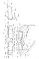
図1に示すように、本実施形態の虚像表示装置100は、眼鏡のような外観を有するヘッドマウントディスプレイであり、この虚像表示装置100を装着した観察者又は使用者に対して虚像による画像光を視認させることができるとともに、観察者に外界像をシースルーで視認又は観察させることができる。虚像表示装置100は、観察者の眼前を透視可能に覆う第1及び第2光学部材101a,101bと、両光学部材101a,101bを支持するフレーム102と、フレーム102の左右両端から後方のつる部分(テンプル)104にかけての部分に付加された第1及び第2像形成本体部105a,105bとを備える。ここで、図面上で左側の第1光学部材101aと第1像形成本体部105aとを組み合わせた第1表示装置100Aは、右眼用の虚像を形成する部分であり、単独でも虚像表示装置として機能する。また、図面上で右側の第2光学部材101bと第2像形成本体部105bとを組み合わせた第2表示装置100Bは、左眼用の虚像を形成する部分であり、単独でも虚像表示装置として機能する。 As shown in FIG. 1, the virtual
図2は、虚像表示装置100の外観と内部とを対比した図であり、図2(A)は、虚像表示装置100の全体を示し、図2(B)は、虚像表示装置100の内部構造を示している。なお、図3(A)〜3(C)は、図2(A)に対応するものであり、虚像表示装置100の外観の正面図、裏面側斜視図、及び側面図である。また、図4(A)〜4(C)は、図2(B)に対応するものであり、虚像表示装置100の内部構造の正面図、裏面図、及び側面図である。図5は、図2(B)の左半分に対応し、虚像表示装置100の第1表示装置100A側を部分的に拡大した斜視図である。 FIG. 2 is a diagram in which the appearance and the inside of the virtual
図示のように、虚像表示装置100に設けたフレーム102は、U字状に折れ曲がった細長い板状の部材であり、左右の横方向(X方向)に延びる正面部102aと、前後の奥行き方向(Z方向)に延びる一対の側面部102b,102cとを備える。フレーム102、すなわち正面部102aと側面部102b,102cとは、アルミダイカストその他の各種金属材料で形成された金属製の一体部品である。正面部102aの奥行き方向(Z方向)の幅は、第1及び第2光学部材101a,101bに対応する導光部20の厚み又は幅よりも十分に厚いものとなっている。フレーム102の左側方、具体的には正面部102aにおける向かって左端部から側面部102bにかけての部分である側方端部65aには、第1光学部材101aと第1像形成本体部105aとがアライメントされネジ止めよって直接固定されることによって支持されている。また、フレーム102の右側方、具体的には正面部102aにおける向かって右端部から側面部102cにかけての部分である側方端部65bには、第2光学部材101bと第2像形成本体部105bとがアライメントされネジ止めによって直接固定されることによって支持されている。なお、第1光学部材101aと第1像形成本体部105aとは、嵌合によって互いにアライメントされ、第2光学部材101bと第2像形成本体部105bとは、嵌合によって互いにアライメントされる。 As shown in the figure, the
フレーム102には、アンダーリム状の部材又は枠状の部材として、プロテクター108が固定されている。プロテクター108の中央部108gは、フレーム102の中央部102gに嵌合及びネジ止めによって固定されている。このため、図4(B)に示すように、フレーム102の中央部102gには、固定用の凹部102kが形成され、凹部102kの中央にはネジ穴が形成されている。プロテクター108は、2段のクランク状に折れ曲がった細長い板状の部材であり、金属材料又は樹脂材料で形成された一体部品である。プロテクター108の奥行き方向(Z方向)の幅は、第1及び第2光学部材101a,101bに対応する導光部20の厚み又は幅程度となっている。プロテクター108の第1先端部108iは、第1像形成本体部105aに対して嵌合によって固定され、プロテクター108の第2先端部108jは、第2像形成本体部105bに対して嵌合によって固定される。より具体的には、プロテクター108の第1先端部108iは、第1像形成本体部105aを覆うカバー状の外装部材105dのうち外部材105eに設けた凹部105iに嵌合した状態で固定される。また、プロテクター108の第2先端部108jは、第2像形成本体部105bを覆うカバー状の外装部材105dのうち外部材105eに設けた凹部105jに嵌合した状態で固定される。 A
フレーム102は、第1及び第2像形成本体部105a,105bを支持するだけでなく、外装部材105dと協働して第1及び第2像形成本体部105a,105bの内部を保護する役割を有する。プロテクター108は、第1及び第2像形成本体部105a,105bに連結される第1及び第2光学部材101a,101b又は導光部20の側辺部や下辺部を保護する役割を有する。具体的には、プロテクター108の縦部分63aは、導光部20の周囲部分A0のうち内側の側辺部を使用環境下に存在する周囲の様々な物体から保護し、プロテクター108の横部分63bは、導光部20の周囲部分A0のうち下側の下辺部を使用環境下にある周囲の様々な物体から保護する。つまり、フレーム102やプロテクター108が十分な強度を有すれば、虚像表示装置100が周囲の他の物体と衝突等しても、第1及び第2像形成本体部105a,105bや第1及び第2光学部材101a,101b、特に露出する導光部20において損傷や位置ずれが発生する可能性を低減できる。 The
プロテクター108の中央部108gに近い一対の縦部分63aには、パッド状の鼻当て部材108aがそれぞれ形成されている。プロテクター108の縦部分63aや横部分63bは、第1及び第2像形成本体部105a,105bに連結される根元側を除いた導光部20の周囲部分A0と離間するか又は緩く接している。なお、導光部20の周囲部分A0は、フレーム102の正面部102aとも離間するか又は緩く接している。このように、導光部20は、根元側を除いたC字状の周囲部分A0でフレーム102及びプロテクター108に近接するが、フレーム102及びプロテクター108に固定されていない。このため、中央の導光部20と、フレーム102及びプロテクター108を含む枠状部材109との間に熱膨張率の差があっても、枠状部材109内での導光部20の膨張が許容され、導光部20に歪み、変形、破損が生じることを防止できる。 A pad-shaped
図4(B)、図5等に示すように、第1表示装置100Aは、見方を変えれば、投影用の光学系である投射透視装置70と、映像光を形成する画像表示装置80とを備える。投射透視装置70は、第1像形成本体部105aによって形成された画像を虚像として観察者の眼に投射する役割を有する。投射透視装置70は、導光及び透視用のプリズム10と、透視用の光透過部材50と、結像用の投射レンズ30とを備える。 As shown in FIG. 4B, FIG. 5, and the like, the
図6に示すように、プリズム10と光透過部材50とは、互いに固定されて一体的な導光部20となっている。ここで、光透過部材50は、光学的に上流にある投射レンズ30に接続されるプリズム10のうち光学的に下流の先端側、すなわち射出側又は光射出側の第1プリズム部分11に連結するようにその延長方向に配置され、接着剤を利用した接合によって第1プリズム部分11に固定されている。図5等に示す投射透視装置70のうち、プリズム10及び光透過部材50を組み合わせた導光部20は、図1における第1光学部材101aに相当し、投射透視装置70の投射レンズ30と表示用の画像パターンを形成する画像表示装置80とは、図1における第1像形成本体部105aに相当する。 As shown in FIG. 6, the
図7(A)及び7(B)等を参照して、第1表示装置100Aのフレーム102への組付けについて説明する。第1像形成本体部105aを構成する投射レンズ30は、その鏡筒39に埋め込むように形成された取付部39gを利用してフレーム102の側方端部65aに設けた第1固定部61fに直接固定されている。このような固定の際、第1固定部61fの裏面68fと取付部39gの上端面39f等とが当接してアライメントが達成され、ネジ孔61sを介してネジ61tを取付部39gにねじ込むことで着脱可能で確実な固定が可能になる。この際、フレーム102のボス孔61xに鏡筒39に設けたボス39xが嵌合して鏡筒39の回転が規制され回転に関する位置決めも行われる。一方、第1光学部材101aである導光部20は、そのネック部に形成された突起状の取付部10gを利用して、フレーム102の側方端部65aに設けた第2固定部61eに直接固定されている。取付部10gは、導光部20の入射側又は光入射側の部分、具体的には第1プリズム部分11と第2プリズム部分12との境界周辺において周囲に拡張するように立設されている。このような固定の際、第2固定部61eの前側部分に設けた突当て面68eと取付部10gの裏面10kとが当接してアライメントが達成され、ネジ孔10uを介してネジ61vをネジ孔61uにねじ込むことで着脱可能で確実な固定が可能になる。この際、取付部10gの裏面10kの周辺部も第2固定部61eに当接してアライメントが補強される。なお、図5等に示す画像表示装置80は、投射レンズ30の鏡筒39の後端に嵌め込むようにして固定される。 With reference to FIGS. 7A and 7B, the assembly of the
導光部20は、プリズム10の第2プリズム部分12側の先端部12jが投射レンズ30の鏡筒39の前端側に設けられて開口する矩形枠状の係止部材39aに嵌合することで投射レンズ30に対して位置決めされた状態で係止される。つまり、導光部20に設けたプリズム10をフレーム102の第2固定部61eに固定する際に、第2プリズム部分12側の先端部12jを鏡筒39の係止部材39a内に嵌合するように挿入する。この際、先端部12jの側面12mが係止部材39aの内面39mとが当接してアライメントが達成される。 The
フレーム102の正面部102aの下面102mには、図7(B)に示すように、ストッパーとして溝状の制限部102nが設けられている。第1光学部材101a又は導光部20の組み付け後において、制限部102nには、導光部20に設けたプリズム10の上端部に設けた突起状のリブ10nが僅かな隙間を有する遊嵌状態で挿入される。これにより、第1光学部材101a又は導光部20の先端側の変位をフレーム102の奥行き方向(図2(B)に示すZ方向)に関して制限することができる。なお、導光部20のリブ10nとフレーム102の制限部102nとは、左右の横方向(X方向)に延びており、リブ10nと制限部102nとが密着又は接合されていないので、導光部20のフレーム102に対する非固定状態が確保されている。つまり、導光部20は、プロテクター108と僅かに離間しており、プロテクター108との関係でも非固定状態とされている。これにより、導光部20とフレーム102との間に熱膨張率の差があっても、フレーム102に対して導光部20の膨張等が許容される。 On the
以上までの工程によって、フレーム102と投射透視装置70とのアセンブリー(図2(B)参照)を得ることができる。 Through the steps described above, an assembly of the
図2(A)及び2(B)等を参照しつつ、フレーム102への外装部材105dの組付けについて説明する。まず、外装部材105dのうち外部材105eをフレーム102及び投射透視装置70等のアセンブリーに固定する。外部材105eは、フレーム102や投射レンズ30との嵌合、投射レンズ30の取付部39gに対してのネジ締結等によって固定される。この際、フレーム102に既に固定されているプロテクター108の先端部108i,108jを外部材105eに形成された凹部105iに嵌合させて固定することになる。次に、内部材105fを外部材105eに嵌合させ、ネジ止めによって外部材105eに固定する。これにより、内部材105fと外部材105eとに挟まれた空間内に第1像形成本体部105aを構成する投射レンズ30、画像表示装置80等と、導光部20の一部である第2プリズム部分12と、フレーム102の側面部102b,102cとが収納される。つまり、第1表示装置100Aの組み付けが完了する。 The assembly of the
なお、図1に示す第2表示装置100Bは、第1表示装置100Aと同様の構造を有し、第1表示装置100Aを左右対称に反転させただけであるので、第2表示装置100Bの構造、機能、組立て等についての説明は省略する。 The
図2(A)、図7(A)等に示すように、つる部分104は、フレーム102に設けた一対の側面部102b,102cの先端に設けた孔102qに固定されている。つる部分104と側面部102b,102cとの連結部は、ヒンジ構造を有するものとでき、この場合、つる部分104の折畳みが可能になる。 As shown in FIGS. 2A, 7A, etc., the
図8を参照して、各表示装置100B,100Aを構成する投射透視装置70等の機能、動作等の詳細について説明する。投射透視装置70のうち、導光部20の一部であるプリズム10は、平面視において顔面に沿うように湾曲した円弧状の部材である。プリズム10のうち、第1プリズム部分11は、鼻に近い中央側つまり光射出側に配置され、光学的な機能を有する側面として、第1面S11と、第2面S12と、第3面S13とを有し、第2プリズム部分12は、鼻から離れた周辺側つまり光入射側に配置され、光学的な機能を有する側面として、第4面S14と、第5面S15と、第6面S16とを有する。このうち、第1面S11と第4面S14とが隣接し、第3面S13と第5面S15とが隣接し、第1面S11と第3面S13との間に第2面S12が配置され、第4面S14と第5面S15との間に第6面S16が配置されている。 With reference to FIG. 8, details of functions, operations, and the like of the projection see-through
プリズム10において、第1面S11は、Z軸に平行な射出側光軸AXOを中心軸とする自由曲面であり、第2面S12は、XZ面に平行な基準面(図示の断面)に含まれZ軸に対して傾斜した光軸AX1を中心軸とする自由曲面であり、第3面S13は、射出側光軸AXOを中心軸とする自由曲面である。第4面S14は、XZ面に平行な上記基準面に含まれZ軸に対して傾斜した一対の光軸AX3,AX4の2等分線を中心軸とする自由曲面であり、第5面S15は、XZ面に平行な上記基準面に含まれZ軸に対して傾斜した一対の光軸AX4,AX5の2等分線を中心軸とする自由曲面であり、第6面S16は、XZ面に平行な上記基準面に含まれZ軸に対して傾斜した光軸AX5を中心軸とする自由曲面である。なお、以上の第1〜第6面S11〜S16は、水平(又は横)に延びるXZ面に平行で光軸AX1〜AX5等が通る基準面(図示の断面)を挟んで、鉛直(又は縦)のY軸方向に関して対称な形状を有している。 In the
プリズム10のうちプリズム本体10sは、可視域で高い光透過性を示す樹脂材料で形成されており、例えば金型内に熱可塑性樹脂を注入・固化させることにより成形する。なお、プリズム本体10sの材料としては、例えばシクロオレフィンポリマー等を用いることができる。プリズム本体10sは、一体形成品とされているが、プリズム10は、上記のように第1プリズム部分11と第2プリズム部分12とに機能的に分けて考えることができる。第1プリズム部分11は、映像光GLの導波及び射出を可能にするとともに、外界光HLの透視を可能にする。第2プリズム部分12は、映像光GLの入射及び導波を可能にする。 The prism
第1プリズム部分11において、第1面S11は、映像光GLを第1プリズム部分11外に射出させる屈折面として機能するとともに、映像光GLを内面側で全反射させる全反射面として機能する。第1面S11は、眼EYの正面に配されるものであり、観察者に対し凹面形状を成している。なお、第1面S11は、プリズム本体10sの表面に施されたハードコート層27によって形成される面である。 In the
第2面S12は、プリズム本体10sの表面であり、当該表面にハーフミラー層15が付随している。このハーフミラー層15は、光透過性を有する反射膜(すなわち半透過反射膜)である。ハーフミラー層(半透過反射膜)15は、第2面S12の全体ではなく、第2面S12を主にY軸に沿った鉛直方向に関して狭めた部分領域PA上に形成されている。ハーフミラー層15は、プリズム本体10sの下地面のうち部分領域PA上に、金属反射膜や誘電体多層膜を成膜することにより形成される。ハーフミラー層15の映像光GLに対する反射率は、シースルーによる外界光HLの観察を容易にする観点で、想定される映像光GLの入射角範囲において10%以上50%以下とする。具体的な実施例のハーフミラー層15の映像光GLに対する反射率は、例えば20%に設定され、映像光GLに対する透過率は、例えば80%に設定される。 The second surface S12 is the surface of the prism
第3面S13は、映像光GLを内面側で全反射させる全反射面として機能する。第3面S13は、眼EYの正面に配されるものであり、第1面S11と同様に観察者に対し凹面形状を成しており、第1面S11と第3面S13とを通過させて外界光HLを見たときに、視度が略0になっている。なお、第3面S13は、プリズム本体10sの表面に施されたハードコート層27によって形成される面である。 The third surface S13 functions as a total reflection surface that totally reflects the video light GL on the inner surface side. The third surface S13 is arranged in front of the eye EY, and has a concave shape with respect to the observer, like the first surface S11, and allows the first surface S11 and the third surface S13 to pass therethrough. When the external light HL is viewed, the diopter is substantially zero. The third surface S13 is a surface formed by the
第2プリズム部分12において、第4面S14は、映像光GLを内面側で全反射させる全反射面として機能する。なお、第4面S14は、プリズム本体10sの表面に施されたハードコート層27によって形成される面である。 In the
第2プリズム部分12において、第5面S15は、既述のように、プリズム本体10sの表面上に無機材料で形成される光反射膜RMを成膜することで形成され、反射面として機能する。 In the
第6面S16は、映像光GLを第2プリズム部分12内に入射させる屈折面として機能する。なお、第6面S16は、プリズム本体10sの表面に施されたハードコート層27によって形成される面である。 The sixth surface S <b> 16 functions as a refracting surface that causes the image light GL to enter the
光透過部材50は、既述のようにプリズム10と一体的に固定され1つの導光部20となっている。光透過部材50は、プリズム10の透視機能を補助する部材(補助プリズム)であり、光学的な機能を有する側面として、第1透過面S51と、第2透過面S52と、第3透過面S53とを有する。ここで、第1透過面S51と第3透過面S53との間に第2透過面S52が配置されている。第1透過面S51は、プリズム10の第1面S11を延長した曲面上にあり、第2透過面S52は、当該第2面S12に対して接着層CCによって接合され一体化されている曲面であり、第3透過面S53は、プリズム10の第3面S13を延長した曲面上にある。このうち第2透過面S52とプリズム10の第2面S12とは、薄い接着層CCを介しての接合によって一体化されるため、略同じ曲率の形状を有する。 As described above, the
光透過部材(補助プリズム)50は、可視域で高い光透過性を示し、光透過部材50の本体部分は、プリズム10のプリズム本体10sと略同一の屈折率を有する熱可塑性樹脂材料で形成されている。なお、光透過部材50は、本体部分をプリズム10のプリズム本体10sに接合した後、接合された状態でプリズム本体10sとともにハードコートによる成膜がなされて形成されるものである。つまり、光透過部材50は、プリズム10と同様、本体部分の表面にハードコート層27が施されたものとなっている。第1透過面S51と第3透過面S53とは、本体部分の表面に施されたハードコート層27によって形成される面である。 The light transmitting member (auxiliary prism) 50 exhibits high light transmittance in the visible range, and the main body portion of the
画像表示装置80は、2次元的な照明光SLを射出する照明装置81と、透過型の空間光変調装置である映像表示素子82と、照明装置81及び映像表示素子82の動作を制御する駆動制御部84とを有する。 The
画像表示装置80の照明装置81は、赤、緑、青の3色を含む光を発生する光源81aと、光源81aからの光を拡散させて矩形断面の光束にするバックライト導光部81bとを有する。映像表示素子82は、例えば液晶表示デバイスで形成される映像素子であり、照明装置81からの照明光SLを空間的に変調して動画像等の表示対象となるべき画像光を形成する。駆動制御部84は、光源駆動回路84aと液晶駆動回路84bとを備える。光源駆動回路84aは、照明装置81の光源81aに電力を供給して安定した輝度の照明光SLを射出させる。液晶駆動回路84bは、映像表示素子(映像素子)82に対して画像信号又は駆動信号を出力することにより、透過率パターンとして動画や静止画の元になるカラーの映像光又は画像光を形成する。なお、液晶駆動回路84bに画像処理機能を持たせることができるが、外付けの制御回路に画像処理機能を持たせることもできる。 The
以下、虚像表示装置100における映像光GL等の光路について説明する。映像表示素子(映像素子)82から射出された映像光GLは、投射レンズ30によって収束されつつ、プリズム10に設けた比較的強い正の屈折力を有する第6面S16に入射する。 Hereinafter, an optical path of the image light GL and the like in the virtual
プリズム10の第6面S16を通過した映像光GLは、収束しつつ進み、第2プリズム部分12を経由する際に、比較的弱い正の屈折力を有する第5面S15で反射され、比較的弱い負の屈折力を有する第4面S14で反射される。 The image light GL that has passed through the sixth surface S16 of the
第2プリズム部分12の第4面S14で反射された映像光GLは、第1プリズム部分11において、比較的弱い正の屈折力を有する第3面S13に入射して全反射され、比較的弱い負の屈折力を有する第1面S11に入射して全反射される。なお、映像光GLは、第3面S13を通過する前後において、プリズム10中に中間像を形成する。この中間像の像面IIは、映像表示素子82の像面OIに対応するものである。 The image light GL reflected by the fourth surface S14 of the
第1面S11で全反射された映像光GLは、第2面S12に入射するが、特にハーフミラー層15に入射した映像光GLは、このハーフミラー層15を部分的に透過しつつも部分的に反射されて第1面S11に再度入射して通過する。なお、ハーフミラー層15は、ここで反射される映像光GLに対して比較的強い正の屈折力を有するものとして作用する。また、第1面S11は、これを通過する映像光GLに対して負の屈折力を有するものとして作用する。 The image light GL totally reflected by the first surface S11 is incident on the second surface S12. In particular, the image light GL incident on the
第1面S11を通過した映像光GLは、観察者の眼EYの瞳に略平行光束として入射する。つまり、観察者は、虚像としての映像光GLにより、映像表示素子(映像素子)82上に形成された画像を観察することになる。 The video light GL that has passed through the first surface S11 enters the pupil of the observer's eye EY as a substantially parallel light beam. That is, the observer observes an image formed on the video display element (video element) 82 by the video light GL as a virtual image.
一方、外界光HLのうち、プリズム10の第2面S12よりも−X側に入射するものは、第1プリズム部分11の第3面S13と第1面S11とを通過するが、この際、正負の屈折力が相殺されるとともに収差が補正される。つまり、観察者は、プリズム10越しに歪みの少ない外界像を観察することになる。同様に、外界光HLのうち、プリズム10の第2面S12よりも+X側に入射するもの、つまり、光透過部材50に入射したものは、これに設けた第3透過面S53と第1透過面S51とを通過する際に、正負の屈折力が相殺されるとともに収差が補正される。つまり、観察者は、光透過部材50越しに歪みの少ない外界像を観察することになる。さらに、外界光HLのうち、プリズム10の第2面S12に対向する光透過部材50の重複部分に入射するものは、第3透過面S53と第1面S11とを通過する際に、正負の屈折力が相殺されるとともに収差が補正される。つまり、観察者は、光透過部材50越しに歪みの少ない外界像を観察することになる。なお、プリズム10の第2面S12と光透過部材50の第2透過面S52とは、略同一の曲面形状をともに有するだけでなく、略同一の屈折率をともに有し、両者の隙間が略同一の屈折率の接着層CCで充填されている。つまり、プリズム10の第2面S12や光透過部材50の第2透過面S52は、外界光HLに対して屈折面として作用しない。 On the other hand, among the external light HL, the light incident on the −X side from the second surface S12 of the
ただし、ハーフミラー層15に入射した外界光HLは、このハーフミラー層15を部分的に透過しつつも部分的に反射されるので、ハーフミラー層15に対応する方向から眼EYに向かう外界光HLは、ハーフミラー層15の透過率に弱められる。その一方で、ハーフミラー層15に対応する方向から眼EYに向けては、映像光GLが入射するので、観察者は、ハーフミラー層15の方向に映像表示素子(映像素子)82上に形成された画像とともに外界像を観察することになる。 However, since the external light HL incident on the
プリズム10内で伝搬されて第2面S12に入射した映像光GLのうち、ハーフミラー層15で反射されなかったものは、光透過部材50内に入射するが、光透過部材50に設けた不図示の反射防止部によってプリズム10に戻ることが防止される。つまり、第2面S12を通過した映像光GLが光路上に戻されて迷光となることが防止される。また、光透過部材50側から入射してハーフミラー層15で反射された外界光HLは、光透過部材50に戻されるが、光透過部材50に設けた上述の不図示の反射防止部によってプリズム10に射出されることが防止される。つまり、ハーフミラー層15で反射された外界光HLが光路上に戻されて迷光となることが防止される。 Of the image light GL propagated in the
以上の説明から明らかなように、第1実施形態の虚像表示装置100によれば、光学部材101a,101b又は導光部20が周囲の一箇所である取付部10gにおいてフレーム102に直接固定されるので、導光部20の固定が簡易になり、虚像表示装置100を軽量化しやすくなるとともに、フレーム102による導光部20の支持強度も向上する。さらに、光学部材101a,101b又は導光部20が取付部10gを除く残りの周囲部分A0においてフレーム102及びプロテクター108に対して非固定状態になっているので、導光部20とフレーム102等との間に熱膨張率の差があっても、フレーム102等に対して導光部20の膨張が許容され、光学部材101a,101b又は導光部20に歪み、変形、破損が生じることを防止できる。
また、本実施形態の虚像表示装置100によれば、プロテクター108が光学部材101a,101b又は導光部20の周囲のうちフレーム102に固定される取付部10gを除く残りの周囲部分A0の少なくとも一部を覆うように保護する。つまり、フレーム102とプロテクター108とによって光学部材101a,101b又は導光部20の周囲を囲んで覆うように保護することができる。これにより、虚像表示装置100を落下させた場合のようにランダムな方向からの強い衝撃に対する耐久性を高めることができる。As is clear from the above description, according to the virtual
Further, according to the virtual
〔第2実施形態〕
以下、第2実施形態の虚像表示装置について説明する。なお、本実施形態の虚像表示装置は、第1実施形態の虚像表示装置100の変形例であり、特に説明しない場合、図1等に示す虚像表示装置100と同様であるものとする。[Second Embodiment]
Hereinafter, the virtual image display apparatus according to the second embodiment will be described. Note that the virtual image display device of the present embodiment is a modification of the virtual
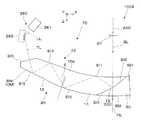
以下、図9(A)及び9(B)を参照して、本実施形態の虚像表示装置200について説明する。図示のように、本実施形態の虚像表示装置200は、観察者の眼前を透視可能に覆う第1及び第2光学部材201a,201bと、両光学部材201a,201bを支持するフレーム102と、フレーム102の左右両端から後方にかけての部分に固定された第1及び第2駆動部205a,205bと、2次元的に走査される信号光を射出する第1及び第2映像素子206a,206bとを備える。図面上で左側の第1光学部材201aと第1駆動部205aと第1映像素子206aとを組み合わせた第1表示装置100Aは、右眼用の虚像を形成する部分であり、単独でも虚像表示装置として機能する。また、図面上で右側の第2光学部材201bと第2駆動部205bと第2映像素子206bとを組み合わせた第2表示装置100Bは、左眼用の虚像を形成する部分であり、第1表示装置100Aの左右を反転させただけであり、第1表示装置100Aと同じ機能を有する。 Hereinafter, the virtual
第1表示装置100Aにおいて、第1映像素子206aは、強度変調された信号光を形成するとともに当該信号光を走査光TLとして射出する。第1光学部材201aは、第1映像素子206aからの走査光TLを反射することによって画像光GLを形成する被照射部材であり、このような画像光GLを眼EYに導く機能を有する。第1駆動部205aは、第1映像素子206aに対して不図示の光ファイバー等を介して照明光を供給する光源、第1映像素子206a等を動作させる制御回路等を含む本体部分280を有する。 In the
第1映像素子206aは、鼻当て部材108aに組み付けられており、フレーム102に対して間接的に固定されている。第1映像素子206aは、本体部分280からの照明光を制御信号に基づいて変調する信号光変調部281と、信号光変調部281を経た信号光を走査しつつ射出させる走査光学系282とを有する。ここで、走査光学系282は、MEMSミラー等で構成され、信号光変調部281による信号光の変調に同期させて姿勢を変化させることにより、信号光の光路を調整することで第1光学部材201aの内面への光線(走査光TL)の射出角度を縦横に変化させる2次元走査を行う。 The
第1光学部材201aは、第1映像素子206aの前方又は光射出方向において装着者の眼EYの前方を覆うように配置されている。第1光学部材201aは、走査光の照射を受ける半透過膜である半透過反射膜285と、半透過反射膜285を支持固定する支持部材286とを有している。これにより、装着者の眼EYには、画像光GLによる虚像のみならず、外界からの光も入ることになり、虚像表示装置200は、双方を重畳して観察可能にするシースルーの構成となっている。なお、半透過反射膜285は、ハーフミラーとすることもできるが、ホログラムその他の回折型の光学素子とすることもできる。 The first
第1光学部材201aは、第1実施形態の第1光学部材101aのような内部伝搬型の導光部ではないが、第1実施形態の場合と同様に眼前を覆う薄い楕円形状を有し、外周の一部である周囲部分A0に取付部10gとリブ10nとを有する。 The first
第1光学部材201aのフレーム102への組付けについて説明する。第1光学部材101aは、周囲部分A0に形成された突起状の取付部10gを利用して、フレーム102の側方にある側方端部65aに設けた第2固定部61e直接固定されており、第1映像素子206a等に対してアライメントされた状態となっている。フレーム102には、ストッパーとして溝状の制限部102nが設けられている。第1光学部材201aの組み付け後において、制限部102nには、第1光学部材201aの上端部に設けた突起状のリブ10nが僅かな隙間を有する遊嵌状態で挿入される。これにより、第1光学部材201aの先端側の変位をフレーム102の奥行き方向に関して制限することができる。なお、第1光学部材201aのうち取付部10gを除いた部分は、フレーム102及びプロテクター108と僅かに離間しており、フレーム102及びプロテクター108との関係で非固定状態とされている。 The assembly of the first
以下、画像形成の動作について説明する。まず、第1映像素子206aのうち、信号光変調部281は、画像を構成する画素の輝度に対応して照明光を変調した信号光を形成し射出する。信号光変調部281から射出された信号光は、スキャン部である走査光学系282に入射する。走査光学系282は、信号光を走査光TLとして第1光学部材101aに向けて射出する。第1光学部材101aにおいて、走査光TLを入射させることで、ここでの反射光としての画像光GLによって虚像が形成され、この虚像を観察者が眼EYで捉えることで、画像が認識される。 Hereinafter, an image forming operation will be described. First, in the
以上、実施形態に即して本発明を説明したが、本発明は、上記の実施形態に限られるものではなく、その要旨を逸脱しない範囲において種々の態様において実施することが可能であり、例えば次のような変形も可能である。 As mentioned above, although this invention was demonstrated according to embodiment, this invention is not restricted to said embodiment, In the range which does not deviate from the summary, it is possible to implement in various aspects, for example, The following modifications are possible.
上記第1実施形態では、フレーム102と投射レンズ30とが別体でネジ止めによって投射レンズ30をフレーム102に固定しているが、投射レンズ30の鏡筒39をフレーム102と一体成形することもできる。鏡筒39をフレーム102と一体成形する方法として、アウトサート成形、ダイカスト一体成形後の鏡筒部削り出し等の手法がある。 In the first embodiment, the
導光部20又は投射レンズ30については、ネジ止めによる締結に限らず、様々な手法でフレーム102に固定することができる。 The
上記の説明では、フレーム102にプロテクター108を取り付けているが、プロテクター108についてはこれを省略することができる。この場合、図2(B)等に示すフレーム102を元の形状のままに維持して、フレーム102の中央部102gに鼻当て部材108aを設けた補助部材を連結することもできるが、補助部材を一体的に設けたフレーム102を予め準備することもできる。かかる補助部材は、プロテクター108の縦部分63aと同様に導光部20を保護する部材として用い得る。なお、フレーム102とプロテクター108とを一体的に作製することもできる。 In the above description, the
上記の説明では、第1光学部材201aである導光部20等がフレーム102側に片持ち状態で支持されているが、導光部20等をフレーム102やプロテクター108によって周囲から支持することができる。この際、フレーム102やプロテクター108に導光部20の相対的な伸縮を許容するような部材又は機構を設けることが望ましい。 In the above description, the
上記第1実施形態では、プリズム10の光入射側に投射レンズ30を配置しているが、投射レンズ30を省略して、プリズム10自体に結像機能を持たせることができる。また、投射レンズ30に代えて結像機能を有する別のプリズム10を配置することもできる。 In the first embodiment, the
上記の説明では、フレーム102に制限部102nを設けているが、これに代えて或いはこれとともに、プロテクター108にプリズム10の変形、ぶれ等を防止するための同様の制限部を設けることもできる。 In the above description, the restricting
上記第1実施形態では、投射レンズ30の鏡筒39に導光部20との係止を可能にする係止部材39aを設けているが、導光部20側に例えば鏡筒39を挟むように鏡筒39と嵌合する係止部材を設けることができる。 In the first embodiment, the locking
上記第1実施形態では、ハーフミラー層(半透過反射膜)15が横長の矩形領域に形成されるとしたが、ハーフミラー層15の輪郭は用途その他の使用に応じて適宜変更することができる。また、ハーフミラー層15の透過率や反射率も用途その他に応じて変更することができる。 In the first embodiment, the half mirror layer (semi-transmissive reflective film) 15 is formed in a horizontally long rectangular region. However, the outline of the
上記第1実施形態では、ハーフミラー層15が単なる半透過性の膜(例えば金属反射膜や誘電体多層膜)であるとしたが、ハーフミラー層15は、平面又は曲面のホログラム素子に置き換えることができる。 In the first embodiment, the
上記第1実施形態では、映像表示素子82における表示輝度の分布を特に調整していないが、位置によって輝度差が生じる場合等においては、表示輝度の分布を不均等に調整することができる。 In the first embodiment, the display luminance distribution in the
上記第1実施形態では、画像表示装置80として、透過型の液晶表示デバイス等からなる映像表示素子82を用いているが、画像表示装置80としては、透過型の液晶表示デバイス等からなる映像表示素子82に限らず種々のものを利用可能である。例えば、反射型の液晶表示デバイスを用いた構成も可能であり、液晶表示デバイス等からなる映像表示素子82に代えてデジタル・マイクロミラー・デバイス等を用いることもできる。また、画像表示装置80として、LEDアレイやOLED(有機EL)などに代表される自発光型素子を用いることができる。 In the first embodiment, the
上記第1実施形態では、透過型の液晶表示デバイス等からなる画像表示装置80を用いているが、これに代えて走査型の画像表示装置を用いることもできる。
具体的には図10に示すように、虚像表示装置としての第1表示装置100Aは、導光部20と画像表示装置380とを備える。導光部20は、第1実施形態として説明したものと同一であり、ここでは説明を省略する。一方、画像表示装置380は、第2実施形態の第1映像素子206aに相当するものであり、信号光形成部381と走査光学系282とを有する。信号光形成部381は、光源も備えており、信号光LLを形成し射出する。走査光学系282は、信号光形成部381の変調に併せてMEMSミラーの姿勢を変化させて光路を調整することにより、映像光GLとなるべき走査光TLを導光部20に入射させるとともに第2面S12のうちハーフミラー層15が形成される部分領域の全体をスキャンさせる。図示の第1表示装置100Aの動作について説明すると、画像表示装置380のうち、信号光形成部GGから射出された信号光LLは、走査光学系282に入射する。走査光学系282は、信号光LLを走査光TLとして導光部20の第6面S16に向けて射出する。導光部20は、第6面S16を通過した走査光TLを全反射等により内部で導光させ、ハーフミラー層15に到達させる。この際、ハーフミラー層15の面上において走査光TLが走査されることで、走査光TLの軌跡としての画像光GLによって虚像が形成され、この虚像を装着者が眼EYで捉えることで、画像が認識される。なお、図示の場合では、導光部20のうち光入射面である第6面S16は、走査光TLの光軸に対して垂直な平面となっている。また、第5面S15及び第4面S14も平面となっている。In the first embodiment, the
Specifically, as illustrated in FIG. 10, the
上記の説明では、一対の表示装置100A,100Bを備える虚像表示装置100について説明しているが、単一の表示装置とできる。つまり、右眼及び左眼の双方に対応して、一組ずつ投射透視装置70及び画像表示装置80を設けるのではなく、右眼又は左眼のいずれか一方に対してのみ投射透視装置70及び画像表示装置80を設け、画像を片眼視する構成にしてもよい。この場合、フレーム107やつる部分104は、例えば図1等に示すままで左右対称に配置する形状とすることもできるが、表示装置を支持しない側のフレーム部分については、耳以外で固定するといった異なる形状とすることもできる。 In the above description, the virtual
上記の説明では、一対の表示装置100A,100BのX方向の間隔について説明していないが、両表示装置100A,100Bの間隔は固定に限らず、機械機構等によって間隔の調整が可能である。つまり、フレーム102に伸縮機構等を設けるならば、両表示装置100A,100BのX方向の間隔を、着用者の眼幅等に応じて調整することができる。 In the above description, the distance between the pair of
上記第1実施形態では、プリズム10の第1面S11及び第3面S13において、表面上にミラーやハーフミラー等を施すことなく空気との界面により映像光を全反射させて導くものとしているが、本願発明の虚像表示装置100における全反射については、第1面S11又は第3面S13上の全体又は一部にミラーコートや、ハーフミラー膜が形成されてなされる反射も含むものとする。例えば、映像光の入射角度が全反射条件を満たした上で、上記第1面S11又は第3面S13の全体又は一部にミラーコート等が施され、実質的に全ての映像光を反射する場合も含まれる。また、十分な明るさの映像光を得られるのであれば、多少透過性のあるミラーによって第1面S11又は第3面S13の全体又は一部がコートされていてもよい。 In the first embodiment, the first surface S11 and the third surface S13 of the
上記の説明では、プリズム10等が眼EYの並ぶ横方向に延びているが、プリズム10を縦方向に延びるように配置することもできる。この場合、プリズム10は、例えば上部での片持ち状態によって支持される。 In the above description, the
A0…周囲部分、 AX1-AX5…光軸、 AXO…射出側光軸、 EY…眼、 GL…映像光、 OI…像面、 RM…光反射膜、 S11-S16…第1-第6面、 S51-S53…第1-第3透過面、 SL…照明光、 10…プリズム、 10g…取付部、 11…第1プリズム部分、 12…第2プリズム部分、 12j…先端部、 15…ハーフミラー層、 20…導光部、 30…投射レンズ、 39…鏡筒、 39a…係止部材、 39g…取付部、 50…光透過部材、 61e…固定部、 61f…固定部、 61x…ボス孔、 65a,65b…側方端部、 68e…突当て面、 70…投射透視装置、 80…画像表示装置、 81…照明装置、 82…映像表示素子、 84…駆動制御部、 100…虚像表示装置、 100A…第1表示装置、 100B…第2表示装置、 101a…第1光学部材、 101b…第2光学部材、 102…フレーム、 102a…正面部、 102b,102c…側面部、 102n…制限部、 104…つる部分、 105a…第1像形成本体部、 105b…第2像形成本体部、 105d…外装部材、 105i…凹部、 108…プロテクター、 108a…鼻当て部材、 108g…中央部、 108i…先端部、 109…枠状部材 A0 ... Ambient part, AX1-AX5 ... Optical axis, AXO ... Exit side optical axis, EY ... Eye, GL ... Video light, OI ... Image plane, RM ... Light reflection film, S11-S16 ... First to sixth surfaces, S51-S53 ... 1st-3rd transmission surface, SL ... Illumination light, 10 ... Prism, 10g ... Mounting part, 11 ... 1st prism part, 12 ... 2nd prism part, 12j ... Tip part, 15 ...
Claims (5)
Translated fromJapanese映像素子と、
前記映像素子からの映像光を内部で反射させて観察者の眼に導く導光部材と、
前記導光部材が観察者の眼前に配置されるように、前記映像素子と前記導光部材とを支持する支持部材とを備え、
前記導光部材の入射側かつ上端側に突状の取付部が設けられ、
前記導光部材は前記取付部で前記支持部材に固定され、前記取付部を除く部分において前記支持部材に非固定状態である、虚像表示装置。A virtual image display device that allows an observer to visually recognize an image as a virtual image,
An image element;
A light guide member that internally reflects image light from the image element and guides it to the eyes of an observer;
A support member that supports the video element and the light guide member so that the light guide member is disposed in front of the eyes of the observer;
Aprojecting mounting portion is provided on the incident side and the upper end side of the light guide member,
The virtual light display device, wherein the light guide memberis fixed to the support member at the attachment portion and is not fixed to the support member at a portion excluding the attachment portion.
Priority Applications (1)
| Application Number | Priority Date | Filing Date | Title |
|---|---|---|---|
| JP2017086940AJP6369593B2 (en) | 2017-04-26 | 2017-04-26 | Virtual image display device |
Applications Claiming Priority (1)
| Application Number | Priority Date | Filing Date | Title |
|---|---|---|---|
| JP2017086940AJP6369593B2 (en) | 2017-04-26 | 2017-04-26 | Virtual image display device |
Related Parent Applications (1)
| Application Number | Title | Priority Date | Filing Date |
|---|---|---|---|
| JP2012243336ADivisionJP6135095B2 (en) | 2012-11-05 | 2012-11-05 | Virtual image display device |
Publications (2)
| Publication Number | Publication Date |
|---|---|
| JP2017163579A JP2017163579A (en) | 2017-09-14 |
| JP6369593B2true JP6369593B2 (en) | 2018-08-08 |
Family
ID=59854079
Family Applications (1)
| Application Number | Title | Priority Date | Filing Date |
|---|---|---|---|
| JP2017086940AActiveJP6369593B2 (en) | 2017-04-26 | 2017-04-26 | Virtual image display device |
Country Status (1)
| Country | Link |
|---|---|
| JP (1) | JP6369593B2 (en) |
Families Citing this family (1)
| Publication number | Priority date | Publication date | Assignee | Title |
|---|---|---|---|---|
| JP7643055B2 (en)* | 2021-01-28 | 2025-03-11 | セイコーエプソン株式会社 | Image display device and manufacturing method thereof |
Family Cites Families (4)
| Publication number | Priority date | Publication date | Assignee | Title |
|---|---|---|---|---|
| JP4772204B2 (en)* | 2001-04-13 | 2011-09-14 | オリンパス株式会社 | Observation optical system |
| JP2008165016A (en)* | 2006-12-28 | 2008-07-17 | Konica Minolta Opto Inc | Optical prism, manufacturing method of optical prism, cemented prism, video display apparatus, head mounted display, and video imaging apparatus |
| JP5133925B2 (en)* | 2009-03-25 | 2013-01-30 | オリンパス株式会社 | Head-mounted image display device |
| JP5389493B2 (en)* | 2009-03-25 | 2014-01-15 | オリンパス株式会社 | Glasses-mounted image display device |
- 2017
- 2017-04-26JPJP2017086940Apatent/JP6369593B2/enactiveActive
Also Published As
| Publication number | Publication date |
|---|---|
| JP2017163579A (en) | 2017-09-14 |
Similar Documents
| Publication | Publication Date | Title |
|---|---|---|
| JP6135095B2 (en) | Virtual image display device | |
| JP6244631B2 (en) | Virtual image display device | |
| JP6221223B2 (en) | Optical member and virtual image display device | |
| US9465217B2 (en) | Virtual image display apparatus | |
| CN104049364B (en) | Virtual image display apparatus | |
| JP6402444B2 (en) | Virtual image display device | |
| CN103592763B (en) | Virtual image display apparatus | |
| JP6201361B2 (en) | Virtual image display device | |
| JP6070259B2 (en) | Light guide device manufacturing method, light guide device, and virtual image display device | |
| JP6307793B2 (en) | Virtual image display device | |
| JP6201347B2 (en) | Virtual image display device | |
| JP6186876B2 (en) | Virtual image display device | |
| JP6848310B2 (en) | Virtual image display device | |
| JP6269046B2 (en) | Virtual image display device | |
| JP5998738B2 (en) | Light guide device, virtual image display device, and method of manufacturing light guide device | |
| JP6471784B2 (en) | Virtual image display device | |
| JP2014191013A (en) | Virtual image display device and projector | |
| JP2015106012A (en) | Virtual image display device | |
| JP6369593B2 (en) | Virtual image display device | |
| CN112748572B (en) | Virtual image display device and light guide component | |
| JP2014235358A (en) | Virtual image display device |
Legal Events
| Date | Code | Title | Description |
|---|---|---|---|
| A977 | Report on retrieval | Free format text:JAPANESE INTERMEDIATE CODE: A971007 Effective date:20180227 | |
| A131 | Notification of reasons for refusal | Free format text:JAPANESE INTERMEDIATE CODE: A131 Effective date:20180403 | |
| RD02 | Notification of acceptance of power of attorney | Free format text:JAPANESE INTERMEDIATE CODE: A7422 Effective date:20180507 | |
| A521 | Written amendment | Free format text:JAPANESE INTERMEDIATE CODE: A523 Effective date:20180528 | |
| TRDD | Decision of grant or rejection written | ||
| A01 | Written decision to grant a patent or to grant a registration (utility model) | Free format text:JAPANESE INTERMEDIATE CODE: A01 Effective date:20180612 | |
| A61 | First payment of annual fees (during grant procedure) | Free format text:JAPANESE INTERMEDIATE CODE: A61 Effective date:20180625 | |
| R150 | Certificate of patent or registration of utility model | Ref document number:6369593 Country of ref document:JP Free format text:JAPANESE INTERMEDIATE CODE: R150 |