JP6364980B2 - Remote control device - Google Patents
Remote control deviceDownload PDFInfo
- Publication number
- JP6364980B2 JP6364980B2JP2014118264AJP2014118264AJP6364980B2JP 6364980 B2JP6364980 B2JP 6364980B2JP 2014118264 AJP2014118264 AJP 2014118264AJP 2014118264 AJP2014118264 AJP 2014118264AJP 6364980 B2JP6364980 B2JP 6364980B2
- Authority
- JP
- Japan
- Prior art keywords
- electrode
- unit
- liquid crystal
- wireless communication
- remote control
- Prior art date
- Legal status (The legal status is an assumption and is not a legal conclusion. Google has not performed a legal analysis and makes no representation as to the accuracy of the status listed.)
- Expired - Fee Related
Links
Images


Classifications
- G—PHYSICS
- G08—SIGNALLING
- G08C—TRANSMISSION SYSTEMS FOR MEASURED VALUES, CONTROL OR SIMILAR SIGNALS
- G08C17/00—Arrangements for transmitting signals characterised by the use of a wireless electrical link
- G08C17/02—Arrangements for transmitting signals characterised by the use of a wireless electrical link using a radio link
- F—MECHANICAL ENGINEERING; LIGHTING; HEATING; WEAPONS; BLASTING
- F24—HEATING; RANGES; VENTILATING
- F24F—AIR-CONDITIONING; AIR-HUMIDIFICATION; VENTILATION; USE OF AIR CURRENTS FOR SCREENING
- F24F11/00—Control or safety arrangements
- F24F11/89—Arrangement or mounting of control or safety devices
- F—MECHANICAL ENGINEERING; LIGHTING; HEATING; WEAPONS; BLASTING
- F24—HEATING; RANGES; VENTILATING
- F24F—AIR-CONDITIONING; AIR-HUMIDIFICATION; VENTILATION; USE OF AIR CURRENTS FOR SCREENING
- F24F11/00—Control or safety arrangements
- F24F11/50—Control or safety arrangements characterised by user interfaces or communication
- F24F11/52—Indication arrangements, e.g. displays
- F—MECHANICAL ENGINEERING; LIGHTING; HEATING; WEAPONS; BLASTING
- F24—HEATING; RANGES; VENTILATING
- F24F—AIR-CONDITIONING; AIR-HUMIDIFICATION; VENTILATION; USE OF AIR CURRENTS FOR SCREENING
- F24F11/00—Control or safety arrangements
- F24F11/50—Control or safety arrangements characterised by user interfaces or communication
- F24F11/56—Remote control
Landscapes
- Engineering & Computer Science (AREA)
- Computer Networks & Wireless Communication (AREA)
- Physics & Mathematics (AREA)
- General Physics & Mathematics (AREA)
- Chemical & Material Sciences (AREA)
- Combustion & Propulsion (AREA)
- Mechanical Engineering (AREA)
- General Engineering & Computer Science (AREA)
- Air Conditioning Control Device (AREA)
- Selective Calling Equipment (AREA)
Description
Translated fromJapanese本発明は、リモートコントロール装置に関する。 The present invention relates to a remote control device.
従来、他の通信装置と無線通信が可能な通信装置がある。例えば、特許文献1(特開2013−17108号公報)には、本体正面側にタッチパネル及びディスプレイを配置されるとともに本体背面側に無線通信用のアンテナを配置され、他の通信装置と無線通信を行えるように構成された通信装置が開示されている。 Conventionally, there is a communication device capable of wireless communication with other communication devices. For example, in Patent Document 1 (Japanese Patent Laid-Open No. 2013-17108), a touch panel and a display are arranged on the front side of the main body, and an antenna for wireless communication is arranged on the rear side of the main body, so that wireless communication with other communication devices is possible. A communication device configured to be able to do so is disclosed.
しかし、側壁に設置されるタイプの空調機又はヒートポンプ装置用リモートコントロール装置として特許文献1の通信装置を適用した場合、無線通信用のアンテナが本体の背面(側壁)側に位置することとなり、近距離無線通信(NFC, Near Field Communication)等の無線通信においてはアンテナの機能が発揮されにくく無線通信の性能が低下することが想定される。一方で、本体正面側に無線通信用のアンテナを配置した場合、アンテナを配置するスペースを確保することによってディスプレイの面積が縮小されることとなり、操作性が低下しやすい。また、係る場合、タッチパネルとは別に無線通信用のアンテナを配設する分、コストがかかる。However, when the communication device of
そこで、本発明の課題は、性能低下及びコスト増大を抑制するリモートコントロール装置を提供することである。 Thus, an object of the present invention is to provide a remote control device that suppresses performance degradation and cost increase.
本発明の第1観点に係るリモートコントロール装置は、室内空間を形成する側壁に設置され、空調機又はヒートポンプ装置と有線通信を行うリモートコントロール装置であって、タッチパネルと、液晶表示部と、ケーシングと、を備える。タッチパネルは、電極ユニットを含む。ケーシングは、タッチパネル及び液晶表示部を収容する。ケーシングは、背面部と、前面部と、を有する。背面部は、設置状態において、側壁に面する。前面部は、設置状態において、室内空間に面する。液晶表示部は、前面部側から見た場合に、タッチパネルと重畳するように配置される。電極ユニットは、第1電極部と、第2電極部と、を有する。第1電極部は、タッチ位置検出用の電極として機能する。第2電極部は、他の通信装置と無線通信を行うためのアンテナとして機能する。第1電極部及び第2電極部は、ケーシング内において、背面部よりも前面部に近接する。第1電極部及び第2電極部は、前面部側から見た場合に重畳しないように配置される。A remote control device according to a first aspect of the present invention is a remote control device that is installed on a side wall that forms an indoor space and performs wired communication with an air conditioneror a heat pump device, and includes a touch panel, a liquid crystal display unit, a casing, . The touch panel includes an electrode unit. The casing houses the touch panel and the liquid crystal display unit. The casing has a back surface portion and a front surface portion. The back portion faces the side wall in the installed state. The front portion faces the indoor space in the installed state. The liquid crystal display unit is arranged to overlap the touch panel when viewed from the front side. The electrode unit has a first electrode part and a second electrode part. The first electrode unit functions as an electrode for touch position detection. The second electrode unit functions as an antenna for performing wireless communication with other communication devices. The first electrode part and the second electrode part are closer to the front part than to the rear part in the casing. The first electrode portion and the second electrode portion are arranged so as not to overlap when viewed from the front surface side.
本発明の第1観点に係るリモートコントロール装置では、タッチパネルは、電極ユニットを含み、電極ユニットは、タッチ位置検出用の電極として機能する第1電極部と、他の通信装置と無線通信を行うためのアンテナとして機能する第2電極部と、を有する。これにより、タッチパネルの電極ユニットの一部が、無線通信用のアンテナとして機能する。その結果、タッチパネルの電極ユニットとは別にアンテナを配置する必要がなくなり、コストが抑制される。 In the remote control device according to the first aspect of the present invention, the touch panel includes an electrode unit, and the electrode unit performs wireless communication with the first electrode unit functioning as an electrode for touch position detection and another communication device. And a second electrode portion functioning as an antenna. Thereby, a part of the electrode unit of the touch panel functions as an antenna for wireless communication. As a result, it is not necessary to arrange an antenna separately from the electrode unit of the touch panel, and the cost is suppressed.
また、本発明の第1観点に係るリモートコントロール装置では、第1電極部及び第2電極部は、ケーシング内において、背面部よりも前面部に近接し、前面部側から見た場合に重畳しないように配置される。これにより、近距離無線通信(NFC, Near Field Communication)等の無線通信においても、第2電極部がアンテナとしての機能を発揮しやすく、無線通信の性能低下が抑制される。また、液晶表示部の面積を縮小する必要もなく、操作性の低下が抑制される。 Further, in the remote control device according to the first aspect of the present invention, the first electrode part and the second electrode part are closer to the front part than the rear part in the casing, and do not overlap when viewed from the front part side. Are arranged as follows. Thereby, also in radio | wireless communication, such as near field communication (NFC, Near Field Communication), the 2nd electrode part tends to exhibit the function as an antenna, and the performance fall of radio | wireless communication is suppressed. Further, it is not necessary to reduce the area of the liquid crystal display unit, and the operability is prevented from being lowered.
本発明の第2観点に係るリモートコントロール装置は、空調機又はヒートポンプ装置と通信を行うリモートコントロール装置であって、タッチパネルと、液晶表示部と、ケーシングと、を備える。タッチパネルは、電極ユニットを含む。ケーシングは、タッチパネル及び液晶表示部を収容する。ケーシングは、厚み方向の長さが縦方向の長さ及び横方向の長さよりも短い筐体である。ケーシングは、前面部と、背面部と、を有する。前面部は、ケーシングの一方の主面を構成する。背面部は、ケーシングの他方の主面を構成する。背面部は、前面部に対向する。液晶表示部は、前面部側から見た場合にタッチパネルと重畳するように配置される。電極ユニットは、第1電極部と、第2電極部と、を有する。第1電極部は、タッチ位置検出用の電極として機能する。第2電極部は、他の通信装置と無線通信を行うためのアンテナとして機能する。第1電極部及び第2電極部は、ケーシング内において、背面部よりも前面部に近接する。第1電極部及び第2電極部は、前面部側から見た場合に互いに外れて配置される。A remote control device according to a second aspect of the present invention is a remote control device that communicates with an air conditioneror a heat pump device, and includes a touch panel, a liquid crystal display unit, and a casing. The touch panel includes an electrode unit. The casing houses the touch panel and the liquid crystal display unit. The casing is a casing whose length in the thickness direction is shorter than the length in the vertical direction and the length in the horizontal direction. The casing has a front surface portion and a back surface portion. The front portion constitutes one main surface of the casing. The back portion constitutes the other main surface of the casing. The back surface portion faces the front surface portion. The liquid crystal display unit is arranged to overlap the touch panel when viewed from the front side. The electrode unit has a first electrode part and a second electrode part. The first electrode unit functions as an electrode for touch position detection. The second electrode unit functions as an antenna for performing wireless communication with other communication devices. The first electrode part and the second electrode part are closer to the front part than to the rear part in the casing. The first electrode portion and the second electrode portion are arranged so as to be separated from each other when viewed from the front surface side.
本発明の第2観点に係るリモートコントロール装置では、タッチパネルは、電極ユニットを含み、電極ユニットは、タッチ位置検出用の電極として機能する第1電極部と、他の通信装置と無線通信を行うためのアンテナとして機能する第2電極部と、を有する。これにより、タッチパネルの電極ユニットの一部が、無線通信用のアンテナとして機能する。その結果、タッチパネルの電極ユニットとは別にアンテナを配置する必要がなくなり、コストが抑制される。 In the remote control device according to the second aspect of the present invention, the touch panel includes an electrode unit, and the electrode unit performs wireless communication with the first electrode unit functioning as an electrode for touch position detection and another communication device. And a second electrode portion functioning as an antenna. Thereby, a part of the electrode unit of the touch panel functions as an antenna for wireless communication. As a result, it is not necessary to arrange an antenna separately from the electrode unit of the touch panel, and the cost is suppressed.
また、本発明の第2観点に係るリモートコントロール装置では、第1電極部及び第2電極部は、ケーシング内において、背面部よりも前面部に近接し、前面部側から見た場合に互いに外れて配置される。これにより、近距離無線通信(NFC, Near Field Communication)等の無線通信においても、第2電極部がアンテナとしての機能を発揮しやすく、無線通信の性能低下が抑制される。また、液晶表示部の面積を縮小する必要もなく、操作性の低下が抑制される。Further, in the remote control device according to the second aspect of the present invention, the first electrode portion and the second electrode portion are closer to the front portion than the rear portion in the casing, andare separated fromeach other when viewed from the front portion side. It is placedTe. Thereby, also in radio | wireless communication, such as near field communication (NFC, Near Field Communication), the 2nd electrode part tends to exhibit the function as an antenna, and the performance fall of radio | wireless communication is suppressed. Further, it is not necessary to reduce the area of the liquid crystal display unit, and the operability is prevented from being lowered.
本発明の第3観点に係るリモートコントロール装置は、第1観点又は第2観点に係るリモートコントロール装置であって、タッチパネルは、グランド部をさらに含む。グランド部は、グランドに接続される。グランド部は、前面部側から見た場合に第1電極部と第2電極部との間に位置する。 A remote control device according to a third aspect of the present invention is the remote control device according to the first aspect or the second aspect, and the touch panel further includes a ground portion. The ground part is connected to the ground. The ground portion is located between the first electrode portion and the second electrode portion when viewed from the front side.
本発明の第3観点に係るリモートコントロール装置では、タッチパネルは、前面部側から見た場合に第1電極部と第2電極部との間に位置するグランド部をさらに含む。これにより、第2電極部が、第1電極部からのノイズを受けにくくなり、アンテナとしての機能をさらに発揮しやすい。よって、通信性能の低下がさらに抑制される。 In the remote control device according to the third aspect of the present invention, the touch panel further includes a ground portion positioned between the first electrode portion and the second electrode portion when viewed from the front side. Thereby, the 2nd electrode part becomes difficult to receive the noise from a 1st electrode part, and it is easy to exhibit the function as an antenna further. Therefore, a decrease in communication performance is further suppressed.
本発明の第4観点に係るリモートコントロール装置は、第1観点から第3観点のいずれかに係るリモートコントロール装置であって、無線通信は、近距離無線通信(NFC, Near Field Communication)である。 A remote control device according to a fourth aspect of the present invention is the remote control device according to any one of the first to third aspects, and the wireless communication is near field communication (NFC).
本発明の第4観点に係るリモートコントロール装置では、無線通信は、近距離無線通信(NFC, Near Field Communication)である。これにより、他の通信装置と近距離無線通信を行うリモートコントロール装置において、コスト増大及び性能低下が抑制される。 In the remote control device according to the fourth aspect of the present invention, the wireless communication is near field communication (NFC). Thereby, an increase in cost and a decrease in performance are suppressed in a remote control device that performs short-range wireless communication with another communication device.
なお、近距離無線通信(NFC, Near Field Communication)は、13.56MHzの周波数を用いて数センチからおよそ1メートル程度の近距離における双方向通信を可能とする通信方式であって、国際標準の一つである。 NFC (Near Field Communication) is a communication system that enables bi-directional communication at a short distance of several centimeters to about 1 meter using a frequency of 13.56 MHz. One.
本発明の第5観点に係るリモートコントロール装置は、第1観点から第4観点のいずれかに係るリモートコントロール装置であって、タッチ検知部をさらに備える。タッチ検知部は、タッチパネルがタッチされた位置を検知する。タッチ検知部は、無線通信が行われている間は検知を停止する。 A remote control device according to a fifth aspect of the present invention is the remote control device according to any one of the first to fourth aspects, further comprising a touch detection unit. The touch detection unit detects a position where the touch panel is touched. The touch detection unit stops detection while wireless communication is being performed.
本発明の第5観点に係るリモートコントロール装置では、タッチパネルがタッチされた位置を検知するタッチ検知部をさらに備え、タッチ検知部は、無線通信が行われている間は検知を停止する。これにより、第2電極部は、他の通信装置と無線通信中においてノイズをさらに受けにくくなり、通信性能の低下がさらに抑制される。 The remote control device according to the fifth aspect of the present invention further includes a touch detection unit that detects a position where the touch panel is touched, and the touch detection unit stops detection while wireless communication is performed. As a result, the second electrode unit is further less susceptible to noise during wireless communication with other communication devices, and further deterioration in communication performance is further suppressed.
本発明の第6観点に係るリモートコントロール装置は、第1観点から第5観点のいずれかに係るリモートコントロール装置であって、バックライト制御部をさらに備える。バックライト制御部は、液晶表示部のバックライトの動作を制御する。バックライト制御部は、無線通信が行われているときには、液晶表示部のバックライトを所定のカラーで点灯させる。 A remote control device according to a sixth aspect of the present invention is the remote control device according to any one of the first to fifth aspects, further comprising a backlight control unit. The backlight control unit controls the operation of the backlight of the liquid crystal display unit. The backlight control unit turns on the backlight of the liquid crystal display unit in a predetermined color when wireless communication is being performed.
本発明の第6観点に係るリモートコントロール装置では、バックライト制御部は、無線通信が行われているときには液晶表示部のバックライトを所定のカラーで点灯させる。これにより、他の通信装置と無線通信が行われる際、他の通信装置と無線通信中であることを操作者が認識しやすくなり、操作性が向上する。 In the remote control device according to the sixth aspect of the present invention, the backlight control unit turns on the backlight of the liquid crystal display unit in a predetermined color when wireless communication is performed. As a result, when wireless communication is performed with another communication device, the operator can easily recognize that wireless communication is being performed with the other communication device, and operability is improved.
本発明の第7観点に係るリモートコントロール装置は、第1観点から第6観点のいずれかに係るリモートコントロール装置であって、無線通信は、通信装置を介して空調機又はヒートポンプ装置の各種設定を行う際に行われる。A remote control device according to a seventh aspect of the present invention is the remote control device according to any one of the first to sixth aspects, wherein the wireless communication performs various settings of the air conditioneror the heat pump device via the communication device. To be done.
本発明の第7観点に係るリモートコントロール装置では、無線通信は、通信装置を介して空調機又はヒートポンプ装置の各種設定を行う際に行われる。これにより、空調機又はヒートポンプ装置の各種設定を行う際における入力手段の多様な選択が可能となり、操作性が向上する。また、リモコン本体に内蔵するメモリの容量を抑えることも可能となり、コスト抑制が実現される。In the remote control device according to the seventh aspect of the present invention, the wireless communication is performed when various settings of the air conditioneror the heat pump device are performed via the communication device. This makes it possible to select various input means when performing various settings of the air conditioneror the heat pump device , thereby improving operability. In addition, it is possible to reduce the capacity of the memory built in the remote control body, thereby realizing cost reduction.
本発明の第1観点に係るリモートコントロール装置では、タッチパネルの電極ユニットとは別にアンテナを配置する必要がなくなり、コストが抑制される。また、近距離無線通信(NFC, Near Field Communication)等の無線通信においても、無線通信の性能低下が抑制される。また、液晶表示部の面積を縮小する必要もなく、操作性の低下が抑制される。 In the remote control device according to the first aspect of the present invention, it is not necessary to arrange an antenna separately from the electrode unit of the touch panel, and the cost is suppressed. In addition, in wireless communication such as near field communication (NFC), degradation of wireless communication performance is suppressed. Further, it is not necessary to reduce the area of the liquid crystal display unit, and the operability is prevented from being lowered.
本発明の第2観点に係るリモートコントロール装置では、タッチパネルの電極ユニットとは別にアンテナを配置する必要がなくなり、コストが抑制される。また、近距離無線通信(NFC, Near Field Communication)等の無線通信においても、無線通信の性能低下が抑制される。また、液晶表示部の面積を縮小する必要もなく、操作性の低下が抑制される。 In the remote control device according to the second aspect of the present invention, it is not necessary to arrange an antenna separately from the electrode unit of the touch panel, and the cost is suppressed. In addition, in wireless communication such as near field communication (NFC), degradation of wireless communication performance is suppressed. Further, it is not necessary to reduce the area of the liquid crystal display unit, and the operability is prevented from being lowered.
本発明の第3観点に係るリモートコントロール装置では、通信性能の低下がさらに抑制される。 In the remote control device according to the third aspect of the present invention, a decrease in communication performance is further suppressed.
本発明の第4観点に係るリモートコントロール装置では、他の通信装置と近距離無線通信を行うリモートコントロール装置において、コスト増大及び性能低下が抑制される。 In the remote control device according to the fourth aspect of the present invention, an increase in cost and a decrease in performance are suppressed in the remote control device that performs short-range wireless communication with other communication devices.
本発明の第5観点に係るリモートコントロール装置では、通信性能の低下がさらに抑制される。 In the remote control device according to the fifth aspect of the present invention, the reduction in communication performance is further suppressed.
本発明の第6観点に係るリモートコントロール装置では、操作性が向上する。 In the remote control device according to the sixth aspect of the present invention, the operability is improved.
本発明の第7観点に係るリモートコントロール装置では、操作性が向上するとともにコスト抑制が実現される。 In the remote control device according to the seventh aspect of the present invention, operability is improved and cost reduction is realized.
以下、図面を参照しながら、本発明の一実施形態に係るリモートコントロール装置30について説明する。なお、以下の実施形態は、本発明の具体例であって、本発明の技術的範囲を限定するものではなく、発明の要旨を逸脱しない範囲で適宜変更が可能である。また、以下の実施形態において、上、下、左、右、正面(前)又は背面(後)といった方向は、図3、図4又は図8に示す方向を意味する。 Hereinafter, a
本実施形態におけるリモートコントロール装置30(以下、リモコン30と記載)は、空調システム100に適用されている。 A remote control device 30 (hereinafter referred to as a remote controller 30) in the present embodiment is applied to the
(1)空調システム100
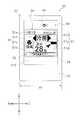
図1は、リモコン30を有する空調システム100の概略構成図である。図2は、室内ユニット20及びリモートコントロール装置30の設置状態を示した模式図である。(1)
FIG. 1 is a schematic configuration diagram of an
空調システム100は、冷媒配管方式の空調システムであって、蒸気圧縮方式の冷凍サイクル運転を行うことで、対象空間の空気調和を実現する。本実施形態において、空調システム100は、室内空間SIの空気調和を行う。空調システム100は、運転モードとして、冷房モード、暖房モード及び除湿モード等を有しており、選択された運転モードに応じて冷房運転、暖房運転又は除湿運転等を行う。 The
空調システム100は、主として、室外ユニット10と、室内ユニット20と、リモコン30と、を備えている。空調システム100においては、室外ユニット10と室内ユニット20とが液冷媒配管LP及びガス冷媒配管GPで接続されることで、冷媒回路が構成されている。 The
(1−1)室外ユニット10
室外ユニット10は、ベランダや地下室等の室外に設置される。室外ユニット10は、略直方体状の室外ユニットケーシング11を有している。室外ユニット10は、室外ユニットケーシング11の内部において、主として、圧縮機、四路切換弁、室外熱交換器、膨張弁、室外ファン、室外電源部及び室外ユニット制御部等を収容されている(図示省略)。(1-1)
The
圧縮機は、低圧のガス冷媒を吸入し、圧縮して吐出する機構である。四路切換弁は、冷房運転と暖房運転との切換時に、冷媒の流れる方向を切り換えるための弁である。室外熱交換器は、冷房運転時には冷媒の凝縮器として機能し、暖房運転時には冷媒の蒸発器として機能する熱交換器である。膨張弁は、高圧の冷媒を減圧する。膨張弁は、例えば運転状況に応じて開度が調整される電動弁である。室外ファンは、外部から室外ユニット10内に流入し室外熱交換器を通過してから室外ユニット10外へ流出する空気流を生成する。室外電源部は、外部電源と接続されて電源を供給される。 The compressor is a mechanism that sucks low-pressure gas refrigerant, compresses it, and discharges it. The four-way switching valve is a valve for switching the direction in which the refrigerant flows when switching between the cooling operation and the heating operation. The outdoor heat exchanger is a heat exchanger that functions as a refrigerant condenser during cooling operation and functions as a refrigerant evaporator during heating operation. The expansion valve depressurizes the high-pressure refrigerant. The expansion valve is a motor-operated valve whose opening degree is adjusted according to, for example, operating conditions. The outdoor fan generates an air flow that flows into the
室外ユニット制御部は、CPUやメモリ等で構成されるマイクロコンピュータを含む。室外ユニット制御部は、室外ユニット10内の機器の動作を制御する。室外ユニット制御部は、室内ユニット制御部22(後述)とケーブルC1で接続されており、相互に信号の送受信を行う。 The outdoor unit control unit includes a microcomputer configured with a CPU, a memory, and the like. The outdoor unit control unit controls the operation of devices in the
(1−2)室内ユニット20
室内ユニット20は、例えば、いわゆる天井埋込み型、天井吊下げ型又は壁掛け型の室内機である。本実施形態において、室内ユニット20は、天井埋め込み形のものが採用されており、吹出口や吸込みグリルが天井CIから室内空間SIに露出するように天井裏に設置されている。室内ユニット20は、その外郭を室内ユニットケーシング21によって構成されている。室内ユニット20は、室内ユニットケーシング21の内部において、室内熱交換器(図示省略)、室内ファン(図示省略)、室内電源部(図示省略)及び室内ユニット制御部22等を収容されている。(1-2)
The
室内熱交換器は、冷房運転時には冷媒の蒸発器として機能し、暖房運転時には冷媒の凝縮器として機能する。室内ファンは、室内ユニット20内に流入して室内熱交換器を通過した後に室内ユニット20外に流出する空気流を生成する送風機である。室内電源部は、室外電源部と接続されて電源を供給される。 The indoor heat exchanger functions as a refrigerant evaporator during cooling operation and functions as a refrigerant condenser during heating operation. The indoor fan is a blower that generates an air flow that flows into the
室内ユニット制御部22は、CPUやメモリ等で構成されるマイクロコンピュータを含む。室内ユニット制御部22は、ケーブルC1を介して室外ユニット制御部と接続されており、相互に信号の送受信を行っている。また、室内ユニット制御部22は、ケーブルC2を介してリモコン制御部80(後述)と接続されており、相互に信号の送受信を行っている。室内ユニット制御部22は、室外ユニット制御部又はリモコン制御部80から所定の信号を受信すると、当該信号に対応する処理を行う。 The indoor
(1−3)リモコン30
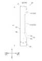
図3は、設置時におけるリモコン30の正面図である。図4は、設置時におけるリモコン30の右側面図である。図5は、リモコン30の概略構成図である。(1-3)
FIG. 3 is a front view of the
リモコン30は、いわゆる有線式のリモートコントロール装置であって、ケーブルC2を介して室内ユニット制御部22と接続されている。また、リモコン30は、室内電源部と接続されて電源を供給される。リモコン30は、例えば室内の内壁等に設置される。本実施形態では、リモコン30は、取付部材(図示省略)を介して室内空間SIの側壁SWに固定されている。 The
リモコン30は、空調システム100の運転開始及び停止、運転モード、設定温度、設定風量、風向、タイマー設定、時刻又は表示言語等の設定項目の変更や切換えを行うための各種指示を、空調システム100に入力するためのインターフェースとして機能する。例えば、リモコン30では、物理キー40(後述)やタッチパネル70(後述)を用いて各種指示を入力することが可能である。また、外部機器110から近距離無線通信によって制御信号を送信することでリモコン30に各種指示を送ることも可能である。 The
なお、外部機器110(特許請求の範囲記載の「通信装置」に相当)は、無線通信用アンテナを備えた機器であり、本実施形態においてはスマートフォンやタブレットPC等の情報端末を想定しているが、他のPCやICカード等であってもよい。また、近距離無線通信(NFC, Near Field Communication)は、13.56MHzの周波数を用いて数センチからおよそ1メートル程度の近距離における双方向通信を可能とする通信方式であって、国際標準の一つである。 The external device 110 (corresponding to “communication device” described in the claims) is a device including a wireless communication antenna. In the present embodiment, an information terminal such as a smartphone or a tablet PC is assumed. However, other PCs and IC cards may be used. NFC (Near Field Communication) is a communication system that enables bidirectional communication at a short distance of several centimeters to about 1 meter using a frequency of 13.56 MHz. One.
また、リモコン30は、空調システム100の運転状態や設定項目を表示する表示装置として機能する。例えば、リモコン30は、運転状態における空調システム100の運転モード、設定温度、設定風量、風向、タイマー設定又は時刻等の設定項目を所定の表示言語で表示する。 In addition, the
また、リモコン30は、空調システム100における各種の制御プログラムを更新するためのインターフェースとしても機能する。例えば、室外ユニット制御部、室内ユニット制御部22又はリモコン制御部80の制御プログラムが更新された場合には、リモコン30は、外部機器110と近距離無線通信を行って更新後のプログラムを取得することが可能である。 The
(2)リモコン30の詳細
リモコン30は、例えば合成樹脂製のケーシング31を有している。ケーシング31は、厚みt1(厚み方向の長さ)が高さh1(縦方向の長さ)及び幅w1(横方向の長さ)よりも短い薄型の筐体であって、正面視において略長方形状を呈している。ケーシング31は、一方の主面を構成する前面部32と、他方の主面を構成する背面部33と、を含んでいる。前面部32と背面部33とは互いに対向している。リモコン30が側壁SWに設置された状態においては、前面部32は室内空間SI(前)方向に面し、背面部33は側壁SW(後)方向に面する。(2) Details of
ケーシング31は、ガラス又はアクリル樹脂等で構成された透明のカバー310を有している。カバー310は、前面部32の中央部分に配置されている。すなわち、前面部32は、カバー310を含んでいる。換言すると、カバー310は、前面部32の一部を構成しているともいえる。 The
リモコン30は、ケーシング31の内部に、主として、物理キー40と、電源表示部43と、タッチスクリーン50と、リモコン制御部80と、を有している。 The
(2−1)物理キー40、電源表示部43
物理キー40は、空調システム100の運転を開始又は停止させる指示をユーザが入力するプッシュ式のボタンである。具体的に、空調システム100が停止状態にある場合に物理キー40を押下すると空調システム100が運転を開始する。また、空調システム100が運転状態にある場合に物理キー40を押下すると空調システム100が停止する。(2-1)
The
物理キー40は、ケーシング31の正面側の左上部に配置されている。物理キー40は、キートップ41及び物理キー電極部42を含んでいる。キートップ41は、ケーシング31に形成された開口から正面側に露出している。物理キー電極部42はリモコン制御部80と接続されており、物理キー40が押下されるとリモコン制御部80へ所定の信号が出力される。 The
電源表示部43は、LED等の発光部である。電源表示部43は、物理キー40に隣接して配置されている。電源表示部43は、リモコン制御部80によって動作を制御される。具体的に、電源表示部43は、空調システム100が運転状態にある場合には点灯し、停止状態にある場合には消灯する。 The
(2−2)タッチスクリーン50
タッチスクリーン50は、リモコン30の正面側の中央部分に配置されている。具体的に、タッチスクリーン50は、カバー310の背面側に近接して配置されている。(2-2)
The
タッチスクリーン50は、リモコン30において、各種指示を入力するための入力手段として機能する。具体的に、タッチスクリーン50は、第1タッチ入力部51a、第2タッチ入力部51b、第3タッチ入力部51c、第4タッチ入力部51d、第5タッチ入力部51e、第6タッチ入力部51f、第7タッチ入力部51gを有している(以下、これらをタッチ入力部51と総称する)。各タッチ入力部51は各種指示と関連付けられており、ユーザは各タッチ入力部51を指やスタライスペン等でタッチすることで所望の指示を入力することが可能である。 The
例えば、第1タッチ入力部51aをタッチすることで運転モードの設定が可能となる。また、第2タッチ入力部51bをタッチすることで設定温度の設定が可能となる。また、第3タッチ入力部51cをタッチすることで風量の設定が可能となる。また、第4タッチ入力部51dをタッチすることで風向の設定が可能となる。また、第5タッチ入力部51eをタッチすることでタイマー又は時刻の設定が可能となる。また、第6タッチ入力部51f又は第7タッチ入力部51gをタッチすることで、現在選択している設定項目のレベルやモード等を変更することが可能である。 For example, the operation mode can be set by touching the first
また、タッチスクリーン50は、各種の情報を表示する表示手段としても機能する。具体的に、タッチスクリーン50は、運転状態において、各タッチ入力部51と重畳するように所定のアイコンや情報を表示する。当該表示により、ユーザが各タッチ入力部51に関連付けられた各種指示を識別できるようになっている。 The
例えば、第1タッチ入力部51aと重畳するように、選択されている運転モードが表示される(図3では、冷房モードが選択されていることを示す「冷房」の文字が表示されている)。また、第2タッチ入力部51bと重畳するように、選択されている設定温度が表示される(図3では、選択されている設定温度を示す「設定28℃」の文字が表示されている)。また、第3タッチ入力部51cと重畳するように、選択されている風量が表示される(図3では、選択されている風量を示す「強風」の文字及びアイコンが表示されている)。また、第4タッチ入力部51dと重畳するように、選択されている風向が表示される(図3では、選択されている風向を示すアイコンが表示されている)。また、第5タッチ入力部51eと重畳するように、現在時刻及びタイマーオフ時刻が表示される(図3では、選択されている現在時刻「10:10」及びタイマーオフ時刻「タイマーオフ11:10」を示す文字及び数字が表示されている)。また、第6タッチ入力部51f又は第7タッチ入力部51gと重畳するように、カーソルを示すアイコンが表示される。 For example, the selected operation mode is displayed so as to be superimposed on the first
また、タッチスクリーン50は、外部機器110と近距離無線通信を行うためのインターフェースとしても機能する。具体的に、タッチスクリーン50の下部には、近距離無線通信用のアンテナとして機能するアンテナ部52が構成されている。これにより、リモコン30は、外部機器110と近距離無線通信を行うことが可能である。なお、タッチスクリーン50では、アンテナ部52と重畳するように「NFC通信エリア」の文字が表示されており、ユーザが近距離無線通信を行う際にアンテナ部52の位置を認識できるようになっている(図3参照)。 The
タッチスクリーン50は、主として、液晶表示部60と、タッチパネル70と、で構成されている。 The
(2−2−1)液晶表示部60
液晶表示部60は、ケーシング31内において、タッチパネル70とリモコン制御部80に挟まれるように配置されている。具体的に、液晶表示部60は、フルドットマトリクス液晶部61(以下、液晶部61と記載)と、3原色LEDバックライト62(以下、バックライト62と記載)と、を有している。(2-2-1) Liquid
The liquid
液晶部61は、液晶及び液晶駆動電極部を含んでいる(図示省略)。液晶部61は、リモコン制御部80と電気的に接続されており、リモコン制御部80によって動作を制御される。 The liquid crystal unit 61 includes a liquid crystal and a liquid crystal drive electrode unit (not shown). The liquid crystal unit 61 is electrically connected to the
液晶表示部60は、供給される電流に応じてバックライト62の輝度及びカラーを切り換えることが可能である。本実施形態においては、液晶表示部60は、バックライト62の輝度を強・弱の2段階で切り換えられ、バックライト62のカラーを青・緑・赤の3パターンで切り換えることが可能である。液晶表示部60は、リモコン制御部80と電気的に接続されており、リモコン制御部80によって、所定のタイミングで液晶部61を駆動されるとともにバックライト62の輝度及びカラーを切り換えられる。なお、本実施形態において、バックライト62は、空調システム100が冷房運転及び除湿運転を行う場合には青で点灯され、空調システム100が暖房運転を行う場合には赤で点灯される。また、バックライト62は、リモコン30が外部機器110と無線通信を行う場合には緑で点灯される。 The liquid
(2−2−2)タッチパネル70
タッチパネル70は、電極の静電容量又は電界の変化を判定することでタッチ入力の有無及びタッチ位置を検出するいわゆる静電容量方式を採用されたタッチパネルである。タッチパネル70は、液晶表示部60とカバー310の間において、背面部33よりも前面部32に近接するように配置されている。また、タッチパネル70は、前面部32側(正面側)から見た場合に液晶表示部60と重畳するように配置されている。換言すると、タッチパネル70は、室内空間SI側から見た場合に液晶表示部60と重畳するように配置されているともいえる。タッチパネル70は、電極ユニット71を含む。(2-2-2)
The
(2−2−2−1)電極ユニット71
図6は、電極ユニット71の模式図である。電極ユニット71は、主として、縦方向(Y方向)のタッチ位置検出用の透明電極を複数配設された透明基板と、横方向(X方向)のタッチ位置検出用の透明電極を複数配設された透明基板と、を含み、両者を重ね合わされて構成されている。電極ユニット71を正面側(前面部側)から視ると、複数の電極がX軸及びY軸方向に所定の間隔を置いて並んでいる。(2-2-2-1)
FIG. 6 is a schematic diagram of the
電極ユニット71は、前面部32のカバー310に隣接して(すなわち、カバー310の直後)に配置されている。換言すると、電極ユニット71は、リモコン30の正面側に配置されている。 The
電極ユニット71は、各タッチ入力部51を構成するタッチ電極部72(特許請求の範囲記載の「第1電極部」に相当)と、アンテナ部52を構成するアンテナ電極部73(特許請求の範囲記載の「第2電極部」に相当)と、グランド部74と、を含んでいる。具体的に、図6において、タッチ電極部72は、囲み線A1で囲われた領域である。アンテナ電極部73は、囲み線B1で囲われた領域である。グランド部74は、囲み線C1に沿って形成されたグランドパターンであり、グランドに接続されている。 The
このように電極ユニット71内には、タッチ電極部72、アンテナ電極部73及びグランド部74が構成されている。すなわち、タッチ電極部72及びアンテナ電極部73は、同一の電極ユニット71内において同一の成分で構成されている。 As described above, the
なお、タッチ電極部72及びアンテナ電極部73は、ケーシング31内において、背面部33よりも前面部32に近接している。すなわち、タッチ電極部72及びアンテナ電極部73は、リモコン30の正面側に配置されている。 The
また、タッチ電極部72及びアンテナ電極部73は、前面部32側(正面側)から見た場合に重畳しないように配置されている。換言すると、タッチ電極部72及びアンテナ電極部73は、室内空間SI側から見た場合に重畳しないように配置されているともいえる。すなわち、タッチ電極部72及びアンテナ電極部73は、前面部32側(又は室内空間SI側)から見た場合に、互いに外れて配置されている。 Further, the
タッチ電極部72内の各電極は、タッチパネル70のタッチ位置検出用の電極として機能する。具体的に、タッチ電極部72内の各電極は、リモコン制御部80と電気的に接続されており、静電容量又は電界が変化するとリモコン制御部80によってその変化量が検出される。当該変化量に基づき、リモコン制御部80は、各タッチ入力部51がタッチされた際にタッチ入力の存在及びタッチ位置を検出する。 Each electrode in the
アンテナ電極部73内の各電極は、外部機器110と無線通信を行うためのアンテナとして機能する。具体的に、アンテナ電極部73内の各電極は、リモコン制御部80と電気的に接続されており、静電容量又は電界が変化すると、リモコン制御部80によってその変化量を検出される。当該変化量に基づき、リモコン制御部80は、外部機器110から信号が送信された際に、当該信号を検出して受信する。また、アンテナ電極部73内の各電極は、リモコン制御部80によって静電容量又は電界を変化させられる。これにより、リモコン制御部80は、他の通信機器へ信号を送信することが可能である。 Each electrode in the
このように、電極ユニット71に含まれる複数の電極の一部は、外部機器110と無線通信を行うためのアンテナとして用いられる。すなわち、本実施形態では、本来、タッチ位置検出用の電極として機能する複数の電極の一部が、無線通信用のアンテナとして使用されている。 Thus, some of the plurality of electrodes included in the
グランド部74は、前面部32側(正面側)から見た場合に、タッチ電極部72とアンテナ電極部73の間に位置し、アンテナ電極部73を囲うように配置されている。換言すると、グランド部74は、室内空間SI側から見た場合に、タッチ電極部72とアンテナ電極部73の間に位置しているともいえる。このような態様で配置されることで、グランド部74は、タッチ電極部72とアンテナ電極部73との電磁的な干渉を抑制する役割を果たしている。 The
(2−3)リモコン制御部80
リモコン制御部80(特許請求の範囲記載の「タッチ検知部」及び「バックライト制御部」に相当)は、CPUやメモリ等で構成されるマイクロコンピュータや各種の電気部品を含み、基板に実装されている。リモコン制御部80は、ケーブルC2を介して室内ユニット制御部22と接続されており、電力の供給を受けるとともに信号の送受信を行う。また、リモコン制御部80は、配線を介して物理キー電極部42、電源表示部43及びタッチスクリーン50(液晶表示部60及びタッチパネル70)と接続されている。リモコン制御部80は、制御モードとして通常モード及び無線通信モードを有している。無線通信モードは外部機器110との近距離無線通信中に選択される制御モードであり、通常モードはそれ以外の場合に選択される制御モードである。(2-3)
The remote control unit 80 (corresponding to “touch detection unit” and “backlight control unit” described in the claims) includes a microcomputer including a CPU and a memory and various electric components, and is mounted on a substrate. ing. The
リモコン制御部80は、主として、第1記憶部81と、第2記憶部82と、第1通信制御部83と、第2通信制御部84と、入力制御部85と、表示制御部86と、通信部87と、を含んでいる。 The
(2−3−1)第1記憶部81、第2記憶部82
第1記憶部81及び第2記憶部82は、ROMやRAM等のメモリを含んでいる。(2-3-1)
The
第1記憶部81は、リモコン制御部80内の各部において適用される制御プログラムを保持している。当該制御プログラムには、リモコン制御部80内における各部の処理がプログラミングされている。 The
第2記憶部82は、いわゆるワーキングメモリであり、各部からの情報を所定の領域に格納される。また、第2記憶部82は、所定の設定項目(運転モード、設定温度、設定風量、風向、タイマー設定、時刻、表示言語等)に関してユーザが選択した最新の情報(以下、「設定情報」と称する)及び過去数回分の情報(以下、「運転履歴情報」と称する)を保持している。第2記憶部82が保持する設定情報や運転履歴情報は、リアルタイムに更新される。 The
(2−3−2)第1通信制御部83
第1通信制御部83は、第2記憶部82に所定の情報が格納されると、当該情報を取得して所定の処理を行う。具体的に、第1通信制御部83は、空調システム100が停止状態に有る場合に物理キー入力情報を取得すると、第2記憶部82に格納されている設定情報に応じて、所定の制御信号を通信部87を介して室内ユニット制御部22に出力する。(2-3-2) First
When predetermined information is stored in the
また、第1通信制御部83は、室内ユニット制御部22から出力された信号を通信部87を介して入力され、これを解読し、解読した情報を第2記憶部82に格納する。 The first
(2−3−3)第2通信制御部84
第2通信制御部84は、アンテナ電極部73における静電容量又は電界の変化を検出し、その変化量に基づいて外部機器110からアンテナ電極部73(アンテナ部52)に送信された信号の有無を判断する。より詳細には、第2通信制御部84は、アンテナ電極部73(アンテナ部52)に送信された13.56MHzの周波数の信号を検出して、通常モードから無線通信モードに切り換える情報(以下、「無線通信モード遷移情報」と称する)を第2記憶部82に格納する。(2-3-3) Second
The second
また、第2通信制御部84は、外部機器110から送信された信号を解読し、解読した情報(以下、「無線通信情報」と称する)を第2記憶部82に格納する。また、第2通信制御部84は、無線通信モード実行中には、所定のタイミングでアンテナ電極部73の静電容量又は電界を変化させることにより、外部機器110に13.56MHzの周波数の信号を送信する。 The second
また、第2通信制御部84は、外部機器110との近距離無線通信が完了すると、無線通信モードから通常モードに切り換える情報(以下、「無線通信モード解除情報」と称する)を第2記憶部82に格納する。 In addition, when the short-range wireless communication with the
(2−3−4)入力制御部85
入力制御部85は、物理キー電極部42からの信号を入力されると、所定の情報(以下、当該情報を「物理キー入力情報」と称する)を第2記憶部82に格納する。(2-3-4)
When the signal from the physical
また、入力制御部85は、第2記憶部82に無線通信モード遷移情報が格納されていない場合、又は無線通信モード解除情報が格納された場合には、これを取得して通常モードに応じた処理を行う。具体的に、入力制御部85は、通常モードにおいては、タッチ電極部72における静電容量又は電界の変化を検出し、その変化量に基づいて各タッチ入力部51へのタッチ入力の有無を判断するとともに、タッチ入力されたタッチ入力部51を特定する。入力制御部85は、タッチ入力されたタッチ入力部51に応じて、所定の情報(以下、当該情報を「タッチ入力情報」と称する)を第2記憶部82に格納する。 In addition, when the wireless communication mode transition information is not stored in the
また、入力制御部85は、第2記憶部82に無線通信モード遷移情報が格納された場合には、これを取得して無線通信モードに応じた処理を行う。具体的に、入力制御部85は、無線通信モードにおいては、タッチ電極部72における静電容量又は電界の変化の検出を停止する。 Moreover, when the wireless communication mode transition information is stored in the
(2−3−5)表示制御部86
表示制御部86は、第2記憶部82に所定の情報が格納されると、当該情報を取得して所定の処理を行う。具体的に、表示制御部86は、空調システム100が停止状態に有る場合に物理キー入力情報を取得すると、電源表示部43及びバックライト62を所定の輝度及びカラーで点灯させるとともに、第2記憶部82に格納されている設定情報に基づき液晶部61を駆動させる。また、表示制御部86は、空調システム100が運転状態に有る場合に物理キー入力情報を取得すると、電源表示部43及びバックライト62を消灯させる。(2-3-5)
When predetermined information is stored in the
また、表示制御部86は、第2記憶部82に無線通信モード遷移情報が格納されていない場合、又は無線通信モード解除情報が格納された場合には、これを取得して通常モードに応じた処理を行う。具体的に、表示制御部86は、通常モードにおいては、タッチ入力情報を取得すると、第2記憶部82に格納されている設定情報に基づき液晶部61を駆動させる。 In addition, when the wireless communication mode transition information is not stored in the
また、表示制御部86は、第2記憶部82に無線通信モード遷移情報が格納された場合には、これを取得して無線通信モードに応じた処理を行う。具体的に、表示制御部86は、無線通信モードにおいては、バックライト62を緑で点灯させる。なお、無線通信モード時には、表示制御部86は液晶部61を駆動させない。よって、無線通信モード時、液晶表示部60では、アイコンや文字等の表示は行われずにバックライト62が緑で点灯している状態となる。 In addition, when wireless communication mode transition information is stored in the
(2−3−6)通信部87
通信部87は、第1通信制御部83から入力される信号を室内ユニット制御部22に出力し、室内ユニット制御部22から入力される信号を第1通信制御部83に出力する通信回路である。(2-3-6)
The
(3)リモコン制御部80による処理の流れ
以下、図7を参照して、リモコン制御部80による処理の流れの一例を説明する。(3) Process Flow by
空調システム100が停止している状態において物理キー40が押下されると、リモコン制御部80は、ステップS101において、電源表示部43を点灯させる。また、リモコン制御部80は、設定情報に基づいて液晶部61を駆動するとともにバックライト62を点灯させる。また、リモコン制御部80は、設定情報に基づき運転を開始させる旨の制御信号を室内ユニット制御部22に送信する。その後、ステップS102へ進む。 When the
ステップS102において、リモコン制御部80は、物理キー40が押下されていないか否かを判定する。当該判定がNOの場合(すなわち、物理キー40が押下された場合)には、リモコン制御部80は、室内ユニット制御部22に運転を停止させる旨の制御信号を送信した後、液晶部61の駆動及びバックライト62の点灯を停止させるとともに電源表示部43を消灯して処理を終了する。一方、当該判定がYESの場合(すなわち、物理キー40が押下されていない場合)には、ステップS103へ進む。 In step S102, the remote
ステップS103において、リモコン制御部80は、アンテナ部52に所定の信号が送信されているか否か(すなわち、アンテナ電極部73の静電容量又は電界が所定の変化量で変化しているか否か)を判定する。当該判定がNOの場合(すなわち、アンテナ部52に所定の信号が送信されていない場合)には、ステップS104へ進む。一方、当該判定がYESの場合(すなわち、アンテナ部52に所定の信号が送信されている場合)には、ステップS107へ進む。 In step S103, the
ステップS104において、リモコン制御部80は、制御モードを通常モードに決定する。その後、ステップS105へ進む。 In step S104, the
ステップS105において、リモコン制御部80は、各タッチ入力部51にタッチ入力があるか否か(すなわち、タッチ電極部72の所定の位置における静電容量又は電界が所定の変化量で変化しているか否か)を判定する。当該判定がNOの場合(すなわち、各タッチ入力部51へのタッチ入力がない場合)には、ステップS102に戻る。一方、当該判定がYESの場合(すなわち、各タッチ入力部51へのタッチ入力がある場合)には、ステップS106へ進む。 In step S105, the
ステップS106において、リモコン制御部80は、設定情報に基づいて液晶部61を駆動するとともにバックライト62を点灯させる。また、リモコン制御部80は、設定情報に基づき運転させる旨の制御信号を室内ユニット制御部22に送信する。その後、ステップS102に戻る。 In step S106, the remote
ステップS107において、リモコン制御部80は、制御モードを無線通信モードに決定する。そして、リモコン制御部80は、液晶部61の駆動を停止させるとともにバックライト62を緑で点灯させる。また、リモコン制御部80は、タッチ入力部51におけるタッチ入力の検出を停止する。そして、リモコン制御部80は、外部機器110と近距離無線通信により信号の送受信を行う。その後、ステップS108へ進む。 In step S107, the
ステップS108において、無線通信が完了していない場合には、外部機器110との近距離無線通信を継続する。一方で、無線通信が完了した場合には、ステップS109へ進む。 If the wireless communication is not completed in step S108, the short-range wireless communication with the
ステップS109において、リモコン制御部80は、無線通信モードを解除する。その後ステップS102に戻る。 In step S109, the remote
(4)近距離無線通信において送受信される情報
上述のように、リモコン30と外部機器110とは近距離無線通信が可能であるが、当該無線通信において送受信される情報は特に限定されず、各種の情報が送受信される。(4) Information transmitted / received in short-range wireless communication As described above, the
例えば、空調システム100の運転開始及び停止、運転モード、設定温度、設定風量、風向、タイマー設定、時刻又は表示言語等の設定項目の変更又は切換えを行わせる各種指示を、外部機器110からリモコン30へ送信することが可能である。また、室外ユニット制御部、室内ユニット制御部22又はリモコン制御部80の制御プログラムが更新された場合には、更新後の制御プログラムを外部機器110からリモコン30へ送信することが可能である。また、特定の操作者の入力のみを許容すべく、リモコン30にセキュリティロック機能をもたせた場合には、セキュリティロックを解除する所定情報を外部機器110からリモコン30へ送信することも可能である。また、空調システム100の運転履歴を検証するために、運転履歴情報を空調システム100から外部機器110へ送信することも可能である。 For example, various instructions for changing or switching setting items such as operation start and stop of the
(5)リモコン30の機能
リモコン30では、タッチパネル70に含まれる電極ユニット71の一部がタッチ電極部72として機能する一方で、他の部分がアンテナ電極部73として機能している。このため、タッチパネル70とは別に近距離無線通信用のアンテナを配置する必要がなく、コスト抑制及びリモコン30のコンパクト化が実現されている。(5) Function of
また、リモコン30では、アンテナ電極部73がリモコン30の正面側に配置されている。その結果、外部機器110と近距離無線通信を行う際に、外部機器110に搭載されるアンテナとアンテナ部52との信号の送受信が円滑に行われやすい。 In the
また、リモコン30では、タッチ電極部72とアンテナ電極部73との間にグランド部74が設けられている。その結果、アンテナ電極部73とタッチ電極部72とが電磁的に干渉しにくく、アンテナ電極部73へのノイズが低減されている。 In the
また、リモコン30では、無線通信モードで制御している期間においては、タッチ電極部72における静電容量又は電界の変化の検出を停止する。すなわち、リモコン30では、外部機器110と無線通信を行っている期間は、各タッチ入力部51におけるタッチ入力の検出を行わない。その結果、外部機器110と無線通信中に、アンテナ電極部73がノイズを受けにくい。 Further, the
また、リモコン30では、無線通信モードで制御している期間においては、液晶表示部60はバックライト62が緑で点灯している状態となる。その結果、リモコン30と外部機器110との間で無線通信が行われる際、無線通信が実行中であることを操作者が認識しやすくなっている。すなわち、液晶表示部60(バックライト62)は、無線通信が行われている場合において無線通信中であることを示す表示部として機能する。 In the
また、無線通信モードで制御している期間においては、液晶表示部60ではアイコンや文字等の表示が行われないため、アンテナ電極部73は液晶部61からのノイズを受けにくい。 In addition, during the period of control in the wireless communication mode, icons and characters are not displayed on the liquid
(6)特徴
(6−1)
上記実施形態では、リモコン30のタッチパネル70は電極ユニット71を含み、電極ユニット71は、タッチ位置検出用の電極として機能するタッチ電極部72と、外部機器110と近距離無線通信を行うためのアンテナとして機能するアンテナ電極部73と、を有している。すなわち、上記実施形態では、本来、タッチ位置検出用の電極として機能する複数の電極の一部が、無線通信用のアンテナとして使用されている。このように、タッチパネル70の電極ユニット71の一部が、近距離無線通信用のアンテナとして機能する結果、リモコン30では、タッチパネル70の電極ユニット71とは別に近距離無線通信用のアンテナを配置する必要がなく、コストが抑制されている。(6) Features (6-1)
In the above embodiment, the
また、上記実施形態では、タッチ電極部72及びアンテナ電極部73は、ケーシング31内において、背面部33よりも前面部32に近接し、前面部32側から見た場合に重畳しないように互いに外れて配置されている。これにより、アンテナ電極部73が、近距離無線通信においてアンテナとしての機能を発揮しやすいようになっている。 Further, in the above-described embodiment, the
また、上記実施形態では、アンテナとして機能するタッチ電極部72をリモコン30の前面部32側(本体正面側)に配置する一方で、液晶表示部60(ディスプレイ)の面積を縮小する必要がなく、操作性の低下が抑制されている。 In the above embodiment, the
(6−2)
上記実施形態では、タッチパネル70は、前面部32側から見た場合にタッチ電極部72とアンテナ電極部73との間に位置するグランド部74をさらに含む。これにより、アンテナ電極部73が、タッチ電極部72からのノイズを受けにくくなっている。(6-2)
In the embodiment described above, the
(6−3)
上記実施形態では、タッチパネル70のタッチされた位置を検知するリモコン制御部80を備え、リモコン制御部80は、外部機器110と無線通信が行っている間はタッチ入力の検知を停止する。これにより、外部機器110と無線通信中に、アンテナ電極部73がノイズを受けにくく、通信性能の低下が抑制されている。(6-3)
In the above-described embodiment, the
(6−4)
上記実施形態では、リモコン制御部80は、外部機器110との無線通信を実行中には、液晶表示部60のバックライト62を所定のカラーで点灯させている。その結果、無線通信が行われている期間には無線通信実行中であることが操作者に示される。これにより、リモコン30と外部機器110とが無線通信を行っているときに、無線通信中であることを操作者が認識しやすいようになっている。(6-4)
In the above embodiment, the
(6−5)
上記実施形態では、外部機器110を介して空調システム100の各種設定を行う際に、近距離無線通信が行われる。これにより、空調システム100の各種設定を行う際における操作性が向上している。また、リモコン30に内蔵するメモリの容量を抑えることも可能となっている。(6-5)
In the above embodiment, short-range wireless communication is performed when various settings of the
(7)変形例
(7−1)変形例A
上記実施形態では、リモコン30は、空調システム100に適用されたが、これに限定されない。例えば、リモコン30は、給湯器や除湿器等のヒートポンプシステムに適用されてもよい。また、リモコン30は、換気装置や空気清浄機等に適用されてもよい。(7) Modification (7-1) Modification A
In the above embodiment, the
(7−2)変形例B
上記実施形態では、室内ユニット20は、いわゆる天井埋込み型のものが採用されたが、これに限定されず、例えば天井吊下げ型、壁掛け型又は床置き型のものであってもよい。(7-2) Modification B
In the above embodiment, the so-called ceiling-embedded type is adopted as the
(7−3)変形例C
上記実施形態では、リモコン30は、1台の室内ユニット20の室内ユニット制御部22と接続されていたが、これに限定されず、複数台の室内ユニット20の室内ユニット制御部22と接続されてもよい。(7-3) Modification C
In the above embodiment, the
また、リモコン30は、室内ユニット20の室内ユニット制御部22とケーブルC2で接続されて通信を行っていた。しかし、これに限定されず、赤外線等により無線通信を行ってもよい。係る場合、ケーブルC2を省略する一方で、リモコン30に電池等の電源を配設してリモコン30の各部に電源を供給すればよい。 In addition, the
また、リモコン30を、室内ユニット制御部22ではなく、室外ユニット制御部と接続するようにしてもよい。係る場合、室外ユニット制御部を経由して室内ユニット制御部22にリモコン30からの信号が送信されることとなる。 Moreover, you may make it connect the
(7−4)変形例D
上記実施形態では、リモコン30は、側壁SWに設置されていた。しかし、リモコン30は、必ずしも側壁SWに設置される必要はない。例えば、リモコン30は、他の場所に設置されてもよいし、特定の場所に固定されなくてもよい。(7-4) Modification D
In the above embodiment, the
また、上記実施形態では、リモートコントロール装置としてリモコン30が採用された。しかし、これに限定されず、リモートコントロール装置として、例えばスマートフォンやタブレットPC等の情報端末を採用してもよい。 In the above embodiment, the
(7−5)変形例E
上記実施形態では、リモコン30と外部機器110との間で行われる無線通信は、近距離無線通信(NFC, Near Field Communication)であったが、特にこれに限定されない。例えば、ISO/IEC 14443やBluetooth(登録商標)等の他の通信規格に基づく無線通信であってもよい。(7-5) Modification E
In the above embodiment, the wireless communication performed between the
(7−6)変形例F
上記実施形態では、外部機器110と無線通信が行われている場合は、無線通信が行われていることを操作者に示すべく、バックライト62を緑で点灯していたが、バックライト62を点灯させるカラーは、特に限定されず他のカラーであってもよい。また、当該場合においてバックライト62を一定周期で点滅させるようにしてもよい。また、当該場合において、液晶部61を駆動させて、液晶表示部60において無線通信中であることを示すアイコンや文字を表示させるようにしてもよい。(7-6) Modification F
In the above embodiment, when wireless communication is performed with the
また、当該場合において、バックライト62を点灯させずに或いはバックライト62とともに、電源表示部43を所定のカラーで点灯若しくは点滅させるようにしてもよい。係る場合、電源表示部43は、無線通信が行われている場合において無線通信中であることを示す表示部として機能する。また、バックライト62や電源表示部43とは別にLED等の表示部を配設して、無線通信中にこれを点灯又は点滅させるようにしてもよい。 In this case, the power
(7−7)変形例G
上記実施形態では、アンテナ電極部73は、タッチパネル70の電極ユニット71に設けられていた。しかし、これに限定されず、アンテナ電極部73を液晶部61の液晶駆動電極に設けてリモコン30を構成してもよい。(7-7) Modification G
In the above embodiment, the
(7−8)変形例H
上記実施形態では、図3又は図6に示すように、各タッチ入力部51(タッチ電極部72)、アンテナ部52(アンテナ電極部73)及びグランド部74は、電極ユニット71において所定の位置に配置されていた。しかし、各タッチ入力部51(タッチ電極部72)、アンテナ部52(アンテナ電極部73)及びグランド部74の配置は、これに限定されず、どのような態様であってもよい。例えば、各タッチ入力部51(タッチ電極部72)、アンテナ部52(アンテナ電極部73)及びグランド部74は、図8に示すような態様で配置されてもよい。(7-8) Modification H
In the above embodiment, as shown in FIG. 3 or FIG. 6, each touch input unit 51 (touch electrode unit 72), antenna unit 52 (antenna electrode unit 73), and
図8に示すリモコン30aでは、アンテナ部52(アンテナ電極部73)は、リモコン30における第5タッチ入力部51eの位置に配置されており、各タッチ入力部51(タッチ電極部72)よりも上方に位置している。これに伴い、グランド部74も各タッチ入力部51(タッチ電極部72)よりも上方に位置しており、タッチ電極部72とアンテナ電極部73の間においてアンテナ部52(アンテナ電極部73)を囲うように配置されている。また、第5タッチ入力部51eがリモコン30におけるアンテナ部52(アンテナ電極部73)の位置に配置されている。リモコン30aのその他の構成は、リモコン30と略同一である。 In the
(7−9)変形例I
タッチパネル70は、いわゆる静電容量方式を採用されていた。しかし、タッチパネル70は、他の方式を採用されてもよい。例えば、タッチパネル70は、タッチされることによって対向する2枚の電極基板同士が接触した時の電圧の変化を検知する、いわゆる抵抗膜方式のタッチパネルを採用されてもよい。(7-9) Modification I
The
本発明は、リモートコントロール装置に利用可能である。 The present invention is applicable to a remote control device.
10 室外ユニット
20 室内ユニット
22 室内ユニット制御部
30、30a リモコン(リモートコントロール装置)
31 ケーシング
32 前面部
33 背面部
40 物理キー
43 電源表示部
50 タッチスクリーン
51 タッチ入力部
52 アンテナ部
60 液晶表示部
61 液晶部
62 バックライト
70 タッチパネル
71 電極ユニット
72 タッチ電極部(第1電極部)
73 アンテナ電極部(第2電極部)
74 グランド部
80 リモコン制御部(タッチ検知部、バックライト制御部)
100 空調システム(空調機)
110 外部機器(通信装置)
310 カバー
C2 ケーブル
SI 室内空間
SW 側壁DESCRIPTION OF
31
73 Antenna electrode part (second electrode part)
74
100 Air conditioning system (air conditioner)
110 External equipment (communication equipment)
310 Cover C2 Cable SI Indoor space SW Side wall
Claims (8)
Translated fromJapanese電極ユニット(71)を含むタッチパネル(70)と、
液晶表示部(60)と、
前記タッチパネル及び前記液晶表示部を収容するケーシング(31)と、
を備え、
前記ケーシングは、設置状態において、前記側壁に面する背面部(33)と、前記室内空間に面する前面部(32)と、を有し、
前記液晶表示部は、前記前面部側から見た場合に前記タッチパネルと重畳するように配置され、
前記電極ユニットは、タッチ位置検出用の電極として機能する第1電極部(72)と、他の情報端末(110)と無線通信を行うためのアンテナとして機能する第2電極部(73)と、
を有し、
前記第1電極部及び前記第2電極部は、前記ケーシング内において、前記背面部よりも前記前面部に近接し、前記前面部側から見た場合に重畳しないように配置され、
前記無線通信は、近距離無線通信(NFC, Near Field Communication)である、
リモートコントロール装置(30、30a)。A remote control device (30, 30a) installed on a side wall (SW) forming an indoor space (SI) and performing wired communication with an air conditioner (100) or a heat pump device,
A touch panel (70) including an electrode unit (71);
A liquid crystal display (60);
A casing (31) for housing the touch panel and the liquid crystal display unit;
With
The casing has a back surface portion (33) facing the side wall and a front surface portion (32) facing the indoor space in the installed state,
The liquid crystal display unit is disposed so as to overlap the touch panel when viewed from the front side.
The electrode unit includes a first electrode part (72) that functions as an electrode for touch position detection, a second electrode part (73) that functions as an antenna for performing wireless communication with anotherinformation terminal (110),
Have
The first electrode part and the second electrode part are arranged in the casing so as not to overlap when viewed from the front part side, closer to the front part than the back part,
The wireless communication is near field communication (NFC),
Remote control device (30, 30a).
電極ユニット(71)を含むタッチパネル(70)と、
液晶表示部(60)と、
前記タッチパネル及び前記液晶表示部を収容するケーシング(31)と、
を備え、
前記ケーシングは、厚み方向の長さ(t1)が縦方向の長さ(h1)及び横方向の長さ(w1)よりも短い筐体であり、一方の主面を構成する前面部(32)と、他方の主面を構成し前記前面部に対向する背面部(33)と、を有し、
前記液晶表示部は、前記前面部側から見た場合に前記タッチパネルと重畳するように配置され、
前記電極ユニットは、タッチ位置検出用の電極として機能する第1電極部(72)と、他の情報端末(110)と無線通信を行うためのアンテナとして機能する第2電極部(73)と、
を有し、
前記第1電極部及び前記第2電極部は、前記ケーシング内において、前記背面部よりも前記前面部に近接し、前記前面部側から見た場合に互いに外れて配置され、
前記無線通信は、近距離無線通信(NFC, Near Field Communication)である、
リモートコントロール装置(30、30a)。A remote control device (30, 30a) for communicating with an air conditioner (100) or a heat pump device,
A touch panel (70) including an electrode unit (71);
A liquid crystal display (60);
A casing (31) for housing the touch panel and the liquid crystal display unit;
With
The casing is a casing having a length (t1) in a thickness direction shorter than a length (h1) in a vertical direction and a length (w1) in a horizontal direction, and a front surface portion (32) constituting one main surface. And a back surface portion (33) that constitutes the other main surface and faces the front surface portion,
The liquid crystal display unit is disposed so as to overlap the touch panel when viewed from the front side.
The electrode unit includes a first electrode part (72) that functions as an electrode for touch position detection, a second electrode part (73) that functions as an antenna for performing wireless communication with anotherinformation terminal (110),
Have
In the casing, the first electrode part and the second electrode part are closer to the front part than the back part, and are arranged away from each other when viewed from the front part side,
The wireless communication is near field communication (NFC),
Remote control device (30, 30a).
電極ユニット(71)を含むタッチパネル(70)と、
液晶表示部(60)と、
前記タッチパネル及び前記液晶表示部を収容するケーシング(31)と、
前記タッチパネルがタッチされた位置を検知するタッチ検知部(80)と、
を備え、
前記ケーシングは、設置状態において、前記側壁に面する背面部(33)と、前記室内空間に面する前面部(32)と、を有し、
前記液晶表示部は、前記前面部側から見た場合に前記タッチパネルと重畳するように配置され、
前記電極ユニットは、タッチ位置検出用の電極として機能する第1電極部(72)と、他の通信装置(110)と無線通信を行うためのアンテナとして機能する第2電極部(73)と、
を有し、
前記第1電極部及び前記第2電極部は、前記ケーシング内において、前記背面部よりも前記前面部に近接し、前記前面部側から見た場合に重畳しないように配置され、
前記タッチ検知部は、前記無線通信が行われている間は前記検知を停止する、
リモートコントロール装置(30、30a)。A remote control device (30, 30a) installed on a side wall (SW) forming an indoor space (SI) and performing wired communication with an air conditioner (100) or a heat pump device,
A touch panel (70) including an electrode unit (71);
A liquid crystal display (60);
A casing (31) for housing the touch panel and the liquid crystal display unit;
A touch detection unit (80) for detecting a position touched by the touch panel;
With
The casing has a back surface portion (33) facing the side wall and a front surface portion (32) facing the indoor space in the installed state,
The liquid crystal display unit is disposed so as to overlap the touch panel when viewed from the front side.
The electrode unit includes a first electrode portion (72) that functions as an electrode for touch position detection, a second electrode portion (73) that functions as an antenna for performing wireless communication with another communication device (110), and
Have
The first electrode part and the second electrode part are arranged in the casing so as not to overlap when viewed from the front part side, closer to the front part than the back part,
The touch detection unit stops the detection while the wireless communication is performed.
Remote control device (30, 30a).
電極ユニット(71)を含むタッチパネル(70)と、
液晶表示部(60)と、
前記タッチパネル及び前記液晶表示部を収容するケーシング(31)と、
前記液晶表示部のバックライトの動作を制御するバックライト制御部(80)と、
を備え、
前記ケーシングは、設置状態において、前記側壁に面する背面部(33)と、前記室内空間に面する前面部(32)と、を有し、
前記液晶表示部は、前記前面部側から見た場合に前記タッチパネルと重畳するように配置され、
前記電極ユニットは、タッチ位置検出用の電極として機能する第1電極部(72)と、他の通信装置(110)と無線通信を行うためのアンテナとして機能する第2電極部(73)と、
を有し、
前記第1電極部及び前記第2電極部は、前記ケーシング内において、前記背面部よりも前記前面部に近接し、前記前面部側から見た場合に重畳しないように配置され、
前記バックライト制御部は、前記無線通信が行われているときには前記液晶表示部のバックライトを所定のカラーで点灯させる、
リモートコントロール装置(30、30a)。A remote control device (30, 30a) installed on a side wall (SW) forming an indoor space (SI) and performing wired communication with an air conditioner (100) or a heat pump device,
A touch panel (70) including an electrode unit (71);
A liquid crystal display (60);
A casing (31) for housing the touch panel and the liquid crystal display unit;
A backlight control unit (80) for controlling the operation of the backlight of the liquid crystal display unit;
With
The casing has a back surface portion (33) facing the side wall and a front surface portion (32) facing the indoor space in the installed state,
The liquid crystal display unit is disposed so as to overlap the touch panel when viewed from the front side.
The electrode unit includes a first electrode portion (72) that functions as an electrode for touch position detection, a second electrode portion (73) that functions as an antenna for performing wireless communication with another communication device (110), and
Have
The first electrode part and the second electrode part are arranged in the casing so as not to overlap when viewed from the front part side, closer to the front part than the back part,
The backlight control unit turns on the backlight of the liquid crystal display unit in a predetermined color when the wireless communication is performed.
Remote control device (30, 30a).
電極ユニット(71)を含むタッチパネル(70)と、
液晶表示部(60)と、
前記タッチパネル及び前記液晶表示部を収容するケーシング(31)と、
前記タッチパネルがタッチされた位置を検知するタッチ検知部(80)と、
を備え、
前記ケーシングは、厚み方向の長さ(t1)が縦方向の長さ(h1)及び横方向の長さ(w1)よりも短い筐体であり、一方の主面を構成する前面部(32)と、他方の主面を構成し前記前面部に対向する背面部(33)と、を有し、
前記液晶表示部は、前記前面部側から見た場合に前記タッチパネルと重畳するように配置され、
前記電極ユニットは、タッチ位置検出用の電極として機能する第1電極部(72)と、他の通信装置(110)と無線通信を行うためのアンテナとして機能する第2電極部(73)と、
を有し、
前記第1電極部及び前記第2電極部は、前記ケーシング内において、前記背面部よりも前記前面部に近接し、前記前面部側から見た場合に互いに外れて配置され、
前記タッチ検知部は、前記無線通信が行われている間は前記検知を停止する、
リモートコントロール装置(30、30a)。A remote control device (30, 30a) for communicating with an air conditioner (100) or a heat pump device,
A touch panel (70) including an electrode unit (71);
A liquid crystal display (60);
A casing (31) for housing the touch panel and the liquid crystal display unit;
A touch detection unit (80) for detecting a position touched by the touch panel;
With
The casing is a casing having a length (t1) in a thickness direction shorter than a length (h1) in a vertical direction and a length (w1) in a horizontal direction, and a front surface portion (32) constituting one main surface. And a back surface portion (33) that constitutes the other main surface and faces the front surface portion,
The liquid crystal display unit is disposed so as to overlap the touch panel when viewed from the front side.
The electrode unit includes a first electrode portion (72) that functions as an electrode for touch position detection, a second electrode portion (73) that functions as an antenna for performing wireless communication with another communication device (110), and
Have
In the casing, the first electrode part and the second electrode part are closer to the front part than the back part, and are arranged away from each other when viewed from the front part side,
The touch detection unit stops the detection while the wireless communication is performed.
Remote control device (30, 30a).
電極ユニット(71)を含むタッチパネル(70)と、
液晶表示部(60)と、
前記タッチパネル及び前記液晶表示部を収容するケーシング(31)と、
前記液晶表示部のバックライトの動作を制御するバックライト制御部(80)と、
を備え、
前記ケーシングは、厚み方向の長さ(t1)が縦方向の長さ(h1)及び横方向の長さ(w1)よりも短い筐体であり、一方の主面を構成する前面部(32)と、他方の主面を構成し前記前面部に対向する背面部(33)と、を有し、
前記液晶表示部は、前記前面部側から見た場合に前記タッチパネルと重畳するように配置され、
前記電極ユニットは、タッチ位置検出用の電極として機能する第1電極部(72)と、他の通信装置(110)と無線通信を行うためのアンテナとして機能する第2電極部(73)と、
を有し、
前記第1電極部及び前記第2電極部は、前記ケーシング内において、前記背面部よりも前記前面部に近接し、前記前面部側から見た場合に互いに外れて配置される、
前記バックライト制御部は、前記無線通信が行われているときには前記液晶表示部のバックライトを所定のカラーで点灯させる、
リモートコントロール装置(30、30a)。A remote control device (30, 30a) for communicating with an air conditioner (100) or a heat pump device,
A touch panel (70) including an electrode unit (71);
A liquid crystal display (60);
A casing (31) for housing the touch panel and the liquid crystal display unit;
A backlight control unit (80) for controlling the operation of the backlight of the liquid crystal display unit;
With
The casing is a casing having a length (t1) in a thickness direction shorter than a length (h1) in a vertical direction and a length (w1) in a horizontal direction, and a front surface portion (32) constituting one main surface. And a back surface portion (33) that constitutes the other main surface and faces the front surface portion,
The liquid crystal display unit is disposed so as to overlap the touch panel when viewed from the front side.
The electrode unit includes a first electrode portion (72) that functions as an electrode for touch position detection, a second electrode portion (73) that functions as an antenna for performing wireless communication with another communication device (110), and
Have
In the casing, the first electrode part and the second electrode part are closer to the front part than the back part, and are arranged away from each other when viewed from the front part side.
The backlight control unit turns on the backlight of the liquid crystal display unit in a predetermined color when the wireless communication is performed.
Remote control device (30, 30a).
請求項1又は2に記載のリモートコントロール装置(30、30a)。The wireless communication is performed when performing various settings of the air conditioner or the heat pump device via theinformation terminal .
The remote control device (30, 30a) according to claim 1or 2 .
前記グランド部は、前記前面部側から見た場合に前記第1電極部と前記第2電極部との間に位置する、
請求項1から7のいずれか1項に記載のリモートコントロール装置(30、30a)。The touch panel further includes a ground part (74) connected to the ground,
The ground portion is located between the first electrode portion and the second electrode portion when viewed from the front surface side.
The remote control device (30, 30a) according toany one of claims 1to 7 .
Priority Applications (7)
| Application Number | Priority Date | Filing Date | Title |
|---|---|---|---|
| JP2014118264AJP6364980B2 (en) | 2014-06-09 | 2014-06-09 | Remote control device |
| PCT/JP2015/065994WO2015190359A1 (en) | 2014-06-09 | 2015-06-03 | Remote control device |
| CN201580030977.0ACN106461258B (en) | 2014-06-09 | 2015-06-03 | remote control device |
| EP15806603.5AEP3153786B1 (en) | 2014-06-09 | 2015-06-03 | Remote control device |
| CN201910837538.0ACN110454921B (en) | 2014-06-09 | 2015-06-03 | remote control device |
| US15/316,973US10235869B2 (en) | 2014-06-09 | 2015-06-03 | Remote control device |
| ES15806603TES2753530T3 (en) | 2014-06-09 | 2015-06-03 | Remote control device |
Applications Claiming Priority (1)
| Application Number | Priority Date | Filing Date | Title |
|---|---|---|---|
| JP2014118264AJP6364980B2 (en) | 2014-06-09 | 2014-06-09 | Remote control device |
Related Child Applications (1)
| Application Number | Title | Priority Date | Filing Date |
|---|---|---|---|
| JP2018073791ADivisionJP6658786B2 (en) | 2018-04-06 | 2018-04-06 | Remote control device |
Publications (2)
| Publication Number | Publication Date |
|---|---|
| JP2015230161A JP2015230161A (en) | 2015-12-21 |
| JP6364980B2true JP6364980B2 (en) | 2018-08-01 |
Family
ID=54833455
Family Applications (1)
| Application Number | Title | Priority Date | Filing Date |
|---|---|---|---|
| JP2014118264AExpired - Fee RelatedJP6364980B2 (en) | 2014-06-09 | 2014-06-09 | Remote control device |
Country Status (6)
| Country | Link |
|---|---|
| US (1) | US10235869B2 (en) |
| EP (1) | EP3153786B1 (en) |
| JP (1) | JP6364980B2 (en) |
| CN (2) | CN110454921B (en) |
| ES (1) | ES2753530T3 (en) |
| WO (1) | WO2015190359A1 (en) |
Families Citing this family (15)
| Publication number | Priority date | Publication date | Assignee | Title |
|---|---|---|---|---|
| JP6364980B2 (en) | 2014-06-09 | 2018-08-01 | ダイキン工業株式会社 | Remote control device |
| JP2016035343A (en)* | 2014-08-01 | 2016-03-17 | 三菱電機株式会社 | Air conditioner remote control device |
| JP6299785B2 (en)* | 2016-02-19 | 2018-03-28 | ダイキン工業株式会社 | Air conditioning system |
| WO2018016039A1 (en)* | 2016-07-20 | 2018-01-25 | 三菱電機株式会社 | Air-conditioning system |
| JP2018066520A (en)* | 2016-10-20 | 2018-04-26 | 日立ジョンソンコントロールズ空調株式会社 | Remote controller for air conditioner and air conditioning system |
| JP6292288B1 (en)* | 2016-12-09 | 2018-03-14 | ダイキン工業株式会社 | Remote controller |
| WO2018146742A1 (en)* | 2017-02-08 | 2018-08-16 | 三菱電機株式会社 | Management device and air-conditioning system |
| JP7034592B2 (en)* | 2017-03-01 | 2022-03-14 | 株式会社荏原製作所 | Water supply and monitoring system |
| WO2019026289A1 (en)* | 2017-08-04 | 2019-02-07 | 三菱電機株式会社 | Operation terminal and air conditioning system |
| CN108231012A (en)* | 2018-01-18 | 2018-06-29 | 青岛海信日立空调系统有限公司 | A kind of adjusting method and device of the backlight illumination of segment encode liquid crystal display |
| DE102018104924B4 (en)* | 2018-03-05 | 2020-08-27 | Qundis Gmbh | Device with a radio communication unit and a switching unit |
| JP6658786B2 (en)* | 2018-04-06 | 2020-03-04 | ダイキン工業株式会社 | Remote control device |
| US10732764B1 (en)* | 2018-09-05 | 2020-08-04 | Amazon Technologies, Inc. | Integrated touch control electrode and antenna |
| CN112181189B (en)* | 2019-07-03 | 2024-05-14 | 夏普株式会社 | Position detection device with antenna function and display device |
| CN112682843A (en)* | 2020-12-23 | 2021-04-20 | 四川长虹空调有限公司 | Air conditioner with cold and warm light color changing function and light control method thereof |
Family Cites Families (30)
| Publication number | Priority date | Publication date | Assignee | Title |
|---|---|---|---|---|
| JPH0322115A (en)* | 1989-06-20 | 1991-01-30 | Omron Corp | Card for remote control and remote controller |
| JP2909491B2 (en)* | 1990-01-19 | 1999-06-23 | 株式会社山武 | Equipment management equipment |
| US6816153B2 (en)* | 2000-08-04 | 2004-11-09 | Gunze Limited | Touch-panel device |
| JP3994671B2 (en)* | 2001-02-20 | 2007-10-24 | 松下電器産業株式会社 | Remote control transmitter for air conditioner |
| US20050194456A1 (en)* | 2004-03-02 | 2005-09-08 | Tessier Patrick C. | Wireless controller with gateway |
| JP2005308253A (en)* | 2004-04-19 | 2005-11-04 | Sharp Corp | Air conditioner remote control system |
| WO2007109557A2 (en)* | 2006-03-16 | 2007-09-27 | Exceptional Innovation, Llc | Automation control system having a configuration tool and two-way communication with a touch-screen display |
| JP2007333245A (en)* | 2006-06-12 | 2007-12-27 | Daikin Ind Ltd | Air conditioner |
| CN101458593B (en)* | 2007-12-12 | 2012-03-14 | 清华大学 | Touch screen and display device |
| US8346396B2 (en)* | 2007-11-30 | 2013-01-01 | Honeywell International Inc. | HVAC controller with parameter clustering |
| KR101563487B1 (en)* | 2009-05-11 | 2015-10-27 | 엘지전자 주식회사 | Portable terminal controlling home appliance |
| CN102253770A (en)* | 2010-05-17 | 2011-11-23 | 海尔集团公司 | Capacitance type touch screen and air conditioner with same |
| US9405395B2 (en)* | 2010-08-04 | 2016-08-02 | Crestron Electronics, Inc. | Wall-mounted control system for a portable touch screen device |
| US20140074537A1 (en)* | 2012-09-05 | 2014-03-13 | Crestron Electronics, Inc. | Initiating Schedule Management Via Near Field Communication |
| TWI557986B (en)* | 2011-05-10 | 2016-11-11 | 群邁通訊股份有限公司 | Portable electronic device with nfc function |
| JP2013017108A (en) | 2011-07-06 | 2013-01-24 | Alps Electric Co Ltd | Antenna structure for portable telephone |
| US9016593B2 (en)* | 2011-07-11 | 2015-04-28 | Ecobee, Inc. | HVAC controller with dynamic temperature compensation |
| KR101806945B1 (en)* | 2011-07-13 | 2017-12-11 | 삼성전자주식회사 | Near field communication antenna device of a mobile terminal |
| JP3171994U (en)* | 2011-09-15 | 2011-11-24 | 雅士晶業股▲ふん▼有限公司 | Multi-function touch panel |
| US9740342B2 (en)* | 2011-12-23 | 2017-08-22 | Cirque Corporation | Method for preventing interference of contactless card reader and touch functions when they are physically and logically bound together for improved authentication security |
| JP2013137113A (en)* | 2011-12-28 | 2013-07-11 | Daikin Industries Ltd | Air conditioning device |
| US8718553B2 (en) | 2012-01-27 | 2014-05-06 | Blackberry Limited | Communications device and method for having integrated NFC antenna and touch screen display |
| US9507979B2 (en) | 2012-04-27 | 2016-11-29 | Cirque Corporation | Saving power in a battery powered system having a touch sensor and an RFID tag reader |
| TWI499953B (en)* | 2012-09-07 | 2015-09-11 | Jieng Tai Internat Electric Corp | Touch panel, display apparatus and electronic apparatus |
| KR20140051679A (en) | 2012-10-23 | 2014-05-02 | 삼성전자주식회사 | Antenna apparatus for near field communication and portable terminal using the same |
| CN203203188U (en)* | 2013-03-22 | 2013-09-18 | 上海兰舍空气技术有限公司 | Multifunctional control panel |
| JP6175844B2 (en)* | 2013-03-27 | 2017-08-09 | 株式会社ジェイテクト | Screen definition device for operation panel |
| CN103235659B (en)* | 2013-04-12 | 2018-06-05 | 京东方科技集团股份有限公司 | A kind of touch panel and preparation method thereof, display device |
| JP2015153369A (en)* | 2014-02-19 | 2015-08-24 | 富士フイルム株式会社 | Touch panel having three-dimensional shape, driving method of touch panel, and calibration method of touch panel |
| JP6364980B2 (en) | 2014-06-09 | 2018-08-01 | ダイキン工業株式会社 | Remote control device |
- 2014
- 2014-06-09JPJP2014118264Apatent/JP6364980B2/ennot_activeExpired - Fee Related
- 2015
- 2015-06-03EPEP15806603.5Apatent/EP3153786B1/enactiveActive
- 2015-06-03CNCN201910837538.0Apatent/CN110454921B/ennot_activeExpired - Fee Related
- 2015-06-03CNCN201580030977.0Apatent/CN106461258B/ennot_activeExpired - Fee Related
- 2015-06-03USUS15/316,973patent/US10235869B2/enactiveActive
- 2015-06-03WOPCT/JP2015/065994patent/WO2015190359A1/enactiveApplication Filing
- 2015-06-03ESES15806603Tpatent/ES2753530T3/enactiveActive
Also Published As
| Publication number | Publication date |
|---|---|
| JP2015230161A (en) | 2015-12-21 |
| CN110454921B (en) | 2021-07-09 |
| CN106461258A (en) | 2017-02-22 |
| EP3153786B1 (en) | 2019-08-07 |
| US20170122618A1 (en) | 2017-05-04 |
| WO2015190359A1 (en) | 2015-12-17 |
| CN106461258B (en) | 2019-08-23 |
| CN110454921A (en) | 2019-11-15 |
| EP3153786A4 (en) | 2018-02-21 |
| EP3153786A1 (en) | 2017-04-12 |
| US10235869B2 (en) | 2019-03-19 |
| ES2753530T3 (en) | 2020-04-13 |
Similar Documents
| Publication | Publication Date | Title |
|---|---|---|
| JP6364980B2 (en) | Remote control device | |
| KR101707787B1 (en) | Remote control device for heat pump system | |
| EP2846105B1 (en) | Home appliance, home appliance system, and control method thereof | |
| KR101994479B1 (en) | A display device of an air conditioner and a control method the same | |
| US20140102664A1 (en) | Display device for an air conditioner and air conditioner having the same | |
| CN107143980B (en) | Air supply guiding device, control method thereof and air conditioner | |
| KR20140046152A (en) | Air conditioning apparatus and air conditioning system | |
| JP4930493B2 (en) | Air conditioner | |
| KR20150039439A (en) | heating, ventilation, and/or air conditioning controller | |
| JP6658786B2 (en) | Remote control device | |
| EP3553881B1 (en) | Remote controller | |
| US20100207802A1 (en) | G-sensor remote controller | |
| KR101942522B1 (en) | An controller and a system of air conditioner comprising thereof | |
| KR102004523B1 (en) | Indoor unit of air conditioning apparatus and air conditioning system | |
| KR20140039874A (en) | An controller and a method thereof | |
| JP7490956B2 (en) | Air Conditioning System | |
| WO2017073690A1 (en) | Air conditioner | |
| KR101994477B1 (en) | A display device of an air conditioner and a control method the same | |
| US20250110629A1 (en) | Operation terminal device and display control method for user interface thereof | |
| KR20050074822A (en) | Air conditioner input system and the control method of the same | |
| KR20160008822A (en) | Air conditioner controller and method | |
| JP2024179460A (en) | Remote control device | |
| JP2016090072A (en) | Remote control device | |
| JP2017163219A (en) | Apparatus information management system and air-conditioning device | |
| KR20140139237A (en) | An controller and a method thereof |
Legal Events
| Date | Code | Title | Description |
|---|---|---|---|
| A621 | Written request for application examination | Free format text:JAPANESE INTERMEDIATE CODE: A621 Effective date:20170509 | |
| A131 | Notification of reasons for refusal | Free format text:JAPANESE INTERMEDIATE CODE: A131 Effective date:20180206 | |
| A521 | Request for written amendment filed | Free format text:JAPANESE INTERMEDIATE CODE: A523 Effective date:20180406 | |
| TRDD | Decision of grant or rejection written | ||
| A01 | Written decision to grant a patent or to grant a registration (utility model) | Free format text:JAPANESE INTERMEDIATE CODE: A01 Effective date:20180605 | |
| A61 | First payment of annual fees (during grant procedure) | Free format text:JAPANESE INTERMEDIATE CODE: A61 Effective date:20180618 | |
| R151 | Written notification of patent or utility model registration | Ref document number:6364980 Country of ref document:JP Free format text:JAPANESE INTERMEDIATE CODE: R151 | |
| LAPS | Cancellation because of no payment of annual fees |