JP6364016B2 - Coaxial bidirectional catheter - Google Patents
Coaxial bidirectional catheterDownload PDFInfo
- Publication number
- JP6364016B2 JP6364016B2JP2015541978AJP2015541978AJP6364016B2JP 6364016 B2JP6364016 B2JP 6364016B2JP 2015541978 AJP2015541978 AJP 2015541978AJP 2015541978 AJP2015541978 AJP 2015541978AJP 6364016 B2JP6364016 B2JP 6364016B2
- Authority
- JP
- Japan
- Prior art keywords
- catheter
- distal
- deflectable
- columnar member
- proximal
- Prior art date
- Legal status (The legal status is an assumption and is not a legal conclusion. Google has not performed a legal analysis and makes no representation as to the accuracy of the status listed.)
- Active
Links
Images


Classifications
- A—HUMAN NECESSITIES
- A61—MEDICAL OR VETERINARY SCIENCE; HYGIENE
- A61M—DEVICES FOR INTRODUCING MEDIA INTO, OR ONTO, THE BODY; DEVICES FOR TRANSDUCING BODY MEDIA OR FOR TAKING MEDIA FROM THE BODY; DEVICES FOR PRODUCING OR ENDING SLEEP OR STUPOR
- A61M25/00—Catheters; Hollow probes
- A61M25/01—Introducing, guiding, advancing, emplacing or holding catheters
- A61M25/0105—Steering means as part of the catheter or advancing means; Markers for positioning
- A61M25/0133—Tip steering devices
- A61M25/0138—Tip steering devices having flexible regions as a result of weakened outer material, e.g. slots, slits, cuts, joints or coils
- A—HUMAN NECESSITIES
- A61—MEDICAL OR VETERINARY SCIENCE; HYGIENE
- A61M—DEVICES FOR INTRODUCING MEDIA INTO, OR ONTO, THE BODY; DEVICES FOR TRANSDUCING BODY MEDIA OR FOR TAKING MEDIA FROM THE BODY; DEVICES FOR PRODUCING OR ENDING SLEEP OR STUPOR
- A61M25/00—Catheters; Hollow probes
- A61M25/0043—Catheters; Hollow probes characterised by structural features
- A61M25/0045—Catheters; Hollow probes characterised by structural features multi-layered, e.g. coated
- A—HUMAN NECESSITIES
- A61—MEDICAL OR VETERINARY SCIENCE; HYGIENE
- A61M—DEVICES FOR INTRODUCING MEDIA INTO, OR ONTO, THE BODY; DEVICES FOR TRANSDUCING BODY MEDIA OR FOR TAKING MEDIA FROM THE BODY; DEVICES FOR PRODUCING OR ENDING SLEEP OR STUPOR
- A61M25/00—Catheters; Hollow probes
- A61M25/0043—Catheters; Hollow probes characterised by structural features
- A61M25/005—Catheters; Hollow probes characterised by structural features with embedded materials for reinforcement, e.g. wires, coils, braids
- A—HUMAN NECESSITIES
- A61—MEDICAL OR VETERINARY SCIENCE; HYGIENE
- A61M—DEVICES FOR INTRODUCING MEDIA INTO, OR ONTO, THE BODY; DEVICES FOR TRANSDUCING BODY MEDIA OR FOR TAKING MEDIA FROM THE BODY; DEVICES FOR PRODUCING OR ENDING SLEEP OR STUPOR
- A61M25/00—Catheters; Hollow probes
- A61M25/01—Introducing, guiding, advancing, emplacing or holding catheters
- A61M25/0105—Steering means as part of the catheter or advancing means; Markers for positioning
- A61M25/0133—Tip steering devices
- A61M25/0144—Tip steering devices having flexible regions as a result of inner reinforcement means, e.g. struts or rods
- A—HUMAN NECESSITIES
- A61—MEDICAL OR VETERINARY SCIENCE; HYGIENE
- A61M—DEVICES FOR INTRODUCING MEDIA INTO, OR ONTO, THE BODY; DEVICES FOR TRANSDUCING BODY MEDIA OR FOR TAKING MEDIA FROM THE BODY; DEVICES FOR PRODUCING OR ENDING SLEEP OR STUPOR
- A61M25/00—Catheters; Hollow probes
- A61M25/01—Introducing, guiding, advancing, emplacing or holding catheters
- A61M25/0105—Steering means as part of the catheter or advancing means; Markers for positioning
- A61M25/0133—Tip steering devices
- A61M25/0147—Tip steering devices with movable mechanical means, e.g. pull wires
- A—HUMAN NECESSITIES
- A61—MEDICAL OR VETERINARY SCIENCE; HYGIENE
- A61M—DEVICES FOR INTRODUCING MEDIA INTO, OR ONTO, THE BODY; DEVICES FOR TRANSDUCING BODY MEDIA OR FOR TAKING MEDIA FROM THE BODY; DEVICES FOR PRODUCING OR ENDING SLEEP OR STUPOR
- A61M25/00—Catheters; Hollow probes
- A61M25/01—Introducing, guiding, advancing, emplacing or holding catheters
- A61M25/09—Guide wires
- A—HUMAN NECESSITIES
- A61—MEDICAL OR VETERINARY SCIENCE; HYGIENE
- A61M—DEVICES FOR INTRODUCING MEDIA INTO, OR ONTO, THE BODY; DEVICES FOR TRANSDUCING BODY MEDIA OR FOR TAKING MEDIA FROM THE BODY; DEVICES FOR PRODUCING OR ENDING SLEEP OR STUPOR
- A61M25/00—Catheters; Hollow probes
- A61M25/0043—Catheters; Hollow probes characterised by structural features
- A61M2025/0059—Catheters; Hollow probes characterised by structural features having means for preventing the catheter, sheath or lumens from collapsing due to outer forces, e.g. compressing forces, or caused by twisting or kinking
Landscapes
- Health & Medical Sciences (AREA)
- Life Sciences & Earth Sciences (AREA)
- Engineering & Computer Science (AREA)
- Biomedical Technology (AREA)
- Pulmonology (AREA)
- Anesthesiology (AREA)
- Biophysics (AREA)
- Heart & Thoracic Surgery (AREA)
- Hematology (AREA)
- Animal Behavior & Ethology (AREA)
- General Health & Medical Sciences (AREA)
- Public Health (AREA)
- Veterinary Medicine (AREA)
- Mechanical Engineering (AREA)
- Media Introduction/Drainage Providing Device (AREA)
Description
Translated fromJapanese本願は、医療器具に関し、特に、曲がりくねった経路を辿って進む際又はアクセサリ(付属物)を偏向させると共に/或いは配置する際に用いられるかじ取り性能を備えた医用カテーテルに関する。 The present application relates to medical devices, and in particular, to a medical catheter with steering performance that is used when following a tortuous path or deflecting and / or positioning an accessory.
〔関連出願の説明〕
本願は、2012年11月10日に出願された米国(US)特許出願第61/724,921号の権益主張出願である。[Description of related applications]
This application is an alleged claim of US Patent Application No. 61 / 724,921 filed on Nov. 10, 2012.
本願は、2013年10月27日に出願されたUS特許出願第14/064,170号の権益主張出願である。 This application is a claim for rights of US Patent Application No. 14 / 064,170 filed on Oct. 27, 2013.
治療オプション、例えば流体送り出し又はコイル留置のために曲がりくねった細い血管系内をナビゲートする際に用いられる可変剛性マイクロカテーテルについての技術的思想がエンゲルソン(Engelson)に付与された米国特許第4,739,786号明細書に開示されている。これは、可変剛性カテーテルの遠位先端部のスチームシェーピング(steam shaping :蒸気による造形)を行い、カテーテルを真っ直ぐな又は湾曲したガイドワイヤと組み合わせて追尾することによって達成される。この方法により、遠隔の野、例えば脳内の野への迅速で正確な接近が可能であるが、この方法によっては、行き先部位にいったん達したときには遠位先端部を僅かに調節してもこれにより治療を助けることができない。調節が必要な場合、カテーテル若しくはガイドワイヤ又は場合によってはこれら両方を抜去して造形しなおす必要がある。 U.S. Pat. No. 4, granted to Engelson for technical ideas about therapeutic options, such as variable stiffness microcatheters used in navigating narrow tortuous vasculature for fluid delivery or coil placement 739,786. This is accomplished by performing steam shaping of the distal tip of the variable stiffness catheter and tracking the catheter in combination with a straight or curved guidewire. This method allows for quick and accurate access to remote fields, such as those in the brain, but this method can be used even if the distal tip is slightly adjusted once the destination site has been reached. Can not help treatment. If adjustment is required, the catheter or guide wire or possibly both must be removed and reshaped.
レバイン(Levine)に付与された米国特許第6,726,700号(以下、「レバイン特許」とも言う)明細書及びレバイン等(Levine et al. )に付与された米国特許第7,591,813号(以下、「レバイン等特許」と言う)明細書は、偏向可能な遠位先端部を備えたマイクロカテーテルを開示することによってこの欠点を是正する試みを行っている。レバイン特許明細書はガイドワイヤ及びアクセサリの運搬のために用いられる主要ルーメン及び放射線不透過性バンドを備えた遠位先端部に固定されるプッシュ/プルワイヤを収容したワイヤルーメンを備えた可撓性継手又はヒンジ領域を有する同一直線型カテーテルを記載している。ヒンジ領域の屈曲又は曲げは、プッシュ/プルワイヤの遠隔操作により達成される。この設計は、実験室ベンチトップでは又は真っ直ぐな血管系内では良好に働くかもしれないが、この設計は、プッシュ/プルワイヤ/ヒンジ構造を特徴付けるその同一直線設計及び可動プッシュ/プルワイヤとワイヤルーメンとの間の摩擦を減少させるのを助ける潤滑剤として働くよう流体をワイヤルーメン内に導入することができないということに起因して、細くて曲がりくねった解剖学的構造内で首尾一貫して偏向しない。 U.S. Patent No. 6,726,700 (hereinafter also referred to as "Levine patent") issued to Levine and U.S. Patent No. 7,591,813 granted to Levine et al. No. (hereinafter “Levine et al.”) Attempts to remedy this deficiency by disclosing a microcatheter with a deflectable distal tip. The Levine patent specification describes a flexible joint with a wire lumen containing a push / pull wire secured to a distal tip with a main lumen and a radiopaque band used to carry guidewires and accessories. Or a collinear catheter with a hinge region is described. Bending or bending of the hinge region is achieved by remote manipulation of the push / pull wire. While this design may work well on a laboratory benchtop or in a straight vasculature, this design is based on its collinear design that characterizes the push / pull wire / hinge structure and the movable push / pull wire and wire lumen. Due to the inability of fluid to be introduced into the wire lumen to act as a lubricant to help reduce friction between them, it does not consistently deflect within the thin and tortuous anatomy.
レバイン特許明細書とレバイン等特許明細書は両方とも、流体で潤滑することができないワイヤルーメン内に位置するプッシュ/プルワイヤの操作により生じる先端部偏向方式の同一直線型二重ルーメン(主要ルーメン及びワイヤルーメン)偏向可能カテーテルを開示している。上述の器具はどれも、小径の曲がりくねった経路に沿うナビゲーションを助けるのに必要とされる滑らかで一貫した偏向を生じさせると共に本明細書において説明するように所望の部位への到達時に流体及びアクセサリを送り出す際の精度を保証するための僅かな先端部調節を可能にするような主要ルーメン(内側カテーテル)の操作及び潤滑方式を用いる同軸(内側カテーテル及び外側カテーテル)器具を開示していない。 Both the Levine patent specification and the Levine et al. Patent specification are collinear double lumens with a tip deflection resulting from the manipulation of a push / pull wire located within a wire lumen that cannot be lubricated with fluid (primary lumen and wire). Lumen) A deflectable catheter is disclosed. All of the above-described devices produce the smooth and consistent deflection needed to aid navigation along a small, tortuous path and provide fluid and accessories upon reaching the desired site as described herein. No coaxial (inner catheter and outer catheter) instrument is disclosed that uses the main lumen (inner catheter) manipulation and lubrication scheme to allow slight tip adjustment to ensure accuracy in delivering the catheter.
本発明は、細くて曲がりくねった解剖学的構造内における先端部操作における上述の欠点を解決する同軸両方向偏向可能カテーテルを提供する。 The present invention provides a coaxial bi-directional deflectable catheter that overcomes the above-mentioned drawbacks in tip manipulation within a narrow and tortuous anatomy.
本発明は、一観点では、近位部分及び遠位部分を備えた外側部材と、外側部材から遠位側に延びる細長い柱状部材と、外側部材と同軸に位置決めされると共に柱状部材に取り付けられた内側部材とを有する偏向可能なカテーテルを提供する。内側部材は、外側部材の遠位側に延び、内側部材は、遠位先端部分を有する。補強部材が柱状部材の軸方向運動を制限するよう柱状部材に嵌めた状態で配置され、内側部材又は外側部材のうちの一方が他方に対して動かされると、柱状部材の軸方向圧縮が補強部材によって制限され、内側部材の遠位先端部分が側方に偏向するようになっている。 In one aspect, the present invention includes an outer member having a proximal portion and a distal portion, an elongated columnar member extending distally from the outer member, and positioned coaxially with and attached to the outer member. A deflectable catheter having an inner member is provided. The inner member extends distally of the outer member, and the inner member has a distal tip portion. When the reinforcing member is disposed in a state of being fitted to the columnar member so as to limit the axial movement of the columnar member, and one of the inner member or the outer member is moved with respect to the other, the axial compression of the columnar member is the reinforcing member. The distal tip portion of the inner member is deflected laterally.
幾つかの実施形態では、外側部材は、中央長手方向軸線を有し、柱状部材は、外側部材の中央長手方向軸線に対して半径方向にオフセットしている。 In some embodiments, the outer member has a central longitudinal axis and the columnar members are radially offset with respect to the central longitudinal axis of the outer member.
幾つかの実施形態では、側方補強部材は、管から成る。好ましくは、幾つかの実施形態では、この管は、螺旋巻きの可撓性コイルである。幾つかの実施形態では、柱状部材は、外側部材及び内側部材に固定的に取り付けられている。他の実施形態では、柱状部材は、内側部材にのみ取り付けられる。 In some embodiments, the side reinforcement member comprises a tube. Preferably, in some embodiments, the tube is a spiral wound flexible coil. In some embodiments, the columnar member is fixedly attached to the outer member and the inner member. In other embodiments, the columnar member is attached only to the inner member.
外側部材は、内側部材を受け入れる中央ルーメンを有するのが良く且つ/或いは内側部材は、ガイドワイヤ又は他のアクセサリと受け入れる中央ルーメンを有するのが良い。外側部材の中央ルーメンは、偏向を容易にするためにこの中央ルーメン内における内側部材の運動を容易にするよう潤滑されるのが良い。 The outer member may have a central lumen for receiving the inner member and / or the inner member may have a central lumen for receiving a guide wire or other accessory. The central lumen of the outer member may be lubricated to facilitate movement of the inner member within the central lumen to facilitate deflection.
柱状部材は、好ましくは、断面が非円形である。幾つかの実施形態では、柱状部材は、外側部材の遠位部分に取り付けられた近位部分及び内側部材の遠位部分に取り付けられた遠位部分を有する。 The columnar member preferably has a non-circular cross section. In some embodiments, the columnar member has a proximal portion attached to the distal portion of the outer member and a distal portion attached to the distal portion of the inner member.
カテーテルは、内側部材の遠位部分のところに設けられたマーカーバンドを更に有するのが良く、柱状部材は、マーカーバンドに取り付けられるのが良い。幾つかの実施形態では、柱状部材の近位部分は、外側部材の遠位部分で終端している。 The catheter may further include a marker band provided at the distal portion of the inner member, and the columnar member may be attached to the marker band. In some embodiments, the proximal portion of the columnar member terminates at the distal portion of the outer member.
好ましくは、近位側への内側部材の運動時又は遠位側への外側部材の運動時、柱状部材の軸方向圧縮は、補強部材によって制限され、従って、柱状部材は、軸方向に屈従することはできず、これとは異なり、遠位先端部分を偏向させるよう側方に屈従する。 Preferably, during movement of the inner member proximally or during movement of the outer member distally, the axial compression of the columnar member is limited by the reinforcing member, so that the columnar member flexes axially. Unlike this, it flexes laterally to deflect the distal tip portion.
幾つかの実施形態では、カテーテルは、内側部材に設けられた第1及び第2のマーカーバンドを有し、柱状部材は、第1及び第2のマーカーバンドに取り付けられる。 In some embodiments, the catheter has first and second marker bands provided on the inner member, and the columnar member is attached to the first and second marker bands.
内側部材の位置を外側部材に対してロックするためにロック組立体が設けられるのが良い。 A lock assembly may be provided to lock the position of the inner member relative to the outer member.
内側部材は、可撓性をもたらすようその遠位端部分のところに切断管を有するのが良い。 The inner member may have a cutting tube at its distal end portion to provide flexibility.
本発明の別の観点によれば、本発明は、近位部分、中間部分及び偏向可能な遠位先端部分を有する偏向可能なカテーテルを提供する。第1の可動部材が第1の位置から第2の位置に軸方向に動くことができ、遠位先端部分は、第1の部材の軸方向運動によって偏向可能であり、遠位先端部分は、圧縮の際に軸方向に屈従することはできず、従って、遠位先端部分は、側方に屈従し、第1の方向における遠位先端部分の偏向を生じさせる。 In accordance with another aspect of the present invention, the present invention provides a deflectable catheter having a proximal portion, an intermediate portion, and a deflectable distal tip portion. The first movable member can move axially from the first position to the second position, the distal tip portion is deflectable by axial movement of the first member, and the distal tip portion is During compression, the distal tip portion cannot flex in the axial direction, thus causing the distal tip portion to flex laterally, causing deflection of the distal tip portion in the first direction.
幾つかの実施形態では、第1の可動部材は、第2の部材内に位置決めされ、第1の位置は、第2の位置の遠位側にある。他の実施形態では、第1の可動部材は、第2の可動部材に嵌めた状態で配置され、第1の位置は、第2の位置の近位側にある。幾つかの実施形態では、第1の可動部材は、第2の可動部材が実質的に静止状態のままである間に偏向する。幾つかの実施形態では、逆方向への軸方向運動により、逆方向への遠位先端部分の曲げが生じる。 In some embodiments, the first movable member is positioned within the second member, the first position being distal to the second position. In other embodiments, the first movable member is disposed in a state of being fitted to the second movable member, and the first position is proximal to the second position. In some embodiments, the first movable member deflects while the second movable member remains substantially stationary. In some embodiments, axial movement in the reverse direction results in bending of the distal tip portion in the reverse direction.
本発明は、別の観点によれば、偏向可能な遠位先端部分を有する偏向可能なカテーテルであって、ルーメン、近位部分及び遠位部分を備えた外側カテーテルと、外側部材から遠位側に延びる細長い部材と、外側カテーテルの内側ルーメン内に同軸状に位置決めされると共に細長い部材に取り付けられた内側カテーテルとを有し、外側部材及び内側部材のうちの一方の軸方向運動により内側カテーテルの遠位先端部分が側方に偏向することを特徴とする偏向可能カテーテルを提供する。 According to another aspect, the present invention provides a deflectable catheter having a deflectable distal tip portion, an outer catheter having a lumen, a proximal portion and a distal portion, and a distal side from the outer member. And an inner catheter coaxially positioned within and attached to the inner lumen of the outer catheter, the axial movement of one of the outer member and the inner member by the axial movement of the inner catheter. A deflectable catheter is provided wherein the distal tip portion deflects laterally.
幾つかの実施形態では、細長い部材は、内側部材に取り付けられ、この細長い部材は、外側部材又は内側部材が互いに対して軸方向に動かされると、柱状部材の軸方向運動を制限するよう運動制限部材によって包囲される。好ましくは、かかる軸方向制限により、一方向における軸方向運動時に柱状部材の軸方向圧縮が制限される。幾つかの実施形態では、内側カテーテルの先端部は、偏向し、外側部材の先端部は、偏向しない。 In some embodiments, the elongate member is attached to the inner member, and the elongate member is limited in movement to limit the axial movement of the columnar member when the outer member or inner member is moved axially relative to each other. Surrounded by the member. Preferably, this axial restriction limits the axial compression of the columnar member during axial movement in one direction. In some embodiments, the tip of the inner catheter is deflected and the tip of the outer member is not deflected.
好ましくは、一方向における内側カテーテルの運動により、細長い部材の軸方向圧縮が生じ、第2の方向における内側カテーテルの運動により、細長い部材の曲げが生じ、それにより逆の第2の方向における偏向が生じる。 Preferably, movement of the inner catheter in one direction causes axial compression of the elongated member, and movement of the inner catheter in the second direction causes bending of the elongated member, thereby deflecting in the opposite second direction. Arise.
本発明の別の観点によれば、偏向可能な遠位先端部分を有する偏向可能なカテーテルであって、ルーメン、近位部分及び遠位部分を備えた外側カテーテルと、外側カテーテルの内側ルーメン内に同軸状に位置決めされていて、外側カテーテルの遠位端の遠位側に延びる遠位先端部分を有する内側カテーテルと、内側カテーテルに取り付けられた柱状部材とを有し、外側部材及び内側部材のうちの一方の軸方向運動が柱状部材に作用して内側カテーテルの遠位先端部分を側方に偏向させることを特徴とする偏向可能カテーテルが提供される。 According to another aspect of the present invention, a deflectable catheter having a deflectable distal tip portion, wherein the outer catheter includes a lumen, a proximal portion and a distal portion, and the inner lumen of the outer catheter. An inner catheter having a distal tip portion positioned coaxially and extending distally of a distal end of the outer catheter; and a columnar member attached to the inner catheter, wherein the outer member and the inner member are There is provided a deflectable catheter characterized in that one axial movement of the inner member acts on the columnar member to deflect the distal tip portion of the inner catheter laterally.
幾つかの実施形態では、柱状部材は、外側カテーテルが接触する近位停止部を有する。 In some embodiments, the columnar member has a proximal stop that contacts the outer catheter.
本発明は又、別の観点によれば、細くて曲がりくねった血管系内で遠位先端部を偏向させながら内側カテーテルと外側カテーテルの間の摩擦に打ち勝つのを助けるための外部装置により内部を潤滑することができる同軸両方向偏向可能カテーテルを提供する。外側カテーテルの内周部により形成される偏向ルーメンを潤滑するための方法では、流体入りの注入器をサイドアームに連結するのが良い。サイドアームは、ロック組立体の一部であるのが良く、手技に先立って、ロック組立体がロック位置にある状態で、流体を外側カテーテルの内側ルーメン中に注入する。次に、ロック組立体を開き、流体が滑らかな運動を保証している状態で内側カテーテルを引いたり押したりして先端部を偏向させる。次に、ロック組立体がロックされた状態で、カテーテル及びガイドワイヤを解剖学的構造中に挿入してこれを辿って進ませるのが良い。任意の時点において、偏向が損なわれた場合、注入器を用いてサイドアームを通って追加の潤滑流体を導入するのが良い。 The present invention also, according to another aspect, lubricates the interior with an external device to help overcome friction between the inner and outer catheters while deflecting the distal tip within the narrow and tortuous vasculature. A coaxial bi-directional deflectable catheter is provided. In a method for lubricating the deflection lumen formed by the inner periphery of the outer catheter, a fluid-filled injector may be connected to the side arm. The side arm may be part of the lock assembly and injects fluid into the inner lumen of the outer catheter with the lock assembly in the locked position prior to the procedure. The lock assembly is then opened and the tip is deflected by pulling and pushing the inner catheter with the fluid ensuring a smooth movement. Next, with the lock assembly locked, the catheter and guidewire may be inserted into the anatomy and advanced. At any point in time, if the deflection is compromised, additional lubricating fluid may be introduced through the side arm using an injector.
本明細書において言及される各特許、特許出願及び/又は特許出願公開を参照により引用し、個々の各特許、特許出願及び/又は特許出願公開が具体的に且つ個別的に記載されているのと同じ程度にその記載内容全体を本明細書の一部とする。 Each patent, patent application and / or patent application publication mentioned in this specification is cited by reference, and each individual patent, patent application and / or patent application publication is specifically and individually described. The entire description is made part of this specification to the same extent as.
図面を参照して本発明の好ましい実施形態について本明細書において説明する。 Preferred embodiments of the present invention are described herein with reference to the drawings.
本願は、細くて曲がりくねった血管系内における先端部偏向を可能にすると共に容易にするための改良型偏向方式を備えた両方向偏向可能カテーテルを提供する。マイクロカテーテルの構造を構成する内側カテーテル(内側部材)と外側カテーテル(外側部材)の両方の種々の実施形態を含む偏向可能カテーテルの種々の実施形態が本明細書において開示される。カテーテルは、内側カテーテル、外側カテーテル及び内側カテーテルに取り付けられた柱状部材の配置に起因して偏向される偏向可能な遠位先端部分を有する。柱状部材にはこれに嵌めて運動制限部材が設けられている。外側カテーテルと内側カテーテルの相対運動は、制限部材が柱状部材の側方運動を制限するので遠位先端部分の側方偏向に影響を及ぼす。これについては以下に詳細に説明する。最初に、カテーテルの構造要素及びこれら構造要素の変形例について説明する。 The present application provides a bi-directional deflectable catheter with an improved deflection scheme to allow and facilitate tip deflection within a narrow and tortuous vasculature. Various embodiments of deflectable catheters are disclosed herein, including various embodiments of both an inner catheter (inner member) and an outer catheter (outer member) that make up the structure of the microcatheter. The catheter has a deflectable distal tip portion that is deflected due to the arrangement of an inner catheter, an outer catheter and a columnar member attached to the inner catheter. The columnar member is provided with a motion limiting member that fits into the columnar member. The relative movement of the outer and inner catheters affects the lateral deflection of the distal tip portion because the limiting member limits the lateral movement of the columnar member. This will be described in detail below. First, structural elements of the catheter and modified examples of these structural elements will be described.
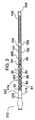
第1の実施形態を参照すると共に図1を参照すると、両方向の同軸偏向可能なマイクロカテーテルが図示されており、このマイクロカテーテルは、全体が参照符号10で示されている。カテーテル10は、内側カテーテル(内側部材)12、外側カテーテル(外側部材)24及び偏向可能な先端部を備えた遠位部分48を有する。 Referring to the first embodiment and with reference to FIG. 1, a microcatheter capable of coaxial deflection in both directions is illustrated, which is generally designated by the
内側カテーテル12は、外側カテーテル24に設けられたルーメンを貫通し、この内側カテーテルは、近位端16と遠位端58との間に延びると共に、内側ルーメンを有する薄肉本体又は管14で構成されたカテーテル本体で構成され、この内側ルーメンの直径は、約0.001インチ(0.03mm)から約1.993インチ(50.62mm)までの範囲の直径を有し、好ましい内径は、約0.017インチ(0.43mm)である。ウィング付きハブ20が内側カテーテル本体14の近位端に結合され、このウィング付きハブは、オプションとして提供されるのが良いひずみ逃がし22に嵌められている。ウィング付きハブ(ルアー)20は、プラスチックで作られるのが良い。所望ならば、ウィング付きハブ20は又、サイドアーム中へのアクセサリの挿入又はサイドアームを介する流体注入のための内側カテーテル12の内側ルーメンに通じるチャネルとなるよう回転止血弁(RHV)18を更に備えるのが良い。考えられるアクセサリとしては、例を挙げると、ガイドワイヤ、コイル、ファイバスコープ、鉗子、ビデオカメラ、レーザ又は電気油圧式結石摘出器械、及び照明又はレーザファイバが挙げられる。他のアクセサリも又、チャネル中に挿入することができる。 The
外側カテーテル24は、近位端28と遠位端44との間に延びると共に内側ルーメンを有する薄肉本体又は管26で構成されたカテーテル本体で構成され、この内側ルーメンの直径は、約0.007インチ(0.18mm)から約1.999インチ(50.77mm)までの範囲にある直径を有し、好ましい内径は、約0.027インチ(0.69mm)である。外側カテーテル本体26は又、比較的可撓性の遠位区分42に接合された比較的剛性の近位区分40を備えていることを特徴としている。ウィング付きハブ(ルアー)34が外側カテーテル本体26の近位端に結合されており、このウィング付きハブ34は、オプションとして提供されるのが良いひずみ逃がし38に嵌められている。端キャップ30及びサイドアーム31を備えた回転止血弁(RHV)32がウィング付きハブ34に取り付けられている。端(ロック)キャップ30は、偏向可能なカテーテルのためのロック組立体として働き、サイドアーム31は、潤滑及び場合によっては視覚化のための流体の導入のために用いられる。潤滑は、手技中における内側カテーテル12の相対運動を容易にすることができ、それにより内側カテーテルと外側カテーテルの滑らかな相対運動を保証することによって偏向が容易になる。キャップ30が完全に開かれると、内側カテーテル12は、自由に軸方向に動くことができ、その結果、以下に説明するように遠位先端部48の偏向が生じる。キャップ30を偏向プロセス中の任意の時点で締め付けることができ、それにより内側カテーテル12をクランプしてこれを定位置に保持し、それにより先端部48を定位置にロックすることができる。
内側カテーテル12の偏向可能先端部48は、側方支持管50で覆われており、この側方支持管は、以下に説明する柱状部材を覆っている。支持管50は、図11に示されているようにその近位端46及び遠位端52がくっつけられており、この支持管については以下において説明する。好ましくは、側方支持管50は、螺旋巻き可撓性コイルであり、このコイルの外径は、約0.008インチ(0.20mm)から約2.00インチ(50.80mm)までの範囲にあり、好ましい直径は、約0.034インチ(0.86mm)である。コイルは、ポリマー又は金属材料で作られるのが良いが、好ましい材料は、放射線不透過性が得られるようにするために白金/イリジウムである。側方支持管50の遠位側には、マーカーバンド54が設けられ、このマーカーバンド54は、端56が内側カテーテル10の最も遠位側の端58にくっつけられている。バンド54は、ポリマー又は金属で作られるのが良く、好ましい材料は、放射線不透過性が得られるようにするために白金/イリジウムである。 The deflectable
図2及び図2Aは、偏向可能カテーテル10の内側カテーテル12の一実施形態を示している。上述した内側カテーテル12は、オプションとしてのひずみ逃がし22に嵌まっているウィング付きハブ20及びオプションとしてのRHV18を有している。内側カテーテル12は、カテーテル本体14を更に有し、このカテーテル本体は、好ましくは、外径が約0.002インチ(0.05mm)から約1.994インチ(50.65mm)までの範囲にあり、好ましい直径が約0.023インチ(0.58mm)であり、近位端16と遠位端62との間に延びる距離が約0.5インチ(12.70mm)から約34フィート(1036.32cm)までの範囲にあり、好ましい長さは約110cmのブレード(編組体)補強ポリマー管で構成された剛性の近位区分60を有している。近位区分60は、遠位端が剛性の低い遠位管64に結合され、この遠位管64は、ブレード又はコイル補強ポリマーで構成可能であるが、好ましくは高密度ポリエチレン(HDPE)で構成され、この遠位管64の外径は約0.002インチ(0.05mm)から約1.994インチ(50.65mm)までの範囲にあり、好ましい直径は、約0.022インチ(0.56mm)であり、近位端(近位区分60の遠位端62に隣接して位置する)から遠位端68まで延びるその長さは、約0.5インチ(12.70mm)から約34フィート(1036.32cm)までの範囲にあり、好ましい長さは、約45cmである。組み合わせ状態の近位区分と遠位区分の全体的な利用可能長さは、約0.5インチ(12.70mm)から約34フィート(1036.32cm)までの範囲にあり、連続した内径は、約0.001インチ(0.03mm)から約1.993インチ(50.62mm)までの範囲にあり、好ましい利用可能な長さは、約150cmであり、好ましい内径は、約0.017インチ(0.43mm)である。内側カテーテル本体14は、窓74を備えたレーザ切断管76を更に有し、このレーザ切断管76は、遠位管64にその遠位端70のところで結合されている。レーザ切断管76は、プラスチック又は金属で構成可能であるが、好ましくは、超弾性ニチノールで作られ、このレーザ切断管の内径は、約0.001インチ(0.03mm)から約1.993インチ(50.62mm)までの範囲にあり、好ましい直径は、約0.017インチ(0.43mm)である。レーザ切断管76の外径は、約0.002インチ(0.05mm)から約1.994インチ(50.65mm)までの範囲にあるのが良く、好ましい外径は、約0.022インチ(0.56mm)である。事実切断管の長さは、約0.5インチ(12.70mm)から約34フィート(1036.32cm)の範囲にあるのが良く、好ましい長さは、約1cmである。 2 and 2A illustrate one embodiment of the
内側カテーテル本体14の遠位部分66は、管78を用いて遠位管64に結合されたレーザ切断管76を有し、管78は、好ましくは、接着剤72で被覆されたポリイミド管である。好ましくは、ポリイミド管78の内径は、約0.001インチ(0.03mm)から約1.993インチ(50.62mm)までの範囲にあり、好ましい内径は、約0.0165インチ(0.419mm)である。ポリイミド管78の外径は、約0.002インチ(0.05mm)から約1.994インチ(50.65mm)までの範囲にあるのが良く、好ましい外径は、約0.0175インチ(0.445mm)である。好ましくは、ポリイミド管78の長さは、約0.25mmから約1cmまでの範囲にあるのが良く、好ましい長さは、約3mmである。 The
約0.5インチ(12.70mm)から約34フィート(1036.32cm)までの範囲にある内側カテーテル12の全体的な利用可能長さは、上述の区分(近位管、遠位管及びレーザ切断管)の全てについて別々の材料を有する必要はない。例えば、レーザ切断ニチノール管(又は他の金属又はプラスチック材料、例えばポリイミド)は、この中に設計される近位及び遠位区分について必要な剛性のばらつきを有して良く、その結果、内側カテーテル12に関する上記範囲を満たす適当な内側カテーテル本体が得られる。 The overall usable length of the
図3は、参照符号312より指示された内側カテーテルの変形実施形態を示している。この実施形態では、内側カテーテル本体314は、近位端316から遠位端358まで延びる減摩性内側ライナ82を有している。このライナの目的は、内側カテーテル314内におけるガイドワイヤの運動を助けるよう摩擦係数を減少させるのに役立つことにある。このライナは、例えばポリテトラフルオロエチレン(PTFE)又はフッ素化エチレンプロピレン(FEP)で作られるのが良い。 FIG. 3 shows an alternative embodiment of the inner catheter indicated by
ライナ82は、ルーメン健全性(補強)の保証に役立つと共に剛性の変化を助けるよう連続編組体84、コイル102及びレーザ切断管106の組み合わせで覆われている。平形若しくは丸形ワイヤ又はこれらの組み合わせで構成可能な編組体84は、近位端316から遠位端398まで延びている。編組体は、ステンレス鋼、ニチノール、ポリマー、繊維のような材料又はそれどころかこれら材料の組み合わせで構成可能である。平形又は丸形ワイヤで構成可能なコイル102は、近位端316から遠位端398まで延びている。コイル102は、例えばステンレス鋼、ニチノール、白金/イリジウム又はそれどころかポリマーのような材料で構成可能である。レーザ切断管106は、近位端104から遠位端358の直ぐ近くまで延びている。レーザ切断管106は、ニチノール又は他の金属であっても良く、或いは、マイクロルーメン(MicroLumen)社(フロリダ州オールズマー所在)製のポリイミド又は別のポリマーから切断形成されても良い。 The
補強層は、3つの別々の区分、即ち、近位区分86、中間区分90及び遠位区分96を作るよう様々な剛性を備えたポリマーで覆われている。近位区分86は、近位端316から遠位端362まで遠位側に延びている。中間区分90は、端362から遠位端94まで遠位側に延びている。遠位区分96は、端94から遠位端358まで延びている。剛性は、近位区分86から遠位区分96まで減少している。剛性の減少は、近位側から遠位側まで材料のデュロメータの減少を用いることによって達成できる。好ましくは、近位区分86は、デュロメータが60Dから75Dまでの範囲にあるナイロン若しくはピーバックス(pebax )であっても良く、或いは、相対デュロメータ硬度の値が約72Dの任意他の材料であっても良い材料88を用いて形成されるのが良く、中間区分90は、デュロメータが約63Dの硬度の低い材料92を用いて形成されるのが良く、遠位区分96は、硬度が更に低い材料100、例えば、デュロメータが25D〜55Dのペレタン(pellethane)又はデュロメータが25D〜40Dの他の材料で形成されるのが良い。これらは、使用できる材料及びデュロメータの例であるに過ぎない。また、各区分は、単一の材料層で形成される必要はなく、所望ならば、これら区分は、2つ又は3つ以上の層で構成できる。実際の材料の選択は、可撓性及び剛性に関する設計上の要望に基づくことになる。コイル又は編組体の追加の層も又、必要に応じて追加可能である。 The stiffening layer is covered with a polymer of varying stiffness to create three separate sections, a
次に、リフロープロセス(熱)を用いてこれら層を互いに融着させる。次に、ひずみ逃がし322及びウィング付きハブ320を追加する。最後に、オプションとして、内側カテーテルの外周部を所与の長さについて親水性被膜108で被覆するのが良い。この被膜の目的は、偏向プロセス中、外側カテーテルに対する内側カテーテルの軸方向運動を助けることにある。被膜が水素を必要とする場合、外側カテーテル10に取り付けられたRHV32に設けられているサイドアーム31を通って液体を注入するのが良い(図1参照)。 The layers are then fused together using a reflow process (heat). Next, a
上述したように、代表的なマイクロカテーテルは、熱により層の全てを互いに融着させるリフロー技術を用いて、必要ならば、取り外し可能な熱収縮管を用いて形成される。内側カテーテル(又は外側カテーテル)の長さが180cmを超えるまで増大するので、これは、現行の機器制限に起因して問題となる場合がある。別の方法は、近位区分、中間区分、及び遠位区分を作るのに様々な剛性の取り外しできない熱収縮管を用いることである。また、図3は、編組体84、コイル102、及びレーザ切断管106が近位区分、中間区分、又は遠位区分のいずれかの中で停止し又は開始する状態を示しているが、これらコンポーネントの各々は、これよりも長くても良く又は短くても良く、その結果、図示した箇所とは異なる箇所で終端し又は開始する。 As mentioned above, a typical microcatheter is formed using a reflow technique in which all of the layers are fused together by heat and, if necessary, a removable heat shrink tube. This can be a problem due to current instrument limitations, as the length of the inner catheter (or outer catheter) increases to over 180 cm. Another method is to use various rigid non-removable heat shrink tubes to make the proximal, middle and distal sections. FIG. 3 also shows the
図4は、全体が参照符号312で示された内側カテーテルの別の実施形態を示している。内側カテーテル本体314′の構造は、レーザ切断管106について長い連続コイル102′が設けられていることを除き、図3の構造とほとんど同じである。マーカーバンド110が設けられている。マーカーバンド110は、透視検査下で視覚化を助ける白金/イリジウム又は他の金属若しくはプラスチックで作られるのが良い。バンド110は、図示した中実管以外のコイル又はそれどころか設計から省かれたコイルで作られても良い。カテーテルの残りの構造は、図3の場合と同じであり、従って、同一の部分を示すために同一の参照符号が用いられている。 FIG. 4 illustrates another embodiment of the inner catheter, generally designated by
内側カテーテルの別の実施形態が図5に示されている。この実施形態では、内側カテーテル本体412は、近位端114(遠位区分415に隣接して位置している)から遠位端458まで延びるレーザ切断螺旋区分116を有する単一のステンレス鋼又はニチノールハイポチューブ(又は変形例として、プラスチック又はポリイミド)で作られている。必要ならば、内側カテーテル本体414の近位端部は、表面模様付き、例えば軸方向刻み付き、輪郭又は筋付き又はそれどころか追加の層を備えるのが良く、或いは、押し/引き及びロックを助けるよう追加された垂直の特徴部を備えるのが良い。カテーテル412は、近位端416のところに位置するひずみ逃がし422及びウィング付きハブ420を有する。他の実施形態の場合と同様、軸方向運動及び曲げに起因した螺旋コイルの引き伸ばし又は位置合わせ不良を制限するために図5の実施形態にオプションとしての外側収縮管又はポリマー層及び/又は内側減摩性層が追加されるのが良い。 Another embodiment of the inner catheter is shown in FIG. In this embodiment, the
次にマイクロカテーテルの外側カテーテル構造を参照すると共に最初に図6を参照すると、この図は、偏向可能なカテーテル10の外側カテーテル24の一実施形態を示している。この実施形態では、上述したように、外側カテーテル本体26は、RHV32を有し、ロック用キャップ30及びサイドアーム31がウィング付きハブ34に取り付けられている。ウィング付きハブ34は、ひずみ逃がし38に嵌められており、これら両方は、カテーテル本体26に結合されている。 Reference is now made to the outer catheter structure of the microcatheter and initially with reference to FIG. 6, which shows one embodiment of the
外側カテーテル本体26は、近位端28から遠位端44まで延びていて、内径が約0.007インチ(0.18mm)から約1.999インチ(50.77mm)の範囲内にあり、好ましい内径が約0.27インチ(6.86mm)の減摩性ライナ128を有している。ライナ128の目的は、外側カテーテル内周部と内側カテーテル外周部との間の摩擦係数を減少させることによって偏向プロセス中における内側カテーテルの運動を助けることにある。ライナは、例えばポリテトラフルオロエチレン(PTFE)又はフッ素化エチレンプロピレン(FEP)のような材料で作られるのが良い。 The
ライナ128は、近位端28から遠位端44まで延びる連続開ピッチのコイル130の補強層で覆われている。コイル130は、平形又は丸形ワイヤで作られるのが良い。コイル130は、例えばステンレス鋼、ニチノール、白金/イリジウム又はそれどころかポリマー若しくは繊維のような材料で作られても良い。また、コイル130は、外側カテーテル本体26の全長について開ピッチ又は連続長さのものである必要はない。例えば、遠位端部は、放射線不透過性の或る特定の長さを有する必要のある場合があり、従って、白金/イリジウムコイルを必要とする。安価に保つため、放射線不透過性を必要とする区分のみが白金/イリジウムであって良く、本体の残部は、安価なコイル、例えばステンレス鋼のコイルで覆われても良い。 The
補強層は、3つの別々の区分、即ち、近位区分118、中間区分120及び遠位区分122を作るよう様々な剛性を備えたポリマーで覆われている。近位区分118は、近位端28から遠位端124まで遠位側に延びている。中間区分120は、近位区分118の遠位端124から遠位端126まで遠位側に延びている。遠位区分122は、中間区分120の遠位端126から遠位端44まで延びている。剛性は、近位区分118から遠位区分122まで減少している。剛性の減少は、近位側から遠位側まで材料のデュロメータの減少を用いることによって達成できる。例えば、近位区分118は、材料132を用いて作られるのが良く、この材料は、デュロメータが60Dから75Dまでの範囲にあるナイロン若しくはピーバックスであっても良く、或いは、相対デュロメータ硬度の値が約72Dの任意他の材料であっても良く、中間区分120は、デュロメータが約63Dのデュロメータの小さい材料134を用いて形成されるのが良く、遠位区分122は、硬度が更に低い材料136、例えば、デュロメータが25D〜55Dのペレタン材料又はデュロメータが25D〜40Dの他の材料で形成されるのが良い。これらは、使用できるデュロメータの例示に過ぎず、と言うのは、実施の材料の選択は、可撓性と剛性のバランスを最適化するよう加減可能だからである。次に、選択された層を熱を用いて互いに融着させる。変形例として、外側カテーテル本体全体は、例えばHDPE、LDPE、ナイロンポリイミド又はポリウレタンのような材料で作られた単一デュロメータ管で構成されても良い。減摩性ライナ及び補強コイル又は編組体も又、オプションとして、この管に追加されても良い。必要ならば、次に、接着剤又は1本若しくは2本以上の熱収縮管を用いて外側カテーテル本体26の長さに沿って1つ又は2つ以上のルーメン(運搬又はバルーンインフレーションのため)を平行に追加するのが良く、かかる接着剤又は熱収縮管は、除去されても良く、除去されなくても良く、そして様々なデュロメータを有して良い。次に、ウィング付きハブ34、ひずみ逃がし38及びロック用キャップ30及びサイドアーム31を備えたRHV32を追加する。 The reinforcing layer is covered with a polymer of varying stiffness to create three separate sections, a
外側カテーテル26に関する最終の使用可能な長さは、約0.5インチ(12.70mm)から約34フィート(1036.32cm)までの範囲にあるのが良く、好ましい使用可能長さは、約135cmである。近位側の外径は、約0.008インチ(0.20mm又は0.61Fr)から約2.00インチ(50.80mm又は152Fr)までの範囲にあるのが良く、好ましい近位側の外径は、約1mm(3Fr)であり、好ましい遠位側の外径は、約0.93mm(2.8Fr)である。 The final usable length for the
外側カテーテル本体26は、マーカーバンド138を更に有し、このマーカーバンドは、外側カテーテル本体26の遠位端のところで内周部中へ中程まで挿入される。好ましくは、マーカーバンド138の長さは、約0.005インチ(0.13mm)から約1インチ(25.40mm)までの範囲にあり、好ましい長さは、約0.039インチ(0.99mm)であり、内径は、約0.0065インチ(0.165mm)から約1.9985インチ(50.762mm)までの範囲にあり、好ましい内径は、約0.0265インチ(0.673mm)である。外径は、約0.0075インチ(0.191mm)から約1.9995インチ(50.787mm)までの範囲にあり、好ましい外径は、約0.0285インチ(0.724mm)である。マーカーバンド138は、金属又はポリマーの管又はコイルで作られるのが良く、好ましい材料は、白金/イリジウムである。 The
カテーテル10は、柱状部材、例えばワイヤ又は管を有し、この柱状部材は、外側カテーテル24の遠位側に延び、内側カテーテルに取り付けられると共に柱状部材の側方運動を制限するよう制限(支持)管によって包囲されている。一実施形態では、柱状部材は、柱140を含み、この柱140は、その近位端部がマーカーバンド138に載っており、又は変形例としてマーカーバンド138の長さに沿って切断形成されたスロット内に嵌められている。柱140の近位部分も又、外側カテーテル本体26の遠位端のところで内周部内に、即ちカテーテル本体壁内に挿入される。次に、接着剤146を追加して部品を定位置に固定する。好ましくは、柱140は、実質的に長方形の断面を有し、その厚さは、約0.0005インチ(0.013mm)から約0.5インチ(12.70mm)までの範囲にあり、好ましい厚さは、約0,002インチ(0.05mm)である。幅は、約0.0005インチ(0.013mm)から約1.95インチ(49.53mm)までの範囲にあるのが良く、好ましい幅は、約0.005インチ(0.13mm)である。柱は、0.25mmから10cmまでの範囲の長さを有するのが良く、好ましい長さは、約8mmである。柱の好ましい断面は、長方形であるが、他の形状、例えば長円形を用いることができる。非円形の断面が所望の方向における曲げを行わせる上で好ましい。好ましい実施形態では、柱は、偏向平面を制御するために実質的に長方形のワイヤ又は平形リボンの形態をしている。また、運動に影響を及ぼすために柱に切れ目又は他の特徴部を追加するのが良い。例えば、切れ目の間隔及び/又は数は、これが可撓性に影響を及ぼすことになるので運動に影響を及ぼすことになる。壁の厚さ及び寸法も又、可撓性及び運動に影響を及ぼすことになる。柱は、任意の金属又は金属合金、それどころかプラスチックで構成可能であるが、好ましい材料は、超弾性ニチノールである。注目すべきこととして、柱140は、外側カテーテル遠位端から遠位側に延びる。
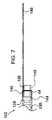
外側カテーテル24の遠位部分142は、フレア144(図7)を備えた遠位端部44を有し、マーカーバンド138を外側カテーテル本体26中にほぼ中程まで挿入することができ、後には部分長さがリップ148を作るよう露出された状態で残される。次に、柱140を減摩性ライナ128とマーカーバンド138(これは、柱を受け入れるスロットを備えても良く、或いは備えなくても良い)との間に挿入し、ついには、その近位端がマーカーバンド138の近位端とほぼ面一をなすようにする。次に、接着剤146を塗布してこれら部分の全てを接合する。 The
2つの別々の部品として挿入される柱140及びマーカーバンド138の代替手段として、これら2つは、所望ならば単一のニチノール管(レーザ切断)で構成されても良く、又はサブアセンブリとして取り付け、次に挿入しても良い。外側管の製造中、マーカーバンドと柱の組立体を追加しても良く、この場合、減摩性ライナ上をこれに沿ってマーカーバンド138を滑らせる。 As an alternative to the
偏向可能なカテーテル10の外側カテーテルの変形実施形態が図8に示されており、この変形実施形態は、参照符号524で示されている。この実施形態では、コイル130に代えて、近位ハイポチューブ550が用いられており、この近位ハイポチューブは、遠位編組体552に突き合わされ又は取り付けられた螺旋切れ目を備えている。これら部品に関する長さは、部品に必要な所要の可撓性及び剛性に応じて様々であって良い。螺旋切れ目付きハイポチューブ550は、ステンレス鋼、ニチノール、ポリマー又はこれらの組み合わせで構成されるのが良い。同様に、編組体も又、ステンレス鋼、ニチノール、ポリマー、繊維又はこれらの組み合わせで構成されるのが良い。カテーテル524の残りのコンポーネントは、図6のカテーテル24と同一であり、従って、これらには同一の参照符号が付けられている。 An alternative embodiment of the outer catheter of the
図2〜図8を比較参照することにより、内側カテーテル本体14と外側カテーテル本体526は、所望ならば、同一の材料及び方法を用いて製作できることが理解できる。したがって、長さ及び直径を除き、単一の設計又は提案された設計の組み合わせを用いて両方の構造体を構成できることが可能である。 By comparing FIGS. 2-8, it can be seen that the
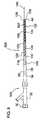
図9は、内側カテーテル12及び外側カテーテル24を示し、柱140が遠位部分150のところで整列状態で取り付けられている。製作にあたり、内側カテーテル12を外側カテーテル24内に挿入し、ついには、レーザ切断管76の遠位端58が柱140の遠位端と面一をなすようにする。次に、レーザ切断管76を回し、ついには、コネクタ又はリブ80が柱140と約90°の位相外れ状態にして(横方向平面内に位置し、柱140の下には位置しないようにする)、所望の平面内における偏向を行わせる。遠位端の整列は、配向のための回転前又は回転後に行われるのが良い。 FIG. 9 shows the
内側カテーテル12と外側カテーテル24を整列させ、マーカーバンド54及び接着剤又ははんだ継手56が遠位部分150のところに位置した状態で互いに接合する(図10参照)。好ましくは、マーカーバンド54は、約0.005インチ(0.13mm)から約1インチ(25.40mm)までの範囲にある長さを有し、好ましい長さは、約0.039インチ(0.99mm)であり、その内径は、約0.0065インチ(0.165mm)から約1.9985インチ(50.762mm)までの範囲にあり、好ましい内径は、約0.0265インチ(0.673mm)である。外径は、約0.0075インチ(0.191mm)から約1.9995インチ(50.787mm)までの範囲にあり、好ましい外径は、0.0285インチ(0.724mm)である。マーカーバンドは、金属又はポリマー管若しくはコイルで作られるのが良く、好ましい材料は、白金/イリジウムである。一変形構成例として、リップ148、柱140、及びマーカーバンド54は全て、ニチノール、ステンレス鋼又は他の適当な材料で作られた単一のレーザ切断部品で構成されるのが良い。別の変形構成例として、柱140は、サブアセンブリとしてマーカーバンド138及びマーカーバンド54にはんだ付けされても良い。別の変形構成例では、はんだ、グルー、レーザ(材料で決まる)で形成された継手又はバンドを必要としない他の接合プロセスを用いて柱140及びレーザ切断管76を遠位端のところで互いに接合しても良い。 The
柱140及び内側カテーテル12の遠位端(これら遠位端は、ほぼ面一の状態をなしている)の整列のための好ましい実施形態が図10に示されている。変形例として、柱140が取り付けられた外側カテーテル24を内側カテーテル12に沿って近位側に引き戻しても良く、後には、内側カテーテル本体14の一部分が露出状態で残される(柱の覆いなしで)。次に、マーカーバンド54をカテーテル本体14の遠位端、即ち管80上でこれに沿って滑らせ、次に柱140上でこれに沿って滑らせ、ついには、その遠位縁が柱140の遠位端と整列するようにする。次に、継手56を形成するのが良い。このセットアップにより、器具の曲げ半径は、柱長さのほぼ半分の状態のままであり、他方、カテーテル遠位先端部の断面輪郭は、内側カテーテルの外側遠位先端部直径まで減少する。注目すべきこととして、調節は、可撓性及び被覆が得られるよう遠位管80(即ち、レーザ切断管)に対して行わなければならない場合がある。 A preferred embodiment for alignment of the
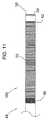
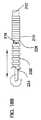
図11は、側方支持管50が定位置にある状態の遠位部分150を示しており、この側方支持管50は、マイクロカテーテルの偏向方法及びシステムを提供するよう柱のためのカバーを形成している。好ましくは、側方支持管50は、リップ148に嵌まっており、この側方支持管は、外径が約0.008インチ(0.20mm)から約2.00インチ(50.80mm)までの範囲にあり、好ましい外径が約0.034インチ(0.86mm)であり、内径が約0.007インチ(0.18mm)から約1.999インチ(50.77mm)までの範囲にあり、好ましい内径が約0.030インチ(0.76mm)である白金/イリジウムで作られた閉ピッチ螺旋巻き可撓性コイルである。好ましい長さは、約1mmから約12cmまでの範囲にあるのが良く、好ましい長さは、約6.5mmである。コイルは、任意の金属又はプラスチックで構成でき、このコイルは、開ピッチ付き又は開ピッチと閉ピッチの組み合わせであっても良く、オプションとして、中実可撓性補強管を形成するようプラスチックで被覆される。側方管支持体(カバー)50は、プラスチック材料、例えばHDPE、LDPE、CFlex、ラテックス、シリコーン、ピーバックス、ナイロン、ポリウレタン又はポリイソプレンで作られた中実管(これは、レーザ切断されても良く、或いはそうでなくても良い)で作られても良い。中実管が用いられる場合、ドレナージ穴を側方支持管又はそれどころか外側カテーテル本体に設けるのが良く、それによりサイドアーム31を通って導入された流体が流出できるようにするのが良い。遠位部分150は、側方支持管50を定位置にくっつける2つの継手46,52を更に有する。別のオプションとして、側方支持管50は、マーカーバンド54の遠位端部を被覆し又はリップ148の近位端を越えて延びるよう作られても良く、その結果、側方支持管50は、外側カテーテル24の外側本体26に直接嵌まり又は側方支持管50を外側本体26の遠位端部中にレーザ切断できるようになる。 FIG. 11 shows the
側方支持管50及びその継手の追加により、偏向可能なカテーテル組立体が完成される。この時点で、カテーテルの外周部は、親水的に被覆されるのが良く、或いは必要ならば、アクセサリ、例えばビデオカメラ、光ファイバ、又はインフレート可能なバルーンのための追加のルーメン(上述したようなルーメン)を外側シャフトに追加するのが良い。これは、接着剤及び/又は様々なデュロメータの収縮管で達成できる。取り付けが行われる場合、親水性被膜を最終ステップとして被着させる。 The addition of the
図12Aは、螺旋切れ目付き先端部156(図5の螺旋切れ目付き管に類似している)が側方支持管50が設けられていない状態で軸方向引張荷重下にある状態で内側カテーテル12の端部に取り付けられた遠位部分150を示している。内側カテーテル本体14が荷重154により近位側の方向に軸方向に引かれると、内部構造体は、短くなる傾向があり、それにより柱140が圧縮される。図12Bは、側方支持管50が設けられていない状態で内側カテーテル本体が荷重155により遠位側の方向に軸方向に押されたときの作用効果を示している。図示のように、これは、モーメントを柱の端部に加え、それにより柱が曲がる。柱140の寸法、例えば断面寸法を変化させることにより、注目すべきこととして、柱140を動かすのに必要な荷重154(又は155)を増減することができる。例えば、例えば大きな断面寸法により形成される剛性の柱は、変形するのにより大きな力を必要とし、従って、偏向するのに大きな力を必要とし、これは、或る特定の場合には有利であると言え、例えば、高い安定性が曲げられた先端部に与えられる。 FIG. 12A shows the
図13A及び図13Cは、側方補強(支持)管50が提供された場合に軸方向引張荷重154を受けた遠位偏向可能先端部48を示している。側方支持管50が定位置にあり、軸方向引張荷重154が加えられた状態で、柱140は、管50による柱の補強に起因してもはや軸方向に圧縮状態になることはない。その結果、主(ガイドワイヤ)ルーメンを含む遠位先端部全体が偏向する。注目すべきこととして、柱140を圧縮することができず、先端部が偏向するので、柱140は、動いて壁に当たる。上述したように、下に位置する柱140の寸法(又は、材料若しくは切れ目)を変化させることにより、遠位先端部を偏向させる荷重154を増減することができる。しかしながら、柱が薄すぎる場合、柱は、不安定になり、それにより荷重を受けて多数の座屈箇所が生じる。この結果、先端部の偏向がほとんどない状態から全くない状態が生じる。 13A and 13C show a distal
図13B及び図13Dは、側方支持管50が設けられている場合に内側カテーテル本体が荷重155によって遠位側の方向に軸方向に動かされたときの作用効果を示している。図示のように、これは、図12Bに示されているように遠位先端部を曲げる。注目されるべきこととして、柱140は、動いて管50の壁に当たる。 FIGS. 13B and 13D show the operational effects when the inner catheter body is moved axially in the distal direction by the
注目されるべきこととして、上述すると共に図12A〜図13Dに示されている運動は、図示のようにそれぞれ近位側又は遠位側への内側カテーテルの運動である。同じ作用効果は、外側カテーテルのそれぞれの遠位側又は近位側への運動によって達成される。所望の方向における内側カテーテルと外側カテーテルの両方の運動も又想定される。 It should be noted that the motion described above and shown in FIGS. 12A-13D is the motion of the inner catheter proximally or distally, respectively, as shown. The same effect is achieved by the respective distal or proximal movement of the outer catheter. Movement of both the inner and outer catheters in the desired direction is also envisioned.
内側カテーテル12と外側カテーテル24との間の回転を最小限に抑えるための回転制御部材158が図14に示されているように提供されるのが良い。回転制御部材158は、継手170により内側カテーテル本体14に固定的に取り付けられている。回転制御部材158に設けられた平坦な区分168は、平坦な区分166と共に働き、この平坦な区分166は、外側カテーテル本体26に設けられた凹み164によって形成され、それにより互いに対するカテーテルの回転又はトルク掛けが制御されるようになっている。回転制御部材158は、近位リップ160を更に有し、この近位リップ160は、これが凹み164に設けられている肩162に接触したときの軸方向停止部として働く。回転制御部材158は、好ましくは、ステンレス鋼で作られるが、任意の金属又はプラスチックを使用することができる。長さは、約1インチ(25.4mm)から約24フィート(731.52cm)までの範囲にあるのが良く、好ましい長さは、約100cmである。多数の短い回転部材も又使用でき、これら回転部材は、内側カテーテル本体14の外周部に沿う種々の箇所に配置されるのが良い。平坦な区分166も又、ハイポチューブに直接形成されるのが良く、このハイポチューブは、内側カテーテル本体14のための近位シャフトを兼ねるのが良い。 A
マイクロカテーテルは、遠位偏向先端部を図15に示されているように操作してロックするためのロック組立体172を有するのが良い。ボタン174の係合により、内側カテーテル12を外側カテーテル24に対して軸方向に引き又は押すことができ、その結果、遠位先端部が偏向する。偏向後の形状をいったん決定すると、ボタンを解除して形状を固定する。ボタンは又、抑制(ロック)することができ、その結果、先端部をカテーテル前進により自由に再造形することができる。変形例として、ボタンを押したままで外側カテーテル24を内側カテーテル12に対して動かしても良く、それにより、これ又偏向が生じる。内側カテーテルの運動を助けるために内側カテーテルと外側カテーテルとの間に潤滑が必要な場合、ロック組立体172のサイドアーム176を通って流体、例えば生理的食塩水又は造影剤を注入するのが良い。潤滑が必要でない場合、設計からサイドアーム176を除いても良い。 The microcatheter may have a locking
マイクロカテーテル178のための別のロック組立体が図16に示されている。ロック組立体172は、遠位偏向先端部を操作してロックするよう設計されており、このロック組立体には回転制御システム180が組み込まれている。回転制御システム180は、内側カテーテル本体の上に位置すると共に、遠位停止部184及び近位停止部186を作るよう一領域が平べったくされたステンレス鋼製のハイポチューブ182及び長円形の又は平べったくされたハイポチューブ188を含み、このハイポチューブ188は、RHVハウジング内に嵌まるようにするために管188の上に位置したステンレス鋼製ハイポチューブ188にはんだ付けされている。平べったくされた管は、回転を阻止するよう設けられている。グルー192がハイポチューブ188組立体をハウジング内の定位置にロックするために用いられている。ロック組立体は、内側カテーテル本体194上でこれに沿って滑らされて定位置に接着されている。隙間196がハイポチューブ182の遠位側に残されており、その結果、ハイポチューブ182を遠位側に押すと、偏向を生じさせることができるようになっている。取っ手が内側カテーテルの軸方向運動をロックするためのねじ組立体なしで示されているが、かかる組立体を所望ならば近位取っ手に追加しても良い。 Another locking assembly for the
使用にあたり、ステンレス鋼製ハイポチューブ182は、近位側に動くと共に縁側に軸方向に動き、ついには、停止部184,186に達するようになる。回転は、ハイポチューブ182に設けられた平べったくされた領域及びこのハイポチューブが挿通状態で自由に動くことができるようにする長円形ハイポチューブ188により制限されることになる。この回転制御に関する技術的思想を全長にわたるガイドワイヤルーメンを備えた偏向可能なマイクロカテーテル設計又は迅速交換ポートを備えた偏向可能なマイクロカテーテルについて利用することができる。一般に、この回転制御設計を回転がほとんどなく又は全くない状態の純粋に軸方向の運動を必要とする任意の設計に利用することができる。加うるに、この設計は、平べったくされたハイポチューブを用いているが、この技術的思想を例えば回転止血弁(RHV)のような部品に射出成形すると、製造を迅速に実施することができる。 In use, the
図17は、迅速交換ポート200を備えた同軸両方向マイクロカテーテル198を示している。迅速交換ポートの目的は、追従のためにカテーテルの内側ルーメンの側部を通ってガイドワイヤを配置することができるようにすることにある。迅速交換ポートは、カテーテルの偏向区分(D)の近位側のどこかの場所に配置しても良い。正確な配置は、設計に用いられる曲げ半径で決まることになる。幾つかの実施形態では、交換ポート200は、遠位先端から6mmのところに位置するのが良いが他の距離も又想定される。また、内側カテーテルに切断形成できる迅速交換ポートの長さは、幾つかの実施形態では、ガイドワイヤが定位置に位置した状態で偏向を許容するよう外側カテーテルに設けられた切れ目よりも長いものであって良い。しかしながら、外側カテーテル及び内側カテーテルは又、同一の長さに切断されても良く、或いは、外側カテーテルは、内側カテーテルよりも長く切断されても良い。内側カテーテルと外側カテーテルは、互いに対して動くので、迅速交換ポートも又、偏向を許容するよう互いに対して動くことができなければならない。ガイドワイヤ又は他の器具が偏向されない場合、迅速交換ポートを偏向区分Dに配置するのが良い。 FIG. 17 shows a coaxial
この実施形態は、器具の近位端部を通る他の器具の導入を可能にする。一例として、ノースゲート・テクノロジーズ・インコーポレイテッド(Northgate Technologies, Inc.)(イリノイ州所在)により製造された電気油圧式結石摘出(EHL)器械204がRHV202から延びた状態で示されている。挿入のための他の考えられる器具としては、例えば、生検プローブ、ガイドワイヤ又はレーザファイバが挙げられる。 This embodiment allows for the introduction of other instruments through the proximal end of the instrument. As an example, an electrohydraulic stone extraction (EHL)
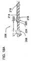
図18A及び図18Bは、遠位先端部偏向機構体206の変形実施形態を示している。この設計により、コンポーネントが取り付けられた内側シャフトが外側カテーテルに対して回転するとともに360°偏向することができる。これは、柱を外側カテーテルに取り付けなくても達成され、かくして、柱は、延びて両方のカテーテルを取り付けることはない。外側カテーテル208、外側コイル210、及びバンド212の一部分L1が内部構造を示すよう図18Aでは省かれている。柱214は、先の設計例の場合と同様に遠位バンド216及び近位バンド218に取り付けられているが、柱の一区分は、近位側に続き、ここで、柱は、外側カテーテル208の内側に定位置に接着されるバンド220の下に通る。停止部222が柱の近位端部のところに取り付けられている。この形態により、柱は、これにトルクが加えられると、内側カテーテル本体及び取り付けコンポーネントと一緒に回ることができるようになる。 18A and 18B show a modified embodiment of the distal
図18Bは、外側カテーテル208、遠位外側コイル210及びバンド212が定位置に設けられて使用状態にある遠位先端部偏向機構体206を示している。内側カテーテル224を回転させることができ、それにより今や内側カテーテルの一部である柱が回転し、それにより360°の偏向が可能である。というのは、柱が任意の平面内で偏向することができるからである。外側カテーテル208を前進させ又は内側カテーテル224を引っ込めると、外側カテーテル208は、端226に接触し、それ以上の運動により、先端部が偏向することになる。外側カテーテルを近位側に引き又は内側カテーテル224を前進させた場合、停止部222は、外側カテーテルに接触し、運動の続行により、カテーテルは、逆方向に偏向することになる。(内側カテーテルの前後の運動によっても、偏向が生じることになる。) FIG. 18B shows distal
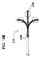
幾つかの実施形態では、バルーン232、例えば血管形成術用バルーンが偏向可能なマイクロカテーテルの遠位部分に設けられるのが良い。図19Aの実施形態では、バルーン232は、偏向遠位先端部230の近位側に設けられている。図19Bの実施形態では、偏向可能マイクロカテーテルの遠位先端部分234は、偏向遠位先端部238の遠位側に設けられたバルーン236を有している。他の考えられるオプションとして、例えば、バルーンを偏向ゾーンの中間に又は正に遠位端部のところに設けることが挙げられる。 In some embodiments, a
注目すべきこととして、本明細書において提供された寸法及び範囲は、例示として与えられており、本明細書において説明したコンポーネントについての他の寸法及び範囲も又想定できることは言うまでもない。 It should be noted that the dimensions and ranges provided herein are given by way of example, and it will be appreciated that other dimensions and ranges for the components described herein can also be envisaged.
本発明のカテーテルの偏向を次のように要約することができる。同軸マイクロカテーテルの遠位先端部の両方向偏向を2つの別々の動き、即ち、軸方向引張偏向及び軸方向押し偏向に分解することができる。軸方向引き偏向を偏心荷重が加えられる柱としてモデル化することができ、軸方向押し偏向を偏心荷重が加えられるビームとしてモデル化することができる。 The deflection of the catheter of the present invention can be summarized as follows. Bidirectional deflection of the distal tip of the coaxial microcatheter can be broken down into two separate movements: axial tensile deflection and axial push deflection. The axial pull deflection can be modeled as a column to which an eccentric load is applied, and the axial push deflection can be modeled as a beam to which an eccentric load is applied.
軸方向引き偏向に関し、カテーテルの遠位端部に側方支持管が設けられていない場合、長方形のニチノールワイヤ(又は別の柱部材構造体、例えば上述したロッド)は、無支持の偏心荷重が加えられる柱としてモデル化される。このことは、内側カテーテルを力Pで近位側の方向に軸方向近位側に動かすと、柱(長方形のニチノールワイヤ)の遠位端部は、その近位端部に向かって軸方向に動く傾向があり、その結果、ニチノールワイヤの圧縮(座屈)が生じることを意味する。これは、図12Aに示されており、図12Aは、本発明の先端部の技術的思想を説明するために側方支持管が設けられていない状態で柱140の運動を示している。側方支持管(例えば、コイル)が設けられた状態で、内側カテーテルが力Pで近位側の方向に軸方向に引かれると、柱(例えば、長方形ニチノールワイヤ)は、軸方向に圧縮状態(座屈状態)になろうとするが、これは、例えば、側方補強(支持)管50によって制限されることになる。先端部がもはや軸方向にもはや屈従する(圧縮状態になる)ことがないので、先端部は、側方に屈従する(偏向する)(図13A及び図13Cを参照されたい)。理解されるべきこととして、内側カテーテルの軸方向近位側への運動について説明する。しかしながら、理解されるべきこととして、外側カテーテルの遠位側への運動は、同一の作用効果を達成する。したがって、本明細書で用いられる「相対運動」という用語は、外側カテーテルに対する内側カテーテルの運動、内側カテーテルに対する外側カテーテルの運動、又は互いに対する逆方向への両方のカテーテルの運動を含む。 With respect to axial pull deflection, when no side support tube is provided at the distal end of the catheter, the rectangular nitinol wire (or another column member structure, such as the rod described above) is subject to unsupported eccentric loads. Modeled as an added pillar. This means that when the inner catheter is moved axially proximally with force P in the proximal direction, the distal end of the column (rectangular nitinol wire) is axially directed toward its proximal end. It means that there is a tendency to move, resulting in compression (buckling) of the Nitinol wire. This is illustrated in FIG. 12A, which shows the movement of the
軸方向押し偏向に関し、側方支持管がカテーテルの遠位端部に設けられていない場合、長方形のニチノールワイヤ(又は別の柱状部材構造体、例えば上述したロッド)は、偏心荷重を受けるビームとしてモデル化される。このことは、内側シャフトが力Pで軸方向に押されると、内側シャフトは、モーメントをビーム(例えば、長方形のニチノールワイヤ)の端部に及ぼし、それによりビームが曲がることを意味している。これは、側方支持管(例えば、コイル)が設けられた図12Bに示されており、内側カテーテルが力Pで遠位側の方向に軸方向に押されると、先端部全体にモーメントが及ぼされ、それにより先端部が図13B及び図13Dに示されているように曲がる(偏向する)ことになる。この場合、コイルの追加によっては、この作用は変わらない。理解されるべきこととして、内側カテーテルの軸方向遠位側の運動について説明する。しかしながら、理解されるべきこととして、外側カテーテルの近位側への運動は、同一の作用効果を達成する。したがって、本明細書で用いられる「相対運動」という用語は、外側カテーテルに対する内側カテーテルの運動、内側カテーテルに対する外側カテーテルの運動、又は互いに対する逆方向への両方のカテーテルの運動を含む。 For axial push deflection, if a side support tube is not provided at the distal end of the catheter, a rectangular nitinol wire (or another columnar structure, such as the rod described above) can be used as a beam subjected to an eccentric load. Modeled. This means that when the inner shaft is pushed axially with force P, the inner shaft exerts a moment on the end of the beam (eg, a rectangular Nitinol wire), which causes the beam to bend. This is shown in FIG. 12B where a side support tube (eg, a coil) is provided, and when the inner catheter is pushed axially in the distal direction with force P, a moment is exerted on the entire tip. As a result, the tip portion bends (deflects) as shown in FIGS. 13B and 13D. In this case, this effect does not change depending on the addition of the coil. As should be understood, the axial distal movement of the inner catheter will be described. However, it should be understood that the proximal movement of the outer catheter achieves the same effect. Thus, the term “relative movement” as used herein includes movement of the inner catheter relative to the outer catheter, movement of the outer catheter relative to the inner catheter, or movement of both catheters relative to each other.
軸方向押し及び引きについてx‐y軸線で考察することができる。軸方向押し及び引きは、x軸上で起こり、曲げ(偏向)は、箇所(x,y)で終わることになる。したがって、先端部が曲がってy1位置に至るようにする柱の圧縮に関し、先端部の遠位端部は、その近位端(−x2)に向かって−x1方向に動いている。 Axial push and pull can be considered in the xy axis. Axial pushing and pulling occurs on the x-axis and bending (deflection) will end at point (x, y). Thus, with respect to the compression of the column that causes the tip to bend to the y1 position, the distal end of the tip is moving in the -x1 direction toward its proximal end (-x2).
かくして、理解できるように、本発明の同軸カテーテル構成では、遠位先端部の偏向は、先行技術の非同軸カテーテルの場合のように遠位先端部を引き下げるのではなく、軸方向運動によって達成される。かくして、カテーテルそれ自体は、偏向技術の並置ワイヤ及びカテーテルとは対照的に、遠位先端部を曲げるために用いられる。換言すると、曲げは、曲げ方向に引くのではなく、軸方向運動によって達成される。本発明の偏向可能カテーテルの構造は、挿入のための減少プロフィールを提供するようカテーテルの全体的サイズ(直径)を減少させるためにスペースを節約する。この構造は又、カテーテルのサイズ(直径)の増大を必要としないで、流体の流れが偏向を促進する(内側カテーテル及び外側カテーテルの相対運動を促進することによって)ためのスペースを提供する。 Thus, as can be appreciated, in the coaxial catheter configuration of the present invention, distal tip deflection is achieved by axial motion rather than pulling down the distal tip as in prior art non-coaxial catheters. The Thus, the catheter itself is used to bend the distal tip, as opposed to the juxtaposed wire and catheter of deflection technology. In other words, bending is achieved by axial movement rather than pulling in the bending direction. The deflectable catheter structure of the present invention saves space to reduce the overall size (diameter) of the catheter to provide a reduced profile for insertion. This structure also provides space for fluid flow to facilitate deflection (by promoting relative movement of the inner and outer catheters) without requiring an increase in the size (diameter) of the catheter.
上述の説明、多くの細部を含むが、これら細部は、本発明の範囲に対して限定として解されてはならず、本発明の好ましい実施形態の例示として解されるに過ぎない。当業者であれば、本明細書に添付された特許請求の範囲に記載された本発明の範囲及び精神に含まれる他の多くの考えられる変形例を想到するであろう。 While the foregoing description includes many details, these details should not be construed as limiting the scope of the invention, but merely as exemplifications of preferred embodiments of the invention. Those skilled in the art will envision many other possible variations that are within the scope and spirit of the invention as set forth in the claims appended hereto.
Claims (20)
Translated fromJapanese近位部分及び遠位部分を備えた外側カテーテルを有し、
前記外側カテーテルから遠位側に延びる細長い柱状部材を有し、
前記外側カテーテルと同軸に位置決めされると共に前記柱状部材に取り付けられた内側カテーテルを有し、前記内側カテーテルは、前記外側カテーテルの遠位側に延び、前記内側カテーテルは、流体を導入するように寸法形状決めされた内側ルーメン、及び、遠位先端部分を有し、
前記柱状部材の軸方向運動を制限するよう前記柱状部材に嵌めた状態で配置された補強部材を有し、前記内側カテーテル又は前記外側カテーテルのうちの一方が他方に対して動かされると、前記柱状部材の軸方向圧縮が前記補強部材によって制限され、前記内側カテーテルの前記遠位端部分は軸方向に屈従することができないため、前記内側カテーテルの前記遠位端部分は、長手方向位置から長手方向軸線から離れる第1の方向に偏向可能であり、かつ、長手方向位置から長手方向軸線から離れる第1の方向と反対側の第2の方向に偏向可能であり、前記柱状部材は、前記補強部材がないときに、その近位端に向かって近位方向に移動しようとして該柱状部材の座屈が生じるように構成されていることによって、前記内側カテーテルの前記遠位先端部分が側方に偏向するようになっている、偏向可能カテーテル。A deflectable tape
Having an outercatheter with a proximal portion and a distal portion;
An elongated columnar member extending distally from the outercatheter ;
An innercatheter which is attached to the columnar member while being positioned on the outercatheter coaxially, said innercatheter extends distally of said outercatheter, the innercatheter isdimensioned so as to introduce the fluid Havinga shaped inner lumen and a distal tip portion;
A reinforcing member disposed in a state of being fitted to the columnar member so as to limit the axial movement of the columnar member, and when one of the innercatheter or the outercatheter is moved with respect to the other, the columnar member Since the axial compression of the member is limited by the reinforcing member and thedistal end portion of the inner catheter cannot bend axially, the distal end portion of the inner catheter is moved longitudinally from a longitudinal position. The columnar member is deflectable in a first direction away from the axis and can be deflected in a second direction opposite to the first direction away from the longitudinal axis from the longitudinal position, and the columnar member is the reinforcing member in the absence, by buckling of columnar members is configured to generate an effort to move toward its proximal end in a proximal direction, the distal of said innercatheter The tip portion is adapted to deflect laterally deflectable catheter.
Applications Claiming Priority (5)
| Application Number | Priority Date | Filing Date | Title |
|---|---|---|---|
| US201261724921P | 2012-11-10 | 2012-11-10 | |
| US61/724,921 | 2012-11-10 | ||
| US14/064,170 | 2013-10-27 | ||
| US14/064,170US9233225B2 (en) | 2012-11-10 | 2013-10-27 | Coaxial bi-directional catheter |
| PCT/US2013/069435WO2014074986A1 (en) | 2012-11-10 | 2013-11-11 | Coaxial bi-directional catheter |
Publications (3)
| Publication Number | Publication Date |
|---|---|
| JP2015533622A JP2015533622A (en) | 2015-11-26 |
| JP2015533622A5 JP2015533622A5 (en) | 2016-12-28 |
| JP6364016B2true JP6364016B2 (en) | 2018-07-25 |
Family
ID=50682395
Family Applications (1)
| Application Number | Title | Priority Date | Filing Date |
|---|---|---|---|
| JP2015541978AActiveJP6364016B2 (en) | 2012-11-10 | 2013-11-11 | Coaxial bidirectional catheter |
Country Status (5)
| Country | Link |
|---|---|
| US (10) | US9233225B2 (en) |
| EP (1) | EP2916903B1 (en) |
| JP (1) | JP6364016B2 (en) |
| CA (1) | CA2890745C (en) |
| WO (1) | WO2014074986A1 (en) |
Families Citing this family (38)
| Publication number | Priority date | Publication date | Assignee | Title |
|---|---|---|---|---|
| US9044575B2 (en)* | 2012-10-22 | 2015-06-02 | Medtronic Adrian Luxembourg S.a.r.l. | Catheters with enhanced flexibility and associated devices, systems, and methods |
| US9549666B2 (en) | 2012-11-10 | 2017-01-24 | Curvo Medical, Inc. | Coaxial micro-endoscope |
| US9233225B2 (en) | 2012-11-10 | 2016-01-12 | Curvo Medical, Inc. | Coaxial bi-directional catheter |
| US10322260B2 (en) | 2013-05-30 | 2019-06-18 | Terumo Kabushiki Kaisha | Treatment method for treating lower limbs using multi-member catheter assembly |
| WO2015095475A1 (en)* | 2013-12-19 | 2015-06-25 | Bendit Technologies Ltd. | Steering tool |
| US9848954B2 (en) | 2013-12-20 | 2017-12-26 | Corbin E. Barnett | Surgical system and related methods |
| WO2015187454A1 (en) | 2014-06-05 | 2015-12-10 | St. Jude Medical, Cardiology Division, Inc. | Medical device with a nested lap joint and a fused conductive element and method for fabricating the same |
| WO2016138443A2 (en) | 2015-02-26 | 2016-09-01 | Stryker Corporation | Surgical instrument with articulation region |
| US10420537B2 (en) | 2015-03-27 | 2019-09-24 | Shifamed Holdings, Llc | Steerable medical devices, systems, and methods of use |
| JP6820864B2 (en) | 2015-04-24 | 2021-01-27 | カリラ メディカル インコーポレイテッド | Manipulable medical devices, systems and usage |
| US10154905B2 (en) | 2015-08-07 | 2018-12-18 | Medtronic Vascular, Inc. | System and method for deflecting a delivery catheter |
| CA2994368A1 (en)* | 2015-08-23 | 2017-03-02 | CardioSert Ltd. | Double concentric guidewire |
| CN108366715A (en) | 2015-11-09 | 2018-08-03 | 施菲姆德控股有限责任公司 | Steering assembly and application method for medical treatment device |
| US10610666B2 (en) | 2015-12-28 | 2020-04-07 | Covidien Lp | Multi-filament catheter |
| CA3009943C (en) | 2016-01-01 | 2020-10-06 | Tractus Vascular, Llc | Flexible catheter |
| US10441748B2 (en)* | 2016-05-16 | 2019-10-15 | Gyrus Acmi, Inc. | Flexible and/or pushable tubular device |
| CN110234295B (en) | 2017-01-20 | 2023-10-24 | W.L.戈尔及同仁股份有限公司 | Embolic filtering system |
| JP7252894B2 (en)* | 2017-02-28 | 2023-04-05 | ボストン サイエンティフィック サイムド,インコーポレイテッド | articulating needle |
| EP3599977A4 (en) | 2017-03-30 | 2020-12-30 | Shifamed Holdings, LLC | Medical tool positioning devices, systems, and methods of use and manufacture |
| US11925427B2 (en) | 2018-02-19 | 2024-03-12 | Gregory P. Schmitz | Biometrically scalable AI designed articulated catheter device |
| US11497889B2 (en) | 2018-08-23 | 2022-11-15 | Nuvera Medical, Inc. | Medical tool positioning devices, systems, and methods of use and manufacture |
| WO2020081814A1 (en)* | 2018-10-17 | 2020-04-23 | W. L. Gore & Associates, Inc. | Embolic filter with flexible coupling |
| EP4344726A3 (en)* | 2018-11-13 | 2024-08-07 | NuVera Medical, Inc. | Medical tool positioning devices |
| US11213309B2 (en) | 2019-05-23 | 2022-01-04 | Biosense Webster (Israel) Ltd. | Medical probe having improved maneuverability |
| EP4013480B1 (en)* | 2019-08-13 | 2025-09-24 | Reflow Medical, Inc. | Support catheter |
| CN114340713B (en) | 2019-09-13 | 2025-02-25 | 史赛克公司 | Image guided surgical system guidewire and method of manufacture and use |
| US20210113813A1 (en)* | 2019-10-17 | 2021-04-22 | Enzian Neurosurgical, Llc | Steerable Neurovascular Guide Catheter |
| WO2021084591A1 (en)* | 2019-10-28 | 2021-05-06 | オリンパス株式会社 | Endoscope |
| EP3982850B1 (en)* | 2019-10-30 | 2024-04-17 | Boston Scientific Scimed, Inc. | Endoscopic catheter device |
| US11938278B2 (en)* | 2020-04-07 | 2024-03-26 | Oscor Inc. | Vascular introducer system with interlocking deflectable guiding catheter sheaths |
| USD1039141S1 (en) | 2020-04-27 | 2024-08-13 | Acclarent, Inc. | Flex section in shaft for ENT instrument |
| EP4240460A4 (en)* | 2020-11-09 | 2024-05-08 | Agile Devices, Inc. | CATHETER CONTROL DEVICES |
| WO2022109034A1 (en)* | 2020-11-18 | 2022-05-27 | Inari Medical, Inc. | Catheters having steerable distal portions, and associated systems and methods |
| US20230052862A1 (en) | 2021-08-12 | 2023-02-16 | Imperative Care, Inc. | Sterile packaging assembly for robotic interventional device |
| US12419703B2 (en) | 2022-08-01 | 2025-09-23 | Imperative Care, Inc. | Robotic drive system for achieving supra-aortic access |
| US20240041480A1 (en) | 2022-08-02 | 2024-02-08 | Imperative Care, Inc. | Multi catheter system with integrated fluidics management |
| US20240181213A1 (en) | 2022-12-01 | 2024-06-06 | Imperative Care, Inc. | Drive table with shuttle |
| US12377206B2 (en) | 2023-05-17 | 2025-08-05 | Imperative Care, Inc. | Fluidics control system for multi catheter stack |
Family Cites Families (284)
| Publication number | Priority date | Publication date | Assignee | Title |
|---|---|---|---|---|
| US3521625A (en)* | 1968-07-17 | 1970-07-28 | John A Mackey | Medical restraint |
| US3903877A (en) | 1973-06-13 | 1975-09-09 | Olympus Optical Co | Endoscope |
| US4245624A (en) | 1977-01-20 | 1981-01-20 | Olympus Optical Co., Ltd. | Endoscope with flexible tip control |
| US4436087A (en) | 1977-12-11 | 1984-03-13 | Kabushiki Kaisha Medos Kenkyusho | Bioptic instrument |
| US4548206A (en) | 1983-07-21 | 1985-10-22 | Cook, Incorporated | Catheter wire guide with movable mandril |
| CA1253932A (en) | 1984-11-01 | 1989-05-09 | Craig Parkinson | Liquid level monitoring assemblies |
| US5470330A (en) | 1984-12-07 | 1995-11-28 | Advanced Interventional Systems, Inc. | Guidance and delivery system for high-energy pulsed laser light |
| CH668691A5 (en) | 1985-05-31 | 1989-01-31 | Alice Dr Med Utz | WIND CLASP. |
| US4699463A (en) | 1985-11-01 | 1987-10-13 | Circon Corporation | Multidirectional viewing borescope |
| US5010876A (en) | 1986-06-02 | 1991-04-30 | Smith & Nephew Dyonics, Inc. | Arthroscopic surgical practice |
| US4723936A (en) | 1986-07-22 | 1988-02-09 | Versaflex Delivery Systems Inc. | Steerable catheter |
| US4796627A (en) | 1986-08-26 | 1989-01-10 | Tucker Wilson H | Clip applicator and spreadable clips for use therein |
| US4719924A (en)* | 1986-09-09 | 1988-01-19 | C. R. Bard, Inc. | Small diameter steerable guidewire with adjustable tip |
| US4927413A (en) | 1987-08-24 | 1990-05-22 | Progressive Angioplasty Systems, Inc. | Catheter for balloon angioplasty |
| US4940062A (en)* | 1988-05-26 | 1990-07-10 | Advanced Cardiovascular Systems, Inc. | Guiding member with deflectable tip |
| US4960134A (en) | 1988-11-18 | 1990-10-02 | Webster Wilton W Jr | Steerable catheter |
| US5480382A (en) | 1989-01-09 | 1996-01-02 | Pilot Cardiovascular Systems, Inc. | Steerable medical device |
| US4878485A (en) | 1989-02-03 | 1989-11-07 | Adair Edwin Lloyd | Rigid video endoscope with heat sterilizable sheath |
| US5257617A (en) | 1989-12-25 | 1993-11-02 | Asahi Kogaku Kogyo Kabushiki Kaisha | Sheathed endoscope and sheath therefor |
| US5152744A (en)* | 1990-02-07 | 1992-10-06 | Smith & Nephew Dyonics | Surgical instrument |
| US5060660A (en)* | 1990-02-28 | 1991-10-29 | C. R. Bard, Inc. | Steerable extendable guidewire with adjustable tip |
| US5040543A (en)* | 1990-07-25 | 1991-08-20 | C. R. Bard, Inc. | Movable core guidewire |
| US5383923A (en) | 1990-10-20 | 1995-01-24 | Webster Laboratories, Inc. | Steerable catheter having puller wire with shape memory |
| US5199417A (en) | 1990-12-21 | 1993-04-06 | Circon Corporation | Endoscope having a deflectable distal section and a semi-rigid proximal section |
| US5169568A (en) | 1990-12-21 | 1992-12-08 | Ainger Iii Raymond | Method for casting a housing around an endoscope frame |
| US5222949A (en)* | 1991-07-23 | 1993-06-29 | Intermed, Inc. | Flexible, noncollapsible catheter tube with hard and soft regions |
| WO1993013704A1 (en) | 1992-01-09 | 1993-07-22 | Endomedix Corporation | Bi-directional miniscope |
| US5396880A (en) | 1992-04-08 | 1995-03-14 | Danek Medical, Inc. | Endoscope for direct visualization of the spine and epidural space |
| US5325845A (en)* | 1992-06-08 | 1994-07-05 | Adair Edwin Lloyd | Steerable sheath for use with selected removable optical catheter |
| US6450950B2 (en) | 1992-11-12 | 2002-09-17 | Karl Storz Gmbh & Co. Kg | Endoscope having stereo-lateral-view optics |
| US5441483A (en) | 1992-11-16 | 1995-08-15 | Avitall; Boaz | Catheter deflection control |
| US5611777A (en) | 1993-05-14 | 1997-03-18 | C.R. Bard, Inc. | Steerable electrode catheter |
| US5562619A (en) | 1993-08-19 | 1996-10-08 | Boston Scientific Corporation | Deflectable catheter |
| US5431168A (en) | 1993-08-23 | 1995-07-11 | Cordis-Webster, Inc. | Steerable open-lumen catheter |
| US5730127A (en) | 1993-12-03 | 1998-03-24 | Avitall; Boaz | Mapping and ablation catheter system |
| US5484433A (en) | 1993-12-30 | 1996-01-16 | The Spectranetics Corporation | Tissue ablating device having a deflectable ablation area and method of using same |
| CH687060A5 (en) | 1994-02-11 | 1996-09-13 | Alice Walder Utz Dr | Piece surgical clip. |
| US6579285B2 (en) | 1994-09-09 | 2003-06-17 | Cardiofocus, Inc. | Photoablation with infrared radiation |
| DE4440346A1 (en) | 1994-11-13 | 1996-05-15 | Daum Gmbh | Puncture instrument |
| US6184923B1 (en) | 1994-11-25 | 2001-02-06 | Olympus Optical Co., Ltd. | Endoscope with an interchangeable distal end optical adapter |
| US5599326A (en) | 1994-12-20 | 1997-02-04 | Target Therapeutics, Inc. | Catheter with multi-layer section |
| US5715832A (en) | 1995-02-28 | 1998-02-10 | Boston Scientific Corporation | Deflectable biopsy catheter |
| WO1996026675A1 (en) | 1995-02-28 | 1996-09-06 | Boston Scientific Corporation | Deflectable catheter for ablating cardiac tissue |
| JP3461974B2 (en) | 1995-05-31 | 2003-10-27 | 株式会社町田製作所 | Endoscope |
| US6096022A (en) | 1995-08-31 | 2000-08-01 | Target Therapeutics Inc. | Bi-directional catheter |
| US5632734A (en) | 1995-10-10 | 1997-05-27 | Guided Medical Systems, Inc. | Catheter shape control by collapsible inner tubular member |
| US6302875B1 (en) | 1996-10-11 | 2001-10-16 | Transvascular, Inc. | Catheters and related devices for forming passageways between blood vessels or other anatomical structures |
| US6302880B1 (en)* | 1996-04-08 | 2001-10-16 | Cardima, Inc. | Linear ablation assembly |
| JPH1029190A (en)* | 1996-07-10 | 1998-02-03 | Mitsubishi Cable Ind Ltd | Active bending mechanism |
| US5820592A (en)* | 1996-07-16 | 1998-10-13 | Hammerslag; Gary R. | Angiographic and/or guide catheter |
| WO1998026835A1 (en) | 1996-12-16 | 1998-06-25 | Icu Medical, Inc. | Positive flow valve |
| US6071279A (en)* | 1996-12-19 | 2000-06-06 | Ep Technologies, Inc. | Branched structures for supporting multiple electrode elements |
| US5853368A (en) | 1996-12-23 | 1998-12-29 | Hewlett-Packard Company | Ultrasound imaging catheter having an independently-controllable treatment structure |
| US6068630A (en) | 1997-01-02 | 2000-05-30 | St. Francis Medical Technologies, Inc. | Spine distraction implant |
| US6013024A (en) | 1997-01-20 | 2000-01-11 | Suzuki Motor Corporation | Hybrid operation system |
| US6092526A (en) | 1997-06-19 | 2000-07-25 | Scimed Life Systems, Inc. | Percutaneous chamber-to-artery bypass |
| US5921978A (en) | 1997-06-20 | 1999-07-13 | Ep Technologies, Inc. | Catheter tip steering plane marker |
| US7799337B2 (en) | 1997-07-21 | 2010-09-21 | Levin Bruce H | Method for directed intranasal administration of a composition |
| US6123699A (en) | 1997-09-05 | 2000-09-26 | Cordis Webster, Inc. | Omni-directional steerable catheter |
| US6554794B1 (en) | 1997-09-24 | 2003-04-29 | Richard L. Mueller | Non-deforming deflectable multi-lumen catheter |
| US6200315B1 (en)* | 1997-12-18 | 2001-03-13 | Medtronic, Inc. | Left atrium ablation catheter |
| CA2321671C (en) | 1998-03-02 | 2009-07-14 | Atrionix, Inc. | Tissue ablation system and method for forming long linear lesion |
| US6592581B2 (en)* | 1998-05-05 | 2003-07-15 | Cardiac Pacemakers, Inc. | Preformed steerable catheter with movable outer sleeve and method for use |
| US6493575B1 (en) | 1998-06-04 | 2002-12-10 | Randy J. Kesten | Fluoroscopic tracking enhanced intraventricular catheter system |
| US6059769A (en)* | 1998-10-02 | 2000-05-09 | Medtronic, Inc. | Medical catheter with grooved soft distal segment |
| US6338790B1 (en) | 1998-10-08 | 2002-01-15 | Therasense, Inc. | Small volume in vitro analyte sensor with diffusible or non-leachable redox mediator |
| US6591472B1 (en)* | 1998-12-08 | 2003-07-15 | Medtronic, Inc. | Multiple segment catheter and method of fabrication |
| US6374476B1 (en) | 1999-03-03 | 2002-04-23 | Codris Webster, Inc. | Method for making a catheter tip section |
| US8216256B2 (en) | 1999-04-09 | 2012-07-10 | Evalve, Inc. | Detachment mechanism for implantable fixation devices |
| US6758830B1 (en) | 1999-05-11 | 2004-07-06 | Atrionix, Inc. | Catheter positioning system |
| US6146339A (en)* | 1999-05-24 | 2000-11-14 | Advanced Cardiovascular Systems | Guide wire with operator controllable tip stiffness |
| US6126649A (en) | 1999-06-10 | 2000-10-03 | Transvascular, Inc. | Steerable catheter with external guidewire as catheter tip deflector |
| DK1065378T3 (en) | 1999-06-28 | 2002-07-29 | California Inst Of Techn | Elastomeric micropump and micro valve systems |
| US20050234437A1 (en) | 1999-07-14 | 2005-10-20 | Cardiofocus, Inc. | Deflectable sheath catheters with out-of-plane bent tip |
| US20050222558A1 (en) | 1999-07-14 | 2005-10-06 | Cardiofocus, Inc. | Methods of cardiac ablation employing a deflectable sheath catheter |
| US7935108B2 (en) | 1999-07-14 | 2011-05-03 | Cardiofocus, Inc. | Deflectable sheath catheters |
| US20050234436A1 (en) | 1999-07-14 | 2005-10-20 | Cardiofocus, Inc. | Methods of cardiac ablation in the vicinity of the right inferior pulmonary vein |
| US7366562B2 (en) | 2003-10-17 | 2008-04-29 | Medtronic Navigation, Inc. | Method and apparatus for surgical navigation |
| US8239001B2 (en) | 2003-10-17 | 2012-08-07 | Medtronic Navigation, Inc. | Method and apparatus for surgical navigation |
| US6428548B1 (en) | 1999-11-18 | 2002-08-06 | Russell F. Durgin | Apparatus and method for compressing body tissue |
| US8221402B2 (en) | 2000-01-19 | 2012-07-17 | Medtronic, Inc. | Method for guiding a medical device |
| US6527796B1 (en) | 2000-01-24 | 2003-03-04 | James A. Magovern | Method and apparatus for burning calories |
| US6778846B1 (en) | 2000-03-30 | 2004-08-17 | Medtronic, Inc. | Method of guiding a medical device and system regarding same |
| US6836687B2 (en) | 2000-03-31 | 2004-12-28 | Medtronic, Inc. | Method and system for delivery of a medical electrical lead within a venous system |
| US6733500B2 (en) | 2000-03-31 | 2004-05-11 | Medtronic, Inc. | Method and system for delivering a medical electrical lead within a venous system |
| US7497844B2 (en) | 2000-03-31 | 2009-03-03 | Medtronic, Inc. | System and method for positioning implantable medical devices within coronary veins |
| WO2001072368A2 (en) | 2000-03-31 | 2001-10-04 | Medtronic, Inc. | Intralumenal visualization system with deflectable mechanism |
| CA2408176A1 (en) | 2000-05-12 | 2001-11-22 | Cardima, Inc. | Multi-channel rf energy delivery with coagulum reduction |
| US7252664B2 (en) | 2000-05-12 | 2007-08-07 | Cardima, Inc. | System and method for multi-channel RF energy delivery with coagulum reduction |
| WO2001087174A1 (en) | 2000-05-16 | 2001-11-22 | Atrionx, Inc. | Deflectable tip catheter with guidewire tracking mechanism |
| US6726700B1 (en) | 2000-08-21 | 2004-04-27 | Counter Clockwise, Inc. | Manipulatable delivery catheter for occlusive devices |
| US7625335B2 (en) | 2000-08-25 | 2009-12-01 | 3Shape Aps | Method and apparatus for three-dimensional optical scanning of interior surfaces |
| US6671550B2 (en) | 2000-09-20 | 2003-12-30 | Medtronic, Inc. | System and method for determining location and tissue contact of an implantable medical device within a body |
| US6640120B1 (en) | 2000-10-05 | 2003-10-28 | Scimed Life Systems, Inc. | Probe assembly for mapping and ablating pulmonary vein tissue and method of using same |
| US20020072712A1 (en) | 2000-10-12 | 2002-06-13 | Nool Jeffrey A. | Medical wire introducer and protective sheath |
| AU2002230524A1 (en) | 2000-11-16 | 2002-05-27 | California Institute Of Technology | Apparatus and methods for conducting assays and high throughput screening |
| US7422586B2 (en) | 2001-02-28 | 2008-09-09 | Angiodynamics, Inc. | Tissue surface treatment apparatus and method |
| US8241494B2 (en) | 2001-03-20 | 2012-08-14 | Assion Norbert M | Liquid filter assembly |
| US6551271B2 (en) | 2001-04-30 | 2003-04-22 | Biosense Webster, Inc. | Asymmetrical bidirectional steerable catheter |
| US6716207B2 (en) | 2001-05-22 | 2004-04-06 | Scimed Life Systems, Inc. | Torqueable and deflectable medical device shaft |
| US8231639B2 (en) | 2001-11-28 | 2012-07-31 | Aptus Endosystems, Inc. | Systems and methods for attaching a prosthesis within a body lumen or hollow organ |
| CN100508910C (en) | 2001-11-29 | 2009-07-08 | 麦迪威公司 | Radio frequency based catheter system with improved deflection and steering mechanism |
| US6755833B1 (en) | 2001-12-14 | 2004-06-29 | Kamaljit S. Paul | Bone support assembly |
| US6893436B2 (en) | 2002-01-03 | 2005-05-17 | Afx, Inc. | Ablation instrument having a flexible distal portion |
| US7099717B2 (en) | 2002-01-03 | 2006-08-29 | Afx Inc. | Catheter having improved steering |
| US7351214B2 (en) | 2002-03-22 | 2008-04-01 | Cordis Corporation | Steerable balloon catheter |
| US7128718B2 (en)* | 2002-03-22 | 2006-10-31 | Cordis Corporation | Guidewire with deflectable tip |
| US7481778B2 (en)* | 2002-03-22 | 2009-01-27 | Cordis Corporation | Guidewire with deflectable tip having improved flexibility |
| US7442198B2 (en) | 2002-06-12 | 2008-10-28 | Boston Scientific Scimed, Inc. | Suturing instrument with multi-load cartridge |
| EP1539291A4 (en) | 2002-09-20 | 2010-03-10 | Flowmedica Inc | Method and apparatus for selective material delivery via an intra-renal catheter |
| US8220494B2 (en) | 2002-09-25 | 2012-07-17 | California Institute Of Technology | Microfluidic large scale integration |
| US20060265043A1 (en) | 2002-09-30 | 2006-11-23 | Evgenia Mandrusov | Method and apparatus for treating vulnerable plaque |
| US8147548B2 (en) | 2005-03-21 | 2012-04-03 | Kyphon Sarl | Interspinous process implant having a thread-shaped wing and method of implantation |
| US20080021468A1 (en) | 2002-10-29 | 2008-01-24 | Zucherman James F | Interspinous process implants and methods of use |
| US7027851B2 (en) | 2002-10-30 | 2006-04-11 | Biosense Webster, Inc. | Multi-tip steerable catheter |
| US20050020914A1 (en) | 2002-11-12 | 2005-01-27 | David Amundson | Coronary sinus access catheter with forward-imaging |
| US7039450B2 (en) | 2002-11-15 | 2006-05-02 | Biosense Webster, Inc. | Telescoping catheter |
| WO2004045672A2 (en) | 2002-11-15 | 2004-06-03 | The Government Of The United States As Represented By The Secretary Of The Department Of Health And Human Services | Variable curve catheter |
| US7881769B2 (en) | 2002-11-18 | 2011-02-01 | Mediguide Ltd. | Method and system for mounting an MPS sensor on a catheter |
| US6951554B2 (en) | 2002-12-16 | 2005-10-04 | Intraluminal Therapeutics Inc. | Deflecting catheter |
| US7725161B2 (en) | 2003-02-03 | 2010-05-25 | John Hopkins University | Active MRI intramyocardial injeciton catheter with a deflectable distal section |
| US7276062B2 (en) | 2003-03-12 | 2007-10-02 | Biosence Webster, Inc. | Deflectable catheter with hinge |
| US7604965B2 (en) | 2003-04-03 | 2009-10-20 | Fluidigm Corporation | Thermal reaction device and method for using the same |
| US7569626B2 (en) | 2003-06-05 | 2009-08-04 | Dfine, Inc. | Polymer composites for biomedical applications and methods of making |
| EP1635736A2 (en) | 2003-06-05 | 2006-03-22 | FlowMedica, Inc. | Systems and methods for performing bi-lateral interventions or diagnosis in branched body lumens |
| US20050010237A1 (en) | 2003-06-09 | 2005-01-13 | Niazi Imran K. | Catheter to cannulate coronary sinus branches |
| AU2004251783B2 (en) | 2003-06-27 | 2009-12-10 | Bayer Essure, Inc. | Methods and devices for occluding body lumens and/or for delivering therapeutic agents |
| US7794454B2 (en) | 2003-07-11 | 2010-09-14 | Medtronic Cryocath Lp | Method and device for epicardial ablation |
| US6926711B2 (en) | 2003-07-30 | 2005-08-09 | Cryocor, Inc. | Articulating catheter for cryoablation with reduced diameter section |
| US20050070821A1 (en) | 2003-07-31 | 2005-03-31 | Deal Stephen E. | System and method for introducing a prosthesis |
| US8211087B2 (en) | 2003-07-31 | 2012-07-03 | Cook Medical Technologies Llc | Distal wire stop |
| JP2007501048A (en) | 2003-08-06 | 2007-01-25 | ブリヴァント リサーチ アンド デベロップメント リミテッド | Guidewire for surgical procedures |
| US7818040B2 (en) | 2003-09-05 | 2010-10-19 | Medtronic, Inc. | Deflectable medical therapy delivery device having common lumen profile |
| US7766868B2 (en) | 2003-09-05 | 2010-08-03 | Medtronic, Inc. | Deflectable medical therapy delivery device having common lumen profile |
| ES2383689T3 (en) | 2003-09-23 | 2012-06-25 | University Of North Carolina At Chapel Hill | Photocurable perfluoropolyethers for use as novel materials in microfluidic devices |
| US7998112B2 (en) | 2003-09-30 | 2011-08-16 | Abbott Cardiovascular Systems Inc. | Deflectable catheter assembly and method of making same |
| US7591813B2 (en) | 2003-10-01 | 2009-09-22 | Micrus Endovascular Corporation | Long nose manipulatable catheter |
| US8238019B2 (en) | 2003-11-01 | 2012-08-07 | Silicon Quest Kabushiki-Kaisha | Projection apparatus with coherent light source |
| US8238013B2 (en) | 2003-11-01 | 2012-08-07 | Silicon Quest Kabushiki-Kaisha | Projection apparatus using micromirror device |
| US8228593B2 (en) | 2003-11-01 | 2012-07-24 | Silicon Quest Kabushiki-Kaisha | System configurations and method for controlling image projection apparatuses |
| US8228594B2 (en) | 2003-11-01 | 2012-07-24 | Silicon Quest Kabushiki-Kaisha | Spatial light modulator with metal layers |
| US8270061B2 (en) | 2003-11-01 | 2012-09-18 | Silicon Quest Kabushiki-Kaisha | Display apparatus using pulsed light source |
| US7481793B2 (en) | 2003-12-10 | 2009-01-27 | Boston Scientic Scimed, Inc. | Modular steerable sheath catheters |
| US7867194B2 (en) | 2004-01-29 | 2011-01-11 | The Charles Stark Draper Laboratory, Inc. | Drug delivery apparatus |
| US7297105B2 (en) | 2004-02-10 | 2007-11-20 | Mackin Robert A | Endotracheal camera |
| US7678077B2 (en) | 2004-02-20 | 2010-03-16 | Boston Scientific Scimed, Inc. | Variable depth injection device and method |
| US7922654B2 (en) | 2004-08-09 | 2011-04-12 | Boston Scientific Scimed, Inc. | Fiber optic imaging catheter |
| ES2552252T3 (en) | 2004-03-23 | 2015-11-26 | Boston Scientific Limited | Live View System |
| EP1727587A1 (en) | 2004-03-24 | 2006-12-06 | Windcrest LLC | Energizer for vascular guidewire |
| US7615032B2 (en) | 2004-03-24 | 2009-11-10 | Windcrest Llc | Vascular guidewire control apparatus |
| US7699829B2 (en) | 2004-03-25 | 2010-04-20 | Boston Scientific Scimed, Inc. | Catheter with sensor tip and method of use of same |
| US7565208B2 (en) | 2004-03-25 | 2009-07-21 | Boston Scientific Scimed, Inc. | Catheter with sensor tips, tool and device and methods of use of same |
| US7507205B2 (en) | 2004-04-07 | 2009-03-24 | St. Jude Medical, Atrial Fibrillation Division, Inc. | Steerable ultrasound catheter |
| US8992420B2 (en) | 2004-04-14 | 2015-03-31 | Usgi Medical, Inc. | Methods and apparatus for off-axis visualization |
| US20060004323A1 (en) | 2004-04-21 | 2006-01-05 | Exploramed Nc1, Inc. | Apparatus and methods for dilating and modifying ostia of paranasal sinuses and other intranasal or paranasal structures |
| US8920402B2 (en) | 2004-04-27 | 2014-12-30 | The Spectranetics Corporation | Thrombectomy and soft debris removal device |
| US7959608B2 (en) | 2004-04-27 | 2011-06-14 | The Spectranetics Corporation | Thrombectomy and soft debris removal device |
| US20050277808A1 (en) | 2004-05-14 | 2005-12-15 | Elazar Sonnenschein | Methods and devices related to camera connectors |
| WO2006015323A2 (en) | 2004-07-29 | 2006-02-09 | Wilson-Cook Medical Inc. | Catheter with splittable wall shaft and peel tool |
| US7372613B2 (en) | 2004-09-27 | 2008-05-13 | Idc, Llc | Method and device for multistate interferometric light modulation |
| US20060178700A1 (en) | 2004-12-15 | 2006-08-10 | Martin Quinn | Medical device suitable for use in treatment of a valve |
| US8182422B2 (en) | 2005-12-13 | 2012-05-22 | Avantis Medical Systems, Inc. | Endoscope having detachable imaging device and method of using |
| AU2005323771B2 (en) | 2005-01-06 | 2011-03-31 | G.I. View Ltd. | Gastrointestinal tool over guiding element |
| US7442187B2 (en) | 2005-01-27 | 2008-10-28 | Boston Scientific Scimed, Inc. | Multiple needle injection catheter |
| US8220466B2 (en) | 2005-02-08 | 2012-07-17 | Koninklijke Philips Electronics N.V. | System and method for percutaneous palate remodeling |
| US8235468B2 (en) | 2005-03-01 | 2012-08-07 | Haworth, Inc. | Arm assembly for a chair |
| JP4904293B2 (en) | 2005-03-03 | 2012-03-28 | セント・ジュード・メディカル・エイトリアル・フィブリレーション・ディヴィジョン・インコーポレーテッド | Method and apparatus for determining the location of the foveal fossa, creating a virtual foveal fossa and performing a transseptal puncture |
| US8075498B2 (en) | 2005-03-04 | 2011-12-13 | Endosense Sa | Medical apparatus system having optical fiber load sensing capability |
| US7909826B2 (en) | 2005-03-24 | 2011-03-22 | Depuy Spine, Inc. | Low profile spinal tethering methods |
| US8147481B2 (en) | 2005-03-24 | 2012-04-03 | The Cleveland Clinic Foundation | Vascular guidewire control apparatus |
| DE602005018444D1 (en) | 2005-04-07 | 2010-02-04 | Creganna Technologies Ltd | Steerable catheter assembly |
| US7497853B2 (en) | 2005-05-05 | 2009-03-03 | Enpath Medical Inc. | Deflectable catheter steering and locking system |
| US20060282151A1 (en) | 2005-06-14 | 2006-12-14 | Jan Weber | Medical device system |
| US7717853B2 (en) | 2005-06-24 | 2010-05-18 | Henry Nita | Methods and apparatus for intracranial ultrasound delivery |
| EP2363073B1 (en) | 2005-08-01 | 2015-10-07 | St. Jude Medical Luxembourg Holding S.à.r.l. | Medical apparatus system having optical fiber load sensing capability |
| WO2007017880A2 (en) | 2005-08-11 | 2007-02-15 | Stimplant Ltd. | Implantable device for obesity prevention |
| US7983765B1 (en) | 2005-08-19 | 2011-07-19 | Pacesetter, Inc. | Left chamber pressure sensor lead delivery system |
| US7515971B1 (en) | 2005-09-09 | 2009-04-07 | Pacesetter, Inc. | Left atrial pressure sensor lead |
| US7771388B2 (en) | 2005-10-12 | 2010-08-10 | Daniel Olsen | Steerable catheter system |
| US8211011B2 (en) | 2006-11-09 | 2012-07-03 | Ncontact Surgical, Inc. | Diaphragm entry for posterior surgical access |
| US8197505B2 (en) | 2005-10-14 | 2012-06-12 | Endocross Ltd. | Balloon catheter system for treating vascular occlusions |
| US7736346B2 (en) | 2005-10-18 | 2010-06-15 | Biocardia, Inc. | Bio-interventional therapeutic treatments for cardiovascular diseases |
| EP1951354A4 (en)* | 2005-11-08 | 2010-09-29 | Custom Med Applications Inc | Reinforced catheter with articulated distal tip |
| CA2630215A1 (en) | 2005-11-17 | 2007-05-24 | Micromuscle Ab | Medical devices and methods for their fabrication and use |
| JP4745808B2 (en) | 2005-12-06 | 2011-08-10 | Hoya株式会社 | Magnifying endoscope |
| US8540696B2 (en) | 2005-12-29 | 2013-09-24 | Biosense Webster, Inc. | Deflectable catheter with a high modulus fiber puller element |
| US20070156114A1 (en) | 2005-12-29 | 2007-07-05 | Worley Seth J | Deflectable catheter with a flexibly attached tip section |
| US7628788B2 (en) | 2005-12-30 | 2009-12-08 | Biosense Webster, Inc. | Ablation catheter with improved tip cooling |
| US7641757B2 (en) | 2006-01-12 | 2010-01-05 | Pacesetter, Inc. | Method of making a tubular body for a catheter, sheath or lead |
| WO2007106580A2 (en) | 2006-03-15 | 2007-09-20 | Micronics, Inc. | Rapid magnetic flow assays |
| US20070225680A1 (en)* | 2006-03-21 | 2007-09-27 | Medtronic Vascular, Inc. | Guiding catheter with chemically softened distal portion and method of making same |
| US8235047B2 (en) | 2006-03-30 | 2012-08-07 | Conceptus, Inc. | Methods and devices for deployment into a lumen |
| US8840560B2 (en) | 2006-04-04 | 2014-09-23 | Volcano Corporation | Ultrasound catheter and hand-held device for manipulating a transducer on the catheter's distal end |
| US7615044B2 (en) | 2006-05-03 | 2009-11-10 | Greatbatch Ltd. | Deflectable sheath handle assembly and method therefor |
| US20070265595A1 (en)* | 2006-05-09 | 2007-11-15 | Olympus Medical Systems Corp. | Treatment tool inserting/withdrawing auxiliary device and medical procedure through endoscope |
| US20070270679A1 (en) | 2006-05-17 | 2007-11-22 | Duy Nguyen | Deflectable variable radius catheters |
| US7674253B2 (en) | 2006-08-18 | 2010-03-09 | Kensey Nash Corporation | Catheter for conducting a procedure within a lumen, duct or organ of a living being |
| WO2008033929A2 (en) | 2006-09-13 | 2008-03-20 | Wilson-Cook Medical Inc. | Medical catheter with stress riser at access port to reduce rupture force |
| RU2417732C2 (en) | 2006-10-10 | 2011-05-10 | Байосенс Уэбстер, Инк. | Oesophageal mapping catheter |
| US7931616B2 (en) | 2006-10-31 | 2011-04-26 | Biosense Webster, Inc. | Insert molded catheter puller member connectors and method of making |
| US20080172037A1 (en) | 2006-11-01 | 2008-07-17 | Percutaneous Systems, Inc. | Catheter with adjustable column stability and methods for its use |
| US8211171B2 (en) | 2006-11-14 | 2012-07-03 | The United States Of America, As Represented By The Secretary Of The Department Of Health And Human Services | Transcatheter coronary sinus mitral valve annuloplasty procedure and coronary artery and myocardial protection device |
| US8118803B1 (en) | 2006-12-19 | 2012-02-21 | Abbott Cardiovascular Systems Inc. | Deflectable catheter assembly |
| DE102007014739A1 (en)* | 2007-03-20 | 2008-09-25 | Karl Storz Gmbh & Co. Kg | Deflectable autoclavable endoscope |
| US7706891B2 (en) | 2007-03-21 | 2010-04-27 | St. Jude Medical, Atrial Fibrillation Division, Inc. | Catheter employing shape memory alloy shaping wire or pull wire and method of its manufacture |
| WO2008136999A1 (en) | 2007-04-30 | 2008-11-13 | The Board Of Trustees Of The Leland Stanford Junior University | Prevention of displacement of prosthetic devices within aneurysms |
| US20120010490A1 (en) | 2010-06-16 | 2012-01-12 | Kauphusman James V | Medical devices having flexible electrodes mounted thereon |
| US20080312712A1 (en) | 2007-06-13 | 2008-12-18 | E-Pacing, Inc. | Implantable Devices and Methods for Stimulation of Cardiac or Other Tissues |
| EP2170458A1 (en) | 2007-06-13 | 2010-04-07 | E- Pacing, Inc. | Implantable devices and methods for stimulation of cardiac or other tissues |
| US7988646B2 (en) | 2007-06-26 | 2011-08-02 | Mark Taber | Catheter apparatus and methods for treating vasculatures |
| US8292872B2 (en) | 2007-06-29 | 2012-10-23 | Cook Medical Technologies Llc | Distal wire stop having adjustable handle |
| US9220398B2 (en) | 2007-10-11 | 2015-12-29 | Intuitive Surgical Operations, Inc. | System for managing Bowden cables in articulating instruments |
| US8197464B2 (en) | 2007-10-19 | 2012-06-12 | Cordis Corporation | Deflecting guide catheter for use in a minimally invasive medical procedure for the treatment of mitral valve regurgitation |
| US20090105815A1 (en) | 2007-10-19 | 2009-04-23 | Matthew Krever | Push-in retainer system for use in the direct plication annuloplasty treatment of mitral valve regurgitation |
| CA2703345C (en) | 2007-10-22 | 2016-04-12 | Endocross Ltd. | Balloons and balloon catheter systems for treating vascular occlusions |
| US8061846B2 (en) | 2007-12-04 | 2011-11-22 | Silicon Quest Kabushiki-Kaisha | Light source control method for video image display apparatus and video image display apparatus |
| EP2231060B1 (en) | 2007-12-10 | 2015-05-27 | Medtronic Ablation Frontiers LLC | Ablation catheter |
| WO2009086007A1 (en) | 2007-12-21 | 2009-07-09 | St. Jude Medical, Atrial Fibrillation Division, Inc. | Longitudinally incompressible, laterally flexible interior shaft for catheter |
| US8235997B2 (en) | 2008-01-29 | 2012-08-07 | Pioneer Surgical Technology, Inc. | Rod locking instrument |
| US8083775B2 (en) | 2008-02-26 | 2011-12-27 | Spartek Medical, Inc. | Load-sharing bone anchor having a natural center of rotation and method for dynamic stabilization of the spine |
| US8267979B2 (en) | 2008-02-26 | 2012-09-18 | Spartek Medical, Inc. | Load-sharing bone anchor having a deflectable post and axial spring and method for dynamic stabilization of the spine |
| US8494608B2 (en) | 2008-04-18 | 2013-07-23 | Medtronic, Inc. | Method and apparatus for mapping a structure |
| US8147502B2 (en) | 2008-05-01 | 2012-04-03 | Ethicon Endo-Surgery, Inc. | Gastric coil manipulator |
| US8087522B2 (en) | 2008-05-27 | 2012-01-03 | Target Brands, Inc. | Quick secure shelving |
| US7641480B1 (en) | 2008-06-18 | 2010-01-05 | Volcano Corporation | Axial multi-wire barrel connector for interconnecting a controller console to catheter including a distally mounted ultrasound transducer assembly |
| US8234824B2 (en) | 2008-06-27 | 2012-08-07 | Sunpower Corporation | Photovoltaic module with removable wind deflector |
| US8486022B2 (en) | 2008-07-03 | 2013-07-16 | Abbott Cardiovascular Systems Inc. | Needle catheter with an angled distal tip lumen |
| US20100036329A1 (en) | 2008-08-07 | 2010-02-11 | Nasser Razack | Hemostasis valve |
| US8172831B2 (en) | 2008-09-02 | 2012-05-08 | Abbott Cardiovascular Systems Inc. | Catheter configured for incremental rotation |
| US9101734B2 (en) | 2008-09-09 | 2015-08-11 | Biosense Webster, Inc. | Force-sensing catheter with bonded center strut |
| US8118775B2 (en) | 2008-09-09 | 2012-02-21 | Biosense Webster, Inc. | Deflectable catheter with bonded center strut and method of manufacture for same |
| US20100063479A1 (en)* | 2008-09-10 | 2010-03-11 | Boston Scientific Scimed, Inc. | Small profile, tubular component design and method of manufacture |
| CN101433469B (en) | 2008-10-09 | 2010-12-22 | 上海交通大学医学院附属仁济医院 | Attaching observation type puncture endoscope for percutaneous nephrolithotomy |
| US20100094334A1 (en) | 2008-10-10 | 2010-04-15 | Matthew Krever | Plication device with formable linear fastener for use in the direct plication annuloplasty treatment of mitral valve regurgitation |
| US8195297B2 (en) | 2008-10-13 | 2012-06-05 | E-Pacing, Inc. | Devices and methods for electrical stimulation of the diaphragm and nerves |
| US8295902B2 (en) | 2008-11-11 | 2012-10-23 | Shifamed Holdings, Llc | Low profile electrode assembly |
| JP4368410B1 (en)* | 2008-11-20 | 2009-11-18 | 日本ライフライン株式会社 | Catheter handle |
| US8123721B2 (en) | 2008-12-31 | 2012-02-28 | St. Jude Medical, Atrial Fibrillation Division, Inc. | Catheter having independently-deflectable segments and method of its manufacture |
| US8556850B2 (en) | 2008-12-31 | 2013-10-15 | St. Jude Medical, Atrial Fibrillation Division, Inc. | Shaft and handle for a catheter with independently-deflectable segments |
| US20100191150A1 (en)* | 2009-01-27 | 2010-07-29 | Palme Jr Robert A | Guidewire |
| WO2010096347A1 (en)* | 2009-02-20 | 2010-08-26 | Boston Scientific Scimed, Inc. | Asymmetric dual directional steerable catheter sheath |
| WO2010096920A1 (en) | 2009-02-24 | 2010-09-02 | George Klein | Anchoring catheter sheath |
| US8784800B2 (en) | 2009-03-09 | 2014-07-22 | Medtronic, Inc. | Method of delivering cell therapy to a target site |
| US8485966B2 (en) | 2009-05-08 | 2013-07-16 | Boston Scientific Scimed, Inc. | Endoscope with distal tip having encased optical components and display orientation capabilities |
| US9254123B2 (en) | 2009-04-29 | 2016-02-09 | Hansen Medical, Inc. | Flexible and steerable elongate instruments with shape control and support elements |
| US8430875B2 (en) | 2009-05-19 | 2013-04-30 | Estech, Inc. (Endoscopic Technologies, Inc.) | Magnetic navigation systems and methods |
| US10828462B2 (en) | 2009-06-01 | 2020-11-10 | Sanovas Intellectual Property, Llc | Systems and methods for impairing smooth muscle tissue function |
| WO2010144402A2 (en) | 2009-06-08 | 2010-12-16 | Surgivision, Inc. | Mri-guided surgical systems with preset scan planes |
| US8920369B2 (en) | 2009-06-24 | 2014-12-30 | Shifamed Holdings, Llc | Steerable delivery sheaths |
| AU2010266027B2 (en) | 2009-06-24 | 2015-05-07 | Shifamed Holdings, Llc | Steerable medical delivery devices and methods of use |
| US8442613B2 (en) | 2009-07-29 | 2013-05-14 | Boston Scientific Scimed, Inc | Mapping probe assembly with skived tube body frame |
| DE102009037827A1 (en)* | 2009-08-10 | 2011-02-17 | Epflex Feinwerktechnik Gmbh | Medical catheter instrument |
| US9387035B2 (en) | 2009-08-25 | 2016-07-12 | Medtronic Ablation Frontiers Llc | Bi-modal catheter steering mechanism |
| WO2011031548A2 (en) | 2009-08-27 | 2011-03-17 | Silver Bullet Therapeutics, Inc. | Bone implants for the treatment of infection |
| JP5604974B2 (en)* | 2009-09-17 | 2014-10-15 | 住友ベークライト株式会社 | catheter |
| WO2011066445A2 (en) | 2009-11-30 | 2011-06-03 | Medwaves, Inc. | Radio frequency ablation system with tracking sensor |
| CN102695465A (en) | 2009-12-02 | 2012-09-26 | 斯帕泰克医疗股份有限公司 | Low profile spinal prosthesis incorporating a bone anchor having a deflectable post and a compound spinal rod |
| US20110166455A1 (en) | 2010-01-07 | 2011-07-07 | Cully Edward H | Catheter |
| US20110190784A1 (en) | 2010-02-04 | 2011-08-04 | Pacesetter, Inc. | Catheter with removable shaping skeleton and methods of using and making same |
| US9795765B2 (en) | 2010-04-09 | 2017-10-24 | St. Jude Medical International Holding S.À R.L. | Variable stiffness steering mechanism for catheters |
| US8870863B2 (en) | 2010-04-26 | 2014-10-28 | Medtronic Ardian Luxembourg S.A.R.L. | Catheter apparatuses, systems, and methods for renal neuromodulation |
| AU2011252976A1 (en) | 2010-05-12 | 2012-11-08 | Shifamed Holdings, Llc | Low profile electrode assembly |
| US20120130217A1 (en) | 2010-11-23 | 2012-05-24 | Kauphusman James V | Medical devices having electrodes mounted thereon and methods of manufacturing therefor |
| US8256585B2 (en) | 2010-08-13 | 2012-09-04 | Amsted Rail Company, Inc. | Tapered brake beam wear liner |
| US20120053419A1 (en)* | 2010-08-24 | 2012-03-01 | Eliot Bloom | Highly Articulable Catheter |
| US9072872B2 (en) | 2010-10-29 | 2015-07-07 | Medtronic, Inc. | Telescoping catheter delivery system for left heart endocardial device placement |
| US9572508B2 (en) | 2010-11-09 | 2017-02-21 | St. Jude Medical, Atrial Fibrillation Division, Inc. | In-plane dual loop fixed diameter electrophysiology catheters and methods of manufacturing therefor |
| US20120130218A1 (en) | 2010-11-23 | 2012-05-24 | Kauphusman James V | Medical devices having an electroanatomical system imaging element mounted thereon |
| GB2486211B (en) | 2010-12-06 | 2015-06-24 | Ford Global Tech Llc | A Motor Vehicle having a Curtain Airbag Assembly |
| US11246653B2 (en) | 2010-12-07 | 2022-02-15 | Boaz Avitall | Catheter systems for cardiac arrhythmia ablation |
| WO2012096816A1 (en) | 2011-01-10 | 2012-07-19 | Spotlight Technology Partners Llc | Apparatus and methods for accessing and treating a body cavity, lumen, or ostium |
| US20120232563A1 (en) | 2011-03-08 | 2012-09-13 | Medtronic, Inc. | Implant catheters for physiological pacing |
| US8831741B2 (en) | 2011-03-14 | 2014-09-09 | Medtronic Vascular, Inc. | Catheter with deflectable cap |
| CN103079451B (en) | 2011-03-29 | 2015-07-15 | 奥林巴斯医疗株式会社 | Endoscope |
| US20140107623A1 (en) | 2012-09-11 | 2014-04-17 | Amr Salahieh | Steerable Delivery Sheaths |
| US8926588B2 (en)* | 2011-07-05 | 2015-01-06 | Medtronic Vascular, Inc. | Steerable delivery catheter |
| US20130030246A1 (en) | 2011-07-26 | 2013-01-31 | Raytheon Company | Method and apparatus for laparoscopically indentifying and locating structures embedded in fat |
| US9456735B2 (en) | 2012-09-27 | 2016-10-04 | Shahinian Karnig Hrayr | Multi-angle rear-viewing endoscope and method of operation thereof |
| US20130204096A1 (en)* | 2012-02-03 | 2013-08-08 | Rui Xing Limited | Medical Device with a Deflectable Shaft Section and Tension Control |
| US8684953B2 (en) | 2012-05-13 | 2014-04-01 | Ozca Engineering Solutions Ltd. | Steering tool |
| US9138566B2 (en) | 2012-05-13 | 2015-09-22 | Bendit Technologies Ltd. | Steering tool |
| US9233225B2 (en) | 2012-11-10 | 2016-01-12 | Curvo Medical, Inc. | Coaxial bi-directional catheter |
| US9265512B2 (en) | 2013-12-23 | 2016-02-23 | Silk Road Medical, Inc. | Transcarotid neurovascular catheter |
| US20210282759A1 (en) | 2020-03-16 | 2021-09-16 | Stryker Corporation | Medical devices with deflective distal ends |
- 2013
- 2013-10-27USUS14/064,170patent/US9233225B2/enactiveActive
- 2013-11-11JPJP2015541978Apatent/JP6364016B2/enactiveActive
- 2013-11-11EPEP13853310.4Apatent/EP2916903B1/enactiveActive
- 2013-11-11WOPCT/US2013/069435patent/WO2014074986A1/enactiveApplication Filing
- 2013-11-11CACA2890745Apatent/CA2890745C/enactiveActive
- 2015
- 2015-09-04USUS14/846,671patent/US10071224B2/enactiveActive
- 2016
- 2016-02-27USUS15/055,553patent/US10071225B2/enactiveActive
- 2016-11-18USUS15/356,528patent/US10124149B2/enactiveActive
- 2016-11-27USUS15/361,454patent/US10086167B2/enactiveActive
- 2016-12-03USUS15/368,593patent/US10029072B2/enactiveActive
- 2018
- 2018-10-19USUS16/166,026patent/US11083873B2/enactiveActive
- 2021
- 2021-07-16USUS17/377,491patent/US12090285B2/enactiveActive
- 2021-12-17USUS17/554,125patent/US12097338B2/enactiveActive
- 2024
- 2024-08-28USUS18/817,326patent/US20240416082A1/enactivePending
Also Published As
| Publication number | Publication date |
|---|---|
| US20170113021A1 (en) | 2017-04-27 |
| EP2916903A4 (en) | 2016-08-03 |
| US20220111178A1 (en) | 2022-04-14 |
| US20240416082A1 (en) | 2024-12-19 |
| US12097338B2 (en) | 2024-09-24 |
| US20170189646A1 (en) | 2017-07-06 |
| CA2890745C (en) | 2023-02-28 |
| US20150374955A1 (en) | 2015-12-31 |
| US20190060614A1 (en) | 2019-02-28 |
| US12090285B2 (en) | 2024-09-17 |
| US10071225B2 (en) | 2018-09-11 |
| EP2916903B1 (en) | 2019-07-24 |
| US10029072B2 (en) | 2018-07-24 |
| US9233225B2 (en) | 2016-01-12 |
| CA2890745A1 (en) | 2014-05-15 |
| US10124149B2 (en) | 2018-11-13 |
| US11083873B2 (en) | 2021-08-10 |
| US20160235947A1 (en) | 2016-08-18 |
| EP2916903A1 (en) | 2015-09-16 |
| US20210338982A1 (en) | 2021-11-04 |
| US20170113020A1 (en) | 2017-04-27 |
| US10086167B2 (en) | 2018-10-02 |
| US20140135736A1 (en) | 2014-05-15 |
| US10071224B2 (en) | 2018-09-11 |
| JP2015533622A (en) | 2015-11-26 |
| WO2014074986A1 (en) | 2014-05-15 |
Similar Documents
| Publication | Publication Date | Title |
|---|---|---|
| JP6364016B2 (en) | Coaxial bidirectional catheter | |
| US20230371798A1 (en) | Steering system with locking mechanism | |
| JP6412505B2 (en) | Steerable guidewire and method of use | |
| US20200086082A1 (en) | Deflectable guide | |
| CA2844348C (en) | Improved catheter stiffness adjustment system and method | |
| EP3503955B1 (en) | Endovascular remotely steerable guidewire catheter | |
| US20230310798A1 (en) | Multi-filar catheter body construction |
Legal Events
| Date | Code | Title | Description |
|---|---|---|---|
| A521 | Request for written amendment filed | Free format text:JAPANESE INTERMEDIATE CODE: A523 Effective date:20150710 | |
| A521 | Request for written amendment filed | Free format text:JAPANESE INTERMEDIATE CODE: A523 Effective date:20161108 | |
| A621 | Written request for application examination | Free format text:JAPANESE INTERMEDIATE CODE: A621 Effective date:20161108 | |
| RD04 | Notification of resignation of power of attorney | Free format text:JAPANESE INTERMEDIATE CODE: A7424 Effective date:20170418 | |
| A977 | Report on retrieval | Free format text:JAPANESE INTERMEDIATE CODE: A971007 Effective date:20170728 | |
| A131 | Notification of reasons for refusal | Free format text:JAPANESE INTERMEDIATE CODE: A131 Effective date:20170809 | |
| A601 | Written request for extension of time | Free format text:JAPANESE INTERMEDIATE CODE: A601 Effective date:20171102 | |
| A521 | Request for written amendment filed | Free format text:JAPANESE INTERMEDIATE CODE: A523 Effective date:20180205 | |
| TRDD | Decision of grant or rejection written | ||
| A01 | Written decision to grant a patent or to grant a registration (utility model) | Free format text:JAPANESE INTERMEDIATE CODE: A01 Effective date:20180530 | |
| A61 | First payment of annual fees (during grant procedure) | Free format text:JAPANESE INTERMEDIATE CODE: A61 Effective date:20180629 | |
| R150 | Certificate of patent or registration of utility model | Ref document number:6364016 Country of ref document:JP Free format text:JAPANESE INTERMEDIATE CODE: R150 | |
| R250 | Receipt of annual fees | Free format text:JAPANESE INTERMEDIATE CODE: R250 | |
| S111 | Request for change of ownership or part of ownership | Free format text:JAPANESE INTERMEDIATE CODE: R313113 | |
| R350 | Written notification of registration of transfer | Free format text:JAPANESE INTERMEDIATE CODE: R350 | |
| R250 | Receipt of annual fees | Free format text:JAPANESE INTERMEDIATE CODE: R250 | |
| R250 | Receipt of annual fees | Free format text:JAPANESE INTERMEDIATE CODE: R250 | |
| R250 | Receipt of annual fees | Free format text:JAPANESE INTERMEDIATE CODE: R250 | |
| R250 | Receipt of annual fees | Free format text:JAPANESE INTERMEDIATE CODE: R250 |