JP6361686B2 - Fuel cell system - Google Patents
Fuel cell systemDownload PDFInfo
- Publication number
- JP6361686B2 JP6361686B2JP2016085783AJP2016085783AJP6361686B2JP 6361686 B2JP6361686 B2JP 6361686B2JP 2016085783 AJP2016085783 AJP 2016085783AJP 2016085783 AJP2016085783 AJP 2016085783AJP 6361686 B2JP6361686 B2JP 6361686B2
- Authority
- JP
- Japan
- Prior art keywords
- voltage
- secondary battery
- fuel cell
- low
- voltage secondary
- Prior art date
- Legal status (The legal status is an assumption and is not a legal conclusion. Google has not performed a legal analysis and makes no representation as to the accuracy of the status listed.)
- Expired - Fee Related
Links
Images


Classifications
- H—ELECTRICITY
- H01—ELECTRIC ELEMENTS
- H01M—PROCESSES OR MEANS, e.g. BATTERIES, FOR THE DIRECT CONVERSION OF CHEMICAL ENERGY INTO ELECTRICAL ENERGY
- H01M8/00—Fuel cells; Manufacture thereof
- H01M8/04—Auxiliary arrangements, e.g. for control of pressure or for circulation of fluids
- H01M8/04298—Processes for controlling fuel cells or fuel cell systems
- H—ELECTRICITY
- H02—GENERATION; CONVERSION OR DISTRIBUTION OF ELECTRIC POWER
- H02J—CIRCUIT ARRANGEMENTS OR SYSTEMS FOR SUPPLYING OR DISTRIBUTING ELECTRIC POWER; SYSTEMS FOR STORING ELECTRIC ENERGY
- H02J7/00—Circuit arrangements for charging or depolarising batteries or for supplying loads from batteries
- H02J7/007—Regulation of charging or discharging current or voltage
- H02J7/007188—Regulation of charging or discharging current or voltage the charge cycle being controlled or terminated in response to non-electric parameters
- H02J7/007192—Regulation of charging or discharging current or voltage the charge cycle being controlled or terminated in response to non-electric parameters in response to temperature
- H02J7/007194—Regulation of charging or discharging current or voltage the charge cycle being controlled or terminated in response to non-electric parameters in response to temperature of the battery
- B—PERFORMING OPERATIONS; TRANSPORTING
- B60—VEHICLES IN GENERAL
- B60L—PROPULSION OF ELECTRICALLY-PROPELLED VEHICLES; SUPPLYING ELECTRIC POWER FOR AUXILIARY EQUIPMENT OF ELECTRICALLY-PROPELLED VEHICLES; ELECTRODYNAMIC BRAKE SYSTEMS FOR VEHICLES IN GENERAL; MAGNETIC SUSPENSION OR LEVITATION FOR VEHICLES; MONITORING OPERATING VARIABLES OF ELECTRICALLY-PROPELLED VEHICLES; ELECTRIC SAFETY DEVICES FOR ELECTRICALLY-PROPELLED VEHICLES
- B60L58/00—Methods or circuit arrangements for monitoring or controlling batteries or fuel cells, specially adapted for electric vehicles
- B60L58/40—Methods or circuit arrangements for monitoring or controlling batteries or fuel cells, specially adapted for electric vehicles for controlling a combination of batteries and fuel cells
- H—ELECTRICITY
- H01—ELECTRIC ELEMENTS
- H01M—PROCESSES OR MEANS, e.g. BATTERIES, FOR THE DIRECT CONVERSION OF CHEMICAL ENERGY INTO ELECTRICAL ENERGY
- H01M10/00—Secondary cells; Manufacture thereof
- H01M10/42—Methods or arrangements for servicing or maintenance of secondary cells or secondary half-cells
- H01M10/425—Structural combination with electronic components, e.g. electronic circuits integrated to the outside of the casing
- H—ELECTRICITY
- H01—ELECTRIC ELEMENTS
- H01M—PROCESSES OR MEANS, e.g. BATTERIES, FOR THE DIRECT CONVERSION OF CHEMICAL ENERGY INTO ELECTRICAL ENERGY
- H01M10/00—Secondary cells; Manufacture thereof
- H01M10/42—Methods or arrangements for servicing or maintenance of secondary cells or secondary half-cells
- H01M10/44—Methods for charging or discharging
- H01M10/441—Methods for charging or discharging for several batteries or cells simultaneously or sequentially
- H—ELECTRICITY
- H01—ELECTRIC ELEMENTS
- H01M—PROCESSES OR MEANS, e.g. BATTERIES, FOR THE DIRECT CONVERSION OF CHEMICAL ENERGY INTO ELECTRICAL ENERGY
- H01M10/00—Secondary cells; Manufacture thereof
- H01M10/42—Methods or arrangements for servicing or maintenance of secondary cells or secondary half-cells
- H01M10/46—Accumulators structurally combined with charging apparatus
- H—ELECTRICITY
- H01—ELECTRIC ELEMENTS
- H01M—PROCESSES OR MEANS, e.g. BATTERIES, FOR THE DIRECT CONVERSION OF CHEMICAL ENERGY INTO ELECTRICAL ENERGY
- H01M10/00—Secondary cells; Manufacture thereof
- H01M10/42—Methods or arrangements for servicing or maintenance of secondary cells or secondary half-cells
- H01M10/48—Accumulators combined with arrangements for measuring, testing or indicating the condition of cells, e.g. the level or density of the electrolyte
- H01M10/486—Accumulators combined with arrangements for measuring, testing or indicating the condition of cells, e.g. the level or density of the electrolyte for measuring temperature
- H—ELECTRICITY
- H01—ELECTRIC ELEMENTS
- H01M—PROCESSES OR MEANS, e.g. BATTERIES, FOR THE DIRECT CONVERSION OF CHEMICAL ENERGY INTO ELECTRICAL ENERGY
- H01M16/00—Structural combinations of different types of electrochemical generators
- H01M16/003—Structural combinations of different types of electrochemical generators of fuel cells with other electrochemical devices, e.g. capacitors, electrolysers
- H01M16/006—Structural combinations of different types of electrochemical generators of fuel cells with other electrochemical devices, e.g. capacitors, electrolysers of fuel cells with rechargeable batteries
- H—ELECTRICITY
- H01—ELECTRIC ELEMENTS
- H01M—PROCESSES OR MEANS, e.g. BATTERIES, FOR THE DIRECT CONVERSION OF CHEMICAL ENERGY INTO ELECTRICAL ENERGY
- H01M8/00—Fuel cells; Manufacture thereof
- H01M8/04—Auxiliary arrangements, e.g. for control of pressure or for circulation of fluids
- H01M8/04298—Processes for controlling fuel cells or fuel cell systems
- H01M8/043—Processes for controlling fuel cells or fuel cell systems applied during specific periods
- H01M8/04302—Processes for controlling fuel cells or fuel cell systems applied during specific periods applied during start-up
- H—ELECTRICITY
- H01—ELECTRIC ELEMENTS
- H01M—PROCESSES OR MEANS, e.g. BATTERIES, FOR THE DIRECT CONVERSION OF CHEMICAL ENERGY INTO ELECTRICAL ENERGY
- H01M8/00—Fuel cells; Manufacture thereof
- H01M8/04—Auxiliary arrangements, e.g. for control of pressure or for circulation of fluids
- H01M8/04298—Processes for controlling fuel cells or fuel cell systems
- H01M8/04313—Processes for controlling fuel cells or fuel cell systems characterised by the detection or assessment of variables; characterised by the detection or assessment of failure or abnormal function
- H01M8/0432—Temperature; Ambient temperature
- H01M8/04373—Temperature; Ambient temperature of auxiliary devices, e.g. reformers, compressors, burners
- H—ELECTRICITY
- H01—ELECTRIC ELEMENTS
- H01M—PROCESSES OR MEANS, e.g. BATTERIES, FOR THE DIRECT CONVERSION OF CHEMICAL ENERGY INTO ELECTRICAL ENERGY
- H01M8/00—Fuel cells; Manufacture thereof
- H01M8/04—Auxiliary arrangements, e.g. for control of pressure or for circulation of fluids
- H01M8/04298—Processes for controlling fuel cells or fuel cell systems
- H01M8/04313—Processes for controlling fuel cells or fuel cell systems characterised by the detection or assessment of variables; characterised by the detection or assessment of failure or abnormal function
- H01M8/04537—Electric variables
- H01M8/04544—Voltage
- H01M8/04567—Voltage of auxiliary devices, e.g. batteries, capacitors
- H—ELECTRICITY
- H01—ELECTRIC ELEMENTS
- H01M—PROCESSES OR MEANS, e.g. BATTERIES, FOR THE DIRECT CONVERSION OF CHEMICAL ENERGY INTO ELECTRICAL ENERGY
- H01M8/00—Fuel cells; Manufacture thereof
- H01M8/04—Auxiliary arrangements, e.g. for control of pressure or for circulation of fluids
- H01M8/04298—Processes for controlling fuel cells or fuel cell systems
- H01M8/04313—Processes for controlling fuel cells or fuel cell systems characterised by the detection or assessment of variables; characterised by the detection or assessment of failure or abnormal function
- H01M8/04537—Electric variables
- H01M8/04574—Current
- H01M8/04582—Current of the individual fuel cell
- H—ELECTRICITY
- H01—ELECTRIC ELEMENTS
- H01M—PROCESSES OR MEANS, e.g. BATTERIES, FOR THE DIRECT CONVERSION OF CHEMICAL ENERGY INTO ELECTRICAL ENERGY
- H01M8/00—Fuel cells; Manufacture thereof
- H01M8/04—Auxiliary arrangements, e.g. for control of pressure or for circulation of fluids
- H01M8/04298—Processes for controlling fuel cells or fuel cell systems
- H01M8/04313—Processes for controlling fuel cells or fuel cell systems characterised by the detection or assessment of variables; characterised by the detection or assessment of failure or abnormal function
- H01M8/04537—Electric variables
- H01M8/04574—Current
- H01M8/04589—Current of fuel cell stacks
- H—ELECTRICITY
- H01—ELECTRIC ELEMENTS
- H01M—PROCESSES OR MEANS, e.g. BATTERIES, FOR THE DIRECT CONVERSION OF CHEMICAL ENERGY INTO ELECTRICAL ENERGY
- H01M8/00—Fuel cells; Manufacture thereof
- H01M8/04—Auxiliary arrangements, e.g. for control of pressure or for circulation of fluids
- H01M8/04298—Processes for controlling fuel cells or fuel cell systems
- H01M8/04694—Processes for controlling fuel cells or fuel cell systems characterised by variables to be controlled
- H01M8/04701—Temperature
- H01M8/04738—Temperature of auxiliary devices, e.g. reformer, compressor, burner
- H—ELECTRICITY
- H01—ELECTRIC ELEMENTS
- H01M—PROCESSES OR MEANS, e.g. BATTERIES, FOR THE DIRECT CONVERSION OF CHEMICAL ENERGY INTO ELECTRICAL ENERGY
- H01M8/00—Fuel cells; Manufacture thereof
- H01M8/04—Auxiliary arrangements, e.g. for control of pressure or for circulation of fluids
- H01M8/04298—Processes for controlling fuel cells or fuel cell systems
- H01M8/04694—Processes for controlling fuel cells or fuel cell systems characterised by variables to be controlled
- H01M8/04858—Electric variables
- H01M8/04865—Voltage
- H01M8/04888—Voltage of auxiliary devices, e.g. batteries, capacitors
- H—ELECTRICITY
- H01—ELECTRIC ELEMENTS
- H01M—PROCESSES OR MEANS, e.g. BATTERIES, FOR THE DIRECT CONVERSION OF CHEMICAL ENERGY INTO ELECTRICAL ENERGY
- H01M8/00—Fuel cells; Manufacture thereof
- H01M8/04—Auxiliary arrangements, e.g. for control of pressure or for circulation of fluids
- H01M8/04298—Processes for controlling fuel cells or fuel cell systems
- H01M8/04694—Processes for controlling fuel cells or fuel cell systems characterised by variables to be controlled
- H01M8/04858—Electric variables
- H01M8/04925—Power, energy, capacity or load
- H01M8/0494—Power, energy, capacity or load of fuel cell stacks
- H—ELECTRICITY
- H01—ELECTRIC ELEMENTS
- H01M—PROCESSES OR MEANS, e.g. BATTERIES, FOR THE DIRECT CONVERSION OF CHEMICAL ENERGY INTO ELECTRICAL ENERGY
- H01M8/00—Fuel cells; Manufacture thereof
- H01M8/04—Auxiliary arrangements, e.g. for control of pressure or for circulation of fluids
- H01M8/04298—Processes for controlling fuel cells or fuel cell systems
- H01M8/04694—Processes for controlling fuel cells or fuel cell systems characterised by variables to be controlled
- H01M8/04955—Shut-off or shut-down of fuel cells
- H—ELECTRICITY
- H02—GENERATION; CONVERSION OR DISTRIBUTION OF ELECTRIC POWER
- H02J—CIRCUIT ARRANGEMENTS OR SYSTEMS FOR SUPPLYING OR DISTRIBUTING ELECTRIC POWER; SYSTEMS FOR STORING ELECTRIC ENERGY
- H02J7/00—Circuit arrangements for charging or depolarising batteries or for supplying loads from batteries
- H02J7/14—Circuit arrangements for charging or depolarising batteries or for supplying loads from batteries for charging batteries from dynamo-electric generators driven at varying speed, e.g. on vehicle
- H02J7/1438—Circuit arrangements for charging or depolarising batteries or for supplying loads from batteries for charging batteries from dynamo-electric generators driven at varying speed, e.g. on vehicle in combination with power supplies for loads other than batteries
- H—ELECTRICITY
- H02—GENERATION; CONVERSION OR DISTRIBUTION OF ELECTRIC POWER
- H02J—CIRCUIT ARRANGEMENTS OR SYSTEMS FOR SUPPLYING OR DISTRIBUTING ELECTRIC POWER; SYSTEMS FOR STORING ELECTRIC ENERGY
- H02J7/00—Circuit arrangements for charging or depolarising batteries or for supplying loads from batteries
- H02J7/34—Parallel operation in networks using both storage and other DC sources, e.g. providing buffering
- H02J7/342—The other DC source being a battery actively interacting with the first one, i.e. battery to battery charging
- H—ELECTRICITY
- H01—ELECTRIC ELEMENTS
- H01M—PROCESSES OR MEANS, e.g. BATTERIES, FOR THE DIRECT CONVERSION OF CHEMICAL ENERGY INTO ELECTRICAL ENERGY
- H01M2220/00—Batteries for particular applications
- H01M2220/20—Batteries in motive systems, e.g. vehicle, ship, plane
- H—ELECTRICITY
- H01—ELECTRIC ELEMENTS
- H01M—PROCESSES OR MEANS, e.g. BATTERIES, FOR THE DIRECT CONVERSION OF CHEMICAL ENERGY INTO ELECTRICAL ENERGY
- H01M2250/00—Fuel cells for particular applications; Specific features of fuel cell system
- H01M2250/20—Fuel cells in motive systems, e.g. vehicle, ship, plane
- Y—GENERAL TAGGING OF NEW TECHNOLOGICAL DEVELOPMENTS; GENERAL TAGGING OF CROSS-SECTIONAL TECHNOLOGIES SPANNING OVER SEVERAL SECTIONS OF THE IPC; TECHNICAL SUBJECTS COVERED BY FORMER USPC CROSS-REFERENCE ART COLLECTIONS [XRACs] AND DIGESTS
- Y02—TECHNOLOGIES OR APPLICATIONS FOR MITIGATION OR ADAPTATION AGAINST CLIMATE CHANGE
- Y02E—REDUCTION OF GREENHOUSE GAS [GHG] EMISSIONS, RELATED TO ENERGY GENERATION, TRANSMISSION OR DISTRIBUTION
- Y02E60/00—Enabling technologies; Technologies with a potential or indirect contribution to GHG emissions mitigation
- Y02E60/10—Energy storage using batteries
- Y—GENERAL TAGGING OF NEW TECHNOLOGICAL DEVELOPMENTS; GENERAL TAGGING OF CROSS-SECTIONAL TECHNOLOGIES SPANNING OVER SEVERAL SECTIONS OF THE IPC; TECHNICAL SUBJECTS COVERED BY FORMER USPC CROSS-REFERENCE ART COLLECTIONS [XRACs] AND DIGESTS
- Y02—TECHNOLOGIES OR APPLICATIONS FOR MITIGATION OR ADAPTATION AGAINST CLIMATE CHANGE
- Y02E—REDUCTION OF GREENHOUSE GAS [GHG] EMISSIONS, RELATED TO ENERGY GENERATION, TRANSMISSION OR DISTRIBUTION
- Y02E60/00—Enabling technologies; Technologies with a potential or indirect contribution to GHG emissions mitigation
- Y02E60/30—Hydrogen technology
- Y02E60/50—Fuel cells
- Y—GENERAL TAGGING OF NEW TECHNOLOGICAL DEVELOPMENTS; GENERAL TAGGING OF CROSS-SECTIONAL TECHNOLOGIES SPANNING OVER SEVERAL SECTIONS OF THE IPC; TECHNICAL SUBJECTS COVERED BY FORMER USPC CROSS-REFERENCE ART COLLECTIONS [XRACs] AND DIGESTS
- Y02—TECHNOLOGIES OR APPLICATIONS FOR MITIGATION OR ADAPTATION AGAINST CLIMATE CHANGE
- Y02T—CLIMATE CHANGE MITIGATION TECHNOLOGIES RELATED TO TRANSPORTATION
- Y02T10/00—Road transport of goods or passengers
- Y02T10/60—Other road transportation technologies with climate change mitigation effect
- Y02T10/70—Energy storage systems for electromobility, e.g. batteries
- Y—GENERAL TAGGING OF NEW TECHNOLOGICAL DEVELOPMENTS; GENERAL TAGGING OF CROSS-SECTIONAL TECHNOLOGIES SPANNING OVER SEVERAL SECTIONS OF THE IPC; TECHNICAL SUBJECTS COVERED BY FORMER USPC CROSS-REFERENCE ART COLLECTIONS [XRACs] AND DIGESTS
- Y02—TECHNOLOGIES OR APPLICATIONS FOR MITIGATION OR ADAPTATION AGAINST CLIMATE CHANGE
- Y02T—CLIMATE CHANGE MITIGATION TECHNOLOGIES RELATED TO TRANSPORTATION
- Y02T90/00—Enabling technologies or technologies with a potential or indirect contribution to GHG emissions mitigation
- Y02T90/40—Application of hydrogen technology to transportation, e.g. using fuel cells
Landscapes
- Engineering & Computer Science (AREA)
- General Chemical & Material Sciences (AREA)
- Chemical & Material Sciences (AREA)
- Chemical Kinetics & Catalysis (AREA)
- Electrochemistry (AREA)
- Manufacturing & Machinery (AREA)
- Sustainable Development (AREA)
- Life Sciences & Earth Sciences (AREA)
- Sustainable Energy (AREA)
- Power Engineering (AREA)
- Microelectronics & Electronic Packaging (AREA)
- Transportation (AREA)
- Mechanical Engineering (AREA)
- Fuel Cell (AREA)
- Electric Propulsion And Braking For Vehicles (AREA)
Description
Translated fromJapanese本発明は、燃料電池システムに関する。 The present invention relates to a fuel cell system.
特許文献1には、燃料電池と、エアコンプレッサと、バッテリと、制御装置とを備える車載用の燃料電池システムが記載されている。バッテリの電力は、走行用のモータに供給される他、エアコンプレッサにも供給される。このようなバッテリとしては、通常の車両(燃料電池を搭載しない車両)に搭載されている鉛蓄電池に比べて出力電圧の高い高電圧二次電池が利用される。また、燃料電池車両において各種のモータやエアコンプレッサを制御するための制御装置の電源として、鉛蓄電池のような低電圧二次電池が搭載される場合がある。通常の車両では、オルタネータにより発電が行われて鉛蓄電池へ充電されるが、燃料電池車両では、燃料電池あるいは高電圧二次電池の電力を用いて低電圧二次電池が充電される。 Patent Document 1 describes a vehicle-mounted fuel cell system including a fuel cell, an air compressor, a battery, and a control device. The electric power of the battery is supplied not only to the motor for traveling but also to the air compressor. As such a battery, a high-voltage secondary battery having a higher output voltage than a lead storage battery mounted on a normal vehicle (a vehicle not equipped with a fuel cell) is used. In some cases, a low-voltage secondary battery such as a lead storage battery is mounted as a power source for a control device for controlling various motors and air compressors in a fuel cell vehicle. In a normal vehicle, power is generated by an alternator and the lead storage battery is charged. In a fuel cell vehicle, the low voltage secondary battery is charged using the power of the fuel cell or the high voltage secondary battery.
ところで、燃料電池車両を起動する場合、燃料電池は、化学反応により電力を発生させるため、発電開始までに時間がかかるので、エアコンプレッサと制御装置には、それぞれ高電圧二次電池と低電圧二次電池から電力が供給される。このとき、低電圧二次電池のバッテリ上がりを防止するために、高電圧二次電池から低電圧二次電池に電力が供給される。ここで、例えば燃料電池システムを低温時に起動させる場合、高電圧二次電池の温度も低くなるため、電流供給能力が小さい。そのため、低温での燃料電池システムの起動時においては、高電圧二次電池に大きな負荷が掛かるという課題があった。 By the way, when starting a fuel cell vehicle, since the fuel cell generates electric power through a chemical reaction, it takes time to start power generation. Therefore, a high-voltage secondary battery and a low-voltage secondary battery are connected to the air compressor and the control device, respectively. Power is supplied from the secondary battery. At this time, power is supplied from the high voltage secondary battery to the low voltage secondary battery in order to prevent the low voltage secondary battery from running out of battery. Here, for example, when the fuel cell system is started at a low temperature, the temperature of the high voltage secondary battery is also lowered, so that the current supply capability is small. Therefore, when starting the fuel cell system at a low temperature, there is a problem that a large load is applied to the high voltage secondary battery.
本発明は、上述の課題を解決するためになされたものであり、以下の形態として実現することが可能である。 The present invention has been made to solve the above-described problems, and can be realized as the following forms.
(1)本発明の一形態によれば、燃料電池システムが提供される。この燃料電池システムは、燃料電池と、前記燃料電池に発電を実行させるために用いられるFC補機と、前記FC補機に電力を供給する高電圧二次電池と、前記高電圧二次電池よりも出力電圧の低い低電圧二次電池と、前記高電圧二次電池の電圧を降圧して前記低電圧二次電池に供給するDC−DCコンバータと、前記低電圧二次電池と前記DC−DCコンバータの間に接続された負荷装置と、前記高電圧二次電池の温度を測定する温度センサと、制御部と、を備える。前記制御部は、前記燃料電池システムを起動させるとき、(i)前記温度センサから取得した前記高電圧二次電池の温度が予め定めた判定値よりも高い場合には、前記DC−DCコンバータの降圧側の出力電圧を前記低電圧二次電池の電圧よりも高い電圧に設定した後に、前記高電圧二次電池からの電力を用いて前記FC補機を起動し、(ii)前記温度センサから取得した前記高電圧二次電池の温度が前記判定値以下の場合には、前記DC−DCコンバータの降圧側の出力電圧を、前記低電圧二次電池の電圧よりも低い電圧に設定した後に、前記高電圧二次電池からの電力を用いて前記FC補機を起動する。
この形態において、高電圧二次電池の温度が予め定めた判定値よりも高い場合は、通常の動作であり、制御部は、DC−DCコンバータの降圧側の出力電圧を低電圧二次電池の電圧よりも高い電圧に設定して、低電圧二次電池に充電を行うことができる。この場合、高電圧二次電池の温度が予め定めた判定値よりも高いので、高電圧二次電池に過度の負荷が掛からない。一方、高電圧二次電池の温度が判定値以下の場合は、DC−DCコンバータの降圧側の出力電圧を低電圧二次電池の電圧よりも低い電圧に設定するので、高電圧二次電池からDC−DCコンバータを介して低電圧二次電池に電力が充電されない状態で燃料電池システムが起動される。従って、起動時における高電圧二次電池の負荷を軽減できる。(1) According to one aspect of the present invention, a fuel cell system is provided. The fuel cell system includes a fuel cell, an FC auxiliary machine used to cause the fuel cell to generate power, a high voltage secondary battery that supplies power to the FC auxiliary machine, and the high voltage secondary battery. A low-voltage secondary battery with a low output voltage, a DC-DC converter that steps down the voltage of the high-voltage secondary battery and supplies the low-voltage secondary battery, the low-voltage secondary battery, and the DC-DC A load device connected between the converters, a temperature sensor that measures the temperature of the high-voltage secondary battery, and a control unit. When the control unit activates the fuel cell system, (i) when the temperature of the high-voltage secondary battery acquired from the temperature sensor is higher than a predetermined determination value, the DC-DC converter After setting the output voltage on the step-down side to a voltage higher than the voltage of the low-voltage secondary battery, the FC auxiliary machine is started using power from the high-voltage secondary battery, and (ii) from the temperature sensor When the acquired temperature of the high-voltage secondary battery is equal to or lower than the determination value, after setting the output voltage on the step-down side of the DC-DC converter to a voltage lower than the voltage of the low-voltage secondary battery, The FC auxiliary machine is started using power from the high-voltage secondary battery.
In this embodiment, when the temperature of the high voltage secondary battery is higher than a predetermined determination value, it is normal operation, and the control unit converts the output voltage on the step-down side of the DC-DC converter to that of the low voltage secondary battery. The low voltage secondary battery can be charged by setting the voltage higher than the voltage. In this case, since the temperature of the high voltage secondary battery is higher than a predetermined determination value, an excessive load is not applied to the high voltage secondary battery. On the other hand, when the temperature of the high voltage secondary battery is equal to or lower than the determination value, the output voltage on the step-down side of the DC-DC converter is set to a voltage lower than the voltage of the low voltage secondary battery. The fuel cell system is activated in a state where power is not charged in the low voltage secondary battery via the DC-DC converter. Therefore, it is possible to reduce the load on the high voltage secondary battery at the time of startup.
(2)上記形態の燃料電池システムにおいて、前記制御部は、前記(i)を実行する場合、前記DC−DCコンバータの降圧側の出力電圧を、前記低電圧二次電池の許容電圧範囲の最大値よりも高い電圧に設定してもよい。
この形態によれば、低電圧二次電池の電圧や電流を測定しなくても、低電圧二次電池に充電を行うことができる。(2) In the fuel cell system of the above aspect, when executing the step (i), the control unit sets the output voltage on the step-down side of the DC-DC converter to the maximum allowable voltage range of the low-voltage secondary battery. A voltage higher than the value may be set.
According to this embodiment, the low voltage secondary battery can be charged without measuring the voltage or current of the low voltage secondary battery.
(3)上記形態の燃料電池システムにおいて、前記制御部は、前記(ii)を実行する場合、前記DC−DCコンバータの降圧側の出力電圧を、前記低電圧二次電池の許容電圧範囲の最小値よりも低い電圧に設定してもよい。
この形態によれば、低電圧二次電池の電圧や電流を測定しなくても、低電圧二次電池に充電をさせないようにできる。(3) In the fuel cell system according to the above aspect, when executing the step (ii), the control unit sets the output voltage on the step-down side of the DC-DC converter to the minimum allowable voltage range of the low-voltage secondary battery. A voltage lower than the value may be set.
According to this aspect, the low voltage secondary battery can be prevented from being charged without measuring the voltage or current of the low voltage secondary battery.
(4)上記形態の燃料電池システムにおいて、さらに、前記低電圧二次電池の電流または電圧を測定するセンサを備え、前記制御部は、前記(ii)を実行する場合、前記センサから得られる前記低電圧二次電池の電流または電圧に基づいて、前記低電圧二次電池への充電が行われないように、前記DC−DCコンバータの降圧側の出力電圧を制御してもよい。
この形態によれば、DC−DCコンバータの低電圧二次電池側の出力電圧を低電圧二次電池への充電が行われない程度に上げることができるので、高電圧二次電池の負荷を軽減できる。(4) In the fuel cell system of the above aspect, the fuel cell system further includes a sensor that measures a current or voltage of the low-voltage secondary battery, and the control unit is obtained from the sensor when executing (ii) Based on the current or voltage of the low-voltage secondary battery, the output voltage on the step-down side of the DC-DC converter may be controlled so that the low-voltage secondary battery is not charged.
According to this embodiment, the output voltage on the low-voltage secondary battery side of the DC-DC converter can be increased to the extent that the low-voltage secondary battery is not charged, so the load on the high-voltage secondary battery is reduced. it can.
(5)上記形態の燃料電池システムにおいて、さらに、前記燃料電池の電流を測定するFC電流センサを備え、前記制御部は、前記(ii)を実行する場合、前記FC補機を起動した後に、前記FC電流センサの測定値に基づいて、前記燃料電池の発電が開始されたと判断された後は、前記DC−DCコンバータの降圧側の出力電圧を前記低電圧二次電池の許容電圧範囲の最大値より高い電圧に設定してもよい。
この形態によれば、燃料電池の発電が開始された後は、燃料電池から低電圧二次電池に充電できるので、高電圧二次電池の負荷を増加させることなく低電圧二次電池の充電を行うことが可能である。(5) In the fuel cell system of the above aspect, the fuel cell system further includes an FC current sensor that measures the current of the fuel cell, and when the control unit executes (ii), after starting the FC auxiliary machine, After it is determined that power generation of the fuel cell is started based on the measured value of the FC current sensor, the output voltage on the step-down side of the DC-DC converter is set to the maximum allowable voltage range of the low-voltage secondary battery. A voltage higher than the value may be set.
According to this embodiment, after power generation of the fuel cell is started, the low voltage secondary battery can be charged from the fuel cell, so that the low voltage secondary battery can be charged without increasing the load of the high voltage secondary battery. Is possible.
(6)本発明の他の形態によれば、燃料電池システムが提供される。この燃料電池システムは、燃料電池と、前記燃料電池に発電を実行させるために用いられるFC補機と、前記FC補機に電力を供給する高電圧二次電池と、前記高電圧二次電池よりも出力電圧の低い低電圧二次電池と、前記高電圧二次電池の電圧を降圧して前記低電圧二次電池に供給するDC−DCコンバータと、前記低電圧二次電池と前記DC−DCコンバータの間に接続された負荷装置と、前記高電圧二次電池の温度を取得する温度センサと、制御部と、を備える。前記制御部は、前記燃料電池システムを起動させるとき、(i)前記温度センサから取得した前記高電圧二次電池の温度が予め定めた判定値よりも高い場合には、前記DC−DCコンバータの降圧側の出力電圧を前記低電圧二次電池の電圧よりも高い電圧に設定した後に、前記高電圧二次電池からの電力を用いて前記FC補機を起動し、(ii)前記温度センサから取得した前記高電圧二次電池の温度が前記判定値以下の場合には、前記DC−DCコンバータの動作を停止状態に維持するか、又はリレーにより前記DC−DCコンバータを前記低電圧二次電池から切り離した後に、前記高電圧二次電池からの電力を用いて前記FC補機を起動する。
この形態において、高電圧二次電池の温度が予め定めた判定値よりも高い場合は、通常の動作であり、制御部は、DC−DCコンバータの降圧側の出力電圧を低電圧二次電池の電圧よりも高い電圧に設定して、低電圧二次電池に充電を行うことができる。この場合、高電圧二次電池の温度が予め定めた判定値よりも高いので、高電圧二次電池に過度の負荷が掛からない。一方、高電圧二次電池の温度が判定値以下の場合は、DC−DCコンバータの動作を停止状態に維持し、またはリレーによりDC−DCコンバータを低電圧二次電池から切り離すので、高電圧二次電池からDC−DCコンバータを介して低電圧二次電池に電力が充電されない状態で燃料電池システムが起動される。従って起動時における高電圧二次電池の負荷を軽減できる。(6) According to another aspect of the present invention, a fuel cell system is provided. The fuel cell system includes a fuel cell, an FC auxiliary machine used to cause the fuel cell to generate power, a high voltage secondary battery that supplies power to the FC auxiliary machine, and the high voltage secondary battery. A low-voltage secondary battery with a low output voltage, a DC-DC converter that steps down the voltage of the high-voltage secondary battery and supplies the low-voltage secondary battery, the low-voltage secondary battery, and the DC-DC A load device connected between the converters, a temperature sensor that acquires the temperature of the high-voltage secondary battery, and a control unit. When the control unit activates the fuel cell system, (i) when the temperature of the high-voltage secondary battery acquired from the temperature sensor is higher than a predetermined determination value, the DC-DC converter After setting the output voltage on the step-down side to a voltage higher than the voltage of the low-voltage secondary battery, the FC auxiliary machine is started using power from the high-voltage secondary battery, and (ii) from the temperature sensor When the acquired temperature of the high-voltage secondary battery is equal to or lower than the determination value, the operation of the DC-DC converter is maintained in a stopped state or the DC-DC converter is connected to the low-voltage secondary battery by a relay. Then, the FC auxiliary machine is started using power from the high-voltage secondary battery.
In this embodiment, when the temperature of the high voltage secondary battery is higher than a predetermined determination value, it is normal operation, and the control unit converts the output voltage on the step-down side of the DC-DC converter to that of the low voltage secondary battery. The low voltage secondary battery can be charged by setting the voltage higher than the voltage. In this case, since the temperature of the high voltage secondary battery is higher than a predetermined determination value, an excessive load is not applied to the high voltage secondary battery. On the other hand, when the temperature of the high-voltage secondary battery is equal to or lower than the determination value, the operation of the DC-DC converter is maintained in a stopped state or the DC-DC converter is disconnected from the low-voltage secondary battery by a relay. The fuel cell system is activated in a state where power is not charged from the secondary battery to the low voltage secondary battery via the DC-DC converter. Accordingly, it is possible to reduce the load on the high voltage secondary battery at the time of start-up.
(7)上記形態の燃料電池システムにおいて、前記制御部は、前記(i)を実行する場合、前記DC−DCコンバータの降圧側の出力電圧を、前記低電圧二次電池の許容電圧範囲の最大値よりも高い電圧に設定してもよい。
この形態によれば、低電圧二次電池の電圧や電流を測定しなくても、低電圧二次電池に充電を行うことができる。(7) In the fuel cell system according to the above aspect, when executing the step (i), the control unit sets the output voltage on the step-down side of the DC-DC converter to the maximum allowable voltage range of the low-voltage secondary battery. A voltage higher than the value may be set.
According to this embodiment, the low voltage secondary battery can be charged without measuring the voltage or current of the low voltage secondary battery.
(8)上記形態の燃料電池システムにおいて、さらに、外気温を測定する外気温センサを備え、前記制御部は、前記燃料電池システムを停止させるときに、前記外気温が予め定められた温度よりも低い場合、前記低電圧二次電池の電圧が前記低電圧二次電池の許容電圧範囲の最大値になるまで充電を行った後、前記燃料電池システムを停止させてもよい。
この形態によれば、燃料電池システム停止時の低電圧二次電池の電圧を十分に高くできるので、その後に燃料電池システムが起動されるときにも、低電圧二次電池の電圧が高くなる。従って、DC−DCコンバータが動作する場合でも、低電圧二次電池に充電される電力を小さく抑えることができるので、高電圧二次電池の負荷を小さくできる。(8) The fuel cell system according to the above aspect further includes an outside air temperature sensor for measuring an outside air temperature, and the control unit is configured such that the outside air temperature is lower than a predetermined temperature when the fuel cell system is stopped. When the voltage is low, the fuel cell system may be stopped after charging until the voltage of the low voltage secondary battery reaches the maximum value of the allowable voltage range of the low voltage secondary battery.
According to this embodiment, since the voltage of the low voltage secondary battery when the fuel cell system is stopped can be sufficiently increased, the voltage of the low voltage secondary battery is increased even when the fuel cell system is subsequently started. Therefore, even when the DC-DC converter operates, the power charged in the low-voltage secondary battery can be kept small, so that the load on the high-voltage secondary battery can be reduced.
なお、本発明は、種々の形態で実現することが可能であり、例えば、燃料電池システムの他、燃料電池システムの制御方法、燃料電池システムを備えた車両、移動体等の形態で実現することができる。 The present invention can be realized in various forms. For example, in addition to the fuel cell system, the present invention can be realized in the form of a control method for the fuel cell system, a vehicle equipped with the fuel cell system, a moving body, and the like. Can do.
・第1の実施形態:
図1は、燃料電池システム10の概略構成を示す説明図である。この燃料電池システム10は、車両等の移動体に搭載される。燃料電池システム10は、燃料電池100(「FC100」とも呼ぶ。)と、高電圧配線110と、低電圧配線120と、高電圧二次電池200と、低電圧二次電池210と、DC−DCコンバータ220(「DDC220」とも呼ぶ。)と、インバータ300と、駆動モータ310と、FC補機320と、制御部400と、スタートスイッチ410と、負荷装置600と、を備える。高電圧配線110には、燃料電池100と、高電圧二次電池200と、DC−DCコンバータ220と、インバータ300と、FC補機320とが接続されている。低電圧配線120には、DC−DCコンバータ220と、低電圧二次電池210と、制御部400と、負荷装置600と、が接続されている。また、低電圧配線120のDC−DCコンバータ220と低電圧二次電池210との間には、リレー122が設けられている。なお、制御部400と負荷装置600とは、低電圧配線120のリレー122よりも低電圧二次電池210側に配置されている。但し、リレー122は省略可能である。First embodiment:
FIG. 1 is an explanatory diagram showing a schematic configuration of the fuel cell system 10. The fuel cell system 10 is mounted on a moving body such as a vehicle. The fuel cell system 10 includes a fuel cell 100 (also referred to as “FC100”), a
燃料電池100は、燃料ガスと酸化剤ガスとを反応させて直流の電力を発生させる発電装置である。燃料電池100には、燃料電池100の電圧Vfcを測定するFC電圧センサ540と、燃料電池100の電流Ifcを測定するFC電流センサ550が設けられている。 The
高電圧二次電池200と低電圧二次電池210は、いずれも二次電池であるが、電圧が異なる。すなわち、高電圧二次電池200の電圧Vhbは、低電圧二次電池210の電圧Vlbよりも高い。高電圧二次電池200は、例えば、ニッケル水素電池や、リチウムイオン電池などで構成されている。高電圧二次電池200の電圧は、200V〜400Vであり、好ましくは240V〜350Vであり、さらに好ましくは260V〜300Vである。低電圧二次電池210は、例えば、鉛蓄電池により構成されている。典型的には、低電圧二次電池210の電圧は、約12Vである。但し、低電圧二次電池210の電圧を10V〜30Vの範囲としても良い。高電圧二次電池200には、高電圧二次電池200の電圧Vhbを測定する電圧センサ510と、高電圧二次電池200の温度Thbを測定する温度センサ500が設けられている。低電圧二次電池210には、低電圧二次電池210の電圧Vlbを測定する電圧センサ520と、低電圧二次電池210の電流Ilbを測定する電流センサ530が設けられている。 The high voltage
DC−DCコンバータ220は、高電圧二次電池200あるいは燃料電池100の電圧を降圧して、低電圧二次電池210側に電力を供給する降圧コンバータであり、スイッチ222と、コイル224(「リアクトル224」とも呼ぶ。)と、ダイオード226と、平滑コンデンサ228と、を備える。なお、DC−DCコンバータ220は、低電圧二次電池210の電圧を昇圧して、高電圧二次電池200に電力を供給することも可能な双方向のDC−DCコンバータとして構成されていても良い。 The DC-
インバータ300は、燃料電池100、または、高電圧二次電池200から供給された直流の電力を、例えば3相交流の電力に変換し、駆動モータ310に供給する。駆動モータ310は、移動体の車輪(図示せず)を駆動するモータである。FC補機320は、燃料電池100または高電圧二次電池200から供給された電力を用いて、燃料電池100に発電を実行させるための補助装置である。FC補機320は、例えば、燃料電池100に酸化剤ガスを供給するためのエアコンプレッサや、燃料電池100に燃料ガスを供給するためのポンプを含む。なお、燃料電池システム10の起動時には、燃料電池100の発電が開始されていないので、FC補機320は、高電圧二次電池200から供給された電力により動作する。その後、燃料電池100の発電が開始された後は、FC補機320は、燃料電池100からの電力により動作する。なお、図1に示す例では、FC補機320は、高電圧配線110に直接接続されているが、FC補機320と高電圧配線110との間にインバータを備え、そのインバータがFC補機320を交流駆動する構成であってもよい。また、FC補機の一部は、低電圧配線120に接続されていてもよい。この場合、低電圧配線120に接続されたFC補機は、負荷装置600に含まれる。 The
制御部400は、低電圧配線120に接続されており、制御部400を動作させるための電力は、低電圧二次電池210から供給される。制御部400は、車両の運転手からの出力要求や、燃料電池100の電流Ifc及び電圧Vfc、高電圧二次電池200の温度Thb及び電圧Vhb、低電圧二次電池210の電圧Vlb及び電流Ilb、並びに、外気温Taを用いて、FC補機320とDC−DCコンバータ220とインバータ300とを制御する。外気温Taは、外気温センサ560により測定される。なお、制御部400は、独立して設けられているものであってもよく、他の制御装置、例えば移動体の制御装置の一部として組み込まれていても良い。スタートスイッチ410は、燃料電池システム10を起動し、または終了させるためのスイッチである。 The
負荷装置600は、低電圧二次電池210から電力の供給を受ける各種の装置である。負荷装置600としては、例えば、燃料電池100の燃料ガス供給系のバルブを開閉するための駆動部や、燃料電池100を冷却するための冷却ポンプ、車両のヘッドライト、ストップライト、インストルメントパネルの計器等(図示せず)が含まれる。但し、低電圧二次電池210の負荷装置600は、これらに限定されるものではない。 The
図2は、低電圧二次電池210のSOCと電圧の関係を示すグラフである。一般に、二次電池は、SOCが予め定められた許容範囲に収まるように制御される。SOCとは、二次電池が全く充電されていない時を0%、二次電池の満充電時を100%として、二次電池がどの程度充電されているかを示す指標である。SOCの許容範囲の最小値SOCminは、0%よりも大きな値に設定され、最大値SOCmaxは、100%未満の値に設定されることが普通である。一般に、SOCが大きいと電圧が高く、SOCが低いと電圧が低い。なお、低電圧二次電池210のSOCと電圧Vlbとの関係は、予め実験等により測定されている。低電圧二次電池210は、SOCが許容範囲から外れると劣化し易いので、許容範囲に収まるように制御される。高電圧二次電池200も同様である。なお、図1では、図示を省略しているが、二次電池200、210には、SOCセンサを設けることが好ましい。図2において、SOCが許容範囲の最大値SOCmaxにあるときの電圧が、低電圧二次電池210の通常動作時の最大許容電圧Vlbmaxであり、SOCが許容範囲の最小値SOCminにあるときの電圧が、低電圧二次電池210の通常動作時の最小許容電圧Vlbminである。したがって、制御部400は、低電圧二次電池210の電圧を、最小許容電圧Vlbmin以上最大許容電圧Vlbmax以下となるように制御しており、低電圧二次電池210の劣化を抑制している。 FIG. 2 is a graph showing the relationship between the SOC and voltage of the low-voltage
図3は、第1の実施形態における起動時の制御フローチャートである。制御部400は、ステップS100でスタートスイッチ410が押されてオンされたことを検知すると、ステップS110に移行する。 FIG. 3 is a control flowchart at the time of activation in the first embodiment. When the
ステップS110では、制御部400は、高電圧二次電池200の温度Thbを温度センサ500から取得する。ステップS120では、制御部400は、高電圧二次電池200の温度Thbが予め定められた判定値Tth1以下であるか否かを判断する。高電圧二次電池200の温度Thbが判定値Tth1以下の場合には、ステップS130に移行し、高電圧二次電池200の温度Thbが判定値Tth1よりも高い場合には、ステップS135に移行する。 In step S110, the
ここで、高電圧二次電池200の電流供給能力は、高電圧二次電池200の温度ThbとSOCにより決まり、SOCが同じ場合、温度Thbが低いほど小さい。従って、高電圧二次電池200の温度Thbが低い場合には、高電圧二次電池200からの電力供給を小さく抑えることが好ましい。ところで、制御部400や負荷装置600を動作させるための電力は、低電圧二次電池210、または、DC−DCコンバータ220から供給され、DC−DCコンバータ220には、高電圧二次電池200から電力が供給される。したがって、高電圧二次電池200の温度Thbが低い場合には、低電圧二次電池210から制御部400や負荷装置600に電力を供給し、DC−DCコンバータ220からの電力を低電圧二次電池210に充電しないように制御することが好ましい。特に氷点下では、高電圧二次電池200の電流供給能力がかなり小さくなる。従って、ステップS120における判定値Tth1は、例えば、0±2℃の範囲に設定されることが好ましい。 Here, the current supply capability of the high-voltage
ステップS130では、制御部400は、DC−DCコンバータ220の低電圧二次電池210側(降圧側)の出力電圧Voutを、低電圧二次電池210の電圧Vlbより低い値に設定する。こうすれば、DC−DCコンバータ220からの電力は、低電圧二次電池210に充電されないので、高電圧二次電池200の負荷を軽減できる。このとき、制御部400や負荷装置600を動作させるための電力は、低電圧二次電池210から供給される。なお、ステップS130の具体的な方法としては、例えば、以下のような種々の方法のいずれかを採用可能である。 In step S <b> 130,
<方法130−1>
DC−DCコンバータ220の降圧側の出力電圧Voutを、電圧センサ520で測定される低電圧二次電池210の電圧Vlbよりも低く設定する。<Method 130-1>
The output voltage Vout on the step-down side of the DC-
<方法130−2>
DC−DCコンバータ220の降圧側の出力電圧Voutを、低電圧二次電池210の許容電圧範囲の最小値である最小許容電圧Vlbmin(図2)よりも低い電圧に設定する。通常の場合、低電圧二次電池210の電圧Vlbは、最小許容電圧Vlbmin以上に維持される。従って、Vout<Vlbminに設定すれば、DC−DCコンバータ220からの電力が低電圧二次電池210に充電されることが無い。また、低電圧二次電池210の最小許容電圧Vlbminは既知なので、この方法130−2は、現在の低電圧二次電池210の電圧Vlbを測定することなくステップS130を実行することができ、この点で上述した方法130−1よりも好ましい。<Method 130-2>
The output voltage Vout on the step-down side of the DC-
<方法130−3>
低電圧二次電池210の電流Ilbを測定してフィードバックし、低電圧二次電池210への充電電流が発生しないように、DC−DCコンバータ220の降圧側の出力電圧Voutを制御する。<Method 130-3>
The current Ilb of the low voltage
このように、ステップS130では、DC−DCコンバータ220の降圧側の出力電圧Voutを、低電圧二次電池210の電圧Vlbよりも低くするので、DC−DCコンバータ220を介して高電圧二次電池200から供給される電力が低電圧二次電池210に充電されない状態とすることができる。この結果、燃料電池システム10の起動時において、高電圧二次電池200の負荷を軽減できる。また、高電圧二次電池200を動作させる前に、高電圧二次電池200の温度Thbに基づいてDC−DCコンバータ220の降圧側の電圧を設定できる。 Thus, in step S130, the output voltage Vout on the step-down side of the DC-
ステップS135では、制御部400は、DC−DCコンバータ220の降圧側の出力電圧Voutを、低電圧二次電池210の電圧Vlbよりも高い値に設定する。こうすれば、低電圧二次電池210に充電を行うことが可能である。なお、ステップS135の具体的な方法としては、以下のいずれかを採用することが可能である。 In step S135,
<方法135−1>
DC−DCコンバータ220の降圧側の出力電圧Voutを、電圧センサ520で測定される低電圧二次電池210の電圧Vlbよりも高く設定する。<Method 135-1>
The output voltage Vout on the step-down side of the DC-
<方法135−2>
DC−DCコンバータ220の降圧側の出力電圧Voutを、低電圧二次電池210の電圧Vlbの許容範囲の最大値である最大許容電圧Vlbmax(図2)以上の電圧に設定する。この方法135−2では、低電圧二次電池210への充電を確実に実行することができる。なお、「低電圧二次電池210の最大許容電圧Vlbmax以上の電圧」としては、例えば、低電圧二次電池210の満充電時の電圧」(SOCが100%のときの電圧)を採用可能である。<Method 135-2>
The output voltage Vout on the step-down side of the DC-
<方法135−3>
低電圧二次電池210の電流Ilbを測定してフィードバックし、低電圧二次電池210への充電電流が発生するように、DC−DCコンバータ220の降圧側の出力電圧Voutを制御する。<Method 135-3>
The current Ilb of the low voltage
なお、ステップS135に移行した場合に実行される動作は、高電圧二次電池200の温度Thbが判定値Tth1よりも高い場合に行われる通常動作であり、仮に高電圧二次電池200からDC−DCコンバータ220を介して低電圧二次電池210を充電する場合が生じても、高電圧二次電池200に過度の負荷は生じない。従って、燃料電池システム10の起動時に、低電圧二次電池210の充電を行うことによって、低電圧二次電池210を十分な充電状態にすることが好ましい。 The operation performed when the process proceeds to step S135 is a normal operation performed when the temperature Thb of the high-voltage
制御部400は、ステップS130又はステップS135を実行した後、ステップS150に移行する。ステップS150では、制御部400は、高電圧二次電池200からの電力を用いてFC補機320に電力を供給して起動し、燃料電池100に酸化剤ガスや燃料ガスを供給させる。燃料電池100は、化学反応により発電するため、酸化剤ガスや燃料ガスの供給開始後、燃料電池100が発電を開始し燃料電池100から電流を引けるまでには若干のタイムラグがある。この間のFC補機320を動作させるための電力は、高電圧二次電池200から供給される。その後、燃料電池100が発電可能な状態に達した後は、適宜、起動後の通常の制御に移行することができる。例えば、制御部400は、燃料電池100が発電可能な状態に達した後に、通常の制御に移行し、その時点以降の燃料電池システム10の運転状況に応じてDC−DCコンバータ220の動作状態を適宜制御するようにしてもよい。或いは、ステップS150の実行を開始してから一定時間経過後に、通常の制御に移行し、その時点以降の燃料電池システム10の運転状況に応じてDC−DCコンバータ220の動作状態を適宜制御するようにしてもよい。 After executing Step S130 or Step S135, the
以上、第1の実施形態によれば、制御部400は、高電圧二次電池200の温度Thbが判定値Tth1以下の場合は、DC−DCコンバータ220の降圧側の出力電圧Voutを低電圧二次電池210の電圧Vlbより低く設定するので、高電圧二次電池200の電力が低電圧二次電池210に充電されない状態とすることができる。従って、燃料電池システム10の起動時において、高電圧二次電池200の負荷を軽減できる。また、高電圧二次電池200の温度Thbが判定値Tth1より高い場合には、制御部400は、DC−DCコンバータ220の降圧側の出力電圧Voutを低電圧二次電池210の電圧Vlbよりも高く設定するので、低電圧二次電池210に充電できる。この場合、高電圧二次電池200の温度Thbが判定値Tth1より高いので、高電圧二次電池200の過度の負荷とはならない。なお、起動時の温度が低い場合に高電圧二次電池200の負荷が過大になるという問題は、高電圧二次電池200が、リチウムイオン電池である場合において特に顕著である。従って、リチウムイオン電池を用いた場合に、図3の制御フローを採用すると特に大きな効果が得られる。 As described above, according to the first embodiment, when the temperature Thb of the high-voltage
・第2の実施形態:
図4は、第2の実施形態における起動時の制御フローチャートである。図3に示す第1の実施形態の制御フローチャートとの違いは、ステップS130の次にステップS134と、ステップS140を備え、ステップS135の後にステップS151を備える点である。ステップS134では、制御部400は、ステップS150(図3)と同様に、高電圧二次電池200からの電力を用いてFC補機320を起動し、燃料電池100に酸化剤ガスや燃料ガスを供給させる。これにより燃料電池100は、発電を開始または継続する。なお、ステップS134を1回実行した後に、ステップS134を再度実行する場合には、FC補機320の動作を継続する。ステップS140では、制御部400は、燃料電池100からの電流Ifcが予め定められた判定値Ith1よりも大きいか否かを判断する。燃料電池100からの電流Ifcが判定値Ith1よりも大きい場合には、制御部400は、燃料電池100の発電が開始され、燃料電池100から十分な電力(電流)を供給可能であると判断できるので、ステップS135に移行する。一方、電流Ifcが判定値Ith1以下の場合、すなわち、燃料電池100の発電が開始されて十分な電力(電流)を供給可能であると判断される前は、ステップS130に戻る。そして、ステップS140で燃料電池100からの電流Ifcが判定値Ith1よりも大きくなるまで、ステップS130〜S140を繰り返す。なお、判定値Ith1は、燃料電池100が十分な電力を供給可能か否か、を判断するための値であり、実験的または経験的に決定される。ステップS151では、制御部400は、ステップS150と同様に、高電圧二次電池200からの電力を用いてFC補機320を起動し、燃料電池100に酸化剤ガスや燃料ガスを供給させる。但し、ステップS140からステップS135に移行した場合には、ステップS134においてFC補機320が起動されているため、ステップS151では、FC補機320の動作が継続される。ステップS151以降の処理は、第1の実施形態のステップS150以降の処理とほぼ同様であるので、説明を省略する。Second embodiment:
FIG. 4 is a control flowchart at the time of activation in the second embodiment. The difference from the control flowchart of the first embodiment shown in FIG. 3 is that step S130 is followed by step S140 and step S140, and step S135 is followed by step S151. In step S134, as in step S150 (FIG. 3), the
図5は、第2の実施形態のステップS130、S140の処理を実行するための制御ブロック図の一例である。この制御ブロックは、第1の実施形態で説明した方法130−3に対応している。制御部400は、DDC目標電圧設定部420と、FC電流判定部430と、PID制御部440と、減算器442と、スイッチ450と、加算器460と、を備える。DDC目標電圧設定部420は、DC−DCコンバータ220の低電圧二次電池210側の電圧指令値Vtar1を設定する。DDC目標電圧設定部420は、電圧指令値Vtar1として、例えば、低電圧二次電池210の最大許容電圧Vlbmax以上の値を設定可能である。最大許容電圧Vlbmax以上とした理由は、スイッチ450が非接続のときには、低電圧二次電池210に電力が充電されるようにするためである。減算器442は、目標電流Itと電流Ilb(測定値)との差(=It−Ilb)を算出して、PID制御部440に送る。ここで、低電圧二次電池210の電流Ilbは、放電時にプラスの値をとるものとしている。なお、目標電流Itは、プラスの値に設定される。こうすれば、低電圧二次電池210の電流Ilbが0よりも大きくなるように(すなわち、放電電流となるように)、DC−DCコンバータ220を制御できる。 FIG. 5 is an example of a control block diagram for executing the processes of steps S130 and S140 of the second embodiment. This control block corresponds to the method 130-3 described in the first embodiment. The
FC電流判定部430は、燃料電池100の電流Ifcを用いて、スイッチ450を接続するか、非接続にするかの指令を発する。電流Ifcが判定値Ith1以下のとき、スイッチ450を接続(オン)とし、電流Ifcが判定値Ith1よりも大きいとき、スイッチ450を非接続(オフ)とする。判定値Ith1は、図4のステップS140における判定値Ith1と同じ値である。PID制御部440は、測定電流Ilbと目標電流Itとの和に基づくPID制御演算を実行して、電圧指令値の差分値ΔVを出力する。なお、PID制御部440の代わりに、PI制御部を用いてもよい。加算器460は、電圧指令値Vtar1と差分値ΔVとを加算して電圧指令値Vtar2を算出し、DC−DCコンバータ220に供給する。DC−DCコンバータ220は、降圧側の出力電圧Voutが、電圧指令値Vtar2となるように動作する。 The FC
このようなPID制御により、最終的には、DC−DCコンバータ220の出力電圧Voutは低電圧二次電池210の電圧Vlbよりも低くなり、低電圧二次電池210に充電されなくなる。この場合、高電圧二次電池200からDC−DCコンバータ220を介して低電圧二次電池210に充電が行われないので、高電圧二次電池200の負荷を軽減できる。なお、燃料電池100が発電を開始した後は、スイッチ450が非接続となるので、DC−DCコンバータ220の出力電圧の電圧指令値Vtar2は、元の電圧指令値Vtar1(≧Vlbmax)となり、DC−DCコンバータ220を介して、低電圧二次電池210に電力が充電される。しかし、この電力は、燃料電池100からも供給されるので、高電圧二次電池200に過度の負荷が掛かることはない。 By such PID control, finally, the output voltage Vout of the DC-
ここで、一般にDC−DCコンバータ220は、降圧幅が大きいほど、その消費電力が大きい。そして、DC−DCコンバータ220の消費電力は、高電圧二次電池200から供給される。したがって、DC−DCコンバータ220の低電圧二次電池210側の降圧幅を過度に大きくしないことが好ましい。図5の形態によれば、低電圧二次電池210への充電を抑制しつつ、DC−DCコンバータ220の消費電力を下げることができるので、高電圧二次電池200の負荷を軽減できる。 Here, in general, the DC-
以上のように、第2の実施形態によれば、制御部400は、高電圧二次電池200の温度が判定値Tth1以下の場合には、燃料電池100の発電が開始されるまでの間、DC−DCコンバータ220の低電圧二次電池210側の出力電圧Voutを、低電圧二次電池210の電圧Vlbより低くなるように制御するので、低電圧二次電池210への充電を抑制するとともに、DC−DCコンバータ220の消費電力を低減でき、高電圧二次電池200の負荷を軽減できる。また、燃料電池100の発電が開始された後においては、燃料電池100からDC−DCコンバータ220に十分な電力(電流)を供給できるようになっているので、低電圧二次電池210に充電がされる場合であっても、高電圧二次電池200に過度の負荷が掛からない。 As described above, according to the second embodiment, when the temperature of the high-voltage
・第3の実施形態:
図6は、第3の実施形態における起動時の制御フローチャートである。図3に示す第1の実施形態の制御フローチャートとの違いは、ステップS130の代わりにステップS138を備える点である。ステップS138では、制御部400は、DC−DCコンバータ220のスイッチ222を開放してDC−DCコンバータ220の動作を停止状態に維持させる。その結果、DC−DCコンバータ220から低電圧二次電池210あるいは制御部400に電流が流れないので、高電圧二次電池200の負荷を軽減できる。なお、DC−DCコンバータ220のスイッチ222を開放する代わりに、リレー122を開放してDC−DCコンバータ220を低電圧二次電池210から切り離しても良い。なお、ステップS138の後に、第2の実施形態のステップS140(図4)を追加し、ステップS140の条件が成立した場合には、ステップS135に移行するようにしても良い。この場合、燃料電池100からDC−DCコンバータ220に十分な電流を供給できるまでDC−DCコンバータ220の動作が停止されるので、高電圧二次電池200の負荷を軽減できる。Third embodiment:
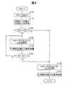
FIG. 6 is a control flowchart at the time of activation in the third embodiment. The difference from the control flowchart of the first embodiment shown in FIG. 3 is that step S138 is provided instead of step S130. In step S138, the
・第4の実施形態:
図7は、第4の実施形態における起動時の制御フローチャートである。図3に示す第1の実施形態の制御フローチャートとの違いは、ステップS130の後にステップS134、S136、S137を追加した点である。ステップS134では、第2の実施形態のステップS134と同様に、制御部400は、FC補機320を起動しまたは動作を継続させる。ステップS136では、制御部400は、高電圧二次電池200の電圧Vhbが予め定められた判定値Vth3より低くなったか否かを判断する。ここで、高電圧二次電池200の電圧Vhbが低くなる理由は、以下の通りである。
(a)ステップS134でFC補機320が動作を開始すると、高電圧二次電池200の電力がFC補機320により消費される。
(b)DC−DCコンバータ220が動作すると、DC−DCコンバータ220により、高電圧二次電池200の電力が消費される。Fourth embodiment:
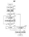
FIG. 7 is a control flowchart at the time of activation in the fourth embodiment. The difference from the control flowchart of the first embodiment shown in FIG. 3 is that steps S134, S136, and S137 are added after step S130. In step S134, as in step S134 of the second embodiment, the
(A) When the FC
(B) When the DC-
電圧Vhbが判定値Vth3より低くなった場合には、制御部400は、ステップS137に移行して、DC−DCコンバータ220を停止させることにより高電圧二次電池200の消費電力を低減する。ここで、DC−DCコンバータ220を停止させる理由は、FC補機320は、燃料電池100の発電に必要であるため停止することができず、一方、DC−DCコンバータ220を停止しても燃料電池100の発電を継続する上で大きな問題が発生しないからである。判定値Vth3の値は、例えば、燃料電池100の起動時にその発電が開始されるまでの間、FC補機320を動作させることができる電力量(すなわちSOC)に対応づけられた高電圧二次電池200の電圧である。 When the voltage Vhb becomes lower than the determination value Vth3, the
第4の実施形態によれば、第1の実施形態と同様に、制御部400は、高電圧二次電池200の温度が判定値Tth1以下の場合には、DC−DCコンバータ220の低電圧二次電池210側の電圧を低電圧二次電池210の電圧Vlbより低く設定する。しかし、この制御により高電圧二次電池200の電力が消費され、高電圧二次電池200の電圧が低くなると、制御部400は、DC−DCコンバータ220を停止させることにより、DC−DCコンバータ220の消費電力を減少させて、高電圧二次電池200の負荷を軽減する。なお、第4の実施形態においても、ステップS134及びステップS136の間と、ステップS137の後と、のうちの少なくとも一方に図4で説明したステップS140を追加し、ステップS140の条件が成立した後にステップS135に移行するようにしてもよい。こうすれば、燃料電池100が発電を開始し、燃料電池100からDC−DCコンバータ220に十分な電流を供給できるようになった後は、ステップS135に移行して低電圧二次電池210の充電を開始することが可能となる。 According to the fourth embodiment, as in the first embodiment, the
・第5の実施形態:
図8は、第5の実施形態における停止時の制御フローチャートである。第1〜第4の実施形態の制御は、燃料電池システム10の起動時の制御であるが、第5の実施形態は、燃料電池システム10の停止時の制御である。第1〜第4の実施形態において、燃料電池システム10の起動時に、低電圧二次電池210の電圧が十分に高ければ、DC−DCコンバータ220が動作して低電圧二次電池210に充電する必要が無く、仮に充電を行う場合にも、高電圧二次電池200の負荷が小さくなる。そこで、第5の実施形態では、燃料電池システム10の停止時に、低電圧二次電池210に対して十分に充電を行っておくことで、DC−DCコンバータ220が動作して低電圧二次電池210に充電する際の高電圧二次電池200の負荷を軽減する。-Fifth embodiment:
FIG. 8 is a control flowchart at the time of stop in the fifth embodiment. The control of the first to fourth embodiments is control when the fuel cell system 10 is started, but the fifth embodiment is control when the fuel cell system 10 is stopped. In the first to fourth embodiments, if the voltage of the low voltage
制御部400は、ステップS200で、燃料電池システム10の動作中においてスタートスイッチ410がオフされたことを検知すると、ステップS210に移行して外気温センサ560から外気温Taを取得する。制御部400は、ステップS220で、外気温Taが予め定められた判定値Tth2以下か否かを判断する。外気温Taが判定値Tth2以下の場合、ステップS230に移行し、外気温Taが判定値Tth2よりも高い場合には、ステップS250に移行する。判定値Tth2は、第1の実施形態のステップS120における判定値Tth1と同じであっても良く、異なっていても良い。また、制御部400は、この外気温Taとして、スタートスイッチ410がオフされたとき外気温Taの他、スタートスイッチ410がオフされたときから遡った所定期間(例えば24時間、あるいは一週間)の間における外気温Taの履歴(例えばスタートスイッチ410がオフされた時の時刻及び外気温と、スタートスイッチ410がオンされた時の時刻及び外気温)から、次にスタートスイッチがオンにされるときの外気温を予測し、その予測された外気温に基づいてステップS220の判定を行っても良い。この理由は、次にスタートスイッチがオンにされる時に、外気温Taが低くなっており、高電圧二次電池200の温度Thbも低くなっている可能性があるからである。 When detecting that the
ステップS230では、制御部400は、例えば、DC−DCコンバータ220の降圧側の出力電圧Voutを最大許容電圧Vlbmax以上に設定して、低電圧二次電池210に充電を行う。ステップS240において、低電圧二次電池210の電圧Vlbが最大許容電圧Vlbmax以上となった場合には、ステップS250に移行する。ステップS250では、制御部400は、燃料電池100への酸化剤ガスや燃料ガスの供給を停止して、燃料電池100の発電を停止させ、燃料電池システム10を停止させる。 In step S230, for example, the
第5の実施形態では、燃料電池システム10の停止時に低電圧二次電池210に充電を行うので、次の燃料電池システム10の再起動時までに低電圧二次電池210からの自然放電があったとしても、低電圧二次電池210には十分な電圧が残存している可能性が高い。したがって、次の燃料電池システム10の再起動時における高電圧二次電池の負荷を軽減できる。 In the fifth embodiment, since the low voltage
・変形例:
図9は、変形例の燃料電池システム12の概略構成を示す説明図である。図1に示す燃料電池システム10では、燃料電池100と、高電圧二次電池200とが高電圧配線110を介して直接接続される構成であったが、図9では、燃料電池システム12は、燃料電池100と、高電圧二次電池200との間に、燃料電池用DC−DCコンバータ230とバッテリ用DC−DCコンバータ240を備える。従って高電圧配線は、より電圧の低い第1の高電圧配線110と、より電圧の高い第2の高電圧配線111に分かれている。燃料電池システム12では、燃料電池用DC−DCコンバータ230とバッテリ用DC−DCコンバータ240との間の第2の高電圧配線111に、インバータ300と、FC補機320とが接続される。燃料電池用DC−DCコンバータ230は、燃料電池100の電圧を昇圧して第2の高電圧配線111に出力する。バッテリ用DC−DCコンバータ240は、第1の高電圧配線110と第2の高電圧配線111との間の電圧変換を行う双方向のDC−DCコンバータである。例えば、第1の高電圧配線110は200V〜400Vであり、好ましくは240V〜350Vであり、さらに好ましくは260V〜300Vの電圧で運用され、第2の高電圧配線111は、500V〜700V、より好ましくは、600V〜650Vの電圧で運用される。また、低電圧配線120は、100V未満(通常は30V未満)で運用される。なお、2つの高電圧配線110、111は、低電圧配線120と比べて電圧が高いので、これらを区別せずに「高電圧配線」と呼ぶことも可能である。燃料電池システム12の制御フローとしては、上述した図3、図4、図6〜図8のいずれを採用しても良い。なお、燃料電池用DC−DCコンバータ230とバッテリ用DC−DCコンバータ240は、いずれか一方を備える構成であってもよい。・ Modification:
FIG. 9 is an explanatory diagram showing a schematic configuration of a fuel cell system 12 according to a modification. In the fuel cell system 10 shown in FIG. 1, the
以上、いくつかの実施例に基づいて本発明の実施の形態について説明してきたが、上記した発明の実施の形態は、本発明の理解を容易にするためのものであり、本発明を限定するものではない。本発明は、その趣旨並びに特許請求の範囲を逸脱することなく、変更、改良され得るとともに、本発明にはその等価物が含まれることはもちろんである。 The embodiments of the present invention have been described above based on some examples. However, the above-described embodiments of the present invention are for facilitating the understanding of the present invention and limit the present invention. It is not a thing. The present invention can be changed and improved without departing from the spirit and scope of the claims, and it is needless to say that the present invention includes equivalents thereof.
10…燃料電池システム
12…燃料電池システム
100…燃料電池
110…高電圧配線(第1の高電圧配線)
111…第2の高電圧配線
120…低電圧配線
122…リレー
200…高電圧二次電池
210…低電圧二次電池
220…DC−DCコンバータ
222…スイッチ
224…コイル(リアクトル)
226…ダイオード
228…平滑コンデンサ
230…燃料電池用DC−DCコンバータ
240…バッテリ用DC−DCコンバータ
300…インバータ
310…駆動モータ
320…FC補機
400…制御部
410…スタートスイッチ
420…DDC目標電圧設定部
430…FC電流判定部
440…PID制御部
442…減算器
450…スイッチ
460…加算器
500…温度センサ
510…高電圧二次電池の電圧センサ
520…低電圧二次電池の電圧センサ
530…低電圧二次電池の電流センサ
540…FC電圧センサ
550…FC電流センサ
560…外気温センサ
600…負荷装置
Ifc…燃料電池の電流
Ilb…低電圧二次電池の電流
It…目標電流
Ith1…判定値
SOCmax…SOCの許容範囲の最大値
SOCmin…SOCの許容範囲の最小値
Ta…外気温
Thb…高電圧二次電池の温度
Tth1…判定値
Tth2…判定値
Vfc…燃料電池の電圧
Vhb…高電圧二次電池の電圧
Vlb…低電圧二次電池の電圧
Vlbmax…最大許容電圧
Vlbmin…最小許容電圧
Vout…DC−DCコンバータの降圧側の出力電圧
Vtar1…電圧指令値
Vtar2…電圧指令値
Vth3…判定値
ΔV…差分値(出力)DESCRIPTION OF SYMBOLS 10 ... Fuel cell system 12 ...
DESCRIPTION OF SYMBOLS 111 ... 2nd
226 ...
Claims (8)
Translated fromJapanese燃料電池と、
前記燃料電池に発電を実行させるために用いられるFC補機と、
前記FC補機に電力を供給する高電圧二次電池と、
前記高電圧二次電池よりも出力電圧の低い低電圧二次電池と、
前記高電圧二次電池の電圧を降圧して前記低電圧二次電池に供給するDC−DCコンバータと、
前記低電圧二次電池と前記DC−DCコンバータの間に接続された負荷装置と、
前記高電圧二次電池の温度を測定する温度センサと、
制御部と、
を備え、
前記制御部は、前記燃料電池システムを起動させるとき、
(i)前記温度センサから取得した前記高電圧二次電池の温度が予め定めた判定値よりも高い場合には、前記DC−DCコンバータの降圧側の出力電圧を前記低電圧二次電池の電圧よりも高い電圧に設定した後に、前記高電圧二次電池からの電力を用いて前記FC補機を起動し、
(ii)前記温度センサから取得した前記高電圧二次電池の温度が前記判定値以下の場合には、前記DC−DCコンバータの降圧側の出力電圧を、前記低電圧二次電池の電圧よりも低い電圧に設定した後に、前記高電圧二次電池からの電力を用いて前記FC補機を起動する、
燃料電池システム。A fuel cell system,
A fuel cell;
An FC auxiliary machine used for causing the fuel cell to generate power;
A high voltage secondary battery for supplying power to the FC auxiliary machine;
A low-voltage secondary battery having a lower output voltage than the high-voltage secondary battery;
A DC-DC converter that steps down the voltage of the high-voltage secondary battery and supplies it to the low-voltage secondary battery;
A load device connected between the low-voltage secondary battery and the DC-DC converter;
A temperature sensor for measuring the temperature of the high-voltage secondary battery;
A control unit;
With
The control unit, when starting the fuel cell system,
(I) When the temperature of the high voltage secondary battery acquired from the temperature sensor is higher than a predetermined determination value, the output voltage on the step-down side of the DC-DC converter is set to the voltage of the low voltage secondary battery. After setting to a higher voltage, the FC auxiliary machine is started using the power from the high voltage secondary battery,
(Ii) When the temperature of the high-voltage secondary battery acquired from the temperature sensor is equal to or lower than the determination value, the output voltage on the step-down side of the DC-DC converter is set to be lower than the voltage of the low-voltage secondary battery. After setting to a low voltage, the FC auxiliary machine is started using power from the high voltage secondary battery.
Fuel cell system.
前記制御部は、前記(i)を実行する場合、前記DC−DCコンバータの降圧側の出力電圧を、前記低電圧二次電池の許容電圧範囲の最大値よりも高い電圧に設定する、燃料電池システム。The fuel cell system according to claim 1, wherein
The control unit, when executing the step (i), sets the output voltage on the step-down side of the DC-DC converter to a voltage higher than the maximum value of the allowable voltage range of the low-voltage secondary battery. system.
前記制御部は、前記(ii)を実行する場合、前記DC−DCコンバータの降圧側の出力電圧を、前記低電圧二次電池の許容電圧範囲の最小値よりも低い電圧に設定する、燃料電池システム。The fuel cell system according to claim 2, wherein
The control unit sets the output voltage on the step-down side of the DC-DC converter to a voltage lower than the minimum value of the allowable voltage range of the low-voltage secondary battery when executing (ii). system.
前記低電圧二次電池の電流または電圧を測定するセンサを備え、
前記制御部は、前記(ii)を実行する場合、前記センサから得られる前記低電圧二次電池の電流または電圧に基づいて、前記低電圧二次電池への充電が行われないように、前記DC−DCコンバータの降圧側の出力電圧を制御する、燃料電池システム。The fuel cell system according to claim 1, further comprising:
A sensor for measuring the current or voltage of the low-voltage secondary battery;
The control unit, when executing (ii), based on the current or voltage of the low-voltage secondary battery obtained from the sensor, so as not to charge the low-voltage secondary battery A fuel cell system for controlling an output voltage on a step-down side of a DC-DC converter.
前記燃料電池の電流を測定するFC電流センサを備え、
前記制御部は、前記(ii)を実行する場合、前記FC補機を起動した後に、前記FC電流センサの測定値に基づいて、前記燃料電池の発電が開始されたと判断された後は、前記DC−DCコンバータの降圧側の出力電圧を前記低電圧二次電池の許容電圧範囲の最大値より高い電圧に設定する、
燃料電池システム。The fuel cell system according to any one of claims 1 to 4, further comprising:
An FC current sensor for measuring the current of the fuel cell;
The control unit, when executing the (ii), after starting the FC auxiliary machine, after determining that the power generation of the fuel cell is started based on the measured value of the FC current sensor, The output voltage on the step-down side of the DC-DC converter is set to a voltage higher than the maximum value of the allowable voltage range of the low-voltage secondary battery.
Fuel cell system.
燃料電池と、
前記燃料電池に発電を実行させるために用いられるFC補機と、
前記FC補機に電力を供給する高電圧二次電池と、
前記高電圧二次電池よりも出力電圧の低い低電圧二次電池と、
前記高電圧二次電池の電圧を降圧して前記低電圧二次電池に供給するDC−DCコンバータと、
前記低電圧二次電池と前記DC−DCコンバータの間に接続された負荷装置と、
前記高電圧二次電池の温度を取得する温度センサと、
制御部と、
を備え、
前記制御部は、前記燃料電池システムを起動させるとき、
(i)前記温度センサから取得した前記高電圧二次電池の温度が予め定めた判定値よりも高い場合には、前記DC−DCコンバータの降圧側の出力電圧を前記低電圧二次電池の電圧よりも高い電圧に設定した後に、前記高電圧二次電池からの電力を用いて前記FC補機を起動し、
(ii)前記温度センサから取得した前記高電圧二次電池の温度が前記判定値以下の場合には、前記DC−DCコンバータの動作を停止状態に維持するか、又はリレーにより前記DC−DCコンバータを前記低電圧二次電池から切り離した後に、前記高電圧二次電池からの電力を用いて前記FC補機を起動する、
燃料電池システム。A fuel cell system,
A fuel cell;
An FC auxiliary machine used for causing the fuel cell to generate power;
A high voltage secondary battery for supplying power to the FC auxiliary machine;
A low-voltage secondary battery having a lower output voltage than the high-voltage secondary battery;
A DC-DC converter that steps down the voltage of the high-voltage secondary battery and supplies it to the low-voltage secondary battery;
A load device connected between the low-voltage secondary battery and the DC-DC converter;
A temperature sensor for acquiring a temperature of the high-voltage secondary battery;
A control unit;
With
The control unit, when starting the fuel cell system,
(I) When the temperature of the high voltage secondary battery acquired from the temperature sensor is higher than a predetermined determination value, the output voltage on the step-down side of the DC-DC converter is set to the voltage of the low voltage secondary battery. After setting to a higher voltage, the FC auxiliary machine is started using the power from the high voltage secondary battery,
(Ii) When the temperature of the high-voltage secondary battery acquired from the temperature sensor is equal to or lower than the determination value, the operation of the DC-DC converter is maintained in a stopped state or the DC-DC converter by a relay After detaching from the low-voltage secondary battery, the FC auxiliary machine is activated using the power from the high-voltage secondary battery,
Fuel cell system.
前記制御部は、前記(i)を実行する場合、前記DC−DCコンバータの降圧側の出力電圧を、前記低電圧二次電池の許容電圧範囲の最大値よりも高い電圧に設定する、燃料電池システム。The fuel cell system according to claim 6, wherein
The control unit, when executing the step (i), sets the output voltage on the step-down side of the DC-DC converter to a voltage higher than the maximum value of the allowable voltage range of the low-voltage secondary battery. system.
外気温を測定する外気温センサを備え、
前記制御部は、前記燃料電池システムを停止させるときに、前記外気温が予め定められた温度よりも低い場合、前記低電圧二次電池の電圧が前記低電圧二次電池の許容電圧範囲の最大値になるまで充電を行った後、前記燃料電池システムを停止させる、
燃料電池システム。The fuel cell system according to any one of claims 1 to 7, further comprising:
It has an outside air temperature sensor that measures outside air temperature,
The control unit, when stopping the fuel cell system, if the outside air temperature is lower than a predetermined temperature, the voltage of the low voltage secondary battery is the maximum of the allowable voltage range of the low voltage secondary battery After charging until the value is reached, stop the fuel cell system,
Fuel cell system.
Priority Applications (4)
| Application Number | Priority Date | Filing Date | Title |
|---|---|---|---|
| JP2016085783AJP6361686B2 (en) | 2016-04-22 | 2016-04-22 | Fuel cell system |
| DE102017106605.5ADE102017106605B4 (en) | 2016-04-22 | 2017-03-28 | fuel cell system |
| US15/488,682US10291054B2 (en) | 2016-04-22 | 2017-04-17 | Fuel cell system |
| CN201710261683.XACN107394236B (en) | 2016-04-22 | 2017-04-20 | fuel cell system |
Applications Claiming Priority (1)
| Application Number | Priority Date | Filing Date | Title |
|---|---|---|---|
| JP2016085783AJP6361686B2 (en) | 2016-04-22 | 2016-04-22 | Fuel cell system |
Publications (2)
| Publication Number | Publication Date |
|---|---|
| JP2017195130A JP2017195130A (en) | 2017-10-26 |
| JP6361686B2true JP6361686B2 (en) | 2018-07-25 |
Family
ID=60021069
Family Applications (1)
| Application Number | Title | Priority Date | Filing Date |
|---|---|---|---|
| JP2016085783AExpired - Fee RelatedJP6361686B2 (en) | 2016-04-22 | 2016-04-22 | Fuel cell system |
Country Status (4)
| Country | Link |
|---|---|
| US (1) | US10291054B2 (en) |
| JP (1) | JP6361686B2 (en) |
| CN (1) | CN107394236B (en) |
| DE (1) | DE102017106605B4 (en) |
Families Citing this family (14)
| Publication number | Priority date | Publication date | Assignee | Title |
|---|---|---|---|---|
| US10202043B2 (en)* | 2016-04-18 | 2019-02-12 | Ford Global Technologies, Llc | Structure to optimize electricity generation in a vehicle |
| WO2018020675A1 (en)* | 2016-07-29 | 2018-02-01 | 日産自動車株式会社 | Vehicle system |
| JP6751512B2 (en)* | 2016-12-08 | 2020-09-09 | 株式会社オートネットワーク技術研究所 | In-vehicle power supply |
| KR102336394B1 (en)* | 2017-03-17 | 2021-12-08 | 현대자동차주식회사 | Air supply control method and system for fuelcell |
| KR102485255B1 (en)* | 2017-12-18 | 2023-01-06 | 현대자동차주식회사 | Fuel cell vehicle and controlling method thereof |
| DE102018212532A1 (en)* | 2018-07-27 | 2020-01-30 | Audi Ag | Electrical energy system with fuel cells |
| TWI705641B (en) | 2018-09-06 | 2020-09-21 | 財團法人工業技術研究院 | Power supply device, flying tool using same and power supply method thereof |
| KR102731551B1 (en)* | 2019-03-04 | 2024-11-18 | 현대자동차주식회사 | System and method for controlling battery charging or discharging |
| JP7367612B2 (en)* | 2020-05-22 | 2023-10-24 | トヨタ自動車株式会社 | fuel cell system |
| JP7527999B2 (en)* | 2021-02-15 | 2024-08-05 | 本田技研工業株式会社 | Power Supply Circuit |
| JP2022127946A (en)* | 2021-02-22 | 2022-09-01 | 本田技研工業株式会社 | power supply circuit |
| KR20230142944A (en) | 2022-04-04 | 2023-10-11 | 현대자동차주식회사 | Apparatus for controlling fuel cell system and method thereof |
| CN114792823B (en)* | 2022-04-24 | 2023-07-04 | 同济大学 | Fuel cell system and starting method thereof |
| CN116141991B (en)* | 2022-09-09 | 2025-09-19 | 深圳欣锐科技股份有限公司 | Integrated electric energy conversion device, power supply device and vehicle |
Family Cites Families (26)
| Publication number | Priority date | Publication date | Assignee | Title |
|---|---|---|---|---|
| JP3819542B2 (en) | 1997-06-11 | 2006-09-13 | 東和化成工業株式会社 | Purification method of erythritol |
| JP4969029B2 (en)* | 2004-08-16 | 2012-07-04 | 株式会社日立製作所 | Power supply device and control method thereof |
| JP4438595B2 (en) | 2004-10-18 | 2010-03-24 | トヨタ自動車株式会社 | Vehicle control device |
| JP4783580B2 (en) | 2005-03-31 | 2011-09-28 | 本田技研工業株式会社 | Fuel cell electrical system, fuel cell vehicle and power supply method |
| JP4589872B2 (en) | 2006-01-04 | 2010-12-01 | 本田技研工業株式会社 | Control device for electric vehicle |
| JP2007250374A (en)* | 2006-03-16 | 2007-09-27 | Denso Corp | Fuel cell system |
| JP4978082B2 (en) | 2006-03-31 | 2012-07-18 | トヨタ自動車株式会社 | Power supply system and vehicle equipped with the same |
| US20070292724A1 (en) | 2006-06-16 | 2007-12-20 | Gilchrist Ian T | System and method to start a fuel cell stack during a cold-start condition |
| JP4245624B2 (en)* | 2006-09-20 | 2009-03-25 | トヨタ自動車株式会社 | Power supply control device and power supply control method for hybrid vehicle |
| US8835065B2 (en)* | 2006-09-29 | 2014-09-16 | GM Global Technology Operations LLC | Fuel cell startup method for fast freeze startup |
| JP5215583B2 (en)* | 2007-04-06 | 2013-06-19 | 本田技研工業株式会社 | Fuel cell system |
| JP4516093B2 (en)* | 2007-05-22 | 2010-08-04 | 本田技研工業株式会社 | Fuel cell system and starting method thereof |
| JP4774430B2 (en)* | 2008-09-24 | 2011-09-14 | 本田技研工業株式会社 | Electric vehicle and power storage device control method |
| JP4758466B2 (en) | 2008-10-31 | 2011-08-31 | 本田技研工業株式会社 | Fuel cell vehicle |
| JP2011072081A (en) | 2009-09-24 | 2011-04-07 | Fujitsu Ten Ltd | Control unit and control method of plug-in vehicle |
| US8994327B2 (en) | 2011-08-24 | 2015-03-31 | General Electric Company | Apparatus and method for charging an electric vehicle |
| JP2014199709A (en) | 2013-03-14 | 2014-10-23 | 株式会社半導体エネルギー研究所 | Memory device and semiconductor device |
| US10115979B2 (en)* | 2013-03-15 | 2018-10-30 | Ford Global Technologies, Llc | Apparatus and method for heating a fuel cell stack |
| JP5920525B2 (en) | 2013-03-21 | 2016-05-18 | トヨタ自動車株式会社 | FUEL CELL SYSTEM AND CONTROL METHOD FOR FUEL CELL SYSTEM |
| JP5928390B2 (en) | 2013-03-26 | 2016-06-01 | トヨタ自動車株式会社 | Driving device and vehicle equipped with the same |
| US9428077B2 (en)* | 2013-10-07 | 2016-08-30 | Ford Global Technologies, Llc | Freeze preparation for a fuel cell system |
| JP6162678B2 (en) | 2014-06-25 | 2017-07-12 | 本田技研工業株式会社 | Dual power load drive fuel cell system and fuel cell vehicle |
| KR101601443B1 (en) | 2014-07-02 | 2016-03-22 | 현대자동차주식회사 | Driving control method of fuel cell system |
| KR101610515B1 (en) | 2014-09-24 | 2016-04-07 | 현대자동차주식회사 | Apparatus and Method for control of converter |
| KR101836611B1 (en)* | 2016-04-07 | 2018-03-09 | 현대자동차주식회사 | Method for controlling start of fuel cell vehicle |
| JP2022000081A (en) | 2020-06-19 | 2022-01-04 | 株式会社三共 | Game machine |
- 2016
- 2016-04-22JPJP2016085783Apatent/JP6361686B2/ennot_activeExpired - Fee Related
- 2017
- 2017-03-28DEDE102017106605.5Apatent/DE102017106605B4/enactiveActive
- 2017-04-17USUS15/488,682patent/US10291054B2/ennot_activeExpired - Fee Related
- 2017-04-20CNCN201710261683.XApatent/CN107394236B/ennot_activeExpired - Fee Related
Also Published As
| Publication number | Publication date |
|---|---|
| DE102017106605B4 (en) | 2022-09-01 |
| JP2017195130A (en) | 2017-10-26 |
| CN107394236A (en) | 2017-11-24 |
| CN107394236B (en) | 2019-04-09 |
| US10291054B2 (en) | 2019-05-14 |
| US20170310142A1 (en) | 2017-10-26 |
| DE102017106605A1 (en) | 2017-10-26 |
Similar Documents
| Publication | Publication Date | Title |
|---|---|---|
| JP6361686B2 (en) | Fuel cell system | |
| EP3670241B1 (en) | Power source system for vehicle | |
| JP6330822B2 (en) | Fuel cell system and control method thereof | |
| US8859158B2 (en) | System and method for controlling operation of fuel cell hybrid system by switching to battery power in response to idle stop condition | |
| JP6500881B2 (en) | Drive system and vehicle | |
| JP6354794B2 (en) | Fuel cell system | |
| US11211813B2 (en) | Battery charge control apparatus for vehicle and method of controlling battery charging of vehicle | |
| US9048473B2 (en) | Vehicular power source unit | |
| JP2003249236A (en) | Power supply device | |
| JP2010238528A (en) | Fuel cell system and vehicle equipped with the same | |
| US9796270B2 (en) | Power supply system and fuel cell vehicle | |
| CN107972504B (en) | Voltage control device for fuel cell vehicle | |
| JP6428524B2 (en) | Vehicle power supply system | |
| JP2017203748A (en) | Power supply system | |
| JP2016082846A (en) | Electric vehicle | |
| JP2017107772A (en) | Battery system | |
| JP6133623B2 (en) | Dual power load drive system and fuel cell vehicle | |
| JP2022016599A (en) | Power system, method, and program | |
| JP6104637B2 (en) | Dual power load drive system and fuel cell vehicle | |
| US20180108926A1 (en) | Fuel cell system | |
| JP4556989B2 (en) | Fuel cell power supply | |
| JP2018042425A (en) | Fuel cell system | |
| JP2003187816A (en) | Power supply | |
| JP2017024461A (en) | Power supply device and control method of power supply device | |
| JP2019033014A (en) | Relay contact welding inspection method |
Legal Events
| Date | Code | Title | Description |
|---|---|---|---|
| A621 | Written request for application examination | Free format text:JAPANESE INTERMEDIATE CODE: A621 Effective date:20170725 | |
| A977 | Report on retrieval | Free format text:JAPANESE INTERMEDIATE CODE: A971007 Effective date:20180514 | |
| TRDD | Decision of grant or rejection written | ||
| A01 | Written decision to grant a patent or to grant a registration (utility model) | Free format text:JAPANESE INTERMEDIATE CODE: A01 Effective date:20180529 | |
| A61 | First payment of annual fees (during grant procedure) | Free format text:JAPANESE INTERMEDIATE CODE: A61 Effective date:20180611 | |
| R151 | Written notification of patent or utility model registration | Ref document number:6361686 Country of ref document:JP Free format text:JAPANESE INTERMEDIATE CODE: R151 | |
| LAPS | Cancellation because of no payment of annual fees |