JP6359986B2 - Vehicle driving support system - Google Patents
Vehicle driving support systemDownload PDFInfo
- Publication number
- JP6359986B2 JP6359986B2JP2015026913AJP2015026913AJP6359986B2JP 6359986 B2JP6359986 B2JP 6359986B2JP 2015026913 AJP2015026913 AJP 2015026913AJP 2015026913 AJP2015026913 AJP 2015026913AJP 6359986 B2JP6359986 B2JP 6359986B2
- Authority
- JP
- Japan
- Prior art keywords
- area
- vehicle
- existing
- unknown
- region
- Prior art date
- Legal status (The legal status is an assumption and is not a legal conclusion. Google has not performed a legal analysis and makes no representation as to the accuracy of the status listed.)
- Active
Links
Images


Classifications
- G—PHYSICS
- G08—SIGNALLING
- G08G—TRAFFIC CONTROL SYSTEMS
- G08G1/00—Traffic control systems for road vehicles
- G08G1/16—Anti-collision systems
- G08G1/165—Anti-collision systems for passive traffic, e.g. including static obstacles, trees
- B—PERFORMING OPERATIONS; TRANSPORTING
- B60—VEHICLES IN GENERAL
- B60W—CONJOINT CONTROL OF VEHICLE SUB-UNITS OF DIFFERENT TYPE OR DIFFERENT FUNCTION; CONTROL SYSTEMS SPECIALLY ADAPTED FOR HYBRID VEHICLES; ROAD VEHICLE DRIVE CONTROL SYSTEMS FOR PURPOSES NOT RELATED TO THE CONTROL OF A PARTICULAR SUB-UNIT
- B60W30/00—Purposes of road vehicle drive control systems not related to the control of a particular sub-unit, e.g. of systems using conjoint control of vehicle sub-units
- B60W30/08—Active safety systems predicting or avoiding probable or impending collision or attempting to minimise its consequences
- B60W30/09—Taking automatic action to avoid collision, e.g. braking and steering
- B—PERFORMING OPERATIONS; TRANSPORTING
- B60—VEHICLES IN GENERAL
- B60W—CONJOINT CONTROL OF VEHICLE SUB-UNITS OF DIFFERENT TYPE OR DIFFERENT FUNCTION; CONTROL SYSTEMS SPECIALLY ADAPTED FOR HYBRID VEHICLES; ROAD VEHICLE DRIVE CONTROL SYSTEMS FOR PURPOSES NOT RELATED TO THE CONTROL OF A PARTICULAR SUB-UNIT
- B60W30/00—Purposes of road vehicle drive control systems not related to the control of a particular sub-unit, e.g. of systems using conjoint control of vehicle sub-units
- B60W30/08—Active safety systems predicting or avoiding probable or impending collision or attempting to minimise its consequences
- B60W30/095—Predicting travel path or likelihood of collision
- G—PHYSICS
- G01—MEASURING; TESTING
- G01S—RADIO DIRECTION-FINDING; RADIO NAVIGATION; DETERMINING DISTANCE OR VELOCITY BY USE OF RADIO WAVES; LOCATING OR PRESENCE-DETECTING BY USE OF THE REFLECTION OR RERADIATION OF RADIO WAVES; ANALOGOUS ARRANGEMENTS USING OTHER WAVES
- G01S13/00—Systems using the reflection or reradiation of radio waves, e.g. radar systems; Analogous systems using reflection or reradiation of waves whose nature or wavelength is irrelevant or unspecified
- G01S13/86—Combinations of radar systems with non-radar systems, e.g. sonar, direction finder
- G—PHYSICS
- G01—MEASURING; TESTING
- G01S—RADIO DIRECTION-FINDING; RADIO NAVIGATION; DETERMINING DISTANCE OR VELOCITY BY USE OF RADIO WAVES; LOCATING OR PRESENCE-DETECTING BY USE OF THE REFLECTION OR RERADIATION OF RADIO WAVES; ANALOGOUS ARRANGEMENTS USING OTHER WAVES
- G01S13/00—Systems using the reflection or reradiation of radio waves, e.g. radar systems; Analogous systems using reflection or reradiation of waves whose nature or wavelength is irrelevant or unspecified
- G01S13/88—Radar or analogous systems specially adapted for specific applications
- G01S13/93—Radar or analogous systems specially adapted for specific applications for anti-collision purposes
- G01S13/931—Radar or analogous systems specially adapted for specific applications for anti-collision purposes of land vehicles
- G—PHYSICS
- G08—SIGNALLING
- G08G—TRAFFIC CONTROL SYSTEMS
- G08G1/00—Traffic control systems for road vehicles
- G08G1/16—Anti-collision systems
- G08G1/166—Anti-collision systems for active traffic, e.g. moving vehicles, pedestrians, bikes
- B—PERFORMING OPERATIONS; TRANSPORTING
- B60—VEHICLES IN GENERAL
- B60W—CONJOINT CONTROL OF VEHICLE SUB-UNITS OF DIFFERENT TYPE OR DIFFERENT FUNCTION; CONTROL SYSTEMS SPECIALLY ADAPTED FOR HYBRID VEHICLES; ROAD VEHICLE DRIVE CONTROL SYSTEMS FOR PURPOSES NOT RELATED TO THE CONTROL OF A PARTICULAR SUB-UNIT
- B60W2420/00—Indexing codes relating to the type of sensors based on the principle of their operation
- B60W2420/40—Photo, light or radio wave sensitive means, e.g. infrared sensors
- B60W2420/408—Radar; Laser, e.g. lidar
- B—PERFORMING OPERATIONS; TRANSPORTING
- B60—VEHICLES IN GENERAL
- B60W—CONJOINT CONTROL OF VEHICLE SUB-UNITS OF DIFFERENT TYPE OR DIFFERENT FUNCTION; CONTROL SYSTEMS SPECIALLY ADAPTED FOR HYBRID VEHICLES; ROAD VEHICLE DRIVE CONTROL SYSTEMS FOR PURPOSES NOT RELATED TO THE CONTROL OF A PARTICULAR SUB-UNIT
- B60W2554/00—Input parameters relating to objects
- B—PERFORMING OPERATIONS; TRANSPORTING
- B60—VEHICLES IN GENERAL
- B60W—CONJOINT CONTROL OF VEHICLE SUB-UNITS OF DIFFERENT TYPE OR DIFFERENT FUNCTION; CONTROL SYSTEMS SPECIALLY ADAPTED FOR HYBRID VEHICLES; ROAD VEHICLE DRIVE CONTROL SYSTEMS FOR PURPOSES NOT RELATED TO THE CONTROL OF A PARTICULAR SUB-UNIT
- B60W2556/00—Input parameters relating to data
- B60W2556/45—External transmission of data to or from the vehicle
- B60W2556/50—External transmission of data to or from the vehicle of positioning data, e.g. GPS [Global Positioning System] data
- B—PERFORMING OPERATIONS; TRANSPORTING
- B60—VEHICLES IN GENERAL
- B60W—CONJOINT CONTROL OF VEHICLE SUB-UNITS OF DIFFERENT TYPE OR DIFFERENT FUNCTION; CONTROL SYSTEMS SPECIALLY ADAPTED FOR HYBRID VEHICLES; ROAD VEHICLE DRIVE CONTROL SYSTEMS FOR PURPOSES NOT RELATED TO THE CONTROL OF A PARTICULAR SUB-UNIT
- B60W2556/00—Input parameters relating to data
- B60W2556/45—External transmission of data to or from the vehicle
- B60W2556/55—External transmission of data to or from the vehicle using telemetry
- G—PHYSICS
- G01—MEASURING; TESTING
- G01S—RADIO DIRECTION-FINDING; RADIO NAVIGATION; DETERMINING DISTANCE OR VELOCITY BY USE OF RADIO WAVES; LOCATING OR PRESENCE-DETECTING BY USE OF THE REFLECTION OR RERADIATION OF RADIO WAVES; ANALOGOUS ARRANGEMENTS USING OTHER WAVES
- G01S13/00—Systems using the reflection or reradiation of radio waves, e.g. radar systems; Analogous systems using reflection or reradiation of waves whose nature or wavelength is irrelevant or unspecified
- G01S13/02—Systems using reflection of radio waves, e.g. primary radar systems; Analogous systems
- G01S13/04—Systems determining presence of a target
- G—PHYSICS
- G01—MEASURING; TESTING
- G01S—RADIO DIRECTION-FINDING; RADIO NAVIGATION; DETERMINING DISTANCE OR VELOCITY BY USE OF RADIO WAVES; LOCATING OR PRESENCE-DETECTING BY USE OF THE REFLECTION OR RERADIATION OF RADIO WAVES; ANALOGOUS ARRANGEMENTS USING OTHER WAVES
- G01S19/00—Satellite radio beacon positioning systems; Determining position, velocity or attitude using signals transmitted by such systems
- G01S19/01—Satellite radio beacon positioning systems transmitting time-stamped messages, e.g. GPS [Global Positioning System], GLONASS [Global Orbiting Navigation Satellite System] or GALILEO
- G01S19/13—Receivers
Landscapes
- Engineering & Computer Science (AREA)
- Radar, Positioning & Navigation (AREA)
- Remote Sensing (AREA)
- Physics & Mathematics (AREA)
- General Physics & Mathematics (AREA)
- Computer Networks & Wireless Communication (AREA)
- Automation & Control Theory (AREA)
- Transportation (AREA)
- Mechanical Engineering (AREA)
- Electromagnetism (AREA)
- Traffic Control Systems (AREA)
Description
Translated fromJapanese本発明は、運転支援制御を実行するうえで好適な車両運転支援システムに関する。 The present invention relates to a vehicle driving support system suitable for executing driving support control.
従来、車両の運転支援制御を実行する車両運転支援システムが知られている(例えば、特許文献1参照)。このシステムは、車両外部に設けられる検出装置と、車両に搭載される車載装置と、を備えている。検出装置は、道路上の他車両などの物体を検出して、車載装置に情報提供する。車載装置は、検出装置から取得した検出物体に基づいて、その物体との衝突を回避するように運転支援制御を実行する。 Conventionally, a vehicle driving support system that executes driving support control of a vehicle is known (see, for example, Patent Document 1). This system includes a detection device provided outside the vehicle and an in-vehicle device mounted on the vehicle. The detection device detects an object such as another vehicle on the road and provides information to the in-vehicle device. The in-vehicle device executes driving support control based on the detected object acquired from the detection device so as to avoid a collision with the object.
ところで、車両の運転支援制御を実行するうえでは、道路交通環境のすべての事象を検出装置を用いて検出できることが望ましいが、一般的には、道路交通環境の一部の事象を検出装置を用いて検出できるだけである。また、全領域のうち、検出装置により検出された物体が存在する存在領域ではない領域は、物体が存在しない領域(以下、非存在領域と称す。)と、物体が存在するか否かが不明である領域(以下、不明領域と称す。)との何れかである。不明領域に向けて車両を誘導する運転支援を行うことはあまり好ましくないが、非存在領域に向けて車両を誘導する運転支援を行うことは好ましい。しかし、上記したシステムでは、検出装置が車両走行に支障をきたす可能性のある物体を検出した場合、車載装置は、その物体との衝突を回避するように制動などの運転支援制御を実行するだけのものであって、物体が存在しない非存在領域に向けて車両を誘導することなどの運転支援制御を行うものではない。 By the way, in executing vehicle driving support control, it is desirable to be able to detect all events in the road traffic environment using a detection device, but in general, some events in the road traffic environment are detected using a detection device. Can only be detected. Of all the regions, the region that is not the existence region where the object detected by the detection device exists is the region where the object does not exist (hereinafter referred to as the non-existence region), and it is unknown whether the object exists. Is an area (hereinafter referred to as an unknown area). Although it is not preferable to perform driving support for guiding the vehicle toward the unknown area, it is preferable to perform driving support for guiding the vehicle toward the non-existing area. However, in the system described above, when the detection device detects an object that may interfere with vehicle travel, the in-vehicle device only executes driving support control such as braking so as to avoid a collision with the object. It does not perform driving support control such as guiding the vehicle toward a non-existing region where no object exists.
本発明は、上述の点に鑑みてなされたものであり、検出装置により検出された物体が存在する存在領域ではない領域のうち不明領域と区別された非存在領域に車両を誘導することで、より高度な運転支援制御を実行することが可能な車両運転支援システムを提供することを目的とする。 The present invention has been made in view of the above points, and by guiding a vehicle to a non-existing region that is distinguished from an unknown region among non-existing regions where an object detected by a detection device exists, An object of the present invention is to provide a vehicle driving support system capable of executing more advanced driving support control.
本発明の一態様は、物体を検出する検出手段と、前記検出手段により検出された物体が存在する存在領域ではない領域を、物体が存在しないと判断される非存在領域と、物体が存在するか否かが不明である不明領域と、に区別する領域判別手段と、車両を前記不明領域ではなく前記非存在領域に誘導する運転支援制御を実行する制御手段と、を備え、前記検出手段は、少なくとも、前記車両に設けられているセンサ、および、前記車両の外部に設けられているセンサを含む、複数のセンサを有し、当該複数のセンサから取得した複数の情報に基づいて、前記物体が存在することを検出し、前記制御手段は、前記領域判別手段による判別結果を、無線通信によって前記車両の外部に設けられている情報処理装置から取得し、当該判別結果に基づいて、前記運転支援制御を実行する車両運転支援システムである。One embodiment of the present invention includes a detection unit that detects an object, a non-existing region where the object detected by the detection unit exists, a non-existing region where it is determined that no object exists, and an object An area determination means for distinguishing whether the area is unknown or not, and a control means for performing driving support control for guiding the vehicle to the non-existence area instead of the unknown area, thedetection means And a plurality of sensors including at least a sensor provided in the vehicle and a sensor provided outside the vehicle, and the object based on a plurality of information acquired from the plurality of sensors. And the control means acquires the determination result by the area determination means from an information processing device provided outside the vehicle by wireless communication, and based on the determination result. Te, a vehicle driving supportsystem executes the driving support control.
本発明によれば、検出手段により検出された物体が存在する存在領域ではない領域のうち不明領域と区別された非存在領域に車両を誘導することで、より高度な運転支援制御を実行することができる。 According to the present invention, more advanced driving support control is performed by guiding a vehicle to a non-existing area that is distinguished from an unknown area among non-existing areas where the object detected by the detecting means is present. Can do.
以下、図面を用いて、本発明に係る車両運転支援システムの具体的な実施の形態について説明する。 Hereinafter, specific embodiments of a vehicle driving support system according to the present invention will be described with reference to the drawings.
図1は、本発明の一実施例である車両運転支援システム10の構成図を示す。本実施例の車両運転支援システム10は、車両の走行を支援するシステムである。車両運転支援システム10は、各車両に搭載される車載装置12と、車両外の道路に設置されるセンタ14と、を備えている。 FIG. 1 shows a configuration diagram of a vehicle
センタ14には、道路脇や道路上に設置された感知センサやカメラなどのセンサ16から送信される情報、道路信号機18から送信される情報、各車両20から送信される情報、人の携帯する携帯端末22から送信される情報、道路管理センタ24などから提供される道路工事情報などが入力される。これらの情報は、主に位置を示す情報であって、例えば道路地図上の物体の存在位置や道路工事の位置などを含むものである。また、センサ16からの情報は、そのセンサ16の道路地図上における監視対象領域の位置を示す情報、及び、その監視対象領域において車両や人などの物体が存在するか否かを示す情報を含むものである。道路信号機18からの情報は、その道路信号機18の進行可や進行禁止などを表す現状を示す情報を含むものである。車両20からの情報は、自車両の位置情報、及び、自車両に搭載されるレーダやカメラなどの車載センサを用いて検出される人や他車両などの物体の有無を示す情報を含むものである。また、車両20からの情報や携帯端末22からの情報は、予め定められた固有の識別情報を含むものであってもよい。 The
センタ14は、道路情報データベース26及びマッチング部28を有している。道路情報データベース26には、道路地図や道路ごとの車線数や歩道の有無などの情報が格納されている。センタ14に入力された上記した各種の情報は、マッチング部28に供給される。マッチング部28は、道路情報データベース26に格納されている情報を参照しながら、センタ14に入力された上記した各種の位置情報を道路地図とマッチングすることにより、現状の道路交通状況を生成する。 The
センタ14は、また、位置情報データベース30、識別部32、及び分割部34を有している。マッチング部28によるマッチングによりセンサ16や車両20,携帯端末22からの情報に基づいて物体が存在することが検出された場合は、マッチング部28は、その物体が存在する領域(以下、存在領域と称す。)の位置を示す情報を位置情報データベース30に供給して格納させる。位置情報データベース30は、マッチング部28から供給される物体の位置を示す情報を格納する。 The
マッチング部28は、入力されたセンサ16の監視対象領域である位置及び車両20に搭載された車載センサの監視対象領域である位置の情報を識別部32に供給する。尚、このマッチング部28から識別部32への監視対象領域の位置情報の供給は、検出された物体が存在する領域の位置情報を除いて行われる。識別部32は、全領域のうち、検出された物体が存在する存在領域ではない領域(以下、未知領域と称す。)を、センサ16及び車載センサの監視対象領域と、その監視対象領域以外の領域と、に識別する処理を行う。 The matching
具体的には、識別部32は、まず、マッチング部28からの情報に基づいて、全領域のうち物体が存在する存在領域ではない未知領域におけるセンサ16及び車載センサの監視対象領域の位置を求める。そのうえで、その監視対象領域を未知領域から除くことにより非監視領域の位置を求める。 Specifically, the
識別部32は、未知領域における監視対象領域の位置及び非監視領域の位置を求めると、その位置情報(特に、監視対象領域の位置情報)を分割部34に供給する。分割部34は、道路情報データベース26に格納されている情報を参照しながら、未知領域における監視対象領域を、道路車線や歩道ごとに、区分けされたグリッド単位で割り当てる処理を行う。分割部34は、未知領域における監視対象領域をグリッド単位で割り当てると、その未知領域における監視対象領域を、物体が存在しないと判断される領域(以下、非存在領域(Empty領域)と称す。)の初期位置として設定する。尚、非存在領域は、車両による合流や車線変更,人による横断に使える、比較的安全な空間である。 When the
そして、識別部32は、グリッド状に形成された非存在領域の初期位置の位置情報を、センサ16等を用いた事実に基づくものとして、位置情報データベース30に供給して格納させる。 And the
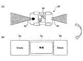
図2は、本実施例において、車両20が自車位置検出装置(GPS装置)40と周辺環境認識装置(レーダ装置)42,44とを搭載する場合の領域設定を行う手法を説明するための図を示す。図3は、本実施例において、車両20がGPS装置40を搭載する場合の領域設定を行う手法を説明するための図を示す。図4は、本実施例において、車両20がGPS装置40もレーダ装置42,44も搭載していない場合の領域設定を行う手法を説明するための図を示す。図5は、本実施例において、道路脇に設置されるセンサ16がある場合の領域設定を行う手法を説明するための図を示す。また、図6は、本実施例において、道路脇に設置されるセンサ16が無い場合の領域設定を行う手法を説明するための図を示す。尚、図2〜図6において、A図には車両20が置かれている状況を、また、B図にはセンタ14が認識する状況を、それぞれ模式的に示す。 FIG. 2 is a diagram for explaining a method for performing region setting when the
例えば、図2(A)に示す如く、車両20がGPS装置40及びレーダ装置42を搭載する場合、車両20は、GPS装置40により検出される自車両20の位置情報、レーダ装置42により検出される自車両20に対する所定前方領域における物体の有無を示す情報、及びレーダ装置44により検出される自車両20に対する所定後方領域における物体の有無を示す情報を図1に示すセンタ14に提供する。この場合、センタ14は、車両20から提供された情報に基づいて車両20が存在することを検出して、その車両20の存在領域Saの位置を示す情報を位置情報データベース30に格納する(図2(B))。 For example, as shown in FIG. 2A, when the
また、車両20に対する前方領域及び後方領域の双方に何ら物体が存在しなければ、その車両20のレーダ装置42,44から物体が存在することを示す情報がセンタ14に提供されない。この場合には、車両20に対する前方領域及び後方領域が未知領域におけるレーダ装置42,44の監視対象領域となり、それらの前方領域及び後方領域の位置情報がセンタ14に提供される。このため、センタ14は、この場合は更に、車両20に対する前方領域及び後方領域を非存在領域Seとして設定して、その非存在領域Seの位置情報を位置情報データベース30に格納する(図2(B))。 Further, if there is no object in both the front region and the rear region with respect to the
例えば、図3(A)に示す如く、車両20がGPS装置40を搭載する場合、車両20は、GPS装置40により検出される自車両20の位置情報をセンタ14に提供する。この場合、センタ14は、車両20が存在することを検出して、その車両20に対する存在領域Saの位置を示す情報を位置情報データベース30に格納する(図3(B))。また、センタ14は、その車両20に対する前方領域及び後方領域を監視対象とするセンサ16や他車両の車載センサが無ければ、それらの前方領域及び後方領域を、センサ16などの監視対象領域ではなく物体が存在するか否かが不明である領域(以下、不明領域(Unknown領域)と称す。)Suとして設定する(図3(B))。尚、不明領域は、存在領域ではない未知領域のうち、非存在領域ではない領域のことであって、車両による合流や車線変更,人による横断に使うことが困難な、比較的安全でない空間である。 For example, as shown in FIG. 3A, when the
例えば、図4(A)に示す如く、車両20がGPS装置40もレーダ装置42,44も搭載していない場合は、車両20は、何ら情報をセンタ14に提供しない。この場合、センタ14は、その車両20の位置並びにその車両20の前方領域及び後方領域を監視対象とするセンサ16や他車両の車載センサが無ければ、その車両20の位置並びにその車両20の前方領域及び後方領域を不明領域Suとして設定する(図4(B))。 For example, as shown in FIG. 4A, when the
例えば、図5(A)に示す如く、道路脇にセンサ16が設置されている場合、そのセンサ16は、監視対象領域の位置情報及びその監視対象領域における物体の存在有無を示す情報をセンタ14に提供する。この場合、センタ14は、センサ16の監視対象領域の位置を特定すると共に、その監視対象領域における物体の存在有無を判別する。そして、センサ16の監視対象領域において物体が存在することを判定した場合には、その監視対象領域を物体が存在する存在領域として設定して、その物体の存在領域の位置を示す情報を位置情報データベース30に格納する。一方、センサ16の監視対象領域となった例えば車両Aと車両Bとの間の領域に物体が存在しないことを判定した場合には、その監視対象領域を非存在領域Seの初期位置として設定し、その非存在領域Seの初期位置を示す情報を位置情報データベース30に格納する(図5(B))。 For example, as shown in FIG. 5A, when a
また例えば、図6(A)に示す如く、道路脇にセンサ16が設置されていない場合、センサ16の監視対象領域の位置情報及びその監視対象領域における物体の存在有無を示す情報がセンタ14に提供されない。この場合、センタ14は、例えば車両Aと車両Bとの間の領域を監視対象とするセンサ16や他車両の車載センサが無ければ、その車両Aと車両Bとの間の領域を不明領域Suとして設定する(図6(B))。 For example, as shown in FIG. 6A, when the
本実施例において、センタ14は、また、消滅処理/移動予測部36を備えている。消滅処理/移動予測部36は、位置情報データベース30に接続されている。消滅処理/移動予測部36は、位置情報データベース30に格納されている非存在領域Seを道路地図上で移動させてその位置を予測する処理、及び、その非存在領域Seを消滅させる処理を行うと共に、その処理に従って位置情報データベース30の非存在領域Seの位置情報を更新する部位である。 In the present embodiment, the
消滅処理/移動予測部36による非存在領域Seの移動は、非存在領域Seを時間経過に伴って道路地図上で移動させるものである。具体的には、かかる移動は、物理法則や交通ルールに従って行われる。また、異なる車線や歩道などの交通ルールが異なる箇所に対してはそれぞれ別々に非存在領域を設定したうえで、各非存在領域に対してそれぞれ別々に移動推定を行うものであればよい。例えば、高速道路上での移動は、車線ごとに予め定められた方向に向けて行われ、法定上の最低速度と最高速度との間の範囲で行われるものとする。また、一般道上での移動は、車線ごとに予め定められた方向に向けて行われ、速度ゼロと法定上の最高速度との間の範囲で行われるものとする。また、歩道上での移動は行われないものとし、歩道上の非存在領域自体が時間経過に伴って縮小されるものであってもよい。更に、非存在領域Seが図5に示す如く車両Aと車両Bとに挟まれる場合は、その非存在領域Seの移動は、車両Aの速度や車両Bの速度に従って行われるものであってもよく、常に車両Aと車両Bとの間に位置するものとすればよい。 The movement of the non-existing area Se by the annihilation process /
図7は、本実施例における非存在領域の移動手法を説明するための一例の図を示す。図8は、本実施例における非存在領域の移動手法を説明するための他の一例の図を示す。また、図9は、本実施例における非存在領域の移動手法を説明するための更に他の一例の図を示す。尚、図7〜図9において、車両20が置かれている状況を左図に、また、センタ14が認識する状況を右図に、それぞれ模式的に示す。 FIG. 7 is a diagram illustrating an example for explaining a non-existing area moving method according to the present embodiment. FIG. 8 is a diagram illustrating another example for explaining the non-existing area moving method according to the present embodiment. FIG. 9 is a diagram showing still another example for explaining the non-existing area moving method in this embodiment. 7 to 9 schematically show the situation where the
例えば、図7(A)に示す如く、時刻t1において、2台の車両A,車両Bそれぞれに搭載されたGPS装置40により車両の位置情報が検出され、かつ、道路脇に設置されたセンサ16の監視対象領域となった車両Aと車両Bとの間の領域に物体が存在しないことが判定されると、その監視対象領域が非存在領域Se1の初期位置として設定される。仮に本実施例とは異なり、車両A及び車両Bの移動に伴って両車両A,B間の非存在領域Se1が移動されない構成では、上記の非存在領域Se1の設定後、車両Aと車両Bとの間の領域を監視対象領域とするセンサ16や車両の車載センサが無ければ、時刻t2において、両車両A,B間の領域は不明領域Suとなってしまう(図7(B))。これに対して、本実施例においては、上記の非存在領域Se1の設定後、その非存在領域Se1が時間経過に伴って車両A及び車両Bの速度に従って同期して移動されるので、時刻t2においても、車両A,B間の領域は非存在領域Se1のまま維持される(図7(C))。 For example, as shown in FIG. 7A, at time t1, the position information of the vehicle is detected by the
例えば、図8(A)に示す如く、道路脇に設置されたセンサ16の監視対象領域に、互いに逆方向を進行方向とする2つの道路46,47の一部と一つの歩道49の一部とが含まれる場合において、その監視対象領域に物体が存在しないことが判定されると、その監視対象領域が非存在領域Seの初期位置として設定される。その後、時間Tが経過すると、手前側道路46上に設定された非存在領域Se1が法定上の最低速度minと最高速度maxとの間の範囲で移動され(Se1min〜Se1max)、奥側道路47上に設定された非存在領域Se2が法定上の最低速度minと最高速度maxとの間の範囲で移動され(Se2min〜Se2max)、歩道49上に設定された非存在領域Se3が縮小される(図8(B))。 For example, as shown in FIG. 8 (A), a part of two
また例えば、図9(A)に示す如く、時刻t1において、2台の車両A,車両Bそれぞれに搭載されたGPS装置40により車両の位置情報が検出され、かつ、道路脇に設置されたセンサ16の監視対象領域となった車両Aと車両Bとの間の領域に物体が存在しないことが判定されると、その監視対象領域が非存在領域Seの初期位置として設定される。その後、時刻t2において、その非存在領域Seが車両Aの速度及び車両Bの速度に従って移動されると共に、それらの車両Aと車両Bとの間の領域に拡縮される(図9(B))。 Further, for example, as shown in FIG. 9A, at time t1, the position information of the vehicle is detected by the
また、消滅処理/移動予測部36による非存在領域Seの消滅は、歩道において非存在領域が検出された後所定時間が経過した場合、道路地図上を移動する非存在領域が他の道路と合流する不明領域である地点を通過した場合、非存在領域に対して先行して移動していた車両が停車した場合或いはその停車後所定時間が経過した場合、2台の車両に挟まれる非存在領域については2台の車両の速度差や離間距離が所定以上に大きくなった場合などに行われる。 Further, the disappearance of the non-existing area Se by the disappearing process /
消滅処理/移動予測部36は、位置情報データベース30に格納されている非存在領域を移動させ或いは消滅させた場合、その非存在領域の移動後の予測位置情報或いは消滅情報を位置情報データベース30に格納させる。 When the non-existing area stored in the
各車両20の車載装置12は、無線通信によりセンタ14の位置情報データベース30に接続可能である。データベース30に格納されている、センサ16や車両20などにより検出された物体が存在する存在領域の位置情報、及び、物体が存在しないと判断される非存在領域の位置情報は、車両20に提供される。この情報提供は、予め定められた所定時間ごとに行われるものとすればよい。尚、更に、不明領域の位置情報も車両20に提供されてもよい。 The in-
車載装置12は、自車両を自動走行(自動運転)させることが可能であり或いは自車両が置かれている状況(他車両や人との相対関係など)を自車両の運転者にディスプレイや音声で提供することが可能である。すなわち、車載装置12は、エンジン制御やモータ制御,ブレーキ制御,ステアリング制御などにより自動走行させること、或いは、運転者への接近警報やブザー警報,音声や表示による運転操作指示などを行うことが可能である。 The in-
車載装置12は、マイクロコンピュータを主体に構成されたECU48を有している。ECU48は、センタ14から物体の存在領域の位置情報及び非存在領域の位置情報が提供された場合、まず、自車両が物体と衝突する確率を算出する。具体的には、自車両が存在領域に進入する可能性があるときは物体との衝突確率を100%に近い値とし、自車両が非存在領域に進入する可能性があるときは物体との衝突確率を0%に近い値とする。尚、非存在領域が初期位置から移動する時間や距離が長くなるほど、その非存在領域に物体が存在する可能性が高くなるので、このときは、非存在領域の移動時間や移動距離が長くなるほど徐々に物体との衝突確率を増やすこととしてもよい。 The in-
そして、ECU48は、自車両と物体との衝突確率に基づいて、自車両をその衝突確率が所定値よりも高い物体との衝突を回避できるように具体的にはその衝突確率が所定値よりも低くなる非存在領域に進入するように自動走行させ、或いは、自車両がその非存在領域に進入できるタイミングを運転者に知らせる運転支援制御を行う。 Then, based on the collision probability between the host vehicle and the object, the
図10は、本実施例における車両に対する運転支援制御の手法を説明するための図を示す。 FIG. 10 is a diagram for explaining a driving support control method for a vehicle in the present embodiment.
例えば、図10(A)に示す如く、車両が走行し得る道路50が道路52に交差点54で合流し、かつ、道路脇に設置されたセンサ16が道路52の交差点54手前の一部を監視対象領域とする道路状況において、道路50を走行する車両56が交差点54で道路52に進入しようとする場合を考える。 For example, as shown in FIG. 10A, a
この場合、時刻t1において、センサ16の監視対象領域に物体が存在しないことが判定されると、その監視対象領域が非存在領域Se1の初期位置として設定される(図10(B))。その後、時刻t2において、センサ16の監視対象領域に物体が存在しないことが判定されると、上記の非存在領域Se1が時刻t1での初期位置から例えば道路52の法定上の最高速度に従って移動された位置に達する共に、センサ16の監視対象領域が非存在領域Se2の初期位置として設定される(図10(C))。 In this case, when it is determined that no object is present in the monitoring target area of the
そして、時刻t3において、道路52上の非存在領域Se1が交差点54に達すると、その交差点54での物体との衝突確率は低くなる。そこで、交差点54手前の道路50に位置する自車両56の車載装置12のECU48は、自車両56を時刻t3に非存在領域Se1が到達する交差点54に進入させて物体との衝突を回避しつつ道路52を走行できるように自動走行或いは運転者への交差点進入タイミングの提供を行う運転支援制御を行う(図10(D))。 When the non-existing region Se1 on the
更に、非存在領域Se1が交差点54に達した際に自車両56がその交差点54に進入しなかった場合でも、その後、道路52上の非存在領域Se2が交差点54に達した際にも、その交差点54での物体との衝突確率は低いままである。そこで、その自車両56の車載装置12のECU48は、自車両56を非存在領域Se2が到達した交差点54に進入させて物体との衝突を回避しつつ道路52を走行できるように自動走行或いは運転者への交差点進入タイミングの提供を行う運転支援制御を行うことができる。 Further, even when the
尚、上記した時刻t3において、センサ16の監視対象領域に車両58が進入すると、その監視対象領域が存在領域Saに設定される(図10(D))。そして、非存在領域Se1,Se2がそれぞれ交差点54に達した際に自車両56がその交差点54に進入していなかった場合、その後、道路52上の存在領域Saが交差点54に達すると、その交差点54での物体との衝突確率が高くなる。このため、交差点54手前の道路50に位置する自車両56の車載装置12のECU48は、自車両56を存在領域Saが到達した交差点54に進入させず存在領域Sa内の物体との衝突を回避するように運転支援制御を行う。 When the
このように、本実施例の車両運転支援システム10においては、センサ16などを用いて車両や人が存在する存在領域を検出しつつ、その存在領域ではない未知領域のうちセンサ16等の監視対象領域を非存在領域の初期位置として設定し、その非存在領域を時間経過に伴って道路地図上で伝搬・移動させることができる。そして、上記の存在領域ではない未知領域から、物体が存在しないと判断される非存在領域を抽出することにより、その未知領域を非存在領域と物体が存在するか否かが不明である不明領域とに区別して管理することができる。また、車載装置12にて、衝突確率が高い存在領域及び物体の存在有無が不明である不明領域へ車両を誘導せず、衝突確率が低い非存在領域へ車両を誘導する運転支援制御を実行することができる。 As described above, in the vehicle driving
上記の運転支援制御は、車両を走行させる領域として非存在領域を不明領域に比して優先させるものであって、ひいては、非存在領域への車両走行を許可する一方で不明領域への車両走行を禁止若しくは制限するものである。尚、上記の運転支援制御は、不明領域への車両走行をその車両を安全な速度(徐行速度や速度ゼロ)に減速させるものであってよい。 The above-described driving support control gives priority to the non-existing area over the unknown area as the area in which the vehicle travels, and thus permits the vehicle to travel to the non-existing area while traveling to the unknown area. Is prohibited or restricted. Note that the driving support control described above may decelerate the vehicle traveling to the unknown area to a safe speed (slow speed or zero speed).
非存在領域に車両が進入しても、その車両と物体との衝突が生じる可能性は極めて低いので、車両を適切に誘導して走行させることができる。従って、本実施例の車両運転支援システムによれば、物体が存在する存在領域に進入しないようにすなわち存在領域内の物体に衝突しないように車両を誘導するだけの構成(対比構成)と異なり、物体が存在する存在領域ではない未知領域のうち不明領域と区別された非存在領域に車両を誘導することで、その対比構成のものに比べて、より高度な運転支援制御を実行することができる。 Even if the vehicle enters the non-existing area, the possibility of collision between the vehicle and the object is extremely low, and therefore the vehicle can be guided and traveled appropriately. Therefore, according to the vehicle driving support system of the present embodiment, unlike the configuration (contrast configuration) in which the vehicle is only guided so as not to enter the existing region where the object exists, that is, not collide with the object in the existing region, By guiding the vehicle to a non-existing region that is not an existing region that is not an existing region in which an object is present, it is possible to execute more advanced driving support control than that of the comparison configuration. .
尚、上記の実施例においては、センサ16、GPS装置40、及びレーダ装置42,44が特許請求の範囲に記載した「検出手段」に、センタ14の識別部32が特許請求の範囲に記載した「領域判別手段」に、車載装置12のECU48が特許請求の範囲に記載した「制御手段」に、それぞれ相当している。 In the above-described embodiment, the
ところで、上記の実施例においては、センサ16等により検出された物体が存在する存在領域ではない領域のうち、センサ16等の監視対象領域を非存在領域の初期位置として設定し、その他を不明領域として設定することとしている。しかし、存在領域内の物体の存在等に起因してセンサ16等が自己の監視対象領域を監視できないことが起こり得る。そこで、センサ16等の監視対象領域であっても不明領域になることがあるものとし、その不明領域を、非存在領域と同様に、時間経過に伴って道路地図上で移動させることとしてもよい。 By the way, in the above-described embodiment, the monitoring target area such as the
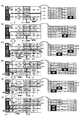
図11は、本発明の変形例における非存在領域及び不明領域の移動手法を説明するための一例の図を示す。 FIG. 11 is a diagram illustrating an example for explaining a moving method of the non-existing area and the unknown area in the modified example of the present invention.
例えば、図11に示す如く、道路脇に設置されたセンサ16の監視対象領域に互いに逆方向を進行方向とする2車線ずつの道路60,62,64,66が含まれ、かつ、走行する車両それぞれにGPS装置40が搭載される場合において、時刻t1において、車両Aに搭載されたGPS装置40により車両の位置情報が検出され、かつ、センサ16の監視対象領域に物体が存在しないことが判定されると、その監視対象領域が道路60〜66ごとに非存在領域Se1,Se2,Se3,Se4の初期位置として設定される(図11(A))。 For example, as shown in FIG. 11, the monitoring target area of the
その後、各道路60〜66の非存在領域Se1,Se2,Se3,Se4が時間経過に伴って当該道路60〜66の進行方向に向けて移動される。そして、時刻t2において、車両Aがセンサ16に最も近い車線道路60(最接近車線道路60)を走行して他の車線道路62,64,66上のセンサ16の監視対象領域を隠すと、センサ16の全監視対象領域のうち最接近車線道路60以外の3つの車線道路62,64,66における監視対象領域が不明領域Su1,Su2,Su3として設定される(図11(B))。 Thereafter, the non-existing areas Se1, Se2, Se3, Se4 of the
その後、各道路60〜66の非存在領域Se1,Se2,Se3,Se4及び不明領域Su1,Su2,Su3が時間経過に伴って当該道路60〜66の進行方向に向けて移動される。そして、時刻t3において、車両Aがセンサ16の監視対象領域から外れると、センサ16の監視対象領域が道路60〜66ごとに非存在領域Se5,Se6,Se7,Se8の初期位置として設定される(図11(C))。 Thereafter, the non-existing areas Se1, Se2, Se3, Se4 and the unknown areas Su1, Su2, Su3 of the
またその後、各道路60〜66の非存在領域及び不明領域が時間経過に伴って当該道路60〜66の進行方向に向けて移動される。そして、時刻t4において、道路信号機18が進入禁止を示す赤色となって非存在領域Se1の移動が停止された箇所に車両Aが到達すると、その非存在領域Se1の移動が停止された箇所が非存在領域Se1から車両Aの存在領域Saへ切り替わる。また、非存在領域Se2の移動が停止された箇所に不明領域Su1が到達すると、その非存在領域Se2の移動が停止された箇所が非存在領域Se2から不明領域Su1へ切り替わる。更に、時刻t4において、車両Bがセンサ16側から2番目の車線道路62(2番車線道路62)を走行してその2番車線道路62よりもセンサ16から遠い側の車線道路64,66上のセンサ16の監視対象領域を隠すと、センサ16の全監視対象領域のうち、最接近車線道路60における監視対象領域が非存在領域Se9として設定され、かつ、2番車線道路62よりもセンサ16から遠い側の車線64,66における監視対象領域が不明領域Su4,Su5として設定される(図11(D))。 Thereafter, the non-existing area and the unknown area of each
その後、各道路60〜66の非存在領域及び不明領域が時間経過に伴って当該道路60〜66の進行方向に向けて移動される。そして、時刻t5において、車両Aの存在領域Saに非存在領域Se5が到達しても、その車両Aの存在がGPS装置40を用いて検出されるので、その非存在領域Se5は消滅する。また、不明領域Su1に非存在領域Se6が到達しても、その不明領域Su1に物体が存在する可能性があるので、その非存在領域Se6は消滅する。更に、時刻t5において、車両Bがセンサ16の監視対象領域から外れると、センサ16の監視対象領域が道路60〜66ごとに非存在領域Se10,Se11,Se12,Se13の初期位置として設定される(図11(E))。 Thereafter, the non-existing area and the unknown area of each of the
その後、各道路60〜66の非存在領域及び不明領域が時間経過に伴って当該道路60〜66の進行方向に向けて移動される。そして、時刻t6において、不明領域Su1に車両Bが到達すると、その車両Bの存在がGPS装置40を用いて検出されるので、その不明領域Su1が消滅して、その不明領域Su1であった箇所が車両Bの存在領域Saへ切り替わる。更に、時刻t6において、センサ16の監視対象領域に何ら物体が存在しないと、センサ16の監視対象領域が道路60〜66ごとに非存在領域Se14,Se15,Se16,Se17の初期位置として設定される(図11(F))。 Thereafter, the non-existing area and the unknown area of each of the
かかる変形例においては、センサ16などを用いて車両や人などの物体が存在する存在領域及びその物体が存在するか否かが不明である不明領域をそれぞれ検出しつつ、存在領域ではない未知領域のうちセンサ16等の監視対象領域を非存在領域の初期位置又は不明領域として設定し、それらの非存在領域及び不明領域を時間経過に伴って道路地図上で伝搬・移動させることができる。そして、衝突確率が高い存在領域及び物体の存在有無が不明である不明領域に車両を誘導せず、衝突確率が低い非存在領域に車両を誘導する運転支援制御を実行することができる。従って、本変形例においても、物体が存在する存在領域ではない未知領域のうち不明領域と区別された非存在領域に車両を誘導することで、より高度な運転支援制御を実行することが可能である。 In such a modified example, an unknown region that is not a presence region is detected by using the
また、上記の実施例においては、物体が存在することが検出された非存在領域に車両を誘導する一方で、物体の存在有無が不明である不明領域に車両を誘導しないこととしている。しかし、本発明はこれに限定されるものではなく、車両を走行させる領域として非存在領域を不明領域に比して優先させるものであればよく、不明領域に車両を誘導することがあってもよい。例えば、不明領域への車両誘導として、車両運転者に徐行運転を勧め若しくは注意を喚起し、又は、車両の自動運転時に不明領域に進入せざるを得ないときには車両運転をその自動運転から車両運転者による手動運転へ切り替えるものであってもよい。 In the above embodiment, the vehicle is guided to the non-existing area where the presence of the object is detected, while the vehicle is not guided to the unknown area where the presence or absence of the object is unknown. However, the present invention is not limited to this, as long as the non-existing area is given priority over the unknown area as the area where the vehicle travels, and the vehicle may be guided to the unknown area. Good. For example, as vehicle guidance to an unknown area, the vehicle driver is encouraged or alerted to drive slowly, or when the vehicle has to enter the unknown area during automatic driving, the vehicle operation is switched from the automatic driving to the vehicle driving. It may be switched to manual operation by a person.
10 車両運転支援システム
12 車載装置
14 センタ
16 センサ
28 マッチング部
30 位置情報データベース
32 識別部
34 分割部
36 消滅処理/移動予測部
40 GPS装置
42,44 レーダ装置
48 ECUDESCRIPTION OF
Claims (3)
Translated fromJapanese前記検出手段により検出された物体が存在する存在領域ではない領域を、物体が存在しないと判断される非存在領域と、物体が存在するか否かが不明である不明領域と、に区別する領域判別手段と、
車両を前記不明領域ではなく前記非存在領域に誘導する運転支援制御を実行する制御手段と、
を備え、
前記検出手段は、少なくとも、前記車両に設けられているセンサ、および、前記車両の外部に設けられているセンサを含む、複数のセンサを有し、当該複数のセンサから取得した複数の情報に基づいて、前記物体が存在することを検出し、
前記制御手段は、前記領域判別手段による判別結果を、無線通信によって前記車両の外部に設けられている情報処理装置から取得し、当該判別結果に基づいて、前記運転支援制御を実行する
ことを特徴とする車両運転支援システム。Detection means for detecting an object;
An area that is not an existing area in which an object detected by the detecting means exists is classified into a non-existing area in which it is determined that no object exists and an unknown area in which it is unknown whether or not an object exists Discrimination means;
Control means for performing driving support control for guiding the vehicle to the non-existing area instead of the unknown area;
Equipped witha,
The detection means has a plurality of sensors including at least a sensor provided in the vehicle and a sensor provided outside the vehicle, and is based on a plurality of information acquired from the plurality of sensors. Detecting the presence of the object,
The control means acquires a determination result by the area determination means from an information processing device provided outside the vehicle by wireless communication, and executes the driving support control based on the determination result. A vehicle driving support system.
The area discriminating means sets, as the non-existing area, an area sandwiched between the two existing areas in which objects that move in the same direction by the detecting means are detected, and other than the non-existing area and the non-existing area The vehicle driving support system according to claim1 , wherein the region is set as the unknown region.
Priority Applications (4)
| Application Number | Priority Date | Filing Date | Title |
|---|---|---|---|
| JP2015026913AJP6359986B2 (en) | 2015-02-13 | 2015-02-13 | Vehicle driving support system |
| US15/012,165US10493983B2 (en) | 2015-02-13 | 2016-02-01 | Vehicle driving support system |
| CN201610076458.4ACN105894854B (en) | 2015-02-13 | 2016-02-03 | vehicle driver assistance system |
| DE102016102143.1ADE102016102143B4 (en) | 2015-02-13 | 2016-02-08 | Vehicle driving support system |
Applications Claiming Priority (1)
| Application Number | Priority Date | Filing Date | Title |
|---|---|---|---|
| JP2015026913AJP6359986B2 (en) | 2015-02-13 | 2015-02-13 | Vehicle driving support system |
Publications (2)
| Publication Number | Publication Date |
|---|---|
| JP2016149100A JP2016149100A (en) | 2016-08-18 |
| JP6359986B2true JP6359986B2 (en) | 2018-07-18 |
Family
ID=56552506
Family Applications (1)
| Application Number | Title | Priority Date | Filing Date |
|---|---|---|---|
| JP2015026913AActiveJP6359986B2 (en) | 2015-02-13 | 2015-02-13 | Vehicle driving support system |
Country Status (4)
| Country | Link |
|---|---|
| US (1) | US10493983B2 (en) |
| JP (1) | JP6359986B2 (en) |
| CN (1) | CN105894854B (en) |
| DE (1) | DE102016102143B4 (en) |
Families Citing this family (21)
| Publication number | Priority date | Publication date | Assignee | Title |
|---|---|---|---|---|
| JP6223504B1 (en)* | 2016-05-18 | 2017-11-01 | 三菱電機株式会社 | Radar device and sensor fusion device using the same |
| JP7014508B2 (en)* | 2016-08-08 | 2022-02-01 | シャープ株式会社 | Autonomous driving device and autonomous driving control method and control program |
| US10852418B2 (en)* | 2016-08-24 | 2020-12-01 | Magna Electronics Inc. | Vehicle sensor with integrated radar and image sensors |
| TW201820287A (en)* | 2016-11-18 | 2018-06-01 | 微星科技股份有限公司 | In-vehicle system and operation method thereof |
| US11180141B2 (en)* | 2016-12-05 | 2021-11-23 | Mazda Motor Corporation | Vehicle control system |
| JP6648721B2 (en)* | 2017-03-09 | 2020-02-14 | オムロン株式会社 | Support device, support method, and program |
| JP6865087B2 (en)* | 2017-03-30 | 2021-04-28 | 三菱重工業株式会社 | Vehicle control devices, positioning systems, control methods and programs |
| JP2018173729A (en)* | 2017-03-31 | 2018-11-08 | パナソニックIpマネジメント株式会社 | Automatic operation control method, automatic operation control apparatus and program using the same |
| JP6705414B2 (en)* | 2017-04-06 | 2020-06-03 | トヨタ自動車株式会社 | Operating range determination device |
| CN108725439A (en)* | 2017-04-14 | 2018-11-02 | 阿尔派株式会社 | Drive assistance device and driving assistance method |
| US10019011B1 (en)* | 2017-10-09 | 2018-07-10 | Uber Technologies, Inc. | Autonomous vehicles featuring machine-learned yield model |
| CA3087361A1 (en)* | 2018-01-05 | 2019-07-11 | Driving Brain International Ltd. | Autonomous driving methods and systems |
| JP7422687B2 (en)* | 2018-06-18 | 2024-01-26 | ズークス インコーポレイテッド | Occlusion awareness planning |
| US10642275B2 (en) | 2018-06-18 | 2020-05-05 | Zoox, Inc. | Occulsion aware planning and control |
| DE102018132523A1 (en)* | 2018-12-17 | 2020-06-18 | Trw Automotive Gmbh | Method and system for controlling a motor vehicle |
| JP6896023B2 (en)* | 2019-07-02 | 2021-06-30 | 三菱電機株式会社 | Vehicle approach notification system and vehicle approach notification method |
| JP7382782B2 (en)* | 2019-10-09 | 2023-11-17 | 日産自動車株式会社 | Object recognition method and object recognition system |
| JP7388238B2 (en)* | 2020-02-21 | 2023-11-29 | トヨタ自動車株式会社 | driving assistance system |
| JP7405657B2 (en)* | 2020-03-17 | 2023-12-26 | 本田技研工業株式会社 | Mobile monitoring system and mobile monitoring method |
| FR3135540B1 (en)* | 2022-05-10 | 2024-11-08 | Psa Automobiles Sa | Method for controlling driving assistance functions of a motor vehicle when crossing a junction |
| JP2024051893A (en)* | 2022-09-30 | 2024-04-11 | 本田技研工業株式会社 | Area monitoring system and area monitoring method |
Family Cites Families (19)
| Publication number | Priority date | Publication date | Assignee | Title |
|---|---|---|---|---|
| JP3174833B2 (en) | 1999-10-27 | 2001-06-11 | 建設省土木研究所長 | Right turn collision prevention system |
| JP4546383B2 (en)* | 2005-11-04 | 2010-09-15 | アルパイン株式会社 | Vehicle driving support device |
| JP4645429B2 (en)* | 2005-12-01 | 2011-03-09 | アイシン・エィ・ダブリュ株式会社 | Vehicle position calculation method and in-vehicle device |
| JP4953313B2 (en)* | 2007-09-10 | 2012-06-13 | 公立大学法人首都大学東京 | Environment recognition system, autonomous mobile body and environment recognition program |
| JP5200568B2 (en) | 2008-02-08 | 2013-06-05 | 沖電気工業株式会社 | In-vehicle device, vehicle running support system |
| JP4939564B2 (en)* | 2009-03-23 | 2012-05-30 | 本田技研工業株式会社 | Vehicle information providing device |
| GB2466318B (en)* | 2009-04-08 | 2011-01-05 | Stephen Edward Britt | Auxillary drive for a cycle |
| US8918209B2 (en)* | 2010-05-20 | 2014-12-23 | Irobot Corporation | Mobile human interface robot |
| JP5678793B2 (en)* | 2011-05-11 | 2015-03-04 | トヨタ自動車株式会社 | Perimeter monitoring device, perimeter monitoring method, and driving support device |
| JP2013004021A (en)* | 2011-06-21 | 2013-01-07 | Toyota Motor Corp | Collision risk determination device |
| JP5910634B2 (en)* | 2011-09-26 | 2016-04-27 | トヨタ自動車株式会社 | Vehicle driving support system |
| US8791835B2 (en)* | 2011-10-03 | 2014-07-29 | Wei Zhang | Methods for road safety enhancement using mobile communication device |
| EP2765046B1 (en)* | 2011-10-03 | 2020-02-12 | Toyota Jidosha Kabushiki Kaisha | Driving assistance system for vehicle |
| WO2013051082A1 (en)* | 2011-10-03 | 2013-04-11 | トヨタ自動車株式会社 | Vehicle driving support system |
| JP5708438B2 (en) | 2011-10-26 | 2015-04-30 | 株式会社デンソー | Vehicle-to-vehicle communication system and vehicle-to-vehicle communication device |
| JP5573876B2 (en) | 2012-03-27 | 2014-08-20 | 株式会社デンソー | Peripheral vehicle determination device |
| DE102012006986A1 (en) | 2012-04-05 | 2013-10-10 | Gm Global Technology Operations, Llc | Method for forecasting available traffic space for ego vehicle in highway and road, involves marking prohibited area adjacent to interference location as non-traffic space for ego vehicle, if interference is present |
| DE102012009297A1 (en) | 2012-05-03 | 2012-12-13 | Daimler Ag | Method for assisting rider when feeding e.g. vehicle, involves proving information, warning and automatic engagement, which results during risk of collision and/or secondary collision with highest priority in priority list |
| JP6123531B2 (en)* | 2013-07-05 | 2017-05-10 | トヨタ自動車株式会社 | Driving support device and driving support method |
- 2015
- 2015-02-13JPJP2015026913Apatent/JP6359986B2/enactiveActive
- 2016
- 2016-02-01USUS15/012,165patent/US10493983B2/enactiveActive
- 2016-02-03CNCN201610076458.4Apatent/CN105894854B/enactiveActive
- 2016-02-08DEDE102016102143.1Apatent/DE102016102143B4/enactiveActive
Also Published As
| Publication number | Publication date |
|---|---|
| DE102016102143A1 (en) | 2016-08-18 |
| CN105894854B (en) | 2019-09-06 |
| JP2016149100A (en) | 2016-08-18 |
| DE102016102143B4 (en) | 2024-08-01 |
| CN105894854A (en) | 2016-08-24 |
| US10493983B2 (en) | 2019-12-03 |
| US20160236682A1 (en) | 2016-08-18 |
Similar Documents
| Publication | Publication Date | Title |
|---|---|---|
| JP6359986B2 (en) | Vehicle driving support system | |
| JP4967015B2 (en) | Safe driving support device | |
| US11282388B2 (en) | Edge-assisted alert system | |
| US10126751B2 (en) | Lane change support device | |
| CN106891888B (en) | Vehicle turn signal detection | |
| JP5880580B2 (en) | Vehicle behavior prediction device, vehicle behavior prediction method, and driving support device | |
| US20190039613A1 (en) | Apparatus and method for changing route of vehicle based on emergency vehicle | |
| WO2016009600A1 (en) | Drive assist device | |
| WO2015115159A1 (en) | Automatic driving assistance device, automatic driving assistance method, and program | |
| EP3675079A1 (en) | Danger warning method for vehicle, danger warning device for vehicle, and medium | |
| JP6575612B2 (en) | Driving support method and apparatus | |
| JP6547434B2 (en) | Stop position setting apparatus and method | |
| JP6007739B2 (en) | Driving support device and driving support method | |
| KR20190035159A (en) | Vehicle motion prediction method and apparatus | |
| CN109383367B (en) | Vehicle external notification device | |
| CN110662683A (en) | Driving assistance device and driving assistance method | |
| WO2016181618A1 (en) | Monitored area setting device and monitored area setting method | |
| CN109318792A (en) | Vehicle external notification device | |
| KR20170119842A (en) | Apparatus and method for controlling autonomous driving vehicle | |
| JP2022515420A (en) | How to support a car | |
| KR20160080231A (en) | System and method for warning danger in driving section | |
| CN113370972A (en) | Travel control device, travel control method, and computer-readable storage medium storing program | |
| JP2015207157A (en) | Alarm device for vehicle | |
| EP4434838A1 (en) | Preventing accidents in a t-intersection using predictive collision avoidance | |
| US20230398866A1 (en) | Systems and methods for heads-up display |
Legal Events
| Date | Code | Title | Description |
|---|---|---|---|
| A621 | Written request for application examination | Free format text:JAPANESE INTERMEDIATE CODE: A621 Effective date:20160511 | |
| A977 | Report on retrieval | Free format text:JAPANESE INTERMEDIATE CODE: A971007 Effective date:20170322 | |
| A131 | Notification of reasons for refusal | Free format text:JAPANESE INTERMEDIATE CODE: A131 Effective date:20170328 | |
| A521 | Request for written amendment filed | Free format text:JAPANESE INTERMEDIATE CODE: A523 Effective date:20170529 | |
| A131 | Notification of reasons for refusal | Free format text:JAPANESE INTERMEDIATE CODE: A131 Effective date:20171031 | |
| A521 | Request for written amendment filed | Free format text:JAPANESE INTERMEDIATE CODE: A523 Effective date:20171227 | |
| TRDD | Decision of grant or rejection written | ||
| A01 | Written decision to grant a patent or to grant a registration (utility model) | Free format text:JAPANESE INTERMEDIATE CODE: A01 Effective date:20180529 | |
| A61 | First payment of annual fees (during grant procedure) | Free format text:JAPANESE INTERMEDIATE CODE: A61 Effective date:20180621 | |
| R151 | Written notification of patent or utility model registration | Ref document number:6359986 Country of ref document:JP Free format text:JAPANESE INTERMEDIATE CODE: R151 | |
| S533 | Written request for registration of change of name | Free format text:JAPANESE INTERMEDIATE CODE: R313533 | |
| R350 | Written notification of registration of transfer | Free format text:JAPANESE INTERMEDIATE CODE: R350 | |
| R250 | Receipt of annual fees | Free format text:JAPANESE INTERMEDIATE CODE: R250 | |
| R250 | Receipt of annual fees | Free format text:JAPANESE INTERMEDIATE CODE: R250 | |
| R250 | Receipt of annual fees | Free format text:JAPANESE INTERMEDIATE CODE: R250 | |
| R250 | Receipt of annual fees | Free format text:JAPANESE INTERMEDIATE CODE: R250 | |
| R250 | Receipt of annual fees | Free format text:JAPANESE INTERMEDIATE CODE: R250 |