JP6356449B2 - Sensor diagnostic device, sensor diagnostic method, and computer program - Google Patents
Sensor diagnostic device, sensor diagnostic method, and computer programDownload PDFInfo
- Publication number
- JP6356449B2 JP6356449B2JP2014057002AJP2014057002AJP6356449B2JP 6356449 B2JP6356449 B2JP 6356449B2JP 2014057002 AJP2014057002 AJP 2014057002AJP 2014057002 AJP2014057002 AJP 2014057002AJP 6356449 B2JP6356449 B2JP 6356449B2
- Authority
- JP
- Japan
- Prior art keywords
- sensor
- combination
- value
- diagnostic
- unit
- Prior art date
- Legal status (The legal status is an assumption and is not a legal conclusion. Google has not performed a legal analysis and makes no representation as to the accuracy of the status listed.)
- Active
Links
Images


Classifications
- G—PHYSICS
- G01—MEASURING; TESTING
- G01D—MEASURING NOT SPECIALLY ADAPTED FOR A SPECIFIC VARIABLE; ARRANGEMENTS FOR MEASURING TWO OR MORE VARIABLES NOT COVERED IN A SINGLE OTHER SUBCLASS; TARIFF METERING APPARATUS; MEASURING OR TESTING NOT OTHERWISE PROVIDED FOR
- G01D21/00—Measuring or testing not otherwise provided for
- G01D21/02—Measuring two or more variables by means not covered by a single other subclass
- G—PHYSICS
- G01—MEASURING; TESTING
- G01D—MEASURING NOT SPECIALLY ADAPTED FOR A SPECIFIC VARIABLE; ARRANGEMENTS FOR MEASURING TWO OR MORE VARIABLES NOT COVERED IN A SINGLE OTHER SUBCLASS; TARIFF METERING APPARATUS; MEASURING OR TESTING NOT OTHERWISE PROVIDED FOR
- G01D1/00—Measuring arrangements giving results other than momentary value of variable, of general application
- G01D1/16—Measuring arrangements giving results other than momentary value of variable, of general application giving a value which is a function of two or more values, e.g. product or ratio
Landscapes
- Physics & Mathematics (AREA)
- General Physics & Mathematics (AREA)
- Testing And Monitoring For Control Systems (AREA)
- Management, Administration, Business Operations System, And Electronic Commerce (AREA)
Description
Translated fromJapanese本発明の実施形態は、センサ割当て装置及びセンサ診断装置に関する。 Embodiments described herein relate generally to a sensor assignment device and a sensor diagnosis device.
近年、高層ビルなどの大規模な施設の設備点検において、センサやアクチュエータ(以下、まとめて「センサ」という)から定期的に取得されるデータに基づいて、自動で設備の異常を診断する自動診断が注目されている。自動診断を実現するために、診断モデルに計装図上のセンサを割当てる、すなわち、診断モデルの引数にセンサIDを割当てる作業は「オブジェクトマッピング」と呼ばれている。 In recent years, in equipment inspection of large-scale facilities such as high-rise buildings, automatic diagnosis that automatically diagnoses equipment abnormalities based on data periodically acquired from sensors and actuators (hereinafter collectively referred to as “sensors”) Is attracting attention. In order to realize automatic diagnosis, an operation of assigning a sensor on an instrumentation diagram to a diagnostic model, that is, assigning a sensor ID to an argument of the diagnostic model is called “object mapping”.
従来、オブジェクトマッピングを容易にするために、計装作業者の作業に連動して結線情報(センサIDやケーブル番号の一覧表)を記録していくことにより、計装図の作成や管理を支援する方法が提案されている。当該方法により作成された計装図に基づいて、診断モデルへのセンサの割当てを行うことができる。 Conventionally, to facilitate object mapping, the connection information (list of sensor IDs and cable numbers) is recorded in conjunction with the work of the instrumentation operator, thereby supporting the creation and management of instrumentation diagrams. A method has been proposed. Based on the instrumentation diagram created by the method, the sensor can be assigned to the diagnostic model.
しかしながら、上記従来の方法では、計装図は作成できるものの、診断モデルへのセンサの割当て方法まではわからない。したがって、オブジェクトマッピングを行うためには、計装図上のセンサと診断モデルとの組合せの中から、適切な組合せを探索しなければならない。これは、設置されたセンサの数が膨大な場合や、センサの設置箇所が複数の計装図にまたがる場合に問題となる。 However, although the above-described conventional method can create an instrumentation diagram, it does not know how to assign a sensor to a diagnostic model. Therefore, in order to perform object mapping, it is necessary to search for an appropriate combination from among combinations of sensors and diagnostic models on the instrumentation diagram. This becomes a problem when the number of installed sensors is enormous or when the installation locations of sensors extend over a plurality of instrumentation diagrams.
診断モデルに対してセンサを容易に割当てることができるセンサ割当て装置及びセンサ診断装置を提供する。 Provided are a sensor assignment device and a sensor diagnosis device that can easily assign a sensor to a diagnostic model.
一実施形態に係るセンサ割当て装置は、計測値記憶部と、生成部と、算出部と、選択部とを備える。計測値記憶部は、複数のセンサの計測値を記憶する。生成部は、複数の引数を有するセンサの診断関数の各引数に対して、センサを割当て、引数とセンサとの組合せを複数生成する。算出部は、生成部により生成された複数の組合せの各々について、計測値記憶部に記憶された計測値を代入して計算される診断関数の値に基づき評価値を算出する。選択部は、算出部により算出された各組合せの評価値に基づいて、複数の組合せの中から少なくとも1つの組合せを選択する。 A sensor assignment device according to an embodiment includes a measurement value storage unit, a generation unit, a calculation unit, and a selection unit. The measurement value storage unit stores measurement values of a plurality of sensors. The generation unit assigns a sensor to each argument of the diagnostic function of the sensor having a plurality of arguments, and generates a plurality of combinations of the argument and the sensor. The calculation unit calculates an evaluation value for each of the plurality of combinations generated by the generation unit based on the value of the diagnostic function calculated by substituting the measurement value stored in the measurement value storage unit. The selection unit selects at least one combination from a plurality of combinations based on the evaluation value of each combination calculated by the calculation unit.
以下、本発明の実施形態について図面を参照して説明する。以下で説明するセンサ割当て装置及びセンサ診断装置は、センサの計測値及び制御値(以下、まとめて「計測値」という)に基づいて、複数のセンサを設けられた施設における、センサの自動診断に用いることができる。また、センサの診断結果に基づいて、センサの計測値と関連する設備の自動診断に用いることもできる。具体的には、センサ割当て装置及びセンサ診断装置は、例えば、ビルや工場などに設けられた空調設備の自動診断や、上下水道設備の自動診断に用いることができる。 Embodiments of the present invention will be described below with reference to the drawings. The sensor assignment device and the sensor diagnosis device described below are used for automatic diagnosis of a sensor in a facility provided with a plurality of sensors based on the measurement values and control values of the sensors (hereinafter collectively referred to as “measurement values”). Can be used. Moreover, based on the diagnostic result of a sensor, it can also be used for the automatic diagnosis of the installation relevant to the measured value of a sensor. Specifically, the sensor assignment device and the sensor diagnosis device can be used for, for example, automatic diagnosis of air conditioning facilities provided in buildings, factories, and the like, and automatic diagnosis of water and sewage facilities.
(第1実施形態)
まず、第1実施形態に係るセンサ割当て装置の構成について、図1〜図8を参照して説明する。図1は、本実施形態に係るセンサ割当て装置の機能構成を示すブロック図である。図1のセンサ割当て装置は、センサ情報記憶部1と、診断モデル記憶部2と、正常計測値記憶部3と、診断モデル生成部4と、評価値算出部5と、診断モデル選択部6と、割当て結果記憶部7と、を備える。(First embodiment)
First, the configuration of the sensor assignment device according to the first embodiment will be described with reference to FIGS. FIG. 1 is a block diagram illustrating a functional configuration of the sensor assignment device according to the present embodiment. 1 includes a sensor
センサ情報記憶部1は、施設に設けられた複数のセンサに関するセンサ情報を記憶しており、記憶したセンサ情報を、後述する組合せ生成部4に入力する。センサ情報には、例えば、各センサのセンサID、センサの説明、及び属性情報が含まれる。センサIDは、各センサを識別するための識別情報である。属性情報は、センサIDにより特定される各センサの特徴を示す情報であり、例えば、計測属性、位置属性、及び種別属性が含まれる。計測属性とは、センサにより計測される物理量の単位を示す情報である。位置属性とは、センサが設けられた位置を示す情報である。種別属性とは、記憶される物理量が、センサの実際の計測値か、あるいは制御情報から取得された制御値かを示す情報である。属性情報は、各センサの特徴を示す情報であれば、上記の情報に限られない。 The sensor
ここで、図2は本実施形態に係るセンサ割当て装置が適用される空調設備の一例を示す計装図であり、図3は図2の計装図と対応してセンサ情報記憶部1に記憶されるセンサ情報の一例を示す図である。 Here, FIG. 2 is an instrumentation diagram showing an example of an air conditioning facility to which the sensor assignment apparatus according to the present embodiment is applied, and FIG. 3 is stored in the sensor
図2は、有向グラフであり、有向辺(図2における矢印)は、空調設備における空気や水の流れる配管及び方向を示している。有向辺の両端のノードは、機器、分岐点、及び部屋のような、空気や水の状態が変化する部分を示しており、それぞれ計装ノードIDが割り振られている。また、図2において、有向辺上及びノードには、センサが設けられており、それぞれセンサIDが割り振られている。以下では、センサIDがXのセンサを、単にセンサXという。 FIG. 2 is a directed graph, and directed edges (arrows in FIG. 2) indicate piping and directions through which air or water flows in the air conditioning equipment. Nodes at both ends of the directed side indicate portions where the state of air or water changes, such as devices, branch points, and rooms, and each is assigned an instrumentation node ID. In FIG. 2, sensors are provided on the directed side and the nodes, and sensor IDs are assigned to the sensors. Hereinafter, a sensor having a sensor ID of X is simply referred to as a sensor X.
図3は、図2に示した空調設備に対してセンサ情報記憶部1に記憶されるセンサ情報の一例を示している。図3において、センサ情報には、センサID、センサの説明、計測属性、種別属性、及び位置属性が含まれる。位置属性は、センサの計測対象(空気や水)の出発点(from)と終着点(to)とにより示されている。例えば、図2において、外気ノードと熱交換ノード02との間の有向辺上に設けられたセンサT1の位置属性は、出発点(from)が外気ノード、終着点(to)が熱交換ノード02となっている。 FIG. 3 shows an example of sensor information stored in the sensor
診断モデル記憶部2は、センサや設備の異常を診断するための診断モデルを少なくとも1つ記憶しており、記憶した診断モデルを、後述する組合せ生成部4に入力する。診断モデルには、例えば、記憶した各診断モデルのモデルID、モデル式、引数、及び属性情報が含まれる。モデルIDは、診断モデル記憶部2に複数の診断モデルが記憶されている場合に、各診断モデルを識別するための識別情報である。 The diagnostic
モデル式は、センサ及び設備を診断するために予め定められた診断関数である。モデル式では、計算のために用いられる計測値が、どのセンサの計測値であるか定められておらず、計測値を用いられるセンサは引数とされている。モデル式は、引数を複数有しており、各引数には、それぞれセンサが割当てられる。引数をxi(i=1,2,・・・)、モデル式をf(xi)と表した場合、モデル式f(xi)は、各引数xiに割当てられたセンサの測定値の関数となる。上述の通り、引数は診断モデル記憶部2に記憶されている。 The model formula is a predetermined diagnostic function for diagnosing sensors and equipment. In the model formula, it is not determined which sensor the measurement value used for the calculation is, and the sensor using the measurement value is an argument. The model formula has a plurality of arguments, and a sensor is assigned to each argument. When the argument is expressed as xi (i = 1, 2,...) And the model expression is expressed as f (xi), the model expression f (xi) is a function of the measured value of the sensor assigned to each argument xi. . As described above, the argument is stored in the diagnostic
属性情報は、センサ情報記憶部1に記憶された属性情報と同様に、各センサの特徴を示す情報であり、各引数に対して記憶される。診断モデル記憶部2に記憶される属性情報は、引数Xiに割当てられるセンサに要求される属性情報である。 The attribute information is information indicating the characteristics of each sensor, similar to the attribute information stored in the sensor
ここで、図4は、診断モデル記憶部2に記憶された診断モデルの一例を示す図である。図4において、診断モデルは2つ示されており、各診断モデルについて、モデルID、モデル式、引数、属性情報が記憶されている。例えば、診断モデルF0010のモデル式f(X|β)は、β1×X1×(X2−X3)−X4+β2である。モデル式f(X|β)は、引数Xiに割当てられたセンサが正常なときにf(X|β)=0を満たすことが想定されている。式中のβi(i=1,2)は、引数Xi(i=1〜4)にセンサが割当てられたのち、後述する評価値が算出される際に同時に決定される調整量(パラメータ)である。 Here, FIG. 4 is a diagram illustrating an example of a diagnostic model stored in the diagnostic
正常計測値記憶部3は、事前(過去)に計測した基準とすべき計測値であって、正常とみなせる計測値を記憶しており、記憶した計測値を、後述する評価値算出部5に入力する。正常とみなせる計測値としては、例えば診断対象となる複数のセンサが正常な状態で動作しているときに計測した計測値を用いることができる。評価値算出部5は、この計測値に基づいてセンサの異常の有無を診断する。 The normal measurement
ここで、図5は、正常計測値記憶部3に記憶された計測値の一例を示す図である。図5において、各日時に計測された各センサの計測値が、10分間隔で記憶されている。このように、正常計測値記憶部3は、計測タイミングが同期している各センサの計測値の組を、所定の時間間隔で複数記憶するのが好ましい。これは、センサが正常な状態であっても、センサの計測値は経時的に変化するため、センシングのタイミングが同期していないとセンサの異常の有無を診断することができないためである。 Here, FIG. 5 is a diagram illustrating an example of the measurement values stored in the normal measurement
なお、正常計測値記憶部3は、各センサの計測値を記憶する記憶部であってもよい。この場合、正常計測値記憶部3は、記憶された各センサの計測値のうち、各センサが正常な状態で動作していたことが判明している日時の計測値を評価値算出部5に入力する。 The normal measurement
組合せ生成部4は、センサ情報記憶部1からセンサ情報を取得し、診断モデル記憶部2から診断モデルを取得し、診断モデルのモデル式の各引数に対して各センサ(センサID)を割当てる。これにより、診断モデルと、当該診断モデルに割当てられたセンサとの組合せが生成される。組合せ生成部4は、このような組合せを複数生成する。組合せ生成部4は、生成した複数の組合せを、評価値算出部5に入力する。 The
組合せ生成部4は、例えば、診断モデルの引数に対して、センサを無作為に割当て、組合せを網羅的に生成する。この場合、N個の引数とM個のセンサに対して、最大でM!/(N−M)!(=MPN)個の組合せが生成される。For example, the
また、組合せ生成部4は、引数の属性情報とセンサの属性情報とに応じて、センサを引数に割当て、診断モデルとセンサとの組合せを生成することもできる。具体的には、組合せ生成部4は、引数の属性情報を参照し、参照した属性情報と一致する属性情報を有するセンサを当該引数に割当てる。これにより、生成される組合せの数を減少させ、センサの割当てに要する時間を短縮することができる。 The
ここで、図6は、組合せ生成部4により生成された診断モデルとセンサとの組合せの一例を示す図である。図6の組合せは、図3のセンサ情報と、図4の診断モデルとに基づいて生成されている。図6に示すように、各組合せには組合せIDが割り振られている。例えば、組合せC001において、診断モデルF0010の引数Xi(i=1〜4)に対して、引数X1にセンサT1、引数X2にセンサT2、引数X3にセンサQ1、引数X4にセンサV1がそれぞれ割当てられている。診断モデルF0010には、引数X5が含まれないため、引数X5の欄はnull(空値)となっている。 Here, FIG. 6 is a diagram illustrating an example of a combination of a diagnostic model generated by the
組合せ生成部4が組合せを網羅的に生成した場合、図6に示す全ての組合せが生成される。これに対して、組合せ生成部4が、引数の位置属性とセンサの位置属性が一致するように組合せを生成した場合、図6に示す組合せのうち、組合せC101〜C103が生成される。また、組合せ生成部4が、引数の計測属性及び位置属性とセンサの計測属性及び位置属性が一致するように組合せを生成した場合、図6に示す組合せのうち、組合せC103が生成される。このように、組合せ生成部4は、組合せを生成するために、1つの属性情報を用いてもよいし、複数の属性情報を用いてもよい。 When the
評価値算出部5は、組合せ生成部4から生成された複数の組合せを取得し、正常計測値記憶部3から各センサの計測値を取得し、各組合せの評価値を算出する。評価値とは、生成された組合せが、センサの診断に適する度合いを示す数値である。評価値は、各組合せを構成する診断モデルに含まれるモデル式に、各組合せにおいて割当てられたセンサの計測値を代入し、得られた値(以下、「モデル値」という)に基づいて算出される。モデル式に代入されるセンサの計測値は、上述の通り、センシングのタイミングが同期していることが好ましい。また、センサの診断に適した診断モデルとセンサとの組合せを精度よく選択するために、モデル値は複数の正常値のサンプルから複数算出されるのが好ましい。 The evaluation
評価値は、モデル式の性質に応じて変化する。例えば、図4のモデル式f(X|β)のように、正常なセンサの計測値を代入すると、モデル値が所定値になることが想定されるモデル式の場合には、評価値算出部5は、評価値としてモデル値を用いればよい。これは、モデル値が所定値又は所定値に近いことが、組合せがセンサの診断に適していることを示すためである。また、このようなモデル式の場合には、複数のモデル値のばらつき度(分散や平均偏差など)を評価値として用いることもできる。 The evaluation value changes according to the property of the model formula. For example, in the case of a model formula in which the model value is assumed to be a predetermined value when a measured value of a normal sensor is substituted as in the model formula f (X | β) in FIG. 5 may use a model value as an evaluation value. This is because that the model value is a predetermined value or close to a predetermined value indicates that the combination is suitable for sensor diagnosis. In the case of such a model formula, the degree of variation (variance, average deviation, etc.) of a plurality of model values can also be used as an evaluation value.
あるいは、正常なセンサの計測値を代入すると、モデル値がなんらかの計測値と相関を示すことが想定されるモデル式の場合には、評価値算出部5は、回帰分析により評価値を算出することができる。例えば、モデル値を目的変数、モデル値と相関のあるパラメータを説明変数とした回帰式を算出し、当該回帰式と複数のモデル値との最小二乗誤差の和を評価値として用いることができる。この場合、最小二乗誤差の和が小さいほど、センサの診断に適した組合せであることを示している。また、モデル値と計測値との間の相関係数を評価値として用いることも可能である。この場合、相関係数が高いほど、センサの診断に適した組合せであることを示している。パラメータとして、例えば、センサの計測値や外気温度などが挙げられる。 Alternatively, when a measurement value of a normal sensor is substituted, in the case of a model formula in which the model value is assumed to correlate with some measurement value, the evaluation
評価値算出部5は、組合せ生成部4から入力された複数の組合せと、算出した各組合せの評価値と、を組合せ選択部6に入力する。また、評価値を算出する過程で、モデル式f(X|β)におけるβのような調整量が算出された場合には、組合せ選択部6に調整量を入力してもよい。 The evaluation
組合せ選択部6は、評価値算出部5から入力された複数の組合せの中から、評価値に基づいて、センサの診断に適した組合せを少なくとも1つ選択する。組合せ選択部6は、各組合せの評価値を参照して、センサの診断に最も適した組合せを1つ選択してもよいし、評価値が所定の範囲に含まれる組合せを1つ以上選択してもよい。組合せ選択部6は、選択した組合せを割当て結果記憶部7に入力する。 The
割当て結果記憶部7は、組合せ選択部6により選択された、診断モデルとセンサとの組合せを記憶する。割当て結果記憶部7に記憶された組合せは、センサの診断に適した組合せであるため、割当てられた各センサの計測値をモデル式に代入し、得られたモデル値と、想定されるモデル値とを比較することにより、割当てられたセンサの異常を診断することができる。 The allocation
ここで、図7は、割当て結果記憶部7に記憶された組合せの一例を示す図である。図7に示す組合せを用いてセンサの異常を診断する場合、診断モデルF0010のモデル式の引数Xi(i=1〜4)に、それぞれセンサV1,T2,T1,Q1の計測値を代入し、得られたモデル値と想定されるモデル値(=0)とを比較することにより、センサV1,T2,T1,Q1の異常を診断することができる。なお、割当て結果記憶部7は、センサを診断するために、評価値や調整量を記憶してもよい。 Here, FIG. 7 is a diagram illustrating an example of combinations stored in the allocation
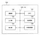
以上説明したセンサ割当て装置は、センサ割当て装置は、コンピュータ装置100を基本ハードウェアとして使用することで実現することができる。コンピュータ装置100は、図8に示すように、CPU101、入力部101、表示部103、通信部104、主記憶部105、外部記憶部106を備え、これらはバス107により相互に通信可能に接続される。 The sensor assignment device described above can be realized by using the
入力部102は、キーボード、マウス等の入力デバイスを備え、入力デバイスの操作による操作信号をCPU101に出力する。表示部103は、LCD(Liquid Crystal Display)、CRT(Cathode Ray Tube)等の表示ディスプレイを含む。通信部104は、無線または有線の通信手段を有し、所定の通信方式で通信を行う。外部記憶部106は、例えば、ハードディスク、メモリ装置、CD−R、CD−RW、DVD−RAM、DVD−R等の記憶媒体等を含む。外部記憶部106は、センサ割当て装置の処理をCPU101に実行させるための制御プログラムを記憶している。また、センサ割当て装置が備える各記憶手段のデータを記憶している。 The
主記憶部105は、CPU101による制御の下で、外部記憶部106に記憶された制御プログラムを展開し、当該プログラムの実行時に必要なデータ、当該プログラムの実行により生じたデータ等を記憶する。制御プログラムがCPU101により実行されることにより、組合せ生成部4、評価値算出部5、及び組合せ選択部6の機能構成が実現される。主記憶部105は、たとえば不揮発性メモリ等の任意のメモリを含む。センサ情報記憶部1、診断モデル記憶部2、正常計測値記憶部3、及び割当て結果記憶部7は、主記憶部105又は外部記憶部106により構成される。 The
上記制御プログラムは、コンピュータ装置100に予めインストールされていてもよいし、CD−ROM等の記憶媒体に記憶され、コンピュータ装置100に適宜インストールされてもよい。 The control program may be installed in advance in the
次に、本実施形態に係るセンサ割当て装置によるセンサ割当て処理について、図9を参照して説明する。ここで、図9は、本実施形態に係るセンサ割当て装置の動作を示すフローチャートである。 Next, sensor assignment processing by the sensor assignment apparatus according to the present embodiment will be described with reference to FIG. Here, FIG. 9 is a flowchart showing the operation of the sensor assignment device according to the present embodiment.
本実施形態に係るセンサ割当て装置によるセンサの割当て処理は、例えば、所定期間ごとに定期的に、あるいはリノベーションにより設備の増設や変更があった場合に行われる。割当て処理が開始されると、まず、組合せ生成部4は、センサ情報記憶部1からセンサ情報(図3参照)を取得し、診断モデル記憶部2から診断モデル(図4参照)を取得する(ステップS1)。 The sensor assignment processing by the sensor assignment device according to the present embodiment is performed, for example, periodically every predetermined period or when facilities are added or changed by renovation. When the allocation process is started, first, the
次に、組合せ生成部4は、取得した診断モデルの中から、割当て処理を実施する診断モデルを選択する(ステップS2)。組合せ生成部4は、選択した診断モデルに含まれる各引数に対してそれぞれセンサを割当て、センサと診断モデルとの組合せを1つ作成する(ステップS3)。この際、組合せ生成部4は、引数に対してセンサを網羅的に割当てる。これにより、例えば、図6に示す組合せC001が生成される。 Next, the
次に、組合せ生成部4は、組合せられた各センサの属性情報と各引数の属性情報とが一致しているか判定する(ステップS4)。属性情報が一致している場合(ステップS4のYES)、組合せ生成部4は、生成された組合せを一時記憶し、全ての組合せが生成されたか判定する(ステップS5)。全ての組合せが生成されていない場合(ステップS5のNO)、組合せ生成部4は次の組合せを生成する。センサ割当て装置は、生成された組合せを一時的に記憶する一時記憶部を備えるのが好ましい。 Next, the
属性情報が一致していない場合(ステップS4のNO)、組合せ生成部4は、生成された組合せを破棄し、次の組合せを生成する(ステップS3)。ステップS4において判定に用いる属性情報は、任意に選択可能である。例えば、計測属性を用いて判定する場合、組合せC001の引数X1の計測属性とセンサT1の計測属性とが比較される。X1の計測属性はm3/sであり(図4参照)、センサT1の計測属性は℃である(図3参照)ため、属性情報が一致しない。したがって、組合せ生成部4は、組合せC001を破棄し、次の組合せを生成する。次の組合せとして、例えば、組合せC002が生成される。If the attribute information does not match (NO in step S4), the
上記のステップS3〜ステップS5を繰り返すことにより、選択した診断モデルに関して、属性情報が一致した全ての組合せが生成される(ステップS5のYES)。なお、組合せ生成部4が属性情報を用いずに網羅的に組合せを生成する場合には、上述のステップS4を省略してもよい。 By repeating the above steps S3 to S5, all combinations having the same attribute information are generated for the selected diagnostic model (YES in step S5). In addition, when the combination production |
全ての組合せが生成されると、組合せ生成部4は一時記憶した組合せを評価値算出部5に入力する。評価値算出部5は、組合せ生成部4から生成された組合せを取得し、正常計測値記憶部3から各センサの計測値を取得する(ステップS6)。 When all the combinations are generated, the
評価値算出部5は、取得した計測値に基づいて、取得した各組合せの評価値を算出する(ステップS7)。算出する評価値は、診断モデルに含まれるモデル式に応じて任意に選択可能である。例えば、評価値算出部5は、各組合せについて、計測日時が2013/9/13 8:00の計測値をモデル式に代入してモデル値を算出し、以降計測日時が10分間隔の計測値ごとにモデル値を算出する。こうして算出された複数のモデル値から、回帰分析により最小二乗誤差の和と回帰係数とを算出し、評価値として最小二乗誤差の和を、モデル式の調整量βとして回帰係数を一時記憶する。センサ割当て装置は、算出された評価値及び調整量(以下、「評価値等」という)を一時的に記憶する一時記憶部を備えるのが好ましい。評価値算出部5は、算出した評価値等及び評価値等が対応する組合せを組合せ選択部6に入力する。 The evaluation
組合せ選択部6は、評価値算出部5から評価値等と組合せとを取得すると(ステップS8)、取得した組合せの中から評価値に基づいて、センサの診断に適した組合せを選択する(ステップS9)。組合せ選択部6は、例えば、評価値として最小二乗誤差の和を取得した場合、評価値が小さい組合せを選択する。組合せ選択部6は、センサの診断に最も適した1つの組合せを選択してもよいし、センサの診断に適した2つ以上の組合せを選択してもよい。 When the
組合せ選択部6は、選択した組合せを割当て結果記憶部7に記憶させ、全ての診断モデルを選択済みか否か判定する(ステップS10)。すなわち、組合せ生成部4が取得した全ての診断モデルについてステップS3〜ステップS9の処理が行われ、組合せを選択したが否か判定する。全ての診断モデルについて組合せを選択済みの場合(ステップS10のYES)、割当て処理は終了する。一方、図4に示すように、診断モデルが複数あり、未処理の診断モデルが存在する場合(ステップS10のNO)、割当て処理はステップS2に戻り、組合せ生成部4は次の診断モデルを選択し、再びステップS3〜ステップS9の処理が実行される。こうして、全ての診断モデルについて、組合せが選択される。 The
以上説明したとおり、本実施形態に係るセンサ割当て装置によれば、診断モデルに対して適切なセンサを自動的に割当てることができるため、診断モデルや診断装置に関する専門的を必要とせずに、容易にセンサを割当てることができる。これと同時に、診断に必要な調整量などのパラメータも、診断モデルごとに自動的に求めることができる。 As described above, according to the sensor assignment device according to the present embodiment, an appropriate sensor can be automatically assigned to a diagnosis model, so that it is easy without requiring specialists related to the diagnosis model and the diagnosis device. Can be assigned a sensor. At the same time, parameters such as adjustment amounts necessary for diagnosis can be automatically obtained for each diagnosis model.
また、センサの割当てを自動的に行うことができるため、リノベーションなどにより設備が増加や変更された場合にも、迅速に新たなセンサの割当てを決定し、センサの診断を実行可能とすることができる。 In addition, since sensor allocation can be performed automatically, even when equipment is increased or changed due to renovation, etc., new sensor allocation can be quickly determined and sensor diagnosis can be executed. it can.
さらに、センサの属性情報と引数の属性情報とを用いて診断モデルとセンサとの組合せを生成することにより、組合せ爆発を抑制し、記憶装置の小容量化や、割当て処理に要する時間の短縮が可能となる。 Furthermore, by generating a combination of the diagnostic model and the sensor using the sensor attribute information and the argument attribute information, the combination explosion is suppressed, the capacity of the storage device is reduced, and the time required for the allocation process is reduced. It becomes possible.
なお、図9の割当て処理は、組合せを生成や評価値の算出は、それぞれの処理を一括して行うウォーターフォール方式で実現されているが、これに限られない。例えば、1つの組合せを生成するごとに、評価値を算出する処理も可能である。また、遺伝的アルゴリズムなどの任意のアルゴリズムを用いて、適切な組合せを探索する処理を行うことも可能である。これにより、センサの数が多い場合であっても、短時間で適切な割当てを選択することができる。 In addition, although the allocation process of FIG. 9 is realized by a waterfall method in which generation of combinations and calculation of evaluation values are performed collectively, the present invention is not limited to this. For example, it is possible to calculate an evaluation value every time one combination is generated. It is also possible to perform processing for searching for an appropriate combination using an arbitrary algorithm such as a genetic algorithm. Thereby, even when the number of sensors is large, an appropriate assignment can be selected in a short time.
(第2実施形態)
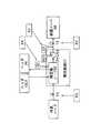
次に、第2実施形態として、第1実施形態に係るセンサ割当て装置を備えるセンサ診断装置について、図10及び図11を参照して説明する。ここで、図10は、本実施形態に係るセンサ診断装置の機能構成を示すブロック図である。図10のセンサ診断装置は、第1実施形態に係るセンサ割当て装置と、診断用計測値記憶部8と、センサ診断部9と、診断結果出力部10とを備える。(Second Embodiment)
Next, as a second embodiment, a sensor diagnosis apparatus including the sensor assignment apparatus according to the first embodiment will be described with reference to FIGS. 10 and 11. Here, FIG. 10 is a block diagram showing a functional configuration of the sensor diagnostic apparatus according to the present embodiment. The sensor diagnostic apparatus of FIG. 10 includes a sensor allocation apparatus according to the first embodiment, a diagnostic measurement
診断用計測値記憶部8は、診断対象となるセンサの計測値を記憶する。診断用計測値記憶部8に記憶される計測値は、正常計測値記憶部3に記憶される計測値と同様の形式で記憶される(図5参照)。しかしながら、診断用計測値記憶部8に記憶される計測値は、正常計測値記憶部3に記憶される計測値とは異なり、センサが正常に動作している時の計測値に限られない。診断用計測値記憶部8は、主記憶部105又は外部記憶部106により構成される。なお、正常計測値記憶部3と診断用計測値記憶部8とは、共用されてもよい。この場合、当該記憶部に記憶されたセンサの計測値のうち、センサが正常に動作していたことが判明している日時の計測値を、正常計測値記憶部3に記憶された計測値として用いればよい。診断用計測値記憶部8は、記憶した計測値をセンサ診断部9に入力する。 The measured value storage unit for
センサ診断部9は、割当て結果記憶部7からセンサを割当てられた診断モデルを取得し、診断用計測値記憶部8から診断用の計測値を取得し、取得した診断モデルと計測値とに基づいて、センサの異常を診断する。具体的には、センサ診断部9は、各引数に割当てられた各センサの計測値をモデル式に代入し評価値を算出する。そして、算出された評価値と異常の有無を診断するために予め定められた閾値とを比較して、センサの異常を診断する。センサ診断部9の機能構成は、CPU101により制御プログラムが実行されることにより実現される。センサ診断部9は、診断結果を診断結果出力部10に入力する。 The sensor
診断結果出力部10は、センサ診断部9の診断結果を出力する出力端末である。診断結果出力部10は、例えば、表示部103により構成される。診断結果出力部10は、診断結果だけでなく、センサ診断部9により算出された評価値を出力してもよいし、診断結果や評価値を計装図と対応させて表示させてもよい。 The diagnosis
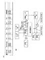
次に、本実施形態に係るセンサ診断装置によるセンサ診断処理について、図11を参照して説明する。図11は、本実施形態に係るセンサ診断装置の動作を示すフローチャートである。センサ診断装置は、まず、診断対象となる1つ異常のセンサを指定される。診断対象となるセンサは、センサ診断装置のオペレータにより入力されてもよいし、制御プログラムにより予め指定されていてもよい。 Next, sensor diagnosis processing by the sensor diagnosis apparatus according to the present embodiment will be described with reference to FIG. FIG. 11 is a flowchart showing the operation of the sensor diagnostic apparatus according to this embodiment. In the sensor diagnostic apparatus, first, one abnormal sensor to be diagnosed is designated. The sensor to be diagnosed may be input by an operator of the sensor diagnostic apparatus, or may be designated in advance by a control program.
診断対象となるセンサを指定されると、診断処理が開始される。センサ診断部9は、まず、指定されたセンサの診断モデルを割当て結果記憶部7から取得し、当該診断モデルに割当てられたセンサの計測値を診断用計測値記憶部8から取得する(ステップS11)。 When a sensor to be diagnosed is designated, a diagnostic process is started. First, the
次に、センサ診断部9は、取得した計測値をモデル式に代入して評価値を算出し(ステップS12)、算出された評価値と、予め定められた閾値と、を比較することによりセンサの異常を診断する(ステップS13)。ここで用いられる閾値として、センサ割当て装置により算出された評価値や当該評価値に基づいて算出される値を用いることができる。そして、センサ診断部9による診断結果が、診断結果出力部10から出力される(ステップS14)。 Next, the
以上説明したとおり、本実施形態に係るセンサ診断装置は、センサ割当て装置により選択されたセンサと診断モデルとの組合せに基づいて、センサの異常を診断することができる。 As described above, the sensor diagnosis apparatus according to the present embodiment can diagnose a sensor abnormality based on the combination of the sensor selected by the sensor assignment apparatus and the diagnosis model.
なお、診断用計測値記憶部8、センサ診断部9、及び診断結果出力部10は、センサ割当て装置とは別のコンピュータ装置により構成され、センサ割当て装置の割当て結果記憶部7に記憶された診断モデルが通信回線によりセンサ診断部9に入力されるセンサ診断システムとして構成されてもよい。 The diagnostic measurement
(第3実施形態)
次に、第3実施形態に係るセンサ割当て装置について、図12〜図15を参照して説明する。図12は、本実施形態に係るセンサ割当て装置の機能構成を示すブロック図である。図12のセンサ割当て装置は、第1実施形態に係るセンサ割当て装置と、計装図記憶部11と、割当て結果表示部12とを備える。(Third embodiment)
Next, a sensor assignment device according to a third embodiment will be described with reference to FIGS. FIG. 12 is a block diagram showing a functional configuration of the sensor assignment device according to the present embodiment. The sensor allocation device of FIG. 12 includes the sensor allocation device according to the first embodiment, an instrumentation
計装図記憶部11は、センサ割当て装置が適用される設備の計装図を記憶する。計装図記憶部11には、例えば、図2に示したような、ノードと、有向辺と、センサとの位置関係や接続関係を示す図が記憶される。計装図記憶部11は、主記憶部105又は外部記憶部106により構成される。 The instrumentation
割当て結果表示部12は、組合せ生成部4により生成された組合せと、評価値算出部5により算出された各組合せの評価値とを表示する表示端末である。具体的には、割当て結果表示部12は、割当て結果を図7に示したような表形式で表示する。また、割当て結果表示部12は、計装図記憶部11から計装図を取得し、取得した計装図上に割当て結果を対応させて出力させることもできる。割当て結果表示部12は、評価値算出部5により評価値を算出された任意の組合せ及びその評価値を表示してもよいし、組合せ選択部6により選択された組合せ及び評価値を表示してもよい。 The allocation
図13は、割当て結果表示部12による表示形式の一例を示す図である。図13において、図2の計装図上に図7の割当て結果が表示されている。また、この計装図とともに、割当て結果の診断モデルの評価値や、各センサの属性情報などが示されてもよい。割当て結果表示部12は、表示部103により構成される。 FIG. 13 is a diagram illustrating an example of a display format by the assignment
なお、本実施形態に係るセンサ割当て装置によるセンサ割当て処理は、第1実施形態と同様である。本実施形態では、センサ割当て処理の終了後、割当て結果が自動的に、あるいはセンサ割当て装置のオペレータからの要請に応じて、割当て結果表示部12に表示される。 Note that the sensor assignment processing by the sensor assignment device according to the present embodiment is the same as that of the first embodiment. In the present embodiment, after the sensor allocation process ends, the allocation result is displayed on the allocation
以上説明したとおり、本実施形態に係るセンサ割当て装置では、割当て結果が割当て結果表示部12に表示される。したがって、センサ割当て装置のオペレータは、センサの割当て結果を視覚的に確認することができるため、割当て結果の内容及び適切さを容易に認識することができる。これは、センサ情報の曖昧さに起因して、割当て結果が一意に決定できない場合に重要である。 As described above, in the sensor assignment device according to the present embodiment, the assignment result is displayed on the assignment
図14は、センサ情報が曖昧な場合のセンサ情報及び計装図の一例を示す図である。図14(B)の計装図では排気ノードが2つ示されているにも関わらず、図14(A)のセンサ情報ではセンサT3の位置属性が分岐ノードから排気ノードとしか記載されていない。このため、図14(B)に示すように、センサT3の位置は、2通り想定され、特定することができない。このような曖昧なセンサ情報は、例えば、ID等の記法が統一されていない複数の計装業者により設備が設置された場合に生じる恐れがある。 FIG. 14 is a diagram illustrating an example of sensor information and an instrumentation diagram when sensor information is ambiguous. Although the instrumentation diagram of FIG. 14B shows two exhaust nodes, the sensor information of FIG. 14A describes only the position attribute of the sensor T3 from the branch node to the exhaust node. . For this reason, as shown in FIG. 14B, two positions of the sensor T3 are assumed and cannot be specified. Such ambiguous sensor information may occur, for example, when equipment is installed by a plurality of instrumentation contractors whose notation such as ID is not unified.
このような場合、組合せ生成部4は、図14の上側の排気ノードと接続された有向辺上に設けられたセンサT3_1と、図14の下側の排気ノードと接続された有向辺上に設けられたセンサT3_2と、の両方を想定し、それぞれについて組合せを生成する。すなわち、組合せ生成部4は、センサT3の属性情報が一意に特定できない場合、センサT3の属性情報として可能性のある各属性情報について組合せを生成する。そして、評価値算出部5は、生成された各組合せについて、それぞれ評価値を算出する。 In such a case, the
図15は、センサT3_1について生成された組合せと、センサT3_2について生成された組合せと、を示す図である。図15(A)の組合せC031と組合せC032とは、引数X4に割当てられたセンサ(センサT3_1,T3_2)以外の要素は同様である。 FIG. 15 is a diagram illustrating combinations generated for the sensor T3_1 and combinations generated for the sensor T3_2. The elements other than the sensors (sensors T3_1 and T3_2) assigned to the argument X4 are the same in the combination C031 and the combination C032 in FIG.
図15(A)や図15(B)に示すように、割当て結果表示部12に、曖昧な位置属性に基づいて割当てられたセンサ以外の要素が同様の組合せの評価値を比較可能なように表示することにより、センサ割当て装置のオペレータは、位置属性が曖昧なセンサの正確な位置を容易に認識することができる。オペレータは、センサの正確な位置属性に基づいて、センサ情報を修正してもよい。 As shown in FIG. 15 (A) and FIG. 15 (B), elements other than sensors assigned based on an ambiguous position attribute can be compared in the assignment
また、センサ割当て装置は、上記の方法により、センサT3_1を含む組合せの群と、センサT3_2を含む組合せの群とを生成し、各群の評価値の平均値を算出し、平均値が高い群の位置属性をセンサT3の位置属性として選択し、選択した位置属性に基づいて、センサ情報を修正してもよい。このような構成の場合、センサ割当て装置は、修正したセンサ情報に基づいて、診断モデルに適切なセンサを割当てることができる。 Further, the sensor allocation device generates a group of combinations including the sensor T3_1 and a group of combinations including the sensor T3_2 by the above method, calculates an average value of the evaluation values of each group, and has a high average value. May be selected as the position attribute of the sensor T3, and the sensor information may be corrected based on the selected position attribute. In the case of such a configuration, the sensor assignment device can assign an appropriate sensor to the diagnostic model based on the corrected sensor information.
このように、本実施形態に係るセンサ割当て装置は、センサ情報が曖昧な場合であっても、センサの診断に適したセンサの割当てを実現することができる。また、曖昧なセンサ情報を、自動的に正しいセンサ情報に修正することもできる。さらに、割当て結果を割当て結果表示部12に表示することにより、オペレータに割当て結果を容易に理解させ、曖昧なセンサ情報を修正させることができる。 As described above, the sensor assignment device according to the present embodiment can realize sensor assignment suitable for sensor diagnosis even when the sensor information is ambiguous. Also, ambiguous sensor information can be automatically corrected to correct sensor information. Furthermore, by displaying the assignment result on the assignment
なお、センサ割当て装置は、計測属性や種別属性が曖昧な場合にも、上記と同様の処理を実行することができる。例えば、種別属性が曖昧な場合には、当該センサの種別属性が計測の場合と制御の場合との両方について、組合せを生成すればよい。計測属性についても同様である。 Note that the sensor allocation device can execute the same processing as described above even when the measurement attribute or the type attribute is ambiguous. For example, if the type attribute is ambiguous, a combination may be generated for both the case where the type attribute of the sensor is measurement and the case of control. The same applies to measurement attributes.
また、本実施形態に係るセンサ割当て装置を備えるセンサ診断装置を構成することもできる。この場合、割当て結果表示部12と診断結果出力部10とを共用することにより、センサ診断装置の構成を簡略化することができる。 Moreover, a sensor diagnostic apparatus including the sensor assignment apparatus according to the present embodiment can be configured. In this case, the configuration of the sensor diagnosis apparatus can be simplified by sharing the assignment
なお、本発明は上記各実施形態そのままに限定されるものではなく、実施段階ではその要旨を逸脱しない範囲で構成要素を変形して具体化できる。また、上記各実施形態に開示されている複数の構成要素を適宜組み合わせることによって種々の発明を形成できる。また例えば、各実施形態に示される全構成要素からいくつかの構成要素を削除した構成も考えられる。さらに、異なる実施形態に記載した構成要素を適宜組み合わせてもよい。 Note that the present invention is not limited to the above-described embodiments as they are, and can be embodied by modifying the components without departing from the scope of the invention in the implementation stage. Moreover, various inventions can be formed by appropriately combining a plurality of constituent elements disclosed in the above embodiments. Further, for example, a configuration in which some components are deleted from all the components shown in each embodiment is also conceivable. Furthermore, you may combine suitably the component described in different embodiment.
1:センサ情報記憶部、2:診断モデル記憶部、3:正常計測値記憶部、4:組合せ生成部、5:評価値算出部、6:組合せ選択部、7:割当て結果記憶部、8:診断用計測値記憶部、9:センサ診断部、10:診断結果出力部、11:計装図記憶部、12:割当て結果表示部、100:コンピュータ装置、101:CPU、102:入力部:、103:表示部:、104:通信部、105:主記憶部、106:外部記憶部、107:バス1: sensor information storage unit, 2: diagnostic model storage unit, 3: normal measurement value storage unit, 4: combination generation unit, 5: evaluation value calculation unit, 6: combination selection unit, 7: allocation result storage unit, 8: Diagnosis measurement value storage unit, 9: sensor diagnosis unit, 10: diagnosis result output unit, 11: instrumentation diagram storage unit, 12: assignment result display unit, 100: computer device, 101: CPU, 102: input unit: 103: Display unit: 104: Communication unit 105: Main storage unit 106: External storage unit 107: Bus
Claims (10)
Translated fromJapanese診断関数に含まれる複数の引数のそれぞれを、前記複数のセンサのうちの1つと組み合わせた組合せを複数生成する生成部と、
前記生成部により生成された複数の組合せの各々について、前記計測値記憶部に記憶された前記計測値を代入して計算される前記診断関数の値に基づき評価値を算出する算出部と、
前記算出部により算出された各組合せの評価値に基づいて、前記複数の組合せの中から少なくとも1つの組合せを選択する選択部と、
前記診断関数の各引数に対して、前記選択部で選択された前記1つの組合せの測定値を代入して計算される前記診断関数の値に基づき、前記1つの組合せに含まれる各センサの異常診断を行う診断部と
を備えるセンサ診断装置。A measured value storage unit for storing measured values of a plurality of sensors;
A generating unit that generates a plurality of combinations in which each of a plurality of arguments included in a diagnostic function is combined with one of the plurality of sensors;
For each of the plurality of combinations generated by the generation unit, a calculation unit that calculates an evaluation value based on the value of the diagnostic function calculated by substituting the measurement value stored in the measurement value storage unit;
A selection unit that selects at least one combination from the plurality of combinations based on the evaluation value of each combination calculated by the calculation unit;
An abnormality of each sensor included in the one combination based on the value of the diagnostic function calculated by substituting the measured value of the one combination selected by the selection unit for each argument of the diagnostic function A sensor diagnostic apparatus comprising: a diagnostic unit that performs diagnosis.
請求項1に記載のセンサ診断装置。The sensor diagnosis apparatus according to claim 1, wherein the calculation unit calculates a correlation coefficient of a plurality of values obtained by substituting measurement values of sensors included in the combination into the diagnosis function as the evaluation value.
請求項1又は請求項2に記載のセンサ診断装置。The said generation part determines the sensor combined with each argument of the said diagnostic function by comparing the attribute information each set to the said argument, and the attribute information each set to the said sensor. The sensor diagnostic apparatus according to 2.
請求項3に記載のセンサ診断装置。The sensor diagnostic apparatus according to claim 3, wherein the generation unit combines a sensor having the same attribute information with each argument of the diagnostic function.
請求項3又は請求項4に記載のセンサ診断装置。The sensor diagnosis apparatus according to claim 3 or 4, wherein the attribute information includes at least one of a measurement attribute indicating a unit of measurement values of each sensor and a position attribute indicating a position where each sensor is installed.
請求項3〜請求項5のいずれか1項に記載のセンサ診断装置。6. The sensor diagnostic apparatus according to claim 3, wherein when there are a plurality of candidates for attribute information of the sensor, the generation unit generates the combination for each candidate. 7.
請求項1〜請求項6のいずれか1項に記載のセンサ診断装置。The sensor diagnostic apparatus according to any one of claims 1 to 6, further comprising a display unit that displays the combination generated by the generation unit and the evaluation value calculated by the calculation unit.
請求項7に記載のセンサ診断装置。The sensor diagnostic apparatus according to claim 7, wherein the display unit displays the combination generated by the generation unit and the evaluation value calculated by the calculation unit in association with an instrumentation diagram.
前記複数の組合せの各々について、前記センサの計測値を代入して計算される前記診断関数の値に基づき評価値を算出するステップと、
各組合せの前記評価値に基づいて、前記複数の組合せの中から少なくとも1つの組合せを選択するステップと、
前記診断関数の各引数に対して、前記選択された1つの組合せの測定値を代入して計算される前記診断関数の値に基づき、前記1つの組合せに含まれる各センサの異常診断を行うステップと
をコンピュータが実行するセンサ診断方法。Generating a plurality of combinations in which each of a plurality of arguments included in the diagnostic function is combined with one of a plurality of sensors;
For each of the plurality of combinations, calculating an evaluation value based on the value of the diagnostic function calculated by substituting the measurement value of the sensor;
Selecting at least one combination from the plurality of combinations based on the evaluation value of each combination;
A step of diagnosing abnormality of each sensor included in the one combination based on the value of the diagnostic function calculated by substituting the measured value of the selected one combination for each argument of the diagnostic function Anda sensor diagnostic method in which acomputer executes .
前記複数の組合せの各々について、前記センサの計測値を代入して計算される前記診断関数の値に基づき評価値を算出するステップと、
各組合せの前記評価値に基づいて、前記複数の組合せの中から少なくとも1つの組合せを選択するステップと、
前記診断関数の各引数に対して、前記選択された1つの組合せの測定値を代入して計算される前記診断関数の値に基づき、前記1つの組合せに含まれる各センサの異常診断を行うステップと
をコンピュータに実行させるコンピュータプログラム。Generating a plurality of combinations in which each of a plurality of arguments included in the diagnostic function is combined with one of a plurality of sensors;
For each of the plurality of combinations, calculating an evaluation value based on the value of the diagnostic function calculated by substituting the measurement value of the sensor;
Selecting at least one combination from the plurality of combinations based on the evaluation value of each combination;
A step of diagnosing abnormality of each sensor included in the one combination based on the value of the diagnostic function calculated by substituting the measured value of the selected one combination for each argument of the diagnostic function A computer program that causes a computer to execute and.
Priority Applications (2)
| Application Number | Priority Date | Filing Date | Title |
|---|---|---|---|
| JP2014057002AJP6356449B2 (en) | 2014-03-19 | 2014-03-19 | Sensor diagnostic device, sensor diagnostic method, and computer program |
| US14/660,017US10627265B2 (en) | 2014-03-19 | 2015-03-17 | Sensor assignment apparatus and sensor diagnostic apparatus |
Applications Claiming Priority (1)
| Application Number | Priority Date | Filing Date | Title |
|---|---|---|---|
| JP2014057002AJP6356449B2 (en) | 2014-03-19 | 2014-03-19 | Sensor diagnostic device, sensor diagnostic method, and computer program |
Publications (2)
| Publication Number | Publication Date |
|---|---|
| JP2015179440A JP2015179440A (en) | 2015-10-08 |
| JP6356449B2true JP6356449B2 (en) | 2018-07-11 |
Family
ID=54141815
Family Applications (1)
| Application Number | Title | Priority Date | Filing Date |
|---|---|---|---|
| JP2014057002AActiveJP6356449B2 (en) | 2014-03-19 | 2014-03-19 | Sensor diagnostic device, sensor diagnostic method, and computer program |
Country Status (2)
| Country | Link |
|---|---|
| US (1) | US10627265B2 (en) |
| JP (1) | JP6356449B2 (en) |
Families Citing this family (9)
| Publication number | Priority date | Publication date | Assignee | Title |
|---|---|---|---|---|
| US9759636B2 (en)* | 2015-03-27 | 2017-09-12 | Aktiebolaget Skf | Synchronized measurements for a portable multi-channel wireless sensor system |
| KR20230157525A (en)* | 2016-05-09 | 2023-11-16 | 스트롱 포스 아이오티 포트폴리오 2016, 엘엘씨 | Methods and systems for the industrial internet of things |
| WO2017204307A1 (en)* | 2016-05-27 | 2017-11-30 | 中部電力株式会社 | System model evaluation system, operation management system, system model evaluation method, and program |
| JP6602280B2 (en)* | 2016-09-30 | 2019-11-06 | 三菱電機ビルテクノサービス株式会社 | Instrumentation diagram data generation apparatus, instrumentation diagram search system, and program |
| JP6945297B2 (en)* | 2016-12-05 | 2021-10-06 | 株式会社日立製作所 | Device diagnostic device, device diagnostic system and device diagnostic method |
| WO2019043744A1 (en)* | 2017-08-28 | 2019-03-07 | 株式会社日立製作所 | System and method for assisting operation of solution |
| US11132542B2 (en)* | 2018-06-28 | 2021-09-28 | Nec Corporation | Time-space de-noising for distributed sensors |
| JP7119901B2 (en)* | 2018-10-26 | 2022-08-17 | 富士通株式会社 | Analysis device, analysis method and analysis program |
| EP3696619A1 (en)* | 2019-02-15 | 2020-08-19 | Basf Se | Determining operating conditions in chemical production plants |
Family Cites Families (12)
| Publication number | Priority date | Publication date | Assignee | Title |
|---|---|---|---|---|
| US5511037A (en)* | 1993-10-22 | 1996-04-23 | Baker Hughes Incorporated | Comprehensive method of processing measurement while drilling data from one or more sensors |
| JPH09212077A (en)* | 1996-02-06 | 1997-08-15 | Hitachi Ltd | Simulator for plant operator training |
| JP2000339357A (en) | 1999-05-26 | 2000-12-08 | Yamatake Sangyo Systems Co Ltd | Device for managing instrumentation drawing and program recording medium |
| AU2002230389A1 (en)* | 2000-06-14 | 2002-04-29 | Vermeer Manufacturing Company | Utility mapping and data distribution system and method |
| JP2006048129A (en)* | 2004-07-30 | 2006-02-16 | Toshiba Corp | Data processing apparatus, data processing method, and data processing program |
| JP2006135412A (en) | 2004-11-02 | 2006-05-25 | Tokyo Gas Co Ltd | Remote monitoring system |
| JP2008269215A (en) | 2007-04-19 | 2008-11-06 | Nippon Telegr & Teleph Corp <Ntt> | Singular pattern detection system, model learning device, singular pattern detection method, and computer program |
| JP5253218B2 (en)* | 2009-02-16 | 2013-07-31 | 日立Geニュークリア・エナジー株式会社 | Device diagnostic method |
| JP5301310B2 (en)* | 2009-02-17 | 2013-09-25 | 株式会社日立製作所 | Anomaly detection method and anomaly detection system |
| JP5337909B2 (en)* | 2010-03-30 | 2013-11-06 | 株式会社東芝 | Anomaly detection device |
| JP2013073414A (en)* | 2011-09-28 | 2013-04-22 | Hitachi-Ge Nuclear Energy Ltd | Sensor diagnostic device and sensor diagnostic method for plant |
| US9230442B2 (en)* | 2013-07-31 | 2016-01-05 | Elwha Llc | Systems and methods for adaptive vehicle sensing systems |
- 2014
- 2014-03-19JPJP2014057002Apatent/JP6356449B2/enactiveActive
- 2015
- 2015-03-17USUS14/660,017patent/US10627265B2/enactiveActive
Also Published As
| Publication number | Publication date |
|---|---|
| JP2015179440A (en) | 2015-10-08 |
| US20150268072A1 (en) | 2015-09-24 |
| US10627265B2 (en) | 2020-04-21 |
Similar Documents
| Publication | Publication Date | Title |
|---|---|---|
| JP6356449B2 (en) | Sensor diagnostic device, sensor diagnostic method, and computer program | |
| US10915419B2 (en) | Industrial control system, and assistance apparatus, control assist method, and program thereof | |
| JP6240050B2 (en) | Bias estimation apparatus, method and program thereof, and fault diagnosis apparatus, method and program thereof | |
| JP6304767B2 (en) | SENSOR MONITORING DEVICE, SENSOR MONITORING METHOD, AND SENSOR MONITORING PROGRAM | |
| JP2020035458A (en) | Information processing apparatus, method, and program | |
| JP2015184823A (en) | Model parameter calculation apparatus, model parameter calculation method, and computer program | |
| CN109032872B (en) | Bayesian network-based equipment fault diagnosis method and system | |
| JPWO2018216197A1 (en) | Abnormality importance calculation system, abnormality importance calculation device, and abnormality importance calculation program | |
| JP2016095751A (en) | Abnormal device identification program, abnormal device identification method, and abnormal device identification device | |
| CN106672722B (en) | Machinery diagnosis device, machinery diagnosis method and machinery diagnosis system | |
| JP2015179443A (en) | Diagnostic model generation apparatus, diagnostic model generation method, and abnormality diagnosis apparatus | |
| JP2013250928A (en) | Facility inspection plan support device and program | |
| US20140188777A1 (en) | Methods and systems for identifying a precursor to a failure of a component in a physical system | |
| JP2022502737A (en) | Boiler operation data monitoring method and equipment by Bayesian network | |
| JP5746480B2 (en) | Analysis result display device and analysis result display method | |
| JP7026012B2 (en) | Equipment status monitoring system and equipment status monitoring method | |
| JP2011199867A (en) | Bayesian approach to identifying sub-module failure | |
| CN105308523A (en) | Workshop diagnostic system | |
| JPWO2019049521A1 (en) | Risk assessment device, risk assessment system, risk assessment method, and risk assessment program | |
| JP6247777B2 (en) | Abnormality diagnosis apparatus and abnormality diagnosis method | |
| JP7444347B2 (en) | diagnostic equipment | |
| JP6782260B2 (en) | Information processing equipment, information processing methods and programs | |
| JP6448745B2 (en) | Bias estimation apparatus, method and program thereof | |
| JP2021002295A (en) | Anomaly detection device, anomaly detection system, and anomaly detection method | |
| JP2010267048A (en) | Plant equipment management system and plant equipment management method |
Legal Events
| Date | Code | Title | Description |
|---|---|---|---|
| A621 | Written request for application examination | Free format text:JAPANESE INTERMEDIATE CODE: A621 Effective date:20160829 | |
| A131 | Notification of reasons for refusal | Free format text:JAPANESE INTERMEDIATE CODE: A131 Effective date:20170421 | |
| A977 | Report on retrieval | Free format text:JAPANESE INTERMEDIATE CODE: A971007 Effective date:20170428 | |
| A521 | Request for written amendment filed | Free format text:JAPANESE INTERMEDIATE CODE: A523 Effective date:20170620 | |
| A131 | Notification of reasons for refusal | Free format text:JAPANESE INTERMEDIATE CODE: A131 Effective date:20171114 | |
| A521 | Request for written amendment filed | Free format text:JAPANESE INTERMEDIATE CODE: A523 Effective date:20180111 | |
| TRDD | Decision of grant or rejection written | ||
| A01 | Written decision to grant a patent or to grant a registration (utility model) | Free format text:JAPANESE INTERMEDIATE CODE: A01 Effective date:20180515 | |
| A61 | First payment of annual fees (during grant procedure) | Free format text:JAPANESE INTERMEDIATE CODE: A61 Effective date:20180614 | |
| R151 | Written notification of patent or utility model registration | Ref document number:6356449 Country of ref document:JP Free format text:JAPANESE INTERMEDIATE CODE: R151 |