JP6353574B2 - Delivery device and method for compliant tissue fasteners - Google Patents
Delivery device and method for compliant tissue fastenersDownload PDFInfo
- Publication number
- JP6353574B2 JP6353574B2JP2017049531AJP2017049531AJP6353574B2JP 6353574 B2JP6353574 B2JP 6353574B2JP 2017049531 AJP2017049531 AJP 2017049531AJP 2017049531 AJP2017049531 AJP 2017049531AJP 6353574 B2JP6353574 B2JP 6353574B2
- Authority
- JP
- Japan
- Prior art keywords
- trigger
- jaw
- jaws
- handle
- tissue
- Prior art date
- Legal status (The legal status is an assumption and is not a legal conclusion. Google has not performed a legal analysis and makes no representation as to the accuracy of the status listed.)
- Active
Links
Images


Classifications
- A—HUMAN NECESSITIES
- A61—MEDICAL OR VETERINARY SCIENCE; HYGIENE
- A61B—DIAGNOSIS; SURGERY; IDENTIFICATION
- A61B17/00—Surgical instruments, devices or methods
- A61B17/064—Surgical staples, i.e. penetrating the tissue
- A61B17/0643—Surgical staples, i.e. penetrating the tissue with separate closing member, e.g. for interlocking with staple
- A—HUMAN NECESSITIES
- A61—MEDICAL OR VETERINARY SCIENCE; HYGIENE
- A61B—DIAGNOSIS; SURGERY; IDENTIFICATION
- A61B17/00—Surgical instruments, devices or methods
- A61B17/068—Surgical staplers, e.g. containing multiple staples or clamps
- A61B17/072—Surgical staplers, e.g. containing multiple staples or clamps for applying a row of staples in a single action, e.g. the staples being applied simultaneously
- A61B2017/07214—Stapler heads
- A61B2017/07228—Arrangement of the staples
Landscapes
- Health & Medical Sciences (AREA)
- Life Sciences & Earth Sciences (AREA)
- Surgery (AREA)
- Heart & Thoracic Surgery (AREA)
- Engineering & Computer Science (AREA)
- Biomedical Technology (AREA)
- Nuclear Medicine, Radiotherapy & Molecular Imaging (AREA)
- Medical Informatics (AREA)
- Molecular Biology (AREA)
- Animal Behavior & Ethology (AREA)
- General Health & Medical Sciences (AREA)
- Public Health (AREA)
- Veterinary Medicine (AREA)
- Surgical Instruments (AREA)
Description
Translated fromJapanese本発明は、概して、医療機器、システム、および方法に関する。より具体的には、本発明は、例えば、左心耳およびそれらの基部の近傍の他の組織構造を分離するために、組織近接のためのコンプライアントなファスナおよび圧縮構造を送達するための、ツール、システム、および方法に関する。 The present invention generally relates to medical devices, systems, and methods. More specifically, the present invention provides a tool for delivering compliant fasteners and compression structures for tissue proximity, for example to isolate the left atrial appendage and other tissue structures near their base. , Systems, and methods.
心房細動は、左心房および右心房の非常に速い鼓動により特徴付けられる比較的一般的な病状である。心房細動は、通常それ自体は致命的ではないが、脳梗塞のリスク増加と関連している。速い鼓動により血液が左心耳に溜まり、塞栓が生じて左心房に放出され、そこから塞栓が脳血管系に入り、脳梗塞をもたらすと考えられる。脳梗塞に加えて、塞栓は冠循環に入り心筋梗塞を生じる可能性、または末梢循環に入り末梢血管疾患を生じる可能性がある。 Atrial fibrillation is a relatively common condition characterized by a very fast beating of the left and right atria. Atrial fibrillation is usually not fatal per se, but is associated with an increased risk of cerebral infarction. It is thought that blood accumulates in the left atrial appendage due to a rapid beating, and an embolus is generated and released into the left atrium, from which the embolus enters the cerebral vasculature and causes cerebral infarction. In addition to cerebral infarction, emboli can enter the coronary circulation and cause myocardial infarction, or can enter the peripheral circulation and cause peripheral vascular disease.
心房細動のある患者の脳梗塞リスクは、種々の方法で軽減できる。例えば、血液抗凝固薬を使用し、血栓形成のリスクを軽減できる。しかし、血液抗凝固薬の使用は、出血性疾患の危険がある患者には禁忌である。 The risk of cerebral infarction in patients with atrial fibrillation can be reduced in various ways. For example, blood anticoagulants can be used to reduce the risk of thrombus formation. However, the use of blood anticoagulants is contraindicated in patients at risk for bleeding disorders.
左心耳を閉鎖することを含む、さらに積極的な治療プロトコルが提案されている。閉鎖および切除は、開心外科手術において行われる場合があり、通常は患者にバイパス術を行い、胸骨を通じて胸部を開く必要がある。代替的に、胸腔鏡および他の低侵襲性手技が提案されている。特許文献1は、鼓動している心臓で行うこと以外は従来の手術技術を使用する手術の実行について教示する。心臓が鼓動している間の、小さな胸部貫通を通じた従来技術の使用は、実行するのが困難であり得る。特許文献2は、ツールを、血管系を通じて導入し、左心房へ通す血管内手法を説明する。ツールを使用し、エネルギ、接着剤等を用いて左心耳を内側から切除または融合する。また特許文献2は、心耳の頚部にテザーを配置し、結紮して分離する胸腔鏡手術についても説明する。特許文献2は、縫合糸、ステープル、形状記憶ワイヤ、生体適合性接着剤等を含む、他の閉鎖要素をなおさらに提唱する。特許文献3は、左心耳の遠位端を把持し、左心耳の基部を取り囲む捕捉ループを通じて後方に引っ張る経腹膜心臓手術について説明する。 More aggressive treatment protocols have been proposed, including closing the left atrial appendage. Closure and resection may be performed in open heart surgery, usually requiring the patient to bypass and open the chest through the sternum. Alternatively, thoracoscopes and other minimally invasive procedures have been proposed. U.S. Patent No. 6,057,031 teaches performing a surgery using conventional surgical techniques, except that it is performed with a beating heart. The use of prior art through small chest penetrations while the heart is beating can be difficult to perform. U.S. Patent No. 6,099,056 describes an intravascular technique where a tool is introduced through the vascular system and passed through the left atrium. Using a tool, excise or fuse the left atrial appendage from the inside with energy, glue, etc. Patent Document 2 also describes thoracoscopic surgery in which a tether is placed in the neck of the atrial appendage and ligated and separated. U.S. Patent No. 6,057,077 still further proposes other closure elements including sutures, staples, shape memory wires, biocompatible adhesives, and the like. U.S. Patent No. 6,057,034 describes transperitoneal heart surgery that grips the distal end of the left atrial appendage and pulls it back through a capture loop that surrounds the base of the left atrial appendage.
本発明にとって特に関心がある左心耳の密閉のためのコンプライアントな閉鎖構造が、同時係属の共有に係る特許文献4(出願第11/744,135号)において説明され、この完全な開示は、参照することによって本明細書に先に組み込まれる。特許文献4において説明されるコンプライアントな構造は、それらの間の開口を規定するように楕円形またはU形状の構成で配置され得る、一対の対向する脚を有する、弾性体を備える。左心耳上で脚間に開口を配置し、開口を左心耳の基部と整列させることによって、所望の密閉を提供するように、構造は閉鎖され得る。構造を閉鎖された状態で保持するために、いくつかの別個の軸方向に離間する組織貫通ファスナが、脚の各々の長さに沿って配置される。ファスナをプレス嵌めするために、脚を一緒に圧縮することによって、左心耳を効果的に分離する、コンプライアントな密閉を提供するように、コンプライアントな構造が閉鎖され得る。 A compliant closure structure for sealing the left atrial appendage of particular interest to the present invention is described in co-pending sharing, US Pat. Which is previously incorporated herein by reference. The compliant structure described in U.S. Patent No. 6,053,049 comprises an elastic body having a pair of opposing legs that can be arranged in an elliptical or U-shaped configuration to define an opening therebetween. By placing openings between the legs on the left atrial appendage and aligning the openings with the base of the left atrial appendage, the structure can be closed to provide the desired seal. In order to hold the structure closed, several separate axially spaced tissue penetrating fasteners are placed along the length of each of the legs. To press fit the fasteners, the compliant structures can be closed to provide a compliant seal that effectively separates the left atrial appendage by compressing the legs together.
特許文献4は、コンプライアントな閉鎖構造のための特定の送達ツールを説明する。送達ツールは、閉鎖構造の脚の中に挿入され、左心耳の上で脚の中でジョーを閉鎖するように起動されることが可能なジョーを含む。ジョーは、コンプライアントな構造をその閉鎖された密閉構成に保持するために、ファスナを係合およびプレス嵌めする、コームスタッドをさらに含む。スタッドは、送達ツールが除去されることを可能にするように、後退されることが意図される。 U.S. Patent No. 6,057,051 describes a specific delivery tool for a compliant closure structure. The delivery tool includes a jaw that is inserted into the leg of the closure structure and can be activated to close the jaw in the leg over the left atrial appendage. The jaws further include comb studs that engage and press fit the fasteners to hold the compliant structure in its closed and sealed configuration. The stud is intended to be retracted to allow the delivery tool to be removed.
機能的ではあるが、特許文献4の送達ツールは、ある欠点を有する。例えば、ジョーの起動、およびコームスタッドの後退は、不適切に実行される可能性があり、コンプライアントな構造の送達が失敗するリスクを増加させる。さらに、送達ツールの位置付けおよび配向は、特に、ツールが、左心房に接近するように、肋間貫通を通じて導入される場合、困難である可能性がある。また、特許文献4の装置内のジョーは、装置シャフトの軸平面において取り付けられる。かかる直線的取り付けは、ジョーを、左心耳の基部に整列させ、および左心耳につながる心房の口にわたって整列させることをより困難にする可能性がある。閉鎖装置が、完全に閉鎖するように、基部にわたって整列されない場合、口、間隙、または開口(「盲管」と称する)は、閉鎖部位に残る可能性があり、心房における血栓形成のリスクを増加させる。かかる盲管を含まない口の完全な密閉の形成の重要性は、非特許文献1において説明されている。 Although functional, the delivery tool of US Pat. For example, jaw activation and comb stud retraction can be performed improperly, increasing the risk of compliant structure delivery failure. Furthermore, the positioning and orientation of the delivery tool can be difficult, especially when the tool is introduced through the intercostal penetration so as to approach the left atrium. Moreover, the jaw in the apparatus of patent document 4 is attached in the axial plane of an apparatus shaft. Such a straight attachment may make it more difficult to align the jaws to the base of the left atrial appendage and across the atrial mouth leading to the left atrial appendage. If the closure device is not aligned across the base to fully close, the mouth, gap, or opening (referred to as the “blind canal”) can remain at the closure site, increasing the risk of thrombus formation in the atria Let The importance of forming a complete seal of the mouth that does not include such a blind tube is described in Non-Patent Document 1.
これらの理由により、特許文献4において説明される組織閉鎖装置とともに使用するための、改善された送達ツールを提供することが望ましいであろう。送達ツールおよびそれらの使用方法が、他の組織閉鎖装置の送達、および左心耳の閉鎖に加えた手技に対して適合性がある場合、さらに望ましいであろう。これらの目的のうちの少なくとも一部は、以降に説明される本発明によって満たされる。 For these reasons, it would be desirable to provide an improved delivery tool for use with the tissue closure device described in US Pat. It would be further desirable if the delivery tools and their method of use are compatible with delivery of other tissue closure devices and procedures in addition to left atrial appendage closure. At least some of these objectives will be met by the invention described below.
左心耳を閉鎖するための低侵襲性および他の手技は、米国特許第6,488,689号、第5,865,791号、および第5,306,234号、ならびに出願公開第2005/0154404号、および第2004/0030335号において説明されている。他の組織結紮ツール、ならびに関連装置および技術は、米国特許第6,790,172号、第6,436,108号、第6,325,810号、第6,273,897号、第6,051,003号、第5,964,774号、第5,624,453号、第5,507,797号、および第4,257,419号において説明されている。上に説明される米国特許出願公開第2007/0260278号もまた参照されたい。 Minimally invasive and other procedures for closing the left atrial appendage are described in US Pat. Nos. 6,488,689, 5,865,791, and 5,306,234, and published application 2005/0154404. And in 2004/0030335. Other tissue ligation tools, and related devices and techniques are described in U.S. Patent Nos. 6,790,172, 6,436,108, 6,325,810, 6,273,897, 6, 051,003, 5,964,774, 5,624,453, 5,507,797, and 4,257,419. See also US Patent Application Publication No. 2007/0260278, described above.
本発明は、対向する組織係合表面、および前記表面間で展開可能な複数の組織貫通ファスナを伴う、2つの脚を有する、圧縮体を含む、閉鎖装置とともに使用するための、閉鎖装置アプリケータを提供する。かかる圧縮体は、同時係属の共有に係る出願である、米国特許出願公開第2007/0260278号において説明され、この完全な開示は、参照することによって本明細書に先に組み込まれる。しかしながら、本発明のアプリケータはまた、類似の構造を有する他の閉鎖装置との使用も見出すであろう。 The present invention relates to a closure device applicator for use with a closure device, including a compression body, having two legs with opposing tissue engaging surfaces and a plurality of tissue penetrating fasteners deployable between said surfaces. I will provide a. Such a compression body is described in co-pending sharing application US 2007/0260278, the complete disclosure of which is hereby incorporated by reference in its entirety. However, the applicator of the present invention will also find use with other closure devices having a similar structure.
本発明の閉鎖装置アプリケータは、シャフトと、シャフトの近位端に取り付けられるハンドルと、シャフトの遠位端に旋回可能に取り付けられる一対のジョーとを備える。各ジョーは、複数の後退可能なスタッドを有し、ジョーは、スタッドが、閉鎖装置内の個々のファスナに係合した状態で、組織閉鎖装置の脚を着脱可能に係合および保持するように適合される。ハンドルは、第1のトリガと、第2のトリガとを含む。典型的に、シャフトを形成する連結アセンブリは、ハンドルをジョーに接合し、第1のトリガおよび第2のトリガは、ジョーを閉鎖するために、およびファスナを展開するように、ファスナに対して、スタッドを同時に係合するために、ハンドルに向かって一緒に後退させられる。次いで、第2のトリガは、スタッドをファスナから係脱するように、第1のトリガに対して後退させられてもよく、第1および第2のトリガは、ジョーを開放するように、一緒にハンドルから離れさせられる。ジョーが完全に閉鎖される(以下に説明されるように「クリッカ」を介して)場合、およびスタッドが後退させられる前の不慮の開放を防止するように、ジョーが係止される場合、聴覚的確認が与えられる。 The closure device applicator of the present invention comprises a shaft, a handle attached to the proximal end of the shaft, and a pair of jaws pivotally attached to the distal end of the shaft. Each jaw has a plurality of retractable studs such that the jaws removably engage and hold the legs of the tissue closure device with the studs engaged with individual fasteners in the closure device. Be adapted. The handle includes a first trigger and a second trigger. Typically, the coupling assembly that forms the shaft joins the handle to the jaw, and the first trigger and the second trigger are relative to the fastener to close the jaw and deploy the fastener. To engage the studs simultaneously, they are retracted together towards the handle. The second trigger may then be retracted relative to the first trigger to disengage the stud from the fastener, and the first and second triggers together to release the jaws. Moved away from the handle. When the jaws are fully closed (via a “clicker” as described below) and when the jaws are locked to prevent inadvertent opening before the studs are retracted, Confirmation is given.
上に説明されるように、別個のトリガを提供することは、それが、ジョーの閉鎖および開放が、スタッド後退から分離されることを可能にするため、有利である。特に、以下に説明されるように、相互係止具を提供することによって、閉鎖装置アプリケータは、(1)ファスナ展開を伴うジョー閉鎖、(2)スタッドの後退、および(3)ジョーの開放を、順に提供するように構成することができる。ファスナが展開される前にスタッドを後退すること、またはファスナが後退させられる前にジョーを開放することは、手技の失敗の著しいリスクをもたらす。ステップの特定の順序付けは、連結アセンブリの具体的な構造、ならびに装置が適切に展開された場合の相互係止具および聴覚的フィードバックの包含によって提供される。 As explained above, providing a separate trigger is advantageous because it allows jaw closure and opening to be separated from stud retraction. In particular, as described below, by providing an interlock, the closure device applicator allows (1) jaw closure with fastener deployment, (2) stud retraction, and (3) jaw opening. Can be provided in order. Retracting the stud before the fastener is deployed or opening the jaw before the fastener is retracted poses a significant risk of procedure failure. The specific ordering of steps is provided by the specific structure of the coupling assembly, as well as the inclusion of interlocks and audio feedback when the device is properly deployed.
具体的な実施例において、連結アセンブリは、トリガをジョーおよびスタッドに接合するシャフトを一緒になって規定する、固定されたロッドに沿って配置される、一対のスリーブを備える。典型的に、スリーブは同軸であり、第1のトリガは、ジョーを閉鎖するように、第1のスリーブを移動させるように接続され、第2のトリガは、スタッドを係脱するように、第2のスリーブに接続される。通常、第1のトリガは、ハンドル上に旋回可能に載置され、第2のトリガは、第1のトリガ上に旋回可能に載置される。 In a specific embodiment, the coupling assembly comprises a pair of sleeves disposed along a fixed rod that together define a shaft joining the trigger to the jaws and studs. Typically, the sleeve is coaxial, the first trigger is connected to move the first sleeve to close the jaws, and the second trigger is connected to disengage the stud. Connected to the two sleeves. Usually, the first trigger is pivotably mounted on the handle, and the second trigger is pivotably mounted on the first trigger.
他の具体的な実施形態において、第1のトリガは、第1のレバーによって、第1のスリーブに結合され、第2のトリガは、第2のレバーによって、第2のスリーブに結合される。好ましくは、相互係止具は、相互係止具が、第1および第2のトリガが、ジョーを閉鎖するように一緒に後退させられる場合に、係合され、かつ第2のトリガが、スタッドを後退させるように、第1のトリガに対して後退させられる場合に、解放されるように、第1のトリガとハンドルとの間に配置される。相互係止具は、スタッドが、第2のトリガを使用して後退させられる前の、ジョーの偶発的な開放を防止する。 In another specific embodiment, the first trigger is coupled to the first sleeve by a first lever, and the second trigger is coupled to the second sleeve by a second lever. Preferably, the interlock is engaged when the interlock is retracted together so that the first and second triggers close the jaws, and the second trigger is the stud Is disposed between the first trigger and the handle so that it is released when retracted relative to the first trigger. The interlock prevents accidental opening of the jaws before the stud is retracted using the second trigger.
本発明の第2の態様において、左心耳上で圧縮体を閉鎖するための閉鎖装置は、シャフトと、シャフトの遠位端に旋回可能に接続される一対のジョーと、シャフトの近位端に取り付けられるハンドルと、ジョーを閉鎖し、左心耳上で圧縮体を展開するように、ジョーに結合される、ハンドル上のトリガ機構とを備える。左心耳への肋間貫通を介して、ジョー上に支持される圧縮体の導入を促進するために、ジョーは、シャフトの軸に対して、10°から20°、典型的に15°の範囲内の角度で配置される平面内で、開放および閉鎖するように構成される。この角度は、シャフトが、患者の身体の前後平面に対して、対応する角度で導入されることを可能にし、前後平面は、矢状面に垂直である。この改善は、先の同時係属出願第2007/0260278号において開示される設計を使用した場合、肋間送達プロトコルにおいて、軸方向に整列された平面において配向される展開ジョーは、位置付けることが困難であろうという、本明細書における本発明者による発明に起因した。特に、角度付けられたジョーは、盲管を含まないように、左心房壁における口を完全に閉鎖することができるように、閉鎖部材が、左心耳の基部にわたって整列されることを可能にする。 In a second aspect of the invention, a closure device for closing a compression body on the left atrial appendage comprises a shaft, a pair of jaws pivotally connected to the distal end of the shaft, and a proximal end of the shaft. And a trigger mechanism on the handle coupled to the jaw to close the jaw and deploy the compression body on the left atrial appendage. To facilitate the introduction of a compression body supported on the jaws through the intercostal penetration into the left atrial appendage, the jaws are within a range of 10 ° to 20 °, typically 15 °, relative to the axis of the shaft. Configured to open and close in a plane arranged at an angle of. This angle allows the shaft to be introduced at a corresponding angle with respect to the anteroposterior plane of the patient's body, the anteroposterior plane being perpendicular to the sagittal plane. This improvement is seen when using the design disclosed in earlier copending application 2007/0260278, deployment jaws oriented in an axially aligned plane are difficult to position in the intercostal delivery protocol. This was attributed to the invention by the inventors in this specification. In particular, the angled jaws allow the closure member to be aligned over the base of the left atrial appendage so that the mouth in the left atrial wall can be completely closed so as not to include the blind tube. .
本発明のなおさらなる態様において、システムは、同時係属の共有に係る第US2007/0260278号において説明されるもの、および上に説明される装置アプリケータのうちのいずれかといった、閉鎖装置を備える。 In yet a further aspect of the invention, the system comprises a closure device, such as any of those described in US2007 / 0260278 for co-pending sharing and the device applicator described above.
組織構造を閉鎖するための本発明による方法は、圧縮体を、少なくとも2つのコンプライアントな組織係合表面が、組織構造の両側に係合する状態で、左心耳といった組織構造上に位置付けるステップを含む。圧縮体を保持する、一対のジョーに結合される、第1のトリガは、ジョーを閉鎖し、組織係合表面間で、および組織構造を通って、複数のファスナを展開するように、引っ張られる。次いで、第2のトリガは、ジョー上の複数のスタッドを、ファスナとの接触から係脱するように引っ張られ、第1のトリガは、ジョーを開放し、圧縮体を解放するように、解放される。好ましくは、少なくとも第1および第2のトリガは、スタッドが解放されるまで、ジョーの開放を防止するように、選択的に相互係止され得る。 The method according to the invention for closing a tissue structure comprises positioning a compression body on a tissue structure, such as the left atrial appendage, with at least two compliant tissue engaging surfaces engaging both sides of the tissue structure. Including. A first trigger coupled to a pair of jaws holding a compression body is pulled to close the jaws and deploy the plurality of fasteners between the tissue engaging surfaces and through the tissue structure. . The second trigger is then pulled to disengage the studs on the jaw from contact with the fastener, and the first trigger is released to open the jaw and release the compression body. The Preferably, at least the first and second triggers can be selectively interlocked to prevent jaw opening until the stud is released.
左心耳の基部を閉鎖するための本発明によるさらなる方法は、シャフトを、肋間切開を通って、左心耳に向かって、挿入するステップを含む。圧縮体を支持するジョーは、左心耳上に位置付けられ、ジョーは、シャフトの軸に対して、10°から20°、典型的に15°の範囲内の角度で配置される平面内で、起動可能である。次いで、ジョーは、左心耳上で圧縮体を展開するように閉鎖される。角度付けられたジョーの利点は、上述されている。
本明細書は、例えば、以下の項目も提供する。
(項目1)
閉鎖装置と使用するための閉鎖装置アプリケータであって、該閉鎖装置は、対向する組織係合表面を有する2つの脚を有する圧縮体と、該表面の間で展開可能な複数の組織貫通ファスナとを含み、
該アプリケータは、
シャフトと、
該シャフトの近位端に取り付けられたハンドルであって、第1のトリガおよび第2のトリガを有するハンドルと、
該シャフトの遠位端に旋回可能に取り付けられた一対のジョーであって、各ジョーは、複数の後退可能なスタッドを有し、該ジョーは、該スタッドが該閉鎖装置の該ファスナを係合することによって、該閉鎖装置を着脱可能に保持するように適合されている、一対のジョーと、
該ハンドルを該一対のジョーに接合する連結アセンブリと
を備え、
該第1のトリガおよび該第2のトリガは、該ハンドルに向かって一緒に後退させられることにより、該ジョーを閉鎖し、かつ、該ファスナを展開し、
該第2のトリガは、該第1のトリガに対して後退させられることにより、該スタッドを該ファスナから係脱させ、
該第1のトリガおよび該第2のトリガは、一緒に該ハンドルから離れさせられることにより、該ジョーを開放する、
アプリケータ。
(項目2)
前記連結アセンブリは、前記シャフトに沿って配置された一対のスリーブを備え、該一対のスリーブは、前記トリガを前記ジョーおよびスタッドに接合する、項目1に記載のアプリケータ。
(項目3)
前記スリーブは、同軸である、項目2に記載のアプリケータ。
(項目4)
前記第1のトリガは、前記ジョーを閉鎖するために、第1のスリーブを移動させるように接続され、前記第2のトリガは、前記スタッドを係脱するために、第2のスリーブに接続されている、項目3に記載のアプリケータ。
(項目5)
前記第1のトリガは、前記ハンドル上に旋回可能に載置されている、項目4に記載のアプリケータ。
(項目6)
前記第2のトリガは、前記第1のトリガ上に旋回可能に載置されている、項目5に記載のアプリケータ。
(項目7)
前記第1のトリガと、前記第1のスリーブとの間に結合された第1のレバーと、前記第2のトリガと、前記第2のスリーブとの間に結合された第2のレバーとをさらに備えている、項目6に記載のアプリケータ。
(項目8)
前記第1のトリガと前記ハンドルとの間の相互係止具をさらに備え、該相互係止具は、該第1のトリガおよび前記第2のトリガが、一緒に後退させられる場合に係合され、該第2のトリガが、該第1のトリガに対して後退させられる場合に解放される、項目1に記載のアプリケータ。
(項目9)
前記ジョーは、前記シャフトの軸に対して、10°から20°の範囲内の角度で配置された平面内で、開放および閉鎖する、項目1に記載のアプリケータ。
(項目10)
前記連結アセンブリは、前記第2のトリガと前記スタッドとの間で接続されたワイヤを備え、該ワイヤは、前記ジョーと前記シャフトとの間の角度に従っている、項目9に記載のアプリケータ。
(項目11)
左心耳の上で圧縮体を閉鎖するための閉鎖装置であって、該装置は、
シャフトと、
該シャフトの遠位端に旋回可能に接続された一対のジョーと、
該シャフトの近位端に取り付けられたハンドルと、
該ハンドル上のトリガ機構であって、該左心耳の上で該ジョーを閉鎖し、該圧縮体を展開するために、該ジョーに結合されたトリガ機構と
を備え、
該ジョーは、該シャフトの軸に対して、10°から20°の範囲内の角度で配置された平面内で、開放および閉鎖する、装置。
(項目12)
閉鎖装置と、項目1から10のうちのいずれか1項に記載のアプリケータとを備えている、システム。
(項目13)
組織構造を閉鎖する方法であって、該方法は、
圧縮体を該組織構造上に位置付けることであって、少なくとも2つのコンプライアントな組織係合表面が、該構造の両側を係合する、ことと、
該ジョーを閉鎖し、該組織係合表面の間かつ該組織構造を通して複数のファスナを展開するために、該圧縮体を保持する一対のジョーに結合された第1のトリガを引っ張ることと、
該ジョーの複数のスタッドを、該ファスナとの接触から係脱するために、第2のトリガを引っ張ることと、
該ジョーを開放し、該圧縮体を解放するために、該第1のトリガを解放することと
を含む、方法。
(項目14)
左心耳の基部を閉鎖する方法であって、該方法は、
肋間切開を通して、該左心耳に向かいシャフトを挿入することと、
圧縮体を支持するジョーを該左心耳の上に位置付けることであって、該ジョーは、該シャフトの軸に対して、10°から20°の範囲内の角度で配置された平面内で、起動可能である、ことと、
該左心耳の上で該圧縮体を展開するために、該ジョーを閉鎖することと
を含む、方法。A further method according to the invention for closing the base of the left atrial appendage comprises the step of inserting a shaft through the intercostal incision towards the left atrial appendage. The jaws that support the compression body are positioned on the left atrial appendage and the jaws are activated in a plane that is positioned at an angle in the range of 10 ° to 20 °, typically 15 ° with respect to the axis of the shaft. Is possible. The jaws are then closed to deploy the compression body over the left atrial appendage. The advantages of angled jaws are described above.
This specification also provides the following items, for example.
(Item 1)
A closure device applicator for use with a closure device comprising a compression body having two legs having opposing tissue engaging surfaces and a plurality of tissue penetrating fasteners deployable between the surfaces. Including
The applicator is
A shaft,
A handle attached to the proximal end of the shaft, the handle having a first trigger and a second trigger;
A pair of jaws pivotally attached to the distal end of the shaft, each jaw having a plurality of retractable studs, the jaws engaging the fasteners of the closure device A pair of jaws adapted to removably hold the closure device;
A coupling assembly for joining the handle to the pair of jaws;
The first trigger and the second trigger are retracted together toward the handle to close the jaws and deploy the fastener;
The second trigger is retracted relative to the first trigger to disengage the stud from the fastener;
The first trigger and the second trigger are released together from the handle to release the jaws;
applicator.
(Item 2)
The applicator of claim 1, wherein the coupling assembly comprises a pair of sleeves disposed along the shaft, the pair of sleeves joining the trigger to the jaws and studs.
(Item 3)
Item 3. The applicator of item 2, wherein the sleeve is coaxial.
(Item 4)
The first trigger is connected to move the first sleeve to close the jaws, and the second trigger is connected to the second sleeve to disengage the stud. The applicator according to item 3.
(Item 5)
The applicator according to item 4, wherein the first trigger is pivotally mounted on the handle.
(Item 6)
The applicator according to item 5, wherein the second trigger is pivotably mounted on the first trigger.
(Item 7)
A first lever coupled between the first trigger and the first sleeve; a second lever coupled between the second trigger and the second sleeve; The applicator according to item 6, further comprising:
(Item 8)
Further comprising an interlock between the first trigger and the handle, the interlock being engaged when the first trigger and the second trigger are retracted together. The applicator of claim 1, wherein the second trigger is released when it is retracted relative to the first trigger.
(Item 9)
Item 2. The applicator of item 1, wherein the jaws open and close in a plane arranged at an angle in the range of 10 ° to 20 ° relative to the axis of the shaft.
(Item 10)
10. The applicator of item 9, wherein the coupling assembly comprises a wire connected between the second trigger and the stud, the wire following an angle between the jaw and the shaft.
(Item 11)
A closure device for closing a compression body on the left atrial appendage, the device comprising:
A shaft,
A pair of jaws pivotally connected to the distal end of the shaft;
A handle attached to the proximal end of the shaft;
A trigger mechanism on the handle, the trigger mechanism coupled to the jaws for closing the jaws on the left atrial appendage and deploying the compression body;
The jaws open and close in a plane arranged at an angle in the range of 10 ° to 20 ° with respect to the axis of the shaft.
(Item 12)
11. A system comprising a closure device and an applicator according to any one of items 1-10.
(Item 13)
A method of closing a tissue structure, the method comprising:
Positioning a compression body on the tissue structure, wherein at least two compliant tissue engaging surfaces engage both sides of the structure;
Pulling a first trigger coupled to a pair of jaws holding the compression body to close the jaws and deploy a plurality of fasteners between the tissue engaging surfaces and through the tissue structure;
Pulling a second trigger to disengage the plurality of studs of the jaw from contact with the fastener;
Releasing the first trigger to release the jaws and release the compression body.
(Item 14)
A method of closing the base of the left atrial appendage, the method comprising:
Inserting a shaft through the intercostal incision toward the left atrial appendage;
Positioning a jaw supporting a compression body on the left atrial appendage, wherein the jaw is activated in a plane arranged at an angle in the range of 10 ° to 20 ° relative to the axis of the shaft Is possible,
Closing the jaws to deploy the compression body over the left atrial appendage.
本発明は、患者の組織構造、例えば、左心耳からの循環に放出された塞栓に起因する脳梗塞または他の有害事象の危険がある患者の左心耳上で、閉鎖装置を展開するための代替および改善された装置、システム、および方法を提供する。本発明の手技の利益を受ける患者は、心房細動に罹患する者を含み、心房細動は、左心耳において血餅および血栓形成を引き起こし、塞栓放出の危険性を増加させる可能性がある。 The present invention provides an alternative for deploying a closure device on a patient's left atrial appendage at risk of cerebral infarction or other adverse event due to histology of the patient, eg, an embolus released into the circulation from the left atrial appendage And improved apparatus, systems, and methods. Patients who benefit from the procedure of the present invention include those suffering from atrial fibrillation, which can cause blood clots and thrombus formation in the left atrial appendage, increasing the risk of embolic release.
本発明は、組織構造を基部で閉鎖するために、閉鎖装置を組織構造の基部の上に導入し、適所に保持するための閉鎖装置アプリケータを提供する。次いで、基部の上にある組織構造の部分は、切除または除去され得るが、これは、医師の選好により残され得る。組織閉鎖装置は、組織構造の両側の上に配置される少なくとも2つの対向するコンプライアントな組織係合表面を有する圧縮体を含む。組織係合表面は、複数の軸方向に離間した組織貫通ファスナによりともに保持され、ファスナは、一方の表面から中間組織を介して他方の表面に延在し、圧縮体を適所に保持し、かつ、望ましいレベルの圧縮力を適用する。この圧縮力は、圧縮体の柔らかさとそれらが完全に取り付けられた場合の表面間の距離の両方により決定される。ウェルをファスナの組織貫通バーブの周囲にある圧縮体内に提供し、組織における穿通部位の周囲にある圧縮体によりガスケット密閉が形成されるようにし得る。安定化リップが圧縮体の一方の脚に提供され、圧縮体の他方の脚に対する一方の脚の回転運動を回避し得る。これは、直線状に整列された2つの対向する軟質部材を維持する。閉鎖装置のより詳細な説明は、共有に係る同時係属の第US2007/0260278号において見出され、この完全な開示は、参照することによって本明細書に先に組み込まれる。 The present invention provides a closure device applicator for introducing a closure device over the base of the tissue structure and holding it in place to close the tissue structure at the base. The portion of the tissue structure overlying the base can then be excised or removed, but this can be left to the physician's preference. The tissue closure device includes a compression body having at least two opposing compliant tissue engaging surfaces disposed on opposite sides of the tissue structure. The tissue engaging surface is held together by a plurality of axially spaced tissue penetrating fasteners that extend from one surface through the intermediate tissue to the other surface to hold the compression body in place, and Apply the desired level of compression. This compressive force is determined by both the softness of the compacts and the distance between the surfaces when they are fully attached. Wells can be provided in the compression body around the tissue penetrating barb of the fastener so that the gasket seal is formed by the compression body around the penetration site in the tissue. A stabilizing lip may be provided on one leg of the compression body to avoid rotational movement of one leg relative to the other leg of the compression body. This maintains two opposing soft members aligned in a straight line. A more detailed description of the closure device can be found in co-pending US 2007/0260278 for sharing, the complete disclosure of which is hereby incorporated by reference earlier.
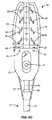
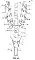
ここで図1を参照すると、本発明の原理に従って構築される、閉鎖装置アプリケータ10は、その近位端にあるハンドルアセンブリ14と、遠位端にあるジョーアセンブリ16とを有するシャフトアセンブリ12を備え、個々のジョー18および20は、図6A〜6Dにおいて最良に例解されるように、閉鎖装置22を支持するように適合されている。閉鎖装置22は、図1、2、および6Aにおいて示されるように、ジョーが開放している場合、左心耳または他の組織構造を受け取るためのV形状の領域24を規定するU形状の構成を有する。複数のスタッド26が、図6Aにおいて最良に示されるように、貫通構成要素28とレセプタクル構成要素30とを備えている組織貫通ファスナを係合するために、各ジョー20および18の内面に沿って形成される。ハンドルアセンブリ14は、ハンドル32と、第1のトリガ34と、第2のトリガ36とを含む。 Referring now to FIG. 1, a
ここで図2および6Aを参照すると、閉鎖装置アプリケータ10が、その保管または送達構成で示され、閉鎖装置22が、ジョーアセンブリ16上に受け取られており、装置内のV形状の開口24が、左心耳(図8を参照されたい)または他の組織構造の上に配置される準備が整っている。第1のトリガ34および第2のトリガ36は、完全に開放されており、即ち、完全に旋回されハンドル32から離れている。 Referring now to FIGS. 2 and 6A, the
閉鎖装置22が、左心耳または他の標的組織構造の上に前進された後、ジョー18および20は、図3および6Bにおいて示されるように、第1のトリガ34をハンドル32に向かって手動で引っ張ることによって、閉鎖される。トリガ34は、ハンドルアセンブリ14に固定して固着される、ピボット40上に載置される。トリガ34を閉鎖すること、即ち、ピボット40上で旋回することは、ピン41およびレバー43によって、トリガに連結されるロッド42を、近位に後退させる。ロッド42は、ジョー18および20の近位端に旋回可能に取り付けられたピン44(図6B)に取り付けられ、ロッド42は、ジョーが、静止スリーブ52に取り付けられたエンドフレーム50のピン48の上のスロット46の移動によって閉鎖されるように、ジョーを近位に後退させる。ジョー18および20が閉鎖される場合、スタッド26は、図6Bにおいて示されるように、組織貫通構成要素28、および組織貫通レセプタクル30が、相互に係合および係止し、このため、閉鎖装置22の2つの脚を閉鎖するように、それらを係合する。第2のトリガ36は、それが、第1のトリガ34と一緒に閉鎖するように、ピン41上に載置される。 After the
第1のトリガ34と第2のトリガ36とが一緒に閉鎖されている場合、ラチェット歯表面62を有する相互係止具60は、図3において示されるように、一度ジョーが閉鎖されると、トリガ34を開放することができないように、ピン64に対して閉鎖される。以下に説明されるように、第2のトリガ36を閉鎖することによって、スタッド26を後退させる前には、ジョーは開放されるべきではないため、上に説明されるとおり、これは有利である。 When the
さらに、第1のトリガ34が、ジョーアセンブリ16のジョー18および20を閉鎖するように、閉鎖される場合、相互係止具60の角66(図7)が、クリッカピン70上の傾斜した表面68に係合し、クリッカピンを保持ピン72から係脱させ、このため、バネ74がピン70を下方向に押下し、底面76がハンドルの底部に突当することを可能にし、このため、ジョーが閉鎖され、相互係止具が係合されたことを、医師に聴覚的に警告するように大きなクリック音が発生される。この聴覚的確認は、閉鎖装置22が閉鎖されたこと、およびスタッド26を後退させることができることを、医師に示す。 Further, when the
ここで図4および6Cを参照すると、スタッド26は、図4において示されるように、第1のトリガ34に対して、第2のトリガ36を閉鎖することによって、後退される。第2のトリガ34の閉鎖は、静止スリーブ52の上の外スリーブ54を近位に引き寄せ、外スリーブ54は、図7において示されるように、スタッドコーム84を近位に引っ張るように、プルワイヤ80を近位に引き寄せる。スタッドコーム84は、ジョー18および20の各々に形成されるスロット88の中で移動するピン86上に載置されている。第2のトリガ36は、ピン41によって、第1のトリガ上に旋回可能に載置され、ピン90および91、ならびにレバー92によって、静止スリーブに結合されている。 Referring now to FIGS. 4 and 6C, the
第2のトリガ36の閉鎖は、第2のトリガ内の固定されたピン96に対して、相互係止具に取り付けられた傾斜した表面94に係合することによって、相互係止具60を係脱させる。ピン96は、表面94に係合するように、図3において破線で示される経路をたどる。図4および5において示されるように、傾斜した表面94は、下方に移動させられ、ラチェット歯62を、固定されたピン64から離して引っ張る。ここで、トリガ34および36は、以降に説明されるように、ジョーを開放するために、開放される準備が整う。 Closure of the
ここで図5および7Cを参照すると、ジョー18および20は、第1および第2のトリガ34および36上の手動圧縮を解放することによって、開放され得、第1のトリガ34の閉鎖中に圧縮されていたバネ98が、ロッド42(ピボット44に取り付けられる)を遠位に前方へ押しやることを可能にし、ジョーを開放し、かつ閉鎖装置22を所定の位置に残す。 Referring now to FIGS. 5 and 7C, the
ここで図8を参照すると、本発明の閉鎖装置アプリケータは、開胸拍動心臓手技において、左心耳LAAの基部の上に閉鎖装置22を送達するために使用することができる。心臓上の作業空間を提供するように、胸骨Sが開かれ、肋骨Rを広げる。心膜を開いた後、図8において示されるように、開口内で左心耳を露出させるために、心臓が、例えば、心臓の後方に配置される、ガーゼまたは他の材料のシートを使用して、持ち上げられ、変向され得る。左心耳LAAを露出させた後、閉鎖装置アプリケータのジョー18および20は、図8において示されるように、シャフト12を操作することによって、左心耳の基部周囲に配置される。典型的に約15°である、シャフトに対するジョー18および20の角度は、ジョーが、左心耳と左心房LAとの間の口と略平行であるように、ジョーが左心耳の基部に係合することを可能にするため、極めて有利である。ジョーの平面が、シャフトと整列されている場合、この配向を達成することが困難であり、左心耳を閉鎖し、盲管(口の後方、および左心耳の内部への開放空間)を残すリスクが大幅に増加される。かかる盲管は、血栓源である可能性があり、形成された場合、同じまたは後の手技において、閉鎖されなければならないため、問題となる。一度ジョー18および20が、左心耳の基部の周囲に閉鎖装置22を適切に位置付けると、先に説明されるように、ジョーは起動され、閉鎖装置は展開される。 Referring now to FIG. 8, the closure device applicator of the present invention can be used to deliver the
上記は、本発明の好適な実施形態に関する完全な説明であるが、種々の代替例、修正、および相当物を使用し得る。したがって、上記の説明は本発明の範囲を限定するものと見なすべきではなく、添付の請求項により定義される。 While the above is a complete description of the preferred embodiments of the invention, various alternatives, modifications, and equivalents may be used. Therefore, the above description should not be taken as limiting the scope of the invention, but is defined by the appended claims.
Claims (5)
Translated fromJapaneseシャフトと、
該シャフトの遠位端に取り付けられるハンドルと、
該シャフトの遠位端に位置する第1のジョーおよび第2のジョーであって、該第1のジョーおよび該第2のジョーは、相互に対して移動するように適合されている、第1のジョーおよび第2のジョーと、
該ジョーのうちの少なくとも1つに対して移動可能な複数のスタッドと、
トリガ機構と
を備え、
該トリガ機構は、
該第1のジョーおよび該第2のジョーのうちの1つと作用可能に関連付けられた第1のトリガアセンブリであって、該第1のトリガアセンブリは、第1のトリガを備え、該第1のトリガは、該ハンドルに向かって第1の方向に移動して、該ジョーを相互に対して閉鎖し、組織を貫通するように構成されたファスナを備える圧縮体が該第1のジョーと該第2のジョーとの間に位置付けられたときに該組織の上で該圧縮体を展開する、第1のトリガアセンブリと、
該第1のトリガアセンブリと作用可能に関連付けられた第2のトリガアセンブリであって、該第2のトリガアセンブリは、第2のトリガを備え、該第2のトリガは、該第1のトリガが閉鎖されたときに該第1のトリガと係合し該第1のトリガを該ハンドルと相互係止する相互係止具に取り付けられた傾斜した表面と該第2のトリガ内の第2のピンを係合するように該第1の方向に該第1のトリガと一緒に移動するように第1のピンにより該第1のトリガ上に旋回可能に載置され、該第1の方向における該第2のトリガのさらなる移動が該傾斜した表面を下方に移動させて該相互係止具を該ハンドルから係脱することにより、該第1のトリガおよび該第2のトリガが該ハンドルから離れる第2の方向に移動可能であるようにし、かつ、該第1のジョーおよび該第2のジョーから該圧縮体を解放するようにする、第2のトリガアセンブリと
を備え、
該トリガ機構は、起動時、かつ、該圧縮体が該第1のジョーと該第2のジョーとの間に位置付けられたときに、以下の動作:(i)該第1のトリガが該第1の方向に移動したときの該スタッドに係合するような該ジョーの相互に対する閉鎖および該ファスナの展開、(ii)該第1のトリガに対して閉鎖するように該第2のトリガが該第1の方向に移動したときの該ファスナとの係合からの該スタッドの後退、(iii)該第1のトリガおよび該第2のトリガが該第2の方向に移動したときの該ジョーの相互に対する開放を順に生じさせるように構成されている、システム。A tissue separation system for separating tissue, the tissue separation system comprising:
A shaft,
A handle attached to the distal end of the shaft;
A first jaw and a second jaw located at a distal end of the shaft, wherein the first jaw and the second jaw are adapted to move relative to each other; And the second jaw,
A plurality of studs movable relative to at least one of the jaws;
With trigger mechanism,
The trigger mechanism is:
A first trigger assembly operatively associated with one of the first jaw and the second jaw, the first trigger assembly comprising a first trigger; A trigger moves in a first direction toward the handle to close the jaws relative to each other, and a compression body comprising a fastener configured to penetrate tissue includes the first jaw and the first A first trigger assembly that deploys the compression body over the tissue when positioned between two jaws;
A second trigger assembly operatively associated with the first trigger assembly, the second trigger assembly comprising a second trigger, wherein the second trigger is the first triggerbeingA sloped surface attached to an interlockthat engages the first trigger and interlocks the first trigger with the handle when closed, and asecond pin in the second trigger the mounted pivotally to the first on the trigger bya first pin so as to movewith the trigger first in the first direction to engage, said in the first direction by further movement of the second trigger is disengaged themutual locking memberis moved to the inclined surface downwardlyfrom the handle, the trigger of the trigger and the second first leaves from the handle Be movable in two directions and the first So as to release the compact from ® over and the second jaw, and a second trigger assembly,
When the trigger mechanism is activated and the compression body is positioned between the first jaw and the second jaw, the following operation is performed: (i) the first trigger is Closure of the jaws relative to each other and engagement of the fasteners to engage the stud when moved in one direction, and (ii) the second trigger is closed to the first trigger Retraction of the stud from engagement with the fastener when moved in a first direction; (iii) of the jaw when the first trigger and the second trigger are moved in the second direction; A system that is configured to cause an opening to each other in turn.
Applications Claiming Priority (2)
| Application Number | Priority Date | Filing Date | Title |
|---|---|---|---|
| US23301109P | 2009-08-11 | 2009-08-11 | |
| US61/233,011 | 2009-08-11 |
Related Parent Applications (1)
| Application Number | Title | Priority Date | Filing Date |
|---|---|---|---|
| JP2015116009ADivisionJP6166750B2 (en) | 2009-08-11 | 2015-06-08 | Tissue separation system for separating tissues |
Related Child Applications (1)
| Application Number | Title | Priority Date | Filing Date |
|---|---|---|---|
| JP2018047740ADivisionJP2018089478A (en) | 2009-08-11 | 2018-03-15 | Delivery device and method for compliant tissue fastener |
Publications (2)
| Publication Number | Publication Date |
|---|---|
| JP2017104665A JP2017104665A (en) | 2017-06-15 |
| JP6353574B2true JP6353574B2 (en) | 2018-07-04 |
Family
ID=43586464
Family Applications (4)
| Application Number | Title | Priority Date | Filing Date |
|---|---|---|---|
| JP2012524852AActiveJP5807312B2 (en) | 2009-08-11 | 2010-08-11 | Closure device applicator and closure system |
| JP2015116009AActiveJP6166750B2 (en) | 2009-08-11 | 2015-06-08 | Tissue separation system for separating tissues |
| JP2017049531AActiveJP6353574B2 (en) | 2009-08-11 | 2017-03-15 | Delivery device and method for compliant tissue fasteners |
| JP2018047740AWithdrawnJP2018089478A (en) | 2009-08-11 | 2018-03-15 | Delivery device and method for compliant tissue fastener |
Family Applications Before (2)
| Application Number | Title | Priority Date | Filing Date |
|---|---|---|---|
| JP2012524852AActiveJP5807312B2 (en) | 2009-08-11 | 2010-08-11 | Closure device applicator and closure system |
| JP2015116009AActiveJP6166750B2 (en) | 2009-08-11 | 2015-06-08 | Tissue separation system for separating tissues |
Family Applications After (1)
| Application Number | Title | Priority Date | Filing Date |
|---|---|---|---|
| JP2018047740AWithdrawnJP2018089478A (en) | 2009-08-11 | 2018-03-15 | Delivery device and method for compliant tissue fastener |
Country Status (5)
| Country | Link |
|---|---|
| US (1) | US8647350B2 (en) |
| EP (1) | EP2464298B1 (en) |
| JP (4) | JP5807312B2 (en) |
| CN (1) | CN102573665B (en) |
| WO (1) | WO2011019848A1 (en) |
Families Citing this family (216)
| Publication number | Priority date | Publication date | Assignee | Title |
|---|---|---|---|---|
| US11229472B2 (en) | 2001-06-12 | 2022-01-25 | Cilag Gmbh International | Modular battery powered handheld surgical instrument with multiple magnetic position sensors |
| US8182501B2 (en) | 2004-02-27 | 2012-05-22 | Ethicon Endo-Surgery, Inc. | Ultrasonic surgical shears and method for sealing a blood vessel using same |
| US20060079879A1 (en) | 2004-10-08 | 2006-04-13 | Faller Craig N | Actuation mechanism for use with an ultrasonic surgical instrument |
| US20070191713A1 (en) | 2005-10-14 | 2007-08-16 | Eichmann Stephen E | Ultrasonic device for cutting and coagulating |
| US7621930B2 (en) | 2006-01-20 | 2009-11-24 | Ethicon Endo-Surgery, Inc. | Ultrasound medical instrument having a medical ultrasonic blade |
| EP2015681B1 (en) | 2006-05-03 | 2018-03-28 | Datascope Corp. | Tissue closure device |
| US8057498B2 (en) | 2007-11-30 | 2011-11-15 | Ethicon Endo-Surgery, Inc. | Ultrasonic surgical instrument blades |
| US8142461B2 (en) | 2007-03-22 | 2012-03-27 | Ethicon Endo-Surgery, Inc. | Surgical instruments |
| US8911460B2 (en) | 2007-03-22 | 2014-12-16 | Ethicon Endo-Surgery, Inc. | Ultrasonic surgical instruments |
| US8808319B2 (en) | 2007-07-27 | 2014-08-19 | Ethicon Endo-Surgery, Inc. | Surgical instruments |
| US8523889B2 (en) | 2007-07-27 | 2013-09-03 | Ethicon Endo-Surgery, Inc. | Ultrasonic end effectors with increased active length |
| US9044261B2 (en) | 2007-07-31 | 2015-06-02 | Ethicon Endo-Surgery, Inc. | Temperature controlled ultrasonic surgical instruments |
| US8512365B2 (en) | 2007-07-31 | 2013-08-20 | Ethicon Endo-Surgery, Inc. | Surgical instruments |
| US8430898B2 (en) | 2007-07-31 | 2013-04-30 | Ethicon Endo-Surgery, Inc. | Ultrasonic surgical instruments |
| EP2217157A2 (en) | 2007-10-05 | 2010-08-18 | Ethicon Endo-Surgery, Inc. | Ergonomic surgical instruments |
| US10010339B2 (en) | 2007-11-30 | 2018-07-03 | Ethicon Llc | Ultrasonic surgical blades |
| US9089360B2 (en) | 2008-08-06 | 2015-07-28 | Ethicon Endo-Surgery, Inc. | Devices and techniques for cutting and coagulating tissue |
| US9700339B2 (en) | 2009-05-20 | 2017-07-11 | Ethicon Endo-Surgery, Inc. | Coupling arrangements and methods for attaching tools to ultrasonic surgical instruments |
| US8663220B2 (en) | 2009-07-15 | 2014-03-04 | Ethicon Endo-Surgery, Inc. | Ultrasonic surgical instruments |
| US10349935B2 (en) | 2009-08-11 | 2019-07-16 | Datascope Corp. | Delivery device and method for compliant tissue fasteners |
| US10441345B2 (en) | 2009-10-09 | 2019-10-15 | Ethicon Llc | Surgical generator for ultrasonic and electrosurgical devices |
| US9050093B2 (en) | 2009-10-09 | 2015-06-09 | Ethicon Endo-Surgery, Inc. | Surgical generator for ultrasonic and electrosurgical devices |
| US10172669B2 (en) | 2009-10-09 | 2019-01-08 | Ethicon Llc | Surgical instrument comprising an energy trigger lockout |
| US11090104B2 (en) | 2009-10-09 | 2021-08-17 | Cilag Gmbh International | Surgical generator for ultrasonic and electrosurgical devices |
| US8951272B2 (en) | 2010-02-11 | 2015-02-10 | Ethicon Endo-Surgery, Inc. | Seal arrangements for ultrasonically powered surgical instruments |
| US8469981B2 (en) | 2010-02-11 | 2013-06-25 | Ethicon Endo-Surgery, Inc. | Rotatable cutting implement arrangements for ultrasonic surgical instruments |
| US8486096B2 (en) | 2010-02-11 | 2013-07-16 | Ethicon Endo-Surgery, Inc. | Dual purpose surgical instrument for cutting and coagulating tissue |
| US8696665B2 (en) | 2010-03-26 | 2014-04-15 | Ethicon Endo-Surgery, Inc. | Surgical cutting and sealing instrument with reduced firing force |
| US8709035B2 (en) | 2010-04-12 | 2014-04-29 | Ethicon Endo-Surgery, Inc. | Electrosurgical cutting and sealing instruments with jaws having a parallel closure motion |
| US8834518B2 (en) | 2010-04-12 | 2014-09-16 | Ethicon Endo-Surgery, Inc. | Electrosurgical cutting and sealing instruments with cam-actuated jaws |
| US8685020B2 (en) | 2010-05-17 | 2014-04-01 | Ethicon Endo-Surgery, Inc. | Surgical instruments and end effectors therefor |
| GB2480498A (en) | 2010-05-21 | 2011-11-23 | Ethicon Endo Surgery Inc | Medical device comprising RF circuitry |
| US9005199B2 (en) | 2010-06-10 | 2015-04-14 | Ethicon Endo-Surgery, Inc. | Heat management configurations for controlling heat dissipation from electrosurgical instruments |
| US8795327B2 (en) | 2010-07-22 | 2014-08-05 | Ethicon Endo-Surgery, Inc. | Electrosurgical instrument with separate closure and cutting members |
| US9192431B2 (en) | 2010-07-23 | 2015-11-24 | Ethicon Endo-Surgery, Inc. | Electrosurgical cutting and sealing instrument |
| US8979890B2 (en) | 2010-10-01 | 2015-03-17 | Ethicon Endo-Surgery, Inc. | Surgical instrument with jaw member |
| GB201100902D0 (en)* | 2011-01-19 | 2011-03-02 | Univ Dundee | A surgical guide and tissue anchor |
| US9259265B2 (en) | 2011-07-22 | 2016-02-16 | Ethicon Endo-Surgery, Llc | Surgical instruments for tensioning tissue |
| US9044243B2 (en) | 2011-08-30 | 2015-06-02 | Ethcon Endo-Surgery, Inc. | Surgical cutting and fastening device with descendible second trigger arrangement |
| US9333025B2 (en) | 2011-10-24 | 2016-05-10 | Ethicon Endo-Surgery, Llc | Battery initialization clip |
| WO2013119545A1 (en) | 2012-02-10 | 2013-08-15 | Ethicon-Endo Surgery, Inc. | Robotically controlled surgical instrument |
| US9439668B2 (en) | 2012-04-09 | 2016-09-13 | Ethicon Endo-Surgery, Llc | Switch arrangements for ultrasonic surgical instruments |
| US20140005705A1 (en) | 2012-06-29 | 2014-01-02 | Ethicon Endo-Surgery, Inc. | Surgical instruments with articulating shafts |
| US20140005640A1 (en) | 2012-06-28 | 2014-01-02 | Ethicon Endo-Surgery, Inc. | Surgical end effector jaw and electrode configurations |
| US9351754B2 (en) | 2012-06-29 | 2016-05-31 | Ethicon Endo-Surgery, Llc | Ultrasonic surgical instruments with distally positioned jaw assemblies |
| US9393037B2 (en) | 2012-06-29 | 2016-07-19 | Ethicon Endo-Surgery, Llc | Surgical instruments with articulating shafts |
| US9408622B2 (en) | 2012-06-29 | 2016-08-09 | Ethicon Endo-Surgery, Llc | Surgical instruments with articulating shafts |
| US9226767B2 (en) | 2012-06-29 | 2016-01-05 | Ethicon Endo-Surgery, Inc. | Closed feedback control for electrosurgical device |
| US9326788B2 (en) | 2012-06-29 | 2016-05-03 | Ethicon Endo-Surgery, Llc | Lockout mechanism for use with robotic electrosurgical device |
| US20140005702A1 (en) | 2012-06-29 | 2014-01-02 | Ethicon Endo-Surgery, Inc. | Ultrasonic surgical instruments with distally positioned transducers |
| US9198714B2 (en) | 2012-06-29 | 2015-12-01 | Ethicon Endo-Surgery, Inc. | Haptic feedback devices for surgical robot |
| US9820768B2 (en) | 2012-06-29 | 2017-11-21 | Ethicon Llc | Ultrasonic surgical instruments with control mechanisms |
| EP2900158B1 (en) | 2012-09-28 | 2020-04-15 | Ethicon LLC | Multi-function bi-polar forceps |
| US9095367B2 (en) | 2012-10-22 | 2015-08-04 | Ethicon Endo-Surgery, Inc. | Flexible harmonic waveguides/blades for surgical instruments |
| US20140135804A1 (en) | 2012-11-15 | 2014-05-15 | Ethicon Endo-Surgery, Inc. | Ultrasonic and electrosurgical devices |
| US20140252064A1 (en)* | 2013-03-05 | 2014-09-11 | Covidien Lp | Surgical stapling device including adjustable fastener crimping |
| US10226273B2 (en) | 2013-03-14 | 2019-03-12 | Ethicon Llc | Mechanical fasteners for use with surgical energy devices |
| FR3005564B1 (en)* | 2013-05-20 | 2018-01-12 | Cousin Biotech | INSTRUMENT FOR USE IN MODIFYING THE VOLUME OF THE STOMACH OF A PATIENT. |
| US9295514B2 (en) | 2013-08-30 | 2016-03-29 | Ethicon Endo-Surgery, Llc | Surgical devices with close quarter articulation features |
| US9814514B2 (en) | 2013-09-13 | 2017-11-14 | Ethicon Llc | Electrosurgical (RF) medical instruments for cutting and coagulating tissue |
| US9861428B2 (en) | 2013-09-16 | 2018-01-09 | Ethicon Llc | Integrated systems for electrosurgical steam or smoke control |
| US9526565B2 (en) | 2013-11-08 | 2016-12-27 | Ethicon Endo-Surgery, Llc | Electrosurgical devices |
| US9265926B2 (en) | 2013-11-08 | 2016-02-23 | Ethicon Endo-Surgery, Llc | Electrosurgical devices |
| WO2015077356A1 (en) | 2013-11-19 | 2015-05-28 | Wheeler William K | Fastener applicator with interlock |
| GB2521229A (en) | 2013-12-16 | 2015-06-17 | Ethicon Endo Surgery Inc | Medical device |
| GB2521228A (en) | 2013-12-16 | 2015-06-17 | Ethicon Endo Surgery Inc | Medical device |
| MX369672B (en) | 2013-12-17 | 2019-11-15 | Standard Bariatrics Inc | Resection line guide for a medical procedure and method of using same. |
| US9839428B2 (en) | 2013-12-23 | 2017-12-12 | Ethicon Llc | Surgical cutting and stapling instruments with independent jaw control features |
| US20150173756A1 (en) | 2013-12-23 | 2015-06-25 | Ethicon Endo-Surgery, Inc. | Surgical cutting and stapling methods |
| US9724092B2 (en) | 2013-12-23 | 2017-08-08 | Ethicon Llc | Modular surgical instruments |
| US11324510B2 (en) | 2013-12-30 | 2022-05-10 | Atricure, Inc. | Systems and methods for left atrial appendage closure |
| US9795436B2 (en) | 2014-01-07 | 2017-10-24 | Ethicon Llc | Harvesting energy from a surgical generator |
| US9408660B2 (en) | 2014-01-17 | 2016-08-09 | Ethicon Endo-Surgery, Llc | Device trigger dampening mechanism |
| US9554854B2 (en) | 2014-03-18 | 2017-01-31 | Ethicon Endo-Surgery, Llc | Detecting short circuits in electrosurgical medical devices |
| US10463421B2 (en) | 2014-03-27 | 2019-11-05 | Ethicon Llc | Two stage trigger, clamp and cut bipolar vessel sealer |
| US10092310B2 (en) | 2014-03-27 | 2018-10-09 | Ethicon Llc | Electrosurgical devices |
| US10524852B1 (en) | 2014-03-28 | 2020-01-07 | Ethicon Llc | Distal sealing end effector with spacers |
| WO2015153324A1 (en) | 2014-03-29 | 2015-10-08 | Standard Bariatrics, Inc. | End effectors, surgical stapling devices, and methods of using same |
| AU2015241193B2 (en) | 2014-03-29 | 2020-01-02 | Standard Bariatrics, Inc. | End effectors surgical stapling devices, and methods of using same |
| JP6396667B2 (en)* | 2014-03-31 | 2018-09-26 | オリンパス株式会社 | Auricular ligation system |
| US9737355B2 (en) | 2014-03-31 | 2017-08-22 | Ethicon Llc | Controlling impedance rise in electrosurgical medical devices |
| US9913680B2 (en) | 2014-04-15 | 2018-03-13 | Ethicon Llc | Software algorithms for electrosurgical instruments |
| US9757186B2 (en) | 2014-04-17 | 2017-09-12 | Ethicon Llc | Device status feedback for bipolar tissue spacer |
| US9700333B2 (en) | 2014-06-30 | 2017-07-11 | Ethicon Llc | Surgical instrument with variable tissue compression |
| US10285724B2 (en) | 2014-07-31 | 2019-05-14 | Ethicon Llc | Actuation mechanisms and load adjustment assemblies for surgical instruments |
| US10194976B2 (en) | 2014-08-25 | 2019-02-05 | Ethicon Llc | Lockout disabling mechanism |
| US9877776B2 (en) | 2014-08-25 | 2018-01-30 | Ethicon Llc | Simultaneous I-beam and spring driven cam jaw closure mechanism |
| US10194972B2 (en) | 2014-08-26 | 2019-02-05 | Ethicon Llc | Managing tissue treatment |
| WO2016037158A1 (en) | 2014-09-05 | 2016-03-10 | Standard Bariatrics, Inc. | Sleeve gastrectomy calibration tube and method of using same |
| US10639092B2 (en) | 2014-12-08 | 2020-05-05 | Ethicon Llc | Electrode configurations for surgical instruments |
| US10111699B2 (en) | 2014-12-22 | 2018-10-30 | Ethicon Llc | RF tissue sealer, shear grip, trigger lock mechanism and energy activation |
| US9848937B2 (en) | 2014-12-22 | 2017-12-26 | Ethicon Llc | End effector with detectable configurations |
| US10092348B2 (en) | 2014-12-22 | 2018-10-09 | Ethicon Llc | RF tissue sealer, shear grip, trigger lock mechanism and energy activation |
| US10159524B2 (en) | 2014-12-22 | 2018-12-25 | Ethicon Llc | High power battery powered RF amplifier topology |
| US10245095B2 (en) | 2015-02-06 | 2019-04-02 | Ethicon Llc | Electrosurgical instrument with rotation and articulation mechanisms |
| US10342602B2 (en) | 2015-03-17 | 2019-07-09 | Ethicon Llc | Managing tissue treatment |
| US10321950B2 (en) | 2015-03-17 | 2019-06-18 | Ethicon Llc | Managing tissue treatment |
| US10595929B2 (en) | 2015-03-24 | 2020-03-24 | Ethicon Llc | Surgical instruments with firing system overload protection mechanisms |
| US10314638B2 (en) | 2015-04-07 | 2019-06-11 | Ethicon Llc | Articulating radio frequency (RF) tissue seal with articulating state sensing |
| US10117702B2 (en) | 2015-04-10 | 2018-11-06 | Ethicon Llc | Surgical generator systems and related methods |
| US10130410B2 (en) | 2015-04-17 | 2018-11-20 | Ethicon Llc | Electrosurgical instrument including a cutting member decouplable from a cutting member trigger |
| US9872725B2 (en) | 2015-04-29 | 2018-01-23 | Ethicon Llc | RF tissue sealer with mode selection |
| US11020140B2 (en) | 2015-06-17 | 2021-06-01 | Cilag Gmbh International | Ultrasonic surgical blade for use with ultrasonic surgical instruments |
| US11129669B2 (en) | 2015-06-30 | 2021-09-28 | Cilag Gmbh International | Surgical system with user adaptable techniques based on tissue type |
| US11141213B2 (en) | 2015-06-30 | 2021-10-12 | Cilag Gmbh International | Surgical instrument with user adaptable techniques |
| US10034704B2 (en) | 2015-06-30 | 2018-07-31 | Ethicon Llc | Surgical instrument with user adaptable algorithms |
| US10898256B2 (en) | 2015-06-30 | 2021-01-26 | Ethicon Llc | Surgical system with user adaptable techniques based on tissue impedance |
| US11051873B2 (en) | 2015-06-30 | 2021-07-06 | Cilag Gmbh International | Surgical system with user adaptable techniques employing multiple energy modalities based on tissue parameters |
| US10357303B2 (en) | 2015-06-30 | 2019-07-23 | Ethicon Llc | Translatable outer tube for sealing using shielded lap chole dissector |
| US10154852B2 (en) | 2015-07-01 | 2018-12-18 | Ethicon Llc | Ultrasonic surgical blade with improved cutting and coagulation features |
| US20170014135A1 (en)* | 2015-07-14 | 2017-01-19 | Keith Edward Martin | Surgical tool |
| CN105193471B (en) | 2015-08-11 | 2017-10-27 | 北京迈迪顶峰医疗科技有限公司 | Auricle clamp and its conveying device |
| US10980538B2 (en) | 2015-08-26 | 2021-04-20 | Ethicon Llc | Surgical stapling configurations for curved and circular stapling instruments |
| MX2018002392A (en) | 2015-08-26 | 2018-08-01 | Ethicon Llc | Staple cartridge assembly comprising various tissue compression gaps and staple forming gaps. |
| MX2022009705A (en) | 2015-08-26 | 2022-11-07 | Ethicon Llc | Surgical staples comprising hardness variations for improved fastening of tissue. |
| RU2725081C2 (en) | 2015-08-26 | 2020-06-29 | ЭТИКОН ЭлЭлСи | Strips with surgical staples allowing the presence of staples with variable properties and providing simple loading of the cartridge |
| US10238390B2 (en) | 2015-09-02 | 2019-03-26 | Ethicon Llc | Surgical staple cartridges with driver arrangements for establishing herringbone staple patterns |
| MX2022006189A (en) | 2015-09-02 | 2022-06-16 | Ethicon Llc | Surgical staple configurations with camming surfaces located between portions supporting surgical staples. |
| US10285837B1 (en) | 2015-09-16 | 2019-05-14 | Standard Bariatrics, Inc. | Systems and methods for measuring volume of potential sleeve in a sleeve gastrectomy |
| WO2017045148A1 (en)* | 2015-09-16 | 2017-03-23 | 瑞奇外科器械(中国)有限公司 | Action execution apparatus and ultrasound surgical instrument |
| US10194973B2 (en) | 2015-09-30 | 2019-02-05 | Ethicon Llc | Generator for digitally generating electrical signal waveforms for electrosurgical and ultrasonic surgical instruments |
| US10959771B2 (en) | 2015-10-16 | 2021-03-30 | Ethicon Llc | Suction and irrigation sealing grasper |
| US10595930B2 (en) | 2015-10-16 | 2020-03-24 | Ethicon Llc | Electrode wiping surgical device |
| US10959806B2 (en) | 2015-12-30 | 2021-03-30 | Ethicon Llc | Energized medical device with reusable handle |
| US10179022B2 (en) | 2015-12-30 | 2019-01-15 | Ethicon Llc | Jaw position impedance limiter for electrosurgical instrument |
| US10575892B2 (en) | 2015-12-31 | 2020-03-03 | Ethicon Llc | Adapter for electrical surgical instruments |
| US10716615B2 (en) | 2016-01-15 | 2020-07-21 | Ethicon Llc | Modular battery powered handheld surgical instrument with curved end effectors having asymmetric engagement between jaw and blade |
| US11129670B2 (en) | 2016-01-15 | 2021-09-28 | Cilag Gmbh International | Modular battery powered handheld surgical instrument with selective application of energy based on button displacement, intensity, or local tissue characterization |
| US11229471B2 (en) | 2016-01-15 | 2022-01-25 | Cilag Gmbh International | Modular battery powered handheld surgical instrument with selective application of energy based on tissue characterization |
| US12193698B2 (en) | 2016-01-15 | 2025-01-14 | Cilag Gmbh International | Method for self-diagnosing operation of a control switch in a surgical instrument system |
| US11051840B2 (en) | 2016-01-15 | 2021-07-06 | Ethicon Llc | Modular battery powered handheld surgical instrument with reusable asymmetric handle housing |
| WO2017139635A1 (en)* | 2016-02-12 | 2017-08-17 | Sanford Health | Mesh for hiatal hernia repair and deployment device |
| US10555769B2 (en) | 2016-02-22 | 2020-02-11 | Ethicon Llc | Flexible circuits for electrosurgical instrument |
| US10702329B2 (en) | 2016-04-29 | 2020-07-07 | Ethicon Llc | Jaw structure with distal post for electrosurgical instruments |
| US10856934B2 (en) | 2016-04-29 | 2020-12-08 | Ethicon Llc | Electrosurgical instrument with electrically conductive gap setting and tissue engaging members |
| US10646269B2 (en) | 2016-04-29 | 2020-05-12 | Ethicon Llc | Non-linear jaw gap for electrosurgical instruments |
| US10485607B2 (en) | 2016-04-29 | 2019-11-26 | Ethicon Llc | Jaw structure with distal closure for electrosurgical instruments |
| US10987156B2 (en) | 2016-04-29 | 2021-04-27 | Ethicon Llc | Electrosurgical instrument with electrically conductive gap setting member and electrically insulative tissue engaging members |
| US10456193B2 (en) | 2016-05-03 | 2019-10-29 | Ethicon Llc | Medical device with a bilateral jaw configuration for nerve stimulation |
| JP6980705B2 (en) | 2016-06-24 | 2021-12-15 | エシコン エルエルシーEthicon LLC | Stapling system for use with wire staples and punched staples |
| USD847989S1 (en) | 2016-06-24 | 2019-05-07 | Ethicon Llc | Surgical fastener cartridge |
| US10893863B2 (en) | 2016-06-24 | 2021-01-19 | Ethicon Llc | Staple cartridge comprising offset longitudinal staple rows |
| JP6957532B2 (en) | 2016-06-24 | 2021-11-02 | エシコン エルエルシーEthicon LLC | Staple cartridges including wire staples and punched staples |
| USD826405S1 (en) | 2016-06-24 | 2018-08-21 | Ethicon Llc | Surgical fastener |
| USD850617S1 (en) | 2016-06-24 | 2019-06-04 | Ethicon Llc | Surgical fastener cartridge |
| US10245064B2 (en) | 2016-07-12 | 2019-04-02 | Ethicon Llc | Ultrasonic surgical instrument with piezoelectric central lumen transducer |
| US10893883B2 (en) | 2016-07-13 | 2021-01-19 | Ethicon Llc | Ultrasonic assembly for use with ultrasonic surgical instruments |
| US10842522B2 (en) | 2016-07-15 | 2020-11-24 | Ethicon Llc | Ultrasonic surgical instruments having offset blades |
| US10376305B2 (en) | 2016-08-05 | 2019-08-13 | Ethicon Llc | Methods and systems for advanced harmonic energy |
| US10285723B2 (en) | 2016-08-09 | 2019-05-14 | Ethicon Llc | Ultrasonic surgical blade with improved heel portion |
| USD847990S1 (en) | 2016-08-16 | 2019-05-07 | Ethicon Llc | Surgical instrument |
| US10952759B2 (en) | 2016-08-25 | 2021-03-23 | Ethicon Llc | Tissue loading of a surgical instrument |
| US10736649B2 (en) | 2016-08-25 | 2020-08-11 | Ethicon Llc | Electrical and thermal connections for ultrasonic transducer |
| US10751117B2 (en) | 2016-09-23 | 2020-08-25 | Ethicon Llc | Electrosurgical instrument with fluid diverter |
| US10603064B2 (en) | 2016-11-28 | 2020-03-31 | Ethicon Llc | Ultrasonic transducer |
| US11266430B2 (en) | 2016-11-29 | 2022-03-08 | Cilag Gmbh International | End effector control and calibration |
| US10687810B2 (en) | 2016-12-21 | 2020-06-23 | Ethicon Llc | Stepped staple cartridge with tissue retention and gap setting features |
| US10993715B2 (en) | 2016-12-21 | 2021-05-04 | Ethicon Llc | Staple cartridge comprising staples with different clamping breadths |
| US10945727B2 (en) | 2016-12-21 | 2021-03-16 | Ethicon Llc | Staple cartridge with deformable driver retention features |
| US20180168648A1 (en) | 2016-12-21 | 2018-06-21 | Ethicon Endo-Surgery, Llc | Durability features for end effectors and firing assemblies of surgical stapling instruments |
| US11684367B2 (en) | 2016-12-21 | 2023-06-27 | Cilag Gmbh International | Stepped assembly having and end-of-life indicator |
| US11033325B2 (en) | 2017-02-16 | 2021-06-15 | Cilag Gmbh International | Electrosurgical instrument with telescoping suction port and debris cleaner |
| US10799284B2 (en) | 2017-03-15 | 2020-10-13 | Ethicon Llc | Electrosurgical instrument with textured jaws |
| US11497546B2 (en) | 2017-03-31 | 2022-11-15 | Cilag Gmbh International | Area ratios of patterned coatings on RF electrodes to reduce sticking |
| US11224511B2 (en)* | 2017-04-18 | 2022-01-18 | Edwards Lifesciences Corporation | Heart valve sealing devices and delivery devices therefor |
| US10603117B2 (en) | 2017-06-28 | 2020-03-31 | Ethicon Llc | Articulation state detection mechanisms |
| US10820920B2 (en) | 2017-07-05 | 2020-11-03 | Ethicon Llc | Reusable ultrasonic medical devices and methods of their use |
| US10912562B2 (en) | 2017-08-14 | 2021-02-09 | Standard Bariatrics, Inc. | End effectors, surgical stapling devices, and methods of using same |
| US11490951B2 (en) | 2017-09-29 | 2022-11-08 | Cilag Gmbh International | Saline contact with electrodes |
| US11484358B2 (en) | 2017-09-29 | 2022-11-01 | Cilag Gmbh International | Flexible electrosurgical instrument |
| US11033323B2 (en) | 2017-09-29 | 2021-06-15 | Cilag Gmbh International | Systems and methods for managing fluid and suction in electrosurgical systems |
| JP7348199B2 (en) | 2018-03-28 | 2023-09-20 | データスコープ コーポレイション | Device for atrial appendage exclusion |
| CN112022258B (en)* | 2019-06-04 | 2024-11-15 | 北京迈迪顶峰医疗科技有限公司 | Atrial appendage closure device delivery system |
| US11547468B2 (en) | 2019-06-27 | 2023-01-10 | Cilag Gmbh International | Robotic surgical system with safety and cooperative sensing control |
| US11607278B2 (en) | 2019-06-27 | 2023-03-21 | Cilag Gmbh International | Cooperative robotic surgical systems |
| US11612445B2 (en) | 2019-06-27 | 2023-03-28 | Cilag Gmbh International | Cooperative operation of robotic arms |
| US11376082B2 (en) | 2019-06-27 | 2022-07-05 | Cilag Gmbh International | Robotic surgical system with local sensing of functional parameters based on measurements of multiple physical inputs |
| US11723729B2 (en) | 2019-06-27 | 2023-08-15 | Cilag Gmbh International | Robotic surgical assembly coupling safety mechanisms |
| US11413102B2 (en) | 2019-06-27 | 2022-08-16 | Cilag Gmbh International | Multi-access port for surgical robotic systems |
| CN112336403B (en)* | 2019-08-06 | 2024-09-24 | 北京领健医疗科技有限公司 | Closer conveying system |
| US12274635B2 (en) | 2019-11-04 | 2025-04-15 | Standard Bariatrics, Inc. | Systems and methods of performing surgery using laplace's law tension retraction during surgery |
| BR112022008009A2 (en) | 2019-11-04 | 2022-07-12 | Standard Bariatrics Inc | SYSTEMS AND METHODS OF PERFORMING SURGERY USING LAPLACE'S LAW TENSION RETRACTION DURING SURGERY |
| US12076006B2 (en) | 2019-12-30 | 2024-09-03 | Cilag Gmbh International | Surgical instrument comprising an orientation detection system |
| US11937866B2 (en) | 2019-12-30 | 2024-03-26 | Cilag Gmbh International | Method for an electrosurgical procedure |
| US11696776B2 (en) | 2019-12-30 | 2023-07-11 | Cilag Gmbh International | Articulatable surgical instrument |
| US11812957B2 (en) | 2019-12-30 | 2023-11-14 | Cilag Gmbh International | Surgical instrument comprising a signal interference resolution system |
| US11786294B2 (en) | 2019-12-30 | 2023-10-17 | Cilag Gmbh International | Control program for modular combination energy device |
| US11452525B2 (en) | 2019-12-30 | 2022-09-27 | Cilag Gmbh International | Surgical instrument comprising an adjustment system |
| US12343063B2 (en) | 2019-12-30 | 2025-07-01 | Cilag Gmbh International | Multi-layer clamp arm pad for enhanced versatility and performance of a surgical device |
| US11779329B2 (en) | 2019-12-30 | 2023-10-10 | Cilag Gmbh International | Surgical instrument comprising a flex circuit including a sensor system |
| US11786291B2 (en) | 2019-12-30 | 2023-10-17 | Cilag Gmbh International | Deflectable support of RF energy electrode with respect to opposing ultrasonic blade |
| US12023086B2 (en) | 2019-12-30 | 2024-07-02 | Cilag Gmbh International | Electrosurgical instrument for delivering blended energy modalities to tissue |
| US11950797B2 (en) | 2019-12-30 | 2024-04-09 | Cilag Gmbh International | Deflectable electrode with higher distal bias relative to proximal bias |
| US11944366B2 (en) | 2019-12-30 | 2024-04-02 | Cilag Gmbh International | Asymmetric segmented ultrasonic support pad for cooperative engagement with a movable RF electrode |
| US11660089B2 (en) | 2019-12-30 | 2023-05-30 | Cilag Gmbh International | Surgical instrument comprising a sensing system |
| US12262937B2 (en) | 2019-12-30 | 2025-04-01 | Cilag Gmbh International | User interface for surgical instrument with combination energy modality end-effector |
| US11779387B2 (en) | 2019-12-30 | 2023-10-10 | Cilag Gmbh International | Clamp arm jaw to minimize tissue sticking and improve tissue control |
| US12114912B2 (en) | 2019-12-30 | 2024-10-15 | Cilag Gmbh International | Non-biased deflectable electrode to minimize contact between ultrasonic blade and electrode |
| US11684412B2 (en) | 2019-12-30 | 2023-06-27 | Cilag Gmbh International | Surgical instrument with rotatable and articulatable surgical end effector |
| US11911063B2 (en) | 2019-12-30 | 2024-02-27 | Cilag Gmbh International | Techniques for detecting ultrasonic blade to electrode contact and reducing power to ultrasonic blade |
| US11937863B2 (en) | 2019-12-30 | 2024-03-26 | Cilag Gmbh International | Deflectable electrode with variable compression bias along the length of the deflectable electrode |
| US12082808B2 (en) | 2019-12-30 | 2024-09-10 | Cilag Gmbh International | Surgical instrument comprising a control system responsive to software configurations |
| US20210196362A1 (en) | 2019-12-30 | 2021-07-01 | Ethicon Llc | Electrosurgical end effectors with thermally insulative and thermally conductive portions |
| US11986201B2 (en) | 2019-12-30 | 2024-05-21 | Cilag Gmbh International | Method for operating a surgical instrument |
| US12053224B2 (en) | 2019-12-30 | 2024-08-06 | Cilag Gmbh International | Variation in electrode parameters and deflectable electrode to modify energy density and tissue interaction |
| US12064109B2 (en) | 2019-12-30 | 2024-08-20 | Cilag Gmbh International | Surgical instrument comprising a feedback control circuit |
| US12336747B2 (en) | 2019-12-30 | 2025-06-24 | Cilag Gmbh International | Method of operating a combination ultrasonic / bipolar RF surgical device with a combination energy modality end-effector |
| US20210196357A1 (en) | 2019-12-30 | 2021-07-01 | Ethicon Llc | Electrosurgical instrument with asynchronous energizing electrodes |
| CN115955943A (en) | 2020-06-30 | 2023-04-11 | 标准肥胖病研究公司 | Systems, devices, and methods for preventing or reducing insufflation loss during laparoscopic procedures |
| AU2022242751B2 (en) | 2021-03-23 | 2024-05-02 | Standard Bariatrics, Inc. | Systems and methods for preventing tissue migration in surgical staplers |
| US12358136B2 (en) | 2021-06-30 | 2025-07-15 | Cilag Gmbh International | Grasping work determination and indications thereof |
| US11974829B2 (en) | 2021-06-30 | 2024-05-07 | Cilag Gmbh International | Link-driven articulation device for a surgical device |
| US11931026B2 (en) | 2021-06-30 | 2024-03-19 | Cilag Gmbh International | Staple cartridge replacement |
| US11660094B2 (en)* | 2021-09-29 | 2023-05-30 | Covidien Lp | Surgical fastening instrument with two-part surgical fasteners |
| US11957342B2 (en) | 2021-11-01 | 2024-04-16 | Cilag Gmbh International | Devices, systems, and methods for detecting tissue and foreign objects during a surgical operation |
| CN119970111A (en)* | 2025-02-21 | 2025-05-13 | 上海交通大学医学院附属新华医院 | Left atrial appendage clamp occluder and clamp assembly thereof |
Family Cites Families (120)
| Publication number | Priority date | Publication date | Assignee | Title |
|---|---|---|---|---|
| US1756670A (en) | 1928-08-06 | 1930-04-29 | Lester A Treat | Vulva clamp |
| US2659371A (en) | 1951-11-27 | 1953-11-17 | Charles F Schnee | Surgical clamp |
| US3336133A (en)* | 1962-06-01 | 1967-08-15 | Kao Corp | Process for the purification and concentration of cobalt and nickel |
| US3361133A (en) | 1965-07-22 | 1968-01-02 | Canadian Patents Dev | Vacuum artery clamp |
| US3525340A (en) | 1967-10-31 | 1970-08-25 | Joseph G Gilbert | Surgical dressing with skin clips thereon |
| US3746002A (en) | 1971-04-29 | 1973-07-17 | J Haller | Atraumatic surgical clamp |
| US3993076A (en) | 1973-08-20 | 1976-11-23 | Fogarty Thomas J | Vessel occluding instrument |
| GB1530282A (en) | 1975-07-22 | 1978-10-25 | Filshie G | Sexual sterilization devices |
| US4060089A (en) | 1975-09-03 | 1977-11-29 | United States Surgical Corporation | Surgical fastening method and device therefor |
| US4016883A (en) | 1975-11-11 | 1977-04-12 | Wright Jr Sanford J | Medical clamp for occluding intracranial blood vessels |
| US4241861A (en) | 1977-12-20 | 1980-12-30 | Fleischer Harry N | Scissor-type surgical stapler |
| US4257419A (en) | 1978-12-14 | 1981-03-24 | Mo Och Domsjo Aktiebolag | Suction-assisted hemorrhoid ligator |
| US4390019A (en) | 1979-02-28 | 1983-06-28 | Leveen Harry H | Blood vessel clamp |
| US4271828A (en) | 1979-09-13 | 1981-06-09 | Angelchik Jean P | Method for maintaining the reduction of a sliding esophageal hiatal hernia |
| US4402445A (en) | 1981-10-09 | 1983-09-06 | United States Surgical Corporation | Surgical fastener and means for applying same |
| US4489725A (en) | 1982-02-11 | 1984-12-25 | Simon Population Trust | Sexual sterilization devices |
| US4548201A (en) | 1982-04-20 | 1985-10-22 | Inbae Yoon | Elastic ligating ring clip |
| US4506671A (en) | 1983-03-30 | 1985-03-26 | United States Surgical Corporation | Apparatus for applying two-part surgical fasteners |
| GB2158539B (en) | 1983-10-04 | 1987-10-14 | United States Surgical Corp | Surgical fastener exhibiting improved hemostasis |
| GB2177748B (en) | 1985-07-10 | 1988-11-16 | Femcare Ltd | Sexual sterilisation device |
| US4924864A (en) | 1985-11-15 | 1990-05-15 | Danzig Fred G | Apparatus and article for ligating blood vessels, nerves and other anatomical structures |
| US4754758A (en) | 1986-04-14 | 1988-07-05 | American Cyanamid Company | Surgical closure device |
| GB8611452D0 (en) | 1986-05-10 | 1986-06-18 | Femcare Ltd | Sexual sterilation device |
| FR2598905B1 (en) | 1986-05-22 | 1993-08-13 | Chevalier Jean Michel | DEVICE FOR INTERRUPTING THE CIRCULATION OF A FLUID IN A FLEXIBLE WALL CONDUIT, IN PARTICULAR A HOLLOW VISCERE AND CLIP ASSEMBLY COMPRISING THIS DEVICE |
| US4822348A (en) | 1987-05-13 | 1989-04-18 | Donn Casey | Surgical clips |
| US4805617A (en) | 1987-11-05 | 1989-02-21 | Ethicon, Inc. | Surgical fastening systems made from polymeric materials |
| GB2212201B (en) | 1987-11-10 | 1992-06-03 | Donn Casey | Surgical clip |
| US5040715B1 (en) | 1989-05-26 | 1994-04-05 | United States Surgical Corp | Apparatus and method for placing staples in laparoscopic or endoscopic procedures |
| US5413268A (en) | 1989-05-26 | 1995-05-09 | United States Surgical Corporation | Apparatus and method for placing stables in laparoscopic or endoscopic procedures |
| US4988355A (en) | 1990-01-16 | 1991-01-29 | Leveen Eric G | Arterial clamp |
| GB9010696D0 (en) | 1990-05-12 | 1990-07-04 | Femcare Ltd | Sterilisation devices |
| US5156614A (en) | 1990-09-17 | 1992-10-20 | United States Surgical Corporation | Apparatus for applying two-part surgical fasteners |
| US5336232A (en) | 1991-03-14 | 1994-08-09 | United States Surgical Corporation | Approximating apparatus for surgical jaw structure and method of using the same |
| CA2061885A1 (en) | 1991-03-14 | 1992-09-15 | David T. Green | Approximating apparatus for surgical jaw structure |
| US5171253A (en) | 1991-03-22 | 1992-12-15 | Klieman Charles H | Velcro-like closure system with absorbable suture materials for absorbable hemostatic clips and surgical strips |
| US5282812A (en) | 1991-07-10 | 1994-02-01 | Suarez Jr Luis | Clamp for use in vascular surgery |
| US5307976A (en) | 1991-10-18 | 1994-05-03 | Ethicon, Inc. | Linear stapling mechanism with cutting means |
| US5257999A (en) | 1992-06-04 | 1993-11-02 | Slanetz Jr Charles A | Self-oriented laparoscopic needle holder for curved needles |
| US5246456A (en) | 1992-06-08 | 1993-09-21 | Wilkinson Lawrence H | Fenestrated gastric pouch |
| US5330486A (en) | 1992-07-29 | 1994-07-19 | Wilk Peter J | Laparoscopic or endoscopic anastomosis technique and associated instruments |
| US6051003A (en) | 1992-10-09 | 2000-04-18 | Boston Scientific Corporation | Combined multiple ligating band dispenser and sclerotherapy needle instrument |
| US5358510A (en) | 1993-01-26 | 1994-10-25 | Ethicon, Inc. | Two part surgical fastener |
| US5624453A (en) | 1993-02-23 | 1997-04-29 | Wilson-Cook Medical, Inc. | Endoscopic ligating instrument |
| US5425705A (en) | 1993-02-22 | 1995-06-20 | Stanford Surgical Technologies, Inc. | Thoracoscopic devices and methods for arresting the heart |
| US5306234A (en) | 1993-03-23 | 1994-04-26 | Johnson W Dudley | Method for closing an atrial appendage |
| US6716232B1 (en) | 1993-04-30 | 2004-04-06 | United States Surgical Corporation | Surgical instrument having an articulated jaw structure and a detachable knife |
| ES2122282T3 (en) | 1993-04-30 | 1998-12-16 | United States Surgical Corp | SURGICAL INSTRUMENT THAT HAS AN ARTICULATED JAW STRUCTURE. |
| US5549621A (en) | 1993-05-14 | 1996-08-27 | Byron C. Sutherland | Apparatus and method for performing vertical banded gastroplasty |
| JP2958219B2 (en) | 1993-08-20 | 1999-10-06 | 住友ベークライト株式会社 | Endoscopic ligation kit |
| US5542594A (en) | 1993-10-06 | 1996-08-06 | United States Surgical Corporation | Surgical stapling apparatus with biocompatible surgical fabric |
| GB9400739D0 (en) | 1994-01-15 | 1994-03-16 | Femcare Ltd | Medical clip |
| US5597107A (en)* | 1994-02-03 | 1997-01-28 | Ethicon Endo-Surgery, Inc. | Surgical stapler instrument |
| US5632432A (en)* | 1994-12-19 | 1997-05-27 | Ethicon Endo-Surgery, Inc. | Surgical instrument |
| US5620452A (en) | 1994-12-22 | 1997-04-15 | Yoon; Inbae | Surgical clip with ductile tissue penetrating members |
| US6132438A (en) | 1995-06-07 | 2000-10-17 | Ep Technologies, Inc. | Devices for installing stasis reducing means in body tissue |
| US5846255A (en) | 1996-01-31 | 1998-12-08 | Casey Medical Products Limited | Surgical clip |
| US6852075B1 (en) | 1996-02-20 | 2005-02-08 | Cardiothoracic Systems, Inc. | Surgical devices for imposing a negative pressure to stabilize cardiac tissue during surgery |
| US5605272A (en) | 1996-03-12 | 1997-02-25 | Ethicon Endo-Surgery, Inc. | Trigger mechanism for surgical instruments |
| US6579304B1 (en) | 1997-02-03 | 2003-06-17 | Applied Medical Resources Corporation | Surgical clamp with improved traction |
| JP3036686B2 (en) | 1997-02-27 | 2000-04-24 | 政夫 高橋 | Hemostatic holding device for vascular anastomosis used for coronary artery bypass surgery |
| US5843101A (en) | 1997-05-02 | 1998-12-01 | Fry; William R. | Disposable clip for temporary vessel occulsion |
| US6582451B1 (en) | 1999-03-16 | 2003-06-24 | The University Of Sydney | Device for use in surgery |
| US6488689B1 (en) | 1999-05-20 | 2002-12-03 | Aaron V. Kaplan | Methods and apparatus for transpericardial left atrial appendage closure |
| US6716233B1 (en) | 1999-06-02 | 2004-04-06 | Power Medical Interventions, Inc. | Electromechanical driver and remote surgical instrument attachment having computer assisted control capabilities |
| US6325810B1 (en) | 1999-06-30 | 2001-12-04 | Ethicon, Inc. | Foam buttress for stapling apparatus |
| US6328689B1 (en) | 2000-03-23 | 2001-12-11 | Spiration, Inc., | Lung constriction apparatus and method |
| US6817972B2 (en) | 1999-10-01 | 2004-11-16 | Computer Motion, Inc. | Heart stabilizer |
| US6406485B1 (en) | 1999-10-08 | 2002-06-18 | Pilling Weck Incorporated | Surgical grasping device and components thereof |
| GB9927040D0 (en) | 1999-11-17 | 2000-01-12 | Femcare Ltd | Medical clips |
| US6238414B1 (en) | 2000-01-20 | 2001-05-29 | Jerry R. Griffiths | Laparoscopic instrument with parallel actuated jaws |
| US6273897B1 (en) | 2000-02-29 | 2001-08-14 | Ethicon, Inc. | Surgical bettress and surgical stapling apparatus |
| US6436108B1 (en) | 2000-04-19 | 2002-08-20 | Ensurg, Inc. | Movable ligating band dispenser |
| US6546935B2 (en) | 2000-04-27 | 2003-04-15 | Atricure, Inc. | Method for transmural ablation |
| EP1330189B1 (en) | 2000-06-23 | 2007-12-19 | Viacor Incorporated | Automated annular plication for mitral valve repair |
| US6746461B2 (en) | 2000-08-15 | 2004-06-08 | William R. Fry | Low-profile, shape-memory surgical occluder |
| US6716226B2 (en)* | 2001-06-25 | 2004-04-06 | Inscope Development, Llc | Surgical clip |
| US6656193B2 (en)* | 2001-05-07 | 2003-12-02 | Ethicon Endo-Surgery, Inc. | Device for attachment of buttress material to a surgical fastening device |
| US6692507B2 (en) | 2001-08-23 | 2004-02-17 | Scimed Life Systems, Inc. | Impermanent biocompatible fastener |
| US6629988B2 (en) | 2001-08-28 | 2003-10-07 | Ethicon, Inc. | Composite staple for completing an anastomosis |
| US6663653B2 (en) | 2001-09-20 | 2003-12-16 | Radi Medical Systems Ab | Adjustable radial artery compressor |
| US7749157B2 (en) | 2001-12-04 | 2010-07-06 | Estech, Inc. (Endoscopic Technologies, Inc.) | Methods and devices for minimally invasive cardiac surgery for atrial fibrillation |
| US20050149069A1 (en) | 2001-12-04 | 2005-07-07 | Bertolero Arthur A. | Left atrial appendage devices and methods |
| US10098640B2 (en) | 2001-12-04 | 2018-10-16 | Atricure, Inc. | Left atrial appendage devices and methods |
| US6974462B2 (en) | 2001-12-19 | 2005-12-13 | Boston Scientific Scimed, Inc. | Surgical anchor implantation device |
| AU2003241467A1 (en) | 2002-05-14 | 2003-12-02 | University Of Pittsburgh | Device and method of use for functional isolation of animal or human tissues |
| US7678122B2 (en)* | 2002-09-20 | 2010-03-16 | Id, Llc | Method of performing a treatment for gastroesophagheal reflux disease (GERD) |
| US20040073241A1 (en) | 2002-10-11 | 2004-04-15 | Spiration, Inc. | Implantable tissue constriction device and method for suppressing leakage of fluid from resectioned body tissue |
| EP1572009A2 (en) | 2002-12-17 | 2005-09-14 | Applied Medical Resources Corporation | Surgical staple-clip and applier |
| WO2004069023A2 (en) | 2003-02-10 | 2004-08-19 | Ramot At Tel Aviv University Ltd. | Vacuum holder for juxtaposing body tissues |
| US7846168B2 (en) | 2003-10-09 | 2010-12-07 | Sentreheart, Inc. | Apparatus and method for the ligation of tissue |
| US7473261B2 (en) | 2003-10-20 | 2009-01-06 | Henry Rennich | External incontinence clamp |
| EP1768604B1 (en) | 2003-12-04 | 2018-01-24 | Boston Scientific Scimed, Inc. | System for delivering a left atrial appendage containment device |
| US20050149068A1 (en) | 2003-12-17 | 2005-07-07 | Mathew Williams | Left atrial appendage exclusion device |
| US20050149988A1 (en) | 2004-01-06 | 2005-07-07 | Sbc Knowledge Ventures, L.P. | Delivering interactive television components in real time for live broadcast events |
| US20050149989A1 (en) | 2004-01-07 | 2005-07-07 | John Lupoi | Event management mechanism for athlete recruiting architecture |
| US7645285B2 (en) | 2004-05-26 | 2010-01-12 | Idx Medical, Ltd | Apparatus and methods for occluding a hollow anatomical structure |
| US20060004388A1 (en) | 2004-06-18 | 2006-01-05 | Ablatrics, Inc. | System for tissue cavity closure |
| US8663245B2 (en) | 2004-06-18 | 2014-03-04 | Medtronic, Inc. | Device for occlusion of a left atrial appendage |
| US7422783B2 (en) | 2004-11-24 | 2008-09-09 | Velcro Industries B.V. | Submerged hooks |
| US20060289602A1 (en)* | 2005-06-23 | 2006-12-28 | Ethicon Endo-Surgery, Inc. | Surgical instrument with articulating shaft with double pivot closure and single pivot frame ground |
| US7569064B1 (en) | 2005-05-13 | 2009-08-04 | Cardica, Inc. | Apparatus and method for closing an atrial appendage |
| SG127831A1 (en)* | 2005-05-17 | 2006-12-29 | Ethicon Endo Surgery Inc | Surgical stapler having a plastic closure plate |
| JP2009501570A (en) | 2005-07-14 | 2009-01-22 | アイディエックス・メディカル・エルティーディー | Apparatus and method for occluding a hollow anatomical structure |
| US20070060951A1 (en) | 2005-09-15 | 2007-03-15 | Shannon Francis L | Atrial tissue fixation device |
| US9486225B2 (en) | 2005-12-22 | 2016-11-08 | Robert E. Michler | Exclusion of the left atrial appendage |
| US9480480B2 (en) | 2005-12-22 | 2016-11-01 | Albert N. Santilli | Vascular and intestinal occlusion |
| US20070246505A1 (en)* | 2006-04-24 | 2007-10-25 | Medical Ventures Inc. | Surgical buttress assemblies and methods of uses thereof |
| EP2015681B1 (en)* | 2006-05-03 | 2018-03-28 | Datascope Corp. | Tissue closure device |
| US20080039879A1 (en) | 2006-08-09 | 2008-02-14 | Chin Albert K | Devices and methods for atrial appendage exclusion |
| US7506791B2 (en) | 2006-09-29 | 2009-03-24 | Ethicon Endo-Surgery, Inc. | Surgical stapling instrument with mechanical mechanism for limiting maximum tissue compression |
| US7758577B2 (en) | 2006-12-05 | 2010-07-20 | Ethicon Endo-Surgery, Inc. | Monopolar resection device and method of use |
| US8114100B2 (en)* | 2006-12-06 | 2012-02-14 | Ethicon Endo-Surgery, Inc. | Safety fastener for tissue apposition |
| US20080208324A1 (en) | 2007-02-23 | 2008-08-28 | Glithero Jason I | Method and apparatus for occluding an anatomical structure |
| US20080287989A1 (en) | 2007-05-17 | 2008-11-20 | Arch Day Design, Llc | Tissue holding implants |
| US9445820B2 (en) | 2007-12-31 | 2016-09-20 | Teleflex Medical Incorporated | Ligation clip with flexible clamping feature |
| US20090187198A1 (en) | 2008-01-22 | 2009-07-23 | Barry Weitzner | Resolution Clip |
| US20090209986A1 (en) | 2008-02-15 | 2009-08-20 | Stewart Michael C | Devices, Tools and Methods for Atrial Appendage Exclusion |
| WO2010011661A1 (en) | 2008-07-21 | 2010-01-28 | Atricure, Inc. | Apparatus and methods for occluding an anatomical structure |
| US20100115739A1 (en) | 2008-09-16 | 2010-05-13 | Mathur Anant | Clip with hard and soft grips |
| US9393023B2 (en) | 2009-01-13 | 2016-07-19 | Atricure, Inc. | Apparatus and methods for deploying a clip to occlude an anatomical structure |
- 2010
- 2010-08-03USUS12/849,534patent/US8647350B2/enactiveActive
- 2010-08-11WOPCT/US2010/045216patent/WO2011019848A1/enactiveApplication Filing
- 2010-08-11CNCN201080042063.3Apatent/CN102573665B/enactiveActive
- 2010-08-11EPEP10808715.6Apatent/EP2464298B1/enactiveActive
- 2010-08-11JPJP2012524852Apatent/JP5807312B2/enactiveActive
- 2015
- 2015-06-08JPJP2015116009Apatent/JP6166750B2/enactiveActive
- 2017
- 2017-03-15JPJP2017049531Apatent/JP6353574B2/enactiveActive
- 2018
- 2018-03-15JPJP2018047740Apatent/JP2018089478A/ennot_activeWithdrawn
Also Published As
| Publication number | Publication date |
|---|---|
| WO2011019848A1 (en) | 2011-02-17 |
| JP2015157166A (en) | 2015-09-03 |
| JP2018089478A (en) | 2018-06-14 |
| JP5807312B2 (en) | 2015-11-10 |
| EP2464298B1 (en) | 2016-12-21 |
| EP2464298A1 (en) | 2012-06-20 |
| US8647350B2 (en) | 2014-02-11 |
| CN102573665B (en) | 2016-01-20 |
| JP2017104665A (en) | 2017-06-15 |
| US20110190809A1 (en) | 2011-08-04 |
| JP6166750B2 (en) | 2017-07-19 |
| JP2013501588A (en) | 2013-01-17 |
| EP2464298A4 (en) | 2015-04-22 |
| CN102573665A (en) | 2012-07-11 |
Similar Documents
| Publication | Publication Date | Title |
|---|---|---|
| JP6353574B2 (en) | Delivery device and method for compliant tissue fasteners | |
| US11992211B2 (en) | Systems and methods of tissue closure | |
| US11564689B2 (en) | Fastener applicator with interlock | |
| JP3995413B2 (en) | Surgical equipment for fixing soft tissue | |
| JP4390414B2 (en) | Minimally invasive mitral valve repair method and apparatus | |
| CN120713680A (en) | Fixation system for engaging tissue of a patient | |
| CN108289662A (en) | Medical devices and methods for heart valve repair | |
| US20110082495A1 (en) | Apparatus And Methods For Excluding The Left Atrial Appendage | |
| JP7750843B2 (en) | Systems, devices, and related methods for stapling tissue | |
| US10349935B2 (en) | Delivery device and method for compliant tissue fasteners |
Legal Events
| Date | Code | Title | Description |
|---|---|---|---|
| A621 | Written request for application examination | Free format text:JAPANESE INTERMEDIATE CODE: A621 Effective date:20170315 | |
| A131 | Notification of reasons for refusal | Free format text:JAPANESE INTERMEDIATE CODE: A131 Effective date:20171215 | |
| A521 | Request for written amendment filed | Free format text:JAPANESE INTERMEDIATE CODE: A523 Effective date:20180315 | |
| TRDD | Decision of grant or rejection written | ||
| A01 | Written decision to grant a patent or to grant a registration (utility model) | Free format text:JAPANESE INTERMEDIATE CODE: A01 Effective date:20180511 | |
| A61 | First payment of annual fees (during grant procedure) | Free format text:JAPANESE INTERMEDIATE CODE: A61 Effective date:20180608 | |
| R150 | Certificate of patent or registration of utility model | Ref document number:6353574 Country of ref document:JP Free format text:JAPANESE INTERMEDIATE CODE: R150 | |
| R250 | Receipt of annual fees | Free format text:JAPANESE INTERMEDIATE CODE: R250 | |
| R250 | Receipt of annual fees | Free format text:JAPANESE INTERMEDIATE CODE: R250 | |
| R250 | Receipt of annual fees | Free format text:JAPANESE INTERMEDIATE CODE: R250 | |
| R250 | Receipt of annual fees | Free format text:JAPANESE INTERMEDIATE CODE: R250 | |
| R250 | Receipt of annual fees | Free format text:JAPANESE INTERMEDIATE CODE: R250 |