JP6350010B2 - Connection mechanism and terminal block using the same - Google Patents
Connection mechanism and terminal block using the sameDownload PDFInfo
- Publication number
- JP6350010B2 JP6350010B2JP2014127571AJP2014127571AJP6350010B2JP 6350010 B2JP6350010 B2JP 6350010B2JP 2014127571 AJP2014127571 AJP 2014127571AJP 2014127571 AJP2014127571 AJP 2014127571AJP 6350010 B2JP6350010 B2JP 6350010B2
- Authority
- JP
- Japan
- Prior art keywords
- connection mechanism
- spring member
- terminal block
- connection
- housing
- Prior art date
- Legal status (The legal status is an assumption and is not a legal conclusion. Google has not performed a legal analysis and makes no representation as to the accuracy of the status listed.)
- Active
Links
- WABPQHHGFIMREM-UHFFFAOYSA-Nlead(0)Chemical compound[Pb]WABPQHHGFIMREM-UHFFFAOYSA-N0.000description9
- 238000012423maintenanceMethods0.000description7
- 210000000078clawAnatomy0.000description5
- 238000010586diagramMethods0.000description5
- 238000000034methodMethods0.000description5
- 238000003780insertionMethods0.000description4
- 230000037431insertionEffects0.000description4
- 238000005452bendingMethods0.000description2
- 238000005192partitionMethods0.000description2
- 230000002093peripheral effectEffects0.000description2
- 230000000694effectsEffects0.000description1
- 230000020169heat generationEffects0.000description1
- 238000009434installationMethods0.000description1
- 230000000149penetrating effectEffects0.000description1
- 230000035515penetrationEffects0.000description1
Images


Landscapes
- Connections Arranged To Contact A Plurality Of Conductors (AREA)
- Connection Or Junction Boxes (AREA)
Description
Translated fromJapanese接続機構部、例えば、リレー付き端子台に組み込まれる接続機構部に関する。 The present invention relates to a connection mechanism unit, for example, a connection mechanism unit incorporated in a terminal block with relay.
従来、端子台に組み込まれる接続機構部としては、例えば、特許文献1で開示しているように、ハウジング内に接続機構部を組み込んだ端子台がある。
すなわち、前記接続機構部は、屈曲したバネ部材の一端部を、その他端部に圧接させることにより、リード線を挟持して電気接続している。そして、前記接続機構部では、ドライバーをハウジング内に挿入して前記一端部を弾性変形させることにより、前記リード線を抜き取ることが開示されている。Conventionally, as a connection mechanism unit incorporated in a terminal block, for example, as disclosed in Patent Document 1, there is a terminal block in which a connection mechanism unit is incorporated in a housing.
That is, the connection mechanism portion is electrically connected with the lead wire sandwiched between the one end portion of the bent spring member and the other end portion. In the connection mechanism portion, it is disclosed that the lead wire is pulled out by inserting a screwdriver into the housing and elastically deforming the one end portion.
しかしながら、前記接続機構部では、ハウジングに対してリード線の挿入位置を変更しようとすると、全く異なる形状を有する内部構成部品を準備する必要がある。このため、内部構成部品の種類が多く、内部構成部品の在庫管理に手間がかかるとともに、メンテナンスが容易でないという問題点がある。
本発明は、前記問題点に鑑み、内部構成部品の在庫管理に手間がかからず、メンテナンスが容易な接続機構部を提供することを課題とする。However, in the connection mechanism portion, it is necessary to prepare an internal component having a completely different shape in order to change the insertion position of the lead wire with respect to the housing. For this reason, there are many types of internal components, and it takes time to manage the inventory of the internal components, and there is a problem that maintenance is not easy.
In view of the above problems, an object of the present invention is to provide a connection mechanism unit that does not require labor for inventory management of internal components and that is easy to maintain.
本発明に係る接続機構部は、前記課題を解決すべく、接続線を接続可能な接続機構部であって、断面門型形状を有するとともに、相互に対向する上辺部および下辺部と、前記上辺部および前記下辺部に接続された側辺部と、前記上辺部および前記下辺部で挟まれるように前記側辺部に突設された支持部とを有する接続機構部本体と、一端部が前記支持部に支持されかつ他端部が前記上辺部および前記下辺部のいずれにも圧接可能に構成されていると共に、前記上辺部および前記下辺部の間に挿入された前記接続線を前記上辺部または前記下辺部と共に挟持して接続可能に屈曲したバネ部材と、を備える、構成としてある。The connection mechanism unit according to the present invention isa connection mechanism unit capable of connecting aconnection line in order to solve the above-described problem, andhas a cross-sectional gate shape, anupper side portion and a lower side portion facingeach other,and the upper side and parts and the lower sides connected side portion to portion, and a connecting mechanism bodyhavingsaid upper portion and said lower side supporting portionprojecting from the said side portion so as to be sandwiched by the part,one end thetogetherand the other end is supported by the support portionis alsoconfigured to be pressed against either of saidupper portion and said lowerportion,said connecting line interposed between the upper portion and the lower portion the upper portion orand a spring member which isconnectable to the bendingby sandwiching together with the lowerpart, it is constituted.
本発明によれば、前記バネ部材は上下を逆転しても接続機構部本体に組み付け可能である。このため、リード線の挿入位置を上下に変更する場合に、前記バネ部材の上下を逆転させて取り付ければ、バネ部材の他端部が前記接続機構部本体に圧接する位置が上下逆転する。このため、内部構成部品を共用でき、内部構成部品の種類が少なくなるので、在庫管理が容易で、メンテナンスも容易な接続機構部が得られる。 According to the present invention, the spring member can be assembled to the connection mechanism body even if the spring member is turned upside down. For this reason, when the insertion position of the lead wire is changed up and down, if the spring member is turned upside down and attached, the position where the other end of the spring member comes into pressure contact with the connection mechanism main body is turned upside down. For this reason, since internal components can be shared and the number of types of internal components is reduced, it is possible to obtain a connection mechanism that facilitates inventory management and easy maintenance.
本発明の実施形態としては、前記上辺部および前記下辺部の少なくともいずれか一方に、前記バネ部材の前記他端部を係止可能な係止突起が設けられてもよい。
本実施形態によれば、前記バネ部材の他端部と前記係止突起とでリード線を挟持することにより、前記リード線の脱落を効果的に防止できる。As an embodiment of the present invention, either the at noless of theupper portion and the lower portion,the other end of the spring member may be lockable locking projectionsareprovided.
According to this embodiment, the lead wire can be effectively prevented from falling off by sandwiching the lead wire between the other end of the spring member and the locking projection.
本発明の他の実施形態としては、前記バネ部材の他端部側に接触して前記接続線の接続を解除可能な操作器具を前記バネ部材の前記他端部側にガイドするガイド部をさらに備えてもよい。
本実施形態によれば、操作器具の位置決めを容易かつ迅速に行えるので、接続作業,メンテナンス作業をより一層効率的に行うことができる。Other As embodiments,prior Symbolthe other end to the guide toRuga idof the spring memberreleasable operating deviceconnection of the connecting line in contact with the other end of the spring member of the present invention A part may befurther provided .
According to the present embodiment, since the operating tool can be positioned easily and quickly, the connection work and the maintenance work can be performed more efficiently.
本発明に係る端子台としては、前述の接続機構部を少なくとも1つ、ハウジング内に組み込んだ構成としてある。 The terminal block according to the present invention has a configuration in which at least one of the connection mechanism portions described above is incorporated in the housing.
本発明によれば、前記バネ部材は上下を逆転しても接続機構部本体に組み付け可能である。このため、リード線の挿入位置を上下に変更する場合に、前記バネ部材の上下を逆転させて取り付ければ、バネ部材の他端部が前記接続機構部本体に圧接する位置が上下逆転する。このため、内部構成部品を共用でき、内部構成部品の種類が少なくなるので、在庫管理が容易で、メンテナンスも容易な端子台が得られる。 According to the present invention, the spring member can be assembled to the connection mechanism body even if the spring member is turned upside down. For this reason, when the insertion position of the lead wire is changed up and down, if the spring member is turned upside down and attached, the position where the other end of the spring member comes into pressure contact with the connection mechanism main body is turned upside down. For this reason, since internal components can be shared and the types of internal components are reduced, a terminal block with easy inventory management and easy maintenance can be obtained.
本発明の実施形態としては、前記ハウジングに、前記バネ部材の他端部側に接触して前記接続線の接続を解除可能な操作器具を前記バネ部材の前記他端部側にガイドするガイド部が設けられてもよい。
本実施形態によれば、操作器具の位置決めを容易かつ迅速に行えるので、接続作業,メンテナンス作業をより一層効率的に行うことができる端子台が得られる。As an embodiment of the present invention, the housing, guidereleasable operating deviceconnection of the connecting line in contact with the other end of the spring memberto the other end of the spring member toRuga An id part may beprovided .
According to the present embodiment, since the operating tool can be positioned easily and quickly, a terminal block that can perform connection work and maintenance work more efficiently can be obtained.
本発明の実施形態としては、リレーを備えたものであってもよい。
本実施形態によれば、内部構成部品の在庫管理が容易で、メンテナンスも容易なリレーを備えた端子台が得られるという効果がある。As an embodiment of the present invention, a relay may be provided.
According to this embodiment, there is an effect that a terminal block having a relay that can easily manage the inventory of internal components and can be easily maintained can be obtained.
本発明に係る接続機構部を適用したリレー付き端子台の実施形態を図1ないし図23に従って説明する。
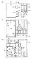
第1実施形態に係るリレー付き端子台は、図1ないし図14に示すように、大略、ハウジング10と、第1接続機構部30と、第2接続機構部60と、第3接続機構部70と、補助接続機構部80と、解除ボタン90と、リレー100と、温度ヒューズ105と、底面カバー110と、文字シール120とで構成されている。An embodiment of a terminal block with a relay to which a connection mechanism according to the present invention is applied will be described with reference to FIGS.
As shown in FIGS. 1 to 14, the terminal block with relay according to the first embodiment is roughly a
ハウジング10は、図2に示すように、その片側半分にリレー100を収納できるように仕切り壁11で仕切られた収納凹所12を形成してあるとともに、その底面に端子孔12aを形成してある(図4A)。また、前記ハウジング10は、その残る片側半分の側面に第1,第2,第3接続孔13a,13b,13cを設けてあるとともに、その上方に文字シール120を貼着するためのテーパ面13dを形成してある。 As shown in FIG. 2, the
また、前記ハウジング10は、図4Aの平面図に示すように、残る片側半分の略中央に上下に貫通する貫通孔14を形成してある。そして、前記貫通孔14の手前側には圧入孔15を形成するとともに、その両側に第1操作孔15aおよび第2,第3操作孔15b,15cをそれぞれ設けてある。 Further, as shown in the plan view of FIG. 4A, the
さらに、前記ハウジング10は、図4Bの背面図に示すように、前記第2,第3接続孔13b,13cにそれぞれ連通し、かつ、背面側から開口する嵌合孔16a,16bを設けてある。また、前記嵌合孔16aに対応する位置に補助嵌合孔16cを設けてある。そして、前記嵌合孔16a,補助嵌合孔16cと隣り合う位置にガイド孔17a,17bをそれぞれ設けてある。 Further, as shown in the rear view of FIG. 4B, the
さらに、前記ハウジング10は、図4Cの底面図に示すように、方形台10aで囲まれた前記貫通孔14の片側に、絶縁壁20aを介して一対の嵌合孔21,22を並設してあるとともに、前記嵌合孔22と隣り合う位置に収納凹部23を形成してある。特に、前記嵌合孔21は、前記第1操作孔15aに連通している。また、前記ハウジング10は、その底面に突設した絶縁壁20bで第1,2,3,4位置決め凹部24a,24b,24c,24dを形成してある。そして、前記第1,2,3,4位置決め凹部24a,24b,24c,24dには、カシメ突起25が適宜設けられている。さらに、前記ハウジング10は、その底面の開口縁部に位置決め突部26を突設してあるとともに、前記ハウジング10の隣り合う3辺の開口縁部に係合孔27をそれぞれ設けてある(図2,3)。 Further, as shown in the bottom view of FIG. 4C, the
第1接続機構部30は、図5に示すように、一対の断面門型形状の接続機構部本体40,50からなり、前記接続機構部本体50は、その上辺部51の先端縁部から断面略L字形状の延在部55を延在してある。また、前記第1接続機構部30は、並設した第1,第2,第3バスバー31,32,33を備えている。 As shown in FIG. 5, the first
前記接続機構部本体40は、図5に示すように、対向する上辺部41および下辺部42の中間に位置する部分を切り起こして支持部43を形成してある。前記支持部43には、屈曲したバネ部材44の一端部を係合できる係合溝43aを形成してある。また、前記接続機構部本体40の上辺部41の内向面(上面)には、前記バネ部材44の他端部を係止できる係止突起41aを突き出し加工で設けてある。そして、前記接続機構部本体40の上辺部41の角部には切り欠き部45を形成してある。さらに、前記接続機構部本体40は、その下辺部42から端子部42aを側方に延在してある。 As shown in FIG. 5, the connection mechanism portion
前記接続機構部本体50は、対向する上辺部51および下辺部52の中間に位置する部分を切り起こして支持部53を形成してある。前記支持部53には、バネ部材54の一端部を係合できる係合溝53aを形成してある。また、前記接続機構部本体50の下辺部52の内向面(下面)には、前記バネ部材54の他端部を係止できる係止突起52aを突き出し加工で設けてある。さらに、図5Aに示すように、前記延在部55は、その上辺部51と隣り合う位置に、一段低い挟持舌片56aを切り起こしてある。このため、前記上辺部56と前記挟持舌片56aとが、略V字形状に屈曲した補助バネ部材57の一辺を挟持する。また、前記補助バネ部材57の下端部は前記上辺部51に突設した係止突起51aに係止している。 The connection mechanism section
第2,第3接続機構部60,70は、図2および図3に示すように、同一構成部品で構成されている。より具体的には、図6に示すように、第2接続機構部60を構成する接続機構部本体61は対向する上辺部62および下辺部63の中間に位置する部分を切り起こすことにより、一対の支持部64,65を形成してある。
前記支持部64には、屈曲したバネ部材66の一端部を係合できる係合溝64aを形成してある。また、前記接続機構部本体61の上辺部62の内向面(上面)には、前記バネ部材66の他端部を係止できる係止突起62aを突き出し加工で設けてある。そして、前記接続機構部本体61の上辺部62のうち、前記係止突起62a近傍の角部に切り欠き部62cを形成してある。
一方、前記支持部65には、屈曲したバネ部材67の一端部を係合できる係合溝65aを形成してある。また、前記上辺部62の内向面(上面)には、前記バネ部材67の他端部を係止できる係止突起62bを突き出し加工で設けてある一方、前記下辺部63の一端部を切り曲げることにより、圧入舌片63aを形成してある。そして、接続機構部本体61は、その片側縁部を曲げ起こしてガイド舌片61aを形成してある。As shown in FIGS. 2 and 3, the second and third
The
On the other hand, the
なお、第3接続機構部70は、前記第2接続機構部60と同一構造を有しているので、同一部分には前記第2接続機構部60に準じた番号を付して説明を省略する。 In addition, since the 3rd
補助接続機構部80は、図7に示すように、断面門型形状の補助接続機構部本体81からなり、前記補助接続機構部本体81は、その上辺部82と隣り合う位置に、より一段低い挟持舌片82aを切り起こしてある。そして、前記上辺部82と挟持舌片82aとが、断面略V字形状に屈曲した補助バネ部材84の一辺を挟持する。また、前記補助バネ部材84の下端部は前記下辺部83に設けた係止突起83aに係止している。さらに、前記補助接続機構部本体81は、その片側縁部を曲げ起こすことにより、ガイド舌片81aを設けてある。 As shown in FIG. 7, the auxiliary
解除ボタン90は、図2,3および図8に示すように、その上端面の中央に、プラスドライバーあるいはマイナスドライバーでの押し下げ操作を容易にする操作凹部91を形成してある。また、前記解除ボタン90は、その下面から一対の弾性脚部92,92を突出するとともに、前記弾性脚部92,92を間にして第1操作片93および第2,第3操作片94,95を突設してある。 As shown in FIGS. 2, 3, and 8, the
リレー100は、図2,3に示すように、前記ハウジング10の収納凹所12に収納可能な立体形状を有し、その下面から信号端子101,102および電力端子103,104を突出している。 As shown in FIGS. 2 and 3, the
温度ヒューズ105は、図2,3に示すように、そのリード線106,107を介して前記リレー100等に電気接続され、端子台での発熱によるトラブルを未然に防止する。 As shown in FIGS. 2 and 3, the
前記底面カバー110は、図2,3に示すように、前記ハウジング10の底面開口部に嵌合可能な平面形状を有し、前記貫通孔14を囲む方形台10aに嵌合可能な方形の貫通孔111を設けてある。また、隣り合う3辺の外周縁部に沿ってそれぞれ立設した弾性枠部112に、係合爪部113をそれぞれ設けてある。
本実施形態によれば、低いに位置に配置した係合爪部113であっても、弾性枠部112の支点間距離が長く、弾性領域が広いので、破損しにくい係合爪部113が得られるという利点がある。As shown in FIGS. 2 and 3, the
According to the present embodiment, even if the engaging
次に、前述の構成部品の組立,接続工程について説明する。
まず、接続機構部本体61にバネ部材66,67の一端部を着脱可能に組み付けた第2接続機構部60、接続機構部本体71にバネ部材76,77の一端部を着脱可能に組み付けた第3接続機構部70、および、補助接続機構部本体81に補助バネ部材84を組み付けた補助接続機構部80を準備し、これらをハウジング10の嵌合孔16a,16bおよび補助嵌合孔16cにそれぞれ圧入する。
そして、前記ハウジング10の収納凹所12内にリレー100を位置決めし、その端子孔12aに信号端子101,102および電力端子103,104をそれぞれ挿入する。Next, the process of assembling and connecting the aforementioned components will be described.
First, the second
Then, the
一方、第1接続機構部30の接続機構部本体40,50にバネ部材44,54,補助バネ部材57の一端部を着脱可能にそれぞれ組み付ける。そして、前記ハウジング10の底面に設けた嵌合孔21,22に前記接続機構部本体40,50をそれぞれ嵌合する。また、図4Cに示す第1,第2,第3,第4位置決め凹部24a,24b,24c,24dに、第1バスバー31,接続機構部本体40の端子部42a,第2バスバー32,第3バスバー33をそれぞれ位置決めする。On the other hand, one end portions of the
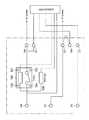
ついで、リレー100の信号端子101,102を、図9に示す第1,第3バスバー31,33に半田付けするとともに、電力端子103,104を接続機構部本体40,50にそれぞれ半田付けする。そして、第2接続機構部60と補助接続機構部80とをリード線(図示せず)で接続する。さらに、温度ヒューズ105をハウジング10の収納凹部23(図4C)に収納するとともに、そのリード線106,107を第2,第3バスバー32,33にそれぞれ圧接する。最後に、外部のコネクタに接続するリード線(図示せず)を、第1,第2バスバー31,32,端子部42aにそれぞれ圧接することにより、図12に示す回路図のように電気接続された端子台が完成する。Next, the
そして、ハウジング10の開口部に底面カバー110を位置決めし、その方形台10aに底面カバー110の貫通孔111を嵌合するとともに、前記ハウジング10の係合孔27に前記底面カバー110の係合爪部113を係合する。さらに、解除ボタン90の弾性脚部92,92をハウジング10の圧入孔15に圧入,係合して抜け止めする。このとき、第1,第2,第3操作片93,94,95はバネ部材44,66,76の上端縁部に押し下げ可能に当接する。最後に、テーパ面13dに文字シール120を貼着して組立,接続作業が完了する。 Then, the
本実施形態によれば、第1,第2,第3接続機構部30,60,70および温度ヒューズ105を並設してあるので、巾狭の端子台が得られるという利点がある。
また、電気接続は前述の第1実施形態にかぎらず、図13に示すように、温度ヒューズ105のリード線106,107をリレー100に接続せず、第2接続機構部60および補助接続機構部80に接続してもよい。
さらに、図14に示すように、前記温度ヒューズ105を外部回路(図示せず)に接続してもよい。
これらの回路図に従って配線すれば、用途に応じて電気回路上の温度ヒューズ105の配置を選択できるので、選択の範囲が広がるという利点がある。According to the present embodiment, since the first, second, and third
Further, the electrical connection is not limited to the first embodiment described above, and as shown in FIG. 13, the
Further, as shown in FIG. 14, the
If wiring is performed according to these circuit diagrams, the arrangement of the
次に、前記端子台に接続線を接続する方法について説明する。
接続前には、図10Aに示すように、バネ部材66,67の他端部は接続機構部本体61の上辺部62に圧接しているとともに、補助バネ部材84の他端部は補助接続機構部本体81の下辺部83に圧接している。そして、図示しない接続線をそれぞれ圧入し、前記バネ部材66,67および補助バネ部材84の他端部を弾性変形させて挟持することにより、抜け止めする。
同様に、図10Bに示すように、バネ部材44の他端部は接続機構部本体40の上辺部41に圧接している。また、バネ部材54の他端部は接続機構部本体50の下辺部52に圧接しているとともに、補助バネ部材57の他端部も接続機構部本体50の上辺部51に圧接している。そして、図示しない接続線をそれぞれ圧入し、前記バネ部材44,54および補助バネ部材57の他端部を弾性変形させて挟持し、抜け止めする。Next, a method for connecting a connection line to the terminal block will be described.
Before the connection, as shown in FIG. 10A, the other end portions of the
Similarly, as shown in FIG. 10B, the other end portion of the
そして、前面側から前記接続線を外す場合には、例えば、図11に示すように、前記解除ボタン90の操作凹部91にドライバー121の先端を押し付け、バネ部材44,66,76の上端部を、第1,第2,第3操作片93,94,95で同時にそれぞれ押し下げることにより、前記接続線を抜き出す。
本実施形態によれば、ワンタッチ操作で3本の接続線を引き抜けるので、作業性が高く、メンテナンスしやすい端子台が得られる。
また、操作凹部91はプラスドライバーおよびマイナスドライバーのいずれにも対応できる形状であり、特別な形状の操作器具を必要としないので、使い勝手が良く、より一層作業性の良い端子台が得られる。When the connection line is removed from the front side, for example, as shown in FIG. 11, the tip of the
According to this embodiment, since the three connection lines can be pulled out by one-touch operation, a terminal block with high workability and easy maintenance can be obtained.
In addition, the
一方、背面側から前記接続線を外す場合には、図11に示すように、ドライバー122をハウジング10に設けた嵌合孔16a,補助嵌合孔16cおよびガイド孔17a,17bにそれぞれ押し込み、補助バネ部材84,バネ部材67,補助バネ部材57,バネ部材54の他端部を弾性変形させることにより、前記接続線を引き抜く。特に、ガイド舌片81a,61aあるいはガイド孔17a,17bでドライバー122をガイドできるので、操作しやすく、作業性の高い端子台が得られる。On the other hand, when the connecting line is removed from the rear side, as shown in FIG. 11, the
本実施形態によれば、バネ部材66,67,44,54の上下を逆転させても、その他端部が接続機構部本体の上辺部および下辺部にそれぞれ圧接するように屈曲した形状となっている。このため、前記バネ部材66等を上下逆転させて取り付けることにより、同一構成部品で接続線の挿入位置を変更できる。この結果、内部構成部品の種類が少なくなるので、内部構成部品の在庫管理が簡単になり、メンテナンスが容易になるという利点がある。 According to the present embodiment, even if the
第2実施形態は、図15ないし図18に示すように、前述の第1実施形態とほぼ同様であり、異なる点は第1実施形態のリレーよりも小型のリレー100に対応するようにした点である。
このため、図18Aに示すように、リレー100を収納する収納凹所12の内周面には、前記リレー100を位置決めするための位置決めリブ11a,11bを設けてある。
また、リレー100の信号端子101,102は第1,第2バスバー31,32にそれぞれ電気接続されているとともに、電力端子103,104は第1接続機構部30の接続機構部本体40,50の端子部42a,52b(図17)にそれぞれ電気接続される。
他は前述の第1実施形態とほぼ同様であるので、同一部分に同一番号を付して説明を省略する。As shown in FIGS. 15 to 18, the second embodiment is substantially the same as the first embodiment described above, and the difference is that it corresponds to the
Therefore, as shown in FIG. 18A, positioning
In addition, the
The other parts are almost the same as those of the first embodiment, and the same parts are denoted by the same reference numerals and the description thereof is omitted.
本実施形態によれば、小型のリレー100にも適用できることから、設計の自由度が大きい端子台が得られるという利点がある。 According to this embodiment, since it is applicable also to the
第3実施形態に係る端子台は、図19ないし図23に示すように、その基本的構成は前述の第1実施形態とほぼ同様であり、異なる点はリレーを外付けとした点である。このため、図22に示すように、ハウジング10は小型化されている。 As shown in FIGS. 19 to 23, the basic structure of the terminal block according to the third embodiment is substantially the same as that of the first embodiment described above, and the difference is that a relay is provided externally. For this reason, the
また、第1,第2,第3接続機構部30,60,70は、全て同一の構成部品で構成されている。このため、内部構成部品を共用でき、内部構成部品の種類が更に少なくなるので、内部構成部品の在庫管理がより一層容易となり、メンテナンスしやすい端子台が得られる。 The first, second, and third
本実施形態によれば、図23Aに示すように、第3接続機構部70の操作前では、バネ部材76,77の他端部は接続機構部本体71の上辺部72に圧接している。そして、図示しない接続線をハウジング10内に圧入すると、前記バネ部材76,77の他端部が弾性変形して前記接続線を挟持することにより、抜け止めする。 According to the present embodiment, as shown in FIG. 23A, the other end portions of the
そして、図23Bに示すように、前面側の接続線を抜き取る場合には、解除ボタン90をプラスドライバー121で押し下げることにより、バネ部材76の上端部を押し下げ、前記接続線を抜き取ることができる。
また、背面側から接続した接続線を抜き取る場合には、図示しないドライバーをガイド舌片71aで位置決めして側方から圧入することにより、前記バネ部材77の他端部を弾性変形させた後、前記接続線を抜き取ることができる。
他は前述の第1実施形態とほぼ同様であるので、同一部分には同一番号を付して説明を省略する。Then, as shown in FIG. 23B, when the connection line on the front side is pulled out, the
Further, when removing the connecting wire connected from the back side, after the other end of the
The other parts are almost the same as those in the first embodiment, and the same parts are denoted by the same reference numerals and description thereof is omitted.
なお、温度ヒューズの設置位置は前述の実施形態に限らず、必要に応じて変更できることは勿論である。 Of course, the installation position of the thermal fuse is not limited to the above-described embodiment, but can be changed as necessary.
本発明に係る端子台は前述のリレーに限らず、他のリレーを取り付け、あるいは、接続して使用してもよいことは勿論である。 Of course, the terminal block according to the present invention is not limited to the above-described relay, and other relays may be attached or connected.
10 ハウジング
11 仕切り壁
12 収納凹所
13a 第1接続孔
13b 第2接続孔
13c 第3接続孔
13d テーパ面
14 貫通孔
15 圧入孔
15a 第1操作孔
15b 第2操作孔
15c 第3操作孔
16a 嵌合孔
16b 嵌合孔
16c 補助嵌合孔
16d 嵌合孔
17a ガイド孔
17b ガイド孔
26 位置決め突部
30 第1接続機構部
31第1バスバー
32第2バスバー
33第3バスバー
40 接続機構部本体
41 上辺部
42 下辺部
43 支持部
44 バネ部材
45 切り欠き部
50 接続機構部本体
51 上辺部
52 下辺部
53 支持部
54 バネ部材
57 補助バネ部材
60 第2接続機構部
61 接続機構部本体
61a ガイド舌片
61b 圧入舌片
62 上辺部
63 下辺部
64 支持部
65 支持部
66 バネ部材
67 バネ部材
70 第3接続機構部
71 接続機構部本体
72 上辺部
73 下辺部
74 支持部
75 支持部
76 バネ部材
77 バネ部材
80 補助接続機構部
81 補助接続機構部本体
82 上辺部
83 下辺部
84 補助バネ部材
90 解除ボタン
91 操作凹部
92 弾性脚部
93 第1操作片
94 第2操作片
95 第3操作片
100 リレー
105 温度ヒューズ
110 底面カバー
112 弾性枠部
113 係合爪部
120 文字シール
121 ドライバー
122 ドライバーDESCRIPTION OF
94
Claims (6)
Translated fromJapanese断面門型形状を有するとともに、相互に対向する上辺部および下辺部と、前記上辺部および前記下辺部に接続された側辺部と、前記上辺部および前記下辺部で挟まれるように前記側辺部に突設された支持部とを有する接続機構部本体と、
一端部が前記支持部に支持されかつ他端部が前記上辺部および前記下辺部のいずれにも圧接可能に構成されていると共に、前記上辺部および前記下辺部の間に挿入された前記接続線を前記上辺部または前記下辺部と共に挟持して接続可能に屈曲したバネ部材と、
を備える、接続機構部。A connection mechanism that can connect a connection line,
And has a cross-sectional gantry shape,the upper side portion and lower side portion opposedto each otherand, with said upper portion and the lower connected side portions in section, the side edges so as to be sandwiched by the upper portion and the lower portion a connection mechanism bodyhavingaprojecting from the supportportion parts,
Withone end the supported by the support portionand the other endis configured either tothe possible pressure of theupper portion and the lowerportion,the connecting line interposed between the upper portion and the lower portion And a spring member bent so asto be connectable with the upper side or the lower side ,
A connection mechanism unit.
Priority Applications (3)
| Application Number | Priority Date | Filing Date | Title |
|---|---|---|---|
| JP2014127571AJP6350010B2 (en) | 2014-06-20 | 2014-06-20 | Connection mechanism and terminal block using the same |
| KR1020150083177AKR101688319B1 (en) | 2014-06-20 | 2015-06-12 | Connection mechanism and using terminal block thereof |
| CN201510342393.9ACN105322309B (en) | 2014-06-20 | 2015-06-18 | Portion of bindiny mechanism and the terminal box using the portion of bindiny mechanism |
Applications Claiming Priority (1)
| Application Number | Priority Date | Filing Date | Title |
|---|---|---|---|
| JP2014127571AJP6350010B2 (en) | 2014-06-20 | 2014-06-20 | Connection mechanism and terminal block using the same |
Publications (2)
| Publication Number | Publication Date |
|---|---|
| JP2016009519A JP2016009519A (en) | 2016-01-18 |
| JP6350010B2true JP6350010B2 (en) | 2018-07-04 |
Family
ID=55129086
Family Applications (1)
| Application Number | Title | Priority Date | Filing Date |
|---|---|---|---|
| JP2014127571AActiveJP6350010B2 (en) | 2014-06-20 | 2014-06-20 | Connection mechanism and terminal block using the same |
Country Status (3)
| Country | Link |
|---|---|
| JP (1) | JP6350010B2 (en) |
| KR (1) | KR101688319B1 (en) |
| CN (1) | CN105322309B (en) |
Family Cites Families (21)
| Publication number | Priority date | Publication date | Assignee | Title |
|---|---|---|---|---|
| JPS5326231Y2 (en)* | 1973-07-04 | 1978-07-04 | ||
| JPS52141184U (en)* | 1976-04-21 | 1977-10-26 | ||
| GB1589649A (en)* | 1977-05-28 | 1981-05-20 | Weidmueller Kg C | Screwless terminals for electrical conductors |
| DE7911182U1 (en)* | 1979-04-17 | 1979-08-16 | C. A. Weidmueller Kg, 4930 Detmold | Screwless clamp for electrical conductors |
| JPS58183773U (en)* | 1982-05-31 | 1983-12-07 | 松下電工株式会社 | Cord quick connection terminal device |
| JPH0337197A (en)* | 1989-06-30 | 1991-02-18 | Kanebo Ltd | Production of silicon carbide whisker |
| JPH0499676U (en)* | 1991-01-28 | 1992-08-28 | ||
| JPH0765895A (en)* | 1993-08-25 | 1995-03-10 | Matsushita Electric Works Ltd | Wiring part for high voltage |
| JPH0955239A (en)* | 1995-08-09 | 1997-02-25 | Nichifu Co Ltd | Wire connection connector |
| JPH09147931A (en)* | 1995-11-17 | 1997-06-06 | Tec Corp | Electric wire connection device |
| JP2000048697A (en)* | 1998-07-28 | 2000-02-18 | Matsushita Electric Works Ltd | Electronic timer integrated with terminal block |
| US6851967B2 (en)* | 2000-08-04 | 2005-02-08 | Omron Corporation | Wire connector |
| ATE496406T1 (en)* | 2002-04-12 | 2011-02-15 | Weidmueller Interface | CONNECTION DEVICE FOR CONDUCTORS |
| DE102004018904B4 (en)* | 2004-04-15 | 2013-11-14 | Wago Verwaltungsgesellschaft Mbh | Screwless busbar connection for electrical terminals |
| JP4214244B2 (en)* | 2005-07-01 | 2009-01-28 | 株式会社ニチフ端子工業 | Electric wire connector and floor heater panel using the same |
| DE102005048972B4 (en) | 2005-10-13 | 2010-08-12 | Phoenix Contact Gmbh & Co. Kg | Spring terminal with clamping spring and current bar |
| DE102006053352B3 (en)* | 2006-11-10 | 2008-04-17 | Phoenix Contact Gmbh & Co. Kg | Insert, has two spring legs which are components of leg springs connected to each other by bent joint and stayed together at obtuse angle, where one spring leg is inactive and extends inside region of mounting units |
| JP2010061840A (en)* | 2008-09-01 | 2010-03-18 | Nichifu Co Ltd | Low-profile connector for cable connection |
| CN201289910Y (en)* | 2008-10-24 | 2009-08-12 | 苏州快可光伏电子有限公司 | Wiring box for solar control system |
| CN202352851U (en)* | 2011-11-30 | 2012-07-25 | 乐清市东南电子科技有限公司 | Screw-free terminal |
| JP5854939B2 (en)* | 2012-07-05 | 2016-02-09 | 三菱電機株式会社 | Wire connection device and ventilation fan |
- 2014
- 2014-06-20JPJP2014127571Apatent/JP6350010B2/enactiveActive
- 2015
- 2015-06-12KRKR1020150083177Apatent/KR101688319B1/ennot_activeExpired - Fee Related
- 2015-06-18CNCN201510342393.9Apatent/CN105322309B/enactiveActive
Also Published As
| Publication number | Publication date |
|---|---|
| JP2016009519A (en) | 2016-01-18 |
| CN105322309B (en) | 2018-06-22 |
| CN105322309A (en) | 2016-02-10 |
| KR20150146400A (en) | 2015-12-31 |
| KR101688319B1 (en) | 2016-12-20 |
Similar Documents
| Publication | Publication Date | Title |
|---|---|---|
| JP4821567B2 (en) | Printed circuit board with fuse housing and electric junction box for automobile | |
| JP5606830B2 (en) | Electrical junction box | |
| JP2010187458A (en) | Electrical junction box | |
| JP2005322554A (en) | Terminal equipment for electrical equipment | |
| JP2008118772A (en) | Board connector | |
| JP4506456B2 (en) | Board terminal mounting structure on circuit board | |
| US10622743B2 (en) | Terminal module with a conductive obliquely wound coil spring held against an electrical contact member and connector having such a terminal module | |
| JP2021111996A (en) | Electrical junction box and wire harness | |
| JP5513952B2 (en) | Holder mounting structure | |
| JP2019021462A (en) | connector | |
| US9496629B2 (en) | Structure of socket contact | |
| JP2012109039A (en) | Terminal connection structure | |
| JP2023014714A (en) | electric junction box | |
| JP2014054005A (en) | Electric connection box | |
| KR101653062B1 (en) | Electrical connector | |
| JP2010046835A (en) | Electrical connection component | |
| JP6350010B2 (en) | Connection mechanism and terminal block using the same | |
| JP5513951B2 (en) | Mounting structure for holder with parts | |
| KR20100121950A (en) | Connector having joint terminal | |
| JP2009183031A (en) | Electrical junction box | |
| JP5802140B2 (en) | Power supply connector | |
| CN105051980A (en) | Electronic-component assembly structure and junction box | |
| JP2023071650A (en) | Usb receptacle | |
| JP5426273B2 (en) | Terminal fitting | |
| KR101001881B1 (en) | Assembly structure of circuit board and board mounted connector |
Legal Events
| Date | Code | Title | Description |
|---|---|---|---|
| A621 | Written request for application examination | Free format text:JAPANESE INTERMEDIATE CODE: A621 Effective date:20170209 | |
| A977 | Report on retrieval | Free format text:JAPANESE INTERMEDIATE CODE: A971007 Effective date:20171023 | |
| A131 | Notification of reasons for refusal | Free format text:JAPANESE INTERMEDIATE CODE: A131 Effective date:20171031 | |
| RD03 | Notification of appointment of power of attorney | Free format text:JAPANESE INTERMEDIATE CODE: A7423 Effective date:20171130 | |
| A521 | Request for written amendment filed | Free format text:JAPANESE INTERMEDIATE CODE: A523 Effective date:20171222 | |
| TRDD | Decision of grant or rejection written | ||
| A01 | Written decision to grant a patent or to grant a registration (utility model) | Free format text:JAPANESE INTERMEDIATE CODE: A01 Effective date:20180508 | |
| A61 | First payment of annual fees (during grant procedure) | Free format text:JAPANESE INTERMEDIATE CODE: A61 Effective date:20180521 | |
| R150 | Certificate of patent or registration of utility model | Ref document number:6350010 Country of ref document:JP Free format text:JAPANESE INTERMEDIATE CODE: R150 | |
| R250 | Receipt of annual fees | Free format text:JAPANESE INTERMEDIATE CODE: R250 | |
| R250 | Receipt of annual fees | Free format text:JAPANESE INTERMEDIATE CODE: R250 | |
| R250 | Receipt of annual fees | Free format text:JAPANESE INTERMEDIATE CODE: R250 |