JP6349318B2 - Vertebral fixation device and system - Google Patents
Vertebral fixation device and systemDownload PDFInfo
- Publication number
- JP6349318B2 JP6349318B2JP2015537411AJP2015537411AJP6349318B2JP 6349318 B2JP6349318 B2JP 6349318B2JP 2015537411 AJP2015537411 AJP 2015537411AJP 2015537411 AJP2015537411 AJP 2015537411AJP 6349318 B2JP6349318 B2JP 6349318B2
- Authority
- JP
- Japan
- Prior art keywords
- fixation
- vertebral
- fixation device
- intervertebral
- interspinous
- Prior art date
- Legal status (The legal status is an assumption and is not a legal conclusion. Google has not performed a legal analysis and makes no representation as to the accuracy of the status listed.)
- Expired - Fee Related
Links
- 239000000463materialSubstances0.000claimsdescription91
- 238000000034methodMethods0.000claimsdescription70
- 230000008569processEffects0.000claimsdescription55
- 210000000988bone and boneAnatomy0.000claimsdescription48
- 230000000452restraining effectEffects0.000claimsdescription11
- 230000006835compressionEffects0.000claimsdescription10
- 238000007906compressionMethods0.000claimsdescription10
- 239000003102growth factorSubstances0.000claimsdescription10
- 238000003780insertionMethods0.000claimsdescription8
- 230000037431insertionEffects0.000claimsdescription8
- 210000003041ligamentAnatomy0.000claimsdescription8
- 239000010409thin filmSubstances0.000claimsdescription8
- 208000037873arthrodesisDiseases0.000claimsdescription7
- 230000008468bone growthEffects0.000claimsdescription5
- 230000001054cortical effectEffects0.000claimsdescription5
- 239000012528membraneSubstances0.000claimsdescription5
- 206010023509KyphosisDiseases0.000claimsdescription4
- 230000002146bilateral effectEffects0.000claimsdescription4
- 241001465754MetazoaSpecies0.000claimsdescription3
- 239000002131composite materialSubstances0.000claimsdescription3
- 239000000835fiberSubstances0.000claimsdescription3
- 239000004033plasticSubstances0.000claimsdescription3
- 229920003023plasticPolymers0.000claimsdescription3
- 238000004873anchoringMethods0.000claimsdescription2
- 230000008093supporting effectEffects0.000claimsdescription2
- 230000000284resting effectEffects0.000claims1
- 230000033001locomotionEffects0.000description20
- 238000002513implantationMethods0.000description9
- 239000008187granular materialSubstances0.000description5
- 238000005452bendingMethods0.000description4
- 239000007943implantSubstances0.000description4
- 238000002347injectionMethods0.000description4
- 239000007924injectionSubstances0.000description4
- 238000004519manufacturing processMethods0.000description4
- 230000004899motilityEffects0.000description4
- 230000000903blocking effectEffects0.000description3
- 238000005520cutting processMethods0.000description3
- 239000010408filmSubstances0.000description3
- 229920000139polyethylene terephthalatePolymers0.000description3
- 239000005020polyethylene terephthalateSubstances0.000description3
- 229920000049Carbon (fiber)Polymers0.000description2
- 239000004696Poly ether ether ketoneSubstances0.000description2
- RTAQQCXQSZGOHL-UHFFFAOYSA-NTitaniumChemical compound[Ti]RTAQQCXQSZGOHL-UHFFFAOYSA-N0.000description2
- 230000009471actionEffects0.000description2
- 230000006978adaptationEffects0.000description2
- JUPQTSLXMOCDHR-UHFFFAOYSA-Nbenzene-1,4-diol;bis(4-fluorophenyl)methanoneChemical compoundOC1=CC=C(O)C=C1.C1=CC(F)=CC=C1C(=O)C1=CC=C(F)C=C1JUPQTSLXMOCDHR-UHFFFAOYSA-N0.000description2
- 239000000560biocompatible materialSubstances0.000description2
- 230000015572biosynthetic processEffects0.000description2
- 239000004917carbon fiberSubstances0.000description2
- 210000000845cartilageAnatomy0.000description2
- 239000002657fibrous materialSubstances0.000description2
- 230000004927fusionEffects0.000description2
- 230000003601intercostal effectEffects0.000description2
- VNWKTOKETHGBQD-UHFFFAOYSA-NmethaneChemical compoundCVNWKTOKETHGBQD-UHFFFAOYSA-N0.000description2
- 229920002530polyetherether ketonePolymers0.000description2
- -1polyethylene terephthalatePolymers0.000description2
- 229920000642polymerPolymers0.000description2
- 230000004044responseEffects0.000description2
- 125000006850spacer groupChemical group0.000description2
- 239000003826tabletSubstances0.000description2
- 210000001519tissueAnatomy0.000description2
- 229910052719titaniumInorganic materials0.000description2
- 239000010936titaniumSubstances0.000description2
- 208000005422Foreign-Body reactionDiseases0.000description1
- JVTAAEKCZFNVCJ-REOHCLBHSA-NL-lactic acidChemical compoundC[C@H](O)C(O)=OJVTAAEKCZFNVCJ-REOHCLBHSA-N0.000description1
- 239000004480active ingredientSubstances0.000description1
- 239000000654additiveSubstances0.000description1
- 210000003484anatomyAnatomy0.000description1
- 210000002808connective tissueAnatomy0.000description1
- 239000000945fillerSubstances0.000description1
- 239000012634fragmentSubstances0.000description1
- 230000001976improved effectEffects0.000description1
- 230000001939inductive effectEffects0.000description1
- 238000007689inspectionMethods0.000description1
- 238000005304joiningMethods0.000description1
- 238000002324minimally invasive surgeryMethods0.000description1
- 201000008482osteoarthritisDiseases0.000description1
- 210000005259peripheral bloodAnatomy0.000description1
- 239000011886peripheral bloodSubstances0.000description1
- 230000002093peripheral effectEffects0.000description1
- 229920001432poly(L-lactide)Polymers0.000description1
- 230000001737promoting effectEffects0.000description1
- 102000004169proteins and genesHuman genes0.000description1
- 108090000623proteins and genesProteins0.000description1
- 230000000541pulsatile effectEffects0.000description1
- 230000005855radiationEffects0.000description1
- 210000000278spinal cordAnatomy0.000description1
- 230000001954sterilising effectEffects0.000description1
- 238000004659sterilization and disinfectionMethods0.000description1
- 230000000638stimulationEffects0.000description1
- 239000000126substanceSubstances0.000description1
- 238000001356surgical procedureMethods0.000description1
- 238000004804windingMethods0.000description1
Images


Classifications
- A—HUMAN NECESSITIES
- A61—MEDICAL OR VETERINARY SCIENCE; HYGIENE
- A61F—FILTERS IMPLANTABLE INTO BLOOD VESSELS; PROSTHESES; DEVICES PROVIDING PATENCY TO, OR PREVENTING COLLAPSING OF, TUBULAR STRUCTURES OF THE BODY, e.g. STENTS; ORTHOPAEDIC, NURSING OR CONTRACEPTIVE DEVICES; FOMENTATION; TREATMENT OR PROTECTION OF EYES OR EARS; BANDAGES, DRESSINGS OR ABSORBENT PADS; FIRST-AID KITS
- A61F2/00—Filters implantable into blood vessels; Prostheses, i.e. artificial substitutes or replacements for parts of the body; Appliances for connecting them with the body; Devices providing patency to, or preventing collapsing of, tubular structures of the body, e.g. stents
- A61F2/02—Prostheses implantable into the body
- A61F2/30—Joints
- A61F2/44—Joints for the spine, e.g. vertebrae, spinal discs
- A61F2/4455—Joints for the spine, e.g. vertebrae, spinal discs for the fusion of spinal bodies, e.g. intervertebral fusion of adjacent spinal bodies, e.g. fusion cages
- A—HUMAN NECESSITIES
- A61—MEDICAL OR VETERINARY SCIENCE; HYGIENE
- A61B—DIAGNOSIS; SURGERY; IDENTIFICATION
- A61B17/00—Surgical instruments, devices or methods
- A61B17/02—Surgical instruments, devices or methods for holding wounds open, e.g. retractors; Tractors
- A61B17/025—Joint distractors
- A—HUMAN NECESSITIES
- A61—MEDICAL OR VETERINARY SCIENCE; HYGIENE
- A61B—DIAGNOSIS; SURGERY; IDENTIFICATION
- A61B17/00—Surgical instruments, devices or methods
- A61B17/56—Surgical instruments or methods for treatment of bones or joints; Devices specially adapted therefor
- A61B17/58—Surgical instruments or methods for treatment of bones or joints; Devices specially adapted therefor for osteosynthesis, e.g. bone plates, screws or setting implements
- A61B17/68—Internal fixation devices, including fasteners and spinal fixators, even if a part thereof projects from the skin
- A61B17/70—Spinal positioners or stabilisers, e.g. stabilisers comprising fluid filler in an implant
- A61B17/7062—Devices acting on, attached to, or simulating the effect of, vertebral processes, vertebral facets or ribs ; Tools for such devices
- A61B17/7064—Devices acting on, attached to, or simulating the effect of, vertebral facets; Tools therefor
- A—HUMAN NECESSITIES
- A61—MEDICAL OR VETERINARY SCIENCE; HYGIENE
- A61B—DIAGNOSIS; SURGERY; IDENTIFICATION
- A61B17/00—Surgical instruments, devices or methods
- A61B17/56—Surgical instruments or methods for treatment of bones or joints; Devices specially adapted therefor
- A61B17/58—Surgical instruments or methods for treatment of bones or joints; Devices specially adapted therefor for osteosynthesis, e.g. bone plates, screws or setting implements
- A61B17/68—Internal fixation devices, including fasteners and spinal fixators, even if a part thereof projects from the skin
- A61B17/70—Spinal positioners or stabilisers, e.g. stabilisers comprising fluid filler in an implant
- A61B17/7062—Devices acting on, attached to, or simulating the effect of, vertebral processes, vertebral facets or ribs ; Tools for such devices
- A61B17/7065—Devices with changeable shape, e.g. collapsible or having retractable arms to aid implantation; Tools therefor
- A—HUMAN NECESSITIES
- A61—MEDICAL OR VETERINARY SCIENCE; HYGIENE
- A61B—DIAGNOSIS; SURGERY; IDENTIFICATION
- A61B17/00—Surgical instruments, devices or methods
- A61B17/56—Surgical instruments or methods for treatment of bones or joints; Devices specially adapted therefor
- A61B17/58—Surgical instruments or methods for treatment of bones or joints; Devices specially adapted therefor for osteosynthesis, e.g. bone plates, screws or setting implements
- A61B17/68—Internal fixation devices, including fasteners and spinal fixators, even if a part thereof projects from the skin
- A61B17/70—Spinal positioners or stabilisers, e.g. stabilisers comprising fluid filler in an implant
- A61B17/7062—Devices acting on, attached to, or simulating the effect of, vertebral processes, vertebral facets or ribs ; Tools for such devices
- A61B17/707—Devices acting on, or attached to, a transverse process or rib; Tools therefor
- A—HUMAN NECESSITIES
- A61—MEDICAL OR VETERINARY SCIENCE; HYGIENE
- A61F—FILTERS IMPLANTABLE INTO BLOOD VESSELS; PROSTHESES; DEVICES PROVIDING PATENCY TO, OR PREVENTING COLLAPSING OF, TUBULAR STRUCTURES OF THE BODY, e.g. STENTS; ORTHOPAEDIC, NURSING OR CONTRACEPTIVE DEVICES; FOMENTATION; TREATMENT OR PROTECTION OF EYES OR EARS; BANDAGES, DRESSINGS OR ABSORBENT PADS; FIRST-AID KITS
- A61F2/00—Filters implantable into blood vessels; Prostheses, i.e. artificial substitutes or replacements for parts of the body; Appliances for connecting them with the body; Devices providing patency to, or preventing collapsing of, tubular structures of the body, e.g. stents
- A61F2/02—Prostheses implantable into the body
- A61F2/30—Joints
- A61F2/44—Joints for the spine, e.g. vertebrae, spinal discs
- A61F2/442—Intervertebral or spinal discs, e.g. resilient
- A—HUMAN NECESSITIES
- A61—MEDICAL OR VETERINARY SCIENCE; HYGIENE
- A61B—DIAGNOSIS; SURGERY; IDENTIFICATION
- A61B17/00—Surgical instruments, devices or methods
- A61B17/02—Surgical instruments, devices or methods for holding wounds open, e.g. retractors; Tractors
- A61B17/025—Joint distractors
- A61B2017/0256—Joint distractors for the spine
- A—HUMAN NECESSITIES
- A61—MEDICAL OR VETERINARY SCIENCE; HYGIENE
- A61F—FILTERS IMPLANTABLE INTO BLOOD VESSELS; PROSTHESES; DEVICES PROVIDING PATENCY TO, OR PREVENTING COLLAPSING OF, TUBULAR STRUCTURES OF THE BODY, e.g. STENTS; ORTHOPAEDIC, NURSING OR CONTRACEPTIVE DEVICES; FOMENTATION; TREATMENT OR PROTECTION OF EYES OR EARS; BANDAGES, DRESSINGS OR ABSORBENT PADS; FIRST-AID KITS
- A61F2/00—Filters implantable into blood vessels; Prostheses, i.e. artificial substitutes or replacements for parts of the body; Appliances for connecting them with the body; Devices providing patency to, or preventing collapsing of, tubular structures of the body, e.g. stents
- A61F2/02—Prostheses implantable into the body
- A61F2/30—Joints
- A61F2/3094—Designing or manufacturing processes
- A61F2/30965—Reinforcing the prosthesis by embedding particles or fibres during moulding or dipping
- A—HUMAN NECESSITIES
- A61—MEDICAL OR VETERINARY SCIENCE; HYGIENE
- A61F—FILTERS IMPLANTABLE INTO BLOOD VESSELS; PROSTHESES; DEVICES PROVIDING PATENCY TO, OR PREVENTING COLLAPSING OF, TUBULAR STRUCTURES OF THE BODY, e.g. STENTS; ORTHOPAEDIC, NURSING OR CONTRACEPTIVE DEVICES; FOMENTATION; TREATMENT OR PROTECTION OF EYES OR EARS; BANDAGES, DRESSINGS OR ABSORBENT PADS; FIRST-AID KITS
- A61F2/00—Filters implantable into blood vessels; Prostheses, i.e. artificial substitutes or replacements for parts of the body; Appliances for connecting them with the body; Devices providing patency to, or preventing collapsing of, tubular structures of the body, e.g. stents
- A61F2/02—Prostheses implantable into the body
- A61F2/30—Joints
- A61F2/44—Joints for the spine, e.g. vertebrae, spinal discs
- A61F2/4455—Joints for the spine, e.g. vertebrae, spinal discs for the fusion of spinal bodies, e.g. intervertebral fusion of adjacent spinal bodies, e.g. fusion cages
- A61F2/446—Joints for the spine, e.g. vertebrae, spinal discs for the fusion of spinal bodies, e.g. intervertebral fusion of adjacent spinal bodies, e.g. fusion cages having a circular or elliptical cross-section substantially parallel to the axis of the spine, e.g. cylinders or frustocones
- A—HUMAN NECESSITIES
- A61—MEDICAL OR VETERINARY SCIENCE; HYGIENE
- A61F—FILTERS IMPLANTABLE INTO BLOOD VESSELS; PROSTHESES; DEVICES PROVIDING PATENCY TO, OR PREVENTING COLLAPSING OF, TUBULAR STRUCTURES OF THE BODY, e.g. STENTS; ORTHOPAEDIC, NURSING OR CONTRACEPTIVE DEVICES; FOMENTATION; TREATMENT OR PROTECTION OF EYES OR EARS; BANDAGES, DRESSINGS OR ABSORBENT PADS; FIRST-AID KITS
- A61F2/00—Filters implantable into blood vessels; Prostheses, i.e. artificial substitutes or replacements for parts of the body; Appliances for connecting them with the body; Devices providing patency to, or preventing collapsing of, tubular structures of the body, e.g. stents
- A61F2/02—Prostheses implantable into the body
- A61F2/30—Joints
- A61F2/30721—Accessories
- A61F2/30734—Modular inserts, sleeves or augments, e.g. placed on proximal part of stem for fixation purposes or wedges for bridging a bone defect
- A61F2002/30736—Augments or augmentation pieces, e.g. wedges or blocks for bridging a bone defect
- A—HUMAN NECESSITIES
- A61—MEDICAL OR VETERINARY SCIENCE; HYGIENE
- A61F—FILTERS IMPLANTABLE INTO BLOOD VESSELS; PROSTHESES; DEVICES PROVIDING PATENCY TO, OR PREVENTING COLLAPSING OF, TUBULAR STRUCTURES OF THE BODY, e.g. STENTS; ORTHOPAEDIC, NURSING OR CONTRACEPTIVE DEVICES; FOMENTATION; TREATMENT OR PROTECTION OF EYES OR EARS; BANDAGES, DRESSINGS OR ABSORBENT PADS; FIRST-AID KITS
- A61F2250/00—Special features of prostheses classified in groups A61F2/00 - A61F2/26 or A61F2/82 or A61F9/00 or A61F11/00 or subgroups thereof
- A61F2250/0058—Additional features; Implant or prostheses properties not otherwise provided for
- A61F2250/0067—Means for introducing or releasing pharmaceutical products into the body
- A—HUMAN NECESSITIES
- A61—MEDICAL OR VETERINARY SCIENCE; HYGIENE
- A61F—FILTERS IMPLANTABLE INTO BLOOD VESSELS; PROSTHESES; DEVICES PROVIDING PATENCY TO, OR PREVENTING COLLAPSING OF, TUBULAR STRUCTURES OF THE BODY, e.g. STENTS; ORTHOPAEDIC, NURSING OR CONTRACEPTIVE DEVICES; FOMENTATION; TREATMENT OR PROTECTION OF EYES OR EARS; BANDAGES, DRESSINGS OR ABSORBENT PADS; FIRST-AID KITS
- A61F2310/00—Prostheses classified in A61F2/28 or A61F2/30 - A61F2/44 being constructed from or coated with a particular material
- A61F2310/00005—The prosthesis being constructed from a particular material
- A61F2310/00011—Metals or alloys
- A61F2310/00023—Titanium or titanium-based alloys, e.g. Ti-Ni alloys
Landscapes
- Health & Medical Sciences (AREA)
- Orthopedic Medicine & Surgery (AREA)
- Life Sciences & Earth Sciences (AREA)
- Neurology (AREA)
- Surgery (AREA)
- Engineering & Computer Science (AREA)
- Biomedical Technology (AREA)
- General Health & Medical Sciences (AREA)
- Veterinary Medicine (AREA)
- Heart & Thoracic Surgery (AREA)
- Public Health (AREA)
- Animal Behavior & Ethology (AREA)
- Molecular Biology (AREA)
- Medical Informatics (AREA)
- Nuclear Medicine, Radiotherapy & Molecular Imaging (AREA)
- Cardiology (AREA)
- Oral & Maxillofacial Surgery (AREA)
- Transplantation (AREA)
- Vascular Medicine (AREA)
- Manufacturing & Machinery (AREA)
- Prostheses (AREA)
- Surgical Instruments (AREA)
Description
Translated fromJapanese発明の分野
本発明は、デバイスおよび椎骨固定システム、即ち、脊椎固定のデバイスおよびシステムに関する。デバイスを移植するための手順、およびこの手順を実施するためのツールキットも、記載される。The present invention relates to devices and vertebral fixation systems, ie spinal fixation devices and systems. A procedure for implanting the device and a toolkit for performing this procedure are also described.
発明の背景
隣接する椎骨の固定に関しては、複数のデバイスが知られており、とりわけ、
− 椎骨の相対的位置を固定するためのロッドおよびスクリューを含む、器具を用いた固定デバイス(instrument−assisted fusion devices);
− 前方または後方または側方アプローチにより移植され得る「ケージ」型固定デバイス;
− 2つの隣接する椎骨の棘突起の間に配置させるのに適した棘突間固定デバイス、
が公知である。BACKGROUND OF THE INVENTION For the fixation of adjacent vertebrae, several devices are known, among others
-Instrument-assisted fusion devices, including rods and screws for fixing the relative position of the vertebrae;
A “cage” type fixation device that can be implanted by an anterior or posterior or lateral approach;
An interspinous fixation device suitable for placement between the spinous processes of two adjacent vertebrae,
Is known.
米国特許出願公開第2005/0055094号に、「Optimesh」として公知のケージ型固定デバイスが開示されている。このデバイスは、損傷を受けた椎間板を置換するために2つの椎体の間に挿入するのに適しており、繊維材料から出発して製造される閉鎖型ケージ要素を含む。このケージ要素には、顆粒状骨材料が充填されている。このデバイスの欠点は、顆粒状骨材料と椎体との固定をケージ要素の繊維材料によって行わなければならず、それゆえ固定が得られ難いことである。その上、所定の応力下にある場合、ケージ要素が破裂する可能性がある。更にデバイスは、2つの隣接する椎骨を互いに固定するため、そして初期固定を提供するために、スクリューおよびロッドを必要とし、それゆえ器具を用いた固定デバイスに属し、製造および移植がより困難である。 U.S. Patent Application Publication No. 2005/0055094 discloses a cage-type fixation device known as "Optimesh". The device is suitable for insertion between two vertebral bodies to replace a damaged intervertebral disc and includes a closed cage element manufactured starting from a fibrous material. This cage element is filled with granular bone material. The disadvantage of this device is that the fixation of the granular bone material and the vertebral body has to be performed by the fiber material of the cage element and is therefore difficult to obtain. Moreover, the cage element can rupture when under a predetermined stress. In addition, the device requires screws and rods to secure two adjacent vertebrae to each other and to provide initial fixation and therefore belongs to a fixation device using instruments and is more difficult to manufacture and implant .
ケージ型デバイスは、頸部椎間板を置換して、頸部椎間板に隣接する椎体の固定を提供するために企図された「Biocage」としても公知である。デバイスは、実質的に管状の網状ケージ要素と、ケージ要素内に配置された顆粒状骨材料と、を含む。ケージ要素は、顆粒状材料を一緒に固定された2つの椎骨の表面と接触させるように、上下が開放されている。ケージ要素は、硬質の再吸収性ポリマー、例えばPLLAによりコーティングされたPETで作製され得る。 Cage-type devices are also known as “Biocages” designed to replace the cervical disc and provide fixation of the vertebral body adjacent to the cervical disc. The device includes a substantially tubular mesh cage element and a granular bone material disposed within the cage element. The cage element is open up and down to bring the granular material into contact with the surfaces of two vertebrae secured together. The cage element can be made of a rigid resorbable polymer, such as PET coated with PLLA.
同じくこのタイプのデバイスは、脊椎固定の形成ができないことが非常に多い。公知の通り、実際には骨接合術では、適切な力を骨材料上に加える必要がある。ケージ要素は、硬質であるため、椎骨の負荷が、顆粒状骨材料の代わりにケージ要素に加えられる。それゆえデバイスの骨材料は、実質的に機械適応力を受けず、そのため椎骨との固定に関して刺激されない。 Again, this type of device is very often unable to form a spinal fixation. As is known, in practice osteosynthesis requires that an appropriate force be applied on the bone material. Because the cage element is rigid, vertebral loads are applied to the cage element instead of granular bone material. Therefore, the bone material of the device is not substantially subjected to mechanical adaptation and is therefore not stimulated for fixation with the vertebra.
それゆえこのデバイスは、硬質構造を得るために再吸収可能であるものの過剰な量であるポリマーを含むため、異物反応を惹起するという欠点を有する。 This device therefore has the disadvantage of inducing a foreign body reaction because it contains an excessive amount of polymer that can be resorbed to obtain a rigid structure.
棘突間固定デバイスは、脊椎の単独での屈伸運動を一部だけ限定する。これに対して棘突間固定デバイスは、相対的な側屈およびねじれ運動は実質的に限定しない。それゆえ、棘突間固定デバイスは、隣接する椎骨に残りの相対的運動性を託して、固定を妨害または遮断する。言い換えれば、棘突間固定デバイスの排他的使用では、固定に発展する初期固定を提供することができない。 Interspinous fixation devices limit only a portion of the spine's sole flexion and extension movement. In contrast, an interspinous fixation device does not substantially limit relative lateral bending and twisting motion. Therefore, the interspinous fixation device commits or blocks the fixation by committing the remaining relative motility to the adjacent vertebrae. In other words, the exclusive use of an interspinous fixation device cannot provide an initial fixation that evolves into fixation.
したがって、移植されたら2つの椎骨に骨材料の固定を機械的に刺激させて、デバイス移植直後の2つの椎骨の相対的運動性を遮断させて、固定を発展するのに必要となる初期固定を提供して先行技術の欠点を克服する、骨固定材料を含む2つの隣接する椎骨の固定のためのデバイスが求められていると感じられる。 Thus, when implanted, the two vertebrae are mechanically stimulated to fix bone material, blocking the relative motility of the two vertebrae immediately after device implantation and providing the initial fixation required to develop the fixation. There appears to be a need for a device for the fixation of two adjacent vertebrae comprising bone fixation material that provides and overcomes the disadvantages of the prior art.
米国特許出願公開第2008/167686 A1号に、2つの圧縮弾性要素、特にリーフスプリングからなるコンテナを含む椎骨間スペーサデバイスが記載されている。例示的な実施形態において、コンテナは、2つの開口端部を有する。実質的には移植部位において固定するために、骨成長を促進するように適合された材料をスペーサデバイスに充填する手順も、記載される。 US 2008/167686 A1 describes an intervertebral spacer device comprising a container consisting of two compression elastic elements, in particular leaf springs. In the exemplary embodiment, the container has two open ends. A procedure for filling a spacer device with a material adapted to promote bone growth for fixation substantially at the implantation site is also described.
WO2009/005819号には、2つの隣接する椎骨の「可動固定(mobile fusion)」を提供する、即ち、椎骨の連結を形成してそれらの間に弾性的な相対的運動性を与える、椎間デバイスが記載されている。実際に、屈伸運動、側屈運動および軸方向回転運動から選択される少なくとも2つの椎骨運動モードを可能にすることを明白に企図した例示的な実施形態が、記載されている。 WO 2009/005819 provides a “mobile fusion” of two adjacent vertebrae, ie, an intervertebral joint that forms a vertebral connection and provides an elastic relative motion between them. The device is listed. Indeed, exemplary embodiments have been described that are explicitly intended to allow at least two vertebral motion modes selected from flexion and extension, lateral flexion and axial rotation.
デバイスは両者とも、椎体と接触するように設計された接触部分を含み、接触部分は椎体により加えられる力に弾性的に反応する。骨成長促進材料は、接触部分を各椎体に固定する以外のことを行うことができず、デバイスを硬化することができず、それゆえ2つの椎骨を互いに固定することができない。実際には前者の場合、コンテナの圧縮運動が、初期固定、つまり2つの椎体の固定を可能にしない。後者の場合、椎体の相対的運動性が、明白に求められている。 Both devices include a contact portion designed to contact the vertebral body, the contact portion being elastically responsive to forces applied by the vertebral body. The bone growth promoting material cannot do anything other than fix the contact portion to each vertebral body, cannot harden the device, and therefore cannot fix the two vertebrae together. In fact, in the former case, the compression movement of the container does not allow initial fixation, i.e. the fixation of the two vertebral bodies. In the latter case, the relative motility of the vertebral body is clearly sought.
それゆえそのようなデバイスは両者とも、実質的には椎間板プロテーゼを具体化しており、真の意味で椎骨固定を形成するのに用いられていない。 Thus, both such devices essentially embody an intervertebral disc prosthesis and have not been used to form a vertebral fixation in a true sense.
米国特許出願公開第2008/167686 A1号のコンテナは、骨接合材料、特に骨材料が顆粒形態で充填され得ないことも観察されている。 It has also been observed that the container of US 2008/167686 A1 cannot be filled with osteosynthesis material, in particular bone material, in granular form.
発明の概要
それゆえ本発明の目的は、固定プロセスを刺激するために椎骨によって加えられる力を受けるように配列された、骨固定材料を含む2つの隣接する椎骨の固定を形成するためのデバイスを提供することである。SUMMARY OF THE INVENTION It is therefore an object of the present invention to provide a device for forming a fixation of two adjacent vertebrae comprising a bone fixation material arranged to receive a force applied by the vertebrae to stimulate the fixation process. Is to provide.
同じく本発明の目的は、2つの椎骨の相対的運動性を遮断し、それによりスクリューおよびプレートなどの任意の初期固定手段を用いずに、2つの椎骨の迅速な固定を促進する初期固定をもたらす、固定システムを提供することである。 The object of the present invention is also to provide an initial fixation that blocks the relative motility of the two vertebrae, thereby facilitating rapid fixation of the two vertebrae without using any initial fixation means such as screws and plates Is to provide a fixing system.
同じく本発明の目的は、容易で最小限の侵襲性手順により移植され得るそのようなデバイスおよびシステムを提供することである。 It is also an object of the present invention to provide such a device and system that can be implanted with an easy and minimally invasive procedure.
同じく本発明の目的は、容易で迅速に製造され得るそのようなデバイスおよびシステムを提供することである。 It is also an object of the present invention to provide such a device and system that can be easily and quickly manufactured.
これらおよび他の目的は、患者の脊椎部分の2つの隣接する椎骨の2つの対応する椎骨部分の間に挿入するように構成された支持要素を含む椎骨固定デバイスであって、対応する椎骨部分が隣接する椎骨の突起および/または関節表面を含み、それにより支持反応が対応する椎骨部分にもたらされ、支持要素が、軸の方向に沿って軸方向コンプライアンスであり、
それらの主な特色は、支持要素が:
− 塑性変形可能な顆粒状骨接合材料と;
− 側壁および2つの開口端部を有する中空コンテナ体と、
を含むことであり、中空コンテナ体は、開口端部を通して顆粒状骨接合材料と2つの対応する椎骨部分との直接的な接触が可能になるように顆粒状骨接合材料を含み、そしてそれによりコンテナが側方に顆粒状骨接合材料を含み、軸方向に沿った対応する椎骨部分の間に顆粒状骨接合材料が連続ピラーを形成するまで、2つの開口端部の間で軸方向の塑性変形が可能になり、側壁が顆粒状骨接合材料の塑性変形の後に軸方向に沿って生じるように配列されている、椎骨固定デバイスにより実現される。These and other objects are vertebral fixation devices that include a support element configured to be inserted between two corresponding vertebral portions of two adjacent vertebrae of a patient's spinal portion, wherein the corresponding vertebral portion is Including adjacent vertebral processes and / or articular surfaces whereby a support response is provided to the corresponding vertebral portion, the support element being axially compliant along the axial direction;
Their main features are the supporting elements:
-A plastically deformable granular osteosynthesis material;
A hollow container body having a side wall and two open ends;
The hollow container body includes a granular osteosynthesis material so as to allow direct contact between the granular osteosynthesis material and two corresponding vertebral portions through the open end, and thereby Axial plasticity between the two open ends until the container contains granular osteosynthesis material laterally and the granule osteosynthesis material forms a continuous pillar between the corresponding vertebral portions along the axial direction This is achieved by a vertebral fixation device that allows deformation and the side walls are arranged to occur along the axial direction after plastic deformation of the granular osteosynthesis material.
こうして対応する椎骨部分の負荷は、ピラーを形成する顆粒状骨材料のみに加えられ、軸方向コンプライアンスのあるコンテナ体には加えられない。これらの状態において、固定デバイスが移植されると、顆粒状骨材料は、それを挟んでいる対応する椎骨部分によって加えられる負荷を支持し、同時に骨固定プロセスを刺激する圧縮力を受け、それにより関節固定の形成が確実になる。 The corresponding vertebral part load is thus only applied to the granular bone material forming the pillars and not to the axially compliant container body. In these conditions, when the fixation device is implanted, the granular bone material is subjected to a compressive force that supports the load applied by the corresponding vertebra part sandwiching it and at the same time stimulates the bone fixation process, thereby The formation of joint fixation is ensured.
その上、同軸方向にある先行技術の硬質固定デバイスとは異なり、この固定は、骨材料の顆粒性により、対応する椎骨部分により一時的に、または全身に伝達され得る脈動力および振動を若干、減弱させるように構成される。これが、椎体の安定性および患者への快適性を改善する。 Moreover, unlike prior art rigid fixation devices in the coaxial direction, this fixation can cause some pulsatile power and vibration that can be transmitted temporarily or systemically by the corresponding vertebral part due to the granular nature of the bone material. Configured to attenuate. This improves vertebral body stability and patient comfort.
その上、そのようなデバイスでは、固定ができなかった場合に、中空コンテナ体の顆粒状骨材料および/または断片を患者の体内に分散させることができない。 Moreover, such devices do not allow the granular bone material and / or fragments of the hollow container body to be dispersed within the patient's body if it cannot be secured.
その他にも、本明細書の以後に示される通り、本発明による固定デバイスは、最小限の侵襲性技術により移植することができる。 In addition, as will be shown later in this specification, a fixation device according to the present invention can be implanted with minimally invasive techniques.
好ましい例示的な実施形態において、中空コンテナ体の側壁は、横方向に実質的に非伸縮性である。こうして顆粒状材料は、半径方向に拡張することができず、全体的に圧迫状態のままである。 In a preferred exemplary embodiment, the side walls of the hollow container body are substantially non-stretchable in the lateral direction. Thus, the granular material cannot be expanded radially and remains generally compressed.
例示的な実施形態において、中空コンテナ体は、一組の実質的に対称の長手方向の外殻を含む。特にその外殻は、各分節に沿って長手方向に連結される。それにより、平坦な物体から出発して中空コンテナ体を作製することが容易になる。 In an exemplary embodiment, the hollow container body includes a set of substantially symmetric longitudinal outer shells. In particular, the outer shell is connected longitudinally along each segment. This makes it easy to make a hollow container body starting from a flat object.
例示的な実施形態において、固定デバイスは、棘突間空間、即ち2つの隣接する椎骨の上部椎骨の棘突起の下部表面と、下部椎骨の棘突起の上部表面と、の間の空間に挿入されるように構成されており、固定デバイスは、棘突間空間を塞ぐするために、それぞれこれらの下部表面および上部表面に隣り合うように構成された上端部と下端部を有する。そのような固定デバイスは、本明細書では以後、棘突間固定デバイスまたは固定棘突間デバイスとして示される。 In an exemplary embodiment, the fixation device is inserted into the interspinous space, ie, the space between the lower surface of the spinous process of the upper vertebra of two adjacent vertebrae and the upper surface of the spinous process of the lower vertebra. And the fixation device has an upper end and a lower end configured to be adjacent to these lower and upper surfaces, respectively, to close the interspinous space. Such a fixation device is hereinafter referred to as an interspinous fixation device or a fixed interspinous device.
好ましくは、棘突間固定デバイスは、6mm〜18mm、特に9mm〜15mmに設定された高さを有する。 Preferably, the interspinous fixation device has a height set between 6 mm and 18 mm, in particular between 9 mm and 15 mm.
有利には棘突間固定デバイスは、上部および下部の隣接する椎骨の各薄膜の間に配置させるように構成された薄膜間前方部分を含む。この薄膜間前方部分により、2つの隣接する椎骨を含む脊椎部分の屈伸運動をより安全に阻害すること、およびそれらの椎骨が脊椎後弯になるのを予防することができる。 [3] Advantageously, the interspinous fixation device includes an anterior interlaminar portion configured to be placed between the respective membranes of the upper and lower adjacent vertebrae. This anterior portion between the thin films can more safely inhibit the flexion and extension movement of the spine portion including two adjacent vertebrae, and prevent the vertebrae from becoming kyphosis. [3]
ことによると薄膜間前方部分が設けられている、棘突間固定デバイスは、有利には先に示された一組の長手方向の外殻からなり、各長手方向の外殻は、それぞれ2つの隣接する椎骨の上部椎骨の棘突起の下部表面および下部椎骨の棘突起の上部表面、好ましくはそれぞれ上部椎骨および下部椎骨の棘突起の上面、を具備するように構成された各上部輪郭および各下部輪郭を有し、それらはそれぞれ上部椎骨および下部椎骨の薄膜を具備するように構成されていてもよい。 The interspinous fixation device, possibly provided with an anterior part between the membranes, advantageously consists of a pair of longitudinal outer shells as indicated above, each longitudinal outer shell comprising two Each upper contour and each lower portion configured to comprise the lower surface of the spinous process of the upper vertebra of the adjacent vertebra and the upper surface of the spinous process of the lower vertebra, preferably the upper surface of the spinous process of the upper and lower vertebra, respectively. Having contours, each of which may be configured with a thin film of upper and lower vertebrae.
有利には固定デバイスは、顆粒状骨接合材料を棘突起間で圧縮状態に保持するために、棘突起と係合するように構成された両側拘束手段を含む。 Advantageously, the fixation device includes bilateral restraining means configured to engage the spinous process to hold the granular osteosynthesis material in compression between the spinous processes.
特に両側拘束手段は、棘突間固定デバイスを棘突起に締着するように構成された靭帯を含む。 In particular, the bilateral restraining means includes a ligament configured to fasten the interspinous fixation device to the spinous process.
固定デバイスの側壁は、実質的に円筒形を有する。特にこの円筒形は、実質的に楕円形の断面を、より特別にはその円筒形は、実質的に円形の断面を有する。特にそのような固定デバイスは、2つの互いに向き合う椎体関節表面の間、または2つの協働する小関節面の間、または隣接する椎骨の2つの横突起の間に挿入されるように構成される。 The side wall of the fixation device has a substantially cylindrical shape. In particular, the cylindrical shape has a substantially elliptical cross section, more particularly the cylindrical shape has a substantially circular cross section. In particular, such a fixation device is configured to be inserted between two mutually facing vertebral joint surfaces, or between two cooperating facet surfaces, or between two transverse processes of adjacent vertebrae. The
例示的な実施形態において、固定デバイスは、2つの椎体の2つの互いに向き合う関節表面の間の椎間空間(intersomatic space)に挿入されるように構成される。この固定デバイスは、本明細書では以後、椎間椎骨固定デバイスまたは固定椎間デバイスとして示される。好ましくはこの椎骨固定椎間デバイスは、5mm〜20mm、特に5mm〜15mmに設定された高さ、および特に5mm〜15mmに設定された横断寸法、特に直径を有する。 In an exemplary embodiment, the fixation device is configured to be inserted into an interstitial space between two opposing articular surfaces of two vertebral bodies. This fixation device is hereinafter referred to as an intervertebral vertebral fixation device or a fixed intervertebral device. Preferably the vertebral fixation intervertebral device has a height set to 5 mm to 20 mm, in particular 5 mm to 15 mm, and a transverse dimension, in particular a diameter set to 5 mm to 15 mm.
例示的な実施形態において、固定デバイスは、2つの隣接する椎骨の2つの協働する小関節面の間に挿入されるように構成される。そのような固定デバイスは、本明細書では以後、関節間椎骨固定デバイスまたは固定関節間デバイスとして示される。好ましくはこの固定関節間デバイスは、5mm〜14mm、特に5mm〜10mmに設定された高さを有する。これらのサイズでは、本明細書の以後に記載される椎間デバイス、より特別には複数の椎間デバイスを、2つの隣接する椎骨の椎体の間のハウジングに挿入することができる。 In an exemplary embodiment, the fixation device is configured to be inserted between two cooperating facet surfaces of two adjacent vertebrae. Such a fixation device is hereinafter referred to as an inter-articular vertebral fixation device or a fixed inter-articular device. Preferably, this fixed inter-articular device has a height set between 5 mm and 14 mm, in particular between 5 mm and 10 mm. At these sizes, the intervertebral devices described later in this specification, and more particularly multiple intervertebral devices, can be inserted into the housing between the vertebral bodies of two adjacent vertebrae.
例示的な実施形態において、固定デバイスは、2つの隣接する椎骨の2つの対応する横突起の間に挿入されるように構成される。そのような固定デバイスは、本明細書では以後、横突間椎骨固定デバイスまたは固定横突間デバイスとして示される。好ましくは横突間デバイスは、15mm〜45mm、特に25mm〜40mmに設定された高さ、および5〜15mmに設定された横断寸法、特に直径を有する。 In an exemplary embodiment, the fixation device is configured to be inserted between two corresponding transverse processes of two adjacent vertebrae. Such a fixation device is hereinafter referred to as an interlateral transversal vertebra fixation device or a fixed interlateral device. Preferably, the interlateral device has a height set to 15 mm to 45 mm, in particular 25 mm to 40 mm, and a transverse dimension set to 5 to 15 mm, in particular a diameter.
中空コンテナ体の側壁は、ケージ要素、即ち網様構造を有する要素を含むことができる。特にこのケージ要素は、交絡したメッシュを有する網状組織を有し、メッシュは、顆粒材料を含むように構成されたサイズを有する。交絡したメッシュ構造は、交絡した網状組織の細片をそれ自身に長手方向に結び付けることにより、平坦な物体から容易に製造することができる。 The side walls of the hollow container body can include cage elements, i.e. elements having a net-like structure. In particular, the cage element has a network with an entangled mesh, the mesh having a size configured to include a granular material. Entangled mesh structures can be easily manufactured from flat objects by tying the entangled network strips to themselves in the longitudinal direction.
代わりとして、中空コンテナ体のケージ壁は、らせん形構造を含んでいてもよい。代わりまたは追加として、中空コンテナ体は、繊維構造を含んでいてもよい。代わりまたは追加として、中空コンテナ体は、複合構造を含んでいてもよい。 Alternatively, the cage wall of the hollow container body may include a helical structure. Alternatively or additionally, the hollow container body may include a fiber structure. Alternatively or additionally, the hollow container body may comprise a composite structure.
中空コンテナ体は、ポリエチレンテレフタラート、チタン、PEEK、炭素繊維またはそれらの組み合わせなどの生体適合性材料で作製されていてもよい。 The hollow container body may be made of a biocompatible material such as polyethylene terephthalate, titanium, PEEK, carbon fiber or combinations thereof.
本発明による固定デバイスは、移植部位にもよるが、最小値と最大値の間に設定される、より低い高さを有する。 The fixation device according to the invention has a lower height, which is set between a minimum and maximum value, depending on the implantation site.
あるいは固定デバイスは、静止位置から予圧縮位置まで軸方向に予圧縮された構成であり、その場合ラッパーが、固定デバイスを予圧縮位置に保持するために提供されている。 [11] Alternatively, the fixation device is a pre-compressed configuration in the axial direction from the rest position to the pre-compression position, in which case a wrapper is provided to hold the fixation device in the pre-compression position. [11]
本発明の別の態様において、先に示された目的は、先に示された特色を有する複数の椎骨固定デバイスを含む椎骨固定システムにより達成され、椎骨固定デバイスは、
− 椎間固定デバイス、即ち、2つの椎体の2つの互いに向き合う関節表面の間に挿入されるように構成されたデバイス;
− 棘突間固定デバイス、即ち、隣接する椎骨の2つの棘突起の間に挿入されるように構成されたデバイス;
− 関節間固定デバイス、即ち、隣接する椎骨の2つの協働する小関節面の間に挿入されるように構成されたデバイス;
− 横突間固定デバイス、即ち、隣接する椎骨の2つの対応する横突起の間に挿入されるように構成されたデバイス、
からなる群から選択され、特にシステムは、対応する右および左の横突起の各組の間に挿入される一組の固定デバイスを含む。 [12]In another aspect of the present invention, the previously indicated objects are achieved by a vertebral fixation system comprising a plurality of vertebral fixation devices having the characteristics indicated above, wherein the vertebral fixation device comprises:
An intervertebral fixation device, ie a device configured to be inserted between two mutually facing articular surfaces of two vertebral bodies;
An interspinous fixation device, ie a device configured to be inserted between two spinous processes of adjacent vertebrae;
-An inter-articular fixation device, ie a device configured to be inserted between two cooperating facet surfaces of adjacent vertebrae;
An interlateral fixation device, ie a device configured to be inserted between two corresponding transverse processes of adjacent vertebrae;
In particular, the system includes a set of fixation devices that are inserted between each set of corresponding right and left lateral projections. [12]
例示的な実施形態において、システムは、棘突間固定デバイスと、少なくとも1つの椎間固定デバイスと、協働する小関節面の各組の間に挿入される一組の関節間固定デバイスと、を含む。 In an exemplary embodiment, the system includes an interspinous fixation device, at least one intervertebral fixation device, and a set of interarticular fixation devices inserted between each set of cooperating facet surfaces. including.
本発明による固定システムにより、隣接する椎骨を互いに締着するスクリューまたは締着ロッドなどの手段を用いずに、骨固定を促進するように初期固定をもたらし得る移植片を作製することが可能になる。 [13] The fixation system according to the present invention makes it possible to create an implant that can provide initial fixation to facilitate bone fixation without using means such as screws or clamping rods to clamp adjacent vertebrae together. . [13]
より詳細には、棘突間固定デバイスは単独で、2つの隣接する椎骨の相対的屈伸運動を少なくとも部分的に遮断することができる。椎間固定デバイスは、相対的屈伸運動を完全にブロックすることができる。好ましくは組み合わせとして用いられる、関節間固定デバイスは、2つの隣接する椎骨の相対的側屈およびねじれ運動も遮断することができる。それゆえ、本発明によるシステムは、高い接触表面を提供して、2つの隣接する椎骨の相対的運動成分を全て抑制することができる。そのような関節固定術は、周囲関節固定術(circumferential arthrodesis)、即ち、複数の異なる要素を含み、その要素のそれぞれが協働して隣接する椎骨の相対的運動の固有の自由度を排除する関節固定術と呼ぶことができる。 More particularly, the interspinous fixation device alone can at least partially block the relative flexion and extension movements of two adjacent vertebrae. The intervertebral fixation device can completely block relative flexion and extension movements. An interarticular fixation device, preferably used in combination, can also block the relative lateral bending and torsional motion of two adjacent vertebrae. Therefore, the system according to the present invention can provide a high contact surface to suppress all the relative motion components of two adjacent vertebrae. Such arthrodesis is a circular arthrosis, i.e. comprising a plurality of different elements, each of which cooperates to eliminate the inherent freedom of relative movement of adjacent vertebrae. It can be called arthrodesis.
こうしてシステムは、固定プロセスを確実に完了させるのに十分強い初期固定をもたらす。これに対して移植後の余分な残りの可動性は、固定を困難または不可能にさえする。これが、先行技術の固定「ケージ」デバイス中で起こり、屈伸、側屈、ねじれ運動のうちの1成分または多くても2成分を抑制する可能性がある。 [18] The system thus provides an initial fixation that is strong enough to ensure that the fixation process is completed. In contrast, the extra remaining mobility after implantation makes fixation difficult or even impossible. This occurs in prior art fixed “cage” devices and may suppress one or at most two components of flexion, lateral bending, and torsional motion. [18]
幾つかの例において、右および/または左の横突起の間に配置された補助的固定デバイスは、隣接する椎骨の相対的運動を遮断するのに有用となり得る。 In some examples, an auxiliary fixation device disposed between the right and / or left transverse processes can be useful to block relative movement of adjacent vertebrae.
先に記載されたデバイスを含む本発明によるシステムは、デバイスが配置される椎骨部分により制御された方法で力が加えられる状態において、移植後の相対的運動の厳しい制約または全体的制約と、刺激される顆粒状骨材料の利用可能性と、の併用を可能にする。この状態は、固定のプロセス、つまり関節固定術の完遂を促す。 A system according to the present invention comprising a device as described above provides for a severe or global constraint of relative movement after implantation and stimulation in a state where force is applied in a controlled manner by the vertebral portion in which the device is placed. The availability of the granulated bone material to be used together. This condition encourages the completion of the fixation process, ie, arthrodesis.
好ましい例示的な実施形態において、椎骨固定システムは、少なくとも1つの前方椎間固定デバイスと、少なくとも1つの後方椎間固定デバイスと、を含み、それらは、それぞれ椎骨間空間内の前方位置および後方位置を含む位置に配置されるように構成され、特定の前方デバイスまたは各前方デバイスは、好ましくは特定の後方デバイスまたは各後方デバイスよりも。これは、2つの隣接する椎骨を含む脊椎分節を脊椎後弯にすることなく関節固定を形成するように働く。特にこの固定システムは、2つの後方椎間固定デバイスおよび1つの前方椎間固定デバイスを含む。 In a preferred exemplary embodiment, the vertebral fixation system includes at least one anterior intervertebral fixation device and at least one posterior intervertebral fixation device, which are respectively an anterior position and a posterior position in the intervertebral space. The specific front device or each front device is preferably more than the specific back device or each back device. This serves to form an arthrodesis without turning a spinal segment containing two adjacent vertebrae into a dorsal kyphosis. In particular, the fixation system includes two posterior intervertebral fixation devices and one anterior intervertebral fixation device.
本発明によるデバイスの顆粒状骨接合材料は、ヒトまたは動物の骨材料、特に骨バンクの骨であってもよい。 The granular osteosynthesis material of the device according to the invention may be human or animal bone material, in particular bone bone.
有利には、この顆粒状骨接合材料は、タブレットの形態、即ち、皮質骨材料および小柱骨材料を所定の割合で含むチップの形態である。小柱骨材料は、骨固定を特に起こし易く、それゆえ小柱骨材料は、関節固定の形成を促進する。 Advantageously, this granular osteosynthesis material is in the form of a tablet, i.e. in the form of a chip comprising a predetermined proportion of cortical bone material and trabecular bone material. Trabecular bone material is particularly prone to bone fixation and therefore trabecular bone material promotes the formation of joint fixation.
固定デバイスは、骨成長因子も含んでいてよい。好ましくはこれらの成長因子は、顆粒状骨接合材料および成長因子を含む充填材料にゲル材料を形成させるように構成される。例えば成長因子は、顆粒状骨接合材料に添加された髄質および/または末梢血中で提供される。 The fixation device may also include a bone growth factor. Preferably these growth factors are configured to cause the gel material to form into a filler material comprising a granular osteosynthesis material and a growth factor. For example, growth factors are provided in the medulla and / or peripheral blood added to the granular osteosynthesis material.
成長因子は、デバイスが用いられる時、即ち、移植片を作製する段階で添加されてもよい。 Growth factors may be added when the device is used, i.e., at the stage of making the implant.
例示的な実施形態において、デバイスは、骨接合を促進するために適合される物質、例えばタンパク質を含んでいてもよい。これにより、デバイスがもたらす骨接触および初期固定により可能になる固定よりも、かなり短時間で固定を形成することができる。 In an exemplary embodiment, the device may include a substance that is adapted to promote osteosynthesis, such as a protein. This allows the fixation to be formed in a much shorter time than the fixation enabled by the bone contact and initial fixation provided by the device.
その上、本発明は、先に記載された固定デバイスを作製する方法に関する。この方法は、本明細書では以後、2つの隣接する椎骨の固定のために先のデバイスおよびシステムを移植する手順と共に記載される。 Moreover, the present invention relates to a method for making the previously described fixation device. This method is described hereinafter with procedures for implanting previous devices and systems for the fixation of two adjacent vertebrae.
ここに本発明を、添付の図面を参照しながら例示的な実施形態の記載と共に示すが、それらの実施形態は、例示であり限定でない。 The present invention will now be illustrated in conjunction with the description of exemplary embodiments with reference to the accompanying drawings, which are illustrative and not limiting.
好ましい例示的な実施形態の説明
椎骨固定システムの例示的な実施形態を、本明細書では以後、本発明によるシステムの椎骨固定デバイスと共に記載する。DESCRIPTION OF PREFERRED EXEMPLARY EMBODIMENTS Exemplary embodiments of a vertebral fixation system are described hereinafter with a vertebral fixation device of a system according to the present invention.
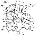
関与する解剖学的部分を図1に示しているが、それは2つの隣接する腰椎10および20を含む対象の脊椎分節1を示す。しかし、本発明によるデバイスは、当業者に明白な改良を施すことを条件に、任意の脊椎レベルで椎骨固定を形成するのに用いることができる。 The anatomical part involved is shown in FIG. 1, which shows the subject's spinal segment 1 including two adjacent
図2、3および4を参照すると、中空コンテナ体31と、中空コンテナ体31の内部に配列された所定量の塑性変形可能な顆粒状骨接合材料32と、を含む支持要素を含む椎骨固定デバイス30が、記載されている。 With reference to FIGS. 2, 3 and 4, a vertebral fixation device including a support element including a
図1の例示的な実施形態において、デバイス30は、実質的に円筒形を有し、特に円形断面を有する円筒形を有する。デバイス30は、隣接する椎骨10、20(図1)の対応する部分の間、特に椎体15、25の2つの互いに向き合う関節表面11、21(図11)の間に挿入されるように構成するための高さHを有していてもよく、その高さHは、好ましくは5〜20mm、特に5〜15mmであり、円形断面の円筒形デバイスにおいて、直径は5〜15mmに設定されている。言い換えると、図2のデバイス30は、椎間固定デバイスとして用いられるように構成される。 In the exemplary embodiment of FIG. 1,
デバイス30は、椎骨10、20の各関節突起13’、23’(図14)の2つの協働する小関節面13、23の間に挿入されるように構成するための高さHを有していてもよく、その高さHは、好ましくは5〜14mm、特に5〜10mmに設定される。言い換えれば図2のデバイス30は、関節間固定デバイスとして用いられるように構成される。 The
図3は、本発明の例示的な実施形態による骨接合材料32を含まない、図2の固定デバイス30の中空コンテナ体31の斜視図である。中空コンテナ体31は、交絡したメッシュを形成する網状組織33などの網様構造の物体から出発して製造され、それゆえ、網様構造のケージ要素を含む。網状組織33の詳細は、図4に示され、それには網33’も描かれている。 3 is a perspective view of the
図5に、隣接する椎骨10、20(図1および13)の2つの横突起14、24の間に挿入されるように構成するための高さまたは長さH’を有する固定デバイス30’を示している。好ましくは高さH’は、15〜45mm、特に5〜10mmに設定され、円筒形デバイスにおいて、直径は、好ましくは5〜15mmに設定される。同じく固定デバイス30’は、顆粒状骨接合材料32を含有する交絡したメッシュの網状組織を含む中空コンテナ体31を含んでいてもよい。言い換えれば図5のデバイス30’は、横突間固定デバイスとして用いられるように構成される。 FIG. 5 shows a
図6に、隣接する椎骨10、20(図1および13)の2つの横突起14、24の間に挿入されるように構成された別の横突間固定デバイス30”を示している。中空コンテナ体31’、即ち、中空コンテナ体31の側壁は、互いに実質的に対称である2つの外殻36’および36”を含み、本発明の例示的な実施形態においては2つの異なる外殻を含む。2つの外殻は、骨接合材料32を含む。 FIG. 6 shows another interlateral
更に図6に示される通り、横突間固定デバイス30”は、横突起14、24との係合のために拘束手段39も具備していてよい。拘束手段は、横突間固定デバイス30’にも設けられていてよい。拘束手段39は、デバイス30’、30”の各端部35’、35”に関して、デバイス30’、30”の端部35’、35”(図5)の異なる位置、特に直径に関して反対の位置に連結されたブランチ38’、38”を含むワイヤ38を含む。外殻が2つである中空コンテナ体の場合、ブランチ38’、38”は、中空コンテナ体31の各外殻36’、36”に連結されている。拘束手段39は、ワイヤ38の長さを調整するためにワイヤ38のためのワイヤ巻き取り体39’をさらに含み、ワイヤを締め付けるように互いに係合され得る一組の係留要素39”も含む。拘束手段39は、顆粒状骨接合材料32を横突起14、24(図1および13)の間に圧迫状態で保持するよう構成される。 Further, as shown in FIG. 6, the lateral
図7に、隣接する椎骨10、20(図1および13)の2つの棘突起12、22を通して挿入されるように構成された固定デバイス40を示す。 FIG. 7 shows a
棘突間デバイス40は、2つの棘突起12、22の間に配置されるように構成された後部42を含む。より詳細には棘突間デバイス40は、棘突間関節固定を形成するよう2つの棘突起12、22の間の棘突間空間8を塞ぐために、それぞれ2つの棘突起12、22の下部表面17および上部表面27(図1)に対してゆとりのある上部47および下部48を含む。
示された例示的な実施形態において、棘突間デバイス40は、互いに実質的に対称であり長手方向に連結された、左外殻46’および右外殻46”からなる中空コンテナ体41を含む。中空コンテナ体41は、交絡したメッシュの網状組織33などの網様構造の物体から出発して製造されてもよい。この外殻が2つである例示的な実施形態において、各外殻46’、46”は、それぞれ2つの棘突起12、22の下部表面17および上部表面27(図1)に対してゆとりのある各上部輪郭47および各下部輪郭48を有する。 In the exemplary embodiment shown, the
図7の例示的な実施形態において、固定デバイス40は、前部、即ち隣接する椎骨10、20の薄膜19、29の間に挿入されるように構成された薄膜間部分43を含んでいてもよい。この挿入は、図11に示されており、それは以下に記載される、デバイス40の本体と類似の中空コンテナ体41を含むデバイス40’(図8)に関する。 In the exemplary embodiment of FIG. 7, the
図8の棘突間固定デバイス40’は、図7のデバイス40と同じ構造を有し、同じく棘突起12、22に係合するための拘束手段49を含む。この場合、拘束手段は、2つの隣接する椎骨10、20と共に締め付けるように配列された靭帯49を含み、それゆえ顆粒状骨接合材料32を圧縮状態で保持するために、棘突起12、22と共に両側拘束手段として働く。より詳細には薄膜間部分40は、薄膜間関節固定を形成するよう2つの薄膜19、29(図11)の間の薄膜間空間7を塞ぐために、それぞれ薄膜19、29の下部表面および上部表面に対してゆとりのある上部輪郭47’および下部輪郭48’を含む。図7の外殻が2つの例示的な実施形態において、各外殻46’、46’’は、各上部輪郭47’および下部輪郭48’を有する。拘束手段49は、上述の利点を有するデバイス40’の側方伸長を含むことにも寄与する。 The
有利には棘突間固定デバイス40、40’は、好ましく6mm〜18mm、特に9mm〜15mmに設定されたサイズ、特に高さL(図13)を有する。 Advantageously, the
先に記載された図に示されたデバイス30、30’、30”、40、40’において、高さH、H’、H”、H’”、Lは、椎骨の寸法を考慮して選択され、それらは患者の体格、および隣接する椎骨10、20の脊椎レベルに依存する。 In the
図2〜8に示された通り、固定デバイスの中空コンテナ体31、31’、41は、開口上端部の上部35’、45’および開口下端部35”、45”を有する。示された例示的な実施形態において、開口部は、コンテナ体31、31’、41の端部全体に及ぶ。こうして図10〜13に示された通り、移植後に中空コンテナ体31、31’、41中に含まれる顆粒状骨接合材料32が、開口端部35、45’、45”を通して対応する椎骨部分の表面11、21;12,22;13,23;14,24と接触するように配列される。 As shown in FIGS. 2-8, the
デバイス30、30’、30”、40、40’の中空コンテナ体31、31’、41は、顆粒状骨接合材料(32)を側方に含む側壁(図3、5)を有する。中空コンテナ体31、31’、41の側壁は、椎骨固定デバイス30、30’、30”、40、40’上で作用する軸力の作用の下で軸方向コンプライアンスである。例示的な実施形態において、側壁は、半径方向、つまり円周方向にも実質的に非伸縮性である。この特色は、例えば図3、4に示された、交絡したメッシュ33’の網状組織33などの網様構造の物体から出発して中空コンテナ体31、31’、41を作製することにより、得ることができる。交絡したメッシュの網状組織33は、交絡接触点33”により画定されるメッシュ33’を含み、そのサイズは、椎骨表面により骨接合材料32に加えられる圧迫により生じる、中空コンテナ体31、31’、41を半径方向に拡大する傾向のある放射力37の作用の下で、網状組織が実質的に非伸縮性になるように選択される。網様構造の代わりに、異なる構造、例えばらせん形構造に加え、繊維および複合構造が可能であり、それらは図には示されていないが、当業者に容易により使用され得る。選択された構造にかかわらず、中空コンテナ体31、31’、41は、生体適合性材料、特にポリエチレンテレフタラート、チタン、PEEK、炭素繊維などの非生体吸収性材料で作製されている。 The
本発明による固定デバイス30、30’、30”、40、40’の顆粒状骨接合材料32は、ヒトの骨または動物の骨であってもよい。特に顆粒状骨接合材料は、皮質骨材料および小柱骨材料の両方を所定の割合で含むタブレット、即ち皮質海綿チップを含んでいてもよい。特に、顆粒状骨接合材料は、プロテーゼが移植された患者から外移植された大腿骨頭から得られてもよい。特に、提供されたヒトの骨材料を用いてもよく、または骨バンクの骨材料を用いることもできる。 The
本発明による固定デバイス30、30’、30”、40、40’の充填材料は、成長因子(図示しない)も含んでいてもよく、それは例えば顆粒状骨接合材料32に添加された髄質および/または末梢血中に含まれる。これらの成長因子は、骨接合を支援する他に、顆粒状骨接合材料32のジェル状充填を形成することができる。成長因子の添加は、デバイスを利用する時、即ち、移植片を作製する段階でも実施することができる。 The filling material of the
図9〜14を参照すると、椎骨固定システムが、本発明により記載される。椎骨固定システムは、棘突間固定デバイス40’、一組の関節間デバイス52および1つまたは好ましくはより多くの椎間デバイス51、51’を含む。関節間デバイス52および椎間デバイス51、51’は、それぞれ先に記載されたデバイス30およびデバイス30’または30”の形状を有していてもよい。 With reference to FIGS. 9-14, a vertebral fixation system is described in accordance with the present invention. The vertebral fixation system includes an interspinous fixation device 40 ', a set of
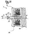
図9、10および13に、隣接する椎骨10、20(図1および13)の椎体15、25の互いに向き合う関節表面11、21の間の椎間板16(図1)の髄核の椎骨間空間9、典型的にはゾーン16’の中に配列された、使用時の椎間デバイス51、51’を示している。椎間デバイス51、51’は、移植の前に実施される2つの隣接する椎骨10、20の伸延により、関節表面11、21からの圧縮力を受けるように配列される。こうして顆粒状骨材料32(図2)は、患者の位置および運動に応じして変動し得る関節表面からの圧縮力を受ける。連続ピラーが形成されるまで、これらの圧縮力が顆粒状骨接合材料32と椎骨間表面11、21との固定を刺激する。図9の例示的な実施形態において、2つの後方椎間デバイス51および前方椎間デバイス51’が提供される。後方デバイス51は、椎弓7の付近に配置され、前方デバイス51は、椎弓7からより遠くに配列される。圧縮に対する棘突間デバイス40’の反応をより効果的に請け負うため、そして椎骨10、20を含む脊椎分節が脊椎後弯になるのをより効果的に予防するために、図10に示された通り、前方デバイス51’の高さH’”は、後方デバイス51の高さH”よりも高くてもよい。 9, 10 and 13, the intervertebral space of the nucleus pulposus of the intervertebral disc 16 (FIG. 1) between the opposing
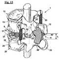
図9および11〜13に、隣接する椎骨10、20の棘突起12、22の間の棘突間空間8の内部に配列された棘突間固定デバイス40’を示している。棘突間固定デバイス40’は、その後部42が移植前に実施される2つの隣接する椎骨10、20の伸延に応答して、下部棘突起22の上部表面27から、そして上部棘突起12の下部表面17から圧縮力を受けるように、配列される。 9 and 11-13 show an interspinous fixation device 40 'arranged within the
図11の例示的な実施形態において、棘突間固定デバイス40’もまた、前部43が下部椎骨20の薄膜29の上部表面から、そして上部椎骨10の薄膜19の下部表面から圧縮力を受けるように、配列される。棘突間固定デバイス40’を棘突起12、22に締め付け得る人工靭帯49が、圧縮力を増加させるように構成されていてもよい。こうして顆粒状骨材料32(図8)は、患者の位置および運動に応じて変動する実質的な圧縮力を受ける。連続ピラーが対応する椎骨部分の間に形成されるまで、この圧縮力が、顆粒状骨接合材料32と棘突起12、22の表面17、27との固定、そしてこの実施形態においては薄膜19、29の表面との固定を刺激する。好ましくは棘突起12、22の表面17、27は、小柱骨材料を顆粒材料32に暴露される。これは、棘突起の表面17、27の、そしてデバイス40’の実施形態では薄膜19、29の表面の皮質骨材料を、例えば、通常の骨切削用カッターで予め除去することにより可能になる。 In the exemplary embodiment of FIG. 11, the
図9〜13には、本発明による単一固定デバイス、詳細には椎間デバイス51、51’、関節間デバイス52、棘突間デバイス40’および横突間デバイス53、を含む移植片も示している。与えられたタイプのデバイスは、独立して移植することができ、そして/またはそれらは、他のデバイスに関して異なる構造を有していてもよい。言い換えれば、例えば本発明による椎間デバイス51、51’は、有利には、棘突間デバイス40’とは異なる本発明による棘突間デバイスと共に移植されてもよく、またはそうでなくてもよい。同様に、本発明による棘突間デバイス40’は、有利には、図13の固定椎間デバイス51、51’とは異なる本発明による少なくとも1つの椎間デバイスと共に移植されてもよく、またはそうでなくてもよい。 9-13 also show an implant comprising a single fixation device according to the present invention, in particular an
図12〜14に示された通り、各関節間固定デバイス52は、協働する小関節面の各組み合わせ、即ち隣接する椎骨10、20の互いに係合する小関節面の各組み合わせの、小関節面13、23の間に配置される。この場合でも、関節間デバイス52は、小関節面13、23からの圧縮力を受けるように配列される。こうして顆粒状骨材料32(図2)は、患者の位置および運動に応じて変動する実質的な圧縮力を受ける。連続ピラーが形成されるまで、これらの圧縮力が顆粒状骨接合材料32と小関節面13、23との固定を刺激して、それらの相互の摺動を遮断し、それにより2つの隣接する椎骨10、20の側屈およびねじれ運動を予防する。 As shown in FIGS. 12-14, each
図14に、固定デバイス52が提供された関節突起13’、23’の領域5の詳細を示す。明瞭にするために、図13に示された固定デバイス51、52を、図14では省略している。協働する小関節面13、23の間にデバイス52を配置させるには、小関節面13、23の間に予め作製されたハウジングが必要であり、それは小関節面13、23の隣接する椎骨10、20の関節突起13’、23’の端部にある結合組織および骨材料の一部を除去することにより得られる。 FIG. 14 shows details of the
図12、13を参照すると、本発明による固定デバイスは、椎間デバイス、関節間デバイスおよび棘突間デバイスに加え、一組の横突間デバイス53を含み得る。各横突間デバイス53は、隣接する椎骨10、20の一組の右または左の横突起の2つの横突起14、24の間に配置される。典型的には補助的デバイスである横突間デバイス53は、図5または図6に示される通り作製されてもよい。図5において中空コンテナ体31は、連続した管状本体であるが、図6においては中空コンテナ体31は、接合線の所で互いに接合され得る2つの半量部分からなる連続した管状本体である。この場合でも、横突間デバイス53は、横突起14、24からの実質的な圧縮力を受けるように配列される。こうして顆粒状骨材料32(図5、6)は、患者の位置および運動に応じて変動する実質的な圧縮力を受ける。連続ピラーが形成されるまで、圧縮力が顆粒状骨接合材料32と横突起14、24との固定を刺激して、2つの隣接する椎骨10、20の相対的運動を遮断すること、および初期固定を支援することができる。 Referring to FIGS. 12 and 13, a fixation device according to the present invention may include a set of
図15〜18に、固定デバイスを移植するためのツールキットをしている。 15-18 show a tool kit for implanting a fixation device.
図15に、少なくとも1つの椎間デバイス51、51’を椎骨間空間8(図13)の中に導入して配置させる前に隣接する椎骨10、20を伸延させて、椎間板16の髄核を置換するための伸延デバイス60を示している。伸延デバイス60は、逆動作鉗子の構造を有し、2つの半量部分61の作業平面を画定するように、蝶番点62の所で互いに連結された2つの実質的に直線状の半量部分61を含む。伸延デバイス60の各半量部分61は、ハンドル部分63および作業部分64を含む。作業部分64は、作業平面に対して実質的に直交した2つの挿入部分65を全体的に含む。隣接する椎骨10、20を予め伸延させるために、伸延デバイスを、伸延デバイス60のハンドル部分63に開離力を加えることにより離された棘突起12、22(図1)の間に配置させる。 In FIG. 15, the
図16に、棘突間固定デバイス40または40’を棘突間空間8(図1)に配置させるための鉗子70を示している。鉗子70は、正動作鉗子の構造を有し、2つの半量部分71の作業平面を画定するように、蝶番点72の所で互いに連結された2つの実質的に直線状の半量部分71を含む。鉗子70の各半量部分71は、ハンドル部分73および作業部分74を含む。作業部分74は、顆粒状骨接合材料32に軸上圧縮を加えてそれを保持するために、棘突間固定デバイス40または40’を含むように構成された2つの平坦なグリップデバイス75を全体的に含む。平坦なグリップデバイスは、棘突間空間8の中に挿入するように、そしてこの空間内で固定デバイス40または40’を開放するように構成される。 FIG. 16 shows a
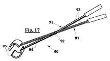
図17に、横突間固定デバイス30または30’(図2、5)を各隣接する椎骨10、20の2つの横突起14、24(図1)の間の空間に配置させるための鉗子90を示している。鉗子90は、正動作鉗子の構造を有し、2つの半量部分91の作業平面を画定するように、蝶番点92の所で互いに連結された2つの実質的に直線状の半量部分91を含む。鉗子90の各半量部分91は、ハンドル部分93および作業部分94を含む。作業部分94は、棘突間固定デバイス30または30’を含むように構成された2つの湾曲したグリップデバイス95、特に円筒形デバイスを全体的に含む。 FIG. 17 shows a
図18に、隣接する椎骨10、20の椎体15、25の間の椎骨間または椎間空間9の中に固定椎間デバイス51、51’(図2、5)を配置させるため、そして隣接する椎骨10、20(図13、14)の椎体15、25の小関節面13、23の間に固定関節間デバイス52を配置させるための、注入デバイス80を示している。注入デバイス80は、一方の操縦端部82’にある蝶番点82の所で互いに連結された2つの半量部分81からなる。2つの半量部分81は、椎間または関節間固定デバイス51、51’、52を摺動自在に受け止めて保持するように構成されたハウジング83を画定する。椎間または関節間固定デバイス51、51’、52を注入デバイス80に沿って操縦端部82’の反対側の1つの開放端部85まで摺動させて、椎間空間9の中、そして小関節面13、23の間のハウジングの中に配置されるように構成させるために、穴(図示しない)が、直線状ガイドデバイス84、特にキルシュナーワイヤー84を移動させるために操縦端部82’に提供されている。 18 to place a fixed
本発明による固定デバイス30、30’、40、40’、51、51’、52、53を作製する手順は、
− 所定の形状およびサイズを有する中空コンテナ体31、31’41(図3〜6)を下準備するステップ;
− 一定量の顆粒状骨接合材料32、特に一定量の顆粒状骨材料を下準備するステップ;
− ことによると顆粒状骨接合材料32に圧縮力を加えることにより、中空コンテナ体31、31’、41に顆粒状骨接合材料32を充填するステップ。顆粒状骨接合材料32の量、および中空コンテナ体31、31’、41に充填する方法は、骨が最初のステップにおいて移植片を再吸収するステップを受けて特定のねじれを起こすことを考慮することにより、選択される;
− 有利には添加剤を顆粒状骨接合材料32に添加するステップ、特に有効成分および/または骨成長因子(図示しない)を添加して骨接合を促進するステップ;
− 真空下、滅菌袋(図示しない)内で固定デバイス30、30’、40、40’、51、51’、52、53を配列するステップ、
を含んでいてもよい。The procedure for producing the fixing
-Preparing a
-Preparing a certain amount of
Filling the
-Advantageously adding additives to the
Arranging the fixing
May be included.
既に記載された通り、本発明による固定デバイス30、30’、40、40’、51、51’、52、53は、予圧縮状態で製造されてもよい。言い換えれば、作製手順において、中空コンテナ体31、31’、41および骨接合材料32を含む固定デバイスを静止位置または形態から予圧縮位置または形態にするステップが、提供されてもよい。固定デバイス30、30’、40、40’、51、51’、52、53が、軸方向に予圧縮された側壁を予圧縮状態で保持するように構成された、ラッパー(図示しない)、例えば上述の真空下での滅菌袋、の中に含まれるステップも提供されてよい。 As already described, the
本明細書では以後、本発明による椎骨固定システムのデバイス30、30’、40、40’、51、51’、52、53を移植するための手順を記載する。 Hereinafter, a procedure for implanting
これらの椎骨固定デバイスは、内側または横からのアプローチにより移植されてもよい。より詳細には、少なくとも1つの椎間デバイス51、51’、一組の関節間デバイス52および棘突間デバイス40または40’を含むシステムを移植するための手順は、
− 2つの隣接する椎骨10、20(図1)を含む脊椎分節で第一の皮膚アクセスを形成するステップ;
− 第一の皮膚アクセスにより2つの椎骨10、20の間の棘突間空間8を覆う黄色靭帯(図示しない)を切断して局所的に除去するステップ;
− 2つの椎骨10、20の間の椎間板16を表出させるために、2つの椎骨10、20の間の脊髄18の一部を移動させるステップ;
− 椎間板16の核を除去するステップ;
− 第一の皮膚アクセスにより椎間デバイス51、51’または複数の椎間デバイス51、51’を椎間板16の核と同じ場所に導入して配置させるステップ;
− 各関節突起13’、23’の2つの協働する小関節面13、23の間に第一の関節間デバイス52を導入して配置させるステップ;
− 棘突間デバイス40、40’を導入して配置させるステップ;
− 第二の皮膚アクセスを形成させるステップ;
− 第二の皮膚アクセスにより第二の関節間デバイス52を導入して配置させるステップ、
を含む。These vertebral fixation devices may be implanted by a medial or lateral approach. More particularly, a procedure for implanting a system that includes at least one
-Forming a first skin access with a spinal segment comprising two
Cutting and locally removing a yellow ligament (not shown) covering the
-Moving a portion of the
-Removing the nucleus of the
Introducing and placing the
Introducing and placing a first
Introducing and placing the
-Forming a second skin access;
-Introducing and positioning the second
including.
別法として、関節固定のためのそのようなシステムを移植するための別の手順において、アクセスサイドは、棘突間デバイス40、40’を導入して配置させるのに用いられず、
− 約4〜5cmの内側後方アクセスを形成させるステップ;
− 内側後方アクセスにより椎骨10、20の間の棘突間空間8を覆う黄色靭帯(図示しない)を切断して局所的に除去するステップ;
− 椎骨10、20の間の椎間板16を表出するために硬膜嚢(図示しない)を移動させるステップ;
− 椎間板16を穿通するステップ;
− 椎間板16の核を外すステップ;
− 例えば2つの隣接する椎骨10、20の椎体15、25の関節表面11、21の間の椎間空間9の中で後方に配列される2つのデバイス51と、前面に配列されるデバイス51’と、の3つの椎間デバイス51、51’を含み得る、少なくとも1つの椎間デバイスを導入して配置させるステップ;
− 2つの協働する小関節面13、23の表面を作製するステップ。そのような作製のステップは、表面の組織、特に軟骨を除去することを含んでいてもよい。これは、従来のツールにより容易に実施され得る;
− 協働する小関節面13、23の間に関節間デバイス52を配置させるステップ;
− 硬膜嚢の位置を戻すステップ;
− 棘突起の小柱骨材料を露出させるために、棘突起12、22の表面を作製するステップ;
− 棘突間デバイス40、40’を導入して配置させるステップ;
− ことによると人工靭帯49により棘突間デバイス40、40’をブロックするステップ、
を含む。Alternatively, in another procedure for implanting such a system for joint fixation, the access side is not used to introduce and place the
-Forming an inner rear access of about 4-5 cm;
Cutting and locally removing a yellow ligament (not shown) covering the
-Moving the dural sac (not shown) to expose the
-Penetrating the
-Removing the nucleus of the
-For example two
Creating the surfaces of the two cooperating facet surfaces 13, 23; Such a production step may comprise removing surface tissue, in particular cartilage. This can be easily done with conventional tools;
Placing the
-Returning the position of the dural sac;
-Creating the surface of the spinous processes 12, 22 to expose the trabecular bone material of the spinous processes;
Introducing and placing the
-Possibly blocking the
including.
こうして2つの隣接する椎骨10、20の周囲関節固定術は、有利には約4〜5cmの長さを有し得て最小限の侵襲性手術を可能にする開口部により得られる。 Thus, a peripheral arthrodesis of two
関節表面13、23を作製するステップは、表面の組織、特に軟骨を除去することを含んでいてもよい。これは、従来のツールにより容易に実施され得る。 Creating the articulating
本発明による固定システムを移植するための手順は、デバイスが配置されたら顆粒状骨接合材料に加えられる圧縮力を増強するために、各デバイスを静止位置から予圧縮位置に圧縮するステップを含んでいてもよい。 The procedure for implanting a fixation system according to the present invention includes the step of compressing each device from a rest position to a pre-compression position to enhance the compressive force applied to the granular osteosynthesis material once the device is deployed. May be.
本発明による固定デバイス、およびその作製および移植の手順の特定の例示的な実施形態の前述の記述により、概念としての本発明が全て明らかにされ、その結果、他者が、現行の知識を適用することで、更なる検査を行わず、そして本発明から離れずに、様々な適用例において特定の例示的な実施形態を改良および/または適合させることができ、したがってそのような適合および改良は、特定の実施形態の均等物と見なされなければならない。本明細書に記載された異なる機能を理解するための手段および材料は、この理由から、本発明の分野を逸脱せず異なる性質を有する可能性がある。本明細書で用いられる表現法または用語法が限定ではなく記述を目的としていることが、理解されなければならない。 The foregoing description of a specific exemplary embodiment of a fixation device according to the present invention, and its fabrication and implantation procedures, reveals all of the concept of the present invention so that others can apply current knowledge. In doing so, certain exemplary embodiments can be improved and / or adapted in various applications without further inspection and without departing from the invention, and such adaptations and improvements are therefore And should be considered equivalents of the specific embodiments. Means and materials for understanding the different functions described herein may have different properties for this reason without departing from the field of the invention. It should be understood that the wording or terminology used herein is for purposes of description and not limitation.
Claims (17)
Translated fromJapanese前記複数の椎骨固定デバイスが、
− 前記隣接する椎骨(10、20)の上部椎骨(10)の棘突起(12)の下部表面(17)と、前記隣接する椎骨(10、20)の下部椎骨(20)の棘突起(22)の上部表面(27)との間にある棘突間空間(8)への挿入のために構成された棘突間固定デバイス(40、40’)であって、前記棘突間固定デバイス(40、40’)が、前記棘突間空間(8)を塞ぐためにそれぞれ前記下部表面(17)および前記上部表面(27)に順応するように構成された上端部(47)および下端部(48)を有する、棘突間固定デバイス(40、40’)と、
− 各組の協働する小関節面(13、23)の間への挿入のために構成された一組の関節間固定デバイス(52)と、
を含み、
前記支持要素が、
− 塑性変形可能な顆粒状骨接合材料(32)と、
− 側壁および2つの開口端部(35’、35”;45’、45”)を有する中空コンテナ体(31、31’、41)であって、前記中空コンテナ体(31、31’、41)が、前記顆粒状骨接合材料(32)を含むように、そして前記開口端部(35’、35”;45’、45”)を通して前記顆粒状骨接合材料(32)と両者の前記対応する椎骨部分(12、22;13、23)との直接的な接触が可能になるように配列され、前記顆粒状骨接合材料(32)が軸方向に沿って前記対応する椎骨部分(12、22;13、23)の間に連続ピラーを形成するまで、前記中空コンテナ体(31、31’、41)が、前記顆粒状骨接合材料(32)を側方に含むように、そして前記2つの開口端部の間に前記軸方向に塑性変形が可能になるように配列され、前記顆粒状骨接合材料(32)の塑性変形の後に、前記側壁が前記軸方向に沿って撓むように配列される、中空コンテナ体(31、31’、41)と、
を含む、椎骨固定システム。A plurality of vertebral fixation device (30each including arespective support element which is configuredforinsertion between the two two corresponding vertebrae portions of adjacent vertebrae (10, 20) of the spine portion of the patient(1), 4 0,40', 52) avertebral fixation system including the corresponding vertebra parts(1 2, 22;spinous process (12 vertebrae (10, 20) which 13,23) is the adjacent, 22) and / or joint surfaces(1 3, 23) by including the supportingforce is the corresponding vertebra parts(1 2, 22; provided in 13,23),
The plurality of vertebral fixation devices is
The lower surface (17) of the spinous process (12) of the upper vertebra (10) of the adjacent vertebra (10, 20) and the spinous process (22) of the lower vertebra (20) of the adjacent vertebra (10, 20); ) Between the interspinous space (8) between the upper surface (27) and the interspinous space fixing device (40, 40 '), 40, 40 ′) are adapted to accommodate the lower surface (17) and the upper surface (27), respectively, to close the interspinous space (8), respectively. An interspinous fixation device (40, 40 ') having
A set of inter-articular fixation devices (52) configured for insertion between each set of cooperating facet surfaces (13, 23);
Including
The support element comprises
-A plastically deformable granular osteosynthesis material (32);
- side walls and two open ends (35', 35 "; 45', 45") a hollow container body having (31, 31 ', 41)a, the hollow container body (31, 31', 41) but wherein to contain granular osteosynthesis material (32), and said open end (35', 35 "; 45', 45") said both said granular osteosynthesis materialthrough (32) Arranged to allow direct contact with the corresponding vertebra part(12, 22; 13, 23) , the granular osteosynthesis material (32)is axially aligned with the corresponding vertebra partThe hollow container body (31, 31 ', 41) includes the granular osteosynthesis material (32) laterally until a continuous pillar is formed between(12, 22; 13, 23). to, and distribution as plastic deformation is possible inthe axial direction between the two open endsHollow container bodies (31, 31 ′, 41) arranged and arranged so that the side wallsbend along the axial direction after plastic deformation of the granular osteosynthesis material (32);
Including a vertebral fixationsystem .
特に前記両側拘束手段が、前記固定デバイス(40’)を前記棘突起(12、22)に締着するように構成された靭帯(49)を含む、請求項1に記載の椎骨固定システム。The interspinous fixation device (40 ′) holds the spinous process (12, 22) in order to hold the granular osteosynthesis material (32) in compression between the spinous processes (12, 22). the configured bilateral restraint (49) to engageseen including,
The vertebral fixationsystem accordingto claim 1, wherein the bilateral restraining means in particular comprises a ligament (49) configured to clamp the fixation device (40 ') to the spinous process (12, 22).
− 5mmと20mmとの間、特に5mmと15mmとの間に設定された高さ(H”、H’”)、
− 5mmと15mmとの間に設定された横断寸法、特に直径、
を有する、請求項1に記載の椎骨固定システム。The vertebrae in which the plurality of vertebral fixation devices are set betweentwo joint surfaces (11, 21) oftwo vertebral bodies (15, 25) facing each other of the two adjacent vertebrae (10, 20)interosseous'includes,the vertebral fixation device (30,51,51 space (9) hasbeen intervertebral fixation device (51,51') configuredfor insertioninto) is,
A height (H ″, H ′ ″) setbetween 5 mmand 20 mm, in particularbetween 5 mmand 15 mm,
-Transverse dimensions setbetween 5 mmand 15 mm, in particular diameter,
Thevertebral fixationsystem of claim 1, comprising:
− 15mmと45mmとの間、特に25mmと40mmとの間に設定された高さ(H’)、
− 5mmと15mmとの間に設定された横断寸法、特に直径、
を有する、請求項1に記載の椎骨固定システム。Wherein the plurality of vertebral fixation device is intended for vertebral arthrodesis,transverse突間fixation device configuredforinsertion between the two corresponding transverse (14, 24)(30 ', 30 ″, 53), and thelateral collision fixing device (30 ′, 30 ″, 53)
-between 15mmand 45 mm, height is specifically setbetween 25mmand 40mm (H'),
-Transverse dimensions setbetween 5 mmand 15 mm, in particular diameter,
Thevertebral fixationsystem of claim 1, comprising:
− らせん形構造、
− 繊維構造、
− 複合構造、
からなる群から選択される構造を有する、請求項1に記載の椎骨固定システム。Said hollow container body (31, 31 ', 41)side wall,
-Helical structure,
-Fiber structure,
-Composite structure,
Thevertebral fixationsystem of claim 1, having a structure selected from the group consisting of:
特に、前記隣接する椎骨(10、20)が脊椎後弯になるのを予防するために、前記前方椎骨間固定デバイス(51’)が、前記後方椎骨間固定デバイス(51)の高さ(H”)よりも高い高さ(H’”)を有し、
特に、前記椎骨固定システムが、2つの後方椎骨間固定デバイス(51)および1つの前方椎骨間固定デバイス(51’)を含む、請求項8に記載の椎骨固定システム。An anteriorintervertebral fixation device (51 ') and a posteriorintervertebral fixation device (51) configured such that thevertebral fixation system is disposed in an anteriorposition and a posterior position, respectively, within the intervertebral space (9). comprising a plurality ofintervertebral fixation device configured to (51, 51 ')viewed freeforinsertion between the two articular surfaces (11,21),
In particular, in order to prevent the adjacent vertebrae (10, 20) from being vertebral kyphosis, the anteriorintervertebral fixation device (51 ') is arranged so that the height of the posteriorintervertebral fixation device (51) (H Has a height (H '") higher than"),
9. Thevertebral fixation system according toclaim 8, in particular, thevertebral fixation system includes two posteriorintervertebral fixation devices (51) and one anteriorintervertebral fixation device (51 ').
Applications Claiming Priority (3)
| Application Number | Priority Date | Filing Date | Title |
|---|---|---|---|
| ITPI2012A000106 | 2012-10-19 | ||
| IT000106AITPI20120106A1 (en) | 2012-10-19 | 2012-10-19 | DEVICE AND SYSTEM FOR VERTEBRAL ARTHRODES |
| PCT/IB2013/059520WO2014061005A2 (en) | 2012-10-19 | 2013-10-21 | Vertebral fusion device and system |
Publications (2)
| Publication Number | Publication Date |
|---|---|
| JP2015532167A JP2015532167A (en) | 2015-11-09 |
| JP6349318B2true JP6349318B2 (en) | 2018-07-04 |
Family
ID=47425248
Family Applications (1)
| Application Number | Title | Priority Date | Filing Date |
|---|---|---|---|
| JP2015537411AExpired - Fee RelatedJP6349318B2 (en) | 2012-10-19 | 2013-10-21 | Vertebral fixation device and system |
Country Status (10)
| Country | Link |
|---|---|
| US (1) | US10159580B2 (en) |
| EP (1) | EP2908748B1 (en) |
| JP (1) | JP6349318B2 (en) |
| CN (1) | CN104768484B (en) |
| BR (1) | BR112015008866B1 (en) |
| ES (1) | ES2676397T3 (en) |
| IT (1) | ITPI20120106A1 (en) |
| PL (1) | PL2908748T3 (en) |
| PT (1) | PT2908748T (en) |
| WO (1) | WO2014061005A2 (en) |
Families Citing this family (19)
| Publication number | Priority date | Publication date | Assignee | Title |
|---|---|---|---|---|
| US9439685B2 (en)* | 2009-05-12 | 2016-09-13 | Bullard Spine, Llc | Multi-layer osteoinductive, osteogenic, and osteoconductive carrier |
| FR3011458B1 (en)* | 2013-10-07 | 2017-02-17 | Cousin Biotech | IMPLANTABLE VERTEBRAL ARTHRODESIS DEVICE FOR FUSION BETWEEN TWO UNDERGROUND AND UNDERLYING VERTEBRES. |
| JP6768001B2 (en) | 2015-04-29 | 2020-10-14 | インスティテュート フォー マスキュロスケレタル サイエンス アンド エジュケイション,リミテッド | Coiled implants and systems and how to make them |
| US10492921B2 (en) | 2015-04-29 | 2019-12-03 | Institute for Musculoskeletal Science and Education, Ltd. | Implant with arched bone contacting elements |
| US10449051B2 (en) | 2015-04-29 | 2019-10-22 | Institute for Musculoskeletal Science and Education, Ltd. | Implant with curved bone contacting elements |
| CN105559868B (en) | 2015-12-15 | 2018-10-30 | 宁波华科润生物科技有限公司 | Fixed system between a kind of spinous process |
| US10478312B2 (en) | 2016-10-25 | 2019-11-19 | Institute for Musculoskeletal Science and Education, Ltd. | Implant with protected fusion zones |
| US11033394B2 (en) | 2016-10-25 | 2021-06-15 | Institute for Musculoskeletal Science and Education, Ltd. | Implant with multi-layer bone interfacing lattice |
| US10512549B2 (en) | 2017-03-13 | 2019-12-24 | Institute for Musculoskeletal Science and Education, Ltd. | Implant with structural members arranged around a ring |
| US10357377B2 (en) | 2017-03-13 | 2019-07-23 | Institute for Musculoskeletal Science and Education, Ltd. | Implant with bone contacting elements having helical and undulating planar geometries |
| US10463403B2 (en) | 2017-07-31 | 2019-11-05 | Medos International Sarl | Systems and methods for reducing the risk of proximal junctional kyphosis using a bone anchor or other attachment point |
| US10456174B2 (en)* | 2017-07-31 | 2019-10-29 | Medos International Sarl | Connectors for use in systems and methods for reducing the risk of proximal junctional kyphosis |
| CN107854197B (en)* | 2017-11-01 | 2023-08-04 | 四川大学华西医院 | A cervical intervertebral fusion device |
| US10940015B2 (en) | 2017-11-21 | 2021-03-09 | Institute for Musculoskeletal Science and Education, Ltd. | Implant with improved flow characteristics |
| US10744001B2 (en) | 2017-11-21 | 2020-08-18 | Institute for Musculoskeletal Science and Education, Ltd. | Implant with improved bone contact |
| FR3083074B1 (en)* | 2018-06-29 | 2020-09-11 | Cousin Biotech | IMPLANTABLE DEVICE FOR THE FUSION OF TWO ADJACENT VERTEBRATES |
| EP3863544B1 (en)* | 2018-10-04 | 2023-01-18 | G & G S.R.L. | Improved interlaminar-type intervertebral support device |
| CN112569022B (en)* | 2020-12-11 | 2023-06-16 | 四川图灵医谷科技有限公司 | Uncinate joint bone grafting net bag, fusion component, manufacturing method and bone grafting packaging tool |
| WO2024119139A1 (en) | 2022-12-01 | 2024-06-06 | Percheron Spine, Llc | Spinal implant and delivery system |
Family Cites Families (38)
| Publication number | Priority date | Publication date | Assignee | Title |
|---|---|---|---|---|
| US5571189A (en)* | 1994-05-20 | 1996-11-05 | Kuslich; Stephen D. | Expandable fabric implant for stabilizing the spinal motion segment |
| US6037519A (en)* | 1997-10-20 | 2000-03-14 | Sdgi Holdings, Inc. | Ceramic fusion implants and compositions |
| US7048762B1 (en)* | 1997-08-27 | 2006-05-23 | Regeneration Technologies, Inc. | Elongated cortical bone implant |
| US6126688A (en)* | 1998-12-21 | 2000-10-03 | Surgical Dynamics Inc. | Apparatus for fusion of adjacent bone structures |
| US6602291B1 (en)* | 1999-04-05 | 2003-08-05 | Raymedica, Inc. | Prosthetic spinal disc nucleus having a shape change characteristic |
| WO2002047587A2 (en)* | 2000-10-25 | 2002-06-20 | Sdgi Holdings, Inc. | Vertically expanding intervertebral body fusion device |
| CA2429149C (en)* | 2000-12-15 | 2010-08-24 | Spineology, Inc. | Annulus-reinforcing band |
| US6719795B1 (en)* | 2001-04-25 | 2004-04-13 | Macropore Biosurgery, Inc. | Resorbable posterior spinal fusion system |
| FR2836373B1 (en)* | 2002-02-26 | 2005-03-25 | Materiel Orthopedique En Abreg | CONNECTING INTERSOMATIC IMPLANTS FOR INSERTING BONE GRAFT FOR REALIZING INTERVERTEBRAL FUSION, INSTRUMENTS FOR CONNECTING THESE IMPLANTS |
| US7041309B2 (en)* | 2002-06-13 | 2006-05-09 | Neuropro Technologies, Inc. | Spinal fusion using an HMG-CoA reductase inhibitor |
| CA2735324A1 (en)* | 2002-11-05 | 2004-05-21 | Spineology, Inc. | A semi-biological intervertebral disc replacement system |
| DE10253169A1 (en)* | 2002-11-14 | 2004-08-05 | Sepitec Foundation | Implant used in procedures for stiffening the vertebral column consists of a compression-resistant hollow body made from two open receptacles which are pressed apart with insertion of filler material |
| FR2861285B1 (en)* | 2003-10-24 | 2006-02-17 | Cousin Biotech | INTERLAMARY SUPPORT |
| DE602004006709T2 (en)* | 2003-11-07 | 2008-02-07 | Impliant Ltd. | SPINE GRAFT |
| US20060036323A1 (en)* | 2004-08-03 | 2006-02-16 | Carl Alan L | Facet device and method |
| WO2006066228A2 (en)* | 2004-12-16 | 2006-06-22 | Innovative Spinal Technologies | Expandable implants for spinal disc replacement |
| US20070055373A1 (en)* | 2005-09-08 | 2007-03-08 | Zimmer Spine, Inc. | Facet replacement/spacing and flexible spinal stabilization |
| US20070083200A1 (en)* | 2005-09-23 | 2007-04-12 | Gittings Darin C | Spinal stabilization systems and methods |
| JP2007167621A (en)* | 2005-11-24 | 2007-07-05 | Olympus Biomaterial Corp | Spinous process spacer |
| US7695514B2 (en)* | 2005-12-29 | 2010-04-13 | Depuy Spine, Inc. | Facet joint and spinal ligament replacement |
| US20080114357A1 (en)* | 2006-11-15 | 2008-05-15 | Warsaw Orthopedic, Inc. | Inter-transverse process spacer device and method for use in correcting a spinal deformity |
| US20080167686A1 (en)* | 2007-01-05 | 2008-07-10 | Warsaw Orthopedic, Inc. | Non-Rigid Intervertebral Spacers |
| EP2182864B1 (en)* | 2007-06-22 | 2016-06-08 | Empirical Spine, Inc. | Devices for controlled flexion restriction of spinal segments |
| US8540752B2 (en)* | 2007-07-03 | 2013-09-24 | Spine Tek, Inc. | Interspinous mesh |
| WO2009005819A1 (en)* | 2007-07-03 | 2009-01-08 | Scribner Robert M | Mobile spinal fusion implant |
| US20110054408A1 (en)* | 2007-07-10 | 2011-03-03 | Guobao Wei | Delivery systems, devices, tools, and methods of use |
| KR20110058781A (en)* | 2008-08-28 | 2011-06-01 | 신세스 게엠바하 | Osteoinduced spinal cord spacing |
| WO2010028070A1 (en)* | 2008-09-02 | 2010-03-11 | Life Spine, Inc. | Peek spinal mesh and peek spinal mesh applicator |
| WO2010048396A2 (en)* | 2008-10-23 | 2010-04-29 | Linares Maedical Devices, Llc | Support insert associated with spinal vertebrae |
| CN101444435B (en)* | 2008-12-25 | 2010-12-29 | 李开南 | Absorbable transverse process fusion apparatus |
| WO2010093955A1 (en)* | 2009-02-12 | 2010-08-19 | Osteotech,Inc. | Segmented delivery system |
| CN201692099U (en)* | 2010-06-25 | 2011-01-05 | 上海交通大学医学院附属仁济医院 | An "H"-shaped allograft fusion device for lumbar spinous processes |
| CN201840551U (en)* | 2010-11-03 | 2011-05-25 | 李超 | Interbody fusion cage |
| WO2012105647A1 (en)* | 2011-02-04 | 2012-08-09 | Hoya株式会社 | Implement for surgery |
| US9271765B2 (en)* | 2011-02-24 | 2016-03-01 | Spinal Elements, Inc. | Vertebral facet joint fusion implant and method for fusion |
| US9539104B2 (en)* | 2011-09-30 | 2017-01-10 | NuTech Spine, Inc. | Osteoconductive implants and methods of using same |
| US20130184826A1 (en)* | 2011-12-22 | 2013-07-18 | Basix Spine Llc | Bioabsorbable enclosures |
| FR3011458B1 (en)* | 2013-10-07 | 2017-02-17 | Cousin Biotech | IMPLANTABLE VERTEBRAL ARTHRODESIS DEVICE FOR FUSION BETWEEN TWO UNDERGROUND AND UNDERLYING VERTEBRES. |
- 2012
- 2012-10-19ITIT000106Apatent/ITPI20120106A1/enunknown
- 2013
- 2013-10-21PLPL13828809Tpatent/PL2908748T3/enunknown
- 2013-10-21JPJP2015537411Apatent/JP6349318B2/ennot_activeExpired - Fee Related
- 2013-10-21ESES13828809.7Tpatent/ES2676397T3/enactiveActive
- 2013-10-21EPEP13828809.7Apatent/EP2908748B1/enactiveActive
- 2013-10-21WOPCT/IB2013/059520patent/WO2014061005A2/enactiveApplication Filing
- 2013-10-21USUS14/436,636patent/US10159580B2/enactiveActive
- 2013-10-21PTPT138288097Tpatent/PT2908748T/enunknown
- 2013-10-21BRBR112015008866-0Apatent/BR112015008866B1/ennot_activeIP Right Cessation
- 2013-10-21CNCN201380058500.4Apatent/CN104768484B/ennot_activeExpired - Fee Related
Also Published As
| Publication number | Publication date |
|---|---|
| US20150282944A1 (en) | 2015-10-08 |
| BR112015008866A2 (en) | 2017-07-04 |
| EP2908748A2 (en) | 2015-08-26 |
| US10159580B2 (en) | 2018-12-25 |
| EP2908748B1 (en) | 2018-04-04 |
| BR112015008866B1 (en) | 2021-12-07 |
| WO2014061005A2 (en) | 2014-04-24 |
| WO2014061005A3 (en) | 2014-06-12 |
| ES2676397T3 (en) | 2018-07-19 |
| JP2015532167A (en) | 2015-11-09 |
| CN104768484A (en) | 2015-07-08 |
| PT2908748T (en) | 2018-07-09 |
| CN104768484B (en) | 2017-10-24 |
| ITPI20120106A1 (en) | 2014-04-20 |
| PL2908748T3 (en) | 2018-11-30 |
Similar Documents
| Publication | Publication Date | Title |
|---|---|---|
| JP6349318B2 (en) | Vertebral fixation device and system | |
| US12409043B2 (en) | Flexible chain implants and instrumentation | |
| US20230165611A1 (en) | Bone fixation devices | |
| US4936848A (en) | Implant for vertebrae | |
| JP6379168B2 (en) | Device for stabilizing bone | |
| JP5636051B2 (en) | Method and apparatus for augmenting bone | |
| US20050256582A1 (en) | Spinal implants, including devices that reduce pressure on the annulus fibrosis | |
| US20090171394A1 (en) | Devices And Methods For The Treatment Of Facet Joint Disease | |
| EP2173266A1 (en) | Method for stabilizing a facet joint | |
| WO2010078647A1 (en) | Spinal covering device | |
| JP2008545475A (en) | Rail-based modular disc nucleus pulposus prosthesis | |
| US20210353333A1 (en) | Integral double rod spinal construct | |
| US10420652B2 (en) | Bone scaffold improvements | |
| KR101822588B1 (en) | Tube member and implant apparatus comprising the same | |
| CN214908684U (en) | Fusiform is in same direction as fixed type of thorn hook vertebra joint and is fused ware | |
| US20240115399A1 (en) | Surgical instrument to implant primary and secondary elements | |
| EP3419536B1 (en) | Integral double rod spinal construct | |
| US20090088855A1 (en) | Posterior rod capturing spacer device and method |
Legal Events
| Date | Code | Title | Description |
|---|---|---|---|
| A521 | Request for written amendment filed | Free format text:JAPANESE INTERMEDIATE CODE: A523 Effective date:20150805 | |
| A621 | Written request for application examination | Free format text:JAPANESE INTERMEDIATE CODE: A621 Effective date:20161020 | |
| A131 | Notification of reasons for refusal | Free format text:JAPANESE INTERMEDIATE CODE: A131 Effective date:20170725 | |
| A977 | Report on retrieval | Free format text:JAPANESE INTERMEDIATE CODE: A971007 Effective date:20170721 | |
| A601 | Written request for extension of time | Free format text:JAPANESE INTERMEDIATE CODE: A601 Effective date:20171024 | |
| A601 | Written request for extension of time | Free format text:JAPANESE INTERMEDIATE CODE: A601 Effective date:20171221 | |
| A521 | Request for written amendment filed | Free format text:JAPANESE INTERMEDIATE CODE: A523 Effective date:20180122 | |
| TRDD | Decision of grant or rejection written | ||
| A01 | Written decision to grant a patent or to grant a registration (utility model) | Free format text:JAPANESE INTERMEDIATE CODE: A01 Effective date:20180515 | |
| A61 | First payment of annual fees (during grant procedure) | Free format text:JAPANESE INTERMEDIATE CODE: A61 Effective date:20180604 | |
| R150 | Certificate of patent or registration of utility model | Ref document number:6349318 Country of ref document:JP Free format text:JAPANESE INTERMEDIATE CODE: R150 | |
| R250 | Receipt of annual fees | Free format text:JAPANESE INTERMEDIATE CODE: R250 | |
| R250 | Receipt of annual fees | Free format text:JAPANESE INTERMEDIATE CODE: R250 | |
| R250 | Receipt of annual fees | Free format text:JAPANESE INTERMEDIATE CODE: R250 | |
| LAPS | Cancellation because of no payment of annual fees |