JP6348065B2 - Granulation synthetic gauze for use with a vacuum treatment system - Google Patents
Granulation synthetic gauze for use with a vacuum treatment systemInfo
- Publication number
- JP6348065B2 JP6348065B2JP2014546146AJP2014546146AJP6348065B2JP 6348065 B2JP6348065 B2JP 6348065B2JP 2014546146 AJP2014546146 AJP 2014546146AJP 2014546146 AJP2014546146 AJP 2014546146AJP 6348065 B2JP6348065 B2JP 6348065B2
- Authority
- JP
- Japan
- Prior art keywords
- synthetic fibers
- manifold member
- intertwined
- ridges
- fibers
- Prior art date
- Legal status (The legal status is an assumption and is not a legal conclusion. Google has not performed a legal analysis and makes no representation as to the accuracy of the status listed.)
- Expired - Fee Related
Links
- 238000005469granulationMethods0.000titleclaimsdescription11
- 230000003179granulationEffects0.000titleclaimsdescription11
- 238000009489vacuum treatmentMethods0.000title1
- 229920002994synthetic fiberPolymers0.000claimsdescription59
- 239000012209synthetic fiberSubstances0.000claimsdescription58
- 239000000835fiberSubstances0.000claimsdescription21
- 229920000642polymerPolymers0.000claimsdescription13
- 239000000463materialSubstances0.000claimsdescription9
- 239000004952PolyamideSubstances0.000claimsdescription5
- 239000000049pigmentSubstances0.000claimsdescription5
- 229920002647polyamidePolymers0.000claimsdescription5
- 229920002472StarchPolymers0.000claimsdescription4
- 230000002209hydrophobic effectEffects0.000claimsdescription4
- 229920000728polyesterPolymers0.000claimsdescription4
- 239000008107starchSubstances0.000claimsdescription4
- 235000019698starchNutrition0.000claimsdescription4
- XLYOFNOQVPJJNP-UHFFFAOYSA-NwaterSubstancesOXLYOFNOQVPJJNP-UHFFFAOYSA-N0.000claimsdescription4
- 210000000624ear auricleAnatomy0.000claimsdescription3
- 239000002245particleSubstances0.000claimsdescription3
- 229920000098polyolefinPolymers0.000claimsdescription3
- 239000013305flexible fiberSubstances0.000claims4
- 210000001519tissueAnatomy0.000description31
- 206010052428WoundDiseases0.000description10
- 208000027418Wounds and injuryDiseases0.000description10
- 239000012530fluidSubstances0.000description10
- 229920000742CottonPolymers0.000description9
- 239000006260foamSubstances0.000description8
- 238000000034methodMethods0.000description7
- 238000002560therapeutic procedureMethods0.000description6
- 230000008901benefitEffects0.000description5
- 239000004372Polyvinyl alcoholSubstances0.000description3
- 239000000853adhesiveSubstances0.000description3
- 230000001070adhesive effectEffects0.000description3
- 230000015572biosynthetic processEffects0.000description3
- 238000004891communicationMethods0.000description3
- 239000000499gelSubstances0.000description3
- 230000004048modificationEffects0.000description3
- 238000012986modificationMethods0.000description3
- 229920001296polysiloxanePolymers0.000description3
- 229920002635polyurethanePolymers0.000description3
- 239000004814polyurethaneSubstances0.000description3
- 229920002451polyvinyl alcoholPolymers0.000description3
- 229920000297RayonPolymers0.000description2
- 239000004599antimicrobialSubstances0.000description2
- 230000006835compressionEffects0.000description2
- 238000007906compressionMethods0.000description2
- 229920001577copolymerPolymers0.000description2
- 230000008878couplingEffects0.000description2
- 238000010168coupling processMethods0.000description2
- 238000005859coupling reactionMethods0.000description2
- 238000005520cutting processMethods0.000description2
- 230000006837decompressionEffects0.000description2
- 210000002615epidermisAnatomy0.000description2
- -1for examplePolymers0.000description2
- 239000000017hydrogelSubstances0.000description2
- 230000001788irregularEffects0.000description2
- 229920005594polymer fiberPolymers0.000description2
- 230000008569processEffects0.000description2
- 239000002964rayonSubstances0.000description2
- 239000012779reinforcing materialSubstances0.000description2
- 238000006467substitution reactionMethods0.000description2
- 206010003445AscitesDiseases0.000description1
- 229920003043Cellulose fiberPolymers0.000description1
- 206010063560Excessive granulation tissueDiseases0.000description1
- 229920002614Polyether block amidePolymers0.000description1
- 239000004721Polyphenylene oxideSubstances0.000description1
- 239000004820Pressure-sensitive adhesiveSubstances0.000description1
- 229920002125Sokalan®Polymers0.000description1
- 238000010521absorption reactionMethods0.000description1
- 230000001133accelerationEffects0.000description1
- NIXOWILDQLNWCW-UHFFFAOYSA-Nacrylic acid groupChemical groupC(C=C)(=O)ONIXOWILDQLNWCW-UHFFFAOYSA-N0.000description1
- 239000000654additiveSubstances0.000description1
- 210000000577adipose tissueAnatomy0.000description1
- 230000000845anti-microbial effectEffects0.000description1
- 238000000071blow mouldingMethods0.000description1
- 210000000988bone and boneAnatomy0.000description1
- 238000003490calenderingMethods0.000description1
- 210000000845cartilageAnatomy0.000description1
- 230000008859changeEffects0.000description1
- 238000000576coating methodMethods0.000description1
- 239000003086colorantSubstances0.000description1
- 210000002808connective tissueAnatomy0.000description1
- 230000003247decreasing effectEffects0.000description1
- 210000004207dermisAnatomy0.000description1
- 230000000694effectsEffects0.000description1
- 229920001971elastomerPolymers0.000description1
- 239000000806elastomerSubstances0.000description1
- 239000013536elastomeric materialSubstances0.000description1
- 230000002708enhancing effectEffects0.000description1
- 210000000416exudates and transudateAnatomy0.000description1
- 239000002657fibrous materialSubstances0.000description1
- 239000003292glueSubstances0.000description1
- 210000001126granulation tissueAnatomy0.000description1
- 230000035876healingEffects0.000description1
- 230000036541healthEffects0.000description1
- 239000000416hydrocolloidSubstances0.000description1
- 230000002706hydrostatic effectEffects0.000description1
- 238000003384imaging methodMethods0.000description1
- 238000009940knittingMethods0.000description1
- 238000003475laminationMethods0.000description1
- 210000003041ligamentAnatomy0.000description1
- 239000007788liquidSubstances0.000description1
- 238000004519manufacturing processMethods0.000description1
- 230000003278mimic effectEffects0.000description1
- 238000000465mouldingMethods0.000description1
- 210000003205muscleAnatomy0.000description1
- 206010033675panniculitisDiseases0.000description1
- 230000035699permeabilityEffects0.000description1
- 239000004584polyacrylic acidSubstances0.000description1
- 229920000570polyetherPolymers0.000description1
- 229920002959polymer blendPolymers0.000description1
- 229920006124polyolefin elastomerPolymers0.000description1
- 229920002689polyvinyl acetatePolymers0.000description1
- 239000011118polyvinyl acetateSubstances0.000description1
- 239000011148porous materialSubstances0.000description1
- 238000007639printingMethods0.000description1
- 238000002601radiographyMethods0.000description1
- 229910052710siliconInorganic materials0.000description1
- 239000010703siliconSubstances0.000description1
- 229910052709silverInorganic materials0.000description1
- 239000004332silverSubstances0.000description1
- 210000003491skinAnatomy0.000description1
- 238000005507sprayingMethods0.000description1
- 210000004304subcutaneous tissueAnatomy0.000description1
- 239000000126substanceSubstances0.000description1
- 229920000247superabsorbent polymerPolymers0.000description1
- 239000004583superabsorbent polymers (SAPs)Substances0.000description1
- 210000002435tendonAnatomy0.000description1
- 229920002725thermoplastic elastomerPolymers0.000description1
- 230000002792vascularEffects0.000description1
- 238000003466weldingMethods0.000description1
Images


Classifications
- A—HUMAN NECESSITIES
- A61—MEDICAL OR VETERINARY SCIENCE; HYGIENE
- A61F—FILTERS IMPLANTABLE INTO BLOOD VESSELS; PROSTHESES; DEVICES PROVIDING PATENCY TO, OR PREVENTING COLLAPSING OF, TUBULAR STRUCTURES OF THE BODY, e.g. STENTS; ORTHOPAEDIC, NURSING OR CONTRACEPTIVE DEVICES; FOMENTATION; TREATMENT OR PROTECTION OF EYES OR EARS; BANDAGES, DRESSINGS OR ABSORBENT PADS; FIRST-AID KITS
- A61F13/00—Bandages or dressings; Absorbent pads
- A61F13/05—Bandages or dressings; Absorbent pads specially adapted for use with sub-pressure or over-pressure therapy, wound drainage or wound irrigation, e.g. for use with negative-pressure wound therapy [NPWT]
- A—HUMAN NECESSITIES
- A61—MEDICAL OR VETERINARY SCIENCE; HYGIENE
- A61F—FILTERS IMPLANTABLE INTO BLOOD VESSELS; PROSTHESES; DEVICES PROVIDING PATENCY TO, OR PREVENTING COLLAPSING OF, TUBULAR STRUCTURES OF THE BODY, e.g. STENTS; ORTHOPAEDIC, NURSING OR CONTRACEPTIVE DEVICES; FOMENTATION; TREATMENT OR PROTECTION OF EYES OR EARS; BANDAGES, DRESSINGS OR ABSORBENT PADS; FIRST-AID KITS
- A61F13/00—Bandages or dressings; Absorbent pads
- A61F13/01—Non-adhesive bandages or dressings
- A61F13/01008—Non-adhesive bandages or dressings characterised by the material
- A61F13/01017—Non-adhesive bandages or dressings characterised by the material synthetic, e.g. polymer based
- A—HUMAN NECESSITIES
- A61—MEDICAL OR VETERINARY SCIENCE; HYGIENE
- A61F—FILTERS IMPLANTABLE INTO BLOOD VESSELS; PROSTHESES; DEVICES PROVIDING PATENCY TO, OR PREVENTING COLLAPSING OF, TUBULAR STRUCTURES OF THE BODY, e.g. STENTS; ORTHOPAEDIC, NURSING OR CONTRACEPTIVE DEVICES; FOMENTATION; TREATMENT OR PROTECTION OF EYES OR EARS; BANDAGES, DRESSINGS OR ABSORBENT PADS; FIRST-AID KITS
- A61F13/00—Bandages or dressings; Absorbent pads
- A61F13/00987—Apparatus or processes for manufacturing non-adhesive dressings or bandages
- A61F13/00991—Apparatus or processes for manufacturing non-adhesive dressings or bandages for treating webs, e.g. for moisturising, coating, impregnating or applying powder
- A—HUMAN NECESSITIES
- A61—MEDICAL OR VETERINARY SCIENCE; HYGIENE
- A61M—DEVICES FOR INTRODUCING MEDIA INTO, OR ONTO, THE BODY; DEVICES FOR TRANSDUCING BODY MEDIA OR FOR TAKING MEDIA FROM THE BODY; DEVICES FOR PRODUCING OR ENDING SLEEP OR STUPOR
- A61M1/00—Suction or pumping devices for medical purposes; Devices for carrying-off, for treatment of, or for carrying-over, body-liquids; Drainage systems
- A61M1/80—Suction pumps
- A—HUMAN NECESSITIES
- A61—MEDICAL OR VETERINARY SCIENCE; HYGIENE
- A61M—DEVICES FOR INTRODUCING MEDIA INTO, OR ONTO, THE BODY; DEVICES FOR TRANSDUCING BODY MEDIA OR FOR TAKING MEDIA FROM THE BODY; DEVICES FOR PRODUCING OR ENDING SLEEP OR STUPOR
- A61M1/00—Suction or pumping devices for medical purposes; Devices for carrying-off, for treatment of, or for carrying-over, body-liquids; Drainage systems
- A61M1/90—Negative pressure wound therapy devices, i.e. devices for applying suction to a wound to promote healing, e.g. including a vacuum dressing
Landscapes
- Health & Medical Sciences (AREA)
- Heart & Thoracic Surgery (AREA)
- Engineering & Computer Science (AREA)
- General Health & Medical Sciences (AREA)
- Biomedical Technology (AREA)
- Life Sciences & Earth Sciences (AREA)
- Animal Behavior & Ethology (AREA)
- Vascular Medicine (AREA)
- Public Health (AREA)
- Veterinary Medicine (AREA)
- Anesthesiology (AREA)
- Hematology (AREA)
- Manufacturing & Machinery (AREA)
- Media Introduction/Drainage Providing Device (AREA)
- Materials For Medical Uses (AREA)
Description
Translated fromJapanese関連出願の相互参照
本出願は、2011年12月7日出願の米国仮特許出願第61/567,998号(SYNTHETIC GRANULATING GAUZE FOR USE WITH REDUCED−PRESSURE TREATMENT SYSTEMS)の優先権を主張し、この開示全体を、参照することにより本明細書に援用する。This application claims the priority of US Provisional Patent Application No. 61 / 567,998, filed Dec. 7, 2011 (SYNTHETIC GRANULING GAUSE FOR USE WITH REDUCED-PRESSURE TREATMENT SYSTEMS). The entirety is hereby incorporated by reference.
本開示は、概して、創傷を治療するための治療システムに関し、より詳細には、限定されるものではないが、減圧治療システム、減圧システム、および方法と使用するための肉芽形成用合成ガーゼに関する。 The present disclosure relates generally to treatment systems for treating wounds, and more particularly, but not exclusively, to a granulation synthetic gauze for use with a reduced pressure treatment system, reduced pressure system, and method.
臨床試験および実習から、組織部位に近接して減圧をもたらすことによって、組織部位における新しい組織の成長を増強および加速することが示されている。この現象の適用は多数あるが、減圧を行うことは、創傷の治療において特に成功している。この治療(医学界では「陰圧閉鎖療法」、「減圧療法」、または「真空療法」と呼ばれることが多い)はいくつもの利点を提供し、それら利点には、迅速な治癒や肉芽組織の形成加速化が含まれる。減圧療法の適用では、一般に、創傷に近接して発泡体パッドが位置決めされ、ドレープで被覆されて、減圧が行われる。 Clinical trials and practices have shown that enhancing and accelerating the growth of new tissue at a tissue site by providing a reduced pressure in proximity to the tissue site. Although there are many applications for this phenomenon, reducing the pressure is particularly successful in the treatment of wounds. This treatment (often referred to in the medical community as “negative pressure closure therapy”, “decompression therapy”, or “vacuum therapy”) offers a number of benefits, including rapid healing and formation of granulation tissue Acceleration is included. In the application of reduced pressure therapy, the foam pad is generally positioned proximate to the wound and covered with a drape to effect reduced pressure.
例示的実施形態によれば、減圧治療システムにおいて使用するためのマニホールド部材は、第1の側面および第2の側面を有するパッドを形成する複数の絡み合い状の(interlocking)合成繊維を含む。マニホールド部材はさらに、パッドの少なくとも第1または第2の側面に形成された複数の隆起を含む。複数の隆起は、組織部位での組織の肉芽形成を促す。 According to an exemplary embodiment, a manifold member for use in a reduced pressure treatment system includes a plurality of interlocking synthetic fibers that form a pad having a first side and a second side. The manifold member further includes a plurality of ridges formed on at least the first or second side of the pad. Multiple ridges promote tissue granulation at the tissue site.
別の例示的実施形態によれば、減圧を用いて患者の組織部位を治療するためのシステムは、組織部位に近接して配置されるように適合されたマニホールド部材と、マニホールド部材を被覆して密閉空間を形成するように適合されたシール部材と、密閉空間に流体的に結合された減圧源とを含む。マニホールド部材は、第1の側面および第2の側面を有するパッドを形成する複数の絡み合い状の合成繊維を含む。マニホールド部材は、さらに、パッドの少なくとも第1または第2の側面に形成された複数の隆起を含む。 According to another exemplary embodiment, a system for treating a patient tissue site using reduced pressure includes a manifold member adapted to be disposed proximate to the tissue site, A seal member adapted to form an enclosed space and a reduced pressure source fluidly coupled to the enclosed space. The manifold member includes a plurality of intertwined synthetic fibers that form a pad having a first side and a second side. The manifold member further includes a plurality of ridges formed on at least the first or second side of the pad.
別の例示的実施形態によれば、組織部位を治療する減圧治療システムにおいて使用するためのマニホールド部材の製造方法は、複数の合成繊維を形成するステップと、複数の合成繊維から、第1の側面および第2の側面を有するパッドを形成するステップと、パッドの少なくとも一部分に複数の隆起を結合するステップとを含む。複数の隆起は、接合によって結合され得るか、または複数の合成繊維の態様として成形され得る。 According to another exemplary embodiment, a method of manufacturing a manifold member for use in a reduced pressure treatment system for treating a tissue site includes forming a plurality of synthetic fibers and a plurality of synthetic fibers from a first side. And forming a pad having a second side, and coupling a plurality of ridges to at least a portion of the pad. The plurality of ridges can be joined by bonding or shaped as a plurality of synthetic fiber embodiments.
別の例示的実施形態によれば、減圧治療システムにおいて使用するためのマニホールド部材は、第1の側面および第2の側面を有する連続気泡発泡体の層を含む。マニホールド部材はまた、連続気泡発泡体の層に結合された複数の絡み合い状の繊維を含む。 According to another exemplary embodiment, a manifold member for use in a reduced pressure treatment system includes a layer of open cell foam having a first side and a second side. The manifold member also includes a plurality of entangled fibers bonded to a layer of open cell foam.
例示的実施形態の他の態様の目的、特徴、および利点は、以下の図面および詳細な説明を参照することから明らかとなる。 Objects, features, and advantages of other aspects of the exemplary embodiments will become apparent upon reference to the following drawings and detailed description.
以下の例示的非限定的な実施形態の詳細な説明において、本明細書の一部をなす添付図面を参照する。これらの実施形態は、当業者が本発明を実施できるようにするのに十分な程度、詳細に説明し、および本発明の趣旨または範囲から逸脱せずに、他の実施形態を使用し得ること、および論理的な構造上の、機械的な、電気的な、および化学的な変更がなされ得ることが理解される。当業者が、本明細書で説明する実施形態を実施できるようにするのに必要ではない詳細に関する説明を避けるために、当業者に公知の特定の情報に関する説明を省略し得る。それゆえ、以下の詳細な説明は、限定的ととられるべきではなく、例示的実施形態の範囲は、添付の特許請求の範囲によってのみ定義される。 In the following detailed description of exemplary, non-limiting embodiments, reference is made to the accompanying drawings that form a part hereof. These embodiments are described in sufficient detail to enable those skilled in the art to practice the invention, and other embodiments may be used without departing from the spirit or scope of the invention. It is understood that mechanical, electrical, and chemical changes can be made, and logical structures. To avoid descriptions of details not necessary to enable one of ordinary skill in the art to practice the embodiments described herein, descriptions of specific information known to those skilled in the art may be omitted. The following detailed description is, therefore, not to be taken in a limiting sense, and the scope of the exemplary embodiments is defined only by the appended claims.
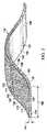
ここで図面を、初めに図1を参照すると、減圧を用いて患者104の組織部位102を治療するシステム100の例示的実施形態が示されている。システム100は、複数の合成繊維108と、複数の隆起110(例えば、図2の隆起110を参照)とを用いて形成されたマニホールド部材106の例示的実施形態を含む。マニホールド部材106は合成のものとし得るが、医療用綿ガーゼの見た目や感触を有するように適合されている。マニホールド部材106は隆起110を含む。隆起110は、組織部位102の肉芽形成を増進させることも、流れ経路を提供して減圧の多岐的な分配(manifolding)を促すこともできる。本明細書全体において、「または」は相互排他性である必要はない。複数の隆起110が肉芽形成を増進させるため、マニホールド部材106は、肉芽形成用合成ガーゼと称し得る。マニホールド部材106は、下記でさらに詳細に説明する。 Referring now to the drawings and initially to FIG. 1, an exemplary embodiment of a
組織部位102は、骨組織、脂肪組織、筋組織、皮膚組織、脈管組織、結合組織、軟骨、腱、靭帯、または任意の他の組織を含む、任意のヒト、動物、または他の生物の体の組織とし得る。組織部位102の治療は、肉芽形成を促す、または流体、例えば滲出液や腹水の除去を促す減圧療法を含み得る。図1の例示的例では、組織部位102は、患者104の創傷にある。創傷は、表皮114を通り、真皮116を通って、皮下組織118まで延在する。 The
マニホールド部材106は、組織部位102に近接して配置され、かつシール部材120によって被覆されて、密閉空間121を形成する。シール部材120は、流体シールをもたらす任意の材料とし得る。流体シールは、特定の減圧源または関連のサブシステムから与えられた減圧を所望の部位に維持するのに適切なシールである。シール部材120は、例えば、不透過性または半透過性のエラストマー材料とし得る。半透過性材料に関し、透過性は、所与の減圧源に対して所望の減圧を維持し得る程度に、十分に低い必要がある。 The
取付装置122は、患者の表皮114の一部分に、またはガスケットや追加的なシール部材などの別の層に、シール部材120を保持するために使用し得る。取付装置122は多数の形態を取り得る。例えば、取付装置122は、シール部材120の周囲または全体に延在する医学的に容認できる感圧接着剤;両面ドレープテープ;糊;親水コロイド;ヒドロゲル;シリコーンゲル;オルガノゲル;または他のシール装置または要素とし得る。 The
シール部材120には減圧インターフェース124が適用されて、密閉空間121への流体連通をもたらす。減圧インターフェース124は、そのような流体連通または流体結合をもたらす任意の装置とし得る。例示的一実施形態では、減圧インターフェース124は、KCI(San Antonio、Texas)から入手可能なT.R.A.C.(登録商標)PadまたはSensa T.R.A.C.(登録商標)Padとし得る。例示的一実施形態では、減圧インターフェース124は、シール部材120を通って延在する導管の一部分とし得る。 A reduced
減圧インターフェース124の第1の端部128には、減圧供給導管126が流体的に結合されている。減圧供給導管126の第2の端部130は、減圧源132に流体的に結合されている。減圧供給導管126は、一般に、医療用チューブ、または流体を運ぶ手段とし得る。 A
減圧源132は、減圧を供給するための任意の装置、例えば真空ポンプ、壁面吸い込み、または他の減圧源とし得る。組織部位に行われる減圧の量および性質は、一般に適用に応じて変動するが、減圧は、一般に、−5mm Hg(−667Pa)〜−500mm Hg(−66.7kPa)、より典型的には−75mm Hg(−9.9kPa)〜−300mm Hg(−39.9kPa)とし得る。 The reduced
減圧は、一般的に、治療が施されている組織部位における周囲圧力を下回る圧力を指す。ほとんどの場合、この減圧は、患者104がいる場所の気圧を下回る。あるいは、減圧は、組織部位102の静水圧を下回り得る。他に指定のない限り、本明細書で述べる圧力の定量値は、ゲージ圧である。送達される減圧は、一定であってもまたは変動しても(パターン化またはランダム)よく、連続的にまたは断続的に送達され得る。用語「真空」および「負圧」を、組織部位に適用される圧力を説明するために使用し得るが、組織部位で行われる実際の圧力は、通常完全な真空に関連付けられる圧力を上回り得る。本明細書での使用に一致して、他に指定のない限り、減圧または真空圧の上昇は、一般に、絶対圧の低下を指す。 Depressurization generally refers to a pressure below the ambient pressure at the tissue site being treated. In most cases, this reduced pressure is below the atmospheric pressure where the patient 104 is. Alternatively, the reduced pressure can be below the hydrostatic pressure of the
ここで主に図1〜5を参照すると、マニホールド部材106は、一般に、医療用綿ガーゼのような見た目や感触に形成される。医療用綿ガーゼの見た目や感触は、一部の医療従事者が望む特徴である。マニホールド部材106は、医療用綿ガーゼのような見た目や感触である一方、減圧治療に関する性能が改善されている。マニホールド部材106は、どのガーゼもそうであるように、創傷床上にまたは組織部位102に接して配置され、さらに、マニホールド部材106の性能は向上されている。 Referring now primarily to FIGS. 1-5, the
マニホールド部材106は、複数の合成繊維108を用いて形成され得る。合成繊維108は、織られて、または組み合わせられて、絡み合った状態の複数の合成繊維134を形成でき、これが、パッド136などの多孔質パッドを形成する。パッド136の細孔は、パッド136を通る流路または流れ経路を形成し、これら流路または流れ経路は、組織部位に減圧を分配するように適合されている。パッド136は第1の側面138および第2の側面140を有する。複数の隆起110は、パッド136の側面138、140の一方または双方に形成され、かつ複数の合成繊維108の一部に取り付けられ得るか、またはその一部として形成され得る。 The
複数の合成繊維108は、例えば、以下のうちの1つまたは複数から形成され得る:不織レーヨン、セルロース配合のレーヨン、ポリエステル、ポリアミド、ポリオレフィン、ポリアクリル酸、ポリ酢酸ビニル、ポリビニルアルコールおよびコポリマー、ポリウレタン、または他のポリマー。合成繊維108は、例えば、円形断面または不規則な断面(例えば、耳たぶ形状)を有し得る。複数の合成繊維108は、スピン形成プロセスまたはブロー形成プロセスによって形成され、天然の綿の見た目や感触を模倣し得る。合成繊維108は、親水性または疎水性となるように形成し得る。合成繊維108を形成する材料に顔料を加え得る。例示的一実施形態では、合成繊維108は、有効径が20μm未満の繊維から形成されるが、繊維の直径が約200μmまたはそれらの間の任意の寸法である、より粗いメッシュも使用し得る。複数の絡み合い状の合成繊維108の平均的な有効径は、一般に、15μm超、かつ25μm未満である。パッド136の密度の範囲は、1平方メートル当たり約20〜200グラム(約20〜200gsm)を可能とし得る。マニホールド部材106の圧縮剛性は、医療用綿ガーゼを上回り、かつ50%の圧縮で8kPaの範囲とし得る。合成繊維108を組み合わせて複数の絡み合い状の合成繊維134を形成し、それでパッド136を形成する。
The plurality of
複数の合成繊維108に多数の材料を追加し得る。例えば、多数の色のうちのいずれかの顔料が複数の合成繊維108に含まれ、容易に視覚認識できるようにする。抗菌剤(例えば、銀)を複数の合成繊維108に加え得る。さらに別の例として、X線不透過性物質を複数の合成繊維108に加え得る。後者の例では、X線撮影を使用して、ドレッシングの変更後に創傷床に残った、いずれのX線不透過性物質の位置も突き止め得る。さらに別の例として、補強用材料、例えば、澱粉、またはポリビニルアルコールなどの感水ポリマーを加えて、マニホールド部材106に比較的高い硬度を与え、かつ補強用材料が濡れるときの硬度を低下させ得る。 Multiple materials can be added to the plurality of
複数の隆起110は、組織部位102に微小歪みまたは比較的より大きな微小歪みをもたらすことによって、肉芽形成を増進させ得る。複数の隆起110はまた、マニホールド部材106を通る流路を提供するのを支援し得る。複数の隆起110は、パッド136または複数の合成繊維110に成形または接合され得るか、または他の方法で形成され得る。複数の隆起110は、例えば、ポリウレタン、シリコーン、TPE、ポリエーテルブロックポリアミド(PEBAX)、またはポリオレフィンエラストマーなどのポリマーから形成し得る。複数の隆起110の硬度は、40〜60Shore Aデュロメータである。複数の隆起110の平均体積は、約0.125mm3〜約8mm3である。The plurality of
隆起110は、少なくとも1つの寸法が10μmを上回るポリマー粒子または小塊を含み得る。複数の隆起110は、顔料、または抗菌剤などの他の添加剤が加えられ得る。複数の隆起110は、小塊として、任意の形状、例えば、不規則な形、ドーム形、正方形、矩形、三角形、または他の形状に形成し得る。複数の隆起110は、間隙および特徴を生じる任意の表面のむらとし得る。複数の隆起110の形状は、構造への内方成長を制限してまたは妨げて、ドレッシングの変更時にマニホールド部材106を除去するのを容易にし得る。The
合成繊維108および隆起110は、多数の方法で形成し得る。ここで主に図2を参照すると、一実施形態では、複数の隆起110はパッド136に結合される。例えば、複数の隆起110はパッド136に接合される。接合は、非水溶性接着材被覆プロセス、例えば、アクリル、ポリウレタン、ケイ素、またはエラストマーベースの医療グレードの接着剤を使用して形成し得る。接合はまた、熱接着または火炎貼合せを使用して形成し得る。
例示的一実施形態では、パッド136を形成する複数の合成繊維108と、複数の隆起110とは、ポリマー繊維のマットを形成してから、ポリマー繊維のマットの表面に形体または物体をスパッタコーティングすることによって、形成し得る。隆起110は、好適な接合性を備える別のポリマーまたは任意の他の好適な材料から形成し得る。別の例示的実施形態では、複数の隆起110は澱粉を含み、澱粉は、創傷に残っても安全とし得る。隆起110には、後続の撮像のためにタグをつけられてもよい。 In an exemplary embodiment, the plurality of
マニホールド部材106は、穿孔または引裂き経路144を有する縦長の条片として形成し得る。完成品のマニホールド部材106をリール上に巻き付け得るか、またはエンドユーザに条片形状で提供され得る。マニホールド部材106の厚さ145は、一般に、約1mm〜約5mmの範囲であり、および幅146は、一般に約1cm〜約30cmの範囲である。当然のことながら、他の寸法も可能である。 The
ここで主に図3および図4を参照すると、別の例示的実施形態では、複数の隆起110は、複数の合成繊維108自体に形成される。例えば、複数の合成繊維108および複数の隆起110は、成形、押出し、カレンダー加工、印刷、吹き付け、または他の手段によって形成し得る。 Referring now primarily to FIGS. 3 and 4, in another exemplary embodiment, a plurality of
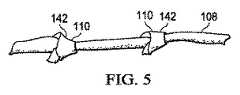
ここで主に図5を参照すると、別の例示的実施形態では、複数の合成繊維108は、各合成繊維108に沿って縦方向に形成された複数の結び目142または結び目のような構造を備えて形成され得る。合成繊維108は、レース編みおよび製網(net making)において使用された技術および方法を用いて形成された織り、編み、編組、乾式、メルトブローンであるか、または他の方法で絡み合うように組まれて、複数の絡み合い状の合成繊維134を形成して、パッド136を形成する。 Referring now primarily to FIG. 5, in another exemplary embodiment, the plurality of
マニホールド部材106を形成する様々な方法の場合、マニホールド部材106の機械的特性は、ポリマーまたはポリマーブレンド、断面(例えば、形成された繊維の断面が、鋭い先を備えるかまたは滑らかな円であるか)、および繊維ストランドの幾何学的形状(跳ね返りを最小にする)の選択によって、制御し得ることに留意されたい。例えば、場合によっては小径の繊維を使用し得る。なぜなら、より小径の繊維は、より直径の大きな繊維から形成された構造と比較して、より柔らかく柔軟な構造を形成する傾向があるためである。耳たぶ状および縦方向に溝付の繊維を使用して、マニホールド部材106のウィッキング性質を高め得る。 For the various methods of forming the
マニホールド部材106は、材料のシートとして形成し得る−シートは、複数の絡み合い状の合成繊維134および複数の隆起110を含む。異なる適用では、追加的な層をパッド136に貼りあわせ得る。例えば、ヒドロゲル、シリコーンゲル、有孔フィルム、および抗菌剤層をパッド136に貼り合わせ得る。 The
再度、主に図2を参照すると、他の実施形態にも適用可能ではあるが、パッド136は、穿孔されるかまたは部分的にカッティングされて引裂き経路144を形成し、引裂きを容易にし得る。パッド136は、一般にロール上に配置される。引裂き経路144は、縦方向に変位され、かつ幅146にわたって横方向に延在する。引裂き経路144は、隙間のない穿孔すなわち穴から、またはセグメント化された穿孔から、またはわずかな切り込みすなわちキスカット(kiss−cuts)から形成して、引裂き経路を制御し得る。各引裂き経路144の各側に封じ込め接合部148が形成されて、引裂き後も、繊維108を引裂き経路144に沿って一緒に保持し得る。マニホールド部材106は、引裂き経路144に沿って引き裂かれるかまたはカッティング具によってカッティングされない限り、手で分離されないように構成し得る。 Referring again primarily to FIG. 2, although applicable to other embodiments,
全ての実施形態に関し、マニホールド部材106は、別の細繊維材料を用いてフロック加工する(flocked)かまたは被覆されて、マニホールド部材106の柔軟性を高め得るかまたは嵩を増やし得る。フロックは、マニホールド部材106に疎水性または親水性を与え得る。細繊維はまた、液体を吸収するとゲルになる超吸収性ポリマーから形成し得る。細繊維の例は、ポリエステル、ポリアミド、ポリアクリル、ポリビニルアルコールおよびコポリマー繊維を含む。 For all embodiments, the
ここで主に図1〜5を参照すると、動作時、例示的一実施形態によれば、使用者は、図1に示すように、それ自体を折り返し得るかまたは詰込み得るマニホールド部材106の条片を選択することによって、マニホールド部材106をある大きさにし、または適切な引裂き経路144を引き裂いてまたはカッティングして、組織部位102を適切に被覆するマニホールド部材106の1つまたは複数の部片を提供し得る。マニホールド部材106は、単に引裂くのではなく、引裂き経路144またはカッティング具を使用し得ることを除いて、医療用綿ガーゼのように組織部位102に実質的に適用され得る。 Referring now primarily to FIGS. 1-5, in operation, according to an exemplary embodiment, a user may fold the
マニホールド部材106の展開後、組織部位102は、シール部材120によって被覆され得る。減圧インターフェース124を適用して、マニホールド部材106を含む密閉空間121に流体連通をもたらす。減圧インターフェース124は、減圧供給導管126によって減圧源132に流体的に結合される。あるいは、アパーチャを備えるシール部材120にマイクロポンプ(明示せず)を直接適用し、密閉空間121への流体通路をもたらす。減圧源132を作動させて、マニホールド部材106を通して組織部位102まで減圧を分配し得る。 After deployment of the
マニホールド部材106は、創傷に迅速に配置し得る。マニホールド部材106は、綿ガーゼの見た目や感触をもたらすが、親水性の吸収性ではなく、減圧用の疎水性の多岐的な分配(manifolding)をもたらすことができる。マニホールド部材106はまた、陰圧閉鎖療法で使用されるとき、肉芽形成または流体の流れを改善する。 The
ここで主に図6を参照すると、減圧システム(図1の100参照)において使用するための例示的なマニホールド部材206の代替的な実施形態が示されている。マニホールド部材206は、第1の側面252および第2の側面254を有する連続気泡発泡体250の層を含む。マニホールド部材206は、さらに、複数の絡み合い状の繊維256を含む。絡み合い状の繊維256は、合成物質、例えば、ポリマー、またはセルロース繊維から形成し得る。例示的一例では、連続気泡発泡体250は、医療用綿ガーゼの一方の側面に適用され得る。複数の絡み合い状の繊維256は、接合部258によって連続気泡発泡体250の層に結合される。接合部258は、接着剤、溶接、機械的な絡み合わせ、または他の取付手段とし得る。連続気泡発泡体250の層の厚さ260は3ミリメートル未満であり、および複数の絡み合い状の繊維256の厚さ262は3ミリメートル未満である。使用時、連続気泡発泡体250は、組織部位に隣接して展開され、かつ図1に関連して説明したように使用する。 Referring now primarily to FIG. 6, an alternative embodiment of an
本発明およびその利点を、例示的非限定的な実施形態に照らして開示したが、添付の特許請求の範囲から逸脱せずに、様々な変更、代替、置換、および修正をなし得ることを理解されたい。いずれか一つの実施形態に関連して説明された任意の特徴はまた、任意の他の実施形態にも適用可能であり得ることを理解されたい。 Although the present invention and its advantages have been disclosed in the light of exemplary, non-limiting embodiments, it will be understood that various changes, substitutions, substitutions, and modifications may be made without departing from the scope of the appended claims. I want to be. It should be understood that any feature described in connection with any one embodiment may also be applicable to any other embodiment.
上述の利益および利点は、一実施形態に関連し得ること、またはいくつかの実施形態に関連し得ることを理解されたい。「1つの(an)」品目への言及は、1つまたは複数のそれら品目を指すことをさらに理解されたい。 It should be understood that the benefits and advantages described above may relate to one embodiment or may relate to several embodiments. It should be further understood that reference to “an” item refers to one or more of those items.
本明細書で説明した方法のステップは、任意の好適な順序で、または適切な場合には同時に実施し得る。 The method steps described herein may be performed in any suitable order or simultaneously, where appropriate.
適切な場合には、上述の実施形態のいずれかの態様を、説明の任意の他の実施形態の態様と組み合わせて、類似のまたは異なる特性を有しかつ同じまたは異なる問題に対処する別の例を形成する。 Where appropriate, another example of combining any aspect of the above-described embodiments with aspects of any other described embodiment, having similar or different characteristics and addressing the same or different issues Form.
好ましい実施形態の上述の説明は例示にすぎず、当業者は様々な修正をなし得ることを理解されたい。上述の明細書、例およびデータは、本発明の例示的な実施形態の構造および使用の完全な説明を提供する。本発明の様々な実施形態を、ある程度詳細に、または1つまたは複数の個々の実施形態を参照して上記で説明したが、当業者は、特許請求の範囲から逸脱せずに、開示の実施形態に多数の修正をなすことができる。 It should be understood that the above description of the preferred embodiments is exemplary only, and that various modifications may be made by those skilled in the art. The above specification, examples and data provide a complete description of the structure and use of exemplary embodiments of the invention. Although various embodiments of the present invention have been described above in some detail or with reference to one or more individual embodiments, those skilled in the art will recognize that the disclosed embodiments can be practiced without departing from the scope of the claims. Numerous modifications can be made to the form.
Claims (28)
Translated fromJapanese複数の柔軟繊維でフロック加工され及び織られて第1の側面および第2の側面を有するガーゼを形成する複数の絡み合い状の合成繊維であって、前記複数の柔軟繊維が、前記複数の合成繊維の素材とは異なる素材を具える、複数の絡み合い状の合成繊維と;
前記ガーゼの少なくとも前記第1の側面または前記第2の側面に形成された複数の隆起であって、少なくとも1つの寸法が約10μm〜約20μmであり、硬さが約40〜約60Shore Aであり、ドーム形、正方形、矩形、又は三角形のうちの少なくとも1つの形状を有し、前記組織部位での組織の肉芽形成を促すよう構成された複数の隆起と
を含むことを特徴とする、マニホールド部材。In a manifold member for treating a tissue site,
A plurality of intertwined synthetic fibersthatare flocked and woven with a plurality of flexible fibers to form a gauze having a first side and a second side, wherein the plurality of flexible fibers are the plurality of synthetic fibers A plurality of intertwined synthetic fibers comprising a material different from that of
A plurality of ridges formed on at least thefirst side orthe second side of the gauze,at least one dimension ofabout 10 [mu] m~ about 20 [mu] m, hardness from about 40 to about 60Shore A Anda plurality of ridgeshaving at least one shape of a dome, square, rectangle, or triangle andconfigured to promote granulation of tissue at the tissue site .
前記組織部位に近接して配置されたマニホールド部材と;A manifold member disposed proximate to the tissue site;
前記マニホールド部材を被覆して、前記組織部位の周りに密閉空間を形成するように適合されたシール部材と;A seal member adapted to cover the manifold member to form an enclosed space around the tissue site;
前記マニホールド部材に流体的に結合された減圧源とA reduced pressure source fluidly coupled to the manifold member;
を含み、およびIncluding, and
前記マニホールド部材が、The manifold member is
複数の柔軟繊維でフロック加工され及び織られて第1の側面および第2の側面を有するガーゼを形成する複数の絡み合い状の合成繊維であって、前記複数の柔軟繊維が、前記複数の合成繊維の素材とは異なる素材を具える、複数の絡み合い状の合成繊維と、A plurality of intertwined synthetic fibers that are flocked and woven with a plurality of flexible fibers to form a gauze having a first side and a second side, wherein the plurality of flexible fibers are the plurality of synthetic fibers A plurality of intertwined synthetic fibers comprising different materials from
前記ガーゼの少なくとも前記第1の側面または前記第2の側面に形成された複数の隆起であって、少なくとも1つの寸法が約10μm〜約20μmであり、硬さが約40〜約60Shore Aであり、ドーム形、正方形、矩形、又は三角形のうちの少なくとも1つの形状を有し、前記組織部位での組織の肉芽形成を促すよう構成された複数の隆起とA plurality of ridges formed on at least the first side or the second side of the gauze, wherein at least one dimension is about 10 μm to about 20 μm, and the hardness is about 40 to about 60 Shore A A plurality of ridges having a shape of at least one of a dome, a square, a rectangle, or a triangle and configured to promote granulation of tissue at the tissue site;
を含むことを特徴とする、システム。A system characterized by comprising:
Applications Claiming Priority (3)
| Application Number | Priority Date | Filing Date | Title |
|---|---|---|---|
| US201161567998P | 2011-12-07 | 2011-12-07 | |
| US61/567,998 | 2011-12-07 | ||
| PCT/US2012/068583WO2013086426A1 (en) | 2011-12-07 | 2012-12-07 | Synthetic granulating gauze for use with reduced-pressure treatment systems |
Publications (3)
| Publication Number | Publication Date |
|---|---|
| JP2015500703A JP2015500703A (en) | 2015-01-08 |
| JP2015500703A5 JP2015500703A5 (en) | 2016-01-28 |
| JP6348065B2true JP6348065B2 (en) | 2018-06-27 |
Family
ID=47436229
Family Applications (1)
| Application Number | Title | Priority Date | Filing Date |
|---|---|---|---|
| JP2014546146AExpired - Fee RelatedJP6348065B2 (en) | 2011-12-07 | 2012-12-07 | Granulation synthetic gauze for use with a vacuum treatment system |
Country Status (7)
| Country | Link |
|---|---|
| US (2) | US10004643B2 (en) |
| EP (1) | EP2787943B2 (en) |
| JP (1) | JP6348065B2 (en) |
| CN (1) | CN104114134B (en) |
| AU (1) | AU2012347524B2 (en) |
| CA (1) | CA2856230C (en) |
| WO (1) | WO2013086426A1 (en) |
Families Citing this family (38)
| Publication number | Priority date | Publication date | Assignee | Title |
|---|---|---|---|---|
| WO2013066426A2 (en) | 2011-06-24 | 2013-05-10 | Kci Licensing, Inc. | Reduced-pressure dressings employing tissue-fixation elements |
| GB201317746D0 (en) | 2013-10-08 | 2013-11-20 | Smith & Nephew | PH indicator |
| US10687983B2 (en) | 2013-04-17 | 2020-06-23 | Mölnlycke Health Care Ab | Wound pad |
| WO2016176147A1 (en)* | 2015-04-25 | 2016-11-03 | Chemokind, Inc. | Wound packing material comprising chemoeffector |
| GB2537841B (en)* | 2015-04-27 | 2020-12-09 | Medtrade Products Ltd | Wound dressing |
| CN105573883B (en)* | 2015-12-11 | 2018-02-06 | 小米科技有限责任公司 | Apparatus control method and device |
| CA3023772A1 (en) | 2016-05-13 | 2017-11-16 | Smith & Nephew Plc | Sensor enabled wound monitoring and therapy apparatus |
| US10941252B2 (en) | 2016-11-03 | 2021-03-09 | 3M Innovative Properties Company | Silicone copolymers, methods of making, and articles |
| JP7091356B2 (en) | 2017-03-09 | 2022-06-27 | スミス アンド ネフュー ピーエルシー | Devices, devices, and methods for determining skin perfusion pressure |
| EP3592230A1 (en) | 2017-03-09 | 2020-01-15 | Smith & Nephew PLC | Apparatus and method for imaging blood in a target region of tissue |
| US11690570B2 (en) | 2017-03-09 | 2023-07-04 | Smith & Nephew Plc | Wound dressing, patch member and method of sensing one or more wound parameters |
| CA3059516A1 (en) | 2017-04-11 | 2018-10-18 | Smith & Nephew Plc | Component positioning and stress relief for sensor enabled wound dressings |
| AU2018269112B2 (en) | 2017-05-15 | 2024-05-02 | Smith & Nephew Plc | Wound analysis device and method |
| EP3635733A1 (en) | 2017-05-15 | 2020-04-15 | Smith & Nephew plc | Negative pressure wound therapy system using eulerian video magnification |
| JP7189159B2 (en) | 2017-06-23 | 2022-12-13 | スミス アンド ネフュー ピーエルシー | Sensor placement for sensor-enabled wound monitoring or therapy |
| US10751212B2 (en)* | 2017-06-26 | 2020-08-25 | Maryam Raza | Multilayer dressing device and method for preventing and treating pressure ulcers and chronic wounds |
| GB201804502D0 (en) | 2018-03-21 | 2018-05-02 | Smith & Nephew | Biocompatible encapsulation and component stress relief for sensor enabled negative pressure wound therapy dressings |
| GB201809007D0 (en) | 2018-06-01 | 2018-07-18 | Smith & Nephew | Restriction of sensor-monitored region for sensor-enabled wound dressings |
| SG11202000913XA (en) | 2017-08-10 | 2020-02-27 | Smith & Nephew | Positioning of sensors for sensor enabled wound monitoring or therapy |
| GB201718870D0 (en) | 2017-11-15 | 2017-12-27 | Smith & Nephew Inc | Sensor enabled wound therapy dressings and systems |
| GB201804971D0 (en) | 2018-03-28 | 2018-05-09 | Smith & Nephew | Electrostatic discharge protection for sensors in wound therapy |
| CN111093477B (en) | 2017-09-10 | 2023-09-12 | 史密夫及内修公开有限公司 | Systems and methods for inspecting packages and components in sensor-equipped wound dressings |
| GB201718859D0 (en) | 2017-11-15 | 2017-12-27 | Smith & Nephew | Sensor positioning for sensor enabled wound therapy dressings and systems |
| WO2019063481A1 (en) | 2017-09-27 | 2019-04-04 | Smith & Nephew Plc | Ph sensing for sensor enabled negative pressure wound monitoring and therapy apparatuses |
| WO2019072531A1 (en) | 2017-09-28 | 2019-04-18 | Smith & Nephew Plc | Neurostimulation and monitoring using sensor enabled wound monitoring and therapy apparatus |
| US11559438B2 (en) | 2017-11-15 | 2023-01-24 | Smith & Nephew Plc | Integrated sensor enabled wound monitoring and/or therapy dressings and systems |
| WO2020005419A1 (en)* | 2018-06-28 | 2020-01-02 | Kci Licensing, Inc. | Long-duration, deep wound filler with means to prevent granulation in-growth |
| GB201814011D0 (en) | 2018-08-29 | 2018-10-10 | Smith & Nephew | Componet positioning and encapsulation for sensor enabled wound dressings |
| EP3849401A1 (en) | 2018-09-12 | 2021-07-21 | Smith & Nephew plc | Device, apparatus and method of determining skin perfusion pressure |
| WO2020064937A1 (en) | 2018-09-28 | 2020-04-02 | T.J.Smith And Nephew,Limited | Optical fibers for optically sensing through wound dressings |
| GB201816838D0 (en) | 2018-10-16 | 2018-11-28 | Smith & Nephew | Systems and method for applying biocompatible encapsulation to sensor enabled wound monitoring and therapy dressings |
| US20210338490A1 (en)* | 2018-10-17 | 2021-11-04 | Kci Licensing, Inc. | Systems, Apparatuses, And Methods For Negative-Pressure Treatment With Reduced Tissue In-Growth |
| GB201820927D0 (en) | 2018-12-21 | 2019-02-06 | Smith & Nephew | Wound therapy systems and methods with supercapacitors |
| JP7529681B2 (en) | 2019-03-18 | 2024-08-06 | スミス アンド ネフュー ピーエルシー | Design rules for sensor integrated boards |
| GB201914443D0 (en) | 2019-10-07 | 2019-11-20 | Smith & Nephew | Sensor enabled negative pressure wound monitoring apparatus with different impedances inks |
| WO2021148925A1 (en)* | 2020-01-21 | 2021-07-29 | Kci Licensing, Inc. | Customizable negative-pressure tissue interface with edge protection |
| EP4139904A1 (en) | 2020-04-21 | 2023-03-01 | T.J. Smith and Nephew, Limited | Wound treatment management using augmented reality overlay |
| EP4338661B1 (en)* | 2022-09-19 | 2025-04-23 | Ivoclar Vivadent AG | Vacuum film for scanning an oral cavity |
Family Cites Families (154)
| Publication number | Priority date | Publication date | Assignee | Title |
|---|---|---|---|---|
| US1355846A (en) | 1920-02-06 | 1920-10-19 | David A Rannells | Medical appliance |
| US2547758A (en) | 1949-01-05 | 1951-04-03 | Wilmer B Keeling | Instrument for treating the male urethra |
| US2632443A (en) | 1949-04-18 | 1953-03-24 | Eleanor P Lesher | Surgical dressing |
| GB692578A (en) | 1949-09-13 | 1953-06-10 | Minnesota Mining & Mfg | Improvements in or relating to drape sheets for surgical use |
| US2682873A (en) | 1952-07-30 | 1954-07-06 | Johnson & Johnson | General purpose protective dressing |
| NL189176B (en) | 1956-07-13 | 1900-01-01 | Hisamitsu Pharmaceutical Co | PLASTER BASED ON A SYNTHETIC RUBBER. |
| US2969057A (en) | 1957-11-04 | 1961-01-24 | Brady Co W H | Nematodic swab |
| US3066672A (en) | 1960-09-27 | 1962-12-04 | Jr William H Crosby | Method and apparatus for serial sampling of intestinal juice |
| US3367332A (en) | 1965-08-27 | 1968-02-06 | Gen Electric | Product and process for establishing a sterile area of skin |
| US3520300A (en) | 1967-03-15 | 1970-07-14 | Amp Inc | Surgical sponge and suction device |
| US3568675A (en) | 1968-08-30 | 1971-03-09 | Clyde B Harvey | Fistula and penetrating wound dressing |
| US3682180A (en) | 1970-06-08 | 1972-08-08 | Coilform Co Inc | Drain clip for surgical drain |
| BE789293Q (en) | 1970-12-07 | 1973-01-15 | Parke Davis & Co | MEDICO-SURGICAL DRESSING FOR BURNS AND SIMILAR LESIONS |
| US3826254A (en) | 1973-02-26 | 1974-07-30 | Verco Ind | Needle or catheter retaining appliance |
| JPS5046974A (en)* | 1973-10-02 | 1975-04-26 | ||
| DE2527706A1 (en) | 1975-06-21 | 1976-12-30 | Hanfried Dr Med Weigand | DEVICE FOR THE INTRODUCTION OF CONTRAST AGENTS INTO AN ARTIFICIAL INTESTINAL OUTLET |
| DE2640413C3 (en) | 1976-09-08 | 1980-03-27 | Richard Wolf Gmbh, 7134 Knittlingen | Catheter monitor |
| NL7710909A (en) | 1976-10-08 | 1978-04-11 | Smith & Nephew | COMPOSITE STRAPS. |
| GB1562244A (en) | 1976-11-11 | 1980-03-05 | Lock P M | Wound dressing materials |
| US4080970A (en) | 1976-11-17 | 1978-03-28 | Miller Thomas J | Post-operative combination dressing and internal drain tube with external shield and tube connector |
| US4139004A (en) | 1977-02-17 | 1979-02-13 | Gonzalez Jr Harry | Bandage apparatus for treating burns |
| US4184510A (en) | 1977-03-15 | 1980-01-22 | Fibra-Sonics, Inc. | Valued device for controlling vacuum in surgery |
| US4165748A (en) | 1977-11-07 | 1979-08-28 | Johnson Melissa C | Catheter tube holder |
| US4245637A (en) | 1978-07-10 | 1981-01-20 | Nichols Robert L | Shutoff valve sleeve |
| SE414994B (en) | 1978-11-28 | 1980-09-01 | Landstingens Inkopscentral | VENKATETERFORBAND |
| GB2047543B (en) | 1978-12-06 | 1983-04-20 | Svedman Paul | Device for treating tissues for example skin |
| US4266545A (en) | 1979-04-06 | 1981-05-12 | Moss James P | Portable suction device for collecting fluids from a closed wound |
| US4284079A (en) | 1979-06-28 | 1981-08-18 | Adair Edwin Lloyd | Method for applying a male incontinence device |
| US4261363A (en) | 1979-11-09 | 1981-04-14 | C. R. Bard, Inc. | Retention clips for body fluid drains |
| US4569348A (en) | 1980-02-22 | 1986-02-11 | Velcro Usa Inc. | Catheter tube holder strap |
| WO1981002516A1 (en) | 1980-03-11 | 1981-09-17 | E Schmid | Cushion for holding an element of grafted skin |
| US4297995A (en) | 1980-06-03 | 1981-11-03 | Key Pharmaceuticals, Inc. | Bandage containing attachment post |
| US4333468A (en) | 1980-08-18 | 1982-06-08 | Geist Robert W | Mesentery tube holder apparatus |
| US4465485A (en) | 1981-03-06 | 1984-08-14 | Becton, Dickinson And Company | Suction canister with unitary shut-off valve and filter features |
| US4392853A (en) | 1981-03-16 | 1983-07-12 | Rudolph Muto | Sterile assembly for protecting and fastening an indwelling device |
| US4373519A (en) | 1981-06-26 | 1983-02-15 | Minnesota Mining And Manufacturing Company | Composite wound dressing |
| US4392858A (en) | 1981-07-16 | 1983-07-12 | Sherwood Medical Company | Wound drainage device |
| US4419097A (en) | 1981-07-31 | 1983-12-06 | Rexar Industries, Inc. | Attachment for catheter tube |
| SE429197B (en) | 1981-10-14 | 1983-08-22 | Frese Nielsen | SAR TREATMENT DEVICE |
| DE3146266A1 (en) | 1981-11-21 | 1983-06-01 | B. Braun Melsungen Ag, 3508 Melsungen | COMBINED DEVICE FOR A MEDICAL SUCTION DRAINAGE |
| US4551139A (en) | 1982-02-08 | 1985-11-05 | Marion Laboratories, Inc. | Method and apparatus for burn wound treatment |
| US4475909A (en) | 1982-05-06 | 1984-10-09 | Eisenberg Melvin I | Male urinary device and method for applying the device |
| EP0100148B1 (en) | 1982-07-06 | 1986-01-08 | Dow Corning Limited | Medical-surgical dressing and a process for the production thereof |
| NZ206837A (en) | 1983-01-27 | 1986-08-08 | Johnson & Johnson Prod Inc | Thin film adhesive dressing:backing material in three sections |
| US4548202A (en) | 1983-06-20 | 1985-10-22 | Ethicon, Inc. | Mesh tissue fasteners |
| US4540412A (en) | 1983-07-14 | 1985-09-10 | The Kendall Company | Device for moist heat therapy |
| JPS6060176A (en)* | 1983-09-14 | 1985-04-06 | Nippon Shokubai Kagaku Kogyo Co Ltd | Sticking material for cooling body surface |
| US4543100A (en) | 1983-11-01 | 1985-09-24 | Brodsky Stuart A | Catheter and drain tube retainer |
| US4525374A (en) | 1984-02-27 | 1985-06-25 | Manresa, Inc. | Treating hydrophobic filters to render them hydrophilic |
| CA1286177C (en) | 1984-05-03 | 1991-07-16 | Smith And Nephew Associated Companies Plc | Adhesive wound dressing |
| US4897081A (en) | 1984-05-25 | 1990-01-30 | Thermedics Inc. | Percutaneous access device |
| US5215522A (en) | 1984-07-23 | 1993-06-01 | Ballard Medical Products | Single use medical aspirating device and method |
| GB8419745D0 (en) | 1984-08-02 | 1984-09-05 | Smith & Nephew Ass | Wound dressing |
| US4872450A (en) | 1984-08-17 | 1989-10-10 | Austad Eric D | Wound dressing and method of forming same |
| US4655754A (en) | 1984-11-09 | 1987-04-07 | Stryker Corporation | Vacuum wound drainage system and lipids baffle therefor |
| US4826494A (en) | 1984-11-09 | 1989-05-02 | Stryker Corporation | Vacuum wound drainage system |
| US4605399A (en) | 1984-12-04 | 1986-08-12 | Complex, Inc. | Transdermal infusion device |
| US5037397A (en) | 1985-05-03 | 1991-08-06 | Medical Distributors, Inc. | Universal clamp |
| US4640688A (en) | 1985-08-23 | 1987-02-03 | Mentor Corporation | Urine collection catheter |
| US4710165A (en) | 1985-09-16 | 1987-12-01 | Mcneil Charles B | Wearable, variable rate suction/collection device |
| US4758220A (en) | 1985-09-26 | 1988-07-19 | Alcon Laboratories, Inc. | Surgical cassette proximity sensing and latching apparatus |
| US4733659A (en) | 1986-01-17 | 1988-03-29 | Seton Company | Foam bandage |
| EP0256060A1 (en) | 1986-01-31 | 1988-02-24 | OSMOND, Roger L. W. | Suction system for wound and gastro-intestinal drainage |
| US4838883A (en) | 1986-03-07 | 1989-06-13 | Nissho Corporation | Urine-collecting device |
| DE3661880D1 (en)* | 1986-04-22 | 1989-03-02 | Braun Karl Otto Kg | Layered textile wound dressing |
| JPS62281965A (en) | 1986-05-29 | 1987-12-07 | テルモ株式会社 | Catheter and catheter fixing member |
| US4699808A (en)* | 1986-08-15 | 1987-10-13 | Personal Products Company | Method and apparatus for providing powder into fibrous web structures |
| GB8621884D0 (en) | 1986-09-11 | 1986-10-15 | Bard Ltd | Catheter applicator |
| GB2195255B (en) | 1986-09-30 | 1991-05-01 | Vacutec Uk Limited | Apparatus for vacuum treatment of an epidermal surface |
| US4743232A (en) | 1986-10-06 | 1988-05-10 | The Clinipad Corporation | Package assembly for plastic film bandage |
| DE3634569A1 (en) | 1986-10-10 | 1988-04-21 | Sachse Hans E | CONDOM CATHETER, A URINE TUBE CATHETER FOR PREVENTING RISING INFECTIONS |
| JPS63135179A (en) | 1986-11-26 | 1988-06-07 | 立花 俊郎 | Subcataneous drug administration set |
| GB8628564D0 (en) | 1986-11-28 | 1987-01-07 | Smiths Industries Plc | Anti-foaming agent suction apparatus |
| GB8706116D0 (en) | 1987-03-14 | 1987-04-15 | Smith & Nephew Ass | Adhesive dressings |
| US4787888A (en) | 1987-06-01 | 1988-11-29 | University Of Connecticut | Disposable piezoelectric polymer bandage for percutaneous delivery of drugs and method for such percutaneous delivery (a) |
| US4863449A (en) | 1987-07-06 | 1989-09-05 | Hollister Incorporated | Adhesive-lined elastic condom cathether |
| US5176663A (en) | 1987-12-02 | 1993-01-05 | Pal Svedman | Dressing having pad with compressibility limiting elements |
| US5274074A (en)* | 1987-12-17 | 1993-12-28 | United States Surgical Corporation | Medical devices fabricated from homopolymers and copolymers having recurring carbonate units |
| US4906240A (en) | 1988-02-01 | 1990-03-06 | Matrix Medica, Inc. | Adhesive-faced porous absorbent sheet and method of making same |
| US4985019A (en) | 1988-03-11 | 1991-01-15 | Michelson Gary K | X-ray marker |
| GB8812803D0 (en) | 1988-05-28 | 1988-06-29 | Smiths Industries Plc | Medico-surgical containers |
| US4919654A (en) | 1988-08-03 | 1990-04-24 | Kalt Medical Corporation | IV clamp with membrane |
| US5000741A (en) | 1988-08-22 | 1991-03-19 | Kalt Medical Corporation | Transparent tracheostomy tube dressing |
| US5059596A (en) | 1989-01-16 | 1991-10-22 | Roussel Uclaf | Azabicyclo compounds |
| GB8906100D0 (en) | 1989-03-16 | 1989-04-26 | Smith & Nephew | Laminates |
| US4969880A (en) | 1989-04-03 | 1990-11-13 | Zamierowski David S | Wound dressing and treatment method |
| US5527293A (en) | 1989-04-03 | 1996-06-18 | Kinetic Concepts, Inc. | Fastening system and method |
| US5100396A (en) | 1989-04-03 | 1992-03-31 | Zamierowski David S | Fluidic connection system and method |
| US5261893A (en) | 1989-04-03 | 1993-11-16 | Zamierowski David S | Fastening system and method |
| DE3916713A1 (en)* | 1989-05-23 | 1990-11-29 | Hoechst Ag | THREE-DIMENSIONALLY MOLDED, METALLIZED NETWORK, METHOD FOR PRODUCING IT AND ITS USE |
| US5358494A (en) | 1989-07-11 | 1994-10-25 | Svedman Paul | Irrigation dressing |
| JP2719671B2 (en) | 1989-07-11 | 1998-02-25 | 日本ゼオン株式会社 | Wound dressing |
| US5232453A (en) | 1989-07-14 | 1993-08-03 | E. R. Squibb & Sons, Inc. | Catheter holder |
| GB2235877A (en) | 1989-09-18 | 1991-03-20 | Antonio Talluri | Closed wound suction apparatus |
| US5134994A (en) | 1990-02-12 | 1992-08-04 | Say Sam L | Field aspirator in a soft pack with externally mounted container |
| US5092858A (en) | 1990-03-20 | 1992-03-03 | Becton, Dickinson And Company | Liquid gelling agent distributor device |
| JP2941918B2 (en) | 1990-09-19 | 1999-08-30 | テルモ株式会社 | Weighing device |
| US5149331A (en) | 1991-05-03 | 1992-09-22 | Ariel Ferdman | Method and device for wound closure |
| US5278100A (en) | 1991-11-08 | 1994-01-11 | Micron Technology, Inc. | Chemical vapor deposition technique for depositing titanium silicide on semiconductor wafers |
| US5645081A (en) | 1991-11-14 | 1997-07-08 | Wake Forest University | Method of treating tissue damage and apparatus for same |
| US5636643A (en) | 1991-11-14 | 1997-06-10 | Wake Forest University | Wound treatment employing reduced pressure |
| US5279550A (en) | 1991-12-19 | 1994-01-18 | Gish Biomedical, Inc. | Orthopedic autotransfusion system |
| US5167613A (en) | 1992-03-23 | 1992-12-01 | The Kendall Company | Composite vented wound dressing |
| FR2690617B1 (en) | 1992-04-29 | 1994-06-24 | Cbh Textile | TRANSPARENT ADHESIVE DRESSING. |
| US5547541A (en)* | 1992-08-17 | 1996-08-20 | Weyerhaeuser Company | Method for densifying fibers using a densifying agent |
| DE4306478A1 (en) | 1993-03-02 | 1994-09-08 | Wolfgang Dr Wagner | Drainage device, in particular pleural drainage device, and drainage method |
| US6241747B1 (en) | 1993-05-03 | 2001-06-05 | Quill Medical, Inc. | Barbed Bodily tissue connector |
| US5342376A (en) | 1993-05-03 | 1994-08-30 | Dermagraphics, Inc. | Inserting device for a barbed tissue connector |
| US5344415A (en) | 1993-06-15 | 1994-09-06 | Deroyal Industries, Inc. | Sterile system for dressing vascular access site |
| US5437651A (en) | 1993-09-01 | 1995-08-01 | Research Medical, Inc. | Medical suction apparatus |
| US5549584A (en) | 1994-02-14 | 1996-08-27 | The Kendall Company | Apparatus for removing fluid from a wound |
| US5607388A (en) | 1994-06-16 | 1997-03-04 | Hercules Incorporated | Multi-purpose wound dressing |
| US5556375A (en) | 1994-06-16 | 1996-09-17 | Hercules Incorporated | Wound dressing having a fenestrated base layer |
| US5664270A (en) | 1994-07-19 | 1997-09-09 | Kinetic Concepts, Inc. | Patient interface system |
| DE69505545T2 (en) | 1994-08-22 | 1999-03-11 | Kinetic Concepts Inc | WOUND DRAINAGE DEVICE |
| DE29504378U1 (en) | 1995-03-15 | 1995-09-14 | MTG Medizinisch, technische Gerätebau GmbH, 66299 Friedrichsthal | Electronically controlled low-vacuum pump for chest and wound drainage |
| GB9523253D0 (en) | 1995-11-14 | 1996-01-17 | Mediscus Prod Ltd | Portable wound treatment apparatus |
| US5807578A (en)† | 1995-11-22 | 1998-09-15 | Lab Pharmaceutical Research International Inc. | Fast-melt tablet and method of making same |
| US6135116A (en) | 1997-07-28 | 2000-10-24 | Kci Licensing, Inc. | Therapeutic method for treating ulcers |
| AU755496B2 (en) | 1997-09-12 | 2002-12-12 | Kci Licensing, Inc. | Surgical drape and suction head for wound treatment |
| GB9719520D0 (en) | 1997-09-12 | 1997-11-19 | Kci Medical Ltd | Surgical drape and suction heads for wound treatment |
| US6071267A (en) | 1998-02-06 | 2000-06-06 | Kinetic Concepts, Inc. | Medical patient fluid management interface system and method |
| US6488643B1 (en) | 1998-10-08 | 2002-12-03 | Kci Licensing, Inc. | Wound healing foot wrap |
| US6287316B1 (en) | 1999-03-26 | 2001-09-11 | Ethicon, Inc. | Knitted surgical mesh |
| US6856821B2 (en) | 2000-05-26 | 2005-02-15 | Kci Licensing, Inc. | System for combined transcutaneous blood gas monitoring and vacuum assisted wound closure |
| US7799004B2 (en) | 2001-03-05 | 2010-09-21 | Kci Licensing, Inc. | Negative pressure wound treatment apparatus and infection identification system and method |
| CA2268344A1 (en) | 1999-04-19 | 2000-10-19 | Texel Inc. | Three dimensional needled non-woven absorbent composites |
| US6991643B2 (en) | 2000-12-20 | 2006-01-31 | Usgi Medical Inc. | Multi-barbed device for retaining tissue in apposition and methods of use |
| JP2001224643A (en)* | 2000-02-16 | 2001-08-21 | Kyoto Silk Kk | Cosmetlogical grime remover |
| ES2220734T3 (en) | 2000-02-24 | 2004-12-16 | Venetec International, Inc. | UNIVERSAL FIXING SYSTEM FOR CATETER. |
| US6365794B1 (en)* | 2000-03-22 | 2002-04-02 | Mcneil-Ppc, Inc. | Microporous films comprising flocked fibers |
| US6540705B2 (en) | 2001-02-22 | 2003-04-01 | Core Products International, Inc. | Ankle brace providing upper and lower ankle adjustment |
| JP4279055B2 (en)* | 2003-06-03 | 2009-06-17 | ライオン株式会社 | Foot patch and foot patch products |
| DE202004017465U1 (en)† | 2004-11-10 | 2005-12-15 | Riesinger, Birgit | Disposable absorbent body for connection to the skin and mucosal surfaces of the human body |
| US8063264B2 (en)* | 2005-08-26 | 2011-11-22 | Michael Spearman | Hemostatic media |
| WO2007051599A1 (en)† | 2005-11-02 | 2007-05-10 | Birgit Riesinger | Absorptive element to be mounted on human or animal skin surfaces |
| AU2007212488B2 (en)* | 2006-02-07 | 2012-07-12 | Smith & Nephew Inc. | Surgical wound dressing |
| US7968114B2 (en)* | 2006-05-26 | 2011-06-28 | Z-Medica Corporation | Clay-based hemostatic agents and devices for the delivery thereof |
| CA2674997C (en)* | 2007-02-09 | 2012-08-14 | Kci Licensing, Inc. | A breathable interface system for topical reduced pressure |
| US7790946B2 (en)† | 2007-07-06 | 2010-09-07 | Tyco Healthcare Group Lp | Subatmospheric pressure wound therapy dressing |
| JP5046974B2 (en) | 2008-01-29 | 2012-10-10 | 株式会社クボタ | Liquid filling device |
| US20090234306A1 (en)† | 2008-03-13 | 2009-09-17 | Tyco Healthcare Group Lp | Vacuum wound therapy wound dressing with variable performance zones |
| US20090240218A1 (en)† | 2008-03-20 | 2009-09-24 | Tyco Healthcare Group Lp | Wound Therapy System |
| BRPI0906527A2 (en)† | 2008-04-04 | 2016-09-06 | 3Mm Innovative Properties Company | apparatus for applying bandages to wounds and medical bandages |
| US8460698B2 (en)* | 2008-08-01 | 2013-06-11 | Milliken & Company | Composite article suitable for use as a wound dressing |
| US20100055158A1 (en)* | 2008-08-28 | 2010-03-04 | Tyco Healthcare Group Lp | Environmentally Activated Compositions, Articles and Methods |
| US8425478B2 (en)* | 2008-09-18 | 2013-04-23 | Kci Licensing, Inc. | Multi-layer dressings, systems, and methods for applying reduced pressure at a tissue site |
| US20100150991A1 (en)* | 2008-12-15 | 2010-06-17 | Bernstein Brent H | Combination Wound Therapy |
| US8708984B2 (en) | 2008-12-24 | 2014-04-29 | Kci Licensing, Inc. | Reduced-pressure wound treatment systems and methods employing manifold structures |
| US20100191198A1 (en)† | 2009-01-26 | 2010-07-29 | Tyco Healthcare Group Lp | Wound Filler Material with Improved Nonadherency Properties |
| AU2010341491B2 (en)* | 2009-12-22 | 2015-05-14 | Smith & Nephew, Inc. | Apparatuses and methods for negative pressure wound therapy |
| US8721606B2 (en)† | 2010-03-11 | 2014-05-13 | Kci Licensing, Inc. | Dressings, systems, and methods for treating a tissue site |
| US9358158B2 (en)* | 2010-03-16 | 2016-06-07 | Kci Licensing, Inc. | Patterned neo-epithelialization dressings, systems, and methods |
| WO2012078556A2 (en)* | 2010-12-07 | 2012-06-14 | Kci Licensing, Inc. | Wound healing apparatus for promoting granulation and epithelialisation at a tissue site |
- 2012
- 2012-12-07JPJP2014546146Apatent/JP6348065B2/ennot_activeExpired - Fee Related
- 2012-12-07CNCN201280056931.2Apatent/CN104114134B/ennot_activeExpired - Fee Related
- 2012-12-07EPEP12806794.9Apatent/EP2787943B2/enactiveActive
- 2012-12-07USUS13/708,759patent/US10004643B2/enactiveActive
- 2012-12-07AUAU2012347524Apatent/AU2012347524B2/ennot_activeCeased
- 2012-12-07CACA2856230Apatent/CA2856230C/enactiveActive
- 2012-12-07WOPCT/US2012/068583patent/WO2013086426A1/enactiveApplication Filing
- 2018
- 2018-02-15USUS15/897,881patent/US20180168868A1/ennot_activeAbandoned
Also Published As
| Publication number | Publication date |
|---|---|
| AU2012347524A1 (en) | 2014-05-01 |
| CA2856230A1 (en) | 2013-06-13 |
| AU2012347524B2 (en) | 2017-12-21 |
| EP2787943A1 (en) | 2014-10-15 |
| US20180168868A1 (en) | 2018-06-21 |
| US20130150815A1 (en) | 2013-06-13 |
| CN104114134B (en) | 2017-03-22 |
| EP2787943B1 (en) | 2015-03-04 |
| US10004643B2 (en) | 2018-06-26 |
| CN104114134A (en) | 2014-10-22 |
| EP2787943B2 (en) | 2018-02-28 |
| CA2856230C (en) | 2020-12-08 |
| JP2015500703A (en) | 2015-01-08 |
| WO2013086426A1 (en) | 2013-06-13 |
Similar Documents
| Publication | Publication Date | Title |
|---|---|---|
| JP6348065B2 (en) | Granulation synthetic gauze for use with a vacuum treatment system | |
| JP7407783B2 (en) | Wound dressings and treatments | |
| JP6942768B2 (en) | Wound bandage | |
| CN109414351B (en) | Negative pressure wound dressing management system | |
| EP3297698B1 (en) | Fluidic connector for negative pressure wound therapy | |
| JP6320930B2 (en) | Peelable medical drape | |
| CN106901900B (en) | Apparatus and method for negative pressure wound therapy | |
| US20220062061A1 (en) | Negative pressure wound therapy apparatus | |
| US20140188090A1 (en) | Wound care article | |
| CN110753531B (en) | Spacer layer for wound dressing | |
| TW201002249A (en) | Reduced-pressure dressing assemblies for use in applying a closing force | |
| TW201210638A (en) | Surface sheet material for wound dressing and wound dressing | |
| EP4017449B1 (en) | Absorbent component | |
| CN114144148A (en) | Wound dressing | |
| JP7710466B6 (en) | Negative Pressure Wound Therapy (NPWT) Dressing |
Legal Events
| Date | Code | Title | Description |
|---|---|---|---|
| A521 | Request for written amendment filed | Free format text:JAPANESE INTERMEDIATE CODE: A523 Effective date:20151204 | |
| A621 | Written request for application examination | Free format text:JAPANESE INTERMEDIATE CODE: A621 Effective date:20151204 | |
| A977 | Report on retrieval | Free format text:JAPANESE INTERMEDIATE CODE: A971007 Effective date:20161128 | |
| A131 | Notification of reasons for refusal | Free format text:JAPANESE INTERMEDIATE CODE: A131 Effective date:20161220 | |
| A601 | Written request for extension of time | Free format text:JAPANESE INTERMEDIATE CODE: A601 Effective date:20170317 | |
| A521 | Request for written amendment filed | Free format text:JAPANESE INTERMEDIATE CODE: A523 Effective date:20170516 | |
| A131 | Notification of reasons for refusal | Free format text:JAPANESE INTERMEDIATE CODE: A131 Effective date:20171010 | |
| A601 | Written request for extension of time | Free format text:JAPANESE INTERMEDIATE CODE: A601 Effective date:20180109 | |
| A521 | Request for written amendment filed | Free format text:JAPANESE INTERMEDIATE CODE: A523 Effective date:20180312 | |
| TRDD | Decision of grant or rejection written | ||
| A01 | Written decision to grant a patent or to grant a registration (utility model) | Free format text:JAPANESE INTERMEDIATE CODE: A01 Effective date:20180515 | |
| A61 | First payment of annual fees (during grant procedure) | Free format text:JAPANESE INTERMEDIATE CODE: A61 Effective date:20180530 | |
| R150 | Certificate of patent or registration of utility model | Ref document number:6348065 Country of ref document:JP Free format text:JAPANESE INTERMEDIATE CODE: R150 | |
| S111 | Request for change of ownership or part of ownership | Free format text:JAPANESE INTERMEDIATE CODE: R313113 | |
| R360 | Written notification for declining of transfer of rights | Free format text:JAPANESE INTERMEDIATE CODE: R360 | |
| R360 | Written notification for declining of transfer of rights | Free format text:JAPANESE INTERMEDIATE CODE: R360 | |
| R371 | Transfer withdrawn | Free format text:JAPANESE INTERMEDIATE CODE: R371 | |
| R250 | Receipt of annual fees | Free format text:JAPANESE INTERMEDIATE CODE: R250 | |
| S111 | Request for change of ownership or part of ownership | Free format text:JAPANESE INTERMEDIATE CODE: R313113 | |
| R350 | Written notification of registration of transfer | Free format text:JAPANESE INTERMEDIATE CODE: R350 | |
| LAPS | Cancellation because of no payment of annual fees |