JP6348021B2 - Measuring instrument parameter setting method and measuring instrument parameter setting program - Google Patents
Measuring instrument parameter setting method and measuring instrument parameter setting programDownload PDFInfo
- Publication number
- JP6348021B2 JP6348021B2JP2014176859AJP2014176859AJP6348021B2JP 6348021 B2JP6348021 B2JP 6348021B2JP 2014176859 AJP2014176859 AJP 2014176859AJP 2014176859 AJP2014176859 AJP 2014176859AJP 6348021 B2JP6348021 B2JP 6348021B2
- Authority
- JP
- Japan
- Prior art keywords
- parameter
- measuring instrument
- setting
- computer
- screen
- Prior art date
- Legal status (The legal status is an assumption and is not a legal conclusion. Google has not performed a legal analysis and makes no representation as to the accuracy of the status listed.)
- Expired - Fee Related
Links
- 238000000034methodMethods0.000titleclaimsdescription38
- 238000005259measurementMethods0.000claimsdescription47
- 239000000523sampleSubstances0.000description18
- 230000007704transitionEffects0.000description13
- 238000004891communicationMethods0.000description7
- 101150013335img1 geneProteins0.000description7
- 238000010586diagramMethods0.000description6
- 238000006073displacement reactionMethods0.000description6
- 238000012545processingMethods0.000description6
- 230000005540biological transmissionEffects0.000description4
- 238000001514detection methodMethods0.000description4
- 239000004973liquid crystal related substanceSubstances0.000description2
- 238000012790confirmationMethods0.000description1
- 230000008602contractionEffects0.000description1
- 238000013461designMethods0.000description1
- 101150071665img2 geneProteins0.000description1
- 238000005070samplingMethods0.000description1
- 239000007787solidSubstances0.000description1
Images


Classifications
- G—PHYSICS
- G01—MEASURING; TESTING
- G01B—MEASURING LENGTH, THICKNESS OR SIMILAR LINEAR DIMENSIONS; MEASURING ANGLES; MEASURING AREAS; MEASURING IRREGULARITIES OF SURFACES OR CONTOURS
- G01B21/00—Measuring arrangements or details thereof, where the measuring technique is not covered by the other groups of this subclass, unspecified or not relevant
- G01B21/02—Measuring arrangements or details thereof, where the measuring technique is not covered by the other groups of this subclass, unspecified or not relevant for measuring length, width, or thickness
- G01B21/04—Measuring arrangements or details thereof, where the measuring technique is not covered by the other groups of this subclass, unspecified or not relevant for measuring length, width, or thickness by measuring coordinates of points
- G01B21/047—Accessories, e.g. for positioning, for tool-setting, for measuring probes
Landscapes
- Physics & Mathematics (AREA)
- General Physics & Mathematics (AREA)
- User Interface Of Digital Computer (AREA)
- Length Measuring Devices With Unspecified Measuring Means (AREA)
Description
Translated fromJapanese本発明は、測定器に記憶される各種のパラメータの設定を行う測定器のパラメータ設定方法及び測定器のパラメータ設定プログラムに関する。 The present invention relates to a parameter setting method for a measuring instrument for setting various parameters stored in the measuring instrument and a parameter setting program for the measuring instrument.
測定子の変位量によって対象物の高さなどを測定する測定器においては、近年、測定値を液晶パネルなどに表示するデジタル式が多く用いられている。デジタル式の測定器においては、様々な測定モードに応じた測定条件、表示設定など、各種のパラメータを設定することで、ユーザの選択した測定モードで正確かつ容易な測定を行うことができるようになっている。 In recent years, in a measuring instrument that measures the height of an object by the amount of displacement of a probe, a digital type that displays a measured value on a liquid crystal panel or the like is often used. In digital measuring instruments, various parameters such as measurement conditions and display settings according to various measurement modes can be set so that accurate and easy measurement can be performed in the measurement mode selected by the user. It has become.
特許文献1には、変位検出測定機からコンピュータへ測定データを入力し、コンピュータのモニタに測定データと変位検出測定機のモデル画像とを表示して、変位検出測定機の状態を常にモニタ上で確認できるシステムが開示されている。 In Patent Document 1, measurement data is input from a displacement detection measuring machine to a computer, the measurement data and a model image of the displacement detection measuring machine are displayed on a computer monitor, and the state of the displacement detection measuring machine is always displayed on the monitor. A system that can be verified is disclosed.
また、特許文献2には、可搬式測定ゲージとリモート装置とを接続して、可搬式測定ゲージのディスプレイ表示を、外部のリモート装置で行う構成が開示されている。 Further, Patent Document 2 discloses a configuration in which a portable measurement gauge and a remote device are connected and display of the portable measurement gauge is displayed by an external remote device.
しかしながら、例えば手で持てるような小型の測定器においては、液晶パネル等の表示部の大きさが小さく、ボタンの配置や数にも制限がある。このため、測定器で各種パラメータを設定するには、操作性が劣るという問題がある。特に、豊富な機能を備えた測定器では、事前に多くのパラメータを設定しておく必要がある。また、一旦設定したパラメータを変更したい場合もある。このような場合、何回もボタンを操作しなければならない。このように、ボタン操作によってパラメータの設定や変更を行うことはできるものの、小さな表示部を参照しながらでは、操作しにくいという問題がある。 However, for example, in a small measuring instrument that can be held by hand, the size of a display unit such as a liquid crystal panel is small, and the arrangement and number of buttons are limited. For this reason, in order to set various parameters with a measuring instrument, there exists a problem that operativity is inferior. In particular, in a measuring instrument having abundant functions, it is necessary to set many parameters in advance. There is also a case where it is desired to change a parameter once set. In such a case, the button must be operated many times. Thus, although parameters can be set and changed by operating buttons, there is a problem that it is difficult to operate while referring to a small display unit.
本発明の目的は、測定器のパラメータ設定を容易に行うことができる測定器のパラメータ設定方法及び測定器のパラメータ設定プログラムを提供することである。 An object of the present invention is to provide a parameter setting method for a measuring instrument and a parameter setting program for the measuring instrument that can easily set the parameter of the measuring instrument.
本発明の測定器のパラメータ設定方法は、測定器とコンピュータとを接続し、コンピュータの画面上で操作を受け付けて測定器の測定に関するパラメータを設定する方法であって、測定器に記憶された機種情報、測定に関する設定項目及び設定項目に対応したパラメータを読み出して、コンピュータの記憶部に一時的に記憶する工程と、機種情報に対応した測定器の外観画像を画面に表示するとともに、画面上で操作を選択するためのアイコンを画面上の外観画像の所定位置に対応付けして表示する工程と、アイコンの選択を受け付けた場合、アイコンに対応付けされた所定位置と関連する測定器での操作によって選択可能となる設定項目を画面に表示する工程と、設定項目に対応したパラメータの変更をコンピュータで受け付ける工程と、変更後のパラメータをコンピュータから測定器へ送信する工程と、を備えたことを特徴とする。 A parameter setting method for a measuring instrument according to the present invention is a method for connecting a measuring instrument and a computer, accepting an operation on the computer screen, and setting parameters relating to the measurement of the measuring instrument, and the model stored in the measuring instrument Information, setting items related to measurement and parameters corresponding to the setting items are read out and temporarily stored in the storage unit of the computer, and an appearance image of the measuring instrument corresponding to the model information is displayed on the screen. A step of displaying an icon for selecting an operation in association with a predetermined position of the appearance image on the screen, and an operation on a measuring instrument associated with the predetermined position associated with the icon when the selection of the icon is accepted A step of displaying on the screen the setting items that can be selected by the step, a step of accepting a change in the parameter corresponding to the setting item by a computer, And transmitting the parameters Sarago from the computer to the instrument, characterized by comprising a.
このような構成によれば、測定器に記憶された機種情報、設定項目及びパラメータをコンピュータで読み取り、コンピュータの画面上の操作によってパラメータの変更を行うことができる。本発明では、コンピュータの画面上に測定器の外観画像が表示され、この外観画像の所定位置に対応してアイコンを表示している。ユーザは、コンピュータの画面に表示されたアイコンを選択することで、実際の測定器を操作した場合と同様な動作の流れによって設定項目を選択でき、画面を参照しながらパラメータを変更することができる。 According to such a configuration, the model information, setting items, and parameters stored in the measuring instrument can be read by the computer, and the parameters can be changed by an operation on the computer screen. In the present invention, an appearance image of a measuring instrument is displayed on a computer screen, and icons are displayed corresponding to predetermined positions of the appearance image. By selecting an icon displayed on the computer screen, the user can select setting items according to the same flow of operation as when operating an actual measuring instrument, and can change parameters while referring to the screen. .
本発明の測定器のパラメータ設定方法において、パラメータの変更を受け付ける工程では、変更後のパラメータを記憶部に一時的に記憶することを含み、変更後のパラメータを測定器へ送信する工程は、記憶部に記憶された変更後のパラメータを読み出して測定器へ送信するようにしてもよい。このような構成によれば、変更後のパラメータを記憶部に一時的に記憶しておき、所定の指示を待ってから測定器へ送信することができる。 In the parameter setting method of the measuring instrument according to the present invention, the step of accepting the parameter change includes temporarily storing the changed parameter in the storage unit, and the step of transmitting the changed parameter to the measuring instrument includes: The changed parameters stored in the unit may be read out and transmitted to the measuring instrument. According to such a configuration, the changed parameter can be temporarily stored in the storage unit and transmitted to the measuring instrument after waiting for a predetermined instruction.
本発明の測定器のパラメータ設定方法において、変更後のパラメータを測定器へ送信する工程では、記憶部に記憶された全ての設定項目に対応したパラメータを読み出して一括して測定器へ送信するようにしてもよい。このような構成によれば、変更後のパラメータを所定の指示を待ってから一括して測定器へ送信することができる。 In the parameter setting method of the measuring instrument of the present invention, in the step of transmitting the changed parameter to the measuring instrument, the parameters corresponding to all the setting items stored in the storage unit are read out and transmitted to the measuring instrument in a batch. It may be. According to such a configuration, the changed parameters can be collectively transmitted to the measuring instrument after waiting for a predetermined instruction.
本発明の測定器のパラメータ設定方法において、パラメータの変更を受け付ける工程では、変更後のパラメータを記憶部に一時的に記憶した後、取消指示を受け付けた場合、記憶部に記憶された変更後のパラメータを元のパラメータに戻すようにしてもよい。このような構成によれば、記憶部に一時的に記憶した変更後のパラメータについて、取消指示があった場合には、元のパラメータに戻すことができる。 In the parameter setting method of the measuring instrument according to the present invention, in the step of accepting the change of the parameter, after temporarily storing the changed parameter in the storage unit, when the cancel instruction is received, the changed parameter stored in the storage unit is stored. You may make it return a parameter to the original parameter. According to such a configuration, when there is an instruction to cancel the changed parameter temporarily stored in the storage unit, it can be returned to the original parameter.
本発明の測定器のパラメータ設定方法において、設定項目を画面に表示する工程では、測定器に取り付けられるアタッチメントの種類を選択する項目を表示し、パラメータの変更を受け付ける工程では、アタッチメントの種類に対応した寸法を受け付けて、アタッチメントを用いて測定する際に用いる演算の係数を前記寸法から算出してもよい。 In the parameter setting method of the measuring instrument according to the present invention, in the step of displaying the setting item on the screen, the item for selecting the type of attachment attached to the measuring instrument is displayed, and in the step of accepting the parameter change, the type of attachment is supported. The calculated coefficient may be calculated from the dimension by receiving the measured dimension and using the attachment.
このような構成によれば、測定器に取り付けたアタッチメントの種類に対応して、このアタッチメントを用いて測定する際の演算の係数を自動的に算出することができる。これにより、アタッチメントを取り替えた場合でも、容易に演算の係数を設定することができる。 According to such a structure, the coefficient of the calculation at the time of measuring using this attachment can be automatically calculated corresponding to the kind of attachment attached to the measuring instrument. Thereby, even when the attachment is replaced, the calculation coefficient can be easily set.
本発明の測定器のパラメータ設定方法において、コンピュータでのみパラメータを変更可能とする設定項目に対応したアイコンを画面に表示する工程をさらに備えていてもよい。このような構成によれば、測定器では変更できないパラメータをコンピュータでのみ変更することができようになる。 The parameter setting method for a measuring instrument according to the present invention may further include a step of displaying an icon corresponding to a setting item whose parameter can be changed only on a computer on a screen. According to such a configuration, parameters that cannot be changed by the measuring instrument can be changed only by the computer.
本発明の測定器のパラメータ設定方法において、設定項目と対応してパラメータの変更を禁止するか否かをコンピュータでのみ選択可能とする禁止可否選択項目を画面に表示する工程と、禁止可否選択項目においてパラメータの変更を禁止する設定を受け付けた場合、禁止可否選択項目と対応する設定項目のパラメータの変更を測定器で禁止する旨の情報をコンピュータから測定器へ送信する工程と、をさらに備えていてもよい。 In the parameter setting method of the measuring instrument according to the present invention, a step of displaying on the screen a prohibition propriety selection item that allows only a computer to select whether or not parameter change is prohibited corresponding to the setting item, and a prohibition propriety selection item And a step of transmitting from the computer to the measuring instrument information indicating that the parameter change of the setting item corresponding to the prohibition selection item is prohibited when the setting prohibiting the parameter change is received in May be.
このような構成によれば、コンピュータで禁止可否選択項目に対応した設定項目のパラメータ変更を禁止する設定を行うと、測定器でのパラメータの変更を不可能にする、すなわちパラメータの変更に関してロックをかけることができる。 According to such a configuration, when the setting for prohibiting the parameter change of the setting item corresponding to the prohibition enable / disable selection item is performed on the computer, the parameter cannot be changed on the measuring instrument, that is, the lock on the parameter change is locked. You can hang it.
本発明の測定器のパラメータ設定方法において、記憶部に一時的に記憶された設定項目及び設定項目に対応したパラメータを画面に一覧表示する一覧表示アイコンを画面に表示する工程をさらに備えていてもよい。このような構成によれば、測定器の設定項目及びパラメータの一覧をコンピュータの画面に表示させることができる。 The measuring instrument parameter setting method of the present invention may further include a step of displaying on the screen a list display icon for displaying a list of setting items temporarily stored in the storage unit and parameters corresponding to the setting items on the screen. Good. According to such a configuration, a list of setting items and parameters of the measuring instrument can be displayed on the computer screen.
本発明の測定器のパラメータ設定方法において、パラメータの変更を受け付ける工程では、変更されたパラメータの設定項目を、パラメータの変更されていない設定項目とは異なる態様で画面に表示するようにしてもよい。このような構成によれば、パラメータが変更された設定項目を画面表示で容易に把握することができる。 In the parameter setting method of the measuring instrument according to the present invention, in the step of accepting the parameter change, the changed parameter setting item may be displayed on the screen in a mode different from the setting item whose parameter is not changed. . According to such a configuration, the setting item whose parameter has been changed can be easily grasped on the screen display.
本発明の測定器のパラメータ設定プログラムは、測定器とコンピュータとを接続し、コンピュータの画面上で操作を受け付けて測定器の測定に関するパラメータを設定するプログラムであって、コンピュータを、測定器に記憶された機種情報、測定に関する設定項目及び設定項目に対応したパラメータを読み出して、コンピュータの記憶部に一時的に記憶する手段、機種情報に対応した測定器の外観画像を画面に表示するとともに、画面上で操作を選択するためのアイコンを画面上の外観画像の所定位置に対応付けして表示する手段、アイコンの選択を受け付けた場合、アイコンに対応付けされた所定位置と関連する測定器での操作によって選択可能となる設定項目を画面に表示する手段、設定項目に対応したパラメータの変更を受け付ける手段、変更後のパラメータを測定器へ送信する手段、として機能させることを特徴とする。 A parameter setting program for a measuring instrument according to the present invention is a program for connecting a measuring instrument and a computer, accepting an operation on the computer screen, and setting parameters relating to the measurement of the measuring instrument, and storing the computer in the measuring instrument. Read the model information, measurement setting items and parameters corresponding to the setting items, and temporarily store them in the storage unit of the computer, and display the appearance image of the measuring instrument corresponding to the model information on the screen Means for displaying an icon for selecting an operation in association with a predetermined position of the appearance image on the screen, and when the selection of the icon is accepted, the measuring instrument associated with the predetermined position associated with the icon A means for displaying setting items that can be selected by operation on the screen, and accepting parameter changes corresponding to the setting items Stage, characterized in that to function as a unit, for transmitting the changed parameter to the instrument.
このような構成によれば、コンピュータで実行されるプログラムによって、測定器に記憶された機種情報、設定項目及びパラメータを読み取り、コンピュータの画面上の操作によってパラメータの変更を行うことができる。本発明では、コンピュータの画面上に測定器の外観画像が表示され、この外観画像の所定位置に対応してアイコンを表示している。ユーザは、コンピュータの画面に表示されたアイコンを選択することで、実際の測定器を操作した場合と同様な動作の流れによって設定項目を選択でき、画面を参照しながらパラメータを変更することができる。 According to such a configuration, the model information, setting items, and parameters stored in the measuring instrument can be read by a program executed on the computer, and the parameters can be changed by an operation on the computer screen. In the present invention, an appearance image of a measuring instrument is displayed on a computer screen, and icons are displayed corresponding to predetermined positions of the appearance image. By selecting an icon displayed on the computer screen, the user can select setting items according to the same flow of operation as when operating an actual measuring instrument, and can change parameters while referring to the screen. .
本発明の測定器のパラメータ設定プログラムにおいて、パラメータの変更を受け付ける手段では、変更後のパラメータを記憶部に一時的に記憶し、変更後のパラメータを測定器へ送信する手段では、記憶部に記憶された変更後のパラメータを読み出して測定器へ送信してもよい。このような構成によれば、変更後のパラメータを記憶部に一時的に記憶しておき、所定の指示を待ってから測定器へ送信することができる。 In the parameter setting program of the measuring instrument of the present invention, the means for accepting the parameter change temporarily stores the changed parameter in the storage unit, and the means for transmitting the changed parameter to the measuring instrument stores in the storage unit. The changed parameter may be read out and transmitted to the measuring instrument. According to such a configuration, the changed parameter can be temporarily stored in the storage unit and transmitted to the measuring instrument after waiting for a predetermined instruction.
本発明の測定器のパラメータ設定プログラムにおいて、変更後のパラメータを測定器へ送信する手段では、記憶部に記憶された全ての設定項目に対応したパラメータを読み出して一括して測定器へ送信するようにしてもよい。このような構成によれば、変更後のパラメータを所定の指示を待ってから一括して測定器へ送信することができる。 In the parameter setting program of the measuring instrument of the present invention, the means for transmitting the changed parameter to the measuring instrument reads the parameters corresponding to all the setting items stored in the storage unit and transmits them to the measuring instrument in a batch. It may be. According to such a configuration, the changed parameters can be collectively transmitted to the measuring instrument after waiting for a predetermined instruction.
本発明の測定器のパラメータ設定プログラムにおいて、パラメータの変更を受け付ける手段では、変更後のパラメータを記憶部に一時的に記憶した後、取消指示を受け付けた場合、記憶部に記憶された変更後のパラメータを元のパラメータに戻すようにしてもよい。このような構成によれば、記憶部に一時的に記憶した変更後のパラメータについて、取消指示があった場合には、元のパラメータに戻すことができる。 In the parameter setting program of the measuring instrument according to the present invention, the means for accepting the parameter change temporarily stores the changed parameter in the storage unit, and then receives the cancellation instruction, and then receives the change instruction stored in the storage unit. You may make it return a parameter to the original parameter. According to such a configuration, when there is an instruction to cancel the changed parameter temporarily stored in the storage unit, it can be returned to the original parameter.
本発明の測定器のパラメータ設定プログラムにおいて、設定項目を画面に表示する手段では、測定器に取り付けられるアタッチメントの種類を選択する項目を表示し、パラメータの変更を受け付ける手段では、アタッチメントの種類に対応した寸法を受け付けて、アタッチメントを用いて測定する際に用いる演算の係数を寸法から算出するようにしてもよい。 In the parameter setting program of the measuring instrument of the present invention, the means for displaying the setting item on the screen displays an item for selecting the type of attachment attached to the measuring instrument, and the means for accepting the parameter change corresponds to the type of attachment. It is also possible to receive the measured dimensions and calculate the coefficient of calculation used when measuring using the attachment from the dimensions.
このような構成によれば、測定器に取り付けたアタッチメントの種類に対応して、このアタッチメントを用いて測定する際の演算の係数を自動的に算出することができる。これにより、アタッチメントを取り替えた場合でも、容易に演算の係数を設定することができる。 According to such a structure, the coefficient of the calculation at the time of measuring using this attachment can be automatically calculated corresponding to the kind of attachment attached to the measuring instrument. Thereby, even when the attachment is replaced, the calculation coefficient can be easily set.
本発明の測定器のパラメータ設定プログラムにおいて、コンピュータでのみパラメータを変更可能とする設定項目に対応したアイコンを画面に表示する手段をさらに備えていてもよい。このような構成によれば、測定器では変更できないパラメータをコンピュータでのみ変更することができようになる。 The parameter setting program for the measuring instrument of the present invention may further include means for displaying on the screen an icon corresponding to a setting item that allows the parameter to be changed only by a computer. According to such a configuration, parameters that cannot be changed by the measuring instrument can be changed only by the computer.
本発明の測定器のパラメータ設定プログラムにおいて、設定項目と対応してパラメータの変更を禁止するか否かをコンピュータでのみ選択可能とする禁止可否選択項目を画面に表示する手段と、禁止可否選択項目においてパラメータの変更を禁止する設定を受け付けた場合、禁止可否選択項目と対応する設定項目のパラメータの変更を測定器で禁止する旨の情報をコンピュータから測定器へ送信する手段と、をさらに備えていてもよい。 In the parameter setting program of the measuring instrument according to the present invention, means for displaying on the screen a prohibition propriety selection item that allows only the computer to select whether or not to prohibit the parameter change corresponding to the setting item, and prohibition propriety selection item And a means for transmitting from the computer to the measuring instrument information indicating that the measuring instrument prohibits the parameter change of the setting item corresponding to the prohibition selection item when the setting prohibiting the parameter change is received in May be.
このような構成によれば、コンピュータで禁止可否選択項目に対応した設定項目のパラメータ変更を禁止する設定を行うと、測定器でのパラメータの変更を不可能にする、すなわちパラメータの変更に関してロックをかけることができる。 According to such a configuration, when the setting for prohibiting the parameter change of the setting item corresponding to the prohibition enable / disable selection item is performed on the computer, the parameter cannot be changed on the measuring instrument, that is, the lock on the parameter change is locked. You can hang it.
本発明の測定器のパラメータ設定プログラムにおいて、記憶部に一時的に記憶された設定項目及び設定項目に対応したパラメータを画面に一覧表示する一覧表示アイコンを画面に表示する手段をさらに備えていてもよい。このような構成によれば、測定器の設定項目及びパラメータの一覧をコンピュータの画面に表示させることができる。 The parameter setting program for the measuring instrument according to the present invention may further include means for displaying on the screen a list display icon for displaying a list of setting items temporarily stored in the storage unit and parameters corresponding to the setting items on the screen. Good. According to such a configuration, a list of setting items and parameters of the measuring instrument can be displayed on the computer screen.
本発明の測定器のパラメータ設定プログラムにおいて、パラメータの変更を受け付ける手段では、変更されたパラメータの設定項目を、パラメータの変更されていない設定項目とは異なる態様で画面に表示するようにしてもよい。このような構成によれば、パラメータが変更された設定項目を画面表示で容易に把握することができる。 In the parameter setting program of the measuring instrument of the present invention, the means for accepting the parameter change may display the changed parameter setting item on the screen in a mode different from the setting item whose parameter is not changed. . According to such a configuration, the setting item whose parameter has been changed can be easily grasped on the screen display.
以下、本発明の実施形態を図面に基づいて説明する。なお、本願明細書と各図において、既出の図に関して前述したものと同様の要素には同一の符号を付して詳細な説明は適宜省略する。 Hereinafter, embodiments of the present invention will be described with reference to the drawings. Note that, in the present specification and each drawing, the same elements as those described above with reference to the previous drawings are denoted by the same reference numerals, and detailed description thereof is omitted as appropriate.
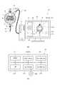
図1は、本実施形態に係る測定器のパラメータ設定方法を説明する図である。図1(a)には測定器10及びコンピュータ20の接続状態が表され、図1(b)にはコンピュータ20のブロック構成図が表される。 FIG. 1 is a diagram for explaining a parameter setting method for a measuring instrument according to this embodiment. 1A shows a connection state between the measuring
図1(a)に表したように、本実施形態に係る測定器10のパラメータ設定方法は、測定器10とコンピュータ20とを接続し、コンピュータ20のモニタ22上で操作を受け付けて測定器10の測定に関するパラメータを設定する方法である。測定器10とコンピュータ20とは、例えばケーブル30によって接続される。なお、測定器10とコンピュータ20との間に変換器(図示せず)を設けてもよい。変換器は、測定器10とコンピュータ20との間のデータ構造及び通信規格を整合させる機能を有する。また、測定器10とコンピュータ20とは無線通信によって接続されてもよい。 As shown in FIG. 1A, the parameter setting method of the measuring
測定器10は、測定子15の変位量に基づく測定値を表示部12に表示するインジケータである。測定器10は、略円形の正面を有する本体筐体11を備える。本体筐体11の下側には、本体筐体11に対して進退可能に設けられたスピンドル16が延出している。このスピンドル16の先端には測定子15が取り付けられる。測定子15を対象物の測定点に接触させることで測定点の高さに応じてスピンドル16が縮むことになる。このスピンドル16の縮む量、すなわち測定子15の変位量に応じた測定値や演算によって求められる値が表示部12に表示される。 The measuring
本体筐体11の正面には複数のボタン13が設けられる。複数のボタン13を適宜操作することで、測定モードや設定モードなどの切り替えや、測定に関する各種のパラメータの設定(新たな設定及び変更を含む。)を行うことができる。 A plurality of
本実施形態では、測定器10と接続したコンピュータ20によって、測定器10のパラメータを設定することができる。コンピュータ20は、本体21及びモニタ22を有する。図1(b)に表したように、コンピュータ20は、CPU(Central Processing Unit)211、インタフェース212、出力部213、入力部214、主記憶部215及び副記憶部216を備える。 In the present embodiment, the parameters of the measuring
CPU211は、各種プログラムの実行によって各部を制御する。インタフェース212は、外部機器との情報入出力を行う部分である。本実施形態では、測定器10から送られる情報をインタフェース212を介してコンピュータ20に取り込む。また、コンピュータ20からインタフェース212を介して情報を測定器10へ送る。インタフェース212は、コンピュータ20をLAN(Local Area Network)やWAN(Wide Area Network)に接続する部分でもある。 The
出力部213は、コンピュータ20で処理した結果を出力する部分である。出力部213には、例えば、図1(a)に示すモニタ22や、プリンタなどが用いられる。入力部214は、ユーザから情報を受け付ける部分である。入力部214には、キーボードやマウスなどが用いられる。また、入力部214は、記録媒体MMに記録された情報を読み取る機能を含む。 The
主記憶部215には、例えばRAM(Random Access Memory)が用いられる。主記憶部215の一部として、副記憶部216の一部が用いられてもよい。副記憶部216には、例えばHDD(Hard disk drive)やSSD(Solid State Drive)が用いられる。副記憶部216は、ネットワークを介して接続された外部記憶装置であってもよい。 For example, a RAM (Random Access Memory) is used as the
本実施形態に係る測定器10のパラメータ設定方法は、先ず、測定器10とコンピュータ20とを接続し、測定器10に記憶された機種情報、測定に関する設定項目及びこの設定項目に対応したパラメータを読み出し、コンピュータ20の記憶部(例えば、主記憶部215)に一時的に記憶する。 In the parameter setting method of the measuring
次に、コンピュータ20において、測定器10から読み出した機種情報に基づき、測定器10の外観画像Gをモニタ22に表示する。モニタ22に表示される外観画像Gのデータは、予めコンピュータ20の副記憶部216等に機種情報と対応付けして記憶されている。コンピュータ20は、機種情報と対応する外観画像Gのデータを副記憶部216から読み出してモニタ22に表示させる。なお、外観画像Gのデータは、機種情報をキーとして外部のサーバ(ネットワークサーバ等)からコンピュータ20へダウンロードするようにしてもよい。 Next, in the
モニタ22には、コンピュータ20と接続された測定器10の外観と同等な外観画像Gが表示される。説明の都合上、図1(a)のモニタ22に表示される外観画像Gの大きさは、測定器10の大きさよりも小さく表されているが、実際には測定器10よりも大きな外観画像Gがモニタ22に表示される。また、モニタ22上での外観画像Gの大きさは任意に拡大縮小することができる。 On the
コンピュータ20は、モニタ22に外観画像Gを表示するとともに、ユーザがモニタ22上で操作を選択するためのアイコンGCを表示する。アイコンGCは、モニタ22に表示された外観画像Gの所定位置と対応付けされている。アイコンGCは、そのアイコンGCと対応付けされた所定位置における実際の測定器10の位置と関連した操作を選択できるようになっている。 The
例えば、アイコンGC131が外観画像Gのボタン画像G131を示す場合、そのアイコンGC131は、ボタン画像G131と対応する実際の測定器10のボタン131によって操作可能な動作が割り当てられている。これにより、ユーザは、実際の測定器10を操作するのと同様な位置に対応付けされたアイコンGCを選択することで、実際の測定器10と同様な動作をモニタ22上で得られることになる。 For example, when the icon GC131 indicates the button image G131 of the appearance image G, an operation that can be operated by the
次に、コンピュータ20は、ユーザによるアイコンGCの選択を受け付けた場合、そのアイコンGCに対応付けされた所定位置と関連する測定器10での操作によって選択可能となる設定項目をモニタ22に表示させる。 Next, when the
そして、コンピュータ20は、モニタ22に表示された設定項目に対応したパラメータの設定を受け付けて、変更後のパラメータを測定器10へ送信する。これにより、ユーザは、コンピュータ20のモニタ22に表示されたアイコンGCを選択することで、実際の測定器10を操作した場合と同様な動作の流れによって設定項目を選択でき、モニタ22を参照しながら所望のパラメータを変更して測定器10に送ることができる。ユーザは、測定器10の表示部12よりも大きなモニタ22を参照しながら、アイコンGCの選択によって容易にパラメータの設定を行うことができることになる。 Then, the
本実施形態に係る測定器10のパラメータ設定方法は、例えば、コンピュータ20で実行されるプログラム(パラメータ設定プログラム)によって実現される。 The parameter setting method of the measuring
図2は、測定器のパラメータ設定プログラムの流れを例示するフローチャートである。
先ず、ステップS101に表した情報の読み込みでは、コンピュータ20と接続された測定器10から、測定器10に記憶された機種情報、設定項目及びパラメータをコンピュータ20に読み込む処理を行う。コンピュータ20は、インタフェース212を介して測定器10に指示を与え、測定器10から送られる情報をインタフェース212を介して読み込む。FIG. 2 is a flowchart illustrating the flow of the parameter setting program of the measuring instrument.
First, in the reading of the information shown in step S101, the model information, setting items, and parameters stored in the measuring
次に、ステップS102に表した情報の一時記憶では、測定器10から読み出した機種情報、設定項目及びパラメータをコンピュータ20の記憶部に一時的に記憶する処理を行う。コンピュータ20は、インタフェース212を介して読み込んだこれらの情報を、例えば主記憶部215に一時的に記憶する。 Next, in the temporary storage of the information shown in step S102, a process of temporarily storing the model information, setting items, and parameters read from the measuring
次に、ステップS103に表した外観画像の表示では、機種情報に対応した測定器10の外観画像Gをモニタ22に表示する処理を行う。また、ステップS104に表したアイコンの表示では、外観画像Gの表示とともに、モニタ22上で操作を選択するためのアイコンGCを、外観画像Gの所定位置に対応付けして表示する処理を行う。これにより、図1(a)に表したように、実際の測定器10に対応した外観画像G及びアイコンGCがモニタ22に表示される。 Next, in the appearance image display shown in step S103, a process of displaying the appearance image G of the measuring
次に、ステップS105に表したアイコン選択の受け付けでは、モニタ22に表示されたアイコンGCのユーザによる選択を受け付ける処理を行う。ユーザは、モニタ22の表示を参照しながら、所望のアイコンGCをマウス等の操作(ボタンクリック等)によって選択する。コンピュータ20は、このアイコンGCの選択を受け付ける。 Next, in the reception of the icon selection shown in step S105, processing for receiving selection by the user of the icon GC displayed on the
次に、ステップS106に表した設定項目の表示では、選択されたアイコンGCに対応付けされた所定位置と関連する測定器10での操作によって選択可能となる設定項目をモニタ22に表示する処理を行う。ユーザは、所望のアイコンGCをマウス等によって選択することで、実際の測定器10を操作したのと同様な設定項目をモニタ22上に表示させることができる。 Next, in the display of the setting item shown in step S106, a process for displaying on the
次に、ステップS107に表したパラメータの受け付けでは、モニタ22に表示された設定項目に対応したパラメータの変更を受け付ける処理を行う。ユーザは、モニタ22の表示を参照しながら、所望の設定項目に対応したパラメータの設定を行う。コンピュータ20は、ユーザの設定したパラメータを受け付ける。 Next, in the parameter reception shown in step S107, a process of receiving a parameter change corresponding to the setting item displayed on the
次に、ステップS108に表したパラメータの一時記憶では、ユーザの設定したパラメータを、例えば主記憶部215に一時的に記憶する処理を行う。なお、新たなパラメータを一時的に記憶した後、ユーザによってキャンセルの指示があった場合、元のパラメータに戻すようにしてもよい。 Next, in the temporary storage of the parameter shown in step S108, a process for temporarily storing the parameter set by the user, for example, in the
次に、ステップS109に表したパラメータの送信では、一時的に記憶した新たなパラメータを測定器10に送信する処理を行う。コンピュータ20は、インタフェース212を介して例えば主記憶部215に記憶された新たなパラメータを測定器10へ送信する。測定器10は、コンピュータ20から送信された新たなパラメータを受信して記憶する。 Next, in the parameter transmission shown in step S <b> 109, a process of transmitting the temporarily stored new parameter to the measuring
このようなプログラムによって、ユーザはモニタ22に表示された内容を参照しながら、所望の設定項目のパラメータを容易に設定することが可能になる。また、モニタ22には、実際の測定器10と同様な外観画像Gが表示され、実際の測定器10の操作と同様な操作をアイコンGCの選択によって行うことができる。したがって、優れたGUI(Graphical User Interface)によって、ユーザは違和感なくパラメータを設定していくことができる。 With such a program, the user can easily set parameters of desired setting items while referring to the contents displayed on the
なお、図2に示したフローチャートでは、ステップS108に示す設定したパラメータの一時記憶を行っているが、このステップS108を行わず、ステップS107に示すパラメータの受け付けを行った後、ステップS109の送信により、新たなパラメータを迅速に測定器10へ送信するようにしてもよい。 In the flowchart shown in FIG. 2, the set parameter shown in step S108 is temporarily stored. However, after step S108 is not performed and the parameter shown in step S107 is accepted, the transmission in step S109 is performed. The new parameter may be transmitted to the measuring
次に、具体的なモニタ22の画面遷移について説明する。
図3(a)〜(c)は、外観画像の表示例を示す図である。図3(a)には機種ID1の外観画像G1が表され、図3(b)には機種ID2の外観画像G2が表され、図3(c)には機種ID3の外観画像G3が表される。Next, a specific screen transition of the
FIGS. 3A to 3C are diagrams showing display examples of appearance images. 3A shows an appearance image G1 of model ID1, FIG. 3B shows an appearance image G2 of model ID2, and FIG. 3C shows an appearance image G3 of model ID3. The
コンピュータ20は、測定器10の機種情報を読み込み、この機種情報に基づいて測定器10の外観画像Gをモニタ22に表示する。例えば、図3(a)に表した機種ID1は、測定値に基づき演算を行うことができる演算型である。また、図3(b)に表した機種ID2は、測定値のピークを検出するピーク検出型である。また、図3(c)に表した機種ID3は、内径や外径を測定するシリンダゲージ型である。 The
また、コンピュータ20は、機種情報に基づき、測定器10の機種に応じて必要なアイコンGCをモニタ22に表示する。機種毎に設定項目が異なることから、モニタ22には機種に応じた外観画像G1〜G3及びその機種に必要なアイコンGCが表示されることになる。 Further, the
図3(a)〜(c)に示すアイコンGCの表示は、外観画像G1〜G3のそれぞれのボタンの位置に対応している。したがって、モニタ22上で所望のアイコンGCを選択すると、そのアイコンGCと対応する測定器10のボタン13が選択された場合と同様な動作がモニタ22上で行われることになる。 The display of the icon GC shown in FIGS. 3A to 3C corresponds to the position of each button of the appearance images G1 to G3. Therefore, when a desired icon GC is selected on the
また、モニタ22には、メニューMを表示させてもよい。メニューMにも機能を選択するアイコンMCが表示される。メニューMには、アプリケーションで共通の機能を実行させるためのアイコンMCが表示される。 Further, the menu M may be displayed on the
図4(a)〜(c)は、「MENU」アイコンが選択された場合の表示例を示す図である。図4(a)には機種ID1の表示例が表され、図4(b)には機種ID2の表示例が表され、図4(c)には機種ID3の表示例が表される。 FIGS. 4A to 4C are diagrams illustrating display examples when the “MENU” icon is selected. 4A shows a display example of model ID1, FIG. 4B shows a display example of model ID2, and FIG. 4C shows a display example of model ID3.
「MENU」アイコンを選択することで、モニタ22には外観画像G1〜G3のそれぞれに対応した設定項目のアイコンGCが表示される。モニタ22に表示されるアイコンGCは、外観画像G1〜G3のそれぞれの機種において選択可能な設定項目だけである。 By selecting the “MENU” icon, the setting item icon GC corresponding to each of the appearance images G1 to G3 is displayed on the
図5(a)〜(c)は、「OTHER」アイコンが選択された場合の表示例を示す図である。図5(a)には機種ID1の表示例が表され、図5(b)には機種ID2の表示例が表され、図5(c)には機種ID3の表示例が表される。 FIGS. 5A to 5C are diagrams showing display examples when the “OTHER” icon is selected. FIG. 5A shows a display example of model ID1, FIG. 5B shows a display example of model ID2, and FIG. 5C shows a display example of model ID3.
「OTHER」アイコンを選択することで、モニタ22には外観画像G1〜G3のそれぞれに対応したその他の設定項目のアイコンGCが表示される。モニタ22には、外観画像G1〜G3のそれぞれの機種において選択可能なその他の設定項目のアイコンGCのみが表示される。「OTHER」アイコンの選択によって、主要な設定項目以外の設定項目のアイコンGCが表示される。 By selecting the “OTHER” icon,
次に、具体的な画面遷移に沿ったパラメータの設定について説明する。
図6〜図12は、具体的な画面遷移の例と、パラメータ設定の例を示す図である。Next, setting of parameters along specific screen transitions will be described.
6 to 12 are diagrams illustrating specific screen transition examples and parameter setting examples.
先ず、コンピュータ20でパラメータ設定プログラムを起動すると、図6(a)に表したように、基本画面が立ち上がる。基本画面では、メニューMに「測定器と接続」のアイコンMCが表示される。 First, when the parameter setting program is activated on the
次に、メニューMの「測定器と接続」のアイコンMCを選択すると、図6(b)に表したように、測定器10との接続を促すウィンドウがポップアップ表示される。測定器10とコンピュータ20とを例えばケーブル30で接続した状態で、「OK」ボタンを選択すると、コンピュータ20に測定器10から送られる機種情報、設定項目及びパラメータが読み込まれる。 Next, when the “Connect with measuring instrument” icon MC in the menu M is selected, a window for prompting connection with the measuring
そして、図6(c)に表したように、コンピュータ20に読み込まれた機種情報に基づき外観画像G及びその機種に応じたアイコンGCがモニタ22に表示される。また、外観画像G及びアイコンGCの表示とともに、メニューMの各種アイコンMCが表示される。 Then, as shown in FIG. 6C, the appearance image G and the icon GC corresponding to the model are displayed on the
機種ID1では、外観画像G1のボタンの位置に対応して、「MENU」、「PEAK」、「PRESET」、「in/mm」、「ZERO,ABS」のアイコンGCが表示される。また、メニューMとして、「測定器と接続」のアイコンMCのほか、「全項目確認」、「設定情報保存」、「設定情報呼出」、「通信終了」のアイコンMCが表示される。 In model ID1, icons GC of “MENU”, “PEAK”, “PRESET”, “in / mm”, and “ZERO, ABS” are displayed corresponding to the position of the button of the appearance image G1. Further, as the menu M, icons “Connect to measuring instrument”, MC “Confirm all items”, “Save setting information”, “Call setting information”, and “End communication” are displayed.
なお、以下の説明では、演算型である機種ID1における画面遷移及びパラメータ設定を例とするが、適宜、機種ID2及び機種ID3における画面遷移及びパラメータ設定の例についても示す。機種ID2の場合、測定器10をコンピュータ20に接続すると、図3(b)に例示する外観画像G2が表示され、機種ID3の場合、図3(c)に例示する外観画像G3が表示されることになる。 In the following description, the screen transition and parameter setting for the model ID 1 that is the arithmetic type are taken as an example, but examples of screen transition and parameter setting for the model ID 2 and the model ID 3 are also shown as appropriate. In the case of model ID2, when the measuring
次に、代表的なアイコンGC及びMCを選択した場合の画面遷移について説明する。
図6(c)に示す「MENU」アイコンGCを選択すると、図7(a)に表したような画面が表示される。機種ID1の場合、「TOL」、「RES」、「CALC」、「SCALE」、「LOCK」、「OTHER」、「戻る」のアイコンGCが表示される。Next, screen transitions when representative icons GC and MC are selected will be described.
When the “MENU” icon GC shown in FIG. 6C is selected, a screen as shown in FIG. 7A is displayed. In the case of the model ID 1, icons “TOL”, “RES”, “CALC”, “SCALE”, “LOCK”, “OTHER”, and “return” are displayed.
どの画面であっても、「戻る」のアイコンGCを選択した場合には、一つ前の画面表示へ戻ることができる。「OTHER」のアイコンGCを選択すると、図7(b)に表したような画面が表示される。機種ID1では、「無単位表示設定(UNIT)」、「オリジンオフセット設定(OFFSET)」、「アナログバー表示設定(RULER)」、「高速サンプリングモード設定(FAST)」、「パラメータロック」のアイコンGCが表示される。 In any screen, when the “return” icon GC is selected, it is possible to return to the previous screen display. When the “OTHER” icon GC is selected, a screen as shown in FIG. 7B is displayed. For model ID1, icons GC of “no unit display setting (UNIT)”, “origin offset setting (OFFSET)”, “analog bar display setting (RULER)”, “high-speed sampling mode setting (FAST)”, “parameter lock” Is displayed.
ここで、メニューMから「通信終了」のアイコンMCを選択すると、図7(c)に表したような通信終了を確認するウィンドウがポップアップ表示される。このウィンドウにおいて「OK」のアイコンGCを選択すると、通信終了となる。一方、「CANCEL」のアイコンGCを選択すると、通信終了せず、ポップアップしたウィンドウが閉じる。 Here, when the “communication end” icon MC is selected from the menu M, a window for confirming the end of communication as shown in FIG. When the “OK” icon GC is selected in this window, the communication is terminated. On the other hand, if the “CANCEL” icon GC is selected, the communication does not end and the pop-up window closes.
図6(c)に表した「PEAK」のアイコンGCを選択すると、図8(a)に表したようなピーク設定のためのウィンドウがポップアップ表示される。ピーク設定のためのウィンドウには、測定モードを選択するためのラジオボタンが表示される。所望の測定モードを示すラジオボタンを選択した後、「確定」のアイコンGCを選択すると、設定したパラメータ(測定モード)が測定器10へ送信される。コンピュータ20から測定器10へパラメータを送信することで、測定器10では新たなパラメータの設定が行われる。 When the “PEAK” icon GC shown in FIG. 6C is selected, a window for setting a peak as shown in FIG. 8A pops up. A radio button for selecting a measurement mode is displayed in the peak setting window. After selecting the radio button indicating the desired measurement mode, when the “determined” icon GC is selected, the set parameter (measurement mode) is transmitted to the measuring
また、「一時保存」のアイコンGCを選択すると、設定したパラメータ(測定モード)をコンピュータ20の記憶部(例えば、主記憶部215)に一時的に記憶しつつ、ウィンドウが閉じられる。ここで、一時的な記憶だけでは、パラメータは測定器10へ送信されない。「CANCEL」のアイコンGCを選択した場合には、何もせずにウィンドウを閉じる。この場合、設定項目は元のパラメータのまま維持される。 When the “temporary save” icon GC is selected, the window is closed while the set parameter (measurement mode) is temporarily stored in the storage unit (for example, the main storage unit 215) of the
図6(c)に表した「PRESET」のアイコンGCを選択すると、図8(b)に表したようなプリセット設定のためのウィンドウがポップアップ表示される。プリセット設定のためのウィンドウには、プリセット番号(PRESET No.)を選択するためのラジオボタンと、プリセット値(PRESET値)を入力するためのテキストボックスとが表示される。ここで、単位の表示は、測定器10からコンピュータ20にパラメータを読み込んだ際の設定に合わせられている。読み込んだ後に単位のパラメータが変更された場合には、変更後の単位で表示される。 When the “PRESET” icon GC shown in FIG. 6C is selected, a window for preset setting shown in FIG. 8B pops up. In the preset setting window, a radio button for selecting a preset number (PRESET No.) and a text box for inputting a preset value (PRESET value) are displayed. Here, the unit display is matched with the setting when the parameter is read from the measuring
プリセット設定のためのウィンドウでプリセットのパラメータを設定した後は、「確定」、「一時保存」、「CANCEL」のいずれかを選択する。「確定」、「一時保存」、「CANCEL」のアイコンGCを選択した場合の処理は、先と同様である。 After setting the preset parameters in the preset setting window, one of “Confirm”, “Temporary save”, and “CANCEL” is selected. The processing when the “GC”, “Temporary Save”, and “CANCEL” icons GC are selected is the same as described above.
ここで、図3(b)に例示する機種ID2の外観画像G2において、「+/−」のアイコンGCを選択すると、図8(c)に表したような計数方向を設定するためのウィンドウがポップアップ表示される。ウィンドウには、計数値をプラスカウントする測定子の方向を選択するためのラジオボタンが表示される。プラスカウントしたい方向のラジオボタンを選択した後は、「確定」、「一時保存」、「CANCEL」のいずれかを選択する。「確定」、「一時保存」、「CANCEL」のアイコンGCを選択した場合の処理は、先と同様である。 Here, when the “+/−” icon GC is selected in the appearance image G2 of the model ID2 illustrated in FIG. 3B, a window for setting the counting direction as shown in FIG. 8C is displayed. Pop-up is displayed. In the window, radio buttons for selecting the direction of the measuring element for counting up the count value are displayed. After selecting the radio button in the direction to be incremented, select one of “Confirm”, “Temporary save”, and “CANCEL”. The processing when the “GC”, “Temporary Save”, and “CANCEL” icons GC are selected is the same as described above.
図7(a)に表した「LOCK」のアイコンGCを選択すると、図9(a)に表したようなキーロックを設定するためのウィンドウがポップアップ表示される。このウィンドウには、キーロックの有効/無効を選択するためのラジオボタンが表示される。また、機種に応じた外観画像Gと、外観画像Gのボタンの位置と対応したボタン表示BCとが表示される。各ボタン表示BCの横にはチェックボックスが表示される。チェックボックスによって選択されたボタン表示BCの示すボタンは、キーロックの有効/無効の設定に従ってキーロックの設定が行われることになる。 When the “LOCK” icon GC shown in FIG. 7A is selected, a window for setting the key lock as shown in FIG. 9A pops up. In this window, a radio button for selecting enable / disable of the key lock is displayed. An appearance image G corresponding to the model and a button display BC corresponding to the position of the button of the appearance image G are displayed. A check box is displayed beside each button display BC. The button indicated by the button display BC selected by the check box is set for key lock according to the key lock valid / invalid setting.
キーロックを設定のためのウィンドウでキーロックのパラメータを設定した後は、「確定」、「一時保存」、「CANCEL」のいずれかを選択する。「確定」、「一時保存」、「CANCEL」のアイコンGCを選択した場合の処理は、先と同様である。測定器10において、キーロックを有効に設定されたボタンは押下されても反応しないことになる。 After setting the key lock parameter in the key lock setting window, one of “Confirm”, “Temporary save”, and “CANCEL” is selected. The processing when the “GC”, “Temporary Save”, and “CANCEL” icons GC are selected is the same as described above. In the measuring
なお、キーロックの設定を行うボタンに対応したボタン表示BCは、機種によって相違する。また、ここでキーロックの設定が行われたボタンについては、測定器10側の所定の操作によってキーロックの解除が可能である。 The button display BC corresponding to the button for setting the key lock differs depending on the model. In addition, for the buttons for which the key lock is set here, the key lock can be released by a predetermined operation on the measuring
図7(b)に表した「パラメータロック」のアイコンGCを選択すると、図9(b)に表したようなパラメータロックを設定するためのウィンドウがポップアップ表示される。このウィンドウには、パラメータロックの有効/無効を選択するためのラジオボタンが表示される。また、機種に応じたパラメータロックの対象となるパラメータのチェックボックスが表示される。 When the “parameter lock” icon GC shown in FIG. 7B is selected, a window for setting the parameter lock as shown in FIG. 9B pops up. In this window, a radio button for selecting validity / invalidity of the parameter lock is displayed. In addition, a checkbox for a parameter to be locked according to the model is displayed.
このパラメータロックは、先に説明したキーロックとは異なり、コンピュータ20でのみパラメータの変更可否を決定するための設定である。コンピュータ20でパラメータロックを指定されたパラメータについては、測定器10側でパラメータロックを解除することはできない。パラメータロックを設定することで、測定器10側で誤ってパラメータが変更されることを防止したり、測定器10側で変更されたくないパラメータを保護したりすることができる。 Unlike the key lock described above, this parameter lock is a setting for determining whether the parameter can be changed only by the
図7(a)に表した「CALC」のアイコンGCを選択すると、図10に表したような演算機能を設定するためのウィンドウがポップアップ表示される。このウィンドウには、演算機能の有効/無効を選択するためのラジオボタンが表示される。また、演算係数A、B及びCのテキストボックスが表示される。演算係数A、B及びCのそれぞれの値は、「係数算出」のアイコンGCを選択し、所定の設定を行うことで自動算出させてもよい。 When the “CALC” icon GC shown in FIG. 7A is selected, a window for setting an arithmetic function as shown in FIG. 10 is popped up. In this window, radio buttons for selecting valid / invalid of the calculation function are displayed. In addition, text boxes for calculation coefficients A, B, and C are displayed. The values of the calculation coefficients A, B, and C may be automatically calculated by selecting a “coefficient calculation” icon GC and performing a predetermined setting.
「係数算出」のアイコンGCを選択すると、図11(a)に表したような治具を選択するためのウィンドウがポップアップ表示される。なお、治具は、本発明におけるアタッチメントの一例である。演算型の測定器10では、測定器10に装着する治具によって演算係数A、B及びCを設定し、治具を用いた測定内容によって所望の演算結果を得られるようにしている。 When the “coefficient calculation” icon GC is selected, a window for selecting a jig as shown in FIG. 11A pops up. The jig is an example of an attachment in the present invention. In the calculation-
図11(a)に表したウィンドウには、測定内容に応じて測定器10に取り付けられる治具のイメージIMG1〜IMG6と、選択のためのラジオボタンが表示される。 In the window shown in FIG. 11A, jig images IMG1 to IMG6 attached to the measuring
治具のイメージIMG1で表される測定内容は、穴径Dの測定である。この測定では、円錐型の測定子を有する治具が測定器10に取り付けられる。ここで、測定子の円錐型が拡がる角度をθ、円錐型の測定子を穴の口元に当接させた際の基準位置から測定子の先端までの距離をxとした場合、穴径Dは以下の計算式で求められる。
D=A×x
演算係数Aは、A=−2tan(θ/2)The measurement content represented by the jig image IMG1 is the measurement of the hole diameter D. In this measurement, a jig having a conical measuring element is attached to the measuring
D = A × x
The calculation coefficient A is A = -2 tan (θ / 2)
治具のイメージIMG2で表される測定内容は、皿モミの口元の穴径Dの測定である。この測定では、球型の測定子を有する治具が測定器10に取り付けられる。ここで、測定子の球型の半径をr、皿モミの角度をθ、球型の測定子を皿モミ内に当接させた際の基準位置から測定子の先端までの距離をxとした場合、穴径Dは以下の計算式で求められる。
D=Ax+B
演算係数Aは、A=−2tan(θ/2)
演算係数Bは、B=2r(1/(cos(θ/2))−tan(θ/2))The measurement content represented by the jig image IMG2 is the measurement of the hole diameter D at the mouth of the dish fir. In this measurement, a jig having a spherical probe is attached to the measuring
D = Ax + B
The calculation coefficient A is A = -2 tan (θ / 2)
The calculation coefficient B is B = 2r (1 / (cos (θ / 2)) − tan (θ / 2)).
治具のイメージIMG3で表される測定内容は、皿モミの深さHの測定である。この測定では、球型の測定子を有する治具が測定器10に取り付けられる。ここで、測定子の球型の半径をr、皿モミの角度をθ、皿モミの奥穴の穴径をd、球型の測定子を皿モミ内に当接させた際の基準位置から測定子の先端までの距離をxとした場合、深さHは以下の計算式で求められる。 The measurement content represented by the jig image IMG3 is the measurement of the depth H of the dish fir. In this measurement, a jig having a spherical probe is attached to the measuring
H=Ax+B
演算係数Aは、A=−1
演算係数Bは、B=r(1/(cos(θ/2))−1)−d/2tan(θ/2))H = Ax + B
The calculation coefficient A is A = -1
The calculation coefficient B is B = r (1 / (cos (θ / 2)) − 1) −d / 2 tan (θ / 2)).
治具のイメージIMG4及びIMG5で表される測定内容は、丸物の外径(半径)である。測定の対象物によって好適な治具の形状が相違する。ここで、治具のイメージIMG4でのV字のアームの角度をθ、基準位置から測定子の先端までの距離をx、丸物の半径をRとした場合、半径Rは以下の計算式で求められる。 The measurement content represented by the jig images IMG4 and IMG5 is the outer diameter (radius) of the round object. The shape of a suitable jig differs depending on the object to be measured. Here, when the angle of the V-shaped arm in the jig image IMG4 is θ, the distance from the reference position to the tip of the measuring element is x, and the radius of the round object is R, the radius R is calculated by the following formula. Desired.
R=Ax
演算係数Aは、A=−(sin(θ/2))/(1−sin(θ/2))R = Ax
The calculation coefficient A is A = − (sin (θ / 2)) / (1−sin (θ / 2)).
また、治具のイメージIMG5での左右2つの接触球体の距離を2L、接触球体の半径をr、測定子が丸物の表面と当接した際の測定子と接触球体との距離をxとした場合、丸物の半径Rは以下の計算式で求められる。 Also, the distance between the left and right contact spheres in the jig image IMG5 is 2L, the radius of the contact sphere is r, and the distance between the probe and the contact sphere when the probe contacts the surface of the round object is x. In this case, the radius R of the round object is obtained by the following calculation formula.
R=Ax+B+Cx−1
演算係数Aは、1/2
演算係数Bは、−r
演算係数Cは、L2/2R = Ax + B + Cx−1
Calculation coefficient A is 1/2
The calculation coefficient B is -r
Calculation coefficientC, L 2/2
治具のイメージIMG6で表される測定内容は、丸物の内径(半径)である。この測定で用いられる治具は、イメージIMG5の測定で用いられた治具と同じである。ここで、治具のイメージIMG6での左右2つの接触球体の距離を2L、接触球体の半径をr、測定子が丸物の表面と当接した際の測定子と接触球体との距離をxとした場合、丸物の半径Rは以下の計算式で求められる。 The measurement content represented by the jig image IMG6 is the inner diameter (radius) of the round object. The jig used in this measurement is the same as the jig used in the measurement of the image IMG5. Here, the distance between the left and right contact spheres in the jig image IMG6 is 2L, the radius of the contact sphere is r, and the distance between the probe and the contact sphere when the probe contacts the surface of the round object is x. In this case, the radius R of the round object is obtained by the following calculation formula.
R=Ax+B+Cx−1
演算係数Aは、−1/2
演算係数Bは、r
演算係数Cは、−L2/2R = Ax + B + Cx−1
The calculation coefficient A is -1/2
The calculation coefficient B is r
Calculation coefficient C,-L 2/2
このように、選択する治具及び測定内容によって演算係数A、B及びCが異なるため、適用する測定内容に応じた演算係数A、B及びCを設定しておく必要がある。図11(a)に表したウィンドウにおいて、例えば、治具のイメージIMG1のラジオボタンを選択し、「OK」のアイコンGCを選択すると、図11(b)に表したようなウィンドウがポップアップ表示される。 As described above, since the calculation coefficients A, B, and C differ depending on the jig to be selected and the measurement content, it is necessary to set the calculation coefficients A, B, and C according to the measurement content to be applied. In the window shown in FIG. 11A, for example, when the radio button of the jig image IMG1 is selected and the “OK” icon GC is selected, the window shown in FIG. 11B pops up. The
このウィンドウには、ラジオボタンで選択されたイメージIMG1が表示される。これにより、そのイメージIMG1の治具による測定内容が選択されたことを容易に認識できる。また、イメージIMG1の治具によって測定する内容に応じて、演算係数A、B及びCの計算に必要なパラメータ(ここでは、θの値)を入力するためのテキストボックスが表示される。選択した測定内容の治具によって、このテキストボックスの表示項目は変わる。 In this window, the image IMG1 selected by the radio button is displayed. Thereby, it can be easily recognized that the measurement content by the jig of the image IMG1 is selected. In addition, a text box for inputting parameters (here, the value of θ) necessary for calculation of the arithmetic coefficients A, B, and C is displayed according to the content measured by the jig of the image IMG1. The display items in this text box vary depending on the selected measurement jig.
このテキストボックスにθの値を入力して、「計算」のアイコンGCを選択すると、ウィンドウ内の演算係数A、B及びCのテキストボックスに自動的に値が入力される。イメージIMG1の治具では、円錐型の角度θの値を入力すれば、測定内容に対応した演算係数Aを示す式(ここでは、A=−2tan(θ/2))によって自動的に演算係数Aが計算され、テキストボックスに自動入力される。なお、計算式に用いられない係数(ここでは、演算係数B及びC)については、”0”が自動的に入力される。 When the value of θ is input to this text box and the “calculation” icon GC is selected, the value is automatically input to the text boxes for the calculation coefficients A, B, and C in the window. In the jig of the image IMG1, when the value of the cone-shaped angle θ is input, the calculation coefficient is automatically calculated by an expression (here, A = −2 tan (θ / 2)) corresponding to the measurement content. A is calculated and automatically entered in the text box. Note that “0” is automatically input for coefficients that are not used in the calculation formula (in this case, calculation coefficients B and C).
演算係数A、B及びCの計算を行った後、図11(b)に表したウィンドウにおいて「OK」のアイコンGCを選択すると、図10に表したウィンドウ表示に戻る。計算後には、このウィンドウの演算係数A、B及びCに先の計算結果が入力されることになる。 After the calculation coefficients A, B, and C are calculated, when the “OK” icon GC is selected in the window shown in FIG. 11B, the window display shown in FIG. 10 is restored. After the calculation, the previous calculation result is input to the operation coefficients A, B, and C of this window.
図6(c)に表したメニューMの「設定情報保存」のアイコンMCを選択すると、コンピュータ20の記憶部(例えば、主記憶部215)に一時保存されたパラメータを、例えばテキストデータ(パラメータセット)としてコンピュータ20の記憶部(例えば、副記憶部216)に保存することができる。 When the “Save setting information” icon MC in the menu M shown in FIG. 6C is selected, the parameters temporarily stored in the storage unit (for example, the main storage unit 215) of the
また、「設定情報保存」のアイコンMCを選択してコンピュータ20に保存したパラメータセットを呼び出すには、図6(c)に表したメニューMの「設定情報呼出」のアイコンMCを選択すればよい。読み出したパラメータセットの各種パラメータを参照、変更及び送信するには、先に説明したアイコンMCの選択によって行えばよい。また、後述する一覧表示を利用して行ってもよい。 Further, in order to call the parameter set stored in the
このような「設定情報保存」及び「設定情報呼出」の機能を用いると、複数台ある同じ機種の測定器10について、同じパラメータを容易に設定することができる。例えば、ある1台の測定器10についてパラメータの設定を行った状態で、パラメータセットをコンピュータ20に保存しておく。その後、別の測定器10をコンピュータ20に接続し、先に保存しておいたパラメータセットを呼び出して、そのパラメータセットによる各種パラメータをコンピュータ20に接続された測定器10に送信し、記憶させる。さらに別の測定器10にも同じパラメータを設定する場合には、その測定器10をコンピュータ20に接続して、呼び出し済みのパラメータセットによる各種パラメータを送信する。これを繰り返すことで、複数台の測定器10に同じパラメータを設定する作業工数が大幅に低減される。 Using such “setting information storage” and “setting information calling” functions, the same parameters can be easily set for a plurality of measuring
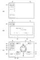
図6(c)に表したメニューMの「全項目確認」のアイコンMCを選択すると、図12に表したような設定項目の一覧を表示するウィンドウがポップアップ表示される。このウィンドウには、機種ごとの設定項目と、その設定項目に対応したパラメータの内容が、例えば表形式で表示される。 When the “confirm all items” icon MC in the menu M shown in FIG. 6C is selected, a window for displaying a list of setting items as shown in FIG. 12 is popped up. In this window, setting items for each model and contents of parameters corresponding to the setting items are displayed in a table format, for example.
この一覧表示では、測定器10からコンピュータ20に読み出した設定項目及びそれに対応したパラメータが表示される。また、コンピュータ20によってユーザがパラメータを変更し、一時保存した場合には、一時保存された変更後のパラメータが表示される。 In this list display, setting items read from the measuring
パラメータが変更された設定項目については、変更されていない設定項目とは異なる表示にしてもよい。例えば、変更された設定項目に特定の色を付けて表示させる。これにより、どの設定項目が変更されたか、変更されていないかを容易に見つけ出すことができる。 The setting item whose parameter has been changed may be displayed differently from the setting item which has not been changed. For example, the changed setting item is displayed with a specific color. As a result, it is possible to easily find out which setting item has been changed or not changed.
また、一覧表示において、各設定項目をアイコンGCで表示してもよい。ユーザは、一覧表示から所望の設定項目のアイコンGCを選択すると、その設定項目のパラメータを変更するためのウィンドウをポップアップ表示させることができる。そして、このポップアップ表示からパラメータを設定し、「OK」のアイコンGCを選択することで、一覧表示に戻る。この一覧表示では、変更したパラメータが反映されていることになる。 In the list display, each setting item may be displayed with an icon GC. When the user selects an icon GC of a desired setting item from the list display, a window for changing the parameter of the setting item can be popped up. Then, parameters are set from this pop-up display, and the “OK” icon GC is selected to return to the list display. In this list display, the changed parameters are reflected.
また、一覧表示において、「一括送信」のアイコンGCを選択すると、一覧表示されている全ての設定項目に対応したパラメータを一括して測定器10へ送信することができる。例えば、変更後のパラメータを一時保存した場合には、一覧表示で確認した後、「一括送信」のアイコンGCを選択することで、個別に設定し、一時保存しておいたパラメータを一回の処理でまとめて測定器10へ送信することができる。コンピュータ20から測定器10へパラメータを送信することで、測定器10では新たなパラメータへの設定が行われる。なお、測定器10において、コンピュータ20から送信されたパラメータを正常に受信した場合に確認音などの報知を行ってもよい。 Further, when the “collective transmission” icon GC is selected in the list display, parameters corresponding to all the setting items displayed in the list can be transmitted to the measuring
また、一覧表示において、変更があった設定項目の例えばパラメータの欄に、「キャンセル」のアイコンGCを設けてもよい。この「キャンセル」のアイコンGCを選択すると、変更後のパラメータを変更前のパラメータに戻す処理を設定項目ごとに行うことができる。 Further, in the list display, a “cancel” icon GC may be provided, for example, in the parameter column of the setting item that has been changed. When this “cancel” icon GC is selected, a process for returning the parameter after the change to the parameter before the change can be performed for each setting item.
また、一覧表示において、「一括キャンセル」のアイコンGCを設けてもよい。この「一括キャンセル」のアイコンGCを選択すると、変更され一時保存された設定項目の全てについて、変更後のパラメータを変更前のパラメータに一括して戻す処理を行うことができる。 In the list display, a “collective cancel” icon GC may be provided. When the “collective cancel” icon GC is selected, it is possible to perform a process of collectively returning the parameter after the change to the parameter before the change for all the changed and temporarily saved setting items.
このように、ユーザはコンピュータ20のモニタ22に表示される外観画像G等を参照し、モニタ22上のアイコンGC及びMCを操作することで、複雑なボタン操作を必要とせず簡単に測定器10のパラメータを設定することが可能になる。 In this way, the user refers to the appearance image G and the like displayed on the
なお、上記説明した本実施形態に係る測定器10のパラメータ設定プログラムは、コンピュータ読取可能な記録媒体MMに記録されていてもよい。すなわち、図2に示すステップS101〜ステップS109の一部または全部を、コンピュータ20に読み取り可能な形式で記録媒体MMに記録してもよい。また、本実施形態に係る測定器10のパラメータ設定プログラムは、ネットワークを介して配信されてもよい。 Note that the parameter setting program of the measuring
以上説明したように、本実施形態によれば、測定器10のパラメータ設定を容易に行うことができる測定器10のパラメータ設定方法及び測定器10のパラメータ設定プログラムを提供することが可能となる。 As described above, according to the present embodiment, it is possible to provide a parameter setting method of the measuring
なお、上記に本実施形態及びその具体例を説明したが、本発明はこれらの例に限定されるものではない。例えば、測定器10の種別、設定項目、画面表示については、これらに限定されるものではない。また、前述の実施形態またはその具体例に対して、当業者が適宜、構成要素の追加、削除、設計変更を行ったものも、本発明の要旨を備えている限り、本発明の範囲に含有される。 In addition, although this embodiment and its specific example were demonstrated above, this invention is not limited to these examples. For example, the type, setting item, and screen display of the measuring
以上のように、本発明は、インジケータのほか、ハイトゲージ、デジタルノギス、デジタルマイクロメータ、リニアスケールなどに好適に利用できる。 As described above, the present invention can be suitably used for height gauges, digital calipers, digital micrometers, linear scales and the like in addition to indicators.
10…測定器
11…本体筐体
12…表示部
15…測定子
16…スピンドル
20…コンピュータ
21…本体
22…モニタ
30…ケーブル
211…CPU
212…インタフェース
213…出力部
214…入力部
215…主記憶部
216…副記憶部
G…外観画像
GC…アイコンDESCRIPTION OF
212 ... Interface 213 ...
Claims (16)
Translated fromJapanese前記測定器に記憶された機種情報、測定に関する設定項目及び前記設定項目に対応したパラメータを読み出して、前記コンピュータの記憶部に一時的に記憶する工程と、
前記機種情報に対応した前記測定器の外観画像を前記画面に表示するとともに、前記画面上で操作を選択するためのアイコンを前記画面上の前記外観画像の所定位置に対応付けして表示する工程と、
前記アイコンの選択を受け付けた場合、前記アイコンに対応付けされた前記所定位置と関連する前記測定器での操作によって選択可能となる前記設定項目を前記画面に表示する工程と、
前記設定項目に対応した前記パラメータの変更を前記コンピュータで受け付ける工程と、
変更後の前記パラメータを前記コンピュータから前記測定器へ送信する工程と、
を備え、
前記パラメータの変更を受け付ける工程では、変更後の前記パラメータを前記記憶部に一時的に記憶した後、取消指示を受け付けた場合、前記記憶部に記憶された変更後の前記パラメータを元のパラメータに戻すことを特徴とする測定器のパラメータ設定方法。A method of connecting a measuring instrument and a computer, accepting an operation on a screen of the computer, and setting parameters relating to the measurement of the measuring instrument,
Reading the model information stored in the measuring instrument, setting items related to measurement and parameters corresponding to the setting items, and temporarily storing them in the storage unit of the computer;
Displaying an appearance image of the measuring instrument corresponding to the model information on the screen, and displaying an icon for selecting an operation on the screen in association with a predetermined position of the appearance image on the screen; When,
When the selection of the icon is accepted, the step of displaying on the screen the setting item that can be selected by an operation on the measuring instrument associated with the predetermined position associated with the icon;
Receiving the change of the parameter corresponding to the setting item in the computer;
Transmitting the changed parameter from the computer to the measuring device;
Equipped witha,
In the step of accepting the change of the parameter, after temporarily storing the parameter after the change in the storage unit, when the cancel instruction is received, the parameter after the change stored in the storage unit is changed to the original parameter. A parameter setting method of the measuring instrument characterized byreturning .
変更後の前記パラメータを前記測定器へ送信する工程では、前記記憶部に記憶された変更後の前記パラメータを読み出して前記測定器へ送信することを特徴とする請求項1記載の測定器のパラメータ設定方法。In the step of accepting the change of the parameter, the parameter after the change is temporarily stored in the storage unit,
2. The parameter of the measuring instrument according to claim 1, wherein in the step of transmitting the changed parameter to the measuring instrument, the changed parameter stored in the storage unit is read and transmitted to the measuring instrument. Setting method.
前記パラメータの変更を受け付ける工程では、前記アタッチメントの種類に対応した寸法を受け付けて、前記アタッチメントを用いて測定する際に用いる演算の係数を前記寸法から算出することを特徴とする請求項1〜3のいずれか1つに記載の測定器のパラメータ設定方法。In the step of displaying the setting item on the screen, an item for selecting the type of attachment attached to the measuring instrument is displayed,
In the step of accepting a change of said parameter, accept the dimensions corresponding to the type of the attachment, according to claim 1 to3, characterized in that for calculating the coefficients of the arithmetic used in measuring with said attachment from said dimension The parameter setting method of the measuring instrument as described in any one of these.
前記禁止可否選択項目において前記パラメータの変更を禁止する設定を受け付けた場合、前記禁止可否選択項目と対応する前記設定項目の前記パラメータの変更を前記測定器で禁止する旨の情報を前記コンピュータから前記測定器へ送信する工程と、
をさらに備えたことを特徴とする請求項1〜5のいずれか1つに記載の測定器のパラメータ設定方法。A step of displaying on the screen a prohibition propriety selection item that allows only the computer to select whether or not to prohibit the change of the parameter corresponding to the setting item;
When the setting for prohibiting the change of the parameter is accepted in the prohibition propriety selection item, the information indicating that the change of the parameter of the setting item corresponding to the prohibition propriety selection item is prohibited by the measuring instrument from the computer Sending to the measuring instrument;
The parameter setting method for a measuring instrument according to any one of claims 1 to5 , further comprising:
前記コンピュータを、
前記測定器に記憶された機種情報、測定に関する設定項目及び前記設定項目に対応したパラメータを読み出して、前記コンピュータの記憶部に一時的に記憶する手段、
前記機種情報に対応した前記測定器の外観画像を前記画面に表示するとともに、前記画面上で操作を選択するためのアイコンを前記画面上の前記外観画像の所定位置に対応付けして表示する手段、
前記アイコンの選択を受け付けた場合、前記アイコンに対応付けされた前記所定位置と関連する前記測定器での操作によって選択可能となる前記設定項目を前記画面に表示する手段、
前記設定項目に対応した前記パラメータの変更を受け付ける手段、
変更後の前記パラメータを前記測定器へ送信する手段、
として機能させ、
前記パラメータの変更を受け付ける手段では、変更後の前記パラメータを前記記憶部に一時的に記憶した後、取消指示を受け付けた場合、前記記憶部に記憶された変更後の前記パラメータを元のパラメータに戻すことを特徴とする測定器のパラメータ設定プログラム。A program that connects a measuring instrument and a computer, accepts an operation on the screen of the computer, and sets parameters relating to the measurement of the measuring instrument,
The computer,
Model information stored in the measuring device, setting items related to measurement, and parameters corresponding to the setting items are read and temporarily stored in the storage unit of the computer,
Means for displaying an appearance image of the measuring instrument corresponding to the model information on the screen and displaying an icon for selecting an operation on the screen in association with a predetermined position of the appearance image on the screen ,
Means for displaying, on the screen, the setting item that can be selected by an operation on the measuring instrument associated with the predetermined position associated with the icon when the selection of the icon is received;
Means for accepting a change in the parameter corresponding to the setting item;
Means for transmitting the changed parameter to the measuring device;
To functionas,
The means for accepting the change of the parameter temporarily stores the parameter after the change in the storage unit, and then when the cancel instruction is accepted, the changed parameter stored in the storage unit is used as the original parameter. A parameter setting program of the measuring instrument characterized byreturning .
変更後の前記パラメータを前記測定器へ送信する手段では、前記記憶部に記憶された変更後の前記パラメータを読み出して前記測定器へ送信することを特徴とする請求項9記載の測定器のパラメータ設定プログラム。The means for accepting the change of the parameter temporarily stores the changed parameter in the storage unit,
10. The parameter of the measuring instrument according to claim9 , wherein in the means for transmitting the changed parameter to the measuring instrument, the changed parameter stored in the storage unit is read and transmitted to the measuring instrument. Configuration program.
前記パラメータの変更を受け付ける手段では、前記アタッチメントの種類に対応した寸法を受け付けて、前記アタッチメントを用いて測定する際に用いる演算の係数を前記寸法から算出することを特徴とする請求項10または11に記載の測定器のパラメータ設定プログラム。The means for displaying the setting item on the screen displays an item for selecting the type of attachment attached to the measuring instrument,
The means for receiving a change of the parameter, accept the dimensions corresponding to the type of the attachment, according to claim 10or 11, characterized in that for calculating the coefficients of the arithmetic used in measuring with said attachment from said dimension Parameter setting program for measuring instruments described in 1.
前記禁止可否選択項目において前記パラメータの変更を禁止する設定を受け付けた場合、前記禁止可否選択項目と対応する前記設定項目の前記パラメータの変更を前記測定器で禁止する旨の情報を前記コンピュータから前記測定器へ送信する手段と、
をさらに備えたことを特徴とする請求項10〜13のいずれか1つに記載の測定器のパラメータ設定プログラム。Means for displaying on the screen a prohibition propriety selection item that allows only the computer to select whether or not to prohibit the change of the parameter in correspondence with the setting item;
When the setting for prohibiting the change of the parameter is accepted in the prohibition propriety selection item, the information indicating that the change of the parameter of the setting item corresponding to the prohibition propriety selection item is prohibited by the measuring instrument from the computer Means for transmitting to the measuring instrument;
The parameter setting program for a measuring instrument according to any one of claims 10 to13 , further comprising:
Priority Applications (2)
| Application Number | Priority Date | Filing Date | Title |
|---|---|---|---|
| JP2014176859AJP6348021B2 (en) | 2014-09-01 | 2014-09-01 | Measuring instrument parameter setting method and measuring instrument parameter setting program |
| US14/837,518US10317202B2 (en) | 2014-09-01 | 2015-08-27 | Parameter setting method of measuring instrument and computer readable medium |
Applications Claiming Priority (1)
| Application Number | Priority Date | Filing Date | Title |
|---|---|---|---|
| JP2014176859AJP6348021B2 (en) | 2014-09-01 | 2014-09-01 | Measuring instrument parameter setting method and measuring instrument parameter setting program |
Publications (2)
| Publication Number | Publication Date |
|---|---|
| JP2016051363A JP2016051363A (en) | 2016-04-11 |
| JP6348021B2true JP6348021B2 (en) | 2018-06-27 |
Family
ID=55402093
Family Applications (1)
| Application Number | Title | Priority Date | Filing Date |
|---|---|---|---|
| JP2014176859AExpired - Fee RelatedJP6348021B2 (en) | 2014-09-01 | 2014-09-01 | Measuring instrument parameter setting method and measuring instrument parameter setting program |
Country Status (2)
| Country | Link |
|---|---|
| US (1) | US10317202B2 (en) |
| JP (1) | JP6348021B2 (en) |
Families Citing this family (5)
| Publication number | Priority date | Publication date | Assignee | Title |
|---|---|---|---|---|
| JP6724625B2 (en)* | 2016-07-21 | 2020-07-15 | 富士ゼロックス株式会社 | Information processing device and program |
| JP6870479B2 (en)* | 2017-05-30 | 2021-05-12 | オムロン株式会社 | HMI development support device, HMI development support method, and HMI development support program |
| JP2019016251A (en)* | 2017-07-10 | 2019-01-31 | セイコーエプソン株式会社 | Display setting method, program, and system |
| JP7072978B2 (en)* | 2018-03-23 | 2022-05-23 | 株式会社ミツトヨ | Measuring instruments and measuring systems |
| EP3640767B1 (en)* | 2018-10-17 | 2024-09-11 | Siemens Schweiz AG | Method for determining at least one area in at least one input model for at least one element to be placed |
Family Cites Families (12)
| Publication number | Priority date | Publication date | Assignee | Title |
|---|---|---|---|---|
| JP2000075989A (en) | 1998-09-03 | 2000-03-14 | Canon Inc | Remote operable device, remote operation method therefor, and remote operation system |
| JP4355389B2 (en)* | 1999-04-12 | 2009-10-28 | セイコーエプソン株式会社 | Printing information setting apparatus and method, and recording medium |
| JP2001067203A (en)* | 1999-08-27 | 2001-03-16 | Canon Inc | Device control device, device information display method, and storage medium |
| US7042469B2 (en)* | 2002-08-13 | 2006-05-09 | National Instruments Corporation | Multiple views for a measurement system diagram |
| JP2005233801A (en) | 2004-02-20 | 2005-09-02 | Mitsutoyo Corp | Condition display system for displacement detection-measuring machine |
| JP4908360B2 (en)* | 2007-09-19 | 2012-04-04 | 株式会社東芝 | Portable information terminal linkage system, linkage processing program, and linkage processing device |
| JP5306709B2 (en)* | 2008-05-30 | 2013-10-02 | 日置電機株式会社 | Measuring apparatus, measuring system and display control program |
| JP2011018085A (en)* | 2008-06-19 | 2011-01-27 | Panasonic Corp | Information processing apparatus |
| JP5810658B2 (en)* | 2011-06-17 | 2015-11-11 | カシオ計算機株式会社 | Function setting management system, portable electronic device, and function setting management apparatus |
| WO2013153711A1 (en)* | 2012-04-09 | 2013-10-17 | 富士フイルム株式会社 | Portable electronic device and display control method |
| US8978263B2 (en)* | 2012-07-31 | 2015-03-17 | Mitutoyo Corporation | Handheld measurement tool with user defined display |
| JP6075055B2 (en)* | 2012-12-20 | 2017-02-08 | カシオ計算機株式会社 | Display terminal device, information display system, information display control method, and program |
- 2014
- 2014-09-01JPJP2014176859Apatent/JP6348021B2/ennot_activeExpired - Fee Related
- 2015
- 2015-08-27USUS14/837,518patent/US10317202B2/enactiveActive
Also Published As
| Publication number | Publication date |
|---|---|
| JP2016051363A (en) | 2016-04-11 |
| US10317202B2 (en) | 2019-06-11 |
| US20160061579A1 (en) | 2016-03-03 |
Similar Documents
| Publication | Publication Date | Title |
|---|---|---|
| JP6348021B2 (en) | Measuring instrument parameter setting method and measuring instrument parameter setting program | |
| US8978263B2 (en) | Handheld measurement tool with user defined display | |
| JP5053230B2 (en) | Work information processing apparatus, program, and work information processing method | |
| JP2017532529A (en) | Method for operating an imaging position locator and an imaging position locator | |
| JP4926248B2 (en) | Information processing apparatus and information processing method | |
| CN103217941B (en) | Graph displaying device | |
| JP2016090582A (en) | Handheld measuring device | |
| JP6608579B2 (en) | Measuring instrument | |
| JP2014512530A (en) | Coordinate positioning device | |
| CN111521090B (en) | One-dimensional measuring machine and recording medium | |
| TW201122928A (en) | System and method of movement information transformation via modulation structure | |
| WO2016009883A1 (en) | System for inspecting portable terminal use and server thereof | |
| EP2573637A2 (en) | System and method for equipment monitoring component configuration | |
| KR101505757B1 (en) | Coordinate information updating device and coordinate information generating device | |
| JP7068814B2 (en) | Positioning equipment and programs | |
| US20170176226A1 (en) | Multi-mode metrology user interface device | |
| US9640043B1 (en) | Remote display device for use in a metrology personal area network | |
| JP6132664B2 (en) | Tool management system, tool management method, program, and computer-readable recording medium | |
| JP5102008B2 (en) | Instrument wireless adapter | |
| US9823643B2 (en) | Controller for machine tool | |
| WO2018147011A1 (en) | Grinding operation assistance device | |
| JP7095261B2 (en) | Image display processing system and image processing equipment | |
| JP7169922B2 (en) | Information processing system and program | |
| JP7057732B2 (en) | 3D measuring device | |
| JP2008021056A (en) | Strength evaluation program of resin molding and apparatus loaded with strength evaluation program |
Legal Events
| Date | Code | Title | Description |
|---|---|---|---|
| A621 | Written request for application examination | Free format text:JAPANESE INTERMEDIATE CODE: A621 Effective date:20170807 | |
| A977 | Report on retrieval | Free format text:JAPANESE INTERMEDIATE CODE: A971007 Effective date:20180322 | |
| A131 | Notification of reasons for refusal | Free format text:JAPANESE INTERMEDIATE CODE: A131 Effective date:20180403 | |
| A521 | Request for written amendment filed | Free format text:JAPANESE INTERMEDIATE CODE: A523 Effective date:20180517 | |
| TRDD | Decision of grant or rejection written | ||
| A01 | Written decision to grant a patent or to grant a registration (utility model) | Free format text:JAPANESE INTERMEDIATE CODE: A01 Effective date:20180529 | |
| A61 | First payment of annual fees (during grant procedure) | Free format text:JAPANESE INTERMEDIATE CODE: A61 Effective date:20180530 | |
| R150 | Certificate of patent or registration of utility model | Ref document number:6348021 Country of ref document:JP Free format text:JAPANESE INTERMEDIATE CODE: R150 | |
| R250 | Receipt of annual fees | Free format text:JAPANESE INTERMEDIATE CODE: R250 | |
| LAPS | Cancellation because of no payment of annual fees |