JP6345767B2 - Electric surgical stapler - Google Patents
Electric surgical staplerDownload PDFInfo
- Publication number
- JP6345767B2 JP6345767B2JP2016508989AJP2016508989AJP6345767B2JP 6345767 B2JP6345767 B2JP 6345767B2JP 2016508989 AJP2016508989 AJP 2016508989AJP 2016508989 AJP2016508989 AJP 2016508989AJP 6345767 B2JP6345767 B2JP 6345767B2
- Authority
- JP
- Japan
- Prior art keywords
- drive
- shaft
- closure
- firing
- end effector
- Prior art date
- Legal status (The legal status is an assumption and is not a legal conclusion. Google has not performed a legal analysis and makes no representation as to the accuracy of the status listed.)
- Active
Links
Images


Classifications
- A—HUMAN NECESSITIES
- A61—MEDICAL OR VETERINARY SCIENCE; HYGIENE
- A61B—DIAGNOSIS; SURGERY; IDENTIFICATION
- A61B17/00—Surgical instruments, devices or methods
- A61B17/068—Surgical staplers, e.g. containing multiple staples or clamps
- A61B17/0682—Surgical staplers, e.g. containing multiple staples or clamps for applying U-shaped staples or clamps, e.g. without a forming anvil
- A61B17/0686—Surgical staplers, e.g. containing multiple staples or clamps for applying U-shaped staples or clamps, e.g. without a forming anvil having a forming anvil staying below the tissue during stapling
- A—HUMAN NECESSITIES
- A61—MEDICAL OR VETERINARY SCIENCE; HYGIENE
- A61B—DIAGNOSIS; SURGERY; IDENTIFICATION
- A61B17/00—Surgical instruments, devices or methods
- A61B17/068—Surgical staplers, e.g. containing multiple staples or clamps
- A—HUMAN NECESSITIES
- A61—MEDICAL OR VETERINARY SCIENCE; HYGIENE
- A61B—DIAGNOSIS; SURGERY; IDENTIFICATION
- A61B17/00—Surgical instruments, devices or methods
- A61B17/068—Surgical staplers, e.g. containing multiple staples or clamps
- A61B17/072—Surgical staplers, e.g. containing multiple staples or clamps for applying a row of staples in a single action, e.g. the staples being applied simultaneously
- A61B17/07207—Surgical staplers, e.g. containing multiple staples or clamps for applying a row of staples in a single action, e.g. the staples being applied simultaneously the staples being applied sequentially
- A—HUMAN NECESSITIES
- A61—MEDICAL OR VETERINARY SCIENCE; HYGIENE
- A61B—DIAGNOSIS; SURGERY; IDENTIFICATION
- A61B17/00—Surgical instruments, devices or methods
- A61B17/11—Surgical instruments, devices or methods for performing anastomosis; Buttons for anastomosis
- A61B17/115—Staplers for performing anastomosis, e.g. in a single operation
- A61B17/1155—Circular staplers comprising a plurality of staples
- A—HUMAN NECESSITIES
- A61—MEDICAL OR VETERINARY SCIENCE; HYGIENE
- A61B—DIAGNOSIS; SURGERY; IDENTIFICATION
- A61B17/00—Surgical instruments, devices or methods
- A61B17/28—Surgical forceps
- A61B17/2812—Surgical forceps with a single pivotal connection
- A61B17/282—Jaws
- A—HUMAN NECESSITIES
- A61—MEDICAL OR VETERINARY SCIENCE; HYGIENE
- A61B—DIAGNOSIS; SURGERY; IDENTIFICATION
- A61B17/00—Surgical instruments, devices or methods
- A61B2017/00017—Electrical control of surgical instruments
- A—HUMAN NECESSITIES
- A61—MEDICAL OR VETERINARY SCIENCE; HYGIENE
- A61B—DIAGNOSIS; SURGERY; IDENTIFICATION
- A61B17/00—Surgical instruments, devices or methods
- A61B2017/00017—Electrical control of surgical instruments
- A61B2017/00115—Electrical control of surgical instruments with audible or visual output
- A—HUMAN NECESSITIES
- A61—MEDICAL OR VETERINARY SCIENCE; HYGIENE
- A61B—DIAGNOSIS; SURGERY; IDENTIFICATION
- A61B17/00—Surgical instruments, devices or methods
- A61B2017/00017—Electrical control of surgical instruments
- A61B2017/00199—Electrical control of surgical instruments with a console, e.g. a control panel with a display
- A—HUMAN NECESSITIES
- A61—MEDICAL OR VETERINARY SCIENCE; HYGIENE
- A61B—DIAGNOSIS; SURGERY; IDENTIFICATION
- A61B17/00—Surgical instruments, devices or methods
- A61B2017/0023—Surgical instruments, devices or methods disposable
- A—HUMAN NECESSITIES
- A61—MEDICAL OR VETERINARY SCIENCE; HYGIENE
- A61B—DIAGNOSIS; SURGERY; IDENTIFICATION
- A61B17/00—Surgical instruments, devices or methods
- A61B2017/00367—Details of actuation of instruments, e.g. relations between pushing buttons, or the like, and activation of the tool, working tip, or the like
- A61B2017/00389—Button or wheel for performing multiple functions, e.g. rotation of shaft and end effector
- A61B2017/00393—Button or wheel for performing multiple functions, e.g. rotation of shaft and end effector with means for switching between functions
- A—HUMAN NECESSITIES
- A61—MEDICAL OR VETERINARY SCIENCE; HYGIENE
- A61B—DIAGNOSIS; SURGERY; IDENTIFICATION
- A61B17/00—Surgical instruments, devices or methods
- A61B2017/00367—Details of actuation of instruments, e.g. relations between pushing buttons, or the like, and activation of the tool, working tip, or the like
- A61B2017/00398—Details of actuation of instruments, e.g. relations between pushing buttons, or the like, and activation of the tool, working tip, or the like using powered actuators, e.g. stepper motors, solenoids
- A—HUMAN NECESSITIES
- A61—MEDICAL OR VETERINARY SCIENCE; HYGIENE
- A61B—DIAGNOSIS; SURGERY; IDENTIFICATION
- A61B17/00—Surgical instruments, devices or methods
- A61B2017/0046—Surgical instruments, devices or methods with a releasable handle; with handle and operating part separable
- A—HUMAN NECESSITIES
- A61—MEDICAL OR VETERINARY SCIENCE; HYGIENE
- A61B—DIAGNOSIS; SURGERY; IDENTIFICATION
- A61B17/00—Surgical instruments, devices or methods
- A61B2017/0046—Surgical instruments, devices or methods with a releasable handle; with handle and operating part separable
- A61B2017/00464—Surgical instruments, devices or methods with a releasable handle; with handle and operating part separable for use with different instruments
- A—HUMAN NECESSITIES
- A61—MEDICAL OR VETERINARY SCIENCE; HYGIENE
- A61B—DIAGNOSIS; SURGERY; IDENTIFICATION
- A61B17/00—Surgical instruments, devices or methods
- A61B2017/0046—Surgical instruments, devices or methods with a releasable handle; with handle and operating part separable
- A61B2017/00473—Distal part, e.g. tip or head
- A—HUMAN NECESSITIES
- A61—MEDICAL OR VETERINARY SCIENCE; HYGIENE
- A61B—DIAGNOSIS; SURGERY; IDENTIFICATION
- A61B17/00—Surgical instruments, devices or methods
- A61B2017/00477—Coupling
- A—HUMAN NECESSITIES
- A61—MEDICAL OR VETERINARY SCIENCE; HYGIENE
- A61B—DIAGNOSIS; SURGERY; IDENTIFICATION
- A61B17/00—Surgical instruments, devices or methods
- A61B2017/00681—Aspects not otherwise provided for
- A61B2017/00734—Aspects not otherwise provided for battery operated
- A—HUMAN NECESSITIES
- A61—MEDICAL OR VETERINARY SCIENCE; HYGIENE
- A61B—DIAGNOSIS; SURGERY; IDENTIFICATION
- A61B17/00—Surgical instruments, devices or methods
- A61B17/068—Surgical staplers, e.g. containing multiple staples or clamps
- A61B2017/0688—Packages or dispensers for surgical staplers
- A—HUMAN NECESSITIES
- A61—MEDICAL OR VETERINARY SCIENCE; HYGIENE
- A61B—DIAGNOSIS; SURGERY; IDENTIFICATION
- A61B17/00—Surgical instruments, devices or methods
- A61B17/068—Surgical staplers, e.g. containing multiple staples or clamps
- A61B17/072—Surgical staplers, e.g. containing multiple staples or clamps for applying a row of staples in a single action, e.g. the staples being applied simultaneously
- A61B2017/07214—Stapler heads
- A61B2017/07221—Stapler heads curved
- A—HUMAN NECESSITIES
- A61—MEDICAL OR VETERINARY SCIENCE; HYGIENE
- A61B—DIAGNOSIS; SURGERY; IDENTIFICATION
- A61B17/00—Surgical instruments, devices or methods
- A61B17/068—Surgical staplers, e.g. containing multiple staples or clamps
- A61B17/072—Surgical staplers, e.g. containing multiple staples or clamps for applying a row of staples in a single action, e.g. the staples being applied simultaneously
- A61B2017/07214—Stapler heads
- A61B2017/07235—Stapler heads containing different staples, e.g. staples of different shapes, sizes or materials
- A—HUMAN NECESSITIES
- A61—MEDICAL OR VETERINARY SCIENCE; HYGIENE
- A61B—DIAGNOSIS; SURGERY; IDENTIFICATION
- A61B17/00—Surgical instruments, devices or methods
- A61B17/068—Surgical staplers, e.g. containing multiple staples or clamps
- A61B17/072—Surgical staplers, e.g. containing multiple staples or clamps for applying a row of staples in a single action, e.g. the staples being applied simultaneously
- A61B2017/07214—Stapler heads
- A61B2017/07242—Stapler heads achieving different staple heights during the same shot, e.g. using an anvil anvil having different heights or staples of different sizes
- A—HUMAN NECESSITIES
- A61—MEDICAL OR VETERINARY SCIENCE; HYGIENE
- A61B—DIAGNOSIS; SURGERY; IDENTIFICATION
- A61B17/00—Surgical instruments, devices or methods
- A61B17/068—Surgical staplers, e.g. containing multiple staples or clamps
- A61B17/072—Surgical staplers, e.g. containing multiple staples or clamps for applying a row of staples in a single action, e.g. the staples being applied simultaneously
- A61B2017/07214—Stapler heads
- A61B2017/0725—Stapler heads with settable gap between anvil and cartridge, e.g. for different staple heights at different shots
- A—HUMAN NECESSITIES
- A61—MEDICAL OR VETERINARY SCIENCE; HYGIENE
- A61B—DIAGNOSIS; SURGERY; IDENTIFICATION
- A61B17/00—Surgical instruments, devices or methods
- A61B17/28—Surgical forceps
- A61B17/29—Forceps for use in minimally invasive surgery
- A61B2017/2901—Details of shaft
- A61B2017/2902—Details of shaft characterized by features of the actuating rod
- A61B2017/2903—Details of shaft characterized by features of the actuating rod transferring rotary motion
- A—HUMAN NECESSITIES
- A61—MEDICAL OR VETERINARY SCIENCE; HYGIENE
- A61B—DIAGNOSIS; SURGERY; IDENTIFICATION
- A61B17/00—Surgical instruments, devices or methods
- A61B17/28—Surgical forceps
- A61B17/29—Forceps for use in minimally invasive surgery
- A61B17/2909—Handles
- A61B2017/2912—Handles transmission of forces to actuating rod or piston
- A61B2017/2919—Handles transmission of forces to actuating rod or piston details of linkages or pivot points
- A61B2017/2922—Handles transmission of forces to actuating rod or piston details of linkages or pivot points toggle linkages
- A—HUMAN NECESSITIES
- A61—MEDICAL OR VETERINARY SCIENCE; HYGIENE
- A61B—DIAGNOSIS; SURGERY; IDENTIFICATION
- A61B17/00—Surgical instruments, devices or methods
- A61B17/28—Surgical forceps
- A61B17/29—Forceps for use in minimally invasive surgery
- A61B17/2909—Handles
- A61B2017/2912—Handles transmission of forces to actuating rod or piston
- A61B2017/2923—Toothed members, e.g. rack and pinion
- A—HUMAN NECESSITIES
- A61—MEDICAL OR VETERINARY SCIENCE; HYGIENE
- A61B—DIAGNOSIS; SURGERY; IDENTIFICATION
- A61B17/00—Surgical instruments, devices or methods
- A61B17/28—Surgical forceps
- A61B17/29—Forceps for use in minimally invasive surgery
- A61B2017/2926—Details of heads or jaws
- A61B2017/2932—Transmission of forces to jaw members
- A61B2017/2933—Transmission of forces to jaw members camming or guiding means
- A61B2017/2936—Pins in guiding slots
- A—HUMAN NECESSITIES
- A61—MEDICAL OR VETERINARY SCIENCE; HYGIENE
- A61B—DIAGNOSIS; SURGERY; IDENTIFICATION
- A61B17/00—Surgical instruments, devices or methods
- A61B17/28—Surgical forceps
- A61B17/29—Forceps for use in minimally invasive surgery
- A61B2017/2926—Details of heads or jaws
- A61B2017/2932—Transmission of forces to jaw members
- A61B2017/2943—Toothed members, e.g. rack and pinion
- A—HUMAN NECESSITIES
- A61—MEDICAL OR VETERINARY SCIENCE; HYGIENE
- A61B—DIAGNOSIS; SURGERY; IDENTIFICATION
- A61B17/00—Surgical instruments, devices or methods
- A61B17/28—Surgical forceps
- A61B17/29—Forceps for use in minimally invasive surgery
- A61B2017/2946—Locking means
- A—HUMAN NECESSITIES
- A61—MEDICAL OR VETERINARY SCIENCE; HYGIENE
- A61B—DIAGNOSIS; SURGERY; IDENTIFICATION
- A61B90/00—Instruments, implements or accessories specially adapted for surgery or diagnosis and not covered by any of the groups A61B1/00 - A61B50/00, e.g. for luxation treatment or for protecting wound edges
- A61B90/03—Automatic limiting or abutting means, e.g. for safety
- A61B2090/038—Automatic limiting or abutting means, e.g. for safety during shipment
- A—HUMAN NECESSITIES
- A61—MEDICAL OR VETERINARY SCIENCE; HYGIENE
- A61B—DIAGNOSIS; SURGERY; IDENTIFICATION
- A61B90/00—Instruments, implements or accessories specially adapted for surgery or diagnosis and not covered by any of the groups A61B1/00 - A61B50/00, e.g. for luxation treatment or for protecting wound edges
- A61B90/08—Accessories or related features not otherwise provided for
- A61B2090/0807—Indication means
- A61B2090/0811—Indication means for the position of a particular part of an instrument with respect to the rest of the instrument, e.g. position of the anvil of a stapling instrument
- A—HUMAN NECESSITIES
- A61—MEDICAL OR VETERINARY SCIENCE; HYGIENE
- A61B—DIAGNOSIS; SURGERY; IDENTIFICATION
- A61B34/00—Computer-aided surgery; Manipulators or robots specially adapted for use in surgery
- A61B34/30—Surgical robots
- Y—GENERAL TAGGING OF NEW TECHNOLOGICAL DEVELOPMENTS; GENERAL TAGGING OF CROSS-SECTIONAL TECHNOLOGIES SPANNING OVER SEVERAL SECTIONS OF THE IPC; TECHNICAL SUBJECTS COVERED BY FORMER USPC CROSS-REFERENCE ART COLLECTIONS [XRACs] AND DIGESTS
- Y02—TECHNOLOGIES OR APPLICATIONS FOR MITIGATION OR ADAPTATION AGAINST CLIMATE CHANGE
- Y02A—TECHNOLOGIES FOR ADAPTATION TO CLIMATE CHANGE
- Y02A90/00—Technologies having an indirect contribution to adaptation to climate change
- Y02A90/10—Information and communication technologies [ICT] supporting adaptation to climate change, e.g. for weather forecasting or climate simulation
Landscapes
- Health & Medical Sciences (AREA)
- Life Sciences & Earth Sciences (AREA)
- Surgery (AREA)
- Molecular Biology (AREA)
- Engineering & Computer Science (AREA)
- Biomedical Technology (AREA)
- Heart & Thoracic Surgery (AREA)
- Medical Informatics (AREA)
- Nuclear Medicine, Radiotherapy & Molecular Imaging (AREA)
- Animal Behavior & Ethology (AREA)
- General Health & Medical Sciences (AREA)
- Public Health (AREA)
- Veterinary Medicine (AREA)
- Ophthalmology & Optometry (AREA)
- Surgical Instruments (AREA)
- Manipulator (AREA)
Description
Translated fromJapanese (関連出願の相互参照)
この非暫定的特許出願は、米国特許法119条(e)項に従って、「SURGICAL INSTRUMENT WITH MULTIPLE FUNCTIONS PERFORMED BY A SINGLE MOTOR」と題され、2013年4月16日に出願された、同時係属中の米国特許仮出願第61/812,365号の利益を主張するものであり、この米国特許仮出願第61/812,365号は、参照によってすべての内容が本明細書に組み込まれる。この非暫定的特許出願はまた、米国特許法119条(e)項に従って、「LINEAR CUTTER WITH POWER」と題され、2013年4月16日に出願された、同時係属中の米国特許仮出願第61/812,376号の利益を主張するものであり、この米国特許仮出願第61/812,376号は、参照によってすべての内容が本明細書に組み込まれる。この非暫定的特許出願はまた、米国特許法119条(e)項に従って、「LINEAR CUTTER WITH MOTOR AND PISTOL GRIP」と題され、2013年4月16日に出願された、同時係属中の米国特許仮出願第61/812,382号の利益を主張するものであり、この米国特許仮出願第61/812,382号は、参照によってすべての内容が本明細書に組み込まれる。この非暫定的特許出願はまた、米国特許法119条(e)項に従って、「SURGICAL INSTRUMENT HANDLE WITH MULTIPLE ACTUATION MOTORS AND MOTOR CONTROL」と題され、2013年4月16日に出願された、同時係属中の米国特許仮出願第61/812,385号の利益を主張するものであり、この米国特許仮出願第61/812,385号は、参照によってすべての内容が本明細書に組み込まれる。この非暫定的特許出願はまた、米国特許法119条(e)項に従って、「SURGICAL INSTRUMENT WITH MULTIPLE FUNCTIONS PERFORMED BY A SINGLE MOTOR」と題され、2013年4月16日に出願された、同時係属中の米国特許仮出願第61/812,372号の利益を主張するものであり、この米国特許仮出願第61/812,372号は、参照によってすべての内容が本明細書に組み込まれる。(Cross-reference of related applications)
This non-provisional patent application is entitled, “SURGICAL INSTRUMENT WITH MULTIPLETIONS PERFORMED BY A SINGLE MOTOR”, filed on April 16, 2013, in accordance with section 119 (e) of the US Patent Act. No. 61 / 812,365 claims the benefit of US Provisional Patent Application No. 61 / 812,365, the entire contents of which are hereby incorporated by reference. This non-provisional patent application is also a co-pending US provisional patent application filed April 16, 2013 entitled “LINEAR CUTTER WITH POWER” in accordance with section 119 (e) of US Patent Law. No. 61 / 812,376, which claims the benefit of US Provisional Application No. 61 / 812,376, the entire contents of which are hereby incorporated by reference. This non-provisional patent application is also a co-pending US patent filed April 16, 2013 entitled “LINEAR CUTTER WITH MOTOR AND PISTOL GRIP” in accordance with section 119 (e) of the US Patent Act. The benefit of
本発明の各種の形態は手術器具に関するものであり、また各種の実施形態において、組織を切断及びステープル留めするように設計された手術用切断及びステープル留め器具、並びにそのステープルカートリッジに関する。 The various aspects of the present invention relate to surgical instruments and, in various embodiments, to surgical cutting and stapling instruments designed to cut and staple tissue and staple cartridges thereof.
添付の図面と関連させてなされる本発明の実施形態の以下の説明を参照すれば、本発明の様々な特徴及び利点、並びにそれらを実現方式がより明らかとなり、また本発明自体がより理解されよう。
対応する参照符合は、複数の図を通じて対応する部分を示している。本明細書に記載する事例は、ある形態において、本発明の好ましい実施形態を示しており、そのような事例は、いかなる方式においても本発明の範囲を限定するものと見なされるべきではない。 Corresponding reference characters indicate corresponding parts throughout the several views. The examples described herein illustrate, in certain forms, preferred embodiments of the invention, and such examples should not be construed as limiting the scope of the invention in any way.
本願の出願人は、2013年3月1日に出願され、各々のすべての内容が参照によって本明細書に組み込まれる以下の特許出願を所有している:
−米国特許出願第13/782,295号、名称「Articulatable Surgical Instruments With Conductive Pathways For Signal Communication」、
−米国特許出願第13/782,323号、名称「Rotary Powered Articulation Joints For Surgical Instruments」、
−米国特許出願第13/782,338号、名称「Thumbwheel Switch Arrangements For Surgical Instruments」、
−米国特許出願第13/782,499号、名称「Electromechanical Surgical Device with Signal Relay Arrangement」、
−米国特許出願第13/782,460号、名称「Multiple Processor Motor Control for Modular Surgical Instruments」、
−米国特許出願第13/782,358号、名称「Joystick Switch Assemblies For Surgical Instruments」、
−米国特許出願第13/782,481号、名称「Sensor Straightened End Effector During Removal Through Trocar」、
−米国特許出願第13/782,518号、名称「Control Methods For Surgical Instruments With Removable Implement Portions」、
−米国特許出願第13/782,375号、名称「Rotary Powered Surgical InstrumeNts With Multiple Degrees of Freedom」、及び
−米国特許出願第13/782,536号、名称「SURGICAL INSTRUMENT SOFT STOP」は、参照によってそれらすべての内容が本明細書に組み込まれる。The applicant of this application owns the following patent applications filed on March 1, 2013, the entire contents of each of which are incorporated herein by reference:
-U.S. Patent Application No. 13 / 782,295, entitled "Articulatable Surgical Instruments With Conductive Pathways For Signal Communication",
-US patent application Ser. No. 13 / 782,323, entitled “Rotary Powered Articulation Joints for Surgical Instruments”,
-U.S. Patent Application No. 13 / 782,338, entitled "Thumbwheel Switch Arrangements For Surgical Instruments",
-U.S. Patent Application No. 13 / 782,499, entitled "Electromechanical Surgical Device with Signal Relay Arrangement",
-US Patent Application No. 13 / 782,460, entitled "Multiple Processor Motor Control for Modular Surgical Instruments",
-U.S. Patent Application No. 13 / 782,358, named "Joystick Switch Assemblies For Surgical Instruments",
-U.S. Patent Application No. 13 / 782,481, entitled "Sensor Straightened End Effect Removing Removable Through Trocar",
-US patent application Ser. No. 13 / 782,518, “Control Methods for Surgical Instruments With Removable Implementation Portions”,
-U.S. Patent Application No. 13 / 782,375, named "Rotary Powered Surgical Instruments With Multiple Degrees of Freedom", and -U.S. Patent Application No. 13 / 782,536, named "SURGICAL INSTRUMENTOP" The entire contents are incorporated herein.
本願の出願人はまた、2013年3月14日に出願され、各々のすべての内容が参照によって本明細書に組み込まれる以下の特許出願を所有している:
−米国特許出願第13/803,097号、名称「ARTICULATABLE SURGICAL INSTRUMENT COMPRISING A FIRING DRIVE」、
−米国特許出願第13/803,193号、名称「CONTROL ARRANGEMENTS FOR A DRIVE MEMBER OF A SURGICAL INSTRUMENT」、
−米国特許出願第13/803,053号、名称「INTERCHANGEABLE SHAFT ASSEMBLIES FOR USE WITH A SURGICAL INSTRUMENT」、
−米国特許出願第13/803,086号、名称「ARTICULATABLE SURGICAL INSTRUMENT COMPRISING AN ARTICULATION LOCK」、
−米国特許出願第13/803,210号、名称「SENSOR ARRANGEMENTS FOR ABSOLUTE POSITIONING SYSTEM FOR SURGICAL INSTRUMENTS」、
−米国特許出願第13/803,148号、名称「MULTI−FUNCTION MOTOR FOR A SURGICAL INSTRUMENT」、
−米国特許出願第13/803,066号、名称「DRIVE SYSTEM LOCKOUT ARRANGEMENTS FOR MODULAR SURGICAL INSTRUMENTS」、
−米国特許出願第13/803,117号、名称「ARTICULATION CONTROL SYSTEM FOR ARTICULATABLE SURGICAL INSTRUMENTS」、
−米国特許出願第13/803,130号、名称「DRIVE TRAIN CONTROL ARRANGEMENTS FOR MODULAR SURGICAL INSTRUMENTS」、及び
−米国特許出願第13/803,159号、名称「METHOD AND SYSTEM FOR OPERATING A SURGICAL INSTRUMENT」。Applicant also has the following patent applications filed on March 14, 2013, the entire contents of each of which are incorporated herein by reference:
-U.S. Patent Application No. 13 / 803,097, entitled "ARTICULABLE SURGICAL INSTRUMENT COMPRISING A FIRING DRIVE",
-U.S. Patent Application No. 13 / 803,193, name "CONTROL ARRANGEMENTS FOR A DRIVER MEMBER OF A SURGICAL INSTRUMENT",
-U.S. Patent Application No. 13 / 803,053, entitled "INTERCHANGABLE SHAFTS ASEMBLIES FOR USE WITH A SURGICAL INSTRUMENT",
-U.S. Patent Application No. 13 / 803,086, entitled "ARTICULABLE SURGICAL INSTRUMENT COMPRISING AN ARTICULATION LOCK",
-U.S. Patent Application No. 13 / 803,210, "SENSOR ARRANGEMENTS FOR ABSOLUTE POSITIONING SYSTEM FOR SURGICAL INSTRUMENTS",
-U.S. Patent Application No. 13 / 803,148, entitled "MULTI-FUNCTION MOTOR FOR A SURGICAL INSTRUMENT",
-U.S. Patent Application No. 13 / 803,066, name "DRIVE SYSTEM LOCKOUT ARRANGEMENTS FOR MODULAR SURGICAL INSTRUMENTS",
-U.S. Patent Application No. 13 / 803,117, "ARTICULATION CONTROL SYSTEM FOR ARTICULABLE SURGICAL INSTRUMENTS",
-US patent application No. 13 / 803,130, name "DRIVE TRAIN CONTROL ARRANGEMENTS FOR MODULAR SURGICAL INSTRUMENTS";
本願の出願人はまた、2014年3月25日に出願され、各々のすべての内容が参照によって本明細書に組み込まれる以下の特許出願を所有している:
米国特許出願第14/226,106号、名称「POWER MANAGEMENT CONTROL SYSTEMS FOR SURGICAL INSTRUMENTS」、
米国特許出願第14/226,099号、名称「STERILIZATION VERIFICATION CIRCUIT」、
米国特許出願第14/226,094号、名称「VERIFICATION OF NUMBER OF BATTERY EXCHANGES/PROCEDURE COUNT」、
米国特許出願第14/226,117号、名称「POWER MANAGEMENT THROUGH SLEEP OPTIONS OF SEGMENTED CIRCUIT AND WAKE UP CONTROL」、
米国特許出願第14/226,075号、名称「MODULAR POWERED SURGICAL INSTRUMENT WITH DETACHABLE SHAFT ASSEMBLIES」、
米国特許出願第14/226,093号、名称「FEEDBACK ALGORITHMS FOR MANUAL BAILOUT SYSTEMS FOR SURGICAL INSTRUMENTS」、
米国特許出願第14/226,116号、名称「SURGICAL INSTRUMENT UTILIZING SENSOR ADAPTATION」、
米国特許出願第14/226,071号、名称「SURGICAL INSTRUMENT CONTROL CIRCUIT HAVING A SAFETY PROCESSOR」、
米国特許出願第14/226,097号、名称「SURGICAL INSTRUMENT COMPRISING INTERACTIVE SYSTEMS」、
米国特許出願第14/226,126号、名称「INTERFACE SYSTEMS FOR USE WITH SURGICAL INSTRUMENTS」、
米国特許出願第14/226,133号、名称「MODULAR SURGICAL INSTRUMENT SYSTEM」、
米国特許出願第14/226,081号、名称「SYSTEMS AND METHODS FOR CONTROLLING A SEGMENTED CIRCUIT」、
米国特許出願第14/226,076号、名称「POWER MANAGEMENT THROUGH SEGMENTED CIRCUIT AND VARIABLE VOLTAGE PROTECTION」、
米国特許出願第14/226,111号、名称「SURGICAL STAPLING INSTRUMENT SYSTEM」、及び
米国特許出願第14/226,125号、名称「SURGICAL INSTRUMENT COMPRISING A ROTATABLE SHAFT」。Applicant also has the following patent applications filed on March 25, 2014, the entire contents of each of which are incorporated herein by reference:
US Patent Application No. 14 / 226,106, entitled “POWER MANAGENENT CONTROL SYSTEM FOR SURGIMAL INSTRUMENTS”,
U.S. Patent Application No. 14 / 226,099, name "STERIZATION VERIFICATION CIRCUIT",
No. 14 / 226,094, name “VERIFICATION OF NUMBER OF BATTERY EXCHANGES / PROCESSED COUNT”,
US Patent Application No. 14 / 226,117, entitled “POWER MANAGENMENT THROUGH SLEEP OPTIONS OF SEGMENTED CIRCUIT AND WAKE UP CONTROL”,
U.S. Patent Application No. 14 / 226,075, name "MODULAR POWERED SURGICAL INSTRUMENT WITH DETACHABLE SHAFFT ASSEMBLIES",
US Patent Application No. 14 / 226,093, name “FEEDBACK ALGORITHMS FOR MANUAL BAILOUT SYSTEMS FOR SURGICAL INSTRUMENTS”,
US Patent Application No. 14 / 226,116, “SURGICAL INSTRUMENT UTILIZING SENSOR ADAPTATION”,
US patent application Ser. No. 14 / 226,071, entitled “SURGICAL INSTRUMENT CONTROL CIRCUIT HAVING A SAFETY PROCESSOR”,
US Patent Application No. 14 / 226,097, “SURGICAL INSTRUMENT COMPRISING INTERACTIVE SYSTEMS”,
US Patent Application No. 14 / 226,126, “INTERFACE SYSTEMS FOR USE WITH SURGICAL INSTRUMENTS”,
US Patent Application No. 14 / 226,133, “MODULAR SURGICAL INSTRUMENT SYSTEM”,
US Patent Application No. 14 / 226,081, “SYSTEMS AND METHODS FOR CONTROLLING A SEGMENTED CIRCUIT”,
US Patent Application No. 14 / 226,076, “POWER MANAGEMENT THROUGH SEGMENTED CIRCUIT AND VARIABLE VOLTAGE PROTECTION”,
US Patent Application No. 14 / 226,111, name “SURGICAL STAPLING INSTRUMENT SYSTEM”, and US Patent Application No. 14 / 226,125, name “SURGICAL INSTRUMENT COMPRISING A ROTABLE TABLE”.
本願の出願人はまた、本願と同日に出願され、それぞれの全内容が参照によって本明細書に組み込まれる、以下の特許出願を所有している。
−米国特許出願第_____号、名称「MOTOR DRIVEN SURGICAL INSTRUMENTS WITH LOCKABLE DUAL DRIVE SHAFTS」、代理人整理番号END7406USNP/140054、
−米国特許出願第____号、名称「SURGICAL INSTRUMENT COMPRISING A CLOSING DRIVE AND A FIRING DRIVE OPERATED FROM THE SAME ROTATABLE OUTPUT」、代理人整理番号END7407USNP/140055、
−米国特許出願第_____号、名称「SURGICAL INSTRUMENT SHAFT INCLUDING SWITCHES FOR CONTROLLING THE OPERATION OF THE SURGICAL INSTRUMENT」、代理人整理番号END7408USNP/140056、
−米国特許出願第_____号、名称「POWERED LINEAR SURGICAL STAPLER」、代理人整理番号END7409USNP/140057、
−米国特許出願第_____号、名称「TRANSMISSION ARRANGEMENT FOR A SURGICAL INSTRUMENT」、代理人整理番号END7410USNP/140058、
−米国特許出願第_____号、名称「MODULAR MOTOR DRIVEN SURGICAL INSTRUMENTS WITH ALIGNMENT FEATURES FOR ALIGNING ROTARY DRIVE SHAFTS WITH SURGICAL END EFFECTOR SHAFTS」、代理人整理番号END7411USNP/140059、
−米国特許出願第_____号、名称「DRIVE SYSTEM DECOUPLING ARRANGEMENT FOR A SURGICAL INSTRUMENT」、代理人整理番号END7413USNP/140061、及び
−米国特許出願第_____号、名称「MODULAR MOTOR DRIVEN SURGICAL INSTRUMENTS WITH STATUS INDICATION ARRANGEMENTS」、代理人整理番号END7414USNP/140062。Applicant also owns the following patent applications filed on the same day as the present application, the entire contents of each of which are incorporated herein by reference.
-U.S. Patent Application No. _____, name "MOTOR DRIVER SURGICAL INSTRUMENTS WITH LOCKABLE DUAL DRIVE SHAFTS", Attorney Docket Number END7406USNP / 140054,
-U.S. Patent Application No. ____, name "SURGICAL INSTRUMENT COMPRISING A CLOSEING DRIVE AND A FIRING DRIVE OPERATED FROM THE SAME ROTATABLE OUTPUT", Attorney Docket No. END7407USNP / 0055
-U.S. Patent Application No. _____, name "SURGICAL INSTRUMENT SHAFT INCLUDING SWITCHES FOR CONTROLLING THE OPERATION OF", THE SURGICAL INSTRUMENT OF, AUTHOR END14408USNP
-U.S. Patent Application No. _____, name "POWERED LINEAR SURGICAL STAPLE", agent serial number END7409USNP / 140057,
-U.S. Patent Application No. _____, name "TRANSMISSION ARRANGEMENT FOR A SURGICAL INSTRUMENT", agent reference number END7410USNP / 140058,
-U.S. Patent Application No. _____, name "MODULAR MOTOR DRIVER SURGICAL INSTRUMENTS WITH ALIGNMENT FEATURES FOR ALIGNING ROTARY DRIVER SHAFTTS WIFT
-U.S. Patent Application No. _____, Name "DRIVE SYSTEM DECOUPLING ARRANGEMENT FOR A SURGICAL INSTRUMENT INSTRUMENT INSTRUMENT INSTRUN INSTRUMENT END", U.S. Patent Application No. Agent reference number END7414USNP / 140062.
本明細書で開示する装置及び方法の構造、機能、製造、及び使用の原理が総括的に理解されるように、特定の例示的な実施形態について、これから説明することにする。これらの実施形態の1つ又は2つ以上の例が添付の図面に示されている。本明細書で詳細に説明し、添付の図面に示す装置及び方法は、非限定的な例示的実施形態であること、並びに、本発明の各種の実施形態の範囲は、特許請求の範囲によってのみ定義されることは、当業者には理解されよう。1つの例示的実施形態との関連において例示又は説明される特徴は、他の実施形態の特徴と組み合わせることができる。かかる修正及び変形は、本発明の範囲内に含まれるものとする。 Certain exemplary embodiments will now be described to provide a comprehensive understanding of the principles of structure, function, manufacture, and use of the devices and methods disclosed herein. One or more examples of these embodiments are illustrated in the accompanying drawings. The devices and methods described in detail herein and illustrated in the accompanying drawings are non-limiting exemplary embodiments, and the scope of the various embodiments of the present invention is limited only by the claims. It will be understood by those skilled in the art that it is defined. Features illustrated or described in the context of one exemplary embodiment may be combined with features of other embodiments. Such modifications and variations are intended to be included within the scope of the present invention.
本明細書の全体を通じて、「様々な実施形態」、「いくつかの実施形態」、「一実施形態」、又は「ある実施形態」などについて言及しているが、これは、その実施形態と関連させて説明した特定の機構、構造、又は特徴が少なくとも1つの実施形態に含められることを意味している。したがって、本明細書の全体を通じた各所で、「様々な実施形態において」、「いくつかの実施形態において」、「一実施形態において」、又は「ある実施形態において」等の語句が出現するが、これらは必ずしもすべてが同じ実施形態を指すわけではない。更に、特定の機構、構造、又は特徴が、1つ又は2つ以上の実施形態において任意の好適な方式で組み合わされてもよい。したがって、一実施形態に関して図示又は説明される特定の機構、構造、又は特徴は、1つ又は2つ以上の他の実施形態の機構、構造、又は特徴と、全体として又は部分的に、制限なしに組み合わせることができる。かかる修正及び変形は、本発明の範囲内に含まれるものとする。 Throughout this specification, reference is made to “various embodiments,” “some embodiments,” “one embodiment,” or “an embodiment,” which relates to that embodiment. It is meant that the particular features, structures, or characteristics described above are included in at least one embodiment. Thus, throughout the specification, phrases such as “in various embodiments”, “in some embodiments”, “in one embodiment”, or “in an embodiment” appear. These are not necessarily all referring to the same embodiment. Furthermore, the particular features, structures, or characteristics may be combined in any suitable manner in one or more embodiments. Accordingly, the particular features, structures, or characteristics illustrated or described with respect to one embodiment are not limited, in whole or in part, to the features, structures, or features of one or more other embodiments. Can be combined. Such modifications and variations are intended to be included within the scope of the present invention.
「近位」及び「遠位」という用語は、本明細書において、外科用器具のハンドル部分を操作する臨床医を基準にして用いられている。「近位」という用語は、医師に最も近い部分を指し、「遠位」という用語は、医師から離れた位置にある部分を指す。便宜のため、また明確にするために、「垂直」、「水平」、「上」、及び「下」など、空間に関する用語は、本明細書において、図面を基準にして用いられ得ることが更に理解されよう。しかしながら、外科用器具は、多くの向き及び位置で使用されるものであり、これらの用語は、限定的及び/又は絶対的であることを意図したものではない。 The terms “proximal” and “distal” are used herein with reference to the clinician operating the handle portion of the surgical instrument. The term “proximal” refers to the portion closest to the physician and the term “distal” refers to the portion that is remote from the physician. For convenience and clarity, terms relating to space, such as “vertical”, “horizontal”, “top”, and “bottom”, may further be used herein with reference to the drawings. It will be understood. However, surgical instruments are used in many orientations and positions, and these terms are not intended to be limiting and / or absolute.
腹腔鏡下及び最小侵襲の外科手技を実施するための様々な例示的な装置及び方法が提供される。しかしながら、本明細書で開示する様々な方法及び装置が、例えば開放的な外科手技を含めて、多数の外科手技及び用途で用いられ得ることが、当業者には容易に理解されよう。この詳細な説明を読み進めると、本明細書で開示する様々な器具が、天然の開口部を通じて、組織内に形成された切り込み又は穿刺孔を通じてなど、任意の方式で身体の中に挿入され得ることが、当業者には更に明らかとなろう。器具の作業部分又はエンドエフェクタ部分は、直接患者の身体の中に挿入されてもよく、又は、外科用器具のエンドエフェクタ及び細長シャフトが前進され得る作業チャネルを有するアクセス装置を通じて挿入されてもよい。 Various exemplary devices and methods are provided for performing laparoscopic and minimally invasive surgical procedures. However, one of ordinary skill in the art will readily appreciate that the various methods and devices disclosed herein can be used in numerous surgical procedures and applications, including, for example, open surgical procedures. Upon reading this detailed description, the various devices disclosed herein can be inserted into the body in any manner, such as through natural openings, through cuts or puncture holes formed in tissue. This will become more apparent to those skilled in the art. The working portion or end effector portion of the instrument may be inserted directly into the patient's body or may be inserted through an access device having a working channel through which the end effector and elongated shaft of the surgical instrument may be advanced. .
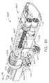
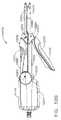
図面を参照し、いくつかの図を通して、同様の番号は、同様の構成要素を示し、図1は、全体として2で示されるモジュール式手術器具システムを示しており、このモジュール式手術器具システムは、一形態において、例えばエンドエフェクタ1000、2000及び3000などの様々な手術用エンドエフェクタと共に使用され得る電動手術器具10を含む。図示の実施形態において、電動手術器具10は、ハンドル14からなるハウジング12を含み、ハンドル14は、臨床医によって握持、操作、及び作動されるように構成されている。この詳細な説明を読み進めるとき、理解されたいこととして、本明細書で開示するハンドル14及び様々なエンドエフェクタ装置に関連させて示す様々な独特かつ新規な駆動システム装置が、ロボット制御される手術システムに関連させて効果的に用いられることができる。したがって、「ハウジング」という用語はまた、本明細書に示す様々な形態の駆動システムを収容するか又は別様に動作可能に支持し得、かつ、本明細書に記述するエンドエフェクタ装置及びそれらの等価な構造物を作動させるために用いられ得る制御運動を生成するように構成され得るハウジング又はロボットシステムの同様の部分を包含し得る。「フレーム」という用語は、手持型手術器具の一部分を指し得る。「フレーム」という用語はまた、電動システム若しくはロボット制御式の手術器具の一部分及び/又は手術器具を動作可能に制御するために用いられ得るロボットシステムの一部分を表し得る。例えば、本明細書で開示する駆動システム装置及びエンドエフェクタ装置は、参照によってすべての内容が本明細書に組み込まれる、米国特許出願第13/118,241号、名称「SURGICAL STAPLING INSTRUMENTS WITH ROTATABLE STAPLE DEPLOYMENT ARRANGEMENTS」、現在の米国特許出願公開第2012/0298719号で開示されている様々なロボットシステム、器具、構成要素及び方法と共に用いられ得る。 Referring to the drawings, wherein like numerals indicate like components throughout the several views, FIG. 1 shows a modular surgical instrument system generally designated 2, which is shown in FIG. , In one form, includes a powered
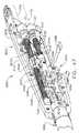
ここで図2〜5を参照するが、ハンドル14は、ねじ、スナップ機構、接着剤などで相互連結され得る一対のハウジング分割部16及び18を備え得る。図示の構成において、ハンドルハウジング分割部16、18は、臨床医に握持及び操作され得るピストルグリップ部分19を形成するように協働する。以下で更に詳細に議論するように、ハンドル14は、その中に2つの回転駆動システム20、40を動作可能に支持し、それら回転駆動システム20、40は、ハンドル14に結合される特定のエンドエフェクタの対応する駆動シャフト部分に、様々な制御運動を発生させて加えるように構成されている。第1の回転駆動システム20は、例えば、エンドエフェクタ内で動作可能に支持される、対応するクロージャ駆動シャフト装置に「閉鎖」運動を加えるために用いられてもよく、また、第2の回転駆動システム40は、ハンドル14に結合されるエンドエフェクタ内にある、対応する発射駆動シャフト装置に「発射」運動を加えるために用いられてもよい。 Referring now to FIGS. 2-5, the
第1及び第2の回転駆動システム20、40は、2つのパワートレーンの間で動力/運動を事実上シフトさせる、独特かつ新規な「シフト式」伝達組立体60を通じて、モータ80によって動力供給される。第1の回転駆動システム20は第1の回転駆動シャフト22を含み、第1の回転駆動シャフト22は、ハンドル14のハウジング12内で回転可能に支持され、第1の駆動シャフト軸「FDA−FDA」を規定する。第1の駆動ギヤ24は、第1の駆動シャフト軸FDA−FDAを中心として第1の回転駆動シャフト22と共に回転するように、第1の回転駆動シャフト22にキー結合されるか、あるいは別様に回転不能に固定される。同様に、第2の回転駆動システム40は第2の回転駆動シャフト42を含み、第2の回転駆動シャフト42は、ハンドル14のハウジング12内で回転可能に支持され、第2の駆動シャフト軸「SDA−SDA」を規定する。少なくとも1つの装置構成において、第2の駆動シャフト軸SDA−SDAは、第1の駆動シャフト軸FDA−FDAからずれており、かつ第1の駆動シャフト軸FDA−FDAに対して平行であるか、又は実質的に平行である。この状況で用いられるとき、「ずれる」という用語は、例えば第1の駆動シャフト軸と第2の駆動シャフト軸とが同軸でないことを意味する。第2の回転駆動シャフト42は第2の駆動ギヤ44を有し、第2の駆動ギヤ44は、第2の駆動シャフト軸SDA−SDAを中心として第2の回転駆動シャフト42と共に回転するように、第2の回転駆動シャフト42にキー結合されるか、あるいは別様に回転不能に固定される。それに加えて、第2の駆動シャフト42は中間駆動ギヤ46を有し、中間駆動ギヤ46は第2の回転駆動シャフト42上で回転可能に支承されており、そのため、中間駆動ギヤ46は、第2の駆動シャフト軸SDA−SDAを中心として第2の回転駆動シャフト42上で自在に回転可能となっている。 The first and second
図2〜5を参照すると、一形態において、モータ80はモータ出力シャフト81を含み、モータ出力シャフト81は、モータ出力シャフト81に回転不能に取り付けられたモータ駆動ギヤ82を有している。モータ駆動ギヤ82は、以下で更に詳細に議論するように、噛み合う「動作可能な」係合を伝達組立体60となすように構成されている。少なくとも1つの形態において、伝達組立体60は伝達キャリッジ62を含み、伝達キャリッジ62は、駆動ギヤ82と第2の回転駆動シャフト42上のギヤ44及び46との間を軸方向に移動するように支持されている。例えば、伝達キャリッジ62は、支持シャフト63上にスライド可能に支承されてもよく、支持シャフト63は、伝達キャリッジの作用線が回転駆動システムのギヤトレーンに対して垂直となるように、ハウジング12内でシャフトマウント61上に装着される。シャフトマウント61は、ハウジング10内のスロット又は他の機構内に強固に支持されるように構成されている。伝達キャリッジ62は、支持シャフト63上に回転可能に支持されるキャリッジギヤ64を含み、駆動ギヤ82とは駆動係合をなす一方で、ギヤ44及び46とは選択的に噛み合い係合をなすように構成されている。図2〜5に示す装置構成において、伝達キャリッジ62は、シフタ、つまり「シフトさせるための手段」70に動作可能に取り付けられており、このシフトさせるための手段70は、「第1の駆動位置」と「第2の駆動位置」との間で伝達キャリッジ62を軸方向にシフトさせるように構成されている。一形態において、例えば、シフトさせるための手段70は、ハンドル14のハウジング12内に支持されるシフタソレノイド71を含んでいる。シフタソレノイド71は、双安定ソレノイドを含んでもよく、又は例えば、「二段配置ばね荷重式」ソレノイドを含んでもよい。図示の装置構成は、例えば、伝達キャリッジ62を第1の駆動位置へと遠位方向「DD」に付勢するばね72を含んでおり、キャリッジギヤ64は、中間駆動ギヤ46と噛み合い係合をなす一方で、駆動ギヤ82とも噛み合い係合をなす。第1の駆動位置にあるとき、モータ80が作動することにより、結果として、ギヤ82、46及び24が回転することになり、これによって最終的に、第1の駆動シャフト22が回転することになる。本明細書で更に議論するように、シフタソレノイド71は発射トリガ90によって作動されてもよく、発射トリガ90は、図2及び5に示すように、ハンドル14のハウジング12上に旋回式で支持されている。図示の実施形態において、発射トリガ90は、ハンドル14内に装着された発射トリガシャフト92上に旋回式で支持されている。発射トリガ90は通常、非作動位置において発射トリガばね94によって付勢されている。図3を参照されたい。発射トリガ90は、発射スイッチ96を動作可能に作動させるように装着されており、発射スイッチ96は、制御回路基板組立体100上に動作可能に支持されている。図示の装置構成において、発射トリガ90が作動することにより、結果としてシフタソレノイド71が作動する。図61、63、64に関連して本明細書で以下に更に詳細に記述するように、ハンドル用プロセッサ7024は、駆動信号をシフタソレノイド7032(71)に与える。ここで再び図2〜5を参照するが、このように、発射トリガ90が作動する結果として、シフタソレノイド71が伝達キャリッジ62を近位方向「PD」に引っ張り、それによって、キャリッジギヤ64を移動させて第2の駆動ギヤ44と噛み合い係合させることになる。図7を参照されたい。キャリッジギヤ64が駆動ギヤ82及び第2の駆動ギヤ44と噛み合い係合をなしているときにモータ80が作動することにより、結果として、第2の駆動シャフト42が第2の駆動シャフト軸「SDA」を中心として回転することになる。また図2〜5で分かるように、シフト式伝達組立体60はまた表示システム74を含んでもよく、表示システム74は、制御基板100並びに伝達表示灯77に動作可能に結合された一対のスイッチ75及び76を含んでいる。スイッチ75、76は伝達キャリッジ62の位置を検出するように働き、その結果、制御システムは、伝達キャリッジ62の位置に応じて表示灯77を作動させることになる。例えば、表示灯77は、伝達キャリッジ62が第1の駆動位置にあるときに付勢されてもよい。これにより、モータ80が作動する結果として第1の駆動システム20が作動する指示が、臨床医に示唆される。 2 to 5, in one form, the
本明細書で開示する様々な手術器具はまた伝達組立体60’を含んでもよく、この伝達組立体60’は、伝達組立体60と実質的に同一であるが、第1の駆動システム20と第2の駆動システム40をロックして、それらが作動されるよう意図されていないときの偶発的作動を防止するためのロック組立体又は手段(全体として65で示す)を更に含んでいる。例えば、図6Aは、第1の駆動ロック66と第2の駆動ロック68とを有する別の伝達キャリッジ62’を示している。第1の駆動ロック66は、伝達キャリッジ62’上に第1のギヤ係合部材又は歯を備えており、この第1のギヤ係合部材又は歯は、キャリッジギヤ64が中間ギヤ46と駆動係合をなすとき(すなわち、伝達組立体60’が第1の駆動位置にあるとき)、第2の駆動ギヤ44と噛み合い係合するように配置されている。図6Bを参照されたい。したがって、伝達組立体60’が第1の駆動位置にあるとき、第1の駆動ロック66は第2の駆動ギヤ44と噛み合い係合をなし、第2の駆動ギヤ44の相対的回転を防止するが、第1の駆動シャフト22は上述の方式で回転される。同様に、伝達組立体60’が第2の駆動位置にある(すなわち、キャリッジギヤ64が第2の駆動ギヤ44と噛み合い係合をなす)とき、第2の駆動ロック68は中間駆動ギヤ46と噛み合い係合をなす。図6Cを参照されたい。したがって、伝達組立体60’が第2の駆動位置にあるとき、第2の駆動ロック68は、中間ギヤ46が回転するのを防止し、またこれにより、第1の駆動ギヤ24が回転するのを防止する。したがって、臨床医がモータ80を動作させて第1の駆動システム20を作動させるとき、第2の駆動システム40は定位置にロックされる。同様に、臨床医が第2の駆動システム40を作動させるとき、第1の駆動システム20は定位置にロックされる。 The various surgical instruments disclosed herein may also include a
モータ80の制御システムは、図61、63、64に関連して本明細書で以下に説明するように、ギヤ42、44の1つの歯が、突き合わされた他のギヤの方向に応じて、垂直又は他の所定の位置に留まるとき、常にある向きで停止するような方式でプログラムされ得る。この特徴は、シフトする間にギヤの歯同士の干渉を回避するように働く。シフトするとき、ロック部材はまた、非回転ギヤトレーンの位置をシフト及びロックする。カートリッジ/アンビル装置又は他のクランプ構成を含むエンドエフェクタと共に用いられるとき、非回転(すなわち無動力)ギヤトレーンをロックすることによって得られる別の利点は、クランプ/アンビルが発射の間も安定な位置に保持されることである。 The control system of the
モータ80は、例えば約25,000RPMの最大回転数を有するブラシ付きDC駆動モータであってもよい。他の装置構成において、モータには、加圧滅菌可能となり得るモータを含めて、ブラシレスモータ、コードレスモータ、同期モータ、ステッパモータ、又は任意の他の好適な電気モータを挙げることができる。モータ80は電源84によって電力供給されてもよく、電源84は一形態において、ハンドル14内に取り外し可能に格納されるパワーパック86を備えてもよい。図2〜5で分かるように、例えば、パワーパック86は、ハンドル14のピストルグリップ部分19内に取り外し可能に収容され得る。パワーパック86にアクセスするには、臨床医が、図示のようにピストルグリップ部分19に取り付けられている取り外し式キャップ17を取り外す。パワーパック86は、その中に複数の電池(図示せず)を動作可能に支持してもよい。電池はそれぞれ、例えば、リチウムイオン(「LI」)又は他の好適な電池を含んでよい。パワーパック86は、制御回路基板組立体100に取り外し可能かつ動作可能に取り付けられるように構成され、制御回路基板組立体100もまたモータ80に動作可能に結合され、ハンドル14内に装着される。直列に接続された多数の電池が、手術器具の電源として使用されてもよい。それに加えて、電源84は、交換式及び/又は充電式であってよく、また少なくとも1つの例において、例えばCR123電池を含み得る。モータ80は「ロッカートリガ」110によって作動されてもよく、ロッカートリガ110は、ハンドル14のピストルグリップ部分19に旋回式で装着される。ロッカートリガ110は、制御基板100に動作可能に結合された第1のモータスイッチ112を作動させるように構成されている。第1のモータスイッチ112は、ロッカートリガ110を旋回させて接触させることによって作動される圧力スイッチを含んでもよい。第1のモータスイッチ112が作動することにより、結果として、駆動ギヤ82が第1の回転方向に回転するように、モータ80が作動することになる。また第2のモータスイッチ114が回路基板100に取り付けられており、ロッカートリガ110によって選択的に接触されるように装着されている。第2のモータスイッチ114が作動することにより、結果として、駆動ギヤ82が第2の方向に回転するように、モータ80が作動することになる。例えば、使用の際、電源84によって与えられる電圧極性により、電気モータ80を時計回りの方向に動作させ得るが、電池によって電気モータに加えられる電圧極性は、電気モータ80を反時計回りの方向に動作させるために逆転され得る。本明細書に記述する他の形態と同様に、ハンドル14はまた、駆動システムが移動されている方向を検知するように構成されたセンサを含み得る。モータ80の1つの具体的な実現形態について、ブラシレスDCモータ7038が記載された図61、63、64に関連させて、本明細書で以下に説明する。DCモータ7038は、加圧滅菌可能となり得る。 The
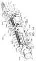
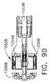
図8〜12は、別の形態の手術器具10’を示しており、この手術器具10’は、以下に記す違いを除いて手術器具10と同一であってもよい。手術器具10’のうちの、上述した手術器具10の構成要素と同じ構成要素は、同じ参照符号で指定することにする。手術器具10’のうちの、手術器具10の対応する構成要素と同一ではないが動作においては類似し得る構成要素は、「’」又は場合によっては「’’」を伴った同じ構成要素番号で指定することにする。図8で分かるように、例えば、第1の駆動シャフト軸「FDA」は、第2の駆動シャフト軸「SDA」からずれており、かつ第2の駆動シャフト軸「SDA」と平行であるか又は実質的に平行である。主に図9を参照するが、例えば、伝達組立体60は、より具体的には伝達キャリッジ62’’は、発射トリガ90’に動作可能に取り付けられたリンク機構組立体120によって手動でシフト可能である。この図で分かるように、例えば、リンク機構組立体120は第1の伝達リンク122を含み、この第1の伝達リンク122は、発射トリガ90’に旋回式で結合されており、また軸方向に延びて伝達ヨーク124に旋回式で結合されている。伝達ヨーク124は、伝達キャリッジ62’’に移動可能にピン結合されている。したがって、発射トリガ90’が作動することにより、結果として、伝達キャリッジ62’’が軸方向に移動する。それ故に、リンク機構組立体120は基本的に、上述したシフタソレノイド71によって実施される作動運動に似た作動運動を実施することが理解されよう。伝達キャリッジ62’’の移動に関してこの実施形態の状況で用いられるとき、「手動でシフト可能」という用語は、発射トリガ90’を押し込むこと以外に、電気又は他の動力手段を用いることなく、伝達キャリッジを第1の駆動位置と第2の駆動位置との間で移動させることを指す。 8-12 illustrate another form of surgical instrument 10 'which may be identical to the
図8〜12でも分かるように、第2の駆動ギヤ44’は、第2の駆動シャフト42’上の中間ギヤ46’からスペーサ45によって離間されている。第2の駆動ギヤ44’は第2の駆動シャフト42’にキー結合されるか、あるいは別様に回転不能に固定されているが、中間駆動ギヤ46’は、第2の駆動シャフト42’上に回転可能に支承されて、第2の駆動シャフト42’に対して自在に回転するようになっている。一形態において、例えば、遠位駆動ギヤ130が、中間駆動ギヤ46’と噛み合い係合をなして支持される。同様に、近位駆動ギヤ136が、第2の駆動ギヤ44’と噛み合い係合をなして支持される。この装置構成において、しかしながら、伝達キャリッジ62’’もまた、中央に配設された伝達ギヤ組立体140を含み、この伝達ギヤ組立体140は、伝達キャリッジ62’と共に軸方向に移動するように、伝達キャリッジ62’に動作可能に取り付けられている。依然として図8〜12を参照するが、伝達ギヤ組立体140は、中央に配設されたシフタ駆動ギヤ142を含み、このシフタ駆動ギヤ142は、モータ駆動ギヤ82とスライド可能な噛み合い係合をなす。したがって、モータ駆動ギヤ82が回転することにより、結果としてシフタ駆動ギヤ142が回転する。それに加えて、近位側に延びる円錐形状の駆動ギヤ144が、シフタ駆動ギヤ142に結合されており、また近位側の駆動ギヤ136に取り付けられた近位側のギヤソケット146と選択的に噛み合い係合をなするように構成されている。同様に、遠位側に延びる円錐形状の駆動ギヤ148が、遠位側の駆動ギヤ130に取り付けられた遠位側のギヤソケット150と選択的に噛み合い係合をなすように構成されている。 As can be seen in FIGS. 8-12, the
臨床医が第1の駆動システム20を作動させることを望む場合、臨床医は、発射トリガ90’を移動させて伝達ギヤ組立体140を軸方向に移動させ、遠位側に延びる円錐形状の駆動ギヤ148が、遠位側の駆動ギヤ130に取り付けられた遠位側のギヤソケット150と嵌め込みによる噛み合い係合をなすようにする。図8〜10を参照されたい。その位置にあるとき、モータ80を動作させることにより、結果として、モータ駆動ギヤ82、シフタ駆動ギヤ142、遠位側の駆動ギヤ130、中間駆動ギヤ46’、第1の駆動ギヤ24、及び第1の駆動シャフト22が回転することになる。臨床医が第2の駆動システム40を作動させることを望む場合、臨床医は、図11及び12に示す位置に発射トリガ90’を移動させ、それによって、近位側に延びる円錐形状の駆動ギヤ144が、近位側の駆動ギヤ136に取り付けられた近位側のギヤソケット146と嵌め込みによる噛み合い係合をなすようにする。その位置にあるとき、モータ80を動作させることにより、結果として、モータ駆動ギヤ82、シフタ駆動ギヤ142、近位側の駆動ギヤ136、第2の駆動ギヤ44’、及び第2の駆動シャフト42’が回転することになる。また図8〜12で分かるように、伝達キャリッジ62’’の位置を検知するために、以下で更に詳細に議論するように、センサ152及び154が用いられてもよい。例えば、センサ152及び154は、図61、63、64に関連して本明細書で以下に記述するホール効果センサ7028を使用して実現されてもよい。 If the clinician wishes to activate the
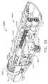
図13〜16は、別の形態の電動手術器具310を示しており、この手術器具310は、以下に記す違いを除いて手術器具10と同一であってもよい。手術器具310のうちの、上述した手術器具10の構成要素と同じ構成要素は、同じ参照符号で指定することにする。この装置構成において、第1及び第2の駆動システム20、40は、独特かつ新規な「シフト式」伝達組立体360を通じてモータ80によって動力供給される。第1の駆動システム20は第1の駆動シャフト22を含み、第1の駆動シャフト22は、第1の駆動プーリ324をキー結合されるか、あるいは別様に回転不能に固定されている。同様に、第2の駆動システム40は第2の駆動シャフト42を含み、第2の駆動シャフト42は、第2の駆動プーリ344をキー結合されるか、あるいは別様に回転不能に固定されている。図14で分かるように、例えば、第1の駆動シャフト軸「FDA」は、第2の駆動シャフト軸「SDA」からずれており、かつ第2の駆動シャフト軸「SDA」と平行であるか、又は実質的に平行である。 FIGS. 13-16 show another form of electric
依然として図13〜16を参照すると、一形態において、モータ80は第1のモータプーリ382を含み、第1のモータプーリ382は、モータ80のシャフトに回転不能に取り付けられている。第1のモータプーリ382は、第1の駆動プーリ324上に受容される第1の駆動ベルト385を駆動する。それに加えて、第2のモータプーリ384がモータシャフトに回転不能に装着されており、第2の駆動ベルト387を動作可能に支持している。第2の駆動ベルト387はまた、第2の駆動シャフト42上の第2の駆動プーリ344上に受容されている。例えば、第1及び第2の駆動ベルト385、387はVベルトを含んでもよい。 Still referring to FIGS. 13-16, in one form, the
器具310はまた伝達組立体360を含み、伝達組立体360は、器具のハウジング内で軸方向に移動するように支持される伝達キャリッジ362を含んでいる。伝達キャリッジ362はアイドラキャリッジ374と動作可能に相互作用し、アイドラキャリッジ374は、伝達キャリッジ362がシフタソレノイド71によって軸方向に移動されるときに、伝達キャリッジ362との接触に反応して横方向に移動するように支持されている。アイドラキャリッジ374は、アイドラキャリッジ374に装着された第1のアイドラプーリ375と第2のアイドラプーリ376とを含んでいる。図示の装置構成において、ばね72は伝達キャリッジ362を第1の駆動位置へと遠位方向「DD」に付勢しており、伝達キャリッジ362は、アイドラキャリッジ374を第1の横方向「FLD」に移動させ、この第1の横方向「FLD」では、第1のアイドラプーリ375が第1の駆動ベルト385から遊びを除去することになる。この位置にあるとき、第2のアイドラプーリ376は、第2の駆動ベルト387との係合から外れて位置する。したがって、モータ80を動作させることにより、結果として第1の駆動シャフト22が回転することになる。第2のモータプーリ384はまた、モータ80が作動されるときに回転されることになるが、第2の駆動ベルト387の遊びにより、回転運動が第2の駆動プーリ344へと伝達されることが防止される。したがって、回転運動は第2の駆動システム40に伝達されない。上で議論したように、シフタソレノイド71は、発射トリガ90によって作動されてもよい。しかしながら、別の装置構成において、シフタソレノイド71はまた、例えば、上述したタイプの、手動で作動可能なリンク機構組立体で置き換えられてもよい。図示の装置構成において、発射トリガ90を作動させることにより、結果として、シフタソレノイド71が伝達キャリッジ362を近位方向「PD」に引っ張り、それによって、アイドラキャリッジ374を第2の横方向「SLD」に側方に変位させて、第2の駆動ベルト387から遊びを除去するように第2のアイドラ376を第2の駆動ベルト387と接触させることになる。また、アイドラキャリッジ374がそのように側方に移動することにより、第1のアイドラ375が第1の駆動ベルト385との係合から外れて、第1の駆動ベルト385を緩めることができる。したがって、そのような第2の駆動位置にあるとき、モータ80が作動することにより、結果として、第2の駆動システム40が作動することになる。第1の駆動ベルト385の遊びは、回転運動が第1の駆動システム20に伝達されるのを防止する。 The
伝達組立体360は、いくつかの明確な利点をもたらし得る。例えば、Vベルトの使用により、噛み合わせギヤ又はクラッチを備えたギヤ装置が排除される。更に、そのような伝動装置は、荷重下で起動又は停止され得る。それに加えて、伝達組立体360は、分離及び係合するために、あまり変位を必要としない。 The
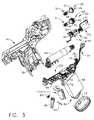
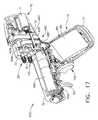
図17〜21は、別の形態の電動手術器具410を示しており、この手術器具410は、以下に記す違いを除いて手術器具10と同一であってもよい。手術器具410のうちの、上述した手術器具10の構成要素と同じ構成要素は、同じ参照符号で指定することにする。この装置構成において、第1及び第2の駆動システム20、40は、独特かつ新規な「シフト式」伝達組立体460を通じてモータ480によって動力供給される。第1の駆動システム20は第1の駆動シャフト22を含み、第1の駆動シャフト22は、第1の駆動プーリ424をキー結合されるか、あるいは別様に回転不能に固定されている。同様に、第2の駆動システム40は第2の駆動シャフト42を含み、第2の駆動シャフト42は、第2の駆動プーリ444をキー結合されるか、あるいは別様に回転不能に固定されている。図18で分かるように、例えば、第1の駆動シャフト軸「FDA」は、第2の駆動シャフト軸「SDA」からずれており、かつ第2の駆動シャフト軸「SDA」と平行であるか、又は実質的に平行である。 17-21 show another form of electric
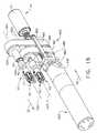
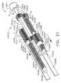
ここで図19を参照すると、一形態において、モータ480はスプライン駆動シャフト481を含み、スプライン駆動シャフト481は、伝達キャリッジ462と相互作用するように構成された伝達シャフト組立体490とスライド可能に係合するように適合されており、そのため、伝達キャリッジ462が軸方向に移動することにより、結果として、スプライン駆動シャフト481上で伝達シャフト組立体490が軸方向に移動するようになっている。図19で分かるように、伝達シャフト組立体490は、その中にスプラインボア491を有しており、スプラインボア491は、その中にスプライン駆動シャフト481をスライド可能かつ動作可能に受容するためのものである。それに加えて、遠位係合カラー492が、伝達シャフト組立体490の遠位端部上に形成されている。遠位係合カラー492は環状溝493を備えて構成され、環状溝493は、対向する2本のヨークロッド465を中に受容するように構成され、それらヨークロッド465は、伝達キャリッジ462のヨーク部分464に取り付けられるものである。そのような装置構成は、伝達シャフト組立体490を伝達キャリッジ462に対して回転させながらも、伝達キャリッジ462を伝動シャフト組立体490に結合するように働く。 Referring now to FIG. 19, in one form, the
依然として図19を参照すると、第1のモータプーリ482が、伝達シャフト組立体490と選択的に駆動係合するように構成されている。例えば、図19で分かるように、伝達シャフト組立体490は、その近位端部上に軸受カラー494を形成されており、軸受カラー494は、第1のモータプーリ482のボア483内にスライド可能かつ回転可能に受容されるように寸法を定められている。それに加えて、第1のモータプーリ482はまた星形の近位駆動キャビティ488を含み、この星形の近位駆動キャビティ488は、伝達シャフト組立体490上に形成された相補的形状の駆動部分495と噛み合いによって係合するように適合されている。第1のモータプーリ482は、同様に第1の駆動プーリ424上に受容される第1の駆動ベルト485を駆動する。手術器具410はまた第2のモータプーリ484を含み、この第2のモータプーリ484は、伝達シャフト組立体490の駆動部分495と噛み合いによって係合するように構成された星形ボア489を有している。第2のモータプーリ484は、同様に第2の駆動プーリ444上に受容される第2の駆動ベルト487を動作可能に支持する。 Still referring to FIG. 19, the
上に示したように、器具410はまた伝達組立体460を含み、伝達組立体460は、器具のハウジング内で軸方向に移動するように支持される伝達キャリッジ462を含んでいる。伝達キャリッジ462は、伝達シャフト組立体490と動作可能に相互作用して、伝達シャフト組立体490が依然としてモータシャフト481と係合されている間に、同様に伝達シャフト組立体490を軸方向に移動させる。図20は、非作動位置にあるシフタソレノイド71を示している。この図で分かるように、伝達キャリッジ462は、「第1の駆動位置」とも呼ばれ得る最近位位置に伝達シャフト組立体490を移動させており、この最近位位置において、駆動部分495は、第1のモータプーリ482の星形ボア488と駆動係合をなす。したがって、モータシャフト481が回転することにより、結果として、伝達シャフト組立体490及び第1のモータプーリ482が回転することになる。第1のモータプーリ482が回転することにより、結果として第1の駆動ベルト485が回転し、その結果として、最終的には第1の駆動シャフト22が回転することになる。伝達シャフト組立体490が第1の駆動位置にあるとき、伝達シャフト組立体490は、第2のモータプーリ484に対して自在に回転する。したがって、第1の駆動システム20が作動されるとき、第2の駆動システム40は依然として作動されない。シフタソレノイド71が、(発射トリガ90を作動させることによって)図21に示す位置へと作動されると、伝達キャリッジ462は、「第2の駆動位置」とも呼ばれ得る、モータシャフト481上の最遠位位置に伝達シャフト組立体490を移動させる。図21で分かるように、伝達シャフト組立体490が第2の位置にあるとき、その駆動部分495は移動されて、第2のモータプーリ484の星形ボア489と噛み合い係合する。したがって、モータシャフト481が回転することにより、結果として、第2のモータプーリ484が回転することになる。第2のモータプーリ484が回転することにより、結果として第2の駆動ベルト487が回転することになり、その結果、第2の駆動シャフト42が回転する。この第2の駆動位置にあるとき、伝達シャフト組立体490は、第1のモータプーリ482内で自在に回転するしたがって、第2の駆動システム40が作動されるとき、第1の駆動システム20は非作動状態にある。 As indicated above, the
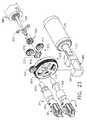
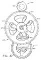
図22〜27は、本明細書で説明する様々な手術器具と共に用いられ得る別のモータ、伝達組立体、並びに第1及び第2の駆動システムを示している。図示の装置は、モータシャフト581を有するモータ580を含んでいる。図23及び24を参照されたい。モータ駆動ギヤ582又は「サンギヤ」582が、モータシャフト581と共に回転するように、モータシャフト581に回転不能に固定されている。この装置はプラネタリギヤ組立体570を更に含んでおり、プラネタリギヤ組立体570は、遠位側のキャリアブラケット573と近位側のキャリアブラケット574との間に回転可能に支持される3つのプラネタリギヤ572を含んでいる。近位側のキャリアブラケット574は、サンギヤ582が近位側のキャリアブラケット574に対して回転し得るように、サンギヤ582のハブ部分上に支持されている。遠位側のキャリアブラケット573は、第2の駆動システム40の第2の駆動シャフト542に固定されており、そのため、遠位側のキャリアブラケット573が回転することにより、結果として第2の駆動システム40の第2の駆動シャフト542が回転するようになっている。3つのプラネタリギヤ572は、リングギヤ組立体575と噛み合い係合をなして支持されている。より具体的に言えば、プラネタリギヤ572は、リングギヤ組立体575上の内部リングギヤ576と噛み合い係合をなす。リングギヤ組立体575は外部リングギヤ577を更に含んでおり、外部リングギヤ577は、第1の駆動システム20の第1の駆動シャフト522に固定された第1の駆動ギヤ524と噛み合い係合をなしている。図24で分かるように、例えば、第1の駆動シャフト軸「FDA」は、第2の駆動シャフト軸「SDA」からずれており、かつ第2の駆動シャフト軸「SDA」と平行であるか、又は実質的に平行である。 FIGS. 22-27 illustrate another motor, transmission assembly, and first and second drive systems that may be used with the various surgical instruments described herein. The illustrated apparatus includes a
図23で分かるように、この装置はソレノイド71を更に含んでおり、ソレノイド71は、本明細書で述べた様々な方式で発射トリガによって動作され得る。この装置構成において、伝達組立体560は、ソレノイド71のシャフト73に取り付けられる。図24は、第1の駆動位置にある伝達組立体560を示している。一形態において、伝達組立体560は、概して590で示されるロック組立体を含んでおり、このロック組立体は、伝達組立体560上に第1の又は近位側のロック突起部分592と第2の又は遠位側のロック突起部分594とを備えている。この図で分かるように、伝達組立体560は、近位側のロック突起部分592が近位側のキャリアブラケット574と係合するように配置されている。この第1の駆動位置にあるとき、近位側のロック突起部分592は、プラネタリギヤ組立体570がサンギヤ582と一体となって回転するのを防止する。しかしながら、サンギヤ582が回転することにより、結果としてプラネタリギヤ572が回転する。プラネタリギヤ572が回転することにより、結果としてリングギヤ組立体575が回転する。リングギヤ組立体575が回転することにより、結果として第1の駆動ギヤ524及び第1の駆動シャフト522が回転する。近位側のキャリアブラケット574は回転するのを防止されているため、遠位側のキャリアブラケット573もまた回転するのを防止されている。したがって、第1の駆動シャフト522が回転されている間、第2の駆動シャフト544もまた回転するのを防止される。ソレノイド71(及びそれに取り付けられた伝達組立体560)をこの「第1の駆動位置」へと付勢するために、ばね(図示せず)が用いられてもよい。臨床医が第2の駆動システム40を作動させるように望むとき、ソレノイド71は、上述のように発射トリガを使用して作動されて、ソレノイドシャフト73を図25に示す位置に移動させ得る。伝達組立体560がこの「第2の駆動位置」にあるとき、遠位側のロック突起部分594は、リングギヤ組立体575と保持によって係合して、リングギヤ組立体575の回転を防止する。したがって、サンギヤ582が回転されるとき、プラネタリギヤキャリヤ(すなわち、遠位側のキャリアブラケット573及び近位側のキャリアブラケット574)もまた回転することになる。プラネタリギヤ572は、固定された内部リングギヤ576内で回転することになる。そのような回転運動が第2の駆動シャフト542に伝達されることになる一方で、第1の駆動シャフト522は依然として作動されない。 As can be seen in FIG. 23, the apparatus further includes a
図28は、別の形態の電動手術器具610を示しており、この手術器具610は、以下に記す違いを除いて手術器具10と同一であってもよい。手術器具610のうちの、上述した手術器具10の構成要素と同じ構成要素は、同じ参照符号で指定することにする。図28で分かるように、例えば、第1の駆動シャフト軸「FDA」は、第2の駆動シャフト軸「SDA」からずれており、かつ第2の駆動シャフト軸「SDA」と平行であるか、又は実質的に平行である。この装置はモータ680を備え、モータ680は、複式の独立作動型モータシャフト681、683を有している。発射トリガがある方式で作動することによって、モータ680が第1のモータシャフト681を回転させ、発射トリガが別の方式で作動することによって、モータ680が第2のモータシャフト683を回転させるように、モータ680は、本明細書に記述する様々なタイプの発射トリガ装置によって制御され得る。この装置構成において、第1のモータギヤ682が第1のモータシャフト681上に装着されており、アイドラギヤ646と噛み合い係合をなして支持されている。アイドラギヤ646は、第1の駆動システム620の第1の駆動シャフト622に装着された第1の駆動ギヤ624と噛み合い係合をなして動作可能に支持されている。したがって、第1のモータシャフト681が作動することにより、結果として第1の駆動システム620が作動することになる。同様に、第2のモータギヤ684が第2のモータシャフト683上に装着されており、第2の駆動システム640の第2の駆動シャフト642上に装着された第2の駆動ギヤ644と噛み合い係合をなして支持されている。したがって、第2のモータシャフト683が作動することにより、結果として第2の駆動システム640が作動することになる。 FIG. 28 shows another form of electric
図29は、別の形態の電動手術器具710を示しており、この手術器具710は、以下に記す違いを除いて手術器具10と同一であってもよい。手術器具710のうちの、上述した手術器具10の構成要素と同じ構成要素は、同じ参照符号で指定することにする。図29で分かるように、例えば、第1の駆動シャフト軸「FDA」は、第2の駆動シャフト軸「SDA」からずれており、かつ第2の駆動シャフト軸「SDA」と平行であるか、又は実質的に平行である。この装置構成において、第1及び第2の駆動システム720、740は、独特かつ新規な「シフト式」伝達組立体760を通じてモータ780によって動力供給される。第1の駆動システム720は第1の駆動シャフト722を含み、第1の駆動シャフト722は、第1の駆動ギヤ724をキー結合されるか、あるいは別様に回転不能に固定されている。同様に、第2の駆動システム740は第2の駆動シャフト742を含み、第2の駆動シャフト742は、第2の駆動ギヤ744をキー結合されるか、あるいは別様に回転不能に固定されている。モータ780はモータギヤ782を含み、モータギヤ782は、モータ780のシャフト781に回転不能に取り付けられている。 FIG. 29 shows another form of electric
図示の装置構成において、以下で更に詳細に議論するように、伝達組立体760をシフトさせるために第2のモータ750が用いられている。第2のモータ750は、例えば、本明細書で開示する様々な発射トリガ及びスイッチ装置によって制御され得る。第2のモータ750は、図61、63、64に関連して本明細書で以下に記述するように、モータ7038が制御される方式と類似した形式で制御され得る。図29で分かるように、第1の伝達プーリ753が、モータシャフト752にキー結合されるか、あるいは別様に回転不能に固定されている。第1のピボットシャフト754が、ハンドル14のハウジング12内で回転可能に支持されている。第1のピボットシャフトは、ピボット軸「PA」を規定している。第2の伝達プーリ755が第1のピボットシャフト754上に回転不能に装着され、伝達ベルト756が第1及び第2の伝達プーリ753、755上に装着されている。一形態において、シフト式伝達組立体760は伝達リンク762を含んでおり、伝達リンク762は第1のピボットシャフト754に取り付けられている。それに加えて、アイドラシャフト763が伝達リンク762に取り付けられており、伝達リンク762は、その上にアイドラギヤ764を動作可能に支持している。シフト式伝達組立体760は、第1の駆動位置と第2の駆動位置との間で移動可能である。シフト式伝達組立体760を第1の駆動位置に移動させるために、臨床医は第2のモータ750を作動させて、ピボット軸PAを中心としてピボットシャフト763及びアイドラギヤ764を回転させ、それにより、アイドラギヤ764は、モータギヤ782及び第1の駆動ギヤ724と噛み合い係合するようになる。この位置にあるとき、モータ780が作動することにより、結果として、次いで第1の駆動システム720が作動することになる。臨床医が第2の駆動システム740を作動させることを望む場合、第2のモータ750は、ピボット軸PAを中心としてアイドラギヤ764を回転させて、モータギヤ782及び第2の駆動ギヤ744と噛み合い係合させるように作動される。この位置にあるとき、モータ780が作動することにより、結果として、第2の駆動システム740が作動することになる。この装置構成を用いて達成され得る1つの利益は、正確なギヤの方向付けが必要とされないことである。アイドラギヤ764が定位置へと旋回するとき、アイドラギヤ764は回転していてもよく、また噛み合う歯を自動的に発見する。 In the illustrated apparatus configuration, a
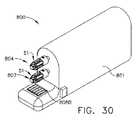
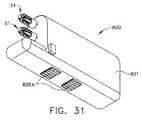
図30〜32は、本明細書に記述するタイプのハウジング内に装着され得る、独特かつ新規なモータユニット800を示している。モータユニット800は別のハウジング構造801を含んでもよく、ハウジング構造801は、第1の駆動システム804を規定する第1のモータシャフト803を備えた第1のモータ802を動作可能に支持する。モータユニット800は、第2の駆動システム807を規定する第2のモータシャフト806を備えた第2のモータ805を含んでもよい。図8で分かるように、例えば、第1の駆動シャフト軸「FDA」は、第2の駆動シャフト軸「SDA」からずれており、かつ第2の駆動シャフト軸「SDA」と平行であるか、又は実質的に平行である。ユニット800は、接点808Aを備えた制御回路基板808を更に含んでもよく、接点808Aは、器具ハウジング内に装着されるか、あるいは別様に器具ハウジング内に支持された回路上の対応する接点と動作可能に接合し、器具の制御システムと通信する。ハウジングは、電気接点808Bを更に含んでもよく、この電気接点808Bは、ハウジングに結合されるエンドエフェクタ用具上の対応する電気接点と動作可能に接合するように構成されている。 30-32 illustrate a unique and
図1に示すように、モジュール式手術システム2は、本明細書で記述する様々な手術器具と共に使用され得る、多種多様な手術用エンドエフェクタ装置1000、2000、及び3000を含んでもよい。以下で更に詳細に議論するように、エンドエフェクタ1000、2000、3000の各々は、手術器具の第1及び第2の駆動システムと動作可能に接合してそれらから制御運動を受け取るように適合された、複式の別々の「第1及び第2のエンドエフェクタ駆動システム」を含んでいる。エンドエフェクタ駆動システムはそれぞれ、エンドエフェクタを動作可能に取り付けられた手術器具によって、対応する回転運動がエンドエフェクタ駆動システムに加えられるのに反応して、対応するエンドエフェクタアクチュエータ構成要素を第1の、つまり最初の直線位置から、第2の、つまり最後の直線位置へと直線的に移動させるように構成されている。エンドエフェクタアクチュエータ構成要素は、様々な手術手技を実施するために、エンドエフェクタ用具のヘッド部分に配置された様々なエンドエフェクタ構成要素に直線的な操作運動を加える。以下で更に詳細に議論するように、エンドエフェクタは、臨床医が手術器具の第1及び第2の駆動シャフトをエンドエフェクタの対応する駆動シャフトと結合するのを支援するために、独特な構成要素及びシステムを用いている。4本の駆動シャフトは基本的には同時に互いに結合されるので、それらのシャフトが、正しい位置、又は駆動システムのそのような同時結合を促進する「ほとんど正しい位置」にあるようにするため、様々な結合装置及び制御技術が用いられ得る。 As shown in FIG. 1, modular
ここで図33を参照すると、手術器具内の2つの駆動システムをエンドエフェクタ内の対応する「被動」シャフトに同時に取り外し可能かつ動作可能に結合するのを容易にするために、ある形態の機械的結合システム50が用いられ得る。結合システム50は、手術器具内の駆動シャフトに取り付けられ得る雄型カプラと、手術用エンドエフェクタ内の被動シャフトに取り付けられる、対応する雌型ソケットカプラとを含み得る。例えば、図9は、第1及び第2の駆動シャフト22、42に止めねじ52によって取り付けられた雄型カプラ51を示している。再び図33を参照すると、雄型カプラ51の各々は、対応する雌型ソケットカプラ57内に駆動式で受容されるように構成されており、雌型ソケットカプラ57もまたエンドエフェクタ内の被動シャフトに取り付けられ得る。一形態において、各雄型カプラ51は、少なくとも3つの駆動リブ53を含み、これら駆動リブ53は、雄型カプラ51の中央部分54の周りに等しく離間されている。図示の実施形態において、例えば、5つの駆動リブ53が、中央部分54の周りに等しく離間されている。各駆動リブ53は、鋭い遠位端部55を有している。各駆動リブ53は、雌型ソケットカプラ57内の対応するソケット溝58の中へ挿入するのを容易にするために、幾分か丸み付きの縁部56を備えて形成されてもよい。各ソケット溝58は、その中に対応する駆動リブ53を挿入するのを容易にするために、テーパ付きの近位入口部分59を有している。各駆動リブ53の鋭い遠位端部55は、各ソケット溝58のテーパ付きの入口59と相まって、結合プロセス中に雄型カプラ51とそれに対応する雌型ソケットカプラ57との心狂いに適応することになる。それに加えて、鋭い遠位端部55上の丸み付きの縁部57もまた、雄型カプラ51を、対応する雌型ソケットカプラ58の中にスライド可能に挿入するのを支援する。 Referring now to FIG. 33, in order to facilitate simultaneous releasable and operative coupling of two drive systems in a surgical instrument to corresponding “driven” shafts in an end effector, some form of mechanical
一形態において、雄型カプラ51のうちの少なくとも1つが、それに対応する手術器具の第1若しくは第2の駆動シャフト、又はそれに対応する手術用エンドエフェクタの第1及び第2の被動シャフトに移動可能に取り付けられる。より具体的に言えば、雄型カプラ51は、シャフト上における「径方向移動の第1の所定量」をなすように、シャフト上で径方向又は角度方向に移動するように取り付けられてもよい。これは、例えば、シャフト上における雄型カプラ51の一定量の径方向又は角度方向移動を容易にするように互いに対して寸法を定められたキー、及びキー溝の装置によって達成され得る。別の言い方をすれば、シャフトは、例えば、キーがキー溝内で移動し、径方向移動の第1の所定量を確立し得るように、雄型カプラ51に形成された対応するキー溝よりも小さなキーをシャフト上に形成されるか、あるいは別様にシャフトに装着され得る。この径方向移動の第1の所定量は好ましくは、カプラを後方駆動又は前方駆動させるのに十分なものである。例えば5つのリブ53を有する雄型カプラ51の場合、径方向移動の第1の所定範囲は、例えば5〜37度となり得る。例えば、径方向移動の第1の所定範囲が5°未満、好ましくは4°以下となり得るいくつかの実施形態も存在し得る。径方向又は角度方向の移動のそのような範囲は、例えば、対応する雌型ソケットカプラ57がそれに対応する駆動シャフトに強固に固定され、また別様にいかなる径方向移動も不可能となる場合には十分となり得る。しかしながら、雄型カプラと雌型カプラの双方が、径方向に又は角度方向に調節する能力を有する場合、径方向又は角度方向の移動のそのような範囲は、各カプラ(雄型カプラ及びそれに対応する雌型ソケットカプラ)に約3〜16度の移動範囲を設けるように、50%、低減され得る。雌型ソケットカプラ57がそれに対応するシャフト上で移動し得る、径方向又は角度方向移動の量は、本明細書において「径方向移動の第2の所定量」と呼ばれ得る。雌型ソケットカプラ57はまた、所望の径方向移動の第2の所定量をもたらす上述したキーとキー溝の装置を用いて、それぞれに対応する駆動シャフトに取り付けられ得る。例えば、所定の径方向移動の第2の範囲が5°未満、好ましくは4°以下となり得るいくつかの実施形態も存在し得る。 In one form, at least one of the
雄型カプラと雌型ソケットカプラの様々な組み合わせ及び装着装置が企図される。例えば、雄型カプラの一方又は両方が、本明細書で記述した様々な方式で、それぞれに対応する手術器具の駆動シャフト(又は手術用エンドエフェクタの被動シャフト)に移動可能に装着され得る。同様に、雌型ソケットカプラの一方又は両方が、本明細書で記述した様々な方式で、それぞれに対応するエンドエフェクタ上の被動シャフト(又は手術器具の駆動シャフト)に移動可能に装着され得る。例えば、第1及び第2の駆動シャフトの一方の雄型カプラが、その雌型ソケットカプラ上に移動可能に装着され得る。もう一方の駆動シャフトに取り付けられる、もう一方の雄型カプラは、雌型ソケットカプラに移動不能に装着され得る。移動可能に装着された雄型カプラに対応する、被動シャフト上の雌型ソケットカプラは、その被動シャフトに移動不能に取り付けられ得、移動不能に装着されたカプラに対応する、もう一方の被動シャフト上に装着された雌型ソケットカプラは、その被動シャフトに移動可能に装着され得る。したがって、「カプラ対」の雄型カプラと雌型カプラソケットの一方は移動可能である。「カプラ対」という用語は、互いに結合されて、手術器具の駆動シャフトをそれに対応するエンドエフェクタの被動シャフトに動作可能に結合するように構成された、雄型カプラとそれに対応する雌型ソケットカプラを指す。他の装置構成において、カプラ対の雄型カプラと雌型カプラソケットは共に、それぞれのシャフトに移動可能に結合され得る。 Various combinations and mounting devices for male and female socket couplers are contemplated. For example, one or both of the male couplers can be movably attached to the corresponding surgical instrument drive shaft (or surgical end effector driven shaft) in the various manners described herein. Similarly, one or both of the female socket couplers can be movably attached to the driven shaft (or the drive shaft of the surgical instrument) on the corresponding end effector in the various manners described herein. For example, one male coupler of the first and second drive shafts can be movably mounted on the female socket coupler. The other male coupler attached to the other drive shaft may be immovably mounted on the female socket coupler. The female socket coupler on the driven shaft, corresponding to the movably mounted male coupler, can be mounted immovably on the driven shaft, the other driven shaft corresponding to the immovably mounted coupler The female socket coupler mounted above can be movably mounted on its driven shaft. Therefore, one of the male coupler and female coupler socket of the “coupler pair” is movable. The term “coupler pair” refers to a male coupler and a corresponding female socket coupler configured to be coupled together to operably couple the drive shaft of the surgical instrument to the driven shaft of the corresponding end effector. Point to. In other arrangements, both the male and female coupler sockets of the coupler pair can be movably coupled to respective shafts.
そのようなカプラ装置は、例えばカプラ構成要素同士の間に小量の角度の遊びを設けるように働き、そのため、構成要素は、十分な心合わせをなすようにわずかに回転され得るようになり、これにより、2つの別々の回転駆動系に取り付けられたカプラ構成要素が同時に心合わせされることができる。それに加えて、結合プロセスに適応するように、十分な量のバックラッシュ又は遊びが駆動系に設けられてもよい。そのようなバックラッシュ又は遊びは、構成要素のそのようなわずかな回転を促進するように、キー/キー溝をギヤ、カプラ、及び/又は噛み合いシャフトに形成することによって設けられ得る。それに加えて、結合の目的でモータを起動して駆動シャフトのわずかな回転を生じさせ得る切り換え装置が、様々なシフト式伝達組立体と共に用いられ得る。 Such coupler devices, for example, serve to provide a small amount of angular play between the coupler components, so that the components can be rotated slightly to achieve sufficient alignment, This allows coupler components attached to two separate rotational drive systems to be centered simultaneously. In addition, a sufficient amount of backlash or play may be provided in the drive train to accommodate the coupling process. Such backlash or play may be provided by forming a key / keyway in the gear, coupler, and / or meshing shaft to facilitate such slight rotation of the component. In addition, a switching device that can activate the motor for coupling purposes to cause a slight rotation of the drive shaft can be used with various shift transmission assemblies.
手術器具内の駆動シャフトが、それらとエンドエフェクタ内の対応する駆動シャフトとの結合を促進する所望の位置に配置されるようにするため、この制御技術及び他の制御技術が用いられ得る。この独特かつ新規な機械的結合システム50は、結合プロセスの間に更なる柔軟性をもたらすように働いて、各駆動シャフト同士の間に幾分かの心狂いがある場合にも、それらの駆動シャフトを互いに結合できるようにしている。本明細書に記述した様々な実施形態は、手術器具内の駆動シャフトに取り付けられた雄型カプラ51と、エンドエフェクタの駆動シャフトに取り付けられた雌型ソケットカプラ58を示しているが、雄型カプラ51はエンドエフェクタの駆動シャフトに取り付けられてもよく、雌型ソケットカプラ58は器具の駆動シャフトに取り付けられてもよいことが理解されよう。 This control technique and other control techniques can be used to ensure that the drive shafts in the surgical instrument are placed in a desired position that facilitates their coupling with the corresponding drive shaft in the end effector. This unique and novel
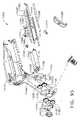
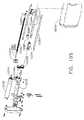
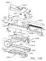
図34〜37は手術用エンドエフェクタ1000を示しており、この手術用エンドエフェクタ1000は、「オープンリニア」ステープラと一般に呼ばれるタイプの手術用切断締結器具を備えている。そのようなオープンリニアステープル留め装置の様々な形態が、例えば、「SURGICAL STAPLER AND STAPLE CARTRIDGE」と題された米国特許第5,415,334号、及び「SURGICAL STAPLING INSTRUMENT」と題された米国特許第8,561,870号に開示されており、各々のすべての開示内容が参照によって本明細書に組み込まれる。エンドエフェクタ1000はエンドエフェクタハウジング1010を備え、エンドエフェクタハウジング1010は、ねじ、突起、スナップ機構などによって互いに取り外し可能に結合されるハウジングセグメント1012、1014から組み立てられ得る。エンドエフェクタハウジング1010から下部ジョー1020と上部ジョー1040が突出しており、これら下部ジョー1020と上部ジョー1040は共同でエンドエフェクタのツールヘッド1004を形成し得る。下部ジョー1020は、手術用ステープルカートリッジ1060を中に動作可能に支持するように構成された下部ジョーフレーム1022を備えている。そのような手術用ステープルカートリッジは当該技術分野で周知であり、したがって本明細書では詳細に説明しない。簡潔に言えば、手術用ステープルカートリッジ1060はカートリッジ本体1062を備え得、カートリッジ本体1062は、カートリッジ本体1062内に中央に配設された細長スロット1068の各外側部に形成されたステープルポケット1066のラインを有している。スロット1068は、以下で更に詳細に議論するように、切断部材1090の長手方向の移動に適応するように構成されている。手術用ステープル(図示せず)が、ステープル駆動部材(図示せず)上のステープルポケット1066内に支持され、そのステープル駆動部材は、発射プロセスの間に各ポケット1066内で上向きに移動するように構成されている。ステープルカートリッジ1060は、下部ジョーフレーム1022から取り外され、別の未使用カートリッジと交換されるように構成されて、エンドエフェクタ1000を再使用可能にしてもよい。しかしながら、エンドエフェクタ1000はまた、1回の使用後に使い捨てにされてもよい。 34-37 illustrate a
図36を参照すると、下部ジョーフレーム1022は、金属材料から形成され、手術用ステープルカートリッジ1060を中に着座式で受容するように構成されたU字形状の遠位部分1024を有してもよい。U字形状の遠位部分1024の側壁1026は、手術用カートリッジ1060の一部分と解放可能にかつ保持によって係合するように構成された遠位端部1028を有してもよい。ステープルカートリッジ本体1062はまた係合機構1064を有してもよく、この係合機構1064は、下部ジョーフレーム1022の直立する壁部分1030と解放可能に係合するように適合されている。エンドエフェクタ1000は、アンビル部分1042を有する上部ジョー1040を更に備えている。アンビル部分1042は、複数のステープル成形ポケットを中に有する裏面(図示せず)を有してもよい。上部ジョー1040は近位本体部分1044を更に含み、この近位本体部分1044は、それを通って延びる遠位トラニオンピン1046を有している。近位本体部分1044の近位端部から外方に突出する遠位トラニオンピン1046の端部は、下部ジョー1020のトラニオンホール1032内に回転可能に受容される。トラニオンピン1046は、上部ジョー1040の近位端部が下部ジョー1020に対して旋回する取り付け軸AA−AAを規定しており、それにより、アンビル部分1042は、下部ジョー1020内に装着されたステープルカートリッジ1060から離間する開位置と、それらの間に配置されたステープルカートリッジ160及び/又は組織に隣接する閉位置との間で移動可能となっている。エンドエフェクタ1000は横断支持ピン1050を更に含んでもよく、この横断支持ピン1050は、下部ジョー1020の直立壁1030に形成されたクレードル1034内に受容され、ハウジングセグメント1012、1014のホール1016内に装着される。支持ピン1050は、アンビル部分1042が旋回する支持軸又は表面として働き得る。 Referring to FIG. 36, the
開位置と閉位置との間におけるアンビル部分1042の移動は、本明細書ではエンドエフェクタクロージャシステム1070とも呼ばれる第1のエンドエフェクタ駆動システムによって制御される。一形態において、例えば、エンドエフェクタクロージャシステム1070は、下部ジョー1020の近位本体部分1024を囲んで延びるクロージャシャトル1072を含む。クロージャシャトル1072はまた、「第1のエンドエフェクタアクチュエータ」とも呼ばれ得る。クロージャシャトル1072は、遠位直立壁1074と近位直立壁1076とを有するU字形状部分を含んでもよい。各遠位直立壁1074は弓状カムスロット1078を含み、この弓状カムスロット1078は、上部ジョー1040に取り付けられたカムピン1048の対応部分を受容するように適合されている。したがって、クロージャシャトル1072が下部ジョー1020に対して軸方向又は直線運動することにより、上部ジョー1040は、カムスロット1078内のカムピン1048の相互作用によって、支点ピン1050上で取り付け軸AA−AAを中心として旋回することになる。 Movement of the
様々な形態において、クロージャシステム1070は回転式のエンドエフェクタクロージャシャフト1080を含み、このエンドエフェクタクロージャシャフト1080はねじ付きであり、エンドエフェクタハウジング1010内に回転可能に支持される遠位端部分1082を含んでいる。エンドエフェクタクロージャシャフト1080は、クロージャシャフト軸CSA−CSAを規定している。図37を参照されたい。クロージャシャフト1080を、手術器具内の第1の駆動シャフトに取り付けられた雄型カプラ51と結合するのを容易にするために、雌型ソケットカプラ57がクロージャシャフト1080の近位端部に取り付けられている。クロージャシステム1070はクロージャナット1084を更に含んでおり、クロージャナット1084はクロージャシャフト108上に螺合可能に受容される。クロージャナット1084は、クロージャシャトル1072の直立壁1076の装着スロット1077内に着座されるように構成されている。したがって、クロージャシャフト1080が第1の方向に回転することにより、クロージャナット1084はクロージャシャトル1072を遠位方向「DD」に駆動することになる。クロージャシャトル1072が遠位方向「DD」に移動することにより、結果として、上部ジョー1040が開位置から閉位置へと旋回移動することになる。同様に、クロージャシャトル1084が近位方向「PD」に移動することにより、結果として、上部ジョー1040が閉位置から再び開位置へと移動することになる。 In various configurations, the
エンドエフェクタ1000は、本明細書において発射システム1100とも呼ばれる、第2のエンドエフェクタ駆動システムを更に含んでおり、この発射システム1100は、組織切断部材1090及びウェッジスレッド組立体1092を開始位置と終了位置との間で駆動するためのものである。ウェッジスレッド組立体1092が手術用ステープルカートリッジ1060を通じて遠位側に駆動されるとき、ウェッジスレッド組立体1092は、手術用ステープルを上で支持するカートリッジ1060内の駆動部と動作可能に相互作用する。ウェッジスレッド組立体1092が遠位側に駆動されるとき、駆動部は、それぞれのポケット内で上向きに駆動されて、支持されているステープルを駆動して上部ジョー1040のアンビル部分1042の裏面と成形係合させる。一形態において、発射システム1100は、エンドエフェクタハウジング1010内に回転可能に支持される、回転式のねじ付き発射シャフト1102を更に含んでいる。発射シャフト1102は、クロージャシャフト軸CSA−CSAと平行か、又は実質的に平行である発射シャフト軸FSA−FSAを規定している。例えば、図37を参照されたい。発射シャフト1102は遠位端部分1104を含み、遠位端部分1104は、エンドエフェクタ1010内に装着された装着ユニット1106内に回転可能に支持されている。発射シャフト1102を、手術器具内の第2の駆動シャフトに取り付けられた雄型クロージャカプラ51と結合するのを容易にするために、雌型ソケットカプラ57が発射シャフト1102の近位端部に取り付けられている。発射システム1100は発射ナット1110を更に含んでおり、発射ナット1110は発射シャフト1102上に螺合可能に受容される。したがって、発射シャフト1102が回転することにより、結果として、発射ナット1110がエンドエフェクタハウジング1010内で軸方向に移動する。一形態において、組織切断部材1090とウェッジスレッド組立体1092は、発射バー1112によって発射ナット1110に結合される。発射バーはまた、発射システムの作動に反応して直線的に又は軸方向に移動される「第2のエンドエフェクタアクチュエータ」とも呼ばれ得る。したがって、発射シャフト1102が第1の方向に回転すると、発射ナット1110、発射バー1112、組織切断部材1090及びウェッジスレッド組立体1092は、例えば開始位置(図35)から終了位置へと遠位方向「DD」に駆動され、この終了位置において、組織切断部材1090及びウェッジスレッド組立体1092は手術用ステープルカートリッジ1060の遠位端部へと駆動されている。発射シャフト1102が反対方向に回転すると、発射ナット1110、発射バー1112、組織切断部材1090及びウェッジスレッド組立体1092は、それぞれの終了位置から再びそれぞれの開始位置へと近位方向「PD」に駆動される。いくつかの実施形態において、ウェッジスレッド組立体は、手術用ステープルカートリッジの遠位端部に残存し、組織切断部材1090と共に開始位置へと復帰しなくてもよい。更に他の実施形態において、組織切断部材及びウェッジスレッド組立体部材は、ステープルカートリッジ部材の遠位端部に残存してもよい。
エンドエフェクタ1000はまた、エンドエフェクタハウジング1010内に装着されたエンドエフェクタの接触板1120に結合された様々なセンサを装備され得る。接触板1120は、エンドエフェクタ1000が手術器具に動作可能に結合されるとき、手術器具ハウジング12内に装着された手術器具の接触板30にエンドエフェクタの接触板1120が電気的に結合されるように、エンドエフェクタハウジング1020と位置決めされ得る。例えば、図1を参照されたい。再び図34を参照すると、エンドエフェクタ1000が手術器具に動作可能に結合されるとき、クロージャセンサ1122が手術器具の制御システムと通信するように、クロージャセンサ1122がエンドエフェクタハウジング1010内に装着され、エンドエフェクタの接触板1120に電気的に結合され得る。クロージャセンサ1122は、クロージャナット1084上のスイッチ突起1086の位置を検出するように構成された、例えば図61、63に関連して以下に示すようなホール効果センサ7028を含んでもよい。それに加えて、発射バー1112の存在を検出するために、発射センサ1124がまたエンドエフェクタハウジング1010内に装着されてもよい。図61、63、64に関連して以下で更に詳細に議論するように、発射センサ1112は、例えば図61、63に関連して以下に示すようなホール効果センサ7028を含み、ハンドル用プロセッサ7024などの手術器具制御システムと最終的に通信するために、エンドエフェクタの接触板1120に電気的に結合されてもよい。 The
エンドエフェクタ1000の使用法について、手術器具10に関連させてこれから説明することにする。しかしながら、エンドエフェクタ1000は、本明細書で開示する様々な他の手術器具装置に動作可能に結合され得ることが明らかとなろう。使用前、クロージャシャフト1080及び発射シャフト1102は、それぞれ第1及び第2の駆動シャフト22、42への取り付けを容易にするように、それぞれの開始位置に「クロック(clocked)」又は配置されている。エンドエフェクタ1000を手術器具10に結合するために、例えば、臨床医は、クロージャシャフト軸CA−CAが第1の駆動シャフト軸FDA−FDAと軸方向に整合し、発射シャフト軸FSA−FSAが第2の駆動シャフト軸SDA−SDAと軸方向に整合する位置に、エンドエフェクタ1000を移動させる。クロージャシャフト1080上の雌型ソケットカプラ57は、第1の駆動シャフト22上の雄型カプラ51と動作可能に係合するように挿入される。同様に、発射シャフト1102上の雌型ソケットカプラ57は、第2の駆動シャフト42上の雄型カプラ51と動作可能に係合するように挿入される。したがって、この位置にあるとき、クロージャシャフト1080は第1の駆動シャフト22に動作可能に結合されており、発射シャフト1102は第2の駆動シャフト42に動作可能に結合されている。エンドエフェクタの接触板1120は手術器具の接触板30に動作可能に結合され、そのため、センサ1122、1124(及びエンドエフェクタ1000内の任意の他のセンサ)が手術器具の制御システムと動作可能に通信するようになっている。エンドエフェクタ1000を、手術器具10と動作可能に係合した状態に保つために、エンドエフェクタ1000はリテーナラッチ1130を含み、このリテーナラッチ1130は、エンドエフェクタハウジング1010に取り付けられるものであり、器具ハウジング12の一部分と解放可能に係合するように構成されている。リテーナラッチ1130は保持突起1132を含んでもよく、保持突起1132は、ハウジング12に形成されたリテーナキャビティ15と解放可能に係合し得る。図1を参照されたい。 The use of the
互いに結合されると、クロージャセンサ1122はクロージャナット1084の位置を検出し、発射センサ1124は発射バー1112の位置を検出する。その情報は、手術器具制御システムに通信される。それに加えて、臨床医は、シフト式伝達組立体(又はその伝達キャリッジ62)がその第1の駆動位置にあることを確認してもよい。これは、上で議論したようにハウジング12上の表示灯77の作動によって確認され得る。シフト式伝達組立体60がその第1の駆動位置にない場合、臨床医は、発射トリガ92を作動させて伝達キャリッジ62を第1の駆動位置に移動させてもよく、それにより、ロッカートリガ110が作動してモータ80が作動すると、結果として第1の駆動システム20が作動するようになる。クロージャシステム1070及び発射システム1100がそれぞれ開始位置にあり、エンドエフェクタ1000が、その中に未使用のステープルカートリッジ1060を適切に取り付けられていると仮定すると、臨床医は次いで、切断及びステープル留めされる標的組織に対してジョー1020、1040を位置決めし得る。臨床医は、ロッカートリガ110を作動させてモータ80を作動させ、第1の駆動シャフト22を回転させることによって、上部ジョー1040を閉鎖し得る。標的組織が上部ジョー1040と下部ジョー1020内の手術用ステープルカートリッジ1060との間にクランプされると、臨床医は次いで、発射トリガ92を作動させて伝達キャリッジ62をその第2の駆動位置に移動させ得、そのため、モータ80が作動することにより、結果として第2の駆動シャフト42が回転するようになる。伝達キャリッジ62が第2の駆動位置に移動されると、臨床医はもう一度ロッカートリガ110を作動させて、第2の駆動システム40、及びエンドエフェクタ1000内の発射システム1100を作動させ、組織切断部材1090及びウェッジスレッド組立体1092を、手術用ステープルカートリッジ1060を通じて遠位側に駆動し得る。組織切断部材1090及びウェッジスレッド組立体1092が遠位側に駆動されるとき、ジョー1020と1040との間にクランプされた標的組織が切断及びステープル留めされる。組織切断部材1090及びウェッジスレッド組立体1092が手術用ステープルカートリッジ1060内でそれらの最遠位位置に駆動されると、臨床医は、ロッカートリガ110を作動させてモータの回転を逆転させ、発射システム1100をその開始位置に復帰させ得る。 When coupled together,
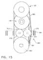
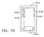
エンドエフェクタ1000及び他のエンドエフェクタ、並びに、同様のジョー装置を備えた、本明細書で開示した手術器具を用いる場合、アンビルの裏面にあるアンビルポケットを適当に清浄にすることが困難となり得る。それに加えて、アンビルポケットは、時間を経て、擦り剥け、削がれ、又は単純に摩耗して、再使用に不適当になり得る。更に、用途によっては、手術用ステープルカートリッジの装填及び除去が困難になり得る。図119〜121は、これらの難題のすべてではなくても一部に対処し得る使い捨て「ステープルパック」1300を示している。 When using the surgical instruments disclosed herein with
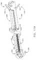
図119は、以下で議論する特異的な違いは除いて、例えばエンドエフェクタ1000並びに本明細書で開示した他のエンドエフェクタに構造及び動作において類似し得るエンドエフェクタ1000’の一部分を示している。図119で分かるように、上部ジョー1240は開放遠位端部1243を含んでいる。上部ジョー1240は、金属材料から形成され、遠位端部から見てU字形状の外形を有し、内向きに延びる2つの対向保持リップ1245を有し得る。エンドエフェクタ1000’は、例えば本明細書で記述した下部ジョーフレーム1222に類似した下部ジョーフレーム1222を更に含んでいる。この図で分かるように、下部ジョーフレーム1222はまた、開放遠位端部1223を有している。 FIG. 119 illustrates a portion of an end effector 1000 'that may be similar in structure and operation to, for example, the
依然として図119を参照すると、「使い捨て」ステープルパック1300の一形態がアンビル1302を含んでおり、アンビル1302はステープル成形表面1304を有し、ステープル成形表面1304は、その中に形成された複数のステープル成形ポケット(図示せず)を含んでいる。ステープルパック1300はステープルカートリッジ1310を更に有しており、ステープルカートリッジ1310は、アンビル1302のステープル成形下面1304に間隔を置いて直面する関係をなすように構成されたカートリッジデッキ1312を有している。ステープルカートリッジ1310は、本明細書で更に詳細に開示する他のステープルカートリッジに類似していてもよく、中に複数の手術用ステープルを動作可能に支持し得る。ステープルパック1300は、ステープル成形下面1304のステープルポケットとステープルカートリッジ1310内のステープル(図示せず)との間の整合を使用前に維持するような方式で、アンビル1302とステープルカートリッジ1310とを摩擦係合させるように寸法及び形状を定められた使い捨てキーパー部材1320を更に含んでいる。キーパー1320はまた、アンビル1302とステープルカートリッジ1310との間に延びるスペーサストリップ1322を含んでもよい。キーパーは、例えば、プラスチック又は他の好適なポリマー材料から成型されてもよく、またスペーサストリップ1322は金属材料から製作されてもよい。スペーサストリップ1322は、キーパー1320に形成されたスロット又は他の保持機構内に摩擦によって保持され得る。 Still referring to FIG. 119, one form of a “disposable”
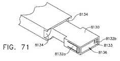
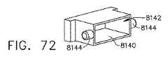
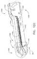
ここで図120を参照すると、ステープルパック1300は、アンビル1302を上部ジョー1240の開放遠位端部1243と整列させることによって取り付けられており、ステープルカートリッジ1310は、下部ジョーフレーム1222の開放遠位端部1245と整列されている。その後に、ステープルパック1300は、図120に示す位置へと、近位方向「PD」に移動される。保持リップ1245は、アンビル1302を上部ジョー1240内に支持するように働く。エンドエフェクタ1000’はまた、手動で作動可能なラッチ機構1340を含んでもよく、このラッチ機構1340は、非ラッチ位置(図119)からラッチ位置(図121)へと移動され得る。ラッチ位置にあるとき、例えば、ラッチ機構1340は、アンビル1302を上部ジョー1240内に、そしてステープルカートリッジ1310を下部ジョーフレーム1222内に保持する。例えば、ラッチ機構1340は、アンビル1302の近位端部上に形成された部分(例えば、リップ、デテント、レッジ又は他の保持機構)と解放可能に係合するように構成された可動上部ラッチアーム1342を含んでもよい。同様に、ラッチ機構1340は、ステープルカートリッジ1310上に形成された部分(例えば、リップ、デテント、レッジ又は他の保持機構)と解放可能に係合するように構成された可動下部ラッチアーム1344を含んでもよい。上部及び下部ラッチアーム1342、1344は、ラッチ位置と非ラッチ位置との間で選択的に移動するように、エンドエフェクタ1000’上に旋回式であるいは別様に移動可能に支持され得る。様々な形態において、上部及び下部ラッチアーム1342、1344は通常、ばね(図示せず)によってラッチ位置へと付勢され得る。そのような装置構成において、臨床医は、ステープルパック1300を上部ジョー1240及び下部ジョーフレーム1222の中に挿入し得る。アンビル1302の近位端部が上部ラッチアーム1342と接触するとき、上部ラッチアーム1342は、アンビル1302を定位置に着座させるように旋回又は移動される。アンビルが定位置に着座されると、上部ラッチアーム1342は、付勢されてアンビル1302とラッチ係合をなす(ばね又は付勢部材が用いられる場合)。別の装置構成において、上部ラッチアーム1342は、ラッチ位置へと手動で移動されてもよい。同様に、ステープルカートリッジ1310の近位端部が下部ラッチアーム1344と接触するとき、下部ラッチアーム1344は、ステープルカートリッジ1310を定位置に着座させるように旋回又は移動される。ステープルカートリッジ1310が定位置に着座されると、下部ラッチアーム1344はステープルカートリッジ1310とのラッチ係合へと付勢されて、ステープルカートリッジ1310を定位置に保持する(ばね又は付勢装置が用いられる場合)。別の実施形態において、下部ラッチアーム1344は、ラッチ位置へと手動で移動されてもよい。ステープルパック1300が取り付けられ、アンビル1302及びステープルカートリッジ1310がエンドエフェクタ1000’にラッチ係合されるかあるいは別様に取り付けられると、臨床医はキーパー組立体1320を取り外し得る。例えば、図121を参照されたい。ステープルパック1300が使用された後、臨床医は次いで、キーパー1320をアンビル1302及びステープルカートリッジ1310の遠位端部の上に戻し得る。これは、キーパー部材1320の開放端部をアンビル1302及びステープルカートリッジ1310と整列させ、次いでキーパー部材1320を押して、アンビル1302及びステープルカートリッジ1310と再び摩擦係合させることによって達成され得る。アンビル1302及びステープルカートリッジ1310の各遠位端部がキーパー部材1320に着座されると、臨床医は、上部及び下部ラッチアーム1342、1344をそれらの非ラッチ位置へと移動させて、ステープルパック1300を上部ジョー1240及び下部ジョーフレーム1222から引っ張り出し得る。その後に、ステープルパック1300は単体で廃棄され得る。他の状況において、臨床医は、最初にキーパー部材1320を取り付けることなく、アンビル1302及びステープルカートリッジ1310をエンドエフェクタ1000’から別々に取り外してもよい。 Referring now to FIG. 120, the
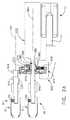
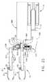
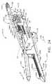
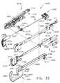
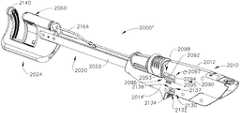
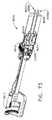
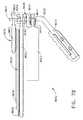
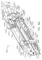
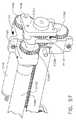
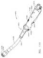
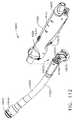
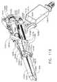
図38〜41は手術用エンドエフェクタ2000を示しており、この手術用エンドエフェクタ2000は、「曲線カッターステープラ」と一般に呼ばれ得るタイプの手術用切断締結器具を備えている。そのようなステーププル留め装置の様々な形態が、例えば、それぞれのすべての開示内容が参照によって本明細書に組み込まれる、「RETAINING PIN LEVER ADVANCEMENT MECHANISM FOR A CURVED CUTTER STAPLER」と題された米国特許第6,988,650号、及び「KNIFE RETRACTION ARM FOR A CURVED CUTTER STAPLER」と題された米国特許第7,134,587号に開示されている。エンドエフェクタ2000はエンドエフェクタハウジング2010を備え、エンドエフェクタハウジング2010は、ねじ、突起、スナップ機構などによって互いに取り外し可能に結合されるハウジングセグメント2012、2014から組み立てられ得る。エンドエフェクタツールヘッド2002にて終端する細長フレーム組立体2020が、エンドエフェクタハウジング2010から突出している。一形態において、フレーム組立体2020は、一対の離間フレームストラット又はプレート2022を備え、この離間フレームストラット又はプレート2022は、ハウジング2010に固定式で取り付けられ、ハウジング2010から遠位側に突出する。C字形状の支持構造体2024が、フレームプレート2022の遠位端部に取り付けられている。「C字形状」という用語は、本明細書の全体を通じて、支持構造体2024及び手術用カートリッジモジュール2060の凹面性を表すために用いられている。C字形状の構造は機能性の向上を促進するものであり、また本明細書におけるC字形状という用語の使用は、同様に手術用ステープリング及び切断器具の機能性を向上させる多様な凹面形状を包含すると見なされるべきである。支持構造体2024は、ショルダーリベット2023及びポスト2026によってフレームプレート2022に取り付けられ、ポスト2026は、支持構造体2024からフレームプレート2022の受容ホールの中へと延びている。様々な形態において、支持構造体2024は、単体構造によって形成され得る。より具体的に言えば、支持構造体2024は、押出しアルミニウム材料から形成され得る。この方式で支持構造体2024を形成することにより、複数の部品は必要でなくなり、それに伴う製造及び組み立てのコストが相当に削減される。それに加えて、支持構造体2024が一体構造であることで、エンドエフェクタ2000の全体的な安定性が向上すると考えられる。更に、支持構造体2024が一体の押出し構造であることは、重量の低減、コバルト照射が押出しアルミニウムに効果的に浸透することによる滅菌の容易化、及び押出しによって達成される平滑な外表面を基にした組織への外傷の軽減をもたらす。 38-41 illustrate a
エンドエフェクタ2000は、エンドエフェクタクロージャシステム2070とも呼ばれる第1のエンドエフェクタ駆動システムと、本明細書では発射システム2100とも呼ばれる第2のエンドエフェクタ駆動システムとを更に含んでいる。一形態において、例えば、エンドエフェクタクロージャシステム2070は、フレームストラット2022の間で軸方向移動をなすよう、フレームストラット2022の間でスライド可能に受容されるように寸法を定められたクロージャビーム組立体2072を含んでいる。クロージャビーム組立体2072は、第1のエンドエフェクタアクチュエータと呼ばれてもよく、また、以下で更に詳細に議論するように、発射システム2100の発射バー組立体2112をスライド可能に受容するように構成された開放底部を有している。一形態において、例えば、クロージャビーム組立体2072は、以下で更に議論するように、移動性及び機能性を求めて付形された成形プラスチック部材である。クロージャビーム組立体2072をプラスチックから製造することにより、製造コストが低減され得、エンドエフェクタ2000の重量もまた低減され得る。それに加えて、エンドエフェクタ2000はコバルト照射でより容易に滅菌され得るが、これは、プラスチックはステンレス鋼よりも浸透しやすいからである。別の装置構成によれば、クロージャビーム組立体2072は押出しアルミニウムから作製され、最終的な外形を機械加工されて整えられてもよい。押出しアルミニウムのクロージャビーム組立体は、プラスチックの構成要素と同じようには容易に製造されないこともあるが、それでもやはり、同じ利点(すなわち、構成要素が排除され、組み立てがより容易であり、重量がより軽く、滅菌がより容易である)を有することになる。
クロージャビーム組立体2072は曲線状遠位端部2074を含んでおり、曲線状遠位端部2074は、支持構造体2024の側壁2027同士の間に受容されるように寸法を定められている。曲線状遠位端部2074は、カートリッジモジュール2060のカートリッジハウジング2062を受容及び保持するように寸法及び形状を定められている。様々な形態において、クロージャビーム組立体2072の近位端部はクロージャナット2084に結合され、クロージャナット2084は、ねじ付きクロージャシャフト2080上にねじ結合可能に受容される。クロージャシャフト2080は、クロージャシャフト軸CSA−CSAを規定しており、また、手術器具内の第1の駆動シャフトに取り付けられた雄型カプラ51とクロージャシャフト2080を結合するのを容易にするために、クロージャシャフト2080の近位端部に取り付けられた雌型ソケットカプラ57を有する。クロージャシャフト2080が第1の方向に回転することにより、クロージャナット2084は、クロージャビーム組立体2072を遠位方向「DD」に駆動することになる。クロージャシャフト2080が反対方向に回転することにより、同様に、結果としてクロージャナット2084及びクロージャビーム組立体2072が近位方向に移動する。 The
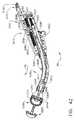
上に示したように、クロージャビーム組立体2072の遠位端部2074は、その中にカートリッジモジュール2060のカートリッジハウジング2062を動作可能に支持するように構成されている。カートリッジモジュール2060は、ステープルドライバ(図示せず)上に複数の手術用ステープル(図示せず)を含み、このステープルドライバは、軸方向に前進されると、ナイフ部材2115の通過に適応するように構成されたスロット1068の各側部に配置された対応するポケット2066から、手術用ステープルを駆動して追い出すものである。カートリッジモジュール2060は、明記された違いを除いて、例えば、共にそれぞれのすべての内容が本明細書に組み込まれる米国特許第6,988,650号及び同第7,134,587号に開示されているカートリッジモジュールと幾分か類似していてもよい。エンドエフェクタ2000は1回の使用後に処分されてもよく、あるいは、エンドエフェクタ2000は、再滅菌された後、進行中の手技の間に又は新たな手技のために、使用済みのカートリッジモジュールを交換することによって再使用型にされてもよい。 As indicated above, the
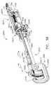
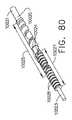
エンドエフェクタ2000は発射システム2100を更に含み、発射システム2100は、クロージャビーム組立体2072の開放底部内にスライド可能に受容されるように構成された発射バー組立体2112を含んでいる。図39を参照されたい。一形態において、発射システム2100は発射シャフト2102を更に含み、発射シャフト2102は、ねじ付き遠位端部2104と、正方形の横断面形状を有する近位部分2106とを有している。ねじ付き遠位端部2104は、発射バー組立体2112の近位端部に取り付けられたねじ付き発射ナット2110内に、螺合可能に受容される。ねじ付き発射ナット2110は、クロージャナット組立体2084内の軸方向キャビティ2085内にスライド可能に受容されるように寸法を定められている。図41を参照されたい。そのような装置により、発射ナット2110は、エンドエフェクタ2000が閉位置へと移動されるときに、クロージャナット組立体2084と共に軸方向に移動し、次いで、発射システム2100が作動されるときに、クロージャナット2084及びクロージャビーム組立体2072に対して軸方向に移動することができる。発射シャフト2102は、クロージャシャフト軸CSA−CSAと平行か、又は実質的に平行である発射シャフト軸FSA−FSAを規定している。例えば、図41を参照されたい。また図39及び41で分かるように、発射シャフト2102の近位部分2106は、その他の点では本明細書に記述した雌型ソケットカプラと同一である雌型ソケットカプラ57’内の細長通路2105内にスライド可能に受容される。細長通路2105は、その中に発射シャフト2102の近位部分2106をスライド可能に受容するように寸法を定められた正方形の横断面形状を有している。そのような装置構成により、発射シャフト2102は、雌型ソケットカプラ57’と共に回転可能でありながらも、雌型ソケットカプラ57’に対して軸方向に移動することができる。したがって、クロージャビーム組立体2072が、手術器具内の第1の駆動システムの作動時に遠位方向「DD」に前進されるとき、発射ナット2110は、クロージャナット組立体2084内で遠位方向「DD」に運ばれることになる。発射シャフト2102の近位部分2106は、雌型ソケットカプラ57’と依然として係合されながらも、雌型ソケットカプラ57’の通路2105内で軸方向に移動する。その後に、雌型ソケットカプラ57’に動作可能に結合されている手術器具内で第2の駆動システムがある回転方向に起動することにより、発射シャフト2102が回転することになり、これによって、発射バー組立体2112は遠位方向「DD」に移動することになる。発射バー組立体2112が遠位方向に移動するとき、ナイフバー2115は、カートリッジモジュール2060を通じて遠位側に前進される。第2の駆動システムが第2の回転方向に作動することにより、発射バー組立体2112は近位方向「PD」に移動することになる。
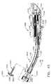
発射バー組立体2112の遠位端部は、駆動部材2114と、その駆動部材2114から遠位側に突出するナイフ部材2115とを含んでいる。図39で分かるように、ナイフ部材2115は、支持構造体2024の曲線状アンビル支持部分2025内に着座されるように構成されたアンビル組立体2140のアンビルアーム部分2142内に、スライド可能に受容されている。アンビル組立体2140に関する更なる詳細が、米国特許第6,988,650号及び同第7,134,587号に見出され得る。エンドエフェクタ2000はまた、既に発射されたカートリッジモジュール2060の発射を防止するための安全ロックアウト機構2150(図39)を含んでもよい。カートリッジモジュール2060と安全ロックアウト機構との相互作用に関する詳細は、米国特許第6,988,650号及び同第7,134,587号に見出され得る。 The distal end of the firing
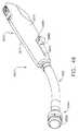
エンドエフェクタ2000はまた、組織保持ピンの作動機構2160を含んでいる。組織保持ピンの作動機構2160は、ハウジング2010の上方部分に配置されたサドル形状のスライド2162を含んでいる。スライド2162は、ハウジング2010内にスライド可能に支持されるプッシュロッドドライバ2163に旋回式に連結されている。プッシュロッドドライバ2163は、エンドエフェクタ2000の長軸に沿った長手方向の移動に関して制限されている。プッシュロッドドライバ2163は、プッシュロッドドライバ2163のスロット2166の中にスナップ嵌めされるプッシュロッド2164上の環状溝2165によって、プッシュロッド2164に連結される。図41を参照されたい。プッシュロッド2164の遠位端部は環状溝2167を有し、環状溝2167は、カートリッジモジュール2160に取り付けられたカプラ2170の近位端部の溝2172と連結する(図41に最良に示す)。カプラ2170の遠位端部は、保持ピン2180上の環状スロット2182と相互連結するための溝2174を有している。スライド2162を手動で移動させることにより、結果としてプッシュロッド2164が移動する。プッシュロッド2164が遠位側に移動すること又は近位側に後退することにより、結果として、それに対応して保持ピン2180が移動することになる。保持ピン2180の作動機構2160はまた、クロージャビーム組立体2072と動作可能に相互作用し、そのため、クロージャシステム2070が作動することにより、結果として、保持ピン2180は、その最近位位置にまだ手動で移動されていない場合、自動的に遠位側に移動するようになっている。保持ピン2180が前進されるとき、保持ピン2180はカートリッジハウジング2062を通じてアンビル組立体2140の中へと延び、それによってカートリッジモジュール2060とアンビル組立体2140との間に組織を捕捉する。
一形態において、保持ピンの作動機構2160は、ピボットピン2192によってハウジング2010内に回転式で又は旋回式で支持されるヨーク2190を含む。クロージャビーム組立体2072は、ハウジング2010の内側にてクロージャビーム組立体2072の両側で横方向に延びるポスト又は突起2073を更に含んでいる。これらのポスト2073は、ヨーク2190の対応する弓状スロット2194内にスライド可能に受容される。ヨーク2190は、プッシュロッドドライバ2163のカム表面2168を押すように配置されたカムピン2196を有している。ヨーク2190は保持ピン2180に直接、取り付けられておらず、したがって外科医は、自身がそのように選ぶ場合、保持ピン2180を手動で前進させ得る。保持ピン2180は、クロージャビーム組立体2072が閉位置へと遠位側に前進されるとき、外科医が保持ピン2180のみを残すように選択する場合、自動的に前進することになる。外科医は、保持ピン2180を手動で後退させなければならない。保持ピンの作動機構2160をこのように構成することにより、保持ピン2180の手動閉鎖及び後退が可能となる。外科医が保持ピン21280を手動で閉鎖しない場合、この保持ピンの作動機構2160は、器具のクランプの間に自動的に保持ピン2180を閉鎖する。保持ピンの作動及び使用法に関する更なる詳細が、米国特許第6,988,650号及び同第7,134,587号に見出され得る。 In one form, the retention
エンドエフェクタ2000はまた、エンドエフェクタハウジング2010内に装着されたエンドエフェクタの接触板2120に結合された様々なセンサを装備され得る。例えば、エンドエフェクタ2000は、エンドエフェクタハウジング2010内に装着され、エンドエフェクタの接触板2120に電気的に結合されたクロージャセンサ2122を含んでもよく、それにより、エンドエフェクタ2000が手術器具に動作可能に結合されるとき、クロージャセンサ2122は手術器具の制御システムと通信するようになる。クロージャセンサ2122は、クロージャナット21084上のスイッチ突起2086の位置を検出するように構成された、図61、63に関連して以下に示すようなホール効果センサ7028を含んでもよい。図40を参照されたい。それに加えて、発射センサ2124がまた、エンドエフェクタハウジング2010内に装着されてもよく、またクロージャナット2084内の発射ナット2110の位置を検出するように装置されてもよい。発射センサ2124は、図61、63に関連して以下に記述するホール効果センサ7028を含んでもよく、また、本明細書で議論するような手術器具制御システムと最終的に通信するように、エンドエフェクタの接触板2120に電気的に結合されてもよい。上で議論したように、接触板2120は、エンドエフェクタ2000が手術器具に動作可能に結合されるとき、手術器具ハウジング12内に装着された手術器具の接触板30にエンドエフェクタの接触板2120が電気的に結合されるように、エンドエフェクタハウジング2020と位置決めされ得る。 The
エンドエフェクタ2000の使用法について、手術器具10に関連させてこれから説明することにする。しかしながら、エンドエフェクタ2000は、本明細書で開示する様々な他の手術器具装置に動作可能に結合され得ることが明らかとなろう。使用前、クロージャシャフト2080及び発射シャフト2102は、それぞれ第1及び第2の駆動シャフト22、42への取り付けを容易にするように、それぞれの開始位置に「クロック」又は配置されている。エンドエフェクタ2000を手術器具10に結合するために、例えば、臨床医は、クロージャシャフト軸CSA−CSAが第1の駆動シャフト軸FDA−FDAと軸方向に整合し、発射シャフト軸FSA−FSAが第2の駆動シャフト軸SDA−SDAと軸方向に整合する位置に、エンドエフェクタ2000を移動させる。クロージャシャフト2080上の雌型ソケットカプラ57は、第1の駆動シャフト22上の雄型カプラ51と動作可能に係合するように挿入される。同様に、発射シャフト2102上の雌型ソケットカプラ57’は、第2の駆動シャフト42上の雄型カプラ51と動作可能に係合するように挿入される。したがって、この位置にあるとき、クロージャシャフト2080は第1の駆動シャフト22に動作可能に結合されており、発射シャフト2102は第2の駆動シャフト42に動作可能に結合されている。エンドエフェクタの接触板1120は手術器具の接触板30に動作可能に結合され、そのため、エンドエフェクタ2000内のセンサが手術器具の制御システムと動作可能に通信するようになっている。エンドエフェクタ2000を、手術器具10と動作可能に係合した状態に保つために、エンドエフェクタ2000はリテーナラッチ2130を含み、このリテーナラッチ2130は、エンドエフェクタハウジング2010に取り付けられるものであり、器具ハウジング12の一部分と解放可能に係合するように構成されている。リテーナラッチ2130は保持突起2132を含んでもよく、保持突起2132は、ハウジング12に形成されたリテーナキャビティ15と解放可能に係合し得る。図1を参照されたい。互いに結合されると、クロージャセンサ2122はクロージャナット2084の位置を検出し、発射センサ2124は発射ナット2110の位置を検出する。その情報は、手術器具制御システムに通信される。それに加えて、臨床医は、シフト式伝達組立体(又はその伝達キャリッジ62)がその第1の駆動位置にあることを確認してもよい。これは、上で議論したようにハウジング12上の表示灯77の作動によって確認され得る。シフト式伝達組立体60がその第1の駆動位置にない場合、臨床医は、発射トリガ92を作動させて伝達キャリッジ62を第1の駆動位置に移動させてもよく、それにより、ロッカートリガ110が作動してモータ80が作動すると、結果として第1の駆動システム20が作動するようになる。クロージャシステム2070及び発射システム2100がそれぞれ開始位置にあり、エンドエフェクタ2000が、その中に未使用のステープルカートリッジモジュール2060を適切に取り付けられていると仮定すると、臨床医は次いで、クロージャシステム2070を作動させて、カートリッジモジュール2060とアンビル組立体2140との間に標的組織を捕捉し得る。 The use of
臨床医は、ロッカートリガ110を作動させてモータ80を作動させ、第1の駆動シャフト22を回転させることによって、クロージャビーム組立体2072を遠位側に移動させ得る。この作動により、カートリッジモジュール2060はアンビル組立体2140に向かって移動して、それらの間に標的組織をクランプする。クロージャビーム2072が遠位側に移動するとき、ポスト2073とヨーク2190の相互作用により、組織保持作動機構2160が作動して、デッキ部分2161を通じて、またアンビル組立体2140を通じてピンポケット2141(図41を参照)の中へと保持ピン2180を遠位側に駆動することになる。保持ピン2180は、アンビル組立体2140とカートリッジモジュール2060との間に標的組織を閉じ込めるように働く。標的組織がアンビル組立体2140とカートリッジモジュール2060との間にクランプされると、臨床医は次いで、発射トリガ92を作動させて伝達キャリッジ62をその第2の駆動位置に移動させ得、そのため、モータ80が作動することにより、結果として第2の駆動シャフト42が回転するようになる。伝達キャリッジ62が第2の駆動位置に移動されると、臨床医はもう一度ロッカートリガ110を作動させて、第2の駆動システム40、及びエンドエフェクタ2000内の発射システム2100を駆動して、発射バー組立体2112を遠位側に駆動し得、またこれにより、ナイフ部材2115がカートリッジモジュール2060を通じて遠位側に駆動されて、アンビル組立体2140とカートリッジモジュール2060との間にクランプされた標的組織を切断する。発射バー組立体2112が遠位側に移動するとき、駆動部材2114はまた、カートリッジモジュール2060内に支持された手術用ステープルを駆動して、カートリッジモジュール2060から追い出し、標的組織に通し、アンビル組立体2140と成形接触させる。切断及びステープリング動作が完了すると、臨床医はロッカートリガ110を作動させて、モータの回転を逆転させ、発射システム2100をその開始位置に復帰させ得る。臨床医は次いで、発射トリガ92を用いて伝達キャリッジ62をその第1の駆動位置に復帰させ得、それにより、ロッカートリガ110を反対方向に作動させることにより、モータ80が逆方向に回転して、クロージャビーム組立体2073をその開始位置に復帰させるようになる。クロージャビーム組立体2073が近位方向に移動するとき、ヨーク2190は組織保持ピン作動機構2160と相互作用して、保持ピン2180をその開始位置に後退させ得る。別法において、臨床医は、サドル形状のスライド2162を使用して、保持ピン2180をその開始位置に手動で後退させてもよい。臨床医は、クロージャシステム2070を作動させてクロージャビーム2072を開始位置に復帰させる前に、保持ピン2180をその開始位置に後退させ得る。曲線状ステープルカッターに関する更なる詳細が、米国特許第6,988,650号及び同第7,134,587号に見出され得る。 The clinician may move the
図42〜45は手術用エンドエフェクタ3000を示しており、この手術用エンドエフェクタ3000は、「円形手術用ステープラ」と一般に呼ばれ得るタイプの手術用切断締結器具を備えている。ある種の外科的手技において、手術用ステープルの使用は、組織を接合する好ましい方法となりつつあり、したがって、特別に構成された手術用ステープラがそれらの用途のために開発されてきた。例えば、疾患部分が切除された後に下部結腸の切片が互いに接合される、下部結腸に関する外科手技で使用するために、腔内又は円形ステープラが開発されてきた。そのような手技を実施するのに有用な円形ステープラが、例えば、米国特許第5,104,025号、同第5,205,459号、同第5,285,945号、同第5,309,927号、同第8,353,439号、及び同第8,360,297号において開示されており、これらのすべての内容がそれぞれ、参照によって本明細書に組み込まれる。 42-45 illustrate a
図42に示すように、エンドエフェクタ3000はエンドエフェクタハウジング3010を備え、エンドエフェクタハウジング3010は、ねじ、突起、スナップ機構などによって互いに脱着可能に結合されるハウジングセグメント3012、3014から組み立てられ得る。エンドエフェクタハウジング3010から、細長シャフト組立体3020が突出している。細長シャフト組立体3020は、円形ツールヘッド3300及びアンビル3320を動作可能に支持しそれらと相互作用するように構成されている。上で参照した例示的な米国特許から明らかとなるように、多種多様な円形ステープルカートリッジ及びアンビル装置が当該技術分野で知られている。例えば図43で分かるように、円形ステープラヘッド3300は、ステープルドライバ組立体3304の形態をなすカートリッジ支持組立体を支持するケーシング部材3302を含んでもよく、ステープルドライバ組立体3304は、円形ステープルカートリッジ3306と連結し、円形ステープルカートリッジ3306内で支持されたステープルを駆動して、アンビル3320のステープル成形裏面3326と接触させるように適合されている。また、円形ナイフ部材3308がステープルドライバ組立体3304内に中央に配設されている。ケーシング部材3302の近位端は、遠位のフェルール部材3024によって弓状シャフト組立体3020の外側管状シュラウド3022に結合されてもよい。アンビル3320は円形本体部分3322を含み、円形本体部分3322はトロカールを取り付けるためのアンビルシャフト3324を有している。アンビル本体3322は、ステープル成形裏面3326を有しており、また遠位端部にシュラウド3328を取り付けられてもよい。以下で更に詳細に議論するように、アンビルシャフト3324は、トロカール3042をアンビルシャフト3324と保持係合した状態に解放可能に保持するように働く、一対のトロカール保持クリップ又は板型ばね3330を更に設けられてもよい。 As shown in FIG. 42, the
一形態において、シャフト組立体3020は、圧縮シャフト3030と、圧縮シャフト遠位部分3032と、張力バンド組立体3040とを含み、張力バンド組立体3040は、外側管状シュラウド3022内に動作可能に支持される。トロカール先端部3042は、ファスナ3041によって張力バンド組立体3040の遠位端部に取り付けられる。周知のように、トロカール先端部3042は、アンビル3320のアンビルシャフト3324の中に挿入され、トロカール保持クリップ3330によって係合状態に保持され得る。 In one form, the
手術用エンドエフェクタ3000は、クロージャシステム3070と発射システム3100とを更に含む。少なくとも一形態において、クロージャシステム3070は、張力バンド3040の近位端部に取り付けられるクロージャナット組立体3084を含んでいる。図42及び43で分かるように、クロージャナット組立体3084は近位カプラ部材3085を含み、近位カプラ部材3085は、ファスナ3087によって張力バンド3040の近位端部に取り付けられる。クロージャシステム3070は、クロージャナット3084とねじ係合するねじ付きクロージャシャフト3080を更に含む。クロージャシャフト3080は、クロージャシャフト軸CSA−CSAを規定しており、また、手術器具内の第1の駆動シャフトに取り付けられた雄型カプラ51とクロージャシャフト3080を結合するのを容易にするために、クロージャシャフト3080の近位端部に取り付けられた雌型ソケットカプラ57を有する。クロージャシャフト3080が第1の方向に回転することにより、クロージャナット3084は、張力バンド組立体3040を遠位方向「DD」に駆動することになる。クロージャシャフト3080が反対方向に回転することにより、同様に、結果としてクロージャナット3084及び張力バンド組立体3040が近位方向に移動する。
また図43で分かるように、遠位圧縮シャフト部分3032は、ステープルドライバ組立体3304に結合されている。したがって、圧縮シャフト3030が外側管状シュラウド3022内で軸方向に移動することにより、ステープルドライバ組立体3304は、ケーシング部材3302内で軸方向に移動する。圧縮シャフト3030の軸方向移動は、発射システム3100によって制御される。一形態において、発射システム3100はねじ付き発射シャフト3102を含み、ねじ付き発射シャフト3102は、圧縮シャフト3030の近位端部に取り付けられるねじ付き発射ナット3110とねじ係合する。発射シャフト3102は、クロージャシャフト軸CSA−CSAと平行か、又は実質的に平行である発射シャフト軸FSA−FSAを規定している。例えば図44及び45を参照されたい。発射シャフト3102を、手術器具内の第2の駆動シャフトに取り付けられた雄型カプラ51と結合するのを容易にするために、発射シャフト3102の近位端部は雌型ソケットカプラ57を取り付けられている。手術器具の第2の駆動システムがある回転方向に起動することにより、発射シャフト3102が第1の方向に回転し、それによって、圧縮シャフト3030を遠位方向「DD」に駆動することになる。圧縮シャフト3030が遠位方向「DD」に移動するとき、円形ステープルドライバ組立体3304は遠位側に駆動され、ステープルカートリッジ3306内の手術用ステープルを駆動してアンビル本体3322の裏面3326と成形接触させる。それに加えて、円形ナイフ部材3308が、アンビル本体3322とステープルカートリッジ3306との間にクランプされた組織を通じて駆動される。第2の駆動システムが第2の回転方向に作動することにより、圧縮シャフト3030は近位方向「PD」に移動することになる。 As can also be seen in FIG. 43, the distal
エンドエフェクタ3000はまた、エンドエフェクタハウジング3010内に装着されたエンドエフェクタの接触板3120に結合された様々なセンサを装備され得る。例えば、エンドエフェクタ3000は、エンドエフェクタハウジング3010内に装着されエンドエフェクタの接触板3120に電気的に結合されたクロージャセンサ3122を含んでもよく、それにより、エンドエフェクタ3000が手術器具に動作可能に結合されるとき、クロージャセンサ3122は手術器具の制御システムと通信するようになる。クロージャセンサ3122は、クロージャナット3084の位置を検出するように構成された、図61、63に関連して以下に記述するホール効果センサ7028を含み得る。図44を参照されたい。それに加えて、発射センサ3124がまた、エンドエフェクタハウジング3010内に装着されてもよく、またクロージャナット3084内の発射ナット3110の位置を検出するように配置されてもよい。例えば図61、63、64に関連して以下で更に詳細に議論するように、発射センサ3124はまた、図61、63に関連して以下に記述するようなホール効果センサ7028を含んでもよく、また、ハンドル用プロセッサ7024などの手術器具制御システムと最終的に通信するために、エンドエフェクタの接触板3120に電気的に結合されてもよい。上で議論したように、接触板3120は、エンドエフェクタ3000が手術器具に動作可能に結合されるとき、手術器具ハウジング12内に装着された手術器具の接触板30にエンドエフェクタの接触板3120が電気的に結合されるように、エンドエフェクタハウジング3000と位置決めされ得る。 The
エンドエフェクタ3000の使用法について、手術器具10に関連させてこれから説明することにする。しかしながら、エンドエフェクタ3000は、本明細書で開示する様々な他の手術器具装置に動作可能に結合され得ることが明らかとなろう。使用前、クロージャシャフト3080及び発射シャフト3102は、それぞれ第1及び第2の駆動シャフト22、42への取り付けを容易にするように、それぞれの開始位置に「クロック」又は配置されている。エンドエフェクタ3000を手術器具10に結合するために、例えば、臨床医は、クロージャシャフト軸CSA−CSAが第1の駆動シャフト軸FDA−FDAと軸方向に整合し、発射シャフト軸FSA−FSAが第2の駆動シャフト軸SDA−SDAと軸方向に整合する位置に、エンドエフェクタ3000を移動させる。クロージャシャフト3080上の雌型ソケットカプラ57は、第1の駆動シャフト22上の雄型カプラ51と動作可能に係合するように挿入される。同様に、発射シャフト3102上の雌型ソケットカプラ57は、第2の駆動シャフト42上の雄型カプラ51と動作可能に係合するように挿入される。したがって、この位置にあるとき、クロージャシャフト3080は第1の駆動シャフト22に動作可能に結合されており、発射シャフト3102は第2の駆動シャフト42に動作可能に結合されている。エンドエフェクタの接触板3120は手術器具の接触板30に動作可能に結合され、そのため、エンドエフェクタ3000内のセンサ3122、3124が手術器具の制御システムと動作可能に通信するようになっている。エンドエフェクタ3000を、手術器具10と動作可能に係合した状態に保つために、エンドエフェクタ3000はリテーナラッチ3130を含み、このリテーナラッチ3130は、エンドエフェクタハウジング3010に取り付けられるものであり、器具ハウジング12の一部分と解放可能に係合するように構成されている。リテーナラッチ3130は保持突起3132を含んでもよく、保持突起1132は、ハウジング12に形成されたリテーナキャビティ15と解放可能に係合し得る。図1を参照されたい。互いに結合されると、クロージャセンサ3122はクロージャナット3084の位置を検出し、発射センサ3124は発射ナット3110の位置を検出する。その情報は、手術器具制御システムに通信される。それに加えて、臨床医は、シフト式伝達組立体(又はその伝達キャリッジ62)がその第1の駆動位置にあることを確認してもよい。これは、上で議論したようにハウジング12上の表示灯77の作動によって確認され得る。シフト式伝達組立体60がその第1の駆動位置にない場合、臨床医は、発射トリガ92を作動させて伝達キャリッジ62を第1の駆動位置に移動させてもよく、それにより、ロッカートリガ110が作動してモータ80が作動すると、結果として第1の駆動システム20が作動するようになる。クロージャシステム3070及び発射システム3100がそれぞれ開始位置にあり、エンドエフェクタ3000が、その中に未使用のステープルカートリッジモジュールを適切に取り付けられていると仮定すると、エンドエフェクタ3000は使用できる状態にある。 The use of the
周知のように、円形ステープラを使用して吻合術を実施するとき、腸は、複数列のステープルが腸の標的部位(すなわち標本)のいずれかの側に置かれた状態で、通常の手術用ステープラを使用してステープル留めされ得る。標的部位は通常、その部位がステープル留めされるときに同時に切断される。標的の標本が除去された後、臨床医は、ステープル線の近位側の、腸の近位部分にアンビル3320を挿入する。これは、腸管近位部分に切り込まれた入口にアンビル本体3322を挿入することによって行われてもよく、あるいは、アンビル3320は、アンビル3320をエンドエフェクタ3000の遠位端部上に置き、直腸の中に器具を挿入することによって、経肛門的に置かれ得る。次に、臨床医は、アンビルシャフト3324をエンドエフェクタ3000のトロカール先端部3042に取り付け、アンビル3320を腸管の遠位部分に挿入する。臨床医は次いで、縫合糸又は他の通常の結び付けデバイスを使用して、腸管の近位部分の遠位端部をアンビルシャフト3324に結び付け、また、別の縫合糸を使用して、直腸遠位部分の近位端部をアンビルシャフト3324の周りに結び付け得る。 As is well known, when performing anastomosis using a circular stapler, the intestine is usually used for surgical operations with multiple rows of staples placed on either side of the target site (ie, specimen) of the intestine. It can be stapled using a stapler. The target site is usually cut simultaneously when the site is stapled. After the target specimen is removed, the clinician inserts an
臨床医は次いで、ロッカートリガ110を作動させてモータ80を作動させ、第1の駆動シャフト22を回転させることによって、張力バンド組立体3040、トロカール先端部3042、及びトロカール先端部3042に取り付けられたアンビル3320を近位側に移動させ得る。この作動により、アンビル3320は、ステープラヘッド3300のケーシング部材3302内に支持されているカートリッジ3306に向かって移動してそれらの間隙を閉鎖し、それによって、それらの間隙において腸管遠位部分の近位端部が腸管近位部分の遠位端部と係合する。臨床医は、所望量の組織の圧縮が得られるまで、引き続き第1の駆動システム20を作動させる。腸管部分がアンビル組立体3320とカートリッジモジュール3300との間にクランプされると、臨床医は次いで、発射トリガ92を作動させて伝達キャリッジ62をその第2の駆動位置に移動させ得、そのため、モータ80が作動することにより、結果として第2の駆動シャフト42が回転するようになる。伝達キャリッジ62が第2の駆動位置に移動されると、臨床医はもう一度ロッカートリガ110を作動させて、第2の駆動システム40、及びエンドエフェクタ3000内の発射システム3100を作動させ、圧縮シャフト3030を遠位側に駆動させ得、またこれにより、円形ステープルドライバ組立体3304及び円形ナイフ部材3308が遠位側に駆動される。そのような動作は、クランプされた腸管の片を切断し、クランプされた腸管の両端部を通じて手術用ステープルを駆動し、それによって腸管の各部分を接合し、管状経路を形成するように働く。同時に、ステープルが駆動され成形されるとき、円形ナイフ3308は腸管組織の端部を通じて駆動され、ステープルの内側の列に隣接する端部を切断する。臨床医は次いで、エンドエフェクタ3000を腸管から引き抜き、吻合術が完了する。 The clinician then attached to the
図46〜49は、以下に明記する違いを除いて、上述した手術用エンドエフェクタ3000と同一となり得る別の手術用エンドエフェクタ3000’を示している。手術用エンドエフェクタ3000’のうちの、上述した手術用エンドエフェクタ3000の構成要素と同じ構成要素は、同じ参照符号で指定することにする。手術用エンドエフェクタ3000’のうちの、手術用エンドエフェクタ3000の対応する構成要素と同一ではないが動作においては類似し得る構成要素は、「’」を伴った同じ構成要素番号で指定することにする。図46〜49で分かるように、手術用エンドエフェクタ3000’は、全体として3090で指定する駆動分離組立体を含み、この駆動分離組立体は有利にも、臨床医が駆動系の遠位部分を駆動系の近位部分から分離できるように構成されている。 FIGS. 46-49 illustrate another surgical end effector 3000 'that can be identical to the
図示の実施形態において、駆動分離組立体3090は、クロージャシステム3070’と共に使用され、それにより、クロージャシステムの遠位部分が不注意で故障するか又は動作不能となった場合でも、臨床医は迅速に、クロージャシステムの駆動系遠位部分を駆動系近位部分から機械的に切り離し得るようになっている。より具体的に、また図47を参照して言えば、張力バンド組立体3040及びトロカール先端部042(図42、43及び45を参照)は、クロージャシステム3070’の「駆動系遠位部分」3092とも呼ばれ得るものであり、また、クロージャシャフト3080及びクロージャナット組立体3084は、例えば、クロージャシステム3070’の「駆動系近位部分」3094と呼ばれ得るものである。図47で分かるように、駆動分離組立体3090の一形態が、張力バンド組立体3040の近位端部に取り付けられる遠位カプラ部材3095を含んでいる。遠位カプラ部材3095は、圧入、接着剤、はんだ、溶接など、又はそのような取り付け装置の任意の組み合わせによって、張力バンド組立体3040に取り付けられ得る。遠位カプラ部材3095は、クロージャナット組立体3084に取り付けられる近位カプラ部材3085’のスロット3097内にスライド可能に受容されるように寸法を定められている。遠位カプラ部材3095は、それを貫く遠位ホール3096を含み、遠位ホール3096は、遠位カプラ部材3095がスロット3097内に着座されるときに近位カプラ部材3085’の近位ホール3098と軸方向に整合するように構成されている。図48を参照されたい。駆動分離組立体3090は駆動カプラピン3099を更に含み、駆動カプラピン3099は、軸方向に整合されたホール3096、3098内に受容されて遠位カプラ部材3095を近位カプラ部材3085’に保持結合するように寸法を定められている。別の言い方をすれば、駆動カプラピン3099は、駆動系遠位部分3092を駆動系近位部分3094に機械的にかつ解放可能に結合するように働く。駆動カプラピン3099は、クロージャシャフト軸CSAに対して直角である結合軸CA−CAに沿って延びている。発射ナット3110に対して軸方向に移動するように駆動カプラピン3099にクリアランスを与えるために、軸方向スロット3111が発射ナット3110に設けられている。図46で分かるように、エンドエフェクタハウジング部分3014’は、軸方向に延びるクリアランススロット3016を設けられて、クロージャシステム3070’の作動中における駆動カプラピン3099の軸方向移動を容易にしている。そのような装置構成により、臨床医は、単純に駆動カプラピン3099をホール3096、3098から横方向に取り外すか又は引き抜いて、遠位カプラ部材3095を近位カプラ部材3085’から分離させることによって、エンドエフェクタ3000’の使用中の任意の時点で、駆動系遠位部分3092を駆動系近位部分3094から迅速に分離することができる。 In the illustrated embodiment, the
駆動分離組立体3090についてはエンドエフェクタ3000’のクロージャシステム3070’に関連して記述してきたが、駆動分離組立体は、別法において、エンドエフェクタ3000’の発射システム3100に関連して用いられ得る。他の構成において、駆動分離組立体3090がクロージャシステムと結び付けられてもよく、第2の駆動分離組立体が発射システムと結び付けられてもよい。したがって、駆動系近位部分の一方又は両方が選択的に、対応する駆動系遠位部分から機械的に切り離され得る。更に、そのような駆動分離組立体は、必ずしも限定するものではないが、例えば、エンドエフェクタ1000及びエンドエフェクタ2000並びにそれぞれの等価な装置を含めて、本明細書で開示する少なくともいくつかの他の手術用エンドエフェクタのクロージャ及び/又は発射システムと関連させて効果的に用いられ得る。 Although the
図50〜53は、以下に明記する違いを除いて、上述した手術用エンドエフェクタ2000と同一となり得る別の手術用エンドエフェクタ2000’を示している。手術用エンドエフェクタ2000’のうちの、上述した手術用エンドエフェクタ2000の構成要素と同じ構成要素は、同じ参照符号で指定することにする。手術用エンドエフェクタ2000’のうちの、手術用エンドエフェクタ2000の対応する構成要素と同一ではないが動作においては類似し得る構成要素は、「’」を伴った同じ構成要素番号で指定することにする。図51〜53で分かるように、手術用エンドエフェクタ2000’は、クロージャ及び発射システムの発射状態に関する視覚的指示を与えるためのインジケータ装置を設けられ得る。 50-53 illustrate another surgical end effector 2000 'that can be identical to the
より具体的に、そして図51及び52を参照して言えば、クロージャシステム2070は、全体として2090で示すクロージャシステムステータス組立体を含んでいる。一形態において、例えば、クロージャシステムステータス組立体2090は、クロージャナット2084’に取り付けられるか、あるいはクロージャナット2084’から延びるクロージャインジケータ部材2092を含む。クロージャシステムステータス組立体2090は、クロージャインジケータ窓2094又は開口部をエンドエフェクタハウジング2010に更に含んでおり、そのため、クロージャインジケータ部材2092の位置が、クロージャインジケータ窓2094を通じてクロージャインジケータ部材2092を視認することによって臨床医に推定され得るようになっている。同様に、発射システム2100’は、全体として2130で示す発射システムステータス組立体を含んでもよい。一形態において、例えば、発射システムステータス組立体2130は、発射ナット2110’に取り付けられるかあるいは発射ナット2110’から延びる発射インジケータ部材2132を含む。発射システムステータス組立体2130は、発射インジケータ窓又は開口部2134をエンドエフェクタハウジング2010に更に含んでおり、そのため、発射インジケータ部材2132の位置が、発射インジケータ窓2134を通じて発射インジケータ部材2132を視認することによって臨床医に推定され得るようになっている。 More specifically, and with reference to FIGS. 51 and 52,
クロージャシステムステータス組立体2090及び発射システムステータス組立体2130は、クロージャシステム2070及び発射システム2100の機械的ステータスを明らかにする。エンドエフェクタの遠位端部の機械的状態は、一般には臨床医によって観察され得るが、組織によって覆われたり、見えなくなったりすることもある。エンドエフェクタの近位部分の機械的状態は、窓装置又は突出するインジケータがなければ分からない。また、エンドエフェクタが完全に閉鎖又は発射したという確証(例えば、完全に閉鎖すればインジケータは緑色)を臨床医に与えるために、シャフト装置の外面上及び/又はインジケータ上の色分けが用いられてもよい。例えば、クロージャインジケータ部材2092はその上に、クロージャインジケータ窓2094を通じて視認可能なクロージャマーク2093を有してもよい。それに加えて、ハウジング2010は、クロージャインジケータ2092の位置を推定するために、第1のクロージャ印2095と第2のクロージャ印2096とをクロージャインジケータ窓2094に隣接して有してもよい。例えば、第1のクロージャ印2095は、第1の色(例えばオレンジ色、赤色など)を有する第1のバーを含んでもよく、第2のクロージャ印は、第1の色とは異なる第2の色(例えば緑色)のバー又は区間を含んでもよい。クロージャインジケータ部材2092上のクロージャマーク2093が第1のクロージャ印バー2095の最近位端部と整合したとき(この位置は図50において要素番号2097で表される)、臨床医は、クロージャシステム2070がその非作動位置にあることに気付き得る。クロージャマスク2093が第1のクロージャ印バー2095内で整合されると、臨床医は、クロージャシステム2070が部分的に作動されている(ただし完全には作動されていないか又は完全には閉鎖されていない)ことに気付き得る。クロージャマスク2093が第2のクロージャ印2096(図50において要素番号2098で表される)と整合すると、臨床医は、クロージャシステム2070がその完全作動位置又は完全閉位置にあることに気付き得る。 Closure
同様に、発射インジケータ部材2132はその上に、発射インジケータ窓2134を通じて視認可能な発射マーク2133を有してもよい。それに加えて、ハウジングセグメント2014’は、発射インジケータ2132の位置を推定するために、第1の発射印2135と第2の発射印2136とを発射インジケータ窓2134に隣接して有してもよい。例えば、第1の発射印2135は、第1の発射色(例えばオレンジ色、赤色など)を有する第1の発射バーを含んでもよく、第2の発射印は、第1の発射色とは異なる第2の発射色(例えば緑色)の第2の発射バー又は区間を含んでもよい。発射インジケータ部材2132上の発射マーク2133が第1の発射印バー2135の最近位端部と整合したとき(この位置は図50において要素番号2137で表される)、臨床医は、発射システム2100がその非作動位置にあることに気付き得る。発射マーク2133が第1の発射印バー2135内で整合したとき、臨床医は、発射システム2100が部分的に作動されている(ただし完全には作動されていないか又は完全に発射されていない)ことに気付き得る。発射マスク2133が第2の発射印2136(図50において要素番号2138で表される)と整合すると、臨床医は、発射システム2170がその完全作動位置又は完全発射位置にあることに気付き得る。したがって、臨床医は、クロージャシステム及び発射システムが作動されている程度を、それぞれの窓内のインジケータの位置を観察することによって判断し得る。 Similarly, the firing
別の装置構成において、インジケータ窓2094及び2134は、クロージャシステム2070及び発射システム2100’が開始位置又は非作動位置にあるとき、それぞれのインジケータ2092、2132が、それぞれインジケータ窓2094、2134において全体が視認され得るように、エンドエフェクタハウジング2010’に設けられてもよい。クロージャシステム2070及び発射システム2100’が作動されるとき、それらのインジケータ2092、2132は、それらのインジケータ窓2094、2134の外に移動する。臨床医は次いで、インジケータ2092、2132のどの程度が窓2094、2134を通じて視認可能であるかを観測することによって、システム2070、2100’の各々がどこまで作動されているかを推定し得る。 In another arrangement, the
クロージャシステムステータス組立体2090及び発射システムステータス組立体2130は、エンドエフェクタ2000’が手術器具ハンドル又はハウジングに取り付けられているか否かに関わらず、クロージャシステム2070及び発射システム2100の機械的状態を明らかにする。エンドエフェクタ2000がハンドル又はハウジングに取り付けられているとき、クロージャシステムステータス組立体2090及び発射システムステータス組立体2130は、手術器具ハンドル又はハウジング上に示された状態の1次又は2次チェックとして、これらのシステムの機械的状態を判断する機会を臨床医に与えることになる。クロージャシステムステータス組立体2090及び発射システムステータス組立体2130はまた、エンドエフェクタ2000’が手術器具ハンドル又はハウジングから分離されたときの1次チェックとしても働く。更に、そのようなクロージャシステム及び発射システムステータス組立体は、必ずしも限定するものではないが、例えば、エンドエフェクタ1000及びエンドエフェクタ3000並びにそれぞれの等価な装置を含めて、本明細書で開示する少なくともいくつかの他の手術用エンドエフェクタのクロージャ及び/又は発射システムと共に効果的に用いられ得る。 Closure
図54〜60は、以下に明記する違いを除いて、上述した手術用エンドエフェクタ2000’と同一となり得る別の手術用エンドエフェクタ2000’’を示している。手術用エンドエフェクタ2000’’のうちの、上述したエンドエフェクタ2000’及び/又はエンドエフェクタ2000の構成要素と同じである構成要素は、同じ参照符号で指定することにする。手術用エンドエフェクタ2000’’のうちの、手術用エンドエフェクタ2000’及び/又は2000の対応する構成要素と同一ではないが動作においては類似し得る構成要素は、「’’」を伴った同じ構成要素番号で指定することにする。図54〜60で分かるように、手術用エンドエフェクタ2000’’は、全体として2200で指定する駆動分離組立体を含み、この駆動分離組立体は有利にも、臨床医が駆動系の遠位部分を駆動系の近位部分から分離できるように構成されている。 54-60 illustrate another
図示の実施形態において、駆動分離組立体2200は、エンドエフェクタ2000’’のクロージャシステム2070’’と共に使用され、それにより、クロージャシステムの遠位部分が不注意によって故障するか又は動作不能となった場合でも、臨床医は迅速に、クロージャシステムの駆動系遠位部分を駆動系近位部分から機械的に切り離し得るようになっている。より具体的に、また図56を参照して言えば、クロージャビーム組立体2072もまた、クロージャシステム2070’’の「駆動系遠位部分」2202と呼ばれ得るものであり、また、クロージャシャフト2080及びクロージャナット組立体2084’’は、例えば、クロージャシステム2070’’の「駆動系近位部分」2204と呼ばれ得るものである。図59で分かるように、クロージャナット組立体2084’’は、上述したクロージャナット2084、2084’と実質的に同一であるが、2部として設けられている。より具体的に言えば、クロージャナット組立体2084’’は、クロージャシャフト2080とねじ係合をなす、ねじ付きの上側部分2210と、上で議論した方式で発射ナット2110を中で軸方向移動させるように支持する下側部分2214とを含んでいる。クロージャナット組立体2084’’の下側部分2214は、クロージャビーム組立体2072に直接、取り付けられ、上で議論したクロージャインジケータ2092と同じ方式で機能するクロージャインジケータ部材2092’’を含んでいる。 In the illustrated embodiment, the
少なくとも一形態において、駆動分離組立体2200は駆動カプラピン2220を含み、駆動カプラピン2220は、クロージャナット組立体2084’’の下側部分2214を上側部分2210に結合するように働く。図59で分かるように、例えば、クロージャナット組立体2084’’の上側部分2210は第1のダブテールスロットセグメント2212を含み、この第1のダブテールスロットセグメント2212は、クロージャナット組立体2084’’の下側部分2214の第2のダブテールスロットセグメント2216と整合するように構成されている。第1のダブテールスロットセグメント2212と第2のダブテールスロットセグメント2216とが、図59に示すように整合すると、それらはホール2215を形成し、図56に示すようにこのホール2215の中に駆動カプラピン2220のバレル部分2222が挿入されて、上側部分2010と下側部分2014とが互いに結合され得る。別の言い方をすれば、駆動カプラピン2220は、クロージャシステム2070’’の駆動系遠位部分2202を駆動系近位部分2204に機械的にかつ解放可能に結合するように働く。駆動カプラピン2220は、クロージャシャフト軸CSAに対して直角である結合軸CA−CAに沿って延びている。図56を参照されたい。駆動カプラピン2220がクロージャナット組立体2084’’と共に軸方向に移動するクリアランスを設けるために、エンドエフェクタハウジング2010’’のハウジングセグメント2014’’は、軸方向に延びるクリアランススロット2224を設けられている。そのような構成により、臨床医は、単純に駆動カプラピン2202を、ダブテールスロットセグメント2212、2216によって形成されたホール2215から横方向に取り外すか又は引き抜くことによって、エンドエフェクタ2000’’の使用中の任意の時点で、駆動系遠位部分2202を駆動系近位部分2204から迅速に分離することができる。駆動カプラピン2220がホール2215から取り外されると、クロージャ組立体2084’’の下側部分2214は上側部分2212に対して移動され得るようになり、それによってカートリッジモジュール2060とアンビル組立体2140との間から組織を解放することが可能となる。 In at least one form, the
図54〜56は、使用前の「開放」位置にあるエンドエフェクタ2000’’を示している。これらの図で分かるように、例えば、カートリッジモジュール2060が据付けられ、すぐに使用できる状態となる。図57及び58は、閉鎖状態にあるエンドエフェクタ2000を示している。つまり、クロージャビーム2080は回転されて、クロージャナット組立体2084’’を遠位方向「DD」に駆動している。クロージャナット組立体2084’’の下側部分2214は駆動カプラピン2220によって上側部分2210に取り付けられるため、クロージャビーム組立体2072(これは下側部分2214に取り付けられるため)もまたその閉位置へと遠位側に移動されて、標的組織をカートリッジモジュール2260とアンビル組立体2140との間でクランプする。上でも議論したように、ハウジング2010’’上のサドル形状のスライドボタン2162が遠位側に移動されることにより、保持ピンがカートリッジハウジングを通じてアンビル組立体2140の中に延び、それによって、組織をカートリッジモジュール2260とアンビル組立体2140との間に捕捉することになる。上でも詳細に議論したように、クロージャナット組立体2084’’が遠位側に移動するとき、発射ナット2110もまた遠位側に移動し、それにより、発射シャフト2102の近位部分2106が、雌型ソケットカプラ57’内の細長通路から引き出される。図58を参照されたい。図59は、ダブテールスロットセグメント2212、2216によって形成されたホール2215から取り外された駆動カプラピン2220を示している。駆動カプラピン2220がホール2215から取り外されると、駆動系近位部分2202(クロージャビーム組立体2072)は、サドル形状のスライドボタン2162を近位側に移動させることによって、近位方向「PD」に移動され得る。ボタン2162のそのような移動により、クロージャビーム組立体2072、クロージャナット組立体2084’’の下側部分2014、発射ナット2110及び発射バー組立体2112、並びに保持ピンが近位側に移動することになる。そのような移動により、カートリッジモジュール2060とアンビル組立体2140との間から組織を解放することが可能となる。 54-56
図61は、ハンドル部分7002とシャフト部分7004とを備えるモジュール式電動手術器具7000のブロックダイヤグラムである。モジュール式電動手術器具7000は、全体として2で示すモジュール式手術器具システムを代表するものであり、このモジュール式手術器具システムは、一形態において、例えば、図1に示すようなエンドエフェクタ1000、2000及び3000など、様々な手術用エンドエフェクタと共に使用され得る電動手術器具10を含む。モジュール式電動手術器具10の様々な機能的及び動作的態様については先に詳細に説明しているため、開示を簡潔かつ明確にするため、そのような詳細は、図61〜64に関連する以下の説明においては繰り返さないことにする。むしろ、以下の図61〜64の説明では、主として、モジュール式電動手術器具7000の電気システム及びサブシステムの機能的及び動作的態様に焦点を置くことにし、これらの機能的及び動作的態様は、先に説明したモジュール式電動手術器具にも全体的に又は部分的に当てはまり得るものである。 FIG. 61 is a block diagram of a modular power
したがって、ここで図61を参照すると、モジュール式電動手術器具7000は、ハンドル部分7002とシャフト部分7004とを備えている。ハンドル及びシャフト部分7002、7004は、通信電力インタフェース7010によって電気的に結合された電気サブシステム7006、7008をそれぞれ備えている。ハンドル部分7002の電気サブシステム7006の構成要素は、前述した制御基板100によって支持されている。通信電力インタフェース7010は、電気信号と電力がハンドル部分7002とシャフト部分7004との間で容易に交換され得るように構成されている。 Accordingly, referring now to FIG. 61, the modular powered
図示の例において、ハンドル部分7002の電気サブシステム7006は、様々な電気要素及びディスプレイ7014に電気的に結合されている。一例において、ディスプレイ7014は有機発光ダイオード(OLED)ディスプレイであるが、ディスプレイ7014はこの状況に限定されるべきではない。シャフト部分7004の電気サブシステム7008は様々な電気要素7016に電気的に結合されており、これらの電気要素7016については、以下で詳細に説明することにする。 In the illustrated example, the electrical subsystem 7006 of the
一態様において、ハンドル部分7002の電気サブシステム7006は、ソレノイドドライバ7018と、加速度計7020と、モータコントローラ/ドライバ7022と、ハンドル用プロセッサ7024と、電圧レギュレータ7026とを備え、複数のスイッチ7028からの入力を受容するように構成される。図示の実施形態において、スイッチ7028はホールスイッチとして示されているが、スイッチ7028はこの状況に限定されるものではない。様々な態様において、ホール効果センサ又はスイッチ7028は、器具のエンドエフェクタ部分、シャフト、及び/又はハンドルのいずれかに配置され得る。 In one aspect, the electrical subsystem 7006 of the
一態様において、ハンドル部分7002の電気サブシステム7006は、ソレノイド7032、クランプポジションスイッチ7034、発射ポジションスイッチ7036、モータ7038、電池7040、OLEDインタフェースボード7042、開放スイッチ7044、閉鎖スイッチ7046、及び発射スイッチ7048から信号を受信するように構成される。一態様において、モータ7038はブラシレスDCモータであるが、様々な態様においてモータはこの状況に限定されない。それでもやはり、モータ7038の記述は、前述のモータ80、480、580、680、750、及び780にも当てはまり得る。ソレノイド7032は、前述したシフタソレノイド71の代表的な例である。 In one aspect, electrical subsystem 7006 of
一態様において、シャフト部分7004の電気サブシステム7008はシャフト用プロセッサ7030を含む。シャフトの電気サブシステム7008は、器具のエンドエフェクタ部分に配置された様々なスイッチ及びセンサから信号を受信するように構成され、それらの信号は、エンドエフェクタのクランプジョー及び切断要素のステータスを示すものである。図61に示すように、シャフトの電気サブシステム7008は、クランプ開放ステータススイッチ7050、クランプ閉鎖ステータススイッチ7052、発射開始ステータススイッチ7054、及び発射終了ステータススイッチ7056から信号を受信するように構成され、それらの信号は、クランプ及び切断要素の状態を示すものである。 In one aspect, the
一態様において、ハンドル用プロセッサ7024は、医療及び手術器具の用途に好適でありかつ運動制御を含んだ汎用マイクロコントローラであってもよい。一例において、ハンドル用プロセッサ7024は、テキサスインスツルメンツ社(Texas Instruments)によって提供されているTM4C123BH6ZRBマイクロコントローラであってもよい。ハンドル用プロセッサ7024は、数ある機構の中でも、システムタイマ(SysTick)を備えた32ビットARM(登録商標)Cortex(商標)M4 80−MHzプロセッサと、統合ネスト型ベクタ割り込みコントローラ(NVIC)と、クロックゲーティングを備えたウェイクアップ割り込みコントローラ(WIC)と、メモリ保護ユニット(MPU)と、IEEE754準拠の単精度浮動小数点演算ユニット(FPU)と、エンベデッドトレースマクロ及びトレースポートと、システム制御ブロック(SCB)と、Thumb−2命令セットとを備え得る。ハンドル用プロセッサ7024は、最大40MHzの256KBシングルサイクルフラッシュなど、オンチップメモリを備えてもよい。40MHz超の性能を改善するために、プリフェッチバッファが設けられ得る。更なるメモリには、CANプロトコルバージョン2.0パートA/Bを使用し、最大で1Mbpsのビットレートを用いた2つのコントローラエリアネットワーク(CAN)など、数ある機構の中でも、32KBシングルサイクルSRAM、C Seriesソフトウェア用のTivaWare(商標)を搭載した内部ROM、2KB EEPROMが挙げられる。 In one aspect, the
一態様において、ハンドル用プロセッサ7024はまた、IrDA、9ビット、及びISO7816をサポートした8つの万能非同期受信送信機(UART)を含めて(モデムステータス及びモデムフロー制御に1つのUART)、高度なシリアル統合性を有し得る。Freescale SPI、MICROWIRE又はテキサスインスツルメンツ社の同期式シリアルインタフェースの動作をサポートするために、4つの同期式シリアルインタフェース(SSI)モジュールが設けられている。それに加えて、例えば、6つのInter−Integrated Circuit(I2C)モジュールが、標準(100kbps)及び高速(400kbps)伝送を提供し、マスタ又はスレーブのいずれかとしてのデータの送信及び受信をサポートする。 In one aspect, the
一態様において、ハンドル用プロセッサ7024はまた、ARM PrimeCell(登録商標)の32チャンネルのコンフィギュレーションが可能なμDMAコントローラを備え、Cortex(商標)M4プロセッサをデータ転送タスクから解放する方式を提供し、プロセッサ及び利用可能なバスのバンド幅の使用をより効率的にする。アナログサポート機能には、例えば、24のアナログ入力チャネル及び100万サンプル/秒のサンプルレートを有する2台の12ビットアナログ−デジタルコンバータ(ADC)、3台のアナログコンパレータ、16台のデジタルコンパレータ、並びにオンチップ電圧レギュレータが挙げられる。 In one aspect, the
一態様において、ハンドル用プロセッサ7024はまた、8台のパルス幅変調(PWM)ジェネレータブロックなど、高度な運動制御機能を備え、各ブロックは、1台の16ビットカウンタ、2台のPWMコンパレータ、PWMシグナルジェネレータ、デッドバンドジェネレータ、及び割り込み/ADCトリガセレクタを備える。低遅延シャットダウンを促進するために、8つのPWMフォルト入力が与えられる。2台の直交エンコーダインタフェース(QEI)モジュールが、内蔵タイマを使用してエンコーダ位置及び速度捕捉を追跡するためのポジションインテグレータを備えている。 In one aspect, the
一態様において、2台のARM FiRM適合のウォッチドッグタイマが、6台の32ビット汎用タイマ(最大で12の16ビット)と共に設けられる。6台のワイド型64ビット汎用タイマ(最大で12の32ビット)、並びに12本の16/32ビット及び12本の32/64ビットの捕捉比較PWM(CCP)ピンが設けられる。汎用入出力(GPIO)割り込みに対するプログラマブルコントロール及びパッド形状を伴った構成、並びに非常に柔軟なピンの多重化によって、最大120のGPIOが設けられ得る。ハンドル用プロセッサ7024はまた、リアルタイムクロックを備えた低電力バッテリバックアップ型のハイバネーションモジュールを備える。複数のクロック源がマイクロコントローラのシステムクロック用に設けられ、精密オシレータ(PIOSC)と、メインオシレータ(MOSC)と、ハイバネーションモジュール用の32.768kHzの外部オシレータと、内部の30kHzオシレータとを含む。 In one aspect, two ARM FiRM compatible watchdog timers are provided along with six 32-bit general purpose timers (up to twelve 16 bits). Six wide 64-bit general purpose timers (up to twelve 32-bits) and twelve 16 / 32-bit and twelve 32 / 64-bit capture comparison PWM (CCP) pins are provided. Up to 120 GPIOs can be provided, with configuration with programmable control and pad shape for general purpose input / output (GPIO) interrupts, and very flexible pin multiplexing. The
一態様において、ハンドル部分7002の電気サブシステム7006の加速度計7020の部分は、マイクロ電気機械システム(MEMS)に基づく運動センサであってもよい。周知のように、MEMS技術は、半導体チップに埋め込まれたセンサ、バルブ、ギヤ、ミラー、及びアクチュエータなどの微小な機械デバイスとコンピュータを組み合わせたものである。一例において、MEMSに基づく加速度計7020が、例えば、STマイクロエレクトロニクスによって提供されているLIS331DLMなど、超低電力の8ビット3軸デジタル加速度計を含み得る。 In one aspect, the
一態様において、LIS331DLMなどの加速度計7020は、ハンドル用プロセッサ7024と通信するのに好適なデジタルI2C/SPIシリアルインタフェース標準出力を備えた、「ナノ」の系統に属する超低電力高性能3軸直線加速度計であってもよい。加速度計7020は、高度な省電力と各機能を呼び起こすスマートスリープを可能にする超低電力動作モードを特徴付けもよい。加速度計7020は、動的にユーザー選択が可能な±2g/±4g/±8gのフルスケールを有してもよく、例えば、0.5Hz〜400Hzの出力データ率で加速度を計測することが可能である。 In one aspect, an
一態様において、加速度計7020は、最終用途でユーザーがセンサの機能性をチェックできるように、自己試験機能を有してもよい。加速度計7020は、内部のウェイクアップ/フリーフォールイベント、並びに器具自体の位置によって割り込み信号を発生させるように構成されていてもよい。割り込みジェネレータの閾値及びタイミングは、オンザフライ式でプログラム可能となり得る。 In one aspect, the
一態様において、モータコントローラ/ドライバ7022は、例えば、アグレロ社(Allegro)によって提供されているA3930モータコントローラ/ドライバなど、3相ブラシレスDC(BLDC)コントローラ及びMOSFETドライバを含んでもよい。3相ブラシレスDCモータコントローラ/ドライバ7022は、例えば、BLDCモータ7038を駆動するために、Nチャネル外部電力MOSFETと共に用いられてもよい。一例において、モータコントローラ/ドライバ7022は、有効な3相モータ駆動システムに必要な回路を組み込んでいてもよい。一例において、は、7Vへの電池電圧の低下に対して適切な(>10V)ゲート駆動をもたらすためにチャージポンプレギュレータを備え、モータコントローラ/ドライバ7022が、5.5Vにまで低下した電池電圧における低減したゲート駆動で動作することが可能となる。チャージポンプにおける電力散逸は、低供給電圧における電圧倍加モードから、14Vの公称駆動電圧におけるドロップアウトモードに切り換えることによって最小化され得る。一態様において、NチャネルMOSFETに必要な上記の電池供給電圧を与えるために、ブートストラップコンデンサが用いられる。ハイサイド駆動用の内部チャージポンプにより、dc(100%デューティサイクル)動作が可能となる。 In one aspect, the motor controller /
内部の固定周波数PWM電流制御回路が、最大負荷電流を調整する。ピーク負荷電流制限は、入力基準電圧及び外部検出抵抗の選択によって設定され得る。PWM周波数は、ユーザー選択の外部RCタイミングネットワークによって設定され得る。柔軟性を高めるために、PWM入力を使用して速度及びトルク制御をもたらし、内部電流制御回路によって最大電流制限を設定するようにし得る。 An internal fixed frequency PWM current control circuit adjusts the maximum load current. The peak load current limit can be set by selecting an input reference voltage and an external sense resistor. The PWM frequency can be set by a user-selected external RC timing network. To increase flexibility, the PWM input may be used to provide speed and torque control and an internal current control circuit to set the maximum current limit.
モータコントローラ/ドライバ7022の効率は、同期整流を用いることによって向上され得る。電力MOSFETは、デッドタイムを用いた統合的なクロスオーバ制御によって、シュートスルーから保護される。デッドタイムは、単一の外部抵抗によって設定され得る。 The efficiency of the motor controller /
一態様において、モータコントローラ/ドライバ7022は、ホール入力がすべてゼロとなる組み合わせに反応してロジックフォルトを示す。モータコントローラ/ドライバ7022の更なる特徴には、NチャネルMOSFET用の大電流3相ゲート駆動、同期整流、クロスコンダクションの防止、100% PWM用のチャージポンプ及びトップオフチャージポンプ、統合された通信デコーダロジック、5.5〜50Vの供給電圧範囲に及ぶ動作、診断用出力、+5Vのホールセンサ電力、並びに低電流スリープモードが挙げられる。 In one aspect, the motor controller /
一態様において、モジュール式電動手術器具7000は、電子整流モータ(ECM、ECモータ)としても知られるブラシレスDC電気モータ7038(BLDCモータ、BLモータ)を装備されている。そのような1つのモータが、ポルテスキャップ社(Portescap)によって提供されているBLDC Motor B0610H4314である。BLDC Motor B0610H4314は、加圧滅菌可能となり得る。BLDCモータ7038は、直前の段落で記述したモータコントローラ/ドライバ7022などのモータを駆動するようにAC電気信号を生成する、統合されたインバータ/スイッチング電源を介してDC電源によって給電される同期モータである。この状況において、AC、つまり交流は、正弦波の波形ではなく、むしろ双方向の電流を意味し、波形には制限がない。更なるセンサ及び電子機器が、インバータの出力振幅及び波形(したがって、DCバス使用率/効率の百分率)及び周波数(すなわちロータの速度)を制御する。 In one aspect, modular electric
BLDCモータ7038のロータ部は永久磁石同期モータであるが、他の態様において、BLDCモータはまた、スイッチドリラクタンスモータ又は誘導モータであってもよい。一部のブラシレスDCモータはステッパモータとして説明され得るが、ステッパモータという用語は、既定の角度位置でロータと共に頻繁に停止される様式で動作されるように特定的に設計されたモータに対して用いられる傾向がある。 Although the rotor portion of the
一態様において、BLDCモータコントローラ/ドライバ7022は、ロータの回転を指示しなければならない。したがって、BLDCモータコントローラ/ドライバ7022は、(ステータコイルに対する)ロータの向き/位置を判断する手段を必要とする。一例において、BLDCモータ7038のロータ部は、ロータの位置を直接計測するためにホール効果センサ又はロータリエンコーダを備えて構成される。他の例は、非駆動コイル中の逆起電力(EMF)を計測してロータの位置を推測し、別のホール効果センサの必要性を排除するものであり、したがってセンサレスコントローラとしばしば呼ばれる。 In one aspect, the BLDC motor controller /
一態様において、BLDCモータコントローラ/ドライバ7022は3つの双方向出力(すなわち周波数制御された3相出力)を有し、これらの出力は論理回路によって制御される。その他のより単純なコントローラでは、コンパレータを用いて、いつ出力相が前進されるべきかを判断してもよいが、より高度なコントローラでは、マイクロコントローラを用いて、加速度を管理し、速度を制御し、効率を微調整してもよい。 In one aspect, the BLDC motor controller /
直線運動を生み出すアクチュエータは、リニアモータと呼ばれている。リニアモータの利点として、リニアモータは、回転モータに必要なボール/送りねじ(ball-and-lead screw)、ラックピニオン、カム、ギヤ又はベルトなどの伝達システムを必要とすることなく直線運動を生み出し得ることである。伝達システムは、生じさせる応答性がより低く、正確性も低いことが知られている。直接駆動式のBLDモータ7038は、磁石歯を備えたスロット付きステータと、移動アクチュエータとを備え得、移動アクチュエータは永久磁石とコイル巻線とを有する。直線運動を得るために、BLDCモータコントローラ/ドライバ7022は、アクチュエータ内のコイル巻線を励起して磁場の相互作用を引き起こし、その結果として直線運動を生じる。 Actuators that produce linear motion are called linear motors. As an advantage of linear motors, linear motors produce linear motion without the need for transmission systems such as ball-and-lead screws, rack and pinions, cams, gears or belts required for rotary motors. Is to get. Transmission systems are known to produce less responsiveness and less accuracy. The direct
一態様において、BLDCモータ7038は、耐久性、効率、トルク、及び速度の組み合わせをモジュール式電動手術器具7000における使用に好適なパッケージとして提供する、ポルテスキャップ社(Portescap)のBO610ブラシレスDCモータである。そのようなBLDCモータ7038は、好適なトルク、密度、速度、位置制御、及び長寿命を提供する。スロットレスのBLDCモータ7038は、アイアンレスDCモータと同じ巻線技術で作製された円筒アイアンレスコイルを使用している。スロット付きBLDCモータ7038はまた、加圧滅菌可能である。スロット付きBLDCモータ7038は、積み重ねた鋼の積層体からなるステータを含んでもよく、巻線は、内周に沿って軸方向に切断されたスロット内に配置される。ブラシレスDCスロット付きBLDCモータ7038は、高加速度と共に、高度なトルク密度と熱放散をもたらす。BLDCモータ7038の3相構成は、Y型接続と、ホール効果センサと、4.5〜24Vの供給電圧を含む。BLDCモータ7038のハウジングは303SS材料から作製されてもよく、シャフトは17−4ph材料から作製されてもよい。 In one aspect, the
一態様において、ホールスイッチ7028は、BU520245Gの商品名で知られるホール効果センサであってもよく、単極の集積回路型のホール効果センサである。これらのセンサは、2.4V〜3.6Vの範囲の供給電圧で動作する。 In one aspect,
一態様において、電圧レギュレータ7026は、通常のPNPパストランジスタをPMOSパスエレメントで置換したものである。PMOSパスエレメントは低値抵抗器として挙動するため、通常50Aの負荷電流で415mVの低ドロップアウト電圧が負荷電流に正比例する。低零入力電流(通常3.2μA)は、負荷電流の全範囲(0mA〜50mA)にわたって安定である。 In one aspect,
一態様において、電圧レギュレータ7026は、テキサスインスツルメンツ社(Texas Instruments)から提供されているTPS71533 LDO電圧レギュレータなどの低ドロップアウト(LDO)電圧レギュレータである。そのようなLDO電圧レギュレータ7026は、入力電圧が高く、ドロップアウト電圧が低く、低電力で動作し、そしてパッケージが小型化されるという利点をもたらす。電圧レギュレータ7026は、2.5V〜24Vの入力範囲にわたって動作し得、いかなるコンデンサ(≧0.47μF)と用いても安定である。このLDO電圧及び低零入力電流によって、きわめて低い電力レベルでも動作が可能となり、したがって電圧レギュレータ7026は、電池管理型の集積回路に給電するのに適している。具体的に言えば、電圧レギュレータ7026は、印加電圧が最小入力電圧に達すると直ちに有効化され、出力が迅速に利用可能となり、ハンドル部分7002の絶えず動作する電池充電集積回路に給電される。 In one aspect, the
一態様において、電池7040はリチウムイオンポリマー(LIPO)電池であり、ポリマーリチウムイオン又はより一般的にはリチウムポリマー電池(略称はLi−poy、Li−Pol、LiPo、LIP、PLI又はLiP)は、充電式(二次電池)電池である。LIPO電池7040は、放電能力を増大させるために、いくつかの同一の二次電池を並列にして含んでもよく、また多くの場合は、利用可能な総電圧を増大させるために、直列「パック」として利用可能である。 In one embodiment,
モジュール式電動手術器具7000用の更なる電力が、テキサスインスツルメンツ社(Texas Instruments)から提供されているTPS6217Xファミリなど、高電力密度を用いた用途に最適化された同期ステップダウンDC−DCコンバータ7058(図63A)によって供給されてもよい。典型的には2.25MHzの高スイッチング周波数が、小型のインダクタの使用を可能にするために用いられてもよく、また、DCS−Control(商標)トポロジの利用によって、迅速な過渡応答並びに高度な出力電圧精度をもたらす。 Additional power for the modular powered
3V〜17Vの広範な動作入力電圧範囲を有することで、同期ステップダウンDC−DCコンバータ7058(図63A)は、Li−Ionか又は他の電池のいずれか、並びに12Vの中間電力レールから給電されるモジュール式電動手術器具7000のシステムに好適となっている。一態様において、同期ステップダウンDC−DCコンバータ7058は、0.9V〜6V(100%のデューティサイクルモードで)にて最大で0.5Aの連続出力電流をサポートする。 With a wide operating input voltage range of 3V to 17V, the synchronous step-down DC-DC converter 7058 (FIG. 63A) is powered from either Li-Ion or other batteries, as well as the 12V intermediate power rail. It is suitable for the system of the modular electric
また電力の順序付けも、Enableピン及びオープンドレインのPower Goodピンを構成することによって可能となる。Power Save Modeにおいて、同期ステップダウンDC−DCコンバータ7058(図63A)は、VINからの約17μAの零入力電流を示す。Power Save Modeは、負荷が小さい場合に自動的かつシームレスに移行し、また全負荷範囲にわたって高度な効率を維持する。Shutdown Modeにおいて、同期ステップダウンDC−DCコンバータ7058はオフにされ、シャットダウンの電力消費は2μA未満となる。 Power sequencing is also possible by configuring an Enable pin and an open drain Power Good pin. In Power Save Mode, synchronous step-down DC-DC converter 7058 (FIG. 63A) exhibits a quiescent current of approximately 17 μA from VIN. Power Save Mode transitions automatically and seamlessly when the load is light, and maintains a high efficiency over the entire load range. In Shutdown Mode, the synchronous step-down DC-
一態様において、OLEDインタフェース7042は、OLEDディスプレイ7014へのインタフェースである。OLEDディスプレイ7014は有機発光ダイオードを備え、この有機発光ダイオードにおいて、放射性のエレクトロルミネセント層は、電流に反応して光を発する有機化合物のフィルムである。この有機半導体の層は2個の電極の間に置かれ、一般にこれらの電極の少なくとも一方は透明である。OLEDディスプレイ7014は、2つの主製品群からのOLEDを含み得る。それらは低分子に基づいたものであり、ポリマーを用いている。可動イオンをOLEDに加えることにより、わずかに異なる動作モードを有する発光電気化学セル又はLECが作られる。OLEDディスプレイ7014は、受動マトリックス(PMOLED)か又は能動マトリックスアドレス指定方式のいずれかを用い得る。能動マトリックスOLED(AMOLED)では、個々のピクセルをオン又はオフに切り換えるために薄膜トランジスタバックプレーンが必要となるが、より高度な解像度とより大きなディスプレイサイズが可能となる。一例において、OLEDディスプレイ7014は、バックライトなしでも動作する。したがって、濃色の黒レベルを表示し得ると共に、液晶ディスプレイ(LCD)と比べてより薄くかつより軽くなり得、理想的にもモジュール式電動手術器具7000のハンドル部分7002上での使用に適するものとなっている。 In one aspect,
一態様において、シャフト部分7004の電気サブシステム7008のシャフト用プロセッサ7030は、テキサスインスツルメンツ社(Texas Instruments)から提供されているMSP430FR5738 Ultra−low Power MCUなど、超低電力の16ビット混合信号MCUとして実装されてもよい。シャフト用プロセッサ7030は、組み込まれたFRAM不揮発性メモリ、超低電力の16ビットMSP430 CPU、及び様々な用途のための付加的な周辺装置を特徴とする複数のデバイスからなる超低電力マイクロコントローラである。このアーキテクチャ、FRAM、及び周辺装置が、7つの低電力モードと組み合わされて、携帯及び無線センシング用途において長期の電池寿命を達成するように最適化される。FRAMは、SRAMの速度、柔軟性、及び耐久性をフラッシュの安定性及び信頼性と、いずれもより低い総消費電力で組み合わせた、新しい不揮発性メモリである。周辺装置には、他の機構の中でもとりわけ、10ビットA/Dコンバータと、電圧基準生成及びヒステリシス機能を備えた16チャネルコンパレータと、I2C、SPI、又はUARTプロトコルが可能な3つの拡張シリアルチャネルと、内部DMAと、ハードウェアマルチプライヤと、リアルタイムクロックと、5台の16ビットタイマとが挙げられる。 In one aspect, the
シャフト用プロセッサ7030は、最大24MHzクロックの16ビットRISCアーキテクチャを含み、2V〜3.6Vの広範な供給電圧範囲にわたって動作し、超低電力モードに対して最適化されている。シャフト用プロセッサ7030はまた、インテリジェントデジタル周辺装置と、超低電力強誘電体RAMと、最大16KBの不揮発性メモリとを含む。組み込まれたマイクロコントローラは、超低電力での書き込み、1ワード当たり125ns、1msで16KBの高速な書き込みサイクルをもたらし、内蔵のError Coding and Correction(ECC)とMemory Protection Unit(MPU)を有している。 The
モジュール式電動手術器具7000のハンドル及びシャフト部分7002、7004の電気システム、サブシステム、及び各構成要素について説明したので、制御システムの機能的態様についてこれから説明することにする。したがって、動作の際、ハンドル部分7002の電気サブシステム7006は、ハンドル部分7002のハウジング上に支持された開放スイッチ7044、閉鎖スイッチ7046、及び発射スイッチ7048から信号を受信するように構成されている。信号が閉鎖スイッチ7046から受信されると、ハンドル用プロセッサ7024はモータ7038を動作させて、クランプアームの閉鎖を開始する。クランプが閉鎖されると、エンドエフェクタ内のクランプ閉鎖ステータススイッチ7052がシャフト用プロセッサ7030に信号を送信し、シャフト用プロセッサ7030は、通信電力インタフェース7010を通じてハンドル用プロセッサ7024へとクランプアームのステータスを通信する。 Having described the electrical system, subsystems, and components of the handle and
標的組織がクランプされると、発射スイッチ7048が作動されて、ハンドル用プロセッサ7024に受信される信号を発生させ得る。それに反応して、図1〜8に関連して上で詳細に説明したように、ハンドル用プロセッサ7024は伝達キャリッジをその第2の駆動位置へと作動させ、そのため、モータ7038が作動することにより、結果として第2の駆動シャフトが回転することになる。切断部材が位置決めされると、エンドエフェクタ内に配置された発射開始ステータススイッチ7054は、切断部材の位置を示す信号をシャフト用プロセッサ7030に送信し、シャフト用プロセッサ7030は、通信電力インタフェース7010を通じて再びハンドル用プロセッサ7024に位置を通信する。 Once the target tissue is clamped, firing
第1のスイッチ7048をもう一度、作動させることにより、信号がハンドル用プロセッサ7038に送信され、ハンドル用プロセッサ7038はそれに反応して、エンドエフェクタ内の第2の駆動システム及び発射システムを作動させ、組織切断部材及びウェッジスレッド組立体を、手術用ステープルカートリッジを通じて遠位側に駆動する。組織切断部材及びウェッジスレッド組立体が手術用ステープルカートリッジ内で最遠位位置に駆動されると、発射終了スイッチ7056はシャフト用プロセッサ7030に信号を送信し、シャフト用プロセッサ7030は、インタフェース7010を通じて再びハンドル用プロセッサ7024に位置を通信する。これで発射スイッチ7048は作動されて信号をハンドル用プロセッサ7024に送信し得るようになり、ハンドル用プロセッサ7024は、モータ7038を逆回転で動作させて発射システムをその開始位置に復帰させる。 By actuating the
開放スイッチ7044をもう1度、作動させることにより、信号がハンドル用プロセッサ7024に送信され、ハンドル用プロセッサ7024は、モータ7038を動作させてクランプを開放する。開放されると、エンドエフェクタ内に配置されたクランプ開放ステータススイッチ7050は信号をシャフト用プロセッサ7030に送信し、シャフト用プロセッサ7030は、クランプの位置をハンドル用プロセッサ7024に通信する。クランプ位置スイッチ7034及び発射位置スイッチ7036は、クランプアーム及び切断部材のそれぞれの位置を示す信号をハンドル用プロセッサ7024に与える。 By actuating the
図62は、種々の装置シャフトの種々の動作に対する、行程及び負荷電流の要件を満たす合計時間を示す表7060である。左の第1の列7062に、円形、曲線、及びTLD装置/シャフトが記されている。これらの装置/シャフトは、第2の列7064に示すように、異なる3種類の動作、つまり閉鎖、開放、及び発射に関して比較される。第3の列7066は、第1の列7063に記した装置/シャフトが1つの行程を完了するのに要する総時間を秒単位で示している。第4の列7068は、第3の列7066に示すように第1の列7062に記した装置/シャフトが、全行程にわたって第2の列7064の動作を完了するための負荷電流要件をアンペア単位で記している。チャートに示すように、クランプアームの閉鎖と開放は、第1の列7062に記す装置/シャフトの各々でおよそ同じ時間を要している。発射動作に関して言えば、円形装置/シャフトは15.69Aの最大負荷電流を必要とし、TLC装置/シャフトは0.69Aの最小量の負荷電流を必要とする。 FIG. 62 is a table 7060 showing the total time to meet stroke and load current requirements for various operations of various device shafts. In the
図63Aは、モジュール式電動手術器具7000のハンドル部分7002内の電気システムの詳細ダイヤグラムである。図63Aに示すように、電圧レギュレータ7026及びDC−DCコンバータ7058は、電気システムの動作電圧を供給する。電圧レギュレータ7026は電池7040の電圧を調整する。ハンドル用プロセッサ7024は、加速度計7020から入力を受信する。VSS−ON/OFF Logicの供給部7086は、入力電圧をハンドル用プロセッサ7024に、そしてVSS入力をDC−DCコンバータ7058に与える。 FIG. 63A is a detailed diagram of the electrical system within the
3色LED 7072が、ハンドル用プロセッサ7024に電気的に結合されている。ハンドル用プロセッサ7024は、赤色、青色、又は緑色のいずれかのLED 7072を付勢して、視覚的フィードバックを与える。 A three
3つのホール効果センサ7028のU10、U11、U12は、図示のようにハンドル用プロセッサ7024に結合される、3つの別々のホール効果出力U1_Hall1、U1_Hall2、U1_Hall3を与える。U1_Hall3出力は、オンボードのLED 7088を駆動する。一態様において、モジュール式電動手術器具7000のエンドエフェクタ部分におけるクランプアーム及び切断部材の位置、又は器具7000の他の要素の位置を判断するために、ホール効果センサ出力U1_Hall1、U1_Hall2、U1_Hall3、及びANALOG_CLAMP信号が、ハンドル用プロセッサ7024に結合される。 U10, U11, U12 of three
ユーザースイッチ7070は、ハンドルのピストルグリップ部分に旋回式で装着される前述の「ロッカートリガ」110の代表例である。ユーザースイッチ7070は、ハンドル用プロセッサ7024に動作可能に結合された第1のモータスイッチ7044を作動させるように動作可能である。第1のモータスイッチ7044は、ユーザースイッチ7070を旋回させて接触させることによって作動される圧力スイッチを含んでもよい。第1のモータスイッチ7044が作動することにより、結果として、駆動ギヤが第1の回転方向に回転するように、モータ7038が作動することになる。また第2のモータスイッチ7046がハンドル用プロセッサ7024に結合されており、ユーザースイッチ7070によって選択的に接触されるように装着されている。第2のモータスイッチ7046が作動することにより、結果として、駆動ギヤが第2の回転方向に回転するように、モータ7038が作動することになる。発射スイッチ7048が、ハンドル用プロセッサ7024に結合されている。上述のように、発射スイッチ7048が作動することにより、結果として、切断要素を前進させるように伝達キャリッジが軸方向に移動する。 The
またJoint Test Action Group(JTAG)7074入力が、ハンドル用プロセッサ7024に結合されている。JTAG7074入力は、集積回路(IC)のデバッグポート用に考案されたIEEE 1149.1 Standard Test Access Port and Boundary−Scan Architectureである。ハンドル用プロセッサ7024はこのJTAG 7074を実装して、シングルステップ及びブレークポイントのようなデバッグ動作を実施する。 Also, the Joint Test Action Group (JTAG) 7074 input is coupled to the
UART 7076が、ハンドル用プロセッサ7024に結合されている。UART 7076は、パラレル形式とシリアル形式との間でデータを変換する。UART 7076は、EIA、RS−232、RS−422又はRS−485などの通信規格と共に一般に使用されている。汎用指定は、データフォーマット及び伝送速度が設定可能であることを示している。電気的な信号伝達のレベル及び方法(差動信号伝達など)は、UART 7076の外部にある駆動回路によって処理される。UART 7076は、ハンドル用プロセッサ1024のシリアルポートを介したシリアル通信に使用される個別の集積回路(又はその一部)であってもよい。UART 7076は、ハンドル用プロセッサ1024に含められ得る。 A
モジュール式電動手術器具7000のハンドル部分7002の電気サブシステム7006の残りの機能的及び動作的態様について、これから図63Bに関連させて説明することにする。図示のように、ハンドル用プロセッサ7024は信号を供給してソレノイド7032を駆動する。シャフトモジュール7078は、位置信号SHAFT_IDO、SHAFT_ID1、CLAMP_HOME、及びFIRE_HOMEをハンドル用プロセッサ7024に供給する。ギヤ位置モジュール7080が、クランプ及び切断要素の位置をハンドル用プロセッサ7024に供給する。シャフトモジュール7078及びギヤ位置モジュール7080によって供給される位置情報により、ハンドル用プロセッサ7024は、ユーザースイッチ7070の信号が受信されてクランプが開放され、クランプが閉鎖され、かつ/又は切断要素が発射されるとき、モータ7038を適切に作動させることができる。 The remaining functional and operational aspects of the electrical subsystem 7006 of the
モータコントローラ7022は、ハンドル用プロセッサ7024からコマンドを受信し、コマンドをMOSFETドライバ7084に供給し、そのMOSFETドライバ7084が3相BLDCモータ7038(図61)を駆動する。前述のように、BLDCモータコントローラ7022は、ロータの回転を指示しなければならない。それに従って、BLDCモータコントローラ/ドライバ7022は、ステータコイルに対するロータの位置/向きを判断する。したがって、BLDCモータ7038のロータ部は、ロータの位置を直接計測するためにホール効果センサ7028を備えて構成される。BLDCモータコントローラ7022は3つの双方向出力(すなわち周波数制御された3相出力)を有し、これらの出力は論理回路によって制御される。 The
したがって、図61、63A、63B、及び64で説明しているように、モータコントローラ7022と、モータドライバ7084と、ギヤ位置モジュール7080及び/又はシャフトモジュール7078と組み合わされたモータのホール効果センサ7028とを含んだモータコントロールシステムは、ギヤを同期させるように動作可能であり、それにより、本明細書で説明した手術器具のシャフト部分においてハンドル部分の雄型カプラが雌型カプラと円滑に結合するようになっている。一例において、例えば、シフト又はキー結合を容易にするために、幾分かの許容差が設けられてもよいが、一方の側から他方の側にシフトすること又は2つの回転キー結合を導入することが禁止される位置でギヤが停止しないようにするため、モータコントロールシステムは、ギヤの位置を追跡するように構成される。別の例において、モータは、いかなる些細な非同期の状態をも解決するために、据付け又はシフトの間にゆっくりと割出しされるように構成されてもよい。これらの同じ問題は、新しいエンドエフェクタを据付けるときだけでなく、器具が2つの駆動部の間でシフトするときに、図6に関連して説明した例で発生し得る。この状況は、図61、63A、63B、及び64に関連して説明したモータ制御システムを用いてギヤを適切に同期させることによって、解決され得る。他の例において、ギヤ/ギヤシャフトの回転を追跡するために、エンコーダが設けられてもよい。 Accordingly, as described in FIGS. 61, 63A, 63B, and 64, a
図64は、モジュール式電動手術器具のハンドル及びシャフト部分の電気システムのブロックダイヤグラムである。図64に示すように、ハンドル用プロセッサ7024は、開放スイッチ7044、閉鎖スイッチ7046、発射スイッチ7048、クランプポジションスイッチ7034、及び発射ポジションスイッチ7036から入力を受信する。それに加えて、ハンドル用プロセッサ7024は、シャフトモジュール7078のクランプホームスイッチ7090及び発射ホームスイッチ7092から入力を受信する。これらのスイッチ入力の様々な組み合わせを使用して、ハンドル用プロセッサ7024は、適切なコマンドをモータ7038及びソレノイド7032に供給する。電池監視回路7088が、ハンドル用プロセッサ7024への入力をアースに対して監視する。ハンドル用プロセッサ7024は、3色LED 7072を駆動する。加速度計7020は、3軸の方向入力をハンドル用プロセッサ7024に供給して、器具7000の向き、及び器具7000が落下されたか否かなど、様々なパラメータを決定する。電圧レギュレータ7026は、調整された電力供給をシステムにもたらす。電源から引き出された電流を検出するために、電流検出モジュール7094が設けられている。 FIG. 64 is a block diagram of the electrical system for the handle and shaft portion of the modular powered surgical instrument. As shown in FIG. 64, the
図65は、モータ機能のマイクロプロセッサ制御を排除するための機械的切り換え動作制御システムを示している。図61〜64に関連して説明したシステムにおいて、ハンドル用プロセッサ7024などのマイクロプロセッサが、モータ7038の機能を制御するために用いられている。ハンドル用プロセッサ7024は、器具7000の全体に配備された各スイッチの様々な状態に基づいて、制御アルゴリズムを実行する。これは、種々のエンドエフェクタを制御するために、ハンドル用プロセッサ7024及びそれに関連する識別機能の利用を必要とする。 FIG. 65 shows a mechanical switching operation control system for eliminating the microprocessor control of the motor function. In the system described in connection with FIGS. 61-64, a microprocessor, such as
しかしながら、図65に示すように、動作関連のスイッチ7096A、7096B、7096C、7096Dをエンドエフェクタシャフト内に置くことによってハンドル用プロセッサ7024の必要性を排除するモータ7038を制御するために、別の技術が用いられてもよい。スイッチ7096A〜Dはその場合、モータ7038の特定の機能をオン及びオフにするように、又は特定のエンドエフェクタ構成要素が位置する場所に基づいてモータの7038の方向を逆転させるように構成される。一例において、方向を逆転させ、切断部材を引っ込めるようにモータ7038の機能を切り替えるために、切断部材の完全配備を示すスイッチが用いられ得る。別の例において、組織に押し付けてアンビルを単純に閉鎖することにより、オン/オフ信号が再びクロージャモータ7038に供給されて、閉鎖動作が停止されるようにするため、スイッチ7096A〜Dは圧力又は力を検出するように構成され得る。 However, as shown in FIG. 65, another technique is used to control
様々な例において、手術器具は、ハンドルと、そのハンドル内に配置された電気モータと、そのハンドルに取り付け可能なシャフトと、そのシャフトから延びるエンドエフェクタとを含み得、電気モータは、エンドエフェクタにてエンドエフェクタ機能を発動させるように構成される。いくつかの例において、手術器具は、1つ又は2つ以上のセンサとマイクロプロセッサとを有する制御システムを含み得、そのマイクロプロセッサは、センサから入力信号を受信し、手術器具の動作を監視し、センサの入力信号を考慮して電気モータを動作させてエンドエフェクタ機能を実施し得。少なくとも1つのそのような例において、手術器具のハンドルは、2つ以上のシャフトと共に使用可能となり得る。例えば、直線状ステープリングシャフト又は円状のステープリングシャフトが、ハンドルに組み付けられ得る。ハンドルは、ハンドルに組み付けられているシャフトのタイプを検知し、この情報をマイクロプロセッサに通信するように構成された、少なくとも1つのセンサを含み得る。このマイクロプロセッサは、ハンドルに組み付けられているシャフトのタイプに応じて、センサ入力信号に反応して様々に電気モータを動作させ得る。例えば、電気モータがエンドエフェクタの閉鎖システムを動作させるように構成されている場合、マイクロプロセッサは、円状ステープラシャフトのアンビルを閉鎖させるために第1の方向に、そして直線状ステープラシャフトのアンビルのアンビルを閉鎖させるために第2の、つまり反対の方向に電気モータを回転させる。電気モータの同じ動作制御がマイクロプロセッサの使用を伴わずに達成され得る他の制御システムも考えられる。少なくとも1つのそのような例において、手術器具のシャフト及び/又はハンドルは、ハンドルに組み付けられているシャフトのタイプに応じて手術器具を様々に動作させ得るスイッチを含み得る。 In various examples, a surgical instrument may include a handle, an electric motor disposed within the handle, a shaft attachable to the handle, and an end effector extending from the shaft, wherein the electric motor is attached to the end effector. And configured to activate the end effector function. In some examples, the surgical instrument may include a control system having one or more sensors and a microprocessor that receives input signals from the sensors and monitors the operation of the surgical instrument. The end effector function can be implemented by operating the electric motor in consideration of the sensor input signal. In at least one such example, the surgical instrument handle may be usable with more than one shaft. For example, a linear stapling shaft or a circular stapling shaft can be assembled to the handle. The handle may include at least one sensor configured to detect the type of shaft that is assembled to the handle and communicate this information to the microprocessor. The microprocessor can operate the electric motor in various ways in response to the sensor input signal, depending on the type of shaft that is assembled to the handle. For example, if the electric motor is configured to operate the end effector closure system, the microprocessor may be in a first direction to close the circular stapler shaft anvil and the linear stapler shaft anvil. The electric motor is rotated in a second or opposite direction to close the anvil. Other control systems are conceivable in which the same operational control of the electric motor can be achieved without the use of a microprocessor. In at least one such example, the surgical instrument shaft and / or handle may include a switch that can operate the surgical instrument in various manners depending on the type of shaft that is assembled to the handle.
様々な例において、手術器具システムは、電源と、第1のエンドエフェクタ機能を実施するように構成された第1のモータと、第2のエンドエフェクタ機能を実施するように構成された第2のモータと、スイッチの制御システムに反応して電源を第1のモータ及び第2のモータとの通信状態に選択的に置くように構成されたスイッチの制御システムとを含み得る。様々な例において、そのような手術器具システムはマイクロプロセッサを含まなくてもよい。第1のモータは、エンドエフェクタのアンビルを閉鎖するように構成された閉鎖システムの閉鎖モータを有し得、第2のモータは、エンドエフェクタのステープルカートリッジからステープルを発射するように構成された発射システムの発射モータを有し得る。スイッチの制御システムはクロージャトリガスイッチを含み得、クロージャトリガスイッチは、閉鎖されると、電源を閉鎖モータに結合するクロージャ電力回路を閉鎖し得る。制御システムは、クロージャ行程終端スイッチを更に含み得、このクロージャ行程終端スイッチは、アンビルがその完全閉位置にあるときにクロージャシステムによって開放され得るものであり、クロージャ電力回路を開放して閉鎖モータ及びクロージャ駆動部を停止させ得る。スイッチの制御システムは発射トリガスイッチも含み得、発射トリガスイッチは、電源を発射モータに結合する発射電力回路の一部をなし得る。様々な状況において、デフォルト状態の発射電力回路が開放され得、それにより、発射電力回路が閉鎖されるのに先立って発射モータが動作されることが防止され得る。したがって、ただ発射スイッチを閉鎖するだけでは、発射電力回路は閉鎖されず、発射モータは動作され得ない。発射電力回路は、第2のクロージャ行程終端スイッチを更に含み得、この第2のクロージャ行程終端スイッチは、アンビルが完全閉位置にあるときにクロージャシステムによって閉鎖され得る。発射スイッチと第2のクロージャ行程終端スイッチを閉鎖することにより、発射電力回路が閉鎖され、発射モータが動作され得る。この制御システムは発射行程終端スイッチを更に含み得、この発射行程終端スイッチは、発射駆動部がその発射行程の終端に到達したときに発射駆動部によって開放され得る。発射行程終端スイッチを開放することにより、発射電力回路が開放され、発射モータが停止され得る。制御システムは第2の発射行程終端スイッチを更に含み得、この第2の発射行程終端スイッチは、逆発射電力回路を閉鎖するために発射駆動部によって閉鎖され得るものであり、逆発射電力回路は、発射モータに加えられる電力の極性を逆転させ、発射モータを反対方向に動作させ、発射駆動部を後退させるものである。また、逆発射電力回路を閉鎖することも、発射トリガスイッチが閉鎖状態にあることを必要とし得る。発射駆動部はその完全後退位置に到達すると、近位発射スイッチを閉鎖し得る。近位発射スイッチが閉鎖されることにより、逆閉鎖電力回路が閉鎖され得、この逆閉鎖電力回路は、閉鎖モータに加えられる電力の極性を逆転させ、閉鎖モータを反対方向に動作させ、アンビルを開放し得る。また、逆クロージャ電力回路を閉鎖することも、クロージャトリガスイッチが閉鎖状態にあることを必要とし得る。アンビルがその完全開位置に到達すると、アンビルは近位クロージャスイッチを開放し得、この近位クロージャスイッチは、逆閉鎖電力回路を開放し、閉鎖モータを停止させ得る。これは一例に過ぎない。 In various examples, a surgical instrument system includes a power source, a first motor configured to perform a first end effector function, and a second configured to perform a second end effector function. A motor and a switch control system configured to selectively place a power supply in communication with the first motor and the second motor in response to the switch control system. In various examples, such a surgical instrument system may not include a microprocessor. The first motor may have a closure system closure motor configured to close the end effector anvil, and the second motor firing configured to fire staples from the end effector staple cartridge. It may have a launch motor for the system. The control system of the switch may include a closure trigger switch that, when closed, may close a closure power circuit that couples the power source to the closure motor. The control system may further include a closure stroke end switch, which may be opened by the closure system when the anvil is in its fully closed position, opening the closure power circuit and the closing motor and The closure drive can be stopped. The switch control system may also include a fire trigger switch, which may be part of a fire power circuit that couples a power source to the fire motor. In various situations, the default firing power circuit may be opened, thereby preventing the firing motor from being operated prior to closing the firing power circuit. Thus, simply closing the firing switch does not close the firing power circuit and the firing motor cannot be operated. The firing power circuit may further include a second closure stroke end switch, which may be closed by the closure system when the anvil is in the fully closed position. By closing the firing switch and the second closure stroke end switch, the firing power circuit can be closed and the firing motor can be operated. The control system may further include a firing stroke end switch that may be opened by the firing drive when the firing drive reaches the end of the firing stroke. By opening the firing stroke end switch, the firing power circuit can be opened and the firing motor can be stopped. The control system can further include a second firing stroke end switch, which can be closed by the firing drive to close the reverse firing power circuit, The polarity of the electric power applied to the firing motor is reversed, the firing motor is operated in the opposite direction, and the firing drive unit is moved backward. Closing the reverse firing power circuit may also require the firing trigger switch to be in a closed state. When the firing drive reaches its fully retracted position, it can close the proximal firing switch. Closing the proximal firing switch can close the reverse closure power circuit, which reverses the polarity of the power applied to the closure motor, operates the closure motor in the opposite direction, It can be opened. Closing the reverse closure power circuit may also require the closure trigger switch to be in a closed state. When the anvil reaches its fully open position, the anvil can open the proximal closure switch, which can open the reverse closure power circuit and stop the closure motor. This is only an example.
様々な例において、本明細書で説明したように、手術器具のハンドルは、ハンドルに選択的に取り付けられ得る種々のシャフト組立体と共に使用され得る。いくつかの例において、同様に本明細書で説明したように、ハンドルは、ハンドルに組み付けられているシャフトのタイプを検出し、ハンドル内に含められた制御システムに従ってハンドルを動作させるように構成され得る。例えば、ハンドルはマイクロプロセッサと少なくとも1つのメモリユニットとを含み得、そのメモリユニットは、特定のシャフト組立体を動作させるように各々が構成された複数の動作プログラムを記憶及び実行し得る。ハンドルが制御システムを含まず、むしろシャフト組立体がそれぞれ、それらシャフト組立体用の制御システムを備え得る他の実施形態も考えられる。例えば、第1のシャフト組立体が第1の制御システムを備え得、第2のシャフト組立体が第2の制御システムを備え得るなどである。様々な例において、ハンドルは、電気モータと、例えば電池及び/又は入力ケーブルなどの電源と、取り付けられたシャフト組立体からの制御入力に基づいて電気モータを動作させるように構成された電気回路とを備え得る。ハンドルは、シャフト制御システムと協働して電気モータを制御し得るアクチュエータを更に備えてもよい。様々な例において、ハンドルは、例えば電気モータを制御するための付加的な制御論理及び/又はマイクロプロセッサを備えていなくてもよい。ハンドルアクチュエータは例外として、ハンドルに取り付けられたシャフト組立体の制御システムは、電気モータを動作させるために必要な制御論理を含む。様々な例において、シャフト組立体の制御システムはマイクロプロセッサを含んでもよいが、他の例では含まなくてもよい。いくつかの例において、第1のシャフト組立体の第1の制御システムは第1のマイクロプロセッサを含み得、第2のシャフト組立体の第2の制御システムは第2のマイクロプロセッサを含み得、他も同様である。様々な例において、ハンドルは、例えば閉鎖モータなどの第1の電気モータと、例えば発射モータなどの第2の電気モータとを含み得、取り付けられたシャフト組立体の制御システムは、閉鎖モータと発射モータとを動作させ得る。特定の例において、ハンドルは、閉鎖アクチュエータと発射アクチュエータとを備え得る。閉鎖アクチュエータと発射アクチュエータは例外として、ハンドルに取り付けられたシャフト組立体の制御システムは、閉鎖モータ及び発射モータを動作させるために必要な制御論理を含む。様々な例において、ハンドルはシャフトインタフェースを含み得、各シャフト組立体は、そのシャフトインタフェースと係合するように構成されたハンドルインタフェースを含み得る。シャフトインタフェースは、シャフト組立体がハンドルに組み付けられるときにハンドルインタフェースの電気コネクタと係合するように構成された電気コネクタを含み得る。少なくとも1つの例において、各コネクタは、ハンドルとシャフト組立体との間に制御パスが1つしか存在しないように、互いに嵌合される電気接点を1つのみ備えてもよい。他の例において、各コネクタは、シャフト組立体がハンドルに取り付けられるときに2つの嵌合対を形成する電気接点を2つのみ備えてもよい。そのような例において、2つの制御パスのみがハンドルとシャフト組立体との間に存在し得る。3つ以上の制御パスがハンドルとシャフト組立体との間に存在する他の実施形態も考えられる。 In various examples, as described herein, a surgical instrument handle may be used with various shaft assemblies that may be selectively attached to the handle. In some examples, as also described herein, the handle is configured to detect the type of shaft that is assembled to the handle and operate the handle according to a control system included within the handle. obtain. For example, the handle may include a microprocessor and at least one memory unit, which may store and execute a plurality of operating programs each configured to operate a particular shaft assembly. Other embodiments are contemplated where the handle does not include a control system, but rather each shaft assembly may include a control system for the shaft assemblies. For example, a first shaft assembly may comprise a first control system, a second shaft assembly may comprise a second control system, and so forth. In various examples, the handle includes an electric motor, a power source such as a battery and / or an input cable, and an electric circuit configured to operate the electric motor based on a control input from an attached shaft assembly. Can be provided. The handle may further comprise an actuator that can control the electric motor in cooperation with the shaft control system. In various examples, the handle may not include additional control logic and / or a microprocessor, for example, to control an electric motor. With the exception of the handle actuator, the control system of the shaft assembly attached to the handle includes the control logic necessary to operate the electric motor. In various examples, the shaft assembly control system may include a microprocessor, but in other examples may not. In some examples, the first control system of the first shaft assembly may include a first microprocessor, the second control system of the second shaft assembly may include a second microprocessor, Others are the same. In various examples, the handle may include a first electric motor, such as a closure motor, and a second electric motor, such as a firing motor, and the attached shaft assembly control system may include a closing motor and a firing motor. The motor can be operated. In certain examples, the handle may include a closure actuator and a firing actuator. With the exception of the closure and firing actuators, the control system for the shaft assembly attached to the handle includes the control logic necessary to operate the closure and firing motors. In various examples, the handle may include a shaft interface, and each shaft assembly may include a handle interface configured to engage the shaft interface. The shaft interface may include an electrical connector configured to engage the electrical connector of the handle interface when the shaft assembly is assembled to the handle. In at least one example, each connector may include only one electrical contact that fits together such that there is only one control path between the handle and the shaft assembly. In other examples, each connector may include only two electrical contacts that form two mated pairs when the shaft assembly is attached to the handle. In such an example, only two control paths can exist between the handle and the shaft assembly. Other embodiments are possible where more than two control paths exist between the handle and the shaft assembly.
様々な例において、手術用エンドエフェクタアタッチメントが手術器具ハンドルと適合し得る。例えば、手術用エンドエフェクタは、手術器具のハンドルに結合され得、手術器具のハンドル内で開始された駆動運動を伝達及び/又は実施し得る。図73及び74を参照すると、手術用エンドエフェクタ8010は、手術器具のハンドル8000と適合し得るいくつかの手術用エンドエフェクタのうちの1つであり得る。種々様々な手術用エンドエフェクタが本開示の全体を通じて記述され、添付の各図の全体を通じて示されている。例えば、本明細書で説明及び図示したこれらの種々様々な手術用エンドエフェクタが同じ手術器具ハンドルと適合し得、かつ/又は、複数のタイプの手術器具ハンドルと適合し得ることが、読者には明らかとなろう。 In various examples, the surgical end effector attachment may be compatible with the surgical instrument handle. For example, the surgical end effector may be coupled to the handle of the surgical instrument and may transmit and / or perform a drive motion initiated within the handle of the surgical instrument. Referring to FIGS. 73 and 74,
ハンドル8000は、例えば駆動システムを含み得、その駆動システムは、手術器具のハンドル8000からエンドエフェクタ8010の構成要素、組立体及び/又はシステムに駆動運動を伝達するように構成され得る。例えば、ハンドル8000は、第1の駆動システム8002aと第2の駆動システム8004aとを含み得る。特定の例において、駆動システム8002a、8004aの一方は、例えば、閉鎖駆動運動をエンドエフェクタ8010(図73)のジョー組立体に伝えるように構成され得、また駆動システム8002a、8004aの一方は、例えば、発射駆動運動をエンドエフェクタ8010内の発射要素に伝えるように構成され得る。駆動システム8002a、8004aは、直線運動、変位、及び/又は並進を、ハンドル8000からエンドエフェクタ8010に伝達するように構成され得る。様々な例において、第1の駆動システム8002aは駆動バー8006を含み得、この駆動バー8006は、第1の駆動システム8002aが作動すると並進しかつ/又は直線的に変位されるように構成され得る。同様に、第2の駆動システム8004aは駆動バー8008を含み得、この駆動バー8008は、第2の駆動システム8004aが作動すると並進しかつ/又は直線的に変位されるように構成され得る。 The
様々な例において、エンドエフェクタ組立体8010は、例えばハンドル8000の第1の駆動システム8002aに応答し得る第1の駆動システム8002bを含み得ると共に、例えばハンドル8000の第2の駆動システム8004aに応答し得る第2の駆動システム8004bもまた含み得る。様々な例において、エンドエフェクタ8010内の第1の駆動システム8002bは、例えばハンドル8000の第1の駆動システム8002aの駆動バー8006に動作可能かつ解放可能に結合され得る駆動要素8012を含み得ると共に、例えば駆動バー8006から直線運動を受容するように構成され得る。それに加えて、エンドエフェクタ8010内の第2の駆動システム8004bは、例えばハンドル8000の第2の駆動システム8004aの駆動バー8008に動作可能かつ解放可能に結合され得る駆動要素8014を含み得ると共に、例えば駆動バー8008から直線運動を受容するように構成され得る。 In various examples, the
様々な例において、ハンドル8000及び/又はエンドエフェクタ8010は結合装置を含み得、その結合装置は、例えば駆動バー8006を駆動要素8012に、かつ/又は例えば駆動バー8008を駆動要素8014に解放可能に結合するように構成され得るものである。換言すれば、この結合装置は、手術器具のハンドル8000内で発生された駆動力が、取り付けられた手術用エンドエフェクタ8010の適切な駆動システム8002b、8004bに伝達され得るように、ハンドル8000の第1の駆動システム8002aをエンドエフェクタ8010の第1の駆動システム8002bに、そしてハンドル8000第2の駆動システム8004aをエンドエフェクタ8010の第2の駆動システム8004bに結合し得る。図73及び74に示されている手術システムは、ハンドル8000内の一対の駆動システム8002a、8004aと、それに対応する、エンドエフェクタ8010内の一対の駆動システム8002b、8004bを含んでいるが、本明細書で開示する様々な結合装置が、例えば、単一の駆動システム又は3つ以上の駆動システムを備える手術用エンドエフェクタ及び/又はハンドル内でも使用され得ることが読者には明らかとなろう。 In various examples, the
様々な例において、手術器具のハンドル内の駆動システムを、取り付け済みのエンドエフェクタ内の駆動システムに結合するための結合装置がラッチを含み得、そのラッチは、対応するハンドルの駆動システムとエンドエフェクタの駆動システムとの連結を保持及び固定するように構成され得る。本明細書で更に詳細に説明するように、ラッチはばね荷重を受け得、例えばトリガに結合され得るが、そのトリガは、例えば、動作可能にばねの付勢力を打ち負かして結合装置をロック解除、開放、及び/又は解放するように構成され得るものである。様々な例において、結合装置は、手術用エンドエフェクタ8010内の各駆動システム8002bごとに、独立及び/又は個別の結合機構を含み得る。そのような場合、駆動システム8002b、8004bの一方は、もう一方の駆動システム8002b、8004bを起動することなく起動され得る。他の例において、駆動システム8002b、8004bは、例えば同時にかつ/又は一斉起動され得る。 In various examples, a coupling device for coupling a drive system in a handle of a surgical instrument to a drive system in an attached end effector may include a latch that includes the corresponding handle drive system and the end effector. And can be configured to hold and secure the connection with the drive system. As described in further detail herein, the latch may be spring loaded and may be coupled to a trigger, for example, which triggers, for example, operably defeats the biasing force of the spring to unlock the coupling device. Can be configured to open, release, and / or release. In various examples, the coupling device may include independent and / or individual coupling mechanisms for each
ここで図66〜72を参照すると、手術用エンドエフェクタと共に使用するための結合装置8100が示されている。例えば、手術用エンドエフェクタは、例えば結合装置8100を介して手術器具のハンドル8170(図67〜69)に取り付けられ得る。様々な例において、結合装置8100は、例えばカプラハウジング又はフレーム8102を含み得る。カプラハウジング8102は、例えばエンドエフェクタの近位取り付け部分内に配置され得る。それに加えて、カプラハウジング8102は、例えばキャリッジ8104を含み得、キャリッジ8104は、例えばカプラハウジング8102に対して移動するように構成され得る。例えば、カプラハウジング8102はチャネル8103を含み得、チャネル8103は、スライド可能及び/又はシフト可能なキャリッジ8104を受容するように寸法及び構造を定められ得る。例えば、キャリッジ8104がチャネル8103内に移動可能に保持され、チャネル8103内で移動及び/又はスライドする構成をなすようにするため、キャリッジ8104はカプラハウジング8102によって拘束され得る。チャネル8103は、例えばハウジング8102に対するキャリッジ8014の移動を案内及び/又は抑制し得る。特定の例において、キャリッジ8104は、例えばランプ又はウェッジ8106などランプ付き表面を有し得、このランプ付き表面は、例えばキャリッジ8104の移動を更に案内及び/又は促進し得る。 Referring now to FIGS. 66-72, a
様々な例において、結合装置8100は、キャリッジ8104のランプ8106とスライド係合するトリガ8120を含み得る。例えば、トリガ8120は傾斜表面8122を有し得、この傾斜表面8122は、例えば、トリガ8120が第1の、つまり非作動位置(図68)と、第2の、つまり作動位置(図67及び69)との間で移動されるときに、キャリッジ8104のランプ8106に沿ってスライドするように構成される。特定の例において、結合装置8100は、例えばガイドレール8110などのガイドを含み得、そのガイドは、例えば第1の非作動位置と第2の作動位置との間でトリガを案内するように位置及び構造を定められ得る。例えば、カプラハウジング8102は一対のガイドレール8110を含み得、そのガイドレール8110はトリガ8120の作動経路を画定し得る。 In various examples, the
様々な例において、トリガ8120Dが、例えば、少なくとも1つのガイドレール8110によって画定された作動経路に沿って方向D1(図67及び69)に非作動位置(図68)から作動位置(図67及び69)へと移動されるとき、キャリッジ8104は、トリガ8120の傾斜表面8122及びキャリッジ8104のランプ8106によって、チャネル8103内で下向きに、つまり方向D3(図67及び69)にシフトされ得る。したがって、例えば、トリガ8120が起動することにより、キャリッジ8104は、カプラハウジング8102、トリガ8120、並びに/又は、結合装置8100の様々な他の構成要素、組立体、及び/若しくはシステムに対してシフトし得る。In various examples, the trigger 8120D is moved from the non-actuated position (FIG. 68) in the direction D1 (FIGS. 67 and 69), for example, along the actuation path defined by the at least one guide rail 8110 (FIGS. 67 and 69), the
様々な例において、トリガ8120が、例えば、少なくとも1つのガイドレール8110に沿って方向D2(図68)に作動位置(図67及び69)から非作動位置(図68)へと移動されるとき、キャリッジ8104は、トリガ8120の傾斜表面8122及びキャリッジ8104のランプ8106によって、チャネル8103内で上向きに、つまり方向D4(図68)にシフトされ得る。したがって、トリガ8120の作動は、例えば、カプラハウジング8102に対するキャリッジ8104の移動に影響を及ぼし得る。特定の例において、例えば、ばね及び/又は他の付勢機構が、チャネル8103及び/又はカプラハウジング8102に対してキャリッジ8104及び/又はトリガ8120を既定の位置に向かって付勢するように構成され得る。In various examples, when the
ここで図66を参照すると、様々な例において、スロット8112がカプラハウジング8102及び/又はエンドエフェクタに画定され得る。スロット8112は、例えば、手術器具のハンドル8170の駆動部材8172を受容するように寸法を定められ得る。特定の例において、例えば、一対のスロット8112がカプラハウジング8102に画定され得、各スロット8112は、ハンドル8170の駆動部材8172の一方を受容するように構成され得る。本明細書で更に詳細に説明するように、駆動部材8172は、ハンドル8170内の駆動システムに結合され、かつ/又はその駆動システムによって駆動され得る。例えば、各駆動部材8172は、ハンドル8170内の駆動システムのリニアアクチュエータに結合され、かつ/又はそのリニアアクチュエータによって駆動され得、そのリニアアクチュエータは、例えば、直線駆動運動をエンドエフェクタ内の対応する駆動システムに移し、伝えるように構成され得る。 Referring now to FIG. 66, in various examples, a
様々な例において、キャリッジ8104はまた、結合装置8100の駆動部材ソケット8130に対して移動及び/又はシフトするように構成され得る。駆動部材ソケット8130は、例えば、ハンドル8170から駆動部材8172の一方を受容するように構成され得る。主に図71を参照すると、ソケット8103は開口部8136を含み得、この開口部8136は、ハンドル8170の駆動システム構成要素を受容するように寸法及び/又は構造を定められ得る。例えば、主に図67を参照すると、開口部8136は、駆動バー8172の遠位部分を受容するように構成され得る。そのような例において、例えば、駆動バー8172が、本明細書で更に詳細に説明するように、ソケット8130内の開口部8136内に固定されるとき、ソケット8130は、駆動バー8172及びソケット8130を介して駆動力をハンドル8170から手術用エンドエフェクタに伝達するように構成され得る。 In various examples, the
依然として図67を参照すると、駆動バー8172は、例えば、ソケット8130への駆動バー8172の係合及び/又はロックを容易にし得るベベル8176と溝又はディボット8174とを含み得る。様々な例において、駆動部材ソケット8130は、例えば、エンドエフェクタ内及び/又はカプラハウジング8102内に定着及び/又は固定され得、キャリッジ8104は、キャリッジ8104がカプラハウジング8102のチャネル8103内でスライドするときに、ソケット8130に対してかつ/又はソケット8130の周りで移動及び/又はシフトするように構成され得る。 Still referring to FIG. 67, the
主として図71を参照すると、ソケット8130は少なくとも1つの柔軟タブ8132a、8132bを含み得る。柔軟タブ8132a、8132bは、例えば、開口部8136に向かって内向きに付勢され得、かつ/又は、内向きに付勢された歯を含み得る。特定の例において、柔軟タブ8132a、8132bは、例えば歯8133を含み得、その歯8133は、駆動バー8172がソケット8130の開口部8136の中に挿入されるとき、駆動バー8172の溝8174と係合するように構成され得る。例えば、駆動バー8172のベベル8176はソケット開口部8136内で歯8133を通り過ぎ得、タブ8132を開口部8136から外向きに屈曲又は撓曲させ得る。駆動バー8172が引き続きソケット8130の開口部8136に進入するとき、タブ8132a、8132bの歯8136は、駆動バー8172の溝8174と係合又はその溝8174を捕捉し得る。そのような例において、歯8136と溝8174との係合により、例えば、駆動バー8172はソケット8130内に解放可能に保持され得る。 Referring primarily to FIG. 71, the
様々な例において、ソケット8130は凹部8134を含み得、この凹部8134は例えば、ばね8150を受容するように構成され得る。他の例において、例えば、ソケット8136は2つ以上の凹部8134を含み得、結合装置8100は2つ以上のばね8150を含み得る。更に、特定の例において、ソケット8130は、2つ以上の柔軟タブ8132a、8132bを含み得る。例えば、ソケット8130は、側方に配置された一対のタブ8132a、8132bを含み得る。例えば、第1のタブ8132aは、ソケット8130の第1の側面上に配置され得、また例えば、第2のタブ8132bは、ソケット8130の第2の側面上に配置され得る。特定の例において、例えば、タブ8132a、8132bは、開口部8136から外向きに撓曲されて、駆動バー8172の進入に適応し得る。他の例において、例えば、ソケット8130は、内向きに付勢されたタブを有しなくてもよく、かつ/又は、3つ以上のタブを含み得る。 In various examples, the
様々な例において、結合装置8100はまたラッチ又はスリーブ8140を含み得、そのラッチ又はスリーブ8140は、ソケット8130に対して移動可能に配置され得る。例えば、ラッチ8140は開口部8142(図72)を含み得、その開口部8142は、ソケット8130の少なくとも一部分を少なくとも部分的に囲むように寸法及び構造を定められ得る。例えば、ラッチ8140は、例えば、ソケット8130を囲んで配置され得、またソケット8130のタブ8132a、8132bに対して移動可能に配置され得る。様々な例において、ばね8150は、例えば、ばね8150がラッチ8140をソケットラッチ係合位置(図68)に向かって付勢し得るように、ソケット8130の一部分とラッチ8140の一部分との間に配置され得る。例えば、ばね8150はラッチ8140をソケットラッチ係合位置(図68)へと付勢し得、このソケットラッチ係合位置においてラッチ8140は、タブ8132a、8132bを囲みかつ/又はタブ8132a、8132bが外向きに撓曲するのを抑制するように配置される。 In various examples,
様々な例において、例えば、ラッチ8140が、タブ8132a、8132bの外向きの撓曲を制限及び/又は防止するように、すなわちソケットラッチ係合位置に配置されると、タブ8132a、8132bが、ソケット8130の開口部8136に対する駆動バー8172の進入及び/又は解放を阻止及び/又は別様に防止し得るように、タブ8132a、8132bの開口部8136から離した外向きの移動が制限され得る。更に、トリガ8120が非作動位置(図68)から作動位置(図67及び69)に移動するとき、ラッチ8140は、例えばばね8150の付勢力を打ち負かし得、ソケットラッチ係合位置(図68)から非ラッチ係合位置(図67及び69)に移動され得る。例えば、非ラッチ位置にあるとき、ラッチ8140は、柔軟タブ8132a、8132bから離れてシフトされ得、そのため、柔軟タブ8132a、8132bは、例えば外向きに撓曲され得、ソケット8130は駆動バー8172を受容し得るようになる。 In various examples, for example, when the
様々な例において、ラッチ8140はナブ又は突出部8144を備え得る。更に、主として図70を参照すると、カプラハウジング8102内のキャリッジ8104は、付勢部材8108を含み得る。付勢部材8108は、例えばランプ又は角度付き表面を含み得、そのランプ又は角度付き表面は、例えば、ナブ8144を、したがってラッチ8140を、第1の、つまりソケットラッチ係合位置(図67及び69)と、第2の、つまりラッチ位置(図68)との間で付勢するように構成され得る。例えば、本明細書で説明したように、トリガ8120の移動によってキャリッジ8104がカプラハウジング8102及びソケット8130に対してシフトするとき、ナブ8144は付勢部材8108の角度付き表面に沿ってスライドし得、それにより、ラッチ8140はソケット8130の柔軟タブ8132に対して移動するようになっている。そのような例において、トリガ8120が起動することにより、ばね8150の付勢力を打ち負かし、ラッチ8140を、ソケット8130の柔軟タブを囲むソケットラッチ係合位置から非ラッチ位置に後退させ得るようになる。そのような例において、ラッチ8140が後退されると、柔軟タブ8132は撓曲しかつ/又は駆動バー8172と係合し得るようになる。更に、例えば、トリガが作動されていないとき、ばね8150はラッチ8140を柔軟タブ8132a、8132bに対して、かつ/又は柔軟タブ8132a、8132bを囲んで付勢し得、それにより、タブ8132a、8132bの撓曲が、したがって駆動バー8172との係合が制限及び/又は防止されるようになる。 In various examples, the
特定の例において、ラッチ8140は、横方向に対向する一対のナブ8144を含み得、そのナブ8144は、キャリッジ8104の、横方向に対向する付勢部材8108とスライド可能に係合し得る。更に、例えば、結合装置8100が2つ以上の駆動システムをハンドル8170と手術用エンドエフェクタとの間で結合する場合、キャリッジ8104は、複数の付勢部材8108、及び/又は複数対の付勢部材8108を含み得る。例えば、各ソケット8130は、横方向に配置された一対のナブ8144を含み得、また例えば、キャリッジ8104は、各ナブ8144に対する付勢部材8108を含み得る。 In certain examples, the
主として図68を参照すると、トリガ8120の起動前及び/又はトリガ8120の解放直後、トリガ8120は遠位の、非作動位置に配置され得、キャリッジ8104は、カプラハウジング8102に対する上昇位置に配置され得、ラッチ8140はソケットラッチ係合位置に配置され得る。そのような装置構成において、ラッチ8140は、例えば、駆動バー8172の進入及び/又はソケット8130との係合を防止し得る。様々な例において、ばね8150並びに/又は異なるばね及び/若しくは付勢部材が、例えば、トリガ8120を非作動位置へ、キャリッジ8104を上昇位置へ、かつ/又はラッチ8140をソケットラッチ係合位置へと付勢し得る。ここで図67を参照すると、例えば、駆動バー8172の一方をソケット8130の一方に連結及び/又は装着するために、トリガ8120は、キャリッジ8104を下降位置にシフトさせ得る、近位の作動位置に移動され得るが、その下降位置では、ラッチ8140を非ラッチ位置にシフトさせることができる。そのような装置構成において、例えば、駆動バー8172は、ソケット8130に進入しかつ/又はソケット8130に受容されるように構成される。 Referring primarily to FIG. 68, the
その後、例えば、ここで図68を参照すると、トリガ8120が解放された場合、ばね8150はトリガ8120を再び遠位の非作動位置に付勢し得、キャリッジ8104を再び上昇位置に付勢し得、ラッチ8140を再びソケットラッチ係合位置に付勢し得る。したがって、ラッチ8140が柔軟タブ8132a、8132bの外向きの撓曲を防止し得、このようにして駆動部材8172をソケット8130内に固定し得るため、駆動部材8172は、ロックされてソケット8130と係合し得る。したがって、ここで図69を参照すると、駆動部材8172をソケット8130から分離するために、トリガ8120は再び、キャリッジ8104を下降位置にシフトさせ得る近位の作動位置に移動され得るが、その下降位置では、ラッチ8140を非作動位置にシフトさせることができる。そのような装置構成において、すなわちソケット8130がラッチされていないとき、例えば駆動部材8172は、ソケット8130から取り外され得る。 Then, for example, referring now to FIG. 68, if the
様々な例において、手術器具は、モータに結合された駆動システムを含み得る。特定の例において、モータ及び駆動システムは、様々な手術機能に影響を及ぼし得る。例えば、モータ及び駆動システムは、例えば手術用エンドエフェクタの開放及び/又は閉鎖に影響を及ぼし得ると共に切断及び/又は発射行程に影響を及ぼし得る。特定の例において、モータ及び駆動システムは、多数の別個の手術機能に影響を及ぼし得る。例えば、手術用エンドエフェクタの開放及び閉鎖は、切断、及び/又は手術用エンドエフェクタからのファスナの発射とは分離され、別個にされ得る。そのような例において、例えば、駆動システムは伝達及び/又はクラッチ組立体を含み得、その組立体は、駆動システムの係合を種々の出力システム間でシフトさせ得る。 In various examples, the surgical instrument can include a drive system coupled to a motor. In certain instances, motors and drive systems can affect various surgical functions. For example, the motor and drive system can affect the opening and / or closing of the surgical end effector and can affect the cutting and / or firing stroke, for example. In certain instances, the motor and drive system can affect a number of separate surgical functions. For example, the opening and closing of the surgical end effector can be separate and separate from cutting and / or firing of the fastener from the surgical end effector. In such instances, for example, the drive system may include a transmission and / or clutch assembly that may shift the engagement of the drive system between the various output systems.
様々な例において、手術器具は、複数の出力シャフトと、それらの種々の出力シャフト間でシフトさせるためのクラッチとを有する駆動システムを含み得る。特定の例において、出力シャフトは種々の手術機能に対応し得る。例えば、第1の出力シャフトはエンドエフェクタの閉鎖動作に対応し得、第2の出力シャフトはエンドエフェクタの発射動作に対応し得る。様々な例において、例えば、駆動システムは、第1の出力シャフトとの係合と、第2の出力シャフトとの係合とを切り換え得るが、そのため、手術機能は、分離され、別々及び/又は独立のものとなる。例えば、エンドエフェクタの閉鎖動作は、エンドエフェクタの発射動作から分離され別々のものとなり得る。例えば、閉鎖動作を開始し、その閉鎖動作が完了した後に、分離された発射動作を開始することが好ましくなり得る。更に、例えば、電気モータに結合され得る単一の駆動システムで、独立した閉鎖動作と発射動作を制御及び/又は駆動することが好ましくなり得る。他の例において、例えば、第1の出力シャフトと第2の出力シャフトとが動作可能に結合され得、様々な手術機能及び/又は手術動作が、同時にかつ/又は少なくとも部分的には同時に生じ得る。 In various examples, a surgical instrument may include a drive system having a plurality of output shafts and a clutch for shifting between the various output shafts. In certain instances, the output shaft can accommodate various surgical functions. For example, the first output shaft may correspond to an end effector closing action and the second output shaft may correspond to an end effector firing action. In various examples, for example, the drive system may switch between engagement with the first output shaft and engagement with the second output shaft, so that the surgical function is separated, separated and / or Become independent. For example, the end effector closing motion may be separate and separate from the end effector firing motion. For example, it may be preferable to initiate a closing operation and initiate a separate firing operation after the closing operation is complete. Further, it may be preferable to control and / or drive independent closing and firing operations, for example, with a single drive system that may be coupled to an electric motor. In other examples, for example, the first output shaft and the second output shaft can be operatively coupled, and various surgical functions and / or surgical operations can occur simultaneously and / or at least partially simultaneously. .
ここで図75〜78を参照すると、例えば、手術器具用のハンドル8600が駆動システム8602を含み得、この駆動システム8602は、第1の出力駆動システム8610と第2の出力駆動システム8620とを含み得る。様々な例において、エンドエフェクタがハンドル8600に取り付けられているとき、第1の出力駆動システム8610は、取り付け済みのエンドエフェクタ内の第1の駆動システムに結合され得、第2の出力駆動システム8620は、取り付け済みのエンドエフェクタ内の第2の駆動システムに結合され得る。第1の出力駆動システム8610は、例えば、エンドエフェクタジョーのクランプなどの第1の手術機能に影響を及ぼし得、第2の出力駆動システム8620は、例えば、エンドエフェクタを通じた発射要素の発射などの第2の手術機能に影響を及ぼし得る。他の例において、例えば、第1の出力駆動システム8610及び第2の出力駆動システム8620に関する手術機能は、逆転されかつ/又は別様に修正され得る。 Referring now to FIGS. 75-78, for example, a
様々な例において、駆動システム8602はモータ組立体を含み得、そのモータ組立体は、電気モータ8640とモータシャフト8642とを含み得る。例えば、駆動ギヤ8644がモータシャフト8642に装着され得、それにより、電気モータ8640が駆動ギヤ8644を駆動しかつ/又は駆動ギヤ8644の回転に影響を及ぼすようになっている。様々な例において、第1の出力駆動システム8610は、第1の駆動シャフト8612と第1の被動ギヤ8612とを含み得る。第1の被動ギヤ8614は、例えば第1の駆動シャフト8612に装着され得、そのため、第1の被動ギヤ8614の回転が第1の駆動シャフト8612の回転に影響を及ぼすようになっている。様々な例において、例えば、リニアアクチュエータ8616が第1の駆動シャフト8612上に螺合可能に配置され得、第1の駆動シャフト8612の回転がリニアアクチュエータ8616の直線変位に影響を及ぼし得る。更に、様々な例において、第2の出力駆動システム8620は、第2の駆動シャフト8622と第2の被動ギヤ8624とを含み得る。第2の被動ギヤ8624は、例えば第2の駆動シャフト8622に装着され得、そのため、第2の被動ギヤ8624の回転が第2の駆動シャフト8622の回転に影響を及ぼすようになっている。様々な例において、例えば、リニアアクチュエータ8626が第2の駆動シャフト8624上に螺合可能に配置され得、第2の駆動シャフト8624の回転がリニアアクチュエータ8626の直線変位に影響を及ぼし得る。 In various examples,
様々な例において、駆動システム8602は、伝達又はシフタ組立体8648を更に含み得る。シフタ組立体8648は、例えば、駆動ギヤ8644の係合を、第1の出力駆動システム8610と第2の出力駆動システム8620との間でシフトさせるように構成され得る。特定の例に関して言えば、例えば、シフタ組立体8648はシフト用ギヤ8652を含み得、このシフト用ギヤ8652は、駆動ギヤ8644と噛み合い係合をなし得る。それに加えて、シフト用ギヤ8652は、例えば、広範な各位置の間でシフト又は移動するように構成され得、また、各位置の範囲内で移動するときにも依然として駆動ギヤ8644と噛み合い係合し得る。 In various examples, the
例えば、シフト用ギヤ8652は、第1の被動ギヤ8614及び/又は第2の被動ギヤ8624の少なくとも一方との係合及び/又は係合解除をなすように移動し得る。様々な例において、シフト用ギヤ8652は、第2の出力駆動システム8620の第2の被動ギヤ8624との噛み合い係合をなすように移動し得る。例えば、位置範囲のうちの第1の位置(図78)にあるとき、シフト用ギヤ8652は第2の被動ギヤ8624から分離され得、位置範囲のうちの第2の位置(図77)にあるとき、シフト用ギヤ8652は第2の被動ギヤ8624と係合され得る。例えば、シフト用ギヤ8652が第2の被動ギヤ8624と係合されるとき、シフト用ギヤ8652は力を駆動ギヤ8644から第2の被動ギヤ8624に伝達し得、そのため、モータ8640は第2の出力駆動システム8620を介して手術機能に影響を及ぼし得るようになる。更に、例えば、シフト用ギヤ8652が第2の被動ギヤ8624から分離される例において、モータ8640の回転は第2の出力駆動システム8620に伝達され得ない。 For example, the
様々な例において、シフタ組立体8648は、中間及び/又は伝達ギヤ8654を更に含み得る。例えば、伝達ギヤ8642は、駆動力をシフト用ギヤ8652から第1の被動ギヤ8614に伝達するように構成され得る。様々な例において、伝達ギヤ8654は、例えば、第1の駆動ギヤ8614と噛み合い係合をなし得、そのため、例えば、伝達ギヤ8654の回転が第1の被動ギヤ8614に伝達されるようになる。更に、様々な例において、シフト用ギヤ8652は、伝達ギヤ8654と係合及び/又は係合解除をなすように移動し得る。例えば、位置範囲のうちの第1の位置(図78)にあるとき、シフト用ギヤ8652は伝達ギヤ8654と係合され得、例えば、また位置範囲のうちの第2の位置(図77)にあるとき、シフト用ギヤ8652は伝達ギヤ8654から分離され得る。例えば、シフト用ギヤ8652が伝達ギヤ8654と係合されるとき、シフト用ギヤ8652は、伝達ギヤ8654を介して力を駆動ギヤ8644から第1の被動ギヤ8614に伝達し得る。そのような例において、例えば、モータ8640は、第1の出力駆動システム8610を介して手術機能に影響を及ぼし得る。更に、例えば、シフト用ギヤ8652が伝達ギヤ8654から分離される例において、モータ8640の回転は第1の出力駆動システム8610に伝達され得ない。 In various examples, the
様々な例において、伝達ギヤ8654は、第2の出力駆動システム8620の第2の駆動シャフト8622上に回転可能に装着され得る。例えば、伝達ギヤ8654は、第2の駆動シャフト8622及びそれに固定されている第2の被動ギヤ8624の回転に影響を及ぼすことなく、第2の駆動シャフト8622に対して回転するように構成され得る。様々な例において、シフタ組立体8648は、シフト用ギヤ8652を少なくとも部分的に囲繞し得るブラケット又はカラー8650を含み得る。ブラケット8650は、例えば、シフト用ギヤ8652を囲んで配置され得、そのため、ブラケット8650の移動によってシフト用ギヤ8652が移動され得るようになっている。 In various examples, the
様々な例において、ハンドル8600及び/又はシフト用組立体8648はトリガ又はクラッチ8630を更に含み得る。クラッチ8630は、位置範囲内でブラケット8650及び/又はシフト用ギヤ8652をシフトさせるように構成され得る。例えば、クラッチ8630は、ハンドル8600から延びるトリガを備え得、ブラケット8650及び/又はシフト用ギヤ8652と係合され得る。様々な例において、ブラケット8650はピン8656を含み得、ピン8656は、ブラケット8640からクラッチ8630のアパーチャ8638(図75)の中へと延び得る。例えば、クラッチ8630は、ハンドル8600上の旋回点8634に結合されるアーム8632及び/又は一対のアーム8632を含み得る。クラッチ8630は、例えば旋回点8634にて旋回し得、またアーム8632が旋回することにより、ブラケット8560のピン8656が移動し得る。例えば、ブラケット8650の移動により、シフト用ギヤ8652は第1の位置(図78)と第2の位置(図77)との間でシフトされ得る。 In various examples, handle 8600 and / or
様々な例において、ブラケット8650の移動は、シフト用ギヤ8652がその位置範囲の全体にわたって長手方向軸に沿って移動するように抑制され得る。更に、クラッチ8630の旋回行程及び/又は移動範囲は、例えば、クラッチ8630が旋回するときにシフト用ギヤ8652が位置範囲内に残留するように制限及び/又は限定され得る。更に、例えば、クラッチ8630のアパーチャ8638(図75)は、位置範囲内に、かつ/又は第2の被動ギヤ8624及び/若しくは伝達ギヤ8654の一方と整合した状態にシフト用ギヤ8652を維持及び/又は保持するように構成及び/又は構築され得る。様々な例において、ハンドル8600は、シフト用ギヤ8652を第1の位置か又は第2の位置のいずれかへと付勢するために、ばね又は他の付勢機構を含み得る。いくつかの例において、ハンドル8600は、シフト用ギヤ8652をその第1の位置又はその第2の位置に保持するように構成された双安定性柔軟(complaint)機構を含み得る。シフト用ギヤ8652が第1の位置と第2の位置との間に位する程度に、双安定性柔軟機構は動力学的に不安定であり得、シフト用ギヤ8652をその第1の位置又はその第2の位置に置くように作用し得る。それに代わって、例えば、シフト用ギヤ8652は中間位置へと付勢され得るが、その中間位置においてシフト用ギヤ8652は、第1の出力駆動システム8610及び第2の出力駆動システム8620と同時に係合され得る。それに加えてあるいはそれに代わって、例えば、ハンドル8600は、シフト用ギヤ8652を第1の位置か又は第2の位置のいずれかに保持するためのロック及び/又はデテントを含み得る。 In various examples, the movement of the
手術器具は、手術器具のクロージャ駆動部及び発射駆動部を動作させるように構成された回転駆動シャフトを含み得る。図79〜84を参照すると、手術器具10000が、回転駆動シャフト10020と、クロージャ駆動部10030と、発射駆動部10040とを含み得る。以下で更に詳細に説明するように、駆動シャフト10020は、クロージャ駆動部10030を動作させるように構成された第1のねじ山10024と、発射駆動部10040を動作させるように構成された第2のねじ山10026とを含み得る。様々な例において、例えば、器具10000は円状ステープラを備え得る。 The surgical instrument may include a rotary drive shaft configured to operate the closure drive and firing drive of the surgical instrument. 79-84, the
手術器具10000は、フレーム10002と、回転運動を発生させるための手段とを備え得る。特定の例において、例えば、回転運動は手動型ハンドクランクによって生成され得るが、一方で、様々な例において、回転運動は電気モータによって生成され得る。いずれの場合も、発生された回転運動は回転入力シャフト10010に伝達され得る。入力シャフト10010は、フレーム10002によって回転可能に支持される近位軸受部分10011と遠位軸受部分10013とを含み得る。様々な例において、近位軸受部分10011及び/又は遠位軸受部分10013は、フレーム10002によって直接、支持され得るが、特定の例において、近位軸受部分10011及び/又は遠位軸受部分10013は、入力シャフト10010とフレーム10002との間に配置された軸受を含み得る。入力シャフト10010は、入力シャフト10010が方向A(図79)に回転されるときにギヤ10012も方向Aに回転されるように、入力シャフト10010に装着及び/又はキー結合されたギヤ10012を更に含み得る。同様に、入力シャフト10010が反対方向、すなわち方向A’(図82)に回転されるとき、ギヤ10012もまた方向A’に回転される。 The
主として図79及び80を参照すると、駆動シャフト10020は近位端部10021と遠位端部10023とを含み得る。近位端部10021及び遠位端部10023は、フレーム10002によって回転可能に支持され得る。様々な例において、近位端部10021及び/又は遠位端部10023は、フレーム10002によって直接、支持され得るが、特定の例において、近位端部10021及び/又は遠位端部10023は、駆動シャフト10020とフレーム10002との間に配置された軸受を含み得る。ギヤ10022は、駆動シャフト10020の近位端部10021に装着及び/又はキー結合され得る。ギヤ10022はギヤ10012と噛み合い係合され、そのため、入力シャフト10010が方向Aに回転されるとき、駆動シャフト10020は方向Bに回転されるようになっている。同様に、図81を参照すると、入力シャフト10010が方向A’に回転されるとき、駆動シャフト10020は方向B’に回転される。同様に、図81を参照すると、入力シャフト10010が方向A’に回転されるとき、駆動シャフト10020は方向B’に回転される。 Referring primarily to FIGS. 79 and 80, the
再び図79を参照すると、クロージャ駆動システム10030は、駆動シャフト10020の第1のねじ山10024と係合されたクロージャピン10032を含み得る。クロージャ駆動システム10030は、並進式クロージャ部材10033を更に含み得る。クロージャピン10032は、クロージャ部材10033の近位端部に画定されたアパーチャ内に配置される。クロージャピン10032は、第1のねじ山10024によって画定された溝内に配置された第1の端部を含み得る。駆動シャフト10020が回転されるとき、溝の側壁がクロージャピン10032の第1の端部と接触し、駆動シャフト10020が回転されている方向に応じて、クロージャピン10032を近位側に又は遠位側に変位させ得る。例えば、駆動シャフト10020が方向B(図79)に回転されるとき、クロージャピン10032は、方向Dで示されるように遠位側に変位又は並進され得る。同様に、駆動シャフト10020が方向B’(図82)に回転されるとき、クロージャピン10032は、方向Pで示されるように近位側に変位又は並進され得る。クロージャピン10032は、クロージャピン10032の変位又は並進がクロージャ部材10033に伝達されるように、クロージャ部材10033に画定されたアパーチャ内に緊密に受容され得る。読者には明らかとなるように、クロージャピン10032及びクロージャ部材10033は、フレーム10002に対して回転するのを抑制され、そのため、駆動シャフト10020の回転がクロージャピン10032及びクロージャ部材10033の並進に変換されるようになっている。 Referring again to FIG. 79, the
主として図80を参照すると、第1のねじ山10024は、駆動シャフト10020の第1の長さ10025に沿って延びている。特定の例において、第1のねじ山10024は駆動シャフト10020の全長に沿って延びていてもよいが、他の状況において、第1のねじ山10024は、駆動シャフト10020の全長未満に沿って延びていてもよい。第1のねじ山10024は、駆動シャフト10020の近位端部10021に隣接する近位部分と、駆動シャフト10020の遠位端部10023に隣接する遠位部分とを含み得る。クロージャピン10032が、図81に示すように第1のねじ山10024の遠位部分にあるとき、クロージャ部材10033は手術器具10000のアンビルを開位置に配置し得る。駆動シャフト10020が方向B’に回転されるとき、クロージャピン10032が、図82に示すように第1のねじ山10024の近位部分に到達するまで、クロージャピン10032は近位側に並進し得る。クロージャピン10032が近位側に移動するとき、クロージャピン10032はクロージャ部材10033及びアンビルを近位側に引き得る。クロージャピン10032が第1のねじ山10024の近位部分に到達すると、アンビルは完全閉位置に位し得る。 Referring primarily to FIG. 80, the
上記に加えて、クロージャ駆動部10030は、手術器具10000のアンビルをステープルカートリッジに対して適切な位置に移動させるように動作され得る。様々な例において、手術器具10000はアクチュエータを含み得、そのアクチュエータは、入力シャフト10010を方向Aに、そして駆動シャフト10020を方向Bに回転させるために第1の方向に、入力シャフト10010を方向A’に、そして駆動シャフト100120を方向B’に回転させるために第2の方向に動作され得る。他の例において、手術器具10000は、動作されると、入力シャフト10010を方向Aに、そして駆動シャフト10020を方向Bに回転させるように構成された第1のアクチュエータと、動作されると、入力シャフト10010を方向A’に、そして駆動シャフト100120を方向B’に回転させるように構成された第2のアクチュエータとを含み得る。いずれの場合にも、手術器具10000の操作者は、アンビルとステープルカートリッジとの間に所望の間隙を生じさせるために、必要に応じて、手術器具10000のアンビルをステープルカートリッジに向かって、またステープルカートリッジから離れて移動させ得る。そのような所望の間隙は、アンビルがその完全閉位置にあるときに設けられてもよく、あるいは設けられなくてもよい。 In addition to the above, the
上記に加えて、手術器具10000はキャッチを含み得るが得、そのキャッチは、クロージャシステム10030がその完全閉鎖構成に到達したときに、駆動ピン10032を受容しかつ解放可能に保持するように構成されたものである。主として図81及び82を参照すると、手術器具10000は、中に画定されたキャッチアパーチャ10077を有するキャッチバー10073を含み得る。駆動ピン10032が近位側に前進されるとき、駆動ピン10032は、キャッチアパーチャ10077と整合され、次いでキャッチアパーチャ10077に少なくとも部分的に進入し得る。キャッチピン10032は、クロージャ部材10033とキャッチピン10032を囲んで延びる環状頭部10037との中間に配置されたばね10035によって、キャッチバー10073に向かって付勢され得る。キャッチピン10032がキャッチアパーチャ10077に対して遠位側に配置されているとき、ばね10035は駆動ピン10032をキャッチバー10073に対して付勢し得る。キャッチピン10032が駆動ねじ10020の回転によって近位側に移動され、キャッチアパーチャ10077と整合されたとき、ばね10035は、駆動ピン10032をキャッチアパーチャ10077の中へと上向きに移動させ得る。駆動ピン10032は、駆動ピン10032の頭部がキャッチバー10073と接触するまで、ばね10035によって上向きに移動され得る。特に、駆動ピン10032がキャッチアパーチャ10077に向かって移動することにより、駆動ピン10032は、第1のねじ山10024から動作可能に分離され得る。このようにして、駆動ピン10032がキャッチアパーチャ10077に到達したとき、クロージャシステム10030は停止され得、そのため、その後に駆動シャフト10020が回転しても、駆動ピン10032、クロージャ部材10033、及びクロージャ部材33と動作可能に係合されたアンビルは、少なくとも駆動ピン10032が、以下で更に詳細に説明するように、第1のねじ山10024と再係合されるまで移動されない。 In addition to the above, the
上で議論したように、駆動ピン10032がキャッチバー10073のキャッチアパーチャ10077の中に進入することにより、クロージャシステム10030の閉鎖行程の終端とアンビルの完全閉位置の境界が定められ得る。様々な例において、キャッチバー10073はフレーム10002に対して移動可能でなくてもよく、またキャッチアパーチャ10077は固定位置の境界を定めてもよい。他の例において、キャッチバー10073はフレーム10002に対して移動可能であってもよい。そのような例において、アンビルの最終的な閉位置は、キャッチアパーチャ10077の位置に依存することになる。その結果、手術器具10000のアンビルとステープルカートリッジとの間の間隙は、キャッチアパーチャ10077の位置に依存することになる。概して図79を参照すると、手術器具10000は、キャッチバー10073を移動させるように構成された間隙設定システム10070を更に備え得る。間隙設定システム10070は、回転ノブ10072と、その回転ノブ10072と係合された駆動ギヤ10071とを含み得る。キャッチバー10073は、キャッチバー10073から延びるラック10075を含み得、ラック10075は複数の歯を有している。駆動ギヤ10071はラック10075と噛み合い係合され、そのため、ノブ10072が第1の方向に回転されるとき、ラック10075はキャッチバー10073を遠位側に駆動し得、ノブ10072が第1の方向と反対の第2の方向に回転されるとき、ラック10075はキャッチバー10073を近位側に駆動し得る。キャッチバー10073が遠位側に移動されるとき、キャッチアパーチャ10077は、クロージャ駆動部10030がその完全閉位置にあるときにより大きな間隙がアンビルとステープルカートリッジとの間に存在し得るように配置され得る。キャッチバー10073が近位側に移動されるとき、キャッチアパーチャ10077は、クロージャ駆動部10030がその完全閉位置にあるときに、より小さな間隙がアンビルとステープルカートリッジとの間に存在し得るように配置され得る。様々な例において、キャッチアパーチャ10077は、手術器具10000のアンビルとステープルカートリッジとの間の距離範囲に適応し得る位置範囲内に配置可能となり得る。 As discussed above, the
様々な例において、間隙設定システム10070は、ノブ10072を定位置に解放可能に保持するように構成されたノブロックを備え得る。例えば、フレーム10002は、フレーム10002から延びるロック突起10004を含み得、このロック突起10004は、ノブ10072に画定された1つ又は2つ以上のロックアパーチャ10074内に受容され得る。ロックアパーチャ10074は、環状経路に沿って配置され得る。各ロックアパーチャ10074は、クロージャ駆動部10030の事前設定位置、及び手術器具10000のアンビルとステープルカートリッジとの間の事前間隙距離と対応し得る。例えば、ロック突出部10004が第1のロックアパーチャ10074内に配置されているとき、クロージャ駆動部10030は第1の事前設定位置に保持され得、それに応じて、アンビルはステープルカートリッジから第1の事前設定距離をおいて保持され得る。ノブ10072を第2の事前設定位置へと移動させるために、ノブ10072はフレーム10002から上昇されて離され、それにより、ロック突出部10004が第1のロックアパーチャ10074内に位置しなくなり、ラック10075及びキャッチバー10073を駆動するように回転され、次いでフレーム10002に向かって移動され、それにより、ロック突出部10004は、ノブ10072に画定された第2のロックアパーチャ10074の中に進入する。ロック突出部10004が第2のロックアパーチャ10074内に配置されているとき、クロージャ駆動部10030は第2の事前設定位置に保持され得、それに対応して、アンビルは、ステープルカートリッジから第1の事前設定距離とは異なる第2の事前設定距離をおいて保持され得る。ノブ10072を第3の事前設定位置へと移動させるために、ノブ10072はフレーム10002から上昇されて離され、それにより、ロック突出部10004が第1又は第2のロックアパーチャ10074内に位置しなくなり、ラック10075及びキャッチバー10073を駆動するように回転され、次いでフレーム10002に向かって移動され、それにより、ロック突出部10004は、ノブ10072に画定された第3のロックアパーチャ10074の中に進入する。ロック突出部10004が第3のロックアパーチャ10074内に配置されているとき、クロージャ駆動部10030は第3の事前設定位置に保持され得、それに対応して、アンビルは、ステープルカートリッジから第1及び第2の事前設定距離とは異なる第3の事前設定距離をおいて保持され得る。間隙設定システム10070は、ノブ10072をフレーム10002に向かって付勢するように構成された付勢要素を更に含み得る。例えば、間隙設定システム10070は、例えばハウジング10002と駆動ギヤ10071との中間に配置されたばね10076を含み得るが、このばね10076は、ロックアパーチャ10074を付勢してロック突出部10004と係合させるように構成されたものである。 In various examples, the
特定の例において、手術器具10000の操作者は、アンビルの位置を観察することによって、クロージャシステム10030の位置を認識することが可能となり得る。いくつかの例において、しかしながら、アンビルは手術野において視認可能でないこともある。主として図79を参照すると、手術器具10000は、アンビルの位置を指示するように構成されたアンビル位置インジケータシステム10050を更に備え得る。アンビル位置インジケータシステム10050は、フレーム10002に画定された窓10058と、窓10058を通じて観察可能な旋回部材10051とを含み得る。旋回部材10051は、フレーム10002に回転可能に装着されたピボット10052と、駆動端部10054と、表示端部10056とを含み得る。旋回部材10051は、アンビルが完全開位置にあることを示す第1の位置(図81)とアンビルが完全閉位置にあることを示す第2の位置(図82)との間で、そしてアンビルの位置範囲を表す第1の位置と第2の位置との間の位置範囲の間で移動可能となり得る。クロージャシステム10030は、旋回部材10051の駆動端部10054と接触して旋回部材10051を移動させるように構成され得る。主として図82を参照すると、駆動ピン10032が駆動シャフト10020によって近位側に移動されるとき、駆動ピン10032はクロージャ部材10033を近位側に引っ張り得るが、それにより、クロージャ部材10033に画定されたショルダー10036が旋回部材10051の駆動端部10054と接触し、ピボット10052を中心として旋回部材10051を回転させるようになっている。旋回部材10051が回転することにより、表示端部10056が窓10058内で移動してアンビルの位置を指示し得る。この観察を容易にするために、フレーム10002及び/又は窓10058は、アンビルの位置を指示し得る1つ又は2つ以上の区切り10059を含み得る。例えば、旋回部材10051の表示端部10056が近位側の区切り10059と整合されるとき(図81)、操作者はアンビルが開位置にあると判断し得、表示端部10056が遠位側の区切り10059と整合されるとき(図82)、操作者はアンビルが閉位置にあると判断し得る。表示端部10056が近位側の区切り10059と遠位側の区切り10059との中間に配置されている場合、操作者は、アンビルがその開位置とその閉位置との間の位置にあると推測し得る。アンビルの更なる位置を指示するために、近位側の区切り10059と遠位側の区切り10059との間の更なる区切り10059が利用され得る。クロージャ部材10033が遠位側に移動されてアンビルを開放するとき(図84)、旋回部材10051は再びその第1の位置へと回転し、近位側の区切り10059ともう一度、整合され得る。位置インジケータシステム10050は、旋回部材10051をその第1の位置へと付勢するように構成された、例えばばねなどの付勢部材を更に含み得る。 In certain examples, an operator of
上で議論したように、手術器具10000のクロージャシステム10030は、手術器具10000のアンビルをステープルカートリッジに対して位置決めするように動作され得る。クロージャシステム10030の動作中、発射システム10040は動作され得ない。発射システム10040は、クロージャ駆動部10030がその完全閉位置に到達するまで、駆動シャフト10020と動作可能に係合され得ない。手術器具10000は、手術器具をアンビルクロージャ動作モードとステープル発射動作モードとの間で切り換えるように構成された、例えばスイッチ10060などのスイッチを含み得る。クロージャ駆動部10030は、クロージャ部材10033の近位端部から延びるスイッチピン10031を更に備え得る。図81と82を比較すると、読者には明らかとなるように、クロージャピン10032がアンビルを閉鎖するために近位側に前進されるとき、スイッチピン10031がスイッチ10060と接触する。スイッチ10060は、ピボット10062を中心としてフレーム10002に旋回可能に装着され得、ピボット10062から延びる1つ又は2つ以上のアーム10064を含み得る。駆動ピン10032がその完全閉位置にあるとき、スイッチピン10031はアーム10064と接触し、ピボット10062を中心としてスイッチ10060を回転させ得る。スイッチ10060は、スイッチ10060から延びるアーム10066を更に備え得、アーム10066は、スイッチ10060がピボット10062を中心として回転されるとき、発射駆動部10040の発射ナット10042を押して駆動シャフト10020と動作係合させるように構成され得る。より具体的に言えば、少なくとも1つの状況において、アーム10066は、プッシュバー10044を遠位側に変位させるように構成され得、次にプッシュバー10044が、発射ナット10042を第2のねじ山10026に押し付け得る。そのような時点で、駆動ピン10032及びクロージャシステム10030は、上述したキャッチアパーチャ10077の結果として、第1のねじ山10024から分離され得、また、発射ナット10042及び発射システム10040は、第2のねじ山10026と係合され得る。 As discussed above, the
上記に加えて、発射ナット10042は、その中に画定されたねじ付きアパーチャ10041を備え得、そのねじ付きアパーチャ10041は、第2のねじ山10026と螺合可能に係合され得る。クロージャ駆動部10030が動作されているとき、上記に加えて、発射ナット10042は、ねじ付きアパーチャ10041が第2のねじ山10026と螺合可能に係合されないように、第2のねじ山10026に対して近位側に配置され得る。そのような状況において、駆動シャフト10020が回転されてクロージャシステム10030が動作される間、発射ナット10042は空回りし得る。発射ナット10042が遠位側に変位されるとき、上記に加えて、ねじ付きアパーチャ10041は、第2のねじ山10026と螺合可能に係合され得る。発射ナット10042が第2のねじ山10026と螺合可能に係合されると、駆動シャフト10020が方向B’(図82)に回転することにより、発射ナット10042が遠位側に変位することになる。発射ナット10042は、例えばフランジ10043などの1つ又は2つ以上の回転防止機構を含み得、その回転防止機構は、フレーム10002とスライド可能に係合されて、発射ナット10042が駆動シャフト10020と共に回転するのを防止し得る。発射駆動部10040は、発射ナット10042に結合された発射部材を更に含み得、その発射部材は、発射ナット10042によって遠位側に押され得る。発射部材は、ステープルをステープルカートリッジから排出するように構成され得る。発射ナット10042が第2のねじ山10026の遠位端部に到達すると、発射ナット10042は、第2のねじ山10026から螺合可能に分離され得、ここで、駆動シャフト10020が方向B’に更に回転しても発射ナット10042は前進され得なくなる。 In addition to the above, the firing
主として図82及び83を参照すると、手術器具10000は、第2のねじ山10026の遠位端部に配置された逆起動部10047を更に備え得る。発射ナット10042は、発射ナット10042が第2のねじ山10026の遠位端部に到達したとき、この逆アクチュエータ10047と接触し、逆アクチュエータ10047を遠位側に変位させるように構成され得る。例えばばね10048などの付勢部材が、逆アクチュエータ10047とフレーム10002との中間に配置され得、その付勢部材は、逆アクチュエータ10047の遠位方向への移動に抗するように構成され得る。逆アクチュエータ10047が遠位側に移動することにより、図83に示すように、ばね10048が圧縮され、近位側への付勢力が発射ナット10042に加えられ得る。図84に示すように、駆動シャフト10020が方向Bに回転されるとき、発射ナット10042に加えられる近位側への付勢力により、発射ナット10042のねじ付きアパーチャ10041は第2のねじ山10026と再係合し得、発射ナット10042は、近位側に移動され得る。発射ナット10042が近位側に移動することにより、発射部材は近位側に移動され得る。近位側に移動するとき、発射ナット10042はプッシュバー10044を変位させ得るが、それにより、プッシュバー10044はスイッチ10060のアーム10066と接触し、スイッチ10060を反対方向に再びその非切り換え位置へと回転させるようになる。そのような時点で、発射ナット10042は、第2のねじ山10026から螺合可能に分離されてもよく、また駆動シャフト10020が方向Bに更に回転しても、発射ナット10042は近位側に変位されなくなってもよい。そのような時点で、発射ナット10042は、その空回り位置に戻ることになる。 Referring primarily to FIGS. 82 and 83, the
スイッチ10060が再びその最初の位置へと回転されると、上記に加えて、スイッチ10060のアーム10064は、スイッチピン10031及びクロージャ部材10033を遠位側に押し込む。スイッチピン10031及びクロージャ部材10033が遠位側に移動することにより、駆動ピン10032は、キャッチバー10073に画定されたキャッチアパーチャ10077から変位され得る。駆動ピン10032がキャッチアパーチャ10077を抜け出すとき、駆動ピン10032は、キャッチバー10073の下方でスライドするために、ばね10035の付勢力に抗して下向きに移動し得る。駆動ピン10032が下向きに移動することにより、駆動ピン10032は第1のねじ山10024と再係合し得る。駆動シャフト10020が方向Bに更に回転することにより、駆動ピン10032及びクロージャ部材10033は遠位側に変位して、手術器具10000のアンビルを開放することになる。そのような時点で、手術器具10000は、後の使用のために再設定されている。様々な例において、ステープルカートリッジは、交換及び/又は再装填され得、手術器具10000はもう1度、使用され得る。 When
読者には上記から明らかとなるように、駆動ねじ10020は、駆動ピン10032を変位させてクロージャ駆動部10030を動作させ、また発射ナット10042を変位させて発射駆動部10040を動作させ得る。上記に加えて、駆動ねじ10020は、駆動ピン10032を駆動ねじ10020の第1の長さ10025に沿って変位させ得る。同様に、駆動ねじ10020は、発射ナット10042を駆動ねじ10020の第2の長さ10027に沿って変位させ得る。第1の長さ10025はクロージャシステム10030のクロージャ行程を規定し得、第2の長さ10027は発射行程10040の発射行程を規定し得る。第1の長さ10025は第2の長さ10027よりも長くてもよいが、第2の長さ10027は特定の状況において第1の長さ10025よりも長くてもよい。使用の際、クロージャピン10032は発射ナット10042を通り過ぎ得る。例えば、クロージャピン10032がアンビルを閉鎖するために近位側に移動されるとき、クロージャピン10032は、発射ナット10042がその空回り位置にあるときに発射ナット10042を通り過ぎ得る。同様に、クロージャピン10032は、クロージャピン10032がアンビルを開放するために遠位側に移動されるとき、空回り位置にある発射ナット10042を通り過ぎ得る。この相対移動を容易にするために、発射ナット10042は、その中に画定された、例えばスロット10046などの開口部を含み得、クロージャピン10032が発射ナット10042に対して移動するとき、クロージャピン10032はそのスロット10046を通過し得る。また、発射ナット10042に画定されたそのような開口部により、発射ナット10042は、様々な他の実施形態において、スライドしてクロージャピン10032を越え得る。 As will be apparent to the reader from the above, the
上記に加えて、第1の長さ10025と第2の長さ10027とは少なくとも部分的に重なり合い得る。更に、第1のねじ山10024と第2のねじ山10026とは少なくとも部分的に重なり合い得る。第1のねじ山10024及び第2のねじ山10026は、駆動ねじ10020の同じ部分に画定され得る。第1のねじ山10024と第2のねじ山10026は十分に異なり得るが、そのため、クロージャピン10032は第2のねじ山10026に追従しないようになり、また発射ナット10042は第1のねじ山10024に追従しないようになる。例えば、第1のねじ山10024は第1のねじピッチを含み得、第2のねじ山10026は、第1のねじピッチとは異なる第2のねじピッチを含み得る。第1のねじ山10024の第1のねじピッチは一定であってもよく、又は一定でなくてもよい。第1のねじピッチが一定である場合、第1のねじ山10024と動作可能に係合されたクロージャピン10032及びアンビルは、駆動シャフト10020の所定の回転速度に対し、クロージャ行程の全体を通じて一定の速度で移動することになる。第1のねじピッチが一定でない場合、クロージャピン10032及びアンビルは、駆動シャフト10020の所定の回転速度に対して、クロージャ行程の間、異なる速度で移動することになる。例えば、第1のねじ山10024の遠位部分は、第1のねじ山10024の近位部分のねじピッチよりも大きなねじピッチを含み得る。そのような状況において、アンビルは、駆動シャフト10020の所定の回転速度に対し、迅速に開位置を離れて移動し、閉位置に近づくとよりゆっくりと移動することになる。そのような装置により、アンビルは、アンビルとステープルカートリッジとの中間に配置された組織に対して迅速に定位置へと移動し、次いで、アンビルが組織と係合されると、組織を過度に圧迫する可能性を低減するために、よりゆっくりと移動することになる。他の様々な例において、第1のねじ山10024の遠位部分は、第1のねじ山10024の近位部分のねじピッチよりも小さなねじピッチを含み得る。いずれの場合も、ねじピッチは、第1のねじ山10024の両端部の間で変化し得る。この変化は、直線的及び/又は非直線的であり得る。 In addition to the above, the
上記に加えて、第2のねじ山10026の第2のねじピッチは一定であってもよく、又は一定でなくてもよい。第2のねじピッチが一定である場合、第2のねじ山10026と動作可能に係合された発射ナット10042及び発射部材は、駆動シャフト10020の所定の回転速度に対し、クロージャ行程の全体を通じて一定の速度で移動することになる。第2のねじピッチが一定でない場合、発射ナット10042及び発射部材は、駆動シャフト10020の所定の回転速度に対して、発射行程の間、異なる速度で移動することになる。例えば、第2のねじ山10026の遠位部分は、第2のねじ山10026の近位部分のねじピッチよりも小さなねじピッチを含み得る。そのような状況において、発射部材は、駆動シャフト10020の所定の回転速度に対して、発射行程の終端ではよりゆっくりと移動することになる。そのような装置構成は、ステープル成形プロセスの終端に到達したとき、発射部材を減速させることになる。更に、そのような装置構成は、ステープル成形プロセスの完了と相関する発射行程の終端で、より大きなトルク量を発生させ得る。他の様々な例において、第2のねじ山10026の遠位部分は、第2のねじ山10026の近位部分のねじピッチよりも大きなねじピッチを含み得る。いずれの場合も、ねじピッチは、第2のねじ山10026の両端部の間で変化し得る。この変化は、直線的及び/又は非直線的であり得る。 In addition to the above, the second thread pitch of the second thread 1000026 may or may not be constant. When the second thread pitch is constant, the firing
ここで図86〜93を参照すると、手術器具10500がシャフト10504とエンドエフェクタ10505とを含み得る。エンドエフェクタ10505は、ステープルカートリッジ10506と可動アンビル10508とを含み得る。手術器具10500は、アンビル10504と動作可能に係合可能なクロージャ部材を含んだクロージャ駆動部と、ステープルカートリッジ10506からステープルを配備するように構成された発射部材を含んだ発射駆動部とを含み得る。手術器具10500は、例えばハンドクランク及び/又は電気モータなど、回転運動を発生させるための手段を含み得る。回転運動は、入力シャフト10510に伝達され得る。更に以下でより詳細に議論するように、手術器具10500は、入力シャフト10510の回転をクロージャ駆動部へ、また発射駆動部へと、選択的に伝達するように構成された伝達部10502を含み得る。 Referring now to FIGS. 86-93, a
入力シャフト10510は、入力シャフト10510に装着及び/又はキー結合された入力ギヤ10512を含み得、入力ギヤ10512は入力シャフト10510と共に回転する。入力シャフト10510は、手術器具10500のフレームによって、近位端部10511及び遠位端部10519で回転可能に支持され得る。入力ギヤ10512は、中間シャフト10520に装着及び/又はキー結合された中間ギヤ10522と噛み合い係合され得る。したがって、入力シャフト10510及び入力ギヤ10512が方向A(図89)に回転されるとき、中間シャフト10520及び中間ギヤ10522は方向B(図89)に回転される。上記と同様に、中間シャフト10520は、手術器具のフレームによって近位端部10521及び遠位端部10529で回転可能に支持され得る。中間シャフト10520はねじ付き部分10524を更に含み得、このねじ付き部分10524は、シフタブロック10526と螺合可能に係合され得る。主として図87を参照すると、シフタブロック10526は、ねじ付き部分10524と螺合可能に係合された1つ又は2つ以上のねじ付きアパーチャ10527を含み得る。中間シャフト10520が方向Bに回転されるとき、主として図89を参照すると、中間シャフト10520はシフタブロック10526を近位側に変位させ得る。 The
上記に加えて、シフタブロック10526は、その中に画定されたギヤスロット10528を含み得る。入力シャフト10510は、入力シャフト10510にスライド可能に装着されたスライダギヤ10516を更に含み得、スライダギヤ10516は、ギヤスロット10528内に配置される。上で議論したように、シフタブロック10526が中間シャフト10520によって近位側に移動されるとき、シフタブロック10526は、キー付き入力シャフト部分10514に沿って、スライダギヤ10516を近位側に押し込み得る。主として図87を参照すると、スライダギヤ10516は、例えば、スライダギヤ10516の中に画定された、1つ又は2つ以上の平坦面を有するアパーチャ10517を含み得るが、それらの平坦面は、キー付き入力シャフト部分10514上の対応する平坦面と整合される。アパーチャ10517とキー付き入力シャフト部分10514の各平坦面は、スライダギヤ10516を入力シャフト10510に沿って長手方向にスライドさせ得、それに加えて、スライダギヤ10516と入力シャフト10510との間で回転動作を伝達するように協働し得る。以下で更に詳細に説明するように、シフタブロック10526は、スライダギヤ10516がクロージャシャフト10530と係合される第1のポジション範囲、スライダギヤ10516が発射シャフト10540と係合される第2のポジション範囲、並びに、スライダギヤ10516がクロージャシャフト10530とも発射シャフト10540とも係合されない、第1のポジション範囲と第2のポジション範囲との中間にあるゼロポジション又はゼロポジション範囲の全体にわたって、スライダギヤ10516をスライドさせ得る。 In addition to the above, the
上記に加えて、図85は、完全閉位置にあるエンドエフェクタ10505のアンビル10508及び非発射位置にある発射駆動部10548を示している。図86は、図85に示すエンドエフェクタ10505の構成と一致する構成をなす伝達部10502を示している。より具体的に言えば、スライダギヤ10516は、そのゼロ、つまり空回りポジションにあり、クロージャ駆動部のクロージャシャフト10530又は発射駆動部の発射シャフト10540と動作可能に係合していない。スライダギヤ10516がその空回りポジションにあるとき、スライダギヤ10516は、クロージャシャフト10530に装着及び/又はキー結合されたクロージャギヤ10532と、発射シャフト10540に装着及び/又はキー結合された発射ギヤ10542との中間に配置される。更に、スライダギヤ10516がその空回りポジションにあるとき、スライダギヤ10516はクロージャギヤ10532又は発射ギヤ10542と係合されない。図88に示すように、アンビル10508をその開位置へと移動させ、かつ/又はアンビル10508をエンドエフェクタ10505から分離するために、入力シャフト10510は、図89に示すように、方向Aに回転され得る。上で議論したように、入力シャフト10510が方向Aに回転することにより、中間シャフト10520は方向Bに回転され得、シフタブロック10526は近位側に移動され得る。シフタブロック10526が近位側に移動するとき、シフタブロック10526はスライダギヤ10516を押し込んでクロージャギヤ10532と動作係合させ得る。そのような時点で、入力シャフト10510の方向Aへの継続的な回転は、噛み合い係合したスライダギヤ10516とクロージャギヤ10532を介してクロージャシャフト10530に伝達され得る。図89に示すように、スライダギヤ10516がクロージャギヤ10532と噛み合い係合されると、入力シャフト10510が方向Aに回転することにより、出力シャフト10530は方向Cに回転することになる。クロージャ駆動部はクロージャナット10536を更に含み得るが、そのクロージャナット10536は、その中に画定されたねじ付きアパーチャ10537を有し、ねじ付きアパーチャ10537は、クロージャシャフト10530のねじ付き部分10534と螺合可能に係合される。クロージャナット10536は、例えば、手術器具のフレームとスライド可能に係合された1つ又は2つ以上の回転防止機構を含み得るが、その回転防止機構は、クロージャナット10536がクロージャシャフト10530と共に回転するのを防止し得るため、クロージャシャフト10530の回転運動がクロージャナット10536の長手方向運動に変換され得るようになっている。クロージャシステムは、クロージャナット10536から延びるクロージャ部材10538を更に含み得、このクロージャ部材10538は、アンビル10508と係合され得る。再び図89を参照すると、クロージャシャフト10530が方向Cに回転されるとき、クロージャナット10536及びクロージャ部材10538は遠位側に前進されて、アンビル10508を開位置へと移動させ得る。 In addition to the above, FIG. 85 shows the
上記に加えて、図89は、クロージャ構成、すなわちアンビル10508が開閉され得る構成をなす伝達部10502を示している。スライダギヤ10516がクロージャギヤ10532と噛み合い係合されるとき、入力シャフト10510は直接、クロージャシャフト10530を駆動することになる。それと同時に、入力ギヤ10512と中間ギヤ10522とが噛み合い係合するために、入力シャフト10510は中間シャフト10520を直接、駆動することになる。また、スライダギヤ10516がクロージャギヤ10532と噛み合い係合されるとき、スライダギヤ10516は発射ギヤ10542とは噛み合い係合されず、したがって、伝達部10502がクロージャ構成をなしているとき、入力シャフト10510は発射シャフト10540を駆動しない。 In addition to the above, FIG. 89 shows a
上記に加えて、アンビル10508が開位置に移動されかつ/又はクロージャ部材10538から分離されると、組織がアンビル10508とステープルカートリッジ10506との中間に配置され得る。図90及び91を参照すると、その後、クロージャナット10536、クロージャ部材10538、及びアンビル10508を近位側に移動させるために、入力シャフト10510を反対方向、すなわち方向A’に回転させ、それによってクロージャシャフト10530が反対方向、すなわちC’に回転することにより、アンビル10508はその閉位置に移動され得る。入力シャフト10510はまた、入力シャフト10510が方向A’に回転されるときに中間シャフト10520を反対方向、すなわち方向B’に回転させる。中間シャフト10520が方向B’に回転されるとき、中間シャフト10520は、シフタブロック10526とスライダギヤ10516を遠位側に変位させる。スライダギヤ10516がクロージャギヤ10532と噛み合い係合されなくなり、スライダギヤ10516がその空回りポジションに復帰されるまで、シフタブロック10526はスライダギヤ10516を遠位側に押し込み得る。スライダギヤ10516は発射ギヤ10542と噛み合い係合するまで、中間シャフト10520が方向B’に更に回転することにより、シフタブロック10526がスライダギヤ10516を遠位側に変位させることになる。図92及び93を参照すると、そのような時点で、入力シャフト10510は発射シャフト10540を直接、駆動し得る。その後、入力シャフト10510が方向A’に回転されるとき、入力シャフト10510は発射シャフト10540を方向D’に回転させ得る。発射システムは発射ナット10546を更に含み得るが、その発射ナット10546は、発射シャフト10540のねじ付き部分10544と螺合可能に係合されるねじ付きアパーチャを有している。発射シャフト10410が方向A’に回転されるとき、発射シャフト10540は発射ナット10546を遠位側に前進させ得る。発射ナット10546は、1つ又は2つ以上の回転防止機構を含み得、その回転防止機構は、手術器具のフレームとスライド可能に係合され得るものであり、それにより、発射ナット10546は発射シャフト10540と共に回転しないようになり、また発射シャフト10540の回転運動が発射ナット10546の長手方向運動に変換され得るようになる。発射駆動部は、発射ナット10546から延びる発射部材10548を更に含み得、この発射部材10548は、遠位側に前進されてステープルカートリッジ10506からステープルを排出する。発射システムの発射行程の全体にわたって、シフタブロック10526は引き続きスライダギヤ10516を遠位側に前進させ得る。発射行程は、スライダギヤ10516が発射ギヤ10542と螺合可能に係合しなくなる点まで、シフタブロック10526がスライダギヤ10516を遠位側に前進させたときに完了され得る。そのような時点で、発射部材10548はその完全発射位置に位し得る。 In addition to the above, when the
上記に加えて、図93は、発射構成、すなわち発射部材10548が前進又は後退され得る構成をなす伝達部10502を示している。スライダギヤ10516が発射ギヤ10542と噛み合い係合されるとき、入力シャフト10510は直接、発射シャフト10540を駆動することになる。それと同時に、入力ギヤ10512と中間ギヤ10522とが噛み合い係合するために、入力シャフト10510は、中間シャフト10520を直接、駆動することになる。また、スライダギヤ10516が発射ギヤ10542と噛み合い係合されるとき、スライダギヤ10516はクロージャギヤ10532とは噛み合い係合されず、したがって、伝達部10502が発射構成をなしているとき、入力シャフト10510はクロージャシャフト10530を駆動しない。 In addition to the above, FIG. 93 shows a
発射部材10548を後退させるために、入力シャフト10510は方向Aに回転されて中間シャフト10520を方向Bに回転させ、シフタブロック10526を近位側に変位させ、スライダギヤ10516を発射ギヤ10542と再係合させ得る。そのような時点で、入力シャフト10510が方向Aに引き続き回転することにより、発射シャフト10540が方向D’の反対方向に回転され、発射ナット10546が近位側に変位され、発射部材10548が後退されることになる。スライダギヤ10516が発射ギヤ10542を回転させているとき、スライダギヤ10516は発射ギヤ10542と噛み合い係合されなくなり、そしてその空回りポジションに到達するまで、シフタブロック10526は引き続きスライダギヤ10516を近位側に引っ張り得るやがて。そのような時点で、アンビル10508を再開放するために、入力シャフト10510が方向Aに引き続き回転することにより、引き続きシフタブロック10526及びスライダギヤ10516は近位側に変位され、スライダギヤ10516はクロージャギヤ10532と再係合することになる。 To retract firing
図94〜98は、組織をステープル留め及び/又は切開するように構成された手術器具11010を示している。手術器具11010は、ピストルグリップ形状のハンドル11015を含み得る。ハンドル11015は、長手方向軸11030を規定する第1のハンドル部分11020を含んでおり、この第1のハンドル部分11020からジョー11070及び11090が延び得る。ハンドル11015は、第2の部分の軸11050を規定する第2のハンドル部分、すなわちハンドルグリップ11040を含んでいる。第2の部分の軸11050は、ある角度11060を長手方向軸11030と規定している。様々な例において、角度11060は、例えば約120度など、任意の好適な角度を含み得る。ジョー11070はカートリッジチャネルを備え得るが、このカートリッジチャネルは、ステープルカートリッジ11080を取り外し可能に受容するように構成された開口部を含んでいる。以下で更に詳細に説明するように、ステープルカートリッジ11080は、少なくとも2つの長手方向の行をなして装置されたステープルキャビティ内に取り外し可能に格納された複数のステープルを含み得、これらのステープルキャビティはチャネルの両側にそれぞれ1つあり、このステープルキャビティ内で、組織を切除するためのナイフが移動し得る。少なくとも1つの例において、ステープルキャビティの3つの長手方向の行がナイフチャネルの第1の側部に装置され得る一方で、ステープルキャビティの3つの長手方向の行がナイフチャネルの第2の側部に装置され得る。ジョー11090は、ステープルカートリッジ11080と対向しかつ整合する位置へ回転可能なアンビルを備え得、それにより、アンビル11090に画定されたアンビルポケットが、ステープルカートリッジ11080から排出されたステープルを受容及び成形し得るようになっている。図98は開位置にあるアンビル11090を示しており、図94は閉位置にあるアンビル11090を示している。図示していないが、ステープルカートリッジ11080を含んだジョーがアンビル11090に対して回転可能となる他の実施形態も考えられる。いずれの場合も、以下で更に詳細に説明するように、ハンドル11015は、アンビル11090をその開位置と閉位置との間で移動させるクロージャシステムを動作させるように構成されたクロージャボタン11065(図98)と、ステープルカートリッジ11080からステープルを排出する発射システムを動作させるように構成された発射ボタン11055とを更に含み得る。クロージャボタン11065は、例えば、ハンドル11015を支持している操作者の手の親指で容易にアクセスされ得るようにハンドル11015上に配置及び装置され得るが、発射ボタン11055は、ハンドル11015を支持している操作者のハンドルの人差し指で容易にアクセスされ得るように配置及び装置され得る。 94-98 illustrate a
上記に加えて、アンビル11090は、使用中、ステープルカートリッジ11080に向かって、かつステープルカートリッジ11080から離して移動され得る。様々な例において、クロージャボタン11065は双方向スイッチを含み得る。クロージャボタン11065が第1の方向に押下されると、手術器具11010のクロージャシステムはアンビル11090をステープルカートリッジ11080に向かって移動させ得、また、クロージャボタン11065が第2の方向に押下されると、クロージャシステムはアンビル11090をステープルカートリッジ11080から離して移動させ得る。主として図95及び97を参照すると、クロージャシステムは、アンビル11090を移動させるように構成されたクロージャモータ11110を含み得る。クロージャモータ11110は、クロージャモータ11110から延びる回転可能なクロージャシャフト11130を含み得、その回転クロージャシャフト11130に第1のクロージャギヤ11140が固定され得る。クロージャモータ11110はクロージャシャフト11130を回転させ得、クロージャシャフト11130は第1のクロージャギヤ11140を回転させ得る。第1のクロージャギヤ11140はアイドラギヤ11150と噛み合い係合され得、次にアイドラギヤ11150はクロージャ送りねじ駆動ギヤ11160と噛み合い係合され得る。クロージャ送りねじ駆動ギヤ11160はクロージャ送りねじ11170に固定されている。第1のクロージャギヤ11140がクロージャシャフト11130によって回転されるとき、第1のクロージャギヤ11140はアイドラギヤ11150を回転させ得、アイドラギヤ11150はクロージャ送りねじ駆動ギヤ11160を回転させ得、クロージャ送りねじ駆動ギヤ11160はクロージャ送りねじ11170を回転させ得る。 In addition to the above, the
主として図97を参照すると、クロージャシャフト11130、第1のクロージャギヤ11140、アイドラギヤ11150、及びクロージャ送りねじ駆動ギヤ11160は、ハンドル部分11120内に支持されたモータブロック11125によって回転可能に支持され得る。クロージャ送りねじ11170は、同様にモータブロック11125によって回転可能に支持される第1の端部、及び/又はハンドル11015のハウジングによって回転可能に支持される第2の端部を含み得る。クロージャ送りねじ11170は、第1の端部と第2の端部との中間にあるねじ付き部分を更に含み得る。クロージャシステムはクロージャブロック11175(図96)を更に含み得、クロージャブロック11175は、クロージャ送りねじ11170のねじ付き部分と螺合可能に係合されるねじ付きアパーチャ11176を有し得る。クロージャブロック11175はクロージャ送りねじ11170と共に回転するのを抑制され得るため、クロージャ送りねじ11170が回転されるとき、クロージャ送りねじ11170は、クロージャ送りねじ11170が回転されている方向に応じて、近位側に又は遠位側にクロージャブロック11175を変位させ得る。例えば、クロージャ送りねじ11170が第1の方向に回転される場合、クロージャ送りねじ11170はクロージャブロック11175を遠位側に変位させ得、クロージャ送りねじ11170が第2の、つまり反対方向に回転されるとき、クロージャ送りねじ11170はクロージャブロック11175を近位側に変位させ得る。主として図96を参照すると、クロージャブロック11175は、クロージャチャネル11180の形態をなすラッチ部材に装着され得るが、このラッチ部材はカートリッジチャネル11170外側に沿って並進する。様々な例において、クロージャチャネル11180はハンドル部分11120に収容され得るが、いくつかの例において、クロージャチャネル11180はハンドル部分11120から突出し得る。クロージャチャネル11180は、端部から見ておおよそ「U字」形状のチャネルを含み得、対向する側壁11182を含み得る。各側壁11182は、その中に画定されたカムスロット11190を含み得る。以下で更に詳細に説明するように、カムスロット11190は、アンビル11090と係合し、アンビル11090をステープルカートリッジ11080に対して移動させるように構成され得る。 Referring primarily to FIG. 97, the
上記に加えて、クロージャチャネル11180はカートリッジチャネル11070の周りに適合し、そのため、カートリッジチャネル11070はクロージャチャネル11180の「U字」形状の内側に入れ子にされるようになっている。主として図96を参照すると、カートリッジチャネル11070はその中に画定された細長スロット11195を含み得、クロージャチャネル11180は、その細長スロット11195の中へと内向きに延びるピンを含み得る。クロージャチャネルピンと細長スロット11195は、クロージャチャネル11180が長手方向の経路に沿ってカートリッジチャネル11070に対して並進するように、クロージャチャネル11180の移動を抑制し得る。クロージャチャネル11180の並進移動により、アンビル11090は回転され得る。アンビル11090は、遠位クロージャピン11210によってクロージャチャネル11180に連結され得、遠位クロージャピン11210は、アンビル11090に画定されたアンビルカムホール11211及びクロージャチャネル11180に画定されたカムスロット11190を通じて延びる。各カムスロット11190は、第1の又は遠位端部11191と、第2の又は近位端部11192とを含み得る。各カムスロット11190は、第1の又は近位駆動表面11193と、第2の又は遠位駆動表面11194とを更に含み得る。クロージャシステムがその開放構成にあり、アンビル11090がその開位置にあるとき、クロージャチャネル11180はその第1の、つまり非前進位置にあり得、遠位クロージャピン11210はカムスロット11190の第1又は遠位端部11191にあり得る。クロージャチャネル11180が遠位側に前進されてアンビル11090をステープルカートリッジ11080に向かって移動させるとき、第1の駆動表面11193は遠位クロージャピン11210と接触し、遠位クロージャピン11210をステープルカートリッジ11080に向かって下向きに押し得る。クロージャシステムがその閉鎖構成にあり、アンビル11090がステープルカートリッジ11080と対面する、その閉位置にあるとき、クロージャチャネル11180は第2の又は完全前進位置にあり得、遠位クロージャピン11210はカムスロット11190の第2又は近位端部11192にあり得る。 In addition to the above, the
各カムスロット11190は、曲線状又は弓状の経路を備え得る。第1の駆動表面11193は第1の弓状表面を含み得、第2の駆動表面11194は第2の弓状表面を含み得る。様々な例において、各カムスロット11190は、少なくとも1つの曲線状部分と、少なくとも直線状の部分とを含み得る。少なくとも1つの例において、各第1の駆動表面11193は、カムスロット11190の遠位端部11191に平坦表面を含み得る。平坦表面は、器具11010の長手方向軸11030に対して垂直であるか、又は少なくとも実質的に垂直である垂直表面を含み得る。そのような平坦表面はデテントとして働き得るが、そのデテントにより、クロージャピン11210をカムスロット11190の弓状部分へと変位させるのに初期量の力が必要となる。特定の例において、各第1の駆動表面11193は、カムスロット11190の近位端部11192に平坦表面11196を含み得る。各平坦表面11196は、長手方向軸11030に平行であるか又は少なくとも実質的に平行である水平表面を含み得る。平坦表面11196は、大きな機械的利益をクロージャチャネル11180とアンビル11090との間にもたらし得る。様々な例において、第1の駆動表面11193は、クロージャピン11210がスロット11190の遠位端部11191にあるとき、非常に小さな機械的利益をクロージャピン11210に加え得るが、クロージャピン11210がカムスロット11190を通じて近位端部11192に向かってスライドするとき、第1の駆動表面11193によってクロージャピン11210に加えられる機械的利益は増大し得る。クロージャピン11210が近位端部11192の中に進入するとき、第1の駆動表面11193によって加えられる機械的利益は最大になり、かつ、クロージャピン11210がカムスロット11190の遠位端部11191にあるときに第1の駆動表面11193によって加えられる機械的利益よりも確実に大きくなり得る。つまり、遠位端部11191が、より小さな機械的利益をクロージャピン11210に加え得る場合には、遠位端部11191はカートリッジ11080に対してクロージャピン11210を迅速に変位させ得る。上で議論したように、クロージャチャネル11180が遠位側に前進され、クロージャピン11210に加えられる機械的利益が増加するとき、第1の駆動表面11193は、クロージャチャネル11180の所与の速度に対して、アンビル11090をよりゆっくりと移動させ得る。 Each
図96に示すように、カートリッジチャネル11070は、その中に画定された遠位クロージャスロット11215を更に含み得、この遠位クロージャスロット11215は、アンビル11090がその閉位置に接近するときに遠位クロージャピン11210を受容するように構成され得る。遠位クロージャスロット11215は実質的に鉛直であり、カートリッジチャネル11070の頂部にある開放端部と、カートリッジチャネル11070の両端にある閉鎖端部とを含み得る。スロット11215は、閉鎖端部と比べて、開放端部でより幅広であってもよい。様々な例において、クロージャピン11210は、アンビル11090がその閉位置に到達したときに、クロージャスロット11215の閉鎖端部と接触し得る。そのような例において、クロージャスロット11215の閉鎖端部は、アンビル11090の移動を停止させ得る。特定の例において、アンビル11090は、アンビル11090がその閉位置にあるときにステープルカートリッジ11080と接触し得る。少なくとも1つの例において、アンビル11090は、アンビル11090の遠位端部11091がステープルカートリッジ11080の遠位端部11081と接触するまで、ピボットピン11200を中心として回転され得る。図98に示すように、アンビル11090を移動させる遠位クロージャピン11210は、ピボットピン11220に対して遠位側に配置されている。したがって、クロージャ駆動部によってアンビル11090に加えられるクロージャ力は、アンビル11090をカートリッジチャネル11070に回転可能に連結するピボットに対して遠位側に加えられる。同様に、クロージャ駆動部によってアンビル11090に加えられる開放力も、アンビル11090をカートリッジチャネル11070に回転可能に連結するピボットに対して遠位側に加えられる。 As shown in FIG. 96, the
上で議論したように、ハンドル11015は、手術器具11010のクロージャシステムを動作させるように構成されたクロージャボタン11065を含み得る。クロージャボタン11065の移動は、例えばセンサ又はスイッチによって検出され得る。クロージャボタン11065が押されると、クロージャスイッチ11285が起動又は閉鎖され、それによって、電力がクロージャモータ11110に流れ込むことになる。そのような例において、スイッチ11285は、電力をクロージャモータ11110に供給し得る電力回路を閉鎖し得る。特定の例において、手術器具11010は、例えばマイクロプロセッサを含み得る。そのような例において、クロージャスイッチ11285はマイクロプロセッサと信号通信をなし得、また、クロージャスイッチ11285が閉鎖されているとき、マイクロプロセッサは電源をクロージャモータ11110に動作可能に接続し得る。いずれの場合も、クロージャ出力シャフト11130を第1の方向に回転させ、アンビル11090を閉鎖するために、第1の電圧極性がクロージャモータ11110に加えられ得、それに加えて、クロージャ出力シャフト11130を第2の、つまり反対の方向に回転させ、アンビル11090を開放するために、第2の、つまり反対の電圧極性がクロージャモータ11110に加えられ得る。 As discussed above, the
様々な例において、手術器具11010は、クロージャ駆動部がその完全閉鎖構成に到達するまで、手術器具11010の操作者がクロージャボタン11065を押下状態に保持することが必要となるように構成されてもよい。クロージャボタン11065が解放された場合、マイクロプロセッサはクロージャモータ11110を停止させ得る。それに代わって、クロージャ駆動部がその完全閉鎖構成に到達する前にクロージャボタン11065が解放された場合、マイクロプロセッサはクロージャモータ11110の方向を逆転させ得る。クロージャ駆動部がその完全閉鎖構成に到達した後、マイクロプロセッサはクロージャモータ11110を停止させてもよい。様々な例において、以下で更に詳細に説明するように、手術器具11010は、クロージャシステムがその完全閉鎖構成に到達したことを検知するように構成されたクロージャセンサ11300(図96及び98)を備え得る。クロージャセンサ11300はマイクロプロセッサと信号通信をなし得、アンビル11090が閉鎖されているという信号をマイクロプロセッサがクロージャセンサ11300から受信したとき、マイクロプロセッサはクロージャモータ11110から電源を切断し得る。様々な例において、クロージャシステムがその完全閉鎖構成に置かれた後に、ただし発射システムが動作される前に、クロージャボタン11065を再び押すことにより、マイクロプロセッサはクロージャモータ11110の方向を逆転させ、アンビル11090を再開放させ得る。特定の例において、マイクロプロセッサはアンビル11090をその完全開位置に再開放し得るが、他の例において、マイクロプロセッサはアンビル11090を部分開位置に再開放し得る。 In various examples, the
アンビル11090が十分に閉鎖されると、手術器具11010の発射システムは動作され得る。主として図95及び97を参照すると、発射システムは発射モータ11120を含み得る。発射モータ11120は、クロージャモータ11110に隣接して配置され得る。クロージャモータ11110は第1のモータ長手方向軸に沿って延び得、発射モータ11120は、第1のモータ軸に対して平行であるか又は少なくとも実質的に平行である第2の長手方向モータ縦軸に沿って延び得る。第1のモータ長手方向軸及び第2のモータ長手方向軸は、手術器具11010の長手方向軸11030に対して平行となり得る。クロージャモータ11110は長手方向軸11030の第1の側に配置され得、発射モータ11120は長手方向軸11030の第2の側に配置され得る。そのような例において、第1のモータ長手方向軸は長手方向軸11030の第1の側に沿って延び得、第2のモータ長手方向軸は長手方向軸11030の第2の側に沿って延び得る。様々な例において、第1のモータ長手方向軸はクロージャシャフト11130の中心を通じて延び得る。上記と同様に、発射モータ11120は、発射モータ11120から延びる回転可能な発射シャフト11230を含み得る。また上記と同様に、第2のモータ長手方向軸は発射シャフト11230の中心を通じて延び得る。 Once the
上記に加えて、第1の発射ギヤ11240が発射シャフト11230に装着され得る。第1の発射ギヤ11240は、発射送りねじ11260に装着された発射送りねじ駆動ギヤ11250と噛み合い係合される。発射シャフト11230がモータ11120によって回転されるとき、発射シャフト11230は第1の発射ギヤ11240を回転させ得、第1の発射ギヤ11240は第1の送りねじ駆動ギヤ11250を回転させ得、発射送りねじ駆動ギヤ11250は発射送りねじ11260を回転させ得る。主として図97を参照すると、発射シャフト11230、第1の発射ギヤ11240、発射送りねじ駆動ギヤ11250、及び/又は発射送りねじ11260は、モータブロック11125によって回転可能に支持され得る。第1の発射ギヤ11240及び発射送りねじ駆動ギヤ11250は、モータブロック11125と第1のブロックプレート11126との中間に配置され得る。第1のブロックプレート11126はモータブロック11125に装着され得ると共に、発射シャフト11230、第1の発射ギヤ11240、発射送りねじ駆動ギヤ11250、及び/又は発射送りねじ11260を回転可能に支持し得る。様々な例において、手術器具11010は第2のブロックプレート11127を更に備え得、この第2のブロックプレート11127は第1のブロックプレート11126に装着され得る。上記と同様に、第1のクロージャギヤ11140、アイドラギヤ11150、及びクロージャ送りねじ駆動ギヤ11160は、第1のブロックプレート11126と第2のブロックプレート11127との中間に配置され得る。様々な例において、第1のブロックプレート11126及び/又は第2のブロックプレート11127は、クロージャシャフト11130、第1のクロージャギヤ11140、アイドラギヤ11150、クロージャ送りねじ駆動ギヤ11160、及び/又はクロージャ送りねじ11170を回転可能に支持し得る。 In addition to the above, a
上述したモータ及びギヤ装置は、手術器具11010のハンドル11015内に空間を維持する一助となり得る。上述のように、また主として図97を参照すると、クロージャモータ11110及び発射モータ11120はモータブロック11125上に設置されている。クロージャモータ11110は、発射モータ11120の一方の側に、かつ発射モータ11120のわずかに近位側に設置されている。一方のモータをもう一方から近位側にずらすことにより、一方のギヤトレーンがもう一方の後方に置かれて、2つのギヤトレーン用の空間が生まれる。例えば、第1のクロージャギヤ11140と、クロージャアイドラギヤ11150と、クロージャ送りねじ駆動ギヤ11160とを含んだクロージャギヤトレーンは、第1の発射ギヤ11240と発射送りねじ駆動ギヤ11250とを含んだ発射ギヤトレーンに対して近位側にある。モータシャフトが近位側に延びてジョーから離れ、モータの本体がジョーに向かって遠位側に延びることにより、ハンドル11015内に空間が生まれ、モータ11110及び11120の本体をハンドル11015内で他の部分に沿って平行に整列させることで、ハンドル11015をより短くしている。 The motor and gear device described above can help maintain space in the
上記に加えて、クロージャ及び発射ギヤトレーンは空間維持のために設計されている。図97に示す実施形態において、クロージャモータ11110は3つのギヤを駆動しており、発射モータ11120は2つのギヤを駆動しているが、クロージャギヤトレーン及び発射ギヤトレーンは任意の好適な個数のギヤを含み得る。第3のギヤ、すなわちクロージャアイドラギヤ11150をクロージャギヤトレーンに加えることにより、クロージャ送りねじ11170が発射送りねじ11260に対して下向きにシフトされ、そのため、別々の送りねじが異なる軸を中心として回転し得るようになっている。更に、第3のギヤにより、より大径のギヤが送りねじの軸をシフトさせる必要が排除され、そのため、ギヤトレーンに必要となる空間の全径及びハンドル11015の容積が低減され得る。 In addition to the above, the closure and firing gear train are designed to maintain space. In the embodiment shown in FIG. 97, the
主として図98を参照すると、クロージャ送りねじ11170は第1のシャフト長手方向軸に沿って延び得、発射送りねじ11260は第2のシャフト長手方向軸に沿って延び得る。第1のシャフト長手方向軸及び第2のシャフト長手方向軸は、手術器具11010の長手方向軸11030に対して平行となり得る。第1のシャフト長手方向軸又は第2のシャフト長手方向軸は、長手方向軸11030と共線をなし得る。様々な例において、発射送りねじ1126は長手方向軸11030に沿って延び得、第2のシャフト長手方向軸は長手方向軸11030と共線をなし得る。そのような例において、閉鎖送りねじ11170及び第1のシャフト長手方向軸は、長手方向軸11030に対してずらされ得る。 Referring primarily to FIG. 98, the closure
上記に加えて、発射送りねじ11260は、例えばモータブロック11125によって回転可能に支持された第1の端部と、ハンドル11015によって回転可能に支持された第2の端部と、第1の端部と第2の端部との間に延びるねじ付き部分とを含み得る。発射送りねじ11260は、カートリッジチャネル11070の「U字」形状内に、かつクロージャ送りねじ11170の上に存在し得る。主として図95を参照すると、発射駆動部は発射ブロック11265を更に含み得、この発射ブロック11265は、発射送りねじ11260のねじ付き部分と螺合可能に係合されたねじ付きアパーチャ11266を含み得る。発射ブロック11265は発射送りねじ11260と共に回転するのを抑制され得るため、発射送りねじ11260が回転することにより、発射モータ11120によって発射送りねじ11260が回転される方向に応じて、近位側又は遠位側に発射ブロック11265が並進され得るようになっている。例えば、発射送りねじ11260が第1の方向に回転されるとき、発射送りねじ11260は発射ブロック11265を遠位側に変位させ得、発射送りねじ11260が第2の方向に回転されるとき、発射送りねじ11260は発射ブロック11265を近位側に変位させ得る。以下で更に詳細に説明するように、発射ブロック11265は遠位側に前進されて、ステープルカートリッジ11080に取り外し可能に格納されたステープルを配備し、かつ/又は、ステープルカートリッジ11080とアンビル11090との間に捕捉された組織を切開し得る。 In addition to the above, the firing
上記に加えて、発射ブロック11265は、プッシャブロック11270が発射ブロック11265と共に並進するように、プッシャブロック11270に固定され得る。発射システムは発射ウェッジ11280を更に含み得、発射ウェッジ11280は、プッシャブロック11270に取り付けられ、プッシャブロック11270から遠位側に延びる。発射ウェッジ11280はそれぞれ、その遠位端部に少なくとも1つのカム表面を含み得、そのカム表面はステープルカートリッジ11080からステープルを排出するように構成され得る。発射システムは、発射ウェッジ11280に沿ってスライド可能に配設されたナイフブロック11281を更に含み得る。様々な例において、発射ブロック11265の初期の遠位運動はナイフブロック11281に伝達され得ないが、発射ブロック11265が遠位側に前進されるとき、例えばプッシャブロック11270は、ナイフブロック11281と接触し、ナイフブロック11281及びそのナイフブロック11281に装着されたナイフ11282を遠位側に押し得る。他の例において、ナイフブロック11281は発射ウェッジ11280に装着され得、そのため、ナイフブロック11281及びナイフ11282が発射ウェッジ11280の運動の全体を通じて発射ウェッジ11280と共に移動するようになる。発射ブロック11265、プッシャブロック11270、発射ウェッジ11280、ナイフブロック11281、及びナイフ11282は、プッシャブロックとナイフの組立体を形成し得る。いずれの場合も、発射ウェッジ11280及びナイフ11282は遠位側に移動されて、ステープルカートリッジ11080内に格納されたステープルを発射すると同時に、ステープルカートリッジ11080とアンビル11090との間に捕捉された組織を切開し得る。発射ウェッジ11280のカム表面はナイフ11282の切断表面に対して遠位側に配置され得、そのため、ステープルカートリッジ11080とアンビル11090との間に捕捉された組織は、切開される前にステープル留めされ得る。 In addition to the above, firing
上で議論したように、クロージャボタン11065は、押されたとき、クロージャスイッチ11285と接触してクロージャモータ11110を付勢する。同様に、発射ボタン11055は、押されたとき、発射スイッチ11290と接触して発射モータ11120を付勢する。様々な例において、発射スイッチ11290は、電力を発射モータ11120に供給し得る電力回路を閉鎖し得る。特定の例において、発射スイッチ11290は手術器具11010のマイクロプロセッサと信号通信をなし得、また、発射スイッチ11290が閉鎖されているとき、マイクロプロセッサは電源を発射モータ11120に動作可能に接続し得る。いずれの場合も、発射出力シャフト11230を第1の方向に回転させ、発射組立体を前進させるために、第1の電圧極性が発射モータ11120に加えられ得、また、発射出力シャフト11230を第2の、つまり反対の方向に回転させ、発射組立体を後退させるために、第2の、つまり反対の電圧極性が発射モータ11120に加えられ得る。様々な例において、発射ボタン11055は、発射ボタン11055が第1の方向に押されたときに第1の方向に、発射ボタン11055が第2の方向に押されたときに第2の方向に発射モータ11120を動作させるように構成された双方向スイッチを含み得る。 As discussed above, the
上で議論したように、発射システムは、クロージャシステムがアンビル11090を十分に閉鎖した後に作動され得る。様々な例において、アンビル11090は、その完全閉位置に到達した後に十分に閉鎖され得る。手術器具11010は、アンビル11090がその完全閉位置に到達したことを検出するように構成され得る。主として図98を参照すると、手術器具11010は、クロージャチャネル11180がそのクロージャ行程の終端に達したことを検出し、したがってアンビル11090がその閉位置に位したことを検出するように構成されたクロージャセンサ11300を含み得る。クロージャセンサ11300は、クロージャ送りねじ11170の遠位端部に又はその遠位端部に隣接して配置され得る。少なくとも1つの例において、クロージャセンサ11300は、クロージャチャネル11180がクロージャセンサ11300に隣接及び/又は接触したことを感知するように構成された近接センサを含み得る。上記と同様に、クロージャセンサ11300は、手術器具11010のマイクロプロセッサと信号通信をなし得る。クロージャチャネル11180がその完全前進位置に到達し、アンビル11090が閉位置に位したという信号を、マイクロプロセッサがクロージャセンサ11300から受信すると、マイクロプロセッサは発射システムを作動させ得る。更に、マイクロプロセッサは、マイクロプロセッサがそのような信号をクロージャセンサ11300から受信するまで、発射システムが作動されるのを防止し得る。そのような例において、マイクロプロセッサは、クロージャセンサ11300からの入力に基づいて、電源から発射モータ11120に電力を選択的に加えるか、又は、発射モータ11120に加えられている電力を選択的に制御し得る。究極的に、これらの実施形態において、発射スイッチ11290は、器具が閉鎖されるまで発射行程を開始し得ない。 As discussed above, the firing system may be activated after the closure system has fully closed the
クロージャシステムが部分的閉鎖構成にあり、アンビル11090が部分的に閉位置にあっても、手術器具11010の発射システムが動作され得る特定の実施形態も考えられる。少なくとも1つの実施形態において、手術器具11010の発射組立体は、発射組立体が遠位側に前進されてステープルカートリッジ11080に格納されたステープルを発射するとき、アンビル11090と接触し、アンビル11090をその完全閉位置へと移動させるように構成され得る。例えば、ナイフ11282は、ナイフ11282が遠位側に前進されるときにアンビル11090と係合するように構成されたカム表面を含み得、このカム表面はアンビル11090をその完全閉位置へと移動させ得る。ナイフ11282はまた、カートリッジチャネル11070と係合するように構成された第2のカム部材を含み得る。カム部材は、アンビル11090をステープルカートリッジ11080に対して位置決めし、それらの間の組織間隙距離を設定するように構成され得る。少なくとも1つの例において、ナイフ11282はIビームを備え得、そのIビームは遠位側に変位されて、組織間隙を設定し、ステープルカートリッジ11080からステープルを排出し、組織を切開するものである。 Certain embodiments are contemplated where the firing system of the
手術器具11010は、発射システムがその発射行程を完了したことを検知するように構成されたセンサを含み得る。少なくとも1つの例において、手術器具11010は、例えばエンコーダなどのセンサを含み得、そのセンサは、発射送りねじ11260の回転を検知及び計数するように構成され得る。そのようなセンサは、手術器具11010のマイクロプロセッサと信号通信をなし得る。マイクロプロセッサは、発射送りねじ11260の回転を計数するように構成され得、また、発射送りねじ11260が十分な回数にわたって回転してステープルカートリッジ11080からすべてのステープルを発射した後、マイクロプロセッサは、発射モータ11120への電力供給を中断して、発射送りねじ11260を停止させ得る。特定の例において、発射組立体がすべてのステープルを発射すると、マイクロプロセッサは、発射モータ11120に印加される電圧極性を逆転させて発射組立体を自動的に後退させ得る。
上で議論したように、手術器具11010は電源を含み得る。電源は、例えば、ハンドル11015の外部に設置された電源と、ハンドル11015の中へ延び得るケーブルとを含み得る。電源は、ハンドル11015内に収容された少なくとも1つの電池を含み得る。電池は、第1のハンドル部分11020及び/又はハンドルグリップ11040内に配置され得る。電池、ギヤ、モータ、及び回転シャフトがすべて、ハンドル11015の残りから分離可能な1つのユニットに組み入れられ得ることも考えられる。そのようなユニットは、洗浄可能及び滅菌可能となり得る。 As discussed above,
様々な例において、手術器具11010は、手術器具11010の状態を示すように構成された1つ又は2つ以上のインジケータを含み得る。少なくとも1つの実施形態において、手術器具11010は例えばLED 11100を含み得る。手術器具の状態をユーザーに伝えるために、LED 11100は、手術器具11010の種々の動作状態の間、種々の色で発光し得る。例えば、LED 11100は、手術器具11010が給電されており、未使用のステープルカートリッジ11080がカートリッジチャネル11070内に配置されていないとき、第1の色を発光し得る。手術器具11010は、ステープルカートリッジ11080がカートリッジチャネル11070内に存在するか否か、そしてステープルがステープルカートリッジ11080から排出されているか否かを検知するように構成され得る1つ又は2つ以上のセンサを含み得る。LED 11100は、手術器具11010が給電されており、未使用のステープルカートリッジ11080がカートリッジチャネル11070内に配置されているとき、第2の色を発光し得る。LED 11100は、器具11010が給電されており、未使用のステープルカートリッジ11080がカートリッジチャネル11070内に装填されており、アンビル11090が閉位置にあるとき、第3の色を発光し得る。そのような第3の色は、手術器具11010がステープルをステープルカートリッジから直ちに発射できる状態にあることを示唆し得る。LED 11100は、発射プロセスが開始された後に第4の色を発光し得る。LEDは、発射プロセスが完了した後に第5の色を発光し得る。これは、1つの例示的な実施形態に過ぎない。手術器具11010の任意の好適な種類の状態を示すために、任意の好適な種類の色が利用され得る。1つ又は2つ以上のLEDが手術器具の状態を伝えるために利用されるが、他のインジケータが利用されてもよい。 In various examples, the
使用の際、手術器具11010のユーザーはまず、ステープルカートリッジ11080をカートリッジチャネル11070の中に置くことによって、手術器具11010にステープルカートリッジ11080を装填し得る。カートリッジ11080がカートリッジチャネル11070の中に装填されることにより、LED 11100は第1の色から第2の色に変化し得る。ステープルカートリッジ11080をカートリッジチャネル11070内に置くために、ユーザーは、ハンドルグリップ11040を握持し、親指起動式のクロージャスイッチを使用して手術器具11010のアンビル11090を開放し得る。ユーザーは次いで、ステープル留め及び切除する組織の一方の側にステープルカートリッジ11080を、その組織のもう一方の側にアンビル11090を位置決めし得る。クロージャボタン11065を自身の親指で保持して、ユーザーは手術器具11010を閉鎖し得る。閉鎖行程が完了する前にクロージャボタン11065が解放されると、必要な場合、アンビル11090が再開放され得、ユーザーに手術器具11010を再位置決めさせ得る。ユーザーは、旋回式ジョーを備えた開放リニアカッターを、リニアカッターの各部分を組み立てる必要なく使用できるという利点を享受し得る。ユーザーは、ピストルグリップの触感の利点を更に享受し得る。 In use, a user of
アンビル11090がその完全閉位置に移動されているとき、クロージャチャネル11180はクロージャセンサ11300と接触し得、クロージャセンサ11300は、発射スイッチ11290を作動可能にするようにマイクロプロセッサに通信し得る。そのような時点で、LED 11100は、装填、閉鎖、及び発射準備された手術器具11010を示すために第3の色を発光し得る。ユーザーは次いで発射ボタン11055を押し得、発射ボタン11055は、発射スイッチ11290と接触し、発射スイッチ11290に発射モータ11120を付勢させる。発射モータ11120を付勢することにより、発射シャフト11230が回転され、発射シャフト11230は、次に、第1の発射ギヤ11240及び発射送りねじ駆動ギヤ11250を回転させる。発射送りねじ駆動ギヤ11250は、発射送りねじ11260を回転させる。発射送りねじ11260のねじ山は、発射ブロック11265に画定された雌ねじと係合し、その雌ねじに対して力を加えて、発射ブロック11265を遠位側に移動させる。発射ブロック11265はプッシャブロック11270を遠位側に移動させて、発射ウェッジ11280を遠位側に運ぶ。発射ウェッジ11280の遠位端部のカム表面11305は、ステープルカートリッジ11080内に格納されたステープルをアンビル11090に向かってカム駆動し、アンビル11090はステープルを成形して組織を締結し得る。プッシャブロック11270はナイフブロック11281と係合して、ナイフブロック11281及びナイフ11282を遠位側に押し込んで、ステープル留めされた組織を切除する。発射行程が完了した後、発射モータ1120は、プッシャブロック11270、ナイフブロック11281、発射ウェッジ11280、及びナイフ11282を復帰させるために逆転され得る。手術器具11010は、発射行程がまだ完了していなくても発射組立体を後退させるようにマイクロプロセッサに自動的に命令するボタン及び/又はスイッチを含み得る。いくつかの例において、発射組立体は後退される必要がないこともある。いずれの場合も、ユーザーは、クロージャボタン11065を押すことによって手術器具11010を開放し得る。クロージャボタン11065は、クロージャスイッチ11285と接触し、クロージャモータ11110を付勢し得る。クロージャモータ11110は、クロージャチャネル11180を近位側に後退させて手術器具11010のアンビル11090を再開放するために、逆方向に動作され得る。LED 11100は、カートリッジの発射及び手技の完了を示す第4の色を発光し得る。 When the
手術用ステープル留め器具12010が図99〜106に示されている。器具12010は、ハンドル12015と、ステープルカートリッジ12080とアンビル12090との間で組織を圧迫するように構成されたクロージャラッチ12050を含んだクロージャ駆動部と、ステープルカートリッジ12080からステープルを排出し、組織を切開するように構成された発射駆動部とを含み得る。図99は、開放非ラッチ状態にある器具12010を示している。器具12010がその開放非ラッチ状態にあるとき、アンビル12090は、ステープルカートリッジ12080から離して旋回されている。様々な例において、アンビル12090は、広角度にわたってステープルカートリッジ12080に対して旋回され得、そのため、アンビル12090及びステープルカートリッジ12080は、組織の両側に容易に配置され得るようになる。図100は、閉鎖非ラッチ状態にある器具12010を示している。器具12010がその閉鎖非ラッチ状態にあるとき、アンビル12090は、ステープルカートリッジ12080と対面する閉位置へと、ステープルカートリッジ12080に向かって回転されている。様々な例において、アンビル12090の閉位置は、アンビル12090とステープルカートリッジ12080との中間に配置された組織の厚さに依存し得る。例えば、アンビル12090とステープルカートリッジ12080との中間に配置された組織が、その組織がより薄いときと比べてより厚い場合、アンビル12090は、ステープルカートリッジ12080から更に離れた閉位置に到達し得る。図101は、閉鎖ラッチ状態にある器具12010を示している。器具12010がその閉鎖ラッチ状態にあるとき、クロージャラッチ12050は回転されてアンビル12090と係合し、アンビル12090をステープルカートリッジ12080に対して位置決めしている。そのような時点で、以下で更に詳細に説明するように、手術器具12010の発射駆動部は、ステープルをステープルカートリッジ12080から発射し、組織を切開するように作動され得る。 A
主として図106を参照すると、手術器具12010は、ハンドル12015から延びるフレーム12020を含み得る。フレーム12020は、その中に画定されたフレームチャネル12022を含み得、そのフレームチャネル12022は、カートリッジチャネル12070を受容及び/又は支持するように構成され得る。カートリッジチャネル12070は、近位端部と遠位端部とを含み得る。カートリッジチャネル12070の近位端部は、フレーム12020に連結され得る。カートリッジチャネル12070の遠位端部は、その中にステープルカートリッジ12080を取り外し可能に受容するように構成され得る。フレームチャネル12022は、その両側に画定されたピボットアパーチャ12207を含み得る。ピボットピン12205がピボットアパーチャ12207内に支持され得、チャネル12022の側部同士の間に延び得る。クロージャラッチ12050は、ラッチバー12052を有するラッチフレーム12051を含み得る。ラッチバー12052は、ラッチバー12052に画定されたピボットアパーチャ12206を通じて延び得るピボットピン12205を用いて、フレーム12020に回転可能に装着され得る。様々な例において、ピボットアパーチャ12206、12207及びピボットピン12205は、クロージャラッチ12050が回転し得る固定軸12208を規定し得る。クロージャラッチ12050は、ラッチバー12052に装着されたラッチハウジング12057を更に含み得る。ラッチハウジング12057が手術器具12010のユーザーによって移動されるとき、ラッチハウジング12057はラッチバー12052を移動させ得る。クロージャラッチ12050の動作については、以下で更に詳細に説明する。 Referring primarily to FIG. 106, the
上記に加えて、アンビル12090は、近位端部と遠位端部とを含み得る。アンビル12090の遠位端部は複数のステープル成形ポケットを含み得、これらのステープル成形ポケットは、アンビル12090がその閉位置にあるとき、ステープルカートリッジ12080に画定されたステープルキャビティと整列可能又は位置合わせ可能である。アンビル12090の近位端部は、フレーム12020に旋回可能に連結され得る。アンビル12090はピボットアパーチャ12201を含み得、このピボットアパーチャ12201は、カートリッジチャネル12207に画定されたピボットアパーチャ12202、及びフレーム12020に画定されたピボットアパーチャ12203と整列され得る。ピボットピン12200が、ピボットアパーチャ12201、12202、及び12203を通じて延び得、アンビル12090をカートリッジチャネル12207に回転可能に連結し得る。様々な例において、ピボットアパーチャ12201、12202、及び12203、並びにピボットピン12200は、アンビル12090が回転し得る固定軸を規定し得る。特定の例において、ピボットアパーチャ12201、12202及び/又は12203は、例えば長手方向に細長くてもよく、そのため、ピボットピン12200は、ピボットアパーチャ12201、12202及び/又は12203内でスライドし得るようになる。そのような例において、アンビル12090は、ある軸を中心としてカートリッジチャネル12070に対して回転し、それに加えてカートリッジチャネル12070に対して並進し得る。アンビル12090は、それに装着されたアンビルハウジング12097を更に含み得る。アンビルハウジング12097が手術器具12010のユーザーによって移動されるとき、アンビルハウジング12097は、アンビル1209が開位置(図99)と閉位置(図100)との間で回転され得るように、アンビル12090を移動させ得る。 In addition to the above, the
上記に加えて、アンビル12090はラッチピン12210を更に含み得る。アンビル12090はラッチピンアパーチャ12211を含み得、アンビルハウジング12097は、ラッチピン12210を受容及び支持するように構成されたラッチピンアパーチャ12212を含み得る。アンビル12090がその閉位置、又は閉位置に隣接する位置へと移動されているとき、ラッチ12050はラッチピン12210と係合し、アンビル12090をステープルカートリッジ12080に向かって引っ張り得る。様々な例において、ラッチ12050のラッチバー12052はそれぞれ、ラッチピン12210と係合するように構成されたラッチアーム12053を含み得る。ラッチ12050は、ラッチアーム12053がラッチピン12210と係合されない非ラッチ位置(図100)とラッチ位置(図101)との間で回転され得る。ラッチ12050がその非ラッチ位置とそのラッチ位置との間で移動されるとき、ラッチアーム12053はラッチピン12210と係合し、アンビル12090をステープルカートリッジ12080に向かって移動させ得る。各ラッチアーム12053は、ラッチピン12210と接触するように構成されたカム表面を含み得る。カム表面は、ラッチピン12210をステープルカートリッジ12080に向かって押し、案内するように構成され得る。ラッチ12050がそのラッチ位置に到達したとき、ラッチピン12210は、ラッチバー12052内に画定されたラッチスロット12054内に捕捉され得る。ラッチスロット12054は、少なくとも部分的にラッチアーム12053によって画定され得る。以下で更に詳細に議論するように、ラッチスロット12054の両側は上昇表面を含み得、その上昇表面は、ラッチ12050がそのラッチ位置と、器具12010を開放するためのその非ラッチ位置との間で回転されるとき、ラッチピン12210と係合し、アンビル12090をステープルカートリッジ12080から離して上昇させるように構成され得る。 In addition to the above, the
上で議論したように、アンビル12090は、ステープルカートリッジ12080に向かって移動され得る。様々な例において、ステープルカートリッジ12080に向かうアンビル12090の移動は、アンビル12090の遠位端部がステープルカートリッジ12080の遠位端部と接触したときに停止され得る。特定の例において、アンビル12090の移動は、ラッチピン12210がカートリッジチャネル12070と接触したときに停止され得る。カートリッジチャネル12070は、その中に画定されたスロット12215を含み得、スロット12215はラッチピン12210を受容するように構成されている。各スロット12215は、ラッチピン12210がスロット12215に進入し得る上向き開放端部を、またそれに加えて閉鎖端部を含み得る。様々な例において、ラッチピン12210は、アンビル12090がその閉位置に到達したときに、スロット12215の閉鎖端部と接触し得る。特定の例において、ラッチピン12210は、厚い組織がアンビル12090とステープルカートリッジ12080との間に配置されている場合、スロット12215の閉鎖端部と接触し得ない。少なくとも1つの例において、アンビル12090はストップピン12095を更に含み得る。ストップピン12095は、アンビル12090内に画定されたピンアパーチャ12096を用いてアンビル12090に装着され、アンビル12090によって支持され得る。ストップピン12095は、カートリッジチャネル12070と接触し、ステープルカートリッジ12080に向かうアンビル12090の移動を停止させるように構成され得る。上記と同様に、カートリッジチャネル12070は、その中に画定されたストップスロット12075を更に含み得、ストップスロット12075はストップピン12095を受容するように構成され得る。各ストップスロット12075は、ストップピン12095がストップスロット12275に進入し得る上向き開放端部を、またそれに加えて閉鎖端部を含み得る。様々な例において、ストップピン12095は、アンビル12090がその閉位置に到達したときに、ストップスロット12075の閉鎖端部と接触し得る。特定の例において、ストップピン12095は、厚い組織がアンビル12090とステープルカートリッジ12080との間に配置されている場合、ストップスロット12075の閉鎖端部と接触し得ない。 As discussed above, the
上で議論したように、カートリッジチャネル12070はフレーム12020に装着され得る。様々な例において、カートリッジチャネル12070は、フレーム12020に強固にかつ固定的に装着され得る。そのような例において、カートリッジチャネル12070は、フレーム12020及び/又はハンドル12015に対して移動可能となり得ない。特定の例において、カートリッジチャネル12070はフレーム12020に旋回可能に結合され得る。少なくとも1つのそのような例において、カートリッジチャネル12070は、その中に画定されたピボットアパーチャ12202を含み得、ピボットアパーチャ12202はピボットピン12200を受容するように構成され得る。そのような状況において、アンビル12090とカートリッジチャネル12070は共に、ピボットピン12200を中心としてフレーム12020に対して回転可能となり得る。ラッチ12050がラッチピン12210と係合されているとき、ラッチ12050は、アンビル12090とカートリッジチャネル12070を定位置に保持し得る。 As discussed above, the
特定の例において、上記に加えて、器具12010は、アンビル12090がその閉位置にあるか否かを検知するように構成された1つ又は2つ以上のセンサを含み得る。少なくとも1つの例において、器具12010は、フレーム12020とカートリッジチャネル12070との中間に配置された圧力センサを含み得る。圧力センサは、例えば、フレームチャネル12022又はカートリッジチャネル12070の底部に装着され得る。圧力センサがカートリッジチャネル12070の底部に装着されるとき、圧力センサは、カートリッジチャネル12070がフレームチャネル12022に向かって移動されるとき、フレームチャネル12022と接触し得る。上で議論したように、カートリッジチャネル12070がフレームチャネル12022に対して回転可能である場合、カートリッジチャネル12070はフレームチャネル12022に向かって移動され得る。上記に加えてあるいは上記に代わって、カートリッジチャネル12070がフレームチャネル12022に向かって屈曲する場合、カートリッジチャネル12070はフレームチャネル12022に向かって移動され得る。カートリッジチャネル12070は、圧縮荷重がアンビル12090とカートリッジチャネル12070との間に発生されたとき、フレームチャネル12022に向かって屈曲し得る。アンビル12090がその閉位置に移動されるとき、及び/又はアンビル12090がラッチ12050によってカートリッジチャネル12070に向かって移動されるとき、アンビル12090とカートリッジチャネル12070との間に圧縮荷重が発生され得る。アンビル12090がカートリッジチャネル12070に向かって押されるとき、及び/又はラッチ12050が使用されてアンビル12090がカートリッジチャネル12070に向かって引っ張られるとき、カートリッジチャネル12070はピボットピン12205を支承し得る。様々な例において、カートリッジチャネル12070はその中に画定されたスロット又は溝12209を含み得、そのスロット又は溝12209は、ピボットピン12205を受容するように構成され得る。いずれの場合も、圧力センサは、圧力又は力がカートリッジチャネル12070に加えられていることを検知するように構成され得る。圧力センサは、手術器具12010のマイクロプロセッサと信号通信をなし得る。圧力センサによって検知される圧力又は力が閾値を超えたとき、マイクロプロセッサは、器具12010の発射システムを動作させ得る。圧力又は力が閾値を超える前に、マイクロプロセッサは、ユーザーが発射システムを動作させようとしたとき、アンビル12090が閉鎖され得ないか又は十分に閉鎖され得ないことを手術器具12010のユーザーに警告し得る。そのような警告に加えてあるいはそれに代わって、マイクロプロセッサは、圧力センサによって検知された圧力又は力が閾値を超えていない場合にも、器具12010の発射システムが動作されるのを防止し得る。 In certain examples, in addition to the above, the
特定の例において、上記に加えて、器具12010は、ラッチ12050がそのラッチ位置にあるか否かを検知するように構成された1つ又は2つ以上のセンサを含み得る。少なくとも1つの例において、器具12010は、フレーム12020とカートリッジチャネル12070との中間に配置されたセンサ12025を含み得る。センサ12025は、例えば、フレームチャネル12022又はカートリッジチャネル12070の底部に装着され得る。センサ12025がカートリッジチャネル12070の底部に装着される場合、ラッチ12050がその非ラッチ位置からそのラッチ位置へと移動されるとき、ラッチ12050はセンサ12025と接触し得る。センサ12025は、手術器具12010のマイクロプロセッサと信号通信をなし得る。ラッチ12050がそのラッチ位置にあることをセンサ12025が検知すると、マイクロプロセッサは器具12010の発射システムを動作させ得る。ラッチ12050がそのラッチ位置にあることをセンサ12025が検知する前に、マイクロプロセッサは、ユーザーが発射システムを動作させようとしたとき、アンビル12090が閉鎖され得ないか又は十分に閉鎖され得ないことを手術器具12010のユーザーに警告し得る。そのような警告に加えてあるいはそれに代わって、マイクロプロセッサは、ラッチ12050がそのラッチ位置に検出されない場合、器具12010の発射システムが動作されるのを防止し得る。様々な例において、例えば、センサ12025は接近センサを備え得る。様々な例において、例えば、センサ12025はホール効果センサを備え得る。少なくとも1つのそのような例において、ラッチ12050は、ホール効果センサによって検出され得る、例えば永久磁石などの少なくとも1つの磁石要素を含み得る。様々な例において、センサ12025は、例えばブラケット12026によって定位置に保持され得る。 In certain examples, in addition to the above, the
主として図105を参照すると、手術器具12010の発射システムは、発射シャフト12230を回転させるように構成された発射モータ12120を含み得る。発射モータ12120は、発射シャフト12230が遠位側に延びるように、手術器具12010のハンドル12015内でモータフレーム12125に装着され得る。発射システムは、第1に、クロージャシャフト12230に装着された第1の発射ギヤ12240を、そして第2に、送りねじ12260に装着された送りねじギヤ12250を含むギヤトレーンを更に備え得る。第1の発射ギヤ12240は送りねじギヤ12250と噛み合い係合され得、それにより、第1の発射ギヤ12240が発射シャフト12230によって回転されるときに、第1の発射ギヤ12240が送りねじギヤ12250を回転させ得、送りねじギヤ12250が送りねじ12260を回転させ得るようになっている。主として図104を参照すると、送りねじ12260は、モータブロック12125内に画定されたアパーチャ内に回転可能に装着される第1の端部12261と、ハンドル12015の軸受部分12264に装着される軸受内で回転可能に支持される第2の端部12263とを備え得る。送りねじ12260は、第1の端部12261と第2の端部12263との間で延びるねじ付き部分12262を更に含み得る。発射システムは、送りねじ12260のねじ付き部分12262と螺合可能に係合された発射ナット12265を更に備え得る。発射ナット12265は送りねじ12260と共に回転するのを抑制され得、そのため、送りねじ12260が発射モータ12120によって第1の方向に回転されるとき、送りねじ12260は発射ナット12265を遠位側に前進させ得、また同様に、送りねじ12260が発射モータ12120によって第2の、つまり反対の方向に回転されるとき、送りねじ12260は発射ナット12265を近位側に後退させ得るようになっている。 Referring primarily to FIG. 105, the firing system of the
上記に加えて、発射ナット12265は、発射ナット12265と共に並進し得る発射ブロック12270に装着され得る。様々な例において、発射ナット12265と発射ブロック12270とは一体に形成され得る。上記と同様に、発射システムは、発射システムから延びる発射バー12280を更に含み得、発射バー12280は、発射ナット12265及び発射ブロック12270と共に並進する。様々な例において、発射ナット12265、発射ブロック12270、及び発射バー12280は、送りねじ12160によって近位側及び/又は遠位側に並進される発射組立体を構成し得る。発射組立体が送りねじ12260によって遠位側に前進されるとき、発射バー12280はステープルカートリッジ12080の中に進入し、ステープルカートリッジ12080からステープルを排出し得る。発射システムは、ナイフブロック12281とナイフバー12282とを更に備え得、ナイフバー12282は、ナイフブロックに装着され、ナイフブロック12281から延びる。発射ブロック12270が遠位側に前進されるとき、発射バー12280はナイフブロック12281と係合し、ナイフブロック12281とナイフバー12282を遠位側に前進させ得る。様々な例において、発射ブロック12270は、発射行程の初期部分の間にはナイフブロック12281に対して移動し、次いで発射行程の最終部分の間には共に移動し得る。少なくとも1つのそのような例において、発射バー12280は、発射バー12280から延びる1つ又は2つ以上の隆起表面がナイフブロック12281と接触し、ナイフブロック12281を遠位側に発射バー12280と共に押すまで、ナイフブロック12281内に画定されたスロットを通じてスライドし得る。様々な例において、発射組立体はナイフブロック12281とナイフバー12282とを更に含み得、ナイフバー12282は、発射ブロック12270及び発射バー12280と同時に移動し得る。いずれの場合も、ナイフバー12282が遠位側に前進されるとき、ナイフバー12282の切断縁部12283が、アンビル12090とステープルカートリッジ12080との間に捕捉された組織を切開し得る。1987年1月6日に発行された米国特許第4,633,874号、名称「SURGICAL STAPLING INSTRUMENT WITH JAW LATCHING MECHANISM AND DISPOSABLE LOADING CARTRIDGE」のすべての開示内容が、参照によって本明細書に組み込まれる。 In addition to the above, the firing
主として図106を参照すると、手術器具12010の発射システムは、発射ボタン12055と発射スイッチ12290とを含み得る。手術器具12010のユーザーが発射ボタン12055を押下すると、発射ボタン12055は発射スイッチ12290と接触し、発射モータ12120を動作させ得る発射回路を閉鎖し得る。手術器具12010のユーザーが発射ボタン12055を解放すると、発射回路は開放され得、発射モータ12120への電力供給が中断され得る。発射ボタン12055はもう一度、押されて、発射モータ12120をもう一度、動作させ得る。特定の例において、発射ボタン12055は双方向スイッチを備え得、その双方向スイッチは、第1の方向に押されると発射モータ12120を第1の方向に動作させ得、第2の方向に押されると発射モータ12120を第2の、つまり反対の方向に動作させ得る。発射スイッチ12090及び/又は任意の好適な構成の発射スイッチは手術器具12010のマイクロプロセッサと信号通信をなし得、そのマイクロプロセッサは、発射モータ12120に供給される電力を制御するように構成され得る。特定の例において、上記に加えて、マイクロプロセッサは、ラッチ12050が閉鎖されたことをセンサ12025が検知するまで、発射ボタン12055からの信号を無視し得る。いずれの場合も、発射ボタン12055は、発射バー12280及びナイフ12282を遠位側に前進させるためには第1の方向に、発射バー12280及びナイフ12282を近位側に後退させるためには第2の方向に押され得る。特定の例において、手術器具12010は、発射モータ12120をその第1の方向に動作させるように構成された発射ボタン及びスイッチと、発射モータ12120をその第2の方向に動作させるように構成された後退ボタン及びスイッチとを含み得る。発射バー12280及びナイフ12282が後退した後、ラッチ12050はそのラッチ位置からその非ラッチ位置に移動されて、ラッチピン12210からラッチアーム12053を分離し得る。その後、アンビル12090はステープルカートリッジ12080から離して旋回されて、手術器具12010を解放非ラッチ状態に復帰させ得る。上記と同様に、手術器具12010は、手術器具12010のステータスを指示するように構成された、例えばLED 12100などの1つ又は2つ以上のインジケータを含み得る。LED 12100は、例えば、手術器具12010のマイクロプロセッサと信号通信をなし得、LED 11100に関連して説明した方式と同様の方式で動作し得る。LED 12100は、例えばブラケット12101によって定位置に保持され得る。 Referring primarily to FIG. 106, the firing system of
様々な例において、器具12010は発射ロックアウトシステムを含み得、その発射ロックアウトシステムは、アンビル12090が閉位置又は実質的閉位置にある場合に、ナイフ12282及び/又は発射バー12280の前進を阻止し得る。図104及び106を参照すると、器具12010は、例えば、カートリッジチャネル12070に装着された付勢部材12400を備え得、付勢部材12400は、ナイフ12282を付勢してハンドル12015のロック部分と係合させ得る。アンビル12090がその閉位置へと回転されるとき、アンビル12090は、付勢部材12400の付勢力に抗して、ナイフ12282を下向きに押して、ロック部分から離し得る。そのような時点で、ナイフ12282は遠位側に前進され得る。同様に、器具12010は、発射バー12280を付勢してハンドル12015のロック部分と係合させ得る付勢部材を含み得、ここで、アンビル12090がその閉位置へと移動されるとき、アンビル12090はロック部分から発射バー12280を分離し得る。 In various examples,
手術器具12010は、手動クロージャシステムと電動ステープル発射システムとを備え得る。ハンドル12015の一部分12040は手術器具12010のユーザーの片手で握持され得、アンビル1209及びラッチ12050はもう一方の手で操作され得る。ラッチ12050を閉鎖することの一部として、少なくとも1つの実施形態において、ユーザーは、自身の一方の手を概ね自身のもう一方の手の方向に移動させ得、これにより、手術器具12010の偶然及び偶発による動作が低減され得る。手術器具12010は、任意の好適な電源によって給電され得る。例えば、電気ケーブルが外部電源からハンドル12015の中へと延び得る。特定の例において、例えば電池がハンドル12015内に格納され得る。
手術用ステープル留め器具13010が図107〜110に示されている。図107は、一部の構成要素を取り除き、その他を横断面図で示した手術器具13010の側面図である。器具13010は、ハンドル13015と、第1のアクチュエータ13020と、第2のアクチュエータ13030と、シャフト組立体13040と、エンドエフェクタ13012とを備え得、エンドエフェクタ13012はアンビル13050とステープルカートリッジ13055とを含んでいる。シャフト部分13040及びアンビル13050は、1998年1月6日に発行された米国特許第5,704,534号、名称「ARTICULATION ASSEMBLY FOR SURGICAL INSTRUMENTS」に図示及び議論されているように動作され得る。1998年1月6日に発行された米国特許第5,704,534号、名称「ARTICULATION ASSEMBLY FOR SURGICAL INSTRUMENTS」のすべての開示内容が参照によって本明細書に組み込まれる。電気入力ケーブル13018が、器具13010を外部電源に接続し得る。少なくとも1つの例において、外部電源は、例えば、オハイオ州シンシナティ(Cincinnati)のエチコン・エネルギー社(Ethicon Energy)によって製造されているGEN11発電器などの発電器を含み得る。様々な例において、外部電源はAC/DCアダプタを含み得る。特定の例において、器具13010は、例えば、2012年7月3日に発行された米国特許第8,210,411号、名称「MOTOR−DRIVEN SURGICAL CUTTING INSTRUMENT」で図示され議論されている電池など、内部電池によって給電され得る。2012年7月3日に発行された米国特許第8,210,411号、名称「MOTOR−DRIVEN SURGICAL CUTTING INSTRUMENT」のすべての開示内容が参照によって本明細書に組み込まれる。 A
様々な例において、主として図107を参照すると、エンドエフェクタ13012のアンビル13050は、以下で更に詳細に説明するように、図107に示すような開位置と、アンビル13050がステープルカートリッジ13055と隣接又は接触して配置される閉位置との間で移動可能となり得る。少なくとも1つのそのような例において、ステープルカートリッジ13055は、アンビル13050に対して旋回可能となり得ない。特定の例において、図示しないが、ステープルカートリッジ13055は、アンビル13050に対して旋回可能となり得る。少なくとも1つのそのような例において、アンビル13050は、ステープルカートリッジ13055に対して旋回可能となり得ない。いずれの場合も、器具13010のユーザーは、組織Tをアンビル13050とカートリッジ13055との間に配置するために、エンドエフェクタ13012を操作し得る。組織Tがアンビル13050とステープルカートリッジ13055との間に適切に配置されると、ユーザーは次いで、第1のアクチュエータ13020を引いて器具13010のクロージャシステムを作動させ得る。クロージャシステムは、ステープルカートリッジ13055に対してアンビル13050を移動させ得る。例えば、以下で更に詳細に説明するように、第1のアクチュエータ13020は、ハンドル13015のピストルグリップ部分13016に向かって引かれてアンビル13050を閉鎖し得る。 In various examples, referring primarily to FIG. 107, the
クロージャ駆動部は、アンビル13050を移動させるように構成されたクロージャモータ13105(図110)を含み得る。クロージャモータ13105は、例えばモータブラケット13101を介してハンドル13015に装着され得る。第1のアクチュエータ13020をその開位置(図108)からその閉位置(図109)へと絞り込むことにより、クロージャモータ13105が付勢され得る。主として図110を参照すると、クロージャモータ13105は、クロージャ送りねじ13110と動作可能に係合される回転可能な出力シャフトを含み得る。クロージャモータ13105が出力シャフトを第1の方向に回転させるとき、出力シャフトは、クロージャ送りねじ13110を第1の方向に回転させ得る。クロージャ送りねじ13110は、ハンドル13015内で回転可能に支持され得、またねじ付き部分を含み得る。クロージャ駆動部は、クロージャ送りねじ13110のねじ付き部分12262と螺合可能に係合されたクロージャナットを更に含み得る。クロージャナットは、クロージャ送りねじ13110と共に回転するのを抑制され得、そのため、クロージャ送りねじ13110の回転動作がクロージャナットに伝達され得るようになっている。クロージャナットは、クロージャヨーク13120と係合されるか又はクロージャヨーク13120と一体に形成され得る。クロージャモータ13015がその第1の方向に回転されるとき、クロージャ送りねじ13110はクロージャヨーク13120を遠位側に前進させ得る。様々な例において、クロージャヨーク13120は、ハンドル13015から延びるレール13122によってハンドル13015内にスライド可能に支持され得、レール13122は、クロージャヨーク13120の運動を長手方向軸に沿って画定された経路に抑制し得る。そのような軸は、シャフト組立体13040によって規定された長手方向軸と平行であり得るか、実質的に平行であり得るか、共線をなし得るか、又は実質的に共線をなし得る。クロージャ駆動部は、クロージャヨーク13120から遠位側に延びるクロージャチューブ13125を更に含み得る。クロージャチューブ13125はまた、シャフト組立体13040の一部となり得、シャフト組立体13040のフレームに対して並進し得る。クロージャヨーク13120がクロージャ送りねじ13110によって遠位側に前進されるとき、クロージャヨーク13120はクロージャチューブ13125を遠位側に前進させ得る。クロージャチューブ13125の遠位端部はアンビル13050と動作可能に係合され得、そのため、クロージャチューブ13125が遠位側に前進されるとき、クロージャチューブ13125はアンビル13050をその開位置からその閉位置に向かって押し得る。1998年1月6日に発行された米国特許第5,704,534号、名称「ARTICULATION ASSEMBLY FOR SURGICAL INSTRUMENTS」に手動クロージャシステムが開示されている。 The closure drive may include a closure motor 13105 (FIG. 110) configured to move the
少なくとも1つの形態において、器具13010は、ハンドル13015内に配置されたクロージャシステムスイッチを含み得、そのクロージャシステムスイッチは、第1のアクチュエータ13020がその開位置(図108)からその閉位置(図109)に向かって移動されるときに閉鎖され得る。特定の例において、クロージャシステムスイッチは、第1のアクチュエータ13020がその閉位置(図109)にあるときに閉鎖され得る。いずれの場合も、上で議論したように、クロージャシステムスイッチが閉鎖されているとき、クロージャモータ13105をその第1の方向に回転させるために、クロージャシステム電力回路が閉鎖されて電力がクロージャモータ13105に供給され得る。特定の例において、手術器具13010はマイクロプロセッサを含み得、また上記と同様に、クロージャシステムスイッチは、そのマイクロプロセッサと信号通信をなし得る。第1のアクチュエータ13020が閉鎖されていることを示す信号をクロージャシステムスイッチがマイクロプロセッサに送信したとき、マイクロプロセッサは電力をクロージャモータ13105に供給して、クロージャモータ13105をその第1の方向に動作させ、アンビル13050をその閉位置に向かって移動させ得る。様々な例において、第1のアクチュエータ13020が少なくとも部分的に作動されており、クロージャシステムスイッチが閉鎖状態にある限り、クロージャモータ13105は、アンビル13050をその閉位置に向かって移動させ得る。ユーザーが第1のアクチュエータ13020を解放し、第1のアクチュエータ13020がその非作動位置に復帰された場合、クロージャシステムスイッチは開放され得、クロージャモータ13105への電力供給が中断され得る。そのような例では、アンビル13050は部分的に閉位置に残され得る。第1のアクチュエータ13020がもう一度、作動され、クロージャシステムスイッチが閉鎖されているとき、電力がもう一度、クロージャモータ13105に供給されて、アンビル13050がその閉位置に向かって移動され得る。上記を考慮して、手術器具13010のユーザーは第1のアクチュエータ13020を作動させ、クロージャモータ13105がアンビル13050をその完全閉位置に配置するまで待機し得る。 In at least one form, the
少なくとも1つの形態において、第1のアクチュエータ13020の運動は、アンビル13050の運動と比例し得る。第1のアクチュエータ13020は、その開位置(図108)とその閉位置(図109)との間で移動されるとき、第1の、つまりアクチュエータの動作範囲の全体にわたって移動し得る。同様に、アンビル13050は、その開位置(図107)とその閉位置との間で移動されるとき、第2の、つまりアンビルの動作範囲の全体にわたって移動し得る。アクチュエータの動作範囲は、アンビルの動作範囲に対応し得る。一例として、アクチュエータの動作範囲はアンビルの動作範囲に等しくなり得る。例えば、アクチュエータの動作範囲は約30度を含み得、アンビルの動作範囲は約30度を含み得る。そのような例において、アンビル13050は、第1のアクチュエータ13020がその完全開位置にあるときには完全開位置に位し得、アンビル13050は、第1のアクチュエータ13020が閉位置に向かって10度、回転されるときに、閉位置に向かって10度、回転され得、アンビル13050は、第1のアクチュエータ13020が閉位置に向かって20度、回転されるときに、閉位置に向かって20度、回転され得、他も同様である。第1のアクチュエータ13020とアンビル13050とがこのように正比例することにより、器具13010のユーザーは、アンビル13050が手術部位において視界から遮られた場合でも、ステープルカートリッジ13055に対するアンビル位置13050の感覚を得ることができる。 In at least one form, the movement of the
上記に加えて、アンビル13050は、第1のアクチュエータ13020の閉鎖動作と開放動作の両方に応答し得る。例えば、第1のアクチュエータ13020がピストルグリップ13016に向かって10度、移動されるとき、アンビル13050はステープルカートリッジ13055に向かって10度、移動され得、また、第1のアクチュエータ13020がピストルグリップ13016から離れて10度、移動されるとき、アンビル13050はステープルカートリッジ13055から離れて10度、移動され得る。第1のアクチュエータ13020の運動とアンビル13050の運動は、1:1の比に従って正比例し得るが、他の比も可能である。例えば、第1のアクチュエータ13020の運動とアンビル13050の運動は、例えば2:1の比に従って正比例し得る。そのような例において、アンビル13050は、第1のアクチュエータ13020がピストルグリップ13016に対して2度、移動されるとき、ステープルカートリッジ13055に対して1度、移動することになる。更に、そのような例において、第1のアクチュエータ13020の動作範囲は、アンビル13050の動作範囲の2倍となり得る。別の例において、例えば、第1のアクチュエータ13020の運動とアンビル13050の運動は、1:2の比に従って正比例し得る。そのような例において、アンビル13050は、第1のアクチュエータ13020がピストルグリップ13016に対して1度、移動されるとき、ステープルカートリッジ13055に対し2度、移動することになる。更に、そのような例において、第1のアクチュエータ13020の動作範囲は、アンビル13050の動作範囲の半分となり得る。様々な例において、第1のアクチュエータ13020の動作は、アンビル13050の動作に線形に比例し得る。他の例において、第1のアクチュエータ13020の動作は、アンビル13050の動作に非線形に比例し得る。以下で更に詳細に説明するように、用いられる比にかかわらず、そのような実施形態は、例えば、第1のアクチュエータ13020の回転を評価し得る電位差計の使用によって可能となり得る。 In addition to the above, the
上記に加えて、図108〜110を参照すると、器具13010のクロージャシステムは、第1のアクチュエータ13020の運動を検知し得るスライドポテンショメータ13090を備え得る。第1のアクチュエータ13020は、ピボット13021を介してハンドル13015に旋回可能に装着され得る。第1のアクチュエータ13020はギヤ部分13070を備え得、ギヤ部分13070は、ピボット13021の周りに円周方向に延びる複数のギヤ歯を備える。第1のアクチュエータ13020がピストルグリップ13016に向かって近位側に回転されるとき、上記に加えて、ギヤ部分13070は遠位側に回転され得る。同様に、第1のアクチュエータ13020がピストルグリップ13016から離れて遠位側に回転されるとき、ギヤ部分13070は近位側に回転され得る。クロージャシステムは、ハンドル13015内にスライド可能に支持されるクロージャヨークラック13080を更に備え得る。クロージャヨークラック13080は、第1のアクチュエータ13020のギヤ部分13070に面するクロージャヨークラック13080の底面に沿って延びる歯の縦配列を備え得る。第1のアクチュエータ13020のギヤ部分13070は、クロージャヨークラック13080上に画定された歯の配列と噛み合い係合され得、そのため、第1のアクチュエータ13020がピボット13021を中心として回転されるとき、第1のアクチュエータ13020は、第1のアクチュエータ13020が回転される方向に応じて、近位側又は遠位側にクロージャヨークラック13080を変位させ得るようになっている。例えば、第1のアクチュエータ13020がピストルグリップ13016に向かって回転されるとき、第1のアクチュエータ13020はクロージャヨークラック13080を遠位側に変位させ得る。同様に、第1のアクチュエータ13020がピストルグリップ13016から離れて回転されるとき、第1のアクチュエータ13020はクロージャヨークラック13080を近位側に変位させ得る。ハンドル13015は、その中に画定されたガイドスロットを含み得、そのガイドスロットは、クロージャヨークラック13080をスライド可能に支持し、クロージャヨークラック13080の運動を長手方向軸に沿って画定された経路に抑制するように構成され得る。この長手方向軸は、シャフト組立体13040の長手方向軸と平行であり得るか、実質的に平行であり得るか、共線をなし得るか、又は実質的に共線をなし得る。 In addition to the above, referring to FIGS. 108-110, the closure system of the
クロージャヨークラック13080は、その上に装着された検出可能要素13081を含み得る。検出可能要素13081は、例えば永久磁石などの磁気要素を含み得る。検出可能要素13081は、クロージャラック13080がハンドル13015内で並進されるとき、スライドポテンショメータ13090内に画定された長手方向スロット13091内で並進するように構成され得る。スライドポテンショメータ13090は、長手方向スロット13091内の検出可能要素13081の位置を検出し、その位置を手術器具13010のマイクロプロセッサに伝えるように構成され得る。例えば、第1のアクチュエータ13020が、その開位置、又は非作動位置(図108)にあるとき、検出可能要素13081は長手方向スロット13091の近位端部に配置され得、ポテンショメータ13090は、第1のアクチュエータ13020がその開位置にあることをマイクロプロセッサに示し得る信号をマイクロプロセッサに伝送し得る。この情報を用いて、マイクロプロセッサはアンビル13050をその開位置に維持し得る。第1のアクチュエータ13020がピストルグリップ13016に向かって回転されるとき、検出可能要素13081は長手方向スロット13091内で遠位側にスライドし得る。ポテンショメータ13090は、第1のアクチュエータ13020の位置を示し得る1つの信号又は複数の信号をマイクロプロセッサに伝送し得る。そのような1つの信号又は複数の信号に反応して、マイクロプロセッサは、第1のアクチュエータ13020の位置に対応する位置にアンビル13055を移動させるようにクロージャモータ13105を動作させ得る。例えば、第1のアクチュエータ13020が、その閉位置又は完全非作動位置(図109)にあるとき、検出可能要素13081は長手方向スロット13091の遠位端部に配置され得、ポテンショメータ13090は、第1のアクチュエータ13020がその閉位置にあることをマイクロプロセッサに示し得る信号をマイクロプロセッサに伝送し得る。この情報を用いて、マイクロプロセッサはアンビル13050をその閉位置に移動させ得る。 The
上で議論したように、第1のアクチュエータ13020がハンドル13015のピストルグリップ13016に実質的に隣接するように引かれるとき、クロージャヨークラック13080はその最遠位位置に移動される。クロージャヨークラック13080がその最遠位位置にあるとき、クロージャ解放ボタン13140は、クロージャヨークラック13080と係合してクロージャヨークラック13080をその最遠位位置に解放可能に保持し、その結果、アンビル13050をその閉位置に解放可能に保持し得る。主として図108を参照すると、クロージャ解放ボタン13140は、ピボット13141を中心として旋回可能にハンドル13015に装着され得る。クロージャ解放ボタン13140は、クロージャ解放ボタン13140から延びるロックアーム13142を含み得る。第1のアクチュエータ13120がその非作動位置にあり、クロージャヨークラック13080がその最近位位置にあるとき、ロックアーム13142は、クロージャヨークラック13080の上部表面の上方にかつ/又はそれに当接して配置され得る。そのような位置において、クロージャヨークラック13080はロックアーム13142に対してスライドし得る。いくつかの状況において、ロックアーム13142は、クロージャヨークラック13080の上部表面に対して付勢され得る。以下で更に詳細に説明するように、器具13010は、第1のアクチュエータ13020及び第2のアクチュエータ13030を図108に示す非作動構成にて解放可能に保持するように構成されたロック13290を更に備え得る。ばね13150がロック13290と発射ボタン13140との中間に配置され得、ばね13150は、ピボット13141を中心としてクロージャ解放ボタン13140を回転可能に付勢し、クロージャヨークラック13080の上部表面に当接させてロックアーム13142を配置し得る。様々な例において、ロック13290は近位突出部13296を含み得、クロージャ解放ボタン13140は遠位突出部13146を含み得、遠位突出部13146は、ロック13290とクロージャ解放ボタン13140との間の定位置にばね13150を保持及び整合させるように構成され得る。図109に示すように、第1のアクチュエータ13020がその作動位置へと回転されると、クロージャヨークラック13080はその最遠位位置に位し得、ロックアーム13142は、クロージャヨークラック13080の近位端部に画定されたノッチ13082の中へと付勢され、つまり引き込まれ得る。更に、第1のアクチュエータ13020が、図109及び110に示すその閉位置又は作動位置に移動されるとき、第1のアクチュエータ13020はロック13290を近位側に押し、ピボット13214を中心としてロック13290を回転させ得る。少なくとも1つの例において、第1のアクチュエータ13020は、第1のアクチュエータ13020から延びるアクチュエータ突出部13025を含み得、アクチュエータ突出部13025は、ロック13290から延びる遠位突出部13295と係合するように構成される。ロック13290のそのような運動により、ばね13150がロック13290とクロージャ解放ボタン13140との間で圧縮され、クロージャ解放ボタン13140に加えられる付勢力が増大され得る。ロックアーム13142がノッチ13082と係合されると、クロージャヨークラック13080は、近位方向又は遠位方向に移動可能になり得ないか、又は少なくとも部分的に移動可能となり得ない。 As discussed above, when the
上で議論したように、第1のアクチュエータ13020及び第2のアクチュエータ13030は、図108に示す非作動位置に解放可能に保持され、かつ/又はその非作動位置へと付勢され得る。器具13010は戻しばね13210を含み得、戻しばね13210は、ピボット13214に結合される第1の端部と、第2のアクチュエータ13030から延びるばねマウント13034に結合される第2の端部とを含み得る。第2のアクチュエータ13030は、ピボット13021を中心として回転可能にハンドル13015に装着され得、戻しばね13210は付勢力を第2のアクチュエータ13030に加えて、ピボット13021を中心として第2のアクチュエータ13030を回転させ得る。ロック13290は、ピボット13021を中心とした第2のアクチュエータ13030の回転を停止させ得る。より具体的に言えば、ばね13150は、クロージャ復帰ボタン13140を付勢してクロージャヨークラック13080と係合させるように作用し、ロック13290を遠位側に押すようにも作用し得、そのため、ロック13290のロックアーム13292は、第2のアクチュエータ13030に画定されたショルダー13032の背後に配置され、それによって第2のアクチュエータ13030の回転が制限され、第2のアクチュエータ13030は図108に示すようにその非作動位置に保持され得るようになっている。主として図110を参照すると、第2のアクチュエータ13030はショルダー13031を備え得、ショルダー13031は、第1のアクチュエータ13020のギヤ部分13070と当接し、第1のアクチュエータ13020をその非作動位置(図108)へと付勢するように構成され得る。第1のアクチュエータ13020がその作動位置(図109)に向かって回転されるとき、第1のアクチュエータ13020は、ばね13210によって与えられる付勢力に抗して、第2のアクチュエータ13030をピストルグリップ13016に向かって少なくとも部分的に回転させ得る。実際に、第1のアクチュエータ13020が作動することにより、第2のアクチュエータ13030は、手術器具13010のユーザーからアクセス可能にされ得る。第1のアクチュエータ13020の作動に先立って、第2のアクチュエータ13030は、ユーザーからアクセス不能になり得る。いずれの場合も、第1のアクチュエータ13020が作動することによってロック13295が近位側に押されることが、読者には思い出されよう。ロック13295がそのように近位側に移動することにより、ロック13295が、第2のアクチュエータ13030に画定されたショルダー13032の背後から変位され得る。 As discussed above, the
上で議論したように、第1のアクチュエータ13020がその完全作動位置(図109)へと移動及びロックされ、アンビル13050がその閉位置へと移動されると、器具13010が使用されて、アンビル1305とステープルカートリッジ13055との中間に配置された組織がステープル留めされ得る。ユーザーがアンビル13050とステープルカートリッジ13055との間の組織の位置に不満である場合、ユーザーは、クロージャ解放ボタン13140を押下することによってアンビル13050をロック解除し得る。クロージャ解放ボタン13140が押下されるとき、クロージャ解放ボタン13140のロックアーム13142は上向きに旋回されてノッチ13082を外れ、これによってクロージャヨークラック13080は、近位側に移動できるようにされ得る。更に、戻りばね13210は、第1のアクチュエータ13020及び第2のアクチュエータ13030を、図109に示すそれらの非作動位置に復帰させ得、また、ギヤ部分13070とクロージャヨークラック13080との噛み合い係合によって、戻りばね13210はクロージャヨークラック13080を再びその近位位置へと復帰させ得る。クロージャヨークラック13080のそのような移動は、スライドポテンショメータ13090によって検出され得、スライドポテンショメータ13090は、第1のアクチュエータ13020がその非作動位置に復帰されており、アンビル13050がその開位置に復帰されるべきであるという信号を、器具13010のマイクロプロセッサに伝送し得る。それに反応して、マイクロプロセッサは、第2の方向に回転して閉鎖システムのクロージャナットを近位側に駆動し、クロージャ管13125を近位側に後退させるようにクロージャモータ13105に命令し得、これによってアンビル13050は再びその開位置に復帰されることになる。ユーザーは次いで、第1のアクチュエータ13020をもう一度、作動させることによって、アンビル13050及びステープルカートリッジ13055を再配置し、アンビル13050を再閉鎖し得る。様々な例において、器具13010のマイクロプロセッサは、アンビル13050が閉位置又は十分に閉位置にあることをポテンショメータ13090が検知するまで、第2のアクチュエータ13030からの入力信号を無視するように構成され得る。 As discussed above, when the
ユーザーがアンビル13050及びステープルカートリッジ13055の位置に満足すると、上記に加えて、ユーザーは、第2のアクチュエータ13030が第1のアクチュエータ13020に近接するように、第2のアクチュエータ13030を閉位置又は作動位置に引き得る。第2のアクチュエータ13030が作動することにより、ハンドル13015内の発射スイッチ13180が押下、つまり閉鎖され得る。様々な例において、発射スイッチ13180はモータマウント13102によって支持され得、モータマウント13102はまた、クロージャモータ13105及び/又は発射モータ13100を支持するように構成され得る。発射スイッチ13180の閉鎖により、発射モータ13100が動作され得る。特定の例において、発射スイッチ13180は、手術器具13010のマイクロプロセッサと信号通信をなし得る。第2のアクチュエータ13030が十分に作動されているという信号をマイクロプロセッサが発射スイッチ13180から受信すると、マイクロプロセッサは発射モータ13100に電力を供給し得る。様々な例において、発射スイッチ13180の閉鎖により、発射モータ13100は直接、DC又はAC電源に接続されて、発射モータ13100が動作され得る。少なくとも1つの例において、発射スイッチ13180は、第2のアクチュエータ13030がその完全閉位置に到達するまで発射スイッチ13180が閉鎖されないように構成され得る。主として図110を参照すると、第2のアクチュエータ13030の回転は、第2のアクチュエータ13030が第1のアクチュエータ13020と接触したときに、完全閉位置にて停止され得る。少なくとも1つのそのような例において、第1のアクチュエータ13020は、停止用凹部13023を備え得、停止用凹部13023は、第2のアクチュエータ13030がその閉位置に到達したとき、第2のアクチュエータ13030から延びる停止用突出部13033を受容するように構成される。 When the user is satisfied with the position of the
発射モータ13100は、発射システムの発射送りねじ13190と動作可能に係合される回転可能な出力シャフトを含み得る。発射モータ13100がその出力シャフトを第1の方向に回転させるように動作されるとき、出力シャフトは、発射送りねじ13190を第1の方向に回転させ得る。発射モータ13100がその出力シャフトを第2の、つまり反対の方向に回転させるように動作されるとき、出力シャフトは、発射送りねじ13190を第2の方向に回転させ得る。発射システムは、発射送りねじ13190のねじ付き部分と螺合可能に係合される発射ナットを更に備え得る。発射ナットは発射送りねじ13190と共に回転するのを抑制され得るため、発射送りねじ13190が回転することにより、発射送りねじ13190が回転される方向に応じて、近位側又は遠位側に発射ナットを並進させ得るようになっている。発射システムは発射シャフト13220を更に備え得、発射シャフト13220は、発射ナット共に変位され得る発射ナットに動作可能に連結される。発射システムはまた、ナイフバー13200とステープル配備発射バンドとを更に備え得、ステープル配備発射バンドは発射シャフト13220から遠位側に延びる。発射モータ13020がその第1の方向に回転されるとき、発射送りねじ13190は、発射ナット、発射シャフト13220、ナイフバー13200、及び発射バンドを遠位側に変位させて、ステープルカートリッジ13055からステープルを排出し、アンビル13050とステープルカートリッジ13055との中間に配置された組織を切開し得る。ナイフ13200及び発射バンドが、それらの移動の終端に到達すると、マイクロプロセッサは発射モータ13100をその第2の、つまり反対の方向に回転させて、ナイフ13200及びバンドを再びそれらの元の位置に戻し得る。様々な例において、器具13010は、マイクロプロセッサと信号通信をなす移動終端センサを含み得、この移動終端センサは、発射駆動部がその発射行程の終端に到達したこと、そして発射行程が後退されるべきであることをマイクロプロセッサに伝え得る。例えば、そのような行程終端センサがアンビル13050及び/又はステープルカートリッジ13055内に配置され得る。特定の例において、発射モータ13100に動作可能に結合されたエンコーダが、ナイフ13200及び発射バンドがそれらの行程の終端に到達するのに十分な回転数にわたって発射モータ13100が回転していると判断し、発射システムが後退されるべきであることをマイクロプロセッサに伝え得る。 Firing
第2のアクチュエータ13030が作動されると、しかしながら、器具13010はその発射状態となり、またマイクロプロセッサは、発射システムがその元の位置に復帰されるまで、第1のアクチュエータ13020及び/又はスライドポテンショメータ13090からのいかなる入力をも無視するように構成され得る。様々な例において、器具13010は中止ボタンを含み得、その中止ボタンは、押下されると、発射組立体が直ちに後退されるべきであることをマイクロプロセッサに伝え得る。少なくとも1つのそのような例において、発射シーケンスは、クロージャ解放ボタン13140が押下されたときに一時停止され得る。上で議論したように、クロージャ解放ボタン13140を押すことにより、クロージャヨークラック13080が近位側に移動し、次にクロージャヨークラック13080は、検出可能要素13081を近位側に移動させる。検出可能要素13081の近位側への移動は、スライドポテンショメータ13090によって検出され得、スライドポテンショメータ13090は、発射モータ13100の回転を逆転させて発射組立体を後退させるように、かつ/又はクロージャモータ13105を動作させてアンビル13050を開放するように、マイクロプロセッサに伝え得る。 When the
器具13010はまた、器具13010の動作状態を示すように構成され得る、例えばLED 13300などの1つ又は2つ以上のインジケータを含み得る。様々な例において、LED 13300は、例えばLED 11100と類似した方式で動作し得る。器具13010はまた、エンドエフェクタ13012を関節運動させる能力を組み入れている。これは、米国特許第5,704,534号で議論されているような関節ノブ13240を用いて行われる。また、シャフト組立体13040の手動回転が米国特許第5,704,534号で議論されている。 The
器具13010のモジュール構想において、シャフト組立体13040及びエンドエフェクタ13012は使い捨て式であり、かつ再使用可能なハンドル13015に取り付けられ得る。別の実施形態において、アンビル13050及びステープルカートリッジ13055は使い捨て式であり、シャフト組立体13040及びハンドル13015は再利用式である。様々な実施形態において、アンビル13015を含むエンドエフェクタ13012、シャフト組立体13040、及びハンドル13015が再利用式であってもよく、ステープルカートリッジ13055が交換式であってもよい。 In the modular concept of
図111は、手術用ステープル留め器具14010の斜視図である。器具14010は、アクチュエータ又はハンドル14020と、シャフト部分14030と、管状カートリッジケーシング14040と、アンビル14050とを備え得る。器具14010は、アンビル14050を開位置と閉位置との間で移動させるように構成されたクロージャシステムを更に含み得る。アクチュエータ14020は回転クロージャノブ14075を備え得、回転クロージャノブ14075は、以下で更に詳細に説明するようにクロージャシステムを動作させ得る。器具14010は、カートリッジケーシング14040に取り出し可能に格納されたステープルを排出するように構成された発射システムを更に含み得る。アクチュエータ14020は発射起動トリガ14070を更に備え得、発射起動トリガ14070は、以下で更に詳細に説明するように発射システムを動作させ得る。シャフト部分14030、カートリッジケーシング14040、及びアンビル14050は、1994年3月8日に発行された米国特許第5,292,053号、名称「SURGICAL ANASTOMOSIS STAPLING INSTRUMENT」に図示され議論されている方式と類似した方式で動作し得る。1994年3月8日に発行された米国特許第5,292,053号、名称「SURGICAL ANASTOMOSIS STAPLING INSTRUMENT」のすべての開示内容が参照によって本明細書に組み込まれる。 111 is a perspective view of a
上記に加えて、アクチュエータ14020は、伝達部14000と、その伝達部14000を動作させるように構成されたスライダボタン14060とを含み得る。スライダボタン14060は、カートリッジケーシング14040により近い遠位位置(図115)と、カートリッジケーシング14040からより離れた近位位置(図114)との間で移動可能である。スライダボタン14060がその近位位置にあるとき、アクチュエータ14020は第1の動作モード、つまり閉鎖モードにあり、アンビル14050をカートリッジケーシング14040に向かって、かつカートリッジケーシング14040から離して移動させ得る。スライダボタン14060がその遠位位置にあるとき、アクチュエータ14020は第2の動作モード、つまり発射モードにあり、ステープルをカートリッジケーシング14040からアンビル14050に向かって排出し得る。アクチュエータ14020がその閉鎖モードにあるとき、回転クロージャノブ14075は、クロージャノブ14075が回転される方向に応じて近位側又は遠位側にアンビル14050を移動させるために、アクチュエータ14020を通じて延びる長手方向軸を中心として回転され得る。アクチュエータ14020がその発射モードにあるとき、発射起動トリガ14070は近位側に回転されて、カートリッジケーシング14040からステープルを排出し得る。クロージャシステム及び発射システムについては、以下でより詳細に議論する。 In addition to the above, the
アクチュエータ14020は、クロージャ駆動部及び発射駆動部を伝達部14000を介して動作させ得る、例えばモータ14090(図113〜115)などの電気モータを備え得る。モータ14090は、アクチュエータ14020のアクチュエータハウジング14080内に支持され得る。主として図113を参照すると、アクチュエータハウジング14080は、2つの半部、つまり、アクチュエータハウジング右半部14080aと、アクチュエータハウジング左半部14080bとを含み得る。アクチュエータハウジング半部14080a及び14080bはねじによって互いに保持され得るが、アクチュエータハウジング14080を組み立てるために、任意の好適な締結及び/又は接着法が用いられ得る。モータ14090は、アクチュエータハウジング半部14080aと14080bとの間で支持され得、モータ14090から遠位側に延びる回転可能なシャフト14100を含み得る。特定の例において、アクチュエータ14020は、ハウジング14080内に配置されたモータ支持部14101を備え得、モータ支持部14101は、モータ14100のハウジングを支持し、モータハウジングがアクチュエータハウジング14080に対して回転するのを抑制するように構成される。様々な例において、回転可能なシャフト14100は、回転可能なシャフト14100に固定された延長部分14110を備え得る。シャフト14100と延長部分14110は、共に回転するように、回転可能に結合され得る。
上記に加えて、主として図116を参照すると、延長部分14110は、円柱状の又は少なくとも実質的に円筒状の本体14111と、延長部分14110の遠位端部14113内に画定された平坦部分14120とを含み得る。延長部分14110の円筒状の本体14111は、軸受14105によってアクチュエータハウジング14080内で回転可能に支持され得る。延長部分14110の遠位端部14113は、スライダ14115内に画定されたスライダアパーチャ14114内に配置され得る。スライダ14115は、以下でより詳細に議論するように、伝達部14000の一部であり、スライダ14115がモータ14090の回転運動をクロージャシステムに伝達する近位位置(図114)と、スライダ14115がモータ14090の回転運動を発射システムに伝達する遠位位置(図115)との間でシフトされ得る。スライダ14115がその近位位置(図114)とその遠位位置(図115)との間でシフトされるとき、スライダ14115は延長部分14110に対してスライドし得る。スライダ14115内に画定されたスライダアパーチャ14114は、延長部分14110の遠位端部14113の周囲と一致するか、又は少なくとも実質的に一致する周囲を画定し得、そのため、第1に、延長部分14110とスライダ14115は回転式で互いに結合され、第2に、スライダ14115は延長部分14110に対して並進し得るようになっている。少なくとも1つの例において、スライダアパーチャ14114は、延長部分14110の円柱状の本体14111と整合する円柱状の部分14116と、スライダ14115の遠位端部14113内に画定された平坦部分14120と整合する平坦部分14117とを備える。 In addition to the above, referring primarily to FIG. 116, the
上記に加えて、スライダ14115は、管状又は概ね管状の構造を備え得る。図115に示すように、スライダ14115は、遠位端部14118と、その遠位端部14118の外表面の周りに延びる外周スプライン14130とを備え得、外周スプライン14130は、発射駆動部と動作可能に係合され得る。図114に示すように、スライダ14115は、スライダアパーチャ14114の遠位端部内に画定された複数の内周スプライン14140を更に備え得、内周スプライン14140は、クロージャ駆動部と動作可能に係合され得る。スライダ14115は、スライダ組立体14150の一部をなし得る。主として図116を参照すると、スライダ組立体14150は、上部ジャーナル軸受14160と、下部ジャーナル軸受14170と、スライダボタン14060と、スライダばね14180とを更に含み得る。上部ジャーナル軸受14160と下部ジャーナル軸受14170は組み合わさって1つのジャーナル軸受を形成し、そのジャーナル軸受は、第1に、スライダ14115がこのジャーナル軸受内で回転し得るように十分にゆるくスライダ14115を支持し得、第2に、スライダ14115を近位側及び遠位側に変位させ得る。主として図116を参照すると、スライダ14115は、スライダ14115から延びる遠位フランジ14121と近位フランジ14122とを備え得、これらはその間にくぼみ14123を画定し得、このくぼみはジャーナル軸受を緊密に受容するように構成されている。スライダボタン14060が遠位側に押されるとき、ジャーナル軸受は遠位フランジ14121を支承してスライダ14115を遠位側に押し得る。同様に、スライダボタン14060が近位側に押されると、ジャーナル軸受は近位フランジ14122を支承してスライダ14115を近位側に押し得る。 In addition to the above, the
スライダ組立体14150は、スライダ14115を定位置に解放可能に保持するように構成されたロックを備え得る。主として図116を参照すると、スライダボタン14060はフランジ14181を備え得、フランジ14181は、アクチュエータハウジング14080内に画定された長手方向スロットの第1の、つまり近位端部に画定された第1の凹部、及び長手方向スロットの第2の、つまり遠位端部に画定された第2の凹部の中に選択的に嵌合し得る。フランジ14181が近位凹部と係合されるとき、フランジ14181は、スライダ14115及びクロージャ駆動部をモータ14090と動作可能に係合させる近位位置にスライダ組立体14150を保持し得る。フランジ14181が遠位凹部と係合されるとき、フランジ14181は、スライダ14115及び発射駆動部をモータ14090と動作可能に係合させる遠位位置にスライダ組立体14150を保持し得る。上部ジャーナル軸受14160は、ボタン14060のシャフト14061をスライド可能に受容するように構成されたジャーナルアパーチャ14161を含み得る。ボタン14060は、ジャーナルアパーチャ14161内で下向きに押されて、フランジ14181をアクチュエータハウジング14080から分離し得る。フランジ14181がアクチュエータハウジング14080から分離されると、ボタン14060は、アクチュエータハウジング14080内に画定された長手方向スロット内でスライドされて、スライダ14115をその近位位置と遠位位置との間で移動させ得る。ばね14180は、フランジ14181をアクチュエータハウジング14080に向かって付勢するように構成され得、手術器具14010のユーザーがボタン14006を解放すると、ばね14180はボタン14060を上向きに付勢してアクチュエータハウジング14080ともう一度、係合させ得る。 The
スライダ組立体14150がその近位位置にあるとき、上記に加えて、スライダ14115はクロージャ駆動部の閉鎖ナット14190と係合される。閉鎖ナット14190は、その近位端部に画定された閉鎖ナット外部スプライン14200を含む、細長い管状構造を備えている。スライダ14115がその近位位置にあるとき、スライダ14115の内部スプライン14140は、閉鎖ナット14190の外部スプライン14200と噛み合い係合され、そのため、スライダ14115がモータ14090によって回転されるとき、閉鎖ナット14190はスライダ14115によって回転されるようになっている。閉鎖ナット14190は、閉鎖ナット14190の遠位端部を回転可能に支持する、例えばブッシング14220などの1つ又は2つ以上の軸受によってアクチュエータハウジング14080内に回転可能に支持され得る。閉鎖ナットブッシング14220は、例えば、デルリン、ナイロン、銅、真ちゅう、青銅、及び/又は炭素から構成され得る。特定の例において、閉鎖ナットブッシング14220は、例えば玉軸受又はころ軸受を含み得る。様々な例において、閉鎖ナットブッシング14220は、アクチュエータハウジング14080の一体部分であってもよい。 In addition to the above, when the
閉鎖ナット14190は、その中に画定された長手方向アパーチャ14191備え得る。クロージャシステムは閉鎖ロッド14230を更に備え得、閉鎖ロッド14230は、長手方向アパーチャ14191内に少なくとも部分的に配置され得る。閉鎖ロッド14230は、その上に画定されたねじ山14231を更に備え得、ねじ山14231は、長手方向アパーチャ14191内に画定された閉鎖ナットねじ山14210と螺合可能に係合される。閉鎖ロッド14230は、閉鎖ナット14190と共に回転するのを抑制され得、そのため、閉鎖ナット14190がモータ14090によって第1の方向に回転されるとき、閉鎖ロッド14230は、閉鎖ナット14190によって近位側に並進され得るようになっている。図115に示すように、閉鎖ロッド14230は、閉鎖ナット14190の長手方向アパーチャ14191内で近位側に移動し得る。同様に、閉鎖ナット14190がモータ14090によって反対の、つまり第2の方向に回転されるとき、閉鎖ロッド14230は、閉鎖ナット14190によって遠位側に並進され得る。以下で更に詳細に説明するように、閉鎖ロッド14230はアンビル14050と動作可能に係合され得、そのため、閉鎖ロッド14230が近位側に引かれるとき、アンビル14050は、カートリッジケーシング14040に向かって移動され得るようになっている。同様に、閉鎖ロッド14230が遠位側に押されるとき、アンビル14050は、カートリッジケーシング14040から離れて移動され得る。様々な例において、クロージャシステムのクロージャ行程の長さは、アンビル14050の開位置と閉位置との間で測定され得る。閉鎖ロッド14230は、クロージャ行程の長さに対応するように、クロージャ行程と少なくとも同じ程度の長さをなし得る。 The
上で議論したように、アクチュエータ14020のボタン14060は、伝達部14000がクロージャ駆動部と係合される近位位置(図114)と、伝達部14000が発射駆動部と係合される遠位位置(図115)との間で移動可能である。このようにして、伝達部14000は、クロージャ駆動部及び発射駆動部をモータ14090と選択的に結合するために使用され得る。手術器具14010のユーザーがカートリッジケーシング14040に対するアンビル14050の位置に満足すると、ユーザーは、図115に示すようにボタン14060を遠位側に変位させて、スライダ14115を閉鎖駆動部から分離し、スライダ14115を発射駆動部と係合させ得る。スライダ14115が遠位側にスライドされるとき、スライダ14115の内部スプライン14140は閉鎖ナット14190の外部スプライン14200から分離され、そのため、その後のスライダ14115の回転は、閉鎖ナット14190及びクロージャシステムに伝達されなくなる。スライダがクロージャシステムから分離されるのと同時に、スライダ14115は発射システムと係合されるようになり得る。それに代わって、スライダ14115が遠位側に変位されるとき、スライダ14115はクロージャシステムから分離されるようになり得、スライダ14115が更に遠位側に変位することにより、スライダ14115は発射システムと係合されるようになり得る。そのような状況において、伝達部14000は、クロージャ駆動部及び発射駆動部を同時にモータ14090と動作可能に係合させ得ない。いずれの場合も、発射システムは、スライダ14115が遠位側に移動されるときにスライダ14115によって係合され得る発射ナット14260を含み得る。 As discussed above, the
上記に加えて、主として図116を参照すると、発射ナット14260はその中に画定されたアパーチャ14261を含み得、アパーチャ14261は、スライダ14115がその遠位位置(図115)へと前進されるときにスライダ14115の遠位端部14118を受容するように構成され得る。発射ナットアパーチャ14261は、その内周の周りに画定された発射ナットスプライン14270を含み得、発射ナットスプライン14270は、スライダ14115の外周スプライン14130と噛み合い得る。スライダ14115の外周スプライン14130が発射ナット14260の発射ナットスプライン14270と噛み合わされているとき、スライダ14115は発射ナット14260と回転可能に結合され得、そのため、スライダ14115の回転が発射ナット14260に伝達されるようになる。アクチュエータ14020は、発射ナット14260を回転可能に支持する発射ナットブッシング14275を更に備え得る。発射ナットブッシング14275は、例えば、針軸受、デルリン、ナイロン、及び/若しくは他のプラスチックのブッシング、金属のブッシング、又はアクチュエータハウジング14080の一体部を備え得る。発射ナット14260は、発射ナットアパーチャ14261の遠位内表面内に画定された雌ねじ14272を更に備え得る。発射システムは、発射ナット14260の雌ねじ14272と螺合可能に係合される発射管14280を更に備え得る。 In addition to the above, referring primarily to FIG. 116, the firing
様々な例において、上記に加えて、発射管14280は、その外表面に画定されたねじ山14281を含み得、ねじ山14281は雌ねじ14272と螺合可能に係合される。発射管14280は、発射ナット14260と共に回転するのを抑制され得、そのため、発射ナット14260がモータ14090及びスライダ14115によって回転されるとき、発射ナット14260は発射管14280を並進させ得るようになっている。例えば、発射ナット14260が第1の方向に回転されるとき、発射管14280は発射ナット14260によって遠位側に変位され得、また、発射ナット14260が第2の、つまり反対の方向に回転されるとき、発射管14280は発射ナット14260によって近位側に変位され得る。発射管14280の少なくとも一部分は、発射ナット14260内に画定されたアパーチャ14261内に配置され得る。発射管14280が近位側に変位されるとき、発射管14280はアパーチャ14261内で近位側に移動し得る。発射管14280が遠位側に変位されるとき、発射管14280はアパーチャ14261内で遠位側に移動し得る。以下で更に詳細に説明するように、発射管14280は発射部材と動作可能に連結され得、その発射部材は、発射管14280が遠位側に前進されるときにカートリッジハウジング14040からステープルを排出し得る。発射管1428が近位側に移動されるとき、発射管14280は発射部材を後退させ得る。発射管1428は、発射部材が非発射位置と発射位置との間で移動されるときに発射部材の発射行程に適応するように、十分に長いものとなり得る。様々な例において、発射管14280のねじ付き部分は、クロージャロッド14230のねじ付き部分よりも短い。そのような状況において、発射行程は、クロージャ行程よりも短くなり得る。他の例において、発射管14280のねじ付き部分は、クロージャロッド14230のねじ付き部分と同じ長さをなし得る。そのような例において、発射行程は、クロージャ行程と同じ長さとなり得る。特定の例において、発射管14280のねじ付き部分は、クロージャロッド14230のねじ付き部分よりも長い。そのような状況において、発射行程は、クロージャ行程よりも長くなり得る。 In various examples, in addition to the above, the firing
上記に加えて、アクチュエータ14020及びシャフト部分14030は、一体のシステムを構成し得る。様々な例において、アクチュエータ14020及びシャフト部分14030は単体の組立体を構成し得る。特定の例において、アクチュエータ14020は、シャフト部分14030から分解され得る。図34は、シャフト部分14030から分解されたアクチュエータ14020を示す、手術用ステープル留め器具14010の斜視図である。器具14010は、シャフト部分14030をアクチュエータ14020に解放可能に保持するように構成された1つ又は2つ以上のロック又はラッチを備え得る。例えば、アクチュエータ14020は、その両側にラッチ14025を含み得、ラッチ14025は、シャフト部分14030をアクチュエータ14020に解放可能に保持するように構成されている。ラッチ14025は、シャフト部分14030と係合される第1の位置と、シャフト部分14030から分離されている第2の位置との間でスライドされ得る。以下で更に詳細に説明するように、アクチュエータ14020及びシャフト部分14030は、シャフト部分14030がアクチュエータ14020に組み付けられるときに互いに動作可能に組み付けられる、クロージャシステムの各部分を備え得る。同様に、アクチュエータ14020及びシャフト部分14030は、シャフト部分14030がアクチュエータ14020に組み付けられるときに互いに動作可能に組み付けられる、発射システムの各部分を備え得る。 In addition to the above, the
上記に加えて、主として図113を参照すると、クロージャシステムは、閉鎖ロッド14230の遠位端部に固定された閉鎖固定部品14240を更に備え得る。様々な例において、ねじが閉鎖固定部品14240を閉鎖ロッド14230にロックし得、そのため、閉鎖固定部品14240は、閉鎖ロッド14230が遠位側に並進されるときに遠位側に変位され、同様に、閉鎖ロッド14230が近位側に並進されるときに近位側に並進されるようになっている。閉鎖固定部品14240は、1つ又は2つ以上の側方延長部を備え得、その側方延長部は、閉鎖固定部品14240と閉鎖ロッド14230とを整列させるようにアクチュエータハウジング14080の溝の中に嵌り込み得る。側方延長部はまた、上で議論したように、閉鎖ロッド14230が閉鎖ナット14190によって駆動されるときに閉鎖ロッド14230及び閉鎖固定部品14240が回転するのを防止し得る。閉鎖固定部品14240は、アクチュエータ14020の閉鎖駆動出力部を備え得、シャフト部分14030のクロージャ駆動入力部に取り付けられ得る。シャフト部分14030のクロージャ駆動入力部は第2の固定部品14250を備え得、第2の固定部品14250は、シャフト部分14030がアクチュエータ14020に組み付けられるとき、閉鎖固定部品14240に取り付けられ得る。閉鎖固定部品14240は、閉鎖固定部品14240が閉鎖ロッド14230によって遠位側に前進されるときに第2の固定部品14250を遠位側に押し得、同様に、閉鎖固定部品14240は、閉鎖固定部品14240が閉鎖ロッド14230によって近位側に後退されるときに第2の固定部品14250を近位側に引き得る。 In addition to the above, referring primarily to FIG. 113, the closure system may further comprise a
シャフト部分14030の閉鎖駆動部分は1つ又は2つ以上の張力バンド14252及び14253を更に備え得、張力バンド14252及び14253は、第2の固定部品14250に装着され、第2の固定部品14250から延びる。張力バンド14252及び14253は第2の固定部品14250に締結され得、そのため、第2の固定部品14250が閉鎖固定部品14240によって遠位側に前進されるとき、第2の固定部品14250は張力バンド14252、14253を遠位側に押し得、同様に、第2の固定部品14250が閉鎖固定部品14240によって近位側に後退されるとき、第2の固定部品14250は張力バンド14252、14253を近位側に引き得るようになる。様々な例において、シャフト部分14030は曲線状であってもよく、また少なくとも1つの例において、近位ハウジングマウント14032から延びる、曲線状のシャフトハウジング14031を含み得る。特定の例において、張力バンド14252及び14253は、シャフト部分14030の閉鎖駆動部分の曲線状経路に適合するように柔軟であってもよい。シャフト部分14030の閉鎖駆動部分は、張力バンド14252及び14253に取り付けられた取り付け部分、つまりトロカール14258を更に含み得る。トロカール14258は張力バンド14252、14253に締結され得、そのため、トロカール14258は、張力バンド14252、14253と共に前進及び後退されるようになる。トロカール14258は、アンビル14050と解放可能に係合され得る遠位端部を備え得、そのため、アンビル14050がトロカール14258に組み付けられるとき、アンビル14050はトロカール14258と共に前進及び後退されるようになる。上で参照した米国特許第5,292,503号でこれについて更に詳細に議論されている。 The closing drive portion of the
上記に加えて、主として図113を参照すると、発射システムは、発射管14280の遠位端部に固定された発射固定部品14290を更に備え得る。様々な例において、ねじが発射固定部品14290を発射管14280にロックし得、そのため、発射固定部品14290は、発射管14280が遠位側に並進されるときに遠位側に変位され、同様に、発射管14280が近位側に並進されるときに近位側に並進されるようになっている。発射固定部品14290は、1つ又は2つ以上の側方延長部を備え得、その側方延長部は、発射固定部品14290と発射管14280とを整列させるようにアクチュエータハウジング14080の溝の中に嵌り込み得る。側方延長部はまた、上で議論したように、発射管14280が発射ナット14260によって駆動されるときに発射管14280及び発射固定部品14290が回転するのを防止し得る。発射固定部品14290は、アクチュエータ14020の発射駆動出力部を備え得、シャフト部分14030の発射駆動入力部に取り付けられ得る。シャフト部分14030の発射駆動入力部は第2の固定片14300を備え得、第2の固定部品14300は、シャフト部分14030がアクチュエータ14020に組み付けられるとき、発射固定部品14290に取り付けられ得る。発射固定部品14290は、さねはぎ方式で第2の発射固定部品14300と噛み合い得る。組み付けられると、発射固定部品14290は、発射固定部品14290が発射管14280によって遠位側に前進されるときに第2の固定部品14300を遠位側に押し得、同様に、発射固定部品14290は、発射固定部品14290が発射管14280によって近位側に後退されるときに第2の固定部品14300を近位側に引き得る。 In addition to the above, referring primarily to FIG. 113, the firing system can further comprise a
発射駆動部はステープルドライバ14310を更に備え得、ステープルドライバ14310は、第2の固定部品14300と共に近位側及び遠位側に移動するように第2の固定部品14300に結合されている。ステープルドライバ14310が第2の固定部品14300によって遠位側に移動されるとき、ステープルドライバ14310はカートリッジケーシング14040からステープルを排出し得る。様々な例において、第2の固定部品14300はナイフ14320をステープルドライバ14310と共に遠位側に前進させて、アンビル14050とカートリッジハウジング14040との間に捕捉された組織を切開し得る。第2の固定部品14300が発射固定部品14290によって近位側に後退されるとき、第2の固定部品14300は、ステープルドライバ14310及びナイフ14320を近位側に後退させ得る。 The firing drive may further comprise a
上記に加えて、特筆され得ることとして、閉鎖システムのうちの閉鎖ナット14190と閉鎖ロッド14230とを備える部分と、発射システムのうちの発射ナット14260と発射管14280とを備える部分とが、同心をなしかつ入れ子にされ得る。発射ナット14260及び発射管14280は外部機構と見なされてもよく、閉鎖ナット14190及び閉鎖ロッド14230は内部機構と見なされてもよい。スライダ14115と共に、閉鎖ナット14190、閉鎖ロッド14230、発射ナット14260、及び発射管14280は、伝達部14000を構成し得る。より小さくかつより容易に保持されるアクチュエータ14020を作製するために、伝達部14000の同心状かつ入れ子状の装置構成によって、閉鎖及び発射システムに必要となる空間が縮小され得る。この装置構成ではまた、外部機構が支持体として働き、内部機構の各部を移動させるための支承表面を設けることができる。図示の実施形態において、内部機構の並進部材は、外部機構の並進部材よりも長いものとして示されている。例えば、閉鎖ロッド14230は、例えば、5センチメートル(2インチ)程度であってもよく、発射管14280は、2.5センチメートル(1インチ)程度であってもよいが、任意の好適な長さが用いられ得る。より長い並進距離が必要となるとき、より長い並進部材が有用となる。図示の実施形態において、内部機構、つまりクロージャ駆動部は、外部機構、つまり発射駆動部よりも長い距離にわたって荷重を駆動し得る。つまり、発射駆動部は、発射駆動部よりも長い距離にわたって荷重を駆動し得る。 In addition to the above, it may be noted that the portion of the closure system comprising the
上で議論したように、アクチュエータ14020及びシャフト部分14030は、組立を容易にするように設計されている。発射固定部品14290は、遠位側に延びるフランジの端部に半円状のリップを備えている。この半円状のリップは、第2の発射固定部品14300の近位端部にある半円状の溝に嵌合する。この嵌合は半円状の表面に関するものであるため、これらの部品の概ね長手方向の軸に対して垂直である又は直交する方向に、発射固定部品14290を第2の発射固定部品14300に向かって並進させることによって、発射固定部品14290を第2の発射固定部品14300と連結することが可能である。クロージャ組立体部品の連結はまた、概ね同じ方式で促進される。例えば、閉鎖固定部品14240は、遠位側に延びるフランジを備え得る。このフランジの遠位端部には、閉鎖固定部品14240の実質的に半円状の部分から延びる半円状のリップがある。第2の固定部品14250の近位部分にある環状の溝が、この半円状のリップを受容して、閉鎖固定部品14240を第2の固定部品14250に取り付ける。閉鎖固定部品14240が半円状であるという性質により、閉鎖固定部品14240及び第2の固定部品14250は、各部品の概ね長手方向の軸に対して垂直であるか又は直交する並進によって組み立て及び分解され、したがって、シャフト部分14030とアクチュエータ14020との迅速な連結及び分離を容易にし得る。 As discussed above,
概して図113を参照すると、発射トリガ14070及び閉鎖ノブ14075が、隣接する部分との相互作用がよく分かるように更に拡大図で示されている。閉鎖ノブ14075は、第1の、つまり時計回りの方向、及び第2の、つまり反時計回りの方向に回転可能である。閉鎖ノブ14075が第1の方向に回転されるとき、閉鎖ノブ14075は第1のスイッチと接触すると共に第1のスイッチを閉鎖し得、閉鎖ノブ14075が第2の方向に回転されるとき、閉鎖ノブ14075は第2のスイッチと接触すると共に第2のスイッチを閉鎖し得る。第1のスイッチが閉鎖ノブ14075によって閉鎖されるとき、モータ14090は付勢され第1の方向に動作され得、第2のスイッチが閉鎖ノブによって閉されるとき、モータ14090は付勢され第2の方向に動作され得る。モータ14090がその第1の方向に動作されるとき、モータ14090は閉鎖ロッド14230を遠位側に駆動して、アンビル14050をカートリッジケーシング14040から離して移動させ得、また、モータ14090がその第2の方向に動作されるとき、モータ14090は閉鎖ロッド14230を近位側に駆動して、アンビル14050をカートリッジケーシング14040に向かって移動させ得る。閉鎖ノブ14075は、第1のスイッチ又は第2のスイッチのいずれも閉鎖されず、モータ14090が閉鎖ノブ14075に応答しない、中心又は中立の位置に配置可能となり得る。様々な例において、器具14010は、例えば閉鎖ノブ14075をその中立の位置へと付勢するように構成された、例えばばね14076などの少なくとも1つのばねを備え得る。 Referring generally to FIG. 113, firing
ここで発射トリガ14070を見ると、発射トリガ14070はアクチュエータハウジング14080に回転可能にピン留めされており、ねじりばね14071によってばね荷重を受けているが、このねじりばね14071は、アクチュエータハウジング14080から離れて回転される位置に発射トリガ14070を押しやるものである。発射トリガ14070の近くに配置された発射スイッチ14305は、発射トリガ14070がねじりばね14071の付勢力に抗してアクチュエータハウジング14080に向かって回転されるときに、発射トリガ14070によって接触される位置にある。発射トリガ14070は、発射トリガ14070が作動されるときに発射スイッチ14305を閉鎖し得る。発射スイッチ14305が閉鎖されるとき、モータ14090は第1の方向に動作されて、発射管14280及びステープルドライバ14310を遠位側に前進させ得る。発射トリガ14070が解放されると、ねじりばね14071は発射トリガ14070を再びその非作動位置に移動させ、発射スイッチ14305との接触から解き得る。そのような時点で、発射スイッチ14305は開放状態にあってもよく、モータ14090は発射トリガ14070に応答しなくてもよい。様々な例において、器具14010は、アクチュエータハウジング14080に回転可能にピン留めされた安全ラッチ14320を更に備え得、安全ラッチ14320は、発射トリガ14070が作動されるのを阻止するロック位置と、発射トリガ14070が作動されて発射スイッチ14035を閉鎖し得る第2の位置との間で回転可能である。いずれの場合も、モータ14090は第2の方向に動作されて、発射管14280及びステープルドライバ14310を後退させ得る。特定の例において、モータ14090は、発射システムがその発射行程の終端に到達したとき、第1の方向と第2の方向との間で切り換えられ得る。いくつかの例において、アクチュエータ14020は、動作されるとモータ14090をその第2の方向に動作させ得る逆転ボタン及びスイッチを更に備え得る。 Looking now at firing
上記を考慮して、器具14010を使用する方法が以下に示されているが、任意の好適な方法が用いられ得る。更に、アクチュエータ14020は2つの出力を供給することが可能であり、シャフト部分14030は2つの入力を受容して2つの機能を実施することが可能であることは上述した。閉鎖機能及び発射機能などの機能について説明してきたが、本発明はそのように限定されるものではない。それらの機能は、例えば、関節運動機能など、任意の好適な機能を含み得る。図112に示すように、アクチュエータ14020を使用するために、様々な例において、ユーザーはまず、アクチュエータ14020の長手方向軸に垂直にアクチュエータ14020をシャフト部分14030に向かって移動させることにより、アクチュエータ14020をシャフト部分14030に組み付け得る。ユーザーは、シャフト部分14030の近位端部の開放側をアクチュエータ14020の遠位部分の開放側に向けて整列させ、各部品を互いに組み付け得る。そのような組立体は、上で議論したように、閉鎖固定部品と発射固定部品とを連結し得る。上でも議論したように、アクチュエータ14020上のラッチ14025はシャフト部分ハウジング14032上のレッジを握持して、アクチュエータ14020とシャフト部分14030とを互いに解放可能に保持し得る。アクチュエータ14020とシャフト部分14030とを組み付けた後、ユーザーはスライダ組立体14150をその第1の位置に置いて、取り付け部分の手術用具の第1の所望の機能を用い得る。上で議論したように、スライダ組立体14150をその第1の部分に配置するために、ボタン14060が利用され得る。 In view of the above, a method of using
概して図114を参照すると、スライダ14115上の内部スプライン14140は、スライダ組立体14150がその第1の位置にあるとき、閉鎖ナット14190上の外部スプライン14200と係合し得る。ユーザーは次いで閉鎖ノブ14075を回転させて、アンビル14050をカートリッジケーシング1404に対して位置決めすることになる。上で議論したように、閉鎖ノブ14075は、第1のクロージャスイッチを閉鎖し、アンビル14050をカートリッジケーシング14040から離して移動させるために第1の方向に、第2のクロージャスイッチを閉鎖し、アンビル14050をカートリッジハウジング14040に向かって移動させるために第2の方向に回転され得る。特定の例において、第1のクロージャスイッチの閉鎖により、モータ14090をその第1の方向に動作させる回路が閉鎖され得、同様に、第2のクロージャスイッチの閉鎖により、モータ14090をその第2の方向に動作させる回路が閉鎖され得る。特定の例において、第1のクロージャスイッチ及び第2のクロージャスイッチは、手術器具14010のマイクロプロセッサと通信をなし得、そのマイクロプロセッサは、モータ14090に供給される電力の極性を含めて、供給される電力を、第1のクロージャスイッチ及び第2のクロージャスイッチからの入力に基づいて制御し得る。上で議論したように、モータ14090は、回転可能なシャフト14100、延長部分14110、スライダ14115を、そして伝達部14000の構成によって閉鎖ナット14190を回転させ得る。上で議論したように、閉鎖ナット14190は、アンビル14050を近位側及び遠位側に変位させる閉鎖ロッド14230と螺合可能に係合される。それに代わって、閉鎖ロッド14230はいくつかの他の機能を実施してもよい。 Referring generally to FIG. 114, the
図114に示すように、スライダ組立体14150がその第1の、つまり近位位置にあるとき、モータ14090は、閉鎖ノブ14075には応答し、発射トリガ14070には応答し得ない。少なくとも1つの例において、スライダ組立体14150の下部ジャーナル軸受14170は、スライダ組立体14150がその第1の位置にあるとき、第1の伝達スイッチ14340と接触し、第1の伝達スイッチ14340を閉鎖し得る。様々な例において、第1の伝達スイッチ14340は、手術器具14010のマイクロプロセッサと通信をなし得、このマイクロプロセッサは、第1の伝達スイッチ14340が閉鎖されているときに発射スイッチ14305からの入力を無視するように構成され得る。そのような状況において、手術器具14010のユーザーは発射トリガ14070を押下することがあり、モータ14090はそれに応答しない。むしろ、そのような状況において、モータ14090は第1及び第2のクロージャスイッチに応答し、第1及び第2のクロージャスイッチは、閉鎖ノブ14075によって作動されてアンビル14050を移動させる。図115に示すように、スライダ組立体14150がその第2の、つまり遠位位置に向かって移動されるとき、下部ジャーナル軸受14170は第1の伝達スイッチ14340から分離され、第1の伝達スイッチ14340は開放状態に復帰することになる。スライダ組立体14150がその第2の、つまり遠位位置へと移動されるとき、下部ジャーナル軸受14170は第2の伝達スイッチ14350と接触し、第2の伝達スイッチ14350を閉鎖し得る。様々な例において、第2の伝達スイッチ14350は、手術器具14010のマイクロプロセッサと通信をなし得、このマイクロプロセッサは、第2の伝達スイッチ14350が閉鎖されているときにクロージャノブ14075からの入力を無視するように構成され得る。そのような状況において、手術器具14010のユーザーはクロージャノブ14075を回転させることがあり、モータ14090はそれに応答しない。むしろ、そのような状況において、モータ14090は、発射トリガ14070によって作動される発射スイッチ14305に応答する。 As shown in FIG. 114, when the
上で議論したように、スライダ組立体14150をその第1の位置からその第2の位置に移動させるために、ユーザーはスライダボタン14060を押下してスライダボタン14060をそのデテントから解放し、スライダ組立体14150をその第2の位置へと遠位側に移動させ得る。そのような状況において、スライダ14115は閉鎖ナット14160から分離され、発射ナット14260と係合され得る。より具体的に言えば、スライダ14115上の内部スプライン14140が閉鎖ナット14190上の外部スプライン14200から分離され、更に、スライダ14150の外部スプライン14130が発射ナット14260の内部スプラインと係合されるようになり得る。そのような時点で、ユーザーは安全ラッチ14320をその非ロック位置に回転させて、発射トリガ14070を発射に備えさせ得る。ユーザーは、図115に示すようにアクチュエータハウジング14080に向かって、発射トリガ14070を反時計回りに回転させることによって発射システムを発射させ得る。上で議論したように、発射トリガ14070は、モータ14090を電気的に付勢し得る発射スイッチ14305と接触し得る。伝達部14000の第1の構成と同様に、モータ14090は、回転可能なシャフト14100、延長部分14110、及びスライダ14115を回転させ得るが、伝達動部14000の第2の構成においては、スライダ14115が発射ナット14260を回転させて発射管14280を並進させる。 As discussed above, in order to move the
様々な例において、電力は、外部電源によって器具14010に供給され得る。特定の例において、アクチュエータ14020内に配置された1つ又は2つ以上の電池が利用され得る。電池は、例えばリチウム二次電池であってもよい。いくつかの例において、電池及びモータ14090は、洗浄可能、滅菌可能、かつ再利用可能である密閉着脱式ハウジング内に配置され得る。 In various examples, power may be supplied to
アクチュエータ14020が手術手技の間に使用された後、ユーザーは、アクチュエータ14020をシャフト部分14030から分離してもよい。ユーザーはラッチ14025を押下して、アクチュエータ14020をシャフト部分14030から分離してもよい。その後、アクチュエータ14020は洗浄され、滅菌され、再使用されるか、又は処分され得る。同様に、シャフト部分14030も洗浄され、滅菌され、再使用されるか、又は処分され得る。シャフト部分14030が再使用されるとき、ステープルがカートリッジケーシング14040の中に再装填され得る。特定の例において、カートリッジハウジング14040は、ステープルを再装填するために使用され得る交換式カートリッジを含み得る。様々な例において、アクチュエータ14020の様々な部分がまた、密閉された区分化モジュール内で組み合わせられてもよく、その区分化モジュールは容易にアクチュエータハウジング14080に挿入され、またアクチュエータハウジング14080から取り外され得る。例えば、モータ14090、回転可能なシャフト14100、延長部分14110、スライダ組立体14150、閉鎖ナット14190、閉鎖ロッド14230、発射ナット14260、及び発射管1280が、アクチュエータハウジング14080から取り外し可能なモジュール式組立体へと組み合わせられ得る。更に、アクチュエータ14020の各部分は、別々の組み立て式モジュールの一部であってもよい。例えば、モータ14090及び電池など、アクチュエータ14020の電子部分が第1のモジュールを構成してもよく、その一方で、回転及び/又は並進部を含んだ機械的組立体が第2のモジュールを構成してもよい。そのような状況において、第1のモジュールは、第2のモジュールとは異なる方法で滅菌され得る。そのような状況では、例えば、第1のモジュールを滅菌するには不適切となり得るガンマ線放射を第2のモジュールに用いることが容易となり得る。 After
アクチュエータ14020への様々な追加物が考えられる。例えば、閉鎖システム及び/又は発射システムの行程終端位置を検出するために、また閉鎖行程及び/又は発射行程を停止するときをモータ14090に示すために、マイクロプロセッシングが利用されてもよい。マイクロプロセッシングはまた、アクチュエータ14020に取り付けられているシャフト組立体のタイプを判断するために利用されてもよい。例えば、アクチュエータ14020は、円状ステープラシャフト組立体がアクチュエータ14020に取り付けられている、又はリニアカッター組立体がアクチュエータ14020に取り付けられている、アクチュエータ14020のマイクロプロセッサと信号通信をなすセンサを含み得る。アクチュエータ14020が、例えば少なくとも1つ、おそらくは2つ又は3つ以上の長手方向運動用の入力を必要とする、多数のタイプの手術用具に動力供給し得ることが考えられる。様々な例において、例えば、アクチュエータ14020は、円状ステープラ、直線状ステープラ、直角ステープラ、はさみ、把持具、及び/又は他のタイプの手術器具に動力供給し得る。 Various additions to the
アクチュエータ14020の更なる改良には、アクチュエータ14020によって利用可能な機能の数が増加され得るように、複数のモータを利用することが含まれる。アクチュエータ14020の特定の改良には、同じモータで3種類以上の機能を実施することが含まれる。例えば、第3の機能が第3の入れ子状機構によって駆動される、スライダ組立体14150の第3のポジションが考えられる。いくつかの例において、上記に加えて、スライダ組立体14150は、モータ14090によって駆動される機能がないアイドラ又はニュートラルポジションである第3のポジションを有してもよい。 Further improvements to
更なる改良には、スライダ14115をあるポジションから別のポジションに並進させるために電気的及び/又は磁気的手段を使用することが含まれ得る。例えば、スライダ14115をあるポジションから別のポジションに移動させるために、ソレノイドが使用されてもよい。ばねがスライダ14115をデフォルトポジションへと予め荷重を加えてもよく、また、ソレノイドを付勢することにより、スライダ14115をデフォルトポジションから第2のポジションへと移動させてもよい。 Further improvements can include using electrical and / or magnetic means to translate the
手術用ステープル留め器具15010が図117及び118に示されている。上記と同様に、器具15010は、ハンドル、ステープルカートリッジ15080に対して開位置(図117)と閉位置(図118)との間でアンビル15090を移動させるように構成されたクロージャシステム、更には、ステープルカートリッジ15080からステープルを配備し、アンビル15090とステープルカートリッジ15080との間に捕捉された組織を切開するように構成された発射システムを備え得る。手術器具ハンドルのハウジングは、その中に収容された様々な構成要素を示す目的で、図117及び118から取り除かれている。また上記と同様に、器具15010のクロージャシステムは、閉鎖モータ15110と、閉鎖ギヤトレーンとを得、閉鎖ギヤトレーンは、閉鎖モータ15110に動作可能に結合されたクロージャ駆動ねじギヤ15160と、クロージャ駆動ねじギヤ15160に動作可能に結合されたクロージャ駆動ねじ15170とを含んでいる。様々な例において、閉鎖モータ15110はモータフレーム15125によって支持され得、モータフレーム15125は、それに加えて、クロージャ駆動ねじギヤ15160及びクロージャ駆動送りねじ15170を回転可能に支持し得る。クロージャシステムは、クロージャスイッチ15285と接触し、クロージャスイッチ15285を閉鎖するように構成されたクロージャボタン15065を更に含み得、クロージャスイッチ15285は、閉鎖されると、閉鎖モータ15110を動作させ得る。いくつかの例において、上記に加えて、クロージャボタン15065は、クロージャモータ15110を第1の方向に動作させ、アンビル15090を閉鎖するように構成されたクロージャスイッチと、そして、クロージャモータ15110を第2の方向に動作させ、アンビル15090を開放するように構成された開放スイッチと接触するように構成され得る。 A
上記に加えて、クロージャシステムはキャリッジ15180を更に含み得、キャリッジ15180は、アンビル15090と係合し、アンビル15090をその開位置(図117)とその閉位置(図118)との間で移動させるように構成される。キャリッジ15180はねじ付きナット部分15175を含み得、ねじ付きナット部分15175は、クロージャ駆動送りねじ15170のねじ付き部分と螺合可能に係合される。キャリッジ15180はクロージャ駆動送りねじ15170と共に回転するのを抑制され得るため、クロージャ駆動送りねじ15170が回転することにより、クロージャ駆動送りねじ15170が回転される方向に応じて、近位側又は遠位側にキャリッジ15180を並進させ得るようになっている。クロージャ駆動送りねじ15170が閉鎖モータ15110によって第1の方向に回転されるとき、クロージャ駆動送りねじ15170は、キャリッジ15180を遠位側に変位させてアンビル15090を閉鎖し得る。同様に、クロージャ駆動送りねじ15170が閉鎖モータ15110によって第2の、つまり反対の方向に回転されるとき、クロージャ駆動送りねじ15170は、キャリッジ15180を近位側に変位させてアンビル15090を開放し得る。キャリッジ15180は、少なくとも部分的にカートリッジチャネル15070を囲んで配設され得、また様々な例において、カートリッジチャネル15070にスライド可能に保持され得る。主として図118を参照すると、カートリッジチャネル15070は、その両側に画定された1つ又は2つ以上のスロット15195を含み得、これらのスロット15195は、キャリッジ15080から内向きに延びる1つ又は2つ以上の突出部15185をスライド可能に受容するように構成されている。他の状況において、チャネル15070が突出部15185を備えてもよく、またキャリッジ15080がスロット15195を備えてもよい。いずれの場合も、スロット15195及び突出部15185は、例えば、キャリッジ15180の移動を長手方向、又は実質的に長手方向の経路に抑制するように構成され得る。 In addition to the above, the closure system may further include a
キャリッジ15080は、アンビル15090を閉鎖するために、第1の、つまり近位の位置(図117)から、第2の、つまり遠位の位置(図118)へと移動可能である。キャリッジ15080はクロスバー15081を含み得、クロスバー15081は、キャリッジ15080がアンビル15090に対して移動されるときに、アンビル15090と接触すると共にアンビル15090を移動させるように構成される。様々な例において、アンビル15090は、ピボット15200を中心として旋回可能にカートリッジチャネル15070に結合され得、アンビル15090は、キャリッジのクロスバー15081によってピボット15200を中心として回転され得る。より具体的に言えば、キャリッジ15080が遠位側に移動されて、カートリッジチャネル15070内に配置されたカートリッジ15080に向かってアンビル15090を回転させるとき、キャリッジのクロスバー15181は、アンビル15090の上部又はカム表面15092と接触し、上部表面15092の全体にわってスライドするように構成され得る。いくつかの例において、アンビル15090の遠位端部15091は、アンビル15090がその完全閉位置に到達したとき、カートリッジ15080の遠位端部15081と接触し得る。図118に示すように、キャリッジ15180がその最遠位位置に到達し、かつ/又はアンビル15090がその完全閉位置に位するまで、キャリッジ15180は遠位側に前進され得る。様々な状況において、キャリッジ15180がその最遠位位置に到達したとき、キャリッジ15180は、行程終端センサと接触し、行程終端センサを閉鎖し得る。特定の例において、行程終端センサは、手術器具15010のマイクロプロセッサと信号通信をなし得る。行程終端センサがキャリッジ15180によって閉鎖されるとき、マイクロプロセッサは、閉鎖モータ15110への電源供給を中断し、キャリッジ15180の前進を停止させ得る。 The
上で議論したように、キャリッジ15180のクロスバー15181は、カム表面15092を下向きに押すことによって、アンビル15090をステープルカートリッジ15080に向かってカム駆動し得る。アンビル15090は、その側部から延びるラッチピン15210を更に備え得、そのラッチピン15210は、アンビル15090がステープルカートリッジ15080に向かって回転されるとき、カートリッジチャネル15070の側部に画定されたスロット15215に受容され得る。様々な例において、ラッチピン15210は、例えば、アンビル15090がその閉位置に到達したときに、スロット15215の閉鎖端部と接触し得る。いくつかの例において、アンビル15090は閉位置にあってもよく、ラッチピン15210はスロット15215の閉鎖端部と接触をなさなくてもよい。特定の例において、クロージャシステムは1つ又は2つ以上のラッチ15190を備え得、そのラッチ15190は、ラッチピン15210と係合し、かつ/又はアンビル15090をステープルカートリッジ15080のより近くに移動させるように構成される。ラッチ15190は、ピボットピン15191によってカートリッジチャネル15070に回転可能に結合され得、ピボット軸を中心として回転されてラッチピン15210と係合し得る。いくつかの例において、ラッチ15190はラッチピン15210と係合し、ラッチピン15210をスロット15215の閉鎖端部に当て付けて配置し得る。各ラッチ15190はラッチアーム15192を備え得、ラッチアーム15192は、ラッチ15190がその閉位置へと遠位側に回転されるときに、ラッチピン15210の上でスライドし、ラッチピン15210を下向きに押し得る。各ラッチアーム15192は、少なくとも部分的にラッチスロット15193を画定し得、ラッチスロット15193は、ラッチ15190が作動位置へと移動されるときに、ラッチピン15210を受容するように構成され得る。ラッチアーム15192、及びスロット15215の閉鎖端部は、ラッチピン15210を定位置に捕捉及び/又は保持するように協働し得る。 As discussed above, the
上記に加えて、ラッチ15190は、キャリッジ15180が遠位側に前進されるときに、キャリッジ15180によって非ラッチ位置(図117)とラッチ位置(図118)との間で移動され得る。アンビル15090がクロスバー15181によって完全閉位置へと移動されない程度に、ラッチ15190はアンビル15090を完全閉位置へと移動させ得る。様々な例において、キャリッジ15180は、その上に画定された遠位カム表面15182を含み得、遠位カム表面15182は、キャリッジ15180が遠位側に前進されるときに、ラッチ15190と係合し得る。少なくとも1つのそのような例において、各カム表面15182は、例えば、傾斜付き又は角度付きの表面を含み得る。クロージャ駆動送りねじ15170がその第2の方向に回転され、キャリッジ15180がクロージャ駆動送りねじ15170によって近位側に後退されるとき、ラッチ15190は非作動位置に復帰され得る。様々な例において、器具15010は、例えば1つ又は2つ以上の付勢ばね15195を更に備え得、付勢ばね15195は、遠位カム表面15182がラッチ15190から離して後退されるときに、ラッチ15190を近位側に回転させるように構成され得る。各ラッチ15190は、その中に画定されたアパーチャ15194を含み得、アパーチャ15194は、ばね15195の第1の端部を受容するように構成される。各ばね15195の第2の端部が、カートリッジチャネル15070から延びるばねポスト15079と係合され得る。例えば、上で議論したように、ラッチ15190がキャリッジ15180によって非ラッチ位置からラッチ位置へと遠位側に回転されるとき、ばね15195は弾力的に伸張され得、そのため、キャリッジ15180が後退されるとき、ばね15195は元の状態に弾性的に復帰し、それによって、アパーチャ15194を介してラッチ15090に力を加え得るようになっている。いずれの場合も、ラッチ15190が非ラッチ位置に復帰されているとき、アンビル15090はもう一度、ステープルカートリッジ15080に対して移動され得る。 In addition to the above, the
上で議論したように、キャリッジ15180のクロスバー15181は、アンビル15090のカム表面15092と接触して、アンビル15090をステープルカートリッジ15080に向かって回転させ得る。キャリッジ15180はまた、アンビル15090をステープルカートリッジ15080から離して回転させるように構成され得る。少なくとも1つのそのような例において、アンビル15090は、その上に画定された第2のカム表面15093を備え得、その第2のカム表面15093は、キャリッジ15080がクロージャ駆動送りねじ15170によって近位側に移動されるときに、キャリッジ15080のクロスバー15181によって接触され得る。読者には明らかとなるように、閉鎖カム表面15092はピボットピン15200の第1の側部に画定され得、また開放カム表面15093はピボットピン15200の第2の、つまり反対側に画定され得る。開放カム表面15093は、閉鎖カム表面15092に対してある角度をなして延び得る。様々な例において、クロスバー15181は、キャリッジ15180が後退されるとき、開放カム表面15093に対して接触及びスライドし得る。開放カム表面15093は、アンビル15090がステープルカートリッジ15080に対して開放される程度又は量が、クロスバー15181が近位側に後退される距離で決まるように構成され得る。例えば、クロスバー15181が、ピボット15200に対して近位側に第1の距離だけ後退される場合、クロスバー15181は、アンビル15090を上向きに旋回させて、第1の角度だけステープルカートリッジ15080から離し得、また、クロスバー15181が、ピボット14200に対して近位側に、第1の距離よりも長い第2の距離だけ後退される場合、クロスバー15181は、アンビル15090を上向きに旋回させて、第1の角度よりも大きい第2の角度だけステープルカートリッジ15080から離し得る。 As discussed above, the
上で議論した閉鎖システムでは、手術器具のユーザーが、手でアンビル15090を操作しなくても、アンビル15090を開位置と閉位置との間で旋回させることができる。上で議論した閉鎖システムはまた、別のアクチュエータを使用する必要なしに、アンビル15090を自動的にその閉位置にラッチ又はロックし得る。アンビル15090がその閉位置にあるときに、ユーザーがアンビル15090とステープルカートリッジ15080との間の組織の配置に不満である限り、ユーザーは、アンビル15090を再開放し、アンビル15090とステープルカートリッジ15080を組織に対して再配置し、次いでアンビル15090をもう一度、閉鎖し得る。ユーザーは、器具15010の発射システムを作動させる前に、アンビル15090を必要な回数だけ開閉させ得る。発射システムは、モータフレーム15125に装着された発射モータ15120と、発射ギヤ15240を含んだ発射モータ15120に動作可能に結合された発射駆動ギヤトレーンと、発射送りねじギヤ15250と、発射駆動送りねじ15260とを備え得る。上記と同様に、発射駆動ギヤトレーン及び/又は発射駆動送りねじ15260は、モータフレーム15125によって回転可能に支持され得る。発射駆動部は発射トリガ15055を更に備え得、発射トリガ15055は、発射モータ15120を動作させるために発射トリガ15055が押下されると、発射スイッチ15290を閉鎖するように構成される。発射モータ15120が第1の方向に動作されて発射駆動送りねじ15260を第1の方向に回転させるとき、発射駆動部は、ステープルカートリッジ15080内に取り外し可能に格納されたステープルを配備し、アンビル15090とステープルカートリッジ15080との間に捕捉された組織を切開し得る。発射モータ15120が第2の方向に動作されて発射駆動送りねじ15260を第2の、つまり反対の方向に回転させるとき、発射駆動部は後退され得る。その後に、アンビル15090は再開放されて、アンビル15090とステープルカートリッジ15080との間から組織が取り出され得る。いくつかの例において、発射駆動部は、アンビル15090を開放するために後退される必要がないこともある。そのような例において、発射駆動部は、発射駆動部が遠位側に前進されるときにアンビル15090と係合しなくてもよい。少なくとも1つのそのような例において、発射駆動部がステープルカートリッジ15080の中に進入してステープルカートリッジ15080からステープルを排出し得、ナイフの縁部がステープルカートリッジ15080とアンビル15090との間を移動して組織を切開してもよい。発射駆動部はアンビル15090をその閉位置にロックしなくてもよいが、発射駆動部がアンビル15090をその閉位置にロックし得る実施形態も考えられる。そのような実施形態では、例えばIビームが利用され得、そのIビームは、Iビームが遠位側に前進されるとき、アンビル15090及びステープルカートリッジ15080と係合し、それらを互いに対して定位置に保持し得る。 In the closed system discussed above, the user of the surgical instrument can pivot the
器具15010は、外部電源及び/又は内部電源によって給電され得る。例えば、ケーブルがアクチュエータハウジング15080の中に進入して、外部電源から電力を供給し得る。例えば内部電源から電力を供給するために、電池15400など1つ又は2つ以上の電池が、例えば器具15010のハンドル内に配置され得る。器具15010はまた、例えば器具15010の動作状態を示し得る、例えばLEDインジケータ15100などの1つ又は2つ以上のインジケータを更に備え得る。例えば、LEDインジケータ15100は、上述したLEDインジケータ11100と同じ方式又は類似した方式で動作し得る。例えば、LEDインジケータ15100は器具15010のマイクロコントローラと信号通信をなし得、そのマイクロコントローラは、プリント回路基板15500上に配置され得る。 The
以前の手術器具では、アンビルを開位置と閉位置との間で移動させるように構成された手動クロージャシステムが利用されてきた。本明細書で開示する様々な実施形態では、固定されたステープルカートリッジに対してアンビルを開位置と閉位置との間で移動させるように構成された電動クロージャシステムが利用されている。アンビルが固定され得、電動クロージャシステムがステープルカートリッジを開位置と閉位置との間で移動させ得る他の実施形態も考えられる。いずれの場合も、クロージャシステムのモータは、アンビルとステープルカートリッジとの間の組織間隙を設定し得る。様々な例において、手術器具のクロージャシステムは、発射システムとは分離された異なるものである。他の例において、クロージャシステムと発射システムとは一体であってもよい。クロージャシステムと発射システムが分離された異なるものであるとき、手術器具のユーザーは、発射システムを動作させる前にステープル留め及び切開されるべき組織に対してアンビル及びステープルカートリッジの位置を評価し得る。 Previous surgical instruments have utilized manual closure systems configured to move the anvil between an open position and a closed position. Various embodiments disclosed herein utilize a motorized closure system configured to move an anvil between an open position and a closed position relative to a fixed staple cartridge. Other embodiments are also contemplated where the anvil can be secured and the electric closure system can move the staple cartridge between the open and closed positions. In either case, the closure system motor may set a tissue gap between the anvil and the staple cartridge. In various examples, the surgical instrument closure system is separate and distinct from the firing system. In other examples, the closure system and the firing system may be integral. When the closure system and firing system are separate and separate, the user of the surgical instrument can evaluate the position of the anvil and staple cartridge relative to the tissue to be stapled and dissected before operating the firing system.
上で議論したように、例えばエンドエフェクタ1000など、手術器具のエンドエフェクタが、そのアンビルジョー1040とステープルカートリッジ1060との間で組織をクランプするように構成され得る。アンビルジョー1040がその閉位置にあるとき、組織間隙がアンビルジョー1040とステープルカートリッジ1060との間に画定され得る。特定の例において、エンドエフェクタ1000は、薄い組織、厚い組織、及びその薄い組織とその厚い組織との中間の厚さを有する組織で使用するのに好適となり得る。ステープル留めするためにエンドエフェクタ1000が適切に使用され得る、最も薄い組織と最も厚い組織が、エンドエフェクタ1000に対する組織厚さ範囲を画定し得る。様々な例において、手術器具システムが、ハンドルと、そのハンドルに組み付けられ得る複数のエンドエフェクタとを含み得、それらのエンドエフェクタのうちの1つ又は2つ以上が、異なる組織厚さ範囲を有し得る。例えば、第1のエンドエフェクタが第1の組織厚さ範囲を有し得、第2のエンドエフェクタが、第1の組織厚さ範囲とは異なる第2の組織厚さ範囲を有し得る。いくつかの例において、第1の組織厚さ範囲と第2の組織厚さ範囲は異なり得るが、他の例において、第1の組織厚さ範囲と第2の組織厚さ範囲は部分的に重なり得る。手術器具システムは、種々の組織厚さ範囲を有する任意の好適な数のエンドエフェクタを利用し得、組織厚さ範囲のいくつかは少なくとも部分的に重なってもよく、また他の組織厚さ範囲は全く重ならなくてもよい。 As discussed above, an end effector of a surgical instrument, such as, for example,
様々な例において、上記に加えて、例えばエンドエフェクタ1000のステープルカートリッジ1060など、エンドエフェクタのステープルカートリッジが交換式となり得る。様々な例において、ステープルカートリッジ1060は、エンドエフェクタ1000の下部ジョー1020内の定位置へと取り外し可能にロックされ得る。定位置にロックされると、ステープルカートリッジ1060のデッキ、又は組織接触表面は、下部ジョー1020に対して移動し得ないか、又は少なくとも実質的に移動し得ない。したがって、アンビルジョー1040がその閉位置へと移動されるとき、ある固定距離、つまり組織間隙が、アンビルジョー1040とステープルカートリッジのデッキ表面との間に画定され得る。この固定距離を変更するために、ステープルカートリッジ1060は下部ジョー1020から取り外され得、異なるステープルカートリッジが下部ジョー1020内に取り外し可能にロックされ得る。種々のステープルカートリッジのデッキ表面が、ステープルカートリッジ1060によって設けられる組織間隙とは異なる組織間隙を設けるように構成され得る。手術器具システムが、ハンドルと、そのハンドルに組み付けられ得る複数のエンドエフェクタと、それらのエンドエフェクタの中に交換可能に挿入され得る複数のステープルカートリッジとを含む実施形態も考えられる。そのような実施形態により、ユーザーは、ある組織厚さ範囲で使用することが可能なエンドエフェクタを選択することができ、そのエンドエフェクタと共に使用するように選択されたステープルカートリッジは、そのエンドエフェクタによってステープル留めされ得る組織厚さの範囲を調節又は微調整し得る。特定の例において、手術器具システムの第1のステープルカートリッジが第1のタイプのステープルを含み得、第2のステープルカートリッジが第2のタイプのステープルを含み得る。例えば、第1のステープルカートリッジは、第1の成形前又は発射前の高さを有するステープルを含み得、第2のステープルカートリッジは、その第1の高さとは異なる、第2の成形前又は発射前の高さを有するステープルを含み得る。 In various examples, in addition to the above, the end effector staple cartridge, such as the
以下のすべての開示内容が参照によって本明細書に組み込まれる。
1995年4月4日に発行された米国特許第5,403,312号、名称「ELECTROSURGICAL HEMOSTATIC DEVICE」、
2006年2月21日に発行された米国特許第7,000,818号、名称「SURGICAL STAPLING INSTRUMENT HAVING SEPARATE DISTINCT CLOSING AND FIRING SYSTEMS」、
2008年9月9日に発行された米国特許第7,422,139号、名称「MOTOR−DRIVEN SURGICAL CUTTING AND FASTENING INSTRUMENT WITH TACTILE POSITION FEEDBACK」、
2008年12月16日に発行された米国特許第7,464,849号、名称「ELECTRO−MECHANICAL SURGICAL INSTRUMENT WITH CLOSURE SYSTEM AND ANVIL ALIGNMENT COMPONENTS」、
2010年3月2日に発行された米国特許第7,670,334号、名称「SURGICAL INSTRUMENT HAVING AN ARTICULATING END EFFECTOR」、
2010年7月13日に発行された米国特許第7,753,245号、名称「SURGICAL STAPLING INSTRUMENTS」、
2013年3月12日に発行された米国特許第8,393,514号、名称「SELECTIVELY ORIENTABLE IMPLANTABLE FASTENER CARTRIDGE」、
2006年1月31日に出願され、現在の米国特許第7,845,537号である米国特許出願第11/343,803号、名称「SURGICAL INSTRUMENT HAVING RECORDING CAPABILITIES」、
2008年2月14日に出願された米国特許出願第12/031,573号、名称「SURGICAL CUTTING AND FASTENING INSTRUMENT HAVING RF ELECTRODES」、
2008年2月15日に出願され、現在は米国特許第7,980,443号である米国特許出願第12/031,873号、名称「END EFFECTORS FOR A SURGICAL CUTTING AND STAPLING INSTRUMENT」、
2008年9月23日に出願され、現在は米国特許第8,210,411号である米国特許出願第12/235,782号、名称「MOTOR−DRIVEN SURGICAL CUTTING INSTRUMENT」、
2008年10月10日に出願され、現在は米国特許第8,608,045号である米国特許出願第12/249,117号、名称「POWERED SURGICAL CUTTING AND STAPLING APPARATUS WITH MANUALLY RETRACTABLE FIRING SYSTEM」、
2009年12月24日に出願され、現在は米国特許第8,220,688号である米国特許出願第12/647,100号、名称「MOTOR−DRIVEN SURGICAL CUTTING INSTRUMENT WITH ELECTRIC ACTUATOR DIRECTIONAL CONTROL ASSEMBLY」、
2012年9月29日に出願され、現在は米国特許出願公開第2012/0074198号である米国特許出願第12/893,461号、名称「STAPLE CARTRIDGE」、
2011年2月28日に出願され、現在は米国特許第8,561,870号である米国特許出願第13/036,647号、名称「SURGICAL STAPLING INSTRUMENT」、
現在は米国特許出願公開第2012/0298719号である米国特許出願第13/118,241号、名称「SURGICAL STAPLING INSTRUMENTS WITH ROTATABLE STAPLE DEPLOYMENT ARRANGEMENTS」、
2012年6月15日に出願され、現在は米国特許出願公開第2013/0334278号である米国特許出願第13/524,049号、名称「ARTICULATABLE SURGICAL INSTRUMENT COMPRISING A FIRING DRIVE」、
2013年3月13日に出願された米国特許出願第13/800,025号、名称「STAPLE CARTRIDGE TISSUE THICKNESS SENSOR SYSTEM」、
2013年3月13日に出願された米国特許出願第13/800,067号、名称「STAPLE CARTRIDGE TISSUE THICKNESS SENSOR SYSTEM」、
2006年1月31日に出願された米国特許出願公開第2007/0175955号、名称「SURGICAL CUTTING AND FASTENING INSTRUMENT WITH CLOSURE TRIGGER LOCKING MECHANISM」、
2010年4月22日に出願され、現在は米国特許第8,308,040号である米国特許出願公開第2010/0264194号、名称「SURGICAL STAPLING INSTRUMENT WITH AN ARTICULATABLE END EFFECTOR」。The entire disclosure below is incorporated herein by reference.
US Pat. No. 5,403,312, issued on April 4, 1995, named “ELECTROSURICALIC HEMOSTATIC DEVICE”,
US Patent No. 7,000,818 issued on February 21, 2006, entitled “SURGICAL STAPLING INSTRUMENT HAVING SEPARATE DISTINCT CLOSEING AND FIRING SYSTEMS”,
US Pat. No. 7,422,139 issued on September 9, 2008, named “MOTOR-DRIVER SURGICAL CUTCHING AND FASTENING INSTRUMENT WITH TACTILE POSITION FEEDBACK”,
U.S. Patent No. 7,464,849 issued on December 16, 2008, named "ELECTRO-MECHANICAL SURGICAL INSTRUMENT WITH CLOSURE SYSTEM AND ANVIL ALIGNMENT COMPONENTS",
U.S. Patent No. 7,670,334 issued on March 2, 2010, named "SURGICAL INSTRUMENT HAVING AN ARTURALING END EFFECTOR",
U.S. Patent No. 7,753,245 issued on July 13, 2010, name "SURGICAL STAPLING INSTRUMENTS",
U.S. Patent No. 8,393,514 issued on March 12, 2013, name "SELECTIVELY ORIENTABLE IMPLANTABLE FASTENER CARTRIDGE",
US Patent Application No. 11 / 343,803, filed January 31, 2006, which is currently US Pat. No. 7,845,537, entitled “SURGICAL INSTRUMENT HAVING RECORDING CAPABILITIES”,
US patent application Ser. No. 12 / 031,573, filed Feb. 14, 2008, entitled “SURGICAL CUTTING AND FASTENING INSTRUMENT HAVING RF ELECTRODES”;
US Patent Application No. 12 / 031,873, filed on February 15, 2008 and currently US Pat. No. 7,980,443, entitled “END EFFECTORS FOR A SURGICAL CUTCHING AND STAPLING INSTRUMENT”,
No. 12 / 235,782, filed September 23, 2008, now US Pat. No. 8,210,411, entitled “MOTOR-DRIVER SURGICAL CUTRING INSTRUMENT”,
US Patent Application No. 12 / 249,117, filed on October 10, 2008, now US Pat. No. 8,608,045, entitled “POWERED SURGICAL COUNTING AND STAPLING APPARATUS WITH MANUALLY REACTABLE FIRTING STILLING,”
US Patent Application No. 12 / 647,100, filed on December 24, 2009, now US Pat. No. 8,220,688, entitled “MOTOR-DRIVER SURGICAL CURTTING INSTRUMENT DIRECTIONAL CONTROLLESS”
US patent application Ser. No. 12 / 893,461, filed Sep. 29, 2012 and now US Patent Application Publication No. 2012/0074198, named “STAPLE CARTRIDGE”;
U.S. Patent Application No. 13 / 036,647, filed on February 28, 2011 and now U.S. Patent No. 8,561,870, entitled "SURGICAL STAPLING INSTRUMENT",
US Patent Application No. 13 / 118,241, currently US Patent Application Publication No. 2012/0298719, entitled “SURGICAL STAPLING INSTRUMENTS WITH ROTATABLE STAPLE DEPLOYMENT ARRANGEENTS”,
U.S. Patent Application No. 13 / 524,049, filed June 15, 2012, now U.S. Patent Application Publication No. 2013/0334278, named "ARTICULABLE SURGICAL INSTRUMENT COMPLIING A FIRING DRIVE"
US Patent Application No. 13 / 800,025, filed March 13, 2013, named “STAPLE CARTRIDGE TISSUE TICHKNESS SENSOR SYSTEM”,
US patent application Ser. No. 13 / 800,067 filed Mar. 13, 2013, entitled “STAPLE CARTRIDGE TISSUE TICHKNESS SENSOR SYSTEM”,
US Patent Application Publication No. 2007/0175955, filed on January 31, 2006, with the name “SURGICAL CUTTING AND FASTENING INSTRUMENT WITH CLOSEURE TRIGGER LOCKING MECHANISM”,
US Patent Application Publication No. 2010/0264194, filed on April 22, 2010 and currently US Pat. No. 8,308,040, entitled “SURGICAL STAPLING INSTRUMENT WITH AN ARTICULABLE END EFFECTOR”.
先に説明したように、手術用装置に関連するデータを検出及び収集するようにセンサが構成され得る。プロセッサは、それらのセンサから受信したセンサデータを処理する。 As previously described, the sensor may be configured to detect and collect data associated with the surgical device. The processor processes sensor data received from those sensors.
プロセッサは、動作ロジックを実行するように構成され得る。プロセッサは、当該技術分野で知られている多数のシングル又はマルチコアプロセッサのうちの任意の1つであってよい。記憶装置は、動作ロジックの永久及び一時(ワーキング)コピーを記憶するように構成された、揮発性及び不揮発性記憶媒体を備え得る。 The processor may be configured to execute operational logic. The processor may be any one of a number of single or multi-core processors known in the art. The storage device may comprise volatile and non-volatile storage media configured to store permanent and working (working) copies of the operating logic.
様々な実施形態において、上述のように、動作ロジックは、動作に関連付けられたデータを処理するように構成され得る。様々な実施形態において、動作論理は、初期の処理を実施し、アプリケーションをホストするコンピュータにデータを伝送して、命令を判断及び生成するように構成され得る。これらの実施形態の場合、動作論理は、ホストコンピュータから情報を受信し、ホストコンピュータにフィードバックを提供するように更に構成され得る。別の実施形態において、動作論理は、情報を受信しフィードバックを判定する上でより大きな役割を負うように構成され得る。いずれの場合も、それ自体で判定するか、ホストコンピュータからの命令に応答するかにかかわらず、動作論理は、ユーザーへのフィードバックを制御及び提供するように更に構成され得る。 In various embodiments, as described above, the operational logic may be configured to process data associated with the operation. In various embodiments, the operational logic may be configured to perform initial processing and transmit data to a computer hosting the application to determine and generate instructions. For these embodiments, the operational logic may be further configured to receive information from the host computer and provide feedback to the host computer. In another embodiment, the operational logic may be configured to play a greater role in receiving information and determining feedback. In any case, regardless of whether it is determined by itself or in response to a command from the host computer, the operational logic can be further configured to control and provide feedback to the user.
様々な実施形態において、動作論理は、プロセッサの命令セットアーキテクチャ(ISA)によってサポートされる命令によって、又は、高水準言語によって、そしてサポートされるISAにコンパイルして実装され得る。動作論理は、1つ又は2つ以上の論理ユニット又はモジュールを含み得る。動作論理は、オブジェクト指向の方式で実装され得る。動作論理は、マルチタスキング及び/又はマルチスレッド方式で実行されるように構成されてもよい。他の実施形態において、動作論理は、ゲートアレイなどのハードウェアに実装されてもよい。 In various embodiments, the operational logic may be implemented by instructions supported by the processor's instruction set architecture (ISA) or by a high-level language and compiled into a supported ISA. The operating logic may include one or more logic units or modules. The behavioral logic can be implemented in an object-oriented manner. The operational logic may be configured to be executed in a multitasking and / or multithreaded manner. In other embodiments, the operational logic may be implemented in hardware such as a gate array.
様々な実施形態において、通信インタフェースは、周辺装置とコンピューティングシステムとの間の通信を促進するように構成され得る。この通信は、ユーザーの身体部位の位置、姿勢、及び/又は運動データに関連する収集済みの生体データをホストコンピュータに伝送すること、並びに、触覚フィードバックに関連するデータをホストコンピュータから周辺装置へ伝送することを含み得る。様々な実施形態において、通信インタフェースは、有線通信インタフェースであっても、無線通信インタフェースであってもよい。有線通信インタフェースの例には、限定するものではないが、ユニバーサルシリアルバス(USB)インタフェースを挙げることができる。無線通信インタフェースの例には、限定するものではないが、Bluetoothインタフェースを挙げることができる。 In various embodiments, the communication interface may be configured to facilitate communication between the peripheral device and the computing system. This communication transmits collected biometric data related to the position, posture, and / or movement data of the user's body part to the host computer, and transmits data related to tactile feedback from the host computer to the peripheral device. Can include. In various embodiments, the communication interface may be a wired communication interface or a wireless communication interface. Examples of wired communication interfaces include, but are not limited to, universal serial bus (USB) interfaces. Examples of the wireless communication interface include, but are not limited to, a Bluetooth interface.
様々な実施形態に対し、プロセッサは、動作論理と共にパッケージ化されてもよい。様々な実施形態において、プロセッサは、動作論理と共にパッケージ化されてシステムインパッケージ(SiP)を形成してもよい。様々な実施形態において、プロセッサは、同じダイで動作論理と統合されてもよい。様々な実施形態において、プロセッサは、動作論理と共にパッケージ化されてシステムオンチップ(SoC)を形成してもよい。 For various embodiments, the processor may be packaged with operational logic. In various embodiments, the processor may be packaged with operational logic to form a system in package (SiP). In various embodiments, the processors may be integrated with operational logic on the same die. In various embodiments, the processor may be packaged with operational logic to form a system on chip (SoC).
様々な実施形態が、本明細書では、プロセッサによって実行されているソフトウェア、プログラムモジュール、及び/又はエンジンなど、コンピュータ実行可能な命令の一般的状況において説明され得る。一般的に、ソフトウェア、プログラムモジュール、及び/又はエンジンは、特定の動作を行う又は特定の抽象データタイプを実現するように構成された任意のソフトウェア要素を含む。ソフトウェア、プログラムモジュール、及び/又はエンジンは、特定のタスクを行う又は特定の抽象データタイプを実現するルーティン、プログラム、オブジェクト、コンポーネント、データ構造などを含み得る。ソフトウェア、プログラムモジュール、及び/又はエンジンコンポーネント並びに技術の実現は、コンピュータ読取可能媒体のいくつかの形態にわたって記憶及び/又は渡され得る。この点において、コンピュータ読取可能媒体は、コンピューティングデバイスが情報を記憶してアクセスできるように使用可能な任意の入手可能な媒体であることができる。いくつかの実施形態は更に、動作が通信ネットワークを通して接続される1つ又は2つ以上の遠隔処理装置によって行われる分散コンピューティング環境にて実行されてもよい。分散コンピューティング環境では、ソフトウェア、プログラムモジュール、及び/又はエンジンは、メモリ記憶デバイスを含むローカル及び遠隔コンピュータ記憶媒体の双方に配置され得る。情報、及びプロセッサで実行される命令を記憶するために、ランダムアクセスメモリ(RAM)又は他の動的記憶装置などのメモリが用いられ得る。メモリはまた、プロセッサによって命令を実行する間、一時変数又は他の中間情報を記憶するために使用されてもよい。 Various embodiments may be described herein in the general context of computer-executable instructions, such as software, program modules, and / or engines being executed by a processor. Generally, software, program modules, and / or engines include any software element configured to perform a specific operation or implement a specific abstract data type. Software, program modules, and / or engines may include routines, programs, objects, components, data structures, etc. that perform particular tasks or implement particular abstract data types. Software, program modules, and / or engine components and technology implementations may be stored and / or passed across several forms of computer-readable media. In this regard, computer-readable media can be any available media that can be used by a computing device to store and access information. Some embodiments may also be practiced in distributed computing environments where operations are performed by one or more remote processing devices that are linked through a communications network. In a distributed computing environment, software, program modules, and / or engines can be located in both local and remote computer storage media including memory storage devices. Memory, such as random access memory (RAM) or other dynamic storage, may be used to store information and instructions that are executed by the processor. The memory may also be used to store temporary variables or other intermediate information while executing instructions by the processor.
いくつかの実施形態は様々な動作を行う機能コンポーネント、ソフトウェア、エンジン、及び/又はモジュールを備えるように示されて記載されるが、このようなコンポーネント又はモジュールは1つ又は2つ以上のハードウェアコンポーネント、ソフトウェアコンポーネント、及び/又はそれらの組み合わせから実現されてもよいことを認識されるであろう。機能コンポーネント、ソフトウェア、エンジン、及び/又はモジュールは、例えば、ロジックデバイス(例えば、プロセッサ)によって実行されるように、論理(例えば、指示、データ、及び/又はコード)によって実現されてもよい。このような論理は、1つ又は2つ以上の種類のコンピュータ読取可能記憶媒体上に、ロジックデバイスの中又は外に記憶されてもよい。他の実施形態では、ソフトウェア、エンジン、及び/又はモジュールなどの機能コンポーネントは、プロセッサ、マイクロプロセッサ、回路、回路要素(例えば、トランジスタ、抵抗器、コンデンサ、インダクタなど)、集積回路、特定用途向け集積回路(ASIC)、プログラマブルロジックデバイス(PLD)、デジタル信号プロセッサ(DSP)、フィールドプログラマブルゲートアレイ(FPGA)、論理ゲート、レジスタ、半導体装置、チップ、マイクロチップ、チップセットなどを含み得るハードウェア要素によって実現されてもよい。 Although some embodiments are shown and described with functional components, software, engines, and / or modules that perform various operations, such components or modules may include one or more hardware. It will be appreciated that may be implemented from components, software components, and / or combinations thereof. Functional components, software, engines, and / or modules may be implemented with logic (eg, instructions, data, and / or code), for example, as executed by a logic device (eg, processor). Such logic may be stored in or out of logic devices on one or more types of computer readable storage media. In other embodiments, functional components such as software, engines, and / or modules may be processors, microprocessors, circuits, circuit elements (eg, transistors, resistors, capacitors, inductors, etc.), integrated circuits, application specific integrations. By hardware elements that may include circuits (ASIC), programmable logic devices (PLD), digital signal processors (DSP), field programmable gate arrays (FPGA), logic gates, registers, semiconductor devices, chips, microchips, chipsets, etc. It may be realized.
ソフトウェア、エンジン、及び/又はモジュールの例としては、ソフトウェアコンポーネント、プログラム、アプリケーション、コンピュータプログラム、アプリケーションプログラム、システムプログラム、機械プログラム、オペレーションシステムソフトウェア、ミドルウェア、ファームウェア、ソフトウェアモジュール、ルーティン、サブルーティン、機能、方法、手順、ソフトウェアインタフェース、アプリケーションプログラムインタフェース(API)、指示セット、計算コード、コンピュータコード、コードセグメント、コンピュータコードセグメント、文字、値、記号、又はそれらの任意の組み合わせを挙げることができる。ある実施形態がハードウェア要素及び/又はソフトウェア要素によって実現されているかの判定は、所望の計算率、動力レベル、耐熱性、処理サイクル予算、入力データレート、出力データレート、メモリリソース、データバス速度及びその他の設計又は性能上の制限などの、任意の数の要因によって変動し得る。 Examples of software, engines, and / or modules include software components, programs, applications, computer programs, application programs, system programs, machine programs, operation system software, middleware, firmware, software modules, routines, subroutines, functions, A method, procedure, software interface, application program interface (API), instruction set, calculation code, computer code, code segment, computer code segment, character, value, symbol, or any combination thereof may be mentioned. Determining whether an embodiment is implemented by hardware and / or software elements depends on the desired calculation rate, power level, heat resistance, processing cycle budget, input data rate, output data rate, memory resources, data bus speed And may vary depending on any number of factors, such as other design or performance limitations.
本明細書で説明したモジュールのうちの1つ又は2つ以上が、ファームウェア、ソフトウェア、ハードウェア、又はそれらの任意の組合わせとして実現された1つ又は2つ以上の組み込みアプリケーションを備え得る。本明細書で記述したモジュールのうちの1つ又は2つ以上が、ソフトウェア、プログラム、データ、ドライバ、アプリケーションプログラムインタフェース(API)など、様々な実行可能モジュールを含み得る。ファームウェアは、ビットマスクされた読出し専用メモリ(ROM)又はフラッシュメモリ内など、不揮発性メモリ(NVM)を含み得る制御器2016及び/又は制御器2022のメモリ内に記憶されてもよい。様々な実現形態において、ファームウェアをROM内に記憶することで、フラッシュメモリを保護することができる。不揮発性メモリ(NVM)は、例えば、プログラム可能ROM(PROM)、消去可能プログラム可能ROM(EPROM)、電気的消去可能プログラム可能ROM(EEPROM)、又は、ダイナミックRAM(DRAM)、ダブルデータレートDRAM(DDRAM)、及び/若しくはシンクロナスDRAM(SDRAM)などのバッテリバックアップ型のランダムアクセスメモリ(RAM)を含め、他の種類のメモリを含み得る。 One or more of the modules described herein may comprise one or more embedded applications implemented as firmware, software, hardware, or any combination thereof. One or more of the modules described herein may include various executable modules, such as software, programs, data, drivers, application program interfaces (APIs). Firmware may be stored in the memory of controller 2016 and / or
いくつかの場合では、様々な実施形態は製品として実現されてもよい。製品は、1つ又は2つ以上の実施形態の様々な動作を行うための論理、指示及び/又はデータを記憶するように構成されたコンピュータ読取可能記憶媒体を含んでいてもよい。様々な実施形態では、例えば、製品は、汎用プロセッサ又は特定用途向けプロセッサによって実行されるのに好適な、コンピュータプログラム指示を含む磁気ディスク、光学ディスク、フラッシュメモリ又はファームウェアを備えていてもよい。それらの実施形態はしかしながら、この状況に限定される。 In some cases, various embodiments may be implemented as a product. The product may include a computer readable storage medium configured to store logic, instructions and / or data for performing various operations of one or more embodiments. In various embodiments, for example, the product may comprise a magnetic disk, optical disk, flash memory or firmware containing computer program instructions suitable for being executed by a general purpose or application specific processor. Those embodiments, however, are limited to this situation.
本明細書で開示する実施形態に関連して説明した各種の機能的要素、論理ブロック、モジュール及び回路素子の各機能は、処理装置で実行されるソフトウェア、制御モジュール、論理、及び/又は論理モジュールなど、コンピュータ実行可能な命令の一般的な状況で実現され得る。一般に、ソフトウェア、制御モジュール、論理、及び/又は論理モジュールは、特定の動作を実施するように構成された任意のソフトウェア要素を含む。ソフトウェア、制御モジュール、論理、及び/又は論理モジュールは、特定のタスクを実施するか又は特定の抽象データ型を実現するルーチン、プログラム、オブジェクト、コンポーネント、データ構造などを含み得る。ソフトウェア、制御モジュール、論理、及び/又は論理モジュール並びに技術の実現形態が、何らかの形態のコンピュータ可読媒体に記憶され、かつ/又はそのコンピュータ可読媒体を介して渡され得る。この点において、コンピュータ読取可能媒体は、コンピューティングデバイスが情報を記憶してアクセスできるように使用可能な任意の入手可能な媒体であることができる。いくつかの実施形態は更に、動作が通信ネットワークを通して接続される1つ又は2つ以上の遠隔処理装置によって行われる分散コンピューティング環境にて実行されてもよい。分散コンピューティング環境において、ソフトウェア、制御モジュール、論理、及び/又は論理モジュールは、メモリ記憶デバイスを含めてローカル及びリモートコンピュータの記憶媒体の双方に配置され得る。 The various functional elements, logic blocks, modules, and circuit element functions described in connection with the embodiments disclosed herein are software, control modules, logic, and / or logic modules that are executed on a processing device. And can be implemented in the general context of computer-executable instructions. In general, software, control modules, logic, and / or logic modules include any software element configured to perform a particular operation. Software, control modules, logic, and / or logic modules may include routines, programs, objects, components, data structures, etc. that perform particular tasks or implement particular abstract data types. Software, control modules, logic, and / or logic modules and technology implementations may be stored on and / or passed through some form of computer readable media. In this regard, computer-readable media can be any available media that can be used by a computing device to store and access information. Some embodiments may also be practiced in distributed computing environments where operations are performed by one or more remote processing devices that are linked through a communications network. In a distributed computing environment, software, control modules, logic, and / or logic modules may be located in both local and remote computer storage media including memory storage devices.
それに加えて、本明細書で説明した実施形態は例示的な実現形態を示すものであり、また、機能要素、論理ブロック、モジュール、及び回路素子は、説明した実施形態と調和する様々な他の方式で実現され得ることが明らかとなろう。更に、そのような機能要素、論理ブロック、モジュール、及び回路素子によって実施される動作は、所与の実現形態のために、結合及び/又は分離されてもよく、また、より多数の又はより少数の構成要素又はモジュールによって実施されてもよい。当業者には本開示を読むと明らかとなるように、本明細書で説明及び図示した個々の実施形態はそれぞれ、本開示の範囲から逸脱することなく、容易に他のいくつかの態様のいずれかの特徴から分離され、またそれらの特徴と結合され得る、別個の構成要素及び特徴を有する。説明したいずれの方法も、説明した事象の順序で、又は論理的に可能な任意の他の順序で実行され得る。 In addition, the embodiments described herein are illustrative of implementations, and functional elements, logic blocks, modules, and circuit elements may be implemented in various other ways consistent with the described embodiments. It will be clear that this can be realized in a manner. Further, the operations performed by such functional elements, logic blocks, modules, and circuit elements may be combined and / or separated for a given implementation, and a greater or lesser number. May be implemented by the following components or modules. As will become apparent to those skilled in the art upon reading this disclosure, each of the individual embodiments described and illustrated herein is easily adapted to any of several other aspects without departing from the scope of this disclosure. It has separate components and features that can be separated from and combined with these features. Any of the described methods may be performed in the order of events described or in any other order that is logically possible.
特筆すべきこととして、「一実施形態」又は「ある実施形態」に言及することは、その実施形態に関連して記述された特定の特徴、構造、又は特性が少なくとも1つの実施形態に含まれることを意味する。「一実施形態において」又は「一態様において」という語句が本明細書に出現するが、これは必ずしも同じ実施形態を指すものではない。 It should be noted that reference to “an embodiment” or “an embodiment” includes at least one embodiment with a particular feature, structure, or characteristic described in connection with that embodiment. Means that. Although the phrases “in one embodiment” or “in one aspect” appear herein, this does not necessarily refer to the same embodiment.
別段の定めがない限り、「処理する(processing)」、「計算する(computing)」、「算出する(calculating)」、「判定する(determining)」などの用語は、レジスタ及び/又はメモリ内に物理量(例えば電子)として表現されるデータを、メモリ、レジスタ又は他のそのような情報記憶装置、伝送又は表示装置内に物理量として同様に表現される他のデータへと、操作及び/又は変換する、汎用プロセッサ、DSP、ASIC、FPGA又は他のプログラマブル論理デバイス、個別のゲート若しくはトランジスタ論理、個別のハードウェア構成要素、又は本明細書で説明した各機能を実施するように設計されたそれらの任意の組み合わせなどの、コンピュータ若しくはコンピューティングシステム、又は同様の電子コンピューティングデバイスの動作及び/又はプロセスを指すものであることが明らかとなろう。 Unless otherwise specified, terms such as “processing”, “computing”, “calculating”, “determining” are used in registers and / or memory. Manipulate and / or convert data represented as physical quantities (eg, electronic) into other data that is also represented as physical quantities in memory, registers or other such information storage devices, transmission or display devices. General purpose processor, DSP, ASIC, FPGA or other programmable logic device, individual gate or transistor logic, individual hardware components, or any of them designed to perform each function described herein Operation of a computer or computing system or similar electronic computing device, such as a combination of It will be apparent to and / or is intended to refer to the process.
特筆すべきこととして、いくつかの実施形態は、「結合された」及び「連結された」という表現を、それらの派生語と共に用いて説明され得る。これらの用語は、互いに同義語となるように意図されたものではない。例えば、いくつかの実施形態は、2つ又は3つ以上の要素が互いに直接、物理的又は電気的接触をなすことを示すために、「連結された」及び/又は「結合された」という用語を用いて説明され得る。「結合された」という用語はまた、しかしながら、2つ又は3つ以上の要素が互いに直接、接触をなさないが、依然として互いに協働又は相互作用することをも意味し得る。例えばソフトウェア要素に関して言えば、「結合された」という用語は、インタフェース、メッセージインタフェース、アプリケーションプログラムインタフェース(API)、交換メッセージなどを指し得る。 Notably, some embodiments may be described using the terms “coupled” and “coupled” together with their derivatives. These terms are not intended to be synonymous with each other. For example, some embodiments may use the terms “coupled” and / or “coupled” to indicate that two or more elements are in direct physical or electrical contact with each other. Can be used to explain. The term “coupled” can also mean, however, that two or more elements do not make direct contact with each other but still cooperate or interact with each other. For example, with respect to software elements, the term “coupled” can refer to an interface, a message interface, an application program interface (API), an exchange message, and the like.
理解されたいこととして、参照によって本明細書に組み込まれると述べられた任意の特許、公報、又は他の開示資料は、部分的に又は全体的に、その組み込まれた資料が既存の定義、記載内容、又は本開示に示した他の開示資料と矛盾しない範囲で本明細書に組み込まれる。したがって、必要な範囲で、本明細書に明瞭に記載される開示は、参照により本明細書に組み込まれる任意の矛盾する文献に取って代わるものとする。参照することにより本明細書に組み込まれると述べた任意の文献又はその一部で、現行の定義、見解、又は本開示に記載された他の開示文献と矛盾するものは、組み込まれた文献と現行の開示文献との間に矛盾が生じない範囲においてのみ組み込まれるものとする。 It should be understood that any patents, publications, or other disclosure materials stated to be incorporated herein by reference are, in part or in whole, incorporated into the existing definitions and descriptions. Incorporated into the present specification to the extent that it is consistent with the content or other disclosure material presented in this disclosure. Accordingly, to the extent necessary, the disclosure expressly set forth herein shall supersede any conflicting literature incorporated herein by reference. Any document or portion thereof that is stated to be incorporated herein by reference that conflicts with the current definitions, views, or other disclosed documents described in this disclosure shall be It shall be incorporated only to the extent that no contradiction arises with the current disclosure documents.
開示した実施形態は、通常の内視鏡及び開放手術器具における応用性、並びにロボット支援手術における応用性を有する。 The disclosed embodiments have applicability in normal endoscopes and open surgical instruments and applicability in robot-assisted surgery.
本明細書で開示した装置の実施形態は、1回の使用後に処分されるように設計されてもよく、又は、それらの実施形態は、複数回使用されるように設計されてもよい。実施形態は、いずれの場合も、少なくとも1回の使用後に再利用のために再調整され得る。再調整することは、装置を分解する工程、それに続いて特定の部品を洗浄及び交換する工程、並びにその後に再組み立てする工程の任意の組み合わせを含み得る。特に、装置の各実施形態は分解されてもよく、また、装置の任意の個数の特定の部片又は部品が、任意の組み合わせで選択的に交換されるか、又は取り外されてもよい。特定の部品の洗浄及び/又は交換の際、装置の各実施形態は、再調整用の施設で、又は外科手技の直前に外科チームによって、後の使用のために再組み立てされてよい。装置の再調整では、分解、洗浄/交換、及び再組み立てのための様々な技術が利用され得ることが、当業者には理解されよう。そのような技術を使用すること、及び得られた再調整された装置は、全て、本出願の範囲内にある。 Embodiments of the devices disclosed herein may be designed to be disposed of after a single use, or the embodiments may be designed to be used multiple times. Embodiments may be reconditioned for reuse in any case after at least one use. Reconditioning can include any combination of the steps of disassembling the device, followed by cleaning and replacement of particular parts, and subsequent reassembly. In particular, each embodiment of the device may be disassembled, and any number of specific pieces or parts of the device may be selectively replaced or removed in any combination. Upon cleaning and / or replacement of particular parts, each embodiment of the device may be reassembled for later use either at a reconditioning facility or by a surgical team immediately prior to a surgical procedure. Those skilled in the art will appreciate that various techniques for disassembly, cleaning / replacement, and reassembly can be utilized in reconditioning the device. The use of such techniques and the resulting reconditioned device are all within the scope of this application.
例に過ぎないが、本明細書で説明した実施形態は、手術前に処理されてもよい。まず、新品又は使用済みの器具が入手され、必要に応じて洗浄されてもよい。器具は次いで、滅菌されてもよい。ある滅菌技術において、器具は、プラスチック製又はタイベック(TYVEK)製のバックなど、閉じられた密封容器内に置かれる。次いで、容器と器具は、ガンマ放射線、X線、又は高エネルギー電子など、容器を透過し得る放射線の場に置かれ得る。放射線により、器具上及び容器内の細菌が死滅され得る。次いで、滅菌された器具は、滅菌容器内に格納され得る。密封容器は、医療施設で開けられるまで、器具を滅菌状態に保ち得る。装置はまた、限定されるものではないが、ベータ若しくはガンマ放射線、エチレンオキシド、又は水蒸気を含めて、当該技術分野で既知の任意の他の技術を使用して滅菌されてもよい。 By way of example only, the embodiments described herein may be processed before surgery. First, a new or used instrument may be obtained and cleaned as necessary. The instrument may then be sterilized. In one sterilization technique, the instrument is placed in a closed, sealed container, such as a plastic or TYVEK bag. The container and instrument can then be placed in a field of radiation that can penetrate the container, such as gamma radiation, x-rays, or high-energy electrons. Radiation can kill bacteria on the instrument and in the container. The sterilized instrument can then be stored in the sterile container. The sealed container can keep the instrument sterile until it is opened in the medical facility. The device may also be sterilized using any other technique known in the art, including but not limited to beta or gamma radiation, ethylene oxide, or water vapor.
当業者に理解されたいこととして、本明細書に記載した構成要素(例えば動作)、装置、目的、及びそれらに関連する議論は、構想を明らかにするための例として用いられており、様々な構成の変更が企図される。結果として、本明細書で用いるとき、記載した特定の例及びそれらに伴う議論は、より一般的な種類を代表することを意図したものである。一般に、特定の代表例を用いることは、その種類を代表することを意図したものであり、また、特定の構成要素(例えば動作)、装置、及び目的を含めないことは、限定するものとみなされるべきではない。 It should be appreciated by those skilled in the art that the components (e.g., operations), devices, purposes, and associated discussions described herein are used as examples to clarify concepts and are described in various ways. Configuration changes are contemplated. As a result, as used herein, the specific examples described and their accompanying discussion are intended to represent a more general type. In general, use of a particular representative example is intended to be representative of that type, and not including a particular component (eg, operation), device, and purpose is considered limiting. Should not be.
実質的に任意の複数及び/又は単数の用語を本明細書で用いることに関して言えば、当業者は、状況及び/又は用途に適切となるように、複数から単数へ、かつ/又は単数から複数へ置き換えることができる。様々な単数/複数の置き換えは、簡潔にするため、本明細書では明示的には記述されない。 With respect to the use of substantially any plural and / or singular terms herein, one of ordinary skill in the art will recognize from plural to singular and / or singular to plural as appropriate to the situation and / or application. Can be replaced. The various singular / plural permutations are not explicitly described herein for the sake of brevity.
本明細書に記載する主題はときに、種々の他の構成要素の中に含められた、又はそれらと連結された種々の構成要素を示している。理解されたいこととして、そのように表現したアーキテクチャは単なる例であり、実際に、同じ機能性を達成する多数の他のアーキテクチャが実現され得る。構想の意味で、同じ機能性を達成する構成要素の任意の配置が、所望の機能性を達成するように効果的に「関連付け」られる。したがって、特定の機能性を達成するように結合された任意の2つの構成要素は、アーキテクチャ又は中間の構成要素に関わらず、所望の機能性を達成するように互いに「関連付け」られたと見なされることができる。同様に、そのように関連付けられた任意の2つの構成要素はまた、所望の機能性を達成するように互いに「動作可能に連結」又は「動作可能に結合」されていると見なされることができ、また、そのように関連付けられることが可能な任意の2つの構成要素はまた、所望の機能性を達成するように互いに「動作可能に結合可能」であると見なされることができる。動作可能に結合可能である特定の例には、限定するものではないが、物理的に嵌合可能及び/若しくは物理的に相互作用する構成要素、並びに/又は、無線式で相互作用可能及び/若しくは無線式で相互作用可能な構成要素、並びに/又は、論理的に相互作用する、及び/若しくは論理的に相互作用可能な構成要素が挙げられる。 The subject matter described herein sometimes indicates various components that are included in or otherwise coupled with various other components. It should be understood that the architecture so expressed is merely an example, and indeed many other architectures that achieve the same functionality may be implemented. In the context of the concept, any arrangement of components that achieve the same functionality is effectively “associated” to achieve the desired functionality. Thus, any two components combined to achieve a particular functionality should be considered “associated” to achieve the desired functionality, regardless of architecture or intermediate components. Can do. Similarly, any two components so associated may also be considered “operably coupled” or “operably coupled” to each other to achieve the desired functionality. Also, any two components that can be so associated can also be considered “operably coupleable” to each other to achieve the desired functionality. Specific examples that are operably coupleable include, but are not limited to, physically matable and / or physically interacting components, and / or wirelessly interactable and / or Or wirelessly interactable components and / or components that interact logically and / or logically interactable.
いくつかの態様が、「結合された」及び「連結された」という表現を、それらの派生語と共に用いて説明され得る。これらの用語は、互いに同義語とすることを意図したものではないことを理解されたい。例えば、いくつかの態様は、2つ又は3つ以上の要素が互いに直接、物理的又は電気的接触をなすことを示すために、「連結された」という用語を用いて説明され得る。別の例において、いくつかの態様は、2つ又は3つ以上の要素が直接、物理的又は電気的接触をなすことを示すために、「結合された」という用語を用いて説明され得る。「結合された」という用語はまた、しかしながら、2つ又は3つ以上の要素が互いに直接、接触をなさないが、依然として互いに協働又は相互作用することをも意味し得る。 Some aspects may be described using the terms “coupled” and “linked” together with their derivatives. It should be understood that these terms are not intended as synonyms for each other. For example, some aspects may be described using the term “coupled” to indicate that two or more elements are in direct physical or electrical contact with each other. In another example, some aspects may be described using the term “coupled” to indicate that two or more elements are in direct physical or electrical contact. The term “coupled” can also mean, however, that two or more elements do not make direct contact with each other but still cooperate or interact with each other.
場合によっては、1つ又は2つ以上の構成要素が、本明細書において、「ように構成される」、「ように構成可能である」、「ように動作可能である/動作する」、「適合される/適合可能である」、「ことが可能である」、「ように適合可能である/適合される」などと呼ばれることがある。当業者に理解されたいこととして、「ように構成される」は一般に、文脈上他の意味に解釈すべき場合を除き、アクティブ状態の構成要素及び/又は非アクティブ状態の構成要素及び/又はスタンドバイ状態の構成要素を包含することができる。 In some cases, one or more components herein may be “configured as”, “configurable as”, “operable / operable as”, “ May be referred to as “adapted / adaptable”, “can be”, “can be adapted / adapted” and the like. It should be understood by those skilled in the art that “configured as” is generally an active component and / or an inactive component and / or stand, unless the context requires otherwise. Bi-state components can be included.
本明細書に記述した主題の特定の態様が図示され説明されているが、当業者には明らかとなるように、本明細書における教示に基づいて、変更及び修正が、本明細書に記述した主題及びその広範な態様から逸脱することなくなされ得、したがって、添付の「特許請求の範囲」は、すべてのそのような変更及び修正を、本明細書に記述した主題の真の範囲内に含まれるものとして包含することになる。当業者には理解されることとして、一般に、本明細書で、そして特に添付の「特許請求の範囲」(例えば添付の「特許請求の範囲」の本文)で用いられる用語は、概して、「開放的」用語とすることを意図したものである(例えば、「含んで(including)」という用語は、「限定はしないが含んで(including but not limited to)」と解釈されるべきであり、「有して(having)」という用語は「少なくとも有して(having at least)」として解釈されるべきであり、「含む(includes)」という用語は「限定はしないが含む(includes but is not limited to)」と解釈されるべきである、など)。更に、導入されたクレーム記載(introduced claim recitation)において特定の数が意図される場合、そのような意図は当該クレーム中に明確に記載され、そのような記載がない場合は、そのような意図も存在しないことが当業者には理解されるであろう。例えば、理解を助けるものとして、後続の添付の「特許請求の範囲」では、「少なくとも1つの(at least one)」及び「1つ又は2つ以上の(one or more)」という導入句が、クレーム記載を導入するために含まれることがある。しかし、そのような語句を使用するからといって、「a」又は「an」という不定冠詞によってクレーム記載を導入した場合に、たとえ同一のクレーム内に、「1つ又は2つ以上の」又は「少なくとも1つの」といった導入句と「a」又は「an」という不定冠詞との両方が含まれていても、そのような導入されたクレーム記載を含む特定のクレームが、そのような記載事項を1つのみ含むクレームに限定されるということが示唆されると解釈されるべきではない(例えば、「a」及び/又は「an」は、通常は、「少なくとも1つの」又は「1つ又は2つ以上の」を意味すると解釈されるべきである)。定冠詞を使用してクレーム記載を導入する場合にも同様のことが当てはまる。 While particular aspects of the subject matter described in this specification have been illustrated and described, modifications and changes have been described herein based on the teachings herein as will be apparent to those skilled in the art. The appended claims can therefore be made without departing from the subject matter and its broad aspects, and thus all such changes and modifications are included within the true scope of the subject matter described herein. Will be included. As will be appreciated by those skilled in the art, the terminology generally used herein and particularly in the appended “claims” (eg, the text of the appended “claims”) is generally referred to as “open”. Is intended to be an "inclusive" term (eg, the term "including" should be interpreted as "including but not limited to" The term “having” should be interpreted as “having at least”, and the term “includes” should include “but includes but is not limited”. to) ", etc.). Further, where a particular number is intended in an introduced claim recitation, such intention is clearly stated in the claim, and if there is no such statement, such intention Those skilled in the art will understand that it does not exist. For example, as an aid to understanding, in the accompanying “Claims” that follow, the introductory phrases “at least one” and “one or more” May be included to introduce claim statement. However, if such a phrase is used and a claim statement is introduced by the indefinite article “a” or “an”, then “one or more” or “ Even if both the introductory phrase “at least one” and the indefinite article “a” or “an” are included, a particular claim including such an introductory claim statement may It should not be construed as implying that it is limited to claims containing only one (eg, “a” and / or “an” are usually “at least one” or “one or two”. Should be taken to mean more than one). The same applies when introducing claim statements using definite articles.
更に、導入されたクレーム記載において特定の数が明示されている場合であっても、そのような記載は、通常、少なくとも記載された数を意味するように解釈されるべきであることは、当業者には理解されよう(例えば、他に修飾語のない、単なる「2つの記載事項」という記載がある場合、この記載は、少なくとも2つの記載事項、又は2つ又は3つ以上の記載事項を意味する)。更に、「A、B、及びCなどのうちの少なくとも1つ」に類する表記が用いられる場合、一般的に、そのような構文は、当業者がその表記を理解するであろう意味で意図されている(例えば、「A、B、及びCのうちの少なくとも1つを有するシステム」は、限定するものではないが、Aのみ、Bのみ、Cのみ、AとBの両方、AとCの両方、BとCの両方、及び/又はAとBとCの全て、などを有するシステムを含む)。「A、B、又はCなどのうちの少なくとも1つ」に類する表記が用いられる場合、一般的に、そのような構文は、当業者がその表記を理解するであろう意味で意図されている(例えば、「A、B、又はCのうちの少なくとも1つを有するシステム」は、限定するものではないが、Aのみ、Bのみ、Cのみ、AとBの両方、AとCの両方、BとCの両方、及び/又はAとBとCの全て、などを有するシステムを含む)。通常、2つ又は3つ以上の選択的な用語を表すあらゆる選言的な語及び/又は句は、説明文内であろうと、請求の範囲内であろうと、又は図面内であろうと、それら用語のうちの1つ、それらの用語のうちのいずれか、又はそれらの用語の両方を含む可能性を意図すると理解されるべきであることが、当業者には理解されよう。例えば、「A又はB」という句は通常、「A」又は「B」又は「A及びB」の可能性を含むと理解されよう。 Furthermore, even if a particular number is explicitly stated in an introduced claim statement, it should be understood that such a description should normally be interpreted to mean at least the stated number. As will be understood by those skilled in the art (for example, if there is a mere “two entries” with no other modifiers, this statement will contain at least two entries, or two or more entries. means). Further, when a notation similar to “at least one of A, B, C, etc.” is used, generally such syntax is intended in the sense that one of ordinary skill in the art would understand the notation. (Eg, “a system having at least one of A, B, and C” includes, but is not limited to, A only, B only, C only, both A and B, A and C Including both, B and C, and / or all of A, B and C, etc.). Where a notation similar to “at least one of A, B, or C, etc.” is used, generally such syntax is intended in the sense that one of ordinary skill in the art would understand the notation (For example, “a system having at least one of A, B, or C” includes, but is not limited to, only A, only B, only C, both A and B, both A and C, Including systems having both B and C, and / or all of A, B and C, etc.). In general, any disjunctive words and / or phrases that represent two or more optional terms, whether in the description, in the claims, or in the drawings, Those skilled in the art will appreciate that it should be understood that one of the terms, any of those terms, or both, is intended to be included. For example, the phrase “A or B” will generally be understood to include the possibilities of “A” or “B” or “A and B”.
添付の「特許請求の範囲」に関して言えば、当業者に明らかとなることとして、本明細書における引用した動作は一般に、任意の順序で実施されてよい。また、様々な動作上の流れがシーケンスで示されているが、理解されたいこととして、様々な動作は、図示した以外の順序で実施されてもよく、又は同時に実施されてもよい。そのような別の順序付けの例には、文脈上他の意味に解釈すべき場合を除き、重複、交互配置、割込み、再順序付け、増加的、予備的、追加的、同時、逆、又は他の異なる順序付けを挙げることができる。更に、「に応答する」、「に関連する」、又は他の過去時制の形容詞は一般に、文脈上他の意味に解釈すべき場合を除き、そのような変化形を除外するように意図するものではない。 As will become apparent to those skilled in the art when referring to the appended claims, the operations cited herein may generally be performed in any order. Also, although various operational flows are shown in sequence, it should be understood that the various operations may be performed in an order other than that shown, or may be performed simultaneously. Examples of such other ordering include duplication, interleaving, interrupting, reordering, incremental, preliminary, additional, simultaneous, reverse, or other, unless the context requires otherwise Different ordering can be mentioned. In addition, adjectives “responding to”, “related to”, or other past tense are generally intended to exclude such variations unless the context requires otherwise. is not.
手短に言えば、本明細書に記述した構想を用いる結果として得られる多数の利点について説明した。1つ又は2つ以上の実施形態の上述の説明は、例示及び説明を目的として提示されたものである。網羅的なものにすること、又は、開示した厳密な形に限定することは意図されていない。上記の教示を鑑みれば、修正又は変形が可能である。1つ又は2つ以上の実施形態は、原理及び実際の応用を説明し、それによって、様々な実施形態を様々な修正例と共に、企図される特定の用途に適するものとして当業者が利用できるようにするものである。本明細書と共に提示される「特許請求の範囲」が全体的な範囲を規定することが意図される。 In short, a number of advantages have been described that result from using the concepts described herein. The foregoing description of one or more embodiments has been presented for purposes of illustration and description. It is not intended to be exhaustive or to limit to the precise form disclosed. In view of the above teachings, modifications or variations are possible. One or more embodiments illustrate the principles and practical applications so that various embodiments can be utilized by those skilled in the art as being suitable for the particular application contemplated, with various modifications. It is to make. It is intended that the “claims” presented with this specification define the overall scope.
〔実施の態様〕
(1) 手術器具であって、
電気モータを含むハンドルであって、前記電気モータは回転可能な出力部を有する、ハンドルと、
前記ハンドルから延びるシャフトであって、長手方向軸を規定する、シャフトと、
中に取り出し可能に格納された複数のファスナを含むファスナカートリッジと、
前記ファスナを変形させるように構成されたアンビルと、
前記アンビルを前記ファスナカートリッジに向かって、かつ前記ファスナカートリッジから離して移動させるように構成されたクロージャ駆動部であって、前記長手方向軸を中心として回転可能である回転可能なクロージャ駆動部分を含む、クロージャ駆動部と、
前記ファスナカートリッジから前記ファスナを配備するように構成された発射駆動部であって、前記長手方向軸を中心として回転可能である回転可能な発射駆動部分を含む、発射駆動部と、
伝達部であって、
前記伝達部が前記回転可能な出力部を前記クロージャ駆動部に動作可能に連結する第1の動作構成と、
前記伝達部が前記回転可能な出力部を前記発射駆動部に動作可能に連結する第2の動作構成と、
前記伝達部を前記第1の動作構成と前記第2の動作構成との間で切り換えるように構成されたスイッチと、を含む、伝達部と、を備える、手術器具。
(2) 前記回転可能なクロージャ駆動部分が、前記回転可能なクロージャ駆動部分を貫いて延びるアパーチャを含み、前記発射駆動部分が、前記アパーチャを通って延びる、実施態様1に記載の手術器具。
(3) 前記伝達部がスライド式カラーを更に含み、前記スイッチが前記スライド式カラーから延びており、前記スイッチが掴み部分を有し、前記スライド式カラーは、前記長手方向軸に対して平行な方向にスライド可能である、実施態様1に記載の手術器具。
(4) 前記伝達部がスライド式カラーを更に含み、前記スライド式カラーは、前記伝達部が前記第1の動作構成にあるときに前記回転可能なクロージャ駆動部分と係合するように構成されたスプラインの第1の組を有し、また前記スライド式カラーは、前記伝達部が前記第2の動作構成にあるときに前記回転可能な発射駆動部分と係合するように構成されたスプラインの第2の組を有する、実施態様1に記載の手術器具。
(5) 前記ハンドルが、
前記伝達部が前記第1の動作構成にあるときに前記電気モータを動作させるように構成された第1のアクチュエータと、
前記伝達部が前記第2の動作構成にあるときに前記電気モータを動作させるように構成された第2のアクチュエータと、を含む、実施態様1に記載の手術器具。Embodiment
(1) A surgical instrument,
A handle including an electric motor, the electric motor having a rotatable output;
A shaft extending from the handle, the shaft defining a longitudinal axis;
A fastener cartridge including a plurality of fasteners removably stored therein;
An anvil configured to deform the fastener;
A closure drive configured to move the anvil toward and away from the fastener cartridge, the closure drive comprising a rotatable closure drive that is rotatable about the longitudinal axis A closure drive,
A firing drive configured to deploy the fastener from the fastener cartridge, comprising a rotatable firing drive portion rotatable about the longitudinal axis; and
A transmission part,
A first operation configuration in which the transmission unit operably couples the rotatable output unit to the closure drive unit;
A second operation configuration in which the transmission unit operably connects the rotatable output unit to the firing drive unit;
A surgical instrument comprising: a transmission unit including a switch configured to switch the transmission unit between the first operation configuration and the second operation configuration.
The surgical instrument of
(3) The transmission portion further includes a sliding collar, the switch extends from the sliding collar, the switch has a gripping portion, and the sliding collar is parallel to the longitudinal axis. The surgical instrument of
(4) The transmission portion further includes a sliding collar, and the sliding collar is configured to engage with the rotatable closure driving portion when the transmission portion is in the first operating configuration. A first set of splines and the sliding collar is configured to engage the rotatable firing drive portion when the transmission is in the second operating configuration. The surgical instrument of
(5) The handle is
A first actuator configured to operate the electric motor when the transmission portion is in the first operating configuration;
The surgical instrument according to
(6) 前記第1のアクチュエータが、前記電気モータの前記回転可能な出力部を第1の方向に回転させるために第1の方向に回転可能であり、また前記第1のアクチュエータが、前記電気モータの前記回転可能な出力部を第2の方向に回転させるために第2の方向に回転可能である、実施態様5に記載の手術器具。
(7) 前記第1のアクチュエータの動作を検知するように構成された第1のセンサと、
前記第2のアクチュエータの動作を検知するように構成された第2のセンサと、
前記第1のセンサ及び前記第2のセンサから信号を受信するように構成されたプロセッサであって、前記伝達部が前記第1の動作構成にあるときに前記第2のセンサからの信号を無視するように構成され、また前記伝達部が前記第2の動作構成にあるときに前記第1のセンサからの信号を無視するように構成される、プロセッサと、を更に備える、実施態様5に記載の手術器具。
(8) 手術器具であって、
電気モータを含むハンドルであって、前記電気モータは回転可能な出力部を有する、ハンドルと、
前記ハンドルから延びるシャフトと、
中に取り出し可能に格納された複数のファスナを含むファスナカートリッジと、
前記ファスナを変形させるように構成されたアンビルと、
前記アンビルを前記ファスナカートリッジに向かって、かつ前記ファスナカートリッジから離して移動させるように構成されたクロージャ駆動部であって、回転可能なクロージャ駆動部分を含む、クロージャ駆動部と、
前記電気モータを第1の方向に回転させ、前記アンビルを前記ファスナカートリッジに向かって移動させるために第1の方向に、そして、前記電気モータを第2の方向に回転させ、前記アンビルを前記ファスナカートリッジから離して移動させるために第2の方向に回転されるように構成された回転可能なアクチュエータノブと、
前記ファスナカートリッジから前記ファスナを配備するように構成された発射駆動部と、を備える、手術器具。
(9) 前記回転可能なアクチュエータノブが、前記長手方向軸を中心として回転可能である、実施態様8に記載の手術器具。
(10) 前記回転可能なアクチュエータノブの前記第1の方向における回転を検知するように構成された第1のセンサと、
前記回転可能なアクチュエータノブの前記第2の方向における回転を検知するように構成された第2のセンサと、を更に備える、実施態様8に記載の手術器具。(6) The first actuator is rotatable in a first direction to rotate the rotatable output portion of the electric motor in a first direction, and the first actuator is The surgical instrument of
(7) a first sensor configured to detect an operation of the first actuator;
A second sensor configured to detect operation of the second actuator;
A processor configured to receive signals from the first sensor and the second sensor, wherein the signal from the second sensor is ignored when the transmitter is in the first operating configuration. 6. The processor of
(8) a surgical instrument,
A handle including an electric motor, the electric motor having a rotatable output;
A shaft extending from the handle;
A fastener cartridge including a plurality of fasteners removably stored therein;
An anvil configured to deform the fastener;
A closure drive configured to move the anvil toward and away from the fastener cartridge, the closure drive comprising a rotatable closure drive; and
Rotating the electric motor in a first direction, rotating the anvil in a first direction to move the anvil toward the fastener cartridge, and rotating the electric motor in a second direction; A rotatable actuator knob configured to be rotated in a second direction for movement away from the cartridge;
A surgical drive comprising: a firing drive configured to deploy the fastener from the fastener cartridge.
(9) The surgical instrument according to embodiment 8, wherein the rotatable actuator knob is rotatable about the longitudinal axis.
(10) a first sensor configured to detect rotation of the rotatable actuator knob in the first direction;
The surgical instrument of embodiment 8, further comprising a second sensor configured to sense rotation of the rotatable actuator knob in the second direction.
(11) プロセッサを更に備え、前記第1のセンサ及び前記第2のセンサが前記プロセッサと信号通信をなし、前記プロセッサは、前記プロセッサが前記第1のセンサから信号を受信したときに前記電気モータを前記第1の方向に動作させるように構成され、また前記プロセッサは、前記プロセッサが前記第2のセンサから信号を受信したときに前記電気モータを前記第2の方向に動作させるように構成される、実施態様10に記載の手術器具。
(12) 伝達部を更に備え、前記伝達部は、
前記伝達部が前記回転可能な出力部を前記クロージャ駆動部に動作可能に連結する第1の動作構成と、
前記伝達部が前記回転可能な出力部を前記発射駆動部に動作可能に連結する第2の動作構成と、
前記伝達部を前記第1の動作構成と前記第2の動作構成との間で切り換えるように構成されたスイッチと、を含む、実施態様8に記載の手術器具。
(13) 前記回転可能なアクチュエータノブは、前記伝達部が前記第1の動作構成にあるときに前記電気モータを動作させるように構成され、前記手術器具が発射アクチュエータを更に備え、前記発射アクチュエータは、前記伝達部が前記第2の動作構成にあるときに前記電気モータを動作させるように構成される、実施態様12に記載の手術器具。
(14) 前記回転可能なアクチュエータノブの動作を検知するように構成された第1のセンサと、
前記発射アクチュエータの動作を検知するように構成された第2のセンサと、
前記第1のセンサ及び前記第2のセンサから信号を受信するように構成されたプロセッサであって、前記伝達部が前記第1の動作構成にあるときに前記第2のセンサからの信号を無視するように構成され、また前記伝達部が前記第2の動作構成にあるときに前記第1のセンサからの信号を無視するように構成される、プロセッサと、を更に備える、実施態様12に記載の手術器具。
(15) 手術器具であって、
ハンドルであって、
電気モータであって、回転可能な出力部を有する、電気モータと、
長手方向軸と、を含む、ハンドルと、
前記ハンドルから延びるシャフトと、
前記シャフトから延びるエンドエフェクタと、
第1のエンドエフェクタ機能を実施するように構成された第1の駆動部であって、前記クロージャ駆動部が、前記長手方向軸を中心として回転可能である第1の回転可能な駆動部分を含む、第1の駆動部と、
第2のエンドエフェクタ機能を実施するように構成された第2の駆動部であって、前記発射駆動部が、前記長手方向軸を中心として回転可能である第2の回転可能な駆動部分を含む、第2の駆動部と、
伝達部であって、
前記伝達部が前記回転可能な出力部を前記第1の駆動部に動作可能に連結する第1の動作構成と、
前記伝達部が前記回転可能な出力部を前記第2の駆動部に動作可能に連結する第2の動作構成と、
前記伝達部を前記第1の動作構成と前記第2の動作構成との間で切り換えるように構成されたスイッチと、を含む、伝達部と、を備える、手術器具。(11) A processor is further provided, and the first sensor and the second sensor are in signal communication with the processor, and the processor receives the signal from the first sensor when the processor receives the signal from the first sensor. Is configured to operate in the first direction, and the processor is configured to operate the electric motor in the second direction when the processor receives a signal from the second sensor. The surgical instrument of
(12) A transmission unit is further provided, and the transmission unit includes:
A first operation configuration in which the transmission unit operably couples the rotatable output unit to the closure drive unit;
A second operation configuration in which the transmission unit operably connects the rotatable output unit to the firing drive unit;
The surgical instrument according to embodiment 8, including a switch configured to switch the transmission unit between the first operation configuration and the second operation configuration.
(13) The rotatable actuator knob is configured to operate the electric motor when the transmission unit is in the first operating configuration, and the surgical instrument further includes a firing actuator, The surgical instrument of
(14) a first sensor configured to detect an operation of the rotatable actuator knob;
A second sensor configured to detect operation of the firing actuator;
A processor configured to receive signals from the first sensor and the second sensor, wherein the signal from the second sensor is ignored when the transmitter is in the first operating configuration. 13. The processor of
(15) a surgical instrument,
A handle,
An electric motor having a rotatable output; and
A handle including a longitudinal axis;
A shaft extending from the handle;
An end effector extending from the shaft;
A first drive configured to perform a first end effector function, wherein the closure drive includes a first rotatable drive portion rotatable about the longitudinal axis; A first drive unit;
A second drive configured to perform a second end effector function, wherein the firing drive includes a second rotatable drive portion rotatable about the longitudinal axis A second drive unit;
A transmission part,
A first operation configuration in which the transmission unit operably connects the rotatable output unit to the first drive unit;
A second operation configuration in which the transmission unit operably couples the rotatable output unit to the second drive unit;
A surgical instrument comprising: a transmission unit including a switch configured to switch the transmission unit between the first operation configuration and the second operation configuration.
(16) 前記ハンドルが、
前記伝達部が前記第1の動作構成にあるときに前記電気モータを動作させるように構成された第1のアクチュエータと、
前記伝達部が前記第2の動作構成にあるときに前記電気モータを動作させるように構成された第2のアクチュエータと、を含む、実施態様15に記載の手術器具。
(17) 前記第1のアクチュエータが、前記電気モータの前記回転可能な出力部を第1の方向に回転させるために第1の方向に回転可能であり、また前記第1のアクチュエータが、前記電気モータの前記回転可能な出力部を第2の方向に回転させるために第2の方向に回転可能である、実施態様16に記載の手術器具。
(18) 前記第1のアクチュエータの動作を検知するように構成された第1のセンサと、
前記第2のアクチュエータの動作を検知するように構成された第2のセンサと、
前記第1のセンサ及び前記第2のセンサから信号を受信するように構成されたプロセッサであって、前記伝達部が前記第1の動作構成にあるときに前記第2のセンサからの信号を無視するように構成され、また前記伝達部が前記第2の動作構成にあるときに前記第1のセンサからの信号を無視するように構成される、プロセッサと、を更に備える、実施態様16に記載の手術器具。
(19) 前記エンドエフェクタが、ファスナカートリッジを含む、実施態様15に記載の手術器具。(16) The handle is
A first actuator configured to operate the electric motor when the transmission portion is in the first operating configuration;
A surgical instrument according to
(17) The first actuator is rotatable in a first direction to rotate the rotatable output portion of the electric motor in a first direction, and the first actuator is
(18) a first sensor configured to detect an operation of the first actuator;
A second sensor configured to detect operation of the second actuator;
A processor configured to receive signals from the first sensor and the second sensor, wherein the signal from the second sensor is ignored when the transmitter is in the first operating configuration. 17. The processor of
19. The surgical instrument of
Claims (12)
Translated fromJapanese電気モータを含むハンドルであって、前記電気モータは回転可能な出力部を有する、ハンドルと、
前記ハンドルから延びるシャフトであって、長手方向軸を規定する、シャフトと、
中に取り出し可能に格納された複数のファスナを含むファスナカートリッジと、
前記ファスナを変形させるように構成されたアンビルと、
前記アンビルを前記ファスナカートリッジに向かって、かつ前記ファスナカートリッジから離して移動させるように構成されたクロージャ駆動部であって、前記長手方向軸を中心として回転可能である回転可能なクロージャ駆動部分を含む、クロージャ駆動部と、
前記ファスナカートリッジから前記ファスナを配備するように構成された発射駆動部であって、前記長手方向軸を中心として回転可能である回転可能な発射駆動部分を含む、発射駆動部と、
伝達部であって、
前記伝達部が前記回転可能な出力部を前記クロージャ駆動部に動作可能に連結する第1の動作構成と、
前記伝達部が前記回転可能な出力部を前記発射駆動部に動作可能に連結する第2の動作構成と、
前記伝達部を前記第1の動作構成と前記第2の動作構成との間で切り換えるように構成されたスイッチと、を含む、伝達部と、を備える、手術器具。A surgical instrument,
A handle including an electric motor, the electric motor having a rotatable output;
A shaft extending from the handle, the shaft defining a longitudinal axis;
A fastener cartridge including a plurality of fasteners removably stored therein;
An anvil configured to deform the fastener;
A closure drive configured to move the anvil toward and away from the fastener cartridge, the closure drive comprising a rotatable closure drive that is rotatable about the longitudinal axis A closure drive,
A firing drive configured to deploy the fastener from the fastener cartridge, comprising a rotatable firing drive portion rotatable about the longitudinal axis; and
A transmission part,
A first operation configuration in which the transmission unit operably couples the rotatable output unit to the closure drive unit;
A second operation configuration in which the transmission unit operably connects the rotatable output unit to the firing drive unit;
A surgical instrument comprising: a transmission unit including a switch configured to switch the transmission unit between the first operation configuration and the second operation configuration.
前記伝達部が前記第1の動作構成にあるときに前記電気モータを動作させるように構成された第1のアクチュエータと、
前記伝達部が前記第2の動作構成にあるときに前記電気モータを動作させるように構成された第2のアクチュエータと、を含み、
前記第1のアクチュエータは閉鎖ノブであり、前記第2のアクチュエータは発射トリガである、請求項1に記載の手術器具。The handle is
A first actuator configured to operate the electric motor when the transmission portion is in the first operating configuration;
Look including a second actuator configured to operate the electric motor when the transmission portion is in said second operating configuration,
The surgical instrument of claim 1,wherein the first actuator is a closure knob and the second actuator is a firing trigger .
前記第2のアクチュエータの動作を検知するように構成された第2のセンサと、
前記第1のセンサ及び前記第2のセンサから信号を受信するように構成されたプロセッサであって、前記伝達部が前記第1の動作構成にあるときに前記第2のセンサからの信号を無視するように構成され、また前記伝達部が前記第2の動作構成にあるときに前記第1のセンサからの信号を無視するように構成される、プロセッサと、を更に備える、請求項5に記載の手術器具。A first sensor configured to detect an operation of the first actuator;
A second sensor configured to detect operation of the second actuator;
A processor configured to receive signals from the first sensor and the second sensor, wherein the signal from the second sensor is ignored when the transmitter is in the first operating configuration. And a processor configured to ignore a signal from the first sensor when the transmitter is in the second operational configuration. Surgical instruments.
ハンドルであって、
電気モータであって、回転可能な出力部を有する、電気モータと、
長手方向軸と、を含む、ハンドルと、
前記ハンドルから延びるシャフトと、
前記シャフトから延びるエンドエフェクタと、
第1のエンドエフェクタ機能を実施するように構成された第1の駆動部であって、前記クロージャ駆動部が、前記長手方向軸を中心として回転可能である第1の回転可能な駆動部分を含む、第1の駆動部と、
第2のエンドエフェクタ機能を実施するように構成された第2の駆動部であって、前記発射駆動部が、前記長手方向軸を中心として回転可能である第2の回転可能な駆動部分を含む、第2の駆動部と、
伝達部であって、
前記伝達部が前記回転可能な出力部を前記第1の駆動部に動作可能に連結する第1の動作構成と、
前記伝達部が前記回転可能な出力部を前記第2の駆動部に動作可能に連結する第2の動作構成と、
前記伝達部を前記第1の動作構成と前記第2の動作構成との間で切り換えるように構成されたスイッチと、を含む、伝達部と、を備える、手術器具。A surgical instrument,
A handle,
An electric motor having a rotatable output; and
A handle including a longitudinal axis;
A shaft extending from the handle;
An end effector extending from the shaft;
A first drive configured to perform a first end effector function, wherein the closure drive includes a first rotatable drive portion rotatable about the longitudinal axis; A first drive unit;
A second drive configured to perform a second end effector function, wherein the firing drive includes a second rotatable drive portion rotatable about the longitudinal axis A second drive unit;
A transmission part,
A first operation configuration in which the transmission unit operably connects the rotatable output unit to the first drive unit;
A second operation configuration in which the transmission unit operably couples the rotatable output unit to the second drive unit;
A surgical instrument comprising: a transmission unit including a switch configured to switch the transmission unit between the first operation configuration and the second operation configuration.
前記伝達部が前記第1の動作構成にあるときに前記電気モータを動作させるように構成された第1のアクチュエータと、
前記伝達部が前記第2の動作構成にあるときに前記電気モータを動作させるように構成された第2のアクチュエータと、を含み、
前記第1のアクチュエータは閉鎖ノブであり、前記第2のアクチュエータは発射トリガである、請求項8に記載の手術器具。The handle is
A first actuator configured to operate the electric motor when the transmission portion is in the first operating configuration;
Look including a second actuator configured to operate the electric motor when the transmission portion is in said second operating configuration,
The surgical instrument of claim8 ,wherein the first actuator is a closure knob and the second actuator is a firing trigger .
前記第2のアクチュエータの動作を検知するように構成された第2のセンサと、
前記第1のセンサ及び前記第2のセンサから信号を受信するように構成されたプロセッサであって、前記伝達部が前記第1の動作構成にあるときに前記第2のセンサからの信号を無視するように構成され、また前記伝達部が前記第2の動作構成にあるときに前記第1のセンサからの信号を無視するように構成される、プロセッサと、を更に備える、請求項9に記載の手術器具。A first sensor configured to detect an operation of the first actuator;
A second sensor configured to detect operation of the second actuator;
A processor configured to receive signals from the first sensor and the second sensor, wherein the signal from the second sensor is ignored when the transmitter is in the first operating configuration. is configured to also be configured to ignore signals from the first sensor when the transfer unit is in the second operating configuration, further comprising a processor, a, according to claim9, Surgical instruments.
Applications Claiming Priority (19)
| Application Number | Priority Date | Filing Date | Title |
|---|---|---|---|
| US201361812372P | 2013-04-16 | 2013-04-16 | |
| US201361812385P | 2013-04-16 | 2013-04-16 | |
| US201361812376P | 2013-04-16 | 2013-04-16 | |
| US201361812382P | 2013-04-16 | 2013-04-16 | |
| US201361812365P | 2013-04-16 | 2013-04-16 | |
| US61/812,382 | 2013-04-16 | ||
| US61/812,365 | 2013-04-16 | ||
| US61/812,372 | 2013-04-16 | ||
| US61/812,376 | 2013-04-16 | ||
| US61/812,385 | 2013-04-16 | ||
| US14/248,581US9649110B2 (en) | 2013-04-16 | 2014-04-09 | Surgical instrument comprising a closing drive and a firing drive operated from the same rotatable output |
| US14/248,587US9867612B2 (en) | 2013-04-16 | 2014-04-09 | Powered surgical stapler |
| US14/248,588US10405857B2 (en) | 2013-04-16 | 2014-04-09 | Powered linear surgical stapler |
| US14/248,586US10136887B2 (en) | 2013-04-16 | 2014-04-09 | Drive system decoupling arrangement for a surgical instrument |
| US14/248,595US9844368B2 (en) | 2013-04-16 | 2014-04-09 | Surgical system comprising first and second drive systems |
| US14/248,584US9801626B2 (en) | 2013-04-16 | 2014-04-09 | Modular motor driven surgical instruments with alignment features for aligning rotary drive shafts with surgical end effector shafts |
| US14/248,587 | 2014-04-09 | ||
| US14/248,591US10149680B2 (en) | 2013-04-16 | 2014-04-09 | Surgical instrument comprising a gap setting system |
| PCT/US2014/033899WO2014172214A2 (en) | 2013-04-16 | 2014-04-12 | Powered surgical stapler |
Publications (2)
| Publication Number | Publication Date |
|---|---|
| JP2016518919A JP2016518919A (en) | 2016-06-30 |
| JP6345767B2true JP6345767B2 (en) | 2018-06-20 |
Family
ID=71995727
Family Applications (6)
| Application Number | Title | Priority Date | Filing Date |
|---|---|---|---|
| JP2016508990AActiveJP6345768B2 (en) | 2013-04-16 | 2014-04-12 | Drive system separation device for surgical instruments |
| JP2016508987AActiveJP6339176B2 (en) | 2013-04-16 | 2014-04-12 | End effector |
| JP2016508988AActiveJP6339177B2 (en) | 2013-04-16 | 2014-04-12 | Modular powered surgical instrument with alignment mechanism for aligning rotary drive shaft with surgical end effector shaft |
| JP2016508986AActiveJP6411462B2 (en) | 2013-04-16 | 2014-04-12 | Electric surgical linear stapler |
| JP2016508989AActiveJP6345767B2 (en) | 2013-04-16 | 2014-04-12 | Electric surgical stapler |
| JP2016508985AActiveJP6411461B2 (en) | 2013-04-16 | 2014-04-12 | Surgical instrument shaft having a switch for controlling operation of the surgical instrument |
Family Applications Before (4)
| Application Number | Title | Priority Date | Filing Date |
|---|---|---|---|
| JP2016508990AActiveJP6345768B2 (en) | 2013-04-16 | 2014-04-12 | Drive system separation device for surgical instruments |
| JP2016508987AActiveJP6339176B2 (en) | 2013-04-16 | 2014-04-12 | End effector |
| JP2016508988AActiveJP6339177B2 (en) | 2013-04-16 | 2014-04-12 | Modular powered surgical instrument with alignment mechanism for aligning rotary drive shaft with surgical end effector shaft |
| JP2016508986AActiveJP6411462B2 (en) | 2013-04-16 | 2014-04-12 | Electric surgical linear stapler |
Family Applications After (1)
| Application Number | Title | Priority Date | Filing Date |
|---|---|---|---|
| JP2016508985AActiveJP6411461B2 (en) | 2013-04-16 | 2014-04-12 | Surgical instrument shaft having a switch for controlling operation of the surgical instrument |
Country Status (8)
| Country | Link |
|---|---|
| US (14) | US9826976B2 (en) |
| EP (17) | EP2792320B1 (en) |
| JP (6) | JP6345768B2 (en) |
| CN (6) | CN105324086B (en) |
| MX (6) | MX379071B (en) |
| PL (1) | PL2792320T3 (en) |
| RU (6) | RU2678366C2 (en) |
| WO (9) | WO2014172210A2 (en) |
Families Citing this family (1242)
| Publication number | Priority date | Publication date | Assignee | Title |
|---|---|---|---|---|
| US9060770B2 (en) | 2003-05-20 | 2015-06-23 | Ethicon Endo-Surgery, Inc. | Robotically-driven surgical instrument with E-beam driver |
| US20070084897A1 (en) | 2003-05-20 | 2007-04-19 | Shelton Frederick E Iv | Articulating surgical stapling instrument incorporating a two-piece e-beam firing mechanism |
| US8182501B2 (en) | 2004-02-27 | 2012-05-22 | Ethicon Endo-Surgery, Inc. | Ultrasonic surgical shears and method for sealing a blood vessel using same |
| US9072535B2 (en) | 2011-05-27 | 2015-07-07 | Ethicon Endo-Surgery, Inc. | Surgical stapling instruments with rotatable staple deployment arrangements |
| US8215531B2 (en) | 2004-07-28 | 2012-07-10 | Ethicon Endo-Surgery, Inc. | Surgical stapling instrument having a medical substance dispenser |
| US11890012B2 (en) | 2004-07-28 | 2024-02-06 | Cilag Gmbh International | Staple cartridge comprising cartridge body and attached support |
| US11998198B2 (en) | 2004-07-28 | 2024-06-04 | Cilag Gmbh International | Surgical stapling instrument incorporating a two-piece E-beam firing mechanism |
| US20060079879A1 (en) | 2004-10-08 | 2006-04-13 | Faller Craig N | Actuation mechanism for use with an ultrasonic surgical instrument |
| US7669746B2 (en) | 2005-08-31 | 2010-03-02 | Ethicon Endo-Surgery, Inc. | Staple cartridges for forming staples having differing formed staple heights |
| US7934630B2 (en) | 2005-08-31 | 2011-05-03 | Ethicon Endo-Surgery, Inc. | Staple cartridges for forming staples having differing formed staple heights |
| US11484312B2 (en) | 2005-08-31 | 2022-11-01 | Cilag Gmbh International | Staple cartridge comprising a staple driver arrangement |
| US11246590B2 (en) | 2005-08-31 | 2022-02-15 | Cilag Gmbh International | Staple cartridge including staple drivers having different unfired heights |
| US9237891B2 (en) | 2005-08-31 | 2016-01-19 | Ethicon Endo-Surgery, Inc. | Robotically-controlled surgical stapling devices that produce formed staples having different lengths |
| US10159482B2 (en) | 2005-08-31 | 2018-12-25 | Ethicon Llc | Fastener cartridge assembly comprising a fixed anvil and different staple heights |
| US7673781B2 (en) | 2005-08-31 | 2010-03-09 | Ethicon Endo-Surgery, Inc. | Surgical stapling device with staple driver that supports multiple wire diameter staples |
| US20070191713A1 (en) | 2005-10-14 | 2007-08-16 | Eichmann Stephen E | Ultrasonic device for cutting and coagulating |
| US20070106317A1 (en) | 2005-11-09 | 2007-05-10 | Shelton Frederick E Iv | Hydraulically and electrically actuated articulation joints for surgical instruments |
| US8628518B2 (en) | 2005-12-30 | 2014-01-14 | Intuitive Surgical Operations, Inc. | Wireless force sensor on a distal portion of a surgical instrument and method |
| US7621930B2 (en) | 2006-01-20 | 2009-11-24 | Ethicon Endo-Surgery, Inc. | Ultrasound medical instrument having a medical ultrasonic blade |
| US8708213B2 (en) | 2006-01-31 | 2014-04-29 | Ethicon Endo-Surgery, Inc. | Surgical instrument having a feedback system |
| US11793518B2 (en) | 2006-01-31 | 2023-10-24 | Cilag Gmbh International | Powered surgical instruments with firing system lockout arrangements |
| US7845537B2 (en) | 2006-01-31 | 2010-12-07 | Ethicon Endo-Surgery, Inc. | Surgical instrument having recording capabilities |
| US20110024477A1 (en) | 2009-02-06 | 2011-02-03 | Hall Steven G | Driven Surgical Stapler Improvements |
| US9861359B2 (en) | 2006-01-31 | 2018-01-09 | Ethicon Llc | Powered surgical instruments with firing system lockout arrangements |
| US20110295295A1 (en) | 2006-01-31 | 2011-12-01 | Ethicon Endo-Surgery, Inc. | Robotically-controlled surgical instrument having recording capabilities |
| US8186555B2 (en) | 2006-01-31 | 2012-05-29 | Ethicon Endo-Surgery, Inc. | Motor-driven surgical cutting and fastening instrument with mechanical closure system |
| US11278279B2 (en) | 2006-01-31 | 2022-03-22 | Cilag Gmbh International | Surgical instrument assembly |
| US20120292367A1 (en) | 2006-01-31 | 2012-11-22 | Ethicon Endo-Surgery, Inc. | Robotically-controlled end effector |
| US8820603B2 (en) | 2006-01-31 | 2014-09-02 | Ethicon Endo-Surgery, Inc. | Accessing data stored in a memory of a surgical instrument |
| US11224427B2 (en) | 2006-01-31 | 2022-01-18 | Cilag Gmbh International | Surgical stapling system including a console and retraction assembly |
| US7753904B2 (en) | 2006-01-31 | 2010-07-13 | Ethicon Endo-Surgery, Inc. | Endoscopic surgical instrument with a handle that can articulate with respect to the shaft |
| US8992422B2 (en) | 2006-03-23 | 2015-03-31 | Ethicon Endo-Surgery, Inc. | Robotically-controlled endoscopic accessory channel |
| US8236010B2 (en) | 2006-03-23 | 2012-08-07 | Ethicon Endo-Surgery, Inc. | Surgical fastener and cutter with mimicking end effector |
| EP2018248B1 (en) | 2006-05-19 | 2015-11-04 | Applied Medical Resources Corporation | Surgical stapler |
| US8322455B2 (en) | 2006-06-27 | 2012-12-04 | Ethicon Endo-Surgery, Inc. | Manually driven surgical cutting and fastening instrument |
| US10130359B2 (en) | 2006-09-29 | 2018-11-20 | Ethicon Llc | Method for forming a staple |
| US10568652B2 (en) | 2006-09-29 | 2020-02-25 | Ethicon Llc | Surgical staples having attached drivers of different heights and stapling instruments for deploying the same |
| US7506791B2 (en) | 2006-09-29 | 2009-03-24 | Ethicon Endo-Surgery, Inc. | Surgical stapling instrument with mechanical mechanism for limiting maximum tissue compression |
| US11980366B2 (en) | 2006-10-03 | 2024-05-14 | Cilag Gmbh International | Surgical instrument |
| US11291441B2 (en) | 2007-01-10 | 2022-04-05 | Cilag Gmbh International | Surgical instrument with wireless communication between control unit and remote sensor |
| US8632535B2 (en) | 2007-01-10 | 2014-01-21 | Ethicon Endo-Surgery, Inc. | Interlock and surgical instrument including same |
| US8684253B2 (en) | 2007-01-10 | 2014-04-01 | Ethicon Endo-Surgery, Inc. | Surgical instrument with wireless communication between a control unit of a robotic system and remote sensor |
| US8652120B2 (en) | 2007-01-10 | 2014-02-18 | Ethicon Endo-Surgery, Inc. | Surgical instrument with wireless communication between control unit and sensor transponders |
| US11039836B2 (en) | 2007-01-11 | 2021-06-22 | Cilag Gmbh International | Staple cartridge for use with a surgical stapling instrument |
| US20080169333A1 (en) | 2007-01-11 | 2008-07-17 | Shelton Frederick E | Surgical stapler end effector with tapered distal end |
| US7673782B2 (en) | 2007-03-15 | 2010-03-09 | Ethicon Endo-Surgery, Inc. | Surgical stapling instrument having a releasable buttress material |
| US8057498B2 (en) | 2007-11-30 | 2011-11-15 | Ethicon Endo-Surgery, Inc. | Ultrasonic surgical instrument blades |
| US8911460B2 (en) | 2007-03-22 | 2014-12-16 | Ethicon Endo-Surgery, Inc. | Ultrasonic surgical instruments |
| US8893946B2 (en) | 2007-03-28 | 2014-11-25 | Ethicon Endo-Surgery, Inc. | Laparoscopic tissue thickness and clamp load measuring devices |
| US11564682B2 (en) | 2007-06-04 | 2023-01-31 | Cilag Gmbh International | Surgical stapler device |
| US8931682B2 (en) | 2007-06-04 | 2015-01-13 | Ethicon Endo-Surgery, Inc. | Robotically-controlled shaft based rotary drive systems for surgical instruments |
| US8408439B2 (en) | 2007-06-22 | 2013-04-02 | Ethicon Endo-Surgery, Inc. | Surgical stapling instrument with an articulatable end effector |
| US7753245B2 (en) | 2007-06-22 | 2010-07-13 | Ethicon Endo-Surgery, Inc. | Surgical stapling instruments |
| US11849941B2 (en) | 2007-06-29 | 2023-12-26 | Cilag Gmbh International | Staple cartridge having staple cavities extending at a transverse angle relative to a longitudinal cartridge axis |
| US8523889B2 (en) | 2007-07-27 | 2013-09-03 | Ethicon Endo-Surgery, Inc. | Ultrasonic end effectors with increased active length |
| US8808319B2 (en) | 2007-07-27 | 2014-08-19 | Ethicon Endo-Surgery, Inc. | Surgical instruments |
| US9044261B2 (en) | 2007-07-31 | 2015-06-02 | Ethicon Endo-Surgery, Inc. | Temperature controlled ultrasonic surgical instruments |
| US8430898B2 (en) | 2007-07-31 | 2013-04-30 | Ethicon Endo-Surgery, Inc. | Ultrasonic surgical instruments |
| US8512365B2 (en) | 2007-07-31 | 2013-08-20 | Ethicon Endo-Surgery, Inc. | Surgical instruments |
| EP2217157A2 (en) | 2007-10-05 | 2010-08-18 | Ethicon Endo-Surgery, Inc. | Ergonomic surgical instruments |
| US10010339B2 (en) | 2007-11-30 | 2018-07-03 | Ethicon Llc | Ultrasonic surgical blades |
| US8561870B2 (en) | 2008-02-13 | 2013-10-22 | Ethicon Endo-Surgery, Inc. | Surgical stapling instrument |
| US7866527B2 (en) | 2008-02-14 | 2011-01-11 | Ethicon Endo-Surgery, Inc. | Surgical stapling apparatus with interlockable firing system |
| JP5410110B2 (en) | 2008-02-14 | 2014-02-05 | エシコン・エンド−サージェリィ・インコーポレイテッド | Surgical cutting / fixing instrument with RF electrode |
| US7819298B2 (en) | 2008-02-14 | 2010-10-26 | Ethicon Endo-Surgery, Inc. | Surgical stapling apparatus with control features operable with one hand |
| US8636736B2 (en) | 2008-02-14 | 2014-01-28 | Ethicon Endo-Surgery, Inc. | Motorized surgical cutting and fastening instrument |
| US11986183B2 (en) | 2008-02-14 | 2024-05-21 | Cilag Gmbh International | Surgical cutting and fastening instrument comprising a plurality of sensors to measure an electrical parameter |
| US8657174B2 (en) | 2008-02-14 | 2014-02-25 | Ethicon Endo-Surgery, Inc. | Motorized surgical cutting and fastening instrument having handle based power source |
| US8758391B2 (en) | 2008-02-14 | 2014-06-24 | Ethicon Endo-Surgery, Inc. | Interchangeable tools for surgical instruments |
| US8573465B2 (en) | 2008-02-14 | 2013-11-05 | Ethicon Endo-Surgery, Inc. | Robotically-controlled surgical end effector system with rotary actuated closure systems |
| US9179912B2 (en) | 2008-02-14 | 2015-11-10 | Ethicon Endo-Surgery, Inc. | Robotically-controlled motorized surgical cutting and fastening instrument |
| US20090206131A1 (en) | 2008-02-15 | 2009-08-20 | Ethicon Endo-Surgery, Inc. | End effector coupling arrangements for a surgical cutting and stapling instrument |
| US11272927B2 (en) | 2008-02-15 | 2022-03-15 | Cilag Gmbh International | Layer arrangements for surgical staple cartridges |
| US9585657B2 (en) | 2008-02-15 | 2017-03-07 | Ethicon Endo-Surgery, Llc | Actuator for releasing a layer of material from a surgical end effector |
| PL3476312T3 (en) | 2008-09-19 | 2024-03-11 | Ethicon Llc | Surgical stapler with apparatus for adjusting staple height |
| US7954686B2 (en) | 2008-09-19 | 2011-06-07 | Ethicon Endo-Surgery, Inc. | Surgical stapler with apparatus for adjusting staple height |
| US9386983B2 (en) | 2008-09-23 | 2016-07-12 | Ethicon Endo-Surgery, Llc | Robotically-controlled motorized surgical instrument |
| US8210411B2 (en) | 2008-09-23 | 2012-07-03 | Ethicon Endo-Surgery, Inc. | Motor-driven surgical cutting instrument |
| US9005230B2 (en) | 2008-09-23 | 2015-04-14 | Ethicon Endo-Surgery, Inc. | Motorized surgical instrument |
| US11648005B2 (en) | 2008-09-23 | 2023-05-16 | Cilag Gmbh International | Robotically-controlled motorized surgical instrument with an end effector |
| US8608045B2 (en) | 2008-10-10 | 2013-12-17 | Ethicon Endo-Sugery, Inc. | Powered surgical cutting and stapling apparatus with manually retractable firing system |
| US8517239B2 (en) | 2009-02-05 | 2013-08-27 | Ethicon Endo-Surgery, Inc. | Surgical stapling instrument comprising a magnetic element driver |
| US8444036B2 (en) | 2009-02-06 | 2013-05-21 | Ethicon Endo-Surgery, Inc. | Motor driven surgical fastener device with mechanisms for adjusting a tissue gap within the end effector |
| US8453907B2 (en) | 2009-02-06 | 2013-06-04 | Ethicon Endo-Surgery, Inc. | Motor driven surgical fastener device with cutting member reversing mechanism |
| RU2525225C2 (en) | 2009-02-06 | 2014-08-10 | Этикон Эндо-Серджери, Инк. | Improvement of drive surgical suturing instrument |
| US8650728B2 (en) | 2009-06-24 | 2014-02-18 | Ethicon Endo-Surgery, Inc. | Method of assembling a transducer for a surgical instrument |
| US8663220B2 (en) | 2009-07-15 | 2014-03-04 | Ethicon Endo-Surgery, Inc. | Ultrasonic surgical instruments |
| US11090104B2 (en) | 2009-10-09 | 2021-08-17 | Cilag Gmbh International | Surgical generator for ultrasonic and electrosurgical devices |
| US8220688B2 (en) | 2009-12-24 | 2012-07-17 | Ethicon Endo-Surgery, Inc. | Motor-driven surgical cutting instrument with electric actuator directional control assembly |
| US8851354B2 (en) | 2009-12-24 | 2014-10-07 | Ethicon Endo-Surgery, Inc. | Surgical cutting instrument that analyzes tissue thickness |
| US8608046B2 (en) | 2010-01-07 | 2013-12-17 | Ethicon Endo-Surgery, Inc. | Test device for a surgical tool |
| US8486096B2 (en) | 2010-02-11 | 2013-07-16 | Ethicon Endo-Surgery, Inc. | Dual purpose surgical instrument for cutting and coagulating tissue |
| US8951272B2 (en) | 2010-02-11 | 2015-02-10 | Ethicon Endo-Surgery, Inc. | Seal arrangements for ultrasonically powered surgical instruments |
| GB2480498A (en) | 2010-05-21 | 2011-11-23 | Ethicon Endo Surgery Inc | Medical device comprising RF circuitry |
| US8783543B2 (en) | 2010-07-30 | 2014-07-22 | Ethicon Endo-Surgery, Inc. | Tissue acquisition arrangements and methods for surgical stapling devices |
| US8360296B2 (en) | 2010-09-09 | 2013-01-29 | Ethicon Endo-Surgery, Inc. | Surgical stapling head assembly with firing lockout for a surgical stapler |
| US9289212B2 (en) | 2010-09-17 | 2016-03-22 | Ethicon Endo-Surgery, Inc. | Surgical instruments and batteries for surgical instruments |
| US8632525B2 (en) | 2010-09-17 | 2014-01-21 | Ethicon Endo-Surgery, Inc. | Power control arrangements for surgical instruments and batteries |
| US8733613B2 (en) | 2010-09-29 | 2014-05-27 | Ethicon Endo-Surgery, Inc. | Staple cartridge |
| US9629814B2 (en) | 2010-09-30 | 2017-04-25 | Ethicon Endo-Surgery, Llc | Tissue thickness compensator configured to redistribute compressive forces |
| US9055941B2 (en) | 2011-09-23 | 2015-06-16 | Ethicon Endo-Surgery, Inc. | Staple cartridge including collapsible deck |
| US9307989B2 (en) | 2012-03-28 | 2016-04-12 | Ethicon Endo-Surgery, Llc | Tissue stapler having a thickness compensator incorportating a hydrophobic agent |
| US10945731B2 (en) | 2010-09-30 | 2021-03-16 | Ethicon Llc | Tissue thickness compensator comprising controlled release and expansion |
| US9232941B2 (en) | 2010-09-30 | 2016-01-12 | Ethicon Endo-Surgery, Inc. | Tissue thickness compensator comprising a reservoir |
| US9301752B2 (en) | 2010-09-30 | 2016-04-05 | Ethicon Endo-Surgery, Llc | Tissue thickness compensator comprising a plurality of capsules |
| US9314246B2 (en) | 2010-09-30 | 2016-04-19 | Ethicon Endo-Surgery, Llc | Tissue stapler having a thickness compensator incorporating an anti-inflammatory agent |
| US9016542B2 (en) | 2010-09-30 | 2015-04-28 | Ethicon Endo-Surgery, Inc. | Staple cartridge comprising compressible distortion resistant components |
| US9220501B2 (en) | 2010-09-30 | 2015-12-29 | Ethicon Endo-Surgery, Inc. | Tissue thickness compensators |
| US9332974B2 (en) | 2010-09-30 | 2016-05-10 | Ethicon Endo-Surgery, Llc | Layered tissue thickness compensator |
| US9364233B2 (en) | 2010-09-30 | 2016-06-14 | Ethicon Endo-Surgery, Llc | Tissue thickness compensators for circular surgical staplers |
| US11812965B2 (en) | 2010-09-30 | 2023-11-14 | Cilag Gmbh International | Layer of material for a surgical end effector |
| US11298125B2 (en) | 2010-09-30 | 2022-04-12 | Cilag Gmbh International | Tissue stapler having a thickness compensator |
| US9386988B2 (en) | 2010-09-30 | 2016-07-12 | Ethicon End-Surgery, LLC | Retainer assembly including a tissue thickness compensator |
| US9277919B2 (en) | 2010-09-30 | 2016-03-08 | Ethicon Endo-Surgery, Llc | Tissue thickness compensator comprising fibers to produce a resilient load |
| US9351730B2 (en) | 2011-04-29 | 2016-05-31 | Ethicon Endo-Surgery, Llc | Tissue thickness compensator comprising channels |
| RU2013119928A (en) | 2010-09-30 | 2014-11-10 | Этикон Эндо-Серджери, Инк. | A STAPLING SYSTEM CONTAINING A RETAINING MATRIX AND A LEVELING MATRIX |
| US9788834B2 (en) | 2010-09-30 | 2017-10-17 | Ethicon Llc | Layer comprising deployable attachment members |
| US12213666B2 (en) | 2010-09-30 | 2025-02-04 | Cilag Gmbh International | Tissue thickness compensator comprising layers |
| US9301753B2 (en) | 2010-09-30 | 2016-04-05 | Ethicon Endo-Surgery, Llc | Expandable tissue thickness compensator |
| US11925354B2 (en) | 2010-09-30 | 2024-03-12 | Cilag Gmbh International | Staple cartridge comprising staples positioned within a compressible portion thereof |
| US8695866B2 (en) | 2010-10-01 | 2014-04-15 | Ethicon Endo-Surgery, Inc. | Surgical instrument having a power control circuit |
| US9211122B2 (en) | 2011-03-14 | 2015-12-15 | Ethicon Endo-Surgery, Inc. | Surgical access devices with anvil introduction and specimen retrieval structures |
| AU2012250197B2 (en) | 2011-04-29 | 2017-08-10 | Ethicon Endo-Surgery, Inc. | Staple cartridge comprising staples positioned within a compressible portion thereof |
| EP2524773B1 (en) | 2011-05-19 | 2017-06-21 | Black & Decker Inc. | Electronic power apparatus for a power tool |
| US11207064B2 (en) | 2011-05-27 | 2021-12-28 | Cilag Gmbh International | Automated end effector component reloading system for use with a robotic system |
| US9050084B2 (en) | 2011-09-23 | 2015-06-09 | Ethicon Endo-Surgery, Inc. | Staple cartridge including collapsible deck arrangement |
| US9333025B2 (en) | 2011-10-24 | 2016-05-10 | Ethicon Endo-Surgery, Llc | Battery initialization clip |
| US9044230B2 (en) | 2012-02-13 | 2015-06-02 | Ethicon Endo-Surgery, Inc. | Surgical cutting and fastening instrument with apparatus for determining cartridge and firing motion status |
| CN103291844A (en)* | 2012-03-02 | 2013-09-11 | 博世电动工具(中国)有限公司 | Electric tool and transmission device thereof |
| US10245042B2 (en)* | 2012-03-13 | 2019-04-02 | Medtronic Xomed, Inc. | Check valve vented sterilizable powered surgical handpiece |
| US9078653B2 (en) | 2012-03-26 | 2015-07-14 | Ethicon Endo-Surgery, Inc. | Surgical stapling device with lockout system for preventing actuation in the absence of an installed staple cartridge |
| BR112014024098B1 (en) | 2012-03-28 | 2021-05-25 | Ethicon Endo-Surgery, Inc. | staple cartridge |
| US9198662B2 (en) | 2012-03-28 | 2015-12-01 | Ethicon Endo-Surgery, Inc. | Tissue thickness compensator having improved visibility |
| MX358135B (en) | 2012-03-28 | 2018-08-06 | Ethicon Endo Surgery Inc | Tissue thickness compensator comprising a plurality of layers. |
| JP6224070B2 (en) | 2012-03-28 | 2017-11-01 | エシコン・エンド−サージェリィ・インコーポレイテッドEthicon Endo−Surgery,Inc. | Retainer assembly including tissue thickness compensator |
| US9439668B2 (en) | 2012-04-09 | 2016-09-13 | Ethicon Endo-Surgery, Llc | Switch arrangements for ultrasonic surgical instruments |
| KR101635698B1 (en)* | 2012-04-27 | 2016-07-08 | 쿠카 레보라토리즈 게엠베하 | Robotic surgery system and surgical instrument |
| US11871901B2 (en) | 2012-05-20 | 2024-01-16 | Cilag Gmbh International | Method for situational awareness for surgical network or surgical network connected device capable of adjusting function based on a sensed situation or usage |
| US9101358B2 (en) | 2012-06-15 | 2015-08-11 | Ethicon Endo-Surgery, Inc. | Articulatable surgical instrument comprising a firing drive |
| US9364220B2 (en)* | 2012-06-19 | 2016-06-14 | Covidien Lp | Apparatus for endoscopic procedures |
| US9289256B2 (en) | 2012-06-28 | 2016-03-22 | Ethicon Endo-Surgery, Llc | Surgical end effectors having angled tissue-contacting surfaces |
| US20140005640A1 (en) | 2012-06-28 | 2014-01-02 | Ethicon Endo-Surgery, Inc. | Surgical end effector jaw and electrode configurations |
| US20140005718A1 (en) | 2012-06-28 | 2014-01-02 | Ethicon Endo-Surgery, Inc. | Multi-functional powered surgical device with external dissection features |
| JP6290201B2 (en) | 2012-06-28 | 2018-03-07 | エシコン・エンド−サージェリィ・インコーポレイテッドEthicon Endo−Surgery,Inc. | Lockout for empty clip cartridge |
| US9101385B2 (en) | 2012-06-28 | 2015-08-11 | Ethicon Endo-Surgery, Inc. | Electrode connections for rotary driven surgical tools |
| US9408606B2 (en) | 2012-06-28 | 2016-08-09 | Ethicon Endo-Surgery, Llc | Robotically powered surgical device with manually-actuatable reversing system |
| US11278284B2 (en) | 2012-06-28 | 2022-03-22 | Cilag Gmbh International | Rotary drive arrangements for surgical instruments |
| US9561038B2 (en) | 2012-06-28 | 2017-02-07 | Ethicon Endo-Surgery, Llc | Interchangeable clip applier |
| US20140005705A1 (en) | 2012-06-29 | 2014-01-02 | Ethicon Endo-Surgery, Inc. | Surgical instruments with articulating shafts |
| US20140001231A1 (en) | 2012-06-28 | 2014-01-02 | Ethicon Endo-Surgery, Inc. | Firing system lockout arrangements for surgical instruments |
| US9072536B2 (en) | 2012-06-28 | 2015-07-07 | Ethicon Endo-Surgery, Inc. | Differential locking arrangements for rotary powered surgical instruments |
| US9125662B2 (en) | 2012-06-28 | 2015-09-08 | Ethicon Endo-Surgery, Inc. | Multi-axis articulating and rotating surgical tools |
| BR112014032776B1 (en) | 2012-06-28 | 2021-09-08 | Ethicon Endo-Surgery, Inc | SURGICAL INSTRUMENT SYSTEM AND SURGICAL KIT FOR USE WITH A SURGICAL INSTRUMENT SYSTEM |
| US12383267B2 (en) | 2012-06-28 | 2025-08-12 | Cilag Gmbh International | Robotically powered surgical device with manually-actuatable reversing system |
| US9282974B2 (en) | 2012-06-28 | 2016-03-15 | Ethicon Endo-Surgery, Llc | Empty clip cartridge lockout |
| US9028494B2 (en) | 2012-06-28 | 2015-05-12 | Ethicon Endo-Surgery, Inc. | Interchangeable end effector coupling arrangement |
| US9408622B2 (en) | 2012-06-29 | 2016-08-09 | Ethicon Endo-Surgery, Llc | Surgical instruments with articulating shafts |
| US9820768B2 (en) | 2012-06-29 | 2017-11-21 | Ethicon Llc | Ultrasonic surgical instruments with control mechanisms |
| US9393037B2 (en) | 2012-06-29 | 2016-07-19 | Ethicon Endo-Surgery, Llc | Surgical instruments with articulating shafts |
| US9386985B2 (en) | 2012-10-15 | 2016-07-12 | Ethicon Endo-Surgery, Llc | Surgical cutting instrument |
| US9398905B2 (en) | 2012-12-13 | 2016-07-26 | Ethicon Endo-Surgery, Llc | Circular needle applier with offset needle and carrier tracks |
| US20140207124A1 (en) | 2013-01-23 | 2014-07-24 | Ethicon Endo-Surgery, Inc. | Surgical instrument with selectable integral or external power source |
| US9386984B2 (en) | 2013-02-08 | 2016-07-12 | Ethicon Endo-Surgery, Llc | Staple cartridge comprising a releasable cover |
| US9468438B2 (en) | 2013-03-01 | 2016-10-18 | Eticon Endo-Surgery, LLC | Sensor straightened end effector during removal through trocar |
| RU2672520C2 (en) | 2013-03-01 | 2018-11-15 | Этикон Эндо-Серджери, Инк. | Hingedly turnable surgical instruments with conducting ways for signal transfer |
| BR112015021082B1 (en) | 2013-03-01 | 2022-05-10 | Ethicon Endo-Surgery, Inc | surgical instrument |
| US9345481B2 (en) | 2013-03-13 | 2016-05-24 | Ethicon Endo-Surgery, Llc | Staple cartridge tissue thickness sensor system |
| US10226273B2 (en) | 2013-03-14 | 2019-03-12 | Ethicon Llc | Mechanical fasteners for use with surgical energy devices |
| US9629629B2 (en) | 2013-03-14 | 2017-04-25 | Ethicon Endo-Surgey, LLC | Control systems for surgical instruments |
| EP2967564B1 (en) | 2013-03-14 | 2018-09-12 | Applied Medical Resources Corporation | Surgical stapler with partial pockets |
| US9808244B2 (en) | 2013-03-14 | 2017-11-07 | Ethicon Llc | Sensor arrangements for absolute positioning system for surgical instruments |
| US20150351749A1 (en) | 2014-06-06 | 2015-12-10 | Ethicon Endo-Surgery, Inc. | Needle Cartridge with Moveable Cover |
| US9820742B2 (en) | 2013-03-15 | 2017-11-21 | Applied Medical Resources Corporation | Surgical stapler with expandable jaw |
| KR102526549B1 (en) | 2013-03-15 | 2023-04-27 | 어플라이드 메디컬 리소시스 코포레이션 | Surgical stapler having actuation mechanism with rotatable shaft |
| US9572577B2 (en) | 2013-03-27 | 2017-02-21 | Ethicon Endo-Surgery, Llc | Fastener cartridge comprising a tissue thickness compensator including openings therein |
| US9332984B2 (en) | 2013-03-27 | 2016-05-10 | Ethicon Endo-Surgery, Llc | Fastener cartridge assemblies |
| US9795384B2 (en) | 2013-03-27 | 2017-10-24 | Ethicon Llc | Fastener cartridge comprising a tissue thickness compensator and a gap setting element |
| BR112015026109B1 (en) | 2013-04-16 | 2022-02-22 | Ethicon Endo-Surgery, Inc | surgical instrument |
| US9826976B2 (en) | 2013-04-16 | 2017-11-28 | Ethicon Llc | Motor driven surgical instruments with lockable dual drive shafts |
| US9574644B2 (en) | 2013-05-30 | 2017-02-21 | Ethicon Endo-Surgery, Llc | Power module for use with a surgical instrument |
| US11114918B2 (en)* | 2013-06-26 | 2021-09-07 | Corindus, Inc. | Differential drive |
| US9775609B2 (en) | 2013-08-23 | 2017-10-03 | Ethicon Llc | Tamper proof circuit for surgical instrument battery pack |
| MX369362B (en) | 2013-08-23 | 2019-11-06 | Ethicon Endo Surgery Llc | Firing member retraction devices for powered surgical instruments. |
| US9713469B2 (en)* | 2013-09-23 | 2017-07-25 | Ethicon Llc | Surgical stapler with rotary cam drive |
| US20150083772A1 (en)* | 2013-09-23 | 2015-03-26 | Ethicon Endo-Surgery, Inc. | Surgical stapler with rotary cam drive and return |
| US10709452B2 (en) | 2013-09-23 | 2020-07-14 | Ethicon Llc | Methods and systems for performing circular stapling |
| US10478189B2 (en)* | 2015-06-26 | 2019-11-19 | Ethicon Llc | Method of applying an annular array of staples to tissue |
| US10980542B2 (en)* | 2016-11-14 | 2021-04-20 | Ethicon Llc | Circular surgical stapler with recessed deck |
| CN105682567B (en) | 2013-11-04 | 2021-09-10 | 柯惠Lp公司 | Surgical fastener applying apparatus |
| JP6366708B2 (en) | 2013-11-04 | 2018-08-01 | コヴィディエン リミテッド パートナーシップ | Surgical fastener application device |
| CN105682568B (en) | 2013-11-04 | 2018-10-23 | 柯惠Lp公司 | Surgical fasteners bringing device |
| FR3013206B1 (en)* | 2013-11-18 | 2015-12-11 | Galiana Jean Marc | MULTIFUNCTIONAL RECHARGEABLE AND DISPOSABLE SURGICAL DEVICE |
| GB2521229A (en) | 2013-12-16 | 2015-06-17 | Ethicon Endo Surgery Inc | Medical device |
| US9848954B2 (en) | 2013-12-20 | 2017-12-26 | Corbin E. Barnett | Surgical system and related methods |
| US20150173756A1 (en) | 2013-12-23 | 2015-06-25 | Ethicon Endo-Surgery, Inc. | Surgical cutting and stapling methods |
| US9839428B2 (en) | 2013-12-23 | 2017-12-12 | Ethicon Llc | Surgical cutting and stapling instruments with independent jaw control features |
| US9642620B2 (en) | 2013-12-23 | 2017-05-09 | Ethicon Endo-Surgery, Llc | Surgical cutting and stapling instruments with articulatable end effectors |
| US9724092B2 (en) | 2013-12-23 | 2017-08-08 | Ethicon Llc | Modular surgical instruments |
| US20150173749A1 (en) | 2013-12-23 | 2015-06-25 | Ethicon Endo-Surgery, Inc. | Surgical staples and staple cartridges |
| US9681870B2 (en) | 2013-12-23 | 2017-06-20 | Ethicon Llc | Articulatable surgical instruments with separate and distinct closing and firing systems |
| US9962161B2 (en) | 2014-02-12 | 2018-05-08 | Ethicon Llc | Deliverable surgical instrument |
| US20140166724A1 (en) | 2014-02-24 | 2014-06-19 | Ethicon Endo-Surgery, Inc. | Staple cartridge including a barbed staple |
| JP6462004B2 (en) | 2014-02-24 | 2019-01-30 | エシコン エルエルシー | Fastening system with launcher lockout |
| BR112016021943B1 (en) | 2014-03-26 | 2022-06-14 | Ethicon Endo-Surgery, Llc | SURGICAL INSTRUMENT FOR USE BY AN OPERATOR IN A SURGICAL PROCEDURE |
| US9913642B2 (en) | 2014-03-26 | 2018-03-13 | Ethicon Llc | Surgical instrument comprising a sensor system |
| US10013049B2 (en) | 2014-03-26 | 2018-07-03 | Ethicon Llc | Power management through sleep options of segmented circuit and wake up control |
| US20150272580A1 (en) | 2014-03-26 | 2015-10-01 | Ethicon Endo-Surgery, Inc. | Verification of number of battery exchanges/procedure count |
| US20180132850A1 (en)* | 2014-03-26 | 2018-05-17 | Ethicon Llc | Surgical instrument comprising a sensor system |
| US10004497B2 (en) | 2014-03-26 | 2018-06-26 | Ethicon Llc | Interface systems for use with surgical instruments |
| US12232723B2 (en) | 2014-03-26 | 2025-02-25 | Cilag Gmbh International | Systems and methods for controlling a segmented circuit |
| US9737355B2 (en) | 2014-03-31 | 2017-08-22 | Ethicon Llc | Controlling impedance rise in electrosurgical medical devices |
| CN106163445B (en) | 2014-03-31 | 2019-11-29 | 直观外科手术操作公司 | Surgical instruments with switchable drives |
| CN106456159B (en) | 2014-04-16 | 2019-03-08 | 伊西康内外科有限责任公司 | Fastener Cartridge Assembly and Nail Retainer Cover Arrangement |
| US10327764B2 (en) | 2014-09-26 | 2019-06-25 | Ethicon Llc | Method for creating a flexible staple line |
| CN106456176B (en) | 2014-04-16 | 2019-06-28 | 伊西康内外科有限责任公司 | Fastener Cartridge Including Extensions With Different Configurations |
| US20150297225A1 (en) | 2014-04-16 | 2015-10-22 | Ethicon Endo-Surgery, Inc. | Fastener cartridges including extensions having different configurations |
| BR112016023825B1 (en) | 2014-04-16 | 2022-08-02 | Ethicon Endo-Surgery, Llc | STAPLE CARTRIDGE FOR USE WITH A SURGICAL STAPLER AND STAPLE CARTRIDGE FOR USE WITH A SURGICAL INSTRUMENT |
| US10470768B2 (en) | 2014-04-16 | 2019-11-12 | Ethicon Llc | Fastener cartridge including a layer attached thereto |
| EP3142569B1 (en) | 2014-05-15 | 2023-12-27 | Covidien LP | Surgical fastener applying apparatus |
| US9901341B2 (en)* | 2014-05-16 | 2018-02-27 | Covidien Lp | Surgical instrument |
| US10004490B2 (en) | 2014-06-06 | 2018-06-26 | Ethicon Llc | Force limited needle driver |
| ES2861258T3 (en) | 2014-06-11 | 2021-10-06 | Applied Med Resources | Circumferential Shot Surgical Stapler |
| US10045781B2 (en) | 2014-06-13 | 2018-08-14 | Ethicon Llc | Closure lockout systems for surgical instruments |
| US9987099B2 (en)* | 2014-06-18 | 2018-06-05 | Covidien Lp | Disposable housings for encasing handle assemblies |
| US9730694B2 (en)* | 2014-07-01 | 2017-08-15 | Covidien Lp | Loading unit including shipping assembly |
| BR112017004361B1 (en) | 2014-09-05 | 2023-04-11 | Ethicon Llc | ELECTRONIC SYSTEM FOR A SURGICAL INSTRUMENT |
| US11311294B2 (en) | 2014-09-05 | 2022-04-26 | Cilag Gmbh International | Powered medical device including measurement of closure state of jaws |
| US10135242B2 (en) | 2014-09-05 | 2018-11-20 | Ethicon Llc | Smart cartridge wake up operation and data retention |
| KR102773368B1 (en) | 2014-09-15 | 2025-02-27 | 어플라이드 메디컬 리소시스 코포레이션 | Surgical stapler with self-adjusting staple height |
| US10105142B2 (en) | 2014-09-18 | 2018-10-23 | Ethicon Llc | Surgical stapler with plurality of cutting elements |
| CN107427300B (en) | 2014-09-26 | 2020-12-04 | 伊西康有限责任公司 | Surgical suture buttresses and auxiliary materials |
| US11523821B2 (en) | 2014-09-26 | 2022-12-13 | Cilag Gmbh International | Method for creating a flexible staple line |
| US10076325B2 (en) | 2014-10-13 | 2018-09-18 | Ethicon Llc | Surgical stapling apparatus comprising a tissue stop |
| US9924944B2 (en) | 2014-10-16 | 2018-03-27 | Ethicon Llc | Staple cartridge comprising an adjunct material |
| US10226254B2 (en)* | 2014-10-21 | 2019-03-12 | Covidien Lp | Adapter, extension, and connector assemblies for surgical devices |
| US10085735B2 (en)* | 2014-10-29 | 2018-10-02 | Smith & Nephew, Inc. | Modular tissue repair kit and devices and method related thereto |
| US11141153B2 (en) | 2014-10-29 | 2021-10-12 | Cilag Gmbh International | Staple cartridges comprising driver arrangements |
| US10517594B2 (en) | 2014-10-29 | 2019-12-31 | Ethicon Llc | Cartridge assemblies for surgical staplers |
| US11504192B2 (en) | 2014-10-30 | 2022-11-22 | Cilag Gmbh International | Method of hub communication with surgical instrument systems |
| US9844376B2 (en) | 2014-11-06 | 2017-12-19 | Ethicon Llc | Staple cartridge comprising a releasable adjunct material |
| CN104367361B (en)* | 2014-11-14 | 2017-01-25 | 常州海尔斯医疗器械科技有限公司 | Disposable intelligent alimentary canal anastomat and application method thereof |
| US9375853B1 (en)* | 2014-12-03 | 2016-06-28 | Google Inc. | Methods and systems to provide feedback based on a motion per path metric indicative of an effect of motion associated with components of a robotic device |
| US10736636B2 (en) | 2014-12-10 | 2020-08-11 | Ethicon Llc | Articulatable surgical instrument system |
| US10085748B2 (en) | 2014-12-18 | 2018-10-02 | Ethicon Llc | Locking arrangements for detachable shaft assemblies with articulatable surgical end effectors |
| US9844375B2 (en) | 2014-12-18 | 2017-12-19 | Ethicon Llc | Drive arrangements for articulatable surgical instruments |
| MX389118B (en) | 2014-12-18 | 2025-03-20 | Ethicon Llc | SURGICAL INSTRUMENT WITH AN ANVIL THAT CAN BE SELECTIVELY MOVED ON A DISCRETE, NON-MOBILE AXIS RELATIVE TO A STAPLE CARTRIDGE. |
| US9943309B2 (en) | 2014-12-18 | 2018-04-17 | Ethicon Llc | Surgical instruments with articulatable end effectors and movable firing beam support arrangements |
| US9844374B2 (en) | 2014-12-18 | 2017-12-19 | Ethicon Llc | Surgical instrument systems comprising an articulatable end effector and means for adjusting the firing stroke of a firing member |
| US10117649B2 (en) | 2014-12-18 | 2018-11-06 | Ethicon Llc | Surgical instrument assembly comprising a lockable articulation system |
| US10188385B2 (en)* | 2014-12-18 | 2019-01-29 | Ethicon Llc | Surgical instrument system comprising lockable systems |
| US9987000B2 (en) | 2014-12-18 | 2018-06-05 | Ethicon Llc | Surgical instrument assembly comprising a flexible articulation system |
| BR112017012924B1 (en)* | 2014-12-18 | 2022-06-14 | Ethicon Llc | SURGICAL INSTRUMENT |
| US10159524B2 (en) | 2014-12-22 | 2018-12-25 | Ethicon Llc | High power battery powered RF amplifier topology |
| US10039549B2 (en)* | 2015-01-07 | 2018-08-07 | Covidien Lp | Loading unit retention clip for surgical stapling instrument |
| US10537320B2 (en) | 2015-02-04 | 2020-01-21 | Smith & Nephew, Inc. | Articulating needle |
| US10111665B2 (en)* | 2015-02-19 | 2018-10-30 | Covidien Lp | Electromechanical surgical systems |
| US10039545B2 (en) | 2015-02-23 | 2018-08-07 | Covidien Lp | Double fire stapling |
| US10085749B2 (en) | 2015-02-26 | 2018-10-02 | Covidien Lp | Surgical apparatus with conductor strain relief |
| US10285698B2 (en) | 2015-02-26 | 2019-05-14 | Covidien Lp | Surgical apparatus |
| US9993258B2 (en)* | 2015-02-27 | 2018-06-12 | Ethicon Llc | Adaptable surgical instrument handle |
| US10159483B2 (en) | 2015-02-27 | 2018-12-25 | Ethicon Llc | Surgical apparatus configured to track an end-of-life parameter |
| US11154301B2 (en) | 2015-02-27 | 2021-10-26 | Cilag Gmbh International | Modular stapling assembly |
| US10180463B2 (en) | 2015-02-27 | 2019-01-15 | Ethicon Llc | Surgical apparatus configured to assess whether a performance parameter of the surgical apparatus is within an acceptable performance band |
| JP2020121162A (en) | 2015-03-06 | 2020-08-13 | エシコン エルエルシーEthicon LLC | Time dependent evaluation of sensor data to determine stability element, creep element and viscoelastic element of measurement |
| US10548504B2 (en) | 2015-03-06 | 2020-02-04 | Ethicon Llc | Overlaid multi sensor radio frequency (RF) electrode system to measure tissue compression |
| US10441279B2 (en) | 2015-03-06 | 2019-10-15 | Ethicon Llc | Multiple level thresholds to modify operation of powered surgical instruments |
| US10045776B2 (en)* | 2015-03-06 | 2018-08-14 | Ethicon Llc | Control techniques and sub-processor contained within modular shaft with select control processing from handle |
| US10617412B2 (en) | 2015-03-06 | 2020-04-14 | Ethicon Llc | System for detecting the mis-insertion of a staple cartridge into a surgical stapler |
| US9808246B2 (en) | 2015-03-06 | 2017-11-07 | Ethicon Endo-Surgery, Llc | Method of operating a powered surgical instrument |
| US9895148B2 (en) | 2015-03-06 | 2018-02-20 | Ethicon Endo-Surgery, Llc | Monitoring speed control and precision incrementing of motor for powered surgical instruments |
| US10245033B2 (en) | 2015-03-06 | 2019-04-02 | Ethicon Llc | Surgical instrument comprising a lockable battery housing |
| US10687806B2 (en) | 2015-03-06 | 2020-06-23 | Ethicon Llc | Adaptive tissue compression techniques to adjust closure rates for multiple tissue types |
| US9993248B2 (en)* | 2015-03-06 | 2018-06-12 | Ethicon Endo-Surgery, Llc | Smart sensors with local signal processing |
| US9924961B2 (en) | 2015-03-06 | 2018-03-27 | Ethicon Endo-Surgery, Llc | Interactive feedback system for powered surgical instruments |
| US9901342B2 (en) | 2015-03-06 | 2018-02-27 | Ethicon Endo-Surgery, Llc | Signal and power communication system positioned on a rotatable shaft |
| US10433844B2 (en) | 2015-03-31 | 2019-10-08 | Ethicon Llc | Surgical instrument with selectively disengageable threaded drive systems |
| CN108135598B (en)* | 2015-03-31 | 2020-10-02 | 伊西康有限责任公司 | Surgical instrument with progressive rotary drive system |
| US10463368B2 (en) | 2015-04-10 | 2019-11-05 | Covidien Lp | Endoscopic stapler |
| GB201506710D0 (en)* | 2015-04-21 | 2015-06-03 | Cambridge Medical Robotics Ltd | Load cells in an instrument drive |
| CN107635481B (en) | 2015-05-25 | 2021-01-05 | 柯惠有限合伙公司 | Minor diameter surgical suturing device |
| US10022120B2 (en) | 2015-05-26 | 2018-07-17 | Ethicon Llc | Surgical needle with recessed features |
| US10172615B2 (en) | 2015-05-27 | 2019-01-08 | Covidien Lp | Multi-fire push rod stapling device |
| US10349941B2 (en) | 2015-05-27 | 2019-07-16 | Covidien Lp | Multi-fire lead screw stapling device |
| FR3037269B1 (en)* | 2015-06-12 | 2017-07-14 | Robocath | MOVEMENT TRANSMISSION CHAIN BETWEEN ACTUATORS AND A DRIVE MEMBER BASE OF A MOBILE ELEMENT |
| US9987001B2 (en)* | 2015-06-12 | 2018-06-05 | Covidien Lp | Surgical anastomosis apparatus |
| US9782164B2 (en)* | 2015-06-16 | 2017-10-10 | Ethicon Endo-Surgery, Llc | Suturing instrument with multi-mode cartridges |
| US9888914B2 (en) | 2015-06-16 | 2018-02-13 | Ethicon Endo-Surgery, Llc | Suturing instrument with motorized needle drive |
| US9839419B2 (en)* | 2015-06-16 | 2017-12-12 | Ethicon Endo-Surgery, Llc | Suturing instrument with jaw having integral cartridge component |
| US11020140B2 (en) | 2015-06-17 | 2021-06-01 | Cilag Gmbh International | Ultrasonic surgical blade for use with ultrasonic surgical instruments |
| CN107771060B (en) | 2015-06-18 | 2021-06-04 | 伊西康有限责任公司 | Dual-articulation drive system structure for articulating surgical instruments |
| US10154841B2 (en) | 2015-06-18 | 2018-12-18 | Ethicon Llc | Surgical stapling instruments with lockout arrangements for preventing firing system actuation when a cartridge is spent or missing |
| US10271841B2 (en)* | 2015-06-26 | 2019-04-30 | Ethicon Llc | Bailout assembly for surgical stapler |
| US10405855B2 (en)* | 2015-06-26 | 2019-09-10 | Ethicon Llc | Firing circuit for surgical stapler |
| US10456134B2 (en)* | 2015-06-26 | 2019-10-29 | Ethicon Llc | Surgical stapler with reversible motor |
| US10517602B2 (en) | 2015-06-26 | 2019-12-31 | Ethicon Llc | Surgical stapler with reversible polarity |
| US10265066B2 (en)* | 2015-06-26 | 2019-04-23 | Ethicon Llc | Surgical stapler with incomplete firing indicator |
| US10188386B2 (en)* | 2015-06-26 | 2019-01-29 | Ethicon Llc | Surgical stapler with anvil state indicator |
| US10905415B2 (en)* | 2015-06-26 | 2021-02-02 | Ethicon Llc | Surgical stapler with electromechanical lockout |
| US10357303B2 (en) | 2015-06-30 | 2019-07-23 | Ethicon Llc | Translatable outer tube for sealing using shielded lap chole dissector |
| ITUB20151790A1 (en)* | 2015-07-02 | 2017-01-02 | J M C S R L | SURGICAL SUTURATOR |
| US10064622B2 (en) | 2015-07-29 | 2018-09-04 | Covidien Lp | Surgical stapling loading unit with stroke counter and lockout |
| US10194913B2 (en)* | 2015-07-30 | 2019-02-05 | Ethicon Llc | Surgical instrument comprising systems for assuring the proper sequential operation of the surgical instrument |
| CN108135602B (en)* | 2015-07-30 | 2021-04-23 | 伊西康有限责任公司 | Surgical instrument comprising a system for ensuring correct sequential operation of the surgical instrument |
| RU2721293C2 (en)* | 2015-07-30 | 2020-05-18 | ЭТИКОН ЭлЭлСи | Surgical instrument comprising systems for providing optional tissue dissection |
| US11154300B2 (en) | 2015-07-30 | 2021-10-26 | Cilag Gmbh International | Surgical instrument comprising separate tissue securing and tissue cutting systems |
| US10045782B2 (en) | 2015-07-30 | 2018-08-14 | Covidien Lp | Surgical stapling loading unit with stroke counter and lockout |
| EP3331455B1 (en) | 2015-08-06 | 2019-10-09 | Applied Medical Resources Corporation | Surgical stapler having locking articulation joint |
| US10835249B2 (en) | 2015-08-17 | 2020-11-17 | Ethicon Llc | Implantable layers for a surgical instrument |
| US10980538B2 (en) | 2015-08-26 | 2021-04-20 | Ethicon Llc | Surgical stapling configurations for curved and circular stapling instruments |
| MX2018002392A (en) | 2015-08-26 | 2018-08-01 | Ethicon Llc | Staple cartridge assembly comprising various tissue compression gaps and staple forming gaps. |
| MX2022009705A (en) | 2015-08-26 | 2022-11-07 | Ethicon Llc | Surgical staples comprising hardness variations for improved fastening of tissue. |
| RU2725081C2 (en) | 2015-08-26 | 2020-06-29 | ЭТИКОН ЭлЭлСи | Strips with surgical staples allowing the presence of staples with variable properties and providing simple loading of the cartridge |
| MX2022006189A (en) | 2015-09-02 | 2022-06-16 | Ethicon Llc | Surgical staple configurations with camming surfaces located between portions supporting surgical staples. |
| US10238390B2 (en) | 2015-09-02 | 2019-03-26 | Ethicon Llc | Surgical staple cartridges with driver arrangements for establishing herringbone staple patterns |
| DE102015115559A1 (en)* | 2015-09-15 | 2017-03-16 | Karl Storz Gmbh & Co. Kg | Manipulation system and handling device for surgical instruments |
| US10327769B2 (en) | 2015-09-23 | 2019-06-25 | Ethicon Llc | Surgical stapler having motor control based on a drive system component |
| US10363036B2 (en) | 2015-09-23 | 2019-07-30 | Ethicon Llc | Surgical stapler having force-based motor control |
| US10105139B2 (en) | 2015-09-23 | 2018-10-23 | Ethicon Llc | Surgical stapler having downstream current-based motor control |
| US10076326B2 (en) | 2015-09-23 | 2018-09-18 | Ethicon Llc | Surgical stapler having current mirror-based motor control |
| US10238386B2 (en) | 2015-09-23 | 2019-03-26 | Ethicon Llc | Surgical stapler having motor control based on an electrical parameter related to a motor current |
| US10085751B2 (en) | 2015-09-23 | 2018-10-02 | Ethicon Llc | Surgical stapler having temperature-based motor control |
| US10299878B2 (en) | 2015-09-25 | 2019-05-28 | Ethicon Llc | Implantable adjunct systems for determining adjunct skew |
| AU2016326371B2 (en)* | 2015-09-25 | 2020-07-23 | Covidien Lp | Robotic surgical assemblies and instrument drive connectors thereof |
| CN108289713B (en)* | 2015-09-25 | 2021-07-27 | 柯惠Lp公司 | Robotic surgical components and their electromechanical instruments |
| US10639111B2 (en)* | 2015-09-25 | 2020-05-05 | Covidien Lp | Surgical robotic assemblies and instrument adapters thereof |
| US10182813B2 (en)* | 2015-09-29 | 2019-01-22 | Ethicon Llc | Surgical stapling instrument with shaft release, powered firing, and powered articulation |
| US10433846B2 (en) | 2015-09-30 | 2019-10-08 | Ethicon Llc | Compressible adjunct with crossing spacer fibers |
| US10478188B2 (en) | 2015-09-30 | 2019-11-19 | Ethicon Llc | Implantable layer comprising a constricted configuration |
| US11890015B2 (en) | 2015-09-30 | 2024-02-06 | Cilag Gmbh International | Compressible adjunct with crossing spacer fibers |
| US10194973B2 (en) | 2015-09-30 | 2019-02-05 | Ethicon Llc | Generator for digitally generating electrical signal waveforms for electrosurgical and ultrasonic surgical instruments |
| US10980539B2 (en) | 2015-09-30 | 2021-04-20 | Ethicon Llc | Implantable adjunct comprising bonded layers |
| US10213204B2 (en) | 2015-10-02 | 2019-02-26 | Covidien Lp | Micro surgical instrument and loading unit for use therewith |
| US10595930B2 (en) | 2015-10-16 | 2020-03-24 | Ethicon Llc | Electrode wiping surgical device |
| US10959771B2 (en) | 2015-10-16 | 2021-03-30 | Ethicon Llc | Suction and irrigation sealing grasper |
| CN111803163B (en) | 2015-10-20 | 2024-04-26 | 柯惠有限合伙公司 | Circular stapler with tissue gap indicator assembly |
| DE102015013923A1 (en)* | 2015-10-21 | 2017-04-27 | Karl Storz Gmbh & Co. Kg | Microsurgical instrument, handle and motor block for a microsurgical instrument |
| US10772632B2 (en) | 2015-10-28 | 2020-09-15 | Covidien Lp | Surgical stapling device with triple leg staples |
| US10939952B2 (en)* | 2015-11-06 | 2021-03-09 | Covidien Lp | Adapter, extension, and connector assemblies for surgical devices |
| US10390831B2 (en)* | 2015-11-10 | 2019-08-27 | Covidien Lp | Endoscopic reposable surgical clip applier |
| US10973517B2 (en) | 2015-11-13 | 2021-04-13 | Intuitive Surgical Operations, Inc. | Stapler with composite cardan and screw drive |
| US10595864B2 (en) | 2015-11-24 | 2020-03-24 | Covidien Lp | Adapter assembly for interconnecting electromechanical surgical devices and surgical loading units, and surgical systems thereof |
| US10271836B2 (en)* | 2015-12-01 | 2019-04-30 | Covidien Lp | Powered endoscopic suturing device |
| US10111660B2 (en) | 2015-12-03 | 2018-10-30 | Covidien Lp | Surgical stapler flexible distal tip |
| USD800306S1 (en) | 2015-12-10 | 2017-10-17 | Ethicon Llc | Surgical suturing device |
| CN105596046B (en)* | 2015-12-22 | 2018-05-08 | 苏州英途康医疗科技有限公司 | Stapler |
| CN105411641B (en)* | 2015-12-22 | 2018-07-06 | 苏州英途康医疗科技有限公司 | Stapler |
| CN105411642B (en)* | 2015-12-22 | 2018-09-11 | 苏州英途康医疗科技有限公司 | Electronic stapler and its closure, firing control method |
| US10253847B2 (en)* | 2015-12-22 | 2019-04-09 | Covidien Lp | Electromechanical surgical devices with single motor drives and adapter assemblies therfor |
| CN105476678B (en)* | 2015-12-22 | 2018-11-09 | 苏州英途康医疗科技有限公司 | Linear incision stapler |
| CN105395232B (en) | 2015-12-22 | 2019-02-15 | 苏州英途康医疗科技有限公司 | Electric stapler |
| US10265068B2 (en) | 2015-12-30 | 2019-04-23 | Ethicon Llc | Surgical instruments with separable motors and motor control circuits |
| US10368865B2 (en) | 2015-12-30 | 2019-08-06 | Ethicon Llc | Mechanisms for compensating for drivetrain failure in powered surgical instruments |
| US10959806B2 (en) | 2015-12-30 | 2021-03-30 | Ethicon Llc | Energized medical device with reusable handle |
| US10292704B2 (en) | 2015-12-30 | 2019-05-21 | Ethicon Llc | Mechanisms for compensating for battery pack failure in powered surgical instruments |
| CN105496486B (en)* | 2015-12-30 | 2018-10-30 | 山东大学齐鲁医院(青岛) | A kind of stapler with drive adjusting device |
| US10561474B2 (en)* | 2015-12-31 | 2020-02-18 | Ethicon Llc | Surgical stapler with end of stroke indicator |
| US10045780B2 (en) | 2015-12-31 | 2018-08-14 | Ethicon Llc | Method of applying staples in lower anterior bowel resection |
| US10610219B2 (en) | 2015-12-31 | 2020-04-07 | Ethicon Llc | Surgical stapler with curved outer surface on anvil |
| US10258334B2 (en) | 2015-12-31 | 2019-04-16 | Ethicon Llc | Surgical stapler with variable height drivers for uniform staple formation |
| US10966717B2 (en) | 2016-01-07 | 2021-04-06 | Covidien Lp | Surgical fastener apparatus |
| US11129670B2 (en) | 2016-01-15 | 2021-09-28 | Cilag Gmbh International | Modular battery powered handheld surgical instrument with selective application of energy based on button displacement, intensity, or local tissue characterization |
| US11051840B2 (en) | 2016-01-15 | 2021-07-06 | Ethicon Llc | Modular battery powered handheld surgical instrument with reusable asymmetric handle housing |
| US10660623B2 (en) | 2016-01-15 | 2020-05-26 | Covidien Lp | Centering mechanism for articulation joint |
| US12193698B2 (en) | 2016-01-15 | 2025-01-14 | Cilag Gmbh International | Method for self-diagnosing operation of a control switch in a surgical instrument system |
| US11229471B2 (en) | 2016-01-15 | 2022-01-25 | Cilag Gmbh International | Modular battery powered handheld surgical instrument with selective application of energy based on tissue characterization |
| CN105496488B (en)* | 2016-02-03 | 2018-09-21 | 苏州英途康医疗科技有限公司 | Electronic stapler |
| CN105476679B (en)* | 2016-02-06 | 2018-07-17 | 苏州英途康医疗科技有限公司 | Linear incision anastomat nail storehouse component and linear incision stapler |
| US11213293B2 (en) | 2016-02-09 | 2022-01-04 | Cilag Gmbh International | Articulatable surgical instruments with single articulation link arrangements |
| US10413291B2 (en) | 2016-02-09 | 2019-09-17 | Ethicon Llc | Surgical instrument articulation mechanism with slotted secondary constraint |
| BR112018016098B1 (en) | 2016-02-09 | 2023-02-23 | Ethicon Llc | SURGICAL INSTRUMENT |
| US10398439B2 (en)* | 2016-02-10 | 2019-09-03 | Covidien Lp | Adapter, extension, and connector assemblies for surgical devices |
| US10349937B2 (en) | 2016-02-10 | 2019-07-16 | Covidien Lp | Surgical stapler with articulation locking mechanism |
| US10420559B2 (en) | 2016-02-11 | 2019-09-24 | Covidien Lp | Surgical stapler with small diameter endoscopic portion |
| US10448948B2 (en) | 2016-02-12 | 2019-10-22 | Ethicon Llc | Mechanisms for compensating for drivetrain failure in powered surgical instruments |
| US10258331B2 (en) | 2016-02-12 | 2019-04-16 | Ethicon Llc | Mechanisms for compensating for drivetrain failure in powered surgical instruments |
| US11224426B2 (en) | 2016-02-12 | 2022-01-18 | Cilag Gmbh International | Mechanisms for compensating for drivetrain failure in powered surgical instruments |
| JP2017170586A (en)* | 2016-03-25 | 2017-09-28 | セイコーエプソン株式会社 | End effector, robot and robot control device |
| DE102016105789A1 (en)* | 2016-03-30 | 2017-10-05 | Aesculap Ag | Sensory encoder system |
| CN109310432B (en)* | 2016-04-01 | 2021-08-24 | 伊西康有限责任公司 | Surgical stapling system including jaw attachment lockout |
| JP6957499B2 (en)* | 2016-04-01 | 2021-11-02 | エシコン エルエルシーEthicon LLC | Surgical staple system with used cartridge lockout |
| US10531874B2 (en) | 2016-04-01 | 2020-01-14 | Ethicon Llc | Surgical cutting and stapling end effector with anvil concentric drive member |
| CN109561895B (en)* | 2016-04-01 | 2021-07-16 | 伊西康有限责任公司 | Surgical instrument including switching mechanism |
| US10420552B2 (en) | 2016-04-01 | 2019-09-24 | Ethicon Llc | Surgical stapling system configured to provide selective cutting of tissue |
| CN109310435B (en)* | 2016-04-01 | 2021-07-13 | 伊西康有限责任公司 | Surgical stapling system including tissue compression lockout |
| CN109219400B (en)* | 2016-04-01 | 2021-07-16 | 伊西康有限责任公司 | Surgical stapling system including a display including a reorientable display field |
| US10413297B2 (en) | 2016-04-01 | 2019-09-17 | Ethicon Llc | Surgical stapling system configured to apply annular rows of staples having different heights |
| US10617413B2 (en) | 2016-04-01 | 2020-04-14 | Ethicon Llc | Closure system arrangements for surgical cutting and stapling devices with separate and distinct firing shafts |
| JP7010838B2 (en) | 2016-04-01 | 2022-01-26 | エシコン エルエルシー | Surgical staple fasteners |
| US11284890B2 (en) | 2016-04-01 | 2022-03-29 | Cilag Gmbh International | Circular stapling system comprising an incisable tissue support |
| JP7010837B2 (en) | 2016-04-01 | 2022-01-26 | エシコン エルエルシー | Surgical staple system configured to provide selective cutting of tissue |
| CN109310418B (en)* | 2016-04-01 | 2021-08-20 | 伊西康有限责任公司 | Surgical instrument handle assembly with reconfigurable handle portion |
| CN109219405B (en)* | 2016-04-01 | 2022-05-24 | 伊西康有限责任公司 | Surgical Suture System |
| JP6965266B2 (en)* | 2016-04-01 | 2021-11-10 | エシコン エルエルシーEthicon LLC | Surgical cutting and stapled end effectors with anvil concentric drives |
| JP6995773B2 (en)* | 2016-04-01 | 2022-01-17 | エシコン エルエルシー | Modular surgical staple fastening system with display |
| WO2017180706A1 (en) | 2016-04-12 | 2017-10-19 | Applied Medical Resources Corporation | Surgical stapler having articulation mechanism |
| AU2017250206B2 (en) | 2016-04-12 | 2022-03-24 | Applied Medical Resources Corporation | Surgical stapler having a powered handle |
| KR102388183B1 (en) | 2016-04-12 | 2022-04-19 | 어플라이드 메디컬 리소시스 코포레이션 | Reload Shaft Assembly for Surgical Stapler |
| WO2017181153A1 (en)* | 2016-04-14 | 2017-10-19 | Transenterix Surgical, Inc. | Electromechanical surgical system inlcuding linearly driven instrument roll |
| US10426467B2 (en) | 2016-04-15 | 2019-10-01 | Ethicon Llc | Surgical instrument with detection sensors |
| US11607239B2 (en) | 2016-04-15 | 2023-03-21 | Cilag Gmbh International | Systems and methods for controlling a surgical stapling and cutting instrument |
| US10492783B2 (en)* | 2016-04-15 | 2019-12-03 | Ethicon, Llc | Surgical instrument with improved stop/start control during a firing motion |
| US11179150B2 (en) | 2016-04-15 | 2021-11-23 | Cilag Gmbh International | Systems and methods for controlling a surgical stapling and cutting instrument |
| US10456137B2 (en) | 2016-04-15 | 2019-10-29 | Ethicon Llc | Staple formation detection mechanisms |
| US10405859B2 (en) | 2016-04-15 | 2019-09-10 | Ethicon Llc | Surgical instrument with adjustable stop/start control during a firing motion |
| US10828028B2 (en) | 2016-04-15 | 2020-11-10 | Ethicon Llc | Surgical instrument with multiple program responses during a firing motion |
| US10357247B2 (en) | 2016-04-15 | 2019-07-23 | Ethicon Llc | Surgical instrument with multiple program responses during a firing motion |
| US10335145B2 (en) | 2016-04-15 | 2019-07-02 | Ethicon Llc | Modular surgical instrument with configurable operating mode |
| US11317917B2 (en) | 2016-04-18 | 2022-05-03 | Cilag Gmbh International | Surgical stapling system comprising a lockable firing assembly |
| US20170296173A1 (en) | 2016-04-18 | 2017-10-19 | Ethicon Endo-Surgery, Llc | Method for operating a surgical instrument |
| US10363037B2 (en) | 2016-04-18 | 2019-07-30 | Ethicon Llc | Surgical instrument system comprising a magnetic lockout |
| US10987156B2 (en) | 2016-04-29 | 2021-04-27 | Ethicon Llc | Electrosurgical instrument with electrically conductive gap setting member and electrically insulative tissue engaging members |
| US10856934B2 (en) | 2016-04-29 | 2020-12-08 | Ethicon Llc | Electrosurgical instrument with electrically conductive gap setting and tissue engaging members |
| US10456193B2 (en) | 2016-05-03 | 2019-10-29 | Ethicon Llc | Medical device with a bilateral jaw configuration for nerve stimulation |
| US10561419B2 (en) | 2016-05-04 | 2020-02-18 | Covidien Lp | Powered end effector assembly with pivotable channel |
| US10736637B2 (en)* | 2016-05-10 | 2020-08-11 | Covidien Lp | Brake for adapter assemblies for surgical devices |
| US11065022B2 (en) | 2016-05-17 | 2021-07-20 | Covidien Lp | Cutting member for a surgical instrument |
| DE102016208541A1 (en)* | 2016-05-18 | 2017-11-23 | Olympus Winter & Ibe Gmbh | Surgical instrument, in particular electrosurgical instrument |
| EP3463143A4 (en)* | 2016-05-26 | 2020-01-22 | Covidien LP | ROBOTIC SURGICAL ARRANGEMENTS |
| USD847989S1 (en) | 2016-06-24 | 2019-05-07 | Ethicon Llc | Surgical fastener cartridge |
| USD826405S1 (en) | 2016-06-24 | 2018-08-21 | Ethicon Llc | Surgical fastener |
| US10893863B2 (en) | 2016-06-24 | 2021-01-19 | Ethicon Llc | Staple cartridge comprising offset longitudinal staple rows |
| USD822206S1 (en) | 2016-06-24 | 2018-07-03 | Ethicon Llc | Surgical fastener |
| JP6957532B2 (en) | 2016-06-24 | 2021-11-02 | エシコン エルエルシーEthicon LLC | Staple cartridges including wire staples and punched staples |
| USD850617S1 (en) | 2016-06-24 | 2019-06-04 | Ethicon Llc | Surgical fastener cartridge |
| JP6980705B2 (en) | 2016-06-24 | 2021-12-15 | エシコン エルエルシーEthicon LLC | Stapling system for use with wire staples and punched staples |
| GB201611306D0 (en) | 2016-06-29 | 2016-08-10 | Norwegian Univ Of Science And Tech (Ntnu) | Surgical stapler and a method of stapling tissue |
| US10245064B2 (en) | 2016-07-12 | 2019-04-02 | Ethicon Llc | Ultrasonic surgical instrument with piezoelectric central lumen transducer |
| GB2554070B (en)* | 2016-09-14 | 2021-11-10 | Cmr Surgical Ltd | Packaging insert |
| GB2552541A (en) | 2016-07-29 | 2018-01-31 | Cambridge Medical Robotics Ltd | Drive transfer |
| GB2595785B (en)* | 2016-07-29 | 2022-05-25 | Cmr Surgical Ltd | Drive transfer |
| US10376305B2 (en) | 2016-08-05 | 2019-08-13 | Ethicon Llc | Methods and systems for advanced harmonic energy |
| US10363035B2 (en)* | 2016-08-16 | 2019-07-30 | Ethicon Llc | Stapler tool with rotary drive lockout |
| US10500000B2 (en) | 2016-08-16 | 2019-12-10 | Ethicon Llc | Surgical tool with manual control of end effector jaws |
| US10478256B2 (en)* | 2016-08-16 | 2019-11-19 | Ethicon Llc | Robotics tool bailouts |
| USD847990S1 (en) | 2016-08-16 | 2019-05-07 | Ethicon Llc | Surgical instrument |
| US10736702B2 (en)* | 2016-08-16 | 2020-08-11 | Ethicon Llc | Activating and rotating surgical end effectors |
| US10736649B2 (en) | 2016-08-25 | 2020-08-11 | Ethicon Llc | Electrical and thermal connections for ultrasonic transducer |
| US10952759B2 (en)* | 2016-08-25 | 2021-03-23 | Ethicon Llc | Tissue loading of a surgical instrument |
| US10751117B2 (en) | 2016-09-23 | 2020-08-25 | Ethicon Llc | Electrosurgical instrument with fluid diverter |
| AU2017331465B2 (en)* | 2016-09-23 | 2022-03-10 | U.S. Patent Innovations Llc | Robotic surgical system |
| US10390834B2 (en)* | 2016-09-27 | 2019-08-27 | Ethicon Llc | Circular surgical staplers with isolating sleeves stored inside anvil |
| CN106333720B (en)* | 2016-10-14 | 2019-02-15 | 苏州英途康医疗科技有限公司 | Intelligent hysteroscope stapler |
| KR101838188B1 (en)* | 2016-10-31 | 2018-03-13 | 비앤알(주) | Circular Stapler |
| US10631857B2 (en) | 2016-11-04 | 2020-04-28 | Covidien Lp | Loading unit for surgical instruments with low profile pushers |
| US11642126B2 (en) | 2016-11-04 | 2023-05-09 | Covidien Lp | Surgical stapling apparatus with tissue pockets |
| US10492784B2 (en) | 2016-11-08 | 2019-12-03 | Covidien Lp | Surgical tool assembly with compact firing assembly |
| US10603041B2 (en)* | 2016-11-14 | 2020-03-31 | Ethicon Llc | Circular surgical stapler with angularly asymmetric deck features |
| US10463371B2 (en) | 2016-11-29 | 2019-11-05 | Covidien Lp | Reload assembly with spent reload indicator |
| US11266430B2 (en) | 2016-11-29 | 2022-03-08 | Cilag Gmbh International | End effector control and calibration |
| US10987177B2 (en) | 2016-12-20 | 2021-04-27 | Ethicon Llc | Robotic endocutter drivetrain with bailout and manual opening |
| US10398460B2 (en)* | 2016-12-20 | 2019-09-03 | Ethicon Llc | Robotic endocutter drivetrain with bailout and manual opening |
| US10980536B2 (en) | 2016-12-21 | 2021-04-20 | Ethicon Llc | No-cartridge and spent cartridge lockout arrangements for surgical staplers |
| JP7062662B2 (en)* | 2016-12-21 | 2022-05-06 | エシコン エルエルシー | Surgical tool assembly with clutch configuration for shifting between a closure system with a closure stroke reduction mechanism and a joint motion and launch system |
| US10485543B2 (en) | 2016-12-21 | 2019-11-26 | Ethicon Llc | Anvil having a knife slot width |
| US10582928B2 (en) | 2016-12-21 | 2020-03-10 | Ethicon Llc | Articulation lock arrangements for locking an end effector in an articulated position in response to actuation of a jaw closure system |
| US11134942B2 (en) | 2016-12-21 | 2021-10-05 | Cilag Gmbh International | Surgical stapling instruments and staple-forming anvils |
| US11684367B2 (en) | 2016-12-21 | 2023-06-27 | Cilag Gmbh International | Stepped assembly having and end-of-life indicator |
| US10973516B2 (en) | 2016-12-21 | 2021-04-13 | Ethicon Llc | Surgical end effectors and adaptable firing members therefor |
| JP7010956B2 (en) | 2016-12-21 | 2022-01-26 | エシコン エルエルシー | How to staple tissue |
| US10426471B2 (en) | 2016-12-21 | 2019-10-01 | Ethicon Llc | Surgical instrument with multiple failure response modes |
| US10898186B2 (en) | 2016-12-21 | 2021-01-26 | Ethicon Llc | Staple forming pocket arrangements comprising primary sidewalls and pocket sidewalls |
| US10993715B2 (en) | 2016-12-21 | 2021-05-04 | Ethicon Llc | Staple cartridge comprising staples with different clamping breadths |
| MX2019007295A (en) | 2016-12-21 | 2019-10-15 | Ethicon Llc | Surgical instrument system comprising an end effector lockout and a firing assembly lockout. |
| CN110099638B (en)* | 2016-12-21 | 2022-08-02 | 爱惜康有限责任公司 | Firing member pin configuration |
| US11419606B2 (en) | 2016-12-21 | 2022-08-23 | Cilag Gmbh International | Shaft assembly comprising a clutch configured to adapt the output of a rotary firing member to two different systems |
| US10945727B2 (en) | 2016-12-21 | 2021-03-16 | Ethicon Llc | Staple cartridge with deformable driver retention features |
| MX2019007299A (en)* | 2016-12-21 | 2019-10-15 | Ethicon Llc | Method for attaching a shaft assembly to a surgical instrument and, alternatively, to a surgical robot. |
| US20180168625A1 (en) | 2016-12-21 | 2018-06-21 | Ethicon Endo-Surgery, Llc | Surgical stapling instruments with smart staple cartridges |
| US10695055B2 (en) | 2016-12-21 | 2020-06-30 | Ethicon Llc | Firing assembly comprising a lockout |
| US10687810B2 (en) | 2016-12-21 | 2020-06-23 | Ethicon Llc | Stepped staple cartridge with tissue retention and gap setting features |
| US10542982B2 (en) | 2016-12-21 | 2020-01-28 | Ethicon Llc | Shaft assembly comprising first and second articulation lockouts |
| JP7066715B2 (en)* | 2016-12-21 | 2022-05-13 | エシコン エルエルシー | Surgical end effector and adjustable launcher for it |
| JP2020501815A (en) | 2016-12-21 | 2020-01-23 | エシコン エルエルシーEthicon LLC | Surgical stapling system |
| CN110087565A (en) | 2016-12-21 | 2019-08-02 | 爱惜康有限责任公司 | Surgical stapling system |
| JP7102409B2 (en)* | 2016-12-21 | 2022-07-19 | エシコン エルエルシー | Shaft assembly with manually operable retracting system for use with motorized surgical instrument systems |
| JP6983893B2 (en) | 2016-12-21 | 2021-12-17 | エシコン エルエルシーEthicon LLC | Lockout configuration for surgical end effectors and replaceable tool assemblies |
| JP7010957B2 (en) | 2016-12-21 | 2022-01-26 | エシコン エルエルシー | Shaft assembly with lockout |
| CN110099631B (en) | 2016-12-21 | 2022-08-26 | 爱惜康有限责任公司 | Articulatable surgical end effector with asymmetric shaft arrangement |
| US20180168648A1 (en) | 2016-12-21 | 2018-06-21 | Ethicon Endo-Surgery, Llc | Durability features for end effectors and firing assemblies of surgical stapling instruments |
| US10813638B2 (en) | 2016-12-21 | 2020-10-27 | Ethicon Llc | Surgical end effectors with expandable tissue stop arrangements |
| US10141682B2 (en)* | 2016-12-21 | 2018-11-27 | Teledyne Instruments, Inc. | Subsea electrical connector with removable ROV mating tool |
| US10758229B2 (en) | 2016-12-21 | 2020-09-01 | Ethicon Llc | Surgical instrument comprising improved jaw control |
| US10471282B2 (en)* | 2016-12-21 | 2019-11-12 | Ethicon Llc | Ultrasonic robotic tool actuation |
| US11090048B2 (en) | 2016-12-21 | 2021-08-17 | Cilag Gmbh International | Method for resetting a fuse of a surgical instrument shaft |
| US20180168615A1 (en) | 2016-12-21 | 2018-06-21 | Ethicon Endo-Surgery, Llc | Method of deforming staples from two different types of staple cartridges with the same surgical stapling instrument |
| US10568625B2 (en) | 2016-12-21 | 2020-02-25 | Ethicon Llc | Staple cartridges and arrangements of staples and staple cavities therein |
| USD865964S1 (en) | 2017-01-05 | 2019-11-05 | Ethicon Llc | Handle for electrosurgical instrument |
| US10709901B2 (en) | 2017-01-05 | 2020-07-14 | Covidien Lp | Implantable fasteners, applicators, and methods for brachytherapy |
| US10952767B2 (en) | 2017-02-06 | 2021-03-23 | Covidien Lp | Connector clip for securing an introducer to a surgical fastener applying apparatus |
| US11033325B2 (en) | 2017-02-16 | 2021-06-15 | Cilag Gmbh International | Electrosurgical instrument with telescoping suction port and debris cleaner |
| US11523833B2 (en)* | 2017-02-17 | 2022-12-13 | Globus Medical, Inc. | Surgical rotary tool |
| US20180235618A1 (en) | 2017-02-22 | 2018-08-23 | Covidien Lp | Loading unit for surgical instruments with low profile pushers |
| US10849621B2 (en) | 2017-02-23 | 2020-12-01 | Covidien Lp | Surgical stapler with small diameter endoscopic portion |
| US11350915B2 (en) | 2017-02-23 | 2022-06-07 | Covidien Lp | Surgical stapler with small diameter endoscopic portion |
| US20180242967A1 (en) | 2017-02-26 | 2018-08-30 | Endoevolution, Llc | Apparatus and method for minimally invasive suturing |
| US10299790B2 (en) | 2017-03-03 | 2019-05-28 | Covidien Lp | Adapter with centering mechanism for articulation joint |
| US10799284B2 (en) | 2017-03-15 | 2020-10-13 | Ethicon Llc | Electrosurgical instrument with textured jaws |
| US10660641B2 (en) | 2017-03-16 | 2020-05-26 | Covidien Lp | Adapter with centering mechanism for articulation joint |
| US11497546B2 (en) | 2017-03-31 | 2022-11-15 | Cilag Gmbh International | Area ratios of patterned coatings on RF electrodes to reduce sticking |
| US10433842B2 (en) | 2017-04-07 | 2019-10-08 | Lexington Medical, Inc. | Surgical handle assembly |
| US11497560B2 (en) | 2017-04-28 | 2022-11-15 | Biosense Webster (Israel) Ltd. | Wireless tool with accelerometer for selective power saving |
| US10603035B2 (en) | 2017-05-02 | 2020-03-31 | Covidien Lp | Surgical loading unit including an articulating end effector |
| US11324502B2 (en) | 2017-05-02 | 2022-05-10 | Covidien Lp | Surgical loading unit including an articulating end effector |
| US10524784B2 (en) | 2017-05-05 | 2020-01-07 | Covidien Lp | Surgical staples with expandable backspan |
| US10390826B2 (en) | 2017-05-08 | 2019-08-27 | Covidien Lp | Surgical stapling device with elongated tool assembly and methods of use |
| WO2019098954A2 (en)* | 2017-05-24 | 2019-05-23 | Senuysal Hilal | A continuous stapling instrument |
| US10420551B2 (en) | 2017-05-30 | 2019-09-24 | Covidien Lp | Authentication and information system for reusable surgical instruments |
| US10478185B2 (en) | 2017-06-02 | 2019-11-19 | Covidien Lp | Tool assembly with minimal dead space |
| US10881399B2 (en) | 2017-06-20 | 2021-01-05 | Ethicon Llc | Techniques for adaptive control of motor velocity of a surgical stapling and cutting instrument |
| US10888321B2 (en) | 2017-06-20 | 2021-01-12 | Ethicon Llc | Systems and methods for controlling velocity of a displacement member of a surgical stapling and cutting instrument |
| USD879809S1 (en) | 2017-06-20 | 2020-03-31 | Ethicon Llc | Display panel with changeable graphical user interface |
| US10390841B2 (en) | 2017-06-20 | 2019-08-27 | Ethicon Llc | Control of motor velocity of a surgical stapling and cutting instrument based on angle of articulation |
| US10646220B2 (en) | 2017-06-20 | 2020-05-12 | Ethicon Llc | Systems and methods for controlling displacement member velocity for a surgical instrument |
| US10881396B2 (en) | 2017-06-20 | 2021-01-05 | Ethicon Llc | Surgical instrument with variable duration trigger arrangement |
| US10813639B2 (en) | 2017-06-20 | 2020-10-27 | Ethicon Llc | Closed loop feedback control of motor velocity of a surgical stapling and cutting instrument based on system conditions |
| US11653914B2 (en) | 2017-06-20 | 2023-05-23 | Cilag Gmbh International | Systems and methods for controlling motor velocity of a surgical stapling and cutting instrument according to articulation angle of end effector |
| US10307170B2 (en) | 2017-06-20 | 2019-06-04 | Ethicon Llc | Method for closed loop control of motor velocity of a surgical stapling and cutting instrument |
| USD890784S1 (en) | 2017-06-20 | 2020-07-21 | Ethicon Llc | Display panel with changeable graphical user interface |
| US10624633B2 (en) | 2017-06-20 | 2020-04-21 | Ethicon Llc | Systems and methods for controlling motor velocity of a surgical stapling and cutting instrument |
| USD879808S1 (en) | 2017-06-20 | 2020-03-31 | Ethicon Llc | Display panel with graphical user interface |
| US11382638B2 (en) | 2017-06-20 | 2022-07-12 | Cilag Gmbh International | Closed loop feedback control of motor velocity of a surgical stapling and cutting instrument based on measured time over a specified displacement distance |
| US10327767B2 (en) | 2017-06-20 | 2019-06-25 | Ethicon Llc | Control of motor velocity of a surgical stapling and cutting instrument based on angle of articulation |
| US10980537B2 (en) | 2017-06-20 | 2021-04-20 | Ethicon Llc | Closed loop feedback control of motor velocity of a surgical stapling and cutting instrument based on measured time over a specified number of shaft rotations |
| US11090046B2 (en) | 2017-06-20 | 2021-08-17 | Cilag Gmbh International | Systems and methods for controlling displacement member motion of a surgical stapling and cutting instrument |
| US11071554B2 (en) | 2017-06-20 | 2021-07-27 | Cilag Gmbh International | Closed loop feedback control of motor velocity of a surgical stapling and cutting instrument based on magnitude of velocity error measurements |
| US11517325B2 (en) | 2017-06-20 | 2022-12-06 | Cilag Gmbh International | Closed loop feedback control of motor velocity of a surgical stapling and cutting instrument based on measured displacement distance traveled over a specified time interval |
| US10779820B2 (en) | 2017-06-20 | 2020-09-22 | Ethicon Llc | Systems and methods for controlling motor speed according to user input for a surgical instrument |
| US10368864B2 (en) | 2017-06-20 | 2019-08-06 | Ethicon Llc | Systems and methods for controlling displaying motor velocity for a surgical instrument |
| US11071548B2 (en)* | 2017-06-27 | 2021-07-27 | Cilag Gmbh International | Powered circular stapler with reciprocating drive member to provide independent stapling and cutting of tissue |
| US11090049B2 (en) | 2017-06-27 | 2021-08-17 | Cilag Gmbh International | Staple forming pocket arrangements |
| US10856869B2 (en) | 2017-06-27 | 2020-12-08 | Ethicon Llc | Surgical anvil arrangements |
| US10667812B2 (en)* | 2017-06-27 | 2020-06-02 | Ethicon Llc | Modular powered electrical connection for surgical instrument with features to prevent electrical discharge |
| US10772629B2 (en) | 2017-06-27 | 2020-09-15 | Ethicon Llc | Surgical anvil arrangements |
| WO2019003031A1 (en) | 2017-06-27 | 2019-01-03 | Ethicon Llc | Surgical anvil arrangements |
| US11266405B2 (en) | 2017-06-27 | 2022-03-08 | Cilag Gmbh International | Surgical anvil manufacturing methods |
| US10993716B2 (en) | 2017-06-27 | 2021-05-04 | Ethicon Llc | Surgical anvil arrangements |
| US10828029B2 (en)* | 2017-06-27 | 2020-11-10 | Ethicon Llc | Surgical stapler with independently actuated drivers to provide varying staple heights |
| US11324503B2 (en) | 2017-06-27 | 2022-05-10 | Cilag Gmbh International | Surgical firing member arrangements |
| US10888324B2 (en)* | 2017-06-27 | 2021-01-12 | Ethicon Llc | Powered surgical instrument with independent selectively applied rotary and linear drivetrains |
| USD906355S1 (en) | 2017-06-28 | 2020-12-29 | Ethicon Llc | Display screen or portion thereof with a graphical user interface for a surgical instrument |
| USD854151S1 (en) | 2017-06-28 | 2019-07-16 | Ethicon Llc | Surgical instrument shaft |
| US10765427B2 (en) | 2017-06-28 | 2020-09-08 | Ethicon Llc | Method for articulating a surgical instrument |
| US10716614B2 (en) | 2017-06-28 | 2020-07-21 | Ethicon Llc | Surgical shaft assemblies with slip ring assemblies with increased contact pressure |
| US10603117B2 (en)* | 2017-06-28 | 2020-03-31 | Ethicon Llc | Articulation state detection mechanisms |
| US10758232B2 (en) | 2017-06-28 | 2020-09-01 | Ethicon Llc | Surgical instrument with positive jaw opening features |
| JP7263268B2 (en)* | 2017-06-28 | 2023-04-24 | エシコン エルエルシー | Surgical instrument with shaft including closed tube profile |
| US11259805B2 (en) | 2017-06-28 | 2022-03-01 | Cilag Gmbh International | Surgical instrument comprising firing member supports |
| USD851762S1 (en) | 2017-06-28 | 2019-06-18 | Ethicon Llc | Anvil |
| BR112019027065B1 (en)* | 2017-06-28 | 2023-12-26 | Ethicon Llc | SURGICAL INSTRUMENT AND SURGICAL SYSTEM |
| US11246592B2 (en) | 2017-06-28 | 2022-02-15 | Cilag Gmbh International | Surgical instrument comprising an articulation system lockable to a frame |
| US10211586B2 (en) | 2017-06-28 | 2019-02-19 | Ethicon Llc | Surgical shaft assemblies with watertight housings |
| US11298128B2 (en) | 2017-06-28 | 2022-04-12 | Cilag Gmbh International | Surgical system couplable with staple cartridge and radio frequency cartridge, and method of using same |
| EP3420947B1 (en) | 2017-06-28 | 2022-05-25 | Cilag GmbH International | Surgical instrument comprising selectively actuatable rotatable couplers |
| US10903685B2 (en) | 2017-06-28 | 2021-01-26 | Ethicon Llc | Surgical shaft assemblies with slip ring assemblies forming capacitive channels |
| US11484310B2 (en) | 2017-06-28 | 2022-11-01 | Cilag Gmbh International | Surgical instrument comprising a shaft including a closure tube profile |
| USD869655S1 (en) | 2017-06-28 | 2019-12-10 | Ethicon Llc | Surgical fastener cartridge |
| US11564686B2 (en) | 2017-06-28 | 2023-01-31 | Cilag Gmbh International | Surgical shaft assemblies with flexible interfaces |
| US11007022B2 (en) | 2017-06-29 | 2021-05-18 | Ethicon Llc | Closed loop velocity control techniques based on sensed tissue parameters for robotic surgical instrument |
| US10258418B2 (en) | 2017-06-29 | 2019-04-16 | Ethicon Llc | System for controlling articulation forces |
| US10898183B2 (en) | 2017-06-29 | 2021-01-26 | Ethicon Llc | Robotic surgical instrument with closed loop feedback techniques for advancement of closure member during firing |
| US10398434B2 (en) | 2017-06-29 | 2019-09-03 | Ethicon Llc | Closed loop velocity control of closure member for robotic surgical instrument |
| US10932772B2 (en) | 2017-06-29 | 2021-03-02 | Ethicon Llc | Methods for closed loop velocity control for robotic surgical instrument |
| GB201711177D0 (en)* | 2017-07-12 | 2017-08-23 | Depuy Ireland Ultd Co | Surgical tool release mechanism |
| US11974742B2 (en) | 2017-08-03 | 2024-05-07 | Cilag Gmbh International | Surgical system comprising an articulation bailout |
| US11471155B2 (en) | 2017-08-03 | 2022-10-18 | Cilag Gmbh International | Surgical system bailout |
| CN110996806B (en)* | 2017-08-03 | 2023-05-02 | 爱惜康有限责任公司 | Emergency auxiliary device of surgical operation system |
| US11944300B2 (en)* | 2017-08-03 | 2024-04-02 | Cilag Gmbh International | Method for operating a surgical system bailout |
| US11304695B2 (en) | 2017-08-03 | 2022-04-19 | Cilag Gmbh International | Surgical system shaft interconnection |
| US10624636B2 (en) | 2017-08-23 | 2020-04-21 | Covidien Lp | Surgical stapling device with floating staple cartridge |
| US10806452B2 (en) | 2017-08-24 | 2020-10-20 | Covidien Lp | Loading unit for a surgical stapling instrument |
| US10695060B2 (en)* | 2017-09-01 | 2020-06-30 | RevMedica, Inc. | Loadable power pack for surgical instruments |
| US11331099B2 (en) | 2017-09-01 | 2022-05-17 | Rev Medica, Inc. | Surgical stapler with removable power pack and interchangeable battery pack |
| US10966720B2 (en) | 2017-09-01 | 2021-04-06 | RevMedica, Inc. | Surgical stapler with removable power pack |
| US11058428B2 (en)* | 2017-09-27 | 2021-07-13 | Cilag Gmbh International | Circular stapling instrument with asymmetric molded shroud components |
| US11033323B2 (en) | 2017-09-29 | 2021-06-15 | Cilag Gmbh International | Systems and methods for managing fluid and suction in electrosurgical systems |
| US10765429B2 (en) | 2017-09-29 | 2020-09-08 | Ethicon Llc | Systems and methods for providing alerts according to the operational state of a surgical instrument |
| US10729501B2 (en) | 2017-09-29 | 2020-08-04 | Ethicon Llc | Systems and methods for language selection of a surgical instrument |
| US11484358B2 (en) | 2017-09-29 | 2022-11-01 | Cilag Gmbh International | Flexible electrosurgical instrument |
| USD917500S1 (en) | 2017-09-29 | 2021-04-27 | Ethicon Llc | Display screen or portion thereof with graphical user interface |
| US11399829B2 (en) | 2017-09-29 | 2022-08-02 | Cilag Gmbh International | Systems and methods of initiating a power shutdown mode for a surgical instrument |
| US10743872B2 (en) | 2017-09-29 | 2020-08-18 | Ethicon Llc | System and methods for controlling a display of a surgical instrument |
| USD907648S1 (en) | 2017-09-29 | 2021-01-12 | Ethicon Llc | Display screen or portion thereof with animated graphical user interface |
| US11490951B2 (en) | 2017-09-29 | 2022-11-08 | Cilag Gmbh International | Saline contact with electrodes |
| USD907647S1 (en) | 2017-09-29 | 2021-01-12 | Ethicon Llc | Display screen or portion thereof with animated graphical user interface |
| US10796471B2 (en) | 2017-09-29 | 2020-10-06 | Ethicon Llc | Systems and methods of displaying a knife position for a surgical instrument |
| US11446104B2 (en)* | 2017-10-26 | 2022-09-20 | Cilag Gmbh International | Manual release assembly for robotic surgical tool |
| CN107693069A (en)* | 2017-10-27 | 2018-02-16 | 无锡贝恩外科器械有限公司 | A kind of disposable hysteroscope linear cutting anastomat |
| EP3488801B1 (en) | 2017-10-30 | 2021-07-14 | Ethicon LLC | Surgical instruments comprising a lockable end effector socket |
| EP3476331B1 (en) | 2017-10-30 | 2021-05-26 | Ethicon LLC | Surgical instrument comprising an adaptive electrical system |
| EP3476348B1 (en) | 2017-10-30 | 2024-07-03 | Ethicon LLC | Surgical dissectors configured to apply mechanical and electrical energy |
| US11925373B2 (en) | 2017-10-30 | 2024-03-12 | Cilag Gmbh International | Surgical suturing instrument comprising a non-circular needle |
| US10736616B2 (en) | 2017-10-30 | 2020-08-11 | Ethicon Llc | Surgical instrument with remote release |
| EP3476307B1 (en) | 2017-10-30 | 2024-04-24 | Ethicon LLC | Surgical instruments comprising a biased shifting mechanism |
| US11129634B2 (en) | 2017-10-30 | 2021-09-28 | Cilag Gmbh International | Surgical instrument with rotary drive selectively actuating multiple end effector functions |
| EP3476306A3 (en) | 2017-10-30 | 2019-11-20 | Ethicon LLC | Surgical instrument systems comprising handle arrangements |
| US10932804B2 (en) | 2017-10-30 | 2021-03-02 | Ethicon Llc | Surgical instrument with sensor and/or control systems |
| US11564756B2 (en) | 2017-10-30 | 2023-01-31 | Cilag Gmbh International | Method of hub communication with surgical instrument systems |
| EP3477654B1 (en) | 2017-10-30 | 2025-06-25 | Ethicon LLC | Electrical power output control based on mechanical forces |
| EP3476339A3 (en) | 2017-10-30 | 2019-07-31 | Ethicon LLC | Surgical clip applier comprising an empty clip cartridge lockout |
| EP3476326A1 (en) | 2017-10-30 | 2019-05-01 | Ethicon LLC | Control system arrangements for a modular surgical instrument |
| US11801098B2 (en) | 2017-10-30 | 2023-10-31 | Cilag Gmbh International | Method of hub communication with surgical instrument systems |
| EP3476305B1 (en) | 2017-10-30 | 2022-09-21 | Ethicon LLC | Adaptive control programs for a surgical system comprising more than one type of cartridge |
| EP3476332B1 (en) | 2017-10-30 | 2024-11-13 | Ethicon LLC | Surgical dissectors and manufacturing techniques |
| US11317919B2 (en) | 2017-10-30 | 2022-05-03 | Cilag Gmbh International | Clip applier comprising a clip crimping system |
| EP3476302B1 (en) | 2017-10-30 | 2025-03-19 | Ethicon LLC | Surgical suturing instrument comprising a non-circular needle |
| US11291510B2 (en) | 2017-10-30 | 2022-04-05 | Cilag Gmbh International | Method of hub communication with surgical instrument systems |
| EP3476333B1 (en) | 2017-10-30 | 2023-10-11 | Ethicon LLC | Surgical instrument systems comprising battery arrangements |
| US11026687B2 (en) | 2017-10-30 | 2021-06-08 | Cilag Gmbh International | Clip applier comprising clip advancing systems |
| US11229436B2 (en) | 2017-10-30 | 2022-01-25 | Cilag Gmbh International | Surgical system comprising a surgical tool and a surgical hub |
| US11134944B2 (en) | 2017-10-30 | 2021-10-05 | Cilag Gmbh International | Surgical stapler knife motion controls |
| EP3476303A3 (en) | 2017-10-30 | 2019-06-26 | Ethicon LLC | Reactive algorithm for surgical system |
| US11911045B2 (en) | 2017-10-30 | 2024-02-27 | Cllag GmbH International | Method for operating a powered articulating multi-clip applier |
| WO2019089296A1 (en) | 2017-10-30 | 2019-05-09 | Ethicon Llc | Surgical instrument systems comprising feedback mechanisms |
| WO2019089305A1 (en) | 2017-10-30 | 2019-05-09 | Ethicon Llc | Surgical suturing instrument configured to manipulate tissue using mechanical and electrical power |
| US11311342B2 (en) | 2017-10-30 | 2022-04-26 | Cilag Gmbh International | Method for communicating with surgical instrument systems |
| EP3476301A1 (en) | 2017-10-30 | 2019-05-01 | Ethicon LLC | Surgical suturing instrument |
| US11090075B2 (en) | 2017-10-30 | 2021-08-17 | Cilag Gmbh International | Articulation features for surgical end effector |
| EP3476325A1 (en) | 2017-10-30 | 2019-05-01 | Ethicon LLC | Surgical suturing instrument configured to manipulate tissue using mechanical and electrical power |
| US11510741B2 (en) | 2017-10-30 | 2022-11-29 | Cilag Gmbh International | Method for producing a surgical instrument comprising a smart electrical system |
| US10842490B2 (en) | 2017-10-31 | 2020-11-24 | Ethicon Llc | Cartridge body design with force reduction based on firing completion |
| US10779903B2 (en) | 2017-10-31 | 2020-09-22 | Ethicon Llc | Positive shaft rotation lock activated by jaw closure |
| US10925603B2 (en) | 2017-11-14 | 2021-02-23 | Covidien Lp | Reload with articulation stabilization system |
| US10675107B2 (en) | 2017-11-15 | 2020-06-09 | Intuitive Surgical Operations, Inc. | Surgical instrument end effector with integral FBG |
| US10863987B2 (en) | 2017-11-16 | 2020-12-15 | Covidien Lp | Surgical instrument with imaging device |
| US10863988B2 (en) | 2017-11-29 | 2020-12-15 | Intuitive Surgical Operations, Inc. | Surgical instrument with lockout mechanism |
| US10722236B2 (en)* | 2017-12-12 | 2020-07-28 | Covidien Lp | Endoscopic reposable surgical clip applier |
| US11033267B2 (en) | 2017-12-15 | 2021-06-15 | Ethicon Llc | Systems and methods of controlling a clamping member firing rate of a surgical instrument |
| US10687813B2 (en) | 2017-12-15 | 2020-06-23 | Ethicon Llc | Adapters with firing stroke sensing arrangements for use in connection with electromechanical surgical instruments |
| US10779826B2 (en) | 2017-12-15 | 2020-09-22 | Ethicon Llc | Methods of operating surgical end effectors |
| US10743875B2 (en) | 2017-12-15 | 2020-08-18 | Ethicon Llc | Surgical end effectors with jaw stiffener arrangements configured to permit monitoring of firing member |
| US10779825B2 (en) | 2017-12-15 | 2020-09-22 | Ethicon Llc | Adapters with end effector position sensing and control arrangements for use in connection with electromechanical surgical instruments |
| US11197670B2 (en) | 2017-12-15 | 2021-12-14 | Cilag Gmbh International | Surgical end effectors with pivotal jaws configured to touch at their respective distal ends when fully closed |
| US11006955B2 (en) | 2017-12-15 | 2021-05-18 | Ethicon Llc | End effectors with positive jaw opening features for use with adapters for electromechanical surgical instruments |
| US10743874B2 (en) | 2017-12-15 | 2020-08-18 | Ethicon Llc | Sealed adapters for use with electromechanical surgical instruments |
| US10828033B2 (en) | 2017-12-15 | 2020-11-10 | Ethicon Llc | Handheld electromechanical surgical instruments with improved motor control arrangements for positioning components of an adapter coupled thereto |
| US11071543B2 (en) | 2017-12-15 | 2021-07-27 | Cilag Gmbh International | Surgical end effectors with clamping assemblies configured to increase jaw aperture ranges |
| US10869666B2 (en) | 2017-12-15 | 2020-12-22 | Ethicon Llc | Adapters with control systems for controlling multiple motors of an electromechanical surgical instrument |
| US10966718B2 (en) | 2017-12-15 | 2021-04-06 | Ethicon Llc | Dynamic clamping assemblies with improved wear characteristics for use in connection with electromechanical surgical instruments |
| US10835330B2 (en) | 2017-12-19 | 2020-11-17 | Ethicon Llc | Method for determining the position of a rotatable jaw of a surgical instrument attachment assembly |
| US10716565B2 (en) | 2017-12-19 | 2020-07-21 | Ethicon Llc | Surgical instruments with dual articulation drivers |
| US10729509B2 (en) | 2017-12-19 | 2020-08-04 | Ethicon Llc | Surgical instrument comprising closure and firing locking mechanism |
| USD910847S1 (en) | 2017-12-19 | 2021-02-16 | Ethicon Llc | Surgical instrument assembly |
| US11045270B2 (en) | 2017-12-19 | 2021-06-29 | Cilag Gmbh International | Robotic attachment comprising exterior drive actuator |
| US11020112B2 (en) | 2017-12-19 | 2021-06-01 | Ethicon Llc | Surgical tools configured for interchangeable use with different controller interfaces |
| US12336705B2 (en) | 2017-12-21 | 2025-06-24 | Cilag Gmbh International | Continuous use self-propelled stapling instrument |
| US11129680B2 (en) | 2017-12-21 | 2021-09-28 | Cilag Gmbh International | Surgical instrument comprising a projector |
| US11311290B2 (en) | 2017-12-21 | 2022-04-26 | Cilag Gmbh International | Surgical instrument comprising an end effector dampener |
| US11179151B2 (en) | 2017-12-21 | 2021-11-23 | Cilag Gmbh International | Surgical instrument comprising a display |
| US11076853B2 (en) | 2017-12-21 | 2021-08-03 | Cilag Gmbh International | Systems and methods of displaying a knife position during transection for a surgical instrument |
| CN108042165B (en)* | 2017-12-25 | 2019-07-23 | 苏州英途康医疗科技有限公司 | Adapter and hysteroscope stapler for hysteroscope stapler |
| US12376855B2 (en) | 2017-12-28 | 2025-08-05 | Cilag Gmbh International | Safety systems for smart powered surgical stapling |
| US11291495B2 (en) | 2017-12-28 | 2022-04-05 | Cilag Gmbh International | Interruption of energy due to inadvertent capacitive coupling |
| US10966791B2 (en) | 2017-12-28 | 2021-04-06 | Ethicon Llc | Cloud-based medical analytics for medical facility segmented individualization of instrument function |
| US11069012B2 (en) | 2017-12-28 | 2021-07-20 | Cilag Gmbh International | Interactive surgical systems with condition handling of devices and data capabilities |
| US11266468B2 (en) | 2017-12-28 | 2022-03-08 | Cilag Gmbh International | Cooperative utilization of data derived from secondary sources by intelligent surgical hubs |
| US11744604B2 (en) | 2017-12-28 | 2023-09-05 | Cilag Gmbh International | Surgical instrument with a hardware-only control circuit |
| US11364075B2 (en) | 2017-12-28 | 2022-06-21 | Cilag Gmbh International | Radio frequency energy device for delivering combined electrical signals |
| US11389164B2 (en) | 2017-12-28 | 2022-07-19 | Cilag Gmbh International | Method of using reinforced flexible circuits with multiple sensors to optimize performance of radio frequency devices |
| US11559308B2 (en) | 2017-12-28 | 2023-01-24 | Cilag Gmbh International | Method for smart energy device infrastructure |
| US11253315B2 (en) | 2017-12-28 | 2022-02-22 | Cilag Gmbh International | Increasing radio frequency to create pad-less monopolar loop |
| US20190200997A1 (en)* | 2017-12-28 | 2019-07-04 | Ethicon Llc | Stapling device with both compulsory and discretionary lockouts based on sensed parameters |
| US11576677B2 (en) | 2017-12-28 | 2023-02-14 | Cilag Gmbh International | Method of hub communication, processing, display, and cloud analytics |
| WO2019133144A1 (en) | 2017-12-28 | 2019-07-04 | Ethicon Llc | Detection and escalation of security responses of surgical instruments to increasing severity threats |
| US11304745B2 (en) | 2017-12-28 | 2022-04-19 | Cilag Gmbh International | Surgical evacuation sensing and display |
| US11659023B2 (en) | 2017-12-28 | 2023-05-23 | Cilag Gmbh International | Method of hub communication |
| US11278281B2 (en) | 2017-12-28 | 2022-03-22 | Cilag Gmbh International | Interactive surgical system |
| US11612444B2 (en) | 2017-12-28 | 2023-03-28 | Cilag Gmbh International | Adjustment of a surgical device function based on situational awareness |
| US20190201112A1 (en) | 2017-12-28 | 2019-07-04 | Ethicon Llc | Computer implemented interactive surgical systems |
| US11464535B2 (en) | 2017-12-28 | 2022-10-11 | Cilag Gmbh International | Detection of end effector emersion in liquid |
| US11529187B2 (en) | 2017-12-28 | 2022-12-20 | Cilag Gmbh International | Surgical evacuation sensor arrangements |
| US11419630B2 (en) | 2017-12-28 | 2022-08-23 | Cilag Gmbh International | Surgical system distributed processing |
| US11324557B2 (en) | 2017-12-28 | 2022-05-10 | Cilag Gmbh International | Surgical instrument with a sensing array |
| US10755813B2 (en) | 2017-12-28 | 2020-08-25 | Ethicon Llc | Communication of smoke evacuation system parameters to hub or cloud in smoke evacuation module for interactive surgical platform |
| US12396806B2 (en) | 2017-12-28 | 2025-08-26 | Cilag Gmbh International | Adjustment of a surgical device function based on situational awareness |
| US12096916B2 (en) | 2017-12-28 | 2024-09-24 | Cilag Gmbh International | Method of sensing particulate from smoke evacuated from a patient, adjusting the pump speed based on the sensed information, and communicating the functional parameters of the system to the hub |
| US10932872B2 (en) | 2017-12-28 | 2021-03-02 | Ethicon Llc | Cloud-based medical analytics for linking of local usage trends with the resource acquisition behaviors of larger data set |
| US11540855B2 (en) | 2017-12-28 | 2023-01-03 | Cilag Gmbh International | Controlling activation of an ultrasonic surgical instrument according to the presence of tissue |
| US11304763B2 (en) | 2017-12-28 | 2022-04-19 | Cilag Gmbh International | Image capturing of the areas outside the abdomen to improve placement and control of a surgical device in use |
| US11424027B2 (en) | 2017-12-28 | 2022-08-23 | Cilag Gmbh International | Method for operating surgical instrument systems |
| US10987178B2 (en) | 2017-12-28 | 2021-04-27 | Ethicon Llc | Surgical hub control arrangements |
| US11937769B2 (en) | 2017-12-28 | 2024-03-26 | Cilag Gmbh International | Method of hub communication, processing, storage and display |
| US10944728B2 (en) | 2017-12-28 | 2021-03-09 | Ethicon Llc | Interactive surgical systems with encrypted communication capabilities |
| US11786245B2 (en) | 2017-12-28 | 2023-10-17 | Cilag Gmbh International | Surgical systems with prioritized data transmission capabilities |
| US10898622B2 (en) | 2017-12-28 | 2021-01-26 | Ethicon Llc | Surgical evacuation system with a communication circuit for communication between a filter and a smoke evacuation device |
| US11678881B2 (en) | 2017-12-28 | 2023-06-20 | Cilag Gmbh International | Spatial awareness of surgical hubs in operating rooms |
| US11056244B2 (en) | 2017-12-28 | 2021-07-06 | Cilag Gmbh International | Automated data scaling, alignment, and organizing based on predefined parameters within surgical networks |
| US12062442B2 (en) | 2017-12-28 | 2024-08-13 | Cilag Gmbh International | Method for operating surgical instrument systems |
| US11376002B2 (en) | 2017-12-28 | 2022-07-05 | Cilag Gmbh International | Surgical instrument cartridge sensor assemblies |
| US11160605B2 (en) | 2017-12-28 | 2021-11-02 | Cilag Gmbh International | Surgical evacuation sensing and motor control |
| US11076921B2 (en) | 2017-12-28 | 2021-08-03 | Cilag Gmbh International | Adaptive control program updates for surgical hubs |
| US11166772B2 (en) | 2017-12-28 | 2021-11-09 | Cilag Gmbh International | Surgical hub coordination of control and communication of operating room devices |
| US11311306B2 (en) | 2017-12-28 | 2022-04-26 | Cilag Gmbh International | Surgical systems for detecting end effector tissue distribution irregularities |
| US11132462B2 (en) | 2017-12-28 | 2021-09-28 | Cilag Gmbh International | Data stripping method to interrogate patient records and create anonymized record |
| US20190201142A1 (en) | 2017-12-28 | 2019-07-04 | Ethicon Llc | Automatic tool adjustments for robot-assisted surgical platforms |
| US11571234B2 (en) | 2017-12-28 | 2023-02-07 | Cilag Gmbh International | Temperature control of ultrasonic end effector and control system therefor |
| US20190201039A1 (en) | 2017-12-28 | 2019-07-04 | Ethicon Llc | Situational awareness of electrosurgical systems |
| US11317937B2 (en) | 2018-03-08 | 2022-05-03 | Cilag Gmbh International | Determining the state of an ultrasonic end effector |
| US11857152B2 (en) | 2017-12-28 | 2024-01-02 | Cilag Gmbh International | Surgical hub spatial awareness to determine devices in operating theater |
| US11903601B2 (en) | 2017-12-28 | 2024-02-20 | Cilag Gmbh International | Surgical instrument comprising a plurality of drive systems |
| US11026751B2 (en) | 2017-12-28 | 2021-06-08 | Cilag Gmbh International | Display of alignment of staple cartridge to prior linear staple line |
| US10943454B2 (en) | 2017-12-28 | 2021-03-09 | Ethicon Llc | Detection and escalation of security responses of surgical instruments to increasing severity threats |
| CN111787865B (en) | 2017-12-28 | 2024-12-03 | 爱惜康有限责任公司 | Surgical instrument including push button circuit |
| US11896322B2 (en) | 2017-12-28 | 2024-02-13 | Cilag Gmbh International | Sensing the patient position and contact utilizing the mono-polar return pad electrode to provide situational awareness to the hub |
| US10758310B2 (en) | 2017-12-28 | 2020-09-01 | Ethicon Llc | Wireless pairing of a surgical device with another device within a sterile surgical field based on the usage and situational awareness of devices |
| US11432885B2 (en) | 2017-12-28 | 2022-09-06 | Cilag Gmbh International | Sensing arrangements for robot-assisted surgical platforms |
| US11419667B2 (en) | 2017-12-28 | 2022-08-23 | Cilag Gmbh International | Ultrasonic energy device which varies pressure applied by clamp arm to provide threshold control pressure at a cut progression location |
| US12127729B2 (en) | 2017-12-28 | 2024-10-29 | Cilag Gmbh International | Method for smoke evacuation for surgical hub |
| US20190201034A1 (en)* | 2017-12-28 | 2019-07-04 | Ethicon Llc | Powered stapling device configured to adjust force, advancement speed, and overall stroke of cutting member based on sensed parameter of firing or clamping |
| US11998193B2 (en) | 2017-12-28 | 2024-06-04 | Cilag Gmbh International | Method for usage of the shroud as an aspect of sensing or controlling a powered surgical device, and a control algorithm to adjust its default operation |
| US11832899B2 (en) | 2017-12-28 | 2023-12-05 | Cilag Gmbh International | Surgical systems with autonomously adjustable control programs |
| US11202570B2 (en) | 2017-12-28 | 2021-12-21 | Cilag Gmbh International | Communication hub and storage device for storing parameters and status of a surgical device to be shared with cloud based analytics systems |
| US11096693B2 (en) | 2017-12-28 | 2021-08-24 | Cilag Gmbh International | Adjustment of staple height of at least one row of staples based on the sensed tissue thickness or force in closing |
| US11179175B2 (en) | 2017-12-28 | 2021-11-23 | Cilag Gmbh International | Controlling an ultrasonic surgical instrument according to tissue location |
| US11602393B2 (en) | 2017-12-28 | 2023-03-14 | Cilag Gmbh International | Surgical evacuation sensing and generator control |
| US11818052B2 (en) | 2017-12-28 | 2023-11-14 | Cilag Gmbh International | Surgical network determination of prioritization of communication, interaction, or processing based on system or device needs |
| US11589888B2 (en) | 2017-12-28 | 2023-02-28 | Cilag Gmbh International | Method for controlling smart energy devices |
| US11410259B2 (en) | 2017-12-28 | 2022-08-09 | Cilag Gmbh International | Adaptive control program updates for surgical devices |
| US11832840B2 (en) | 2017-12-28 | 2023-12-05 | Cilag Gmbh International | Surgical instrument having a flexible circuit |
| US11179208B2 (en) | 2017-12-28 | 2021-11-23 | Cilag Gmbh International | Cloud-based medical analytics for security and authentication trends and reactive measures |
| US11786251B2 (en) | 2017-12-28 | 2023-10-17 | Cilag Gmbh International | Method for adaptive control schemes for surgical network control and interaction |
| US20190206569A1 (en) | 2017-12-28 | 2019-07-04 | Ethicon Llc | Method of cloud based data analytics for use with the hub |
| US11304699B2 (en) | 2017-12-28 | 2022-04-19 | Cilag Gmbh International | Method for adaptive control schemes for surgical network control and interaction |
| US11969216B2 (en) | 2017-12-28 | 2024-04-30 | Cilag Gmbh International | Surgical network recommendations from real time analysis of procedure variables against a baseline highlighting differences from the optimal solution |
| US10918310B2 (en) | 2018-01-03 | 2021-02-16 | Biosense Webster (Israel) Ltd. | Fast anatomical mapping (FAM) using volume filling |
| US11234756B2 (en) | 2017-12-28 | 2022-02-01 | Cilag Gmbh International | Powered surgical tool with predefined adjustable control algorithm for controlling end effector parameter |
| US10849697B2 (en) | 2017-12-28 | 2020-12-01 | Ethicon Llc | Cloud interface for coupled surgical devices |
| US10892899B2 (en) | 2017-12-28 | 2021-01-12 | Ethicon Llc | Self describing data packets generated at an issuing instrument |
| US11446052B2 (en) | 2017-12-28 | 2022-09-20 | Cilag Gmbh International | Variation of radio frequency and ultrasonic power level in cooperation with varying clamp arm pressure to achieve predefined heat flux or power applied to tissue |
| US11257589B2 (en) | 2017-12-28 | 2022-02-22 | Cilag Gmbh International | Real-time analysis of comprehensive cost of all instrumentation used in surgery utilizing data fluidity to track instruments through stocking and in-house processes |
| US11559307B2 (en) | 2017-12-28 | 2023-01-24 | Cilag Gmbh International | Method of robotic hub communication, detection, and control |
| US11013563B2 (en) | 2017-12-28 | 2021-05-25 | Ethicon Llc | Drive arrangements for robot-assisted surgical platforms |
| US10695081B2 (en) | 2017-12-28 | 2020-06-30 | Ethicon Llc | Controlling a surgical instrument according to sensed closure parameters |
| US11423007B2 (en) | 2017-12-28 | 2022-08-23 | Cilag Gmbh International | Adjustment of device control programs based on stratified contextual data in addition to the data |
| US20190201027A1 (en) | 2017-12-28 | 2019-07-04 | Ethicon Llc | Surgical instrument with acoustic-based motor control |
| US11304720B2 (en) | 2017-12-28 | 2022-04-19 | Cilag Gmbh International | Activation of energy devices |
| US11308075B2 (en) | 2017-12-28 | 2022-04-19 | Cilag Gmbh International | Surgical network, instrument, and cloud responses based on validation of received dataset and authentication of its source and integrity |
| US11100631B2 (en) | 2017-12-28 | 2021-08-24 | Cilag Gmbh International | Use of laser light and red-green-blue coloration to determine properties of back scattered light |
| US11147607B2 (en) | 2017-12-28 | 2021-10-19 | Cilag Gmbh International | Bipolar combination device that automatically adjusts pressure based on energy modality |
| US11896443B2 (en) | 2017-12-28 | 2024-02-13 | Cilag Gmbh International | Control of a surgical system through a surgical barrier |
| US11696760B2 (en) | 2017-12-28 | 2023-07-11 | Cilag Gmbh International | Safety systems for smart powered surgical stapling |
| US11109866B2 (en) | 2017-12-28 | 2021-09-07 | Cilag Gmbh International | Method for circular stapler control algorithm adjustment based on situational awareness |
| US11273001B2 (en) | 2017-12-28 | 2022-03-15 | Cilag Gmbh International | Surgical hub and modular device response adjustment based on situational awareness |
| US11969142B2 (en) | 2017-12-28 | 2024-04-30 | Cilag Gmbh International | Method of compressing tissue within a stapling device and simultaneously displaying the location of the tissue within the jaws |
| US10892995B2 (en) | 2017-12-28 | 2021-01-12 | Ethicon Llc | Surgical network determination of prioritization of communication, interaction, or processing based on system or device needs |
| US20190201090A1 (en) | 2017-12-28 | 2019-07-04 | Ethicon Llc | Capacitive coupled return path pad with separable array elements |
| US11633237B2 (en) | 2017-12-28 | 2023-04-25 | Cilag Gmbh International | Usage and technique analysis of surgeon / staff performance against a baseline to optimize device utilization and performance for both current and future procedures |
| US11284936B2 (en) | 2017-12-28 | 2022-03-29 | Cilag Gmbh International | Surgical instrument having a flexible electrode |
| US11864728B2 (en) | 2017-12-28 | 2024-01-09 | Cilag Gmbh International | Characterization of tissue irregularities through the use of mono-chromatic light refractivity |
| US11464559B2 (en) | 2017-12-28 | 2022-10-11 | Cilag Gmbh International | Estimating state of ultrasonic end effector and control system therefor |
| US11666331B2 (en) | 2017-12-28 | 2023-06-06 | Cilag Gmbh International | Systems for detecting proximity of surgical end effector to cancerous tissue |
| US11051876B2 (en) | 2017-12-28 | 2021-07-06 | Cilag Gmbh International | Surgical evacuation flow paths |
| GB201800696D0 (en)* | 2018-01-16 | 2018-02-28 | Depuy Ireland Ultd Co | Replaceable battery unit for a surgical power tool |
| US10945732B2 (en) | 2018-01-17 | 2021-03-16 | Covidien Lp | Surgical stapler with self-returning assembly |
| CN111989051B (en) | 2018-02-12 | 2024-09-24 | 直观外科手术操作公司 | Surgical instruments with locking mechanism |
| US10695140B2 (en)* | 2018-02-15 | 2020-06-30 | Ethicon Llc | Near field communication between a surgical instrument and a robotic surgical system |
| US11439390B2 (en) | 2018-02-26 | 2022-09-13 | Intuitive Surgical Operations, Inc. | Surgical instrument with lockout mechanism |
| KR20250038836A (en) | 2018-02-27 | 2025-03-19 | 어플라이드 메디컬 리소시스 코포레이션 | Surgical stapler having a powered handle |
| US20190261982A1 (en) | 2018-02-27 | 2019-08-29 | Covidien Lp | Powered stapler having varying staple heights and sizes |
| CA3090020A1 (en) | 2018-03-02 | 2019-09-06 | Covidien Lp | Surgical stapling instrument |
| US12303159B2 (en) | 2018-03-08 | 2025-05-20 | Cilag Gmbh International | Methods for estimating and controlling state of ultrasonic end effector |
| US11259830B2 (en) | 2018-03-08 | 2022-03-01 | Cilag Gmbh International | Methods for controlling temperature in ultrasonic device |
| US11986233B2 (en) | 2018-03-08 | 2024-05-21 | Cilag Gmbh International | Adjustment of complex impedance to compensate for lost power in an articulating ultrasonic device |
| US11534196B2 (en) | 2018-03-08 | 2022-12-27 | Cilag Gmbh International | Using spectroscopy to determine device use state in combo instrument |
| US11096688B2 (en) | 2018-03-28 | 2021-08-24 | Cilag Gmbh International | Rotary driven firing members with different anvil and channel engagement features |
| US11207067B2 (en) | 2018-03-28 | 2021-12-28 | Cilag Gmbh International | Surgical stapling device with separate rotary driven closure and firing systems and firing member that engages both jaws while firing |
| US11219453B2 (en) | 2018-03-28 | 2022-01-11 | Cilag Gmbh International | Surgical stapling devices with cartridge compatible closure and firing lockout arrangements |
| US11278280B2 (en) | 2018-03-28 | 2022-03-22 | Cilag Gmbh International | Surgical instrument comprising a jaw closure lockout |
| US20190298353A1 (en) | 2018-03-28 | 2019-10-03 | Ethicon Llc | Surgical stapling devices with asymmetric closure features |
| US10973520B2 (en) | 2018-03-28 | 2021-04-13 | Ethicon Llc | Surgical staple cartridge with firing member driven camming assembly that has an onboard tissue cutting feature |
| US11589865B2 (en) | 2018-03-28 | 2023-02-28 | Cilag Gmbh International | Methods for controlling a powered surgical stapler that has separate rotary closure and firing systems |
| US11090047B2 (en) | 2018-03-28 | 2021-08-17 | Cilag Gmbh International | Surgical instrument comprising an adaptive control system |
| US11471156B2 (en) | 2018-03-28 | 2022-10-18 | Cilag Gmbh International | Surgical stapling devices with improved rotary driven closure systems |
| US11213294B2 (en) | 2018-03-28 | 2022-01-04 | Cilag Gmbh International | Surgical instrument comprising co-operating lockout features |
| US11071441B2 (en)* | 2018-04-20 | 2021-07-27 | Verb Surgical Inc. | Surgical robotic tool multi-motor actuator and controller |
| DE102018111234B3 (en)* | 2018-05-09 | 2019-08-29 | Otto Bock Healthcare Products Gmbh | Orthopedic aid |
| EP3790490A4 (en)* | 2018-05-09 | 2022-06-22 | Covidien LP | Surgical robotic systems |
| WO2019227032A1 (en)* | 2018-05-25 | 2019-11-28 | Intuitive Surgical Operations, Inc. | Fiber bragg grating end effector force sensor |
| US12029473B2 (en) | 2018-05-31 | 2024-07-09 | Intuitive Surgical Operations, Inc. | Surgical instruments having a jaw locking mechanism |
| US20190365360A1 (en)* | 2018-06-05 | 2019-12-05 | Transmed7, Llc | Soft and hard tissue excisional devices and methods |
| JP7267309B2 (en)* | 2018-06-07 | 2023-05-01 | オーリス ヘルス インコーポレイテッド | Robotic medical system with high-strength instruments |
| US10849622B2 (en) | 2018-06-21 | 2020-12-01 | Covidien Lp | Articulated stapling with fire lock |
| US20190388085A1 (en)* | 2018-06-21 | 2019-12-26 | Covidien Lp | Power endo stitch |
| CN110623697B (en)* | 2018-06-21 | 2025-05-27 | 北京博辉瑞进生物科技有限公司 | Single motor electric surgical instrument handheld assembly and electric surgical instrument |
| JP7539364B2 (en)* | 2018-07-09 | 2024-08-23 | コヴィディエン リミテッド パートナーシップ | Handheld electromechanical surgical system |
| US11272948B2 (en)* | 2018-07-10 | 2022-03-15 | Covidien Lp | Hand-held surgical instruments |
| US11197665B2 (en) | 2018-08-06 | 2021-12-14 | Covidien Lp | Needle reload device for use with endostitch device |
| US10736631B2 (en)* | 2018-08-07 | 2020-08-11 | Covidien Lp | End effector with staple cartridge ejector |
| US10779821B2 (en) | 2018-08-20 | 2020-09-22 | Ethicon Llc | Surgical stapler anvils with tissue stop features configured to avoid tissue pinch |
| US11207065B2 (en) | 2018-08-20 | 2021-12-28 | Cilag Gmbh International | Method for fabricating surgical stapler anvils |
| US11324501B2 (en) | 2018-08-20 | 2022-05-10 | Cilag Gmbh International | Surgical stapling devices with improved closure members |
| US11083458B2 (en) | 2018-08-20 | 2021-08-10 | Cilag Gmbh International | Powered surgical instruments with clutching arrangements to convert linear drive motions to rotary drive motions |
| US10856870B2 (en) | 2018-08-20 | 2020-12-08 | Ethicon Llc | Switching arrangements for motor powered articulatable surgical instruments |
| US20200054321A1 (en) | 2018-08-20 | 2020-02-20 | Ethicon Llc | Surgical instruments with progressive jaw closure arrangements |
| US11253256B2 (en) | 2018-08-20 | 2022-02-22 | Cilag Gmbh International | Articulatable motor powered surgical instruments with dedicated articulation motor arrangements |
| US11045192B2 (en) | 2018-08-20 | 2021-06-29 | Cilag Gmbh International | Fabricating techniques for surgical stapler anvils |
| US11039834B2 (en) | 2018-08-20 | 2021-06-22 | Cilag Gmbh International | Surgical stapler anvils with staple directing protrusions and tissue stability features |
| US10842492B2 (en) | 2018-08-20 | 2020-11-24 | Ethicon Llc | Powered articulatable surgical instruments with clutching and locking arrangements for linking an articulation drive system to a firing drive system |
| US10912559B2 (en) | 2018-08-20 | 2021-02-09 | Ethicon Llc | Reinforced deformable anvil tip for surgical stapler anvil |
| USD914878S1 (en) | 2018-08-20 | 2021-03-30 | Ethicon Llc | Surgical instrument anvil |
| US11291440B2 (en) | 2018-08-20 | 2022-04-05 | Cilag Gmbh International | Method for operating a powered articulatable surgical instrument |
| US11260538B2 (en)* | 2018-08-22 | 2022-03-01 | Flexiv Ltd. | Robot training system including a motion bar |
| US11564691B2 (en)* | 2018-08-24 | 2023-01-31 | Covidien Lp | Powered circular stapling device |
| CN109009264A (en)* | 2018-08-24 | 2018-12-18 | 微创(上海)医疗机器人有限公司 | Snake Surgical Instruments |
| JP6745306B2 (en)* | 2018-08-28 | 2020-08-26 | 株式会社メディカロイド | Adapter and connection method |
| US10849620B2 (en) | 2018-09-14 | 2020-12-01 | Covidien Lp | Connector mechanisms for surgical stapling instruments |
| US11871924B2 (en) | 2018-09-21 | 2024-01-16 | Covidien Lp | Hand-held surgical instruments |
| US11395655B2 (en) | 2019-12-06 | 2022-07-26 | Covidien Lp | Hand-held surgical instruments |
| US11389159B2 (en)* | 2018-09-21 | 2022-07-19 | Covidien Lp | Powered surgical tack applier |
| US11510669B2 (en) | 2020-09-29 | 2022-11-29 | Covidien Lp | Hand-held surgical instruments |
| CN113194852A (en)* | 2018-10-19 | 2021-07-30 | 耐氏体内吻合术医疗器械公司 | Apparatus and method for minimally invasive surgical treatment |
| CN118750062A (en) | 2018-10-19 | 2024-10-11 | 直观外科手术操作公司 | Endoscopic purse-line suture surgical device |
| US11090051B2 (en) | 2018-10-23 | 2021-08-17 | Covidien Lp | Surgical stapling device with floating staple cartridge |
| US11419665B2 (en) | 2018-10-26 | 2022-08-23 | Covidien Lp | Electrosurgical forceps |
| US11197673B2 (en) | 2018-10-30 | 2021-12-14 | Covidien Lp | Surgical stapling instruments and end effector assemblies thereof |
| USD895112S1 (en) | 2018-11-15 | 2020-09-01 | Ethicon Llc | Laparoscopic bipolar electrosurgical device |
| CN111227890B (en)* | 2018-11-29 | 2025-05-27 | 北京博辉瑞进生物科技有限公司 | Electric surgical instrument handheld assembly and electric surgical instrument |
| EP3897405A4 (en) | 2018-12-21 | 2022-09-14 | Intuitive Surgical Operations, Inc. | ACTUATION MECHANISMS FOR SURGICAL INSTRUMENTS |
| WO2020131692A1 (en)* | 2018-12-21 | 2020-06-25 | Intuitive Surgical Operations, Inc. | Surgical instruments having mechanisms for identifying and/or deactivating stapler cartridges |
| JP7241178B2 (en) | 2018-12-21 | 2023-03-16 | インテュイティブ サージカル オペレーションズ, インコーポレイテッド | Surgical instrument with reinforced staple cartridge |
| US11857188B2 (en) | 2018-12-21 | 2024-01-02 | Intuitive Surgical Operations, Inc. | Articulation assemblies for surgical instruments |
| CN111345864B (en)* | 2018-12-24 | 2025-01-24 | 北京博辉瑞进生物科技有限公司 | Single motor electric surgical instruments |
| CN111345863B (en)* | 2018-12-24 | 2025-04-25 | 北京博辉瑞进生物科技有限公司 | Electric surgical instruments |
| USD926318S1 (en) | 2018-12-28 | 2021-07-27 | Cilag Gmbh International | Surgical stapler deck with tissue engagement recess features |
| USD926317S1 (en) | 2018-12-28 | 2021-07-27 | Cilag Gmbh International | Surgical stapler deck with tissue engagement cleat features |
| US10912563B2 (en) | 2019-01-02 | 2021-02-09 | Covidien Lp | Stapling device including tool assembly stabilizing member |
| CN111466983B (en)* | 2019-01-24 | 2021-05-14 | 苏州英途康医疗科技有限公司 | Anastomat handle system and anastomat |
| CN111466974B (en)* | 2019-01-24 | 2021-05-14 | 苏州英途康医疗科技有限公司 | Surgical instrument and linear stapler |
| US11510725B2 (en) | 2019-01-30 | 2022-11-29 | Covidien Lp | Electrosurgical forceps |
| US11304743B2 (en) | 2019-01-30 | 2022-04-19 | Covidien Lp | Electrosurgical forceps |
| US11497545B2 (en) | 2019-02-14 | 2022-11-15 | Covidien Lp | Electrosurgical forceps |
| US11369377B2 (en) | 2019-02-19 | 2022-06-28 | Cilag Gmbh International | Surgical stapling assembly with cartridge based retainer configured to unlock a firing lockout |
| US11331100B2 (en) | 2019-02-19 | 2022-05-17 | Cilag Gmbh International | Staple cartridge retainer system with authentication keys |
| US11317915B2 (en) | 2019-02-19 | 2022-05-03 | Cilag Gmbh International | Universal cartridge based key feature that unlocks multiple lockout arrangements in different surgical staplers |
| US11464511B2 (en) | 2019-02-19 | 2022-10-11 | Cilag Gmbh International | Surgical staple cartridges with movable authentication key arrangements |
| US11357503B2 (en) | 2019-02-19 | 2022-06-14 | Cilag Gmbh International | Staple cartridge retainers with frangible retention features and methods of using same |
| EP3930588B1 (en) | 2019-02-27 | 2025-09-03 | Applied Medical Resources Corporation | Surgical stapling instrument having a two-position lockout mechanism |
| US11344297B2 (en) | 2019-02-28 | 2022-05-31 | Covidien Lp | Surgical stapling device with independently movable jaws |
| US11337701B2 (en)* | 2019-03-01 | 2022-05-24 | Covidien Lp | Devices and methods for assembling adapter assemblies |
| TWM579415U (en)* | 2019-03-08 | 2019-06-11 | 華碩電腦股份有限公司 | Function assembly and electronic device including the same |
| US11259808B2 (en) | 2019-03-13 | 2022-03-01 | Covidien Lp | Tool assemblies with a gap locking member |
| US11172929B2 (en) | 2019-03-25 | 2021-11-16 | Cilag Gmbh International | Articulation drive arrangements for surgical systems |
| US11696761B2 (en) | 2019-03-25 | 2023-07-11 | Cilag Gmbh International | Firing drive arrangements for surgical systems |
| US11147551B2 (en) | 2019-03-25 | 2021-10-19 | Cilag Gmbh International | Firing drive arrangements for surgical systems |
| US11147553B2 (en) | 2019-03-25 | 2021-10-19 | Cilag Gmbh International | Firing drive arrangements for surgical systems |
| KR20210145248A (en) | 2019-03-29 | 2021-12-01 | 어플라이드 메디컬 리소시스 코포레이션 | Reload cover for surgical stapling system |
| US11284892B2 (en) | 2019-04-02 | 2022-03-29 | Covidien Lp | Loading unit and adapter with modified coupling assembly |
| US11284893B2 (en) | 2019-04-02 | 2022-03-29 | Covidien Lp | Stapling device with articulating tool assembly |
| US11241228B2 (en) | 2019-04-05 | 2022-02-08 | Covidien Lp | Surgical instrument including an adapter assembly and an articulating surgical loading unit |
| US11944302B2 (en) | 2019-04-15 | 2024-04-02 | Intuitive Surgical Operations, Inc. | Staple cartridge for a surgical instrument |
| WO2020214397A1 (en) | 2019-04-17 | 2020-10-22 | Intuitive Surgical Operations, Inc. | Surgical stapling instrument |
| CN109998617A (en)* | 2019-04-29 | 2019-07-12 | 上海博洽医疗器械有限公司 | Multiduty hysteroscope surgical instruments |
| US11432816B2 (en) | 2019-04-30 | 2022-09-06 | Cilag Gmbh International | Articulation pin for a surgical instrument |
| US11452528B2 (en) | 2019-04-30 | 2022-09-27 | Cilag Gmbh International | Articulation actuators for a surgical instrument |
| US11903581B2 (en) | 2019-04-30 | 2024-02-20 | Cilag Gmbh International | Methods for stapling tissue using a surgical instrument |
| US11426251B2 (en) | 2019-04-30 | 2022-08-30 | Cilag Gmbh International | Articulation directional lights on a surgical instrument |
| US11648009B2 (en) | 2019-04-30 | 2023-05-16 | Cilag Gmbh International | Rotatable jaw tip for a surgical instrument |
| US20200345356A1 (en) | 2019-04-30 | 2020-11-05 | Ethicon Llc | Intelligent firing associated with a surgical instrument |
| US11471157B2 (en) | 2019-04-30 | 2022-10-18 | Cilag Gmbh International | Articulation control mapping for a surgical instrument |
| US20200345357A1 (en) | 2019-04-30 | 2020-11-05 | Ethicon Llc | Intelligent firing associated with a surgical instrument |
| US20200345359A1 (en) | 2019-04-30 | 2020-11-05 | Ethicon Llc | Tissue stop for a surgical instrument |
| US11253254B2 (en) | 2019-04-30 | 2022-02-22 | Cilag Gmbh International | Shaft rotation actuator on a surgical instrument |
| EP4516260A3 (en)* | 2019-05-01 | 2025-04-16 | Fulbright Medical Inc. | Driving device, surgical instrument, and operation method of surgical instrument |
| CN112006738B (en)* | 2019-05-29 | 2024-03-22 | 苏州英途康医疗科技有限公司 | End effector and linear stapler |
| CA3139541A1 (en) | 2019-05-31 | 2020-12-03 | Covidien Lp | Circular stapling device |
| CN113905675B (en) | 2019-05-31 | 2025-01-14 | 直观外科手术操作公司 | Staple cartridge for surgical instruments |
| USD952144S1 (en) | 2019-06-25 | 2022-05-17 | Cilag Gmbh International | Surgical staple cartridge retainer with firing system authentication key |
| USD964564S1 (en) | 2019-06-25 | 2022-09-20 | Cilag Gmbh International | Surgical staple cartridge retainer with a closure system authentication key |
| USD950728S1 (en) | 2019-06-25 | 2022-05-03 | Cilag Gmbh International | Surgical staple cartridge |
| US11612445B2 (en) | 2019-06-27 | 2023-03-28 | Cilag Gmbh International | Cooperative operation of robotic arms |
| US11723729B2 (en) | 2019-06-27 | 2023-08-15 | Cilag Gmbh International | Robotic surgical assembly coupling safety mechanisms |
| US11369443B2 (en) | 2019-06-27 | 2022-06-28 | Cilag Gmbh International | Method of using a surgical modular robotic assembly |
| US11207146B2 (en) | 2019-06-27 | 2021-12-28 | Cilag Gmbh International | Surgical instrument drive systems with cable-tightening system |
| US11376082B2 (en) | 2019-06-27 | 2022-07-05 | Cilag Gmbh International | Robotic surgical system with local sensing of functional parameters based on measurements of multiple physical inputs |
| US11413102B2 (en) | 2019-06-27 | 2022-08-16 | Cilag Gmbh International | Multi-access port for surgical robotic systems |
| US11399906B2 (en) | 2019-06-27 | 2022-08-02 | Cilag Gmbh International | Robotic surgical system for controlling close operation of end-effectors |
| US11278362B2 (en)* | 2019-06-27 | 2022-03-22 | Cilag Gmbh International | Surgical instrument drive systems |
| US11547468B2 (en) | 2019-06-27 | 2023-01-10 | Cilag Gmbh International | Robotic surgical system with safety and cooperative sensing control |
| US11376083B2 (en) | 2019-06-27 | 2022-07-05 | Cilag Gmbh International | Determining robotic surgical assembly coupling status |
| US11607278B2 (en) | 2019-06-27 | 2023-03-21 | Cilag Gmbh International | Cooperative robotic surgical systems |
| US11361176B2 (en) | 2019-06-28 | 2022-06-14 | Cilag Gmbh International | Surgical RFID assemblies for compatibility detection |
| US11684434B2 (en) | 2019-06-28 | 2023-06-27 | Cilag Gmbh International | Surgical RFID assemblies for instrument operational setting control |
| US11771419B2 (en) | 2019-06-28 | 2023-10-03 | Cilag Gmbh International | Packaging for a replaceable component of a surgical stapling system |
| US11638587B2 (en) | 2019-06-28 | 2023-05-02 | Cilag Gmbh International | RFID identification systems for surgical instruments |
| US11241235B2 (en) | 2019-06-28 | 2022-02-08 | Cilag Gmbh International | Method of using multiple RFID chips with a surgical assembly |
| US11051807B2 (en) | 2019-06-28 | 2021-07-06 | Cilag Gmbh International | Packaging assembly including a particulate trap |
| US11246678B2 (en) | 2019-06-28 | 2022-02-15 | Cilag Gmbh International | Surgical stapling system having a frangible RFID tag |
| US11298132B2 (en) | 2019-06-28 | 2022-04-12 | Cilag GmbH Inlernational | Staple cartridge including a honeycomb extension |
| US11464601B2 (en) | 2019-06-28 | 2022-10-11 | Cilag Gmbh International | Surgical instrument comprising an RFID system for tracking a movable component |
| US20200405306A1 (en)* | 2019-06-28 | 2020-12-31 | Ethicon Llc | Surgical instrument including a firing system bailout |
| US11478241B2 (en) | 2019-06-28 | 2022-10-25 | Cilag Gmbh International | Staple cartridge including projections |
| US11298127B2 (en) | 2019-06-28 | 2022-04-12 | Cilag GmbH Interational | Surgical stapling system having a lockout mechanism for an incompatible cartridge |
| US11426167B2 (en) | 2019-06-28 | 2022-08-30 | Cilag Gmbh International | Mechanisms for proper anvil attachment surgical stapling head assembly |
| US11553971B2 (en) | 2019-06-28 | 2023-01-17 | Cilag Gmbh International | Surgical RFID assemblies for display and communication |
| US11497492B2 (en) | 2019-06-28 | 2022-11-15 | Cilag Gmbh International | Surgical instrument including an articulation lock |
| US11399837B2 (en) | 2019-06-28 | 2022-08-02 | Cilag Gmbh International | Mechanisms for motor control adjustments of a motorized surgical instrument |
| US11224497B2 (en) | 2019-06-28 | 2022-01-18 | Cilag Gmbh International | Surgical systems with multiple RFID tags |
| US11376098B2 (en) | 2019-06-28 | 2022-07-05 | Cilag Gmbh International | Surgical instrument system comprising an RFID system |
| US12004740B2 (en) | 2019-06-28 | 2024-06-11 | Cilag Gmbh International | Surgical stapling system having an information decryption protocol |
| US11853835B2 (en) | 2019-06-28 | 2023-12-26 | Cilag Gmbh International | RFID identification systems for surgical instruments |
| US11627959B2 (en) | 2019-06-28 | 2023-04-18 | Cilag Gmbh International | Surgical instruments including manual and powered system lockouts |
| US11660163B2 (en) | 2019-06-28 | 2023-05-30 | Cilag Gmbh International | Surgical system with RFID tags for updating motor assembly parameters |
| US11291451B2 (en) | 2019-06-28 | 2022-04-05 | Cilag Gmbh International | Surgical instrument with battery compatibility verification functionality |
| US11259803B2 (en) | 2019-06-28 | 2022-03-01 | Cilag Gmbh International | Surgical stapling system having an information encryption protocol |
| US11219455B2 (en) | 2019-06-28 | 2022-01-11 | Cilag Gmbh International | Surgical instrument including a lockout key |
| US11523822B2 (en) | 2019-06-28 | 2022-12-13 | Cilag Gmbh International | Battery pack including a circuit interrupter |
| US11786325B2 (en) | 2019-07-02 | 2023-10-17 | Intuitive Surgical Operations, Inc. | Remotely controlling a system using video |
| US12357307B2 (en) | 2022-05-13 | 2025-07-15 | RevMedica, Inc. | Power pack for activating surgical instruments and providing user feedback |
| US12279771B2 (en) | 2019-07-19 | 2025-04-22 | RevMedica, Inc. | Power pack for activating surgical instruments and providing user feedback |
| US12290257B2 (en) | 2019-07-19 | 2025-05-06 | RevMedica, Inc. | Surgical clip applier with removable power pack |
| EP3998960A4 (en) | 2019-07-19 | 2022-12-14 | Revmedica, Inc. | Surgical stapler with removable power pack |
| US12279770B2 (en) | 2019-07-19 | 2025-04-22 | RevMedica, Inc. | Power pack for activating surgical instruments and providing user feedback |
| CN212089645U (en)* | 2019-07-31 | 2020-12-08 | 柯惠有限合伙公司 | Handle unit and electric hand-held surgical instrument |
| US11224424B2 (en) | 2019-08-02 | 2022-01-18 | Covidien Lp | Linear stapling device with vertically movable knife |
| WO2021022407A1 (en) | 2019-08-02 | 2021-02-11 | Covidien Lp | Surgical stapling device with curved tool assembly |
| BR112022002665A2 (en) | 2019-08-29 | 2022-08-09 | Touchstone International Medical Science Co Ltd | CLOSING DRIVE MECHANISM AND SURGICAL STAPLER |
| TWI731413B (en)* | 2019-09-11 | 2021-06-21 | 茂達電子股份有限公司 | Motor driving device having lock protection mode |
| US11185324B2 (en)* | 2019-09-18 | 2021-11-30 | Cilag Gmbh International | Anvil retention and release features for powered circular surgical stapler |
| US11123074B2 (en)* | 2019-09-18 | 2021-09-21 | Cilag Gmbh International | Method for controlling cutting member actuation for powered surgical stapler |
| US11464516B2 (en)* | 2019-09-18 | 2022-10-11 | Cilag Gmbh International | Method for calibrating movements of actuated members of powered surgical stapler |
| CN110613489B (en)* | 2019-09-23 | 2020-08-21 | 宋勇 | An endoscopic surgical instrument |
| US11406385B2 (en) | 2019-10-11 | 2022-08-09 | Covidien Lp | Stapling device with a gap locking member |
| CN114502083A (en) | 2019-10-18 | 2022-05-13 | 直观外科手术操作公司 | Surgical instrument with adjustable jaws |
| CN114727818A (en) | 2019-11-01 | 2022-07-08 | 柯惠有限合伙公司 | Surgical Stapling Device with Blade Lock |
| US11123068B2 (en) | 2019-11-08 | 2021-09-21 | Covidien Lp | Surgical staple cartridge |
| EP4065029A1 (en)* | 2019-11-25 | 2022-10-05 | Covidien LP | Robotic surgical systems |
| CA3161864A1 (en) | 2019-11-28 | 2021-06-03 | Microbot Medical Ltd. | Modular robotic system for driving movement of surgical tools |
| US11974743B2 (en) | 2019-12-02 | 2024-05-07 | Covidien Lp | Linear stapling device with a gap locking member |
| US11707274B2 (en) | 2019-12-06 | 2023-07-25 | Covidien Lp | Articulating mechanism for surgical instrument |
| US11109862B2 (en) | 2019-12-12 | 2021-09-07 | Covidien Lp | Surgical stapling device with flexible shaft |
| US20210177500A1 (en)* | 2019-12-12 | 2021-06-17 | Intuitive Surgical Operations, Inc. | Surgical instruments having non-linear cam slots |
| US12383260B2 (en) | 2019-12-13 | 2025-08-12 | Covidien Lp | Surgical stapler with universal tip reload |
| US11737747B2 (en) | 2019-12-17 | 2023-08-29 | Covidien Lp | Hand-held surgical instruments |
| WO2021120046A1 (en) | 2019-12-18 | 2021-06-24 | Covidien Lp | Surgical stapling device with shipping cap |
| US11529137B2 (en) | 2019-12-19 | 2022-12-20 | Cilag Gmbh International | Staple cartridge comprising driver retention members |
| US11529139B2 (en)* | 2019-12-19 | 2022-12-20 | Cilag Gmbh International | Motor driven surgical instrument |
| US11304696B2 (en) | 2019-12-19 | 2022-04-19 | Cilag Gmbh International | Surgical instrument comprising a powered articulation system |
| US11607219B2 (en) | 2019-12-19 | 2023-03-21 | Cilag Gmbh International | Staple cartridge comprising a detachable tissue cutting knife |
| US11291447B2 (en) | 2019-12-19 | 2022-04-05 | Cilag Gmbh International | Stapling instrument comprising independent jaw closing and staple firing systems |
| US11446029B2 (en) | 2019-12-19 | 2022-09-20 | Cilag Gmbh International | Staple cartridge comprising projections extending from a curved deck surface |
| US11701111B2 (en) | 2019-12-19 | 2023-07-18 | Cilag Gmbh International | Method for operating a surgical stapling instrument |
| US11576672B2 (en) | 2019-12-19 | 2023-02-14 | Cilag Gmbh International | Surgical instrument comprising a closure system including a closure member and an opening member driven by a drive screw |
| US11464512B2 (en) | 2019-12-19 | 2022-10-11 | Cilag Gmbh International | Staple cartridge comprising a curved deck surface |
| US11559304B2 (en) | 2019-12-19 | 2023-01-24 | Cilag Gmbh International | Surgical instrument comprising a rapid closure mechanism |
| US11234698B2 (en) | 2019-12-19 | 2022-02-01 | Cilag Gmbh International | Stapling system comprising a clamp lockout and a firing lockout |
| US11504122B2 (en) | 2019-12-19 | 2022-11-22 | Cilag Gmbh International | Surgical instrument comprising a nested firing member |
| US11844520B2 (en) | 2019-12-19 | 2023-12-19 | Cilag Gmbh International | Staple cartridge comprising driver retention members |
| US11931033B2 (en) | 2019-12-19 | 2024-03-19 | Cilag Gmbh International | Staple cartridge comprising a latch lockout |
| US11911032B2 (en) | 2019-12-19 | 2024-02-27 | Cilag Gmbh International | Staple cartridge comprising a seating cam |
| US12035913B2 (en) | 2019-12-19 | 2024-07-16 | Cilag Gmbh International | Staple cartridge comprising a deployable knife |
| US11452525B2 (en) | 2019-12-30 | 2022-09-27 | Cilag Gmbh International | Surgical instrument comprising an adjustment system |
| US20210196362A1 (en) | 2019-12-30 | 2021-07-01 | Ethicon Llc | Electrosurgical end effectors with thermally insulative and thermally conductive portions |
| US11786291B2 (en) | 2019-12-30 | 2023-10-17 | Cilag Gmbh International | Deflectable support of RF energy electrode with respect to opposing ultrasonic blade |
| US11684412B2 (en) | 2019-12-30 | 2023-06-27 | Cilag Gmbh International | Surgical instrument with rotatable and articulatable surgical end effector |
| US11950797B2 (en) | 2019-12-30 | 2024-04-09 | Cilag Gmbh International | Deflectable electrode with higher distal bias relative to proximal bias |
| US20210196270A1 (en) | 2019-12-30 | 2021-07-01 | Ethicon Llc | Surgical instrument comprising a flex circuit |
| US11660089B2 (en) | 2019-12-30 | 2023-05-30 | Cilag Gmbh International | Surgical instrument comprising a sensing system |
| US11786294B2 (en) | 2019-12-30 | 2023-10-17 | Cilag Gmbh International | Control program for modular combination energy device |
| US11812957B2 (en) | 2019-12-30 | 2023-11-14 | Cilag Gmbh International | Surgical instrument comprising a signal interference resolution system |
| US12064109B2 (en) | 2019-12-30 | 2024-08-20 | Cilag Gmbh International | Surgical instrument comprising a feedback control circuit |
| US12076006B2 (en) | 2019-12-30 | 2024-09-03 | Cilag Gmbh International | Surgical instrument comprising an orientation detection system |
| US11986201B2 (en) | 2019-12-30 | 2024-05-21 | Cilag Gmbh International | Method for operating a surgical instrument |
| US12343063B2 (en) | 2019-12-30 | 2025-07-01 | Cilag Gmbh International | Multi-layer clamp arm pad for enhanced versatility and performance of a surgical device |
| US11944366B2 (en) | 2019-12-30 | 2024-04-02 | Cilag Gmbh International | Asymmetric segmented ultrasonic support pad for cooperative engagement with a movable RF electrode |
| US12053224B2 (en) | 2019-12-30 | 2024-08-06 | Cilag Gmbh International | Variation in electrode parameters and deflectable electrode to modify energy density and tissue interaction |
| US20210196357A1 (en) | 2019-12-30 | 2021-07-01 | Ethicon Llc | Electrosurgical instrument with asynchronous energizing electrodes |
| US11779387B2 (en) | 2019-12-30 | 2023-10-10 | Cilag Gmbh International | Clamp arm jaw to minimize tissue sticking and improve tissue control |
| US12023086B2 (en) | 2019-12-30 | 2024-07-02 | Cilag Gmbh International | Electrosurgical instrument for delivering blended energy modalities to tissue |
| US11937866B2 (en) | 2019-12-30 | 2024-03-26 | Cilag Gmbh International | Method for an electrosurgical procedure |
| US12262937B2 (en) | 2019-12-30 | 2025-04-01 | Cilag Gmbh International | User interface for surgical instrument with combination energy modality end-effector |
| US12114912B2 (en) | 2019-12-30 | 2024-10-15 | Cilag Gmbh International | Non-biased deflectable electrode to minimize contact between ultrasonic blade and electrode |
| US12082808B2 (en) | 2019-12-30 | 2024-09-10 | Cilag Gmbh International | Surgical instrument comprising a control system responsive to software configurations |
| US12336747B2 (en) | 2019-12-30 | 2025-06-24 | Cilag Gmbh International | Method of operating a combination ultrasonic / bipolar RF surgical device with a combination energy modality end-effector |
| US11937863B2 (en) | 2019-12-30 | 2024-03-26 | Cilag Gmbh International | Deflectable electrode with variable compression bias along the length of the deflectable electrode |
| US11779329B2 (en) | 2019-12-30 | 2023-10-10 | Cilag Gmbh International | Surgical instrument comprising a flex circuit including a sensor system |
| US11696776B2 (en) | 2019-12-30 | 2023-07-11 | Cilag Gmbh International | Articulatable surgical instrument |
| US11963711B2 (en) | 2019-12-31 | 2024-04-23 | Applied Medical Resources Corporation | Electrosurgical system with tissue and maximum current identification |
| WO2021141971A1 (en) | 2020-01-07 | 2021-07-15 | Intuitive Surgical Operations, Inc. | Surgical instruments for applying multiple clips |
| US11642129B2 (en) | 2020-01-15 | 2023-05-09 | Intuitive Surgical Operations, Inc. | Staple cartridge and drive member for surgical instrument |
| US11452524B2 (en) | 2020-01-31 | 2022-09-27 | Covidien Lp | Surgical stapling device with lockout |
| US11278282B2 (en) | 2020-01-31 | 2022-03-22 | Covidien Lp | Stapling device with selective cutting |
| WO2021155483A1 (en) | 2020-02-03 | 2021-08-12 | Covidien Lp | Tissue guide for curved end effectors |
| US12156651B2 (en) | 2020-02-03 | 2024-12-03 | Covidien Lp | Surgical stapling device |
| CN115103642A (en) | 2020-02-14 | 2022-09-23 | 柯惠有限合伙公司 | surgical stapler |
| JP2023523507A (en) | 2020-02-14 | 2023-06-06 | コヴィディエン リミテッド パートナーシップ | A cartridge holder for surgical staples and having ridges on the peripheral wall for gripping tissue |
| US11622767B2 (en) | 2020-02-19 | 2023-04-11 | Covidien Lp | Sealed trocar assembly for stapling device |
| US11779343B2 (en) | 2020-02-26 | 2023-10-10 | Covidien Lp | Staple reload assembly with releasable knife |
| JP2023524928A (en) | 2020-02-27 | 2023-06-14 | コヴィディエン リミテッド パートナーシップ | Surgical stapling device with reloadable cartridge |
| US11344301B2 (en) | 2020-03-02 | 2022-05-31 | Covidien Lp | Surgical stapling device with replaceable reload assembly |
| US11344302B2 (en) | 2020-03-05 | 2022-05-31 | Covidien Lp | Articulation mechanism for surgical stapling device |
| US11707278B2 (en) | 2020-03-06 | 2023-07-25 | Covidien Lp | Surgical stapler tool assembly to minimize bleeding |
| US11246593B2 (en) | 2020-03-06 | 2022-02-15 | Covidien Lp | Staple cartridge |
| US11317911B2 (en) | 2020-03-10 | 2022-05-03 | Covidien Lp | Tool assembly with replaceable cartridge assembly |
| US11357505B2 (en) | 2020-03-10 | 2022-06-14 | Covidien Lp | Surgical stapling apparatus with firing lockout mechanism |
| US11406383B2 (en)* | 2020-03-17 | 2022-08-09 | Covidien Lp | Fire assisted powered EGIA handle |
| US12108953B2 (en) | 2020-03-24 | 2024-10-08 | Covidien Lp | Surgical stapling device with replaceable staple cartridge |
| US11331098B2 (en) | 2020-04-01 | 2022-05-17 | Covidien Lp | Sled detection device |
| US11426159B2 (en) | 2020-04-01 | 2022-08-30 | Covidien Lp | Sled detection device |
| US11504117B2 (en) | 2020-04-02 | 2022-11-22 | Covidien Lp | Hand-held surgical instruments |
| US20230093375A1 (en)* | 2020-05-08 | 2023-03-23 | Covidien Lp | Surgical robotic systems |
| US11937794B2 (en) | 2020-05-11 | 2024-03-26 | Covidien Lp | Powered handle assembly for surgical devices |
| US11191537B1 (en)* | 2020-05-12 | 2021-12-07 | Covidien Lp | Stapling device with continuously parallel jaws |
| US11406387B2 (en) | 2020-05-12 | 2022-08-09 | Covidien Lp | Surgical stapling device with replaceable staple cartridge |
| US11653925B2 (en) | 2020-05-21 | 2023-05-23 | Covidien Lp | Tissue relaxation monitoring for optimized tissue stapling |
| US11547405B2 (en) | 2020-05-22 | 2023-01-10 | Covidien Lp | Surgical stapling device |
| US11534167B2 (en) | 2020-05-28 | 2022-12-27 | Covidien Lp | Electrotaxis-conducive stapling |
| USD974560S1 (en) | 2020-06-02 | 2023-01-03 | Cilag Gmbh International | Staple cartridge |
| USD975278S1 (en) | 2020-06-02 | 2023-01-10 | Cilag Gmbh International | Staple cartridge |
| USD966512S1 (en) | 2020-06-02 | 2022-10-11 | Cilag Gmbh International | Staple cartridge |
| USD975851S1 (en) | 2020-06-02 | 2023-01-17 | Cilag Gmbh International | Staple cartridge |
| USD976401S1 (en) | 2020-06-02 | 2023-01-24 | Cilag Gmbh International | Staple cartridge |
| USD967421S1 (en) | 2020-06-02 | 2022-10-18 | Cilag Gmbh International | Staple cartridge |
| USD975850S1 (en) | 2020-06-02 | 2023-01-17 | Cilag Gmbh International | Staple cartridge |
| US11191538B1 (en) | 2020-06-08 | 2021-12-07 | Covidien Lp | Surgical stapling device with parallel jaw closure |
| US11744584B2 (en) | 2020-06-09 | 2023-09-05 | Covidien Lp | Alignment pin assembly for surgical stapler |
| US12016557B2 (en)* | 2020-06-10 | 2024-06-25 | Covidien Lp | Sealed electrical connection between surgical loading unit and adapter |
| CN111588432B (en)* | 2020-06-11 | 2025-03-18 | 瑞贝医疗器械(常州)有限公司 | A manual and automatic electric stapler |
| US20230255627A1 (en)* | 2020-06-12 | 2023-08-17 | Covidien Lp | Curved surgical stapling device |
| US12408902B2 (en) | 2020-06-22 | 2025-09-09 | Cilag Gmbh International | Drive patterns and spline arrangement for robotic surgical tools |
| US11833675B2 (en)* | 2020-06-22 | 2023-12-05 | Cilag Gmbh International | Structural exoskeleton for robotic surgical tool |
| US11844517B2 (en) | 2020-06-25 | 2023-12-19 | Covidien Lp | Linear stapling device with continuously parallel jaws |
| US11324500B2 (en) | 2020-06-30 | 2022-05-10 | Covidien Lp | Surgical stapling device |
| US12023027B2 (en) | 2020-07-02 | 2024-07-02 | Covidien Lp | Surgical stapling device with compressible staple cartridge |
| US11446028B2 (en) | 2020-07-09 | 2022-09-20 | Covidien Lp | Tool assembly with pivotable clamping beam |
| US11517305B2 (en) | 2020-07-09 | 2022-12-06 | Covidien Lp | Contoured staple pusher |
| US12349902B2 (en) | 2020-07-09 | 2025-07-08 | Covidien Lp | Powered handle assembly for surgical devices |
| US11553921B2 (en) | 2020-07-15 | 2023-01-17 | Covidien Lp | Surgical stapling device with flexible shaft |
| US12193662B2 (en)* | 2020-07-16 | 2025-01-14 | Cilag Gmbh International | Firing circuit and control algorithm for surgical stapler |
| EP4185215A4 (en) | 2020-07-21 | 2024-04-03 | Covidien LP | Shipping cover for staple cartridge |
| US11871925B2 (en) | 2020-07-28 | 2024-01-16 | Cilag Gmbh International | Surgical instruments with dual spherical articulation joint arrangements |
| TWM604078U (en)* | 2020-07-30 | 2020-11-11 | 第一傳動科技股份有限公司 | Electric push rod with wire protection mechanism |
| US11266402B2 (en) | 2020-07-30 | 2022-03-08 | Covidien Lp | Sensing curved tip for surgical stapling instruments |
| US11439392B2 (en) | 2020-08-03 | 2022-09-13 | Covidien Lp | Surgical stapling device and fastener for pathological exam |
| CN114052809B (en)* | 2020-08-04 | 2022-12-23 | 苏州英途康医疗科技有限公司 | Electric anastomat, handle low-power-consumption control method and device thereof, and storage medium |
| US11395654B2 (en) | 2020-08-07 | 2022-07-26 | Covidien Lp | Surgical stapling device with articulation braking assembly |
| US11627966B2 (en) | 2020-08-26 | 2023-04-18 | Covidien Lp | Surgical stapling device |
| US11602342B2 (en) | 2020-08-27 | 2023-03-14 | Covidien Lp | Surgical stapling device with laser probe |
| CN111938739B (en)* | 2020-09-07 | 2025-06-20 | 苏州英途康医疗科技有限公司 | A clip applier |
| US11678878B2 (en) | 2020-09-16 | 2023-06-20 | Covidien Lp | Articulation mechanism for surgical stapling device |
| US11801054B2 (en) | 2020-09-22 | 2023-10-31 | Covidien Lp | Surgical stapler with oval tool assembly |
| USD915163S1 (en) | 2020-09-25 | 2021-04-06 | James Reynolds | Staple punch |
| CN112206561A (en)* | 2020-09-28 | 2021-01-12 | 郭爱堂 | Can clean clear bits device of tiny clastic intelligence of filter screen |
| US11660092B2 (en) | 2020-09-29 | 2023-05-30 | Covidien Lp | Adapter for securing loading units to handle assemblies of surgical stapling instruments |
| US11701117B2 (en)* | 2020-09-29 | 2023-07-18 | Cilag Gmbh International | Manual drive functions for surgical tool |
| US11911030B2 (en)* | 2020-10-02 | 2024-02-27 | Cilag Gmbh International | Communication capability of a surgical device with component |
| US11963683B2 (en) | 2020-10-02 | 2024-04-23 | Cilag Gmbh International | Method for operating tiered operation modes in a surgical system |
| US11712509B2 (en) | 2020-10-02 | 2023-08-01 | Covidien Lp | Seal assembly for circular stapling instrument |
| US11406384B2 (en) | 2020-10-05 | 2022-08-09 | Covidien Lp | Stapling device with drive assembly stop member |
| US11576674B2 (en) | 2020-10-06 | 2023-02-14 | Covidien Lp | Surgical stapling device with articulation lock assembly |
| EP4236819A1 (en) | 2020-10-29 | 2023-09-06 | Applied Medical Resources Corporation | Material combinations and processing methods for a surgical instrument |
| US11896217B2 (en) | 2020-10-29 | 2024-02-13 | Cilag Gmbh International | Surgical instrument comprising an articulation lock |
| US12053175B2 (en) | 2020-10-29 | 2024-08-06 | Cilag Gmbh International | Surgical instrument comprising a stowed closure actuator stop |
| KR20230096077A (en) | 2020-10-29 | 2023-06-29 | 어플라이드 메디컬 리소시스 코포레이션 | Working Shaft Retaining Mechanism for Surgical Stapler |
| US20220133303A1 (en) | 2020-10-29 | 2022-05-05 | Ethicon Llc | Surgical instrument comprising sealable interface |
| US11452526B2 (en) | 2020-10-29 | 2022-09-27 | Cilag Gmbh International | Surgical instrument comprising a staged voltage regulation start-up system |
| US11517390B2 (en) | 2020-10-29 | 2022-12-06 | Cilag Gmbh International | Surgical instrument comprising a limited travel switch |
| USD980425S1 (en) | 2020-10-29 | 2023-03-07 | Cilag Gmbh International | Surgical instrument assembly |
| US11717289B2 (en) | 2020-10-29 | 2023-08-08 | Cilag Gmbh International | Surgical instrument comprising an indicator which indicates that an articulation drive is actuatable |
| US11534259B2 (en) | 2020-10-29 | 2022-12-27 | Cilag Gmbh International | Surgical instrument comprising an articulation indicator |
| US11931025B2 (en) | 2020-10-29 | 2024-03-19 | Cilag Gmbh International | Surgical instrument comprising a releasable closure drive lock |
| USD1013170S1 (en) | 2020-10-29 | 2024-01-30 | Cilag Gmbh International | Surgical instrument assembly |
| US11779330B2 (en) | 2020-10-29 | 2023-10-10 | Cilag Gmbh International | Surgical instrument comprising a jaw alignment system |
| US11844518B2 (en) | 2020-10-29 | 2023-12-19 | Cilag Gmbh International | Method for operating a surgical instrument |
| US11730475B2 (en) | 2020-10-29 | 2023-08-22 | Applied Medical Resources Corporation | Surgical stapler having a powered handle |
| US11617577B2 (en) | 2020-10-29 | 2023-04-04 | Cilag Gmbh International | Surgical instrument comprising a sensor configured to sense whether an articulation drive of the surgical instrument is actuatable |
| US11890007B2 (en) | 2020-11-18 | 2024-02-06 | Covidien Lp | Stapling device with flex cable and tensioning mechanism |
| US11627967B2 (en) | 2020-11-23 | 2023-04-18 | Covidien Lp | Trans-anastomotic insertion device |
| CN114552277A (en)* | 2020-11-24 | 2022-05-27 | 台达电子工业股份有限公司 | charging gun |
| US11849943B2 (en) | 2020-12-02 | 2023-12-26 | Cilag Gmbh International | Surgical instrument with cartridge release mechanisms |
| US11653915B2 (en) | 2020-12-02 | 2023-05-23 | Cilag Gmbh International | Surgical instruments with sled location detection and adjustment features |
| US11890010B2 (en) | 2020-12-02 | 2024-02-06 | Cllag GmbH International | Dual-sided reinforced reload for surgical instruments |
| US11678882B2 (en) | 2020-12-02 | 2023-06-20 | Cilag Gmbh International | Surgical instruments with interactive features to remedy incidental sled movements |
| US11744581B2 (en) | 2020-12-02 | 2023-09-05 | Cilag Gmbh International | Powered surgical instruments with multi-phase tissue treatment |
| US11653920B2 (en) | 2020-12-02 | 2023-05-23 | Cilag Gmbh International | Powered surgical instruments with communication interfaces through sterile barrier |
| US11737751B2 (en) | 2020-12-02 | 2023-08-29 | Cilag Gmbh International | Devices and methods of managing energy dissipated within sterile barriers of surgical instrument housings |
| US11944296B2 (en) | 2020-12-02 | 2024-04-02 | Cilag Gmbh International | Powered surgical instruments with external connectors |
| US11627960B2 (en) | 2020-12-02 | 2023-04-18 | Cilag Gmbh International | Powered surgical instruments with smart reload with separately attachable exteriorly mounted wiring connections |
| CN112617928B (en)* | 2020-12-04 | 2021-11-19 | 苏州法兰克曼医疗器械有限公司 | Anastomat with cutter driving mechanism capable of cutting in arc shape |
| US11737774B2 (en) | 2020-12-04 | 2023-08-29 | Covidien Lp | Surgical instrument with articulation assembly |
| CN114617598B (en)* | 2020-12-11 | 2023-12-08 | 江苏风和医疗器材股份有限公司 | Electric anastomat and control method thereof |
| US11819200B2 (en) | 2020-12-15 | 2023-11-21 | Covidien Lp | Surgical instrument with articulation assembly |
| EP4262580B1 (en) | 2020-12-15 | 2025-10-08 | Covidien LP | Surgical stapling device rotatable camming element |
| US11802609B2 (en) | 2020-12-15 | 2023-10-31 | Covidien Lp | Handle assemblies for hand-held surgical instruments |
| US12343010B2 (en) | 2020-12-17 | 2025-07-01 | Covidien Lp | Stapling device with curved end effector |
| US11553914B2 (en) | 2020-12-22 | 2023-01-17 | Covidien Lp | Surgical stapling device with parallel jaw closure |
| WO2022140080A1 (en) | 2020-12-23 | 2022-06-30 | Covidien Lp | Surgical instrument including a decoupling mechanism |
| CN114680975B (en)* | 2020-12-29 | 2024-09-03 | 天臣国际医疗科技股份有限公司 | Surgical stapler |
| US11744582B2 (en) | 2021-01-05 | 2023-09-05 | Covidien Lp | Surgical stapling device with firing lockout mechanism |
| US11759206B2 (en) | 2021-01-05 | 2023-09-19 | Covidien Lp | Surgical stapling device with firing lockout mechanism |
| US12402883B2 (en) | 2021-01-08 | 2025-09-02 | Intuitive Surgical Operations, Inc. | Surgical instrument with linear and purse string suture staples |
| US12279767B2 (en) | 2021-01-14 | 2025-04-22 | Applied Medical Resources Corporation | Surgical stapler having shaft recognition mechanism |
| US11877750B2 (en) | 2021-01-21 | 2024-01-23 | Covidien Lp | Surgical stapler with powered and manual functions |
| US11517313B2 (en) | 2021-01-27 | 2022-12-06 | Covidien Lp | Surgical stapling device with laminated drive member |
| US11759207B2 (en) | 2021-01-27 | 2023-09-19 | Covidien Lp | Surgical stapling apparatus with adjustable height clamping member |
| US11986187B2 (en) | 2021-01-29 | 2024-05-21 | Covidien Lp | Circular stapling device with integrated visualization device |
| US11786241B2 (en) | 2021-02-16 | 2023-10-17 | Covidien Lp | Surgical stapling device including a hydraulic staple formation mechanism |
| CN116847802A (en)* | 2021-02-17 | 2023-10-03 | 奥瑞斯健康公司 | Instrument roll control |
| CN112890899B (en)* | 2021-02-19 | 2022-02-08 | 苏州法兰克曼医疗器械有限公司 | High-safety cutting anastomat with blocking mechanism |
| WO2022178758A1 (en) | 2021-02-25 | 2022-09-01 | Covidien Lp | Anvil assembly with reduced deflection |
| US12108951B2 (en) | 2021-02-26 | 2024-10-08 | Cilag Gmbh International | Staple cartridge comprising a sensing array and a temperature control system |
| US12324580B2 (en) | 2021-02-26 | 2025-06-10 | Cilag Gmbh International | Method of powering and communicating with a staple cartridge |
| US11950779B2 (en) | 2021-02-26 | 2024-04-09 | Cilag Gmbh International | Method of powering and communicating with a staple cartridge |
| US11751869B2 (en) | 2021-02-26 | 2023-09-12 | Cilag Gmbh International | Monitoring of multiple sensors over time to detect moving characteristics of tissue |
| US11723657B2 (en) | 2021-02-26 | 2023-08-15 | Cilag Gmbh International | Adjustable communication based on available bandwidth and power capacity |
| US11950777B2 (en) | 2021-02-26 | 2024-04-09 | Cilag Gmbh International | Staple cartridge comprising an information access control system |
| US11980362B2 (en) | 2021-02-26 | 2024-05-14 | Cilag Gmbh International | Surgical instrument system comprising a power transfer coil |
| US11744583B2 (en) | 2021-02-26 | 2023-09-05 | Cilag Gmbh International | Distal communication array to tune frequency of RF systems |
| US11793514B2 (en) | 2021-02-26 | 2023-10-24 | Cilag Gmbh International | Staple cartridge comprising sensor array which may be embedded in cartridge body |
| US11730473B2 (en) | 2021-02-26 | 2023-08-22 | Cilag Gmbh International | Monitoring of manufacturing life-cycle |
| US11749877B2 (en) | 2021-02-26 | 2023-09-05 | Cilag Gmbh International | Stapling instrument comprising a signal antenna |
| US11701113B2 (en) | 2021-02-26 | 2023-07-18 | Cilag Gmbh International | Stapling instrument comprising a separate power antenna and a data transfer antenna |
| US11696757B2 (en) | 2021-02-26 | 2023-07-11 | Cilag Gmbh International | Monitoring of internal systems to detect and track cartridge motion status |
| US11925349B2 (en) | 2021-02-26 | 2024-03-12 | Cilag Gmbh International | Adjustment to transfer parameters to improve available power |
| US11812964B2 (en) | 2021-02-26 | 2023-11-14 | Cilag Gmbh International | Staple cartridge comprising a power management circuit |
| US12178535B2 (en) | 2021-03-01 | 2024-12-31 | RevMedica, Inc. | Power pack for activating surgical instruments |
| CN113048210B (en)* | 2021-03-10 | 2022-03-15 | 极限人工智能有限公司 | Structure module for multi-shaft transmission torque and push-pull force transmission |
| US11717300B2 (en) | 2021-03-11 | 2023-08-08 | Covidien Lp | Surgical stapling apparatus with integrated visualization |
| US11826012B2 (en) | 2021-03-22 | 2023-11-28 | Cilag Gmbh International | Stapling instrument comprising a pulsed motor-driven firing rack |
| US11717291B2 (en) | 2021-03-22 | 2023-08-08 | Cilag Gmbh International | Staple cartridge comprising staples configured to apply different tissue compression |
| US11737749B2 (en) | 2021-03-22 | 2023-08-29 | Cilag Gmbh International | Surgical stapling instrument comprising a retraction system |
| US11759202B2 (en) | 2021-03-22 | 2023-09-19 | Cilag Gmbh International | Staple cartridge comprising an implantable layer |
| US11826042B2 (en) | 2021-03-22 | 2023-11-28 | Cilag Gmbh International | Surgical instrument comprising a firing drive including a selectable leverage mechanism |
| US11723658B2 (en) | 2021-03-22 | 2023-08-15 | Cilag Gmbh International | Staple cartridge comprising a firing lockout |
| US11806011B2 (en) | 2021-03-22 | 2023-11-07 | Cilag Gmbh International | Stapling instrument comprising tissue compression systems |
| US11849944B2 (en) | 2021-03-24 | 2023-12-26 | Cilag Gmbh International | Drivers for fastener cartridge assemblies having rotary drive screws |
| US12102323B2 (en) | 2021-03-24 | 2024-10-01 | Cilag Gmbh International | Rotary-driven surgical stapling assembly comprising a floatable component |
| US11786243B2 (en) | 2021-03-24 | 2023-10-17 | Cilag Gmbh International | Firing members having flexible portions for adapting to a load during a surgical firing stroke |
| US11744603B2 (en) | 2021-03-24 | 2023-09-05 | Cilag Gmbh International | Multi-axis pivot joints for surgical instruments and methods for manufacturing same |
| US11849945B2 (en) | 2021-03-24 | 2023-12-26 | Cilag Gmbh International | Rotary-driven surgical stapling assembly comprising eccentrically driven firing member |
| US11793516B2 (en) | 2021-03-24 | 2023-10-24 | Cilag Gmbh International | Surgical staple cartridge comprising longitudinal support beam |
| US11903582B2 (en) | 2021-03-24 | 2024-02-20 | Cilag Gmbh International | Leveraging surfaces for cartridge installation |
| US11896219B2 (en) | 2021-03-24 | 2024-02-13 | Cilag Gmbh International | Mating features between drivers and underside of a cartridge deck |
| US11944336B2 (en) | 2021-03-24 | 2024-04-02 | Cilag Gmbh International | Joint arrangements for multi-planar alignment and support of operational drive shafts in articulatable surgical instruments |
| US11832816B2 (en) | 2021-03-24 | 2023-12-05 | Cilag Gmbh International | Surgical stapling assembly comprising nonplanar staples and planar staples |
| US11857183B2 (en) | 2021-03-24 | 2024-01-02 | Cilag Gmbh International | Stapling assembly components having metal substrates and plastic bodies |
| US11896218B2 (en) | 2021-03-24 | 2024-02-13 | Cilag Gmbh International | Method of using a powered stapling device |
| US11786239B2 (en) | 2021-03-24 | 2023-10-17 | Cilag Gmbh International | Surgical instrument articulation joint arrangements comprising multiple moving linkage features |
| US11974750B2 (en) | 2021-03-26 | 2024-05-07 | Covidien Lp | Surgical staple cartridge |
| JP2024511662A (en) | 2021-03-30 | 2024-03-14 | コヴィディエン リミテッド パートナーシップ | Surgical anastomosis device including loading unit alignment indicator |
| US11497495B2 (en) | 2021-03-31 | 2022-11-15 | Covidien Lp | Continuous stapler strip for use with a surgical stapling device |
| US11666330B2 (en) | 2021-04-05 | 2023-06-06 | Covidien Lp | Surgical stapling device with lockout mechanism |
| CN113081086B (en)* | 2021-04-27 | 2022-04-01 | 极限人工智能有限公司 | Auxiliary surgical instrument |
| US11918275B2 (en) | 2021-04-30 | 2024-03-05 | Cilag Gmbh International | Electrosurgical adaptation techniques of energy modality for combination electrosurgical instruments based on shorting or tissue impedance irregularity |
| US12232796B2 (en) | 2021-04-30 | 2025-02-25 | Cilag Gmbh International | Electrosurgical techniques for sealing, short circuit detection, and system determination of power level |
| US20220346785A1 (en) | 2021-04-30 | 2022-11-03 | Cilag Gmbh International | Surgical instrument comprising end effector with energy sensitive resistance elements |
| US11944295B2 (en) | 2021-04-30 | 2024-04-02 | Cilag Gmbh International | Surgical instrument comprising end effector with longitudinal sealing step |
| US11826043B2 (en) | 2021-04-30 | 2023-11-28 | Cilag Gmbh International | Staple cartridge comprising formation support features |
| US20220346859A1 (en) | 2021-04-30 | 2022-11-03 | Cilag Gmbh International | Surgical instrument comprising independently activatable segmented electrodes |
| US11857184B2 (en) | 2021-04-30 | 2024-01-02 | Cilag Gmbh International | Surgical instrument comprising a rotation-driven and translation-driven tissue cutting knife |
| US20220346861A1 (en) | 2021-04-30 | 2022-11-03 | Cilag Gmbh International | Surgical systems configured to cooperatively control end effector function and application of therapeutic energy |
| US20220346773A1 (en) | 2021-04-30 | 2022-11-03 | Cilag Gmbh International | Surgical staple for use with combination electrosurgical instruments |
| US11931035B2 (en) | 2021-04-30 | 2024-03-19 | Cilag Gmbh International | Articulation system for surgical instrument |
| US20220346787A1 (en) | 2021-04-30 | 2022-11-03 | Cilag Gmbh International | Interchangeable end effector reloads |
| US20220346784A1 (en) | 2021-04-30 | 2022-11-03 | Cilag Gmbh International | Surgical instrument comprising a closure bar and a firing bar |
| US20220346860A1 (en) | 2021-04-30 | 2022-11-03 | Cilag Gmbh International | Surgical systems configured to control therapeutic energy application to tissue based on cartridge and tissue parameters |
| US20220346781A1 (en) | 2021-04-30 | 2022-11-03 | Cilag Gmbh International | Staple cartridge comprising staple drivers and stability supports |
| US20220346786A1 (en) | 2021-04-30 | 2022-11-03 | Cilag Gmbh International | Shaft system for surgical instrument |
| US11553920B2 (en) | 2021-05-03 | 2023-01-17 | Covidien Lp | Trocar retainer assembly for surgical stapler |
| WO2022235625A1 (en)* | 2021-05-03 | 2022-11-10 | Covidien Lp | Motor position control and methods for robotic assisted sealing instrument |
| US11576670B2 (en) | 2021-05-06 | 2023-02-14 | Covidien Lp | Surgical stapling device with optimized drive assembly |
| US20220370064A1 (en)* | 2021-05-10 | 2022-11-24 | Cilag Gmbh International | Method for delivering a staple in situ paired to the in situ environment |
| BR112023023389A2 (en) | 2021-05-10 | 2024-01-23 | Cilag Gmbh Int | ABSORBABLE SURGICAL CLIP COMPRISING A COATING |
| US20220370065A1 (en) | 2021-05-10 | 2022-11-24 | Cilag Gmbh International | Dissimilar staple cartridges with different bioabsorbable components |
| EP4188238A1 (en) | 2021-05-10 | 2023-06-07 | Cilag GmbH International | Bioabsorbable staple comprising mechanisms for slowing the absorption of the staple |
| WO2022238841A2 (en) | 2021-05-10 | 2022-11-17 | Cilag Gmbh International | Packaging assemblies for surgical staple cartridges containing bioabsorbable staples |
| EP4178458A1 (en) | 2021-05-10 | 2023-05-17 | Cilag GmbH International | System of surgical staple cartridges comprising absorbable staples |
| US20220354487A1 (en) | 2021-05-10 | 2022-11-10 | Cilag Gmbh International | Method for implementing a staple system |
| US11490894B1 (en) | 2021-05-12 | 2022-11-08 | Covidien Lp | Surgical device with grease filter |
| US11642131B2 (en) | 2021-05-17 | 2023-05-09 | Covidien Lp | Devices and methods for shortening a rectal stump during a lower anterior resection procedure |
| US11812956B2 (en) | 2021-05-18 | 2023-11-14 | Covidien Lp | Dual firing radial stapling device |
| US11696755B2 (en) | 2021-05-19 | 2023-07-11 | Covidien Lp | Surgical stapling device with reload assembly removal lockout |
| CN117337154A (en) | 2021-05-21 | 2024-01-02 | 柯惠有限合伙公司 | Articulated assemblies for surgical devices |
| CN117715596A (en) | 2021-05-24 | 2024-03-15 | 柯惠有限合伙公司 | Anvil and delivery system components with automatic holding suture release |
| US11612400B2 (en) | 2021-05-24 | 2023-03-28 | Covidien Lp | Trocar assembly with bearing assembly for load sharing |
| US11510673B1 (en) | 2021-05-25 | 2022-11-29 | Covidien Lp | Powered stapling device with manual retraction |
| US11771423B2 (en) | 2021-05-25 | 2023-10-03 | Covidien Lp | Powered stapling device with manual retraction |
| US11701119B2 (en) | 2021-05-26 | 2023-07-18 | Covidien Lp | Powered stapling device with rack release |
| WO2022249094A1 (en) | 2021-05-28 | 2022-12-01 | Cilag Gmbh International | Stapling instrument comprising a control system that controls a firiing stroke length |
| BR112023022500A2 (en) | 2021-05-28 | 2024-01-16 | Cilag Gmbh Int | CLIPPING INSTRUMENT COMPRISING A SHOT LOCK |
| JP2024520515A (en) | 2021-05-28 | 2024-05-24 | シラグ・ゲーエムベーハー・インターナショナル | Stapling instrument with articulation control display - Patents.com |
| EP4167872A1 (en) | 2021-05-28 | 2023-04-26 | Cilag GmbH International | Stapling instrument comprising jaw mounts |
| US11826047B2 (en) | 2021-05-28 | 2023-11-28 | Cilag Gmbh International | Stapling instrument comprising jaw mounts |
| WO2022249088A1 (en) | 2021-05-28 | 2022-12-01 | Cilag Gmbh International | Stapling instrument comprising a staple cartridge insertion stop |
| BR112023023286A2 (en) | 2021-05-28 | 2024-01-30 | Cilag Gmbh Int | CLIPPING INSTRUMENT COMPRISING A MOUNTED DRIVE AXIS ORIENTATION SENSOR |
| US11576675B2 (en) | 2021-06-07 | 2023-02-14 | Covidien Lp | Staple cartridge with knife |
| US12343009B2 (en) | 2021-06-07 | 2025-07-01 | Lexington Medical, Inc. | Motorized surgical handle assembly |
| US12257014B2 (en) | 2021-06-22 | 2025-03-25 | Intuitive Surgical Operations, Inc. | Devices and methods for crimp interface for cable tension sensor |
| US11771432B2 (en)* | 2021-06-29 | 2023-10-03 | Covidien Lp | Stapling and cutting to default values in the event of strain gauge data integrity loss |
| US11617579B2 (en) | 2021-06-29 | 2023-04-04 | Covidien Lp | Ultra low profile surgical stapling instrument for tissue resections |
| US11707275B2 (en) | 2021-06-29 | 2023-07-25 | Covidien Lp | Asymmetrical surgical stapling device |
| US11974829B2 (en) | 2021-06-30 | 2024-05-07 | Cilag Gmbh International | Link-driven articulation device for a surgical device |
| US12358136B2 (en) | 2021-06-30 | 2025-07-15 | Cilag Gmbh International | Grasping work determination and indications thereof |
| US11931026B2 (en) | 2021-06-30 | 2024-03-19 | Cilag Gmbh International | Staple cartridge replacement |
| US11602344B2 (en) | 2021-06-30 | 2023-03-14 | Covidien Lp | Surgical stapling apparatus with firing lockout assembly |
| US12268390B2 (en) | 2021-07-19 | 2025-04-08 | Covidien Lp | Stapling device with replaceable cartridge module |
| CN115670539A (en)* | 2021-07-29 | 2023-02-03 | 天津瑞奇外科器械股份有限公司 | a surgical instrument |
| US11737759B2 (en) | 2021-08-05 | 2023-08-29 | Covidien Lp | Surgical stapling device accommodating prolapsed tissue |
| US11540831B1 (en) | 2021-08-12 | 2023-01-03 | Covidien Lp | Staple cartridge with actuation sled detection |
| US11779334B2 (en) | 2021-08-19 | 2023-10-10 | Covidien Lp | Surgical stapling device including a manual retraction assembly |
| US12023028B2 (en) | 2021-08-20 | 2024-07-02 | Covidien Lp | Articulating surgical stapling apparatus with pivotable knife bar guide assembly |
| US11707277B2 (en) | 2021-08-20 | 2023-07-25 | Covidien Lp | Articulating surgical stapling apparatus with pivotable knife bar guide assembly |
| US11576671B1 (en) | 2021-08-20 | 2023-02-14 | Covidien Lp | Small diameter linear surgical stapling apparatus |
| CN117881350A (en) | 2021-09-03 | 2024-04-12 | 利思梅德株式会社 | End tool of surgical instrument and surgical instrument having the same |
| US12016642B2 (en) | 2021-09-08 | 2024-06-25 | Proprio, Inc. | Constellations for tracking instruments, such as surgical instruments, and associated systems and methods |
| US11883028B2 (en) | 2021-09-08 | 2024-01-30 | Covidien Lp | Systems and methods for post-operative anastomotic leak detection |
| US11864761B2 (en) | 2021-09-14 | 2024-01-09 | Covidien Lp | Surgical instrument with illumination mechanism |
| US11660094B2 (en) | 2021-09-29 | 2023-05-30 | Covidien Lp | Surgical fastening instrument with two-part surgical fasteners |
| US11653922B2 (en) | 2021-09-29 | 2023-05-23 | Covidien Lp | Surgical stapling device with firing lockout mechanism |
| US11849949B2 (en) | 2021-09-30 | 2023-12-26 | Covidien Lp | Surgical stapling device with firing lockout member |
| US11717299B2 (en) | 2021-10-12 | 2023-08-08 | Covidien Lp | Surgical stapling device with probiotics |
| US12035909B2 (en) | 2021-10-13 | 2024-07-16 | Covidien Lp | Surgical stapling device with firing lockout mechanism |
| US11957337B2 (en) | 2021-10-18 | 2024-04-16 | Cilag Gmbh International | Surgical stapling assembly with offset ramped drive surfaces |
| US11980363B2 (en) | 2021-10-18 | 2024-05-14 | Cilag Gmbh International | Row-to-row staple array variations |
| US11877745B2 (en) | 2021-10-18 | 2024-01-23 | Cilag Gmbh International | Surgical stapling assembly having longitudinally-repeating staple leg clusters |
| US12239317B2 (en) | 2021-10-18 | 2025-03-04 | Cilag Gmbh International | Anvil comprising an arrangement of forming pockets proximal to tissue stop |
| US12279845B2 (en) | 2021-10-18 | 2025-04-22 | Cilag Gmbh International | Cable-driven actuation system for robotic surgical tool attachment |
| US12251105B2 (en) | 2021-10-20 | 2025-03-18 | Cilag Gmbh International | Lockout arrangements for surgical instruments |
| US12089841B2 (en) | 2021-10-28 | 2024-09-17 | Cilag CmbH International | Staple cartridge identification systems |
| US20230134883A1 (en) | 2021-10-28 | 2023-05-04 | Cilag Gmbh International | Alternate means to establish resistive load force |
| US20230138314A1 (en) | 2021-10-28 | 2023-05-04 | Cilag Gmbh International | Surgical device with internal communication that combines multiple signals per wire |
| US11937816B2 (en) | 2021-10-28 | 2024-03-26 | Cilag Gmbh International | Electrical lead arrangements for surgical instruments |
| US12432790B2 (en) | 2021-10-28 | 2025-09-30 | Cilag Gmbh International | Method and device for transmitting UART communications over a security short range wireless communication |
| US20230135811A1 (en) | 2021-10-28 | 2023-05-04 | Cilag Gmbh International | Surgical instrument cartridge with unique resistor for surgical instrument identification |
| US11957342B2 (en) | 2021-11-01 | 2024-04-16 | Cilag Gmbh International | Devices, systems, and methods for detecting tissue and foreign objects during a surgical operation |
| US12268389B2 (en) | 2021-11-12 | 2025-04-08 | Covidien Lp | Surgical stapling device with firing lockout |
| US12213674B2 (en) | 2021-12-08 | 2025-02-04 | Covidien Lp | Determination of premature staple ejection |
| CN114259270B (en)* | 2021-12-23 | 2023-06-30 | 苏州贝诺医疗器械有限公司 | Electric anastomat with firing degree display function |
| JP2025509154A (en) | 2022-03-08 | 2025-04-11 | エクアシールド メディカル リミテッド | Fluid transfer station in a robotic pharmaceutical preparation system |
| US12114882B2 (en)* | 2022-03-25 | 2024-10-15 | Cilag Gmbh International | Surgical stapler features for stapling variable thickness tissue |
| US12295577B2 (en) | 2022-03-25 | 2025-05-13 | Cilag Gmbh International | Tissue cushion adjuncts for surgical stapler end effector |
| US12082834B2 (en) | 2022-03-25 | 2024-09-10 | Cilag Gmbh International | Tissue cushion adjunct with staple leg support features for surgical stapler end effector |
| US12349933B2 (en) | 2022-03-25 | 2025-07-08 | Cilag Gmbh International | Tissue cushion adjunct for surgical stapler end effector |
| US12161331B2 (en) | 2022-03-25 | 2024-12-10 | Cilag Gmbh International | Thermally formed tissue cushion adjunct for surgical stapler end effector |
| WO2023220605A2 (en) | 2022-05-09 | 2023-11-16 | Proprio, Inc. | Methods and systems for calibrating instruments within an imaging system, such as a surgical imaging system |
| US12137905B2 (en) | 2022-05-16 | 2024-11-12 | Covidien Lp | Gas-powered continuous feed surgical fastening device |
| US12193666B2 (en) | 2022-05-27 | 2025-01-14 | Covidien Lp | Replaceable staple cartridge with retractable knife |
| WO2024023682A1 (en)* | 2022-07-25 | 2024-02-01 | Covidien Lp | Powered surgical stapling device with end effector articulation |
| JP2024036816A (en)* | 2022-09-06 | 2024-03-18 | 川崎重工業株式会社 | Control method for surgical support system and operating device |
| EP4608286A1 (en)* | 2022-10-28 | 2025-09-03 | Covidien LP | Powered surgical device with linear position sensor |
| US12193664B1 (en) | 2023-10-04 | 2025-01-14 | Cilag Gmbh International | Motor control of surgical stapler with controlled impact at end of firing stroke |
| WO2025144424A1 (en)* | 2023-12-29 | 2025-07-03 | Genesis Medtech (USA) Inc. | Endoluminal surgical device |
| US12419638B1 (en) | 2024-06-25 | 2025-09-23 | Cilag Gmbh International | Adaptive knife-based closure methods for surgical stapler |
| CN118458320B (en)* | 2024-07-09 | 2024-09-10 | 常州华阳检验检测技术有限公司 | Dynamic detection and conveying device applied to electric power energy storage BMS test cabinet |
Family Cites Families (6010)
| Publication number | Priority date | Publication date | Assignee | Title |
|---|---|---|---|---|
| DE273689C (en) | 1913-08-07 | 1914-05-08 | ||
| US1314601A (en) | 1919-09-02 | Flexible shaft | ||
| US66052A (en) | 1867-06-25 | smith | ||
| US1306107A (en) | 1919-06-10 | Assigotob to amebxcak | ||
| US2120951A (en) | 1938-06-14 | Steering repeater compass | ||
| US662587A (en) | 1900-05-18 | 1900-11-27 | Charles Chandler Blake | Insulated support for electric conductors. |
| US670748A (en) | 1900-10-25 | 1901-03-26 | Paul Weddeler | Flexible shafting. |
| US719487A (en) | 1901-09-16 | 1903-02-03 | William E Minor | Dilator. |
| US804229A (en) | 1904-07-27 | 1905-11-14 | Thomas C Hutchinson | Forceps and the like. |
| FR5738E (en) | 1905-02-11 | 1906-08-08 | Georges Robert Maurice Sweetin | Process for extracting copper from its ores |
| US903739A (en) | 1908-07-30 | 1908-11-10 | William Lesemann | Gearing. |
| US951393A (en) | 1909-04-06 | 1910-03-08 | John N Hahn | Staple. |
| US988650A (en) | 1910-07-26 | 1911-04-04 | Harry E Norris | Explosive-engine. |
| FR459743A (en) | 1912-09-14 | 1913-11-12 | Bariquant Et Marre Des Atel | Flexible transmission |
| US1082105A (en) | 1912-10-17 | 1913-12-23 | George A Anderson | Releasable driving mechanism. |
| US1075556A (en) | 1913-05-12 | 1913-10-14 | American Carbon & Battery Company | Battery. |
| US1188721A (en) | 1915-05-05 | 1916-06-27 | Frank Bittner | Pipe-wrench. |
| US1466128A (en) | 1921-11-28 | 1923-08-28 | Baker Bros | Drill-press control |
| US1677337A (en) | 1924-09-27 | 1928-07-17 | Thomas E Grove | Antrum drill |
| US1849427A (en) | 1927-10-17 | 1932-03-15 | Westminster Tool And Electric | Handle of tools driven by flexible shafts |
| US1794907A (en) | 1929-07-19 | 1931-03-03 | Joseph N Kelly | Worm and gear |
| US1944116A (en) | 1930-05-26 | 1934-01-16 | Edward A Stratman | Lever locking device |
| US1954048A (en) | 1931-01-06 | 1934-04-10 | Jeffrey Mfg Co | Tool holder |
| US2028635A (en) | 1933-09-11 | 1936-01-21 | Wappler Frederick Charles | Forcipated surgical instrument |
| US2037727A (en) | 1934-12-27 | 1936-04-21 | United Shoe Machinery Corp | Fastening |
| US2132295A (en) | 1937-05-05 | 1938-10-04 | Hawkins Earl | Stapling device |
| US2211117A (en) | 1937-09-06 | 1940-08-13 | Rieter Joh Jacob & Cie Ag | Device for drawing rovings in speeders and spinning machines |
| US2161632A (en) | 1937-12-20 | 1939-06-06 | Martin L Nattenheimer | Fastening device |
| US2214870A (en) | 1938-08-10 | 1940-09-17 | William J West | Siding cutter |
| US2224108A (en) | 1939-04-15 | 1940-12-03 | Ingersoll Milling Machine Co | Machine tool |
| US2224882A (en) | 1939-08-01 | 1940-12-17 | Herbert G Peck | Umbrella |
| US2329440A (en) | 1941-04-02 | 1943-09-14 | Bocjl Corp | Fastener |
| US2318379A (en) | 1941-04-17 | 1943-05-04 | Walter S Davis | Suture package |
| US2406389A (en) | 1942-11-30 | 1946-08-27 | Lee Engineering Res Corp | Electric motor |
| US2420552A (en) | 1942-12-05 | 1947-05-13 | Gen Electric | Driving mechanism |
| US2377581A (en) | 1944-03-09 | 1945-06-05 | Matthew J Shaffrey | Divided nut construction |
| US2441096A (en) | 1944-09-04 | 1948-05-04 | Singer Mfg Co | Control means for portable electric tools |
| US2448741A (en) | 1945-04-25 | 1948-09-07 | American Cystoscope Makers Inc | Endoscopic surgical instrument |
| US2578686A (en) | 1945-04-27 | 1951-12-18 | Tubing Appliance Co Inc | Open-sided-socket ratchet wrench |
| US2450527A (en) | 1945-10-27 | 1948-10-05 | P & V Quicklocking Co | Semiautomatic coupling |
| US2507872A (en) | 1946-01-18 | 1950-05-16 | Unsinger Ap Corp | Implement or toolholder |
| US2491872A (en) | 1946-06-15 | 1949-12-20 | Int Resistance Co | Liquid cooled resistor |
| US2526902A (en) | 1947-07-31 | 1950-10-24 | Norman C Rublee | Insulating staple |
| US2527256A (en) | 1947-11-07 | 1950-10-24 | Earle R Jackson | Connector for brushes, brooms, and the like |
| FR999646A (en) | 1949-11-16 | 1952-02-04 | Cable clamp device | |
| US2742955A (en) | 1951-01-13 | 1956-04-24 | Richard A Dominguez | Collapsible seat structure |
| US2638901A (en) | 1951-07-30 | 1953-05-19 | Everett D Sugarbaker | Surgical clamp |
| US2701489A (en) | 1951-09-12 | 1955-02-08 | Leonard C Osborn | Cam-actuated slidable jaw wrench |
| US2674149A (en) | 1952-03-01 | 1954-04-06 | Jerry S Benson | Multiple pronged fastener device with spreading means |
| US2711461A (en) | 1953-12-24 | 1955-06-21 | Singer Mfg Co | Portable electric tool handle assemblies |
| US2724289A (en) | 1954-04-27 | 1955-11-22 | Janette Electric Mfg Co | Coupling apparatus |
| US2804848A (en) | 1954-09-30 | 1957-09-03 | Chicago Pneumatic Tool Co | Drilling apparatus |
| FR1112936A (en) | 1954-10-20 | 1956-03-20 | Electric motor and three-speed control enclosed in a sheath | |
| US2887004A (en) | 1954-11-04 | 1959-05-19 | William H Stewart | Staple having flat depressed head with reinforcing ridge |
| US2825178A (en) | 1955-10-07 | 1958-03-04 | Havilah S Hawkins | Articulated toy set of building blocks |
| US2808482A (en) | 1956-04-12 | 1957-10-01 | Miniature Switch Corp | Toggle switch construction |
| US2853074A (en) | 1956-06-15 | 1958-09-23 | Edward A Olson | Stapling instrument for surgical purposes |
| US2856192A (en) | 1956-10-29 | 1958-10-14 | Hi Shear Rivet Tool Company | Collet with spring jaws |
| US3060972A (en) | 1957-08-22 | 1962-10-30 | Bausch & Lomb | Flexible tube structures |
| US3972734A (en) | 1957-12-27 | 1976-08-03 | Catalyst Research Corporation | Thermal deferred action battery |
| US2959974A (en) | 1958-05-28 | 1960-11-15 | Melvin H Emrick | Forward and reverse friction drive tapping attachment |
| DE1775926U (en) | 1958-06-11 | 1958-10-16 | Rudolf W Dipl Ing Ihmig | BALLPOINT REFILL. |
| US2957353A (en) | 1958-08-26 | 1960-10-25 | Teleflex Inc | Connector |
| US3032769A (en) | 1959-08-18 | 1962-05-08 | John R Palmer | Method of making a bracket |
| US3078465A (en) | 1959-09-09 | 1963-02-26 | Bobrov Boris Sergueevitch | Instrument for stitching gastric stump |
| US3080564A (en) | 1959-09-10 | 1963-03-12 | Strekopitov Alexey Alexeevich | Instrument for stitching hollow organs |
| GB939929A (en) | 1959-10-30 | 1963-10-16 | Vasilii Fedotovich Goodov | Instrument for stitching blood vessels, intestines, bronchi and other soft tissues |
| US3079606A (en) | 1960-01-04 | 1963-03-05 | Bobrov Boris Sergeevich | Instrument for placing lateral gastrointestinal anastomoses |
| US3075062A (en) | 1960-02-02 | 1963-01-22 | J B T Instr Inc | Toggle switch |
| US3035256A (en) | 1960-02-02 | 1962-05-15 | Thompson Ramo Wooldridge Inc | Remote frequency indicator |
| US4034143A (en) | 1960-02-24 | 1977-07-05 | Catalyst Research Corporation | Thermal deferred action battery with interconnecting, foldable electrodes |
| SU143738A1 (en) | 1960-06-15 | 1960-11-30 | А.А. Стрекопытов | Method of suturing lung tissue by double-sided immersion sutures |
| US3026744A (en) | 1960-07-14 | 1962-03-27 | Cutler Hammer Inc | Motor operated and overriding manual drive for rotatable shaft operated devices |
| US3204731A (en) | 1961-05-26 | 1965-09-07 | Gardner Denver Co | Positive engaging jaw clutch or brake |
| US3187308A (en) | 1961-07-03 | 1965-06-01 | Gen Electric | Information storage system for microwave computer |
| US3157308A (en) | 1961-09-05 | 1964-11-17 | Clark Mfg Co J L | Canister type container and method of making the same |
| US3196869A (en) | 1962-06-13 | 1965-07-27 | William M Scholl | Buttress pad and method of making the same |
| US3166072A (en) | 1962-10-22 | 1965-01-19 | Jr John T Sullivan | Barbed clips |
| US3180236A (en) | 1962-12-20 | 1965-04-27 | Beckett Harcum Co | Fluid motor construction |
| US3266494A (en) | 1963-08-26 | 1966-08-16 | Possis Machine Corp | Powered forceps |
| US3317105A (en) | 1964-03-25 | 1967-05-02 | Niiex Khirurgicheskoi Apparatu | Instrument for placing lateral intestinal anastomoses |
| US3269630A (en) | 1964-04-30 | 1966-08-30 | Fleischer Harry | Stapling instrument |
| US3269631A (en) | 1964-06-19 | 1966-08-30 | Takaro Timothy | Surgical stapler |
| US3359978A (en) | 1964-10-26 | 1967-12-26 | Jr Raymond M Smith | Guide needle for flexible catheters |
| US3317103A (en) | 1965-05-03 | 1967-05-02 | Cullen | Apparatus for handling hose or similar elongate members |
| US3275211A (en) | 1965-05-10 | 1966-09-27 | United States Surgical Corp | Surgical stapler with replaceable cartridge |
| US3357296A (en) | 1965-05-14 | 1967-12-12 | Keuneth W Lefever | Staple fastener |
| US3315863A (en) | 1965-07-06 | 1967-04-25 | United States Surgical Corp | Medical instrument |
| US3726755A (en) | 1966-09-29 | 1973-04-10 | Owens Corning Fiberglass Corp | High-strength foam material |
| US3509629A (en) | 1966-10-01 | 1970-05-05 | Mitsubishi Electric Corp | Portable and adjustable contra-angle dental instrument |
| US3494533A (en) | 1966-10-10 | 1970-02-10 | United States Surgical Corp | Surgical stapler for stitching body organs |
| US3490675A (en) | 1966-10-10 | 1970-01-20 | United States Surgical Corp | Instrument for placing lateral gastrointestinal anastomoses |
| GB1210522A (en) | 1966-10-10 | 1970-10-28 | United States Surgical Corp | Instrument for placing lateral gastro-intestinal anastomoses |
| US3377893A (en) | 1967-03-06 | 1968-04-16 | John A. Shorb | Wrench having pivoted jaws adjustable by a lockable exterior camming sleeve |
| US3499591A (en) | 1967-06-23 | 1970-03-10 | United States Surgical Corp | Instrument for placing lateral gastro-intestinal anastomoses |
| US3480193A (en) | 1967-09-15 | 1969-11-25 | Robert E Ralston | Power-operable fastener applying device |
| DE1791114B1 (en) | 1967-09-19 | 1971-12-02 | Vnii Chirurgitscheskoj Apparat | Surgical device for stapling tissues |
| US3503396A (en) | 1967-09-21 | 1970-03-31 | American Hospital Supply Corp | Atraumatic surgical clamp |
| GB1217159A (en) | 1967-12-05 | 1970-12-31 | Coventry Gauge & Tool Co Ltd | Torque limiting device |
| US3583393A (en) | 1967-12-26 | 1971-06-08 | Olympus Optical Co | Bendable tube assembly |
| JPS4711908Y1 (en) | 1968-01-18 | 1972-05-02 | ||
| DE1775926A1 (en) | 1968-08-28 | 1972-01-27 | Ver Deutsche Metallwerke Ag | Verfaerkungen for plastic Bowden cable guide hoses without wire reinforcement |
| US3568675A (en) | 1968-08-30 | 1971-03-09 | Clyde B Harvey | Fistula and penetrating wound dressing |
| US3551987A (en) | 1968-09-12 | 1971-01-05 | Jack E Wilkinson | Stapling clamp for gastrointestinal surgery |
| US4369013A (en) | 1969-02-13 | 1983-01-18 | Velo-Bind, Inc. | Bookbinding strips |
| US3640317A (en) | 1969-03-21 | 1972-02-08 | Jack Panfili | Clip for closing fragile stuffed casings |
| US3661339A (en) | 1969-03-27 | 1972-05-09 | Nippon Kogaku Kk | Film rewinding mechanism for cameras |
| US3572159A (en) | 1969-06-12 | 1971-03-23 | Teleflex Inc | Motion transmitting remote control assembly |
| US3635394A (en) | 1969-07-30 | 1972-01-18 | Rohe Scientific Corp | Automated clinical laboratory |
| US3604561A (en) | 1969-08-07 | 1971-09-14 | Codman & Shurtleff | Multiple stapler cartridge |
| US3643851A (en) | 1969-08-25 | 1972-02-22 | United States Surgical Corp | Skin stapler |
| US3688966A (en) | 1969-11-10 | 1972-09-05 | Spotnails | Magazine and feed assembly for a fastener-driving tool |
| US3709221A (en) | 1969-11-21 | 1973-01-09 | Pall Corp | Microporous nonadherent surgical dressing |
| US3598943A (en) | 1969-12-01 | 1971-08-10 | Illinois Tool Works | Actuator assembly for toggle switch |
| US3744495A (en) | 1970-01-02 | 1973-07-10 | M Johnson | Method of securing prolapsed vagina in cattle |
| US3608549A (en) | 1970-01-15 | 1971-09-28 | Merrill Edward Wilson | Method of administering drugs and capsule therefor |
| US3662939A (en) | 1970-02-26 | 1972-05-16 | United States Surgical Corp | Surgical stapler for skin and fascia |
| FR2084475A5 (en) | 1970-03-16 | 1971-12-17 | Brumlik George | |
| US3618842A (en) | 1970-03-20 | 1971-11-09 | United States Surgical Corp | Surgical stapling cartridge with cylindrical driving cams |
| US3902247A (en) | 1970-05-15 | 1975-09-02 | Siemens Ag | Device for operating dental hand pieces |
| US3638652A (en) | 1970-06-01 | 1972-02-01 | James L Kelley | Surgical instrument for intraluminal anastomosis |
| US3695646A (en) | 1970-06-18 | 1972-10-03 | Metal Matic Inc | Ball and socket pipe joint with clip spring |
| US3685250A (en) | 1970-07-09 | 1972-08-22 | Woodman Co | Cam interrupted sealing jaws for product stripping |
| US3661666A (en) | 1970-08-06 | 1972-05-09 | Philip Morris Inc | Method for making swab applicators |
| US3650453A (en) | 1970-08-13 | 1972-03-21 | United States Surgical Corp | Staple cartridge with drive belt |
| US3740994A (en) | 1970-10-13 | 1973-06-26 | Surgical Corp | Three stage medical instrument |
| US3837555A (en) | 1970-12-14 | 1974-09-24 | Surgical Corp | Powering instrument for stapling skin and fascia |
| US3717294A (en) | 1970-12-14 | 1973-02-20 | Surgical Corp | Cartridge and powering instrument for stapling skin and fascia |
| US3799151A (en) | 1970-12-21 | 1974-03-26 | Olympus Optical Co | Controllably bendable tube of an endoscope |
| US3727904A (en) | 1971-03-12 | 1973-04-17 | E Gabbey | Concentricity coil for screw threads |
| US3746002A (en) | 1971-04-29 | 1973-07-17 | J Haller | Atraumatic surgical clamp |
| US3724237A (en) | 1971-06-07 | 1973-04-03 | Black & Decker Mfg Co | Attachment coupling for power tool |
| US3836171A (en) | 1971-07-07 | 1974-09-17 | Tokai Rika Co Ltd | Safety belt locking device |
| CA960189A (en) | 1971-07-12 | 1974-12-31 | Hilti Aktiengesellschaft | Nail holder assembly |
| US3752161A (en) | 1971-08-02 | 1973-08-14 | Minnesota Mining & Mfg | Fluid operated surgical tool |
| US3747692A (en) | 1971-08-30 | 1973-07-24 | Parrott Bell Seltzer Park & Gi | Stonesetter{40 s hand tool |
| US3851196A (en) | 1971-09-08 | 1974-11-26 | Xynetics Inc | Plural axis linear motor structure |
| US3747603A (en) | 1971-11-03 | 1973-07-24 | B Adler | Cervical dilators |
| US3883624A (en) | 1971-11-18 | 1975-05-13 | Grandview Ind Limited | Recovery and utilization of scrap in production of foamed thermoplastic polymeric products |
| US3734207A (en) | 1971-12-27 | 1973-05-22 | M Fishbein | Battery powered orthopedic cutting tool |
| US3940844A (en) | 1972-02-22 | 1976-03-02 | Pci Group, Inc. | Method of installing an insulating sleeve on a staple |
| US3751902A (en) | 1972-02-22 | 1973-08-14 | Emhart Corp | Apparatus for installing insulation on a staple |
| US4198734A (en) | 1972-04-04 | 1980-04-22 | Brumlik George C | Self-gripping devices with flexible self-gripping means and method |
| GB1339394A (en) | 1972-04-06 | 1973-12-05 | Vnii Khirurgicheskoi Apparatur | Dies for surgical stapling instruments |
| JPS5212039B2 (en) | 1972-04-14 | 1977-04-04 | ||
| USRE28932E (en) | 1972-09-29 | 1976-08-17 | United States Surgical Corporation | Surgical stapling instrument |
| US3819100A (en) | 1972-09-29 | 1974-06-25 | United States Surgical Corp | Surgical stapling instrument |
| US3892228A (en) | 1972-10-06 | 1975-07-01 | Olympus Optical Co | Apparatus for adjusting the flexing of the bending section of an endoscope |
| US3821919A (en) | 1972-11-10 | 1974-07-02 | Illinois Tool Works | Staple |
| US3887393A (en) | 1972-12-15 | 1975-06-03 | Bell & Howell Co | Battery holder assembly |
| JPS5140421B2 (en) | 1973-01-12 | 1976-11-04 | ||
| US3959879A (en) | 1973-02-26 | 1976-06-01 | Rockwell International Corporation | Electrically powered grass trimmer |
| US3944163A (en) | 1973-03-24 | 1976-03-16 | Kabushiki Kaisha Tokai Rika Denki Seisakusho | Seat belt retractor |
| US3826978A (en) | 1973-04-03 | 1974-07-30 | Dynalysis Of Princeton | Waveguide refractometer |
| US3863940A (en) | 1973-04-04 | 1975-02-04 | Philip T Cummings | Wide opening collet |
| US3808452A (en) | 1973-06-04 | 1974-04-30 | Gte Automatic Electric Lab Inc | Power supply system having redundant d. c. power supplies |
| SU511939A1 (en) | 1973-07-13 | 1976-04-30 | Центральная Научно-Исследовательская Лаборатория При 4-М Главном Управлении | Apparatus for imposing arcuate suture on the greater curvature of the stomach |
| JPS5033988U (en) | 1973-07-21 | 1975-04-11 | ||
| JPS5333899B2 (en) | 1973-08-17 | 1978-09-18 | ||
| US3885491A (en) | 1973-12-21 | 1975-05-27 | Illinois Tool Works | Locking staple |
| JPS552966Y2 (en) | 1974-02-08 | 1980-01-24 | ||
| JPS543B2 (en) | 1974-02-28 | 1979-01-05 | ||
| US3952747A (en) | 1974-03-28 | 1976-04-27 | Kimmell Jr Garman O | Filter and filter insertion instrument |
| US3863639A (en) | 1974-04-04 | 1975-02-04 | Richard N Kleaveland | Disposable visceral retainer |
| CA1015829A (en) | 1974-05-23 | 1977-08-16 | Kurt Pokrandt | Current sensing circuitry |
| US4169990A (en) | 1974-06-24 | 1979-10-02 | General Electric Company | Electronically commutated motor |
| US4459519A (en) | 1974-06-24 | 1984-07-10 | General Electric Company | Electronically commutated motor systems and control therefor |
| US3894174A (en) | 1974-07-03 | 1975-07-08 | Emhart Corp | Insulated staple and method of making the same |
| US3973179A (en) | 1974-08-23 | 1976-08-03 | The Black And Decker Manufacturing Company | Modular cordless tools |
| DE2442260A1 (en) | 1974-09-04 | 1976-03-18 | Bosch Gmbh Robert | CRAFT MACHINE |
| US3955581A (en) | 1974-10-18 | 1976-05-11 | United States Surgical Corporation | Three-stage surgical instrument |
| DE2530261C2 (en) | 1974-10-22 | 1986-10-23 | Asea S.p.A., Mailand/Milano | Programming device for a manipulator |
| US4129059A (en) | 1974-11-07 | 1978-12-12 | Eck William F Van | Staple-type fastener |
| US3950686A (en) | 1974-12-11 | 1976-04-13 | Trw Inc. | Series redundant drive system |
| US3999110A (en) | 1975-02-06 | 1976-12-21 | The Black And Decker Manufacturing Company | Battery pack and latch |
| GB1491083A (en) | 1975-03-19 | 1977-11-09 | Newage Kitchens Ltd | Joint assemblies |
| US4108211A (en) | 1975-04-28 | 1978-08-22 | Fuji Photo Optical Co., Ltd. | Articulated, four-way bendable tube structure |
| SU566574A1 (en) | 1975-05-04 | 1977-07-30 | Всесоюзный научно-исследовательский и испытательный институт медицинской техники | Apparatus for applying linear agraffe suture on organs and tissue |
| US4185701A (en) | 1975-05-19 | 1980-01-29 | Sps Technologies, Inc. | Tightening apparatus |
| US4060089A (en) | 1975-09-03 | 1977-11-29 | United States Surgical Corporation | Surgical fastening method and device therefor |
| US4027746A (en) | 1975-09-05 | 1977-06-07 | Shimano Industrial Company, Limited | Center-pull type caliper brake for a bicycle |
| US4085337A (en) | 1975-10-07 | 1978-04-18 | Moeller Wolfgang W | Electric drill multi-functional apparatus |
| JPS607357B2 (en) | 1976-06-02 | 1985-02-23 | 株式会社日立ホームテック | sheathed heater |
| DE2628508A1 (en) | 1976-06-25 | 1977-12-29 | Hilti Ag | SWIVEL NUT WITH TWO U-SHAPED DISCS |
| US4054108A (en) | 1976-08-02 | 1977-10-18 | General Motors Corporation | Internal combustion engine |
| US4100820A (en) | 1976-09-13 | 1978-07-18 | Joel Evett | Shift lever and integral handbrake apparatus |
| US4226242A (en) | 1977-09-13 | 1980-10-07 | United States Surgical Corporation | Repeating hemostatic clip applying instruments and multi-clip cartridges therefor |
| AU518664B2 (en) | 1976-10-08 | 1981-10-15 | K. Jarvik Robert | Surgical' clip applicator |
| US4127227A (en) | 1976-10-08 | 1978-11-28 | United States Surgical Corporation | Wide fascia staple cartridge |
| DE2649052C2 (en) | 1976-10-28 | 1979-01-25 | Roland Offsetmaschinenfabrik Faber & Schleicher Ag, 6050 Offenbach | Device for switching off the bearing play on printing cylinders of printing machines, in particular rotary offset printing machines |
| SU674747A1 (en) | 1976-11-24 | 1979-07-25 | Всесоюзный научно-исследовательский и испытательный институт медицинской техники | Apparatus for mechanical suturing of tissues |
| FR2446509A1 (en) | 1977-04-29 | 1980-08-08 | Garret Roger | PROGRAMMER |
| SU728848A1 (en) | 1977-05-24 | 1980-04-25 | Всесоюзный научно-исследовательский и испытательный институт медицинской техники | Surgical suturing arrangement |
| US4573468A (en) | 1977-05-26 | 1986-03-04 | United States Surgical Corporation | Hollow body organ stapling instrument and disposable cartridge employing relief vents |
| US4304236A (en) | 1977-05-26 | 1981-12-08 | United States Surgical Corporation | Stapling instrument having an anvil-carrying part of particular geometric shape |
| US4135517A (en) | 1977-07-21 | 1979-01-23 | Minnesota Mining And Manufacturing Company | Femoral prosthesis trial fitting device |
| CA1124605A (en) | 1977-08-05 | 1982-06-01 | Charles H. Klieman | Surgical stapler |
| US4452376A (en) | 1977-08-05 | 1984-06-05 | Charles H. Klieman | Hemostatic clip applicator |
| USD261356S (en) | 1977-09-07 | 1981-10-20 | Ofrex Group Limited | Strip of insulated cable clips |
| US6264617B1 (en) | 1977-09-12 | 2001-07-24 | Symbiosis Corporation | Radial jaw biopsy forceps |
| US5133727A (en) | 1990-05-10 | 1992-07-28 | Symbiosis Corporation | Radial jaw biopsy forceps |
| US4154122A (en) | 1977-09-16 | 1979-05-15 | Severin Hubert J | Hand-powered tool |
| US4106620A (en) | 1977-10-03 | 1978-08-15 | Brimmer Frances M | Surgical blade dispenser |
| JPS6060024B2 (en) | 1977-10-19 | 1985-12-27 | 株式会社日立製作所 | Engine control method |
| US4203444A (en) | 1977-11-07 | 1980-05-20 | Dyonics, Inc. | Surgical instrument suitable for closed surgery such as of the knee |
| US4241861A (en) | 1977-12-20 | 1980-12-30 | Fleischer Harry N | Scissor-type surgical stapler |
| US4160857A (en) | 1978-02-16 | 1979-07-10 | Codman & Shurtleff, Inc. | Canister and removable battery pack unit therefor |
| US4900303A (en) | 1978-03-10 | 1990-02-13 | Lemelson Jerome H | Dispensing catheter and method |
| US4190042A (en) | 1978-03-16 | 1980-02-26 | Manfred Sinnreich | Surgical retractor for endoscopes |
| US4207898A (en) | 1978-03-27 | 1980-06-17 | Senco Products, Inc. | Intralumenal anastomosis surgical stapling instrument |
| US4321002A (en) | 1978-03-27 | 1982-03-23 | Minnesota Mining And Manufacturing Company | Medical stapling device |
| US4274304A (en) | 1978-03-29 | 1981-06-23 | Cooper Industries, Inc. | In-line reversing mechanism |
| SU1036324A1 (en) | 1978-03-31 | 1983-08-23 | Всесоюзный научно-исследовательский и испытательный институт медицинской техники | Surgical suturing device |
| US4198982A (en) | 1978-03-31 | 1980-04-22 | Memorial Hospital For Cancer And Allied Diseases | Surgical stapling instrument and method |
| GB2024012B (en) | 1978-04-10 | 1982-07-28 | Johnson & Johnson | Oxygen-generating surgical dressing |
| US4180285A (en) | 1978-05-11 | 1979-12-25 | Reneau Bobby J | Articulated ball connector for use with pipeline |
| DE2839990C2 (en) | 1978-09-14 | 1980-05-14 | Audi Nsu Auto Union Ag, 7107 Neckarsulm | Method for remelt hardening the surface of a workpiece rotating about its axis of rotation, which surface is at a different distance from the axis of rotation |
| US4321746A (en) | 1978-11-01 | 1982-03-30 | White Consolidated Industries, Inc. | Tool changer for vertical boring machine |
| SU886897A1 (en) | 1978-12-25 | 1981-12-07 | Всесоюзный Научно-Исследовательский Институт Медицинской Техники | Surgical apparatus for applying side gastroenterostomy |
| SE419421B (en) | 1979-03-16 | 1981-08-03 | Ove Larson | RESIDENTIAL ARM IN SPECIAL ROBOT ARM |
| US4340331A (en) | 1979-03-26 | 1982-07-20 | Savino Dominick J | Staple and anviless stapling apparatus therefor |
| SU886900A1 (en) | 1979-03-26 | 1981-12-07 | Всесоюзный научно-исследовательский и испытательный институт медицинской техники | Surgical apparatus for applying line sutures |
| JPS55138634A (en) | 1979-04-16 | 1980-10-29 | Kansai Electric Power Co Inc:The | Fault diagnosis apparatus of apparatus |
| US4512038A (en) | 1979-04-27 | 1985-04-23 | University Of Medicine And Dentistry Of New Jersey | Bio-absorbable composite tissue scaffold |
| US4261244A (en) | 1979-05-14 | 1981-04-14 | Senco Products, Inc. | Surgical staple |
| US4274398A (en) | 1979-05-14 | 1981-06-23 | Scott Jr Frank B | Surgical retractor utilizing elastic tubes frictionally held in spaced notches |
| US4289131A (en) | 1979-05-17 | 1981-09-15 | Ergo Instruments, Inc. | Surgical power tool |
| US4272662A (en) | 1979-05-21 | 1981-06-09 | C & K Components, Inc. | Toggle switch with shaped wire spring contact |
| US4275813A (en) | 1979-06-04 | 1981-06-30 | United States Surgical Corporation | Coherent surgical staple array |
| US4272002A (en) | 1979-07-23 | 1981-06-09 | Lawrence M. Smith | Internal surgical stapler |
| US4296654A (en) | 1979-08-20 | 1981-10-27 | Mercer Albert E | Adjustable angled socket wrench extension |
| US4250436A (en) | 1979-09-24 | 1981-02-10 | The Singer Company | Motor braking arrangement and method |
| US4357940A (en) | 1979-12-13 | 1982-11-09 | Detroit Neurosurgical Foundation | Tissue pneumatic separator structure |
| SU1022703A1 (en) | 1979-12-20 | 1983-06-15 | Всесоюзный научно-исследовательский и испытательный институт медицинской техники | Device for correcting and fixing vertebral column of patients ill with scoliosis surgical apparatus for applying compression sutures |
| US4278091A (en) | 1980-02-01 | 1981-07-14 | Howmedica, Inc. | Soft tissue retainer for use with bone implants, especially bone staples |
| CA1205525A (en) | 1980-02-01 | 1986-06-03 | Russell H. Taggart | Current detector |
| AU534210B2 (en) | 1980-02-05 | 1984-01-12 | United States Surgical Corporation | Surgical staples |
| US4429695A (en) | 1980-02-05 | 1984-02-07 | United States Surgical Corporation | Surgical instruments |
| US4376380A (en) | 1980-02-05 | 1983-03-15 | John D. Brush & Co., Inc. | Combination lock |
| JPS56112235A (en) | 1980-02-07 | 1981-09-04 | Vnii Ispytatel Med Tech | Surgical suturing implement for suturing staple |
| JPS56113007A (en) | 1980-02-08 | 1981-09-05 | Toyota Motor Corp | Exhaust gas purifier for internal combustion engine |
| SU1042742A1 (en) | 1980-02-08 | 1983-09-23 | Всесоюзный Научно-Исследовательский Институт Клинической И Экспериментальной Хирургии | Surgical suturing apparatus for application of linear suture |
| US4368731A (en) | 1980-02-12 | 1983-01-18 | Schramm Heinrich W | Pistol-type syringe |
| US4396139A (en) | 1980-02-15 | 1983-08-02 | Technalytics, Inc. | Surgical stapling system, apparatus and staple |
| US4317451A (en) | 1980-02-19 | 1982-03-02 | Ethicon, Inc. | Plastic surgical staple |
| US4319576A (en)* | 1980-02-26 | 1982-03-16 | Senco Products, Inc. | Intralumenal anastomosis surgical stapling instrument |
| US4312363A (en) | 1980-02-26 | 1982-01-26 | Senco Products, Inc. | Surgical tissue thickness measuring instrument |
| US4361057A (en) | 1980-02-28 | 1982-11-30 | John Sigan | Handlebar adjusting device |
| US4289133A (en) | 1980-02-28 | 1981-09-15 | Senco Products, Inc. | Cut-through backup washer for the scalpel of an intraluminal surgical stapling instrument |
| US4296881A (en) | 1980-04-03 | 1981-10-27 | Sukoo Lee | Surgical stapler using cartridge |
| US4428376A (en) | 1980-05-02 | 1984-01-31 | Ethicon Inc. | Plastic surgical staple |
| US4331277A (en) | 1980-05-23 | 1982-05-25 | United States Surgical Corporation | Self-contained gas powered surgical stapler |
| US5445604A (en) | 1980-05-22 | 1995-08-29 | Smith & Nephew Associated Companies, Ltd. | Wound dressing with conformable elastomeric wound contact layer |
| US4293604A (en) | 1980-07-11 | 1981-10-06 | Minnesota Mining And Manufacturing Company | Flocked three-dimensional network mat |
| US4380312A (en) | 1980-07-17 | 1983-04-19 | Minnesota Mining And Manufacturing Company | Stapling tool |
| US4606343A (en) | 1980-08-18 | 1986-08-19 | United States Surgical Corporation | Self-powered surgical fastening instrument |
| US4328839A (en) | 1980-09-19 | 1982-05-11 | Drilling Development, Inc. | Flexible drill pipe |
| US4353371A (en) | 1980-09-24 | 1982-10-12 | Cosman Eric R | Longitudinally, side-biting, bipolar coagulating, surgical instrument |
| DE3036217C2 (en) | 1980-09-25 | 1986-12-18 | Siemens AG, 1000 Berlin und 8000 München | Remote-controlled medical device |
| US4349028A (en) | 1980-10-03 | 1982-09-14 | United States Surgical Corporation | Surgical stapling apparatus having self-contained pneumatic system for completing manually initiated motion sequence |
| AU542936B2 (en) | 1980-10-17 | 1985-03-28 | United States Surgical Corporation | Self centering staple |
| JPS5778844A (en) | 1980-11-04 | 1982-05-17 | Kogyo Gijutsuin | Lasre knife |
| US4430997A (en) | 1980-11-19 | 1984-02-14 | Ethicon, Inc. | Multiple clip applier |
| US4500024A (en) | 1980-11-19 | 1985-02-19 | Ethicon, Inc. | Multiple clip applier |
| US4347450A (en) | 1980-12-10 | 1982-08-31 | Colligan Wallace M | Portable power tool |
| SU1235495A1 (en) | 1980-12-29 | 1986-06-07 | Всесоюзный научно-исследовательский и испытательный институт медицинской техники | Apparatus for placing compression anastomoses |
| US4451743A (en) | 1980-12-29 | 1984-05-29 | Citizen Watch Company Limited | DC-to-DC Voltage converter |
| US4394613A (en) | 1981-01-19 | 1983-07-19 | California Institute Of Technology | Full-charge indicator for battery chargers |
| US4409057A (en) | 1981-01-19 | 1983-10-11 | Minnesota Mining & Manufacturing Company | Staple supporting and removing strip |
| US4382326A (en) | 1981-01-19 | 1983-05-10 | Minnesota Mining & Manufacturing Company | Staple supporting and staple removing strip |
| US4348603A (en) | 1981-01-29 | 1982-09-07 | Black & Decker Inc. | Printed-circuit board and trigger-switch arrangement for a portable electric tool |
| FR2499395A1 (en) | 1981-02-10 | 1982-08-13 | Amphoux Andre | DEFORMABLE CONDUIT SUCH AS GAS FLUID SUCTION ARM |
| FR2499782A1 (en) | 1981-02-11 | 1982-08-13 | Faiveley Sa | METHOD FOR ADJUSTING THE POWER SUPPLY OF A DC MOTOR AND DEVICE FOR IMPLEMENTING SAID METHOD |
| US4379457A (en) | 1981-02-17 | 1983-04-12 | United States Surgical Corporation | Indicator for surgical stapler |
| US4350151A (en) | 1981-03-12 | 1982-09-21 | Lone Star Medical Products, Inc. | Expanding dilator |
| SU1009439A1 (en) | 1981-03-24 | 1983-04-07 | Предприятие П/Я Р-6094 | Surgical suturing device for application of anastomosis on digestive tract |
| US4389963A (en) | 1981-03-26 | 1983-06-28 | Pearson Richard W | Apparatus and method for monitoring periodic dispensation of pills |
| US4526174A (en) | 1981-03-27 | 1985-07-02 | Minnesota Mining And Manufacturing Company | Staple and cartridge for use in a tissue stapling device and a tissue closing method |
| SU982676A1 (en) | 1981-04-07 | 1982-12-23 | Всесоюзный научно-исследовательский и испытательный институт медицинской техники | Surgical cramp |
| DE3115192C2 (en) | 1981-04-15 | 1983-05-19 | Christian Prof. Dr.med. 2400 Lübeck Krüger | Medical instrument |
| US4406621A (en) | 1981-05-04 | 1983-09-27 | Young Dental Manufacturing Company, Inc. | Coupling ensemble for dental handpiece |
| US4383634A (en) | 1981-05-26 | 1983-05-17 | United States Surgical Corporation | Surgical stapler apparatus with pivotally mounted actuator assemblies |
| JPS57211361A (en) | 1981-06-23 | 1982-12-25 | Terumo Corp | Liquid injecting apparatus |
| US4485816A (en) | 1981-06-25 | 1984-12-04 | Alchemia | Shape-memory surgical staple apparatus and method for use in surgical suturing |
| US4421264A (en) | 1981-06-26 | 1983-12-20 | International Business Machines Corporation | Variable thickness set compensation for stapler |
| FR2509490B1 (en) | 1981-07-09 | 1985-02-22 | Tractel Sa | RELEASE MECHANISM FOR TRACTION EQUIPMENT ACTING ON A CABLE THROUGH IT |
| US4486928A (en) | 1981-07-09 | 1984-12-11 | Magnavox Government And Industrial Electronics Company | Apparatus for tool storage and selection |
| US4373147A (en) | 1981-07-23 | 1983-02-08 | General Signal Corporation | Torque compensated electric motor |
| US4475679A (en) | 1981-08-07 | 1984-10-09 | Fleury Jr George J | Multi-staple cartridge for surgical staplers |
| US4632290A (en) | 1981-08-17 | 1986-12-30 | United States Surgical Corporation | Surgical stapler apparatus |
| US4417890A (en) | 1981-08-17 | 1983-11-29 | Baxter Travenol Laboratories, Inc. | Antibacterial closure |
| US4576167A (en) | 1981-09-03 | 1986-03-18 | United States Surgical Corporation | Surgical stapler apparatus with curved shaft |
| US4461305A (en) | 1981-09-04 | 1984-07-24 | Cibley Leonard J | Automated biopsy device |
| JPS5844033A (en) | 1981-09-11 | 1983-03-14 | 富士写真光機株式会社 | Adaptor type treating tool introducing apparatus for endoscope |
| JPS5861747A (en) | 1981-10-08 | 1983-04-12 | 馬渕 健一 | Beauty tool |
| US4402445A (en) | 1981-10-09 | 1983-09-06 | United States Surgical Corporation | Surgical fastener and means for applying same |
| EP0077526B1 (en) | 1981-10-15 | 1987-09-16 | Olympus Optical Co., Ltd. | Endoscope system with an electric bending mechanism |
| US4483562A (en) | 1981-10-16 | 1984-11-20 | Arnold Schoolman | Locking flexible shaft device with live distal end attachment |
| US4809695A (en) | 1981-10-21 | 1989-03-07 | Owen M. Gwathmey | Suturing assembly and method |
| US4416276A (en) | 1981-10-26 | 1983-11-22 | Valleylab, Inc. | Adaptive, return electrode monitoring system |
| US4415112A (en) | 1981-10-27 | 1983-11-15 | United States Surgical Corporation | Surgical stapling assembly having resiliently mounted anvil |
| JPS5878639A (en) | 1981-11-04 | 1983-05-12 | オリンパス光学工業株式会社 | Endoscope |
| US4423456A (en) | 1981-11-13 | 1983-12-27 | Medtronic, Inc. | Battery reversal protection |
| JPS5887494U (en) | 1981-12-05 | 1983-06-14 | 株式会社モリタ製作所 | Speed control device for small medical motors |
| US4442964A (en) | 1981-12-07 | 1984-04-17 | Senco Products, Inc. | Pressure sensitive and working-gap controlled surgical stapling instrument |
| US4586502A (en) | 1982-02-03 | 1986-05-06 | Ethicon, Inc. | Surgical instrument actuator with non-collinear hydraulic pistons |
| US4448194A (en) | 1982-02-03 | 1984-05-15 | Ethicon, Inc. | Full stroke compelling mechanism for surgical instrument with drum drive |
| US4724840A (en) | 1982-02-03 | 1988-02-16 | Ethicon, Inc. | Surgical fastener applier with rotatable front housing and laterally extending curved needle for guiding a flexible pusher |
| US4471781A (en) | 1982-02-03 | 1984-09-18 | Ethicon, Inc. | Surgical instrument with rotatable front housing and latch mechanism |
| US4478220A (en) | 1982-02-05 | 1984-10-23 | Ethicon, Inc. | Ligating clip cartridge |
| US4471780A (en) | 1982-02-05 | 1984-09-18 | Ethicon, Inc. | Multiple ligating clip applier instrument |
| US4480641A (en) | 1982-02-05 | 1984-11-06 | Ethicon, Inc. | Tip configuration for a ligating clip applier |
| DE3204532C2 (en) | 1982-02-10 | 1983-12-08 | B. Braun Melsungen Ag, 3508 Melsungen | Surgical skin staple |
| SU1114405A1 (en) | 1982-02-23 | 1984-09-23 | Всесоюзный научно-исследовательский и испытательный институт медицинской техники | Surgical suturing apparatus for placing compression anastomoses on the organs of digestive tract |
| US4425915A (en) | 1982-02-26 | 1984-01-17 | Ethicon, Inc. | Surgical clip applier with in-line cartridge and interruptable biased feeder |
| DE3210466A1 (en) | 1982-03-22 | 1983-09-29 | Peter Dipl.-Kfm. Dr. 6230 Frankfurt Gschaider | Method and device for carrying out handling processes |
| USD278081S (en) | 1982-04-02 | 1985-03-19 | United States Surgical Corporation | Linear anastomosis surgical staple cartridge |
| US4408692A (en) | 1982-04-12 | 1983-10-11 | The Kendall Company | Sterile cover for instrument |
| US4664305A (en) | 1982-05-04 | 1987-05-12 | Blake Joseph W Iii | Surgical stapler |
| JPS58201360A (en) | 1982-05-19 | 1983-11-24 | Nec Corp | Manufacturing method of semiconductor device |
| US4473077A (en) | 1982-05-28 | 1984-09-25 | United States Surgical Corporation | Surgical stapler apparatus with flexible shaft |
| US4485817A (en) | 1982-05-28 | 1984-12-04 | United States Surgical Corporation | Surgical stapler apparatus with flexible shaft |
| US4467805A (en) | 1982-08-25 | 1984-08-28 | Mamoru Fukuda | Skin closure stapling device for surgical procedures |
| US4488523A (en) | 1982-09-24 | 1984-12-18 | United States Surgical Corporation | Flexible, hydraulically actuated device for applying surgical fasteners |
| JPS5949356U (en) | 1982-09-25 | 1984-04-02 | 新正工業株式会社 | Cassette type battery case |
| US4476864A (en) | 1982-09-29 | 1984-10-16 | Jirayr Tezel | Combined multiple punch and single punch hair transplant cutting device |
| FR2534801A1 (en) | 1982-10-21 | 1984-04-27 | Claracq Michel | DEVICE FOR PARTIALLY OCCLUDING A VESSEL, PARTICULARLY OF THE CAUDAL CAVE VEIN, AND CONSTITUENT PART THEREOF |
| US4604786A (en) | 1982-11-05 | 1986-08-12 | The Grigoleit Company | Method of making a composite article including a body having a decorative metal plate attached thereto |
| US4790225A (en) | 1982-11-24 | 1988-12-13 | Panduit Corp. | Dispenser of discrete cable ties provided on a continuous ribbon of cable ties |
| US4676245A (en) | 1983-02-09 | 1987-06-30 | Mamoru Fukuda | Interlocking surgical staple assembly |
| JPS59163608A (en) | 1983-03-08 | 1984-09-14 | Hitachi Koki Co Ltd | jigsaw |
| JPS59168848A (en) | 1983-03-11 | 1984-09-22 | エチコン・インコ−ポレ−テツド | Antiseptic surgical apparatus made of nonmetal having affinity to organism |
| US4652820A (en) | 1983-03-23 | 1987-03-24 | North American Philips Corporation | Combined position sensor and magnetic motor or bearing |
| US4569346A (en) | 1983-03-30 | 1986-02-11 | United States Surgical Corporation | Safety apparatus for surgical occluding and cutting device |
| US4556058A (en) | 1983-08-17 | 1985-12-03 | United States Surgical Corporation | Apparatus for ligation and division with fixed jaws |
| US4506671A (en) | 1983-03-30 | 1985-03-26 | United States Surgical Corporation | Apparatus for applying two-part surgical fasteners |
| US4481458A (en) | 1983-04-11 | 1984-11-06 | Levitt-Safety Limited | Miners lamp power pack |
| US4530357A (en) | 1983-04-18 | 1985-07-23 | Pawloski James A | Fluid actuated orthopedic tool |
| GB2138298B (en) | 1983-04-21 | 1986-11-05 | Hundon Forge Ltd | Pellet implanter |
| US4522327A (en) | 1983-05-18 | 1985-06-11 | United States Surgical Corporation | Surgical fastener applying apparatus |
| JPS59226738A (en) | 1983-06-03 | 1984-12-19 | Toyota Motor Corp | Controlling apparatus for driving by change of gear ratio of auxiliary transmission |
| US4527724A (en) | 1983-06-10 | 1985-07-09 | Senmed, Inc. | Disposable linear surgical stapling instrument |
| US4531522A (en) | 1983-06-20 | 1985-07-30 | Ethicon, Inc. | Two-piece tissue fastener with locking top and method for applying same |
| US4573469A (en) | 1983-06-20 | 1986-03-04 | Ethicon, Inc. | Two-piece tissue fastener with coinable leg staple and retaining receiver and method and instrument for applying same |
| US4548202A (en) | 1983-06-20 | 1985-10-22 | Ethicon, Inc. | Mesh tissue fasteners |
| US4532927A (en) | 1983-06-20 | 1985-08-06 | Ethicon, Inc. | Two-piece tissue fastener with non-reentry bent leg staple and retaining receiver |
| GR81919B (en) | 1983-06-20 | 1984-12-12 | Ethicon Inc | |
| US4693248A (en) | 1983-06-20 | 1987-09-15 | Ethicon, Inc. | Two-piece tissue fastener with deformable retaining receiver |
| DE3325282C2 (en) | 1983-07-13 | 1986-09-25 | Howmedica International, Inc., 2301 Schönkirchen | Procedure for charging an accumulator |
| SU1175891A1 (en) | 1983-08-16 | 1985-08-30 | Предприятие П/Я А-7840 | Device for moulding articles |
| US4944443A (en) | 1988-04-22 | 1990-07-31 | Innovative Surgical Devices, Inc. | Surgical suturing instrument and method |
| US4669647A (en) | 1983-08-26 | 1987-06-02 | Technalytics, Inc. | Surgical stapler |
| US4589416A (en) | 1983-10-04 | 1986-05-20 | United States Surgical Corporation | Surgical fastener retainer member assembly |
| US4530453A (en) | 1983-10-04 | 1985-07-23 | United States Surgical Corporation | Surgical fastener applying apparatus |
| US4667674A (en) | 1983-10-04 | 1987-05-26 | United States Surgical Corporation | Surgical fastener exhibiting improved hemostasis |
| US4505414A (en) | 1983-10-12 | 1985-03-19 | Filipi Charles J | Expandable anvil surgical stapler |
| US4610383A (en) | 1983-10-14 | 1986-09-09 | Senmed, Inc. | Disposable linear surgical stapler |
| US4571213A (en) | 1983-11-17 | 1986-02-18 | Nikko Co., Ltd. | Direction-converting device for a toy car |
| JPS60113007A (en) | 1983-11-24 | 1985-06-19 | Nissan Motor Co Ltd | Internal combustion engine intake/exhaust valve control device |
| US4565109A (en) | 1983-12-27 | 1986-01-21 | Tsay Chi Chour | Instantaneous direction changing rotation mechanism |
| US4576165A (en) | 1984-01-23 | 1986-03-18 | United States Surgical Corporation | Surgical ligation and cutting device with safety means |
| US4635638A (en) | 1984-02-07 | 1987-01-13 | Galil Advanced Technologies Ltd. | Power-driven gripping tool particularly useful as a suturing device |
| US4589870A (en) | 1984-02-21 | 1986-05-20 | Indicon, Inc. | Incremental actuator for syringe |
| USD287278S (en) | 1984-02-21 | 1986-12-16 | Senmed, Inc. | Flexible surgical stapler |
| JPS60137406U (en) | 1984-02-24 | 1985-09-11 | シ−アイ化成株式会社 | magnetic sheet |
| US4600037A (en) | 1984-03-19 | 1986-07-15 | Texas Eastern Drilling Systems, Inc. | Flexible drill pipe |
| US4612933A (en) | 1984-03-30 | 1986-09-23 | Senmed, Inc. | Multiple-load cartridge assembly for a linear surgical stapling instrument |
| US4608980A (en) | 1984-04-13 | 1986-09-02 | Osada Electric Co., Ltd. | Laser hand piece |
| US4619391A (en) | 1984-04-18 | 1986-10-28 | Acme United Corporation | Surgical stapling instrument |
| US4607638A (en) | 1984-04-20 | 1986-08-26 | Design Standards Corporation | Surgical staples |
| JPS60232124A (en) | 1984-05-04 | 1985-11-18 | 旭光学工業株式会社 | Endoscope bending device |
| US4894051A (en) | 1984-05-14 | 1990-01-16 | Surgical Systems & Instruments, Inc. | Atherectomy system with a biasing sleeve and method of using the same |
| US5002553A (en) | 1984-05-14 | 1991-03-26 | Surgical Systems & Instruments, Inc. | Atherectomy system with a clutch |
| US4628636A (en) | 1984-05-18 | 1986-12-16 | Holmes-Hally Industries, Inc. | Garage door operator mechanism |
| US5464013A (en) | 1984-05-25 | 1995-11-07 | Lemelson; Jerome H. | Medical scanning and treatment system and method |
| US4781186A (en) | 1984-05-30 | 1988-11-01 | Devices For Vascular Intervention, Inc. | Atherectomy device having a flexible housing |
| GB8417562D0 (en) | 1984-07-10 | 1984-08-15 | Surgical Design Services | Fasteners |
| IN165375B (en) | 1984-07-16 | 1989-10-07 | Ethicon Inc | |
| US4607636A (en) | 1984-07-16 | 1986-08-26 | Ethicon, Inc. | Surgical instrument for applying fasteners having tissue locking means for maintaining the tissue in the instrument while applying the fasteners (case I) |
| US4605004A (en) | 1984-07-16 | 1986-08-12 | Ethicon, Inc. | Surgical instrument for applying fasteners said instrument including force supporting means (case IV) |
| US4591085A (en) | 1984-07-16 | 1986-05-27 | Ethicon, Inc. | Surgical instrument for applying fasteners, said instrument having an improved trigger interlocking mechanism (Case VI) |
| US4585153A (en) | 1984-07-16 | 1986-04-29 | Ethicon, Inc. | Surgical instrument for applying two-piece fasteners comprising frictionally held U-shaped staples and receivers (Case III) |
| US4741336A (en) | 1984-07-16 | 1988-05-03 | Ethicon, Inc. | Shaped staples and slotted receivers (case VII) |
| DE3426173A1 (en) | 1984-07-16 | 1986-01-23 | Hilti Ag, Schaan | DRIVING DEVICE FOR FASTENING ELEMENTS, LIKE NAILS, CLIPS AND THE LIKE |
| DE3427329A1 (en) | 1984-07-25 | 1986-01-30 | Mannesmann Kienzle GmbH, 7730 Villingen-Schwenningen | METHOD FOR POSITIONING A SWITCH ASSOCIATED WITH A SPEED LIMITER |
| US4655222A (en) | 1984-07-30 | 1987-04-07 | Ethicon, Inc. | Coated surgical staple |
| US4754909A (en) | 1984-08-09 | 1988-07-05 | Barker John M | Flexible stapler |
| US4671445A (en) | 1984-08-09 | 1987-06-09 | Baxter Travenol Laboratories, Inc. | Flexible surgical stapler assembly |
| US4560915A (en) | 1984-08-23 | 1985-12-24 | Wen Products, Inc. | Electronic charging circuit for battery operated appliances |
| US4589582A (en) | 1984-08-23 | 1986-05-20 | Senmed, Inc. | Cartridge and driver assembly for a surgical stapling instrument |
| IL73079A (en) | 1984-09-26 | 1989-01-31 | Porat Michael | Gripper means for medical instruments |
| USD286180S (en) | 1984-10-16 | 1986-10-14 | United States Surgical Corporation | Surgical fastener |
| US4633861A (en) | 1984-10-19 | 1987-01-06 | Senmed, Inc. | Surgical stapling instrument with jaw clamping mechanism |
| US4605001A (en) | 1984-10-19 | 1986-08-12 | Senmed, Inc. | Surgical stapling instrument with dual staple height mechanism |
| US4573622A (en) | 1984-10-19 | 1986-03-04 | United States Surgical Corporation | Surgical fastener applying apparatus with variable fastener arrays |
| US4566620A (en) | 1984-10-19 | 1986-01-28 | United States Surgical Corporation | Articulated surgical fastener applying apparatus |
| US4608981A (en) | 1984-10-19 | 1986-09-02 | Senmed, Inc. | Surgical stapling instrument with staple height adjusting mechanism |
| US4767044A (en) | 1984-10-19 | 1988-08-30 | United States Surgical Corporation | Surgical fastener applying apparatus |
| US4633874A (en) | 1984-10-19 | 1987-01-06 | Senmed, Inc. | Surgical stapling instrument with jaw latching mechanism and disposable staple cartridge |
| US4580712A (en) | 1984-10-19 | 1986-04-08 | United States Surgical Corporation | Surgical fastener applying apparatus with progressive application of fastener |
| IT1180106B (en) | 1984-11-05 | 1987-09-23 | Olivetti & Co Spa | CIRCUIT FOR PILOTING ELECTRIC MOTORS OF TABULATION SELECTION AND INTERLINE OF A ELECTRONIC WRITING MACHINE |
| US4949707A (en) | 1984-11-08 | 1990-08-21 | Minnesota Scientific, Inc. | Retractor apparatus |
| US4787387A (en) | 1984-11-08 | 1988-11-29 | American Cyanamid Company | Surgical closure element |
| DE3543096A1 (en) | 1984-12-05 | 1986-06-05 | Olympus Optical Co., Ltd., Tokio/Tokyo | DEVICE FOR THE CRUSHING OF STONES, LIKE KIDNEY AND GALLET STONES OR THE LIKE |
| US4646722A (en) | 1984-12-10 | 1987-03-03 | Opielab, Inc. | Protective endoscope sheath and method of installing same |
| SU1271497A1 (en) | 1985-01-07 | 1986-11-23 | Научно-производственное объединение "Мединструмент" | Apparatus for bringing together the wound edges |
| US4828542A (en) | 1986-08-29 | 1989-05-09 | Twin Rivers Engineering | Foam substrate and micropackaged active ingredient particle composite dispensing materials |
| US4671278A (en) | 1985-01-14 | 1987-06-09 | Thomas J. Fogarty | Scalp hemostatic clip and dispenser therefor |
| US4641076A (en) | 1985-01-23 | 1987-02-03 | Hall Surgical-Division Of Zimmer, Inc. | Method and apparatus for sterilizing and charging batteries |
| US4705038A (en) | 1985-01-23 | 1987-11-10 | Dyonics, Inc. | Surgical system for powered instruments |
| US4643173A (en) | 1985-01-29 | 1987-02-17 | Bell John H | Heated traction belt |
| JPS61129692U (en) | 1985-02-02 | 1986-08-14 | ||
| US4651734A (en) | 1985-02-08 | 1987-03-24 | The United States Of America As Represented By The United States Department Of Energy | Electrosurgical device for both mechanical cutting and coagulation of bleeding |
| JPH0663165B2 (en) | 1985-11-20 | 1994-08-17 | ユニ・チヤ−ム株式会社 | Nonwoven fabric manufacturing method and apparatus |
| US4569469A (en) | 1985-02-15 | 1986-02-11 | Minnesota Mining And Manufacturing Company | Bone stapler cartridge |
| IL74405A0 (en) | 1985-02-21 | 1985-05-31 | Moshe Meller | Illuminated dental drill |
| JPS61209647A (en) | 1985-03-14 | 1986-09-17 | 須广 久善 | Incision opening retractor for connecting blood vessel |
| JPS635697Y2 (en) | 1985-04-04 | 1988-02-17 | ||
| JPS61235446A (en) | 1985-04-11 | 1986-10-20 | Karupu Kogyo Kk | Jacket tube for industrial robot |
| SU1377052A1 (en) | 1985-04-17 | 1988-02-28 | Всесоюзный онкологический научный центр | Arrangement for connecting hollow organs |
| US4833937A (en) | 1985-04-22 | 1989-05-30 | Shimano Industrial Company Limited | Adjusting device for a control cable for a bicycle |
| US4807628A (en) | 1985-04-26 | 1989-02-28 | Edward Weck & Company, Inc. | Method and apparatus for storing, dispensing, and applying surgical staples |
| DE3515659C1 (en) | 1985-05-02 | 1986-08-28 | Goetze Ag, 5093 Burscheid | Piston ring |
| US4671280A (en) | 1985-05-13 | 1987-06-09 | Ethicon, Inc. | Surgical fastening device and method for manufacture |
| US4642618A (en) | 1985-07-23 | 1987-02-10 | Ibm Corporation | Tool failure detector |
| US5012411A (en) | 1985-07-23 | 1991-04-30 | Charles J. Policastro | Apparatus for monitoring, storing and transmitting detected physiological information |
| US4665916A (en) | 1985-08-09 | 1987-05-19 | United States Surgical Corporation | Surgical stapler apparatus |
| US4643731A (en) | 1985-08-16 | 1987-02-17 | Alza Corporation | Means for providing instant agent from agent dispensing system |
| US4750488A (en) | 1986-05-19 | 1988-06-14 | Sonomed Technology, Inc. | Vibration apparatus preferably for endoscopic ultrasonic aspirator |
| US4750902A (en) | 1985-08-28 | 1988-06-14 | Sonomed Technology, Inc. | Endoscopic ultrasonic aspirators |
| US4728020A (en) | 1985-08-30 | 1988-03-01 | United States Surgical Corporation | Articulated surgical fastener applying apparatus |
| CH670753A5 (en) | 1985-09-10 | 1989-07-14 | Vnii Ispytatel Med Tech | |
| SU1377053A1 (en) | 1985-10-02 | 1988-02-28 | В. Г. Сахаутдинов, Р. А. Талипов, Р. М. Халиков и 3. X. Гарифуллин | Surgical suturing apparatus |
| US4610250A (en) | 1985-10-08 | 1986-09-09 | United States Surgical Corporation | Two-part surgical fastener for fascia wound approximation |
| US4715520A (en) | 1985-10-10 | 1987-12-29 | United States Surgical Corporation | Surgical fastener applying apparatus with tissue edge control |
| US4721099A (en) | 1985-10-30 | 1988-01-26 | Kabushiki Kaisha Machida Seisakusho | Operating mechanism for bendable section of endoscope |
| US4729260A (en) | 1985-12-06 | 1988-03-08 | Desoutter Limited | Two speed gearbox |
| SU1333319A2 (en) | 1985-12-10 | 1987-08-30 | Петрозаводский государственный университет им.О.В.Куусинена | Suture appliance for hollow organs |
| US4634419A (en) | 1985-12-13 | 1987-01-06 | Cooper Lasersonics, Inc. | Angulated ultrasonic surgical handpieces and method for their production |
| USD297764S (en) | 1985-12-18 | 1988-09-20 | Ethicon, Inc. | Surgical staple cartridge |
| US4679719A (en) | 1985-12-27 | 1987-07-14 | Senco Products, Inc. | Electronic control for a pneumatic fastener driving tool |
| USD286442S (en) | 1985-12-31 | 1986-10-28 | United States Surgical Corporation | Surgical fastener |
| US4763669A (en) | 1986-01-09 | 1988-08-16 | Jaeger John C | Surgical instrument with adjustable angle of operation |
| US4728876A (en) | 1986-02-19 | 1988-03-01 | Minnesota Mining And Manufacturing Company | Orthopedic drive assembly |
| US4672964A (en) | 1986-02-21 | 1987-06-16 | Dee Robert N | Scalpel with universally adjustable blade |
| US4662555A (en) | 1986-03-11 | 1987-05-05 | Edward Weck & Company, Inc. | Surgical stapler |
| US4675944A (en) | 1986-03-17 | 1987-06-30 | Wells Daryl F | Pneumatic meat saw |
| JPS62221897A (en) | 1986-03-24 | 1987-09-29 | Mitsubishi Electric Corp | Motor control apparatus |
| US4700703A (en) | 1986-03-27 | 1987-10-20 | Semion Resnick | Cartridge assembly for a surgical stapling instrument |
| US4903697A (en) | 1986-03-27 | 1990-02-27 | Semion Resnick | Cartridge assembly for a surgical stapling instrument |
| US4909789A (en) | 1986-03-28 | 1990-03-20 | Olympus Optical Co., Ltd. | Observation assisting forceps |
| US4827911A (en) | 1986-04-02 | 1989-05-09 | Cooper Lasersonics, Inc. | Method and apparatus for ultrasonic surgical fragmentation and removal of tissue |
| US4747820A (en) | 1986-04-09 | 1988-05-31 | Cooper Lasersonics, Inc. | Irrigation/aspiration manifold and fittings for ultrasonic surgical aspiration system |
| US4988334A (en) | 1986-04-09 | 1991-01-29 | Valleylab, Inc. | Ultrasonic surgical system with aspiration tubulation connector |
| JPS62170011U (en) | 1986-04-16 | 1987-10-28 | ||
| US4817847A (en) | 1986-04-21 | 1989-04-04 | Finanzaktiengesellschaft Globe Control | Instrument and a procedure for performing an anastomosis |
| SU1561964A1 (en) | 1986-04-24 | 1990-05-07 | Благовещенский государственный медицинский институт | Surgical suturing apparatus |
| US4688555A (en) | 1986-04-25 | 1987-08-25 | Circon Corporation | Endoscope with cable compensating mechanism |
| US4691703A (en) | 1986-04-25 | 1987-09-08 | Board Of Regents, University Of Washington | Thermal cautery system |
| EP0251444A1 (en) | 1986-04-30 | 1988-01-07 | Minnesota Mining And Manufacturing Company | Anvil assembly |
| FR2598905B1 (en) | 1986-05-22 | 1993-08-13 | Chevalier Jean Michel | DEVICE FOR INTERRUPTING THE CIRCULATION OF A FLUID IN A FLEXIBLE WALL CONDUIT, IN PARTICULAR A HOLLOW VISCERE AND CLIP ASSEMBLY COMPRISING THIS DEVICE |
| US4709120A (en) | 1986-06-06 | 1987-11-24 | Pearson Dean C | Underground utility equipment vault |
| USD298967S (en) | 1986-06-09 | 1988-12-13 | Ethicon, Inc. | Surgical staple cartridge |
| US5190544A (en) | 1986-06-23 | 1993-03-02 | Pfizer Hospital Products Group, Inc. | Modular femoral fixation system |
| US4744363A (en) | 1986-07-07 | 1988-05-17 | Hasson Harrith M | Intra-abdominal organ stabilizer, retractor and tissue manipulator |
| DE8620714U1 (en) | 1986-08-01 | 1986-11-20 | C. & E. Fein GmbH & Co KG, 70176 Stuttgart | Sterilizable battery |
| US4727308A (en) | 1986-08-28 | 1988-02-23 | International Business Machines Corporation | FET power converter with reduced switching loss |
| US4743214A (en) | 1986-09-03 | 1988-05-10 | Tai Cheng Yang | Steering control for toy electric vehicles |
| US4875486A (en) | 1986-09-04 | 1989-10-24 | Advanced Techtronics, Inc. | Instrument and method for non-invasive in vivo testing for body fluid constituents |
| US4890613A (en) | 1986-09-19 | 1990-01-02 | Ethicon, Inc. | Two piece internal organ fastener |
| US4752024A (en) | 1986-10-17 | 1988-06-21 | Green David T | Surgical fastener and surgical stapling apparatus |
| US4893622A (en) | 1986-10-17 | 1990-01-16 | United States Surgical Corporation | Method of stapling tubular body organs |
| CH674058A5 (en) | 1986-10-22 | 1990-04-30 | Festo Kg | |
| US4933843A (en) | 1986-11-06 | 1990-06-12 | Storz Instrument Company | Control system for ophthalmic surgical instruments |
| US4970656A (en) | 1986-11-07 | 1990-11-13 | Alcon Laboratories, Inc. | Analog drive for ultrasonic probe with tunable phase angle |
| US4954960A (en) | 1986-11-07 | 1990-09-04 | Alcon Laboratories | Linear power control for ultrasonic probe with tuned reactance |
| JPH0418209Y2 (en) | 1986-11-14 | 1992-04-23 | ||
| JPH0755222B2 (en) | 1986-12-12 | 1995-06-14 | オリンパス光学工業株式会社 | Treatment tool |
| SE457680B (en) | 1987-01-15 | 1989-01-16 | Toecksfors Verkstads Ab | ELECTRONIC SWITCH INCLUDING ONE IN A MUCH MOVABLE MANUAL |
| US4832158A (en) | 1987-01-20 | 1989-05-23 | Delaware Capital Formation, Inc. | Elevator system having microprocessor-based door operator |
| US4865030A (en) | 1987-01-21 | 1989-09-12 | American Medical Systems, Inc. | Apparatus for removal of objects from body passages |
| CA1322314C (en) | 1987-02-10 | 1993-09-21 | Paul Mulhauser | Venous cuff applicator |
| US4873977A (en) | 1987-02-11 | 1989-10-17 | Odis L. Avant | Stapling method and apparatus for vesicle-urethral re-anastomosis following retropubic prostatectomy and other tubular anastomosis |
| US4719917A (en) | 1987-02-17 | 1988-01-19 | Minnesota Mining And Manufacturing Company | Surgical staple |
| US5217478A (en) | 1987-02-18 | 1993-06-08 | Linvatec Corporation | Arthroscopic surgical instrument drive system |
| GB8704265D0 (en) | 1987-02-24 | 1987-04-01 | Yang T H | Manual electric tools(1) |
| US4950268A (en) | 1987-02-27 | 1990-08-21 | Xintec Corporation | Laser driver and control circuit |
| DE3807004A1 (en) | 1987-03-02 | 1988-09-15 | Olympus Optical Co | ULTRASONIC TREATMENT DEVICE |
| DE3709067A1 (en) | 1987-03-19 | 1988-09-29 | Ewald Hensler | Medical, especially surgical, instrument |
| US5001649A (en) | 1987-04-06 | 1991-03-19 | Alcon Laboratories, Inc. | Linear power control for ultrasonic probe with tuned reactance |
| US4777780A (en) | 1987-04-21 | 1988-10-18 | United States Surgical Corporation | Method for forming a sealed sterile package |
| US4730726A (en) | 1987-04-21 | 1988-03-15 | United States Surgical Corporation | Sealed sterile package |
| SU1443874A1 (en) | 1987-04-23 | 1988-12-15 | Всесоюзный научно-исследовательский и испытательный институт медицинской техники | Surgical apparatus for applying compression anastomoses |
| JPS63270040A (en) | 1987-04-28 | 1988-11-08 | Haruo Takase | Suturing method and device in surgical operation |
| US4941623A (en) | 1987-05-12 | 1990-07-17 | United States Surgical Corporation | Stapling process and device for use on the mesentery of the abdomen |
| US5542949A (en) | 1987-05-14 | 1996-08-06 | Yoon; Inbae | Multifunctional clip applier instrument |
| US4928699A (en) | 1987-05-18 | 1990-05-29 | Olympus Optical Co., Ltd. | Ultrasonic diagnosis device |
| US4838859A (en) | 1987-05-19 | 1989-06-13 | Steve Strassmann | Steerable catheter |
| US5158222A (en) | 1987-05-26 | 1992-10-27 | United States Surgical Corp. | Surgical stapler apparatus |
| US5285944A (en) | 1987-05-26 | 1994-02-15 | United States Surgical Corporation | Surgical stapler apparatus |
| USD309350S (en) | 1987-06-01 | 1990-07-17 | Pfizer Hospital Products Group, Inc. | Surgical sternotomy band tightening instrument |
| US4844068A (en) | 1987-06-05 | 1989-07-04 | Ethicon, Inc. | Bariatric surgical instrument |
| US4761326A (en) | 1987-06-09 | 1988-08-02 | Precision Fabrics Group, Inc. | Foam coated CSR/surgical instrument wrap fabric |
| SU1475611A1 (en) | 1987-06-10 | 1989-04-30 | Предприятие П/Я А-3697 | Device for joining tubular organs |
| US4848637A (en) | 1987-06-11 | 1989-07-18 | Pruitt J Crayton | Staple device for use on the mesenteries of the abdomen |
| US5027834A (en) | 1987-06-11 | 1991-07-02 | United States Surgical Corporation | Stapling process for use on the mesenteries of the abdomen |
| US4930503A (en) | 1987-06-11 | 1990-06-05 | Pruitt J Crayton | Stapling process and device for use on the mesenteries of the abdomen |
| JPS63318824A (en) | 1987-06-22 | 1988-12-27 | Oki Electric Ind Co Ltd | Capacity coupled rotary coupler |
| US4773420A (en) | 1987-06-22 | 1988-09-27 | U.S. Surgical Corporation | Purse string applicator |
| DE3723310A1 (en) | 1987-07-15 | 1989-01-26 | John Urquhart | PHARMACEUTICAL PREPARATION AND METHOD FOR THE PRODUCTION THEREOF |
| US4817643A (en) | 1987-07-30 | 1989-04-04 | Olson Mary Lou C | Chinese finger cuff dental floss |
| US5158567A (en) | 1987-09-02 | 1992-10-27 | United States Surgical Corporation | One-piece surgical staple |
| US4821939A (en) | 1987-09-02 | 1989-04-18 | United States Surgical Corporation | Staple cartridge and an anvilless surgical stapler |
| SU1509051A1 (en) | 1987-09-14 | 1989-09-23 | Институт прикладной физики АН СССР | Appliance for suturing organs |
| GB2209673B (en) | 1987-09-15 | 1991-06-12 | Wallace Ltd H G | Catheter and cannula assembly |
| US5025559A (en) | 1987-09-29 | 1991-06-25 | Food Industry Equipment International, Inc. | Pneumatic control system for meat trimming knife |
| US4931047A (en) | 1987-09-30 | 1990-06-05 | Cavitron, Inc. | Method and apparatus for providing enhanced tissue fragmentation and/or hemostasis |
| US5015227A (en) | 1987-09-30 | 1991-05-14 | Valleylab Inc. | Apparatus for providing enhanced tissue fragmentation and/or hemostasis |
| US4921479A (en) | 1987-10-02 | 1990-05-01 | Joseph Grayzel | Catheter sheath with longitudinal seam |
| US4834096A (en) | 1987-10-26 | 1989-05-30 | Edward Weck Incorporated | Plastic ligating clips |
| US4805617A (en) | 1987-11-05 | 1989-02-21 | Ethicon, Inc. | Surgical fastening systems made from polymeric materials |
| US4830855A (en) | 1987-11-13 | 1989-05-16 | Landec Labs, Inc. | Temperature-controlled active agent dispenser |
| FR2622429A1 (en) | 1987-11-16 | 1989-05-05 | Blagoveschensky G | SURGICAL SUTURE APPARATUS |
| GB2212433B (en) | 1987-11-16 | 1992-07-29 | Canon Kk | A sheet stapler |
| US5106627A (en) | 1987-11-17 | 1992-04-21 | Brown University Research Foundation | Neurological therapy devices |
| US5018515A (en) | 1987-12-14 | 1991-05-28 | The Kendall Company | See through absorbent dressing |
| US5062491A (en) | 1987-12-23 | 1991-11-05 | Honda Giken Kogyo Kabushiki Kaisha | Apparatus for controlling nut runner |
| US4834720A (en) | 1987-12-24 | 1989-05-30 | Becton, Dickinson And Company | Implantable port septum |
| US4951860A (en) | 1987-12-28 | 1990-08-28 | Edward Weck & Co. | Method and apparatus for storing, dispensing and applying surgical staples |
| US4819853A (en) | 1987-12-31 | 1989-04-11 | United States Surgical Corporation | Surgical fastener cartridge |
| US5084057A (en) | 1989-07-18 | 1992-01-28 | United States Surgical Corporation | Apparatus and method for applying surgical clips in laparoscopic or endoscopic procedures |
| US5100420A (en) | 1989-07-18 | 1992-03-31 | United States Surgical Corporation | Apparatus and method for applying surgical clips in laparoscopic or endoscopic procedures |
| GB8800909D0 (en) | 1988-01-15 | 1988-02-17 | Ethicon Inc | Gas powered surgical stapler |
| US5383881A (en) | 1989-07-18 | 1995-01-24 | United States Surgical Corporation | Safety device for use with endoscopic instrumentation |
| US5030226A (en) | 1988-01-15 | 1991-07-09 | United States Surgical Corporation | Surgical clip applicator |
| US5197970A (en) | 1988-01-15 | 1993-03-30 | United States Surgical Corporation | Surgical clip applicator |
| JPH01182196A (en) | 1988-01-18 | 1989-07-20 | Sanshin Ind Co Ltd | Auxiliary shift device |
| DE3805179A1 (en) | 1988-02-19 | 1989-08-31 | Wolf Gmbh Richard | DEVICE WITH A ROTATING DRIVEN SURGICAL INSTRUMENT |
| US5060658A (en) | 1988-02-23 | 1991-10-29 | Vance Products Incorporated | Fine-needle aspiration cell sampling apparatus |
| US4860644A (en) | 1988-02-29 | 1989-08-29 | Donaldson Company, Inc. | Articulatable fume exhauster trunk |
| FR2628488B1 (en) | 1988-03-14 | 1990-12-28 | Ecia Equip Composants Ind Auto | QUICK ATTACHMENT OF THE IMPROVED BAYONET TYPE |
| US4827552A (en) | 1988-03-14 | 1989-05-09 | Better Health Concepts, Inc. | Rotary electric toothbrush |
| US4862891A (en) | 1988-03-14 | 1989-09-05 | Canyon Medical Products | Device for sequential percutaneous dilation |
| US4790314A (en) | 1988-03-16 | 1988-12-13 | Kenneth Weaver | Orifice dilator |
| US4805823A (en) | 1988-03-18 | 1989-02-21 | Ethicon, Inc. | Pocket configuration for internal organ staplers |
| US4856078A (en) | 1988-03-23 | 1989-08-08 | Zenith Electronics Corporation | DC fan speed control |
| FR2631396B1 (en) | 1988-05-11 | 1991-01-04 | Marot Jacques | ASSEMBLY DEVICE FOR REMOVABLE OR MODULAR ELEMENTS |
| US4880015A (en) | 1988-06-03 | 1989-11-14 | Nierman David M | Biopsy forceps |
| US4933800A (en) | 1988-06-03 | 1990-06-12 | Yang Tai Her | Motor overload detection with predetermined rotation reversal |
| GB2220919B (en) | 1988-06-10 | 1992-04-08 | Seikosha Kk | Automatic feeder |
| JPH01313783A (en) | 1988-06-14 | 1989-12-19 | Philips Kk | Measuring circuit for capacity of battery |
| US5193731A (en) | 1988-07-01 | 1993-03-16 | United States Surgical Corporation | Anastomosis surgical stapling instrument |
| KR920001244Y1 (en) | 1988-07-06 | 1992-02-20 | 이재희 | Stapler |
| US5185717A (en) | 1988-08-05 | 1993-02-09 | Ryoichi Mori | Tamper resistant module having logical elements arranged in multiple layers on the outer surface of a substrate to protect stored information |
| US5444113A (en) | 1988-08-08 | 1995-08-22 | Ecopol, Llc | End use applications of biodegradable polymers |
| ES2011110A6 (en) | 1988-09-02 | 1989-12-16 | Lopez Hervas Pedro | Hydraulic device with flexible body for surgical anastomosts |
| CA1327424C (en) | 1988-09-16 | 1994-03-08 | James C. Armour | Compact tampon applicator |
| DE3831607A1 (en) | 1988-09-17 | 1990-03-22 | Haubold Kihlberg Gmbh | STRIKE DEVICE OPERATED BY COMPRESSED AIR WITH BLEEDING VALVE FOR THE MAIN VALVE |
| US5024671A (en) | 1988-09-19 | 1991-06-18 | Baxter International Inc. | Microporous vascular graft |
| US5071052A (en) | 1988-09-22 | 1991-12-10 | United States Surgical Corporation | Surgical fastening apparatus with activation lockout |
| US5024652A (en) | 1988-09-23 | 1991-06-18 | Dumenek Vladimir A | Ophthalmological device |
| DE3832528C1 (en) | 1988-09-24 | 1989-11-16 | Fresenius Ag, 6380 Bad Homburg, De | |
| US4869415A (en) | 1988-09-26 | 1989-09-26 | Ethicon, Inc. | Energy storage means for a surgical stapler |
| US4948327A (en) | 1988-09-28 | 1990-08-14 | Crupi Jr Theodore P | Towing apparatus for coupling to towed vehicle undercarriage |
| CA1308782C (en) | 1988-10-13 | 1992-10-13 | Gyrus Medical Limited | Screening and monitoring instrument |
| JP2625176B2 (en) | 1988-10-14 | 1997-07-02 | 株式会社テック | Rechargeable electric razor |
| US4892244A (en) | 1988-11-07 | 1990-01-09 | Ethicon, Inc. | Surgical stapler cartridge lockout device |
| US4962681A (en) | 1988-11-09 | 1990-10-16 | Yang Tai Her | Modular manual electric appliance |
| DE68924692T2 (en) | 1988-11-11 | 1996-04-25 | United States Surgical Corp | Surgical instrument. |
| US5197648A (en) | 1988-11-29 | 1993-03-30 | Gingold Bruce S | Surgical stapling apparatus |
| US4915100A (en) | 1988-12-19 | 1990-04-10 | United States Surgical Corporation | Surgical stapler apparatus with tissue shield |
| US4986808A (en) | 1988-12-20 | 1991-01-22 | Valleylab, Inc. | Magnetostrictive transducer |
| US4978333A (en) | 1988-12-20 | 1990-12-18 | Valleylab, Inc. | Resonator for surgical handpiece |
| US5098360A (en) | 1988-12-26 | 1992-03-24 | Tochigifujisangyo Kabushiki Kaisha | Differential gear with limited slip and locking mechanism |
| US5108368A (en) | 1990-01-04 | 1992-04-28 | Pilot Cardiovascular System, Inc. | Steerable medical device |
| US5111987A (en) | 1989-01-23 | 1992-05-12 | Moeinzadeh Manssour H | Semi-disposable surgical stapler |
| US5089606A (en) | 1989-01-24 | 1992-02-18 | Minnesota Mining And Manufacturing Company | Water-insoluble polysaccharide hydrogel foam for medical applications |
| US4919679A (en) | 1989-01-31 | 1990-04-24 | Osteonics Corp. | Femoral stem surgical instrument system |
| US5077506A (en) | 1989-02-03 | 1991-12-31 | Dyonics, Inc. | Microprocessor controlled arthroscopic surgical system |
| US5061269A (en) | 1989-02-07 | 1991-10-29 | Joseph J. Berke | Surgical rongeur power grip structure and method |
| EP0389102B1 (en) | 1989-02-22 | 1995-05-10 | United States Surgical Corporation | Skin fastener |
| US4930674A (en) | 1989-02-24 | 1990-06-05 | Abiomed, Inc. | Surgical stapler |
| US5186711A (en) | 1989-03-07 | 1993-02-16 | Albert Einstein College Of Medicine Of Yeshiva University | Hemostasis apparatus and method |
| US5522817A (en) | 1989-03-31 | 1996-06-04 | United States Surgical Corporation | Absorbable surgical fastener with bone penetrating elements |
| US5062563A (en) | 1989-04-10 | 1991-11-05 | United States Surgical Corporation | Fascia stapler |
| US5104397A (en) | 1989-04-14 | 1992-04-14 | Codman & Shurtleff, Inc. | Multi-position latching mechanism for forceps |
| US5038247A (en) | 1989-04-17 | 1991-08-06 | Delco Electronics Corporation | Method and apparatus for inductive load control with current simulation |
| US5119009A (en) | 1989-04-20 | 1992-06-02 | Motorola, Inc. | Lithium battery deactivator |
| US5164652A (en) | 1989-04-21 | 1992-11-17 | Motorola, Inc. | Method and apparatus for determining battery type and modifying operating characteristics |
| US6200320B1 (en) | 1989-04-24 | 2001-03-13 | Gary Karlin Michelson | Surgical rongeur |
| US5009661A (en) | 1989-04-24 | 1991-04-23 | Michelson Gary K | Protective mechanism for surgical rongeurs |
| JP2722132B2 (en) | 1989-05-03 | 1998-03-04 | 日機装株式会社 | Device and method for alleviating stenosis from the lumen |
| US5222976A (en) | 1989-05-16 | 1993-06-29 | Inbae Yoon | Suture devices particularly useful in endoscopic surgery |
| SU1708312A1 (en) | 1989-05-16 | 1992-01-30 | Всесоюзный научно-исследовательский и испытательный институт медицинской техники | Surgical apparatus for suturing bone tissue |
| US5104400A (en) | 1989-05-26 | 1992-04-14 | Impra, Inc. | Blood vessel patch |
| US5106008A (en) | 1989-05-26 | 1992-04-21 | United States Surgical Corporation | Locking mechanism for a surgical fastening apparatus |
| US5318221A (en) | 1989-05-26 | 1994-06-07 | United States Surgical Corporation | Apparatus and method for placing staples in laparoscopic or endoscopic procedures |
| US5100422A (en) | 1989-05-26 | 1992-03-31 | Impra, Inc. | Blood vessel patch |
| US5031814A (en) | 1989-05-26 | 1991-07-16 | United States Surgical Corporation | Locking mechanism for surgical fastening apparatus |
| US5505363A (en) | 1989-05-26 | 1996-04-09 | United States Surgical Corporation | Surgical staples with plated anvils |
| US5040715B1 (en) | 1989-05-26 | 1994-04-05 | United States Surgical Corp | Apparatus and method for placing staples in laparoscopic or endoscopic procedures |
| US4955959A (en) | 1989-05-26 | 1990-09-11 | United States Surgical Corporation | Locking mechanism for a surgical fastening apparatus |
| US5413268A (en) | 1989-05-26 | 1995-05-09 | United States Surgical Corporation | Apparatus and method for placing stables in laparoscopic or endoscopic procedures |
| US4978049A (en) | 1989-05-26 | 1990-12-18 | United States Surgical Corporation | Three staple drive member |
| US5035040A (en) | 1989-05-30 | 1991-07-30 | Duo-Fast Corporation | Hog ring fastener, tool and methods |
| FR2647683B1 (en) | 1989-05-31 | 1993-02-12 | Kyocera Corp | BLOOD WATERPROOFING / COAGULATION DEVICE OUTSIDE BLOOD VESSELS |
| JPH034831A (en) | 1989-06-01 | 1991-01-10 | Toshiba Corp | endoscope equipment |
| US4946067A (en) | 1989-06-07 | 1990-08-07 | Wickes Manufacturing Company | Inflation valve with actuating lever interlock |
| US4987049A (en) | 1989-07-21 | 1991-01-22 | Konica Corporation | Image-receiving element for heat transfer type dye image |
| US5009222A (en) | 1989-07-24 | 1991-04-23 | Her Ming Long | Diving case massager |
| USD327323S (en) | 1989-08-02 | 1992-06-23 | Ethicon,Inc. | Combination skin stapler and rotating head |
| US6004330A (en) | 1989-08-16 | 1999-12-21 | Medtronic, Inc. | Device or apparatus for manipulating matter |
| US4932960A (en) | 1989-09-01 | 1990-06-12 | United States Surgical Corporation | Absorbable surgical fastener |
| DE3929575A1 (en) | 1989-09-06 | 1991-03-07 | Vascomed Kathetertech | DILATATION CATHETER FOR EXTENDING BLOOD VESSELS WITH MOTOR DRIVE |
| US5155941A (en) | 1989-09-18 | 1992-10-20 | Olympus Optical Co., Ltd. | Industrial endoscope system having a rotary treatment member |
| US4965709A (en) | 1989-09-25 | 1990-10-23 | General Electric Company | Switching converter with pseudo-resonant DC link |
| US4984564A (en) | 1989-09-27 | 1991-01-15 | Frank Yuen | Surgical retractor device |
| CH677728A5 (en) | 1989-10-17 | 1991-06-28 | Bieffe Medital Sa | |
| US5264218A (en) | 1989-10-25 | 1993-11-23 | C. R. Bard, Inc. | Modifiable, semi-permeable, wound dressing |
| GB8924806D0 (en) | 1989-11-03 | 1989-12-20 | Neoligaments Ltd | Prosthectic ligament system |
| US5239981A (en) | 1989-11-16 | 1993-08-31 | Effner Biomet Gmbh | Film covering to protect a surgical instrument and an endoscope to be used with the film covering |
| US5176677A (en) | 1989-11-17 | 1993-01-05 | Sonokinetics Group | Endoscopic ultrasonic rotary electro-cauterizing aspirator |
| JPH0737603Y2 (en) | 1989-11-30 | 1995-08-30 | 晴夫 高瀬 | Surgical suture instrument |
| JPH0527929Y2 (en) | 1989-12-19 | 1993-07-16 | ||
| US5098004A (en) | 1989-12-19 | 1992-03-24 | Duo-Fast Corporation | Fastener driving tool |
| US5156609A (en) | 1989-12-26 | 1992-10-20 | Nakao Naomi L | Endoscopic stapling device and method |
| US5109722A (en) | 1990-01-12 | 1992-05-05 | The Toro Company | Self-detenting transmission shift key |
| US6033378A (en) | 1990-02-02 | 2000-03-07 | Ep Technologies, Inc. | Catheter steering mechanism |
| US5195968A (en) | 1990-02-02 | 1993-03-23 | Ingemar Lundquist | Catheter steering mechanism |
| AU7082091A (en) | 1990-02-13 | 1991-08-15 | Ethicon Inc. | Rotating head skin stapler |
| US5100042A (en) | 1990-03-05 | 1992-03-31 | United States Surgical Corporation | Surgical fastener apparatus |
| US5217457A (en) | 1990-03-15 | 1993-06-08 | Valleylab Inc. | Enhanced electrosurgical apparatus |
| US5244462A (en) | 1990-03-15 | 1993-09-14 | Valleylab Inc. | Electrosurgical apparatus |
| US5088997A (en) | 1990-03-15 | 1992-02-18 | Valleylab, Inc. | Gas coagulation device |
| US5014899A (en) | 1990-03-30 | 1991-05-14 | United States Surgical Corporation | Surgical stapling apparatus |
| SU1722476A1 (en) | 1990-04-02 | 1992-03-30 | Свердловский Филиал Научно-Производственного Объединения "Фтизиопульмонология" | Appliance for temporary occlusion of tubular organs |
| US5005754A (en) | 1990-04-04 | 1991-04-09 | Ethicon, Inc. | Bladder and mandrel for use with surgical stapler |
| US5002543A (en) | 1990-04-09 | 1991-03-26 | Bradshaw Anthony J | Steerable intramedullary fracture reduction device |
| US5343391A (en) | 1990-04-10 | 1994-08-30 | Mushabac David R | Device for obtaining three dimensional contour data and for operating on a patient and related method |
| US5124990A (en) | 1990-05-08 | 1992-06-23 | Caterpillar Inc. | Diagnostic hardware for serial datalink |
| US5454378A (en) | 1993-02-11 | 1995-10-03 | Symbiosis Corporation | Biopsy forceps having a detachable proximal handle and distal jaws |
| US5613499A (en) | 1990-05-10 | 1997-03-25 | Symbiosis Corporation | Endoscopic biopsy forceps jaws and instruments incorporating same |
| US5431645A (en) | 1990-05-10 | 1995-07-11 | Symbiosis Corporation | Remotely activated endoscopic tools such as endoscopic biopsy forceps |
| US5331971A (en) | 1990-05-10 | 1994-07-26 | Symbiosis Corporation | Endoscopic surgical instruments |
| US5086401A (en) | 1990-05-11 | 1992-02-04 | International Business Machines Corporation | Image-directed robotic system for precise robotic surgery including redundant consistency checking |
| CA2042006C (en) | 1990-05-11 | 1995-08-29 | Morito Idemoto | Surgical ultrasonic horn |
| US5290271A (en) | 1990-05-14 | 1994-03-01 | Jernberg Gary R | Surgical implant and method for controlled release of chemotherapeutic agents |
| US5116349A (en) | 1990-05-23 | 1992-05-26 | United States Surgical Corporation | Surgical fastener apparatus |
| US5396635A (en) | 1990-06-01 | 1995-03-07 | Vadem Corporation | Power conservation apparatus having multiple power reduction levels dependent upon the activity of the computer system |
| US5074454A (en) | 1990-06-04 | 1991-12-24 | Peters Ronald L | Surgical stapler |
| US5342395A (en) | 1990-07-06 | 1994-08-30 | American Cyanamid Co. | Absorbable surgical repair devices |
| NL9001564A (en) | 1990-07-09 | 1992-02-03 | Optische Ind De Oude Delft Nv | BODY CONTAINABLE TUBE EQUIPPED WITH A MANIPULATOR. |
| SU1752361A1 (en) | 1990-07-10 | 1992-08-07 | Производственное Объединение "Челябинский Тракторный Завод Им.В.И.Ленина" | Surgical sutural material |
| RU2008830C1 (en) | 1990-07-13 | 1994-03-15 | Константин Алексеевич Додонов | Electrosurgical apparatus |
| US5163598A (en) | 1990-07-23 | 1992-11-17 | Rudolph Peters | Sternum stapling apparatus |
| US5033552A (en) | 1990-07-24 | 1991-07-23 | Hu Cheng Te | Multi-function electric tool |
| US5234447A (en) | 1990-08-28 | 1993-08-10 | Robert L. Kaster | Side-to-end vascular anastomotic staple apparatus |
| US5094247A (en) | 1990-08-31 | 1992-03-10 | Cordis Corporation | Biopsy forceps with handle having a flexible coupling |
| US5389102A (en) | 1990-09-13 | 1995-02-14 | United States Surgical Corporation | Apparatus and method for subcuticular stapling of body tissue |
| US5653373A (en) | 1990-09-17 | 1997-08-05 | United States Surgical Corporation | Arcuate apparatus for applying two-part surgical fasteners |
| US5156614A (en) | 1990-09-17 | 1992-10-20 | United States Surgical Corporation | Apparatus for applying two-part surgical fasteners |
| US5156315A (en) | 1990-09-17 | 1992-10-20 | United States Surgical Corporation | Arcuate apparatus for applying two-part surgical fasteners |
| US5253793A (en) | 1990-09-17 | 1993-10-19 | United States Surgical Corporation | Apparatus for applying two-part surgical fasteners |
| US5104025A (en) | 1990-09-28 | 1992-04-14 | Ethicon, Inc. | Intraluminal anastomotic surgical stapler with detached anvil |
| US5080556A (en) | 1990-09-28 | 1992-01-14 | General Electric Company | Thermal seal for a gas turbine spacer disc |
| EP0484677B2 (en) | 1990-10-05 | 2000-07-05 | United States Surgical Corporation | Apparatus for placing staples in laparoscopic or endoscopic procedures |
| US5088979A (en) | 1990-10-11 | 1992-02-18 | Wilson-Cook Medical Inc. | Method for esophageal invagination and devices useful therein |
| US5042707A (en) | 1990-10-16 | 1991-08-27 | Taheri Syde A | Intravascular stapler, and method of operating same |
| USD330699S (en) | 1990-10-19 | 1992-11-03 | W. W. Cross, Inc. | Insulated staple |
| FR2668361A1 (en) | 1990-10-30 | 1992-04-30 | Mai Christian | OSTEOSYNTHESIS CLIP AND PLATE WITH SELF-RETENTIVE DYNAMIC COMPRESSION. |
| US5344454A (en) | 1991-07-24 | 1994-09-06 | Baxter International Inc. | Closed porous chambers for implanting tissue in a host |
| US5658307A (en) | 1990-11-07 | 1997-08-19 | Exconde; Primo D. | Method of using a surgical dissector instrument |
| GB9025131D0 (en) | 1990-11-19 | 1991-01-02 | Ofrex Group Holdings Plc | Improvements in or relating to a stapling machine |
| US5129570A (en) | 1990-11-30 | 1992-07-14 | Ethicon, Inc. | Surgical stapler |
| CA2055943C (en) | 1990-12-06 | 2003-09-23 | Daniel P. Rodak | Surgical fastening apparatus with locking mechanism |
| US5470009A (en) | 1990-12-06 | 1995-11-28 | United States Surgical Corporation | Surgical fastening apparatus with locking mechanism |
| US5209747A (en) | 1990-12-13 | 1993-05-11 | Knoepfler Dennis J | Adjustable angle medical forceps |
| USRE36720E (en) | 1990-12-13 | 2000-05-30 | United States Surgical Corporation | Apparatus and method for applying latchless surgical clips |
| US5122156A (en) | 1990-12-14 | 1992-06-16 | United States Surgical Corporation | Apparatus for securement and attachment of body organs |
| US7384417B2 (en) | 1990-12-14 | 2008-06-10 | Cucin Robert L | Air-powered tissue-aspiration instrument system employing curved bipolar-type electro-cauterizing dual cannula assembly |
| BR9107241A (en) | 1990-12-18 | 1994-02-16 | Minnesota Mining & Mfg | CLAMP CARTRIDGE SET ADAPTED FOR USE IN A SURGICAL STAPLER |
| US5083695A (en) | 1990-12-18 | 1992-01-28 | Minnesota Mining And Manufacturing Company | Stapler and firing device |
| US5141144A (en) | 1990-12-18 | 1992-08-25 | Minnesota Mining And Manufacturing Company | Stapler and firing device |
| CA2055985A1 (en) | 1990-12-20 | 1992-06-21 | Daniel Shichman | Fascia clip |
| US5195505A (en) | 1990-12-27 | 1993-03-23 | United States Surgical Corporation | Surgical retractor |
| EP0566694A1 (en) | 1991-01-09 | 1993-10-27 | EndoMedix Corporation | Method and device for intracorporeal liquidization of tissue and/or intracorporeal fragmentation of calculi during endoscopic surgical procedures |
| US5354303A (en) | 1991-01-09 | 1994-10-11 | Endomedix Corporation | Devices for enclosing, manipulating, debulking and removing tissue through minimal incisions |
| US5222963A (en) | 1991-01-17 | 1993-06-29 | Ethicon, Inc. | Pull-through circular anastomosic intraluminal stapler with absorbable fastener means |
| US5188111A (en) | 1991-01-18 | 1993-02-23 | Catheter Research, Inc. | Device for seeking an area of interest within a body |
| US5425355A (en) | 1991-01-28 | 1995-06-20 | Laserscope | Energy discharging surgical probe and surgical process having distal energy application without concomitant proximal movement |
| US5342385A (en) | 1991-02-05 | 1994-08-30 | Norelli Robert A | Fluid-expandable surgical retractor |
| CA2060635A1 (en) | 1991-02-12 | 1992-08-13 | Keith D'alessio | Bioabsorbable medical implants |
| US5690675A (en) | 1991-02-13 | 1997-11-25 | Fusion Medical Technologies, Inc. | Methods for sealing of staples and other fasteners in tissue |
| US5168605A (en) | 1991-02-15 | 1992-12-08 | Russell Bartlett | Method and apparatus for securing a tarp |
| US5329923A (en) | 1991-02-15 | 1994-07-19 | Lundquist Ingemar H | Torquable catheter |
| DE4104755A1 (en) | 1991-02-15 | 1992-08-20 | Heidmueller Harald | SURGICAL INSTRUMENT |
| US5571285A (en) | 1991-02-19 | 1996-11-05 | Ethicon, Inc. | Surgical staple for insertion into tissue |
| AU1102192A (en) | 1991-02-19 | 1992-08-27 | Ethicon Inc. | Surgical staple for insertion into tissue |
| US5324489A (en) | 1991-03-04 | 1994-06-28 | Johnson & Johnson Medical, Inc. | Medical instrument sterilization container with a contaminant plug |
| US5219111A (en) | 1991-03-11 | 1993-06-15 | Ethicon, Inc. | Pneumatically actuated linear stapling device |
| US5445155A (en) | 1991-03-13 | 1995-08-29 | Scimed Life Systems Incorporated | Intravascular imaging apparatus and methods for use and manufacture |
| US5353798A (en) | 1991-03-13 | 1994-10-11 | Scimed Life Systems, Incorporated | Intravascular imaging apparatus and methods for use and manufacture |
| US5438997A (en) | 1991-03-13 | 1995-08-08 | Sieben; Wayne | Intravascular imaging apparatus and methods for use and manufacture |
| US5336232A (en) | 1991-03-14 | 1994-08-09 | United States Surgical Corporation | Approximating apparatus for surgical jaw structure and method of using the same |
| CA2061885A1 (en) | 1991-03-14 | 1992-09-15 | David T. Green | Approximating apparatus for surgical jaw structure |
| JP2760666B2 (en) | 1991-03-15 | 1998-06-04 | 株式会社東芝 | Method and apparatus for controlling PWM converter |
| US5170925A (en) | 1991-03-18 | 1992-12-15 | Ethicon, Inc. | Laparoscopic stapler with knife means |
| US5217453A (en) | 1991-03-18 | 1993-06-08 | Wilk Peter J | Automated surgical system and apparatus |
| SU1814161A1 (en) | 1991-03-19 | 1993-05-07 | Penzen Nii Elektronno Mekh Pri | Electric motor |
| USD338729S (en) | 1991-03-22 | 1993-08-24 | Ethicon, Inc. | Linear surgical stapler |
| US5171253A (en) | 1991-03-22 | 1992-12-15 | Klieman Charles H | Velcro-like closure system with absorbable suture materials for absorbable hemostatic clips and surgical strips |
| US5065929A (en) | 1991-04-01 | 1991-11-19 | Ethicon, Inc. | Surgical stapler with locking means |
| US5470010A (en) | 1991-04-04 | 1995-11-28 | Ethicon, Inc. | Multiple fire endoscopic stapling mechanism |
| US5171247A (en) | 1991-04-04 | 1992-12-15 | Ethicon, Inc. | Endoscopic multiple ligating clip applier with rotating shaft |
| US5171249A (en) | 1991-04-04 | 1992-12-15 | Ethicon, Inc. | Endoscopic multiple ligating clip applier |
| US5359993A (en) | 1992-12-31 | 1994-11-01 | Symbiosis Corporation | Apparatus for counting the number of times a medical instrument has been used |
| US5246156A (en) | 1991-09-12 | 1993-09-21 | Ethicon, Inc. | Multiple fire endoscopic stapling mechanism |
| JPH05226945A (en) | 1991-04-09 | 1993-09-03 | Olympus Optical Co Ltd | Voltage current conversion circuit and differential amplifier circuit having same circuit |
| JPH05208014A (en) | 1991-04-10 | 1993-08-20 | Olympus Optical Co Ltd | Treating tool |
| US5297714A (en) | 1991-04-17 | 1994-03-29 | Ethicon, Inc. | Surgical staple with modified "B" shaped configuration |
| US5339799A (en) | 1991-04-23 | 1994-08-23 | Olympus Optical Co., Ltd. | Medical system for reproducing a state of contact of the treatment section in the operation unit |
| US5338317A (en) | 1991-05-03 | 1994-08-16 | Vance Products Incorporated | Rotational surgical instrument handle |
| US5257713A (en) | 1991-05-07 | 1993-11-02 | United States Surgical Corporation | Surgical fastening device |
| AU671685B2 (en) | 1991-05-14 | 1996-09-05 | United States Surgical Corporation | Surgical stapler with spent cartridge sensing and lockout means |
| US5413267A (en) | 1991-05-14 | 1995-05-09 | United States Surgical Corporation | Surgical stapler with spent cartridge sensing and lockout means |
| US5137198A (en)* | 1991-05-16 | 1992-08-11 | Ethicon, Inc. | Fast closure device for linear surgical stapling instrument |
| DE4116343A1 (en) | 1991-05-18 | 1992-11-19 | Bosch Gmbh Robert | HAND-MADE ELECTRIC TOOL, ESPECIALLY DRILLING MACHINE |
| US5181514A (en) | 1991-05-21 | 1993-01-26 | Hewlett-Packard Company | Transducer positioning system |
| JP2581082Y2 (en) | 1991-05-24 | 1998-09-17 | 三洋電機株式会社 | Battery device |
| FI93607C (en) | 1991-05-24 | 1995-05-10 | John Koivukangas | Cutting Remedy |
| US5370134A (en) | 1991-05-29 | 1994-12-06 | Orgin Medsystems, Inc. | Method and apparatus for body structure manipulation and dissection |
| US5527264A (en) | 1991-05-29 | 1996-06-18 | Origin Medsystem, Inc. | Methods of using endoscopic inflatable retraction devices |
| US5361752A (en) | 1991-05-29 | 1994-11-08 | Origin Medsystems, Inc. | Retraction apparatus and methods for endoscopic surgery |
| US5258010A (en) | 1991-05-30 | 1993-11-02 | United States Surgical Corporation | Anvilless surgical apparatus for applying surgical fasteners |
| US5190517A (en) | 1991-06-06 | 1993-03-02 | Valleylab Inc. | Electrosurgical and ultrasonic surgical system |
| US5221036A (en) | 1991-06-11 | 1993-06-22 | Haruo Takase | Surgical stapler |
| US5190560A (en) | 1991-06-20 | 1993-03-02 | Woods John B | Instrument for ligation and castration |
| US5262678A (en) | 1991-06-21 | 1993-11-16 | Lutron Electronics Co., Inc. | Wallbox-mountable switch and dimmer |
| US5268622A (en) | 1991-06-27 | 1993-12-07 | Stryker Corporation | DC powered surgical handpiece having a motor control circuit |
| US5207697A (en) | 1991-06-27 | 1993-05-04 | Stryker Corporation | Battery powered surgical handpiece |
| US5735290A (en) | 1993-02-22 | 1998-04-07 | Heartport, Inc. | Methods and systems for performing thoracoscopic coronary bypass and other procedures |
| US5176688A (en) | 1991-07-17 | 1993-01-05 | Perinchery Narayan | Stone extractor and method |
| US5261877A (en) | 1991-07-22 | 1993-11-16 | Dow Corning Wright | Method of performing a thrombectomy procedure |
| US5190657A (en) | 1991-07-22 | 1993-03-02 | Lydall, Inc. | Blood filter and method of filtration |
| US5173133A (en) | 1991-07-23 | 1992-12-22 | United States Surgical Corporation | Method for annealing stapler anvils |
| US5187422A (en) | 1991-07-31 | 1993-02-16 | Stryker Corporation | Charger for batteries of different type |
| US5383888A (en) | 1992-02-12 | 1995-01-24 | United States Surgical Corporation | Articulating endoscopic surgical apparatus |
| US5391180A (en) | 1991-08-05 | 1995-02-21 | United States Surgical Corporation | Articulating endoscopic surgical apparatus |
| US5490819A (en) | 1991-08-05 | 1996-02-13 | United States Surgical Corporation | Articulating endoscopic surgical apparatus |
| AU2063592A (en) | 1991-08-09 | 1993-02-11 | Emerson Electric Co. | Cordless power tool |
| US5282829A (en) | 1991-08-15 | 1994-02-01 | United States Surgical Corporation | Hollow body implants |
| US5302148A (en) | 1991-08-16 | 1994-04-12 | Ted Heinz | Rotatable demountable blocks of several shapes on a central elastic anchor |
| US5333773A (en) | 1991-08-23 | 1994-08-02 | Ethicon, Inc. | Sealing means for endoscopic surgical anastomosis stapling instrument |
| GR920100358A (en) | 1991-08-23 | 1993-06-07 | Ethicon Inc | Surgical anastomosis stapling instrument. |
| US5350104A (en) | 1991-08-23 | 1994-09-27 | Ethicon, Inc. | Sealing means for endoscopic surgical anastomosis stapling instrument |
| US5259835A (en) | 1991-08-29 | 1993-11-09 | Tri-Point Medical L.P. | Wound closure means and method using flowable adhesive |
| US5263973A (en) | 1991-08-30 | 1993-11-23 | Cook Melvin S | Surgical stapling method |
| US5142932A (en) | 1991-09-04 | 1992-09-01 | The United States Of America As Represented By The Administrator Of The National Aeronautics And Space Administration | Flexible robotic arm |
| US5200280A (en) | 1991-09-05 | 1993-04-06 | Black & Decker Inc. | Terminal cover for a battery pack |
| IT1251206B (en) | 1991-09-18 | 1995-05-04 | Magneti Marelli Spa | ELECTRICAL SYSTEM OF A MOTOR VEHICLE, INCLUDING AT LEAST A SUPER CAPACITOR. |
| US5476479A (en) | 1991-09-26 | 1995-12-19 | United States Surgical Corporation | Handle for endoscopic surgical instruments and jaw structure |
| CA2075319C (en) | 1991-09-26 | 1998-06-30 | Ernie Aranyi | Handle for surgical instruments |
| US5431654A (en) | 1991-09-30 | 1995-07-11 | Stryker Corporation | Bone cement injector |
| US5369565A (en) | 1991-10-04 | 1994-11-29 | Innova Electronics Corp. | Modular power supply system |
| US5220269A (en) | 1991-10-04 | 1993-06-15 | Innova Electronics Corporation | Power supply unit |
| JP2817749B2 (en) | 1991-10-07 | 1998-10-30 | 三菱電機株式会社 | Laser processing equipment |
| US5697909A (en) | 1992-01-07 | 1997-12-16 | Arthrocare Corporation | Methods and apparatus for surgical cutting |
| US5292503A (en) | 1991-10-09 | 1994-03-08 | General Electric Company | Stable water in oil emulsions |
| USD347474S (en) | 1991-10-11 | 1994-05-31 | Ethicon, Inc. | Endoscopic stapler |
| USD348930S (en) | 1991-10-11 | 1994-07-19 | Ethicon, Inc. | Endoscopic stapler |
| US5275608A (en) | 1991-10-16 | 1994-01-04 | Implemed, Inc. | Generic endoscopic instrument |
| CA2075141C (en) | 1991-10-17 | 1998-06-30 | Donald A. Morin | Anvil for surgical staplers |
| US6250532B1 (en) | 1991-10-18 | 2001-06-26 | United States Surgical Corporation | Surgical stapling apparatus |
| US5366134A (en) | 1991-10-18 | 1994-11-22 | United States Surgical Corporation | Surgical fastening apparatus |
| US5356064A (en) | 1991-10-18 | 1994-10-18 | United States Surgical Corporation | Apparatus and method for applying surgical staples to attach an object to body tissue |
| US5364001A (en) | 1991-10-18 | 1994-11-15 | United States Surgical Corporation | Self contained gas powered surgical apparatus |
| US5312023A (en) | 1991-10-18 | 1994-05-17 | United States Surgical Corporation | Self contained gas powered surgical apparatus |
| US5478003A (en) | 1991-10-18 | 1995-12-26 | United States Surgical Corporation | Surgical apparatus |
| US5332142A (en) | 1991-10-18 | 1994-07-26 | Ethicon, Inc. | Linear stapling mechanism with cutting means |
| US5431322A (en) | 1991-10-18 | 1995-07-11 | United States Surgical Corporation | Self contained gas powered surgical apparatus |
| US5289963A (en) | 1991-10-18 | 1994-03-01 | United States Surgical Corporation | Apparatus and method for applying surgical staples to attach an object to body tissue |
| AU660712B2 (en) | 1991-10-18 | 1995-07-06 | United States Surgical Corporation | Apparatus for applying surgical fasteners |
| CA2079756A1 (en) | 1991-10-18 | 1993-04-19 | David T. Green | Apparatus for applying surgical fasteners |
| US5307976A (en) | 1991-10-18 | 1994-05-03 | Ethicon, Inc. | Linear stapling mechanism with cutting means |
| US5308576A (en) | 1991-10-18 | 1994-05-03 | United States Surgical Corporation | Injection molded anvils |
| US5397046A (en) | 1991-10-18 | 1995-03-14 | United States Surgical Corporation | Lockout mechanism for surgical apparatus |
| US5474223A (en) | 1991-10-18 | 1995-12-12 | United States Surgical Corporation | Surgical fastener applying apparatus |
| CA2075227C (en) | 1991-10-18 | 2004-02-10 | Robert J. Geiste | Surgical fastening apparatus with shipping interlock |
| US5579978A (en) | 1991-10-18 | 1996-12-03 | United States Surgical Corporation | Apparatus for applying surgical fasteners |
| US5443198A (en) | 1991-10-18 | 1995-08-22 | United States Surgical Corporation | Surgical fastener applying apparatus |
| CA2078794C (en) | 1991-10-18 | 1998-10-06 | Frank J. Viola | Locking device for an apparatus for applying surgical fasteners |
| AU657364B2 (en) | 1991-10-18 | 1995-03-09 | United States Surgical Corporation | Self contained gas powered surgical apparatus |
| US5497933A (en) | 1991-10-18 | 1996-03-12 | United States Surgical Corporation | Apparatus and method for applying surgical staples to attach an object to body tissue |
| US5395312A (en) | 1991-10-18 | 1995-03-07 | Desai; Ashvin | Surgical tool |
| US5711472A (en) | 1991-10-18 | 1998-01-27 | United States Surgical Corporation | Self contained gas powered surgical apparatus |
| US5326013A (en) | 1991-10-18 | 1994-07-05 | United States Surgical Corporation | Self contained gas powered surgical apparatus |
| EP0540461A1 (en) | 1991-10-29 | 1993-05-05 | SULZER Medizinaltechnik AG | Sterile puncturing apparatus for blood vessels with non-sterile ultrasound probe and device for preparing the apparatus |
| US5197649A (en) | 1991-10-29 | 1993-03-30 | The Trustees Of Columbia University In The City Of New York | Gastrointestinal endoscoptic stapler |
| US5240163A (en) | 1991-10-30 | 1993-08-31 | American Cyanamid Company | Linear surgical stapling instrument |
| US5290310A (en) | 1991-10-30 | 1994-03-01 | Howmedica, Inc. | Hemostatic implant introducer |
| US5350400A (en) | 1991-10-30 | 1994-09-27 | American Cyanamid Company | Malleable, bioabsorbable, plastic staple; and method and apparatus for deforming such staple |
| EP0541950B1 (en) | 1991-10-30 | 2004-03-10 | Sherwood Services AG | Stapling device comprising malleable, bioabsorbable, plastic staples |
| US5531744A (en) | 1991-11-01 | 1996-07-02 | Medical Scientific, Inc. | Alternative current pathways for bipolar surgical cutting tool |
| WO1993008754A1 (en) | 1991-11-01 | 1993-05-13 | Medical Scientific, Inc. | Electrosurgical cutting tool |
| US5665085A (en) | 1991-11-01 | 1997-09-09 | Medical Scientific, Inc. | Electrosurgical cutting tool |
| JPH05123325A (en) | 1991-11-01 | 1993-05-21 | Olympus Optical Co Ltd | Treating tool |
| US5713896A (en) | 1991-11-01 | 1998-02-03 | Medical Scientific, Inc. | Impedance feedback electrosurgical system |
| US5741271A (en) | 1991-11-05 | 1998-04-21 | Nakao; Naomi L. | Surgical retrieval assembly and associated method |
| US5395034A (en) | 1991-11-07 | 1995-03-07 | American Cyanamid Co. | Linear surgical stapling instrument |
| CA2106410C (en) | 1991-11-08 | 2004-07-06 | Stuart D. Edwards | Ablation electrode with insulated temperature sensing elements |
| US5383874A (en) | 1991-11-08 | 1995-01-24 | Ep Technologies, Inc. | Systems for identifying catheters and monitoring their use |
| WO1993009843A1 (en) | 1991-11-15 | 1993-05-27 | Schoendorf Erhard | Electrotherapy apparatus |
| RU2069981C1 (en) | 1991-11-15 | 1996-12-10 | Ялмар Яковлевич Татти | Surgical suture appliance |
| US5242456A (en) | 1991-11-21 | 1993-09-07 | Kensey Nash Corporation | Apparatus and methods for clamping tissue and reflecting the same |
| US5173053A (en) | 1991-11-26 | 1992-12-22 | Caterpillar Inc. | Electrical connector for an electromechanical device |
| US5439467A (en) | 1991-12-03 | 1995-08-08 | Vesica Medical, Inc. | Suture passer |
| US5458579A (en) | 1991-12-31 | 1995-10-17 | Technalytics, Inc. | Mechanical trocar insertion apparatus |
| WO1993013704A1 (en) | 1992-01-09 | 1993-07-22 | Endomedix Corporation | Bi-directional miniscope |
| US5433721A (en) | 1992-01-17 | 1995-07-18 | Ethicon, Inc. | Endoscopic instrument having a torsionally stiff drive shaft for applying fasteners to tissue |
| US5383880A (en) | 1992-01-17 | 1995-01-24 | Ethicon, Inc. | Endoscopic surgical system with sensing means |
| CA2128606C (en) | 1992-01-21 | 2008-07-22 | Philip S. Green | Teleoperator system and method with telepresence |
| US6963792B1 (en) | 1992-01-21 | 2005-11-08 | Sri International | Surgical method |
| DE9290164U1 (en) | 1992-01-21 | 1994-09-15 | Valleylab, Inc., Boulder, Col. | Electrosurgical control for a trocar |
| US5631973A (en) | 1994-05-05 | 1997-05-20 | Sri International | Method for telemanipulation with telepresence |
| US5284128A (en) | 1992-01-24 | 1994-02-08 | Applied Medical Resources Corporation | Surgical manipulator |
| DE9290173U1 (en) | 1992-02-07 | 1994-10-27 | Valleylab, Inc., Boulder, Col. | Ultrasonic surgical device |
| WO1993015648A1 (en) | 1992-02-07 | 1993-08-19 | Wilk Peter J | Endoscope with disposable insertion member |
| US5271543A (en) | 1992-02-07 | 1993-12-21 | Ethicon, Inc. | Surgical anastomosis stapling instrument with flexible support shaft and anvil adjusting mechanism |
| US5348259A (en) | 1992-02-10 | 1994-09-20 | Massachusetts Institute Of Technology | Flexible, articulable column |
| US5514157A (en) | 1992-02-12 | 1996-05-07 | United States Surgical Corporation | Articulating endoscopic surgical apparatus |
| US5626595A (en) | 1992-02-14 | 1997-05-06 | Automated Medical Instruments, Inc. | Automated surgical instrument |
| US5350355A (en) | 1992-02-14 | 1994-09-27 | Automated Medical Instruments, Inc. | Automated surgical instrument |
| AU667877B2 (en) | 1992-02-14 | 1996-04-18 | Board Of Regents, The University Of Texas System | Multi-phase bioerodible implant/carrier and method of manufacturing and using same |
| US5261922A (en) | 1992-02-20 | 1993-11-16 | Hood Larry L | Improved ultrasonic knife |
| US5282806A (en) | 1992-08-21 | 1994-02-01 | Habley Medical Technology Corporation | Endoscopic surgical instrument having a removable, rotatable, end effector assembly |
| CA2089999A1 (en) | 1992-02-24 | 1993-08-25 | H. Jonathan Tovey | Resilient arm mesh deployer |
| US5658238A (en) | 1992-02-25 | 1997-08-19 | Olympus Optical Co., Ltd. | Endoscope apparatus capable of being switched to a mode in which a curvature operating lever is returned and to a mode in which the curvature operating lever is not returned |
| US5282826A (en) | 1992-03-05 | 1994-02-01 | Quadtello Corporation | Dissector for endoscopic and laparoscopic use |
| US5352235A (en) | 1992-03-16 | 1994-10-04 | Tibor Koros | Laparoscopic grasper and cutter |
| GR1002537B (en) | 1992-03-30 | 1997-01-27 | Ethicon Inc. | Surgical staple for insertion into tissue. |
| US5484095A (en) | 1992-03-31 | 1996-01-16 | United States Surgical Corporation | Apparatus for endoscopically applying staples individually to body tissue |
| US5281216A (en) | 1992-03-31 | 1994-01-25 | Valleylab, Inc. | Electrosurgical bipolar treating apparatus |
| US5223675A (en) | 1992-04-02 | 1993-06-29 | Taft Anthony W | Cable fastener |
| DE4211230C2 (en) | 1992-04-03 | 1997-06-26 | Ivoclar Ag | Rechargeable light curing device |
| US5314424A (en) | 1992-04-06 | 1994-05-24 | United States Surgical Corporation | Surgical instrument locking mechanism |
| US5411481A (en) | 1992-04-08 | 1995-05-02 | American Cyanamid Co. | Surgical purse string suturing instrument and method |
| US5563481A (en) | 1992-04-13 | 1996-10-08 | Smith & Nephew Endoscopy, Inc. | Brushless motor |
| US5602449A (en) | 1992-04-13 | 1997-02-11 | Smith & Nephew Endoscopy, Inc. | Motor controlled surgical system and method having positional control |
| US5672945A (en) | 1992-04-13 | 1997-09-30 | Smith & Nephew Endoscopy, Inc. | Motor controlled surgical system and method having self clearing motor control |
| US5314466A (en) | 1992-04-13 | 1994-05-24 | Ep Technologies, Inc. | Articulated unidirectional microwave antenna systems for cardiac ablation |
| WO1993020886A1 (en) | 1992-04-13 | 1993-10-28 | Ep Technologies, Inc. | Articulated systems for cardiac ablation |
| FR2689749B1 (en) | 1992-04-13 | 1994-07-22 | Toledano Haviv | FLEXIBLE SURGICAL STAPLING INSTRUMENT FOR CIRCULAR ANASTOMOSES. |
| US5236440A (en) | 1992-04-14 | 1993-08-17 | American Cyanamid Company | Surgical fastener |
| DK50592A (en) | 1992-04-15 | 1993-10-16 | Jane Noeglebaek Christensen | BACENTIAL TRAINING APPARATUS |
| US5355897A (en) | 1992-04-16 | 1994-10-18 | Ethicon, Inc. | Method of performing a pyloroplasty/pylorectomy using a stapler having a shield |
| US5603318A (en) | 1992-04-21 | 1997-02-18 | University Of Utah Research Foundation | Apparatus and method for photogrammetric surgical localization |
| US5417203A (en) | 1992-04-23 | 1995-05-23 | United States Surgical Corporation | Articulating endoscopic surgical apparatus |
| US5443463A (en) | 1992-05-01 | 1995-08-22 | Vesta Medical, Inc. | Coagulating forceps |
| US5261135A (en) | 1992-05-01 | 1993-11-16 | Mitchell Brent R | Screw gun router for drywall installation |
| GR1002336B (en) | 1992-05-06 | 1996-05-21 | Ethicon Inc. | Endoscopic surgical apparatus capable of ligation and division. |
| US5242457A (en) | 1992-05-08 | 1993-09-07 | Ethicon, Inc. | Surgical instrument and staples for applying purse string sutures |
| US5484451A (en) | 1992-05-08 | 1996-01-16 | Ethicon, Inc. | Endoscopic surgical instrument and staples for applying purse string sutures |
| US5211655A (en) | 1992-05-08 | 1993-05-18 | Hasson Harrith M | Multiple use forceps for endoscopy |
| US5258007A (en) | 1992-05-14 | 1993-11-02 | Robert F. Spetzler | Powered surgical instrument |
| US5344059A (en) | 1992-05-19 | 1994-09-06 | United States Surgical Corporation | Surgical apparatus and anvil delivery system therefor |
| JPH0630945A (en) | 1992-05-19 | 1994-02-08 | Olympus Optical Co Ltd | Suturing apparatus |
| US5389098A (en) | 1992-05-19 | 1995-02-14 | Olympus Optical Co., Ltd. | Surgical device for stapling and/or fastening body tissues |
| US5405378A (en) | 1992-05-20 | 1995-04-11 | Strecker; Ernst P. | Device with a prosthesis implantable in the body of a patient |
| US5197966A (en) | 1992-05-22 | 1993-03-30 | Sommerkamp T Greg | Radiodorsal buttress blade plate implant for repairing distal radius fractures |
| US5192288A (en) | 1992-05-26 | 1993-03-09 | Origin Medsystems, Inc. | Surgical clip applier |
| US5658300A (en) | 1992-06-04 | 1997-08-19 | Olympus Optical Co., Ltd. | Tissue fixing surgical instrument, tissue-fixing device, and method of fixing tissues |
| US5906625A (en) | 1992-06-04 | 1999-05-25 | Olympus Optical Co., Ltd. | Tissue-fixing surgical instrument, tissue-fixing device, and method of fixing tissue |
| JPH0647050A (en) | 1992-06-04 | 1994-02-22 | Olympus Optical Co Ltd | Tissue suture and ligature device |
| US5236424A (en) | 1992-06-05 | 1993-08-17 | Cardiac Pathways Corporation | Catheter with retractable cannula for delivering a plurality of chemicals |
| US5389072A (en) | 1992-06-05 | 1995-02-14 | Mircor Biomedical, Inc. | Mechanism for manipulating a tool and flexible elongate device using the same |
| US5361902A (en) | 1992-06-05 | 1994-11-08 | Leonard Bloom | Surgical blade dispenser and disposal system for use during an operating procedure and method thereof |
| US5279416A (en) | 1992-06-05 | 1994-01-18 | Edward Weck Incorporated | Ligating device cartridge with separable retainer |
| JP3442423B2 (en) | 1992-06-05 | 2003-09-02 | 積水化学工業株式会社 | Simple corset and simple corset stuck body |
| US7928281B2 (en) | 1992-06-19 | 2011-04-19 | Arizant Technologies Llc | Wound covering |
| US5263629A (en) | 1992-06-29 | 1993-11-23 | Ethicon, Inc. | Method and apparatus for achieving hemostasis along a staple line |
| US5258009A (en) | 1992-06-30 | 1993-11-02 | American Cyanamid Company | Malleable, bioabsorbable,plastic staple having a knotted configuration; and method and apparatus for deforming such staple |
| US5221281A (en) | 1992-06-30 | 1993-06-22 | Valleylab Inc. | Electrosurgical tubular trocar |
| US5258012A (en) | 1992-06-30 | 1993-11-02 | Ethicon, Inc. | Surgical fasteners |
| US5341807A (en) | 1992-06-30 | 1994-08-30 | American Cardiac Ablation Co., Inc. | Ablation catheter positioning system |
| US5368606A (en) | 1992-07-02 | 1994-11-29 | Marlow Surgical Technologies, Inc. | Endoscopic instrument system |
| JP3217463B2 (en) | 1992-07-07 | 2001-10-09 | 住友大阪セメント株式会社 | Fiber end face interferometer |
| US5222975A (en) | 1992-07-13 | 1993-06-29 | Lawrence Crainich | Surgical staples |
| US5360428A (en) | 1992-07-22 | 1994-11-01 | Hutchinson Jr William B | Laparoscopic instrument with electrical cutting wires |
| US5313967A (en) | 1992-07-24 | 1994-05-24 | Medtronic, Inc. | Helical guidewire |
| US5258008A (en) | 1992-07-29 | 1993-11-02 | Wilk Peter J | Surgical stapling device and associated method |
| US5330486A (en) | 1992-07-29 | 1994-07-19 | Wilk Peter J | Laparoscopic or endoscopic anastomosis technique and associated instruments |
| US5511564A (en) | 1992-07-29 | 1996-04-30 | Valleylab Inc. | Laparoscopic stretching instrument and associated method |
| US5762458A (en) | 1996-02-20 | 1998-06-09 | Computer Motion, Inc. | Method and apparatus for performing minimally invasive cardiac procedures |
| US5524180A (en) | 1992-08-10 | 1996-06-04 | Computer Motion, Inc. | Automated endoscope system for optimal positioning |
| US5657429A (en) | 1992-08-10 | 1997-08-12 | Computer Motion, Inc. | Automated endoscope system optimal positioning |
| AU675077B2 (en) | 1992-08-14 | 1997-01-23 | British Telecommunications Public Limited Company | Position location system |
| US5375588A (en) | 1992-08-17 | 1994-12-27 | Yoon; Inbae | Method and apparatus for use in endoscopic procedures |
| US5291133A (en) | 1992-08-24 | 1994-03-01 | General Motors Corporation | Multi-bit encoder signal conditioning circuit having common mode disturbance compensation |
| US5308358A (en) | 1992-08-25 | 1994-05-03 | Bond Albert L | Rigid-shaft surgical instruments that can be disassembled for improved cleaning |
| DE4228909C2 (en) | 1992-08-28 | 1994-06-09 | Ethicon Gmbh | Endoscopic instrument for the application of ligature binders and ligature binders |
| US5308353A (en) | 1992-08-31 | 1994-05-03 | Merrimac Industries, Inc. | Surgical suturing device |
| US5630782A (en) | 1992-09-01 | 1997-05-20 | Adair; Edwin L. | Sterilizable endoscope with separable auxiliary assembly |
| JP3421038B2 (en) | 1992-09-01 | 2003-06-30 | エドウィン エル アデアー, | Sterilizable endoscope having a detachable disposable tube assembly |
| CA2104345A1 (en) | 1992-09-02 | 1994-03-03 | David T. Green | Surgical clamp apparatus |
| US5368215A (en) | 1992-09-08 | 1994-11-29 | United States Surgical Corporation | Surgical apparatus and detachable anvil rod therefor |
| US5285381A (en) | 1992-09-09 | 1994-02-08 | Vanderbilt University | Multiple control-point control system and method of use |
| US5772597A (en) | 1992-09-14 | 1998-06-30 | Sextant Medical Corporation | Surgical tool end effector |
| CA2100532C (en) | 1992-09-21 | 2004-04-20 | David T. Green | Device for applying a meniscal staple |
| US5485952A (en) | 1992-09-23 | 1996-01-23 | United States Surgical Corporation | Apparatus for applying surgical fasteners |
| US5465819A (en) | 1992-09-29 | 1995-11-14 | Borg-Warner Automotive, Inc. | Power transmitting assembly |
| US5281400A (en) | 1992-09-30 | 1994-01-25 | Carr Metal Products | Plastic autoclave tray and lid combination |
| US5423471A (en) | 1992-10-02 | 1995-06-13 | United States Surgical Corporation | Apparatus for applying two-part surgical fasteners in laparoscopic or endoscopic procedures |
| US5573169A (en) | 1992-10-02 | 1996-11-12 | United States Surgical Corporation | Apparatus for applying two-part surgical fasteners in laparoscopic or endoscopic procedures |
| US5383460A (en) | 1992-10-05 | 1995-01-24 | Cardiovascular Imaging Systems, Inc. | Method and apparatus for ultrasound imaging and atherectomy |
| US5569161A (en) | 1992-10-08 | 1996-10-29 | Wendell V. Ebling | Endoscope with sterile sleeve |
| US5381943A (en) | 1992-10-09 | 1995-01-17 | Ethicon, Inc. | Endoscopic surgical stapling instrument with pivotable and rotatable staple cartridge |
| US5374277A (en) | 1992-10-09 | 1994-12-20 | Ethicon, Inc. | Surgical instrument |
| US5330502A (en) | 1992-10-09 | 1994-07-19 | Ethicon, Inc. | Rotational endoscopic mechanism with jointed drive mechanism |
| US5662662A (en) | 1992-10-09 | 1997-09-02 | Ethicon Endo-Surgery, Inc. | Surgical instrument and method |
| US5286253A (en) | 1992-10-09 | 1994-02-15 | Linvatec Corporation | Angled rotating surgical instrument |
| US5626587A (en) | 1992-10-09 | 1997-05-06 | Ethicon Endo-Surgery, Inc. | Method for operating a surgical instrument |
| US5601224A (en) | 1992-10-09 | 1997-02-11 | Ethicon, Inc. | Surgical instrument |
| US5431323A (en) | 1992-10-09 | 1995-07-11 | Ethicon, Inc. | Endoscopic surgical instrument with pivotable and rotatable staple cartridge |
| US5222945A (en) | 1992-10-13 | 1993-06-29 | Basnight Robert W | Hypodermic syringe with protective shield |
| US5350391A (en) | 1992-10-19 | 1994-09-27 | Benedetto Iacovelli | Laparoscopic instruments |
| US5718548A (en) | 1992-10-20 | 1998-02-17 | Clipmaster Corporation Pty Ltd | Staple assembly |
| CA2108605A1 (en) | 1992-10-21 | 1994-04-22 | Nagabhushanam Totakura | Bioabsorbable foam pledget |
| US5309927A (en) | 1992-10-22 | 1994-05-10 | Ethicon, Inc. | Circular stapler tissue retention spring method |
| US5578052A (en) | 1992-10-27 | 1996-11-26 | Koros; Tibor | Insulated laparoscopic grasper with removable shaft |
| US5259366A (en) | 1992-11-03 | 1993-11-09 | Boris Reydel | Method of using a catheter-sleeve assembly for an endoscope |
| US5409498A (en) | 1992-11-05 | 1995-04-25 | Ethicon, Inc. | Rotatable articulating endoscopic fastening instrument |
| GB2272159A (en) | 1992-11-10 | 1994-05-11 | Andreas G Constantinides | Surgical/diagnostic aid |
| IL103737A (en) | 1992-11-13 | 1997-02-18 | Technion Res & Dev Foundation | Stapler device particularly useful in medical suturing |
| US5441483A (en) | 1992-11-16 | 1995-08-15 | Avitall; Boaz | Catheter deflection control |
| US5389104A (en) | 1992-11-18 | 1995-02-14 | Symbiosis Corporation | Arthroscopic surgical instruments |
| US5346504A (en) | 1992-11-19 | 1994-09-13 | Ethicon, Inc. | Intraluminal manipulator with a head having articulating links |
| US5372602A (en) | 1992-11-30 | 1994-12-13 | Device For Vascular Intervention, Inc. | Method of removing plaque using catheter cutter with torque control |
| AU672227B2 (en) | 1992-11-30 | 1996-09-26 | Sherwood Services Ag | An ultrasonic surgical handpiece and an energy initiator to maintain the vibration and linear dynamics |
| US5333422A (en) | 1992-12-02 | 1994-08-02 | The United States Of America As Represented By The United States Department Of Energy | Lightweight extendable and retractable pole |
| US5769640A (en) | 1992-12-02 | 1998-06-23 | Cybernet Systems Corporation | Method and system for simulating medical procedures including virtual reality and control method and system for use therein |
| US5400267A (en) | 1992-12-08 | 1995-03-21 | Hemostatix Corporation | Local in-device memory feature for electrically powered medical equipment |
| US5356006A (en) | 1992-12-16 | 1994-10-18 | Ethicon, Inc. | Sterile package for surgical devices |
| US5330487A (en) | 1992-12-17 | 1994-07-19 | Tfi Acquistion Corp. | Drive mechanism for surgical instruments |
| JP3042816B2 (en) | 1992-12-18 | 2000-05-22 | 矢崎総業株式会社 | Power supply connector |
| US5558671A (en) | 1993-07-22 | 1996-09-24 | Yates; David C. | Impedance feedback monitor for electrosurgical instrument |
| US5807393A (en) | 1992-12-22 | 1998-09-15 | Ethicon Endo-Surgery, Inc. | Surgical tissue treating device with locking mechanism |
| US5403312A (en) | 1993-07-22 | 1995-04-04 | Ethicon, Inc. | Electrosurgical hemostatic device |
| FR2699806B1 (en) | 1992-12-30 | 1995-03-24 | Duthoit Francois | Instrument, intended in particular to allow the extraction of pathological venous sections such as varicose veins. |
| EP0604789A1 (en) | 1992-12-31 | 1994-07-06 | K. Widmann Ag | Surgical clamping element for making a purse string |
| US5313935A (en) | 1992-12-31 | 1994-05-24 | Symbiosis Corporation | Apparatus for counting the number of times a surgical instrument has been used |
| US5236269A (en) | 1993-01-14 | 1993-08-17 | Mattel, Inc. | Battery-powered dispenser for hot melt adhesive |
| US5468253A (en) | 1993-01-21 | 1995-11-21 | Ethicon, Inc. | Elastomeric medical device |
| US5358510A (en) | 1993-01-26 | 1994-10-25 | Ethicon, Inc. | Two part surgical fastener |
| JP2857555B2 (en) | 1993-01-27 | 1999-02-17 | 三菱電機株式会社 | Electric power steering device |
| CA2114282A1 (en) | 1993-01-28 | 1994-07-29 | Lothar Schilder | Multi-layered implant |
| US5304204A (en) | 1993-02-09 | 1994-04-19 | Ethicon, Inc. | Receiverless surgical fasteners |
| US5336229A (en) | 1993-02-09 | 1994-08-09 | Laparomed Corporation | Dual ligating and dividing apparatus |
| US5383895A (en) | 1993-02-10 | 1995-01-24 | Unisurge, Inc. | Endoscopic surgical grasper and method |
| US5342381A (en) | 1993-02-11 | 1994-08-30 | Everest Medical Corporation | Combination bipolar scissors and forceps instrument |
| US5263937A (en) | 1993-02-11 | 1993-11-23 | Shipp John I | Trocar with profile to reduce insertion force |
| US5553624A (en) | 1993-02-11 | 1996-09-10 | Symbiosis Corporation | Endoscopic biopsy forceps jaws and instruments incorporating same |
| JPH06237937A (en) | 1993-02-12 | 1994-08-30 | Olympus Optical Co Ltd | Suturing device for surgery |
| US5403276A (en) | 1993-02-16 | 1995-04-04 | Danek Medical, Inc. | Apparatus for minimally invasive tissue removal |
| DE4304571A1 (en) | 1993-02-16 | 1994-08-18 | Mdc Med Diagnostic Computing | Procedures for planning and controlling a surgical procedure |
| JPH08502438A (en) | 1993-02-22 | 1996-03-19 | ヴァリーラブ・インコーポレーテッド | Laparoscopic distraction tension retractor device and method |
| US5613937A (en) | 1993-02-22 | 1997-03-25 | Heartport, Inc. | Method of retracting heart tissue in closed-chest heart surgery using endo-scopic retraction |
| US5749968A (en) | 1993-03-01 | 1998-05-12 | Focal, Inc. | Device for priming for improved adherence of gels to substrates |
| US5643294A (en) | 1993-03-01 | 1997-07-01 | United States Surgical Corporation | Surgical apparatus having an increased range of operability |
| JP2672713B2 (en) | 1993-03-02 | 1997-11-05 | ホロビーム インコーポレイティド | Surgical equipment |
| US5342396A (en) | 1993-03-02 | 1994-08-30 | Cook Melvin S | Staples |
| US5336130A (en) | 1993-03-04 | 1994-08-09 | Metal-Fab, Inc. | Adjustable exhauster arm assembly |
| DE4306786C1 (en) | 1993-03-04 | 1994-02-10 | Wolfgang Daum | Hand-type surgical manipulator for areas hard to reach - has distal components actuated by fingers via Bowden cables |
| US5431676A (en) | 1993-03-05 | 1995-07-11 | Innerdyne Medical, Inc. | Trocar system having expandable port |
| US5397324A (en) | 1993-03-10 | 1995-03-14 | Carroll; Brendan J. | Surgical stapler instrument and method for vascular hemostasis |
| DE4308454A1 (en) | 1993-03-17 | 1994-09-22 | Ferdinand Dr Koeckerling | Surgical suture clip, in particular tobacco pouch suture clip |
| US5360305A (en) | 1993-03-19 | 1994-11-01 | Duo-Fast Corporation | Clinch staples and method of manufacturing and applying clinch staples |
| US5343382A (en) | 1993-04-05 | 1994-08-30 | Delco Electronics Corp. | Adaptive current control |
| US5312329A (en) | 1993-04-07 | 1994-05-17 | Valleylab Inc. | Piezo ultrasonic and electrosurgical handpiece |
| US5456917A (en) | 1993-04-12 | 1995-10-10 | Cambridge Scientific, Inc. | Method for making a bioerodible material for the sustained release of a medicament and the material made from the method |
| US5303606A (en) | 1993-04-15 | 1994-04-19 | Kokinda Mark A | Anti-backlash nut having a free floating insert for applying an axial force to a lead screw |
| US5370645A (en) | 1993-04-19 | 1994-12-06 | Valleylab Inc. | Electrosurgical processor and method of use |
| USD352780S (en) | 1993-04-19 | 1994-11-22 | Valleylab Inc. | Combined suction, irrigation and electrosurgical handle |
| DE69406845T2 (en) | 1993-04-20 | 1998-04-09 | United States Surgical Corp | Surgical stapling instrument |
| US5540375A (en) | 1993-04-20 | 1996-07-30 | United States Surgical Corporation | Endoscopic stapler |
| CA2121861A1 (en) | 1993-04-23 | 1994-10-24 | William D. Fox | Mechanical morcellator |
| US5467911A (en) | 1993-04-27 | 1995-11-21 | Olympus Optical Co., Ltd. | Surgical device for stapling and fastening body tissues |
| JPH06304176A (en) | 1993-04-27 | 1994-11-01 | Olympus Optical Co Ltd | Suturing and ligating device |
| DE69403271T2 (en) | 1993-04-27 | 1997-09-18 | American Cyanamid Co | Automatic laparoscopic applicator for ligation clips |
| US5407293A (en) | 1993-04-29 | 1995-04-18 | Crainich; Lawrence | Coupling apparatus for medical instrument |
| US5431668A (en) | 1993-04-29 | 1995-07-11 | Ethicon, Inc. | Ligating clip applier |
| US5464300A (en) | 1993-04-29 | 1995-11-07 | Crainich; Lawrence | Medical instrument and coupling apparatus for same |
| US6716232B1 (en) | 1993-04-30 | 2004-04-06 | United States Surgical Corporation | Surgical instrument having an articulated jaw structure and a detachable knife |
| ES2122282T3 (en) | 1993-04-30 | 1998-12-16 | United States Surgical Corp | SURGICAL INSTRUMENT THAT HAS AN ARTICULATED JAW STRUCTURE. |
| US5447265A (en) | 1993-04-30 | 1995-09-05 | Minnesota Mining And Manufacturing Company | Laparoscopic surgical instrument with a mechanism for preventing its entry into the abdominal cavity once it is depleted and removed from the abdominal cavity |
| GB9309151D0 (en) | 1993-05-04 | 1993-06-16 | Zeneca Ltd | Syringes and syringe pumps |
| GB9309142D0 (en) | 1993-05-04 | 1993-06-16 | Gyrus Medical Ltd | Laparoscopic instrument |
| US5364003A (en) | 1993-05-05 | 1994-11-15 | Ethicon Endo-Surgery | Staple cartridge for a surgical stapler |
| US5415334A (en) | 1993-05-05 | 1995-05-16 | Ethicon Endo-Surgery | Surgical stapler and staple cartridge |
| US5509918A (en) | 1993-05-11 | 1996-04-23 | David Romano | Method and apparatus for drilling a curved bore in an object |
| US5352229A (en) | 1993-05-12 | 1994-10-04 | Marlowe Goble E | Arbor press staple and washer and method for its use |
| US5449370A (en) | 1993-05-12 | 1995-09-12 | Ethicon, Inc. | Blunt tipped ultrasonic trocar |
| US5549621A (en) | 1993-05-14 | 1996-08-27 | Byron C. Sutherland | Apparatus and method for performing vertical banded gastroplasty |
| EP0699053B1 (en) | 1993-05-14 | 1999-03-17 | Sri International | Surgical apparatus |
| US6406472B1 (en) | 1993-05-14 | 2002-06-18 | Sri International, Inc. | Remote center positioner |
| US5791231A (en) | 1993-05-17 | 1998-08-11 | Endorobotics Corporation | Surgical robotic system and hydraulic actuator therefor |
| JPH06327684A (en) | 1993-05-19 | 1994-11-29 | Olympus Optical Co Ltd | Surgical suture instrument |
| CA2124109A1 (en) | 1993-05-24 | 1994-11-25 | Mark T. Byrne | Endoscopic surgical instrument with electromagnetic sensor |
| JP3172977B2 (en) | 1993-05-26 | 2001-06-04 | 富士重工業株式会社 | In-vehicle battery capacity meter |
| US5601604A (en) | 1993-05-27 | 1997-02-11 | Inamed Development Co. | Universal gastric band |
| US5489290A (en) | 1993-05-28 | 1996-02-06 | Snowden-Pencer, Inc. | Flush port for endoscopic surgical instruments |
| US5404870A (en) | 1993-05-28 | 1995-04-11 | Ethicon, Inc. | Method of using a transanal inserter |
| US5381649A (en) | 1993-06-04 | 1995-01-17 | Webb; Stephen A. | Medical staple forming die and punch |
| US5443197A (en) | 1993-06-16 | 1995-08-22 | United States Surgical Corporation | Locking mechanism for a skin stapler cartridge |
| RU2066128C1 (en) | 1993-06-21 | 1996-09-10 | Иван Александрович Корольков | Surgical suture appliance |
| US5409703A (en) | 1993-06-24 | 1995-04-25 | Carrington Laboratories, Inc. | Dried hydrogel from hydrophilic-hygroscopic polymer |
| US5341724A (en) | 1993-06-28 | 1994-08-30 | Bronislav Vatel | Pneumatic telescoping cylinder and method |
| US6063025A (en) | 1993-07-09 | 2000-05-16 | Bioenterics Corporation | Apparatus for holding intestines out of an operative field |
| US5651762A (en) | 1993-07-09 | 1997-07-29 | Bridges; Doye R. | Apparatus for holding intestines out of an operative field |
| GB9314391D0 (en) | 1993-07-12 | 1993-08-25 | Gyrus Medical Ltd | A radio frequency oscillator and an electrosurgical generator incorporating such an oscillator |
| DE4323585A1 (en) | 1993-07-14 | 1995-01-19 | Delma Elektro Med App | Bipolar high-frequency surgical instrument |
| US5478354A (en) | 1993-07-14 | 1995-12-26 | United States Surgical Corporation | Wound closing apparatus and method |
| DE4323815C2 (en) | 1993-07-15 | 1997-09-25 | Siemens Ag | Method and device for the hygienic preparation of medical, in particular dental, instruments |
| DE9310601U1 (en) | 1993-07-15 | 1993-09-02 | Siemens AG, 80333 München | Cassette for holding medical, in particular dental, instruments |
| US5501654A (en) | 1993-07-15 | 1996-03-26 | Ethicon, Inc. | Endoscopic instrument having articulating element |
| US5805140A (en) | 1993-07-16 | 1998-09-08 | Immersion Corporation | High bandwidth force feedback interface using voice coils and flexures |
| US5792165A (en) | 1993-07-21 | 1998-08-11 | Charles H. Klieman | Endoscopic instrument with detachable end effector |
| ATE209875T1 (en) | 1993-07-21 | 2001-12-15 | Charles H Klieman | SURGICAL INSTRUMENT FOR ENDOSCOPIC AND GENERAL OPERATIONS |
| US5827323A (en) | 1993-07-21 | 1998-10-27 | Charles H. Klieman | Surgical instrument for endoscopic and general surgery |
| US5582617A (en) | 1993-07-21 | 1996-12-10 | Charles H. Klieman | Surgical instrument for endoscopic and general surgery |
| US5688270A (en) | 1993-07-22 | 1997-11-18 | Ethicon Endo-Surgery,Inc. | Electrosurgical hemostatic device with recessed and/or offset electrodes |
| US5810811A (en) | 1993-07-22 | 1998-09-22 | Ethicon Endo-Surgery, Inc. | Electrosurgical hemostatic device |
| GR940100335A (en) | 1993-07-22 | 1996-05-22 | Ethicon Inc. | Electrosurgical device for placing staples. |
| US5693051A (en) | 1993-07-22 | 1997-12-02 | Ethicon Endo-Surgery, Inc. | Electrosurgical hemostatic device with adaptive electrodes |
| US5709680A (en) | 1993-07-22 | 1998-01-20 | Ethicon Endo-Surgery, Inc. | Electrosurgical hemostatic device |
| US5817093A (en) | 1993-07-22 | 1998-10-06 | Ethicon Endo-Surgery, Inc. | Impedance feedback monitor with query electrode for electrosurgical instrument |
| JPH079622U (en) | 1993-07-27 | 1995-02-10 | 和光化成工業株式会社 | Vehicle sun visor holder structure |
| US5372596A (en) | 1993-07-27 | 1994-12-13 | Valleylab Inc. | Apparatus for leakage control and method for its use |
| US5441494A (en) | 1993-07-29 | 1995-08-15 | Ethicon, Inc. | Manipulable hand for laparoscopy |
| US5503320A (en) | 1993-08-19 | 1996-04-02 | United States Surgical Corporation | Surgical apparatus with indicator |
| US5447417A (en) | 1993-08-31 | 1995-09-05 | Valleylab Inc. | Self-adjusting pump head and safety manifold cartridge for a peristaltic pump |
| USD357981S (en) | 1993-09-01 | 1995-05-02 | United States Surgical Corporation | Surgical stapler |
| CH689906A5 (en) | 1993-09-16 | 2000-01-14 | Whitaker Corp | Module-like electrical contact arrangement. |
| US5441193A (en) | 1993-09-23 | 1995-08-15 | United States Surgical Corporation | Surgical fastener applying apparatus with resilient film |
| WO1995008354A1 (en) | 1993-09-24 | 1995-03-30 | Takiron Co., Ltd. | Implantation material |
| US5419766A (en) | 1993-09-28 | 1995-05-30 | Critikon, Inc. | Catheter with stick protection |
| US5405344A (en) | 1993-09-30 | 1995-04-11 | Ethicon, Inc. | Articulable socket joint assembly for an endoscopic instrument for surgical fastner track therefor |
| CA2133159A1 (en) | 1993-09-30 | 1995-03-31 | Eric J. Butterfield | Surgical instrument having improved manipulating means |
| DE4333983A1 (en) | 1993-10-05 | 1995-04-06 | Delma Elektro Med App | High frequency electrosurgical instrument |
| US5542594A (en) | 1993-10-06 | 1996-08-06 | United States Surgical Corporation | Surgical stapling apparatus with biocompatible surgical fabric |
| US5496312A (en) | 1993-10-07 | 1996-03-05 | Valleylab Inc. | Impedance and temperature generator control |
| US5439155A (en) | 1993-10-07 | 1995-08-08 | United States Surgical Corporation | Cartridge for surgical fastener applying apparatus |
| US6210403B1 (en) | 1993-10-07 | 2001-04-03 | Sherwood Services Ag | Automatic control for energy from an electrosurgical generator |
| CA2132917C (en) | 1993-10-07 | 2004-12-14 | John Charles Robertson | Circular anastomosis device |
| US5487499A (en) | 1993-10-08 | 1996-01-30 | United States Surgical Corporation | Surgical apparatus for applying surgical fasteners including a counter |
| US5560532A (en) | 1993-10-08 | 1996-10-01 | United States Surgical Corporation | Apparatus and method for applying surgical staples to body tissue |
| US5607436A (en) | 1993-10-08 | 1997-03-04 | United States Surgical Corporation | Apparatus for applying surgical clips |
| US5725554A (en) | 1993-10-08 | 1998-03-10 | Richard-Allan Medical Industries, Inc. | Surgical staple and stapler |
| US5562682A (en) | 1993-10-08 | 1996-10-08 | Richard-Allan Medical Industries, Inc. | Surgical Instrument with adjustable arms |
| RU2098025C1 (en) | 1993-10-11 | 1997-12-10 | Аркадий Вениаминович Дубровский | Rotary device |
| US5556416A (en) | 1993-10-12 | 1996-09-17 | Valleylab, Inc. | Endoscopic instrument |
| US5724025A (en) | 1993-10-21 | 1998-03-03 | Tavori; Itzchak | Portable vital signs monitor |
| US5427298A (en) | 1993-10-28 | 1995-06-27 | Tegtmeier; C. Allen | Method and apparatus for indicating quantity of fasteners in a fastening device |
| US5571100B1 (en) | 1993-11-01 | 1998-01-06 | Gyrus Medical Ltd | Electrosurgical apparatus |
| GB9322464D0 (en) | 1993-11-01 | 1993-12-22 | Gyrus Medical Ltd | Electrosurgical apparatus |
| JP3414455B2 (en) | 1993-11-02 | 2003-06-09 | オリンパス光学工業株式会社 | Suture device |
| US5376095A (en) | 1993-11-04 | 1994-12-27 | Ethicon Endo-Surgery | Endoscopic multi-fire flat stapler with low profile |
| US5487377A (en) | 1993-11-05 | 1996-01-30 | Clinical Innovation Associates, Inc. | Uterine manipulator and manipulator tip assembly |
| US5531305A (en) | 1993-11-05 | 1996-07-02 | Borg-Warner Automotive, Inc. | Synchronizer clutch assembly for multiple ratio gearing |
| US5658298A (en) | 1993-11-09 | 1997-08-19 | Inamed Development Company | Laparoscopic tool |
| US5562690A (en) | 1993-11-12 | 1996-10-08 | United States Surgical Corporation | Apparatus and method for performing compressional anastomoses |
| US5503635A (en) | 1993-11-12 | 1996-04-02 | United States Surgical Corporation | Apparatus and method for performing compressional anastomoses |
| US5449355A (en) | 1993-11-24 | 1995-09-12 | Valleylab Inc. | Retrograde tissue splitter and method |
| US5633374A (en) | 1993-11-26 | 1997-05-27 | The Upjohn Company | Pyrimidine, cyanoguanidines as K-channel blockers |
| DE4340707C2 (en) | 1993-11-30 | 1997-03-27 | Wolf Gmbh Richard | manipulator |
| US5514129A (en) | 1993-12-03 | 1996-05-07 | Valleylab Inc. | Automatic bipolar control for an electrosurgical generator |
| US5465894A (en) | 1993-12-06 | 1995-11-14 | Ethicon, Inc. | Surgical stapling instrument with articulated stapling head assembly on rotatable and flexible support shaft |
| US5405073A (en) | 1993-12-06 | 1995-04-11 | Ethicon, Inc. | Flexible support shaft assembly |
| US5543695A (en) | 1993-12-15 | 1996-08-06 | Stryker Corporation | Medical instrument with programmable torque control |
| US5743456A (en) | 1993-12-16 | 1998-04-28 | Stryker Corporation | Hand actuable surgical handpiece |
| US5470008A (en) | 1993-12-20 | 1995-11-28 | United States Surgical Corporation | Apparatus for applying surgical fasteners |
| US5422567A (en) | 1993-12-27 | 1995-06-06 | Valleylab Inc. | High frequency power measurement |
| US5564658A (en) | 1993-12-29 | 1996-10-15 | B-Line Systems, Inc. | Support system for data transmission lines |
| US5643293A (en) | 1993-12-29 | 1997-07-01 | Olympus Optical Co., Ltd. | Suturing instrument |
| US5441191A (en) | 1993-12-30 | 1995-08-15 | Linden; Gerald E. | Indicating "staples low" in a paper stapler |
| WO1995017855A1 (en) | 1993-12-30 | 1995-07-06 | Valleylab, Inc. | Bipolar ultrasonic surgery |
| US5782397A (en) | 1994-01-04 | 1998-07-21 | Alpha Surgical Technologies, Inc. | Stapling device |
| US5437681A (en) | 1994-01-13 | 1995-08-01 | Suturtek Inc. | Suturing instrument with thread management |
| US5382247A (en) | 1994-01-21 | 1995-01-17 | Valleylab Inc. | Technique for electrosurgical tips and method of manufacture and use |
| US5452837A (en) | 1994-01-21 | 1995-09-26 | Ethicon Endo-Surgery, Inc. | Surgical stapler with tissue gripping ridge |
| JP2925036B2 (en) | 1994-01-31 | 1999-07-26 | ヴァリーラブ・インコーポレーテッド | Telescopic telescopic bipolar electrode for non-invasive therapy |
| US5597107A (en) | 1994-02-03 | 1997-01-28 | Ethicon Endo-Surgery, Inc. | Surgical stapler instrument |
| US5465895A (en) | 1994-02-03 | 1995-11-14 | Ethicon Endo-Surgery, Inc. | Surgical stapler instrument |
| US5487500A (en) | 1994-02-03 | 1996-01-30 | Ethicon Endo-Surgery, Inc. | Surgical stapler instrument |
| US5452836A (en) | 1994-02-07 | 1995-09-26 | Ethicon Endo-Surgery, Inc. | Surgical stapling instrument with improved jaw closure and staple firing actuator mechanism |
| US5527320A (en) | 1994-02-10 | 1996-06-18 | Pilling Weck Inc. | Surgical clip applying instrument |
| US5503638A (en) | 1994-02-10 | 1996-04-02 | Bio-Vascular, Inc. | Soft tissue stapling buttress |
| US5413107A (en) | 1994-02-16 | 1995-05-09 | Tetrad Corporation | Ultrasonic probe having articulated structure and rotatable transducer head |
| US5507773A (en) | 1994-02-18 | 1996-04-16 | Ethicon Endo-Surgery | Cable-actuated jaw assembly for surgical instruments |
| US5431666A (en) | 1994-02-24 | 1995-07-11 | Lasersurge, Inc. | Surgical suture instrument |
| JPH0833642A (en) | 1994-02-25 | 1996-02-06 | Ethicon Endo Surgery Inc | Improved anvil receiving port for surgical stapler |
| WO1995023557A1 (en) | 1994-03-01 | 1995-09-08 | United States Surgical Corporation | Surgical stapler with anvil sensor and lockout |
| CA2143560C (en) | 1994-03-02 | 2007-01-16 | Mark Fogelberg | Sterile occlusion fasteners and instrument and method for their placement |
| US5445142A (en) | 1994-03-15 | 1995-08-29 | Ethicon Endo-Surgery, Inc. | Surgical trocars having optical tips defining one or more viewing ports |
| DE9404459U1 (en) | 1994-03-16 | 1994-07-14 | Chr. Renz GmbH & Co, 73540 Heubach | Device for packaging binding elements |
| CA2144211C (en) | 1994-03-16 | 2005-05-24 | David T. Green | Surgical instruments useful for endoscopic spinal procedures |
| JP3421117B2 (en) | 1994-03-17 | 2003-06-30 | テルモ株式会社 | Surgical instruments |
| US5484398A (en) | 1994-03-17 | 1996-01-16 | Valleylab Inc. | Methods of making and using ultrasonic handpiece |
| US5561881A (en) | 1994-03-22 | 1996-10-08 | U.S. Philips Corporation | Electric toothbrush |
| RU2052979C1 (en) | 1994-03-22 | 1996-01-27 | Товарищество с ограниченной ответственностью "Дипы" ЛТД | Apparatus for application of clamping clips and magazine for suturing staples or clamping clips |
| US5472442A (en) | 1994-03-23 | 1995-12-05 | Valleylab Inc. | Moveable switchable electrosurgical handpiece |
| US5860581A (en) | 1994-03-24 | 1999-01-19 | United States Surgical Corporation | Anvil for circular stapler |
| US5541376A (en) | 1994-03-28 | 1996-07-30 | Valleylab Inc | Switch and connector |
| CA2145723A1 (en) | 1994-03-30 | 1995-10-01 | Steven W. Hamblin | Surgical stapling instrument with remotely articulated stapling head assembly on rotatable support shaft |
| US5715987A (en) | 1994-04-05 | 1998-02-10 | Tracor Incorporated | Constant width, adjustable grip, staple apparatus and method |
| US5695524A (en) | 1994-04-05 | 1997-12-09 | Tracor Aerospace, Inc. | Constant width, adjustable grip, staple apparatus and method |
| CA2144818C (en) | 1994-04-07 | 2006-07-11 | Henry Bolanos | Graduated anvil for surgical stapling instruments |
| US5415335A (en) | 1994-04-07 | 1995-05-16 | Ethicon Endo-Surgery | Surgical stapler cartridge containing lockout mechanism |
| US5626979A (en) | 1994-04-08 | 1997-05-06 | Sony Corporation | Battery device and electronic equipment employing the battery device as power source |
| US5653677A (en) | 1994-04-12 | 1997-08-05 | Fuji Photo Optical Co. Ltd | Electronic endoscope apparatus with imaging unit separable therefrom |
| JPH07285089A (en) | 1994-04-14 | 1995-10-31 | Mitsubishi Heavy Ind Ltd | Pentadactylic hand arm mechanism |
| US5529235A (en) | 1994-04-28 | 1996-06-25 | Ethicon Endo-Surgery, Inc. | Identification device for surgical instrument |
| US5489058A (en) | 1994-05-02 | 1996-02-06 | Minnesota Mining And Manufacturing Company | Surgical stapler with mechanisms for reducing the firing force |
| US5470007A (en) | 1994-05-02 | 1995-11-28 | Minnesota Mining And Manufacturing Company | Laparoscopic stapler with overload sensor and interlock |
| CA2148667A1 (en) | 1994-05-05 | 1995-11-06 | Carlo A. Mililli | Self-contained powered surgical apparatus |
| US5628446A (en) | 1994-05-05 | 1997-05-13 | United States Surgical Corporation | Self-contained powered surgical apparatus |
| US5474566A (en) | 1994-05-05 | 1995-12-12 | United States Surgical Corporation | Self-contained powered surgical apparatus |
| US5498164A (en) | 1994-05-09 | 1996-03-12 | Ward; Mark C. | Automotive steering column electrical connector |
| US5843021A (en) | 1994-05-09 | 1998-12-01 | Somnus Medical Technologies, Inc. | Cell necrosis apparatus |
| US5480409A (en) | 1994-05-10 | 1996-01-02 | Riza; Erol D. | Laparoscopic surgical instrument |
| US5782749A (en) | 1994-05-10 | 1998-07-21 | Riza; Erol D. | Laparoscopic surgical instrument with adjustable grip |
| US6704210B1 (en) | 1994-05-20 | 2004-03-09 | Medtronic, Inc. | Bioprothesis film strip for surgical stapler and method of attaching the same |
| US5454827A (en) | 1994-05-24 | 1995-10-03 | Aust; Gilbert M. | Surgical instrument |
| USRE38335E1 (en) | 1994-05-24 | 2003-11-25 | Endius Incorporated | Surgical instrument |
| ES2135012T3 (en) | 1994-05-30 | 1999-10-16 | Canon Kk | RECHARGEABLE BATTERIES. |
| US5814057A (en) | 1994-06-03 | 1998-09-29 | Gunze Limited | Supporting element for staple region |
| GB9411429D0 (en) | 1994-06-08 | 1994-07-27 | Seton Healthcare Group Plc | Wound dressings |
| US5553675A (en) | 1994-06-10 | 1996-09-10 | Minnesota Mining And Manufacturing Company | Orthopedic surgical device |
| US5522831A (en) | 1994-06-13 | 1996-06-04 | Dennis R. Sleister | Incising trocar and cannula assembly |
| US5473204A (en) | 1994-06-16 | 1995-12-05 | Temple; Thomas D. | Time delay switch |
| US5732872A (en) | 1994-06-17 | 1998-03-31 | Heartport, Inc. | Surgical stapling instrument |
| US5881943A (en) | 1994-06-17 | 1999-03-16 | Heartport, Inc. | Surgical anastomosis apparatus and method thereof |
| WO1995035065A1 (en) | 1994-06-17 | 1995-12-28 | Heartport, Inc. | Surgical stapling instrument and method thereof |
| US5807376A (en) | 1994-06-24 | 1998-09-15 | United States Surgical Corporation | Apparatus and method for performing surgical tasks during laparoscopic procedures |
| US5558665A (en) | 1994-06-24 | 1996-09-24 | Archimedes Surgical, Inc. | Surgical instrument and method for intraluminal retraction of an anatomic structure |
| US5746224A (en) | 1994-06-24 | 1998-05-05 | Somnus Medical Technologies, Inc. | Method for ablating turbinates |
| DE19523332C2 (en) | 1994-06-27 | 1998-05-28 | Ricoh Kk | Battery disposal and collection device |
| DE4422621C1 (en) | 1994-06-28 | 1995-08-31 | Aesculap Ag | Surgical instrument for gripping, transporting or fixing objects |
| GB9413070D0 (en) | 1994-06-29 | 1994-08-17 | Gyrus Medical Ltd | Electrosurgical apparatus |
| US5833695A (en) | 1994-07-13 | 1998-11-10 | Yoon; Inbae | Surgical stapling system and method of applying staples from multiple staple cartridges |
| US5551622A (en) | 1994-07-13 | 1996-09-03 | Yoon; Inbae | Surgical stapler |
| US5623582A (en) | 1994-07-14 | 1997-04-22 | Immersion Human Interface Corporation | Computer interface or control input device for laparoscopic surgical instrument and other elongated mechanical objects |
| US5533521A (en) | 1994-07-15 | 1996-07-09 | United States Surgical Corporation | Interchangeable tissue measuring device |
| US5629577A (en) | 1994-07-15 | 1997-05-13 | Micro Medical Devices | Miniature linear motion actuator |
| US5712460A (en) | 1994-07-19 | 1998-01-27 | Linvatec Corporation | Multi-function surgical device control system |
| US5583114A (en) | 1994-07-27 | 1996-12-10 | Minnesota Mining And Manufacturing Company | Adhesive sealant composition |
| US5544802A (en) | 1994-07-27 | 1996-08-13 | Crainich; Lawrence | Surgical staple and stapler device therefor |
| US5582907A (en) | 1994-07-28 | 1996-12-10 | Pall Corporation | Melt-blown fibrous web |
| DE9412228U1 (en) | 1994-07-28 | 1994-09-22 | Loctite Europa E.E.I.G. (E.W.I.V.), 85748 Garching | Peristaltic pump for precise dosing of small amounts of liquid |
| AU694225B2 (en) | 1994-08-02 | 1998-07-16 | Ethicon Endo-Surgery, Inc. | Ultrasonic hemostatic and cutting instrument |
| RU2104671C1 (en) | 1994-08-03 | 1998-02-20 | Виктор Алексеевич Липатов | Surgical suturing device |
| US5507426A (en) | 1994-08-05 | 1996-04-16 | United States Surgical Corporation | Apparatus for applying surgical fasteners |
| EP0699418A1 (en) | 1994-08-05 | 1996-03-06 | United States Surgical Corporation | Self-contained powered surgical apparatus |
| US5779130A (en) | 1994-08-05 | 1998-07-14 | United States Surgical Corporation | Self-contained powered surgical apparatus |
| JPH0860708A (en) | 1994-08-10 | 1996-03-05 | Karl Schaeff Gmbh & Co Mas Fab | Civil engineering car |
| US5509916A (en) | 1994-08-12 | 1996-04-23 | Valleylab Inc. | Laser-assisted electrosurgery system |
| US5480089A (en) | 1994-08-19 | 1996-01-02 | United States Surgical Corporation | Surgical stapler apparatus with improved staple pockets |
| CA2146508C (en) | 1994-08-25 | 2006-11-14 | Robert H. Schnut | Anvil for circular stapler |
| US6120433A (en) | 1994-09-01 | 2000-09-19 | Olympus Optical Co., Ltd. | Surgical manipulator system |
| JPH08136626A (en) | 1994-09-16 | 1996-05-31 | Seiko Epson Corp | Battery remaining capacity meter and method for calculating battery remaining capacity |
| US5609601A (en) | 1994-09-23 | 1997-03-11 | United States Surgical Corporation | Endoscopic surgical apparatus with rotation lock |
| US5569284A (en) | 1994-09-23 | 1996-10-29 | United States Surgical Corporation | Morcellator |
| US5916225A (en) | 1994-09-29 | 1999-06-29 | Surgical Sense, Inc. | Hernia mesh patch |
| DE4434864C2 (en) | 1994-09-29 | 1997-06-19 | United States Surgical Corp | Surgical staple applicator with interchangeable staple magazine |
| US5571116A (en) | 1994-10-02 | 1996-11-05 | United States Surgical Corporation | Non-invasive treatment of gastroesophageal reflux disease |
| US5685474A (en) | 1994-10-04 | 1997-11-11 | United States Surgical Corporation | Tactile indicator for surgical instrument |
| US5797538A (en) | 1994-10-05 | 1998-08-25 | United States Surgical Corporation | Articulating apparatus for applying surgical fasteners to body tissue |
| US5901895A (en) | 1994-10-05 | 1999-05-11 | United States Surgical Corporation | Articulating apparatus for applying surgical fasteners to body tissue |
| US5540374A (en) | 1994-10-06 | 1996-07-30 | Minnesota Mining And Manufacturing Company | Bone stapler cartridge |
| CA2157744C (en) | 1994-10-07 | 2005-08-23 | Charles R. Sherts | Endoscopic vascular suturing apparatus |
| EP0705571A1 (en) | 1994-10-07 | 1996-04-10 | United States Surgical Corporation | Self-contained powered surgical apparatus |
| US5571090A (en) | 1994-10-07 | 1996-11-05 | United States Surgical Corporation | Vascular suturing apparatus |
| US5575805A (en) | 1994-10-07 | 1996-11-19 | Li Medical Technologies, Inc. | Variable tip-pressure surgical grasper |
| US5718714A (en) | 1994-10-11 | 1998-02-17 | Circon Corporation | Surgical instrument with removable shaft assembly |
| CN1163558A (en) | 1994-10-11 | 1997-10-29 | 查尔斯·H·克利曼 | Endoscopic instrument with detachable end effector |
| US5591170A (en) | 1994-10-14 | 1997-01-07 | Genesis Orthopedics | Intramedullary bone cutting saw |
| US5549627A (en) | 1994-10-21 | 1996-08-27 | Kieturakis; Maciej J. | Surgical instruments and method for applying progressive intracorporeal traction |
| US5599852A (en) | 1994-10-18 | 1997-02-04 | Ethicon, Inc. | Injectable microdispersions for soft tissue repair and augmentation |
| US5752973A (en) | 1994-10-18 | 1998-05-19 | Archimedes Surgical, Inc. | Endoscopic surgical gripping instrument with universal joint jaw coupler |
| AU706434B2 (en) | 1994-10-18 | 1999-06-17 | Ethicon Inc. | Injectable liquid copolymers for soft tissue repair and augmentation |
| US5620454A (en) | 1994-10-25 | 1997-04-15 | Becton, Dickinson And Company | Guarded surgical scalpel |
| USD381077S (en) | 1994-10-25 | 1997-07-15 | Ethicon Endo-Surgery | Multifunctional surgical stapling instrument |
| US5575789A (en) | 1994-10-27 | 1996-11-19 | Valleylab Inc. | Energizable surgical tool safety device and method |
| US5549637A (en) | 1994-11-10 | 1996-08-27 | Crainich; Lawrence | Articulated medical instrument |
| JPH08136628A (en) | 1994-11-11 | 1996-05-31 | Fujitsu Ltd | Battery capacity monitor |
| US5989244A (en) | 1994-11-15 | 1999-11-23 | Gregory; Kenton W. | Method of use of a sheet of elastin or elastin-based material |
| US5891558A (en) | 1994-11-22 | 1999-04-06 | Tissue Engineering, Inc. | Biopolymer foams for use in tissue repair and reconstruction |
| US5709934A (en) | 1994-11-22 | 1998-01-20 | Tissue Engineering, Inc. | Bipolymer foams having extracellular matrix particulates |
| US6206897B1 (en) | 1994-12-02 | 2001-03-27 | Ethicon, Inc. | Enhanced visualization of the latching mechanism of latching surgical devices |
| US5868760A (en) | 1994-12-07 | 1999-02-09 | Mcguckin, Jr.; James F. | Method and apparatus for endolumenally resectioning tissue |
| US7235089B1 (en) | 1994-12-07 | 2007-06-26 | Boston Scientific Corporation | Surgical apparatus and method |
| US5636779A (en) | 1994-12-13 | 1997-06-10 | United States Surgical Corporation | Apparatus for applying surgical fasteners |
| JPH08164141A (en) | 1994-12-13 | 1996-06-25 | Olympus Optical Co Ltd | Treating tool |
| US5988479A (en) | 1994-12-13 | 1999-11-23 | United States Surgical Corporation | Apparatus for applying surgical fasteners |
| US5569270A (en) | 1994-12-13 | 1996-10-29 | Weng; Edward E. | Laparoscopic surgical instrument |
| US5541489A (en) | 1994-12-15 | 1996-07-30 | Intel Corporation | Smart battery power availability feature based on battery-specific characteristics |
| US5632432A (en) | 1994-12-19 | 1997-05-27 | Ethicon Endo-Surgery, Inc. | Surgical instrument |
| US5713505A (en) | 1996-05-13 | 1998-02-03 | Ethicon Endo-Surgery, Inc. | Articulation transmission mechanism for surgical instruments |
| US5704534A (en) | 1994-12-19 | 1998-01-06 | Ethicon Endo-Surgery, Inc. | Articulation assembly for surgical instruments |
| US5492671A (en) | 1994-12-20 | 1996-02-20 | Zimmer, Inc. | Sterilization case and method of sterilization |
| US5613966A (en) | 1994-12-21 | 1997-03-25 | Valleylab Inc | System and method for accessory rate control |
| GB9425781D0 (en) | 1994-12-21 | 1995-02-22 | Gyrus Medical Ltd | Electrosurgical instrument |
| US5628743A (en) | 1994-12-21 | 1997-05-13 | Valleylab Inc. | Dual mode ultrasonic surgical apparatus |
| US5695494A (en) | 1994-12-22 | 1997-12-09 | Valleylab Inc | Rem output stage topology |
| AU701320B2 (en) | 1994-12-22 | 1999-01-28 | Ethicon Endo-Surgery, Inc. | Impedance feedback monitor with query electrode for electrosurgical instrument |
| US5620452A (en) | 1994-12-22 | 1997-04-15 | Yoon; Inbae | Surgical clip with ductile tissue penetrating members |
| US5713895A (en) | 1994-12-30 | 1998-02-03 | Valleylab Inc | Partially coated electrodes |
| US5466020A (en) | 1994-12-30 | 1995-11-14 | Valleylab Inc. | Bayonet connector for surgical handpiece |
| US6430298B1 (en) | 1995-01-13 | 2002-08-06 | Lonnie Joe Kettl | Microphone mounting structure for a sound amplifying respirator and/or bubble suit |
| US5637110A (en) | 1995-01-31 | 1997-06-10 | Stryker Corporation | Electrocautery surgical tool with relatively pivoted tissue engaging jaws |
| CA2168404C (en) | 1995-02-01 | 2007-07-10 | Dale Schulze | Surgical instrument with expandable cutting element |
| USD372086S (en) | 1995-02-03 | 1996-07-23 | Valleylab Inc. | Aspirator attachment for a surgical device |
| CA2210517A1 (en) | 1995-02-03 | 1996-08-08 | Valleylab, Inc. | Electrosurgical aspirator combined with a pencil |
| AU4763296A (en) | 1995-02-03 | 1996-08-21 | Inbae Yoon | Cannula with distal end valve |
| EP0726632B1 (en) | 1995-02-10 | 2000-10-25 | The Raymond Corporation | Lift truck with internal temperature monitor and system |
| US5669907A (en) | 1995-02-10 | 1997-09-23 | Valleylab Inc. | Plasma enhanced bipolar electrosurgical system |
| US6409722B1 (en) | 1998-07-07 | 2002-06-25 | Medtronic, Inc. | Apparatus and method for creating, maintaining, and controlling a virtual electrode used for the ablation of tissue |
| US5695504A (en) | 1995-02-24 | 1997-12-09 | Heartport, Inc. | Devices and methods for performing a vascular anastomosis |
| US6110187A (en) | 1995-02-24 | 2000-08-29 | Heartport, Inc. | Device and method for minimizing heart displacements during a beating heart surgical procedure |
| US5735445A (en) | 1995-03-07 | 1998-04-07 | United States Surgical Corporation | Surgical stapler |
| US5669904A (en) | 1995-03-07 | 1997-09-23 | Valleylab Inc. | Surgical gas plasma ignition apparatus and method |
| US6213999B1 (en) | 1995-03-07 | 2001-04-10 | Sherwood Services Ag | Surgical gas plasma ignition apparatus and method |
| US5681341A (en) | 1995-03-14 | 1997-10-28 | Origin Medsystems, Inc. | Flexible lifting apparatus |
| DE19509115C2 (en) | 1995-03-16 | 1997-11-27 | Deutsche Forsch Luft Raumfahrt | Surgical device for preparing an anastomosis using minimally invasive surgical techniques |
| DE19509116C2 (en) | 1995-03-16 | 2000-01-05 | Deutsch Zentr Luft & Raumfahrt | Flexible structure |
| US5575799A (en) | 1995-03-30 | 1996-11-19 | United States Surgical Corporation | Articulating surgical apparatus |
| US5599350A (en) | 1995-04-03 | 1997-02-04 | Ethicon Endo-Surgery, Inc. | Electrosurgical clamping device with coagulation feedback |
| US5618307A (en) | 1995-04-03 | 1997-04-08 | Heartport, Inc. | Clamp assembly and method of use |
| US5619992A (en) | 1995-04-06 | 1997-04-15 | Guthrie; Robert B. | Methods and apparatus for inhibiting contamination of reusable pulse oximetry sensors |
| US6056735A (en) | 1996-04-04 | 2000-05-02 | Olympus Optical Co., Ltd. | Ultrasound treatment system |
| US6669690B1 (en) | 1995-04-06 | 2003-12-30 | Olympus Optical Co., Ltd. | Ultrasound treatment system |
| US5624452A (en) | 1995-04-07 | 1997-04-29 | Ethicon Endo-Surgery, Inc. | Hemostatic surgical cutting or stapling instrument |
| JPH10513390A (en) | 1995-04-21 | 1998-12-22 | ダブリュ.エル.ゴア アンド アソシエイツ,インコーポレイティド | Surgical pledget dispensing and feeding system |
| JPH08289895A (en) | 1995-04-21 | 1996-11-05 | Olympus Optical Co Ltd | Suture device |
| US5553765A (en) | 1995-04-28 | 1996-09-10 | Ethicon Endo-Surgery, Inc. | Surgical stapler with improved operating lever mounting arrangement |
| US5773991A (en) | 1995-05-02 | 1998-06-30 | Texas Instruments Incorporated | Motor current sense circuit using H bridge circuits |
| US5657417A (en) | 1995-05-02 | 1997-08-12 | Burndy Corporation | Control for battery powered tool |
| JP3795100B2 (en) | 1995-05-08 | 2006-07-12 | 株式会社伊垣医療設計 | Medical suture material |
| JP3526487B2 (en) | 1995-05-08 | 2004-05-17 | 株式会社伊垣医療設計 | Medical sutures |
| JP3446394B2 (en) | 1995-05-11 | 2003-09-16 | 大同特殊鋼株式会社 | Precipitation hardening stainless steel |
| AU5741296A (en) | 1995-05-12 | 1996-11-29 | Rodney C. Perkins | Translumenal circumferential injector |
| US5540705A (en) | 1995-05-19 | 1996-07-30 | Suturtek, Inc. | Suturing instrument with thread management |
| US6123241A (en) | 1995-05-23 | 2000-09-26 | Applied Tool Development Corporation | Internal combustion powered tool |
| US5678748A (en) | 1995-05-24 | 1997-10-21 | Vir Engineering | Surgical stapler with improved safety mechanism |
| US5630540A (en) | 1995-05-24 | 1997-05-20 | United States Surgical Corporation | Surgical staple and staple drive member |
| US5628745A (en) | 1995-06-06 | 1997-05-13 | Bek; Robin B. | Exit spark control for an electrosurgical generator |
| WO1996039086A1 (en) | 1995-06-06 | 1996-12-12 | Valleylab Inc. | Power control for an electrosurgical generator |
| US5720744A (en) | 1995-06-06 | 1998-02-24 | Valleylab Inc | Control system for neurosurgery |
| JPH10506564A (en) | 1995-06-06 | 1998-06-30 | ヴァリーラブ・インコーポレーテッド | Digital waveform generation for electrosurgical generators |
| US5599344A (en) | 1995-06-06 | 1997-02-04 | Valleylab Inc. | Control apparatus for electrosurgical generator power output |
| US5649956A (en) | 1995-06-07 | 1997-07-22 | Sri International | System and method for releasably holding a surgical instrument |
| US5814038A (en) | 1995-06-07 | 1998-09-29 | Sri International | Surgical manipulator for a telerobotic system |
| US5667864A (en) | 1995-06-07 | 1997-09-16 | Landoll; Leo M. | Absorbant laminates and method of making same |
| US5614887A (en) | 1995-06-07 | 1997-03-25 | Buchbinder; Dale | Patient monitoring system and method thereof |
| US5620326A (en) | 1995-06-09 | 1997-04-15 | Simulab Corporation | Anatomical simulator for videoendoscopic surgical training |
| DE19521257C2 (en) | 1995-06-10 | 1999-01-28 | Winter & Ibe Olympus | Surgical forceps |
| FR2735350B1 (en) | 1995-06-15 | 1997-12-26 | Maurice Lanzoni | DEVICE FOR DEVELOPING EFFORTS OF A CUTTER |
| US5849011A (en) | 1995-06-19 | 1998-12-15 | Vidamed, Inc. | Medical device with trigger actuation assembly |
| KR19990028365A (en) | 1995-06-23 | 1999-04-15 | 니겔 마크 고블 | Electrosurgical surgical instruments |
| GB9604770D0 (en) | 1995-06-23 | 1996-05-08 | Gyrus Medical Ltd | An electrosurgical generator and system |
| GB9526627D0 (en) | 1995-12-29 | 1996-02-28 | Gyrus Medical Ltd | An electrosurgical instrument and an electrosurgical electrode assembly |
| GB9600377D0 (en) | 1996-01-09 | 1996-03-13 | Gyrus Medical Ltd | Electrosurgical instrument |
| US6780180B1 (en) | 1995-06-23 | 2004-08-24 | Gyrus Medical Limited | Electrosurgical instrument |
| US6293942B1 (en) | 1995-06-23 | 2001-09-25 | Gyrus Medical Limited | Electrosurgical generator method |
| US6015406A (en) | 1996-01-09 | 2000-01-18 | Gyrus Medical Limited | Electrosurgical instrument |
| EP1025807B1 (en) | 1995-06-23 | 2004-12-08 | Gyrus Medical Limited | An electrosurgical instrument |
| US6185356B1 (en) | 1995-06-27 | 2001-02-06 | Lumitex, Inc. | Protective cover for a lighting device |
| US6077280A (en) | 1995-06-29 | 2000-06-20 | Thomas Jefferson University | Surgical clamp |
| US5902312A (en) | 1995-07-03 | 1999-05-11 | Frater; Dirk A. | System for mounting bolster material on tissue staplers |
| US5878607A (en) | 1995-07-06 | 1999-03-09 | Johnson & Johnson Professional, Inc. | Surgical cast cutter |
| USRE38708E1 (en) | 1995-07-11 | 2005-03-01 | United States Surgical Corporation | Disposable loading unit for surgical stapler |
| US5752644A (en) | 1995-07-11 | 1998-05-19 | United States Surgical Corporation | Disposable loading unit for surgical stapler |
| US5591187A (en) | 1995-07-14 | 1997-01-07 | Dekel; Moshe | Laparoscopic tissue retrieval device and method |
| US5706998A (en) | 1995-07-17 | 1998-01-13 | United States Surgical Corporation | Surgical stapler with alignment pin locking mechanism |
| US6447518B1 (en) | 1995-07-18 | 2002-09-10 | William R. Krause | Flexible shaft components |
| US5749896A (en) | 1995-07-18 | 1998-05-12 | Cook; Melvin S. | Staple overlap |
| AU6499596A (en) | 1995-07-18 | 1997-02-18 | Edwards, Garland U. | Flexible shaft |
| US5702409A (en) | 1995-07-21 | 1997-12-30 | W. L. Gore & Associates, Inc. | Device and method for reinforcing surgical staples |
| US5556020A (en) | 1995-07-21 | 1996-09-17 | Hou; Chang F. | Power staple gun |
| US5810855A (en) | 1995-07-21 | 1998-09-22 | Gore Enterprise Holdings, Inc. | Endoscopic device and method for reinforcing surgical staples |
| US6023638A (en) | 1995-07-28 | 2000-02-08 | Scimed Life Systems, Inc. | System and method for conducting electrophysiological testing using high-voltage energy pulses to stun tissue |
| JP3264607B2 (en) | 1995-07-28 | 2002-03-11 | 株式会社モリタ製作所 | Motor control device for dental handpiece |
| RU2110965C1 (en) | 1995-08-03 | 1998-05-20 | Ярослав Петрович Кулик | Apparatus for laparoscopic interventions |
| US5810846A (en) | 1995-08-03 | 1998-09-22 | United States Surgical Corporation | Vascular hole closure |
| US5549583A (en) | 1995-08-04 | 1996-08-27 | Adam Spence Corporation | Surgical connector |
| US5611709A (en) | 1995-08-10 | 1997-03-18 | Valleylab Inc | Method and assembly of member and terminal |
| US5715988A (en) | 1995-08-14 | 1998-02-10 | United States Surgical Corporation | Surgical stapler with lockout mechanism |
| US5718359A (en) | 1995-08-14 | 1998-02-17 | United States Of America Surgical Corporation | Surgical stapler with lockout mechanism |
| US5839639A (en) | 1995-08-17 | 1998-11-24 | Lasersurge, Inc. | Collapsible anvil assembly and applicator instrument |
| US5931853A (en) | 1995-08-25 | 1999-08-03 | Mcewen; James A. | Physiologic tourniquet with safety circuit |
| US5782396A (en) | 1995-08-28 | 1998-07-21 | United States Surgical Corporation | Surgical stapler |
| US6032849A (en)* | 1995-08-28 | 2000-03-07 | United States Surgical | Surgical stapler |
| US5762256A (en) | 1995-08-28 | 1998-06-09 | United States Surgical Corporation | Surgical stapler |
| US5574431A (en) | 1995-08-29 | 1996-11-12 | Checkpoint Systems, Inc. | Deactivateable security tag |
| US5664404A (en) | 1995-08-31 | 1997-09-09 | Ethicon, Inc. | Automatic zipper package winding and packaging machine |
| US5667526A (en) | 1995-09-07 | 1997-09-16 | Levin; John M. | Tissue retaining clamp |
| US5891094A (en) | 1995-09-07 | 1999-04-06 | Innerdyne, Inc. | System for direct heating of fluid solution in a hollow body organ and methods |
| US6075441A (en) | 1996-09-05 | 2000-06-13 | Key-Trak, Inc. | Inventoriable-object control and tracking system |
| DE19534112A1 (en) | 1995-09-14 | 1997-03-20 | Wolf Gmbh Richard | Endoscopic instrument with steerable distal end |
| DE19534043A1 (en) | 1995-09-14 | 1997-03-20 | Carisius Christensen Gmbh Dr | Surgical machine with inductively stored electric energy driven electric motor |
| JP3132991B2 (en) | 1995-09-18 | 2001-02-05 | ウエスト電気株式会社 | Variable illumination angle flash device |
| US5827271A (en) | 1995-09-19 | 1998-10-27 | Valleylab | Energy delivery system for vessel sealing |
| US5704087A (en) | 1995-09-19 | 1998-01-06 | Strub; Richard | Dental care apparatus and technique |
| US5662667A (en) | 1995-09-19 | 1997-09-02 | Ethicon Endo-Surgery, Inc. | Surgical clamping mechanism |
| US5776130A (en) | 1995-09-19 | 1998-07-07 | Valleylab, Inc. | Vascular tissue sealing pressure control |
| US5814055A (en) | 1995-09-19 | 1998-09-29 | Ethicon Endo-Surgery, Inc. | Surgical clamping mechanism |
| US5797959A (en) | 1995-09-21 | 1998-08-25 | United States Surgical Corporation | Surgical apparatus with articulating jaw structure |
| US5797927A (en) | 1995-09-22 | 1998-08-25 | Yoon; Inbae | Combined tissue clamping and suturing instrument |
| DE19535179A1 (en) | 1995-09-22 | 1997-03-27 | Wolf Gmbh Richard | Angled pipe and process for its manufacture |
| US5772659A (en) | 1995-09-26 | 1998-06-30 | Valleylab Inc. | Electrosurgical generator power control circuit and method |
| US5702387A (en) | 1995-09-27 | 1997-12-30 | Valleylab Inc | Coated electrosurgical electrode |
| US5732821A (en) | 1995-09-28 | 1998-03-31 | Biomet, Inc. | System for sterilizing medical devices |
| US5707392A (en) | 1995-09-29 | 1998-01-13 | Symbiosis Corporation | Hermaphroditic stamped forceps jaw for disposable endoscopic biopsy forceps and method of making the same |
| US5796188A (en) | 1995-10-05 | 1998-08-18 | Xomed Surgical Products, Inc. | Battery-powered medical instrument with power booster |
| US5804726A (en) | 1995-10-16 | 1998-09-08 | Mtd Products Inc. | Acoustic signature analysis for a noisy enviroment |
| US5653721A (en) | 1995-10-19 | 1997-08-05 | Ethicon Endo-Surgery, Inc. | Override mechanism for an actuator on a surgical instrument |
| US5809441A (en) | 1995-10-19 | 1998-09-15 | Case Corporation | Apparatus and method of neutral start control of a power transmission |
| US5697542A (en) | 1995-10-19 | 1997-12-16 | Ethicon Endo-Surgery, Inc. | Endoscopic surgical stapler with compact profile |
| US5839369A (en) | 1995-10-20 | 1998-11-24 | Eastman Kodak Company | Method of controlled laser imaging of zirconia alloy ceramic lithographic member to provide localized melting in exposed areas |
| US5700270A (en) | 1995-10-20 | 1997-12-23 | United States Surgical Corporation | Surgical clip applier |
| US5997552A (en) | 1995-10-20 | 1999-12-07 | United States Surgical Corporation | Meniscal fastener applying device |
| GB9521772D0 (en) | 1995-10-24 | 1996-01-03 | Gyrus Medical Ltd | An electrosurgical instrument |
| CA2188738A1 (en) | 1995-10-27 | 1997-04-28 | Lisa W. Heaton | Surgical stapler having interchangeable loading units |
| US5651491A (en) | 1995-10-27 | 1997-07-29 | United States Surgical Corporation | Surgical stapler having interchangeable loading units |
| US5941442A (en) | 1995-10-27 | 1999-08-24 | United States Surgical | Surgical stapler |
| US5804936A (en) | 1995-10-31 | 1998-09-08 | Smith & Nephew, Inc. | Motor controlled surgical system |
| US5827298A (en) | 1995-11-17 | 1998-10-27 | Innovasive Devices, Inc. | Surgical fastening system and method for using the same |
| US5860953A (en) | 1995-11-21 | 1999-01-19 | Catheter Imaging Systems, Inc. | Steerable catheter having disposable module and sterilizable handle and method of connecting same |
| JPH09149941A (en) | 1995-12-01 | 1997-06-10 | Tokai Rika Co Ltd | Sensor for intra-corporeal medical instrument |
| US5658281A (en) | 1995-12-04 | 1997-08-19 | Valleylab Inc | Bipolar electrosurgical scissors and method of manufacture |
| US5656917A (en) | 1995-12-14 | 1997-08-12 | Motorola, Inc. | Battery identification apparatus and associated method |
| US5638582A (en) | 1995-12-20 | 1997-06-17 | Flexible Steel Lacing Company | Belt fastener with pre-set staples |
| US5865638A (en) | 1995-12-21 | 1999-02-02 | Alcoa Fujikura Ltd. | Electrical connector |
| US5971916A (en) | 1995-12-27 | 1999-10-26 | Koren; Arie | Video camera cover |
| BR9612395A (en) | 1995-12-29 | 1999-07-13 | Gyrus Medical Ltd | Electrosurgical instrument and an electrosurgical electrode set |
| US6013076A (en) | 1996-01-09 | 2000-01-11 | Gyrus Medical Limited | Electrosurgical instrument |
| GB9600354D0 (en) | 1996-01-09 | 1996-03-13 | Gyrus Medical Ltd | Electrosurgical instrument |
| US6090106A (en) | 1996-01-09 | 2000-07-18 | Gyrus Medical Limited | Electrosurgical instrument |
| US5755717A (en) | 1996-01-16 | 1998-05-26 | Ethicon Endo-Surgery, Inc. | Electrosurgical clamping device with improved coagulation feedback |
| US5738648A (en) | 1996-01-23 | 1998-04-14 | Valleylab Inc | Method and apparatus for a valve and irrigator |
| US6015417A (en) | 1996-01-25 | 2000-01-18 | Reynolds, Jr.; Walker | Surgical fastener |
| DE19603889C2 (en) | 1996-02-03 | 1999-05-06 | Aesculap Ag & Co Kg | Surgical application device |
| US7166117B2 (en) | 1996-02-07 | 2007-01-23 | Hellenkamp Johann F | Automatic surgical device and control assembly for cutting a cornea |
| US20070244496A1 (en) | 1996-02-07 | 2007-10-18 | Hellenkamp Johann F | Automatic surgical device and control assembly for cutting a cornea |
| US5624398A (en) | 1996-02-08 | 1997-04-29 | Symbiosis Corporation | Endoscopic robotic surgical tools and methods |
| GB9602580D0 (en) | 1996-02-08 | 1996-04-10 | Dual Voltage Ltd | Plastics flexible core |
| US5620289A (en) | 1996-02-09 | 1997-04-15 | Curry; Rinda M. | Colored staples |
| US5749889A (en) | 1996-02-13 | 1998-05-12 | Imagyn Medical, Inc. | Method and apparatus for performing biopsy |
| WO1997029680A1 (en) | 1996-02-13 | 1997-08-21 | Imagyn Medical, Inc. | Surgical access device and method of constructing same |
| US5713128A (en) | 1996-02-16 | 1998-02-03 | Valleylab Inc | Electrosurgical pad apparatus and method of manufacture |
| US6699177B1 (en) | 1996-02-20 | 2004-03-02 | Computer Motion, Inc. | Method and apparatus for performing minimally invasive surgical procedures |
| US5725536A (en) | 1996-02-20 | 1998-03-10 | Richard-Allen Medical Industries, Inc. | Articulated surgical instrument with improved articulation control mechanism |
| US5894843A (en) | 1996-02-20 | 1999-04-20 | Cardiothoracic Systems, Inc. | Surgical method for stabilizing the beating heart during coronary artery bypass graft surgery |
| US5762255A (en) | 1996-02-20 | 1998-06-09 | Richard-Allan Medical Industries, Inc. | Surgical instrument with improvement safety lockout mechanisms |
| US5855583A (en) | 1996-02-20 | 1999-01-05 | Computer Motion, Inc. | Method and apparatus for performing minimally invasive cardiac procedures |
| CA2197614C (en) | 1996-02-20 | 2002-07-02 | Charles S. Taylor | Surgical instruments and procedures for stabilizing the beating heart during coronary artery bypass graft surgery |
| US5797537A (en) | 1996-02-20 | 1998-08-25 | Richard-Allan Medical Industries, Inc. | Articulated surgical instrument with improved firing mechanism |
| US6436107B1 (en) | 1996-02-20 | 2002-08-20 | Computer Motion, Inc. | Method and apparatus for performing minimally invasive surgical procedures |
| US5820009A (en) | 1996-02-20 | 1998-10-13 | Richard-Allan Medical Industries, Inc. | Articulated surgical instrument with improved jaw closure mechanism |
| US6063095A (en) | 1996-02-20 | 2000-05-16 | Computer Motion, Inc. | Method and apparatus for performing minimally invasive surgical procedures |
| US6010054A (en) | 1996-02-20 | 2000-01-04 | Imagyn Medical Technologies | Linear stapling instrument with improved staple cartridge |
| US6402780B2 (en) | 1996-02-23 | 2002-06-11 | Cardiovascular Technologies, L.L.C. | Means and method of replacing a heart valve in a minimally invasive manner |
| US5891160A (en) | 1996-02-23 | 1999-04-06 | Cardiovascular Technologies, Llc | Fastener delivery and deployment mechanism and method for placing the fastener in minimally invasive surgery |
| US5800379A (en) | 1996-02-23 | 1998-09-01 | Sommus Medical Technologies, Inc. | Method for ablating interior sections of the tongue |
| US5868664A (en) | 1996-02-23 | 1999-02-09 | Envision Medical Corporation | Electrically isolated sterilizable endoscopic video camera head |
| US5716370A (en) | 1996-02-23 | 1998-02-10 | Williamson, Iv; Warren | Means for replacing a heart valve in a minimally invasive manner |
| DE19607123C2 (en) | 1996-02-26 | 1998-07-16 | Aesculap Ag & Co Kg | Drilling machine for surgical purposes |
| US6099537A (en) | 1996-02-26 | 2000-08-08 | Olympus Optical Co., Ltd. | Medical treatment instrument |
| US5951575A (en) | 1996-03-01 | 1999-09-14 | Heartport, Inc. | Apparatus and methods for rotationally deploying needles |
| US5810721A (en) | 1996-03-04 | 1998-09-22 | Heartport, Inc. | Soft tissue retractor and method for providing surgical access |
| US5673842A (en) | 1996-03-05 | 1997-10-07 | Ethicon Endo-Surgery | Surgical stapler with locking mechanism |
| US5605272A (en) | 1996-03-12 | 1997-02-25 | Ethicon Endo-Surgery, Inc. | Trigger mechanism for surgical instruments |
| US5697543A (en) | 1996-03-12 | 1997-12-16 | Ethicon Endo-Surgery, Inc. | Linear stapler with improved firing stroke |
| US5810240A (en) | 1996-03-15 | 1998-09-22 | United States Surgical Corporation | Surgical fastener applying device |
| US5732859A (en) | 1996-03-20 | 1998-03-31 | Leblanc; Kevin A. | Apparatus for pressing garments |
| IL117607A0 (en) | 1996-03-21 | 1996-07-23 | Dev Of Advanced Medical Produc | Surgical stapler and method of surgical fastening |
| WO1997035533A1 (en) | 1996-03-25 | 1997-10-02 | Enrico Nicolo | Surgical mesh prosthetic material and methods of use |
| US5747953A (en) | 1996-03-29 | 1998-05-05 | Stryker Corporation | Cordless, battery operated surical tool |
| US5772099A (en) | 1996-04-01 | 1998-06-30 | United States Surgical Corporation | Surgical fastening apparatus with alignment pin |
| USD416089S (en) | 1996-04-08 | 1999-11-02 | Richard-Allan Medical Industries, Inc. | Endoscopic linear stapling and dividing surgical instrument |
| US5785232A (en) | 1996-04-17 | 1998-07-28 | Vir Engineering | Surgical stapler |
| US5728121A (en) | 1996-04-17 | 1998-03-17 | Teleflex Medical, Inc. | Surgical grasper devices |
| US6149660A (en) | 1996-04-22 | 2000-11-21 | Vnus Medical Technologies, Inc. | Method and apparatus for delivery of an appliance in a vessel |
| US5836503A (en) | 1996-04-22 | 1998-11-17 | United States Surgical Corporation | Insertion device for surgical apparatus |
| JP3791856B2 (en) | 1996-04-26 | 2006-06-28 | オリンパス株式会社 | Medical suture device |
| US6050472A (en) | 1996-04-26 | 2000-04-18 | Olympus Optical Co., Ltd. | Surgical anastomosis stapler |
| US5928137A (en) | 1996-05-03 | 1999-07-27 | Green; Philip S. | System and method for endoscopic imaging and endosurgery |
| US6221007B1 (en) | 1996-05-03 | 2001-04-24 | Philip S. Green | System and method for endoscopic imaging and endosurgery |
| US5741305A (en) | 1996-05-06 | 1998-04-21 | Physio-Control Corporation | Keyed self-latching battery pack for a portable defibrillator |
| DE19618291A1 (en) | 1996-05-07 | 1998-01-29 | Storz Karl Gmbh & Co | Instrument with a bendable handle |
| US5823066A (en) | 1996-05-13 | 1998-10-20 | Ethicon Endo-Surgery, Inc. | Articulation transmission mechanism for surgical instruments |
| US5797900A (en) | 1996-05-20 | 1998-08-25 | Intuitive Surgical, Inc. | Wrist mechanism for surgical instrument for performing minimally invasive surgery with enhanced dexterity and sensitivity |
| US5792135A (en) | 1996-05-20 | 1998-08-11 | Intuitive Surgical, Inc. | Articulated surgical instrument for performing minimally invasive surgery with enhanced dexterity and sensitivity |
| US5772379A (en) | 1996-05-24 | 1998-06-30 | Evensen; Kenneth | Self-filling staple fastener |
| JPH09323068A (en) | 1996-06-07 | 1997-12-16 | Chowa Kogyo Kk | Method for controlling phase difference of eccentric weight for excitation and mechanism for controlling the same phase |
| US6119913A (en) | 1996-06-14 | 2000-09-19 | Boston Scientific Corporation | Endoscopic stapler |
| GB2314274A (en) | 1996-06-20 | 1997-12-24 | Gyrus Medical Ltd | Electrode construction for an electrosurgical instrument |
| US5735874A (en) | 1996-06-21 | 1998-04-07 | Ethicon Endo-Surgery, Inc. | Variable position handle locking mechanism |
| US6911916B1 (en) | 1996-06-24 | 2005-06-28 | The Cleveland Clinic Foundation | Method and apparatus for accessing medical data over a network |
| US5736271A (en) | 1996-06-28 | 1998-04-07 | Telxon Corporation | Battery pack for portable electronic device |
| US5853366A (en) | 1996-07-08 | 1998-12-29 | Kelsey, Inc. | Marker element for interstitial treatment and localizing device and method using same |
| US5782748A (en) | 1996-07-10 | 1998-07-21 | Symbiosis Corporation | Endoscopic surgical instruments having detachable proximal and distal portions |
| US5957831A (en) | 1996-07-12 | 1999-09-28 | Adair; Edwin L. | Sterile encapsulated endoscopic video monitor |
| US5765565A (en) | 1996-07-12 | 1998-06-16 | Adair; Edwin L. | Sterile encapsulated operating room video monitor and video monitor support device |
| US5812188A (en) | 1996-07-12 | 1998-09-22 | Adair; Edwin L. | Sterile encapsulated endoscopic video monitor |
| US5732712A (en) | 1996-07-12 | 1998-03-31 | Adair; Edwin L. | Sterile encapsulated operating room video monitor and video monitor support device |
| US5702408A (en) | 1996-07-17 | 1997-12-30 | Ethicon Endo-Surgery, Inc. | Articulating surgical instrument |
| US6083234A (en) | 1996-07-23 | 2000-07-04 | Surgical Dynamics, Inc. | Anastomosis instrument and method |
| US6440146B2 (en) | 1996-07-23 | 2002-08-27 | United States Surgical Corporation | Anastomosis instrument and method |
| US6024748A (en) | 1996-07-23 | 2000-02-15 | United States Surgical Corporation | Singleshot anastomosis instrument with detachable loading unit and method |
| US5785647A (en) | 1996-07-31 | 1998-07-28 | United States Surgical Corporation | Surgical instruments useful for spinal surgery |
| US6054142A (en) | 1996-08-01 | 2000-04-25 | Cyto Therapeutics, Inc. | Biocompatible devices with foam scaffolds |
| JP3752737B2 (en) | 1996-08-12 | 2006-03-08 | トヨタ自動車株式会社 | Angular velocity detector |
| US5830598A (en) | 1996-08-15 | 1998-11-03 | Ericsson Inc. | Battery pack incorporating battery pack contact assembly and method |
| US6017354A (en) | 1996-08-15 | 2000-01-25 | Stryker Corporation | Integrated system for powered surgical tools |
| USD393067S (en) | 1996-08-27 | 1998-03-31 | Valleylab Inc. | Electrosurgical pencil |
| US5873885A (en) | 1996-08-29 | 1999-02-23 | Storz Instrument Company | Surgical handpiece |
| US5997528A (en) | 1996-08-29 | 1999-12-07 | Bausch & Lomb Surgical, Inc. | Surgical system providing automatic reconfiguration |
| US6065679A (en) | 1996-09-06 | 2000-05-23 | Ivi Checkmate Inc. | Modular transaction terminal |
| US6364888B1 (en) | 1996-09-09 | 2002-04-02 | Intuitive Surgical, Inc. | Alignment of master and slave in a minimally invasive surgical apparatus |
| US5730758A (en) | 1996-09-12 | 1998-03-24 | Allgeyer; Dean O. | Staple and staple applicator for use in skin fixation of catheters |
| US20050143769A1 (en) | 2002-08-19 | 2005-06-30 | White Jeffrey S. | Ultrasonic dissector |
| US5833696A (en) | 1996-10-03 | 1998-11-10 | United States Surgical Corporation | Apparatus for applying surgical clips |
| US6036667A (en) | 1996-10-04 | 2000-03-14 | United States Surgical Corporation | Ultrasonic dissection and coagulation system |
| US6109500A (en) | 1996-10-04 | 2000-08-29 | United States Surgical Corporation | Lockout mechanism for a surgical stapler |
| US5843132A (en) | 1996-10-07 | 1998-12-01 | Ilvento; Joseph P. | Self-contained, self-powered temporary intravenous pacing catheter assembly |
| US5904647A (en) | 1996-10-08 | 1999-05-18 | Asahi Kogyo Kabushiki Kaisha | Treatment accessories for an endoscope |
| US5851179A (en) | 1996-10-10 | 1998-12-22 | Nellcor Puritan Bennett Incorporated | Pulse oximeter sensor with articulating head |
| JP3091420B2 (en) | 1996-10-18 | 2000-09-25 | 株式会社貝印刃物開発センター | Endoscope treatment tool |
| US5752965A (en) | 1996-10-21 | 1998-05-19 | Bio-Vascular, Inc. | Apparatus and method for producing a reinforced surgical fastener suture line |
| US5769892A (en) | 1996-10-22 | 1998-06-23 | Mitroflow International Inc. | Surgical stapler sleeve for reinforcing staple lines |
| US6043626A (en) | 1996-10-29 | 2000-03-28 | Ericsson Inc. | Auxiliary battery holder with multicharger functionality |
| US6162537A (en) | 1996-11-12 | 2000-12-19 | Solutia Inc. | Implantable fibers and medical articles |
| HU223059B1 (en) | 1996-11-15 | 2004-03-01 | Michael Stuart Gardner | Ear tag applicator |
| US6033105A (en) | 1996-11-15 | 2000-03-07 | Barker; Donald | Integrated bone cement mixing and dispensing system |
| BR9714740A (en) | 1996-11-18 | 2002-01-02 | Univ Massachusetts | Systems, methods and instruments for minimized penetration surgery |
| US6165184A (en) | 1996-11-18 | 2000-12-26 | Smith & Nephew, Inc. | Systems methods and instruments for minimally invasive surgery |
| US5993466A (en) | 1997-06-17 | 1999-11-30 | Yoon; Inbae | Suturing instrument with multiple rotatably mounted spreadable needle holders |
| US6159224A (en) | 1996-11-27 | 2000-12-12 | Yoon; Inbae | Multiple needle suturing instrument and method |
| FR2756574B1 (en) | 1996-11-29 | 1999-01-08 | Staubli Lyon | SELECTION DEVICE, THREE POSITION WEAPON MECHANICS AND WEAVING MACHINE EQUIPPED WITH SUCH WEAPON MECHANICS |
| US6102926A (en) | 1996-12-02 | 2000-08-15 | Angiotrax, Inc. | Apparatus for percutaneously performing myocardial revascularization having means for sensing tissue parameters and methods of use |
| US5899915A (en) | 1996-12-02 | 1999-05-04 | Angiotrax, Inc. | Apparatus and method for intraoperatively performing surgery |
| US6165188A (en) | 1996-12-02 | 2000-12-26 | Angiotrax, Inc. | Apparatus for percutaneously performing myocardial revascularization having controlled cutting depth and methods of use |
| US5766186A (en) | 1996-12-03 | 1998-06-16 | Simon Fraser University | Suturing device |
| US6162211A (en) | 1996-12-05 | 2000-12-19 | Thermolase Corporation | Skin enhancement using laser light |
| CA2224366C (en) | 1996-12-11 | 2006-10-31 | Ethicon, Inc. | Meniscal repair device |
| US8206406B2 (en) | 1996-12-12 | 2012-06-26 | Intuitive Surgical Operations, Inc. | Disposable sterile surgical adaptor |
| US6132368A (en) | 1996-12-12 | 2000-10-17 | Intuitive Surgical, Inc. | Multi-component telepresence system and method |
| US6331181B1 (en) | 1998-12-08 | 2001-12-18 | Intuitive Surgical, Inc. | Surgical robotic tools, data architecture, and use |
| US9050119B2 (en) | 2005-12-20 | 2015-06-09 | Intuitive Surgical Operations, Inc. | Cable tensioning in a robotic surgical system |
| US6019780A (en) | 1996-12-17 | 2000-02-01 | Tnco, Inc. | Dual pin and groove pivot for micro-instrument |
| GB9626512D0 (en) | 1996-12-20 | 1997-02-05 | Gyrus Medical Ltd | An improved electrosurgical generator and system |
| US6063098A (en) | 1996-12-23 | 2000-05-16 | Houser; Kevin | Articulable ultrasonic surgical apparatus |
| US5966126A (en) | 1996-12-23 | 1999-10-12 | Szabo; Andrew J. | Graphic user interface for database system |
| IL119883A0 (en) | 1996-12-23 | 1997-03-18 | Dev Of Advanced Medical Produc | Connector of rod posts in surgical stapler apparatus |
| US5849023A (en) | 1996-12-27 | 1998-12-15 | Mericle; Robert William | Disposable remote flexible drive cutting apparatus |
| US6007521A (en) | 1997-01-07 | 1999-12-28 | Bidwell; Robert E. | Drainage catheter system |
| DE19700402C2 (en) | 1997-01-08 | 1999-12-30 | Ferdinand Peer | Instrument to compensate for hand tremors when manipulating fine structures |
| US5931847A (en) | 1997-01-09 | 1999-08-03 | Ethicon Endo-Surgery, Inc. | Surgical cutting instrument with improved cutting edge |
| US6074401A (en) | 1997-01-09 | 2000-06-13 | Coalescent Surgical, Inc. | Pinned retainer surgical fasteners, instruments and methods for minimally invasive vascular and endoscopic surgery |
| US5769748A (en) | 1997-01-16 | 1998-06-23 | Hughes Electronics Corporation | Gimbal employing differential combination of offset drives |
| JPH10200699A (en) | 1997-01-16 | 1998-07-31 | Ricoh Co Ltd | Servo control device in scanner of image forming apparatus |
| GB2323744B (en) | 1997-01-17 | 1999-03-24 | Connell Anne O | Method of supporting unknown addresses in an interface for data transmission in an asynchronous transfer mode |
| US6485667B1 (en) | 1997-01-17 | 2002-11-26 | Rayonier Products And Financial Services Company | Process for making a soft, strong, absorbent material for use in absorbent articles |
| US5784934A (en) | 1997-01-30 | 1998-07-28 | Shinano Pneumatic Industries, Inc. | Ratchet wrench with pivotable head |
| US5908402A (en) | 1997-02-03 | 1999-06-01 | Valleylab | Method and apparatus for detecting tube occlusion in argon electrosurgery system |
| US6545384B1 (en) | 1997-02-07 | 2003-04-08 | Sri International | Electroactive polymer devices |
| US6376971B1 (en) | 1997-02-07 | 2002-04-23 | Sri International | Electroactive polymer electrodes |
| US5899824A (en) | 1997-02-12 | 1999-05-04 | Accudart Corporation | Snap-fit dart and adapter |
| US5732749A (en) | 1997-02-14 | 1998-03-31 | Albany International Corp. | Pin seam for laminated integrally woven papermaker's fabric |
| US5797637A (en) | 1997-02-21 | 1998-08-25 | Ervin; Scott P. | Roll mover and method of using |
| DE19707373C1 (en) | 1997-02-25 | 1998-02-05 | Storz Karl Gmbh & Co | Releasable connection of two tube shaft instruments or instrument parts |
| US5907211A (en) | 1997-02-28 | 1999-05-25 | Massachusetts Institute Of Technology | High-efficiency, large stroke electromechanical actuator |
| IT1291164B1 (en) | 1997-03-04 | 1998-12-29 | Coral Spa | UNIVERSAL DUCT FOR THE CONVEYANCE OF HARMFUL SMOKES OR GAS FROM A WORKING PLACE. |
| CA2283392C (en) | 1997-03-05 | 2009-06-30 | The Trustees Of Columbia University In The City Of New York | Electrothermal device for sealing and joining or cutting tissue |
| US5810821A (en) | 1997-03-28 | 1998-09-22 | Biomet Inc. | Bone fixation screw system |
| WO1998043543A1 (en) | 1997-03-31 | 1998-10-08 | Kabushikikaisha Igaki Iryo Sekkei | Suture retaining member for use in medical treatment |
| US6050172A (en) | 1997-04-04 | 2000-04-18 | Emhart Glass S.A. | Pneumatically operated mechanism |
| US5843169A (en) | 1997-04-08 | 1998-12-01 | Taheri; Syde A. | Apparatus and method for stapling graft material to a blood vessel wall while preserving the patency of orifices |
| US5846254A (en) | 1997-04-08 | 1998-12-08 | Ethicon Endo-Surgery, Inc. | Surgical instrument for forming a knot |
| US6033399A (en) | 1997-04-09 | 2000-03-07 | Valleylab, Inc. | Electrosurgical generator with adaptive power control |
| US6270916B1 (en) | 1997-04-10 | 2001-08-07 | Alcatel | Complete discharge device for lithium battery |
| RU2144791C1 (en) | 1997-04-14 | 2000-01-27 | Дубровский Аркадий Вениаминович | Gently sloping turning device |
| USD462758S1 (en) | 1997-04-14 | 2002-09-10 | Baxter International Inc. | Pistol grip manually operable irrigation surgical instrument |
| TW473600B (en) | 1997-04-15 | 2002-01-21 | Swagelok Co | Tube fitting, rear ferrule for a two ferrule tube fitting and ferrule for a tube fitting and a non-flared tube fitting |
| US5919198A (en) | 1997-04-17 | 1999-07-06 | Ethicon Endo-Surgery, Inc. | Disposable cartridge with drivers |
| DE29720616U1 (en) | 1997-04-18 | 1998-08-20 | Kaltenbach & Voigt Gmbh & Co, 88400 Biberach | Handpiece for medical purposes, in particular for a medical or dental treatment facility, preferably for machining a tooth root canal |
| US5893878A (en) | 1997-04-24 | 1999-04-13 | Pierce; Javin | Micro traumatic tissue manipulator apparatus |
| GB9708268D0 (en) | 1997-04-24 | 1997-06-18 | Gyrus Medical Ltd | An electrosurgical instrument |
| JPH10296660A (en) | 1997-04-25 | 1998-11-10 | Hitachi Koki Co Ltd | Battery-powered portable tools |
| US5906577A (en) | 1997-04-30 | 1999-05-25 | University Of Massachusetts | Device, surgical access port, and method of retracting an incision into an opening and providing a channel through the incision |
| US6157169A (en) | 1997-04-30 | 2000-12-05 | Samsung Electronics Co., Ltd. | Monitoring technique for accurately determining residual capacity of a battery |
| US6037724A (en) | 1997-05-01 | 2000-03-14 | Osteomed Corporation | Electronic controlled surgical power tool |
| US6017358A (en) | 1997-05-01 | 2000-01-25 | Inbae Yoon | Surgical instrument with multiple rotatably mounted offset end effectors |
| US6867248B1 (en) | 1997-05-12 | 2005-03-15 | Metabolix, Inc. | Polyhydroxyalkanoate compositions having controlled degradation rates |
| USH1904H (en) | 1997-05-14 | 2000-10-03 | Ethicon Endo-Surgery, Inc. | Electrosurgical hemostatic method and device |
| USH2037H1 (en) | 1997-05-14 | 2002-07-02 | David C. Yates | Electrosurgical hemostatic device including an anvil |
| US7048716B1 (en) | 1997-05-15 | 2006-05-23 | Stanford University | MR-compatible devices |
| DE19721076A1 (en) | 1997-05-20 | 1998-11-26 | Trw Repa Gmbh | Method for producing a rope section with a fastening element for a vehicle occupant restraint system, and rope section produced with this method |
| US5817091A (en) | 1997-05-20 | 1998-10-06 | Medical Scientific, Inc. | Electrosurgical device having a visible indicator |
| US5997952A (en) | 1997-05-23 | 1999-12-07 | The Dow Chemical Company | Fast-setting latex coating and formulations |
| US5851212A (en) | 1997-06-11 | 1998-12-22 | Endius Incorporated | Surgical instrument |
| US5899914A (en) | 1997-06-11 | 1999-05-04 | Endius Incorporated | Surgical instrument |
| US6231565B1 (en) | 1997-06-18 | 2001-05-15 | United States Surgical Corporation | Robotic arm DLUs for performing surgical tasks |
| US5947996A (en) | 1997-06-23 | 1999-09-07 | Medicor Corporation | Yoke for surgical instrument |
| US5951552A (en) | 1997-06-30 | 1999-09-14 | Ethicon Endo-Surgery, Inc. | Capacitively coupled cordless electrosurgical instrument |
| US5849020A (en) | 1997-06-30 | 1998-12-15 | Ethicon Endo-Surgery, Inc. | Inductively coupled electrosurgical instrument |
| US7021878B1 (en) | 1997-07-03 | 2006-04-04 | Trackers Company | Categorizing fasteners and construction connectors using visual identifiers |
| US6049145A (en) | 1997-07-07 | 2000-04-11 | Motorola, Inc. | Tamper proof safety circuit |
| FR2765794B1 (en) | 1997-07-11 | 1999-09-03 | Joel Bardeau | DRAINAGE DEVICE, PARTICULARLY FOR COVERING |
| US6338737B1 (en) | 1997-07-17 | 2002-01-15 | Haviv Toledano | Flexible annular stapler for closed surgery of hollow organs |
| WO1999003409A1 (en) | 1997-07-18 | 1999-01-28 | Gyrus Medical Limited | An electrosurgical instrument |
| US5937951A (en) | 1997-07-18 | 1999-08-17 | Ethicon Endo-Surgery, Inc. | Skin stapler with rack and pinion staple feed mechanism |
| WO1999003408A1 (en) | 1997-07-18 | 1999-01-28 | Gyrus Medical Limited | An electrosurgical instrument |
| GB9900964D0 (en) | 1999-01-15 | 1999-03-10 | Gyrus Medical Ltd | An electrosurgical system |
| GB2327352A (en) | 1997-07-18 | 1999-01-27 | Gyrus Medical Ltd | Electrosurgical instrument |
| US7278994B2 (en) | 1997-07-18 | 2007-10-09 | Gyrus Medical Limited | Electrosurgical instrument |
| US6923803B2 (en) | 1999-01-15 | 2005-08-02 | Gyrus Medical Limited | Electrosurgical system and method |
| AU731398B2 (en) | 1997-07-18 | 2001-03-29 | Gyrus Medical Limited | An electrosurgical instrument |
| CA2297122A1 (en) | 1997-07-24 | 1999-02-04 | James F. Mcguckin, Jr. | Stationary central tunnel dialysis catheter with optional separable sheath |
| US6532958B1 (en) | 1997-07-25 | 2003-03-18 | Minnesota Innovative Technologies & Instruments Corporation | Automated control and conservation of supplemental respiratory oxygen |
| US5948030A (en) | 1997-07-25 | 1999-09-07 | General Motors Corporation | Steering angle determaination method and apparatus |
| US6371114B1 (en) | 1998-07-24 | 2002-04-16 | Minnesota Innovative Technologies & Instruments Corporation | Control device for supplying supplemental respiratory oxygen |
| ES2242289T3 (en) | 1997-07-25 | 2005-11-01 | MINNESOTA INNOVATIVE TECHNOLOGIES & INSTRUMENTS CORPORATION (MITI) | CONTROL DEVICE TO SUPPLY SUPPLEMENTARY OXYGEN FOR BREATHING. |
| AU8586298A (en) | 1997-07-25 | 1999-02-16 | University Of Massachusetts | Designed protein pores as components for biosensors |
| DE69824545T2 (en) | 1997-07-29 | 2005-06-16 | Thomas & Betts International, Inc., Wilmington | DEVICE FOR DISTRIBUTING CABLE TIES |
| JP3811291B2 (en) | 1998-07-02 | 2006-08-16 | オリンパス株式会社 | Endoscope system |
| US5878938A (en) | 1997-08-11 | 1999-03-09 | Ethicon Endo-Surgery, Inc. | Surgical stapler with improved locking mechanism |
| US5904702A (en) | 1997-08-14 | 1999-05-18 | University Of Massachusetts | Instrument for thoracic surgical procedures |
| US6024750A (en) | 1997-08-14 | 2000-02-15 | United States Surgical | Ultrasonic curved blade |
| US6024764A (en) | 1997-08-19 | 2000-02-15 | Intermedics, Inc. | Apparatus for imparting physician-determined shapes to implantable tubular devices |
| US6211626B1 (en) | 1997-08-26 | 2001-04-03 | Color Kinetics, Incorporated | Illumination components |
| US6083223A (en) | 1997-08-28 | 2000-07-04 | Baker; James A. | Methods and apparatus for welding blood vessels |
| AUPO889497A0 (en) | 1997-09-01 | 1997-09-25 | N.J. Phillips Pty. Limited | An applicator |
| US6731976B2 (en) | 1997-09-03 | 2004-05-04 | Medtronic, Inc. | Device and method to measure and communicate body parameters |
| US6267761B1 (en) | 1997-09-09 | 2001-07-31 | Sherwood Services Ag | Apparatus and method for sealing and cutting tissue |
| WO1999012488A1 (en) | 1997-09-10 | 1999-03-18 | Sherwood Services Ag | Bipolar instrument for vessel fusion |
| AU9478498A (en) | 1997-09-11 | 1999-03-29 | Genzyme Corporation | Articulating endoscopic implant rotator surgical apparatus and method for using same |
| US6017356A (en) | 1997-09-19 | 2000-01-25 | Ethicon Endo-Surgery Inc. | Method for using a trocar for penetration and skin incision |
| EP2362286B1 (en) | 1997-09-19 | 2015-09-02 | Massachusetts Institute Of Technology | Robotic apparatus |
| US6214001B1 (en) | 1997-09-19 | 2001-04-10 | Oratec Interventions, Inc. | Electrocauterizing tool for orthopedic shave devices |
| US20040236352A1 (en) | 1997-09-22 | 2004-11-25 | Yulun Wang | Method and apparatus for performing minimally invasive cardiac procedures |
| US5865361A (en) | 1997-09-23 | 1999-02-02 | United States Surgical Corporation | Surgical stapling apparatus |
| US5921956A (en) | 1997-09-24 | 1999-07-13 | Smith & Nephew, Inc. | Surgical instrument |
| CA2305375C (en) | 1997-09-29 | 2007-10-09 | Scimed Life Systems, Inc. | Intravascular imaging guidewire |
| US6173074B1 (en) | 1997-09-30 | 2001-01-09 | Lucent Technologies, Inc. | Acoustic signature recognition and identification |
| US6174318B1 (en) | 1998-04-23 | 2001-01-16 | Scimed Life Systems, Inc. | Basket with one or more moveable legs |
| CA2304663C (en) | 1997-10-02 | 2005-08-09 | Boston Scientific Limited | Device and method for delivering fiber into a body |
| GB2329840C (en) | 1997-10-03 | 2007-10-05 | Johnson & Johnson Medical | Biopolymer sponge tubes |
| US6293941B1 (en) | 1997-10-06 | 2001-09-25 | Somnus Medical Technologies, Inc. | Method and apparatus for impedance measurement in a multi-channel electro-surgical generator |
| US5944172A (en) | 1997-10-06 | 1999-08-31 | Allen-Bradley Company, Llc | Biasing assembly for a switching device |
| US5984949A (en) | 1997-10-06 | 1999-11-16 | Levin; John M. | Tissue hooks and tools for applying same |
| US7030904B2 (en) | 1997-10-06 | 2006-04-18 | Micro-Medical Devices, Inc. | Reduced area imaging device incorporated within wireless endoscopic devices |
| EP1674044B1 (en) | 1997-10-09 | 2015-08-19 | Aesculap AG | Systems for organ resection |
| US6206894B1 (en) | 1997-10-09 | 2001-03-27 | Ethicon Endo-Surgery, Inc. | Electrically powered needle holder to assist in suturing |
| US6171316B1 (en) | 1997-10-10 | 2001-01-09 | Origin Medsystems, Inc. | Endoscopic surgical instrument for rotational manipulation |
| US5893835A (en) | 1997-10-10 | 1999-04-13 | Ethicon Endo-Surgery, Inc. | Ultrasonic clamp coagulator apparatus having dual rotational positioning |
| US5947984A (en) | 1997-10-10 | 1999-09-07 | Ethicon Endo-Surger, Inc. | Ultrasonic clamp coagulator apparatus having force limiting clamping mechanism |
| US6241723B1 (en) | 1997-10-15 | 2001-06-05 | Team Medical Llc | Electrosurgical system |
| US6224617B1 (en) | 1997-10-17 | 2001-05-01 | Angiotrax, Inc. | Methods and apparatus for defibrillating a heart refractory to electrical stimuli |
| US6511468B1 (en) | 1997-10-17 | 2003-01-28 | Micro Therapeutics, Inc. | Device and method for controlling injection of liquid embolic composition |
| US6117148A (en) | 1997-10-17 | 2000-09-12 | Ravo; Biagio | Intraluminal anastomotic device |
| US6142149A (en) | 1997-10-23 | 2000-11-07 | Steen; Scot Kenneth | Oximetry device, open oxygen delivery system oximetry device and method of controlling oxygen saturation |
| US5903117A (en) | 1997-10-28 | 1999-05-11 | Xomed Surgical Products, Inc. | Method and adaptor for connecting a powered surgical instrument to a medical console |
| JP4121615B2 (en) | 1997-10-31 | 2008-07-23 | オリンパス株式会社 | Endoscope |
| US6086600A (en) | 1997-11-03 | 2000-07-11 | Symbiosis Corporation | Flexible endoscopic surgical instrument for invagination and fundoplication |
| US7435249B2 (en) | 1997-11-12 | 2008-10-14 | Covidien Ag | Electrosurgical instruments which reduces collateral damage to adjacent tissue |
| US6050996A (en) | 1997-11-12 | 2000-04-18 | Sherwood Services Ag | Bipolar electrosurgical instrument with replaceable electrodes |
| US6187003B1 (en) | 1997-11-12 | 2001-02-13 | Sherwood Services Ag | Bipolar electrosurgical instrument for sealing vessels |
| US5946978A (en) | 1997-11-13 | 1999-09-07 | Shimano Inc. | Cable adjustment device |
| US6228083B1 (en) | 1997-11-14 | 2001-05-08 | Sherwood Services Ag | Laparoscopic bipolar electrosurgical instrument |
| FR2771145B1 (en) | 1997-11-19 | 2000-02-25 | Car X | FLEXIBLE SHEATH WITH BELLOWS FOR ARTICULATED JOINT AND TOOLS FOR PLACING THIS SHEATH |
| US6010513A (en) | 1997-11-26 | 2000-01-04 | Bionx Implants Oy | Device for installing a tissue fastener |
| US6273876B1 (en) | 1997-12-05 | 2001-08-14 | Intratherapeutics, Inc. | Catheter segments having circumferential supports with axial projection |
| US6254642B1 (en) | 1997-12-09 | 2001-07-03 | Thomas V. Taylor | Perorally insertable gastroesophageal anti-reflux valve prosthesis and tool for implantation thereof |
| US6068627A (en) | 1997-12-10 | 2000-05-30 | Valleylab, Inc. | Smart recognition apparatus and method |
| US6171330B1 (en) | 1997-12-15 | 2001-01-09 | Sofradim Production | Pneumatic surgical instrument for the distribution and placement of connecting or fastening means |
| US6472784B2 (en) | 1997-12-16 | 2002-10-29 | Fred N. Miekka | Methods and apparatus for increasing power of permanent magnet motors |
| ES2227877T3 (en) | 1997-12-16 | 2005-04-01 | B. Braun Celsa | MEDICAL SET FOR THE TREATMENT OF AN ANATOMICAL CONDUCT AFFECTION. |
| EP0923907A1 (en) | 1997-12-19 | 1999-06-23 | Gyrus Medical Limited | An electrosurgical instrument |
| US6055062A (en) | 1997-12-19 | 2000-04-25 | Hewlett-Packard Company | Electronic printer having wireless power and communications connections to accessory units |
| US6228089B1 (en) | 1997-12-19 | 2001-05-08 | Depuy International Limited | Device for positioning and guiding a surgical instrument during orthopaedic interventions |
| JPH11178833A (en) | 1997-12-24 | 1999-07-06 | Olympus Optical Co Ltd | Ultrasonic treatment implement |
| US6033427A (en) | 1998-01-07 | 2000-03-07 | Lee; Benjamin I. | Method and device for percutaneous sealing of internal puncture sites |
| US6620166B1 (en) | 1998-01-09 | 2003-09-16 | Ethicon, Inc. | Suture buttress system |
| US6245081B1 (en) | 1998-01-09 | 2001-06-12 | Steven M. Bowman | Suture buttress |
| US6156056A (en) | 1998-01-09 | 2000-12-05 | Ethicon, Inc. | Suture buttress |
| GB2336214A (en) | 1998-01-16 | 1999-10-13 | David William Taylor | Preventionof multiple use of limited use devices |
| US6200311B1 (en) | 1998-01-20 | 2001-03-13 | Eclipse Surgical Technologies, Inc. | Minimally invasive TMR device |
| US6072299A (en) | 1998-01-26 | 2000-06-06 | Medtronic Physio-Control Manufacturing Corp. | Smart battery with maintenance and testing functions |
| US6096074A (en) | 1998-01-27 | 2000-08-01 | United States Surgical | Stapling apparatus and method for heart valve replacement |
| US6228454B1 (en) | 1998-02-02 | 2001-05-08 | Fort James Corporation | Sheet material having weakness zones and a system for dispensing the material |
| US6165175A (en) | 1999-02-02 | 2000-12-26 | Ethicon Endo-Surgery, Inc. | RF bipolar mesentery takedown device including improved bipolar end effector |
| US6296640B1 (en) | 1998-02-06 | 2001-10-02 | Ethicon Endo-Surgery, Inc. | RF bipolar end effector for use in electrosurgical instruments |
| US6457625B1 (en) | 1998-02-17 | 2002-10-01 | Bionx Implants, Oy | Device for installing a tissue fastener |
| US7052499B2 (en) | 1998-02-18 | 2006-05-30 | Walter Lorenz Surgical, Inc. | Method and apparatus for bone fracture fixation |
| US6645201B1 (en) | 1998-02-19 | 2003-11-11 | Curon Medical, Inc. | Systems and methods for treating dysfunctions in the intestines and rectum |
| US20020128661A1 (en) | 1998-02-24 | 2002-09-12 | Brock David L. | Surgical instrument |
| US7789875B2 (en) | 1998-02-24 | 2010-09-07 | Hansen Medical, Inc. | Surgical instruments |
| US6949106B2 (en) | 1998-02-24 | 2005-09-27 | Endovia Medical, Inc. | Surgical instrument |
| US7713190B2 (en) | 1998-02-24 | 2010-05-11 | Hansen Medical, Inc. | Flexible instrument |
| US8414598B2 (en) | 1998-02-24 | 2013-04-09 | Hansen Medical, Inc. | Flexible instrument |
| US20020087048A1 (en) | 1998-02-24 | 2002-07-04 | Brock David L. | Flexible instrument |
| US7090683B2 (en) | 1998-02-24 | 2006-08-15 | Hansen Medical, Inc. | Flexible instrument |
| US20020095175A1 (en) | 1998-02-24 | 2002-07-18 | Brock David L. | Flexible instrument |
| US7775972B2 (en) | 1998-02-24 | 2010-08-17 | Hansen Medical, Inc. | Flexible instrument |
| US6554844B2 (en) | 1998-02-24 | 2003-04-29 | Endovia Medical, Inc. | Surgical instrument |
| US6183442B1 (en) | 1998-03-02 | 2001-02-06 | Board Of Regents Of The University Of Texas System | Tissue penetrating device and methods for using same |
| US5909062A (en) | 1998-03-10 | 1999-06-01 | Krietzman; Mark Howard | Secondary power supply for use with handheld illumination devices |
| RU2141279C1 (en) | 1998-03-11 | 1999-11-20 | Кондратюк Георгий Константинович | Multipurpose attachment |
| US6099551A (en) | 1998-03-12 | 2000-08-08 | Shelhigh, Inc. | Pericardial strip and stapler assembly for dividing and sealing visceral tissues and method of use thereof |
| US7491232B2 (en) | 1998-09-18 | 2009-02-17 | Aptus Endosystems, Inc. | Catheter-based fastener implantation apparatus and methods with implantation force resolution |
| US6042601A (en) | 1998-03-18 | 2000-03-28 | United States Surgical Corporation | Apparatus for vascular hole closure |
| US6592538B1 (en) | 1998-03-20 | 2003-07-15 | New York Society For The Ruptured And Crippled Maintaining The Hospital For Special Surgery | Dynamic orthopedic braces |
| US20020025921A1 (en) | 1999-07-26 | 2002-02-28 | Petito George D. | Composition and method for growing, protecting, and healing tissues and cells |
| AU3157599A (en) | 1998-03-26 | 1999-10-18 | Gyrus Medical Limited | An electrosurgical instrument |
| GB9807303D0 (en) | 1998-04-03 | 1998-06-03 | Gyrus Medical Ltd | An electrode assembly for an electrosurgical instrument |
| US6626938B1 (en) | 2000-11-16 | 2003-09-30 | Cordis Corporation | Stent graft having a pleated graft member |
| GB2335858A (en) | 1998-04-03 | 1999-10-06 | Gyrus Medical Ltd | Resectoscope having pivoting electrode assembly |
| US6347241B2 (en) | 1999-02-02 | 2002-02-12 | Senorx, Inc. | Ultrasonic and x-ray detectable biopsy site marker and apparatus for applying it |
| US6482217B1 (en) | 1998-04-10 | 2002-11-19 | Endicor Medical, Inc. | Neuro thrombectomy catheter |
| US6001112A (en) | 1998-04-10 | 1999-12-14 | Endicor Medical, Inc. | Rotational atherectomy device |
| US6249076B1 (en) | 1998-04-14 | 2001-06-19 | Massachusetts Institute Of Technology | Conducting polymer actuator |
| US6047861A (en) | 1998-04-15 | 2000-04-11 | Vir Engineering, Inc. | Two component fluid dispenser |
| FR2777443B1 (en) | 1998-04-21 | 2000-06-30 | Tornier Sa | ANCILLARY FOR THE PLACEMENT AND REMOVAL OF AN IMPLANT AND MORE PARTICULARLY A SUTURE ANCHOR |
| US6450989B2 (en) | 1998-04-27 | 2002-09-17 | Artemis Medical, Inc. | Dilating and support apparatus with disease inhibitors and methods for use |
| US6023641A (en) | 1998-04-29 | 2000-02-08 | Medtronic, Inc. | Power consumption reduction in medical devices employing multiple digital signal processors |
| US6003517A (en) | 1998-04-30 | 1999-12-21 | Ethicon Endo-Surgery, Inc. | Method for using an electrosurgical device on lung tissue |
| US6514252B2 (en) | 1998-05-01 | 2003-02-04 | Perfect Surgical Techniques, Inc. | Bipolar surgical instruments having focused electrical fields |
| US6030384A (en) | 1998-05-01 | 2000-02-29 | Nezhat; Camran | Bipolar surgical instruments having focused electrical fields |
| US6010520A (en) | 1998-05-01 | 2000-01-04 | Pattison; C. Phillip | Double tapered esophageal dilator |
| US6558378B2 (en) | 1998-05-05 | 2003-05-06 | Cardiac Pacemakers, Inc. | RF ablation system and method having automatic temperature control |
| US6171305B1 (en) | 1998-05-05 | 2001-01-09 | Cardiac Pacemakers, Inc. | RF ablation apparatus and method having high output impedance drivers |
| US6517566B1 (en) | 1998-05-11 | 2003-02-11 | Surgical Connections, Inc. | Devices and methods for treating e.g. urinary stress incontinence |
| US6062360A (en) | 1998-05-13 | 2000-05-16 | Brunswick Corporation | Synchronizer for a gear shift mechanism for a marine propulsion system |
| US6039126A (en) | 1998-05-15 | 2000-03-21 | Hsieh; An-Fu | Multi-usage electric tool with angle-changeable grip |
| US6165929A (en) | 1998-05-18 | 2000-12-26 | Phillips Petroleum Company | Compositions that can produce polymers |
| US6261679B1 (en) | 1998-05-22 | 2001-07-17 | Kimberly-Clark Worldwide, Inc. | Fibrous absorbent material and methods of making the same |
| US20050283188A1 (en) | 1998-05-29 | 2005-12-22 | By-Pass, Inc. | Vascular closure device |
| KR20010052459A (en) | 1998-05-29 | 2001-06-25 | 바이-패스, 인크. | Methods and devices for vascular surgery |
| US6309403B1 (en) | 1998-06-01 | 2001-10-30 | Board Of Trustees Operating Michigan State University | Dexterous articulated linkage for surgical applications |
| US6599302B2 (en) | 1998-06-10 | 2003-07-29 | Converge Medical, Inc. | Aortic aneurysm treatment systems |
| JP2000002228A (en) | 1998-06-12 | 2000-01-07 | Chuo Spring Co Ltd | End structure of pull cable |
| JP3331172B2 (en) | 1998-06-12 | 2002-10-07 | 旭光学工業株式会社 | Endoscope foreign matter collection tool |
| US6126058A (en) | 1998-06-19 | 2000-10-03 | Scimed Life Systems, Inc. | Method and device for full thickness resectioning of an organ |
| US6629630B2 (en) | 1998-06-19 | 2003-10-07 | Scimed Life Systems, Inc. | Non-circular resection device and endoscope |
| US6601749B2 (en) | 1998-06-19 | 2003-08-05 | Scimed Life Systems, Inc. | Multi fire full thickness resectioning device |
| US6585144B2 (en) | 1998-06-19 | 2003-07-01 | Acimed Life Systems, Inc. | Integrated surgical staple retainer for a full thickness resectioning device |
| US6478210B2 (en) | 2000-10-25 | 2002-11-12 | Scimed Life Systems, Inc. | Method and device for full thickness resectioning of an organ |
| US6018227A (en) | 1998-06-22 | 2000-01-25 | Stryker Corporation | Battery charger especially useful with sterilizable, rechargeable battery packs |
| US5941890A (en) | 1998-06-26 | 1999-08-24 | Ethicon Endo-Surgery, Inc. | Implantable surgical marker |
| US6309400B2 (en) | 1998-06-29 | 2001-10-30 | Ethicon Endo-Surgery, Inc. | Curved ultrasonic blade having a trapezoidal cross section |
| CA2276313C (en) | 1998-06-29 | 2008-01-29 | Ethicon Endo-Surgery, Inc. | Balanced ultrasonic blade including a plurality of balance asymmetries |
| CA2276316C (en) | 1998-06-29 | 2008-02-12 | Ethicon Endo-Surgery, Inc. | Method of balancing asymmetric ultrasonic surgical blades |
| US6066132A (en) | 1998-06-30 | 2000-05-23 | Ethicon, Inc. | Articulating endometrial ablation device |
| US6228098B1 (en) | 1998-07-10 | 2001-05-08 | General Surgical Innovations, Inc. | Apparatus and method for surgical fastening |
| JP3806518B2 (en) | 1998-07-17 | 2006-08-09 | オリンパス株式会社 | Endoscopic treatment device |
| US6352503B1 (en) | 1998-07-17 | 2002-03-05 | Olympus Optical Co., Ltd. | Endoscopic surgery apparatus |
| US5977746A (en) | 1998-07-21 | 1999-11-02 | Stryker Corporation | Rechargeable battery pack and method for manufacturing same |
| JP2000055752A (en) | 1998-08-03 | 2000-02-25 | Kayaba Ind Co Ltd | Torque detector |
| WO2000007503A1 (en) | 1998-08-04 | 2000-02-17 | Intuitive Surgical, Inc. | Manipulator positioning linkage for robotic surgery |
| WO2000009179A2 (en) | 1998-08-14 | 2000-02-24 | Verigen Transplantation Service International (Vtsi) Ag | Methods, instruments and materials for chondrocyte cell transplantation |
| US6818018B1 (en) | 1998-08-14 | 2004-11-16 | Incept Llc | In situ polymerizable hydrogels |
| DE19836950B4 (en) | 1998-08-17 | 2004-09-02 | Deutsches Zentrum für Luft- und Raumfahrt e.V. | Surgical instrument in the form of a suturing device |
| DE19837258A1 (en) | 1998-08-17 | 2000-03-02 | Deutsch Zentr Luft & Raumfahrt | Device for operating a surgical instrument for anastomosis of hollow organs |
| US6554798B1 (en) | 1998-08-18 | 2003-04-29 | Medtronic Minimed, Inc. | External infusion device with remote programming, bolus estimator and/or vibration alarm capabilities |
| US6050989A (en) | 1998-08-24 | 2000-04-18 | Linvatec Corporation | Angularly adjustable powered surgical handpiece |
| US6458147B1 (en) | 1998-11-06 | 2002-10-01 | Neomend, Inc. | Compositions, systems, and methods for arresting or controlling bleeding or fluid leakage in body tissue |
| USH2086H1 (en) | 1998-08-31 | 2003-10-07 | Kimberly-Clark Worldwide | Fine particle liquid filtration media |
| US6726651B1 (en) | 1999-08-04 | 2004-04-27 | Cardeon Corporation | Method and apparatus for differentially perfusing a patient during cardiopulmonary bypass |
| US6131790A (en) | 1998-09-02 | 2000-10-17 | Piraka; Hadi A. | Surgical stapler and cartridge |
| DE19840163A1 (en) | 1998-09-03 | 2000-03-16 | Webasto Karosseriesysteme | Drive device and method for adjusting a vehicle part |
| US6924781B1 (en) | 1998-09-11 | 2005-08-02 | Visible Tech-Knowledgy, Inc. | Smart electronic label employing electronic ink |
| FR2783429B1 (en) | 1998-09-18 | 2002-04-12 | Imedex Biomateriaux | BICOMPOSITE COLLAGENIC MATERIAL, ITS OBTAINING PROCESS AND ITS THERAPEUTIC APPLICATIONS |
| US6402748B1 (en) | 1998-09-23 | 2002-06-11 | Sherwood Services Ag | Electrosurgical device having a dielectrical seal |
| US6445530B1 (en) | 1998-09-25 | 2002-09-03 | Seagate Technology Llc | Class AB H-bridge using current sensing MOSFETs |
| JP3766552B2 (en) | 1998-10-01 | 2006-04-12 | 富士写真フイルム株式会社 | Film unit with lens with data imprinting device |
| US6262216B1 (en) | 1998-10-13 | 2001-07-17 | Affymetrix, Inc. | Functionalized silicon compounds and methods for their synthesis and use |
| US6245084B1 (en) | 1998-10-20 | 2001-06-12 | Promex, Inc. | System for controlling a motor driven surgical cutting instrument |
| US5951574A (en) | 1998-10-23 | 1999-09-14 | Ethicon Endo-Surgery, Inc. | Multiple clip applier having a split feeding mechanism |
| WO2000024322A1 (en) | 1998-10-23 | 2000-05-04 | Applied Medical Resources Corporation | Surgical grasper with inserts and method of using same |
| JP4164235B2 (en) | 1998-10-23 | 2008-10-15 | コビディエン アクチェンゲゼルシャフト | Endoscopic bipolar electrosurgical forceps |
| US7267677B2 (en) | 1998-10-23 | 2007-09-11 | Sherwood Services Ag | Vessel sealing instrument |
| AU756626B2 (en) | 1998-10-23 | 2003-01-16 | Covidien Ag | Open vessel sealing forceps with disposable electrodes |
| US7137980B2 (en) | 1998-10-23 | 2006-11-21 | Sherwood Services Ag | Method and system for controlling output of RF medical generator |
| JP4463424B2 (en) | 1998-10-23 | 2010-05-19 | ボストン サイエンティフィック リミテッド | Improved system and method for intraluminal imaging processing |
| US6398779B1 (en) | 1998-10-23 | 2002-06-04 | Sherwood Services Ag | Vessel sealing system |
| US6270508B1 (en) | 1998-10-26 | 2001-08-07 | Charles H. Klieman | End effector and instrument for endoscopic and general surgery needle control |
| JP2000210299A (en) | 1999-01-20 | 2000-08-02 | Olympus Optical Co Ltd | Surgical operation instrument |
| DE19851291A1 (en) | 1998-11-06 | 2000-01-05 | Siemens Ag | Data input unit suitable for use in operating theatre |
| JP3034508B1 (en) | 1998-11-12 | 2000-04-17 | 本田技研工業株式会社 | Motor drive |
| US6887710B2 (en) | 1998-11-13 | 2005-05-03 | Mesosystems Technology, Inc. | Robust system for screening mail for biological agents |
| US6249105B1 (en) | 1998-11-13 | 2001-06-19 | Neal Andrews | System and method for detecting performance components of a battery pack |
| US6398726B1 (en) | 1998-11-20 | 2002-06-04 | Intuitive Surgical, Inc. | Stabilizer for robotic beating-heart surgery |
| US6459926B1 (en) | 1998-11-20 | 2002-10-01 | Intuitive Surgical, Inc. | Repositioning and reorientation of master/slave relationship in minimally invasive telesurgery |
| US6659939B2 (en) | 1998-11-20 | 2003-12-09 | Intuitive Surgical, Inc. | Cooperative minimally invasive telesurgical system |
| US6102271A (en) | 1998-11-23 | 2000-08-15 | Ethicon Endo-Surgery, Inc. | Circular stapler for hemorrhoidal surgery |
| JP4542710B2 (en) | 1998-11-23 | 2010-09-15 | マイクロデクステラティー・システムズ・インコーポレーテッド | Surgical manipulator |
| US6142933A (en) | 1998-11-23 | 2000-11-07 | Ethicon Endo-Surgery, Inc. | Anoscope for hemorrhoidal surgery |
| US6200330B1 (en) | 1998-11-23 | 2001-03-13 | Theodore V. Benderev | Systems for securing sutures, grafts and soft tissue to bone and periosteum |
| US6167185A (en) | 1998-11-24 | 2000-12-26 | Jds Fitel Inc. | Adjustable optical attenuator |
| US6254534B1 (en) | 1999-10-14 | 2001-07-03 | Atropos Limited | Retractor |
| US7537564B2 (en) | 1998-12-01 | 2009-05-26 | Atropos Limited | Wound retractor device |
| US6309397B1 (en) | 1999-12-02 | 2001-10-30 | Sri International | Accessories for minimally invasive robotic surgery and methods |
| US7125403B2 (en) | 1998-12-08 | 2006-10-24 | Intuitive Surgical | In vivo accessories for minimally invasive robotic surgery |
| JP2000171730A (en) | 1998-12-08 | 2000-06-23 | Olympus Optical Co Ltd | Battery type portable endoscopic device |
| JP4233656B2 (en) | 1998-12-11 | 2009-03-04 | ジョンソン・エンド・ジョンソン株式会社 | Automatic anastomosis instrument and guide balloon attachable to the anastomosis instrument |
| US6828902B2 (en) | 1998-12-14 | 2004-12-07 | Soundcraft, Inc. | Wireless data input to RFID reader |
| US6887244B1 (en) | 1998-12-16 | 2005-05-03 | Medtronic, Inc. | Cordless surgical handpiece with disposable battery; and method |
| US6126670A (en) | 1998-12-16 | 2000-10-03 | Medtronic, Inc. | Cordless surgical handpiece with disposable battery; and method |
| DE19858512C1 (en) | 1998-12-18 | 2000-05-25 | Storz Karl Gmbh & Co Kg | Bipolar medical instrument for minimally invasive surgery for endoscopic operations; has mutually insulated leads passing through tubular shaft to conductor elements on linked jaw parts |
| DE19860444C2 (en) | 1998-12-28 | 2001-03-29 | Storz Karl Gmbh & Co Kg | Handle for a medical tubular shaft instrument |
| DE19860611C1 (en) | 1998-12-29 | 2000-03-23 | Fraunhofer Ges Forschung | Particulate polymer foam product molding process for impact resisting cushions, models, prototypes, involving shaping and microwave fusing of foam particles in evacuated bag |
| US6806867B1 (en) | 1998-12-31 | 2004-10-19 | A.T.X. International, Inc. | Palm pad system |
| US6147135A (en) | 1998-12-31 | 2000-11-14 | Ethicon, Inc. | Fabrication of biocompatible polymeric composites |
| US6113618A (en) | 1999-01-13 | 2000-09-05 | Stryker Corporation | Surgical saw with spring-loaded, low-noise cutting blade |
| US20040030333A1 (en) | 1999-01-15 | 2004-02-12 | Gyrus Medical Ltd. | Electrosurgical system and method |
| US7001380B2 (en) | 1999-01-15 | 2006-02-21 | Gyrus Medical Limited | Electrosurgical system and method |
| US6554861B2 (en) | 1999-01-19 | 2003-04-29 | Gyrus Ent L.L.C. | Otologic prosthesis |
| US6273252B1 (en) | 1999-01-20 | 2001-08-14 | Burke H. Mitchell | Protective covering for a hand-held device |
| ES2153313B1 (en) | 1999-01-21 | 2001-11-16 | Biomed S A | APPARATUS FOR THE GUIDED APPLICATION OF A RETRACTABLE CLAMP FOR THE PRECUTE CLOSURE OF ORIFICES, INCISIONS OR LACERATIONS IN VESSELS, DUCTS OR ANATOMICAL STRUCTURES, HUMAN RETRACTABLE AND PROCEDURE FOR APPLICATION. |
| US6394998B1 (en) | 1999-01-22 | 2002-05-28 | Intuitive Surgical, Inc. | Surgical tools for use in minimally invasive telesurgical applications |
| US8529588B2 (en) | 1999-01-25 | 2013-09-10 | Applied Medical Resources Corporation | Multiple clip applier apparatus and method |
| DE19905085A1 (en) | 1999-01-29 | 2000-08-03 | Black & Decker Inc N D Ges D S | Battery operated, hand-held power tool |
| US6387113B1 (en) | 1999-02-02 | 2002-05-14 | Biomet, Inc. | Method and apparatus for repairing a torn meniscus |
| US6174309B1 (en) | 1999-02-11 | 2001-01-16 | Medical Scientific, Inc. | Seal & cut electrosurgical instrument |
| DE19906191A1 (en) | 1999-02-15 | 2000-08-17 | Ingo F Herrmann | Mouldable endoscope for transmitting light and images with supplementary device has non-round cross section along longitudinal section for inserting in human or animal body opening |
| US6295888B1 (en) | 1999-02-16 | 2001-10-02 | Shimano Inc. | Gear indicator for a bicycle |
| US6083242A (en) | 1999-02-17 | 2000-07-04 | Holobeam, Inc. | Surgical staples with deformation zones of non-uniform cross section |
| US6065919A (en) | 1999-02-18 | 2000-05-23 | Peck; Philip D. | Self-tapping screw with an improved thread design |
| USD429252S (en) | 1999-02-22 | 2000-08-08 | 3Com Corporation | Computer icon for a display screen |
| US6806808B1 (en) | 1999-02-26 | 2004-10-19 | Sri International | Wireless event-recording device with identification codes |
| US6666875B1 (en) | 1999-03-05 | 2003-12-23 | Olympus Optical Co., Ltd. | Surgical apparatus permitting recharge of battery-driven surgical instrument in noncontact state |
| GB9905210D0 (en) | 1999-03-05 | 1999-04-28 | Gyrus Medical Ltd | Electrosurgical system |
| US6398781B1 (en) | 1999-03-05 | 2002-06-04 | Gyrus Medical Limited | Electrosurgery system |
| US6582427B1 (en) | 1999-03-05 | 2003-06-24 | Gyrus Medical Limited | Electrosurgery system |
| GB9905209D0 (en) | 1999-03-05 | 1999-04-28 | Gyrus Medical Ltd | Electrosurgery system |
| US20020022836A1 (en) | 1999-03-05 | 2002-02-21 | Gyrus Medical Limited | Electrosurgery system |
| GB9905211D0 (en) | 1999-03-05 | 1999-04-28 | Gyrus Medical Ltd | Electrosurgery system and instrument |
| US6190386B1 (en) | 1999-03-09 | 2001-02-20 | Everest Medical Corporation | Electrosurgical forceps with needle electrodes |
| US6159146A (en) | 1999-03-12 | 2000-12-12 | El Gazayerli; Mohamed Mounir | Method and apparatus for minimally-invasive fundoplication |
| US6179776B1 (en) | 1999-03-12 | 2001-01-30 | Scimed Life Systems, Inc. | Controllable endoscopic sheath apparatus and related method of use |
| US6512360B1 (en) | 1999-03-15 | 2003-01-28 | Amiteq Co., Ltd | Self-induction-type stroke sensor |
| DE19912038C1 (en) | 1999-03-17 | 2001-01-25 | Storz Karl Gmbh & Co Kg | Handle for a medical instrument |
| JP2000271141A (en) | 1999-03-23 | 2000-10-03 | Olympus Optical Co Ltd | Operation device |
| CA2368470C (en) | 1999-03-25 | 2011-05-17 | Metabolix, Inc. | Medical devices and applications of polyhydroxyalkanoate polymers |
| US6186957B1 (en) | 1999-03-30 | 2001-02-13 | Michael W. Milam | Stethoscope cover |
| US6086544A (en) | 1999-03-31 | 2000-07-11 | Ethicon Endo-Surgery, Inc. | Control apparatus for an automated surgical biopsy device |
| US6416486B1 (en) | 1999-03-31 | 2002-07-09 | Ethicon Endo-Surgery, Inc. | Ultrasonic surgical device having an embedding surface and a coagulating surface |
| AU4187800A (en) | 1999-03-31 | 2000-10-16 | Peter L. Rosenblatt | Systems and methods for soft tissue reconstruction |
| US6120462A (en) | 1999-03-31 | 2000-09-19 | Ethicon Endo-Surgery, Inc. | Control method for an automated surgical biopsy device |
| JP2000287987A (en) | 1999-04-01 | 2000-10-17 | Olympus Optical Co Ltd | Chargeable battery type medical treatment apparatus |
| DE19915291A1 (en) | 1999-04-03 | 2000-10-05 | Gardena Kress & Kastner Gmbh | Pipe connector comprises two connecting sections and locking sleeve which can be slid back to undo joint, sleeve and one part of the coupling having stops which fit into sockets on other part to lock connector together |
| US6228084B1 (en) | 1999-04-06 | 2001-05-08 | Kirwan Surgical Products, Inc. | Electro-surgical forceps having recessed irrigation channel |
| US6424885B1 (en) | 1999-04-07 | 2002-07-23 | Intuitive Surgical, Inc. | Camera referenced control in a minimally invasive surgical apparatus |
| US6594552B1 (en) | 1999-04-07 | 2003-07-15 | Intuitive Surgical, Inc. | Grip strength with tactile feedback for robotic surgery |
| US6565554B1 (en) | 1999-04-07 | 2003-05-20 | Intuitive Surgical, Inc. | Friction compensation in a minimally invasive surgical apparatus |
| US10327743B2 (en) | 1999-04-09 | 2019-06-25 | Evalve, Inc. | Device and methods for endoscopic annuloplasty |
| US7226467B2 (en) | 1999-04-09 | 2007-06-05 | Evalve, Inc. | Fixation device delivery catheter, systems and methods of use |
| AU770243B2 (en) | 1999-04-09 | 2004-02-19 | Evalve, Inc. | Methods and apparatus for cardiac valve repair |
| US6182673B1 (en) | 1999-04-12 | 2001-02-06 | Mike Kindermann Marketing/Vertriebs Gmbh | Dump facility for cassette sewage tanks |
| US6308089B1 (en) | 1999-04-14 | 2001-10-23 | O.B. Scientific, Inc. | Limited use medical probe |
| US7160311B2 (en) | 1999-04-16 | 2007-01-09 | Integrated Vascular Interventional Technologies, L.C. (Ivit Lc) | Locking compression plate anastomosis apparatus |
| US6248117B1 (en) | 1999-04-16 | 2001-06-19 | Vital Access Corp | Anastomosis apparatus for use in intraluminally directed vascular anastomosis |
| US6689153B1 (en) | 1999-04-16 | 2004-02-10 | Orthopaedic Biosystems Ltd, Inc. | Methods and apparatus for a coated anchoring device and/or suture |
| JP2000304153A (en) | 1999-04-19 | 2000-11-02 | Honda Motor Co Ltd | Electromagnetic actuator drive |
| US6319510B1 (en) | 1999-04-20 | 2001-11-20 | Alayne Yates | Gum pad for delivery of medication to mucosal tissues |
| US20050222665A1 (en) | 1999-04-23 | 2005-10-06 | Ernest Aranyi | Endovascular fastener applicator |
| US6325805B1 (en) | 1999-04-23 | 2001-12-04 | Sdgi Holdings, Inc. | Shape memory alloy staple |
| TNSN00088A1 (en) | 1999-04-26 | 2002-05-30 | Int Paper Co | VARIABLE MOTION SYSTEM AND METHOD |
| US6181105B1 (en) | 1999-04-26 | 2001-01-30 | Exonix Corporation | Self contained transportable power source maintenance and charge |
| DE59900101D1 (en) | 1999-04-29 | 2001-06-28 | Storz Karl Gmbh & Co Kg | Medical instrument for tissue preparation |
| US6383201B1 (en) | 1999-05-14 | 2002-05-07 | Tennison S. Dong | Surgical prosthesis for repairing a hernia |
| JP4503725B2 (en) | 1999-05-17 | 2010-07-14 | オリンパス株式会社 | Endoscopic treatment device |
| AU5150600A (en) | 1999-05-18 | 2000-12-05 | Vascular Innovations, Inc. | Tissue punch |
| US6921412B1 (en) | 1999-05-18 | 2005-07-26 | Cryolife, Inc. | Self-supporting, shaped, three-dimensional biopolymeric materials and methods |
| US6547786B1 (en) | 1999-05-21 | 2003-04-15 | Gyrus Medical | Electrosurgery system and instrument |
| GB9911954D0 (en) | 1999-05-21 | 1999-07-21 | Gyrus Medical Ltd | Electrosurgery system and instrument |
| GB9911956D0 (en) | 1999-05-21 | 1999-07-21 | Gyrus Medical Ltd | Electrosurgery system and method |
| US6762339B1 (en) | 1999-05-21 | 2004-07-13 | 3M Innovative Properties Company | Hydrophilic polypropylene fibers having antimicrobial activity |
| US6063020A (en) | 1999-05-21 | 2000-05-16 | Datex-Ohmeda, Inc. | Heater door safety interlock for infant warming apparatus |
| US6454781B1 (en) | 1999-05-26 | 2002-09-24 | Ethicon Endo-Surgery, Inc. | Feedback control in an ultrasonic surgical instrument for improved tissue effects |
| DE19924311A1 (en) | 1999-05-27 | 2000-11-30 | Walter A Rau | Clip cutting device to cut body tissue and place staple on at least one side of cut line; has clamp head with staples and pressure plate part, with collagen and fibrin fleece underlay covering staples |
| US6409724B1 (en) | 1999-05-28 | 2002-06-25 | Gyrus Medical Limited | Electrosurgical instrument |
| GB9912625D0 (en) | 1999-05-28 | 1999-07-28 | Gyrus Medical Ltd | An electrosurgical generator and system |
| GB9912627D0 (en) | 1999-05-28 | 1999-07-28 | Gyrus Medical Ltd | An electrosurgical instrument |
| US6981941B2 (en) | 1999-06-02 | 2006-01-03 | Power Medical Interventions | Electro-mechanical surgical device |
| US7032798B2 (en) | 1999-06-02 | 2006-04-25 | Power Medical Interventions, Inc. | Electro-mechanical surgical device |
| US6716233B1 (en) | 1999-06-02 | 2004-04-06 | Power Medical Interventions, Inc. | Electromechanical driver and remote surgical instrument attachment having computer assisted control capabilities |
| US6315184B1 (en) | 1999-06-02 | 2001-11-13 | Powermed, Inc. | Stapling device for use with an electromechanical driver device for use with anastomosing, stapling, and resecting instruments |
| US7951071B2 (en) | 1999-06-02 | 2011-05-31 | Tyco Healthcare Group Lp | Moisture-detecting shaft for use with an electro-mechanical surgical device |
| US6264087B1 (en) | 1999-07-12 | 2001-07-24 | Powermed, Inc. | Expanding parallel jaw device for use with an electromechanical driver device |
| US8241322B2 (en) | 2005-07-27 | 2012-08-14 | Tyco Healthcare Group Lp | Surgical device |
| US8025199B2 (en) | 2004-02-23 | 2011-09-27 | Tyco Healthcare Group Lp | Surgical cutting and stapling device |
| US6443973B1 (en) | 1999-06-02 | 2002-09-03 | Power Medical Interventions, Inc. | Electromechanical driver device for use with anastomosing, stapling, and resecting instruments |
| US6491201B1 (en) | 2000-02-22 | 2002-12-10 | Power Medical Interventions, Inc. | Fluid delivery mechanism for use with anastomosing, stapling, and resecting instruments |
| US6517565B1 (en) | 1999-06-02 | 2003-02-11 | Power Medical Interventions, Inc. | Carriage assembly for controlling a steering wire steering mechanism within a flexible shaft |
| US8229549B2 (en) | 2004-07-09 | 2012-07-24 | Tyco Healthcare Group Lp | Surgical imaging device |
| US6793652B1 (en) | 1999-06-02 | 2004-09-21 | Power Medical Interventions, Inc. | Electro-mechanical surgical device |
| US7695485B2 (en) | 2001-11-30 | 2010-04-13 | Power Medical Interventions, Llc | Surgical device |
| US6223833B1 (en) | 1999-06-03 | 2001-05-01 | One World Technologies, Inc. | Spindle lock and chipping mechanism for hammer drill |
| EP1058177A1 (en) | 1999-06-04 | 2000-12-06 | Alps Electric Co., Ltd. | Input device for game machine |
| GB9913652D0 (en) | 1999-06-11 | 1999-08-11 | Gyrus Medical Ltd | An electrosurgical generator |
| US6273902B1 (en) | 1999-06-18 | 2001-08-14 | Novare Surgical Systems, Inc. | Surgical clamp having replaceable pad |
| SE519023C2 (en) | 1999-06-21 | 2002-12-23 | Micromuscle Ab | Catheter-borne microsurgical tool kit |
| US6494888B1 (en) | 1999-06-22 | 2002-12-17 | Ndo Surgical, Inc. | Tissue reconfiguration |
| FR2795301B1 (en) | 1999-06-25 | 2001-08-31 | Prec | ENDOSCOPIC SURGERY INSTRUMENT |
| US7637905B2 (en) | 2003-01-15 | 2009-12-29 | Usgi Medical, Inc. | Endoluminal tool deployment system |
| US6257351B1 (en) | 1999-06-29 | 2001-07-10 | Microaire Surgical Instruments, Inc. | Powered surgical instrument having locking systems and a clutch mechanism |
| US6355699B1 (en) | 1999-06-30 | 2002-03-12 | Ethicon, Inc. | Process for manufacturing biomedical foams |
| US6325810B1 (en) | 1999-06-30 | 2001-12-04 | Ethicon, Inc. | Foam buttress for stapling apparatus |
| US6333029B1 (en) | 1999-06-30 | 2001-12-25 | Ethicon, Inc. | Porous tissue scaffoldings for the repair of regeneration of tissue |
| US6175290B1 (en) | 1999-06-30 | 2001-01-16 | Gt Development Corporation | Contactless stalk mounted control switch |
| US6306424B1 (en) | 1999-06-30 | 2001-10-23 | Ethicon, Inc. | Foam composite for the repair or regeneration of tissue |
| US6488196B1 (en) | 1999-06-30 | 2002-12-03 | Axya Medical, Inc. | Surgical stapler and method of applying plastic staples to body tissue |
| US6104304A (en) | 1999-07-06 | 2000-08-15 | Conexant Systems, Inc. | Self-test and status reporting system for microcontroller-controlled devices |
| JP3293802B2 (en) | 1999-07-07 | 2002-06-17 | エスエムシー株式会社 | Chuck with position detection function |
| US6117158A (en) | 1999-07-07 | 2000-09-12 | Ethicon Endo-Surgery, Inc. | Ratchet release mechanism for hand held instruments |
| US6168605B1 (en) | 1999-07-08 | 2001-01-02 | Ethicon Endo-Surgery, Inc. | Curved laparoscopic scissor having arcs of curvature |
| JP2001035827A (en) | 1999-07-16 | 2001-02-09 | Memc Kk | High concentration ozone water, preparation method thereof and cleaning method using the same |
| RU2161450C1 (en) | 1999-07-22 | 2001-01-10 | Каншин Николай Николаевич | Surgical suturing device |
| US6402766B2 (en) | 1999-07-23 | 2002-06-11 | Ethicon, Inc. | Graft fixation device combination |
| US6436110B2 (en) | 1999-07-23 | 2002-08-20 | Ethicon, Inc. | Method of securing a graft using a graft fixation device |
| US6391038B2 (en) | 1999-07-28 | 2002-05-21 | Cardica, Inc. | Anastomosis system and method for controlling a tissue site |
| US7766924B1 (en) | 1999-07-28 | 2010-08-03 | Cardica, Inc. | System for performing anastomosis |
| US7063712B2 (en) | 2001-04-27 | 2006-06-20 | Cardica, Inc. | Anastomosis method |
| US7303570B2 (en) | 1999-07-28 | 2007-12-04 | Cardica, Inc. | Anastomosis tool having a connector holder |
| US7682368B1 (en) | 1999-07-28 | 2010-03-23 | Cardica, Inc. | Anastomosis tool actuated with stored energy |
| US7285131B1 (en) | 1999-07-28 | 2007-10-23 | Cardica, Inc. | System for performing anastomosis |
| DE19935725C2 (en) | 1999-07-29 | 2003-11-13 | Wolf Gmbh Richard | Medical instrument, especially a rectoscope |
| DE19935904C1 (en) | 1999-07-30 | 2001-07-12 | Karlsruhe Forschzent | Applicator tip of a surgical applicator for placing clips / clips for the connection of tissue |
| US20020116063A1 (en) | 1999-08-02 | 2002-08-22 | Bruno Giannetti | Kit for chondrocyte cell transplantation |
| US6788018B1 (en) | 1999-08-03 | 2004-09-07 | Intuitive Surgical, Inc. | Ceiling and floor mounted surgical robot set-up arms |
| CA2380111A1 (en) | 1999-08-03 | 2001-02-08 | Smith & Nephew, Inc. | Controlled release implantable devices |
| US6527785B2 (en) | 1999-08-03 | 2003-03-04 | Onux Medical, Inc. | Surgical suturing instrument and method of use |
| AU6519100A (en) | 1999-08-05 | 2001-03-05 | Biocardia, Inc. | A system and method for delivering thermally sensitive and reverse-thermal gelation matrials |
| IT1307263B1 (en) | 1999-08-05 | 2001-10-30 | Sorin Biomedica Cardio Spa | ANGIOPLASTIC STENT WITH RESTENOSIS ANTAGONIST ACTION, RELATED KIT AND COMPONENTS. |
| EP1206254A1 (en) | 1999-08-06 | 2002-05-22 | The Board Of Regents, The University Of Texas System | Drug releasing biodegradable fiber implant |
| US6358197B1 (en) | 1999-08-13 | 2002-03-19 | Enteric Medical Technologies, Inc. | Apparatus for forming implants in gastrointestinal tract and kit for use therewith |
| US6666860B1 (en) | 1999-08-24 | 2003-12-23 | Olympus Optical Co., Ltd. | Electric treatment system |
| JP2001069758A (en) | 1999-08-26 | 2001-03-16 | Asahi Optical Co Ltd | Power supply for endoscope |
| DE19941859C2 (en) | 1999-09-02 | 2002-06-13 | Siemens Audiologische Technik | Digital hearing aid |
| US6611793B1 (en) | 1999-09-07 | 2003-08-26 | Scimed Life Systems, Inc. | Systems and methods to identify and disable re-use single use devices based on detecting environmental changes |
| US6237604B1 (en) | 1999-09-07 | 2001-05-29 | Scimed Life Systems, Inc. | Systems and methods for preventing automatic identification of re-used single use devices |
| US6387092B1 (en) | 1999-09-07 | 2002-05-14 | Scimed Life Systems, Inc. | Systems and methods to identify and disable re-used single use devices based on time elapsed from first therapeutic use |
| DE50014373D1 (en) | 1999-09-09 | 2007-07-12 | Tuebingen Scient Medical Gmbh | SURGICAL INSTRUMENT FOR MINIMALLY INVASIVE INTERVENTIONS |
| US6077290A (en) | 1999-09-10 | 2000-06-20 | Tnco, Incorporated | Endoscopic instrument with removable front end |
| US6104162A (en) | 1999-09-11 | 2000-08-15 | Sainsbury; Simon R. | Method and apparatus for multi-power source for power tools |
| US7662161B2 (en) | 1999-09-13 | 2010-02-16 | Rex Medical, L.P | Vascular hole closure device |
| US7267679B2 (en) | 1999-09-13 | 2007-09-11 | Rex Medical, L.P | Vascular hole closure device |
| US6317616B1 (en) | 1999-09-15 | 2001-11-13 | Neil David Glossop | Method and system to facilitate image guided surgery |
| US7075770B1 (en) | 1999-09-17 | 2006-07-11 | Taser International, Inc. | Less lethal weapons and methods for halting locomotion |
| US6636412B2 (en) | 1999-09-17 | 2003-10-21 | Taser International, Inc. | Hand-held stun gun for incapacitating a human target |
| JP2001087272A (en) | 1999-09-24 | 2001-04-03 | Motoko Iwabuchi | Automatic suturing unit for excising living body tissue |
| US6356072B1 (en) | 1999-09-24 | 2002-03-12 | Jacob Chass | Hall effect sensor of displacement of magnetic core |
| US6358224B1 (en) | 1999-09-24 | 2002-03-19 | Tyco Healthcare Group Lp | Irrigation system for endoscopic surgery |
| US6325811B1 (en) | 1999-10-05 | 2001-12-04 | Ethicon Endo-Surgery, Inc. | Blades with functional balance asymmetries for use with ultrasonic surgical instruments |
| CA2322061A1 (en) | 1999-10-05 | 2001-04-05 | Anil K. Nalagatla | Stapling instrument having two staple forming surfaces |
| US6458142B1 (en) | 1999-10-05 | 2002-10-01 | Ethicon Endo-Surgery, Inc. | Force limiting mechanism for an ultrasonic surgical instrument |
| US6312435B1 (en) | 1999-10-08 | 2001-11-06 | Intuitive Surgical, Inc. | Surgical instrument with extended reach for use in minimally invasive surgery |
| US6206903B1 (en) | 1999-10-08 | 2001-03-27 | Intuitive Surgical, Inc. | Surgical tool with mechanical advantage |
| EP1092487A3 (en) | 1999-10-15 | 2004-08-25 | Gustav Klauke GmbH | Pressing tool with pressure jaws |
| US7887535B2 (en) | 1999-10-18 | 2011-02-15 | Covidien Ag | Vessel sealing wave jaw |
| US6320123B1 (en) | 1999-10-20 | 2001-11-20 | Steven S. Reimers | System and method for shielding electrical components from electromagnetic waves |
| US6780151B2 (en) | 1999-10-26 | 2004-08-24 | Acmi Corporation | Flexible ureteropyeloscope |
| US6749560B1 (en) | 1999-10-26 | 2004-06-15 | Circon Corporation | Endoscope shaft with slotted tube |
| EP1095627A1 (en) | 1999-10-27 | 2001-05-02 | Everest Medical Corporation | Electrosurgical probe for surface treatment |
| US6471659B2 (en) | 1999-12-27 | 2002-10-29 | Neothermia Corporation | Minimally invasive intact recovery of tissue |
| DE19951940C2 (en) | 1999-10-28 | 2001-11-29 | Karlsruhe Forschzent | Clamping device that can be used endoscopically |
| US6716215B1 (en) | 1999-10-29 | 2004-04-06 | Image-Guided Neurologics | Cranial drill with sterile barrier |
| SE515391C2 (en) | 1999-11-08 | 2001-07-23 | Tagmaster Ab | Identification tag and reader with interference protection |
| DE19954497C1 (en) | 1999-11-11 | 2001-04-19 | Norbert Lemke | Electrical apparatus operating device for use in sterile area uses magnetic field device within sterile device cooperating with magnetic field sensor outside sterile area |
| US6666846B1 (en) | 1999-11-12 | 2003-12-23 | Edwards Lifesciences Corporation | Medical device introducer and obturator and methods of use |
| DE19955412A1 (en) | 1999-11-18 | 2001-05-23 | Hilti Ag | Drilling and chiseling device |
| US6482063B1 (en) | 1999-11-18 | 2002-11-19 | Charles Raymond Frigard | Articulating blocks toy |
| GB9927338D0 (en) | 1999-11-18 | 2000-01-12 | Gyrus Medical Ltd | Electrosurgical system |
| US6592572B1 (en) | 1999-11-22 | 2003-07-15 | Olympus Optical Co., Ltd. | Surgical operation apparatus |
| US6324339B1 (en) | 1999-11-29 | 2001-11-27 | Eveready Battery Company, Inc. | Battery pack including input and output waveform modification capability |
| US6494896B1 (en) | 1999-11-30 | 2002-12-17 | Closure Medical Corporation | Applicator for laparoscopic or endoscopic surgery |
| US20020022810A1 (en) | 1999-12-07 | 2002-02-21 | Alex Urich | Non-linear flow restrictor for a medical aspiration system |
| US6184655B1 (en) | 1999-12-10 | 2001-02-06 | Stryker Corporation | Battery charging system with internal power manager |
| US6736825B2 (en) | 1999-12-14 | 2004-05-18 | Integrated Vascular Interventional Technologies, L C (Ivit Lc) | Paired expandable anastomosis devices and related methods |
| US6352532B1 (en) | 1999-12-14 | 2002-03-05 | Ethicon Endo-Surgery, Inc. | Active load control of ultrasonic surgical instruments |
| TW429637B (en) | 1999-12-17 | 2001-04-11 | Synergy Scientech Corp | Electrical energy storage device |
| US6428487B1 (en) | 1999-12-17 | 2002-08-06 | Ethicon Endo-Surgery, Inc. | Surgical biopsy system with remote control for selecting an operational mode |
| US6432065B1 (en) | 1999-12-17 | 2002-08-13 | Ethicon Endo-Surgery, Inc. | Method for using a surgical biopsy system with remote control for selecting and operational mode |
| USD535657S1 (en) | 1999-12-20 | 2007-01-23 | Apple Computer, Inc. | User interface for computer display |
| US6254619B1 (en) | 1999-12-28 | 2001-07-03 | Antoine Garabet | Microkeratome |
| US6942674B2 (en) | 2000-01-05 | 2005-09-13 | Integrated Vascular Systems, Inc. | Apparatus and methods for delivering a closure device |
| US6197042B1 (en) | 2000-01-05 | 2001-03-06 | Medical Technology Group, Inc. | Vascular sheath with puncture site closure apparatus and methods of use |
| US6364828B1 (en) | 2000-01-06 | 2002-04-02 | Hubert K. Yeung | Elongated flexible inspection neck |
| RU2181566C2 (en) | 2000-01-10 | 2002-04-27 | Дубровский Аркадий Вениаминович | Controllable pivoting mechanism |
| US6361546B1 (en) | 2000-01-13 | 2002-03-26 | Endotex Interventional Systems, Inc. | Deployable recoverable vascular filter and methods for use |
| US6770078B2 (en) | 2000-01-14 | 2004-08-03 | Peter M. Bonutti | Movable knee implant and methods therefor |
| US6699214B2 (en) | 2000-01-19 | 2004-03-02 | Scimed Life Systems, Inc. | Shear-sensitive injectable delivery system |
| US8221402B2 (en) | 2000-01-19 | 2012-07-17 | Medtronic, Inc. | Method for guiding a medical device |
| US20030205029A1 (en) | 2000-01-20 | 2003-11-06 | Chapolini Robert J. | Method and apparatus for introducing a non-sterile component into a sterile device |
| US6193129B1 (en) | 2000-01-24 | 2001-02-27 | Ethicon Endo-Surgery, Inc. | Cutting blade for a surgical anastomosis stapling instrument |
| HU225908B1 (en) | 2000-01-24 | 2007-12-28 | Ethicon Endo Surgery Europe | Surgical circular stapling head |
| DE10003020C2 (en) | 2000-01-25 | 2001-12-06 | Aesculap Ag & Co Kg | Bipolar barrel instrument |
| US6377011B1 (en) | 2000-01-26 | 2002-04-23 | Massachusetts Institute Of Technology | Force feedback user interface for minimally invasive surgical simulator and teleoperator and other similar apparatus |
| US20010034530A1 (en) | 2000-01-27 | 2001-10-25 | Malackowski Donald W. | Surgery system |
| US6429611B1 (en) | 2000-01-28 | 2002-08-06 | Hui Li | Rotary and linear motor |
| JP2001208655A (en) | 2000-01-28 | 2001-08-03 | Rion Co Ltd | Failure diagnosis method and device |
| DE10004264C2 (en) | 2000-02-01 | 2002-06-13 | Storz Karl Gmbh & Co Kg | Device for the intracorporeal, minimally invasive treatment of a patient |
| GB0002666D0 (en) | 2000-02-04 | 2000-03-29 | Univ London | Blockade of voltage dependent sodium channels |
| KR20020081295A (en) | 2000-02-04 | 2002-10-26 | 이매진 메디칼 테크놀로지즈 캘리포니아, 인코포레이티드. | Surgical clip applier |
| US6758846B2 (en) | 2000-02-08 | 2004-07-06 | Gyrus Medical Limited | Electrosurgical instrument and an electrosurgery system including such an instrument |
| GB0223348D0 (en) | 2002-10-08 | 2002-11-13 | Gyrus Medical Ltd | A surgical instrument |
| US20040068307A1 (en) | 2000-02-08 | 2004-04-08 | Gyrus Medical Limited | Surgical instrument |
| US20040181219A1 (en) | 2000-02-08 | 2004-09-16 | Gyrus Medical Limited | Electrosurgical instrument and an electrosugery system including such an instrument |
| GB0002849D0 (en) | 2000-02-08 | 2000-03-29 | Gyrus Medical Ltd | An electrosurgical instrument and an electosurgery system including such an instrument |
| US6756705B2 (en) | 2000-02-10 | 2004-06-29 | Tri-Tech., Inc | Linear stepper motor |
| US7963964B2 (en) | 2000-02-10 | 2011-06-21 | Santilli Albert N | Surgical clamp assembly with electrodes |
| US6306149B1 (en) | 2000-02-15 | 2001-10-23 | Microline, Inc. | Medical clip device with cyclical pusher mechanism |
| US6911033B2 (en) | 2001-08-21 | 2005-06-28 | Microline Pentax Inc. | Medical clip applying device |
| US6569171B2 (en) | 2001-02-28 | 2003-05-27 | Microline, Inc. | Safety locking mechanism for a medical clip device |
| US6589164B1 (en) | 2000-02-15 | 2003-07-08 | Transvascular, Inc. | Sterility barriers for insertion of non-sterile apparatus into catheters or other medical devices |
| DE10007919C2 (en) | 2000-02-21 | 2003-07-17 | Wolf Gmbh Richard | Forceps for free preparation of tissue in a body cavity |
| US8016855B2 (en) | 2002-01-08 | 2011-09-13 | Tyco Healthcare Group Lp | Surgical device |
| JP4447196B2 (en) | 2000-02-22 | 2010-04-07 | パワー メディカル インターベンションズ, エルエルシー | Telesurgical instrument attachment with electromechanical driver and computer control capability |
| US6348061B1 (en) | 2000-02-22 | 2002-02-19 | Powermed, Inc. | Vessel and lumen expander attachment for use with an electromechanical driver device |
| US6533157B1 (en) | 2000-02-22 | 2003-03-18 | Power Medical Interventions, Inc. | Tissue stapling attachment for use with an electromechanical driver device |
| GB0004179D0 (en) | 2000-02-22 | 2000-04-12 | Gyrus Medical Ltd | Tissue resurfacing |
| US7335199B2 (en) | 2000-02-22 | 2008-02-26 | Rhytec Limited | Tissue resurfacing |
| US6723091B2 (en) | 2000-02-22 | 2004-04-20 | Gyrus Medical Limited | Tissue resurfacing |
| US6488197B1 (en) | 2000-02-22 | 2002-12-03 | Power Medical Interventions, Inc. | Fluid delivery device for use with anastomosing resecting and stapling instruments |
| US7770773B2 (en) | 2005-07-27 | 2010-08-10 | Power Medical Interventions, Llc | Surgical device |
| US6629974B2 (en) | 2000-02-22 | 2003-10-07 | Gyrus Medical Limited | Tissue treatment method |
| US6603050B2 (en) | 2000-02-23 | 2003-08-05 | Uxb International, Inc. | Destruction of energetic materials |
| US6582441B1 (en) | 2000-02-24 | 2003-06-24 | Advanced Bionics Corporation | Surgical insertion tool |
| US20010025183A1 (en) | 2000-02-25 | 2001-09-27 | Ramin Shahidi | Methods and apparatuses for maintaining a trajectory in sterotaxi for tracking a target inside a body |
| US6273897B1 (en) | 2000-02-29 | 2001-08-14 | Ethicon, Inc. | Surgical bettress and surgical stapling apparatus |
| US20030070683A1 (en) | 2000-03-04 | 2003-04-17 | Deem Mark E. | Methods and devices for use in performing pulmonary procedures |
| US6953461B2 (en) | 2002-05-16 | 2005-10-11 | Tissuelink Medical, Inc. | Fluid-assisted medical devices, systems and methods |
| DE60136862D1 (en) | 2000-03-06 | 2009-01-15 | Tyco Healthcare | DEVICE FOR IMPLEMENTING A BYPASS IN THE DIGESTING SYSTEM |
| US6763307B2 (en) | 2000-03-06 | 2004-07-13 | Bioseek, Inc. | Patient classification |
| US6423079B1 (en) | 2000-03-07 | 2002-07-23 | Blake, Iii Joseph W | Repeating multi-clip applier |
| USD455758S1 (en) | 2000-03-08 | 2002-04-16 | Ethicon Endo-Surgery, Inc. | Operational mode icon for a display screen of a control unit for a surgical device |
| GB0005897D0 (en) | 2000-03-10 | 2000-05-03 | Black & Decker Inc | Power tool |
| US6663623B1 (en) | 2000-03-13 | 2003-12-16 | Olympus Optical Co., Ltd. | Electric surgical operation apparatus |
| US6525499B2 (en) | 2000-03-15 | 2003-02-25 | Keihin Corporation | System for controlling vehicle power sliding door |
| US7819799B2 (en) | 2000-03-16 | 2010-10-26 | Immersion Medical, Inc. | System and method for controlling force applied to and manipulation of medical instruments |
| IL138632A (en) | 2000-09-21 | 2008-06-05 | Minelu Zonnenschein | Multiple view endoscopes |
| IL139788A (en) | 2000-11-20 | 2006-10-05 | Minelu Zonnenschein | Stapler for endoscopes |
| JP4477280B2 (en) | 2000-03-16 | 2010-06-09 | メディガス リミテッド | Gastric fistula wall forming device |
| US6510854B2 (en) | 2000-03-16 | 2003-01-28 | Gyrus Medical Limited | Method of treatment of prostatic adenoma |
| US6770070B1 (en) | 2000-03-17 | 2004-08-03 | Rita Medical Systems, Inc. | Lung treatment apparatus and method |
| US9314339B2 (en) | 2000-03-27 | 2016-04-19 | Formae, Inc. | Implants for replacing cartilage, with negatively-charged hydrogel surfaces and flexible matrix reinforcement |
| DE10015398A1 (en) | 2000-03-28 | 2001-10-11 | Bosch Gmbh Robert | Electrical device, especially hand-held tool, has connection point for transfer of information via information link for evaluation in power supply unit |
| JP2001276091A (en) | 2000-03-29 | 2001-10-09 | Toshiba Corp | Medical manipulator |
| US6778846B1 (en) | 2000-03-30 | 2004-08-17 | Medtronic, Inc. | Method of guiding a medical device and system regarding same |
| JP2001275941A (en) | 2000-03-31 | 2001-10-09 | Olympus Optical Co Ltd | Motor-driven bending endoscopic apparatus |
| US6802822B1 (en) | 2000-03-31 | 2004-10-12 | 3M Innovative Properties Company | Dispenser for an adhesive tissue sealant having a flexible link |
| JP4723156B2 (en) | 2000-03-31 | 2011-07-13 | アンジオ ダイナミクス インコーポレイテッド | Tissue biopsy and treatment equipment |
| US8888688B2 (en) | 2000-04-03 | 2014-11-18 | Intuitive Surgical Operations, Inc. | Connector device for a controllable instrument |
| WO2005018428A2 (en) | 2000-04-03 | 2005-03-03 | Neoguide Systems, Inc. | Activated polymer articulated instruments and methods of insertion |
| US6837846B2 (en) | 2000-04-03 | 2005-01-04 | Neo Guide Systems, Inc. | Endoscope having a guide tube |
| US6858005B2 (en) | 2000-04-03 | 2005-02-22 | Neo Guide Systems, Inc. | Tendon-driven endoscope and methods of insertion |
| US6984203B2 (en) | 2000-04-03 | 2006-01-10 | Neoguide Systems, Inc. | Endoscope with adjacently positioned guiding apparatus |
| IL135571A0 (en) | 2000-04-10 | 2001-05-20 | Doron Adler | Minimal invasive surgery imaging system |
| US6517528B1 (en) | 2000-04-13 | 2003-02-11 | Scimed Life Systems, Inc. | Magnetic catheter drive shaft clutch |
| JP4716594B2 (en) | 2000-04-17 | 2011-07-06 | オリンパス株式会社 | Endoscope |
| USD445745S1 (en) | 2000-04-18 | 2001-07-31 | Honda Giken Kogyo Kabushiki Kaisha | Indicator icon for a vehicle display screen |
| US6415542B1 (en) | 2000-04-19 | 2002-07-09 | International Business Machines Corporation | Location-based firearm discharge prevention |
| US6905498B2 (en) | 2000-04-27 | 2005-06-14 | Atricure Inc. | Transmural ablation device with EKG sensor and pacing electrode |
| RU2187249C2 (en) | 2000-04-27 | 2002-08-20 | Общество с ограниченной ответственностью "ЭНДОМЕДИУМ+" | Surgical instrument |
| DE60111517T2 (en) | 2000-04-27 | 2006-05-11 | Medtronic, Inc., Minneapolis | VIBRATION-SENSITIVE ABLATION DEVICE |
| US6527735B1 (en) | 2000-04-27 | 2003-03-04 | Renaltech International Llc | Method of peritoneal dialysis |
| US6412639B1 (en) | 2000-04-28 | 2002-07-02 | Closure Medical Corporation | Medical procedure kit having medical adhesive |
| US6387114B2 (en) | 2000-04-28 | 2002-05-14 | Scimed Life Systems, Inc. | Gastrointestinal compression clips |
| DE10058796A1 (en) | 2000-05-09 | 2001-11-15 | Heidelberger Druckmasch Ag | Saddle stitcher with separate drives |
| FR2808674B1 (en) | 2000-05-12 | 2002-08-02 | Cie Euro Etude Rech Paroscopie | GASTROPLASTY RING WITH GRIPPED LEGS |
| US6305891B1 (en) | 2000-05-15 | 2001-10-23 | Mark S. Burlingame | Fastening device and a spacer, and a method of using the same |
| US6361542B1 (en) | 2000-05-17 | 2002-03-26 | Prism Enterprises, Inc. | Obstetrical vacuum extractor cup with force measuring capabilities |
| US7172615B2 (en) | 2000-05-19 | 2007-02-06 | Coapt Systems, Inc. | Remotely anchored tissue fixation device |
| US7510566B2 (en) | 2000-05-19 | 2009-03-31 | Coapt Systems, Inc. | Multi-point tissue tension distribution device and method, a chin lift variation |
| US6485503B2 (en) | 2000-05-19 | 2002-11-26 | Coapt Systems, Inc. | Multi-point tissue tension distribution device, a brow and face lift variation, and a method of tissue approximation using the device |
| US6419695B1 (en) | 2000-05-22 | 2002-07-16 | Shlomo Gabbay | Cardiac prosthesis for helping improve operation of a heart valve |
| US6805273B2 (en) | 2002-11-04 | 2004-10-19 | Federico Bilotti | Surgical stapling instrument |
| DE10026683C2 (en) | 2000-05-30 | 2003-07-10 | Ethicon Endo Surgery Europe | Surgical stapling device |
| US20020023126A1 (en) | 2000-06-01 | 2002-02-21 | Flavin James D. | Systems and methods for application service provision |
| US6306423B1 (en) | 2000-06-02 | 2001-10-23 | Allergan Sales, Inc. | Neurotoxin implant |
| US6602262B2 (en) | 2000-06-02 | 2003-08-05 | Scimed Life Systems, Inc. | Medical device having linear to rotation control |
| US6883199B1 (en) | 2000-06-06 | 2005-04-26 | Koninklijke Philips Electronics, N.V. | Short-life power toothbrush for trial use |
| AU2001275511A1 (en) | 2000-06-07 | 2001-12-17 | Stereotaxis, Inc. | Guide for medical devices |
| GB0014059D0 (en) | 2000-06-09 | 2000-08-02 | Chumas Paul D | Method and apparatus |
| GB0014120D0 (en) | 2000-06-10 | 2000-08-02 | Sinton Richard T | Hand instrument |
| US6492785B1 (en) | 2000-06-27 | 2002-12-10 | Deere & Company | Variable current limit control for vehicle electric drive system |
| DE10031436A1 (en) | 2000-06-28 | 2002-01-10 | Alexander Von Fuchs | Anti-slip protection for a housing head of medical instruments |
| US6863694B1 (en) | 2000-07-03 | 2005-03-08 | Osteotech, Inc. | Osteogenic implants derived from bone |
| JP3789733B2 (en) | 2000-07-06 | 2006-06-28 | アルプス電気株式会社 | Compound operation switch |
| DE10033344B4 (en) | 2000-07-08 | 2011-04-07 | Robert Bosch Gmbh | Method and device for evaluating a sensor signal |
| US6660008B1 (en) | 2001-06-07 | 2003-12-09 | Opus Medical, Inc. | Method and apparatus for attaching connective tissues to bone using a suture anchoring device |
| JP3897962B2 (en) | 2000-07-19 | 2007-03-28 | 株式会社モリタ製作所 | Identification-type instrument body, identification-type adapter, identification-type tube, and medical device using these |
| EP2005914B1 (en) | 2000-07-20 | 2012-04-04 | CareFusion 2200, Inc. | Hand-actuated articulating surgical tool |
| US20100241137A1 (en) | 2000-07-20 | 2010-09-23 | Mark Doyle | Hand-actuated articulating surgical tool |
| EP1303222A1 (en) | 2000-07-21 | 2003-04-23 | Atropos Limited | A cannula |
| US6447799B1 (en) | 2000-07-24 | 2002-09-10 | Joseph M. Ullman | Thromboplastic system |
| US6494882B1 (en) | 2000-07-25 | 2002-12-17 | Verimetra, Inc. | Cutting instrument having integrated sensors |
| JP2004520865A (en) | 2000-07-25 | 2004-07-15 | リタ メディカル システムズ インコーポレイテッド | Apparatus for tumor detection and treatment using localized impedance measurements |
| US6392854B1 (en) | 2000-07-27 | 2002-05-21 | Motorola, Inc. | Method and system for testing continuity of a motor and associated drive circuitry |
| US6746443B1 (en) | 2000-07-27 | 2004-06-08 | Intuitive Surgical Inc. | Roll-pitch-roll surgical tool |
| US6902560B1 (en) | 2000-07-27 | 2005-06-07 | Intuitive Surgical, Inc. | Roll-pitch-roll surgical tool |
| US6585664B2 (en) | 2000-08-02 | 2003-07-01 | Ethicon Endo-Surgery, Inc. | Calibration method for an automated surgical biopsy device |
| US8366787B2 (en) | 2000-08-04 | 2013-02-05 | Depuy Products, Inc. | Hybrid biologic-synthetic bioabsorbable scaffolds |
| JP5162782B2 (en) | 2000-08-07 | 2013-03-13 | 株式会社小松製作所 | Work machine display |
| JP2002054903A (en) | 2000-08-10 | 2002-02-20 | Nippon Densan Corp | Displacement detecting device |
| JP2002051974A (en) | 2000-08-14 | 2002-02-19 | Fuji Photo Optical Co Ltd | Endoscope manipulator |
| US6572629B2 (en) | 2000-08-17 | 2003-06-03 | Johns Hopkins University | Gastric reduction endoscopy |
| GB0020461D0 (en) | 2000-08-18 | 2000-10-11 | Oliver Crispin Consulting Ltd | Improvements in and relating to the robotic positioning of a work tool to a sensor |
| US6533723B1 (en) | 2000-08-25 | 2003-03-18 | Ge Marquette Medical Systems, Inc. | Multiple-link cable management apparatus |
| US6876850B2 (en) | 2000-08-30 | 2005-04-05 | Sony Corporation | Communication apparatus and communication method |
| AU2001288462A1 (en) | 2000-08-30 | 2002-03-13 | Cerebral Vascular Applications Inc. | Medical instrument |
| US6767356B2 (en) | 2000-09-01 | 2004-07-27 | Angiolink Corporation | Advanced wound site management systems and methods |
| US20040093024A1 (en) | 2000-09-01 | 2004-05-13 | James Lousararian | Advanced wound site management systems and methods |
| GB0021799D0 (en) | 2000-09-05 | 2000-10-18 | Gyrus Medical Ltd | Electrosurgery system |
| AU2001288945A1 (en) | 2000-09-07 | 2002-03-22 | Eva Arkin | Fluorescent surgical device |
| DE60144328D1 (en) | 2000-09-08 | 2011-05-12 | Abbott Vascular Inc | Surgical clamp |
| JP2002078674A (en) | 2000-09-08 | 2002-03-19 | Fuji Photo Optical Co Ltd | Curved surface structure of endoscope |
| US6712773B1 (en) | 2000-09-11 | 2004-03-30 | Tyco Healthcare Group Lp | Biopsy system |
| JP4297603B2 (en) | 2000-09-19 | 2009-07-15 | 株式会社トップ | Surgical stapler |
| ATE369800T1 (en) | 2000-09-24 | 2007-09-15 | Medtronic Inc | MOTOR CONTROL SYSTEM FOR A SURGICAL HANDPIECE |
| WO2002026143A1 (en) | 2000-09-27 | 2002-04-04 | Applied Medical Resources | Surgical apparatus with detachable handle assembly |
| US6755843B2 (en) | 2000-09-29 | 2004-06-29 | Olympus Optical Co., Ltd. | Endoscopic suturing device |
| JP4014792B2 (en) | 2000-09-29 | 2007-11-28 | 株式会社東芝 | manipulator |
| BR0017336B1 (en) | 2000-10-04 | 2008-11-18 | device for supplying electric power to an electric pen, electric pen for use with such a device as well as device with such an electric pen. | |
| US7007176B2 (en) | 2000-10-10 | 2006-02-28 | Primarion, Inc. | System and method for highly phased power regulation using adaptive compensation control |
| US6817508B1 (en) | 2000-10-13 | 2004-11-16 | Tyco Healthcare Group, Lp | Surgical stapling device |
| WO2003079909A2 (en) | 2002-03-19 | 2003-10-02 | Tyco Healthcare Group, Lp | Surgical fastener applying apparatus |
| US7407076B2 (en) | 2000-10-13 | 2008-08-05 | Tyco Healthcare Group Lp | Surgical stapling device |
| US7055730B2 (en) | 2000-10-13 | 2006-06-06 | Tyco Healthcare Group Lp | Surgical fastener applying apparatus |
| US7334717B2 (en) | 2001-10-05 | 2008-02-26 | Tyco Healthcare Group Lp | Surgical fastener applying apparatus |
| US6551333B2 (en) | 2000-10-19 | 2003-04-22 | Ethicon Endo-Surgery, Inc. | Method for attaching hernia mesh |
| JP5190169B2 (en) | 2000-10-19 | 2013-04-24 | アプライド メディカル リソーシーズ コーポレイション | Surgical access instruments and methods |
| US7485124B2 (en) | 2000-10-19 | 2009-02-03 | Ethicon Endo-Surgery, Inc. | Surgical instrument having a fastener delivery mechanism |
| US6773438B1 (en) | 2000-10-19 | 2004-08-10 | Ethicon Endo-Surgery | Surgical instrument having a rotary lockout mechanism |
| US6908472B2 (en) | 2000-10-20 | 2005-06-21 | Ethicon Endo-Surgery, Inc. | Apparatus and method for altering generator functions in an ultrasonic surgical system |
| AU2002234140A1 (en) | 2000-10-20 | 2002-05-06 | Onux Medical, Inc. | Surgical suturing instrument and method of use |
| US7273483B2 (en) | 2000-10-20 | 2007-09-25 | Ethicon Endo-Surgery, Inc. | Apparatus and method for alerting generator functions in an ultrasonic surgical system |
| US6945981B2 (en) | 2000-10-20 | 2005-09-20 | Ethicon-Endo Surgery, Inc. | Finger operated switch for controlling a surgical handpiece |
| US20040267310A1 (en) | 2000-10-20 | 2004-12-30 | Racenet David C | Directionally biased staple and anvil assembly for forming the staple |
| US6656177B2 (en) | 2000-10-23 | 2003-12-02 | Csaba Truckai | Electrosurgical systems and techniques for sealing tissue |
| US6500176B1 (en) | 2000-10-23 | 2002-12-31 | Csaba Truckai | Electrosurgical systems and techniques for sealing tissue |
| US6913608B2 (en) | 2000-10-23 | 2005-07-05 | Viacor, Inc. | Automated annular plication for mitral valve repair |
| US7665995B2 (en) | 2000-10-23 | 2010-02-23 | Toly Christopher C | Medical training simulator including contact-less sensors |
| US20020188287A1 (en) | 2001-05-21 | 2002-12-12 | Roni Zvuloni | Apparatus and method for cryosurgery within a body cavity |
| US6605090B1 (en) | 2000-10-25 | 2003-08-12 | Sdgi Holdings, Inc. | Non-metallic implant devices and intra-operative methods for assembly and fixation |
| US6793661B2 (en) | 2000-10-30 | 2004-09-21 | Vision Sciences, Inc. | Endoscopic sheath assemblies having longitudinal expansion inhibiting mechanisms |
| US6843789B2 (en) | 2000-10-31 | 2005-01-18 | Gyrus Medical Limited | Electrosurgical system |
| GB0026586D0 (en) | 2000-10-31 | 2000-12-13 | Gyrus Medical Ltd | An electrosurgical system |
| US6893435B2 (en) | 2000-10-31 | 2005-05-17 | Gyrus Medical Limited | Electrosurgical system |
| US20030139741A1 (en) | 2000-10-31 | 2003-07-24 | Gyrus Medical Limited | Surgical instrument |
| FR2815842B1 (en) | 2000-10-31 | 2003-05-09 | Assist Publ Hopitaux De Paris | MECHANICAL STAPLER FOR RECTUM SURGERY |
| JP2002149860A (en) | 2000-11-07 | 2002-05-24 | Japan Institute Of Plant Maintenance | Maintenance management method and maintenance management support system for equipment in manufacturing operations |
| JP2002143078A (en) | 2000-11-08 | 2002-05-21 | Olympus Optical Co Ltd | Outside tube for endoscope |
| US6506197B1 (en) | 2000-11-15 | 2003-01-14 | Ethicon, Inc. | Surgical method for affixing a valve to a heart using a looped suture combination |
| US6749600B1 (en) | 2000-11-15 | 2004-06-15 | Impulse Dynamics N.V. | Braided splittable catheter sheath |
| JP3822433B2 (en) | 2000-11-16 | 2006-09-20 | オリンパス株式会社 | TREATMENT TOOL, TREATMENT TOOL CONTROL DEVICE AND MEDICAL TREATMENT SYSTEM |
| US6498480B1 (en) | 2000-11-22 | 2002-12-24 | Wabash Technologies, Inc. | Magnetic non-contacting rotary transducer |
| US6821282B2 (en) | 2000-11-27 | 2004-11-23 | Scimed Life Systems, Inc. | Full thickness resection device control handle |
| US8286845B2 (en) | 2000-11-27 | 2012-10-16 | Boston Scientific Scimed, Inc. | Full thickness resection device control handle |
| US6520971B1 (en) | 2000-11-27 | 2003-02-18 | Scimed Life Systems, Inc. | Full thickness resection device control handle |
| JP2002159500A (en) | 2000-11-28 | 2002-06-04 | Koseki Ika Kk | Ligament fixing system |
| US6899915B2 (en) | 2000-11-29 | 2005-05-31 | President And Fellows Of Harvard College | Methods and compositions for culturing a biological tooth |
| US7081114B2 (en) | 2000-11-29 | 2006-07-25 | St. Jude Medical, Atrial Fibrillation Division, Inc. | Electrophysiology/ablation catheter having lariat configuration of variable radius |
| US6398795B1 (en) | 2000-11-30 | 2002-06-04 | Scimed Life Systems, Inc. | Stapling and cutting in resectioning for full thickness resection devices |
| JP2002170622A (en) | 2000-11-30 | 2002-06-14 | Sumitomo Wiring Syst Ltd | Connector |
| US6439446B1 (en) | 2000-12-01 | 2002-08-27 | Stephen J. Perry | Safety lockout for actuator shaft |
| US20020138086A1 (en) | 2000-12-06 | 2002-09-26 | Robert Sixto | Surgical clips particularly useful in the endoluminal treatment of gastroesophageal reflux disease (GERD) |
| US6569085B2 (en) | 2001-08-16 | 2003-05-27 | Syntheon, Llc | Methods and apparatus for delivering a medical instrument over an endoscope while the endoscope is in a body lumen |
| US6588931B2 (en) | 2000-12-07 | 2003-07-08 | Delphi Technologies, Inc. | Temperature sensor with flexible circuit substrate |
| ES2326467T3 (en) | 2000-12-08 | 2009-10-13 | Osteotech, Inc. | IMPLANT FOR ORTHOPEDIC APPLICATIONS. |
| CA2365376C (en) | 2000-12-21 | 2006-03-28 | Ethicon, Inc. | Use of reinforced foam implants with enhanced integrity for soft tissue repair and regeneration |
| US6599323B2 (en) | 2000-12-21 | 2003-07-29 | Ethicon, Inc. | Reinforced tissue implants and methods of manufacture and use |
| US6852330B2 (en) | 2000-12-21 | 2005-02-08 | Depuy Mitek, Inc. | Reinforced foam implants with enhanced integrity for soft tissue repair and regeneration |
| US20020127265A1 (en) | 2000-12-21 | 2002-09-12 | Bowman Steven M. | Use of reinforced foam implants with enhanced integrity for soft tissue repair and regeneration |
| US6406440B1 (en) | 2000-12-21 | 2002-06-18 | Ethicon Endo-Surgery, Inc. | Specimen retrieval bag |
| US20020185514A1 (en) | 2000-12-22 | 2002-12-12 | Shane Adams | Control module for flywheel operated hand tool |
| KR100498302B1 (en) | 2000-12-27 | 2005-07-01 | 엘지전자 주식회사 | Copacity variable motor for linear compressor |
| US6503259B2 (en) | 2000-12-27 | 2003-01-07 | Ethicon, Inc. | Expandable anastomotic device |
| US7041868B2 (en) | 2000-12-29 | 2006-05-09 | Kimberly-Clark Worldwide, Inc. | Bioabsorbable wound dressing |
| US6840938B1 (en) | 2000-12-29 | 2005-01-11 | Intuitive Surgical, Inc. | Bipolar cauterizing instrument |
| US6482200B2 (en) | 2001-01-03 | 2002-11-19 | Ronald D. Shippert | Cautery apparatus and method |
| DE60218814T2 (en) | 2001-01-03 | 2007-12-06 | Santa Fe Science and Technology, Inc., Santa Fe | STABLE, CONJUGATED POLYMER-CONTAINING ELECTROCHROMIC DEVICES WITH IONIC LIQUIDS |
| US20020151770A1 (en) | 2001-01-04 | 2002-10-17 | Noll Austin F. | Implantable medical device with sensor |
| AU2002251732A1 (en) | 2001-01-04 | 2002-08-28 | Becomm Corporation | Universal media bar for controlling different types of media |
| US7037314B2 (en) | 2001-01-09 | 2006-05-02 | Armstrong David N | Multiple band ligator and anoscope system and method for using same |
| US20020133131A1 (en) | 2001-01-09 | 2002-09-19 | Krishnakumar Rangachari | Absorbent material incorporating synthetic fibers and process for making the material |
| IL156876A0 (en) | 2001-01-11 | 2004-02-08 | Given Imaging Ltd | Device and system for in-vivo procedures |
| US6439439B1 (en) | 2001-01-12 | 2002-08-27 | Telios Orthopedic Systems, Inc. | Bone cement delivery apparatus and hand-held fluent material dispensing apparatus |
| US6494885B1 (en) | 2001-01-17 | 2002-12-17 | Avtar S. Dhindsa | Endoscopic stone extraction device with rotatable basket |
| US6695774B2 (en) | 2001-01-19 | 2004-02-24 | Endactive, Inc. | Apparatus and method for controlling endoscopic instruments |
| JP4121730B2 (en) | 2001-01-19 | 2008-07-23 | 富士通コンポーネント株式会社 | Pointing device and portable information device |
| EP1357844B1 (en) | 2001-01-24 | 2008-06-25 | Tyco Healthcare Group Lp | Anastomosis instrument and method for performing same |
| US6620161B2 (en) | 2001-01-24 | 2003-09-16 | Ethicon, Inc. | Electrosurgical instrument with an operational sequencing element |
| US6626834B2 (en) | 2001-01-25 | 2003-09-30 | Shane Dunne | Spiral scanner with electronic control |
| US20020111624A1 (en) | 2001-01-26 | 2002-08-15 | Witt David A. | Coagulating electrosurgical instrument with tissue dam |
| ES2304430T3 (en) | 2001-01-29 | 2008-10-16 | The Acrobot Company Limited | ROBOTS WITH ACTIVE LIMITATION. |
| US20020134811A1 (en) | 2001-01-29 | 2002-09-26 | Senco Products, Inc. | Multi-mode power tool utilizing attachment |
| US6835199B2 (en) | 2001-01-31 | 2004-12-28 | Rex Medical, L.P. | Apparatus and method for resectioning gastro-esophageal tissue |
| US20020103494A1 (en) | 2001-01-31 | 2002-08-01 | Pacey John Allen | Percutaneous cannula delvery system for hernia patch |
| US8313496B2 (en) | 2001-02-02 | 2012-11-20 | Lsi Solutions, Inc. | System for endoscopic suturing |
| US6997931B2 (en) | 2001-02-02 | 2006-02-14 | Lsi Solutions, Inc. | System for endoscopic suturing |
| US9050192B2 (en) | 2001-02-05 | 2015-06-09 | Formae, Inc. | Cartilage repair implant with soft bearing surface and flexible anchoring device |
| JP3939158B2 (en) | 2001-02-06 | 2007-07-04 | オリンパス株式会社 | Endoscope device |
| US6723109B2 (en) | 2001-02-07 | 2004-04-20 | Karl Storz Endoscopy-America, Inc. | Deployable surgical clamp with delivery/retrieval device and actuator |
| US6302743B1 (en) | 2001-02-09 | 2001-10-16 | Pen-Li Chiu | Electric outlet assembly with rotary receptacles |
| US7699835B2 (en) | 2001-02-15 | 2010-04-20 | Hansen Medical, Inc. | Robotically controlled surgical instruments |
| AU2002251958A1 (en) | 2001-02-15 | 2002-09-04 | Brock Rogers Surgical, Inc. | Surgical master/slave system |
| EP2298220B1 (en) | 2001-02-15 | 2016-06-08 | Hansen Medical, Inc. | Flexible instrument |
| US20030135204A1 (en) | 2001-02-15 | 2003-07-17 | Endo Via Medical, Inc. | Robotically controlled medical instrument with a flexible section |
| US7766894B2 (en) | 2001-02-15 | 2010-08-03 | Hansen Medical, Inc. | Coaxial catheter system |
| US7008433B2 (en) | 2001-02-15 | 2006-03-07 | Depuy Acromed, Inc. | Vertebroplasty injection device |
| DE10108732A1 (en) | 2001-02-23 | 2002-09-05 | Philips Corp Intellectual Pty | Device with a magnetic position sensor |
| US6533784B2 (en) | 2001-02-24 | 2003-03-18 | Csaba Truckai | Electrosurgical working end for transecting and sealing tissue |
| WO2002067798A1 (en) | 2001-02-26 | 2002-09-06 | Ntero Surgical, Inc. | System and method for reducing post-surgical complications |
| EP1234587B1 (en) | 2001-02-26 | 2005-11-23 | Ethicon, Inc. | Biocompatible foam composite |
| USD454951S1 (en) | 2001-02-27 | 2002-03-26 | Visionary Biomedical, Inc. | Steerable catheter |
| DE60224990T2 (en) | 2001-02-27 | 2009-02-05 | Tyco Healthcare Group Lp, Norwalk | EXTERNAL MIXING ARRANGEMENT |
| US7139016B2 (en) | 2001-02-28 | 2006-11-21 | Eastman Kodak Company | Intra-oral camera system with chair-mounted display |
| US6682527B2 (en) | 2001-03-13 | 2004-01-27 | Perfect Surgical Techniques, Inc. | Method and system for heating tissue with a bipolar instrument |
| US6582387B2 (en) | 2001-03-20 | 2003-06-24 | Therox, Inc. | System for enriching a bodily fluid with a gas |
| US20020135474A1 (en) | 2001-03-21 | 2002-09-26 | Sylliassen Douglas G. | Method and device for sensor-based power management of a consumer electronic device |
| US6802844B2 (en) | 2001-03-26 | 2004-10-12 | Nuvasive, Inc | Spinal alignment apparatus and methods |
| US7605826B2 (en) | 2001-03-27 | 2009-10-20 | Siemens Corporate Research, Inc. | Augmented reality guided instrument positioning with depth determining graphics |
| JP2002282269A (en) | 2001-03-28 | 2002-10-02 | Gc Corp | Pin for fixing dental tissue regenerated membrane |
| US20030181900A1 (en) | 2002-03-25 | 2003-09-25 | Long Gary L. | Endoscopic ablation system with a plurality of electrodes |
| US7097644B2 (en) | 2001-03-30 | 2006-08-29 | Ethicon Endo-Surgery, Inc. | Medical device with improved wall construction |
| US6861954B2 (en) | 2001-03-30 | 2005-03-01 | Bruce H. Levin | Tracking medical products with integrated circuits |
| US6769590B2 (en) | 2001-04-02 | 2004-08-03 | Susan E. Vresh | Luminal anastomotic device and method |
| US6605669B2 (en) | 2001-04-03 | 2003-08-12 | E. I. Du Pont De Nemours And Company | Radiation-curable coating compounds |
| EP2397080B1 (en) | 2001-04-03 | 2018-08-01 | Covidien LP | Surgical stapling device |
| JP2004525707A (en) | 2001-04-05 | 2004-08-26 | ヒースレイ、ジョン、マーティン | General field isolation rubber dam |
| US7101372B2 (en) | 2001-04-06 | 2006-09-05 | Sherwood Sevices Ag | Vessel sealer and divider |
| ES2262639T3 (en) | 2001-04-06 | 2006-12-01 | Sherwood Services Ag | SHUTTER AND DIVIDER OF GLASSES WITH BUMPER MEMBERS N OCONDUCTIVES. |
| US7090673B2 (en) | 2001-04-06 | 2006-08-15 | Sherwood Services Ag | Vessel sealer and divider |
| US7101371B2 (en) | 2001-04-06 | 2006-09-05 | Dycus Sean T | Vessel sealer and divider |
| DE10117597C1 (en) | 2001-04-07 | 2002-11-28 | Itt Mfg Enterprises Inc | Switch |
| US6638285B2 (en) | 2001-04-16 | 2003-10-28 | Shlomo Gabbay | Biological tissue strip and system and method to seal tissue |
| JP2002314298A (en) | 2001-04-18 | 2002-10-25 | Matsushita Electric Ind Co Ltd | Electronic component mounting equipment |
| US7824401B2 (en) | 2004-10-08 | 2010-11-02 | Intuitive Surgical Operations, Inc. | Robotic tool with wristed monopolar electrosurgical end effectors |
| US7367973B2 (en) | 2003-06-30 | 2008-05-06 | Intuitive Surgical, Inc. | Electro-surgical instrument with replaceable end-effectors and inhibited surface conduction |
| US6783524B2 (en) | 2001-04-19 | 2004-08-31 | Intuitive Surgical, Inc. | Robotic surgical tool with ultrasound cauterizing and cutting instrument |
| US6994708B2 (en) | 2001-04-19 | 2006-02-07 | Intuitive Surgical | Robotic tool with monopolar electro-surgical scissors |
| US6620111B2 (en) | 2001-04-20 | 2003-09-16 | Ethicon Endo-Surgery, Inc. | Surgical biopsy device having automatic rotation of the probe for taking multiple samples |
| WO2002085254A1 (en) | 2001-04-20 | 2002-10-31 | The Research Foundation Of State University Of Newyork | Apparatus and method for fixation of vascular grafts |
| JP4617059B2 (en) | 2001-04-20 | 2011-01-19 | パワー メディカル インターベンションズ, エルエルシー | Imaging device |
| US20040110439A1 (en) | 2001-04-20 | 2004-06-10 | Chaikof Elliot L | Native protein mimetic fibers, fiber networks and fabrics for medical use |
| ATE551955T1 (en) | 2001-04-20 | 2012-04-15 | Tyco Healthcare | SURGICAL DEVICE HAVING BIPOLAR OR ULTRASONIC FEATURES |
| IL158527A0 (en) | 2001-04-26 | 2004-05-12 | Control Delivery Sys Inc | Sustained release drug delivery system containing codrugs |
| US20020158593A1 (en) | 2001-04-27 | 2002-10-31 | Henderson Jeffery L. | Circuit for controlling dynamic braking of a motor shaft in a power tool |
| US20020188170A1 (en) | 2001-04-27 | 2002-12-12 | Santamore William P. | Prevention of myocardial infarction induced ventricular expansion and remodeling |
| US7225959B2 (en) | 2001-04-30 | 2007-06-05 | Black & Decker, Inc. | Portable, battery-powered air compressor for a pneumatic tool system |
| US6913579B2 (en) | 2001-05-01 | 2005-07-05 | Surgrx, Inc. | Electrosurgical working end and method for obtaining tissue samples for biopsy |
| NZ511444A (en) | 2001-05-01 | 2004-01-30 | Deep Video Imaging Ltd | Information display |
| US6586898B2 (en) | 2001-05-01 | 2003-07-01 | Magnon Engineering, Inc. | Systems and methods of electric motor control |
| US6535764B2 (en) | 2001-05-01 | 2003-03-18 | Intrapace, Inc. | Gastric treatment and diagnosis device and method |
| DE10121305A1 (en) | 2001-05-02 | 2002-12-12 | Ethicon Endo Surgery Europe | Surgical instrument |
| US6349868B1 (en) | 2001-05-03 | 2002-02-26 | Chris A. Mattingly | Multipurpose stapler |
| DK1389958T3 (en) | 2001-05-06 | 2009-01-12 | Stereotaxis Inc | Catheter delivery system |
| US6656193B2 (en) | 2001-05-07 | 2003-12-02 | Ethicon Endo-Surgery, Inc. | Device for attachment of buttress material to a surgical fastening device |
| US6503257B2 (en) | 2001-05-07 | 2003-01-07 | Ethicon Endo-Surgery, Inc. | Method for releasing buttress material attached to a surgical fastening device |
| US7160296B2 (en) | 2001-05-10 | 2007-01-09 | Rita Medical Systems, Inc. | Tissue ablation apparatus and method |
| US6827725B2 (en) | 2001-05-10 | 2004-12-07 | Gyrus Medical Limited | Surgical instrument |
| US6630047B2 (en) | 2001-05-21 | 2003-10-07 | 3M Innovative Properties Company | Fluoropolymer bonding composition and method |
| US6588277B2 (en) | 2001-05-21 | 2003-07-08 | Ethicon Endo-Surgery | Method for detecting transverse mode vibrations in an ultrasonic hand piece/blade |
| US20020177848A1 (en) | 2001-05-24 | 2002-11-28 | Csaba Truckai | Electrosurgical working end for sealing tissue |
| US20050010158A1 (en) | 2001-05-24 | 2005-01-13 | Brugger James M. | Drop-in blood treatment cartridge with filter |
| US6766957B2 (en) | 2001-05-25 | 2004-07-27 | Sony Corporation | Optical device for bar-code reading, method for manufacturing an optical device, and light projection/receiving package |
| US6558400B2 (en) | 2001-05-30 | 2003-05-06 | Satiety, Inc. | Obesity treatment tools and methods |
| US8740987B2 (en) | 2001-06-04 | 2014-06-03 | Warsaw Orthopedic, Inc. | Tissue-derived mesh for orthopedic regeneration |
| DE50214070D1 (en) | 2001-06-07 | 2010-01-21 | Kaltenbach & Voigt | MEDICAL OR DENTAL MEDICINE INSTRUMENT AND / OR SUPPLY APPARATUS AND / OR CARE INSTRUMENT FOR THE MEDICAL OR DENTAL MEDICINE INSTRUMENT |
| IES20010547A2 (en) | 2001-06-07 | 2002-12-11 | Christy Cummins | Surgical Staple |
| US7041068B2 (en) | 2001-06-12 | 2006-05-09 | Pelikan Technologies, Inc. | Sampling module device and method |
| US7371403B2 (en) | 2002-06-14 | 2008-05-13 | Providence Health System-Oregon | Wound dressing and method for controlling severe, life-threatening bleeding |
| EP2308391B1 (en) | 2001-06-14 | 2016-08-31 | Endoevolution, Llc | Apparatus for surgical suturing with thread management |
| DE20121753U1 (en) | 2001-06-15 | 2003-04-17 | BEMA GmbH + Co. KG Endochirurgische Instrumente, 78576 Emmingen-Liptingen | Handle for a surgical instrument comprises a locking device having a sliding element attached to one handle part and axially moving in a clamping housing attached to the other handle part |
| US20030040670A1 (en) | 2001-06-15 | 2003-02-27 | Assaf Govari | Method for measuring temperature and of adjusting for temperature sensitivity with a medical device having a position sensor |
| USD465226S1 (en) | 2001-06-18 | 2002-11-05 | Bellsouth Intellecutal Property Corporation | Display screen with a user interface icon |
| AU2002315397A1 (en) | 2001-06-20 | 2003-01-08 | Power Medical Interventions, Inc. | A method and system for integrated medical tracking |
| US7000911B2 (en) | 2001-06-22 | 2006-02-21 | Delaware Capital Formation, Inc. | Motor pack for automated machinery |
| CA2814279C (en)* | 2001-06-22 | 2015-12-29 | Tyco Healthcare Group Lp | Electro-mechanical surgical device with data memory unit |
| US6726706B2 (en) | 2001-06-26 | 2004-04-27 | Steven Dominguez | Suture tape and method for use |
| US20050182298A1 (en) | 2002-12-06 | 2005-08-18 | Intuitive Surgical Inc. | Cardiac tissue ablation instrument with flexible wrist |
| US6817974B2 (en) | 2001-06-29 | 2004-11-16 | Intuitive Surgical, Inc. | Surgical tool having positively positionable tendon-actuated multi-disk wrist joint |
| AU2002322374B2 (en) | 2001-06-29 | 2006-10-26 | Intuitive Surgical, Inc. | Platform link wrist mechanism |
| US20060199999A1 (en) | 2001-06-29 | 2006-09-07 | Intuitive Surgical Inc. | Cardiac tissue ablation instrument with flexible wrist |
| US20060178556A1 (en) | 2001-06-29 | 2006-08-10 | Intuitive Surgical, Inc. | Articulate and swapable endoscope for a surgical robot |
| US7607189B2 (en) | 2004-07-14 | 2009-10-27 | Colgate-Palmolive | Oral care implement |
| US20040243147A1 (en) | 2001-07-03 | 2004-12-02 | Lipow Kenneth I. | Surgical robot and robotic controller |
| JP3646162B2 (en) | 2001-07-04 | 2005-05-11 | 独立行政法人産業技術総合研究所 | Transplant for cartilage tissue regeneration |
| CN2488482Y (en) | 2001-07-05 | 2002-05-01 | 天津市华志计算机应用有限公司 | Joint locking mechanism for mechanical arm |
| CA2451102C (en) | 2001-07-09 | 2009-09-15 | Tyco Healthcare Group Lp | Right angle clip applier apparatus and method |
| US6696814B2 (en) | 2001-07-09 | 2004-02-24 | Tyco Electronics Corporation | Microprocessor for controlling the speed and frequency of a motor shaft in a power tool |
| US8025896B2 (en) | 2001-07-16 | 2011-09-27 | Depuy Products, Inc. | Porous extracellular matrix scaffold and method |
| US7056123B2 (en) | 2001-07-16 | 2006-06-06 | Immersion Corporation | Interface apparatus with cable-driven force feedback and grounded actuators |
| US20050027307A1 (en) | 2001-07-16 | 2005-02-03 | Schwartz Herbert Eugene | Unitary surgical device and method |
| AU2002313694B2 (en) | 2001-07-16 | 2007-08-30 | Depuy Products, Inc. | Cartilage repair apparatus and method |
| IL144446A0 (en) | 2001-07-19 | 2002-05-23 | Prochon Biotech Ltd | Plasma protein matrices and methods for their preparation |
| DE50109817D1 (en) | 2001-07-19 | 2006-06-22 | Hilti Ag | Bolt setting tool with setting depth control |
| US7510534B2 (en) | 2001-07-20 | 2009-03-31 | Ethicon Endo-Surgery, Inc. | Method for operating biopsy device |
| JP3646163B2 (en) | 2001-07-31 | 2005-05-11 | 国立大学法人 東京大学 | Active forceps |
| DE20112837U1 (en) | 2001-08-02 | 2001-10-04 | Aesculap AG & Co. KG, 78532 Tuttlingen | Forceps or tweezers shaped surgical instrument |
| WO2003013374A1 (en) | 2001-08-06 | 2003-02-20 | Penn State Research Foundation | Multifunctional tool and method for minimally invasive surgery |
| JP4235105B2 (en) | 2001-08-07 | 2009-03-11 | 並木精密宝石株式会社 | Magnetic microencoder and micromotor |
| DE60216676T2 (en) | 2001-08-07 | 2007-10-04 | Universitair Medisch Centrum Utrecht | Device for connecting a surgical device with a stable base |
| EP2314233B1 (en) | 2001-08-08 | 2013-06-12 | Stryker Corporation | A surgical tool system with an intermediate attachment located between the handpiece and an accessory or an implant, the attachment able to transmit energy from the handpiece to the accessory or the implant and the transmission of data signals from the accessory or implant to the handpiece |
| DE10139153A1 (en) | 2001-08-09 | 2003-02-27 | Ingo F Herrmann | Disposable endoscope sheath |
| IES20010748A2 (en) | 2001-08-09 | 2003-02-19 | Christy Cummins | Surgical Stapling Device and Method |
| US6592608B2 (en) | 2001-12-07 | 2003-07-15 | Biopsy Sciences, Llc | Bioabsorbable sealant |
| ATE333094T1 (en) | 2001-08-10 | 2006-08-15 | Hoffmann La Roche | METHOD FOR PRODUCING PROTEIN-LOADED MICROPARTICLES |
| JP3926119B2 (en) | 2001-08-10 | 2007-06-06 | 株式会社東芝 | Medical manipulator |
| US6705503B1 (en) | 2001-08-20 | 2004-03-16 | Tricord Solutions, Inc. | Electrical motor driven nail gun |
| US6692507B2 (en) | 2001-08-23 | 2004-02-17 | Scimed Life Systems, Inc. | Impermanent biocompatible fastener |
| US7563862B2 (en) | 2001-08-24 | 2009-07-21 | Neuren Pharmaceuticals Limited | Neural regeneration peptides and methods for their use in treatment of brain damage |
| US6966907B2 (en) | 2001-08-27 | 2005-11-22 | Gyrus Medical Limited | Electrosurgical generator and system |
| US7344532B2 (en) | 2001-08-27 | 2008-03-18 | Gyrus Medical Limited | Electrosurgical generator and system |
| US6808525B2 (en) | 2001-08-27 | 2004-10-26 | Gyrus Medical, Inc. | Bipolar electrosurgical hook probe for cutting and coagulating tissue |
| US6929641B2 (en) | 2001-08-27 | 2005-08-16 | Gyrus Medical Limited | Electrosurgical system |
| GB0425051D0 (en) | 2004-11-12 | 2004-12-15 | Gyrus Medical Ltd | Electrosurgical generator and system |
| EP1287788B1 (en) | 2001-08-27 | 2011-04-20 | Gyrus Medical Limited | Electrosurgical system |
| US7282048B2 (en) | 2001-08-27 | 2007-10-16 | Gyrus Medical Limited | Electrosurgical generator and system |
| WO2004078051A2 (en) | 2001-08-27 | 2004-09-16 | Gyrus Medial Limited | Electrosurgical system |
| US6629988B2 (en) | 2001-08-28 | 2003-10-07 | Ethicon, Inc. | Composite staple for completing an anastomosis |
| US6755338B2 (en) | 2001-08-29 | 2004-06-29 | Cerebral Vascular Applications, Inc. | Medical instrument |
| US20030045835A1 (en) | 2001-08-30 | 2003-03-06 | Vascular Solutions, Inc. | Method and apparatus for coagulation and closure of pseudoaneurysms |
| NL1018874C2 (en) | 2001-09-03 | 2003-03-05 | Michel Petronella Hub Vleugels | Surgical instrument. |
| JP2003070804A (en) | 2001-09-05 | 2003-03-11 | Olympus Optical Co Ltd | Remote medical support system |
| US6747121B2 (en) | 2001-09-05 | 2004-06-08 | Synthes (Usa) | Poly(L-lactide-co-glycolide) copolymers, methods for making and using same, and devices containing same |
| JP4857504B2 (en) | 2001-09-10 | 2012-01-18 | マックス株式会社 | Electric stapler staple detection mechanism |
| KR100431690B1 (en) | 2001-09-12 | 2004-05-17 | 김중한 | Apparatus for binding wire |
| US6799669B2 (en) | 2001-09-13 | 2004-10-05 | Siemens Vdo Automotive Corporation | Dynamic clutch control |
| US6802843B2 (en) | 2001-09-13 | 2004-10-12 | Csaba Truckai | Electrosurgical working end with resistive gradient electrodes |
| US6773409B2 (en) | 2001-09-19 | 2004-08-10 | Surgrx Llc | Surgical system for applying ultrasonic energy to tissue |
| US6955864B1 (en) | 2001-09-21 | 2005-10-18 | Defibtech, Llc | Medical device battery pack with active status indication |
| GB2379878B (en) | 2001-09-21 | 2004-11-10 | Gyrus Medical Ltd | Electrosurgical system and method |
| US6587750B2 (en) | 2001-09-25 | 2003-07-01 | Intuitive Surgical, Inc. | Removable infinite roll master grip handle and touch sensor for robotic surgery |
| DE10147145C2 (en) | 2001-09-25 | 2003-12-18 | Kunz Reiner | Multi-function instrument for micro-invasive surgery |
| US6578751B2 (en) | 2001-09-26 | 2003-06-17 | Scimed Life Systems, Inc. | Method of sequentially firing staples using springs and a rotary or linear shutter |
| JP3557186B2 (en) | 2001-09-26 | 2004-08-25 | 三洋電機株式会社 | DC-DC converter |
| JP4450622B2 (en) | 2001-09-28 | 2010-04-14 | アンジオ ダイナミクス インコーポレイテッド | Impedance-controlled tissue peeling device and method |
| US7108701B2 (en) | 2001-09-28 | 2006-09-19 | Ethicon, Inc. | Drug releasing anastomosis devices and methods for treating anastomotic sites |
| SE523684C2 (en) | 2001-10-04 | 2004-05-11 | Isaberg Rapid Ab | Control device for a drive motor in a stapler |
| US6835173B2 (en) | 2001-10-05 | 2004-12-28 | Scimed Life Systems, Inc. | Robotic endoscope |
| CA2462536C (en) | 2001-10-05 | 2010-03-30 | Tyco Healthcare Group Lp | Tilt top anvil for a surgical fastener device |
| JP4245480B2 (en) | 2001-10-05 | 2009-03-25 | タイコ ヘルスケア グループ エルピー | Surgical stapling apparatus and method |
| US6770027B2 (en) | 2001-10-05 | 2004-08-03 | Scimed Life Systems, Inc. | Robotic endoscope with wireless interface |
| EP1434571B1 (en) | 2001-10-05 | 2005-05-11 | SurModics, Inc. | Particle immobilized coatings and uses thereof |
| EP1432358B1 (en) | 2001-10-05 | 2015-08-12 | Covidien LP | Surgical stapling device |
| US6929644B2 (en) | 2001-10-22 | 2005-08-16 | Surgrx Inc. | Electrosurgical jaw structure for controlled energy delivery |
| US7070597B2 (en) | 2001-10-18 | 2006-07-04 | Surgrx, Inc. | Electrosurgical working end for controlled energy delivery |
| US10285694B2 (en) | 2001-10-20 | 2019-05-14 | Covidien Lp | Surgical stapler with timer and feedback display |
| US7464847B2 (en) | 2005-06-03 | 2008-12-16 | Tyco Healthcare Group Lp | Surgical stapler with timer and feedback display |
| US7052454B2 (en) | 2001-10-20 | 2006-05-30 | Applied Medical Resources Corporation | Sealed surgical access device |
| US6770072B1 (en) | 2001-10-22 | 2004-08-03 | Surgrx, Inc. | Electrosurgical jaw structure for controlled energy delivery |
| US20030216732A1 (en) | 2002-05-20 | 2003-11-20 | Csaba Truckai | Medical instrument with thermochromic or piezochromic surface indicators |
| US7041102B2 (en) | 2001-10-22 | 2006-05-09 | Surgrx, Inc. | Electrosurgical working end with replaceable cartridges |
| US6905497B2 (en) | 2001-10-22 | 2005-06-14 | Surgrx, Inc. | Jaw structure for electrosurgical instrument |
| US7083619B2 (en) | 2001-10-22 | 2006-08-01 | Surgrx, Inc. | Electrosurgical instrument and method of use |
| US7011657B2 (en) | 2001-10-22 | 2006-03-14 | Surgrx, Inc. | Jaw structure for electrosurgical instrument and method of use |
| US6926716B2 (en) | 2001-11-09 | 2005-08-09 | Surgrx Inc. | Electrosurgical instrument |
| US7125409B2 (en) | 2001-10-22 | 2006-10-24 | Surgrx, Inc. | Electrosurgical working end for controlled energy delivery |
| US6677687B2 (en) | 2001-10-23 | 2004-01-13 | Sun Microsystems, Inc. | System for distributing power in CPCI computer architecture |
| WO2003054849A1 (en) | 2001-10-23 | 2003-07-03 | Immersion Corporation | Method of using tactile feedback to deliver silent status information to a user of an electronic device |
| US20060020336A1 (en) | 2001-10-23 | 2006-01-26 | Liddicoat John R | Automated annular plication for mitral valve repair |
| FR2831417B1 (en) | 2001-10-30 | 2004-08-06 | Eurosurgical | SURGICAL INSTRUMENT |
| JP2003135473A (en) | 2001-11-01 | 2003-05-13 | Mizuho Co Ltd | Active forceps for endoscopic surgery |
| AUPR865901A0 (en) | 2001-11-02 | 2002-01-24 | Poly Systems Pty Ltd | Projectile firing device |
| US8089509B2 (en) | 2001-11-09 | 2012-01-03 | Karl Storz Imaging, Inc. | Programmable camera control unit with updatable program |
| US6716223B2 (en) | 2001-11-09 | 2004-04-06 | Micrus Corporation | Reloadable sheath for catheter system for deploying vasoocclusive devices |
| FR2832262A1 (en) | 2001-11-09 | 2003-05-16 | France Telecom | METHOD AND DEVICE FOR SUPPLYING ELECTRICAL ENERGY TO AN APPARATUS |
| US6471106B1 (en) | 2001-11-15 | 2002-10-29 | Intellectual Property Llc | Apparatus and method for restricting the discharge of fasteners from a tool |
| GB2382226A (en) | 2001-11-20 | 2003-05-21 | Black & Decker Inc | Switch mechanism for a power tool |
| US6997935B2 (en) | 2001-11-20 | 2006-02-14 | Advanced Medical Optics, Inc. | Resonant converter tuning for maintaining substantially constant phaco handpiece power under increased load |
| US6993200B2 (en) | 2001-11-20 | 2006-01-31 | Sony Corporation | System and method for effectively rendering high dynamic range images |
| JP2003164066A (en) | 2001-11-21 | 2003-06-06 | Hitachi Koki Co Ltd | Battery pack |
| US6605078B2 (en) | 2001-11-26 | 2003-08-12 | Scimed Life Systems, Inc. | Full thickness resection device |
| US6671185B2 (en) | 2001-11-28 | 2003-12-30 | Landon Duval | Intelligent fasteners |
| DE10158246C1 (en) | 2001-11-28 | 2003-08-21 | Ethicon Endo Surgery Europe | Surgical stapling instrument |
| US20070073389A1 (en) | 2001-11-28 | 2007-03-29 | Aptus Endosystems, Inc. | Endovascular aneurysm devices, systems, and methods |
| US9320503B2 (en) | 2001-11-28 | 2016-04-26 | Medtronic Vascular, Inc. | Devices, system, and methods for guiding an operative tool into an interior body region |
| DE60238362D1 (en) | 2001-11-29 | 2010-12-30 | Max Co Ltd | Electric stapler |
| US7591818B2 (en) | 2001-12-04 | 2009-09-22 | Endoscopic Technologies, Inc. | Cardiac ablation devices and methods |
| US10098640B2 (en) | 2001-12-04 | 2018-10-16 | Atricure, Inc. | Left atrial appendage devices and methods |
| EP1453432B1 (en) | 2001-12-04 | 2012-08-01 | Tyco Healthcare Group LP | System and method for calibrating a surgical instrument |
| US7542807B2 (en) | 2001-12-04 | 2009-06-02 | Endoscopic Technologies, Inc. | Conduction block verification probe and method of use |
| US7331968B2 (en) | 2004-06-14 | 2008-02-19 | Ethicon Endo-Surgery, Inc. | Endoscopic clip applier with threaded clip |
| US7918867B2 (en) | 2001-12-07 | 2011-04-05 | Abbott Laboratories | Suture trimmer |
| US20030121586A1 (en) | 2001-12-11 | 2003-07-03 | 3M Innovative Properties Company | Tack-on-pressure films for temporary surface protection and surface modification |
| US20030114851A1 (en) | 2001-12-13 | 2003-06-19 | Csaba Truckai | Electrosurgical jaws for controlled application of clamping pressure |
| GB2383006A (en) | 2001-12-13 | 2003-06-18 | Black & Decker Inc | Mechanism for use in a power tool and a power tool including such a mechanism |
| US6723087B2 (en) | 2001-12-14 | 2004-04-20 | Medtronic, Inc. | Apparatus and method for performing surgery on a patient |
| US7122028B2 (en) | 2001-12-19 | 2006-10-17 | Allegiance Corporation | Reconfiguration surgical apparatus |
| US6974462B2 (en) | 2001-12-19 | 2005-12-13 | Boston Scientific Scimed, Inc. | Surgical anchor implantation device |
| US6939358B2 (en) | 2001-12-20 | 2005-09-06 | Gore Enterprise Holdings, Inc. | Apparatus and method for applying reinforcement material to a surgical stapler |
| EP1465555B1 (en) | 2001-12-21 | 2015-05-06 | QuickRing Medical Technologies Ltd. | Implantation system for annuloplasty rings |
| US7729742B2 (en) | 2001-12-21 | 2010-06-01 | Biosense, Inc. | Wireless position sensor |
| RU2225170C2 (en) | 2001-12-25 | 2004-03-10 | Дубровский Аркадий Вениаминович | Instrument having rotation device |
| JP4313205B2 (en) | 2001-12-27 | 2009-08-12 | ジラス メディカル リミティド | Surgical instruments |
| US20060264929A1 (en) | 2001-12-27 | 2006-11-23 | Gyrus Group Plc | Surgical system |
| US6942662B2 (en) | 2001-12-27 | 2005-09-13 | Gyrus Group Plc | Surgical Instrument |
| GB0425842D0 (en) | 2004-11-24 | 2004-12-29 | Gyrus Group Plc | An electrosurgical instrument |
| GB0130975D0 (en) | 2001-12-27 | 2002-02-13 | Gyrus Group Plc | A surgical instrument |
| US6729119B2 (en) | 2001-12-28 | 2004-05-04 | The Schnipke Family Limited Liability Company | Robotic loader for surgical stapling cartridge |
| US6913594B2 (en) | 2001-12-31 | 2005-07-05 | Biosense Webster, Inc. | Dual-function catheter handle |
| US6602252B2 (en) | 2002-01-03 | 2003-08-05 | Starion Instruments Corporation | Combined dissecting, cauterizing, and stapling device |
| US6740030B2 (en) | 2002-01-04 | 2004-05-25 | Vision Sciences, Inc. | Endoscope assemblies having working channels with reduced bending and stretching resistance |
| CA2472207A1 (en) | 2002-01-09 | 2003-07-24 | Neoguide Systems, Inc. | Apparatus and method for endoscopic colectomy |
| AU2003205148A1 (en) | 2002-01-16 | 2003-09-02 | Eva Corporation | Catheter hand-piece apparatus and method of using the same |
| DE60335080D1 (en) | 2002-01-16 | 2011-01-05 | Toyota Motor Co Ltd | TESTING PROCEDURE, STORAGE MEDIUM, PROGRAM, DRIVE |
| US6869435B2 (en) | 2002-01-17 | 2005-03-22 | Blake, Iii John W | Repeating multi-clip applier |
| US6999821B2 (en) | 2002-01-18 | 2006-02-14 | Pacesetter, Inc. | Body implantable lead including one or more conductive polymer electrodes and methods for fabricating same |
| US7091412B2 (en) | 2002-03-04 | 2006-08-15 | Nanoset, Llc | Magnetically shielded assembly |
| US6676660B2 (en) | 2002-01-23 | 2004-01-13 | Ethicon Endo-Surgery, Inc. | Feedback light apparatus and method for use with an electrosurgical instrument |
| DE10203282A1 (en) | 2002-01-29 | 2003-08-21 | Behrens Ag Friedrich Joh | Fasteners and process for its manufacture |
| EP1478263B1 (en) | 2002-01-30 | 2011-03-09 | Tyco Healthcare Group LP | Surgical imaging device |
| US7530985B2 (en) | 2002-01-30 | 2009-05-12 | Olympus Corporation | Endoscopic suturing system |
| US20030149406A1 (en) | 2002-02-07 | 2003-08-07 | Lucie Martineau | Multi-layer dressing as medical drug delivery system |
| US7501198B2 (en) | 2002-02-07 | 2009-03-10 | Linvatec Corporation | Sterile transfer battery container |
| JP2005516714A (en) | 2002-02-13 | 2005-06-09 | アプライド メディカル リソーシーズ コーポレイション | Tissue melting / welding apparatus and method |
| EP1336392A1 (en) | 2002-02-14 | 2003-08-20 | John S. Geis | Body vessel support and catheter system |
| US7494499B2 (en) | 2002-02-15 | 2009-02-24 | Olympus Corporation | Surgical therapeutic instrument |
| US6524180B1 (en) | 2002-02-19 | 2003-02-25 | Maury Simms | Adjustable duct assembly for fume and dust removal |
| US7427607B2 (en) | 2002-02-20 | 2008-09-23 | Next21 K.K. | Drug administration method |
| US6646307B1 (en) | 2002-02-21 | 2003-11-11 | Advanced Micro Devices, Inc. | MOSFET having a double gate |
| US7400752B2 (en) | 2002-02-21 | 2008-07-15 | Alcon Manufacturing, Ltd. | Video overlay system for surgical apparatus |
| US20050120836A1 (en) | 2003-03-04 | 2005-06-09 | Anderson Steven P. | Hinged socket wrench speed handle |
| US7197965B1 (en) | 2002-02-25 | 2007-04-03 | Anderson Steven P | Hinged socket wrench speed handle |
| US6847190B2 (en) | 2002-02-26 | 2005-01-25 | Linvatec Corporation | Method and apparatus for charging sterilizable rechargeable batteries |
| US6747300B2 (en) | 2002-03-04 | 2004-06-08 | Ternational Rectifier Corporation | H-bridge drive utilizing a pair of high and low side MOSFETs in a common insulation housing |
| US7831292B2 (en) | 2002-03-06 | 2010-11-09 | Mako Surgical Corp. | Guidance system and method for surgical procedures with improved feedback |
| US8010180B2 (en) | 2002-03-06 | 2011-08-30 | Mako Surgical Corp. | Haptic guidance system and method |
| TW200304608A (en) | 2002-03-06 | 2003-10-01 | Z Kat Inc | System and method for using a haptic device in combination with a computer-assisted surgery system |
| USD473239S1 (en) | 2002-03-08 | 2003-04-15 | Dca Design International Limited | Portion of a display panel with a computer icon image |
| US7289139B2 (en) | 2002-03-12 | 2007-10-30 | Karl Storz Imaging, Inc. | Endoscope reader |
| GB0206208D0 (en) | 2002-03-15 | 2002-05-01 | Gyrus Medical Ltd | A surgical instrument |
| US20040049172A1 (en) | 2002-03-18 | 2004-03-11 | Root Thomas V. | Reusable instruments and related systems and methods |
| US7660988B2 (en) | 2002-03-18 | 2010-02-09 | Cognomina, Inc. | Electronic notary |
| USD478986S1 (en) | 2002-03-22 | 2003-08-26 | Gyrus Ent L.L.C. | Surgical tool |
| USD484243S1 (en) | 2002-03-22 | 2003-12-23 | Gyrus Ent L.L.C. | Surgical tool blade holder |
| USD484596S1 (en) | 2002-03-22 | 2003-12-30 | Gyrus Ent L.L.C. | Surgical tool blade holder |
| US7247161B2 (en) | 2002-03-22 | 2007-07-24 | Gyrus Ent L.L.C. | Powered surgical apparatus, method of manufacturing powered surgical apparatus, and method of using powered surgical apparatus |
| USD484977S1 (en) | 2002-03-22 | 2004-01-06 | Gyrus Ent L.L.C. | Surgical tool blade holder |
| USD484595S1 (en) | 2002-03-22 | 2003-12-30 | Gyrus Ent L.L.C. | Surgical tool blade holder |
| USD478665S1 (en) | 2002-03-22 | 2003-08-19 | Gyrus Ent L.L.C. | Disposable trigger |
| JP4071642B2 (en) | 2002-03-25 | 2008-04-02 | 株式会社リコー | Paper processing apparatus and image forming system |
| US6991146B2 (en) | 2002-03-25 | 2006-01-31 | Design Circle, Inc. | Stapler having detached base |
| US7137981B2 (en) | 2002-03-25 | 2006-11-21 | Ethicon Endo-Surgery, Inc. | Endoscopic ablation system with a distally mounted image sensor |
| US7128748B2 (en) | 2002-03-26 | 2006-10-31 | Synovis Life Technologies, Inc. | Circular stapler buttress combination |
| JP4347705B2 (en) | 2002-04-09 | 2009-10-21 | ファン キム,ジェ | Medical intestinal tract manager for stool bypass of patients with bowel surgery |
| JP2003300416A (en) | 2002-04-10 | 2003-10-21 | Kyowa Sangyo Kk | Sun visor for vehicles |
| US7070083B2 (en) | 2002-04-11 | 2006-07-04 | Tyco Healthcare Group Lp | Surgical stapling apparatus including an anvil and cartridge each having cooperating mating surfaces |
| CA2479765C (en) | 2002-04-15 | 2009-01-27 | Cook Biotech Incorporated | Apparatus and method for producing a reinforced surgical staple line |
| WO2003088854A1 (en) | 2002-04-15 | 2003-10-30 | Tyco Healthcare Group, Lp | Instrument introducer |
| EP2298187B1 (en) | 2002-04-16 | 2017-06-07 | Covidien LP | Surgical stapler and method |
| US7547287B2 (en) | 2002-04-19 | 2009-06-16 | Pelikan Technologies, Inc. | Method and apparatus for penetrating tissue |
| US6846811B2 (en) | 2002-04-22 | 2005-01-25 | Wisconsin Alumni Research Foundation | (20S) 1α-hydroxy-2α-methyl and 2β-methyl-19-nor-vitamin D3 and their uses |
| JP4347216B2 (en) | 2002-04-22 | 2009-10-21 | マルシオ マルク アブリュー | Biological parameter measuring device |
| US7141055B2 (en) | 2002-04-24 | 2006-11-28 | Surgical Connections, Inc. | Resection and anastomosis devices and methods |
| US8241308B2 (en) | 2002-04-24 | 2012-08-14 | Boston Scientific Scimed, Inc. | Tissue fastening devices and processes that promote tissue adhesion |
| AU2003234088A1 (en) | 2002-04-25 | 2003-11-10 | Terumo Kabushiki Kaisha | Organism tissue suturing apparatus |
| US7161580B2 (en) | 2002-04-25 | 2007-01-09 | Immersion Corporation | Haptic feedback using rotary harmonic moving mass |
| WO2003090630A2 (en) | 2002-04-25 | 2003-11-06 | Tyco Healthcare Group, Lp | Surgical instruments including micro-electromechanical systems (mems) |
| US6692692B2 (en) | 2002-04-29 | 2004-02-17 | Eric J. Stetzel | Dental drill sterilization through application of high amperage current |
| US6969385B2 (en) | 2002-05-01 | 2005-11-29 | Manuel Ricardo Moreyra | Wrist with decoupled motion transmission |
| US7101394B2 (en) | 2002-05-02 | 2006-09-05 | Boston Scientific Scimed, Inc. | Energetically-controlled delivery of biologically active material from an implanted medical device |
| US7674270B2 (en) | 2002-05-02 | 2010-03-09 | Laparocision, Inc | Apparatus for positioning a medical instrument |
| CN1457139A (en) | 2002-05-08 | 2003-11-19 | 精工爱普生株式会社 | Stabilized voltage swtich supply with overpressure output protective circuit and electronic device |
| AU2003224567A1 (en) | 2002-05-08 | 2003-11-11 | Radi Medical Systems Ab | Dissolvable medical sealing device |
| US7044350B2 (en) | 2002-05-09 | 2006-05-16 | Toshiyuki Kameyama | Cartridge for stapler and stapler |
| EP2292151B1 (en) | 2002-05-10 | 2014-08-27 | Covidien LP | Surgical stapling apparatus having a wound closure material applicator assembly |
| US6736854B2 (en) | 2002-05-10 | 2004-05-18 | C. R. Bard, Inc. | Prosthetic repair fabric with erosion resistant edge |
| JP4316491B2 (en) | 2002-05-10 | 2009-08-19 | タイコ ヘルスケア グループ エルピー | Wound closure material applicator and stapler |
| AU2003230359B2 (en) | 2002-05-10 | 2008-11-13 | Covidien Lp | Electrosurgical stapling apparatus |
| TWI237916B (en) | 2002-05-13 | 2005-08-11 | Sun Bridge Corp | Cordless device system |
| AU2003234551A1 (en) | 2002-05-13 | 2003-11-11 | Tyco Healthcare Group, Lp | Surgical stapler and disposable loading unit having different size staples |
| US20040254455A1 (en) | 2002-05-15 | 2004-12-16 | Iddan Gavriel J. | Magneic switch for use in a system that includes an in-vivo device, and method of use thereof |
| US20040158261A1 (en) | 2002-05-15 | 2004-08-12 | Vu Dinh Q. | Endoscopic device for spill-proof laparoscopic ovarian cystectomy |
| WO2003097111A2 (en) | 2002-05-16 | 2003-11-27 | Scott Laboratories, Inc. | System and method for permitting sterile operation of a sedation and analgesia system |
| US7968569B2 (en) | 2002-05-17 | 2011-06-28 | Celgene Corporation | Methods for treatment of multiple myeloma using 3-(4-amino-1-oxo-1,3-dihydro-isoindol-2-yl)-piperidine-2,6-dione |
| US7967839B2 (en) | 2002-05-20 | 2011-06-28 | Rocky Mountain Biosystems, Inc. | Electromagnetic treatment of tissues and cells |
| US8147421B2 (en) | 2003-01-15 | 2012-04-03 | Nuvasive, Inc. | System and methods for determining nerve direction to a surgical instrument |
| US6638297B1 (en) | 2002-05-30 | 2003-10-28 | Ethicon Endo-Surgery, Inc. | Surgical staple |
| US7004174B2 (en) | 2002-05-31 | 2006-02-28 | Neothermia Corporation | Electrosurgery with infiltration anesthesia |
| US20030225439A1 (en) | 2002-05-31 | 2003-12-04 | Cook Alonzo D. | Implantable product with improved aqueous interface characteristics and method for making and using same |
| US6543456B1 (en) | 2002-05-31 | 2003-04-08 | Ethicon Endo-Surgery, Inc. | Method for minimally invasive surgery in the digestive system |
| US7056330B2 (en) | 2002-05-31 | 2006-06-06 | Ethicon Endo-Surgery, Inc. | Method for applying tissue fastener |
| US6769594B2 (en) | 2002-05-31 | 2004-08-03 | Tyco Healthcare Group, Lp | End-to-end anastomosis instrument and method for performing same |
| US6989034B2 (en) | 2002-05-31 | 2006-01-24 | Ethicon, Inc. | Attachment of absorbable tissue scaffolds to fixation devices |
| US6861142B1 (en) | 2002-06-06 | 2005-03-01 | Hills, Inc. | Controlling the dissolution of dissolvable polymer components in plural component fibers |
| ATE392998T1 (en) | 2002-06-07 | 2008-05-15 | Black & Decker Inc | POWER-DRIVEN TOOL WITH LOCKING DEVICE |
| US7166133B2 (en) | 2002-06-13 | 2007-01-23 | Kensey Nash Corporation | Devices and methods for treating defects in the tissue of a living being |
| US20050137454A1 (en) | 2002-06-13 | 2005-06-23 | Usgi Medical Corp. | Shape lockable apparatus and method for advancing an instrument through unsupported anatomy |
| US6790173B2 (en) | 2002-06-13 | 2004-09-14 | Usgi Medical, Inc. | Shape lockable apparatus and method for advancing an instrument through unsupported anatomy |
| CA2489727C (en) | 2002-06-14 | 2011-04-26 | Power Medical Interventions, Inc. | Surgical device |
| US7717873B2 (en) | 2002-06-14 | 2010-05-18 | Mcneil-Ppc, Inc. | Applicator device for suppositories and the like |
| EP1515645B1 (en) | 2002-06-17 | 2006-08-16 | Tyco Healthcare Group Lp | Annular support structures |
| EP1719461B1 (en) | 2002-06-17 | 2009-06-03 | Tyco Healthcare Group Lp | Annular support structures |
| US7063671B2 (en) | 2002-06-21 | 2006-06-20 | Boston Scientific Scimed, Inc. | Electronically activated capture device |
| US20030234194A1 (en) | 2002-06-21 | 2003-12-25 | Clark Dan Warren | Protective shield for a patient control unit |
| US6635838B1 (en) | 2002-06-24 | 2003-10-21 | Brent A. Kornelson | Switch actuating device and method of mounting same |
| RU2284160C2 (en) | 2002-06-24 | 2006-09-27 | Аркадий Вениаминович Дубровский | Device for rotating remote control instrument |
| US7112214B2 (en) | 2002-06-25 | 2006-09-26 | Incisive Surgical, Inc. | Dynamic bioabsorbable fastener for use in wound closure |
| US6726705B2 (en) | 2002-06-25 | 2004-04-27 | Incisive Surgical, Inc. | Mechanical method and apparatus for bilateral tissue fastening |
| US7699856B2 (en) | 2002-06-27 | 2010-04-20 | Van Wyk Robert A | Method, apparatus, and kit for thermal suture cutting |
| GB2390024B (en) | 2002-06-27 | 2005-09-21 | Gyrus Medical Ltd | Electrosurgical system |
| US9126317B2 (en) | 2002-06-27 | 2015-09-08 | Snap-On Incorporated | Tool apparatus system and method of use |
| US7220260B2 (en) | 2002-06-27 | 2007-05-22 | Gyrus Medical Limited | Electrosurgical system |
| AUPS322702A0 (en) | 2002-06-28 | 2002-07-18 | Cochlear Limited | Cochlear implant electrode array |
| US8287561B2 (en) | 2002-06-28 | 2012-10-16 | Boston Scientific Scimed, Inc. | Balloon-type actuator for surgical applications |
| US20040006340A1 (en) | 2002-07-02 | 2004-01-08 | Gyrus Medical, Inc. | Bipolar electrosurgical instrument for cutting, desiccating and sealing tissue |
| US7033356B2 (en) | 2002-07-02 | 2006-04-25 | Gyrus Medical, Inc. | Bipolar electrosurgical instrument for cutting desiccating and sealing tissue |
| EP1646320B1 (en) | 2002-07-03 | 2009-02-25 | Abbott Vascular Inc | Surgical stapling device |
| US6932218B2 (en) | 2002-07-03 | 2005-08-23 | Monica Rich Kosann Photography Llc | Folding photo case |
| US20040006335A1 (en) | 2002-07-08 | 2004-01-08 | Garrison Lawrence L. | Cauterizing surgical saw |
| US7029439B2 (en) | 2002-07-09 | 2006-04-18 | Welch Allyn, Inc. | Medical diagnostic instrument |
| US20060089535A1 (en) | 2002-07-11 | 2006-04-27 | Dan Raz | Piston-actuated endoscopic steering system |
| US7035762B2 (en) | 2002-07-11 | 2006-04-25 | Alcatel Canada Inc. | System and method for tracking utilization data for an electronic device |
| US20040006860A1 (en) | 2002-07-15 | 2004-01-15 | Haytayan Harry M. | Method and apparatus for attaching structural components with fasteners |
| US20040166169A1 (en) | 2002-07-15 | 2004-08-26 | Prasanna Malaviya | Porous extracellular matrix scaffold and method |
| US7769427B2 (en) | 2002-07-16 | 2010-08-03 | Magnetics, Inc. | Apparatus and method for catheter guidance control and imaging |
| US7054696B2 (en) | 2002-07-18 | 2006-05-30 | Black & Decker Inc. | System and method for data retrieval in AC power tools via an AC line cord |
| US7074880B2 (en) | 2002-07-22 | 2006-07-11 | Aspen Aerogels, Inc. | Polyimide aerogels, carbon aerogels, and metal carbide aerogels and methods of making same |
| IL150853A0 (en) | 2002-07-22 | 2003-02-12 | Niti Medical Technologies Ltd | Imppoved intussusception and anastomosis apparatus |
| JP4046569B2 (en) | 2002-07-30 | 2008-02-13 | オリンパス株式会社 | Surgical instrument |
| JP4063166B2 (en) | 2002-07-31 | 2008-03-19 | 日産自動車株式会社 | Electric motor control device |
| WO2004011037A2 (en) | 2002-07-31 | 2004-02-05 | Tyco Heathcare Group, Lp | Tool member cover and cover deployment device |
| US8016881B2 (en) | 2002-07-31 | 2011-09-13 | Icon Interventional Systems, Inc. | Sutures and surgical staples for anastamoses, wound closures, and surgical closures |
| US7179223B2 (en) | 2002-08-06 | 2007-02-20 | Olympus Optical Co., Ltd. | Endoscope apparatus having an internal channel |
| US6969395B2 (en) | 2002-08-07 | 2005-11-29 | Boston Scientific Scimed, Inc. | Electroactive polymer actuated medical devices |
| JP4142369B2 (en) | 2002-08-07 | 2008-09-03 | オリンパス株式会社 | Endoscopic treatment system |
| US9271753B2 (en) | 2002-08-08 | 2016-03-01 | Atropos Limited | Surgical device |
| US6720734B2 (en) | 2002-08-08 | 2004-04-13 | Datex-Ohmeda, Inc. | Oximeter with nulled op-amp current feedback |
| AU2003257309A1 (en) | 2002-08-13 | 2004-02-25 | Microbotics Corporation | Microsurgical robot system |
| US6863668B2 (en) | 2002-08-16 | 2005-03-08 | Edwards Lifesciences Corporation | Articulation mechanism for medical devices |
| US20040044295A1 (en) | 2002-08-19 | 2004-03-04 | Orthosoft Inc. | Graphical user interface for computer-assisted surgery |
| AU2002332597A1 (en) | 2002-08-21 | 2004-03-11 | Neothermia Corporation | Device and method for minimally invasive and intact recovery of tissue |
| US7494460B2 (en) | 2002-08-21 | 2009-02-24 | Medtronic, Inc. | Methods and apparatus providing suction-assisted tissue engagement through a minimally invasive incision |
| EP1531750B1 (en) | 2002-08-28 | 2014-08-27 | Heribert Schmid | Dental treatment system |
| US6784775B2 (en) | 2002-08-29 | 2004-08-31 | Ljm Associates, Inc. | Proximity safety switch suitable for use in a hair dryer for disabling operation |
| US20040044364A1 (en) | 2002-08-29 | 2004-03-04 | Devries Robert | Tissue fasteners and related deployment systems and methods |
| US6981978B2 (en) | 2002-08-30 | 2006-01-03 | Satiety, Inc. | Methods and devices for maintaining a space occupying device in a relatively fixed location within a stomach |
| DE10240719B4 (en) | 2002-09-04 | 2006-01-19 | Hilti Ag | Electric hand tool with soft start |
| US7174636B2 (en) | 2002-09-04 | 2007-02-13 | Scimed Life Systems, Inc. | Method of making an embolic filter |
| US7223230B2 (en) | 2002-09-06 | 2007-05-29 | C. R. Bard, Inc. | External endoscopic accessory control system |
| US20040049121A1 (en) | 2002-09-06 | 2004-03-11 | Uri Yaron | Positioning system for neurological procedures in the brain |
| AU2003270549A1 (en) | 2002-09-09 | 2004-03-29 | Brian Kelleher | Device and method for endoluminal therapy |
| US6925849B2 (en) | 2002-09-10 | 2005-08-09 | Acco Brands, Inc. | Stapler anvil |
| US6895176B2 (en) | 2002-09-12 | 2005-05-17 | General Electric Company | Method and apparatus for controlling electronically commutated motor operating characteristics |
| US8298161B2 (en) | 2002-09-12 | 2012-10-30 | Intuitive Surgical Operations, Inc. | Shape-transferring cannula system and method of use |
| US7096972B2 (en) | 2002-09-17 | 2006-08-29 | Orozco Jr Efrem | Hammer drill attachment |
| JP3680050B2 (en) | 2002-09-18 | 2005-08-10 | 株式会社東芝 | Medical manipulator and control method thereof |
| GB0221707D0 (en) | 2002-09-18 | 2002-10-30 | Gyrus Medical Ltd | Electrical system |
| KR100450086B1 (en) | 2002-09-18 | 2004-09-30 | 삼성테크윈 주식회사 | Means for containing batteries |
| US7033378B2 (en) | 2002-09-20 | 2006-04-25 | Id, Llc | Surgical fastener, particularly for the endoluminal treatment of gastroesophageal reflux disease (GERD) |
| US8454628B2 (en) | 2002-09-20 | 2013-06-04 | Syntheon, Llc | Surgical fastener aligning instrument particularly for transoral treatment of gastroesophageal reflux disease |
| US7001408B2 (en) | 2002-09-20 | 2006-02-21 | Ethicon Endo-Surgery,Inc. | Surgical device with expandable member |
| US7256695B2 (en) | 2002-09-23 | 2007-08-14 | Microstrain, Inc. | Remotely powered and remotely interrogated wireless digital sensor telemetry system |
| US6814154B2 (en) | 2002-09-23 | 2004-11-09 | Wen San Chou | Power tool having automatically selective driving direction |
| WO2004028402A2 (en) | 2002-09-26 | 2004-04-08 | Bioaccess, Inc. | Orthopedic medical device with unitary components |
| WO2006047598A1 (en) | 2002-09-27 | 2006-05-04 | Surgifile, Inc. | Surgical file system |
| AU2002368279A1 (en) | 2002-09-27 | 2004-05-04 | Aesculap Ag And Co. Kg | Set of instruments for performing a surgical operation |
| WO2004028585A2 (en) | 2002-09-30 | 2004-04-08 | Sightline Technologies Ltd. | Piston-actuated endoscopic tool |
| US7326203B2 (en) | 2002-09-30 | 2008-02-05 | Depuy Acromed, Inc. | Device for advancing a functional element through tissue |
| US7087054B2 (en) | 2002-10-01 | 2006-08-08 | Surgrx, Inc. | Electrosurgical instrument and method of use |
| JP4049217B2 (en) | 2002-10-02 | 2008-02-20 | イーメックス株式会社 | Conductive polymer molded article and apparatus using laminate |
| US20040068161A1 (en) | 2002-10-02 | 2004-04-08 | Couvillon Lucien Alfred | Thrombolysis catheter |
| US20040068224A1 (en) | 2002-10-02 | 2004-04-08 | Couvillon Lucien Alfred | Electroactive polymer actuated medication infusion pumps |
| US6836611B2 (en) | 2002-10-03 | 2004-12-28 | J. W. Speaker Corporation | Light guide and lateral illuminator |
| US7135027B2 (en) | 2002-10-04 | 2006-11-14 | Baxter International, Inc. | Devices and methods for mixing and extruding medically useful compositions |
| AU2003279854B2 (en) | 2002-10-04 | 2008-12-18 | Covidien Lp | Tool assembly for a surgical stapling device |
| CA2500785C (en) | 2002-10-04 | 2011-04-26 | Philip C. Roy | Pneumatic powered surgical stapling device |
| US7276068B2 (en) | 2002-10-04 | 2007-10-02 | Sherwood Services Ag | Vessel sealing instrument with electrical cutting mechanism |
| AU2012268848B2 (en) | 2002-10-04 | 2016-01-28 | Covidien Lp | Surgical stapler with universal articulation and tissue pre-clamp |
| JP4422027B2 (en) | 2002-10-04 | 2010-02-24 | タイコ ヘルスケア グループ エルピー | Surgical stapling device |
| ES2730694T3 (en) | 2002-10-04 | 2019-11-12 | Covidien Lp | Surgical stapler with universal joint and prior tissue support |
| US7083626B2 (en) | 2002-10-04 | 2006-08-01 | Applied Medical Resources Corporation | Surgical access device with pendent valve |
| ES2289334T3 (en) | 2002-10-04 | 2008-02-01 | Tyco Healthcare Group Lp | TOOL ASSEMBLY FOR SURGICAL STAPLING DEVICE. |
| US20040070369A1 (en) | 2002-10-11 | 2004-04-15 | Makita Corporation | Adapters for battery chargers |
| US7041088B2 (en) | 2002-10-11 | 2006-05-09 | Ethicon, Inc. | Medical devices having durable and lubricious polymeric coating |
| US6958035B2 (en) | 2002-10-15 | 2005-10-25 | Dusa Pharmaceuticals, Inc | Medical device sheath apparatus and method of making and using same |
| US7023159B2 (en) | 2002-10-18 | 2006-04-04 | Black & Decker Inc. | Method and device for braking a motor |
| US20040092992A1 (en) | 2002-10-23 | 2004-05-13 | Kenneth Adams | Disposable battery powered rotary tissue cutting instruments and methods therefor |
| US8100872B2 (en) | 2002-10-23 | 2012-01-24 | Tyco Healthcare Group Lp | Medical dressing containing antimicrobial agent |
| AU2003287204B2 (en) | 2002-10-28 | 2008-12-11 | Covidien Lp | Fast curing compositions |
| JP4086621B2 (en) | 2002-10-28 | 2008-05-14 | 株式会社トップ | Surgical instrument handle structure |
| US6923093B2 (en) | 2002-10-29 | 2005-08-02 | Rizwan Ullah | Tool drive system |
| US7083620B2 (en) | 2002-10-30 | 2006-08-01 | Medtronic, Inc. | Electrosurgical hemostat |
| US20040085180A1 (en) | 2002-10-30 | 2004-05-06 | Cyntec Co., Ltd. | Current sensor, its production substrate, and its production process |
| US7037344B2 (en) | 2002-11-01 | 2006-05-02 | Valentx, Inc. | Apparatus and methods for treatment of morbid obesity |
| US20090149871A9 (en) | 2002-11-01 | 2009-06-11 | Jonathan Kagan | Devices and methods for treating morbid obesity |
| US8070743B2 (en) | 2002-11-01 | 2011-12-06 | Valentx, Inc. | Devices and methods for attaching an endolumenal gastrointestinal implant |
| US8142515B2 (en) | 2002-11-04 | 2012-03-27 | Sofradim Production | Prosthesis for reinforcement of tissue structures |
| US20040218451A1 (en) | 2002-11-05 | 2004-11-04 | Said Joe P. | Accessible user interface and navigation system and method |
| US6884392B2 (en) | 2002-11-12 | 2005-04-26 | Minntech Corporation | Apparatus and method for steam reprocessing flexible endoscopes |
| US6951562B2 (en) | 2002-11-13 | 2005-10-04 | Ralph Fritz Zwirnmann | Adjustable length tap and method for drilling and tapping a bore in bone |
| CA2505743A1 (en) | 2002-11-14 | 2004-06-03 | Ethicon Endo-Surgery, Inc. | Methods and devices for detecting tissue cells |
| US20050256452A1 (en) | 2002-11-15 | 2005-11-17 | Demarchi Thomas | Steerable vascular sheath |
| DE10253572A1 (en) | 2002-11-15 | 2004-07-29 | Vega Grieshaber Kg | Wireless communication |
| US7211092B2 (en) | 2002-11-19 | 2007-05-01 | Pilling Weck Incorporated | Automated-feed surgical clip applier and related methods |
| CN1486667A (en) | 2002-11-22 | 2004-04-07 | Endoscope system with disposable sheath | |
| US7896897B2 (en) | 2002-11-22 | 2011-03-01 | Tyco Healthcare Group Lp | Sheath introduction apparatus and method |
| DE10257760A1 (en) | 2002-11-26 | 2004-06-17 | Stefan Koscher | Surgical instrument |
| US20040101822A1 (en) | 2002-11-26 | 2004-05-27 | Ulrich Wiesner | Fluorescent silica-based nanoparticles |
| US6801009B2 (en) | 2002-11-27 | 2004-10-05 | Siemens Vdo Automotive Inc. | Current limitation process of brush and brushless DC motors during severe voltage changes |
| US20040102783A1 (en) | 2002-11-27 | 2004-05-27 | Sutterlin Chester E. | Powered Kerrison-like Rongeur system |
| CA2507803C (en) | 2002-11-29 | 2012-12-04 | John R. Liddicoat | Apparatus and method for manipulating tissue |
| EP1572259A2 (en) | 2002-12-05 | 2005-09-14 | Cardio Incorporated | Layered bioresorbable implant |
| US7386365B2 (en) | 2004-05-04 | 2008-06-10 | Intuitive Surgical, Inc. | Tool grip calibration for robotic surgery |
| KR100486596B1 (en) | 2002-12-06 | 2005-05-03 | 엘지전자 주식회사 | Apparatus and control method for driving of reciprocating compressor |
| JP3686947B2 (en) | 2002-12-09 | 2005-08-24 | 国立大学法人 東京大学 | High-rigid forceps tip structure for active forceps and active forceps including the same |
| KR100803798B1 (en) | 2002-12-16 | 2008-02-14 | 군제 가부시키가이샤 | Medical film |
| EP1572009A2 (en) | 2002-12-17 | 2005-09-14 | Applied Medical Resources Corporation | Surgical staple-clip and applier |
| US7119534B2 (en) | 2002-12-18 | 2006-10-10 | Koninklijke Philips Electronics N.V. | Magnetic position sensor |
| US20040122419A1 (en) | 2002-12-18 | 2004-06-24 | Ceramoptec Industries, Inc. | Medical device recognition system with write-back feature |
| US20040147909A1 (en) | 2002-12-20 | 2004-07-29 | Gyrus Ent L.L.C. | Surgical instrument |
| US7343920B2 (en) | 2002-12-20 | 2008-03-18 | Toby E Bruce | Connective tissue repair system |
| US7682686B2 (en) | 2002-12-20 | 2010-03-23 | The Procter & Gamble Company | Tufted fibrous web |
| US7348763B1 (en) | 2002-12-20 | 2008-03-25 | Linvatec Corporation | Method for utilizing temperature to determine a battery state |
| US7249267B2 (en) | 2002-12-21 | 2007-07-24 | Power-One, Inc. | Method and system for communicating filter compensation coefficients for a digital power control system |
| US20040119185A1 (en) | 2002-12-23 | 2004-06-24 | Chen Ching Hsi | Method for manufacturing opened-cell plastic foams |
| GB0230055D0 (en) | 2002-12-23 | 2003-01-29 | Gyrus Medical Ltd | Electrosurgical method and apparatus |
| US7131445B2 (en) | 2002-12-23 | 2006-11-07 | Gyrus Medical Limited | Electrosurgical method and apparatus |
| US6863924B2 (en) | 2002-12-23 | 2005-03-08 | Kimberly-Clark Worldwide, Inc. | Method of making an absorbent composite |
| US6931830B2 (en) | 2002-12-23 | 2005-08-23 | Chase Liao | Method of forming a wire package |
| US20040186349A1 (en) | 2002-12-24 | 2004-09-23 | Usgi Medical Corp. | Apparatus and methods for achieving endoluminal access |
| JP2004208922A (en) | 2002-12-27 | 2004-07-29 | Olympus Corp | Medical apparatus, medical manipulator and control process for medical apparatus |
| JP4160381B2 (en) | 2002-12-27 | 2008-10-01 | ローム株式会社 | Electronic device having audio output device |
| US7455687B2 (en) | 2002-12-30 | 2008-11-25 | Advanced Cardiovascular Systems, Inc. | Polymer link hybrid stent |
| US7914561B2 (en) | 2002-12-31 | 2011-03-29 | Depuy Spine, Inc. | Resilient bone plate and screw system allowing bi-directional assembly |
| JP2004209042A (en) | 2003-01-06 | 2004-07-29 | Olympus Corp | Ultrasonic treatment apparatus |
| CN1323649C (en) | 2003-01-09 | 2007-07-04 | 盖拉斯医疗有限公司 | electrosurgical generator |
| GB0426648D0 (en) | 2004-12-03 | 2005-01-05 | Gyrus Medical Ltd | An electrosurgical generator |
| US7195627B2 (en) | 2003-01-09 | 2007-03-27 | Gyrus Medical Limited | Electrosurgical generator |
| US7287682B1 (en) | 2003-01-20 | 2007-10-30 | Hazem Ezzat | Surgical device and method |
| TWI225129B (en) | 2003-01-21 | 2004-12-11 | Honda Motor Co Ltd | Transmission |
| US20040143297A1 (en) | 2003-01-21 | 2004-07-22 | Maynard Ramsey | Advanced automatic external defibrillator powered by alternative and optionally multiple electrical power sources and a new business method for single use AED distribution and refurbishment |
| US6821284B2 (en) | 2003-01-22 | 2004-11-23 | Novare Surgical Systems, Inc. | Surgical clamp inserts with micro-tractive surfaces |
| US6960220B2 (en) | 2003-01-22 | 2005-11-01 | Cardia, Inc. | Hoop design for occlusion device |
| US6852122B2 (en) | 2003-01-23 | 2005-02-08 | Cordis Corporation | Coated endovascular AAA device |
| US20040225186A1 (en) | 2003-01-29 | 2004-11-11 | Horne Guy E. | Composite flexible endoscope insertion shaft with tubular substructure |
| US7341591B2 (en) | 2003-01-30 | 2008-03-11 | Depuy Spine, Inc. | Anterior buttress staple |
| EP1442720A1 (en) | 2003-01-31 | 2004-08-04 | Tre Esse Progettazione Biomedica S.r.l | Apparatus for the maneuvering of flexible catheters in the human cardiovascular system |
| JP2004229976A (en) | 2003-01-31 | 2004-08-19 | Nippon Zeon Co Ltd | Forceps type electric treatment instrument |
| EP2263833B1 (en) | 2003-02-05 | 2012-01-18 | Makita Corporation | Power tool with a torque limiter using only rotational angle detecting means |
| US7067038B2 (en) | 2003-02-06 | 2006-06-27 | The Procter & Gamble Company | Process for making unitary fibrous structure comprising randomly distributed cellulosic fibers and non-randomly distributed synthetic fibers |
| US20090318557A1 (en) | 2003-12-22 | 2009-12-24 | Stockel Richard F | Dermatological compositions |
| US7041196B2 (en) | 2003-02-06 | 2006-05-09 | The Procter & Gamble Company | Process for making a fibrous structure comprising cellulosic and synthetic fibers |
| EP2196288B1 (en) | 2003-02-07 | 2011-11-23 | MAX Kabushiki Kaisha | Staple Refill, Stapler |
| DE602004015729D1 (en) | 2003-02-11 | 2008-09-25 | Olympus Corp | ABOUT TUBE |
| CN100442622C (en) | 2003-02-18 | 2008-12-10 | 美商波特-凯博公司 | Over current protective amperage control for battery of electric tool |
| US20040167572A1 (en) | 2003-02-20 | 2004-08-26 | Roth Noah M. | Coated medical devices |
| AU2004212990B2 (en) | 2003-02-20 | 2009-12-10 | Covidien Ag | Motion detector for controlling electrosurgical output |
| US7083615B2 (en) | 2003-02-24 | 2006-08-01 | Intuitive Surgical Inc | Surgical tool having electrocautery energy supply conductor with inhibited current leakage |
| JP4754474B2 (en)* | 2003-02-25 | 2011-08-24 | エシコン・エンド−サージェリィ・インコーポレイテッド | Biopsy device with variable speed cutter |
| CA2877504C (en) | 2003-02-25 | 2017-07-25 | Bennie Thompson | Biopsy device with variable speed cutter advance |
| EP2604216B1 (en) | 2003-02-25 | 2018-08-22 | Tria Beauty, Inc. | Self-contained, diode-laser-based dermatologic treatment apparatus |
| ES2570987T3 (en) | 2003-02-25 | 2016-05-23 | Tria Beauty Inc | Dermatological treatment device, based on diode laser and autonomous |
| JP4231707B2 (en) | 2003-02-25 | 2009-03-04 | オリンパス株式会社 | Capsule medical device |
| US7476237B2 (en) | 2003-02-27 | 2009-01-13 | Olympus Corporation | Surgical instrument |
| WO2004078236A2 (en) | 2003-03-04 | 2004-09-16 | Norton Healthcare Limited | Medicament dispensing device with a display indicative of the state of an internal medicament reservoir |
| AU2004216886B9 (en) | 2003-03-05 | 2010-02-25 | Gyrus Medical Limited | Electrosurgical generator and system |
| US7368124B2 (en) | 2003-03-07 | 2008-05-06 | Depuy Mitek, Inc. | Method of preparation of bioabsorbable porous reinforced tissue implants and implants thereof |
| US8197837B2 (en) | 2003-03-07 | 2012-06-12 | Depuy Mitek, Inc. | Method of preparation of bioabsorbable porous reinforced tissue implants and implants thereof |
| IL154814A0 (en) | 2003-03-09 | 2003-10-31 | Edward G Shifrin | Sternal closure system, method and apparatus therefor |
| FR2852226B1 (en) | 2003-03-10 | 2005-07-15 | Univ Grenoble 1 | LOCALIZED MEDICAL INSTRUMENT WITH ORIENTABLE SCREEN |
| US7126879B2 (en) | 2003-03-10 | 2006-10-24 | Healthtrac Systems, Inc. | Medication package and method |
| FR2852210B1 (en) | 2003-03-12 | 2005-04-15 | Lafuma Sa | DEVICE FOR BACKPACKING A LOAD AND ADJUSTING ITS POSITION |
| US20060064086A1 (en) | 2003-03-13 | 2006-03-23 | Darren Odom | Bipolar forceps with multiple electrode array end effector assembly |
| EP1603452B1 (en) | 2003-03-17 | 2017-05-17 | Covidien LP | Endoscopic tissue removal apparatus |
| CA2433205A1 (en) | 2003-03-18 | 2004-09-18 | James Alexander Keenan | Drug delivery, bodily fluid drainage, and biopsy device with enhanced ultrasonic visibility |
| US6928902B1 (en) | 2003-03-20 | 2005-08-16 | Luis P. Eyssallenne | Air powered wrench device with pivotable head and method of using |
| US20060041188A1 (en) | 2003-03-25 | 2006-02-23 | Dirusso Carlo A | Flexible endoscope |
| US20040193189A1 (en) | 2003-03-25 | 2004-09-30 | Kortenbach Juergen A. | Passive surgical clip |
| US7559449B2 (en) | 2003-03-26 | 2009-07-14 | Tyco Healthcare Group Lp | Energy stored in spring with controlled release |
| DE10314072B4 (en) | 2003-03-28 | 2009-01-15 | Aesculap Ag | Surgical instrument |
| US7014640B2 (en) | 2003-03-28 | 2006-03-21 | Depuy Products, Inc. | Bone graft delivery device and method of use |
| US7295893B2 (en) | 2003-03-31 | 2007-11-13 | Kabushiki Kaisha Toshiba | Manipulator and its control apparatus and method |
| JP3944108B2 (en) | 2003-03-31 | 2007-07-11 | 株式会社東芝 | Power transmission mechanism and manipulator for medical manipulator |
| US7527632B2 (en) | 2003-03-31 | 2009-05-05 | Cordis Corporation | Modified delivery device for coated medical devices |
| JP3752494B2 (en) | 2003-03-31 | 2006-03-08 | 株式会社東芝 | Master-slave manipulator, control device and control method thereof |
| DE10330604A1 (en) | 2003-04-01 | 2004-10-28 | Tuebingen Scientific Surgical Products Gmbh | Surgical instrument |
| US7591783B2 (en) | 2003-04-01 | 2009-09-22 | Boston Scientific Scimed, Inc. | Articulation joint for video endoscope |
| DE10314827B3 (en) | 2003-04-01 | 2004-04-22 | Tuebingen Scientific Surgical Products Gmbh | Surgical instrument used in minimal invasive surgery comprises an effector-operating gear train having a push bar displaceably arranged in a tubular shaft and lying in contact with a push bolt interacting with an engaging element |
| DE10324844A1 (en) | 2003-04-01 | 2004-12-23 | Tuebingen Scientific Surgical Products Gmbh | Surgical instrument with instrument handle and zero point adjustment |
| US20040243163A1 (en) | 2003-04-02 | 2004-12-02 | Gyrus Ent L.L.C | Surgical instrument |
| US20040199181A1 (en) | 2003-04-02 | 2004-10-07 | Knodel Bryan D. | Surgical device for anastomosis |
| US20040197375A1 (en) | 2003-04-02 | 2004-10-07 | Alireza Rezania | Composite scaffolds seeded with mammalian cells |
| US20070010702A1 (en) | 2003-04-08 | 2007-01-11 | Xingwu Wang | Medical device with low magnetic susceptibility |
| US20040204735A1 (en) | 2003-04-11 | 2004-10-14 | Shiroff Jason Alan | Subcutaneous dissection tool incorporating pharmacological agent delivery |
| US6754959B1 (en) | 2003-04-15 | 2004-06-29 | Guiette, Iii William E. | Hand-held, cartridge-actuated cutter |
| US20050116673A1 (en) | 2003-04-18 | 2005-06-02 | Rensselaer Polytechnic Institute | Methods and systems for controlling the operation of a tool |
| US8377029B2 (en) | 2003-04-23 | 2013-02-19 | Otsuka Pharmaceutical Factory, Inc. | Drug solution filling plastic ampoule and process for producing the same |
| CN100515381C (en) | 2003-04-23 | 2009-07-22 | 株式会社大塚制药工厂 | Plastic ampoule filled with medicinal liquid and its manufacturing method |
| CA2523270A1 (en) | 2003-04-25 | 2004-11-11 | Applied Medical Resources Corporation | Steerable kink-resistant sheath |
| US9597078B2 (en) | 2003-04-29 | 2017-03-21 | Covidien Lp | Surgical stapling device with dissecting tip |
| US20040243151A1 (en) | 2003-04-29 | 2004-12-02 | Demmy Todd L. | Surgical stapling device with dissecting tip |
| US8714429B2 (en) | 2003-04-29 | 2014-05-06 | Covidien Lp | Dissecting tip for surgical stapler |
| TWI231076B (en) | 2003-04-29 | 2005-04-11 | Univ Nat Chiao Tung | Evanescent-field optical amplifiers and lasers |
| RU32984U1 (en) | 2003-04-30 | 2003-10-10 | Институт экспериментальной ветеринарии Сибири и Дальнего Востока СО РАСХН | CUTIMETER |
| US7160299B2 (en) | 2003-05-01 | 2007-01-09 | Sherwood Services Ag | Method of fusing biomaterials with radiofrequency energy |
| US8128624B2 (en) | 2003-05-01 | 2012-03-06 | Covidien Ag | Electrosurgical instrument that directs energy delivery and protects adjacent tissue |
| CA2777958C (en) | 2003-05-06 | 2015-01-20 | Enpath Medical, Inc. | Rotatable lead introducer |
| JP4391762B2 (en) | 2003-05-08 | 2009-12-24 | オリンパス株式会社 | Surgical instrument |
| US6722550B1 (en) | 2003-05-09 | 2004-04-20 | Illinois Tool Works Inc. | Fuel level indicator for combustion tools |
| AU2003243219B2 (en) | 2003-05-09 | 2009-10-29 | Covidien Lp | Anastomotic staple with fluid dispensing capillary |
| US7404449B2 (en) | 2003-05-12 | 2008-07-29 | Bermingham Construction Limited | Pile driving control apparatus and pile driving system |
| US7025775B2 (en) | 2003-05-15 | 2006-04-11 | Applied Medical Resources Corporation | Surgical instrument with removable shaft apparatus and method |
| US7615003B2 (en) | 2005-05-13 | 2009-11-10 | Ethicon Endo-Surgery, Inc. | Track for medical devices |
| US7815565B2 (en) | 2003-05-16 | 2010-10-19 | Ethicon Endo-Surgery, Inc. | Endcap for use with an endoscope |
| US7431694B2 (en) | 2003-05-16 | 2008-10-07 | Ethicon Endo-Surgery, Inc. | Method of guiding medical devices |
| WO2004102824A1 (en) | 2003-05-19 | 2004-11-25 | Telefonaktiebolaget L M Ericsson (Publ) | Determination of a channel estimate of a transmission channel |
| US7140528B2 (en) | 2003-05-20 | 2006-11-28 | Ethicon Endo-Surgery, Inc. | Surgical stapling instrument having an electroactive polymer actuated single lockout mechanism for prevention of firing |
| US20070010838A1 (en) | 2003-05-20 | 2007-01-11 | Shelton Frederick E Iv | Surgical stapling instrument having a firing lockout for an unclosed anvil |
| US7380695B2 (en) | 2003-05-20 | 2008-06-03 | Ethicon Endo-Surgery, Inc. | Surgical stapling instrument having a single lockout mechanism for prevention of firing |
| US9060770B2 (en) | 2003-05-20 | 2015-06-23 | Ethicon Endo-Surgery, Inc. | Robotically-driven surgical instrument with E-beam driver |
| US7380696B2 (en) | 2003-05-20 | 2008-06-03 | Ethicon Endo-Surgery, Inc. | Articulating surgical stapling instrument incorporating a two-piece E-beam firing mechanism |
| US20070084897A1 (en) | 2003-05-20 | 2007-04-19 | Shelton Frederick E Iv | Articulating surgical stapling instrument incorporating a two-piece e-beam firing mechanism |
| US7286850B2 (en) | 2003-05-20 | 2007-10-23 | Agere Systems Inc. | Wireless communication module system and method for performing a wireless communication |
| US7143923B2 (en) | 2003-05-20 | 2006-12-05 | Ethicon Endo-Surgery, Inc. | Surgical stapling instrument having a firing lockout for an unclosed anvil |
| US6988649B2 (en) | 2003-05-20 | 2006-01-24 | Ethicon Endo-Surgery, Inc. | Surgical stapling instrument having a spent cartridge lockout |
| US7044352B2 (en) | 2003-05-20 | 2006-05-16 | Ethicon Endo-Surgery, Inc. | Surgical stapling instrument having a single lockout mechanism for prevention of firing |
| US6978921B2 (en) | 2003-05-20 | 2005-12-27 | Ethicon Endo-Surgery, Inc. | Surgical stapling instrument incorporating an E-beam firing mechanism |
| USD502994S1 (en) | 2003-05-21 | 2005-03-15 | Blake, Iii Joseph W | Repeating multi-clip applier |
| US7090637B2 (en) | 2003-05-23 | 2006-08-15 | Novare Surgical Systems, Inc. | Articulating mechanism for remote manipulation of a surgical or diagnostic tool |
| US7410483B2 (en) | 2003-05-23 | 2008-08-12 | Novare Surgical Systems, Inc. | Hand-actuated device for remote manipulation of a grasping tool |
| US8100824B2 (en) | 2003-05-23 | 2012-01-24 | Intuitive Surgical Operations, Inc. | Tool with articulation lock |
| NL1023532C2 (en) | 2003-05-26 | 2004-11-29 | Innosource B V | Speed control for a brushless DC motor. |
| US7413563B2 (en) | 2003-05-27 | 2008-08-19 | Cardia, Inc. | Flexible medical device |
| US6965183B2 (en) | 2003-05-27 | 2005-11-15 | Pratt & Whitney Canada Corp. | Architecture for electric machine |
| US7583063B2 (en) | 2003-05-27 | 2009-09-01 | Pratt & Whitney Canada Corp. | Architecture for electric machine |
| US6921397B2 (en) | 2003-05-27 | 2005-07-26 | Cardia, Inc. | Flexible delivery device |
| US7430772B2 (en) | 2003-05-28 | 2008-10-07 | Koninklijke Philips Electronics N.V. | Device including moveable support for examining persons |
| DE10325393B3 (en) | 2003-05-28 | 2005-01-05 | Karl Storz Gmbh & Co. Kg | retractor |
| JP3521910B1 (en) | 2003-05-29 | 2004-04-26 | 清輝 司馬 | External forceps channel device for endoscope |
| US7346344B2 (en) | 2003-05-30 | 2008-03-18 | Aol Llc, A Delaware Limited Liability Company | Identity-based wireless device configuration |
| US6796921B1 (en) | 2003-05-30 | 2004-09-28 | One World Technologies Limited | Three speed rotary power tool |
| US20040247415A1 (en) | 2003-06-04 | 2004-12-09 | Mangone Peter G. | Slotted fastener and fastening method |
| US8007511B2 (en) | 2003-06-06 | 2011-08-30 | Hansen Medical, Inc. | Surgical instrument design |
| US7043852B2 (en) | 2003-06-09 | 2006-05-16 | Mitutoyo Corporation | Measuring instrument |
| WO2004110553A1 (en) | 2003-06-09 | 2004-12-23 | The University Of Cincinnati | Actuation mechanisms for a heart actuation device |
| WO2005006939A2 (en) | 2003-06-11 | 2005-01-27 | Pelikan Technologies, Inc. | Method and apparatus for body fluid sampling and analyte sensing |
| DE10326677A1 (en) | 2003-06-13 | 2005-01-20 | Zf Friedrichshafen Ag | planetary gear |
| US7597693B2 (en) | 2003-06-13 | 2009-10-06 | Covidien Ag | Vessel sealer and divider for use with small trocars and cannulas |
| US7905902B2 (en) | 2003-06-16 | 2011-03-15 | Ethicon Endo-Surgery, Inc. | Surgical implant with preferential corrosion zone |
| US20060052825A1 (en) | 2003-06-16 | 2006-03-09 | Ransick Mark H | Surgical implant alloy |
| US7862546B2 (en) | 2003-06-16 | 2011-01-04 | Ethicon Endo-Surgery, Inc. | Subcutaneous self attaching injection port with integral moveable retention members |
| US20060052824A1 (en) | 2003-06-16 | 2006-03-09 | Ransick Mark H | Surgical implant |
| US20040254590A1 (en) | 2003-06-16 | 2004-12-16 | Hoffman Gary H. | Method and instrument for the performance of stapled anastamoses |
| US7494039B2 (en) | 2003-06-17 | 2009-02-24 | Tyco Healthcare Group Lp | Surgical stapling device |
| AU2012200594B2 (en) | 2003-06-17 | 2014-03-27 | Covidien Lp | Surgical stapling device |
| US20040260315A1 (en) | 2003-06-17 | 2004-12-23 | Dell Jeffrey R. | Expandable tissue support member and method of forming the support member |
| EP2474272B1 (en) | 2003-06-17 | 2020-11-04 | Covidien LP | Surgical stapling device |
| US7038421B2 (en) | 2003-06-17 | 2006-05-02 | International Business Machines Corporation | Method and system for multiple servo motor control |
| JP4665432B2 (en) | 2003-06-20 | 2011-04-06 | 日立工機株式会社 | Combustion power tool |
| WO2004112652A2 (en) | 2003-06-20 | 2004-12-29 | Medtronic Vascular, Inc. | Device, system, and method for contracting tissue in a mammalian body |
| EP1635712B1 (en) | 2003-06-20 | 2015-09-30 | Covidien LP | Surgical stapling device |
| US20060154546A1 (en) | 2003-06-25 | 2006-07-13 | Andover Coated Products, Inc. | Air permeable pressure-sensitive adhesive tapes |
| SE526852C2 (en) | 2003-06-26 | 2005-11-08 | Kongsberg Automotive Ab | Method and arrangement for controlling DC motor |
| GB0314863D0 (en) | 2003-06-26 | 2003-07-30 | Univ Dundee | Medical apparatus and method |
| DE10328934B4 (en) | 2003-06-27 | 2005-06-02 | Christoph Zepf | Motor drive for surgical instruments |
| JP2005013573A (en) | 2003-06-27 | 2005-01-20 | Olympus Corp | Electronic endoscope system |
| US6998816B2 (en) | 2003-06-30 | 2006-02-14 | Sony Electronics Inc. | System and method for reducing external battery capacity requirement for a wireless card |
| US9002518B2 (en) | 2003-06-30 | 2015-04-07 | Intuitive Surgical Operations, Inc. | Maximum torque driving of robotic surgical tools in robotic surgical systems |
| US8226715B2 (en) | 2003-06-30 | 2012-07-24 | Depuy Mitek, Inc. | Scaffold for connective tissue repair |
| DE102004063606B4 (en) | 2004-02-20 | 2015-10-22 | Carl Zeiss Meditec Ag | Holding device, in particular for a medical-optical instrument, with a device for active vibration damping |
| US7126303B2 (en) | 2003-07-08 | 2006-10-24 | Board Of Regents Of The University Of Nebraska | Robot for surgical applications |
| US20050010213A1 (en) | 2003-07-08 | 2005-01-13 | Depuy Spine, Inc. | Attachment mechanism for surgical instrument |
| US7147648B2 (en) | 2003-07-08 | 2006-12-12 | Board Of Supervisors Of Louisiana State University And Agricultural And Mechanical College | Device for cutting and holding a cornea during a transplant procedure |
| US7042184B2 (en) | 2003-07-08 | 2006-05-09 | Board Of Regents Of The University Of Nebraska | Microrobot for surgical applications |
| US7111769B2 (en) | 2003-07-09 | 2006-09-26 | Ethicon Endo-Surgery, Inc. | Surgical instrument incorporating an articulation mechanism having rotation about the longitudinal axis |
| US7055731B2 (en) | 2003-07-09 | 2006-06-06 | Ethicon Endo-Surgery Inc. | Surgical stapling instrument incorporating a tapered firing bar for increased flexibility around the articulation joint |
| US7213736B2 (en) | 2003-07-09 | 2007-05-08 | Ethicon Endo-Surgery, Inc. | Surgical stapling instrument incorporating an electroactive polymer actuated firing bar track through an articulation joint |
| US6786382B1 (en) | 2003-07-09 | 2004-09-07 | Ethicon Endo-Surgery, Inc. | Surgical stapling instrument incorporating an articulation joint for a firing bar track |
| US6981628B2 (en) | 2003-07-09 | 2006-01-03 | Ethicon Endo-Surgery, Inc. | Surgical instrument with a lateral-moving articulation control |
| US6964363B2 (en) | 2003-07-09 | 2005-11-15 | Ethicon Endo-Surgery, Inc. | Surgical stapling instrument having articulation joint support plates for supporting a firing bar |
| US7066879B2 (en) | 2003-07-15 | 2006-06-27 | The Trustees Of Columbia University In The City Of New York | Insertable device and system for minimal access procedure |
| US7931695B2 (en) | 2003-07-15 | 2011-04-26 | Kensey Nash Corporation | Compliant osteosynthesis fixation plate |
| EP1498077B8 (en) | 2003-07-15 | 2005-12-28 | University Of Dundee | Medical gripping and/or cutting instrument |
| CA2531909C (en) | 2003-07-16 | 2011-02-15 | Tyco Healthcare Group Lp | Surgical stapling device with tissue tensioner |
| WO2005008769A1 (en) | 2003-07-16 | 2005-01-27 | Tokyo Electron Limited | Transportation apparatus and drive mechanism |
| ATE482656T1 (en) | 2003-07-17 | 2010-10-15 | Gunze Kk | SEAM REINFORCEMENT MATERIAL FOR AN AUTOMATIC SEWING DEVICE |
| US7183737B2 (en) | 2003-07-17 | 2007-02-27 | Asmo Co., Ltd. | Motor control device and motor control method |
| DE102004034444A1 (en) | 2003-07-18 | 2005-02-03 | Pentax Corp. | Endoscope capsule for digestive tract investigations has power coupling coils at different angles to provide stable output and orientation information |
| JP4124041B2 (en) | 2003-07-18 | 2008-07-23 | 日立工機株式会社 | DC power supply with charging function |
| US7712182B2 (en) | 2003-07-25 | 2010-05-11 | Milwaukee Electric Tool Corporation | Air flow-producing device, such as a vacuum cleaner or a blower |
| US6949196B2 (en) | 2003-07-28 | 2005-09-27 | Fkos, Llc | Methods and systems for improved dosing of a chemical treatment, such as chlorine dioxide, into a fluid stream, such as a wastewater stream |
| US7121773B2 (en) | 2003-08-01 | 2006-10-17 | Nitto Kohki Co., Ltd. | Electric drill apparatus |
| US20050032511A1 (en) | 2003-08-07 | 2005-02-10 | Cardiac Pacemakers, Inc. | Wireless firmware download to an external device |
| JP4472395B2 (en) | 2003-08-07 | 2010-06-02 | オリンパス株式会社 | Ultrasonic surgery system |
| FI120333B (en) | 2003-08-20 | 2009-09-30 | Bioretec Oy | Porous medical agent and process for its manufacture |
| US7313430B2 (en) | 2003-08-28 | 2007-12-25 | Medtronic Navigation, Inc. | Method and apparatus for performing stereotactic surgery |
| JP3853807B2 (en) | 2003-08-28 | 2006-12-06 | 本田技研工業株式会社 | Sound vibration analysis apparatus, sound vibration analysis method, computer-readable recording medium recording sound vibration analysis program, and program for sound vibration analysis |
| US7686201B2 (en) | 2003-09-01 | 2010-03-30 | Tyco Healthcare Group Lp | Circular stapler for hemorrhoid operations |
| JP4190983B2 (en) | 2003-09-04 | 2008-12-03 | ジョンソン・エンド・ジョンソン株式会社 | Staple device |
| CA2439536A1 (en) | 2003-09-04 | 2005-03-04 | Jacek Krzyzanowski | Variations of biopsy jaw and clevis and method of manufacture |
| US7205959B2 (en) | 2003-09-09 | 2007-04-17 | Sony Ericsson Mobile Communications Ab | Multi-layered displays providing different focal lengths with optically shiftable viewing formats and terminals incorporating the same |
| JP4722849B2 (en) | 2003-09-12 | 2011-07-13 | マイルストーン サイアンティフィック インク | Drug injection device that identifies tissue using pressure sensing |
| US7901381B2 (en) | 2003-09-15 | 2011-03-08 | Allergan, Inc. | Implantable device fastening system and methods of use |
| JP4722850B2 (en) | 2003-09-15 | 2011-07-13 | アラーガン、インコーポレイテッド | Implantable device clamping system and method of use |
| US20050058890A1 (en) | 2003-09-15 | 2005-03-17 | Kenneth Brazell | Removable battery pack for a portable electric power tool |
| US7547312B2 (en) | 2003-09-17 | 2009-06-16 | Gore Enterprise Holdings, Inc. | Circular stapler buttress |
| US20050059997A1 (en) | 2003-09-17 | 2005-03-17 | Bauman Ann M. | Circular stapler buttress |
| US20090325859A1 (en) | 2003-09-19 | 2009-12-31 | Northwestern University | Citric acid polymers |
| US7434715B2 (en) | 2003-09-29 | 2008-10-14 | Ethicon Endo-Surgery, Inc. | Surgical stapling instrument having multistroke firing with opening lockout |
| US6959852B2 (en) | 2003-09-29 | 2005-11-01 | Ethicon Endo-Surgery, Inc. | Surgical stapling instrument with multistroke firing incorporating an anti-backup mechanism |
| US7303108B2 (en) | 2003-09-29 | 2007-12-04 | Ethicon Endo-Surgery, Inc. | Surgical stapling instrument incorporating a multi-stroke firing mechanism with a flexible rack |
| US6905057B2 (en) | 2003-09-29 | 2005-06-14 | Ethicon Endo-Surgery, Inc. | Surgical stapling instrument incorporating a firing mechanism having a linked rack transmission |
| US7364061B2 (en) | 2003-09-29 | 2008-04-29 | Ethicon Endo-Surgery, Inc. | Surgical stapling instrument incorporating a multistroke firing position indicator and retraction mechanism |
| US7094202B2 (en) | 2003-09-29 | 2006-08-22 | Ethicon Endo-Surgery, Inc. | Method of operating an endoscopic device with one hand |
| DE20321118U1 (en) | 2003-09-29 | 2005-12-22 | Robert Bosch Gmbh | Cordless drill/driver, comprising spring supported switch extending across full front of handle |
| US7000819B2 (en) | 2003-09-29 | 2006-02-21 | Ethicon Endo-Surgery, Inc. | Surgical stapling instrument having multistroke firing incorporating a traction-biased ratcheting mechanism |
| US7083075B2 (en) | 2003-09-29 | 2006-08-01 | Ethicon Endo-Surgery, Inc. | Multi-stroke mechanism with automatic end of stroke retraction |
| US20050070929A1 (en) | 2003-09-30 | 2005-03-31 | Dalessandro David A. | Apparatus and method for attaching a surgical buttress to a stapling apparatus |
| JP4296894B2 (en) | 2003-09-30 | 2009-07-15 | 東海ゴム工業株式会社 | Fluid transfer tube bracket |
| US20050075561A1 (en) | 2003-10-01 | 2005-04-07 | Lucent Medical Systems, Inc. | Method and apparatus for indicating an encountered obstacle during insertion of a medical device |
| US7202576B1 (en) | 2003-10-03 | 2007-04-10 | American Power Conversion Corporation | Uninterruptible power supply systems and enclosures |
| US7556647B2 (en) | 2003-10-08 | 2009-07-07 | Arbor Surgical Technologies, Inc. | Attachment device and methods of using the same |
| US7914543B2 (en) | 2003-10-14 | 2011-03-29 | Satiety, Inc. | Single fold device for tissue fixation |
| US7097650B2 (en) | 2003-10-14 | 2006-08-29 | Satiety, Inc. | System for tissue approximation and fixation |
| US7533906B2 (en) | 2003-10-14 | 2009-05-19 | Water Pik, Inc. | Rotatable and pivotable connector |
| US20060161050A1 (en) | 2003-10-15 | 2006-07-20 | John Butler | A surgical sealing device |
| US7029435B2 (en) | 2003-10-16 | 2006-04-18 | Granit Medical Innovation, Llc | Endoscope having multiple working segments |
| US7840253B2 (en) | 2003-10-17 | 2010-11-23 | Medtronic Navigation, Inc. | Method and apparatus for surgical navigation |
| US10022123B2 (en) | 2012-07-09 | 2018-07-17 | Covidien Lp | Surgical adapter assemblies for use between surgical handle assembly and surgical end effectors |
| US10588629B2 (en) | 2009-11-20 | 2020-03-17 | Covidien Lp | Surgical console and hand-held surgical device |
| USD509589S1 (en) | 2003-10-17 | 2005-09-13 | Tyco Healthcare Group, Lp | Handle for surgical instrument |
| US20090090763A1 (en) | 2007-10-05 | 2009-04-09 | Tyco Healthcare Group Lp | Powered surgical stapling device |
| USD509297S1 (en) | 2003-10-17 | 2005-09-06 | Tyco Healthcare Group, Lp | Surgical instrument |
| EP1680028B1 (en) | 2003-10-17 | 2012-01-25 | Tyco Healthcare Group LP | Surgical stapling device |
| US9113880B2 (en) | 2007-10-05 | 2015-08-25 | Covidien Lp | Internal backbone structural chassis for a surgical device |
| US10041822B2 (en) | 2007-10-05 | 2018-08-07 | Covidien Lp | Methods to shorten calibration times for powered devices |
| US10105140B2 (en) | 2009-11-20 | 2018-10-23 | Covidien Lp | Surgical console and hand-held surgical device |
| US8770459B2 (en) | 2003-10-17 | 2014-07-08 | Covidien Lp | Surgical stapling device with independent tip rotation |
| US9055943B2 (en) | 2007-09-21 | 2015-06-16 | Covidien Lp | Hand held surgical handle assembly, surgical adapters for use between surgical handle assembly and surgical end effectors, and methods of use |
| US8968276B2 (en) | 2007-09-21 | 2015-03-03 | Covidien Lp | Hand held surgical handle assembly, surgical adapters for use between surgical handle assembly and surgical end effectors, and methods of use |
| US7296722B2 (en) | 2003-10-17 | 2007-11-20 | Tyco Healthcare Group Lp | Surgical fastener applying apparatus with controlled beam deflection |
| US8806973B2 (en) | 2009-12-02 | 2014-08-19 | Covidien Lp | Adapters for use between surgical handle assembly and surgical end effector |
| US20050090817A1 (en) | 2003-10-22 | 2005-04-28 | Scimed Life Systems, Inc. | Bendable endoscopic bipolar device |
| CA2542849C (en) | 2003-10-23 | 2013-08-20 | Sherwood Services Ag | Redundant temperature monitoring in electrosurgical systems for safety mitigation |
| US20050214318A1 (en) | 2003-10-23 | 2005-09-29 | Nmk Research, Llc | Immunogenic composition and method of developing a vaccine based on fusion protein |
| US7190147B2 (en) | 2003-10-24 | 2007-03-13 | Eagle-Picher Technologies, Llc | Battery with complete discharge device |
| WO2005039835A1 (en) | 2003-10-24 | 2005-05-06 | The University Of Western Ontario | Force reflective robotic control system and minimally invasive surgical device |
| EP1682297A4 (en) | 2003-10-28 | 2009-11-11 | Ibex Ind Ltd | Powered hand tool |
| US7147650B2 (en) | 2003-10-30 | 2006-12-12 | Woojin Lee | Surgical instrument |
| US7686826B2 (en) | 2003-10-30 | 2010-03-30 | Cambridge Endoscopic Devices, Inc. | Surgical instrument |
| US7842028B2 (en) | 2005-04-14 | 2010-11-30 | Cambridge Endoscopic Devices, Inc. | Surgical instrument guide device |
| DE602004015134D1 (en) | 2003-10-30 | 2008-08-28 | Mcneil Ppc Inc | VACUUM ARTICLES WITH METAL-LOADED NANOTEILES |
| US7338513B2 (en) | 2003-10-30 | 2008-03-04 | Cambridge Endoscopic Devices, Inc. | Surgical instrument |
| JP2005131211A (en) | 2003-10-31 | 2005-05-26 | Olympus Corp | Externally mounted channel for endoscope |
| JP2005131212A (en) | 2003-10-31 | 2005-05-26 | Olympus Corp | External channel for endoscope and endoscope device |
| JP2005131164A (en) | 2003-10-31 | 2005-05-26 | Olympus Corp | External channel for endoscope |
| JP2005131163A (en) | 2003-10-31 | 2005-05-26 | Olympus Corp | External channel for endoscope |
| JP2005131173A (en) | 2003-10-31 | 2005-05-26 | Olympus Corp | Externally mounted channel for endoscope |
| US20050096683A1 (en) | 2003-11-01 | 2005-05-05 | Medtronic, Inc. | Using thinner laminations to reduce operating temperature in a high speed hand-held surgical power tool |
| JP2005137423A (en) | 2003-11-04 | 2005-06-02 | Olympus Corp | External channel for endoscope and branch member for external channel |
| US7397364B2 (en) | 2003-11-11 | 2008-07-08 | Biosense Webster, Inc. | Digital wireless position sensor |
| JP4614965B2 (en) | 2003-11-12 | 2011-01-19 | アプライド メディカル リソーシーズ コーポレイション | Overmold gripping jaw |
| DE10353846A1 (en) | 2003-11-18 | 2005-06-16 | Maquet Gmbh & Co. Kg | Method of preparation of equipment intended for the performance of medical or surgical procedures |
| US8122128B2 (en) | 2003-11-18 | 2012-02-21 | Burke Ii Robert M | System for regulating access to and distributing content in a network |
| US6899593B1 (en) | 2003-11-18 | 2005-05-31 | Dieter Moeller | Grinding apparatus for blending defects on turbine blades and associated method of use |
| JP4594612B2 (en) | 2003-11-27 | 2010-12-08 | オリンパス株式会社 | Insertion aid |
| GB0327904D0 (en) | 2003-12-02 | 2004-01-07 | Qinetiq Ltd | Gear change mechanism |
| US8389588B2 (en) | 2003-12-04 | 2013-03-05 | Kensey Nash Corporation | Bi-phasic compressed porous reinforcement materials suitable for implant |
| US8257393B2 (en) | 2003-12-04 | 2012-09-04 | Ethicon, Inc. | Active suture for the delivery of therapeutic fluids |
| US8133500B2 (en) | 2003-12-04 | 2012-03-13 | Kensey Nash Bvf Technology, Llc | Compressed high density fibrous polymers suitable for implant |
| GB2408936B (en) | 2003-12-09 | 2007-07-18 | Gyrus Group Plc | A surgical instrument |
| US7439354B2 (en) | 2003-12-11 | 2008-10-21 | E.I. Du Pont De Nemours And Company | Process for preparing amide acetals |
| US7375493B2 (en) | 2003-12-12 | 2008-05-20 | Microsoft Corporation | Inductive battery charger |
| US7378817B2 (en) | 2003-12-12 | 2008-05-27 | Microsoft Corporation | Inductive power adapter |
| MXPA06006362A (en) | 2003-12-12 | 2006-08-23 | Automated Merchandising System | Adjustable storage rack for a vending machine. |
| JP4460890B2 (en) | 2003-12-15 | 2010-05-12 | 衛 光石 | Multi-DOF manipulator |
| US7604118B2 (en) | 2003-12-15 | 2009-10-20 | Panasonic Corporation | Puncture needle cartridge and lancet for blood collection |
| US20050131457A1 (en) | 2003-12-15 | 2005-06-16 | Ethicon, Inc. | Variable stiffness shaft |
| US8221424B2 (en) | 2004-12-20 | 2012-07-17 | Spinascope, Inc. | Surgical instrument for orthopedic surgery |
| US7091191B2 (en) | 2003-12-19 | 2006-08-15 | Ethicon, Inc. | Modified hyaluronic acid for use in musculoskeletal tissue repair |
| JP4552435B2 (en) | 2003-12-22 | 2010-09-29 | 住友化学株式会社 | Oxime production method |
| US7742036B2 (en) | 2003-12-22 | 2010-06-22 | Immersion Corporation | System and method for controlling haptic devices having multiple operational modes |
| US8590764B2 (en) | 2003-12-24 | 2013-11-26 | Boston Scientific Scimed, Inc. | Circumferential full thickness resectioning device |
| JP4398716B2 (en) | 2003-12-24 | 2010-01-13 | 呉羽テック株式会社 | Highly stretchable nonwoven fabric provided with a clear embossed pattern and method for producing the same |
| CN1634601A (en) | 2003-12-26 | 2005-07-06 | 吉林省中立实业有限公司 | Method for sterilizing medical appliance |
| US7618427B2 (en) | 2003-12-29 | 2009-11-17 | Ethicon Endo-Surgery, Inc. | Device and method for intralumenal anastomosis |
| US7549563B2 (en) | 2003-12-30 | 2009-06-23 | Ethicon Endo-Surgery, Inc. | Rotating curved cutter stapler |
| US20050143759A1 (en) | 2003-12-30 | 2005-06-30 | Kelly William D. | Curved cutter stapler shaped for male pelvis |
| US6988650B2 (en) | 2003-12-30 | 2006-01-24 | Ethicon Endo-Surgery, Inc. | Retaining pin lever advancement mechanism for a curved cutter stapler |
| US7204404B2 (en) | 2003-12-30 | 2007-04-17 | Ethicon Endo-Surgery, Inc. | Slotted pins guiding knife in a curved cutter stapler |
| US7207472B2 (en) | 2003-12-30 | 2007-04-24 | Ethicon Endo-Surgery, Inc. | Cartridge with locking knife for a curved cutter stapler |
| US7134587B2 (en) | 2003-12-30 | 2006-11-14 | Ethicon Endo-Surgery, Inc. | Knife retraction arm for a curved cutter stapler |
| US7147139B2 (en) | 2003-12-30 | 2006-12-12 | Ethicon Endo-Surgery, Inc | Closure plate lockout for a curved cutter stapler |
| US7147140B2 (en) | 2003-12-30 | 2006-12-12 | Ethicon Endo - Surgery, Inc. | Cartridge retainer for a curved cutter stapler |
| US7766207B2 (en)* | 2003-12-30 | 2010-08-03 | Ethicon Endo-Surgery, Inc. | Articulating curved cutter stapler |
| US20050139636A1 (en) | 2003-12-30 | 2005-06-30 | Schwemberger Richard F. | Replaceable cartridge module for a surgical stapling and cutting instrument |
| US20050191936A1 (en) | 2004-01-07 | 2005-09-01 | Marine Jon C. | Doll |
| US6995729B2 (en) | 2004-01-09 | 2006-02-07 | Biosense Webster, Inc. | Transponder with overlapping coil antennas on a common core |
| TWI228850B (en) | 2004-01-14 | 2005-03-01 | Asia Optical Co Inc | Laser driver circuit for burst mode and making method thereof |
| US7146191B2 (en) | 2004-01-16 | 2006-12-05 | United States Thermoelectric Consortium | Wireless communications apparatus and method |
| GB2410161B (en) | 2004-01-16 | 2008-09-03 | Btg Int Ltd | Method and system for calculating and verifying the integrity of data in data transmission system |
| US7219980B2 (en) | 2004-01-21 | 2007-05-22 | Silverbrook Research Pty Ltd | Printhead assembly with removable cover |
| US20050171522A1 (en) | 2004-01-30 | 2005-08-04 | Christopherson Mark A. | Transurethral needle ablation system with needle position indicator |
| JP2005211455A (en) | 2004-01-30 | 2005-08-11 | Olympus Corp | Surgical excision apparatus |
| US7204835B2 (en) | 2004-02-02 | 2007-04-17 | Gyrus Medical, Inc. | Surgical instrument |
| US20050177176A1 (en) | 2004-02-05 | 2005-08-11 | Craig Gerbi | Single-fold system for tissue approximation and fixation |
| DE102004005709A1 (en) | 2004-02-05 | 2005-08-25 | Polydiagnost Gmbh | Endoscope with a flexible probe |
| JP4845382B2 (en) | 2004-02-06 | 2011-12-28 | キヤノン株式会社 | Image processing apparatus, control method therefor, computer program, and computer-readable storage medium |
| KR100855957B1 (en) | 2004-02-09 | 2008-09-02 | 삼성전자주식회사 | Solid-state image sensor and its driving method for compensating the brightness of the periphery of the screen |
| US11395865B2 (en) | 2004-02-09 | 2022-07-26 | DePuy Synthes Products, Inc. | Scaffolds with viable tissue |
| AU2005212341B2 (en) | 2004-02-10 | 2011-11-24 | Synecor, Llc. | Intravascular delivery system for therapeutic agents |
| US7979137B2 (en) | 2004-02-11 | 2011-07-12 | Ethicon, Inc. | System and method for nerve stimulation |
| GB0403020D0 (en) | 2004-02-11 | 2004-03-17 | Pa Consulting Services | Portable charging device |
| ATE520440T1 (en) | 2004-02-12 | 2011-09-15 | Ndi Medical Llc | WEARABLE ARRANGEMENTS AND SYSTEMS FOR FUNCTIONAL OR THERAPEUTIC NEUROMUSCULAR STIMULATION |
| ES2285587T3 (en) | 2004-02-17 | 2007-11-16 | Tyco Healthcare Group Lp | SURGICAL ENGRAVING DEVICE WITH LOCKING MECHANISM. |
| US20100191292A1 (en) | 2004-02-17 | 2010-07-29 | Demeo Joseph | Oriented polymer implantable device and process for making same |
| DE602005001328T2 (en) | 2004-02-17 | 2008-02-14 | Tyco Healthcare Group Lp, Norwalk | Surgical stapler |
| US7097089B2 (en) | 2004-02-17 | 2006-08-29 | Tyco Healthcare Group Lp | Surgical stapling apparatus with locking mechanism |
| GB2429651C (en) | 2004-02-17 | 2009-03-25 | Cook Biotech Inc | Medical devices and methods useful for applying bolster material |
| US7886952B2 (en) | 2004-02-17 | 2011-02-15 | Tyco Healthcare Group Lp | Surgical stapling apparatus with locking mechanism |
| ES2285586T3 (en) | 2004-02-17 | 2007-11-16 | Tyco Healthcare Group Lp | SURGICAL ENGRAVING DEVICE WITH LOCKING MECHANISM. |
| US20050182443A1 (en) | 2004-02-18 | 2005-08-18 | Closure Medical Corporation | Adhesive-containing wound closure device and method |
| US7086267B2 (en) | 2004-02-18 | 2006-08-08 | Frank W. Dworak | Metal-forming die and method for manufacturing same |
| US6953138B1 (en) | 2004-02-18 | 2005-10-11 | Frank W. Dworak | Surgical stapler anvil with nested staple forming pockets |
| US20050187545A1 (en) | 2004-02-20 | 2005-08-25 | Hooven Michael D. | Magnetic catheter ablation device and method |
| US20050186240A1 (en) | 2004-02-23 | 2005-08-25 | Ringeisen Timothy A. | Gel suitable for implantation and delivery system |
| US8046049B2 (en) | 2004-02-23 | 2011-10-25 | Biosense Webster, Inc. | Robotically guided catheter |
| GB2411527B (en) | 2004-02-26 | 2006-06-28 | Itt Mfg Enterprises Inc | Electrical connector |
| JP2005279253A (en) | 2004-03-02 | 2005-10-13 | Olympus Corp | Endoscope |
| US20050209614A1 (en) | 2004-03-04 | 2005-09-22 | Fenter Felix W | Anastomosis apparatus and methods with computer-aided, automated features |
| WO2005087128A1 (en) | 2004-03-05 | 2005-09-22 | Hansen Medical, Inc. | Robotic catheter system |
| US8052636B2 (en) | 2004-03-05 | 2011-11-08 | Hansen Medical, Inc. | Robotic catheter system and methods |
| US20060100610A1 (en) | 2004-03-05 | 2006-05-11 | Wallace Daniel T | Methods using a robotic catheter system |
| US8252009B2 (en) | 2004-03-09 | 2012-08-28 | Ethicon Endo-Surgery, Inc. | Devices and methods for placement of partitions within a hollow body organ |
| US9028511B2 (en) | 2004-03-09 | 2015-05-12 | Ethicon Endo-Surgery, Inc. | Devices and methods for placement of partitions within a hollow body organ |
| US8449560B2 (en) | 2004-03-09 | 2013-05-28 | Satiety, Inc. | Devices and methods for placement of partitions within a hollow body organ |
| WO2005084556A1 (en) | 2004-03-10 | 2005-09-15 | Olympus Corporation | Treatment tool for surgery |
| JP4610934B2 (en) | 2004-06-03 | 2011-01-12 | オリンパス株式会社 | Surgical instrument |
| US20080269596A1 (en) | 2004-03-10 | 2008-10-30 | Ian Revie | Orthpaedic Monitoring Systems, Methods, Implants and Instruments |
| US7066944B2 (en) | 2004-03-11 | 2006-06-27 | Laufer Michael D | Surgical fastening system |
| GB2412232A (en) | 2004-03-15 | 2005-09-21 | Ims Nanofabrication Gmbh | Particle-optical projection system |
| US7118528B1 (en) | 2004-03-16 | 2006-10-10 | Gregory Piskun | Hemorrhoids treatment method and associated instrument assembly including anoscope and cofunctioning tissue occlusion device |
| MXPA06010653A (en) | 2004-03-18 | 2007-03-26 | Contipi Ltd | Apparatus for the prevention of urinary incontinence in females. |
| FI20040415A7 (en) | 2004-03-18 | 2005-09-19 | Stora Enso Oyj | Food packaging and its manufacturing method |
| ES2400050T3 (en) | 2004-03-19 | 2013-04-05 | Covidien Lp | Anvil set with improved cutting ring |
| US8181840B2 (en) | 2004-03-19 | 2012-05-22 | Tyco Healthcare Group Lp | Tissue tensioner assembly and approximation mechanism for surgical stapling device |
| US7093492B2 (en) | 2004-03-19 | 2006-08-22 | Mechworks Systems Inc. | Configurable vibration sensor |
| WO2005092177A1 (en) | 2004-03-22 | 2005-10-06 | Bodymedia, Inc. | Non-invasive temperature monitoring device |
| US7625388B2 (en) | 2004-03-22 | 2009-12-01 | Alcon, Inc. | Method of controlling a surgical system based on a load on the cutting tip of a handpiece |
| DE102004014011A1 (en) | 2004-03-23 | 2005-10-20 | Airtec Pneumatic Gmbh | Multifunctional therapy device for shock wave or massage therapy comprises a module with a housing containing a rear and a front cylinder head and a cylinder tube, a piston, a control unit, a piston rod, and an adaptable treatment head |
| JP4727158B2 (en) | 2004-03-23 | 2011-07-20 | オリンパス株式会社 | Endoscope system |
| TWI234339B (en) | 2004-03-25 | 2005-06-11 | Richtek Techohnology Corp | High-efficiency voltage transformer |
| EP1584300A3 (en) | 2004-03-30 | 2006-07-05 | Kabushiki Kaisha Toshiba | Manipulator apparatus |
| DE102004015667B3 (en) | 2004-03-31 | 2006-01-19 | Sutter Medizintechnik Gmbh | Bipolar double jointed instrument |
| EP1591208A1 (en) | 2004-04-02 | 2005-11-02 | BLACK & DECKER INC. | Electronic fastening tool |
| US7331403B2 (en) | 2004-04-02 | 2008-02-19 | Black & Decker Inc. | Lock-out for activation arm mechanism in a power tool |
| US7036680B1 (en) | 2004-04-07 | 2006-05-02 | Avery Dennison Corporation | Device for dispensing plastic fasteners |
| JP2005296412A (en) | 2004-04-13 | 2005-10-27 | Olympus Corp | Endoscopic treatment apparatus |
| WO2006033671A2 (en) | 2004-04-15 | 2006-03-30 | Wilson-Cook Medical Inc. | Endoscopic surgical access devices and methods of articulating an external accessory channel |
| US6960107B1 (en) | 2004-04-16 | 2005-11-01 | Brunswick Corporation | Marine transmission with a cone clutch used for direct transfer of torque |
| WO2005102193A2 (en) | 2004-04-19 | 2005-11-03 | Acumed, Llc | Placement of fasteners into bone |
| US7361168B2 (en) | 2004-04-21 | 2008-04-22 | Acclarent, Inc. | Implantable device and methods for delivering drugs and other substances to treat sinusitis and other disorders |
| US7758612B2 (en) | 2004-04-27 | 2010-07-20 | Tyco Healthcare Group Lp | Surgery delivery device and mesh anchor |
| US7377918B2 (en) | 2004-04-28 | 2008-05-27 | Gyrus Medical Limited | Electrosurgical method and apparatus |
| US7948381B2 (en) | 2004-04-30 | 2011-05-24 | Binforma Group Limited Liability Company | Reversibly deactivating a radio frequency identification data tag |
| US7098794B2 (en) | 2004-04-30 | 2006-08-29 | Kimberly-Clark Worldwide, Inc. | Deactivating a data tag for user privacy or tamper-evident packaging |
| US7336183B2 (en) | 2004-04-30 | 2008-02-26 | Kimberly-Clark Worldwide, Inc. | Decommissioning an electronic data tag |
| US7151455B2 (en) | 2004-04-30 | 2006-12-19 | Kimberly-Clark Worldwide, Inc. | Activating a data tag by load or orientation or user control |
| CA2562096A1 (en) | 2004-05-03 | 2005-11-24 | Ams Research Corporation | Surgical implants and related methods |
| US7348875B2 (en) | 2004-05-04 | 2008-03-25 | Battelle Memorial Institute | Semi-passive radio frequency identification (RFID) tag with active beacon |
| CA2563426C (en) | 2004-05-05 | 2013-12-24 | Direct Flow Medical, Inc. | Unstented heart valve with formed in place support structure |
| US7736374B2 (en) | 2004-05-07 | 2010-06-15 | Usgi Medical, Inc. | Tissue manipulation and securement system |
| US20050251063A1 (en) | 2004-05-07 | 2005-11-10 | Raghuveer Basude | Safety device for sampling tissue |
| US8333764B2 (en) | 2004-05-12 | 2012-12-18 | Medtronic, Inc. | Device and method for determining tissue thickness and creating cardiac ablation lesions |
| US8251891B2 (en) | 2004-05-14 | 2012-08-28 | Nathan Moskowitz | Totally wireless electronically embedded action-ended endoscope utilizing differential directional illumination with digitally controlled mirrors and/or prisms |
| JP2005328882A (en) | 2004-05-18 | 2005-12-02 | Olympus Corp | Treatment instrument for endoscope, and endoscopic system |
| GB2414185A (en) | 2004-05-20 | 2005-11-23 | Gyrus Medical Ltd | Morcellating device using cutting electrodes on end-face of tube |
| US7158032B2 (en) | 2004-05-20 | 2007-01-02 | Xerox Corporation | Diagnosis of programmable modules |
| US7260431B2 (en) | 2004-05-20 | 2007-08-21 | Cardiac Pacemakers, Inc. | Combined remodeling control therapy and anti-remodeling therapy by implantable cardiac device |
| JP2005335432A (en) | 2004-05-24 | 2005-12-08 | Nissan Motor Co Ltd | Rear wheel steering control device |
| IES20040368A2 (en) | 2004-05-25 | 2005-11-30 | James E Coleman | Surgical stapler |
| US7450991B2 (en) | 2004-05-28 | 2008-11-11 | Advanced Neuromodulation Systems, Inc. | Systems and methods used to reserve a constant battery capacity |
| US7828808B2 (en) | 2004-06-07 | 2010-11-09 | Novare Surgical Systems, Inc. | Link systems and articulation mechanisms for remote manipulation of surgical or diagnostic tools |
| DE102004027850A1 (en) | 2004-06-08 | 2006-01-05 | Henke-Sass Wolf Gmbh | Bendable section of an introducer tube of an endoscope and method for its manufacture |
| US7695493B2 (en) | 2004-06-09 | 2010-04-13 | Usgi Medical, Inc. | System for optimizing anchoring force |
| US7446131B1 (en) | 2004-06-10 | 2008-11-04 | The United States Of America As Represented By The Secretary Of Agriculture | Porous polymeric matrices made of natural polymers and synthetic polymers and optionally at least one cation and methods of making |
| US8663245B2 (en) | 2004-06-18 | 2014-03-04 | Medtronic, Inc. | Device for occlusion of a left atrial appendage |
| GB2415140A (en) | 2004-06-18 | 2005-12-21 | Gyrus Medical Ltd | A surgical instrument |
| US20050283226A1 (en) | 2004-06-18 | 2005-12-22 | Scimed Life Systems, Inc. | Medical devices |
| US7331406B2 (en) | 2004-06-21 | 2008-02-19 | Duraspin Products Llc | Apparatus for controlling a fastener driving tool, with user-adjustable torque limiting control |
| USD530339S1 (en) | 2004-06-23 | 2006-10-17 | Cellco Partnership | Animated icon for a cellularly communicative electronic device |
| USD511525S1 (en) | 2004-06-24 | 2005-11-15 | Verizon Wireless | Icon for the display screen of a cellulary communicative electronic device |
| US7059508B2 (en) | 2004-06-30 | 2006-06-13 | Ethicon Endo-Surgery, Inc. | Surgical stapling instrument incorporating an uneven multistroke firing mechanism having a rotary transmission |
| US7229408B2 (en) | 2004-06-30 | 2007-06-12 | Ethicon, Inc. | Low profile surgical retractor |
| US20060020167A1 (en) | 2004-06-30 | 2006-01-26 | James Sitzmann | Medical devices for minimally invasive surgeries and other internal procedures |
| US7367485B2 (en) | 2004-06-30 | 2008-05-06 | Ethicon Endo-Surgery, Inc. | Surgical stapling instrument incorporating a multistroke firing mechanism having a rotary transmission |
| EP1614394A3 (en) | 2004-07-02 | 2006-11-02 | Discus Dental Impressions Inc. | Support system for dentistry |
| US7443547B2 (en) | 2004-07-03 | 2008-10-28 | Science Forge, Inc. | Portable electronic faxing, scanning, copying, and printing device |
| US7966236B2 (en) | 2004-07-07 | 2011-06-21 | Ubs Financial Services Inc. | Method and system for real time margin calculation |
| JP4257270B2 (en) | 2004-07-14 | 2009-04-22 | オリンパス株式会社 | Biological tissue suturing method and biological tissue suturing device |
| US7485133B2 (en) | 2004-07-14 | 2009-02-03 | Warsaw Orthopedic, Inc. | Force diffusion spinal hook |
| US20060020258A1 (en) | 2004-07-20 | 2006-01-26 | Medtronic, Inc. | Surgical apparatus with a manually actuatable assembly and a method of operating same |
| JP4596844B2 (en) | 2004-07-23 | 2010-12-15 | テルモ株式会社 | Medical article and ordering system for medical article |
| RU42750U1 (en) | 2004-07-26 | 2004-12-20 | Альбертин Сергей Викторович | DEVICE FOR DOSED SUBMISSION OF SUBSTANCES |
| US20090078736A1 (en) | 2004-07-26 | 2009-03-26 | Van Lue Stephen J | Surgical stapler with magnetically secured components |
| US8075476B2 (en) | 2004-07-27 | 2011-12-13 | Intuitive Surgical Operations, Inc. | Cannula system and method of use |
| US7410086B2 (en) | 2004-07-28 | 2008-08-12 | Ethicon Endo-Surgery, Inc. | Electroactive polymer-based actuation mechanism for circular stapler |
| US7487899B2 (en) | 2004-07-28 | 2009-02-10 | Ethicon Endo-Surgery, Inc. | Surgical instrument incorporating EAP complete firing system lockout mechanism |
| US20060025812A1 (en) | 2004-07-28 | 2006-02-02 | Ethicon Endo-Surgery, Inc. | Surgical instrument incorporating an electrically actuated pivoting articulation mechanism |
| US7506790B2 (en) | 2004-07-28 | 2009-03-24 | Ethicon Endo-Surgery, Inc. | Surgical instrument incorporating an electrically actuated articulation mechanism |
| US7879070B2 (en) | 2004-07-28 | 2011-02-01 | Ethicon Endo-Surgery, Inc. | Electroactive polymer-based actuation mechanism for grasper |
| US7407074B2 (en) | 2004-07-28 | 2008-08-05 | Ethicon Endo-Surgery, Inc. | Electroactive polymer-based actuation mechanism for multi-fire surgical fastening instrument |
| US8905977B2 (en) | 2004-07-28 | 2014-12-09 | Ethicon Endo-Surgery, Inc. | Surgical stapling instrument having an electroactive polymer actuated medical substance dispenser |
| AU2005203215B2 (en) | 2004-07-28 | 2011-06-09 | Ethicon Endo-Surgery, Inc. | Surgical instrument incorporating an electrically actuated pivoting articulation mechanism |
| US11998198B2 (en) | 2004-07-28 | 2024-06-04 | Cilag Gmbh International | Surgical stapling instrument incorporating a two-piece E-beam firing mechanism |
| US7147138B2 (en) | 2004-07-28 | 2006-12-12 | Ethicon Endo-Surgery, Inc. | Surgical stapling instrument having an electroactive polymer actuated buttress deployment mechanism |
| US7354447B2 (en) | 2005-11-10 | 2008-04-08 | Ethicon Endo-Surgery, Inc. | Disposable loading unit and surgical instruments including same |
| US7513408B2 (en) | 2004-07-28 | 2009-04-07 | Ethicon Endo-Surgery, Inc. | Multiple firing stroke surgical instrument incorporating electroactive polymer anti-backup mechanism |
| US7857183B2 (en) | 2004-07-28 | 2010-12-28 | Ethicon Endo-Surgery, Inc. | Surgical instrument incorporating an electrically actuated articulation mechanism |
| US9072535B2 (en) | 2011-05-27 | 2015-07-07 | Ethicon Endo-Surgery, Inc. | Surgical stapling instruments with rotatable staple deployment arrangements |
| US7407077B2 (en) | 2004-07-28 | 2008-08-05 | Ethicon Endo-Surgery, Inc. | Electroactive polymer-based actuation mechanism for linear surgical stapler |
| US8215531B2 (en) | 2004-07-28 | 2012-07-10 | Ethicon Endo-Surgery, Inc. | Surgical stapling instrument having a medical substance dispenser |
| CA2512948C (en) | 2004-07-28 | 2013-10-01 | Ethicon Endo-Surgery, Inc. | Surgical stapling instrument having an electroactive polymer actuated medical substance dispenser |
| US8057508B2 (en) | 2004-07-28 | 2011-11-15 | Ethicon Endo-Surgery, Inc. | Surgical instrument incorporating an electrically actuated articulation locking mechanism |
| US7143925B2 (en) | 2004-07-28 | 2006-12-05 | Ethicon Endo-Surgery, Inc. | Surgical instrument incorporating EAP blocking lockout mechanism |
| US7143926B2 (en) | 2005-02-07 | 2006-12-05 | Ethicon Endo-Surgery, Inc. | Surgical stapling instrument incorporating a multi-stroke firing mechanism with return spring rotary manual retraction system |
| DE102004038414A1 (en) | 2004-07-30 | 2006-03-23 | Aesculap Ag & Co. Kg | Surgical machine and method for operating a surgical machine |
| US7210609B2 (en) | 2004-07-30 | 2007-05-01 | Tools For Surgery, Llc | Stapling apparatus having a curved anvil and driver |
| DE202004012389U1 (en) | 2004-07-30 | 2004-09-30 | Aesculap Ag & Co. Kg | Surgical machine has brushless electric motor with space vector pulse width modulation control using rotor position sensing by reverse EMF during coil disconnection |
| DE102004038415A1 (en) | 2004-07-30 | 2006-03-23 | Aesculap Ag & Co. Kg | Surgical machine and method for controlling and / or regulating a surgical machine |
| EP1774037B1 (en) | 2004-08-06 | 2011-05-11 | Genentech, Inc. | Assays and methods using biomarkers |
| CN2716900Y (en) | 2004-08-09 | 2005-08-10 | 陈永 | Novel feeling mouse |
| US7779737B2 (en) | 2004-08-12 | 2010-08-24 | The Chisel Works, LLC. | Multi-axis panel saw |
| AU2005277448B2 (en) | 2004-08-17 | 2011-04-21 | Covidien Lp | Stapling support structures |
| EP1778752B1 (en) | 2004-08-19 | 2012-02-15 | Tyco Healthcare Group LP | Water-swellable copolymers and articles and coating made therefrom |
| US7182239B1 (en) | 2004-08-27 | 2007-02-27 | Myers Stephan R | Segmented introducer device for a circular surgical stapler |
| DE102004041871B4 (en) | 2004-08-27 | 2014-01-30 | W.O.M. World Of Medicine Ag | Method for producing an autoclavable remote control and autoclavable remote control |
| WO2006026520A2 (en) | 2004-08-31 | 2006-03-09 | Surgical Solutions Llc | Medical device with articulating shaft |
| US8657808B2 (en) | 2004-08-31 | 2014-02-25 | Medtronic, Inc. | Surgical apparatus including a hand-activated, cable assembly and method of using same |
| DE102004042886A1 (en) | 2004-09-04 | 2006-03-30 | Roche Diagnostics Gmbh | Lancet device for creating a puncture wound |
| US8066158B2 (en) | 2004-09-05 | 2011-11-29 | Gateway Plastics, Inc. | Closure for a container |
| US7128254B2 (en) | 2004-09-07 | 2006-10-31 | Ethicon Endo-Surgery, Inc. | Surgical stapling instrument incorporating a multistroke firing mechanism having a rotary slip-clutch transmission |
| CA2579606C (en) | 2004-09-10 | 2012-04-17 | Ethicon Endo-Surgery, Inc. | Surgical stapling instrument |
| KR100646762B1 (en) | 2004-09-10 | 2006-11-23 | 인하대학교 산학협력단 | Surgical staples and surgical anastomosis device having the same |
| US7162758B2 (en) | 2004-09-14 | 2007-01-16 | Skinner Lyle J | Multipurpose gripping tool |
| US7726171B2 (en) | 2004-09-15 | 2010-06-01 | Ao Technology Ag | Device and process for calibrating geometrical measurements of surgical tools and orienting the same in space |
| JP2006081687A (en) | 2004-09-15 | 2006-03-30 | Max Co Ltd | Medical stapler |
| US7391164B2 (en) | 2004-09-15 | 2008-06-24 | Research In Motion Limited | Visual notification methods for candy-bar type cellphones |
| US8123764B2 (en) | 2004-09-20 | 2012-02-28 | Endoevolution, Llc | Apparatus and method for minimally invasive suturing |
| US7540872B2 (en) | 2004-09-21 | 2009-06-02 | Covidien Ag | Articulating bipolar electrosurgical instrument |
| GB0519252D0 (en) | 2005-09-21 | 2005-10-26 | Dezac Ltd | Laser hair removal device |
| US7336184B2 (en) | 2004-09-24 | 2008-02-26 | Intel Corporation | Inertially controlled switch and RFID tag |
| US20070187857A1 (en) | 2004-09-30 | 2007-08-16 | Riley Susan L | Methods for making and using composites, polymer scaffolds, and composite scaffolds |
| US10646292B2 (en) | 2004-09-30 | 2020-05-12 | Intuitive Surgical Operations, Inc. | Electro-mechanical strap stack in robotic arms |
| BRPI0419120B8 (en) | 2004-09-30 | 2021-06-22 | Ethicon Endo Surgery Inc | surgical stapling instrument |
| US9261172B2 (en) | 2004-09-30 | 2016-02-16 | Intuitive Surgical Operations, Inc. | Multi-ply strap drive trains for surgical robotic arms |
| JP5047797B2 (en) | 2004-09-30 | 2012-10-10 | コヴァロン・テクノロジーズ・インコーポレーテッド | Non-adhesive elastic gelatin matrix |
| USD541418S1 (en) | 2004-10-06 | 2007-04-24 | Sherwood Services Ag | Lung sealing device |
| FR2876020B1 (en) | 2004-10-06 | 2007-03-09 | Sofradim Production Sa | APPARATUS FOR STORAGE, DISTRIBUTION AND INSTALLATION OF SURGICAL ATTACHES |
| US20120016239A1 (en) | 2004-10-06 | 2012-01-19 | Guided Therapy Systems, Llc | Systems for cosmetic treatment |
| EP2641548B1 (en) | 2004-10-08 | 2015-08-19 | Covidien LP | Endoscopic surgical clip applier |
| US9763668B2 (en) | 2004-10-08 | 2017-09-19 | Covidien Lp | Endoscopic surgical clip applier |
| CA2809110A1 (en) | 2004-10-08 | 2006-04-20 | Tyco Healthcare Group Lp | Apparatus for applying surgical clips |
| US8409222B2 (en) | 2004-10-08 | 2013-04-02 | Covidien Lp | Endoscopic surgical clip applier |
| US20060079879A1 (en) | 2004-10-08 | 2006-04-13 | Faller Craig N | Actuation mechanism for use with an ultrasonic surgical instrument |
| US7819886B2 (en) | 2004-10-08 | 2010-10-26 | Tyco Healthcare Group Lp | Endoscopic surgical clip applier |
| WO2006044581A2 (en) | 2004-10-13 | 2006-04-27 | Medtronic, Inc. | Single-use transurethral needle ablation device |
| US7857813B2 (en) | 2006-08-29 | 2010-12-28 | Baxano, Inc. | Tissue access guidewire system and method |
| US20100331883A1 (en) | 2004-10-15 | 2010-12-30 | Schmitz Gregory P | Access and tissue modification systems and methods |
| US8372094B2 (en) | 2004-10-15 | 2013-02-12 | Covidien Lp | Seal element for anastomosis |
| US8257356B2 (en) | 2004-10-15 | 2012-09-04 | Baxano, Inc. | Guidewire exchange systems to treat spinal stenosis |
| ES2748926T3 (en) | 2004-10-18 | 2020-03-18 | Covidien Lp | Surgical fixings coated with wound treatment materials |
| US7455682B2 (en) | 2004-10-18 | 2008-11-25 | Tyco Healthcare Group Lp | Structure containing wound treatment material |
| US7717313B2 (en) | 2004-10-18 | 2010-05-18 | Tyco Healthcare Group Lp | Surgical apparatus and structure for applying sprayable wound treatment material |
| WO2006044799A2 (en) | 2004-10-18 | 2006-04-27 | Tyco Healthcare Group, Lp | Extraluminal sealant applicator and method |
| US7922743B2 (en) | 2004-10-18 | 2011-04-12 | Tyco Healthcare Group Lp | Structure for applying sprayable wound treatment material |
| CA2583800C (en) | 2004-10-18 | 2013-12-10 | Tyco Healthcare Group Lp | Apparatus for applying wound treatment material using tissue-penetrating needles |
| CN201515238U (en) | 2004-10-18 | 2010-06-23 | 布莱克和戴克公司 | Cordless power tool system and battery pack for cordless power tool system |
| US7823592B2 (en) | 2004-10-18 | 2010-11-02 | Tyco Healthcare Group Lp | Annular adhesive structure |
| US7938307B2 (en) | 2004-10-18 | 2011-05-10 | Tyco Healthcare Group Lp | Support structures and methods of using the same |
| US7845536B2 (en) | 2004-10-18 | 2010-12-07 | Tyco Healthcare Group Lp | Annular adhesive structure |
| US9070068B2 (en) | 2004-10-19 | 2015-06-30 | Michael E. Coveley | Passive tamper-resistant seal and applications therefor |
| DE102004052204A1 (en) | 2004-10-19 | 2006-05-04 | Karl Storz Gmbh & Co. Kg | Deflectible endoscopic instrument |
| US7582086B2 (en) | 2004-10-20 | 2009-09-01 | Atricure, Inc. | Surgical clamp |
| US8128662B2 (en) | 2004-10-20 | 2012-03-06 | Vertiflex, Inc. | Minimally invasive tooling for delivery of interspinous spacer |
| CN101137402B (en) | 2004-10-20 | 2012-01-11 | 伊西康公司 | Reinforced absorbable multilayered fabric for use in medical devices and its preparation thereof |
| US20060087746A1 (en) | 2004-10-22 | 2006-04-27 | Kenneth Lipow | Remote augmented motor-sensory interface for surgery |
| US9463012B2 (en) | 2004-10-26 | 2016-10-11 | P Tech, Llc | Apparatus for guiding and positioning an implant |
| US20060086032A1 (en) | 2004-10-27 | 2006-04-27 | Joseph Valencic | Weapon and input device to record information |
| ATE479387T1 (en) | 2004-11-02 | 2010-09-15 | Medtronic Inc | TECHNIQUES FOR USER-ACTIVATED DATA RETENTION IN AN IMPLANTABLE MEDICAL DEVICE |
| US20060097699A1 (en) | 2004-11-05 | 2006-05-11 | Mathews Associates, Inc. | State of charge indicator for battery |
| US20060106369A1 (en) | 2004-11-12 | 2006-05-18 | Desai Jaydev P | Haptic interface for force reflection in manipulation tasks |
| KR20060046933A (en) | 2004-11-12 | 2006-05-18 | 노틸러스효성 주식회사 | Pinpad module protector |
| CN2738962Y (en) | 2004-11-15 | 2005-11-09 | 胡建坤 | Electric shaver and electric shaver with charger |
| US20060226957A1 (en) | 2004-11-15 | 2006-10-12 | Miller Ronald H | Health care operating system with radio frequency information transfer |
| US7641671B2 (en) | 2004-11-22 | 2010-01-05 | Design Standards Corporation | Closing assemblies for clamping device |
| US7492261B2 (en) | 2004-11-22 | 2009-02-17 | Warsaw Orthopedic, Inc. | Control system for an RFID-based system for assembling and verifying outbound surgical equipment corresponding to a particular surgery |
| EP1838223A2 (en) | 2004-11-23 | 2007-10-03 | Novare Surgical Systems, Inc. | Articulating mechanisms and link systems with torque transmission in remote manipulation of instruments and tools |
| US9700334B2 (en) | 2004-11-23 | 2017-07-11 | Intuitive Surgical Operations, Inc. | Articulating mechanisms and link systems with torque transmission in remote manipulation of instruments and tools |
| US7182763B2 (en) | 2004-11-23 | 2007-02-27 | Instrasurgical, Llc | Wound closure device |
| GB0425843D0 (en) | 2004-11-24 | 2004-12-29 | Gyrus Group Plc | An electrosurgical instrument |
| CA2526541C (en) | 2004-12-01 | 2013-09-03 | Tyco Healthcare Group Lp | Novel biomaterial drug delivery and surface modification compositions |
| US7255012B2 (en) | 2004-12-01 | 2007-08-14 | Rosemount Inc. | Process fluid flow device with variable orifice |
| JP2006158525A (en) | 2004-12-03 | 2006-06-22 | Olympus Medical Systems Corp | Ultrasonic surgical apparatus and driving method of ultrasonic treatment instrument |
| US7121446B2 (en) | 2004-12-13 | 2006-10-17 | Niti Medical Technologies Ltd. | Palm-size surgical stapler for single hand operation |
| US7328829B2 (en) | 2004-12-13 | 2008-02-12 | Niti Medical Technologies Ltd. | Palm size surgical stapler for single hand operation |
| US7568619B2 (en) | 2004-12-15 | 2009-08-04 | Alcon, Inc. | System and method for identifying and controlling ophthalmic surgical devices and components |
| US7384403B2 (en) | 2004-12-17 | 2008-06-10 | Depuy Products, Inc. | Wireless communication system for transmitting information from a medical device |
| US7678121B1 (en) | 2004-12-23 | 2010-03-16 | Cardica, Inc. | Surgical stapling tool |
| US7611474B2 (en) | 2004-12-29 | 2009-11-03 | Ethicon Endo-Surgery, Inc. | Core sampling biopsy device with short coupled MRI-compatible driver |
| US20060142772A1 (en) | 2004-12-29 | 2006-06-29 | Ralph James D | Surgical fasteners and related implant devices having bioabsorbable components |
| US7896869B2 (en) | 2004-12-29 | 2011-03-01 | Depuy Products, Inc. | System and method for ensuring proper medical instrument use in an operating room |
| US7118020B2 (en) | 2005-01-05 | 2006-10-10 | Chung-Heng Lee | Stapler |
| US7419321B2 (en) | 2005-01-05 | 2008-09-02 | Misha Tereschouk | Hand applicator of encapsulated liquids |
| US8182422B2 (en) | 2005-12-13 | 2012-05-22 | Avantis Medical Systems, Inc. | Endoscope having detachable imaging device and method of using |
| US7713542B2 (en) | 2005-01-14 | 2010-05-11 | Ada Foundation | Three dimensional cell protector/pore architecture formation for bone and tissue constructs |
| JP4681961B2 (en) | 2005-01-14 | 2011-05-11 | オリンパスメディカルシステムズ株式会社 | Surgical instrument |
| US7686804B2 (en) | 2005-01-14 | 2010-03-30 | Covidien Ag | Vessel sealer and divider with rotating sealer and cutter |
| US20060161185A1 (en) | 2005-01-14 | 2006-07-20 | Usgi Medical Inc. | Methods and apparatus for transmitting force to an end effector over an elongate member |
| EP1847225B1 (en) | 2005-01-26 | 2011-12-21 | Suzhou Touchstone International Medical Science Co., Ltd. | Surgical stapler having a stapling head with a rotatable cutter |
| US20060167471A1 (en) | 2005-01-27 | 2006-07-27 | Vector Surgical | Surgical marker |
| US20060173470A1 (en) | 2005-01-31 | 2006-08-03 | Oray B N | Surgical fastener buttress material |
| US20060176031A1 (en) | 2005-02-04 | 2006-08-10 | Ess Technology, Inc. | Dual output switching regulator and method of operation |
| US8007440B2 (en) | 2005-02-08 | 2011-08-30 | Volcano Corporation | Apparatus and methods for low-cost intravascular ultrasound imaging and for crossing severe vascular occlusions |
| WO2006086223A2 (en) | 2005-02-08 | 2006-08-17 | Blue Belt Technologies, Inc. | Augmented reality device and method |
| EP1690638A1 (en) | 2005-02-09 | 2006-08-16 | BLACK & DECKER INC. | Power tool gear-train and torque overload clutch therefor |
| WO2006085389A1 (en) | 2005-02-09 | 2006-08-17 | Johnson & Johnson Kabushiki Kaisha | Stapling instrument |
| JP2006218129A (en) | 2005-02-10 | 2006-08-24 | Olympus Corp | Surgery supporting system |
| US7706853B2 (en) | 2005-02-10 | 2010-04-27 | Terumo Cardiovascular Systems Corporation | Near infrared spectroscopy device with reusable portion |
| GB2423199B (en) | 2005-02-11 | 2009-05-13 | Pa Consulting Services | Power supply systems for electrical devices |
| CA2597621C (en) | 2005-02-11 | 2012-04-17 | Radatec, Inc. | Microstrip patch antenna for high temperature environments |
| JP2006218228A (en) | 2005-02-14 | 2006-08-24 | Olympus Corp | Battery unit, battery device having the same, medical instrument and endoscope |
| US20060180633A1 (en) | 2005-02-17 | 2006-08-17 | Tyco Healthcare Group, Lp | Surgical staple |
| US7654431B2 (en) | 2005-02-18 | 2010-02-02 | Ethicon Endo-Surgery, Inc. | Surgical instrument with guided laterally moving articulation member |
| US7784662B2 (en) | 2005-02-18 | 2010-08-31 | Ethicon Endo-Surgery, Inc. | Surgical instrument with articulating shaft with single pivot closure and double pivot frame ground |
| US20060289602A1 (en) | 2005-06-23 | 2006-12-28 | Ethicon Endo-Surgery, Inc. | Surgical instrument with articulating shaft with double pivot closure and single pivot frame ground |
| US7572285B2 (en) | 2005-02-18 | 2009-08-11 | Smiths Medical Asd, Inc. | System for providing actuated optimal inflation to multiple temperature regulated blankets and method therefor |
| US7559452B2 (en) | 2005-02-18 | 2009-07-14 | Ethicon Endo-Surgery, Inc. | Surgical instrument having fluid actuated opposing jaws |
| US7780054B2 (en)* | 2005-02-18 | 2010-08-24 | Ethicon Endo-Surgery, Inc. | Surgical instrument with laterally moved shaft actuator coupled to pivoting articulation joint |
| US7559450B2 (en) | 2005-02-18 | 2009-07-14 | Ethicon Endo-Surgery, Inc. | Surgical instrument incorporating a fluid transfer controlled articulation mechanism |
| US7878981B2 (en) | 2005-03-01 | 2011-02-01 | Checkpoint Surgical, Llc | Systems and methods for intra-operative stimulation |
| GB2423931B (en) | 2005-03-03 | 2009-08-26 | Michael John Radley Young | Ultrasonic cutting tool |
| US7674263B2 (en) | 2005-03-04 | 2010-03-09 | Gyrus Ent, L.L.C. | Surgical instrument and method |
| JP5484674B2 (en) | 2005-03-04 | 2014-05-07 | シー・アール・バード・インコーポレーテッド | Access port and identification method |
| US7699846B2 (en) | 2005-03-04 | 2010-04-20 | Gyrus Ent L.L.C. | Surgical instrument and method |
| US20060206100A1 (en) | 2005-03-09 | 2006-09-14 | Brasseler Usa Medical Llc | Surgical apparatus and power module for same, and a method of preparing a surgical apparatus |
| US20060217729A1 (en) | 2005-03-09 | 2006-09-28 | Brasseler Usa Medical Llc | Surgical apparatus and tools for same |
| US20060201989A1 (en) | 2005-03-11 | 2006-09-14 | Ojeda Herminio F | Surgical anvil and system for deploying the same |
| US7064509B1 (en) | 2005-03-14 | 2006-06-20 | Visteon Global Technologies, Inc. | Apparatus for DC motor position detection with capacitive ripple current extraction |
| US7942890B2 (en) | 2005-03-15 | 2011-05-17 | Tyco Healthcare Group Lp | Anastomosis composite gasket |
| AU2012200178B2 (en) | 2005-03-15 | 2013-07-11 | Covidien Lp | Anastomosis composite gasket |
| US9364229B2 (en) | 2005-03-15 | 2016-06-14 | Covidien Lp | Circular anastomosis structures |
| US20070203510A1 (en) | 2006-02-28 | 2007-08-30 | Bettuchi Michael J | Annular disk for reduction of anastomotic tension and methods of using the same |
| CN2785249Y (en) | 2005-03-16 | 2006-05-31 | 刘文辉 | H bridge power module bypassing circuit in H bridge series connection voltage type inverter |
| US7431230B2 (en) | 2005-03-16 | 2008-10-07 | Medtronic Ps Medical, Inc. | Apparatus and method for bone morselization for surgical grafting |
| US7784663B2 (en) | 2005-03-17 | 2010-08-31 | Ethicon Endo-Surgery, Inc. | Surgical stapling instrument having load sensing control circuitry |
| US9504521B2 (en) | 2005-03-17 | 2016-11-29 | Stryker Corporation | Surgical tool arrangement |
| JP4887838B2 (en) | 2005-03-18 | 2012-02-29 | 株式会社ジェイ・エム・エス | Method for producing porous body and porous body using the same |
| CN2796654Y (en) | 2005-03-21 | 2006-07-19 | 强生(上海)医疗器材有限公司 | Linear cutting and suturing instrument |
| US7116100B1 (en) | 2005-03-21 | 2006-10-03 | Hr Textron, Inc. | Position sensing for moveable mechanical systems and associated methods and apparatus |
| WO2006100658A2 (en) | 2005-03-22 | 2006-09-28 | Atropos Limited | A surgical instrument |
| US20060252993A1 (en) | 2005-03-23 | 2006-11-09 | Freed David I | Medical devices and systems |
| US7670337B2 (en) | 2005-03-25 | 2010-03-02 | Boston Scientific Scimed, Inc. | Ablation probe having a plurality of arrays of electrodes |
| US7918848B2 (en) | 2005-03-25 | 2011-04-05 | Maquet Cardiovascular, Llc | Tissue welding and cutting apparatus and method |
| JP2006271697A (en) | 2005-03-29 | 2006-10-12 | Fujinon Corp | Electronic endoscope |
| ATE543455T1 (en) | 2005-03-29 | 2012-02-15 | Toshiba Kk | MANIPULATOR |
| US9138226B2 (en) | 2005-03-30 | 2015-09-22 | Covidien Lp | Cartridge assembly for a surgical stapling device |
| US8945095B2 (en) | 2005-03-30 | 2015-02-03 | Intuitive Surgical Operations, Inc. | Force and torque sensing for surgical instruments |
| JP4857585B2 (en) | 2005-04-04 | 2012-01-18 | 日立工機株式会社 | Cordless power tool |
| US7780055B2 (en) | 2005-04-06 | 2010-08-24 | Tyco Healthcare Group Lp | Loading unit having drive assembly locking mechanism |
| US7408310B2 (en) | 2005-04-08 | 2008-08-05 | Lg Electronics Inc. | Apparatus for controlling driving of reciprocating compressor and method thereof |
| US7211979B2 (en) | 2005-04-13 | 2007-05-01 | The Broad Of Trustees Of The Leland Stanford Junior University | Torque-position transformer for task control of position controlled robots |
| US8523882B2 (en) | 2005-04-14 | 2013-09-03 | Ethicon Endo-Surgery, Inc. | Clip advancer mechanism with alignment features |
| US8038686B2 (en) | 2005-04-14 | 2011-10-18 | Ethicon Endo-Surgery, Inc. | Clip applier configured to prevent clip fallout |
| US7699860B2 (en) | 2005-04-14 | 2010-04-20 | Ethicon Endo-Surgery, Inc. | Surgical clip |
| US7731724B2 (en) | 2005-04-14 | 2010-06-08 | Ethicon Endo-Surgery, Inc. | Surgical clip advancement and alignment mechanism |
| US7297149B2 (en) | 2005-04-14 | 2007-11-20 | Ethicon Endo-Surgery, Inc. | Surgical clip applier methods |
| US9204830B2 (en) | 2005-04-15 | 2015-12-08 | Surgisense Corporation | Surgical instruments with sensors for detecting tissue properties, and system using such instruments |
| JP4892546B2 (en) | 2005-04-16 | 2012-03-07 | アエスキュラップ アーゲー | Surgical machine and method for controlling and / or adjusting surgical machine |
| EP1874211B1 (en) | 2005-04-21 | 2017-05-31 | Boston Scientific Scimed, Inc. | Control devices for energy delivery |
| US20080206186A1 (en) | 2005-04-26 | 2008-08-28 | Rimon Therapeutics Ltd. | Pro-Angiogenic Polymer Scaffolds |
| WO2006116392A2 (en) | 2005-04-27 | 2006-11-02 | The Regents Of The University Of Michigan | Particle-containing complex porous materials |
| US7837694B2 (en) | 2005-04-28 | 2010-11-23 | Warsaw Orthopedic, Inc. | Method and apparatus for surgical instrument identification |
| US20060244460A1 (en) | 2005-04-29 | 2006-11-02 | Weaver Jeffrey S | System and method for battery management |
| DE102005020377B4 (en) | 2005-05-02 | 2021-08-12 | Robert Bosch Gmbh | Method for operating an electric machine tool |
| US8084001B2 (en) | 2005-05-02 | 2011-12-27 | Cornell Research Foundation, Inc. | Photoluminescent silica-based sensors and methods of use |
| US20090177226A1 (en) | 2005-05-05 | 2009-07-09 | Jon Reinprecht | Bioabsorbable Surgical Compositions |
| US20100012703A1 (en) | 2005-05-05 | 2010-01-21 | Allison Calabrese | Surgical Gasket |
| US20100016888A1 (en) | 2005-05-05 | 2010-01-21 | Allison Calabrese | Surgical Gasket |
| US20100100124A1 (en) | 2005-05-05 | 2010-04-22 | Tyco Healthcare Group Lp | Bioabsorbable surgical composition |
| US20060252990A1 (en) | 2005-05-06 | 2006-11-09 | Melissa Kubach | Systems and methods for endoscope integrity testing |
| US7418078B2 (en) | 2005-05-06 | 2008-08-26 | Siemens Medical Solutions Usa, Inc. | Spot-size effect reduction |
| US7806871B2 (en) | 2005-05-09 | 2010-10-05 | Boston Scientific Scimed, Inc. | Method and device for tissue removal and for delivery of a therapeutic agent or bulking agent |
| WO2006122167A2 (en) | 2005-05-10 | 2006-11-16 | Cardinal Health 303, Inc | Medication safety system featuring a multiplexed rfid interrogator panel |
| JP4339275B2 (en) | 2005-05-12 | 2009-10-07 | 株式会社エスティック | Method and apparatus for controlling impact type screw fastening device |
| US7648457B2 (en) | 2005-05-13 | 2010-01-19 | Ethicon Endo-Surgery, Inc. | Method of positioning a device on an endoscope |
| US20060258904A1 (en) | 2005-05-13 | 2006-11-16 | David Stefanchik | Feeding tube and track |
| US8108072B2 (en) | 2007-09-30 | 2012-01-31 | Intuitive Surgical Operations, Inc. | Methods and systems for robotic instrument tool tracking with adaptive fusion of kinematics information and image information |
| SG127831A1 (en) | 2005-05-17 | 2006-12-29 | Ethicon Endo Surgery Inc | Surgical stapler having a plastic closure plate |
| DE102006023187B4 (en) | 2005-05-17 | 2020-02-27 | Milwaukee Electric Tool Corp. | Method for operating a battery charger and a combination comprising a battery and a battery charger |
| DE102005000062A1 (en) | 2005-05-18 | 2006-11-23 | Hilti Ag | Electrically operated tacker |
| US7415827B2 (en) | 2005-05-18 | 2008-08-26 | United Technologies Corporation | Arrangement for controlling fluid jets injected into a fluid stream |
| US7682561B2 (en) | 2005-05-19 | 2010-03-23 | Sage Products, Inc. | Needleless hub disinfection device and method |
| US20060263444A1 (en) | 2005-05-19 | 2006-11-23 | Xintian Ming | Antimicrobial composition |
| US8840876B2 (en) | 2005-05-19 | 2014-09-23 | Ethicon, Inc. | Antimicrobial polymer compositions and the use thereof |
| US7758594B2 (en) | 2005-05-20 | 2010-07-20 | Neotract, Inc. | Devices, systems and methods for treating benign prostatic hyperplasia and other conditions |
| US20060265031A1 (en) | 2005-05-20 | 2006-11-23 | Medtronic, Inc. | Operation indicator for a portable therapy delivery device |
| US8157815B2 (en) | 2005-05-20 | 2012-04-17 | Neotract, Inc. | Integrated handle assembly for anchor delivery system |
| US20060261763A1 (en) | 2005-05-23 | 2006-11-23 | Masco Corporation | Brushed motor position control based upon back current detection |
| EP1883358B1 (en) | 2005-05-25 | 2009-12-02 | Gyrus Medical, Inc. | A surgical instrument |
| US20060271042A1 (en) | 2005-05-26 | 2006-11-30 | Gyrus Medical, Inc. | Cutting and coagulating electrosurgical forceps having cam controlled jaw closure |
| JP2006334029A (en) | 2005-05-31 | 2006-12-14 | Olympus Medical Systems Corp | Surgical surgical device |
| DE202005009061U1 (en) | 2005-05-31 | 2006-10-12 | Karl Storz Gmbh & Co. Kg | Clip and clip setter for closing blood vessels |
| CA2549209C (en) | 2005-06-02 | 2014-03-25 | Tyco Healthcare Group Lp | Multiple coil staple and staple applier |
| US20060291981A1 (en) | 2005-06-02 | 2006-12-28 | Viola Frank J | Expandable backspan staple |
| US7909191B2 (en) | 2005-06-03 | 2011-03-22 | Greatbatch Ltd. | Connectable instrument trays for creating a modular case |
| AU2006344427B2 (en) | 2005-06-03 | 2012-03-01 | Covidien Lp | Surgical stapler with timer and feedback display |
| AU2012203035B2 (en) | 2005-06-03 | 2014-10-23 | Covidien Lp | Surgical stapler with timer and feedback display |
| US20060276726A1 (en) | 2005-06-03 | 2006-12-07 | Holsten Henry E | Tissue tension detection system |
| US11291443B2 (en) | 2005-06-03 | 2022-04-05 | Covidien Lp | Surgical stapler with timer and feedback display |
| CA2609970C (en) | 2005-06-03 | 2014-08-12 | Tyco Healthcare Group Lp | Battery powered surgical instrument |
| US7717312B2 (en) | 2005-06-03 | 2010-05-18 | Tyco Healthcare Group Lp | Surgical instruments employing sensors |
| MX2007015387A (en) | 2005-06-06 | 2008-02-19 | Lutron Electronics Co | Method and apparatus for quiet variable motor speed control. |
| US7824579B2 (en) | 2005-06-07 | 2010-11-02 | E. I. Du Pont De Nemours And Company | Aluminum thick film composition(s), electrode(s), semiconductor device(s) and methods of making thereof |
| TW200642841A (en) | 2005-06-08 | 2006-12-16 | Nanoforce Technologies Corp | After glow lighting film having UV filtering and explosion-proof |
| US7265374B2 (en) | 2005-06-10 | 2007-09-04 | Arima Computer Corporation | Light emitting semiconductor device |
| US7295907B2 (en) | 2005-06-14 | 2007-11-13 | Trw Automotive U.S. Llc | Recovery of calibrated center steering position after loss of battery power |
| EP1736112B1 (en) | 2005-06-20 | 2011-08-17 | Heribert Schmid | Medical device |
| US7655003B2 (en) | 2005-06-22 | 2010-02-02 | Smith & Nephew, Inc. | Electrosurgical power control |
| EP2241270B1 (en) | 2005-06-28 | 2012-10-10 | Stryker Corporation | Control assembly for a motorized surgical tool that contains a sensor that monitors the state of the motor rotor |
| KR100846472B1 (en) | 2005-06-29 | 2008-07-17 | 엘지전자 주식회사 | Linear motor |
| US7898198B2 (en) | 2005-06-29 | 2011-03-01 | Drs Test & Energy Management, Llc | Torque controller in an electric motor |
| EP1901884B1 (en) | 2005-06-30 | 2019-02-13 | Intuitive Surgical Operations Inc. | Indicator for tool state communication in multi-arm telesurgery |
| US20070005002A1 (en) | 2005-06-30 | 2007-01-04 | Intuitive Surgical Inc. | Robotic surgical instruments for irrigation, aspiration, and blowing |
| US7709136B2 (en) | 2005-07-01 | 2010-05-04 | Perimeter Technologies Incorporated | Battery pack assembly |
| USD605201S1 (en) | 2005-07-01 | 2009-12-01 | Roche Diagnostics Operations, Inc. | Image for a risk evaluation system for a portion of a computer screen |
| US20080312686A1 (en) | 2005-07-01 | 2008-12-18 | Abbott Laboratories | Antimicrobial closure element and closure element applier |
| KR100751733B1 (en) | 2005-07-07 | 2007-08-24 | 한국과학기술연구원 | Method of preparing porous polymer scaffold for tissue engineering using gel spinning technique |
| JP4879645B2 (en) | 2005-07-12 | 2012-02-22 | ローム株式会社 | Motor drive device and electric apparatus using the same |
| US7837685B2 (en) | 2005-07-13 | 2010-11-23 | Covidien Ag | Switch mechanisms for safe activation of energy on an electrosurgical instrument |
| US8409175B2 (en) | 2005-07-20 | 2013-04-02 | Woojin Lee | Surgical instrument guide device |
| WO2007014215A2 (en) | 2005-07-22 | 2007-02-01 | Berg Howard K | Ultrasonic scalpel device |
| JP4756943B2 (en) | 2005-07-22 | 2011-08-24 | オリンパス株式会社 | Endoscopic suturing device |
| US7597699B2 (en) | 2005-07-25 | 2009-10-06 | Rogers William G | Motorized surgical handpiece |
| US7554343B2 (en) | 2005-07-25 | 2009-06-30 | Piezoinnovations | Ultrasonic transducer control method and system |
| US7959050B2 (en) | 2005-07-26 | 2011-06-14 | Ethicon Endo-Surgery, Inc | Electrically self-powered surgical instrument with manual release |
| US8679154B2 (en) | 2007-01-12 | 2014-03-25 | Ethicon Endo-Surgery, Inc. | Adjustable compression staple and method for stapling with adjustable compression |
| US8579176B2 (en) | 2005-07-26 | 2013-11-12 | Ethicon Endo-Surgery, Inc. | Surgical stapling and cutting device and method for using the device |
| US7479608B2 (en) | 2006-05-19 | 2009-01-20 | Ethicon Endo-Surgery, Inc. | Force switch |
| US9662116B2 (en) | 2006-05-19 | 2017-05-30 | Ethicon, Llc | Electrically self-powered surgical instrument with cryptographic identification of interchangeable part |
| US8123523B2 (en) | 2005-07-26 | 2012-02-28 | Angstrom Manufacturing, Inc. | Prophy angle and adapter |
| US8627995B2 (en) | 2006-05-19 | 2014-01-14 | Ethicon Endo-Sugery, Inc. | Electrically self-powered surgical instrument with cryptographic identification of interchangeable part |
| JP4336386B2 (en) | 2005-07-26 | 2009-09-30 | エシコン エンド−サージェリー,インク. | Surgical stapling and cutting device and method of using the device |
| US8573462B2 (en) | 2006-05-19 | 2013-11-05 | Ethicon Endo-Surgery, Inc. | Electrical surgical instrument with optimized power supply and drive |
| US9554803B2 (en) | 2005-07-26 | 2017-01-31 | Ethicon Endo-Surgery, Llc | Electrically self-powered surgical instrument with manual release |
| US8627993B2 (en) | 2007-02-12 | 2014-01-14 | Ethicon Endo-Surgery, Inc. | Active braking electrical surgical instrument and method for braking such an instrument |
| CN101495046B (en) | 2005-07-27 | 2012-12-12 | Tyco医疗健康集团 | e.g. shafts for electromechanical surgical equipment |
| WO2007014354A2 (en) | 2005-07-27 | 2007-02-01 | Power Medical Interventions, Inc. | Staple pocket arrangement for surgical stapler |
| CA2617120C (en) | 2005-07-27 | 2014-10-07 | Power Medical Interventions, Inc. | System and method for forming staple pockets of a surgical stapler |
| US7604668B2 (en) | 2005-07-29 | 2009-10-20 | Gore Enterprise Holdings, Inc. | Composite self-cohered web materials |
| US7655288B2 (en) | 2005-07-29 | 2010-02-02 | Gore Enterprise Holdings, Inc. | Composite self-cohered web materials |
| US20070026039A1 (en) | 2005-07-29 | 2007-02-01 | Drumheller Paul D | Composite self-cohered web materials |
| CA2616886C (en) | 2005-07-29 | 2011-11-08 | Gore Enterprise Holdings, Inc. | Highly porous self-cohered web materials having haemostatic properties |
| US8048503B2 (en) | 2005-07-29 | 2011-11-01 | Gore Enterprise Holdings, Inc. | Highly porous self-cohered web materials |
| US20070027551A1 (en) | 2005-07-29 | 2007-02-01 | Farnsworth Ted R | Composite self-cohered web materials |
| US20070026040A1 (en) | 2005-07-29 | 2007-02-01 | Crawley Jerald M | Composite self-cohered web materials |
| US20070155010A1 (en) | 2005-07-29 | 2007-07-05 | Farnsworth Ted R | Highly porous self-cohered fibrous tissue engineering scaffold |
| US7655584B2 (en) | 2005-07-29 | 2010-02-02 | Gore Enterprise Holdings, Inc. | Highly porous self-cohered web materials |
| US20070027468A1 (en) | 2005-08-01 | 2007-02-01 | Wales Kenneth S | Surgical instrument with an articulating shaft locking mechanism |
| BRPI0520473A2 (en) | 2005-08-01 | 2009-05-12 | Miret Lab | preservative systems comprising cationic surfactants |
| JP4675709B2 (en) | 2005-08-03 | 2011-04-27 | 株式会社リコー | Optical scanning apparatus and image forming apparatus |
| US7641092B2 (en) | 2005-08-05 | 2010-01-05 | Ethicon Endo - Surgery, Inc. | Swing gate for device lockout in a curved cutter stapler |
| US7559937B2 (en) | 2005-08-09 | 2009-07-14 | Towertech Research Group | Surgical fastener apparatus and reinforcing material |
| US7101187B1 (en) | 2005-08-11 | 2006-09-05 | Protex International Corp. | Rotatable electrical connector |
| US7398908B2 (en) | 2005-08-15 | 2008-07-15 | Tyco Healthcare Group Lp | Surgical stapling instruments including a cartridge having multiple staple sizes |
| US8579178B2 (en) | 2005-08-15 | 2013-11-12 | Covidien Lp | Surgical stapling instruments including a cartridge having multiple staples sizes |
| US7401721B2 (en) | 2005-08-15 | 2008-07-22 | Tyco Healthcare Group Lp | Surgical stapling instruments including a cartridge having multiple staple sizes |
| US7407075B2 (en) | 2005-08-15 | 2008-08-05 | Tyco Healthcare Group Lp | Staple cartridge having multiple staple sizes for a surgical stapling instrument |
| US7388484B2 (en) | 2005-08-16 | 2008-06-17 | Honeywell International Inc. | Conductive tamper switch for security devices |
| DE102005038919A1 (en) | 2005-08-17 | 2007-03-15 | BSH Bosch und Siemens Hausgeräte GmbH | Electric motor kitchen appliance with electrical or electronic interlock |
| JP4402629B2 (en) | 2005-08-19 | 2010-01-20 | オリンパスメディカルシステムズ株式会社 | Ultrasonic coagulation and incision device |
| US8657814B2 (en) | 2005-08-22 | 2014-02-25 | Medtronic Ablation Frontiers Llc | User interface for tissue ablation system |
| CA2620196A1 (en) | 2005-08-24 | 2007-03-01 | Traxtal Inc. | System, method and devices for navigated flexible endoscopy |
| US20070049950A1 (en) | 2005-08-25 | 2007-03-01 | Microline Pentax Inc. | Medical clip applying device |
| US7828794B2 (en) | 2005-08-25 | 2010-11-09 | Covidien Ag | Handheld electrosurgical apparatus for controlling operating room equipment |
| US20080177392A1 (en) | 2005-08-30 | 2008-07-24 | Williams Michael S | Closed system artificial intervertebral disc |
| US8800838B2 (en) | 2005-08-31 | 2014-08-12 | Ethicon Endo-Surgery, Inc. | Robotically-controlled cable-based surgical end effectors |
| US11246590B2 (en) | 2005-08-31 | 2022-02-15 | Cilag Gmbh International | Staple cartridge including staple drivers having different unfired heights |
| US7673781B2 (en) | 2005-08-31 | 2010-03-09 | Ethicon Endo-Surgery, Inc. | Surgical stapling device with staple driver that supports multiple wire diameter staples |
| US9237891B2 (en) | 2005-08-31 | 2016-01-19 | Ethicon Endo-Surgery, Inc. | Robotically-controlled surgical stapling devices that produce formed staples having different lengths |
| US7934630B2 (en) | 2005-08-31 | 2011-05-03 | Ethicon Endo-Surgery, Inc. | Staple cartridges for forming staples having differing formed staple heights |
| US7500979B2 (en) | 2005-08-31 | 2009-03-10 | Ethicon Endo-Surgery, Inc. | Surgical stapling device with multiple stacked actuator wedge cams for driving staple drivers |
| US7669746B2 (en) | 2005-08-31 | 2010-03-02 | Ethicon Endo-Surgery, Inc. | Staple cartridges for forming staples having differing formed staple heights |
| US10159482B2 (en) | 2005-08-31 | 2018-12-25 | Ethicon Llc | Fastener cartridge assembly comprising a fixed anvil and different staple heights |
| CN2815700Y (en) | 2005-09-01 | 2006-09-13 | 煜日升电子(深圳)有限公司 | Electric book binding machine |
| US20070051375A1 (en) | 2005-09-06 | 2007-03-08 | Milliman Keith L | Instrument introducer |
| US7778004B2 (en) | 2005-09-13 | 2010-08-17 | Taser International, Inc. | Systems and methods for modular electronic weaponry |
| JP2009507617A (en) | 2005-09-14 | 2009-02-26 | ネオガイド システムズ, インコーポレイテッド | Method and apparatus for performing transluminal and other operations |
| US7407078B2 (en) | 2005-09-21 | 2008-08-05 | Ehthicon Endo-Surgery, Inc. | Surgical stapling instrument having force controlled spacing end effector |
| CA2520413C (en) | 2005-09-21 | 2016-10-11 | Sherwood Services Ag | Bipolar forceps with multiple electrode array end effector assembly |
| US20090204126A1 (en) | 2005-09-21 | 2009-08-13 | Andrew Le | Cutting Instrument |
| US7467740B2 (en) | 2005-09-21 | 2008-12-23 | Ethicon Endo-Surgery, Inc. | Surgical stapling instruments having flexible channel and anvil features for adjustable staple heights |
| EP1767163A1 (en) | 2005-09-22 | 2007-03-28 | Sherwood Services AG | Bipolar forceps with multiple electrode array end effector assembly |
| US7772725B2 (en) | 2005-09-22 | 2010-08-10 | Eastman Kodak Company | Apparatus and method for current control in H-Bridge load drivers |
| US7691106B2 (en) | 2005-09-23 | 2010-04-06 | Synvasive Technology, Inc. | Transverse acting surgical saw blade |
| US7451904B2 (en) | 2005-09-26 | 2008-11-18 | Ethicon Endo-Surgery, Inc. | Surgical stapling instrument having end effector gripping surfaces |
| JP4190530B2 (en) | 2005-09-26 | 2008-12-03 | オリンパスメディカルシステムズ株式会社 | Ultrasonic diagnostic equipment |
| JP2007097252A (en) | 2005-09-27 | 2007-04-12 | Nayuta:Kk | Power unit and its bidirectional step-up/step-down converter |
| JP4927371B2 (en) | 2005-09-28 | 2012-05-09 | 興和株式会社 | Intraocular lens |
| US7357287B2 (en) | 2005-09-29 | 2008-04-15 | Ethicon Endo-Surgery, Inc. | Surgical stapling instrument having preloaded firing assistance mechanism |
| US8079950B2 (en) | 2005-09-29 | 2011-12-20 | Intuitive Surgical Operations, Inc. | Autofocus and/or autoscaling in telesurgery |
| AU2006222753B2 (en) | 2005-09-30 | 2012-09-27 | Ethicon Endo-Surgery, Inc. | Electroactive polymer-based actuation mechanism for linear surgical stapler |
| DE102005047320A1 (en) | 2005-09-30 | 2007-04-05 | Biotronik Crm Patent Ag | Detector for atrial flicker and flutter |
| US7722607B2 (en) | 2005-09-30 | 2010-05-25 | Covidien Ag | In-line vessel sealer and divider |
| ES2381560T3 (en) | 2005-09-30 | 2012-05-29 | Covidien Ag | Insulating sleeve for electrosurgical forceps |
| US20070078484A1 (en) | 2005-10-03 | 2007-04-05 | Joseph Talarico | Gentle touch surgical instrument and method of using same |
| US9055942B2 (en) | 2005-10-03 | 2015-06-16 | Boston Scienctific Scimed, Inc. | Endoscopic plication devices and methods |
| US20080190989A1 (en) | 2005-10-03 | 2008-08-14 | Crews Samuel T | Endoscopic plication device and method |
| US7635074B2 (en) | 2005-10-04 | 2009-12-22 | Tyco Healthcare Group Lp | Staple drive assembly |
| US7641091B2 (en) | 2005-10-04 | 2010-01-05 | Tyco Healthcare Group Lp | Staple drive assembly |
| US8096459B2 (en) | 2005-10-11 | 2012-01-17 | Ethicon Endo-Surgery, Inc. | Surgical stapler with an end effector support |
| CA2563147C (en) | 2005-10-14 | 2014-09-23 | Tyco Healthcare Group Lp | Surgical stapling device |
| AU2006304141B2 (en) | 2005-10-14 | 2012-07-05 | Applied Medical Resources Corporation | Gel cap for wound retractor |
| AU2006228045B2 (en) | 2005-10-14 | 2011-11-24 | Covidien Lp | Apparatus for laparoscopic or endoscopic procedures |
| US8266232B2 (en) | 2005-10-15 | 2012-09-11 | International Business Machines Corporation | Hardware processing of commands within virtual client computing environment |
| US20070173870A2 (en) | 2005-10-18 | 2007-07-26 | Jaime Zacharias | Precision Surgical System |
| US7966269B2 (en) | 2005-10-20 | 2011-06-21 | Bauer James D | Intelligent human-machine interface |
| US20070244471A1 (en) | 2005-10-21 | 2007-10-18 | Don Malackowski | System and method for managing the operation of a battery powered surgical tool and the battery used to power the tool |
| DE602006018510D1 (en) | 2005-10-21 | 2011-01-05 | Stryker Corp | SYSTEM AND METHOD FOR RECHARGING A HARSH ENVIRONMENT EXPOSED BATTERY |
| US20070103437A1 (en) | 2005-10-26 | 2007-05-10 | Outland Research, Llc | Haptic metering for minimally invasive medical procedures |
| US8080004B2 (en) | 2005-10-26 | 2011-12-20 | Earl Downey | Laparoscopic surgical instrument |
| US7850623B2 (en) | 2005-10-27 | 2010-12-14 | Boston Scientific Scimed, Inc. | Elongate medical device with continuous reinforcement member |
| EP1780867B1 (en) | 2005-10-28 | 2016-11-30 | Black & Decker Inc. | Battery pack for cordless power tools |
| EP2919295B1 (en) | 2005-10-31 | 2018-08-29 | Black & Decker, Inc. | Method of arranging the components of a battery pack |
| US7656131B2 (en) | 2005-10-31 | 2010-02-02 | Black & Decker Inc. | Methods of charging battery packs for cordless power tool systems |
| CN101030709A (en) | 2005-11-01 | 2007-09-05 | 布莱克和戴克公司 | Recharging battery group and operation system |
| US20070102472A1 (en) | 2005-11-04 | 2007-05-10 | Ethicon Endo-Surgery, Inc. | Electrosurgical stapling instrument with disposable severing / stapling unit |
| US7673783B2 (en) | 2005-11-04 | 2010-03-09 | Ethicon Endo-Surgery, Inc. | Surgical stapling instruments structured for delivery of medical agents |
| US7607557B2 (en) | 2005-11-04 | 2009-10-27 | Ethicon Endo-Surgery, Inc. | Surgical stapling instruments structured for pump-assisted delivery of medical agents |
| US8182444B2 (en) | 2005-11-04 | 2012-05-22 | Medrad, Inc. | Delivery of agents such as cells to tissue |
| US7328828B2 (en) | 2005-11-04 | 2008-02-12 | Ethicon Endo-Surgery, Inc, | Lockout mechanisms and surgical instruments including same |
| US20070106113A1 (en) | 2005-11-07 | 2007-05-10 | Biagio Ravo | Combination endoscopic operative delivery system |
| US7673780B2 (en) | 2005-11-09 | 2010-03-09 | Ethicon Endo-Surgery, Inc. | Articulation joint with improved moment arm extension for articulating an end effector of a surgical instrument |
| US7799039B2 (en) | 2005-11-09 | 2010-09-21 | Ethicon Endo-Surgery, Inc. | Surgical instrument having a hydraulically actuated end effector |
| US20070106317A1 (en) | 2005-11-09 | 2007-05-10 | Shelton Frederick E Iv | Hydraulically and electrically actuated articulation joints for surgical instruments |
| CN2868212Y (en) | 2005-11-11 | 2007-02-14 | 钟李宽 | Random-replaceable laparoscope surgical forceps |
| JP4827498B2 (en) | 2005-11-11 | 2011-11-30 | キヤノン株式会社 | Layout method and apparatus |
| CN101351236B (en) | 2005-11-15 | 2013-05-29 | 约翰霍普金斯大学 | An active sleeve for biosensing and surgery |
| EP1785703B1 (en) | 2005-11-15 | 2011-12-21 | Mettler-Toledo AG | Method for monitoring and/or determining the condition of a force measuring device and force measuring device |
| US7272002B2 (en) | 2005-11-16 | 2007-09-18 | Adc Dsl Systems, Inc. | Auxiliary cooling methods and systems for electrical device housings |
| WO2007061890A2 (en) | 2005-11-17 | 2007-05-31 | Calypso Medical Technologies, Inc. | Apparatus and methods for using an electromagnetic transponder in orthopedic procedures |
| US20070118115A1 (en) | 2005-11-22 | 2007-05-24 | Sherwood Services Ag | Bipolar electrosurgical sealing instrument having an improved tissue gripping device |
| US7896895B2 (en) | 2005-11-23 | 2011-03-01 | Ethicon Endo-Surgery, Inc. | Surgical clip and applier device and method of use |
| US7651017B2 (en) | 2005-11-23 | 2010-01-26 | Ethicon Endo-Surgery, Inc. | Surgical stapler with a bendable end effector |
| US7246734B2 (en) | 2005-12-05 | 2007-07-24 | Ethicon Endo-Surgery, Inc. | Rotary hydraulic pump actuated multi-stroke surgical instrument |
| DE102005058107A1 (en) | 2005-12-05 | 2007-07-26 | Müller, Erich Johann, Dr. med. | Surgical processing tool |
| CN101336315B (en) | 2005-12-07 | 2012-12-19 | 特拉维夫大学拉莫特有限公司 | Drug-delivering composite structures |
| US8498691B2 (en) | 2005-12-09 | 2013-07-30 | Hansen Medical, Inc. | Robotic catheter system and methods |
| US8190238B2 (en) | 2005-12-09 | 2012-05-29 | Hansen Medical, Inc. | Robotic catheter system and methods |
| US20070135686A1 (en) | 2005-12-14 | 2007-06-14 | Pruitt John C Jr | Tools and methods for epicardial access |
| CN2868208Y (en) | 2005-12-14 | 2007-02-14 | 苏州天臣国际医疗科技有限公司 | Round Tube Binding Instrument with Automatic Safety Mechanism |
| KR101337278B1 (en) | 2005-12-20 | 2013-12-09 | 인튜어티브 서지컬 인코포레이티드 | Instrument interface of a robotic surgical system |
| US8672922B2 (en) | 2005-12-20 | 2014-03-18 | Intuitive Surgical Operations, Inc. | Wireless communication in a robotic surgical system |
| US7464845B2 (en) | 2005-12-22 | 2008-12-16 | Welcome Co., Ltd. | Hand-held staple gun having a safety device |
| RU61114U1 (en) | 2005-12-23 | 2007-02-27 | Мирзакарим Санакулович Норбеков | DEVICE FOR THE DEVELOPMENT OF BRAIN ACTIVITY |
| WO2007074647A1 (en) | 2005-12-26 | 2007-07-05 | Nitto Kohki Co., Ltd. | Portable drilling machine |
| WO2007074430A1 (en) | 2005-12-28 | 2007-07-05 | Given Imaging Ltd. | Device, system and method for activation of an in vivo device |
| US20100145146A1 (en) | 2005-12-28 | 2010-06-10 | Envisionier Medical Technologies, Inc. | Endoscopic digital recording system with removable screen and storage device |
| US7553173B2 (en) | 2005-12-30 | 2009-06-30 | Click, Inc. | Vehicle connector lockout apparatus and method of using same |
| US8628518B2 (en) | 2005-12-30 | 2014-01-14 | Intuitive Surgical Operations, Inc. | Wireless force sensor on a distal portion of a surgical instrument and method |
| TWI288526B (en) | 2005-12-30 | 2007-10-11 | Yen Sun Technology Corp | Speed transmission control circuit of a brushless DC motor |
| US7481824B2 (en) | 2005-12-30 | 2009-01-27 | Ethicon Endo-Surgery, Inc. | Surgical instrument with bending articulation controlled articulation pivot joint |
| US7930065B2 (en) | 2005-12-30 | 2011-04-19 | Intuitive Surgical Operations, Inc. | Robotic surgery system including position sensors using fiber bragg gratings |
| USD552623S1 (en) | 2006-01-04 | 2007-10-09 | Microsoft Corporation | User interface for a portion of a display screen |
| US7955257B2 (en) | 2006-01-05 | 2011-06-07 | Depuy Spine, Inc. | Non-rigid surgical retractor |
| JP4597871B2 (en) | 2006-01-05 | 2010-12-15 | 富士フイルム株式会社 | Digital camera |
| US7835823B2 (en) | 2006-01-05 | 2010-11-16 | Intuitive Surgical Operations, Inc. | Method for tracking and reporting usage events to determine when preventive maintenance is due for a medical robotic system |
| US8202535B2 (en) | 2006-01-06 | 2012-06-19 | Acelrx Pharmaceuticals, Inc. | Small-volume oral transmucosal dosage forms |
| KR100752548B1 (en) | 2006-01-10 | 2007-08-29 | (주)이앤아이 | Control device of hybrid electric motor and control method thereof |
| US7670334B2 (en) | 2006-01-10 | 2010-03-02 | Ethicon Endo-Surgery, Inc. | Surgical instrument having an articulating end effector |
| DE102006001677B3 (en) | 2006-01-12 | 2007-05-03 | Gebr. Brasseler Gmbh & Co. Kg | Surgical connection device e.g. for removable connection of hand piece to surgical instrument, has recess in which coupling part of instrument can be inserted and at wall on inside of recess resting recess is provided |
| WO2007080783A1 (en) | 2006-01-13 | 2007-07-19 | Olympus Medical Systems Corp. | Rotary self-running endoscope system, program, and method of driving rotary self-running endoscope system |
| US20120064483A1 (en) | 2010-09-13 | 2012-03-15 | Kevin Lint | Hard-wired and wireless system with footswitch for operating a dental or medical treatment apparatus |
| US20070173872A1 (en) | 2006-01-23 | 2007-07-26 | Ethicon Endo-Surgery, Inc. | Surgical instrument for cutting and coagulating patient tissue |
| CA2574934C (en) | 2006-01-24 | 2015-12-29 | Sherwood Services Ag | System and method for closed loop monitoring of monopolar electrosurgical apparatus |
| US20070173813A1 (en) | 2006-01-24 | 2007-07-26 | Sherwood Services Ag | System and method for tissue sealing |
| US8147485B2 (en) | 2006-01-24 | 2012-04-03 | Covidien Ag | System and method for tissue sealing |
| CA2854625C (en) | 2006-01-27 | 2017-01-24 | Suturtek Incorporated | Apparatus and method for tissue closure |
| US7705559B2 (en) | 2006-01-27 | 2010-04-27 | Stryker Corporation | Aseptic battery with a removal cell cluster, the cell cluster configured for charging in a socket that receives a sterilizable battery |
| US20070198039A1 (en) | 2006-01-27 | 2007-08-23 | Wilson-Cook Medical, Inc. | Intragastric device for treating obesity |
| US11793518B2 (en) | 2006-01-31 | 2023-10-24 | Cilag Gmbh International | Powered surgical instruments with firing system lockout arrangements |
| US7845537B2 (en) | 2006-01-31 | 2010-12-07 | Ethicon Endo-Surgery, Inc. | Surgical instrument having recording capabilities |
| US20120292367A1 (en) | 2006-01-31 | 2012-11-22 | Ethicon Endo-Surgery, Inc. | Robotically-controlled end effector |
| US7568603B2 (en) | 2006-01-31 | 2009-08-04 | Ethicon Endo-Surgery, Inc. | Motor-driven surgical cutting and fastening instrument with articulatable end effector |
| US8161977B2 (en) | 2006-01-31 | 2012-04-24 | Ethicon Endo-Surgery, Inc. | Accessing data stored in a memory of a surgical instrument |
| US11224427B2 (en) | 2006-01-31 | 2022-01-18 | Cilag Gmbh International | Surgical stapling system including a console and retraction assembly |
| US11278279B2 (en) | 2006-01-31 | 2022-03-22 | Cilag Gmbh International | Surgical instrument assembly |
| US7464849B2 (en) | 2006-01-31 | 2008-12-16 | Ethicon Endo-Surgery, Inc. | Electro-mechanical surgical instrument with closure system and anvil alignment components |
| US7575144B2 (en) | 2006-01-31 | 2009-08-18 | Ethicon Endo-Surgery, Inc. | Surgical fastener and cutter with single cable actuator |
| US8186555B2 (en) | 2006-01-31 | 2012-05-29 | Ethicon Endo-Surgery, Inc. | Motor-driven surgical cutting and fastening instrument with mechanical closure system |
| GB2435214B (en) | 2006-01-31 | 2010-01-20 | Michael John Radley Young | Ultrasonic Cutting Tool |
| US7422139B2 (en) | 2006-01-31 | 2008-09-09 | Ethicon Endo-Surgery, Inc. | Motor-driven surgical cutting fastening instrument with tactile position feedback |
| US20070175950A1 (en)* | 2006-01-31 | 2007-08-02 | Shelton Frederick E Iv | Disposable staple cartridge having an anvil with tissue locator for use with a surgical cutting and fastening instrument and modular end effector system therefor |
| US7766210B2 (en) | 2006-01-31 | 2010-08-03 | Ethicon Endo-Surgery, Inc. | Motor-driven surgical cutting and fastening instrument with user feedback system |
| US7770775B2 (en) | 2006-01-31 | 2010-08-10 | Ethicon Endo-Surgery, Inc. | Motor-driven surgical cutting and fastening instrument with adaptive user feedback |
| US20110295295A1 (en) | 2006-01-31 | 2011-12-01 | Ethicon Endo-Surgery, Inc. | Robotically-controlled surgical instrument having recording capabilities |
| US9861359B2 (en) | 2006-01-31 | 2018-01-09 | Ethicon Llc | Powered surgical instruments with firing system lockout arrangements |
| US20110024477A1 (en) | 2009-02-06 | 2011-02-03 | Hall Steven G | Driven Surgical Stapler Improvements |
| US7891531B1 (en) | 2006-01-31 | 2011-02-22 | Ward Gary L | Sub-miniature surgical staple cartridge |
| US8820603B2 (en) | 2006-01-31 | 2014-09-02 | Ethicon Endo-Surgery, Inc. | Accessing data stored in a memory of a surgical instrument |
| US7644848B2 (en) | 2006-01-31 | 2010-01-12 | Ethicon Endo-Surgery, Inc. | Electronic lockouts and surgical instrument including same |
| US8708213B2 (en) | 2006-01-31 | 2014-04-29 | Ethicon Endo-Surgery, Inc. | Surgical instrument having a feedback system |
| US20070175951A1 (en) | 2006-01-31 | 2007-08-02 | Shelton Frederick E Iv | Gearing selector for a powered surgical cutting and fastening instrument |
| US7464846B2 (en) | 2006-01-31 | 2008-12-16 | Ethicon Endo-Surgery, Inc. | Surgical instrument having a removable battery |
| US8763879B2 (en) | 2006-01-31 | 2014-07-01 | Ethicon Endo-Surgery, Inc. | Accessing data stored in a memory of surgical instrument |
| US7416101B2 (en) | 2006-01-31 | 2008-08-26 | Ethicon Endo-Surgery, Inc. | Motor-driven surgical cutting and fastening instrument with loading force feedback |
| US7753904B2 (en) | 2006-01-31 | 2010-07-13 | Ethicon Endo-Surgery, Inc. | Endoscopic surgical instrument with a handle that can articulate with respect to the shaft |
| US20070175955A1 (en) | 2006-01-31 | 2007-08-02 | Shelton Frederick E Iv | Surgical cutting and fastening instrument with closure trigger locking mechanism |
| US7422138B2 (en) | 2006-02-01 | 2008-09-09 | Ethicon Endo-Surgery, Inc. | Elliptical intraluminal surgical stapler for anastomosis |
| US7595642B2 (en) | 2006-02-01 | 2009-09-29 | Qualcomm Incorporated | Battery management system for determining battery charge sufficiency for a task |
| US9629626B2 (en) | 2006-02-02 | 2017-04-25 | Covidien Lp | Mechanically tuned buttress material to assist with proper formation of surgical element in diseased tissue |
| US8062236B2 (en) | 2006-02-02 | 2011-11-22 | Tyco Healthcare Group, Lp | Method and system to determine an optimal tissue compression time to implant a surgical element |
| GB0602192D0 (en) | 2006-02-03 | 2006-03-15 | Tissuemed Ltd | Tissue-adhesive materials |
| EP1815950A1 (en) | 2006-02-03 | 2007-08-08 | The European Atomic Energy Community (EURATOM), represented by the European Commission | Robotic surgical system for performing minimally invasive medical procedures |
| EP1837041A1 (en) | 2006-03-20 | 2007-09-26 | Tissuemed Limited | Tissue-adhesive materials |
| WO2007092852A2 (en) | 2006-02-06 | 2007-08-16 | Mynosys Cellular Devices, Inc. | Microsurgical cutting instruments |
| US20070185545A1 (en) | 2006-02-06 | 2007-08-09 | Medtronic Emergency Response Systems, Inc. | Post-download patient data protection in a medical device |
| DE102006005998B4 (en) | 2006-02-08 | 2008-05-08 | Schnier, Dietmar, Dr. | Nut with at least two parts |
| WO2007095005A1 (en) | 2006-02-10 | 2007-08-23 | Z-Medica Corporation | Agents and devices for providing blood clotting functions to wounds |
| US7854735B2 (en) | 2006-02-16 | 2010-12-21 | Ethicon Endo-Surgery, Inc. | Energy-based medical treatment system and method |
| CN201263101Y (en) | 2006-02-20 | 2009-06-24 | 布莱克和戴克公司 | DC motor with double commutator strip set and selectable series/parallel connection adjacent coil |
| US20070208375A1 (en) | 2006-02-23 | 2007-09-06 | Kouji Nishizawa | Surgical device |
| JP4910423B2 (en) | 2006-02-27 | 2012-04-04 | ソニー株式会社 | Battery pack, electronic device, and battery remaining amount detection method |
| US8500628B2 (en) | 2006-02-28 | 2013-08-06 | Olympus Endo Technology America, Inc. | Rotate-to-advance catheterization system |
| US20070208359A1 (en) | 2006-03-01 | 2007-09-06 | Hoffman Douglas B | Method for stapling tissue |
| US20070207010A1 (en) | 2006-03-03 | 2007-09-06 | Roni Caspi | Split nut with magnetic coupling |
| US8706316B1 (en) | 2006-03-14 | 2014-04-22 | Snap-On Incorporated | Method and system for enhanced scanner user interface |
| US7955380B2 (en) | 2006-03-17 | 2011-06-07 | Medtronic Vascular, Inc. | Prosthesis fixation apparatus and methods |
| US7771396B2 (en) | 2006-03-22 | 2010-08-10 | Ethicon Endo-Surgery, Inc. | Intubation device for enteral feeding |
| US8992422B2 (en) | 2006-03-23 | 2015-03-31 | Ethicon Endo-Surgery, Inc. | Robotically-controlled endoscopic accessory channel |
| US8721630B2 (en) | 2006-03-23 | 2014-05-13 | Ethicon Endo-Surgery, Inc. | Methods and devices for controlling articulation |
| US20110163146A1 (en) | 2006-03-23 | 2011-07-07 | Ortiz Mark S | Surgical Stapling And Cuttting Device |
| US8348959B2 (en) | 2006-03-23 | 2013-01-08 | Symmetry Medical Manufacturing, Inc. | Angled surgical driver |
| US8236010B2 (en) | 2006-03-23 | 2012-08-07 | Ethicon Endo-Surgery, Inc. | Surgical fastener and cutter with mimicking end effector |
| JP4689511B2 (en) | 2006-03-24 | 2011-05-25 | 株式会社エヌ・ティ・ティ・ドコモ | Portable base station equipment |
| US20070270660A1 (en) | 2006-03-29 | 2007-11-22 | Caylor Edward J Iii | System and method for determining a location of an orthopaedic medical device |
| US9675375B2 (en) | 2006-03-29 | 2017-06-13 | Ethicon Llc | Ultrasonic surgical system and method |
| US20090020958A1 (en) | 2006-03-31 | 2009-01-22 | Soul David F | Methods and apparatus for operating an internal combustion engine |
| EP2007466A4 (en) | 2006-03-31 | 2012-01-18 | Automated Medical Instr Inc | System and method for advancing, orienting, and immobilizing on internal body tissue a catheter or other therapeutic device |
| US7739889B2 (en) | 2006-03-31 | 2010-06-22 | Lonati S.P.A. | Circular knitting machine for hosiery or the like |
| US7836400B2 (en) | 2006-03-31 | 2010-11-16 | Research In Motion Limited | Snooze support for event reminders |
| JP4102409B2 (en) | 2006-04-03 | 2008-06-18 | オリンパス株式会社 | Suture and ligature applier |
| US7635922B2 (en) | 2006-04-03 | 2009-12-22 | C.E. Niehoff & Co. | Power control system and method |
| US20100081883A1 (en) | 2008-09-30 | 2010-04-01 | Ethicon Endo-Surgery, Inc. | Methods and devices for performing gastroplasties using a multiple port access device |
| US8915842B2 (en) | 2008-07-14 | 2014-12-23 | Ethicon Endo-Surgery, Inc. | Methods and devices for maintaining visibility and providing irrigation and/or suction during surgical procedures |
| US8926506B2 (en) | 2009-03-06 | 2015-01-06 | Ethicon Endo-Surgery, Inc. | Methods and devices for providing access into a body cavity |
| US8485970B2 (en) | 2008-09-30 | 2013-07-16 | Ethicon Endo-Surgery, Inc. | Surgical access device |
| CA2648283A1 (en) | 2006-04-07 | 2007-10-18 | Societe De Commercialisation Des Produits De La Recherche Appliquee Socp Ra Sciences Et Genie S.E.C. | Integrated cement delivery system for bone augmentation procedures and methods |
| MX2008012555A (en) | 2006-04-11 | 2008-10-14 | Tyco Healthcare | Wound dressings with anti-microbial and zinc-containing agents. |
| EP2006185B1 (en) | 2006-04-11 | 2016-07-20 | NSK Ltd. | Electric power steering device and method of assembling the same |
| KR100739165B1 (en) | 2006-04-13 | 2007-07-13 | 엘지전자 주식회사 | Operation control device and method of linear compressor |
| US7741273B2 (en) | 2006-04-13 | 2010-06-22 | Warsaw Orthopedic, Inc. | Drug depot implant designs |
| US20070243227A1 (en) | 2006-04-14 | 2007-10-18 | Michael Gertner | Coatings for surgical staplers |
| US7450010B1 (en) | 2006-04-17 | 2008-11-11 | Tc License Ltd. | RFID mutual authentication verification session |
| US8267849B2 (en) | 2006-04-18 | 2012-09-18 | Wazer David E | Radioactive therapeutic fastening instrument |
| AU2007250136B2 (en) | 2006-04-20 | 2011-05-26 | Illinois Tool Works Inc. | Fastener-driving tool having trigger control mechanism for alternatively permitting bump firing and sequential firing modes of operation |
| US20070246505A1 (en) | 2006-04-24 | 2007-10-25 | Medical Ventures Inc. | Surgical buttress assemblies and methods of uses thereof |
| US8518024B2 (en) | 2006-04-24 | 2013-08-27 | Transenterix, Inc. | System and method for multi-instrument surgical access using a single access port |
| US7650185B2 (en) | 2006-04-25 | 2010-01-19 | Cardiac Pacemakers, Inc. | System and method for walking an implantable medical device from a sleep state |
| US7278563B1 (en) | 2006-04-25 | 2007-10-09 | Green David T | Surgical instrument for progressively stapling and incising tissue |
| JP4566943B2 (en) | 2006-04-26 | 2010-10-20 | 株式会社マキタ | Charger |
| CN101484599A (en) | 2006-04-28 | 2009-07-15 | 生物镁系统有限公司 | Biodegradable magnesium alloys and uses thereof |
| JP2009535161A (en) | 2006-04-29 | 2009-10-01 | ボード・オブ・リージエンツ,ザ・ユニバーシテイ・オブ・テキサス・システム | Device for use in transmural and intraluminal surgery |
| EP2015681B1 (en) | 2006-05-03 | 2018-03-28 | Datascope Corp. | Tissue closure device |
| US20070260132A1 (en) | 2006-05-04 | 2007-11-08 | Sterling Bernhard B | Method and apparatus for processing signals reflecting physiological characteristics from multiple sensors |
| WO2007129121A1 (en) | 2006-05-08 | 2007-11-15 | Tayside Health Board | Device and method for improved surgical suturing |
| US20070262592A1 (en) | 2006-05-08 | 2007-11-15 | Shih-Ming Hwang | Mounting plate for lock and lock therewith |
| JP2007306710A (en) | 2006-05-11 | 2007-11-22 | Mitsubishi Electric Corp | Electric power steering device |
| JP4829005B2 (en) | 2006-05-12 | 2011-11-30 | テルモ株式会社 | manipulator |
| JP4584186B2 (en) | 2006-05-15 | 2010-11-17 | トヨタ自動車株式会社 | Failure diagnosis method and failure diagnosis apparatus |
| EP3181063B1 (en) | 2006-05-19 | 2019-09-11 | Ethicon Endo-Surgery, Inc. | Surgical device |
| EP2486862B1 (en) | 2006-05-19 | 2019-03-27 | Ethicon Endo-Surgery, Inc. | Electrical surgical instrument |
| WO2007136769A2 (en) | 2006-05-19 | 2007-11-29 | Mako Surgical Corp. | Method and apparatus for controlling a haptic device |
| BRPI0722407B8 (en) | 2006-05-19 | 2021-06-22 | Ethicon Endo Surgery Inc | surgical instrument with optimized power and operating period |
| EP2018248B1 (en) | 2006-05-19 | 2015-11-04 | Applied Medical Resources Corporation | Surgical stapler |
| US8105350B2 (en) | 2006-05-23 | 2012-01-31 | Cambridge Endoscopic Devices, Inc. | Surgical instrument |
| US7586289B2 (en) | 2006-05-23 | 2009-09-08 | Ultralife Corporation | Complete discharge device |
| US20070275035A1 (en) | 2006-05-24 | 2007-11-29 | Microchips, Inc. | Minimally Invasive Medical Implant Devices for Controlled Drug Delivery |
| US20070276409A1 (en) | 2006-05-25 | 2007-11-29 | Ethicon Endo-Surgery, Inc. | Endoscopic gastric restriction methods and devices |
| US20080039746A1 (en) | 2006-05-25 | 2008-02-14 | Medtronic, Inc. | Methods of using high intensity focused ultrasound to form an ablated tissue area containing a plurality of lesions |
| WO2007138571A2 (en) | 2006-06-01 | 2007-12-06 | Mor Research Applications Ltd. | Membrane augmentation, such as of for treatment of cardiac valves, and fastening devices for membrane augmentation |
| US7615067B2 (en) | 2006-06-05 | 2009-11-10 | Cambridge Endoscopic Devices, Inc. | Surgical instrument |
| IL176133A0 (en) | 2006-06-05 | 2006-10-05 | Medigus Ltd | Stapler |
| US7530984B2 (en) | 2006-06-05 | 2009-05-12 | Medigus Ltd. | Transgastric method for carrying out a partial fundoplication |
| US20070286892A1 (en) | 2006-06-13 | 2007-12-13 | Uri Herzberg | Compositions and methods for preventing or reducing postoperative ileus and gastric stasis in mammals |
| WO2007146984A2 (en) | 2006-06-13 | 2007-12-21 | Intuitive Surgical, Inc. | Control system configured to compensate for non-ideal actuator-to-joint linkage characteristics in a medical robotic system |
| US8551076B2 (en) | 2006-06-13 | 2013-10-08 | Intuitive Surgical Operations, Inc. | Retrograde instrument |
| US9561045B2 (en) | 2006-06-13 | 2017-02-07 | Intuitive Surgical Operations, Inc. | Tool with rotation lock |
| KR101477133B1 (en) | 2006-06-13 | 2014-12-29 | 인튜어티브 서지컬 인코포레이티드 | Minimally invasive surgical system |
| DE202007003114U1 (en) | 2006-06-13 | 2007-06-21 | Olympus Winter & Ibe Gmbh | Medical forceps has a removable tool that fits into a retaining sleeve that has a snap action element that prevents rotation |
| EP2040635A1 (en) | 2006-06-14 | 2009-04-01 | MacDonald Dettwiler & Associates Inc. | Surgical manipulator with right-angle pulley drive mechanisms |
| WO2007147058A2 (en) | 2006-06-14 | 2007-12-21 | Cornova, Inc. | Method and apparatus for identifying and treating myocardial infarction |
| US8560047B2 (en) | 2006-06-16 | 2013-10-15 | Board Of Regents Of The University Of Nebraska | Method and apparatus for computer aided surgery |
| EP2035723A4 (en) | 2006-06-20 | 2011-11-30 | Aortx Inc | Torque shaft and torque drive |
| DE502006006482C5 (en) | 2006-06-21 | 2017-08-17 | Steffpa Gmbh | DEVICE FOR INTRODUCING AND POSITIONING SURGICAL INSTRUMENTS |
| US9579088B2 (en) | 2007-02-20 | 2017-02-28 | Board Of Regents Of The University Of Nebraska | Methods, systems, and devices for surgical visualization and device manipulation |
| US8974542B2 (en) | 2006-06-27 | 2015-03-10 | University of Pittsburgh—of the Commonwealth System of Higher Education | Biodegradable elastomeric patch for treating cardiac or cardiovascular conditions |
| US8322455B2 (en) | 2006-06-27 | 2012-12-04 | Ethicon Endo-Surgery, Inc. | Manually driven surgical cutting and fastening instrument |
| US9718190B2 (en) | 2006-06-29 | 2017-08-01 | Intuitive Surgical Operations, Inc. | Tool position and identification indicator displayed in a boundary area of a computer display screen |
| EP1872729B1 (en) | 2006-06-29 | 2009-10-21 | The University of Dundee | Medical instrument for grasping on object, in particular needle holder |
| US20080003196A1 (en) | 2006-06-30 | 2008-01-03 | Jonn Jerry Y | Absorbable cyanoacrylate compositions |
| US20080200835A1 (en) | 2006-06-30 | 2008-08-21 | Monson Gavin M | Energy Biopsy Device for Tissue Penetration and Hemostasis |
| US7391173B2 (en) | 2006-06-30 | 2008-06-24 | Intuitive Surgical, Inc | Mechanically decoupled capstan drive |
| US9492192B2 (en) | 2006-06-30 | 2016-11-15 | Atheromed, Inc. | Atherectomy devices, systems, and methods |
| CN101500630B (en) | 2006-07-03 | 2012-05-30 | 诺沃-诺迪斯克有限公司 | Coupling for an injection device |
| JP4157574B2 (en) | 2006-07-04 | 2008-10-01 | オリンパスメディカルシステムズ株式会社 | Surgical instrument |
| WO2008004548A1 (en) | 2006-07-06 | 2008-01-10 | Nippon Oil Corporation | Refrigerator oil, compressor oil composition, hydraulic fluid composition, metalworking fluid composition, heat treatment oil composition, lubricant composition for machine tool and lubricant composition |
| US7776037B2 (en) | 2006-07-07 | 2010-08-17 | Covidien Ag | System and method for controlling electrode gap during tissue sealing |
| DE602006017990D1 (en) | 2006-07-07 | 2010-12-16 | Ethicon Endo Surgery Inc | Surgical stapling applicator and stapling cartridge and staple for such a device |
| DE602006010845D1 (en) | 2006-07-07 | 2010-01-14 | Ethicon Endo Surgery Inc | Surgical stapling device |
| US7993360B2 (en) | 2006-07-11 | 2011-08-09 | Arthrex, Inc. | Rotary shaver with improved connection between flexible and rigid rotatable tubes |
| DE102006031971A1 (en) | 2006-07-11 | 2008-01-17 | Karl Storz Gmbh & Co. Kg | Medical instrument |
| CA2592221C (en) | 2006-07-11 | 2014-10-07 | Tyco Healthcare Group Lp | Skin staples with thermal properties |
| FR2903696B1 (en) | 2006-07-12 | 2011-02-11 | Provence Technologies | PROCESS FOR PURIFYING DIAMINOPHENOTHIAZIUM COMPOUNDS |
| RU61122U1 (en) | 2006-07-14 | 2007-02-27 | Нина Васильевна Гайгерова | SURGICAL STAPER |
| IL176889A0 (en) | 2006-07-16 | 2006-10-31 | Medigus Ltd | Devices and methods for treating morbid obesity |
| WO2008011351A2 (en) | 2006-07-19 | 2008-01-24 | Boston Scientific Scimed, Inc. | Apparatus for tissue resection |
| DE102007020583B4 (en) | 2006-07-19 | 2012-10-11 | Erbe Elektromedizin Gmbh | Electrode device with an impedance measuring device and method for producing such an electrode device |
| US7748632B2 (en) | 2006-07-25 | 2010-07-06 | Hand Held Products, Inc. | Portable data terminal and battery therefor |
| WO2008013863A2 (en) | 2006-07-26 | 2008-01-31 | Cytori Therapeutics, Inc. | Generation of adipose tissue and adipocytes |
| US7431189B2 (en) | 2006-08-02 | 2008-10-07 | Ethicon Endo-Surgery, Inc. | Pneumatically powered surgical cutting and fastening instrument with mechanical linkage coupling end effector and trigger motion |
| US20080029574A1 (en) | 2006-08-02 | 2008-02-07 | Shelton Frederick E | Pneumatically powered surgical cutting and fastening instrument with actuator at distal end |
| US7740159B2 (en) | 2006-08-02 | 2010-06-22 | Ethicon Endo-Surgery, Inc. | Pneumatically powered surgical cutting and fastening instrument with a variable control of the actuating rate of firing with mechanical power assist |
| US20080030170A1 (en) | 2006-08-03 | 2008-02-07 | Bruno Dacquay | Safety charging system for surgical hand piece |
| JP4755047B2 (en) | 2006-08-08 | 2011-08-24 | テルモ株式会社 | Working mechanism and manipulator |
| WO2008021969A2 (en) | 2006-08-09 | 2008-02-21 | Coherex Medical, Inc. | Methods, systems and devices for reducing the size of an internal tissue opening |
| US7708758B2 (en) | 2006-08-16 | 2010-05-04 | Cambridge Endoscopic Devices, Inc. | Surgical instrument |
| US20080042861A1 (en) | 2006-08-16 | 2008-02-21 | Bruno Dacquay | Safety battery meter system for surgical hand piece |
| CN200942099Y (en) | 2006-08-17 | 2007-09-05 | 苏州天臣国际医疗科技有限公司 | Stapler Insurance Agency |
| DE102006038515A1 (en) | 2006-08-17 | 2008-02-21 | Karl Storz Gmbh & Co. Kg | Medical tubular shaft instrument |
| US7674253B2 (en) | 2006-08-18 | 2010-03-09 | Kensey Nash Corporation | Catheter for conducting a procedure within a lumen, duct or organ of a living being |
| US20080051833A1 (en) | 2006-08-25 | 2008-02-28 | Vincent Gramuglia | Suture passer and method of passing suture material |
| US20080196253A1 (en) | 2006-08-28 | 2008-08-21 | Richard Simon Ezra | Precision knife and blade dispenser for the same |
| US20080125749A1 (en) | 2006-08-29 | 2008-05-29 | Boston Scientific Scimed, Inc. | Self-powered medical devices |
| DE102006041951B4 (en) | 2006-08-30 | 2022-05-05 | Deltatech Controls Usa, Llc | Switch |
| WO2008026319A1 (en) | 2006-08-30 | 2008-03-06 | Rohm Co., Ltd. | Motor drive circuit, drive method, and motor unit and electronic device using the motor unit |
| US8323789B2 (en) | 2006-08-31 | 2012-12-04 | Cambridge Enterprise Limited | Nanomaterial polymer compositions and uses thereof |
| US20080071328A1 (en) | 2006-09-06 | 2008-03-20 | Medtronic, Inc. | Initiating medical system communications |
| US8982195B2 (en) | 2006-09-07 | 2015-03-17 | Abbott Medical Optics Inc. | Digital video capture system and method with customizable graphical overlay |
| ATE440549T1 (en) | 2006-09-08 | 2009-09-15 | Ethicon Endo Surgery Inc | SURGICAL INSTRUMENT AND ACTUATING DEVICE FOR TRANSMITTING MOTION THEREFOR |
| US20080065153A1 (en) | 2006-09-08 | 2008-03-13 | Warsaw Orthopedic, Inc. | Surgical staple |
| US8403196B2 (en) | 2006-09-08 | 2013-03-26 | Covidien Lp | Dissection tip and introducer for surgical instrument |
| US20080064920A1 (en) | 2006-09-08 | 2008-03-13 | Ethicon Endo-Surgery, Inc. | Medical drive system for providing motion to at least a portion of a medical apparatus |
| US8136711B2 (en) | 2006-09-08 | 2012-03-20 | Tyco Healthcare Group Lp | Dissection tip and introducer for surgical instrument |
| CN100464715C (en) | 2006-09-11 | 2009-03-04 | 苏州天臣国际医疗科技有限公司 | Surgical binding instrument binding mechanism |
| US8794496B2 (en) | 2006-09-11 | 2014-08-05 | Covidien Lp | Rotating knob locking mechanism for surgical stapling device |
| JP5148092B2 (en) | 2006-09-11 | 2013-02-20 | オリンパスメディカルシステムズ株式会社 | Energy surgical device |
| EP2068743B1 (en) | 2006-09-12 | 2017-03-15 | Vidacare LLC | Medical procedures trays, kits and related methods |
| US8944069B2 (en) | 2006-09-12 | 2015-02-03 | Vidacare Corporation | Assemblies for coupling intraosseous (IO) devices to powered drivers |
| US7648519B2 (en) | 2006-09-13 | 2010-01-19 | Cambridge Endoscopic Devices, Inc. | Surgical instrument |
| DE502006007177D1 (en) | 2006-09-15 | 2010-07-22 | Brainlab Ag | Apparatus and method for measuring geometric properties of medical treatment devices, in particular for the automatic verification, calibration and measurement of instruments for computer-assisted surgery |
| US7887755B2 (en) | 2006-09-20 | 2011-02-15 | Binforma Group Limited Liability Company | Packaging closures integrated with disposable RFID devices |
| US7780663B2 (en) | 2006-09-22 | 2010-08-24 | Ethicon Endo-Surgery, Inc. | End effector coatings for electrosurgical instruments |
| US20190269402A1 (en) | 2006-09-29 | 2019-09-05 | Ethicon Llc | Surgical staple having a deformable member with a non-circular cross-sectional geometry |
| US20110087276A1 (en) | 2009-10-09 | 2011-04-14 | Ethicon Endo-Surgery, Inc. | Method for forming a staple |
| US10568652B2 (en) | 2006-09-29 | 2020-02-25 | Ethicon Llc | Surgical staples having attached drivers of different heights and stapling instruments for deploying the same |
| US20200038018A1 (en) | 2006-09-29 | 2020-02-06 | Ethicon Llc | End effector for use with a surgical fastening instrument |
| US7506791B2 (en) | 2006-09-29 | 2009-03-24 | Ethicon Endo-Surgery, Inc. | Surgical stapling instrument with mechanical mechanism for limiting maximum tissue compression |
| US20100133317A1 (en) | 2006-09-29 | 2010-06-03 | Shelton Iv Frederick E | Motor-Driven Surgical Cutting And Fastening Instrument with Tactile Position Feedback |
| US10130359B2 (en) | 2006-09-29 | 2018-11-20 | Ethicon Llc | Method for forming a staple |
| US20080082114A1 (en) | 2006-09-29 | 2008-04-03 | Mckenna Robert H | Adhesive Mechanical Fastener for Lumen Creation Utilizing Tissue Necrosing Means |
| US20080081948A1 (en) | 2006-10-03 | 2008-04-03 | Ethicon Endo-Surgery, Inc. | Apparatus for cleaning a distal scope end of a medical viewing scope |
| US8226667B2 (en) | 2006-10-05 | 2012-07-24 | Tyco Healthcare Group Lp | Axial stitching device |
| DE102006047204B4 (en) | 2006-10-05 | 2015-04-23 | Erbe Elektromedizin Gmbh | Tubular shaft instrument |
| US8708210B2 (en) | 2006-10-05 | 2014-04-29 | Covidien Lp | Method and force-limiting handle mechanism for a surgical instrument |
| JP5481194B2 (en) | 2006-10-05 | 2014-04-23 | コヴィディエン リミテッド パートナーシップ | Flexible endoscopic suturing device |
| US7967178B2 (en) | 2006-10-06 | 2011-06-28 | Tyco Healthcare Group Lp | Grasping jaw mechanism |
| US20080085296A1 (en) | 2006-10-06 | 2008-04-10 | Powell Darrel M | Methods for reduction of post operative ileus. |
| JP5225996B2 (en) | 2006-10-06 | 2013-07-03 | タイコ ヘルスケア グループ リミテッド パートナーシップ | Endoscopic vessel sealer and divider with flexible articulation shaft |
| US8807414B2 (en) | 2006-10-06 | 2014-08-19 | Covidien Lp | System and method for non-contact electronic articulation sensing |
| US7481348B2 (en) | 2006-10-06 | 2009-01-27 | Tyco Healthcare Group Lp | Surgical instrument with articulating tool assembly |
| US20080086078A1 (en) | 2006-10-06 | 2008-04-10 | Powell Darrel M | Devices for reduction of post operative ileus |
| EP1908422B1 (en) | 2006-10-06 | 2009-07-08 | Ethicon Endo-Surgery, Inc. | Improvements relating to an anastomotic ring applier |
| US8584921B2 (en) | 2006-10-06 | 2013-11-19 | Covidien Lp | Surgical instrument with articulating tool assembly |
| US8733614B2 (en) | 2006-10-06 | 2014-05-27 | Covidien Lp | End effector identification by mechanical features |
| US8475453B2 (en) | 2006-10-06 | 2013-07-02 | Covidien Lp | Endoscopic vessel sealer and divider having a flexible articulating shaft |
| CN101273908A (en) | 2006-10-06 | 2008-10-01 | 伊西康内外科公司 | Devices for reduction of post operative ileus |
| US7866525B2 (en) | 2006-10-06 | 2011-01-11 | Tyco Healthcare Group Lp | Surgical instrument having a plastic surface |
| DE102006047882B3 (en) | 2006-10-10 | 2007-08-02 | Rasmussen Gmbh | Pluggable connection arrangement for hose and pipe or tube, uses leaf-spring ring for latching into annular groove |
| US7736254B2 (en) | 2006-10-12 | 2010-06-15 | Intuitive Surgical Operations, Inc. | Compact cable tension tender device |
| ATE470399T1 (en) | 2006-10-13 | 2010-06-15 | Terumo Corp | MANIPULATOR |
| CA2605135C (en) | 2006-10-17 | 2014-12-30 | Tyco Healthcare Group Lp | Apparatus for applying surgical clips |
| US7862502B2 (en) | 2006-10-20 | 2011-01-04 | Ellipse Technologies, Inc. | Method and apparatus for adjusting a gastrointestinal restriction device |
| US8226635B2 (en) | 2006-10-23 | 2012-07-24 | Boston Scientific Scimed, Inc. | Device for circulating heated fluid |
| JP5198014B2 (en) | 2006-10-25 | 2013-05-15 | テルモ株式会社 | Medical manipulator |
| US8157793B2 (en) | 2006-10-25 | 2012-04-17 | Terumo Kabushiki Kaisha | Manipulator for medical use |
| EP1915963A1 (en) | 2006-10-25 | 2008-04-30 | The European Atomic Energy Community (EURATOM), represented by the European Commission | Force estimation for a minimally invasive robotic surgery system |
| JP5085996B2 (en) | 2006-10-25 | 2012-11-28 | テルモ株式会社 | Manipulator system |
| US8028883B2 (en) | 2006-10-26 | 2011-10-04 | Tyco Healthcare Group Lp | Methods of using shape memory alloys for buttress attachment |
| US7845533B2 (en) | 2007-06-22 | 2010-12-07 | Tyco Healthcare Group Lp | Detachable buttress material retention systems for use with a surgical stapling device |
| US7828854B2 (en) | 2006-10-31 | 2010-11-09 | Ethicon, Inc. | Implantable repair device |
| US20080129253A1 (en) | 2006-11-03 | 2008-06-05 | Advanced Desalination Inc. | Battery energy reclamation apparatus and method thereby |
| US8822934B2 (en) | 2006-11-03 | 2014-09-02 | Accuray Incorporated | Collimator changer |
| EP2091463B1 (en) | 2006-11-03 | 2018-03-07 | Koninklijke Philips N.V. | System for maintaining performance of battery-operated toothbrushes |
| JP2008114339A (en) | 2006-11-06 | 2008-05-22 | Terumo Corp | manipulator |
| SE0602364L (en) | 2006-11-08 | 2008-04-15 | Atlas Copco Tools Ab | Power tool with interchangeable gear unit |
| US7946453B2 (en) | 2006-11-09 | 2011-05-24 | Ethicon Endo-Surgery, Inc. | Surgical band fluid media dispenser |
| US7780685B2 (en) | 2006-11-09 | 2010-08-24 | Ethicon Endo-Surgery, Inc. | Adhesive and mechanical fastener |
| US7708180B2 (en) | 2006-11-09 | 2010-05-04 | Ethicon Endo-Surgery, Inc. | Surgical fastening device with initiator impregnation of a matrix or buttress to improve adhesive application |
| US8834498B2 (en) | 2006-11-10 | 2014-09-16 | Ethicon Endo-Surgery, Inc. | Method and device for effecting anastomosis of hollow organ structures using adhesive and fasteners |
| US7721930B2 (en) | 2006-11-10 | 2010-05-25 | Thicon Endo-Surgery, Inc. | Disposable cartridge with adhesive for use with a stapling device |
| US20080114250A1 (en) | 2006-11-10 | 2008-05-15 | Penrith Corporation | Transducer array imaging system |
| US7935130B2 (en) | 2006-11-16 | 2011-05-03 | Intuitive Surgical Operations, Inc. | Two-piece end-effectors for robotic surgical tools |
| US9011439B2 (en) | 2006-11-20 | 2015-04-21 | Poly-Med, Inc. | Selectively absorbable/biodegradable, fibrous composite constructs and applications thereof |
| WO2008061566A1 (en) | 2006-11-23 | 2008-05-29 | Tte Germany Gmbh | Power failure detection circuit |
| CN200984209Y (en) | 2006-11-24 | 2007-12-05 | 苏州天臣国际医疗科技有限公司 | Nail anvil molding groove of the chirurgery binding instrument |
| US8114100B2 (en) | 2006-12-06 | 2012-02-14 | Ethicon Endo-Surgery, Inc. | Safety fastener for tissue apposition |
| US20080140159A1 (en) | 2006-12-06 | 2008-06-12 | Transoma Medical, Inc. | Implantable device for monitoring biological signals |
| WO2008073362A2 (en) | 2006-12-08 | 2008-06-19 | Bovie Medical | Forceps for performing endoscopic surgery |
| US7871440B2 (en) | 2006-12-11 | 2011-01-18 | Depuy Products, Inc. | Unitary surgical device and method |
| US20080308504A1 (en) | 2006-12-12 | 2008-12-18 | Hallan Matthew J | Element loading mechanism and method |
| US8062306B2 (en) | 2006-12-14 | 2011-11-22 | Ethicon Endo-Surgery, Inc. | Manually articulating devices |
| CN200991269Y (en) | 2006-12-20 | 2007-12-19 | 张红 | Reload-unit structure of alimentary tract stapler |
| PL2094173T3 (en) | 2006-12-21 | 2016-09-30 | Disposable vitrectomy handpiece | |
| US7434716B2 (en) | 2006-12-21 | 2008-10-14 | Tyco Healthcare Group Lp | Staple driver for articulating surgical stapler |
| WO2008078879A1 (en) | 2006-12-22 | 2008-07-03 | Hyun Duk Uhm | Structure of staple magazine having permanent magnet |
| US8292801B2 (en) | 2006-12-22 | 2012-10-23 | Olympus Medical Systems Corp. | Surgical treatment apparatus |
| JP2008154804A (en) | 2006-12-25 | 2008-07-10 | Cyber Firm Inc | Device for discriminating living body condition, and laser blood flowmeter |
| CN201001747Y (en) | 2006-12-25 | 2008-01-09 | 苏州天臣国际医疗科技有限公司 | Illuminated round tube surgical stapler |
| ES1070456Y (en) | 2007-01-02 | 2009-11-25 | La Torre Martinez Ruben De | CLAMP CLAMP WITH SECURITY AND IDENTIFICATION SYSTEM |
| CN201029899Y (en) | 2007-01-05 | 2008-03-05 | 苏州天臣国际医疗科技有限公司 | Minimally Invasive Surgery Side-to-Side Binding Instruments |
| US8684253B2 (en) | 2007-01-10 | 2014-04-01 | Ethicon Endo-Surgery, Inc. | Surgical instrument with wireless communication between a control unit of a robotic system and remote sensor |
| US20110174861A1 (en) | 2007-01-10 | 2011-07-21 | Shelton Iv Frederick E | Surgical Instrument With Wireless Communication Between Control Unit and Remote Sensor |
| US8652120B2 (en) | 2007-01-10 | 2014-02-18 | Ethicon Endo-Surgery, Inc. | Surgical instrument with wireless communication between control unit and sensor transponders |
| US7721936B2 (en) | 2007-01-10 | 2010-05-25 | Ethicon Endo-Surgery, Inc. | Interlock and surgical instrument including same |
| US7721931B2 (en) | 2007-01-10 | 2010-05-25 | Ethicon Endo-Surgery, Inc. | Prevention of cartridge reuse in a surgical instrument |
| US8459520B2 (en) | 2007-01-10 | 2013-06-11 | Ethicon Endo-Surgery, Inc. | Surgical instrument with wireless communication between control unit and remote sensor |
| US7900805B2 (en) | 2007-01-10 | 2011-03-08 | Ethicon Endo-Surgery, Inc. | Surgical instrument with enhanced battery performance |
| US7954682B2 (en) | 2007-01-10 | 2011-06-07 | Ethicon Endo-Surgery, Inc. | Surgical instrument with elements to communicate between control unit and end effector |
| US8632535B2 (en) | 2007-01-10 | 2014-01-21 | Ethicon Endo-Surgery, Inc. | Interlock and surgical instrument including same |
| US11291441B2 (en) | 2007-01-10 | 2022-04-05 | Cilag Gmbh International | Surgical instrument with wireless communication between control unit and remote sensor |
| US7738971B2 (en) | 2007-01-10 | 2010-06-15 | Ethicon Endo-Surgery, Inc. | Post-sterilization programming of surgical instruments |
| US20080169328A1 (en) | 2007-01-11 | 2008-07-17 | Shelton Frederick E | Buttress material for use with a surgical stapler |
| US20220061862A1 (en) | 2007-01-11 | 2022-03-03 | Cilag Gmbh International | Surgical stapling device with a curved end effector |
| US11039836B2 (en) | 2007-01-11 | 2021-06-22 | Cilag Gmbh International | Staple cartridge for use with a surgical stapling instrument |
| US20080169333A1 (en) | 2007-01-11 | 2008-07-17 | Shelton Frederick E | Surgical stapler end effector with tapered distal end |
| AU2011218702B2 (en) | 2007-01-12 | 2013-06-06 | Ethicon Endo-Surgery, Inc | Adjustable compression staple and method for stapling with adjustable compression |
| WO2008089404A2 (en) | 2007-01-19 | 2008-07-24 | Synovis Life Technologies, Inc. | Circular stapler anvil introducer |
| WO2008092056A1 (en) | 2007-01-25 | 2008-07-31 | Eveready Battery Company, Inc. | Portable power supply |
| US7950562B2 (en) | 2007-01-31 | 2011-05-31 | Tyco Healthcare Group Lp | Surgical instrument with replaceable loading unit |
| US7753246B2 (en) | 2007-01-31 | 2010-07-13 | Tyco Healthcare Group Lp | Surgical instrument with replaceable loading unit |
| US20110125149A1 (en) | 2007-02-06 | 2011-05-26 | Rizk El-Galley | Universal surgical function control system |
| US7789883B2 (en) | 2007-02-14 | 2010-09-07 | Olympus Medical Systems Corp. | Curative treatment system, curative treatment device, and treatment method for living tissue using energy |
| US20080200755A1 (en) | 2007-02-15 | 2008-08-21 | Bakos Gregory J | Method and device for retrieving suture tags |
| US20080249536A1 (en) | 2007-02-15 | 2008-10-09 | Hansen Medical, Inc. | Interface assembly for controlling orientation of robotically controlled medical instrument |
| US20080200911A1 (en) | 2007-02-15 | 2008-08-21 | Long Gary L | Electrical ablation apparatus, system, and method |
| US7655004B2 (en) | 2007-02-15 | 2010-02-02 | Ethicon Endo-Surgery, Inc. | Electroporation ablation apparatus, system, and method |
| US20080200933A1 (en) | 2007-02-15 | 2008-08-21 | Bakos Gregory J | Surgical devices and methods for forming an anastomosis between organs by gaining access thereto through a natural orifice in the body |
| US20080200934A1 (en) | 2007-02-15 | 2008-08-21 | Fox William D | Surgical devices and methods using magnetic force to form an anastomosis |
| US7430675B2 (en) | 2007-02-16 | 2008-09-30 | Apple Inc. | Anticipatory power management for battery-powered electronic device |
| CA2621045A1 (en) | 2007-02-16 | 2008-08-16 | Serge Dube | Build-up monitoring system for refrigerated enclosures |
| US20080200762A1 (en) | 2007-02-16 | 2008-08-21 | Stokes Michael J | Flexible endoscope shapelock |
| EP1961433A1 (en) | 2007-02-20 | 2008-08-27 | National University of Ireland Galway | Porous substrates for implantation |
| US7681725B2 (en) | 2007-02-23 | 2010-03-23 | The Procter And Gamble Company | Container with ability to transfer a material to container content |
| US9265559B2 (en) | 2007-02-25 | 2016-02-23 | Avent, Inc. | Electrosurgical method |
| US7682367B2 (en) | 2007-02-28 | 2010-03-23 | Tyco Healthcare Group Lp | Surgical stapling apparatus |
| JP5096020B2 (en) | 2007-03-02 | 2012-12-12 | オリエンタルモーター株式会社 | Inductance load control device |
| EP1983312B1 (en) | 2007-03-05 | 2018-02-28 | LG Electronics Inc. | Automatic Liquid Dispenser And Refrigerator With The Same |
| US20100076489A1 (en) | 2007-03-06 | 2010-03-25 | Joshua Stopek | Wound closure material |
| US9888924B2 (en) | 2007-03-06 | 2018-02-13 | Covidien Lp | Wound closure material |
| CA2678889A1 (en) | 2007-03-06 | 2008-09-12 | Tyco Healthcare Group Lp | Wound closure material |
| EP3087929B1 (en) | 2007-03-06 | 2020-04-29 | Covidien LP | Surgical stapling apparatus |
| US8011550B2 (en) | 2009-03-31 | 2011-09-06 | Tyco Healthcare Group Lp | Surgical stapling apparatus |
| US8011555B2 (en) | 2007-03-06 | 2011-09-06 | Tyco Healthcare Group Lp | Surgical stapling apparatus |
| US7533790B1 (en) | 2007-03-08 | 2009-05-19 | Cardica, Inc. | Surgical stapler |
| US7815662B2 (en) | 2007-03-08 | 2010-10-19 | Ethicon Endo-Surgery, Inc. | Surgical suture anchors and deployment device |
| US20110016960A1 (en) | 2007-03-13 | 2011-01-27 | Franck Debrailly | Device For Detecting Angular Position, Electric Motor, Steering Column And Reduction Gear |
| US20100318085A1 (en) | 2007-03-13 | 2010-12-16 | Smith & Nephew, Inc. | Internal fixation devices |
| US20150127021A1 (en) | 2007-03-13 | 2015-05-07 | Longevity Surgical, Inc. | Devices for reconfiguring a portion of the gastrointestinal tract |
| EP2338325B1 (en) | 2007-03-14 | 2018-05-16 | Robert Bosch GmbH | Cutting tools |
| US7431188B1 (en) | 2007-03-15 | 2008-10-07 | Tyco Healthcare Group Lp | Surgical stapling apparatus with powered articulation |
| US7422136B1 (en) | 2007-03-15 | 2008-09-09 | Tyco Healthcare Group Lp | Powered surgical stapling device |
| US7673782B2 (en) | 2007-03-15 | 2010-03-09 | Ethicon Endo-Surgery, Inc. | Surgical stapling instrument having a releasable buttress material |
| US20110052660A1 (en) | 2007-03-16 | 2011-03-03 | Board Of Regents Of The University Of Texas System | Ceramic scaffolds for bone repair |
| US7776065B2 (en) | 2007-03-20 | 2010-08-17 | Symmetry Medical New Bedford Inc | End effector mechanism for a surgical instrument |
| JP4916011B2 (en) | 2007-03-20 | 2012-04-11 | 株式会社日立製作所 | Master / slave manipulator system |
| US8308725B2 (en) | 2007-03-20 | 2012-11-13 | Minos Medical | Reverse sealing and dissection instrument |
| US8226675B2 (en) | 2007-03-22 | 2012-07-24 | Ethicon Endo-Surgery, Inc. | Surgical instruments |
| CA2681186C (en) | 2007-03-22 | 2015-07-21 | Tyco Healthcare Group Lp | Apparatus for forming variable height surgical fasteners |
| US8911460B2 (en) | 2007-03-22 | 2014-12-16 | Ethicon Endo-Surgery, Inc. | Ultrasonic surgical instruments |
| US8142461B2 (en) | 2007-03-22 | 2012-03-27 | Ethicon Endo-Surgery, Inc. | Surgical instruments |
| US20080234709A1 (en) | 2007-03-22 | 2008-09-25 | Houser Kevin L | Ultrasonic surgical instrument and cartilage and bone shaping blades therefor |
| US8142200B2 (en) | 2007-03-26 | 2012-03-27 | Liposonix, Inc. | Slip ring spacer and method for its use |
| US8608745B2 (en) | 2007-03-26 | 2013-12-17 | DePuy Synthes Products, LLC | System, apparatus, and method for cutting bone during an orthopaedic surgical procedure |
| EP2157920B1 (en) | 2007-03-26 | 2017-09-27 | Covidien LP | Endoscopic surgical clip applier |
| US8893946B2 (en) | 2007-03-28 | 2014-11-25 | Ethicon Endo-Surgery, Inc. | Laparoscopic tissue thickness and clamp load measuring devices |
| US8056787B2 (en) | 2007-03-28 | 2011-11-15 | Ethicon Endo-Surgery, Inc. | Surgical stapling and cutting instrument with travel-indicating retraction member |
| US7490749B2 (en) | 2007-03-28 | 2009-02-17 | Ethicon Endo-Surgery, Inc. | Surgical stapling and cutting instrument with manually retractable firing member |
| US20080243088A1 (en) | 2007-03-28 | 2008-10-02 | Docusys, Inc. | Radio frequency identification drug delivery device and monitoring system |
| US8496153B2 (en) | 2007-03-29 | 2013-07-30 | Covidien Lp | Anvil-mounted dissecting tip for surgical stapling device |
| US8377044B2 (en) | 2007-03-30 | 2013-02-19 | Ethicon Endo-Surgery, Inc. | Detachable end effectors |
| AU2008233166B2 (en) | 2007-03-30 | 2013-05-16 | Covidien Lp | Laparoscopic port assembly |
| US7630841B2 (en) | 2007-03-30 | 2009-12-08 | Texas Instruments Incorporated | Supervising and sequencing commonly driven power supplies with digital information |
| US7923144B2 (en) | 2007-03-31 | 2011-04-12 | Tesla Motors, Inc. | Tunable frangible battery pack system |
| USD570868S1 (en) | 2007-04-02 | 2008-06-10 | Tokyo Electron Limited | Computer generated image for a display panel or screen |
| US20080242939A1 (en) | 2007-04-02 | 2008-10-02 | William Johnston | Retractor system for internal in-situ assembly during laparoscopic surgery |
| JP5090045B2 (en) | 2007-04-03 | 2012-12-05 | テルモ株式会社 | Manipulator and control method thereof |
| JP5006093B2 (en) | 2007-04-03 | 2012-08-22 | テルモ株式会社 | Manipulator system and control device |
| US20080249608A1 (en) | 2007-04-04 | 2008-10-09 | Vipul Dave | Bioabsorbable Polymer, Bioabsorbable Composite Stents |
| JP4728996B2 (en) | 2007-04-04 | 2011-07-20 | 三菱電機株式会社 | Particle beam therapy apparatus and particle beam irradiation dose calculation method |
| FR2914554B1 (en) | 2007-04-05 | 2009-07-17 | Germitec Soc Par Actions Simpl | METHOD OF MONITORING THE USE OF A MEDICAL DEVICE. |
| US8951274B2 (en) | 2007-04-06 | 2015-02-10 | Hologic, Inc. | Methods of high rate, low profile tissue removal |
| EP2144660A4 (en) | 2007-04-09 | 2016-05-04 | Creative Surgical Llc | FRAME DEVICE |
| US8006885B2 (en) | 2007-04-09 | 2011-08-30 | Tyco Healthcare Group Lp | Surgical stapling apparatus with powered retraction |
| US20080255420A1 (en) | 2007-04-10 | 2008-10-16 | Cambridge Endoscopic Devices, Inc. | Surgical instrument |
| CN102327136B (en) | 2007-04-11 | 2014-04-23 | 柯惠Lp公司 | Surgical clip applier |
| US7950560B2 (en) | 2007-04-13 | 2011-05-31 | Tyco Healthcare Group Lp | Powered surgical instrument |
| US8800837B2 (en) | 2007-04-13 | 2014-08-12 | Covidien Lp | Powered surgical instrument |
| US20080255663A1 (en) | 2007-04-13 | 2008-10-16 | Akpek Esen K | Artificial Cornea and Method of Making Same |
| US20080255413A1 (en) | 2007-04-13 | 2008-10-16 | Michael Zemlok | Powered surgical instrument |
| USD582934S1 (en) | 2007-04-13 | 2008-12-16 | Samsung Electronics Co., Ltd. | Transitional video image display for portable phone |
| US9050123B2 (en) | 2007-04-16 | 2015-06-09 | Smith & Nephew, Inc. | Powered surgical system |
| US7839109B2 (en) | 2007-04-17 | 2010-11-23 | Lutron Electronics Co., Inc. | Method of controlling a motorized window treatment |
| US7708182B2 (en) | 2007-04-17 | 2010-05-04 | Tyco Healthcare Group Lp | Flexible endoluminal surgical instrument |
| US8323271B2 (en) | 2007-04-20 | 2012-12-04 | Doheny Eye Institute | Sterile surgical tray |
| CN101765414B (en) | 2007-04-20 | 2013-09-25 | 多汉尼眼科研究所 | Independent surgical center |
| DE102007019409B3 (en) | 2007-04-23 | 2008-11-13 | Lösomat Schraubtechnik Neef Gmbh | power wrench |
| JP4668946B2 (en) | 2007-04-25 | 2011-04-13 | 株式会社デンソー | On-vehicle air conditioner operation unit and on-vehicle air conditioner control apparatus using the same |
| EP1986123A1 (en) | 2007-04-27 | 2008-10-29 | Italdata Ingegneria Dell'Idea S.p.A. | Data survey device, integrated with an anti-tamper system |
| US8028882B2 (en) | 2007-05-01 | 2011-10-04 | Tyco Healthcare Group | Anvil position detector for a surgical stapler |
| US7823760B2 (en) | 2007-05-01 | 2010-11-02 | Tyco Healthcare Group Lp | Powered surgical stapling device platform |
| US8486047B2 (en) | 2007-05-03 | 2013-07-16 | Covidien Lp | Packaged medical device |
| US9636111B2 (en) | 2007-05-07 | 2017-05-02 | Covidien Lp | Method of stapling tissues with a staple assembly |
| JP2007289715A (en) | 2007-05-07 | 2007-11-08 | Olympus Corp | Ultrasonic diagnostic and therapeutic system |
| US20080281332A1 (en) | 2007-05-07 | 2008-11-13 | Warsaw Orthopedic, Inc. | Surgical screwdriver |
| US20080281171A1 (en) | 2007-05-08 | 2008-11-13 | Abbott Diabetes Care, Inc. | Analyte monitoring system and methods |
| JP4348714B2 (en) | 2007-05-10 | 2009-10-21 | シャープ株式会社 | Data transmission system and data transmission method |
| US7931660B2 (en) | 2007-05-10 | 2011-04-26 | Tyco Healthcare Group Lp | Powered tacker instrument |
| CA2691269C (en) | 2007-05-12 | 2016-04-12 | Barosense, Inc. | Devices and methods for stomach partitioning |
| US7810691B2 (en) | 2007-05-16 | 2010-10-12 | The Invention Science Fund I, Llc | Gentle touch surgical stapler |
| US7823761B2 (en) | 2007-05-16 | 2010-11-02 | The Invention Science Fund I, Llc | Maneuverable surgical stapler |
| US7832611B2 (en) | 2007-05-16 | 2010-11-16 | The Invention Science Fund I, Llc | Steerable surgical stapler |
| DE102007023585B4 (en) | 2007-05-16 | 2009-08-20 | Esab Cutting Systems Gmbh | Device and method for calibrating swivel units, in particular on cutting machines |
| US8910846B2 (en) | 2007-05-17 | 2014-12-16 | Covidien Lp | Gear driven knife drive mechanism |
| US9545258B2 (en) | 2007-05-17 | 2017-01-17 | Boston Scientific Scimed, Inc. | Tissue aperture securing and sealing apparatuses and related methods of use |
| US7981102B2 (en) | 2007-05-21 | 2011-07-19 | Asante Solutions, Inc. | Removable controller for an infusion pump |
| US20080293910A1 (en) | 2007-05-24 | 2008-11-27 | Tyco Healthcare Group Lp | Adhesive formulatiions |
| US8038045B2 (en) | 2007-05-25 | 2011-10-18 | Tyco Healthcare Group Lp | Staple buttress retention system |
| US7798386B2 (en) | 2007-05-30 | 2010-09-21 | Ethicon Endo-Surgery, Inc. | Surgical instrument articulation joint cover |
| US7971414B1 (en) | 2007-05-30 | 2011-07-05 | Walgreen Co. | Multi-dose filling machine |
| US7810693B2 (en) | 2007-05-30 | 2010-10-12 | Ethicon Endo-Surgery, Inc. | Surgical stapling and cutting instrument with articulatable end effector |
| US20080297287A1 (en) | 2007-05-30 | 2008-12-04 | Magnetecs, Inc. | Magnetic linear actuator for deployable catheter tools |
| US7549564B2 (en) | 2007-06-22 | 2009-06-23 | Ethicon Endo-Surgery, Inc. | Surgical stapling instrument with an articulating end effector |
| US8157145B2 (en) | 2007-05-31 | 2012-04-17 | Ethicon Endo-Surgery, Inc. | Pneumatically powered surgical cutting and fastening instrument with electrical feedback |
| US20080296346A1 (en) | 2007-05-31 | 2008-12-04 | Shelton Iv Frederick E | Pneumatically powered surgical cutting and fastening instrument with electrical control and recording mechanisms |
| US7939152B2 (en) | 2007-06-01 | 2011-05-10 | M-Tech Corporation | Heat-shrinkable anti-fomitic device |
| US7819299B2 (en) | 2007-06-04 | 2010-10-26 | Ethicon Endo-Surgery, Inc. | Surgical instrument having a common trigger for actuating an end effector closing system and a staple firing system |
| US7832408B2 (en) | 2007-06-04 | 2010-11-16 | Ethicon Endo-Surgery, Inc. | Surgical instrument having a directional switching mechanism |
| KR101349639B1 (en) | 2007-06-04 | 2014-01-09 | 타이코 일렉트로닉스 저팬 지.케이. | A memory card and a SIM card mounting socket having a sensing switch |
| US8931682B2 (en) | 2007-06-04 | 2015-01-13 | Ethicon Endo-Surgery, Inc. | Robotically-controlled shaft based rotary drive systems for surgical instruments |
| US8534528B2 (en) | 2007-06-04 | 2013-09-17 | Ethicon Endo-Surgery, Inc. | Surgical instrument having a multiple rate directional switching mechanism |
| US7905380B2 (en) | 2007-06-04 | 2011-03-15 | Ethicon Endo-Surgery, Inc. | Surgical instrument having a multiple rate directional switching mechanism |
| US20080298784A1 (en) | 2007-06-04 | 2008-12-04 | Mark Allen Kastner | Method of Sensing Speed of Electric Motors and Generators |
| US7780309B2 (en) | 2007-06-05 | 2010-08-24 | Eveready Battery Company, Inc. | Preparedness flashlight |
| US8016841B2 (en) | 2007-06-11 | 2011-09-13 | Novus Scientific Pte. Ltd. | Mesh implant with an interlocking knitted structure |
| JP2008307383A (en) | 2007-06-12 | 2008-12-25 | Tyco Healthcare Group Lp | Surgical fastener |
| US8899460B2 (en) | 2007-06-12 | 2014-12-02 | Black & Decker Inc. | Magazine assembly for nailer |
| US9096033B2 (en) | 2007-06-13 | 2015-08-04 | Intuitive Surgical Operations, Inc. | Surgical system instrument sterile adapter |
| US8620473B2 (en) | 2007-06-13 | 2013-12-31 | Intuitive Surgical Operations, Inc. | Medical robotic system with coupled control modes |
| US7950561B2 (en) | 2007-06-18 | 2011-05-31 | Tyco Healthcare Group Lp | Structure for attachment of buttress material to anvils and cartridges of surgical staplers |
| US7731072B2 (en) | 2007-06-18 | 2010-06-08 | Ethicon Endo-Surgery, Inc. | Surgical stapling and cutting instrument with improved anvil opening features |
| US7665646B2 (en) | 2007-06-18 | 2010-02-23 | Tyco Healthcare Group Lp | Interlocking buttress material retention system |
| USD578644S1 (en) | 2007-06-20 | 2008-10-14 | Abbott Laboratories | Medical device delivery handle |
| US7753245B2 (en) | 2007-06-22 | 2010-07-13 | Ethicon Endo-Surgery, Inc. | Surgical stapling instruments |
| ES2677323T3 (en) | 2007-06-22 | 2018-08-01 | Medical Components, Inc. | Bushing for removable sheath assembly with hemostatic valve |
| US7597229B2 (en) | 2007-06-22 | 2009-10-06 | Ethicon Endo-Surgery, Inc. | End effector closure system for a surgical stapling instrument |
| US8408439B2 (en) | 2007-06-22 | 2013-04-02 | Ethicon Endo-Surgery, Inc. | Surgical stapling instrument with an articulatable end effector |
| US7604150B2 (en) | 2007-06-22 | 2009-10-20 | Ethicon Endo-Surgery, Inc. | Surgical stapling instrument with an anti-back up mechanism |
| US7658311B2 (en) | 2007-06-22 | 2010-02-09 | Ethicon Endo-Surgery, Inc. | Surgical stapling instrument with a geared return mechanism |
| US7441685B1 (en) | 2007-06-22 | 2008-10-28 | Ethicon Endo-Surgery, Inc. | Surgical stapling instrument with a return mechanism |
| US20090004455A1 (en) | 2007-06-27 | 2009-01-01 | Philippe Gravagna | Reinforced composite implant |
| US8062330B2 (en) | 2007-06-27 | 2011-11-22 | Tyco Healthcare Group Lp | Buttress and surgical stapling apparatus |
| CA2698728C (en) | 2007-06-29 | 2016-08-02 | Ethicon Endo-Surgery, Inc. | Washer for use with a surgical stapling instrument |
| US10219832B2 (en) | 2007-06-29 | 2019-03-05 | Actuated Medical, Inc. | Device and method for less forceful tissue puncture |
| CN101873834B (en) | 2007-06-29 | 2012-12-05 | 伊西康内外科公司 | Washer for use with a surgical stapling instrument |
| US8093572B2 (en) | 2007-06-29 | 2012-01-10 | Accuray Incorporated | Integrated variable-aperture collimator and fixed-aperture collimator |
| DE102007031008A1 (en) | 2007-07-04 | 2009-01-08 | Braun Gmbh | Device with electrical device and charging station |
| US7600663B2 (en) | 2007-07-05 | 2009-10-13 | Green David T | Apparatus for stapling and incising tissue |
| US8758366B2 (en) | 2007-07-09 | 2014-06-24 | Neotract, Inc. | Multi-actuating trigger anchor delivery system |
| US9492278B2 (en) | 2007-07-10 | 2016-11-15 | Warsaw Orthopedic, Inc. | Delivery system |
| US8348972B2 (en) | 2007-07-11 | 2013-01-08 | Covidien Lp | Surgical staple with augmented compression area |
| US7967791B2 (en) | 2007-07-23 | 2011-06-28 | Ethicon Endo-Surgery, Inc. | Surgical access device |
| US9539061B2 (en) | 2007-07-25 | 2017-01-10 | Karl Storz Gmbh & Co. Kg | Medical manipulator and welding method |
| JP2009028157A (en) | 2007-07-25 | 2009-02-12 | Terumo Corp | Medical manipulator system |
| KR101540920B1 (en) | 2007-07-26 | 2015-08-03 | 사노피 파스퇴르 리미티드 | Antigen-adjuvant compositions and methods |
| US8808319B2 (en) | 2007-07-27 | 2014-08-19 | Ethicon Endo-Surgery, Inc. | Surgical instruments |
| JP5042738B2 (en) | 2007-07-30 | 2012-10-03 | テルモ株式会社 | Working mechanism and cleaning method of medical manipulator |
| US8430898B2 (en) | 2007-07-31 | 2013-04-30 | Ethicon Endo-Surgery, Inc. | Ultrasonic surgical instruments |
| US9044261B2 (en) | 2007-07-31 | 2015-06-02 | Ethicon Endo-Surgery, Inc. | Temperature controlled ultrasonic surgical instruments |
| US7829416B2 (en) | 2007-08-07 | 2010-11-09 | Panasonic Corporation | Silicon carbide semiconductor device and method for producing the same |
| US7747146B2 (en) | 2007-08-08 | 2010-06-29 | Allegro Microsystems, Inc. | Motor controller having a multifunction port |
| US7787256B2 (en) | 2007-08-10 | 2010-08-31 | Gore Enterprise Holdings, Inc. | Tamper respondent system |
| US20090048589A1 (en) | 2007-08-14 | 2009-02-19 | Tomoyuki Takashino | Treatment device and treatment method for living tissue |
| EP2626030A3 (en) | 2007-08-14 | 2017-03-08 | Koninklijke Philips N.V. | Robotic instrument systems and methods utilizing optical fiber sensors |
| WO2009023745A1 (en) | 2007-08-14 | 2009-02-19 | The Regents Of The University Of California | Mesocellular oxide foams as hemostatic compositions and methods of use |
| US7556185B2 (en) | 2007-08-15 | 2009-07-07 | Tyco Healthcare Group Lp | Surgical instrument with flexible drive mechanism |
| CA2695619C (en) | 2007-08-15 | 2015-11-24 | Board Of Regents Of The University Of Nebraska | Modular and cooperative medical devices and related systems and methods |
| US7714334B2 (en) | 2007-08-16 | 2010-05-11 | Lin Peter P W | Polarless surface mounting light emitting diode |
| US8165663B2 (en) | 2007-10-03 | 2012-04-24 | The Invention Science Fund I, Llc | Vasculature and lymphatic system imaging and ablation |
| US9005238B2 (en) | 2007-08-23 | 2015-04-14 | Covidien Lp | Endoscopic surgical devices |
| JP2009050288A (en) | 2007-08-23 | 2009-03-12 | Terumo Corp | Work mechanism of medical manipulator |
| US8465515B2 (en) | 2007-08-29 | 2013-06-18 | Ethicon Endo-Surgery, Inc. | Tissue retractors |
| US7967181B2 (en) | 2007-08-29 | 2011-06-28 | Tyco Healthcare Group Lp | Rotary knife cutting systems |
| KR101387404B1 (en) | 2007-08-30 | 2014-04-21 | 삼성전자주식회사 | Apparatus of controlling digital image processing apparatus and method thereof |
| US8262655B2 (en) | 2007-11-21 | 2012-09-11 | Ethicon Endo-Surgery, Inc. | Bipolar forceps |
| US8061576B2 (en) | 2007-08-31 | 2011-11-22 | Tyco Healthcare Group Lp | Surgical instrument |
| JP2009056164A (en) | 2007-08-31 | 2009-03-19 | Terumo Corp | Medical manipulator system |
| US7624902B2 (en) | 2007-08-31 | 2009-12-01 | Tyco Healthcare Group Lp | Surgical stapling apparatus |
| US8579897B2 (en) | 2007-11-21 | 2013-11-12 | Ethicon Endo-Surgery, Inc. | Bipolar forceps |
| US9168039B1 (en) | 2007-09-06 | 2015-10-27 | Cardica, Inc. | Surgical stapler with staples of different sizes |
| US7988026B2 (en) | 2007-09-06 | 2011-08-02 | Cardica, Inc. | Endocutter with staple feed |
| FR2920683B1 (en) | 2007-09-06 | 2010-02-12 | Pellenc Sa | MULTIPURPOSE ELECTROPORTATIVE DEVICES. |
| US8556151B2 (en) | 2007-09-11 | 2013-10-15 | Covidien Lp | Articulating joint for surgical instruments |
| US8257386B2 (en) | 2007-09-11 | 2012-09-04 | Cambridge Endoscopic Devices, Inc. | Surgical instrument |
| GB2452720A (en) | 2007-09-11 | 2009-03-18 | Ethicon Inc | Wound dressing with an antimicrobial absorbent layer and an apertured cover sheet |
| US8317790B2 (en) | 2007-09-14 | 2012-11-27 | W. L. Gore & Associates, Inc. | Surgical staple line reinforcements |
| US20090076506A1 (en) | 2007-09-18 | 2009-03-19 | Surgrx, Inc. | Electrosurgical instrument and method |
| EP2039302A3 (en) | 2007-09-18 | 2009-06-10 | Ethicon Endo-Surgery, Inc. | Devices for reduction of post operative ileus |
| US7513407B1 (en) | 2007-09-20 | 2009-04-07 | Acuman Power Tools Corp. | Counterforce-counteracting device for a nailer |
| US9023014B2 (en) | 2007-09-21 | 2015-05-05 | Covidien Lp | Quick connect assembly for use between surgical handle assembly and surgical accessories |
| AU2008302043B2 (en) | 2007-09-21 | 2013-06-27 | Covidien Lp | Surgical device |
| CN102793571B (en) | 2007-09-21 | 2014-12-17 | 柯惠Lp公司 | Surgical device |
| US8678263B2 (en) | 2007-09-24 | 2014-03-25 | Covidien Lp | Materials delivery system for stapling device |
| US9597080B2 (en) | 2007-09-24 | 2017-03-21 | Covidien Lp | Insertion shroud for surgical instrument |
| US8721666B2 (en) | 2007-09-26 | 2014-05-13 | Ethicon, Inc. | Method of facial reconstructive surgery using a self-anchoring tissue lifting device |
| US20090088659A1 (en) | 2007-09-27 | 2009-04-02 | Immersion Corporation | Biological Sensing With Haptic Feedback |
| US20090132400A1 (en) | 2007-09-28 | 2009-05-21 | Verizon Services Organization Inc. | Data metering |
| US7703653B2 (en) | 2007-09-28 | 2010-04-27 | Tyco Healthcare Group Lp | Articulation mechanism for surgical instrument |
| US9050120B2 (en) | 2007-09-30 | 2015-06-09 | Intuitive Surgical Operations, Inc. | Apparatus and method of user interface with alternate tool mode for robotic surgical tools |
| US8084969B2 (en) | 2007-10-01 | 2011-12-27 | Allegro Microsystems, Inc. | Hall-effect based linear motor controller |
| US9707003B2 (en) | 2007-10-02 | 2017-07-18 | Covidien Lp | Articulating surgical instrument |
| US7945798B2 (en) | 2007-10-03 | 2011-05-17 | Lenovo (Singapore) Pte. Ltd. | Battery pack for portable computer |
| US8285367B2 (en) | 2007-10-05 | 2012-10-09 | The Invention Science Fund I, Llc | Vasculature and lymphatic system imaging and ablation associated with a reservoir |
| US10500309B2 (en) | 2007-10-05 | 2019-12-10 | Cook Biotech Incorporated | Absorbable adhesives and their formulation for use in medical applications |
| US10271844B2 (en) | 2009-04-27 | 2019-04-30 | Covidien Lp | Surgical stapling apparatus employing a predictive stapling algorithm |
| US20130214025A1 (en) | 2007-10-05 | 2013-08-22 | Covidien Lp | Powered surgical stapling device |
| EP2044888B1 (en)* | 2007-10-05 | 2016-12-07 | Covidien LP | Articulation mechanism for a surgical instrument |
| US8967443B2 (en) | 2007-10-05 | 2015-03-03 | Covidien Lp | Method and apparatus for determining parameters of linear motion in a surgical instrument |
| US8517241B2 (en) | 2010-04-16 | 2013-08-27 | Covidien Lp | Hand-held surgical devices |
| US8960520B2 (en) | 2007-10-05 | 2015-02-24 | Covidien Lp | Method and apparatus for determining parameters of linear motion in a surgical instrument |
| US20110022032A1 (en) | 2007-10-05 | 2011-01-27 | Tyco Healthcare Group Lp | Battery ejection design for a surgical device |
| US10779818B2 (en) | 2007-10-05 | 2020-09-22 | Covidien Lp | Powered surgical stapling device |
| US10498269B2 (en) | 2007-10-05 | 2019-12-03 | Covidien Lp | Powered surgical stapling device |
| US8012170B2 (en) | 2009-04-27 | 2011-09-06 | Tyco Healthcare Group Lp | Device and method for controlling compression of tissue |
| AU2008311321B2 (en) | 2007-10-08 | 2012-11-08 | W. L. Gore & Associates, Inc. | Apparatus for supplying surgical staple line reinforcement |
| US20120289979A1 (en) | 2007-10-08 | 2012-11-15 | Sherif Eskaros | Apparatus for Supplying Surgical Staple Line Reinforcement |
| US8044536B2 (en) | 2007-10-10 | 2011-10-25 | Ams Research Corporation | Powering devices having low and high voltage circuits |
| US8992409B2 (en) | 2007-10-11 | 2015-03-31 | Peter Forsell | Method for controlling flow in a bodily organ |
| US20090099579A1 (en) | 2007-10-16 | 2009-04-16 | Tyco Healthcare Group Lp | Self-adherent implants and methods of preparation |
| EP2995276B1 (en) | 2007-10-17 | 2017-07-05 | Davol, Inc. | Fixating means between a mesh and mesh deployment means especially useful for hernia repair surgeries |
| CN101188900B (en) | 2007-10-17 | 2011-07-20 | 廖云峰 | Medical diagnosis X ray high-frequency and high-voltage generator based on dual-bed and dual-tube |
| US7945792B2 (en) | 2007-10-17 | 2011-05-17 | Spansion Llc | Tamper reactive memory device to secure data from tamper attacks |
| EP2052678A1 (en) | 2007-10-24 | 2009-04-29 | F. Hoffmann-Roche AG | Medical system with monitoring of consumables |
| CN101203085B (en) | 2007-10-30 | 2011-08-10 | 杨扬 | X ray high frequency high voltage generator for medical use diagnose |
| US8142425B2 (en) | 2007-10-30 | 2012-03-27 | Hemostatix Medical Techs, LLC | Hemostatic surgical blade, system and method of blade manufacture |
| JP5364255B2 (en) | 2007-10-31 | 2013-12-11 | テルモ株式会社 | Medical manipulator |
| US20090112234A1 (en) | 2007-10-31 | 2009-04-30 | Lawrence Crainich | Reloadable laparoscopic fastener deploying device for use in a gastric volume reduction procedure |
| US20090118762A1 (en) | 2007-10-31 | 2009-05-07 | Lawrence Crainch | Disposable cartridge for use in a gastric volume reduction procedure |
| AU2008318560B2 (en) | 2007-10-31 | 2014-12-04 | Cardinal Health 529, Llc | Method of making a vascular closure device |
| JP5011067B2 (en) | 2007-10-31 | 2012-08-29 | 株式会社東芝 | Manipulator system |
| US7922063B2 (en) | 2007-10-31 | 2011-04-12 | Tyco Healthcare Group, Lp | Powered surgical instrument |
| KR100877721B1 (en) | 2007-11-05 | 2009-01-07 | (주)건양트루넷 | Riveting device |
| US7954685B2 (en) | 2007-11-06 | 2011-06-07 | Tyco Healthcare Group Lp | Articulation and firing force mechanisms |
| US7954687B2 (en) | 2007-11-06 | 2011-06-07 | Tyco Healthcare Group Lp | Coated surgical staples and an illuminated staple cartridge for a surgical stapling instrument |
| JP2009115640A (en) | 2007-11-07 | 2009-05-28 | Honda Motor Co Ltd | Navigation device |
| RU2010123052A (en) | 2007-11-08 | 2011-12-20 | Сеапро Инк. (Ca) | AVENANTRAMID COMPOSITIONS |
| US8425600B2 (en) | 2007-11-14 | 2013-04-23 | G. Patrick Maxwell | Interfaced medical implant assembly |
| US8125168B2 (en) | 2007-11-19 | 2012-02-28 | Honeywell International Inc. | Motor having controllable torque |
| US20090131819A1 (en) | 2007-11-20 | 2009-05-21 | Ritchie Paul G | User Interface On Biopsy Device |
| EP2214612B1 (en) | 2007-11-21 | 2019-05-01 | Smith & Nephew PLC | Wound dressing |
| ES2715605T3 (en) | 2007-11-21 | 2019-06-05 | Smith & Nephew | Wound dressing |
| GB0722820D0 (en) | 2007-11-21 | 2008-01-02 | Smith & Nephew | Vacuum assisted wound dressing |
| WO2009067649A2 (en) | 2007-11-21 | 2009-05-28 | Ethicon Endo-Surgery, Inc. | Bipolar forceps having a cutting element |
| US8457757B2 (en) | 2007-11-26 | 2013-06-04 | Micro Transponder, Inc. | Implantable transponder systems and methods |
| DE102007057033A1 (en) | 2007-11-27 | 2009-05-28 | Robert Bosch Gmbh | Electrically drivable hand tool machine |
| US7791009B2 (en) | 2007-11-27 | 2010-09-07 | University Of Washington | Eliminating illumination crosstalk while using multiple imaging devices with plural scanning devices, each coupled to an optical fiber |
| US8377059B2 (en) | 2007-11-28 | 2013-02-19 | Covidien Ag | Cordless medical cauterization and cutting device |
| WO2009073577A2 (en) | 2007-11-29 | 2009-06-11 | Surgiquest, Inc. | Surgical instruments with improved dexterity for use in minimally invasive surgical procedures |
| JP5283209B2 (en) | 2007-11-29 | 2013-09-04 | マニー株式会社 | Medical staples |
| US20090143855A1 (en) | 2007-11-29 | 2009-06-04 | Boston Scientific Scimed, Inc. | Medical Device Including Drug-Loaded Fibers |
| JP5377944B2 (en) | 2007-11-30 | 2013-12-25 | 住友ベークライト株式会社 | Gastrostomy sheath, sheathed dilator, gastrostomy sheath with insertion aid, gastrostomy catheter kit |
| US9017355B2 (en) | 2007-12-03 | 2015-04-28 | Covidien Ag | Battery-powered hand-held ultrasonic surgical cautery cutting device |
| US8061014B2 (en) | 2007-12-03 | 2011-11-22 | Covidien Ag | Method of assembling a cordless hand-held ultrasonic cautery cutting device |
| US9107690B2 (en) | 2007-12-03 | 2015-08-18 | Covidien Ag | Battery-powered hand-held ultrasonic surgical cautery cutting device |
| US20090143800A1 (en) | 2007-12-03 | 2009-06-04 | Derek Dee Deville | Cordless Hand-Held Ultrasonic Cautery Cutting Device |
| US7772720B2 (en) | 2007-12-03 | 2010-08-10 | Spx Corporation | Supercapacitor and charger for secondary power |
| US8663262B2 (en) | 2007-12-03 | 2014-03-04 | Covidien Ag | Battery assembly for battery-powered surgical instruments |
| US9314261B2 (en) | 2007-12-03 | 2016-04-19 | Covidien Ag | Battery-powered hand-held ultrasonic surgical cautery cutting device |
| US8334468B2 (en) | 2008-11-06 | 2012-12-18 | Covidien Ag | Method of switching a cordless hand-held ultrasonic cautery cutting device |
| US8425545B2 (en) | 2007-12-03 | 2013-04-23 | Covidien Ag | Cordless hand-held ultrasonic cautery cutting device and method |
| JP5235394B2 (en) | 2007-12-06 | 2013-07-10 | 株式会社ハーモニック・エイディ | Switchable rotary drive |
| US8319002B2 (en) | 2007-12-06 | 2012-11-27 | Nanosys, Inc. | Nanostructure-enhanced platelet binding and hemostatic structures |
| WO2009073815A1 (en) | 2007-12-06 | 2009-06-11 | Cpair, Inc. | Cpr system with feed back instruction |
| US8180458B2 (en) | 2007-12-17 | 2012-05-15 | Thermage, Inc. | Method and apparatus for digital signal processing for radio frequency surgery measurements |
| AU2008345557B2 (en) | 2007-12-21 | 2014-11-27 | Smith & Nephew, Inc. | Surgical drilling aimer |
| US8352004B2 (en) | 2007-12-21 | 2013-01-08 | Covidien Lp | Medical sensor and technique for using the same |
| JP5071103B2 (en) | 2007-12-29 | 2012-11-14 | ブラザー工業株式会社 | Display body and display body structure |
| US20090171147A1 (en) | 2007-12-31 | 2009-07-02 | Woojin Lee | Surgical instrument |
| TWI348086B (en) | 2008-01-02 | 2011-09-01 | Mstar Semiconductor Inc | Dc power converter and mode-switching method |
| US8727199B2 (en) | 2008-01-03 | 2014-05-20 | Covidien Lp | Surgical stapler |
| US9192376B2 (en) | 2008-01-04 | 2015-11-24 | Luis Jose Almodovar | Rotational driver |
| JP5116490B2 (en) | 2008-01-08 | 2013-01-09 | 株式会社マキタ | Motor control device and electric tool using the same |
| EP2240083B8 (en) | 2008-01-10 | 2015-08-19 | Covidien LP | Imaging system for a surgical device |
| US8647258B2 (en) | 2008-01-10 | 2014-02-11 | Covidien Lp | Apparatus for endoscopic procedures |
| US20090181290A1 (en) | 2008-01-14 | 2009-07-16 | Travis Baldwin | System and Method for an Automated Battery Arrangement |
| US8031069B2 (en) | 2008-01-14 | 2011-10-04 | Oded Yair Cohn | Electronic security seal and system |
| US8490851B2 (en) | 2008-01-15 | 2013-07-23 | Covidien Lp | Surgical stapling apparatus |
| WO2009091497A2 (en) | 2008-01-16 | 2009-07-23 | John Hyoung Kim | Minimally invasive surgical instrument |
| US20110287082A1 (en) | 2008-01-25 | 2011-11-24 | Jennifer Margaret Smith | Multilayer Scaffold |
| US8192350B2 (en) | 2008-01-28 | 2012-06-05 | Ethicon Endo-Surgery, Inc. | Methods and devices for measuring impedance in a gastric restriction system |
| US8814836B2 (en) | 2008-01-29 | 2014-08-26 | Edge Systems Llc | Devices, systems and methods for treating the skin using time-release substances |
| US20090192534A1 (en) | 2008-01-29 | 2009-07-30 | Ethicon Endo-Surgery, Inc. | Sensor trigger |
| MX2010008003A (en) | 2008-01-29 | 2010-09-24 | Milux Holding Sa | Apparatus for treating obesity. |
| WO2009097468A2 (en) | 2008-01-29 | 2009-08-06 | Kliman Gilbert H | Drug delivery devices, kits and methods therefor |
| US8006365B2 (en) | 2008-01-30 | 2011-08-30 | Easylap Ltd. | Device and method for applying rotary tacks |
| JP4672031B2 (en) | 2008-01-31 | 2011-04-20 | オリンパスメディカルシステムズ株式会社 | Medical instruments |
| CN101219648B (en) | 2008-01-31 | 2010-12-08 | 北京经纬恒润科技有限公司 | Car lamp steering driving mechanism |
| US20100249947A1 (en) | 2009-03-27 | 2010-09-30 | Evera Medical, Inc. | Porous implant with effective extensibility and methods of forming an implant |
| US8870867B2 (en) | 2008-02-06 | 2014-10-28 | Aesculap Ag | Articulable electrosurgical instrument with a stabilizable articulation actuator |
| US20090198272A1 (en) | 2008-02-06 | 2009-08-06 | Lawrence Kerver | Method and apparatus for articulating the wrist of a laparoscopic grasping instrument |
| US8114345B2 (en) | 2008-02-08 | 2012-02-14 | Ethicon Endo-Surgery, Inc. | System and method of sterilizing an implantable medical device |
| US8540133B2 (en) | 2008-09-19 | 2013-09-24 | Ethicon Endo-Surgery, Inc. | Staple cartridge |
| US8453908B2 (en) | 2008-02-13 | 2013-06-04 | Ethicon Endo-Surgery, Inc. | Surgical stapling instrument with improved firing trigger arrangement |
| US7766209B2 (en) | 2008-02-13 | 2010-08-03 | Ethicon Endo-Surgery, Inc. | Surgical stapling instrument with improved firing trigger arrangement |
| US8561870B2 (en) | 2008-02-13 | 2013-10-22 | Ethicon Endo-Surgery, Inc. | Surgical stapling instrument |
| US20090206133A1 (en) | 2008-02-14 | 2009-08-20 | Ethicon Endo-Surgery, Inc. | Articulatable loading units for surgical stapling and cutting instruments |
| US7819297B2 (en) | 2008-02-14 | 2010-10-26 | Ethicon Endo-Surgery, Inc. | Surgical stapling apparatus with reprocessible handle assembly |
| US8584919B2 (en) | 2008-02-14 | 2013-11-19 | Ethicon Endo-Sugery, Inc. | Surgical stapling apparatus with load-sensitive firing mechanism |
| US8657174B2 (en) | 2008-02-14 | 2014-02-25 | Ethicon Endo-Surgery, Inc. | Motorized surgical cutting and fastening instrument having handle based power source |
| US8752749B2 (en) | 2008-02-14 | 2014-06-17 | Ethicon Endo-Surgery, Inc. | Robotically-controlled disposable motor-driven loading unit |
| US8622274B2 (en)* | 2008-02-14 | 2014-01-07 | Ethicon Endo-Surgery, Inc. | Motorized cutting and fastening instrument having control circuit for optimizing battery usage |
| US7857185B2 (en) | 2008-02-14 | 2010-12-28 | Ethicon Endo-Surgery, Inc. | Disposable loading unit for surgical stapling apparatus |
| US7819296B2 (en) | 2008-02-14 | 2010-10-26 | Ethicon Endo-Surgery, Inc. | Surgical stapling apparatus with retractable firing systems |
| US7866527B2 (en) | 2008-02-14 | 2011-01-11 | Ethicon Endo-Surgery, Inc. | Surgical stapling apparatus with interlockable firing system |
| US7913891B2 (en) | 2008-02-14 | 2011-03-29 | Ethicon Endo-Surgery, Inc. | Disposable loading unit with user feedback features and surgical instrument for use therewith |
| US8459525B2 (en) | 2008-02-14 | 2013-06-11 | Ethicon Endo-Sugery, Inc. | Motorized surgical cutting and fastening instrument having a magnetic drive train torque limiting device |
| US7793812B2 (en) | 2008-02-14 | 2010-09-14 | Ethicon Endo-Surgery, Inc. | Disposable motor-driven loading unit for use with a surgical cutting and stapling apparatus |
| JP5496520B2 (en) | 2008-02-14 | 2014-05-21 | エシコン・エンド−サージェリィ・インコーポレイテッド | Motorized cutting and fastening device with control circuit to optimize battery use |
| US8636736B2 (en) | 2008-02-14 | 2014-01-28 | Ethicon Endo-Surgery, Inc. | Motorized surgical cutting and fastening instrument |
| US9179912B2 (en) | 2008-02-14 | 2015-11-10 | Ethicon Endo-Surgery, Inc. | Robotically-controlled motorized surgical cutting and fastening instrument |
| US8573465B2 (en) | 2008-02-14 | 2013-11-05 | Ethicon Endo-Surgery, Inc. | Robotically-controlled surgical end effector system with rotary actuated closure systems |
| US8758391B2 (en) | 2008-02-14 | 2014-06-24 | Ethicon Endo-Surgery, Inc. | Interchangeable tools for surgical instruments |
| US7819298B2 (en) | 2008-02-14 | 2010-10-26 | Ethicon Endo-Surgery, Inc. | Surgical stapling apparatus with control features operable with one hand |
| US7810692B2 (en) | 2008-02-14 | 2010-10-12 | Ethicon Endo-Surgery, Inc. | Disposable loading unit with firing indicator |
| US7861906B2 (en) | 2008-02-14 | 2011-01-04 | Ethicon Endo-Surgery, Inc. | Surgical stapling apparatus with articulatable components |
| JP5410110B2 (en) | 2008-02-14 | 2014-02-05 | エシコン・エンド−サージェリィ・インコーポレイテッド | Surgical cutting / fixing instrument with RF electrode |
| US9585657B2 (en) | 2008-02-15 | 2017-03-07 | Ethicon Endo-Surgery, Llc | Actuator for releasing a layer of material from a surgical end effector |
| US8608044B2 (en) | 2008-02-15 | 2013-12-17 | Ethicon Endo-Surgery, Inc. | Feedback and lockout mechanism for surgical instrument |
| US20090206141A1 (en) | 2008-02-15 | 2009-08-20 | Ethicon Endo-Surgery, Inc. | Buttress material having an activatable adhesive |
| US7959051B2 (en) | 2008-02-15 | 2011-06-14 | Ethicon Endo-Surgery, Inc. | Closure systems for a surgical cutting and stapling instrument |
| US8047100B2 (en) | 2008-02-15 | 2011-11-01 | Black & Decker Inc. | Tool assembly having telescoping fastener support |
| JP5507093B2 (en) | 2008-02-15 | 2014-05-28 | エシコン・エンド−サージェリィ・インコーポレイテッド | Surgical end effector with support retention feature |
| US8398673B2 (en) | 2008-02-15 | 2013-03-19 | Surgical Innovations V.O.F. | Surgical instrument for grasping and cutting tissue |
| US20090206131A1 (en) | 2008-02-15 | 2009-08-20 | Ethicon Endo-Surgery, Inc. | End effector coupling arrangements for a surgical cutting and stapling instrument |
| US11272927B2 (en) | 2008-02-15 | 2022-03-15 | Cilag Gmbh International | Layer arrangements for surgical staple cartridges |
| US20090206137A1 (en) | 2008-02-15 | 2009-08-20 | Ethicon Endo-Surgery, Inc. | Disposable loading units for a surgical cutting and stapling instrument |
| US7980443B2 (en) | 2008-02-15 | 2011-07-19 | Ethicon Endo-Surgery, Inc. | End effectors for a surgical cutting and stapling instrument |
| EP2252222B1 (en) | 2008-02-18 | 2014-03-26 | Texas Scottish Rite Hospital For Children | Tool for external fixation strut adjustment |
| JP5377991B2 (en) | 2008-02-26 | 2013-12-25 | テルモ株式会社 | manipulator |
| JP2009207260A (en) | 2008-02-27 | 2009-09-10 | Denso Corp | Motor controller |
| US8733611B2 (en) | 2008-03-12 | 2014-05-27 | Covidien Lp | Ratcheting mechanism for surgical stapling device |
| US8118206B2 (en) | 2008-03-15 | 2012-02-21 | Surgisense Corporation | Sensing adjunct for surgical staplers |
| US20090234273A1 (en) | 2008-03-17 | 2009-09-17 | Alfred Intoccia | Surgical trocar with feedback |
| US8020741B2 (en) | 2008-03-18 | 2011-09-20 | Barosense, Inc. | Endoscopic stapling devices and methods |
| US8328802B2 (en) | 2008-03-19 | 2012-12-11 | Covidien Ag | Cordless medical cauterization and cutting device |
| US8491581B2 (en) | 2008-03-19 | 2013-07-23 | Covidien Ag | Method for powering a surgical instrument |
| US8197501B2 (en) | 2008-03-20 | 2012-06-12 | Medtronic Xomed, Inc. | Control for a powered surgical instrument |
| JP2009226028A (en) | 2008-03-24 | 2009-10-08 | Terumo Corp | Manipulator |
| US20090247901A1 (en) | 2008-03-25 | 2009-10-01 | Brian Zimmer | Latching side removal spacer |
| US8639936B2 (en) | 2008-03-25 | 2014-01-28 | Alcatel Lucent | Methods and entities using IPSec ESP to support security functionality for UDP-based traffic |
| US8136713B2 (en) | 2008-03-25 | 2012-03-20 | Tyco Healthcare Group Lp | Surgical stapling instrument having transducer effecting vibrations |
| US20090242610A1 (en) | 2008-03-26 | 2009-10-01 | Shelton Iv Frederick E | Disposable loading unit and surgical instruments including same |
| US8317744B2 (en) | 2008-03-27 | 2012-11-27 | St. Jude Medical, Atrial Fibrillation Division, Inc. | Robotic catheter manipulator assembly |
| US8684962B2 (en) | 2008-03-27 | 2014-04-01 | St. Jude Medical, Atrial Fibrillation Division, Inc. | Robotic catheter device cartridge |
| US20090248100A1 (en) | 2008-03-28 | 2009-10-01 | Defibtech, Llc | System and Method for Conditioning a Lithium Battery in an Automatic External Defibrillator |
| US8808164B2 (en) | 2008-03-28 | 2014-08-19 | Intuitive Surgical Operations, Inc. | Controlling a robotic surgical tool with a display monitor |
| US10368838B2 (en) | 2008-03-31 | 2019-08-06 | Intuitive Surgical Operations, Inc. | Surgical tools for laser marking and laser cutting |
| ES2442241T3 (en) | 2008-03-31 | 2014-02-10 | Applied Medical Resources Corporation | Electrosurgical system with a switching mechanism |
| JP2009240605A (en) | 2008-03-31 | 2009-10-22 | Gc Corp | Cell engineering support and its manufacturing method |
| US9895813B2 (en) | 2008-03-31 | 2018-02-20 | Intuitive Surgical Operations, Inc. | Force and torque sensing in a surgical robot setup arm |
| US20090247368A1 (en) | 2008-03-31 | 2009-10-01 | Boson Technology Co., Ltd. | Sports health care apparatus with physiological monitoring function |
| US7886743B2 (en) | 2008-03-31 | 2011-02-15 | Intuitive Surgical Operations, Inc. | Sterile drape interface for robotic surgical instrument |
| US7843158B2 (en) | 2008-03-31 | 2010-11-30 | Intuitive Surgical Operations, Inc. | Medical robotic system adapted to inhibit motions resulting in excessive end effector forces |
| WO2009146089A2 (en) | 2008-04-01 | 2009-12-03 | Cardiomems, Inc. | System and apparatus for in-vivo assessment of relative position of an implant |
| FR2929544B1 (en) | 2008-04-02 | 2010-09-03 | Facom | AUTONOMOUS PORTABLE ELECTRICAL APPARATUS WITH ELECTRIC POWER SUPPLY BLOCK LOCKING. |
| US8534527B2 (en) | 2008-04-03 | 2013-09-17 | Black & Decker Inc. | Cordless framing nailer |
| JP5301867B2 (en) | 2008-04-07 | 2013-09-25 | オリンパスメディカルシステムズ株式会社 | Medical manipulator system |
| JP5145103B2 (en) | 2008-04-08 | 2013-02-13 | ローム株式会社 | Inverter, control circuit thereof, control method, and liquid crystal display device using the same |
| DE102008018158A1 (en) | 2008-04-10 | 2009-10-15 | Aesculap Ag | Ligature clip magazine and bearing body for use in this |
| US8231041B2 (en) | 2008-04-14 | 2012-07-31 | Tyco Healthcare Group Lp | Variable compression surgical fastener cartridge |
| US8231040B2 (en) | 2008-04-14 | 2012-07-31 | Tyco Healthcare Group Lp | Variable compression surgical fastener cartridge |
| US8100310B2 (en) | 2008-04-14 | 2012-01-24 | Tyco Healthcare Group Lp | Variable compression surgical fastener apparatus |
| US7926691B2 (en) | 2008-04-14 | 2011-04-19 | Tyco Healthcare Group, L.P. | Variable compression surgical fastener cartridge |
| US20090255974A1 (en) | 2008-04-14 | 2009-10-15 | Tyco Healthcare Group Lp | Single loop surgical fastener apparatus for applying variable compression |
| US8170241B2 (en) | 2008-04-17 | 2012-05-01 | Intouch Technologies, Inc. | Mobile tele-presence system with a microphone system |
| US20090261141A1 (en) | 2008-04-18 | 2009-10-22 | Stratton Lawrence D | Ergonomic stapler and method for setting staples |
| US20090262078A1 (en) | 2008-04-21 | 2009-10-22 | David Pizzi | Cellular phone with special sensor functions |
| US8021375B2 (en) | 2008-04-21 | 2011-09-20 | Conmed Corporation | Surgical clip applicator |
| US8357158B2 (en) | 2008-04-22 | 2013-01-22 | Covidien Lp | Jaw closure detection system |
| US8028884B2 (en) | 2008-04-22 | 2011-10-04 | Tyco Healthcare Group Lp | Cartridge for applying varying amounts of tissue compression |
| US8640940B2 (en) | 2008-04-30 | 2014-02-04 | Educational Foundation Jichi Medical University | Surgical system and surgical method for natural orifice transluminal endoscopic surgery (NOTES) |
| CA2665017A1 (en) | 2008-05-05 | 2009-11-05 | Tyco Healthcare Group Lp | Surgical instrument with sequential clamping and cutting |
| US7997468B2 (en) | 2008-05-05 | 2011-08-16 | Tyco Healthcare Group Lp | Surgical instrument with clamp |
| EP2502595B1 (en) | 2008-05-05 | 2014-10-01 | Stryker Corporation | Control console for a surgical tool, the console capable of reading data from a memory integral with the tool from the console terminals over which power is sourced to the tool |
| WO2009137410A1 (en) | 2008-05-06 | 2009-11-12 | Corindus Ltd. | Catheter system |
| DE102008001664B4 (en) | 2008-05-08 | 2015-07-30 | Deutsches Zentrum für Luft- und Raumfahrt e.V. | Medical robot and method for meeting the performance requirement of a medical robot |
| US8308659B2 (en) | 2008-05-09 | 2012-11-13 | Greatbatch Ltd. | Bi-directional sheath deflection mechanism |
| US8795308B2 (en) | 2008-05-09 | 2014-08-05 | Elmer Valin | Laparoscopic gastric and intestinal trocar |
| JP5145113B2 (en) | 2008-05-09 | 2013-02-13 | Hoya株式会社 | Endoscope operation part |
| US8186556B2 (en) | 2008-05-09 | 2012-05-29 | Tyco Healthcare Group Lp | Variable compression surgical fastener apparatus |
| US8091756B2 (en) | 2008-05-09 | 2012-01-10 | Tyco Healthcare Group Lp | Varying tissue compression using take-up component |
| US8006577B2 (en) | 2008-05-09 | 2011-08-30 | The Schnipke Family, LLC | Method and apparatus for testing for the presence of excess drivers in a surgical cartridge |
| US8464922B2 (en) | 2008-05-09 | 2013-06-18 | Covidien Lp | Variable compression surgical fastener cartridge |
| US9016541B2 (en) | 2008-05-09 | 2015-04-28 | Covidien Lp | Varying tissue compression with an anvil configuration |
| US8967446B2 (en) | 2008-05-09 | 2015-03-03 | Covidien Lp | Variable compression surgical fastener cartridge |
| US8409079B2 (en) | 2008-05-14 | 2013-04-02 | Olympus Medical Systems Corp. | Electric bending operation device and medical treatment system including electric bending operation device |
| DE102008024438A1 (en) | 2008-05-14 | 2009-11-19 | Aesculap Ag | Surgical drive unit, surgical instrument and surgical drive system |
| US8273404B2 (en) | 2008-05-19 | 2012-09-25 | Cordis Corporation | Extraction of solvents from drug containing polymer reservoirs |
| US20090290016A1 (en) | 2008-05-20 | 2009-11-26 | Hoya Corporation | Endoscope system |
| DE112009001239T5 (en) | 2008-05-21 | 2011-04-07 | Cook Biotech, Inc., West Lafayette | Apparatus and methods for attaching reinforcing materials to surgical fasteners |
| US7922061B2 (en) | 2008-05-21 | 2011-04-12 | Ethicon Endo-Surgery, Inc. | Surgical instrument with automatically reconfigurable articulating end effector |
| US9402679B2 (en) | 2008-05-27 | 2016-08-02 | Maquet Cardiovascular Llc | Surgical instrument and method |
| US8179705B2 (en) | 2008-05-27 | 2012-05-15 | Power-One, Inc. | Apparatus and method of optimizing power system efficiency using a power loss model |
| MX2010012963A (en) | 2008-05-30 | 2011-04-05 | Xbiotech Inc | Il-1î± abs and methods of use. |
| US8771260B2 (en) | 2008-05-30 | 2014-07-08 | Ethicon Endo-Surgery, Inc. | Actuating and articulating surgical device |
| US8016176B2 (en) | 2008-06-04 | 2011-09-13 | Tyco Healthcare Group, Lp | Surgical stapling instrument with independent sequential firing |
| US8403926B2 (en) | 2008-06-05 | 2013-03-26 | Ethicon Endo-Surgery, Inc. | Manually articulating devices |
| US7789283B2 (en) | 2008-06-06 | 2010-09-07 | Tyco Healthcare Group Lp | Knife/firing rod connection for surgical instrument |
| US20090306639A1 (en) | 2008-06-06 | 2009-12-10 | Galil Medical Ltd. | Cryoprobe incorporating electronic module, and system utilizing same |
| US7942303B2 (en) | 2008-06-06 | 2011-05-17 | Tyco Healthcare Group Lp | Knife lockout mechanisms for surgical instrument |
| US8701959B2 (en) | 2008-06-06 | 2014-04-22 | Covidien Lp | Mechanically pivoting cartridge channel for surgical instrument |
| WO2009151064A1 (en) | 2008-06-10 | 2009-12-17 | 株式会社マキタ | Circular saw |
| US8267951B2 (en) | 2008-06-12 | 2012-09-18 | Ncontact Surgical, Inc. | Dissecting cannula and methods of use thereof |
| EP2303353B1 (en) | 2008-06-12 | 2018-01-10 | Ramot at Tel-Aviv University Ltd. | Drug-eluting medical devices |
| US8007513B2 (en) | 2008-06-12 | 2011-08-30 | Ethicon Endo-Surgery, Inc. | Partially reusable surgical stapler |
| BRPI0915375B8 (en) | 2008-06-12 | 2021-06-22 | Ethicon Endo Surgery Inc | surgical stapler for installing staples in fabrics |
| US8628545B2 (en) | 2008-06-13 | 2014-01-14 | Covidien Lp | Endoscopic stitching devices |
| US9396669B2 (en) | 2008-06-16 | 2016-07-19 | Microsoft Technology Licensing, Llc | Surgical procedure capture, modelling, and editing interactive playback |
| US9486126B2 (en) | 2008-06-17 | 2016-11-08 | Apollo Endosurgery, Inc. | Endoscopic helix tissue grasping device |
| US20140100558A1 (en) | 2012-10-05 | 2014-04-10 | Gregory P. Schmitz | Micro-articulated surgical instruments using micro gear actuation |
| US7543730B1 (en) | 2008-06-24 | 2009-06-09 | Tyco Healthcare Group Lp | Segmented drive member for surgical instruments |
| DE102008002641A1 (en) | 2008-06-25 | 2009-12-31 | Biotronik Vi Patent Ag | Fiber strand and implantable support body with a fiber strand |
| US8414469B2 (en) | 2008-06-27 | 2013-04-09 | Intuitive Surgical Operations, Inc. | Medical robotic system having entry guide controller with instrument tip velocity limiting |
| US9179832B2 (en) | 2008-06-27 | 2015-11-10 | Intuitive Surgical Operations, Inc. | Medical robotic system with image referenced camera control using partitionable orientational and translational modes |
| US8011551B2 (en) | 2008-07-01 | 2011-09-06 | Tyco Healthcare Group Lp | Retraction mechanism with clutch-less drive for use with a surgical apparatus |
| US20100005035A1 (en) | 2008-07-02 | 2010-01-07 | Cake Financial Corporation | Systems and Methods for a Cross-Linked Investment Trading Platform |
| DE102008040061A1 (en) | 2008-07-02 | 2010-01-07 | Robert Bosch Gmbh | Power tool |
| US8206482B2 (en) | 2008-07-04 | 2012-06-26 | Emerson Electric Co. | Vacuum appliance filter assemblies and associated vacuum systems |
| JP2011527611A (en) | 2008-07-08 | 2011-11-04 | パワー メディカル インターベンションズ, エルエルシー | Surgical attachment for use with robotic surgical systems |
| DE102008040341A1 (en) | 2008-07-11 | 2010-01-14 | Robert Bosch Gmbh | Accumulator with several accumulator cells |
| US8888792B2 (en) | 2008-07-14 | 2014-11-18 | Ethicon Endo-Surgery, Inc. | Tissue apposition clip application devices and methods |
| US8834465B2 (en) | 2008-07-15 | 2014-09-16 | Immersion Corporation | Modular tool with signal feedback |
| US8487487B2 (en) | 2008-07-15 | 2013-07-16 | Ethicon Endo-Surgery, Inc. | Magnetostrictive actuator of a medical ultrasound transducer assembly, and a medical ultrasound handpiece and a medical ultrasound system having such actuator |
| US8771270B2 (en) | 2008-07-16 | 2014-07-08 | Intuitive Surgical Operations, Inc. | Bipolar cautery instrument |
| US9186221B2 (en) | 2008-07-16 | 2015-11-17 | Intuitive Surgical Operations Inc. | Backend mechanism for four-cable wrist |
| US9204923B2 (en) | 2008-07-16 | 2015-12-08 | Intuitive Surgical Operations, Inc. | Medical instrument electronically energized using drive cables |
| US8074858B2 (en) | 2008-07-17 | 2011-12-13 | Tyco Healthcare Group Lp | Surgical retraction mechanism |
| US20110101794A1 (en) | 2008-07-21 | 2011-05-05 | Kirk Schroeder | Portable Power Supply Device |
| WO2010011661A1 (en) | 2008-07-21 | 2010-01-28 | Atricure, Inc. | Apparatus and methods for occluding an anatomical structure |
| US8634250B2 (en) | 2008-07-22 | 2014-01-21 | Lsi Corporation | Methods and apparatus for programming multiple program values per signal level in flash memories |
| US20100022824A1 (en) | 2008-07-22 | 2010-01-28 | Cybulski James S | Tissue modification devices and methods of using the same |
| US20110088921A1 (en) | 2008-07-25 | 2011-04-21 | Sylvain Forgues | Pneumatic hand tool rotational speed control method and portable apparatus |
| US9061392B2 (en) | 2008-07-25 | 2015-06-23 | Sylvain Forgues | Controlled electro-pneumatic power tools and interactive consumable |
| US20100023024A1 (en) | 2008-07-25 | 2010-01-28 | Zeiner Mark S | Reloadable laparoscopic fastener deploying device with disposable cartridge for use in a gastric volume reduction procedure |
| US8317437B2 (en) | 2008-08-01 | 2012-11-27 | The Boeing Company | Adaptive positive feed drilling system |
| US8801752B2 (en) | 2008-08-04 | 2014-08-12 | Covidien Lp | Articulating surgical device |
| US8968355B2 (en) | 2008-08-04 | 2015-03-03 | Covidien Lp | Articulating surgical device |
| US9089360B2 (en) | 2008-08-06 | 2015-07-28 | Ethicon Endo-Surgery, Inc. | Devices and techniques for cutting and coagulating tissue |
| US8058771B2 (en) | 2008-08-06 | 2011-11-15 | Ethicon Endo-Surgery, Inc. | Ultrasonic device for cutting and coagulating with stepped output |
| US20100036370A1 (en) | 2008-08-07 | 2010-02-11 | Al Mirel | Electrosurgical instrument jaw structure with cutting tip |
| US8109426B2 (en) | 2008-08-12 | 2012-02-07 | Tyco Healthcare Group Lp | Surgical tilt anvil assembly |
| US8413661B2 (en) | 2008-08-14 | 2013-04-09 | Ethicon, Inc. | Methods and devices for treatment of obstructive sleep apnea |
| US8211125B2 (en) | 2008-08-15 | 2012-07-03 | Ethicon Endo-Surgery, Inc. | Sterile appliance delivery device for endoscopic procedures |
| US8465475B2 (en) | 2008-08-18 | 2013-06-18 | Intuitive Surgical Operations, Inc. | Instrument with multiple articulation locks |
| WO2010022329A1 (en) | 2008-08-22 | 2010-02-25 | Zevex, Inc. | Removable adapter for phacoemulsification handpiece having irrigation and aspiration fluid paths |
| US8532747B2 (en) | 2008-08-22 | 2013-09-10 | Devicor Medical Products, Inc. | Biopsy marker delivery device |
| US7954688B2 (en) | 2008-08-22 | 2011-06-07 | Medtronic, Inc. | Endovascular stapling apparatus and methods of use |
| US8465502B2 (en) | 2008-08-25 | 2013-06-18 | Covidien Lp | Surgical clip applier and method of assembly |
| JP2010054718A (en) | 2008-08-27 | 2010-03-11 | Sony Corp | Display device |
| US8409223B2 (en) | 2008-08-29 | 2013-04-02 | Covidien Lp | Endoscopic surgical clip applier with clip retention |
| US9358015B2 (en) | 2008-08-29 | 2016-06-07 | Covidien Lp | Endoscopic surgical clip applier with wedge plate |
| US8834353B2 (en) | 2008-09-02 | 2014-09-16 | Olympus Medical Systems Corp. | Medical manipulator, treatment system, and treatment method |
| US20100051668A1 (en) | 2008-09-03 | 2010-03-04 | Milliman Keith L | Surgical instrument with indicator |
| US20100057118A1 (en) | 2008-09-03 | 2010-03-04 | Dietz Timothy G | Ultrasonic surgical blade |
| US8113405B2 (en) | 2008-09-03 | 2012-02-14 | Tyco Healthcare Group, Lp | Surgical instrument with indicator |
| WO2010028332A2 (en) | 2008-09-08 | 2010-03-11 | Mayo Foundation For Medical Education And Research | Devices, kits and methods for surgical fastening |
| WO2010028701A1 (en) | 2008-09-09 | 2010-03-18 | , Olympus Winter & Ibe Gmbh | Laparoscope having adjustable shaft |
| US8808294B2 (en) | 2008-09-09 | 2014-08-19 | William Casey Fox | Method and apparatus for a multiple transition temperature implant |
| JP5089537B2 (en) | 2008-09-10 | 2012-12-05 | 三菱電機株式会社 | Failure diagnosis device for electric blower and electric device equipped with the same |
| CN101669833A (en) | 2008-09-11 | 2010-03-17 | 苏州天臣国际医疗科技有限公司 | Automatic purse-string device |
| WO2010030850A2 (en) | 2008-09-12 | 2010-03-18 | Ethicon Endo-Surgery, Inc. | Ultrasonic device for fingertip control |
| US8047236B2 (en) | 2008-09-12 | 2011-11-01 | Boston Scientific Scimed, Inc. | Flexible conduit with locking element |
| EP2163209A1 (en) | 2008-09-15 | 2010-03-17 | Zhiqiang Weng | Lockout mechanism for a surgical stapler |
| US20100069942A1 (en) | 2008-09-18 | 2010-03-18 | Ethicon Endo-Surgery, Inc. | Surgical instrument with apparatus for measuring elapsed time between actions |
| US8290883B2 (en) | 2008-09-18 | 2012-10-16 | Honda Motor Co., Ltd. | Learning system and learning method comprising an event list database |
| US8083120B2 (en) | 2008-09-18 | 2011-12-27 | Ethicon Endo-Surgery, Inc. | End effector for use with a surgical cutting and stapling instrument |
| US7837080B2 (en) | 2008-09-18 | 2010-11-23 | Ethicon Endo-Surgery, Inc. | Surgical stapling instrument with device for indicating when the instrument has cut through tissue |
| US7954686B2 (en) | 2008-09-19 | 2011-06-07 | Ethicon Endo-Surgery, Inc. | Surgical stapler with apparatus for adjusting staple height |
| BRPI0903919B8 (en) | 2008-09-19 | 2021-06-22 | Ethicon Endo Surgery Inc | staple cartridge and surgical stapler |
| BRPI0904975B1 (en) | 2008-09-19 | 2019-09-10 | Ethicon Endo Surgery Inc | surgical stapler |
| US7896214B2 (en) | 2008-09-23 | 2011-03-01 | Tyco Healthcare Group Lp | Tissue stop for surgical instrument |
| US9386983B2 (en) | 2008-09-23 | 2016-07-12 | Ethicon Endo-Surgery, Llc | Robotically-controlled motorized surgical instrument |
| US9005230B2 (en) | 2008-09-23 | 2015-04-14 | Ethicon Endo-Surgery, Inc. | Motorized surgical instrument |
| US8628544B2 (en) | 2008-09-23 | 2014-01-14 | Covidien Lp | Knife bar for surgical instrument |
| US8360298B2 (en) | 2008-09-23 | 2013-01-29 | Covidien Lp | Surgical instrument and loading unit for use therewith |
| US9327061B2 (en) | 2008-09-23 | 2016-05-03 | Senorx, Inc. | Porous bioabsorbable implant |
| US8215532B2 (en) | 2008-09-23 | 2012-07-10 | Tyco Healthcare Group Lp | Tissue stop for surgical instrument |
| US7988028B2 (en) | 2008-09-23 | 2011-08-02 | Tyco Healthcare Group Lp | Surgical instrument having an asymmetric dynamic clamping member |
| US9050083B2 (en) | 2008-09-23 | 2015-06-09 | Ethicon Endo-Surgery, Inc. | Motorized surgical instrument |
| US8210411B2 (en) | 2008-09-23 | 2012-07-03 | Ethicon Endo-Surgery, Inc. | Motor-driven surgical cutting instrument |
| JP2010075242A (en) | 2008-09-24 | 2010-04-08 | Terumo Corp | Medical manipulator |
| US9339342B2 (en) | 2008-09-30 | 2016-05-17 | Intuitive Surgical Operations, Inc. | Instrument interface |
| US9259274B2 (en) | 2008-09-30 | 2016-02-16 | Intuitive Surgical Operations, Inc. | Passive preload and capstan drive for surgical instruments |
| JP5475262B2 (en) | 2008-10-01 | 2014-04-16 | テルモ株式会社 | Medical manipulator |
| US8608045B2 (en) | 2008-10-10 | 2013-12-17 | Ethicon Endo-Sugery, Inc. | Powered surgical cutting and stapling apparatus with manually retractable firing system |
| US8808308B2 (en) | 2008-10-13 | 2014-08-19 | Alcon Research, Ltd. | Automated intraocular lens injector device |
| US8287487B2 (en) | 2008-10-15 | 2012-10-16 | Asante Solutions, Inc. | Infusion pump system and methods |
| US20100094340A1 (en) | 2008-10-15 | 2010-04-15 | Tyco Healthcare Group Lp | Coating compositions |
| US8020743B2 (en) | 2008-10-15 | 2011-09-20 | Ethicon Endo-Surgery, Inc. | Powered articulatable surgical cutting and fastening instrument with flexible drive member |
| JP2010098844A (en) | 2008-10-16 | 2010-04-30 | Toyota Motor Corp | Power supply system of vehicle |
| US7918377B2 (en) | 2008-10-16 | 2011-04-05 | Ethicon Endo-Surgery, Inc. | Surgical stapling instrument with apparatus for providing anvil position feedback |
| US9889230B2 (en) | 2008-10-17 | 2018-02-13 | Covidien Lp | Hemostatic implant |
| US20100100123A1 (en) | 2008-10-17 | 2010-04-22 | Confluent Surgical, Inc. | Hemostatic implant |
| US8063619B2 (en) | 2008-10-20 | 2011-11-22 | Dell Products L.P. | System and method for powering an information handling system in multiple power states |
| US8996165B2 (en) | 2008-10-21 | 2015-03-31 | Intouch Technologies, Inc. | Telepresence robot with a camera boom |
| US9370341B2 (en) | 2008-10-23 | 2016-06-21 | Covidien Lp | Surgical retrieval apparatus |
| CN101721236A (en) | 2008-10-29 | 2010-06-09 | 苏州天臣国际医疗科技有限公司 | Surgical cutting and binding apparatus |
| US8561617B2 (en) | 2008-10-30 | 2013-10-22 | Ethicon, Inc. | Implant systems and methods for treating obstructive sleep apnea |
| KR101075363B1 (en) | 2008-10-31 | 2011-10-19 | 정창욱 | Surgical Robot System Having Tool for Minimally Invasive Surgery |
| MX2011004313A (en) | 2008-10-31 | 2011-06-16 | Dsm Ip Assets Bv | Improved composition for making a dairy product. |
| US8231042B2 (en) | 2008-11-06 | 2012-07-31 | Tyco Healthcare Group Lp | Surgical stapler |
| US9119898B2 (en) | 2008-11-07 | 2015-09-01 | Sofradim Production | Medical implant including a 3D mesh of oxidized cellulose and a collagen sponge |
| US7934631B2 (en) | 2008-11-10 | 2011-05-03 | Barosense, Inc. | Multi-fire stapling systems and methods for delivering arrays of staples |
| US20110009694A1 (en) | 2009-07-10 | 2011-01-13 | Schultz Eric E | Hand-held minimally dimensioned diagnostic device having integrated distal end visualization |
| EP2355720A4 (en) | 2008-11-14 | 2015-11-11 | Cole Isolation Tech Llc | Follicular dissection device and method |
| US8657821B2 (en) | 2008-11-14 | 2014-02-25 | Revascular Therapeutics Inc. | Method and system for reversibly controlled drilling of luminal occlusions |
| JP5212039B2 (en) | 2008-11-18 | 2013-06-19 | 宇部興産株式会社 | Fiber mixed papermaking board and manufacturing method thereof |
| US7886951B2 (en) | 2008-11-24 | 2011-02-15 | Tyco Healthcare Group Lp | Pouch used to deliver medication when ruptured |
| TWI414713B (en) | 2008-11-24 | 2013-11-11 | Everlight Electronics Co Ltd | Led lamp device manufacturing method |
| US8157834B2 (en) | 2008-11-25 | 2012-04-17 | Ethicon Endo-Surgery, Inc. | Rotational coupling device for surgical instrument with flexible actuators |
| CN101756727A (en) | 2008-11-27 | 2010-06-30 | 苏州天臣国际医疗科技有限公司 | Nail barn of linear type cutting closer |
| US8539866B2 (en) | 2008-12-01 | 2013-09-24 | Castrax, L.L.C. | Method and apparatus to remove cast from an individual |
| USD600712S1 (en) | 2008-12-02 | 2009-09-22 | Microsoft Corporation | Icon for a display screen |
| GB0822110D0 (en) | 2008-12-03 | 2009-01-07 | Angiomed Ag | Catheter sheath for implant delivery |
| GB2466180B (en) | 2008-12-05 | 2013-07-10 | Surgical Innovations Ltd | Surgical instrument, handle for a surgical instrument and surgical instrument system |
| US8348837B2 (en) | 2008-12-09 | 2013-01-08 | Covidien Lp | Anoscope |
| US8034363B2 (en) | 2008-12-11 | 2011-10-11 | Advanced Technologies And Regenerative Medicine, Llc. | Sustained release systems of ascorbic acid phosphate |
| US20100331856A1 (en) | 2008-12-12 | 2010-12-30 | Hansen Medical Inc. | Multiple flexible and steerable elongate instruments for minimally invasive operations |
| USD607010S1 (en) | 2008-12-12 | 2009-12-29 | Microsoft Corporation | Icon for a portion of a display screen |
| US8060250B2 (en) | 2008-12-15 | 2011-11-15 | GM Global Technology Operations LLC | Joint-space impedance control for tendon-driven manipulators |
| US20100147921A1 (en) | 2008-12-16 | 2010-06-17 | Lee Olson | Surgical Apparatus Including Surgical Buttress |
| US8770460B2 (en) | 2008-12-23 | 2014-07-08 | George E. Belzer | Shield for surgical stapler and method of use |
| US8245594B2 (en) | 2008-12-23 | 2012-08-21 | Intuitive Surgical Operations, Inc. | Roll joint and method for a surgical apparatus |
| US8374723B2 (en) | 2008-12-31 | 2013-02-12 | Intuitive Surgical Operations, Inc. | Obtaining force information in a minimally invasive surgical procedure |
| US8281974B2 (en) | 2009-01-14 | 2012-10-09 | Tyco Healthcare, Group LP | Surgical stapler with suture locator |
| US8632539B2 (en) | 2009-01-14 | 2014-01-21 | Covidien Lp | Vessel sealer and divider |
| WO2010083110A1 (en) | 2009-01-16 | 2010-07-22 | Rhaphis Medical, Inc. | Surgical suturing latch |
| US20130268062A1 (en) | 2012-04-05 | 2013-10-10 | Zeus Industrial Products, Inc. | Composite prosthetic devices |
| US20100180711A1 (en) | 2009-01-19 | 2010-07-22 | Comau, Inc. | Robotic end effector system and method |
| US9713468B2 (en) | 2009-01-26 | 2017-07-25 | Ethicon Endo-Surgery, Inc. | Surgical stapler for applying a large staple through a small delivery port and a method of using the stapler to secure a tissue fold |
| US8833219B2 (en) | 2009-01-26 | 2014-09-16 | Illinois Tool Works Inc. | Wire saw |
| US20120330329A1 (en) | 2011-06-21 | 2012-12-27 | Harris Jason L | Methods of forming a laparoscopic greater curvature plication using a surgical stapler |
| US20100191262A1 (en) | 2009-01-26 | 2010-07-29 | Harris Jason L | Surgical stapler for applying a large staple through small delivery port and a method of using the stapler to secure a tissue fold |
| US20110278343A1 (en) | 2009-01-29 | 2011-11-17 | Cardica, Inc. | Clamping of Hybrid Surgical Instrument |
| US8228048B2 (en) | 2009-01-30 | 2012-07-24 | Hewlett-Packard Development Company, L.P. | Method and system of regulating voltages |
| US8037591B2 (en) | 2009-02-02 | 2011-10-18 | Ethicon Endo-Surgery, Inc. | Surgical scissors |
| US8523900B2 (en) | 2009-02-03 | 2013-09-03 | Terumo Kabushiki Kaisha | Medical manipulator |
| US20100193566A1 (en) | 2009-02-05 | 2010-08-05 | Ethicon Endo-Surgery, Inc. | Surgical stapling instrument |
| US8414577B2 (en) | 2009-02-05 | 2013-04-09 | Ethicon Endo-Surgery, Inc. | Surgical instruments and components for use in sterile environments |
| US8485413B2 (en) | 2009-02-05 | 2013-07-16 | Ethicon Endo-Surgery, Inc. | Surgical stapling instrument comprising an articulation joint |
| US8397971B2 (en) | 2009-02-05 | 2013-03-19 | Ethicon Endo-Surgery, Inc. | Sterilizable surgical instrument |
| US8517239B2 (en) | 2009-02-05 | 2013-08-27 | Ethicon Endo-Surgery, Inc. | Surgical stapling instrument comprising a magnetic element driver |
| US20110024478A1 (en) | 2009-02-06 | 2011-02-03 | Shelton Iv Frederick E | Driven Surgical Stapler Improvements |
| RU2525225C2 (en) | 2009-02-06 | 2014-08-10 | Этикон Эндо-Серджери, Инк. | Improvement of drive surgical suturing instrument |
| US8444036B2 (en) | 2009-02-06 | 2013-05-21 | Ethicon Endo-Surgery, Inc. | Motor driven surgical fastener device with mechanisms for adjusting a tissue gap within the end effector |
| US20120007442A1 (en) | 2009-02-06 | 2012-01-12 | Mark Rhodes | Rotary data and power transfer system |
| US8453907B2 (en) | 2009-02-06 | 2013-06-04 | Ethicon Endo-Surgery, Inc. | Motor driven surgical fastener device with cutting member reversing mechanism |
| US8245899B2 (en) | 2009-02-06 | 2012-08-21 | Ethicon Endo-Surgery, Inc. | Driven surgical stapler improvements |
| USD622286S1 (en) | 2009-02-11 | 2010-08-24 | Ricoh Company, Ltd. | Portion of liquid crystal panel with icon image |
| EP2395941B1 (en) | 2009-02-11 | 2017-01-11 | Nanyang Technological University | Multi-layered surgical prosthesis |
| US8708211B2 (en) | 2009-02-12 | 2014-04-29 | Covidien Lp | Powered surgical instrument with secondary circuit board |
| US20100204717A1 (en) | 2009-02-12 | 2010-08-12 | Cardica, Inc. | Surgical Device for Multiple Clip Application |
| WO2010093955A1 (en) | 2009-02-12 | 2010-08-19 | Osteotech,Inc. | Segmented delivery system |
| US8690776B2 (en) | 2009-02-17 | 2014-04-08 | Inneroptic Technology, Inc. | Systems, methods, apparatuses, and computer-readable media for image guided surgery |
| US20100298636A1 (en) | 2009-02-19 | 2010-11-25 | Salvatore Castro | Flexible rigidizing instruments |
| US8349987B2 (en) | 2009-02-19 | 2013-01-08 | Covidien Lp | Adhesive formulations |
| JP2010193994A (en) | 2009-02-24 | 2010-09-09 | Fujifilm Corp | Clip package, multiple clip system, and mechanism for preventing mismatch of the multiple clip system |
| US8393516B2 (en) | 2009-02-26 | 2013-03-12 | Covidien Lp | Surgical stapling apparatus with curved cartridge and anvil assemblies |
| DE102009012175A1 (en) | 2009-02-27 | 2010-09-02 | Andreas Stihl Ag & Co. Kg | Electrical appliance with a battery pack |
| US20130066304A1 (en) | 2009-02-27 | 2013-03-14 | Modular Surgical, Inc. | Apparatus and methods for hybrid endoscopic and laparoscopic surgery |
| US9030169B2 (en) | 2009-03-03 | 2015-05-12 | Robert Bosch Gmbh | Battery system and method for system state of charge determination |
| JP5431749B2 (en) | 2009-03-04 | 2014-03-05 | テルモ株式会社 | Medical manipulator |
| US8858547B2 (en) | 2009-03-05 | 2014-10-14 | Intuitive Surgical Operations, Inc. | Cut and seal instrument |
| US20100228250A1 (en) | 2009-03-05 | 2010-09-09 | Intuitive Surgical Operations, Inc. | Cut and seal instrument |
| US8423182B2 (en) | 2009-03-09 | 2013-04-16 | Intuitive Surgical Operations, Inc. | Adaptable integrated energy control system for electrosurgical tools in robotic surgical systems |
| US8418073B2 (en) | 2009-03-09 | 2013-04-09 | Intuitive Surgical Operations, Inc. | User interfaces for electrosurgical tools in robotic surgical systems |
| US8120301B2 (en) | 2009-03-09 | 2012-02-21 | Intuitive Surgical Operations, Inc. | Ergonomic surgeon control console in robotic surgical systems |
| US7918376B1 (en) | 2009-03-09 | 2011-04-05 | Cardica, Inc. | Articulated surgical instrument |
| US8356740B1 (en) | 2009-03-09 | 2013-01-22 | Cardica, Inc. | Controlling compression applied to tissue by surgical tool |
| US8397973B1 (en) | 2009-03-09 | 2013-03-19 | Cardica, Inc. | Wide handle for true multi-fire surgical stapler |
| US8317071B1 (en) | 2009-03-09 | 2012-11-27 | Cardica, Inc. | Endocutter with auto-feed buttress |
| US8007370B2 (en) | 2009-03-10 | 2011-08-30 | Cobra Golf, Inc. | Metal injection molded putter |
| JP5177683B2 (en) | 2009-03-12 | 2013-04-03 | 株式会社リコー | Image reading apparatus and copying machine |
| JP4875117B2 (en) | 2009-03-13 | 2012-02-15 | 株式会社東芝 | Image processing device |
| DE102009013034B4 (en) | 2009-03-16 | 2015-11-19 | Olympus Winter & Ibe Gmbh | Autoclavable charging device for an energy store of a surgical instrument and method for charging a rechargeable energy store in an autoclaved surgical instrument or for an autoclaved surgical instrument |
| US8366719B2 (en) | 2009-03-18 | 2013-02-05 | Integrated Spinal Concepts, Inc. | Image-guided minimal-step placement of screw into bone |
| US8066167B2 (en) | 2009-03-23 | 2011-11-29 | Ethicon Endo-Surgery, Inc. | Circular surgical stapling instrument with anvil locking system |
| CN102421384B (en) | 2009-03-27 | 2014-11-12 | 内球外科股份有限公司 | Cannula with integrated camera and illumination |
| JP5292155B2 (en) | 2009-03-27 | 2013-09-18 | Tdkラムダ株式会社 | Power supply control device, power supply device, and power supply control method |
| US8092443B2 (en) | 2009-03-30 | 2012-01-10 | Medtronic, Inc. | Element for implantation with medical device |
| US20100249497A1 (en) | 2009-03-30 | 2010-09-30 | Peine William J | Surgical instrument |
| US8110208B1 (en) | 2009-03-30 | 2012-02-07 | Biolife, L.L.C. | Hemostatic compositions for arresting blood flow from an open wound or surgical site |
| US8348126B2 (en) | 2009-03-31 | 2013-01-08 | Covidien Lp | Crimp and release of suture holding buttress material |
| JP2010239817A (en) | 2009-03-31 | 2010-10-21 | Brother Ind Ltd | Information display device |
| US8365972B2 (en) | 2009-03-31 | 2013-02-05 | Covidien Lp | Surgical stapling apparatus |
| US8016178B2 (en) | 2009-03-31 | 2011-09-13 | Tyco Healthcare Group Lp | Surgical stapling apparatus |
| US20100249520A1 (en) | 2009-03-31 | 2010-09-30 | Shelton Iv Frederick E | Method Of Surgical Access |
| US9486215B2 (en) | 2009-03-31 | 2016-11-08 | Covidien Lp | Surgical stapling apparatus |
| US7988027B2 (en) | 2009-03-31 | 2011-08-02 | Tyco Healthcare Group Lp | Crimp and release of suture holding buttress material |
| US7967179B2 (en) | 2009-03-31 | 2011-06-28 | Tyco Healthcare Group Lp | Center cinch and release of buttress material |
| US9277969B2 (en) | 2009-04-01 | 2016-03-08 | Covidien Lp | Microwave ablation system with user-controlled ablation size and method of use |
| US8945163B2 (en) | 2009-04-01 | 2015-02-03 | Ethicon Endo-Surgery, Inc. | Methods and devices for cutting and fastening tissue |
| KR101132659B1 (en) | 2009-04-02 | 2012-04-02 | 한국과학기술원 | A Laparoscopic Surgical Instrument with 4 Degree of Freedom |
| FR2943906B1 (en) | 2009-04-03 | 2013-03-22 | Univ Pierre Et Marie Curie Paris 6 | SURGICAL INSTRUMENT. |
| AU2010232921B2 (en) | 2009-04-03 | 2016-04-28 | The Board Of Trustees Of The Leland Stanford Junior University | Surgical device and method |
| US9050176B2 (en) | 2009-04-03 | 2015-06-09 | Biomerix Corporation | At least partially resorbable reticulated elastomeric matrix elements and methods of making same |
| US20100256675A1 (en) | 2009-04-03 | 2010-10-07 | Romans Matthew L | Absorbable surgical staple |
| EP2413838A4 (en) | 2009-04-03 | 2012-09-19 | Biomerix Corp | At least partially resorbable reticulated elastomeric matrix elements and methods of making same |
| US8419635B2 (en) | 2009-04-08 | 2013-04-16 | Ethicon Endo-Surgery, Inc. | Surgical access device having removable and replaceable components |
| US8257251B2 (en) | 2009-04-08 | 2012-09-04 | Ethicon Endo-Surgery, Inc. | Methods and devices for providing access into a body cavity |
| US8444549B2 (en) | 2009-04-16 | 2013-05-21 | Covidien Lp | Self-steering endoscopic device |
| US9131977B2 (en) | 2009-04-17 | 2015-09-15 | Domain Surgical, Inc. | Layered ferromagnetic coated conductor thermal surgical tool |
| US9730749B2 (en) | 2009-04-17 | 2017-08-15 | Domain Surgical, Inc. | Surgical scalpel with inductively heated regions |
| US20100274160A1 (en) | 2009-04-22 | 2010-10-28 | Chie Yachi | Switching structure and surgical equipment |
| WO2010121356A1 (en) | 2009-04-24 | 2010-10-28 | Storefront.Com Online Inc. | Automated battery and data delivery system |
| EP2424448A4 (en) | 2009-04-27 | 2015-03-04 | Intersect Ent Inc | Devices and methods for treating pain associated with tonsillectomies |
| PL2424458T3 (en) | 2009-04-29 | 2019-09-30 | Erbe Elektromedizin Gmbh | Hf surgery generator and method for operating an hf surgery generator |
| JP5886043B2 (en) | 2009-04-30 | 2016-03-16 | カール シュトルツ ゲゼルシャフト ミット ベシュレンクテル ハフツング ウント コンパニー コマンディートゲゼルシャフト | Medical manipulator |
| US9192430B2 (en) | 2009-05-01 | 2015-11-24 | Covidien Lp | Electrosurgical instrument with time limit circuit |
| US8631992B1 (en) | 2009-05-03 | 2014-01-21 | Cardica, Inc. | Feeder belt with padded staples for true multi-fire surgical stapler |
| US8365975B1 (en) | 2009-05-05 | 2013-02-05 | Cardica, Inc. | Cam-controlled knife for surgical instrument |
| US8167898B1 (en) | 2009-05-05 | 2012-05-01 | Cardica, Inc. | Flexible cutter for surgical stapler |
| US9038881B1 (en) | 2009-05-05 | 2015-05-26 | Cardica, Inc. | Feeder belt actuation mechanism for true multi-fire surgical stapler |
| US8328064B2 (en) | 2009-05-06 | 2012-12-11 | Covidien Lp | Pin locking mechanism for a surgical instrument |
| US8523881B2 (en) | 2010-07-26 | 2013-09-03 | Valtech Cardio, Ltd. | Multiple anchor delivery tool |
| US8127976B2 (en) | 2009-05-08 | 2012-03-06 | Tyco Healthcare Group Lp | Stapler cartridge and channel interlock |
| US8324585B2 (en) | 2009-05-11 | 2012-12-04 | General Electric Company | Digital image detector |
| US20100292540A1 (en) | 2009-05-12 | 2010-11-18 | Hess Christopher J | Surgical retractor and method |
| US8728099B2 (en) | 2009-05-12 | 2014-05-20 | Ethicon, Inc. | Surgical fasteners, applicator instruments, and methods for deploying surgical fasteners |
| JP5428515B2 (en) | 2009-05-15 | 2014-02-26 | マックス株式会社 | Electric stapler and motor driving method of electric stapler |
| US9023069B2 (en) | 2009-05-18 | 2015-05-05 | Covidien Lp | Attachable clamp for use with surgical instruments |
| US8308043B2 (en) | 2009-05-19 | 2012-11-13 | Covidien Lp | Recognition of interchangeable component of a device |
| WO2010134913A1 (en) | 2009-05-20 | 2010-11-25 | California Institute Of Technology | Endoscope and system and method of operation thereof |
| CN102448389B (en) | 2009-05-26 | 2014-10-15 | 捷迈公司 | Handheld tool for driving a bone pin into a fractured bone |
| US9004339B1 (en) | 2009-05-26 | 2015-04-14 | Cardica, Inc. | Cartridgizable feeder belt for surgical stapler |
| US8070034B1 (en) | 2009-05-29 | 2011-12-06 | Cardica, Inc. | Surgical stapler with angled staple bays |
| SG176213A1 (en) | 2009-05-29 | 2011-12-29 | Univ Nanyang Tech | Robotic system for flexible endoscopy |
| US8418909B2 (en) | 2009-06-02 | 2013-04-16 | Covidien Lp | Surgical instrument and method for performing a resection |
| US9383881B2 (en) | 2009-06-03 | 2016-07-05 | Synaptics Incorporated | Input device and method with pressure-sensitive layer |
| US8056789B1 (en) | 2009-06-03 | 2011-11-15 | Cardica, Inc. | Staple and feeder belt configurations for surgical stapler |
| US20100310623A1 (en) | 2009-06-05 | 2010-12-09 | Laurencin Cato T | Synergetic functionalized spiral-in-tubular bone scaffolds |
| US8132706B2 (en) | 2009-06-05 | 2012-03-13 | Tyco Healthcare Group Lp | Surgical stapling apparatus having articulation mechanism |
| US9086875B2 (en) | 2009-06-05 | 2015-07-21 | Qualcomm Incorporated | Controlling power consumption of a mobile device based on gesture recognition |
| US8821514B2 (en) | 2009-06-08 | 2014-09-02 | Covidien Lp | Powered tack applier |
| CH701320B1 (en) | 2009-06-16 | 2013-10-15 | Frii S A | A device for resection treatments / endoscopic tissue removal. |
| US8827134B2 (en) | 2009-06-19 | 2014-09-09 | Covidien Lp | Flexible surgical stapler with motor in the head |
| US8701960B1 (en) | 2009-06-22 | 2014-04-22 | Cardica, Inc. | Surgical stapler with reduced clamp gap for insertion |
| US8087562B1 (en) | 2009-06-22 | 2012-01-03 | Cardica, Inc. | Anvil for surgical instrument |
| USD604325S1 (en) | 2009-06-26 | 2009-11-17 | Microsoft Corporation | Animated image for a portion of a display screen |
| US8784404B2 (en) | 2009-06-29 | 2014-07-22 | Carefusion 2200, Inc. | Flexible wrist-type element and methods of manufacture and use thereof |
| US9463260B2 (en) | 2009-06-29 | 2016-10-11 | Covidien Lp | Self-sealing compositions |
| KR101180665B1 (en) | 2009-07-03 | 2012-09-07 | 주식회사 이턴 | Hybrid surgical robot system and control method thereof |
| CN101940844A (en) | 2009-07-03 | 2011-01-12 | 林翠琼 | Analog dog tail oscillator |
| US9030166B2 (en) | 2009-07-03 | 2015-05-12 | Nikon Corporation | Electronic device, and method controlling electronic power supply |
| US8276802B2 (en) | 2009-07-11 | 2012-10-02 | Tyco Healthcare Group Lp | Surgical instrument with double cartridge and anvil assemblies |
| US8146790B2 (en) | 2009-07-11 | 2012-04-03 | Tyco Healthcare Group Lp | Surgical instrument with safety mechanism |
| US8343150B2 (en) | 2009-07-15 | 2013-01-01 | Covidien Lp | Mechanical cycling of seal pressure coupled with energy for tissue fusion |
| CN102497827B (en) | 2009-07-15 | 2016-06-01 | 伊西康内外科公司 | Electrosurgical generator for ultrasonic surgical instrument |
| US20110011916A1 (en) | 2009-07-16 | 2011-01-20 | New York University | Anastomosis device |
| US8328062B2 (en) | 2009-07-21 | 2012-12-11 | Covidien Lp | Surgical instrument with curvilinear tissue-contacting surfaces |
| USD606992S1 (en) | 2009-07-21 | 2009-12-29 | Micro-Star Int'l Co., Ltd. | Laptop computer |
| US8143520B2 (en) | 2009-07-22 | 2012-03-27 | Paul Cutler | Universal wall plate thermometer |
| US8205779B2 (en) | 2009-07-23 | 2012-06-26 | Tyco Healthcare Group Lp | Surgical stapler with tactile feedback system |
| US20110021871A1 (en) | 2009-07-27 | 2011-01-27 | Gerry Berkelaar | Laparoscopic surgical instrument |
| MX2012001210A (en) | 2009-07-29 | 2012-03-26 | Hitachi Koki Kk | Impact tool. |
| US20110025311A1 (en) | 2009-07-29 | 2011-02-03 | Logitech Europe S.A. | Magnetic rotary system for input devices |
| JP5440766B2 (en) | 2009-07-29 | 2014-03-12 | 日立工機株式会社 | Impact tools |
| FR2948594B1 (en) | 2009-07-31 | 2012-07-20 | Dexterite Surgical | ERGONOMIC AND SEMI-AUTOMATIC MANIPULATOR AND INSTRUMENT APPLICATIONS FOR MINI-INVASIVE SURGERY |
| EP2281506B1 (en) | 2009-08-03 | 2013-01-16 | Fico Mirrors, S.A. | Method and system for determining an individual's state of attention |
| US8968358B2 (en) | 2009-08-05 | 2015-03-03 | Covidien Lp | Blunt tissue dissection surgical instrument jaw designs |
| US8172004B2 (en) | 2009-08-05 | 2012-05-08 | Techtronic Power Tools Technology Limited | Automatic transmission for a power tool |
| US10383629B2 (en) | 2009-08-10 | 2019-08-20 | Covidien Lp | System and method for preventing reprocessing of a powered surgical instrument |
| US20110036891A1 (en) | 2009-08-11 | 2011-02-17 | Tyco Healthcare Group Lp | Surgical stapler with visual positional indicator |
| US8276801B2 (en) | 2011-02-01 | 2012-10-02 | Tyco Healthcare Group Lp | Surgical stapling apparatus |
| US8955732B2 (en) | 2009-08-11 | 2015-02-17 | Covidien Lp | Surgical stapling apparatus |
| DE202009011312U1 (en) | 2009-08-11 | 2010-12-23 | C. & E. Fein Gmbh | Hand tool with an oscillation drive |
| US8360299B2 (en) | 2009-08-11 | 2013-01-29 | Covidien Lp | Surgical stapling apparatus |
| US8459524B2 (en) | 2009-08-14 | 2013-06-11 | Covidien Lp | Tissue fastening system for a medical device |
| CA2770743C (en) | 2009-08-14 | 2018-05-01 | Ethicon Endo-Surgery, Inc. | Ultrasonic surgical apparatus and silicon waveguide and methods for use thereof |
| US8342378B2 (en) | 2009-08-17 | 2013-01-01 | Covidien Lp | One handed stapler |
| US20110046667A1 (en) | 2009-08-17 | 2011-02-24 | Patrick John Culligan | Apparatus for housing a plurality of needles and method of use therefor |
| US8733612B2 (en) | 2009-08-17 | 2014-05-27 | Covidien Lp | Safety method for powered surgical instruments |
| US9271718B2 (en) | 2009-08-18 | 2016-03-01 | Karl Storz Gmbh & Co. Kg | Suturing and ligating method |
| US9265500B2 (en) | 2009-08-19 | 2016-02-23 | Covidien Lp | Surgical staple |
| US8387848B2 (en) | 2009-08-20 | 2013-03-05 | Covidien Lp | Surgical staple |
| US8162965B2 (en) | 2009-09-09 | 2012-04-24 | Tyco Healthcare Group Lp | Low profile cutting assembly with a return spring |
| JP2011079510A (en) | 2009-09-10 | 2011-04-21 | Makita Corp | Electric vehicle |
| US8258745B2 (en) | 2009-09-10 | 2012-09-04 | Syntheon, Llc | Surgical sterilizer with integrated battery charging device |
| TWI394362B (en) | 2009-09-11 | 2013-04-21 | Anpec Electronics Corp | Method of driving dc motor and related circuit for avoiding reverse current |
| US8974932B2 (en) | 2009-09-14 | 2015-03-10 | Warsaw Orthopedic, Inc. | Battery powered surgical tool with guide wire |
| US9168144B2 (en) | 2009-09-14 | 2015-10-27 | Evgeny Rivin | Prosthesis for replacement of cartilage |
| US20110066156A1 (en) | 2009-09-14 | 2011-03-17 | Warsaw Orthopedic, Inc. | Surgical Tool |
| DE102009041329A1 (en) | 2009-09-15 | 2011-03-24 | Celon Ag Medical Instruments | Combined Ultrasonic and HF Surgical System |
| DE102009042411A1 (en) | 2009-09-21 | 2011-03-31 | Richard Wolf Gmbh | Medical instrument |
| EP2485079B1 (en) | 2009-09-29 | 2016-12-21 | Olympus Corporation | Endoscope system |
| JP2011072574A (en) | 2009-09-30 | 2011-04-14 | Terumo Corp | Medical manipulator |
| WO2011041488A2 (en) | 2009-09-30 | 2011-04-07 | Mayo Foundation For Medical Education And Research | Tissue capture and occlusion systems and methods |
| US8470355B2 (en) | 2009-10-01 | 2013-06-25 | Covidien Lp | Mesh implant |
| WO2011041571A2 (en) | 2009-10-01 | 2011-04-07 | Kardium Inc. | Medical device, kit and method for constricting tissue or a bodily orifice, for example, a mitral valve |
| US8970507B2 (en) | 2009-10-02 | 2015-03-03 | Blackberry Limited | Method of waking up and a portable electronic device configured to perform the same |
| US8236011B2 (en) | 2009-10-06 | 2012-08-07 | Ethicon Endo-Surgery, Inc. | Method for deploying fasteners for use in a gastric volume reduction procedure |
| US8430892B2 (en) | 2009-10-06 | 2013-04-30 | Covidien Lp | Surgical clip applier having a wireless clip counter |
| US8257634B2 (en) | 2009-10-06 | 2012-09-04 | Tyco Healthcare Group Lp | Actuation sled having a curved guide member and method |
| US10194904B2 (en) | 2009-10-08 | 2019-02-05 | Covidien Lp | Surgical staple and method of use |
| US8496154B2 (en) | 2009-10-08 | 2013-07-30 | Covidien Lp | Pair of double staple pusher in triple row stapler |
| US9474540B2 (en) | 2009-10-08 | 2016-10-25 | Ethicon-Endo-Surgery, Inc. | Laparoscopic device with compound angulation |
| US9168054B2 (en) | 2009-10-09 | 2015-10-27 | Ethicon Endo-Surgery, Inc. | Surgical generator for ultrasonic and electrosurgical devices |
| US10172669B2 (en) | 2009-10-09 | 2019-01-08 | Ethicon Llc | Surgical instrument comprising an energy trigger lockout |
| WO2011044343A2 (en) | 2009-10-09 | 2011-04-14 | Ethicon Endo-Surgery, Inc. | Surgical instrument |
| US10441345B2 (en) | 2009-10-09 | 2019-10-15 | Ethicon Llc | Surgical generator for ultrasonic and electrosurgical devices |
| US9050093B2 (en) | 2009-10-09 | 2015-06-09 | Ethicon Endo-Surgery, Inc. | Surgical generator for ultrasonic and electrosurgical devices |
| US8152041B2 (en) | 2009-10-14 | 2012-04-10 | Tyco Healthcare Group Lp | Varying tissue compression aided by elastic members |
| US20150231409A1 (en) | 2009-10-15 | 2015-08-20 | Covidien Lp | Buttress brachytherapy and integrated staple line markers for margin identification |
| US8157151B2 (en) | 2009-10-15 | 2012-04-17 | Tyco Healthcare Group Lp | Staple line reinforcement for anvil and cartridge |
| US9693772B2 (en) | 2009-10-15 | 2017-07-04 | Covidien Lp | Staple line reinforcement for anvil and cartridge |
| US9610080B2 (en) | 2009-10-15 | 2017-04-04 | Covidien Lp | Staple line reinforcement for anvil and cartridge |
| US10293553B2 (en) | 2009-10-15 | 2019-05-21 | Covidien Lp | Buttress brachytherapy and integrated staple line markers for margin identification |
| US8523042B2 (en) | 2009-10-21 | 2013-09-03 | The General Hospital Corporation | Apparatus and method for preserving a tissue margin |
| US8038693B2 (en) | 2009-10-21 | 2011-10-18 | Tyco Healthcare Group Ip | Methods for ultrasonic tissue sensing and feedback |
| US20110095064A1 (en) | 2009-10-22 | 2011-04-28 | Taylor Walter J | Fuel level monitoring system for combustion-powered tools |
| JP4704520B1 (en) | 2009-10-28 | 2011-06-15 | オリンパスメディカルシステムズ株式会社 | High-frequency surgical apparatus and medical device operating method |
| US8413872B2 (en) | 2009-10-28 | 2013-04-09 | Covidien Lp | Surgical fastening apparatus |
| JPWO2011052391A1 (en) | 2009-10-28 | 2013-03-21 | オリンパスメディカルシステムズ株式会社 | Medical device |
| US8322590B2 (en) | 2009-10-28 | 2012-12-04 | Covidien Lp | Surgical stapling instrument |
| US8430292B2 (en) | 2009-10-28 | 2013-04-30 | Covidien Lp | Surgical fastening apparatus |
| US8657175B2 (en) | 2009-10-29 | 2014-02-25 | Medigus Ltd. | Medical device comprising alignment systems for bringing two portions into alignment |
| MX2012004919A (en) | 2009-10-29 | 2012-08-15 | Prosidyan Inc | Bone graft material. |
| US8398633B2 (en) | 2009-10-30 | 2013-03-19 | Covidien Lp | Jaw roll joint |
| US8357161B2 (en) | 2009-10-30 | 2013-01-22 | Covidien Lp | Coaxial drive |
| US8225979B2 (en) | 2009-10-30 | 2012-07-24 | Tyco Healthcare Group Lp | Locking shipping wedge |
| WO2011055244A1 (en) | 2009-11-04 | 2011-05-12 | Koninklijke Philips Electronics N.V. | Disposable tip with sheath |
| US8418907B2 (en) | 2009-11-05 | 2013-04-16 | Covidien Lp | Surgical stapler having cartridge with adjustable cam mechanism |
| US20110112517A1 (en) | 2009-11-06 | 2011-05-12 | Peine Willliam J | Surgical instrument |
| US20110112530A1 (en) | 2009-11-06 | 2011-05-12 | Keller Craig A | Battery Powered Electrosurgery |
| US8162138B2 (en) | 2009-11-09 | 2012-04-24 | Containmed, Inc. | Universal surgical fastener sterilization caddy |
| US8186558B2 (en) | 2009-11-10 | 2012-05-29 | Tyco Healthcare Group Lp | Locking mechanism for use with loading units |
| EP2467065B1 (en) | 2009-11-13 | 2020-01-08 | Intuitive Surgical Operations, Inc. | End effector with redundant closing mechanisms |
| KR102152042B1 (en) | 2009-11-13 | 2020-09-04 | 인튜어티브 서지컬 오퍼레이션즈 인코포레이티드 | Surgical tool with a compact wrist |
| US20110118708A1 (en) | 2009-11-13 | 2011-05-19 | Intuitive Surgical Operations, Inc. | Double universal joint |
| EP2498710B1 (en) | 2009-11-13 | 2018-05-16 | Intuitive Surgical Operations, Inc. | Motor interface for parallel drive shafts within an independently rotating member |
| US20110114697A1 (en) | 2009-11-19 | 2011-05-19 | Ethicon Endo-Surgery, Inc. | Circular stapler introducer with multi-lumen sheath |
| US8235272B2 (en) | 2009-11-20 | 2012-08-07 | Tyco Healthcare Group Lp | Surgical stapling device with captive anvil |
| JP5211022B2 (en) | 2009-11-30 | 2013-06-12 | 株式会社日立製作所 | Lithium ion secondary battery |
| JP5073733B2 (en) | 2009-11-30 | 2012-11-14 | シャープ株式会社 | Storage battery forced discharge mechanism and safety switch device |
| US8167622B2 (en) | 2009-12-02 | 2012-05-01 | Mig Technology Inc. | Power plug with a freely rotatable delivery point |
| DE102009060987A1 (en) | 2009-12-07 | 2011-06-09 | Deutsches Zentrum für Luft- und Raumfahrt e.V. | Surgical manipulation instrument |
| US8136712B2 (en) | 2009-12-10 | 2012-03-20 | Ethicon Endo-Surgery, Inc. | Surgical stapler with discrete staple height adjustment and tactile feedback |
| FR2953752B1 (en) | 2009-12-11 | 2012-01-20 | Prospection & Inventions | INTERNAL COMBUSTION ENGINE FIXING TOOL WITH SINGLE CHAMBER OPENING AND CLOSING |
| CN101716090A (en) | 2009-12-15 | 2010-06-02 | 李东瑞 | Nut cap of tubular anastomat |
| DE102009059196A1 (en) | 2009-12-17 | 2011-06-22 | Aesculap AG, 78532 | Surgical system for connecting body tissue |
| GB2476461A (en) | 2009-12-22 | 2011-06-29 | Neosurgical Ltd | Laparoscopic surgical device with jaws biased closed |
| DE102009060495A1 (en) | 2009-12-23 | 2011-06-30 | Karl Storz GmbH & Co. KG, 78532 | Holding device for medical instruments |
| US8220688B2 (en) | 2009-12-24 | 2012-07-17 | Ethicon Endo-Surgery, Inc. | Motor-driven surgical cutting instrument with electric actuator directional control assembly |
| US8851354B2 (en) | 2009-12-24 | 2014-10-07 | Ethicon Endo-Surgery, Inc. | Surgical cutting instrument that analyzes tissue thickness |
| US8267300B2 (en) | 2009-12-30 | 2012-09-18 | Ethicon Endo-Surgery, Inc. | Dampening device for endoscopic surgical stapler |
| US8561871B2 (en) | 2009-12-31 | 2013-10-22 | Covidien Lp | Indicators for surgical staplers |
| US8714430B2 (en) | 2009-12-31 | 2014-05-06 | Covidien Lp | Indicator for surgical stapler |
| US8261958B1 (en) | 2010-01-06 | 2012-09-11 | Cardica, Inc. | Stapler cartridge with staples frangibly affixed thereto |
| US9475180B2 (en) | 2010-01-07 | 2016-10-25 | Black & Decker Inc. | Power tool having rotary input control |
| US8608046B2 (en) | 2010-01-07 | 2013-12-17 | Ethicon Endo-Surgery, Inc. | Test device for a surgical tool |
| CN102753782B (en) | 2010-01-07 | 2015-09-30 | 布莱克和戴克公司 | There is the electric screw driver rotating input control |
| US20110173536A1 (en) | 2010-01-12 | 2011-07-14 | Mark Allan Payne | System and method for facilitating on-site stain removal |
| US8313509B2 (en) | 2010-01-19 | 2012-11-20 | Covidien Lp | Suture and retainer assembly and SULU |
| AU2011341678B2 (en) | 2010-01-21 | 2014-12-11 | OrthAlign, Inc. | Systems and methods for joint replacement |
| US10911515B2 (en) | 2012-05-24 | 2021-02-02 | Deka Products Limited Partnership | System, method, and apparatus for electronic patient care |
| US8469254B2 (en) | 2010-01-22 | 2013-06-25 | Covidien Lp | Surgical instrument having a drive assembly |
| CN102811675B (en) | 2010-01-22 | 2016-01-20 | 奥林巴斯株式会社 | Treatment instrument for treatment, treatment device for treatment, and treatment method for treatment |
| ES2662543T3 (en) | 2010-01-26 | 2018-04-06 | Artack Medical (2013) Ltd. | Articulated medical instrument |
| US8322901B2 (en) | 2010-01-28 | 2012-12-04 | Michelotti William M | Illuminated vehicle wheel with bearing seal slip ring assembly |
| US8328061B2 (en) | 2010-02-02 | 2012-12-11 | Covidien Lp | Surgical instrument for joining tissue |
| US9510925B2 (en) | 2010-02-02 | 2016-12-06 | Covidien Lp | Surgical meshes |
| WO2011097634A1 (en) | 2010-02-08 | 2011-08-11 | On Demand Therapeutics, Inc. | Low-permeability, laser-activated drug delivery device |
| JP5461221B2 (en) | 2010-02-12 | 2014-04-02 | 株式会社マキタ | Electric tool powered by multiple battery packs |
| JP5432761B2 (en) | 2010-02-12 | 2014-03-05 | 株式会社マキタ | Electric tool powered by multiple battery packs |
| US20110199225A1 (en) | 2010-02-15 | 2011-08-18 | Honeywell International Inc. | Use of token switch to indicate unauthorized manipulation of a protected device |
| CN101779977B (en) | 2010-02-25 | 2011-12-14 | 上海创亿医疗器械技术有限公司 | Nail bin for surgical linear cut stapler |
| US8403945B2 (en) | 2010-02-25 | 2013-03-26 | Covidien Lp | Articulating endoscopic surgical clip applier |
| US8672209B2 (en) | 2010-02-25 | 2014-03-18 | Design Standards Corporation | Laproscopic stapler |
| US8403832B2 (en) | 2010-02-26 | 2013-03-26 | Covidien Lp | Drive mechanism for articulation of a surgical instrument |
| EP2538841A2 (en) | 2010-02-26 | 2013-01-02 | Myskin, Inc. | Analytic methods of tissue evaluation |
| US9610412B2 (en) | 2010-03-02 | 2017-04-04 | Covidien Lp | Internally pressurized medical devices |
| US20110218400A1 (en) | 2010-03-05 | 2011-09-08 | Tyco Healthcare Group Lp | Surgical instrument with integrated wireless camera |
| US20110218550A1 (en) | 2010-03-08 | 2011-09-08 | Tyco Healthcare Group Lp | System and method for determining and adjusting positioning and orientation of a surgical device |
| DE102010002702A1 (en) | 2010-03-09 | 2011-09-15 | Robert Bosch Gmbh | Electrical appliance, in particular electric hand tool |
| US8864761B2 (en) | 2010-03-10 | 2014-10-21 | Covidien Lp | System and method for determining proximity relative to a critical structure |
| AU2011200961B2 (en) | 2010-03-12 | 2014-05-29 | Covidien Lp | Method and apparatus for determining parameters of linear motion in a surgical instrument |
| JP5875973B2 (en) | 2010-03-15 | 2016-03-02 | カール シュトルツ ゲゼルシャフト ミット ベシュレンクテル ハフツング ウント コンパニー コマンディートゲゼルシャフト | Medical manipulator |
| US8575880B2 (en) | 2010-03-17 | 2013-11-05 | Alan Lyndon Grantz | Direct current motor with independently driven and switchable stators |
| US8288984B2 (en) | 2010-03-17 | 2012-10-16 | Tai-Her Yang | DC brushless motor drive circuit with speed variable-voltage |
| US8696665B2 (en) | 2010-03-26 | 2014-04-15 | Ethicon Endo-Surgery, Inc. | Surgical cutting and sealing instrument with reduced firing force |
| US20110172495A1 (en) | 2010-03-26 | 2011-07-14 | Armstrong David N | Surgical retractor |
| DE102010003339B4 (en) | 2010-03-26 | 2012-02-02 | Leica Microsystems (Schweiz) Ag | Sterile control unit with touch screen |
| DE102010013150A1 (en) | 2010-03-27 | 2011-09-29 | Volkswagen Ag | Device for thermal insulation of e.g. lead acid battery utilized in engine component of hybrid car, has battery arranged at distance from inner surfaces of base part, side panel and upper part of housing |
| CN102834064B (en) | 2010-03-30 | 2016-01-27 | 卡尔·施托尔茨两合公司 | Medical manipulator system |
| US20110241597A1 (en) | 2010-03-30 | 2011-10-06 | Lin Engineering | H-bridge drive circuit for step motor control |
| US8894654B2 (en) | 2010-03-31 | 2014-11-25 | Smart Medical Devices, Inc. | Depth controllable and measurable medical driver devices and methods of use |
| US8074859B2 (en) | 2010-03-31 | 2011-12-13 | Tyco Healthcare Group Lp | Surgical instrument |
| CN201719298U (en) | 2010-04-01 | 2011-01-26 | 江苏瑞安贝医疗器械有限公司 | Free handle anti-dropping mechanism for straight line cutting anastomat |
| USD667018S1 (en) | 2010-04-02 | 2012-09-11 | Kewaunee Scientific Corporation | Display screen of a biological safety cabinet with graphical user interface |
| US20120265220A1 (en) | 2010-04-06 | 2012-10-18 | Pavel Menn | Articulating Steerable Clip Applier for Laparoscopic Procedures |
| US8348127B2 (en) | 2010-04-07 | 2013-01-08 | Covidien Lp | Surgical fastener applying apparatus |
| US9722334B2 (en) | 2010-04-07 | 2017-08-01 | Black & Decker Inc. | Power tool with light unit |
| US8662370B2 (en) | 2010-04-08 | 2014-03-04 | Hidehisa Thomas Takei | Introducer system and assembly for surgical staplers |
| US8961504B2 (en) | 2010-04-09 | 2015-02-24 | Covidien Lp | Optical hydrology arrays and system and method for monitoring water displacement during treatment of patient tissue |
| US8597295B2 (en) | 2010-04-12 | 2013-12-03 | Covidien Lp | Surgical instrument with non-contact electrical coupling |
| US8834518B2 (en) | 2010-04-12 | 2014-09-16 | Ethicon Endo-Surgery, Inc. | Electrosurgical cutting and sealing instruments with cam-actuated jaws |
| EP2377477B1 (en) | 2010-04-14 | 2012-05-30 | Tuebingen Scientific Medical GmbH | Surgical instrument with elastically moveable instrument head |
| US8734831B2 (en) | 2010-04-16 | 2014-05-27 | Snu R&Db Foundation | Method for manufacturing a porous ceramic scaffold having an organic/inorganic hybrid coating layer containing a bioactive factor |
| IT1399603B1 (en) | 2010-04-26 | 2013-04-26 | Scuola Superiore Di Studi Universitari E Di Perfez | ROBOTIC SYSTEM FOR MINIMUM INVASIVE SURGERY INTERVENTIONS |
| US9451938B2 (en) | 2010-04-27 | 2016-09-27 | DePuy Synthes Products, Inc. | Insertion instrument for anchor assembly |
| CA2797582C (en) | 2010-04-29 | 2018-04-10 | Ethicon, Llc | High-density self-retaining sutures, manufacturing equipment and methods |
| US20110271186A1 (en) | 2010-04-30 | 2011-11-03 | John Colin Owens | Visual audio mixing system and method thereof |
| US8562592B2 (en) | 2010-05-07 | 2013-10-22 | Ethicon Endo-Surgery, Inc. | Compound angle laparoscopic methods and devices |
| US20110276083A1 (en) | 2010-05-07 | 2011-11-10 | Ethicon Endo-Surgery, Inc. | Bendable shaft for handle positioning |
| US20110275901A1 (en) | 2010-05-07 | 2011-11-10 | Ethicon Endo-Surgery, Inc. | Laparoscopic devices with articulating end effectors |
| US9226760B2 (en) | 2010-05-07 | 2016-01-05 | Ethicon Endo-Surgery, Inc. | Laparoscopic devices with flexible actuation mechanisms |
| US8646674B2 (en) | 2010-05-11 | 2014-02-11 | Ethicon Endo-Surgery, Inc. | Methods and apparatus for delivering tissue treatment compositions to stapled tissue |
| US8464925B2 (en) | 2010-05-11 | 2013-06-18 | Ethicon Endo-Surgery, Inc. | Methods and apparatus for delivering tissue treatment compositions to stapled tissue |
| CN101828940A (en) | 2010-05-12 | 2010-09-15 | 苏州天臣国际医疗科技有限公司 | Flexural linear closed cutter |
| US8603077B2 (en) | 2010-05-14 | 2013-12-10 | Intuitive Surgical Operations, Inc. | Force transmission for robotic surgical instrument |
| US8958860B2 (en) | 2010-05-17 | 2015-02-17 | Covidien Lp | Optical sensors for intraoperative procedures |
| US8685020B2 (en) | 2010-05-17 | 2014-04-01 | Ethicon Endo-Surgery, Inc. | Surgical instruments and end effectors therefor |
| JP5085684B2 (en) | 2010-05-19 | 2012-11-28 | オリンパスメディカルシステムズ株式会社 | Treatment instrument system and manipulator system |
| DE102010029100A1 (en) | 2010-05-19 | 2011-11-24 | Osram Gesellschaft mit beschränkter Haftung | Circuit arrangement for operating at least one discharge lamp and at least one LED |
| JP5534327B2 (en) | 2010-05-19 | 2014-06-25 | 日立工機株式会社 | Electric tool |
| US20110285507A1 (en) | 2010-05-21 | 2011-11-24 | Nelson Erik T | Tamper Detection RFID Tape |
| US20110293690A1 (en) | 2010-05-27 | 2011-12-01 | Tyco Healthcare Group Lp | Biodegradable Polymer Encapsulated Microsphere Particulate Film and Method of Making Thereof |
| US9091588B2 (en) | 2010-05-28 | 2015-07-28 | Prognost Systems Gmbh | System and method of mechanical fault detection based on signature detection |
| US20110292258A1 (en) | 2010-05-28 | 2011-12-01 | C2Cure, Inc. | Two sensor imaging systems |
| USD666209S1 (en) | 2010-06-05 | 2012-08-28 | Apple Inc. | Display screen or portion thereof with graphical user interface |
| CN101856250B (en) | 2010-06-07 | 2011-08-31 | 常州威克医疗器械有限公司 | Disposable automatic safety circular anastomat |
| US9144455B2 (en) | 2010-06-07 | 2015-09-29 | Just Right Surgical, Llc | Low power tissue sealing device and method |
| KR101095099B1 (en) | 2010-06-07 | 2011-12-16 | 삼성전기주식회사 | Flat vibration motor |
| FR2961087B1 (en) | 2010-06-09 | 2013-06-28 | Allflex Europ | TOOL FOR SAMPLING AN ANIMAL TISSUE SAMPLE. |
| US8795276B2 (en) | 2010-06-09 | 2014-08-05 | Ethicon Endo-Surgery, Inc. | Electrosurgical instrument employing a plurality of electrodes |
| WO2011156776A2 (en) | 2010-06-10 | 2011-12-15 | The Regents Of The University Of California | Smart electric vehicle (ev) charging and grid integration apparatus and methods |
| US8825164B2 (en) | 2010-06-11 | 2014-09-02 | Enteromedics Inc. | Neural modulation devices and methods |
| US20120130217A1 (en) | 2010-11-23 | 2012-05-24 | Kauphusman James V | Medical devices having electrodes mounted thereon and methods of manufacturing therefor |
| US20110313894A1 (en) | 2010-06-18 | 2011-12-22 | Dye Alan W | System and Method for Surgical Pack Manufacture, Monitoring, and Tracking |
| US8596515B2 (en) | 2010-06-18 | 2013-12-03 | Covidien Lp | Staple position sensor system |
| US8302323B2 (en) | 2010-06-21 | 2012-11-06 | Confluent Surgical, Inc. | Hemostatic patch |
| KR20110139127A (en) | 2010-06-21 | 2011-12-28 | 엔비전 에너지 (덴마크) 에이피에스 | Wind turbines and shafts for wind turbines |
| US9028495B2 (en) | 2010-06-23 | 2015-05-12 | Covidien Lp | Surgical instrument with a separable coaxial joint |
| US9226799B2 (en) | 2010-06-23 | 2016-01-05 | Mako Surgical Corp. | Inertially tracked objects |
| US8366559B2 (en) | 2010-06-23 | 2013-02-05 | Lenkbar, Llc | Cannulated flexible drive shaft |
| US20110315413A1 (en) | 2010-06-25 | 2011-12-29 | Mako Surgical Corp. | Kit-Of Parts for Multi-Functional Tool, Drive Unit, and Operating Members |
| USD650789S1 (en) | 2010-06-25 | 2011-12-20 | Microsoft Corporation | Display screen with in-process indicator |
| KR101143469B1 (en) | 2010-07-02 | 2012-05-08 | 에스케이하이닉스 주식회사 | Output enable signal generation circuit of semiconductor memory |
| US20120004636A1 (en) | 2010-07-02 | 2012-01-05 | Denny Lo | Hemostatic fibrous material |
| US20120008880A1 (en) | 2010-07-06 | 2012-01-12 | Landy Toth | Isolation system for a mobile computing device |
| EP2405439B1 (en) | 2010-07-07 | 2013-01-23 | Crocus Technology S.A. | Magnetic device with optimized heat confinement |
| WO2012006306A2 (en) | 2010-07-08 | 2012-01-12 | Ethicon Endo-Surgery, Inc. | Surgical instrument comprising an articulatable end effector |
| US9149324B2 (en) | 2010-07-08 | 2015-10-06 | Ethicon Endo-Surgery, Inc. | Surgical instrument comprising an articulatable end effector |
| WO2012149480A2 (en) | 2011-04-29 | 2012-11-01 | University Of Southern California | Systems and methods for in vitro and in vivo imaging of cells on a substrate |
| US8453906B2 (en) | 2010-07-14 | 2013-06-04 | Ethicon Endo-Surgery, Inc. | Surgical instruments with electrodes |
| US20120016413A1 (en) | 2010-07-14 | 2012-01-19 | Ethicon Endo-Surgery, Inc. | Surgical fastening devices comprising rivets |
| JP2012023847A (en) | 2010-07-14 | 2012-02-02 | Panasonic Electric Works Co Ltd | Rechargeable electrical apparatus |
| US8439246B1 (en) | 2010-07-20 | 2013-05-14 | Cardica, Inc. | Surgical stapler with cartridge-adjustable clamp gap |
| US9011437B2 (en) | 2010-07-23 | 2015-04-21 | Ethicon Endo-Surgery, Inc. | Electrosurgical cutting and sealing instrument |
| US8979843B2 (en) | 2010-07-23 | 2015-03-17 | Ethicon Endo-Surgery, Inc. | Electrosurgical cutting and sealing instrument |
| US8840609B2 (en) | 2010-07-23 | 2014-09-23 | Conmed Corporation | Tissue fusion system and method of performing a functional verification test |
| US8663270B2 (en) | 2010-07-23 | 2014-03-04 | Conmed Corporation | Jaw movement mechanism and method for a surgical tool |
| WO2012013577A1 (en) | 2010-07-26 | 2012-02-02 | Laboratorios Miret, S.A. | Composition for coating medical devices containing lae and a polycationic amphoteric polymer |
| US8403946B2 (en) | 2010-07-28 | 2013-03-26 | Covidien Lp | Articulating clip applier cartridge |
| US8968337B2 (en) | 2010-07-28 | 2015-03-03 | Covidien Lp | Articulating clip applier |
| US8783543B2 (en) | 2010-07-30 | 2014-07-22 | Ethicon Endo-Surgery, Inc. | Tissue acquisition arrangements and methods for surgical stapling devices |
| US8789740B2 (en) | 2010-07-30 | 2014-07-29 | Ethicon Endo-Surgery, Inc. | Linear cutting and stapling device with selectively disengageable cutting member |
| US8801734B2 (en)* | 2010-07-30 | 2014-08-12 | Ethicon Endo-Surgery, Inc. | Circular stapling instruments with secondary cutting arrangements and methods of using same |
| JP5686236B2 (en) | 2010-07-30 | 2015-03-18 | 日立工機株式会社 | Electric tools and electric tools for screw tightening |
| US8900267B2 (en) | 2010-08-05 | 2014-12-02 | Microline Surgical, Inc. | Articulable surgical instrument |
| US8852199B2 (en) | 2010-08-06 | 2014-10-07 | Abyrx, Inc. | Method and device for handling bone adhesives |
| CN103140226B (en) | 2010-08-06 | 2015-07-08 | 大日本住友制药株式会社 | Preparation for treatment of spinal cord injury |
| CN102378503A (en) | 2010-08-06 | 2012-03-14 | 鸿富锦精密工业(深圳)有限公司 | Electronic device combination |
| US8675820B2 (en) | 2010-08-10 | 2014-03-18 | Varian Medical Systems, Inc. | Electronic conical collimator verification |
| EP2417925B1 (en) | 2010-08-12 | 2016-12-07 | Immersion Corporation | Electrosurgical tool having tactile feedback |
| CN101912284B (en) | 2010-08-13 | 2012-07-18 | 李东瑞 | Arc-shaped cutting anastomat |
| US8298233B2 (en) | 2010-08-20 | 2012-10-30 | Tyco Healthcare Group Lp | Surgical instrument configured for use with interchangeable hand grips |
| JP2013126430A (en) | 2010-08-25 | 2013-06-27 | Kevin W Smith | Battery-powered hand-held ultrasonic surgical cautery cutting device |
| WO2012033860A1 (en) | 2010-09-07 | 2012-03-15 | Boston Scientific Scimed, Inc. | Self-powered ablation catheter for renal denervation |
| US8360296B2 (en) | 2010-09-09 | 2013-01-29 | Ethicon Endo-Surgery, Inc. | Surgical stapling head assembly with firing lockout for a surgical stapler |
| US8632525B2 (en) | 2010-09-17 | 2014-01-21 | Ethicon Endo-Surgery, Inc. | Power control arrangements for surgical instruments and batteries |
| US9289212B2 (en) | 2010-09-17 | 2016-03-22 | Ethicon Endo-Surgery, Inc. | Surgical instruments and batteries for surgical instruments |
| WO2012036296A1 (en) | 2010-09-17 | 2012-03-22 | ユニバーサル・バイオ・リサーチ株式会社 | Cartridge and automatic analysis device |
| US9220559B2 (en) | 2010-09-24 | 2015-12-29 | Ethicon Endo-Surgery, Inc. | Articulation joint features for articulating surgical device |
| US20130131651A1 (en) | 2010-09-24 | 2013-05-23 | Ethicon Endo-Surgery, Inc. | Features providing linear actuation through articulation joint in surgical instrument |
| US9545253B2 (en) | 2010-09-24 | 2017-01-17 | Ethicon Endo-Surgery, Llc | Surgical instrument with contained dual helix actuator assembly |
| US20120078244A1 (en) | 2010-09-24 | 2012-03-29 | Worrell Barry C | Control features for articulating surgical device |
| US8733613B2 (en) | 2010-09-29 | 2014-05-27 | Ethicon Endo-Surgery, Inc. | Staple cartridge |
| DK2621339T3 (en) | 2010-09-29 | 2020-02-24 | Dexcom Inc | ADVANCED SYSTEM FOR CONTINUOUS ANALYTICAL MONITORING |
| US11812965B2 (en) | 2010-09-30 | 2023-11-14 | Cilag Gmbh International | Layer of material for a surgical end effector |
| RU2013119928A (en) | 2010-09-30 | 2014-11-10 | Этикон Эндо-Серджери, Инк. | A STAPLING SYSTEM CONTAINING A RETAINING MATRIX AND A LEVELING MATRIX |
| US9301753B2 (en) | 2010-09-30 | 2016-04-05 | Ethicon Endo-Surgery, Llc | Expandable tissue thickness compensator |
| US9332974B2 (en) | 2010-09-30 | 2016-05-10 | Ethicon Endo-Surgery, Llc | Layered tissue thickness compensator |
| US11298125B2 (en) | 2010-09-30 | 2022-04-12 | Cilag Gmbh International | Tissue stapler having a thickness compensator |
| CN103458808B (en) | 2010-09-30 | 2016-10-05 | 伊西康内外科公司 | There is the surgery suturing appliance of compact articulation control arrangement |
| US9351730B2 (en) | 2011-04-29 | 2016-05-31 | Ethicon Endo-Surgery, Llc | Tissue thickness compensator comprising channels |
| US9277919B2 (en) | 2010-09-30 | 2016-03-08 | Ethicon Endo-Surgery, Llc | Tissue thickness compensator comprising fibers to produce a resilient load |
| US10945731B2 (en) | 2010-09-30 | 2021-03-16 | Ethicon Llc | Tissue thickness compensator comprising controlled release and expansion |
| US9788834B2 (en) | 2010-09-30 | 2017-10-17 | Ethicon Llc | Layer comprising deployable attachment members |
| US9220501B2 (en) | 2010-09-30 | 2015-12-29 | Ethicon Endo-Surgery, Inc. | Tissue thickness compensators |
| US9364233B2 (en) | 2010-09-30 | 2016-06-14 | Ethicon Endo-Surgery, Llc | Tissue thickness compensators for circular surgical staplers |
| EP3120781B1 (en) | 2010-09-30 | 2018-03-21 | Ethicon LLC | Surgical stapling instrument with interchangeable staple cartridge arrangements |
| RU2586246C2 (en) | 2010-09-30 | 2016-06-10 | Этикон Эндо-Серджери, Инк. | Compressible fastener cartridge |
| US9301752B2 (en) | 2010-09-30 | 2016-04-05 | Ethicon Endo-Surgery, Llc | Tissue thickness compensator comprising a plurality of capsules |
| US9307989B2 (en) | 2012-03-28 | 2016-04-12 | Ethicon Endo-Surgery, Llc | Tissue stapler having a thickness compensator incorportating a hydrophobic agent |
| US9629814B2 (en) | 2010-09-30 | 2017-04-25 | Ethicon Endo-Surgery, Llc | Tissue thickness compensator configured to redistribute compressive forces |
| US9232941B2 (en) | 2010-09-30 | 2016-01-12 | Ethicon Endo-Surgery, Inc. | Tissue thickness compensator comprising a reservoir |
| US9386988B2 (en) | 2010-09-30 | 2016-07-12 | Ethicon End-Surgery, LLC | Retainer assembly including a tissue thickness compensator |
| JP5902177B2 (en) | 2010-09-30 | 2016-04-13 | エシコン・エンド−サージェリィ・インコーポレイテッドEthicon Endo−Surgery,Inc. | Implantable fastener cartridge including support retainer |
| CN102440813B (en) | 2010-09-30 | 2013-05-08 | 上海创亿医疗器械技术有限公司 | Endoscopic surgical cutting anastomat with chain joints |
| US9314246B2 (en) | 2010-09-30 | 2016-04-19 | Ethicon Endo-Surgery, Llc | Tissue stapler having a thickness compensator incorporating an anti-inflammatory agent |
| US9113862B2 (en) | 2010-09-30 | 2015-08-25 | Ethicon Endo-Surgery, Inc. | Surgical stapling instrument with a variable staple forming system |
| US8893949B2 (en) | 2010-09-30 | 2014-11-25 | Ethicon Endo-Surgery, Inc. | Surgical stapler with floating anvil |
| BR112013007624B1 (en) | 2010-09-30 | 2020-09-08 | Ethicon Endo-Surgery, Inc. | CUTTING AND FIXING SURGICAL INSTRUMENTS WITH SEPARATE SYSTEMS AND DIFFERENT CUTTING AND TISSUE CUTTING SYSTEMS |
| US9016542B2 (en) | 2010-09-30 | 2015-04-28 | Ethicon Endo-Surgery, Inc. | Staple cartridge comprising compressible distortion resistant components |
| US20120248169A1 (en) | 2010-09-30 | 2012-10-04 | Ethicon Endo-Surgery, Inc. | Methods for forming tissue thickness compensator arrangements for surgical staplers |
| US9055941B2 (en) | 2011-09-23 | 2015-06-16 | Ethicon Endo-Surgery, Inc. | Staple cartridge including collapsible deck |
| EP2621390A2 (en) | 2010-10-01 | 2013-08-07 | Ethicon Endo-Surgery, Inc. | Surgical instrument with jaw member |
| US8899461B2 (en) | 2010-10-01 | 2014-12-02 | Covidien Lp | Tissue stop for surgical instrument |
| US8979890B2 (en) | 2010-10-01 | 2015-03-17 | Ethicon Endo-Surgery, Inc. | Surgical instrument with jaw member |
| USD650074S1 (en) | 2010-10-01 | 2011-12-06 | Ethicon Endo-Surgery, Inc. | Surgical instrument |
| US8888809B2 (en) | 2010-10-01 | 2014-11-18 | Ethicon Endo-Surgery, Inc. | Surgical instrument with jaw member |
| US8695866B2 (en) | 2010-10-01 | 2014-04-15 | Ethicon Endo-Surgery, Inc. | Surgical instrument having a power control circuit |
| US9750502B2 (en) | 2010-10-01 | 2017-09-05 | Covidien Lp | Surgical stapling device for performing circular anastomosis and surgical staples for use therewith |
| US8998061B2 (en) | 2010-10-01 | 2015-04-07 | Covidien Lp | Surgical fastener applying apparatus |
| JP5636247B2 (en) | 2010-10-06 | 2014-12-03 | Hoya株式会社 | Electronic endoscope processor and electronic endoscope apparatus |
| GB2500478A (en) | 2010-10-12 | 2013-09-25 | Hewlett Packard Development Co | Supplying power to an electronic device using multiple power sources |
| US8828046B2 (en) | 2010-10-14 | 2014-09-09 | Ethicon Endo-Surgery, Inc. | Laparoscopic device with distal handle |
| US20110225105A1 (en) | 2010-10-21 | 2011-09-15 | Ford Global Technologies, Llc | Method and system for monitoring an energy storage system for a vehicle for trip planning |
| JP5753970B2 (en) | 2010-10-22 | 2015-07-22 | パナソニックIpマネジメント株式会社 | Flow measuring device |
| US9039694B2 (en) | 2010-10-22 | 2015-05-26 | Just Right Surgical, Llc | RF generator system for surgical vessel sealing |
| US20120109186A1 (en) | 2010-10-29 | 2012-05-03 | Parrott David A | Articulating laparoscopic surgical instruments |
| US8568425B2 (en) | 2010-11-01 | 2013-10-29 | Covidien Lp | Wire spool for passing of wire through a rotational coupling |
| US8292150B2 (en)* | 2010-11-02 | 2012-10-23 | Tyco Healthcare Group Lp | Adapter for powered surgical devices |
| US9510895B2 (en) | 2010-11-05 | 2016-12-06 | Ethicon Endo-Surgery, Llc | Surgical instrument with modular shaft and end effector |
| US9381058B2 (en) | 2010-11-05 | 2016-07-05 | Ethicon Endo-Surgery, Llc | Recharge system for medical devices |
| US9782214B2 (en) | 2010-11-05 | 2017-10-10 | Ethicon Llc | Surgical instrument with sensor and powered control |
| US9375255B2 (en) | 2010-11-05 | 2016-06-28 | Ethicon Endo-Surgery, Llc | Surgical instrument handpiece with resiliently biased coupling to modular shaft and end effector |
| US9000720B2 (en) | 2010-11-05 | 2015-04-07 | Ethicon Endo-Surgery, Inc. | Medical device packaging with charging interface |
| US9039720B2 (en) | 2010-11-05 | 2015-05-26 | Ethicon Endo-Surgery, Inc. | Surgical instrument with ratcheting rotatable shaft |
| US20120116265A1 (en) | 2010-11-05 | 2012-05-10 | Houser Kevin L | Surgical instrument with charging devices |
| US9017851B2 (en) | 2010-11-05 | 2015-04-28 | Ethicon Endo-Surgery, Inc. | Sterile housing for non-sterile medical device component |
| US9017849B2 (en) | 2010-11-05 | 2015-04-28 | Ethicon Endo-Surgery, Inc. | Power source management for medical device |
| US9597143B2 (en) | 2010-11-05 | 2017-03-21 | Ethicon Endo-Surgery, Llc | Sterile medical instrument charging device |
| US20120116261A1 (en) | 2010-11-05 | 2012-05-10 | Mumaw Daniel J | Surgical instrument with slip ring assembly to power ultrasonic transducer |
| US9089338B2 (en) | 2010-11-05 | 2015-07-28 | Ethicon Endo-Surgery, Inc. | Medical device packaging with window for insertion of reusable component |
| US9421062B2 (en) | 2010-11-05 | 2016-08-23 | Ethicon Endo-Surgery, Llc | Surgical instrument shaft with resiliently biased coupling to handpiece |
| US9161803B2 (en) | 2010-11-05 | 2015-10-20 | Ethicon Endo-Surgery, Inc. | Motor driven electrosurgical device with mechanical and electrical feedback |
| US9011471B2 (en) | 2010-11-05 | 2015-04-21 | Ethicon Endo-Surgery, Inc. | Surgical instrument with pivoting coupling to modular shaft and end effector |
| US9072523B2 (en) | 2010-11-05 | 2015-07-07 | Ethicon Endo-Surgery, Inc. | Medical device with feature for sterile acceptance of non-sterile reusable component |
| US9526921B2 (en) | 2010-11-05 | 2016-12-27 | Ethicon Endo-Surgery, Llc | User feedback through end effector of surgical instrument |
| US20120116381A1 (en) | 2010-11-05 | 2012-05-10 | Houser Kevin L | Surgical instrument with charging station and wireless communication |
| US8308041B2 (en) | 2010-11-10 | 2012-11-13 | Tyco Healthcare Group Lp | Staple formed over the wire wound closure procedure |
| US20120123463A1 (en) | 2010-11-11 | 2012-05-17 | Moises Jacobs | Mechanically-guided transoral bougie |
| EP2640301B1 (en) | 2010-11-15 | 2016-03-30 | Intuitive Surgical Operations, Inc. | Decoupling instrument shaft roll and end effector actuation in a surgical instrument |
| US8480703B2 (en) | 2010-11-19 | 2013-07-09 | Covidien Lp | Surgical device |
| US20120175398A1 (en) | 2010-11-22 | 2012-07-12 | Mayo Foundation For Medical Education And Research | Stapling apparatus and methods of assembling or operating the same |
| US8679093B2 (en) | 2010-11-23 | 2014-03-25 | Microchips, Inc. | Multi-dose drug delivery device and method |
| KR20120059105A (en) | 2010-11-30 | 2012-06-08 | 현대자동차주식회사 | Water drain apparatus of mounting high voltage battery pack in vehicle |
| WO2012072133A1 (en) | 2010-12-01 | 2012-06-07 | Ethicon Endo-Surgery, Inc. | A surgical stapling device and a method for anchoring a liner to a hollow organ |
| US9731410B2 (en) | 2010-12-02 | 2017-08-15 | Makita Corporation | Power tool |
| JP5530911B2 (en)* | 2010-12-02 | 2014-06-25 | Hoya株式会社 | Zoom electronic endoscope |
| US8801710B2 (en) | 2010-12-07 | 2014-08-12 | Immersion Corporation | Electrosurgical sealing tool having haptic feedback |
| CN102038532A (en) | 2010-12-07 | 2011-05-04 | 苏州天臣国际医疗科技有限公司 | Nail bin assembly |
| US8523043B2 (en) | 2010-12-07 | 2013-09-03 | Immersion Corporation | Surgical stapler having haptic feedback |
| DE102010053811A1 (en) | 2010-12-08 | 2012-06-14 | Moog Gmbh | Fault-proof actuation system |
| CN201949071U (en) | 2010-12-10 | 2011-08-31 | 苏州天臣国际医疗科技有限公司 | Linear type cutting suturing device |
| CN101991452B (en) | 2010-12-10 | 2012-07-04 | 苏州天臣国际医疗科技有限公司 | Linear type surgical stapling apparatus |
| US8714352B2 (en) | 2010-12-10 | 2014-05-06 | Covidien Lp | Cartridge shipping aid |
| US20120239068A1 (en) | 2010-12-10 | 2012-09-20 | Morris James R | Surgical instrument |
| CN101991453B (en) | 2010-12-10 | 2012-07-18 | 苏州天臣国际医疗科技有限公司 | Linear type cutting seaming device |
| US8348130B2 (en) | 2010-12-10 | 2013-01-08 | Covidien Lp | Surgical apparatus including surgical buttress |
| FR2968564B1 (en) | 2010-12-13 | 2013-06-21 | Perouse Medical | MEDICAL DEVICE FOR INPUT IN CONTACT WITH TISSUE OF A PATIENT AND ASSOCIATED MANUFACTURING METHOD. |
| US8736212B2 (en) | 2010-12-16 | 2014-05-27 | St. Jude Medical, Atrial Fibrillation Division, Inc. | System and method of automatic detection and prevention of motor runaway |
| US8540735B2 (en) | 2010-12-16 | 2013-09-24 | Apollo Endosurgery, Inc. | Endoscopic suture cinch system |
| CN102068290B (en) | 2010-12-16 | 2013-06-05 | 苏州天臣国际医疗科技有限公司 | Linear cutting stapler |
| CN201879759U (en) | 2010-12-21 | 2011-06-29 | 南京迈迪欣医疗器械有限公司 | Cartridge device of disposable rotary cutting anastomat capable of controlling tissue thickness |
| WO2012083468A1 (en) | 2010-12-24 | 2012-06-28 | Ao Technology Ag | Surgical instrument |
| CN102228387B (en) | 2010-12-29 | 2012-11-07 | 北京中法派尔特医疗设备有限公司 | Numerically controlled surgical stapling apparatus |
| US9124097B2 (en) | 2010-12-29 | 2015-09-01 | International Safety And Development, Inc. | Polarity correcting device |
| US8936614B2 (en) | 2010-12-30 | 2015-01-20 | Covidien Lp | Combined unilateral/bilateral jaws on a surgical instrument |
| DE102011002404A1 (en) | 2011-01-03 | 2012-07-05 | Robert Bosch Gmbh | Hand machine tool power supply unit |
| DE102012100086A1 (en) | 2011-01-07 | 2012-08-02 | Z-Medical Gmbh & Co. Kg | Surgical instrument |
| JP2012143283A (en) | 2011-01-07 | 2012-08-02 | Tomato Inc:Kk | Optical beauty instrument and handpiece used for it |
| WO2012097342A1 (en) | 2011-01-14 | 2012-07-19 | Transenterix, Inc. | Surgical stapling device and method |
| US8603089B2 (en) | 2011-01-19 | 2013-12-10 | Covidien Lp | Surgical instrument including inductively coupled accessory |
| JPWO2012101728A1 (en) | 2011-01-25 | 2014-06-30 | パナソニック株式会社 | Battery module and assembled battery used therefor |
| US9084602B2 (en) | 2011-01-26 | 2015-07-21 | Covidien Lp | Buttress film with hemostatic action for surgical stapling apparatus |
| EP3964146B1 (en) | 2011-01-31 | 2023-10-18 | Boston Scientific Scimed Inc. | Medical devices having releasable coupling |
| US20120197239A1 (en) | 2011-01-31 | 2012-08-02 | Paul Smith | Endoscopic medical device with articulating joints |
| US9730717B2 (en) | 2011-02-03 | 2017-08-15 | Karl Storz Gmbh & Co. Kg | Medical manipulator system |
| US8336754B2 (en) | 2011-02-04 | 2012-12-25 | Covidien Lp | Locking articulation mechanism for surgical stapler |
| US8348124B2 (en) | 2011-02-08 | 2013-01-08 | Covidien Lp | Knife bar with geared overdrive |
| KR102143818B1 (en) | 2011-02-15 | 2020-08-13 | 인튜어티브 서지컬 오퍼레이션즈 인코포레이티드 | Indicator for knife location in a stapling or vessel sealing instrument |
| US9216062B2 (en) | 2011-02-15 | 2015-12-22 | Intuitive Surgical Operations, Inc. | Seals and sealing methods for a surgical instrument having an articulated end effector actuated by a drive shaft |
| WO2012110119A1 (en) | 2011-02-15 | 2012-08-23 | Zimmer Surgical Sa | Battery housing for powered surgical tool |
| KR102359695B1 (en) | 2011-02-15 | 2022-02-09 | 인튜어티브 서지컬 오퍼레이션즈 인코포레이티드 | Systems for detecting clamping or firing failure |
| US9393017B2 (en) | 2011-02-15 | 2016-07-19 | Intuitive Surgical Operations, Inc. | Methods and systems for detecting staple cartridge misfire or failure |
| WO2012112251A1 (en) | 2011-02-15 | 2012-08-23 | Intuitive Surgical Operations, Inc. | Systems for indicating a clamping prediction |
| DE102011011497A1 (en) | 2011-02-17 | 2012-08-23 | Kuka Roboter Gmbh | Surgical instrument |
| JP6518403B2 (en) | 2011-02-18 | 2019-05-22 | インテュイティブ サージカル オペレーションズ, インコーポレイテッド | Fusion and cutting surgical instruments and related methods |
| BR112013021042B1 (en) | 2011-02-18 | 2021-08-17 | DePuy Synthes Products, LLC | MANUAL TOOL |
| US8968340B2 (en) | 2011-02-23 | 2015-03-03 | Covidien Lp | Single actuating jaw flexible endolumenal stitching device |
| US20120211542A1 (en) | 2011-02-23 | 2012-08-23 | Tyco Healthcare Group I.P | Controlled tissue compression systems and methods |
| US9585672B2 (en) | 2011-02-25 | 2017-03-07 | Thd S.P.A. | Device for implanting a prosthesis in a tissue |
| US8479968B2 (en) | 2011-03-10 | 2013-07-09 | Covidien Lp | Surgical instrument buttress attachment |
| CN106217295B (en) | 2011-03-11 | 2019-07-12 | S·D·温纳德 | Hand-held drive device |
| US9211122B2 (en) | 2011-03-14 | 2015-12-15 | Ethicon Endo-Surgery, Inc. | Surgical access devices with anvil introduction and specimen retrieval structures |
| US20120234895A1 (en) | 2011-03-15 | 2012-09-20 | Ethicon Endo-Surgery, Inc. | Surgical staple cartridges and end effectors with vessel measurement arrangements |
| US8857693B2 (en) | 2011-03-15 | 2014-10-14 | Ethicon Endo-Surgery, Inc. | Surgical instruments with lockable articulating end effector |
| US8926598B2 (en) | 2011-03-15 | 2015-01-06 | Ethicon Endo-Surgery, Inc. | Surgical instruments with articulatable and rotatable end effector |
| US8800841B2 (en) | 2011-03-15 | 2014-08-12 | Ethicon Endo-Surgery, Inc. | Surgical staple cartridges |
| US8540131B2 (en) | 2011-03-15 | 2013-09-24 | Ethicon Endo-Surgery, Inc. | Surgical staple cartridges with tissue tethers for manipulating divided tissue and methods of using same |
| US8556935B1 (en) | 2011-03-15 | 2013-10-15 | Cardica, Inc. | Method of manufacturing surgical staples |
| US9044229B2 (en) | 2011-03-15 | 2015-06-02 | Ethicon Endo-Surgery, Inc. | Surgical fastener instruments |
| US8397972B2 (en) | 2011-03-18 | 2013-03-19 | Covidien Lp | Shipping wedge with lockout |
| WO2012127462A1 (en) | 2011-03-22 | 2012-09-27 | Human Extensions Ltd. | Motorized surgical instruments |
| US9949754B2 (en) | 2011-03-28 | 2018-04-24 | Avinger, Inc. | Occlusion-crossing devices |
| US8575895B2 (en) | 2011-03-29 | 2013-11-05 | Rally Manufacturing, Inc. | Method and device for voltage detection and charging of electric battery |
| US10729458B2 (en) | 2011-03-30 | 2020-08-04 | Covidien Lp | Ultrasonic surgical instruments |
| US20120253328A1 (en) | 2011-03-30 | 2012-10-04 | Tyco Healthcare Group Lp | Combined presentation unit for reposable battery operated surgical system |
| WO2012135721A1 (en) | 2011-03-30 | 2012-10-04 | Tyco Healthcare Group Lp | Ultrasonic surgical instruments |
| US20120251861A1 (en) | 2011-03-31 | 2012-10-04 | De Poan Pneumatic Corp. | Shock proof structure of battery pack for receiving battery cell |
| US20140330579A1 (en) | 2011-03-31 | 2014-11-06 | Healthspot, Inc. | Medical Kiosk and Method of Use |
| US9370362B2 (en) | 2011-04-07 | 2016-06-21 | Wake Forest University Health Sciences | Surgical staplers with tissue protection and related methods |
| CN103402414B (en) | 2011-04-08 | 2016-05-11 | 奥林巴斯株式会社 | Endoscope |
| DE102011007121A1 (en) | 2011-04-11 | 2012-10-11 | Karl Storz Gmbh & Co. Kg | Handling device for a micro-invasive-surgical instrument |
| WO2012141679A1 (en) | 2011-04-11 | 2012-10-18 | Hassan Chandra | Surgical technique(s) and/or device(s) |
| CA2774751C (en) | 2011-04-15 | 2018-11-06 | Covidien Ag | Battery powered hand-held ultrasonic surgical cautery cutting device |
| US9131950B2 (en) | 2011-04-15 | 2015-09-15 | Endoplus, Inc. | Laparoscopic instrument |
| JP5703497B2 (en) | 2011-04-18 | 2015-04-22 | ▲華▼▲為▼▲終▼端有限公司 | Battery, battery assembly, and user equipment |
| US8540646B2 (en) | 2011-04-18 | 2013-09-24 | Jose Arturo Mendez-Coll | Biopsy and sutureless device |
| US9655615B2 (en) | 2011-04-19 | 2017-05-23 | Dextera Surgical Inc. | Active wedge and I-beam for surgical stapler |
| US9021684B2 (en) | 2011-04-19 | 2015-05-05 | Tyco Electronics Corporation | Method of fabricating a slip ring component |
| CN102743201B (en) | 2011-04-20 | 2014-03-12 | 苏州天臣国际医疗科技有限公司 | Linear cutting suturing device |
| US20140039549A1 (en) | 2011-04-21 | 2014-02-06 | Novogate Medical Ltd | Tissue closure device and method of deliver and uses thereof |
| US8631990B1 (en) | 2011-04-25 | 2014-01-21 | Cardica, Inc. | Staple trap for surgical stapler |
| JP5839828B2 (en) | 2011-04-25 | 2016-01-06 | キヤノン株式会社 | Image forming apparatus, image forming apparatus control method, and program |
| US8789737B2 (en) | 2011-04-27 | 2014-07-29 | Covidien Lp | Circular stapler and staple line reinforcement material |
| US10603044B2 (en) | 2011-04-27 | 2020-03-31 | Covidien Lp | Surgical instruments for use with diagnostic scanning devices |
| US9337668B2 (en) | 2011-04-28 | 2016-05-10 | Zoll Circulation, Inc. | Viral distribution of battery management parameters |
| CN103797681B (en) | 2011-04-28 | 2018-05-11 | 佐尔循环公司 | The system and method for tracking and achieving battery performance |
| JP2014513512A (en) | 2011-04-28 | 2014-05-29 | ゾール サーキュレイション インコーポレイテッド | Battery management system for control of lithium power cell |
| CN102247182A (en) | 2011-04-29 | 2011-11-23 | 常州市康迪医用吻合器有限公司 | Electric anastomat for surgical department |
| CA3182519A1 (en) | 2011-04-29 | 2012-11-01 | Selecta Biosciences, Inc. | Tolerogenic synthetic nanocarriers for antigen-specific deletion of t effector cells |
| BR112013027777B1 (en) | 2011-04-29 | 2020-11-24 | Ethicon Endo-Surgery, Inc. | staple cartridge |
| CN103648410B (en) | 2011-04-29 | 2016-10-26 | 伊西康内外科公司 | Compressible cartridge assembly |
| US9901412B2 (en) | 2011-04-29 | 2018-02-27 | Vanderbilt University | Dexterous surgical manipulator and method of use |
| AU2012250197B2 (en) | 2011-04-29 | 2017-08-10 | Ethicon Endo-Surgery, Inc. | Staple cartridge comprising staples positioned within a compressible portion thereof |
| CN102125450B (en) | 2011-04-29 | 2012-07-25 | 常州市康迪医用吻合器有限公司 | Cutter stapler for surgery |
| AU2012201645B2 (en) | 2011-04-29 | 2015-04-16 | Covidien Lp | Surgical stapling apparatus |
| RU2606316C2 (en) | 2011-04-29 | 2017-01-10 | Этикон Эндо-Серджери, Инк. | Staple cartridge with implanted compressed part and cap for introduction |
| HK1198738A1 (en) | 2011-05-03 | 2015-06-05 | Endosee股份有限公司 | Method and apparatus for hysteroscopy and endometrial biopsy |
| JP5816457B2 (en) | 2011-05-12 | 2015-11-18 | オリンパス株式会社 | Surgical device |
| US9820741B2 (en) | 2011-05-12 | 2017-11-21 | Covidien Lp | Replaceable staple cartridge |
| US20120289811A1 (en) | 2011-05-13 | 2012-11-15 | Tyco Healthcare Group Lp | Mask on monitor hernia locator |
| US8852185B2 (en) | 2011-05-19 | 2014-10-07 | Covidien Lp | Apparatus for performing an electrosurgical procedure |
| FR2975534B1 (en) | 2011-05-19 | 2013-06-28 | Electricite De France | METAL-AIR ACCUMULATOR WITH PROTECTION DEVICE FOR THE AIR ELECTRODE |
| US8733615B2 (en) | 2011-05-19 | 2014-05-27 | Ethicon Endo-Surgery, Inc. | Circular stapler with frictional reducing member |
| JP5159918B2 (en) | 2011-05-20 | 2013-03-13 | 浩平 窪田 | Medical implantable staples |
| US20120296342A1 (en) | 2011-05-22 | 2012-11-22 | Kathleen Haglund Wendelschafer | Electric hand-held grooming tool |
| US9161807B2 (en) | 2011-05-23 | 2015-10-20 | Covidien Lp | Apparatus for performing an electrosurgical procedure |
| WO2012160163A1 (en) | 2011-05-25 | 2012-11-29 | Sanofi-Aventis Deutschland Gmbh | Medicament delivery device with cap |
| US11207064B2 (en) | 2011-05-27 | 2021-12-28 | Cilag Gmbh International | Automated end effector component reloading system for use with a robotic system |
| US10542978B2 (en) | 2011-05-27 | 2020-01-28 | Covidien Lp | Method of internally potting or sealing a handheld medical device |
| KR102109615B1 (en) | 2011-05-31 | 2020-05-12 | 인튜어티브 서지컬 오퍼레이션즈 인코포레이티드 | Positive control of robotic surgical instrument end effector |
| WO2012166817A2 (en) | 2011-05-31 | 2012-12-06 | Intuitive Surgical Operations, Inc. | Surgical instrument with single drive input for two end effector mechanisms |
| US9913694B2 (en) | 2011-05-31 | 2018-03-13 | Intuitive Surgical Operations, Inc. | Grip force control in a robotic surgical instrument |
| US9358065B2 (en) | 2011-06-23 | 2016-06-07 | Covidien Lp | Shaped electrode bipolar resection apparatus, system and methods of use |
| US9050089B2 (en) | 2011-05-31 | 2015-06-09 | Covidien Lp | Electrosurgical apparatus with tissue site sensing and feedback control |
| US8523787B2 (en) | 2011-06-03 | 2013-09-03 | Biosense Webster (Israel), Ltd. | Detection of tenting |
| CN102217963A (en) | 2011-06-08 | 2011-10-19 | 刘忠臣 | Sandwiched stapler type alimentary tract anastomosis dissecting sealer |
| US9289209B2 (en) | 2011-06-09 | 2016-03-22 | Covidien Lp | Surgical fastener applying apparatus |
| WO2012171423A1 (en) | 2011-06-14 | 2012-12-20 | 常州市康迪医用吻合器有限公司 | Kidney-shaped surgical stapler nail and shaping groove therefor |
| US8715302B2 (en) | 2011-06-17 | 2014-05-06 | Estech, Inc. (Endoscopic Technologies, Inc.) | Left atrial appendage treatment systems and methods |
| CN102835977A (en) | 2011-06-21 | 2012-12-26 | 达华国际股份有限公司 | Minimally invasive medical device |
| US8963714B2 (en) | 2011-06-24 | 2015-02-24 | Abbvie Inc. | Tamper-evident packaging |
| CN102243850B (en) | 2011-06-27 | 2013-03-06 | 青岛海信电器股份有限公司 | Backlight source driving circuit, driving method thereof as well as liquid crystal television |
| US9498231B2 (en) | 2011-06-27 | 2016-11-22 | Board Of Regents Of The University Of Nebraska | On-board tool tracking system and methods of computer assisted surgery |
| CN103764061B (en) | 2011-06-27 | 2017-03-08 | 内布拉斯加大学评议会 | On Tool Tracking System and Computer Assisted Surgery Method |
| US9474513B2 (en) | 2011-06-30 | 2016-10-25 | Karl Storz Gmbh & Co. Kg | Medical manipulator |
| US8763876B2 (en) | 2011-06-30 | 2014-07-01 | Covidien Lp | Surgical instrument and cartridge for use therewith |
| US20130012983A1 (en) | 2011-07-08 | 2013-01-10 | Tyco Healthcare Group Lp | Surgical Instrument with Flexible Shaft |
| WO2013009252A2 (en) | 2011-07-11 | 2013-01-17 | Medical Vision Research & Development Ab | Status control for electrically powered surgical tool systems |
| CN103648414A (en) | 2011-07-11 | 2014-03-19 | 意昂外科手术有限公司 | Laparoscopic graspers |
| EP2734121A2 (en) | 2011-07-11 | 2014-05-28 | Agile Endosurgery, Inc. | Articulated surgical tool |
| US8758235B2 (en) | 2011-07-13 | 2014-06-24 | Cook Medical Technologies Llc | Foldable surgical retractor |
| WO2013010107A2 (en) | 2011-07-13 | 2013-01-17 | Cook Medical Technologies Llc | Surgical retractor device |
| US8960521B2 (en) | 2011-07-15 | 2015-02-24 | Covidien Lp | Loose staples removal system |
| US9421682B2 (en) | 2011-07-18 | 2016-08-23 | Black & Decker Inc. | Multi-head power tool with reverse lock-out capability |
| ES2951258T3 (en) | 2011-07-20 | 2023-10-19 | Int Paper Co | Substrate for board joint tape and process for its manufacture |
| US8574263B2 (en) | 2011-07-20 | 2013-11-05 | Covidien Lp | Coaxial coil lock |
| US8603135B2 (en) | 2011-07-20 | 2013-12-10 | Covidien Lp | Articulating surgical apparatus |
| US20130023910A1 (en) | 2011-07-21 | 2013-01-24 | Solomon Clifford T | Tissue-identifying surgical instrument |
| US9259265B2 (en) | 2011-07-22 | 2016-02-16 | Ethicon Endo-Surgery, Llc | Surgical instruments for tensioning tissue |
| TWI485572B (en) | 2011-07-26 | 2015-05-21 | 睿能創意公司 | Apparatus, method and article for physical preservation of power storage devices in vehicles |
| CN103891089B (en) | 2011-07-26 | 2016-10-12 | 睿能创意公司 | Apparatus, method and article for authentication, security and control of electric power storage devices such as batteries |
| US10512459B2 (en) | 2011-07-27 | 2019-12-24 | William Casey Fox | Bone staple, instrument and method of use and manufacturing |
| US8998059B2 (en) | 2011-08-01 | 2015-04-07 | Ethicon Endo-Surgery, Inc. | Adjunct therapy device having driver with cavity for hemostatic agent |
| JP5841451B2 (en) | 2011-08-04 | 2016-01-13 | オリンパス株式会社 | Surgical instrument and control method thereof |
| US8931692B2 (en) | 2011-08-05 | 2015-01-13 | Murat Sancak | Multi-communication featured, touch-operated or keyboard cash register with contact and non-contact credit card reader |
| US9724095B2 (en) | 2011-08-08 | 2017-08-08 | Covidien Lp | Surgical fastener applying apparatus |
| US20130041292A1 (en) | 2011-08-09 | 2013-02-14 | Tyco Healthcare Group Lp | Customizable Haptic Assisted Robot Procedure System with Catalog of Specialized Diagnostic Tips |
| US9492170B2 (en) | 2011-08-10 | 2016-11-15 | Ethicon Endo-Surgery, Inc. | Device for applying adjunct in endoscopic procedure |
| KR20130017624A (en) | 2011-08-11 | 2013-02-20 | 주식회사 모바수 | Apparatus for holding articulative structure |
| WO2013027202A2 (en) | 2011-08-21 | 2013-02-28 | M.S.T. Medical Surgery Technologies Ltd. | Device and method for asissting laparoscopic surgery - rule based approach |
| JP5859650B2 (en) | 2011-08-25 | 2016-02-10 | アンドコントロルEndocontrol | Surgical instrument with disengageable handle |
| US9004799B1 (en) | 2011-08-31 | 2015-04-14 | Skylar Tibbits | Transformable linked self-assembly system |
| US8956342B1 (en) | 2011-09-01 | 2015-02-17 | Microaire Surgical Instruments Llc | Method and device for ergonomically and ambidextrously operable surgical device |
| US9707043B2 (en) | 2011-09-02 | 2017-07-18 | Stryker Corporation | Surgical instrument including housing, a cutting accessory that extends from the housing and actuators that establish the position of the cutting accessory relative to the housing |
| US8833632B2 (en) | 2011-09-06 | 2014-09-16 | Ethicon Endo-Surgery, Inc. | Firing member displacement system for a stapling instrument |
| JP5330627B2 (en) | 2011-09-08 | 2013-10-30 | オリンパスメディカルシステムズ株式会社 | Multi-DOF forceps |
| US9099863B2 (en) | 2011-09-09 | 2015-08-04 | Covidien Lp | Surgical generator and related method for mitigating overcurrent conditions |
| USD677273S1 (en) | 2011-09-12 | 2013-03-05 | Microsoft Corporation | Display screen with icon |
| EP2755549A1 (en) | 2011-09-13 | 2014-07-23 | Dose Medical Corporation | Intraocular physiological sensor |
| US8998060B2 (en) | 2011-09-13 | 2015-04-07 | Ethicon Endo-Surgery, Inc. | Resistive heated surgical staple cartridge with phase change sealant |
| US9101359B2 (en) | 2011-09-13 | 2015-08-11 | Ethicon Endo-Surgery, Inc. | Surgical staple cartridge with self-dispensing staple buttress |
| US8679098B2 (en) | 2011-09-13 | 2014-03-25 | Covidien Lp | Rotation knobs for surgical instruments |
| US9999408B2 (en) | 2011-09-14 | 2018-06-19 | Ethicon Endo-Surgery, Inc. | Surgical instrument with fluid fillable buttress |
| DE102011113126B4 (en) | 2011-09-14 | 2015-05-13 | Olaf Storz | Power unit and medical hand-held device |
| DE102011113127B4 (en) | 2011-09-14 | 2015-05-13 | Olaf Storz | Medical handset and power unit |
| US8814025B2 (en) | 2011-09-15 | 2014-08-26 | Ethicon Endo-Surgery, Inc. | Fibrin pad matrix with suspended heat activated beads of adhesive |
| US20130068816A1 (en) | 2011-09-15 | 2013-03-21 | Venkataramanan Mandakolathur Vasudevan | Surgical instrument and buttress material |
| WO2013042118A1 (en) | 2011-09-20 | 2013-03-28 | A.A. Cash Technology Ltd | Methods and devices for occluding blood flow to an organ |
| US9198644B2 (en) | 2011-09-22 | 2015-12-01 | Ethicon Endo-Surgery, Inc. | Anvil cartridge for surgical fastening device |
| US9393018B2 (en) | 2011-09-22 | 2016-07-19 | Ethicon Endo-Surgery, Inc. | Surgical staple assembly with hemostatic feature |
| US20130075447A1 (en) | 2011-09-22 | 2013-03-28 | II William B. Weisenburgh | Adjunct therapy device for applying hemostatic agent |
| USD680646S1 (en) | 2011-09-23 | 2013-04-23 | Ethicon Endo-Surgery, Inc. | Circular stapler |
| US9050084B2 (en) | 2011-09-23 | 2015-06-09 | Ethicon Endo-Surgery, Inc. | Staple cartridge including collapsible deck arrangement |
| US8911448B2 (en) | 2011-09-23 | 2014-12-16 | Orthosensor, Inc | Device and method for enabling an orthopedic tool for parameter measurement |
| US8985429B2 (en) | 2011-09-23 | 2015-03-24 | Ethicon Endo-Surgery, Inc. | Surgical stapling device with adjunct material application feature |
| CN104105957B (en) | 2011-09-30 | 2018-06-19 | 生命科技公司 | For the optical system and method for bioanalysis |
| JP2014528796A (en) | 2011-09-30 | 2014-10-30 | コヴィディエン リミテッド パートナーシップ | Implantable device having a swellable gripping member |
| KR101609959B1 (en) | 2011-09-30 | 2016-04-06 | 히타치가세이가부시끼가이샤 | Rfid tag |
| US8899464B2 (en) | 2011-10-03 | 2014-12-02 | Ethicon Endo-Surgery, Inc. | Attachment of surgical staple buttress to cartridge |
| US9089326B2 (en) | 2011-10-07 | 2015-07-28 | Ethicon Endo-Surgery, Inc. | Dual staple cartridge for surgical stapler |
| US9629652B2 (en) | 2011-10-10 | 2017-04-25 | Ethicon Endo-Surgery, Llc | Surgical instrument with clutching slip ring assembly to power ultrasonic transducer |
| US8585721B2 (en) | 2011-10-12 | 2013-11-19 | Covidien Lp | Mesh fixation system |
| DE102011084499A1 (en) | 2011-10-14 | 2013-04-18 | Robert Bosch Gmbh | tool attachment |
| US9153994B2 (en) | 2011-10-14 | 2015-10-06 | Welch Allyn, Inc. | Motion sensitive and capacitor powered handheld device |
| US8931679B2 (en) | 2011-10-17 | 2015-01-13 | Covidien Lp | Surgical stapling apparatus |
| US8708212B2 (en) | 2011-10-18 | 2014-04-29 | Covidien Lp | Tilt top anvil with torsion spring |
| US9060794B2 (en) | 2011-10-18 | 2015-06-23 | Mako Surgical Corp. | System and method for robotic surgery |
| US20130096568A1 (en) | 2011-10-18 | 2013-04-18 | Warsaw Orthopedic, Inc. | Modular tool apparatus and method |
| EP2768418B1 (en) | 2011-10-19 | 2017-07-19 | Ethicon Endo-Surgery, Inc. | Clip applier adapted for use with a surgical robot |
| US8968308B2 (en) | 2011-10-20 | 2015-03-03 | Covidien Lp | Multi-circuit seal plates |
| US9333025B2 (en) | 2011-10-24 | 2016-05-10 | Ethicon Endo-Surgery, Llc | Battery initialization clip |
| US9161855B2 (en) | 2011-10-24 | 2015-10-20 | Ethicon, Inc. | Tissue supporting device and method |
| US8657177B2 (en) | 2011-10-25 | 2014-02-25 | Covidien Lp | Surgical apparatus and method for endoscopic surgery |
| US8672206B2 (en) | 2011-10-25 | 2014-03-18 | Covidien Lp | Apparatus for endoscopic procedures |
| US20130098970A1 (en) | 2011-10-25 | 2013-04-25 | David Racenet | Surgical Apparatus and Method for Endoluminal Surgery |
| US8899462B2 (en) | 2011-10-25 | 2014-12-02 | Covidien Lp | Apparatus for endoscopic procedures |
| US9492146B2 (en) | 2011-10-25 | 2016-11-15 | Covidien Lp | Apparatus for endoscopic procedures |
| US9480492B2 (en) | 2011-10-25 | 2016-11-01 | Covidien Lp | Apparatus for endoscopic procedures |
| US9016539B2 (en) | 2011-10-25 | 2015-04-28 | Covidien Lp | Multi-use loading unit |
| EP2770937B1 (en) | 2011-10-26 | 2016-10-05 | Intuitive Surgical Operations, Inc. | Cartridge status and presence detection |
| KR102019754B1 (en) | 2011-10-26 | 2019-09-10 | 인튜어티브 서지컬 오퍼레이션즈 인코포레이티드 | Surgical instrument with integral knife blade |
| US8418908B1 (en) | 2011-10-26 | 2013-04-16 | Covidien Lp | Staple feeding and forming apparatus |
| US8912746B2 (en) | 2011-10-26 | 2014-12-16 | Intuitive Surgical Operations, Inc. | Surgical instrument motor pack latch |
| US9675351B2 (en) | 2011-10-26 | 2017-06-13 | Covidien Lp | Buttress release from surgical stapler by knife pushing |
| US9364231B2 (en) | 2011-10-27 | 2016-06-14 | Covidien Lp | System and method of using simulation reload to optimize staple formation |
| JP2013099120A (en) | 2011-10-31 | 2013-05-20 | Sanyo Electric Co Ltd | Charger, battery pack attachment unit, and battery pack unit |
| JP5855423B2 (en) | 2011-11-01 | 2016-02-09 | オリンパス株式会社 | Surgery support device |
| US9393354B2 (en) | 2011-11-01 | 2016-07-19 | J&M Shuler Medical, Inc. | Mechanical wound therapy for sub-atmospheric wound care system |
| US8584920B2 (en) | 2011-11-04 | 2013-11-19 | Covidien Lp | Surgical stapling apparatus including releasable buttress |
| WO2013063674A1 (en) | 2011-11-04 | 2013-05-10 | Titan Medical Inc. | Apparatus and method for controlling an end-effector assembly |
| CN202313537U (en) | 2011-11-07 | 2012-07-11 | 苏州天臣国际医疗科技有限公司 | Staple cartridge component for linear stapling and cutting device |
| CN103083053A (en) | 2011-11-07 | 2013-05-08 | 苏州天臣国际医疗科技有限公司 | Nail head assembly of stitching device and sewing cutting device |
| US20130123816A1 (en) | 2011-11-10 | 2013-05-16 | Gerald Hodgkinson | Hydrophilic medical devices |
| US9486213B2 (en) | 2011-11-14 | 2016-11-08 | Thd Lap Ltd. | Drive mechanism for articulating tacker |
| US8992042B2 (en) | 2011-11-14 | 2015-03-31 | Halma Holdings, Inc. | Illumination devices using natural light LEDs |
| CN111281457B (en) | 2011-11-15 | 2023-10-20 | 直观外科手术操作公司 | Surgical instrument with retracting blade |
| WO2013074694A1 (en) | 2011-11-15 | 2013-05-23 | Oneeros, Inc. | Pulse oximetry system |
| US8968312B2 (en) | 2011-11-16 | 2015-03-03 | Covidien Lp | Surgical device with powered articulation wrist rotation |
| EP2781195B1 (en) | 2011-11-16 | 2016-10-26 | Olympus Corporation | Medical instrument |
| DE102011086826A1 (en) | 2011-11-22 | 2013-05-23 | Robert Bosch Gmbh | System with a hand tool battery and at least one hand tool battery charger |
| JP5591213B2 (en) | 2011-11-25 | 2014-09-17 | 三菱電機株式会社 | Inverter device and air conditioner equipped with the same |
| WO2013137942A1 (en) | 2012-03-13 | 2013-09-19 | Eca Medical Instruments | Bidirectional ramped disposable torque limiting device |
| US9486186B2 (en) | 2011-12-05 | 2016-11-08 | Devicor Medical Products, Inc. | Biopsy device with slide-in probe |
| US9125651B2 (en) | 2011-12-07 | 2015-09-08 | Ethicon Endo-Surgery, Inc. | Reusable linear stapler cartridge device for tissue thickness measurement |
| WO2013087092A1 (en) | 2011-12-13 | 2013-06-20 | Ethicon Endo-Surgery, Inc. | An applier and a method for anchoring a lining to a hollow organ |
| US9351732B2 (en) | 2011-12-14 | 2016-05-31 | Covidien Lp | Buttress attachment to degradable polymer zones |
| US8967448B2 (en) | 2011-12-14 | 2015-03-03 | Covidien Lp | Surgical stapling apparatus including buttress attachment via tabs |
| US9351731B2 (en) | 2011-12-14 | 2016-05-31 | Covidien Lp | Surgical stapling apparatus including releasable surgical buttress |
| US9113885B2 (en) | 2011-12-14 | 2015-08-25 | Covidien Lp | Buttress assembly for use with surgical stapling device |
| US9010608B2 (en) | 2011-12-14 | 2015-04-21 | Covidien Lp | Releasable buttress retention on a surgical stapler |
| US9237892B2 (en) | 2011-12-14 | 2016-01-19 | Covidien Lp | Buttress attachment to the cartridge surface |
| US9173657B2 (en) | 2011-12-15 | 2015-11-03 | Ethicon Endo-Surgery, Inc. | Devices and methods for endoluminal plication |
| US9113868B2 (en) | 2011-12-15 | 2015-08-25 | Ethicon Endo-Surgery, Inc. | Devices and methods for endoluminal plication |
| US9603599B2 (en) | 2011-12-16 | 2017-03-28 | Ethicon Endo-Surgery, Llc | Feature to reengage safety switch of tissue stapler |
| CN103169493A (en) | 2011-12-20 | 2013-06-26 | 通用电气公司 | Device and method for guiding ultraphonic probe and ultraphonic system |
| CN202568350U (en) | 2011-12-21 | 2012-12-05 | 常州市康迪医用吻合器有限公司 | Clamping thickness adjustment mechanism for surgical linear cut stapler |
| CN202426586U (en) | 2011-12-22 | 2012-09-12 | 苏州天臣国际医疗科技有限公司 | Nail cabinet for surgical suture cutter |
| US8920368B2 (en) | 2011-12-22 | 2014-12-30 | St. Jude Medical, Atrial Fibrillation Division, Inc. | Multi-user touch-based control of a remote catheter guidance system (RCGS) |
| CA2796525A1 (en) | 2011-12-23 | 2013-06-23 | Covidien Lp | Apparatus for endoscopic procedures |
| USD701238S1 (en) | 2011-12-23 | 2014-03-18 | Citrix Systems, Inc. | Display screen with animated graphical user interface |
| JP5361983B2 (en) | 2011-12-27 | 2013-12-04 | 株式会社東芝 | Information processing apparatus and control method |
| US9220502B2 (en) | 2011-12-28 | 2015-12-29 | Covidien Lp | Staple formation recognition for a surgical device |
| WO2013101485A1 (en) | 2011-12-29 | 2013-07-04 | Boston Scientific Scimed, Inc. | Device and methods for renal nerve modulation monitoring |
| CN202397539U (en) | 2011-12-29 | 2012-08-29 | 瑞奇外科器械(中国)有限公司 | Surgical suturing machine and suturing nail drive thereof |
| US9402555B2 (en) | 2011-12-29 | 2016-08-02 | St. Jude Medical, Atrial Fibrillation Division, Inc. | Drive assembly for use in a robotic control and guidance system |
| CN202489990U (en) | 2011-12-30 | 2012-10-17 | 苏州天臣国际医疗科技有限公司 | Linear sewing and cutting device for surgery |
| US9186148B2 (en) | 2012-01-05 | 2015-11-17 | Ethicon Endo-Surgery, Inc. | Tissue stapler anvil feature to prevent premature jaw opening |
| US9168042B2 (en) | 2012-01-12 | 2015-10-27 | Covidien Lp | Circular stapling instruments |
| US8894647B2 (en) | 2012-01-13 | 2014-11-25 | Covidien Lp | System and method for performing surgical procedures with a reusable instrument module |
| US9636091B2 (en) | 2012-01-13 | 2017-05-02 | Covidien Lp | Hand-held electromechanical surgical system |
| USD736792S1 (en) | 2012-01-13 | 2015-08-18 | Htc Corporation | Display screen with graphical user interface |
| EP2804541B1 (en) | 2012-01-18 | 2017-10-04 | Covidien LP | Surgical fastener applying apparatus |
| US8864010B2 (en) | 2012-01-20 | 2014-10-21 | Covidien Lp | Curved guide member for articulating instruments |
| US20130211244A1 (en) | 2012-01-25 | 2013-08-15 | Surgix Ltd. | Methods, Devices, Systems, Circuits and Associated Computer Executable Code for Detecting and Predicting the Position, Orientation and Trajectory of Surgical Tools |
| US9326812B2 (en) | 2012-01-25 | 2016-05-03 | Covidien Lp | Portable surgical instrument |
| US9098153B2 (en) | 2012-02-01 | 2015-08-04 | Qualcomm Technologies, Inc. | Touch panel excitation using a drive signal having time-varying characteristics |
| WO2013116869A1 (en) | 2012-02-02 | 2013-08-08 | Transenterix, Inc. | Mechanized multi-instrument surgical system |
| US9265510B2 (en) | 2012-02-06 | 2016-02-23 | Zimmer, Inc. | Cone lock quick connect mechanism |
| US9931116B2 (en) | 2012-02-10 | 2018-04-03 | Covidien Lp | Buttress composition |
| WO2013119545A1 (en) | 2012-02-10 | 2013-08-15 | Ethicon-Endo Surgery, Inc. | Robotically controlled surgical instrument |
| US9044230B2 (en) | 2012-02-13 | 2015-06-02 | Ethicon Endo-Surgery, Inc. | Surgical cutting and fastening instrument with apparatus for determining cartridge and firing motion status |
| JP5620932B2 (en) | 2012-02-14 | 2014-11-05 | 富士フイルム株式会社 | Endoscope system, processor device for endoscope system, and method for operating endoscope system |
| USD686244S1 (en) | 2012-02-23 | 2013-07-16 | JVC Kenwood Corporation | Display screen with an animated dial for a wireless communication device |
| US8820606B2 (en) | 2012-02-24 | 2014-09-02 | Covidien Lp | Buttress retention system for linear endostaplers |
| USD725674S1 (en) | 2012-02-24 | 2015-03-31 | Samsung Electronics Co., Ltd. | Display screen or portion thereof with transitional graphical user interface |
| US20130231661A1 (en) | 2012-03-01 | 2013-09-05 | Hasan M. Sh. Sh. Alshemari | Electrosurgical midline clamping scissors |
| ES2422332B1 (en) | 2012-03-05 | 2014-07-01 | Iv�n Jes�s ARTEAGA GONZ�LEZ | Surgical device |
| KR101965892B1 (en) | 2012-03-05 | 2019-04-08 | 삼성디스플레이 주식회사 | DC-DC Converter and Organic Light Emitting Display Device Using the same |
| US8752264B2 (en) | 2012-03-06 | 2014-06-17 | Covidien Lp | Surgical tissue sealer |
| US20150066000A1 (en) | 2012-03-06 | 2015-03-05 | Briteseed Llc | Surgical Tool With Integrated Sensor |
| JP2013188812A (en) | 2012-03-13 | 2013-09-26 | Hitachi Koki Co Ltd | Impact tool |
| EP2825105B1 (en) | 2012-03-13 | 2022-05-04 | Medtronic Xomed, Inc. | Surgical system including powered rotary-type handpiece |
| US9113881B2 (en) | 2012-03-16 | 2015-08-25 | Covidien Lp | Travel clip for surgical staple cartridge |
| US20130253480A1 (en) | 2012-03-22 | 2013-09-26 | Cory G. Kimball | Surgical instrument usage data management |
| MX368000B (en) | 2012-03-22 | 2019-09-13 | Trb Chemedica Int S A | Method for repair of ligament or tendon. |
| US9078653B2 (en) | 2012-03-26 | 2015-07-14 | Ethicon Endo-Surgery, Inc. | Surgical stapling device with lockout system for preventing actuation in the absence of an installed staple cartridge |
| KR101400981B1 (en) | 2012-03-27 | 2014-05-30 | 주식회사 루트로닉 | Radio-frequency surgical electrode, radio-frequency surgical devices and method for controlling thereof |
| US9198662B2 (en) | 2012-03-28 | 2015-12-01 | Ethicon Endo-Surgery, Inc. | Tissue thickness compensator having improved visibility |
| BR112014024153B1 (en) | 2012-03-28 | 2021-09-14 | Ethicon Endo-Surgery, Inc | CLAMP ATTACHED TO AN ANGEL OF A HOLDING INSTRUMENT |
| JP6224070B2 (en) | 2012-03-28 | 2017-11-01 | エシコン・エンド−サージェリィ・インコーポレイテッドEthicon Endo−Surgery,Inc. | Retainer assembly including tissue thickness compensator |
| JP6305977B2 (en) | 2012-03-28 | 2018-04-04 | エシコン・エンド−サージェリィ・インコーポレイテッドEthicon Endo−Surgery,Inc. | Tissue thickness compensator containing structures that generate elastic loads |
| JP6193351B2 (en) | 2012-03-28 | 2017-09-06 | エシコン・エンド−サージェリィ・インコーポレイテッドEthicon Endo−Surgery,Inc. | Tissue thickness compensator with at least one drug |
| EP3275378B1 (en) | 2012-03-28 | 2019-07-17 | Ethicon LLC | Tissue thickness compensator comprising a plurality of capsules |
| MX358135B (en) | 2012-03-28 | 2018-08-06 | Ethicon Endo Surgery Inc | Tissue thickness compensator comprising a plurality of layers. |
| MX373516B (en) | 2012-03-28 | 2020-04-30 | Ethicon Endo Surgery Inc | TISSUE THICKNESS COMPENSATOR COMPRISING CONTROLLED EXPANSION AND RELEASE. |
| US20130256373A1 (en) | 2012-03-28 | 2013-10-03 | Ethicon Endo-Surgery, Inc. | Devices and methods for attaching tissue thickness compensating materials to surgical stapling instruments |
| BR112014024098B1 (en) | 2012-03-28 | 2021-05-25 | Ethicon Endo-Surgery, Inc. | staple cartridge |
| EP2833802A4 (en) | 2012-04-04 | 2015-11-18 | Cardica Inc | Surgical staple cartridge with bendable tip |
| US9526563B2 (en) | 2012-04-06 | 2016-12-27 | Covidien Lp | Spindle assembly with mechanical fuse for surgical instruments |
| EP2836123B1 (en) | 2012-04-09 | 2017-05-10 | Facet Technologies, LLC | Push-to-charge lancing device |
| WO2013152452A1 (en) | 2012-04-09 | 2013-10-17 | Intel Corporation | Parallel processing image data having top-left dependent pixels |
| CA2809613C (en) | 2012-04-09 | 2019-11-12 | Covidien Lp | Surgical fastener applying apparatus |
| US9724118B2 (en) | 2012-04-09 | 2017-08-08 | Ethicon Endo-Surgery, Llc | Techniques for cutting and coagulating tissue for ultrasonic surgical instruments |
| US9237921B2 (en) | 2012-04-09 | 2016-01-19 | Ethicon Endo-Surgery, Inc. | Devices and techniques for cutting and coagulating tissue |
| US9241731B2 (en) | 2012-04-09 | 2016-01-26 | Ethicon Endo-Surgery, Inc. | Rotatable electrical connection for ultrasonic surgical instruments |
| US9439668B2 (en) | 2012-04-09 | 2016-09-13 | Ethicon Endo-Surgery, Llc | Switch arrangements for ultrasonic surgical instruments |
| US9044238B2 (en) | 2012-04-10 | 2015-06-02 | Covidien Lp | Electrosurgical monopolar apparatus with arc energy vascular coagulation control |
| US9113887B2 (en) | 2012-04-10 | 2015-08-25 | Covidien Lp | Electrosurgical generator |
| AU2013201994B2 (en) | 2012-04-11 | 2017-09-07 | Covidien Lp | Apparatus for endoscopic procedures |
| JP5883343B2 (en) | 2012-04-12 | 2016-03-15 | 株式会社スズキプレシオン | Medical manipulator |
| JP5997365B2 (en) | 2012-04-18 | 2016-09-28 | カーディカ インコーポレイテッド | Safety lockout for surgical staplers |
| US9788851B2 (en) | 2012-04-18 | 2017-10-17 | Ethicon Llc | Surgical instrument with tissue density sensing |
| US9539726B2 (en) | 2012-04-20 | 2017-01-10 | Vanderbilt University | Systems and methods for safe compliant insertion and hybrid force/motion telemanipulation of continuum robots |
| US9507399B2 (en) | 2012-04-24 | 2016-11-29 | Analog Devices, Inc. | Accelerometer-controlled master power switch for electronic devices |
| US8818523B2 (en) | 2012-04-25 | 2014-08-26 | Medtronic, Inc. | Recharge of an implantable device in the presence of other conductive objects |
| US20130284792A1 (en) | 2012-04-26 | 2013-10-31 | Covidien Lp | Surgical Stapling Device Including A Camera |
| US9331721B2 (en) | 2012-04-30 | 2016-05-03 | The Trustees Of Columbia University In The City Of New York | Systems, devices, and methods for continuous time signal processing |
| KR101800189B1 (en) | 2012-04-30 | 2017-11-23 | 삼성전자주식회사 | Apparatus and method for controlling power of surgical robot |
| US9668807B2 (en) | 2012-05-01 | 2017-06-06 | Covidien Lp | Simplified spring load mechanism for delivering shaft force of a surgical instrument |
| US9204920B2 (en) | 2012-05-02 | 2015-12-08 | Covidien Lp | External reader for device management |
| EP2846710B1 (en) | 2012-05-09 | 2016-07-13 | Boston Scientific Scimed, Inc. | Bushing arm deformation mechanism |
| DE102012207707A1 (en) | 2012-05-09 | 2013-11-28 | Deutsches Zentrum für Luft- und Raumfahrt e.V. | Minimally invasive instrument for robotic surgery |
| CA2873076A1 (en) | 2012-05-10 | 2013-11-14 | The Trustees Of The Stevens Institute Of Technology | Biphasic osteochondral scaffold for reconstruction of articular cartilage |
| US9364228B2 (en) | 2012-05-11 | 2016-06-14 | Ethicon, Llc | Applicator instruments having distal end caps for facilitating the accurate placement of surgical fasteners during open repair procedures |
| US10575716B2 (en) | 2012-05-11 | 2020-03-03 | Ethicon Llc | Applicator instruments with imaging systems for dispensing surgical fasteners during open repair procedures |
| US11871901B2 (en) | 2012-05-20 | 2024-01-16 | Cilag Gmbh International | Method for situational awareness for surgical network or surgical network connected device capable of adjusting function based on a sensed situation or usage |
| EP2852336B1 (en) | 2012-05-23 | 2021-06-23 | Stryker Corporation | Battery and control module for a powered surgical tool, the module including a switch and sensors for both the surgical tool and the switch |
| US8973805B2 (en) | 2012-05-25 | 2015-03-10 | Covidien Lp | Surgical fastener applying apparatus including a knife guard |
| US9681884B2 (en) | 2012-05-31 | 2017-06-20 | Ethicon Endo-Surgery, Llc | Surgical instrument with stress sensor |
| US9572592B2 (en) | 2012-05-31 | 2017-02-21 | Ethicon Endo-Surgery, Llc | Surgical instrument with orientation sensing |
| AU2013203675B2 (en) | 2012-05-31 | 2014-11-27 | Covidien Lp | Hand held surgical handle assembly, surgical adapters for use between surgical handle assembly and surgical end effectors, and methods of use |
| US9868198B2 (en) | 2012-06-01 | 2018-01-16 | Covidien Lp | Hand held surgical handle assembly, surgical adapters for use between surgical handle assembly and surgical loading units, and methods of use |
| US9597104B2 (en) | 2012-06-01 | 2017-03-21 | Covidien Lp | Handheld surgical handle assembly, surgical adapters for use between surgical handle assembly and surgical end effectors, and methods of use |
| US20130327552A1 (en) | 2012-06-08 | 2013-12-12 | Black & Decker Inc. | Power tool having multiple operating modes |
| US10039440B2 (en) | 2012-06-11 | 2018-08-07 | Intuitive Surgical Operations, Inc. | Systems and methods for cleaning a minimally invasive instrument |
| US20130334280A1 (en) | 2012-06-14 | 2013-12-19 | Covidien Lp | Sliding Anvil/Retracting Cartridge Reload |
| US9101358B2 (en) | 2012-06-15 | 2015-08-11 | Ethicon Endo-Surgery, Inc. | Articulatable surgical instrument comprising a firing drive |
| US9364220B2 (en) | 2012-06-19 | 2016-06-14 | Covidien Lp | Apparatus for endoscopic procedures |
| US11589771B2 (en) | 2012-06-21 | 2023-02-28 | Globus Medical Inc. | Method for recording probe movement and determining an extent of matter removed |
| USD692916S1 (en) | 2012-06-22 | 2013-11-05 | Mako Surgical Corp. | Display device or portion thereof with graphical user interface |
| US20140107697A1 (en) | 2012-06-25 | 2014-04-17 | Castle Surgical, Inc. | Clamping Forceps and Associated Methods |
| US9641122B2 (en) | 2012-06-26 | 2017-05-02 | Johnson Controls Technology Company | HVAC actuator with automatic end stop recalibration |
| US9561038B2 (en) | 2012-06-28 | 2017-02-07 | Ethicon Endo-Surgery, Llc | Interchangeable clip applier |
| US9282974B2 (en) | 2012-06-28 | 2016-03-15 | Ethicon Endo-Surgery, Llc | Empty clip cartridge lockout |
| US9289256B2 (en) | 2012-06-28 | 2016-03-22 | Ethicon Endo-Surgery, Llc | Surgical end effectors having angled tissue-contacting surfaces |
| US9028494B2 (en) | 2012-06-28 | 2015-05-12 | Ethicon Endo-Surgery, Inc. | Interchangeable end effector coupling arrangement |
| BR112014032776B1 (en) | 2012-06-28 | 2021-09-08 | Ethicon Endo-Surgery, Inc | SURGICAL INSTRUMENT SYSTEM AND SURGICAL KIT FOR USE WITH A SURGICAL INSTRUMENT SYSTEM |
| US20140005640A1 (en) | 2012-06-28 | 2014-01-02 | Ethicon Endo-Surgery, Inc. | Surgical end effector jaw and electrode configurations |
| US9119657B2 (en) | 2012-06-28 | 2015-09-01 | Ethicon Endo-Surgery, Inc. | Rotary actuatable closure arrangement for surgical end effector |
| JP6290201B2 (en) | 2012-06-28 | 2018-03-07 | エシコン・エンド−サージェリィ・インコーポレイテッドEthicon Endo−Surgery,Inc. | Lockout for empty clip cartridge |
| US20140005718A1 (en) | 2012-06-28 | 2014-01-02 | Ethicon Endo-Surgery, Inc. | Multi-functional powered surgical device with external dissection features |
| US9408606B2 (en) | 2012-06-28 | 2016-08-09 | Ethicon Endo-Surgery, Llc | Robotically powered surgical device with manually-actuatable reversing system |
| US20140001231A1 (en) | 2012-06-28 | 2014-01-02 | Ethicon Endo-Surgery, Inc. | Firing system lockout arrangements for surgical instruments |
| US9101385B2 (en) | 2012-06-28 | 2015-08-11 | Ethicon Endo-Surgery, Inc. | Electrode connections for rotary driven surgical tools |
| US11278284B2 (en) | 2012-06-28 | 2022-03-22 | Cilag Gmbh International | Rotary drive arrangements for surgical instruments |
| US8747238B2 (en) | 2012-06-28 | 2014-06-10 | Ethicon Endo-Surgery, Inc. | Rotary drive shaft assemblies for surgical instruments with articulatable end effectors |
| US9072536B2 (en) | 2012-06-28 | 2015-07-07 | Ethicon Endo-Surgery, Inc. | Differential locking arrangements for rotary powered surgical instruments |
| RU2686954C2 (en) | 2012-06-28 | 2019-05-06 | Конинклейке Филипс Н.В. | Navigation by optical fiber sensor for visualization and monitoring of vessels |
| US9125662B2 (en) | 2012-06-28 | 2015-09-08 | Ethicon Endo-Surgery, Inc. | Multi-axis articulating and rotating surgical tools |
| US9326788B2 (en) | 2012-06-29 | 2016-05-03 | Ethicon Endo-Surgery, Llc | Lockout mechanism for use with robotic electrosurgical device |
| US9226767B2 (en) | 2012-06-29 | 2016-01-05 | Ethicon Endo-Surgery, Inc. | Closed feedback control for electrosurgical device |
| US9408622B2 (en) | 2012-06-29 | 2016-08-09 | Ethicon Endo-Surgery, Llc | Surgical instruments with articulating shafts |
| US20140005702A1 (en) | 2012-06-29 | 2014-01-02 | Ethicon Endo-Surgery, Inc. | Ultrasonic surgical instruments with distally positioned transducers |
| EP2693954B1 (en) | 2012-06-29 | 2022-03-02 | Gyrus ACMI, Inc. | Blade retention mechanism for surgical instrument |
| US9283045B2 (en) | 2012-06-29 | 2016-03-15 | Ethicon Endo-Surgery, Llc | Surgical instruments with fluid management system |
| US9039691B2 (en) | 2012-06-29 | 2015-05-26 | Covidien Lp | Surgical forceps |
| US9220570B2 (en) | 2012-06-29 | 2015-12-29 | Children's National Medical Center | Automated surgical and interventional procedures |
| US9820768B2 (en) | 2012-06-29 | 2017-11-21 | Ethicon Llc | Ultrasonic surgical instruments with control mechanisms |
| JP6235008B2 (en) | 2012-07-02 | 2017-11-22 | ボストン サイエンティフィック サイムド,インコーポレイテッドBoston Scientific Scimed,Inc. | Stapling apparatus and staple cartridge assembly |
| EP2883511B1 (en) | 2012-07-03 | 2018-08-22 | KUKA Deutschland GmbH | Surgical instrument arrangement |
| DE102012211886A1 (en) | 2012-07-06 | 2014-01-09 | Technische Universität Berlin | Medical instrument and method for pivoting such a medical instrument |
| US9955965B2 (en) | 2012-07-09 | 2018-05-01 | Covidien Lp | Switch block control assembly of a medical device |
| US9839480B2 (en) | 2012-07-09 | 2017-12-12 | Covidien Lp | Surgical adapter assemblies for use between surgical handle assembly and surgical end effectors |
| US10492814B2 (en) | 2012-07-09 | 2019-12-03 | Covidien Lp | Apparatus for endoscopic procedures |
| US9408605B1 (en) | 2012-07-12 | 2016-08-09 | Cardica, Inc. | Single-trigger clamping and firing of surgical stapler |
| WO2014010998A1 (en) | 2012-07-13 | 2014-01-16 | Samsung Electronics Co., Ltd. | Method for transmitting and receiving data between memo layer and application and electronic device using the same |
| WO2014014965A1 (en) | 2012-07-16 | 2014-01-23 | Mirabilis Medica, Inc. | Human interface and device for ultrasound guided treatment |
| US8939975B2 (en) | 2012-07-17 | 2015-01-27 | Covidien Lp | Gap control via overmold teeth and hard stops |
| US9572576B2 (en) | 2012-07-18 | 2017-02-21 | Covidien Lp | Surgical apparatus including surgical buttress |
| US9554796B2 (en) | 2012-07-18 | 2017-01-31 | Covidien Lp | Multi-fire surgical stapling apparatus including safety lockout and visual indicator |
| AU2013206807A1 (en) | 2012-07-18 | 2014-02-06 | Covidien Lp | Apparatus for endoscopic procedures |
| US10194907B2 (en) | 2012-07-18 | 2019-02-05 | Covidien Lp | Multi-fire stapler with electronic counter, lockout, and visual indicator |
| US20140022283A1 (en) | 2012-07-20 | 2014-01-23 | University Health Network | Augmented reality apparatus |
| US9402604B2 (en) | 2012-07-20 | 2016-08-02 | Covidien Lp | Apparatus for endoscopic procedures |
| US10058317B2 (en) | 2012-07-26 | 2018-08-28 | Smith & Nephew, Inc. | Knotless anchor for instability repair |
| DE102012213322A1 (en) | 2012-07-30 | 2014-01-30 | Siemens Aktiengesellschaft | Medical apparatus e.g. C-arm X-ray machine has control panel with holding device for releasable attachment of sterile cover, such that cover is clamped on and locked against displacement relative to display |
| US9161769B2 (en) | 2012-07-30 | 2015-10-20 | Covidien Lp | Endoscopic instrument |
| US8919951B2 (en) | 2012-08-09 | 2014-12-30 | Spello Holdings, Llc | Cycling safety glasses with rearview mirror |
| KR101359053B1 (en) | 2012-08-14 | 2014-02-06 | 정창욱 | Apparatus for holding articulative structure |
| US9468447B2 (en) | 2012-08-14 | 2016-10-18 | Insurgical, LLC | Limited-use tool system and method of reprocessing |
| AU2013206804B2 (en) | 2012-08-15 | 2017-12-07 | Covidien Lp | Buttress attachment to degradable polymer zones |
| US9277957B2 (en) | 2012-08-15 | 2016-03-08 | Ethicon Endo-Surgery, Inc. | Electrosurgical devices and methods |
| US8690893B2 (en) | 2012-08-16 | 2014-04-08 | Coloplast A/S | Vaginal manipulator head with tissue index and head extender |
| CN102783741B (en) | 2012-08-16 | 2014-10-15 | 东华大学 | Multistage-spreading heat-dissipation fire-proof heat-insulation composite fabric, preparation method and application |
| US20140048580A1 (en) | 2012-08-20 | 2014-02-20 | Covidien Lp | Buttress attachment features for surgical stapling apparatus |
| US9610068B2 (en) | 2012-08-29 | 2017-04-04 | Boston Scientific Scimed, Inc. | Articulation joint with bending member |
| US9131957B2 (en) | 2012-09-12 | 2015-09-15 | Gyrus Acmi, Inc. | Automatic tool marking |
| US9353917B2 (en) | 2012-09-14 | 2016-05-31 | Cree, Inc. | High efficiency lighting device including one or more solid state light emitters, and method of lighting |
| US9713474B2 (en) | 2012-09-17 | 2017-07-25 | The Cleveland Clinic Foundation | Endoscopic stapler |
| CN104640514B (en) | 2012-09-17 | 2019-05-07 | 直观外科手术操作公司 | Method and system for assigning input devices to teleoperated surgical instrument functionality |
| CN102885641B (en) | 2012-09-18 | 2015-04-01 | 上海逸思医疗科技有限公司 | Improved performer for surgical instruments |
| SG11201502034WA (en) | 2012-09-19 | 2015-05-28 | Univ Nanyang Tech | Flexible master - slave robotic endoscopy system |
| JP6082553B2 (en) | 2012-09-26 | 2017-02-15 | カール シュトルツ ゲゼルシャフト ミット ベシュレンクテル ハフツング ウント コンパニー コマンディートゲゼルシャフト | Brake release mechanism and medical manipulator having the same |
| JP2014069252A (en) | 2012-09-28 | 2014-04-21 | Hitachi Koki Co Ltd | Power tool |
| US20140094681A1 (en) | 2012-10-02 | 2014-04-03 | Covidien Lp | System for navigating surgical instruments adjacent tissue of interest |
| US9526564B2 (en) | 2012-10-08 | 2016-12-27 | Covidien Lp | Electric stapler device |
| US10842357B2 (en) | 2012-10-10 | 2020-11-24 | Moskowitz Family Llc | Endoscopic surgical system |
| US9161753B2 (en) | 2012-10-10 | 2015-10-20 | Covidien Lp | Buttress fixation for a circular stapler |
| US9386985B2 (en) | 2012-10-15 | 2016-07-12 | Ethicon Endo-Surgery, Llc | Surgical cutting instrument |
| US9364217B2 (en) | 2012-10-16 | 2016-06-14 | Covidien Lp | In-situ loaded stapler |
| US10478182B2 (en) | 2012-10-18 | 2019-11-19 | Covidien Lp | Surgical device identification |
| US9044281B2 (en) | 2012-10-18 | 2015-06-02 | Ellipse Technologies, Inc. | Intramedullary implants for replacing lost bone |
| US9421014B2 (en) | 2012-10-18 | 2016-08-23 | Covidien Lp | Loading unit velocity and position feedback |
| US20140115229A1 (en) | 2012-10-19 | 2014-04-24 | Lsi Corporation | Method and system to reduce system boot loader download time for spi based flash memories |
| US10201365B2 (en) | 2012-10-22 | 2019-02-12 | Ethicon Llc | Surgeon feedback sensing and display methods |
| US9095367B2 (en) | 2012-10-22 | 2015-08-04 | Ethicon Endo-Surgery, Inc. | Flexible harmonic waveguides/blades for surgical instruments |
| US9265585B2 (en) | 2012-10-23 | 2016-02-23 | Covidien Lp | Surgical instrument with rapid post event detection |
| USD686240S1 (en) | 2012-10-25 | 2013-07-16 | Advanced Mediwatch Co., Ltd. | Display screen with graphical user interface for a sports device |
| JP6304661B2 (en) | 2012-10-26 | 2018-04-04 | 勝行 戸津 | Automatic screw tightening control method and apparatus |
| WO2014070831A1 (en) | 2012-10-30 | 2014-05-08 | Board Of Trustees Of The University Of Alabama | Distributed battery power electronics architecture and control |
| JP5154710B1 (en) | 2012-11-01 | 2013-02-27 | 株式会社テクノプロジェクト | Medical image exchange system, image relay server, medical image transmission system, and medical image reception system |
| CN104755041B (en) | 2012-11-02 | 2018-11-13 | 直观外科手术操作公司 | Self-antagonistic drive for medical instruments |
| US9192384B2 (en) | 2012-11-09 | 2015-11-24 | Covidien Lp | Recessed groove for better suture retention |
| US20140131418A1 (en) | 2012-11-09 | 2014-05-15 | Covidien Lp | Surgical Stapling Apparatus Including Buttress Attachment |
| WO2014080862A1 (en) | 2012-11-20 | 2014-05-30 | オリンパスメディカルシステムズ株式会社 | Tissue ablation apparatus |
| US9610397B2 (en) | 2012-11-20 | 2017-04-04 | Medimop Medical Projects Ltd. | System and method to distribute power to both an inertial device and a voltage sensitive device from a single current limited power source |
| USD748668S1 (en) | 2012-11-23 | 2016-02-02 | Samsung Electronics Co., Ltd. | Display screen or portion thereof with transitional graphical user interface |
| CN103829981A (en) | 2012-11-26 | 2014-06-04 | 天津瑞贝精密机械技术研发有限公司 | Electric endoscope anastomat |
| CN103841802B (en) | 2012-11-27 | 2017-04-05 | 华硕电脑股份有限公司 | electronic device |
| US9289207B2 (en) | 2012-11-29 | 2016-03-22 | Ethicon Endo-Surgery, Llc | Surgical staple with integral pledget for tip deflection |
| USD729274S1 (en) | 2012-11-30 | 2015-05-12 | Google Inc. | Portion of a display screen with icon |
| US9295466B2 (en) | 2012-11-30 | 2016-03-29 | Covidien Lp | Surgical apparatus including surgical buttress |
| US9681936B2 (en) | 2012-11-30 | 2017-06-20 | Covidien Lp | Multi-layer porous film material |
| US9566062B2 (en) | 2012-12-03 | 2017-02-14 | Ethicon Endo-Surgery, Llc | Surgical instrument with secondary jaw closure feature |
| KR102076233B1 (en) | 2012-12-05 | 2020-02-11 | 가부시키가이샤 아이피솔루션즈 | Facility-management-system control interface |
| US20140158747A1 (en) | 2012-12-06 | 2014-06-12 | Ethicon Endo-Surgery, Inc. | Surgical stapler with varying staple widths along different circumferences |
| US9050100B2 (en) | 2012-12-10 | 2015-06-09 | Ethicon Endo-Surgery, Inc. | Surgical instrument with feedback at end effector |
| US9445808B2 (en) | 2012-12-11 | 2016-09-20 | Ethicon Endo-Surgery, Llc | Electrosurgical end effector with tissue tacking features |
| US8815594B2 (en) | 2012-12-12 | 2014-08-26 | Southwest Research Institute | Hybrid tissue scaffold for tissue engineering |
| US9398905B2 (en) | 2012-12-13 | 2016-07-26 | Ethicon Endo-Surgery, Llc | Circular needle applier with offset needle and carrier tracks |
| US9402627B2 (en) | 2012-12-13 | 2016-08-02 | Covidien Lp | Folded buttress for use with a surgical apparatus |
| CN102973300B (en) | 2012-12-13 | 2014-10-15 | 常州市新能源吻合器总厂有限公司 | Tissue clamping piece of linear cutting anastomat and nail bin seat thereof |
| KR101484208B1 (en) | 2012-12-14 | 2015-01-21 | 현대자동차 주식회사 | The motor velocity compensating device of the fuel cell vehicle and sensor, the motor velocity compensating method thereof |
| JP6154483B2 (en) | 2012-12-17 | 2017-06-28 | コーニンクレッカ フィリップス エヌ ヴェKoninklijke Philips N.V. | Apparatus and method for preparing extrudable food |
| BR112015013795A2 (en) | 2012-12-17 | 2017-07-11 | Koninklijke Philips Nv | method for performing the self-test of a defibrillator, and defibrillator that has an automatic self-test protocol |
| US9445816B2 (en) | 2012-12-17 | 2016-09-20 | Ethicon Endo-Surgery, Llc | Circular stapler with selectable motorized and manual control |
| CN103860221B (en) | 2012-12-18 | 2016-08-17 | 苏州天臣国际医疗科技有限公司 | Linear stapling cutter nail-head component |
| CN103860225B (en) | 2012-12-18 | 2016-03-09 | 苏州天臣国际医疗科技有限公司 | Linear seam cutting device |
| USD741895S1 (en) | 2012-12-18 | 2015-10-27 | 2236008 Ontario Inc. | Display screen or portion thereof with graphical user interface |
| AU2013266989A1 (en) | 2012-12-19 | 2014-07-03 | Covidien Lp | Buttress attachment to the cartridge surface |
| US9470297B2 (en) | 2012-12-19 | 2016-10-18 | Covidien Lp | Lower anterior resection 90 degree instrument |
| US9566065B2 (en) | 2012-12-21 | 2017-02-14 | Cardica, Inc. | Apparatus and methods for surgical stapler clamping and deployment |
| US9099922B2 (en) | 2012-12-21 | 2015-08-04 | Silicon Laboratories Inc. | System and method for adaptive current limit of a switching regulator |
| JP6024446B2 (en) | 2012-12-22 | 2016-11-16 | 日立工機株式会社 | Impact tools |
| DE102012025393A1 (en) | 2012-12-24 | 2014-06-26 | Festool Group Gmbh & Co. Kg | Electric device in the form of a hand-held machine tool or a suction device |
| US20140181710A1 (en) | 2012-12-26 | 2014-06-26 | Harman International Industries, Incorporated | Proximity location system |
| US9614258B2 (en) | 2012-12-28 | 2017-04-04 | Semiconductor Energy Laboratory Co., Ltd. | Power storage device and power storage system |
| CN103908313A (en) | 2012-12-29 | 2014-07-09 | 苏州天臣国际医疗科技有限公司 | Surgical operating instrument |
| JP6297060B2 (en) | 2012-12-31 | 2018-03-20 | インテュイティブ サージカル オペレーションズ, インコーポレイテッド | Surgical staple cartridge with enhanced knife clearance |
| GB2509523A (en) | 2013-01-07 | 2014-07-09 | Anish Kumar Mampetta | Surgical instrument with flexible members and a motor |
| USD750129S1 (en) | 2013-01-09 | 2016-02-23 | Samsung Electronics Co., Ltd. | Display screen or portion thereof with graphical user interface |
| US9204881B2 (en) | 2013-01-11 | 2015-12-08 | Covidien Lp | Buttress retainer for EEA anvil |
| US9522003B2 (en) | 2013-01-14 | 2016-12-20 | Intuitive Surgical Operations, Inc. | Clamping instrument |
| US9675354B2 (en) | 2013-01-14 | 2017-06-13 | Intuitive Surgical Operations, Inc. | Torque compensation |
| US10265090B2 (en) | 2013-01-16 | 2019-04-23 | Covidien Lp | Hand held electromechanical surgical system including battery compartment diagnostic display |
| PL2945549T3 (en) | 2013-01-18 | 2019-01-31 | Ethicon Llc | Motorized surgical instrument |
| US9782187B2 (en) | 2013-01-18 | 2017-10-10 | Covidien Lp | Adapter load button lockout |
| US9345480B2 (en) | 2013-01-18 | 2016-05-24 | Covidien Lp | Surgical instrument and cartridge members for use therewith |
| US9433420B2 (en) | 2013-01-23 | 2016-09-06 | Covidien Lp | Surgical apparatus including surgical buttress |
| US20140207124A1 (en) | 2013-01-23 | 2014-07-24 | Ethicon Endo-Surgery, Inc. | Surgical instrument with selectable integral or external power source |
| US10918364B2 (en) | 2013-01-24 | 2021-02-16 | Covidien Lp | Intelligent adapter assembly for use with an electromechanical surgical system |
| EP2948274A1 (en) | 2013-01-24 | 2015-12-02 | Hitachi Koki Co., Ltd. | Power tool |
| US9241758B2 (en) | 2013-01-25 | 2016-01-26 | Ethicon Endo-Surgery, Inc. | Surgical instrument with blade compliant along vertical cutting edge plane |
| US9149325B2 (en) | 2013-01-25 | 2015-10-06 | Ethicon Endo-Surgery, Inc. | End effector with compliant clamping jaw |
| US20140209658A1 (en) | 2013-01-25 | 2014-07-31 | Covidien Lp | Foam application to stapling device |
| US9610114B2 (en) | 2013-01-29 | 2017-04-04 | Ethicon Endo-Surgery, Llc | Bipolar electrosurgical hand shears |
| JP6033698B2 (en) | 2013-02-01 | 2016-11-30 | 株式会社マキタ | Electric tool |
| US9028510B2 (en) | 2013-02-01 | 2015-05-12 | Olympus Medical Systems Corp. | Tissue excision method |
| DE102013101158A1 (en) | 2013-02-06 | 2014-08-07 | Karl Storz Gmbh & Co. Kg | Medical device e.g. endoscope, for forming medical system to perform diagnostic or therapeutic surgeries for patient, has signaling device producing viewable, audible or instruction signal to medical elements with coupling mode |
| US9386984B2 (en) | 2013-02-08 | 2016-07-12 | Ethicon Endo-Surgery, Llc | Staple cartridge comprising a releasable cover |
| CN105120771B (en) | 2013-02-08 | 2018-07-24 | 伊西康内外科公司 | Multi-thickness for surgical stapling device can plant layer |
| US20140224857A1 (en) | 2013-02-08 | 2014-08-14 | Ethicon Endo-Surgery, Inc. | Staple cartridge comprising a compressible portion |
| MX360430B (en) | 2013-02-08 | 2018-10-31 | Ethicon Endo Surgery Inc | Staple cartridge comprising a releasable cover. |
| BR112015018699B1 (en) | 2013-02-08 | 2022-01-11 | Ethicon Endo-Surgery, Inc | END ACTUATOR ASSEMBLY FOR USE WITH A SURGICAL INSTRUMENT |
| JP5733332B2 (en) | 2013-02-13 | 2015-06-10 | 株式会社豊田自動織機 | Battery module |
| USD759063S1 (en) | 2013-02-14 | 2016-06-14 | Healthmate International, LLC | Display screen with graphical user interface for an electrotherapy device |
| US10231728B2 (en) | 2013-02-15 | 2019-03-19 | Surgimatix, Inc. | Medical fastening device |
| US9421003B2 (en) | 2013-02-18 | 2016-08-23 | Covidien Lp | Apparatus for endoscopic procedures |
| US9216013B2 (en) | 2013-02-18 | 2015-12-22 | Covidien Lp | Apparatus for endoscopic procedures |
| US9717497B2 (en) | 2013-02-28 | 2017-08-01 | Ethicon Llc | Lockout feature for movable cutting member of surgical instrument |
| US9808248B2 (en) | 2013-02-28 | 2017-11-07 | Ethicon Llc | Installation features for surgical instrument end effector cartridge |
| US9622746B2 (en) | 2013-02-28 | 2017-04-18 | Ethicon Endo-Surgery, Llc | Distal tip features for end effector of surgical instrument |
| US20140239047A1 (en) | 2013-02-28 | 2014-08-28 | Covidien Lp | Adherence concepts for non-woven absorbable felt buttresses |
| US10092292B2 (en) | 2013-02-28 | 2018-10-09 | Ethicon Llc | Staple forming features for surgical stapling instrument |
| US9839421B2 (en) | 2013-02-28 | 2017-12-12 | Ethicon Llc | Jaw closure feature for end effector of surgical instrument |
| US9517065B2 (en) | 2013-02-28 | 2016-12-13 | Ethicon Endo-Surgery, Llc | Integrated tissue positioning and jaw alignment features for surgical stapler |
| US9867615B2 (en) | 2013-02-28 | 2018-01-16 | Ethicon Llc | Surgical instrument with articulation lock having a detenting binary spring |
| US9186142B2 (en) | 2013-02-28 | 2015-11-17 | Ethicon Endo-Surgery, Inc. | Surgical instrument end effector articulation drive with pinion and opposing racks |
| US9795379B2 (en) | 2013-02-28 | 2017-10-24 | Ethicon Llc | Surgical instrument with multi-diameter shaft |
| BR112015021082B1 (en) | 2013-03-01 | 2022-05-10 | Ethicon Endo-Surgery, Inc | surgical instrument |
| MX373144B (en) | 2013-03-01 | 2020-05-26 | Ethicon Endo Surgery Inc | ROTATIONALLY FED SURGICAL INSTRUMENTS WITH MULTIPLE DEGREES OF FREEDOM. |
| US9468438B2 (en) | 2013-03-01 | 2016-10-18 | Eticon Endo-Surgery, LLC | Sensor straightened end effector during removal through trocar |
| RU2672520C2 (en) | 2013-03-01 | 2018-11-15 | Этикон Эндо-Серджери, Инк. | Hingedly turnable surgical instruments with conducting ways for signal transfer |
| JP2014194211A (en) | 2013-03-01 | 2014-10-09 | Aisan Ind Co Ltd | Electric vacuum pump |
| US9483095B2 (en) | 2013-03-04 | 2016-11-01 | Abbott Medical Optics Inc. | Apparatus and method for providing a modular power supply with multiple adjustable output voltages |
| US10561432B2 (en) | 2013-03-05 | 2020-02-18 | Covidien Lp | Pivoting screw for use with a pair of jaw members of a surgical instrument |
| US9839481B2 (en) | 2013-03-07 | 2017-12-12 | Intuitive Surgical Operations, Inc. | Hybrid manual and robotic interventional instruments and methods of use |
| AU2014200501B2 (en) | 2013-03-07 | 2017-08-24 | Covidien Lp | Powered surgical stapling device |
| US9706993B2 (en) | 2013-03-08 | 2017-07-18 | Covidien Lp | Staple cartridge with shipping wedge |
| USD711905S1 (en) | 2013-03-12 | 2014-08-26 | Arthrocare Corporation | Display screen for electrosurgical controller with graphical user interface |
| US9936951B2 (en) | 2013-03-12 | 2018-04-10 | Covidien Lp | Interchangeable tip reload |
| CN104042267A (en) | 2013-03-12 | 2014-09-17 | 伊西康内外科公司 | Powered Surgical Instruments With Firing System Lockout Arrangements |
| US9668729B2 (en) | 2013-03-13 | 2017-06-06 | Covidien Lp | Surgical stapling apparatus |
| EP3135225B1 (en) | 2013-03-13 | 2019-08-14 | Covidien LP | Surgical stapling apparatus |
| US9717498B2 (en) | 2013-03-13 | 2017-08-01 | Covidien Lp | Surgical stapling apparatus |
| US9254170B2 (en) | 2013-03-13 | 2016-02-09 | Ethicon Endo-Surgery, Inc. | Electrosurgical device with disposable shaft having modular subassembly |
| US9814463B2 (en) | 2013-03-13 | 2017-11-14 | Covidien Lp | Surgical stapling apparatus |
| US9492189B2 (en) | 2013-03-13 | 2016-11-15 | Covidien Lp | Apparatus for endoscopic procedures |
| US9629628B2 (en) | 2013-03-13 | 2017-04-25 | Covidien Lp | Surgical stapling apparatus |
| US9345481B2 (en) | 2013-03-13 | 2016-05-24 | Ethicon Endo-Surgery, Llc | Staple cartridge tissue thickness sensor system |
| US9655613B2 (en) | 2013-03-14 | 2017-05-23 | Dextera Surgical Inc. | Beltless staple chain for cartridge and cartridgeless surgical staplers |
| US9808244B2 (en) | 2013-03-14 | 2017-11-07 | Ethicon Llc | Sensor arrangements for absolute positioning system for surgical instruments |
| JP6114583B2 (en) | 2013-03-14 | 2017-04-12 | カール シュトルツ ゲゼルシャフト ミット ベシュレンクテル ハフツング ウント コンパニー コマンディートゲゼルシャフト | Medical manipulator |
| US9592056B2 (en) | 2013-03-14 | 2017-03-14 | Covidien Lp | Powered stapling apparatus |
| US9867620B2 (en) | 2013-03-14 | 2018-01-16 | Covidien Lp | Articulation joint for apparatus for endoscopic procedures |
| EP2967564B1 (en) | 2013-03-14 | 2018-09-12 | Applied Medical Resources Corporation | Surgical stapler with partial pockets |
| US10314559B2 (en) | 2013-03-14 | 2019-06-11 | Inneroptic Technology, Inc. | Medical device guidance |
| US9629629B2 (en) | 2013-03-14 | 2017-04-25 | Ethicon Endo-Surgey, LLC | Control systems for surgical instruments |
| US9352071B2 (en) | 2013-03-14 | 2016-05-31 | Ethicon, Inc. | Method of forming an implantable device |
| US20140276730A1 (en) | 2013-03-14 | 2014-09-18 | Ethicon Endo-Surgery, Inc. | Surgical instrument with reinforced articulation section |
| US8961191B2 (en) | 2013-03-15 | 2015-02-24 | Garmin Switzerland Gmbh | Electrical connector for pedal spindle |
| US10105149B2 (en) | 2013-03-15 | 2018-10-23 | Board Of Regents Of The University Of Nebraska | On-board tool tracking system and methods of computer assisted surgery |
| AU2014228789A1 (en) | 2013-03-15 | 2015-10-29 | Board Of Regents Of The University Of Nebraska | On-board tool tracking system and methods of computer assisted surgery |
| CN105228443B (en) | 2013-03-15 | 2019-05-03 | 索迈克创新公司 | The equipment, system and method for microelectronics animal identification |
| JP6396987B2 (en) | 2013-03-15 | 2018-09-26 | エスアールアイ インターナショナルSRI International | Super elaborate surgical system |
| US9722236B2 (en) | 2013-03-15 | 2017-08-01 | General Atomics | Apparatus and method for use in storing energy |
| KR102526549B1 (en) | 2013-03-15 | 2023-04-27 | 어플라이드 메디컬 리소시스 코포레이션 | Surgical stapler having actuation mechanism with rotatable shaft |
| US20140263558A1 (en) | 2013-03-15 | 2014-09-18 | Cardica, Inc. | Extended curved tip for surgical apparatus |
| US10303851B2 (en) | 2013-03-15 | 2019-05-28 | Md24 Patent Technology, Llc | Physician-centric health care delivery platform |
| US9615816B2 (en) | 2013-03-15 | 2017-04-11 | Vidacare LLC | Drivers and drive systems |
| US9283028B2 (en) | 2013-03-15 | 2016-03-15 | Covidien Lp | Crest-factor control of phase-shifted inverter |
| US9420967B2 (en) | 2013-03-19 | 2016-08-23 | Surgisense Corporation | Apparatus, systems and methods for determining tissue oxygenation |
| FR3003660B1 (en) | 2013-03-22 | 2016-06-24 | Schneider Electric Ind Sas | MAN-MACHINE DIALOGUE SYSTEM |
| US9510827B2 (en) | 2013-03-25 | 2016-12-06 | Covidien Lp | Micro surgical instrument and loading unit for use therewith |
| US9332984B2 (en) | 2013-03-27 | 2016-05-10 | Ethicon Endo-Surgery, Llc | Fastener cartridge assemblies |
| US9572577B2 (en) | 2013-03-27 | 2017-02-21 | Ethicon Endo-Surgery, Llc | Fastener cartridge comprising a tissue thickness compensator including openings therein |
| US9795384B2 (en) | 2013-03-27 | 2017-10-24 | Ethicon Llc | Fastener cartridge comprising a tissue thickness compensator and a gap setting element |
| US20140291379A1 (en) | 2013-03-27 | 2014-10-02 | Ethicon Endo-Surgery, Inc. | Tissue thickness compensator comprising a cutting member path |
| US20140303660A1 (en) | 2013-04-04 | 2014-10-09 | Elwha Llc | Active tremor control in surgical instruments |
| US9775610B2 (en) | 2013-04-09 | 2017-10-03 | Covidien Lp | Apparatus for endoscopic procedures |
| US9700318B2 (en) | 2013-04-09 | 2017-07-11 | Covidien Lp | Apparatus for endoscopic procedures |
| BR112015026109B1 (en) | 2013-04-16 | 2022-02-22 | Ethicon Endo-Surgery, Inc | surgical instrument |
| US9826976B2 (en) | 2013-04-16 | 2017-11-28 | Ethicon Llc | Motor driven surgical instruments with lockable dual drive shafts |
| WO2014172589A1 (en) | 2013-04-17 | 2014-10-23 | Sp Surgical Inc. | Method and apparatus for passing suture |
| ITMI20130666A1 (en) | 2013-04-23 | 2014-10-24 | Valuebiotech S R L | ROBOT STRUCTURE, PARTICULARLY FOR MINI-INVASIVE SURGERY THROUGH SINGLE PARIETAL ENGRAVING OR NATURAL ORIFICE. |
| WO2014175894A1 (en) | 2013-04-25 | 2014-10-30 | Cardica, Inc. | Active wedge and i-beam for surgical stapler |
| US10542908B2 (en) | 2013-04-25 | 2020-01-28 | Intuitive Surgical Operations, Inc. | Surgical equipment control input visualization field |
| KR20140129702A (en) | 2013-04-30 | 2014-11-07 | 삼성전자주식회사 | Surgical robot system and method for controlling the same |
| USD741882S1 (en) | 2013-05-01 | 2015-10-27 | Viber Media S.A.R.L. | Display screen or a portion thereof with graphical user interface |
| US20140330298A1 (en) | 2013-05-03 | 2014-11-06 | Ethicon Endo-Surgery, Inc. | Clamp arm features for ultrasonic surgical instrument |
| US9956677B2 (en) | 2013-05-08 | 2018-05-01 | Black & Decker Inc. | Power tool with interchangeable power heads |
| US9687233B2 (en) | 2013-05-09 | 2017-06-27 | Dextera Surgical Inc. | Surgical stapling and cutting apparatus—deployment mechanisms, systems and methods |
| US9237900B2 (en) | 2013-05-10 | 2016-01-19 | Ethicon Endo-Surgery, Inc. | Surgical instrument with split jaw |
| CN105473031B (en) | 2013-05-10 | 2018-11-02 | 竹斯柔公司 | Juicing system and method |
| ES2799580T3 (en) | 2013-05-15 | 2020-12-18 | Aesculap Ag | Stapling and cutting surgical apparatus |
| US9240740B2 (en) | 2013-05-30 | 2016-01-19 | The Boeing Company | Active voltage controller for an electric motor |
| US11020016B2 (en) | 2013-05-30 | 2021-06-01 | Auris Health, Inc. | System and method for displaying anatomy and devices on a movable display |
| US9574644B2 (en) | 2013-05-30 | 2017-02-21 | Ethicon Endo-Surgery, Llc | Power module for use with a surgical instrument |
| US10722292B2 (en) | 2013-05-31 | 2020-07-28 | Covidien Lp | Surgical device with an end-effector assembly and system for monitoring of tissue during a surgical procedure |
| US9504520B2 (en) | 2013-06-06 | 2016-11-29 | Ethicon Endo-Surgery, Llc | Surgical instrument with modular motor |
| USD742893S1 (en) | 2013-06-09 | 2015-11-10 | Apple Inc. | Display screen or portion thereof with graphical user interface |
| USD742894S1 (en) | 2013-06-10 | 2015-11-10 | Apple Inc. | Display screen or portion thereof with graphical user interface |
| USD740851S1 (en) | 2013-06-10 | 2015-10-13 | Apple Inc. | Display screen or portion thereof with icon |
| DE102013106277A1 (en) | 2013-06-17 | 2014-12-18 | Aesculap Ag | Surgical clip applicator |
| US20140367445A1 (en) | 2013-06-18 | 2014-12-18 | Covidien Lp | Emergency retraction for electro-mechanical surgical devices and systems |
| US10117654B2 (en) | 2013-06-18 | 2018-11-06 | Covidien Lp | Method of emergency retraction for electro-mechanical surgical devices and systems |
| TWM473838U (en) | 2013-06-19 | 2014-03-11 | Mouldex Co Ltd | Rotary medical connector |
| US9797486B2 (en) | 2013-06-20 | 2017-10-24 | Covidien Lp | Adapter direct drive with manual retraction, lockout and connection mechanisms |
| CN203328751U (en) | 2013-06-20 | 2013-12-11 | 瑞奇外科器械(中国)有限公司 | Surgical operating instrument and driving device thereof |
| US9351728B2 (en) | 2013-06-28 | 2016-05-31 | Covidien Lp | Articulating apparatus for endoscopic procedures |
| US9358004B2 (en) | 2013-06-28 | 2016-06-07 | Covidien Lp | Articulating apparatus for endoscopic procedures |
| US10085746B2 (en) | 2013-06-28 | 2018-10-02 | Covidien Lp | Surgical instrument including rotating end effector and rotation-limiting structure |
| US9668730B2 (en) | 2013-06-28 | 2017-06-06 | Covidien Lp | Articulating apparatus for endoscopic procedures with timing system |
| EP3014394B1 (en) | 2013-07-05 | 2022-06-22 | Rubin, Jacob A. | Whole-body human-computer interface |
| US9757129B2 (en) | 2013-07-08 | 2017-09-12 | Covidien Lp | Coupling member configured for use with surgical devices |
| KR101550600B1 (en) | 2013-07-10 | 2015-09-07 | 현대자동차 주식회사 | Hydraulic circuit for automatic transmission |
| US9750503B2 (en) | 2013-07-11 | 2017-09-05 | Covidien Lp | Methods and devices for performing a surgical anastomosis |
| JP6157258B2 (en) | 2013-07-26 | 2017-07-05 | オリンパス株式会社 | Manipulator and manipulator system |
| USD757028S1 (en) | 2013-08-01 | 2016-05-24 | Palantir Technologies Inc. | Display screen or portion thereof with graphical user interface |
| US10828089B2 (en) | 2013-08-02 | 2020-11-10 | Biosense Webster (Israel) Ltd. | Catheter with improved irrigated tip electrode having two-piece construction, and method of manufacturing therefor |
| USD749623S1 (en) | 2013-08-07 | 2016-02-16 | Robert Bosch Gmbh | Display screen with an animated graphical user interface |
| CN104337556B (en) | 2013-08-09 | 2016-07-13 | 瑞奇外科器械(中国)有限公司 | Curved rotation control apparatus and surgical operating instrument |
| CN103391037B (en) | 2013-08-13 | 2016-01-20 | 山东大学 | Based on the chaos mixing control system that ARM single-chip microcomputer chaotic maps controls |
| US9597074B2 (en) | 2013-08-15 | 2017-03-21 | Ethicon Endo-Surgery, Llc | Endoluminal stapler with rotating wheel cam for multi-staple firing |
| US9561029B2 (en) | 2013-08-15 | 2017-02-07 | Ethicon Endo-Surgery, Llc | Surgical stapler with rolling anvil |
| US9636112B2 (en) | 2013-08-16 | 2017-05-02 | Covidien Lp | Chip assembly for reusable surgical instruments |
| JP6090576B2 (en) | 2013-08-19 | 2017-03-08 | 日立工機株式会社 | Electric tool |
| MX369362B (en) | 2013-08-23 | 2019-11-06 | Ethicon Endo Surgery Llc | Firing member retraction devices for powered surgical instruments. |
| US9775609B2 (en) | 2013-08-23 | 2017-10-03 | Ethicon Llc | Tamper proof circuit for surgical instrument battery pack |
| WO2015025493A1 (en) | 2013-08-23 | 2015-02-26 | 日本電産コパル電子株式会社 | Damping mechanism |
| BR112016003537B1 (en) | 2013-08-23 | 2023-01-17 | Ethicon Endo-Surgery, Llc | SURGICAL INSTRUMENT, EQUIPPED WITH A MOTOR, WITH SECONDARY BATTERY PROVISIONS |
| US9662108B2 (en) | 2013-08-30 | 2017-05-30 | Covidien Lp | Surgical stapling apparatus |
| US9295514B2 (en) | 2013-08-30 | 2016-03-29 | Ethicon Endo-Surgery, Llc | Surgical devices with close quarter articulation features |
| USD740414S1 (en) | 2013-08-30 | 2015-10-06 | Karl Storz Gmbh & Co. Kg | Operation handle for medical manipulator system |
| WO2015032797A1 (en) | 2013-09-03 | 2015-03-12 | Frank Wenger | Intraluminal stapler |
| US9220508B2 (en) | 2013-09-06 | 2015-12-29 | Ethicon Endo-Surgery, Inc. | Surgical clip applier with articulation section |
| EP3041427B1 (en) | 2013-09-06 | 2024-11-06 | Brigham and Women's Hospital, Inc. | System for a tissue resection margin measurement device |
| CN104422849A (en) | 2013-09-09 | 2015-03-18 | 南京南瑞继保电气有限公司 | Short circuit simulation test circuit and test method thereof |
| USD751082S1 (en) | 2013-09-13 | 2016-03-08 | Airwatch Llc | Display screen with a graphical user interface for an email application |
| US20140018832A1 (en) | 2013-09-13 | 2014-01-16 | Ethicon Endo-Surgery, Inc. | Method For Applying A Surgical Clip Having A Compliant Portion |
| US20140014704A1 (en) | 2013-09-16 | 2014-01-16 | Ethicon Endo-Surgery, Inc. | Medical Device Having An Improved Coating |
| US20140014707A1 (en) | 2013-09-16 | 2014-01-16 | Ethicon Endo-Surgery, Inc. | Surgical Stapling Instrument Having An Improved Coating |
| US10172636B2 (en) | 2013-09-17 | 2019-01-08 | Ethicon Llc | Articulation features for ultrasonic surgical instrument |
| US20150076211A1 (en) | 2013-09-17 | 2015-03-19 | Covidien Lp | Surgical instrument controls with illuminated feedback |
| US9955966B2 (en) | 2013-09-17 | 2018-05-01 | Covidien Lp | Adapter direct drive with manual retraction, lockout, and connection mechanisms for improper use prevention |
| US9962157B2 (en) | 2013-09-18 | 2018-05-08 | Covidien Lp | Apparatus and method for differentiating between tissue and mechanical obstruction in a surgical instrument |
| CN103505264B (en) | 2013-09-18 | 2015-06-24 | 大连理工大学 | Minimally invasive surgical instrument for treating thoracolumbar spine burst fracture through vertebral pedicle tunnel |
| US9642642B2 (en) | 2013-09-20 | 2017-05-09 | Kok Hoo LIM | Guide tip introducer and method to create thereof |
| USD768152S1 (en) | 2013-09-20 | 2016-10-04 | ACCO Brands Corporation | Display screen including a graphical user interface |
| US20150088547A1 (en) | 2013-09-22 | 2015-03-26 | Ricoh Company, Ltd. | Mobile Information Gateway for Home Healthcare |
| US20180132849A1 (en) | 2016-11-14 | 2018-05-17 | Ethicon Endo-Surgery, Llc | Staple forming pocket configurations for circular surgical stapler anvil |
| US9907552B2 (en) | 2013-09-23 | 2018-03-06 | Ethicon Llc | Control features for motorized surgical stapling instrument |
| CN203564285U (en) | 2013-09-23 | 2014-04-30 | 瑞奇外科器械(中国)有限公司 | End effector, surgical operating instrument and purse-string clamp |
| US9936949B2 (en) | 2013-09-23 | 2018-04-10 | Ethicon Llc | Surgical stapling instrument with drive assembly having toggle features |
| US10478189B2 (en) | 2015-06-26 | 2019-11-19 | Ethicon Llc | Method of applying an annular array of staples to tissue |
| CN203564287U (en) | 2013-09-23 | 2014-04-30 | 瑞奇外科器械(中国)有限公司 | End effector, surgical operating instrument and purse-string forceps |
| US20150082624A1 (en) | 2013-09-24 | 2015-03-26 | Covidien Lp | Aseptic bag to encapsulate an energy source of a surgical instrument |
| US20150088127A1 (en) | 2013-09-24 | 2015-03-26 | Covidien Lp | Aseptic bag to encapsulate an energy source of a surgical instrument |
| US20150087952A1 (en) | 2013-09-24 | 2015-03-26 | Alivecor, Inc. | Smartphone and ecg device microbial shield |
| US9392885B2 (en) | 2013-09-24 | 2016-07-19 | Marketing Impact Limited | Modular manual lift dispenser security systems and methods for assembling, manufacturing and/or utilizing said security systems |
| CN110074755A (en) | 2013-09-25 | 2019-08-02 | 柯惠Lp公司 | Surgical instrument with magnetic sensor |
| WO2015046349A1 (en) | 2013-09-27 | 2015-04-02 | オリンパスメディカルシステムズ株式会社 | Treatment tool and treatment system |
| US20140175150A1 (en) | 2013-10-01 | 2014-06-26 | Ethicon Endo-Surgery, Inc. | Providing Near Real Time Feedback To A User of A Surgical Instrument |
| USD749128S1 (en) | 2013-10-04 | 2016-02-09 | Microsoft Corporation | Display screen with icon |
| CN104580654B (en) | 2013-10-09 | 2019-05-10 | 中兴通讯股份有限公司 | A kind of method of terminal and electronics waterproof |
| EP3441023B1 (en) | 2013-10-10 | 2021-04-07 | Gyrus ACMI, Inc. (D.B.A. Olympus Surgical Technologies America) | Laparoscopic forceps assembly |
| US9295565B2 (en) | 2013-10-18 | 2016-03-29 | Spine Wave, Inc. | Method of expanding an intradiscal space and providing an osteoconductive path during expansion |
| CN203597997U (en) | 2013-10-31 | 2014-05-21 | 山东威瑞外科医用制品有限公司 | Nail bin of anastomat and anastomat |
| US11504346B2 (en) | 2013-11-03 | 2022-11-22 | Arizona Board Of Regents On Behalf Of The University Of Arizona | Redox-activated pro-chelators |
| DE102013018499B3 (en) | 2013-11-04 | 2014-12-24 | Wagner GmbH Fabrik für medizinische Geräte | Ventilation valve arrangement for a vacuum sterilizing container |
| US9936950B2 (en) | 2013-11-08 | 2018-04-10 | Ethicon Llc | Hybrid adjunct materials for use in surgical stapling |
| US20150134077A1 (en) | 2013-11-08 | 2015-05-14 | Ethicon Endo-Surgery, Inc. | Sealing materials for use in surgical stapling |
| US9295522B2 (en) | 2013-11-08 | 2016-03-29 | Covidien Lp | Medical device adapter with wrist mechanism |
| USD746459S1 (en) | 2013-11-14 | 2015-12-29 | Karl Storz Gmbh & Co. Kg | Laparoscopic vacuum grasper |
| US9907600B2 (en) | 2013-11-15 | 2018-03-06 | Ethicon Llc | Ultrasonic anastomosis instrument with piezoelectric sealing head |
| JP6007357B2 (en) | 2013-11-18 | 2016-10-12 | 日信工業株式会社 | Electronic control device and vehicle brake fluid pressure control device |
| WO2015076780A1 (en) | 2013-11-19 | 2015-05-28 | Perfecseal, Inc | A vented rigid gas sterilization packaging tray |
| US10368892B2 (en) | 2013-11-22 | 2019-08-06 | Ethicon Llc | Features for coupling surgical instrument shaft assembly with instrument body |
| CN104682792B (en) | 2013-11-27 | 2020-01-31 | 德昌电机(深圳)有限公司 | Direct current motor control circuit |
| EP2878274A1 (en) | 2013-12-02 | 2015-06-03 | Ethicon Endo-Surgery, Inc. | Electrically self-powered surgical instrument with cryptographic identification of interchangeable part |
| USD750122S1 (en) | 2013-12-04 | 2016-02-23 | Medtronic, Inc. | Display screen or portion thereof with graphical user interface |
| MX2016007236A (en) | 2013-12-04 | 2016-08-04 | Obalon Therapeutics Inc | Systems and methods for locating and/or characterizing intragastric devices. |
| USD746854S1 (en) | 2013-12-04 | 2016-01-05 | Medtronic, Inc. | Display screen or portion thereof with graphical user interface |
| ES2755485T3 (en) | 2013-12-09 | 2020-04-22 | Covidien Lp | Adapter assembly for the interconnection of electromechanical surgical devices and surgical load units, and surgical systems thereof |
| CN105813582B (en) | 2013-12-11 | 2019-05-28 | 柯惠Lp公司 | Wrist and jaw assemblies for robotic surgical systems |
| US9782193B2 (en) | 2013-12-11 | 2017-10-10 | Medos International Sàrl | Tissue shaving device having a fluid removal path |
| CN110448377A (en) | 2013-12-12 | 2019-11-15 | 柯惠Lp公司 | Gear train for robotic surgical system |
| MX369672B (en) | 2013-12-17 | 2019-11-15 | Standard Bariatrics Inc | Resection line guide for a medical procedure and method of using same. |
| USD769930S1 (en) | 2013-12-18 | 2016-10-25 | Aliphcom | Display screen or portion thereof with animated graphical user interface |
| USD744528S1 (en) | 2013-12-18 | 2015-12-01 | Aliphcom | Display screen or portion thereof with animated graphical user interface |
| US9867613B2 (en) | 2013-12-19 | 2018-01-16 | Covidien Lp | Surgical staples and end effectors for deploying the same |
| US20150173749A1 (en) | 2013-12-23 | 2015-06-25 | Ethicon Endo-Surgery, Inc. | Surgical staples and staple cartridges |
| US20150173789A1 (en) | 2013-12-23 | 2015-06-25 | Ethicon Endo-Surgery, Inc. | Surgical instruments with articulatable shaft arrangements |
| US9839428B2 (en) | 2013-12-23 | 2017-12-12 | Ethicon Llc | Surgical cutting and stapling instruments with independent jaw control features |
| USD775336S1 (en) | 2013-12-23 | 2016-12-27 | Ethicon Endo-Surgery, Llc | Surgical fastener |
| US20150173756A1 (en) | 2013-12-23 | 2015-06-25 | Ethicon Endo-Surgery, Inc. | Surgical cutting and stapling methods |
| US9681870B2 (en) | 2013-12-23 | 2017-06-20 | Ethicon Llc | Articulatable surgical instruments with separate and distinct closing and firing systems |
| US9724092B2 (en) | 2013-12-23 | 2017-08-08 | Ethicon Llc | Modular surgical instruments |
| US9642620B2 (en) | 2013-12-23 | 2017-05-09 | Ethicon Endo-Surgery, Llc | Surgical cutting and stapling instruments with articulatable end effectors |
| EP3087928A4 (en) | 2013-12-27 | 2017-11-08 | Olympus Corporation | Treatment tool handle and treatment tool |
| CN203736251U (en) | 2013-12-30 | 2014-07-30 | 瑞奇外科器械(中国)有限公司 | Support of flexible driving element, end effector and surgical operating instrument |
| CN103750872B (en) | 2013-12-31 | 2016-05-11 | 苏州天臣国际医疗科技有限公司 | Straight line stitching instrument cutter sweep |
| CN103690212B (en) | 2013-12-31 | 2015-08-12 | 上海创亿医疗器械技术有限公司 | There is the surgical linear anastomat from changing cutter function |
| US20150201918A1 (en) | 2014-01-02 | 2015-07-23 | Osseodyne Surgical Solutions, Llc | Surgical Handpiece |
| CN203693685U (en) | 2014-01-09 | 2014-07-09 | 杨宗德 | High-speed automatic stop vertebral plate drill |
| US9655616B2 (en) | 2014-01-22 | 2017-05-23 | Covidien Lp | Apparatus for endoscopic procedures |
| US9700312B2 (en) | 2014-01-28 | 2017-07-11 | Covidien Lp | Surgical apparatus |
| US9802033B2 (en) | 2014-01-28 | 2017-10-31 | Ethicon Llc | Surgical devices having controlled tissue cutting and sealing |
| US9629627B2 (en) | 2014-01-28 | 2017-04-25 | Coviden Lp | Surgical apparatus |
| CN203815517U (en) | 2014-01-29 | 2014-09-10 | 上海创亿医疗器械技术有限公司 | Surgical anastomotic nail forming groove with nail bending groove |
| US9936952B2 (en) | 2014-02-03 | 2018-04-10 | Covidien Lp | Introducer assembly for a surgical fastener applying apparatus |
| US9706674B2 (en) | 2014-02-04 | 2017-07-11 | Covidien Lp | Authentication system for reusable surgical instruments |
| US10213266B2 (en) | 2014-02-07 | 2019-02-26 | Covidien Lp | Robotic surgical assemblies and adapter assemblies thereof |
| USD787548S1 (en) | 2014-02-10 | 2017-05-23 | What Watch Ag | Display screen or portion thereof with animated graphical user interface |
| USD758433S1 (en) | 2014-02-11 | 2016-06-07 | Samsung Electronics Co., Ltd. | Display screen or portion thereof with graphical user interface |
| US11090109B2 (en) | 2014-02-11 | 2021-08-17 | Covidien Lp | Temperature-sensing electrically-conductive tissue-contacting plate configured for use in an electrosurgical jaw member, electrosurgical system including same, and methods of controlling vessel sealing using same |
| US9962161B2 (en) | 2014-02-12 | 2018-05-08 | Ethicon Llc | Deliverable surgical instrument |
| US9974541B2 (en) | 2014-02-14 | 2018-05-22 | Covidien Lp | End stop detection |
| US9707005B2 (en) | 2014-02-14 | 2017-07-18 | Ethicon Llc | Lockout mechanisms for surgical devices |
| CA2939345C (en) | 2014-02-17 | 2022-05-31 | Children's National Medical Center | Method and system for providing recommendation for optimal execution of surgical procedures |
| JP6218634B2 (en) | 2014-02-20 | 2017-10-25 | オリンパス株式会社 | ENDOSCOPE SYSTEM AND ENDOSCOPE OPERATING METHOD |
| USD756373S1 (en) | 2014-02-21 | 2016-05-17 | Aliphcom | Display screen or portion thereof with graphical user interface |
| US9301691B2 (en) | 2014-02-21 | 2016-04-05 | Covidien Lp | Instrument for optically detecting tissue attributes |
| KR20230056068A (en) | 2014-02-21 | 2023-04-26 | 인튜어티브 서지컬 오퍼레이션즈 인코포레이티드 | Articulatable members having constrained motion, and related devices and methods |
| US11033182B2 (en) | 2014-02-21 | 2021-06-15 | 3Dintegrated Aps | Set comprising a surgical instrument |
| USD755196S1 (en) | 2014-02-24 | 2016-05-03 | Kennedy-Wilson, Inc. | Display screen or portion thereof with graphical user interface |
| JP6462004B2 (en) | 2014-02-24 | 2019-01-30 | エシコン エルエルシー | Fastening system with launcher lockout |
| RU2703827C2 (en) | 2014-02-24 | 2019-10-22 | ЭТИКОН ЭНДО-СЕРДЖЕРИ, ЭлЭлСи. | Implantable layers containing compressed area |
| US20140166724A1 (en) | 2014-02-24 | 2014-06-19 | Ethicon Endo-Surgery, Inc. | Staple cartridge including a barbed staple |
| US20150238118A1 (en) | 2014-02-27 | 2015-08-27 | Biorasis, Inc. | Detection of the spatial location of an implantable biosensing platform and method thereof |
| CN103829983A (en) | 2014-03-07 | 2014-06-04 | 常州威克医疗器械有限公司 | Anti-skid cartridge with different staple heights |
| WO2015134755A2 (en) | 2014-03-07 | 2015-09-11 | Ubiquiti Networks, Inc. | Devices and methods for networked living and work spaces |
| US10342623B2 (en) | 2014-03-12 | 2019-07-09 | Proximed, Llc | Surgical guidance systems, devices, and methods |
| WO2015138760A1 (en) | 2014-03-12 | 2015-09-17 | Conextions, Inc. | Soft tissue repair devices, systems, and methods |
| US9861261B2 (en) | 2014-03-14 | 2018-01-09 | Hrayr Karnig Shahinian | Endoscope system and method of operation thereof |
| WO2015137040A1 (en) | 2014-03-14 | 2015-09-17 | ソニー株式会社 | Robot arm device, robot arm control method and program |
| US10595836B2 (en) | 2014-03-17 | 2020-03-24 | Intuitive Surgical Operations, Inc. | Systems and methods for confirming disc engagement |
| KR102553082B1 (en) | 2014-03-17 | 2023-07-10 | 인튜어티브 서지컬 오퍼레이션즈 인코포레이티드 | Surgical cannula mounts and related systems and methods |
| JP2017508590A (en) | 2014-03-20 | 2017-03-30 | ステップワイズ エルティーディーStepwise Ltd | Convertible surgical tissue stapler and application method thereof |
| JP6204858B2 (en) | 2014-03-25 | 2017-09-27 | 富士フイルム株式会社 | Touch panel module and electronic device |
| US20180132850A1 (en) | 2014-03-26 | 2018-05-17 | Ethicon Llc | Surgical instrument comprising a sensor system |
| US10013049B2 (en) | 2014-03-26 | 2018-07-03 | Ethicon Llc | Power management through sleep options of segmented circuit and wake up control |
| US9913642B2 (en) | 2014-03-26 | 2018-03-13 | Ethicon Llc | Surgical instrument comprising a sensor system |
| CN106413578B (en) | 2014-03-26 | 2019-09-06 | 伊西康内外科有限责任公司 | Surgery suturing appliance system |
| BR112016021943B1 (en) | 2014-03-26 | 2022-06-14 | Ethicon Endo-Surgery, Llc | SURGICAL INSTRUMENT FOR USE BY AN OPERATOR IN A SURGICAL PROCEDURE |
| US20150272580A1 (en) | 2014-03-26 | 2015-10-01 | Ethicon Endo-Surgery, Inc. | Verification of number of battery exchanges/procedure count |
| US10004497B2 (en) | 2014-03-26 | 2018-06-26 | Ethicon Llc | Interface systems for use with surgical instruments |
| US10130382B2 (en) | 2014-03-27 | 2018-11-20 | Medtronic Xomed, Inc. | Powered surgical handpiece having a surgical tool with an RFID tag |
| CN106456267B (en) | 2014-03-28 | 2020-04-03 | 直观外科手术操作公司 | Quantitative 3D visualization of instruments in the field of view |
| WO2015153324A1 (en) | 2014-03-29 | 2015-10-08 | Standard Bariatrics, Inc. | End effectors, surgical stapling devices, and methods of using same |
| AU2015241193B2 (en) | 2014-03-29 | 2020-01-02 | Standard Bariatrics, Inc. | End effectors surgical stapling devices, and methods of using same |
| CN106163445B (en) | 2014-03-31 | 2019-11-29 | 直观外科手术操作公司 | Surgical instruments with switchable drives |
| US10420577B2 (en) | 2014-03-31 | 2019-09-24 | Covidien Lp | Apparatus and method for tissue thickness sensing |
| WO2015153646A1 (en) | 2014-03-31 | 2015-10-08 | Adrian Edward Park | Minimally invasive surgery tissue (mist) clip |
| US9549750B2 (en) | 2014-03-31 | 2017-01-24 | Ethicon Endo-Surgery, Llc | Surgical devices with articulating end effectors and methods of using surgical devices with articulating end effectors |
| US9757126B2 (en) | 2014-03-31 | 2017-09-12 | Covidien Lp | Surgical stapling apparatus with firing lockout mechanism |
| US11116383B2 (en) | 2014-04-02 | 2021-09-14 | Asensus Surgical Europe S.à.R.L. | Articulated structured light based-laparoscope |
| US9918730B2 (en) | 2014-04-08 | 2018-03-20 | Ethicon Llc | Methods and devices for controlling motorized surgical devices |
| US9980769B2 (en) | 2014-04-08 | 2018-05-29 | Ethicon Llc | Methods and devices for controlling motorized surgical devices |
| JP6654623B2 (en) | 2014-04-08 | 2020-02-26 | アキュイティバイオ コーポレーション | Delivery system for placing and gluing a surgical mesh or surgical buttress over a resection edge |
| US9675405B2 (en) | 2014-04-08 | 2017-06-13 | Ethicon Llc | Methods and devices for controlling motorized surgical devices |
| WO2015154188A1 (en) | 2014-04-09 | 2015-10-15 | The University Of British Columbia | Drill cover and chuck mechanism |
| US10105126B2 (en) | 2014-04-09 | 2018-10-23 | Lsi Solutions, Inc. | Self-articulating joint for a minimally invasive surgical apparatus |
| CN106456159B (en) | 2014-04-16 | 2019-03-08 | 伊西康内外科有限责任公司 | Fastener Cartridge Assembly and Nail Retainer Cover Arrangement |
| CN106456176B (en) | 2014-04-16 | 2019-06-28 | 伊西康内外科有限责任公司 | Fastener Cartridge Including Extensions With Different Configurations |
| BR112016023825B1 (en) | 2014-04-16 | 2022-08-02 | Ethicon Endo-Surgery, Llc | STAPLE CARTRIDGE FOR USE WITH A SURGICAL STAPLER AND STAPLE CARTRIDGE FOR USE WITH A SURGICAL INSTRUMENT |
| US20150297225A1 (en) | 2014-04-16 | 2015-10-22 | Ethicon Endo-Surgery, Inc. | Fastener cartridges including extensions having different configurations |
| US10470768B2 (en) | 2014-04-16 | 2019-11-12 | Ethicon Llc | Fastener cartridge including a layer attached thereto |
| US10636104B2 (en) | 2014-04-16 | 2020-04-28 | Vios Medical, Inc. | Patient care and health information management systems and methods |
| US10327764B2 (en) | 2014-09-26 | 2019-06-25 | Ethicon Llc | Method for creating a flexible staple line |
| USD756377S1 (en) | 2014-04-17 | 2016-05-17 | Google Inc. | Portion of a display panel with an animated computer icon |
| DE102015201574A1 (en) | 2014-04-17 | 2015-10-22 | Robert Bosch Gmbh | battery device |
| US20150297200A1 (en) | 2014-04-17 | 2015-10-22 | Covidien Lp | End of life transmission system for surgical instruments |
| US10164466B2 (en) | 2014-04-17 | 2018-12-25 | Covidien Lp | Non-contact surgical adapter electrical interface |
| US9668733B2 (en) | 2014-04-21 | 2017-06-06 | Covidien Lp | Stapling device with features to prevent inadvertent firing of staples |
| US10080552B2 (en) | 2014-04-21 | 2018-09-25 | Covidien Lp | Adapter assembly with gimbal for interconnecting electromechanical surgical devices and surgical loading units, and surgical systems thereof |
| US9855108B2 (en) | 2014-04-22 | 2018-01-02 | Bio-Medical Engineering (HK) Limited | Robotic devices and systems for performing single incision procedures and natural orifice translumenal endoscopic surgical procedures, and methods of configuring robotic devices and systems |
| US10258363B2 (en) | 2014-04-22 | 2019-04-16 | Ethicon Llc | Method of operating an articulating ultrasonic surgical instrument |
| CN105358072B (en) | 2014-04-22 | 2018-11-09 | 香港生物医学工程有限公司 | Single access channel surgical robotic devices and systems and methods of configuring single access channel surgical robotic devices and systems |
| US10133248B2 (en) | 2014-04-28 | 2018-11-20 | Covidien Lp | Systems and methods for determining an end of life state for surgical devices |
| CA2947530A1 (en) | 2014-04-30 | 2015-11-05 | Vanderbilt Universtiy | Surgical grasper |
| USD786280S1 (en) | 2014-05-01 | 2017-05-09 | Beijing Qihoo Technology Company Limited | Display screen with a graphical user interface |
| US9872722B2 (en) | 2014-05-05 | 2018-01-23 | Covidien Lp | Wake-up system and method for powered surgical instruments |
| US10175127B2 (en) | 2014-05-05 | 2019-01-08 | Covidien Lp | End-effector force measurement drive circuit |
| US9861366B2 (en) | 2014-05-06 | 2018-01-09 | Covidien Lp | Ejecting assembly for a surgical stapler |
| US9675368B2 (en) | 2014-05-07 | 2017-06-13 | Stmicroelectronics Asia Pacific Pte Ltd. | Touch panel scanning method, circuit and system |
| US20150324317A1 (en) | 2014-05-07 | 2015-11-12 | Covidien Lp | Authentication and information system for reusable surgical instruments |
| USD754679S1 (en) | 2014-05-08 | 2016-04-26 | Express Scripts, Inc. | Display screen with a graphical user interface |
| CN103981635B (en) | 2014-05-09 | 2017-01-11 | 浙江省纺织测试研究院 | Preparation method of porous fiber non-woven fabric |
| EP3142569B1 (en) | 2014-05-15 | 2023-12-27 | Covidien LP | Surgical fastener applying apparatus |
| US9668734B2 (en) | 2014-05-16 | 2017-06-06 | Covidien Lp | In-situ loaded stapler |
| US9901341B2 (en) | 2014-05-16 | 2018-02-27 | Covidien Lp | Surgical instrument |
| JP2015217112A (en) | 2014-05-16 | 2015-12-07 | キヤノン株式会社 | Mobile radiography apparatus and mobile radiation generation apparatus |
| JP1517663S (en) | 2014-05-30 | 2015-02-16 | ||
| USD771112S1 (en) | 2014-06-01 | 2016-11-08 | Apple Inc. | Display screen or portion thereof with graphical user interface |
| WO2015187107A1 (en) | 2014-06-05 | 2015-12-10 | Eae Elektri̇k Asansör Endüstri̇si̇ İnşaat Sanayi̇ Ve Ti̇caret Anoni̇m Şi̇rketi̇ | Rotary connection mechanism carrying cable in the wind turbines |
| CN104027145B (en) | 2014-06-06 | 2016-07-06 | 山东威瑞外科医用制品有限公司 | Anti-misoperation type Endo-GIA |
| US10251725B2 (en) | 2014-06-09 | 2019-04-09 | Covidien Lp | Authentication and information system for reusable surgical instruments |
| US9936954B2 (en) | 2014-06-10 | 2018-04-10 | Ethicon Llc | Devices and methods for sealing staples in tissue |
| US10172611B2 (en) | 2014-06-10 | 2019-01-08 | Ethicon Llc | Adjunct materials and methods of using same in surgical methods for tissue sealing |
| US9848871B2 (en) | 2014-06-10 | 2017-12-26 | Ethicon Llc | Woven and fibrous materials for reinforcing a staple line |
| ES2861258T3 (en) | 2014-06-11 | 2021-10-06 | Applied Med Resources | Circumferential Shot Surgical Stapler |
| US10045781B2 (en) | 2014-06-13 | 2018-08-14 | Ethicon Llc | Closure lockout systems for surgical instruments |
| US9918714B2 (en) | 2014-06-13 | 2018-03-20 | Cook Medical Technologies Llc | Stapling device and method |
| US20150366585A1 (en) | 2014-06-18 | 2015-12-24 | Matthieu Olivier Lemay | Tension-limiting temporary epicardial pacing wire extraction device |
| US9987099B2 (en) | 2014-06-18 | 2018-06-05 | Covidien Lp | Disposable housings for encasing handle assemblies |
| US9471969B2 (en) | 2014-06-23 | 2016-10-18 | Exxonmobil Upstream Research Company | Methods for differential image quality enhancement for a multiple detector system, systems and use thereof |
| US9693774B2 (en) | 2014-06-25 | 2017-07-04 | Ethicon Llc | Pivotable articulation joint unlocking feature for surgical stapler |
| US10314577B2 (en) | 2014-06-25 | 2019-06-11 | Ethicon Llc | Lockout engagement features for surgical stapler |
| US10335147B2 (en) | 2014-06-25 | 2019-07-02 | Ethicon Llc | Method of using lockout features for surgical stapler cartridge |
| US9999423B2 (en) | 2014-06-25 | 2018-06-19 | Ethicon Llc | Translatable articulation joint unlocking feature for surgical stapler |
| US10456132B2 (en) | 2014-06-25 | 2019-10-29 | Ethicon Llc | Jaw opening feature for surgical stapler |
| US10064620B2 (en) | 2014-06-25 | 2018-09-04 | Ethicon Llc | Method of unlocking articulation joint in surgical stapler |
| JP2016007800A (en) | 2014-06-25 | 2016-01-18 | 株式会社リコー | Abnormality detection system, electronic apparatus, abnormality detection method, and program |
| US9987095B2 (en) | 2014-06-26 | 2018-06-05 | Covidien Lp | Adapter assemblies for interconnecting electromechanical handle assemblies and surgical loading units |
| US20150374372A1 (en) | 2014-06-26 | 2015-12-31 | Covidien Lp | Hand held surgical handle assembly, surgical adapters for use between surgical handle assembly and surgical end effectors, and methods of use |
| US10163589B2 (en) | 2014-06-26 | 2018-12-25 | Covidien Lp | Adapter assemblies for interconnecting surgical loading units and handle assemblies |
| US10561418B2 (en) | 2014-06-26 | 2020-02-18 | Covidien Lp | Adapter assemblies for interconnecting surgical loading units and handle assemblies |
| USD753167S1 (en) | 2014-06-27 | 2016-04-05 | Opower, Inc. | Display screen of a communications terminal with graphical user interface |
| US9629631B2 (en) | 2014-07-01 | 2017-04-25 | Covidien Lp | Composite drive beam for surgical stapling |
| DE102014009893B4 (en) | 2014-07-04 | 2016-04-28 | gomtec GmbH | End effector for an instrument |
| US10064649B2 (en) | 2014-07-07 | 2018-09-04 | Covidien Lp | Pleated seal for surgical hand or instrument access |
| CN112862775A (en) | 2014-07-25 | 2021-05-28 | 柯惠Lp公司 | Augmenting surgical reality environment |
| US10717179B2 (en) | 2014-07-28 | 2020-07-21 | Black & Decker Inc. | Sound damping for power tools |
| JP6265859B2 (en) | 2014-07-28 | 2018-01-24 | オリンパス株式会社 | Treatment instrument drive |
| US10542976B2 (en) | 2014-07-31 | 2020-01-28 | Covidien Lp | Powered surgical instrument with pressure sensitive motor speed control |
| US10058395B2 (en) | 2014-08-01 | 2018-08-28 | Intuitive Surgical Operations, Inc. | Active and semi-active damping in a telesurgical system |
| EP3178411B1 (en) | 2014-08-04 | 2023-12-20 | Olympus Corporation | Surgical instrument |
| US9913733B2 (en) | 2014-08-20 | 2018-03-13 | Synaptive Medical (Barbados) Inc. | Intra-operative determination of dimensions for fabrication of artificial bone flap |
| US9877776B2 (en) | 2014-08-25 | 2018-01-30 | Ethicon Llc | Simultaneous I-beam and spring driven cam jaw closure mechanism |
| US10194976B2 (en) | 2014-08-25 | 2019-02-05 | Ethicon Llc | Lockout disabling mechanism |
| US20160051316A1 (en) | 2014-08-25 | 2016-02-25 | Ethicon Endo-Surgery, Inc. | Electrosurgical electrode mechanism |
| CA2959162C (en) | 2014-08-28 | 2023-02-28 | Unitract Syringe Pty Ltd | Sensor systems for drug delivery devices |
| US9700320B2 (en) | 2014-09-02 | 2017-07-11 | Ethicon Llc | Devices and methods for removably coupling a cartridge to an end effector of a surgical device |
| US9795380B2 (en) | 2014-09-02 | 2017-10-24 | Ethicon Llc | Devices and methods for facilitating closing and clamping of an end effector of a surgical device |
| US9788835B2 (en) | 2014-09-02 | 2017-10-17 | Ethicon Llc | Devices and methods for facilitating ejection of surgical fasteners from cartridges |
| US9877722B2 (en) | 2014-09-02 | 2018-01-30 | Ethicon Llc | Devices and methods for guiding surgical fasteners |
| US9943312B2 (en) | 2014-09-02 | 2018-04-17 | Ethicon Llc | Methods and devices for locking a surgical device based on loading of a fastener cartridge in the surgical device |
| USD762659S1 (en) | 2014-09-02 | 2016-08-02 | Apple Inc. | Display screen or portion thereof with graphical user interface |
| US9848877B2 (en) | 2014-09-02 | 2017-12-26 | Ethicon Llc | Methods and devices for adjusting a tissue gap of an end effector of a surgical device |
| US10004500B2 (en) | 2014-09-02 | 2018-06-26 | Ethicon Llc | Devices and methods for manually retracting a drive shaft, drive beam, and associated components of a surgical fastening device |
| US9413128B2 (en) | 2014-09-04 | 2016-08-09 | Htc Corporation | Connector module having a rotating element disposed within and rotatable relative to a case |
| US10135242B2 (en) | 2014-09-05 | 2018-11-20 | Ethicon Llc | Smart cartridge wake up operation and data retention |
| BR112017004361B1 (en) | 2014-09-05 | 2023-04-11 | Ethicon Llc | ELECTRONIC SYSTEM FOR A SURGICAL INSTRUMENT |
| CN204092074U (en) | 2014-09-05 | 2015-01-14 | 瑞奇外科器械(中国)有限公司 | The driving device of surgical operating instrument and surgical operating instrument |
| US11311294B2 (en) | 2014-09-05 | 2022-04-26 | Cilag Gmbh International | Powered medical device including measurement of closure state of jaws |
| US20160069449A1 (en) | 2014-09-08 | 2016-03-10 | Nidec Copal Electronics Corporation | Thin-type gear motor and muscle force assisting device using thin-type gear motor |
| WO2016037529A1 (en) | 2014-09-12 | 2016-03-17 | 瑞奇外科器械(中国)有限公司 | End effector and staple magazine assembly thereof, and surgical operation instrument |
| US10820939B2 (en) | 2014-09-15 | 2020-11-03 | Covidien Lp | Vessel-sealing device including force-balance interface and electrosurgical system including same |
| KR102773368B1 (en) | 2014-09-15 | 2025-02-27 | 어플라이드 메디컬 리소시스 코포레이션 | Surgical stapler with self-adjusting staple height |
| US10105142B2 (en) | 2014-09-18 | 2018-10-23 | Ethicon Llc | Surgical stapler with plurality of cutting elements |
| US11523821B2 (en) | 2014-09-26 | 2022-12-13 | Cilag Gmbh International | Method for creating a flexible staple line |
| CN107427300B (en) | 2014-09-26 | 2020-12-04 | 伊西康有限责任公司 | Surgical suture buttresses and auxiliary materials |
| CN204158441U (en) | 2014-09-26 | 2015-02-18 | 重庆康美唯外科器械有限公司 | Pin chamber of straight anastomat structure |
| CN204158440U (en) | 2014-09-26 | 2015-02-18 | 重庆康美唯外科器械有限公司 | Linear anastomat suturing nail chamber structure |
| US9953193B2 (en) | 2014-09-30 | 2018-04-24 | Tego, Inc. | Operating systems for an RFID tag |
| US9924943B2 (en) | 2014-10-01 | 2018-03-27 | Covidien Lp | Method of manufacturing jaw members for surgical stapling instrument |
| US9901406B2 (en) | 2014-10-02 | 2018-02-27 | Inneroptic Technology, Inc. | Affected region display associated with a medical device |
| US10603128B2 (en) | 2014-10-07 | 2020-03-31 | Covidien Lp | Handheld electromechanical surgical system |
| USD766261S1 (en) | 2014-10-10 | 2016-09-13 | Salesforce.Com, Inc. | Display screen or portion thereof with animated graphical user interface |
| US10076325B2 (en) | 2014-10-13 | 2018-09-18 | Ethicon Llc | Surgical stapling apparatus comprising a tissue stop |
| US9974539B2 (en) | 2014-10-15 | 2018-05-22 | Ethicon Llc | Surgical instrument battery pack with voltage polling |
| GB2531994B (en) | 2014-10-15 | 2020-06-24 | Cmr Surgical Ltd | Surgical articulation |
| USD780803S1 (en) | 2014-10-16 | 2017-03-07 | Orange Research, Inc. | Display panel portion with icon |
| US9924944B2 (en) | 2014-10-16 | 2018-03-27 | Ethicon Llc | Staple cartridge comprising an adjunct material |
| USD761309S1 (en) | 2014-10-17 | 2016-07-12 | Samsung Electronics Co., Ltd. | Display screen or portion thereof with animated graphical user interface |
| JP5945653B1 (en) | 2014-10-20 | 2016-07-05 | オリンパス株式会社 | Solid-state imaging device and electronic endoscope provided with the solid-state imaging device |
| US10729443B2 (en) | 2014-10-21 | 2020-08-04 | Covidien Lp | Adapter, extension, and connector assemblies for surgical devices |
| US10085750B2 (en) | 2014-10-22 | 2018-10-02 | Covidien Lp | Adapter with fire rod J-hook lockout |
| US11141153B2 (en) | 2014-10-29 | 2021-10-12 | Cilag Gmbh International | Staple cartridges comprising driver arrangements |
| US10517594B2 (en) | 2014-10-29 | 2019-12-31 | Ethicon Llc | Cartridge assemblies for surgical staplers |
| US11504192B2 (en) | 2014-10-30 | 2022-11-22 | Cilag Gmbh International | Method of hub communication with surgical instrument systems |
| US9844376B2 (en) | 2014-11-06 | 2017-12-19 | Ethicon Llc | Staple cartridge comprising a releasable adjunct material |
| ES2907269T3 (en) | 2014-11-07 | 2022-04-22 | Corium Inc | Medical device container. |
| WO2016076100A1 (en) | 2014-11-11 | 2016-05-19 | オリンパス株式会社 | Treatment instrument and treatment system |
| USD772905S1 (en) | 2014-11-14 | 2016-11-29 | Volvo Car Corporation | Display screen with graphical user interface |
| EP3220797A1 (en) | 2014-11-17 | 2017-09-27 | Lina Medical ApS | A device for use in hysteroscopy |
| US10736636B2 (en) | 2014-12-10 | 2020-08-11 | Ethicon Llc | Articulatable surgical instrument system |
| EP3229703B1 (en) | 2014-12-10 | 2024-08-28 | Edwards Lifesciences AG | Multiple-firing securing device |
| USD777773S1 (en) | 2014-12-11 | 2017-01-31 | Lenovo (Beijing) Co., Ltd. | Display screen or portion thereof with graphical user interface |
| WO2016100682A1 (en) | 2014-12-17 | 2016-06-23 | Maquet Cardiovascular Llc | Surgical device |
| JP6518766B2 (en) | 2014-12-17 | 2019-05-22 | コヴィディエン リミテッド パートナーシップ | Surgical stapling device with firing indicator |
| US10188385B2 (en) | 2014-12-18 | 2019-01-29 | Ethicon Llc | Surgical instrument system comprising lockable systems |
| US10117649B2 (en) | 2014-12-18 | 2018-11-06 | Ethicon Llc | Surgical instrument assembly comprising a lockable articulation system |
| US9844374B2 (en) | 2014-12-18 | 2017-12-19 | Ethicon Llc | Surgical instrument systems comprising an articulatable end effector and means for adjusting the firing stroke of a firing member |
| US9844375B2 (en) | 2014-12-18 | 2017-12-19 | Ethicon Llc | Drive arrangements for articulatable surgical instruments |
| US9943309B2 (en) | 2014-12-18 | 2018-04-17 | Ethicon Llc | Surgical instruments with articulatable end effectors and movable firing beam support arrangements |
| US10085748B2 (en) | 2014-12-18 | 2018-10-02 | Ethicon Llc | Locking arrangements for detachable shaft assemblies with articulatable surgical end effectors |
| US9987000B2 (en) | 2014-12-18 | 2018-06-05 | Ethicon Llc | Surgical instrument assembly comprising a flexible articulation system |
| US9993284B2 (en) | 2014-12-19 | 2018-06-12 | Ethicon Llc | Electrosurgical instrument with jaw cleaning mode |
| USD785794S1 (en) | 2014-12-23 | 2017-05-02 | Gyrus Acmi, Inc. | Adapter for a surgical device |
| WO2016107585A1 (en) | 2014-12-30 | 2016-07-07 | 苏州天臣国际医疗科技有限公司 | Nail head assembly and suturing and cutting apparatus for endoscopic surgery |
| CN104434250B (en) | 2014-12-30 | 2017-01-18 | 苏州天臣国际医疗科技有限公司 | Reload unit and medical stapler using same |
| CN104490440B (en) | 2014-12-30 | 2016-09-14 | 苏州天臣国际医疗科技有限公司 | Surgical Instruments |
| ES2971142T3 (en) | 2014-12-30 | 2024-06-03 | Touchstone International Medical Science Co Ltd | Stapling head and suturing and cutting apparatus set for endoscopic surgery |
| US10888323B2 (en) | 2014-12-31 | 2021-01-12 | Touchstone International Medical Science Co., Ltd. | Staple cartridge assembly and medical stapler using the staple cartridge assembly |
| US9775611B2 (en) | 2015-01-06 | 2017-10-03 | Covidien Lp | Clam shell surgical stapling loading unit |
| US20170106302A1 (en) | 2015-01-16 | 2017-04-20 | Kma Concepts Limited | Toy Figure with Articulating Limbs and Body |
| AU2016200084B2 (en) | 2015-01-16 | 2020-01-16 | Covidien Lp | Powered surgical stapling device |
| CN104586463A (en) | 2015-01-19 | 2015-05-06 | 鲁仁义 | Medical disposable electric motor saw |
| WO2016118616A1 (en) | 2015-01-20 | 2016-07-28 | Talon Medical, LLC | Tissue engagement devices, systems, and methods |
| US11026750B2 (en) | 2015-01-23 | 2021-06-08 | Queen's University At Kingston | Real-time surgical navigation |
| USD798319S1 (en) | 2015-02-02 | 2017-09-26 | Scanmaskin Sverige Ab | Portion of an electronic display panel with changeable computer-generated screens and icons |
| US9396369B1 (en) | 2015-02-03 | 2016-07-19 | Apple Inc. | Electronic tag transmissions corresponding to physical disturbance of tag |
| US10470767B2 (en) | 2015-02-10 | 2019-11-12 | Covidien Lp | Surgical stapling instrument having ultrasonic energy delivery |
| US10111658B2 (en) | 2015-02-12 | 2018-10-30 | Covidien Lp | Display screens for medical devices |
| CN204520822U (en) | 2015-02-15 | 2015-08-05 | 王超航 | A kind of interchangeable cartridge device for surgical stapling device |
| US10111665B2 (en) | 2015-02-19 | 2018-10-30 | Covidien Lp | Electromechanical surgical systems |
| US10034668B2 (en) | 2015-02-19 | 2018-07-31 | Covidien Lp | Circular knife blade for linear staplers |
| USD791784S1 (en) | 2015-02-20 | 2017-07-11 | Google Inc. | Portion of a display panel with a graphical user interface with icons |
| US10039545B2 (en) | 2015-02-23 | 2018-08-07 | Covidien Lp | Double fire stapling |
| WO2016138443A2 (en) | 2015-02-26 | 2016-09-01 | Stryker Corporation | Surgical instrument with articulation region |
| US10085749B2 (en) | 2015-02-26 | 2018-10-02 | Covidien Lp | Surgical apparatus with conductor strain relief |
| USD767624S1 (en) | 2015-02-26 | 2016-09-27 | Samsung Electronics Co., Ltd. | Display screen or portion thereof with animated graphical user interface |
| US10285698B2 (en) | 2015-02-26 | 2019-05-14 | Covidien Lp | Surgical apparatus |
| US9993258B2 (en) | 2015-02-27 | 2018-06-12 | Ethicon Llc | Adaptable surgical instrument handle |
| US11154301B2 (en) | 2015-02-27 | 2021-10-26 | Cilag Gmbh International | Modular stapling assembly |
| JP6762952B2 (en) | 2015-02-27 | 2020-09-30 | エシコン エルエルシーEthicon LLC | Surgical instrument system with inspection station |
| USD770515S1 (en) | 2015-02-27 | 2016-11-01 | Samsung Electronics Co., Ltd. | Display screen or portion thereof with graphical user interface |
| US10159483B2 (en) | 2015-02-27 | 2018-12-25 | Ethicon Llc | Surgical apparatus configured to track an end-of-life parameter |
| US10180463B2 (en) | 2015-02-27 | 2019-01-15 | Ethicon Llc | Surgical apparatus configured to assess whether a performance parameter of the surgical apparatus is within an acceptable performance band |
| US9855040B2 (en) | 2015-03-04 | 2018-01-02 | Covidien Lp | Surgical stapling loading unit having articulating jaws |
| US20160256221A1 (en) | 2015-03-05 | 2016-09-08 | Donald L. Smith | Anesthesia cover system |
| US20160256159A1 (en) | 2015-03-05 | 2016-09-08 | Covidien Lp | Jaw members and methods of manufacture |
| US10441279B2 (en) | 2015-03-06 | 2019-10-15 | Ethicon Llc | Multiple level thresholds to modify operation of powered surgical instruments |
| US9808246B2 (en) | 2015-03-06 | 2017-11-07 | Ethicon Endo-Surgery, Llc | Method of operating a powered surgical instrument |
| US10045776B2 (en) | 2015-03-06 | 2018-08-14 | Ethicon Llc | Control techniques and sub-processor contained within modular shaft with select control processing from handle |
| US9924961B2 (en) | 2015-03-06 | 2018-03-27 | Ethicon Endo-Surgery, Llc | Interactive feedback system for powered surgical instruments |
| JP2020121162A (en) | 2015-03-06 | 2020-08-13 | エシコン エルエルシーEthicon LLC | Time dependent evaluation of sensor data to determine stability element, creep element and viscoelastic element of measurement |
| US9993248B2 (en) | 2015-03-06 | 2018-06-12 | Ethicon Endo-Surgery, Llc | Smart sensors with local signal processing |
| US10687806B2 (en) | 2015-03-06 | 2020-06-23 | Ethicon Llc | Adaptive tissue compression techniques to adjust closure rates for multiple tissue types |
| US10617412B2 (en) | 2015-03-06 | 2020-04-14 | Ethicon Llc | System for detecting the mis-insertion of a staple cartridge into a surgical stapler |
| US9901342B2 (en) | 2015-03-06 | 2018-02-27 | Ethicon Endo-Surgery, Llc | Signal and power communication system positioned on a rotatable shaft |
| US9895148B2 (en) | 2015-03-06 | 2018-02-20 | Ethicon Endo-Surgery, Llc | Monitoring speed control and precision incrementing of motor for powered surgical instruments |
| US10245033B2 (en) | 2015-03-06 | 2019-04-02 | Ethicon Llc | Surgical instrument comprising a lockable battery housing |
| US10548504B2 (en) | 2015-03-06 | 2020-02-04 | Ethicon Llc | Overlaid multi sensor radio frequency (RF) electrode system to measure tissue compression |
| US10190888B2 (en) | 2015-03-11 | 2019-01-29 | Covidien Lp | Surgical stapling instruments with linear position assembly |
| CN204636451U (en) | 2015-03-12 | 2015-09-16 | 葛益飞 | Arteriovenous is cut and stapling apparatus |
| US10159506B2 (en) | 2015-03-16 | 2018-12-25 | Ethicon Llc | Methods and devices for actuating surgical instruments |
| US10092290B2 (en) | 2015-03-17 | 2018-10-09 | Covidien Lp | Surgical instrument, loading unit for use therewith and related methods |
| US9918717B2 (en) | 2015-03-18 | 2018-03-20 | Covidien Lp | Pivot mechanism for surgical device |
| US9883843B2 (en) | 2015-03-19 | 2018-02-06 | Medtronic Navigation, Inc. | Apparatus and method of counterbalancing axes and maintaining a user selected position of a X-Ray scanner gantry |
| US10595929B2 (en) | 2015-03-24 | 2020-03-24 | Ethicon Llc | Surgical instruments with firing system overload protection mechanisms |
| US10863984B2 (en) | 2015-03-25 | 2020-12-15 | Ethicon Llc | Low inherent viscosity bioabsorbable polymer adhesive for releasably attaching a staple buttress to a surgical stapler |
| US10478187B2 (en) | 2015-03-25 | 2019-11-19 | Ethicon Llc | Biologically derived extracellular matrix with infused viscous absorbable copolymer for releasably attaching a staple buttress to a surgical stapler |
| US10172618B2 (en) | 2015-03-25 | 2019-01-08 | Ethicon Llc | Low glass transition temperature bioabsorbable polymer adhesive for releasably attaching a staple buttress to a surgical stapler |
| US10172617B2 (en) | 2015-03-25 | 2019-01-08 | Ethicon Llc | Malleable bioabsorbable polymer adhesive for releasably attaching a staple buttress to a surgical stapler |
| US10349939B2 (en) | 2015-03-25 | 2019-07-16 | Ethicon Llc | Method of applying a buttress to a surgical stapler |
| US10568621B2 (en) | 2015-03-25 | 2020-02-25 | Ethicon Llc | Surgical staple buttress with integral adhesive for releasably attaching to a surgical stapler |
| US10548593B2 (en) | 2015-03-25 | 2020-02-04 | Ethicon Llc | Flowable bioabsorbable polymer adhesive for releasably attaching a staple buttress to a surgical stapler |
| US10136891B2 (en) | 2015-03-25 | 2018-11-27 | Ethicon Llc | Naturally derived bioabsorbable polymer gel adhesive for releasably attaching a staple buttress to a surgical stapler |
| USD832301S1 (en) | 2015-03-30 | 2018-10-30 | Creed Smith | Display screen or portion thereof with animated graphical user interface |
| US10433844B2 (en) | 2015-03-31 | 2019-10-08 | Ethicon Llc | Surgical instrument with selectively disengageable threaded drive systems |
| US20160287279A1 (en) | 2015-04-01 | 2016-10-06 | Auris Surgical Robotics, Inc. | Microsurgical tool for robotic applications |
| AU2016243992B2 (en) | 2015-04-03 | 2019-02-21 | Conmed Corporation | Autoclave tolerant battery powered motorized surgical hand piece tool and motor control method |
| US10016656B2 (en) | 2015-04-07 | 2018-07-10 | Ohio State Innovation Foundation | Automatically adjustable treadmill control system |
| USD768167S1 (en) | 2015-04-08 | 2016-10-04 | Anthony M Jones | Display screen with icon |
| US10226239B2 (en) | 2015-04-10 | 2019-03-12 | Covidien Lp | Adapter assembly with gimbal for interconnecting electromechanical surgical devices and surgical loading units, and surgical systems thereof |
| US10342567B2 (en) | 2015-04-16 | 2019-07-09 | Ethicon Llc | Ultrasonic surgical instrument with opposing thread drive for end effector articulation |
| US10111698B2 (en) | 2015-04-16 | 2018-10-30 | Ethicon Llc | Surgical instrument with rotatable shaft having plurality of locking positions |
| US10029125B2 (en) | 2015-04-16 | 2018-07-24 | Ethicon Llc | Ultrasonic surgical instrument with articulation joint having integral stiffening members |
| US10226274B2 (en) | 2015-04-16 | 2019-03-12 | Ethicon Llc | Ultrasonic surgical instrument with articulation joint having plurality of locking positions |
| JP6344674B2 (en) | 2015-04-20 | 2018-06-20 | メディ チューリップ カンパニー,リミテッド | Surgical linear stapling device |
| EP3741309A1 (en) | 2015-04-22 | 2020-11-25 | Covidien LP | Handheld electromechanical surgical system |
| US20160314712A1 (en) | 2015-04-27 | 2016-10-27 | KindHeart, Inc. | Telerobotic surgery system for remote surgeon training using robotic surgery station and remote surgeon station and associated methods |
| US20160314717A1 (en) | 2015-04-27 | 2016-10-27 | KindHeart, Inc. | Telerobotic surgery system for remote surgeon training using robotic surgery station coupled to remote surgeon trainee and instructor stations and associated methods |
| US10117650B2 (en) | 2015-05-05 | 2018-11-06 | Covidien Lp | Adapter assembly and loading units for surgical stapling devices |
| US10299789B2 (en) | 2015-05-05 | 2019-05-28 | Covidie LP | Adapter assembly for surgical stapling devices |
| US10039532B2 (en) | 2015-05-06 | 2018-08-07 | Covidien Lp | Surgical instrument with articulation assembly |
| EP4245227A3 (en) | 2015-05-08 | 2024-01-17 | Bolder Surgical, LLC | Surgical stapler |
| CA3029355A1 (en) | 2015-05-22 | 2016-11-22 | Covidien Lp | Surgical instruments and methods for performing tonsillectomy, adenoidectomy, and other surgical procedures |
| CN107635481B (en) | 2015-05-25 | 2021-01-05 | 柯惠有限合伙公司 | Minor diameter surgical suturing device |
| US10022120B2 (en) | 2015-05-26 | 2018-07-17 | Ethicon Llc | Surgical needle with recessed features |
| US10349941B2 (en) | 2015-05-27 | 2019-07-16 | Covidien Lp | Multi-fire lead screw stapling device |
| US10172615B2 (en) | 2015-05-27 | 2019-01-08 | Covidien Lp | Multi-fire push rod stapling device |
| US10722293B2 (en) | 2015-05-29 | 2020-07-28 | Covidien Lp | Surgical device with an end effector assembly and system for monitoring of tissue before and after a surgical procedure |
| US10426555B2 (en) | 2015-06-03 | 2019-10-01 | Covidien Lp | Medical instrument with sensor for use in a system and method for electromagnetic navigation |
| USD772269S1 (en) | 2015-06-05 | 2016-11-22 | Apple Inc. | Display screen or portion thereof with graphical user interface |
| USD764498S1 (en) | 2015-06-07 | 2016-08-23 | Apple Inc. | Display screen or portion thereof with graphical user interface |
| US10201381B2 (en) | 2015-06-11 | 2019-02-12 | Conmed Corporation | Hand instruments with shaped shafts for use in laparoscopic surgery |
| US9888914B2 (en) | 2015-06-16 | 2018-02-13 | Ethicon Endo-Surgery, Llc | Suturing instrument with motorized needle drive |
| KR101719208B1 (en) | 2015-06-17 | 2017-03-23 | 주식회사 하이딥 | Touch pressure detectable touch input device including display module |
| US10154841B2 (en) | 2015-06-18 | 2018-12-18 | Ethicon Llc | Surgical stapling instruments with lockout arrangements for preventing firing system actuation when a cartridge is spent or missing |
| US10194911B2 (en) | 2015-06-26 | 2019-02-05 | Ethicon Llc | Surgical stapler with ready state indicator |
| US10905415B2 (en) | 2015-06-26 | 2021-02-02 | Ethicon Llc | Surgical stapler with electromechanical lockout |
| US10226276B2 (en) | 2015-06-26 | 2019-03-12 | Covidien Lp | Tissue-removing catheter including operational control mechanism |
| US11051873B2 (en) | 2015-06-30 | 2021-07-06 | Cilag Gmbh International | Surgical system with user adaptable techniques employing multiple energy modalities based on tissue parameters |
| USD769315S1 (en) | 2015-07-09 | 2016-10-18 | Monthly Gift Inc. | Display screen or portion thereof with graphical user interface |
| CN108024806B (en) | 2015-07-21 | 2022-07-01 | 3D集成公司 | Cannula assembly kit, trocar assembly kit, sleeve assembly, minimally invasive surgical system and method thereof |
| GB201512964D0 (en) | 2015-07-22 | 2015-09-02 | Cambridge Medical Robotics Ltd | Communication paths for robot arms |
| GB2540757B (en) | 2015-07-22 | 2021-03-31 | Cmr Surgical Ltd | Torque sensors |
| US10194912B2 (en) | 2015-07-28 | 2019-02-05 | Ethicon Llc | Surgical staple cartridge with outer edge compression features |
| US10314580B2 (en) | 2015-07-28 | 2019-06-11 | Ethicon Llc | Surgical staple cartridge with compression feature at knife slot |
| US10201348B2 (en) | 2015-07-28 | 2019-02-12 | Ethicon Llc | Surgical stapler cartridge with compression features at staple driver edges |
| US10064622B2 (en) | 2015-07-29 | 2018-09-04 | Covidien Lp | Surgical stapling loading unit with stroke counter and lockout |
| US10194913B2 (en) | 2015-07-30 | 2019-02-05 | Ethicon Llc | Surgical instrument comprising systems for assuring the proper sequential operation of the surgical instrument |
| US10045782B2 (en) | 2015-07-30 | 2018-08-14 | Covidien Lp | Surgical stapling loading unit with stroke counter and lockout |
| US11154300B2 (en) | 2015-07-30 | 2021-10-26 | Cilag Gmbh International | Surgical instrument comprising separate tissue securing and tissue cutting systems |
| USD768709S1 (en) | 2015-07-31 | 2016-10-11 | Gen-Probe Incorporated | Display screen or portion thereof with animated graphical user interface |
| USD763277S1 (en) | 2015-08-06 | 2016-08-09 | Fore Support Services, Llc | Display screen with an insurance authorization/preauthorization dashboard graphical user interface |
| US10835249B2 (en) | 2015-08-17 | 2020-11-17 | Ethicon Llc | Implantable layers for a surgical instrument |
| US10166023B2 (en) | 2015-08-24 | 2019-01-01 | Ethicon Llc | Method of applying a buttress to a surgical stapler end effector |
| US10980538B2 (en) | 2015-08-26 | 2021-04-20 | Ethicon Llc | Surgical stapling configurations for curved and circular stapling instruments |
| USD803234S1 (en) | 2015-08-26 | 2017-11-21 | General Electric Company | Display screen or portion thereof with graphical user interface |
| USD770476S1 (en) | 2015-08-27 | 2016-11-01 | Google Inc. | Display screen with animated graphical user interface |
| US10130738B2 (en) | 2015-08-31 | 2018-11-20 | Ethicon Llc | Adjunct material to promote tissue growth |
| US10188389B2 (en) | 2015-08-31 | 2019-01-29 | Ethicon Llc | Adjunct material for delivery to colon tissue |
| US9829698B2 (en) | 2015-08-31 | 2017-11-28 | Panasonic Corporation | Endoscope |
| US10245034B2 (en) | 2015-08-31 | 2019-04-02 | Ethicon Llc | Inducing tissue adhesions using surgical adjuncts and medicants |
| US10569071B2 (en) | 2015-08-31 | 2020-02-25 | Ethicon Llc | Medicant eluting adjuncts and methods of using medicant eluting adjuncts |
| US10238390B2 (en) | 2015-09-02 | 2019-03-26 | Ethicon Llc | Surgical staple cartridges with driver arrangements for establishing herringbone staple patterns |
| CN108348264B (en) | 2015-09-03 | 2021-04-30 | 史赛克公司 | Powered surgical drill with integrated depth gauge including probe sliding on drill bit |
| US20170066054A1 (en) | 2015-09-08 | 2017-03-09 | Caterpillar Inc. | Powdered metal compacting |
| HRP20240478T1 (en) | 2015-09-15 | 2024-07-05 | Ilc Therapeutics Ltd | Compositions and methods relating to the treatment of diseases |
| US10076326B2 (en) | 2015-09-23 | 2018-09-18 | Ethicon Llc | Surgical stapler having current mirror-based motor control |
| US10105139B2 (en) | 2015-09-23 | 2018-10-23 | Ethicon Llc | Surgical stapler having downstream current-based motor control |
| US10327769B2 (en) | 2015-09-23 | 2019-06-25 | Ethicon Llc | Surgical stapler having motor control based on a drive system component |
| US10238386B2 (en) | 2015-09-23 | 2019-03-26 | Ethicon Llc | Surgical stapler having motor control based on an electrical parameter related to a motor current |
| US10363036B2 (en) | 2015-09-23 | 2019-07-30 | Ethicon Llc | Surgical stapler having force-based motor control |
| US20170079642A1 (en) | 2015-09-23 | 2017-03-23 | Ethicon Endo-Surgery, Llc | Surgical stapler having magnetic field-based motor control |
| US10085751B2 (en) | 2015-09-23 | 2018-10-02 | Ethicon Llc | Surgical stapler having temperature-based motor control |
| US10299878B2 (en) | 2015-09-25 | 2019-05-28 | Ethicon Llc | Implantable adjunct systems for determining adjunct skew |
| US10642633B1 (en) | 2015-09-29 | 2020-05-05 | EMC IP Holding Company LLC | Intelligent backups with dynamic proxy in virtualized environment |
| US10314578B2 (en) | 2015-09-29 | 2019-06-11 | Ethicon Llc | Battery drain circuit for surgical instrument |
| US10182813B2 (en) | 2015-09-29 | 2019-01-22 | Ethicon Llc | Surgical stapling instrument with shaft release, powered firing, and powered articulation |
| US11890015B2 (en) | 2015-09-30 | 2024-02-06 | Cilag Gmbh International | Compressible adjunct with crossing spacer fibers |
| US10980539B2 (en) | 2015-09-30 | 2021-04-20 | Ethicon Llc | Implantable adjunct comprising bonded layers |
| US10478188B2 (en) | 2015-09-30 | 2019-11-19 | Ethicon Llc | Implantable layer comprising a constricted configuration |
| US10433846B2 (en) | 2015-09-30 | 2019-10-08 | Ethicon Llc | Compressible adjunct with crossing spacer fibers |
| US10213204B2 (en) | 2015-10-02 | 2019-02-26 | Covidien Lp | Micro surgical instrument and loading unit for use therewith |
| US10052164B2 (en) | 2015-10-02 | 2018-08-21 | Ethicon Llc | System and method of converting user input into motion of a surgical instrument via a robotic surgical system |
| US9987097B2 (en) | 2015-10-02 | 2018-06-05 | Elucent Medical, Inc. | Signal tag detection components, devices, and systems |
| WO2017062516A1 (en) | 2015-10-05 | 2017-04-13 | Flexdex, Inc. | Medical devices having smoothly articulating multi-cluster joints |
| US10404136B2 (en) | 2015-10-14 | 2019-09-03 | Black & Decker Inc. | Power tool with separate motor case compartment |
| US10265073B2 (en) | 2015-10-15 | 2019-04-23 | Ethicon Llc | Surgical stapler with terminal staple orientation crossing center line |
| US10499917B2 (en) | 2015-10-15 | 2019-12-10 | Ethicon Llc | Surgical stapler end effector with knife position indicators |
| US11141159B2 (en) | 2015-10-15 | 2021-10-12 | Cilag Gmbh International | Surgical stapler end effector with multi-staple driver crossing center line |
| US10226251B2 (en) | 2015-10-15 | 2019-03-12 | Ethicon Llc | Surgical staple actuating sled with actuation stroke having minimized distance relative to distal staple |
| US10342535B2 (en) | 2015-10-15 | 2019-07-09 | Ethicon Llc | Method of applying staples to liver and other organs |
| USD788140S1 (en) | 2015-10-16 | 2017-05-30 | Nasdaq, Inc. | Display screen or portion thereof with animated graphical user interface |
| USD788123S1 (en) | 2015-10-20 | 2017-05-30 | 23Andme, Inc. | Display screen or portion thereof with a graphical user interface for conveying genetic information |
| USD788792S1 (en) | 2015-10-28 | 2017-06-06 | Technogym S.P.A. | Portion of a display screen with a graphical user interface |
| US10772632B2 (en) | 2015-10-28 | 2020-09-15 | Covidien Lp | Surgical stapling device with triple leg staples |
| US10517592B2 (en) | 2015-10-29 | 2019-12-31 | Ethicon Llc | Surgical stapler buttress assembly with adhesion to wet end effector |
| US10314588B2 (en) | 2015-10-29 | 2019-06-11 | Ethicon Llc | Fluid penetrable buttress assembly for a surgical stapler |
| US10441286B2 (en) | 2015-10-29 | 2019-10-15 | Ethicon Llc | Multi-layer surgical stapler buttress assembly |
| US10357248B2 (en) | 2015-10-29 | 2019-07-23 | Ethicon Llc | Extensible buttress assembly for surgical stapler |
| US10251649B2 (en) | 2015-10-29 | 2019-04-09 | Ethicon Llc | Surgical stapler buttress applicator with data communication |
| US10433839B2 (en) | 2015-10-29 | 2019-10-08 | Ethicon Llc | Surgical stapler buttress assembly with gel adhesive retainer |
| US10499918B2 (en) | 2015-10-29 | 2019-12-10 | Ethicon Llc | Surgical stapler buttress assembly with features to interact with movable end effector components |
| WO2017079044A1 (en) | 2015-11-06 | 2017-05-11 | Intuitive Surgical Operations, Inc. | Knife with mechanical fuse |
| DE102015221998B4 (en) | 2015-11-09 | 2019-01-17 | Siemens Healthcare Gmbh | A method of assisting a finder in locating a target structure in a breast, apparatus and computer program |
| EP3373838B1 (en) | 2015-11-11 | 2020-10-28 | Intuitive Surgical Operations Inc. | Reconfigurable end effector architecture |
| WO2017083129A1 (en) | 2015-11-13 | 2017-05-18 | Intuitive Surgical Operations, Inc. | Stapler anvil with compliant tip |
| US10307204B2 (en) | 2015-11-13 | 2019-06-04 | Ethicon Llc | Integrated bailout for motorized RF device |
| US10709495B2 (en) | 2015-11-13 | 2020-07-14 | Ethicon Llc | Dual step bailout for motorized RF device |
| US10973517B2 (en) | 2015-11-13 | 2021-04-13 | Intuitive Surgical Operations, Inc. | Stapler with composite cardan and screw drive |
| US10143514B2 (en) | 2015-11-13 | 2018-12-04 | Ethicon Llc | Electronic bailout for motorized RF device |
| US10772630B2 (en) | 2015-11-13 | 2020-09-15 | Intuitive Surgical Operations, Inc. | Staple pusher with lost motion between ramps |
| WO2017083989A1 (en) | 2015-11-16 | 2017-05-26 | Ao Technology Ag | Surgical power drill including a measuring unit suitable for bone screw length determination |
| US10617411B2 (en) | 2015-12-01 | 2020-04-14 | Covidien Lp | Adapter assembly for surgical device |
| JP6682627B2 (en) | 2015-12-03 | 2020-04-15 | ボストン サイエンティフィック サイムド,インコーポレイテッドBoston Scientific Scimed,Inc. | Electrocautery hemostatic clip |
| US10111660B2 (en) | 2015-12-03 | 2018-10-30 | Covidien Lp | Surgical stapler flexible distal tip |
| USD803235S1 (en) | 2015-12-04 | 2017-11-21 | Capital One Services, Llc | Display screen with a graphical user interface |
| USD789384S1 (en) | 2015-12-09 | 2017-06-13 | Facebook, Inc. | Display screen with animated graphical user interface |
| GB201521812D0 (en) | 2015-12-10 | 2016-01-27 | Cambridge Medical Robotics Ltd | Driving a surgical instrument articulation |
| US10952726B2 (en) | 2015-12-10 | 2021-03-23 | Covidien Lp | Handheld electromechanical surgical instruments |
| USD800766S1 (en) | 2015-12-11 | 2017-10-24 | Samsung Electronics Co., Ltd. | Display screen or portion thereof with graphical user interface |
| AU2016262637B2 (en) | 2015-12-17 | 2020-12-10 | Covidien Lp | Multi-fire stapler with electronic counter, lockout, and visual indicator |
| USD795919S1 (en) | 2015-12-17 | 2017-08-29 | The Procter & Gamble Company | Display screen with icon |
| US10624616B2 (en) | 2015-12-18 | 2020-04-21 | Covidien Lp | Surgical instruments including sensors |
| USD864388S1 (en) | 2015-12-21 | 2019-10-22 | avateramedical GmBH | Instrument unit |
| US10420554B2 (en) | 2015-12-22 | 2019-09-24 | Covidien Lp | Personalization of powered surgical devices |
| JP6180692B1 (en) | 2015-12-28 | 2017-08-16 | オリンパス株式会社 | Medical manipulator system |
| US10368865B2 (en) | 2015-12-30 | 2019-08-06 | Ethicon Llc | Mechanisms for compensating for drivetrain failure in powered surgical instruments |
| US10265068B2 (en) | 2015-12-30 | 2019-04-23 | Ethicon Llc | Surgical instruments with separable motors and motor control circuits |
| US10292704B2 (en) | 2015-12-30 | 2019-05-21 | Ethicon Llc | Mechanisms for compensating for battery pack failure in powered surgical instruments |
| US10561474B2 (en) | 2015-12-31 | 2020-02-18 | Ethicon Llc | Surgical stapler with end of stroke indicator |
| US10966717B2 (en) | 2016-01-07 | 2021-04-06 | Covidien Lp | Surgical fastener apparatus |
| CN108430350B (en) | 2016-01-11 | 2021-06-08 | 捷锐士阿希迈公司(以奥林巴斯美国外科技术名义) | Clamps with Tissue Stops |
| US10786248B2 (en) | 2016-01-11 | 2020-09-29 | Ethicon. Inc. | Intra dermal tissue fixation device |
| GB201600546D0 (en) | 2016-01-12 | 2016-02-24 | Gyrus Medical Ltd | Electrosurgical device |
| US11051840B2 (en) | 2016-01-15 | 2021-07-06 | Ethicon Llc | Modular battery powered handheld surgical instrument with reusable asymmetric handle housing |
| EP3192491B1 (en) | 2016-01-15 | 2020-01-08 | Evonik Operations GmbH | Composition comprising polyglycerol esters and hydroxy-alkyl modified guar |
| US11129670B2 (en) | 2016-01-15 | 2021-09-28 | Cilag Gmbh International | Modular battery powered handheld surgical instrument with selective application of energy based on button displacement, intensity, or local tissue characterization |
| US10508720B2 (en) | 2016-01-21 | 2019-12-17 | Covidien Lp | Adapter assembly with planetary gear drive for interconnecting electromechanical surgical devices and surgical loading units, and surgical systems thereof |
| KR102760033B1 (en) | 2016-01-29 | 2025-02-03 | 인튜어티브 서지컬 오퍼레이션즈 인코포레이티드 | Systems and methods for variable speed surgical devices |
| US10695123B2 (en) | 2016-01-29 | 2020-06-30 | Covidien Lp | Surgical instrument with sensor |
| USD782530S1 (en) | 2016-02-01 | 2017-03-28 | Microsoft Corporation | Display screen with animated graphical user interface |
| EP3410957B1 (en) | 2016-02-04 | 2020-06-03 | Covidien LP | Circular stapler with visual indicator mechanism |
| BR112018016098B1 (en) | 2016-02-09 | 2023-02-23 | Ethicon Llc | SURGICAL INSTRUMENT |
| US11213293B2 (en) | 2016-02-09 | 2022-01-04 | Cilag Gmbh International | Articulatable surgical instruments with single articulation link arrangements |
| US10413291B2 (en) | 2016-02-09 | 2019-09-17 | Ethicon Llc | Surgical instrument articulation mechanism with slotted secondary constraint |
| US10349937B2 (en) | 2016-02-10 | 2019-07-16 | Covidien Lp | Surgical stapler with articulation locking mechanism |
| US10420559B2 (en) | 2016-02-11 | 2019-09-24 | Covidien Lp | Surgical stapler with small diameter endoscopic portion |
| US10448948B2 (en) | 2016-02-12 | 2019-10-22 | Ethicon Llc | Mechanisms for compensating for drivetrain failure in powered surgical instruments |
| US10258331B2 (en) | 2016-02-12 | 2019-04-16 | Ethicon Llc | Mechanisms for compensating for drivetrain failure in powered surgical instruments |
| US11224426B2 (en) | 2016-02-12 | 2022-01-18 | Cilag Gmbh International | Mechanisms for compensating for drivetrain failure in powered surgical instruments |
| US20170231628A1 (en) | 2016-02-12 | 2017-08-17 | Ethicon Endo-Surgery, Llc | Mechanisms for compensating for drivetrain failure in powered surgical instruments |
| US20170242455A1 (en) | 2016-02-24 | 2017-08-24 | Shavena Dickens | Sterile Screen Protector |
| US9824251B2 (en) | 2016-03-04 | 2017-11-21 | Motorola Mobility Llc | Automating device testing using RFID |
| US10315566B2 (en) | 2016-03-07 | 2019-06-11 | Lg Electronics Inc. | Vehicle control device mounted on vehicle and method for controlling the vehicle |
| US10625062B2 (en) | 2016-03-08 | 2020-04-21 | Acclarent, Inc. | Dilation catheter assembly with rapid change components |
| USD800904S1 (en) | 2016-03-09 | 2017-10-24 | Ethicon Endo-Surgery, Llc | Surgical stapling instrument |
| US20170262110A1 (en) | 2016-03-10 | 2017-09-14 | Synaptics Incorporated | Hybrid force sensor |
| CN111329553B (en) | 2016-03-12 | 2021-05-04 | P·K·朗 | Devices and methods for surgery |
| US10631858B2 (en) | 2016-03-17 | 2020-04-28 | Intuitive Surgical Operations, Inc. | Stapler with cable-driven advanceable clamping element and distal pulley |
| US10350016B2 (en) | 2016-03-17 | 2019-07-16 | Intuitive Surgical Operations, Inc. | Stapler with cable-driven advanceable clamping element and dual distal pulleys |
| US10278703B2 (en) | 2016-03-21 | 2019-05-07 | Ethicon, Inc. | Temporary fixation tools for use with circular anastomotic staplers |
| USD800742S1 (en) | 2016-03-25 | 2017-10-24 | Illumina, Inc. | Display screen or portion thereof with graphical user interface |
| US20190110779A1 (en) | 2016-03-31 | 2019-04-18 | Snpshot Trustee Limited | Biological sampler, collector and storage container |
| US10617413B2 (en) | 2016-04-01 | 2020-04-14 | Ethicon Llc | Closure system arrangements for surgical cutting and stapling devices with separate and distinct firing shafts |
| US11284890B2 (en) | 2016-04-01 | 2022-03-29 | Cilag Gmbh International | Circular stapling system comprising an incisable tissue support |
| US10420552B2 (en) | 2016-04-01 | 2019-09-24 | Ethicon Llc | Surgical stapling system configured to provide selective cutting of tissue |
| US10413297B2 (en) | 2016-04-01 | 2019-09-17 | Ethicon Llc | Surgical stapling system configured to apply annular rows of staples having different heights |
| US10531874B2 (en) | 2016-04-01 | 2020-01-14 | Ethicon Llc | Surgical cutting and stapling end effector with anvil concentric drive member |
| US10743850B2 (en) | 2016-04-04 | 2020-08-18 | Ethicon Llc | Surgical instrument with locking articulation drive wheel |
| US10507034B2 (en) | 2016-04-04 | 2019-12-17 | Ethicon Llc | Surgical instrument with motorized articulation drive in shaft rotation knob |
| US10722233B2 (en) | 2016-04-07 | 2020-07-28 | Intuitive Surgical Operations, Inc. | Stapling cartridge |
| KR102388183B1 (en) | 2016-04-12 | 2022-04-19 | 어플라이드 메디컬 리소시스 코포레이션 | Reload Shaft Assembly for Surgical Stapler |
| US20170297106A1 (en) | 2016-04-14 | 2017-10-19 | Desktop Metal, Inc. | System for fabricating an interface layer to separate binder jetted objects from support structures |
| US10357247B2 (en) | 2016-04-15 | 2019-07-23 | Ethicon Llc | Surgical instrument with multiple program responses during a firing motion |
| US10456137B2 (en) | 2016-04-15 | 2019-10-29 | Ethicon Llc | Staple formation detection mechanisms |
| US11607239B2 (en) | 2016-04-15 | 2023-03-21 | Cilag Gmbh International | Systems and methods for controlling a surgical stapling and cutting instrument |
| US10426467B2 (en) | 2016-04-15 | 2019-10-01 | Ethicon Llc | Surgical instrument with detection sensors |
| US10828028B2 (en) | 2016-04-15 | 2020-11-10 | Ethicon Llc | Surgical instrument with multiple program responses during a firing motion |
| US10492783B2 (en) | 2016-04-15 | 2019-12-03 | Ethicon, Llc | Surgical instrument with improved stop/start control during a firing motion |
| US10335145B2 (en) | 2016-04-15 | 2019-07-02 | Ethicon Llc | Modular surgical instrument with configurable operating mode |
| US10405859B2 (en) | 2016-04-15 | 2019-09-10 | Ethicon Llc | Surgical instrument with adjustable stop/start control during a firing motion |
| US11179150B2 (en) | 2016-04-15 | 2021-11-23 | Cilag Gmbh International | Systems and methods for controlling a surgical stapling and cutting instrument |
| US10363037B2 (en) | 2016-04-18 | 2019-07-30 | Ethicon Llc | Surgical instrument system comprising a magnetic lockout |
| US11317917B2 (en) | 2016-04-18 | 2022-05-03 | Cilag Gmbh International | Surgical stapling system comprising a lockable firing assembly |
| US20170296173A1 (en) | 2016-04-18 | 2017-10-19 | Ethicon Endo-Surgery, Llc | Method for operating a surgical instrument |
| EP4104775A1 (en) | 2016-04-18 | 2022-12-21 | Ethicon LLC | Surgical instrument comprising a lockout |
| US10285700B2 (en) | 2016-04-20 | 2019-05-14 | Ethicon Llc | Surgical staple cartridge with hydraulic staple deployment |
| USD786896S1 (en) | 2016-04-29 | 2017-05-16 | Salesforce.Com, Inc. | Display screen or portion thereof with animated graphical user interface |
| US10561419B2 (en) | 2016-05-04 | 2020-02-18 | Covidien Lp | Powered end effector assembly with pivotable channel |
| CN114588435A (en) | 2016-05-19 | 2022-06-07 | 曼金德公司 | Devices, systems and methods for detecting and monitoring inhalation |
| US11076908B2 (en) | 2016-06-02 | 2021-08-03 | Gyrus Acmi, Inc. | Two-stage electrosurgical device for vessel sealing |
| US20170348010A1 (en) | 2016-06-03 | 2017-12-07 | Orion Biotech Inc. | Surgical drill and method of controlling the automatic stop thereof |
| USD790575S1 (en) | 2016-06-12 | 2017-06-27 | Apple Inc. | Display screen or portion thereof with graphical user interface |
| US10349963B2 (en) | 2016-06-14 | 2019-07-16 | Gyrus Acmi, Inc. | Surgical apparatus with jaw force limiter |
| US10959731B2 (en) | 2016-06-14 | 2021-03-30 | Covidien Lp | Buttress attachment for surgical stapling instrument |
| US20170360441A1 (en) | 2016-06-15 | 2017-12-21 | Covidien Lp | Tool assembly for leak resistant tissue dissection |
| WO2017214928A1 (en) | 2016-06-16 | 2017-12-21 | 深圳市汇顶科技股份有限公司 | Touch sensor, touch detection apparatus and detection method, and touch control device |
| USD850617S1 (en) | 2016-06-24 | 2019-06-04 | Ethicon Llc | Surgical fastener cartridge |
| USD826405S1 (en) | 2016-06-24 | 2018-08-21 | Ethicon Llc | Surgical fastener |
| US10893863B2 (en) | 2016-06-24 | 2021-01-19 | Ethicon Llc | Staple cartridge comprising offset longitudinal staple rows |
| USD847989S1 (en) | 2016-06-24 | 2019-05-07 | Ethicon Llc | Surgical fastener cartridge |
| USD822206S1 (en) | 2016-06-24 | 2018-07-03 | Ethicon Llc | Surgical fastener |
| USD819682S1 (en) | 2016-06-29 | 2018-06-05 | Rockwell Collins, Inc. | Ground system display screen portion with transitional graphical user interface |
| CN105997173A (en) | 2016-06-30 | 2016-10-12 | 江苏风和医疗器材有限公司 | Nail cartridge for surgical instrument and surgical instrument |
| CN105919642A (en) | 2016-06-30 | 2016-09-07 | 江苏风和医疗器材有限公司 | Nail cabin for surgical instrument and surgical instrument |
| JP6602979B2 (en) | 2016-07-11 | 2019-11-06 | オリンパス株式会社 | Endoscope device |
| USD813899S1 (en) | 2016-07-20 | 2018-03-27 | Facebook, Inc. | Display screen with animated graphical user interface |
| USD844666S1 (en) | 2016-08-02 | 2019-04-02 | Smule, Inc. | Display screen or portion thereof with graphical user interface |
| USD845342S1 (en) | 2016-08-02 | 2019-04-09 | Smule, Inc. | Display screen or portion thereof with graphical user interface |
| USD844667S1 (en) | 2016-08-02 | 2019-04-02 | Smule, Inc. | Display screen or portion thereof with graphical user interface |
| US10413373B2 (en) | 2016-08-16 | 2019-09-17 | Ethicon, Llc | Robotic visualization and collision avoidance |
| US10849698B2 (en) | 2016-08-16 | 2020-12-01 | Ethicon Llc | Robotics tool bailouts |
| US10687904B2 (en) | 2016-08-16 | 2020-06-23 | Ethicon Llc | Robotics tool exchange |
| US10500000B2 (en) | 2016-08-16 | 2019-12-10 | Ethicon Llc | Surgical tool with manual control of end effector jaws |
| US9943377B2 (en) | 2016-08-16 | 2018-04-17 | Ethicon Endo-Surgery, Llc | Methods, systems, and devices for causing end effector motion with a robotic surgical system |
| US10993760B2 (en) | 2016-08-16 | 2021-05-04 | Ethicon, Llc | Modular surgical robotic tool |
| US10952759B2 (en) | 2016-08-25 | 2021-03-23 | Ethicon Llc | Tissue loading of a surgical instrument |
| US10682137B2 (en) | 2016-08-29 | 2020-06-16 | Ethicon Llc | Surgical stapler |
| US10125586B2 (en) | 2016-09-02 | 2018-11-13 | Saudi Arabian Oil Company | Controlling hydrocarbon production |
| US11234700B2 (en) | 2016-09-09 | 2022-02-01 | Intuitive Surgical Operations, Inc. | Wrist architecture |
| CN106344091B (en) | 2016-09-23 | 2018-09-14 | 普瑞斯星(常州)医疗器械有限公司 | The nail bin groupware of disposable intracavitary cutting incisxal edge stapler |
| CN109996490B (en) | 2016-09-28 | 2023-01-10 | 项目莫里股份有限公司 | Base station, charging station and/or server for robotic catheter systems and other uses, and improved articulation apparatus and systems |
| US20180092710A1 (en) | 2016-09-30 | 2018-04-05 | Kerr Corporation | Electronic tool recognition system for dental devices |
| US10482292B2 (en) | 2016-10-03 | 2019-11-19 | Gary L. Sharpe | RFID scanning device |
| USD806108S1 (en) | 2016-10-07 | 2017-12-26 | General Electric Company | Display screen portion with graphical user interface for a healthcare command center computing system |
| KR20240129097A (en) | 2016-10-11 | 2024-08-27 | 인튜어티브 서지컬 오퍼레이션즈 인코포레이티드 | Stapler cartridge with an integral knife |
| CN107967874B (en) | 2016-10-19 | 2020-04-28 | 元太科技工业股份有限公司 | pixel structure |
| MY197572A (en) | 2016-10-26 | 2023-06-26 | Virginia Flavin Pribanic | System and method for synthetic interaction with user and devices |
| US10610236B2 (en) | 2016-11-01 | 2020-04-07 | Covidien Lp | Endoscopic reposable surgical clip applier |
| USD819684S1 (en) | 2016-11-04 | 2018-06-05 | Microsoft Corporation | Display screen with graphical user interface |
| US10631857B2 (en) | 2016-11-04 | 2020-04-28 | Covidien Lp | Loading unit for surgical instruments with low profile pushers |
| US11642126B2 (en) | 2016-11-04 | 2023-05-09 | Covidien Lp | Surgical stapling apparatus with tissue pockets |
| US11116594B2 (en) | 2016-11-08 | 2021-09-14 | Covidien Lp | Surgical systems including adapter assemblies for interconnecting electromechanical surgical devices and end effectors |
| ES2984481T3 (en) | 2016-11-10 | 2024-10-29 | Reach Surgical Inc | Surgical instrument with interlocking function |
| KR20180053811A (en) | 2016-11-14 | 2018-05-24 | 재단법인 오송첨단의료산업진흥재단 | Distance detecting system for real-time detection of tumor location and method for detecting tumor location using the same |
| US10603041B2 (en) | 2016-11-14 | 2020-03-31 | Ethicon Llc | Circular surgical stapler with angularly asymmetric deck features |
| USD830550S1 (en) | 2016-11-14 | 2018-10-09 | Ethicon Llc | Surgical stapler |
| USD833608S1 (en) | 2016-11-14 | 2018-11-13 | Ethicon Llc | Stapling head feature for surgical stapler |
| US11602364B2 (en) | 2016-11-16 | 2023-03-14 | Cilag Gmbh International | Surgical instrument with removable end effector components |
| USD820307S1 (en) | 2016-11-16 | 2018-06-12 | Airbnb, Inc. | Display screen with graphical user interface for a video pagination indicator |
| USD810099S1 (en) | 2016-11-17 | 2018-02-13 | Nasdaq, Inc. | Display screen or portion thereof with graphical user interface |
| US11382649B2 (en) | 2016-11-17 | 2022-07-12 | Covidien Lp | Rotation control systems for surgical instruments |
| US10337148B2 (en) | 2016-11-23 | 2019-07-02 | Kimberly-Clark Worldwide, Inc. | Hesperaloe tissue having improved cross-machine direction properties |
| US10463371B2 (en) | 2016-11-29 | 2019-11-05 | Covidien Lp | Reload assembly with spent reload indicator |
| US10881446B2 (en) | 2016-12-19 | 2021-01-05 | Ethicon Llc | Visual displays of electrical pathways |
| USD841667S1 (en) | 2016-12-19 | 2019-02-26 | Coren Intellect LLC | Display screen with employee survey graphical user interface |
| US10251716B2 (en) | 2016-12-19 | 2019-04-09 | Ethicon Llc | Robotic surgical system with selective motion control decoupling |
| US10398460B2 (en) | 2016-12-20 | 2019-09-03 | Ethicon Llc | Robotic endocutter drivetrain with bailout and manual opening |
| USD808989S1 (en) | 2016-12-20 | 2018-01-30 | Abbott Laboratories | Display screen with graphical user interface |
| US10987177B2 (en) | 2016-12-20 | 2021-04-27 | Ethicon Llc | Robotic endocutter drivetrain with bailout and manual opening |
| USD831676S1 (en) | 2016-12-20 | 2018-10-23 | Hancom, Inc. | Display screen or portion thereof with icon |
| US20180168648A1 (en) | 2016-12-21 | 2018-06-21 | Ethicon Endo-Surgery, Llc | Durability features for end effectors and firing assemblies of surgical stapling instruments |
| US11134942B2 (en) | 2016-12-21 | 2021-10-05 | Cilag Gmbh International | Surgical stapling instruments and staple-forming anvils |
| US20180168615A1 (en) | 2016-12-21 | 2018-06-21 | Ethicon Endo-Surgery, Llc | Method of deforming staples from two different types of staple cartridges with the same surgical stapling instrument |
| US10687810B2 (en) | 2016-12-21 | 2020-06-23 | Ethicon Llc | Stepped staple cartridge with tissue retention and gap setting features |
| JP6983893B2 (en) | 2016-12-21 | 2021-12-17 | エシコン エルエルシーEthicon LLC | Lockout configuration for surgical end effectors and replaceable tool assemblies |
| JP7010956B2 (en) | 2016-12-21 | 2022-01-26 | エシコン エルエルシー | How to staple tissue |
| US10945727B2 (en) | 2016-12-21 | 2021-03-16 | Ethicon Llc | Staple cartridge with deformable driver retention features |
| US11419606B2 (en) | 2016-12-21 | 2022-08-23 | Cilag Gmbh International | Shaft assembly comprising a clutch configured to adapt the output of a rotary firing member to two different systems |
| US11090048B2 (en) | 2016-12-21 | 2021-08-17 | Cilag Gmbh International | Method for resetting a fuse of a surgical instrument shaft |
| US10813638B2 (en) | 2016-12-21 | 2020-10-27 | Ethicon Llc | Surgical end effectors with expandable tissue stop arrangements |
| US10426471B2 (en) | 2016-12-21 | 2019-10-01 | Ethicon Llc | Surgical instrument with multiple failure response modes |
| US10973516B2 (en) | 2016-12-21 | 2021-04-13 | Ethicon Llc | Surgical end effectors and adaptable firing members therefor |
| US10758229B2 (en) | 2016-12-21 | 2020-09-01 | Ethicon Llc | Surgical instrument comprising improved jaw control |
| CN110087565A (en) | 2016-12-21 | 2019-08-02 | 爱惜康有限责任公司 | Surgical stapling system |
| US10582928B2 (en) | 2016-12-21 | 2020-03-10 | Ethicon Llc | Articulation lock arrangements for locking an end effector in an articulated position in response to actuation of a jaw closure system |
| US10471282B2 (en) | 2016-12-21 | 2019-11-12 | Ethicon Llc | Ultrasonic robotic tool actuation |
| US10542982B2 (en) | 2016-12-21 | 2020-01-28 | Ethicon Llc | Shaft assembly comprising first and second articulation lockouts |
| US10980536B2 (en) | 2016-12-21 | 2021-04-20 | Ethicon Llc | No-cartridge and spent cartridge lockout arrangements for surgical staplers |
| US10485543B2 (en) | 2016-12-21 | 2019-11-26 | Ethicon Llc | Anvil having a knife slot width |
| US20180168625A1 (en) | 2016-12-21 | 2018-06-21 | Ethicon Endo-Surgery, Llc | Surgical stapling instruments with smart staple cartridges |
| US10695055B2 (en) | 2016-12-21 | 2020-06-30 | Ethicon Llc | Firing assembly comprising a lockout |
| JP7010957B2 (en) | 2016-12-21 | 2022-01-26 | エシコン エルエルシー | Shaft assembly with lockout |
| US10993715B2 (en) | 2016-12-21 | 2021-05-04 | Ethicon Llc | Staple cartridge comprising staples with different clamping breadths |
| US10568625B2 (en) | 2016-12-21 | 2020-02-25 | Ethicon Llc | Staple cartridges and arrangements of staples and staple cavities therein |
| US10898186B2 (en) | 2016-12-21 | 2021-01-26 | Ethicon Llc | Staple forming pocket arrangements comprising primary sidewalls and pocket sidewalls |
| USD820867S1 (en) | 2016-12-30 | 2018-06-19 | Facebook, Inc. | Display screen with animated graphical user interface |
| US10952767B2 (en) | 2017-02-06 | 2021-03-23 | Covidien Lp | Connector clip for securing an introducer to a surgical fastener applying apparatus |
| US11564687B2 (en) | 2017-02-17 | 2023-01-31 | Cilag Gmbh International | Method of surgical stapling with end effector component having a curved tip |
| US10758231B2 (en) | 2017-02-17 | 2020-09-01 | Ethicon Llc | Surgical stapler with bent anvil tip, angled staple cartridge tip, and tissue gripping features |
| US10828031B2 (en) | 2017-02-17 | 2020-11-10 | Ethicon Llc | Surgical stapler with elastically deformable tip |
| US10806451B2 (en) | 2017-02-17 | 2020-10-20 | Ethicon Llc | Surgical stapler with cooperating distal tip features on anvil and staple cartridge |
| US10849621B2 (en) | 2017-02-23 | 2020-12-01 | Covidien Lp | Surgical stapler with small diameter endoscopic portion |
| WO2018159338A1 (en) | 2017-02-28 | 2018-09-07 | ソニー株式会社 | Medical support arm system and control device |
| US20180242970A1 (en) | 2017-02-28 | 2018-08-30 | Covidien Lp | Reusable powered surgical devices having improved durability |
| US10813710B2 (en) | 2017-03-02 | 2020-10-27 | KindHeart, Inc. | Telerobotic surgery system using minimally invasive surgical tool with variable force scaling and feedback and relayed communications between remote surgeon and surgery station |
| US10299790B2 (en) | 2017-03-03 | 2019-05-28 | Covidien Lp | Adapter with centering mechanism for articulation joint |
| USD854032S1 (en) | 2017-03-03 | 2019-07-16 | Deere & Company | Display screen with a graphical user interface |
| US11078945B2 (en) | 2017-03-26 | 2021-08-03 | Verb Surgical Inc. | Coupler to attach robotic arm to surgical table |
| USD837244S1 (en) | 2017-03-27 | 2019-01-01 | Vudu, Inc. | Display screen or portion thereof with interactive graphical user interface |
| USD837245S1 (en) | 2017-03-27 | 2019-01-01 | Vudu, Inc. | Display screen or portion thereof with graphical user interface |
| USD819072S1 (en) | 2017-03-30 | 2018-05-29 | Facebook, Inc. | Display panel of a programmed computer system with a graphical user interface |
| JP6557274B2 (en) | 2017-03-31 | 2019-08-07 | ファナック株式会社 | Component mounting position guidance device, component mounting position guidance system, and component mounting position guidance method |
| US10765442B2 (en) | 2017-04-14 | 2020-09-08 | Ethicon Llc | Surgical devices and methods for biasing an end effector to a closed configuration |
| US10524784B2 (en) | 2017-05-05 | 2020-01-07 | Covidien Lp | Surgical staples with expandable backspan |
| US10667408B2 (en) | 2017-05-18 | 2020-05-26 | Covidien Lp | Fully encapsulated electronics and printed circuit boards |
| US10588231B2 (en) | 2017-05-18 | 2020-03-10 | Covidien Lp | Hermetically sealed printed circuit boards |
| US10420551B2 (en) | 2017-05-30 | 2019-09-24 | Covidien Lp | Authentication and information system for reusable surgical instruments |
| JP1603246S (en) | 2017-05-31 | 2018-05-07 | ||
| AU2018202705B2 (en) | 2017-06-02 | 2023-11-16 | Covidien Lp | Handheld electromechanical surgical system |
| US10478185B2 (en) | 2017-06-02 | 2019-11-19 | Covidien Lp | Tool assembly with minimal dead space |
| JP1601498S (en) | 2017-06-05 | 2018-04-09 | ||
| CA3064576A1 (en) | 2017-06-09 | 2018-12-13 | Stryker Corporation | Surgical systems with twist-lock battery connection |
| US10932784B2 (en) | 2017-06-09 | 2021-03-02 | Covidien Lp | Handheld electromechanical surgical system |
| US10425894B2 (en) | 2017-06-16 | 2019-09-24 | Stryker Corporation | System and method for providing power from a battery to a medical device |
| USD836124S1 (en) | 2017-06-19 | 2018-12-18 | Abishkking Ltd. | Display screen or portion thereof with a graphical user interface |
| USD890784S1 (en) | 2017-06-20 | 2020-07-21 | Ethicon Llc | Display panel with changeable graphical user interface |
| US10881396B2 (en) | 2017-06-20 | 2021-01-05 | Ethicon Llc | Surgical instrument with variable duration trigger arrangement |
| US11071554B2 (en) | 2017-06-20 | 2021-07-27 | Cilag Gmbh International | Closed loop feedback control of motor velocity of a surgical stapling and cutting instrument based on magnitude of velocity error measurements |
| US10779820B2 (en) | 2017-06-20 | 2020-09-22 | Ethicon Llc | Systems and methods for controlling motor speed according to user input for a surgical instrument |
| US11382638B2 (en) | 2017-06-20 | 2022-07-12 | Cilag Gmbh International | Closed loop feedback control of motor velocity of a surgical stapling and cutting instrument based on measured time over a specified displacement distance |
| US10881399B2 (en) | 2017-06-20 | 2021-01-05 | Ethicon Llc | Techniques for adaptive control of motor velocity of a surgical stapling and cutting instrument |
| US10888321B2 (en) | 2017-06-20 | 2021-01-12 | Ethicon Llc | Systems and methods for controlling velocity of a displacement member of a surgical stapling and cutting instrument |
| US10307170B2 (en) | 2017-06-20 | 2019-06-04 | Ethicon Llc | Method for closed loop control of motor velocity of a surgical stapling and cutting instrument |
| US10368864B2 (en) | 2017-06-20 | 2019-08-06 | Ethicon Llc | Systems and methods for controlling displaying motor velocity for a surgical instrument |
| US10327767B2 (en) | 2017-06-20 | 2019-06-25 | Ethicon Llc | Control of motor velocity of a surgical stapling and cutting instrument based on angle of articulation |
| US20180360456A1 (en) | 2017-06-20 | 2018-12-20 | Ethicon Llc | Surgical instrument having controllable articulation velocity |
| US10813639B2 (en) | 2017-06-20 | 2020-10-27 | Ethicon Llc | Closed loop feedback control of motor velocity of a surgical stapling and cutting instrument based on system conditions |
| US10646220B2 (en) | 2017-06-20 | 2020-05-12 | Ethicon Llc | Systems and methods for controlling displacement member velocity for a surgical instrument |
| US11653914B2 (en) | 2017-06-20 | 2023-05-23 | Cilag Gmbh International | Systems and methods for controlling motor velocity of a surgical stapling and cutting instrument according to articulation angle of end effector |
| US10980537B2 (en) | 2017-06-20 | 2021-04-20 | Ethicon Llc | Closed loop feedback control of motor velocity of a surgical stapling and cutting instrument based on measured time over a specified number of shaft rotations |
| US11517325B2 (en) | 2017-06-20 | 2022-12-06 | Cilag Gmbh International | Closed loop feedback control of motor velocity of a surgical stapling and cutting instrument based on measured displacement distance traveled over a specified time interval |
| USD879808S1 (en) | 2017-06-20 | 2020-03-31 | Ethicon Llc | Display panel with graphical user interface |
| USD879809S1 (en) | 2017-06-20 | 2020-03-31 | Ethicon Llc | Display panel with changeable graphical user interface |
| US10624633B2 (en) | 2017-06-20 | 2020-04-21 | Ethicon Llc | Systems and methods for controlling motor velocity of a surgical stapling and cutting instrument |
| US11090046B2 (en) | 2017-06-20 | 2021-08-17 | Cilag Gmbh International | Systems and methods for controlling displacement member motion of a surgical stapling and cutting instrument |
| US10390841B2 (en) | 2017-06-20 | 2019-08-27 | Ethicon Llc | Control of motor velocity of a surgical stapling and cutting instrument based on angle of articulation |
| US10677853B2 (en) | 2017-06-22 | 2020-06-09 | Stryker Corporation | System and method for determining an amount of degradation of a medical device battery |
| US10856869B2 (en) | 2017-06-27 | 2020-12-08 | Ethicon Llc | Surgical anvil arrangements |
| US10639018B2 (en) | 2017-06-27 | 2020-05-05 | Ethicon Llc | Battery pack with integrated circuit providing sleep mode to battery pack and associated surgical instrument |
| US10772629B2 (en) | 2017-06-27 | 2020-09-15 | Ethicon Llc | Surgical anvil arrangements |
| US11324503B2 (en) | 2017-06-27 | 2022-05-10 | Cilag Gmbh International | Surgical firing member arrangements |
| US10828029B2 (en) | 2017-06-27 | 2020-11-10 | Ethicon Llc | Surgical stapler with independently actuated drivers to provide varying staple heights |
| US10993716B2 (en) | 2017-06-27 | 2021-05-04 | Ethicon Llc | Surgical anvil arrangements |
| USD865174S1 (en) | 2017-06-27 | 2019-10-29 | Ethicon Llc | Shaft assembly for surgical stapler |
| US11090049B2 (en) | 2017-06-27 | 2021-08-17 | Cilag Gmbh International | Staple forming pocket arrangements |
| US11266405B2 (en) | 2017-06-27 | 2022-03-08 | Cilag Gmbh International | Surgical anvil manufacturing methods |
| US10888369B2 (en) | 2017-06-28 | 2021-01-12 | Ethicon Llc | Systems and methods for controlling control circuits for independent energy delivery over segmented sections |
| US10888325B2 (en) | 2017-06-28 | 2021-01-12 | Ethicon Llc | Cartridge arrangements for surgical cutting and fastening instruments with lockout disablement features |
| USD851762S1 (en) | 2017-06-28 | 2019-06-18 | Ethicon Llc | Anvil |
| US10716614B2 (en) | 2017-06-28 | 2020-07-21 | Ethicon Llc | Surgical shaft assemblies with slip ring assemblies with increased contact pressure |
| US11246592B2 (en) | 2017-06-28 | 2022-02-15 | Cilag Gmbh International | Surgical instrument comprising an articulation system lockable to a frame |
| US10813640B2 (en) | 2017-06-28 | 2020-10-27 | Ethicon Llc | Method of coating slip rings |
| US10211586B2 (en) | 2017-06-28 | 2019-02-19 | Ethicon Llc | Surgical shaft assemblies with watertight housings |
| US10758232B2 (en) | 2017-06-28 | 2020-09-01 | Ethicon Llc | Surgical instrument with positive jaw opening features |
| USD893717S1 (en) | 2017-06-28 | 2020-08-18 | Ethicon Llc | Staple cartridge for surgical instrument |
| US11259805B2 (en) | 2017-06-28 | 2022-03-01 | Cilag Gmbh International | Surgical instrument comprising firing member supports |
| USD854151S1 (en) | 2017-06-28 | 2019-07-16 | Ethicon Llc | Surgical instrument shaft |
| US11298128B2 (en) | 2017-06-28 | 2022-04-12 | Cilag Gmbh International | Surgical system couplable with staple cartridge and radio frequency cartridge, and method of using same |
| US10903685B2 (en) | 2017-06-28 | 2021-01-26 | Ethicon Llc | Surgical shaft assemblies with slip ring assemblies forming capacitive channels |
| US11065048B2 (en) | 2017-06-28 | 2021-07-20 | Cilag Gmbh International | Flexible circuit arrangement for surgical fastening instruments |
| BR112019027065B1 (en) | 2017-06-28 | 2023-12-26 | Ethicon Llc | SURGICAL INSTRUMENT AND SURGICAL SYSTEM |
| US11013552B2 (en) | 2017-06-28 | 2021-05-25 | Cilag Gmbh International | Electrosurgical cartridge for use in thin profile surgical cutting and stapling instrument |
| US11129666B2 (en) | 2017-06-28 | 2021-09-28 | Cilag Gmbh International | Shaft module circuitry arrangements |
| USD865175S1 (en) | 2017-06-28 | 2019-10-29 | Ethicon Llc | Staple cartridge for surgical instrument |
| US11564686B2 (en) | 2017-06-28 | 2023-01-31 | Cilag Gmbh International | Surgical shaft assemblies with flexible interfaces |
| USD906355S1 (en) | 2017-06-28 | 2020-12-29 | Ethicon Llc | Display screen or portion thereof with a graphical user interface for a surgical instrument |
| USD908216S1 (en) | 2017-06-28 | 2021-01-19 | Ethicon Llc | Surgical instrument |
| US10765427B2 (en) | 2017-06-28 | 2020-09-08 | Ethicon Llc | Method for articulating a surgical instrument |
| US11484310B2 (en) | 2017-06-28 | 2022-11-01 | Cilag Gmbh International | Surgical instrument comprising a shaft including a closure tube profile |
| US10603117B2 (en) | 2017-06-28 | 2020-03-31 | Ethicon Llc | Articulation state detection mechanisms |
| USD869655S1 (en) | 2017-06-28 | 2019-12-10 | Ethicon Llc | Surgical fastener cartridge |
| US11007022B2 (en) | 2017-06-29 | 2021-05-18 | Ethicon Llc | Closed loop velocity control techniques based on sensed tissue parameters for robotic surgical instrument |
| US10898183B2 (en) | 2017-06-29 | 2021-01-26 | Ethicon Llc | Robotic surgical instrument with closed loop feedback techniques for advancement of closure member during firing |
| US10398434B2 (en) | 2017-06-29 | 2019-09-03 | Ethicon Llc | Closed loop velocity control of closure member for robotic surgical instrument |
| US10932772B2 (en) | 2017-06-29 | 2021-03-02 | Ethicon Llc | Methods for closed loop velocity control for robotic surgical instrument |
| US10258418B2 (en) | 2017-06-29 | 2019-04-16 | Ethicon Llc | System for controlling articulation forces |
| USD865796S1 (en) | 2017-07-19 | 2019-11-05 | Lenovo (Beijing) Co., Ltd. | Smart glasses with graphical user interface |
| US11304695B2 (en) | 2017-08-03 | 2022-04-19 | Cilag Gmbh International | Surgical system shaft interconnection |
| US11471155B2 (en) | 2017-08-03 | 2022-10-18 | Cilag Gmbh International | Surgical system bailout |
| US11944300B2 (en) | 2017-08-03 | 2024-04-02 | Cilag Gmbh International | Method for operating a surgical system bailout |
| US11974742B2 (en) | 2017-08-03 | 2024-05-07 | Cilag Gmbh International | Surgical system comprising an articulation bailout |
| US10849625B2 (en) | 2017-08-07 | 2020-12-01 | Covidien Lp | Surgical buttress retention systems for surgical stapling apparatus |
| USD858767S1 (en) | 2017-08-10 | 2019-09-03 | Ethicon Llc | Surgical clip applier device |
| US10912562B2 (en) | 2017-08-14 | 2021-02-09 | Standard Bariatrics, Inc. | End effectors, surgical stapling devices, and methods of using same |
| US10163065B1 (en) | 2017-08-16 | 2018-12-25 | Nmetric, Llc | Systems and methods of ensuring and maintaining equipment viability for a task |
| USD855634S1 (en) | 2017-08-17 | 2019-08-06 | Samsung Electronics Co., Ltd. | Display screen or portion thereof with transitional graphical user interface |
| US20190059986A1 (en) | 2017-08-29 | 2019-02-28 | Ethicon Llc | Methods, systems, and devices for controlling electrosurgical tools |
| US10966720B2 (en) | 2017-09-01 | 2021-04-06 | RevMedica, Inc. | Surgical stapler with removable power pack |
| USD831209S1 (en) | 2017-09-14 | 2018-10-16 | Ethicon Llc | Surgical stapler cartridge |
| AU2018342093B2 (en) | 2017-09-26 | 2023-09-07 | Stryker Corporation | System and method for wirelessly charging a medical device battery |
| USD863343S1 (en) | 2017-09-27 | 2019-10-15 | Bigfoot Biomedical, Inc. | Display screen or portion thereof with graphical user interface associated with insulin delivery |
| US10729501B2 (en) | 2017-09-29 | 2020-08-04 | Ethicon Llc | Systems and methods for language selection of a surgical instrument |
| USD907648S1 (en) | 2017-09-29 | 2021-01-12 | Ethicon Llc | Display screen or portion thereof with animated graphical user interface |
| US10743872B2 (en) | 2017-09-29 | 2020-08-18 | Ethicon Llc | System and methods for controlling a display of a surgical instrument |
| US11399829B2 (en) | 2017-09-29 | 2022-08-02 | Cilag Gmbh International | Systems and methods of initiating a power shutdown mode for a surgical instrument |
| USD907647S1 (en) | 2017-09-29 | 2021-01-12 | Ethicon Llc | Display screen or portion thereof with animated graphical user interface |
| US10796471B2 (en) | 2017-09-29 | 2020-10-06 | Ethicon Llc | Systems and methods of displaying a knife position for a surgical instrument |
| US10765429B2 (en) | 2017-09-29 | 2020-09-08 | Ethicon Llc | Systems and methods for providing alerts according to the operational state of a surgical instrument |
| USD917500S1 (en) | 2017-09-29 | 2021-04-27 | Ethicon Llc | Display screen or portion thereof with graphical user interface |
| NL2019672B1 (en) | 2017-10-05 | 2019-04-15 | N V Nederlandsche Apparatenfabriek Nedap | System of RFID reader units transmitting synchronized modulation using asynchronous carrier waves |
| USD847199S1 (en) | 2017-10-16 | 2019-04-30 | Caterpillar Inc. | Display screen with animated graphical user interface |
| US10624709B2 (en) | 2017-10-26 | 2020-04-21 | Ethicon Llc | Robotic surgical tool with manual release lever |
| EP3476339A3 (en) | 2017-10-30 | 2019-07-31 | Ethicon LLC | Surgical clip applier comprising an empty clip cartridge lockout |
| US11134944B2 (en) | 2017-10-30 | 2021-10-05 | Cilag Gmbh International | Surgical stapler knife motion controls |
| US11311342B2 (en) | 2017-10-30 | 2022-04-26 | Cilag Gmbh International | Method for communicating with surgical instrument systems |
| US11229436B2 (en) | 2017-10-30 | 2022-01-25 | Cilag Gmbh International | Surgical system comprising a surgical tool and a surgical hub |
| US11925373B2 (en) | 2017-10-30 | 2024-03-12 | Cilag Gmbh International | Surgical suturing instrument comprising a non-circular needle |
| US11291510B2 (en) | 2017-10-30 | 2022-04-05 | Cilag Gmbh International | Method of hub communication with surgical instrument systems |
| US11911045B2 (en) | 2017-10-30 | 2024-02-27 | Cllag GmbH International | Method for operating a powered articulating multi-clip applier |
| US11564756B2 (en) | 2017-10-30 | 2023-01-31 | Cilag Gmbh International | Method of hub communication with surgical instrument systems |
| US11510741B2 (en) | 2017-10-30 | 2022-11-29 | Cilag Gmbh International | Method for producing a surgical instrument comprising a smart electrical system |
| US10736616B2 (en) | 2017-10-30 | 2020-08-11 | Ethicon Llc | Surgical instrument with remote release |
| US10987104B2 (en) | 2017-10-30 | 2021-04-27 | Covidien Lp | Apparatus for endoscopic procedures |
| US11026687B2 (en) | 2017-10-30 | 2021-06-08 | Cilag Gmbh International | Clip applier comprising clip advancing systems |
| US11129634B2 (en) | 2017-10-30 | 2021-09-28 | Cilag Gmbh International | Surgical instrument with rotary drive selectively actuating multiple end effector functions |
| US10932804B2 (en) | 2017-10-30 | 2021-03-02 | Ethicon Llc | Surgical instrument with sensor and/or control systems |
| US11317919B2 (en) | 2017-10-30 | 2022-05-03 | Cilag Gmbh International | Clip applier comprising a clip crimping system |
| US11801098B2 (en) | 2017-10-30 | 2023-10-31 | Cilag Gmbh International | Method of hub communication with surgical instrument systems |
| US11090075B2 (en) | 2017-10-30 | 2021-08-17 | Cilag Gmbh International | Articulation features for surgical end effector |
| US10779903B2 (en) | 2017-10-31 | 2020-09-22 | Ethicon Llc | Positive shaft rotation lock activated by jaw closure |
| US10842490B2 (en) | 2017-10-31 | 2020-11-24 | Ethicon Llc | Cartridge body design with force reduction based on firing completion |
| USD848473S1 (en) | 2017-11-01 | 2019-05-14 | General Electric Company | Display screen with transitional graphical user interface |
| USD839900S1 (en) | 2017-11-06 | 2019-02-05 | Shenzhen Valuelink E-Commerce Co., Ltd. | Display screen with graphical user interface |
| JP1630005S (en) | 2017-11-21 | 2019-04-22 | ||
| AU201812807S (en) | 2017-11-24 | 2018-06-14 | Dyson Technology Ltd | Display screen with graphical user interface |
| US10966718B2 (en) | 2017-12-15 | 2021-04-06 | Ethicon Llc | Dynamic clamping assemblies with improved wear characteristics for use in connection with electromechanical surgical instruments |
| US10779825B2 (en) | 2017-12-15 | 2020-09-22 | Ethicon Llc | Adapters with end effector position sensing and control arrangements for use in connection with electromechanical surgical instruments |
| US11006955B2 (en) | 2017-12-15 | 2021-05-18 | Ethicon Llc | End effectors with positive jaw opening features for use with adapters for electromechanical surgical instruments |
| US10743875B2 (en) | 2017-12-15 | 2020-08-18 | Ethicon Llc | Surgical end effectors with jaw stiffener arrangements configured to permit monitoring of firing member |
| US10869666B2 (en) | 2017-12-15 | 2020-12-22 | Ethicon Llc | Adapters with control systems for controlling multiple motors of an electromechanical surgical instrument |
| US11197670B2 (en) | 2017-12-15 | 2021-12-14 | Cilag Gmbh International | Surgical end effectors with pivotal jaws configured to touch at their respective distal ends when fully closed |
| US11033267B2 (en) | 2017-12-15 | 2021-06-15 | Ethicon Llc | Systems and methods of controlling a clamping member firing rate of a surgical instrument |
| US10828033B2 (en) | 2017-12-15 | 2020-11-10 | Ethicon Llc | Handheld electromechanical surgical instruments with improved motor control arrangements for positioning components of an adapter coupled thereto |
| US10779826B2 (en) | 2017-12-15 | 2020-09-22 | Ethicon Llc | Methods of operating surgical end effectors |
| US10743874B2 (en) | 2017-12-15 | 2020-08-18 | Ethicon Llc | Sealed adapters for use with electromechanical surgical instruments |
| US11071543B2 (en) | 2017-12-15 | 2021-07-27 | Cilag Gmbh International | Surgical end effectors with clamping assemblies configured to increase jaw aperture ranges |
| US10687813B2 (en) | 2017-12-15 | 2020-06-23 | Ethicon Llc | Adapters with firing stroke sensing arrangements for use in connection with electromechanical surgical instruments |
| US20190183502A1 (en) | 2017-12-15 | 2019-06-20 | Ethicon Llc | Systems and methods of controlling a clamping member |
| US10716565B2 (en) | 2017-12-19 | 2020-07-21 | Ethicon Llc | Surgical instruments with dual articulation drivers |
| USD910847S1 (en) | 2017-12-19 | 2021-02-16 | Ethicon Llc | Surgical instrument assembly |
| US10729509B2 (en) | 2017-12-19 | 2020-08-04 | Ethicon Llc | Surgical instrument comprising closure and firing locking mechanism |
| US10835330B2 (en) | 2017-12-19 | 2020-11-17 | Ethicon Llc | Method for determining the position of a rotatable jaw of a surgical instrument attachment assembly |
| US11045270B2 (en) | 2017-12-19 | 2021-06-29 | Cilag Gmbh International | Robotic attachment comprising exterior drive actuator |
| US11020112B2 (en) | 2017-12-19 | 2021-06-01 | Ethicon Llc | Surgical tools configured for interchangeable use with different controller interfaces |
| US11129680B2 (en) | 2017-12-21 | 2021-09-28 | Cilag Gmbh International | Surgical instrument comprising a projector |
| US11311290B2 (en) | 2017-12-21 | 2022-04-26 | Cilag Gmbh International | Surgical instrument comprising an end effector dampener |
| US11179151B2 (en) | 2017-12-21 | 2021-11-23 | Cilag Gmbh International | Surgical instrument comprising a display |
| US11076853B2 (en) | 2017-12-21 | 2021-08-03 | Cilag Gmbh International | Systems and methods of displaying a knife position during transection for a surgical instrument |
| US20190205567A1 (en) | 2017-12-28 | 2019-07-04 | Ethicon Llc | Data pairing to interconnect a device measured parameter with an outcome |
| US11969142B2 (en) | 2017-12-28 | 2024-04-30 | Cilag Gmbh International | Method of compressing tissue within a stapling device and simultaneously displaying the location of the tissue within the jaws |
| US20190201142A1 (en) | 2017-12-28 | 2019-07-04 | Ethicon Llc | Automatic tool adjustments for robot-assisted surgical platforms |
| US20190201140A1 (en) | 2017-12-28 | 2019-07-04 | Ethicon Llc | Surgical hub situational awareness |
| US11864728B2 (en) | 2017-12-28 | 2024-01-09 | Cilag Gmbh International | Characterization of tissue irregularities through the use of mono-chromatic light refractivity |
| US11678881B2 (en) | 2017-12-28 | 2023-06-20 | Cilag Gmbh International | Spatial awareness of surgical hubs in operating rooms |
| US12127729B2 (en) | 2017-12-28 | 2024-10-29 | Cilag Gmbh International | Method for smoke evacuation for surgical hub |
| US20190200906A1 (en) | 2017-12-28 | 2019-07-04 | Ethicon Llc | Dual cmos array imaging |
| US11069012B2 (en) | 2017-12-28 | 2021-07-20 | Cilag Gmbh International | Interactive surgical systems with condition handling of devices and data capabilities |
| US11013563B2 (en) | 2017-12-28 | 2021-05-25 | Ethicon Llc | Drive arrangements for robot-assisted surgical platforms |
| US11026751B2 (en) | 2017-12-28 | 2021-06-08 | Cilag Gmbh International | Display of alignment of staple cartridge to prior linear staple line |
| US10695081B2 (en) | 2017-12-28 | 2020-06-30 | Ethicon Llc | Controlling a surgical instrument according to sensed closure parameters |
| US11304699B2 (en) | 2017-12-28 | 2022-04-19 | Cilag Gmbh International | Method for adaptive control schemes for surgical network control and interaction |
| US20190201027A1 (en) | 2017-12-28 | 2019-07-04 | Ethicon Llc | Surgical instrument with acoustic-based motor control |
| US11937769B2 (en) | 2017-12-28 | 2024-03-26 | Cilag Gmbh International | Method of hub communication, processing, storage and display |
| US11100631B2 (en) | 2017-12-28 | 2021-08-24 | Cilag Gmbh International | Use of laser light and red-green-blue coloration to determine properties of back scattered light |
| US11132462B2 (en) | 2017-12-28 | 2021-09-28 | Cilag Gmbh International | Data stripping method to interrogate patient records and create anonymized record |
| US20190206561A1 (en) | 2017-12-28 | 2019-07-04 | Ethicon Llc | Data handling and prioritization in a cloud analytics network |
| US11659023B2 (en) | 2017-12-28 | 2023-05-23 | Cilag Gmbh International | Method of hub communication |
| US10987178B2 (en) | 2017-12-28 | 2021-04-27 | Ethicon Llc | Surgical hub control arrangements |
| US11424027B2 (en) | 2017-12-28 | 2022-08-23 | Cilag Gmbh International | Method for operating surgical instrument systems |
| US11576677B2 (en) | 2017-12-28 | 2023-02-14 | Cilag Gmbh International | Method of hub communication, processing, display, and cloud analytics |
| US20190201034A1 (en) | 2017-12-28 | 2019-07-04 | Ethicon Llc | Powered stapling device configured to adjust force, advancement speed, and overall stroke of cutting member based on sensed parameter of firing or clamping |
| US11744604B2 (en) | 2017-12-28 | 2023-09-05 | Cilag Gmbh International | Surgical instrument with a hardware-only control circuit |
| US11432885B2 (en) | 2017-12-28 | 2022-09-06 | Cilag Gmbh International | Sensing arrangements for robot-assisted surgical platforms |
| US11559307B2 (en) | 2017-12-28 | 2023-01-24 | Cilag Gmbh International | Method of robotic hub communication, detection, and control |
| US11324557B2 (en) | 2017-12-28 | 2022-05-10 | Cilag Gmbh International | Surgical instrument with a sensing array |
| US12096916B2 (en) | 2017-12-28 | 2024-09-24 | Cilag Gmbh International | Method of sensing particulate from smoke evacuated from a patient, adjusting the pump speed based on the sensed information, and communicating the functional parameters of the system to the hub |
| US20190206555A1 (en) | 2017-12-28 | 2019-07-04 | Ethicon Llc | Cloud-based medical analytics for customization and recommendations to a user |
| US20190206569A1 (en) | 2017-12-28 | 2019-07-04 | Ethicon Llc | Method of cloud based data analytics for use with the hub |
| US11857152B2 (en) | 2017-12-28 | 2024-01-02 | Cilag Gmbh International | Surgical hub spatial awareness to determine devices in operating theater |
| US11109866B2 (en) | 2017-12-28 | 2021-09-07 | Cilag Gmbh International | Method for circular stapler control algorithm adjustment based on situational awareness |
| US10966791B2 (en) | 2017-12-28 | 2021-04-06 | Ethicon Llc | Cloud-based medical analytics for medical facility segmented individualization of instrument function |
| US10849697B2 (en) | 2017-12-28 | 2020-12-01 | Ethicon Llc | Cloud interface for coupled surgical devices |
| US11076921B2 (en) | 2017-12-28 | 2021-08-03 | Cilag Gmbh International | Adaptive control program updates for surgical hubs |
| US20190201112A1 (en) | 2017-12-28 | 2019-07-04 | Ethicon Llc | Computer implemented interactive surgical systems |
| US11589888B2 (en) | 2017-12-28 | 2023-02-28 | Cilag Gmbh International | Method for controlling smart energy devices |
| US11179208B2 (en) | 2017-12-28 | 2021-11-23 | Cilag Gmbh International | Cloud-based medical analytics for security and authentication trends and reactive measures |
| US11419630B2 (en) | 2017-12-28 | 2022-08-23 | Cilag Gmbh International | Surgical system distributed processing |
| CN208625784U (en) | 2017-12-28 | 2019-03-22 | 重庆西山科技股份有限公司 | Sealing structure of stapler power handle |
| US10944728B2 (en) | 2017-12-28 | 2021-03-09 | Ethicon Llc | Interactive surgical systems with encrypted communication capabilities |
| US11559308B2 (en) | 2017-12-28 | 2023-01-24 | Cilag Gmbh International | Method for smart energy device infrastructure |
| US20190201115A1 (en) | 2017-12-28 | 2019-07-04 | Ethicon Llc | Aggregation and reporting of surgical hub data |
| US20190206564A1 (en) | 2017-12-28 | 2019-07-04 | Ethicon Llc | Method for facility data collection and interpretation |
| US11389164B2 (en) | 2017-12-28 | 2022-07-19 | Cilag Gmbh International | Method of using reinforced flexible circuits with multiple sensors to optimize performance of radio frequency devices |
| US11998193B2 (en) | 2017-12-28 | 2024-06-04 | Cilag Gmbh International | Method for usage of the shroud as an aspect of sensing or controlling a powered surgical device, and a control algorithm to adjust its default operation |
| US10892899B2 (en) | 2017-12-28 | 2021-01-12 | Ethicon Llc | Self describing data packets generated at an issuing instrument |
| US11410259B2 (en) | 2017-12-28 | 2022-08-09 | Cilag Gmbh International | Adaptive control program updates for surgical devices |
| US11903601B2 (en) | 2017-12-28 | 2024-02-20 | Cilag Gmbh International | Surgical instrument comprising a plurality of drive systems |
| US10932872B2 (en) | 2017-12-28 | 2021-03-02 | Ethicon Llc | Cloud-based medical analytics for linking of local usage trends with the resource acquisition behaviors of larger data set |
| US11696760B2 (en) | 2017-12-28 | 2023-07-11 | Cilag Gmbh International | Safety systems for smart powered surgical stapling |
| US11166772B2 (en) | 2017-12-28 | 2021-11-09 | Cilag Gmbh International | Surgical hub coordination of control and communication of operating room devices |
| US11266468B2 (en) | 2017-12-28 | 2022-03-08 | Cilag Gmbh International | Cooperative utilization of data derived from secondary sources by intelligent surgical hubs |
| US11202570B2 (en) | 2017-12-28 | 2021-12-21 | Cilag Gmbh International | Communication hub and storage device for storing parameters and status of a surgical device to be shared with cloud based analytics systems |
| WO2019136041A1 (en) | 2018-01-04 | 2019-07-11 | Covidien Lp | Robotic surgical instrument including high articulation wrist assembly with torque transmission and mechanical manipulation |
| USD870742S1 (en) | 2018-01-26 | 2019-12-24 | Facebook, Inc. | Display screen or portion thereof with animated user interface |
| US10667818B2 (en) | 2018-02-06 | 2020-06-02 | Ethicon Llc | Lockout assembly for linear surgical stapler |
| US10687819B2 (en) | 2018-02-06 | 2020-06-23 | Ethicon Llc | Clamping mechanism for linear surgical stapler |
| US10210244B1 (en) | 2018-02-12 | 2019-02-19 | Asapp, Inc. | Updating natural language interfaces by processing usage data |
| US11134946B2 (en) | 2018-02-27 | 2021-10-05 | Bolder Surgical, Llc | Staple cartridge and methods for surgical staplers |
| KR20250038836A (en) | 2018-02-27 | 2025-03-19 | 어플라이드 메디컬 리소시스 코포레이션 | Surgical stapler having a powered handle |
| USD861035S1 (en) | 2018-03-01 | 2019-09-24 | Google Llc | Display screen with animated icon |
| US11160601B2 (en) | 2018-03-13 | 2021-11-02 | Cilag Gmbh International | Supplying electrical energy to electrosurgical instruments |
| US10631860B2 (en) | 2018-03-23 | 2020-04-28 | Ethicon Llc | Surgical instrument with electrical contact under membrane |
| US11213294B2 (en) | 2018-03-28 | 2022-01-04 | Cilag Gmbh International | Surgical instrument comprising co-operating lockout features |
| US11471156B2 (en) | 2018-03-28 | 2022-10-18 | Cilag Gmbh International | Surgical stapling devices with improved rotary driven closure systems |
| US11589865B2 (en) | 2018-03-28 | 2023-02-28 | Cilag Gmbh International | Methods for controlling a powered surgical stapler that has separate rotary closure and firing systems |
| US10973520B2 (en) | 2018-03-28 | 2021-04-13 | Ethicon Llc | Surgical staple cartridge with firing member driven camming assembly that has an onboard tissue cutting feature |
| US11096688B2 (en) | 2018-03-28 | 2021-08-24 | Cilag Gmbh International | Rotary driven firing members with different anvil and channel engagement features |
| US11090047B2 (en) | 2018-03-28 | 2021-08-17 | Cilag Gmbh International | Surgical instrument comprising an adaptive control system |
| US11219453B2 (en) | 2018-03-28 | 2022-01-11 | Cilag Gmbh International | Surgical stapling devices with cartridge compatible closure and firing lockout arrangements |
| US20190298353A1 (en) | 2018-03-28 | 2019-10-03 | Ethicon Llc | Surgical stapling devices with asymmetric closure features |
| US11278280B2 (en) | 2018-03-28 | 2022-03-22 | Cilag Gmbh International | Surgical instrument comprising a jaw closure lockout |
| US11207067B2 (en) | 2018-03-28 | 2021-12-28 | Cilag Gmbh International | Surgical stapling device with separate rotary driven closure and firing systems and firing member that engages both jaws while firing |
| US10912578B2 (en) | 2018-04-24 | 2021-02-09 | Covidien Lp | Clamping device with parallel jaw closure |
| USD856359S1 (en) | 2018-05-30 | 2019-08-13 | Mindtronic Ai Co., Ltd. | Vehicle display screen or portion thereof with an animated graphical user interface |
| US20210204941A1 (en) | 2018-06-01 | 2021-07-08 | Steerable Instruments nv | Controllable steerable fusing device |
| US10973515B2 (en) | 2018-07-16 | 2021-04-13 | Ethicon Llc | Permanent attachment means for curved tip of component of surgical stapling instrument |
| USD904613S1 (en) | 2018-08-13 | 2020-12-08 | Ethicon Llc | Cartridge for linear surgical stapler |
| USD904612S1 (en) | 2018-08-13 | 2020-12-08 | Ethicon Llc | Cartridge for linear surgical stapler |
| US10912559B2 (en) | 2018-08-20 | 2021-02-09 | Ethicon Llc | Reinforced deformable anvil tip for surgical stapler anvil |
| US11039834B2 (en) | 2018-08-20 | 2021-06-22 | Cilag Gmbh International | Surgical stapler anvils with staple directing protrusions and tissue stability features |
| US10856870B2 (en) | 2018-08-20 | 2020-12-08 | Ethicon Llc | Switching arrangements for motor powered articulatable surgical instruments |
| US10779821B2 (en) | 2018-08-20 | 2020-09-22 | Ethicon Llc | Surgical stapler anvils with tissue stop features configured to avoid tissue pinch |
| US20200054321A1 (en) | 2018-08-20 | 2020-02-20 | Ethicon Llc | Surgical instruments with progressive jaw closure arrangements |
| US11324501B2 (en) | 2018-08-20 | 2022-05-10 | Cilag Gmbh International | Surgical stapling devices with improved closure members |
| US11253256B2 (en) | 2018-08-20 | 2022-02-22 | Cilag Gmbh International | Articulatable motor powered surgical instruments with dedicated articulation motor arrangements |
| US11207065B2 (en) | 2018-08-20 | 2021-12-28 | Cilag Gmbh International | Method for fabricating surgical stapler anvils |
| US11083458B2 (en) | 2018-08-20 | 2021-08-10 | Cilag Gmbh International | Powered surgical instruments with clutching arrangements to convert linear drive motions to rotary drive motions |
| USD914878S1 (en) | 2018-08-20 | 2021-03-30 | Ethicon Llc | Surgical instrument anvil |
| US10842492B2 (en) | 2018-08-20 | 2020-11-24 | Ethicon Llc | Powered articulatable surgical instruments with clutching and locking arrangements for linking an articulation drive system to a firing drive system |
| US11045192B2 (en) | 2018-08-20 | 2021-06-29 | Cilag Gmbh International | Fabricating techniques for surgical stapler anvils |
| US11291440B2 (en) | 2018-08-20 | 2022-04-05 | Cilag Gmbh International | Method for operating a powered articulatable surgical instrument |
| EP3852668B1 (en) | 2018-09-17 | 2023-12-13 | Covidien LP | Highly articulated laparoscopic joint including electrical signal transmission therethrough |
| CN111134849B (en) | 2018-11-02 | 2024-05-31 | 威博外科公司 | Surgical robot system |
| CN111134754B (en) | 2018-11-02 | 2025-03-18 | 逸思(苏州)医疗科技有限公司 | A push rod adaptive structure |
| EP3897405A4 (en) | 2018-12-21 | 2022-09-14 | Intuitive Surgical Operations, Inc. | ACTUATION MECHANISMS FOR SURGICAL INSTRUMENTS |
| US11701109B2 (en) | 2018-12-28 | 2023-07-18 | Cilag Gmbh International | Surgical stapler with sloped staple deck for varying tissue compression |
| US11369373B2 (en) | 2019-01-23 | 2022-06-28 | Lexington Medical, Inc. | Surgical stapler |
| US11464511B2 (en) | 2019-02-19 | 2022-10-11 | Cilag Gmbh International | Surgical staple cartridges with movable authentication key arrangements |
| US11317915B2 (en) | 2019-02-19 | 2022-05-03 | Cilag Gmbh International | Universal cartridge based key feature that unlocks multiple lockout arrangements in different surgical staplers |
| US11369377B2 (en) | 2019-02-19 | 2022-06-28 | Cilag Gmbh International | Surgical stapling assembly with cartridge based retainer configured to unlock a firing lockout |
| US11331100B2 (en) | 2019-02-19 | 2022-05-17 | Cilag Gmbh International | Staple cartridge retainer system with authentication keys |
| US11357503B2 (en) | 2019-02-19 | 2022-06-14 | Cilag Gmbh International | Staple cartridge retainers with frangible retention features and methods of using same |
| US11376000B2 (en) | 2019-03-13 | 2022-07-05 | Covidien Lp | Surgical stapler anvil with directionally biased staple pockets |
| US11696761B2 (en) | 2019-03-25 | 2023-07-11 | Cilag Gmbh International | Firing drive arrangements for surgical systems |
| US11172929B2 (en) | 2019-03-25 | 2021-11-16 | Cilag Gmbh International | Articulation drive arrangements for surgical systems |
| US11147553B2 (en) | 2019-03-25 | 2021-10-19 | Cilag Gmbh International | Firing drive arrangements for surgical systems |
| US11147551B2 (en) | 2019-03-25 | 2021-10-19 | Cilag Gmbh International | Firing drive arrangements for surgical systems |
| KR20210145248A (en) | 2019-03-29 | 2021-12-01 | 어플라이드 메디컬 리소시스 코포레이션 | Reload cover for surgical stapling system |
| US11076933B2 (en) | 2019-04-19 | 2021-08-03 | Elt Sight, Inc. | Authentication systems and methods for an excimer laser system |
| US20200345359A1 (en) | 2019-04-30 | 2020-11-05 | Ethicon Llc | Tissue stop for a surgical instrument |
| US11432816B2 (en) | 2019-04-30 | 2022-09-06 | Cilag Gmbh International | Articulation pin for a surgical instrument |
| US11903581B2 (en) | 2019-04-30 | 2024-02-20 | Cilag Gmbh International | Methods for stapling tissue using a surgical instrument |
| US11648009B2 (en) | 2019-04-30 | 2023-05-16 | Cilag Gmbh International | Rotatable jaw tip for a surgical instrument |
| US11426251B2 (en) | 2019-04-30 | 2022-08-30 | Cilag Gmbh International | Articulation directional lights on a surgical instrument |
| US20200345356A1 (en) | 2019-04-30 | 2020-11-05 | Ethicon Llc | Intelligent firing associated with a surgical instrument |
| US11253254B2 (en) | 2019-04-30 | 2022-02-22 | Cilag Gmbh International | Shaft rotation actuator on a surgical instrument |
| US20200345357A1 (en) | 2019-04-30 | 2020-11-05 | Ethicon Llc | Intelligent firing associated with a surgical instrument |
| US11471157B2 (en) | 2019-04-30 | 2022-10-18 | Cilag Gmbh International | Articulation control mapping for a surgical instrument |
| US11452528B2 (en) | 2019-04-30 | 2022-09-27 | Cilag Gmbh International | Articulation actuators for a surgical instrument |
| US11207146B2 (en) | 2019-06-27 | 2021-12-28 | Cilag Gmbh International | Surgical instrument drive systems with cable-tightening system |
| US11413102B2 (en) | 2019-06-27 | 2022-08-16 | Cilag Gmbh International | Multi-access port for surgical robotic systems |
| US11660163B2 (en) | 2019-06-28 | 2023-05-30 | Cilag Gmbh International | Surgical system with RFID tags for updating motor assembly parameters |
| US11259803B2 (en) | 2019-06-28 | 2022-03-01 | Cilag Gmbh International | Surgical stapling system having an information encryption protocol |
| US20200405308A1 (en) | 2019-06-28 | 2020-12-31 | Ethicon Llc | Surgical instrument including a firing lockout |
| US11051807B2 (en) | 2019-06-28 | 2021-07-06 | Cilag Gmbh International | Packaging assembly including a particulate trap |
| US11464601B2 (en) | 2019-06-28 | 2022-10-11 | Cilag Gmbh International | Surgical instrument comprising an RFID system for tracking a movable component |
| US11478241B2 (en) | 2019-06-28 | 2022-10-25 | Cilag Gmbh International | Staple cartridge including projections |
| US20200405306A1 (en) | 2019-06-28 | 2020-12-31 | Ethicon Llc | Surgical instrument including a firing system bailout |
| US12004740B2 (en) | 2019-06-28 | 2024-06-11 | Cilag Gmbh International | Surgical stapling system having an information decryption protocol |
| US11553971B2 (en) | 2019-06-28 | 2023-01-17 | Cilag Gmbh International | Surgical RFID assemblies for display and communication |
| US11241235B2 (en) | 2019-06-28 | 2022-02-08 | Cilag Gmbh International | Method of using multiple RFID chips with a surgical assembly |
| US11246678B2 (en) | 2019-06-28 | 2022-02-15 | Cilag Gmbh International | Surgical stapling system having a frangible RFID tag |
| US11627959B2 (en) | 2019-06-28 | 2023-04-18 | Cilag Gmbh International | Surgical instruments including manual and powered system lockouts |
| US11298132B2 (en) | 2019-06-28 | 2022-04-12 | Cilag GmbH Inlernational | Staple cartridge including a honeycomb extension |
| US20200405307A1 (en) | 2019-06-28 | 2020-12-31 | Ethicon Llc | Control circuit comprising a coating |
| US11853835B2 (en) | 2019-06-28 | 2023-12-26 | Cilag Gmbh International | RFID identification systems for surgical instruments |
| US20200405292A1 (en) | 2019-06-28 | 2020-12-31 | Ethicon Llc | Surgical instrument including a battery unit |
| US11291451B2 (en) | 2019-06-28 | 2022-04-05 | Cilag Gmbh International | Surgical instrument with battery compatibility verification functionality |
| US11426167B2 (en) | 2019-06-28 | 2022-08-30 | Cilag Gmbh International | Mechanisms for proper anvil attachment surgical stapling head assembly |
| US11361176B2 (en) | 2019-06-28 | 2022-06-14 | Cilag Gmbh International | Surgical RFID assemblies for compatibility detection |
| US11523822B2 (en) | 2019-06-28 | 2022-12-13 | Cilag Gmbh International | Battery pack including a circuit interrupter |
| US11399837B2 (en) | 2019-06-28 | 2022-08-02 | Cilag Gmbh International | Mechanisms for motor control adjustments of a motorized surgical instrument |
| US11497492B2 (en) | 2019-06-28 | 2022-11-15 | Cilag Gmbh International | Surgical instrument including an articulation lock |
| US11298127B2 (en) | 2019-06-28 | 2022-04-12 | Cilag GmbH Interational | Surgical stapling system having a lockout mechanism for an incompatible cartridge |
| US11376098B2 (en) | 2019-06-28 | 2022-07-05 | Cilag Gmbh International | Surgical instrument system comprising an RFID system |
| US11219455B2 (en) | 2019-06-28 | 2022-01-11 | Cilag Gmbh International | Surgical instrument including a lockout key |
| US11638587B2 (en) | 2019-06-28 | 2023-05-02 | Cilag Gmbh International | RFID identification systems for surgical instruments |
| US11224497B2 (en) | 2019-06-28 | 2022-01-18 | Cilag Gmbh International | Surgical systems with multiple RFID tags |
| US11684434B2 (en) | 2019-06-28 | 2023-06-27 | Cilag Gmbh International | Surgical RFID assemblies for instrument operational setting control |
| US11771419B2 (en) | 2019-06-28 | 2023-10-03 | Cilag Gmbh International | Packaging for a replaceable component of a surgical stapling system |
| US11642130B2 (en) | 2019-09-16 | 2023-05-09 | Cilag Gmbh International | Compressible non-fibrous adjuncts |
| US11529137B2 (en) | 2019-12-19 | 2022-12-20 | Cilag Gmbh International | Staple cartridge comprising driver retention members |
| US11607219B2 (en) | 2019-12-19 | 2023-03-21 | Cilag Gmbh International | Staple cartridge comprising a detachable tissue cutting knife |
| US11931033B2 (en) | 2019-12-19 | 2024-03-19 | Cilag Gmbh International | Staple cartridge comprising a latch lockout |
| US11304696B2 (en) | 2019-12-19 | 2022-04-19 | Cilag Gmbh International | Surgical instrument comprising a powered articulation system |
| US11576672B2 (en) | 2019-12-19 | 2023-02-14 | Cilag Gmbh International | Surgical instrument comprising a closure system including a closure member and an opening member driven by a drive screw |
| US11701111B2 (en) | 2019-12-19 | 2023-07-18 | Cilag Gmbh International | Method for operating a surgical stapling instrument |
| US11844520B2 (en) | 2019-12-19 | 2023-12-19 | Cilag Gmbh International | Staple cartridge comprising driver retention members |
| US11911032B2 (en) | 2019-12-19 | 2024-02-27 | Cilag Gmbh International | Staple cartridge comprising a seating cam |
| US11291447B2 (en) | 2019-12-19 | 2022-04-05 | Cilag Gmbh International | Stapling instrument comprising independent jaw closing and staple firing systems |
| US11234698B2 (en) | 2019-12-19 | 2022-02-01 | Cilag Gmbh International | Stapling system comprising a clamp lockout and a firing lockout |
| US11464512B2 (en) | 2019-12-19 | 2022-10-11 | Cilag Gmbh International | Staple cartridge comprising a curved deck surface |
| US11529139B2 (en) | 2019-12-19 | 2022-12-20 | Cilag Gmbh International | Motor driven surgical instrument |
| US11446029B2 (en) | 2019-12-19 | 2022-09-20 | Cilag Gmbh International | Staple cartridge comprising projections extending from a curved deck surface |
| US11559304B2 (en) | 2019-12-19 | 2023-01-24 | Cilag Gmbh International | Surgical instrument comprising a rapid closure mechanism |
| US11504122B2 (en) | 2019-12-19 | 2022-11-22 | Cilag Gmbh International | Surgical instrument comprising a nested firing member |
| US12035913B2 (en) | 2019-12-19 | 2024-07-16 | Cilag Gmbh International | Staple cartridge comprising a deployable knife |
| US12303217B2 (en) | 2019-12-20 | 2025-05-20 | Auris Health, Inc. | Functional indicators for robotic medical systems |
| US11871925B2 (en) | 2020-07-28 | 2024-01-16 | Cilag Gmbh International | Surgical instruments with dual spherical articulation joint arrangements |
- 2014
- 2014-04-09USUS14/248,590patent/US9826976B2/enactiveActive
- 2014-04-09USUS14/248,584patent/US9801626B2/enactiveActive
- 2014-04-09USUS14/248,581patent/US9649110B2/enactiveActive
- 2014-04-09USUS14/248,595patent/US9844368B2/enactiveActive
- 2014-04-09USUS14/248,607patent/US9814460B2/enactiveActive
- 2014-04-09USUS14/248,587patent/US9867612B2/enactiveActive
- 2014-04-09USUS14/248,586patent/US10136887B2/enactiveActive
- 2014-04-09USUS14/248,588patent/US10405857B2/enactiveActive
- 2014-04-09USUS14/248,591patent/US10149680B2/enactiveActive
- 2014-04-12RURU2015148784Apatent/RU2678366C2/ennot_activeIP Right Cessation
- 2014-04-12CNCN201480034197.9Apatent/CN105324086B/enactiveActive
- 2014-04-12RURU2015148781Apatent/RU2676439C2/ennot_activeIP Right Cessation
- 2014-04-12MXMX2015014562Apatent/MX379071B/enunknown
- 2014-04-12CNCN201480034184.1Apatent/CN105324083B/enactiveActive
- 2014-04-12RURU2015148783Apatent/RU2677531C2/ennot_activeIP Right Cessation
- 2014-04-12MXMX2015014559Apatent/MX377212B/enactiveIP Right Grant
- 2014-04-12WOPCT/US2014/033895patent/WO2014172210A2/enactiveApplication Filing
- 2014-04-12WOPCT/US2014/033897patent/WO2014172212A2/enactiveApplication Filing
- 2014-04-12JPJP2016508990Apatent/JP6345768B2/enactiveActive
- 2014-04-12CNCN201480034171.4Apatent/CN105307576B/enactiveActive
- 2014-04-12MXMX2015014556Apatent/MX364727B/enactiveIP Right Grant
- 2014-04-12JPJP2016508987Apatent/JP6339176B2/enactiveActive
- 2014-04-12RURU2015148779Apatent/RU2690895C2/ennot_activeIP Right Cessation
- 2014-04-12MXMX2015014563Apatent/MX379070B/enunknown
- 2014-04-12JPJP2016508988Apatent/JP6339177B2/enactiveActive
- 2014-04-12WOPCT/US2014/033896patent/WO2014172211A2/enactiveApplication Filing
- 2014-04-12MXMX2015014561Apatent/MX379104B/enunknown
- 2014-04-12WOPCT/US2014/033900patent/WO2014172215A2/enactiveApplication Filing
- 2014-04-12CNCN201480034188.XApatent/CN105324084B/enactiveActive
- 2014-04-12WOPCT/US2014/033899patent/WO2014172214A2/enactiveApplication Filing
- 2014-04-12CNCN201480034185.6Apatent/CN105307579B/enactiveActive
- 2014-04-12CNCN201480034191.1Apatent/CN105451667B/enactiveActive
- 2014-04-12MXMX2015014558Apatent/MX361940B/enactiveIP Right Grant
- 2014-04-12RURU2015148980Apatent/RU2665132C2/ennot_activeIP Right Cessation
- 2014-04-12JPJP2016508986Apatent/JP6411462B2/enactiveActive
- 2014-04-12WOPCT/US2014/033893patent/WO2014172208A1/enactiveApplication Filing
- 2014-04-12JPJP2016508989Apatent/JP6345767B2/enactiveActive
- 2014-04-12WOPCT/US2014/033898patent/WO2014172213A2/enactiveApplication Filing
- 2014-04-12WOPCT/US2014/033901patent/WO2014172216A1/enactiveApplication Filing
- 2014-04-12WOPCT/US2014/033894patent/WO2014172209A2/enactiveApplication Filing
- 2014-04-12JPJP2016508985Apatent/JP6411461B2/enactiveActive
- 2014-04-12RURU2015148663Apatent/RU2653625C2/ennot_activeIP Right Cessation
- 2014-04-16EPEP14164936.8Apatent/EP2792320B1/enactiveActive
- 2014-04-16EPEP14164968.1Apatent/EP2792306B1/enactiveActive
- 2014-04-16EPEP20205498.7Apatent/EP3799802A1/ennot_activeWithdrawn
- 2014-04-16EPEP18163364.5Apatent/EP3395261B1/enactiveActive
- 2014-04-16EPEP14164924.4Apatent/EP2792308B1/enactiveActive
- 2014-04-16EPEP14164982.2Apatent/EP2792313B1/enactiveActive
- 2014-04-16EPEP17166923.7Apatent/EP3248554B1/enactiveActive
- 2014-04-16EPEP17162440.6Apatent/EP3213701B1/enactiveActive
- 2014-04-16PLPL14164936Tpatent/PL2792320T3/enunknown
- 2014-04-16EPEP14164935.0Apatent/EP2792311B1/enactiveActive
- 2014-04-16EPEP17194635.3Apatent/EP3318198B1/enactiveActive
- 2014-04-16EPEP14164925.1Apatent/EP2792310B1/enactiveActive
- 2014-04-16EPEP14164975.6Apatent/EP2792312B1/enactiveActive
- 2014-04-16EPEP14164948.3Apatent/EP2792309B1/enactiveActive
- 2014-04-16EPEP14165011.9Apatent/EP2803324B1/enactiveActive
- 2014-04-16EPEP18178190.7Apatent/EP3398532B1/enactiveActive
- 2014-04-16EPEP18188837.1Apatent/EP3431017B1/enactiveActive
- 2014-04-16EPEP20150582.3Apatent/EP3659530B1/enactiveActive
- 2018
- 2018-01-12USUS15/869,706patent/US10702266B2/enactiveActive
- 2018-10-16USUS16/161,784patent/US10888318B2/enactiveActive
- 2020
- 2020-01-17USUS16/746,114patent/US11406381B2/enactiveActive
- 2020-09-22USUS17/028,294patent/US11564679B2/enactiveActive
- 2020-09-22USUS17/028,292patent/US11395652B2/enactiveActive
Also Published As
Similar Documents
| Publication | Publication Date | Title |
|---|---|---|
| JP6345767B2 (en) | Electric surgical stapler | |
| JP6325086B2 (en) | Surgical instrument comprising a closing drive and a firing drive operated from the same rotatable output | |
| JP6352396B2 (en) | Electric surgical instrument with a lockable double drive shaft | |
| JP6724031B2 (en) | Modular stapling assembly |
Legal Events
| Date | Code | Title | Description |
|---|---|---|---|
| A621 | Written request for application examination | Free format text:JAPANESE INTERMEDIATE CODE: A621 Effective date:20170301 | |
| A977 | Report on retrieval | Free format text:JAPANESE INTERMEDIATE CODE: A971007 Effective date:20171227 | |
| A131 | Notification of reasons for refusal | Free format text:JAPANESE INTERMEDIATE CODE: A131 Effective date:20180109 | |
| A521 | Request for written amendment filed | Free format text:JAPANESE INTERMEDIATE CODE: A523 Effective date:20180404 | |
| TRDD | Decision of grant or rejection written | ||
| A01 | Written decision to grant a patent or to grant a registration (utility model) | Free format text:JAPANESE INTERMEDIATE CODE: A01 Effective date:20180424 | |
| A61 | First payment of annual fees (during grant procedure) | Free format text:JAPANESE INTERMEDIATE CODE: A61 Effective date:20180523 | |
| R150 | Certificate of patent or registration of utility model | Ref document number:6345767 Country of ref document:JP Free format text:JAPANESE INTERMEDIATE CODE: R150 | |
| R250 | Receipt of annual fees | Free format text:JAPANESE INTERMEDIATE CODE: R250 | |
| R250 | Receipt of annual fees | Free format text:JAPANESE INTERMEDIATE CODE: R250 | |
| R250 | Receipt of annual fees | Free format text:JAPANESE INTERMEDIATE CODE: R250 | |
| R250 | Receipt of annual fees | Free format text:JAPANESE INTERMEDIATE CODE: R250 | |
| R250 | Receipt of annual fees | Free format text:JAPANESE INTERMEDIATE CODE: R250 |