JP6345523B2 - Battery powered work machine - Google Patents
Battery powered work machineDownload PDFInfo
- Publication number
- JP6345523B2 JP6345523B2JP2014149730AJP2014149730AJP6345523B2JP 6345523 B2JP6345523 B2JP 6345523B2JP 2014149730 AJP2014149730 AJP 2014149730AJP 2014149730 AJP2014149730 AJP 2014149730AJP 6345523 B2JP6345523 B2JP 6345523B2
- Authority
- JP
- Japan
- Prior art keywords
- battery
- battery pack
- casing
- protective bracket
- connection terminal
- Prior art date
- Legal status (The legal status is an assumption and is not a legal conclusion. Google has not performed a legal analysis and makes no representation as to the accuracy of the status listed.)
- Active
Links
Images


Classifications
- A—HUMAN NECESSITIES
- A01—AGRICULTURE; FORESTRY; ANIMAL HUSBANDRY; HUNTING; TRAPPING; FISHING
- A01D—HARVESTING; MOWING
- A01D34/00—Mowers; Mowing apparatus of harvesters
- A01D34/01—Mowers; Mowing apparatus of harvesters characterised by features relating to the type of cutting apparatus
- A01D34/412—Mowers; Mowing apparatus of harvesters characterised by features relating to the type of cutting apparatus having rotating cutters
- A01D34/416—Flexible line cutters
- A01D34/4167—Protection devices
- A—HUMAN NECESSITIES
- A01—AGRICULTURE; FORESTRY; ANIMAL HUSBANDRY; HUNTING; TRAPPING; FISHING
- A01D—HARVESTING; MOWING
- A01D34/00—Mowers; Mowing apparatus of harvesters
- A01D34/01—Mowers; Mowing apparatus of harvesters characterised by features relating to the type of cutting apparatus
- A01D34/412—Mowers; Mowing apparatus of harvesters characterised by features relating to the type of cutting apparatus having rotating cutters
- A01D34/63—Mowers; Mowing apparatus of harvesters characterised by features relating to the type of cutting apparatus having rotating cutters having cutters rotating about a vertical axis
- A01D34/67—Mowers; Mowing apparatus of harvesters characterised by features relating to the type of cutting apparatus having rotating cutters having cutters rotating about a vertical axis hand-guided by a walking operator
- A01D34/68—Mowers; Mowing apparatus of harvesters characterised by features relating to the type of cutting apparatus having rotating cutters having cutters rotating about a vertical axis hand-guided by a walking operator with motor driven cutters or wheels
- B—PERFORMING OPERATIONS; TRANSPORTING
- B25—HAND TOOLS; PORTABLE POWER-DRIVEN TOOLS; MANIPULATORS
- B25F—COMBINATION OR MULTI-PURPOSE TOOLS NOT OTHERWISE PROVIDED FOR; DETAILS OR COMPONENTS OF PORTABLE POWER-DRIVEN TOOLS NOT PARTICULARLY RELATED TO THE OPERATIONS PERFORMED AND NOT OTHERWISE PROVIDED FOR
- B25F5/00—Details or components of portable power-driven tools not particularly related to the operations performed and not otherwise provided for
- B25F5/02—Construction of casings, bodies or handles
Landscapes
- Life Sciences & Earth Sciences (AREA)
- Environmental Sciences (AREA)
- Engineering & Computer Science (AREA)
- Mechanical Engineering (AREA)
- Harvester Elements (AREA)
- Battery Mounting, Suspending (AREA)
Description
Translated fromJapanese本発明は、バッテリで駆動される電動モータを備えたバッテリ駆動式作業機に関し、特にそのバッテリ装着部に関するものである。 The present invention relates to a battery-driven work machine including an electric motor driven by a battery, and more particularly to a battery mounting portion thereof.
従来より、例えば特許文献1及び2のようなバッテリで駆動される電動モータを備えたバッテリ駆動式作業機が知られている。北米のホームセンターなどでは、このような刈払機、ヘッジトリマー、チェーンソー等のようなバッテリ駆動式作業機は、梱包した状態ではなく、梱包から取り出し、バッテリパックを付けた状態で展示され、それをカートに乗せてレジに持って行って購買することが行われている。このような場合、高価で取り外しが容易なバッテリパックが露出しているので、盗難されるおそれがある。また、ホームセンターの従業員や購買者が誤って電源を入れてしまうと刃物の駆動などにより怪我をするおそれがある。 Conventionally, for example, a battery-driven working machine including an electric motor driven by a battery as in
そこで盗難を防ぐために、例えばホームセンターの従業員は、バッテリパックの盗難や事故を防止するために結束バンドや針金で固定している。 Therefore, in order to prevent theft, for example, an employee of a home center fixes the battery pack with a binding band or a wire to prevent the battery pack from being stolen.
一方、例えば、特許文献3のように、テーブルの天板などに置かれているコンピュータなどの製品を盗難から守る盗難防止用のクランプが知られている。このクランプにより、専用工具等を用いないと容易に製品を取り外せないようにしている。 On the other hand, for example, as in
しかしながら、特許文献3のような盗難防止方法では、製品を固定するための支持部が必ず必要となり、電動工具のように手に持って作業性を確認したいような製品には適用できない。また、専用の工具が必要となれば、わざわざ従業員を呼んで買いたい製品を取り外してカートに乗せる必要がある。 However, the anti-theft method as in
本発明は、かかる点に鑑みてなされたものであり、その目的とするところは、簡単な構造で、ホームセンターなどで陳列したときに、バッテリパックの盗難を確実に防止すると共に、誤って作動しないようにすることにある。 The present invention has been made in view of the above points, and the object of the present invention is to have a simple structure and reliably prevent the battery pack from being stolen when it is displayed at a home center or the like, and does not operate erroneously. There is in doing so.
上記の目的を達成するために、この発明では、バッテリパックとケーシング間に保護ブラケットを設けた。 In order to achieve the above object, in the present invention, a protective bracket is provided between the battery pack and the casing.
具体的には、第1の発明では、
電動モータが内蔵されたケーシングと、
上記電動モータに駆動されると共に、上記ケーシングから延びる作業部と、
上記ケーシングに着脱可能に構成されると共に、上記電動モータに電力を供給可能なバッテリパックと、
上記ケーシングに設けられ、上記バッテリパックのバッテリ側接続端子を接続可能なケーシング側接続端子と、
上記バッテリパックに係合した状態で上記ケーシングに固定可能に構成され、該バッテリパックの盗難を防止すると共に、上記ケーシング側接続端子と上記バッテリ側接続端子との距離を確保して上記ケーシング側接続端子と上記バッテリ側接続端子との非接続状態を維持する保護ブラケットとを備えている。Specifically, in the first invention,
A casing with a built-in electric motor;
A working unit driven by the electric motor and extending from the casing;
A battery pack configured to be detachable from the casing and capable of supplying power to the electric motor;
A casing-side connection terminal provided on the casing and connectable to a battery-side connection terminal of the battery pack;
The battery pack is configured to be able to be fixed to the casing while being engaged with the battery pack, and prevents the theft of the battery pack and secures a distance between the casing side connection terminal and the battery side connection terminal to connect the casing side. And a protective bracket for maintaining a non-connected state between the terminal and the battery-side connection terminal.
上記の構成によると、保護ブラケットをバッテリパックに係合した状態でケーシングに固定することで、ケーシング側接続端子とバッテリ側接続端子との距離を確保してケーシング側接続端子とバッテリ側接続端子との非接続状態を維持することができる。また、保護ブラケットをバッテリパックに係合した状態でケーシングに固定するので、バッテリパックの盗難が防止される。 According to the above configuration, by securing the protective bracket to the casing in a state of being engaged with the battery pack, the distance between the casing side connection terminal and the battery side connection terminal is secured, and the casing side connection terminal and the battery side connection terminal are The non-connected state can be maintained. In addition, since the protective bracket is fixed to the casing while being engaged with the battery pack, the battery pack is prevented from being stolen.
第2の発明では、第1の発明において、
上記ケーシングには、上記保護ブラケットを締結する締結部が形成されている。In the second invention, in the first invention,
A fastening portion for fastening the protective bracket is formed on the casing.
上記の構成によると、保護ブラケットがケーシングに締結具より締結されるので、締結具を外すための工具を使わない限りバッテリパックを取り外せないようにすることができる。また、締結具を外すにも時間を要する。このため、盗難防止機能が強化される。なお、締結具は、ネジ、ピンなど特に限定されないが、工具などを用いなければ、容易に外せないものとする。また、締結部は、ケーシングに一体に設けられたスタンドなどの部位に設けられていてもよい。 According to the above configuration, since the protective bracket is fastened to the casing from the fastener, it is possible to prevent the battery pack from being removed unless a tool for removing the fastener is used. Also, it takes time to remove the fastener. For this reason, the anti-theft function is enhanced. The fastener is not particularly limited, such as a screw or a pin. However, it cannot be easily removed unless a tool or the like is used. Moreover, the fastening part may be provided in parts, such as a stand integrally provided in the casing.
第3の発明では、第2の発明において、
上記保護ブラケットは、上記バッテリパックに係合する係合部を有し、該係合部を上記バッテリパックに設けた被係合部に係合させ、且つ該バッテリパックを上記ケーシングにスライドさせて収容した状態で該バッテリパックが抜き出し不能に構成されている。In the third invention, in the second invention,
The protective bracket has an engaging portion that engages with the battery pack, engages the engaging portion with an engaged portion provided in the battery pack, and slides the battery pack onto the casing. The battery pack is configured so that it cannot be removed in the housed state.
上記の構成によると、保護ブラケットをバッテリパックと共に奥まで差し込んだ状態でケーシングに容易且つ確実にバッテリパックを固定できる。 According to said structure, a battery pack can be fixed to a casing easily and reliably in the state which inserted the protective bracket to the back with the battery pack.
第4の発明では、第1から第3のいずれか1つの発明において、
上記保護ブラケットは、衝撃吸収部を備え、地面に落下したときの衝撃を吸収可能に構成されている。In a fourth invention, in any one of the first to third inventions,
The protective bracket includes an impact absorbing portion, and is configured to be able to absorb an impact when dropped on the ground.
上記の構成によると、バッテリ駆動式作業機を誤って落としたときに重量の大きいバッテリパック部分から地面等に衝突しても、保護ブラケットの衝撃吸収部が積極的に衝撃を吸収するので、スタンド、ケーシング及びケーシング内の電装部品、バッテリパック等のより高価な部品の損傷が避けられる。 According to the above configuration, even if the battery-powered work machine is accidentally dropped, even if the heavy battery pack collides with the ground or the like, the shock absorbing part of the protective bracket actively absorbs the shock. Damage to more expensive parts such as the casing and electrical components in the casing, battery pack, etc. is avoided.
第5の発明では、第4の発明において、
上記衝撃吸収部は、上記保護ブラケットにおける脆弱部分よりなる。In the fifth invention, in the fourth invention,
The impact absorbing portion is formed by a fragile portion of the protective bracket.
上記の構成によると、落下等の衝撃を受けたときに脆弱部分が積極的に撓んだり破損したりして衝撃を和らげるので、他の部品の損傷が効果的に避けられる。 According to the above configuration, when the impact such as a drop is received, the fragile portion is positively bent or broken to moderate the impact, so that damage to other parts can be effectively avoided.
以上説明したように、本発明によれば、バッテリパックに係合した状態でケーシングに固定可能な保護ブラケットを設けてバッテリパックの盗難を防止すると共に、ケーシング側接続端子とバッテリ側接続端子との距離を確保してケーシング側接続端子とバッテリ側接続端子との非接続状態を維持するようにしたので、簡単な構造で、ホームセンターなどで陳列したときに、バッテリパックの盗難を確実に防止すると共に、誤って作動しないようにすることができる。 As described above, according to the present invention, the protective bracket that can be fixed to the casing while being engaged with the battery pack is provided to prevent the battery pack from being stolen, and the casing-side connection terminal and the battery-side connection terminal are connected to each other. Since the distance between the casing side connection terminal and the battery side connection terminal is maintained so that the distance is maintained, the battery pack is securely prevented from being stolen when displayed at a home center or the like with a simple structure. , It can prevent accidental operation.
以下、本発明の実施形態を図面に基づいて説明する。 Hereinafter, embodiments of the present invention will be described with reference to the drawings.
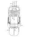
図2〜図4は本発明の実施形態のバッテリ駆動式作業機としてのバッテリ駆動式刈払機1を示し、このバッテリ駆動式刈払機1は、内部に電動モータ11を収容するケーシング2を有する。このケーシング2は、その下側に連結されたスタンド3を備えている。スタンド3は、ケーシング2に一体に設けてもよい。スタンド3内には、バッテリパック4を後方からスライドさせて脱着可能となっている。ケーシング2の先端には、リアハンドル5が設けられ、その先端からは、棒状の操作バー6が延び、操作バー6のリアハンドル5に近い側に環状のフロントハンドル7が連結されている。安全スイッチ5bを握りながら、リアハンドル5の下側に設けた操作スイッチ5aを握ることで、バッテリパック4から電力が供給されて電動モータ11が駆動するようになっている。 2 to 4 show a battery-driven brush cutter 1 as a battery-driven work machine according to an embodiment of the present invention. The battery-driven brush cutter 1 has a
操作バー6の先端には、ナイロンカッター8が電動モータ11の駆動力により回転可能に設けられ、ナイロンカッター8から延びるナイロンコード9の回転力で雑草等を刈ることができるようになっている。なお、ナイロンカッター8ではなく、金属製円板刃が回転可能に取り付けられていてもよい。ナイロンカッター8のケーシング2側は、飛散防止カバー10で覆われ、ユーザ側に小石などが飛び散らないようになっている。電動モータ11で駆動される主として操作バー6内の図示しない動力伝達部、ナイロンカッター8、ナイロンコード9などの刈払の作業をする部分で操作部60が構成されている。 A
例えば、ケーシング2は、強度の高いナイロン6(PA6)のガラス繊維強化プラスチックで形成され、スタンド3は、ポリプロピレン樹脂で形成されている。 For example, the
バッテリパック4は、図6〜図9に示すように、例えば、ポリカーボネイト樹脂のバッテリカバー41の内部に複数の電池42が内蔵されている。バッテリカバー41の上面前側には、複数のバッテリ側接続端子43が設けられている。一方、ケーシング2の下側には、図5に示すように、複数のケーシング側接続端子21が設けられ、バッテリパック4を後方からスライドさせながらスタンド3内に挿入することで、バッテリ側接続端子43がケーシング側接続端子21に確実に接続されるようになっている。バッテリカバー41の上面後側には、コイルバネ44aで付勢された押込式の例えばナイロン6製のロック爪44が設けられ、ケーシング2下面後ろ側に形成した凹状の係合凹部22に嵌まり込む(図6参照)ことで、バッテリパック4が抜け止めされるようになっている。ロック爪44は、後方に押下凹部44bを有し、この押下凹部44bを指で押し下げてコイルバネ44aに抗して押し下げることで、バッテリパック4の係合凹部22に対するロックが解除されて引き出して取り出せるようになっている。 As shown in FIGS. 6 to 9, for example, the
また、ケーシング2に設けたスタンド3により、バッテリ駆動式刈払機1を立てたまま、後方からバッテリパック4を出し入れ可能となっている。 In addition, the
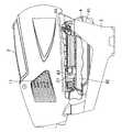
そして、バッテリ駆動式刈払機1には、バッテリパック4に係合した状態でケーシング2が有するスタンド3に固定可能な保護ブラケット50が設けられている。具体的には、この保護ブラケット50は、例えば、ポリプロピレン樹脂などの適度な剛性と柔軟性を有する樹脂成形品よりなる。なお、ケーシング側接続端子21とバッテリ側接続端子43とが電気的に接続されないのであれば、保護ブラケット50は、バネ鋼などの金属等でもよい。保護ブラケット50は、バッテリパック4の盗難を防止すると共に、ケーシング側接続端子21とバッテリ側接続端子43との距離を確保してケーシング側接続端子21とバッテリ側接続端子43との非接続状態を維持する役割を果たす。 The battery-driven brush cutter 1 is provided with a
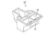
図10及び図11に示すように、保護ブラケット50は、バッテリパック4に係合する下向きに突出した係合部51を有する。図9に示すように、この係合部51をバッテリパック4に設けた被係合部45に係合させることで、バッテリパック4に保護ブラケット50を係合でき、バッテリパック4を、そのスタンド3への挿入方向と反対側に引っ張っても抜けないようになっている。そして、図9に断面で示すように、スタンド3の前側には、保護ブラケット50をネジ止めする締結部としての貫通孔31が形成されている。それに対応させて保護ブラケット50には、貫通孔31に挿通したネジ12を締結するためのネジ穴52(図9及び図11(c)参照)が設けられている。締結部の構成は、貫通孔31でなくても、ネジ12等の締結具で保護ブラケット50を固定できるものであれば特に限定されない。このように、保護ブラケット50をバッテリパック4に係合した状態で、バッテリパック4をスタンド3にスライドさせて収容し、その状態で貫通孔31にネジ12を挿通してネジ穴52に締結することで、保護ブラケット50がスタンド3に固定され、結果としてバッテリパック4が抜き出し不能となる。 As shown in FIGS. 10 and 11, the
保護ブラケット50は、衝撃吸収部53を備え、地面に落下したときのバッテリパック4に加わる衝撃を吸収可能に構成されている。具体的には、衝撃吸収部53は、保護ブラケット50における脆弱部分よりなり、本実施形態では、複数のリブ及び側壁で構成されている。この複数のリブの本数及び側壁の強度を適切に設定することにより、脆弱部分が形成されている。例えば、一部のリブや側壁を薄くしたり、一部のリブに切欠を設けたりしてもよい。 The
次いで、本実施形態の保護ブラケット50の使用方法について説明する。 Next, a method for using the
北米などのホームセンターで見られるように、本実施形態のバッテリ駆動式刈払機1を包装箱から出して商品棚に陳列するような場合に、本実施形態の保護ブラケット50が用いられる。保護ブラケット50は、製造ラインで予め取り付けてもよいし、ホームセンターなどで梱包を解いた後、取り付けてもよい。製造ラインで取り付ければ、搬送時に保護ブラケット50が機能する点で有利である。 As seen in home centers such as North America, the
まず最初にバッテリ駆動式刈払機1は地面に置いていてもよいし、スタンド3が見やすいように台の上に載せていてもよい。 First, the battery-driven brush cutter 1 may be placed on the ground, or may be placed on a stand so that the
そして、バッテリパック4の被係合部45に保護ブラケット50の係合部51を引っ掛けた状態で、保護ブラケット50の先端側からスタンド3の奥側へ挿入する。 Then, with the engaging
図9に示すように、保護ブラケット50の先端がスタンド3の貫通孔31に突き当たった状態で、ドライバ等により、貫通孔31にネジ12を締結する。 As shown in FIG. 9, the
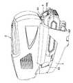
このようにすれば、図1に示すように、バッテリパック4の後部がケーシング2の後部よりも出っ張った状態となり、ケーシング側接続端子21とバッテリ側接続端子43との距離が保護ブラケット50で確実に確保され、ケーシング側接続端子21とバッテリ側接続端子43との非接続状態を維持することができる。このため、ホームセンターの従業員や購買者が安全スイッチ5bを握りながら操作スイッチ5aを操作しても電動モータ11が作動しない。 In this way, as shown in FIG. 1, the rear portion of the
また、バッテリパック4自身がスタンド3の奥まで挿入されていないので、図6で示したような、ロック爪44と係合凹部22とによるバッテリパック4の固定は行われないが、保護ブラケット50がバッテリパック4に係合した状態でネジ12で確実にスタンド3に固定されるので、ドライバなどの専用工具を使わない限りバッテリパック4を取り外せない。また、ドライバでネジ12を外すにも時間を要する。このため、バッテリパック4の盗難を確実に防止することができる。なお、例えば、ネジ12を特殊ネジとして家庭用のドライバで回せないものとすれば、さらに盗難防止効果は向上する。 Further, since the
また、本実施形態では、スタンド3によりバッテリ駆動式刈払機1を立てた状態でバッテリパック4を脱着することもでき、保護ブラケット50をバッテリパック4と共に奥まで差し込んだ状態でスタンド3に容易且つ確実にバッテリパック4を固定できる。 In the present embodiment, the
そして、本実施形態では、保護ブラケット50が衝撃吸収部53を有するので、ホームセンターの従業員や購買者が誤ってバッテリ駆動式刈払機1を落下させても、後方に出っ張ったバッテリパック4が地面に衝突し、脆弱部分が積極的に撓んだり破損したりするので、スタンド3、ケーシング2、バッテリパック4等のより高価な部品の損傷が避けられる。仮に衝撃吸収部53が損傷した場合には、安価な保護ブラケット50は、ネジ12を外して交換するだけで済む。また、展示の際は、飛散防止カバー10を引っ掛けて吊るすために、バッテリパック4が地面側になることが一般的である。そして、展示の際、または展示品を手に取るときなどに、従業員や購買者が誤って落下させることが考えられる。バッテリパック4の位置は、例えば地面から50cm位の購買者が見やすい高さに展示してある。この位置からバッテリ駆動式刈払機1を落下させると、落下による衝撃を受けるが、衝撃吸収部53が積極的に損傷するので、他の部位が損傷しにくい。 In this embodiment, since the
したがって、本実施形態に係るバッテリ駆動式刈払機1によると、簡単な構造で、ホームセンターなどで陳列したときだけでなく、購買者が納屋などに長期保管する場合などに、バッテリパック4の盗難を確実に防止すると共に、誤って作動しないようにすることができ、さらには、バッテリ駆動式刈払機1自体の損傷を防ぐことができる。 Therefore, according to the battery-driven brush cutter 1 according to the present embodiment, the
−変形例1−
図12及び図13は本発明の実施形態の変形例1の保護ブラケット50’を示し、脆弱部の形状が異なる点で上記実施形態と異なる。なお、以下の各変形例では、図1〜図11と同じ部分については同じ符号を付してその詳細な説明は省略する。-Modification 1-
12 and 13 show a
本変形例では、衝撃吸収部53’の脆弱部分が、湾曲した側壁で構成されており、上記実施形態のような複数のリブが設けられていない。これにより、バッテリパック4の方向から圧縮されやすくすることで保護ブラケット50’の剛性をさらに弱め、落下時に積極的に衝撃吸収部53’を変形させることで、他の部品の損傷を効果的に防止している。 In this modification, the fragile portion of the
−変形例2−
図14及び図15は本発明の実施形態の変形例2の保護ブラケット50’’を示し、脆弱部の形状が異なる点で上記実施形態と異なる。-Modification 2-
14 and 15 show a
本変形例では、衝撃吸収部53’’の脆弱部分が、蛇腹状に湾曲した側壁で構成されている。本変形例でも上記実施形態のように複数のリブを設ける場合に比べてバッテリパック4の方向から圧縮されやすくすることで剛性が積極的に弱められている。このように、保護ブラケット50’’の剛性を弱めて落下時に積極的に衝撃吸収部53’’を変形させることで、他の部品の損傷を効果的に防止している。 In this modification, the fragile portion of the
(その他の実施形態)
本発明は、上記実施形態について、以下のような構成としてもよい。(Other embodiments)
The present invention may be configured as follows with respect to the above embodiment.
すなわち、上記実施形態では、バッテリ駆動式作業機として操作部60が刈払作業をするバッテリ駆動式刈払機1の例を示したが、ヘッジトリマ、チェーンソーなどの各種作業を行うバッテリ駆動式の作業機であれば、本発明は適用可能である。その場合、操作部60がケーシング2のいずれの部分から延びていてもよく、バッテリパック4の挿入方向も限定されない。また、本実施形態のようにスタンド3にバッテリパック4を挿入するものに限定されず、ケーシング2そのものにバッテリパック4を挿入するようにしてもよい。その場合には、貫通孔32は、ケーシング2に形成すればよい。衝撃吸収効果を高めるには、保護ブラケット50を装着したときにバッテリパック4の後端が露出するのが望ましい。 That is, in the above-described embodiment, an example of the battery-driven brush cutter 1 in which the
なお、以上の実施形態は、本質的に好ましい例示であって、本発明、その適用物や用途の範囲を制限することを意図するものではない。 In addition, the above embodiment is an essentially preferable illustration, Comprising: It does not intend restrict | limiting the range of this invention, its application thing, or a use.
以上説明したように、本発明は、バッテリ駆動式の刈払機、ヘッジトリマ、チェーンソーなどのバッテリ駆動式作業機について有用である。 As described above, the present invention is useful for battery-powered work machines such as battery-powered brush cutters, hedge trimmers, and chainsaws.
1 バッテリ駆動式刈払機(バッテリ駆動式作業機)
2 ケーシング
3 スタンド
4 バッテリパック
5 リアハンドル
5a 操作スイッチ
5b 安全スイッチ
6 操作バー
7 フロントハンドル
8 ナイロンカッター
9 ナイロンコード
10 飛散防止カバー
11 電動モータ
12 ネジ
21 ケーシング側接続端子
22 係合凹部
31 貫通孔(締結部)
41 バッテリカバー
42 電池
43 バッテリ側接続端子
44 ロック爪
44a コイルバネ
44b 押下凹部
45 被係合部
50,50',50’’ 保護ブラケット
51 係合部
52 ネジ穴
53,53',53’’ 衝撃吸収部
60 操作部1 Battery-powered brush cutter (battery-driven work machine)
2 Casing
3 Stand
4 Battery pack
5 Rear handle
5a Operation switch
5b Safety switch
6 Operation bar
7 Front handle
8 Nylon cutter
9 Nylon cord
10 Splash prevention cover
11 Electric motor
12 screws
21 Casing side connection terminal
22 Engaging recess
31 Through hole (fastening part)
41 Battery cover
42 batteries
43 Battery side connection terminal
44 lock claw
44a Coil spring
44b Pressing recess
45 engaged parts
50, 50 ', 50 "protective bracket
51 engaging part
52 Screw holes
53, 53 ', 53 "shock absorber
60 Operation unit
Claims (5)
Translated fromJapanese上記電動モータに駆動されると共に、上記ケーシングから延びる作業部と、
上記ケーシングに着脱可能に構成されると共に、上記電動モータに電力を供給可能なバッテリパックと、
上記ケーシングに設けられ、上記バッテリパックのバッテリ側接続端子を接続可能なケーシング側接続端子と、
上記バッテリパックに係合した状態で上記ケーシングに固定可能に構成され、該バッテリパックの盗難を防止すると共に、上記ケーシング側接続端子と上記バッテリ側接続端子との距離を確保して上記ケーシング側接続端子と上記バッテリ側接続端子との非接続状態を維持する保護ブラケットとを備えている
ことを特徴とするバッテリ駆動式作業機。A casing with a built-in electric motor;
A working unit driven by the electric motor and extending from the casing;
A battery pack configured to be detachable from the casing and capable of supplying power to the electric motor;
A casing-side connection terminal provided on the casing and connectable to a battery-side connection terminal of the battery pack;
The battery pack is configured to be able to be fixed to the casing while being engaged with the battery pack, and prevents the theft of the battery pack and secures a distance between the casing side connection terminal and the battery side connection terminal to connect the casing side. A battery-powered work machine comprising a protective bracket for maintaining a non-connected state between the terminal and the battery-side connection terminal.
上記ケーシングには、上記保護ブラケットを締結する締結部が形成されている
ことを特徴とするバッテリ駆動式作業機。The battery-powered work machine according to claim 1,
The battery-operated working machine, wherein a fastening portion for fastening the protective bracket is formed in the casing.
上記保護ブラケットは、上記バッテリパックに係合する係合部を有し、該係合部を上記バッテリパックに設けた被係合部に係合させ、且つ該バッテリパックを上記ケーシングにスライドさせて収容した状態で該バッテリパックが抜き出し不能に構成されている
ことを特徴とするバッテリ駆動式作業機。The battery-powered work machine according to claim 2,
The protective bracket has an engaging portion that engages with the battery pack, engages the engaging portion with an engaged portion provided in the battery pack, and slides the battery pack onto the casing. A battery-operated working machine, wherein the battery pack is configured so that the battery pack cannot be removed in a housed state.
上記保護ブラケットは、衝撃吸収部を備え、地面に落下したときに加わる衝撃を吸収可能に構成されている
ことを特徴とするバッテリ駆動式作業機。In the battery-powered work machine according to any one of claims 1 to 3,
The battery-operated working machine according to claim 1, wherein the protective bracket includes an impact absorbing portion and is configured to absorb an impact applied when the protective bracket is dropped on the ground.
上記衝撃吸収部は、上記保護ブラケットにおける脆弱部分よりなる
ことを特徴とするバッテリ駆動式作業機。The battery-powered work machine accordingto claim4 ,
The battery-operated working machine according to claim 1, wherein the impact absorbing portion is formed by a weak portion of the protective bracket.
Priority Applications (5)
| Application Number | Priority Date | Filing Date | Title |
|---|---|---|---|
| JP2014149730AJP6345523B2 (en) | 2014-07-23 | 2014-07-23 | Battery powered work machine |
| EP14898091.5AEP3141097B1 (en) | 2014-07-23 | 2014-08-20 | Battery-powered working machine |
| PCT/JP2014/004263WO2016013050A1 (en) | 2014-07-23 | 2014-08-20 | Battery-powered working machine |
| CN201480080077.2ACN106659119B (en) | 2014-07-23 | 2014-08-20 | Battery powered type working rig |
| US15/324,704US10709063B2 (en) | 2014-07-23 | 2014-08-20 | Battery-powered working machine |
Applications Claiming Priority (1)
| Application Number | Priority Date | Filing Date | Title |
|---|---|---|---|
| JP2014149730AJP6345523B2 (en) | 2014-07-23 | 2014-07-23 | Battery powered work machine |
Publications (3)
| Publication Number | Publication Date |
|---|---|
| JP2016021938A JP2016021938A (en) | 2016-02-08 |
| JP2016021938A5 JP2016021938A5 (en) | 2017-07-06 |
| JP6345523B2true JP6345523B2 (en) | 2018-06-20 |
Family
ID=55162609
Family Applications (1)
| Application Number | Title | Priority Date | Filing Date |
|---|---|---|---|
| JP2014149730AActiveJP6345523B2 (en) | 2014-07-23 | 2014-07-23 | Battery powered work machine |
Country Status (5)
| Country | Link |
|---|---|
| US (1) | US10709063B2 (en) |
| EP (1) | EP3141097B1 (en) |
| JP (1) | JP6345523B2 (en) |
| CN (1) | CN106659119B (en) |
| WO (1) | WO2016013050A1 (en) |
Families Citing this family (8)
| Publication number | Priority date | Publication date | Assignee | Title |
|---|---|---|---|---|
| JP6345523B2 (en)* | 2014-07-23 | 2018-06-20 | 株式会社やまびこ | Battery powered work machine |
| JP2018088853A (en)* | 2016-11-30 | 2018-06-14 | 本田技研工業株式会社 | Electric working machine |
| EP3653344A1 (en)* | 2018-11-13 | 2020-05-20 | Hilti Aktiengesellschaft | Battery operated handheld machine tool |
| EP3653343A1 (en)* | 2018-11-13 | 2020-05-20 | Hilti Aktiengesellschaft | Battery operated handheld machine tool |
| JP7159091B2 (en)* | 2019-03-22 | 2022-10-24 | 株式会社マキタ | Cord holder and work machine |
| IT201900004273A1 (en)* | 2019-03-25 | 2020-09-25 | Emak Spa | WORK TOOL EQUIPPED WITH A DAMPING ELEMENT |
| JP7261633B2 (en)* | 2019-03-26 | 2023-04-20 | 株式会社やまびこ | electric work machine |
| TWI691262B (en)* | 2019-10-08 | 2020-04-21 | 何炳梓 | Electric gardening machine |
Family Cites Families (35)
| Publication number | Priority date | Publication date | Assignee | Title |
|---|---|---|---|---|
| US6357534B1 (en)* | 1998-04-20 | 2002-03-19 | Illinois Tool Works Inc | Battery pack latching assembly for fastener driving tool |
| US6257542B1 (en)* | 1999-02-08 | 2001-07-10 | Lawrence P. Westfield | Theft prevention clamp |
| US6257351B1 (en)* | 1999-06-29 | 2001-07-10 | Microaire Surgical Instruments, Inc. | Powered surgical instrument having locking systems and a clutch mechanism |
| JP3952253B2 (en)* | 2001-03-01 | 2007-08-01 | 株式会社マキタ | adapter |
| JP2002362456A (en)* | 2001-06-04 | 2002-12-18 | Uni Sunstar Bv | Power-assisted bicycle, electric bicycle, and battery bracket |
| DE102004049085A1 (en)* | 2004-10-08 | 2006-04-13 | Robert Bosch Gmbh | Device for locking a battery pack in a guide of a power tool |
| JP2009040309A (en)* | 2007-08-10 | 2009-02-26 | Yamaha Motor Co Ltd | Motorcycle |
| US20110022032A1 (en)* | 2007-10-05 | 2011-01-27 | Tyco Healthcare Group Lp | Battery ejection design for a surgical device |
| JP3138654U (en)* | 2007-10-11 | 2008-01-17 | 株式会社ハマシステム | Anti-theft device |
| DE102007057033A1 (en)* | 2007-11-27 | 2009-05-28 | Robert Bosch Gmbh | Electrically drivable hand tool machine |
| DE102008006030A1 (en)* | 2008-01-25 | 2009-07-30 | Robert Bosch Gmbh | Hand tool, in particular electrically operated hand tool |
| FR2929544B1 (en)* | 2008-04-02 | 2010-09-03 | Facom | AUTONOMOUS PORTABLE ELECTRICAL APPARATUS WITH ELECTRIC POWER SUPPLY BLOCK LOCKING. |
| JP5535949B2 (en)* | 2009-02-10 | 2014-07-02 | 株式会社マキタ | Power tool connection system |
| DE102009012175A1 (en)* | 2009-02-27 | 2010-09-02 | Andreas Stihl Ag & Co. Kg | Electrical appliance with a battery pack |
| JP5825750B2 (en) | 2009-03-03 | 2015-12-02 | 日立工機株式会社 | Electric working machine |
| JP5544143B2 (en)* | 2009-11-04 | 2014-07-09 | リョービ株式会社 | Battery powered electric brush cutter |
| EP2329921B1 (en)* | 2009-12-07 | 2016-03-16 | Black & Decker Inc. | Anti-theft system |
| US20110179757A1 (en)* | 2009-12-25 | 2011-07-28 | Scott-Stanbridge N | Lightweight battery-driven air-supported vegetation trimmer |
| JP5461221B2 (en)* | 2010-02-12 | 2014-04-02 | 株式会社マキタ | Electric tool powered by multiple battery packs |
| JP5432761B2 (en)* | 2010-02-12 | 2014-03-05 | 株式会社マキタ | Electric tool powered by multiple battery packs |
| EP2540153B1 (en)* | 2010-02-25 | 2016-08-17 | Makita Corporation | Power tool |
| JP5443208B2 (en) | 2010-02-25 | 2014-03-19 | 株式会社マキタ | Power tools |
| CN201758599U (en)* | 2010-04-29 | 2011-03-16 | 常州格力博工具有限公司 | Electric tool |
| US20130091905A1 (en)* | 2011-10-17 | 2013-04-18 | Display Technologies, Inc. | Anti-theft device including a strap and method of use |
| CN202292694U (en)* | 2011-10-18 | 2012-07-04 | 常州格力博工具有限公司 | Electric tool |
| US9189663B2 (en)* | 2011-12-02 | 2015-11-17 | The Stanley Works Israel, Ltd | Battery operated device and tag for a battery operated tool |
| US9190644B2 (en)* | 2011-12-21 | 2015-11-17 | Echo, Inc. | Staging system for battery on a portable tool |
| CN202524793U (en)* | 2012-04-06 | 2012-11-14 | 袁爱民 | Motor-driven grass cutting machine |
| DE102012104538A1 (en)* | 2012-05-25 | 2013-11-28 | Gustav Klauke Gmbh | Tool |
| US9630310B2 (en)* | 2013-02-01 | 2017-04-25 | Makita Corporation | Electric tool |
| JP6315541B2 (en)* | 2013-02-01 | 2018-04-25 | 株式会社マキタ | Brush cutter |
| JP6033698B2 (en)* | 2013-02-01 | 2016-11-30 | 株式会社マキタ | Electric tool |
| JP6096593B2 (en)* | 2013-05-29 | 2017-03-15 | 株式会社マキタ | Reciprocating work tool |
| JP6345523B2 (en)* | 2014-07-23 | 2018-06-20 | 株式会社やまびこ | Battery powered work machine |
| US10312498B2 (en)* | 2017-10-02 | 2019-06-04 | Black & Decker, Inc. | Security device for a battery pack |
- 2014
- 2014-07-23JPJP2014149730Apatent/JP6345523B2/enactiveActive
- 2014-08-20EPEP14898091.5Apatent/EP3141097B1/enactiveActive
- 2014-08-20CNCN201480080077.2Apatent/CN106659119B/enactiveActive
- 2014-08-20USUS15/324,704patent/US10709063B2/enactiveActive
- 2014-08-20WOPCT/JP2014/004263patent/WO2016013050A1/enactiveApplication Filing
Also Published As
| Publication number | Publication date |
|---|---|
| US20170202137A1 (en) | 2017-07-20 |
| EP3141097A1 (en) | 2017-03-15 |
| US10709063B2 (en) | 2020-07-14 |
| JP2016021938A (en) | 2016-02-08 |
| EP3141097B1 (en) | 2019-10-02 |
| CN106659119A (en) | 2017-05-10 |
| EP3141097A4 (en) | 2017-07-19 |
| WO2016013050A1 (en) | 2016-01-28 |
| CN106659119B (en) | 2018-11-06 |
Similar Documents
| Publication | Publication Date | Title |
|---|---|---|
| JP6345523B2 (en) | Battery powered work machine | |
| US10105832B2 (en) | Battery powered tool | |
| US11024916B2 (en) | String trimmer battery housing assembly | |
| JP6910840B2 (en) | Electric tool | |
| EP2952306B1 (en) | Chain saw | |
| KR101715860B1 (en) | Shock absorbtive safety blade unit for brush cutter | |
| JP6253088B2 (en) | Back working machine | |
| JP6762194B2 (en) | Backpack type power supply system | |
| GB2493333A (en) | A power tool and battery pack safety device | |
| US11577422B2 (en) | Display or storage assembly for handheld power tool | |
| EP2678137B1 (en) | Tool supporting apparatus | |
| JP2012190736A (en) | Terminal cover, inverter and power tool equipped with them | |
| US11806858B2 (en) | Impact protecting member for a cutting tool | |
| KR200466656Y1 (en) | Multipurpose amputation apparatus | |
| JP5698546B2 (en) | Rechargeable power tool | |
| US20090045090A1 (en) | Container and a storage for a saw blade | |
| US11110584B2 (en) | Jigsaw blade storage | |
| JP2013243962A (en) | Lawn mower | |
| JP6762193B2 (en) | Backpack type power supply system | |
| GB2500476A (en) | Tool storage box with auxiliary case on front | |
| JP2013256094A (en) | Engine working machine | |
| KR200192536Y1 (en) | A multi ability flash | |
| KR200439957Y1 (en) | Snowboard Bag | |
| KR20240170125A (en) | Foldable safety tack | |
| KR20100000875U (en) | Sickle fastening device |
Legal Events
| Date | Code | Title | Description |
|---|---|---|---|
| A521 | Request for written amendment filed | Free format text:JAPANESE INTERMEDIATE CODE: A523 Effective date:20170526 | |
| A621 | Written request for application examination | Free format text:JAPANESE INTERMEDIATE CODE: A621 Effective date:20170526 | |
| TRDD | Decision of grant or rejection written | ||
| A01 | Written decision to grant a patent or to grant a registration (utility model) | Free format text:JAPANESE INTERMEDIATE CODE: A01 Effective date:20180515 | |
| A61 | First payment of annual fees (during grant procedure) | Free format text:JAPANESE INTERMEDIATE CODE: A61 Effective date:20180523 | |
| R150 | Certificate of patent or registration of utility model | Ref document number:6345523 Country of ref document:JP Free format text:JAPANESE INTERMEDIATE CODE: R150 | |
| R250 | Receipt of annual fees | Free format text:JAPANESE INTERMEDIATE CODE: R250 | |
| R250 | Receipt of annual fees | Free format text:JAPANESE INTERMEDIATE CODE: R250 | |
| R250 | Receipt of annual fees | Free format text:JAPANESE INTERMEDIATE CODE: R250 | |
| R250 | Receipt of annual fees | Free format text:JAPANESE INTERMEDIATE CODE: R250 | |
| R250 | Receipt of annual fees | Free format text:JAPANESE INTERMEDIATE CODE: R250 |