JP6344030B2 - Control device for hybrid vehicle - Google Patents
Control device for hybrid vehicleDownload PDFInfo
- Publication number
- JP6344030B2 JP6344030B2JP2014086105AJP2014086105AJP6344030B2JP 6344030 B2JP6344030 B2JP 6344030B2JP 2014086105 AJP2014086105 AJP 2014086105AJP 2014086105 AJP2014086105 AJP 2014086105AJP 6344030 B2JP6344030 B2JP 6344030B2
- Authority
- JP
- Japan
- Prior art keywords
- torque
- motor
- engine
- output
- control
- Prior art date
- Legal status (The legal status is an assumption and is not a legal conclusion. Google has not performed a legal analysis and makes no representation as to the accuracy of the status listed.)
- Expired - Fee Related
Links
Images


Classifications
- B—PERFORMING OPERATIONS; TRANSPORTING
- B60—VEHICLES IN GENERAL
- B60W—CONJOINT CONTROL OF VEHICLE SUB-UNITS OF DIFFERENT TYPE OR DIFFERENT FUNCTION; CONTROL SYSTEMS SPECIALLY ADAPTED FOR HYBRID VEHICLES; ROAD VEHICLE DRIVE CONTROL SYSTEMS FOR PURPOSES NOT RELATED TO THE CONTROL OF A PARTICULAR SUB-UNIT
- B60W20/00—Control systems specially adapted for hybrid vehicles
- B60W20/40—Controlling the engagement or disengagement of prime movers, e.g. for transition between prime movers
- B—PERFORMING OPERATIONS; TRANSPORTING
- B60—VEHICLES IN GENERAL
- B60K—ARRANGEMENT OR MOUNTING OF PROPULSION UNITS OR OF TRANSMISSIONS IN VEHICLES; ARRANGEMENT OR MOUNTING OF PLURAL DIVERSE PRIME-MOVERS IN VEHICLES; AUXILIARY DRIVES FOR VEHICLES; INSTRUMENTATION OR DASHBOARDS FOR VEHICLES; ARRANGEMENTS IN CONNECTION WITH COOLING, AIR INTAKE, GAS EXHAUST OR FUEL SUPPLY OF PROPULSION UNITS IN VEHICLES
- B60K6/00—Arrangement or mounting of plural diverse prime-movers for mutual or common propulsion, e.g. hybrid propulsion systems comprising electric motors and internal combustion engines
- B60K6/20—Arrangement or mounting of plural diverse prime-movers for mutual or common propulsion, e.g. hybrid propulsion systems comprising electric motors and internal combustion engines the prime-movers consisting of electric motors and internal combustion engines, e.g. HEVs
- B60K6/22—Arrangement or mounting of plural diverse prime-movers for mutual or common propulsion, e.g. hybrid propulsion systems comprising electric motors and internal combustion engines the prime-movers consisting of electric motors and internal combustion engines, e.g. HEVs characterised by apparatus, components or means specially adapted for HEVs
- B60K6/36—Arrangement or mounting of plural diverse prime-movers for mutual or common propulsion, e.g. hybrid propulsion systems comprising electric motors and internal combustion engines the prime-movers consisting of electric motors and internal combustion engines, e.g. HEVs characterised by apparatus, components or means specially adapted for HEVs characterised by the transmission gearings
- B60K6/365—Arrangement or mounting of plural diverse prime-movers for mutual or common propulsion, e.g. hybrid propulsion systems comprising electric motors and internal combustion engines the prime-movers consisting of electric motors and internal combustion engines, e.g. HEVs characterised by apparatus, components or means specially adapted for HEVs characterised by the transmission gearings with the gears having orbital motion
- B—PERFORMING OPERATIONS; TRANSPORTING
- B60—VEHICLES IN GENERAL
- B60K—ARRANGEMENT OR MOUNTING OF PROPULSION UNITS OR OF TRANSMISSIONS IN VEHICLES; ARRANGEMENT OR MOUNTING OF PLURAL DIVERSE PRIME-MOVERS IN VEHICLES; AUXILIARY DRIVES FOR VEHICLES; INSTRUMENTATION OR DASHBOARDS FOR VEHICLES; ARRANGEMENTS IN CONNECTION WITH COOLING, AIR INTAKE, GAS EXHAUST OR FUEL SUPPLY OF PROPULSION UNITS IN VEHICLES
- B60K6/00—Arrangement or mounting of plural diverse prime-movers for mutual or common propulsion, e.g. hybrid propulsion systems comprising electric motors and internal combustion engines
- B60K6/20—Arrangement or mounting of plural diverse prime-movers for mutual or common propulsion, e.g. hybrid propulsion systems comprising electric motors and internal combustion engines the prime-movers consisting of electric motors and internal combustion engines, e.g. HEVs
- B60K6/22—Arrangement or mounting of plural diverse prime-movers for mutual or common propulsion, e.g. hybrid propulsion systems comprising electric motors and internal combustion engines the prime-movers consisting of electric motors and internal combustion engines, e.g. HEVs characterised by apparatus, components or means specially adapted for HEVs
- B60K6/38—Arrangement or mounting of plural diverse prime-movers for mutual or common propulsion, e.g. hybrid propulsion systems comprising electric motors and internal combustion engines the prime-movers consisting of electric motors and internal combustion engines, e.g. HEVs characterised by apparatus, components or means specially adapted for HEVs characterised by the driveline clutches
- B60K6/383—One-way clutches or freewheel devices
- B—PERFORMING OPERATIONS; TRANSPORTING
- B60—VEHICLES IN GENERAL
- B60K—ARRANGEMENT OR MOUNTING OF PROPULSION UNITS OR OF TRANSMISSIONS IN VEHICLES; ARRANGEMENT OR MOUNTING OF PLURAL DIVERSE PRIME-MOVERS IN VEHICLES; AUXILIARY DRIVES FOR VEHICLES; INSTRUMENTATION OR DASHBOARDS FOR VEHICLES; ARRANGEMENTS IN CONNECTION WITH COOLING, AIR INTAKE, GAS EXHAUST OR FUEL SUPPLY OF PROPULSION UNITS IN VEHICLES
- B60K6/00—Arrangement or mounting of plural diverse prime-movers for mutual or common propulsion, e.g. hybrid propulsion systems comprising electric motors and internal combustion engines
- B60K6/20—Arrangement or mounting of plural diverse prime-movers for mutual or common propulsion, e.g. hybrid propulsion systems comprising electric motors and internal combustion engines the prime-movers consisting of electric motors and internal combustion engines, e.g. HEVs
- B60K6/22—Arrangement or mounting of plural diverse prime-movers for mutual or common propulsion, e.g. hybrid propulsion systems comprising electric motors and internal combustion engines the prime-movers consisting of electric motors and internal combustion engines, e.g. HEVs characterised by apparatus, components or means specially adapted for HEVs
- B60K6/38—Arrangement or mounting of plural diverse prime-movers for mutual or common propulsion, e.g. hybrid propulsion systems comprising electric motors and internal combustion engines the prime-movers consisting of electric motors and internal combustion engines, e.g. HEVs characterised by apparatus, components or means specially adapted for HEVs characterised by the driveline clutches
- B60K6/387—Actuated clutches, i.e. clutches engaged or disengaged by electric, hydraulic or mechanical actuating means
- B—PERFORMING OPERATIONS; TRANSPORTING
- B60—VEHICLES IN GENERAL
- B60K—ARRANGEMENT OR MOUNTING OF PROPULSION UNITS OR OF TRANSMISSIONS IN VEHICLES; ARRANGEMENT OR MOUNTING OF PLURAL DIVERSE PRIME-MOVERS IN VEHICLES; AUXILIARY DRIVES FOR VEHICLES; INSTRUMENTATION OR DASHBOARDS FOR VEHICLES; ARRANGEMENTS IN CONNECTION WITH COOLING, AIR INTAKE, GAS EXHAUST OR FUEL SUPPLY OF PROPULSION UNITS IN VEHICLES
- B60K6/00—Arrangement or mounting of plural diverse prime-movers for mutual or common propulsion, e.g. hybrid propulsion systems comprising electric motors and internal combustion engines
- B60K6/20—Arrangement or mounting of plural diverse prime-movers for mutual or common propulsion, e.g. hybrid propulsion systems comprising electric motors and internal combustion engines the prime-movers consisting of electric motors and internal combustion engines, e.g. HEVs
- B60K6/22—Arrangement or mounting of plural diverse prime-movers for mutual or common propulsion, e.g. hybrid propulsion systems comprising electric motors and internal combustion engines the prime-movers consisting of electric motors and internal combustion engines, e.g. HEVs characterised by apparatus, components or means specially adapted for HEVs
- B60K6/40—Arrangement or mounting of plural diverse prime-movers for mutual or common propulsion, e.g. hybrid propulsion systems comprising electric motors and internal combustion engines the prime-movers consisting of electric motors and internal combustion engines, e.g. HEVs characterised by apparatus, components or means specially adapted for HEVs characterised by the assembly or relative disposition of components
- B—PERFORMING OPERATIONS; TRANSPORTING
- B60—VEHICLES IN GENERAL
- B60K—ARRANGEMENT OR MOUNTING OF PROPULSION UNITS OR OF TRANSMISSIONS IN VEHICLES; ARRANGEMENT OR MOUNTING OF PLURAL DIVERSE PRIME-MOVERS IN VEHICLES; AUXILIARY DRIVES FOR VEHICLES; INSTRUMENTATION OR DASHBOARDS FOR VEHICLES; ARRANGEMENTS IN CONNECTION WITH COOLING, AIR INTAKE, GAS EXHAUST OR FUEL SUPPLY OF PROPULSION UNITS IN VEHICLES
- B60K6/00—Arrangement or mounting of plural diverse prime-movers for mutual or common propulsion, e.g. hybrid propulsion systems comprising electric motors and internal combustion engines
- B60K6/20—Arrangement or mounting of plural diverse prime-movers for mutual or common propulsion, e.g. hybrid propulsion systems comprising electric motors and internal combustion engines the prime-movers consisting of electric motors and internal combustion engines, e.g. HEVs
- B60K6/42—Arrangement or mounting of plural diverse prime-movers for mutual or common propulsion, e.g. hybrid propulsion systems comprising electric motors and internal combustion engines the prime-movers consisting of electric motors and internal combustion engines, e.g. HEVs characterised by the architecture of the hybrid electric vehicle
- B60K6/44—Series-parallel type
- B60K6/445—Differential gearing distribution type
- B—PERFORMING OPERATIONS; TRANSPORTING
- B60—VEHICLES IN GENERAL
- B60W—CONJOINT CONTROL OF VEHICLE SUB-UNITS OF DIFFERENT TYPE OR DIFFERENT FUNCTION; CONTROL SYSTEMS SPECIALLY ADAPTED FOR HYBRID VEHICLES; ROAD VEHICLE DRIVE CONTROL SYSTEMS FOR PURPOSES NOT RELATED TO THE CONTROL OF A PARTICULAR SUB-UNIT
- B60W10/00—Conjoint control of vehicle sub-units of different type or different function
- B60W10/02—Conjoint control of vehicle sub-units of different type or different function including control of driveline clutches
- B—PERFORMING OPERATIONS; TRANSPORTING
- B60—VEHICLES IN GENERAL
- B60W—CONJOINT CONTROL OF VEHICLE SUB-UNITS OF DIFFERENT TYPE OR DIFFERENT FUNCTION; CONTROL SYSTEMS SPECIALLY ADAPTED FOR HYBRID VEHICLES; ROAD VEHICLE DRIVE CONTROL SYSTEMS FOR PURPOSES NOT RELATED TO THE CONTROL OF A PARTICULAR SUB-UNIT
- B60W10/00—Conjoint control of vehicle sub-units of different type or different function
- B60W10/04—Conjoint control of vehicle sub-units of different type or different function including control of propulsion units
- B60W10/08—Conjoint control of vehicle sub-units of different type or different function including control of propulsion units including control of electric propulsion units, e.g. motors or generators
- B—PERFORMING OPERATIONS; TRANSPORTING
- B60—VEHICLES IN GENERAL
- B60W—CONJOINT CONTROL OF VEHICLE SUB-UNITS OF DIFFERENT TYPE OR DIFFERENT FUNCTION; CONTROL SYSTEMS SPECIALLY ADAPTED FOR HYBRID VEHICLES; ROAD VEHICLE DRIVE CONTROL SYSTEMS FOR PURPOSES NOT RELATED TO THE CONTROL OF A PARTICULAR SUB-UNIT
- B60W20/00—Control systems specially adapted for hybrid vehicles
- B—PERFORMING OPERATIONS; TRANSPORTING
- B60—VEHICLES IN GENERAL
- B60K—ARRANGEMENT OR MOUNTING OF PROPULSION UNITS OR OF TRANSMISSIONS IN VEHICLES; ARRANGEMENT OR MOUNTING OF PLURAL DIVERSE PRIME-MOVERS IN VEHICLES; AUXILIARY DRIVES FOR VEHICLES; INSTRUMENTATION OR DASHBOARDS FOR VEHICLES; ARRANGEMENTS IN CONNECTION WITH COOLING, AIR INTAKE, GAS EXHAUST OR FUEL SUPPLY OF PROPULSION UNITS IN VEHICLES
- B60K6/00—Arrangement or mounting of plural diverse prime-movers for mutual or common propulsion, e.g. hybrid propulsion systems comprising electric motors and internal combustion engines
- B60K6/20—Arrangement or mounting of plural diverse prime-movers for mutual or common propulsion, e.g. hybrid propulsion systems comprising electric motors and internal combustion engines the prime-movers consisting of electric motors and internal combustion engines, e.g. HEVs
- B60K6/22—Arrangement or mounting of plural diverse prime-movers for mutual or common propulsion, e.g. hybrid propulsion systems comprising electric motors and internal combustion engines the prime-movers consisting of electric motors and internal combustion engines, e.g. HEVs characterised by apparatus, components or means specially adapted for HEVs
- B60K6/38—Arrangement or mounting of plural diverse prime-movers for mutual or common propulsion, e.g. hybrid propulsion systems comprising electric motors and internal combustion engines the prime-movers consisting of electric motors and internal combustion engines, e.g. HEVs characterised by apparatus, components or means specially adapted for HEVs characterised by the driveline clutches
- B60K2006/381—Arrangement or mounting of plural diverse prime-movers for mutual or common propulsion, e.g. hybrid propulsion systems comprising electric motors and internal combustion engines the prime-movers consisting of electric motors and internal combustion engines, e.g. HEVs characterised by apparatus, components or means specially adapted for HEVs characterised by the driveline clutches characterized by driveline brakes
- B—PERFORMING OPERATIONS; TRANSPORTING
- B60—VEHICLES IN GENERAL
- B60K—ARRANGEMENT OR MOUNTING OF PROPULSION UNITS OR OF TRANSMISSIONS IN VEHICLES; ARRANGEMENT OR MOUNTING OF PLURAL DIVERSE PRIME-MOVERS IN VEHICLES; AUXILIARY DRIVES FOR VEHICLES; INSTRUMENTATION OR DASHBOARDS FOR VEHICLES; ARRANGEMENTS IN CONNECTION WITH COOLING, AIR INTAKE, GAS EXHAUST OR FUEL SUPPLY OF PROPULSION UNITS IN VEHICLES
- B60K6/00—Arrangement or mounting of plural diverse prime-movers for mutual or common propulsion, e.g. hybrid propulsion systems comprising electric motors and internal combustion engines
- B60K6/20—Arrangement or mounting of plural diverse prime-movers for mutual or common propulsion, e.g. hybrid propulsion systems comprising electric motors and internal combustion engines the prime-movers consisting of electric motors and internal combustion engines, e.g. HEVs
- B60K6/22—Arrangement or mounting of plural diverse prime-movers for mutual or common propulsion, e.g. hybrid propulsion systems comprising electric motors and internal combustion engines the prime-movers consisting of electric motors and internal combustion engines, e.g. HEVs characterised by apparatus, components or means specially adapted for HEVs
- B—PERFORMING OPERATIONS; TRANSPORTING
- B60—VEHICLES IN GENERAL
- B60W—CONJOINT CONTROL OF VEHICLE SUB-UNITS OF DIFFERENT TYPE OR DIFFERENT FUNCTION; CONTROL SYSTEMS SPECIALLY ADAPTED FOR HYBRID VEHICLES; ROAD VEHICLE DRIVE CONTROL SYSTEMS FOR PURPOSES NOT RELATED TO THE CONTROL OF A PARTICULAR SUB-UNIT
- B60W2710/00—Output or target parameters relating to a particular sub-units
- B60W2710/02—Clutches
- B60W2710/025—Clutch slip, i.e. difference between input and output speeds
- B—PERFORMING OPERATIONS; TRANSPORTING
- B60—VEHICLES IN GENERAL
- B60W—CONJOINT CONTROL OF VEHICLE SUB-UNITS OF DIFFERENT TYPE OR DIFFERENT FUNCTION; CONTROL SYSTEMS SPECIALLY ADAPTED FOR HYBRID VEHICLES; ROAD VEHICLE DRIVE CONTROL SYSTEMS FOR PURPOSES NOT RELATED TO THE CONTROL OF A PARTICULAR SUB-UNIT
- B60W2710/00—Output or target parameters relating to a particular sub-units
- B60W2710/02—Clutches
- B60W2710/027—Clutch torque
- Y—GENERAL TAGGING OF NEW TECHNOLOGICAL DEVELOPMENTS; GENERAL TAGGING OF CROSS-SECTIONAL TECHNOLOGIES SPANNING OVER SEVERAL SECTIONS OF THE IPC; TECHNICAL SUBJECTS COVERED BY FORMER USPC CROSS-REFERENCE ART COLLECTIONS [XRACs] AND DIGESTS
- Y02—TECHNOLOGIES OR APPLICATIONS FOR MITIGATION OR ADAPTATION AGAINST CLIMATE CHANGE
- Y02T—CLIMATE CHANGE MITIGATION TECHNOLOGIES RELATED TO TRANSPORTATION
- Y02T10/00—Road transport of goods or passengers
- Y02T10/60—Other road transportation technologies with climate change mitigation effect
- Y02T10/62—Hybrid vehicles
- Y—GENERAL TAGGING OF NEW TECHNOLOGICAL DEVELOPMENTS; GENERAL TAGGING OF CROSS-SECTIONAL TECHNOLOGIES SPANNING OVER SEVERAL SECTIONS OF THE IPC; TECHNICAL SUBJECTS COVERED BY FORMER USPC CROSS-REFERENCE ART COLLECTIONS [XRACs] AND DIGESTS
- Y02—TECHNOLOGIES OR APPLICATIONS FOR MITIGATION OR ADAPTATION AGAINST CLIMATE CHANGE
- Y02T—CLIMATE CHANGE MITIGATION TECHNOLOGIES RELATED TO TRANSPORTATION
- Y02T10/00—Road transport of goods or passengers
- Y02T10/60—Other road transportation technologies with climate change mitigation effect
- Y02T10/72—Electric energy management in electromobility
Landscapes
- Engineering & Computer Science (AREA)
- Transportation (AREA)
- Mechanical Engineering (AREA)
- Chemical & Material Sciences (AREA)
- Combustion & Propulsion (AREA)
- Automation & Control Theory (AREA)
- Electric Propulsion And Braking For Vehicles (AREA)
- Hybrid Electric Vehicles (AREA)
Description
Translated fromJapaneseこの発明は、エンジンと、少なくとも二つ以上の複数のモータとを駆動力源として備えたハイブリッド車両の制御装置に関し、特に、いずれか一つのモータから出力されたトルクを駆動輪に伝達して走行するモードと、少なくとも二つのモータから出力されたトルクを駆動輪に伝達して走行するモードとを切り替えることができるように構成されたハイブリッド車両の制御装置に関するものである。 The present invention relates to a hybrid vehicle control device including an engine and at least two or more motors as a driving force source, and in particular, travels by transmitting torque output from any one of the motors to driving wheels. The present invention relates to a control device for a hybrid vehicle configured to be able to switch between a mode for driving and a mode for traveling by transmitting torque output from at least two motors to drive wheels.
特許文献1には、エンジンに連結された第1回転要素と、第1モータに連結された第2回転要素と、駆動輪に連結された第3回転要素とを有する差動機構、および駆動輪にトルク伝達可能に連結された第2モータを備えたハイブリッド車両が記載されている。このハイブリッド車両は、第2回転要素を反力要素として機能させるように第1モータを制御することにより、エンジンから出力されたトルクを駆動輪に伝達して走行させるモードと、第2モータから出力されたトルクを駆動輪に伝達して走行させるモードとを切り替えることができる。また、要求駆動力が比較的大きい場合であっても、エンジンを停止させた状態で走行させることができるように構成されている。具体的には、第1モータおよび第2モータから出力されたトルクを駆動輪に伝達して走行させることができるように、差動機構の入力軸にワンウェイクラッチや制御ブレーキなどを設けている。すなわち、第1回転要素を反力要素として機能させるとともに、第2回転要素を入力要素として機能させることができるように構成されている。なお、エンジンを停止させずに、二つのモータから出力されたトルクを駆動輪に伝達して走行させることができるように、エンジンを切り離すクラッチが、上記差動機構の入力軸と、エンジンの出力軸との間に設けられている。 Patent Document 1 discloses a differential mechanism having a first rotating element coupled to an engine, a second rotating element coupled to a first motor, and a third rotating element coupled to a driving wheel, and a driving wheel. Describes a hybrid vehicle including a second motor coupled to transmit torque. In this hybrid vehicle, the first motor is controlled so that the second rotation element functions as a reaction force element, so that the torque output from the engine is transmitted to the drive wheels to travel, and the output from the second motor. It is possible to switch between the mode in which the generated torque is transmitted to the drive wheels and the vehicle travels. Further, even when the required driving force is relatively large, the engine can be run with the engine stopped. Specifically, a one-way clutch, a control brake, and the like are provided on the input shaft of the differential mechanism so that the torque output from the first motor and the second motor can be transmitted to the drive wheels for traveling. In other words, the first rotating element can function as a reaction force element, and the second rotating element can function as an input element. The clutch for separating the engine is connected to the input shaft of the differential mechanism and the output of the engine so that the torque output from the two motors can be transmitted to the drive wheels without causing the engine to stop. It is provided between the shafts.
特許文献1に記載されたハイブリッド車両のように、エンジンの出力軸と差動機構の入力軸との間にクラッチを設け、かつ差動機構の入力軸を固定するワンウェイクラッチなどの固定機構を設けた構成では、駆動輪から過剰に大きなトルクが入力された際に、そのトルクが固定機構に作用することになるから、固定機構の耐久性が低下する可能性がある。そのように固定機構に大きなトルクが入力されることを抑制するためのトルクリミッターを、差動機構の入力軸と第1回転要素との間に設けることが考えられるが、装置が大型化する可能性がある。 As in the hybrid vehicle described in Patent Document 1, a clutch is provided between the output shaft of the engine and the input shaft of the differential mechanism, and a fixing mechanism such as a one-way clutch that fixes the input shaft of the differential mechanism is provided. With this configuration, when an excessively large torque is input from the drive wheel, the torque acts on the fixing mechanism, so that the durability of the fixing mechanism may be reduced. Although it is conceivable to provide a torque limiter for suppressing a large torque from being input to the fixing mechanism between the input shaft of the differential mechanism and the first rotating element, the apparatus can be increased in size. There is sex.
そこで、エンジンを差動機構から切り離すクラッチを、固定機構のトルクリミッターとして機能させるように差動機構の入力軸と第1回転要素との間に配置する構成が有効である。その場合、第2モータから出力されたトルクを駆動輪に伝達して走行するモードから、二つのモータから出力されたトルクを駆動輪に伝達して走行するモードに移行するためには、クラッチを係合させることになる。この切替制御においてクラッチにおける差回転数がほぼ「0」になるように回転数の同期を行い、かつ係合させた後に、第1モータからトルクを出力して走行モードを切り替えることになると、走行モードを切り替えるための時間が長くなり、加速応答性などが低下する可能性がある。 Therefore, a configuration in which a clutch that disconnects the engine from the differential mechanism is disposed between the input shaft of the differential mechanism and the first rotating element so as to function as a torque limiter of the fixed mechanism is effective. In this case, in order to shift from the mode in which the torque output from the second motor is transmitted to the drive wheels to the mode in which the torque output from the two motors is transmitted to the drive wheels, the clutch is Will be engaged. In this switching control, the rotational speed is synchronized so that the differential rotational speed of the clutch becomes substantially “0”, and after engaging, the torque is output from the first motor to switch the traveling mode. There is a possibility that the time for switching the mode becomes long, and acceleration response and the like are lowered.
この発明は上記の技術的課題に着目してなされたものであり、一つのモータから出力されたトルクを駆動輪に伝達して走行するモードから、二つのモータから出力されたトルクを駆動輪に伝達して走行するモードへの切り替えを迅速に行うことができるハイブリッド車両の制御装置を提供することを目的とするものである。 The present invention has been made paying attention to the technical problem described above. From the mode in which the torque output from one motor is transmitted to the drive wheels to travel, the torque output from the two motors is applied to the drive wheels. It is an object of the present invention to provide a control device for a hybrid vehicle capable of promptly switching to a mode for transmitting and traveling.
上記の目的を達成するために、請求項1の発明は、エンジンと少なくとも二つ以上の複数のモータとを駆動力源として備え、前記エンジンにトルク伝達可能に連結された第1回転要素と、前記複数のモータのうちの第1モータにトルク伝達可能に連結された第2回転要素と、駆動輪にトルク伝達可能に連結されるとともに、前記複数のモータのうちの第2モータにトルク伝達可能に連結された第3回転要素とを有する差動機構と、伝達トルク容量を制御することができるとともに、解放することにより前記各回転要素のうちいずれか一つの回転要素へのトルクの伝達を選択的に遮断することができる係合装置と、動力伝達経路における前記係合装置よりも前記エンジン側に配置されかつ固定部に係合させることにより前記エンジンの出力軸を停止させる固定機構とを備えたハイブリッド車両の制御装置において、前記係合装置を解放しかつ前記エンジンを停止させた状態で前記第2モータから出力されたトルクを前記駆動輪に伝達して走行する第1走行モードから、前記係合装置を係合させかつ前記固定機構により前記出力軸を停止させた状態で前記第1モータおよび前記第2モータから出力されたトルクを前記駆動輪に伝達して走行する第2走行モードに切り替える際に、前記係合装置の入力側の回転数と出力側の回転数との差を低減させるように前記第1モータの回転数を変化させるモータ制御と、前記係合装置の伝達トルク容量を増大させる係合制御とを並行して実行し、前記係合装置の入力側の回転数と出力側の回転数との差が小さくなるにつれて、前記係合装置の伝達トルク容量を増大させかつ前記第2モータの出力トルクを低下させるように構成されていることを特徴とするものである。
In order to achieve the above object, the invention of claim 1 includes a first rotating element that includes an engine and at least two or more motors as a driving force source, and is coupled to the engine so as to transmit torque. The second rotating element connected to the first motor of the plurality of motors so as to be able to transmit torque, and connected to the driving wheel so as to be able to transmit torque, and capable of transmitting torque to the second motor of the plurality of motors. A differential mechanism having a third rotating element coupled to the rotating mechanism, and the transmission torque capacity can be controlled, and the transmission of torque to one of the rotating elements is selected by releasing the differential mechanism An engagement device that can be shut off automatically, and an engine output shaft that is disposed closer to the engine than the engagement device in the power transmission path and is engaged with a fixed portion. The control apparatus of the hybrid vehicle equipped with a fixing mechanism to locked, travels by transmittingthe torque output from the second motor in a state where the engagement of the coupling device to release and the said engine is stopped tothe driving wheel From the first travel mode, the torque output from the first motor and the second motor is transmitted to the drive wheels in a state where the engagement device is engaged and the output shaft is stopped by the fixing mechanism. Motor control for changing the rotational speed of the first motor so as to reduce the difference between the rotational speed on the input side and the rotational speed on the output side of the engagement device when switching to the second traveling mode for traveling;as run in parallel and engagement control for increasing the transmission torque capacity of the engagingdevice, the difference in rotational speed between the output side of the input side of the engaging device is reduced, the engagement device Transmission And it is characterized in that itis configured to reduce the output torque of the increased click volume and the second motor.
請求項2の発明は、エンジンと少なくとも二つ以上の複数のモータとを駆動力源として備え、前記エンジンにトルク伝達可能に連結された第1回転要素と、前記複数のモータのうちの第1モータにトルク伝達可能に連結された第2回転要素と、駆動輪にトルク伝達可能に連結されるとともに、前記複数のモータのうちの第2モータにトルク伝達可能に連結された第3回転要素とを有する差動機構と、伝達トルク容量を制御することができるとともに、解放することにより前記各回転要素のうちいずれか一つの回転要素へのトルクの伝達を選択的に遮断することができる係合装置と、動力伝達経路における前記係合装置よりも前記エンジン側に配置されかつ固定部に係合させることにより前記エンジンの出力軸を停止させる固定機構とを備えたハイブリッド車両の制御装置において、前記係合装置を解放しかつ前記エンジンを停止させた状態で前記第2モータから出力されたトルクを前記駆動輪に伝達して走行する第1走行モードから、前記係合装置を係合させかつ前記固定機構により前記出力軸を停止させた状態で前記第1モータおよび前記第2モータから出力されたトルクを前記駆動輪に伝達して走行する第2走行モードに切り替える際に、前記係合装置の入力側の回転数と出力側の回転数との差を低減させるように前記第1モータの回転数を変化させるモータ制御と、前記係合装置の伝達トルク容量を増大させる係合制御とを並行して実行するように構成され、前記固定機構は、前記出力軸に作用させる制動トルクを制御することができるように構成され、前記第1走行モードから前記第2走行モードに切り替える際に、前記係合制御を実行する以前に、前記固定機構により前記出力軸に作用させる制動トルクを増大させる制動制御を実行するように構成されていることを特徴とするハイブリッド車両の制御装置である。
According to a second aspect of the present invention, there isprovided a first rotating element that includesan engine and at least two or more motors as a driving force source, and is coupled to the engine so as to be able to transmit torque, and a first of the plurality of motors. A second rotating element coupled to the motor to transmit torque, and a third rotating element coupled to the drive wheel to transmit torque and coupled to the second motor of the plurality of motors to transmit torque. And a differential mechanism having an engagement that can control transmission torque capacity and can selectively block transmission of torque to any one of the rotating elements by releasing the differential mechanism. And a fixing mechanism that is disposed closer to the engine than the engagement device in the power transmission path and stops the output shaft of the engine by engaging with a fixing portion. In the control device for the hybrid vehicle, the engagement device is released and the torque output from the second motor is transmitted to the drive wheels in a state where the engine is stopped, and then the engagement is performed. Switching to the second traveling mode in which the torque is output from the first motor and the second motor to the drive wheels while the combined device is engaged and the output shaft is stopped by the fixing mechanism. In this case, the motor control for changing the rotation speed of the first motor so as to reduce the difference between the rotation speed on the input side and the rotation speed on the output side of the engagement device, and the transmission torque capacity of the engagement device are set. in parallel and engagement control for increasing configured to perform, before Symbol fixing mechanism is configured to be able to control the braking torque to be applied to the output shaft, the first drive mode When switching to the second traveling mode, before the engagement control is executed, the braking control for increasing the braking torque to be applied to the output shaft by the fixing mechanism is executed. It is the control apparatus of the hybrid vehicle.
請求項3の発明は、請求項2の発明において、前記係合装置の入力側の回転数と出力側の回転数との差が小さくなるにつれて、前記係合装置の伝達トルク容量を増大させかつ前記第2モータの出力トルクを低下させるように構成されていることを特徴とするハイブリッド車両の制御装置である。
According to a third aspect of the present invention, in thesecond aspect of the invention, asthe difference between the rotational speed on the input side and the rotational speed on the output side of the engagement device decreases, the transmission torque capacity of the engagement device is increased. The hybrid vehicle control device is configuredto reduce an output torque of the second motor .
請求項4の発明は、請求項1ないし3のいずれか一項の発明において、前記係合制御は、前記エンジンを回転させる際に要するトルクよりも小さくなるように前記係合装置の伝達トルク容量を制御するように構成されていることを特徴とするハイブリッド車両の制御装置である。
According to a fourth aspect of the present invention, in the invention according to anyone of the first to third aspects,a transmission torque capacity of the engagement device is such that the engagement control is smaller than a torque required for rotating the engine. This is a control device for a hybrid vehicle, characterized in that it is configuredto control the vehicle.
この発明によれば、エンジンと二つのモータとが連結された差動機構と、差動機構におけるいずれか一つの回転要素へのトルクの伝達を選択的に遮断することができる係合装置と、動力伝達経路における係合装置よりもエンジン側に配置されかつエンジンの出力軸を停止させる固定機構とを備えている。また、係合装置を解放しかつエンジンの出力軸を停止させた状態で第2モータから出力されたトルクを駆動輪に伝達して走行する第1走行モードから、係合装置を係合させかつ固定機構によりエンジンの出力軸を停止させた状態で各モータから出力されたトルクを駆動輪に伝達して走行する第2走行モードに移行する際に、係合装置の入力側の回転数と出力側の回転数との差を低減させるように第1モータの回転数を変化させるモータ制御と、係合装置の伝達トルク容量を増大させる係合制御とを並行して実行する。そのため、係合装置が同期することを待たずに、係合装置を係合させ始めることができるので、第1走行モードから第2走行モードへの切替を迅速に行うことができる。その結果、加速応答性を向上させることができる。 According to the present invention, a differential mechanism in which an engine and two motors are connected, and an engagement device capable of selectively interrupting transmission of torque to any one rotating element in the differential mechanism, And a fixing mechanism that is disposed closer to the engine than the engagement device in the power transmission path and stops the output shaft of the engine. Further, the engagement device is engaged from the first travel mode in which the torque output from the second motor is transmitted to the drive wheels while the engagement device is released and the output shaft of the engine is stopped. When shifting to the second travel mode in which the torque output from each motor is transmitted to the drive wheels while the output shaft of the engine is stopped by the fixing mechanism and the vehicle travels, the rotational speed and output on the input side of the engagement device The motor control for changing the rotation speed of the first motor so as to reduce the difference from the rotation speed on the side and the engagement control for increasing the transmission torque capacity of the engagement device are executed in parallel. Therefore, it is possible to start engaging the engaging device without waiting for the engaging device to synchronize, so that the switching from the first traveling mode to the second traveling mode can be performed quickly. As a result, acceleration response can be improved.
また、固定機構が、エンジンの出力軸に作用させる制動トルクを制御することができるように構成されている場合には、第1走行モードから第2走行モードに切り替える際であってかつ係合制御を実行する以前に、出力軸に作用させる制動トルクを増大させる制動制御を実行することにより、係合装置がトルクを伝達することに起因してエンジンが回転させられることを抑制することができる。その結果、上記走行モードの切り替えの際に、エンジンが連れ回されることによる動力損失を低減することができるので、電力消費量を低減することができる。 Further, when the fixing mechanism is configured to be able to control the braking torque applied to the output shaft of the engine, the engagement control is performed when switching from the first traveling mode to the second traveling mode. By executing the braking control for increasing the braking torque to be applied to the output shaft before executing the above, it is possible to suppress the engine from being rotated due to the engagement device transmitting the torque. As a result, since the power loss due to the engine being driven can be reduced when the travel mode is switched, the power consumption can be reduced.
さらに、第1走行モードから第2走行モードに切り替える際における係合装置の伝達トルク容量を、エンジンを回転させる際に要するトルクよりも小さくすることにより、係合装置がトルクを伝達し始めることを要因としてエンジンが回転させられることを抑制することができる。その結果、上記走行モードの切り替えの際に、エンジンが連れ回されることによる動力損失を低減することができるので、走行モードの切り替え時における電力消費量を低減することができる。 Furthermore, by making the transmission torque capacity of the engagement device when switching from the first travel mode to the second travel mode smaller than the torque required to rotate the engine, the engagement device starts to transmit torque. It can suppress that an engine is rotated as a factor. As a result, since the power loss due to the engine being driven can be reduced when the travel mode is switched, the power consumption at the time of switching the travel mode can be reduced.
またさらに、係合装置の入力側の回転数と出力側の回転数との差が小さくなるにつれて、係合装置の伝達トルク容量を増大させかつ第2モータの出力トルクを低下させることにより、係合装置が係合することによるショックの発生を抑制することができる。 Furthermore, as the difference between the rotational speed on the input side and the rotational speed on the output side of the engagement device becomes smaller, the transmission torque capacity of the engagement device is increased and the output torque of the second motor is decreased, thereby Generation of shock due to engagement of the combined device can be suppressed.
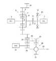
この発明の対象とするハイブリッド車両は、エンジンと少なくとも二つ以上の複数のモータとを駆動力源として備えている。そのように構成されたハイブリッド車両の一例を図3に示している。図3に示す車両は、エンジン(ENG)1の出力軸2にクラッチK0 を介して動力分割機構3が連結されている。この動力分割機構3は、従来知られているツーモータタイプのハイブリッド駆動装置における動力分割機構と同様に構成されており、三つの回転要素を有する差動機構である。図3に示す例では、動力分割機構3は、シングルピニオン型の遊星歯車機構により構成されている。この動力分割機構3は、エンジン1から出力された動力のうちの一部を電力に変換するとともに、エンジン1から出力された動力のうちの他の一部を駆動輪4に伝達するように構成されている。具体的には、第1モータ(MG1)5に連結されたサンギヤ6と、サンギヤ6に噛み合う複数のピニオンギヤ7と、それら複数のピニオンギヤ7を自転および公転可能に保持するとともにエンジン1にトルク伝達可能に連結されたキャリヤ8と、各ピニオンギヤ7に噛み合いかつサンギヤ6と同心円上に配置されたリングギヤ9とにより構成されており、そのリングギヤ9が図示しないデファレンシャルギヤなどの他のギヤトレーン部を介して駆動輪4にトルク伝達可能に連結されている。
A hybrid vehicle as an object of the present invention includes an engine and at least two or more motors as driving force sources. An example of such a hybrid vehicle is shown in FIG. In the vehicle shown in FIG. 3, a
上述したように構成された動力分割機構3は、エンジン1から出力されたトルクが動力分割機構3に入力された際に、サンギヤ6に伝達されるトルクに対抗して第1モータ5からトルクを出力することにより、サンギヤ6が反力要素として機能する。したがって、エンジン1から出力されたトルクが駆動輪4に伝達される。また、第1モータ5は、従来知られている同期電動機などの発電機能を有するモータであって、第1モータ5が出力するトルクの向きとは反対方向に回転させられることにより発電する。以下の説明では、第1モータ5を、第1モータ・ジェネレータ(MG1)5と記す。したがって、上記のようにサンギヤ6を反力要素として機能させるように第1モータ・ジェネレータ5からトルクを出力している際に、エンジン1から伝達されたトルクにより、第1モータ・ジェネレータ5が出力したトルクの向きとは反対方向に回転させられると、エンジン1から伝達された動力の一部が電力に変換させられる。そのため、上記のように電力に変換させられた分の動力が低下させられた状態で、エンジン1から出力された動力が駆動輪4に伝達させられる。 The power split
また、図3に示す車両は、エンジン1の出力軸2の延長線上に第2モータ10が設けられている。図3に示す第2モータ10は、シングルピニオン型の遊星歯車機構により構成された減速機11を介して、上記リングギヤ9に連結されている。この減速機11は、サンギヤ12と、そのサンギヤ12に噛み合う複数のピニオンギヤ13を自転可能に保持するキャリヤ14と、サンギヤ12と同心円上に配置されたリングギヤ15とにより構成された三要素の差動機構である。そして、サンギヤ12には、第2モータ10が連結され、リングギヤ15には、上記動力分割機構3におけるリングギヤ9が一体に回転するように連結され、キャリヤ14には、ハウジングなどの固定部16が連結されている。したがって、第2モータ10から出力されたトルクは反転させられかつこの遊星歯車機構のギヤ比に応じて変速させられてリングギヤ15から出力される。 In the vehicle shown in FIG. 3, the
この第2モータ10は、第1モータ・ジェネレータ5と同様に、同期電動機などの発電機能を有するモータである。以下の説明では、第2モータ10を、第2モータ・ジェネレータ(MG2)10と記す。この第2モータ・ジェネレータ10は、エンジン1から駆動輪4に伝達するトルクを増減させるように構成されている。より具体的には、第1モータ・ジェネレータ5が上記のように反力を作用させることにより発電した場合には、その発電された電力、またはその電力に加えて図示しない蓄電装置の電力が第2モータ・ジェネレータ10に供給されて駆動させられ、それとは反対に、第1モータ・ジェネレータ5が反力を作用させる際に発電しない場合、すなわち第1モータ・ジェネレータ5が動力を加算した場合には、その加算された動力を回生して電力に変換するように構成されている。なお、制動時には、第2モータ・ジェネレータ10を発電機として機能させることにより、駆動輪4に制動力を作用させることができる。 Similar to the first motor /
このように構成された車両は、上述したようにエンジン1から出力された動力を駆動輪4に伝達して走行する以外に、エンジン1を停止させた状態で第2モータ・ジェネレータ10から駆動輪4にトルクを伝達して走行することができる。このように第2モータ・ジェネレータ10から駆動輪4にトルクを伝達して走行することを、以下の説明では、シングルEV走行と記す。シングルEV走行時には、第2モータ・ジェネレータ5から出力されたトルクは、駆動輪4に伝達されるとともに、リングギヤ15を介して動力分割機構3に伝達される。エンジン1の慣性トルクが第1モータ・ジェネレータ5の慣性トルクよりも大きいので、そのように第2モータ・ジェネレータ5から動力分割機構3にトルクが伝達されると、エンジン1の回転が停止した状態を維持しつつ、第1モータ・ジェネレータ5が空転させられる。すなわち、第2モータ・ジェネレータ10から動力分割機構3にトルクが伝達された際には、エンジン1が反力として機能して、第1モータ・ジェネレータ5が回転させられる。したがって、第1モータ・ジェネレータ5が空転することによる動力損失が生じる可能性がある。そのため、図3に示す例では、エンジン1の慣性トルクが反力として機能することを抑制して第1モータ・ジェネレータ5が空転することを抑制するために、キャリヤ8と一体化されたインプットシャフト17と出力軸2とのトルクの伝達を遮断することができるクラッチK0 が設けられている。なお、このクラッチK0 がこの発明における係合装置に相当する。 As described above, the vehicle configured as described above transmits the power output from the engine 1 to the
このクラッチK0 は、ダイヤフラムスプリングの弾性力により摩擦板を係合させ、そのダイヤフラムスプリングの弾性力が低下する方向にアクチュエータから動力を作用させるように構成された、従来知られている乾式の摩擦クラッチや、油圧アクチュエータや電磁アクチュエータなどの制御量に応じて摩擦係合するように構成された、従来知られている湿式の摩擦クラッチなどにより構成することができる。なお、このクラッチK0 は、伝達トルク容量を制御することができるものであればよく、したがって、摩擦力によりトルクを伝達するように構成されたクラッチに限られない。 The clutch K0 is a conventionally known dry friction clutch configured to engage a friction plate by the elastic force of a diaphragm spring and to apply power from an actuator in a direction in which the elastic force of the diaphragm spring decreases. Alternatively, it can be configured by a conventionally known wet friction clutch configured to be frictionally engaged according to a control amount of a hydraulic actuator or an electromagnetic actuator. The clutch K0 may be any clutch that can control the transmission torque capacity, and is not limited to a clutch configured to transmit torque by frictional force.
一方、シングルEV走行は、第2モータ・ジェネレータ10の動力のみで走行することになるから、大きな駆動力を出力することができない。そのため、図3に示す例では、第2モータ・ジェネレータ10の動力のみでは出力することができない駆動力が要求された場合に、二つのモータ・ジェネレータ5,10から出力されたトルクを駆動輪4に伝達することができるように構成されている。具体的には、エンジン1の出力軸2に、その出力軸2の回転を停止させることができるブレーキBKが設けられている。このブレーキBKは、この発明における固定機構に相当するものであって、固定部16に係合させることにより制動トルクを出力軸2に作用させるように構成されている。図3に示すブレーキBKは、摩擦係合することにより出力軸2に制動トルクを作用させるように構成されている。なお、図3に示す例では、摩擦係合することにより出力軸2の回転を停止させる制動トルクを作用させるように構成された摩擦係合装置を設けているが、ワンウェイクラッチやドグクラッチなどの他のブレーキ機構であってもよい。 On the other hand, since the single EV traveling is performed only by the power of the second motor /
このようにブレーキBKを設けることにより、エンジン1の出力軸2が回転することを抑制することができる。すなわち、キャリヤ8を反力要素として機能させることができる。そのため、ブレーキBKを係合させた状態で、第1モータ・ジェネレータ5からトルクを出力することにより、第1モータ・ジェネレータ5から出力されたトルクを駆動輪4に伝達することができる。したがって、第1モータ・ジェネレータ5と第2モータ・ジェネレータ10とから出力されたトルクを駆動輪4に伝達することができるので、上記シングルEV走行よりも大きな駆動力を出力することができる。以下の説明では、二つのモータ・ジェネレータ5,10から駆動輪4にトルクを伝達して走行することを、ツインEV走行と記す。 Thus, by providing brake BK, it can suppress that
また、図3に示すように出力軸2の回転を停止させるようにブレーキBKを設けるとともに、そのエンジン1の出力軸2とインプットシャフト17との間にクラッチK0 を設けることより、ブレーキBKを係合させて出力軸2を固定している状態で駆動輪4から大きなトルクが作用した場合には、クラッチK0 をスリップさせることができる。すなわち、クラッチK0 を、ブレーキBKのトルクリミッターとして機能させることができる。そのため、ブレーキBKに過剰なトルクが伝達されることを抑制することができるので、剛性を向上させるためなどによりブレーキBKが大型化することを抑制することができるとともに、ブレーキBKの耐久性が低下することを抑制することができる。 Further, as shown in FIG. 3, a brake BK is provided so as to stop the rotation of the
図3に示す例では、上述したエンジン1、各モータ・ジェネレータ5,10、クラッチK0 、ブレーキBKを制御するための電子制御装置(ECU)19が設けられている。この電子制御装置19は、マイクロコンピュータを主体にして構成され、入力されたデータや指令信号に基づいて演算を行って、その演算結果を制御信号としてエンジン1、各モータ・ジェネレータ5,10、クラッチK0 、ブレーキBKに出力して各種の制御を行うように構成されている。 In the example shown in FIG. 3, an electronic control unit (ECU) 19 for controlling the engine 1, the
この発明に係る制御装置は、要求駆動力が増大するなどしてシングルEV走行からツインEV走行に迅速に移行させることができるように構成されている。その制御の一例を図1に示すフローチャートを参照して説明する。なお、図1に示す制御フローは、所定時間毎に繰り返し実行される。図1に示す制御例では、まず、シングルEV走行時であるか否かが判断される(ステップS1)。このステップS1は、クラッチK0 を解放させる信号が出力された状態で走行しているか否かに基づいて判断することができる。または、図示しないアクセルペダルの開度などに基づく要求駆動力などにより判断することができる。 The control device according to the present invention is configured to be able to quickly shift from single EV traveling to twin EV traveling due to an increase in required driving force. An example of the control will be described with reference to the flowchart shown in FIG. Note that the control flow shown in FIG. 1 is repeatedly executed every predetermined time. In the control example shown in FIG. 1, it is first determined whether or not it is during single EV travel (step S1). This step S1 can be determined based on whether or not the vehicle is traveling in a state where a signal for releasing the clutch K0 is output. Alternatively, it can be determined by a required driving force based on an opening degree of an accelerator pedal (not shown).
シングルEV走行でなくステップS1で否定的に判断された場合、すなわちツインEV走行している場合やエンジン1から駆動輪4にトルクを伝達して走行している場合には、そのままリターンする。それとは反対に、シングルEV走行時であってステップS1で肯定的に判断された場合には、ツインEV走行に移行するか否かが判断される(ステップS2)。このステップS2は、図示しないアクセルペダルの開度が増大するなどして要求駆動力が、シングルEV走行では出力することができない駆動力まで増加したか否かによって判断することができる。 If the determination is negative in step S1 instead of the single EV traveling, that is, if the vehicle is traveling with twin EVs or traveling with torque transmitted from the engine 1 to the
ツインEV走行に移行しない場合には、ステップS2で否定的に判断されて、そのままリターンする。それとは反対にツインEV走行に移行することによりステップS2で肯定的に判断された場合には、クラッチK0 およびブレーキBKを係合させるための制御が実行される。具体的には、まず、出力軸2とインプットシャフト17との回転数の差を低下させるように、第1モータ・ジェネレータ5の回転数を変化させ始める(ステップS3)。上述したようにシングルEV走行時には、エンジン1を停止させるとともにクラッチK0 を解放しているので、出力軸2および第1モータ・ジェネレータ5の回転数は「0」である。したがって、図3に示す構成では、第1モータ・ジェネレータ5を、負側に回転させ始める。すなわち、エンジン1からトルクを出力して走行する際にエンジン1が回転する方向とは反対方向に第1モータ・ジェネレータ5を回転させ始める。ついで、ブレーキBKの伝達トルク容量を増大させ始めてから(ステップS4)、クラッチK0 の伝達トルク容量を増大させ始める(ステップS5)。If the vehicle does not shift to the twin EV traveling, a negative determination is made in step S2, and the process returns as it is. On the other hand, if the determination is affirmative in step S2 by shifting to the twin EV traveling, the control for engaging the clutch K0 and the brake BK is executed. Specifically, first, the rotation speed of the first motor /
上記のステップS3ないしステップS5の順序は特に限定されず、また同時に実行されてもよいが、第1モータ・ジェネレータ5の回転数を変化させている制御と、クラッチK0 の伝達トルク容量を増大させる制御とが並行して実行されている期間がある。一方、クラッチK0 の伝達トルク容量を増大させる以前に、ブレーキBKの伝達トルク容量を増大させることにより、エンジン1が回転させられることを抑制することができるので、クラッチK0 の伝達トルク容量を増大させ始める以前に、ブレーキBKの伝達トルク容量を増大させ始めることが好ましい。また、クラッチK0 の伝達トルク容量を増大させる以前に、第1モータ・ジェネレータ5の回転数を変化させることにより、クラッチK0 が係合し始めた時点における第1モータ・ジェネレータ5の慣性トルクを小さくすることができる。言い換えると、クラッチK0 が係合し始めることによりエンジン1が回転させるように作用するトルクを小さくすることができ、エンジン1が回転することを抑制することができる。そのため、クラッチK0 の伝達トルク容量を増大させ始める以前に、第1モータ・ジェネレータ5の回転数を変化させ始めることが好ましい。したがって、図1に示す順序で第1モータ・ジェネレータ5、ブレーキBK、クラッチK0 を制御することが好ましい。 The order of the above steps S3 to S5 is not particularly limited and may be executed at the same time. However, the control for changing the rotation speed of the first motor /
そして、上記ステップS5の後に、クラッチK0 が完全に係合したか否かを判断する(ステップS6)。このステップS6は、インプットシャフト17と出力軸2との回転数が一致したか否か、またはクラッチK0 を係合させるためのアクチュエータに入力される信号が、クラッチK0 を完全に係合させる際にそのアクチュエータに入力される信号になっているか否かなどに応じて判断することができる。クラッチK0 が未だ完全に係合しておらずステップS6で否定的に判断された場合は、クラッチK0 が完全に係合するまで繰り返しステップS6を実行する。それとは反対にクラッチK0 が完全に係合していることによりステップS6で肯定的に判断された場合には、ブレーキBKの係合が完了したか否かを判断する(ステップS7)。このステップS7は、ブレーキBKを係合させるためのアクチュエータに入力される信号が、ブレーキBKを完全に係合させる際にそのアクチュエータに入力される信号になっているか否かなどに応じて判断することができる。または、第1モータ・ジェネレータ5から微小なトルクを出力して出力軸2が回転するか否かを判断してもよい。 After step S5, it is determined whether or not the clutch K0 is completely engaged (step S6). This step S6 is performed when the input speed of the
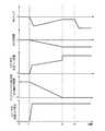
つぎに、図1に示す制御を実行した際における第1モータ・ジェネレータ5の運転状態、クラッチK0 およびブレーキBKの伝達トルク容量、出力軸2とインプットシャフト17との回転数の差のそれぞれの変化を、図2に示すタイムチャートを参照して説明する。図2に示す例では、t0時点では、シングルEV走行により走行している。したがって、第1モータ・ジェネレータ5は、停止しているとともにトルクが出力されていない。また、上述したようにシングルEV走行では、クラッチK0 およびブレーキBKが解放させられているので、図2に示す例では、クラッチK0 およびブレーキBKの伝達トルク容量が「0」になり、かつ出力軸2とインプットシャフト17との回転数の差が比較的大きい。 Next, changes in the operating state of the first motor /
そして、図1におけるステップS2がt1時点で肯定的に判断されると、すなわち、シングルEV走行からツインEV走行へ移行することが判断されると、第1モータ・ジェネレータ5が回転させられ始めるとともに、クラッチK0 およびブレーキBKが係合させられ始める。このようにクラッチK0 を係合させる際には、エンジン1が回転させられないようにすることが好ましく、具体的には、エンジン1のフリクショントルクや慣性トルクにブレーキBKの制動トルクを加算した値よりもクラッチK0 の伝達トルク容量を小さくする。なお、図2に示す例では、第1モータ・ジェネレータ5を回転させ始めると同時に、クラッチK0 およびブレーキBKの伝達トルク容量を増大させ始めている。 When step S2 in FIG. 1 is positively determined at time t1, that is, when it is determined that the single EV traveling is shifted to the twin EV traveling, the first motor /
また、図2に示す例では、クラッチK0 が係合することによりショックが生じることを抑制するために、出力軸2とインプットシャフト17との回転数の差が小さくなるにつれて、第1モータ・ジェネレータ5の出力トルクを低下させつつ、クラッチK0 の伝達トルク容量を増大させている。 Further, in the example shown in FIG. 2, in order to suppress the occurrence of shock due to the engagement of the clutch K0, the first motor / generator is generated as the difference in the rotational speed between the
そして、出力軸2とインプットシャフト17との回転数が一致すると(t2時点)、クラッチK0 が滑ることなくトルクを伝達していることとなるので、クラッチK0 の伝達トルク容量を最大値まで増大させる。なお、図2に示す例では、第1モータ・ジェネレータ5の出力トルクが一定に保たれている。ついで、ブレーキBKを係合させることができたことを確認するための所定時間が経過した後に、ブレーキBKの係合が完了したことが判断される(t3時点)。なお、このt2時点からt3時点までの間に、駆動力が変化しないように、第1モータ・ジェネレータ5の出力トルクを増大させるとともに、第2モータ・ジェネレータ10の出力トルクを低下させるなどにより、出力軸2が回転しないことを確認することで、ブレーキBKが係合したことを判断することができる。そして、ブレーキBKが係合したことが判断されたら、ツインEV走行することができるので、要求駆動力に応じて第1モータ・ジェネレータ5の出力トルクを増大させる。 When the rotational speeds of the
図1および図2に示すように、出力軸2とインプットシャフト17との回転数の差を低下させつつ、クラッチK0 を係合させることにより、クラッチK0 が同期することを待たずにクラッチK0 を係合させ始めることができるので、シングルEV走行からツインEV走行への切り替えを迅速に行うことができる。その結果、駆動力の応答性を向上させることができる。また、そのようにクラッチK0 を係合させる際におけるクラッチK0 の伝達トルク容量を、エンジン1のフリクショントルクや慣性トルクあるいはブレーキBKの制動トルクなどよりも小さくすること、すなわち、エンジン1を回転させる際に要するトルクよりも小さくすることにより、エンジン1が回転させられることを抑制することができる。その結果、エンジン1を連れ回すことによる動力損失を低減することができるので、シングルEV走行からツインEV走行へ移行する際における電力消費量を低減することができる。特に、クラッチK0 の伝達トルク容量を増大させる以前に、ブレーキBKの伝達トルク容量を増大させ始めることにより、エンジン1が連れ回されにくくなるので、クラッチK0 の伝達トルク容量を迅速に増大させることができる。その結果、シングルEV走行からツインEV走行への切り替えを迅速に行うことができる。 As shown in FIGS. 1 and 2, by engaging the clutch K0 while reducing the difference in rotational speed between the
また、上述したようにエンジン1が連れ回されることを抑制することにより、エンジン1の停止位置が変化してしまうことを抑制することができる。すなわち、エンジン1の停止時におけるクランク角が変化することを抑制することができる。その結果、エンジン1を始動して走行させるためにエンジン1をクランキングさせる際に、エンジン1のトルク変動が増大するなどによるショックや異音が生じることを抑制することができる。さらに、出力軸2とインプットシャフト17との回転数の差が小さくなるにつれて、第1モータ・ジェネレータ5の出力トルクを低下させつつ、クラッチK0 の伝達トルク容量を増大させることにより、クラッチK0 の係合時にショックが生じることを抑制することができる。 Moreover, it can suppress that the stop position of the engine 1 changes by suppressing that the engine 1 is rotated as mentioned above. That is, it is possible to suppress a change in the crank angle when the engine 1 is stopped. As a result, when cranking the engine 1 in order to start and run the engine 1, it is possible to suppress the occurrence of shock and noise due to an increase in torque fluctuation of the engine 1. Further, as the difference between the rotational speeds of the
なお、この発明で対象とする車両は、図3に示す構成に限定されず、図4ないし図6に示すように構成されたものであってもよい。以下、図4ないし図6に示す車両の構成を簡単に説明する。なお、図3と同様の構成には、同一の参照符号を付してその説明を省略する。 The vehicle targeted by the present invention is not limited to the configuration shown in FIG. 3, and may be configured as shown in FIGS. Hereinafter, the configuration of the vehicle shown in FIGS. 4 to 6 will be briefly described. The same components as those in FIG. 3 are denoted by the same reference numerals, and the description thereof is omitted.
図4に示す例では、第1モータ・ジェネレータ5が、インプットシャフト17の延長線上に配置されている。また、上記の動力分割機構3や第1モータ・ジェネレータ5などの回転中心軸線と平行にカウンタシャフト20が配置されており、上記のリングギヤ9には、外歯歯車の出力ギヤ21が形成され、その出力ギヤ21に噛み合っているカウンタドリブンギヤ22がこのカウンタシャフト20と一体に回転するように取り付けられている。 In the example shown in FIG. 4, the first motor /
さらに、上記の動力分割機構3からドライブシャフト23に伝達されるトルクに、第2モータ・ジェネレータ10のトルクを負荷するように構成されている。すなわち、上記のカウンタシャフト20と平行に第2モータ・ジェネレータ11が配置されており、そのロータに連結されたリダクションギヤ24が上記のカウンタドリブンギヤ22に噛み合っている。そのリダクションギヤ24はカウンタドリブンギヤ22より小径であり、したがって第2モータ・ジェネレータ11のトルクを増幅してカウンタドリブンギヤ22もしくはカウンタシャフト20に伝達するように構成されている。 Further, the torque transmitted from the
カウンタシャフト20には、更に、カウンタドライブギヤ25が一体に回転するように設けられており、このカウンタドライブギヤ25が終減速機であるデファレンシャルギヤ26におけるリングギヤ27に噛み合っている。 Further, a
また、この発明における係合装置は、解放することによりエンジン1と駆動輪4とのトルクの伝達を遮断することができればよい。したがって、動力分割機構3におけるいずれか一つの回転要素へのトルクの伝達を遮断することができればよい。そのため、図5に示すように第1モータ・ジェネレータ5とサンギヤ6との間にクラッチK0 設けてもよく、図6に示すようにリングギヤ9と出力ギヤ21との間にクラッチK0 を設けてもよい。なお、図5および図6に示すようにエンジン1と動力分割機構3との間にクラッチK0 を設けない場合には、エンジン1の出力軸2とインプットシャフト17とは同一の部材であってもよい。 Further, the engagement device according to the present invention only needs to be able to block the transmission of torque between the engine 1 and the
さらに、エンジン1がキャリヤ8に連結され、かつ第1モータ・ジェネレータ5がサンギヤ6に連結された構成に限らず、エンジン1がサンギヤ6に連結され、かつ第1モータ・ジェネレータ5がキャリヤ8に連結された構成であってもよい。そのように構成されている場合には、シングルEV走行からツインEV走行に移行する際には、第1モータ・ジェネレータ5の出力トルクは、図3に示す車両とは反対方向にリングギヤ9に作用するので、シングルEV走行からツインEV走行に切り替える際には、図2に示す回転方向とは反対方向に第1モータ・ジェネレータ5を回転させればよい。そして、上述した各構成では、二つのモータ・ジェネレータ5,10を備えた例を挙げて説明しているが、例えば、動力分割機構3と駆動輪4との間に、第2モータ・ジェネレータ10以外の他のモータを更に設けていてもよい。 Further, the engine 1 is connected to the
1…エンジン(ENG)、 3…動力分割機構、 4…駆動輪、 5,10…モータ・ジェネレータ、 6,12…サンギヤ、 7,13…ピニオンギヤ、 8,14…キャリヤ、 9,15…リングギヤ、 11…減速機、 16…固定部、 19…電子制御装置、 K0 …クラッチ、 BK…ブレーキ。 DESCRIPTION OF SYMBOLS 1 ... Engine (ENG), 3 ... Power split mechanism, 4 ... Drive wheel, 5, 10 ... Motor generator, 6, 12 ... Sun gear, 7, 13 ... Pinion gear, 8, 14 ... Carrier, 9, 15 ... Ring gear, DESCRIPTION OF
Claims (4)
Translated fromJapanese前記係合装置を解放しかつ前記エンジンを停止させた状態で前記第2モータから出力されたトルクを前記駆動輪に伝達して走行する第1走行モードから、前記係合装置を係合させかつ前記固定機構により前記出力軸を停止させた状態で前記第1モータおよび前記第2モータから出力されたトルクを前記駆動輪に伝達して走行する第2走行モードに切り替える際に、前記係合装置の入力側の回転数と出力側の回転数との差を低減させるように前記第1モータの回転数を変化させるモータ制御と、前記係合装置の伝達トルク容量を増大させる係合制御とを並行して実行し、
前記係合装置の入力側の回転数と出力側の回転数との差が小さくなるにつれて、前記係合装置の伝達トルク容量を増大させかつ前記第2モータの出力トルクを低下させるように構成されていることを特徴とするハイブリッド車両の制御装置。A first rotating element having an engine and at least two or more motors as a driving force source and connected to the engine so as to transmit torque, and connected to the first motor of the plurality of motors so as to transmit torque A differential mechanism having a second rotating element that is connected to the driving wheel so as to be able to transmit torque and a third rotating element that is connected to a second motor of the plurality of motors so as to be able to transmit torque; An engagement device capable of controlling a transmission torque capacity and selectively interrupting transmission of torque to any one of the rotating elements by releasing, and in a power transmission path A hybrid vehicle including a fixing mechanism that is disposed closer to the engine than the engagement device and that stops the output shaft of the engine by engaging with a fixing portion. In the control device,
From a first traveling mode in which the vehicle travels by transmittingthe torque output from the second motor in a state where the engagement of the engagement device to release and the said engine is stopped tothe driving wheel, and engaged with the engagement device When switching to the second traveling mode in which the torque output from the first motor and the second motor is transmitted to the drive wheels while the output shaft is stopped by the fixing mechanism, the engaging device is switched. Motor control for changing the rotation speed of the first motor so as to reduce the difference between the rotation speed on the input side and the rotation speed on the output side, and engagement control for increasing the transmission torque capacity of the engagement device. in parallelrun,
As the difference between the rotational speed on the input side and the rotational speed on the output side of the engagement device becomes smaller, the transmission torque capacity of the engagement device is increased and the output torque of the second motor is decreased. and control apparatus for a hybrid vehicle, wherein it is.
前記係合装置を解放しかつ前記エンジンを停止させた状態で前記第2モータから出力されたトルクを前記駆動輪に伝達して走行する第1走行モードから、前記係合装置を係合させかつ前記固定機構により前記出力軸を停止させた状態で前記第1モータおよび前記第2モータから出力されたトルクを前記駆動輪に伝達して走行する第2走行モードに切り替える際に、前記係合装置の入力側の回転数と出力側の回転数との差を低減させるように前記第1モータの回転数を変化させるモータ制御と、前記係合装置の伝達トルク容量を増大させる係合制御とを並行して実行するように構成され、
前記固定機構は、前記出力軸に作用させる制動トルクを制御することができるように構成され、
前記第1走行モードから前記第2走行モードに切り替える際に、前記係合制御を実行する以前に、前記固定機構により前記出力軸に作用させる制動トルクを増大させる制動制御を実行するように構成されていることを特徴とするハイブリッド車両の制御装置。A first rotating element having an engine and at least two or more motors as a driving force source and connected to the engine so as to transmit torque, and connected to the first motor of the plurality of motors so as to transmit torque A differential mechanism having a second rotating element that is connected to the driving wheel so as to be able to transmit torque and a third rotating element that is connected to a second motor of the plurality of motors so as to be able to transmit torque; An engagement device capable of controlling a transmission torque capacity and selectively interrupting transmission of torque to any one of the rotating elements by releasing, and in a power transmission path A hybrid vehicle including a fixing mechanism that is disposed closer to the engine than the engagement device and that stops the output shaft of the engine by engaging with a fixing portion. In the control device,
From the first travel mode in which the torque output from the second motor is transmitted to the drive wheels while the engagement device is released and the engine is stopped, the engagement device is engaged, and When switching to the second traveling mode in which the torque output from the first motor and the second motor is transmitted to the drive wheels while the output shaft is stopped by the fixing mechanism, the engaging device is switched. Motor control for changing the rotation speed of the first motor so as to reduce the difference between the rotation speed on the input side and the rotation speed on the output side, and engagement control for increasing the transmission torque capacity of the engagement device. Configured to run in parallel,
Before SL fixing mechanism is configured to be able to control the braking torque to be applied to said output shaft,
When switching from the first travel mode to the second travel mode, before the engagement control is performed, the braking control is performed to increase the braking torque applied to the output shaft by the fixing mechanism. the control device features and toRuha hybrid vehicle that has.
Priority Applications (4)
| Application Number | Priority Date | Filing Date | Title |
|---|---|---|---|
| JP2014086105AJP6344030B2 (en) | 2014-04-18 | 2014-04-18 | Control device for hybrid vehicle |
| US15/304,974US9944279B2 (en) | 2014-04-18 | 2015-03-25 | Control system for hybrid vehicle |
| PCT/JP2015/001703WO2015159490A1 (en) | 2014-04-18 | 2015-03-25 | Control system for hybrid vehicle |
| CN201580032706.9ACN106458205B (en) | 2014-04-18 | 2015-03-25 | Control system for hybrid vehicle |
Applications Claiming Priority (1)
| Application Number | Priority Date | Filing Date | Title |
|---|---|---|---|
| JP2014086105AJP6344030B2 (en) | 2014-04-18 | 2014-04-18 | Control device for hybrid vehicle |
Publications (2)
| Publication Number | Publication Date |
|---|---|
| JP2015205549A JP2015205549A (en) | 2015-11-19 |
| JP6344030B2true JP6344030B2 (en) | 2018-06-20 |
Family
ID=53008821
Family Applications (1)
| Application Number | Title | Priority Date | Filing Date |
|---|---|---|---|
| JP2014086105AExpired - Fee RelatedJP6344030B2 (en) | 2014-04-18 | 2014-04-18 | Control device for hybrid vehicle |
Country Status (4)
| Country | Link |
|---|---|
| US (1) | US9944279B2 (en) |
| JP (1) | JP6344030B2 (en) |
| CN (1) | CN106458205B (en) |
| WO (1) | WO2015159490A1 (en) |
Families Citing this family (10)
| Publication number | Priority date | Publication date | Assignee | Title |
|---|---|---|---|---|
| JP6344030B2 (en)* | 2014-04-18 | 2018-06-20 | トヨタ自動車株式会社 | Control device for hybrid vehicle |
| JP6623936B2 (en)* | 2016-05-30 | 2019-12-25 | 株式会社豊田中央研究所 | Driving force transmission device |
| JP2019166938A (en)* | 2018-03-23 | 2019-10-03 | 本田技研工業株式会社 | Drive unit for hybrid vehicle |
| KR102663982B1 (en)* | 2018-10-10 | 2024-05-07 | 현대자동차 주식회사 | Power transmission system of hybrid electric vehicle |
| KR102681920B1 (en)* | 2018-11-30 | 2024-07-04 | 현대자동차 주식회사 | Power transmission system of hybrid electric vehicle |
| US11173781B2 (en) | 2019-12-20 | 2021-11-16 | Allison Transmission, Inc. | Component alignment for a multiple motor mixed-speed continuous power transmission |
| US11331991B2 (en) | 2019-12-20 | 2022-05-17 | Allison Transmission, Inc. | Motor configurations for multiple motor mixed-speed continuous power transmission |
| US11371589B2 (en)* | 2020-04-30 | 2022-06-28 | Allison Transmission, Inc. | Clutch configurations for a multiple motor mixed-speed continuous power transmission |
| US11421759B2 (en) | 2020-06-02 | 2022-08-23 | Allison Transmission, Inc. | Output gearing for a dual motor mixed-speed continuous power transmission |
| CN113479059B (en)* | 2021-07-30 | 2022-12-09 | 重庆长安汽车股份有限公司 | Hybrid power driving system and hybrid power automobile |
Family Cites Families (40)
| Publication number | Priority date | Publication date | Assignee | Title |
|---|---|---|---|---|
| DE4308761A1 (en)* | 1993-03-19 | 1994-09-22 | Zahnradfabrik Friedrichshafen | Infinitely variable transmission with large gear ratio spread |
| IN189939B (en)* | 1993-12-20 | 2003-05-17 | Torotrak Dev Ltd | |
| JP3173319B2 (en)* | 1995-04-28 | 2001-06-04 | 株式会社エクォス・リサーチ | Hybrid vehicle |
| JP2973920B2 (en)* | 1995-05-24 | 1999-11-08 | トヨタ自動車株式会社 | Hybrid electric vehicle |
| GB2369164A (en)* | 2000-11-16 | 2002-05-22 | Torotrak Dev Ltd | Hydraulic control of a continuously-variable ratio transmission |
| US6447422B1 (en)* | 2001-01-16 | 2002-09-10 | General Motors Corporation | Dual mode, geared neutral continuously variable transmission |
| GB0129125D0 (en)* | 2001-12-05 | 2002-01-23 | Drivetec Uk Ltd | Automotive vehicle transmission systems |
| JP3614409B2 (en)* | 2002-03-25 | 2005-01-26 | 日産自動車株式会社 | Hybrid transmission |
| JP3626151B2 (en)* | 2002-06-17 | 2005-03-02 | 日産自動車株式会社 | Hybrid transmission |
| JP3858898B2 (en)* | 2004-02-13 | 2006-12-20 | 日産自動車株式会社 | Mode change control device for hybrid transmission |
| US7347800B2 (en)* | 2005-02-11 | 2008-03-25 | Eaton Corporation | Multi-speed power splitting CVT |
| US7252611B2 (en)* | 2005-02-18 | 2007-08-07 | Gm Global Technology Operations, Inc. | Electrically variable transmission having two planetary gear sets with one interconnecting member and clutched input |
| JP4483819B2 (en)* | 2005-04-28 | 2010-06-16 | 株式会社豊田中央研究所 | Power transmission system |
| DE102005022012A1 (en)* | 2005-05-12 | 2006-12-07 | Daimlerchrysler Ag | Transmission for a motor vehicle with stepless power-split driving ranges |
| US7338401B2 (en)* | 2005-07-22 | 2008-03-04 | Gm Global Technology Operations, Inc. | Two mode electrically variable transmission with equal forward and reverse input-split modal and fixed ratio performance |
| US7572201B2 (en)* | 2005-10-20 | 2009-08-11 | Ford Global Technologies, Llc | Electric hybrid powertrain system |
| US7422535B2 (en)* | 2006-03-17 | 2008-09-09 | Gm Global Technology Operations, Inc. | Electrically variable transmissions having two planetary gearsets and clutched input |
| US7473199B2 (en)* | 2006-05-25 | 2009-01-06 | Gm Global Technology Operations, Inc. | Two-planetary electrically variable transmissions with multiple fixed ratios |
| JP4396661B2 (en)* | 2006-05-26 | 2010-01-13 | 日産自動車株式会社 | Clutch engagement control device for hybrid vehicle |
| JP4263219B2 (en)* | 2007-03-30 | 2009-05-13 | 本田技研工業株式会社 | Power equipment |
| JP5018445B2 (en)* | 2007-12-13 | 2012-09-05 | トヨタ自動車株式会社 | Control device for vehicle power transmission device |
| US9545839B2 (en)* | 2008-09-05 | 2017-01-17 | Ford Global Technologies, Llc | Hybrid electric vehicle powertrain with enhanced reverse drive performance |
| JP5203332B2 (en)* | 2008-11-11 | 2013-06-05 | 株式会社日本自動車部品総合研究所 | On-vehicle power transmission device and vehicle drive device |
| JP5372648B2 (en)* | 2009-07-31 | 2013-12-18 | 株式会社日本自動車部品総合研究所 | Power transmission device and power transmission control system |
| US8465387B2 (en)* | 2009-03-04 | 2013-06-18 | GM Global Technology Operations LLC | Output-split electrically-variable transmission with two planetary gear sets and two motor/generators |
| US8550958B2 (en)* | 2009-03-31 | 2013-10-08 | GM Global Technology Operations LLC | Shift control method for a multi-mode hybrid transmission |
| US8579748B2 (en)* | 2009-04-28 | 2013-11-12 | Nippon Soken, Inc. | In-vehicle power transmission device and power transmission system for vehicle |
| JP5037589B2 (en)* | 2009-11-16 | 2012-09-26 | 株式会社日本自動車部品総合研究所 | In-vehicle power transmission device and in-vehicle power transmission control system |
| JP5026496B2 (en)* | 2009-11-16 | 2012-09-12 | 株式会社日本自動車部品総合研究所 | In-vehicle power transmission device and in-vehicle power transmission control system |
| US8337352B2 (en)* | 2010-06-22 | 2012-12-25 | Oshkosh Corporation | Electromechanical variable transmission |
| DE102011080081A1 (en)* | 2010-07-30 | 2012-02-02 | Denso Corporation | Vehicle power transmission device |
| JP5275409B2 (en)* | 2011-05-30 | 2013-08-28 | 株式会社日本自動車部品総合研究所 | Power transmission device |
| US20130331216A1 (en)* | 2012-06-08 | 2013-12-12 | Chrysler Group Llc | Two motor electric drive hybrid transmission |
| CN104470744B (en)* | 2012-07-17 | 2017-03-15 | 丰田自动车株式会社 | Drive device for hybrid vehicle |
| IN2015DN00559A (en)* | 2012-07-31 | 2015-06-26 | Toyota Motor Co Ltd | |
| JP5949938B2 (en)* | 2012-11-16 | 2016-07-13 | トヨタ自動車株式会社 | Vehicle shift control device |
| JP5950036B2 (en) | 2013-04-30 | 2016-07-13 | トヨタ自動車株式会社 | Hybrid vehicle drive device |
| JP6060850B2 (en) | 2013-08-09 | 2017-01-18 | トヨタ自動車株式会社 | Control device for hybrid vehicle |
| JP6176011B2 (en)* | 2013-09-11 | 2017-08-09 | トヨタ自動車株式会社 | Vehicle control device |
| JP6344030B2 (en)* | 2014-04-18 | 2018-06-20 | トヨタ自動車株式会社 | Control device for hybrid vehicle |
- 2014
- 2014-04-18JPJP2014086105Apatent/JP6344030B2/ennot_activeExpired - Fee Related
- 2015
- 2015-03-25CNCN201580032706.9Apatent/CN106458205B/ennot_activeExpired - Fee Related
- 2015-03-25WOPCT/JP2015/001703patent/WO2015159490A1/enactiveApplication Filing
- 2015-03-25USUS15/304,974patent/US9944279B2/enactiveActive
Also Published As
| Publication number | Publication date |
|---|---|
| JP2015205549A (en) | 2015-11-19 |
| US20170182997A1 (en) | 2017-06-29 |
| CN106458205A (en) | 2017-02-22 |
| CN106458205B (en) | 2018-12-11 |
| US9944279B2 (en) | 2018-04-17 |
| WO2015159490A1 (en) | 2015-10-22 |
Similar Documents
| Publication | Publication Date | Title |
|---|---|---|
| JP6344030B2 (en) | Control device for hybrid vehicle | |
| JP6255510B2 (en) | Hybrid drive unit | |
| JP6156243B2 (en) | Control device for hybrid vehicle | |
| CN105473406B (en) | hybrid vehicle | |
| JP6003843B2 (en) | Control device for hybrid vehicle | |
| JP6107824B2 (en) | Vehicle travel control device | |
| WO2014006716A1 (en) | Control device for hybrid vehicle | |
| JP2015020590A (en) | Control device for hybrid vehicle | |
| JP6115572B2 (en) | Power transmission device | |
| JP5907155B2 (en) | Control device for hybrid drive | |
| JP4046035B2 (en) | Hybrid vehicle drive system | |
| JP2013141959A (en) | Driving device for vehicle | |
| JP5929641B2 (en) | Hybrid vehicle drive device | |
| JP6285273B2 (en) | Hydraulic control device for automatic transmission | |
| WO2019159625A1 (en) | Drive device, and vehicle | |
| WO2018128012A1 (en) | Electric driving device and vehicle controlling device | |
| JP4040541B2 (en) | Hybrid vehicle drive system | |
| JP6922802B2 (en) | Hybrid vehicle control device | |
| JP2018065512A (en) | Hybrid vehicle drive control system | |
| JP6304083B2 (en) | Control device for hybrid vehicle | |
| JP6048335B2 (en) | Vehicle control device | |
| JP6146273B2 (en) | Power transmission control device | |
| JP6658229B2 (en) | Drive control device for hybrid vehicle | |
| JP2016088270A (en) | vehicle | |
| JP2012255489A (en) | Release control device of electromagnetic engaging device |
Legal Events
| Date | Code | Title | Description |
|---|---|---|---|
| A621 | Written request for application examination | Free format text:JAPANESE INTERMEDIATE CODE: A621 Effective date:20161107 | |
| A131 | Notification of reasons for refusal | Free format text:JAPANESE INTERMEDIATE CODE: A131 Effective date:20171114 | |
| A521 | Request for written amendment filed | Free format text:JAPANESE INTERMEDIATE CODE: A523 Effective date:20171226 | |
| TRDD | Decision of grant or rejection written | ||
| A01 | Written decision to grant a patent or to grant a registration (utility model) | Free format text:JAPANESE INTERMEDIATE CODE: A01 Effective date:20180424 | |
| A61 | First payment of annual fees (during grant procedure) | Free format text:JAPANESE INTERMEDIATE CODE: A61 Effective date:20180507 | |
| R151 | Written notification of patent or utility model registration | Ref document number:6344030 Country of ref document:JP Free format text:JAPANESE INTERMEDIATE CODE: R151 | |
| LAPS | Cancellation because of no payment of annual fees |