JP6342108B2 - Knotted suture anchor - Google Patents
Knotted suture anchorDownload PDFInfo
- Publication number
- JP6342108B2 JP6342108B2JP2012216080AJP2012216080AJP6342108B2JP 6342108 B2JP6342108 B2JP 6342108B2JP 2012216080 AJP2012216080 AJP 2012216080AJP 2012216080 AJP2012216080 AJP 2012216080AJP 6342108 B2JP6342108 B2JP 6342108B2
- Authority
- JP
- Japan
- Prior art keywords
- suture
- distal
- anchor body
- anchor
- bone
- Prior art date
- Legal status (The legal status is an assumption and is not a legal conclusion. Google has not performed a legal analysis and makes no representation as to the accuracy of the status listed.)
- Expired - Fee Related
Links
Images


Classifications
- A—HUMAN NECESSITIES
- A61—MEDICAL OR VETERINARY SCIENCE; HYGIENE
- A61B—DIAGNOSIS; SURGERY; IDENTIFICATION
- A61B17/00—Surgical instruments, devices or methods
- A61B17/04—Surgical instruments, devices or methods for suturing wounds; Holders or packages for needles or suture materials
- A61B17/0401—Suture anchors, buttons or pledgets, i.e. means for attaching sutures to bone, cartilage or soft tissue; Instruments for applying or removing suture anchors
- A61B2017/0409—Instruments for applying suture anchors
- A—HUMAN NECESSITIES
- A61—MEDICAL OR VETERINARY SCIENCE; HYGIENE
- A61B—DIAGNOSIS; SURGERY; IDENTIFICATION
- A61B17/00—Surgical instruments, devices or methods
- A61B17/04—Surgical instruments, devices or methods for suturing wounds; Holders or packages for needles or suture materials
- A61B17/0401—Suture anchors, buttons or pledgets, i.e. means for attaching sutures to bone, cartilage or soft tissue; Instruments for applying or removing suture anchors
- A61B2017/0414—Suture anchors, buttons or pledgets, i.e. means for attaching sutures to bone, cartilage or soft tissue; Instruments for applying or removing suture anchors having a suture-receiving opening, e.g. lateral opening
- A—HUMAN NECESSITIES
- A61—MEDICAL OR VETERINARY SCIENCE; HYGIENE
- A61B—DIAGNOSIS; SURGERY; IDENTIFICATION
- A61B17/00—Surgical instruments, devices or methods
- A61B17/04—Surgical instruments, devices or methods for suturing wounds; Holders or packages for needles or suture materials
- A61B17/0401—Suture anchors, buttons or pledgets, i.e. means for attaching sutures to bone, cartilage or soft tissue; Instruments for applying or removing suture anchors
- A61B2017/044—Suture anchors, buttons or pledgets, i.e. means for attaching sutures to bone, cartilage or soft tissue; Instruments for applying or removing suture anchors with a threaded shaft, e.g. screws
- A—HUMAN NECESSITIES
- A61—MEDICAL OR VETERINARY SCIENCE; HYGIENE
- A61B—DIAGNOSIS; SURGERY; IDENTIFICATION
- A61B17/00—Surgical instruments, devices or methods
- A61B17/04—Surgical instruments, devices or methods for suturing wounds; Holders or packages for needles or suture materials
- A61B17/0401—Suture anchors, buttons or pledgets, i.e. means for attaching sutures to bone, cartilage or soft tissue; Instruments for applying or removing suture anchors
- A61B2017/0445—Suture anchors, buttons or pledgets, i.e. means for attaching sutures to bone, cartilage or soft tissue; Instruments for applying or removing suture anchors cannulated, e.g. with a longitudinal through-hole for passage of an instrument
Landscapes
- Health & Medical Sciences (AREA)
- Surgery (AREA)
- Life Sciences & Earth Sciences (AREA)
- Biomedical Technology (AREA)
- Nuclear Medicine, Radiotherapy & Molecular Imaging (AREA)
- Engineering & Computer Science (AREA)
- Rheumatology (AREA)
- Heart & Thoracic Surgery (AREA)
- Medical Informatics (AREA)
- Molecular Biology (AREA)
- Animal Behavior & Ethology (AREA)
- General Health & Medical Sciences (AREA)
- Public Health (AREA)
- Veterinary Medicine (AREA)
- Surgical Instruments (AREA)
Description
Translated fromJapanese本出願は縫合糸アンカーに関し、より詳細には、結び目のない縫合糸のアンカーに関する。 This application relates to suture anchors and, more particularly, to knotless suture anchors.
縫合糸アンカーは、腱又は靭帯などの軟組織を、骨に付着させるために、一般的に用いられる。例えば、回旋筋腱板の修復では、縫合糸を、回旋筋腱板の腱の剥離部分、又は損傷部分に貫通させる。縫合糸アンカーを、近接する骨の中に植え込む。このアンカーに縫合糸を取り付けることによって、腱は、骨と接触するように引き寄せられ、腱と骨との付着が促進される。 Suture anchors are commonly used to attach soft tissue such as tendons or ligaments to bone. For example, in rotator cuff repair, sutures are passed through the rotator cuff tendon detachment or injury. A suture anchor is implanted in the adjacent bone. By attaching a suture thread to the anchor, the tendon is pulled into contact with the bone, and adhesion between the tendon and the bone is promoted.
そのような手術は、細いカニューレを通じて、関節鏡下で実施される場合が多い。このことにより、患者に対する外傷は低減されるが、結び目を使用する、アンカーへの縫合糸の取り付けは、より困難になる。外科医が、所望の程度まで縫合糸に張力をかけ、次いで結び目を作る必要もなく、アンカーに縫合糸を固定することを可能にする、結び目のない縫合糸アンカーを用いることができる。典型的な結び目のないアンカーは、米国特許公報第20080033460号に示されており、縫合糸は、互いに同軸関係の、アンカーの内側部材と外側部材との間に捕捉される。そのようなアンカーは良好に機能するが、一方で、その複雑性が製造コストを増大させ、また金属又は従来のポリマーよりも脆くて低強度の場合が多い生体吸収性材料で、アンカーを形成することを困難にする。 Such surgery is often performed arthroscopically through a thin cannula. This reduces trauma to the patient, but makes it more difficult to attach the suture to the anchor using a knot. A knotted suture anchor can be used that allows the surgeon to tension the suture to the desired degree and then secure the suture to the anchor without having to tie a knot. A typical unknotted anchor is shown in U.S. Patent Publication No. 20080033460, where the suture is captured between the inner and outer members of the anchor in a coaxial relationship. While such anchors work well, on the other hand, their complexity increases manufacturing costs and forms the anchor with a bioabsorbable material that is often more brittle and lower strength than metals or conventional polymers Make it difficult.
本発明は、単純かつ洗練された設計で、従来技術のこれらの制限及び他の制限を克服する。 The present invention overcomes these and other limitations of the prior art with a simple and sophisticated design.
本発明による縫合糸アンカーシステムは、縫合糸取付け部と、遠位アンカー本体から近位方向に伸びるガイドワイヤとを有する遠位アンカー本体と、ガイドワイヤを収容する寸法を有する、内部を通過する中心穴と、近位アンカー本体から延びる1つ又は2つ以上の保持強化部とを有する近位アンカー本体と、を備える。 A suture anchor system according to the present invention includes a distal anchor body having a suture attachment portion, a guide wire extending proximally from the distal anchor body, and an interior passing center having dimensions to receive the guide wire. A proximal anchor body having a hole and one or more retention reinforcements extending from the proximal anchor body.
細長い可撓性部材を含む縫合糸通し具(suture passer)が、縫合糸取付け部に通され、かつループなどの遠位縫合糸捕捉構成を有し、前記ループに縫合糸が通過され得ることが好ましい。遠位アンカー本体は、細長いドライバー本体を有する第1のドライバーに装着され、遠位アンカー本体は遠位端に取り付けられ、ガイドワイヤはドライバー本体に沿って延びることが好ましい。 A suture passer including an elongate flexible member is threaded through the suture attachment and has a distal suture capture configuration such as a loop such that the suture can be passed through the loop. preferable. The distal anchor body is preferably attached to a first driver having an elongated driver body, the distal anchor body is attached to the distal end, and the guidewire extends along the driver body.
1つ又は2つ以上の保持強化部は、ねじ山を含むことが好ましい。 One or more of the retention reinforcements preferably include threads.
本発明による縫合糸アンカーシステムは、縫合糸取付け部と遠位突き錐先端部とを有する遠位アンカー本体を備える。遠位アンカー本体は、突き錐ドライバー上に装着され、それにより遠位アンカー本体は骨内に推進されて骨孔を形成することができる。近位アンカー本体は、遠位アンカー本体により形成された骨孔内に嵌合する寸法を有し、かつ近位アンカー本体から延びる1つ又は2つ以上の保持強化部を有する。 The suture anchor system according to the present invention comprises a distal anchor body having a suture attachment portion and a distal awl tip. The distal anchor body is mounted on an awl driver so that the distal anchor body can be driven into the bone to form a bone hole. The proximal anchor body is sized to fit within a bone hole formed by the distal anchor body and has one or more retention reinforcements extending from the proximal anchor body.
遠位縫合糸捕捉構成を有する、細長い可撓性部材を含む縫合糸通し具は、縫合糸取付け部に通されてもよい。縫合糸捕捉構成は、内部を縫合糸が通過し得るループを含むことが好ましい。保持強化部は、ねじ山を含むことが好ましい。 A suture threader including an elongated flexible member having a distal suture capture configuration may be threaded through the suture attachment. The suture capture arrangement preferably includes a loop through which the suture can pass. It is preferable that the holding reinforcing portion includes a screw thread.
本発明による方法は、骨に対する軟組織の付着を提供する。本方法は、骨内に遠位縫合糸アンカー本体を植え込み、遠位縫合糸アンカー本体から骨の外部へと近位方向に延びるガイドワイヤを残留させる工程と、遠位縫合糸アンカー本体上の縫合糸取付け部に軟組織からの縫合糸を通す工程であって、縫合糸が、遠位縫合糸アンカー本体が骨内に植え込まれているとき、軟組織から遠位縫合糸アンカー本体へ、そして骨の外部へ延びる工程と、縫合糸の少なくとも一部分が近位縫合糸アンカー本体と骨との間に捕捉されるように、近位縫合糸アンカー本体をガイドワイヤ上を越えて骨内に植え込む工程と、を含む。 The method according to the invention provides soft tissue attachment to bone. The method includes implanting a distal suture anchor body within the bone, leaving a guidewire extending proximally from the distal suture anchor body to the exterior of the bone, and suturing on the distal suture anchor body. Passing the suture from the soft tissue through the thread attachment, wherein the suture is transferred from the soft tissue to the distal suture anchor body and into the bone when the distal suture anchor body is implanted in the bone; Extending outwardly, implanting the proximal suture anchor body over the guidewire and into the bone such that at least a portion of the suture is captured between the proximal suture anchor body and the bone; including.
遠位本体上の縫合糸取付け部に縫合糸を通す工程は、縫合糸取付け部に通された縫合糸シャトルの縫合糸捕捉区分内に縫合糸を配置した後、縫合糸取付け部を通して縫合糸シャトルを牽引して、縫合糸取付け部を通して縫合糸捕捉区分を引っ張り、したがって縫合糸を引っ張ることにより達成されることが好ましい。縫合糸シャトルは、遠位アンカー本体を植え込む工程の間、縫合糸取付け部を通して配置されていることが好ましい。 The step of threading the suture through the suture attachment on the distal body includes placing the suture within the suture capture section of the suture shuttle passed through the suture attachment and then passing the suture shuttle through the suture attachment. Is preferably achieved by pulling the suture pulling section through the suture attachment and thus pulling the suture. The suture shuttle is preferably placed through the suture attachment during the process of implanting the distal anchor body.
近位アンカー本体にはねじ山がつけられており、近位アンカー本体を植え込む工程は、近位アンカー本体を遠位縫合糸本体の後部にて骨内に差し込む工程を含むことが好ましい。遠位アンカー本体を植え込んだ後、近位アンカー本体を完全に植え込むことにより縫合糸を固定する前に、所望の張力が縫合糸に適用されることが好ましい。 The proximal anchor body is threaded, and implanting the proximal anchor body preferably includes inserting the proximal anchor body into the bone behind the distal suture body. Preferably, the desired tension is applied to the suture after implanting the distal anchor body and before the suture is secured by fully implanting the proximal anchor body.
本発明による方法は、骨に対する軟組織の付着を提供する。本方法は、遠位突き錐先端部と、内部を通過するある長さの縫合糸を有する縫合糸取付け部とを有する遠位縫合糸アンカー本体を用いて骨に孔を開け、骨孔を形成する工程であって、遠位縫合糸アンカー本体が突き錐ドライバー上に装着されている、工程と、突き錐ドライバーを除去し、骨孔内に植え込まれた遠位アンカー本体を、縫合糸の第1の部分が骨孔から外部に延びた状態で残留させる工程と、縫合糸の第2の部分を軟組織に通す工程と、第1の部分上を引っ張ることにより縫合糸に張力をかける工程と、縫合糸の少なくとも一部分が近位縫合糸アンカー本体と骨との間に捕捉されるように、近位縫合糸アンカー本体を遠位アンカー本体の近位にて骨孔内に植え込む工程と、を含む。 The method according to the invention provides soft tissue attachment to bone. The method pierces a bone using a distal suture anchor body having a distal awl tip and a suture attachment having a length of suture passing therethrough to form a bone hole. A distal suture anchor body mounted on the awl driver, and removing the awl driver and implanting the distal anchor body implanted in the bony hole of the suture. Leaving the first portion extending out of the bone hole, passing the second portion of the suture through the soft tissue, and tensioning the suture by pulling over the first portion; Implanting the proximal suture anchor body into the bone hole proximal to the distal anchor body such that at least a portion of the suture is captured between the proximal suture anchor body and the bone; Including.
近位アンカー本体にはねじ山がつけられており、近位アンカー本体を植え込む工程は、近位アンカー本体を遠位縫合糸本体の後部にて骨内に差し込む工程を含むことが好ましい。 The proximal anchor body is threaded, and implanting the proximal anchor body preferably includes inserting the proximal anchor body into the bone behind the distal suture body.
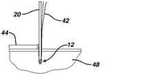
図1は、本発明による、結び目のない縫合糸アンカー10を示す。縫合糸アンカー10は、尖った遠位先端部14と近位方向に延びる延長部16とを有する遠位アンカー本体12を含む。延長部16は、ドライバーツール(図1に示さず)と係合するための、例えば六角形などの形と、縫合糸(これも図1に示さず)を受容するための縫合糸開口18を内部に有する。ガイドワイヤ20は、アンカー本体12から近位方向に延び、摩擦又はねじ切りなどによりアンカー本体12に解放可能に接続している。本体12上のねじ山22は、本体12を骨内に差し込むことを可能にする。あるいは、遠位アンカー本体12は突き錐のように骨内に推進されてもよく、その場合、ねじ山22は、除去のために使用されてもよく、又は全体が省略されてもよい。例えばRaynham,MAのDePuy Mitek,Inc.から入手可能なCHIA PERC通し具(登録商標)のような縫合糸通し具24が、縫合糸開口18内に配置されている。縫合糸通し具24は細長い編成NITINOLワイヤ26を含み、前記ワイヤ26は、凧形状の遠位縫合糸捕捉ループ28を有する。 FIG. 1 shows a
縫合糸アンカー10は更に、外部ねじ山32と、ガイドワイヤ20を摺動可能に収容する寸法を有する軸線方向の中心穴34とを有する近位アンカー本体30を含む。近位アンカー本体30は、丸い遠位端36と、好ましくは六角形の近位推進ツール受容凹部38とを有する。近位アンカー本体30はまた、以下に説明するように、遠位アンカー本体12の延長部16を収容する寸法を有して近位アンカー本体30を通常の骨の孔内により深く前進させる、軸線方向の遠位ソケット40が設けられてもよい。好ましくは、参照により本明細書に組み込まれる、West,Jr.に付与された米国特許第7,322,978号に記載されているように、ねじ山32と同一のピッチを有する追加の近位ねじ山開始部(thread start)41が設けられて、より硬い皮質骨材料内での更なる保持を提供してもよい。 The
図2〜9は、図1の縫合糸アンカー10の使用を示す。ある長さの縫合糸42を、例えば回旋筋腱板内の腱などの組織44の一部分に通過させ、所望の位置において、隣接する骨48内にアンカー10を配置するための骨孔46を形成する。ドライバー52の遠位端50上に配置されている遠位アンカー本体12を、骨孔46の所に配置する(図2)。ドライバー52は、遠位アンカー本体12の近位延長部16と接合する遠位ツール末端部54を有し、ワイヤ26を受容するための1つ又は2つ以上の軸線方向ルーメン56又は溝を有する。次いで、遠位アンカー本体12を、骨孔46内に推進する(図3)。ドライバー52を除去し、遠位アンカー12を骨孔46内に残留させ、ガイドワイヤ20は骨孔46の外部へ近位方向に延びている。 2-9 illustrate the use of the
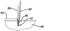
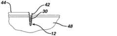
好ましい関節鏡下手技では、縫合糸42の末端部、ガイドワイヤ20、縫合糸捕捉ループ28、及びワイヤ26の他方の末端部は、全て、患者の外部に延び、次いで縫合糸42が捕捉ループ28内に負荷されるであろう(図4)。ワイヤ26を引くことにより、縫合糸42が遠位アンカー本体12の縫合糸孔18を通して移動される(図5)。縫合糸42に張力がかけられて、組織44の所望の位置及び組織44上の張力を提供する(図6)。近位アンカー本体30をガイドワイヤ20上を越えて遠位方向に通過させ、骨孔46の所に配置する(図7)。近位アンカー本体30は、遠位ツール末端部60を有する第2のドライバー58上に受容され、遠位ツール末端部60は、近位アンカー本体30のツール凹部38と接合し、ガイドワイヤ20を受容するための軸線方向ルーメン62又は溝を有する。この時点で、縫合糸42の最終的な張力調整を行ってもよく、次いで、近位アンカー本体30を骨孔46内に推進して縫合糸42を固定する(図8)。第2のドライバー58及びガイドワイヤ20を除去し、過剰な縫合糸42を切り取る(図9)。 In a preferred arthroscopic procedure, the distal end of
ソケット40の通路は遠位アンカー本体12の延長部16により遮断されないため、ソケット40によって近位アンカー本体30を骨孔30内に更に挿入することが可能となる。縫合糸42は近位アンカー本体30と骨孔46との間に捕捉されて固定され、また、近位アンカー本体30が最後まで推進されて遠位アンカー本体12と接触(contract)し、延長部16がソケット40内に受容された場合、縫合糸42は、遠位アンカー本体12と近位アンカー本体30との間にも捕捉されて、更に定着されることができる。場合により、延長部16及びソケット40は、係合して遠位アンカー本体12の追加の回転と骨内への更なる前進とを可能にするように構成されてもよい。 Since the passage of the
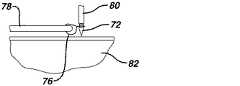
図10〜16は、縫合糸アンカー10と類似するが、遠位アンカー本体72上のねじ切り、ガイドワイヤ、又は近位アンカー74内のガイドワイヤのための穴を有さない、遠位アンカー本体72及び近位アンカー本体74を有する本発明による押し込み型の縫合糸アンカー70の使用を示す。予め準備した孔の必要性を省略することにより、潜在的な誤差を低減するための工程を最小限にし、手術時間を短縮する。 FIGS. 10-16 are similar to the
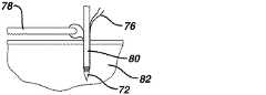
最初に、ある長さの縫合糸76を組織78に通過させ、遠位アンカー本体72上に負荷する。遠位アンカー本体72をドライバー80上に負荷して、遠位アンカー本体72が除去可能な突き錐先端部として機能する突き錐を形成し、遠位アンカー本体72を骨82上の所望の挿入位置に配置する(図10)。 Initially, a length of
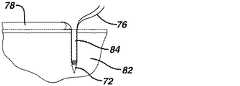
次いで、例えばドライバー80を打込むことにより、遠位アンカー本体72を骨82内に推進する(図11)。縫合糸76に張力をかけて組織78上に所望の張力を提供し(図12)、ドライバー80を除去して、遠位アンカー本体72を、遠位アンカー本体72の挿入により形成された骨孔84の底部にて定位置に残留させる(図13)。縫合糸76上に張力が維持されている間、第2のドライバー86上に負荷されている近位アンカー本体74を骨孔84内に挿入し(図14)、内部に完全に差し込んで縫合糸76を定位置に固定する(図15)。第2のドライバー86を除去し、過剰の縫合糸76を切り取り、手順を完了させる(図15)。 The
図は、縫合糸アンカー10及び70の操作に焦点をあてるために、単一のアンカーと、組織を通した単純な縫合糸ループとを有する、単純な縫合技術を示している。しかしながら、本発明の縫合糸アンカー10及び70は、すくい綴じ縫合糸構成を用いた二列のアンカー固定(anchoring)のような、より複雑な構成に用途を有し、ここでアンカーの列(多くの場合、10又は70などの結び目のないアンカーではない)を腱の下に配置し、結び目のないアンカーの第2の列を腱の側方に配置し、縫合糸は腱を通して第1の列から第2の列へと交差パターンにて上方に延び、それによって腱を骨に保持する。 The figure shows a simple suturing technique with a single anchor and a simple suture loop through the tissue to focus on the manipulation of suture anchors 10 and 70. However, the suture anchors 10 and 70 of the present invention have applications in more complex configurations, such as a two-row anchoring using a rake-spun suture configuration, where the anchor rows (many Is not a knot anchor, such as 10 or 70), is placed under the tendon, a second row of knot anchors is placed to the side of the tendon, and the suture passes through the tendon through the first row. Extends upward in a crossing pattern from to the second row, thereby holding the tendon to the bone.
本発明の新規縫合糸アンカーは、金属材料、非生分解性ポリマー、生分解性ポリマー、又は生分解性ポリマー若しくはコポリマーと生体機能性セラミックとの複合材料を含む多数の好適な材料から作製することができる。本明細書で使用するとき、生分解性という用語は、身体内で分解し、次いで身体内に吸収されるか又は身体から排出されるかのいずれかである材料を意味すると定義される。本明細書で使用するとき、生体機能性セラミックという用語は、身体組織と適合性がある、セラミック材料及びガラス材料を意味すると定義される。生体機能性セラミックは、好ましくは生分解性である。 The novel suture anchors of the present invention are made from a number of suitable materials including metallic materials, non-biodegradable polymers, biodegradable polymers, or composite materials of biodegradable polymers or copolymers and biofunctional ceramics. Can do. As used herein, the term biodegradable is defined to mean a material that degrades in the body and is then either absorbed into the body or excreted from the body. As used herein, the term biofunctional ceramic is defined to mean ceramic and glass materials that are compatible with body tissue. The biofunctional ceramic is preferably biodegradable.
本発明のアンカーを製造するために使用することができる金属材料としては、ステンレス鋼、チタン、ニッケルとチタンとの合金、又は他の生体適合性金属材料が挙げられる。 Metallic materials that can be used to produce the anchors of the present invention include stainless steel, titanium, nickel and titanium alloys, or other biocompatible metallic materials.
本発明のアンカーを製造するために使用することができる非生分解性材料としては、ポリエチレン、ポリプロピレン、PEEK(ポリエーテルエーテルケトン)、又は他の生体適合性の非吸収性ポリマーが挙げられる。 Non-biodegradable materials that can be used to produce the anchors of the present invention include polyethylene, polypropylene, PEEK (polyether ether ketone), or other biocompatible non-absorbable polymers.
本発明で使用されるアンカーを製造するために使用することができる生分解性ポリマーとしては、脂肪族ポリエステル、ポリオルトエステル、ポリ無水物、ポリカーボネート、ポリウレタン、ポリアミド、及びポリアルキレンオキシドからなる群から選択される生分解性ポリマーが挙げられる。好ましくは、生分解性ポリマーは、脂肪族ポリエステルのポリマー及びコポリマー、並びにそれらのブレンドである。脂肪族ポリエステルは、典型的には、開環重合で合成される。好適なモノマーとしては、乳酸、ラクチド(L−、D−、メソ、及びD、Lの混合を含む)、グリコール酸、グリコリド、ε−カプロラクトン、p−ジオキサノン(1,4−ジオキサン−2−オン)、トリメチレンカーボネート(1,3−ジオキサン−2−オン)、δ−バレロラクトン、及びこれらの組み合わせが挙げられるが、それらに限定されない。 Biodegradable polymers that can be used to produce the anchors used in the present invention include aliphatic polyesters, polyorthoesters, polyanhydrides, polycarbonates, polyurethanes, polyamides, and polyalkylene oxides. Examples include biodegradable polymers that are selected. Preferably, the biodegradable polymers are aliphatic polyester polymers and copolymers, and blends thereof. Aliphatic polyesters are typically synthesized by ring opening polymerization. Suitable monomers include lactic acid, lactide (including a mixture of L-, D-, meso, and D, L), glycolic acid, glycolide, ε-caprolactone, p-dioxanone (1,4-dioxane-2-one) ), Trimethylene carbonate (1,3-dioxane-2-one), δ-valerolactone, and combinations thereof, but are not limited thereto.
本発明の複合材料アンカーに使用することができる生体機能性セラミックとしては、モノ−、ジ−、トリ−、α−トリ−、β−トリ−、及びテトラ−リン酸カルシウム、ヒドロキシアパタイト、硫酸カルシウム、酸化カルシウム、炭酸カルシウム、リン酸マグネシウムカルシウムが挙げられる。β−リン酸トリトリカルシウムを使用することが、特に好ましい。生体機能性セラミックに加えて、バイオグラスもまた、この複合材料スクリューに使用することができる。バイオグラスとしては、リン酸ガラス及びリン酸バイオグラスを挙げることができる。 Examples of biofunctional ceramics that can be used for the composite material anchor of the present invention include mono-, di-, tri-, α-tri-, β-tri-, and tetra-calcium phosphate, hydroxyapatite, calcium sulfate, and oxidation. Examples include calcium, calcium carbonate, and magnesium calcium phosphate. It is particularly preferred to use β-tritricalcium phosphate. In addition to biofunctional ceramics, bioglass can also be used in this composite screw. Examples of bioglass include phosphate glass and phosphate bioglass.
好適な生体適合性の合成ポリマーとしては、脂肪族ポリエステル、ポリ(アミノ酸)、コポリ(エーテル−エステル)、シュウ酸ポリアルキレン、ポリアミド、チロシン誘導ポリカーボネート、ポリ(イミノカーボネート)、ポリオルトエステル、ポリオキサエステル、ポリアミドエステル、ポリオキサエステル含有アミン基、ポリ(無水物)、ポリホスファゼン、ポリウレタン、ポリ(エーテルウレタン)、ポリ(エステルウレタン)、ポリ(プロピレンフマレート)、ポリ(ヒドロキシアルカノエート)、及びこれらのブレンドからなる群から選択されるポリマーを挙げることができる。 Suitable biocompatible synthetic polymers include aliphatic polyester, poly (amino acid), copoly (ether-ester), polyalkylene oxalate, polyamide, tyrosine-derived polycarbonate, poly (iminocarbonate), polyorthoester, polyoxa Ester, polyamide ester, polyoxaester-containing amine group, poly (anhydride), polyphosphazene, polyurethane, poly (ether urethane), poly (ester urethane), poly (propylene fumarate), poly (hydroxyalkanoate), and Mention may be made of polymers selected from the group consisting of these blends.
本発明の目的上、脂肪族ポリエステルとしては、ラクチド(乳酸、D−、L−、及びメソラクチドを含む)、グリコリド(グリコール酸を含む)、ε−カプロラクトン、p−ジオキサノン(1,4−ジオキサン−2−オン)、トリメチレンカーボネート(1,3−ジオキサン−2−オン)、トリメチレンカーボネートのアルキル誘導体、δ−バレロラクトン、β−ブチロラクトン、γ−ブチロラクトン、ε−デカラクトン、ヒドロキシブチレート、ヒドロキシバレレート、1,4−ジオキセパン−2−オン(その二量体1,5,8,12−テトラオキサシクロテトラデカン−7,14−ジオンを含む)、1,5−ジオキセパン−2−オン、6,6−ジメチル−1,4−ジオキサン−2−オン、2,5−ジケトモルホリン、ピバロラクトン、α,α−ジエチルプロピオラクトン、エチレンカーボネート、エチレンオキサレート、3−メチル−1,4−ジオキサン−2,5−ジオン、3,3−ジエチル−1,4−ジオキサン−2,5−ジオン、6,6−ジメチル−ジオキセパン−2−オン、6,8−ジオキサビシクロオクタン−7−オンのホモポリマー及びコポリマー、並びにこれらのポリマーブレンドが挙げられるが、それらに限定されない。更なる例示的なポリマー又はポリマーブレンドとしては、非限定的な例として、ポリジオキサノン、ポリヒドロキシブチレート−コ−ヒドロキシバレレート、ポリオルトカーボネート、ポリアミノカーボネート、及びポリトリメチレンカーボネートが挙げられる。本発明で用いられる脂肪族ポリエステルは、直鎖、分岐鎖又は星型構造を有するホモポリマー又はコポリマー(ランダム、ブロック、セグメント化、テーパ形状ブロック、グラフト、三元ブロックなど)であることができる。本発明の目的において、ポリ(イミノカーボネート)には、ドーム(Domb)ら編「生分解性ポリマーの手引き(Handbook of Biodegradable Polymers)」、ハードウッド・アカデミック・プレス(Hardwood Academic Press)、251〜272頁(1997年)にケムニッツァー(Kemnitzer)及びコーン(Kohn)により記載されたポリマーが挙げられると理解される。本発明の目的上、コポリ(エーテル−エステル)は、Cohn及びYounesによる、「Journal of Biomaterials Research」、Vol.22,993〜1009頁(1988年)、並びにCohnによる、「Polymer Preprints(ACS Division of Polymer Chemistry)」、Vol.30(1),498頁(1989年)に記載のコポリエステル−エーテル(例えば、PEO/PLA)が挙げられることが理解される。本発明の目的上、ポリアルキレンオキサレートとしては、米国特許第4,208,511号、同第4,141,087号、同第4,130,639号、同第4,140,678号、同第4,105,034号、及び同第4,205,399号に記載されているものが挙げられる。ポリホスファゼン、すなわち、L−ラクチド、D,L−ラクチド、乳酸、グリコリド、グリコール酸、パラ−ジオキサノン、トリメチレンカーボネート、及びE−カプロラクトンから作製される、コ−、ター−、及びより高次の混合モノマーを基にしたポリマーは、Allcockによる、「The Encyclopedia of Polymer Science」、Vol.13,31〜41頁,Wiley Intersciences,John Wiley & Sons,1988年、及びVandorpeらによる、Dombら編「Handbook of Biodegradable Polymers」、Hardwood Academic Press,161〜182頁(1997年)などに記載されている。ポリ無水物としては、HOOC−−C.sub.6H.sub.4−−O−−(−CH.sub.2).sub.m−−O−−C.sub.6H.sub.4−−COOH(式中、「m」は2〜8の範囲内の整数である)の形態の二塩基酸から誘導されたもの、及び12個までの炭素からなる脂肪族α〜ω二塩基酸を有する、そのコポリマーが挙げられる。ポリオキサエステル、ポリオキサアミド、並びにアミン及び/又はアミド基を含有するポリオキサエステルは、米国特許第5,464,929号、同第5,595,751号、同第5,597,579号、同第5,607,687号、同第5,618,552号、同第5,620,698号、同第5,645,850号、同第5,648,088号、同第5,698,213号、同第5,700,583号、及び同第5,859,150号のうちの1つ又は2つ以上に記載されている。ポリオルトエステルは、例えば、Dombら編「Handbook of Biodegradable Polymers」、Hardwood Academic Press,99〜118頁(1997年)に、Hellerによって記載されているものである。 For the purposes of the present invention, aliphatic polyesters include lactide (including lactic acid, D-, L-, and meso lactide), glycolide (including glycolic acid), ε-caprolactone, p-dioxanone (1,4-dioxane- 2-one), trimethylene carbonate (1,3-dioxane-2-one), alkyl derivatives of trimethylene carbonate, δ-valerolactone, β-butyrolactone, γ-butyrolactone, ε-decalactone, hydroxybutyrate, hydroxyvale Rate, 1,4-dioxepan-2-one (including its dimer 1,5,8,12-tetraoxacyclotetradecane-7,14-dione), 1,5-dioxepan-2-one, 6, 6-dimethyl-1,4-dioxane-2-one, 2,5-diketomorpholine, pivalolactone, α, α Diethylpropiolactone, ethylene carbonate, ethylene oxalate, 3-methyl-1,4-dioxane-2,5-dione, 3,3-diethyl-1,4-dioxane-2,5-dione, 6,6- Examples include, but are not limited to, dimethyl-dioxepan-2-one, homopolymers and copolymers of 6,8-dioxabicyclooctane-7-one, and polymer blends thereof. Further exemplary polymers or polymer blends include, by way of non-limiting examples, polydioxanone, polyhydroxybutyrate-co-hydroxyvalerate, polyorthocarbonate, polyaminocarbonate, and polytrimethylene carbonate. The aliphatic polyester used in the present invention can be a homopolymer or copolymer (random, block, segmented, tapered block, graft, ternary block, etc.) having a linear, branched or star structure. For the purposes of the present invention, poly (iminocarbonate) includes domb et al. "Handbook of Biodegradable Polymers", Hardwood Academic Press, 251-272. It is understood that the polymers described by Chemnzer and Kohn on page (1997) are mentioned. For the purposes of the present invention, copoly (ether-esters) are described by Cohn and Younes, “Journal of Biomaterials Research”, Vol. 22, pp. 993-1009 (1988), and by Cohn, “Polymer Preprints (ACS Division of Polymer Chemistry)”, Vol. 30 (1), page 498 (1989), which is understood to include copolyester-ethers (eg, PEO / PLA). For the purposes of the present invention, polyalkylene oxalates include U.S. Pat. Nos. 4,208,511, 4,141,087, 4,130,639, 4,140,678, Examples are described in US Pat. No. 4,105,034 and US Pat. No. 4,205,399. Polyphosphazenes, ie L-lactide, D, L-lactide, lactic acid, glycolide, glycolic acid, para-dioxanone, trimethylene carbonate, and co-, ter-, and higher order made from E-caprolactone Polymers based on mixed monomers are described by Allcock in “The Encyclopedia of Polymer Science”, Vol. 13, 31-41, Wiley Intersciences, John Wiley & Sons, 1988, and Vandorpe et al., Domb et al., “Handbook of Biodegradable Polymers”, Hardwood Academic 16 (Hardwood Academic 16) Yes. Polyanhydrides include HOOC--C.I. sub. 6H. sub. 4--O-(-CH.sub.2). sub. m--O--C. sub. 6H. sub. One derived from a dibasic acid in the form of 4--COOH, where “m” is an integer in the range of 2-8, and an aliphatic α-ω dibasic consisting of up to 12 carbons Examples thereof include an acid-containing copolymer. Polyoxaesters, polyoxaamides, and polyoxaesters containing amine and / or amide groups are described in U.S. Pat. Nos. 5,464,929, 5,595,751, and 5,597,579. No. 5,607,687, No. 5,618,552, No. 5,620,698, No. 5,645,850, No. 5,648,088, No. 5, 698,213, 5,700,583, and 5,859,150. Polyorthoesters are, for example, those described by Heller in Domb et al., “Handbook of Biodegradable Polymers”, Hardwood Academic Press, pages 99-118 (1997).
本発明について、その好ましい実施形態に関連して説明してきた。明らかに、先の詳細な説明を読み理解すると、修正及び変更が他者にも思いつくであろう。そのような修正及び変更が添付の特許請求の範囲及びその等価物の範疇に入る限り、本発明はそのような修正及び変更の全てを含むと解釈されるものとする。 The invention has been described with reference to its preferred embodiments. Obviously, modifications and changes will occur to others upon reading and understanding the above detailed description. To the extent that such modifications and changes fall within the scope of the appended claims and their equivalents, the present invention should be construed as including all such modifications and changes.
〔実施の態様〕
(1) 縫合糸アンカーシステムであって、
遠位アンカー本体であって、縫合糸取付け部と、前記遠位アンカー本体から近位方向に伸びるガイドワイヤとを有する、遠位アンカー本体と、
近位アンカー本体であって、前記ガイドワイヤを収容する寸法を有する、内部を通過する中心穴と、前記近位アンカー本体から延びる1つ又は2つ以上の保持強化部とを有する、近位アンカー本体と、を備える、縫合糸アンカーシステム。
(2) 前記縫合糸取付け部に通され、かつ遠位縫合糸捕捉構成を有する、細長い可撓性部材を含む縫合糸通し具を更に備える、実施態様1に記載の縫合糸アンカーシステム。
(3) 前記縫合糸捕捉構成が、縫合糸が通過され得るループを含む、実施態様2に記載の縫合糸アンカーシステム。
(4) 細長いドライバー本体を有する第1のドライバーを更に備え、前記遠位アンカー本体が前記第1のドライバーの遠位端に取り付けられ、前記ガイドワイヤが前記ドライバー本体に沿って延びる、実施態様1に記載の縫合糸アンカーシステム。
(5) 前記1つ又は2つ以上の保持強化部が、ねじ山を含む、実施態様1に記載の縫合糸アンカーシステム。
(6) 縫合糸アンカーシステムであって、
縫合糸取付け部と遠位突き錐先端部とを有する遠位アンカー本体であって、突き錐ドライバー上に装着され、それにより前記遠位アンカー本体が骨内に推進されて骨孔を形成することができる、遠位アンカー本体と、
近位アンカー本体であって、前記遠位アンカー本体により形成された骨孔内に嵌合する寸法を有し、かつ前記近位アンカー本体から延びる1つ又は2つ以上の保持強化部を有する、近位アンカー本体と、を備える、縫合糸アンカーシステム。
(7) 前記縫合糸取付け部に通され、かつ遠位縫合糸捕捉構成を有する、細長い可撓性部材を含む縫合糸通し具を更に備える、実施態様6に記載の縫合糸アンカーシステム。
(8) 前記縫合糸捕捉構成が、縫合糸が通過され得るループを含む、実施態様7に記載の縫合糸アンカーシステム。
(9) 前記保持強化部が、ねじ山を含む、実施態様6に記載の縫合糸アンカーシステム。
(10) 軟組織を骨に付着させるための方法であって、
前記骨内に遠位縫合糸アンカー本体を植え込み、前記遠位縫合糸アンカー本体から前記骨の外部へと近位方向に延びるガイドワイヤを残留させる工程と、
前記遠位縫合糸アンカー本体上の縫合糸取付け部に前記軟組織からの縫合糸を通す工程であって、前記遠位縫合糸アンカー本体が前記骨内に植え込まれているとき、前記縫合糸が前記軟組織から前記遠位縫合糸アンカー本体へ、そして前記骨の外部へ延びる、工程と、
前記縫合糸の少なくとも一部分が近位縫合糸アンカー本体と前記骨との間に捕捉されるように、前記近位縫合糸アンカー本体を前記ガイドワイヤ上を越えて前記骨内に植え込む工程と、を含む、方法。Embodiment
(1) a suture anchor system,
A distal anchor body having a suture attachment portion and a guidewire extending proximally from the distal anchor body;
A proximal anchor body having a center hole passing therethrough and having one or more retention reinforcements extending from the proximal anchor body and having a dimension to receive the guidewire A suture anchor system comprising: a body.
The suture anchor system according to claim 1, further comprising a suture threader including an elongated flexible member that is threaded through the suture attachment and has a distal suture capture configuration.
The suture anchor system according to claim 2, wherein the suture capture configuration includes a loop through which a suture can be passed.
4. The embodiment 1 further comprising a first driver having an elongated driver body, wherein the distal anchor body is attached to a distal end of the first driver, and the guidewire extends along the driver body. A suture anchor system according to claim 1.
(5) The suture anchor system according to embodiment 1, wherein the one or more retention reinforcements include threads.
(6) a suture anchor system,
A distal anchor body having a suture attachment portion and a distal awl tip, mounted on an awl driver, whereby the distal anchor body is propelled into the bone to form a bone hole A distal anchor body,
A proximal anchor body having one or more retention reinforcements dimensioned to fit within a bone hole formed by the distal anchor body and extending from the proximal anchor body; A suture anchor system comprising: a proximal anchor body;
7. The suture anchor system of embodiment 6, further comprising a suture threader including an elongated flexible member that is threaded through the suture attachment and has a distal suture capture configuration.
8. The suture anchor system of embodiment 7, wherein the suture capture configuration includes a loop through which a suture can be passed.
(9) The suture anchor system according to embodiment 6, wherein the retention reinforcement includes a screw thread.
(10) A method for attaching soft tissue to bone,
Implanting a distal suture anchor body within the bone and leaving a guidewire extending proximally from the distal suture anchor body to the exterior of the bone;
Passing a suture from the soft tissue through a suture attachment portion on the distal suture anchor body, wherein the suture is inserted when the distal suture anchor body is implanted in the bone. Extending from the soft tissue to the distal suture anchor body and out of the bone;
Implanting the proximal suture anchor body over the guidewire and into the bone such that at least a portion of the suture is captured between the proximal suture anchor body and the bone; Including.
(11) 前記縫合糸取付け部に通された縫合糸シャトルの縫合糸捕捉区分内に前記縫合糸を配置した後、前記縫合糸取付け部を通して前記縫合糸シャトルを牽引して、前記縫合糸取付け部を通して前記縫合糸捕捉区分を引っ張り、したがって前記縫合糸を引っ張ることにより、前記遠位本体上の前記縫合糸取付け部に前記縫合糸を通す工程を更に含む、実施態様10に記載の方法。
(12) 前記縫合糸シャトルが、前記遠位アンカー本体を植え込む工程の間、前記縫合糸取付け部を通して配置されている、実施態様11に記載の方法。
(13) 前記近位アンカー本体にねじ山がつけられており、前記近位アンカー本体を植え込む工程が、前記近位アンカー本体を前記遠位縫合糸本体の後部にて前記骨内に差し込む工程を含む、実施態様10に記載の方法。
(14) 前記遠位アンカー本体を植え込んだ後、前記近位アンカー本体を完全に植え込むことにより前記縫合糸を固定する前に、所望の張力が前記縫合糸に適用される、実施態様10に記載の方法。
(15) 軟組織を骨に付着させるための方法であって、
遠位突き錐先端部と、内部を通過するある長さの縫合糸を有する縫合糸取付け部とを有する遠位縫合糸アンカー本体を用いて骨に孔を開け、骨孔を形成する工程であって、前記遠位縫合糸アンカー本体は突き錐ドライバー上に装着されている、工程と、
前記突き錐ドライバーを除去し、前記骨孔内に植え込まれた前記遠位アンカー本体を、前記縫合糸の第1の部分が前記骨孔から外部に延びた状態で残留させる工程と、
前記縫合糸の第2の部分を前記軟組織に通す工程と、
前記第1の部分上を引っ張ることにより前記縫合糸に張力をかける工程と、
前記縫合糸の少なくとも一部分が近位縫合糸アンカー本体と前記骨との間に捕捉されるように、前記近位縫合糸アンカー本体を前記遠位アンカー本体の近位にて前記骨孔内に植え込む工程と、を含む、方法。
(16) 前記近位アンカー本体にねじ山がつけられており、前記近位アンカー本体を植え込む工程が、前記近位アンカー本体を前記遠位縫合糸本体の後部にて前記骨内に差し込む工程を含む、実施態様15に記載の方法。(11) After the suture is disposed in the suture catching section of the suture shuttle passed through the suture attachment portion, the suture shuttle is pulled through the suture attachment portion, and the suture attachment portion 11. The method of
12. The method of embodiment 11, wherein the suture shuttle is positioned through the suture attachment during the step of implanting the distal anchor body.
(13) The proximal anchor body is threaded, and implanting the proximal anchor body includes inserting the proximal anchor body into the bone at the rear of the distal suture body. Embodiment 11. The method of
14. The embodiment of
(15) A method for attaching soft tissue to bone,
Forming a bone hole by drilling a hole in a bone using a distal suture anchor body having a distal awl tip and a suture attachment portion having a length of suture passing therethrough. The distal suture anchor body is mounted on an awl driver; and
Removing the awl driver and leaving the distal anchor body implanted in the bone hole with the first portion of the suture extending out of the bone hole;
Passing a second portion of the suture through the soft tissue;
Tensioning the suture by pulling on the first portion;
Implanting the proximal suture anchor body into the bone hole proximal to the distal anchor body such that at least a portion of the suture is captured between the proximal suture anchor body and the bone. A method comprising the steps of:
(16) The proximal anchor body is threaded, and implanting the proximal anchor body includes inserting the proximal anchor body into the bone at the rear of the distal suture body.
Claims (9)
Translated fromJapanese遠位アンカー本体であって、前記遠位アンカー本体の骨への差し込みを可能にする前記遠位アンカー本体上のねじ山と、縫合糸取付け部と、前記遠位アンカー本体から近位方向に伸び、前記遠位アンカー本体に解放可能に取り付けられたガイドワイヤとを有する、遠位アンカー本体と、
前記縫合糸取付け部に通され、遠位縫合糸捕捉構成を有する、細長い可撓性部材を含む縫合糸通し具と、
前記遠位アンカー本体を骨の中へ進めるためのドライバーであって、細長いドライバー本体を有し、前記細長いドライバー本体の遠位端に前記遠位アンカー本体が取り外し可能に取り付けられ、前記ガイドワイヤが前記ドライバー本体に沿って延びる、ドライバーと、
近位アンカー本体であって、前記ドライバーが取り外されると前記近位アンカー本体が前記骨の中へ進められることができるように前記ガイドワイヤを収容する寸法を有する、内部を通過する中心穴と、前記近位アンカー本体から延び、前記縫合糸通し具によって前記縫合糸取付け部を通って引かれた縫合糸を前記近位アンカー本体と前記骨との間に捉えるように構成された1つ又は2つ以上の保持強化部とを有する、近位アンカー本体と、を備える、縫合糸アンカーシステム。A suture anchor system comprising:
A distal anchor body extending proximally from thedistal anchor body, a thread on the distal anchor body that allows insertion of the distal anchor body into bone, a suture attachment, andA distal anchor body having a guidewirereleasably attached to the distal anchor body;
A suture threader including an elongated flexible member threaded through the suture attachment and having a distal suture capture configuration;
A driver for advancing the distal anchor body into bone, having an elongate driver body, the distal anchor body removably attached to a distal end of the elongate driver body, and the guide wire A driver extending along the driver body;
A proximal anchor body, a central hole passing therethrough, dimensioned toreceive the guidewireso that the proximal anchor body can be advanced into the bone when the driver is removed ; One or twoconfigured to catch a suture extending from the proximal anchor bodyand pulled through the suture attachment by the suture threader between the proximal anchor body and the bone A suture anchor system comprising: a proximal anchor body having one or more retention reinforcements.
縫合糸取付け部と遠位突き錐先端部とを有する遠位アンカー本体であって、前記遠位アンカー本体は突き錐ドライバー上に装着され、それにより前記遠位アンカー本体が骨内に推進されて骨孔を形成することができる、遠位アンカー本体と、
近位アンカー本体であって、前記遠位アンカー本体により形成された骨孔内に嵌合する寸法を有し、前記近位アンカー本体から延び、かつ前記縫合糸取付け部の中を通された縫合糸を前記近位アンカー本体と前記骨孔との間に捉えるように構成された1つ又は2つ以上の保持強化部を有する、近位アンカー本体と、を備える、縫合糸アンカーシステム。A suture anchor system comprising:
A distal anchor body having a suture attachment portion and a distal awl tip,wherein the distal anchor body is mounted on an awl driver so that the distal anchor body is propelled into the bone A distal anchor body capable of forming a bone hole;
A proximal anchor body has dimensions to fit the distal anchor bone hole formed by thebody, before extending from Kikinkurai anchorbody, and was passed through a said suture mounting portion A suture anchor system comprising: a proximal anchor body having one or more retention reinforcementsconfigured to capture a suture between the proximal anchor body and the bone hole .
Applications Claiming Priority (2)
| Application Number | Priority Date | Filing Date | Title |
|---|---|---|---|
| US13/249,941 | 2011-09-30 | ||
| US13/249,941US20130085528A1 (en) | 2011-09-30 | 2011-09-30 | Knotless suture anchor |
Publications (2)
| Publication Number | Publication Date |
|---|---|
| JP2013078580A JP2013078580A (en) | 2013-05-02 |
| JP6342108B2true JP6342108B2 (en) | 2018-06-13 |
Family
ID=47046374
Family Applications (1)
| Application Number | Title | Priority Date | Filing Date |
|---|---|---|---|
| JP2012216080AExpired - Fee RelatedJP6342108B2 (en) | 2011-09-30 | 2012-09-28 | Knotted suture anchor |
Country Status (6)
| Country | Link |
|---|---|
| US (1) | US20130085528A1 (en) |
| EP (1) | EP2574284B1 (en) |
| JP (1) | JP6342108B2 (en) |
| CN (1) | CN103027737B (en) |
| AU (1) | AU2012227343B2 (en) |
| CA (1) | CA2790522A1 (en) |
Families Citing this family (22)
| Publication number | Priority date | Publication date | Assignee | Title |
|---|---|---|---|---|
| US9107653B2 (en)* | 2011-09-22 | 2015-08-18 | Arthrex, Inc. | Tensionable knotless anchors with splice and methods of tissue repair |
| US20150272567A1 (en) | 2012-08-03 | 2015-10-01 | Stabilynx, Inc. | Devices, systems, and methods for attaching soft tissue to bone tissue |
| US9687222B2 (en)* | 2013-03-05 | 2017-06-27 | Arthrex, Inc. | Knotless repair technique using tape/suture hybrid |
| US10503276B2 (en)* | 2013-12-19 | 2019-12-10 | Korea Electronics Technology Institute | Electronic device and a control method thereof |
| US9980715B2 (en) | 2014-02-05 | 2018-05-29 | Trinity Orthopedics, Llc | Anchor devices and methods of use |
| USD740417S1 (en) | 2014-08-08 | 2015-10-06 | Dunamis, LLC | Suture anchor |
| USD741480S1 (en) | 2014-08-08 | 2015-10-20 | Dunamis, LLC | Suture anchor |
| USD740419S1 (en) | 2014-08-08 | 2015-10-06 | Dunamis, LLC | Suture anchor |
| USD740418S1 (en) | 2014-08-08 | 2015-10-06 | Dunamis, LLC | Suture anchor |
| WO2016044053A1 (en)* | 2014-09-19 | 2016-03-24 | Crossroads Extremity Systems, Llc | Bone fixation implant and means of fixation |
| CN104688285B (en)* | 2015-03-27 | 2017-09-29 | 王谦 | Shoulder joint sutures self-locking structure |
| US10182808B2 (en) | 2015-04-23 | 2019-01-22 | DePuy Synthes Products, Inc. | Knotless suture anchor guide |
| US10085736B2 (en) | 2015-05-01 | 2018-10-02 | L. Pearce McCarty, III | Hollow body anchor |
| US10265060B2 (en) | 2015-08-20 | 2019-04-23 | Arthrex, Inc. | Tensionable constructs with multi-limb locking mechanism through single splice and methods of tissue repair |
| US10335136B2 (en) | 2015-08-20 | 2019-07-02 | Arthrex, Inc. | Tensionable constructs with multi-limb locking mechanism through single splice and methods of tissue repair |
| US10463357B2 (en) | 2017-03-13 | 2019-11-05 | Medos International Sarl | Methods and devices for knotless suture anchoring |
| US10368857B2 (en)* | 2017-03-13 | 2019-08-06 | Medos International Sarl | Methods and devices for knotless suture anchoring |
| US10383618B2 (en) | 2017-03-13 | 2019-08-20 | Medos International Sarl | Methods and devices for knotless suture anchoring |
| US10245020B2 (en) | 2017-03-13 | 2019-04-02 | Medos International Sarl | Methods and systems for knotless suture anchoring |
| US11272924B2 (en) | 2018-07-18 | 2022-03-15 | Arthrex, Inc. | Knotless closure sutures and methods of tissue fixation |
| CN111184546B (en)* | 2020-02-24 | 2025-04-18 | 长春圣博玛生物材料有限公司 | Anchor nail with wire |
| CN115300018B (en)* | 2022-06-20 | 2025-03-25 | 孟庆广 | Tendon suture device and method |
Family Cites Families (28)
| Publication number | Priority date | Publication date | Assignee | Title |
|---|---|---|---|---|
| US4208511A (en) | 1977-01-19 | 1980-06-17 | Ethicon, Inc. | Isomorphic copolyoxalates and sutures thereof |
| US4141087A (en) | 1977-01-19 | 1979-02-27 | Ethicon, Inc. | Isomorphic copolyoxalates and sutures thereof |
| US4105034A (en) | 1977-06-10 | 1978-08-08 | Ethicon, Inc. | Poly(alkylene oxalate) absorbable coating for sutures |
| US4140678A (en) | 1977-06-13 | 1979-02-20 | Ethicon, Inc. | Synthetic absorbable surgical devices of poly(alkylene oxalates) |
| US4205399A (en) | 1977-06-13 | 1980-06-03 | Ethicon, Inc. | Synthetic absorbable surgical devices of poly(alkylene oxalates) |
| US4130639A (en) | 1977-09-28 | 1978-12-19 | Ethicon, Inc. | Absorbable pharmaceutical compositions based on isomorphic copolyoxalates |
| US5700583A (en) | 1995-03-06 | 1997-12-23 | Ethicon, Inc. | Hydrogels of absorbable polyoxaesters containing amines or amido groups |
| US5597579A (en) | 1995-03-06 | 1997-01-28 | Ethicon, Inc. | Blends of absorbable polyoxaamides |
| US5618552A (en) | 1995-03-06 | 1997-04-08 | Ethicon, Inc. | Absorbable polyoxaesters |
| US5595751A (en) | 1995-03-06 | 1997-01-21 | Ethicon, Inc. | Absorbable polyoxaesters containing amines and/or amido groups |
| US5859150A (en) | 1995-03-06 | 1999-01-12 | Ethicon, Inc. | Prepolymers of absorbable polyoxaesters |
| US5464929A (en) | 1995-03-06 | 1995-11-07 | Ethicon, Inc. | Absorbable polyoxaesters |
| US5698213A (en) | 1995-03-06 | 1997-12-16 | Ethicon, Inc. | Hydrogels of absorbable polyoxaesters |
| US5607687A (en) | 1995-03-06 | 1997-03-04 | Ethicon, Inc. | Polymer blends containing absorbable polyoxaesters |
| US5648088A (en) | 1995-03-06 | 1997-07-15 | Ethicon, Inc. | Blends of absorbable polyoxaesters containing amines and/or amide groups |
| US5800447A (en)* | 1997-01-03 | 1998-09-01 | Mitek Surgical Products, Inc. | Suture threader assembly, suture anchor assembly, and method for threading suture |
| US7322978B2 (en) | 2004-06-22 | 2008-01-29 | Hs West Investments, Llc | Bone anchors for use in attaching soft tissue to a bone |
| US8986345B2 (en)* | 2004-12-07 | 2015-03-24 | Biomet Sports Medicine, Llc | Expanding suture anchor having an actuator pin |
| US20060271060A1 (en)* | 2005-05-26 | 2006-11-30 | Arthrocare Corporation | Threaded knotless suture anchoring device and method |
| US7828820B2 (en)* | 2006-03-21 | 2010-11-09 | Biomet Sports Medicine, Llc | Method and apparatuses for securing suture |
| US9750492B2 (en)* | 2006-08-04 | 2017-09-05 | Depuy Mitek, Llc | Suture anchor system with tension relief mechanism |
| CA2702952C (en)* | 2007-10-27 | 2017-01-03 | Parcus Medical, Llc | Suture anchor |
| US20100016893A1 (en)* | 2008-03-05 | 2010-01-21 | Fanton Gary S | Method and apparatus for enhancing the fixation of bone and soft tissue anchors |
| US20090281581A1 (en)* | 2008-05-06 | 2009-11-12 | Berg Jeffery H | Method and device for securing sutures to bones |
| US20100049249A1 (en)* | 2008-08-25 | 2010-02-25 | Linvatec Corporation | Suture anchor extension |
| US20100292733A1 (en)* | 2009-05-12 | 2010-11-18 | Foundry Newco Xi, Inc. | Knotless suture anchor and methods of use |
| US8613756B2 (en)* | 2009-10-30 | 2013-12-24 | Depuy Mitek, Llc | Knotless suture anchor |
| US8523903B2 (en)* | 2009-10-30 | 2013-09-03 | Depuy Mitek, Llc | Partial thickness rotator cuff repair system and method |
- 2011
- 2011-09-30USUS13/249,941patent/US20130085528A1/ennot_activeAbandoned
- 2012
- 2012-09-20CACA2790522Apatent/CA2790522A1/ennot_activeAbandoned
- 2012-09-26AUAU2012227343Apatent/AU2012227343B2/ennot_activeCeased
- 2012-09-28EPEP12186703.0Apatent/EP2574284B1/ennot_activeNot-in-force
- 2012-09-28JPJP2012216080Apatent/JP6342108B2/ennot_activeExpired - Fee Related
- 2012-09-28CNCN201210367986.7Apatent/CN103027737B/ennot_activeExpired - Fee Related
Also Published As
| Publication number | Publication date |
|---|---|
| CN103027737A (en) | 2013-04-10 |
| JP2013078580A (en) | 2013-05-02 |
| CN103027737B (en) | 2018-01-19 |
| US20130085528A1 (en) | 2013-04-04 |
| AU2012227343B2 (en) | 2015-08-27 |
| CA2790522A1 (en) | 2013-03-30 |
| EP2574284B1 (en) | 2019-08-14 |
| AU2012227343A1 (en) | 2013-04-18 |
| EP2574284A1 (en) | 2013-04-03 |
Similar Documents
| Publication | Publication Date | Title |
|---|---|---|
| JP6342108B2 (en) | Knotted suture anchor | |
| US20230083181A1 (en) | Knotless suture anchor | |
| US11344289B2 (en) | Knotless suture anchor and driver | |
| JP6147671B2 (en) | Adjustable anchor system | |
| US8460340B2 (en) | Knotless suture anchor | |
| US10045771B2 (en) | Knotless suture anchor | |
| CN102551823A (en) | Anchor driver with suture clutch | |
| CN102551826B (en) | Sew up anchor and threading apparatus |
Legal Events
| Date | Code | Title | Description |
|---|---|---|---|
| A621 | Written request for application examination | Free format text:JAPANESE INTERMEDIATE CODE: A621 Effective date:20150928 | |
| A131 | Notification of reasons for refusal | Free format text:JAPANESE INTERMEDIATE CODE: A131 Effective date:20160823 | |
| A977 | Report on retrieval | Free format text:JAPANESE INTERMEDIATE CODE: A971007 Effective date:20160826 | |
| A601 | Written request for extension of time | Free format text:JAPANESE INTERMEDIATE CODE: A601 Effective date:20161122 | |
| A601 | Written request for extension of time | Free format text:JAPANESE INTERMEDIATE CODE: A601 Effective date:20170123 | |
| A521 | Request for written amendment filed | Free format text:JAPANESE INTERMEDIATE CODE: A523 Effective date:20170221 | |
| A131 | Notification of reasons for refusal | Free format text:JAPANESE INTERMEDIATE CODE: A131 Effective date:20170516 | |
| A601 | Written request for extension of time | Free format text:JAPANESE INTERMEDIATE CODE: A601 Effective date:20170816 | |
| A601 | Written request for extension of time | Free format text:JAPANESE INTERMEDIATE CODE: A601 Effective date:20171016 | |
| TRDD | Decision of grant or rejection written | ||
| A01 | Written decision to grant a patent or to grant a registration (utility model) | Free format text:JAPANESE INTERMEDIATE CODE: A01 Effective date:20180417 | |
| A61 | First payment of annual fees (during grant procedure) | Free format text:JAPANESE INTERMEDIATE CODE: A61 Effective date:20180516 | |
| R150 | Certificate of patent or registration of utility model | Ref document number:6342108 Country of ref document:JP Free format text:JAPANESE INTERMEDIATE CODE: R150 | |
| LAPS | Cancellation because of no payment of annual fees |