JP6340738B2 - Vehicle control device, vehicle control method, and vehicle control program - Google Patents
Vehicle control device, vehicle control method, and vehicle control programDownload PDFInfo
- Publication number
- JP6340738B2 JP6340738B2JP2016178763AJP2016178763AJP6340738B2JP 6340738 B2JP6340738 B2JP 6340738B2JP 2016178763 AJP2016178763 AJP 2016178763AJP 2016178763 AJP2016178763 AJP 2016178763AJP 6340738 B2JP6340738 B2JP 6340738B2
- Authority
- JP
- Japan
- Prior art keywords
- pedestrian
- vehicle
- traveling direction
- identify
- unit
- Prior art date
- Legal status (The legal status is an assumption and is not a legal conclusion. Google has not performed a legal analysis and makes no representation as to the accuracy of the status listed.)
- Active
Links
Images


Landscapes
- Traffic Control Systems (AREA)
Description
Translated fromJapanese本発明は、車両制御装置、車両制御方法、および車両制御プログラムに関する。 The present invention relates to a vehicle control device, a vehicle control method, and a vehicle control program.
従来、車両の周辺の物体を検出し、検出した物体が歩行者であるか否かを認識する装置がある。例えば、車両の存在する位置や車速等に基づいて、車両と歩行者とが接触する危険度を求め、警報を行う装置であって、この危険度に応じて検出した物体を歩行者として認識する認識レベルを切り替えて、車両の周辺の歩行者を認識し、警報する装置が開示されている(例えば、特許文献1参照)。 Conventionally, there is an apparatus that detects an object around a vehicle and recognizes whether or not the detected object is a pedestrian. For example, it is a device that calculates the degree of risk of contact between a vehicle and a pedestrian based on the position of the vehicle, the vehicle speed, etc., and gives an alarm, and recognizes an object detected according to the degree of risk as a pedestrian An apparatus for switching and recognizing pedestrians around a vehicle and alarming is disclosed (for example, see Patent Document 1).
しかしながら、上記特許文献1の装置は、車両と検出した物体との位置関係によっては、ノイズや歩行者でない物体を歩行者と認識したり、歩行者をノイズや歩行者でない物体と認識したりすることで運転者が意図しないタイミングで警報がされる場合があり、商品性を損ねる可能性がある。 However, depending on the positional relationship between the vehicle and the detected object, the device of
本発明は、このような事情を考慮してなされたものであり、運転者が意図しないタイミングでの警報等を抑制すると共に、精度よく物体を認識することができる車両制御装置、車両制御方法、および車両制御プログラムを提供することを目的の一つとする。 The present invention has been made in view of such circumstances, and suppresses an alarm or the like at a timing not intended by the driver, and can accurately recognize an object, a vehicle control device, a vehicle control method, Another object is to provide a vehicle control program.
請求項1記載の発明は、車両の周辺の物体を検出する物体検出部と、前記車両と前記物体検出部により検出された物体との位置関係を求めると共に、前記物体検出部により検出された物体を歩行者であると識別する認識部であって、前記物体検出部が物体を検出する対象の領域において、前記車両の進行予定の軌跡である進行方向軌跡上にある前記物体を歩行者であると識別するために用いる閾値を、前記進行方向軌跡上にない前記物体を歩行者であると識別するために用いる閾値に比して高く設定することで、前記進行方向軌跡上にある前記物体を歩行者と識別しにくくする認識部と、前記認識部による識別結果に基づいて、前記車両の走行を支援する走行支援部とを備える車両制御システムである。
According to the first aspect of the present invention, an object detection unit that detects an object around a vehicle, a positional relationship between the vehicle and the object detected by the object detection unit, and an object detected by the object detection unit A recognition unit that identifies apedestrian as apedestrian, and theobject detection unit isa pedestrian in an area in which theobject detection unit detects an object on a travel direction trajectory that is a trajectory that the vehicle is scheduled to travel Is set higher than the threshold used to identify the object that is not on the traveling direction trajectory as a pedestrian, so that the object on the traveling direction trajectory is It is a vehicle control system providedwith the recognition part whichmakes it hard to identify with a pedestrian, and the driving | running | working assistance part which assists driving | running | working of the said vehicle based on the identification result by the said recognition part.
請求項2に記載の発明は、車両の周辺の物体を検出する物体検出部と、前記車両と前記物体検出部により検出された物体との位置関係を求めると共に、前記物体検出部により検出された物体を歩行者であると識別する認識部であって、前記物体検出部が物体を検出する対象の領域において、前記車両の進行予定の軌跡である進行方向軌跡を歩行者であると識別された物体が横切ろうとしていると判定した場合に前記進行方向軌跡を横切ろうとしている物体を歩行者であると識別するために用いる閾値を、前記進行方向軌跡を歩行者であると識別された物体が横切ろうとしていると判定しなかった場合に前記進行方向軌跡を横切ろうとしていない物体を歩行者であると識別するために用いる閾値に比して低く設定することで、前記進行方向軌跡を横切ろうとしている前記物体を歩行者と識別しやすくする認識部と、前記認識部による識別結果に基づいて、前記車両の走行を支援する走行支援部とを備える車両制御システムである。
According to a second aspect of the present invention,an object detection unit that detects an object around a vehicle and a positional relationship between the vehicle and an object detected by the object detection unit are obtained and detected by the object detection unit. A recognition unit that identifies an object as a pedestrian, wherein a travel direction trajectory that is a trajectory that the vehicle is scheduled to travel is identified as a pedestrian in a region where the object detection unit detects an object When it is determined that the object is about to cross, the threshold value used to identify the object that is about to cross the traveling direction trajectory as a pedestrian is identified, and the traveling direction trajectory is identified as a pedestrian The traveling direction is set lower than a threshold used to identify an object that does not attempt to cross the traveling direction trajectory as a pedestrian when it is not determined that the object is about to cross. Trajectory A recognition unit to easily identify and to pedestrians the object is will to cross, based on the identification result by the recognition unit, a vehicle control system and a driving support unit to support the running of the vehicle.
請求項3に記載の発明は、請求項1または2に記載の車両制御システムであって、前記認識部は、前記車両の横方向の位置に関して前記車両から遠い領域ほど、物体を歩行者であると識別するために用いる閾値を低く設定することで、前記物体を歩行者と識別しやすくするものである。
Invention ofClaim 3 isa vehicle control system of
請求項4に記載の発明は、請求項1から3のうちいずれか1項記載の車両制御システムであって、前記認識部は、前記車両の進行方向に関して前記車両から第1の距離以上の第1領域については、前記車両から前記第1の距離に至る手前の第2領域に比して、物体を歩行者であると識別するために用いる閾値を高く設定することで、前記物体を歩行者と識別しにくくするものである。
Invention of Claim 4 isa vehicle control system of any one of
請求項5に記載の発明は、請求項1から4のうちいずれか1項記載の車両制御システムであって、前記認識部は、前記車両の進行方向に関して前記車両から第2の距離未満の第3領域については、前記車両から第2の距離以上となる第4領域に比して、物体を歩行者であると識別するために用いる閾値を高く設定することで、前記物体を歩行者と識別しにくくするものである。
Invention of Claim 5 isa vehicle control system of any one of
請求項6に記載の発明は、請求項1から5のうちいずれか1項記載の車両制御システムであって、前記物体検出部は、画像を撮像する撮像部であって、歩行者のエッジの分布が記憶された物体モデル情報を格納する記憶部を、更に備え、前記認識部は、前記撮像部により撮像された時系列の画像からエッジを抽出し、抽出したエッジの分布と、前記記憶部が格納する物体モデル情報に記憶されたエッジの分布との類似度の指標を、前記時系列の画像ごとに導出し、前記時系列の画像ごとに導出した類似度の指標の変動に基づいて、前記歩行者を認識するものである。
A sixth aspect of the present invention is the vehicle control system according to any one of the first to fifth aspects,wherein the object detection unit is an imaging unit that captures an image, and is configured to detect an edge of a pedestrian. A storage unit for storing object model information in which the distribution is stored; and the recognition unit extracts edges from a time-series image captured by the imaging unit, the extracted edge distribution, and the storage unit Deriving an index of similarity with the distribution of the edge stored in the object model information stored for each time-series image, based on the variation of the similarity index derived for each of the time-series images, It recognizes the pedestrian.
請求項7に記載の発明は、コンピュータが、車両の周辺の物体を検出し、前記車両と前記検出された物体との位置関係を求めると共に、前記検出された物体を歩行者であると識別し、前記物体を検出する対象の領域において、前記車両の進行予定の軌跡である進行方向軌跡上にある前記物体を歩行者であると識別するために用いる閾値を、前記進行方向軌跡上にない前記物体を歩行者であると識別するために用いる閾値に比して高く設定することで、前記進行方向軌跡上にある前記物体を歩行者と識別しにくくし、前記識別結果に基づいて、前記車両の走行を支援する車両制御方法である。
In the seventh aspect of the invention, thecomputer detects an object around the vehicle, obtains a positional relationship between the vehicle and the detected object,and identifies the detected object as apedestrian. Inthe target area for detecting the object, a threshold value used for identifying the object on the traveling direction trajectory that is the trajectory of the traveling schedule of the vehicle as a pedestrian is not on the traveling direction trajectory. By setting the object higher than the threshold used for identifying the object as a pedestrian, the object on the traveling direction trajectory is made difficult to identify from the pedestrian, and the vehicle is based on the identification result. This is avehicle control method for supporting the running of thevehicle.
請求項8に記載の発明は、コンピュータに、車両の周辺の物体を検出させ、前記車両と前記検出された物体との位置関係を求めると共に、前記検出された物体を歩行者であると識別させ、前記物体を検出する対象の領域において、前記車両の進行予定の軌跡である進行方向軌跡上にある前記物体を歩行者であると識別するために用いる閾値を、前記進行方向軌跡上にない前記物体を歩行者であると識別するために用いる閾値に比して高く設定することで、前記進行方向軌跡上にある前記物体を歩行者と識別しにくくさせ、前記識別結果に基づいて、前記車両の走行を支援させる車両制御プログラムである。
According to an eighth aspect of the present invention, a computer detects an object around a vehicle, determines a positional relationship between the vehicle and the detected object,and identifies the detected object as apedestrian. Inthe target area for detecting the object, a threshold value used for identifying the object on the traveling direction trajectory that is the trajectory of the traveling schedule of the vehicle as a pedestrian is not on the traveling direction trajectory. By setting the object higher than the threshold used to identify the object as a pedestrian, the object on the traveling direction trajectory is made difficult to identify from the pedestrian, and based on the identification result, the vehicle This is a vehicle control program for supporting the running of the vehicle.
請求項9に記載の発明は、コンピュータに、車両の周辺の物体を検出させ、前記車両と前記検出された物体との位置関係を求めると共に、前記検出された物体を歩行者であると識別させ、前記物体を検出する対象の領域において、前記車両の進行予定の軌跡である進行方向軌跡を歩行者であると識別された物体が横切ろうとしていると判定した場合に前記進行方向軌跡を横切ろうとしている物体を歩行者であると識別するために用いる閾値を、前記進行方向軌跡を歩行者であると識別された物体が横切ろうとしていると判定しなかった場合に前記進行方向軌跡を横切ろうとしていない物体を歩行者であると識別するために用いる閾値に比して低く設定することで、前記進行方向軌跡を横切ろうとしている前記物体を歩行者と識別しやすくさせ、前記識別結果に基づいて、前記車両の走行を支援させる車両制御プログラムである。
The invention according to claim 9causes a computerto detect an object around the vehicle, obtain a positional relationship between the vehicle and the detected object, and identify the detected object as a pedestrian. When the object identified as a pedestrian crosses the traveling direction trajectory, which is the trajectory that the vehicle is scheduled to travel, in the region where the object is to be detected, The threshold value used to identify the object to be cut as a pedestrian is the threshold value used when the object identified as the pedestrian is not going to cross the advance direction locus. The object that is not intended to cross the trajectory is set lower than the threshold used to identify the object as a pedestrian, thereby making it easier to identify the object that is attempting to cross the traveling direction trajectory from the pedestrian. Based on the identification result, a vehicle control programfor supporting the running of the vehicle.
請求項1から9記載の発明によれば、車両と物体検出部により検出された物体との位置関係に基づいて、前記物体の種別を識別する処理の内容を変更することにより、運転者が意図しないタイミングでの警報等を抑制すると共に、精度よく物体を認識することができる。また、走行制御部は、認識部の識別結果に基づいて、車両の走行を支援することにより、周辺の状況に応じた車両の制御を実現することができる。 According to the first to ninth aspects of the present invention, the driver intends to change the content of the process for identifying the type of the object based on the positional relationship between the vehicle and the object detected by the object detection unit. It is possible to suppress an alarm or the like at a timing when it is not performed and accurately recognize an object. In addition, the travel control unit can realize vehicle control according to the surrounding situation by assisting the vehicle travel based on the identification result of the recognition unit.
以下、図面を参照し、本発明の車両制御システム、車両制御方法、および車両制御プログラムの実施形態について説明する。 Hereinafter, embodiments of a vehicle control system, a vehicle control method, and a vehicle control program of the present invention will be described with reference to the drawings.
<第1実施形態>
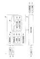
図1は、物体認識装置20を含む車両制御システム1の機能構成の一例を示す図である。車両制御システム1は、例えば、レーダ装置10、カメラ12、車両センサ14、物体認識装置20、車両制御装置70、走行駆動装置72、およびブレーキ装置74を備える。<First Embodiment>
FIG. 1 is a diagram illustrating an example of a functional configuration of a
レーダ装置10は、例えば、車両制御システム1が搭載された車両(以下、自車両)のバンパーや、フロントグリル等の周辺に設けられる。レーダ装置10は、例えば、自車両の前方にミリ波を放射し、放射したミリ波が物体に当たって反射した反射波を受信し、受信した反射波を解析することにより、物体の位置を特定する。物体の位置は、例えば自車両から物体までの距離を少なくとも含み、その他、自車両に対する物体の方位や横位置等を含んでもよい。レーダ装置10は、例えばFM−CW(Frequency−Modulated Continuous Wave)方式によって物体の位置を検出し、検出結果を物体認識装置20に出力する。レーダ装置10は、「物体検出部」の一例である。 The
カメラ12は、CCD(Charge Couple Device)やCMOS(Complementary Metal Oxide Semiconductor)等の固体撮像素子を利用したデジタルカメラである。カメラ12は、フロントウインドシールド上部やルームミラー裏面等に取り付けられる。カメラ12は、例えば、周期的に繰り返し自車両の前方を撮像する。カメラ12は、例えば、画像を撮像し、撮像した画像を物体認識装置20に出力する。カメラ12は、1台に限らず、自車両に複数設けられてもよいし、複数のカメラを含むステレオカメラであってもよい。カメラ12は、「物体検出部」の一例である。 The
車両センサ14は、車速を検出する車速センサ、加速度を検出する加速度センサ、鉛直軸回りの角速度を検出するヨーレートセンサ、自車両の向きを検出する方位センサ等を含む。車両センサ14は、各センサの検出結果を車両制御装置70に出力する。 The
物体認識装置20は、例えば、画像取得部30、画像認識部32、周辺状況認識部50、および記憶部60を備える。画像取得部30、画像認識部32、および周辺状況認識部50のうち、一部または全部は、プロセッサがプログラム(ソフトウェア)を実行することにより実現される。また、これらのうち一部または全部は、LSI(Large Scale Integration)やASIC(Application Specific Integrated Circuit)等のハードウェアによって実現されてもよいし、ソフトウェアとハードウェアの組み合わせによって実現されてもよい。また、物体認識装置20に含まれる各機能部は、複数のコンピュータ装置によって分散化されたものであってもよい。記憶部60は、ROM(Read Only Memory)やRAM(Random Access Memory)、HDD(Hard Disk Drive)、フラッシュメモリ等で実現される。 The
画像取得部30は、カメラ12により撮像された画像を取得する。 The
画像認識部32は、例えば、特徴量抽出部34、処理部36、および識別部38を備える。処理部36は、車両と画像取得部30により取得された画像における処理対象となる領域(物体が含まれる領域)との位置関係を求める。例えば、処理部36は、カメラ12の位置や、カメラ12の焦点距離、画像における無限遠点(例えば道路消失点)等のパラメータに基づいて処理対象の領域に対応する位置を導出する。 The
特徴量抽出部34は、画像取得部30により取得された画像から特徴量を取得し、取得した特徴量からエッジを導出する。エッジとは、周辺画素または画素をグループ化した画素群との輝度差や色彩パラメータの差が基準より大きく変化する画素または画素群である。例えば、エッジは、SOBELフィルタなどにより周辺の画素または画素群の間において特徴量の変化が求められることで導出される。 The feature
処理部36は、求めた位置関係に基づいて、物体の種別を識別する処理の内容を変更する。以下の説明では、識別する対象の物体の種別は、歩行者であるものとして説明する。
物体の種別を識別する処理の内容の変更とは、識別部38が物体を歩行者であると識別する処理に用いる閾値を変更することである。処理部36は、識別部38により識別された実空間上の歩行者の位置を導出する。処理部36は、時系列の画像における物体(例えば歩行者)の位置の変化に基づいて、その物体の移動方向や移動速度等を導出する。The
The change in the content of the process for identifying the type of the object is to change the threshold value used for the process in which the
識別部38は、特徴量抽出部34により抽出された特徴量と、記憶部60に記憶された歩行者モデル情報64とに基づいて物体が歩行者であるか否かを識別する。 The
周辺状況認識部50は、レーダ装置10の検出結果を取得し、取得した結果に基づいて、物体の位置を認識する。また、周辺状況認識部50は、画像認識部32の処理結果として、実空間上の歩行者の位置を取得する。なお、周辺状況認識部50は、レーダ装置10によって特定された物体の位置のうち自車両からの距離を重視すると共に、画像認識部32から取得した歩行者の位置のうち方位または横位置を重視する傾向で、これらの位置を統合し、歩行者の位置を認識してもよい。また、レーダ装置10に代えて(または、加えて)レーザレーダ、超音波センサ等のセンサを備えてもよい。 The surrounding situation recognition unit 50 acquires the detection result of the
また、周辺状況認識部50は、車車間通信や、道路を歩行、または横断する歩行者を検出するセンサから取得した情報に基づいて、歩行者の位置や速度等を検出してもよい。この場合、自車両は、他の車両や、道路を走行する車両を検出するセンサ等と通信する通信部を備える。 Moreover, the surrounding state recognition part 50 may detect the position, speed, etc. of a pedestrian based on the information acquired from the vehicle-to-vehicle communication or the sensor which detects the pedestrian who walks or crosses a road. In this case, the host vehicle includes a communication unit that communicates with another vehicle, a sensor that detects a vehicle traveling on the road, and the like.
車両制御装置70は、車両センサ14の検出結果、および周辺状況認識部50により認識された歩行者の位置に基づいて、自車両を制御する。例えば、車両制御装置70は、認識された歩行者とのTTC(Time To Collision)が一定以下になったときにブレーキ装置74に制動力を出力させる自動ブレーキ制御を行う。また、車両制御装置70は、スピーカ(不図示)に警報を出力させてもよい。また、車両制御装置70は、歩行者との距離が一定距離以下に近づかないように走行駆動装置72またはブレーキ装置74を制御してもよい。車両制御装置70は、「走行支援部」の一例である。 The
記憶部60には、例えば、簡易モデル情報62、歩行者モデル情報64や、その他車両を制御するための制御プログラム等が記憶される。簡易モデル情報62は、歩行者モデル情報64よりも緩やかな基準で生成された歩行者のエッジの分布を表す歩行者モデル情報である。緩やかな基準とは、エッジの分布が歩行者モデル情報64に含まれる歩行者のエッジの分布に比して少ないことをいう。歩行者モデル情報64には、少なくとも、歩行者のエッジの分布を表す歩行者モデル情報が、その物体の識別情報と共に記憶されている。 The
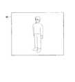
図2は、歩行者モデル情報64の内容を模式的に示した図である。歩行者モデル情報64は、例えば、歩行者が撮像された画像から抽出されると想定されるエッジの分布を示している。この歩行者モデル情報64から、エッジが所定の間隔で間引かれたものが、簡易モデル情報62である。また、歩行者モデル情報64において、歩行者モデル情報は歩行者の部位ごとに細分化されて記憶されてよい。 FIG. 2 is a diagram schematically showing the contents of the
走行駆動装置72は、車両が走行するための走行駆動力(トルク)を駆動輪に出力する。走行駆動装置72は、例えば、自車両が内燃機関を動力源とした自動車である場合、エンジン、変速機、およびエンジンを制御するエンジンECU(Electronic Control Unit)を備え、自車両が電動機を動力源とした電気自動車である場合、走行用モータおよび走行用モータを制御するモータECUを備え、自車両がハイブリッド自動車である場合、エンジン、変速機、およびエンジンECUと走行用モータおよびモータECUとを備える。走行駆動装置72がエンジンのみを含む場合、エンジンECUは、後述する車両制御装置70から入力される情報に従って、エンジンのスロットル開度やシフト段等を調整する。走行駆動装置72が走行用モータのみを含む場合、モータECUは、車両制御装置70から入力される情報に従って、走行用モータに与えるPWM信号のデューティ比を調整する。走行駆動装置72がエンジンおよび走行用モータを含む場合、エンジンECUおよびモータECUは、車両制御装置70から入力される情報に従って、互いに協調して走行駆動力を制御する。 The travel drive device 72 outputs a travel drive force (torque) for traveling of the vehicle to the drive wheels. For example, when the host vehicle is an automobile using an internal combustion engine as a power source, the travel drive device 72 includes an engine, a transmission, and an engine ECU (Electronic Control Unit) that controls the engine, and the host vehicle uses the motor as a power source. When the vehicle is a hybrid vehicle, the vehicle includes an engine, a transmission, and an engine ECU, and a travel motor and a motor ECU. . When the travel drive device 72 includes only an engine, the engine ECU adjusts the throttle opening, shift stage, and the like of the engine according to information input from the
ブレーキ装置74は、例えば、ブレーキキャリパーと、ブレーキキャリパーに油圧を伝達するシリンダと、シリンダに油圧を発生させる電動モータと、制動制御部とを備える電動サーボブレーキ装置である。電動サーボブレーキ装置の制動制御部は、不図示の自動ブレーキ制御部により出力された情報に従って電動モータを制御し、制動操作に応じたブレーキトルクが各車輪に出力されるようにする。電動サーボブレーキ装置は、ブレーキペダルの操作によって発生させた油圧を、マスターシリンダを介してシリンダに伝達する機構をバックアップとして備えてよい。なお、ブレーキ装置74は、上記説明した電動サーボブレーキ装置に限らず、電子制御式油圧ブレーキ装置であってもよい。電子制御式油圧ブレーキ装置は、車両制御装置70により出力された情報に従ってアクチュエータを制御して、マスターシリンダの油圧をシリンダに伝達する。また、自車両が走行用モータを含む場合、ブレーキ装置74は、走行駆動装置72のところで説明した走行用モータによる回生ブレーキを含んでもよい。 The brake device 74 is, for example, an electric servo brake device that includes a brake caliper, a cylinder that transmits hydraulic pressure to the brake caliper, an electric motor that generates hydraulic pressure in the cylinder, and a braking control unit. The braking control unit of the electric servo brake device controls the electric motor according to the information output by an automatic brake control unit (not shown) so that the brake torque corresponding to the braking operation is output to each wheel. The electric servo brake device may include, as a backup, a mechanism that transmits the hydraulic pressure generated by operating the brake pedal to the cylinder via the master cylinder. The brake device 74 is not limited to the electric servo brake device described above, but may be an electronically controlled hydraulic brake device. The electronically controlled hydraulic brake device controls the actuator according to the information output by the
図3は、物体認識装置20により実行される処理の流れを示すフローチャートである。
本処理は、例えば、画像取得部30が、カメラ12により撮像された画像を取得するごとに実行される。なお、このフローチャートの処理は、繰り返し実行されることを前提とし、今回のルーチンでの時刻をtとして表現している。FIG. 3 is a flowchart showing a flow of processing executed by the
This process is executed each time the
まず、画像取得部30が、カメラ12により撮像された画像を取得する(ステップS100)。次に、特徴量抽出部34が、ステップS100で取得された画像からエッジを抽出する(ステップS102)。次に、処理部36が、歩行者が時刻t−1において(すなわち前回のルーチンにおいて)横断歩行者を認識したか否かを判定する(ステップS104)。横断歩行者とは、自車両の進行方向に対して横方向に移動している歩行者である。横方向に移動しているとは、歩行者の移動軌跡を移動方向に対して仮想的に延出させた仮想線と、自車両の移動軌跡を移動方向に対して仮想的に延出させた仮想線とが直交する場合に加え、これらの仮想線が交差する場合も含む。 First, the
歩行者が時刻t−1において横断歩行者を認識していない場合、処理部36は、候補領域を抽出する(ステップS106)。ステップS106における候補領域は、画像に含まれる領域が複数の領域に細分化された領域のうち、歩行者が存在している可能性が高い領域である。処理部36は、抽出されたエッジの分布と、簡易モデル情報62のエッジの分布との類似度が所定以上のエッジの分布を含む領域を候補領域として抽出する。また、処理部36は、例えば、レーダ装置10により物体が検出された領域や、所定数以上のエッジが含まれる領域を候補領域として抽出してもよい。 When the pedestrian does not recognize the crossing pedestrian at time t-1, the
次に、処理部36は、ステップS106で抽出した候補領域に歩行者が存在するか否かを識別するために、自車両と物体との位置関係に基づいて、歩行者を識別する処理に用いる閾値を設定する(ステップS108)。位置関係とは、例えば、実平面上の自車両の位置と物体の位置との関係である。なお、閾値の設定の詳細については後述する。 Next, the
次に、識別部38が、ステップS102で抽出されたエッジの分布、歩行者モデル情報64のエッジの分布、および処理部36により設定された閾値に基づいて、ステップS106で抽出された候補領域における物体が歩行者であるか否かを識別する(ステップS110)。例えば、識別部38は、抽出されたエッジの分布と、歩行者モデル情報64のエッジの分布との類似度が、ステップS108で設定された閾値以上の場合、抽出されたエッジの分布に対応する物体は歩行者であると識別する。 Next, based on the edge distribution extracted in step S102, the edge distribution of the
一方、識別部38は、抽出されたエッジの分布と、歩行者モデル情報64のエッジの分布との類似度が、処理部36により設定された閾値未満の場合、抽出されたエッジの分布に対応する物体は歩行者でなくノイズや、道路における窪み、歩行者以外の物体であると識別する。この場合、識別部38は、抽出されたエッジの分布と、他のモデル情報の分布との類似度に基づいて、物体を識別してもよい。他のモデル情報とは、歩行者とは異なる物体の識別情報と、その物体のエッジの分布を表す情報とが対応付けられて記憶された情報である。歩行者とは異なる物体とは、例えば車両や、動物など、自車両が走行する際に注視すべき物体が類型化されたものである。他のモデル情報は、記憶部60に記憶される。 On the other hand, when the similarity between the extracted edge distribution and the edge distribution of the
時刻t−1において横断歩行者を認識している場合、処理部36は、前回以前の画像に基づいて、候補領域を抽出する(ステップS112)。ステップS112における候補領域は、画像が複数の領域に細分化された領域のうち、追跡している歩行者が存在している可能性が高い領域である。処理部36は、例えば、前回以前の画像に基づいて導出された追跡している歩行者の移動方向や、移動速度に基づいて、今回のルーチンで取得した画像において歩行者が存在している可能性が高い候補領域を抽出する。 When the crossing pedestrian is recognized at time t−1, the
次に、処理部36が、歩行者を識別する処理に用いる閾値を設定する(ステップS114)。処理部36は、例えば、候補領域の自車両に対する相対位置、追跡している歩行者の移動方向、追跡している歩行者の移動速度のうち少なくとも1つ以上の要素に基づいて、閾値を設定する。相対位置とは、実平面上の相対位置であり、画像平面上の位置から写像された位置である。ステップS114の処理の詳細については後述する。 Next, the
次に、識別部38が、ステップS102で抽出されたエッジの分布、歩行者モデル情報64の分布、および処理部36により設定された閾値に基づいて、ステップS112で抽出された候補領域における物体を識別する(ステップS116)。例えば、識別部38は、抽出されたエッジの分布と、歩行者モデル情報64の分布との類似度が、ステップS114で設定された閾値以上の場合、抽出されたエッジの分布に対応する物体は歩行者であると識別する。これにより、画像認識部32により横断歩行者が検出される。 Next, based on the edge distribution extracted in step S102, the distribution of the
次に、画像認識部32は、検出された歩行者についてトラッキング処理を実行する(ステップS118)。画像認識部32は、例えば、トラッキングとして以下の処理を行う。画像認識部32は、例えば、識別した歩行者の自車両に対する相対位置を導出する。また、画像認識部32は、例えば、歩行者が前回以前のルーチンで検出されている場合、今回および前回以前のルーチンで導出された歩行者の相対位置に基づいて、歩行者の移動方向や、移動速度等を導出する。ここで導出された移動方向や、移動速度は、次のルーチンの処理で取得された画像おいて、歩行者の位置を推定する処理に用いられるため、画像認識部32は、歩行者に関する情報を記憶部60に記憶される。 Next, the
また、周辺状況認識部50は、画像認識部32の処理結果、およびレーダ装置10により特定された物体の情報を取得し、取得した情報に基づいて、自車両の周辺に存在する歩行者を把握する。そして、車両制御装置70は、周辺状況認識部50により把握された歩行者の位置や、移動方向等に基づいて、走行駆動装置72またはブレーキ装置74を制御する。これにより本フローチャートの処理は終了する。 Further, the surrounding situation recognition unit 50 acquires the processing result of the
[閾値の設定の詳細(その1)]
ここで、ステップS108の閾値設定処理について説明する。図4は、処理部36により実行される閾値の設定処理の流れを示すフローチャートである。まず、処理部36が、図3のステップS106で抽出した候補領域が進行方向軌跡内に存在するか否かを判定する(ステップS200)。候補領域が進行方向軌跡内に存在する場合、候補領域において歩行者を識別する処理に用いる閾値を高く設定し(ステップS202)、候補領域が進行方向軌跡内に存在しない場合、ステップS204の処理に進む。進行方向軌跡は、自車両の左右端を自車両Mの中心軸方向に延出させた二本の線で囲まれた領域であってもよいし、操舵角等を考慮して曲がりを持って設定されてもよい。候補領域において歩行者を識別する処理に用いる閾値を高く設定とは、他の領域に比して相対的に閾値を高く設定することである(以下同様)。[Details of threshold setting (part 1)]
Here, the threshold value setting process in step S108 will be described. FIG. 4 is a flowchart showing a flow of threshold setting processing executed by the
処理部36は、自車両から候補領域までの距離を算出する。距離が算出された候補領域の位置を、例えば図5に示すように上方から自車両を見た場合の二次元空間で表す。 The
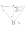
図5は、候補領域が進行方向軌跡内に存在する場合に設定される閾値を説明するための図である。図中、X方向は自車両Mの横方向を表し、Y方向は自車両Mの進行方向を示している。また、図中、領域A1は、カメラ12により撮像される領域を表し、領域A2は、進行方向軌跡に対応する領域を表している。図中、領域CA1および領域CA2は、処理対象の候補領域を表している。 FIG. 5 is a diagram for explaining a threshold value that is set when a candidate region is present in the traveling direction locus. In the figure, the X direction represents the lateral direction of the host vehicle M, and the Y direction represents the traveling direction of the host vehicle M. In the figure, the area A1 represents an area captured by the
処理部36は、自車両Mの進行方向軌跡に対応する領域A2に含まれる領域CA1に対して、領域A2に含まれない領域CA2に比して、歩行者を識別する処理に用いる閾値を高く設定する。ここで、領域A2において、閾値が高く設定されないと、ノイズ等を歩行者であると認識する誤認識が生じる場合がある。この場合、車両制御装置70は、誤認識した結果に基づいて自車両Mを制御するため、煩わしい。一方、上述したように領域A2において、閾値が高く設定されると、誤認識が生じることが抑制されることで、不要な制御が行われること無く自車両Mの周辺状況に応じて自車両Mの制御を実現することができる。 The
次に、処理部36は、自車両Mの横方向の位置に基づいて、歩行者を識別する処理に用いる閾値を決定する(ステップS204)。図6は、自車両Mの横方向の位置に基づいて設定される閾値を説明するための図である。図中、領域CA11および領域CA12は、処理対象の候補領域を表している。仮想線LAは、仮想線LBに直交するように仮想的に延出された仮想線である。仮想線LBは、自車両Mから自車両Mの中心軸方向に仮想的に延出させた仮想線である。なお、図5と重複する説明は省略する。 Next, the
処理部36は、自車両Mの横方向の位置に関して、自車両Mから遠い領域ほど、閾値を低く設定する。図示する例では、処理部36は、領域CA12と仮想線LBとの距離を示す仮想線LA2の長さは、領域CA11と仮想線LBとの距離を示す仮想線LA1の長さに比して長いため、領域CA12において歩行者を識別する処理に用いる閾値は、領域CA11において歩行者を識別する処理に用いる閾値より低く設定される。自車両Mの横方向の位置に関して、自車両Mから遠い領域にいる歩行者は、この時点では注視する対象とならないため、上記のように閾値が低く設定されても問題はない。むしろ、閾値が低く設定されることで、物体を歩行者として認識しやすくし、認識した歩行者を追跡の対象とすることができる。これにより、以降の処理において、認識された物体の種別をより確実に認識することができる。 The
次に、処理部36は、自車両Mの進行方向に関して、ステップS106で抽出された候補領域が自車両Mから第1の距離以上の領域に含まれるか否かを判定する(ステップS206)。第1の距離以上の領域に候補領域が存在する場合、処理部36は、候補領域において歩行者を識別する処理に用いる閾値を高く設定し(ステップS208)、第1の距離以上の領域に候補領域が存在しない場合、ステップS210の処理に進む。 Next, the
次に、処理部36は、自車両Mの進行方向に関して、ステップS106で抽出された候補領域が自車両Mから第2の距離未満の領域に存在するか否かを判定する(ステップS210)。第2の距離未満の領域に候補領域が存在する場合、処理部36は、候補領域において歩行者を識別する処理に用いる閾値を高く設定し(ステップS212)、第2の距離未満の領域に候補領域が存在しない場合、本フローチャートの処理は終了する。 Next, the
図7は、進行方向に関する距離に応じて設定される閾値を説明するための図である。図中、領域A11は、自車両Mの基準点(例えば重心)から自車両Mの進行方向に対して第1の距離以上の領域である。領域A11は、「第1領域」の一例である。第1の距離以上の領域においては、物体が小さく認識されているため、候補領域に含まれる対象が歩行者であるか、ノイズ等であるかの識別が困難な場合がある。このため、処理部36は、第1の距離以上の候補領域においては、歩行者(図中、OB1)を識別する処理に用いる閾値を高く設定することで、誤認識を抑制する。 FIG. 7 is a diagram for explaining a threshold value set according to the distance in the traveling direction. In the figure, a region A11 is a region equal to or greater than a first distance from the reference point (for example, the center of gravity) of the host vehicle M with respect to the traveling direction of the host vehicle M. The area A11 is an example of a “first area”. In an area greater than or equal to the first distance, since an object is recognized as being small, it may be difficult to identify whether the target included in the candidate area is a pedestrian or noise. For this reason, the
図中、領域A12は、自車両Mの基準点から自車両Mの進行方向に対して第2の距離未満の候補領域である。領域A12は、「第3領域」の一例である。第2の距離未満の領域においては、誤認識によりノイズ等を歩行者であると識別すると、自車両Mは歩行者を回避する動作や急制動等を行うことがあり、自車両Mの走行状態が不安定となる。このため、処理部36は、第2の距離未満の領域においては、歩行者(図中、OB2)を識別する処理に用いる閾値を高く設定することで、誤認識を抑制する。 In the figure, a region A12 is a candidate region that is less than the second distance from the reference point of the host vehicle M with respect to the traveling direction of the host vehicle M. The area A12 is an example of a “third area”. In an area less than the second distance, if noise or the like is identified as a pedestrian due to misrecognition, the host vehicle M may perform an operation to avoid the pedestrian, sudden braking, or the like. Becomes unstable. For this reason, the
なお、処理部36は、自車両Mの進行方向に対して第1の距離に至る手前、且つ第2の距離以上となる領域A13に存在する物体OB3を識別する処理に用いる閾値は変化させない。領域A13は、「車両から第1の距離に至る手前の第2領域」、および「車両から第2の距離以上となる第4領域」の一例である。 Note that the
なお、図示する例では、第1の距離と第2の距離とは異なる距離であるものとして説明したが、同じ距離であってもよい。 In the illustrated example, the first distance and the second distance are described as different distances, but the same distance may be used.
また、第1の距離に基づいて閾値が設定される処理(ステップS206、ステップS208)と、第2の距離に基づいて閾値が設定される処理(ステップS210およびステップS212)とのうち、一方の処理は省略されてもよい。 In addition, one of a process for setting a threshold based on the first distance (steps S206 and S208) and a process for setting a threshold based on the second distance (steps S210 and S212). Processing may be omitted.
図8は、第2の距離に基づいて閾値が設定される処理が省略される場合の一例を示す図である。図7と重複する説明は省略する。図中、領域A13#は、自車両Mの基準点から自車両Mの進行方向に対して第1の距離未満の領域である。領域A13#は、「車両から第1の距離に至る手前の第2領域」の一例である。処理部36は、第1の距離以上の領域においては、歩行者(図中、OB1)を識別する処理に用いる閾値を、車両から第1の距離に至る手前の領域A13#に比して高く設定することで、誤認識を抑制する。 FIG. 8 is a diagram illustrating an example of a case where the process of setting a threshold based on the second distance is omitted. The description overlapping with FIG. 7 is omitted. In the drawing, a region A13 # is a region less than the first distance from the reference point of the host vehicle M with respect to the traveling direction of the host vehicle M. The area A13 # is an example of “a second area in front of reaching the first distance from the vehicle”. In the area equal to or greater than the first distance, the
図9は、第1の距離に基づいて閾値が設定される処理が省略される場合の一例を示す図である。図7と重複する説明は省略する。図中、領域A13##は、自車両Mの基準点から自車両Mの進行方向に対して第2の距離以上となる候補領域である。領域A13##は、「車両から第2の距離以上となる第4領域」の一例である。処理部36は、第2の距離未満の領域においては、歩行者(図中、OB2)を識別する処理に用いる閾値を、車両から第2の距離以上となる領域A13##に比して、高く設定することで、誤認識を抑制する。 FIG. 9 is a diagram illustrating an example of a case where the process of setting the threshold based on the first distance is omitted. The description overlapping with FIG. 7 is omitted. In the figure, a region A13 ## is a candidate region that is at least a second distance from the reference point of the host vehicle M with respect to the traveling direction of the host vehicle M. Area A13 ## is an example of “fourth area that is equal to or greater than the second distance from the vehicle”. In the area less than the second distance, the
また、処理部36は、自車両Mと候補領域の距離に基づく処理に代えて、物体の大きさに基づいて、閾値を変更してもよい。例えば、処理部36は、物体の大きさが所定の大きさ以下の場合、閾値を高く設定してもよい。 Further, the
[閾値の設定の詳細(その2)]
ここで、図3のステップS114で処理部36が、物体を識別する処理に用いる閾値を設定する処理について説明する。処理部36は、ステップS106で抽出された歩行者が存在している可能性が高い領域である候補領域について、その候補領域が進行方向軌跡内に存在する場合、候補領域において歩行者を識別する処理に用いる閾値を高く設定するが、自車両Mの進行方向に横断歩行者が存在していると判定された場合はこの限りではなく、進行方向軌跡内の候補領域の閾値を低く設定する。これにより、横断歩行者の検出安定性を向上させることができる。また、閾値を低く設定するに当たってさらに条件を追加し、候補領域が進行方向軌跡内に存在し、且つ、自車両Mと横断歩行者との衝突の可能性が高い場合には、候補領域において歩行者を識別する処理に用いる閾値を低く設定してもよい。衝突の可能性が高いとは、横断歩行者が進行方向軌跡内に存在していると予測される時間において、横断歩行者が存在している領域を自車両Mが通過、またはその領域付近に接近することが予測することができることである。[Details of threshold setting (part 2)]
Here, the process in which the
例えば、処理部36は、時系列における横断歩行者の位置および移動速度に基づいて、横断歩行者が進行方向軌跡内に存在していると予測される時間帯、または横断歩行者が進行方向軌跡内から進行方向軌跡外に移動すると予測される時刻を導出する。処理部36は、現在の時刻から横断歩行者が進行方向軌跡内から進行方向軌跡外に移動すると予測される時刻との間の時間に対して、自車両Mの速度を乗算することにより、自車両Mの将来位置を予測する。この場合、処理部36は、自車両Mの進行方向において、自車両Mの将来位置が、横断歩行者の位置よりも所定距離以上手前であれば、衝突の可能性は低いと判定し、所定距離以上手前でない、または予測した横断歩行者の位置を通過している場合は、衝突の可能性が高いと判定する。 For example, the
また、処理部36は、衝突地点を横断歩行者がほぼ通過していない場合において、自車両Mの進行方向軌跡と、横断歩行者の移動方向の軌跡である移動軌跡との重なり量を評価する指標値であるラップ量およびラップ率を用いて、衝突の可能性を判定してもよい。衝突地点とは、自車両Mの進行方向軌跡と、歩行者の移動軌跡との重なる部分である。 Further, the
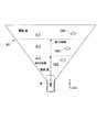
図10は、ラップ量について説明するための図である。図中、横断歩行者OB1#は、自車両Mが衝突地点に到達する予想時刻における歩行者の予想位置である。また、y1は自車両Mの左端部から自車両Mの進行方向に延出する仮想線であり、y2は自車両Mの右端部から自車両Mの進行方向に延出する仮想線である。 FIG. 10 is a diagram for explaining the lap amount. In the figure, the crossing pedestrian OB1 # is the predicted position of the pedestrian at the predicted time when the host vehicle M reaches the collision point. Further, y1 is a virtual line extending from the left end portion of the host vehicle M in the traveling direction of the host vehicle M, and y2 is a virtual line extending from the right end portion of the host vehicle M in the traveling direction of the host vehicle M.
処理部36は、横断歩行者の予想位置を求め、横断歩行者OB1#の移動する方向を考慮した前端部(この場合、左端部H1L)から、既に前端部が通過した第2の仮想直線y2までの距離βH1を、ラップ量として算出する。ここで、横断歩行者OB1#が、第1の仮想直線y1と第2の仮想直線y2との間の領域である進行方向軌跡の外に存在する場合、ラップ量はゼロと算出される。更に、処理部36は、ラップ量を第1の仮想直線y1と第2の仮想直線y2との幅Wで除算し、100を乗じた値をラップ率[%]として算出する。そして、処理部36は、ラップ率が70[%]以上である場合、衝突の可能性は高いと判定する。また、処理部36は、ラップ率が70[%]未満であっても、ラップ率が0[%]を超える場合、ラップ率が0[%]より大きくなるにつれて衝突の可能性は高い傾向であると判定する。また、処理部36は、上記したように進行方向軌跡の外に横断歩行者が存在する場合、衝突の可能性は低いと判定する。尚、衝突の可能性が高いと判定するにあたって、ラップ率の基準値は70[%]に限定されるものではなく、横断歩行者OB1#がある程度ラップしていればよく、例えば50[%]などとしてもよい。 The
また、処理部36は、上記の[閾値の設定の詳細(その2)]に代えて(加えて)、横方向に移動した歩行者を識別する処理に用いる閾値を低く設定してもよいし、1つ前の処理において横断歩行者であると識別された物体と同一である可能性が高い物体を識別する処理に用いる閾値を低く設定してもよい。同一である可能性が高いとは、1つ前以前の処理における物体の位置や移動速度から予測される位置と、今回の処理において検出された物体の位置とが合致することである。 Further, the
また、処理部36は、上記の[閾値の設定の詳細(その2)]に代えて(加えて)、自車両Mの車速が所定の速度以下であり、且つ自車両Mの位置から所定距離以上の位置に物体が存在する場合、歩行者を識別する処理に用いる閾値を上げてもよい。 Further, the
上述した図3のフローチャートでは、処理部36が、ある時刻において撮像された画像ごとに閾値を設定し、物体が横断歩行者であるか否かを識別するものとしたが、これに代えて(または加えて)、所定の時間内に撮像された複数の画像に基づいて、物体が横断歩行者であるか否かを識別してもよい。 In the flowchart of FIG. 3 described above, the
ここで、画像に含まれる物体が歩行者であるか否かが識別される場合、歩行者から抽出したエッジの分布と、歩行者モデル情報に含まれるエッジの分布との類似度を用いて、物体が横断歩行者であるか否かが識別される。しかしながら、横断歩行者は横断の動作によって姿勢を変えるため、歩行者を精度よく識別するためには、横断歩行者の姿勢ごとにエッジの分布の情報を用意する必要がある。また、横断歩行者の姿勢ごとにエッジの分布の情報を用意しても、姿勢ごとのエッジの分布と、画像から抽出したエッジの分布とを比較する必要があるため、処理が煩雑になる場合がある。 Here, when it is identified whether or not the object included in the image is a pedestrian, using the similarity between the edge distribution extracted from the pedestrian and the edge distribution included in the pedestrian model information, It is identified whether the object is a crossing pedestrian. However, since crossing pedestrians change postures by crossing movements, it is necessary to prepare edge distribution information for each crossing pedestrian posture in order to identify pedestrians with high accuracy. Also, even if you prepare edge distribution information for each pedestrian's posture, it is necessary to compare the edge distribution for each posture with the edge distribution extracted from the image, so the processing becomes complicated There is.
図11は、横断歩行者の姿勢と類似度の指標の変動との関係について説明するための図である。横断歩行者は、歩行の動作に応じて図中(a)から(d)のように姿勢が変化する。この場合、横断歩行者が撮像された画像から抽出されたエッジの分布と、歩行者モデル情報64のエッジの分布との類似度の指標は、歩行者の動作(時間)ごとに変動する。図中のグラフの縦軸は、類似度の指標を示し、横軸は時間を示している。また、横断歩行者は歩行の動作を繰り返しているため、異なる周期の類似度の指標の変動は合致する。図示するように、例えば、図11の周期t−xにおける類似度の指標の変動と、図11の周期tにおける類似度の指標の変動は合致する。このように異なる周期において継続的に類似度の指標の変動が合致している場合、処理部36は、画像における対象の物体は横断歩行者であると識別する。また、異なる周期において継続的に類似度の指標の変動が合致し、且つ所定の割合以上、1周期の中で類似度の指標が閾値を超える場合、処理部36は、画像における対象の物体は横断歩行者であると識別してもよい。一方、異なる周期において継続的に類似度の指標の変動が合致しない場合、処理部36は、横断歩行者が撮像された画像における物体は横断歩行者でないと識別する。 FIG. 11 is a diagram for explaining the relationship between the posture of the crossing pedestrian and the variation of the similarity index. The posture of the crossing pedestrian changes from (a) to (d) in the figure according to the walking motion. In this case, the index of similarity between the edge distribution extracted from the image in which the crossing pedestrian is imaged and the edge distribution of the
図12は、横断歩行者でないと識別される類似度の指標の変動について説明するための図である。図中のグラフの縦軸は、類似度の指標を示し、横軸は時間を示している。図示するように、例えば、図12の周期t−x#における類似度の指標の変動と、図12の周期t#における類似度の指標の変動が合致しない場合、処理部36は、撮像された画像における対象の物体は横断歩行者でないと識別する。 FIG. 12 is a diagram for explaining changes in the similarity index that is identified as not being a crossing pedestrian. The vertical axis of the graph in the figure indicates the similarity index, and the horizontal axis indicates time. As shown in the figure, for example, when the variation of the similarity index in the cycle t-x # in FIG. 12 and the variation in the similarity index in the cycle t # in FIG. The target object in the image is identified as not a crossing pedestrian.
なお、この場合、処理部36は、1周期に含まれる類似度の指標のうち、所定の割合以上、類似度の指標が閾値を超える場合は、画像における対象の物体は横断歩行者であると識別してもよい。また、上述した類似度の指標の変動に基づいて、歩行者を識別する処理は、進行方向軌跡内に存在する候補領域に対してのみ行われてもよい。 In this case, the
上述した処理では、歩行者の姿勢ごとにエッジの分布の情報を用意しなくても、所定の時間内に撮像された複数の画像に基づいて、物体が横断歩行者であるか否かを識別することができるが、ある時刻において撮像された画像において歩行者を精度よく認識することについては考慮がされていない。本実施形態では、処理部36は、ある時刻において撮像された画像に対して、自車両Mと物体との位置関係に基づいて、歩行者を識別するのに用いる閾値を変更する。これにより、歩行者の姿勢ごとにエッジの分布の情報を用意しなくても、誤検出を抑制すると共に、精度よく歩行者を認識することができる。 In the above-described processing, it is possible to identify whether an object is a crossing pedestrian based on a plurality of images captured within a predetermined time without preparing edge distribution information for each pedestrian posture. However, no consideration is given to accurately recognizing a pedestrian in an image taken at a certain time. In the present embodiment, the
また、本実施形態の物体認識装置20は、更にレーダ装置10の検出結果等を加味して歩行者を識別するため、位置関係に基づいて歩行者を識別する処理の内容が変更された場合であっても、歩行者に対する識別性能は担保される。 In addition, since the
以上説明した第1の実施形態では、画像認識部32は、車両と物体との位置関係を求めると共に、検出された物体の種別を識別する画像認識部であって、求めた位置関係に基づいて、物体の種別を識別する処理の内容を変更することにより、運転者が意図しないタイミングでの警報等を抑制すると共に、精度よく物体を認識することができる。また、車両制御装置70は、画像認識部32の識別結果に基づいて、車両の走行を支援することにより、周辺の状況に応じた車両の制御を実現することができる。 In the first embodiment described above, the
<第2の実施形態>
以下、第2の実施形態について説明する。第1の実施形態では、物体認識装置20は、横断歩行者を認識されている場合に抽出された候補領域と、横断歩行者が認識されていない場合に抽出された候補領域とのうち、いずれかの候補領域に対して閾値を設定する処理を実行するものとした。これに対して、第2の実施形態の物体認識装置20は、横断歩行者を認識されている場合に抽出された候補領域と、横断歩行者が認識されていない場合に抽出された候補領域とに対して、並列で閾値を設定する処理を実行する。ここでは、第1の実施形態との相違点を中心に説明し、第1の実施形態と共通する機能等についての説明は省略する。<Second Embodiment>
Hereinafter, the second embodiment will be described. In the first embodiment, the
図13は、第2の実施形態の物体認識装置20により実行される処理の流れを示すフローチャートである。本処理は、例えば、時刻tにおいて、カメラ12により撮像された画像に対して実行される処理である。 FIG. 13 is a flowchart illustrating a flow of processing executed by the
まず、画像取得部30が、カメラ12により撮像された画像を取得する(ステップS300)。次に、特徴量抽出部34が、ステップS300で取得された画像からエッジを抽出する(ステップS302)。次に、処理部36は、候補領域を抽出する(ステップS304)。処理部36は、抽出されたエッジの分布と、簡易モデル情報62のエッジの分布との類似度が所定以上のエッジの分布を含む領域を候補領域として抽出する。 First, the
次に、処理部36は、ステップS304で抽出した候補領域に歩行者が存在するか否かを識別するために、自車両と物体との位置関係に基づいて、歩行者を識別する処理に用いる閾値を設定する(ステップS306)。ステップS306で歩行者を識別する処理に用いる閾値は、例えば、図4のステップS200からステップS212で実行される処理に従って設定される。 Next, the
次に、処理部36が、歩行者が時刻t−1において(すなわち前回の本フローチャートのルーチンにおいて)横断歩行者を認識したか否かを判定する(ステップS308)。時刻t−1において横断歩行者を認識していない場合、ステップS314の処理に進む。時刻t−1において横断歩行者を認識している場合、処理部36は、前回以前の画像に基づいて、今回のルーチンで取得した画像において歩行者が存在している可能性が高い候補領域を抽出する(ステップS310)。次に、処理部36が、ステップS310で抽出した候補領域に対して、歩行者を識別する処理に用いる閾値を設定する(ステップS312)。ステップS312で歩行者を識別する処理に用いる閾値は、例えば、図4のステップS200からステップS212で実行される処理、および上述した[閾値の設定の詳細(その2)]の処理を実行することで設定される。[閾値の設定の詳細(その2)]の処理は、例えば、ステップS310で抽出された候補領域が進行方向軌跡内に存在する場合、その候補領域において歩行者を識別する処理に用いる閾値を低く設定する処理である。 Next, the
次に、識別部38が、ステップS302で抽出されたエッジの分布、歩行者モデル情報64のエッジの分布、および処理部36により設定された閾値に基づいて、ステップS304および/またはステップS310で抽出された候補領域における物体が歩行者であるか否かを識別する(ステップS314)。次に、画像認識部32は、検出された歩行者についてトラッキング処理を実行する(ステップS316)。これにより本フローチャートの処理は終了する。そして、物体認識装置20は、時刻t+1において、カメラ12により撮像された画像に対して、上述した処理を実行する。 Next, the
なお、上述した処理において、ステップS310の歩行者が存在している可能性が高い候補領域が抽出される処理は省略されてもよい。この場合、ステップS312において、処理部36は、ステップS304で抽出されてステップS306の処理が実行された候補領域に対して、更に[閾値の設定の詳細(その2)]の処理を実行して閾値を設定する。 In the above-described process, the process of extracting candidate regions that are likely to have a pedestrian in step S310 may be omitted. In this case, in step S312, the
以上説明した第2の実施形態によれば、物体認識装置20は、横断歩行者が認識されている場合に抽出された候補領域と、横断歩行者が認識されていない場合に抽出された候補領域とに対して、並列で閾値を設定する処理を実行することにより、第1の実施形態の効果と同様の効果を奏すると共に、より迅速に車両の周辺の状況を認識することができる。 According to the second embodiment described above, the
<第3の実施形態>
以下、第3の実施形態について説明する。第1の実施形態では、車両制御装置70が、物体認識装置20の処理結果に基づいて、自動ブレーキ制御や警報出力、或いは車間距離制御などを実行するものとしたが、第3の実施形態では、自動運転制御装置100が、物体認識装置20の処理結果に基づいて、自動運転制御を行う。ここでは、第1の実施形態との相違点を中心に説明し、第1の実施形態と共通する機能等についての説明は省略する。<Third Embodiment>
Hereinafter, a third embodiment will be described. In the first embodiment, the
図13は、第3の実施形態の車両制御システム1Aの機能構成の一例を示す図である。車両制御システム1Aは、第1の実施形態の物体認識装置20に代えて、自動運転制御装置100を備える。自動運転制御装置100は、記憶部102、目標車線決定部104、および自動運転制御部110を備える。記憶部102には、例えば、高精度地図情報、目標車線情報、行動計画情報などの情報が格納される。 FIG. 13 is a diagram illustrating an example of a functional configuration of a vehicle control system 1A according to the third embodiment. The vehicle control system 1A includes an automatic
目標車線決定部104は、例えば、MPU(Micro-Processing Unit)などにより実現される。目標車線決定部104は、ナビゲーション装置から提供された経路を複数のブロックに分割し(例えば、車両進行方向に関して100[m]毎に分割し)、高精度地図情報を参照してブロックごとに目標車線を決定する。目標車線決定部104は、例えば、左から何番目の車線を走行するといった決定を行う。目標車線決定部104は、例えば、経路において分岐箇所や合流箇所などが存在する場合、自車両が、分岐先に進行するための合理的な走行経路を走行できるように、目標車線を決定する。目標車線決定部104により決定された目標車線は、目標車線情報として記憶部102に記憶される。 The target lane determining unit 104 is realized by, for example, an MPU (Micro-Processing Unit). The target lane determination unit 104 divides the route provided from the navigation device into a plurality of blocks (for example, every 100 [m] with respect to the vehicle traveling direction), and refers to the high-accuracy map information for each block. Determine the lane. The target lane determining unit 104 determines, for example, what number lane from the left to travel. For example, the target lane determination unit 104 determines the target lane so that the host vehicle can travel on a reasonable travel route for proceeding to the branch destination when there is a branch point or a merge point in the route. The target lane determined by the target lane determination unit 104 is stored in the
自動運転制御部110は、例えば、行動計画生成部112と、軌道生成部114と、走行制御部116と、切替制御部118とを備える。 The automatic
行動計画生成部112は、自動運転のスタート地点、および/または自動運転の目的地を設定する。行動計画生成部112は、そのスタート地点と自動運転の目的地との間の区間において、行動計画を生成する。行動計画は、例えば、順次実行される複数のイベントで構成される。イベントには、例えば、自車両を減速させる減速イベントや、自車両を加速させる加速イベント、走行車線を逸脱しないように自車両を走行させるレーンキープイベント、走行車線を変更させる車線変更イベント、前走車両を追従するイベント等が含まれる。行動計画生成部112によって生成された行動計画を示す情報は、行動計画情報として記憶部102に格納される。 The action plan generation unit 112 sets a starting point of automatic driving and / or a destination of automatic driving. The action plan generation unit 112 generates an action plan in a section between the start point and the destination for automatic driving. The action plan is composed of, for example, a plurality of events that are sequentially executed. Events include, for example, a deceleration event for decelerating the host vehicle, an acceleration event for accelerating the host vehicle, a lane keeping event for driving the host vehicle so as not to deviate from the driving lane, a lane change event for changing the driving lane, Events that follow the vehicle are included. Information indicating the action plan generated by the action plan generation unit 112 is stored in the
軌道生成部114は、定速走行、追従走行、低速追従走行、減速走行、カーブ走行、障害物回避走行、車線変更走行、合流走行、分岐走行などのうちいずれかの走行態様を決定し、決定した走行態様に基づいて、軌道の候補を生成する。軌道生成部114は、例えば、将来の所定時間ごとに、自車両の基準位置(例えば重心や後輪軸中心)が到達すべき目標位置(軌道点)の集まりとして軌道を生成する。 The track generation unit 114 determines and determines one of the traveling modes such as constant speed traveling, following traveling, low speed following traveling, deceleration traveling, curve traveling, obstacle avoidance traveling, lane change traveling, merging traveling, branch traveling, and the like. A trajectory candidate is generated based on the travel mode. For example, the track generation unit 114 generates a track as a collection of target positions (track points) that the reference position (for example, the center of gravity and the center of the rear wheel axis) of the host vehicle should reach at predetermined future times.
走行制御部116は、軌道生成部114によって生成された軌道を、予定の時刻通りに自車両が通過するように、走行駆動装置72またはブレーキ装置74を制御する。切替制御部118は、自動運転切替スイッチ120から入力される信号に基づいて自動運転モードと手動運転モードとを相互に切り替える。 The travel control unit 116 controls the travel drive device 72 or the brake device 74 so that the host vehicle passes the track generated by the track generation unit 114 at a scheduled time. The switching
以上説明した第3の実施形態によれば、第1の実施形態と同様の効果を奏すると共に、より精度よく自動運転を実施することができる。 According to the third embodiment described above, the same effect as that of the first embodiment can be obtained, and the automatic operation can be performed with higher accuracy.
以上、本発明を実施するための形態について実施形態を用いて説明したが、本発明はこうした実施形態に何等限定されるものではなく、本発明の要旨を逸脱しない範囲内において種々の変形及び置換を加えることができる。 As mentioned above, although the form for implementing this invention was demonstrated using embodiment, this invention is not limited to such embodiment at all, In the range which does not deviate from the summary of this invention, various deformation | transformation and substitution Can be added.
1‥車両制御システム1、10…レーダ装置、12…カメラ、14…車両センサ、20…物体認識装置、30…画像取得部、32…画像認識部、34…特徴量抽出部、36…処理部、38…識別部50…周辺状況認識部、60…記憶部、72…走行駆動装置、74…ブレーキ装置DESCRIPTION OF
Claims (9)
Translated fromJapanese前記車両と前記物体検出部により検出された物体との位置関係を求めると共に、前記物体検出部により検出された物体を歩行者であると識別する認識部であって、前記物体検出部が物体を検出する対象の領域において、前記車両の進行予定の軌跡である進行方向軌跡上にある前記物体を歩行者であると識別するために用いる閾値を、前記進行方向軌跡上にない前記物体を歩行者であると識別するために用いる閾値に比して高く設定することで、前記進行方向軌跡上にある前記物体を歩行者と識別しにくくする認識部と、
前記認識部による識別結果に基づいて、前記車両の走行を支援する走行支援部と、
を備える車両制御システム。An object detection unit for detecting objects around the vehicle;
A recognition unit that obtains a positional relationship between the vehicle and the object detected by the object detection unit, and that identifies the object detected by the object detection unit as apedestrian ,wherein the object detection unit identifies theobject In a region to be detected, a threshold value used to identify the object on the traveling direction trajectory that is the trajectory that the vehicle is scheduled to travel as a pedestrian is set to a threshold that is not on the traveling direction trajectory. A recognition unitthat makes it difficult to identify the object on the traveling direction trajectory from a pedestrian by setting it higher than a threshold used to identify
Based on the identification result by the recognition unit, a driving support unit that supports driving of the vehicle;
A vehicle control system comprising:
前記車両と前記物体検出部により検出された物体との位置関係を求めると共に、前記物体検出部により検出された物体を歩行者であると識別する認識部であって、前記物体検出部が物体を検出する対象の領域において、前記車両の進行予定の軌跡である進行方向軌跡を歩行者であると識別された物体が横切ろうとしていると判定した場合に前記進行方向軌跡を横切ろうとしている物体を歩行者であると識別するために用いる閾値を、前記進行方向軌跡を歩行者であると識別された物体が横切ろうとしていると判定しなかった場合に前記進行方向軌跡を横切ろうとしていない物体を歩行者であると識別するために用いる閾値に比して低く設定することで、前記進行方向軌跡を横切ろうとしている前記物体を歩行者と識別しやすくする認識部と、 A recognition unit that obtains a positional relationship between the vehicle and the object detected by the object detection unit, and that identifies the object detected by the object detection unit as a pedestrian, wherein the object detection unit identifies the object When it is determined that an object identified as a pedestrian is about to cross a travel direction trajectory that is a trajectory that the vehicle is scheduled to travel in the region to be detected, the vehicle is about to cross the travel direction trajectory. Let the threshold used to identify the object as a pedestrian cross the travel direction trajectory if it is not determined that the object identified as the pedestrian is traversing the travel direction trajectory A recognition unit that makes it easier to identify the object that is going to cross the traveling direction trajectory as a pedestrian by setting it lower than a threshold used to identify an object that is not a pedestrian,
前記認識部による識別結果に基づいて、前記車両の走行を支援する走行支援部と、 Based on the identification result by the recognition unit, a driving support unit that supports driving of the vehicle;
を備える車両制御システム。 A vehicle control system comprising:
請求項1または2に記載の車両制御システム。 The vehicle control system according to claim 1 or 2.
請求項1から3のうちいずれか1項記載の車両制御システム。 The vehicle control system according to any one of claims 1 to 3.
請求項1から4のうちいずれか1項記載の車両制御システム。 The vehicle control system according to any one of claims 1 to 4.
歩行者のエッジの分布が記憶された物体モデル情報を格納する記憶部を、更に備え、
前記認識部は、前記撮像部により撮像された時系列の画像からエッジを抽出し、抽出したエッジの分布と、前記記憶部が格納する物体モデル情報に記憶されたエッジの分布との類似度の指標を、前記時系列の画像ごとに導出し、前記時系列の画像ごとに導出した類似度の指標の変動に基づいて、前記歩行者を認識する、
請求項1から5のうちいずれか1項記載の車両制御システム。The object detection unit is an imaging unit that captures an image,
A storage unit for storing object model information in which the distribution of pedestrian edges is stored;
The recognition unit extracts edges from a time-series image captured by the imaging unit, and the similarity between the extracted edge distribution and the edge distribution stored in the object model information stored in the storage unit An index is derived for each time-series image, and the pedestrian is recognized based on a variation in the similarity index derived for each time-series image.
The vehicle control system according to any one of claims 1 to 5.
車両の周辺の物体を検出し、 Detect objects around the vehicle,
前記車両と前記検出された物体との位置関係を求めると共に、前記検出された物体を歩行者であると識別し、 Obtaining a positional relationship between the vehicle and the detected object, and identifying the detected object as a pedestrian;
前記物体を検出する対象の領域において、前記車両の進行予定の軌跡である進行方向軌跡上にある前記物体を歩行者であると識別するために用いる閾値を、前記進行方向軌跡上にない前記物体を歩行者であると識別するために用いる閾値に比して高く設定することで、前記進行方向軌跡上にある前記物体を歩行者と識別しにくくし、 In the target region for detecting the object, the object that is not on the traveling direction locus has a threshold value used to identify the object that is on the traveling direction locus that is the locus of travel of the vehicle as a pedestrian. Is set higher than the threshold value used to identify a pedestrian, thereby making it difficult to identify the object on the trajectory in the traveling direction as a pedestrian,
前記識別結果に基づいて、前記車両の走行を支援する、 Based on the identification result, assisting the traveling of the vehicle,
車両制御方法。 Vehicle control method.
車両の周辺の物体を検出させ、
前記車両と前記検出された物体との位置関係を求めると共に、前記検出された物体を歩行者であると識別させ、
前記物体を検出する対象の領域において、前記車両の進行予定の軌跡である進行方向軌跡上にある前記物体を歩行者であると識別するために用いる閾値を、前記進行方向軌跡上にない前記物体を歩行者であると識別するために用いる閾値に比して高く設定することで、前記進行方向軌跡上にある前記物体を歩行者と識別しにくくさせ、
前記識別結果に基づいて、前記車両の走行を支援させる、
車両制御プログラム。On the computer,
Detect objects around the vehicle,
Obtaining a positional relationship between the vehicle and the detected object, and identifying the detected object as apedestrian ;
In the target region for detecting the object, the object that is not on the traveling direction locus has a threshold value used to identify the object that is on the traveling direction locus that is the locus of travel of the vehicle as a pedestrian. Is set higher than the threshold used to identify a pedestrian, thereby making it difficult to identify the object on the traveling direction trajectory as a pedestrian ,
Based on the identification result, driving of the vehicle is supported.
Vehicle control program.
車両の周辺の物体を検出させ、
前記車両と前記検出された物体との位置関係を求めると共に、前記検出された物体を歩行者であると識別させ、
前記物体を検出する対象の領域において、前記車両の進行予定の軌跡である進行方向軌跡を歩行者であると識別された物体が横切ろうとしていると判定した場合に前記進行方向軌跡を横切ろうとしている物体を歩行者であると識別するために用いる閾値を、前記進行方向軌跡を歩行者であると識別された物体が横切ろうとしていると判定しなかった場合に前記進行方向軌跡を横切ろうとしていない物体を歩行者であると識別するために用いる閾値に比して低く設定することで、前記進行方向軌跡を横切ろうとしている前記物体を歩行者と識別しやすくさせ、
前記識別結果に基づいて、前記車両の走行を支援させる、
車両制御プログラム。On the computer,
Detect objects around the vehicle,
Obtaining a positional relationship between the vehicle and the detected object, and identifying the detected object as a pedestrian;
When it is determined that an object identified as a pedestrian is about to cross a traveling direction trajectory that is a trajectory that the vehicle is scheduled to travel in the target area to detect the object, the traveling direction trajectory is traversed. The threshold used to identify the object that is about to be a pedestrian is the threshold value used to determine that the object that has been identified as being a pedestrian crosses the direction-of-travel locus. By setting it lower than the threshold used to identify an object that is not going to cross as a pedestrian, the object that is going to cross the traveling direction trajectory can be easily identified as a pedestrian,
Based on the identification result, driving of the vehicle is supported.
Vehicle control program.
Priority Applications (1)
| Application Number | Priority Date | Filing Date | Title |
|---|---|---|---|
| JP2016178763AJP6340738B2 (en) | 2016-09-13 | 2016-09-13 | Vehicle control device, vehicle control method, and vehicle control program |
Applications Claiming Priority (1)
| Application Number | Priority Date | Filing Date | Title |
|---|---|---|---|
| JP2016178763AJP6340738B2 (en) | 2016-09-13 | 2016-09-13 | Vehicle control device, vehicle control method, and vehicle control program |
Publications (2)
| Publication Number | Publication Date |
|---|---|
| JP2018045385A JP2018045385A (en) | 2018-03-22 |
| JP6340738B2true JP6340738B2 (en) | 2018-06-13 |
Family
ID=61694960
Family Applications (1)
| Application Number | Title | Priority Date | Filing Date |
|---|---|---|---|
| JP2016178763AActiveJP6340738B2 (en) | 2016-09-13 | 2016-09-13 | Vehicle control device, vehicle control method, and vehicle control program |
Country Status (1)
| Country | Link |
|---|---|
| JP (1) | JP6340738B2 (en) |
Cited By (1)
| Publication number | Priority date | Publication date | Assignee | Title |
|---|---|---|---|---|
| CN111028491A (en)* | 2019-12-27 | 2020-04-17 | 苏州欧孚网络科技股份有限公司 | System and method for monitoring safe food delivery of rider |
Families Citing this family (7)
| Publication number | Priority date | Publication date | Assignee | Title |
|---|---|---|---|---|
| JP7512657B2 (en)* | 2020-04-17 | 2024-07-09 | マツダ株式会社 | Vehicle control device |
| CN111597959B (en)* | 2020-05-12 | 2023-09-26 | 盛景智能科技(嘉兴)有限公司 | Behavior detection method and device and electronic equipment |
| JP2022042328A (en)* | 2020-09-02 | 2022-03-14 | 株式会社Jvcケンウッド | Person recognition control device and person recognition control method |
| JP7528649B2 (en)* | 2020-09-02 | 2024-08-06 | 株式会社Jvcケンウッド | OBJECT RECOGNITION CONTROL DEVICE AND OBJECT RECOGNITION CONTROL METHOD |
| JP7528650B2 (en)* | 2020-09-02 | 2024-08-06 | 株式会社Jvcケンウッド | OBJECT RECOGNITION CONTROL DEVICE AND OBJECT RECOGNITION METHOD |
| JP7567303B2 (en)* | 2020-09-15 | 2024-10-16 | 株式会社Jvcケンウッド | OBJECT RECOGNITION CONTROL DEVICE AND OBJECT RECOGNITION CONTROL METHOD |
| CN112861683B (en)* | 2021-01-29 | 2025-01-07 | 上海商汤临港智能科技有限公司 | A driving direction detection method, device, computer equipment and storage medium |
Family Cites Families (8)
| Publication number | Priority date | Publication date | Assignee | Title |
|---|---|---|---|---|
| JP3843502B2 (en)* | 1996-09-30 | 2006-11-08 | マツダ株式会社 | Vehicle motion recognition device |
| JP3925369B2 (en)* | 2002-09-19 | 2007-06-06 | 日産自動車株式会社 | Obstacle judgment device for vehicle |
| JP4277658B2 (en)* | 2003-11-21 | 2009-06-10 | 日産自動車株式会社 | In-vehicle information providing device for driving support |
| JP5103722B2 (en)* | 2005-09-28 | 2012-12-19 | 日産自動車株式会社 | Stop vehicle discrimination device |
| JP4944535B2 (en)* | 2006-08-03 | 2012-06-06 | 本田技研工業株式会社 | Vehicle control device |
| JP2008045880A (en)* | 2006-08-10 | 2008-02-28 | Fujitsu Ten Ltd | Radar equipment |
| JP2011129013A (en)* | 2009-12-21 | 2011-06-30 | Toyota Motor Corp | Drive assistance device |
| JP6340957B2 (en)* | 2014-07-02 | 2018-06-13 | 株式会社デンソー | Object detection apparatus and object detection program |
- 2016
- 2016-09-13JPJP2016178763Apatent/JP6340738B2/enactiveActive
Cited By (1)
| Publication number | Priority date | Publication date | Assignee | Title |
|---|---|---|---|---|
| CN111028491A (en)* | 2019-12-27 | 2020-04-17 | 苏州欧孚网络科技股份有限公司 | System and method for monitoring safe food delivery of rider |
Also Published As
| Publication number | Publication date |
|---|---|
| JP2018045385A (en) | 2018-03-22 |
Similar Documents
| Publication | Publication Date | Title |
|---|---|---|
| JP6340738B2 (en) | Vehicle control device, vehicle control method, and vehicle control program | |
| US11975716B2 (en) | Device for setting target vehicle, system for setting target vehicle, and method for setting target vehicle | |
| US11370420B2 (en) | Vehicle control device, vehicle control method, and storage medium | |
| US11072328B2 (en) | Control-target vehicle setting apparatus, control-target vehicle setting system, and control-target vehicle setting method | |
| US20190146519A1 (en) | Vehicle control device, vehicle control method, and storage medium | |
| JP5892129B2 (en) | Road shape recognition method, road shape recognition device, program, and recording medium | |
| US20190071094A1 (en) | Vehicle control system, vehicle control method, and storage medium | |
| JP5893601B2 (en) | Vehicle control system | |
| US10747219B2 (en) | Processing apparatus, vehicle, processing method, and storage medium | |
| JP2019119216A (en) | Vehicle travel control device, vehicle travel control system and vehicle travel control method | |
| JP2018097687A (en) | Vehicle control device, vehicle control method | |
| JP2016192166A (en) | Vehicle control device and vehicle control method | |
| US11338812B2 (en) | Vehicle control device | |
| JP5363920B2 (en) | Vehicle white line recognition device | |
| JP2020134981A (en) | Driving assistance device | |
| US12275398B2 (en) | Vehicle drive assist apparatus | |
| JP6617696B2 (en) | Vehicle control apparatus and vehicle control method | |
| JP6733616B2 (en) | Vehicle control device | |
| CN108528450B (en) | Vehicle driving automatic control method and device | |
| JP6014534B2 (en) | Vehicle white line recognition device | |
| JP7461847B2 (en) | Vehicle control device, vehicle control method, and program | |
| JP6082293B2 (en) | Vehicle white line recognition device | |
| JP2024067342A (en) | Vehicle control device, control method, and program | |
| WO2025191744A1 (en) | Object detection device, object detection processing method, and recording medium | |
| JP2025119474A (en) | Vehicle control device |
Legal Events
| Date | Code | Title | Description |
|---|---|---|---|
| A131 | Notification of reasons for refusal | Free format text:JAPANESE INTERMEDIATE CODE: A131 Effective date:20180206 | |
| A521 | Written amendment | Free format text:JAPANESE INTERMEDIATE CODE: A523 Effective date:20180409 | |
| TRDD | Decision of grant or rejection written | ||
| A01 | Written decision to grant a patent or to grant a registration (utility model) | Free format text:JAPANESE INTERMEDIATE CODE: A01 Effective date:20180417 | |
| A61 | First payment of annual fees (during grant procedure) | Free format text:JAPANESE INTERMEDIATE CODE: A61 Effective date:20180427 | |
| R150 | Certificate of patent or registration of utility model | Ref document number:6340738 Country of ref document:JP Free format text:JAPANESE INTERMEDIATE CODE: R150 |