JP6340342B2 - Multi-core fiber - Google Patents
Multi-core fiberDownload PDFInfo
- Publication number
- JP6340342B2 JP6340342B2JP2015107929AJP2015107929AJP6340342B2JP 6340342 B2JP6340342 B2JP 6340342B2JP 2015107929 AJP2015107929 AJP 2015107929AJP 2015107929 AJP2015107929 AJP 2015107929AJP 6340342 B2JP6340342 B2JP 6340342B2
- Authority
- JP
- Japan
- Prior art keywords
- core
- light
- mode
- loss
- order
- Prior art date
- Legal status (The legal status is an assumption and is not a legal conclusion. Google has not performed a legal analysis and makes no representation as to the accuracy of the status listed.)
- Active
Links
Images


Classifications
- G—PHYSICS
- G02—OPTICS
- G02B—OPTICAL ELEMENTS, SYSTEMS OR APPARATUS
- G02B6/00—Light guides; Structural details of arrangements comprising light guides and other optical elements, e.g. couplings
- G02B6/02—Optical fibres with cladding with or without a coating
- G02B6/02042—Multicore optical fibres
- G—PHYSICS
- G02—OPTICS
- G02B—OPTICAL ELEMENTS, SYSTEMS OR APPARATUS
- G02B6/00—Light guides; Structural details of arrangements comprising light guides and other optical elements, e.g. couplings
- G02B6/02—Optical fibres with cladding with or without a coating
- G—PHYSICS
- G02—OPTICS
- G02B—OPTICAL ELEMENTS, SYSTEMS OR APPARATUS
- G02B6/00—Light guides; Structural details of arrangements comprising light guides and other optical elements, e.g. couplings
- G02B6/02—Optical fibres with cladding with or without a coating
- G02B6/02004—Optical fibres with cladding with or without a coating characterised by the core effective area or mode field radius
- G02B6/02009—Large effective area or mode field radius, e.g. to reduce nonlinear effects in single mode fibres
- G02B6/02023—Based on higher order modes, i.e. propagating modes other than the LP01 or HE11 fundamental mode
- G—PHYSICS
- G02—OPTICS
- G02B—OPTICAL ELEMENTS, SYSTEMS OR APPARATUS
- G02B6/00—Light guides; Structural details of arrangements comprising light guides and other optical elements, e.g. couplings
- G02B6/02—Optical fibres with cladding with or without a coating
- G02B6/036—Optical fibres with cladding with or without a coating core or cladding comprising multiple layers
- G02B6/03694—Multiple layers differing in properties other than the refractive index, e.g. attenuation, diffusion, stress properties
- G—PHYSICS
- G02—OPTICS
- G02B—OPTICAL ELEMENTS, SYSTEMS OR APPARATUS
- G02B6/00—Light guides; Structural details of arrangements comprising light guides and other optical elements, e.g. couplings
- G02B6/02—Optical fibres with cladding with or without a coating
- G02B6/036—Optical fibres with cladding with or without a coating core or cladding comprising multiple layers
- G02B6/03616—Optical fibres characterised both by the number of different refractive index layers around the central core segment, i.e. around the innermost high index core layer, and their relative refractive index difference
- G02B6/03622—Optical fibres characterised both by the number of different refractive index layers around the central core segment, i.e. around the innermost high index core layer, and their relative refractive index difference having 2 layers only
- G02B6/03633—Optical fibres characterised both by the number of different refractive index layers around the central core segment, i.e. around the innermost high index core layer, and their relative refractive index difference having 2 layers only arranged - -
Landscapes
- Physics & Mathematics (AREA)
- General Physics & Mathematics (AREA)
- Optics & Photonics (AREA)
- Optical Integrated Circuits (AREA)
- Optical Fibers, Optical Fiber Cores, And Optical Fiber Bundles (AREA)
Description
Translated fromJapanese本発明は、マルチコアファイバに関し、設計の自由度を向上させる場合に好適なものである。 The present invention relates to a multi-core fiber and is suitable for improving the degree of design freedom.
現在、一般に普及している光ファイバ通信システムに用いられる光ファイバは、1本のコアの外周がクラッドにより囲まれた構造をしており、このコア内を光信号が伝搬することで情報が伝送される。そして、近年、光ファイバ通信システムの普及に伴い、伝送される情報量が飛躍的に増大している。このような伝送される情報量の増大に伴い、光ファイバ通信システムにおいては、数十本から数百本といった多数の光ファイバが用いられることで、大容量の長距離光通信が行われている。 An optical fiber used in a currently popular optical fiber communication system has a structure in which the outer periphery of one core is surrounded by a clad, and information is transmitted by propagation of an optical signal in the core. Is done. In recent years, with the spread of optical fiber communication systems, the amount of information transmitted has increased dramatically. With such an increase in the amount of information transmitted, in optical fiber communication systems, large numbers of long-distance optical communications are performed by using a large number of optical fibers such as tens to hundreds. .
こうした光ファイバ通信システムにおいて、複数のコアの外周が1個のクラッドにより囲まれたマルチコアファイバを用いて、それぞれのコアを伝搬する光により、複数の信号を伝送させることが知られている。 In such an optical fiber communication system, it is known that a plurality of signals are transmitted by light propagating through each core using a multi-core fiber in which the outer circumferences of the plurality of cores are surrounded by one clad.
下記特許文献1にはマルチコアファイバの一例が記載されている。このマルチコアファイバでは、クラッドの中心に1個のコアが配置され、この中心に配置されたコアの周りに6個のコアが配置されている。このような配置は、コアを最密充填できる構造であるため、特定のクラッドの外径に対して、多くのコアを配置することができる。また、この特許文献1に記載のマルチコアファイバでは、それぞれのコアを伝播する光のクロストークを抑制するために互いに隣り合うコアを伝搬する光の伝搬定数が互いに異なるものとされている。
しかし、特許文献1に記載のマルチコアファイバのように互いに隣り合うコアの実効屈折率を変化させる場合よりもクロストークを更に抑制したいという要請がある。そこで、それぞれのコアの外周面を囲むようにクラッドよりも屈折率の低い低屈折率層が配置され、クロストークがより防止されたマルチコアファイバが知られている。下記特許文献2にはこのようなマルチコアファイバが記載されている。このマルチコアファイバを屈折率の観点から見ると上記低屈折率層がトレンチ状となるため、当該マルチコアファイバはトレンチ型と称され、コアから低屈折率層までの構成をコア要素と称する。このようなトレンチ型のマルチコアファイバであっても、それぞれのコアを伝播する光のクロストークを抑制するために互いに隣り合うコアを伝搬する光の伝搬定数が互いに異なることが好ましい。 However, there is a demand for further suppressing crosstalk as compared with the case where the effective refractive index of the cores adjacent to each other is changed as in the multi-core fiber described in
しかし、上記のように互いに隣り合うコアを伝搬する光の伝搬定数を互いに変える為には、互いに隣り合うコアの屈折率や径を互いに変える必要がある。しかし、所望の波長帯域において、所望のモードの光により通信を行うためには、コアの屈折率や径の取り得る値の範囲が狭く、互いに隣り合うコアの屈折率や径を互いに変える為の設計の自由度に制限がある。 However, in order to change the propagation constants of light propagating through mutually adjacent cores as described above, it is necessary to change the refractive indexes and diameters of the mutually adjacent cores. However, in order to perform communication using light of a desired mode in a desired wavelength band, the range of values that can be taken by the refractive index and diameter of the core is narrow, and the refractive index and diameter of adjacent cores can be changed with each other. There is a limit to the degree of freedom of design.
また、トレンチ型のマルチコアファイバでは、コア要素が特定のコアやコア要素を囲むように配置されると、当該特定のコアやコア要素を伝搬する光における高次モードの光が逃げづらく、カットオフ波長が長波長化する傾向がある。従って、コア要素が単独で存在する場合に伝搬する光のモードより高次のモードの光の伝搬を抑制するためには、コア間距離をあまり小さくできず、やはり設計の自由度に制限がある。 In addition, in the trench type multi-core fiber, when the core element is arranged so as to surround a specific core or core element, the light of higher-order mode in the light propagating through the specific core or core element is difficult to escape, and is cut off. There is a tendency that the wavelength becomes longer. Therefore, in order to suppress the propagation of light in a higher-order mode than the light that propagates when the core element is present alone, the distance between the cores cannot be made very small, and the degree of freedom in design is also limited. .
そこで、本発明は、設計の自由度を向上させることができるマルチコアファイバを提供することを目的とする。 Accordingly, an object of the present invention is to provide a multi-core fiber that can improve the degree of freedom in design.
上記目的を達成するため、本発明は、通信帯域においてx次LPモードまでの光(xは1以上の整数)により通信を行うマルチコアファイバであって、(x+1)次LPモードまでの光を伝搬する複数の信号光伝搬コアと、伝搬する光を前記信号光伝搬コアよりも損失する少なくとも1つの高損失コアと、を備え、前記信号光伝搬コアの少なくとも1つを伝搬する(x+1)次LPモードの光と、前記高損失コアの少なくとも1つを伝搬する1次LPモードの光とがクロストークすることを特徴とするものである。 In order to achieve the above object, the present invention is a multi-core fiber that communicates with light up to the x-order LP mode (x is an integer of 1 or more) in the communication band, and propagates light up to the (x + 1) -order LP mode. A plurality of signal light propagation cores and at least one high-loss core that loses propagating light more than the signal light propagation core, and propagates at least one of the signal light propagation cores (x + 1) th order LP The mode light and the first-order LP mode light propagating through at least one of the high-loss cores cross-talk with each other.
このようなマルチコアファイバによれば、それぞれのコアは、x次LPモードまでの光を伝搬するコアよりも1LPモード高次の光を伝搬するコアであるため、x次モードまでの光のコアへの閉じ込めを強くすることができる。従って、x次LPモードまでの光のみを伝搬するコアで構成されたマルチコアファイバと比べて、x次モードまでの光のクロストークの抑制が可能となる。このため、x次LPモードまでの光を伝搬するコアを用いるマルチコアファイバよりもコア間距離の設計自由度およびそれぞれのコアの屈折率や径の設計自由度が向上する。 According to such a multi-core fiber, each core is a core that propagates light of 1 LP mode higher order than a core that propagates light up to the x-order LP mode. Can be strengthened. Therefore, it is possible to suppress crosstalk of light up to the x-order mode, compared to a multi-core fiber configured with a core that propagates only light up to the x-order LP mode. Therefore, the degree of freedom in designing the inter-core distance and the degree of freedom in designing the refractive index and the diameter of each core are improved as compared with the multi-core fiber using the core that propagates light up to the x-order LP mode.
また、信号光伝搬コアを伝搬する(x+1)次LPモードの光と、高損失コアを伝搬する1次LPモードの光とがクロストークするため、信号光伝搬コアを伝搬する(x+1)次LPモードの光は、高損失コアに移動することができる。このため、信号光伝搬コアを伝搬する(x+1)次LPモードの光は減衰する。また、高損失コアは伝搬する光を信号光伝搬コアよりも損失するため、信号光伝搬コアから高損失コアに移動した光も減衰する。こうして、通信に不要な(x+1)次LPモードの光を除去することができる。 In addition, since the (x + 1) th order LP mode light propagating through the signal light propagation core and the first order LP mode light propagating through the high loss core crosstalk, the (x + 1) th order LP propagates through the signal light propagation core. Mode light can travel to the high loss core. For this reason, the (x + 1) th order LP mode light propagating through the signal light propagation core is attenuated. Further, since the high loss core loses the propagating light more than the signal light propagation core, the light moved from the signal light propagation core to the high loss core is also attenuated. In this way, (x + 1) th order LP mode light unnecessary for communication can be removed.
また、前記信号光伝搬コアを伝搬する(x+1)次LPモードの光の伝搬定数と、前記高損失コアを伝搬する1次LPモードの光の伝搬定数とが一致することが好ましい。 Further, it is preferable that the propagation constant of the (x + 1) th order LP mode light propagating through the signal light propagation core matches the propagation constant of the first order LP mode light propagating through the high loss core.
伝搬定数が一致することで、信号光伝搬コアを伝搬する(x+1)次LPモードの光と、高損失コアを伝搬する1次LPモードの光とのクロストーク量を最大とすることができ、信号光伝搬コアを伝搬する(x+1)次LPモードの光を高損失コアにより効率良く移動させることができる。従って、通信に不要な(x+1)次LPモードの光をより効率的に除去することができる。 By matching the propagation constants, it is possible to maximize the amount of crosstalk between the (x + 1) th order LP mode light propagating through the signal light propagation core and the first order LP mode light propagating through the high loss core, The (x + 1) th order LP mode light propagating through the signal light propagation core can be efficiently moved by the high loss core. Therefore, (x + 1) th order LP mode light unnecessary for communication can be more efficiently removed.
また、前記高損失コアを伝搬する光の伝搬損失は、3dB/km以上とされることが好ましい。 The propagation loss of light propagating through the high-loss core is preferably 3 dB / km or more.
高損失コアを伝搬する光が3dB/km以上で損失することで、光の10kmの伝搬により、パワーを1/1000以下にすることができる。 Since the light propagating through the high-loss core is lost at 3 dB / km or more, the power can be reduced to 1/1000 or less by the propagation of 10 km of light.
また、互いに隣り合う前記信号光伝搬コア間の距離は、x次LPモードまでの光のクロストークが−40dB/km以下となり、(x+1)次LPモードの光のクロストークが−30dB/km以上となる距離とされることが好ましい。 The distance between the signal light propagation cores adjacent to each other is such that the crosstalk of light up to the xth order LP mode is −40 dB / km or less, and the crosstalk of light in the (x + 1) th order LP mode is −30 dB / km or more. It is preferable that the distance be
(x+1)次LPモードの光の実効コア断面積はx次LPモードまでの光の実効コア断面積よりも大きい。このことを利用して、互いに隣り合う信号光伝搬コア間の距離は、x次LPモードまでの光のクロストークが−40dB/km以下となり、(x+1)次LPモードの光のクロストークが−30dB/km以上となる距離とすることができる。したがって、通信に用いるx次LPモードまでの光のクロストークは抑制され、通信に不要な光である(x+1)次LPモードの光はクロストークする。このため、高損失コアと直接クロストーク出来ない信号光伝搬コアがある場合であっても、当該信号光伝搬コアを伝搬する(x+1)次の光は、高損失コアとクロストーク可能な信号光伝搬コアまでクロストークにより移動することができ、さらに高損失コアにクロストークにより移動させることができる。従って、高損失コアと直接クロストーク出来ない信号光伝搬コアを伝搬する(x+1)次LPモードの光を除去することができる。 The effective core area of light in the (x + 1) th order LP mode is larger than the effective core area of light up to the xth order LP mode. Utilizing this fact, the distance between adjacent signal light propagation cores is such that the crosstalk of light up to the xth order LP mode is −40 dB / km or less, and the crosstalk of light in the (x + 1) th order LP mode is − The distance can be 30 dB / km or more. Therefore, crosstalk of light up to the xth order LP mode used for communication is suppressed, and light of (x + 1) th order LP mode, which is light unnecessary for communication, crosstalks. For this reason, even when there is a signal light propagation core that cannot directly crosstalk with the high loss core, the (x + 1) -order light that propagates through the signal light propagation core is signal light that can crosstalk with the high loss core. It can be moved to the propagation core by crosstalk, and can further be moved to the high loss core by crosstalk. Therefore, the (x + 1) th order LP mode light propagating in the signal light propagation core that cannot directly crosstalk with the high loss core can be removed.
また、前記高損失コアは、3個以上の前記信号光伝搬コアで囲まれる位置に配置されることが好ましい。 Moreover, it is preferable that the high-loss core is disposed at a position surrounded by three or more signal light propagation cores.
高損失コアが3つ以上の信号光伝搬コアで囲まれることで、それぞれの信号光伝搬コアとクロストークすることができ、効率良く信号光伝搬コアから高損失コアに(x+1)次LPモードの光を移動させることができる。 Since the high-loss core is surrounded by three or more signal light propagation cores, each signal light propagation core can be cross-talked, and the (x + 1) th order LP mode of the signal light propagation core is efficiently transferred from the signal light propagation core to the high-loss core. The light can be moved.
また、前記複数の信号光伝搬コアの長手方向の一部において、前記複数の信号光伝搬コアの径が細くなるように延伸された延伸部を更に備え、前記延伸部では、前記複数の信号光伝搬コアはx次LPモードまでの光を伝搬し、(x+1)次LPモードの光の伝搬が抑制されることが好ましい。またこの場合、前記延伸部では、前記複数の信号光伝搬コアを伝搬する(x+1)次LPモードの光の損失が20dB以上とされることが好ましい。 In addition, the extending portion further includes an extending portion extending so that a diameter of the plurality of signal light propagating cores is reduced in a part of a longitudinal direction of the plurality of signal light transmitting cores, and the extending portion includes the plurality of signal lights. The propagation core preferably propagates light up to the x-order LP mode and suppresses propagation of light in the (x + 1) -order LP mode. In this case, it is preferable that in the extending portion, the loss of light in the (x + 1) -order LP mode propagating through the plurality of signal light propagation cores is 20 dB or more.
このような延伸部が設けられることにより、(x+1)次LPモードの光をより損失させることができ、通信に不要なモードの光をより適切に排除することができる。 By providing such an extending portion, (x + 1) th order LP mode light can be further lost, and light in a mode unnecessary for communication can be more appropriately excluded.
また、x=1とされることとしても良い。このような構成のマルチコアファイバによれば、従来の基本モードの光のみを伝搬するコアのみを用いたマルチコアファイバよりもクロストークを改善したシングルモードマルチコアファイバを達成することができる。 Alternatively, x = 1 may be set. According to the multi-core fiber having such a configuration, it is possible to achieve a single-mode multi-core fiber having improved crosstalk as compared to a multi-core fiber using only a core that propagates only light in the fundamental mode.
以上のように、本発明によれば、設計の自由度を向上させることができるマルチコアファイバが提供される。 As described above, according to the present invention, a multi-core fiber that can improve the degree of freedom in design is provided.
以下、本発明に係るマルチコアファイバの好適な実施形態について図面を参照しながら詳細に説明する。なお、理解の容易のため、ぞれぞれの図に記載のスケールと、以下の説明に記載のスケールとが異なる場合がある。 Hereinafter, preferred embodiments of a multi-core fiber according to the present invention will be described in detail with reference to the drawings. For ease of understanding, the scale described in each drawing may be different from the scale described in the following description.
図1は、本実施形態に係るマルチコアファイバの様子を示す図である。図1に示すように、マルチコアファイバ1は、複数のコア要素10と、複数の高損失コア15と、それぞれのコア要素10及び高損失コア15を隙間無く囲むクラッド20と、クラッド20を被覆する被覆層30とを備える。 FIG. 1 is a diagram illustrating a state of a multi-core fiber according to the present embodiment. As shown in FIG. 1, the
それぞれのコア要素10は、正方格子の各格子点上に配置される。具体的には、クラッド20の中心を囲むように4つのコア要素10が正方形の各頂点に位置するよう配置され、12個のコア要素10が、当該4つのコア要素10を囲むように上記正方形を基準とした正方格子の各格子点上に配置される。こうして本実施形態では16個のコア要素10が配置されている。 Each
それぞれのコア要素10は互いに同様の構造をしている。それぞれのコア要素10は、信号光を伝搬する信号光伝搬コアとしてのコア11と、コア11の外周面を隙間なく囲む内側クラッド12と、内側クラッド12の外周面を隙間なく囲み、クラッド20に外周面が隙間なく囲まれる低屈折率層13とを有している。 Each
また、複数の高損失コア15は、それぞれの正方格子の中心に配置されている。したがって、それぞれの高損失コア15は、4個のコア要素10で囲まれている。こうして本実施形態では、9個の高損失コア15が配置され、全てのコア要素10が少なくとも1つの高損失コア15と隣り合っている。 The plurality of high-
図2は、図1に示すマルチコアファイバ1のそれぞれのコア要素10及び高損失コア15の屈折率分布を示す図である。 FIG. 2 is a diagram showing the refractive index distribution of each
図2に示すように、コア要素10のコア11の屈折率は、内側クラッド12の屈折率及びクラッド20の屈折率よりも高く、低屈折率層13の屈折率は、内側クラッド12の屈折率及びクラッド20の屈折率よりも低くされている。このようにそれぞれのコア要素10を屈折率の観点から見る場合に、低屈折率層13はそれぞれ溝状となり、それぞれのコア要素10はトレンチ構造を有している。このような、トレンチ構造により、マルチコアファイバ1のそれぞれのコア11を伝搬する光の閉じ込めを強くすることができる。なお、本実施形態では、内側クラッド12の屈折率はクラッド20の屈折率と同じ屈折率とされている。 As shown in FIG. 2, the refractive index of the
それぞれのコア要素10は、このような屈折率を有するため、例えば、クラッド20及びそれぞれの内側クラッド12はドーパントが何ら添加されていない石英から成り、それぞれの第1コア11は、ゲルマニウム等の屈折率を上げるドーパントが添加された石英から成り、低屈折率層13は、フッ素等の屈折率を下げるドーパントが添加された石英等から成る。 Since each
また、それぞれのコア要素10は、LP01モードの光及びLP11モードの光を伝搬する。それぞれのコア要素10を伝搬するLP01モードの光は、標準的なシングルモードファイバとの接続性の観点から、波長1550nmにおける実効コア断面積Aeffが80μm2と同程度とされることが好ましい。ここで、低屈折率層13のクラッド20に対する比屈折率差Δtが−0.7%であり、コア11の半径r1と内側クラッド12の半径r2との比r2/r1が1.7である場合において、波長が1550nmの光のLP01モードの光の実効コア断面積Aeffが80μm2となる場合のコア11のクラッド20に対する比屈折率差Δと、コア11の半径r1との組み合わせを表1に示す。
この場合、コア11を伝搬するLP11モードの光の波長1550nmにおける実効コア断面積Aeffは概ね92μm2とされる。なお、コア11を伝搬する光は伝搬損失が例えば0.30dB/km以下とされる。In this case, the effective core area Aeff at the wavelength of 1550 nm of the LP11 mode light propagating through the
また、それぞれの高損失コア15は、クラッドよりも高い屈折率とされ、コア11が伝搬する波長の光をLP01モードで伝搬する。例えば、波長1550nmの光を伝搬する場合、高損失コア15は、クラッド20に対する比屈折率差が0.29%とされ、半径が3.0μmとされる。 Each high-
それぞれの高損失コア15は、このような屈折率を有するため、例えば、クラッド20がドーパントが何ら添加されていない石英から成る場合に、ゲルマニウム等の屈折率を上げるドーパントが添加された石英から成る。 Since each high-
また、図2における破線は、コア11を伝搬する各LPモードの光の実効屈折率及び高損失コア15を伝搬するLP01モードの光の実効屈折率を示す。図2から明らかなように、マルチコアファイバ1では、コア11を伝搬する光の波長において、コア11の2次LPモードであるLP11モードの光の実効屈折率と高損失コア15の1次LPモードであるLP01モードの光の実効屈折率とが互いに一致する。伝搬定数は実効屈折率と対応している。従って、本実施形態では、コア11のLP11モードの光の伝搬定数と高損失コア15のLP01モードの光の伝搬定数とが一致する。このため、コア11を伝搬するLP11モードの光と高損失コア15を伝搬するLP01モードの光とがクロストークすることができる。 2 indicate the effective refractive index of each LP mode light propagating through the
一方、図2より明らかなように、マルチコアファイバ1では、コア11を伝搬する光の波長において、コア11のLP01モードの光の実効屈折率と高損失コア15のLP01モードの光の実効屈折率とが互いに異なる。従って、コア11を伝搬するLP01モードの光は高損失コア15にクロストークにより移動することが抑制される。 On the other hand, as is clear from FIG. 2, in the
このようにコア11のLP11モードの光の伝搬定数と高損失コア15のLP01モードの光の伝搬定数とが一致するには、例えば、波長が1550nmの光が伝搬する場合において、上記のように、低屈折率層13のクラッド20に対する比屈折率差Δtが−0.7%であり、コア11の半径r1と内側クラッド12の半径r2との比r2/r1が1.7であり、コア11のクラッド20に対する比屈折率差Δが0.45%であり、コア11の半径が5.17μmである場合に、高損失コア15は、クラッド20に対する比屈折率差は0.29%とされ、半径が3.0μmとされる。Thus, in order for the propagation constant of the LP11 mode light of the
また、高損失コア15はコア11よりも伝搬する光を減衰するよう構成されている。例えば、高損失コア15を伝搬する光の伝搬損失は3dB/km以上とされる。光の伝搬損失が3dB/km以上であれば、高損失コア15を光が10km伝搬することで、パワーを1/1000以下にすることができる。このような構成とするには、例えば、マルチコアファイバ1の製造過程において、高損失コア15となるガラスロッドに水酸基が行きわたるようにして、かつ、脱水時に酸素を過剰に流す等すればよい。 The high-
また、被覆層30の屈折率は、クラッド20よりも高い。被覆層30は光を吸収する性質を有し、クラッド20から被覆層30に達する光は被覆層30で吸収されて消滅する。このような被覆層30と構成する材料としては、例えば、紫外線硬化樹脂を挙げることができる。 Further, the refractive index of the
次にコア11同士のコア間距離とクロストークとの関係について説明する。なお、ここでいうコア間距離とは、互いに隣り合うコア11の中心間距離である。 Next, the relationship between the inter-core distance between the
図3は、本実施形態のマルチコアファイバ1の曲げ半径とクロストークとの関係の計算結果を示す図である。図3の計算では、コア間距離Λを32μmとして、LP01モードの光の波長、及び、LP11モードの光の波長を1550nmとした。図3において、実線は、コア11のクラッド20に対する比屈折率差Δを0.45%とし、コア11の半径を5.17μmとし、コア11の半径r1と内側クラッド12の半径r2との比r2/r1を1.7とし、コア11の半径r1と低屈折率層13の厚さWとの比W/r1を0.9とし、コア間距離Λを32μmとした計算結果を示す。また、破線が示す計算結果は、コア11のクラッド20に対する比屈折率差Δを0.46%とし、コア11の半径を5.20μmとし、コア11の半径r1と低屈折率層13の厚さWとの比W/r1を0.8とした点において、実線が示す計算結果と異なる。また、点線が示す計算結果は、コア11のクラッド20に対する比屈折率差Δを0.47%とし、コア11の半径を5.22μmとし、コア11の半径r1と低屈折率層13の厚さWとの比W/r1を0.7とした点において、実線が示す計算結果と異なる。FIG. 3 is a diagram illustrating a calculation result of the relationship between the bending radius and the crosstalk of the
図3に示すように、LP01モードの光のクロストークは、いずれの場合も−40dB/kmより小さくできる結果となった。また、LP11モードの光のクロストークは、いずれの場合も−30dB/kmより大きい結果となった。つまり、上記条件の場合、コア間距離が32μmであれば、LP01モードの光のクロストークを−40dB/km以下にでき、LP11モードの光のクロストークを−30dB/km以上とすることができる。さらに、図3では、Cバンド帯及びLバンド帯において、LP01モードの光の波長は実効コア断面積Aeffが最も大きい波長とされ、LP11モードの光の波長は実効コア断面積Aeffが最も小さい波長とされて、計算されている。従って、同一波長帯でLP01モードの光及びLP11モードの光を伝搬する場合、LP01モードの光のクロストークを光通信に支障のない小さな値とし、LP11モードの光のクロストークを大きな値とすることができるコア間距離Λが存在することとなる。As shown in FIG. 3, the crosstalk of the LP01 mode light can be made smaller than −40 dB / km in any case. In addition, the crosstalk of light in the LP11 mode was larger than −30 dB / km in any case. That is, under the above conditions, if the inter-core distance is 32 μm, the crosstalk of the LP01 mode light can be −40 dB / km or less, and the crosstalk of the LP11 mode light can be −30 dB / km or more. . Further, in FIG. 3, in the C-band and L-band, the wavelength of the LP01 mode light has the largest effective core area Aeff , and the wavelength of the LP11 mode light has the largest effective core area Aeff. It is calculated as a small wavelength. Accordingly, when the LP01 mode light and the LP11 mode light are propagated in the same wavelength band, the LP01 mode light crosstalk is set to a small value that does not interfere with optical communication, and the LP11 mode light crosstalk is set to a large value. There will be an inter-core distance Λ.
そこで、本実施形態のマルチコアファイバ1のそれぞれのコア間距離Λは、LP01モード(1次LPモード)の光のクロストークが−40dB/km以下となり、LP11モード(2次LPモード)の光のクロストークが−30dB/km以上となる距離とされる。 Therefore, the inter-core distance Λ of the
このため、本実施形態のマルチコアファイバ1では、それぞれのコア要素10を伝搬するLP01モードの光のクロストークが抑えられるが、それぞれのコア要素10を伝搬するLP11モードの光はクロストークにより互いに隣り合うコア要素10の間を移動することができる。 Therefore, in the
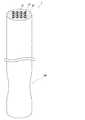
図4は、図1のマルチコアファイバ1を横から見た図である。ただし、図4では、理解の容易のため、被覆層30を省略している。図4に示すように、本実施形態のマルチコアファイバ1は、複数のコア11の長手方向の一部において、複数のコア11の径が細くなるように延伸された延伸部BPを備える。延伸部BPは、マルチコアファイバ1の被覆層30を部分的に剥離して、マルチコアファイバ1をクラッド20の外部から加熱して引っ張ることで延伸する。 FIG. 4 is a side view of the
図5は、延伸倍率とLP11モードの光の伝搬損失との関係の計算結果を示す図である。図5の計算を行うに際して、低屈折率層13のクラッド20に対する比屈折率差Δtを−0.7%とし、コア11の半径r1と内側クラッド12の半径r2との比r2/r1を1.7とし、コア11のクラッド20に対する比屈折率差Δを0.45%とし、コア11の半径が5.17μmとし、コア11の半径r1と低屈折率層13の厚さWとの比W/r1を0.9とした。図5から、延伸部BPの非延伸部に対する縮径比を0.6程度にする、すなわち延伸部BPにおけるマルチコアファイバ1の各部材の径が非縮径部におけるマルチコアファイバ1の各部材の径の0.6倍にすると、コア要素10を伝搬するLP11モードの光の損失が10dB/cmとなることが予想できる。従って、縮径比0.6程度の延伸部BPを2cm程度設けることで、LP11モードの光を光通信が阻害されない程度まで除去することができる。なお、この場合、基本モードであるLP01モードは延伸による光の損失はほとんどなく、光通信に影響を殆ど与えない。FIG. 5 is a diagram showing a calculation result of the relationship between the draw ratio and the propagation loss of light in the LP11 mode. In the calculation of FIG. 5, the relative refractive index difference deltat with respect to the
以上のように本実施形態のマルチコアファイバ1は、通信帯域において1次LPモードの光により通信を行うマルチコアファイバとされ、2次LPモードまでの光を伝搬する複数のコア11と、伝搬する光をコア11よりも高損失で損失する複数の高損失コア15とを備える。そして、コア11を伝搬する2次LPモードの光と、高損失コア15を伝搬する1次LPモードの光とがクロストークする。 As described above, the
従って、本実施形態のマルチコアファイバ1によれば、1次モードの光のコア11への閉じ込めを強くすることができる。従って、1次LPモードの光のみを伝搬するコアで構成されたマルチコアファイバと比べて、1次モードの光のクロストークの抑制が可能となる。このため、1次LPモードの光のみを伝搬するマルチコアファイバよりもコア間距離の設計自由度およびそれぞれのコアの屈折率や径の設計自由度が向上する。 Therefore, according to the
また、コア11を伝搬する2次LPモードの光と、高損失コア15を伝搬する1次LPモードの光とがクロストークするため、コア11を伝搬する2次LPモードの光は、高損失コア15に移動することができる。このため、コア11を伝搬する2次LPモードの光は減衰する。また、高損失コア15は伝搬する光を損失するため、コア11から高損失コア15に移動した光は減衰する。こうして、通信に不要な2次LPモードの光を除去することができる。 In addition, since the second order LP mode light propagating through the
また、本実施形態のマルチコアファイバ1では、コア11を伝搬する2次LPモードの光の伝搬定数と、高損失コア15を伝搬する1次LPモードの光の伝搬定数とが一致する。従って、コア11を伝搬する2次LPモードの光と、高損失コア15を伝搬する1次LPモードの光とのクロストーク量を最大とすることができ、コア11を伝搬する2次LPモードの光を高損失コア15により効率良く移動させることができる。従って、通信に不要な2次LPモードの光を効率的に除去することができる。 In the
また、本実施形態のマルチコアファイバ1では、互いに隣り合うコア11間の距離は、1次LPモードまでの光のクロストークが−40dB/km以下となり、2次LPモードの光のクロストークが−30dB/km以上となる距離とされる。したがって、通信に用いる1次LPモードまでの光のクロストークは抑制され、通信に不要な光である2次LPモードの光はクロストークする。このため、2次の光は、高損失コア15とクロストーク可能なコア11までクロストークにより移動することができる。従って、仮に高損失コア15と隣接しておらず高損失コア15とクロストークしづらいコア11がある場合であっても、2次LPモードの光を当該コア11から他のコア11を介して高損失コア15にクロストークにより移動させることができる。従って、高損失コア15と直接クロストーク出来ないコア11がある場合であっても、2次LPモードの光を除去することができる。 In the
また、本実施形態のマルチコアファイバ1では、高損失コア15は、3個以上のコア11で囲まれる位置に配置されている。従って、それぞれのコア11とクロストークすることができ、効率良くコア11から高損失コア15に2次LPモードの光を移動させることができる。 In the
また、本実施形態のマルチコアファイバ1では、複数のコア11の長手方向の一部において、複数のコア11の径が細くなるように延伸された延伸部BPを更に備え、延伸部BPでは、複数のコア11は1次LPモードまでの光を伝搬し、2次LPモードの光の伝搬が抑制される。しかも、本実施形態の延伸部BPでは、複数のコア11を伝搬する2次LPモードの光の損失が20dB以上とされる。このような延伸部BPが設けられることにより、2次LPモードの光をより損失させることができ、通信に不要な2次LPモードの光をより適切に排除することができる。 In addition, the
以上、本発明について、上記実施形態を例に説明したが、本発明はこれらに限定されるものではない。 As mentioned above, although the said embodiment was demonstrated to the example about this invention, this invention is not limited to these.
例えば、上記実施形態のマルチコアファイバ1において、延伸部BPが設けられなくても良い。ただし、通信に不要なLP11モードの光をより適切に排除する観点から、延伸部BPが設けられることが好ましい。 For example, in the
また、上記実施形態では、16個のコア要素10が正方格子状に配置されたが、本発明のマルチコアファイバでは、コア要素10の数は複数であれば良く、その配置や数は特に限定されない。例えば、複数のコア要素10が三角格子の各格子点上に配置されるものとされても良い。この場合、高損失コア15は、3個のコア要素で囲まれる位置に配置されることが好ましい。 Further, in the above-described embodiment, 16
また、上記実施形態のマルチコアファイバ1では、高損失コア15が複数とされ、それぞれの高損失コア15が4つのコア11で囲まれる構成とされた。しかし、高損失コア15は単数であっても良い。単数であっても、少なくとも高損失コア15とクロストークするコア11のLP02モードの光と減衰することができる。また、上記実施形態のマルチコアファイバ1のように、互いに隣り合うコア11においてLP11モードの光がクロストークする場合、高損失コア15とクロストークしないコア11から高損失コア15とクロストークするコア11にLP11モードの光を移動させることができる。 In the
また、高損失コア15は、少なくとも1つのコア11とクロストークすればよいため、例えば、複数のコア11の外周側に高損失コア15が配置されても良い。また、コア11のLP11モードの光の伝搬定数と高損失コア15のLP01モードの光の伝搬定数とが多少ずれているとしても、コア11を伝搬するLP11モードの光と高損失コア15を伝搬するLP01モードの光とがクロストークし、コア11を伝搬するLP01モードの光と高損失コア15を伝搬するLP01モードの光とのクロストークが抑制されれば良い。 Moreover, since the high-
また、上記実施形態では、マルチコアファイバ1は、通信帯域においてLP01モードの光によりシングルモード通信を行い、それぞれのコア11がLP01モードの光及びLP11モードの光を伝搬するものとされ、LP11モードの光が除去される構成とされた。しかし、本発明はこれに限らない。つまり、フューモード通信やマルチモード通信を行う場合にも用いることができ、それぞれのコアが通信に用いるモードよりも1LPモード高次のモードまでの光を伝搬する構成とされ、当該1LPモード高次の光を高損失コア15により除去するものとしても良い。これを一般化すると、通信帯域においてx次LPモードまでの光(xは1以上の整数)により通信を行うマルチコアファイバであって、(x+1)次LPモードまでの光を伝搬する複数の信号光伝搬コアと、伝搬する光を前記信号光伝搬コアよりも高損失で損失する少なくとも1つの高損失コアと、を備え、前記信号光伝搬コアの少なくとも1つを伝搬する(x+1)次LPモードの光と、前記高損失コアの少なくとも1つを伝搬する1次LPモードの光とがクロストークする構成とされる。 In the above embodiment, the
このようにマルチコアファイバが通信帯域においてx次LPモードまでの光により通信を行う場合においても、延伸部BPが設けられることが好ましい。この場合、延伸部BPでは(x+1)次LPモードの光の損失が20dB以上とされることが好ましく、x次LPモードの光の過剰損失が0.001dB以下とされることがより好ましい。 Thus, even when the multi-core fiber performs communication with light up to the x-order LP mode in the communication band, it is preferable that the extending portion BP is provided. In this case, it is preferable that the loss of light in the (x + 1) -order LP mode is 20 dB or more in the extending portion BP, and it is more preferable that the excess loss of light in the x-order LP mode is 0.001 dB or less.
また、上記実施形態や変形例では、それぞれのコア11が内側クラッド12及び低屈折率層13で囲まれる構成とされたが、本発明はこれに限らない。例えば、それぞれのコア要素10において、内側クラッド12が省略されて、コア11が低屈折率層13に直接囲まれる構成とされても良い。さらに、それぞれのコア要素10において、内側クラッド12及び低屈折率層13が省略されて、コア11がクラッド20により直接囲まれても良い。 Moreover, in the said embodiment and modification, each core 11 was set as the structure enclosed by the
以上説明したように、本発明によれば、設計の自由度を向上させることができるマルチコアファイバが提供され、光通信の分野において利用することができる。 As described above, according to the present invention, a multicore fiber capable of improving the degree of design freedom is provided and can be used in the field of optical communication.
1〜4・・・マルチコアファイバ
10・・・コア要素
11・・・コア(信号光伝搬コア)
12・・・内側クラッド
13・・・低屈折率層
15・・・高損失コア
20・・・クラッド
30・・・被覆層
BP・・・延伸部
Tc・・・クラッド厚
Λ・・・コア間距離1-4 ...
12 ...
Claims (8)
Translated fromJapanese(x+1)次LPモードまでの光を伝搬する複数の信号光伝搬コアと、
伝搬する光を前記信号光伝搬コアよりも損失する少なくとも1つの高損失コアと、
を備え、
互いに隣り合う前記信号光伝搬コア間の距離は、x次LPモードまでの光のクロストークが−40dB/km以下となり、(x+1)次LPモードの光のクロストークが−30dB/km以上となる距離とされ、
前記信号光伝搬コアの少なくとも1つを伝搬する(x+1)次LPモードの光と、前記高損失コアの少なくとも1つを伝搬する1次LPモードの光とがクロストークする
ことを特徴とするマルチコアファイバ。A multi-core fiber that performs communication with light up to the x-order LP mode (x is an integer of 1 or more) in a communication band,
(X + 1) a plurality of signal light propagation cores that propagate light up to the next LP mode;
At least one high loss core that loses propagating light more than the signal light propagation core;
With
The distance between the signal light propagation cores adjacent to each other is such that the crosstalk of light up to the xth order LP mode is −40dB / km or less, and the crosstalk of light in the (x + 1) th order LP mode is −30 dB / km or more. Is a distance
(X + 1) -order LP mode light propagating in at least one of the signal light propagation cores and first-order LP mode light propagating in at least one of the high-loss cores cross-talk. fiber.
ことを特徴とする請求項1に記載のマルチコアファイバ。Propagating said signal light propagating core and (x + 1) propagation constant in the next LP mode light,to claim1 in which the propagation constant of light of the first-order LP modes propagating the high loss core, characterized in that the matching The described multi-core fiber.
ことを特徴とする請求項1または2に記載のマルチコアファイバ。The multi-core fiber according to claim 1or 2 , wherein a propagation loss of light propagating through the high-loss core is set to 3 dB / km or more.
ことを特徴とする請求項1から3のいずれか1項に記載のマルチコアファイバ。The multi-core fiber according to any one of claims 1 to3 , wherein the high-loss core is disposed at a position sandwiched between two signal light propagation cores.
ことを特徴とする請求項1から4のいずれか1項に記載のマルチコアファイバ。The multi-core fiber according to any one of claims 1 to4 , wherein the high-loss core is disposed at a position surrounded by three or more signal light propagation cores.
前記延伸部では、前記複数の信号光伝搬コアはx次LPモードまでの光を伝搬し、(x+1)次LPモードの光の伝搬が抑制される
ことを特徴とする請求項1から5のいずれか1項に記載のマルチコアファイバ。In the part of the longitudinal direction of the plurality of signal light propagation cores, further comprising a stretched portion that is stretched so that the diameter of the plurality of signal light propagation cores is thin,
In the stretching section, the plurality of signal light propagating core propagates the light to x next LP mode, (x + 1) any of claims 1 to5, characterized in that the propagation of light in the next LP mode is suppressed The multi-core fiber according to claim 1.
ことを特徴とする請求項6に記載のマルチコアファイバ。The multi-core fiber according to claim6 , wherein a loss of (x + 1) -order LP mode light propagating through the plurality of signal light propagation cores is 20 dB or more in the extending portion.
ことを特徴とする請求項1から7のいずれか1項に記載のマルチコアファイバ。The multi-core fiber according to any one of claims 1 to7 , wherein x = 1.
Priority Applications (5)
| Application Number | Priority Date | Filing Date | Title |
|---|---|---|---|
| JP2015107929AJP6340342B2 (en) | 2015-05-27 | 2015-05-27 | Multi-core fiber |
| PCT/JP2016/064971WO2016190228A1 (en) | 2015-05-27 | 2016-05-20 | Multi-core fiber |
| CN201680004425.7ACN107111052A (en) | 2015-05-27 | 2016-05-20 | multi-core fiber |
| EP16799933.3AEP3306365A4 (en) | 2015-05-27 | 2016-05-20 | FIBER MULTIC UR |
| US15/571,530US10310176B2 (en) | 2015-05-27 | 2016-05-20 | Multi-core fiber |
Applications Claiming Priority (1)
| Application Number | Priority Date | Filing Date | Title |
|---|---|---|---|
| JP2015107929AJP6340342B2 (en) | 2015-05-27 | 2015-05-27 | Multi-core fiber |
Publications (2)
| Publication Number | Publication Date |
|---|---|
| JP2016224134A JP2016224134A (en) | 2016-12-28 |
| JP6340342B2true JP6340342B2 (en) | 2018-06-06 |
Family
ID=57392845
Family Applications (1)
| Application Number | Title | Priority Date | Filing Date |
|---|---|---|---|
| JP2015107929AActiveJP6340342B2 (en) | 2015-05-27 | 2015-05-27 | Multi-core fiber |
Country Status (5)
| Country | Link |
|---|---|
| US (1) | US10310176B2 (en) |
| EP (1) | EP3306365A4 (en) |
| JP (1) | JP6340342B2 (en) |
| CN (1) | CN107111052A (en) |
| WO (1) | WO2016190228A1 (en) |
Families Citing this family (8)
| Publication number | Priority date | Publication date | Assignee | Title |
|---|---|---|---|---|
| JP6340342B2 (en)* | 2015-05-27 | 2018-06-06 | 株式会社フジクラ | Multi-core fiber |
| US10989868B1 (en)* | 2017-09-14 | 2021-04-27 | Apple Inc. | Fabric items with thermally imprinted light-emitting regions |
| JP7012408B2 (en)* | 2018-02-28 | 2022-01-28 | 古河電気工業株式会社 | Multi-core fiber, optical transmission system and optical transmission method |
| JP2023518466A (en) | 2020-03-19 | 2023-05-01 | コーニング インコーポレイテッド | Multicore fiber with outer cladding region |
| CN111999799B (en)* | 2020-09-18 | 2022-04-08 | 长飞光纤光缆股份有限公司 | Multi-core optical fiber |
| CN112198586B (en)* | 2020-09-25 | 2021-11-19 | 北京邮电大学 | Multi-core optical fiber |
| US12032200B2 (en)* | 2021-12-28 | 2024-07-09 | Sterlite Technologies Limited | Trench assisted multi-core optical fiber with reduced crosstalk |
| CN118647910A (en)* | 2022-03-30 | 2024-09-13 | 住友电气工业株式会社 | Multi-core optical fiber |
Family Cites Families (24)
| Publication number | Priority date | Publication date | Assignee | Title |
|---|---|---|---|---|
| JPS4940750A (en)* | 1972-08-23 | 1974-04-16 | ||
| JP3805384B2 (en) | 1993-05-11 | 2006-08-02 | オリンパス株式会社 | Image fiber |
| US5689578A (en) | 1993-02-25 | 1997-11-18 | Fujikura Ltd. | Polarized wave holding optical fiber, production method therefor, connection method therefor, optical amplifier, laser oscillator and polarized wave holding optical fiber coupler |
| US5479550A (en)* | 1993-05-13 | 1995-12-26 | Olympus Optical Co., Ltd. | Image fiber |
| JPH0894864A (en)* | 1994-04-08 | 1996-04-12 | Olympus Optical Co Ltd | Image fiber and its production |
| WO2011024808A1 (en)* | 2009-08-28 | 2011-03-03 | 株式会社フジクラ | Multi-core fiber |
| JP5678679B2 (en) | 2010-01-22 | 2015-03-04 | 住友電気工業株式会社 | Multi-core fiber |
| JP5279751B2 (en)* | 2010-03-31 | 2013-09-04 | 日本電信電話株式会社 | Optical fiber and manufacturing method thereof |
| JP5855351B2 (en) | 2010-11-08 | 2016-02-09 | 株式会社フジクラ | Multi-core fiber |
| JP5595888B2 (en)* | 2010-12-09 | 2014-09-24 | 株式会社フジクラ | Multi-core fiber |
| EP2678729B1 (en) | 2011-02-24 | 2021-01-20 | OFS Fitel, LLC | Multicore fiber designs for spatial multiplexing |
| DK2682793T3 (en) | 2011-03-02 | 2017-07-10 | Fujikura Ltd | MULTI-CORE FIBER |
| JP5819682B2 (en)* | 2011-09-05 | 2015-11-24 | 株式会社フジクラ | Multicore fiber for communication |
| JP5916525B2 (en)* | 2012-01-19 | 2016-05-11 | 株式会社フジクラ | Multi-core fiber |
| JP2014010266A (en)* | 2012-06-29 | 2014-01-20 | Fujikura Ltd | Multi-core fiber |
| JP6057340B2 (en)* | 2013-08-27 | 2017-01-11 | 日本電信電話株式会社 | Multi-core optical fiber |
| JP5921518B2 (en)* | 2013-11-18 | 2016-05-24 | 株式会社フジクラ | Multi-core fiber and method for producing the multi-core fiber |
| JP5860024B2 (en)* | 2013-11-25 | 2016-02-16 | 株式会社フジクラ | Multi-core fiber |
| JP2015212791A (en)* | 2014-05-07 | 2015-11-26 | 株式会社フジクラ | Multi-core fiber |
| JP6034344B2 (en)* | 2014-08-29 | 2016-11-30 | 株式会社フジクラ | Fiber optic cable |
| JP6050847B2 (en)* | 2015-02-12 | 2016-12-21 | 株式会社フジクラ | Multi-core fiber |
| JP6532748B2 (en)* | 2015-04-30 | 2019-06-19 | 株式会社フジクラ | Multicore fiber |
| JP6340342B2 (en)* | 2015-05-27 | 2018-06-06 | 株式会社フジクラ | Multi-core fiber |
| JP6692128B2 (en)* | 2015-07-02 | 2020-05-13 | 株式会社フジクラ | Multi-core polarization maintaining fiber |
- 2015
- 2015-05-27JPJP2015107929Apatent/JP6340342B2/enactiveActive
- 2016
- 2016-05-20CNCN201680004425.7Apatent/CN107111052A/enactivePending
- 2016-05-20USUS15/571,530patent/US10310176B2/ennot_activeExpired - Fee Related
- 2016-05-20EPEP16799933.3Apatent/EP3306365A4/ennot_activeWithdrawn
- 2016-05-20WOPCT/JP2016/064971patent/WO2016190228A1/ennot_activeCeased
Also Published As
| Publication number | Publication date |
|---|---|
| EP3306365A1 (en) | 2018-04-11 |
| JP2016224134A (en) | 2016-12-28 |
| CN107111052A (en) | 2017-08-29 |
| US10310176B2 (en) | 2019-06-04 |
| WO2016190228A1 (en) | 2016-12-01 |
| EP3306365A4 (en) | 2019-01-23 |
| US20180120502A1 (en) | 2018-05-03 |
Similar Documents
| Publication | Publication Date | Title |
|---|---|---|
| JP6340342B2 (en) | Multi-core fiber | |
| JP6532748B2 (en) | Multicore fiber | |
| JP6177994B2 (en) | Multi-core fiber | |
| JP5916525B2 (en) | Multi-core fiber | |
| JP5855351B2 (en) | Multi-core fiber | |
| US9529144B2 (en) | Multicore fiber | |
| JP2013092801A (en) | Multi-core fiber | |
| JP5468711B2 (en) | Multi-core fiber | |
| JPWO2017159385A1 (en) | Multi-core fiber | |
| JP2014010266A (en) | Multi-core fiber | |
| JP2012181282A (en) | Multi-core fiber | |
| JP2013228548A (en) | Multicore optical fiber | |
| JP6334582B2 (en) | Multi-core fiber | |
| JP2013088458A (en) | Multicore single mode optical fiber and optical cable | |
| JP6503513B2 (en) | Multicore fiber | |
| JP2005338436A (en) | Hole assisted optical fiber | |
| JP6192442B2 (en) | Coupled multi-core fiber | |
| JP6096268B2 (en) | Multi-core fiber | |
| JP7012408B2 (en) | Multi-core fiber, optical transmission system and optical transmission method | |
| WO2017168843A1 (en) | Optical fiber | |
| JP7720583B2 (en) | Multicore Fiber |
Legal Events
| Date | Code | Title | Description |
|---|---|---|---|
| A521 | Request for written amendment filed | Free format text:JAPANESE INTERMEDIATE CODE: A523 Effective date:20170202 | |
| A131 | Notification of reasons for refusal | Free format text:JAPANESE INTERMEDIATE CODE: A131 Effective date:20170328 | |
| A521 | Request for written amendment filed | Free format text:JAPANESE INTERMEDIATE CODE: A523 Effective date:20170523 | |
| A131 | Notification of reasons for refusal | Free format text:JAPANESE INTERMEDIATE CODE: A131 Effective date:20171024 | |
| A521 | Request for written amendment filed | Free format text:JAPANESE INTERMEDIATE CODE: A523 Effective date:20171225 | |
| TRDD | Decision of grant or rejection written | ||
| A01 | Written decision to grant a patent or to grant a registration (utility model) | Free format text:JAPANESE INTERMEDIATE CODE: A01 Effective date:20180501 | |
| A61 | First payment of annual fees (during grant procedure) | Free format text:JAPANESE INTERMEDIATE CODE: A61 Effective date:20180514 | |
| R150 | Certificate of patent or registration of utility model | Ref document number:6340342 Country of ref document:JP Free format text:JAPANESE INTERMEDIATE CODE: R150 | |
| R250 | Receipt of annual fees | Free format text:JAPANESE INTERMEDIATE CODE: R250 | |
| R250 | Receipt of annual fees | Free format text:JAPANESE INTERMEDIATE CODE: R250 | |
| R250 | Receipt of annual fees | Free format text:JAPANESE INTERMEDIATE CODE: R250 | |
| R250 | Receipt of annual fees | Free format text:JAPANESE INTERMEDIATE CODE: R250 | |
| R250 | Receipt of annual fees | Free format text:JAPANESE INTERMEDIATE CODE: R250 |