JP6338467B2 - Imaging device - Google Patents
Imaging deviceDownload PDFInfo
- Publication number
- JP6338467B2 JP6338467B2JP2014125724AJP2014125724AJP6338467B2JP 6338467 B2JP6338467 B2JP 6338467B2JP 2014125724 AJP2014125724 AJP 2014125724AJP 2014125724 AJP2014125724 AJP 2014125724AJP 6338467 B2JP6338467 B2JP 6338467B2
- Authority
- JP
- Japan
- Prior art keywords
- optical fiber
- optical
- imaging
- light
- angle
- Prior art date
- Legal status (The legal status is an assumption and is not a legal conclusion. Google has not performed a legal analysis and makes no representation as to the accuracy of the status listed.)
- Expired - Fee Related
Links
Images


Classifications
- G—PHYSICS
- G02—OPTICS
- G02B—OPTICAL ELEMENTS, SYSTEMS OR APPARATUS
- G02B6/00—Light guides; Structural details of arrangements comprising light guides and other optical elements, e.g. couplings
- G02B6/04—Light guides; Structural details of arrangements comprising light guides and other optical elements, e.g. couplings formed by bundles of fibres
- G02B6/06—Light guides; Structural details of arrangements comprising light guides and other optical elements, e.g. couplings formed by bundles of fibres the relative position of the fibres being the same at both ends, e.g. for transporting images
- G—PHYSICS
- G02—OPTICS
- G02B—OPTICAL ELEMENTS, SYSTEMS OR APPARATUS
- G02B13/00—Optical objectives specially designed for the purposes specified below
- G02B13/18—Optical objectives specially designed for the purposes specified below with lenses having one or more non-spherical faces, e.g. for reducing geometrical aberration
- G—PHYSICS
- G02—OPTICS
- G02B—OPTICAL ELEMENTS, SYSTEMS OR APPARATUS
- G02B6/00—Light guides; Structural details of arrangements comprising light guides and other optical elements, e.g. couplings
- G02B6/0001—Light guides; Structural details of arrangements comprising light guides and other optical elements, e.g. couplings specially adapted for lighting devices or systems
- G02B6/0005—Light guides; Structural details of arrangements comprising light guides and other optical elements, e.g. couplings specially adapted for lighting devices or systems the light guides being of the fibre type
- H—ELECTRICITY
- H04—ELECTRIC COMMUNICATION TECHNIQUE
- H04N—PICTORIAL COMMUNICATION, e.g. TELEVISION
- H04N23/00—Cameras or camera modules comprising electronic image sensors; Control thereof
- H04N23/50—Constructional details
- H04N23/54—Mounting of pick-up tubes, electronic image sensors, deviation or focusing coils
- G—PHYSICS
- G02—OPTICS
- G02B—OPTICAL ELEMENTS, SYSTEMS OR APPARATUS
- G02B13/00—Optical objectives specially designed for the purposes specified below
- G02B13/06—Panoramic objectives; So-called "sky lenses" including panoramic objectives having reflecting surfaces
- G—PHYSICS
- G02—OPTICS
- G02B—OPTICAL ELEMENTS, SYSTEMS OR APPARATUS
- G02B6/00—Light guides; Structural details of arrangements comprising light guides and other optical elements, e.g. couplings
- G02B6/0001—Light guides; Structural details of arrangements comprising light guides and other optical elements, e.g. couplings specially adapted for lighting devices or systems
- G02B6/0011—Light guides; Structural details of arrangements comprising light guides and other optical elements, e.g. couplings specially adapted for lighting devices or systems the light guides being planar or of plate-like form
- G02B6/0013—Means for improving the coupling-in of light from the light source into the light guide
- G02B6/0015—Means for improving the coupling-in of light from the light source into the light guide provided on the surface of the light guide or in the bulk of it
- G02B6/0016—Grooves, prisms, gratings, scattering particles or rough surfaces
- G—PHYSICS
- G02—OPTICS
- G02B—OPTICAL ELEMENTS, SYSTEMS OR APPARATUS
- G02B9/00—Optical objectives characterised both by the number of the components and their arrangements according to their sign, i.e. + or -
- G02B9/60—Optical objectives characterised both by the number of the components and their arrangements according to their sign, i.e. + or - having five components only
Landscapes
- Physics & Mathematics (AREA)
- General Physics & Mathematics (AREA)
- Optics & Photonics (AREA)
- Engineering & Computer Science (AREA)
- Multimedia (AREA)
- Signal Processing (AREA)
- Optical Fibers, Optical Fiber Cores, And Optical Fiber Bundles (AREA)
- Lenses (AREA)
- Transforming Light Signals Into Electric Signals (AREA)
- Studio Devices (AREA)
- Optical Couplings Of Light Guides (AREA)
Description
Translated fromJapanese本発明は、撮像装置に関する。 The present invention relates to an imaging apparatus.
複数の光ファイバにより構成された光ファイバ束を用いて、撮像光学系(結像光学手段)からの光(結像光線)を撮像素子に導く撮像装置(結像光学装置)が開発されている。
特許文献1には、光ファイバ束を用いて、その受光端面(光入射面)に入射した結像光学手段による結像光線をイメージ検収手段(撮像素子)へ伝送する結像光学装置が開示されている。そして、この結像光学装置は、光ファイバ束の受光端面を結像光学手段の結像面に位置させるとともに受光端面の面形状を結像面の形状と同等の面形状としている。An imaging device (imaging optical device) that guides light (imaging light beam) from an imaging optical system (imaging optical means) to an imaging device using an optical fiber bundle composed of a plurality of optical fibers has been developed. .
しかし、特許文献1のように、軸方向が結像光学手段の光軸と平行な光ファイバからなる光ファイバ束の受光端面を凹面形状とした場合、以下のような問題が生じる。すなわち、各光ファイバの受光端面が傾斜するため、光ファイバ内を伝搬する光が全反射条件を満たしにくくなり、結像光学手段の広画角の光束の光ファイバの透過率が大きく減衰する。その結果、撮像素子の周辺部の画素の光量が低下する。
本発明は、光軸から離れた位置にある光ファイバに入射する光の透過率の低下を抑えた撮像装置を提供することを目的とする。However, as in
It is an object of the present invention to provide an imaging device that suppresses a decrease in the transmittance of light incident on an optical fiber located away from the optical axis.
本発明は、撮像光学系と、撮像素子と、前記撮像光学系からの光を前記撮像素子へと導く複数の光ファイバにより構成される光ファイバ束と、を有する撮像装置であって、前記光ファイバ束の光入射面は前記撮像光学系に対して凹面であり、前記複数の光ファイバのうち前記撮像光学系の光軸上以外に配置された光ファイバは、下記の関係式を満たすことを特徴とする撮像装置。The present invention is animaging apparatus comprising: animaging optical system; an imaging element; and an optical fiber bundle including a plurality of optical fibers that guide light from the imaging optical system to the imaging element. The light incident surface of the fiber bundle is concave with respect to the imaging optical system, and among the plurality of optical fibers, the optical fibersarranged on the optical axisother than the imaging optical system satisfy the following relational expression. An imaging device that is characterized.

ただし、αは前記光ファイバの傾斜角、βは前記光ファイバの光入射面の傾斜角、ωは前記光ファイバに入射する前記撮像光学系からの主光線の角度、N1は前記光ファイバのコア部の屈折率、N2は前記光ファイバのクラッド部の屈折率である。
Where α is the inclination angle of the optical fiber, β is the inclination angle of the light incident surface of the optical fiber, ω is the angle of the principal ray from the imaging optical system incident on the optical fiber, and N1 is the core of the optical fiber. Where N2 is the refractive index of the cladding of the optical fiber.
本発明によれば、光軸から離れた位置にある光ファイバに入射する光の透過率の低下を低減した撮像装置を得ることができる。 ADVANTAGE OF THE INVENTION According to this invention, the imaging device which reduced the fall of the transmittance | permeability of the light which injects into the optical fiber in the position away from the optical axis can be obtained.
本発明について、実施形態、図面を用いて詳細に説明するが、本発明は各実施形態の構成に限らない。 The present invention will be described in detail with reference to embodiments and drawings. However, the present invention is not limited to the configuration of each embodiment.
(実施形態1)
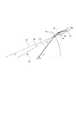
図1(a)は、本実施形態に係る撮像装置の一例を示す模式図である。本実施形態の撮像装置1は、撮像光学系(結像光学系)であるボールレンズ2、像伝送手段である光ファイバ束3、撮像素子であるセンサ4を有している。そして、ボールレンズ2の像を光ファイバ束3によってセンサ4に伝送するように、ボールレンズ2と光ファイバ束3とセンサ4が配置されている。光ファイバ束3は、ボールレンズ2からの光をセンサ4へと導く複数の光ファイバ3cにより構成されている。具体的には、各光ファイバ3cが、撮像光BMをボールレンズ2を介して受光し、光ファイバ3c内を伝搬させて、撮像光BMをセンサ4の各画素へと導いている。撮像光BMは、絞り2cの開口を通り光ファイバ3cに入射しうる光であり、絞り2cの開口の中心を通る主光線PRや、絞り2cの開口で規定される上側マージナル線NR、下側マージナル線MRが含まれる。(Embodiment 1)
FIG. 1A is a schematic diagram illustrating an example of an imaging apparatus according to the present embodiment. The
また、光ファイバ束3の光入射面3aは、ボールレンズ2に対して凹面であり、より具体的には、ボールレンズ2の結像面とほぼ同形状の凹面形状である。光ファイバ束3の光入射面3aは、ガラスレンズと同様の球面研磨加工によって滑らかな光学面が形成される。この加工技術により光入射面3aの表面で発生する散乱を抑えることができる。一方、光ファイバ束3の光射出面3bは平面形状である。そして、光ファイバ束3は、その光射出面3bとセンサ4の光入射面とが密着するように配置されている。光ファイバ束3の光射出面3bも、光入射面3aと同様に平面研磨加工により光学面が形成され、撮像素子への密着性が向上している。 Further, the
また、光ファイバ束3の周辺部にある各光ファイバ3cは、その軸方向が光軸AXに対して傾斜した構成となっており、さらに、その傾斜角度が、後述するように所望の範囲に設定されている。この構成により、光ファイバ束3の周辺部の光ファイバ3cの透過率の低下が抑制される。 Each
なお、ボールレンズ2の光軸AXは、ボールレンズ2の中に配置された絞り2cで規定される開口部の中心を通り、センサ4の受光面に垂直な直線のことである。絞り2cの開口部の中心はボールレンズ2の射出瞳の中心と一致しており、光軸AXは、撮像光学系の射出瞳の中心を通り、センサ4の受光面に垂直な直線のことであるともいえる。また、光軸AXは、光ファイバ束3の光入射面3aの中心を通っている。つまり、撮像光学系の射出瞳の中心と光ファイバ束3の光入射面3aの中心とを結ぶ直線は光軸AXと一致している。 The optical axis AX of the
また、図1(b)は、センサ4の受光面に平行な、光ファイバ束3の断面の一部である。この断面内で、コア部3coは三角格子状に配置されており、コア部3coの間にクラッド部3clが配置されている。このように、各光ファイバ3cは、コア部3coとコア部3coの周りに配置されたクラッド部3clとで構成されている。なお、図1(b)では、コア部3coは三角格子状に配置されているが、これに限定されるものではない。例えば、コア部3coは正方格子状や斜方格子状など任意の格子状に配置されていてもよい。また、クラッド部3clがコア部3coの間に配置されるのであれば、コア部3coはランダムに配置されていてもよい。さらに、コア部3coが格子状に配置された領域とコア部3coがランダムに配置された領域とが混在する光ファイバ束を用いることも可能である。 FIG. 1B is a part of the cross section of the optical fiber bundle 3 parallel to the light receiving surface of the
光ファイバ束3の各光ファイバ3cは、センサ4の各画素と1対1で対応していてもよいし、そうでなくてもよい。例えば、光ファイバ3cを伝搬する撮像光BMの一部の光は、センサ4のある画素で受光され、それ以外の光が別の画素で受光される構成であってもよい。また、センサ4のある画素が、複数の光ファイバ3cをそれぞれ伝播した撮像光BMを受光する構成であってもよい。 Each
なお、本実施形態では、光ファイバ3cの光入射面3ca側のコア部3coの径よりも、光ファイバ3cの光射出面3cb側のコア部3coの径を大きくなっている。この構成であれば、光ファイバ3cの傾斜角度を所望の値に容易に制御することが可能となる。なお、後述の実施形態で示すように、光入射面3ca側のコア部3coの径と光射出面3cb側のコア部3coの径とが同じであっても本発明は適用可能である。 In the present embodiment, the diameter of the core portion 3co on the light exit surface 3cb side of the
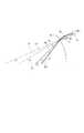
次に、本発明が解決する課題について説明する。まず、一般的な光ファイバ中を光が伝搬する様子について、図2(a)、(b)を用いて説明する。図2(a)は、撮像装置11の模式図である。撮像装置11は、撮像光学系であるボールレンズ12、光ファイバ束13、撮像素子であるセンサ14を有している。光ファイバ束13は複数の光ファイバ13cを有している。そして、各光ファイバ13cの各軸方向はボールレンズ12の光軸AXに平行であり、センサ14の受光面に対して垂直に配置されている。また、各光ファイバ13cの光入射面13caは、光ファイバ13cの軸方向に対して垂直に配置されている。そして、各光ファイバ13cの各光入射面13caは、ボールレンズ12の結像面に合わせるように、その位置が調整されている。このため、ボールレンズ12の光軸AXからの距離に応じて、光ファイバ13cの光入射面13caの位置が、光軸AXに平行な方向に関して図2(a)のように異なっている。 Next, problems to be solved by the present invention will be described. First, how light propagates in a general optical fiber will be described with reference to FIGS. FIG. 2A is a schematic diagram of the
図2(b)は、光ファイバ13cの構成と光ファイバ13cの中を光が伝搬する様子を示している。光ファイバ13cは、コア部13coとクラッド部13clとで構成されている。撮像光BMは光入射面13aに対して入射角θiで入射し、射出角θaでコア部13co内を伝搬する。そして、この伝搬光は、コア部13coとクラッド部13clとの界面に入射角θbで入射する。ここで、伝搬光は、コア部13coとクラッド部13clとの界面を全反射することでコア部13co内を伝搬するのだが、その条件は、入射角θbが式1を満足する必要がある。 FIG. 2B shows the configuration of the
ただし、N1は、コア部13coの屈折率、N2は、クラッド部13clの屈折率である。
However, N1 is the refractive index of the core part 13co, N2 is the refractive index of the clad part 13cl.
図2(a)、(b)で示すように、光ファイバ13cの光入射面13caを光ファイバの軸方向に対して垂直に配置した場合、光ファイバ13cの開口数NAを式2で表すことができる。 As shown in FIGS. 2A and 2B, when the light incident surface 13ca of the
ただし、N0は光入射面13caが接する媒体の屈折率(本実施形態の場合は空気N0=1.000とした)、θiは、上述したように光ファイバ13cの光入射面13caに対する撮像光BMの入射角である。
However, N0 is the refractive index of the medium with which the light incident surface 13ca is in contact (in this embodiment, air N0 = 1.000), and θi is the imaging light BM for the light incident surface 13ca of the
近年では光ファイバ13cを構成するガラス材料の進展が目覚ましく、コア部13coとクラッド部13clとの屈折率差が大きく異なるガラス材料が開発された。これにより、光ファイバの開口数NAが増加し、NA=1.0のものまで存在する。NA=1.0となる構成例は、コア部13coの屈折率N1=1.820、クラッド部13clの屈折率N2=1.495である。NA=1.0の構成では、式1を必ず満たすため、このような材料を用いることで光ファイバの透過率を高くすることができる。 In recent years, the progress of the glass material constituting the
しかし、図2(a)、(b)のような光ファイバ束13を構成するには、光ファイバ13cを1つずつ所望の位置に配列する必要があるため製造が困難である。そのため、図3(a)、(b)で示すような撮像装置21の構成を採ることが考えられる。図3(a)は、撮像装置21の模式図である。撮像装置21は、撮像光学系であるボールレンズ22、光ファイバ束23、撮像素子であるセンサ24を有している。光ファイバ束23は、複数の光ファイバ23cを有している。そして、複数の光ファイバ23cの各軸方向は、センサ24に対して垂直に配置され、ボールレンズ22の光軸AXに対して平行である。光ファイバ束23の光入射面23aは、光ファイバ束23の光入射面23aが撮像光学系12の結像面と同じ形状にされている。これは、複数の光ファイバ23cを束ねた後、光ファイバ束23の光入射面23aをボールレンズ22に対してほぼ凹面形状となるように光ファイバ束23を削ることにより形成される。 However, it is difficult to manufacture the
このような光ファイバ束23では、図3(b)で示すように、光ファイバ23cの光入射面23caが光ファイバ23cの軸方向に対して傾く。具体的には、光ファイバ23cの光入射面23caは、その面法線が光ファイバ23cの軸方向に対して角度ψ傾いている。なお、光ファイバ束23の光入射面23aの曲率半径が数mm乃至数十mmであるのに対して、各光ファイバ23cのピッチは数μmである。よって、光ファイバ23cの光入射面23caは光ファイバ束23の光入射面23aの微小区間なので傾斜した平面と見なせる。 In such an
この場合、撮像光BMは光ファイバ23cの光入射面23caに対して入射角θiで入射するが、図2(b)の場合と比べて入射角θiが小さくなる。その結果、光ファイバ23cの光入射面23caから射出してコア部13coとクラッド部13clとの界面に入射する光の角度は撮像光BMの角度から殆ど変更されない。つまり、コア部13coとクラッド部13clとの界面への入射角θbは図2(b)の場合と比べて小さくなり、式1に示した全反射条件を満足できなくなる。そのため、撮像光BMはクラッド部13clに侵入し、光ファイバ23cの外へ放出され、光ファイバ23cの光射出面23cbへは到達しない。 In this case, the imaging light BM is incident on the light incident surface 23ca of the
そして、光ファイバ23cの光入射面23caの法線の光ファイバ23cの軸方向に対する傾きは、光ファイバ束23の中心部よりも周辺部で大きくなり、光ファイバ束23の周辺部で光ファイバ23cの透過率が低下する。それに伴い、撮像素子の周辺部の画素において、受光する光量が低下する。 The inclination of the normal line of the light incident surface 23ca of the
この課題を解決するために、本実施形態の撮像装置1において、図1(a)、(c)で示すように、光ファイバ3cの軸方向がボールレンズ2の光軸AXに対して傾斜した構成となっている。図1(c)は、光ファイバ3cの構成を示している。この光ファイバ3cを光軸AXと平行ではなく、光軸AXに対して傾斜させることで、撮像光BMの入射角θiが図3(b)の構成と同じであっても、コア部3coとクラッド部3clとの界面への入射角θbが大きくすることができる。このため、光ファイバ3cの透過率の低下は抑制される。 In order to solve this problem, in the
さらに、図4、5を用いて光ファイバ3cのボールレンズ2の光軸AXに対する傾斜角αについて説明する。図4で、傾斜角αは光ファイバ3cの軸VFと光軸AXとがなす、0.00以上90.00[deg]未満の角度である。ただし、本実施形態の光ファイバ3cはテーパー型光ファイバであり、光ファイバ3cのコア部3coの太さが場所によって異なっている。また、光ファイバ3cの形状は、直線状でもよいし、湾曲状であってもよい。また、本実施形態では、図5(a)のように、光ファイバ束3を構成する光ファイバ3cが、光軸AXと平行でない部分と光軸AXに平行な部分とで構成される形態でもよい。このため、光ファイバ3cの軸VFを図5(b)を用いて、以下のように定義する。光ファイバ3c軸VFは、光ファイバ3cの光入射面3caにあるコア部3coの断面の中心Aと中心Aから光ファイバ3cの光入射面3caのコア部3coの径の大きさLだけコア部3coの内部にあるコア部3coの断面SBの中心点Bとを結ぶ直線とする。 Furthermore, the inclination angle α of the
図4において、βは光ファイバ3cの光入射面3caの傾斜角である。具体的には、傾斜角βは、光ファイバ3cの光入射面3caの法線VRと光軸AXとがなす、0.00以上90.00[deg]未満の角度である。本実施形態では、光ファイバ3cは、傾斜角αよりも傾斜角βが大きくなるように構成されている。つまり、α<βである。なお、光ファイバ3cの光入射面3caは、光ファイバ束3の光入射面3aに対して微小領域であるため平面とみなす。 In FIG. 4, β is an inclination angle of the light incident surface 3ca of the
図4において、ωは、光ファイバ3cに入射する撮像光学系からの主光線PRの角度である。具体的には、角度ωは、ボールレンズ2の射出瞳の中心点PEと光ファイバ3cの光入射面3caにあるコア部3coの中心点A(図5(b)参照)とを結ぶ直線と光軸AXとがなす、0.00以上90.00[deg]未満の角度である。本実施形態では、光ファイバ3cに、傾斜角αよりも大きな角度ωの主光線PRを入射させている。つまり、α<ωである。 In FIG. 4, ω is the angle of the principal ray PR from the imaging optical system that enters the
本実施形態では、光ファイバ3cの傾斜角αが、角度ωを有する主光線PRに対して光ファイバ3c内で全反射する条件を満たすように、光ファイバ3cを構成することで、任意の光ファイバ3cの透過率の低下を抑制している。全反射条件は、具体的には、以下のように導かれる。まず、光ファイバ3cの光入射面3caにおいて、スネルの法則から式3を満たす。
N0sinθi=N1sinθo ・・・式3
ここで、N0は、光入射面が接する媒体の屈折率(本実施形態の場合は空気N0=1.000とした)、θiは、光ファイバ3cの光入射面3caに対する主光線PRの入射角である。また、N1は、コア部3coの屈折率、θoは、光入射面3aでの主光線PRの屈折角である。さらに、光ファイバ3cのコア部3coとクラッド部3clとの界面における全反射条件は式4のように表される。In the present embodiment, the
N0sinθi = N1sinθo Equation 3
Here, N0 is the refractive index of the medium with which the light incident surface is in contact (in this embodiment, air N0 = 1.000), and θi is the incident angle of the principal ray PR with respect to the light incident surface 3ca of the
ここで、N2は、クラッド部3clの屈折率、θlは、コア部3coとクラッド部3clの界面への屈折された主光線の入射角である。なお、角度θiとθoとθlは、α、β、ωと補助的に記された図4の角度θk、θmを用いると、以下の式5乃至7のように表される。
θi=ω−β ・・・式5
θl+θk=90.00deg ・・・式6
θk=θo+θm=θo+(β―α) ・・・式7
式3乃至7を用いると、光ファイバ3cの傾斜角αが満たすべき全反射条件が以下の式8のように導かれる。
Here, N2 is the refractive index of the clad part 3cl, and θl is the incident angle of the refracted principal ray to the interface between the core part 3co and the clad part 3cl. Note that the angles θi, θo, and θl are expressed by the following equations 5 to 7 using the angles θk and θm of FIG. 4 supplementarily written as α, β, and ω.
θi = ω−β Equation 5
θl + θk = 90.00 deg Equation 6
θk = θo + θm = θo + (β−α) Equation 7
When Expressions 3 to 7 are used, the total reflection condition to be satisfied by the inclination angle α of the
また、光軸AXに近い光ファイバ3cでは、傾斜角β、角度ωが小さく、式8の左辺は負の値を採る場合がある。一方、光ファイバ3cの傾斜角αの上限は、主光線PRの射出角ωである。これは、光ファイバ束3の製造方法にもよるが、画角±47.00[deg]を超えるような撮像光学系を用いる場合には、光ファイバ3cの傾斜角αが主光線の角度ω以上とすることが困難なためである。その点を踏まえると、光ファイバ3cの傾斜角αが、下記の式9を満たすように、光ファイバ3cが構成される。
Further, in the
ここで、max{A,B}はAとBのうち大きい方の値を採るという意味の関数である。なお、光軸AX上に光ファイバ3cがある場合は、その光ファイバの傾斜角αは0.00[deg]に設定される。その場合、式9を満たさないが、それ以外の光ファイバ3cはそれぞれ上記式9を満たすように構成されている。
Here, max {A, B} is a function meaning that the larger one of A and B is taken. When the
光ファイバ束3のうち、撮像光学系(ボールレンズ2)の光軸AX上から離れた位置にある光ファイバ3cが式9を満たすような傾斜角αを満たすことで、その光ファイバ3cの透過率の低下を抑制することができる。その結果、撮像素子(センサ4)の画素が受光する光量の低下を抑制することができる。 In the optical fiber bundle 3, when the
また、光ファイバ3cの光入射面3caの位置と光軸AXとの間の距離に応じて、つまり、光ファイバ3cで取り込む撮像光BMの主光線PRの射出角ωや光入射面3caの傾斜角βに応じて、光ファイバ3cの傾斜角度αが設定される。これは、光ファイバ3cの光入射面3caの位置と光軸AXとの間の距離が大きくなると、式9の変数である射出角ω、傾斜角βが大きくなるためである。具体的には、光ファイバ3cの傾斜角度αは、光軸AXに対して光入射面3caの位置が相対的に遠い光ファイバ3cの方が、相対的に近い光ファイバ3cよりも、大きくすることが好ましい。この構成であれば、容易に光ファイバ束3を製造することが可能となる。 Further, according to the distance between the position of the light incident surface 3ca of the
なお、撮像素子であるセンサ4は、CMOSセンサであってもよいしCCDセンサであってもよい。 The
本実施形態では、光ファイバ束3の光入射面3aを球面形状としたが、これに限ったものではなく、放物面や非球面でもよい。その面の曲率中心を算出する際は、ベース球面若しくは近軸の曲率半径を用いればよい。 In the present embodiment, the
<数値例1>
表1に本実施形態の撮像装置における数値例を示す。<Numerical example 1>
Table 1 shows numerical examples in the imaging apparatus of the present embodiment.
表1には、射出角ωが0.00乃至60.00[deg]の各主光線に対する各数値が示されている。射出角ω=0.00[deg]は光軸と平行であることを意味している。射出角ωが大きくなればなるほど、光ファイバ3cの位置が光軸AXからより離れることを意味している。光軸AXから離れた位置にある(ω=0.00[deg]以外の)各光ファイバ3cの傾斜角αは、式9を満たすように設定されている。表1の傾斜角αとすることで、光ファイバ束3を容易に製造することが可能である。また、本数値例では、光ファイバ束3の光入射面3aの曲率中心と撮像光学系2の射出瞳の中心PEとを一致させており、射出角ωと光ファイバ3cの光入射面3aの傾斜角βは各光ファイバ3cにおいて同じ値としている。
Table 1 shows numerical values for the principal rays having an exit angle ω of 0.00 to 60.00 [deg]. The exit angle ω = 0.00 [deg] means being parallel to the optical axis. It means that the position of the
なお、本数値例では、光ファイバ3cの傾斜角αは、光軸AXと平行光であることを意味する射出角ω=0.00[deg]の場合を除き、上限値よりも小さく下限値以上に設定されており、式9を満足している。これにより、光ファイバ束3に入射する全ての撮像光BMの主光線PRに対して光ファイバ3c内で全反射条件を満足させることができるので、撮像光学系が結像させた像を撮像素子へ伝送する際の光量の低下を低減することができる。特に、画角が±30.00[deg]を超える広角撮像光学系、画角が±47.00[deg]を超える超広角撮像光学系においては射出角ωも大きくなる傾向にある。光ファイバ3cの傾斜角αが式9を満たすように光ファイバ3cを構成することにより、射出角ωが大きい光ファイバ束3の周辺部においても光ファイバ3cの透過率の低下を軽減することができる。 In this numerical example, the inclination angle α of the
また、本数値例の光ファイバ束3は、光入射面3a側の光ファイバ3cのコア部3coの口径が相対的に小さく、光射出面3b側の光ファイバ3cのコア部3coの口径が相対的に大きい。このため、各光ファイバ3cの間隔を均一に保ちながら光ファイバ3cを傾斜できるので、光ファイバ3cの傾斜角αを安定して所望な角度に容易に設定することができる。 In the optical fiber bundle 3 of this numerical example, the diameter of the core portion 3co of the
また、撮像光学系は点対称性を有するボールレンズ2でなくてもよい。例えば、撮像光学系が、絞りと、絞りより光入射側に配置された前群レンズと、絞りより光射出側に配置された後群レンズと、を有する複数のレンズ群で構成されていてもよい。さらに、その前群レンズとして、前群レンズの最強パワーを有するレンズ面の曲率中心が絞りの中心近傍に位置する光学系を用いてもよい。また、後群レンズとして、後群レンズの最強パワーを有するレンズ面の曲率中心が絞りの中心近傍に位置する光学系を用いてもよい。なお、絞りの中心近傍とは、絞りの中心から主光線の波長の長さを半径とした球内に含まれる範囲をいう。また、前群レンズ、後群レンズはそれぞれ、一つのレンズでもよいし、複数のレンズで構成されていてもよい。 Further, the imaging optical system may not be the
(実施形態2)
本実施形態の撮像装置(結像光学装置)は、撮像光BM中の全光線が光ファイバ束3の各光ファイバ3c中で全反射できる構成とした点で、実施形態1と異なっている。具体的には、実施形態2では、光ファイバ3cが満たす全反射条件の式が実施形態1と異なっており、それ以外は実施形態1と同じであり、撮像装置の模式図の構成は図1と同じである。(Embodiment 2)
The imaging apparatus (imaging optical apparatus) of the present embodiment is different from that of the first embodiment in that all light rays in the imaging light BM can be totally reflected in each
図6は、本実施形態の光ファイバ3cの傾斜角αについて説明するための図である。本実施形態では、上述したように、全光線が光ファイバ束3の各光ファイバ3c中で全反射できるために、主光線PRの他、下側マージナル光線MRが光ファイバ3c内で全反射するための条件を考える。なお、1つの光ファイバ3cには、撮像光BMとしては、下側マージナル光線MRから上側マージナル光線(不図示)まで含まれる光線が入射する。 FIG. 6 is a diagram for explaining the inclination angle α of the
撮像光の主光線PRは、撮像光学系の射出瞳の中心点PCから射出され、撮像光学系の結像面に結像している。一方、下側マージナル光線MRは射出瞳の下端からから射出され、結像面上の主光線と同じ結像点に集光している。ここで、結像点に向かう主光線PRと下側マージナル光線MRとのなす角度をマージナル光線角ρとして図示している。 The principal ray PR of the imaging light is emitted from the center point PC of the exit pupil of the imaging optical system and forms an image on the imaging plane of the imaging optical system. On the other hand, the lower marginal ray MR is emitted from the lower end of the exit pupil and is condensed at the same image formation point as the principal ray on the image formation plane. Here, an angle formed between the principal ray PR toward the image forming point and the lower marginal ray MR is shown as a marginal ray angle ρ.
光ファイバ3c内で下側マージナル光線MRを全反射するためには、図6と図4を比べると分かるように、式5の入射角θiを、ω−βではなく、ω−βにマージナル光線角ρを加えたω−β+ρとして計算すればよい。つまり、本実施形態において、光軸AXから離れた位置にある光ファイバ3cは、光ファイバ3cの傾斜角αが下記式10満たすように構成されている。なお、実施形態1と同様に、光軸AX上にある光ファイバ3cの傾斜角αは0.00[deg]に設定されている。 In order to totally reflect the lower marginal ray MR within the
光ファイバ束3のうち、撮像光学系(ボールレンズ2)の光軸AX上から離れた位置にある光ファイバ3cが式10を満たすような傾斜角αを満たすことで、実施形態1と比べて光ファイバ3cの透過率の低下をより抑制することができる。その結果、実施形態1と比べて撮像素子(センサ4)の画素が受光する光量の低下をより抑制することができる。
Compared with the first embodiment, the
<数値例2>
表2に本実施形態の撮像装置における数値例を示す。<Numerical example 2>
Table 2 shows numerical examples in the imaging apparatus of the present embodiment.
表2には、射出角ωが0.00乃至60.00[deg]の各撮像光に対する各数値が示されている。射出角ω=0.00[deg]は光軸と平行であることを意味している。射出角ωが大きくなればなるほど、光ファイバ3cの位置が光軸AXからより離れることを意味している。光軸AXから離れた位置にある(ω=0.00[deg]以外の)各光ファイバ3cの傾斜角αは、式10を満たすように設定されている。表2の傾斜角αとすることで、光ファイバ束3を容易に製造することが可能である。また、本数値例では、光ファイバ束3の光入射面3aの曲率中心と撮像光学系2の射出瞳の中心PEとを一致させており、射出角ωと光ファイバ3cの光入射面3aの傾斜角βは各光ファイバ3cにおいて同じ値としている。
Table 2 shows numerical values for the respective imaging lights having an emission angle ω of 0.00 to 60.00 [deg]. The exit angle ω = 0.00 [deg] means being parallel to the optical axis. It means that the position of the
なお、本数値例では、光ファイバ3cの傾斜角αは、光軸AXと平行光であることを意味する射出角ω=0.00[deg]の場合を除き、上限値よりも小さく下限値以上に設定しており、式10を満足している。本数値例では、光ファイバ3c内で全反射させる対象を数値例1の時の主光線PRではなく、下側マージナル光線MRまで広げている。この下側マージナル光線MRは、撮像光BMのうち光ファイバ3cの軸方向に対して最も傾斜した角度で光ファイバ3cに入射するため、撮像光BMの全光線中で最も全反射し難い光線である。式10を満足すれば、全ての撮像光BMの全ての光線が光ファイバ3cのコア部3coとクラッド部3clとの界面で全反射して光ファイバ3cを伝搬し、撮像素子に到達させることができる。これにより、光ファイバ3cの透過率の低減をより低減し、センサ4の周辺部の画素における光量の低下を抑制することができ、周辺画角まで明るい高品位な画像を提供することができる。特に、画角が±30.00[deg]を超える広角撮像光学系、画角が±47.00[deg]を超える超広角撮像光学系においては射出角ωも大きくなる傾向にある。光ファイバ3cの傾斜角αが式9を満たすように光ファイバ3cを構成することにより、射出角ωが大きい光ファイバ束3の周辺部においても光ファイバ3cの透過率の低下を大幅に軽減することができる。 In this numerical example, the inclination angle α of the
<数値例3>
表3に本実施形態の撮像装置における別の数値例を示す。<Numerical example 3>
Table 3 shows another numerical example in the imaging apparatus of the present embodiment.
表3には、射出角ωが0.00乃至60.00[deg]の各撮像光に対する各数値が示されている。射出角ω=0.00[deg]は光軸と平行であることを意味している。射出角ωが大きくなればなるほど、光ファイバ3cの位置が光軸AXからより離れることを意味している。光軸AXから離れた位置にある(ω=0.00[deg]以外の)各光ファイバ3cの傾斜角αは、式10を満たすように設定されている。
Table 3 shows numerical values for the respective imaging lights having an emission angle ω of 0.00 to 60.00 [deg]. The exit angle ω = 0.00 [deg] means being parallel to the optical axis. It means that the position of the
本数値例では、撮像光学系2の結像面は、撮像光学系2の射出瞳の中心PE位置よりも物体側に曲率中心を有する球面形状とする。それに合わせて、光ファイバ束3の光入射面3aは、撮像光学系2の射出瞳の中心PEよりも物体側に曲率中心を有する球面形状としている。つまり、β=ωではなく、β<ωである。具体的には、撮像光学系2の射出瞳の中心PEから光ファイバ束3の光入射面3aまでの距離が10.00[mm]であるのに対して、光ファイバ束3の光入射面3aの曲率半径を13.00[mm]としている。これにより、光ファイバ束3の光入射面3aの曲率中心が撮像光学系2の射出瞳の中心PEよりも物体側に3.00[mm]の位置に配置されている。 In this numerical example, the imaging surface of the imaging
数値例2では、β=ωであるため、主光線PRは光ファイバ3cの光入射面3caに垂直に入射し、光入射面3caで屈折せずに光ファイバ3c内を射出角ωのままの角度で通過する。マージナル光線MRも光ファイバ3cの光入射面3caで屈折はするが、その屈折角が小さい。こうした場合、光ファイバ3cのコア部3coとクラッド部3clへの入射角は鋭角となり全反射条件を満たすためには、光ファイバ3cの傾斜角αを大きく設定する必要がある。 In Numerical Example 2, since β = ω, the principal ray PR is perpendicularly incident on the light incident surface 3ca of the
本数値例のように、β<ωとする場合、光ファイバ3cの光入射面3aにおいて主光線PRを光ファイバ3cの傾斜角αに近づく方向に屈折させることができる。また、マージナル光線MRも光ファイバ3cの光入射面3aで屈折し、光ファイバ3cの傾斜角αにより近づく方向に屈折させることができる。これにより、光ファイバ3cのコア部3coとクラッド部3clへの入射角は鈍角となり全反射条件を満たし易くなり、光ファイバ3cの傾斜角αを小さく設定することができるようになる。 As in this numerical example, when β <ω, the principal ray PR can be refracted in the direction approaching the inclination angle α of the
なお、本数値例では、光ファイバ3cの傾斜角αは、光軸上である射出角ω=0.00[deg]を除き、常に上限値よりも小さく下限値以上に設定しており、式10を満足している。これにより、光ファイバ3cの透過率の低減をより低減することができる。 In this numerical example, the inclination angle α of the
(実施形態3)
図7は、本実施形態に係る撮像装置(結像光学装置)31の一例を示す模式図である。本実施形態の撮像装置は、実施形態2の撮像装置1とは、撮像光学系の構成と像伝送手段である光ファイバ束の構成が異なる。(Embodiment 3)
FIG. 7 is a schematic diagram illustrating an example of an imaging device (imaging optical device) 31 according to the present embodiment. The imaging apparatus according to the present embodiment is different from the
具体的には、本実施形態の撮像装置31における撮像光学系32は複数のレンズ32a、32bから構成されている。そして、この撮像光学系32により、入射瞳PIへ入射した撮像光BMを射出瞳PEから射出させている。 Specifically, the imaging
光ファイバ束33は、複数の光ファイバ33cで構成されている。光ファイバ33cは光入射面33a側と光射出面33b側とでそのコア部の径が等しい光ファイバである。光ファイバ束3の光入射面33a側では光ファイバ33cは密に形成されている。一方、光射出面33b側では光ファイバ33cが疎となるように、隙間33dが形成されている。これにより、光ファイバ33cの軸方向が撮像光学系32の光軸AXへ向けて傾斜するように構成されている。 The optical fiber bundle 33 is composed of a plurality of
この場合でも、光軸AXから離れた光ファイバ33cの傾斜角αが式10を満たすように、各光ファイバ33cが構成されていればよい。全ての撮像光BMの全ての光線が光ファイバ33cのコア部3coとクラッド部3clとの界面で全反射して光ファイバ33cを伝搬し、撮像素子に到達させることができる。ただし撮像光学系の光軸AX上は光ファイバの傾斜角α=0.00[deg]に設定しており除外する。 Even in this case, each
<数値例4>
表4に本実施形態の撮像装置における数値例を示す。<Numerical example 4>
Table 4 shows numerical examples in the imaging apparatus of the present embodiment.
表4には、射出角ωが0.00乃至60.00[deg]の各撮像光に対する各数値が示されている。射出角ω=0.00[deg]は光軸と平行であることを意味している。射出角ωが大きくなればなるほど、光ファイバ3cの位置が光軸AXからより離れることを意味している。光軸AXから離れた位置にある(ω=0.00[deg]以外の)各光ファイバ33cの傾斜角αは、式10を満たすように設定されている。表4の傾斜角αとすることで、光ファイバ束33を容易に製造することが可能である。また、数値例3と同様に、光ファイバ束33の光入射面33aは、撮像光学系32の射出瞳の中心PEよりも物体側に曲率中心を有する球面形状としている。つまりβ<ωとしている。
Table 4 shows numerical values with respect to each imaging light having an emission angle ω of 0.00 to 60.00 [deg]. The exit angle ω = 0.00 [deg] means being parallel to the optical axis. It means that the position of the
なお、本数値例では、光ファイバ33cの傾斜角αは、光軸AXと平行光であることを意味する射出角ω=0.00[deg]を除き、常に上限値よりも小さく下限値以上に設定しており、式10を満足している。 In this numerical example, the inclination angle α of the
また、本実施形態の光ファイバ束33ではストレート型の光ファイバ33cを採用している。このため、光ファイバ束33の光入射面33aにおいて中心部と周辺部とで光ファイバ33cのピッチがほぼ等しくなり、光ファイバ33cに入射する光量を略同一とすることで、撮像素子に入射する光量の像高依存性を軽減することができる。これにより、周辺光量落ちが少ない高品位な画像を提供することができる。 Further, the optical fiber bundle 33 of the present embodiment employs a straight type
また、光ファイバ33c同士の隙間33dに空気を配置すれば、光ファイバ束33は光入射面33a近傍以外の場所は自由に動かすことも可能となり、フレキシブルな光ファイバ束33を構成することも可能となる。これは、ファイバースコープなどに利用可能である。 Further, if air is disposed in the
本発明は、デジタルカメラやデジタルビデオカメラ、携帯電話用カメラ、監視カメラ、ファイバースコープなど、撮像装置を用いる製品に利用可能である。 The present invention can be used for products using an imaging apparatus such as a digital camera, a digital video camera, a mobile phone camera, a surveillance camera, and a fiberscope.
1 撮像装置
2 撮像光学系
3 光ファイバ束
3c 光ファイバ
4 撮像素子DESCRIPTION OF
Claims (10)
Translated fromJapanese前記光ファイバ束の光入射面は、前記撮像光学系に対して凹面であり、
前記複数の光ファイバのうち前記撮像光学系の光軸上以外に配置された光ファイバは、下記の式を満たすことを特徴とする撮像装置。
ただし、αは前記光軸に対する前記光ファイバの傾斜角、βは前記光軸に対する前記光ファイバの光入射面の傾斜角、ωは前記光ファイバに入射する前記撮像光学系からの主光線の前記光軸に対する角度、N1は前記光ファイバのコア部の屈折率、N2は前記光ファイバのクラッド部の屈折率である。An imaging device having an imaging optical system, an imaging element, and an optical fiber bundle composed of a plurality of optical fibers that guide light from the imaging optical system to the imaging element,
The light incident surface of the optical fiber bundle is concave with respect to the imaging optical system,
An image pickup apparatus, whereinan optical fiberarranged outside the optical axis of the image pickup optical system among the plurality of optical fibers satisfies the following expression.
However, alpha is the angle of inclination of the optical fiber relative tothe optical axis, beta inclination angle of the light incident surface of the optical fiber with respect tothe optical axis, omega isthe main ray from the image pickup optical system is incident on the optical fiberThe angle with respect to theoptical axis , N1 is the refractive index of the core portion of the optical fiber, and N2 is the refractive index of the cladding portion of the optical fiber.
ただし、ρは前記光ファイバに入射する前記撮像光学系からのマージナル光線の前記光軸に対する角度である。The image pickup apparatus according to claim 1,wherein the optical fiberarranged on a position other than the optical axis satisfies the following expression.
Here , ρ is an angle of the marginal ray incident on the optical fiber with respect to theoptical axis from the imaging optical system.
Priority Applications (2)
| Application Number | Priority Date | Filing Date | Title |
|---|---|---|---|
| JP2014125724AJP6338467B2 (en) | 2014-06-18 | 2014-06-18 | Imaging device |
| US14/740,769US9453961B2 (en) | 2014-06-18 | 2015-06-16 | Image pickup apparatus |
Applications Claiming Priority (1)
| Application Number | Priority Date | Filing Date | Title |
|---|---|---|---|
| JP2014125724AJP6338467B2 (en) | 2014-06-18 | 2014-06-18 | Imaging device |
Publications (3)
| Publication Number | Publication Date |
|---|---|
| JP2016005197A JP2016005197A (en) | 2016-01-12 |
| JP2016005197A5 JP2016005197A5 (en) | 2017-07-27 |
| JP6338467B2true JP6338467B2 (en) | 2018-06-06 |
Family
ID=54869468
Family Applications (1)
| Application Number | Title | Priority Date | Filing Date |
|---|---|---|---|
| JP2014125724AExpired - Fee RelatedJP6338467B2 (en) | 2014-06-18 | 2014-06-18 | Imaging device |
Country Status (2)
| Country | Link |
|---|---|
| US (1) | US9453961B2 (en) |
| JP (1) | JP6338467B2 (en) |
Families Citing this family (32)
| Publication number | Priority date | Publication date | Assignee | Title |
|---|---|---|---|---|
| US10298834B2 (en) | 2006-12-01 | 2019-05-21 | Google Llc | Video refocusing |
| US9858649B2 (en) | 2015-09-30 | 2018-01-02 | Lytro, Inc. | Depth-based image blurring |
| US10334151B2 (en) | 2013-04-22 | 2019-06-25 | Google Llc | Phase detection autofocus using subaperture images |
| JP2016005198A (en)* | 2014-06-18 | 2016-01-12 | キヤノン株式会社 | Imaging apparatus |
| US10565734B2 (en) | 2015-04-15 | 2020-02-18 | Google Llc | Video capture, processing, calibration, computational fiber artifact removal, and light-field pipeline |
| US10546424B2 (en) | 2015-04-15 | 2020-01-28 | Google Llc | Layered content delivery for virtual and augmented reality experiences |
| US10419737B2 (en) | 2015-04-15 | 2019-09-17 | Google Llc | Data structures and delivery methods for expediting virtual reality playback |
| US11328446B2 (en) | 2015-04-15 | 2022-05-10 | Google Llc | Combining light-field data with active depth data for depth map generation |
| US10440407B2 (en) | 2017-05-09 | 2019-10-08 | Google Llc | Adaptive control for immersive experience delivery |
| US10275898B1 (en) | 2015-04-15 | 2019-04-30 | Google Llc | Wedge-based light-field video capture |
| US10567464B2 (en) | 2015-04-15 | 2020-02-18 | Google Llc | Video compression with adaptive view-dependent lighting removal |
| US10444931B2 (en) | 2017-05-09 | 2019-10-15 | Google Llc | Vantage generation and interactive playback |
| US10540818B2 (en) | 2015-04-15 | 2020-01-21 | Google Llc | Stereo image generation and interactive playback |
| US10341632B2 (en) | 2015-04-15 | 2019-07-02 | Google Llc. | Spatial random access enabled video system with a three-dimensional viewing volume |
| US10412373B2 (en) | 2015-04-15 | 2019-09-10 | Google Llc | Image capture for virtual reality displays |
| US10469873B2 (en) | 2015-04-15 | 2019-11-05 | Google Llc | Encoding and decoding virtual reality video |
| WO2016168415A1 (en)* | 2015-04-15 | 2016-10-20 | Lytro, Inc. | Light guided image plane tiled arrays with dense fiber optic bundles for light-field and high resolution image acquisition |
| JP2017017517A (en)* | 2015-06-30 | 2017-01-19 | キヤノン株式会社 | Imaging device and projection device |
| US9979909B2 (en) | 2015-07-24 | 2018-05-22 | Lytro, Inc. | Automatic lens flare detection and correction for light-field images |
| EP3400470B1 (en)* | 2016-01-05 | 2025-01-08 | Saab Ab | Transparent optical projection display |
| US10275892B2 (en) | 2016-06-09 | 2019-04-30 | Google Llc | Multi-view scene segmentation and propagation |
| JP6760374B2 (en)* | 2016-06-30 | 2020-09-23 | 株式会社ニコン | Imaging device |
| US10679361B2 (en) | 2016-12-05 | 2020-06-09 | Google Llc | Multi-view rotoscope contour propagation |
| US10594945B2 (en) | 2017-04-03 | 2020-03-17 | Google Llc | Generating dolly zoom effect using light field image data |
| US10474227B2 (en) | 2017-05-09 | 2019-11-12 | Google Llc | Generation of virtual reality with 6 degrees of freedom from limited viewer data |
| US10354399B2 (en) | 2017-05-25 | 2019-07-16 | Google Llc | Multi-view back-projection to a light-field |
| US10545215B2 (en) | 2017-09-13 | 2020-01-28 | Google Llc | 4D camera tracking and optical stabilization |
| US10965862B2 (en) | 2018-01-18 | 2021-03-30 | Google Llc | Multi-camera navigation interface |
| US20190302262A1 (en)* | 2018-04-03 | 2019-10-03 | GM Global Technology Operations LLC | Light conveyance in a lidar system with a monocentric lens |
| EP3553590B1 (en)* | 2018-04-13 | 2025-05-28 | Deutsche Telekom AG | Device and method for recording, transmitting and spatial reconstruction of images of three-dimensional objects |
| US12418342B2 (en) | 2021-04-13 | 2025-09-16 | Signify Holding B.V. | Optical detector |
| US20240405867A1 (en)* | 2023-06-01 | 2024-12-05 | Qualcomm Incorporated | Utilizing curved focal planes for optical wireless communication |
Family Cites Families (10)
| Publication number | Priority date | Publication date | Assignee | Title |
|---|---|---|---|---|
| JPS6396618A (en)* | 1986-10-13 | 1988-04-27 | Canon Inc | Image pickup device |
| JPH0695036A (en)* | 1992-07-27 | 1994-04-08 | Nikon Corp | Optical element |
| JPH07281053A (en)* | 1994-04-11 | 1995-10-27 | Mitsui Petrochem Ind Ltd | Fiber optic coupler |
| US5554850A (en)* | 1994-11-04 | 1996-09-10 | Eastman Kodak Company | X-ray scintillating plate utilizing angled fiber optic rods |
| JPH10253841A (en)* | 1997-03-07 | 1998-09-25 | Rikagaku Kenkyusho | Imaging optics |
| WO2003032034A1 (en)* | 2001-10-02 | 2003-04-17 | Matsushita Electric Industrial Co., Ltd. | Image sensing apparatus |
| JP4574229B2 (en)* | 2004-05-26 | 2010-11-04 | キヤノン株式会社 | Wide-angle lens device, camera and projector |
| JP5921288B2 (en)* | 2012-03-30 | 2016-05-24 | キヤノン株式会社 | Imaging device |
| JP2016005198A (en)* | 2014-06-18 | 2016-01-12 | キヤノン株式会社 | Imaging apparatus |
| JP5941113B2 (en)* | 2014-09-30 | 2016-06-29 | ファナック株式会社 | Laser processing equipment that can expand the condensing diameter |
- 2014
- 2014-06-18JPJP2014125724Apatent/JP6338467B2/ennot_activeExpired - Fee Related
- 2015
- 2015-06-16USUS14/740,769patent/US9453961B2/ennot_activeExpired - Fee Related
Also Published As
| Publication number | Publication date |
|---|---|
| JP2016005197A (en) | 2016-01-12 |
| US20150370011A1 (en) | 2015-12-24 |
| US9453961B2 (en) | 2016-09-27 |
Similar Documents
| Publication | Publication Date | Title |
|---|---|---|
| JP6338467B2 (en) | Imaging device | |
| JP2016005198A (en) | Imaging apparatus | |
| KR101544792B1 (en) | Iris lens system | |
| KR101252916B1 (en) | Imaging optical system and imaging device using same | |
| JP5021849B2 (en) | Illumination optics | |
| JP6376857B2 (en) | Imaging device | |
| JP2016005197A5 (en) | ||
| US8730592B2 (en) | Optical system | |
| CN105814471B (en) | Wide-angle optics and endoscopes | |
| JP2010271533A (en) | Optical element and optical system having the same | |
| JP5525790B2 (en) | Optical system | |
| CN110488469A (en) | A kind of optical lens and electronic equipment | |
| JP2016008979A5 (en) | ||
| JP5361480B2 (en) | Optical system | |
| JP2011075916A (en) | Optical system | |
| US9398202B2 (en) | Imaging device | |
| JP2009276502A (en) | Illumination optical system for endoscope | |
| JP6596744B2 (en) | Optical element | |
| JP2004513386A (en) | Apparatus for providing an image of a remote object accessible only through a finite diameter opening | |
| US12055696B2 (en) | Set of negative meniscus lenses, wide-angle optical system, image pickup apparatus, and projection apparatus | |
| JP5269530B2 (en) | Aspherical lens and endoscope illumination optical system | |
| JP3020074B2 (en) | Illumination optical system | |
| TWI839976B (en) | Optical lens assembly | |
| WO2017002335A1 (en) | Imaging apparatus | |
| KR101483976B1 (en) | Projection system of ultra short throw projector using plane mirror |
Legal Events
| Date | Code | Title | Description |
|---|---|---|---|
| A521 | Request for written amendment filed | Free format text:JAPANESE INTERMEDIATE CODE: A523 Effective date:20170616 | |
| A621 | Written request for application examination | Free format text:JAPANESE INTERMEDIATE CODE: A621 Effective date:20170616 | |
| A977 | Report on retrieval | Free format text:JAPANESE INTERMEDIATE CODE: A971007 Effective date:20180327 | |
| TRDD | Decision of grant or rejection written | ||
| A01 | Written decision to grant a patent or to grant a registration (utility model) | Free format text:JAPANESE INTERMEDIATE CODE: A01 Effective date:20180410 | |
| A61 | First payment of annual fees (during grant procedure) | Free format text:JAPANESE INTERMEDIATE CODE: A61 Effective date:20180508 | |
| R151 | Written notification of patent or utility model registration | Ref document number:6338467 Country of ref document:JP Free format text:JAPANESE INTERMEDIATE CODE: R151 | |
| LAPS | Cancellation because of no payment of annual fees |