JP6337147B2 - Sampling nozzle, automatic analyzer using the same, and method of manufacturing sampling nozzle - Google Patents
Sampling nozzle, automatic analyzer using the same, and method of manufacturing sampling nozzleDownload PDFInfo
- Publication number
- JP6337147B2 JP6337147B2JP2016564788AJP2016564788AJP6337147B2JP 6337147 B2JP6337147 B2JP 6337147B2JP 2016564788 AJP2016564788 AJP 2016564788AJP 2016564788 AJP2016564788 AJP 2016564788AJP 6337147 B2JP6337147 B2JP 6337147B2
- Authority
- JP
- Japan
- Prior art keywords
- tip
- nozzle
- sampling nozzle
- cts
- rubber
- Prior art date
- Legal status (The legal status is an assumption and is not a legal conclusion. Google has not performed a legal analysis and makes no representation as to the accuracy of the status listed.)
- Active
Links
Images


Classifications
- G—PHYSICS
- G01—MEASURING; TESTING
- G01N—INVESTIGATING OR ANALYSING MATERIALS BY DETERMINING THEIR CHEMICAL OR PHYSICAL PROPERTIES
- G01N35/00—Automatic analysis not limited to methods or materials provided for in any single one of groups G01N1/00 - G01N33/00; Handling materials therefor
- G01N35/10—Devices for transferring samples or any liquids to, in, or from, the analysis apparatus, e.g. suction devices, injection devices
- G01N35/1079—Devices for transferring samples or any liquids to, in, or from, the analysis apparatus, e.g. suction devices, injection devices with means for piercing stoppers or septums
- B—PERFORMING OPERATIONS; TRANSPORTING
- B01—PHYSICAL OR CHEMICAL PROCESSES OR APPARATUS IN GENERAL
- B01L—CHEMICAL OR PHYSICAL LABORATORY APPARATUS FOR GENERAL USE
- B01L3/00—Containers or dishes for laboratory use, e.g. laboratory glassware; Droppers
- B01L3/02—Burettes; Pipettes
- B01L3/0289—Apparatus for withdrawing or distributing predetermined quantities of fluid
- B01L3/0293—Apparatus for withdrawing or distributing predetermined quantities of fluid for liquids
- B01L3/0296—Apparatus for withdrawing or distributing predetermined quantities of fluid for liquids from piercable tubing, e.g. in extracorporeal blood sampling
- G—PHYSICS
- G01—MEASURING; TESTING
- G01N—INVESTIGATING OR ANALYSING MATERIALS BY DETERMINING THEIR CHEMICAL OR PHYSICAL PROPERTIES
- G01N1/00—Sampling; Preparing specimens for investigation
- G01N1/02—Devices for withdrawing samples
- G01N1/10—Devices for withdrawing samples in the liquid or fluent state
- B—PERFORMING OPERATIONS; TRANSPORTING
- B01—PHYSICAL OR CHEMICAL PROCESSES OR APPARATUS IN GENERAL
- B01L—CHEMICAL OR PHYSICAL LABORATORY APPARATUS FOR GENERAL USE
- B01L2300/00—Additional constructional details
- B01L2300/06—Auxiliary integrated devices, integrated components
- B01L2300/0672—Integrated piercing tool
- B—PERFORMING OPERATIONS; TRANSPORTING
- B01—PHYSICAL OR CHEMICAL PROCESSES OR APPARATUS IN GENERAL
- B01L—CHEMICAL OR PHYSICAL LABORATORY APPARATUS FOR GENERAL USE
- B01L3/00—Containers or dishes for laboratory use, e.g. laboratory glassware; Droppers
- B01L3/02—Burettes; Pipettes
- B01L3/0241—Drop counters; Drop formers
- B01L3/0244—Drop counters; Drop formers using pins
- B01L3/0255—Drop counters; Drop formers using pins characterized by the form or material of the pin tip
- B—PERFORMING OPERATIONS; TRANSPORTING
- B01—PHYSICAL OR CHEMICAL PROCESSES OR APPARATUS IN GENERAL
- B01L—CHEMICAL OR PHYSICAL LABORATORY APPARATUS FOR GENERAL USE
- B01L3/00—Containers or dishes for laboratory use, e.g. laboratory glassware; Droppers
- B01L3/50—Containers for the purpose of retaining a material to be analysed, e.g. test tubes
- B01L3/508—Containers for the purpose of retaining a material to be analysed, e.g. test tubes rigid containers not provided for above
- B01L3/5082—Test tubes per se
- B01L3/50825—Closing or opening means, corks, bungs
- G—PHYSICS
- G01—MEASURING; TESTING
- G01N—INVESTIGATING OR ANALYSING MATERIALS BY DETERMINING THEIR CHEMICAL OR PHYSICAL PROPERTIES
- G01N35/00—Automatic analysis not limited to methods or materials provided for in any single one of groups G01N1/00 - G01N33/00; Handling materials therefor
- G01N2035/00178—Special arrangements of analysers
- G01N2035/00277—Special precautions to avoid contamination (e.g. enclosures, glove- boxes, sealed sample carriers, disposal of contaminated material)
- G01N2035/00287—Special precautions to avoid contamination (e.g. enclosures, glove- boxes, sealed sample carriers, disposal of contaminated material) movable lid/cover for sample or reaction tubes
- G—PHYSICS
- G01—MEASURING; TESTING
- G01N—INVESTIGATING OR ANALYSING MATERIALS BY DETERMINING THEIR CHEMICAL OR PHYSICAL PROPERTIES
- G01N35/00—Automatic analysis not limited to methods or materials provided for in any single one of groups G01N1/00 - G01N33/00; Handling materials therefor
- G01N35/02—Automatic analysis not limited to methods or materials provided for in any single one of groups G01N1/00 - G01N33/00; Handling materials therefor using a plurality of sample containers moved by a conveyor system past one or more treatment or analysis stations
- G01N35/04—Details of the conveyor system
- G01N2035/0401—Sample carriers, cuvettes or reaction vessels
- G01N2035/0403—Sample carriers with closing or sealing means
Landscapes
- Health & Medical Sciences (AREA)
- Chemical & Material Sciences (AREA)
- Analytical Chemistry (AREA)
- General Health & Medical Sciences (AREA)
- Life Sciences & Earth Sciences (AREA)
- Physics & Mathematics (AREA)
- Biochemistry (AREA)
- General Physics & Mathematics (AREA)
- Immunology (AREA)
- Pathology (AREA)
- Clinical Laboratory Science (AREA)
- Chemical Kinetics & Catalysis (AREA)
- Hematology (AREA)
- Hydrology & Water Resources (AREA)
- Automatic Analysis And Handling Materials Therefor (AREA)
- Sampling And Sample Adjustment (AREA)
Description
Translated fromJapanese本発明は、血清や尿などのサンプルと試薬を混ぜ合わせることで成分分析を行う自動分析装置において、ゴム栓で密封されたサンプル容器からゴム栓を貫通し内部のサンプルを吸引するサンプリングノズルに関する。 The present invention relates to a sampling nozzle that sucks an internal sample through a rubber stopper from a sample container sealed with a rubber stopper in an automatic analyzer that performs component analysis by mixing a sample such as serum or urine with a reagent.
血液などのサンプルを入れる容器は、サンプルの劣化や液漏れを防止するためにゴムなどでできた栓で封入して使われる。このようなサンプル容器を使う自動分析装置の中には、サンプル容器の開栓を行わずに閉栓したままの状態でサンプルを分注し分析できるCTS(Closed Tube Sampling)に対応した装置がある。CTS対応の自動分析装置は、厚みが6mm程度のゴム栓を貫通するために先端が鋭利なノズル(以後、CTSノズルとも言う)を有した分注機構を備え、CTSノズルで栓を貫通させて容器内のサンプルを吸引する。一般的なCTSノズルは、特許文献1のように中空部を有する金属管の先端の片面を斜めにカットすることで、先端部を鋭利にしている。 Containers that contain blood samples are sealed with rubber stoppers to prevent sample deterioration and leakage. Among automatic analyzers using such sample containers, there is an apparatus compatible with CTS (Closed Tube Sampling) that can dispense and analyze a sample without closing the sample container. The CTS-compatible automatic analyzer includes a dispensing mechanism having a nozzle with a sharp tip (hereinafter also referred to as a CTS nozzle) in order to penetrate a rubber stopper having a thickness of about 6 mm, and the stopper is penetrated by the CTS nozzle. Aspirate the sample in the container. A general CTS nozzle sharpens the tip by cutting one side of the tip of a metal tube having a hollow portion diagonally as in Patent Document 1.
また、CTSノズルには、特許文献2や特許文献3のように中空金属管の先端部にニードルのような刃を持たせ、サンプルの吸引を行う開口部をノズルの側面としたタイプのノズルもある。 In addition, the CTS nozzle includes a nozzle having a needle-like blade at the tip of a hollow metal tube as in Patent Document 2 and Patent Document 3, and an opening for sucking a sample as a side surface of the nozzle. is there.
一方、特許文献4のようにノズルとは別にゴム栓を開口するための穿孔針を備え、穿孔針が広げたゴム栓の開口部にノズルを通過させてサンプルを吸引する方法もある。 On the other hand, there is a method in which a perforation needle for opening a rubber plug is provided separately from the nozzle as in Patent Document 4, and the sample is sucked by passing the nozzle through the opening of the rubber plug widened by the perforation needle.
いわゆるCTSノズルにおいては、分注精度が確保できる構造であり、尚且つ以下2つの要素を考慮することが重要である。1つ目は、CTSノズルをゴム栓に挿入したときに発生するゴムの切り屑を低減できる構造であること。2つ目は、ノズルの寿命が長いことである。 The so-called CTS nozzle has a structure capable of ensuring dispensing accuracy, and it is important to consider the following two factors. The first is a structure that can reduce rubber chips generated when a CTS nozzle is inserted into a rubber stopper. Second, the life of the nozzle is long.
例えば、特許文献1のようにサンプル容器のゴム栓をCTSノズルで貫通し、内部のサンプルを分注するCTSでは、CTSノズルがゴム栓を挿抜したときにゴムの切り屑が発生することがある。ゴム栓から引き抜いたCTSノズルにゴムの切り屑が付着すると、ノズルの移動やサンプルの吐出などのタイミングで切り屑が装置上に落下する。落下した切り屑が、反応セル内のサンプルなどに混ざると検査精度に影響を与える虞があるため好ましくない。また、反応セル以外に落下した場合も装置を汚すため、CTSノズルを挿抜したときに発生するゴムの切り屑を低減することが望まれる。 For example, in CTS that penetrates a rubber stopper of a sample container with a CTS nozzle and dispenses an internal sample as in Patent Document 1, rubber chips may be generated when the CTS nozzle inserts and removes the rubber stopper. . When rubber chips adhere to the CTS nozzle pulled out from the rubber stopper, the chips fall onto the apparatus at the timing of nozzle movement or sample discharge. If the fallen chips are mixed with the sample in the reaction cell or the like, there is a possibility of affecting the inspection accuracy. Further, in order to contaminate the apparatus even if it falls outside the reaction cell, it is desired to reduce rubber chips generated when the CTS nozzle is inserted and removed.
特許文献1のCTSノズルにおいてゴムの切り屑が発生し易い理由としては、円錐状テーパ角度16とカット角18との構造的なバランスが考慮されておらずCTSノズルをゴム栓に挿入したときの負荷がカット角18側の面に偏るためである。このため、カット角18側に偏ったゴム圧がかかる。偏ったゴム圧によりゴムとノズルとの摩擦力が挿入時に大きくなり、この結果ゴムが削られ易くなりゴムの切り屑が発生する。従い、特許文献1における構造のノズルは比較的ゴムの切り屑が発生し易い構造であるという課題があり、ゴムの切り屑の課題については何ら考慮されていない。 The reason why rubber chips are likely to be generated in the CTS nozzle of Patent Document 1 is that the structural balance between the conical taper angle 16 and the cut angle 18 is not considered and the CTS nozzle is inserted into the rubber stopper. This is because the load is biased toward the surface on the cut angle 18 side. For this reason, a biased rubber pressure is applied to the cut angle 18 side. Due to the biased rubber pressure, the frictional force between the rubber and the nozzle is increased at the time of insertion. As a result, the rubber is easily scraped and rubber chips are generated. Accordingly, the nozzle having the structure in Patent Document 1 has a problem that rubber chips are relatively easily generated, and no consideration is given to the problem of rubber chips.
また、自動分析装置のCTSノズルは、分注後にノズルの内部や外部を洗浄することで繰り返し使用され、1日に数千サンプルを取り扱うこともある。また、検査件数の増加に対応するため、ノズルを高速にゴム栓に挿抜する必要があり、ノズルの先端は次第に磨耗し、ゴム栓を切り開く性能は劣化していく。従い、ノズルの先端の摩耗がし難い構造のノズルが望まれる。 In addition, the CTS nozzle of the automatic analyzer is repeatedly used by washing the inside and outside of the nozzle after dispensing, and sometimes handles thousands of samples per day. Further, in order to cope with the increase in the number of inspections, it is necessary to insert and remove the nozzle from the rubber plug at a high speed, the tip of the nozzle gradually wears, and the ability to open the rubber plug deteriorates. Therefore, a nozzle having a structure in which the tip of the nozzle is difficult to wear is desired.
一方、特許文献2や3のような先端がニードル形状のノズルでは、吸引口が側面にあるため吸引したサンプルを吐出するときに、サンプルの液切れが悪くなること(分注精度の悪化)やノズル内部の洗浄ムラが発生しやすくなるなどの別の本質的な課題がある。 On the other hand, in the case of a needle-shaped nozzle such as in Patent Documents 2 and 3, since the suction port is on the side surface, when the sucked sample is ejected, the sample is poorly drained (deterioration in dispensing accuracy) and There is another essential problem such as easy cleaning unevenness inside the nozzle.
特に、特許文献3では、先端8の領域に力成分が半径方向に互いに打ち消すように、傾斜と面積が選択されることを開示している。ノズルの構造的なバランスが考慮されおりある程度の摩擦力の低減効果は期待できる構造である。しかしながら、面26は針先端に配置されておらず、真に針先端での構造的なバランスについては何ら考慮されていない。真に針先端での構造的なバランスが取られていない、つまり局所的な針先端において力の負荷分散が適切になされない場合には、僅かながら力の偏りが生じその結果として、挿入時に針が僅かながら傾いて挿入される。この結果として、垂直に挿入した場合に比べノズル先端の摩耗が生じ易い。これは、ゴムとノズルの摩擦力が大きくなる箇所が生じることになるため、ゴムの切り屑が発生し易いことにも繋がる。 In particular, Patent Document 3 discloses that the slope and the area are selected so that the force components cancel each other in the radial direction in the region of the tip 8. The structure balance of the nozzles is taken into consideration, and the effect of reducing friction force to some extent can be expected. However, the surface 26 is not disposed at the needle tip, and no consideration is given to the structural balance at the true needle tip. If structural balance is not truly achieved at the needle tip, that is, if the load distribution of the force is not properly distributed at the local needle tip, there will be a slight bias in force resulting in the needle being inserted. Is inserted with a slight inclination. As a result, the tip of the nozzle is more easily worn than when inserted vertically. This results in a portion where the frictional force between the rubber and the nozzle is increased, which leads to easy generation of rubber chips.
特許文献4では、ゴム栓を開口するための専用の針やそれを上下駆動するための機構が必要となるため、装置が複雑になりコストが増える。 In Patent Document 4, a dedicated needle for opening the rubber plug and a mechanism for driving it up and down are required, which complicates the apparatus and increases the cost.
上記のように、これまでのCTSノズルは、分注精度が確保できる構造であって、ゴムの切り屑を低減できること、かつ、ノズルの寿命が比較的長いこと、の両方を充分満足できる構造のノズルが見当たらなかった。そして、将来的なゴム栓へのノズルの挿入速度の高速化は、これらの課題を顕在化させるためこれらの課題を同時に解決することを発明者は考えた。発明者は鋭意検討に努めた結果、実施例に開示する構造のCTSノズルを発明するに至った。 As described above, conventional CTS nozzles have a structure that can ensure dispensing accuracy, can reduce rubber chips, and have a structure that can sufficiently satisfy both of the long life of the nozzle. No nozzles were found. Then, the inventor considered that an increase in the speed of insertion of the nozzle into the rubber plug in the future would solve these problems at the same time in order to make these problems obvious. As a result of diligent investigations, the inventors have invented a CTS nozzle having a structure disclosed in Examples.
そこで、本発明では繰り返し使用に耐え切り屑の発生が少ないCTSノズルを提供することを目的とする。 Accordingly, an object of the present invention is to provide a CTS nozzle that withstands repeated use and generates less debris.
本発明の代表的なものを挙げると以下のとおりである。 Typical examples of the present invention are as follows.
本発明は、ゴム付きのサンプリング容器を貫通し内部のサンプルを吸引する円筒形のサンプリングノズルにおいて、サンプルを吸引するための開口部を含み、前記サンプリングノズルの長さ方向に延在する中空部と、前記中空部が配置された管の端部に備えられ、前記開口部を取り囲む平面を有する第1の面と、前記第1の面の反対方向に備えられた第2の面と、前記第1の面と前記第2の面の交線で形成された前記サンプリングノズルの先端部と、を備え、前記中空部は前記先端部付近で屈曲せずに前記開口部を含み、前記第2の面は、前記円筒形の円周方向に湾曲し、前記長さ方向に対して直線的に傾斜する曲面を有し、前記第2の面の前記サンプリングノズルの根元側の端部と前記先端部の距離は、前記第1の面の前記サンプリングノズルの根元側の端部と前記先端部の距離よりも短いサンプリングノズルである。 The present invention relates to a cylindrical sampling nozzle that penetrates a sampling container with rubber and sucks an internal sample, and includes a hollow portion that includes an opening for sucking a sample and extends in the length direction of the sampling nozzle. A first surface having a plane surrounding the opening, a second surface provided in a direction opposite to the first surface, and a second surface provided at an end of the tube in which the hollow portion is disposed. A tip portion of the sampling nozzle formed by a line of intersection of the first surface and the second surface, the hollow portion including the opening without being bent near the tip portion, and the second portion The surface is curved in the circumferential direction of the cylindrical shape and has a curved surface that is linearly inclined with respect to the length direction. The end portion on the root side of the sampling nozzle and the tip portion of the second surface Is the sampling distance of the first surface. It is a short sampling nozzle than the distance of the tip and the root end of the Le.
本発明のサンプリングノズル(CTSノズル)では、真の針先端となるノズル先端部に2面の切削面(以下、切断面や面とも言う)を設けることで、ノズルをゴム栓に挿入したときにゴムから受ける圧力(ノズルがゴムに押し付けられる力)がノズルの片面に偏らず、ノズルの2面(第1の面と第2の面)に分散する。ゴムから受ける圧力が分散することで、ノズルの切削面がゴムに押し付けられる力は小さくなり、ノズルの切削面とゴムの摩擦によって発生していたゴムの切り屑の発生を低減できる。また、ゴムとの摩擦が低減することで、ノズル先端部の磨耗が抑えられる。 In the sampling nozzle (CTS nozzle) of the present invention, when the nozzle is inserted into a rubber stopper by providing two cutting surfaces (hereinafter, also referred to as cutting surfaces or surfaces) at the nozzle tip which is the true needle tip The pressure received from the rubber (the force with which the nozzle is pressed against the rubber) is not biased to one side of the nozzle, but is distributed on the two sides of the nozzle (the first side and the second side). By dispersing the pressure received from the rubber, the force with which the cutting surface of the nozzle is pressed against the rubber is reduced, and the generation of rubber chips generated by the friction between the cutting surface of the nozzle and the rubber can be reduced. Further, the friction with the rubber is reduced, so that the wear of the nozzle tip can be suppressed.
また、製造方法においては、本発明は、(a)長さ方向に延在する中空部を有する管を準備する工程と、(b)前記管の軸に軸対照な曲面であって、前記中空部を屈曲させることなく、前記管の先端に前記円筒形の円周方向に湾曲し、前記長さ方向に対して直線的に傾斜する曲面を形成する工程と、(c)前記曲面上の点と、前記曲面が配置された箇所よりも前記管の根元側の点とを通過する平面で直線的に加工し、前記中空部を取り囲む面、かつ、前記曲面との交線で前記サンプリングノズルの先端部を形成する工程と、を有する。 Further, in the manufacturing method, the present invention includes (a) a step of preparing a tube having a hollow portion extending in the length direction, and (b) a curved surface that is axially contrasted with the axis of the tube, Forming a curved surface that is curved in the circumferential direction of the cylindrical shape and is linearly inclined with respect to the length direction at the tip of the tube without bending the portion; and (c) a point on the curved surface And a surface that passes through a point that is closer to the base of the tube than the place where the curved surface is disposed, and a surface that surrounds the hollow portion and a line of intersection with the curved surface of the sampling nozzle. Forming a tip portion.
以上のように、ノズル先端部に上記の第1と第2の面に相当する2面の切削面を設けることでゴムの切り屑の発生を抑え、ゴムの摩擦によって磨耗していたノズルのカット面の寿命を延ばすことを可能とする。 As described above, by providing two cutting surfaces corresponding to the first and second surfaces at the tip of the nozzle, the generation of rubber chips is suppressed, and the nozzle cut that has been worn by the friction of the rubber is cut. It is possible to extend the life of the surface.
本発明によれば、ゴム栓を貫通して内部のサンプルを直接吸引するCTSに対応した自動分析装置で、CTSノズルをゴム栓に挿抜したときに発生するゴムの切り屑を低減し、ノズル寿命を延ばすことができる。 According to the present invention, in an automatic analyzer that supports CTS that directly sucks an internal sample through a rubber plug, the amount of rubber chips generated when the CTS nozzle is inserted into and removed from the rubber plug is reduced, and the life of the nozzle is reduced. Can be extended.
以下、図1から図9を参照し、本発明の実施形態について詳細に説明する。 Hereinafter, embodiments of the present invention will be described in detail with reference to FIGS.
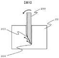
図1は本発明の自動分析装置の構成を示す図である。自動分析装置10は、試薬容器11を複数搭載する試薬ディスク12と、試薬とサンプルを混ぜ合わせて反応を測定する反応ディスク13と、試薬の吸引や吐出を行う試薬用分注機構14と、サンプルの吸引や吐出を行うサンプル分注機構15から構成される。試薬用分注機構14は試薬分注用の試薬用ノズル21を備え、サンプル分注機構15はサンプル分注用のCTSノズル22を備える。装置に投入されたサンプルは、ゴム栓23で閉栓されたサンプル容器(試験管)24に封入された状態で、ラック25に搭載されて搬送される。ラック25には複数のサンプル容器24が搭載される。なお、サンプルは血清や全血などの血液由来のサンプル又は尿などである。 FIG. 1 is a diagram showing the configuration of the automatic analyzer of the present invention. The
サンプル分注機構15は、CTSノズル22を、サンプル容器24からサンプル吸引を行う吸引位置、セル28に吐出を行う吐出位置、および、CTSノズル22の先端を洗浄する洗浄槽20がある洗浄位置へ移動させる。さらに、サンプル分注機構15は、吸引位置、吐出位置、および、洗浄位置ではサンプル容器24、反応セル13、洗浄槽20の高さの夫々合わせて、CTSノズル22を下降させる。サンプル容器24での下降動作では、CTSノズル22をサンプル容器24のゴム栓23に貫通させ、サンプル容器24内にあるサンプルにCTSノズル22先端を入れてサンプル吸引が行われる。前述の通りゴム栓23を取り外すことなく、CTSノズル22でゴム栓23を貫通させて直接分注を行うため、CTSノズル22の先端部は、ゴム栓23を貫くために先鋭である。 The
以上のような動作を行うため、サンプル分注機構15は上下左右にCTSノズル22を移動できる構成となっている。また、CTSノズル22は1つのサンプルを分注したあとで洗浄されて、別のサンプルを同じCTSノズル22で分注する。このようにCTSノズル22は繰り返し分注に使用される。 In order to perform the operation as described above, the
サンプル吸引が行われた後、セル28にサンプルが吐出され、セル28内でサンプルと試薬の混合液を光学的に測定することにより、サンプルに含まれる所定成分の濃度等を算出することができる。自動分析装置の分析の詳細については公知であるためここでの詳細な説明は省略する。 After the sample is aspirated, the sample is discharged into the
図2は一般的なCTSノズルの先端部の断面図(a)と外観図(b)の一例である。一般的なCTSノズル200は、内部が中空の金属製の管でできており、先端部分を斜めにカットすることでカット面201を有し先端が鋭利になっている。CTSノズル200の先端部には、先端カットによって楕円状の開口部202があり、開口部202からサンプルの吸引や吐出を行う。また、CTSノズル200の根元側には配管と接続する部分(図示せず)があり、中空部203は水で充填された配管とつながり、さらに配管にはポンプ(図示せず)がつながる。CTSノズル200の中空部203内の圧力は、ポンプの動作によって変化できるので、CTSノズル200でサンプルの吸引や吐出が行える。 FIG. 2 is an example of a cross-sectional view (a) and an external view (b) of a tip portion of a general CTS nozzle. The
前述の通り、ノズルは繰り返しゴム栓に貫通させ使用するため、CTSノズル200の先端部204は鋭利過ぎると肉厚が薄くなり欠けやすくなる。そのため、先端部204にはある程度の肉厚が必要であり、特に高速に繰り返しゴム栓23に挿入する装置に搭載するCTSノズル200の先端は1回のみ使用する注射針に比べると鋭角になっていない。 As described above, since the nozzle is repeatedly penetrated through the rubber stopper and used, if the
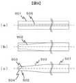
図3は一般的なCTSノズル200をゴム栓23に挿入したときの断面図である。CTSノズル200の先端部204がゴム栓23を切断し、斜めにカットされたカット面201がゴムを押しのけて、ゴム栓23の切断部分を押し広げながらCTSノズル200はゴム内を通過する。カット面201が押しのけたゴムは、ゴムの復元力によってカット面201へゴムの圧力を与えることになる。しかし、CTSノズル200は、カット面201が片側にあるため、ゴムの変形はカット面201側が大きく、ゴムから受ける圧力はCTSノズル200のカット面201側に偏ることになる。そのため、ゴム栓23の切断面とカット面201の間には大きな摩擦力が発生する。さらに、通常CTSノズル200のカット面201は、レーザ加工機などで切断されるが、CTSノズル200の側面に比べると表面が粗く、ゴム栓23との摩擦でゴムの切り屑が発生しやすい。また、前述のような摩擦力のためCTSノズル200はゴムに対して傾いて挿入される傾向にある。 FIG. 3 is a cross-sectional view when a
図4は図3(CTSノズル200)とは別のCTSノズル400の例である。例えば、特許文献1のように円錐状テーパが設けられたノズルである(特許文献1の円錐状テーパ角度16で得られるテーパ)。図は夫々、CTSノズルの先端部の断面図(a)、側面から見た外観図(b)、開口部から見た外観図(c)、斜視図(d)である。 FIG. 4 is an example of a
CTSノズル400は、内部が中空の金属製の管の先端部にテーパ401を設け、さらに先端を斜めに切断することでカット面402を有し先端403が鋭利になっている。先端部にテーパ401を設けることで、ゴムを通過する際の荷重は低減できるが、テーパ長が短いとノズル挿入によってゴムが急激な変化をし、ノズルには強いゴム圧がかかり挿入荷重の増加とゴムの切り屑が発生する。そのため、CTSノズル400のような形状では、テーパ端404を少なくとも先端カット端405よりノズルの根元側の位置としテーパ角度を小さくする必要がある。しかし、テーパ角を小さくしたとき(テーパ長を長くしたとき)、CTSノズル400の先端は、CTS200と同様にゴムはノズルのカット面402側に偏ってあたることで切り屑が発生する。また、CTSノズル400は、先端部全体にテーパ401があるため、先端の肉厚は全体的に薄くなり、繰り返しの使用で欠けやすくなる。 The
図5は本発明のCTSノズル形状の一例である。CTSノズル22は、根元側ストレート部501の外径がφ1.6mmで、先端側ストレート部502(先端から3.5mm)の外径がφ0.8mmで、根元側ストレート部501と先端側ストレート部502との間に中間テーパ部503があり、さらに先端側ストレート部502より先端側に先端側テーパ部504を有し、内部にストレートの中空部505を有する(図5(a))。中空部505は、CTSノズルの長さ方向に延在する。図では、断面図(b)、外観図(c)、(d)を示している。なお、根元側ストレート部501は円筒形であり、先端側ストレート部502はテーパ箇所を除き円筒形である。従い、サンプリングノズルの基本的な形状は円筒形である。ここで、本明細書ではストレート部とは、その断面において外面と断面の向かい合う線同士が略平行な円筒形を意味する。また、ストレートの中空部とは、その断面において中空部と管との向かい合う境界線が略平行な円筒形の空洞であることを意味する。 FIG. 5 is an example of the CTS nozzle shape of the present invention. The
なお、CTSノズル22の根元側には、一般のCTSノズル200と同様に配管に接続され、ポンプの動作によって、サンプルの吸引や吐出が行える。 The root side of the
ゴム栓23にCTSノズル22を挿入するとき、一般のCTSノズル200の例で前述したとおり変形したゴムの復元力がCTSノズル22に圧力として作用する。CTSノズル22を搭載したサンプル分注機構15は、高速(90mm/s〜300mm/s)にゴム栓23にCTSノズル22を挿入するが、テーパ部503の長さが短いとゴムは急激な変形が必要となり、CTSノズルに作用する圧力が増大することで挿入時の荷重は増大する。そのため、テーパ部503の長さはできるだけ長くすることが望ましく、例えば20mm以上とすることが好ましい。 When the
また、本発明のCTSノズル22の先端には、前述の通り先端側テーパ部504があり、先端ストレート部502の先端を、切断面508と先端側テーパ部504の切削面を夫々斜めに削ることで、CTSノズル22の先端部506は鋭利となっている((b)参照)。切断面508は、開口部507を楕円状とする切断面である。切断面508は、中空部が配置された管の端部に備えられ、開口部507を取り囲む平面を有するカット面(第1の面)である。また、先端側テーパ部504は、このカット面の反対側に備えられたテーパ部(第2の面)である。そして、先端部506は、切断面508(第1の面)と先端側テーパ部504(第2の面)の交線で形成されている先端部である。なお、符号508は特に管を切断する面であるため切断面と称しているが切削面と同義であり単に切削面と言う場合もある。 Further, as described above, the tip
また、中空部505はサンプルを吸引するための開口部507を含み、分注精度の悪化を防ぐため、先端部付近で屈曲していない。 The
CTSノズル22の先端部506の角度は、切断面508の切断角度と先端側テーパ部504の角度によって決まり、27.5度付近が望ましい(角度の詳細については後述する)。 The angle of the
CTSノズル22の切断面508は、例えばレーザ加工機などの切断機で切断するが、切削面の淵509には角ができる。切削面に角のある状態でCTSノズル22をゴム栓23に挿入すると切削面の淵509がゴムを削りゴムの切り屑を発生するため、切削面の淵の部分を丸める加工(例えばブラスト研磨など)を行うことが好ましい。 The cutting
また、CTSノズル22の開口部の根元側の淵509が鋭角であると、ゴム栓23に挿入したときに先端部506と同様にゴムに対して刃として作用するため、CTSノズル22の開口部507内に入ってきたゴムをCTSノズルの根元側の淵509で切断し、CTSノズル22の中空部505を詰まらせてしまう。ゴム栓23の切り屑の詰まり防止のためにも、CTSノズル22の切削面の淵を丸める加工を行うことが好ましい。 Further, when the
本発明では、先端側テーパ部504(第2の面)を設けたことが特徴であるため、これについて図6を用いて説明する。 The present invention is characterized in that the front end side taper portion 504 (second surface) is provided, and this will be described with reference to FIG.
図6は本発明のCTSノズル形状の一例の補足図である。CTSノズルを開口部507から見た図(a)と要部斜視図の拡大図である(b)。 FIG. 6 is a supplementary view of an example of the CTS nozzle shape of the present invention. It is the enlarged view of the figure (a) which looked at the CTS nozzle from the
まず本発明に係るCTSノズルの1点目の特徴は、先端側テーパ部504となる切削面の根元側の端部の位置である。図5(a)、(b)、(d)および図6(b)で示すようにこの端部は比較的先端側に位置付けられていることが分かる。この端部を境に先端に向かって肉厚が薄くなるためこの端部は先端に近づけている。肉厚部分が薄くなる部分の長さが短くできるため強度の面でメリットがある。従いこの構成はノズル寿命の長期化に寄与する。少なくともこの端部は切断面508の端部よりも先端側に近づけることが重要であり、構成上の特徴として、先端側テーパ部504(第2の面)のCTSノズルの根元側端部と先端部との距離は、切断面508(第1の面)のCTSノズルの根元側の端部と先端部との距離よりも短い。なお、この距離は傾斜した面上の距離ではなく軸方向の距離を比較することを意味する。 First, the first feature of the CTS nozzle according to the present invention is the position of the end portion on the base side of the cutting surface to be the tip side tapered
次に2点目の特徴は、先端部506を形成する先端側テーパ部504における円筒形の円周方向に対して湾曲した曲面である。図6(a)で示すように先端側テーパ部504が円周方向に対して曲面であることが分かる。肉厚が薄くなっている部分が曲面であるため先端側テーパ部が平面である場合に比べ切断面508側から受ける力を分散し易く先端が欠けにくい構造となっている。また、曲面とすることで表面積を大きくでき曲面側で受ける力を大きくすることができ、切断面508と先端側テーパ部504とにかかる力において適度なバランスを確保することができる。 Next, the second feature is a curved surface curved with respect to the circumferential direction of the cylindrical shape in the distal end side tapered
また、本発明のCTSノズル22は先端側テーパ部504が曲面であるため、CTSノズル22の先端506には幅が広い刃が構成できる。CTSノズル22をゴム栓23に貫通したときは、CTSノズル22が通過した部分のゴムはCTSノズル22の根元径(本実施例では1.6mm)以上の大きさに押し広げることになるが、先端506の幅が広いことでゴム栓23に大きな切り口が開けられ、ゴムを小さい力で押し広げられる。特に本発明のCTSノズル22の形状においては、ストレート部502の外径幅と同じ幅に先端部506の刃となる部分を持つことで、ストレート部502がゴムを通過するときにはわずかな力で挿入でき、その後のテーパ部503がゴムを通過するときにゴムを緩やかに押し広げ、最後に最も外径が太い根元側ストレート部501が通過することになり、ゴムが無理に押し広げられないことで、ゴムの切り屑の発生を減らすことができる。 Further, since the tip
また、3点目の特徴は、先端側テーパ部504がCTSノズルの長さ方向に対して直線的に傾斜していることである。図5(a)、(b)、(d)および図6(b)で示すように長さ方向に対して直線的に傾斜していることが分かる。切断面508も長さ方向に対して直線的に傾斜する面であることから、ゴム圧を均等に分散し易くなりノズルが斜めに挿入することを防ぐことができる。斜めに挿入することが防げることで、ゴムの切り屑を低減でき、ノズルの長寿命化に寄与する。例えば、先端側テーパ部504が直線的に傾斜していないとすると、ゴム圧を受ける面の角度が、ノズルがゴムに挿入される深さによって変わり安定しないので、ノズルが僅かに斜めに挿入される傾向がある。特に本発明のノズルと同タイプの吸引口が真下にある構造では先端部がノズルの肉厚部近傍に偏って配置されているため先端部がノズル中心付近に配置されている特許文献2や3のノズルと比較し、ゴムに挿入された直後のゴム圧の分散バランスの不安定さがノズル挿入の垂直性に大きな影響を与える。従い、先端側テーパ部504は円周方向に対しては曲面でありつつも長さ方向に対しては直線的に傾斜していることが重要である。 The third feature is that the tip
これらの3点の特徴を備えることにより、CTSノズルの強度の他、ゴム栓に挿抜したときに発生するゴムの切り屑を低減し、かつノズル寿命を延ばすことができる。 By providing these three features, in addition to the strength of the CTS nozzle, it is possible to reduce rubber chips generated when inserted into and removed from the rubber plug and to extend the life of the nozzle.
また、上記3点が本発明に係るCTSノズルの特徴であるが、好ましくは以下の構成をとすることが望ましい。 The above three points are the characteristics of the CTS nozzle according to the present invention. Preferably, the following configuration is used.
まず、切断面508の傾斜角が先端側テーパ部504の傾斜角よりも大きいことである。これについては図8で詳細を述べる。 First, the inclination angle of the
また、ストレート部502の側面から先端部506までの距離510と、中空部505の端から先端部506までの距離511を定義したとき、刃となる先端部506の位置は、距離510が距離511より大きくなるように選択することが望ましい。言い換えると、開口部507側から見たときに、先端部506は、ノズルの肉厚範囲内に位置付けられ、先端部は肉厚範囲内の外側よりも開口部507側に近い位置に位置付けられている。これについても後述する。 Further, when a
また、先端テーパ部504と切断面508の面積との差で力分散のバランスを確保することが望ましい。これについても後述する。 In addition, it is desirable to ensure a balance of force dispersion by the difference between the tip tapered
また、図5で示したように、根元側ストレート部と、根元側ストレート部よりも外径の小さい先端側ストレート部と、根元側ストレート部と先端側ストレート部との間に配置されたテーパ部とを備え、先端部は先端側ストレート部の先端に配置されていることが望ましい。 In addition, as shown in FIG. 5, the root-side straight portion, the tip-side straight portion having a smaller outer diameter than the root-side straight portion, and the taper portion disposed between the root-side straight portion and the tip-side straight portion It is desirable that the tip portion be disposed at the tip of the tip-side straight portion.
また、根元側ストレート部、先端側ストレート部、テーパ部、先端部は互いに溶接されることなく同一の部材であることが望ましい。 Further, it is desirable that the root side straight portion, the tip side straight portion, the taper portion, and the tip portion are the same member without being welded to each other.
図7は本発明のCTSノズルをゴム栓23に挿入したときの断面図である。本発明のCTSノズル22をゴム栓23に挿入すると、先端部506がゴムを切断し、CTSノズル22の通過によってゴムは先端側テーパ部504とノズル先端の切断面508の2面でそれぞれの方向にゴムを押しのけて、切断部分を押し広げながらCTSノズル22は通過する。CTSノズル22がゴム栓23を通過するとき、ゴムの復元力によって先端側テーパ部504とノズル先端の切断面508はゴムから圧力を受けるが、CTSノズル22の先端が複数方向にゴムを押しのけるため、ゴムからの圧力は分散する。また、図示する左右2方向のみならず、先端側テーパ部の曲面により図右側の矢印は紙面の手前や奥方向に対してもゴムを押しのけることができる。そのため、切断面508とゴム栓23との間の摩擦力は、一般的なCTSノズル200に比べ低くなり、CTSノズルの切削面とゴムの摩擦によって発生していたゴムの切り屑の発生を低減できる。 FIG. 7 is a cross-sectional view when the CTS nozzle of the present invention is inserted into the
さらに、CTSノズル22の先端に2面の切削面(504と508)を設けることで、ゴム栓23に挿入したときにゴムから受ける圧力が偏り難いため、ノズルが斜めに挿入されることを防ぎゴム栓23に垂直に挿入できる。特に、真に先端部での構造的なバランスが確保できるためノズルが斜めに挿入されることを防ぐことができる。また、ゴムから受ける圧力が分散することで、CTSノズル22の切断面508は、ゴムとの摩擦が低減され、切断面508の磨耗が抑えられる。 Furthermore, by providing two cutting surfaces (504 and 508) at the tip of the
また、前述したように、先端側テーパ部504は図8の断面図において直線的な形状であることも重要である。切断面508が直線的な形状であり裏面の先端側テーパ部504も直線であることで、ノズル先端の挿入時に安定してゴム圧を均等に分散しやすくなりノズルが斜めに挿入することを防ぐことができる。 Further, as described above, it is also important that the tip
ここで、切断面508の形状について説明する。切断面508(第1のテーパ部)は開口部507を取り囲む平面である。この開口部507は管に対して斜めに切断されて形成された箇所であるため楕円形状である。仮に先端側テーパ部504が無ければ切断面508の外周は均等な肉厚を斜めに切削されているため楕円形状であるが、先端側テーパ部504が形成されているため切断面508は開口部507の長径方向において僅かに削られている。すなわち切断面508の平面は開口部507の長径方向において先端部側の方が根元側よりも短くなっている。ここでの長短は切断面508の平面上の長さを比較しているが、図6(a)の向きにおいても符号510の箇所が削られており符号511の箇所が残されていることからこの長短関係を把握することができる。また、図5(c)において根元側の肉厚の切断面508が幅広になっていることからもこの関係を把握することができる。 Here, the shape of the
また、前述のようなゴム圧の分散効果を好適に得るため、先端側テーパ部504の面積とノズル先端の切断面508の刃として機能している部分の面積(図6においてノズル中心からノズル先端506の部分、以降ノズル先端の切断面512と呼ぶ)が同等程度であることが好ましい。ゴム栓23に挿入直後のゴム圧のバランスを適切に確保することがノズルの斜め挿入を効果的に防ぐことができるためである。例えば、これらの面積の差を0.1mm2以内に抑えることが望ましい。Further, in order to suitably obtain the rubber pressure dispersion effect as described above, the area of the tip
言い換えると、開口部507の楕円形状の短径を境として略同心楕円形状の切断面508は根元側と先端部側とに2分割することができ、この先端部側に分割された面積と、先端側テーパ部504の面積との差を0.1mm2以内に抑えることが望ましい。なお、切断面508の根元側の面積によりゴム圧のバランスの偏りが生じることになるがある程度の深さまでノズルが挿入されていることによりノズルの斜め挿入への影響は無視することができる。また、先に述べたように、先端側テーパ部504(第2の面)が円周方向に曲面であるため、CTSノズル22の先端506には幅が広い湾曲した刃が構成でき、ゴムを小さい力で押し広げることができるため、ノズルの斜め挿入への影響を無視できる程度に抑えることができる。In other words, the substantially concentric
図8は本発明のCTSノズル22における切削部の角度の定義を示す図である。本発明のCTSノズル22は前述の通り、ノズル先端506の部分に先端側テーパ部504とノズル先端の切断面508があり、CTSノズル22の断面図において切断部508の直線とCTSノズル22の中心線の間の角度(傾斜角)を角度A(801)と定義し、先端側テーパ部504の直線とCTSノズル22の中心線の間の角度(傾斜角)を角度B(802)と定義し、CTSノズル22の先端角度を角度C(803)と定義する。角度C(803)は、角度A(801)と角度B(802)を足し合わせた角度である。また、CTSノズル22の先端から切断面508の端までの長さをLa(804)、CTSノズル22の先端から先端側テーパ部504(第2の面)の端までの長さをLb(805)と定義する。 FIG. 8 is a view showing the definition of the angle of the cutting portion in the
CTSノズル22の先端部506は、前述の通りゴムを押しのけて、切断面504への圧力を低減し切り屑の発生を低減する効果があるが、切り屑の発生には切断面504との摩擦以外にも影響する因子がある。例えば、CTSノズル22の詰まりの原因となる開口部の根元側の淵509の部分が鋭角であるためにゴムを削ることで切り屑が発生する場合や、CTSノズル22の先端部506が鈍角であるために切断性能が低くなり、CTSノズル22の先端部506がゴムを押しつぶしながら切断し切り口を荒らして切り屑を発生する場合がある。つまり、切り屑の発生には、角度A(801)や角度C(803)も関係する。 The
表1に角度A(801)と角度B(802)の組み合わせを変えて作ったCTSノズル22を使い、ゴム栓23に挿抜を行ったときの切り屑の発生率を示す。 Table 1 shows the generation rate of chips when the

一定速度(150mm/s)で直動できる機構に表1記載の各条件のCTSノズル22を固定して、CTSノズル22の進行方向にはゴム栓23の付いた状態のサンプル容器24を固定して、CTSノズル22を一定速度でゴム栓23に挿抜し、CTSノズル22に付着した切り屑の有無を確認した。表1から、CTSノズル22の先端角度C(803)が27.0度と28.5度の条件においてゴムの切り屑の付着はなかった。表1の結果から角度A(801)が15.0度、角度B(802)が12.5度、角度C(803)は27.5度(角度A(801)が15.0度、角度B(802)が12.5度)のCTSノズル22を作り、ゴム栓23に挿抜を行い切り屑の付着を確認したところ、表1の条件5および条件6と同じく切り屑の付着はなかった。 A
以上の結果から、切り屑の低減に対して、先端角度C(803)を25.5度より大きく30.0度未満の範囲の角度とすることが望ましいことが分かる。さらに望ましい範囲は26.0度以上29.5度以下の範囲であることが望ましい。さらに望ましい範囲は26.5度以上29.0以下の範囲であり、さらに望ましい範囲は27.0度以上28.5度以下の範囲である。 From the above results, it can be seen that it is desirable to set the tip angle C (803) to an angle in the range of more than 25.5 degrees and less than 30.0 degrees for chip reduction. A more desirable range is 26.0 degrees or more and 29.5 degrees or less. A more desirable range is a range from 26.5 degrees to 29.0 degrees, and a further desirable range is a range from 27.0 degrees to 28.5 degrees.
次に、表面積について確認した。角度A(801)を9.0〜18.0度の範囲で変更したときノズル先端の切断面512の表面積は0.39〜0.97mm2(角度が小さく方が表面積は大きくなる)となり、角度B(802)を12.0〜15.0度の範囲で変更したとき先端側テーパ部504の表面積は0.36〜0.44mm2(角度が小さく方が表面積は小さくなる)となる。前述の通り、ゴム圧の分散効果を好適に得るため、ノズル先端の切断面512と先端側テーパ部504の表面積は同程度であることが好ましいが、先端角度C(803)は鋭角である方がゴムの切断性能が高まることから、表1の結果から先端角度C803は30.0度未満の範囲が望ましい。本発明の構成によれば、ノズル先端の切断面512と先端側テーパ部504の角度の調整で先端角度C803を調整可能である。Next, the surface area was confirmed. When the angle A (801) is changed in the range of 9.0 to 18.0 degrees, the surface area of the cutting surface 512 at the nozzle tip is 0.39 to 0.97 mm2 (the smaller the angle, the larger the surface area). When the angle B (802) is changed in the range of 12.0 to 15.0 degrees, the surface area of the tip
角度A(801)を15度とするとノズル先端の切断面512の表面積は0.44mm2で、角度B(802)を12.5度とすると0.38mm2で、両面の表面積は同等で先端の角度Cは27.5度と29.5度以下となる。また両面積の差は0.06mm2である。この差は限りなく同等であることが望ましいが、0.1mm2以下であればこの差は許容できる。これは角度C(803)を変更せずともCTSノズルの肉厚に依存する値であるため肉厚の厚さを決めるのに有効な指標となる。 When the angle A (801) is 15 degrees, the surface area of the cutting surface 512 at the nozzle tip is 0.44 mm.2If the angle B (802) is 12.5 degrees, then 0.38 mm2Thus, the surface areas of both surfaces are the same, and the angle C of the tip is 27.5 degrees and 29.5 degrees or less. The difference between the two areas is 0.06mm2It is. It is desirable that this difference is infinitely equal, but 0.1 mm2This difference is acceptable if: Since this is a value that depends on the thickness of the CTS nozzle without changing the angle C (803), it is an effective index for determining the thickness of the thickness.
さらに、CTSノズル22をゴムに挿入したときには、先端側テーパ部504とノズル先端の切断面512のそれぞれの表面積と角度によってゴムの分散化効果が決まる。そのため、角度A(801)と角度B(802)が近い角度で、かつ切断面512と先端側テーパ部504の表面積が近い値となることが好ましい。以上のような条件を満たすには、先端側テーパ部504の位置は、ノズルの開口部507の根元側の端よりも先端側にあり、Lb(805)はLa(804)よりも小さい値となる。なお、先端側テーパ部504は先端に位置付けられるものであり、先端側テーパ部504の根元側の端部は開口部507の楕円中心(開口部の楕円とノズルの中心軸との交点)よりも先端側に位置付けられることが望ましい。 Further, when the
また、先端側テーパ部504の表面積を確保するために、ストレート部502の側面から先端部506までの距離510と、中空部505の端から先端部506までの距離511は、距離510が距離511より大きくなるように選択することが望ましい(図6(a)参照)。さらに、ノズル先端506は、前述の通り肉厚が薄いと繰り返し使用により磨耗が進行するため、Lb(805)の長さを短くし肉厚を確保することが好ましい。以上により、本発明のCTSノズル22では、Lb(805)がLa(804)よりも短く、角度A(801)を15.0度、角度B(802)を12.0度以上15.0度未満の範囲とすることが望ましい。従い先述のように角度A(801)は角度B(802)よりも大きいことが望ましい。 Further, in order to secure the surface area of the tip
また、前記の3つの特徴点を備えたCTSノズルは例えば90mm/s以上の高速でゴム栓23に挿入される分注動作に対して特に効果があり、さらには図8で説明したような具体的な構造を備えていることが望ましい。低速の場合にはゴムとノズルとの摩擦力が小さいためゴム屑の課題が生じ難いためである。なお、望ましくは100mm/s以上で用いられる場合や150mm/s以上で用いられる場合等、速ければ速い程、摩擦力の影響が大きくなるためこれらの速度以上で用いられることでより効果が得られる。 In addition, the CTS nozzle having the above three characteristic points is particularly effective for the dispensing operation inserted into the
また、CTSノズル22においては、図5で示したようにCTSノズル22の先端部に先端側テーパ部504(および切断面512)、ストレート部502、テーパ部503、ストレート部501を有することが望ましい。これにより、ゴムを鋭角である先端506で切断し、その後先端側テーパ部504と切断面512がゴムを分散し、テーパ部503がゴムを緩やかに押し広げる。CTSノズル22をサンプル分注機構15に搭載することで、ゴム栓23の挿抜時に発生するゴムの切り屑を少なくし、さらにCTSノズル22の先端磨耗を抑えることで交換期間を長くすることができる。 Further, the
また、試料の微量分注ではセル28に先端を接触させた状態で試料を吐出する場合がある。先端側テーパ部504で切削されていることにより切削面508側から見た切削面508先端は比較的緩やかな曲線となっている(図5(c)の先端参照)。先端の曲線が緩やかであれば先端接触時に相対的に広い範囲でセル底と接触できるため本発明のCTSノズルは先端を接触させた状態で試料を吐出する場合に適している。広い範囲でセル底と接触できると吐出する液玉のセル底との接触面積を大きくすることができ、試料である液玉のノズル先端への持ち帰りを適切に防ぎ、セル底への微量分注を行い易くすることができる。従い、自動分析装置の構成としてサンプル分注機構を備え、このサンプル分注機構は、CTSノズル内の試料をセルに吐出する際にセルの底に先端部を接触させた状態で試料を吐出することが望ましい。 In addition, when dispensing a small amount of sample, the sample may be discharged while the tip is in contact with the
次にCTSノズルの製造方法について説明する。 Next, a method for manufacturing a CTS nozzle will be described.
図9は本発明のCTSノズル形状を製作する方法の一例である。本発明のCTSノズル22は、一般的なCTSノズル200と同様に金属製の管を加工して製作し、例えばステンレス鋼材の中空管(内径φ0.4mm)を用いる。ストレートの中空部505を有するストレート管901(図9(a))は単一の部品であり、ストレート管901を旋盤などの切削機械を用いて切削加工902を行うことで、先端側テーパ部504と、先端ストレート部502と、根元テーパ部503と、根元ストレート部501に形成される(図9(b)、(c))。なお、この加工は管を軸中心に回転させながら切削加工するためどの向きから見てもこの形状である。この先端側テーパ部504について、この加工によりテーパ角や面形状が決まる。つまり2点目と3点目の特徴点を考慮した加工が必要となる。この先端側テーパ部となる先端の形状は円筒形の円周方向に対して湾曲し長さ方向に対して直線的に傾斜する面である。なお、この時点では回転させながら切削加工しているため要部曲面は円錐形の一部の曲面を有している。 FIG. 9 is an example of a method for producing the CTS nozzle shape of the present invention. The
次に、図9(c)の形状に対し、さらに、切断機(例えばレーザ加工機)で切断加工903を行うことで図5(a)に示した本発明のCTSノズル22を製作することができる。ここでは1点目の特徴を考慮した加工が必要となる。つまり、この切断加工903では、先端側テーパ部504より根元側を切削端部とし、他方の切削端部は先端側テーパ部の傾斜面の途中に設ける。切削加工902と切断加工903の加工角度によってノズル先端506の位置(510と511)やノズル先端506の刃角を決定できる。以上のような工程においては、CTSノズル22の形状を製造する上で加工が単純であるためばらつきが少なく、さらに低コストで製造が可能である。なお、根元ストレート部501を別部材として溶接することも可能であるがこのように単一部材から切り出して製造することが望ましい。 Next, the
図9の製造工程の要点を言い換えると以下のとおりである。まず、長さ方向に延在する中空部を有する管を準備する。次に、管の軸に軸対照な曲面であって、管の先端に円筒形の円周方向に切削する。これにより、円周方向に湾曲し、かつ長さ方向に対して直線的に傾斜する曲面が形成される。なお、軸対照な曲面とは円錐形の底面近くの曲面の一部であり、この切削は中空部を屈曲させない状態で行われる。次に、この曲面上の点と、この曲面が配置された箇所よりも管の根元側(CTSノズルとなったときの根元側)の点とを通過する平面、つまり切断線903で直線的に加工し、中空部を取り囲む面、かつ、(平面と)この曲面との交線で前記サンプリングノズルの先端部を形成する。すなわち、先端部は、管の先端をテ―パ加工した形状に対して、斜め方向に加工して一部を取り除いた残りの部分から構成されている。 In other words, the main points of the manufacturing process of FIG. 9 are as follows. First, a tube having a hollow portion extending in the length direction is prepared. Next, it is a curved surface having an axis contrast with the axis of the tube, and is cut in the circumferential direction of the cylindrical shape at the tip of the tube. As a result, a curved surface that is curved in the circumferential direction and linearly inclined with respect to the length direction is formed. The axially contrasting curved surface is a part of the curved surface near the bottom of the conical shape, and this cutting is performed without bending the hollow portion. Next, a plane passing through the point on the curved surface and a point on the tube root side (the root side when the CTS nozzle is formed) with respect to the position where the curved surface is disposed, that is, linearly at a
また望ましくは、曲面を切削する工程は、根元側ストレート部501よりも外径の小さい先端側ストレート部502と、これらの間の根元側テーパ部503とを形成する工程を含み、この曲面を切削する工程は、先端側ストレート部502の先端を切削する工程を含む。また望ましくは、前述のように切断面の淵の部分を丸める加工(例えばブラスト研磨など)を行うことが好ましいため、中空部を取り囲む面と中空部で挟まれた管の鋭角部を丸める工程を含む。 Desirably, the step of cutting the curved surface includes a step of forming a tip-side
なお、本発明のCTSノズルにおいては、前述の特徴点以外にも望ましい形状を有するが先端部を形成するための曲面と平面の加工位置や加工角度を調節することで当業者であれば容易に製造方法も特定できる。例えば、先端部の位置が肉厚範囲内の外側よりも開口部側に近い位置に位置付ける場合には、前述の切削面508を形成するための加工面に含まれる曲面上の点の位置を調節すればよい。また、先端部の角度を26.0度以上29.5度以下とするためには夫々の面のテーパ角を調整すればよい。 The CTS nozzle of the present invention has a desirable shape in addition to the above-described feature points, but those skilled in the art can easily adjust the processing position and processing angle of the curved and flat surfaces for forming the tip. The manufacturing method can also be specified. For example, when the position of the tip portion is positioned closer to the opening side than the outside in the thickness range, the position of the point on the curved surface included in the processing surface for forming the above-described
また、先端部においては他の面で切削して複雑な先端形状とするのではなく曲面と平面の2面で形成されることがコストの面から望ましい。 In addition, it is desirable from the viewpoint of cost that the tip portion is formed by two surfaces, a curved surface and a flat surface, instead of cutting the other surface into a complicated tip shape.
実施例で示したCTSノズル22の諸寸法は一例であり、テーパ部の長さ、および材質は、ノズル先端の2面の切削面によるゴムの切り屑の低減効果や磨耗抑制効果には影響せず、本発明の実施形態を拘束するものではない。 The dimensions of the
10 自動分析装置
11 試薬容器
12 試薬ディスク
13 反応ディスク
14 試薬分注機構
15 サンプル分注機構
21 試薬用ノズル
22 CTSノズル
23 ゴム栓
24 サンプル容器
25 サンプルラック
28 セル
200 一般的なCTSノズル
201 カット面
202 開口部
203 中空部
204 先端部
401 テーパ
402 カット面
403 ノズル先端
404 テーパ端
405 カット端
501 根元側ストレート部
502 先端側ストレート部
503 根元側テーパ部
504 先端側テーパ部
505 中空部
506 ノズル先端(刃)
507 ノズル開口部
508 ノズル先端の切断面
509 ノズル開口部の淵
510 ノズル側面から刃までの距離
511 ノズル開口部端から刃までの距離
512 ノズル中心線から刃までの切断面面積
801 角度A
802 角度B
803 角度C
804 長さLa
805 長さLb
901 中空管
902 旋盤加工線
903 切断線DESCRIPTION OF
507
802 Angle B
803 Angle C
804 length La
805 Length Lb
901
Claims (12)
Translated fromJapaneseサンプルを吸引するための開口部を含み、前記サンプリングノズルの長さ方向に延在する中空部と、
前記中空部が配置された管の端部に備えられ、前記開口部を取り囲む平面を有する第1の面と、
前記第1の面の反対方向に備えられた第2の面と、
前記第1の面と前記第2の面の交線で形成された前記サンプリングノズルの先端部と、を備え、
前記中空部は前記先端部付近で屈曲せずに前記開口部を含み、
前記第2の面は、前記円筒形の円周方向に湾曲し、前記長さ方向に対して直線的に傾斜する、前記円筒形の中心軸を軸とする円錐形の一部からなる曲面を有し、
前記第2の面の前記サンプリングノズルの根元側の端部と前記先端部の距離は、前記第1の面の前記サンプリングノズルの根元側の端部と前記先端部の距離よりも短いことを特徴とするサンプリングノズル。In a cylindrical sampling nozzle that sucks a sample inside through a rubber sampling container,
A hollow portion including an opening for sucking a sample and extending in a length direction of the sampling nozzle;
A first surface provided at an end of a tube in which the hollow portion is disposed and having a plane surrounding the opening;
A second surface provided in a direction opposite to the first surface;
A tip end portion of the sampling nozzle formed by a line of intersection of the first surface and the second surface;
The hollow portion includes the opening without being bent near the tip,
The second surface is a curved surface that is curved in the circumferential direction of the cylindrical shape and that is linearly inclined with respect to the length direction and that is a part of a conical shape with the central axis of the cylindrical shape as an axis. Have
The distance between the end portion on the base side of the sampling nozzle on the second surface and the tip portion is shorter than the distance between the end portion on the root side of the sampling nozzle on the first surface and the tip portion. Sampling nozzle.
前記第1の面の傾斜角は、前記第2の面の傾斜角よりも大きいことを特徴とするサンプリングノズル。The sampling nozzle according to claim 1, wherein
The sampling nozzle characterized in that an inclination angle of the first surface is larger than an inclination angle of the second surface.
前記開口部側から見たときに、前記先端部は、前記サンプリングノズルの肉厚範囲内に位置付けられ、前記先端部は前記肉厚範囲内の外側よりも前記開口部側に近い位置に位置付けられていることを特徴とするサンプリングノズル。The sampling nozzle according to claim 1, wherein
When viewed from the opening side, the tip is positioned within the thickness range of the sampling nozzle, and the tip is positioned closer to the opening than the outside of the thickness range. A sampling nozzle characterized by
前記第1のテーパ部の前記開口部は楕円形状であり、前記楕円形状の長径方向において前記平面は前記先端部側の方が前記根元側の方よりも短いことを特徴とするサンプリングノズル。The sampling nozzle according to claim 1, wherein
The sampling nozzle according to claim 1, wherein the opening of the first taper portion has an elliptical shape, and the flat surface in the major axis direction of the elliptical shape is shorter on the tip end side than on the root side.
前記惰円形状の短径を境として前記根元側と前記先端部側とに2分割された前記平面のうち、前記先端側部側に分割された面積と、前記第2の面との面積との差が0.1mm2以下であることを特徴とするサンプリングノズル。The sampling nozzle according to claim 4.
Of the plane divided into two at the root side and the tip side with the ellipse-shaped minor axis as a boundary, the area divided into the tip side and the area of the second surface A sampling nozzle characterized by a difference of 0.1 mm2 or less.
前記先端部の角度は、26.0度以上29.5度以下の範囲であることを特徴とするサンプリングノズル。The sampling nozzle according to claim 1, wherein
The sampling nozzle, wherein an angle of the tip is in a range of 26.0 degrees or more and 29.5 degrees or less.
第1のストレート部と、前記第1のストレート部よりも外径の小さい第2のストレート部と、前記第1のストレート部と前記第2のストレート部との間に配置されたテーパ部とを備え、前記先端部は前記第2のストレート部の先端に配置されていることを特徴とするサンプリングノズル。The sampling nozzle according to claim 1, wherein
A first straight portion; a second straight portion having an outer diameter smaller than that of the first straight portion; and a tapered portion disposed between the first straight portion and the second straight portion. A sampling nozzle, wherein the tip is disposed at a tip of the second straight portion.
前記第1のストレート部、前記第2のストレート部、前記テーパ部、前記先端部は互いに溶接されることなく同一の部材であることを特徴するサンプリングノズル。The sampling nozzle according to claim 7,
The sampling nozzle, wherein the first straight portion, the second straight portion, the taper portion, and the tip portion are the same member without being welded to each other.
(a)長さ方向に延在する中空部を有する管を準備する工程と、
(b)前記管の軸に軸対照な曲面であって、前記中空部を屈曲させることなく、前記管の先端に前記円筒形の円周方向に湾曲し、前記長さ方向に対して直線的に傾斜する、前記円筒形の中心軸を軸とする円錐形の一部からなる曲面を形成する工程と、
(c)前記曲面上の点と、前記曲面が配置された箇所よりも前記管の根元側の点とを通過する平面で直線的に加工し、前記中空部を取り囲む面、かつ、前記曲面との交線で前記サンプリングノズルの先端部を形成する工程と、
を有することを特徴とするサンプリングノズルの製造方法。In a method of manufacturing a cylindrical sampling nozzle that passes through a sampling container with rubber and sucks an internal sample,
(A) preparing a tube having a hollow portion extending in the length direction;
(B) A curved surface that is axially contrasted to the axis of the tube, and is curved in the circumferential direction of the cylindrical shape at the tip of the tube without bending the hollow portion, and is linear with respect to the length direction. Forming a curved surface comprising a part of a conical shape with the central axis of the cylindrical shape as an axis,
(C) a surface that is linearly processed on a plane that passes through a point on the curved surface and a point closer to the root side of the tube than the place where the curved surface is disposed, and a surface that surrounds the hollow portion; and the curved surface; Forming the tip of the sampling nozzle at the intersection of
A method for manufacturing a sampling nozzle, comprising:
前記(b)工程は、第1のストレート部よりも外径の小さい第2のストレート部と、前記第1のストレート部と前記第2のストレート部との間のテーパ部と、を形成する工程を含み、前記(b)工程における曲面を切削する工程は、前記第2のストレート部の先端を切削する工程であることを特徴とするサンプリングノズルの製造方法。In the manufacturing method of the sampling nozzle according to claim 10,
The step (b) is a step of forming a second straight portion having an outer diameter smaller than that of the first straight portion, and a tapered portion between the first straight portion and the second straight portion. And the step of cutting the curved surface in the step (b) is a step of cutting the tip of the second straight part.
さらに以下の(d)工程を有することを特徴とするサンプリングノズルの製造方法。
(d)前記中空部を取り囲む面と前記中空部で挟まれた前記管の鋭角部を丸める工程。In the manufacturing method of the sampling nozzle according to claim 10,
Furthermore, the manufacturing method of the sampling nozzle characterized by having the following (d) processes.
(D) A step of rounding an acute angle portion of the tube sandwiched between the surface surrounding the hollow portion and the hollow portion.
Applications Claiming Priority (3)
| Application Number | Priority Date | Filing Date | Title |
|---|---|---|---|
| JP2014255707 | 2014-12-18 | ||
| JP2014255707 | 2014-12-18 | ||
| PCT/JP2015/084227WO2016098622A1 (en) | 2014-12-18 | 2015-12-07 | Sampling nozzle, automated analyzer using same, and sampling nozzle manufacturing method |
Publications (2)
| Publication Number | Publication Date |
|---|---|
| JPWO2016098622A1 JPWO2016098622A1 (en) | 2017-11-16 |
| JP6337147B2true JP6337147B2 (en) | 2018-06-06 |
Family
ID=56126515
Family Applications (1)
| Application Number | Title | Priority Date | Filing Date |
|---|---|---|---|
| JP2016564788AActiveJP6337147B2 (en) | 2014-12-18 | 2015-12-07 | Sampling nozzle, automatic analyzer using the same, and method of manufacturing sampling nozzle |
Country Status (5)
| Country | Link |
|---|---|
| US (1) | US10539584B2 (en) |
| EP (1) | EP3236269B1 (en) |
| JP (1) | JP6337147B2 (en) |
| CN (1) | CN107003330B (en) |
| WO (1) | WO2016098622A1 (en) |
Families Citing this family (6)
| Publication number | Priority date | Publication date | Assignee | Title |
|---|---|---|---|---|
| CN118253359A (en)* | 2018-01-24 | 2024-06-28 | 思纳福(苏州)生命科技有限公司 | Liquid discharge gun head, micro-droplet generation device and generation method |
| US11666900B2 (en) | 2018-01-24 | 2023-06-06 | Sniper (Suzhou) Life Technology Co. | Motion controlling mechanism, liquid discharging nozzle, microdroplet generating device and method, liquid driving mechanism and method, microdroplet generating method, and surface processing method of liquid discharging nozzle |
| WO2019144905A1 (en) | 2018-01-24 | 2019-08-01 | 北京光阱管理咨询合伙企业(有限合伙) | Microdroplet container, method for preparing microdroplet container, microdroplet spreading method, microdroplet formation kit, temperature control device, oil phase composition for microdroplet formation and treatment method therefor |
| JP2022076499A (en)* | 2020-11-05 | 2022-05-20 | 京都電子工業株式会社 | Liquid suction device and liquid suction method |
| DE102021122999A1 (en)* | 2021-09-06 | 2023-03-09 | Dionex Softron Gmbh | Needle for use in analytical applications |
| EP4497558A4 (en)* | 2022-03-22 | 2025-08-13 | Fujifilm Corp | DRILLING TOOL |
Family Cites Families (9)
| Publication number | Priority date | Publication date | Assignee | Title |
|---|---|---|---|---|
| US5354537A (en)* | 1992-04-27 | 1994-10-11 | Akzo N.V. | Piercing and sampling probe |
| CA2130129A1 (en) | 1993-09-10 | 1995-03-11 | Martin Walter Ellenberger | Closure having an array of piercable places |
| US5733266A (en)* | 1996-07-26 | 1998-03-31 | Gravlee, Jr.; Joseph F. | Hypodermic needle |
| JP2003166911A (en) | 2001-12-04 | 2003-06-13 | Sysmex Corp | Piercer and smearing specimen preparing apparatus |
| JP5015874B2 (en) | 2008-07-22 | 2012-08-29 | 日立アロカメディカル株式会社 | Nozzle unit |
| JP2011167230A (en)* | 2010-02-16 | 2011-09-01 | Terumo Corp | Mixing implement |
| JP3180120U (en) | 2012-09-21 | 2012-12-06 | 株式会社島津製作所 | Cap piercing needle |
| ES2734977T3 (en) | 2012-09-24 | 2019-12-13 | Siemens Healthcare Diagnostics Products Gmbh | Hollow needle for a sample pipette |
| NL2009896C2 (en) | 2012-11-28 | 2014-06-02 | Ingeny Pcr B V | Pipette tip, pipette provided with such a tip, a set comprising such a pipette tip and at least one enclosure containing a sample, and a method of using such a pipette. |
- 2015
- 2015-12-07JPJP2016564788Apatent/JP6337147B2/enactiveActive
- 2015-12-07WOPCT/JP2015/084227patent/WO2016098622A1/enactiveApplication Filing
- 2015-12-07USUS15/534,628patent/US10539584B2/enactiveActive
- 2015-12-07CNCN201580066429.3Apatent/CN107003330B/enactiveActive
- 2015-12-07EPEP15869827.4Apatent/EP3236269B1/enactiveActive
Also Published As
| Publication number | Publication date |
|---|---|
| WO2016098622A1 (en) | 2016-06-23 |
| EP3236269B1 (en) | 2024-02-07 |
| CN107003330B (en) | 2018-08-28 |
| EP3236269A4 (en) | 2018-08-08 |
| CN107003330A (en) | 2017-08-01 |
| JPWO2016098622A1 (en) | 2017-11-16 |
| US10539584B2 (en) | 2020-01-21 |
| US20170370957A1 (en) | 2017-12-28 |
| EP3236269A1 (en) | 2017-10-25 |
Similar Documents
| Publication | Publication Date | Title |
|---|---|---|
| JP6337147B2 (en) | Sampling nozzle, automatic analyzer using the same, and method of manufacturing sampling nozzle | |
| JP6681899B2 (en) | Automatic analyzer | |
| US9329195B2 (en) | Container cleaning device, discharge member for container cleaning device, and analyzer | |
| CN102316989A (en) | Be used to provide the method and apparatus of blood constitutent | |
| JP3180120U (en) | Cap piercing needle | |
| JP2012068108A (en) | Cell analyzer | |
| JP2008232829A (en) | Nozzle tip for dispensing | |
| JP5878138B2 (en) | Sample analyzer | |
| JPWO2011093347A1 (en) | Automatic analyzer | |
| JP5542184B2 (en) | Liquid handling plunger for biological samples in tubes | |
| WO2017056839A1 (en) | Pipette tip and liquid injection method | |
| US8021495B2 (en) | Pipette cleaning device and cleaning method | |
| CN113804910A (en) | Micro sample loading method, device, sample analyzer and readable storage medium | |
| JP2018004388A (en) | Automatic analyzer | |
| JP4955330B2 (en) | Nozzle tip for dispensing equipment | |
| JP2002022756A (en) | Liquid suction pipe and its manufacturing method | |
| JP7278199B2 (en) | automatic analyzer | |
| WO2016080509A1 (en) | Container for specimen dilution | |
| CN120155110B (en) | In-needle mixing method and system based on ultrasound | |
| US20250012828A1 (en) | Perforating tool | |
| JP2002001136A (en) | nozzle | |
| JP5955478B2 (en) | Body fluid collector | |
| JPS6370169A (en) | Cleaning of probe | |
| JP2015222211A (en) | Dispensing device, and film incision method | |
| WO1994004272A1 (en) | Fluid testing device |
Legal Events
| Date | Code | Title | Description |
|---|---|---|---|
| AA64 | Notification of invalidation of claim of internal priority (with term) | Free format text:JAPANESE INTERMEDIATE CODE: A241764 Effective date:20170808 | |
| A521 | Request for written amendment filed | Free format text:JAPANESE INTERMEDIATE CODE: A523 Effective date:20170831 | |
| TRDD | Decision of grant or rejection written | ||
| A01 | Written decision to grant a patent or to grant a registration (utility model) | Free format text:JAPANESE INTERMEDIATE CODE: A01 Effective date:20180410 | |
| A61 | First payment of annual fees (during grant procedure) | Free format text:JAPANESE INTERMEDIATE CODE: A61 Effective date:20180507 | |
| R150 | Certificate of patent or registration of utility model | Ref document number:6337147 Country of ref document:JP Free format text:JAPANESE INTERMEDIATE CODE: R150 | |
| S531 | Written request for registration of change of domicile | Free format text:JAPANESE INTERMEDIATE CODE: R313531 | |
| S533 | Written request for registration of change of name | Free format text:JAPANESE INTERMEDIATE CODE: R313533 | |
| R350 | Written notification of registration of transfer | Free format text:JAPANESE INTERMEDIATE CODE: R350 |