JP6337129B2 - Method for cleaning nozzle device in spray-drying equipment, and spray-drying equipment for implementing the method - Google Patents
Method for cleaning nozzle device in spray-drying equipment, and spray-drying equipment for implementing the methodDownload PDFInfo
- Publication number
- JP6337129B2 JP6337129B2JP2016548414AJP2016548414AJP6337129B2JP 6337129 B2JP6337129 B2JP 6337129B2JP 2016548414 AJP2016548414 AJP 2016548414AJP 2016548414 AJP2016548414 AJP 2016548414AJP 6337129 B2JP6337129 B2JP 6337129B2
- Authority
- JP
- Japan
- Prior art keywords
- feed
- nozzle
- nozzle device
- pressure
- spray
- Prior art date
- Legal status (The legal status is an assumption and is not a legal conclusion. Google has not performed a legal analysis and makes no representation as to the accuracy of the status listed.)
- Active
Links
Images


Classifications
- F—MECHANICAL ENGINEERING; LIGHTING; HEATING; WEAPONS; BLASTING
- F26—DRYING
- F26B—DRYING SOLID MATERIALS OR OBJECTS BY REMOVING LIQUID THEREFROM
- F26B3/00—Drying solid materials or objects by processes involving the application of heat
- F26B3/02—Drying solid materials or objects by processes involving the application of heat by convection, i.e. heat being conveyed from a heat source to the materials or objects to be dried by a gas or vapour, e.g. air
- F26B3/10—Drying solid materials or objects by processes involving the application of heat by convection, i.e. heat being conveyed from a heat source to the materials or objects to be dried by a gas or vapour, e.g. air the gas or vapour carrying the materials or objects to be dried with it
- F26B3/12—Drying solid materials or objects by processes involving the application of heat by convection, i.e. heat being conveyed from a heat source to the materials or objects to be dried by a gas or vapour, e.g. air the gas or vapour carrying the materials or objects to be dried with it in the form of a spray, i.e. sprayed or dispersed emulsions or suspensions
- B—PERFORMING OPERATIONS; TRANSPORTING
- B01—PHYSICAL OR CHEMICAL PROCESSES OR APPARATUS IN GENERAL
- B01D—SEPARATION
- B01D1/00—Evaporating
- B01D1/16—Evaporating by spraying
- B01D1/18—Evaporating by spraying to obtain dry solids
- B—PERFORMING OPERATIONS; TRANSPORTING
- B05—SPRAYING OR ATOMISING IN GENERAL; APPLYING FLUENT MATERIALS TO SURFACES, IN GENERAL
- B05B—SPRAYING APPARATUS; ATOMISING APPARATUS; NOZZLES
- B05B15/00—Details of spraying plant or spraying apparatus not otherwise provided for; Accessories
- B05B15/50—Arrangements for cleaning; Arrangements for preventing deposits, drying-out or blockage; Arrangements for detecting improper discharge caused by the presence of foreign matter
- B05B15/52—Arrangements for cleaning; Arrangements for preventing deposits, drying-out or blockage; Arrangements for detecting improper discharge caused by the presence of foreign matter for removal of clogging particles
- B—PERFORMING OPERATIONS; TRANSPORTING
- B05—SPRAYING OR ATOMISING IN GENERAL; APPLYING FLUENT MATERIALS TO SURFACES, IN GENERAL
- B05B—SPRAYING APPARATUS; ATOMISING APPARATUS; NOZZLES
- B05B15/00—Details of spraying plant or spraying apparatus not otherwise provided for; Accessories
- B05B15/50—Arrangements for cleaning; Arrangements for preventing deposits, drying-out or blockage; Arrangements for detecting improper discharge caused by the presence of foreign matter
- B05B15/55—Arrangements for cleaning; Arrangements for preventing deposits, drying-out or blockage; Arrangements for detecting improper discharge caused by the presence of foreign matter using cleaning fluids
- B05B15/555—Arrangements for cleaning; Arrangements for preventing deposits, drying-out or blockage; Arrangements for detecting improper discharge caused by the presence of foreign matter using cleaning fluids discharged by cleaning nozzles
- B—PERFORMING OPERATIONS; TRANSPORTING
- B08—CLEANING
- B08B—CLEANING IN GENERAL; PREVENTION OF FOULING IN GENERAL
- B08B9/00—Cleaning hollow articles by methods or apparatus specially adapted thereto
- B08B9/02—Cleaning pipes or tubes or systems of pipes or tubes
- B08B9/027—Cleaning the internal surfaces; Removal of blockages
Landscapes
- Engineering & Computer Science (AREA)
- Mechanical Engineering (AREA)
- Life Sciences & Earth Sciences (AREA)
- Microbiology (AREA)
- General Engineering & Computer Science (AREA)
- Chemical & Material Sciences (AREA)
- Chemical Kinetics & Catalysis (AREA)
- Drying Of Solid Materials (AREA)
- Cleaning In General (AREA)
- Nozzles (AREA)
- Details Or Accessories Of Spraying Plant Or Apparatus (AREA)
- Cleaning By Liquid Or Steam (AREA)
Description
Translated fromJapanese本発明は、噴霧乾燥機器のノズル装置を操作中に清浄化する方法であって、乾燥チャンバを備えた噴霧乾燥機器を用意し、乾燥チャンバ内に挿入されてフィード物入口とフィード物出口とを有する少なくとも1つの圧力ノズル装置を用意し、各ノズル装置のフィード物入口へ液状フィード物を、液状フィード物を霧化するための所定の圧力で供給するためのフィード物導管を用意し、少なくとも1つのノズル装置を清浄化するシステムを用意し、操作中に清浄化されるべきノズル装置に対するフィード物供給を停止し、少なくとも1つのノズル装置を乾燥チャンバから取り外すとともに、ノズル装置を清浄化システム内で清浄化する工程を含む、噴霧乾燥機器のノズル装置を操作中に清浄化する方法に関する。本発明はさらに噴霧乾燥機器に関する。 The present invention is a method for cleaning a nozzle device of a spray drying apparatus during operation, and a spray drying apparatus having a drying chamber is prepared and inserted into the drying chamber so that a feed object inlet and a feed object outlet are provided. Providing at least one pressure nozzle device having a feed conduit for supplying a liquid feed to a feed inlet of each nozzle device at a predetermined pressure for atomizing the liquid feed; Providing a system for cleaning one nozzle device, stopping the feed supply to the nozzle device to be cleaned during operation, removing at least one nozzle device from the drying chamber and removing the nozzle device in the cleaning system; The present invention relates to a method for cleaning during operation of a nozzle device of a spray-drying device, including a step of cleaning. The invention further relates to a spray drying device.
このような噴霧乾燥機器において、霧化された液状フィード物と乾燥空気又はガスとを接触させることにより、液体生成物を粉末生成物に変化させる。乾燥は乾燥チャンバ内で行われる。乾燥チャンバ内で、乾燥空気は霧化されたフィード物と接触させられる。霧化は、1つ又は2つ以上のノズル、又は他の形態のアトマイザ、例えば回転アトマイザによって行われる。乾燥空気は、乾燥チャンバの頂部に、又はその近くに位置決めされた空気分散器を介して乾燥チャンバに入る。このような乾燥システム内にはさらなる乾燥手段、例えば流動床が設けられていてもよい。同じ液状フィード物、又は複数の異なる液状フィード物を乾燥させるために、同一の噴霧乾燥機器を利用することができる。 In such spray drying equipment, the liquid product is changed to a powder product by bringing the atomized liquid feed into contact with dry air or gas. Drying takes place in a drying chamber. Within the drying chamber, dry air is contacted with the atomized feed. Atomization is performed by one or more nozzles, or other forms of atomizer, such as a rotary atomizer. Dry air enters the drying chamber via an air disperser positioned at or near the top of the drying chamber. Additional drying means such as a fluidized bed may be provided in such a drying system. The same spray drying equipment can be utilized to dry the same liquid feed or a plurality of different liquid feeds.
噴霧乾燥機器の部分は定期的なインターバルで、例えば所定の清浄化スケジュールに従って清浄化する必要がある。定期的な清浄化は政府規制、及び/又は製造仕様書によって定められた要件を満たすために必要である。このような清浄化は生成物の劣化、汚染、及び構成部分内の堆積物の形成を回避するのに適したインターバルで行われる。清浄化をいわゆる現場清浄化(Cleaning-In-Place: CIP)システムによって行うことにより、清浄化に必要な時間をできる限り短くし、構成部分の分解をできる限り少なくする。清浄化流体は水、又は場合によっては水と適宜な洗剤又は清浄化剤とが交互に使用される。いくつかの目的では、さらなる滅菌プロセスとの組み合わせでCIPが用いられることがある。CIP後には、システムの乾燥が行われる。 The parts of the spray drying equipment need to be cleaned at regular intervals, for example according to a predetermined cleaning schedule. Periodic cleaning is necessary to meet the requirements set by government regulations and / or manufacturing specifications. Such cleaning is performed at intervals suitable to avoid product degradation, contamination, and formation of deposits within the component. By carrying out the cleaning by means of a so-called Cleaning-In-Place (CIP) system, the time required for cleaning is as short as possible and the decomposition of the components is minimized. As the cleaning fluid, water or, in some cases, water and an appropriate detergent or cleaning agent are alternately used. For some purposes, CIP may be used in combination with further sterilization processes. After CIP, the system is dried.
乾燥チャンバのような構成部分、及び噴霧乾燥プラントの部分を形成する他のユニット、例えばサイクロン、バグフィルタ、流動床チャンバ、プロセスチャンバ、コンテナ、タンク、ダクト、又は任意の類似の容器が、チャンバ又は容器自体内に清浄化流体を分配する清浄化ノズルによって清浄化される。液体の霧化のためにノズルを利用する噴霧乾燥機器内で、清浄化のために乾燥チャンバからノズルを取り外し、乾燥チャンバの頂部のCIPスタンドに置くことにより、ノズル、ノズルランス、及び上流側のフィード管を清浄化する。噴霧乾燥機器全体の清浄化は通常、休止時に行われるが、しかし機器の部分は操作中にもCIPで清浄化される。 Components such as drying chambers, and other units that form part of a spray drying plant, such as cyclones, bag filters, fluidized bed chambers, process chambers, containers, tanks, ducts, or any similar vessel, It is cleaned by a cleaning nozzle that distributes the cleaning fluid within the container itself. Within a spray drying device that utilizes a nozzle for liquid atomization, the nozzle, nozzle lance, and upstream side are removed by removing the nozzle from the drying chamber for cleaning and placing it on a CIP stand at the top of the drying chamber. Clean the feed tube. Cleaning of the entire spray-drying equipment is usually done at rest, but parts of the equipment are also cleaned with CIP during operation.
アトマイザノズルは主に2つのカテゴリ、すなわち圧力ノズル及び二流体ノズルを含む。上記タイプの組み合わせを含む他のタイプのノズルも数多く存在する。圧力ノズルの場合、液状フィード物は高い圧力で供給されるのに対して、二流体ノズル霧化は、液状フィード物に衝突する高速圧縮空気/ガスによって空気圧式に達成される。二流体ノズルは、流動特性が剪断とともに速度の急上昇をもたらすような生成物に適している。このような生成物は通常、圧力ノズル内の霧化は適しておらず、二流体ノズル内でうまく取り扱われる。二流体ノズル内では、極めて低い剪断応力を加えることによって霧化が達成される。二流体ノズル内の霧化のための運動エネルギーは圧縮空気によって供給され、従って二流体ノズルの適用は圧縮空気の生成コストにより限定される。 Atomizer nozzles mainly include two categories: pressure nozzles and two-fluid nozzles. There are many other types of nozzles including combinations of the above types. In the case of a pressure nozzle, the liquid feed is supplied at a high pressure, whereas the two-fluid nozzle atomization is accomplished pneumatically with high-speed compressed air / gas impinging on the liquid feed. Two-fluid nozzles are suitable for products whose flow characteristics result in a rapid increase in speed with shear. Such products are usually not suitable for atomization in pressure nozzles and are handled well in two-fluid nozzles. Within a two-fluid nozzle, atomization is achieved by applying very low shear stress. The kinetic energy for atomization in the two-fluid nozzle is supplied by compressed air, so the application of the two-fluid nozzle is limited by the cost of generating the compressed air.
ここで圧力ノズルについて述べるならば、清浄化中に、例えば清浄化スケジュールの1工程として、場合によってはそれぞれのノズルランスに取り付けられた、典型的には例えば4〜12本のノズルから成る群を成すノズルを乾燥チャンバから取り外し、乾燥チャンバの頂部のCIPスタンドに置く。ノズル群、すなわち操作中のノズル総数のうちのサブセットを取り外す前に、ノズルへの液状フィード物の供給を、例えばフィード物のための供給弁を切り換えることによってストップさせ、ノズル、ノズルランス、及び上流側のフィード物供給管をパージ空気又はガスでフラッシュすることにより、これらからフィード物を排出する。清浄化処置に続いて、ノズルを乾燥チャンバ内に再挿入し、フィード物の供給を再開する。典型的にはこれら全ては制御システムによって制御する。次いでこのルーティンをノズルの別のサブセットに対して行う。ノズル群のこのような切り換えプロセスにかかる時間は、噴霧乾燥機器のサイズ、タイプ、及び関与するフィード物に応じて、典型的には最大30分である。ノズル群の清浄化は例えば典型的には、関連の蒸発器及び/又は他のフィード物処理設備の上流側の清浄化によって決定し、これに関連づけることができる。 When referring to pressure nozzles here, a group consisting of, for example, 4 to 12 nozzles, typically attached to each nozzle lance, possibly as a step in the cleaning schedule, for example, as a step in the cleaning schedule. The resulting nozzle is removed from the drying chamber and placed on the CIP stand at the top of the drying chamber. Before removing the nozzle group, i.e. a subset of the total number of nozzles in operation, the supply of liquid feed to the nozzle is stopped, for example by switching the supply valve for the feed, and the nozzle, nozzle lance and upstream The feed is discharged from these by flushing the feed feed pipes on the side with purge air or gas. Following the cleaning procedure, the nozzle is reinserted into the drying chamber and the feed is resumed. All of these are typically controlled by a control system. This routine is then performed on another subset of nozzles. The time required for such a nozzle group switching process is typically up to 30 minutes, depending on the size and type of spray drying equipment and the feed involved. Nozzle group cleaning, for example, can typically be determined and associated with cleaning upstream of the associated evaporator and / or other feed processing equipment.
このような切り換え処置及び清浄化処置は申し分なく機能するものの、時間の経過とともに、噴霧乾燥機器の部分、具体的には乾燥チャンバ内部の側壁及び上壁における堆積物の形成及び蓄積が不可避であることが判っている。このようなものとして堆積物は数多くの視点から、具体的には清浄化、生成物品質、容量、及び過熱に関して不都合である。 Although such switching and cleaning procedures work satisfactorily, over time, it is inevitable that deposits form and accumulate on parts of the spray drying equipment, specifically the side walls and top walls inside the drying chamber. I know that. As such, deposits are disadvantageous from a number of perspectives, particularly with regard to cleaning, product quality, capacity, and overheating.
従って、一例が出願人の国際公開第93/23129号パンフレット(商業製品はJET SWEEP(登録商標)という名称で取引されている)に示されている、堆積物の形成を低減しようという試み、また例えば操作中に赤外線カメラによって噴霧乾燥機をモニタリングする出願人の国際公開第2011/063808号パンフレットに示されているような、堆積物を検出する操作を調査しようという試みが為されている。 Thus, an attempt to reduce the formation of deposits, an example being given in the applicant's WO 93/23129 (commercial product is traded under the name JET SWEEP®), and Attempts have been made to investigate an operation to detect deposits, as shown, for example, in Applicant's International Publication No. 2011/063808, which monitors spray dryers with an infrared camera during operation.
とはいえ、上記刊行物はいくつかの利点をもたらしはするものの、堆積物の回避又は低減の問題はなおも極めて重要である。 Nonetheless, while the publications provide several advantages, the problem of deposit avoidance or reduction is still extremely important.
また弁が組み込まれた圧力ノズルが知られているが、しかし上述の目的にとって一連の欠点を有している。これら欠点により、このようなノズルは食品又は医薬品の噴霧乾燥プロセスにおける多くの目的のために選択されなくなる。上記欠点は例えば、機能及び密閉性に関する信頼性、CIP可能性、及び摩耗部分から摩耗片が生成物内へ放出される危険である。 Pressure nozzles incorporating valves are also known, but have a series of drawbacks for the purposes described above. These drawbacks make such nozzles unselected for many purposes in food or pharmaceutical spray drying processes. The above disadvantages are, for example, reliability with respect to function and sealing, CIP possibilities, and the risk of wear pieces being released from the wear part into the product.
このような背景において、本発明の目的は、堆積物形成のリスクが軽減される、冒頭で述べた種類の方法を提供することである。 In this context, the object of the present invention is to provide a method of the kind mentioned at the outset, in which the risk of deposit formation is reduced.
第1の態様において、この目的及びさらなる目的は、噴霧乾燥機器のノズル装置を操作中に清浄化する方法であって、
乾燥チャンバを備えた噴霧乾燥機器を用意し、
乾燥チャンバ内に挿入されてフィード物入口とフィード物出口とを有する少なくとも1つの圧力ノズル装置を用意し、
各ノズル装置のフィード物入口へ液状フィード物を、液状フィード物を霧化するための所定の圧力で供給するためのフィード物導管を用意し、
少なくとも1つのノズル装置を清浄化するシステムを用意し、
操作中に清浄化されるべきノズル装置に対するフィード物供給を停止し、
操作中にノズル装置を乾燥チャンバから取り外し、
ノズル装置を清浄化システム内で清浄化する
工程を含み、
フィード物供給が停止された後、ノズル装置が乾燥チャンバから取り外される前に、ノズル装置が、
i) 所定のフィード物供給圧力と概ね同じ圧力で液体をノズル装置のフィード物入口へ供給すること、
ii) 少なくとも16barの圧力で加圧空気又はガスをノズル装置のフィード物入口へ供給すること、
iii) ノズル装置のフィード物入口から吸引力を加えること、及び
iv) ノズル装置のフィード物出口と同軸的に付加的な加圧空気流又はガス流を加えること
から選択された方法工程によってフィード物を排出される、噴霧乾燥機器のノズル装置を操作中に清浄化する方法によって満たされる。In a first aspect, this and further objects are a method of cleaning a nozzle device of a spray drying device during operation comprising:
Prepare spray drying equipment with drying chamber,
Providing at least one pressure nozzle device inserted into the drying chamber and having a feed inlet and a feed outlet;
Preparing a feed conduit for supplying a liquid feed to the feed inlet of each nozzle device at a predetermined pressure for atomizing the liquid feed;
A system for cleaning at least one nozzle device;
Stop the feed supply to the nozzle device to be cleaned during operation,
During operation, the nozzle device is removed from the drying chamber,
Cleaning the nozzle device in a cleaning system;
After the feed supply is stopped, before the nozzle device is removed from the drying chamber, the nozzle device
i) supplying liquid to the feed inlet of the nozzle device at approximately the same pressure as the predetermined feed supply pressure;
ii) supplying pressurized air or gas to the feed inlet of the nozzle device at a pressure of at least 16 bar;
iii) applying a suction force from the feed inlet of the nozzle device, and iv) applying a feed flow by a method step selected coaxially with the feed outlet of the nozzle device and applying an additional flow of pressurized air or gas. The nozzle device of the spray-drying equipment is discharged by a method of cleaning during operation.
フィード物を排出するこのような方法工程を提供することにより、フィード物供給を停止した後にノズル装置及び上流側の設備に残っているフィード物も同様に確実に霧化される。理論に縛られたくはないが、本発明の根底にある原理は、ノズルのフィード物の供給停止後に乾燥チャンバに入るフィード物が噴霧乾燥チャンバの内面に形成される1つの堆積物源となるという認識に基づいている。従来の方法では、このような切り換え中に発生する霧化は不十分である。本発明による方法を用いれば乾燥チャンバに入るフィード物の全てが適切に霧化されるので、壁にフィード物が堆積するリスクは排除されるか、又は少なくとも大幅に軽減される。 By providing such a process step for discharging the feed product, the feed product remaining in the nozzle device and the upstream equipment after the feed product supply has been stopped is likewise reliably atomized. While not wishing to be bound by theory, the underlying principle of the present invention is that the feed entering the drying chamber after the nozzle feed is stopped is a source of deposit that forms on the inner surface of the spray drying chamber. Based on recognition. In the conventional method, the atomization that occurs during such switching is insufficient. With the method according to the invention, all of the feed entering the drying chamber is properly atomized so that the risk of depositing on the wall is eliminated or at least greatly reduced.
方法において、「ノズル装置」という用語はノズル自体と、ノズルランスと、個々のノズルに対応する閉鎖弁の下流側にある任意の管とを含むものとして定義される。 In the method, the term “nozzle device” is defined to include the nozzle itself, the nozzle lance, and any tube downstream of the shut-off valve corresponding to the individual nozzle.
「加圧空気又はガス」という用語は、目的に適するとともに、規制などと適合する任意のガスを含むように意図される。 The term “pressurized air or gas” is intended to include any gas that is suitable for the purpose and compatible with regulations and the like.
清浄化方法はプラントのいくつかの部分に関与する清浄化処置全体における1工程としてノズル装置を清浄化するために利用することができるが、乾燥チャンバ内の他のノズル装置の操作を妨害することなしにノズル装置を乾燥チャンバ内に再挿入するさらなる工程を含むことが特に有利である。さらに、ノズル装置の別のサブセットに対するフィード物供給が、清浄化のための排出及び取り外しのために停止されるのと概ね同時に、清浄化されるとともに乾燥チャンバ内へ再挿入されたノズル装置について、フィード物供給が停止解除される、プロセス全体の付加的な効率が得られる。 Although the cleaning method can be used to clean the nozzle device as a step in the overall cleaning procedure involving some parts of the plant, it interferes with the operation of other nozzle devices in the drying chamber. It is particularly advantageous to include the further step of re-inserting the nozzle device into the drying chamber without it. Furthermore, for a nozzle device that has been cleaned and reinserted into the drying chamber at approximately the same time that the feed supply to another subset of nozzle devices is stopped for discharge and removal for cleaning, Additional efficiency of the entire process is obtained, where the feed supply is released.
本発明の方法の選択肢i)の場合、方法工程i)が第1の所定の時間にわたって適用され、続いて、フィード物中の溶媒の量に相当する量で液体を第2の所定の時間にわたって供給するさらなる工程が実施されると有利である。この手段は、乾燥チャンバ内の乾燥条件ができるかぎり一定に維持されることを保証する。それというのも、第1の時間においてフィード物が排出されたあと、乾燥チャンバ内の乾燥空気と溶媒/液体とのバランスが第2の時間において妨げられずに維持されるからである。
If option i) of the process of the present invention, a method step i) is applied for a first predetermined time, followed by for a predetermined time the liquid in the second in an amount corresponding to theamount of solvent in the feed material It is advantageous if a further step of feeding is carried out. This measure ensures that the drying conditions in the drying chamber are kept as constant as possible. This is because after the feed is discharged at the first time, the balance of dry air and solvent / liquid in the drying chamber is maintained unimpeded at the second time.
工程i)の液体は水であることが好ましく、所定のフィード物供給圧力、及び工程i)の圧力は100〜250barであることが好ましい。 The liquid in step i) is preferably water, and the predetermined feed supply pressure and the pressure in step i) are preferably from 100 to 250 bar.
選択肢ii)の場合、方法工程ii)が少なくとも30bar、好ましくは50bar(5MPa)超で行われる。限界値16barで、供給停止後に、ノズル装置内に残ったフィード物が充分に霧化される。有利な下限値30barで、ノズル出口で「スパッタリング(sputtering)」がほとんど生じることなしにフィード物が排出される。 In the case of option ii), process step ii) is carried out at at least 30 bar, preferably above 50 bar (5 MPa). At a limit value of 16 bar, the feed material remaining in the nozzle device after the supply stop is sufficiently atomized. With an advantageous lower limit of 30 bar, the feed is discharged with little “sputtering” occurring at the nozzle outlet.
選択肢iii)の場合、方法工程iii)は、少なくとも2.5kPa、より好ましくは少なくとも5kPa、及び最も好ましくは少なくとも10kPaの、乾燥チャンバ内の圧力に対する負圧で実施される。このような負圧を確立する手段は当業者によく知られている。 For option iii), method step iii) is performed at a negative pressure relative to the pressure in the drying chamber of at least 2.5 kPa, more preferably at least 5 kPa, and most preferably at least 10 kPa. Means for establishing such negative pressure are well known to those skilled in the art.
選択肢iv)の場合、方法工程iv)は少なくとも0.5barの圧力で行われる。実際の圧力はフィード速度に応じて選択される。排出中にフィード物を霧化するために必要となる圧力は例えば、1又は3又は5bar、或いは8又は12barであってよい。なお、フィード物出口と同軸的に付加的な加圧空気/ガス流を提供することはフィード物排出段階中にのみ行われる一方、これと同時に適度の圧力が、ノズルにフィード物を導くためにノズル装置に加えられる。このような圧力は、霧化に関して上述した圧力と同じであってよいが、しかしフィード物特性に応じて異なっていてもよい。もちろん、同じ空気/ガス源を両方の目的に使用し得ると構成上好都合となる。この付加流のための供給システムは、本明細書中に提示された他の実施形態の教示内容に従ってよい。 In the case of option iv), process step iv) is performed at a pressure of at least 0.5 bar. The actual pressure is selected according to the feed rate. The pressure required to atomize the feed during discharge can be, for example, 1 or 3 or 5 bar, or 8 or 12 bar. It should be noted that providing additional pressurized air / gas flow coaxially with the feed outlet is only done during the feed discharge stage, while at the same time moderate pressure is required to direct the feed to the nozzle. Added to the nozzle device. Such pressure may be the same as described above for atomization, but may vary depending on the feed characteristics. Of course, it would be advantageous in construction if the same air / gas source could be used for both purposes. The supply system for this additional stream may be in accordance with the teachings of other embodiments presented herein.
大型プラントにおいて特に有利な実施形態では、方法は、複数の群を成す複数のノズル装置を用意する工程を含み、前記群が相次いで順次に清浄化される。 In a particularly advantageous embodiment in a large plant, the method comprises providing a plurality of nozzle devices in a plurality of groups, the groups being cleaned one after another in sequence.
別の態様では、噴霧乾燥機器であって、乾燥チャンバと、空気分散器と、少なくとも1つの圧力ノズル装置と、フィードシステムと、フィード物排出システムと、清浄化システムとを含み、フィード物排出システムが、少なくとも1つのノズル装置内で霧化を維持しながらフィード物を排出する手段を含むことを特徴とする、噴霧乾燥機器が提供される。このようにして、ノズル装置内に残ったフィード物が完全に霧化される。 In another aspect, a spray drying apparatus comprising a drying chamber, an air disperser, at least one pressure nozzle device, a feed system, a feed discharge system, and a cleaning system, the feed discharge system. Includes a means for discharging the feed while maintaining atomization within the at least one nozzle device. In this way, the feed remaining in the nozzle device is completely atomized.
目下のところ好ましい実施形態では、フィード物排出システムは、ポンプと、加圧空気/ガス源と、導管とを含み、噴霧乾燥機器は少なくとも1つの弁を含み、弁は、フィードシステムからフィード物排出システムへの切り換えを可能にする。このシステムはフィード物から排出媒体、すなわちここでは加圧空気、又は任意の適宜なガスへの、良好に機能する信頼性の高い切り換えをノズル装置に対して行うのを可能にする。 In a presently preferred embodiment, the feed discharge system includes a pump, a pressurized air / gas source, and a conduit, the spray drying device includes at least one valve, and the valve discharges the feed from the feed system. Allows switching to the system. This system makes it possible for the nozzle device to perform a well-functioning and reliable switching from the feed to the discharge medium, here pressurized air, or any suitable gas.
上記実施形態の好ましい発展形では、フィードシステムが、液状フィード物を少なくとも1つのノズル装置へ送出する高圧ポンプを含み、噴霧乾燥機器がさらに、フィード物又は加圧空気/ガスの通過を可能にする弁を含み、フィード物排出システムが一方向弁と、ドレン弁と、逆止弁と、加圧空気/ガスへの切り換えを可能にするためのさらなる弁とを含む。 In a preferred development of the above embodiment, the feed system includes a high-pressure pump that delivers the liquid feed to at least one nozzle device, and the spray drying device further allows the feed or pressurized air / gas to pass through. A feed discharge system including a one-way valve, a drain valve, a check valve, and a further valve to allow switching to pressurized air / gas.
本発明による方法によって清浄化されるべき噴霧乾燥機器内のノズル装置は、原則的には単一のノズル装置を含むことができる。しかしながら通常は、乾燥チャンバ内には少なくとも2つのノズル装置が存在する。本発明は、ノズル装置が複数の群を成す複数のノズル装置として提供される実施形態において特に有利である。 The nozzle device in the spray-drying equipment to be cleaned by the method according to the invention can in principle comprise a single nozzle device. Usually, however, there are at least two nozzle devices in the drying chamber. The present invention is particularly advantageous in embodiments where the nozzle device is provided as a plurality of nozzle devices in a plurality of groups.
この好ましい実施形態のさらなる発展形では、清浄化システムは、一度に1つのノズル装置群を収容するように構成されている。 In a further development of this preferred embodiment, the cleaning system is configured to accommodate one group of nozzle devices at a time.
その他の従属請求項から、下記の好ましい実施形態、及び方法を実施するための例の詳細な説明から、さらなる詳細及び利点が明らかになる。 Further details and advantages will emerge from the other dependent claims from the following detailed description of preferred embodiments and examples for carrying out the method.
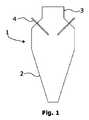
図1には、全体的に符号1で表された噴霧乾燥機器の一実施形態が示されている。それ自体周知のように、噴霧乾燥機器1は乾燥チャンバ2と、乾燥チャンバ2の頂部に設けられた空気分散器3とを含んでいる。全体的に符号4で表されたノズル装置の形態を成すアトマイザ手段が、乾燥チャンバの鉛直又は高さ方向に対して所定の角度を成して延びるように、乾燥チャンバ2の上側区分に挿入されている。ノズル装置4は、乾燥チャンバ2の上側区分の周囲に均一に分配された4本のノズル装置4として概略的に示されている。個々のノズル装置4の構成については下でさらに詳述する。 FIG. 1 shows an embodiment of a spray-drying device, generally designated 1. As is known per se, the spray-drying
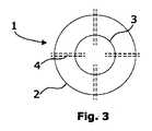
これに相応して、図2及び図4の実施形態は4本のノズル装置4を含むが、しかしこれらノズル装置は空気分散器3の頂部に位置決めされている。一般に、ノズル装置の位置及び角度は任意であり、申し分のない乾燥が行われるように選択される。種々の実施形態の説明全体を通して、同じ又は類似の機能を有するエレメントには、同一の符号を付ける。 Correspondingly, the embodiment of FIGS. 2 and 4 includes four
図5の実施形態では、ノズル装置4が乾燥チャンバ2内に概ね水平方向に延びるように位置決めされている。 In the embodiment of FIG. 5, the
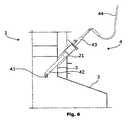
さらなる実施形態における噴霧乾燥機器1の上側区分の一部を示す図6及び図7を次に参照すると、ノズル装置4は空気分散器3の鉛直方向壁区分を通して乾燥チャンバ2内に挿入され、この場合には空気分散器3にそれぞれのソケット片21を当該角度で結合することにより、鉛直面に対して所定の角度を成して延びている。適宜のシール・ロック手段が設けられていてよい(詳細には図示せず)。図7に示されているように、この実施形態の場合、噴霧乾燥機器には16本のノズル装置4が設けられている。 With reference now to FIGS. 6 and 7, which show a part of the upper section of the spray-drying
各ノズル装置4は、ノズルランス42の一方の端部に位置決めされた圧力ノズル41を含んでいる。ノズルランス42の反対側の端部では、ノズル装置4は、液状フィード物の供給のためのフィードシステム(この実施形態を示す図6及び図7には示されていない)に結合されたフィード物入口43を備えている。フィードシステムは図示の実施態様では供給管44であり、この供給管は弁を介して上流側のパイプ状フィードシステムに結合されている。ノズル41は、乾燥チャンバ2の内部に向いた端部にフィード物出口(図示せず)を有している。この文脈において、「ノズル装置」という用語は、ノズル自体と、ノズルランスと、個々のノズルに対応する閉鎖弁の下流側にある任意の管とを含むものとして定義される。これらエレメントはさらに下で詳述するようにフィード物を排出され、清浄化される。 Each
このようなノズル41の構成はよく知られており、例えばGEA Process Engineering A/Sによって提供されるような商業的に入手可能な圧力ノズルである。ノズルランス42のようなさらなる構成部分、及びブラケット、取り付け装置、シール部材、パイプなどのような付属部品も標準的な設備である。 The construction of such a
図8及び図9のさらに別の実施形態では、8本のノズル装置4が空気分散器3の頂部に配置されており、ノズルランス42はフィード物入口43から、乾燥チャンバ2内に位置するノズル41のフィード物出口へ概ね鉛直方向に延びている。図9に示されているように、フィード物供給管44は、噴霧乾燥機器の全体的に符号5で表されたフィードシステムに結合されている。 In still another embodiment of FIGS. 8 and 9, eight
上記実施形態の噴霧乾燥機器はそれぞれ4本、16本、及び8本のノズル装置4を有する状態で示されている。ノズル装置は原則的にはいかなる構成で配置されていてもよく、典型的には例えば4〜12本のノズル装置から成る群を成して配置されている。ノズル装置群は、清浄化するために相次いで乾燥チャンバから取り外すことができる。 The spray-drying apparatus of the above embodiment is shown with four, sixteen, and eight
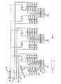
図10は、本発明のさらに別の実施形態における噴霧乾燥機器のフィードシステム5の構成の詳細を示すフローダイヤグラムである。ここでは、ノズル装置は3つの群104,204,304を成して配列されている。それぞれの群は9本のノズル装置4を含んでいる。ノズル装置4の1つの群についてのみ詳細に説明する。さらに、全体的に符号7で表された清浄化システムが図10に示されている。 FIG. 10 is a flow diagram showing details of the configuration of the feed system 5 of the spray drying apparatus in still another embodiment of the present invention. Here, the nozzle devices are arranged in three
フィードシステム5は、液状フィード物を図示していない供給部から送出する高圧ポンプ50を含んでいる。ポンプ50は、主フィード物導管51を通して、さらに分枝フィード物導管52を通して、群104のうちの4本のノズル装置4から成る部分群へ、つまり図10で見て左側の部分群へ液状フィード物を送出し、主フィード物導管52からの残りのフィード物を、群104のうちの5本のノズル装置4から成る他方の部分群へ、つまり図10で見て右側の部分群へ供給する。弁53がノズル装置4の近くでフィード物の供給をオフ・オンにするのを可能にする。供給管44の上流側の端部にはさらなる弁45が設けられており、これによりフィード物又は排出媒体が導管46を通過することができる。排出媒体は図10に示された実施形態では、下でさらに詳述するように加圧空気、又は任意の適宜なガスである。 The feed system 5 includes a high-
フィード物の排出中に霧化を維持するために、フィード物排出システム6が設けられている。フィード物排出システムは、ポンプ60と、加圧空気源61と、分枝導管62と、一方向弁63と、ドレン弁64と、逆止弁65とを含んでいる。さらなる弁66により、導管46へ入る流体を、フィード物から加圧空気、又はこの目的に適した任意の他のガスへ切り換えることができる。 A feed discharge system 6 is provided to maintain atomization during discharge of the feed. The feed discharge system includes a pump 60, a
上記実施形態のいずれかの噴霧乾燥機器の操作中に、霧化されるべき液状フィード物がフィードシステム5から、フィード物供給管44を介してノズル装置4へ供給される。フィード物はフィード物入口43から、ノズルランス42、及びノズル41のフィード物出口を介して乾燥チャンバ2に入る。 During the operation of the spray drying apparatus of any of the above embodiments, the liquid feed material to be atomized is supplied from the feed system 5 to the
操作中の清浄化プログラムにおける清浄化工程として、又は1つのフィード物ラインから別のフィード物ラインへフィード物を切り換えることができるように、個々のノズル装置4、又はノズル装置4の群104,204,304を清浄化システム内で清浄化するときには、下記処置が開始される。
先ず、清浄化されるべきノズル装置に対してフィード物供給を停止する。清浄化は通常、噴霧乾燥機器を含むプラントの操作中に行われる。個々のノズル、又は1つのノズル装置群全体を取り外す一方で、乾燥チャンバ内に存在する残りのノズル装置を通して霧化を行うことにより噴霧乾燥機器の操作を続行する。ノズル装置は、噴霧乾燥機器の清浄化システム内で清浄化する。 First, the feed supply to the nozzle device to be cleaned is stopped. Cleaning is usually done during operation of the plant including spray drying equipment. While removing individual nozzles, or an entire group of nozzle devices, the operation of the spray drying equipment is continued by atomizing through the remaining nozzle devices present in the drying chamber. The nozzle device is cleaned in the cleaning system of the spray drying equipment.
フィード物供給が停止された後、少なくとも1つのノズル装置が乾燥チャンバから取り外される前に、ノズル装置が下記選択肢、すなわち:
i) 所定のフィード物供給圧力と概ね同じ圧力で液体をノズル装置のフィード物入口へ供給すること、
ii) 少なくとも16barの圧力で加圧空気又はガスをノズル装置のフィード物入口へ供給すること、
iii) ノズル装置のフィード物入口から吸引力を加えること、及び
iv) ノズル装置のフィード物出口と同軸的に付加的な加圧空気流又はガス流を加えること
のうちの1つから選択された方法工程によってフィード物を排出される。After the feed supply is stopped, before the at least one nozzle device is removed from the drying chamber, the nozzle device has the following options:
i) supplying liquid to the feed inlet of the nozzle device at approximately the same pressure as the predetermined feed supply pressure;
ii) supplying pressurized air or gas to the feed inlet of the nozzle device at a pressure of at least 16 bar;
iii) selected from one of applying suction from the feed inlet of the nozzle device, and iv) applying additional pressurized air or gas flow coaxially with the feed outlet of the nozzle device The feed is discharged by a method step.
図10を参照すると、工程ii)に基づく排出処置が示されている。 Referring to FIG. 10, an evacuation procedure based on step ii) is shown.
なお、圧力値は、当業者によって広く使用されている「bar」、「kPa」、及び「MPa」で表されており、値の変換は技能の範囲に含まれる。 The pressure value is represented by “bar”, “kPa”, and “MPa” widely used by those skilled in the art, and the conversion of the value is included in the range of skill.
1つの群104のノズル装置のフィード物排出、取り外し、及び清浄化に続いて、残りの群の操作を続行しながら乾燥チャンバ内にこの群を再挿入することができ、相応の処置を別の群204又は304に対して行うことができる。これは、群を相次いで順次に清浄化するための予めプログラミングされたスケジュールに従って行うことができる。 Following feed discharge, removal, and cleaning of one
実施例
圧力ノズル装置によって液状の全乳フィード物を霧化した。下記表1に挙げた種々異なる圧力で方法工程ii)によってノズル装置からフィード物を排出した。その結果を視覚的に評価した。液状フィード物の粘度は48cPであり、固形分は47.3%であった。Example A liquid whole milk feed was atomized by a pressure nozzle device. The feed was discharged from the nozzle apparatus by method step ii) at different pressures listed in Table 1 below. The results were visually evaluated. The liquid feed had a viscosity of 48 cP and a solid content of 47.3%.
結果は、利用された圧力に応じて変動した。 Results varied depending on the pressure utilized.
10barの圧力は霧化をもたらさなかった。 A pressure of 10 bar did not result in atomization.
16barの圧力は霧化をもたらしたが、しかし僅かに不均一であった。 A pressure of 16 bar resulted in atomization but was slightly uneven.
30barの圧力は申し分のない霧化をもたらした。ノズルからの僅かなスパッタが、フィード物排出処置の終了間近に観察された。 A pressure of 30 bar resulted in satisfactory atomization. Slight spatter from the nozzle was observed near the end of the feed discharge procedure.
50〜75barの圧力は申し分のない霧化をもたらす。フィード物排出処置の終了間近に、ノズルからのスパッタは事実上観察されなかった。
本発明は、上述した図示の実施形態に限定されるものと見なされてはならない。いくつかの変更及び組み合わせが添付の特許請求の範囲内で考えられる。 The present invention should not be regarded as limited to the illustrated embodiments described above. Several modifications and combinations are contemplated within the scope of the appended claims.
Claims (16)
Translated fromJapanese乾燥チャンバ(2)を備えた噴霧乾燥機器(1)を用意し、
前記乾燥チャンバ(2)内に挿入されてフィード物入口とフィード物出口とを有する少なくとも2つの圧力ノズル装置(4)を用意し、
各ノズル装置(4)の前記フィード物入口へ液状フィード物を、該液状フィード物を霧化するための所定の圧力で供給するためのフィード物導管(51)を用意し、
少なくとも1つのノズル装置(4)を清浄化するシステム(7)を用意し、
操作中に清浄化されるべき前記ノズル装置(4)に対するフィード物供給を停止し、
前記ノズル装置(4)を前記乾燥チャンバ(2)から取り外す一方で、前記乾燥チャンバ内に存在する残りのノズル装置を通して霧化を行うことにより前記噴霧乾燥機器の操作を続行するとともに、
前記ノズル装置(4)を、清浄化する前記システム(7)内で清浄化する
工程を含み、
フィード物供給が停止された後、前記ノズル装置が前記乾燥チャンバから取り外される前に、前記ノズル装置(4)が、
i) 所定のフィード物供給圧力と同じ圧力で液体を前記ノズル装置のフィード物入口へ供給すること、
ii) 少なくとも16bar(1.6MPa)の圧力で加圧空気又はガスを前記ノズル装置の前記フィード物入口へ供給すること、
iii) 前記ノズル装置の前記フィード物入口から吸引力を加えること、及び
iv) 前記ノズル装置の前記フィード物出口と同軸的に付加的な加圧空気流又はガス流を加えること
から選択された方法工程によってフィード物を排出される、噴霧乾燥機器のノズル装置を操作中に清浄化する方法。A method for cleaning during operation of a nozzle device of a spray drying device,
Prepare spray drying equipment (1) with drying chamber (2),
Providing at least two pressure nozzle devices (4) inserted into the drying chamber (2) and having a feed inlet and a feed outlet;
Providing a feed product conduit (51) for supplying a liquid feed product to the feed product inlet of each nozzle device (4) at a predetermined pressure for atomizing the liquid feed product;
Providing a system (7) for cleaning at least one nozzle device (4);
Stop feeding the feed to the nozzle device (4) to be cleaned during operation;
While continuing to operate the spray drying equipment by atomizing through the remaining nozzle devices present in the drying chamber while removing the nozzle device (4) from the drying chamber (2),
Cleaning the nozzle device (4) in the system (7) for cleaning,
After the feed supply has been stopped and before the nozzle device is removed from the drying chamber, the nozzle device (4)
i) supplying liquid to the feed inlet of the nozzle device at the same pressure as a predetermined feed supply pressure;
ii) supplying pressurized air or gas to the feed inlet of the nozzle device at a pressure of at least 16 bar (1.6 MPa);
iii) applying a suction from the feed inlet of the nozzle device; and iv) applying an additional pressurized air or gas stream coaxially with the feed outlet of the nozzle device. A method of cleaning during operation of a nozzle device of a spray-drying device, wherein the feed is discharged by a process.
乾燥チャンバ(2)と、
空気分散器(3)と、
少なくとも2つの圧力ノズル装置(4)と、
フィードシステム(5)と、
フィード物排出システム(6)と、
清浄化システム(7)と
を含み、
前記フィード物排出システム(6)が、ポンプ(60)と、加圧空気源又は加圧ガス源(61)と、導管(62)とを含む、フィード物を排出する手段を含み、操作中に清浄化されるべき少なくとも1つのノズル装置(4)についてフィード物供給を停止した後、他のノズル装置(4)における霧化が維持されることにより、前記ノズル装置(4)に残っている前記フィード物の完全な霧化が達成されるように、前記噴霧乾燥機器が、前記フィードシステム(5)から前記フィード物排出システム(6)への切り換えを可能にする少なくとも1つの弁(45,53,63,64,65,66)を含むことを特徴とする、噴霧乾燥機器。Spray drying equipment (1),
A drying chamber (2);
An air disperser (3);
At leasttwo pressure nozzle devices (4);
A feed system (5);
A feed discharge system (6);
A cleaning system (7),
The feed discharge system (6) includes means for discharging the feed, including a pump (60), a source of pressurized air or gas (61), and a conduit (62), during operation. After stopping the feed supply for at least one nozzle device (4) to be cleaned, the atomization in the other nozzle device (4) is maintained so that it remains in the nozzle device (4). At least one valve (45, 53) enabling the spray drying device to switch from the feed system (5) to the feed discharge system (6) so that complete atomization of the feed is achieved. , 63, 64, 65, 66).
Applications Claiming Priority (1)
| Application Number | Priority Date | Filing Date | Title |
|---|---|---|---|
| PCT/DK2013/050336WO2015055204A1 (en) | 2013-10-18 | 2013-10-18 | Method for cleaning a nozzle arrangement in a spray drying apparatus, and spray drying apparatus for carrying out the method |
Publications (2)
| Publication Number | Publication Date |
|---|---|
| JP2016536563A JP2016536563A (en) | 2016-11-24 |
| JP6337129B2true JP6337129B2 (en) | 2018-06-06 |
Family
ID=49486330
Family Applications (1)
| Application Number | Title | Priority Date | Filing Date |
|---|---|---|---|
| JP2016548414AActiveJP6337129B2 (en) | 2013-10-18 | 2013-10-18 | Method for cleaning nozzle device in spray-drying equipment, and spray-drying equipment for implementing the method |
Country Status (12)
| Country | Link |
|---|---|
| US (1) | US10443933B2 (en) |
| EP (1) | EP3058299B1 (en) |
| JP (1) | JP6337129B2 (en) |
| KR (1) | KR101993853B1 (en) |
| CN (1) | CN105683692B (en) |
| AU (1) | AU2013403071B2 (en) |
| BR (1) | BR112016008407B1 (en) |
| DK (1) | DK3058299T3 (en) |
| NZ (1) | NZ626343A (en) |
| PL (1) | PL3058299T3 (en) |
| SG (1) | SG11201602959TA (en) |
| WO (1) | WO2015055204A1 (en) |
Families Citing this family (7)
| Publication number | Priority date | Publication date | Assignee | Title |
|---|---|---|---|---|
| CN108031133B (en)* | 2017-12-20 | 2020-07-10 | 临邑禹王植物蛋白有限公司 | Drying and spraying device and method capable of replacing guns online |
| BE1026316B1 (en)* | 2018-05-30 | 2019-12-24 | Procept | SPRAY PROCESS INSTALLATION |
| WO2019233537A1 (en) | 2018-06-04 | 2019-12-12 | Gea Process Engineering A/S | A valve for a valve arrangement for a liquid feed system for a spray drying apparatus, such valve arrangement and such spray drying apparatus |
| US12072145B2 (en)* | 2018-06-29 | 2024-08-27 | Gea Process Engineering A/S | Gas disperser for a spray dryer and methods |
| CN112524902B (en)* | 2020-12-09 | 2021-12-28 | 江西倍得力生物工程有限公司 | Spray drying device is used in black-bone chicken peptide powder production |
| CN113856226B (en)* | 2021-10-27 | 2022-09-13 | 山东省绿士农药有限公司 | Dry suspending agent type pesticide production line |
| CN118716652B (en)* | 2024-09-03 | 2024-11-15 | 福建正味生物科技有限公司 | Processing method for preparing composite flavoring agent by spraying technology |
Family Cites Families (22)
| Publication number | Priority date | Publication date | Assignee | Title |
|---|---|---|---|---|
| JPS5651921Y2 (en) | 1976-09-08 | 1981-12-04 | ||
| FI104713B (en) | 1998-09-02 | 2000-03-31 | Nextrom Holding Sa | Clean system |
| US5596817A (en) | 1992-05-21 | 1997-01-28 | Niro Holding A/S | Method and an apparatus for minimizing deposits in a drying chamber |
| JPH0725901A (en) | 1993-07-14 | 1995-01-27 | Dai Ichi Kogyo Seiyaku Co Ltd | Production of carboxymethyl ether salt of alga |
| JPH0725901U (en)* | 1993-10-19 | 1995-05-16 | 株式会社大川原製作所 | Nozzle cleaning structure in media sphere fluidized bed processor |
| JP3096611B2 (en) | 1995-04-28 | 2000-10-10 | 藤崎電機株式会社 | Equipment for spray drying and fluidized granulation |
| KR0138924B1 (en) | 1995-08-04 | 1998-04-27 | 배순훈 | Nozzle cleaning device of adhesive applicator |
| ATE216621T1 (en)* | 1997-02-20 | 2002-05-15 | Niro Atomizer As | METHOD AND DEVICE FOR SPRAY DRYING AND CLEANING METHOD FOR SUCH DEVICE |
| JPH11128796A (en) | 1997-10-30 | 1999-05-18 | Itw Dynatec Kk | Reactive hot melt adhesive coating machine |
| JP3652174B2 (en) | 1999-06-17 | 2005-05-25 | 京セラ株式会社 | Spray drying apparatus and spray drying method using the same |
| JP2002038046A (en) | 2000-07-27 | 2002-02-06 | Sumitomo Chem Co Ltd | Spray drying method of aqueous solution or dispersion of organic dye compound |
| JP3907605B2 (en) | 2002-10-03 | 2007-04-18 | 株式会社ホソカワ粉体技術研究所 | Granulator and powder production method using the granulator |
| JP2006000769A (en) | 2004-06-18 | 2006-01-05 | Nissan Motor Co Ltd | Spray coating equipment for fuel cell electrode manufacturing |
| NL2003423C2 (en)* | 2009-09-02 | 2011-03-03 | Anro Spray Solutions | SPRAY DRYER. |
| CN102648041B (en) | 2009-11-24 | 2014-08-20 | 基伊埃工程技术股份有限公司 | A method of monitoring a spray dryer and a spray dryer comprising one or more infrared cameras |
| KR20110101449A (en) | 2010-03-08 | 2011-09-16 | 주식회사 바이칼 | Injection system with anti-clogging function of injection nozzle |
| JP2012024682A (en) | 2010-07-22 | 2012-02-09 | Abino:Kk | Device for charging foamed urethane, and injection gun for charging foamed urethane |
| DE102011110022B4 (en) | 2010-09-08 | 2013-09-12 | Kraussmaffei Technologies Gmbh | Cleaning device for a mixing or spraying head with an outlet pipe |
| ES2998440T3 (en) | 2010-10-29 | 2025-02-20 | Velico Medical Inc | Collection bag for spray drier |
| CN102288015A (en) | 2011-07-26 | 2011-12-21 | 中国林业科学研究院林产化学工业研究所 | Normal-pressure low-temperature spray drying device and drying method |
| CN202666435U (en) | 2012-05-09 | 2013-01-16 | 山东隆科特酶制剂有限公司 | Centrifugal spray drying machine |
| CN203183712U (en) | 2013-02-05 | 2013-09-11 | 常州市君成机械有限公司 | Spray dryer |
- 2013
- 2013-10-18JPJP2016548414Apatent/JP6337129B2/enactiveActive
- 2013-10-18EPEP13782951.1Apatent/EP3058299B1/enactiveActive
- 2013-10-18KRKR1020167012998Apatent/KR101993853B1/enactiveActive
- 2013-10-18NZNZ626343Apatent/NZ626343A/enunknown
- 2013-10-18BRBR112016008407-1Apatent/BR112016008407B1/enactiveIP Right Grant
- 2013-10-18DKDK13782951.1Tpatent/DK3058299T3/enactive
- 2013-10-18SGSG11201602959TApatent/SG11201602959TA/enunknown
- 2013-10-18PLPL13782951Tpatent/PL3058299T3/enunknown
- 2013-10-18USUS15/030,056patent/US10443933B2/enactiveActive
- 2013-10-18AUAU2013403071Apatent/AU2013403071B2/enactiveActive
- 2013-10-18WOPCT/DK2013/050336patent/WO2015055204A1/enactiveApplication Filing
- 2013-10-18CNCN201380080312.1Apatent/CN105683692B/enactiveActive
Also Published As
| Publication number | Publication date |
|---|---|
| WO2015055204A9 (en) | 2015-07-02 |
| SG11201602959TA (en) | 2016-05-30 |
| US20160252299A1 (en) | 2016-09-01 |
| CN105683692A (en) | 2016-06-15 |
| KR20160093602A (en) | 2016-08-08 |
| EP3058299B1 (en) | 2020-03-25 |
| NZ626343A (en) | 2016-08-26 |
| CN105683692B (en) | 2017-10-20 |
| BR112016008407B1 (en) | 2021-07-06 |
| KR101993853B1 (en) | 2019-06-27 |
| PL3058299T3 (en) | 2020-09-07 |
| BR112016008407A2 (en) | 2017-08-01 |
| AU2013403071A1 (en) | 2016-05-12 |
| JP2016536563A (en) | 2016-11-24 |
| EP3058299A1 (en) | 2016-08-24 |
| US10443933B2 (en) | 2019-10-15 |
| DK3058299T3 (en) | 2020-06-02 |
| WO2015055204A1 (en) | 2015-04-23 |
| AU2013403071B2 (en) | 2018-02-22 |
Similar Documents
| Publication | Publication Date | Title |
|---|---|---|
| JP6337129B2 (en) | Method for cleaning nozzle device in spray-drying equipment, and spray-drying equipment for implementing the method | |
| US9788566B2 (en) | Process for drying and powderizing functional foods, nutraceuticals, and natural health ingredients | |
| JP5463288B2 (en) | How to supply particulate aids to a coating system | |
| CN101563167A (en) | Powder pump with vacuum filling | |
| CN109311139B (en) | Device for producing CO2 particles from CO2 snow and cleaning device | |
| CN105562383A (en) | Cleaning process and cleaning device for one or more parts of an application system | |
| ITRM20090656A1 (en) | APPARATUS AND PNEUMATIC TRANSPORT PROCEDURE WITH EMPTY FOR POWDER OR SIMILAR PRODUCTS. | |
| JP2013512770A (en) | Apparatus and method for spray droplet collection and drying treatment in a paint booth | |
| CN101652192A (en) | Method for producing a cleaning medium, and method and cleaning device for cleaning a workpiece | |
| US8689810B2 (en) | Dust extractor, in the context of the transfer of powdery products, installation, dust extraction method, transfer method, and sterilization method using said device | |
| US8608862B2 (en) | Clean in place gassing manifold | |
| KR101802172B1 (en) | Pipe cleaning apparatus using nitrogen | |
| US5730163A (en) | Automatically operating cleaning installation for workpieces | |
| US20070267520A1 (en) | Method and apparatus for supplying a spraying machine with small quantites of liquid product to be sprayed | |
| JP2690781B2 (en) | 2-fluid spray nozzle mechanism | |
| WO2011032807A1 (en) | Method and device for conveying and distributing powders in a gas stream | |
| CN107377261A (en) | A kind of wooden packing box spray-painting plant | |
| KR102003024B1 (en) | Adjustment ejector system | |
| JP2010215328A (en) | Powder carrying device | |
| CN111888509B (en) | A nozzle sterilizing device for liquid food packaging machinery | |
| WO2018146382A1 (en) | Apparatus and method for processing gas or aerosol | |
| CN102949910B (en) | DT steam cleaner | |
| RU2312759C2 (en) | Apparatus for dust-free sand blasting of surface | |
| CN107820783B (en) | Seed slurry coating equipment for planting industry | |
| WO2022103329A1 (en) | A system and method for scrubbing particulate laden exhaust air/gas |
Legal Events
| Date | Code | Title | Description |
|---|---|---|---|
| A521 | Request for written amendment filed | Free format text:JAPANESE INTERMEDIATE CODE: A523 Effective date:20160714 | |
| A529 | Written submission of copy of amendment under article 34 pct | Free format text:JAPANESE INTERMEDIATE CODE: A529 Effective date:20160531 | |
| A621 | Written request for application examination | Free format text:JAPANESE INTERMEDIATE CODE: A621 Effective date:20160714 | |
| A977 | Report on retrieval | Free format text:JAPANESE INTERMEDIATE CODE: A971007 Effective date:20170623 | |
| A131 | Notification of reasons for refusal | Free format text:JAPANESE INTERMEDIATE CODE: A131 Effective date:20170718 | |
| A601 | Written request for extension of time | Free format text:JAPANESE INTERMEDIATE CODE: A601 Effective date:20171018 | |
| A521 | Request for written amendment filed | Free format text:JAPANESE INTERMEDIATE CODE: A523 Effective date:20171228 | |
| TRDD | Decision of grant or rejection written | ||
| A01 | Written decision to grant a patent or to grant a registration (utility model) | Free format text:JAPANESE INTERMEDIATE CODE: A01 Effective date:20180403 | |
| A61 | First payment of annual fees (during grant procedure) | Free format text:JAPANESE INTERMEDIATE CODE: A61 Effective date:20180507 | |
| R150 | Certificate of patent or registration of utility model | Ref document number:6337129 Country of ref document:JP Free format text:JAPANESE INTERMEDIATE CODE: R150 | |
| R250 | Receipt of annual fees | Free format text:JAPANESE INTERMEDIATE CODE: R250 | |
| R250 | Receipt of annual fees | Free format text:JAPANESE INTERMEDIATE CODE: R250 | |
| R250 | Receipt of annual fees | Free format text:JAPANESE INTERMEDIATE CODE: R250 | |
| R250 | Receipt of annual fees | Free format text:JAPANESE INTERMEDIATE CODE: R250 | |
| R250 | Receipt of annual fees | Free format text:JAPANESE INTERMEDIATE CODE: R250 |