JP6336230B1 - Endoscope - Google Patents
EndoscopeDownload PDFInfo
- Publication number
- JP6336230B1 JP6336230B1JP2018503690AJP2018503690AJP6336230B1JP 6336230 B1JP6336230 B1JP 6336230B1JP 2018503690 AJP2018503690 AJP 2018503690AJP 2018503690 AJP2018503690 AJP 2018503690AJP 6336230 B1JP6336230 B1JP 6336230B1
- Authority
- JP
- Japan
- Prior art keywords
- bending
- switching
- guide coil
- wire
- distal end
- Prior art date
- Legal status (The legal status is an assumption and is not a legal conclusion. Google has not performed a legal analysis and makes no representation as to the accuracy of the status listed.)
- Active
Links
Images


Classifications
- A—HUMAN NECESSITIES
- A61—MEDICAL OR VETERINARY SCIENCE; HYGIENE
- A61B—DIAGNOSIS; SURGERY; IDENTIFICATION
- A61B1/00—Instruments for performing medical examinations of the interior of cavities or tubes of the body by visual or photographical inspection, e.g. endoscopes; Illuminating arrangements therefor
- A61B1/005—Flexible endoscopes
- A61B1/0051—Flexible endoscopes with controlled bending of insertion part
- A61B1/0057—Constructional details of force transmission elements, e.g. control wires
- A—HUMAN NECESSITIES
- A61—MEDICAL OR VETERINARY SCIENCE; HYGIENE
- A61B—DIAGNOSIS; SURGERY; IDENTIFICATION
- A61B1/00—Instruments for performing medical examinations of the interior of cavities or tubes of the body by visual or photographical inspection, e.g. endoscopes; Illuminating arrangements therefor
- A61B1/00064—Constructional details of the endoscope body
- A61B1/00071—Insertion part of the endoscope body
- A61B1/00078—Insertion part of the endoscope body with stiffening means
- A—HUMAN NECESSITIES
- A61—MEDICAL OR VETERINARY SCIENCE; HYGIENE
- A61B—DIAGNOSIS; SURGERY; IDENTIFICATION
- A61B1/00—Instruments for performing medical examinations of the interior of cavities or tubes of the body by visual or photographical inspection, e.g. endoscopes; Illuminating arrangements therefor
- A61B1/005—Flexible endoscopes
- A61B1/0051—Flexible endoscopes with controlled bending of insertion part
- A61B1/0052—Constructional details of control elements, e.g. handles
- A—HUMAN NECESSITIES
- A61—MEDICAL OR VETERINARY SCIENCE; HYGIENE
- A61B—DIAGNOSIS; SURGERY; IDENTIFICATION
- A61B1/00—Instruments for performing medical examinations of the interior of cavities or tubes of the body by visual or photographical inspection, e.g. endoscopes; Illuminating arrangements therefor
- A61B1/005—Flexible endoscopes
- A61B1/0051—Flexible endoscopes with controlled bending of insertion part
- A61B1/0055—Constructional details of insertion parts, e.g. vertebral elements
Landscapes
- Health & Medical Sciences (AREA)
- Life Sciences & Earth Sciences (AREA)
- Surgery (AREA)
- Biomedical Technology (AREA)
- Medical Informatics (AREA)
- Optics & Photonics (AREA)
- Pathology (AREA)
- Radiology & Medical Imaging (AREA)
- Biophysics (AREA)
- Engineering & Computer Science (AREA)
- Physics & Mathematics (AREA)
- Heart & Thoracic Surgery (AREA)
- Nuclear Medicine, Radiotherapy & Molecular Imaging (AREA)
- Molecular Biology (AREA)
- Animal Behavior & Ethology (AREA)
- General Health & Medical Sciences (AREA)
- Public Health (AREA)
- Veterinary Medicine (AREA)
- Instruments For Viewing The Inside Of Hollow Bodies (AREA)
- Endoscopes (AREA)
Abstract
Translated fromJapaneseDescription
Translated fromJapanese本発明は、挿入部に湾曲部を備えた内視鏡に関するものである。 The present invention relates to an endoscope having a bending portion in an insertion portion.
近年、被検体内に挿入される医療機器として、例えば内視鏡が医療分野および工業分野において利用されている。医療分野で使用される内視鏡は、細長な挿入部を被検体に挿入して臓器の観察、あるいは、処置具を用いた各種処置を行うことができるようになっている。 In recent years, for example, an endoscope is used in the medical field and the industrial field as a medical device inserted into a subject. Endoscopes used in the medical field can insert an elongated insertion portion into a subject and observe an organ or perform various treatments using a treatment tool.
内視鏡には、例えば、日本国特開2007−282693号公報に開示されるように観察視野方向を任意の方向に可変できるように、湾曲部を備えたものが周知である。この日本国特開2007−282693号公報には、湾曲部を湾曲操作するための操作ワイヤを挿通するガイドコイルの操作部内における固定位置を調整できるようにした技術が開示されている。 As an endoscope, for example, one having a curved portion so as to change an observation visual field direction to an arbitrary direction as disclosed in Japanese Patent Laid-Open No. 2007-282893 is well known. Japanese Patent Application Laid-Open No. 2007-282893 discloses a technique in which a fixed position in an operation portion of a guide coil for inserting an operation wire for bending the bending portion can be adjusted.
ところで、従来の内視鏡の湾曲部は、湾曲操作時、湾曲部基端部分から先に曲がる特性がある。このような特性を有する内視鏡では小回りが利かないという問題が発生し、挿入部を入り組んだ体腔の深部に向けて挿入する際の挿入性が低下すると共に、被検部位の観察、処置などが行い難いという課題がある。 By the way, the bending portion of the conventional endoscope has a characteristic that it bends from the proximal end portion of the bending portion at the time of bending operation. An endoscope having such characteristics has a problem that it is difficult to make a small turn, and insertability when the insertion portion is inserted toward a deep portion of a complicated body cavity is deteriorated. There is a problem that it is difficult to do.
本発明は上記事情に鑑みてなされたものであって、湾曲部を長湾曲状態と短湾曲状態とに切り替えて入り組んだ体腔深部への挿入性の向上を図りつつ、短湾曲状態を維持して観察、処置を行える操作性に優れた内視鏡を提供することを目的とする。 The present invention has been made in view of the above circumstances, and while maintaining the short bending state while improving the insertability into the deep body cavity by switching the bending portion between the long bending state and the short bending state. An object of the present invention is to provide an endoscope with excellent operability that allows observation and treatment.
本発明の一態様の内視鏡は、先端から順に第1の湾曲部および第2の湾曲部を備え、湾曲操作ワイヤを牽引弛緩することで湾曲する湾曲部と、前記第2の湾曲部の基端に連設された可撓管部と、前記可撓管部の基端に連設された操作部と、前記第2の湾曲部の先端部分に先端が固定され、内部に前記湾曲操作ワイヤが挿通された第1のガイドコイルと、前記可撓管部の先端部分に先端が固定されると共に前記操作部内に基端が固定され、内部に前記第1のガイドコイルが挿通された第2のガイドコイルと、前記操作部内に進退自在に設けられ、前記第1のガイドコイルの基端が接続された移動体と、移動されて前記移動体を押圧して、前記第1のガイドコイルを圧縮させることで前記第1のガイドコイルの剛性を増大させて、前記湾曲部の該湾曲部全体が湾曲する長湾曲状態から前記第1の湾曲部のみが湾曲する短湾曲状態に切り替える切替部と、前記切替部を介して前記移動体が押圧されることで切り替えられた前記短湾曲状態を維持する切替レバー制動機構部と、を具備している。An endoscope according to an aspect of the present invention includes a first bending portion and a second bending portion in order from the distal end, a bending portion that is bent by pulling and loosening a bending operation wire, and the second bending portion. A distal end is fixed to a distal end portion of the flexible tube portion provided continuously to the proximal end, an operation portion provided continuously to the proximal end of the flexible tube portion, and the second bending portion, and the bending operation is performed inside. A first guide coil having a wire inserted therein, a distal end fixed to the distal end portion of the flexible tube portion, a proximal end fixed in the operation portion, and a first guide coil inserted therein. Two guide coils, a movable body provided in the operation portion so as to be movable back and forth, and connected to a proximal end of the first guide coil, and moved to press the movable body to thereby move the first guide coil To increase the rigidity of the first guide coil, andThe short curved the entire curved portion and a switching portion for switching to short bent state in which only the first bending portion from the long bent state of the bending is bent,the movable body via the switching unit is switched by being pressed A switching lever braking mechanism that maintains the state .
以下、本発明の内視鏡について説明する。なお、以下の説明において、各実施の形態に基づく図面は、模式的なものであり、各部分の厚みと幅との関係、夫々の部分の厚みの比率などは現実のものとは異なることに留意すべきであり、図面の相互間においても互いの寸法の関係や比率が異なる部分が含まれている場合がある。 Hereinafter, the endoscope of the present invention will be described. In the following description, the drawings based on each embodiment are schematic, and the relationship between the thickness and width of each part, the thickness ratio of each part, and the like are different from the actual ones. It should be noted that the drawings may include portions having different dimensional relationships and ratios between the drawings.
図1に示すように、本実施形態の電子内視鏡(以下、単に内視鏡と称す)1は、気管支内視鏡を例示している。なお、内視鏡1は、気管支内視鏡に限定されることなく口腔から導入して、胃、十二指腸などに挿入する所謂上部内視鏡、肛門から導入して大腸に挿入する所謂下部内視鏡としてもよい。 As shown in FIG. 1, an electronic endoscope (hereinafter simply referred to as an endoscope) 1 according to the present embodiment exemplifies a bronchial endoscope. The endoscope 1 is not limited to a bronchoscope, but is introduced from the oral cavity and is inserted into the stomach, duodenum, etc., so-called upper endoscope, so-called lower endoscope, which is introduced from the anus and inserted into the large intestine It may be a mirror.
内視鏡1は、挿入部2と、操作部3と、ユニバーサルコード4と、によって主に構成されている。挿入部2は、細長管状に形成されている。操作部3は、挿入部2の基端に連設されている。ユニバーサルコード4は、内視鏡ケーブルであり、操作部3から延設されている。ユニバーサルコード4の端部には内視鏡コネクタ5が配設されている。 The endoscope 1 is mainly configured by an
挿入部2は、先端側から順に先端部6、湾曲部7、可撓管部8が連設されて形成され可撓性を備えた管状部材である。先端部6には観察窓、照明窓および処置具チャンネル開口部(何れも不図示)が設けられている。 The
先端部6には撮像ユニット(不図示)、照明光学系(不図示)が内蔵されている。撮像ユニットは、内部に撮像手段を備えた撮像装置であるCCDセンサまたはCMOSセンサを有する。照明光学系は、図示しない照明伝送手段などから伝送された照明光を被検体に向けて照射する。 An imaging unit (not shown) and an illumination optical system (not shown) are built in the distal end portion 6. The imaging unit includes a CCD sensor or a CMOS sensor which is an imaging device provided with imaging means inside. The illumination optical system irradiates the subject with illumination light transmitted from an illumination transmission means (not shown) or the like.
なお、内視鏡1は、電子内視鏡に限定されることなく、挿入部2にイメージガイドファイバーを設けたいわゆるファイバースコープであってもよい。 The endoscope 1 is not limited to an electronic endoscope, and may be a so-called fiberscope in which an image guide fiber is provided in the
湾曲部7は、操作部3に設けられた後述する湾曲操作部材である湾曲操作レバー13の回動操作によって上下2方向(UP−DOWN)へと能動的に湾曲し得るように構成されている。 The
なお、湾曲部7は、上下2方向に湾曲する構成に限定されるものではなく、上下方向に加えて左右方向をも含めた4方向(上下左右の操作によって軸回りの全周方向、UP−DOWN/RIGHT−LEFT)に湾曲し得る構成であっても良い。 Note that the
可撓管部8は、受動的に可撓可能となるように柔軟性を持たせて形成される管状部材である。可撓管部8の内部には内視鏡内蔵物が挿通されている。内視鏡内蔵物としては、図示しない処置具挿通チャンネルのほか、撮像ユニットから延出された各種信号線、光源装置からの照明光を導光し先端部6から出射させるライトガイドなどである。 The flexible tube portion 8 is a tubular member formed with flexibility so as to be passively flexible. An endoscope built-in object is inserted into the flexible tube portion 8. Examples of the built-in endoscope include a treatment instrument insertion channel (not shown), various signal lines extended from the imaging unit, and a light guide that guides illumination light from the light source device and emits it from the distal end portion 6.
操作部3は、可撓管部8と折れ止め部9を介して連設される把持部10を有する。把持部10は、使用者が内視鏡1を使用する時に手によって把持する部位である。可撓管部8の基端は折れ止め部9によって覆われている。把持部10の外表面には各種内視鏡機能を操作する操作ボタン14が設けられている。符号15は吸引バルブである。 The
符号11は処置具挿通部である。処置具挿通部11は、各種処置具(不図示)が挿入される処置具挿通口を備えている。処置具挿通部11は、操作部3の内部で分岐部材を介して吸引管路を兼ねる処置具挿通チャンネルに連通している。符号12は鉗子栓である。鉗子栓12は、処置具挿通口を開閉するための蓋部材であって、処置具挿通部11に対して着脱自在、すなわち、交換可能である。
なお、湾曲操作レバー13の根元近傍には切替レバー21が設けられている。切替レバー21は湾曲長切替用レバーであって、湾曲部7を長湾曲状態または短湾曲状態に切り替える際に操作される切替操作部材である。切替レバー21を含む湾曲長切換機構については後に詳しく説明する。 A
ユニバーサルコード4は複合ケーブルである。ユニバーサルコード4内には、先端部6から延出されて挿入部2内部を挿通して操作部3に至り、さらに操作部3を通過した各種信号線、光源装置(不図示)からの照明光を伝送するためのライトガイドなどが挿通されている。 The universal cord 4 is a composite cable. In the universal cord 4, it extends from the distal end portion 6, passes through the
内視鏡コネクタ5は、電気コネクタ部16を側面部に有すると共に、光源コネクタ部17を有している。電気コネクタ部16は、外部機器であるビデオプロセッサ(不図示)に接続される信号ケーブルに設けられたコネクタが接続される。光源コネクタ部17は、外部機器である光源装置に接続される。 The
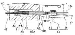
図2を参照して挿入部2、特に湾曲部7について説明する。
図2に示すように湾曲部7は、円環状の複数の湾曲駒31を備え、各湾曲駒31同士がリベットなどの枢支部25によって互いが回動自在に連結されている。複数の湾曲駒31の外周には、図示しないが網管としてのブレードおよび湾曲ゴムが被覆されている。With reference to FIG. 2, the
As shown in FIG. 2, the
本実施形態の湾曲部7は、先端部6側に配置された第1の湾曲部7aと、可撓管部8側に配置された第2の湾曲部7bと、を備えている。第1の湾曲部7aは、先端部6に連結される最先端湾曲駒31aから中途部分に設けられる中間湾曲駒31bの手前までを構成している。第2の湾曲部7bは、中間湾曲駒31bから最基端湾曲駒31cまでを構成している。 The
なお、第1の湾曲部7a、および、第2の湾曲部7bに関して、用いられる湾曲駒31の数および種類などは、各種挿入する生体管腔の使用目的に応じて適宜設定可能である。 In addition, regarding the
最先端湾曲駒31aには2つのワイヤ固定部32が、略中心点対称となる相対位置に設けられている。2つのワイヤ固定部32には、上湾曲操作ワイヤ41uの先端と下湾曲操作ワイヤ41dの先端がそれぞれ固定されている。 The most
上湾曲操作ワイヤ41uと下湾曲操作ワイヤ41dは、挿入部2内を通過して操作部3内まで挿通される。上湾曲操作ワイヤ41uと下湾曲操作ワイヤ41dは、第1の湾曲部7a内において各湾曲駒31に設けられたワイヤーガイド24内に挿通されている。 The upper
これに対して、第2の湾曲部7bの先端部分である中間湾曲駒31bの上湾曲操作ワイヤ41u側には第1のガイドコイル固定部33が設けられている。第1のガイドコイル固定部33は、上用ガイドコイル固定部33uであって、第1のガイドコイル43の一方である上用ガイドコイル43uの先端が固定されている。 On the other hand, a first guide coil fixing portion 33 is provided on the upper
第2の湾曲部7bの基端部分に設けられた最基端湾曲駒31cは、可撓管部8内に設けられた螺旋管26の先端の湾曲部接続管26aと接続されている。湾曲部接続管26aの上湾曲操作ワイヤ41u側には第2のガイドコイル固定部34が設けられ、下湾曲操作ワイヤ41d側には第1のガイドコイル固定部33である下用ガイドコイル固定部33dが設けられている。第2のガイドコイル固定部34と下用ガイドコイル固定部33dは略中心点対称となる相対位置に設けられている。 The most proximal
第2のガイドコイル固定部34には、第2のガイドコイル44の先端が固定されている。下用ガイドコイル固定部33dには第1のガイドコイル43の他方である下用ガイドコイル43dの先端が固定されている。 The tip of the
上用ガイドコイル43uおよび下用ガイドコイル43dは、細径金属コイルである。これらガイドコイル43u、43dは、挿入部2内を通過して操作部3まで挿通される。そして、上用ガイドコイル43uの内部には上湾曲操作ワイヤ41uが挿通され、下用ガイドコイル43dの内部には下湾曲操作ワイヤ41dが挿通されている。 The
第2のガイドコイル44は、太径金属コイルであって、コイル内径は上用ガイドコイル43uの外径より大径である。そして、第2のガイドコイル44には上湾曲操作ワイヤ41uが挿通された上用ガイドコイル43uが挿通されている。 The
即ち、本実施形態の挿入部2において、第1の湾曲部7a内は、上湾曲操作ワイヤ41uと下湾曲操作ワイヤ41dとを配設したワイヤ単独構造である。これに対して、第2の湾曲部7b内は、上湾曲操作ワイヤ41uを上用ガイドコイル43u内に挿通したワイヤ及びコイル構造と、下湾曲操作ワイヤ41dを配設したワイヤ単独構造と、になっている。可撓管部8内は、上湾曲操作ワイヤ41uが挿通された上用ガイドコイル43uが第2のガイドコイル44内に挿通されたワイヤ及び二重コイル構造と、下湾曲操作ワイヤ41dが下用ガイドコイル43d内に挿通されたワイヤ及びコイル構造と、になっている。 That is, in the
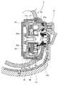
図3を参照して操作部3内の概略構成を説明する。
図3に示すように操作部3内にはフレーム51が設けられている。フレーム51は、アルミ、ステンレスなど剛性を備えた例えば金属製である。フレーム51の基端側には、湾曲操作プーリ45と湾曲長切替プーリ46とが回動自在に設けられている。A schematic configuration in the
As shown in FIG. 3, a
湾曲操作プーリ45は、湾曲操作レバー13の回動操作に連動して回動する。湾曲操作プーリ45の外周面の予め定めた位置には、上湾曲操作ワイヤ41uの基端および下湾曲操作ワイヤ41dの基端が接続されている。上湾曲操作ワイヤ41uおよび下湾曲操作ワイヤ41dは、湾曲操作プーリ45が回動することで相対的に牽引弛緩される。 The bending
また、上湾曲操作ワイヤ41uおよび下湾曲操作ワイヤ41dには、長さ調整のためのターンバックル42a、42bがそれぞれ介装されている。 Further, turn buckles 42a and 42b for adjusting the length are respectively interposed in the upper
この内視鏡1によれば湾曲部7は、湾曲操作レバー13の回動操作によって上下方向に湾曲する。そして、湾曲部7の上下方向の湾曲量(湾曲角度)は、上湾曲操作ワイヤ41uおよび下湾曲操作ワイヤ41dの相対的な牽引弛緩量に基いてに決定する。
なお、このような湾曲操作レバー13によって湾曲部7を湾曲させる機構は、従来構成と同様であるため、その他の詳細な説明を省略する。According to the endoscope 1, the bending
Note that the mechanism for bending the bending
フレーム51の先端側には固定ブロック52がビス(不図示)などによって固定されている。固定ブロック52には、第2のガイドコイル44の基端部分を固定する固定孔52h1とワイヤ挿通孔52h2とを有している。固定孔52h1には第2のガイドコイル44の基端部が固定され、ワイヤ挿通孔52h2内には下用ガイドコイル43dが挿通される。固定ブロック52に固定された第2のガイドコイル44の基端側からは上用ガイドコイル43uが延出している。 A fixed
符号53は、第1ガイドコイル取付部であって、フレーム51の中途部の予め定めた位置にビス(不図示)などによって固定されている。第1ガイドコイル取付部53には後述する上用ガイドコイル受け部材61と、下用ガイドコイル受け部材71とが設けられている。
符号54は切替装置であって、切替部55と、固定板56と、支持ピン57と、を有している。切替装置54は、第1ガイドコイル取付部53近傍の予め定めた位置に配設されている。
湾曲長切替プーリ46は回動部材であって、切替レバー21の回動操作に連動して回動する。湾曲長切替プーリ46の外周面の予め定めた位置には、湾曲長切替ワイヤ47の一端である基端側が接続されている。湾曲長切替ワイヤ47は、湾曲長切替プーリ46が図の初期位置からUP方向に回転されることによって牽引されるようになっている。
湾曲長切替ワイヤ47の他端である先端側は、切替部55に接続されている。The bending
The distal end side which is the other end of the bending
ここで、図4A−図4Fを参照して第1ガイドコイル取付部53、および、切替装置54の構成及び作用を説明する。
まず、図4A、図4Bを参照して第1ガイドコイル取付部53を説明する。
図4Aに示すように第1ガイドコイル取付部53には、操作部長手軸(図3の符号a3参照)に対して平行に第1段付き孔53h1と第2段付き孔53h2とが設けられている。本実施形態において、第1段付き孔53h1には移動体である上用ガイドコイル受体60が進退自在に配置され、第2段付き孔53h2には下用ガイドコイル受け部材71が配置される。Here, with reference to FIG. 4A-FIG. 4F, the structure and effect | action of the 1st guide
First, the first guide
As shown in FIG. 4A, the first guide
下用ガイドコイル受け部材71は、段付きピンであって、太径部72と細径部73とを有する。下用ガイドコイル受け部材71の中央には貫通孔である段付き孔74が設けられている。段付き孔74は、太径なコイル穴75と、細径なワイヤ挿通孔76と、を有している。ワイヤ挿通孔76は、コイル穴75の底面に開口を有して外部とコイル穴75の内部空間とに通じている。 The lower guide
コイル穴75内には下用のガイドコイル43dの基端部が固設される。ワイヤ挿通孔76内には下用ガイドコイル43dから導出された下湾曲操作ワイヤ41dが挿通される。下湾曲操作ワイヤ41dは、ワイヤ挿通孔76内を通過して外部に延出される。 In the
図4Aに示すように第2段付き孔53h2は、太径孔77と細径孔78とを有する。下用ガイドコイル受け部材71は、細径部73を細径孔78内に挿通し、太径部72を太径孔77内に挿通して第2段付き孔53h2内に配置される。 As shown in FIG. 4A, the second stepped hole 53h2 has a
これに対して上用ガイドコイル受体60、図4Bに示すように下用ガイドコイル受け部材71と略同様に構成された上用ガイドコイル受け部材61と、貫通孔69hを有するパイプ69とで構成されている。上用ガイドコイル受け部材61は、太径部62と細径部63とを有する。細径部63にはパイプ69の先端部が外嵌される。パイプ69は、例えば接着剤によって細径部63に固定される。パイプ69の基端部は、図4Aに示すように第1ガイドコイル取付部53の基端面側から外部に延出されている。 In contrast, the upper
上用ガイドコイル受け部材61の中央には貫通孔である段付き孔64が設けられている。段付き孔64は、太径なコイル穴65と、細径なワイヤ挿通孔66と、を有している。ワイヤ挿通孔66は、コイル穴65の底面に開口を有して外部とコイル穴65の内部空間とに通じている。 A stepped
コイル穴65内には上用ガイドコイル43uの基端部が固設される。ワイヤ挿通孔66内には上用ガイドコイル43uから導出された上湾曲操作ワイヤ41uが挿通される。そして、ワイヤ挿通孔65内から導出された上湾曲操作ワイヤ41uは、パイプ69の貫通孔69h内を通過して外部に延出されている。 In the
図4Aに示すように第1段付き孔53h1は、太径孔67と細径孔68とを有する。上用ガイドコイル受体60を構成するパイプ69の基端部は、第1段付き孔53h1の細径孔68内に予め定めた嵌め合いで摺動自在に配置されている。上用ガイドコイル受体60の太径部62は、第1段付き孔53h2の太径孔67内に遊嵌状態で配置されている。 As shown in FIG. 4A, the first stepped hole 53h1 has a
次に、図4A、図4C、図4Dを参照して切替装置54を説明する。
図4Aに示す切替部55は、固定板56に対して支持ピン57によって回動自在に軸支される。Next, the switching
The switching
図4Cに示すように切替部55は、直方体形状の押圧用ブロックであって、予め定めた位置に長孔55h1と、ワイヤ固定孔55h2と、ピン孔55h3と、が形成されている。 As shown in FIG. 4C, the switching
本実施形態において長孔55h1とワイヤ固定孔55h2とは長手側側面55aに開口を有している。長孔55h1は、ワイヤ逃がし孔であって、該長孔55h1内には上湾曲操作ワイヤ41uが遊嵌状態で挿通される。 In the present embodiment, the long hole 55h1 and the wire fixing hole 55h2 have openings on the
長孔55h1の開口は、扁平形状であって、長手側幅w1が上湾曲操作ワイヤ41uの直径に対して大きく設定され、短手側幅w2は上湾曲操作ワイヤ41uの直径より僅かに大きく設定してある。この結果、切替部55が回動された際、長孔55h1の内面が上湾曲操作ワイヤ41uに接触することが防止されている。 The opening of the long hole 55h1 has a flat shape, the long side width w1 is set larger than the diameter of the upper
図4Dに示すようにワイヤ固定孔55h2には湾曲長切替ワイヤ47の他端部が配置される。符号47aはワイヤ固定ブロックであって、湾曲長切替ワイヤ47の他端に配設されて一体に接合または固定される金属パイプである。湾曲長切替ワイヤ47の他端に一体に設けられたワイヤ固定ブロック47aは、例えば接着によってワイヤ固定孔55h2内に一体に固定される。 As shown in FIG. 4D, the other end of the bending
ピン孔55h3は、長孔55h1とワイヤ固定孔55h2との間に設けられている。ピン孔55h3の中心軸は、長孔55h1の中心軸及びワイヤ固定孔55h2の中心軸に対して直交する位置関係である。ピン孔55h3には支持ピン57が挿通される。 The pin hole 55h3 is provided between the long hole 55h1 and the wire fixing hole 55h2. The central axis of the pin hole 55h3 is a positional relationship orthogonal to the central axis of the long hole 55h1 and the central axis of the wire fixing hole 55h2. A
図4A、図4Dに示すように固定板56は、L字形状であって、フレーム51に設置されるフレーム面部56aと、切替部55が配置される切替面部56bと、を有する。切替面部56bには支持ピン57が挿通される逃がし孔(図4Aの符号56h参照)が設けられている。そして、固定板56は、図3に示すようにフレーム51の予め定めた位置にビス(不図示)などによって固定される。 As shown in FIGS. 4A and 4D, the fixing
切替部55は、図4Aに示すように固定板56の切替面部56bの載置面に配置される。この配置状態で、支持ピン57を切替部55のピン孔55h3に通過させて切替面部56bの逃がし孔56h内に挿入する。すると、支持ピン57の先端部が逃がし孔56hから予め定めた量突出する。 The switching
この突出した先端部には周溝(不図示)が設けられており、この周溝には図4A、図4Dに示すようにEリング58が嵌め込まれる。この結果、切替部55は、支持ピン57によって固定板56に回動自在に軸支配置される。なお、符号57hはピン頭部であって、その外径は支持ピン57の外径より大径である。 A circumferential groove (not shown) is provided at the protruding tip, and an E-ring 58 is fitted into the circumferential groove as shown in FIGS. 4A and 4D. As a result, the switching
そして、切替部55は、湾曲長切替ワイヤ47が図4Dの矢印Y4D1に示す方向への牽引に伴って矢印Y4D2に示す方向に二点鎖線に示すように支持ピン57を中心に回動する。すると、図4Eに示すように湾曲長切替ワイヤ47の牽引力によって回動された切替部55が第1ガイドコイル取付部53の基端面から突出したパイプ69の端面に当接する。 Then, the switching
その後、湾曲長切替ワイヤ47がさらに牽引されていくことによって、切替部55からパイプ69に徐々に押圧力が伝達されて該パイプ69が矢印Y4Eに示す方向に押し込まれていく。そして、図4Fに示すようにパイプ69が切替部55の回転移動によって先端側へ移動される。つまり、湾曲長切替ワイヤ47は、牽引されることによって切替部55からパイプ69に押圧力を伝達する伝達部材である。 Thereafter, the bending
このことによって、上湾曲操作ワイヤ41uが挿通されている上用ガイドコイル43uが先端側に押し込まれて圧縮されて剛性が増大する。上用ガイドコイル43uは、図2に示したように先端が第2の湾曲部7bの中間湾曲駒31bに設けられた第1のガイドコイル固定部33に固定されている。このため、上用ガイドコイル43uは、圧縮に伴って硬化していく。 As a result, the
なお、切替レバー21が図3の初期状態に戻されると、湾曲長切替ワイヤ47が弛緩されていく。すると、パイプ69は、圧縮されていた上用ガイドコイル43uからの伸長力を受けて第1ガイドコイル取付部53の基端面から突出した元の状態に戻されていく。すなわち、上用ガイドコイル43uは、圧縮されていないフリーな状態に復帰する。 When the switching
上述のように構成した内視鏡1の作用を説明する。
内視鏡1は、切替レバー21が図3に示す初期位置に位置するとき湾曲部7は長湾曲状態である。ここで、ユーザが湾曲操作レバー13を例えばUP方向に回動操作すると上湾曲操作ワイヤ41uが牽引されて湾曲部7がUP方向に湾曲していく。The operation of the endoscope 1 configured as described above will be described.
In the endoscope 1, when the switching
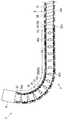
このとき、図5に示すように、可撓管部8の先端側に位置する第2の湾曲部7bおよびその先端側に位置する第1の湾曲部7aが湾曲する。 At this time, as shown in FIG. 5, the
一方、内視鏡1は、切替レバー21を操作することによって湾曲部7が長湾曲状態から短湾曲状態に切り替えられる。このとき、上用ガイドコイル43uが切替レバー21の操作に伴って図4Fに示したように圧縮される。 On the other hand, in the endoscope 1, the bending
この状態で、ユーザが、湾曲操作レバー13をUP方向に回動操作すると上湾曲操作ワイヤ41uが牽引されることで、湾曲部7がUP方向に湾曲する。このとき、図6に示すように、湾曲部7の先端側に位置する第1の湾曲部7aのみが上方向に向けて湾曲する。 In this state, when the user rotates the bending
即ち、本実施形態の内視鏡1によれば、操作部3に設けられた切替レバー21を切替位置まで操作していくことによって上用ガイドコイル43uを徐々に圧縮して硬度を硬くしていくことができる。 That is, according to the endoscope 1 of the present embodiment, the
したがって、ユーザは、湾曲部7の先端部分である第1の湾曲部7aのみを上方向に湾曲させて小回りが可能な状態と、従来と同様に湾曲部7全体が湾曲させた状態とを選択的に切替えることができる。 Therefore, the user selects a state in which only the
このように、本実施の形態の内視鏡1によれば、湾曲部7の湾曲操作時、切替レバー21の操作だけで湾曲部7の先端側の第1の湾曲部7aのみが略湾曲する状態と、第1の湾曲部7aおよび第2の湾曲部7bが共に湾曲する状態と、を容易に得ることができる。 Thus, according to the endoscope 1 of the present embodiment, only the
この結果、内視鏡1の挿入部2を入り組んだ生体内深部に挿入する際、湾曲部7の先端側の第1の湾曲部7aのみを湾曲させることで小回りが利き、入り組んだ体腔への挿入性が向上する。 As a result, when the
なお、上述した実施形態においては、切替装置54によって上湾曲操作ワイヤ41uが挿通された上用ガイドコイル43uを圧縮する構成を示している。しかし、上湾曲操作ワイヤ41uが挿通された上用ガイドコイル43uの代わりに、下湾曲操作ワイヤ41dが挿通される下用ガイドコイル43dを切替装置54によって圧縮するよう構成にしてもよい。 In the embodiment described above, a configuration is shown in which the
また、2つの切替装置54を設け、この2つの切替装置54によって上湾曲操作ワイヤ41uが挿通された上用ガイドコイル43uと、下湾曲操作ワイヤ41dが挿通された下用ガイドコイル43dと、を選択的に圧縮するよう構成にしてもよい。 Also, two
本実施形態において内視鏡1は、少なくとも上用ガイドコイル43uが先端側に押し込まれた圧縮状態を維持する切替レバー制動機構部を備えている。すなわち、切替レバー21は、切替レバー制動機構部によって回動状態を維持するように構成されている。 In the present embodiment, the endoscope 1 includes a switching lever braking mechanism that maintains a compressed state in which at least the
図7に示すように操作部3には、湾曲操作レバー13と切替レバー21とが設けられている。符号13aは湾曲操作レバー軸体であり、湾曲操作レバー13に一体に固定されている。一方、符号21aは切替レバー軸体であり、切替レバー21に一体に固定されている。 As shown in FIG. 7, the
図7、図8に示すように湾曲操作レバー軸体13aには軸先端側から順に、湾曲操作プーリ45、摩擦板81、カム板82、湾曲長切替プーリ46、制動板83が設けられている。符号80は、カバー部材であって、操作部3の外表面に設けられる。本実施形態において、切替レバー制動機構部は、主に、湾曲長切替プーリ46、摩擦板81、カム板82によって構成されている。カム板82は、第1の凸部であるカム部85を備え、湾曲長切替プーリ46に対して摺動自在に重ねられて配置されている。 As shown in FIGS. 7 and 8, the bending operation
制動板83は、例えばポリアセタール等、滑り性が良好な樹脂製の予め定めた厚さ寸法の円板に切欠83cを設けて形作られている。切欠83cには湾曲操作レバー軸受凹部83aが設けられている。湾曲操作レバー軸受凹部83aには湾曲操作レバー軸体(図8においては不図示)13aが係入される。このことによって、制動板83は、湾曲操作レバー軸体13aに対して摺動自在に配置される。 The
湾曲長切替プーリ46は、金属製円板であり、制動機構部となるカム部を有する。符号84は押し出し凹部であって第2の凸部であるカム部を形成するために等間隔に3つ設けられている。したがって、3つの押出凹部84を有する面の反対面には、カム部(不図示)として傾斜凸部が3つ設けられる。3つの傾斜凸部は、湾曲長切替プーリ46の中心から均等な距離の位置に周方向に沿って配列されている。
なお、湾曲長切替プーリ46にカム部を設ける場合、上述したプレス加工による押し出し凹部を設けること無く、反対面に例えばカム部を設けるようにしてもよい。The curved
In addition, when providing a cam part in the curve
湾曲長切替プーリ46は、異形孔46hを備えている。異形孔46hは、湾曲操作レバー軸体13aが挿通する挿通部46aと、切替レバー軸体21aの先端部に設けられた接続凸部21bが係入して配置される係入溝46bと、を有している。係入溝46bは、略円形の挿通部46aの円形内周面から外方に突出するように形作られている。 The curved
本実施形態においては、挿通部46aに湾曲操作レバー軸体13aが挿通される。このことによって、湾曲長切替プーリ46は、湾曲操作レバー軸体13aに対して摺動自在に配置される。そして、湾曲長切替プーリ46は、接続凸部21bが切替レバー軸体21aの回動に伴って時計方向或いは反時計方向に回転されることによって、湾曲操作レバー軸体13aに対して軸回りに回動される。 In the present embodiment, the bending operation
カム板82は、板部材例えば金属製円板であり、湾曲長切替プーリ46のカム部に略対向するように第1の凸部として3つのカム部85が該カム板82の中心から均等な距離の位置に周方向に配列して設けられている。 The
湾曲長切替プーリ46のカム部およびカム板82の3つのカム部85は、斜面85aを有する傾斜凸部である。その斜面85aは表面から回動する円周方向に沿って高さがなだらかに高くなるように形成されている。そして、カム頂点は、例えば、平坦面として形成されている。
なお、カム頂点は平坦面に限定されるものでは曲面であってもよい。The cam portion of the curve
The cam apex may be a curved surface if it is limited to a flat surface.
カム板82の3つのカム部85は、湾曲長切替ワイヤ47を牽引する際に湾曲長切替プーリ46が回動する方向に向かってその凸部の高さが徐々に増加するように形成されている。そして、カム頂点は、湾曲長切替プーリ46の表面上に配置される。これに対して、湾曲長切替プーリ46のカム部は、湾曲長切替ワイヤ47を牽引する際に回動する方向に向かってその凸部の高さが徐々に増加するように形成されている。 The three
カム板82には湾曲操作レバー軸体13aが挿通される湾曲操作レバー軸受孔82hが設けられている。カム板82は、湾曲操作レバー軸体13aに対して摺動自在に配置される。 The
摩擦板81は、例えば、ポリエーテルエーテルケトン(PEEK)等の樹脂製の平板円板である。摩擦板81は、湾曲操作レバー軸受孔81hを備えている。湾曲操作レバー軸受孔81hには湾曲操作レバー軸体13aが挿通される。そして、摩擦板81は、湾曲操作レバー軸体13aに対して摺動自在に配置される。 The
湾曲操作プーリ45は、固定孔45hを備えている。固定孔45hは、例えば、角形の貫通孔であって、湾曲操作レバー軸体13aの先端部が嵌合配置されて例えば接着固定される。この結果、湾曲長切替プーリ46は、湾曲操作レバー13の操作に伴って湾曲操作レバー軸体13aが一体に回転することによって時計方向或いは反時計方向に回転される。 The bending
ここで、切替レバー制動機構部の作用を説明する。
ユーザが切替レバー21を操作すると、該切替レバー21の接続凸部21bが係入溝46b内に配置されているため、湾曲長切替プーリ46が切替レバー軸体21aの回動に伴って湾曲操作レバー軸体13aに対して回転されていく。Here, the operation of the switching lever braking mechanism will be described.
When the user operates the switching
このとき、湾曲長切替プーリ46に設けられている図示されていないカム部の斜面85aがカム板82に設けられているカム部85の斜面85a上に配置される。その後、湾曲長切替プーリ46が切替レバー21の操作によって更に回転することによって、湾曲長切替プーリ46のカム部の斜面85aがカム板82のカム部85の斜面85a上を移動していく。
すると、湾曲長切替プーリ46のカム部の斜面85aとカム板82に設けられているカム部85の斜面85aとの間の摩擦力が徐々に徐々に増加していく。At this time, the
Then, the frictional force between the
そして、ユーザが切替レバー21を切替点まで操作することによって、湾曲長切替プーリ46のカム部とカム板82のカム部85との摩擦力が予め定め力量に到達して、切替レバー21が固定される。 Then, when the user operates the switching
このことによって、上湾曲操作ワイヤ41uが挿通された上用ガイドコイル43uが圧縮された状態に維持することができる。すなわち、湾曲部7は、短湾曲状態に固定される。 Thus, the
なお、切替レバー21を切替位置から初期状態に戻す、湾曲長切替ワイヤ47が弛緩され、パイプ69が圧縮されていた上用ガイドコイル43uからの伸長力を受けて第1ガイドコイル取付部53の基端面から突出した状態に戻される。すなわち、上用ガイドコイル43uが圧縮されていないフリーな状態に復帰して湾曲部7は長湾曲状態になる。 The bending
このように、第1のガイドコイルを圧縮状態に維持する切替レバー制動機構部を設けている。このため、切替レバー21を切替位置まで操作することによって湾曲部7の先端側の第1の湾曲部7aのみが湾曲する状態を安定的に得ることができる。このため、挿入部2の湾曲部7の先端側だけを湾曲させた状態を維持させて、安定的に、観察、あるいは、処置具を行うことができる。 Thus, the switching lever braking mechanism part which maintains a 1st guide coil in a compression state is provided. For this reason, by operating the switching
なお、本実施形態においては、カム板82に第1の凸部としてカム部85を設け、湾曲長切替プーリ46には第2の凸部としてのカム部を設け、カム部同士を対向する位置関係で配置するとしている。しかし、カム板82に第1の凸部としてカム部85を設け、湾曲長切替プーリ46には第2の凸部としてのカム部を設けなくてもよい。 In the present embodiment, a
本発明の内視鏡によれば、湾曲部を長湾曲状態と短湾曲状態とに切り替えて入り組んだ体腔深部への挿入性の向上を図りつつ、短湾曲状態を維持できるので、観察、処置を行える操作性に優れた内視鏡を提供できる。 According to the endoscope of the present invention, the short bending state can be maintained while improving the insertability into the deep body cavity by switching the bending portion between the long bending state and the short bending state. An endoscope with excellent operability can be provided.
以上に記載の本発明は、上述した実施形態及び変形例に限定されるものではなく、本発明の要旨を変えない範囲において、種々の変更、改変などが可能である。 The present invention described above is not limited to the above-described embodiments and modifications, and various changes and modifications can be made without departing from the scope of the present invention.
本出願は、2016年8月19日に日本国に出願された特願2016−161214号を優先権主張の基礎として出願するものであり、上記の開示内容は、本願明細書、請求の範囲に引用されるものとする。 This application is filed on the basis of the priority claim of Japanese Patent Application No. 2016-161214 filed in Japan on August 19, 2016, and the above disclosure is included in the present specification and claims Shall be quoted.
Claims (6)
Translated fromJapanese前記第2の湾曲部の基端に連設された可撓管部と、
前記可撓管部の基端に連設された操作部と、
前記第2の湾曲部の先端部分に先端が固定され、内部に前記湾曲操作ワイヤが挿通された第1のガイドコイルと、
前記可撓管部の先端部分に先端が固定されると共に前記操作部内に基端が固定され、内部に前記第1のガイドコイルが挿通された第2のガイドコイルと、
前記操作部内に進退自在に設けられ、前記第1のガイドコイルの基端が接続された移動体と、
移動されて前記移動体を押圧して、前記第1のガイドコイルを圧縮させることで前記第1のガイドコイルの剛性を増大させて、前記湾曲部の該湾曲部全体が湾曲する長湾曲状態から前記第1の湾曲部のみが湾曲する短湾曲状態に切り替える切替部と、
前記切替部を介して前記移動体が押圧されることで切り替えられた前記短湾曲状態を維持する切替レバー制動機構部と、
を具備することを特徴とする内視鏡。A bending portion comprising a first bending portion and a second bending portion in order from the tip, and bending by pulling and relaxing the bending operation wire;
A flexible tube portion connected to the proximal end of the second curved portion;
An operation unit connected to the proximal end of the flexible tube unit;
A first guide coil having a distal end fixed to a distal end portion of the second bending portion and having the bending operation wire inserted therein;
A second guide coil having a distal end fixed to the distal end portion of the flexible tube portion and a proximal end fixed in the operation portion, and the first guide coil inserted therein;
A movable body provided in the operation portion so as to be freely advanced and retracted, and connected to a proximal end of the first guide coil;
Since the first guide coil is compressed by moving and pressing the moving body to compress the first guide coil, the entire bending portion of the bending portion is bent. A switching unit that switches to a short bending state in which only the first bending unit is bent;
A switching lever braking mechanism that maintains the short-curved state switched by pressing the moving body via the switching unit;
An endoscope comprising:
前記操作部内に回動自在に配設され、予め定めた回動半径の位置に前記伝達部材の基端側が接続された、回動することにより前記伝達部材を押し引きして前記切替部を介して前記移動体を進退移動させる回動部材と、
前記回動部材と摺動可能に重ねられて前記操作部内に配置され、前記回動部材の回動に伴って摺動による摩擦力を増加させるように形成された第1の凸部を有する板部材と、
を有することを特徴とする請求項2に記載の内視鏡。The switching lever braking mechanism is
It is rotatably arranged in the operation unit, and the base end side of the transmission member is connected to a position of a predetermined rotation radius. By rotating, the transmission member is pushed and pulled, via the switching unit. A rotating member for moving the moving body forward and backward,
A plate having a first convex portion that is slidably overlapped with the rotating member and is disposed in the operation portion, and is formed so as to increase a frictional force due to sliding as the rotating member rotates. Members,
The endoscope according to claim2 , further comprising:
Applications Claiming Priority (3)
| Application Number | Priority Date | Filing Date | Title |
|---|---|---|---|
| JP2016161214 | 2016-08-19 | ||
| JP2016161214 | 2016-08-19 | ||
| PCT/JP2017/015530WO2018034021A1 (en) | 2016-08-19 | 2017-04-18 | Endoscope |
Publications (2)
| Publication Number | Publication Date |
|---|---|
| JP6336230B1true JP6336230B1 (en) | 2018-06-06 |
| JPWO2018034021A1 JPWO2018034021A1 (en) | 2018-08-16 |
Family
ID=61197188
Family Applications (1)
| Application Number | Title | Priority Date | Filing Date |
|---|---|---|---|
| JP2018503690AActiveJP6336230B1 (en) | 2016-08-19 | 2017-04-18 | Endoscope |
Country Status (3)
| Country | Link |
|---|---|
| US (1) | US11311180B2 (en) |
| JP (1) | JP6336230B1 (en) |
| WO (1) | WO2018034021A1 (en) |
Cited By (1)
| Publication number | Priority date | Publication date | Assignee | Title |
|---|---|---|---|---|
| CN120267214A (en)* | 2025-06-06 | 2025-07-08 | 湖南省华芯医疗器械有限公司 | Snake bone unit, initiative bending section and endoscope |
Families Citing this family (16)
| Publication number | Priority date | Publication date | Assignee | Title |
|---|---|---|---|---|
| WO2018098465A1 (en) | 2016-11-28 | 2018-05-31 | Inventio, Inc. | Endoscope with separable, disposable shaft |
| USD867589S1 (en)* | 2017-03-23 | 2019-11-19 | Pioneer Medical Instrument Co., Ltd. | Steerable structure for endoscope |
| DE102017123975A1 (en) | 2017-10-16 | 2019-04-18 | Hoya Corporation | Method of making an introducer tube of an endoscope and endoscope with an introducer tube |
| JP7128963B2 (en)* | 2018-10-25 | 2022-08-31 | キヤノン ユーエスエイ,インコーポレイテッド | Medical device with reflow trap anchor and method of use thereof |
| JP7214864B2 (en) | 2019-06-13 | 2023-01-30 | 富士フイルム株式会社 | Coating composition for endoscope, lubricating member for endoscope, method for producing lubricating member for endoscope, flexible tube for endoscope, and endoscope |
| CN120093197A (en)* | 2019-12-19 | 2025-06-06 | 诺亚医疗集团公司 | Modular endoscopy systems and methods |
| USD1018844S1 (en) | 2020-01-09 | 2024-03-19 | Adaptivendo Llc | Endoscope handle |
| USD1051380S1 (en) | 2020-11-17 | 2024-11-12 | Adaptivendo Llc | Endoscope handle |
| DE102021109025A1 (en) | 2021-04-12 | 2022-10-13 | Karl Storz Se & Co. Kg | Handpiece for a flexible endoscope or for a flexible endoscopic instrument |
| USD1031035S1 (en) | 2021-04-29 | 2024-06-11 | Adaptivendo Llc | Endoscope handle |
| USD1070082S1 (en) | 2021-04-29 | 2025-04-08 | Adaptivendo Llc | Endoscope handle |
| US20230000312A1 (en)* | 2021-06-30 | 2023-01-05 | Boston Scientific Scimed, Inc. | Articulation control device and methods of use |
| CN113576378B (en)* | 2021-08-11 | 2024-07-05 | 岱川医疗(深圳)有限责任公司 | Bending structure of endoscope |
| USD1066659S1 (en) | 2021-09-24 | 2025-03-11 | Adaptivendo Llc | Endoscope handle |
| CN114795069B (en) | 2022-05-25 | 2023-03-24 | 湖南省华芯医疗器械有限公司 | Disposable section of endoscope handle, endoscope handle and endoscope |
| JPWO2024071044A1 (en) | 2022-09-29 | 2024-04-04 |
Citations (4)
| Publication number | Priority date | Publication date | Assignee | Title |
|---|---|---|---|---|
| JP2003038421A (en)* | 2001-08-01 | 2003-02-12 | Olympus Optical Co Ltd | Endoscope |
| JP4856289B2 (en)* | 2010-01-29 | 2012-01-18 | オリンパスメディカルシステムズ株式会社 | Insertion device, endoscope |
| JP2016054967A (en)* | 2014-09-10 | 2016-04-21 | オリンパス株式会社 | Medical instrument |
| WO2017043124A1 (en)* | 2015-09-11 | 2017-03-16 | オリンパス株式会社 | Endoscope |
Family Cites Families (20)
| Publication number | Priority date | Publication date | Assignee | Title |
|---|---|---|---|---|
| JP3858560B2 (en)* | 2000-03-31 | 2006-12-13 | フジノン株式会社 | Coil shaft manufacturing method |
| US6717092B2 (en)* | 2000-08-11 | 2004-04-06 | Pentax Corporation | Method of manufacturing treatment instrument of endoscope |
| JP4312038B2 (en) | 2003-12-03 | 2009-08-12 | オリンパス株式会社 | Endoscope |
| US8206287B2 (en)* | 2005-02-14 | 2012-06-26 | Olympus Corporation | Endoscope having flexible tube |
| JP4477519B2 (en)* | 2005-02-14 | 2010-06-09 | オリンパス株式会社 | Endoscope |
| JP2007054125A (en)* | 2005-08-22 | 2007-03-08 | Olympus Medical Systems Corp | Endoscope |
| JP5033346B2 (en) | 2006-04-13 | 2012-09-26 | Hoya株式会社 | Endoscope bending device |
| US9220398B2 (en)* | 2007-10-11 | 2015-12-29 | Intuitive Surgical Operations, Inc. | System for managing Bowden cables in articulating instruments |
| JP5059231B2 (en)* | 2010-05-18 | 2012-10-24 | オリンパスメディカルシステムズ株式会社 | Medical equipment |
| WO2012120955A1 (en)* | 2011-03-08 | 2012-09-13 | オリンパスメディカルシステムズ株式会社 | Insertion device |
| JP5211271B2 (en)* | 2011-03-25 | 2013-06-12 | オリンパスメディカルシステムズ株式会社 | Endoscope |
| JP5519570B2 (en) | 2011-04-28 | 2014-06-11 | オリンパスメディカルシステムズ株式会社 | Endoscope |
| WO2012147581A1 (en)* | 2011-04-28 | 2012-11-01 | オリンパスメディカルシステムズ株式会社 | Endoscope |
| US9186049B2 (en)* | 2012-10-25 | 2015-11-17 | Choon Kee Lee | Extensible and guidable apparatus |
| US9549666B2 (en)* | 2012-11-10 | 2017-01-24 | Curvo Medical, Inc. | Coaxial micro-endoscope |
| WO2014192446A1 (en)* | 2013-05-29 | 2014-12-04 | オリンパスメディカルシステムズ株式会社 | Endoscope |
| EP3031384A4 (en)* | 2013-08-06 | 2017-03-29 | Olympus Corporation | Insertion device |
| JP5747365B1 (en)* | 2013-08-28 | 2015-07-15 | オリンパス株式会社 | Insertion device and endoscope |
| WO2015163019A1 (en)* | 2014-04-21 | 2015-10-29 | オリンパス株式会社 | Insertion device |
| WO2017212332A1 (en)* | 2016-06-06 | 2017-12-14 | 3Nt Medical Ltd. | Modular body cavity access system |
- 2017
- 2017-04-18JPJP2018503690Apatent/JP6336230B1/enactiveActive
- 2017-04-18WOPCT/JP2017/015530patent/WO2018034021A1/ennot_activeCeased
- 2018
- 2018-10-26USUS16/171,529patent/US11311180B2/enactiveActive
Patent Citations (4)
| Publication number | Priority date | Publication date | Assignee | Title |
|---|---|---|---|---|
| JP2003038421A (en)* | 2001-08-01 | 2003-02-12 | Olympus Optical Co Ltd | Endoscope |
| JP4856289B2 (en)* | 2010-01-29 | 2012-01-18 | オリンパスメディカルシステムズ株式会社 | Insertion device, endoscope |
| JP2016054967A (en)* | 2014-09-10 | 2016-04-21 | オリンパス株式会社 | Medical instrument |
| WO2017043124A1 (en)* | 2015-09-11 | 2017-03-16 | オリンパス株式会社 | Endoscope |
Cited By (1)
| Publication number | Priority date | Publication date | Assignee | Title |
|---|---|---|---|---|
| CN120267214A (en)* | 2025-06-06 | 2025-07-08 | 湖南省华芯医疗器械有限公司 | Snake bone unit, initiative bending section and endoscope |
Also Published As
| Publication number | Publication date |
|---|---|
| WO2018034021A1 (en) | 2018-02-22 |
| JPWO2018034021A1 (en) | 2018-08-16 |
| US11311180B2 (en) | 2022-04-26 |
| US20190059700A1 (en) | 2019-02-28 |
Similar Documents
| Publication | Publication Date | Title |
|---|---|---|
| JP6336230B1 (en) | Endoscope | |
| US8784299B2 (en) | Operation mechanism, endoscope apparatus, and guide catheter | |
| US10028643B2 (en) | Endoscope apparatus | |
| JP4477519B2 (en) | Endoscope | |
| JP7089008B2 (en) | Endoscope | |
| US11925316B2 (en) | Endoscope | |
| US20140165772A1 (en) | Insertion instrument | |
| JP4323441B2 (en) | Endoscope | |
| JP6180679B2 (en) | Endoscope | |
| JP2013027466A (en) | Medical apparatus | |
| US9770158B2 (en) | Holding mechanism for endoscope guide member, and endoscope | |
| US12178405B2 (en) | Endoscope having tension adjustment part | |
| WO2016002835A1 (en) | Medical puncture device | |
| US20100063357A1 (en) | Endoscope insertion aid, endoscope apparatus and endoscope apparatus insertion method | |
| KR102443789B1 (en) | Endoscope Controlled by Power Acceptor | |
| US12022993B2 (en) | Endoscope | |
| US20130253271A1 (en) | Endoscope | |
| JP6689589B2 (en) | Endoscope | |
| JP2015136375A (en) | Insertion instrument | |
| US11045078B2 (en) | Treatment instrument insertion tool | |
| JP2011182981A (en) | Endoscope operation section | |
| JP3722732B2 (en) | Endoscope | |
| JP2003116779A (en) | Endoscope | |
| JPWO2016194412A1 (en) | Mounting unit | |
| JP2003111717A (en) | Endoscope |
Legal Events
| Date | Code | Title | Description |
|---|---|---|---|
| A975 | Report on accelerated examination | Free format text:JAPANESE INTERMEDIATE CODE: A971005 Effective date:20180410 | |
| TRDD | Decision of grant or rejection written | ||
| A01 | Written decision to grant a patent or to grant a registration (utility model) | Free format text:JAPANESE INTERMEDIATE CODE: A01 Effective date:20180417 | |
| A61 | First payment of annual fees (during grant procedure) | Free format text:JAPANESE INTERMEDIATE CODE: A61 Effective date:20180501 | |
| R150 | Certificate of patent or registration of utility model | Ref document number:6336230 Country of ref document:JP Free format text:JAPANESE INTERMEDIATE CODE: R150 | |
| R250 | Receipt of annual fees | Free format text:JAPANESE INTERMEDIATE CODE: R250 | |
| R250 | Receipt of annual fees | Free format text:JAPANESE INTERMEDIATE CODE: R250 | |
| R250 | Receipt of annual fees | Free format text:JAPANESE INTERMEDIATE CODE: R250 | |
| R250 | Receipt of annual fees | Free format text:JAPANESE INTERMEDIATE CODE: R250 | |
| R250 | Receipt of annual fees | Free format text:JAPANESE INTERMEDIATE CODE: R250 |