JP6334517B2 - System and method for deformation compensation using shape sensing - Google Patents
System and method for deformation compensation using shape sensingDownload PDFInfo
- Publication number
- JP6334517B2 JP6334517B2JP2015512721AJP2015512721AJP6334517B2JP 6334517 B2JP6334517 B2JP 6334517B2JP 2015512721 AJP2015512721 AJP 2015512721AJP 2015512721 AJP2015512721 AJP 2015512721AJP 6334517 B2JP6334517 B2JP 6334517B2
- Authority
- JP
- Japan
- Prior art keywords
- model
- shape
- force
- deforming
- processor
- Prior art date
- Legal status (The legal status is an assumption and is not a legal conclusion. Google has not performed a legal analysis and makes no representation as to the accuracy of the status listed.)
- Active
Links
- 0CN=*CCS#CChemical compoundCN=*CCS#C0.000description1
Images


Classifications
- A—HUMAN NECESSITIES
- A61—MEDICAL OR VETERINARY SCIENCE; HYGIENE
- A61B—DIAGNOSIS; SURGERY; IDENTIFICATION
- A61B18/00—Surgical instruments, devices or methods for transferring non-mechanical forms of energy to or from the body
- A—HUMAN NECESSITIES
- A61—MEDICAL OR VETERINARY SCIENCE; HYGIENE
- A61B—DIAGNOSIS; SURGERY; IDENTIFICATION
- A61B5/00—Measuring for diagnostic purposes; Identification of persons
- A61B5/06—Devices, other than using radiation, for detecting or locating foreign bodies ; Determining position of diagnostic devices within or on the body of the patient
- A61B5/065—Determining position of the probe employing exclusively positioning means located on or in the probe, e.g. using position sensors arranged on the probe
- A61B5/066—Superposing sensor position on an image of the patient, e.g. obtained by ultrasound or x-ray imaging
- A—HUMAN NECESSITIES
- A61—MEDICAL OR VETERINARY SCIENCE; HYGIENE
- A61B—DIAGNOSIS; SURGERY; IDENTIFICATION
- A61B34/00—Computer-aided surgery; Manipulators or robots specially adapted for use in surgery
- A61B34/30—Surgical robots
- A—HUMAN NECESSITIES
- A61—MEDICAL OR VETERINARY SCIENCE; HYGIENE
- A61B—DIAGNOSIS; SURGERY; IDENTIFICATION
- A61B5/00—Measuring for diagnostic purposes; Identification of persons
- A61B5/0033—Features or image-related aspects of imaging apparatus, e.g. for MRI, optical tomography or impedance tomography apparatus; Arrangements of imaging apparatus in a room
- A61B5/004—Features or image-related aspects of imaging apparatus, e.g. for MRI, optical tomography or impedance tomography apparatus; Arrangements of imaging apparatus in a room adapted for image acquisition of a particular organ or body part
- A61B5/0044—Features or image-related aspects of imaging apparatus, e.g. for MRI, optical tomography or impedance tomography apparatus; Arrangements of imaging apparatus in a room adapted for image acquisition of a particular organ or body part for the heart
- A—HUMAN NECESSITIES
- A61—MEDICAL OR VETERINARY SCIENCE; HYGIENE
- A61B—DIAGNOSIS; SURGERY; IDENTIFICATION
- A61B5/00—Measuring for diagnostic purposes; Identification of persons
- A61B5/06—Devices, other than using radiation, for detecting or locating foreign bodies ; Determining position of diagnostic devices within or on the body of the patient
- A61B5/061—Determining position of a probe within the body employing means separate from the probe, e.g. sensing internal probe position employing impedance electrodes on the surface of the body
- A61B5/062—Determining position of a probe within the body employing means separate from the probe, e.g. sensing internal probe position employing impedance electrodes on the surface of the body using magnetic field
- A—HUMAN NECESSITIES
- A61—MEDICAL OR VETERINARY SCIENCE; HYGIENE
- A61B—DIAGNOSIS; SURGERY; IDENTIFICATION
- A61B5/00—Measuring for diagnostic purposes; Identification of persons
- A61B5/06—Devices, other than using radiation, for detecting or locating foreign bodies ; Determining position of diagnostic devices within or on the body of the patient
- A61B5/065—Determining position of the probe employing exclusively positioning means located on or in the probe, e.g. using position sensors arranged on the probe
- G—PHYSICS
- G16—INFORMATION AND COMMUNICATION TECHNOLOGY [ICT] SPECIALLY ADAPTED FOR SPECIFIC APPLICATION FIELDS
- G16Z—INFORMATION AND COMMUNICATION TECHNOLOGY [ICT] SPECIALLY ADAPTED FOR SPECIFIC APPLICATION FIELDS, NOT OTHERWISE PROVIDED FOR
- G16Z99/00—Subject matter not provided for in other main groups of this subclass
- A—HUMAN NECESSITIES
- A61—MEDICAL OR VETERINARY SCIENCE; HYGIENE
- A61B—DIAGNOSIS; SURGERY; IDENTIFICATION
- A61B17/00—Surgical instruments, devices or methods
- A61B2017/00681—Aspects not otherwise provided for
- A61B2017/00694—Aspects not otherwise provided for with means correcting for movement of or for synchronisation with the body
- A61B2017/00699—Aspects not otherwise provided for with means correcting for movement of or for synchronisation with the body correcting for movement caused by respiration, e.g. by triggering
- A—HUMAN NECESSITIES
- A61—MEDICAL OR VETERINARY SCIENCE; HYGIENE
- A61B—DIAGNOSIS; SURGERY; IDENTIFICATION
- A61B17/00—Surgical instruments, devices or methods
- A61B2017/00743—Type of operation; Specification of treatment sites
- A61B2017/00809—Lung operations
- A—HUMAN NECESSITIES
- A61—MEDICAL OR VETERINARY SCIENCE; HYGIENE
- A61B—DIAGNOSIS; SURGERY; IDENTIFICATION
- A61B34/00—Computer-aided surgery; Manipulators or robots specially adapted for use in surgery
- A61B34/10—Computer-aided planning, simulation or modelling of surgical operations
- A61B2034/101—Computer-aided simulation of surgical operations
- A61B2034/105—Modelling of the patient, e.g. for ligaments or bones
- A—HUMAN NECESSITIES
- A61—MEDICAL OR VETERINARY SCIENCE; HYGIENE
- A61B—DIAGNOSIS; SURGERY; IDENTIFICATION
- A61B34/00—Computer-aided surgery; Manipulators or robots specially adapted for use in surgery
- A61B34/20—Surgical navigation systems; Devices for tracking or guiding surgical instruments, e.g. for frameless stereotaxis
- A61B2034/2046—Tracking techniques
- A61B2034/2051—Electromagnetic tracking systems
- A—HUMAN NECESSITIES
- A61—MEDICAL OR VETERINARY SCIENCE; HYGIENE
- A61B—DIAGNOSIS; SURGERY; IDENTIFICATION
- A61B34/00—Computer-aided surgery; Manipulators or robots specially adapted for use in surgery
- A61B34/20—Surgical navigation systems; Devices for tracking or guiding surgical instruments, e.g. for frameless stereotaxis
- A61B2034/2046—Tracking techniques
- A61B2034/2061—Tracking techniques using shape-sensors, e.g. fiber shape sensors with Bragg gratings
- A—HUMAN NECESSITIES
- A61—MEDICAL OR VETERINARY SCIENCE; HYGIENE
- A61B—DIAGNOSIS; SURGERY; IDENTIFICATION
- A61B34/00—Computer-aided surgery; Manipulators or robots specially adapted for use in surgery
- A61B34/30—Surgical robots
- A61B2034/301—Surgical robots for introducing or steering flexible instruments inserted into the body, e.g. catheters or endoscopes
- A—HUMAN NECESSITIES
- A61—MEDICAL OR VETERINARY SCIENCE; HYGIENE
- A61B—DIAGNOSIS; SURGERY; IDENTIFICATION
- A61B34/00—Computer-aided surgery; Manipulators or robots specially adapted for use in surgery
- A61B34/30—Surgical robots
- A61B2034/303—Surgical robots specifically adapted for manipulations within body lumens, e.g. within lumen of gut, spine, or blood vessels
- A—HUMAN NECESSITIES
- A61—MEDICAL OR VETERINARY SCIENCE; HYGIENE
- A61B—DIAGNOSIS; SURGERY; IDENTIFICATION
- A61B2505/00—Evaluating, monitoring or diagnosing in the context of a particular type of medical care
- A61B2505/05—Surgical care
- A—HUMAN NECESSITIES
- A61—MEDICAL OR VETERINARY SCIENCE; HYGIENE
- A61B—DIAGNOSIS; SURGERY; IDENTIFICATION
- A61B2562/00—Details of sensors; Constructional details of sensor housings or probes; Accessories for sensors
- A61B2562/04—Arrangements of multiple sensors of the same type
- A61B2562/043—Arrangements of multiple sensors of the same type in a linear array
Landscapes
- Health & Medical Sciences (AREA)
- Life Sciences & Earth Sciences (AREA)
- Engineering & Computer Science (AREA)
- Surgery (AREA)
- Veterinary Medicine (AREA)
- Public Health (AREA)
- General Health & Medical Sciences (AREA)
- Biomedical Technology (AREA)
- Heart & Thoracic Surgery (AREA)
- Medical Informatics (AREA)
- Molecular Biology (AREA)
- Animal Behavior & Ethology (AREA)
- Nuclear Medicine, Radiotherapy & Molecular Imaging (AREA)
- Pathology (AREA)
- Biophysics (AREA)
- Physics & Mathematics (AREA)
- Human Computer Interaction (AREA)
- Radiology & Medical Imaging (AREA)
- Gynecology & Obstetrics (AREA)
- Robotics (AREA)
- Cardiology (AREA)
- Otolaryngology (AREA)
- Endoscopes (AREA)
- Apparatus For Radiation Diagnosis (AREA)
- Image Processing (AREA)
- Magnetic Resonance Imaging Apparatus (AREA)
Description
Translated fromJapanese本開示は、医療処置の間に患者の解剖学的形態内の医療装置を追跡するためのシステム及び方法を対象としており、特に、形状センサを使用した患者の解剖学的形態内の医療装置を効率的に追跡するためのシステム及び方法を対象としている。 The present disclosure is directed to a system and method for tracking a medical device within a patient's anatomy during a medical procedure, and more particularly to a medical device within a patient's anatomy using a shape sensor. It is directed to a system and method for efficient tracking.
最小侵襲医療技術は、診断又は外科手術手技の間にダメージを受ける組織の量を減らし、その結果、患者の回復時間を短くする、不快感を減らす、及び、有害な副作用を減らすように意図される。そのような最小侵襲技術は、患者の解剖学的形態における自然孔を介して、又は、1つ又は複数の外科的切開を介して行ってもよい。これらの自然孔又は切開を介して、臨床医は、手術器具を挿入して標的組織位置に到達してもよい。標的組織位置に到達するために、最小侵襲手術器具は、肺、大腸、腸管、腎臓、心臓若しくは循環器系等の解剖学的システム内の自然の又は外科的に作られた通路を進んでもよい。ナビゲーション補助システムは、臨床医が手術器具の経路を定める、及び、解剖学的形態に対するダメージを回避するのに寄与する。これらのシステムは、実際の空間における又は処置前若しくは同時発生の画像に関する手術器具の形状、ポーズ及び位置をより正確に表す形状センサの使用を具体化することができる。多くの解剖学的通路が密集した動的な解剖学的システムにおいて及び/又は解剖学的領域において、最小侵襲器具を解剖学的システムに正確に位置合わせすることは、時間のかかる且つ多量の処理を必要とする作業である。 Minimally invasive medical technology is intended to reduce the amount of tissue that is damaged during a diagnostic or surgical procedure, thereby reducing patient recovery time, reducing discomfort, and reducing adverse side effects. The Such minimally invasive techniques may be performed through natural holes in the patient's anatomy or through one or more surgical incisions. Through these natural holes or incisions, the clinician may insert a surgical instrument to reach the target tissue location. In order to reach the target tissue location, the minimally invasive surgical instrument may travel through a natural or surgically created passage in an anatomical system such as the lung, large intestine, intestine, kidney, heart or circulatory system . Navigation assist systems help clinicians route surgical instruments and avoid damage to anatomy. These systems can embody the use of shape sensors that more accurately represent the shape, pose, and position of the surgical instrument in actual space or with respect to pre-treatment or concurrent images. Accurately aligning a minimally invasive instrument to an anatomical system in a dynamic anatomical system and / or in an anatomical region where many anatomical passages are dense is a time consuming and voluminous process It is work that requires.
改善されたシステム及び方法が、最小侵襲器具を解剖学的システムに位置合わせするシステム及び方法の精度及び能率を上げるために必要とされる。 Improved systems and methods are needed to increase the accuracy and efficiency of systems and methods for aligning minimally invasive instruments with anatomical systems.
本発明の実施形態が、以下に続く特許請求の範囲によって要約される。 Embodiments of the invention are summarized by the claims that follow.
一実施形態において、方法が、患者の解剖学的形態を描く解剖学的データから、少なくとも1つの解剖学的通路の第1のモデルを生成するステップ、及び、枝分かれした解剖学的通路内に置かれた装置の形状を決定するステップを含む。当該方法は、決定された装置の形状に相対して第1のモデルを調整することによって、複数の枝分かれした解剖学的通路の第2のモデルを生成するステップも含む。 In one embodiment, the method generates a first model of at least one anatomical passage from anatomical data describing a patient's anatomy, and is placed in the branched anatomical passage. Determining the shape of the device. The method also includes generating a second model of the plurality of branched anatomical passages by adjusting the first model relative to the determined device shape.
別の実施形態において、医療システムが、形状センサを含む可撓性の装置、患者の解剖学的形態を描く解剖学的データを記憶するメモリ及びプロセッサを含む。このプロセッサは、患者の解剖学的形態を描く解剖学的データから、複数の枝分かれした解剖学的通路の第1のモデルを生成し、さらに、形状センサから情報を受信して、枝分かれした解剖学的通路内に置かれた装置の形状を決定する。プロセッサは、装置の形状に相対して第1のモデルを調整することによって、複数の枝分かれした解剖学的通路の第2のモデルも生成する。 In another embodiment, a medical system includes a flexible device that includes a shape sensor, a memory that stores anatomical data describing a patient's anatomy, and a processor. The processor generates a first model of a plurality of branched anatomical passages from anatomical data describing a patient's anatomy, and further receives information from a shape sensor to generate a branched anatomy. The shape of the device placed in the mechanical passage is determined. The processor also generates a second model of the plurality of branched anatomical passages by adjusting the first model relative to the shape of the device.
別の実施形態において、方法が、枝分かれした解剖学的通路が交互に起る動き(alternating movement)の第1の状態にありながら記録された、患者の解剖学的形態を描く解剖学的データから、複数の枝分かれした解剖学的通路の第1のモデルを生成するステップを含む。当該方法は、枝分かれした解剖学的通路が交互に起る動きの第2の状態にありながら記録された、患者の解剖学的形態を描く解剖学的データから、複数の枝分かれした解剖学的通路の第2のモデルを生成するステップも含む。当該方法は、枝分かれした解剖学的通路が第1の状態にある場合に、第1の形状における、枝分かれした解剖学的通路内に置かれた装置の第1の画像を生成するステップ、及び、枝分かれした解剖学的通路が第2の状態にある場合に、第2の形状における、枝分かれした解剖学的通路内に置かれた装置の第2の画像を生成するステップも含む。 In another embodiment, the method is based on anatomical data depicting a patient's anatomy recorded in a first state of alternating movement of branched anatomical passages. Generating a first model of the plurality of branched anatomical passages. The method includes a plurality of branched anatomical paths from anatomical data describing a patient's anatomy recorded in a second state of motion in which the branched anatomical paths alternate. Generating a second model of: The method generates a first image of a device placed in the branched anatomical passage in a first shape when the branched anatomical passage is in a first state; and The method also includes generating a second image of the device placed in the branched anatomical passage in the second shape when the branched anatomical passage is in the second state.
本開示の態様は、以下の詳細な説明から、付随の図と共に読まれた場合に最も理解される。当産業における標準的技法に従って、種々の特徴は一定の比例に応じて描かれているのではないということが強調される。実際、種々の特徴の大きさは、考察を明瞭にするため、任意に増やすか又は減らしてもよい。加えて、本開示は、種々の例において参照番号及び/又は文字を繰り返してもよい。この繰り返しは、単純性及び明瞭性のためであり、それ自体が、考察される種々の実施形態及び/又は構成間の関係を決定するわけではない。 Aspects of the present disclosure are best understood from the following detailed description when read with the accompanying figures. It is emphasized that according to standard techniques in the industry, the various features are not drawn to scale. Indeed, the size of the various features may be arbitrarily increased or decreased for clarity of discussion. In addition, the present disclosure may repeat reference numerals and / or letters in various examples. This repetition is for simplicity and clarity and as such does not determine the relationship between the various embodiments and / or configurations discussed.
以下の本発明の実施形態の詳細な説明において、数多くの特定の詳細が明記され、開示される実施形態の完全な理解を提供している。しかし、この開示の実施形態は、これらの特定の詳細を要することなく実行されてもよいということが当業者には明らかである。他の例において、よく知られた方法、手順、構成要素及び回路は、本発明の実施形態の態様を不必要に不明瞭にしないように詳細に記載されていない。 In the following detailed description of embodiments of the present invention, numerous specific details are set forth in order to provide a thorough understanding of the disclosed embodiments. However, it will be apparent to those skilled in the art that the embodiments of the disclosure may be practiced without these specific details. In other instances, well-known methods, procedures, components, and circuits have not been described in detail so as not to unnecessarily obscure aspects of the embodiments of the present invention.
以下の実施形態は、種々の器具及び器具の一部を、三次元空間におけるその状態の観点から説明している。本明細書において使用される場合、「位置」という用語は、(例えば、デカルトX、Y、Z座標に沿った3つの並進移動(translational)自由度等)三次元空間における対象又は対象の一部の位置を意味する。本明細書において使用される場合、「方向」という用語は、対象又は対象の一部の回転による配置(3つの回転自由度、例えばロール、ピッチ及びヨー等)を意味する。本明細書において使用される場合、「ポーズ」という用語は、(全部で6つの自由度までで)少なくとも1つの並進移動自由度における対象又は対象の一部の位置、及び、少なくとも1つの回転自由度におけるその対象又は対象の一部の方向を意味する。本明細書において使用される場合、「形状」という用語は、対象に沿って測定される一組のポーズ、位置又は方向を意味する。 The following embodiments describe various instruments and parts of instruments in terms of their state in a three-dimensional space. As used herein, the term “position” refers to an object or part of an object in three-dimensional space (eg, three translational degrees of freedom along Cartesian X, Y, Z coordinates). Means the position of As used herein, the term “direction” means an arrangement by rotation of an object or part of an object (three rotational degrees of freedom, eg, roll, pitch, and yaw). As used herein, the term “pose” refers to the position of an object or part of an object in at least one translational freedom degree (up to a total of six degrees of freedom) and at least one rotational freedom. Means the direction of the object or part of the object in degrees. As used herein, the term “shape” means a set of poses, positions, or directions measured along an object.
図面の図1を参考にすると、ロボット手術システムが、参照番号100によって概して示されている。図1において示されているように、ロボットシステム100は、一般に、患者Pに対して種々の処理を行うことにおいて手術器具104を操作するための外科用マニピュレーターアセンブリ102を含む。アセンブリ102は、手術台Oに載せられるか又はその近くにある。マスターアセンブリ106は、外科医Sが手術部位を見るのを、及び、マニピュレーターアセンブリ102を制御するのを可能にする。 Referring to FIG. 1 of the drawings, a robotic surgical system is indicated generally by the
別の実施形態において、ロボットシステムは、2つ以上のマニピュレーターアセンブリを含んでもよい。マニピュレーターアセンブリの正確な数は、複数の要因の中でも外科手術手技及び手術室内の空間制限次第である。 In another embodiment, the robotic system may include more than one manipulator assembly. The exact number of manipulator assemblies depends on the surgical procedure and space limitations within the operating room, among other factors.
マスターアセンブリ106は、手術台Oと同じ室内に通常置かれる外科医のコンソールCに置かれてもよい。しかし、外科医Sは、患者Pとは異なる部屋又は完全に異なる建物に置くことができるということが理解されるべきである。マスターアセンブリ106は、一般に、任意の支持物108、及び、マニピュレーターアセンブリ102を制御するための1つ又は複数の制御装置112を含む。1つ又は複数の制御装置112は、ジョイスティック、トラックボール、グローブ、トリガーガン、手動操作制御装置又は音声認識装置等、いかなる数の種々の入力装置を含んでもよい。いくつかの実施形態において、1つ又は複数の制御装置112には、付随の手術器具104と同じ自由度が提供されて、テレプレゼンス、又は、1つ又は複数の制御装置112が器具104と一体であるという知覚を外科医に提供するため、外科医は、器具104を直接制御しているという強い感覚を有する。いくつかの実施形態において、制御装置112は、6つの自由度で動く手動の入力装置であり、(例えば、はさみ口(grasping jaw)を閉じるため、電極に電位を加えるため又は薬物治療を送達するため等)器具を作動させるための作動可能ハンドルも含んでよい。 The
可視化システム110は、手術部位の同時発生又はリアルタイム画像が外科医コンソールCに提供されるように、(以下でより詳細に記載される)目視鏡(viewing scope)アセンブリを含んでもよい。同時発生画像は、例えば、手術部位内に置かれた内視鏡によってキャプチャされる二次元又は三次元画像であってもよい。この実施形態において、可視化システム100は、手術器具104に統合して又は取外し可能に結合されてもよい内視鏡的構成要素を含む。しかし、別の実施形態において、別のマニピュレーターアセンブリに取り付けられた別の内視鏡を手術器具と共に使用し、手術部位を画像表示してもよい。可視化システム110は、1つ又は複数のコンピュータプロセッサと相互作用するか又さもなければ1つ又は複数のコンピュータプロセッサによって実行されるハードウェア、ファームウェア、ソフトウェア又はその組み合わせとして実行されてもよく、1つ又は複数のコンピュータプロセッサは、(以下に記載される)制御システム116のプロセッサを含んでもよい。 The
表示システム111は、可視化システム110によってキャプチャされた手術部位及び手術器具の画像を表示してもよい。ディスプレイ111及びマスター制御装置112は、スコープアセンブリにおける画像処理装置と手術器具との相対位置が、外科医の眼と手との相対位置と類似するように方向づけられてもよく、従って、オペレータは、実質的に本当に目の前で作業空間を見ているかのように、手術器具104及び手動の制御を操縦することができる。本当に目の前でとは、画像の提示が、本当の眺望の画像であり、手術器具104を物理的に操縦しているオペレータの視点をシミュレートしているということを意味している。 The
或いは又は加えて、モニター111は、コンピュータ断層撮影法(CT)、磁気共鳴画像法(MRI)、蛍光透視法、サーモグラフィー、超音波、光干渉断層撮影法(OCT)、熱画像測定、インピーダンス画像法、レーザー画像法又はナノチューブX線画像法等の画像処理技術を使用して手術前に記録された及び/又はモデリングされた手術部位の画像を示してもよい。示された手術前画像は、二次元、三次元又は四次元画像を含んでもよい。 Alternatively or in addition, the
いくつかの実施形態において、モニター111は、手術器具の実際の位置が、手術前又は同時発生の画像に位置合わせされて(すなわち動的に参照されて)手術器具の先端の位置の内部の手術部位の仮想的な画像を外科医Sに与える仮想的なナビゲーション画像を表示してもよい。手術器具の先端の画像又は他のグラフィカル若しくは英数字の表示を仮想的な画像に重ねて、手術器具を制御する外科医を補助してもよい。或いは、手術器具は、仮想的な画像において可視でなくてもよい。 In some embodiments, the
他の実施形態において、モニター111は、手術器具の実際の位置が、手術前又は同時発生の画像に位置合わせされて、外部視点からの手術位置内の手術器具の仮想的な画像を外科医Sに与える仮想的なナビゲーション画像を表示してもよい。手術器具の一部の画像又は他のグラフィカル若しくは英数字の表示を仮想的な画像に重ねて、手術器具を制御する外科医を補助してもよい。 In another embodiment, the
図1において示されているように、制御システム116は、外科用マニピュレーターアセンブリ102とマスターアセンブリ106と画像及び表示システム110との間の制御に影響を与えるための少なくとも1つのプロセッサ及び典型的には複数のプロセッサを含む。制御システム116は、本明細書において記載される方法の一部又は全てを実行するソフトウェアプログラミング命令も含む。制御システム116は、図1の概略図において単一のブロックとして示されているけれども、このシステムは、処理の少なくとも一部が任意で入力装置に隣接して行われる、一部がマニピュレーターに隣接して行われる等、(例えば、外科用マニピュレーターアセンブリ102及び/又はマスターアセンブリ106上に)多くのデータ処理回路を含んでもよい。種々様々な集中型又は分散型データ処理アーキテクチャーのいずれも利用してよい。同様に、プログラミングコードを、多くの別のプログラム若しくはサブルーチンとして実行してもよく、又は、本明細書に記載されるロボットシステムの多くの他の態様に統合させてもよい。一実施形態において、制御システム116は、Bluetooth(登録商標)、IrDA、HomeRF、IEEE802.11、DECT及びWireless Telemetry等の無線通信プロトコルをサポートしてもよい。 As shown in FIG. 1, the
いくつかの実施形態において、制御システム116は、手術器具104からの力及びトルクフィードバックを手動の制御装置112に提供するためにサーボコントローラを含んでもよい。いかなる適した従来又は専門のサーボコントローラも使用してよい。サーボコントローラは、マニピュレーターアセンブリ102とは別であってもよく、又は、マニピュレーターアセンブリ102と一体であってもよい。いくつかの実施形態において、サーボコントローラ及びマニピュレーターアセンブリは、患者の体に隣接して置かれるロボットアームカートの一部として提供される。サーボコントローラは、体内の開口部を介して患者の体内の内部手術部位内に延びる器具をマニピュレーターアセンブリに動かすように命令する信号を送る。 In some embodiments, the
手術器具104を支えるマニピュレーターアセンブリ102のそれぞれが、一般的にはセットアップ接合と呼ばれる一連の手動でつなげることができるリンケージ、及び、ロボットマニピュレーターを含んでもよい。ロボットマニピュレーターアセンブリ102は、一連の作動装置(例えばモータ等)によって駆動されてもよい。これらのモータは、制御システム116からのコマンドに応答してロボットマニピュレーターを能動的に動かす。モータは、自然に又は外科的に作られた解剖学的孔の中に手術器具を進めるよう、及び、複数の自由度において手術器具の遠位端を動かすように手術器具にさらに結合され、複数の自由度は、(例えばX、Y、Zの直進運動等の)3つの直線運動度、及び、(例えば、ロール、ピッチ、ヨー等の)3つの回転運動度を含んでもよい。加えて、モータを使用して、生検装置等のはさみ口において組織をとらえるために、器具のつなげることができるエンドエフェクタを作動させることができる。 Each of the
図2は、手術器具システム104を含む追跡される器具システム118及びそのインターフェースシステムを例示している。手術器具システム104は、インターフェース122によって、マニピュレーターアセンブリ102及び可視化システム110に結合される可撓性の器具120を含む。器具120は、可撓体124、その遠位端128にて先端126、及び、その近位端130にてインターフェース122を有している。可撓体124は、例えば点線のバージョンの曲げられた先端126によって示されているように先端を制御可能に曲げる又は回転させるため、及び、いくつかの実施形態においては任意のエンドエフェクタ132を制御するために、インターフェース122と先端126との間を延びるケーブル、リンケージ又は他の操縦制御装置(図示せず)を収容している。可撓性の器具は、上記の操縦制御装置を含んで操縦可能であってもよく、又は、器具の曲りのオペレータ制御に対して統合された機構を有することなく操縦不可能であってもよい。エンドエフェクタは、例えば標的組織の所定の処理に影響を与えるため等、医療作用に対して操作可能な作業遠位部分であってもよい。例えば、いくつかのエンドエフェクタは、外科用メス、刃又は電極等、1つの作業部材を有する。図2の実施形態において示されているもの等の他のエンドエフェクタは、例えば、鉗子、捕捉器具、はさみ又はクリップアプライヤー等、一対又は複数の作業部材を有する。電気活性化エンドエフェクタの例として、電気外科的な電極、トランスデューサー及びセンサ等が挙げられる。エンドエフェクタは、例えば、流体送達、付属品導入及び生検抽出等を要する吸引、吸入、灌漑、処理を行うために、流体、ガス又は固形物を運ぶための導管も含んでよい。他の実施形態において、可撓体124は1つ又は複数の管腔を定めることができ、管腔を介して、手術器具を展開し、さらに、標的手術位置にて使用することができる。 FIG. 2 illustrates a tracked
器具120は画像キャプチャ要素134を含むこともでき、画像キャプチャ要素134は、表示システム111による表示のために、可視化システム110に送られ、さらに、可視化システム110によって処理される画像をキャプチャするために、遠位端128にて配置される双眼実体カメラ又は単眼実体カメラを含んでもよい。或いは、画像キャプチャ要素134は、ファイバースコープ等、器具120の近位端上の画像及び処理システムに結合するコヒーレント光ファイバー束であってもよい。画像キャプチャ要素134は、可視又は赤外線/紫外線スペクトルにおける画像データをキャプチャするために、単一又は多スペクトル感応性であってもよい。 The
追跡システム135は、遠位端128並びに器具120に沿った1つ又は複数のセグメント137の位置、方向、速度、ポーズ及び/又は形状を決定するために、電磁(EM)センサシステム136及び形状センサシステム138を含む。例証的な組のセグメント137のみが図2において描かれているけれども、遠位端128と近位端130との間の、且つ、先端126を含む器具120の全長は、複数のセグメントへと効果的に分割されてもよい。追跡システム135は、1つ又は複数のコンピュータプロセッサと相互作用するか又さもなければ1つ又は複数のコンピュータプロセッサによって実行されるハードウェア、ファームウェア、ソフトウェア又はその組み合わせとして実行されてもよく、1つ又は複数のコンピュータプロセッサは、制御システム116のプロセッサを含んでもよい。 The
EMセンサシステム136は、外部で生成される電磁場に供することができる1つ又は複数の導電コイルを含む。EMセンサシステム136のそれぞれのコイルは、次に、外部で生成される電磁場に対するコイルの位置及び方向次第である特徴を有する誘導電気信号を生じる。一実施形態において、EMセンサシステムは、例えば、3つの位置座標X、Y、Z、並びに、基点のピッチ、ヨー及びロールを示す3つの配向角度等、6つの自由度を測定するように構成され及び置かれてもよい。EMセンサシステムのさらなる説明が、全内容を本願に援用する“Six−Degree of Freedom Tracking System Having a Passive Transponder on the Object Being Tracked”を開示している1999年8月11日に出願した米国特許第6,380,732号において提供されている。 The
センサシステム138は、(例えば、内部のチャネル(図示せず)内に提供される、又は、外側に載せられる等)可撓体124に合わせられた光ファイバー140を含む。追跡システム135は、光ファイバー140の近位端に結合される。この実施形態において、ファイバー140は、約200μmの直径を有する。他の実施形態において、その大きさは、より大きいか又はより小さくてもよい。 The
光ファイバー140は、器具120の形状を決定するための光ファイバー曲げセンサを形成する。別の手段において、ファイバーブラッググレーティング(Fiber Bragg Gratings(FBG))を含む光ファイバーが、1つ又は複数の大きさの構造体におけるひずみ測定試験を提供するために使用される。三次元における光ファイバーの形状及び相対位置をモニターするための種々のシステム及び方法が、全内容を本願に援用する“Fiber optic position and shape sensing device and method relating thereto”を開示している2005年7月13日に出願した米国特許出願第11/180,389号、“Fiber−optic shape and relative position sensing”を開示している2004年7月16日に出願した米国仮特許出願第60/588,336号、及び、“Optical Fibre Bend Sensor”を開示している1998年6月17日に出願した米国特許第6,389,187号において記載されている。他の手段において、レイリー散乱、ラマン散乱、ブリュアン散乱及び蛍光散乱等、他のひずみ感知技術を利用するセンサが適していてもよい。他の別の実施形態において、器具120の形状は、他の技術を使用して決定されてもよい。例えば、器具の先端のポーズの経緯が、ナビゲーション表示を更新するための期間よりも短いある時間の間、又は、(例えば吸息及び呼息等)交互に起る動きの間記憶される場合、そのポーズの経緯を使用して、その期間にわたって装置の形状を再現することができる。別の例として、過去のポーズ、位置又は方向のデータは、呼吸等、交互に起る動きのサイクルに沿った器具の既知のポイントに対して記憶してもよい。この記憶されたデータを使用して、器具に関する形状の情報を展開してもよい。或いは、器具に沿って置かれるEMセンサ等の一連の位置センサを、形状感知のために使用することができる。或いは、特に解剖学的通路が概して静的である場合に、処理の間の器具上のEMセンサ等の位置センサからのデータの経緯を使用して器具の形状を表してもよい。或いは、外部の磁場によって位置又は方向が制御される無線装置を、形状感知のために使用してもよい。その位置の経緯を使用して、ナビゲートされた通路に対する形状を決定してもよい。 The
この実施形態において、光ファイバー140は、1つのクラッド146内に複数のコアを含んでもよい。各コアは、各コアにおける光が、他のコアにおいて運ばれている光と著しく相互作用しないように、充分な距離及びコアを隔てるクラッドを持ったシングルモードであってもよい。他の実施形態において、コアの数は変わってもよく、又は、各コアは、別の光ファイバー内に含有されてもよい。 In this embodiment, the
いくつかの実施形態において、FBGのアレイが、各コア内に提供されている。各FBGは、屈折率において空間的周期性を生成するように、一連のコアの屈折率の変調を含む。その間隔は、各率の変化からの部分的な反射が、狭帯域の波長に対してコヒーレントに合算され、従って、はるかに広い帯域を通過させながら、この狭帯域の波長のみを反射するように選ばれてもよい。FBGを製作している間に、変調は既知の距離によって間隔があけられ、その結果、既知の域の波長の反射を引き起こしている。しかし、ひずみがファイバーコア上で誘発される場合、変調の間隔は、コア内のひずみの量に応じて変わる。或いは、光ファイバーの曲げと共に変わる後方散乱又は他の光学現象を使用して、各コア内のひずみを決定することができる。 In some embodiments, an array of FBGs is provided in each core. Each FBG includes a series of core refractive index modulations to produce a spatial periodicity in the refractive index. The spacing is such that the partial reflections from each rate change are coherently summed for the narrowband wavelength, thus reflecting only this narrowband wavelength while passing through a much wider band. It may be chosen. During fabrication of the FBG, the modulation is spaced by a known distance, resulting in a reflection of a wavelength in a known region. However, when strain is induced on the fiber core, the modulation interval varies depending on the amount of strain in the core. Alternatively, backscatter or other optical phenomena that change with the bending of the optical fiber can be used to determine the strain within each core.
従って、ひずみを測定するために、光がファイバーまで送られ、戻ってくる光の特徴が測定される。例えば、FBGは、ファイバー上のひずみ及びその温度の結果である反射波長を生じる。このFBG技術は、Smart Fibres社(Bracknell,England)等の種々の供給源から商業的に入手可能である。ロボット手術に対する位置センサにおけるFBG技術の使用は、全内容を本願に援用する“Robotic Surgery System Including Position Sensors Using Fiber Bragg Gratings”を開示している2006年7月20日に出願した米国特許第7,930,065号において記載されている。 Thus, to measure strain, light is sent to the fiber and the characteristics of the returning light are measured. For example, FBGs produce a reflected wavelength that is a result of strain on the fiber and its temperature. This FBG technology is commercially available from various sources such as Smart Fibers (Blacknell, England). The use of FBG technology in position sensors for robotic surgery is described in US Pat. No. 7, filed on Jul. 20, 2006, which discloses “Robotic Surgical System Inclusion Position Sensors Using Fiber Bragg Gratings,” the entire contents of which are incorporated herein by reference. 930,065.
マルチコアファイバーに適用される場合、光ファイバーの曲げは、各コア内の波長シフトをモニターすることによって測定することができるコア上のひずみを誘発する。3つ以上のコアをファイバー内の軸外しで配置させることによって、ファイバーの曲げは、コアのそれぞれに異なるひずみを誘発する。これらのひずみは、局所的なファイバーの曲げ度の結果である。例えば、FBGを含有するコアの領域は、ファイバーが曲げられるポイントにて置かれた場合、その結果、それらのポイントでの曲げの量を決定するために使用することができる。既知のFBG領域の間隔と組み合わされたこれらのデータは、ファイバーの形状を再現するために使用することができる。そのようなシステムは、Luna Innovations社(Blacksburg、Va)によって記載されてきた。 When applied to multi-core fibers, bending of the optical fiber induces strain on the core that can be measured by monitoring the wavelength shift within each core. By placing more than two cores off-axis in the fiber, fiber bending induces different strains in each of the cores. These strains are the result of local fiber bending. For example, if the region of the core containing the FBG is placed at points where the fiber is bent, it can then be used to determine the amount of bending at those points. These data combined with known FBG region spacing can be used to recreate the fiber shape. Such a system has been described by Luna Innovations (Blacksburg, Va).
上記のように、光ファイバー140は、器具120の少なくとも一部の形状をモニターするために使用される。より明確には、光ファイバー140を通過する光が、手術器具120の形状を検出するため、及び、その情報を利用して外科手術手技を補助するために、追跡システム135によって処理される。追跡システム135は、器具120の形状を決定するために使用される光を生成及び検出するための検出システムを含んでもよい。この情報は、次に、手術器具の一部の速度及び加速度等、他の関連する変数を決定するために使用することができる。これらの変数のうち1つ又は複数の変数の正確な測定値をリアルタイムで得ることによって、コントローラは、ロボット手術システムの精度を改善する、及び、構成要素部品を駆動させることにおいて導入されるエラーを補うことができる。感知は、ロボットシステムによって作動される自由度のみに限定されてもよく、又は、(例えば、接合間の未作動の堅い部材の曲げ等)受動自由度にも、(例えば、作動された器具の動き等)能動自由度にも適用されてもよい。 As described above, the
追跡システム135からの情報は、ナビゲーションシステム142に送られてもよく、そこで、可視化システム110からの情報及び/又は手術前に撮られた画像と組み合わされて、器具120の制御において使用するために、表示システム111上でリアルタイムの位置情報を外科医又は他のオペレータに提供する。制御システム116は、器具120を置くためのフィードバックとしてその位置情報を利用してもよい。手術器具を手術画像に位置合わせする及びそれを表示するために光ファイバーセンサを使用するための種々のシステムが、全内容を本願に援用する“Medical System Providing Dynamic Registration of a Model of an Anatomical Structure for Image−Guided Surgery”を開示している2011年5月13日に出願した米国特許出願第13/107,562号において提供されている。 Information from tracking
図2の実施形態において、器具104は、ロボット手術システム100内で遠隔操作される。別の実施形態において、マニピュレーターアセンブリは、直接のオペレータ制御と交換されてもよい。直接の操作の別の手段において、種々のハンドル及びオペレータインターフェースを、器具のハンドヘルドの操作のために含ませてもよい。 In the embodiment of FIG. 2, the
図3aは、可撓性の器具120等、可撓性の器具の器具の画像154に位置合わせされた、肺の外からの視点からのヒトの肺152の画像151を含む合成画像150を描いている。肺152の画像151は、手術前に記録された画像から生成されてもよく、又は、外科手術手技の間に同時に生成されてもよい。合成画像150は、表示システム111を介して表示されてもよい。器具120が、肺152の気管支通路156を通って進められるに従い、追跡システム135及び/又は可視化システム110からの情報が使用され、肺の画像151に器具の画像154を位置合わせする。肺152の画像151は、例えば、吸気又は呼気の状態の肺を描くために変わってもよい。器具の画像154は、気管支通路156を通った器具120の前進又は後退を描くために変わってもよい。時折、合成画像150は、器具の画像の一部154´が気管支通路の外側にあるように、器具の画像154を誤ってレンダリングしてもよい。器具が気管支通路内に置かれるように器具の画像を正すためのシステム及び方法が以下に記載される。 FIG. 3a depicts a
図3bは、器具120の視点からの肺の領域を描いた、ヒトの肺152の内部画像160である。画像160は、肺152の描写された部分に置かれながら器具120によって外科手術手技の間に撮られた同時発生の画像であってもよい。より明確には、画像は、可視化システム110によってキャプチャされてもよい。或いは、画像160は、追跡システム135によって決定された器具120の先端の位置に基づき選択される手術前に記録された画像であってもよい。 FIG. 3 b is an
多くは、EMセンサシステム136及び形状センサシステム138を含む追跡システム135が、解剖学的通路の外側にある器具120の器具の先端126若しくは1つ又は複数のセグメント137に対する位置を計算してもよい。これはおそらく、(解剖学的通路の壁は破られていないと仮定して)わずかな測定エラーを示す。そのようなエラーは、肺又は心臓等の特定の解剖学的構造体の動的な性質から生じ得る。例えば、吸息及び呼息は、肺の気管支通路の位置及びサイズを変える。或いは、エラーは、患者の動きから、又は、解剖学的通路内の手術器具の存在によって引き起こされる組織の変形から生じ得る。器具の画像及び患者の解剖学的形態の画像が共に位置合わせされる及び表示される場合に、器具の位置を正すために、及び、通路内の器具の1つ又は複数のポイントを正確に突き止めるために、選択された器具のポイントは、解剖学的通路の壁上の位置まで、又は、解剖学的通路の管腔まで動かされる(snapped)か若しくはグラフィカルに位置合わせされてもよい。以下で詳細に記載されるように、手術前の画像の記録の後、患者の解剖学的形態のモデルを訂正して、内部及び外部の変形力、患者の動き、又は、患者の解剖学的形態における他の変化に対して調整するために、種々の補償方法を使用してもよい。解剖学的形態の組織に対する内部の変形力は、例えば、吸気及び呼気の呼吸状態の間の動き、心臓の動き及び咳から生じ得る。解剖学的形態の組織に対する外部の変形力は、例えば、器具の挿入及び操縦から生じ得る。訂正された患者の解剖学的形態のモデルは、より正確な、解剖学的通路に対する器具の合成画像の生成を可能にする。 In many cases,
訂正されたモデルは、患者の解剖学的通路の内側における仮想的なナビゲーションと関連して、特に有用であり得る。仮想的なナビゲーションは、三次元の解剖学的通路の構造体と付随する手術前に取得されたデータセットへの参照に基づく。例えば、データセットは、手術前のCTスキャンによって取得されてもよい。ソフトウェアを使用して、CT画像が、通路の種々の位置及び形状並びにその連結を描く三次元モデルに変えられる。仮想的なナビゲーション手順の間、センサシステム、特にEMセンサシステムを使用して、患者の解剖学的形態に対する器具のおおよその位置を算定してもよい。典型的に、患者の解剖学的形態の全ての部分が互いに対して固定されるということが仮定される。この仮定の下、図3bにおける視野と類似の患者の解剖学的形態の内側にある器具の先端の位置からの仮想的な視野を、手術前のCTスキャンデータセットから算定することができる。上記のように、患者の解剖学的形態が固定されたままであるという仮定は、一般的に、患者の解剖学的形態に適用される種々の変形力のため根拠のないものである。センサシステムによって導入される動き又は他のエラーを補償するために、仮想的な視野を、算定した器具の先端の位置からではなく、通路の内側にある、検知された器具の先端の位置に対する最も近いポイントから生成してもよい。検知された器具の位置の位置を、通路内又は通路の壁上の調整された位置まで調整するプロセスは、スナッピング(snapping)として知られている。スナッピングは、通路が十分に離れている且つ密集して詰められていない場合に特に十分に機能し得る。変形力が大きく、さらに、通路が密集している場合、スナッピングだけでは、器具が置かれる気道に対しては不適当な選択を生じ得る。 The corrected model may be particularly useful in connection with virtual navigation inside the patient's anatomical passage. Virtual navigation is based on a reference to a three-dimensional anatomical passage structure and associated pre-operative data sets. For example, the data set may be acquired by a CT scan before surgery. Using software, the CT image is converted into a three-dimensional model that depicts the various positions and shapes of the passages and their connections. During a virtual navigation procedure, a sensor system, in particular an EM sensor system, may be used to calculate the approximate position of the instrument relative to the patient anatomy. It is typically assumed that all parts of the patient anatomy are fixed relative to each other. Under this assumption, a virtual field from the position of the instrument tip inside the patient anatomy similar to the field in FIG. 3b can be calculated from the pre-operative CT scan data set. As noted above, the assumption that the patient's anatomy remains fixed is generally unfounded due to the various deformation forces applied to the patient's anatomy. In order to compensate for movement or other errors introduced by the sensor system, the virtual field of view is the most relative to the detected instrument tip position inside the passage and not from the calculated instrument tip position. You may generate from a close point. The process of adjusting the position of the detected instrument position to an adjusted position in the passage or on the wall of the passage is known as snapping. Snapping can work particularly well when the passages are well separated and not packed tightly. If the deformation force is large and the passages are dense, snapping alone can make an inappropriate choice for the airway where the device is placed.
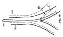
図4aは、肺の気管支通路202の変形されていないモデル200を例示している。カテーテル204が、気管支通路202内に延びている。カテーテル204は、器具120と実質的に類似し得る。モデル200は、表示システム上に表示されてもよく、又は、コンピュータメモリにおいて表示されない形で存在してもよい。示されているように、カテーテル204は、気管支通路202に対して変形力Fを及ぼす。図4bは、モデル160に対する変形力Fの効果を例示している。カテーテル204の力Fは、角度θで気管支通路202を動かす。変形されたモデル206は、気管支通路202の位置及び方向に対するカテーテル164の力の効果を例示している。 FIG. 4 a illustrates an
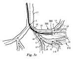
図5aは、気管支通路の枝分かれした構造体の変形されていないモデル300、及び、その通路を通って延びるカテーテル302の合成画像を例示している。変形されていないモデル300では、カテーテル302の先端304は、合成画像において、通路L4内ではなく、気管支通路L5内に置かれているように見えている。 FIG. 5a illustrates a composite image of an
図5aにおいて示されているように、気管支通路は、ピッチ方向でもヨー方向でも連結ポイントC等の変形ポイントの周りを回転することができる接合によって連結された堅いリンクの組L1乃至L10としてモデリングされる。いくつかの実施形態において、ストレッチ及びロール等の他の自由度を適合させてもよい。他の実施形態において、接合又は他のタイプの変形ポイントを、リンクL1乃至L10の長手方向に沿って置き、リンクの長手方向に沿った多数の曲げるための位置を可能にしてもよい。いくつかの実施形態において、変形ポイントは、連結ポイントの位置に構わずに、モデリングされたリンクL1乃至L10の至る所に分布されてもよい。 As shown in FIG. 5a, the bronchial passageway is modeled as a set of rigid links L1-L10 connected by a joint that can rotate around a deformation point, such as connection point C, both in the pitch and yaw directions. The In some embodiments, other degrees of freedom such as stretch and roll may be adapted. In other embodiments, joints or other types of deformation points may be placed along the longitudinal direction of the links L1-L10, allowing multiple bending positions along the longitudinal direction of the links. In some embodiments, the deformation points may be distributed throughout the modeled links L1-L10 regardless of the location of the connection points.
モデル300を変形させる、及び、カテーテルによって加えられる力に合わせて訂正するために、気管支通路上のカテーテル全体の形状が決定される。形状センサシステム138等の形状センサシステムを使用して、先端だけでなく、カテーテル全体の形状を決定してもよい。カテーテルの形状は、変形されていないモデルにおける各連結ポイントCでの(例えば、ピッチ及びヨー角度等の)一組の変形変数を決定するために使用される。気管支構造体におけるリンクのポーズに対する、モデリングされた連結ポイントのピッチ及びヨー角度を変えるために使用される方法は、例えば、Siciliano et al.、Springer Handbook of Robotics(Springer、2008)において見つけられる標準的な動態学的方法である。気管支通路の変形の量は、変形されていないモデルにおいて通路の外側にあるカテーテルのポイントにより生じる仮想的な力によって決定される。これらの力は、カテーテルの方向において通路を引っ張るよう効果的に作用する。変形の量は、変形されていない形状及び構造の方向に通路を片寄らせる気管支通路及び周囲の結合組織の剛性等、反作用的力によっても決定される。 In order to deform the
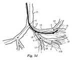
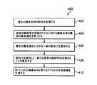
図5b乃至5dは、枝分かれした気管支通路の変形されていないモデル300を描いており、さらに、カテーテル302が通路を通って進められるのに従った、枝分かれした気管支通路の変形モデル310も示している。図5bにおいて、カテーテル302は、リンクL1を通って且つリンクL2内に進められている。変形モデル310は、変形されていないモデル300からわずかにシフトされて、リンクL1、L2に対するカテーテル302の直接力、及び、連結した遠位のリンクL3乃至L10に対する間接力に合わせて調整されている。先端304は、変形されていないモデル300でも、変形されたモデル310でも、リンクL2内にあるとして描かれているが、リンクL2内の先端304の正確な位置は、2つのモデル間で異なっている。図5cにおいて、カテーテル302は、リンクL2を通って且つリンクL3内に進められている。変形モデル310は、変形されていないモデル300からさらにシフトされて、リンクL1、L2、L3に対するカテーテル302の直接力、及び、連結した遠位のリンクL4乃至L10に対する間接力に合わせて調整されている。先端304は、変形されていないモデル300においてはリンクL3の外側にあるとして描かれているが、変形されたモデル310においてはリンクL3内にあるとして描かれている。このように、変形されたモデル310は、先端304が気管支通路の内側にあるという現実をより正確に反映している。図5dにおいて、カテーテル302は、リンクL4内に進められている。変形モデル310は、変形されていないモデル300からさらにシフトされて、リンクL1、L2、L3、L4に対するカテーテル302の直接力、及び、連結した遠位のリンクL5乃至L10に対する間接力に合わせて調整されている。先端304は、変形されていないモデル300においてリンクL5内に描かれており、さらに、変形されたモデル310においてリンクL4の内側に描かれている。このように、変形されたモデル310は、先端304の実際の位置をより正確に反映している。最終的な変形されたモデル310が、図6において描かれている。 FIGS. 5b-5d depict an
変形されていないモデルを、調整されたか又は変形されたモデルに訂正するための方法の一実施形態が、図7の流れ図400において提供されている。モデルは、例えば手術前の画像から、患者の解剖学的形態を描く二次元又は三次元のデータセットから、基準(すなわち、患者特異的なモデルではない)から、又は、上記のいずれの混成から等、患者の解剖学的形態を描く記憶されたデータから生成されてもよい。最初は、変形されるモデルは、全ての変形変数(例えばピッチ/ヨー角度、ストレッチ等)がゼロに設定された静的な変形されていないモデルに等しい。ステップ402にて、手術器具のカテーテル又は別のタイプの検知される装置の現在の形状が、センサシステムのうち1つ又は複数のセンサを使用して取得される。ステップ404にて、変形されるモデルに対する、形づけられたカテーテルに沿ったポイントのサンプリングが、最良適合に合わせられる。この最初の補償サイクルの反復の間、変形されるモデルは、静的モデルに等しい。より詳細には、この最良適合マッチング技術は、1つの例として示される実施形態において、a)カテーテルの先端に最も近いN個のリンクLを見つけること、b)N個のリンクLのそれぞれに対して、そのリンクから気管支構造体の基点までの経路を形成するリンクの独自のサブセットを算定すること、c)N個のサブセットのそれぞれに対して、カテーテルの形状に沿ったサンプリングされたポイントのそれぞれに対する気管支通路上の最も近いポイントを算定すること、d)サンプリングされたポイントの、気管支通路における対応する最も近いポイントに対する距離の関数として、N個の選択肢のそれぞれに対して距離スコアを算定すること、及び、最も低い組み合わされた距離スコアに基づき、N個の選択肢から最良な選択肢を選ぶこと、を含む。 One embodiment of a method for correcting an undeformed model to an adjusted or deformed model is provided in the
ステップ406にて、選択された最良適合に対する一組の変形力が計算される。カテーテルの形状に沿ったサンプリングされたポイントのそれぞれに対して、力が、ポイントの位置と、気管支通路上の最も近いポイントの位置との間のベクトルとして定められる。任意で、気管支通路をその元の形状の方向に片寄らせる力に相当する一組の復元力が算定されてもよい。これらの復元力は、変形された気管支通路のリンク上のサンプリングされたポイントと、変形されていないリンク上の対応するポイントとの間で定められている。さらに任意で、局所的な形状を、変形されていない局所的な形状に片寄らせる力に相当する一組の維持力が算定されてもよい。これらの維持力は、例えば、連結したリンクの各対の間で、その連結での変形の角度に等しく且つ反対のトルクで作用する接合トルクとして定めることができる。気管支通路の枝分かれした構造体に作用する全ての力の組が、変形力及び復元力の組の重み付き加算として算定される。重み因子は、ユーザによって決定されてもよく、又は、例えば、測定された解剖学的形態の機械的特性に基づき等、最も現実的な動作を生じる方法で設定されてもよい。組織の弾性静力学的特性も、(例えば3D又は4DCT等の)多次元診断画像において予め評価することができ、弾性荷重に対する強度に対してリアルな患者画像のデータベースもおそらく要する。CT画像処理様式は、相対的な組織密度をキャプチャするため、画像強度と組織部位の弾性特性との間のマッピングを予め算定することができる。実行時間の間、既知の大きさ及び方向の力の下での組織の変形を算定して、より物理的に正確な組織の動作を反映させることができる。 At
ステップ408にて、新たな気管支通路の変形されたモデルが、気管支通路のリンク間の各接合を、その接合にて加えられた全トルクに比例する量だけ調整することによって算定される。 At
ステップ410にて、変形されたモデルとカテーテルとの合成画像が、気管支通路の枝分かれした構造体内のカテーテルの位置を正確に描写するために生成される。加えて、変形されたモデルにおける正しいリンクに位置合わせされたカテーテルの先端を用いて、正しい仮想的なナビゲーション視野を、手術前に記憶された画像から検索することができる。プロセスは、カテーテルが気管支構造体内のその所望の標的に到達するまで、ステップ402から繰り返してもよい。 At
別の実施形態において、枝分かれした気管支構造体の静的でない性質を、気管支構造体の吸息状態に対応する気管支構造体の吸気モデル、及び、気管支構造体の呼息状態に対応する呼気モデルにおいて示すことができる。図8を参考にすると、センサシステムに基づきすでに調整されたカテーテルのポーズ、位置又は方向を、通路が吸気と呼気との状態間で及び逆もまた同様に調整されるに従い、気管支通路の形状までさらに改良するか又は曲げることができる。図8は、吸気モデル450及び呼気モデル452を描いている。カテーテル454は、最初に、センサシステムに基づきその位置が突き止められるが、吸気と呼気との状態間で動くに従い、気管支通路の画像内に残るように調整される。図9は、吸気と呼気の状態に基づきカテーテルを調整するための方法を説明している流れ図460である。ステップ462にて、現在のカテーテルの形状が取得される。ステップ464にて、カテーテルの形状が、吸気の状態における気管支通路の形状にマッチさせられる。ステップ466にて、カテーテルの形状が、呼気の状態における気管支通路の形状にマッチさせられる。気管支通路とカテーテルとの合成画像において、カテーテルの画像が、呼気及び吸気のそれぞれの状態に対して、気管支通路内で維持される。そのプロセスは、カテーテルが、気管支構造体内のその所望の標的に到達するまで繰り返されてもよい。別の実施形態において、そのプロセスを使用して、いかなる動いている解剖学的構造体、特に、既知の状態を交互に繰り返す、心臓又は肺等の解剖学的構造体内に置かれたいかなる器具に対しても画像を訂正してもよい。例えば、動いている解剖学的構造体は、心臓周期の拡張期と収縮期とを交互に繰り返す心臓であってもよい。 In another embodiment, the non-static nature of the branched bronchial structure is determined in the inhalation model of the bronchial structure corresponding to the inhalation state of the bronchial structure and the exhalation model corresponding to the exhalation state of the bronchial structure. Can show. Referring to FIG. 8, the catheter pose, position or direction already adjusted based on the sensor system is adjusted to the shape of the bronchial passage as the passage is adjusted between inspiratory and expiratory states and vice versa. It can be further improved or bent. FIG. 8 depicts an
別の実施形態において、器具又は解剖学的通路は、類似性検索を行うために、三次元形状ヒストグラムを使用してモデリングされてもよい。例えば、2つの三次元曲線間の類似性を測定するために、メトリックを展開させてもよい。図10を参考にして、曲線500は、参照解剖学的形態を通った測定される装置の経路に相当し、さらに、曲線502は、実際の解剖学的通路に相当する。これらの曲線上の各ポイントPiに対して、以下のパラメータ、a)局所的な勾配、b)局所的な曲率、c)終点コネクタに対するラジアル角変位(radial angular displacement)、d)終点のコネクタに対するラジアル距離、e)第3の参照軸504に対するラジアル角/変位が定められてもよい。図11において示されているように、ヒストグラム505は、上記パラメータのそれぞれから作製されてもよい。ヒストグラムは、各曲線の類似性に対するメトリックを作製するために直接マッチさせられる。In another embodiment, the instrument or anatomical passage may be modeled using a 3D shape histogram to perform a similarity search. For example, a metric may be developed to measure the similarity between two 3D curves. With reference to FIG. 10,
別の実施形態において、マッチの質を測定するためにメトリックを使用して、任意に形づけられたポイントの組が、別のポイントの組まで動かされる。図12を参考にすると、2つのポイントの組PT及びPSが提供されている。PSで始まり、類似性測定|SS→T|が算定される。類似性測定は、参照点からの距離に対して索引がつけられる一次元ヒストグラムである。参照点での接ベクトルの値が、参照ベクトルに対して記憶される。オプティマイザが、変形に対する自由度を最適化して、PSとPTとの間で同時に類似性測定を最大にするために使用される。In another embodiment, using a metric to measure match quality, an arbitrarily shaped set of points is moved to another set of points. Referring to FIG. 12, two point sets PT and PS are provided. Starting with PS , the similarity measure | SS → T | is calculated. A similarity measure is a one-dimensional histogram that is indexed to distance from a reference point. The value of the tangent vector at the reference point is stored for the reference vector. Optimizer optimizes the flexibility to deformation, are used to maximize the same time similarity measure between PS and PT.
可撓性の器具の少なくとも一部の画像を、解剖学的システムの画像に位置合わせするための別のシステム及び方法が、全内容を本願に援用する“Systems and Methods for Registration of a Medical Device Using a Reduced Search Space”を開示している米国特許出願第(参照番号ISRG04290)、及び、“Systems and Methods for Registration of a Medical Device Using Rapid Pose Search”を開示している米国特許出願第(参照番号ISRG03740)において開示されている。参照システム及び方法によって具体化されるこれらの態様は上記のシステム及び方法と共に使用して、可撓性の器具の少なくとも一部の画像を、解剖学的システムの画像に正確に位置合わせする別の方法を提供してもよい。 Another system and method for registering an image of at least a portion of a flexible instrument to an image of an anatomical system is incorporated herein by reference in its entirety. “Systems and Methods for Registration of Medical Device Using” US Patent Application No. (reference number ISRG04290) disclosing "Reduced Search Space" and "Systems and Methods for Registration of a Medical Device Using Rapid Pass No. US Patent Application No. 37" ). These aspects embodied by the reference system and method may be used in conjunction with the systems and methods described above to provide another alternative for accurately aligning an image of at least a portion of a flexible instrument with an image of an anatomical system. A method may be provided.
レジストレーションシステム及び方法が、遠隔操作又は手動の外科手術システムに関して本明細書において記載されてきたけれども、これらのレジストレーションシステム及び方法は、種々の医療器具及び医療以外の器具において応用されることになり、さもなければ、それらの種々の医療器具及び医療以外の器具において、正確な器具の画像レジストレーションは、時間がかかり過ぎるか、又は、多量のコンピュータ処理を要する。 Although registration systems and methods have been described herein with reference to remotely operated or manual surgical systems, these registration systems and methods are to be applied in a variety of medical and non-medical devices. Otherwise, in these various medical and non-medical devices, accurate device image registration can be time consuming or require a significant amount of computer processing.
本開示のシステム及び方法は、肺の連結した気管支通路において使用するために例示されてきたけれども、大腸、腸管、腎臓、脳、心臓又は循環器系等を含む種々の解剖学的システムのいずれにおける自然の又は外科的に作られた連結した通路を介した他の組織のナビゲーション及び処置にも適している。本開示の方法及び実施形態は、非外科的適用にも適している。 Although the systems and methods of the present disclosure have been illustrated for use in the connected bronchial passages of the lung, in any of a variety of anatomical systems including the large intestine, intestine, kidney, brain, heart or circulatory system It is also suitable for navigation and treatment of other tissues through natural or surgically created connected passages. The methods and embodiments of the present disclosure are also suitable for non-surgical applications.
本発明の実施形態における1つ又は複数の要素は、制御システム116等のコンピュータシステムのプロセッサ上で行うようにソフトウェアにおいて実行されてもよい。ソフトウェアにおいて実行される場合、本発明の実施形態の要素は、本質的に、必要なタスクを行うコードセグメントである。プログラム又はコードセグメントは、プロセッサ可読記憶媒体又は装置において記憶することができ、伝送媒体又は通信リンクにわたる搬送波で表されるコンピュータデータシグナルとしてダウンロードされてもよい。プロセッサ可読記憶装置は、光媒体、半導体媒体及び磁気媒体を含む、情報を記憶することができるいかなる媒体を含んでもよい。プロセッサ可読記憶装置の例として、電子回路、半導体素子、半導体メモリ素子、読取り専用メモリ(ROM)、フラッシュメモリ、消去プログラム可能読取り専用メモリ(EPROM)、フロッピー(登録商標)ディスケット、CD−ROM、光ディスク、ハードディスク又は他の記憶装置が挙げられる。コードセグメントは、インターネット、イントラネット等のコンピュータネットワークを介してダウンロードされてもよい。 One or more elements in embodiments of the present invention may be implemented in software as performed on a processor of a computer system, such as
示された処理及び表示は、いかなる特定のコンピュータ又は他の装置にも本質的には関連しないということに留意されたい。種々の汎用システムを、本明細書における教示によるプログラムと共に使用することができるか、又は、記載される動作を行うためにより専門の装置を構成するのに便利であると証明することができる。種々のこれらのシステムに対する要求される構造は、特許請求の範囲における要素として明らかになる。加えて、本発明の実施形態は、いかなる特定のプログラム言語を参考にしても記載されない。種々のプログラム言語を使用して、本明細書において記載される本発明の教示を実行してもよいということが正しく理解されることになる。 Note that the processes and displays shown are not inherently related to any particular computer or other device. Various general purpose systems can be used with the programs according to the teachings herein, or can prove to be more convenient for configuring more specialized devices to perform the operations described. The required structure for a variety of these systems will appear as elements in the claims. In addition, embodiments of the present invention are not described with reference to any particular programming language. It will be appreciated that various programming languages may be used to implement the teachings of the invention described herein.
本発明の特定の例証的な実施形態が記載され、さらに、付随の図面において示されてきたけれども、そのような実施形態は単に広義の発明を例示したものであって、その広義の発明を限定するのではないということ、及び、本発明の実施形態は、種々の他の修正が当業者に対して生じ得るため、示され且つ記載される特定の構造及び配置に限定されないということが理解されることになる。 While specific illustrative embodiments of the invention have been described and further illustrated in the accompanying drawings, such embodiments are merely illustrative of the broad invention and limit the broad invention. It is understood that the present invention is not, and embodiments of the invention are not limited to the specific structure and arrangement shown and described, as various other modifications can occur to those skilled in the art. Will be.
Claims (18)
Translated fromJapanese記憶された前記患者の解剖学的形態を描く前記解剖学的データから、複数の枝分かれした解剖学的通路の第1のモデルを前記プロセッサにより生成するステップ、
前記枝分かれした解剖学的通路内に置かれた前記装置の形状を決定するために前記形状センサからの情報を前記プロセッサにより受信するステップ、及び
決定された前記装置の形状に基づいて前記第1のモデルを変形させることによって、前記複数の前記枝分かれした解剖学的通路の第2のモデルを前記プロセッサにより生成するステップ、
を含む作動方法。A method of operating a medical system having a flexible device including a shape sensor, a memory storing anatomical data describing a patient's anatomy, and a processor, the method comprising:
Generating, from the processor, a first model of a plurality of branched anatomical passages from the stored anatomical data describing the patient anatomy;
Receiving information from the shape sensor by the processor to determine a shape of the device placed in the branched anatomical passage, andbased on the determined shape of the device, the first Generating a second model of the plurality of the branched anatomical passages by the processor by deforming a model;
Operation method including.
患者の解剖学的形態を描く解剖学的データを記憶するメモリ、及び
前記記憶された患者の解剖学的形態を描く解剖学的データから、複数の枝分かれした解剖学的通路の第1のモデルを生成し、
前記形状センサから情報を受信して、前記枝分かれした解剖学的通路内に置かれた前記装置の形状を決定し、さらに
前記装置の決定された前記形状に基づいて前記第1のモデルを変形させることによって、複数の前記枝分かれした解剖学的通路の第2のモデルを生成する、
ように構成されるプロセッサ、を含む医療システム。A flexible device including a shape sensor;
A first model of a plurality of branched anatomical paths from a memory storing anatomical data describing a patient's anatomy, and from the stored anatomical data describing a patient's anatomy; Generate and
Receiving information from the shape sensor, determining a shape of the device placed in the branched anatomical passage, and further deforming the first modelbased on the determined shape of the device Generating a second model of a plurality of said branched anatomical passages,
A medical system comprising: a processor configured to:
Applications Claiming Priority (3)
| Application Number | Priority Date | Filing Date | Title |
|---|---|---|---|
| US201261646669P | 2012-05-14 | 2012-05-14 | |
| US61/646,669 | 2012-05-14 | ||
| PCT/US2013/040780WO2013173229A1 (en) | 2012-05-14 | 2013-05-13 | Systems and methods for deformation compensation using shape sensing |
Related Child Applications (1)
| Application Number | Title | Priority Date | Filing Date |
|---|---|---|---|
| JP2018084937ADivisionJP6666379B2 (en) | 2012-05-14 | 2018-04-26 | System and method for deformation compensation using shape sensing |
Publications (2)
| Publication Number | Publication Date |
|---|---|
| JP2015519131A JP2015519131A (en) | 2015-07-09 |
| JP6334517B2true JP6334517B2 (en) | 2018-05-30 |
Family
ID=49549156
Family Applications (2)
| Application Number | Title | Priority Date | Filing Date |
|---|---|---|---|
| JP2015512721AActiveJP6334517B2 (en) | 2012-05-14 | 2013-05-13 | System and method for deformation compensation using shape sensing |
| JP2018084937AActiveJP6666379B2 (en) | 2012-05-14 | 2018-04-26 | System and method for deformation compensation using shape sensing |
Family Applications After (1)
| Application Number | Title | Priority Date | Filing Date |
|---|---|---|---|
| JP2018084937AActiveJP6666379B2 (en) | 2012-05-14 | 2018-04-26 | System and method for deformation compensation using shape sensing |
Country Status (6)
| Country | Link |
|---|---|
| US (5) | US10085671B2 (en) |
| EP (2) | EP2849669B1 (en) |
| JP (2) | JP6334517B2 (en) |
| KR (1) | KR102171520B1 (en) |
| CN (2) | CN108542499B (en) |
| WO (1) | WO2013173229A1 (en) |
Families Citing this family (88)
| Publication number | Priority date | Publication date | Assignee | Title |
|---|---|---|---|---|
| US8218847B2 (en) | 2008-06-06 | 2012-07-10 | Superdimension, Ltd. | Hybrid registration method |
| US8672837B2 (en) | 2010-06-24 | 2014-03-18 | Hansen Medical, Inc. | Methods and devices for controlling a shapeable medical device |
| JP6195822B2 (en)* | 2011-03-31 | 2017-09-13 | コーニンクレッカ フィリップス エヌ ヴェKoninklijke Philips N.V. | Shape detection to support medical procedures |
| US10039473B2 (en) | 2012-05-14 | 2018-08-07 | Intuitive Surgical Operations, Inc. | Systems and methods for navigation based on ordered sensor records |
| CN109452930B (en) | 2012-05-14 | 2021-10-29 | 直观外科手术操作公司 | Registration system and method for medical devices using reduced search space |
| JP6334517B2 (en) | 2012-05-14 | 2018-05-30 | インテュイティブ サージカル オペレーションズ, インコーポレイテッド | System and method for deformation compensation using shape sensing |
| US9183354B2 (en) | 2012-08-15 | 2015-11-10 | Musc Foundation For Research Development | Systems and methods for image guided surgery |
| DE102012217792B4 (en)* | 2012-09-28 | 2023-02-02 | Siemens Healthcare Gmbh | Angiographic examination method for displaying flow properties |
| US9057600B2 (en) | 2013-03-13 | 2015-06-16 | Hansen Medical, Inc. | Reducing incremental measurement sensor error |
| US9014851B2 (en) | 2013-03-15 | 2015-04-21 | Hansen Medical, Inc. | Systems and methods for tracking robotically controlled medical instruments |
| US9271663B2 (en) | 2013-03-15 | 2016-03-01 | Hansen Medical, Inc. | Flexible instrument localization from both remote and elongation sensors |
| US9592095B2 (en) | 2013-05-16 | 2017-03-14 | Intuitive Surgical Operations, Inc. | Systems and methods for robotic medical system integration with external imaging |
| WO2015032676A1 (en)* | 2013-09-06 | 2015-03-12 | Koninklijke Philips N.V. | Navigation system |
| EP3079625B1 (en)* | 2013-12-09 | 2023-09-13 | Intuitive Surgical Operations, Inc. | Systems and non-surgical methods for device-aware flexible tool registration |
| JP6509906B2 (en)* | 2014-01-06 | 2019-05-08 | ボディ・ビジョン・メディカル・リミテッドBody Vision Medical Ltd. | Method of operating a medical device |
| US10314656B2 (en) | 2014-02-04 | 2019-06-11 | Intuitive Surgical Operations, Inc. | Systems and methods for non-rigid deformation of tissue for virtual navigation of interventional tools |
| US10772684B2 (en)* | 2014-02-11 | 2020-09-15 | Koninklijke Philips N.V. | Spatial visualization of internal mammary artery during minimally invasive bypass surgery |
| US20150272698A1 (en)* | 2014-03-31 | 2015-10-01 | Regents Of The University Of Minnesota | Navigation tools using shape sensing technology |
| WO2015165736A1 (en)* | 2014-04-29 | 2015-11-05 | Koninklijke Philips N.V. | Device for determining a specific position of a catheter |
| US9633431B2 (en) | 2014-07-02 | 2017-04-25 | Covidien Lp | Fluoroscopic pose estimation |
| US9603668B2 (en) | 2014-07-02 | 2017-03-28 | Covidien Lp | Dynamic 3D lung map view for tool navigation inside the lung |
| EP4328856B1 (en)* | 2014-07-28 | 2025-07-02 | Intuitive Surgical Operations, Inc. | Systems and methods for intraoperative segmentation |
| US9974525B2 (en) | 2014-10-31 | 2018-05-22 | Covidien Lp | Computed tomography enhanced fluoroscopic system, device, and method of utilizing the same |
| EP3037056B1 (en) | 2014-12-23 | 2021-04-21 | Stryker European Holdings I, LLC | System for reconstructing a trajectory of an optical fiber |
| EP3247301B1 (en)* | 2015-01-22 | 2020-10-28 | Koninklijke Philips N.V. | Endograft visualization with optical shape sensing |
| CN107660134B (en)* | 2015-05-22 | 2021-06-29 | 直观外科手术操作公司 | System and method for image-guided surgical recording |
| FR3037785B1 (en)* | 2015-06-26 | 2017-08-18 | Therenva | METHOD AND SYSTEM FOR GUIDING A ENDOVASCULAR TOOL IN VASCULAR STRUCTURES |
| US10674982B2 (en) | 2015-08-06 | 2020-06-09 | Covidien Lp | System and method for local three dimensional volume reconstruction using a standard fluoroscope |
| US10702226B2 (en) | 2015-08-06 | 2020-07-07 | Covidien Lp | System and method for local three dimensional volume reconstruction using a standard fluoroscope |
| US10716525B2 (en) | 2015-08-06 | 2020-07-21 | Covidien Lp | System and method for navigating to target and performing procedure on target utilizing fluoroscopic-based local three dimensional volume reconstruction |
| JP6902533B2 (en)* | 2015-10-02 | 2021-07-14 | コーニンクレッカ フィリップス エヌ ヴェKoninklijke Philips N.V. | Hub for device placement with shape detection system |
| CA3017070C (en) | 2016-03-13 | 2023-09-26 | Synaptive Medical (Barbados) Inc. | System and method for sensing tissue deformation |
| CN109643318B (en)* | 2016-04-14 | 2023-07-14 | 艾德计算机运作与贸易股份公司 | Content-Based Search and Retrieval of Trademark Images |
| EP3576663B1 (en)* | 2017-02-01 | 2024-07-03 | Intuitive Surgical Operations, Inc. | Systems of registration for image-guided procedures |
| US11793579B2 (en) | 2017-02-22 | 2023-10-24 | Covidien Lp | Integration of multiple data sources for localization and navigation |
| JP6702902B2 (en)* | 2017-02-24 | 2020-06-03 | 富士フイルム株式会社 | Mapping image display control device, method and program |
| JP6745748B2 (en)* | 2017-03-16 | 2020-08-26 | 富士フイルム株式会社 | Endoscope position specifying device, its operating method and program |
| US11602396B2 (en)* | 2017-03-30 | 2023-03-14 | Koninklijke Philips N.V. | OSS foreshortening detection systems, controllers and methods |
| WO2018178383A1 (en)* | 2017-03-31 | 2018-10-04 | Koninklijke Philips N.V. | Force sensed surface scanning systems, devices, controllers and methods |
| US10299870B2 (en) | 2017-06-28 | 2019-05-28 | Auris Health, Inc. | Instrument insertion compensation |
| US10699448B2 (en) | 2017-06-29 | 2020-06-30 | Covidien Lp | System and method for identifying, marking and navigating to a target using real time two dimensional fluoroscopic data |
| EP3694412A4 (en) | 2017-10-10 | 2021-08-18 | Covidien LP | SYSTEM AND METHOD FOR IDENTIFYING AND MARKING A TARGET IN A FLUOROSCOPIC THREE-DIMENSIONAL RECONSTRUCTION |
| US10930064B2 (en) | 2018-02-08 | 2021-02-23 | Covidien Lp | Imaging reconstruction system and method |
| US10893842B2 (en) | 2018-02-08 | 2021-01-19 | Covidien Lp | System and method for pose estimation of an imaging device and for determining the location of a medical device with respect to a target |
| US10905498B2 (en) | 2018-02-08 | 2021-02-02 | Covidien Lp | System and method for catheter detection in fluoroscopic images and updating displayed position of catheter |
| US11071591B2 (en) | 2018-07-26 | 2021-07-27 | Covidien Lp | Modeling a collapsed lung using CT data |
| US11705238B2 (en) | 2018-07-26 | 2023-07-18 | Covidien Lp | Systems and methods for providing assistance during surgery |
| EP3829426A1 (en)* | 2018-08-03 | 2021-06-09 | Chelak Medical Solution Inc. | Non-barometric determination of hemodynamic effects of cardiac arrhythmias using signals sensed by an implantable device |
| US11944388B2 (en) | 2018-09-28 | 2024-04-02 | Covidien Lp | Systems and methods for magnetic interference correction |
| US11877806B2 (en) | 2018-12-06 | 2024-01-23 | Covidien Lp | Deformable registration of computer-generated airway models to airway trees |
| US11045075B2 (en) | 2018-12-10 | 2021-06-29 | Covidien Lp | System and method for generating a three-dimensional model of a surgical site |
| US11801113B2 (en) | 2018-12-13 | 2023-10-31 | Covidien Lp | Thoracic imaging, distance measuring, and notification system and method |
| US11617493B2 (en) | 2018-12-13 | 2023-04-04 | Covidien Lp | Thoracic imaging, distance measuring, surgical awareness, and notification system and method |
| WO2020129050A1 (en) | 2018-12-16 | 2020-06-25 | Magnisity Ltd | Magnetic localization using a dc magnetometer |
| US11357593B2 (en) | 2019-01-10 | 2022-06-14 | Covidien Lp | Endoscopic imaging with augmented parallax |
| DE102019200803A1 (en)* | 2019-01-23 | 2020-07-23 | Siemens Healthcare Gmbh | Medical robot, medical system, method for its operation, computer program and storage medium |
| US11625825B2 (en) | 2019-01-30 | 2023-04-11 | Covidien Lp | Method for displaying tumor location within endoscopic images |
| US11925333B2 (en) | 2019-02-01 | 2024-03-12 | Covidien Lp | System for fluoroscopic tracking of a catheter to update the relative position of a target and the catheter in a 3D model of a luminal network |
| US11564751B2 (en) | 2019-02-01 | 2023-01-31 | Covidien Lp | Systems and methods for visualizing navigation of medical devices relative to targets |
| US11744643B2 (en) | 2019-02-04 | 2023-09-05 | Covidien Lp | Systems and methods facilitating pre-operative prediction of post-operative tissue function |
| CN113614844B (en)* | 2019-03-14 | 2025-09-23 | 皇家飞利浦有限公司 | Dynamic intervention 3D model deformation |
| US11819285B2 (en) | 2019-04-05 | 2023-11-21 | Covidien Lp | Magnetic interference detection systems and methods |
| US12089902B2 (en) | 2019-07-30 | 2024-09-17 | Coviden Lp | Cone beam and 3D fluoroscope lung navigation |
| US11269173B2 (en) | 2019-08-19 | 2022-03-08 | Covidien Lp | Systems and methods for displaying medical video images and/or medical 3D models |
| US12059281B2 (en) | 2019-08-19 | 2024-08-13 | Covidien Lp | Systems and methods of fluoro-CT imaging for initial registration |
| US11864935B2 (en) | 2019-09-09 | 2024-01-09 | Covidien Lp | Systems and methods for pose estimation of a fluoroscopic imaging device and for three-dimensional imaging of body structures |
| EP4027876A4 (en) | 2019-09-09 | 2022-10-05 | Magnisity Ltd | MAGNETIC FLEXIBLE CATHETER TRACKING SYSTEM AND METHODS USING DIGITAL MAGNETOMETERS |
| US11931111B2 (en) | 2019-09-09 | 2024-03-19 | Covidien Lp | Systems and methods for providing surgical guidance |
| US11627924B2 (en) | 2019-09-24 | 2023-04-18 | Covidien Lp | Systems and methods for image-guided navigation of percutaneously-inserted devices |
| US12102298B2 (en) | 2019-12-10 | 2024-10-01 | Covidien Lp | Lymphatic system tracking |
| US11380060B2 (en) | 2020-01-24 | 2022-07-05 | Covidien Lp | System and method for linking a segmentation graph to volumetric data |
| US11847730B2 (en) | 2020-01-24 | 2023-12-19 | Covidien Lp | Orientation detection in fluoroscopic images |
| US12094061B2 (en)* | 2020-03-16 | 2024-09-17 | Covidien Lp | System and methods for updating an anatomical 3D model |
| US12064191B2 (en) | 2020-06-03 | 2024-08-20 | Covidien Lp | Surgical tool navigation using sensor fusion |
| US11950950B2 (en) | 2020-07-24 | 2024-04-09 | Covidien Lp | Zoom detection and fluoroscope movement detection for target overlay |
| US12008760B2 (en) | 2020-07-24 | 2024-06-11 | Covidien Lp | Systems and methods for estimating the movement of a target using a universal deformation model for anatomic tissue |
| US12256923B2 (en) | 2020-08-13 | 2025-03-25 | Covidien Lp | Endoluminal robotic systems and methods for suturing |
| US12383352B2 (en) | 2020-08-13 | 2025-08-12 | Covidien Lp | Endoluminal robotic (ELR) systems and methods |
| US12161309B2 (en) | 2020-09-24 | 2024-12-10 | Covidien Lp | Articulating mechanism for the laparoscopic ablation device for blunt dissection |
| EP4259026A4 (en)* | 2020-12-10 | 2024-10-16 | Magnisity Ltd. | DYNAMIC DEFORMATION TRACKING OF NAVIGATIONAL BRONCHOSCOPY |
| DE102021204728A1 (en)* | 2021-05-10 | 2022-11-10 | Siemens Healthcare Gmbh | Method and system for providing a corrected data set |
| KR102305965B1 (en) | 2021-05-25 | 2021-09-29 | 재단법인 아산사회복지재단 | Device and method for detecting guidewire |
| US20240382268A1 (en)* | 2021-09-09 | 2024-11-21 | Magnisity Ltd. | Self-steering endoluminal device using a dynamic deformable luminal map |
| US12303220B2 (en) | 2022-01-26 | 2025-05-20 | Covidien Lp | Autonomous endobronchial access with an EM guided catheter |
| TWI860512B (en)* | 2022-03-31 | 2024-11-01 | 炳碩生醫股份有限公司 | Navigation method and navigation system for surgical instrument |
| US12257082B2 (en) | 2022-06-30 | 2025-03-25 | Covidien Lp | Cone beam computed tomography integration for creating a navigation pathway to a target in the lung and method of navigating to the target |
| WO2024150235A1 (en)* | 2023-01-12 | 2024-07-18 | Magnisity Ltd. | Dynamic anatomy deformation tracking for in-vivo navigation |
| CN119214797A (en)* | 2023-06-30 | 2024-12-31 | 深圳市精锋医疗科技股份有限公司 | Catheter robot and registration method thereof |
Family Cites Families (35)
| Publication number | Priority date | Publication date | Assignee | Title |
|---|---|---|---|---|
| US6929481B1 (en)* | 1996-09-04 | 2005-08-16 | Immersion Medical, Inc. | Interface device and method for interfacing instruments to medical procedure simulation systems |
| WO1998036236A1 (en) | 1997-02-13 | 1998-08-20 | Super Dimension Ltd. | Six-degree tracking system |
| GB9713018D0 (en) | 1997-06-20 | 1997-08-27 | Secr Defence | Optical fibre bend sensor |
| US8442618B2 (en)* | 1999-05-18 | 2013-05-14 | Mediguide Ltd. | Method and system for delivering a medical device to a selected position within a lumen |
| DE19946948A1 (en)* | 1999-09-30 | 2001-04-05 | Philips Corp Intellectual Pty | Method and arrangement for determining the position of a medical instrument |
| US7397934B2 (en)* | 2002-04-03 | 2008-07-08 | Segami S.A.R.L. | Registration of thoracic and abdominal imaging modalities |
| US7901348B2 (en)* | 2003-12-12 | 2011-03-08 | University Of Washington | Catheterscope 3D guidance and interface system |
| US7742450B2 (en) | 2004-02-17 | 2010-06-22 | Motorola, Inc. | Method for efficient bearer traffic routing in a communication system |
| US20060013523A1 (en) | 2004-07-16 | 2006-01-19 | Luna Innovations Incorporated | Fiber optic position and shape sensing device and method relating thereto |
| US7781724B2 (en) | 2004-07-16 | 2010-08-24 | Luna Innovations Incorporated | Fiber optic position and shape sensing device and method relating thereto |
| CN1725029A (en)* | 2004-07-20 | 2006-01-25 | 北京大学第三医院 | Apparatus and method for correcting diffuse image distortion |
| US8989349B2 (en)* | 2004-09-30 | 2015-03-24 | Accuray, Inc. | Dynamic tracking of moving targets |
| US7930065B2 (en)* | 2005-12-30 | 2011-04-19 | Intuitive Surgical Operations, Inc. | Robotic surgery system including position sensors using fiber bragg gratings |
| EP3260042B1 (en) | 2006-11-10 | 2020-07-15 | Covidien LP | Adaptive navigation technique for navigating a catheter through a body channel or cavity |
| JP2010510815A (en) | 2006-11-28 | 2010-04-08 | スーパーディメンション, リミテッド | Adaptive navigation technology for navigating a catheter through a body passage or cavity |
| WO2008076910A1 (en) | 2006-12-15 | 2008-06-26 | The Board Of Trustees Of The Leland Stanford Junior University | Image mosaicing systems and methods |
| US8473030B2 (en)* | 2007-01-12 | 2013-06-25 | Medtronic Vascular, Inc. | Vessel position and configuration imaging apparatus and methods |
| WO2008131303A2 (en)* | 2007-04-20 | 2008-10-30 | Hansen Medical, Inc. | Optical fiber shape sensing systems |
| CN101765864B (en)* | 2007-07-27 | 2012-06-27 | 皇家飞利浦电子股份有限公司 | Interactive atlas to image registration |
| WO2009093146A1 (en)* | 2008-01-24 | 2009-07-30 | Koninklijke Philips Electronics N.V. | Interactive image segmentation |
| US8219179B2 (en)* | 2008-03-06 | 2012-07-10 | Vida Diagnostics, Inc. | Systems and methods for navigation within a branched structure of a body |
| US8218847B2 (en) | 2008-06-06 | 2012-07-10 | Superdimension, Ltd. | Hybrid registration method |
| US8957891B2 (en)* | 2008-09-26 | 2015-02-17 | Koninklijke Philips N.V. | Anatomy-defined automated image generation |
| WO2010105197A2 (en)* | 2009-03-12 | 2010-09-16 | The General Hospital Corporation | Non-contact optical system, computer-accessible medium and method for measuring at least one mechanical property of tissue using coherent speckle techniques(s) |
| US10004387B2 (en)* | 2009-03-26 | 2018-06-26 | Intuitive Surgical Operations, Inc. | Method and system for assisting an operator in endoscopic navigation |
| KR101903307B1 (en) | 2009-03-26 | 2018-10-01 | 인튜어티브 서지컬 오퍼레이션즈 인코포레이티드 | System for providing visual guidance for steering a tip of an endoscopic device towards one or more landmarks and assisting an operator in endoscopic navigation |
| US8718338B2 (en)* | 2009-07-23 | 2014-05-06 | General Electric Company | System and method to compensate for respiratory motion in acquired radiography images |
| US8460236B2 (en)* | 2010-06-24 | 2013-06-11 | Hansen Medical, Inc. | Fiber optic instrument sensing system |
| JP5848762B2 (en)* | 2010-06-28 | 2016-01-27 | コーニンクレッカ フィリップス エヌ ヴェKoninklijke Philips N.V. | Real-time quality control of EM calibration |
| EP3659490B1 (en)* | 2010-08-20 | 2025-10-01 | Veran Medical Technologies, Inc. | Apparatus and method for four dimensional soft tissue navigation |
| WO2012025856A1 (en) | 2010-08-23 | 2012-03-01 | Koninklijke Philips Electronics N.V. | Mapping system and method for medical procedures |
| US8900131B2 (en) | 2011-05-13 | 2014-12-02 | Intuitive Surgical Operations, Inc. | Medical system providing dynamic registration of a model of an anatomical structure for image-guided surgery |
| CN109452930B (en) | 2012-05-14 | 2021-10-29 | 直观外科手术操作公司 | Registration system and method for medical devices using reduced search space |
| US10376178B2 (en) | 2012-05-14 | 2019-08-13 | Intuitive Surgical Operations, Inc. | Systems and methods for registration of a medical device using rapid pose search |
| JP6334517B2 (en) | 2012-05-14 | 2018-05-30 | インテュイティブ サージカル オペレーションズ, インコーポレイテッド | System and method for deformation compensation using shape sensing |
- 2013
- 2013-05-13JPJP2015512721Apatent/JP6334517B2/enactiveActive
- 2013-05-13CNCN201810460365.0Apatent/CN108542499B/enactiveActive
- 2013-05-13WOPCT/US2013/040780patent/WO2013173229A1/enactiveApplication Filing
- 2013-05-13EPEP13791486.7Apatent/EP2849669B1/enactiveActive
- 2013-05-13USUS13/893,008patent/US10085671B2/enactiveActive
- 2013-05-13CNCN201380025063.6Apatent/CN104427952B/enactiveActive
- 2013-05-13KRKR1020147031089Apatent/KR102171520B1/enactiveActive
- 2013-05-13EPEP18208173.7Apatent/EP3470003B1/enactiveActive
- 2018
- 2018-04-26JPJP2018084937Apatent/JP6666379B2/enactiveActive
- 2018-08-28USUS16/114,456patent/US11026594B2/enactiveActive
- 2021
- 2021-04-26USUS17/240,154patent/US11678813B2/enactiveActive
- 2023
- 2023-05-02USUS18/311,031patent/US12082920B2/enactiveActive
- 2024
- 2024-08-02USUS18/793,090patent/US20240389882A1/enactivePending
Also Published As
| Publication number | Publication date |
|---|---|
| EP3470003A3 (en) | 2019-04-24 |
| US20230380716A1 (en) | 2023-11-30 |
| EP3470003B1 (en) | 2024-09-11 |
| EP2849669B1 (en) | 2018-11-28 |
| US12082920B2 (en) | 2024-09-10 |
| CN104427952B (en) | 2018-06-12 |
| US10085671B2 (en) | 2018-10-02 |
| JP2018149319A (en) | 2018-09-27 |
| WO2013173229A1 (en) | 2013-11-21 |
| US20210282662A1 (en) | 2021-09-16 |
| JP2015519131A (en) | 2015-07-09 |
| JP6666379B2 (en) | 2020-03-13 |
| KR20150017327A (en) | 2015-02-16 |
| EP3470003A2 (en) | 2019-04-17 |
| CN108542499B (en) | 2020-12-04 |
| EP2849669A1 (en) | 2015-03-25 |
| CN108542499A (en) | 2018-09-18 |
| US20190008413A1 (en) | 2019-01-10 |
| US11678813B2 (en) | 2023-06-20 |
| US20240389882A1 (en) | 2024-11-28 |
| US11026594B2 (en) | 2021-06-08 |
| US20130303893A1 (en) | 2013-11-14 |
| EP2849669A4 (en) | 2016-08-10 |
| CN104427952A (en) | 2015-03-18 |
| KR102171520B1 (en) | 2020-10-29 |
Similar Documents
| Publication | Publication Date | Title |
|---|---|---|
| US12082920B2 (en) | Systems and methods for deformation compensation using shape sensing | |
| US12171543B2 (en) | Systems and methods for registration of a medical device using a reduced search space | |
| US12310675B2 (en) | Systems and methods for device-aware flexible tool registration |
Legal Events
| Date | Code | Title | Description |
|---|---|---|---|
| A621 | Written request for application examination | Free format text:JAPANESE INTERMEDIATE CODE: A621 Effective date:20160425 | |
| A977 | Report on retrieval | Free format text:JAPANESE INTERMEDIATE CODE: A971007 Effective date:20170209 | |
| A131 | Notification of reasons for refusal | Free format text:JAPANESE INTERMEDIATE CODE: A131 Effective date:20170221 | |
| A521 | Request for written amendment filed | Free format text:JAPANESE INTERMEDIATE CODE: A523 Effective date:20170519 | |
| A131 | Notification of reasons for refusal | Free format text:JAPANESE INTERMEDIATE CODE: A131 Effective date:20171107 | |
| A521 | Request for written amendment filed | Free format text:JAPANESE INTERMEDIATE CODE: A523 Effective date:20180131 | |
| TRDD | Decision of grant or rejection written | ||
| A01 | Written decision to grant a patent or to grant a registration (utility model) | Free format text:JAPANESE INTERMEDIATE CODE: A01 Effective date:20180327 | |
| A61 | First payment of annual fees (during grant procedure) | Free format text:JAPANESE INTERMEDIATE CODE: A61 Effective date:20180426 | |
| R150 | Certificate of patent or registration of utility model | Ref document number:6334517 Country of ref document:JP Free format text:JAPANESE INTERMEDIATE CODE: R150 | |
| R250 | Receipt of annual fees | Free format text:JAPANESE INTERMEDIATE CODE: R250 | |
| R250 | Receipt of annual fees | Free format text:JAPANESE INTERMEDIATE CODE: R250 | |
| R250 | Receipt of annual fees | Free format text:JAPANESE INTERMEDIATE CODE: R250 | |
| R250 | Receipt of annual fees | Free format text:JAPANESE INTERMEDIATE CODE: R250 | |
| R250 | Receipt of annual fees | Free format text:JAPANESE INTERMEDIATE CODE: R250 |