JP6334358B2 - Image signal processing apparatus and bit extension calculation processing method - Google Patents
Image signal processing apparatus and bit extension calculation processing methodDownload PDFInfo
- Publication number
- JP6334358B2 JP6334358B2JP2014206985AJP2014206985AJP6334358B2JP 6334358 B2JP6334358 B2JP 6334358B2JP 2014206985 AJP2014206985 AJP 2014206985AJP 2014206985 AJP2014206985 AJP 2014206985AJP 6334358 B2JP6334358 B2JP 6334358B2
- Authority
- JP
- Japan
- Prior art keywords
- bit
- pixel
- bits
- interest
- image signal
- Prior art date
- Legal status (The legal status is an assumption and is not a legal conclusion. Google has not performed a legal analysis and makes no representation as to the accuracy of the status listed.)
- Active
Links
- 238000003672processing methodMethods0.000titleclaimsdescription9
- 238000004364calculation methodMethods0.000titledescription21
- 238000000034methodMethods0.000claimsdescription25
- 238000010606normalizationMethods0.000claimsdescription5
- 238000006243chemical reactionMethods0.000description12
- 238000010586diagramMethods0.000description11
- 230000002093peripheral effectEffects0.000description7
- 230000006866deteriorationEffects0.000description6
- 230000015556catabolic processEffects0.000description4
- 238000006731degradation reactionMethods0.000description4
- 230000000694effectsEffects0.000description3
- 238000009825accumulationMethods0.000description2
- 239000006185dispersionSubstances0.000description2
- 238000013139quantizationMethods0.000description2
- 238000007796conventional methodMethods0.000description1
- 230000007423decreaseEffects0.000description1
- 230000012447hatchingEffects0.000description1
Images


Classifications
- G—PHYSICS
- G09—EDUCATION; CRYPTOGRAPHY; DISPLAY; ADVERTISING; SEALS
- G09G—ARRANGEMENTS OR CIRCUITS FOR CONTROL OF INDICATING DEVICES USING STATIC MEANS TO PRESENT VARIABLE INFORMATION
- G09G5/00—Control arrangements or circuits for visual indicators common to cathode-ray tube indicators and other visual indicators
- G09G5/10—Intensity circuits
- G—PHYSICS
- G09—EDUCATION; CRYPTOGRAPHY; DISPLAY; ADVERTISING; SEALS
- G09G—ARRANGEMENTS OR CIRCUITS FOR CONTROL OF INDICATING DEVICES USING STATIC MEANS TO PRESENT VARIABLE INFORMATION
- G09G3/00—Control arrangements or circuits, of interest only in connection with visual indicators other than cathode-ray tubes
- G09G3/20—Control arrangements or circuits, of interest only in connection with visual indicators other than cathode-ray tubes for presentation of an assembly of a number of characters, e.g. a page, by composing the assembly by combination of individual elements arranged in a matrix no fixed position being assigned to or needed to be assigned to the individual characters or partial characters
- G—PHYSICS
- G09—EDUCATION; CRYPTOGRAPHY; DISPLAY; ADVERTISING; SEALS
- G09G—ARRANGEMENTS OR CIRCUITS FOR CONTROL OF INDICATING DEVICES USING STATIC MEANS TO PRESENT VARIABLE INFORMATION
- G09G2320/00—Control of display operating conditions
- G09G2320/02—Improving the quality of display appearance
- G09G2320/0271—Adjustment of the gradation levels within the range of the gradation scale, e.g. by redistribution or clipping
- G09G2320/0276—Adjustment of the gradation levels within the range of the gradation scale, e.g. by redistribution or clipping for the purpose of adaptation to the characteristics of a display device, i.e. gamma correction
- G—PHYSICS
- G09—EDUCATION; CRYPTOGRAPHY; DISPLAY; ADVERTISING; SEALS
- G09G—ARRANGEMENTS OR CIRCUITS FOR CONTROL OF INDICATING DEVICES USING STATIC MEANS TO PRESENT VARIABLE INFORMATION
- G09G2340/00—Aspects of display data processing
- G09G2340/04—Changes in size, position or resolution of an image
- G09G2340/0407—Resolution change, inclusive of the use of different resolutions for different screen areas
- G09G2340/0428—Gradation resolution change
Landscapes
- Engineering & Computer Science (AREA)
- Physics & Mathematics (AREA)
- Computer Hardware Design (AREA)
- General Physics & Mathematics (AREA)
- Theoretical Computer Science (AREA)
- Multimedia (AREA)
- Signal Processing (AREA)
- Image Processing (AREA)
- Control Of Indicators Other Than Cathode Ray Tubes (AREA)
- Facsimile Image Signal Circuits (AREA)
- Picture Signal Circuits (AREA)
Description
Translated fromJapanese本発明は、入力ビット数を拡張して表示する際に、画質劣化を生じさせることのない画像信号処理装置およびビット拡張演算処理方法に関する。 The present invention relates to an image signal processing apparatus and a bit expansion calculation processing method that do not cause deterioration in image quality when displaying an extended number of input bits.
テレビやPCおよび携帯端末等の画像ディスプレイにおいては、RGBそれぞれ8ビットの精度のものが多い。そして、入力画像(RGB各8ビット)に対し、何らかの画像信号処理後に表示されるときには、演算誤差の積み重ねによって、信頼できるビット長が8ビットより少なくなって、疑似輪郭が生じることがあった。 Many image displays such as televisions, PCs, and portable terminals have RGB accuracy of 8 bits. When an input image (8 bits for each of RGB) is displayed after some image signal processing, a reliable bit length may be less than 8 bits due to accumulation of calculation errors, resulting in a pseudo contour.
画像信号処理の顕著な例としては、ガンマ補正処理があるが、入力8ビットに対してLUT(ルックアップテーブル)等で階調変換をする際に、ビット精度が落ちることがある。 A prominent example of image signal processing is gamma correction processing. However, when tone conversion is performed with an LUT (look-up table) or the like on input 8 bits, the bit accuracy may drop.
このような問題を解決するために、あらかじめ、8ビットの入力を例えば10ビットに拡張して、LUTに入力する方法がある。図8は、従来の画像信号処理装置の構成図である。具体的には、8ビットの入力画像を10ビットに拡張した後、ガンマ補正処理を行って8ビットとし、ディスプレイパネルに出力する際の構成を示したものである。このように、ビット拡張処理を施した後に、ガンマ補正などの所望の演算処理を施すことで、ビット精度の劣化を抑えることが検討されている。 In order to solve such a problem, there is a method in which an 8-bit input is expanded to, for example, 10 bits and input to the LUT in advance. FIG. 8 is a configuration diagram of a conventional image signal processing apparatus. Specifically, the configuration is shown in which an 8-bit input image is expanded to 10 bits, and then gamma correction processing is performed to obtain 8 bits, which are output to a display panel. As described above, it has been studied to suppress deterioration of bit accuracy by performing desired arithmetic processing such as gamma correction after performing the bit expansion processing.
しかしながら、従来技術には、以下のような演算精度の問題、および階調変換の問題がある。
(1)演算精度の問題について
フィルタ等では積和演算が主である。ここで、簡単のために、固定長演算で8ビットの入力と8ビットの係数の積和演算を考える。図9は、従来の画像信号処理装置において積和演算を行うことによって精度劣化が生じる状態を説明するための図である。途中演算でビット精度を維持したとしても、最終的に8ビットに丸めて出力すると、有効桁は、7ビットになる。However, the conventional technique has the following problem of calculation accuracy and the problem of gradation conversion.
(1) Calculation accuracy problems In products such as filters, product-sum operations are mainly used. Here, for the sake of simplicity, consider a product-sum operation of an 8-bit input and an 8-bit coefficient in a fixed-length operation. FIG. 9 is a diagram for explaining a state in which accuracy deterioration is caused by performing a product-sum operation in a conventional image signal processing apparatus. Even if the bit precision is maintained in the middle of the operation, when the data is finally rounded to 8 bits and output, the effective digit becomes 7 bits.
また、フィルタを2段使用した場合には、有効桁は、さらに1ビット少なくなり、6ビットになる。このように、演算が重なるに従って、有効桁が少なくなり、結果として、6ビットや5ビット精度の画像になることで、グラデーション部において疑似輪郭が見えるなどといった問題が生じることがある。 When two stages of filters are used, the effective digit is further reduced by 1 bit to 6 bits. As described above, the number of significant digits decreases as the operations overlap, and as a result, an image with 6-bit or 5-bit accuracy may be generated, thereby causing a problem that a pseudo contour can be seen in the gradation portion.
(2)階調変換の問題について
例えば、ガンマ変換を考えた場合、8ビット入力で8ビット出力のガンマ変換では、画素値の存在範囲が飛び飛びになることがある。図10は、従来の画像信号処理装置において、階調変換を行った際のヒストグラムの変化の様子を説明するための図である。具体的には、図10(a)は、8ビット入力データに対して、ガンマ変換を施して8ビット出力データを得た際の変換カーブを示している。また、図10(b)は、入力画像のヒストグラム、図10(c)は、ガンマ変換後の画像のヒストグラムを示している。図10(b)と図10(c)との比較から明らかなように、ガンマ変換後は、画素値の頻度分布に飛び飛びの変化が生じ、元の画像の滑らかさが失われることがある。(2) Regarding the problem of gradation conversion For example, when gamma conversion is considered, the gamma conversion of 8-bit input and 8-bit output may cause the range of pixel values to be skipped. FIG. 10 is a diagram for explaining how the histogram changes when gradation conversion is performed in a conventional image signal processing apparatus. Specifically, FIG. 10A shows a conversion curve when 8-bit input data is obtained by performing gamma conversion on 8-bit input data. FIG. 10B shows a histogram of the input image, and FIG. 10C shows a histogram of the image after gamma conversion. As is apparent from a comparison between FIG. 10B and FIG. 10C, after gamma conversion, the frequency distribution of pixel values may vary greatly, and the original image may lose smoothness.
以上の内容を整理すると、以下のようになる。例えば、8ビットの入力画像に対し、輝度補正や色調補正あるいは画質改善のために、何らかの階調変換やフィルタ処理が行われることがある。しかしながら、その演算過程においては、ハードウェアの制約のため、演算の丸め誤差が蓄積し、信頼できるビット精度が6ビットや5ビットよりも少なくなることがある。結果として、グラデーション部に疑似輪郭等の画質劣化が見えることが問題となっている。 The above contents are organized as follows. For example, some gradation conversion or filter processing may be performed on an 8-bit input image for luminance correction, color tone correction, or image quality improvement. However, in the calculation process, rounding errors of calculation accumulate due to hardware limitations, and the reliable bit precision may be less than 6 bits or 5 bits. As a result, there is a problem that image quality deterioration such as a pseudo contour can be seen in the gradation portion.
また、このような問題は、入力画像を単純にビット拡張しただけでは改善されず、画像劣化を防止するために、入力画像の輝度分布状態に応じて適切にビット拡張処理を行うことが望まれていた。 In addition, such problems cannot be improved by simply bit-extending the input image, and it is desirable to appropriately perform bit expansion processing according to the luminance distribution state of the input image in order to prevent image degradation. It was.
本発明は、前記のような課題を解決するためになされたものであり、演算誤差の蓄積で精度を落とさず、あらかじめ、疑似輪郭等の画質劣化を防止するように、入力画像の輝度分布状態に応じて、pビットからqビットへ高精度に階調を拡張することのできる画像信号処理装置およびビット拡張演算処理方法を得ることを目的とする。 The present invention has been made to solve the above-described problems, and the luminance distribution state of the input image is previously prevented so as not to deteriorate the accuracy by accumulating calculation errors and to prevent image quality deterioration such as pseudo contours. Accordingly, it is an object of the present invention to obtain an image signal processing apparatus and a bit expansion arithmetic processing method capable of extending gradations from p bits to q bits with high accuracy.
本発明に係る画像信号処理装置は、輝度値がpビットの分解能を有するディジタル入力画像を、qビット(p<q)にビット拡張するビット拡張処理部を備えた画像信号処理装置であって、ビット拡張処理部は、ディジタル入力画像における注目画素の輝度値をビット拡張する際に、注目画素の周囲に存在する複数の周囲画素の輝度値と、注目画素の輝度値との大小関係から、注目画素の輝度値に重み付けを付加し、重み付けが付加された後の注目画素の輝度値に対してゲイン補正を行うことで、pビットからqビットへのビット拡張処理を実行するものである。 An image signal processing device according to the present invention is an image signal processing device including a bit expansion processing unit that performs bit expansion of a digital input image having a luminance value of p-bit resolution to q bits (p <q), When the bit expansion processing unit performs bit expansion on the luminance value of the pixel of interest in the digital input image, the bit expansion processing unit uses the magnitude relationship between the luminance values of a plurality of surrounding pixels existing around the pixel of interest and the luminance value of the pixel of interest. A bit extension process from p bits to q bits is executed by adding weight to the luminance value of the pixel and performing gain correction on the luminance value of the target pixel after the weight is added.
また、本発明に係るビット拡張演算処理方法は、輝度値がpビットの分解能を有するディジタル入力画像を、qビット(p<q)にビット拡張するビット拡張処理部を備えた画像信号処理装置で実行されるビット拡張演算処理方法であって、ビット拡張処理部において、ディジタル入力画像における注目画素の輝度値をビット拡張する際に、注目画素の周囲に存在する複数の周囲画素の輝度値と、注目画素の輝度値との大小関係から、注目画素の輝度値に重み付けを付加する重み付けステップと、重み付けが付加された後の注目画素の輝度値に対してゲイン補正を行うことで、pビットからqビットへのビット拡張処理を実行するゲイン補正ステップとを有するものである。 The bit extension calculation processing method according to the present invention is an image signal processing apparatus including a bit extension processing unit that bit-extends a digital input image having a luminance value of p bits to q bits (p <q). A bit extension calculation processing method to be executed, and when the bit extension processing unit bit-extends the luminance value of the pixel of interest in the digital input image, the luminance values of a plurality of surrounding pixels existing around the pixel of interest; From the magnitude relationship with the luminance value of the pixel of interest, a weighting step for adding weighting to the luminance value of the pixel of interest, and by performing gain correction on the luminance value of the pixel of interest after the weighting is added, and a gain correction step for executing a bit extension process to q bits.
本発明によれば、所望の信号処理を実行する前段階で、pビットの入力画像に対して、入力画像の局所的な特徴を生かして、あらかじめqビットにビット拡張処理を行っておく構成を備えている。この結果、演算誤差の蓄積で精度を落とさず、あらかじめ、疑似輪郭等の画質劣化を防止するように、入力画像の輝度分布状態に応じて、pビットからqビットへ高精度に階調を拡張することのできる画像信号処理装置およびビット拡張演算処理方法を得ることができる。 According to the present invention, a configuration in which a bit extension process is performed in advance on q bits using a local feature of an input image on a p-bit input image in advance of executing desired signal processing. I have. As a result, the gradation is expanded from p bits to q bits with high accuracy according to the luminance distribution state of the input image in advance so as not to deteriorate the image quality such as pseudo contours without accumulating the calculation errors. It is possible to obtain an image signal processing device and a bit expansion calculation processing method that can be performed.
本発明は、pビット(例えば、8ビット)の入力画像に対し、入力画像の輝度分布状態に応じて、画像の局所的な特徴を活かして、あらかじめqビット(例えば、10ビットや12ビット)に階調を高精度に拡張することで、ビット拡張後の入力画像に対する演算後の信頼できるビット精度を、8ビット以上に保つことができ、画質劣化を生じさせることのない画像信号処理装置およびビット拡張演算処理方法を実現することを技術的特徴とするものである。そこで、本発明の画像信号処理装置およびビット拡張演算処理方法の好適な実施の形態につき図面を用いて、以下に説明する。 In the present invention, an input image of p bits (for example, 8 bits) is preliminarily q bits (for example, 10 bits or 12 bits) by utilizing local characteristics of the image according to the luminance distribution state of the input image. In addition, by extending the gradation with high accuracy, an image signal processing device that can maintain reliable bit accuracy after calculation for an input image after bit expansion to 8 bits or more and does not cause image quality degradation, and The technical feature is to realize the bit extension calculation processing method. A preferred embodiment of the image signal processing apparatus and the bit extension arithmetic processing method of the present invention will be described below with reference to the drawings.
実施の形態1.
図1は、本発明の実施の形態1における画像信号処理装置の構成図である。本実施の形態1における画像信号処理装置10は、ビット拡張処理部11および表示画像生成処理部12で構成され、表示画像生成処理部12による処理後の出力画像が、ディスプレイパネル20に表示される。なお、図1においては、入力画像が8ビット、ビット拡張処理後の画像が10ビット、出力画像が8ビットの場合を一例として示している。Embodiment 1 FIG.
FIG. 1 is a configuration diagram of an image signal processing apparatus according to Embodiment 1 of the present invention. The image
ただし、本発明は、図1に例示したような、8ビットから10ビットへの拡張に限定されるものではなく、ビット拡張処理部11により、入力画像の輝度分布状態に応じて、画像の局所的な特徴を活かして、入力画像pビットをq(q>p)ビットに拡張することで、その後の表示画像生成処理部12による処理後の画像品質の劣化を防止することがポイントである。 However, the present invention is not limited to the expansion from 8 bits to 10 bits as illustrated in FIG. 1, and the bit
次に、入力画像pビットをqビットに拡張する場合について、一般化して、本実施の形態1におけるビット拡張アルゴリズムのコア部分を説明する。図2は、本発明の実施の形態1におけるビット拡張処理部11によるビット拡張アルゴリズを説明するための図である。 Next, the case of extending the input image p bits to q bits will be generalized, and the core part of the bit extension algorithm in the first embodiment will be described. FIG. 2 is a diagram for explaining the bit expansion algorithm by the bit
本実施の形態1におけるビット拡張処理部11は、図2に示す注目画素X5の周辺の8個の画素X1〜X4、X6〜X9の変化について、局所的な特徴を検出するために、以下の比較演算を行う。 The bit

比較演算の結果、注目画素X5よりも周辺の8個の画素X1〜X4、X6〜X9が全て小さかった場合には、sum=−8となり、逆に、注目画素X5よりも周辺の8個の画素X1〜X4、X6〜X9が全て大きかった場合には、sum=+8となる。従って、sumは、周辺の8個の画素X1〜X4、X6〜X9と、注目画素X5との大小関係に応じて、−8〜+8の値をとることとなる。 As a result of the comparison operation, when all the eight pixels X1 to X4 and X6 to X9 around the pixel of interest X5 are all smaller, sum = -8, and conversely, eight pixels around the pixel of interest X5 When the pixels X1 to X4 and X6 to X9 are all large, sum = + 8. Therefore, sum takes a value of −8 to +8 according to the magnitude relationship between the surrounding eight pixels X1 to X4 and X6 to X9 and the target pixel X5.
そして、この変化の様子を表す指標値として算出されたsumに対して重みづけをして、オフセットの0.5と合わせて、もとの画素値X5に加減することで、ビット拡張を行う。 Then, weighting is applied to the sum calculated as an index value representing the state of the change, and bit extension is performed by adding or subtracting to the original pixel value X5 together with the offset of 0.5.
このビット拡張処理において、元の量子化された画素値の存在範囲を超えないように正規化するための係数が、1/16であり、wgtは、−0.5〜+0.5の範囲に制限される。 In this bit expansion process, the coefficient for normalization so as not to exceed the existing range of the quantized pixel value is 1/16, and wgt is in the range of −0.5 to +0.5. Limited.
また、maは、ビット拡張の効き具合を調整するための係数であり、通常0.0〜1.0の値である。maを1.0以上に設定するときは、最終的なwgtを−0.5〜+0.5の範囲にクリップする必要がある。 Further, ma is a coefficient for adjusting the effectiveness of bit expansion, and is usually a value of 0.0 to 1.0. When setting ma to 1.0 or more, it is necessary to clip the final wgt in the range of -0.5 to +0.5.
さらに、全体のゲインを補償するための係数が、(2q−1)/2pである。Further, the coefficient for compensating the overall gain is (2q −1) / 2p .
各注目画素に対して、このような演算処理を行うことで、画像の局所的な特徴である周囲の画素の影響を反映させて、注目画素のビット拡張処理を行うことができる。 By performing such arithmetic processing on each pixel of interest, it is possible to perform bit expansion processing of the pixel of interest while reflecting the influence of surrounding pixels that are local features of the image.
なお、図2においては、周囲の8個の画素を、注目画素X5に隣接する画素X1〜X4、X6〜X9として規定した。しかしながら、注目画素X5に対して、隣接する画素X1〜X4、X6〜X9がほとんど変化しないような画像に対しては、注目画素X5に対して、隣接する画素X1〜X4、X6〜X9の影響を十分に反映できないことが考えられる。 In FIG. 2, the surrounding eight pixels are defined as pixels X1 to X4 and X6 to X9 adjacent to the target pixel X5. However, for an image in which the adjacent pixels X1 to X4 and X6 to X9 hardly change with respect to the target pixel X5, the influence of the adjacent pixels X1 to X4 and X6 to X9 on the target pixel X5. May not be fully reflected.
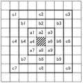
そこで、本発明では、入力画像の輝度分布状態に応じて、周囲の画素として、隣接する画素X1〜X4、X6〜X9よりも遠方の8つの画素を選択することを可能としている。この内容を、図3を用いて、説明する。図3は、本発明の実施の形態1におけるビット拡張処理部11において選択可能な3種類の周囲画素パターンを例示した図である。 Therefore, in the present invention, it is possible to select eight pixels farther from the adjacent pixels X1 to X4 and X6 to X9 as surrounding pixels according to the luminance distribution state of the input image. This will be described with reference to FIG. FIG. 3 is a diagram illustrating three types of surrounding pixel patterns that can be selected by the bit
図3には、選択可能な周囲画素パターンとして、以下の3つのパターンが示されている。なお、図3において、斜めのハッチングで示した画素が、注目画素に相当する。
パターンA:注目画素に隣接する8個の画素a1〜a4、a6〜a9を周囲画素として規定したもの。
パターンB:注目画素から1画素隔てた位置の8個の画素b1〜b4、b6〜b9を周囲画素として規定したもの。
パターンC:注目画素から2画素隔てた位置の8個の画素c1〜c4、c6〜c9を周囲画素として規定したもの。FIG. 3 shows the following three patterns as selectable surrounding pixel patterns. In FIG. 3, pixels indicated by oblique hatching correspond to the target pixel.
Pattern A: 8 pixels a1 to a4 and a6 to a9 adjacent to the target pixel are defined as surrounding pixels.
Pattern B: Eight pixels b1 to b4 and b6 to b9 that are separated by one pixel from the target pixel are defined as surrounding pixels.
Pattern C: Eight pixels c1 to c4 and c6 to c9 located two pixels away from the target pixel are defined as surrounding pixels.
次に、パターンAとパターンBの選択を例に、具体的に説明する。まず、ビット拡張処理部11は、注目画素を中心とした3×3の領域の9画素の輝度値に関する分散値を算出する。そして、算出した分散値が、あらかじめ設定した判定用閾値よりも大きい場合には、ビット拡張処理部11は、注目画素に対して、8個の画素a1〜a4、a6〜a9がばらついているため、これらの影響を反映させたビット拡張処理を行うことが適切であると判断し、周囲画素としてパターンAを採用する。 Next, the selection of the pattern A and the pattern B will be specifically described as an example. First, the bit
一方、算出した分散値が、あらかじめ設定した判定用閾値以下の場合には、ビット拡張処理部11は、注目画素に対して、8個の画素a1〜a4、a6〜a9がばらついていないため、これらの影響を反映させたビット拡張処理を行うことは不適切であると判断し、周囲画素として、パターンAの代わりに、パターンAよりも遠方のパターンBを採用する。 On the other hand, when the calculated variance value is less than or equal to the predetermined threshold for determination, the bit
なお、遠方のパターンとしては、パターンBではなく、パターンCを採用するように、あらかじめ設定しておくことも可能である。 In addition, it is also possible to set in advance so as to adopt the pattern C instead of the pattern B as the distant pattern.
また、ビット拡張処理部11は、注目画素を中心とした5×5の領域の分散値に基づいて、周囲画素として、パターンBとパターンCのいずれを採用すべきかを、同様の処理によって判断することが可能である。 In addition, the bit
次に、図4、図5を用いて、本実施の形態1におけるビット拡張処理の原理および有効性について説明する。まず、図4は、本発明の実施の形態1の均等量子化時における画素値の存在範囲(値域)とゲイン補正の考え方を説明するための図である。なお、説明を簡略化するために、図4では、2ビットから3ビットへのビット拡張を一例として示している。 Next, the principle and effectiveness of the bit extension processing in the first embodiment will be described with reference to FIGS. First, FIG. 4 is a diagram for explaining the concept of pixel value existence range (value range) and gain correction during uniform quantization according to Embodiment 1 of the present invention. In order to simplify the explanation, FIG. 4 shows bit extension from 2 bits to 3 bits as an example.
図4に示すように、00〜11の4つの値域を有する2ビットデータは、ゲイン補正を行ってビット拡張を行うことで、000〜111の8つの値域を有する3ビットデータへと拡張される。ここで、例えば、2ビットの値域01をビット拡張する際に、3ビットでの値域として、011あるいは010のいずれの値に拡張すべきかが問題となる。単純にどちらか一方にビット拡張してしまうと、ビット拡張後のデータに片寄りが発生してしまう。 As shown in FIG. 4, 2-bit data having four value ranges from 00 to 11 is expanded to 3-bit data having eight value ranges from 000 to 111 by performing gain extension by performing gain correction. . Here, for example, when the 2-
これに対して、本発明では、ビット拡張する際に、注目画素の値だけに依存して、特定のビットにゲイン補正を行ってしまうのではなく、周囲画素における輝度値の局所的特徴を考慮して、例えば、2ビットの値域01を、011あるいは010のどちらかに拡張すべきかを決定している。この結果、ビット拡張後のデータが、局所的特徴に基づいて、全ての値域に存在することとなる。 On the other hand, in the present invention, when bit expansion is performed, the gain correction is not performed on a specific bit depending on only the value of the pixel of interest, but local characteristics of luminance values in surrounding pixels are considered. Thus, for example, it is determined whether the 2-
次に、図5は、本発明の実施の形態1における画像の局所的特徴を利用する効果を説明するための図である。なお、説明を簡略化するために、図5では、2ビットデータを例に、注目画素X5に対して、水平方向の周囲画素X4、X6の局所的特徴を考慮することによる効果を示している。 Next, FIG. 5 is a diagram for explaining the effect of using local features of an image according to Embodiment 1 of the present invention. In order to simplify the explanation, FIG. 5 shows the effect of considering local features of the surrounding pixels X4 and X6 in the horizontal direction with respect to the target pixel X5, taking 2-bit data as an example. .
図5の例では、ビット拡張前の2ビットデータ画像において、注目画素X5の輝度値(信号値)が01であり、注目画素X5の水平方向の周囲画素X4、X6の輝度値がともに10である状態を示している。このような状態において、本発明では、周囲画素X4、X6の局所的特徴を考慮することで、注目画素X5は、図5に示したような、値域10に近い「真の存在範囲」のデータであると推測し、3ビットに拡張する際には、値域011となるようにしている。 In the example of FIG. 5, in the 2-bit data image before bit extension, the luminance value (signal value) of the target pixel X5 is 01, and the luminance values of the surrounding pixels X4 and X6 in the horizontal direction of the target pixel X5 are both 10. It shows a certain state. In such a state, the present invention takes into consideration the local characteristics of the surrounding pixels X4 and X6, so that the pixel of interest X5 is “true existence range” data close to the
なお、図5では、値域01の中の上半分の位置が「真の存在範囲」として特定されているが、局所的特徴に応じて、下半分の位置を「真の存在範囲」と特定する場合もある。そして、本発明では、先の数式で示したような比較演算処理をそれぞれの注目画素に対して実行し、周囲画素の局所的特徴を考慮した重み付けを行った上でビット拡張を行うことで、このような図5で説明した「真の存在範囲」を特定した上で、適切なビット拡張処理を実現している。 In FIG. 5, the upper half position in the
次に、ビット拡張処理部11の詳細な構成および詳細な処理内容について、図面を用いて説明する。図6は、本発明の実施の形態1におけるビット拡張処理部11の詳細構成を示した図である。また、図7は、本発明の実施の形態1におけるビット拡張処理部11および表示画像生成処理部12による一連処理を示したフローチャートである。そこで、先の数式で示した演算処理、および図6の内部構成を踏まえて、図7によるフローチャートに示した一連処理を説明する。 Next, a detailed configuration and detailed processing contents of the bit
なお、以下の説明では、n=5とし、注目画素のビット拡張を行う際に考慮する局所的特徴の対象となる周囲画素を、先の図3に示したパターンA(周囲画素をa1〜a4、a6〜a9とする場合)と、パターンB(周囲画素をb1〜b4、b6〜b9とする場合)のいずれかに切り換える場合について説明する。 In the following description, it is assumed that n = 5, and the surrounding pixels that are the target of the local feature to be considered when performing bit extension of the pixel of interest are the pattern A shown in FIG. 3 (the surrounding pixels are a1 to a4). , A6 to a9) and pattern B (when surrounding pixels are b1 to b4 and b6 to b9) will be described.
入力されたpビットのデータは、一旦、nラインメモリ111に蓄えられる(ステップS701)。次に、n×nデータ読出し部112は、nラインメモリ111からは、n×n個のブロックデータを読み出す(ステップS702)。すなわち、n=5を例にとると、パターンAとパターンBを包含する、5×5の領域が抽出されることとなる。 The input p-bit data is temporarily stored in the n-line memory 111 (step S701). Next, the n × n
次に、分散値算出部113は、パターンAを含む3×3の領域について、分散値を算出する(ステップS703)。そして、平坦度判定部114は、分散値算出部113で算出された分散値と、平坦度を判定するためにあらかじめ設定された閾値TH1とを比較し、分散値が閾値TH1よりも小さいときには0(分散値が小さいことから、平坦度が高く、3×3の領域が平坦部分であると判定したことに相当)、分散値が閾値TH1以上のときには1(分散値が大きいことから、平坦度が低く、3×3の領域が平坦部ではないと判定したことに相当)を、判定結果として出力する(ステップS704)。 Next, the variance
次に、3×3データ読出し部115は、平坦度判定部114の判定結果が1のときは、最近傍の3×3のデータを、nラインメモリ111から読み出す(ステップS705)。すなわち、注目画素と、注目画素に対してAパターンとして規定される周囲画素a1〜a4、a6〜a9とから構成される3×3のデータを読み出す。 Next, when the determination result of the
一方、3×3データ読出し部115は、平坦度判定部114の判定結果が0のときは、遠方より3×3のデータを、nラインメモリ111から読み出す(ステップS706)。すなわち、注目画素と、注目画素に対してBパターンとして規定される周囲画素b1〜b4、b6〜b9とから構成される3×3のデータを読み出す。 On the other hand, when the determination result of the
このようにして、3×3データ読出し部115は、平坦度判定部114の判定結果に応じて、周囲画素が平坦でない場合には、注目画素に近い8画素を周囲画素として収集し、周囲画素が平坦である場合には、注目画素から遠い8画素を周囲画素として収集することで、入力画像の輝度分布状態に応じて、ビット拡張処理を行うために適切な3×3のデータを読み出すことができる。 In this manner, according to the determination result of the
次に、データ比較総和値算出部116は、総和値sumを0に初期化するとともに、ステップS705またはステップS706で読み出した3×3のデータを、先の図2に示したようなX1〜X9としてセットする(ステップS707)。 Next, the data comparison total
次に、データ比較総和値算出部116は、3×3データ読出し部115で読み出された3×3のデータのうち、中心部X5を注目画素とし、その周辺のデータXi(i=1〜4、6〜9)との比較により、X5が小さい時は+1とし、X5が大きい時は−1として、総和値sumを算出する(ステップS708〜ステップS713)。 Next, the data comparison total
さらに、正規化補正部117は、データ比較総和値算出部116で算出された総和値sumに対し、先に数式として示したような適切な正規化処理を行い、注目画素X5に加算した上で、適切なゲイン補正を行い、qビットに拡張されたデータを出力する(ステップS714、ステップS715)。 Further, the normalization correction unit 117 performs an appropriate normalization process as shown in the equation above on the total value sum calculated by the data comparison total
以上のように、実施の形態1によれば、入力画像の局所的な特徴を生かして、周囲画素の平坦度に応じて、注目画素の重み付けを適切に行うことで、入力画像の輝度分布状態に応じて、入力画像pビット(例えば、8ビット)のデータを、qビット(例えば、10ビットや12ビット)に精度よく拡張できる。この結果、途中の丸め演算による誤差の蓄積を抑えることができ、疑似輪郭等の画質劣化を防止できる。 As described above, according to the first embodiment, the luminance distribution state of the input image is obtained by appropriately weighting the pixel of interest according to the flatness of the surrounding pixels by utilizing the local characteristics of the input image. Accordingly, data of input image p bits (for example, 8 bits) can be accurately expanded to q bits (for example, 10 bits or 12 bits). As a result, it is possible to suppress the accumulation of errors due to a rounding operation in the middle, and to prevent image quality deterioration such as a pseudo contour.
また、8ビットの入力画像に対して、本発明のビット拡張手法を実行することで、10ビットや12ビットを表現できる高精度ディスプレイに対し、高階調表示が実現できる。さらに、本発明のビット拡張手法は、簡単な比較演算をベースに実施できるため、ソフトウェア的にもハードウェア的にも軽く、安価に高精度化を実現できるメリットがある。 Further, by executing the bit expansion method of the present invention on an 8-bit input image, a high gradation display can be realized with respect to a high-precision display capable of expressing 10 bits or 12 bits. Furthermore, since the bit expansion method of the present invention can be implemented based on a simple comparison operation, it is light in terms of software and hardware, and has an advantage that high accuracy can be realized at low cost.
なお、本実施の形態1では、入力画像の局所的な特徴を得るための周囲画素として、図3に示したようなパターンA〜パターンCのいずれかを選択する場合について説明したが、周囲画素の集合は、このようなパターンに限定されるものではない。例えば、パターンAで示した注目画素に隣接する8つの画素よりも、注目画素から遠方の位置にある画素の集合を、パターンB、パターンCの代わりに、遠方の周囲画素として設定することも可能である。 In the first embodiment, the case where any one of the patterns A to C as shown in FIG. 3 is selected as the surrounding pixel for obtaining the local feature of the input image has been described. The set of is not limited to such a pattern. For example, a set of pixels farther from the target pixel than the eight pixels adjacent to the target pixel indicated by the pattern A can be set as a peripheral pixel far away from the pattern B and pattern C. It is.
入力画像の輝度分布状態によっては、例えば、パターンB、パターンCの両方の要素からなる画素の集合を、遠方の周囲画素として規定することができる。あるいは、注目画素から1画素以上の間隔を空けて、ある距離範囲に含まれるような画素の集合を、遠方の周囲画素として規定することもできる。 Depending on the luminance distribution state of the input image, for example, a set of pixels composed of both elements of pattern B and pattern C can be defined as distant surrounding pixels. Alternatively, a set of pixels included in a certain distance range with an interval of one pixel or more from the target pixel can be defined as a distant peripheral pixel.
また、近傍の周囲画素自体も、パターンAで示した注目画素に隣接する8つの画素に限定する必要はない。入力画像の輝度分布状態によっては、例えば、パターンA、パターンBの両方の要素からなる画素の集合を、近傍の周囲画素として規定する、あるいは、パターンBを近傍の周囲画素として規定することができる。 Also, the neighboring peripheral pixels themselves need not be limited to the eight pixels adjacent to the target pixel indicated by the pattern A. Depending on the luminance distribution state of the input image, for example, a set of pixels composed of both elements of pattern A and pattern B can be defined as neighboring peripheral pixels, or pattern B can be defined as neighboring peripheral pixels. .
いずれにせよ、注目画素に対して、ある一定の距離範囲内の領域を近傍の周囲画素として規定し、近傍の周囲画素よりも、注目画素から遠方に位置する画素の集合を遠方の周囲画素として規定することが可能である。そして、近傍の周囲画素と注目画素からなる画素の集合のばらつき具合に応じて、周囲画素の選択を近傍か遠方に切り換えることができればよい。 In any case, an area within a certain distance range is defined as a neighboring peripheral pixel with respect to the target pixel, and a set of pixels located farther from the target pixel than the neighboring peripheral pixels is defined as a far surrounding pixel. It is possible to prescribe. Then, it is only necessary that the selection of the surrounding pixels can be switched between the vicinity and the distance according to the variation of the set of pixels including the neighboring surrounding pixels and the target pixel.
10 画像信号処理装置、11 ビット拡張処理部、12 表示画像生成処理部、20 ディスプレイパネル、111 nラインメモリ、112 n×nデータ読出し部、113 分散値算出部、114 平坦度判定部、115 3×3データ読出し部、116 データ比較総和値算出部、117 正規化補正部。 DESCRIPTION OF
Claims (4)
Translated fromJapanese前記ビット拡張処理部は、前記ディジタル入力画像における注目画素の輝度値をビット拡張する際に、前記注目画素の周囲に存在する複数の周囲画素の輝度値と、前記注目画素の輝度値との大小関係から、前記注目画素の輝度値に重み付けを付加し、前記重み付けが付加された後の前記注目画素の輝度値に対してゲイン補正を行うことで、pビットからqビットへのビット拡張処理を実行する
画像信号処理装置。An image signal processing apparatus comprising a bit extension processing unit for bit-extending a digital input image having a luminance value of p-bit resolution to q bits (p <q),
The bit expansion processing unit, when performing bit expansion on the luminance value of the pixel of interest in the digital input image, determines the magnitude of the luminance values of a plurality of surrounding pixels existing around the pixel of interest and the luminance value of the pixel of interest. From the relationship, a bit expansion process from p bits to q bits is performed by adding a weight to the luminance value of the target pixel and performing gain correction on the luminance value of the target pixel after the weight is added. An image signal processing device to be executed.
請求項1に記載の画像信号処理装置。The bit extension processing unit calculates a variance value of luminance values in a 3 × 3 pixel region centered on the target pixel, and when the calculated variance value is larger than a predetermined determination threshold, When eight pixels adjacent to the target pixel are set as the surrounding pixels, and the calculated variance value is equal to or less than a predetermined determination threshold, the target pixel is more than the eight pixels adjacent to the target pixel. The image signal processing device according to claim 1, wherein the bit extension processing is executed by setting a set of pixels located far from the pixel as the surrounding pixels.
前記ゲイン補正を行った後のビット拡張データが、前記qビットで表現できる値域を超えないように、前記重み付けに対して正規化を行い、正規化後の重み付けが付加された後の前記注目画素の輝度値に対してゲイン補正を行うことで、pビットからqビットへのビット拡張処理を実行する
請求項1または2に記載の画像信号処理装置。The bit extension processing unit
The pixel of interest after the weighting is normalized so that the bit extension data after the gain correction does not exceed the range that can be expressed by the q bits, and the weighting after the normalization is added The image signal processing apparatus according to claim 1, wherein a bit expansion process from p bits to q bits is performed by performing gain correction on the luminance value of the image signal.
前記ビット拡張処理部において、
前記ディジタル入力画像における注目画素の輝度値をビット拡張する際に、前記注目画素の周囲に存在する複数の周囲画素の輝度値と、前記注目画素の輝度値との大小関係から、前記注目画素の輝度値に重み付けを付加する重み付けステップと、
前記重み付けが付加された後の前記注目画素の輝度値に対してゲイン補正を行うことで、pビットからqビットへのビット拡張処理を実行するゲイン補正ステップと
を有するビット拡張演算処理方法。A bit extension arithmetic processing method executed by an image signal processing apparatus including a bit extension processing unit that bit-extends a digital input image having a luminance value of p bits to q bits (p <q),
In the bit extension processing unit,
When the luminance value of the pixel of interest in the digital input image is bit-extended, from the magnitude relationship between the luminance values of a plurality of surrounding pixels existing around the pixel of interest and the luminance value of the pixel of interest, A weighting step for adding weights to the luminance values;
And a gain correction step of performing a bit expansion process from p bits to q bits by performing gain correction on the luminance value of the target pixel after the weighting is added.
Priority Applications (3)
| Application Number | Priority Date | Filing Date | Title |
|---|---|---|---|
| JP2014206985AJP6334358B2 (en) | 2014-10-08 | 2014-10-08 | Image signal processing apparatus and bit extension calculation processing method |
| KR1020150107114AKR101713149B1 (en) | 2014-10-08 | 2015-07-29 | Bit Expansion Method and Apparatus |
| US14/876,383US9679537B2 (en) | 2014-10-08 | 2015-10-06 | Bit expansion method and apparatus |
Applications Claiming Priority (1)
| Application Number | Priority Date | Filing Date | Title |
|---|---|---|---|
| JP2014206985AJP6334358B2 (en) | 2014-10-08 | 2014-10-08 | Image signal processing apparatus and bit extension calculation processing method |
Publications (2)
| Publication Number | Publication Date |
|---|---|
| JP2016076143A JP2016076143A (en) | 2016-05-12 |
| JP6334358B2true JP6334358B2 (en) | 2018-05-30 |
Family
ID=55655883
Family Applications (1)
| Application Number | Title | Priority Date | Filing Date |
|---|---|---|---|
| JP2014206985AActiveJP6334358B2 (en) | 2014-10-08 | 2014-10-08 | Image signal processing apparatus and bit extension calculation processing method |
Country Status (3)
| Country | Link |
|---|---|
| US (1) | US9679537B2 (en) |
| JP (1) | JP6334358B2 (en) |
| KR (1) | KR101713149B1 (en) |
Families Citing this family (1)
| Publication number | Priority date | Publication date | Assignee | Title |
|---|---|---|---|---|
| CN112233615B (en)* | 2020-12-09 | 2021-03-05 | 卡莱特(深圳)云科技有限公司 | Method and device for improving display effect of LED display screen |
Family Cites Families (18)
| Publication number | Priority date | Publication date | Assignee | Title |
|---|---|---|---|---|
| JPH08237669A (en)* | 1995-02-28 | 1996-09-13 | Sony Corp | Picture signal processor, picture signal processing method and picture signal decoder |
| JP2002232713A (en)* | 2001-02-06 | 2002-08-16 | Mitsubishi Electric Corp | Image processing apparatus and image processing method |
| US6989636B2 (en)* | 2004-06-16 | 2006-01-24 | Eastman Kodak Company | Method and apparatus for uniformity and brightness correction in an OLED display |
| JP4192900B2 (en) | 2005-02-08 | 2008-12-10 | ソニー株式会社 | Quantization accuracy reproduction method, quantization accuracy reproduction device, imaging device, information processing device, and program |
| KR100679047B1 (en)* | 2005-09-29 | 2007-02-05 | 삼성전자주식회사 | Bit resolution extension method and device |
| US8160381B2 (en)* | 2006-08-30 | 2012-04-17 | Micron Technology, Inc. | Method and apparatus for image noise reduction using noise models |
| JP4527750B2 (en)* | 2007-05-30 | 2010-08-18 | 三菱電機株式会社 | Image processing apparatus and method, and image display apparatus |
| JP4983415B2 (en)* | 2007-06-11 | 2012-07-25 | ソニー株式会社 | Image signal processing apparatus, image signal processing method, and program |
| JP2009276956A (en)* | 2008-05-14 | 2009-11-26 | Fujifilm Corp | Image processing apparatus and method, and program |
| JPWO2010061436A1 (en)* | 2008-11-25 | 2012-04-19 | パイオニア株式会社 | Video processing circuit, information reproducing apparatus, and video processing method |
| US8406569B2 (en)* | 2009-01-19 | 2013-03-26 | Sharp Laboratories Of America, Inc. | Methods and systems for enhanced dynamic range images and video from multiple exposures |
| JP5159651B2 (en) | 2009-01-21 | 2013-03-06 | 三菱電機株式会社 | Image processing apparatus, image processing method, and image display apparatus |
| JP2012058850A (en)* | 2010-09-06 | 2012-03-22 | Sony Corp | Information processing device and method, and program |
| US8773451B2 (en)* | 2011-05-03 | 2014-07-08 | Apple Inc. | Color correction method and apparatus for displays |
| JP5899684B2 (en)* | 2011-07-11 | 2016-04-06 | ソニー株式会社 | Image processing apparatus, image processing method, and program |
| US20130162625A1 (en)* | 2011-12-23 | 2013-06-27 | Michael L. Schmit | Displayed Image Improvement |
| JP5843641B2 (en)* | 2012-02-07 | 2016-01-13 | 株式会社東芝 | Image processing apparatus and solid-state imaging apparatus |
| JP6320053B2 (en)* | 2014-01-22 | 2018-05-09 | キヤノン株式会社 | Image processing apparatus, image processing method, and computer program |
- 2014
- 2014-10-08JPJP2014206985Apatent/JP6334358B2/enactiveActive
- 2015
- 2015-07-29KRKR1020150107114Apatent/KR101713149B1/enactiveActive
- 2015-10-06USUS14/876,383patent/US9679537B2/enactiveActive
Also Published As
| Publication number | Publication date |
|---|---|
| US9679537B2 (en) | 2017-06-13 |
| KR20160041751A (en) | 2016-04-18 |
| JP2016076143A (en) | 2016-05-12 |
| KR101713149B1 (en) | 2017-03-07 |
| US20160104459A1 (en) | 2016-04-14 |
Similar Documents
| Publication | Publication Date | Title |
|---|---|---|
| CN107068037B (en) | Gray scale correction method and gray scale correction device of display panel | |
| CN102918562B (en) | For the method and system of generating enhanced images | |
| JP4217657B2 (en) | Image processing method, program, storage medium, and apparatus | |
| JP2004159344A (en) | Contrast correction device and method | |
| KR101551641B1 (en) | Device for average calculating of non-linear data | |
| KR20080038414A (en) | Systems, methods, and devices for organizing tables, and use in image processing | |
| JP2009010489A (en) | Image processing apparatus and image processing method | |
| US20220004857A1 (en) | Neural network processing apparatus, neural network processing method, and neural network processing program | |
| CN116682350A (en) | Data processing method, device and computer-readable storage medium of display panel | |
| US9715720B1 (en) | System and method for reducing image noise | |
| JP5152203B2 (en) | Image processing apparatus, image processing method, image processing program, and image correction apparatus | |
| JP6334358B2 (en) | Image signal processing apparatus and bit extension calculation processing method | |
| CN114758603A (en) | Pressure drop compensation method, device, equipment and storage medium | |
| WO2016165357A1 (en) | Image processing method and apparatus, terminal and storage medium | |
| KR20030066511A (en) | Apparatus and method for real-time brightness control of moving images | |
| CN111385437A (en) | Image device and burn-in prevention method | |
| CN116682351A (en) | Data processing method, device and computer-readable storage medium of display panel | |
| CN114783367A (en) | Box linearity correction method and device, display screen and display control method | |
| JP3808798B2 (en) | Color signal expansion apparatus and color signal expansion method | |
| JP4930845B2 (en) | Image processing apparatus, image processing method, and image processing program | |
| CN107292829B (en) | Image processing method and device | |
| JP2001357394A (en) | Color unevenness correction data creation system and image display device | |
| CN116052584B (en) | Color correction method, apparatus, electronic device, and computer-readable storage medium | |
| JP6303636B2 (en) | Image processing apparatus and image processing method | |
| JP2009239608A (en) | Image processing apparatus and digital camera |
Legal Events
| Date | Code | Title | Description |
|---|---|---|---|
| A621 | Written request for application examination | Free format text:JAPANESE INTERMEDIATE CODE: A621 Effective date:20170308 | |
| A977 | Report on retrieval | Free format text:JAPANESE INTERMEDIATE CODE: A971007 Effective date:20180320 | |
| TRDD | Decision of grant or rejection written | ||
| A01 | Written decision to grant a patent or to grant a registration (utility model) | Free format text:JAPANESE INTERMEDIATE CODE: A01 Effective date:20180403 | |
| A61 | First payment of annual fees (during grant procedure) | Free format text:JAPANESE INTERMEDIATE CODE: A61 Effective date:20180426 | |
| R150 | Certificate of patent or registration of utility model | Ref document number:6334358 Country of ref document:JP Free format text:JAPANESE INTERMEDIATE CODE: R150 | |
| R250 | Receipt of annual fees | Free format text:JAPANESE INTERMEDIATE CODE: R250 | |
| R250 | Receipt of annual fees | Free format text:JAPANESE INTERMEDIATE CODE: R250 | |
| R250 | Receipt of annual fees | Free format text:JAPANESE INTERMEDIATE CODE: R250 | |
| R250 | Receipt of annual fees | Free format text:JAPANESE INTERMEDIATE CODE: R250 | |
| R250 | Receipt of annual fees | Free format text:JAPANESE INTERMEDIATE CODE: R250 |