JP6331138B2 - Flow ratio calculation device, control device including the same, gas turbine plant including the control device, flow ratio calculation method, and fuel system control method - Google Patents
Flow ratio calculation device, control device including the same, gas turbine plant including the control device, flow ratio calculation method, and fuel system control methodDownload PDFInfo
- Publication number
- JP6331138B2 JP6331138B2JP2014160605AJP2014160605AJP6331138B2JP 6331138 B2JP6331138 B2JP 6331138B2JP 2014160605 AJP2014160605 AJP 2014160605AJP 2014160605 AJP2014160605 AJP 2014160605AJP 6331138 B2JP6331138 B2JP 6331138B2
- Authority
- JP
- Japan
- Prior art keywords
- flow rate
- value
- correction value
- fuel
- ratio
- Prior art date
- Legal status (The legal status is an assumption and is not a legal conclusion. Google has not performed a legal analysis and makes no representation as to the accuracy of the status listed.)
- Active
Links
Images


Classifications
- F—MECHANICAL ENGINEERING; LIGHTING; HEATING; WEAPONS; BLASTING
- F02—COMBUSTION ENGINES; HOT-GAS OR COMBUSTION-PRODUCT ENGINE PLANTS
- F02C—GAS-TURBINE PLANTS; AIR INTAKES FOR JET-PROPULSION PLANTS; CONTROLLING FUEL SUPPLY IN AIR-BREATHING JET-PROPULSION PLANTS
- F02C9/00—Controlling gas-turbine plants; Controlling fuel supply in air- breathing jet-propulsion plants
- F02C9/26—Control of fuel supply
- F02C9/28—Regulating systems responsive to plant or ambient parameters, e.g. temperature, pressure, rotor speed
- F—MECHANICAL ENGINEERING; LIGHTING; HEATING; WEAPONS; BLASTING
- F02—COMBUSTION ENGINES; HOT-GAS OR COMBUSTION-PRODUCT ENGINE PLANTS
- F02C—GAS-TURBINE PLANTS; AIR INTAKES FOR JET-PROPULSION PLANTS; CONTROLLING FUEL SUPPLY IN AIR-BREATHING JET-PROPULSION PLANTS
- F02C9/00—Controlling gas-turbine plants; Controlling fuel supply in air- breathing jet-propulsion plants
- F—MECHANICAL ENGINEERING; LIGHTING; HEATING; WEAPONS; BLASTING
- F23—COMBUSTION APPARATUS; COMBUSTION PROCESSES
- F23N—REGULATING OR CONTROLLING COMBUSTION
- F23N1/00—Regulating fuel supply
- F23N1/002—Regulating fuel supply using electronic means
- F—MECHANICAL ENGINEERING; LIGHTING; HEATING; WEAPONS; BLASTING
- F23—COMBUSTION APPARATUS; COMBUSTION PROCESSES
- F23N—REGULATING OR CONTROLLING COMBUSTION
- F23N5/00—Systems for controlling combustion
- F23N5/16—Systems for controlling combustion using noise-sensitive detectors
- F—MECHANICAL ENGINEERING; LIGHTING; HEATING; WEAPONS; BLASTING
- F23—COMBUSTION APPARATUS; COMBUSTION PROCESSES
- F23R—GENERATING COMBUSTION PRODUCTS OF HIGH PRESSURE OR HIGH VELOCITY, e.g. GAS-TURBINE COMBUSTION CHAMBERS
- F23R3/00—Continuous combustion chambers using liquid or gaseous fuel
- F23R3/28—Continuous combustion chambers using liquid or gaseous fuel characterised by the fuel supply
- F23R3/34—Feeding into different combustion zones
- F23R3/346—Feeding into different combustion zones for staged combustion
- F—MECHANICAL ENGINEERING; LIGHTING; HEATING; WEAPONS; BLASTING
- F02—COMBUSTION ENGINES; HOT-GAS OR COMBUSTION-PRODUCT ENGINE PLANTS
- F02C—GAS-TURBINE PLANTS; AIR INTAKES FOR JET-PROPULSION PLANTS; CONTROLLING FUEL SUPPLY IN AIR-BREATHING JET-PROPULSION PLANTS
- F02C9/00—Controlling gas-turbine plants; Controlling fuel supply in air- breathing jet-propulsion plants
- F02C9/26—Control of fuel supply
- F02C9/263—Control of fuel supply by means of fuel metering valves
- F—MECHANICAL ENGINEERING; LIGHTING; HEATING; WEAPONS; BLASTING
- F02—COMBUSTION ENGINES; HOT-GAS OR COMBUSTION-PRODUCT ENGINE PLANTS
- F02C—GAS-TURBINE PLANTS; AIR INTAKES FOR JET-PROPULSION PLANTS; CONTROLLING FUEL SUPPLY IN AIR-BREATHING JET-PROPULSION PLANTS
- F02C9/00—Controlling gas-turbine plants; Controlling fuel supply in air- breathing jet-propulsion plants
- F02C9/26—Control of fuel supply
- F02C9/32—Control of fuel supply characterised by throttling of fuel
- F02C9/34—Joint control of separate flows to main and auxiliary burners
- F—MECHANICAL ENGINEERING; LIGHTING; HEATING; WEAPONS; BLASTING
- F05—INDEXING SCHEMES RELATING TO ENGINES OR PUMPS IN VARIOUS SUBCLASSES OF CLASSES F01-F04
- F05D—INDEXING SCHEME FOR ASPECTS RELATING TO NON-POSITIVE-DISPLACEMENT MACHINES OR ENGINES, GAS-TURBINES OR JET-PROPULSION PLANTS
- F05D2260/00—Function
- F05D2260/96—Preventing, counteracting or reducing vibration or noise
- F05D2260/964—Preventing, counteracting or reducing vibration or noise counteracting thermoacoustic noise
- F—MECHANICAL ENGINEERING; LIGHTING; HEATING; WEAPONS; BLASTING
- F23—COMBUSTION APPARATUS; COMBUSTION PROCESSES
- F23N—REGULATING OR CONTROLLING COMBUSTION
- F23N2237/00—Controlling
- F23N2237/02—Controlling two or more burners
- F—MECHANICAL ENGINEERING; LIGHTING; HEATING; WEAPONS; BLASTING
- F23—COMBUSTION APPARATUS; COMBUSTION PROCESSES
- F23N—REGULATING OR CONTROLLING COMBUSTION
- F23N2241/00—Applications
- F23N2241/20—Gas turbines
- F—MECHANICAL ENGINEERING; LIGHTING; HEATING; WEAPONS; BLASTING
- F23—COMBUSTION APPARATUS; COMBUSTION PROCESSES
- F23R—GENERATING COMBUSTION PRODUCTS OF HIGH PRESSURE OR HIGH VELOCITY, e.g. GAS-TURBINE COMBUSTION CHAMBERS
- F23R2900/00—Special features of, or arrangements for continuous combustion chambers; Combustion processes therefor
- F23R2900/00013—Reducing thermo-acoustic vibrations by active means
- F—MECHANICAL ENGINEERING; LIGHTING; HEATING; WEAPONS; BLASTING
- F23—COMBUSTION APPARATUS; COMBUSTION PROCESSES
- F23R—GENERATING COMBUSTION PRODUCTS OF HIGH PRESSURE OR HIGH VELOCITY, e.g. GAS-TURBINE COMBUSTION CHAMBERS
- F23R3/00—Continuous combustion chambers using liquid or gaseous fuel
- F23R3/28—Continuous combustion chambers using liquid or gaseous fuel characterised by the fuel supply
- F23R3/286—Continuous combustion chambers using liquid or gaseous fuel characterised by the fuel supply having fuel-air premixing devices
- F—MECHANICAL ENGINEERING; LIGHTING; HEATING; WEAPONS; BLASTING
- F23—COMBUSTION APPARATUS; COMBUSTION PROCESSES
- F23R—GENERATING COMBUSTION PRODUCTS OF HIGH PRESSURE OR HIGH VELOCITY, e.g. GAS-TURBINE COMBUSTION CHAMBERS
- F23R3/00—Continuous combustion chambers using liquid or gaseous fuel
- F23R3/28—Continuous combustion chambers using liquid or gaseous fuel characterised by the fuel supply
- F23R3/36—Supply of different fuels
Landscapes
- Engineering & Computer Science (AREA)
- Chemical & Material Sciences (AREA)
- Combustion & Propulsion (AREA)
- Mechanical Engineering (AREA)
- General Engineering & Computer Science (AREA)
- Control Of Turbines (AREA)
- Regulation And Control Of Combustion (AREA)
Description
Translated fromJapanese本発明は、複数の燃料系統から燃焼器へ供給される各燃料の流量比を算出する技術に関する。 The present invention relates to a technique for calculating a flow ratio of each fuel supplied from a plurality of fuel systems to a combustor.
ガスタービンは、空気を圧縮する圧縮機と、圧縮機で圧縮された空気中で燃料を燃焼させて燃焼ガスを生成する燃焼器と、燃焼ガスにより駆動するタービンと、を備えている。燃焼器には、燃料を拡散燃焼させるパイロットバーナと、燃料を予混合燃焼させるメインバーナとを有している燃焼器がある。このような燃焼器では、各バーナに供給する燃料流量の比を管理する必要がある。 The gas turbine includes a compressor that compresses air, a combustor that generates combustion gas by burning fuel in the air compressed by the compressor, and a turbine that is driven by the combustion gas. Combustors include a combustor having a pilot burner that diffuses and burns fuel and a main burner that premixes and burns fuel. In such a combustor, it is necessary to manage the ratio of the fuel flow rate supplied to each burner.
例えば、以下の特許文献1に記載の技術では、燃焼器からの燃焼ガスが流入するタービンの入口温度を無次元化した燃焼負荷指令が示す値に応じて、各バーナに供給する燃料流量の比を定めている。さらに、この技術では、負荷を急激に低下させるランバック運転時に、燃焼負荷指令値に応じて定めた燃料流量比を変更して、ランバック運転時に生じることがある燃焼振動を抑制している。 For example, in the technique described in
上記特許文献1に記載の技術では、ランバック運転時における燃焼振動を抑えることができる。しかしながら、ランバック運転時を除いて負荷を低下させる場合や、逆に負荷を高める場合でも、燃焼器内で燃料を安定燃焼させることが望まれる。 With the technique described in
そこで、本発明は、各種負荷変化時における燃焼器での燃焼安定性を高めることができる技術を提供することを目的とする。 Then, an object of this invention is to provide the technique which can improve the combustion stability in a combustor at the time of various load changes.
上記目的を達成するための発明に係る一態様としての流量比算出装置は、
複数の燃料系統と、空気を圧縮して圧縮空気を生成する圧縮機と、複数の前記燃料系統からの燃料を前記圧縮空気中で燃焼させて燃焼ガスを生成する燃焼器と、前記燃焼ガスにより駆動するタービンとを備えるガスタービンで、複数の前記燃料系統を流れる前記燃料の流量比を算出する流量比算出装置において、前記燃焼器での燃焼状態を表すことができる複数のパラメータのうちの第一パラメータの値を受け付け、前記第一パラメータと前記流量比との予め定められた関係を用いて、受け付けた前記第一パラメータの値に応じた前記流量比を求める流量比演算器と、前記ガスタービンの負荷変化時における前記流量比の補正値を求める補正値演算器と、前記ガスタービンの負荷変化に対して相関性を持って変化する値又は前記負荷の値である負荷相関値の変動を検知する変動検知器と、前記変動検知器で前記負荷相関値の変動が検知されると、前記流量比演算器で求められた前記流量比を前記補正値演算器で求められた前記補正値で補正する補正器と、を備える。前記補正値演算器は、前記複数のパラメータのうち、前記第一パラメータと異なる第二パラメータの値を受け付け、前記第二パラメータと前記補正値との予め定められた関係を用いて、受け付けた前記第二パラメータの値に応じた前記補正値を求める。前記補正値演算器は、前記負荷相関値が増加しているときの前記第二パラメータと前記補正値との予め定められた増加時関係を用いて、前記負荷相関値が増加しているときの前記第二パラメータの値に応じた補正値を求める増加時補正値演算器と、前記負荷相関値が減少しているときの前記第二パラメータと前記補正値との予め定められた減少時関係を用いて、前記負荷相関値が減少しているときの前記第二パラメータの値に応じた補正値を求める減少時補正値演算器と、を有する。前記補正器は、前記変動検知器で前記負荷相関値の増加が検知されると、前記流量比演算器で求められた前記流量比を前記増加時補正値演算器で求められた前記補正値で補正し、前記変動検知器で前記負荷相関値の減少が検知されると、前記流量比演算器で求められた前記流量比を前記減少時補正値演算器で求められた前記補正値で補正する。The flow rate ratio calculation device as one aspect according to the invention for achieving the above object is as follows:
A plurality of fuel systems, a compressor that compresses air to generate compressed air, a combustor that generates combustion gas by burning fuel from the plurality of fuel systems in the compressed air, and the combustion gas In a flow rate ratio calculating apparatus for calculating a flow rate ratio of the fuel flowing through a plurality of the fuel systems in a gas turbine comprising a driving turbine, a first of a plurality of parameters that can represent a combustion state in the combustor Receiving a value of one parameter, using a predetermined relationship between the first parameter and the flow rate ratio, and determining a flow rate ratio according to the received first parameter value; A correction value calculator for obtaining a correction value of the flow rate ratio when the load of the turbine changes, and a value that changes in correlation with the load change of the gas turbine or the value of the load. A fluctuation detector for detecting fluctuations in the load correlation value, and when the fluctuation in the load correlation value is detected by the fluctuation detector, the flow rate ratio obtained by the flow ratio calculator is obtained by the correction value calculator. And a corrector for correcting with the correction value.The correction value calculator receives a value of a second parameter different from the first parameter among the plurality of parameters, and uses the predetermined relationship between the second parameter and the correction value, The correction value corresponding to the value of the second parameter is obtained. The correction value calculator uses the predetermined increase relationship between the second parameter and the correction value when the load correlation value is increasing, when the load correlation value is increasing. An increase correction value calculator for calculating a correction value according to the value of the second parameter, and a predetermined decrease relationship between the second parameter and the correction value when the load correlation value is decreasing. And a decreasing correction value calculator for calculating a correction value according to the value of the second parameter when the load correlation value is decreasing. When the increase of the load correlation value is detected by the fluctuation detector, the corrector calculates the flow rate ratio determined by the flow rate ratio calculator with the correction value determined by the increase correction value calculator. When the decrease of the load correlation value is detected by the fluctuation detector, the flow rate ratio calculated by the flow rate ratio calculator is corrected by the correction value determined by the decrease correction value calculator. .
燃焼器の燃焼条件は、燃焼器での燃焼状態を表すことができる複数のパラメータのうち所定のパラメータの値が所定値のときに、燃焼器内での安定燃焼のための条件として厳しい条件になっている場合がある。この厳しい条件のときに、燃焼器に投入する全燃料流量を変更すると、つまり負荷を変更すると、燃焼器内での燃焼の安定性が損なわる場合がある。そこで、当該流量比算出装置では、変動検知器で負荷相関値の変動が検知されると、流量比演算器で求められた流量比を補正値で補正する。よって、当該流量比算出装置では、負荷相関値の変動時における燃焼器内での燃焼安定性を図ることができる。 The combustion condition of the combustor is a severe condition as a condition for stable combustion in the combustor when the value of the predetermined parameter among the plurality of parameters that can represent the combustion state in the combustor is a predetermined value. It may be. If the flow rate of the total fuel input to the combustor is changed under this severe condition, that is, if the load is changed, the stability of combustion in the combustor may be impaired. Therefore, in the flow rate calculation device, when the fluctuation of the load correlation value is detected by the fluctuation detector, the flow ratio obtained by the flow ratio calculator is corrected with the correction value. Therefore, the flow rate ratio calculation device can achieve combustion stability in the combustor when the load correlation value fluctuates.
ここで、前記流量比算出装置において、前記補正器は、出力する補正値を、時間経過に伴って前記補正値演算器で求められた前記補正値に近づくよう変化させる補正値調節器と、前記補正値調節器からの出力された補正値で前記流量比演算器で求められた前記流量比を補正する流量比補正器と、を有してもよい。
また、上記目的を達成するための発明に係る他の態様としての流量比算出装置は、
複数の燃料系統と、空気を圧縮して圧縮空気を生成する圧縮機と、複数の前記燃料系統からの燃料を前記圧縮空気中で燃焼させて燃焼ガスを生成する燃焼器と、前記燃焼ガスにより駆動するタービンとを備えるガスタービンで、複数の前記燃料系統を流れる前記燃料の流量比を算出する流量比算出装置において、前記燃焼器での燃焼状態を表すことができる複数のパラメータのうちの第一パラメータの値を受け付け、前記第一パラメータと前記流量比との予め定められた関係を用いて、受け付けた前記第一パラメータの値に応じた前記流量比を求める流量比演算器と、前記ガスタービンの負荷変化時における前記流量比の補正値を求める補正値演算器と、前記ガスタービンの負荷変化に対して相関性を持って変化する値又は前記負荷の値である負荷相関値の変動を検知する変動検知器と、前記変動検知器で前記負荷相関値の変動が検知されると、前記流量比演算器で求められた前記流量比を前記補正値演算器で求められた前記補正値で補正する補正器と、を備える。前記補正器は、出力する補正値を、時間経過に伴って前記補正値演算器で求められた前記補正値に近づくよう変化させる補正値調節器と、前記補正値調節器からの出力された補正値で前記流量比演算器で求められた前記流量比を補正する流量比補正器と、を有する。
前記他の態様としての前記流量比算出装置において、前記補正値演算器は、前記複数のパラメータのうち、前記第一パラメータと異なる第二パラメータの値を受け付け、前記第二パラメータと前記補正値との予め定められた関係を用いて、受け付けた前記第二パラメータの値に応じた前記補正値を求めてもよい。Here, before Symbol flow ratio calculation device, wherein the corrector comprises: a correction value adjuster correction value output is varied so as to approach the correction value determined by the correction value calculator with time, And a flow rate ratio corrector that corrects the flow rate ratio obtained by the flow rate ratio calculator with the correction value output from the correction value adjuster.
Moreover, the flow rate ratio calculation apparatus as another aspect according to the invention for achieving the above object is as follows:
A plurality of fuel systems, a compressor that compresses air to generate compressed air, a combustor that generates combustion gas by burning fuel from the plurality of fuel systems in the compressed air, and the combustion gas In a flow rate ratio calculating apparatus for calculating a flow rate ratio of the fuel flowing through a plurality of the fuel systems in a gas turbine comprising a driving turbine, a first of a plurality of parameters that can represent a combustion state in the combustor Receiving a value of one parameter, using a predetermined relationship between the first parameter and the flow rate ratio, and determining a flow rate ratio according to the received first parameter value; A correction value calculator for obtaining a correction value of the flow rate ratio when the load of the turbine changes, and a value that changes in correlation with the load change of the gas turbine or the value of the load. A fluctuation detector for detecting fluctuations in the load correlation value, and when the fluctuation in the load correlation value is detected by the fluctuation detector, the flow rate ratio obtained by the flow ratio calculator is obtained by the correction value calculator. And a corrector for correcting with the correction value. The correction unit includes a correction value adjuster that changes a correction value to be output so as to approach the correction value obtained by the correction value calculator with time, and a correction output from the correction value adjuster. And a flow rate ratio corrector that corrects the flow rate ratio obtained by the flow rate ratio calculator with a value.
In the flow rate ratio calculation apparatus as the other aspect, the correction value calculator accepts a value of a second parameter different from the first parameter among the plurality of parameters, and the second parameter and the correction value The correction value corresponding to the received value of the second parameter may be obtained using the predetermined relationship.
また、以上のいずれかの前記流量比算出装置において、前記燃焼器は、燃料を噴射するパイロットバーナ及びメインバーナを有しており、前記ガスタービンは、複数の燃料系統として、前記パイロットバーナに燃料を供給するパイロット燃料系統と、前記メインバーナに燃料を供給するメイン燃料系統とを有しており、前記流量比は、複数の燃料系統から前記燃焼器に供給する燃料の全流量に対する前記パイロット燃料系統から前記燃焼器に供給する燃料の流量の比であるパイロット燃料比を含んでもよい。 Further, in any one of the flow rate ratio calculation devices described above, the combustor includes a pilot burner and a main burner for injecting fuel, and the gas turbine supplies fuel to the pilot burner as a plurality of fuel systems. A pilot fuel system for supplying fuel and a main fuel system for supplying fuel to the main burner, wherein the flow rate ratio corresponds to the total amount of fuel supplied to the combustor from a plurality of fuel systems. A pilot fuel ratio that is a ratio of a flow rate of fuel supplied from the system to the combustor may be included.
また、上記目的を達成するための発明に係るさらに他の態様としての流量比算出装置は、
複数の燃料系統と、空気を圧縮して圧縮空気を生成する圧縮機と、複数の前記燃料系統からの燃料を前記圧縮空気中で燃焼させて燃焼ガスを生成する燃焼器と、前記燃焼ガスにより駆動するタービンとを備えるガスタービンで、複数の前記燃料系統を流れる前記燃料の流量比を算出する流量比算出装置において、前記燃焼器での燃焼状態を表すことができる複数のパラメータのうちの第一パラメータの値を受け付け、前記第一パラメータと前記流量比との予め定められた関係を用いて、受け付けた前記第一パラメータの値に応じた前記流量比を求める流量比演算器と、前記ガスタービンの負荷変化時における前記流量比の補正値を求める補正値演算器と、前記ガスタービンの負荷変化に対して相関性を持って変化する値又は前記負荷の値である負荷相関値の変動を検知する変動検知器と、前記変動検知器で前記負荷相関値の変動が検知されると、前記流量比演算器で求められた前記流量比を前記補正値演算器で求められた前記補正値で補正する補正器と、を備える。前記補正値演算器は、前記複数のパラメータのうち、前記第一パラメータと異なる第二パラメータの値を受け付け、前記第二パラメータと前記補正値との予め定められた関係を用いて、受け付けた前記第二パラメータの値に応じた前記補正値を求める。前記燃焼器は、燃料を噴射するパイロットバーナ及びメインバーナを有しており、前記ガスタービンは、複数の燃料系統として、前記パイロットバーナに燃料を供給するパイロット燃料系統と、前記メインバーナに燃料を供給するメイン燃料系統とを有しており、前記流量比は、複数の燃料系統から前記燃焼器に供給する燃料の全流量に対する前記パイロット燃料系統から前記燃焼器に供給する燃料の流量の比であるパイロット燃料比を含み、前記補正値演算器は、前記負荷相関値が増加しているときの前記第二パラメータと前記補正値との予め定められた増加時関係を用いて、前記負荷相関値が増加しているときの前記第二パラメータの値に応じた補正値を求める増加時補正値演算器と、前記負荷相関値が減少しているときの前記第二パラメータと前記補正値との予め定められた減少時関係を用いて、前記負荷相関値が減少しているときの前記第二パラメータの値に応じた補正値を求める減少時補正値演算器と、を有し、前記補正器は、前記変動検知器で前記負荷相関値の増加が検知されると、前記流量比演算器で求められた前記流量比を前記増加時補正値演算器で求められた前記補正値で補正し、前記変動検知器で前記負荷相関値の減少が検知されると、前記流量比演算器で求められた前記流量比を前記減少時補正値演算器で求められた前記補正値で補正し、前記減少時補正値演算器は、前記第二パラメータの値が同一の値における前記増加時補正値演算器が求める補正値よりも大きな値の補正値を算出する。
ここで、前記さらに他の態様としての流量比算出装置において、前記補正値演算器は、前記複数のパラメータのうち、前記第一パラメータと異なる第二パラメータの値を受け付け、前記第二パラメータと前記補正値との予め定められた関係を用いて、受け付けた前記第二パラメータの値に応じた前記補正値を求めてもよい。Further, a flow rate ratio calculation apparatus as still another aspect according to the invention for achieving the above-described object,
A plurality of fuel systems, a compressor that compresses air to generate compressed air, a combustor that generates combustion gas by burning fuel from the plurality of fuel systems in the compressed air, and the combustion gas In a flow rate ratio calculating apparatus for calculating a flow rate ratio of the fuel flowing through a plurality of the fuel systems in a gas turbine comprising a driving turbine, a first of a plurality of parameters that can represent a combustion state in the combustor Receiving a value of one parameter, using a predetermined relationship between the first parameter and the flow rate ratio, and determining a flow rate ratio according to the received first parameter value; A correction value calculator for obtaining a correction value of the flow rate ratio when the load of the turbine changes, and a value that changes in correlation with the load change of the gas turbine or the value of the load. A fluctuation detector for detecting fluctuations in the load correlation value, and when the fluctuation in the load correlation value is detected by the fluctuation detector, the flow rate ratio obtained by the flow ratio calculator is obtained by the correction value calculator. And a corrector for correcting with the correction value. The correction value calculator receives a value of a second parameter different from the first parameter among the plurality of parameters, and uses the predetermined relationship between the second parameter and the correction value, The correction value corresponding to the value of the second parameter is obtained. The combustor has a pilot burner and a main burner for injecting fuel, and the gas turbine has a plurality of fuel systems, a pilot fuel system for supplying fuel to the pilot burner, and fuel for the main burner. The flow rate ratio is a ratio of the flow rate of fuel supplied from the pilot fuel system to the combustor with respect to the total flow rate of fuel supplied from the plurality of fuel systems to the combustor. The correction value calculator includes a pilot fuel ratio, and the correction value calculator uses the predetermined increase relationship between the second parameter and the correction value when the load correlation value is increasing. An increase correction value calculator for calculating a correction value according to the value of the second parameter when the load correlation value increases, and the second parameter when the load correlation value decreases. A correction value calculator for decreasing value that calculates a correction value according to the value of the second parameter when the load correlation value is decreasing, using a predetermined decrease time relationship between the data and the correction value; And when the increase in the load correlation value is detected by the fluctuation detector, the corrector calculates the flow rate ratio determined by the flow rate ratio calculator by the correction value calculator at the time of increase. When the decrease in the load correlation value is detected by the fluctuation detector, the flow rate ratio determined by the flow rate ratio calculator is used to determine the flow rate ratio determined by the decrease correction value calculator. Correction is performed using a correction value, and the decrease correction value calculator calculates a correction value larger than the correction value obtained by the increase correction value calculator when the second parameter value is the same.
Here, in the flow rate ratio calculating apparatus as still another aspect, the correction value calculator accepts a value of a second parameter different from the first parameter among the plurality of parameters, and the second parameter and the The correction value corresponding to the received value of the second parameter may be obtained using a predetermined relationship with the correction value.
また、前記流量比として前記パイロット比を含む流量比算出装置において、前記補正値演算器は、前記流量比演算器で算出された前記パイロット燃料比を大きくする前記補正値を算出してもよい。 Further, in the flow rate ratio calculating apparatus including the pilot ratio as the flow rate ratio, the correction value calculator may calculate the correction value that increases the pilot fuel ratio calculated by the flow rate ratio calculator.
この場合、前記補正器は、前記変動検知器で前記負荷相関値の減少が検知されると、前記補正値演算器で求められた前記補正値を用いて、前記流量比演算器で算出された前記パイロット燃料比が大きくなるよう、前記パイロット燃料比を補正してもよい。 In this case, when the decrease of the load correlation value is detected by the fluctuation detector, the corrector is calculated by the flow rate ratio calculator using the correction value obtained by the correction value calculator. The pilot fuel ratio may be corrected so as to increase the pilot fuel ratio.
また、以上のいずれかの前記流量比算出装置において、前記燃焼器は、燃料を噴射するバーナを有しており、前記ガスタービンは、複数の燃料系統として、前記バーナに燃料を供給するバーナ燃料系統と、前記バーナに送られる空気中に燃料を供給するトップハット燃料系統とを有しており、前記流量比は、複数の燃料系統から前記燃焼器に供給する燃料の全流量に対する前記トップハット燃料系統から前記燃焼器に供給する燃料の流量の比であるトップハット燃料比を含んでもよい。 In any of the above flow rate ratio calculation devices, the combustor includes a burner that injects fuel, and the gas turbine supplies a burner fuel that supplies fuel to the burner as a plurality of fuel systems. A top hat fuel system that supplies fuel into the air sent to the burner, and the flow rate ratio is the top hat relative to the total flow rate of fuel supplied to the combustor from a plurality of fuel systems. A top hat fuel ratio that is a ratio of a flow rate of fuel supplied from the fuel system to the combustor may be included.
上記目的を達成するための発明に係る一態様としての制御装置は、
以上のいずれかの前記流量比算出装置と、複数の前記燃料系統から前記燃焼器に供給する燃料の全流量を求める全流量演算器と、前記全流量演算器で求められた前記全流量と、前記流量比算出装置で算出された前記流量比とを用いて、複数の燃料系統毎の燃料流量を求める系統流量演算器と、複数の前記燃料系統毎の燃料流量が前記系統流量演算器で求められた前記燃料流量になるよう、複数の前記燃料系統毎に設けられている燃料流量調節弁に対して制御信号を出力する弁制御器と、を備えている。A control device as one aspect according to the invention for achieving the above object is as follows:
Any of the above flow rate ratio calculation devices, a total flow rate calculator for determining the total flow rate of fuel supplied from the plurality of fuel systems to the combustor, and the total flow rate determined by the total flow rate calculator, A system flow rate calculator for obtaining a fuel flow rate for each of a plurality of fuel systems using the flow rate ratio calculated by the flow rate ratio calculation device, and a fuel flow rate for each of the plurality of fuel systems is obtained by the system flow rate calculator. And a valve controller for outputting a control signal to a fuel flow rate adjusting valve provided for each of the plurality of fuel systems so as to achieve the fuel flow rate.
ここで、前記制御装置において、前記タービンにおける前記燃焼ガスの入口温度変化に対して正の相関性を持って変化する燃焼負荷指令値を発生する燃焼負荷指令発生器を備え、前記流量比算出装置の前記流量比演算器は、前記燃焼負荷指令値を前記第一パラメータの値として、前記燃焼負荷指令値に応じた流量比を算出してもよい。 Here, the control device includes a combustion load command generator that generates a combustion load command value that changes with a positive correlation with an inlet temperature change of the combustion gas in the turbine, and the flow rate ratio calculation device The flow rate ratio calculator may calculate a flow rate ratio according to the combustion load command value using the combustion load command value as the value of the first parameter.
また、以上のいずれかの前記制御装置において、前記変動検知器は、前記全流量演算器で求められた前記全流量を前記負荷相関値として、前記負荷相関値の変動を検知してもよい。 In any one of the control devices described above, the fluctuation detector may detect fluctuations in the load correlation value using the total flow rate obtained by the total flow rate calculator as the load correlation value.
上記目的を達成するための発明に係る一態様としてのガスタービンプラントは、
以上のいずれかの前記制御装置と、前記ガスタービンと、を備えている。A gas turbine plant as one aspect according to the invention for achieving the above object is as follows:
One of the above-described control devices and the gas turbine are provided.
上記目的を達成するための発明に係る一態様としての流量比算出方法は、
複数の燃料系統と、空気を圧縮して圧縮空気を生成する圧縮機と、複数の前記燃料系統からの燃料を前記圧縮空気中で燃焼させて燃焼ガスを生成する燃焼器と、前記燃焼ガスにより駆動するタービンとを備えるガスタービンで、複数の前記燃料系統を流れる前記燃料の流量比を算出する流量比算出方法において、前記燃焼器での燃焼状態を表すことができる複数のパラメータのうちの第一パラメータの値を受け付け、前記第一パラメータと前記流量比との予め定められた関係を用いて、受け付けた前記第一パラメータの値に応じた前記流量比を求める流量比演算工程と、前記ガスタービンの負荷変化時における前記流量比の補正値を求める補正値演算工程と、前記ガスタービンの負荷変化に対して相関性を持って変化する値又は前記負荷の値である負荷相関値の変動を検知する変動検知工程と、前記変動検知工程で前記負荷相関値の変動が検知されると、前記流量比演算工程で求められた前記流量比を前記補正値演算工程で求められた前記補正値で補正する補正工程と、を実行する。前記補正値演算工程では、前記複数のパラメータのうち、前記第一パラメータと異なる第二パラメータの値を受け付け、前記第二パラメータと前記補正値との予め定められた関係を用いて、受け付けた前記第二パラメータの値に応じた前記補正値を求める。前記補正値演算工程は、前記負荷相関値が増加しているときの前記第二パラメータと前記流量比の補正値との予め定められた増加時関係を用いて、前記負荷相関値が増加しているときの前記第二パラメータの値に応じた補正値を求める増加時補正値演算工程と、前記負荷相関値が減少しているときの前記第二パラメータと前記流量比の補正値との予め定められた減少時関係を用いて、前記負荷相関値が減少しているときの前記第二パラメータの値に応じた補正値を求める減少時補正値演算工程と、を含む。前記補正工程では、前記変動検知工程で前記負荷相関値の増加が検知されると、前記流量比演算工程で求められた前記流量比を前記増加時補正値演算工程で求められた前記補正値で補正し、前記変動検知工程で前記負荷相関値の減少が検知されると、前記流量比演算工程で求められた前記流量比を前記減少時補正値演算工程で求められた前記補正値で補正する。
ここで、前記一態様としての前記流量比算出方法において、前記補正工程は、出力する補正値を、時間経過に伴って前記補正値演算工程で求められた前記補正値に近づくよう変化させる補正値調節工程と、前記補正値調節工程で変化させられた補正値を用いて前記流量比演算工程で求められた前記流量比を補正する流量比補正工程と、を含んでもよい。The flow rate ratio calculation method as one aspect according to the invention for achieving the above object is as follows:
A plurality of fuel systems, a compressor that compresses air to generate compressed air, a combustor that generates combustion gas by burning fuel from the plurality of fuel systems in the compressed air, and the combustion gas In a flow rate calculation method for calculating a flow rate ratio of the fuel flowing through a plurality of the fuel systems in a gas turbine including a driving turbine, a first of a plurality of parameters that can represent a combustion state in the combustor Receiving a value of one parameter, and using a predetermined relationship between the first parameter and the flow rate ratio, a flow rate calculation step for obtaining the flow rate ratio according to the received value of the first parameter; and the gas A correction value calculating step for obtaining a correction value of the flow rate ratio when the load of the turbine changes, and a value that changes in correlation with the load change of the gas turbine or the value of the load When a change in the load correlation value is detected in the fluctuation detecting step for detecting a change in a certain load correlation value and in the fluctuation detecting step, the flow rate ratio obtained in the flow rate ratio calculating step is calculated in the correction value calculating step. And a correction step of correcting with the obtained correction value.In the correction value calculation step, a value of a second parameter different from the first parameter among the plurality of parameters is received, and the received value is received using a predetermined relationship between the second parameter and the correction value. The correction value corresponding to the value of the second parameter is obtained. In the correction value calculating step, the load correlation value is increased byusing a predetermined increase relationship between the second parameter andthe correction value of the flow rate ratio when the load correlation value is increasing. An increase correction value calculation step for obtaining a correction value according to the value of the second parameter when the load is present, and a predetermined value of the second parameter and the correction value of the flow rate ratio when the load correlation value is decreasing And a reduction correction value calculation step of obtaining a correction value according to the value of the second parameter when the load correlation value is decreasing using the decrease relation. In the correction step, when an increase in the load correlation value is detected in the variation detection step, the flow rate ratio obtained in the flow rate ratio calculation step is changed to the correction value obtained in the increase correction value calculation step. When a decrease in the load correlation value is detected in the fluctuation detection step, the flow rate ratio obtained in the flow rate ratio calculation step is corrected with the correction value obtained in the decrease correction value calculation step. .
Here, in the flow rate ratio calculation method as the one aspect, the correction step changes a correction value to be output so as to approach the correction value obtained in the correction value calculation step with time. An adjustment step and a flow rate correction step of correcting the flow rate ratio obtained in the flow rate ratio calculation step using the correction value changed in the correction value adjustment step may be included.
上記目的を達成するための発明に係る他の態様としての制御方法は、
複数の燃料系統と、空気を圧縮して圧縮空気を生成する圧縮機と、複数の前記燃料系統からの燃料を前記圧縮空気中で燃焼させて燃焼ガスを生成する燃焼器と、前記燃焼ガスにより駆動するタービンとを備えるガスタービンで、複数の前記燃料系統を流れる前記燃料の流量比を算出する流量比算出方法において、前記燃焼器での燃焼状態を表すことができる複数のパラメータのうちの第一パラメータの値を受け付け、前記第一パラメータと前記流量比との予め定められた関係を用いて、受け付けた前記第一パラメータの値に応じた前記流量比を求める流量比演算工程と、前記ガスタービンの負荷変化時における前記流量比の補正値を求める補正値演算工程と、前記ガスタービンの負荷変化に対して相関性を持って変化する値又は前記負荷の値である負荷相関値の変動を検知する変動検知工程と、前記変動検知工程で前記負荷相関値の変動が検知されると、前記流量比演算工程で求められた前記流量比を前記補正値演算工程で求められた前記補正値で補正する補正工程と、を実行する。前記補正工程は、出力する補正値を、時間経過に伴って前記補正値演算工程で求められた前記補正値に近づくよう変化させる補正値調節工程と、前記補正値調節工程で変化させられた補正値を用いて前記流量比演算工程で求められた前記流量比を補正する流量比補正工程と、を含む。The method as another aspect of the invention for achieving the aboveSymbol object,
A plurality of fuel systems, a compressor that compresses air to generate compressed air, a combustor that generates combustion gas by burning fuel from the plurality of fuel systems in the compressed air, and the combustion gas In a flow rate calculation method for calculating a flow rate ratio of the fuel flowing through a plurality of the fuel systems in a gas turbine including a driving turbine, a first of a plurality of parameters that can represent a combustion state in the combustor Receiving a value of one parameter, and using a predetermined relationship between the first parameter and the flow rate ratio, a flow rate calculation step for obtaining the flow rate ratio according to the received value of the first parameter; and the gas A correction value calculating step for obtaining a correction value of the flow rate ratio when the load of the turbine changes, and a value that changes in correlation with the load change of the gas turbine or the value of the load When a change in the load correlation value is detected in the change detection step and a change detection step for detecting a change in a certain load correlation value, a correction step of correcting by the correction value determined, run. The correction step includes a correction value adjustment step for changing a correction value to be output so as to approach the correction value obtained in the correction value calculation step over time, and a correction changed in the correction value adjustment step.including a flow rate correcting step of correcting the flow rate obtained by the flow rate calculation process using the value,the.
上記目的を達成するための発明に係る一態様としての燃料系統の制御方法は、
以上のいずれかの流量比算出方法を実行すると共に、複数の燃料系統から前記燃焼器に供給する燃料の全流量を求める全流量演算工程と、前記全流量演算工程で求められた前記全流量と、前記流量比算出方法で算出された前記流量比とを用いて、複数の燃料系統毎の燃料流量を求める系統流量演算工程と、複数の前記燃料系統毎の燃料流量が前記系統流量演算工程で求められた前記燃料流量になるよう、複数の前記燃料系統毎に設けられている燃料流量調節弁に対して制御信号を出力する弁制御工程と、を実行する。A fuel system control method as one aspect according to the invention for achieving the above object is as follows:
While performing any one of the flow rate ratio calculation methods described above, a total flow rate calculating step for determining the total flow rate of fuel supplied to the combustor from a plurality of fuel systems, and the total flow rate calculated in the total flow rate calculating step A system flow rate calculation step for obtaining a fuel flow rate for each of the plurality of fuel systems using the flow rate ratio calculated by the flow rate ratio calculation method, and a fuel flow rate for each of the plurality of fuel systems in the system flow rate calculation step And a valve control step of outputting a control signal to a fuel flow rate adjusting valve provided for each of the plurality of fuel systems so as to obtain the obtained fuel flow rate.
本発明の一態様によれば、ランバック運転時に限らず、負荷の低下時や負荷の増加時における燃焼器での燃焼安定性を高めることができる。 According to one aspect of the present invention, it is possible to improve the combustion stability in the combustor not only during the runback operation but also when the load is reduced or when the load is increased.
以下、本発明に係る流量比算出装置、制御装置、この制御装置を備えているガスタービンプラントの一実施形態について、図面を用いて説明する。 Hereinafter, an embodiment of a flow ratio calculation device, a control device, and a gas turbine plant provided with the control device according to the present invention will be described with reference to the drawings.
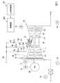
本実施形態のガスタービンプラントは、図1に示すように、ガスタービン10と、ガスタービン10の駆動で発電する発電機29と、を備えている。ガスタービン10は、空気を圧縮する圧縮機11と、圧縮機11で圧縮された空気中で燃料Fを燃焼させて燃焼ガスを生成する燃焼器31と、高温高圧の燃焼ガスにより駆動するタービン21と、を備えている。 As shown in FIG. 1, the gas turbine plant of the present embodiment includes a
圧縮機11は、軸線を中心として回転する圧縮機ロータ13と、この圧縮機ロータ13を回転可能に覆う圧縮機ケーシング12と、この圧縮機ケーシング12の吸込み口に設けられているIGV(inlet guide vane)14と、を有する。IGV14は、複数のガイドベーン15と、複数のガイドベーン15を駆動する駆動器16とを有し、圧縮機ケーシング12内に吸い込まれる空気の流量を調節する。 The
タービン21は、燃焼器31からの燃焼ガスにより、軸線を中心として回転するタービンロータ23と、このタービンロータ23を回転可能に覆うタービンケーシング22と、を有する。タービンロータ23と圧縮機ロータ13とは、同一の軸線を中心として回転するもので、相互に連結されて、ガスタービンロータ28を成している。このガスタービンロータ28には、発電機29のロータが接続されている。 The
燃焼器31は、図2に示すように、タービンケーシング22に固定されている外筒32と、タービンケーシング22内に配置され、燃焼ガスをタービン21の燃焼ガス流路中に送る燃焼筒(又は尾筒)33と、この燃焼筒33内に燃料及び空気を供給する燃料供給器41と、を備える。 As shown in FIG. 2, the
燃料供給器41は、図2及び図3に示すように、内筒42と、内筒42の中心軸線上に配置されているパイロットバーナ43と、このパイロットバーナ43を中心として周方向に等間隔で配置されている複数のメインバーナ53と、外筒32の内周側で内筒42の外周側に配置されているトップハットノズル51と、を有する。なお、以下では、内筒42の中心軸線が延びる方向で、燃焼筒33内で燃焼ガスGが流れていく側を下流側とし、その反対側を上流側とする。 As shown in FIGS. 2 and 3, the
パイロットバーナ43は、内筒42の中心軸線上に配置されているパイロットノズル44と、このパイロットノズル44の外周を囲む筒状のパイロット空気用筒45と、を有する。パイロット空気用筒45の下流側は、下流側に向かうに連れて次第に拡径されたパイロットコーン46を成している。パイロット空気用筒45の内周側には、圧縮機11からの圧縮空気Acがパイロット空気Apとして流れるパイロット空気流路48を成している。パイロットノズル44から噴射されたパイロット燃料Fpは、このパイロット空気流路48から噴出したパイロット空気Ap中で燃焼(拡散燃焼)して、拡散火炎49を形成する。 The
メインバーナ53は、パイロット空気用筒45の外周を囲む筒状のメイン空気用内筒55と、メイン空気用内筒55の外周を囲む筒状のメイン空気用外筒56と、メイン空気用内筒55の外周側とメイン空気用外筒56の内周側との間の環状の空間を周方向に複数に分割する仕切板57と、複数の仕切板57の相互間に配置されているメインノズル54と、を有する。メイン空気用内筒55とメイン空気用外筒56と複数の仕切板57で画定される複数の空間は、圧縮機11からの圧縮空気Acがメイン空気Amとして流れるメイン空気流路58を成している。このメイン空気流路58を流れるメイン空気Amには、このメイン空気流路58内に配置されているメインノズル54からメイン燃料Fmが噴射される。このため、メイン空気流路58内でメインノズル54の先端(下流端)よりも下流側には、メイン空気Amとメイン燃料Fmとが混ざり合った予混合気体が流れる。この予混合気体は、メイン空気流路58から流出すると燃焼(予混合燃焼)して、予混合火炎59を形成する。前述の拡散火炎49は、この予混合火炎59を保炎する役目を担っている。 The
外筒32の内周側と内筒42の外周側との空間は、圧縮機11からの圧縮空気Acを内筒42内に導く圧縮空気流路52を成している。トップハットノズル51は、この圧縮空気流路52にトップハット燃料Ftを噴射する。このため、トップハット燃料Ftが圧縮空気流路52に噴射されると、メイン空気Am及びパイロット空気Ap中にトップハット燃料Ftが混入することになる。 A space between the inner peripheral side of the outer cylinder 32 and the outer peripheral side of the
本実施形態のガスタービンプラントは、さらに、図1及び図2に示すように、パイロットノズル44にパイロット燃料Fpを送るパイロット燃料ライン61と、メインノズル54にメイン燃料Fmを送るメイン燃料ライン62と、トップハットノズル51にトップハット燃料Ftを送るトップハット燃料ライン63と、パイロット燃料Fpの流量を調節するパイロット燃料弁65と、メイン燃料Fmの流量を調節するメイン燃料弁66と、トップハット燃料Ftの流量を調節するトップハット燃料弁67と、これらの燃料弁65,66,67の動作等を制御する制御装置100と、を備える。 As shown in FIGS. 1 and 2, the gas turbine plant of the present embodiment further includes a
パイロット燃料ライン61、メイン燃料ライン62及びトップハット燃料ライン63は、いずれも燃料ライン60から分岐したラインである。パイロット燃料弁65は、パイロット燃料ライン61に設けられ、メイン燃料弁66は、メイン燃料ライン62に設けられ、トップハット燃料弁67は、トップハット燃料ライン63に設けられている。 The
本実施形態のガスタービンプラントは、さらに、図1に示すように、ガスタービンロータ28の回転数Nを検知する回転数計71と、発電機29の出力PWを検知する出力計72と、圧縮機11が吸い込む空気Aの温度である吸気温度Tiを検知する吸気温度計73と、圧縮機11が吸い込む空気の圧力である吸気圧(大気圧)Piを検知する吸気圧計74と、タービン21の最終段直後の燃焼ガスの温度であるブレードパス温度Tbを検知するブレードパス温度計75と、タービン21の最終段よりも下流側の排気ダクト内の排気ガスの温度Teを検知する排気ガス温度計76と、を備える。 As shown in FIG. 1, the gas turbine plant of the present embodiment further includes a
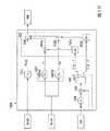
制御装置100は、図4に示すように、各検知計からの検知値等を受け付けるインタフェース180と、燃焼負荷指令値CLCSOを発生する燃焼負荷指令発生器110と、ガスタービンの現時点における負荷率%Loadを求める負荷率演算器120と、燃料流量指令値CSOを発生する燃料流量指令発生器130と、全燃料流量に対するパイロット燃料流量Fpfの比であるパイロット比(PL比)を算出するパイロット比算出器140pと、全燃料流量に対するトップハット燃料流量Ftfの比であるトップハット比(TH比)を算出するトップハット比算出器140tと、各燃料ライン61,62,63の流量を求める系統流量演算器160と、各燃料ライン61,62,63の流量に応じて各燃料弁65,66,67に制御信号を出力する弁制御器170と、を備える。なお、本実施形態において、パイロット比算出器140pとトップハット比算出器140tとで流量比算出装置140を構成している。 As shown in FIG. 4, the
燃焼負荷指令値CLCSOは、タービン21における燃焼ガスの入口温度を無次元化したパラメータで、この入口温度と正の相関性を持つパラメータである。燃焼負荷指令値CLCSOは、入口温度が下限値のときに0%、入口温度が上限値のときに100%となるように設定される。例えば、入口温度の下限値を700℃、入口温度の上限値を1500℃としたとき、燃焼負荷指令値CLCSOは以下の式で表される。 The combustion load command value CLCSO is a parameter obtained by making the inlet temperature of the combustion gas in the
CLCSO(%)={(発電機出力の実測値−700℃MW)/(1500℃MW−700℃MW)}
×100
なお、700℃MWは、入口温度が下限値である700℃のときにおける発電機出力であり、1500℃MWは、入口温度が上限値である1500℃のときにおける発電機出力である。CLCSO (%) = {(actual value of generator output−700 ° C. MW) / (1500 ° C. MW−700 ° C. MW)}
× 100
700 MW is a generator output when the inlet temperature is 700 ° C., which is the lower limit value, and 1500 ° C. MW is a generator output when the inlet temperature is 1500 ° C., which is the upper limit value.
燃焼負荷指令発生器110は、図5に示すように、入口温度が下限値である700℃のときにおける発電機出力700℃MWを求める第一出力演算器111aと、入口温度が上限値である1500℃のときにおける発電機出力1500℃MWを求める第二出力演算器111bと、予め設定されている標準大気圧Psを発生する標準大気圧発生器112と、標準大気圧(標準吸気圧)Psに対する吸気圧計74で検知された吸気圧Piの割合である吸気圧比Prを求める第一除算器113と、第一出力演算器111aが求めた発電機出力700℃MWに吸気圧比Prを乗算する第一乗算器114aと、第二出力演算器111bが求めた発電機出力1500℃MWに吸気圧比Prを乗算する第二乗算器114bと、出力計72で検知された発電機29の実測出力PWから第一乗算器114aでの乗算結果を減算する第一減算器115aと、第二乗算器114bでの乗算結果から第一乗算器114aでの乗算結果を減算する第二減算器115bと、第一減算器115aでの減算結果を第二減算器115bでの減算結果で割る第二除算器116と、第二除算器116からの出力の増減レートを制限する制限器117と、を有する。As shown in FIG. 5, the combustion
第一出力演算器111aは、吸気温度TiとIGV開度指令値とを変動パラメータとし、関数H1xを用いて、入口温度が700℃のときの発電機出力700℃MWを求める。また、第二出力演算器111bは、吸気温度TiとIGV開度指令値とを変動パラメータとし、関数H2xを用いて、入口温度が1500℃のときの発電機出力1500℃MWを求める。ここで、IGV開度指令値は、制御装置100がIGV14の駆動器16に与える指令値である。このIGV開度指令値は、例えば、圧縮機11の入口の圧力である大気圧Piと圧縮機11の出口の圧力等から求められる。これら出力演算器111a,111bは、吸気温度及びIGV開度指令値が基準値である場合における700℃MW、1500℃MWの既知の値を、実際の吸気温度Ti及びIGV開度指令値に対応する値に変更して、変更後の値を700℃MW、1500℃MWとして出力する。The
これらの700℃MW及び1500℃MWは、さらに、吸気圧(大気圧)の実測値Piに基づき補正処理される。具体的に、第一除算器113は、標準大気圧発生器112からの標準吸気圧(標準大気圧)Psに対する、吸気圧計74で検知された吸気圧(大気圧)Piの割合である吸気圧比Prを求める。第一乗算器114aは、第一出力演算器111aからの700℃MWに吸気圧比Prを掛けて、700℃MWを吸気圧比Prに対応する値に補正する。第二乗算器114bは、第二出力演算器111bからの1500℃MWに吸気圧比Prを掛けて、1500℃MWを吸気圧比Prに対応する値に補正する。すなわち、以上では、吸気温度及びIGV開度指令値が基準値である場合における700℃MW、1500℃MWの既知の値を、実測吸気温度Ti、IGV開度指令値、及び実測吸気圧比Prに対応する値に補正する。 These 700 ° C. MW and 1500 ° C. MW are further corrected based on the actually measured value Pi of the intake pressure (atmospheric pressure). Specifically, the
第一減算器115aは、出力計72で検知された発電機29の実測出力PWから、吸気圧比Prで補正された700℃MWを減算する。すなわち、第一減算器115aは、上記式の分子の値を求める。第二減算器115bは、吸気圧比Prで補正された1500℃MWから、吸気圧比Prで補正された700℃MWを減算する。すなわち、第二減算器115bは、上記式の分母の値を求める。 The
第二除算器116は、第一減算器115aで求められた上記式の分子の値を、第二減算器115bで求められた上記式の分母の値で割り、この値を燃焼負荷指令値として出力する。制限器117は、第二除算器116からの燃焼負荷指令値の単位時間当たりの変化量である増減レートが予め定められた値以下になるよう、この燃焼負荷指令値の増減レートを制限する。 The
なお、以上では、タービン21における燃焼ガスの入口温度の下限値を700℃、その上限値を1500℃にしたが、燃焼器31の型式等によっては、タービン21における燃焼ガスの入口温度の下限値及び上限値を以上の例と異なる値にしてもよい。 In the above, the lower limit value of the combustion gas inlet temperature in the
燃焼負荷指令発生器110からは、制限器117で増減レートが制限された燃焼負荷指令値CLCSOが出力される。 The combustion
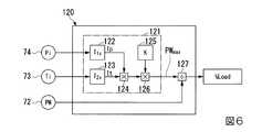
ガスタービン10の負荷率%Loadは、現時点でのガスタービン10の状態で許容される最大負荷PWmaxに対する現在の負荷PWの割合である。負荷率演算器120は、図6に示すように、現時点でのガスタービン10の状態で許容される最大負荷PWmaxを求める最大負荷演算器121と、出力計72で検知された発電機29の出力である実測負荷PWを最大負荷PWmaxで割る除算器127と、を有する。 The load factor% Load of the
最大負荷演算器121は、吸気圧Piに応じた最大負荷係数Ipを求める第一負荷係数演算器122と、吸気温度Tiに応じた最大負荷係数Itを求める第二負荷係数演算器123と、最大負荷係数Ipと最大負荷係数Itとを乗算する第一乗算器124と、ガスタービン10の運転時間に応じた劣化係数Kを発生する劣化係数発生器125と、第一乗算器124での乗算結果に劣化係数Kを乗算する第二乗算器126と、を有する。すなわち、最大負荷演算器121は、吸気圧計74で検知された実測吸気圧Piと、吸気温度計73で検知された実測吸気温度Tiと、ガスタービン10の劣化係数Kとに応じた最大負荷PWmaxを求める。除算器127は、前述したように、出力計72で検知された発電機29の出力である実測負荷PWを最大負荷PWmaxで割り、これを負荷率%Loadとして出力する。 The
燃料流量指令値CSOは、燃焼器31に供給する燃料の全流量(以下、全燃料流量とする)を示す値である。したがって、燃料流量指令発生器130は、全流量演算器として機能する。このため、燃料流量指令発生器130は、全燃料流量を求める全燃料流量演算工程を実行する。 The fuel flow rate command value CSO is a value indicating the total flow rate of fuel supplied to the combustor 31 (hereinafter referred to as the total fuel flow rate). Therefore, the fuel flow
燃料流量指令発生器130は、図7に示すように、ガスタービンロータ28の回転数Nが目標回転数になるように全燃料流量を制御するための指令値を出力するガバナ制御器131と、発電機出力PWが発電機出力指令値と一致するように全燃料流量を制御するための指令値を出力する負荷制御器132と、ガスタービンのブレードパス温度Tbが上限値を超えないように全燃料流量を制御するための指令値を出力する第一温度制御器133と、排気ガス温度Teが上限値を超えないよう全燃料流量を制御するための指令値を出力する第二温度制御器134と、各制御器131〜134からの指令値のうちで最少の指令値を出力する低値選択器135と、低値選択器135からの指令の増減レートを制限する制限器136と、を有する。 As shown in FIG. 7, the fuel flow
ガバナ制御器131は、回転数計71からガスタービンロータ28の回転数Nを受け取り、このガスタービンロータ28の回転数Nが目標回転数と一致するように全燃料流量を制御するための指令値GVCSOを出力する。具体的に、ガバナ制御器131は、ガスタービンロータ28の実測回転数Nと予め設定されているGV設定値とを比較し、比例制御信号を指令値GVCSOとして出力する。 The
負荷制御器132は、出力計72から発電機29の実測出力PWと上位制御装置90(図1参照)から発電機出力指令値とを受け取る。負荷制御器132は、実測出力PWが発電機出力指令値と一致するように全燃料流量を制御するための指令値LDCSOを出力する。具体的に、負荷制御器132は、実測出力PWと発電機出力指令値とを比較し、比例積分演算を行い、この結果を指令値LDCSOとして出力する。 The
第一温度制御器133は、ブレードパス温度計75からブレードパス温度Tbを受け取って、このブレードパス温度Tbが上限値を超えないように全燃料流量を制御するための指令値BPCSOを出力する。具体的には、第一温度制御器133は、実測ブレードパス温度Tbとその上限値とを比較し、比例積分演算を行い、この結果を指令値BPCSOとして出力する。 The
第二温度制御器134は、排気ガス温度計76から排気ガス温度Teを受け取って、この排ガス温度Teが上限値を超えないように全燃料流量を制御するための指令値EXCSOを出力する。具体的に、第二温度制御器134は、実測排ガス温度Teとその上限値とを比較し、比例積分演算を行い、この結果を指令値EXCSOとして出力する。 The
低値選択器135は、各制御器131〜134からの指令値のうちで最少の指令値を選択し、この指令値を出力する。制限器136は、低値選択器135からの指令の増減レートを制限し、これを燃料流量指令値(全燃料流量指令値)CSOとして出力する。 The
パイロット比(PL比)は、全燃料流量に対するパイロット燃料流量Fpfの比である。パイロット比算出器140pは、図9に示すように、燃焼負荷指令値CLCSOに応じたパイロット比であるPL0比を求めるPL0比演算器(流量比演算器)141pと、負荷率%Loadに応じた補正値を算出する補正値演算器142pと、燃料流量指令値CSOの変動を検知する変動検知器144と、PL0比を補正値で補正する補正器151と、を有する。The pilot ratio (PL ratio) is a ratio of the pilot fuel flow rate Fpf to the total fuel flow rate. As shown in FIG. 9, the
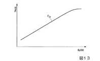
PL0比演算器141pは、タービン21における燃焼ガスの入口温度と正の相関性を持つ燃焼負荷指令値CLCSOとPL0比との関係を規定する関数F1xを持っている。関数F1xは、図11に示すように、燃焼負荷指令値CLCSOの増加に伴って、つまり燃焼ガスの入口温度の上昇に伴って、次第にPL0比が小さくなる関数である。PL0比演算器141pは、燃焼負荷指令発生器110から燃焼負荷指令値CLCSOを受け取り、関数F1xを用いて、この燃焼負荷指令値CLCSOに対応したPL0比を求める。なお、ここでは、燃焼負荷指令値CLCSOとPL0比との関係を関数F1xで規定しているが、この関係をマップで規定してもよい。The PL0 ratio calculator 141p has a function F1 x that defines the relationship between the combustion load command value CLCSO and the PL0 ratio having a positive correlation with the combustion gas inlet temperature in the
補正値演算器142pは、燃料流量指令値CSOが増加しているときの増加時補正値Ciを求める増加時補正値演算器143paと、燃料流量指令値CSOが減少しているときの減少時補正値Cdを求める減少時補正値演算器143pbと、を有する。増加時補正値演算器143paは、図12に示すように、負荷率%Loadと増加時補正値Ciとの関係を規定する関数G1xを持っており、現在の負荷率%Loadに応じた増加時補正値Ciを求める。また、減少時補正値演算器143pbは、負荷率%Loadと減少時補正値Cdとの関係を規定する関数G2xを持っており、現在の負荷率%Loadに応じた減少時補正値Cdを求める。The
PL0比は、図12に示すように、負荷率%Loadの増加に伴って小さくされる。特に、負荷率%Loadが例えば60%以上の高負荷率の場合には、NOxの低減を図るためにPL0比をより小さくする傾向がある。よって、高負荷率の場合、燃焼器31内で燃料が安定燃焼するための条件としては、厳しい条件になっている。増加時補正値Ci及び減少時補正値Cdは、いずれも、この高負荷率の場合に、PL0比を補って、PL比を大きくするための補正値である。減少時補正値Cdは、ここでは、同一負荷率%Loadにおける増加時補正値Ciよりも大きく設定されている。The PL0 ratio is reduced as the load factor% Load increases as shown in FIG. In particular, when the load factor% Load is a high load factor of 60% or more, for example, the PL0 ratio tends to be made smaller in order to reduce NOx. Therefore, in the case of a high load factor, the conditions for the stable combustion of fuel in the
燃焼負荷指令値CLCSOは、前述したように、タービン21における燃焼ガスの入口温度と正の相関性を持つパラメータである。従って、燃焼負荷指令値CLCSOは、入口温度が高いときには大きな値になり、入口温度が低いときには小さな値になる。ところで、燃焼器31への燃料流量を増加させたことで、タービン21における燃焼ガスの入口温度が高くなっても、直ちに発電機出力が高まらない。また、燃焼器31への燃料流量を減少させたことで、タービン21における燃焼ガスの入口温度が低くなっても、直ちに発電機出力が低下しない。すなわち、燃焼器31への燃料流量を増減変化させたことで、タービン21における燃焼ガスの入口温度が変化しても、直ちに発電機出力は変化しない。このため、実測した発電機出力PWを用いて求める燃焼負荷指令値CLCSOは、燃焼器31への燃料流量を増減変化させた場合、直ちにタービン21における燃焼ガスの入口温度に対応した値にならない。 As described above, the combustion load command value CLCSO is a parameter having a positive correlation with the combustion gas inlet temperature in the
よって、燃料が安定燃焼するために厳しい条件下である高負荷率のときに、燃焼器31への燃料流量を増減変化させた場合、燃焼負荷指令値CLCSOに基づいて定めたPL0比では、燃焼器31内での燃焼が不安定になるおそれがある。そこで、本実施形態では、高負荷率のときに燃焼器31への燃料流量を増減変化させる場合に、増加時補正値Ci及び減少時補正値Cdを用いてPL0比を補うようにしている。特に、燃焼器31への燃料流量を減少させる場合には、燃焼器31内での燃焼が不安定になる傾向が強いため、本実施形態では、増加時補正値Ciよりも大きな値である減少時補正値Cdを用いてPL0比を補うようにしている。このため、燃料減少時における補正後のPLd比は、前述したように、燃料増加時における補正後のPLi比よりも大きな値になる。Therefore, when the fuel flow rate to the
増加時補正値演算器143pa及び減少時補正値演算器143pbは、いずれも、負荷率演算器120から負荷率%Loadを受け取る。増加時補正値演算器143paは、関数G1xを用いて、この負荷率%Loadに応じた増加時補正値Ciを求める。また、減少時補正値演算器143pbは、関数G2xを用いて、この負荷率%Loadに応じた減少時補正値Cdを求める。The increase correction value calculator 143pa and the decrease correction value calculator 143pb both receive the load factor% Load from the
変動検知器144は、燃料流量指令発生器130からの燃料流量指令値CSOを所定時時間後に出力する遅延器145と、燃料流量指令発生器130からの燃料流量指令値CSOと遅延器145からの燃料流量指令値CSOとの差を求める減算器146と、減算結果に応じて燃料流量指令値CSOが所定値以上増加しているか又は所定値以上減少しているかを判断する増減判断器147と、を有する。増減判断器147は、減算器146による減算結果が正の値で且つこの値が所定値以上の場合には、増加している旨を示す「+1」を出力し、減算器による減算結果が負の値で且つこの値が所定値以下の場合には、減少している旨を示す「−1」を出力し、他の場合には、増減変化していない旨を示す「0」を出力する。 The
補正器151は、増加時補正値Ciの増減レートを制限する制限係数を出力する増加時係数発生器152aと、減少時補正値Cdの増減レートを制限する制限係数を出力する減少時係数発生器152bと、増加時補正値Ciに制限係数を掛ける第一乗算器153aと、減少時補正値Cdに制限係数を掛ける第二乗算器153bと、増減レートが制限された増加時補正値Ci又は減少時補正値CdをPL0比に加える加算器(流量比補正器)154と、を有する。このように、燃焼負荷指令値CLCSOに基づいて定めたPL0比に、増減レートが制限された増加時補正値Ci又は減少時補正値CdをPL0比に加えることで、本実施形態では、高負荷率のときに燃焼器31への燃料流量を増減変化させた場合のPL0比を補っている。この加算器154による加算結果が補正されたPL比としてパイロット比算出器140pから出力される。The
なお、本実施形態では、増加時係数発生器152aと第一乗算器153aとで、出力する補正値を時間経過に伴って増加時補正値演算器143paで求められた増加時補正値Ciに近づくよう変化させる補正値調節器を構成している。また、本実施形態では、減少時係数発生器152bと第二乗算器153bとで、出力する補正値を時間経過に伴って減少時補正値演算器143pbで求められた減少時補正値Cdに近づくよう変化させる補正値調節器を構成している。 In the present embodiment, the increase
図15に示すフローチャートに従って、以上で説明したパイロット比算出器140pの動作について説明する。 The operation of
パイロット比算出器140pのPL0比演算器(流量比演算器)141pは、関数F1xを用いて燃焼負荷指令CLCSOに対応したPL0比を求める(S1:流量比演算工程)。
パイロット比算出器140pの補正値演算器142pは、負荷率%Loadに応じた補正値Ci,Cdを求める(S2:補正値演算工程)。具体的に、補正値演算器142pの増加時補正値演算器143paは、前述したように、関数G1xを用いて、現在の負荷率%Loadに応じた増加時補正値Ciを求める(S2a:増加時補正値演算工程)。また、減少時補正値演算器143pbは、関数G2xを用いて、現在の負荷率%Loadに応じた減少時補正値Cdを求める(S2b;減少時補正値演算工程)。The
パイロット比算出器140pの変動検知器144は、単位時間当たりの燃料流量指令値CSOの増加量が所定値以上の場合に、増加している旨を示す「+1」を出力し、単位時間当たりの燃料流量指令値CSOの減少量が所定値以上の場合に、減少している旨を示す「−1」を出力する。また、変動検知器144は、その他の場合には、単位時間当たりの燃料流量指令値CSOが増減変化していない旨を示す「0」を出力する(S3:変動検知工程)。 The
補正器151は、変動検知器144が燃料流量指令値CSOの増加している旨を示す「+1」を出力するか、又は燃料流量指令値CSOの減少している旨を示す「−1」を出力すると、補正値演算器142pが求めた補正値Ci又は補正値Cdを用いて、PL0比演算器141pが求めたPL0比を補正する(S4:補正工程)。具体的に、変動検知器144が燃料流量指令値CSOの増加している旨を示す「+1」を出力すると、補正器151の増加時係数発生器152aは、増加時補正値Ciの増減レートを制限する制限係数を出力する。補正器151の第一乗算器153aは、この制限係数を受け付けると、増加時係数発生器152aからの増加時補正値Ciにこの制限係数を掛けて、増減レートを制限した増加時補正値Ciを出力する。加算器154は、PL0比演算器141pからのPL0比に、増減レートを制限した増加時補正値Ciを加えて、これを補正されたPLi比(図12参照)として出力する(S4a:増加時補正工程)。また、変動検知器144が燃料流量指令値CSOの減少している旨を示す「−1」を出力すると、減少時係数発生器152bは、減少時補正値Cdの増減レートを制限する制限係数を出力する。第二乗算器153bは、この制限係数を受け付けると、減少時係数発生器152bからの減少時補正値Cdにこの制限係数を掛けて、増減レートを制限した減少時補正値Cdを出力する。加算器154は、PL0比演算器141pからのPL0比に、増減レートを制限した減少時補正値Cdを加えて、これを補正されたPLd比(図12参照)として出力する(S4b:減少時補正工程)。The
なお、補正器151は、変動検知器144が「0」を出力した時には、第一乗算器153a及び第二乗算器153bからの出力が「0」になるため、PL0比演算器141pからのPL0比が補正されず、PL0比をPL比として出力する。また、負荷率%Loadが高負荷率でない場合、補正値演算器142pからは補正値として「0」が出力されるため、第一乗算器153a及び第二乗算器153bからの出力も「0」になる。このため、負荷率%Loadが高負荷率でない場合も、PL0比演算器141pからPL0比が補正されず、PL0比をPL比として出力する。すなわち、補正器151は、負荷率%Loadが高負荷率であり且つ燃料流量指令値CSOが所定以上の増減変動した場合のみ、PL0比演算器141pからのPL0比を補正する。Note that when the
なお、図15に示すフローチャートでは、流量比演算工程(S1)を実行した後、補正値演算工程(S2)を実行し、その後、変動検知工程(S3)を実行するように描いているが、実際には、流量比演算工程(S1)、補正値演算工程(S2)、及び変動検知工程(S3)を並行して実行する。 In the flowchart shown in FIG. 15, the flow rate calculation step (S1) is executed, the correction value calculation step (S2) is executed, and then the fluctuation detection step (S3) is executed. Actually, the flow rate calculation step (S1), the correction value calculation step (S2), and the fluctuation detection step (S3) are executed in parallel.
トップハット比(TH比)は、全燃料流量に対するトップハット燃料流量Ftfの比である。トップハット比算出器140tは、図10に示すように、燃焼負荷指令値CLCSOに応じたトップハット比であるTH0比を求めるTH0比演算器(流量比演算器)141tと、負荷率%Loadに応じた補正値を算出する補正値演算器142tと、燃料流量指令値CSOの変動を検知する変動検知器144と、TH0比を補正値で補正する補正器151と、を有する。The top hat ratio (TH ratio) is the ratio of the top hat fuel flow rate Ftf to the total fuel flow rate. As shown in FIG. 10, the top
TH0比演算器141tは、燃焼負荷指令値CLCSOとTH0比との関係を規定する関数F2xを持っている。関数F2xは、図13に示すように、燃焼負荷指令値CLCSOの増加に伴って、つまり燃焼ガスの入口温度の上昇に伴って、次第にTH0比が大きくなる関数である。TH0比演算器141tは、燃焼負荷指令発生器110から燃焼負荷指令値CLCSOを受け取り、関数F2xを用いて、この燃焼負荷指令値CLCSOに対応したTH0比を求める。なお、ここでは、燃焼負荷指令値CLCSOとTH0比との関係を関数F2xで規定しているが、この関係をマップで規定してもよい。The TH0 ratio calculator 141t has a function F2 x that defines the relationship between the combustion load command value CLCSO and the TH0 ratio. As shown in FIG. 13, the function F2 x is a function in which the TH0 ratio gradually increases as the combustion load command value CLCSO increases, that is, as the combustion gas inlet temperature increases. TH0 ratio calculator 141t receives combustion loadcommand value C LCSO from the combustion
補正値演算器142tは、燃料流量指令値CSOが増加しているときの増加時補正値Ciを求める増加時補正値演算器143taと、燃料流量指令値CSOが減少しているときの減少時補正値Cdを求める減少時補正値演算器143tbとを有する。増加時補正値演算器143taは、図14に示すように、負荷率%Loadと増加時補正値Ciとの関係を規定する関数G3xを持っており、現在の負荷率%Loadに応じた増加時補正値Ciを求める。また、減少時補正値演算器143tbは、負荷率%Loadと減少時補正値Cdとの関係を規定する関数G4xを持っており、現在の負荷率%Loadに応じた減少時補正値Cdを求める。これら増加時補正値Ci及び減少時補正値Cdは、いずれも負の値である。また、減少時補正値Cdは、ここでは、同一負荷率%Loadにおける増加時補正値Ciよりも大きく設定されている。言い換えると、減少時補正値Cdの絶対値は、ここでは、同一負荷率%Loadにおける増加時補正値Ciの絶対値よりも小さく設定されている。The
TH0比は、図14に示すように、基本的に、負荷率%Loadの増加に伴って大きくされる。但し、ここでのTH0比は、負荷率%Loadが例えば60%以上の高負荷率の場合、負荷率%Loadが増加してもほぼ一定である。As shown in FIG. 14, the TH0 ratio is basically increased as the load factor% Load increases. However, the TH0 ratio here is substantially constant even when the load factor% Load increases when the load factor% Load is a high load factor of 60% or more, for example.
燃焼器は、その構造や、燃焼器に投入される燃料の物性等により、その構造等に応じた負荷率で燃焼振動の傾向が強くなることがある。本実施形態の燃焼器31では、高負荷率のときに燃焼振動の傾向が強くなる。本実施形態の燃焼器31では、この高負荷率のときで且つ燃料流量指令値CSOが増減変化するときにTH比を小さくすると、燃焼振動を抑制できる。そこで、本実施形態のTH0比の増加時補正値Ci及び減少時補正値Cdは、いずれも、高負荷率の場合に、補正後のTH比を小さくする負の値の補正値である。Depending on the structure of the combustor and the physical properties of the fuel supplied to the combustor, the combustion vibration tends to increase with a load factor corresponding to the structure. In the
変動検知器144は、パイロット比算出器140pの変動検知器144と同一構成である。このため、この変動検知器144は、単位時間当たりの燃料流量指令値CSOの増加量が所定値以上の場合に、増加している旨を示す「+1」を出力し、単位時間当たりの燃料流量指令値CSOの減少量が所定値以上の場合に、減少している旨を示す「−1」を出力する。また、変動検知器144は、その他の場合には、単位時間当たりの燃料流量指令値CSOが増減変化していない旨を示す「0」を出力する。 The
補正器151は、パイロット比算出器140pの補正器151と同一構成である。このため、この補正器151は、変動検知器144が燃料流量指令値CSOの増加している旨を示す「+1」を出力するか、又は燃料流量指令値CSOの減少している旨を示す「−1」を出力すると、補正値演算器142tが求めた補正値Ci又は補正値Cdを用いて、TH0比演算器141tが求めたTH0比を補正する。The
以上で説明したトップハット比算出器140tの動作は、図15を用いて前述したパイロット比算出器140pの動作と同一である。但し、トップハット比算出器140tの補正値演算器142tが求める増加時補正値Ci及び減少時補正値Cdは、いずれも負の値であるため、補正器151により補正されたTHi比、THd比(図14参照)は、いずれも、補正前のTH0比より小さくなる。The operation of the top
なお、以上は、高負荷率のときに燃焼振動の傾向が強くなる燃焼器31に対するTH0比の補正例である。しかしながら、例えば、50%〜60%程度の中負荷率のときに燃焼振動の傾向が強くなる燃焼器も存在する。この場合、補正値演算器142tは、TH0比の補正値として、中負荷率における補正値を定めることになる。また、以上は、TH比を小さくすることで燃焼振動を抑制できる燃焼器31に対するTH0比の補正例である。しかしながら、TH比を大きくすることで燃焼振動を抑制できる燃焼器も存在する。この場合、TH0比の補正として、補正器151が正の値の補正値を定め、この補正値をTH0比に加算することになる。また、以上では、減少時補正値Cdを同一負荷率%Loadにおける増加時補正値Ciよりも大きく設定している。しかしながら、燃焼器によっては、減少時補正値Cdを同一負荷率%Loadにおける増加時補正値Ciよりも小さく設定する場合もある。The above is a correction example of the TH0 ratio for the
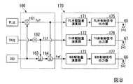
系統流量演算器160は、図8に示すように、パイロット比算出器140pが求めたPL比を用いてパイロット燃料流量Fpfを求める第一乗算器161と、トップハット比算出器140tが求めたTH比を用いてトッププハット燃料流量Ftfを求める第二乗算器162と、全燃料流量を示す燃料流量指令値CSOからトップハット燃料流量Ftfを減算する第一減算器163と、第一減算器163の減算結果からさらにパイロット燃料流量Fpfを減算する第二減算器164と、を有する。 As shown in FIG. 8, the system
第一乗算器161は、全燃料流量を示す燃料流量指令値CSOにパイロット比算出器140pが求めたPL比を掛けて、パイロット燃料流量Fpfを求め、これを弁制御器170に出力する。第二乗算器162は、全燃料流量を示す燃料流量指令値CSOにトップハット比算出器140tが求めたTH比を掛けて、トップハット燃料流量Ftfを求め、これを弁制御器170に出力する。第一減算器163は、前述したように、全燃料流量を示す燃料流量指令値CSOからトップハット燃料流量Ftfを減算する。第二減算器164は、第一減算器163の減算結果からさらにパイロット燃料流量Fpfを減算し、この減算結果をメイン燃料流量Fmfとして弁制御器170に出力する。すなわち、この系統流量演算器160は、各燃料流量を求める系統流量演算工程を実行する。 The
弁制御器170は、図8に示すように、パイロット燃料弁65の駆動量を求める弁駆動量演算器171と、パイロット燃料弁65に制御信号を出力する弁制御信号出力器175と、トップハット燃料弁67の駆動量を求める弁駆動量演算器172と、トップハット燃料弁67に制御信号を出力する弁制御信号出力器176と、メイン燃料弁66の駆動量を求める弁駆動量演算器173と、メイン燃料弁66に制御信号を出力する弁制御信号出力器177と、を有する。 As shown in FIG. 8, the
パイロット燃料弁65の駆動量を求める弁駆動量演算器171は、系統流量演算器160が求めたパイロット燃料流量Fpfに応じて、パイロット燃料弁65の駆動量を求める。弁制御信号出力器175は、このパイロット燃料弁65の駆動量に応じた制御信号を作成して、この制御信号をパイロット燃料弁65に出力する。トップハット燃料弁67の駆動量を求める弁駆動量演算器172は、系統流量演算器160が求めたトップハット燃料流量Ftfに応じて、トップハット燃料弁67の駆動量を求める。弁制御信号出力器176は、このトップハット燃料弁67の駆動量に応じた制御信号を作成して、この制御信号をトップハット燃料弁67に出力する。メイン燃料弁66の駆動量を求める弁駆動量演算器173は、系統流量演算器160が求めたメイン燃料流量Fmfに応じて、メイン燃料弁66の駆動量を求める。弁制御信号出力器177は、このメイン燃料弁66の駆動量に応じた制御信号を作成して、この制御信号をメイン燃料弁66に出力する。すなわち、この弁制御器170は、各燃料弁に対して制御信号を出力する弁制御工程を実行する。 The valve
各弁制御信号出力器175,176,177から各燃料弁65,66,67に制御信号が出力されると、各燃料弁65,66,67は、制御信号が示す駆動量に応じて駆動する。この結果、パイロット燃料ライン61には、パイロット比算出器140pが求めたPL比に応じた流量Fpfのパイロット燃料Fpが流れる。トップハット燃料ライン63には、トップハット比算出器140tが求めたTH比に応じた流量Ftfのトップハット燃料Ftが流れる。また、メイン燃料ライン62には、全燃料流量からパイロット燃料流量Fpf及びトップハット燃料流量Ftfを引いた流量Fmfのメイン燃料Fmが流れる。 When a control signal is output from each valve control
以上のように、本実施形態では、燃焼負荷指令値CLCSOに基づいて定めた各燃料の流量比について、燃料流量指令値CSOが変動したときにガスタービンの負荷率に応じて補正している。このため、負荷変化時の過渡的な燃焼振動を抑制し、燃焼器31での燃焼安定性を高めることができる。しかも、本実施形態では、ランバック運転時に限らず、負荷の低下時や負荷の増加時における燃焼器での燃焼安定性を高めることができる。 As described above, in this embodiment, the flow ratio of each fuel determined based on the combustion load command value CLCSO is corrected according to the load factor of the gas turbine when the fuel flow command value CSO varies. For this reason, the transient combustion vibration at the time of load change can be suppressed, and the combustion stability in the
なお、本実施形態の流量比算出器140p,140tは、燃焼負荷指令値CLCSOに基づいて各燃料の補正前の流量比を定めている。しかしながら、流量比算出器140p,140tは、タービン21における燃焼ガスの入口温度変化に対して相関性を持って変化する値又はこの入口温度である入口温度相関値に基づいて、各燃料の補正前の流量比を定めてもよい。The flow
燃焼器31内での燃焼状態は、上記入口温度相関値と、燃焼器31内における燃焼ガスの流速変化に対して相関性を持って変化する流速相関値とで特定することができる。この流速相関値には、補正値を求める際に用いた負荷率の他、ガスタービン10の出力(発電機出力)、燃焼器31に供給される燃料の全流量、圧縮機11が吸い込む空気の流量等がある。このため、上記入口温度相関値を第一パラメータとし、この第一パラメータを用いて各燃料の補正前の流量比を定めた場合、ガスタービン10の出力、燃焼器31に供給される全燃料の流量、圧縮機11が吸い込む空気の流量等のいずれか一つのパラメータを第二パラメータとし、この第二パラメータを用いて補正値を定めてもよい。 The combustion state in the
また、本実施形態の変動検知器144は、燃料流量指令値CSOの変動を検知することにより負荷指令の変動を検知する。しかしながら、変動検知器144は、燃料流量指令値CSO以外で、ガスタービンの負荷変化に対して相関性を持って変化する値又は負荷の値(発電機出力)である負荷相関値の変動を検知してもよい。 Further, the
10:ガスタービン、11:圧縮機、14:IGV、21:タービン、31:燃焼器、33:燃焼筒(又は尾筒)、43:パイロットバーナ、44:パイロットノズル、51:トップハットノズル、53:メインバーナ、54:メインノズル、60:燃料ライン、61:パイロット燃料ライン、62:メイン燃料ライン、63:トップハット燃料ライン、65:パイロット燃料弁、66:メイン燃料弁、67:トップハット燃料弁、71:回転数計、72:出力計、73:吸気温度計、74:吸気圧計、75:ブレードパス温度計、76:排気ガス温度計、100:制御装置、110:燃焼負荷指令発生器、120:負荷率演算器、130:燃料流量指令発生器(全流量演算器)、140:流量比算出装置(流量比算出器)、140p:パイロット比算出器、141p:PL0比演算器(流量比演算器)、142p:補正値演算器、143pa:増加時補正値演算器、143pb:減少時補正値演算器、144:変動検知器、151:補正器、154:加算器(流量比補正器)、140t:トップハット比算出器、141t:TH0比演算器(流量比演算器)、142t:補正値演算器、143ta:増加時補正値演算器、143tb:減少時補正値演算器、160:系統流量演算器、170:弁制御器、180:インタフェース10: Gas turbine, 11: Compressor, 14: IGV, 21: Turbine, 31: Combustor, 33: Combustion cylinder (or tail cylinder), 43: Pilot burner, 44: Pilot nozzle, 51: Top hat nozzle, 53 : Main burner, 54: Main nozzle, 60: Fuel line, 61: Pilot fuel line, 62: Main fuel line, 63: Top hat fuel line, 65: Pilot fuel valve, 66: Main fuel valve, 67: Top hat fuel Valve: 71: Revolution meter, 72: Output meter, 73: Intake thermometer, 74: Intake pressure gauge, 75: Blade path thermometer, 76: Exhaust gas thermometer, 100: Control device, 110: Combustion load command generator , 120: load factor calculator, 130: fuel flow command generator (total flow calculator), 140: flow ratio calculator (flow ratio calculator), 140p: pie Tsu Ratio calculator, 141 p: PL0 ratio calculator (flow ratio calculator), 142p: correction value calculator, 143Pa: increased when the correction value calculator, 143Pb: reduced when the correction value calculator, 144: variation detector 151: corrector, 154: adder (flow ratio corrector), 140t: top hat ratio calculator, 141t: TH0 ratio calculator (flow ratio calculator), 142t: correction value calculator, 143ta: when increasing Correction value calculator, 143tb: Decrease correction value calculator, 160: System flow rate calculator, 170: Valve controller, 180: Interface
Claims (18)
Translated fromJapanese前記燃焼器での燃焼状態を表すことができる複数のパラメータのうちの第一パラメータの値を受け付け、前記第一パラメータと前記流量比との予め定められた関係を用いて、受け付けた前記第一パラメータの値に応じた前記流量比を求める流量比演算器と、
前記ガスタービンの負荷変化時における前記流量比の補正値を求める補正値演算器と、
前記ガスタービンの負荷変化に対して相関性を持って変化する値又は前記負荷の値である負荷相関値の変動を検知する変動検知器と、
前記変動検知器で前記負荷相関値の変動が検知されると、前記流量比演算器で求められた前記流量比を前記補正値演算器で求められた前記補正値で補正する補正器と、
を備え、
前記補正値演算器は、前記複数のパラメータのうち、前記第一パラメータと異なる第二パラメータの値を受け付け、前記第二パラメータと前記補正値との予め定められた関係を用いて、受け付けた前記第二パラメータの値に応じた前記補正値を求め、
前記補正値演算器は、前記負荷相関値が増加しているときの前記第二パラメータと前記補正値との予め定められた増加時関係を用いて、前記負荷相関値が増加しているときの前記第二パラメータの値に応じた補正値を求める増加時補正値演算器と、前記負荷相関値が減少しているときの前記第二パラメータと前記補正値との予め定められた減少時関係を用いて、前記負荷相関値が減少しているときの前記第二パラメータの値に応じた補正値を求める減少時補正値演算器と、を有し、
前記補正器は、前記変動検知器で前記負荷相関値の増加が検知されると、前記流量比演算器で求められた前記流量比を前記増加時補正値演算器で求められた前記補正値で補正し、前記変動検知器で前記負荷相関値の減少が検知されると、前記流量比演算器で求められた前記流量比を前記減少時補正値演算器で求められた前記補正値で補正する、
流量比算出装置。A plurality of fuel systems, a compressor that compresses air to generate compressed air, a combustor that generates combustion gas by burning fuel from the plurality of fuel systems in the compressed air, and the combustion gas In a flow rate calculation device for calculating a flow rate ratio of the fuel flowing through a plurality of the fuel systems in a gas turbine comprising a driving turbine,
The first parameter value among a plurality of parameters that can represent the combustion state in the combustor is received, and the received first parameter is received using a predetermined relationship between the first parameter and the flow rate ratio. A flow ratio calculator for obtaining the flow ratio according to the value of the parameter;
A correction value calculator for obtaining a correction value of the flow rate ratio when the load of the gas turbine changes,
A variation detector for detecting a variation of a load correlation value that is a value that changes in correlation with a load variation of the gas turbine or a value of the load;
When a change in the load correlation value is detected by the fluctuation detector, a corrector that corrects the flow rate ratio determined by the flow rate ratio calculator with the correction value determined by the correction value calculator;
With
The correction value calculator receives a value of a second parameter different from the first parameter among the plurality of parameters, and uses the predetermined relationship between the second parameter and the correction value, Obtaining the correction value according to the value of the second parameter;
The correction value calculator uses the predetermined increase relationship between the second parameter and the correction value when the load correlation value is increasing, when the load correlation value is increasing. An increase correction value calculator for calculating a correction value according to the value of the second parameter, and a predetermined decrease relationship between the second parameter and the correction value when the load correlation value is decreasing. And a reduction correction value calculator that calculates a correction value according to the value of the second parameter when the load correlation value is decreasing,
When the increase of the load correlation value is detected by the fluctuation detector, the corrector calculates the flow rate ratio determined by the flow rate ratio calculator with the correction value determined by the increase correction value calculator. When the decrease of the load correlation value is detected by the fluctuation detector, the flow rate ratio calculated by the flow rate ratio calculator is corrected by the correction value determined by the decrease correction value calculator. ,
Flow rate ratio calculation device.
前記補正器は、出力する補正値を、時間経過に伴って前記補正値演算器で求められた前記補正値に近づくよう変化させる補正値調節器と、前記補正値調節器からの出力された補正値で前記流量比演算器で求められた前記流量比を補正する流量比補正器と、を有する、
流量比算出装置。In the flow ratio calculation apparatus according toclaim 1 ,
The correction unit includes a correction value adjuster that changes a correction value to be output so as to approach the correction value obtained by the correction value calculator with time, and a correction output from the correction value adjuster. A flow ratio corrector that corrects the flow ratio determined by the flow ratio calculator with a value,
Flow rate calculation device.
前記燃焼器での燃焼状態を表すことができる複数のパラメータのうちの第一パラメータの値を受け付け、前記第一パラメータと前記流量比との予め定められた関係を用いて、受け付けた前記第一パラメータの値に応じた前記流量比を求める流量比演算器と、
前記ガスタービンの負荷変化時における前記流量比の補正値を求める補正値演算器と、
前記ガスタービンの負荷変化に対して相関性を持って変化する値又は前記負荷の値である負荷相関値の変動を検知する変動検知器と、
前記変動検知器で前記負荷相関値の変動が検知されると、前記流量比演算器で求められた前記流量比を前記補正値演算器で求められた前記補正値で補正する補正器と、
を備え、
前記補正器は、出力する補正値を、時間経過に伴って前記補正値演算器で求められた前記補正値に近づくよう変化させる補正値調節器と、前記補正値調節器からの出力された補正値で前記流量比演算器で求められた前記流量比を補正する流量比補正器と、を有する、
流量比算出装置。A plurality of fuel systems, a compressor that compresses air to generate compressed air, a combustor that generates combustion gas by burning fuel from the plurality of fuel systems in the compressed air, and the combustion gas In a flow rate calculation device for calculating a flow rate ratio of the fuel flowing through a plurality of the fuel systems in a gas turbine comprising a driving turbine,
The first parameter value among a plurality of parameters that can represent the combustion state in the combustor is received, and the received first parameter is received using a predetermined relationship between the first parameter and the flow rate ratio. A flow ratio calculator for obtaining the flow ratio according to the value of the parameter;
A correction value calculator for obtaining a correction value of the flow rate ratio when the load of the gas turbine changes,
A variation detector for detecting a variation of a load correlation value that is a value that changes in correlation with a load variation of the gas turbine or a value of the load;
When a change in the load correlation value is detected by the fluctuation detector, a corrector that corrects the flow rate ratio determined by the flow rate ratio calculator with the correction value determined by the correction value calculator;
With
The correction unit includes a correction value adjuster that changes a correction value to be output so as to approach the correction value obtained by the correction value calculator with time, and a correction output from the correction value adjuster. A flow ratio corrector that corrects the flow ratio determined by the flow ratio calculator with a value,
Flow rate ratio calculation device.
前記補正値演算器は、前記複数のパラメータのうち、前記第一パラメータと異なる第二パラメータの値を受け付け、前記第二パラメータと前記補正値との予め定められた関係を用いて、受け付けた前記第二パラメータの値に応じた前記補正値を求める、
流量比算出装置。In the flow rate ratio calculation device according toclaim 3 ,
The correction value calculator receives a value of a second parameter different from the first parameter among the plurality of parameters, and uses the predetermined relationship between the second parameter and the correction value, Obtaining the correction value according to the value of the second parameter;
Flow rate calculation device.
前記燃焼器は、燃料を噴射するパイロットバーナ及びメインバーナを有しており、
前記ガスタービンは、複数の燃料系統として、前記パイロットバーナに燃料を供給するパイロット燃料系統と、前記メインバーナに燃料を供給するメイン燃料系統とを有しており、
前記流量比は、複数の燃料系統から前記燃焼器に供給する燃料の全流量に対する前記パイロット燃料系統から前記燃焼器に供給する燃料の流量の比であるパイロット燃料比を含む、
流量比算出装置。In flow ratio calculating apparatus according to any oneof claims 1 oret 4,
The combustor has a pilot burner and a main burner for injecting fuel,
The gas turbine has, as a plurality of fuel systems, a pilot fuel system that supplies fuel to the pilot burner, and a main fuel system that supplies fuel to the main burner,
The flow rate ratio includes a pilot fuel ratio that is a ratio of a flow rate of fuel supplied from the pilot fuel system to the combustor with respect to a total flow rate of fuel supplied from a plurality of fuel systems to the combustor.
Flow rate ratio calculation device.
前記燃焼器での燃焼状態を表すことができる複数のパラメータのうちの第一パラメータの値を受け付け、前記第一パラメータと前記流量比との予め定められた関係を用いて、受け付けた前記第一パラメータの値に応じた前記流量比を求める流量比演算器と、
前記ガスタービンの負荷変化時における前記流量比の補正値を求める補正値演算器と、
前記ガスタービンの負荷変化に対して相関性を持って変化する値又は前記負荷の値である負荷相関値の変動を検知する変動検知器と、
前記変動検知器で前記負荷相関値の変動が検知されると、前記流量比演算器で求められた前記流量比を前記補正値演算器で求められた前記補正値で補正する補正器と、
を備え、
前記補正値演算器は、前記複数のパラメータのうち、前記第一パラメータと異なる第二パラメータの値を受け付け、前記第二パラメータと前記補正値との予め定められた関係を用いて、受け付けた前記第二パラメータの値に応じた前記補正値を求め、
前記燃焼器は、燃料を噴射するパイロットバーナ及びメインバーナを有しており、
前記ガスタービンは、複数の燃料系統として、前記パイロットバーナに燃料を供給するパイロット燃料系統と、前記メインバーナに燃料を供給するメイン燃料系統とを有しており、
前記流量比は、複数の燃料系統から前記燃焼器に供給する燃料の全流量に対する前記パイロット燃料系統から前記燃焼器に供給する燃料の流量の比であるパイロット燃料比を含み、
前記補正値演算器は、前記負荷相関値が増加しているときの前記第二パラメータと前記補正値との予め定められた増加時関係を用いて、前記負荷相関値が増加しているときの前記第二パラメータの値に応じた補正値を求める増加時補正値演算器と、前記負荷相関値が減少しているときの前記第二パラメータと前記補正値との予め定められた減少時関係を用いて、前記負荷相関値が減少しているときの前記第二パラメータの値に応じた補正値を求める減少時補正値演算器と、を有し、
前記補正器は、前記変動検知器で前記負荷相関値の増加が検知されると、前記流量比演算器で求められた前記流量比を前記増加時補正値演算器で求められた前記補正値で補正し、前記変動検知器で前記負荷相関値の減少が検知されると、前記流量比演算器で求められた前記流量比を前記減少時補正値演算器で求められた前記補正値で補正し、
前記減少時補正値演算器は、前記第二パラメータの値が同一の値における前記増加時補正値演算器が求める補正値よりも大きな値の補正値を算出する、
流量比算出装置。A plurality of fuel systems, a compressor that compresses air to generate compressed air, a combustor that generates combustion gas by burning fuel from the plurality of fuel systems in the compressed air, and the combustion gas In a flow rate calculation device for calculating a flow rate ratio of the fuel flowing through a plurality of the fuel systems in a gas turbine comprising a driving turbine,
The first parameter value among a plurality of parameters that can represent the combustion state in the combustor is received, and the received first parameter is received using a predetermined relationship between the first parameter and the flow rate ratio. A flow ratio calculator for obtaining the flow ratio according to the value of the parameter;
A correction value calculator for obtaining a correction value of the flow rate ratio when the load of the gas turbine changes,
A variation detector for detecting a variation of a load correlation value that is a value that changes in correlation with a load variation of the gas turbine or a value of the load;
When a change in the load correlation value is detected by the fluctuation detector, a corrector that corrects the flow rate ratio determined by the flow rate ratio calculator with the correction value determined by the correction value calculator;
With
The correction value calculator receives a value of a second parameter different from the first parameter among the plurality of parameters, and uses the predetermined relationship between the second parameter and the correction value, Obtaining the correction value according to the value of the second parameter;
The combustor has a pilot burner and a main burner for injecting fuel,
The gas turbine has, as a plurality of fuel systems, a pilot fuel system that supplies fuel to the pilot burner, and a main fuel system that supplies fuel to the main burner,
The flow rate ratio includes a pilot fuel ratio that is a ratio of a flow rate of fuel supplied from the pilot fuel system to the combustor with respect to a total flow rate of fuel supplied from a plurality of fuel systems to the combustor;
The correction value calculator uses the predetermined increase relationship between the second parameter and the correction value when the load correlation value is increasing, when the load correlation value is increasing. An increase correction value calculator for calculating a correction value according to the value of the second parameter, and a predetermined decrease relationship between the second parameter and the correction value when the load correlation value is decreasing. And a reduction correction value calculator that calculates a correction value according to the value of the second parameter when the load correlation value is decreasing,
When the increase of the load correlation value is detected by the fluctuation detector, the corrector calculates the flow rate ratio determined by the flow rate ratio calculator with the correction value determined by the increase correction value calculator. And when the decrease of the load correlation value is detected by the fluctuation detector, the flow rate ratio calculated by the flow rate ratio calculator is corrected by the correction value determined by the decrease correction value calculator. ,
The decrease correction value calculator calculates a correction value that is larger than the correction value obtained by the increase correction value calculator when the value of the second parameter is the same.
Flow rate calculation device.
前記第一パラメータは、前記タービンにおける前記燃焼ガスの入口温度変化に対して相関性を持って変化する値又は前記入口温度である入口温度相関値であり、
前記第二パラメータは、前記ガスタービンの出力と、前記ガスタービンが許容する最大負荷に対する現在の負荷の割合である負荷率と、複数の前記燃料系統から前記燃焼器に供給される全燃料の流量と、前記圧縮機が吸い込む前記空気の流量とのうち、いずれか一つである、
流量比算出装置。In the flow rate ratio calculation device according toany one of claims 1, 2, 4, and 6 ,
The first parameter is an inlet temperature correlation value that is a value that changes in correlation with an inlet temperature change of the combustion gas in the turbine or the inlet temperature.
The second parameter includes an output of the gas turbine, a load factor that is a ratio of a current load to a maximum load allowed by the gas turbine, and a flow rate of a total fuel supplied from the plurality of fuel systems to the combustor. And the flow rate of the air sucked in by the compressor.
Flow rate calculation device.
前記燃焼器は、燃料を噴射するパイロットバーナ及びメインバーナを有しており、
前記ガスタービンは、複数の燃料系統として、前記パイロットバーナに燃料を供給するパイロット燃料系統と、前記メインバーナに燃料を供給するメイン燃料系統とを有しており、
前記流量比は、複数の燃料系統から前記燃焼器に供給する燃料の全流量に対する前記パイロット燃料系統から前記燃焼器に供給する燃料の流量の比であるパイロット燃料比を含み、
前記補正値演算器は、前記流量比演算器で算出された前記パイロット燃料比を大きくする前記補正値を算出する、
流量比算出装置。In the flow ratio calculation apparatus according to claim1 or 3 ,
The combustor has a pilot burner and a main burner for injecting fuel,
The gas turbine has, as a plurality of fuel systems, a pilot fuel system that supplies fuel to the pilot burner, and a main fuel system that supplies fuel to the main burner,
The flow rate ratio includes a pilot fuel ratio that is a ratio of a flow rate of fuel supplied from the pilot fuel system to the combustor with respect to a total flow rate of fuel supplied from a plurality of fuel systems to the combustor;
The correction value calculator calculates the correction value for increasing the pilot fuel ratio calculated by the flow rate ratio calculator.
Flow rate calculation device.
前記補正器は、前記変動検知器で前記負荷相関値の減少が検知されると、前記補正値演算器で求められた前記補正値を用いて、前記流量比演算器で算出された前記パイロット燃料比が大きくなるよう、前記パイロット燃料比を補正する、
流量比算出装置。In the flow rate ratio calculation apparatus according to claim 8,
When the fluctuation detector detects a decrease in the load correlation value, the corrector uses the correction value obtained by the correction value calculator to calculate the pilot fuel calculated by the flow rate ratio calculator. Correcting the pilot fuel ratio so as to increase the ratio;
Flow rate calculation device.
前記燃焼器は、燃料を噴射するバーナを有しており、
前記ガスタービンは、複数の燃料系統として、前記バーナに燃料を供給するバーナ燃料系統と、前記バーナに送られる空気中に燃料を供給するトップハット燃料系統とを有しており、
前記流量比は、複数の燃料系統から前記燃焼器に供給する燃料の全流量に対する前記トップハット燃料系統から前記燃焼器に供給する燃料の流量の比であるトップハット燃料比を含む、
流量比算出装置。In the flow ratio calculation device according to any one of claims 1 to 9,
The combustor has a burner for injecting fuel,
The gas turbine has, as a plurality of fuel systems, a burner fuel system that supplies fuel to the burner, and a top hat fuel system that supplies fuel into the air sent to the burner,
The flow rate ratio includes a top hat fuel ratio that is a ratio of a flow rate of fuel supplied from the top hat fuel system to the combustor with respect to a total flow rate of fuel supplied from a plurality of fuel systems to the combustor.
Flow rate calculation device.
複数の前記燃料系統から前記燃焼器に供給する燃料の全流量を求める全流量演算器と、
前記全流量演算器で求められた前記全流量と、前記流量比算出装置で算出された前記流量比とを用いて、複数の燃料系統毎の燃料流量を求める系統流量演算器と、
複数の前記燃料系統毎の燃料流量が前記系統流量演算器で求められた前記燃料流量になるよう、複数の前記燃料系統毎に設けられている燃料流量調節弁に対して制御信号を出力する弁制御器と、
を備えている制御装置。A flow rate ratio calculation device according to any one of claims 1 to 10,
A total flow rate calculator for determining the total flow rate of fuel supplied to the combustor from a plurality of the fuel systems;
A system flow rate calculator for obtaining a fuel flow rate for each of a plurality of fuel systems, using the total flow rate obtained by the total flow rate calculator and the flow rate ratio calculated by the flow rate ratio calculation device;
A valve that outputs a control signal to a fuel flow rate adjustment valve provided for each of the plurality of fuel systems so that the fuel flow rate for each of the plurality of fuel systems becomes the fuel flow rate obtained by the system flow rate calculator. A controller;
A control device comprising:
前記タービンにおける前記燃焼ガスの入口温度変化に対して正の相関性を持って変化する燃焼負荷指令値を発生する燃焼負荷指令発生器を備え、
前記流量比算出装置の前記流量比演算器は、前記燃焼負荷指令値を前記第一パラメータの値として、前記燃焼負荷指令値に応じた流量比を算出する、
ことを特徴とする制御装置。The control device according to claim 11,
A combustion load command generator that generates a combustion load command value that changes with a positive correlation with an inlet temperature change of the combustion gas in the turbine;
The flow rate ratio calculator of the flow rate ratio calculation device calculates a flow rate ratio according to the combustion load command value using the combustion load command value as the value of the first parameter.
A control device characterized by that.
前記変動検知器は、前記全流量演算器で求められた前記全流量を前記負荷相関値として、前記負荷相関値の変動を検知する、
ことを特徴とする制御装置。The control device according to claim 11 or 12,
The fluctuation detector uses the total flow obtained by the total flow calculator as the load correlation value, and detects fluctuations in the load correlation value.
A control device characterized by that.
前記ガスタービンと、
を備えているガスタービンプラント。A control device according to any one of claims 11 to 13,
The gas turbine;
Gas turbine plant equipped with.
前記燃焼器での燃焼状態を表すことができる複数のパラメータのうちの第一パラメータの値を受け付け、前記第一パラメータと前記流量比との予め定められた関係を用いて、受け付けた前記第一パラメータの値に応じた前記流量比を求める流量比演算工程と、
前記ガスタービンの負荷変化時における前記流量比の補正値を求める補正値演算工程と、
前記ガスタービンの負荷変化に対して相関性を持って変化する値又は前記負荷の値である負荷相関値の変動を検知する変動検知工程と、
前記変動検知工程で前記負荷相関値の変動が検知されると、前記流量比演算工程で求められた前記流量比を前記補正値演算工程で求められた前記補正値で補正する補正工程と、
を実行し、
前記補正値演算工程では、前記複数のパラメータのうち、前記第一パラメータと異なる第二パラメータの値を受け付け、前記第二パラメータと前記補正値との予め定められた関係を用いて、受け付けた前記第二パラメータの値に応じた前記補正値を求め、
前記補正値演算工程は、前記負荷相関値が増加しているときの前記第二パラメータと前記流量比の補正値との予め定められた増加時関係を用いて、前記負荷相関値が増加しているときの前記第二パラメータの値に応じた補正値を求める増加時補正値演算工程と、前記負荷相関値が減少しているときの前記第二パラメータと前記流量比の補正値との予め定められた減少時関係を用いて、前記負荷相関値が減少しているときの前記第二パラメータの値に応じた補正値を求める減少時補正値演算工程と、を含み、
前記補正工程では、前記変動検知工程で前記負荷相関値の増加が検知されると、前記流量比演算工程で求められた前記流量比を前記増加時補正値演算工程で求められた前記補正値で補正し、前記変動検知工程で前記負荷相関値の減少が検知されると、前記流量比演算工程で求められた前記流量比を前記減少時補正値演算工程で求められた前記補正値で補正する、
流量比算出方法。A plurality of fuel systems, a compressor that compresses air to generate compressed air, a combustor that generates combustion gas by burning fuel from the plurality of fuel systems in the compressed air, and the combustion gas In a gas turbine comprising a driving turbine, a flow ratio calculation method for calculating a flow ratio of the fuel flowing through a plurality of the fuel systems,
The first parameter value among a plurality of parameters that can represent the combustion state in the combustor is received, and the received first parameter is received using a predetermined relationship between the first parameter and the flow rate ratio. A flow rate ratio calculating step for obtaining the flow rate ratio according to a parameter value;
A correction value calculation step for obtaining a correction value of the flow rate ratio when the load of the gas turbine changes;
A change detecting step for detecting a change in a correlation with a load change of the gas turbine or a change in a load correlation value which is a value of the load;
When the fluctuation of the load correlation value is detected in the fluctuation detection step, a correction step of correcting the flow rate ratio obtained in the flow rate ratio calculation step with the correction value obtained in the correction value calculation step;
Run
In the correction value calculation step, a value of a second parameter different from the first parameter among the plurality of parameters is received, and the received value is received using a predetermined relationship between the second parameter and the correction value. Obtaining the correction value according to the value of the second parameter;
In the correction value calculating step, the load correlation value is increased by using a predetermined increase relationship between the second parameter and the correction value of the flow rate ratio when the load correlation value is increasing. An increase correction value calculation step for obtaining a correction value according to the value of the second parameter when the load is present, and a predetermined value of the second parameter and the correction value of the flow rate ratio when the load correlation value is decreasing A reduction correction value calculation step for obtaining a correction value according to the value of the second parameter when the load correlation value is decreasing, using the reduced relationship,
In the correction step, when an increase in the load correlation value is detected in the variation detection step, the flow rate ratio obtained in the flow rate ratio calculation step is changed to the correction value obtained in the increase correction value calculation step. When a decrease in the load correlation value is detected in the fluctuation detection step, the flow rate ratio obtained in the flow rate ratio calculation step is corrected with the correction value obtained in the decrease correction value calculation step. ,
Flow ratio calculation method.
前記補正工程は、出力する補正値を、時間経過に伴って前記補正値演算工程で求められた前記補正値に近づくよう変化させる補正値調節工程と、前記補正値調節工程で変化させられた補正値を用いて前記流量比演算工程で求められた前記流量比を補正する流量比補正工程と、を含む、
流量比算出方法。The flow rate ratio calculation method according toclaim 15 ,
The correction step includes a correction value adjustment step for changing a correction value to be output so as to approach the correction value obtained in the correction value calculation step over time, and a correction changed in the correction value adjustment step. A flow rate correction step of correcting the flow rate ratio obtained in the flow rate ratio calculation step using a value,
Flow ratio calculation method.
前記燃焼器での燃焼状態を表すことができる複数のパラメータのうちの第一パラメータの値を受け付け、前記第一パラメータと前記流量比との予め定められた関係を用いて、受け付けた前記第一パラメータの値に応じた前記流量比を求める流量比演算工程と、
前記ガスタービンの負荷変化時における前記流量比の補正値を求める補正値演算工程と、
前記ガスタービンの負荷変化に対して相関性を持って変化する値又は前記負荷の値である負荷相関値の変動を検知する変動検知工程と、
前記変動検知工程で前記負荷相関値の変動が検知されると、前記流量比演算工程で求められた前記流量比を前記補正値演算工程で求められた前記補正値で補正する補正工程と、
を実行し、
前記補正工程は、出力する補正値を、時間経過に伴って前記補正値演算工程で求められた前記補正値に近づくよう変化させる補正値調節工程と、前記補正値調節工程で変化させられた補正値を用いて前記流量比演算工程で求められた前記流量比を補正する流量比補正工程と、を含む、
流量比算出方法。A plurality of fuel systems, a compressor that compresses air to generate compressed air, a combustor that generates combustion gas by burning fuel from the plurality of fuel systems in the compressed air, and the combustion gas In a gas turbine comprising a driving turbine, a flow ratio calculation method for calculating a flow ratio of the fuel flowing through a plurality of the fuel systems,
The first parameter value among a plurality of parameters that can represent the combustion state in the combustor is received, and the received first parameter is received using a predetermined relationship between the first parameter and the flow rate ratio. A flow rate ratio calculating step for obtaining the flow rate ratio according to a parameter value;
A correction value calculation step for obtaining a correction value of the flow rate ratio when the load of the gas turbine changes;
A change detecting step for detecting a change in a correlation with a load change of the gas turbine or a change in a load correlation value which is a value of the load;
When the fluctuation of the load correlation value is detected in the fluctuation detection step, a correction step of correcting the flow rate ratio obtained in the flow rate ratio calculation step with the correction value obtained in the correction value calculation step;
Run
The correction step includes a correction value adjustment step for changing a correction value to be output so as to approach the correction value obtained in the correction value calculation step over time, and a correction changed in the correction value adjustment step. A flow rate correction step of correcting the flow rate ratio obtained in the flow rate ratio calculation step using a value,
Flow ratio calculation method.
複数の前記燃料系統から前記燃焼器に供給する燃料の全流量を求める全流量演算工程と、
前記全流量演算工程で求められた前記全流量と、前記流量比算出方法で算出された前記流量比とを用いて、複数の燃料系統毎の燃料流量を求める系統流量演算工程と、
複数の前記燃料系統毎の燃料流量が前記系統流量演算工程で求められた前記燃料流量になるよう、複数の前記燃料系統毎に設けられている燃料流量調節弁に対して制御信号を出力する弁制御工程と、
を実行する燃料系統の制御方法。And executes a flow ratio calculating method according to any oneof claims 15 oret 17,
A total flow rate calculating step for obtaining a total flow rate of fuel supplied to the combustor from a plurality of the fuel systems;
A system flow rate calculation step for obtaining a fuel flow rate for each of a plurality of fuel systems using the total flow rate obtained in the total flow rate calculation step and the flow rate ratio calculated by the flow rate ratio calculation method;
A valve that outputs a control signal to a fuel flow rate control valve provided for each of the plurality of fuel systems so that the fuel flow rate for each of the plurality of fuel systems becomes the fuel flow rate obtained in the system flow rate calculation step Control process;
The control method of the fuel system to execute.
Priority Applications (6)
| Application Number | Priority Date | Filing Date | Title |
|---|---|---|---|
| JP2014160605AJP6331138B2 (en) | 2014-08-06 | 2014-08-06 | Flow ratio calculation device, control device including the same, gas turbine plant including the control device, flow ratio calculation method, and fuel system control method |
| KR1020177001389AKR101885489B1 (en) | 2014-08-06 | 2015-06-08 | Flow ratio calculation device, control device provided with same, gas turbine plant provided with said control device, flow ratio calculation method, and method for controlling fuel system |
| US15/325,908US10612472B2 (en) | 2014-08-06 | 2015-06-08 | Flow ratio calculation device, control device provided with same, gas turbine plant provided with said control device, flow ratio calculation method, and method for controlling fuel system |
| DE112015003604.0TDE112015003604B4 (en) | 2014-08-06 | 2015-06-08 | Flow ratio calculation device, control device provided with the same, gas turbine plant provided with said control device, flow ratio calculation method, and method for controlling the fuel system |
| PCT/JP2015/066496WO2016021298A1 (en) | 2014-08-06 | 2015-06-08 | Flow ratio calculation device, control device provided with same, gas turbine plant provided with said control device, flow ratio calculation method, and method for controlling fuel system |
| CN201580038565.1ACN106536898B (en) | 2014-08-06 | 2015-06-08 | Flow-rate ratio computing device, control device, gas-turbine plant, flow-rate ratio calculation method and fuel system control method |
Applications Claiming Priority (1)
| Application Number | Priority Date | Filing Date | Title |
|---|---|---|---|
| JP2014160605AJP6331138B2 (en) | 2014-08-06 | 2014-08-06 | Flow ratio calculation device, control device including the same, gas turbine plant including the control device, flow ratio calculation method, and fuel system control method |
Publications (2)
| Publication Number | Publication Date |
|---|---|
| JP2016037882A JP2016037882A (en) | 2016-03-22 |
| JP6331138B2true JP6331138B2 (en) | 2018-05-30 |
Family
ID=55263576
Family Applications (1)
| Application Number | Title | Priority Date | Filing Date |
|---|---|---|---|
| JP2014160605AActiveJP6331138B2 (en) | 2014-08-06 | 2014-08-06 | Flow ratio calculation device, control device including the same, gas turbine plant including the control device, flow ratio calculation method, and fuel system control method |
Country Status (6)
| Country | Link |
|---|---|
| US (1) | US10612472B2 (en) |
| JP (1) | JP6331138B2 (en) |
| KR (1) | KR101885489B1 (en) |
| CN (1) | CN106536898B (en) |
| DE (1) | DE112015003604B4 (en) |
| WO (1) | WO2016021298A1 (en) |
Families Citing this family (9)
| Publication number | Priority date | Publication date | Assignee | Title |
|---|---|---|---|---|
| JP6173367B2 (en) | 2015-02-03 | 2017-08-02 | 三菱日立パワーシステムズ株式会社 | State determination device, operation control device, gas turbine, and state determination method |
| JP6763629B2 (en)* | 2016-12-15 | 2020-09-30 | 三菱パワー株式会社 | Gas turbine control device, gas turbine control method |
| JP6963450B2 (en)* | 2017-09-22 | 2021-11-10 | 三菱パワー株式会社 | Rotating machine control device, rotating machine equipment, rotating machine control method, and rotating machine control program |
| JP6935327B2 (en)* | 2017-12-28 | 2021-09-15 | 三菱パワー株式会社 | Controls, gas turbines, control methods and programs |
| JP7176932B2 (en)* | 2018-11-08 | 2022-11-22 | 三菱重工業株式会社 | Gas turbine control device, gas turbine equipment, gas turbine control method, and gas turbine control program |
| US11174792B2 (en) | 2019-05-21 | 2021-11-16 | General Electric Company | System and method for high frequency acoustic dampers with baffles |
| US11156164B2 (en) | 2019-05-21 | 2021-10-26 | General Electric Company | System and method for high frequency accoustic dampers with caps |
| WO2022091504A1 (en)* | 2020-10-26 | 2022-05-05 | 三菱パワー株式会社 | Gas turbine output correcting method, control method, device for executing said methods, and program causing computer to execute said methods |
| CN116447618B (en)* | 2023-04-18 | 2025-01-14 | 南京国电南自维美德自动化有限公司 | Annular combustion chamber fuel flow control method and system |
Family Cites Families (12)
| Publication number | Priority date | Publication date | Assignee | Title |
|---|---|---|---|---|
| US6092362A (en)* | 1996-11-27 | 2000-07-25 | Hitachi, Ltd. | Gas-turbine combustor with load-responsive premix burners |
| JP2004108315A (en)* | 2002-09-20 | 2004-04-08 | Toshiba Corp | Gas turbine system and operating method thereof |
| JP2006029162A (en)* | 2004-07-14 | 2006-02-02 | Toshiba Corp | Gas turbine control device and control method |
| JP4015656B2 (en)* | 2004-11-17 | 2007-11-28 | 三菱重工業株式会社 | Gas turbine combustor |
| JP2006170194A (en) | 2004-11-17 | 2006-06-29 | Mitsubishi Heavy Ind Ltd | Control device of compressor and gas turbine power generation plant having this |
| JP4119909B2 (en)* | 2005-09-14 | 2008-07-16 | 三菱重工業株式会社 | Combustion control device for gas turbine |
| JP4119908B2 (en)* | 2005-09-14 | 2008-07-16 | 三菱重工業株式会社 | Combustion control device for gas turbine |
| EP1944547A1 (en)* | 2007-01-15 | 2008-07-16 | Siemens Aktiengesellschaft | Method of controlling a fuel split |
| JP5185791B2 (en)* | 2008-11-28 | 2013-04-17 | 三菱重工業株式会社 | Gas turbine control device |
| JP5517870B2 (en)* | 2010-09-30 | 2014-06-11 | 三菱重工業株式会社 | Gas turbine control device, gas turbine, and gas turbine control method |
| JP5595221B2 (en)* | 2010-10-25 | 2014-09-24 | 三菱重工業株式会社 | Gas turbine control device, gas turbine, and gas turbine control method |
| JP5836069B2 (en)* | 2011-10-31 | 2015-12-24 | 三菱日立パワーシステムズ株式会社 | Gas turbine and combustion control method for gas turbine |
- 2014
- 2014-08-06JPJP2014160605Apatent/JP6331138B2/enactiveActive
- 2015
- 2015-06-08DEDE112015003604.0Tpatent/DE112015003604B4/enactiveActive
- 2015-06-08KRKR1020177001389Apatent/KR101885489B1/enactiveActive
- 2015-06-08WOPCT/JP2015/066496patent/WO2016021298A1/enactiveIP Right Grant
- 2015-06-08USUS15/325,908patent/US10612472B2/enactiveActive
- 2015-06-08CNCN201580038565.1Apatent/CN106536898B/enactiveActive
Also Published As
| Publication number | Publication date |
|---|---|
| DE112015003604T5 (en) | 2017-04-20 |
| US20180209352A1 (en) | 2018-07-26 |
| CN106536898A (en) | 2017-03-22 |
| CN106536898B (en) | 2019-03-19 |
| KR101885489B1 (en) | 2018-08-03 |
| KR20170018955A (en) | 2017-02-20 |
| WO2016021298A1 (en) | 2016-02-11 |
| DE112015003604B4 (en) | 2025-08-07 |
| JP2016037882A (en) | 2016-03-22 |
| US10612472B2 (en) | 2020-04-07 |
Similar Documents
| Publication | Publication Date | Title |
|---|---|---|
| JP6331138B2 (en) | Flow ratio calculation device, control device including the same, gas turbine plant including the control device, flow ratio calculation method, and fuel system control method | |
| JP6332747B2 (en) | Flow ratio calculation device, control device including the same, gas turbine plant including the control device, flow ratio calculation method, and fuel system control method | |
| JP4119908B2 (en) | Combustion control device for gas turbine | |
| JP4119909B2 (en) | Combustion control device for gas turbine | |
| KR101520240B1 (en) | Valve control device, gas turbine, and valve control method | |
| JP4831820B2 (en) | Gas turbine output learning circuit and gas turbine combustion control apparatus having the same | |
| JP6508470B2 (en) | Method for setting fuel flow rate, device for performing this method, gas turbine plant equipped with this device | |
| US10550716B2 (en) | Gas turbine inlet guide vane control device, system and control method | |
| JP2010285955A (en) | Control device of gas turbine, and power generation system | |
| JP2013194688A (en) | Device and method for control of gas turbine | |
| JP2017031876A5 (en) | ||
| JP6134616B2 (en) | 2-shaft gas turbine | |
| CN107208554A (en) | State determining apparatus, operation controller, gas turbine and condition judgement method | |
| US20230417154A1 (en) | Method for creating maximum output in gas turbine, method for creating output for controlling gas turbine, method for controlling gas turbine, device for executing said methods, and program for causing computer to execute said methods | |
| JP6267087B2 (en) | Power control apparatus, gas turbine, and power control method | |
| JP2013160154A (en) | Gas turbine control apparatus, method and program and power plant employing the same | |
| JP2011038478A (en) | Control device and control method of gas turbine engine | |
| US11959424B2 (en) | Gas turbine output correcting method, control method, device for executing said methods, and program causing computer to execute said methods | |
| JP5660958B2 (en) | Gas turbine control device, gas turbine, and gas turbine control method |
Legal Events
| Date | Code | Title | Description |
|---|---|---|---|
| A625 | Written request for application examination (by other person) | Free format text:JAPANESE INTERMEDIATE CODE: A625 Effective date:20170324 | |
| A131 | Notification of reasons for refusal | Free format text:JAPANESE INTERMEDIATE CODE: A131 Effective date:20180109 | |
| A521 | Request for written amendment filed | Free format text:JAPANESE INTERMEDIATE CODE: A523 Effective date:20180312 | |
| A521 | Request for written amendment filed | Free format text:JAPANESE INTERMEDIATE CODE: A821 Effective date:20180313 | |
| TRDD | Decision of grant or rejection written | ||
| A01 | Written decision to grant a patent or to grant a registration (utility model) | Free format text:JAPANESE INTERMEDIATE CODE: A01 Effective date:20180403 | |
| A61 | First payment of annual fees (during grant procedure) | Free format text:JAPANESE INTERMEDIATE CODE: A61 Effective date:20180412 | |
| R150 | Certificate of patent or registration of utility model | Ref document number:6331138 Country of ref document:JP Free format text:JAPANESE INTERMEDIATE CODE: R150 | |
| S533 | Written request for registration of change of name | Free format text:JAPANESE INTERMEDIATE CODE: R313533 | |
| R350 | Written notification of registration of transfer | Free format text:JAPANESE INTERMEDIATE CODE: R350 |