JP6330052B2 - Injector - Google Patents
InjectorDownload PDFInfo
- Publication number
- JP6330052B2 JP6330052B2JP2016549447AJP2016549447AJP6330052B2JP 6330052 B2JP6330052 B2JP 6330052B2JP 2016549447 AJP2016549447 AJP 2016549447AJP 2016549447 AJP2016549447 AJP 2016549447AJP 6330052 B2JP6330052 B2JP 6330052B2
- Authority
- JP
- Japan
- Prior art keywords
- locking
- injector
- adjustment
- adjusting
- housing
- Prior art date
- Legal status (The legal status is an assumption and is not a legal conclusion. Google has not performed a legal analysis and makes no representation as to the accuracy of the status listed.)
- Active
Links
- 239000007788liquidSubstances0.000claimsdescription55
- 239000007921spraySubstances0.000claimsdescription28
- 230000008878couplingEffects0.000claimsdescription19
- 238000010168coupling processMethods0.000claimsdescription19
- 238000005859coupling reactionMethods0.000claimsdescription19
- 238000006073displacement reactionMethods0.000claimsdescription5
- 238000002347injectionMethods0.000description22
- 239000007924injectionSubstances0.000description22
- 238000000034methodMethods0.000description6
- 230000037452primingEffects0.000description4
- 239000003380propellantSubstances0.000description4
- 238000012856packingMethods0.000description3
- 230000006835compressionEffects0.000description2
- 238000007906compressionMethods0.000description2
- 230000002093peripheral effectEffects0.000description1
- 239000011435rockSubstances0.000description1
- 238000011287therapeutic doseMethods0.000description1
Images


Classifications
- A—HUMAN NECESSITIES
- A61—MEDICAL OR VETERINARY SCIENCE; HYGIENE
- A61M—DEVICES FOR INTRODUCING MEDIA INTO, OR ONTO, THE BODY; DEVICES FOR TRANSDUCING BODY MEDIA OR FOR TAKING MEDIA FROM THE BODY; DEVICES FOR PRODUCING OR ENDING SLEEP OR STUPOR
- A61M5/00—Devices for bringing media into the body in a subcutaneous, intra-vascular or intramuscular way; Accessories therefor, e.g. filling or cleaning devices, arm-rests
- A61M5/178—Syringes
- A61M5/31—Details
- A61M5/315—Pistons; Piston-rods; Guiding, blocking or restricting the movement of the rod or piston; Appliances on the rod for facilitating dosing ; Dosing mechanisms
- A61M5/31565—Administration mechanisms, i.e. constructional features, modes of administering a dose
- A61M5/31576—Constructional features or modes of drive mechanisms for piston rods
- A61M5/31583—Constructional features or modes of drive mechanisms for piston rods based on rotational translation, i.e. movement of piston rod is caused by relative rotation between the user activated actuator and the piston rod
- A61M5/31585—Constructional features or modes of drive mechanisms for piston rods based on rotational translation, i.e. movement of piston rod is caused by relative rotation between the user activated actuator and the piston rod performed by axially moving actuator, e.g. an injection button
- A—HUMAN NECESSITIES
- A61—MEDICAL OR VETERINARY SCIENCE; HYGIENE
- A61M—DEVICES FOR INTRODUCING MEDIA INTO, OR ONTO, THE BODY; DEVICES FOR TRANSDUCING BODY MEDIA OR FOR TAKING MEDIA FROM THE BODY; DEVICES FOR PRODUCING OR ENDING SLEEP OR STUPOR
- A61M5/00—Devices for bringing media into the body in a subcutaneous, intra-vascular or intramuscular way; Accessories therefor, e.g. filling or cleaning devices, arm-rests
- A61M5/178—Syringes
- A61M5/24—Ampoule syringes, i.e. syringes with needle for use in combination with replaceable ampoules or carpules, e.g. automatic
- A—HUMAN NECESSITIES
- A61—MEDICAL OR VETERINARY SCIENCE; HYGIENE
- A61M—DEVICES FOR INTRODUCING MEDIA INTO, OR ONTO, THE BODY; DEVICES FOR TRANSDUCING BODY MEDIA OR FOR TAKING MEDIA FROM THE BODY; DEVICES FOR PRODUCING OR ENDING SLEEP OR STUPOR
- A61M5/00—Devices for bringing media into the body in a subcutaneous, intra-vascular or intramuscular way; Accessories therefor, e.g. filling or cleaning devices, arm-rests
- A61M5/178—Syringes
- A61M5/31—Details
- A61M5/315—Pistons; Piston-rods; Guiding, blocking or restricting the movement of the rod or piston; Appliances on the rod for facilitating dosing ; Dosing mechanisms
- A61M5/31533—Dosing mechanisms, i.e. setting a dose
- A61M5/31545—Setting modes for dosing
- A61M5/31548—Mechanically operated dose setting member
- A61M5/3155—Mechanically operated dose setting member by rotational movement of dose setting member, e.g. during setting or filling of a syringe
- A61M5/31551—Mechanically operated dose setting member by rotational movement of dose setting member, e.g. during setting or filling of a syringe including axial movement of dose setting member
- A—HUMAN NECESSITIES
- A61—MEDICAL OR VETERINARY SCIENCE; HYGIENE
- A61M—DEVICES FOR INTRODUCING MEDIA INTO, OR ONTO, THE BODY; DEVICES FOR TRANSDUCING BODY MEDIA OR FOR TAKING MEDIA FROM THE BODY; DEVICES FOR PRODUCING OR ENDING SLEEP OR STUPOR
- A61M5/00—Devices for bringing media into the body in a subcutaneous, intra-vascular or intramuscular way; Accessories therefor, e.g. filling or cleaning devices, arm-rests
- A61M5/178—Syringes
- A61M5/31—Details
- A61M5/315—Pistons; Piston-rods; Guiding, blocking or restricting the movement of the rod or piston; Appliances on the rod for facilitating dosing ; Dosing mechanisms
- A61M5/31533—Dosing mechanisms, i.e. setting a dose
- A61M5/31545—Setting modes for dosing
- A61M5/31548—Mechanically operated dose setting member
- A61M5/3156—Mechanically operated dose setting member using volume steps only adjustable in discrete intervals, i.e. individually distinct intervals
- A—HUMAN NECESSITIES
- A61—MEDICAL OR VETERINARY SCIENCE; HYGIENE
- A61M—DEVICES FOR INTRODUCING MEDIA INTO, OR ONTO, THE BODY; DEVICES FOR TRANSDUCING BODY MEDIA OR FOR TAKING MEDIA FROM THE BODY; DEVICES FOR PRODUCING OR ENDING SLEEP OR STUPOR
- A61M5/00—Devices for bringing media into the body in a subcutaneous, intra-vascular or intramuscular way; Accessories therefor, e.g. filling or cleaning devices, arm-rests
- A61M5/178—Syringes
- A61M5/31—Details
- A61M5/315—Pistons; Piston-rods; Guiding, blocking or restricting the movement of the rod or piston; Appliances on the rod for facilitating dosing ; Dosing mechanisms
- A61M5/31565—Administration mechanisms, i.e. constructional features, modes of administering a dose
- A61M5/3159—Dose expelling manners
- A61M5/31593—Multi-dose, i.e. individually set dose repeatedly administered from the same medicament reservoir
Landscapes
- Health & Medical Sciences (AREA)
- Vascular Medicine (AREA)
- Engineering & Computer Science (AREA)
- Anesthesiology (AREA)
- Biomedical Technology (AREA)
- Heart & Thoracic Surgery (AREA)
- Hematology (AREA)
- Life Sciences & Earth Sciences (AREA)
- Animal Behavior & Ethology (AREA)
- General Health & Medical Sciences (AREA)
- Public Health (AREA)
- Veterinary Medicine (AREA)
- Infusion, Injection, And Reservoir Apparatuses (AREA)
- Fuel-Injection Apparatus (AREA)
Description
Translated fromJapanese 本発明は、請求項1の上位概念部に記載された種類の噴射器に関するものである。 The invention relates to an injector of the type described in the superordinate concept part of
特許文献1から、調整部分としてスケールパイプを有する噴射器が知られている。噴射液の噴出量を調整する場合、スケールパイプは末端方向に移動する。噴射液の噴出量を噴出させる場合には、スケールパイプは逆方向に移動する。スケールパイプはねじ山結合部を介してハウジングと結合され、その結果末端方向または基端方向への移動に加えて、スケールパイプはハウジングに対し回転する。この噴射器はさらに、ねじ山部分とハウジングとの間で作用するロック装置を有している。噴射液の噴出量を調整する場合、ねじ山部分はハウジングに対し回転する。噴射液の噴出量を噴出させる場合には、ねじ山部分がハウジング内で軸線方向に案内され、その結果、ロック装置は配量分を噴出させる際に作用せず、ロック装置のカチッというクリック音が聞こえない。 From
特許文献1から知られている噴射器は、固定配量ステップを有している。たとえば治療のために調整される噴射液量が0.2mlと0.25ml必要である場合、これら公知の噴射器は、最大で0.05mlの配量ステップが調整可能であるように設計されている。このことは、一方では、治療用の配量分まで達するまで、使用者が複数のロックステップを克服しなければならないことを意味している。他方、たとえば0.05mlの最小固定配量ステップでは、プライミング過程で排除される噴射液量は比較的多い。それ故、プライミング過程に対しては、これよりもかなり少量の配量ステップが望ましい。しかしながら、配量ステップを少なくすると、ロック位置の数量が多くなり、使用者は配量調整の際にこれらのロック位置を克服せねばならない。 The injector known from the document US Pat. For example, if the amount of propellant adjusted for treatment requires 0.2 ml and 0.25 ml, these known injectors are designed so that a dispensing step of up to 0.05 ml can be adjusted. Yes. This means, on the one hand, that the user has to overcome several lock steps until the therapeutic dose is reached. On the other hand, in the minimum fixed dispensing step of, for example, 0.05 ml, the amount of the injected liquid that is excluded in the priming process is relatively large. Therefore, a much smaller amount of dispensing step is desirable for the priming process. However, if the dispensing step is reduced, the number of lock positions increases, and the user must overcome these lock positions when adjusting the dispensing.
本発明の課題は、冒頭で述べた種類の噴射器において、異なる間隔での複数のロック位置の配置を可能にするように構成することである。 An object of the present invention is to make it possible to arrange a plurality of locking positions at different intervals in an injector of the kind mentioned at the outset.
この課題は、請求項1の構成を備えた噴射器によって解決される。 This problem is solved by an injector having the structure of
本発明によれば、それぞれのロック位置に、ハウジングに対する調整部分の一義的な回転位置が割り当てられている。これによって、必要とする複数のロック位置を互いに異なる間隔で配置することができる。たとえば、冒頭で例示した治療のためには、0.01mlのプライミング過程と、0.20mlおよび0.25mlの注射配量とに対して、ちょうど3つのロック位置を提供するような噴射器が得られる。これにより、噴射器の操作がかなり容易になる。 According to the invention, a unique rotational position of the adjustment part relative to the housing is assigned to each locking position. Thereby, a plurality of required lock positions can be arranged at different intervals. For example, for the treatment illustrated at the outset, an injector is provided that provides just three locking positions for the 0.01 ml priming process and the 0.20 and 0.25 ml injection doses. It is done. This makes the operation of the injector considerably easier.
前記特許文献1の場合には、噴射のたびにスケールパイプに対するねじ山部分の半径方向相対位置が変化する。配量を調整する場合には、ハウジングに対しスケールパイプとねじ山部分とが回転する。噴射液の噴出量を噴出させる場合には、スケールパイプが戻り回転し、他方ねじ山部分は相対回転不能に且つ軸線方向に移動可能にハウジング内で案内されている。これにより、所定配量を調整する場合に、ハウジング内でのねじ山部分の回転位置が不定になり、噴射過程ごとに変化することがある。これに対し本発明では、各ロック位置に、ハウジングに対する調整部分の一義的な回転位置が割り当てられている。これにより、複数のロック位置を互いに異なる間隔で配置することができる。 In the case of the said
たとえば、所定量の噴射液に割り当てられていないようなロック位置を省略することができる。 For example, a lock position that is not assigned to a predetermined amount of spray liquid can be omitted.
簡潔な構成は、少なくとも1つのロック位置が、ハウジングと相対回転不能に結合されている少なくとも1つの第1のロック要素と、調整部分と相対回転不能に結合され、第1のロック要素と協働する少なくとも1つの第2のロック要素とによって決定されていれば、得られる。この場合、ロック要素は常にハウジングまたは調整部分と相対回転不能に結合されている。噴射過程の際に調整部分が第2のロック要素とともに戻り回転することにより、各ロック位置に、ハウジングに対する調整部分の一義的な回転位置が割り当てられていることが簡単に達成できる。有利には、ロック装置は、調整部分とは独立に軸線方向に変位可能なロック部分を含んでいる。この場合、ロック部分はハウジングと相対回転不能に結合されている。ロック部分には、少なくとも1つの第1のロック要素が配置されている。少なくとも1つの第1のロック要素と少なくとも1つの第2のロック要素とは、ロック部分および調整部分の第1の軸線方向位置において、少なくとも1つのロック位置を決定する。ロック部分および調整部分の少なくとも1つの第2の軸線方向位置において、少なくとも1つの第1のロック要素と少なくとも1つの第2のロック要素とは、ロック部分に対する調整部分の相対位置に関係なく係合解除されている。第1の軸線方向位置と第2の軸線方向位置とは、軸線方向におけるロック部分と調整部分との相対位置である。この場合、ロック部分と調整部分とのハウジングに対する位置は変化させることができる。ロック要素がロック部分および調整部分の第2の軸線方向位置で係合解除されていることにより、調整部分はロック部分に対し第2の軸線方向位置で復帰することができる。第2の軸線方向位置は、有利には、噴射液が噴射器から噴出されるときに与えられている。これにより、噴射液の噴出の際にロック装置のカチッというクリック音は聞こえない。噴射液を噴出させるために必要な力は、噴射液の噴出量を調整する際にはっきりと聞くことができ知覚可能であるロック位置でも、小さくさせることができる。 The concise configuration is such that at least one locking position is associated with at least one first locking element that is non-rotatably coupled with the housing and with the adjustment part and is non-rotatably coupled with the first locking element. If determined by at least one second locking element. In this case, the locking element is always non-rotatably coupled with the housing or adjustment part. By rotating the adjustment part back together with the second locking element during the injection process, it can be easily achieved that each lock position is assigned a unique rotational position of the adjustment part relative to the housing. Advantageously, the locking device comprises a locking part that is axially displaceable independently of the adjusting part. In this case, the lock portion is coupled to the housing so as not to rotate relative to the housing. At least one first locking element is arranged in the locking part. The at least one first locking element and the at least one second locking element determine at least one locking position at a first axial position of the locking part and the adjusting part. In at least one second axial position of the locking part and the adjusting part, the at least one first locking element and the at least one second locking element engage irrespective of the relative position of the adjusting part with respect to the locking part It has been released. The first axial position and the second axial position are relative positions of the lock portion and the adjustment portion in the axial direction. In this case, the positions of the lock portion and the adjustment portion relative to the housing can be changed. Since the locking element is disengaged at the second axial position of the locking part and the adjusting part, the adjusting part can be returned to the locking part at the second axial position. The second axial position is advantageously provided when the propellant is ejected from the injector. As a result, the clicking sound of the locking device cannot be heard when the spray liquid is ejected. The force required to eject the spray liquid can be reduced even in the locked position where it can be clearly heard and perceived when adjusting the spray amount of the spray liquid.
有利には、噴射器は、ロック部分を第1の軸線方向位置の方向にあらかじめ付勢しているばねを有している。このばねは特に圧縮ばねまたは引張ばねであり、噴射器の長手中心軸線の方向の力をロック部分に対し作用させる。ばねに抗する力が作用しなければ、ロック装置はアクティブである。ロック要素は有利には軸線方向に指向されており、軸線方向に作用する。有利には、少なくとも1つのロック要素は、ロック位置に到達する前に噴射器の長手中心軸線方向に偏位する。 Advantageously, the injector has a spring which pre-biases the locking part in the direction of the first axial position. This spring is in particular a compression spring or a tension spring and exerts a force in the direction of the longitudinal central axis of the injector on the locking part. If no force against the spring acts, the locking device is active. The locking element is preferably oriented in the axial direction and acts in the axial direction. Advantageously, the at least one locking element is offset in the direction of the longitudinal central axis of the injector before reaching the locked position.
有利には、ロック装置は、各ロック位置で、第1の回転方向でのハウジングに対する調整部分の相対回転を可能にし、第2の回転方向での相対回転を阻止する。これにより、一度調整した配量を戻すことはもはや不可能である。しかしながら、操作者がロック位置を第2の回転方向において解除できるように、ロック装置が設計されていてもよい。噴射器は、特に、調整部分とハウジングとの間で作用して調整部分を第2の回転方向にあらかじめ付勢しているばねを有している。このばねは、調整部分がロック位置にないときに、調整部分を次に小さなロック位置へ戻す。このばねは特にねじりばねである。この場合ロック装置は、有利には次のように設計されており、すなわちばねによってトルクがもたらされたときにロック装置が第2の回転方向への調整部分の相対回転を阻止するように、設計されている。しかしながら、操作者が第2の回転方向により大きなトルクをもたらすことによってロック装置が1つのロック位置から次に小さなロック位置へ変位できるように構成してもよい。ロック装置とばねとを適宜構成することにより、誤って配量の調整が多すぎた場合に、復帰を可能にさせることができる。ばねにより、調整部分が複数のロック位置の間に留まって、非所定量の噴射液が噴出されるのを阻止することができる。有利には、噴射器は、ロック部分を第1の軸線方向位置へ予め付勢している第1のばねと、調整部分を第2の回転方向へ予め付勢している第2のばねとを有している。しかしながら、第1のばねのみ、または、第2のばねのみが設けられていてもよい。 Advantageously, the locking device allows relative rotation of the adjustment part relative to the housing in the first rotational direction and prevents relative rotation in the second rotational direction at each locking position. As a result, it is no longer possible to return the adjusted amount once. However, the lock device may be designed so that the operator can release the lock position in the second rotational direction. In particular, the injector has a spring which acts between the adjustment part and the housing to pre-bias the adjustment part in the second rotational direction. This spring returns the adjustment part to the next smaller lock position when the adjustment part is not in the lock position. This spring is in particular a torsion spring. In this case, the locking device is advantageously designed as follows: when the torque is provided by the spring, the locking device prevents relative rotation of the adjusting part in the second direction of rotation. Designed. However, the lock device may be configured to be displaced from one lock position to the next smaller lock position by the operator providing a larger torque in the second rotational direction. By appropriately configuring the locking device and the spring, it is possible to make it possible to return when there is too much adjustment of the metering by mistake. The spring can prevent the non-predetermined amount of the jetting liquid from being ejected while the adjustment portion remains between the plurality of lock positions. Advantageously, the injector includes a first spring that pre-biases the locking portion to a first axial position and a second spring that pre-biases the adjustment portion in a second rotational direction. have. However, only the first spring or only the second spring may be provided.
有利には、噴射器は、第1の位置で調整部分を操作要素と相対回転不能に結合させて、第2の位置で調整部分を操作要素に対し相対回転させる連結部を有している。有利には、連結部は、噴射液の噴出量を調整する際には第1の位置にあり、噴射液を噴射器から噴出させる際には第2の位置にある。これにより、噴射液の噴出量を調整する際には操作要素を調整部分と一緒に回転させ、噴射液の噴出量を噴出させる際には操作要素を基端方向へ変位させるようにした操作が可能である。噴射液を噴出させる際にハウジングに対し回転する調整部分が、操作要素に対しても回転することができることにより、噴射液の噴出量を噴出させる際に操作要素は回転する必要がない。有利には、操作要素は、噴射液の噴出量を噴出させる際に、少なくともその変位距離の一部分にわたってハウジングに対し相対回転不能に案内されている。 Advantageously, the injector has a connecting part for coupling the adjustment part with the operating element in a non-rotatable manner in the first position and for rotating the adjustment part relative to the operating element in the second position. Advantageously, the connecting portion is in the first position when adjusting the ejection amount of the jet liquid, and is in the second position when jetting the jet liquid from the injector. Thus, the operation element is rotated together with the adjustment portion when adjusting the ejection amount of the spray liquid, and the operation element is displaced in the proximal direction when ejecting the ejection amount of the spray liquid. Is possible. Since the adjustment portion that rotates with respect to the housing when ejecting the spray liquid can also rotate with respect to the operation element, the operation element does not need to rotate when the ejection amount of the spray liquid is ejected. Advantageously, the operating element is guided so as not to rotate relative to the housing over at least a part of its displacement distance when ejecting the ejection volume of the spray liquid.
連結部の、第1の位置から第2の位置への変位を、有利には操作要素を基端方向に変位させることによって行う。ロック部分は、有利には、基端方向への操作要素の移動が基端方向へのロック部分の移動を生じさせるように、操作要素に連結されている。これにより、連結部が第2の位置にあるときに、すなわち噴射が可能であるときに、ロック装置が非作動状態にあるよう保証されている。簡潔な構成は、ロック部分と操作要素とが、軸線方向に互いに固定結合され、且つ互いに相対的に回転可能に結合されているならば、得られる。これにより、ロック部分を軸線方向にあらかじめ付勢しているばねは、操作要素にも作用する。有利には、ばねは末端方向に操作要素に作用し、その結果噴射を起動させる際に、操作要素をばねの力に抗して基端方向へ移動させねばならない。 The displacement of the connecting part from the first position to the second position is preferably effected by displacing the operating element in the proximal direction. The locking part is advantageously connected to the operating element such that movement of the operating element in the proximal direction causes movement of the locking part in the proximal direction. This ensures that the locking device is in an inactive state when the coupling is in the second position, i.e. when injection is possible. A simple arrangement is obtained if the locking part and the operating element are fixedly connected to each other in the axial direction and rotatably connected to each other. As a result, the spring that urges the lock portion in the axial direction in advance also acts on the operating element. Advantageously, the spring acts on the operating element in the distal direction, so that when the injection is activated, the operating element must be moved in the proximal direction against the force of the spring.
連結部の簡潔な構成は、連結部が、調整部分に第1の歯部を有し、該第1の歯部が、操作要素に設けた第2の歯部と協働するならば、得られる。噴射液の噴出量を調整する際に操作要素がハウジングに対し回転し、他方噴射過程の際にハウジングに対し相対回転不能に案内されていれば、調整部分に対する操作要素の相対位置が変化することがあるので、操作要素と調整部分との理論的に可能なすべての相対位置で、連結部は操作要素と調整部分との間の相対回転不能な結合を可能にさせねばならない。これは、対応的に微細に形成される歯部によって簡単に達成できる。 A simple configuration of the connecting part can be obtained if the connecting part has a first tooth on the adjustment part and the first tooth cooperates with a second tooth provided on the operating element. It is done. If the operating element rotates with respect to the housing when adjusting the ejection amount of the spray liquid and is guided so as not to rotate relative to the housing during the injection process, the relative position of the operating element with respect to the adjusting portion changes. Therefore, at all the theoretically possible relative positions of the operating element and the adjusting part, the coupling part must allow a relatively non-rotatable connection between the operating element and the adjusting part. This can be easily achieved with correspondingly finely formed teeth.
本発明によれば、調整部分は、第1のねじ山結合部を介して、ハウジングと結合され、噴射液の噴出量を調整する際には、第1の回転方向での回転に加えて末端方向へ移動し、調整した噴出液量を噴出させる際には、第2の回転方向での回転に加えて基端方向へ移動する。有利な実施態様では、調整部分が末端方向に移動する距離は、調整した噴射液量を噴出させるために噴射器の配量ピストンが移動しなければならない距離に対応している。これは、特に、調整部分とハウジングとの間で、調整部分を第2の回転方向にあらかじめ付勢させているばねが作用する場合に有利である。その際、調整した噴射液量の噴出を生じさせる、第2の回転方向への調整部分の回転は、ばねによって発生せしめられ、その結果ロック位置を解除した後に、調整した噴射液量の噴出が自動的に行われる。According to thepresent invention , the adjustment portion is coupled to the housing via the first thread coupling portion, and when adjusting the ejection amount of the spray liquid, in addition to the rotation in the first rotation direction, the end portion When moving in the direction and ejecting the adjusted amount of the ejected liquid, in addition to the rotation in the second rotation direction, it moves in the proximal direction. In an advantageous embodiment, the distance that the adjusting part moves in the distal direction corresponds to the distance that the dispensing piston of the injector has to move in order to eject the adjusted amount of liquid. This is particularly advantageous when a spring acts between the adjustment part and the housing in advance to bias the adjustment part in the second rotational direction. At that time, the rotation of the adjustment portion in the second rotational direction, which causes ejection of the adjusted amount of the injected liquid, is generated by the spring. As a result, after the lock position is released, the adjusted amount of the injected liquid is ejected. Done automatically.
有利な適用例では、噴射液は、ガスを含んだ実質的に筒状の容器内にある。容器は片側を栓で閉塞され、他側にパッキンディスクを備えている。パッキンディスクはエッジフランジキャップによって容器に押圧される。噴射液を噴出させる前に、パッキンディスクに噴射針を突き刺して貫通させる必要がある。噴射液を噴出させるには、噴射器の配量ピストンで栓を所望距離だけ変位させ、これにより対応する量の噴射液が噴射針によって噴出される。操作要素は有利には送出部分と相対回転不能に結合され、該送出部分は、第2のねじ山結合部を介して、ハウジングに対し相対回転不能に保持されている配量ピストンと結合されている。配量ピストンはハウジングに対し相対回転不能に保持されている。これにより、噴射液の噴出量を調整する際、送出部分は第2のねじ山結合部を介して末端方向に移動する。噴射液の噴出量を噴出させる際、送出部分は操作要素と相対回転不能に結合されているので、噴射液の噴出量を噴出させる際に送出部分は回転するのではなく、たんに基端方向に移動する。これによって配量ピストンも基端方向に移動し、カルプーレの栓を変位させる。有利には、調整部分は、基端方向への該調整部分の移動が基端方向への送出部分の移動を生じさせるように、送出部分に作用する。この場合、第1および第2のねじ山結合部は、特に次のように構成でき、すなわち噴射液の噴出量を調整する際に、調整部分が少なくとも送出部分と同じ距離だけ末端方向に移動するように構成できる。好ましくは、送出部分と調整部分とはほぼ同じ距離だけ末端方向に移動するように構成されている。 In an advantageous application, the propellant is in a substantially cylindrical container containing gas. The container is closed on one side with a stopper and has a packing disc on the other side. The packing disc is pressed against the container by the edge flange cap. Before the jetting liquid is jetted, it is necessary to pierce the packing disc with a jet needle. In order to eject the spray liquid, the stopper is displaced by a desired distance with a metering piston of the injector, whereby a corresponding amount of the spray liquid is ejected by the spray needle. The operating element is preferably coupled to the delivery part in a non-rotatable manner, and the delivery part is connected via a second thread coupling to a metering piston which is held in a relatively non-rotatable manner with respect to the housing. Yes. The metering piston is held so as not to rotate relative to the housing. Thereby, when adjusting the ejection amount of a jet liquid, a delivery part moves to a terminal direction via a 2nd thread coupling part. When ejecting the ejection amount of the spray liquid, the delivery portion is coupled to the operation element so as not to rotate relative to the operation element. Therefore, when ejecting the ejection amount of the ejection liquid, the delivery portion does not rotate but is simply in the proximal direction. Move to. As a result, the metering piston also moves in the proximal direction and displaces the capule stopper. Advantageously, the adjustment part acts on the delivery part such that movement of the adjustment part in the proximal direction causes movement of the delivery part in the proximal direction. In this case, the first and second thread coupling portions can be configured in particular as follows, that is, when adjusting the ejection amount of the spray liquid, the adjustment portion moves in the distal direction at least by the same distance as the delivery portion. It can be configured as follows. Preferably, the delivery portion and the adjustment portion are configured to move distally by approximately the same distance.
次に、本発明の実施形態を、添付の図面を用いて説明する。
図1および図2は噴射器1を示している。噴射器は、所定量の噴射液を調整して、噴射器1内に保持されているカルプーレから噴出させるために用いる。噴射器1はハウジング2を有し、ハウジングは、上部ハウジング部分3と、該上部ハウジング部分3に配置されているホールダ4とを含んでいる。ホールダ4内にはカルプーレが配置され、該カルプーレは、噴射液を備えた有利には透明な容器78と、容器78内に配置され、有利には外部から見える栓79とを含んでいる。ホールダ4は、本実施形態では、互いに対向して配置されている2つの視認窓7を有し、該視認窓を通じて操作者は、どの程度の噴射液がまだ容器78内に含まれているかを見ることができる。栓79には、噴射器1の配量ピストン12が当接している。配量ピストン12はピストン棒13を有し、該ピストン棒にピストンディスク14が保持されている。配量ピストン12のピストンディスク14は容器78の栓79に当接し、線7を基端方向に変位させることによって噴射液を噴出させる。なお基端方向とは噴射方向のことであり、すなわち噴射針の受容部へ向かう方向、または、容器78から噴射液を噴出させる方向である。末端方向はこれとは逆の方向であり、すなわち噴射針から離間する方向である。噴射器の末端部は、噴射器に保持されている噴射針とは逆の側の端部である。「基端」とは、噴射器の、噴射の際に穿刺部位に対向する側であり、「末端」とは穿刺部位とは逆の側である。 1 and 2 show the
図1および図2が示すように、ホールダ4はその基端側に雄ねじ8を有し、該雄ねじに噴射針9が固定されている。雄ねじ8の代わりに、他のどのような種類の固定装置も、噴射針9をホールダ4に固定するために設けられていてよい。図2では噴射針9は取り外されており、その結果雄ねじ8が見て取れる。 As shown in FIGS. 1 and 2, the holder 4 has a male screw 8 on the base end side, and an injection needle 9 is fixed to the male screw. Instead of the male screw 8, any other kind of fixing device may be provided for fixing the injection needle 9 to the holder 4. In FIG. 2, the injection needle 9 has been removed, so that the male screw 8 can be seen.
噴射器1は、その末端部に操作要素6を有している。図1が示すように、操作要素6には、上部ハウジング部分3側に、噴射器1の長手中心軸線10に対し平行に延びる複数の縦リブ11が配置されている。上部ハウジング部分3はさらに繰り抜き部5を有し、該繰り抜き部を通じて、噴射液の調整量を表示するスケール77が見える。図1に示した噴射器1の位置では、配量は調整されていない。配量を調整するには、操作要素6をハウジング2に対し第1の回転方向43(本実施形態では時計方向)に回転させねばならない。その際、操作要素6はハウジング2に対し末端方向へ移動し、すなわち矢印15の方向に移動する。 The
図2に示した位置では配量が調整されている。本実施形態では、調整した配量が数字の「4」で示されている。調整した配量を噴出させるには、操作要素6をハウジング2に対し基端方向に、すなわち図2の矢印45の方向に移動させねばならない。その際、操作要素6は、以下に詳細に説明するばね37(図4)の力に抗して操作者によって基端方向へ押される。図3は、操作要素6を該操作要素6と上部ハウジング部分3との間に形成されているストッパー73まで基端方向へ変位させた位置で噴射器1を示している。図4も示しているように、操作要素6のこの位置では、該操作要素6は、上部ハウジング部分3の縦溝31内へ突出している縦リブ11を介して、ハウジング2に対し相対回転不能に保持されている。新たに噴射液の噴出量を調整できるようにするため、操作要素6をまず長手中心軸線10の方向において末端方向へ移動させて(矢印15によって示唆した)、縦リブ11が縦溝31から押し出されて操作要素6が図1に示した位置にあるようにしなければならない。末端方向への操作要素6の移動は、図4に示したばね37により行われる。操作要素6をばね37によって末端方向へ変位させた後、操作要素6を第1の回転方向43に回転させることにより新たに噴射液噴出量を調整することができる。 The distribution is adjusted at the position shown in FIG. In the present embodiment, the adjusted amount is indicated by the numeral “4”. In order to eject the adjusted dose, the
図3および図4が示すように、上部ハウジング部分3はその基端部にねじ山16を有し、該ねじ山にホールダ4を螺合させることができる。基端部では、外周にローレット加工部18を有するピストン棒ガイド17が上部ハウジング部分3から突出している。ピストン棒ガイド17はピストン棒13と相対回転不能に結合されている。このため、ピストン棒13は少なくとも1つの平坦部19を長手側に有し、この平坦部にピストン棒ガイド17の対応する平坦部が公知の態様で係合する。ピストン棒ガイド17は、図示していないばねにより、図3および図4に示した位置にあらかじめ付勢されている。容器78がホールダ4内に挿入されていて、該ホールダ4をねじ山16に螺合させると、ピストン棒ガイド17は容器78によって末端方向に移動する。図4が示すように、ピスト棒ガイド17は少なくとも1つの傾斜部20を有し、該傾斜部は、ピストン棒ガイド17の末端方向において上部ハウジング部分3の少なくとも1つの傾斜部21と協働して、ピストン棒ガイド17を上部ハウジング部分3と相対回転不能に結合させる。これにより、ホールダ4を取り付けると、ピストン棒13は上部ハウジング部分3と相対回転不能に結合される。また図4が示すように、ピストン棒ガイド17はロックエッジ22を有し、該ロックエッジは、上部ハウジング部分3のロックエッジ23と協働して、ピストン棒ガイド17を、図示していないばねの力に抗して基端方向において上部ハウジング部分3で保持する。ピストン棒ガイド17は、カルプーレを交換後にピストン棒13を上部ハウジング部分3にねじ込むことができるようにするために用いる。この場合、操作者はピストン棒ガイド17のローレット加工部18を握り、ハウジング2に対し回転させることができる。カルプーレの交換をしない噴射器の場合には、ピストン棒13は直接上部ハウジング部分3に相対回転不能に保持されていてよい。図4に示したピストン棒ガイド17の基端位置では、傾斜部20と21は係合しておらず、その結果ピストン棒ガイド17を上部ハウジング部分3に対し回転させることができる。 As shown in FIGS. 3 and 4, the
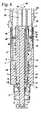
図4が示すように、噴射器1は送出部分24を有し、該送出部分は、本実施形態では実質的に筒状に形成され、ピストン棒13が内部に突出している。ピストン棒13は、ねじ山結合部27を介して送出部分24と結合されている。ピストン棒13が上部ハウジング部分3内で回転不能に固定されているので、送出部分24の回転により、送出部分24は末端方向に移動する。送出部分24は、縦ガイド32を介して操作要素6と相対回転不能に結合されている。噴射器1はさらに調整部分25を有している。本実施形態では、調整部分25も実質的に筒状に形成され、送出部分24の外周に配置されている。調整部分25は基端側端面74でもって走出部分24の縁75に当接している。調整部分25はねじ山結合部26を介して上部ハウジング部分3と結合されている。調整部分25が第1の回転方向43(図1)に回転すると、ねじ山結合部26が設けられているために調整部分25は末端方向に移動し、逆方向44(図6)に回転すると、調整部分25は基端方向に移動する。 As shown in FIG. 4, the
調整部分25は細条部を有し、該細条部は、調整部分25の筒状部分から半径方向外側へ突出し、該細条部でばね28が保持されている。ばね28はねじりばねとして形成され、その他端によって上部ハウジング部分3に固定されている。ばね28は調整部分25を第1の回転方向43(図1)とは逆の方向で上部ハウジング部分3に対し調整部分25をあらかじめ付勢している。 The
操作要素6と調整部分25との間で連結部33が作用する。連結部33は、図4では、該連結部が開いている位置47にある。位置47では、連結部33は操作要素6に対する調整部分25の相対回転を可能にする。連結部33は操作要素6に歯部34を有し、該歯部は、連結部33の位置46(図5)において調整部分25の歯部35に係合して、操作要素6と調整部分25とを互いに相対回転不能に結合させることができる。図4が示すように、歯部34は長手中心軸線10に対し平行に測った高さbを有している。操作要素6は、図3および図4に示した位置では、上部ハウジング部分3のストッパー73に載置されている。 A connecting
また、図4が示すように、操作要素6は軸線方向においてロック部分29と固定結合されている。ロック部分29はスリーブ状に形成され、縦ガイド36を介して上部ハウジング部分3と相対回転不能に結合されている。ロック部分29は、本実施形態では圧縮ばねとして形成されているばね37により、末端方向にあらかじめ付勢されている。ロック部分29は凹部80を有し、該凹部内にばね37が配置されている。ばね37はロック部分29の段部81で支持されている。凹部80は、ロック部分29と調整部分25との間に形成されている、ばね37を受容するための中空筒状の受容室を有している。操作要素6をロック部分29と軸線方向に固定結合させるため、ロック部分29の凹部38内へ突出している、操作要素6のロックエッジ39が用いられる。しかしながら、操作要素6が基端方向に移動するときだけロック部分29に作用して、操作要素6に追従する、ばね37による末端方向へのロック部分29の移動が、行われるようにしてもよい。 As shown in FIG. 4, the
ロック部分29は、調整部分25の縁40側に端面50を有している。端面50はロック部分29の末端側端面である。端面50には、ロック部分29の第1のロック要素30が配置されている。第1のロック要素30は、図4に示した位置で、縁40に対し、長手中心軸線10の方向に測った間隔aを有している。ロック要素30は、縁40の端面50側に配置した、調整部分25のロック要素(図4には図示せず)と係合していない。調整部分25とロック部分29とは図4において第2の軸線方向位置49にあり、該第2の軸線方向位置では、調整部分25の回転位置に関係なく、調整部分25とロック部分29との間のロックは可能でない。 The
噴射液を噴出させた後、操作要素6を、ばね37により、図4に示した位置から矢印15の方向に、すなわち末端方向へ移動させて、操作要素6が図5に示した位置にあるようにする。操作要素6は段部41を有し、該段部は、図4ではストッパー73に当接し、図5ではストッパー73に対し間隔cを有している。この間隔cは、図4に示したロック要素30と縁40との間の間隔aに相当している。図5は、調整部分25とロック部分29との間に形成されているロック装置72を第1の軸線方向位置48で示したもので、この第1の軸線方向位置では、第1のロック要素30は、調整部分25に配置されているロック要素と協働し、噴射器1の複数のロック位置を決定することができる。ロック部分29は、第1の軸線方向位置48において、そのロック要素30でもって縁40に当接する。また図5が示すように、操作要素6の縦リブ11は間隔cよりも短く、その結果縦リブ11は、噴射器1の図5に示した位置で、縦溝31の領域から到達している。操作要素6が基端方向に移動した場合、操作要素6の歯部34は調整部分25の歯部35内へ変位する。図5に示した、連結部33の第1の位置46では、操作要素6と調整部分25とは互いに相対回転不能に結合されている。 After the jetting liquid is ejected, the
噴射配量を調整するには、操作要素6を第1の回転方向43において縦中心軸線10のまわりに回転させねばならない。操作要素6と送出部分24との間の相対回転不能な結合により、送出部分24も回転する。送出部分24は、さらに、第2のねじ山結合部27を介して末端方向に移動する。調整部分25は、連結部33を介して、同様に操作要素6と相対回転不能に結合され、ねじ山結合部26により、その回転の際に同様に付加的に末端方向に移動する。その際、送出部分24と調整部分25とが移動する距離は、ほぼ同じ大きさである。好ましくは、調整部分25が移動する距離は、送出部分24の距離よりも幾分大きく、その結果配量を調整する際の基端方向への配量ピストン12の移動を回避することができる。ロック部分29はばね37により末端方向へ移動し、調整部分25の移動に追従する。これにより、ロック部分29と固定結合されている操作要素6も末端方向に移動する。 In order to adjust the injection quantity, the
図6は、噴射液の噴出量を調整した後の噴射器1を示している。段部41はストッパー73に対し間隔eを有し、この間隔は間隔cよりも著しく大きい。送出部分24は基端側の端面76を有し、該端面は、図5に示した位置に比べて、距離dだけ末端方向へ移動している。間隔eは、距離dと図5に示した間隔cとの和に相当している。ハウジング部分3の繰り抜き部5により、外周にスケール77が配置されている調整部分25の細条部42が見える。 FIG. 6 shows the
噴射液の調整した量を噴出させるため、矢印45で示唆したように、操作者は操作要素6をばね37の力に抗して基端方向へ移動させる。これによって操作要素6は調整部分25に対し相対的に移動する。連結部33は、図4に示した位置47へ変位する。ロック要素30も調整部分25に対し基端方向へ移動し、その結果第1のロック要素30は、縁40に配置されたロック要素と係合を解除される。ロック機構72は、図4に示したように、操作要素6の移動によって基端方向において第2の軸線方向位置49へ変位する。本実施形態では、まずロック装置72の係合を解除し、次に連結部33を解除させる。調整部分25は、連結部33とロック装置72とが解除されたときに、ばね28によって、第1の回転方向43とは逆方向の第2の回転方向44(図6)に回転する。ねじ山結合部26を介して、調整部分25は回転に加えて矢印45の方向において基端方向へ移動する。調整部分25の端面74は送出部分24の縁75に対し作用し、送出部分24を基端方向において距離dだけ変位させる。送出部分24が操作要素6と相対回転不能に結合されているので、送出部分24は回転することができない。それ故、上部ハウジング部分3と相対回転不能に結合されている配量ピストン12は基端方向に回転し、噴射液を容器から噴出させる。 In order to eject the adjusted amount of the spray liquid, the operator moves the
図7ないし図26は、噴射器1の各部分を詳細に示している。図7ないし図9は操作要素6を示している。図7には、操作要素6に設けた縦リブ11が示されている。本実施形態では、周部に均等に配分して配置されている4つの縦リブ11が設けられている。 7 to 26 show each part of the
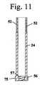
図8および図9が示すように、操作要素6はほぼ筒状に形成され、スリーブ55を有し、該スリーブの基端部には、内側へ突出するロックエッジ39が配置されている。スリーブ55は末端部で閉じている。スリーブ55の内部には、ほぼ筒状の接続部材54が装着され、該接続部材は完全にスリーブ55内部にあり、その基端側には歯部34が形成されている。本実施形態では、歯部34は接続部材54の外面に形成されている。歯部34は外径fを有している。また図8および図9が示すように、接続部材54の内周に複数の細条部51が設けられ、これら細条部は、図10および図11に示した、送出部分24の外周に設けた溝52と協働して、操作要素6を、該操作要素6と送出部分24との各相対位置で互いに相対回転不能に結合させる。図6および図9が示すように、接続部材54は受容部53を画成し、該受容部内へ送出部分24が突出している。 As shown in FIGS. 8 and 9, the
図11が示すように、送出部分24は縁75の領域に雌ねじ56を有している。ピストン棒13は、図12に示した雄ねじ61を有し、該雄ねじは送出部分24の目ねじ56に螺合している。縁75には段部57が配置され、該段部には、カルプーレ内にある残量よりも多い配量を調整したときに、ピストン棒13のストッパー58が係止される。ストッパー58はピストン棒13の末端部に配置され、ピストン棒13の雄ねじ61よりも大きな外径を有している。送出部分24へのピストン棒13の取り付けを可能にするため、ピストンディスク14はピスト棒13とは別個に形成されて、これに固定されている。図13が示すように、ピストン棒13は、該ピストン棒13の互いに対向しあっている長手側に配置されてピストン棒ガイド17と相対回転不能に結合するための2つの平坦部19を有している。しかし、相対回転不能な結合の他の構成も有利である。 As shown in FIG. 11, the
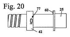
図14ないし図19は、調整部分25の構成を詳細に示している。調整部分25もほぼスリーブ状に形成され、外側へ突出する縁40を有し、この縁の基端側に第2のロック要素60が配置されている。第2のロック要素60はロック部分29のロック要素と協働し、これとともにロック装置72を形成している。ロック要素60は、図15では、図面の裏側にある。ロック要素60は傾斜状に形成され、該ロック要素60の、長手中心軸線10に対しほぼ平行に延びている側面は、調整部分25の回転の際に、第2の回転方向44において下流側に配置され、平坦に落ち込んでいる側面は、調整部分25の回転の際に、第1の回転方向43において下流側に配置されている。送出部分25の基端領域には、ねじ山結合部26の一部である雄ねじ59が設けられている。 14 to 19 show the configuration of the
図16および図19が示すように、連結部33の歯部35は調整部分25の末端側に配置され、内側へ向けられている。歯部35の基端側には、調整部分25のスリーブ状部分63が接続し、該スリーブ状部分の内径gは、図8に示した歯部34の外径fよりも大きい。歯部34がスリーブ状部分63内にあると、歯部34と35は係合を解除され、操作要素6は送出部分25に対し回転可能である。 As FIG. 16 and FIG. 19 show, the tooth | gear
図17が示すように、第2のロック要素60は、縁40の、長手中心軸線10に対し半径方向に測った幅全体にわたって、延在している。本実施形態では、ただ1つの第2のロック要素60が設けられている。しかし、他の数量の第2のロック要素60も有利であり、たとえば操作要素6の回転角が小さくて済み、ロック位置が明確に知覚されて聞こえるのが望ましい場合に、有利である。図18が示すように、細条部42は開口部62を有している。開口部62内にはばね28が掛止されている。 As shown in FIG. 17, the
図20なし図23には、調整部分25の細条部42上に設けられているスケール77が詳細に図示されている。スケール77の個々の値は、周方向において互いに異なる間隔を有している。これら値相互の側方へのずれ、すなわち長手中心軸線10(図15)の方向への相互のずれも異なっている。スケール77のこれら値の中心からそれぞれ測った、周方向におけるこれら値相互の間隔は、ロック部分29の付設のロック要素相互の間隔に対応している。側方への異なるずれは、調整部分25が1つのロック位置から次のロック位置へ移動する軸線方向距離から生じる。 FIG. 23 without FIG. 20 shows the
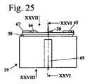
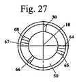
図24ないし図28は、ロック部分29を詳細に示している。ロック部分29はほぼスリーブ状に形成され、その端面50に第1のロック要素30,64,65,66,67,68を有している。ロック要素64はゼロ位置に関連付けられ、周方向においてロック要素64に対し短い間隔で配置されている第1のロック要素65は、プライミングの位置に対応している。互いに異なる間隔で配置されているロック要素66,67,68,30は、噴射液の異なる量に対応している。すべての第1のロック要素30,64ないし68は傾斜状に形成され、調整部分25が回転方向43に回転する際に前方にある側面は緩やかに傾斜しており、後方にある側面は急傾斜に降下している。調整部分25がロック部分29に対し第1の回転方向43に移動すると、第2のロック要素60の、平坦に降下している側面は、ロック要素30と64ないし68の、斜めに延びている側面に沿って滑動する。これによってロック部分29に対し基端方向の力が発生し、この力によってロック部分29はばね37の力に抗して偏位する。これにより、ロック位置に到達したことが操作者に聞こえ、知覚することができる。 24 to 28 show the
図24ないし図26が示すように、ロック部分29は、端面50にすぐ隣接して凹部38を有し、該凹部に操作要素6のロックエッジ39が係合している。図26が示すように、ロック部分29は、端面50とは逆の側に、凹部80を有し、該凹部においてロック部分29は拡大内径を有している。凹部80は、段部81でもって、より小さな内径を持つ部分に移行している。凹部80は、調整部分25とともに、ばね37のための受容室を画成している。ばね37は段部81で支持されている。図24、図25、図26、図28が示すように、4つの凹部69がロック部分29の周部に均等に配分されている。これらの凹部69は噴射器1の長手中心軸線10に対し平行に延在し、ロック部分29を上部ハウジング部分3と相対回転不能に結合させるために用いる。図27は、第1のロック要素が端面50に不規則に配置されていることを示している。第1のロック要素30と64ないし68はほぼ任意に端面50に配置してよい。有利には、操作要素6は、最大配量に到達するまでに、全1回転よりも少なく回転可能である。これにより、配量を調整する際に各ロック要素はせいぜい1回乗り越えられ、その結果複数のロック要素の任意の配置と、これによって噴射液調整量の任意の選択とが可能である。 As shown in FIGS. 24 to 26, the
図29および図30は、上部ハウジング部分3を示している。図29が示すように、上部ハウジング部分3はその内面に縦細条部70を有し、該縦細条部はロック部分29の凹部69に係合し、これによってロック部分29をハウジング2内で相対回転不能に保持する。ハウジング部分3はその基端領域に雌ねじ71を有し、該雌ねじは、調整部分25の雄ねじ59(図14)と協働して、これとともに第1のねじ山結合部26を形成している。また図26が示すように、上部ハウジング部分3はその末端部に多数の縦溝31を有し、その結果操作要素6を種々の回転位置でハウジング部分3内へ押し込むことができる。 29 and 30 show the
調整部分25が、噴射液の噴出量を調整する際にハウジング2に対し回転し、配量分を噴出させる際に同じ距離だけ戻り回転することにより、調整部分25と、ハウジング2に相対回転不能に保持されているロック部分29とは、どのロック位置でも互いに一義的に決定される回転位置にある。噴射配量の調整の際に最大で全1回転する調整部分の回転位置が常に噴射配量に対応しているので、各配量に対して別個のロック位置を設けることができる。中間ロックステップは必要ない。 The
Claims (13)
Translated fromJapanese前記調整部分(25)が、第1のねじ山結合部(26)を介して、前記ハウジング(2)と結合され、噴射液の噴出量を調整する際には、前記第1の回転方向(43)での回転に加えて末端方向へ移動し、調整した噴出液量を噴出させる際には、前記第2の回転方向(44)での回転に加えて基端方向へ移動し、各ロック位置に、前記ハウジング(2)に対する前記調整部分(25)の一義的な回転位置が割り当てられていることを特徴とする噴射器。The longitudinal central axis of the injector (1) in the first rotational direction (43) relative to the housing (2) of the injector (1) when adjusting the amount of spray liquid to be ejected from the injector (1) (10) a second rotation in a direction opposite to the first rotational direction (43) when the jetting liquid is ejected from the injector (1), the adjusting portion (25) rotating around The adjusting part (25) rotating in the direction (44) and a locking device (72) for determining at least one locking position of the adjusting part (25), wherein the locking device (72) 25) and the housing (2), and the locking device (72) actsat least in adjusting the amount of the spray liquid to be ejected from the injector (1), and the at least one The locking position is the housing (2) At least one first locking element (30, 64, 65, 66, 67, 68) that is non-rotatably coupled to the adjustment portion (25) and is non-rotatably coupled to the first locking element. In said injector,determined by at least one second locking element (60) cooperating with the element (30, 64, 65, 66, 67, 68) ;
The adjustment portion (25) is coupled to the housing (2) via the first thread coupling portion (26), and when adjusting the ejection amount of the spray liquid, the first rotation direction ( 43) When moving in the distal direction in addition to the rotation in 43) and ejecting the adjusted amount of ejected liquid, in addition to the rotation in the second rotation direction (44), it moves in the proximal direction, and each lock The injector is characterized in that the position is assigned a unique rotational position of the adjusting part (25) relative to the housing (2).
The adjustment portion (25) acts on the delivery portion (24) such that movement of the adjustment portion (25) in the proximal direction causes movement of the delivery portion (24) in the proximal direction. The injector according to claim12 , wherein:
Applications Claiming Priority (3)
| Application Number | Priority Date | Filing Date | Title |
|---|---|---|---|
| DE202014001135.4 | 2014-02-05 | ||
| DE202014001135.4UDE202014001135U1 (en) | 2014-02-05 | 2014-02-05 | injection device |
| PCT/EP2015/000206WO2015117747A1 (en) | 2014-02-05 | 2015-02-03 | Injection device |
Publications (2)
| Publication Number | Publication Date |
|---|---|
| JP2017507696A JP2017507696A (en) | 2017-03-23 |
| JP6330052B2true JP6330052B2 (en) | 2018-05-23 |
Family
ID=52446337
Family Applications (1)
| Application Number | Title | Priority Date | Filing Date |
|---|---|---|---|
| JP2016549447AActiveJP6330052B2 (en) | 2014-02-05 | 2015-02-03 | Injector |
Country Status (13)
| Country | Link |
|---|---|
| US (1) | US10583259B2 (en) |
| EP (1) | EP3102257B1 (en) |
| JP (1) | JP6330052B2 (en) |
| CN (1) | CN106163591B (en) |
| BR (1) | BR112016015688B1 (en) |
| CA (1) | CA2938055C (en) |
| DE (1) | DE202014001135U1 (en) |
| DK (1) | DK3102257T3 (en) |
| ES (1) | ES2733063T3 (en) |
| PL (1) | PL3102257T3 (en) |
| RU (1) | RU2661755C1 (en) |
| TR (1) | TR201908089T4 (en) |
| WO (1) | WO2015117747A1 (en) |
Cited By (1)
| Publication number | Priority date | Publication date | Assignee | Title |
|---|---|---|---|---|
| JP3127470B2 (en) | 1990-12-17 | 2001-01-22 | 住友重機械工業株式会社 | Sand filtration equipment |
Families Citing this family (6)
| Publication number | Priority date | Publication date | Assignee | Title |
|---|---|---|---|---|
| DE202015006841U1 (en) | 2015-09-30 | 2016-01-15 | Haselmeier Ag | injection device |
| DE202015006842U1 (en) | 2015-09-30 | 2016-01-15 | Haselmeier Ag | injection device |
| DE202015006845U1 (en)* | 2015-09-30 | 2016-01-15 | Haselmeier Ag | injection device |
| US10688247B2 (en) | 2017-07-13 | 2020-06-23 | Haselmeier Ag | Injection device with flexible dose selection |
| CN115337499B (en)* | 2017-10-19 | 2024-09-06 | 赛诺菲 | Medicament administration device and data collection device |
| US11969583B2 (en) | 2018-07-17 | 2024-04-30 | Medmix Switzerland Ag | Injection device with dose interruption fail safe |
Family Cites Families (21)
| Publication number | Priority date | Publication date | Assignee | Title |
|---|---|---|---|---|
| SU1057040A1 (en)* | 1981-08-31 | 1983-11-30 | Всесоюзный Научно-Исследовательский Институт Незаразных Болезней Животных | Pneumatic injector without needle |
| DE3638984C3 (en)* | 1986-11-14 | 1993-11-18 | Haselmeier Wilhelm Fa | Injection device |
| SU1634285A1 (en)* | 1988-01-13 | 1991-03-15 | Ал.Н.Сургутанов, Н.А.Сургутанов и Ан.Н.Сургутанов | Injection appliance |
| DK175491D0 (en)* | 1991-10-18 | 1991-10-18 | Novo Nordisk As | APPARATUS |
| GB0306642D0 (en)* | 2003-03-22 | 2003-04-30 | Dca Design Int Ltd | Improvements in and relating to an injector for a medical product |
| DE20317377U1 (en) | 2003-11-03 | 2005-03-17 | B D Medico S A R L | injection device |
| ATE444090T1 (en)* | 2004-10-21 | 2009-10-15 | Novo Nordisk As | SELECTION MECHANISM FOR A ROTARY PIN |
| EP1843809B1 (en)* | 2005-01-21 | 2017-04-19 | Novo Nordisk A/S | An automatic injection device with a top release mechanism |
| DE102005060929A1 (en)* | 2005-09-14 | 2007-03-15 | Tecpharma Licensing Ag | Product e.g. insulin, injecting device, has housing and operating knob with locking units that are formed such that movement of operating knob in one direction has smaller resistance in contrast to movement in other direction |
| DE102005060928A1 (en)* | 2005-12-20 | 2007-06-28 | Tecpharma Licensing Ag | Injection device with axially overlapping metering or display element |
| DE102007019124A1 (en)* | 2007-04-23 | 2008-11-06 | Tecpharma Licensing Ag | Reversible metering device for an injection device |
| DE102007026083A1 (en)* | 2007-05-25 | 2008-11-27 | Haselmeier S.A.R.L. | injection device |
| RU79426U1 (en)* | 2008-07-09 | 2009-01-10 | ОТКРЫТОЕ АКЦИОНЕРНОЕ ОБЩЕСТВО "МЕДИКО-ИНСТРУМЕНТАЛЬНЫЙ ЗАВОД" им. В.И. Ленина | BEADLESS INJECTOR |
| TR201807257T4 (en)* | 2009-02-26 | 2018-06-21 | Shl Group Ab | Dose adjustment mechanisms. |
| US8585656B2 (en)* | 2009-06-01 | 2013-11-19 | Sanofi-Aventis Deutschland Gmbh | Dose setting mechanism for priming a drug delivery device |
| DE102009048497A1 (en)* | 2009-09-26 | 2011-03-31 | Haselmeier Gmbh | injection device |
| ES2574057T3 (en)* | 2009-12-15 | 2016-06-14 | Shl Group Ab | Medication delivery device |
| WO2011101349A1 (en)* | 2010-02-17 | 2011-08-25 | Sanofi-Aventis Deutschland Gmbh | Automatic injection device with torsional spring |
| WO2012049144A1 (en)* | 2010-10-13 | 2012-04-19 | Sanofi-Aventis Deutschland Gmbh | Dose setting mechanism and method of setting a dose |
| DE202012001411U1 (en)* | 2012-02-10 | 2013-05-13 | Haselmeier Gmbh | injection device |
| CN203043167U (en)* | 2013-01-22 | 2013-07-10 | 纪柏 | Automatic pen-type insulin syringe with dose memory function |
- 2014
- 2014-02-05DEDE202014001135.4Upatent/DE202014001135U1/ennot_activeExpired - Lifetime
- 2015
- 2015-02-03RURU2016134754Apatent/RU2661755C1/enactive
- 2015-02-03BRBR112016015688-9Apatent/BR112016015688B1/enactiveIP Right Grant
- 2015-02-03EPEP15702374.8Apatent/EP3102257B1/enactiveActive
- 2015-02-03JPJP2016549447Apatent/JP6330052B2/enactiveActive
- 2015-02-03WOPCT/EP2015/000206patent/WO2015117747A1/enactiveApplication Filing
- 2015-02-03PLPL15702374Tpatent/PL3102257T3/enunknown
- 2015-02-03CACA2938055Apatent/CA2938055C/enactiveActive
- 2015-02-03TRTR2019/08089Tpatent/TR201908089T4/enunknown
- 2015-02-03CNCN201580007300.5Apatent/CN106163591B/enactiveActive
- 2015-02-03DKDK15702374.8Tpatent/DK3102257T3/enactive
- 2015-02-03ESES15702374Tpatent/ES2733063T3/enactiveActive
- 2016
- 2016-08-05USUS15/230,259patent/US10583259B2/enactiveActive
Cited By (1)
| Publication number | Priority date | Publication date | Assignee | Title |
|---|---|---|---|---|
| JP3127470B2 (en) | 1990-12-17 | 2001-01-22 | 住友重機械工業株式会社 | Sand filtration equipment |
Also Published As
| Publication number | Publication date |
|---|---|
| EP3102257A1 (en) | 2016-12-14 |
| BR112016015688B1 (en) | 2022-04-26 |
| CN106163591A (en) | 2016-11-23 |
| EP3102257B1 (en) | 2019-03-27 |
| US10583259B2 (en) | 2020-03-10 |
| US20160339181A1 (en) | 2016-11-24 |
| RU2661755C1 (en) | 2018-07-19 |
| CN106163591B (en) | 2020-02-07 |
| TR201908089T4 (en) | 2019-06-21 |
| BR112016015688A2 (en) | 2017-08-08 |
| ES2733063T3 (en) | 2019-11-27 |
| JP2017507696A (en) | 2017-03-23 |
| DK3102257T3 (en) | 2019-06-24 |
| WO2015117747A1 (en) | 2015-08-13 |
| WO2015117747A8 (en) | 2015-10-08 |
| PL3102257T3 (en) | 2019-09-30 |
| DE202014001135U1 (en) | 2015-05-06 |
| CA2938055C (en) | 2018-10-02 |
| CA2938055A1 (en) | 2015-08-13 |
Similar Documents
| Publication | Publication Date | Title |
|---|---|---|
| JP6330052B2 (en) | Injector | |
| US11969584B2 (en) | Injection device with flexible dose selection | |
| JP6412946B2 (en) | Injector | |
| US10675413B2 (en) | Delivery device | |
| US8012131B2 (en) | Extractable dose setting knob | |
| US10518037B2 (en) | Injection device | |
| KR101976299B1 (en) | Dose setting mechanism and medicament delivery device comprising the dose setting mechanism | |
| RU2434651C1 (en) | Device for medication supply | |
| JP4011543B2 (en) | Latching device for connecting the housing part of the administration device | |
| JP5917769B2 (en) | Drug delivery device | |
| US7976509B2 (en) | Injection device with secured dosing button | |
| JP2007512932A (en) | Pharmaceutical supply device having air shot means | |
| CN105813669A (en) | Mechanical dose expelled indicator | |
| JP2019524225A (en) | Drug delivery device with adjustment member | |
| JP2018519091A (en) | Method for assembling a drug delivery device and drug delivery device formed by the method | |
| CN107787237A (en) | Delivery device | |
| TW201701913A (en) | Dose setting mechanism and medicament delivery device comprising the dose setting mechanism | |
| JP6858758B2 (en) | Piston washer assembly, assembly method, and drug delivery device incorporating such a piston washer assembly | |
| CN101370541B (en) | Injection device with fixed dosing knob | |
| TWI442952B (en) | Medicament delivery device |
Legal Events
| Date | Code | Title | Description |
|---|---|---|---|
| A131 | Notification of reasons for refusal | Free format text:JAPANESE INTERMEDIATE CODE: A131 Effective date:20170627 | |
| A977 | Report on retrieval | Free format text:JAPANESE INTERMEDIATE CODE: A971007 Effective date:20170623 | |
| A601 | Written request for extension of time | Free format text:JAPANESE INTERMEDIATE CODE: A601 Effective date:20170926 | |
| A601 | Written request for extension of time | Free format text:JAPANESE INTERMEDIATE CODE: A601 Effective date:20171124 | |
| A521 | Request for written amendment filed | Free format text:JAPANESE INTERMEDIATE CODE: A523 Effective date:20171225 | |
| TRDD | Decision of grant or rejection written | ||
| A01 | Written decision to grant a patent or to grant a registration (utility model) | Free format text:JAPANESE INTERMEDIATE CODE: A01 Effective date:20180403 | |
| A61 | First payment of annual fees (during grant procedure) | Free format text:JAPANESE INTERMEDIATE CODE: A61 Effective date:20180423 | |
| R150 | Certificate of patent or registration of utility model | Ref document number:6330052 Country of ref document:JP Free format text:JAPANESE INTERMEDIATE CODE: R150 | |
| R250 | Receipt of annual fees | Free format text:JAPANESE INTERMEDIATE CODE: R250 | |
| S111 | Request for change of ownership or part of ownership | Free format text:JAPANESE INTERMEDIATE CODE: R313111 | |
| R250 | Receipt of annual fees | Free format text:JAPANESE INTERMEDIATE CODE: R250 | |
| R350 | Written notification of registration of transfer | Free format text:JAPANESE INTERMEDIATE CODE: R350 | |
| S533 | Written request for registration of change of name | Free format text:JAPANESE INTERMEDIATE CODE: R313533 | |
| R350 | Written notification of registration of transfer | Free format text:JAPANESE INTERMEDIATE CODE: R350 | |
| R250 | Receipt of annual fees | Free format text:JAPANESE INTERMEDIATE CODE: R250 | |
| R250 | Receipt of annual fees | Free format text:JAPANESE INTERMEDIATE CODE: R250 |