JP6327041B2 - Spectrometer - Google Patents
SpectrometerDownload PDFInfo
- Publication number
- JP6327041B2 JP6327041B2JP2014151540AJP2014151540AJP6327041B2JP 6327041 B2JP6327041 B2JP 6327041B2JP 2014151540 AJP2014151540 AJP 2014151540AJP 2014151540 AJP2014151540 AJP 2014151540AJP 6327041 B2JP6327041 B2JP 6327041B2
- Authority
- JP
- Japan
- Prior art keywords
- light
- measurement
- optical
- parallel light
- condensing
- Prior art date
- Legal status (The legal status is an assumption and is not a legal conclusion. Google has not performed a legal analysis and makes no representation as to the accuracy of the status listed.)
- Active
Links
Images


Landscapes
- Spectrometry And Color Measurement (AREA)
- Investigating, Analyzing Materials By Fluorescence Or Luminescence (AREA)
Description
Translated fromJapanese本発明は分光測定装置に関する。特に、ラマン分光測定装置のように、特定の波長範囲の光を除去する光学フィルタを用いる分光測定装置に関する。 The present invention relates to a spectrometer. In particular, the present invention relates to a spectrometer that uses an optical filter that removes light in a specific wavelength range, such as a Raman spectrometer.
ラマン分光測定では、試料に励起光を照射し、試料によりラマン散乱された光(ラマン散乱光)を測定してラマンスペクトルを作成する。ラマンスペクトルでは、励起光の波長よりも長波長側にストークス線、短波長側に反ストークス線が現れる。励起光の波長と、ストークス線(あるいは反ストークス線)の波長の差に対応するエネルギーは、分子の固有振動のエネルギーを反映する。そのため、このエネルギーの大きさから試料に含まれる物質を特定することができる。また、ラマン散乱スペクトルに現れるストークス線や反ストークス線の強度から、該ストークス線あるいは反ストークス線に対応する物質を定量することができる。特許文献1には、ガスエンジンに供給する燃料ガスについてラマン分光測定を行い、その結果に基づいて燃料ガスの濃度をリアルタイムで調整するガス成分調整装置が記載されている。 In the Raman spectroscopic measurement, a sample is irradiated with excitation light, and the Raman spectrum is created by measuring the Raman scattered light (Raman scattered light) by the sample. In the Raman spectrum, a Stokes line appears on the longer wavelength side than the wavelength of the excitation light, and an anti-Stokes line appears on the shorter wavelength side. The energy corresponding to the difference between the wavelength of the excitation light and the wavelength of the Stokes line (or anti-Stokes line) reflects the energy of the natural vibration of the molecule. Therefore, the substance contained in the sample can be specified from the magnitude of this energy. Further, the substance corresponding to the Stokes line or the anti-Stokes line can be quantified from the intensity of the Stokes line or the anti-Stokes line appearing in the Raman scattering spectrum.
ラマン分光測定装置は、所定の波長の励起光を発する光源、該励起光を集光して試料に照射する入射光学系、試料からのラマン散乱光を集光し波長分離する分光光学系、及び該分光光学系において波長分離された光を検出する検出器を備えている。 The Raman spectroscopic measurement apparatus includes a light source that emits excitation light of a predetermined wavelength, an incident optical system that collects the excitation light and irradiates the sample, a spectroscopic optical system that collects Raman scattered light from the sample and separates the wavelength, and The spectroscopic optical system includes a detector that detects light separated in wavelength.
ラマン分光測定装置の分光光学系は、被測定点において試料から広角に発せられるラマン散乱光を平行光に変換する第1集光レンズ、該第1集光レンズを通過した平行光のうち、励起光と同じ波長の光であるレイリー光を除去する平板状の光学フィルタ、該光学フィルタを通過したラマン散乱光を集光する第2集光レンズを備えている。第2集光レンズを通過した光は所定位置に集光して検出器で検出される。 The spectroscopic optical system of the Raman spectroscopic measurement apparatus includes a first condensing lens that converts Raman scattered light emitted from a sample at a wide angle at a measurement point into parallel light, and excitation is performed among parallel light that has passed through the first condensing lens. A flat optical filter that removes Rayleigh light, which has the same wavelength as the light, and a second condenser lens that condenses the Raman scattered light that has passed through the optical filter are provided. The light that has passed through the second condenser lens is condensed at a predetermined position and detected by a detector.
光学フィルタとしては、特定の波長範囲の光を除去するノッチフィルタや、特定の波長よりも短い(あるいは長い)波長の光を除去するエッジフィルタが用いられる。こうした光学フィルタは、複数種類の材料を周期的に積層した多層構造を有している。この多層構造は、材料の屈折率と各層の厚さの積が、光学フィルタの表面に垂直な方向から入射する光のうちの除去する光の波長に対して所定の比率になるように設定される。 As the optical filter, a notch filter that removes light in a specific wavelength range or an edge filter that removes light having a wavelength shorter (or longer) than the specific wavelength is used. Such an optical filter has a multilayer structure in which a plurality of types of materials are periodically stacked. This multilayer structure is set so that the product of the refractive index of the material and the thickness of each layer has a predetermined ratio to the wavelength of light to be removed from light incident from a direction perpendicular to the surface of the optical filter. The
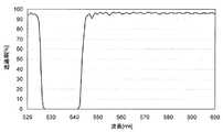
一般に、ノッチフィルタやエッジフィルタの光透過特性は、透過帯域と阻止帯域の境界付近において、光の波長に対して周期的に変化する性質をもつ。図1に典型的なノッチフィルタの光透過特性(横軸:波長、縦軸:光透過率)の例を示す。このような光透過特性の周期的変化を以下リップルと呼ぶ。リップルが存在すると、ラマン散乱光の波長により、発生強度と検出強度の関係が異なるため、試料の定量結果に誤差を生じる。
ここでは、ラマン分光測定を例に挙げて説明したが、ノッチフィルタやエッジフィルタを用いる他の分光測定方法や分光測定装置においても同様の問題が生じる。In general, the light transmission characteristics of the notch filter and the edge filter have a property of periodically changing with respect to the wavelength of light in the vicinity of the boundary between the transmission band and the stop band. FIG. 1 shows an example of light transmission characteristics (horizontal axis: wavelength, vertical axis: light transmittance) of a typical notch filter. Such a periodic change in light transmission characteristics is hereinafter referred to as a ripple. If the ripple exists, the relationship between the generated intensity and the detected intensity differs depending on the wavelength of the Raman scattered light, which causes an error in the quantification result of the sample.
Here, the Raman spectroscopic measurement has been described as an example, but the same problem occurs in other spectroscopic measurement methods and spectroscopic measurement apparatuses using notch filters and edge filters.
本発明が解決しようとする課題は、ノッチフィルタやエッジフィルタを用いる分光測定方法及び分光測定装置において、該フィルタの光透過特性に現れるリップルの影響を低減して高い精度で試料の分光特性を測定することである。 The problem to be solved by the present invention is to measure the spectral characteristics of a sample with high accuracy by reducing the influence of ripples appearing in the light transmission characteristics of the filter in a spectroscopic measurement method and a spectroscopic measurement apparatus using notch filters and edge filters. It is to be.
上記課題を解決するために成された本発明は、測定点から発せられる測定光から特定の波長の光を光学フィルタを用いて除去した後、波長分離し、該波長分離後の光の強度を検出して前記測定光の分光特性を測定する分光測定方法において、
前記測定光を非単一の入射角で前記光学フィルタに入射させ、該光学フィルタを透過した測定光の分光特性を測定する
ことを特徴とする。In order to solve the above-mentioned problems, the present invention eliminates light of a specific wavelength from measurement light emitted from a measurement point using an optical filter, and then wavelength-separates the light after the wavelength separation. In the spectroscopic measurement method for detecting and measuring the spectral characteristics of the measurement light,
The measurement light is incident on the optical filter at a non-single incident angle, and spectral characteristics of the measurement light transmitted through the optical filter are measured.
上記の「測定光を非単一の入射角で光学フィルタに入射」させる、とは、測定光を光学フィルタの入射面に対して複数の異なる入射角で入射させること、あるいは、測定光を光学フィルタの入射面に対して連続的に変化する(幅のある)入射角で入射させること、を意味する。このように測定光を光学フィルタに入射させる方法としては、例えば、非平行光である測定光を平板状の光学フィルタに入射させる方法や、測定光の光軸に対して異なる角度で入射面を配置した複数の光学フィルタを用い、それらの光学フィルタに平行光に変換した測定光を入射させる方法を用いることができる。 “Making the measurement light incident on the optical filter at a non-single incident angle” means that the measurement light is incident on the incident surface of the optical filter at a plurality of different incident angles, or the measurement light is optical This means that the light is incident at an incident angle that continuously changes (width) with respect to the incident surface of the filter. As a method for making the measurement light incident on the optical filter in this way, for example, a method in which measurement light that is non-parallel light is made incident on a flat optical filter, or an incident surface is formed at different angles with respect to the optical axis of the measurement light A method can be used in which a plurality of arranged optical filters are used and measurement light converted into parallel light is incident on these optical filters.
本発明者は、測定光を光学フィルタに入射させる角度を変化させると、光学フィルタの光透過特性を示すグラフに現れるリップルが波長軸方向にシフトする点に着目して本発明を想到した。従来の分光光学系では、平板状のフィルタの表面に垂直な方向から平行光を入射させていたため、その入射角は単一(0度のみ)であったが、本発明に係る分光測定装置では、複数の入射角で光学フィルタに測定光を入射させる。互いに異なる複数の入射角で光学フィルタに入射した測定光の強度には、該複数の入射角に対応するリップルがそれぞれ反映されるため、これらをまとめて測定すると波長に対する光透過率の変動が平均化される。従って、ラマン散乱光の波長を問わず発生強度と検出強度の関係を一定に保ち、高い精度で試料の分光特性を測定することができる。 The present inventor has conceived the present invention by paying attention to the fact that the ripple appearing in the graph showing the light transmission characteristics of the optical filter shifts in the wavelength axis direction when the angle at which the measurement light is incident on the optical filter is changed. In the conventional spectroscopic optical system, since parallel light is incident from a direction perpendicular to the surface of the flat plate-like filter, the incident angle is single (only 0 degree), but in the spectroscopic measurement device according to the present invention, The measurement light is incident on the optical filter at a plurality of incident angles. The ripples corresponding to the multiple incident angles are reflected in the intensity of the measurement light incident on the optical filter at a plurality of different incident angles. Therefore, when these are measured together, the variation in light transmittance with respect to the wavelength is averaged. It becomes. Therefore, the spectral characteristics of the sample can be measured with high accuracy while maintaining the relationship between the generated intensity and the detected intensity constant regardless of the wavelength of the Raman scattered light.
また、上記課題を解決するために成された本発明の別の態様は、上記分光測定方法を実行する分光測定装置であって、
測定点から発せられる測定光を所定の集光位置に集光する集光光学系と、
前記測定光が非単一の入射角で入射し、特定の波長範囲の光を除去する光学フィルタと、
を備えることを特徴とする。Another aspect of the present invention made to solve the above problems is a spectroscopic measurement apparatus for executing the spectroscopic measurement method,
A condensing optical system for condensing measurement light emitted from the measurement point at a predetermined condensing position;
An optical filter that receives the measurement light at a non-single incident angle and removes light in a specific wavelength range;
It is characterized by providing.
本発明に係る分光測定装置は、例えば、
前記光学フィルタが、前記測定点から前記集光位置までの光路上であって、前記測定光が非平行光である光路上に配置された特定の波長範囲の光を除去する平板状の光学フィルタを有する
ように構成することができる。The spectrometer according to the present invention is, for example,
The optical filter is on the optical path from the measurement point to the condensing position, and is a flat optical filter that removes light in a specific wavelength range disposed on the optical path where the measurement light is non-parallel light It can comprise so that it may have.
この分光測定装置は、例えば、測定点から発せられる測定光を平行光に変換する第1集光レンズ、該平行光を所定の集光位置に集光する第2集光レンズ、及び測定点から第1集光レンズまでの光路上、あるいは、第2集光レンズから所定の集光位置までの光路上に配置された光学フィルタにより構成することができる。この場合には、上記集光光学系は、第1集光レンズと第2集光レンズにより構成される。集光光学系の構成はこれに限らず、3枚以上の集光レンズを用いるものであってもよい。また、集光光学系は、測定光を平行光に変換することなく所定の集光位置に集光するものであってもよい。 The spectroscopic measurement device includes, for example, a first condensing lens that converts measurement light emitted from a measurement point into parallel light, a second condensing lens that condenses the parallel light at a predetermined condensing position, and a measurement point. It can be configured by an optical filter arranged on the optical path to the first condenser lens or on the optical path from the second condenser lens to a predetermined condenser position. In this case, the condensing optical system includes a first condenser lens and a second condenser lens. The configuration of the condensing optical system is not limited to this, and three or more condensing lenses may be used. Further, the condensing optical system may condense the measurement light at a predetermined condensing position without converting the measurement light into parallel light.
この分光測定装置では、光学フィルタを、測定光が測定点から拡がりつつ進行する光路上、及び測定光が収束しつつ進行する光路上の少なくとも一方に配置し、光軸からの距離に応じて連続的に変化する入射角で測定光を光学フィルタに入射させる。光学フィルタを通過した測定光を第2集光レンズで集光すると、前記連続的に変化する入射角に対応する、連続的にシフトしたリップルが重畳して波長に対する光透過率の変動が平均化される。従って、ラマン散乱光の波長を問わず発生強度と検出強度の関係を一定に保ち、高い精度で試料の分光特性を測定することができる。 In this spectroscopic measurement device, the optical filter is disposed on at least one of the optical path on which the measurement light travels while spreading from the measurement point and the optical path on which the measurement light travels while converging, and continuously according to the distance from the optical axis. The measurement light is incident on the optical filter at an incident angle that changes with time. When the measurement light that has passed through the optical filter is collected by the second condenser lens, the fluctuation of the light transmittance with respect to the wavelength is averaged by superimposing continuously shifted ripples corresponding to the continuously changing incident angle. Is done. Therefore, the spectral characteristics of the sample can be measured with high accuracy while maintaining the relationship between the generated intensity and the detected intensity constant regardless of the wavelength of the Raman scattered light.
また、本発明に係る分光測定装置は、例えば、
前記集光光学系が、測定点から発せられる測定光を平行光に変換する第1集光レンズと、前記平行光を所定の集光位置に集光する第2集光レンズとを有し、
前記光学フィルタが、前記第1集光レンズと前記第2集光レンズとの間において前記平行光の光路上に配置された複数枚の平板状の光学フィルタを有し、それらのうちの少なくとも2枚について該平行光の光軸と入射面がなす角度が互いに異なる
ように構成することができる。The spectroscopic measurement device according to the present invention is, for example,
The condensing optical system includes a first condensing lens that converts measurement light emitted from a measurement point into parallel light, and a second condensing lens that condenses the parallel light at a predetermined condensing position,
The optical filter has a plurality of plate-like optical filters disposed on the optical path of the parallel light between the first condenser lens and the second condenser lens, and at least two of them. The angle between the optical axis of the parallel light and the incident surface can be different from each other.
この分光測定装置では、平行光が、異なる角度で複数回、光学フィルタに入射する。これにより、第2集光レンズにより集光される測定光の強度に対して複数の入射角にそれぞれ対応するリップルが重畳し、波長に対する光透過率の変動が平均化される。従って、ラマン散乱光の波長を問わず発生強度と検出強度の関係を一定に保ち、高い精度で試料の分光特性を測定することができる。 In this spectrometer, the parallel light is incident on the optical filter a plurality of times at different angles. Thereby, ripples corresponding to a plurality of incident angles are superimposed on the intensity of the measurement light collected by the second condenser lens, and the variation in light transmittance with respect to the wavelength is averaged. Therefore, the spectral characteristics of the sample can be measured with high accuracy while maintaining the relationship between the generated intensity and the detected intensity constant regardless of the wavelength of the Raman scattered light.
さらに、本発明に係る分光測定装置は、例えば、
前記集光光学系が、測定点から発せられる測定光を平行光に変換する第1集光レンズと、前記平行光を所定の集光位置に集光する第2集光レンズとを有し、
前記光学フィルタが、前記第1集光レンズと前記第2集光レンズの間とにおいて、複数に分割された前記平行光の光路上にそれぞれ配置された特定の波長範囲の光を除去する複数枚の平板状の光学フィルタを有し、それらのうちの少なくとも2枚について該平行光の光軸と入射面がなす角度が互いに異なる
ように構成することができる。Furthermore, the spectrometer according to the present invention is, for example,
The condensing optical system includes a first condensing lens that converts measurement light emitted from a measurement point into parallel light, and a second condensing lens that condenses the parallel light at a predetermined condensing position,
A plurality of the optical filters for removing light in a specific wavelength range respectively arranged on the optical path of the parallel light divided into a plurality of parts between the first condenser lens and the second condenser lens And at least two of them can be configured such that the angles formed by the optical axis of the parallel light and the incident surface are different from each other.
この分光測定装置では、複数の平行光がそれぞれの光路上に配置された光学フィルタに対して異なる角度で入射する。これにより、測定光の強度に対して複数の入射角にそれぞれ対応するリップルが重畳し、波長に対する光透過率の変動が平均化される。従って、ラマン散乱光の波長を問わず発生強度と検出強度の関係を一定に保ち、高い精度で試料の分光特性を測定することができる。 In this spectrometer, a plurality of parallel lights are incident on the optical filters arranged on the respective optical paths at different angles. Thereby, ripples respectively corresponding to a plurality of incident angles are superimposed on the intensity of the measurement light, and the variation of the light transmittance with respect to the wavelength is averaged. Therefore, the spectral characteristics of the sample can be measured with high accuracy while maintaining the relationship between the generated intensity and the detected intensity constant regardless of the wavelength of the Raman scattered light.
さらに、本発明に係る分光測定装置は、例えば、
前記集光光学系が、測定点から発せられる測定光を平行光に変換する第1集光レンズと、前記平行光を所定の集光位置に集光する第2集光レンズとを有し、
前記光学フィルタが、前記第1集光レンズと前記第2集光レンズとの間において前記平行光の光路上に配置され、
前記第1集光レンズと前記光学フィルタとの間に配置された、前記平行光のうちの一部の光を進行方向を変更する方向変更部を更に備える
ように構成することができる。Furthermore, the spectrometer according to the present invention is, for example,
The condensing optical system includes a first condensing lens that converts measurement light emitted from a measurement point into parallel light, and a second condensing lens that condenses the parallel light at a predetermined condensing position,
The optical filter is disposed on an optical path of the parallel light between the first condenser lens and the second condenser lens;
A direction changing unit arranged between the first condenser lens and the optical filter for changing a traveling direction of a part of the parallel light can be further provided.
この分光測定装置では、平行光のうちの一部の光が方向変更部を通過して、その進行方向が変化する。その結果、方向変更部を通過した平行光とそれ以外の平行光とが互いに異なる角度で光学フィルタに入射し、これらの平行光の入射角にそれぞれ対応するリップルが重畳して波長に対する光透過率の変動が平均化される。従って、ラマン散乱光の波長を問わず発生強度と検出強度の関係を一定に保ち、高い精度で試料の分光特性を測定することができる。 In this spectrometer, a part of the parallel light passes through the direction changing unit, and the traveling direction thereof changes. As a result, the parallel light that has passed through the direction changing unit and the other parallel light are incident on the optical filter at different angles, and ripples corresponding to the incident angles of these parallel lights are superimposed, respectively, and the light transmittance with respect to the wavelength. Fluctuations are averaged. Therefore, the spectral characteristics of the sample can be measured with high accuracy while maintaining the relationship between the generated intensity and the detected intensity constant regardless of the wavelength of the Raman scattered light.
光学フィルタの光透過特性に現れるリップルは、個々の光学フィルタで異なる。また、測定光の入射角が大きいほどリップルのシフトが大きくなる。そこで、上記各態様の分光測定装置では、個々の光学フィルタについてそれぞれ予備測定を行うなどして、前記測定光の光軸と光学フィルタの入射面とがなす角度が、リップルの影響を最も低減するように設定されていることが好ましい。Ripple appearing in the light transmission characteristics of the optical filter is different for each optical filter. Further, the ripple shift increases as the incident angle of the measurement light increases. Therefore, the spectroscopic measurement apparatus of the embodiment, and the like preliminarily measured respectively for each of the optical filter, the incident surface and theangles that form the optical axis and the optical filter of the measuring light, most the effect of ripple reduction It is preferable to set so as to.
ところで、ラマン分光測定装置の光源として用いられるダイオードレーザでは、周辺の温度が時間的に変化するとレーザ光の波長も追従して変化する。このように励起光の波長が時間的に変化すると、ラマン散乱光の波長も同様に変化する。本発明に係る各態様の分光測定装置では、波長に対する光透過率の変動が平均化されるため、このようにラマン散乱光の波長が時間的に変化する場合でも高精度でラマン散乱光を測定することができる。 By the way, in the diode laser used as the light source of the Raman spectroscopic measurement device, the wavelength of the laser light changes following the surrounding temperature as time changes. Thus, when the wavelength of the excitation light changes with time, the wavelength of the Raman scattered light also changes. In the spectroscopic measurement device according to each aspect of the present invention, the fluctuation of the light transmittance with respect to the wavelength is averaged, and thus the Raman scattered light is measured with high accuracy even when the wavelength of the Raman scattered light changes with time. can do.
本発明に係る分光測定方法や分光測定装置を用いることにより、光学フィルタの光透過特性に現れるリップルの影響を低減して高い精度で試料の分光特性を測定することができる。 By using the spectroscopic measurement method or spectroscopic measurement apparatus according to the present invention, it is possible to reduce the influence of ripples appearing in the light transmission characteristics of the optical filter and measure the spectroscopic characteristics of the sample with high accuracy.
本発明に係る分光測定装置の一実施形態であるラマン分光測定装置について説明する。図2は本実施例のラマン分光測定装置1の概略構成図である。 A Raman spectrometer which is an embodiment of the spectrometer according to the present invention will be described. FIG. 2 is a schematic configuration diagram of the
このラマン分光測定装置1は、配管2中を流れるガスに含まれる目的成分の濃度を測定する装置である。ラマン分光測定装置1は、配管2に接続され、内部に光源部4と検出部5が収容された筐体3を備えている。配管2と筐体3の接続部分には光源部4からの照射光を配管2の内部に照射するとともに、配管2の内部で発生したラマン散乱光(測定光)を検出部5に取り込むための透明な窓部6が形成されている。光源部4は、波長532nmのレーザ光を発するレーザ光源41、及び該レーザ光源41から発せられた光を配管2の内部の所定位置(測定点M)に集光する照射光学系42を備えている。また、検出部5は、検出器51、及び測定点Mにおいてガスにより散乱された光を検出器51に導く検出光学系52を備えている。検出器51からの出力信号は図示しないデータ処理装置に送られる。データ処理装置ではラマンスペクトルが作成され、目的成分のストークス線(あるいは反ストークス線)の強度から濃度が決定される。このラマン分光測定装置1は、以下に説明するとおり、検出光学系52の構成に特徴を有する。 The Raman
図3に、実施例1のラマン分光測定装置の検出光学系52の構成を示す。この検出光学系52は、測定点Mから発せられる測定光を平行光に変換する第1集光レンズ7、第1集光レンズ7を通過した平行光を検出器51の受光面上に集光させる第2集光レンズ8、及び第2集光レンズ8と検出器51の間の光路上に配置されたノッチフィルタ9を備えている。この検出光学系は、測定点Mから発せられた測定光を収集するとともに、該測定光の中から試料ガスからのレイリー散乱光(光源41から発せられるレーザ光と同一波長の光)を除去して検出器51の受光面上に集光させる。 FIG. 3 shows the configuration of the detection
実施例1の検出光学系52では、第2集光レンズ8と検出器51の間の光路上にノッチフィルタ9が配置されている。この光路上では測定光が収束しつつ進む。そのため、測定光がノッチフィルタ9に入射する角度は、測定光の光軸(第1集光レンズ7、及び第2集光レンズ8の曲率中心軸)から離れるにつれて連続的に大きくなる。 In the detection
ここで、測定光の入射角が0度〜20度の間で2.5度ずつ変化したときの、ノッチフィルタ9の光透過特性の変化を図4に示す。図4から分かるように、測定光がノッチフィルタ9に入射する角度が変化すると、ノッチフィルタ9の光透過特性が短波長側にシフトする。本実施例のように、入射角が連続的に変化するように測定光をノッチフィルタ9に入射させると、該ノッチフィルタ9の光透過特性が連続的にシフトするため、これら光透過特性が重畳してノッチフィルタ9の光透過率の増減が平均化され、リップルの影響が低減される。従って、ラマン散乱光の波長によって検出強度が変動するという問題が解消されて測定精度が向上する。Here, FIG. 4 shows a change in the light transmission characteristics of the
ただし、図4に破線で示すように、入射角が17.5度以上になると、ノッチフィルタ9の光透過特性のシフトが大きくなりすぎ、レイリー光の波長(532nm)の光を除去できなくなってしまう。従って、本実施例では、ノッチフィルタ9への測定光の最大入射角θmax(光軸から最も遠い位置での測定光の入射角)が15度以下となるように平行光を収束させる第2集光レンズ8を使用する。 However, as shown by the broken line in FIG. 4, when the incident angle is 17.5 degrees or more, the shift of the light transmission characteristics of the
なお、ここでは、ノッチフィルタ9を第2集光レンズ8と検出器51の間の光路上に配置する構成を説明したが、測定点Mと第1集光レンズ7の間の光路上に配置しても同様の効果を得ることができる。 Here, the configuration in which the
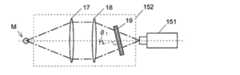
図5に、実施例2のラマン分光測定装置の検出光学系152の構成を示す。この検出光学系152は、実施例1の検出光学系52と同様に、第1集光レンズ17、第2集光レンズ18、及びノッチフィルタ19を備えている。実施例1の検出光学系52では、測定光の光軸を進む光のノッチフィルタ9への入射角は0度であったが、実施例2の検出光学系152では、測定光の光軸を進む光のノッチフィルタ19への入射角がθ1(θ1≠0度)となるようにノッチフィルタ19を配置している。FIG. 5 shows the configuration of the detection
ここで、図4に示したノッチフィルタの光透過特性を示すグラフを拡大したもの(入射角が0度から10度の間で2.5度ずつ変化したときの光透過特性の変化)を図6に示す。ノッチフィルタのリップルの形状には個体差があるが、事前の測定によりリップルの形状を把握することができる。そこで、ノッチフィルタ19のリップルの影響が最も効果的に低減されるように入射角θ1を設定する。これにより、実施例1の検出光学系52よりも一層、測定精度を向上することができる。4 is an enlarged graph showing the light transmission characteristics of the notch filter shown in FIG. 4 (changes in light transmission characteristics when the incident angle is changed by 2.5 degrees between 0 degrees and 10 degrees). It is shown in FIG. Although there are individual differences in the ripple shape of the notch filter, the shape of the ripple can be grasped by prior measurement. Therefore, the incident angle θ1 is set so that the influence of the ripple of the
また、入射角の変化に対する光透過特性のシフト量は、入射角を大きくするほど大きくなる。実施例1で説明した構成では測定光の入射角の範囲が0度±θmaxとなり、0度を挟んで対称に分布するが、実施例2の構成では測定光の入射角の範囲が(θ1-θmax)〜(θ1+θmax)となり、非対称に分布するため、実施例1の構成に比べて測定光の最大入射角の絶対値を大きくすることができる。これにより、光透過特性のシフト量を大きくして効率よくリップルを平均化することができる。Further, the shift amount of the light transmission characteristic with respect to the change in the incident angle becomes larger as the incident angle is increased. In the configuration described in the first embodiment, the range of the incident angle of the measurement light is 0 ° ± θmax, and is distributed symmetrically across 0 °. However, in the configuration of the second embodiment, the range of the incident angle of the measurement light is (θ1-θmax) ~ (θ 1 + θmax ) becomes, for asymmetrically distributed, it is possible to increase the absolute value of the maximum incident angle of the measuring light as compared with the configuration of the first embodiment. Thereby, the amount of shift of the light transmission characteristic can be increased and the ripple can be averaged efficiently.
上記の実施例1及び2では、典型的な集光光学系の一例として、測定光を平行光に変換する第1集光レンズと平行光を集光する第2集光レンズを用いる構成を記載したが、2枚の集光レンズからなる集光光学系には限定されない。また、測定光を平行光に変換した後で集光するものにも限定されない。 In the first and second embodiments, a configuration using a first condenser lens that converts measurement light into parallel light and a second condenser lens that collects parallel light is described as an example of a typical condensing optical system. However, the present invention is not limited to a condensing optical system composed of two condensing lenses. Moreover, it is not limited to what condenses after converting measuring light into parallel light.
図7に、実施例3のラマン分光測定装置の検出光学系252の構成を示す。この検出光学系252は、測定点Mから発せられる測定光を平行光に変換する第1集光レンズ27、第1集光レンズ27を通過した平行光を検出器251の受光面上に集光させる第2集光レンズ28、及び第1集光レンズ27と第2集光レンズ28の間で平行光の進行方向に並べて配置された2枚のノッチフィルタ291、292を備えている。実施例3では、ノッチフィルタ291に対する平行光の入射角がθ2(θ2≠0度)、ノッチフィルタ292に対する平行光の入射角が0度となるように、2枚のノッチフィルタを配置している。FIG. 7 shows the configuration of the detection
実施例3の検出光学系252では、第1集光レンズ27によって平行光に変換された測定光が、異なる入射角(θ2、0度)でノッチフィルタ291とノッチフィルタ292に順に入射する。検出器251の受光面上に集光されるラマン散乱光の強度は、それら2つの入射角に対応する2つの光透過特性を足し合わせたものとなる。従って、波長に対する光透過率の変動を平均化し、測定精度を高めることができる。In the detection
なお、本実施例では、ノッチフィルタ291に対する測定光の入射角をθ2、ノッチフィルタ292に対する測定光の入射角を0度としたが、入射角は適宜に組み合わせることができる。好ましくは、ノッチフィルタの光透過率の増減傾向が反対となる入射角の組み合わせを選択する。これにより、リップルの影響を最も効率的に低減することができる。また、ノッチフィルタを3枚以上使用して検出光学系252を構成し、それらに対する入射角を適宜に設定してリップルの影響を低減するようにしてもよい。In this embodiment, the incident angle of the measuring light with respect to the
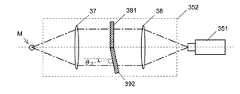
図8に、実施例4のラマン分光測定装置の検出光学系352の構成を示す。この検出光学系352は、測定点Mから発せられる測定光を平行光に変換する第1集光レンズ37、第1集光レンズ37を通過した平行光を検出器351の受光面上に集光させる第2集光レンズ38、及び第1集光レンズ37と第2集光レンズ38の間で平行光の幅方向(平行光の光軸に対して垂直な方向)に並べて配置された2枚のノッチフィルタ391、392を備えている。ノッチフィルタ391に対する平行光の入射角は0度、ノッチフィルタ392に対する平行光の入射角はθ3(θ3≠0度)である。FIG. 8 shows the configuration of the detection
実施例4の検出光学系352では、第1集光レンズ37によって平行光に変換された測定光のうちの半分の光がノッチフィルタ391に、残り半分の光がノッチフィルタ392に、互いに異なる入射角(0度、θ3)で入射する。検出器351の受光面上には、ノッチフィルタ391を通過してその光透過特性を反映した強度を有する光と、ノッチフィルタ392を通過してその光透過特性を反映した強度を有する光とが集光されて検出される。従って、検出強度は2つの光透過特性を足し合わせたものとなり、リップルの影響が低減される。
実施例4においても、実施例3と同様に、入射角に対する光透過特性のシフト量を考慮し、光透過率の増減傾向が逆になる入射角の組み合わせとなるように構成することが好ましい。また、3枚以上のノッチフィルタを用いて検出光学系352を構成してもよい。In the detection
In the fourth embodiment, similarly to the third embodiment, in consideration of the shift amount of the light transmission characteristic with respect to the incident angle, it is preferable to configure the combination of the incident angles in which the increase / decrease tendency of the light transmittance is reversed. Further, the detection
図9に、実施例5のラマン分光測定装置の検出光学系452の構成を示す。この検出光学系452は、測定点Mから発せられる測定光を平行光に変換する第1集光レンズ47、第1集光レンズ47を通過した平行光を検出器451の受光面上に集光させる第2集光レンズ48、及び第1集光レンズ47と第2集光レンズ48の間に配置されたノッチフィルタ49を備えている。また、第1集光レンズ47を通過した平行光のうちの一部の光の進行方向を変更してノッチフィルタ49に入射させる1組のプリズム501を備えている。 FIG. 9 shows a configuration of the detection optical system 452 of the Raman spectrometer of Example 5. The detection optical system 452 condenses the parallel light that has passed through the first condenser lens 47 and the first condenser lens 47 that converts the measurement light emitted from the measurement point M into parallel light on the light receiving surface of the detector 451. And a notch filter 49 disposed between the first condenser lens 47 and the second condenser lens 48. In addition, a set of prisms 501 that change the traveling direction of a part of the parallel light that has passed through the first condenser lens 47 and enter the notch filter 49 are provided.
実施例5の検出光学系452では、第1集光レンズ47によって平行光に変換された測定光のうちの一部の光の進行方向がプリズム501によって変更される。従って、プリズム501を通過する光とそれ以外の光とが異なる角度でノッチフィルタ49に入射する。これらの光の強度には、それぞれの入射角に対応した、ノッチフィルタ49の光透過特性が反映され、それらが合計して検出される。従って、波長に対する光透過率の変動を平均化し、測定精度を高めることができる。
上記の実施例はいずれも一例であって、本発明の趣旨に沿って適宜に変更することができる。
上記の実施例では、ラマン分光測定装置を例に挙げて説明したが、特定の波長を有する光を除去する光学フィルタを用いる分光測定装置であれば、ラマン分光測定装置以外のものに適用して上記同様の効果を得ることができる。
また、上記実施例では、光学フィルタがノッチフィルタである場合について説明したが、光学フィルタとしてエッジフィルタを用いる場合にも同様の効果を得ることができる。In the detection optical system 452 of the fifth embodiment, the traveling direction of a part of the measurement light converted into parallel light by the first condenser lens 47 is changed by the prism 501. Therefore, the light passing through the prism 501 and the other light enter the notch filter 49 at different angles. These light intensities reflect the light transmission characteristics of the notch filter 49 corresponding to each incident angle, and are detected in total. Therefore, it is possible to average the fluctuation of the light transmittance with respect to the wavelength and increase the measurement accuracy.
Each of the above-described embodiments is an example, and can be appropriately changed in accordance with the gist of the present invention.
In the above embodiment, the Raman spectrometer has been described as an example. However, any spectrometer other than the Raman spectrometer can be used as long as the spectrometer uses an optical filter that removes light having a specific wavelength. The same effect as described above can be obtained.
Moreover, although the case where the optical filter is a notch filter has been described in the above embodiment, the same effect can be obtained when an edge filter is used as the optical filter.
1…ラマン分光測定装置
2…配管
3…筐体
4…光源部
41…光源
42…照射光学系
5…検出部
51、151、251、351、451…検出器
52、152、252、352、452…検出光学系
7、17、27、37、47…第1集光レンズ
8、18、28、38、48…第2集光レンズ
9、19、291、292、391、392、49…ノッチフィルタ
501…プリズム
6…窓部DESCRIPTION OF
Claims (6)
Translated fromJapanese前記測定点から前記集光位置までの光路上であって、前記測定光が非平行光である光路上に配置され、前記測定光が非単一の入射角で入射し、特定の波長範囲の光を除去する平板状の光学フィルタと
を備え、前記測定光の光軸と前記光学フィルタの入射面とがなす角度が、リップルの影響が最も低減される角度に設定されている分光測定装置。A condensing optical system for condensing measurement light emitted from the measurement point at a predetermined condensing position;
An optical path from the measurement point to the condensing position, the measurement light is disposed on an optical path that is non-parallel light, the measurement light is incident at a non-single incident angle, and has a specific wavelength range. And a planar optical filter for removing light, wherein an angle formed between an optical axis of the measurement light and an incident surface of the optical filter is set to an angle at which an influence of ripple is reduced most.
前記第1集光レンズと前記第2集光レンズとの間において前記平行光の光路上に配置された複数枚の平板状の光学フィルタであって、それらのうちの少なくとも2枚について該平行光の光軸と入射面がなす角度が互いに異なる複数枚の平板状の光学フィルタと
を備え、
前記平行光の光軸と前記光学フィルタの入射面がなす角度が、リップルの影響が最も低減される角度に設定されている分光測定装置。A condensing optical system having a first condensing lens that converts measurement light emitted from a measurement point into parallel light, and a second condensing lens that condenses the parallel light at a predetermined condensing position;
A plurality of plate-like optical filters disposed on the optical path of the parallel light between the first condenser lens and the second condenser lens, wherein at least two of the parallel optical filters are the parallel light A plurality of plate-like optical filters having different angles formed by the optical axis and the incident surface,
The spectroscopic measurement device in which an angle formed between the optical axis of the parallel light and the incident surface of the optical filter is set to an angle at which the influence of ripple is reduced most.
前記測定光が非単一の入射角で入射し、特定の波長範囲の光を除去する光学フィルタと
を備えた分光測定装置であって、
前記光学フィルタが、前記第1集光レンズと前記第2集光レンズとの間において、複数に分割された前記平行光の光路上にそれぞれ配置された複数枚の平板状の光学フィルタであり、それらのうちの少なくとも2枚について該平行光の光軸と入射面がなす角度が互いに異なる分光測定装置。A condensing optical system having a first condensing lens that converts measurement light emitted from a measurement point into parallel light, and a second condensing lens that condenses the parallel light at a predetermined condensing position;
An optical filter that receives the measurement light at a non-single incident angle and removes light in a specific wavelength range;
The optical filter is a plurality of plate-like optical filters respectively disposed on the optical path of the parallel light divided into a plurality of parts between the first condenser lens and the second condenser lens; A spectroscopic measurement device in which at least two of them have different angles between the optical axis of the parallel light and the incident surface.
前記第1集光レンズと前記第2集光レンズとの間において前記平行光の光路上に配置され、前記測定光が非単一の入射角で入射し、特定の波長範囲の光を除去する光学フィルタと、
前記第1集光レンズと前記光学フィルタとの間に配置された、前記平行光のうちの一部の光を進行方向を変更する方向変更部と
を備える分光測定装置。A condensing optical system having a first condensing lens that converts measurement light emitted from a measurement point into parallel light, and a second condensing lens that condenses the parallel light at a predetermined condensing position;
It is disposed on the optical path of the parallel light between the first condenser lens and the second condenser lens, and the measurement light is incident at a non-single incident angle, and removes light in a specific wavelength range. An optical filter;
A spectroscopic measurement apparatus comprising: a direction changing unit that is disposed between the first condenser lens and the optical filter and changes a traveling direction of a part of the parallel light.
Priority Applications (1)
| Application Number | Priority Date | Filing Date | Title |
|---|---|---|---|
| JP2014151540AJP6327041B2 (en) | 2014-07-25 | 2014-07-25 | Spectrometer |
Applications Claiming Priority (1)
| Application Number | Priority Date | Filing Date | Title |
|---|---|---|---|
| JP2014151540AJP6327041B2 (en) | 2014-07-25 | 2014-07-25 | Spectrometer |
Publications (2)
| Publication Number | Publication Date |
|---|---|
| JP2016029341A JP2016029341A (en) | 2016-03-03 |
| JP6327041B2true JP6327041B2 (en) | 2018-05-23 |
Family
ID=55435285
Family Applications (1)
| Application Number | Title | Priority Date | Filing Date |
|---|---|---|---|
| JP2014151540AActiveJP6327041B2 (en) | 2014-07-25 | 2014-07-25 | Spectrometer |
Country Status (1)
| Country | Link |
|---|---|
| JP (1) | JP6327041B2 (en) |
Families Citing this family (1)
| Publication number | Priority date | Publication date | Assignee | Title |
|---|---|---|---|---|
| CN112051037B (en)* | 2020-09-03 | 2022-11-04 | Oppo(重庆)智能科技有限公司 | Lens detection method and device and terminal equipment |
Family Cites Families (4)
| Publication number | Priority date | Publication date | Assignee | Title |
|---|---|---|---|---|
| DE3617123C2 (en)* | 1985-07-04 | 1997-03-20 | Cammann Karl | Method for improving the selectivity of spectrometric measurements and device for carrying out the method |
| GB8830039D0 (en)* | 1988-12-22 | 1989-02-15 | Renishaw Plc | Raman microscope |
| GB9511490D0 (en)* | 1995-06-07 | 1995-08-02 | Renishaw Plc | Raman microscope |
| US7123416B1 (en)* | 2003-05-06 | 2006-10-17 | Semrock, Inc. | Method of making high performance optical edge and notch filters and resulting products |
- 2014
- 2014-07-25JPJP2014151540Apatent/JP6327041B2/enactiveActive
Also Published As
| Publication number | Publication date |
|---|---|
| JP2016029341A (en) | 2016-03-03 |
Similar Documents
| Publication | Publication Date | Title |
|---|---|---|
| JP7129809B2 (en) | Optical filters and spectrometers | |
| JP5609241B2 (en) | Spectroscopic method and analyzer | |
| CN103354915B (en) | Manufacturing method of multivariate optical element | |
| JP2013164372A5 (en) | ||
| JP5975175B2 (en) | Raman spectrometer | |
| JP6748427B2 (en) | Concrete measuring method, concrete measuring device | |
| WO2016171042A1 (en) | Spectrometry device | |
| KR20170052256A (en) | Apparatus and method for measuring concentration of material | |
| KR101620594B1 (en) | spectroscopy apparatus | |
| JP7172959B2 (en) | Spectroscopic analysis device and spectroscopic analysis method | |
| JP3848623B2 (en) | Fluorescence measuring device | |
| JP6327041B2 (en) | Spectrometer | |
| CN102419312B (en) | Cascade optical waveguide sensor based on passive resonant cavity and grating demultiplexer | |
| CN110031402A (en) | Device and method for analyzing fluid | |
| KR101317059B1 (en) | Multi-gas analysis device for ultra-violet measurements | |
| CN207689375U (en) | Lower wave number Raman Measurement system | |
| JP5929504B2 (en) | Spectrometer | |
| US20140139835A1 (en) | Measurement device of degree of cure | |
| JP2014211310A (en) | Raman scattering spectrophotometer achieving simultaneous measurement of stokes peak and anti-stokes peak by construction of two-optical path | |
| JP2011196766A (en) | Method for measuring shape of measured object having light transmittance | |
| JP5842652B2 (en) | Tunable monochromatic light source | |
| JP2008026127A (en) | Spectroscopic unit, meteorological lidar system | |
| KR20240094368A (en) | Method and device for laser absorption spectroscopy analysis | |
| JP5226420B2 (en) | Optical filter | |
| JP6750734B2 (en) | Flow cell and detector equipped with the flow cell |
Legal Events
| Date | Code | Title | Description |
|---|---|---|---|
| A621 | Written request for application examination | Free format text:JAPANESE INTERMEDIATE CODE: A621 Effective date:20161024 | |
| A977 | Report on retrieval | Free format text:JAPANESE INTERMEDIATE CODE: A971007 Effective date:20170721 | |
| A131 | Notification of reasons for refusal | Free format text:JAPANESE INTERMEDIATE CODE: A131 Effective date:20170801 | |
| A521 | Written amendment | Free format text:JAPANESE INTERMEDIATE CODE: A523 Effective date:20170915 | |
| A131 | Notification of reasons for refusal | Free format text:JAPANESE INTERMEDIATE CODE: A131 Effective date:20180206 | |
| A521 | Written amendment | Free format text:JAPANESE INTERMEDIATE CODE: A523 Effective date:20180305 | |
| TRDD | Decision of grant or rejection written | ||
| A01 | Written decision to grant a patent or to grant a registration (utility model) | Free format text:JAPANESE INTERMEDIATE CODE: A01 Effective date:20180320 | |
| A61 | First payment of annual fees (during grant procedure) | Free format text:JAPANESE INTERMEDIATE CODE: A61 Effective date:20180402 | |
| R151 | Written notification of patent or utility model registration | Ref document number:6327041 Country of ref document:JP Free format text:JAPANESE INTERMEDIATE CODE: R151 |