JP6326711B2 - System and moving recording control method - Google Patents
System and moving recording control methodDownload PDFInfo
- Publication number
- JP6326711B2 JP6326711B2JP2012175311AJP2012175311AJP6326711B2JP 6326711 B2JP6326711 B2JP 6326711B2JP 2012175311 AJP2012175311 AJP 2012175311AJP 2012175311 AJP2012175311 AJP 2012175311AJP 6326711 B2JP6326711 B2JP 6326711B2
- Authority
- JP
- Japan
- Prior art keywords
- measurement
- data
- distance
- unit
- storage
- Prior art date
- Legal status (The legal status is an assumption and is not a legal conclusion. Google has not performed a legal analysis and makes no representation as to the accuracy of the status listed.)
- Expired - Fee Related
Links
Images


Classifications
- G—PHYSICS
- G01—MEASURING; TESTING
- G01C—MEASURING DISTANCES, LEVELS OR BEARINGS; SURVEYING; NAVIGATION; GYROSCOPIC INSTRUMENTS; PHOTOGRAMMETRY OR VIDEOGRAMMETRY
- G01C22/00—Measuring distance traversed on the ground by vehicles, persons, animals or other moving solid bodies, e.g. using odometers, using pedometers
- G01C22/006—Pedometers
- G—PHYSICS
- G01—MEASURING; TESTING
- G01C—MEASURING DISTANCES, LEVELS OR BEARINGS; SURVEYING; NAVIGATION; GYROSCOPIC INSTRUMENTS; PHOTOGRAMMETRY OR VIDEOGRAMMETRY
- G01C22/00—Measuring distance traversed on the ground by vehicles, persons, animals or other moving solid bodies, e.g. using odometers, using pedometers
- A—HUMAN NECESSITIES
- A61—MEDICAL OR VETERINARY SCIENCE; HYGIENE
- A61B—DIAGNOSIS; SURGERY; IDENTIFICATION
- A61B5/00—Measuring for diagnostic purposes; Identification of persons
- A61B5/68—Arrangements of detecting, measuring or recording means, e.g. sensors, in relation to patient
- A61B5/6801—Arrangements of detecting, measuring or recording means, e.g. sensors, in relation to patient specially adapted to be attached to or worn on the body surface
- A61B5/6802—Sensor mounted on worn items
- A61B5/681—Wristwatch-type devices
- A—HUMAN NECESSITIES
- A63—SPORTS; GAMES; AMUSEMENTS
- A63B—APPARATUS FOR PHYSICAL TRAINING, GYMNASTICS, SWIMMING, CLIMBING, OR FENCING; BALL GAMES; TRAINING EQUIPMENT
- A63B24/00—Electric or electronic controls for exercising apparatus of preceding groups; Controlling or monitoring of exercises, sportive games, training or athletic performances
- A63B24/0062—Monitoring athletic performances, e.g. for determining the work of a user on an exercise apparatus, the completed jogging or cycling distance
- G—PHYSICS
- G01—MEASURING; TESTING
- G01S—RADIO DIRECTION-FINDING; RADIO NAVIGATION; DETERMINING DISTANCE OR VELOCITY BY USE OF RADIO WAVES; LOCATING OR PRESENCE-DETECTING BY USE OF THE REFLECTION OR RERADIATION OF RADIO WAVES; ANALOGOUS ARRANGEMENTS USING OTHER WAVES
- G01S19/00—Satellite radio beacon positioning systems; Determining position, velocity or attitude using signals transmitted by such systems
- G01S19/01—Satellite radio beacon positioning systems transmitting time-stamped messages, e.g. GPS [Global Positioning System], GLONASS [Global Orbiting Navigation Satellite System] or GALILEO
- G01S19/13—Receivers
- G01S19/14—Receivers specially adapted for specific applications
- G01S19/19—Sporting applications
- G—PHYSICS
- G06—COMPUTING OR CALCULATING; COUNTING
- G06Q—INFORMATION AND COMMUNICATION TECHNOLOGY [ICT] SPECIALLY ADAPTED FOR ADMINISTRATIVE, COMMERCIAL, FINANCIAL, MANAGERIAL OR SUPERVISORY PURPOSES; SYSTEMS OR METHODS SPECIALLY ADAPTED FOR ADMINISTRATIVE, COMMERCIAL, FINANCIAL, MANAGERIAL OR SUPERVISORY PURPOSES, NOT OTHERWISE PROVIDED FOR
- G06Q10/00—Administration; Management
- G06Q10/06—Resources, workflows, human or project management; Enterprise or organisation planning; Enterprise or organisation modelling
- G06Q10/063—Operations research, analysis or management
- G06Q10/0639—Performance analysis of employees; Performance analysis of enterprise or organisation operations
Landscapes
- Engineering & Computer Science (AREA)
- Physics & Mathematics (AREA)
- Radar, Positioning & Navigation (AREA)
- Remote Sensing (AREA)
- Health & Medical Sciences (AREA)
- General Physics & Mathematics (AREA)
- Life Sciences & Earth Sciences (AREA)
- General Health & Medical Sciences (AREA)
- Computer Networks & Wireless Communication (AREA)
- Pathology (AREA)
- Heart & Thoracic Surgery (AREA)
- Medical Informatics (AREA)
- Molecular Biology (AREA)
- Surgery (AREA)
- Animal Behavior & Ethology (AREA)
- Biomedical Technology (AREA)
- Public Health (AREA)
- Veterinary Medicine (AREA)
- Biophysics (AREA)
- Physical Education & Sports Medicine (AREA)
- Business, Economics & Management (AREA)
- Human Resources & Organizations (AREA)
- Navigation (AREA)
- Position Fixing By Use Of Radio Waves (AREA)
- Strategic Management (AREA)
- Development Economics (AREA)
- Educational Administration (AREA)
- Measurement Of Distances Traversed OnThe Ground (AREA)
- Economics (AREA)
- Entrepreneurship & Innovation (AREA)
- Traffic Control Systems (AREA)
- Game Theory and Decision Science (AREA)
- Marketing (AREA)
- Operations Research (AREA)
- Quality & Reliability (AREA)
- Tourism & Hospitality (AREA)
- General Business, Economics & Management (AREA)
- Theoretical Computer Science (AREA)
Description
Translated fromJapanese本発明は、位置を測定する測定部を備えた身体に装着可能な電子機器を含むシステム等に関する。The present invention relatesto a system including an electronic devicethat can be worn on the body, and includes a measurement unit that measures a position.
従来、GPSを利用する累積移動距離を測定する装置が知られている(例えば、特許文献1参照)。こうした装置は、地球上における現在位置を測定する位置測定機能を有した「ランニングウォッチ」「トレーニングウォッチ」「ランナーズウォッチ」等と呼ばれる腕時計タイプの身体装着可能な電子機器として利用されている。こうした電子機器は、例えば、時計と、GPS受信機と、演算装置と、記憶媒体とを有している。ユーザーがランニングをする際に位置の測定を開始操作すると、電子機器は、周期的に計測された緯度・経度などを含む位置測定情報を自動的・継続的に記憶する。そして、電子機器に記憶されたランニング中の位置情報等は、パソコンなどの外部装置により解析され、ランニングした軌跡を地図上に表示させたり(マップ表示)、ペースやピッチなどのパラメーターを演算してランニング開始から終了までの変化をグラフ表示させたりするのに利用される。ユーザーは、こうしたマップ表示やグラフ表示を利用して、効率的なトレーニングを実現することができる。 2. Description of the Related Art Conventionally, an apparatus that measures a cumulative moving distance using GPS is known (for example, see Patent Document 1). Such a device is used as a wristwatch type body-worn electronic device called “running watch”, “training watch”, “runners watch” or the like having a position measuring function for measuring the current position on the earth. Such an electronic device has, for example, a clock, a GPS receiver, an arithmetic device, and a storage medium. When the user starts the position measurement when running, the electronic device automatically and continuously stores position measurement information including the latitude and longitude measured periodically. The running position information stored in the electronic device is analyzed by an external device such as a personal computer, and the running track is displayed on a map (map display), and parameters such as pace and pitch are calculated. It is used to display changes from the start to the end of the graph. The user can realize efficient training using such map display and graph display.
さて、ランニングウォッチ等の位置測定機能を有した身体装着可能な電子機器において、最も重要な要件の一つが、ランニングの邪魔にならない薄さと軽さ、すなわち「小型軽量」である。しかし、小型軽量化は、当然のことながら搭載できるICメモリー等の記憶媒体の搭載量やバッテリーの大きさ(つまりは容量)とトレードオフする。そのため、公知のランニングウォッチ等では、比較的短距離や短時間のランニングの記憶には十分であるが、所要時間が長いランニングやフルマラソンのような長距離のランニングについてはデータ記憶容量やバッテリーの持続時間が不足しがちであった。 In a body-worn electronic device having a position measuring function such as a running watch, one of the most important requirements is thinness and lightness that does not interfere with running, that is, “small and light”. However, the reduction in size and weight naturally trades off the amount of storage medium such as an IC memory that can be mounted and the size (that is, capacity) of the battery. For this reason, a known running watch or the like is sufficient for storing a relatively short distance or a short run, but for a long distance run or a long distance run such as a full marathon, the data storage capacity or battery The duration was apt to be short.
また、GPS等を利用した位置の測定では、さまざまな環境要因により常に位置が正確に測定されるとは限らない。たとえ直線的に移動していたとしても、測定結果が示す位置が左右に振れていたり、時に大きくジャンプしたように計測されることがある。その為、ランニングウォッチ等で記憶された記憶点の位置情報をそのままマップ表示に用いると、実際のランニング軌跡よりもジグザグし、時に大きく外れた軌跡を描いてしまうことになる。また、記憶点の位置の変位から距離を算出する場合には、実際の移動距離との誤差が生じてしまう。 Further, in position measurement using GPS or the like, the position is not always accurately measured due to various environmental factors. Even if it moves linearly, the position indicated by the measurement result may be swung to the left or right, or sometimes measured as if it jumped greatly. For this reason, if the position information of the storage points stored in the running watch or the like is used as it is for the map display, it will zigzag from the actual running trajectory and sometimes draw a trajectory that deviates greatly. Further, when the distance is calculated from the displacement of the position of the memory point, an error from the actual moving distance occurs.
本発明は、こうした事情を鑑みてなされたものであり、小型軽量と長距離に渡る計測データの記憶とが両立する身体装着可能な電子機器を実現することを目的とする。 The present invention has been made in view of such circumstances, and an object of the present invention is to realize a body-worn electronic device that is compatible with both small size and light weight and storage of measurement data over a long distance.
以上の課題を解決するための第1の形態は、所定周期で位置を測定する測定部と、前記測定部での測定結果に基づいて累積移動距離を算出して表示制御する距離表示制御部と、前記測定部で測定される毎に、過去の測定結果を参照して、前記測定部での測定結果を保存するか否かを判定する判定部と、前記判定部が肯定判定した場合に前記測定部での測定結果を記憶部に記憶させる記憶制御部と、前記記憶部に記憶された測定結果のデータを外部装置へ出力する制御を行う外部出力制御部と、を備えた身体装着用電子機器である。 A first form for solving the above problems is a measurement unit that measures a position at a predetermined period, a distance display control unit that calculates and displays a cumulative movement distance based on a measurement result in the measurement unit, and Each time the measurement unit is measured, the determination unit determines whether to save the measurement result in the measurement unit with reference to the past measurement result, and when the determination unit makes a positive determination, A body-worn electronic device comprising: a storage control unit that stores a measurement result of the measurement unit in a storage unit; and an external output control unit that performs control to output measurement result data stored in the storage unit to an external device. Equipment.
また、別形態として、身体に装着される電子機器が実行する移動記録制御方法であって、所定周期で位置を測定することと、前記測定による測定結果に基づいて累積移動距離を算出して表示制御することと、前記測定がなされる毎に、過去の測定結果を参照して、前記測定による測定結果を保存するか否かを判定することと、前記保存するか否かの判定が肯定判定の場合に前記測定による測定結果を記憶部に記憶させることと、前記記憶部に記憶された測定結果のデータを外部装置へ出力する制御を行うことと、を含む移動記録制御方法を構成することができる(第8の形態)。 According to another aspect, there is provided a movement recording control method executed by an electronic device worn on the body, wherein a position is measured at a predetermined cycle, and a cumulative movement distance is calculated and displayed based on a measurement result of the measurement. Each time the measurement is performed, the determination of whether to save the measurement result by the measurement with reference to the past measurement result, and the determination of whether to save the determination are affirmative In this case, a storage recording control method is included, including storing a measurement result of the measurement in a storage unit and performing control to output the measurement result data stored in the storage unit to an external device. (Eighth form).
第1の形態及びその別形態によれば、測定部で測定された測定結果を全て記憶するのではなく、過去の測定結果を参照して保存するか否かを判定し、保存すると判定された測定結果のみ保存することで、計測開始から終了までの一連の測定結果のデータのサイズを小さくすることができる。つまり、保存するデータの間引きができる。保存するデータのサイズが小さくなれば、その分記憶部へのデータ書き込みに要する電力消費を抑制できる。よって、小型軽量が実現された従来と同程度の身体装着用電子機器であったとしても、より長距離・長時間にわたる計測データの記憶と小型軽量とを両立することが可能になる。 According to the first mode and the other mode, it is determined not to store all the measurement results measured by the measurement unit, but to store with reference to the past measurement results, and to determine to store By storing only the measurement results, the data size of a series of measurement results from the start to the end of the measurement can be reduced. That is, the data to be saved can be thinned out. If the size of the data to be saved is reduced, the power consumption required for writing data to the storage unit can be reduced accordingly. Therefore, even if it is a body-worn electronic device similar to the conventional one that has been realized in a small size and a light weight, it is possible to achieve both a storage of measurement data over a long distance and a long time and a small size and a light weight.
第2の形態の身体装着用電子機器は、前記判定部が、前記測定部の測定結果に基づき進行方向が転換したことを示す方向転換条件を満たす場合に、当該測定結果を保存すると判定してもよい。 The electronic device for body wearing according to the second aspect determines that the determination unit stores the measurement result when the determination unit satisfies a direction change condition indicating that the traveling direction has changed based on the measurement result of the measurement unit. Also good.
第2の形態によれば、測定結果が進行方向が転換したと見なされる場合に保存すると判定できる。つまり、記憶部に記憶・保存されるデータサイズを小さくしても、方向転換された位置の情報は保存されているので、データ解析として移動軌跡を地図上に描く「マップ表示」をさせるとしても、実際の軌跡に近い軌跡を描画させることができる。 According to the second embodiment, it can be determined that the measurement result is stored when the traveling direction is considered to have changed. In other words, even if the data size stored / saved in the storage unit is reduced, the information on the changed position is saved, so even if the map is displayed as a data analysis, the movement trajectory is drawn on the map. The locus close to the actual locus can be drawn.
第3の形態の身体装着用電子機器は、前記測定部が、衛星信号に基づいて位置を測定し、かつ、当該衛星信号のドップラーに基づいて少なくとも進行方向を測定し、前記判定部が、前記測定部により測定された進行方向に基づいて、前記方向転換条件を満たすか否かを判定してもよい。 In the electronic device for body wearing according to a third aspect, the measurement unit measures a position based on a satellite signal and measures at least a traveling direction based on a Doppler of the satellite signal, and the determination unit includes the Based on the traveling direction measured by the measurement unit, it may be determined whether or not the direction change condition is satisfied.
第3の形態によれば、公知の衛星航法システムを利用して方向転換に係る判定を実現できる。 According to the 3rd form, the determination which concerns on a direction change is realizable using a well-known satellite navigation system.
第4の形態の身体装着用電子機器は、前記判定部が、前記測定部により測定された進行方向と、前記測定部により測定された位置に基づく移動方向とが所定の近似条件を満たさない場合に、当該測定結果を保存しないと判定してもよい。 In the electronic device for body wearing according to the fourth aspect, the determination unit is configured such that the traveling direction measured by the measurement unit and the moving direction based on the position measured by the measurement unit do not satisfy a predetermined approximate condition. In addition, it may be determined that the measurement result is not stored.
第4の形態によれば、衛星信号に誤差が含まれやすい受信環境で受信したと判断される測定結果を保存しないようにできる。 According to the fourth embodiment, it is possible to prevent the measurement result determined to be received in a reception environment in which an error is easily included in the satellite signal from being stored.
第5の形態の身体装着用電子機器は、前記所定周期よりも長い時間間隔で前記累積移動距離を前記記憶部に時系列に記憶させていく移動距離記憶制御部を更に備え、
前記外部出力制御部は、更に、前記記憶部に記憶された累積移動距離のデータを前記外部装置に出力してもよい。The electronic device for body wearing according to a fifth aspect further includes a movement distance storage control unit that stores the cumulative movement distance in the storage unit in a time series at a time interval longer than the predetermined period,
The external output control unit may further output data of the accumulated movement distance stored in the storage unit to the external device.
第5の形態によれば、累積移動距離が保存可能になる。 According to the fifth aspect, the accumulated movement distance can be saved.
第6の形態の身体装着用電子機器は、前記累積移動距離の算出開始からの経過時間を表示制御する経過時間表示制御部と、前記記憶制御部により前記記憶部に記憶される前記測定結果に対応付けて、前記経過時間を前記記憶部に記憶させる経過時間記憶制御部と、前記累積移動距離が所定の区間距離に達する毎に前記経過時間或いは当該区間距離の移動に要した時間である区間時間情報を前記記憶部に記憶させる区間時間情報記憶制御部と、を更に備え、前記外部出力制御部は、更に、前記記憶部に記憶された経過時間のデータ及び区間時間情報のデータを前記外部装置に出力してもよい。 The electronic device for body wearing according to a sixth aspect includes an elapsed time display control unit that performs display control of an elapsed time from the start of calculation of the cumulative movement distance, and the measurement result stored in the storage unit by the storage control unit. Correspondingly, an elapsed time storage control unit that stores the elapsed time in the storage unit, and an interval that is the time required for the elapsed time or movement of the interval distance every time the cumulative movement distance reaches a predetermined interval distance A section time information storage control section for storing time information in the storage section, and the external output control section further stores the elapsed time data and section time information data stored in the storage section. You may output to an apparatus.
第6の形態によれば、いわゆる区間計測が可能になる。 According to the sixth embodiment, so-called interval measurement is possible.
第7の形態は、第6の形態の身体装着用電子機器から出力されたデータを受信する受信部と、前記受信部により受信されたデータの中に、前記区間時間情報に対応する測定結果のデータが無い場合に、当該区間時間情報の前後の経過時間のデータ及び当該経過時間に対応する測定結果のデータに基づいて、当該区間時間情報に対応する測定結果を補間して生成する補間部と、を備えたデータ解析装置である。 In the seventh embodiment, a receiving unit that receives data output from the electronic device for body wearing of the sixth embodiment, and a measurement result corresponding to the section time information in the data received by the receiving unit. An interpolation unit for interpolating and generating a measurement result corresponding to the section time information based on data of an elapsed time before and after the section time information and data of a measurement result corresponding to the elapsed time when there is no data; , A data analysis apparatus comprising:
第6の形態によれば、測定結果の保存要否の判定によっては、区間計測のデータ解析に必要なデータが保存されないことがある。しかし、第7の形態によれば、区間計測に必要な測定結果が保存されていなくとも、経過時間が前後する他の保存されている測定結果を利用して補間して得ることができる。よって、保存する測定結果の間引きを行ったとしても、区間計測に係るデータ解析が可能になる。 According to the sixth aspect, depending on the determination as to whether or not the measurement result needs to be stored, data necessary for the data analysis of the section measurement may not be stored. However, according to the seventh embodiment, even if the measurement result necessary for the interval measurement is not stored, it can be obtained by interpolation using another stored measurement result whose elapsed time is around. Therefore, even if the measurement results to be stored are thinned out, data analysis related to the section measurement can be performed.
〔第1実施形態〕
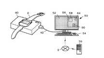
図1は、本実施形態における身体装着用電子機器の構成例を示す図である。図2は、身体装着用電子機器で計測・記憶されたデータを解析するためのシステム構成例を示す図である。[First Embodiment]
FIG. 1 is a diagram illustrating a configuration example of a body-worn electronic device according to the present embodiment. FIG. 2 is a diagram illustrating a system configuration example for analyzing data measured and stored by the body-worn electronic device.
図1に示すように、本実施形態の身体装着用電子機器2(以下短縮して「電子機器2」として説明する)は、腕時計と同様にユーザー1の手首や腕に装着可能な機器であって、その外見は腕時計やランニングウォッチに分類されるウェアラブルコンピューターである。 As shown in FIG. 1, a body-worn electronic device 2 (hereinafter abbreviated as “
電子機器2のメインフレーム10の上面には、時刻や位置測定情報に基づく各種トレーニングデータ等を表示可能なタッチパネル12が設けられている。また、メインフレーム10の側面には、各種操作入力のための操作スイッチ16と、バンド18とが設けられている。バンド18は装着具である。これを巻き付けることで当該電子機器2を腕時計のように手首や足首などに固定することができる。 On the upper surface of the
メインフレーム10は気密室を形成し、タッチパネル12や操作スイッチ16などに電気的に接続された基板20と、基板20等へ電力を供給する充電式バッテリー21とが内蔵されている。充電式バッテリー21への充電方式は適宜設定できる。例えば図2に示すように、家庭用電源に接続されたクレードル40に電子機器2をセットし、メインフレーム10の裏面に設けられた電気接点を介してクレードル40経由で通電・充電される構成でも良いし、無線式充電でも良い。 The
基板20は、電子機器2を統合的に制御する。具体的には、CPU(Central Processing Unit)22と、メインメモリー24と、計測データ用メモリー26と、位置測定モジュール28と、近距離無線モジュール30とを搭載する。また、その他には電源管理ICや、タッチパネル12のドライバIC、などのICや電子部品を適宜搭載することができる。 The
メインメモリー24は、プログラムや初期設定データを格納したり、CPU22の演算値を格納することのできる情報記憶媒体である。RAMやROM、フラッシュメモリなどを適宜用いて実現される。 The
計測データ用メモリー26は、データ書き換えが可能な不揮発性メモリーであって、位置測定情報などを含む測定結果のデータ(以下、「計測データ」と称する)を記憶するための記憶媒体である。本実施形態ではフラッシュメモリを用いるが、強誘導体メモリ(FeRAM)や、磁気抵抗メモリ(MRAM)などその他の書き換え可能な不揮発性メモリーを用いるとしても良い。 The
位置測定モジュール28は、位置測定システムから提供される信号を受信して所定周期(1秒毎)に、位置測定情報をCPU22へ出力することができる。本実施形態では、位置測定システムとしてGPS(Global Positioning System)を利用する。よって位置測定モジュール28は、公知の「GPSモジュール」や「GPS受信機」等を利用することができる。「位置測定情報」には、測位日時(UTC:Coordinated Universal Time)、位置座標(緯度・経度)、対地速さ(スカラー量)、速度方位(例えば真北を0°とした進行方向)が含まれる。対地速さと速度方位とは合わせて速度(Velocity)として算出されるとしてもよい。また、対地速さや速度方位は、GPS衛星から発信される信号に生じるドップラーシフト(ドップラーとも呼ばれる)に基づいて算出される。位置測定情報には、適宜その他の情報が含まれるとしても良い
尚、位置測定に利用するシステムはGPSに限らず、その他の衛星航法システムを利用するとしても良い。追加的に地上位置が分っている基地局からの電波を利用する構成としても良い。The
図2に示すように、電子機器2は、クレードル40を介した有線接続(例えば、USBケーブル42による接続)によりデータアップロード装置50とデータ通信を可能にする。或いは、近距離無線モジュール30を介して無線通信でデータアップロード装置50と接続するとしても良い。 As shown in FIG. 2, the
データアップロード装置50は、電子機器2で記憶された計測データを取得し、インターネット9を介してデータ解析装置70にアップロードするための装置である。データ解析装置70から解析結果を受信して表示することもできる。データアップロード装置50は、パソコンやスマートフォン、タブレット型コンピューター等により実現できる。データアップロード装置50はクレードル40を兼ねる構成でも良い。 The data upload
データアップロード装置50は、例えばタッチパネル52と、キーボード54と、基板56とを備える。基板56には、CPU58やGPU、ICメモリー60、近距離無線モジュール64などが搭載されている。データアップロード装置50は、USBケーブル42の接続や、近距離無線モジュール64の受信範囲に存在する他の近距離無線モジュールの自動認識によって、電子機器2とのデータ通信を確立する。そして、電子機器2から未取得の計測データを取得して保存し、データ解析装置70へ送信する。そして、データ解析装置70から解析結果を受信してタッチパネル52で表示することができる。尚、データアップロード装置50とデータ解析装置70を同一装置とする構成も可能である。 The data upload
図3は、本実施形態の電子機器2における計測データの生成について説明するための図である。
先ず、従来のランニングウォッチにおける計測データの記憶の仕方を振り返ると、従来は、位置測定モジュール28から出力される位置測定情報をそのまま全て計測データとして記憶していた。位置測定モジュール28は、所定周期で位置測定情報を出力する。従って、例えば約5kmのコースをランニングした場合(ペースにもよるが)記憶点の数は1700点に及ぶ。より長距離のコース(例えば、マラソン級のコース)の場合であれば記憶点の数は更に増え、それに伴って必要とされる記憶領域も膨大となる。また、計測データを記憶する記憶媒体は、バッテリー切れによるデータ損失が起きないように書き換え可能な不揮発性メモリー(主に、フラッシュメモリー)が使用されるが、そうした不揮発性メモリーは揮発性のRAMに比べてデータの書き換えにより多くの電力を要する。そして、記憶点の数が増えるほど記憶に使用される電力も当然比例して大きくなる。小型軽量の要件から、搭載されるフラッシュメモリーの容量やバッテリーの容量が制限されるため、結果として従来のランニングウォッチでは、長距離コースでは計測データを全て記憶することができないケースがあった。FIG. 3 is a diagram for explaining generation of measurement data in the
First, looking back on how measurement data is stored in a conventional running watch, conventionally, all the position measurement information output from the
そこで、本実施形態の電子機器2では、位置測定モジュール28から所定の測定周期で出力される位置測定情報をそのまま全て計測データとして保存するのではなく、新たに出力された位置測定情報が、データ解析に有用であるかを判定し、有用である位置測定情報を選別して記憶・保存することで一連の計測(例えば、1回のランニング)における計測データの量を削減する。計測データの量が削減されることにより、計測データ用メモリー26への書き込み回数も減り、結果として電力消費が抑制され同じ容量のバッテリーであっても持続時間を延ばすことが可能になる。 Therefore, in the
本実施形態における位置測定情報の有用性の判定は、計測精度の観点から見た第1段階の判定と、更に今回の位置測定情報が示す測位点における有意な方向転換の有無による第2段階の判定とを含む。そして、第1段階の判定で計測精度「良好」と判定され、更に第2段階の判定で方向転換したと判定されてはじめて、その位置測定情報は記憶・保存される。すなわち、その位置測定情報が示す測位点は「記憶点」として計測データに登録される。 The determination of the usefulness of the position measurement information in the present embodiment is based on the first stage determination from the viewpoint of measurement accuracy and the second stage based on the presence or absence of a significant direction change at the positioning point indicated by the current position measurement information. Judgment. The position measurement information is stored / saved only when it is determined that the measurement accuracy is “good” in the determination in the first stage and the direction is changed in the determination in the second stage. That is, the positioning point indicated by the position measurement information is registered as “memory point” in the measurement data.
計測精度の観点から見た第1段階の判定は、最新の測定周期で測定された進行方向である「速度方位」と、測位点の位置の移動に基づいて得られる移動方向である「位置方位」と、が所定の近似条件を満たすか判定することで実現される。 The first stage determination from the viewpoint of measurement accuracy is the “speed azimuth” that is the traveling direction measured in the latest measurement cycle and the “direction azimuth” that is the movement direction obtained based on the movement of the position of the positioning point. Is realized by determining whether or not a predetermined approximate condition is satisfied.
具体的には、図3(1)に示すように、位置測定情報には、測位日時(UTC)と、位置座標(緯度、経度)と、高度H(m)と、対地速さV(m/s:スカラー量)と、速度方位Dv(deg:進行方向に読み代え可)とが含まれる。これらの値には電波受信環境によっては誤差が含まれる。電波受信環境が良くなければ、例え電子機器2(位置測定モジュール28)が直進しているとしても、位置測定情報が示す測位点は、本来の直進軌跡に対して左右に振れ、ときには大きく離れる「計測ジャンプ」を起こすこともあることが知られている。そこで本実施形態では、図3(2)に示すように、一つ前の測定周期にて得られた位置測定情報の示す測位点P1から今回得られた位置測定情報の示す測位点P2を向いた位置方位D12と、今回の速度方位Dv(deg)との方位差θdが所定の計測精度判定閾値θj(deg)以上の場合、計測精度「不良」と判断される。反対に、計測精度判定閾値θj未満であれば計測精度「良好」と判断される。 Specifically, as shown in FIG. 3 (1), the position measurement information includes positioning date / time (UTC), position coordinates (latitude, longitude), altitude H (m), and ground speed V (m / s: scalar amount) and speed direction Dv (deg: can be read in the traveling direction). These values include errors depending on the radio wave reception environment. If the radio wave reception environment is not good, even if the electronic device 2 (position measurement module 28) is traveling straight, the positioning point indicated by the position measurement information is swung to the left and right with respect to the original straight traveling locus, and sometimes far away. It is known that a “measurement jump” may occur. Therefore, in the present embodiment, as shown in FIG. 3B, the positioning point P2 indicated by the position measurement information obtained this time is directed from the positioning point P1 indicated by the position measurement information obtained in the previous measurement cycle. If the azimuth difference θd between the current position azimuth D12 and the current velocity azimuth Dv (deg) is greater than or equal to a predetermined measurement accuracy determination threshold θj (deg), it is determined that the measurement accuracy is “bad”. On the contrary, if it is less than the measurement accuracy determination threshold θj, it is determined that the measurement accuracy is “good”.
なお、位置座標は、GPS衛星の位置と擬似距離とから算出され、対地速さV及び速度方位Dvは、GPS衛星と電子機器2間の相対位置の変化であるドップラーに基づいて算出される。算出に利用する値が異なることから、位置方位と速度方位Dvとを比較することが可能となるのである。 The position coordinates are calculated from the position of the GPS satellite and the pseudorange, and the ground speed V and the speed direction Dv are calculated based on Doppler, which is a change in the relative position between the GPS satellite and the
有意な方向転換の有無による第2段階の判定は、第1段階の判定で計測精度「良好」と判定された場合に適用される。
具体的には、例えば図3(3)に示すように、(a)直近過去の記憶点から、最新の測位点の一つ前の測位点へ向く「前回位置方位」と、直近過去の記憶点から、最新の測位点へ向く「今回位置方位」との方位差θpを求める。または、(b)最新の速度方位である「今回速度方位」と、一つ前の速度方位である「前回速度方位」との方位差θpを求める。The determination in the second stage based on the presence or absence of a significant change in direction is applied when the measurement accuracy is determined as “good” in the determination in the first stage.
Specifically, for example, as shown in FIG. 3 (3), (a) “previous position orientation” from the latest past storage point to the positioning point immediately before the latest positioning point, and the past past storage From the point, the azimuth difference θp from the “current position azimuth” toward the latest positioning point is obtained. Alternatively, (b) the azimuth difference θp between the “current speed direction” that is the latest speed direction and the “previous speed direction” that is the previous speed direction is obtained.
そして、方位差θpを方向転換認識閾値θcと比較する。方向転換認識閾値θcは、本実施形態における進行方向が転換したことを示す方向転換条件である。方位差θpが所定の方向転換認識閾値θc未満であれば、有意な進行方向の転換は無かったと見なされる。結果、当該位置測定情報を記憶する有用性は無く、保存「不要」と判定される。反対に、方向転換認識閾値θc以上であれば、最新の位置測定情報が示す測位位置は方向転換されたキーポイントと判断できるので有用性有りと判定される。すなわち、保存「要」とされ、当該位置測定情報が示す測位点は「記憶点」として計測データに登録される。 Then, the azimuth difference θp is compared with the direction change recognition threshold value θc. The direction change recognition threshold value θc is a direction change condition indicating that the traveling direction has changed in the present embodiment. If the azimuth difference θp is less than the predetermined direction change recognition threshold value θc, it is considered that there is no significant change in the traveling direction. As a result, there is no utility for storing the position measurement information, and it is determined that the storage is “unnecessary”. On the contrary, if it is more than the direction change recognition threshold value θc, it can be determined that the positioning position indicated by the latest position measurement information is a key point that has been changed direction, so that it is useful. That is, it is stored as “necessary”, and the positioning point indicated by the position measurement information is registered as “memory point” in the measurement data.
具体的には、時系列順に測位点P1〜P9が得られ、何れも第1段階の判定では計測「良好」であったとする。
最初の測定周期で得られる位置測定情報が示す測位点P1は、スタート地点に相当するので無条件で登録・保存の対象となる。つまり最初の記憶点とされる。2回目の測定周期で得られる位置測定情報が示す測位点P2について考えると、一つ前の測定周期における測位点P1が直近過去の記憶点であり、たった一つの過去の測定点なので「前回位置方位」は求められない。よって、測位点P1における「前回速度方位Dv1」と、測位点P2における「今回速度方位Dv2」から方位差θpを求める。そして、測位点P2における方位差θpは方向転換認識閾値θc未満であり、移動する方向に大きな変化は無かったと見なされ保存「不要」と判定される。よって、測位点P2の位置測定情報は計測データには登録されない。Specifically, it is assumed that the positioning points P1 to P9 are obtained in time series order, and all of them are “good” in the determination in the first stage.
Since the positioning point P1 indicated by the position measurement information obtained in the first measurement cycle corresponds to the start point, it is unconditionally registered and stored. That is, it is the first memory point. Considering the positioning point P2 indicated by the position measurement information obtained in the second measurement cycle, since the positioning point P1 in the previous measurement cycle is the most recent past memory point and only one past measurement point, the “previous position” "Direction" is not required. Therefore, the azimuth difference θp is obtained from the “previous speed direction Dv1” at the positioning point P1 and the “current speed direction Dv2” at the positioning point P2. Then, the azimuth difference θp at the positioning point P2 is less than the direction change recognition threshold value θc, and it is considered that there is no significant change in the moving direction, and it is determined as stored “unnecessary”. Therefore, the position measurement information of the positioning point P2 is not registered in the measurement data.
次に、3回目の測定周期で得られる位置測定情報が示す測位点P3について考えると、前回位置方位D12(直近過去の記憶点である測位点P1→測位点P2)と、今回位置方位D13(直近過去の記憶点である測位点P1→測位点P3)の方位差θpは、方向転換認識閾値θc未満であり、測位点P3の位置測定情報も測位点P2と同様に保存「不要」と判定され計測データには登録されない。 Next, considering the positioning point P3 indicated by the position measurement information obtained in the third measurement cycle, the previous position direction D12 (positioning point P1 → positioning point P2 which is the latest past storage point) and the current position direction D13 ( The azimuth difference θp of the positioning point P1 → the positioning point P3), which is the most recent memory point, is less than the direction change recognition threshold θc, and the position measurement information of the positioning point P3 is also stored and determined as “unnecessary” similarly to the positioning point P2. It is not registered in the measurement data.
5回目の測定周期で得られる位置測定情報が示す測位点P5について考えると、前回位置方位D14(測位点P1→測位点P4)と、今回位置方位D15(測位点P1→測位点P5)の方位差θpは方向転換認識閾値θcに達している。よって、測位点P5は方向転換されたキーポイントと見なせるので保存「要」と判定され、測位点P5の位置測定情報は計測データの一部として計測データ用メモリー26に登録・保存される。これにより、測位点P5は二つ目の「記憶点」となる。 Considering the positioning point P5 indicated by the position measurement information obtained in the fifth measurement cycle, the previous position orientation D14 (positioning point P1 → positioning point P4) and the current position orientation D15 (positioning point P1 → positioning point P5) The difference θp reaches the direction change recognition threshold value θc. Therefore, since the positioning point P5 can be regarded as a key point whose direction has been changed, it is determined as “required” to be stored, and the position measurement information of the positioning point P5 is registered and stored in the
6回目の測定周期における測位点P6については、一つ前の測定周期における測位点P5が直近過去の記憶点なので「前回位置方位」は求められない。よって、測位点P5における「前回速度方位Dv5」と「今回速度方位Dv6」との方位差θpを方向転換認識閾値θcと比較する。測位点P5における方位差θpは方向転換認識閾値θcに達している。よって、保存「要」と判定され測位点P6は三つ目の「記憶点」として登録される。7回目の測定周期における測位点P7については、一つ前の測定周期における測位点P6が直近過去の記憶点なので、測定点P6における「前回速度方位Dv6」と測定点P7における「今回速度方位Dv7」との方位差θpを方向転換認識閾値θcと比較する。測定点P7における方位差θpは方向転換認識閾値θcに達していないので保存「不要」と判定される。よって、測位点P7の位置測定情報は計測データには登録されない。 With respect to the positioning point P6 in the sixth measurement cycle, the “previous position orientation” is not obtained because the positioning point P5 in the previous measurement cycle is the memory point in the past. Therefore, the heading difference θp between the “previous speed heading Dv5” and the “current speed heading Dv6” at the positioning point P5 is compared with the direction change recognition threshold value θc. The orientation difference θp at the positioning point P5 has reached the direction change recognition threshold value θc. Therefore, it is determined that the storage is “necessary”, and the positioning point P6 is registered as the third “memory point”. As for the positioning point P7 in the seventh measurement cycle, since the positioning point P6 in the previous measurement cycle is the most recent past storage point, the “previous speed direction Dv6” at the measurement point P6 and the “current speed direction Dv7” at the measurement point P7. Is compared with a direction change recognition threshold value θc. Since the azimuth difference θp at the measurement point P7 has not reached the direction change recognition threshold value θc, it is determined to be stored “unnecessary”. Therefore, the position measurement information of the positioning point P7 is not registered in the measurement data.
続く8回目の測定周期における測位点P8については、今回移動方位D78(直近過去の記憶点である測位点P6→測位点P8)と、前回移動方位D67(直近過去の記憶点である測位点P6→測位点P7)との方位差θpは方向転換認識閾値θc未満であり保存「不要」と判定される。よって、測位点P8の位置測定情報は計測データには登録されない。測位点P9は、計測終了操作が検出された直後の測定周期で得られた位置測定情報が示す測位点である。つまり、ゴール地点に相当するので自動的に計測データに登録・保存される。 For the positioning point P8 in the subsequent eighth measurement cycle, the current movement direction D78 (positioning point P6 which is the most recent past storage point → positioning point P8) and the previous movement direction D67 (positioning point P6 which is the most recent past storage point). → The orientation difference θp with respect to the positioning point P7) is less than the direction change recognition threshold value θc and is determined to be stored “unnecessary”. Therefore, the position measurement information of the positioning point P8 is not registered in the measurement data. The positioning point P9 is a positioning point indicated by position measurement information obtained in the measurement cycle immediately after the measurement end operation is detected. That is, since it corresponds to the goal point, it is automatically registered and stored in the measurement data.
結果、九つの測位点P1〜P9のうち、測位点P1,P5,P6,P9の4点のみが「記憶点」として計測データに登録されることとなる。このように、本実施形態では計測精度が低いと見なされる位置測定情報の間引きや、データ解析に有用な位置測定情報の選別、省略可能な位置測定情報の間引きをすることにより、計測データの容量を従来の方式に比べて大幅に削減することができる。それにより、メモリーへの書き込み回数も減る。メモリーへの書き込み回数が減れば、当然書き込みに要する電力消費も抑えられる。仮に、電子機器2が小型軽量を実現している従来の同様の製品と同じメモリー容量を有しているとしても、従来よりもバッテリーが長持ちし、従来よりも多くの計測データが記憶可能になる。 As a result, among the nine positioning points P1 to P9, only four of the positioning points P1, P5, P6, and P9 are registered in the measurement data as “memory points”. Thus, in this embodiment, the measurement data capacity is reduced by thinning out position measurement information regarded as having low measurement accuracy, selecting position measurement information useful for data analysis, and thinning out position measurement information that can be omitted. Can be significantly reduced as compared with the conventional method. This also reduces the number of writes to the memory. If the number of times of writing to the memory is reduced, the power consumption required for writing is naturally reduced. Even if the
図4は、本実施形態における累積移動距離の算出方法について説明するための図である。測位点の位置やそのうち記憶点とされる点の関係は図3の例を踏襲している。 FIG. 4 is a diagram for explaining a method of calculating the cumulative movement distance in the present embodiment. The position of the positioning point and the relationship between the points used as memory points follow the example of FIG.
本実施形態の電子機器2は、計測開始位置から現在位置までの移動距離の合計を「累積移動距離」としてタッチパネル12へ表示することができる(図1の累積移動距離表示6を参照)。本実施形態では、累積移動距離は、基本的には記憶点間の距離の累積すなわち「累積記憶点間距離」として求められるが、新たな記憶点が登録されるまでの間は、直近過去の記憶点から最新測位点までの「測位点間距離」を「累積記憶点間距離」に加算した値を暫定の「累積移動距離」とする。 The
図4(1)は、計測開始直後の測位点P1をスタート地点である1つ目の記憶点として登録した後、次の測定周期で測位点P2が得られた状態を示している。この時点では、記憶点は1つなので累積記憶点距離は「0」である。よって、直近過去の記憶点である測位点P1から測位点P2までの測位点間距離L12が累積移動距離LAの値となる。その次の測定周期では、図4(2)に示すように測位点P3が得られる。累積記憶点間距離は変わらず「0」であるから、直近過去の記憶点である測位点P1から測位点P3までの測位点間距離L13が累積移動距離LAの値となる。同様にして、更に次の測定周期では図4(3)に示すように測位点P4が得られるが、この段階でも累積記憶点間距離は変わらず「0」であるから、測位点P1から測位点P4までの測位点間距離L14が累積移動距離LAの値となる。 FIG. 4 (1) shows a state in which the positioning point P2 is obtained in the next measurement cycle after the positioning point P1 immediately after the start of measurement is registered as the first storage point as the start point. At this time, since there is one storage point, the cumulative storage point distance is “0”. Therefore, the distance L12 between the positioning points from the positioning point P1 to the positioning point P2, which is the latest past storage point, becomes the value of the cumulative movement distance LA. In the next measurement cycle, a positioning point P3 is obtained as shown in FIG. Since the distance between the accumulated storage points remains unchanged and is “0”, the distance L13 between the positioning points from the positioning point P1 to the positioning point P3, which is the latest past storage point, becomes the value of the accumulated movement distance LA. Similarly, in the next measurement cycle, a positioning point P4 is obtained as shown in FIG. 4 (3). At this stage, the accumulated inter-point distance remains unchanged and is “0”. The distance L14 between the positioning points up to the point P4 becomes the value of the cumulative movement distance LA.
更にその次の周期では、図4(4)に示すように測位点P5が得られる。測位点P5は2つ目の記憶点となる。ここで初めて記憶点P1〜記憶点P5の累積記憶点間距離L15が得られ、この時点における累積移動距離LAとされる。そして、図4(5)に示すように、測位点P6が得られると、当該測位点は3つ目の記憶点として登録されるので、累積記憶点間距離は「L15+L56」となり、これが測位点P6が得られた時点の累積移動距離LAとなる。更にその次の測定周期で測位点P7が得られると、累積記憶点間距離は「L15+L56」となり、これに直近過去の記憶点である測位点P6から最新の測位点P7までの測位点間距離L67が合算されて累積移動距離LAとされる。つまり、この時点での累積移動距離LAは「L15+L56+L67」となる。
以降、同様に累積移動距離LAが算出される。図3で示した測位点P1〜P9の例では、最終的に記憶点となるのは測位点P1,P5,P6,P9の4点なので、累積移動距離LAは「L15+L56+L69」となる。Further, in the next cycle, a positioning point P5 is obtained as shown in FIG. The positioning point P5 is the second storage point. Here, for the first time, the accumulated distance L15 between the storage points P1 to P5 is obtained, and is set as the accumulated movement distance LA at this time. Then, as shown in FIG. 4 (5), when the positioning point P6 is obtained, the positioning point is registered as the third memory point, so the accumulated distance between the memory points becomes “L15 + L56”, which is the positioning point. The accumulated moving distance LA when P6 is obtained. Further, when the positioning point P7 is obtained in the next measurement cycle, the distance between the accumulated storage points becomes “L15 + L56”, and the distance between the positioning points from the positioning point P6 which is the latest past storage point to the latest positioning point P7. L67 is added up to be the cumulative travel distance LA. That is, the cumulative movement distance LA at this time is “L15 + L56 + L67”.
Thereafter, the cumulative movement distance LA is similarly calculated. In the example of the positioning points P1 to P9 shown in FIG. 3, since the storage points are finally the four positioning points P1, P5, P6, and P9, the cumulative movement distance LA is “L15 + L56 + L69”.
尚、新たに得られた位置測定情報の計測精度が「不良」の場合には、当該測位点における対地速さから1周期分の推定移動距離を算出して、測位点間距離の暫定値として代用するとしてもよい。本実施形態は、1周期1秒とし、対地速さVの単位を(m/s)とするので、対地速さVをそのまま測位点間距離相当として利用できる。 In addition, when the measurement accuracy of the newly obtained position measurement information is “bad”, an estimated movement distance for one cycle is calculated from the ground speed at the positioning point, and the provisional value of the distance between the positioning points is calculated. It may be substituted. In this embodiment, one cycle is 1 second, and the unit of the ground speed V is (m / s). Therefore, the ground speed V can be used as it is as a distance between positioning points.
従来のように周期的に得られる位置測定情報の全てを記憶点として記憶し、記憶点間距離の累積として累積移動距離LAを算出すると、前述のように電波受信環境が良くなければ、直線的に移動しているとしても位置測定情報が示す測位点は直進方向に対して左右に振れることがある。この場合の累積移動距離LAには「測位点の左右振れ」に起因する余剰距離(図3(3)の例では一点鎖線の長さと、記憶点P1→P5→P6→P9を直線で結んだ長さとの差)を含むこととなる。しかし、本実施形態のように実質的に直線移動と見なせる間の測位点の位置測定情報を間引くことで、余剰距離を累積移動距離LAの算出から除外できる。よって、単純に測位点間の距離を累積していく累積移動距離の算出法よりも正確な距離を算出することができる。換言すれば、測位点の間引きにより測位誤差を除外するフィルター効果が得られるとも言える。 When all the position measurement information obtained periodically is stored as memory points and the accumulated movement distance LA is calculated as the accumulated distance between the memory points as in the past, if the radio wave reception environment is not good as described above, it is linear. Even if it is moving, the positioning point indicated by the position measurement information may swing left and right with respect to the straight direction. In this case, the accumulated movement distance LA is obtained by connecting the surplus distance resulting from “left-right deflection of the positioning point” (in the example of FIG. 3 (3), the length of the alternate long and short dash line and the storage points P1 → P5 → P6 → P9 by a straight line. Difference with the length). However, the surplus distance can be excluded from the calculation of the cumulative movement distance LA by thinning out the position measurement information of the positioning point while it can be regarded as a substantially linear movement as in this embodiment. Therefore, it is possible to calculate a more accurate distance than a method of calculating an accumulated movement distance that simply accumulates distances between positioning points. In other words, it can be said that a filter effect that excludes positioning errors is obtained by thinning out positioning points.
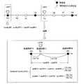
図5は、本実施形態における区間計測点の決定方法について説明するための図である。時系列に測位点P1〜P8が得られるとして、そのうち測位点P1、P4、P8が記憶点とされたものとして図示している。 FIG. 5 is a diagram for explaining a method of determining the section measurement points in the present embodiment. The positioning points P1 to P8 are obtained in time series, and the positioning points P1, P4, and P8 are shown as memory points.
区間計測点(区間が終了した地点。以降「ラップ地点」と呼ぶ。)は、所定のラップ条件を満たしたと判断された測位点とされる。本実施形態のラップ条件は、区間距離が1kmに達する毎、すなわち累積移動距離LAが前回の区間計測点から1km以上増えた次の測位点がラップ地点として記憶され、当該区間距離の移動に要した時間を区間時間情報(いわゆるラップタイム)として計測データに加えて保存する。 The section measurement point (the point at which the section ends. Hereinafter referred to as “lap point”) is a positioning point that is determined to satisfy a predetermined lap condition. The lap condition of the present embodiment is that every time the section distance reaches 1 km, that is, the next positioning point whose cumulative travel distance LA has increased by 1 km or more from the previous section measurement point is stored as a lap point, and is necessary for the movement of the section distance. The recorded time is stored as section time information (so-called lap time) in addition to the measurement data.
第1のラップ地点LAP1のように、ラップ条件を満たしたと判定された時点の測位点P1が記憶点となった場合には、当該ラップ地点の位置情報(緯度・経度)は測位点P1が記憶されるため、記憶されることとなる。
一方で、本実施形態では測位点は間引きされる場合がある。図5の例では、第2のラップ地点LAP2は合致するはずの測位点P5が間引きされている。そこで、本実施形態では当該ラップ地点LAP2の位置情報は「未定」を意味するダミーデータに置き換えて一旦計測データに追加される。そして、データ解析の段階で位置情報がダミーデータにされているラップ地点LAP2の位置情報を、測定日時が前後する記憶点P4、P8の位置測定情報から補間して解析に用いる。よって、測位点の間引きを行ったとしても区間計測を正しく行うことができる。When the positioning point P1 at the time when it is determined that the lap condition is satisfied becomes a storage point like the first lap point LAP1, the positioning point P1 stores the position information (latitude / longitude) of the lap point. Therefore, it will be memorized.
On the other hand, in this embodiment, positioning points may be thinned out. In the example of FIG. 5, the positioning point P5 that should match the second lap point LAP2 is thinned out. Therefore, in the present embodiment, the position information of the lap point LAP2 is temporarily added to the measurement data by replacing it with dummy data meaning “undecided”. Then, the position information of the lap point LAP2 whose position information is dummy data at the stage of data analysis is interpolated from the position measurement information of the storage points P4 and P8 whose measurement date and time is before and after and used for analysis. Therefore, even if the positioning points are thinned out, the section measurement can be correctly performed.
次に、本実施形態におけるデータ解析について説明する。
電子機器2で計測・記憶されたデータは、データアップロード装置50を介してデータ解析装置70に出力されて記憶・保存される。計測データには固有の識別情報と計測日時が含まれるので、一旦データ解析装置70に保存された計測データは過去に遡っていつでも閲覧できる。Next, data analysis in this embodiment will be described.
Data measured and stored by the
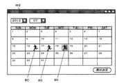
例えば、データ解析装置70は、図6に示すようなカレンダー型一覧表示画面W2によって、カレンダーにマーク80等を付与することで、その日に計測された計測データが保存されていて解析対象として選択可能であることをユーザーに示すことができる。このカレンダー型一覧表示画面W2では、ユーザーが解析対象としたい計測データのマーク80を選択することができる。そして選択決定操作をすれば選択した解析対象の計測データに基づくグラフ表示画面とマップ表示画面とがタッチパネル52に新たに表示される。 For example, the
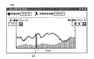
図7は、グラフ表示画面の例を示している。本実施形態のグラフ表示画面W4では、ランニングの所要時間や累積移動距離とともにグラフが表示される。本実施形態のグラフは、横軸を共通とする第1縦軸(左縦軸)と第2縦軸(右縦軸)とを有する。横軸は経過時間に固定されている。第1縦軸及び第2縦軸のパラメータはユーザーが変更することができる。図7の例では、第1縦軸が「ペース」、第2縦軸が「標高」にそれぞれ設定されているが、その他の選択可能なパラメータとしては例えば、ピッチ、平均消費カロリー、ストライドなどを適宜設定することができる。また、縦軸のスケールは自動調整される。このとき、平均値や中央値との差が一定以上大きい値は、スケール自動調整の対象外とされる。図7の例では、第1縦軸の「ペース」が他のデータに比べて極端に数値が低いデータ(符合82付近のデータ)がある。図7の例は、ランニング中に交通信号や危険回避のために一時的に止まらざるを得なかった地点のデータであるが、第1縦軸のスケーリングはそうした極端に数値が低いデータ(または、高いデータ)をスケーリング自動調整として含め無いので、グラフ表示範囲外となる。 FIG. 7 shows an example of a graph display screen. In the graph display screen W4 of the present embodiment, a graph is displayed together with the time required for running and the cumulative movement distance. The graph of the present embodiment has a first vertical axis (left vertical axis) and a second vertical axis (right vertical axis) having a common horizontal axis. The horizontal axis is fixed to the elapsed time. The parameters of the first vertical axis and the second vertical axis can be changed by the user. In the example of FIG. 7, the first vertical axis is set to “pace” and the second vertical axis is set to “elevation”, but other selectable parameters include, for example, pitch, average calorie consumption, stride, and the like. It can be set appropriately. The scale of the vertical axis is automatically adjusted. At this time, a value whose difference from the average value or the median is larger than a certain value is excluded from the automatic scale adjustment. In the example of FIG. 7, there is data whose “pace” on the first vertical axis is extremely lower than other data (data near the sign 82). The example in FIG. 7 is data at a point where it was necessary to temporarily stop for traffic signals or avoiding danger during running, but the scaling of the first vertical axis is such extremely low data (or High data) is not included in the automatic scaling adjustment, so it is outside the graph display range.
図8は、マップ表示画面の例を示している。本実施形態のマップ表示画面W6では、ランニングした軌跡84が地図86に描かれるとともに、区間計測点88が軌跡84の上に表示される。従来のように位置測定モジュール28から得られた全ての位置測定情報を繋ぐように軌跡を表示させると、位置測定情報の左右の振れや、計測ジャンプにより軌跡はジグザグに乱れるが、本実施形態のように方向転換した測位点のみを記憶点として選別することにより、無用で見辛い左右への細かなブレが無く、端正で正確な軌跡を表示させることができる。 FIG. 8 shows an example of the map display screen. In the map display screen W6 of the present embodiment, the running
次に、本実施形態における機能構成について説明する。
図9は、本実施形態における機能構成例を示す機能ブロック図である
電子機器2は、操作入力部100と、測定部102と、処理部200と、画像表示部360と、通信部370と、記憶部500とを備える。Next, a functional configuration in the present embodiment will be described.
FIG. 9 is a functional block diagram illustrating a functional configuration example in the present embodiment. The
操作入力部100は、ユーザーによって為された各種の操作入力に応じて操作入力信号を処理部200に出力する。例えば、ボタンスイッチや、タッチパネルといった直接プレーヤが手指で操作する素子はもちろん、加速度センサーや角速度センサー、傾斜センサー、地磁気センサーなど、運動や姿勢を検知する素子などによっても実現できる。図1のタッチパネル12や操作スイッチ16がこれに該当する。 The
測定部102は、所定周期で位置を測定する。具体的には、位置測定システムから信号を受信し、所定の測定周期で受信した信号に基づく位置測定情報を算出して処理部200へ出力する。図1の位置測定モジュール28がこれに該当する。 The measuring
処理部200は、例えばCPUやGPU等のマイクロプロセッサや、ICメモリーなどの電子部品によって実現され、操作入力部100や記憶部500を含む装置の各機能部との間でデータの入出力制御を行う。そして、所定のプログラムやデータ等に基づいて各種の演算処理を実行して、電子機器2の動作を制御する。図1では基板20がこれに該当する。 The
そして、本実施形態の処理部200は、移動記録制御部202と、画像生成部260と、通信制御部270と、を備える。 The
移動記録制御部202は、計測制御全般と計測結果の算出処理、そして記憶・保存に係る各種演算処理を実行する。本実施形態の移動記録制御部202は、距離表示制御部204と、移動距離記憶制御部206と、判定部210と、記憶制御部212と、経過時間表示制御部218と、経過時間記憶制御部220と、区間時間情報記憶制御部222と、外部出力制御部224と、を含む。 The movement
距離表示制御部204は、測定部102での測定結果に基づいて累積移動距離LAを算出して表示制御する。 The distance
移動距離記憶制御部206は、測定部102が測位情報を算出・出力する測定周期よりも長い時間間隔の距離記憶周期毎(例えば、6秒毎)に、距離表示制御部204が算出した累積移動距離LAを記憶部500に記憶させる制御をする。これにより、距離記憶周期で算出された累積移動距離LAは、記憶部500の計測データ602に記憶・保存される。 The movement distance
判定部210は、測定部102で測定される毎、すなわち位置測定情報が算出される毎に、過去の測定結果を参照して、当該測定結果を保存するか否かを判定する。保存「要」と判定された位置測定情報は、記憶部500の計測データ602として記憶・保存される。 The
具体的には、本実施形態の判定部210は、第1段階の判定として、測定部102により測定された進行方向(図3(2)の速度方位Dv)と、測定部102により測定された位置に基づく移動方向(図3(2)の位置方位D12)とが所定の近似条件(図3(2)の方位差θdが計測判定閾値θj未満)を満たさない場合に、当該測定結果を保存しないと判定する。
また、第2段階の判定として、測定部102の測定結果に基づき進行方向が転換したことを示す方向転換条件を満たす場合に当該測定結果を保存すると判定する。本実施形態における方向転換条件は、(a)直近過去の記憶点から、最新の測位点の一つ前の測位点へ向く「前回位置方位」と、直近過去の記憶点から最新の測位点へ向く「今回位置方位」との方位差θp、または(b)最新の速度方位である「今回速度方位」と、一つ前の速度方位である「前回速度方位」との方位差θpが方向転換認識閾値θc以上であることとする(図3(3)参照)。Specifically, the
Further, as the second stage determination, it is determined that the measurement result is stored when the direction change condition indicating that the traveling direction is changed based on the measurement result of the
記憶制御部212は、判定部210が肯定判定した場合に当該測定結果を記憶部500に記憶させる。 The
経過時間表示制御部218は、計測開始からの経過時間、すなわち累積移動距離LAの算出開始からの経過時間を算出して画像表示部360に表示させる制御をする。 The elapsed time
経過時間記憶制御部220は、記憶部500に記憶される測定結果に対応付けて経過時間を記憶部500に記憶させる。本実施形態では、経過時間算出時点における対地速さVと高度Hとを対応づけて記憶させる。 The elapsed time
区間時間情報記憶制御部222は、累積移動距離LAが所定の区間距離(例えば1km)に達する毎に経過時間或いは当該区間距離の移動に要した時間である区間時間情報(いわゆるラップタイム)を記憶部500に記憶させる制御をする。 The section time information
外部出力制御部224は、記憶部500に記憶された測定結果のデータ(計測データ602)等を外部装置へ出力する制御を行う。本実施形態では、計測データ602には距離記憶周期毎の累積移動距離LAが含まれているので、外部出力制御部224は、実質的に記憶部500に記憶された累積移動距離LAのデータを外部装置に出力する制御を行う。また、計測データ602には経過時間のデータ及び区間時間情報のデータが含まれるので、外部出力制御部224は、それらを外部装置に出力することができる。 The external
画像生成部260は、例えば、CPU、液晶ディスプレイのドライバIC、GPU(Graphics Processing Unit)、ビデオコーデックなどのプログラム、フレームバッファ等の描画フレーム用ICメモリー、テクスチャデータの展開用に使用されるICメモリー等によって実現される。画像生成部260は、各種の画像を画像表示部360に表示させるための制御をする。 The
画像表示部360は、画像生成部260から入力される制御信号に基づいて各種画像を表示する。例えば、フラットパネルディスプレイ、プロジェクターなどの画像表示装置によって実現できる。本実施形態では、図1のタッチパネル12がこれに該当する。 The
通信制御部270は、データ通信に係るデータ処理を実行し、通信部370を介して外部装置とのデータのやりとりを実現する。 The
通信部370は、外部装置とのデータ通信を実現する。例えば、無線通信機、有線用の通信ケーブルのジャックや制御回路等によって実現され、図1の近距離無線モジュール30がこれに該当する。 The
記憶部500は、処理部200に電子機器2を統合的に制御させるための諸機能を実現するためのプログラムや各種初期設定データ等を記憶する。また、処理部200による演算処理の作業領域として用いられ、処理部200が各種プログラムに従って実行した演算結果や、操作入力部100から入力される入力データ、測定部102で測定された測定結果のデータ等を一時的に記憶することができる。こうした機能は、例えばRAMやフラッシュメモリなどのICメモリーなどによって実現される。図1では基板20が搭載するメインメモリー24及び計測データ用メモリー26がこれに該当する。 The
本実施形態の記憶部500は、システムプログラム501と、移動記録制御プログラム502と、方向転換認識閾値テーブル510とを予めを記憶している。
また、計測開始とともに、随時記憶され書き換えられる情報として、最新位置測定情報512と、前回位置測定情報514と、最新記憶点情報515と、前回位置方位516と、今回位置方位518と、計測精度フラグ520と、保存要否フラグ522と、測位点間距離524と、記憶点間距離528と、累積記憶点間距離530と、累積移動距離532と、前回累積移動距離533と、経過時間534と、距離記憶周期タイマー538と、計測データ602と、を記憶する。その他、適宜計時タイマーや、フラグ、などを記憶することができる。The
In addition, as the measurement is started and stored and rewritten as needed, the latest
システムプログラム501は、電子機器2にコンピューターとしての基本機能を実現するためのプログラムである。移動記録制御プログラム502は、処理部200が読み出して実行することによって移動記録制御部202としての機能を実現させるためのアプリケーションソフトであるが、システムプログラム501の一部として組み込まれた構成であっても良い。方向転換認識閾値テーブル510は、対地速さVの区分と、各区分に対応する方向転換認識閾値θcを対応づけて格納している。 The
最新位置測定情報512は、最も新しい位置測定情報である。前回位置測定情報514は、一つ前の測定周期で得られた位置測定情報を格納する。最新記憶点情報515は、最も新しく記憶点とされた測位点、すなわち直近過去の記憶点の位置測定情報を格納する。 The latest
前回位置方位516は、直近過去の記憶点から前回の測定周期の測位点を向く方位を格納する。今回位置方位518は、直近過去の記憶点から最新位置測定情報512が示す最新の測位点を向く方位を格納する。 The previous position /
計測精度フラグ520は、最新の位置測定情報の計測精度の良好/不良を示すフラグである。保存要否フラグ522は、最新の位置測定情報を計測データ602に記憶・保存するか否かを示すフラグである。 The
測位点間距離524は、直近過去の記憶点から最新位置測定情報512が示す最新の測位点までの位置座標に基づいて算出される距離を格納する。記憶点間距離528は、直近過去の記憶点から保存「要」と判定された測位点すなわち新しい記憶点までの位置座標に基づいて算出される距離を格納する。
累積記憶点間距離530は、記憶点間距離528の累積値を格納する。従前に登録・保存された全記憶点を、最新の記憶点まで順番に結んだ距離に相当する。計測開始前の初期化で「0」にリセットされる。
累積移動距離532は、計測開始地点を基準とした最新の累積移動距離LAを格納する。
前回累積移動距離533は、最新の値の1つ前の累積移動距離LAを格納する。The distance between
The accumulated
The
The previous
経過時間534は、計測開始日時を基準とした経過時間を格納する計測開始前の初期化で「0」にリセットされる。
距離記憶周期タイマー538は、距離記憶周期を計時するためのタイマーである。The elapsed time 534 is reset to “0” by initialization before the start of measurement in which the elapsed time based on the measurement start date and time is stored.
The distance
計測データ602は、計測開始操作検出時から、計測終了操作検出までに計測された位置測定情報等のデータを格納する。例えば、図10に示すように、計測開始時に付与される計測識別子604と、計測開始日時606と、記憶点登録データ610と、距離履歴データ620と、ラップデータ630とを格納する。 The
記憶点登録データ610は、保存「要」と判定された測位点すなわち記憶点の位置測定情報を格納する。本実施形態では位置測定にGPSを利用するので、記憶点登録データ610はいわゆる「GPSログ」に相当する。本実施形態では、記憶点の登録毎に、記憶点識別子612と、計測開始からの経過時間614と、位置座標616とが対応づけて格納される。勿論、その他の情報を対応づけて格納することができる。 The storage
距離履歴データ620は、距離記憶周期で、当該距離記憶周期が到来する時点で算出されている累積移動距離LAの履歴を格納する。例えば、距離識別子622と、その時の累積移動距離624と、対地速さ626と、高度628とが対応づけて格納される。勿論、その他の情報を対応づけて格納することができる。 The
ラップデータ630は、区間計測(所謂ラップ(LAP))の結果を逐次格納する。例えば、1つの区間計測の結果は、ラップ識別子632と、計測開始からの区間時間情報634と、区間計測地点の位置座標636とが対応づけて格納される。区間時間情報634は、累積移動距離LAが所定の区間距離(例えば1km)に達する毎に、当該区間距離に達するまでの経過時間、或いは当該区間距離の移動に要した時間の何れかであるが、本実施形態では前者とする。勿論、その他の情報を対応づけて格納することができる。 The
図11は、本実施形態におけるデータ解析装置70の機能構成例を示す機能ブロック図である。データ解析装置70は、操作入力部100vと、処理部200vと、画像表示部360vと、通信部370vと、記憶部500vとを備えたコンピューターであり、いわゆるサーバーである。 FIG. 11 is a functional block diagram illustrating a functional configuration example of the
操作入力部100vは、例えばキーボードやマウスに相当し、電子機器2における操作入力部100に相当する。 The
処理部200vは、CPU等を有して構成され、電子機器2における処理部200に相当し、データ解析装置70の動作を統合的に制御する。本実施形態では、解析演算部230と、画像生成部260vと、通信制御部270vとを含む。そして、解析演算部230は、計測データ取得制御部232と、保存計測データ生成部234と、解析対象選択制御部236と、グラフ表示制御部240と、マップ表示制御部242と、を含む。 The
計測データ取得制御部232は、電子機器2から出力された未取得の計測データ602を取得するための制御を行う。本実施形態では、通信制御部270v(電子機器2における通信制御部270に相当)を利用して、通信部370v(電子機器2における通信部370に相当)の受信部372を介して計測データ602を受信・取得するための制御をする。 The measurement data
保存計測データ生成部234は、取得した計測データ602から保存計測データ603を生成し、記憶部500v(電子機器2における記憶部500相当)に記憶させるための制御をする。そして、保存計測データ生成部234は、計測データ602に含まれる補間対象を示す情報を、補間生成し置換する補間部235を含む。The stored measurement
補間部235は、本実施形態では、計測データ602のラップデータ630で、「未定」を意味する所定値(図10中の「NULL」がこれに該当)が与えられている位置座標636を抽出する。そして、区間時間情報634が前後する記憶点の位置座標616を記憶点登録データ610から参照して補間し、未定となっていた値を求めて書き換える処理をする。もし、受信された計測データ602の中に、区間時間情報634に対応する測定結果のデータが無い場合には、当該区間時間情報634の前後の経過時間のデータ及び当該経過時間に対応する測定結果のデータに基づいて、当該区間時間情報634に対応する測定結果を補間して生成することもできる。なお、この補間部235の機能をデータアップロード装置50が有することとし、データアップロード装置50は、補間した上で、計測データ602をデータ解析装置70にアップロードすることとしてもよい。 In this embodiment, the
また、保存計測データ生成部234は、取得した計測データ602を間引きすることができる。本実施形態では、グラフ表示画面W4のグラフの横軸の最小目盛数が固定とされるので、最小目盛数よりも記憶点登録データ610に登録されている記憶点の数が多い場合には、記憶点を間引きすることができる。また、距離履歴データ620に登録されている距離データが最小目盛数よりも多い場合には、距離データを間引きすることができる。間引きは、例えば、時系列に前後する複数のデータの内何れかを単純に消去することは勿論、複数のデータをそれらの平均値で置き換えるなど、適宜設定することができる。 Further, the stored measurement
解析対象選択制御部236は、保存計測データ603の中から何れかをデータ解析対象としてユーザーに選択させるための制御を行う。本実施形態では、カレンダー型一覧表示画面W2をデータアップロード装置50のタッチパネル52にて表示させるためのデータを生成する。 The analysis target
グラフ表示制御部240及びマップ表示制御部242は、ともにデータ解析の一部機能を担う。前者は、グラフ表示画面W4をデータアップロード装置50のタッチパネル52にて表示させるためのデータを生成する処理を行い、後者はマップ表示画面W6を表示させるためのデータを生成する処理を行う。 Both the graph
通信部370vは、電子機器2における通信部370に相当する。本実施形態では、電子機器2から出力されたデータを受信する受信部372を兼ねる。 The
記憶部500vは、電子機器2における記憶部500に相当する。本実施形態の記憶部500vには、システムプログラム503と、解析プログラム505と、保存計測データ603とが記憶される。 The
システムプログラム503は、データ解析装置70にコンピューターとしての基本機能を実現させるためのプログラムである。解析プログラム505は、処理部200vが読み出して実行することによって解析演算部230としての機能を実現させるためのアプリケーションソフトである。システムプログラム503の一部として組み込まれた構成であっても良い。 The
保存計測データ603は、図12に示すように、基本的には計測データ602と同様のデータ構成を有するが、間引き情報608と、ユーザーID609とを含む。間引き情報608は、保存計測データ603を生成する際に、オリジナルである受信した計測データ602のデータの間引きの内容を示す所定情報である。例えば、距離履歴データ620を、1つおきに単純に削除して間引きを行ったならば、間引き後の距離履歴データ620に適用される距離算出周期を格納する。また、記憶点登録データ610の2つの記憶点を、それらの平均値を有する1つの新しい記憶点に置き換える場合には、置き換え比率に相当する元の記憶点の数「2」を格納するとしても良い。 As shown in FIG. 12, the stored
次に、電子機器2の動作について説明する。
図13は、本実施形態における電子機器2における処理(移動記録制御処理)の流れを説明するためのフローチャートである。電子機器2の処理部200は、所定の操作スイッチ16(図1参照)を押下などの所定の計測開始操作を検出したならば(ステップS2のYES)、固有の計測識別子を設定し(ステップS4)、計測処理を実行する(ステップS6)。すなわち計測を開始する。Next, the operation of the
FIG. 13 is a flowchart for explaining the flow of processing (movement recording control processing) in the
図14は、本実施形態における計測処理の流れを説明するためのフローチャートである。
計測処理において、電子機器2の処理部200は、先ず初期化を行う(ステップS20)。
初期化では、計測データ602の記憶領域を確保し、最新位置測定情報512、前回位置測定情報514、最新記憶点情報515をクリアする。また、前回位置方位516、今回位置方位518、測位点間距離524、記憶点間距離528、累積記憶点間距離530、累積移動距離532、前回累積移動距離533、経過時間534、距離記憶周期タイマー538を「0」にリセットする。FIG. 14 is a flowchart for explaining the flow of measurement processing in the present embodiment.
In the measurement process, the
In the initialization, a storage area for the
次に、処理部200は、測定部102から位置測定情報を取得し、当該位置測定情報を最新位置測定情報512に格納する(ステップS22)。そして、この位置測定情報が示す第1の測位点を1つ目の記憶点として計測データ602の記憶点登録データ610へ追加登録するとともに、当該位置測定情報を最新記憶点情報515に上書きする。また、当該位置測定情報の測位日時を計測開始日時606として記憶・保存する(ステップS24)。そして、処理部200は、距離記憶周期タイマー538を起動する(ステップS26)。 Next, the
次に、測定部102から新しい位置測定情報が出力されたならば(ステップS28のYES)、処理部200は、最新位置測定情報512の内容を前回位置測定情報514に上書きし(ステップS30)、新しい位置測定情報を取得し、最新位置測定情報512を更新する(ステップS32)。そして、保存要否判定処理を実行して、最新位置測定情報512が示す測位点を記憶点として登録するか否かを決める(ステップS34)。 Next, if new position measurement information is output from the measurement unit 102 (YES in step S28), the
図15は、本実施形態における保存要否判定処理の流れを説明するためのフローチャートである。同処理において、電子機器2の処理部200は、先ず、計測精度判定処理を実行する(ステップS50)。 FIG. 15 is a flowchart for explaining the flow of the storage necessity determination process in the present embodiment. In this process, the
図16は、本実施形態における計測精度判定処理の流れを説明するためのフローチャートである。計測精度判定処理は、位置測定情報について、計測精度に基づく第1段階の判定を行う(図3(2)参照)。具体的には、同処理において処理部200は先ず、最新位置測定情報512が、位置測定システムから信号受信できなかった状態すなわち信号ロスト状態を示す値でなければ(ステップS52のNO)、前回位置測定情報514の示す前回の測位点から最新位置測定情報512が示す最新の測位点を向いた方位、すなわち今回位置方位518を算出する(ステップS54)。 FIG. 16 is a flowchart for explaining the flow of the measurement accuracy determination process in the present embodiment. The measurement accuracy determination process performs a first stage determination based on the measurement accuracy for the position measurement information (see FIG. 3B). Specifically, in this process, the
次いで、最新位置測定情報512の速度方位Dv(図3(1)参照)と、先に算出した今回位置方位518との方位差θdを算出し、算出した方位差θdと所定の計測精度判定閾値θjとを比較する。もし方位差θdが計測精度判定閾値θj未満であれば(ステップS56のYES)、計測精度「良好」と判定して計測精度フラグ520を「1(良好)」に設定し(ステップS58)、計測精度判定処理を終了する。 Next, an azimuth difference θd between the speed azimuth Dv (see FIG. 3 (1)) of the latest
反対に、方位差θdが計測精度判定閾値θj以上であれば(ステップS56のNO)、処理部200は計測精度「不良」と見なして計測精度フラグ520を「0(不良)」に設定し(ステップS60)、計測精度判定処理を終了する。 On the other hand, if the azimuth difference θd is greater than or equal to the measurement accuracy determination threshold θj (NO in step S56), the
また、そもそも、最新位置測定情報512が信号ロストを示す値であれば(ステップS52のYES)、処理部200はやはり計測精度「不良」と判定して計測精度フラグ520を「0(不良)」に設定し(ステップS60)、計測精度判定処理を終了する。 In the first place, if the latest
図15のフローチャートに戻って、計測精度判定処理により、計測精度「良好」と判定されたならば(ステップS70のYES)、前回位置測定情報514が示す前回測位点と、最新記憶点情報515が示す最新記憶点とが同一であるかを判定する。 Returning to the flowchart of FIG. 15, if the measurement accuracy determination process determines that the measurement accuracy is “good” (YES in step S <b> 70), the previous positioning point indicated by the previous
もし、前回測位点と最新記憶点とが同一である場合(ステップS72のYES)、処理部200は、最新位置測定情報512に含まれる対地速さVに応じた方向転換認識閾値θc(図3(3)参照)を方向転換認識閾値テーブル510から選択する(ステップS74)。
次いで、最新位置測定情報512に含まれる速度方位Dvすなわち進行方向と、最新記憶点情報515に含まれる速度方位Dvとの方位差θpを算出し(ステップS76)、算出した方位差θpが先に選択した方向転換認識閾値θcに達していれば(ステップS78のYES)、処理部200は保存「要」と判定し、保存要否フラグ522を「1(要)」に設定する(ステップS80)。反対に、算出した方位差θpが先に選択した方向転換認識閾値θc未満であれば(ステップS78のNO)、保存「不要」と判定し保存要否フラグ522を「0(不要)」に設定する(ステップS82)。そして、前回位置測定情報514が示す前回測位点から最新位置測定情報512が示す測位点を結ぶ方位を前回位置方位516として上書きし(ステップS84)、保存要否判定処理を終了するIf the previous positioning point and the latest storage point are the same (YES in step S72), the
Next, an azimuth difference θp between the velocity azimuth Dv included in the latest
もし、ステップS72において、前回測位点と最新記憶点とが異なると判定されたならば(ステップS72のNO)、処理部200は、方向転換認識閾値θcを選択し(ステッ
プS88)、前回測位点から最新測位点を向いた方位を算出して今回位置方位518へ上書きする(ステップS90)。次いで、前回位置方位516と今回位置方位518との方位差θpを算出し(ステップS92)、当該方位差θpが先に選択した方向転換認識閾値θcに達していれば(ステップS94のYES)、保存「要」と判定し(ステップS96)、前回位置方位516を今回位置方位518で上書きして(ステップS100)、保存要否判定処理を終了する。もし、方位差θpが方向転換認識閾値θcに達していなければ(ステップS94のNO)、保存「不要」と判定し(ステップS98)、前回位置方位516を今回位置方位518の内容で上書きして(ステップS100)、保存要否判定処理を終了する。If it is determined in step S72 that the previous positioning point is different from the latest stored point (NO in step S72), the
また、ステップS70にて、そもそも計測精度判定処理にて計測精度「不良」と判定された場合には(ステップS70のNO)、処理部200は、保存「不要」と判定し(ステップS98)、前回位置方位516を今回位置方位518で上書きして(ステップS100)、保存要否判定処理を終了する。If it is determined in step S70 that the measurement accuracy is “bad” in the first place (NO in step S70), the
図14のフローチャートに戻って、保存要否判定処理により保存「要」と判定されたならば(ステップS120のYES)、処理部200は、計測データ602の記憶点登録データ610に、最新位置測定情報512に基づく新たなデータを追加登録するとともに、最新位置測定情報512を最新記憶点情報515に上書きして最新測位点を新たな記憶点として登録する(ステップS122)。もし、保存「不要」と判定されたならば(ステップS120のNO)、ステップS122はスキップされ、最新測位点は記憶点とはされない。 Returning to the flowchart of FIG. 14, if it is determined that the storage is “necessary” by the storage necessity determination process (YES in step S <b> 120), the
次に、処理部200は距離算出処理を実行する(ステップS124)。
図17は、本実施形態における距離算出処理の流れを説明するためのフローチャートである。同処理において、処理部200は先ず、計測精度フラグ520を参照する。Next, the
FIG. 17 is a flowchart for explaining the flow of the distance calculation process in the present embodiment. In this process, the
計測精度フラグ520が「1(良好)」の場合(ステップS140のYES)、最新位置測定情報512は十分な計測精度を有していると見なせるので、処理部200は、続いて最新位置測定情報512が示す最新測位点が最新記憶点情報515が示す最新記憶点と一致するかを判定する(ステップS142)。 When the
もし、最新測位点と最新記憶点とが一致しなければ(ステップS142のNO)、処理部200は、最新記憶点情報515の位置座標と、最新位置測定情報512の位置座標とに基づいて、最新の記憶点(すなわち直近過去の記憶点)から最新測位点までの測位点間距離524を算出し(ステップS144)、距離算出処理を終了する。 If the latest positioning point and the latest memory point do not match (NO in step S142), the
もし、最新測位点と最新記憶点とが一致するならば(ステップS142のYES)、処理部200は測位点間距離524を「0」にリセットし(ステップS146)、次いで計測データ602に登録されている最新記憶点から登録順1つ前の記憶点までの記憶点間距離528を算出し(ステップS148)、算出した記憶点間距離528を累積記憶点間距離530に加算して(ステップS150)、距離算出処理を終了する。 If the latest positioning point coincides with the latest storage point (YES in step S142), the
一方、ステップS140にて、そもそも最新の位置測定情報が計測精度「不良」と判断されている場合には(ステップS140のNO)、前回位置測定情報514の対地速さVと速度方位Dvに基づく予測位置を算出し、前回位置測定情報514が示す前回測位点から予測位置までの距離を算出して、これを測位点間距離524に設定し(ステップS152)、距離算出処理を終了する。尚、本実施形態では、測定周期は1秒なので、前回位置測定情報514の対地速さVの値をそのまま測位点間距離524とすることができる。 On the other hand, if it is determined in step S140 that the latest position measurement information is originally “defective” (NO in step S140), it is based on the ground speed V and the speed direction Dv of the previous
図14のフローチャートに戻って、処理部200は次に、累積移動距離532の値を前回累積移動距離533に上書きした後、距離算出処理により更新された測位点間距離524と累積記憶点間距離530とを合算して累積移動距離532を更新し(ステップS170)、更新した累積移動距離532の表示を更新する(ステップS172:図1の累積移動距離表示6を参照)。 Returning to the flowchart of FIG. 14, the
次に、処理部200は、計測データ602の計測開始日時606と、最新位置測定情報512の測位日時とを比較して経過時間534を新たに算出・更新し、画像表示部360で経過時間534の表示を更新する(ステップS174:図1の経過時間表示8を参照)。 Next, the
次に、処理部200は、距離記憶周期タイマー538を参照し、距離記憶周期が到来しているならば(ステップS176のYES)、計測データ602の距離履歴データ620に、現在の累積移動距離532の値と、最新位置測定情報512に含まれる対地速さVと高度Hとを対応づけて追加する(ステップS178)。 Next, the
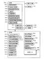
次に処理部200は、区間計測処理を実行する(ステップS180)。
図18は、本実施形態における区間計測処理の流れを説明するためのフローチャートである。同処理において、電子機器2の処理部200は、先ず最新位置測定情報512が示す最新測位点が、区間計測の区間終了点すなわちラップ地点として適合条件を満たすか判定する(ステップS182)。本実施形態の適合条件は、「累積移動距離532と前回累積移動距離533との差が1km以上増加した最初の測位点」とするが、その他の内容を設定することもできる。Next, the
FIG. 18 is a flowchart for explaining the flow of the section measurement process in the present embodiment. In this process, the
そして、最新測位点がラップ地点に適合すると判定されたならば(ステップS182のYES)、処理部200は、計測精度が「良好」で(ステップS184のYES)且つ保存「要」であれば(ステップS186のYES)、計測データ602のラップデータ630に新たにラップ地点のデータを追加登録する(ステップS186)。この際、新たに登録される区間時間情報634には経過時間534が上書きされ、新たに登録される位置座標636には最新位置測定情報512の位置情報が上書きされる。そして、処理部200は、ラップ登録処理を終了する。 If it is determined that the latest positioning point matches the lap point (YES in step S182), the
反対に、最新測位点がラップ地点に適合しているが(ステップS182のYES)、計測精度が「不良」(ステップS184のNO)、または保存「不要」と判定されている場合には(ステップS186のNO)、処理部200はラップデータ630に新たにラップ地点のデータを追加するが、位置座標636については「未定」を意味する所定のダミーデータ(図9の例では「NULL」)を格納し(ステップS190)、区間計測処理を終了する。 On the contrary, when the latest positioning point is suitable for the lap point (YES in step S182), but the measurement accuracy is determined to be “bad” (NO in step S184), or stored “unnecessary” (step) In step S186, the
図14のフローチャートに戻って、処理部200は、計測終了操作を検出するまで(ステップS200のNO)、ステップS28〜ステップS180を繰り返す。そして、計測終了操作を検出したならば(ステップS200のYES)、測定部102から位置測定情報を取得し、取得した位置測定情報に基づいて最後の記憶点を記憶点登録データ610に追加・登録して(ステップS202)、計測処理を終了する。 Returning to the flowchart of FIG. 14, the
図13のフローチャートに戻って、電子機器2の処理部200は、データアップロード装置50との通信接続を検出したならば(ステップS250のYES)、記憶部500に記憶されている未送信の計測データ602を送信する(ステップS252)。尚、電子機器2とデータアップロード装置50との通信接続は、近距離無線によるアドホックネットワークの確立や、USBケーブル42の接続検出により実現される。 Returning to the flowchart of FIG. 13, if the
次に、データアップロード装置50とデータ解析装置70との動作について説明する。
図19は、本実施形形態のデータアップロードからデータ解析の表示に係る処理の流れを説明するためのフローチャートである。Next, operations of the data upload
FIG. 19 is a flowchart for explaining a flow of processing related to display of data analysis from data upload according to the present embodiment.
データアップロード装置50は、電子機器2から計測データ602を受信すると、自身のICメモリー60等にこれを一旦保存する(ステップS260)。そして、インターネット9に接続してデータ解析装置70とのデータ通信を確立し(ステップS262)、電子機器2から受信した計測データ602を予め用意されているユーザー登録情報とともにデータ解析装置70へ送信する(ステップS264)。 Upon receiving the
データ解析装置70は、例えばユーザー登録制のウェブサイトのサーバーを兼ねることができる。その場合、電子機器2やデータアップロード装置50には、予め当該ウェブサイトのユーザー識別用の情報が登録されていることとし、データ解析装置70へのデータ送信に際してはユーザー認証を経るものとする。 The
データ解析装置70は、データアップロード装置50から受信した計測データ603を、ユーザーID609と対応づけて保存計測データ603として記憶・保存する(ステップS270:図12参照)。 The
次いで、データ解析装置70の処理部200vは、保存計測データ603をグラフ表示に適当な数まで間引き処理をする(ステップS272)。具体的には、距離履歴データ620の履歴数を、グラフ表示の横軸(時間軸)の目盛数と同じくなるように、例えば前後する複数の履歴の各パラメータ値(例えば、累積移動距離624や対地速さ626等)から平均値を算出し、それら複数の履歴を一つの履歴に置き換えるようにして間引きする。この時、間引き情報608を生成し、保存計測データ603に加える。 Next, the
次いで、データ解析装置70は、保存計測データ603からラップデータ630の位置座標636にダミーデータが設定されているラップ地点を抽出し、抽出されたラップ地点の位置座標636を、抽出されたラップ地点の区間時間情報634と経過時間614が前後する記憶点の位置座標616等に基づいて補間計算して求め、ダミーデータを補間値で上書きし更新する(ステップS274:図5参照)。 Next, the
次に、データ解析装置70は、すでにデータアップロード装置50から過去に受信し保存されている保存計測データ603の何れかを解析対象としてユーザーに選択させるための選択画面(図6のカレンダー型一覧表示画面W2)をデータアップロード装置50にて表示させるための一覧表示画面データ(例えば、画像データ、スクリプトデータなど)を生成し、データアップロード装置50へ送信する(ステップS276)。Next, the
データアップロード装置50は、このデータを受信して、カレンダー型一覧表示画面W2を表示する(ステップS280)。そして、カレンダー型一覧表示画面W2が表示された状態で、解析対象とする計測データの選択操作を検出したならば、データアップロード装置50は選択結果情報をデータ解析装置70へ送信する(ステップS282)。 The data upload
データ解析装置70は選択結果情報を受信すると、解析対象として選択された保存計測データ603に基づいて、グラフの第1縦軸と第2縦軸のパラメータを初期設定としてグラフ表示画面W4をタッチパネル52にて表示させるためのグラフ表示画面データを生成し、データアップロード装置50へ送信する(ステップS284)。更に、マップ表示画面をタッチパネル52にて表示させるためのマップ表示画面データを生成し、データアップロード装置50へ送信する(ステップS286)。 When the
データアップロード装置50は、グラフ表示画面データを受信して、タッチパネル52にグラフ表示画面W4を表示させ(ステップS300:図7参照)、マップ表示画面データを受信して、タッチパネル52にマップ表示画面W6を表示させる(ステップS302:図8参照)。The data upload
次いで、データアップロード装置50は、グラフ表示画面W4が表示されている状態で、グラフの縦軸とするパラメータの変更操作を検出したならば(ステップS310のYES)、パラメータの変更要求をデータ解析装置に送信する(ステップS312)。データ解析装置70はこれを受信すると、グラフの縦軸のパラメータ設定を受信した変更要求に応じて変更し、グラフ表示画面データを生成し直してデータアップロード装置50へ送信する(ステップS314)。データアップロード装置50は、この生成し直されたグラフ表示画面データを受信して、グラフ表示画面W4を更新する(ステップS316)。 Next, when the data upload
データアップロード装置50は、所定の解析終了操作を検出すると(ステップS320のYES)、解析終了信号をデータ解析装置70へ送信し(ステップS322)、データアップロードとデータ解析結果の表示に係る処理を終了する。 When the data upload
以上、本実施形態によれば、位置測定情報を間引くことで計測データ602のデータ量を削減することができる。よって、メモリー容量やバッテリー容量が、小型軽量を実現している従来製品に搭載されたものと同程度であったとしても、本発明を適用することでより長距離・より長時間に渡る計測データの記憶が可能となる。 As described above, according to the present embodiment, the data amount of the
〔変形例〕
以上、本発明を適用した実施形態について説明したが、本発明の適用形態はこれに限定されるものではなく、適宜構成要素の追加・省略・変更を施すことができる。[Modification]
As described above, the embodiment to which the present invention is applied has been described. However, the application form of the present invention is not limited to this, and additions, omissions, and changes of components can be appropriately made.
例えば、上記実施形態では電子機器2をユーザーの手首に装着するのに適した装置として例示したが、身体の何処に装着するかは適宜変更することができる。例えば、図20に示す電子機器2’に示すように、主にバンド18で上腕部に装着することを想定した装置としてデザインしても良い。その場合、装置のデザインは腕時計型に限らず、タブレットタイプであっても良く、適宜設定できる。 For example, in the above-described embodiment, the
また、上記実施形態では、データアップロード装置50とデータ解析装置70とを別の装置として説明したが、両装置が同じとしても良い。例えば、データアップロード装置50がデータ解析装置70における処理を実行する構成とすることができる。 In the above-described embodiment, the data upload
また、位置計測システムとしてGPSを用いる説明をしたが、WAAS(Wide Area Augmentation System)、QZSS(Quasi Zenith Satellite System)、GLONASS(GLObal NAvigation Satellite System)、GALILEO等の他の衛星測位システムであっても良い。 Moreover, although GPS was used as the position measurement system, other satellite positioning systems such as WAAS (Wide Area Augmentation System), QZSS (Quasi Zenith Satellite System), GLONASS (GLObal NAvigation Satellite System), and GALILEO good.
1…ユーザー、2…身体装着用電子機器、6…累積移動距離表示、9…インターネット、10…メインフレーム、12…タッチパネル、16…操作スイッチ、18…バンド、20…基板、21…充電式バッテリー、22…CPU、24…メインメモリー、26…計測データ用メモリー、28…位置測定モジュール、30…近距離無線モジュール、40…クレードル、42…USBケーブル、50…データアップロード装置、52…タッチパネル、54…キーボード、56…基板、58…CPU、60…ICメモリー、64…近距離無線モジュール、70…データ解析装置、80…マーク、84…軌跡、86…地図、88…区間計測点、100…操作入力部、100v…操作入力部、102…測定部、200…処理部、200v…処理部、202…移動記録制御部、204…距離表示制御部、206…移動距離記憶制御部、210…判定部、212…記憶制御部、216…外部出力制御部、218…経過時間表示制御部、220…経過時間記憶制御部、222…区間時間情報記憶制御部、224…外部出力制御部、230…解析演算部、232…計測データ取得制御部、234…保存計測データ生成部、235…補間部、236…解析対象選択制御部、240…グラフ表示制御部、242…マップ表示制御部、260…画像生成部、260v…画像生成部、270…通信制御部、270v…通信制御部、360…画像表示部、360v…画像表示部、370…通信部、370v…通信部、372…受信部、500…記憶部、501…システムプログラム、502…移動記録制御プログラム、503…システムプログラム、505…解析プログラム、510…方向転換認識閾値テーブル、512…最新位置測定情報、514…前回位置測定情報、515…最新記憶点情報、516…前回位置方位、518…今回位置方位、520…計測精度フラグ、522…保存要否フラグ、524…測位点間距離、528…記憶点間距離、530…累積記憶点間距離、532…累積移動距離、533…前回累積移動距離、534…経過時間、538…距離記憶周期タイマー、602…計測データ、603…保存計測データ、604…計測識別子、606…計測開始日時、608…間引き情報、609…ユーザーID、610…記憶点登録データ、612…記憶点識別子、614…経過時間、616…位置座標、620…距離履歴データ、622…距離識別子、624…累積移動距離、628…高度、630…ラップデータ、632…ラップ識別子、634…区間時間情報、636…位置座標、W2…カレンダー型一覧表示画面、W4…グラフ表示画面、W6…マップ表示画面DESCRIPTION OF
Claims (2)
Translated fromJapaneseデータ解析装置と、
を含み、
前記電子機器は、
所定周期で位置を測定する測定部と、
前記測定部で測定される毎に、前記測定部での測定結果に基づいて累積移動距離を算出して表示制御する距離表示制御部と、
前記測定部で測定される毎に、過去の測定結果を参照して進行方向が転換したことを示す方向転換条件を満たすか否かを判定することにより、前記測定部での測定結果を保存するか否かを判定する判定部と、
前記判定部が前記方向転換条件を満たすと判定した場合、前記測定部での測定結果を、前記累積移動距離の算出開始からの経過時間と対応付けて記憶部に記憶させる記憶制御部と、
前記累積移動距離が所定の区間距離増える毎に、当該区間距離に達したときの前記経過時間である区間時間情報を前記記憶部に記憶させる区間時間情報記憶制御部と、
前記記憶部に記憶された測定結果と経過時間との対応付けデータ、及び区間時間情報のデータを前記データ解析装置へ出力する制御を行う外部出力制御部と、
を含み、
前記データ解析装置は、
前記電子機器から出力されたデータを受信する受信部と、
前記受信部により受信されたデータの中に、前記区間時間情報が示す経過時間の対応付けデータが無い場合、当該区間時間情報の前後の経過時間のデータ及び当該経過時間に対応する測定結果のデータに基づいて、当該区間時間情報に対応する測定結果を補間することにより、前記累積移動距離が前記区間距離増える毎の測定結果に係るデータを生成する補間部と、
を含む、
システム。Electronic devices that can be worn on the body,
A data analysis device;
Including
The electronic device is
A measurement unit that measures a position at a predetermined period;
A distance display control unit that calculates and displays a cumulative movement distance based on a measurement result in the measurement unit each time it is measured by the measurement unit;
Each time measurement is performed by the measurement unit, the measurement result of the measurement unit is stored by determining whether or not a direction change condition indicating that the traveling direction has changed is referred to the past measurement result. A determination unit for determining whether or not
When the determination unit determines that the direction change condition is satisfied, a storage control unit that stores a measurement result in the measurement unit in a storage unit in association with an elapsed time from the calculation start of the cumulative movement distance;
Each time the cumulative travel distance increases by a predetermined section distance, a section time information storage control section that stores section time information that is the elapsed time when the section distance is reached in the storage section,
An external output control unit that performs control to output the association data between the measurement result and the elapsed time stored in the storage unit, and the data of the section time information to the data analysis device,
Including
The data analyzer is
A receiving unit for receiving data output from the electronic device;
When the data received by the receiving unit does not include the association data of the elapsed time indicated by the section time information, the data of the elapsed time before and after the section time information and the data of the measurement result corresponding to the elapsed time And interpolating a measurement result corresponding to the section time information, an interpolation unit that generates data related to the measurement result every time the cumulative travel distance increases the section distance;
including,
system.
前記電子機器が、
所定周期で位置を測定するステップと、
前記測定がなされる毎に、前記測定による測定結果に基づいて累積移動距離を算出して表示制御するステップと、
前記測定がなされる毎に、過去の測定結果を参照して進行方向が転換したことを示す方向転換条件を満たすか否かを判定することにより、前記測定による測定結果を保存するか否かを判定するステップと、
前記方向転換条件を満たすと判定した場合、前記測定による測定結果を、前記累積移動距離の算出開始からの経過時間と対応付けて記憶部に記憶させるステップと、
前記累積移動距離が所定の区間距離増える毎に、当該区間距離に達したときの前記経過時間である区間時間情報を前記記憶部に記憶させるステップと、
前記記憶部に記憶された測定結果と経過時間との対応付けデータ、及び区間時間情報のデータを前記データ解析装置へ出力する制御を行うステップと、
を実行し、
前記データ解析装置が、
前記電子機器から出力されたデータを受信するステップと、
前記受信されたデータの中に、前記区間時間情報が示す経過時間の対応付けデータが無い場合、当該区間時間情報の前後の経過時間のデータ及び当該経過時間に対応する測定結果のデータに基づいて、当該区間時間情報に対応する測定結果を補間することにより、前記累積移動距離が前記区間距離増える毎の測定結果に係るデータを生成するステップと、
を実行する、
移動記録制御方法。Executed by an electronic device and a data analysis device that can be worn on the body
The electronic device is
Measuring a position at a predetermined period;
Each time the measurement is made, calculating a cumulative movement distance based on the measurement result of the measurement and controlling the display;
Whether or not to save the measurement result by the measurement by determining whether or not the direction change condition indicating that the traveling direction has changed by referring to the past measurement result every time the measurement is made. A determining step;
If it is determined that the direction change condition is satisfied, the measurement result by the measurement is stored in the storage unit in association with the elapsed time from the start of calculation of the cumulative movement distance;
Each time the cumulative travel distance is increased by a predetermined section distance, the section time information that is the elapsed time when the section distance is reached is stored in the storage unit;
Performing the control of outputting the measurement result stored in the storage unit and the association data between the elapsed time and the data of the section time information to the data analysis device;
Run
The data analyzer is
Receiving data output from the electronic device;
When the received data does not include the association data of the elapsed time indicated by the section time information, based on the elapsed time data before and after the section time information and the measurement result data corresponding to the elapsed time. Interpolating the measurement results corresponding to the section time information to generate data related to the measurement results each time the cumulative travel distance increases the section distance;
Run the
Moving recording control method.
Priority Applications (2)
| Application Number | Priority Date | Filing Date | Title |
|---|---|---|---|
| JP2012175311AJP6326711B2 (en) | 2012-08-07 | 2012-08-07 | System and moving recording control method |
| US13/960,768US9372096B2 (en) | 2012-08-07 | 2013-08-06 | Wearable electronic apparatus, data analyzer, and travel record control method |
Applications Claiming Priority (1)
| Application Number | Priority Date | Filing Date | Title |
|---|---|---|---|
| JP2012175311AJP6326711B2 (en) | 2012-08-07 | 2012-08-07 | System and moving recording control method |
Publications (3)
| Publication Number | Publication Date |
|---|---|
| JP2014035219A JP2014035219A (en) | 2014-02-24 |
| JP2014035219A5 JP2014035219A5 (en) | 2015-09-17 |
| JP6326711B2true JP6326711B2 (en) | 2018-05-23 |
Family
ID=50066811
Family Applications (1)
| Application Number | Title | Priority Date | Filing Date |
|---|---|---|---|
| JP2012175311AExpired - Fee RelatedJP6326711B2 (en) | 2012-08-07 | 2012-08-07 | System and moving recording control method |
Country Status (2)
| Country | Link |
|---|---|
| US (1) | US9372096B2 (en) |
| JP (1) | JP6326711B2 (en) |
Families Citing this family (41)
| Publication number | Priority date | Publication date | Assignee | Title |
|---|---|---|---|---|
| US9213781B1 (en) | 2012-09-19 | 2015-12-15 | Placemeter LLC | System and method for processing image data |
| TWM475596U (en)* | 2013-12-10 | 2014-04-01 | Ming Chuan Universitytw | Speed display device of satellite positioning |
| CA2933662C (en) | 2013-12-11 | 2022-08-09 | Prinoth Ltd. | Snow groomer or other tracked vehicle and systems therefor |
| KR101434514B1 (en) | 2014-03-21 | 2014-08-26 | (주) 골프존 | Time synchronization method for data of different kinds of devices and data processing device for generating time-synchronized data |
| USD729652S1 (en) | 2014-05-22 | 2015-05-19 | Samsung Electronics Co., Ltd. | Electronic device |
| USD729647S1 (en) | 2014-05-22 | 2015-05-19 | Samsung Electronics Co., Ltd. | Electronic device |
| USD729646S1 (en) | 2014-05-22 | 2015-05-19 | Samsung Electronics Co., Ltd. | Electronic device |
| USD729091S1 (en) | 2014-05-22 | 2015-05-12 | Samsung Electronics Co., Ltd. | Electronic device |
| USD729086S1 (en) | 2014-05-22 | 2015-05-12 | Samsung Electronics Co., Ltd. | Electronic device |
| USD729653S1 (en) | 2014-05-22 | 2015-05-19 | Samsung Electronics Co., Ltd. | Electronic device |
| USD729079S1 (en) | 2014-05-22 | 2015-05-12 | Samsung Electronics Co., Ltd. | Electronic device |
| USD729670S1 (en) | 2014-05-22 | 2015-05-19 | Samsung Electronics Co., Ltd. | Electronic device |
| USD729671S1 (en) | 2014-05-22 | 2015-05-19 | Samsung Electronics Co., Ltd. | Electronic device |
| USD729667S1 (en) | 2014-05-22 | 2015-05-19 | Samsung Electronics Co., Ltd. | Electronic device |
| USD729650S1 (en) | 2014-05-22 | 2015-05-19 | Samsung Electronics Co., Ltd. | Electronic device |
| USD729654S1 (en) | 2014-05-22 | 2015-05-19 | Samsung Electronics Co., Ltd. | Electronic device |
| USD729085S1 (en) | 2014-05-22 | 2015-05-12 | Samsung Electronics Co., Ltd. | Electronic device |
| USD729651S1 (en) | 2014-05-22 | 2015-05-19 | Samsung Electronics Co., Ltd. | Electronic device |
| USD729648S1 (en) | 2014-05-22 | 2015-05-19 | Samsung Electronics Co., Ltd. | Electronic device |
| USD729649S1 (en) | 2014-05-22 | 2015-05-19 | Samsung Electronics Co., Ltd. | Electronic device |
| USD729672S1 (en) | 2014-05-22 | 2015-05-19 | Samsung Electronics Co., Ltd. | Electronic device |
| USD729078S1 (en) | 2014-05-22 | 2015-05-12 | Samsung Electronics Co., Ltd. | Electronic device |
| WO2015184440A2 (en) | 2014-05-30 | 2015-12-03 | Placemeter Inc. | System and method for activity monitoring using video data |
| KR20160055577A (en)* | 2014-11-10 | 2016-05-18 | 엘지전자 주식회사 | Wearable device |
| US20160259419A1 (en)* | 2015-03-05 | 2016-09-08 | Harman International Industries, Inc | Techniques for controlling devices based on user proximity |
| US10043078B2 (en)* | 2015-04-21 | 2018-08-07 | Placemeter LLC | Virtual turnstile system and method |
| KR102300246B1 (en) | 2015-05-21 | 2021-09-09 | 삼성전자주식회사 | Wireless charging Apparatus and electronic device using the same |
| US10380431B2 (en)* | 2015-06-01 | 2019-08-13 | Placemeter LLC | Systems and methods for processing video streams |
| KR102359281B1 (en)* | 2015-06-17 | 2022-02-04 | 삼성전자주식회사 | Method and wearable device for providing information on exercise |
| KR102398320B1 (en) | 2015-08-07 | 2022-05-16 | 삼성전자주식회사 | Method for providing route information and an electronic device thereof |
| CN107084731B (en)* | 2016-02-16 | 2021-01-22 | 中移物联网有限公司 | Method and device for optimizing vehicle-mounted positioning track |
| CN105790783A (en)* | 2016-03-01 | 2016-07-20 | 成都怡康科技有限公司 | Group movement bracelet system for scenic area |
| CN109788910B (en) | 2016-09-30 | 2021-08-31 | 亚洲航测株式会社 | Mobile body information providing system and computer-readable storage medium |
| JP7035440B2 (en)* | 2017-10-11 | 2022-03-15 | セイコーエプソン株式会社 | Position measurement method, electronic equipment and positioning system |
| JP7069771B2 (en)* | 2018-02-06 | 2022-05-18 | カシオ計算機株式会社 | Exercise data display device and exercise data display method |
| US10371535B1 (en)* | 2018-05-09 | 2019-08-06 | Ford Global Technologies, Llc | Automatic map generation |
| JP6738876B2 (en)* | 2018-10-29 | 2020-08-12 | アイサンテクノロジー株式会社 | Correction parameter creating device, correction parameter creating method, and correction parameter creating program |
| CN110665185A (en)* | 2019-08-19 | 2020-01-10 | 重庆特斯联智慧科技股份有限公司 | Wisdom scenic spot stereoscopic imaging navigation |
| CN110927768A (en)* | 2019-11-08 | 2020-03-27 | 广东高驰运动科技有限公司 | Distance measuring method based on mobile coordinate positioning and portable terminal equipment |
| JP2021189571A (en)* | 2020-05-26 | 2021-12-13 | 盛吾 栗林 | Information display program and information display system |
| TW202524443A (en)* | 2023-11-30 | 2025-06-16 | 智易科技股份有限公司 | Vehicle trajectory recording system and method for vehicles with a sensor |
Family Cites Families (14)
| Publication number | Priority date | Publication date | Assignee | Title |
|---|---|---|---|---|
| JPH0540440A (en)* | 1991-08-06 | 1993-02-19 | Pioneer Electron Corp | Navigation device |
| US6002982A (en)* | 1996-11-01 | 1999-12-14 | Fry; William R. | Sports computer with GPS receiver and performance tracking capabilities |
| JP3114013B2 (en)* | 1997-03-25 | 2000-12-04 | セイコーインスツルメンツ株式会社 | Portable GPS receiver |
| US5916300A (en)* | 1997-07-18 | 1999-06-29 | Trimble Navigation Limited | Automatic event recognition to trigger recording changes |
| JP2000241193A (en)* | 1999-02-23 | 2000-09-08 | Matsushita Electric Works Ltd | Pedometer |
| JP2000284041A (en)* | 1999-03-30 | 2000-10-13 | Seiko Instruments Inc | Portable range-velocity meter |
| US6975941B1 (en)* | 2002-04-24 | 2005-12-13 | Chung Lau | Method and apparatus for intelligent acquisition of position information |
| JP2003322545A (en) | 2002-05-07 | 2003-11-14 | Takashi Doi | Cumulative moving distance measuring device and cumulative moving distance measuring method |
| JP2004038585A (en)* | 2002-07-03 | 2004-02-05 | Kazuo Mito | Movement recorder |
| JP2004125542A (en)* | 2002-10-01 | 2004-04-22 | Seiko Epson Corp | Navigation device, electronic device and program |
| US8032276B2 (en)* | 2004-12-07 | 2011-10-04 | Geotab, Inc. | Apparatus and method for optimally recording geographical position data |
| US7853428B2 (en)* | 2007-01-11 | 2010-12-14 | Yamaha Corporation | Apparatus for displaying fitness exercise condition |
| JP5685582B2 (en)* | 2009-04-26 | 2015-03-18 | ナイキ イノベイト セー. フェー. | Exercise clock |
| CN105210084B (en)* | 2013-03-15 | 2019-03-12 | 耐克创新有限合伙公司 | Feedback signal from image data of athletic performance |
- 2012
- 2012-08-07JPJP2012175311Apatent/JP6326711B2/ennot_activeExpired - Fee Related
- 2013
- 2013-08-06USUS13/960,768patent/US9372096B2/ennot_activeExpired - Fee Related
Also Published As
| Publication number | Publication date |
|---|---|
| US20140046588A1 (en) | 2014-02-13 |
| JP2014035219A (en) | 2014-02-24 |
| US9372096B2 (en) | 2016-06-21 |
Similar Documents
| Publication | Publication Date | Title |
|---|---|---|
| JP6326711B2 (en) | System and moving recording control method | |
| JP5150310B2 (en) | Geographic data collection device | |
| JP4793479B2 (en) | Positioning device, positioning method and program | |
| US20240401976A1 (en) | Distance measuring method based on moving coordinate positioning and portable terminal device | |
| EP2570771B1 (en) | Route smoothing | |
| CN102538791B (en) | Itinerary generates equipment and itinerary generation method | |
| CN102192742B (en) | Navigation method and device | |
| JP2014035219A5 (en) | ||
| CN113295174B (en) | Lane-level positioning method, related device, equipment and storage medium | |
| US20110183684A1 (en) | Mobile communication terminal and method | |
| CN102538780A (en) | Positioning apparatus, positioning method, and storage medium for measuring position using both autonomous navigation and GPS | |
| CN112362054B (en) | Calibration method, calibration device, electronic equipment and storage medium | |
| JP2017009341A (en) | Data analysis device, data analysis method and data analysis program | |
| JP2011102707A (en) | Positioning device and positioning method | |
| JP6669171B2 (en) | Information processing apparatus, control method, and program | |
| KR102652232B1 (en) | Method for correcting a sensor and direction information obtained via the sensor based on another direction information obtained via the satellite positioning circuit and electronic device thereof | |
| JP2019148586A (en) | Position measurement device, position correction method, and position information acquisition system | |
| CN116152950B (en) | Data processing method, device and system, electronic equipment and storage medium | |
| JP2011102792A (en) | Positioning device and positioning method | |
| JP5811558B2 (en) | Mobile terminal and travel route calculation program | |
| HK40049430A (en) | A method, related devices, equipment and storage medium of lane-level positioning | |
| HK40049430B (en) | A method, related devices, equipment and storage medium of lane-level positioning | |
| JP5768426B2 (en) | Mobile terminal and travel route calculation program | |
| JPWO2017126552A1 (en) | Positioning device and positioning method |
Legal Events
| Date | Code | Title | Description |
|---|---|---|---|
| A521 | Request for written amendment filed | Free format text:JAPANESE INTERMEDIATE CODE: A523 Effective date:20150804 | |
| A621 | Written request for application examination | Free format text:JAPANESE INTERMEDIATE CODE: A621 Effective date:20150804 | |
| A131 | Notification of reasons for refusal | Free format text:JAPANESE INTERMEDIATE CODE: A131 Effective date:20160906 | |
| A521 | Request for written amendment filed | Free format text:JAPANESE INTERMEDIATE CODE: A523 Effective date:20161107 | |
| A131 | Notification of reasons for refusal | Free format text:JAPANESE INTERMEDIATE CODE: A131 Effective date:20170411 | |
| A521 | Request for written amendment filed | Free format text:JAPANESE INTERMEDIATE CODE: A523 Effective date:20170607 | |
| A02 | Decision of refusal | Free format text:JAPANESE INTERMEDIATE CODE: A02 Effective date:20171121 | |
| A521 | Request for written amendment filed | Free format text:JAPANESE INTERMEDIATE CODE: A523 Effective date:20180214 | |
| A911 | Transfer to examiner for re-examination before appeal (zenchi) | Free format text:JAPANESE INTERMEDIATE CODE: A911 Effective date:20180221 | |
| TRDD | Decision of grant or rejection written | ||
| A01 | Written decision to grant a patent or to grant a registration (utility model) | Free format text:JAPANESE INTERMEDIATE CODE: A01 Effective date:20180320 | |
| A61 | First payment of annual fees (during grant procedure) | Free format text:JAPANESE INTERMEDIATE CODE: A61 Effective date:20180402 | |
| R150 | Certificate of patent or registration of utility model | Ref document number:6326711 Country of ref document:JP Free format text:JAPANESE INTERMEDIATE CODE: R150 | |
| LAPS | Cancellation because of no payment of annual fees |