JP6326210B2 - Quartz glass part and method for producing quartz glass part - Google Patents
Quartz glass part and method for producing quartz glass partDownload PDFInfo
- Publication number
- JP6326210B2 JP6326210B2JP2013205494AJP2013205494AJP6326210B2JP 6326210 B2JP6326210 B2JP 6326210B2JP 2013205494 AJP2013205494 AJP 2013205494AJP 2013205494 AJP2013205494 AJP 2013205494AJP 6326210 B2JP6326210 B2JP 6326210B2
- Authority
- JP
- Japan
- Prior art keywords
- quartz glass
- film
- glass substrate
- silicon powder
- particle size
- Prior art date
- Legal status (The legal status is an assumption and is not a legal conclusion. Google has not performed a legal analysis and makes no representation as to the accuracy of the status listed.)
- Active
Links
Images


Classifications
- C—CHEMISTRY; METALLURGY
- C03—GLASS; MINERAL OR SLAG WOOL
- C03C—CHEMICAL COMPOSITION OF GLASSES, GLAZES OR VITREOUS ENAMELS; SURFACE TREATMENT OF GLASS; SURFACE TREATMENT OF FIBRES OR FILAMENTS MADE FROM GLASS, MINERALS OR SLAGS; JOINING GLASS TO GLASS OR OTHER MATERIALS
- C03C17/00—Surface treatment of glass, not in the form of fibres or filaments, by coating
- C03C17/22—Surface treatment of glass, not in the form of fibres or filaments, by coating with other inorganic material
- C—CHEMISTRY; METALLURGY
- C03—GLASS; MINERAL OR SLAG WOOL
- C03C—CHEMICAL COMPOSITION OF GLASSES, GLAZES OR VITREOUS ENAMELS; SURFACE TREATMENT OF GLASS; SURFACE TREATMENT OF FIBRES OR FILAMENTS MADE FROM GLASS, MINERALS OR SLAGS; JOINING GLASS TO GLASS OR OTHER MATERIALS
- C03C15/00—Surface treatment of glass, not in the form of fibres or filaments, by etching
- C—CHEMISTRY; METALLURGY
- C03—GLASS; MINERAL OR SLAG WOOL
- C03C—CHEMICAL COMPOSITION OF GLASSES, GLAZES OR VITREOUS ENAMELS; SURFACE TREATMENT OF GLASS; SURFACE TREATMENT OF FIBRES OR FILAMENTS MADE FROM GLASS, MINERALS OR SLAGS; JOINING GLASS TO GLASS OR OTHER MATERIALS
- C03C2217/00—Coatings on glass
- C03C2217/20—Materials for coating a single layer on glass
- C03C2217/25—Metals
- C03C2217/262—Light metals other than Al
- C—CHEMISTRY; METALLURGY
- C03—GLASS; MINERAL OR SLAG WOOL
- C03C—CHEMICAL COMPOSITION OF GLASSES, GLAZES OR VITREOUS ENAMELS; SURFACE TREATMENT OF GLASS; SURFACE TREATMENT OF FIBRES OR FILAMENTS MADE FROM GLASS, MINERALS OR SLAGS; JOINING GLASS TO GLASS OR OTHER MATERIALS
- C03C2218/00—Methods for coating glass
- C03C2218/10—Deposition methods
- C03C2218/13—Deposition methods from melts
- C—CHEMISTRY; METALLURGY
- C03—GLASS; MINERAL OR SLAG WOOL
- C03C—CHEMICAL COMPOSITION OF GLASSES, GLAZES OR VITREOUS ENAMELS; SURFACE TREATMENT OF GLASS; SURFACE TREATMENT OF FIBRES OR FILAMENTS MADE FROM GLASS, MINERALS OR SLAGS; JOINING GLASS TO GLASS OR OTHER MATERIALS
- C03C2218/00—Methods for coating glass
- C03C2218/30—Aspects of methods for coating glass not covered above
- C03C2218/31—Pre-treatment
- C—CHEMISTRY; METALLURGY
- C03—GLASS; MINERAL OR SLAG WOOL
- C03C—CHEMICAL COMPOSITION OF GLASSES, GLAZES OR VITREOUS ENAMELS; SURFACE TREATMENT OF GLASS; SURFACE TREATMENT OF FIBRES OR FILAMENTS MADE FROM GLASS, MINERALS OR SLAGS; JOINING GLASS TO GLASS OR OTHER MATERIALS
- C03C2218/00—Methods for coating glass
- C03C2218/30—Aspects of methods for coating glass not covered above
- C03C2218/32—After-treatment
- C03C2218/328—Partly or completely removing a coating
- C03C2218/33—Partly or completely removing a coating by etching
Landscapes
- Chemical & Material Sciences (AREA)
- Life Sciences & Earth Sciences (AREA)
- Engineering & Computer Science (AREA)
- Chemical Kinetics & Catalysis (AREA)
- General Chemical & Material Sciences (AREA)
- Geochemistry & Mineralogy (AREA)
- Materials Engineering (AREA)
- Organic Chemistry (AREA)
- Surface Treatment Of Glass (AREA)
Description
Translated fromJapanese本発明は、石英ガラス部品及び石英ガラス部品の製造方法に関する。 The present invention relates to a quartz glass part and a method for producing a quartz glass part.
一般的に半導体ウエハに対して不活性雰囲気又は酸化性雰囲気下で赤外線輻射により結晶完全性を高めるため又は表面改質を目的として高温熱処理装置が施される。該高温熱処理装置は400度〜1400度の高温環境下で処理するため、装置内周辺の構造部品には、耐熱性に優れ、かつ加工しやすい石英ガラス部品が広汎に使用されている。 In general, a high-temperature heat treatment apparatus is applied to a semiconductor wafer in order to improve crystal integrity by infrared radiation in an inert atmosphere or an oxidizing atmosphere or for the purpose of surface modification. Since the high-temperature heat treatment apparatus is processed in a high-temperature environment of 400 ° C. to 1400 ° C., quartz glass parts that are excellent in heat resistance and easy to process are widely used as structural parts around the apparatus.
通常、高温熱処理装置内の石英ガラス部品として、機能上赤外線を透過させる部位には透明石英ガラス基材を、逆に赤外線を遮蔽し遮熱性を必要とする部位には微細な内部気泡を大量に含有する不透明石英ガラス基材が選択される。例えば透明石英ガラス基材は赤外線の透過率が高く、当該石英ガラス部品を透過した赤外線が高温熱処理装置内のシール部に設けたOリングを熱し、熱せられたOリングが引張強度の低下又は溶融により変質および切断されることで高温熱処理装置が故障する問題が発生している。このような問題に対して、例えば特許文献5には、石英ガラス部品の表面にSiCをコーテイングすることで遮熱性を向上させた石英ガラス部品が開示されている。また、特許文献1には、石英ガラス基材の表面を多孔質の石英ガラス溶射膜で被覆することで、赤外線反射機能を有する石英ガラス部品の製造方法が開示されている。 Usually, as quartz glass parts in high-temperature heat treatment equipment, transparent quartz glass substrate is functionally used for parts that transmit infrared rays, and conversely, a large amount of fine internal bubbles are used for parts that shield infrared rays and require heat insulation. The opaque quartz glass substrate to be contained is selected. For example, a transparent quartz glass substrate has a high infrared transmittance, and the infrared rays that have passed through the quartz glass component heat the O-ring provided at the seal portion in the high-temperature heat treatment apparatus, and the heated O-ring has a reduced tensile strength or melts. There is a problem that the high-temperature heat treatment apparatus fails due to deterioration and cutting caused by the above. In order to solve such a problem, for example, Patent Document 5 discloses a quartz glass part in which the heat shielding property is improved by coating SiC on the surface of the quartz glass part.
高温熱処理装置には熱処理プロセスの精密制御の必要性から、高温処理部周辺に各種精密部品、精密駆動機構並びに計測機器及びモニタリング機構が配置されており、高温処理部とこれら周辺機構部との間が遮熱されている。更に近年においては半導体ウエハの大口径化に伴い、高温熱処理装置の構造が例えば特許文献5に開示されているバッチ処理方式から、枚葉処理方式へ移行しており、装置設置面積の縮小要求から、高温処理部とこれら周辺機構部との間をより小さな空間で遮熱する必要性が高まっている。このため石英ガラス部品を備える高温熱処理装置おいて、遮熱性を必要とする不透明石英ガラス部品に対し薄型化を図った場合、熱処理における遮熱性機能が低下するという問題が発生していた。 Because of the necessity of precise control of the heat treatment process, high-temperature heat treatment equipment is equipped with various precision parts, precision drive mechanisms, measuring instruments, and monitoring mechanisms around the high-temperature treatment section. Is insulated. In recent years, with the increase in the diameter of semiconductor wafers, the structure of a high-temperature heat treatment apparatus has shifted from, for example, the batch processing method disclosed in Patent Document 5 to the single wafer processing method, and from the demand for reducing the installation area of the apparatus. In addition, there is an increasing need to shield heat between the high temperature processing section and these peripheral mechanism sections in a smaller space. For this reason, in a high-temperature heat treatment apparatus equipped with a quartz glass part, when an opaque quartz glass part that requires heat shielding is made thin, there has been a problem that the heat shielding function in the heat treatment is lowered.
本発明は斯かる事情に鑑みてなされたものであり、その目的とするところは、薄型化に対応し、かつ遮光性及び耐熱性を向上させた石英ガラス部品及び石英ガラス部品の製造方法を提供することにある。 The present invention has been made in view of such circumstances, and an object of the present invention is to provide a quartz glass component and a method for manufacturing the quartz glass component that are adapted to be made thin and have improved light shielding properties and heat resistance. There is to do.
本発明に係る石英ガラス部品は、石英ガラス基材の表面にシリコン粉末をプラズマ溶射することにより遮光性及び耐熱性を向上させるための皮膜を形成してなる石英ガラス部品であって、前記石英ガラス基材は不透明石英ガラスから成り、前記シリコン粉末における100μm以上の粒径の比率は3%以下であり、前記皮膜が形成された不透明石英ガラスは、光の透過率が波長300〜900nmにかけて0.1%以下であることを特徴とする。The quartz glass part according to the present invention is a quartz glass part formed by forming a film for improving light shielding and heat resistance by plasma spraying silicon powder on the surface of a quartz glass substrate, substrateconsists opaque quartz glass, the ratio of 100μm or more particle size in the silicon powder is less than 3%, opaque quartz glass, wherein the film has been formed, the light transmittance over the
本発明に係る石英ガラス部品は、前記シリコン粉末における100μm以上の粒径の比率は0%であり、前記シリコン粉末におけるD50%粒径は25〜35μmであることを特徴とする。 The quartz glass part according to the present invention is characterized in that the ratio of the particle diameter of 100 μm or more in the silicon powder is 0%, and the D50% particle diameter in the silicon powder is 25 to 35 μm.
本発明に係る石英ガラス部品は、前記皮膜の平均膜厚は40〜60μmであることを特徴とする。 The quartz glass part according to the present invention is characterized in that the average film thickness of the film is 40 to 60 μm.
本発明に係る石英ガラス部品は、前記石英ガラス基材の表面粗さRaは2〜4μmであることを特徴とする。 The quartz glass component according to the present invention is characterized in that the quartz glass substrate has a surface roughness Ra of 2 to 4 μm.
本発明に係る石英ガラス部品は、前記皮膜に含まれる気孔率が1〜4%であることを特徴とする。 The quartz glass part according to the present invention is characterized in that the porosity contained in the film is 1 to 4%.
本発明に係る石英ガラス部品の製造方法は、不透明石英ガラス基材に遮光性及び耐熱性を向上させるための皮膜を形成してなる石英ガラス部品の製造方法であって、前記不透明石英ガラス基材の表面に100μm以上の粒径の比率が3%以下であるシリコン粉末を溶射することにより、前記不透明石英ガラス基材を含めた光の透過率が波長300〜900nmにかけて0.1%以下である皮膜を形成することを特徴とする。A method for producing a quartz glass part according to the present invention is a method for producing a quartz glass part, wherein a film for improving light-shielding properties and heat resistance is formed on an opaque quartz glass substrate,wherein the opaque quartz glass substrate By spraying a silicon powder having a particle size ratio of 100 μm or more on the surface of 3% or less, the light transmittance including the opaque quartz glass substrate is 0.1% or less over a wavelength range of 300 to 900 nm. A film is formed.
本発明に係る石英ガラス部品の製造方法は、100μm以上の粒径の比率が0%であり、D50%粒径が25〜35μmであるシリコン粉末により皮膜を形成することを特徴とする。 The method for producing a quartz glass part according to the present invention is characterized in that a film is formed of silicon powder having a particle diameter ratio of 100 μm or more of 0% and a D50% particle diameter of 25 to 35 μm.
本発明に係る石英ガラス部品の製造方法は、前記石英ガラス基材に形成した皮膜に対してドライアイスの粒子を噴射し、該粒子を噴射した皮膜に対してフッ酸系の薬液でエッチングすることを特徴とする。 In the method for producing a quartz glass part according to the present invention, the dry ice particles are sprayed onto the film formed on the quartz glass substrate, and the film sprayed with the particles is etched with a hydrofluoric acid chemical solution. It is characterized by.
本発明に係る石英ガラス部品は、石英ガラス基材にシリコン粉末を溶射することにより表面に遮光性及び耐熱性を向上させるための皮膜を形成してなる石英ガラス部品であって、前記石英ガラス基材は透明石英ガラスから成り、前記シリコン粉末における100μm以上の粒径の比率は0%であり、前記シリコン粉末におけるD50%粒径は25〜35μmであり、前記皮膜の平均膜厚は40〜60μmであり、前記石英ガラス基材の表面粗さRaは1〜3μmであり、前記皮膜が形成された透明石英ガラスは、光の透過率が波長300〜900nmにかけて0.1%以下であることを特徴とする。The quartz glass component according to the present invention is a quartz glass component formed by spraying silicon powder on a quartz glass substrate to form a film for improving light shielding and heat resistance on the surface, Materialconsists Toru Ei Akashi glass, the ratio of 100μm or more particle size in the silicon powder is 0%, D50% particle size of the silicon powder is 25~35Myuemu, the average thickness of the
本発明に係る石英ガラス部品は、前記石英ガラス基材における非溶射面の表面が、スリガラス状に粗面化されていることを特徴とする。 The quartz glass component according to the present invention is characterized in that the surface of the non-sprayed surface of the quartz glass substrate is roughened into a ground glass shape.
本発明に係る石英ガラス部品は、前記皮膜に含まれる気孔率が1〜4%であることを特徴とする。 The quartz glass part according to the present invention is characterized in that the porosity contained in the film is 1 to 4%.
本発明に係る石英ガラス部品の製造方法は、透明石英ガラスから成る石英ガラス基材に遮光性及び耐熱性を向上させるための皮膜を形成してなる石英ガラス部品の製造方法であって、表面粗さRaが1〜3μmである石英ガラス基材の表面に、100μm以上の粒径の比率が0%であり、且つD50%粒径が25〜35μmであるシリコン粉末を溶射することにより、前記透明石英ガラス基材を含めた光の透過率が波長300〜900nmにかけて0.1%以下であり、且つ平均膜厚が40〜60μmである皮膜を形成することを特徴とする。A method for producing a quartz glass component according to the present invention is a method for producing a quartz glass component comprising a quartz glass substrate made of transparent quartz glass and having a film for improving light shielding and heat resistance. to the Ra surface of 1~3μmder Ru quartz glass substrate, the ratio of the particle size of more than 100μm is 0% and D50% particle size by spraying the silicon powder is 25~35Myuemu, wherein A light transmittance including a transparent quartz glass substrate is 0.1% or less over a wavelength range of 300 to 900 nm, and a film having an average film thickness of 40 to 60 μm is formed.
本発明に係る石英ガラス部品の製造方法は、前記皮膜を形成するに先立ち、石英ガラス基材における非溶射面をスリガラス状に粗面加工することを特徴とする。 The method for producing a quartz glass component according to the present invention is characterized in that the non-sprayed surface of the quartz glass substrate is roughened into a ground glass shape before the coating is formed.
本発明に係る石英ガラス部品の製造方法は、前記石英ガラス基材に形成した皮膜に対してドライアイスの粒子を噴射し、該粒子を噴射した皮膜に対してフッ酸系の薬液でエッチングすることを特徴とする。 In the method for producing a quartz glass part according to the present invention, the dry ice particles are sprayed onto the film formed on the quartz glass substrate, and the film sprayed with the particles is etched with a hydrofluoric acid chemical solution. It is characterized by.
本発明によれば、石英ガラス部品は不透明石英ガラス基材を備え、シリコン粉末における100μm以上の粒径の比率は3%以下である。このことにより、石英ガラス部品は薄型化に対応し、かつ遮光性及び耐熱性を向上させることができる。 According to the present invention, the quartz glass part comprises an opaque quartz glass substrate, and the ratio of the particle size of 100 μm or more in the silicon powder is 3% or less. As a result, the quartz glass part can cope with the reduction in thickness and can improve the light shielding property and heat resistance.
以下、本発明をその実施の形態を示す図面に基づいて詳述する。 Hereinafter, the present invention will be described in detail with reference to the drawings illustrating embodiments thereof.
実施の形態1
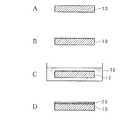
図1は石英ガラス部品の製造方法を簡略的に示す模式図である。以下本実施の形態に係る石英ガラス部品の製造方法について説明する。まず始めに、石英ガラス基材10を用意する。石英ガラス基材10は不透明石英ガラスであり、内部に気泡を含むことにより不透明化されている。なお、本実施形態における石英ガラス基材10は平板状を一例として挙げたがこれに限られるものではない。石英ガラス基材10は例えば円筒、円柱、角柱又は切断もしくは切削加工により任意の形状に加工した石英ガラス基材を用いてもよい。図1Aは研削により形状加工が施された石英ガラス基材10の断面図を示している。
FIG. 1 is a schematic view schematically showing a method for manufacturing a quartz glass part. Hereinafter, a method for manufacturing a quartz glass component according to the present embodiment will be described. First, a
次に石英ガラス基材10の一面(溶射面側表面)をメタルボンド砥石を備える研削盤により研削する。メタルボンド砥石は例えばダイヤモンドホイールである。また石英ガラス基材10の一面をサンドブラスト加工により粗面化してもよい。サンドブラストとはコンプレッサから排出される圧縮空気に砥粒を混ぜて被研削材に噴出することにより、該被研削材を粗面化する加工方法である。図1Bは研削された石英ガラス基材10の断面図を示している。一般的に、溶射膜と基材の密着性を向上させる方法として、溶射前の基材表面を粗面化することが行われている。 Next, one surface (sprayed surface side surface) of the
さらに研削された石英ガラス基材10をHF溶液(フッ酸系の薬液)30に浸漬することによりエッチングを行う。例えば、石英ガラス基材10に深さ20μmのエッチングを行う場合、研削された石英ガラス基材10を濃度15%、液温20度のHF溶液30に2時間浸漬する。図1Cはエッチングの工程における石英ガラス基材10の断面図を示している。なお、本実施形態における石英ガラス基材10はHF溶液30に浸漬したがこれに限るものではない。例えば、石英ガラス基材10はバッファードフッ酸(BHF)溶液又はフッ化水素アンモニウム(NH4 F・HF)溶液等の薬液に浸漬してもよい。Further, etching is performed by immersing the ground
さらにエッチングが行われた石英ガラス基材10に、後述するプラズマ溶射装置からシリコン粉末を溶射することにより遮光又は遮熱が必要な部分に皮膜20を形成する。図1Dは皮膜20を形成した石英ガラス基材10の断面図を示している。 Furthermore, the
図2はプラズマ溶射装置のプラズマトーチ部4による皮膜20の形成工程を示す説明図である。なお、図2において紙面左側はプラズマトーチ部4の底面側、紙面右側はプラズマトーチ部4の上面側であり、紙面垂直方向はプラズマトーチ部4の左右方向である。 FIG. 2 is an explanatory view showing a process of forming the
図2に示すプラズマトーチ部4は有底円筒状であり、電源(図示せず)に接続されている。プラズマトーチ部4は、底部に設けられたカソード45と、円筒周面の上部に設けられたアノード41と、カソード45の右側に形成され、希ガスを供給する供給孔42と、アノード41の右側に形成され、シリコン粉末を供給する供給孔43とを備える。 The
以下では図2に基づいて石英ガラス基材10に皮膜20を形成する形成工程について説明する。まずエッチングを行った石英ガラス基材10において、研削した一面をプラズマトーチ部4のカソード45に対向させて配置する。プラズマ溶射装置4は電源によりカソード45とアノード41との間に電圧をかけることでアーク放電を発生させる。プラズマトーチ部4には希ガス(例えばアルゴン)が供給孔42から供給され、供給された希ガスがアーク放電により電離することでプラズマジェットが発生する。プラズマトーチ部4にシリコン粉末を供給孔43から供給し、供給されたシリコン粉末はプラズマジェット中で加熱され、上面に開口された開口部44から溶融状態で噴射される。プラズマ溶射装置4は、開口部44に対向した位置に配置された石英ガラス基材10の遮光又は遮熱が必要な部分に噴射したシリコン粉末を溶射する。溶融したシリコン粉は基材表面に衝突後、偏平化されると同時に、急速凝固され堆積層を形成する。この過程を経て、石英ガラス基材10の遮光又は遮熱が必要な部分に皮膜20が形成される。なお、通常石英ガラス基材の形状と溶射膜を形成する領域に応じて、プラズマトーチ4及び石英ガラス基材10を移動させる施工が行われる。また、石英ガラス基材において、溶射膜を形成されない部位にはマスキング処理が施され、溶射の施工が行われる。 Below, the formation process which forms the membrane | film |
石英ガラス部品の製造例を下記の表1及び表2に示す。 Examples of production of quartz glass parts are shown in Tables 1 and 2 below.

表1及び表2の製造例に従って、石英ガラス部品を製造する。以下では表1及び表2の各列を説明する。種類列は石英ガラス基材10の種類を示す。石英ガラス基材10の種類は例えば不透明石英ガラスI又は不透明石英ガラスIIである。不透明石英ガラスIは気泡の平均断面積が225〜275μm×225〜275μmであり、石英ガラス基材10に対する気泡の密度が1.20×10³個/cm3〜1.50×103個/cm3である。不透明石英ガラスIIは気泡の平均断面積が108〜132μm×108〜132μmであり、石英ガラス基材10に対する気泡の密度が1.50個/cm3〜2.00個/cm3である。According to the manufacturing examples in Table 1 and Table 2, quartz glass parts are manufactured. Hereinafter, each column of Table 1 and Table 2 will be described. The type column indicates the type of the
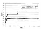
図3は不透明石英ガラスIの透過率を示すグラフである。図3に示すように、実線で示す厚さ2mmの不透明石英ガラスI及び点線で示す厚さ5mmの不透明石英ガラスIを分光光度計(日立製U−3010)により測定した。縦軸は透過率を示し、単位は%である。横軸は波長を示し、単位はnmである。厚さ5mmの不透明石英ガラスIは300nm〜900nmにかけて0.3%の透過率であり、厚さ2mmの不透明石英ガラスIは300nm〜900nmにかけて0.5%〜0.6%の透過率である。
ゆえに、不透明石英ガラスは、板厚の減少とともに、透過率が上昇する。FIG. 3 is a graph showing the transmittance of the opaque quartz glass I. As shown in FIG. 3, the opaque quartz glass I having a thickness of 2 mm indicated by a solid line and the opaque quartz glass I having a thickness of 5 mm indicated by a dotted line were measured with a spectrophotometer (Hitachi U-3010). The vertical axis represents the transmittance, and the unit is%. The horizontal axis indicates the wavelength, and the unit is nm. The opaque quartz glass I having a thickness of 5 mm has a transmittance of 0.3% from 300 nm to 900 nm, and the opaque quartz glass I having a thickness of 2 mm has a transmittance of 0.5% to 0.6% from 300 nm to 900 nm. .
Therefore, the transmittance of the opaque quartz glass increases as the plate thickness decreases.
気孔率列は皮膜20内の気孔の存在比率(比率)を示し、単位は%である。皮膜20内の気孔の存在比率の計測方法を以下に示す。まず皮膜20を例えばダイサーで切断し、切断面を研磨し、皮膜20の切断面の画像をCCD(Charge-coupled device)カメラ又はデジタルカメラ等を用いて撮像し、撮像した画像をコンピュータに読み込む。コンピュータにより読み込まれた画像に画像処理を行うことで気孔の断面積を測定する。測定した気孔の断面積を皮膜20全体の断面積で除算して算出した比率を100分率で表すことにより皮膜20内の気孔の存在比率を計測する。 A porosity row | line | column shows the abundance ratio (ratio) of the pore in the membrane | film |
平均膜厚列は皮膜20の平均膜厚を示し、単位はμmである。皮膜20の平均膜厚の計測方法は以下の通りである。まずエッチングされた石英ガラス基材10の厚さと、皮膜20を形成した石英ガラス基材10の厚さとをマイクロメータにより測定する。次にエッチングが行われた石英ガラス基材10の厚さと、皮膜20を形成した石英ガラス基材10の厚さとの差分を算出することで平均膜厚を計測する。皮膜20の平均膜厚は例えば20±5のように表記され、この場合、平均膜厚が20μmであり、誤差が5μmあることを示す。 The average film thickness column indicates the average film thickness of the
表面粗さRa列はエッチングを行った石英ガラス基材10の表面粗さRaを示し、単位はμmである。表面粗さRaはJISB0633に基づいて、エッチングが行われた石英ガラス基材10の一面を接触式の表面粗さ計(東京精密製サーフコム130A)で10箇所測定し、そのうちの最小値を示す。不透明石英ガラスにおける表面粗さRaの測定は、研削により表面に露出した気泡を測定することで測定値の大きい箇所が発生するため、気泡の影響を排除することを目的として最小値を用いた。 The surface roughness Ra column indicates the surface roughness Ra of the
加工条件列は石英ガラス基材10の研削方法を示す。石英ガラス基材10の研削方法は例えば、研削、粗研削又はサンドブラスト等である。研削は砥粒粒度#400〜600のメタルボンドダイヤモンド砥石を使用した研削方法を示す。粗研削は砥粒粒度#120〜200のメタルボンドダイヤモンド砥石を使用した研削方法を示す。サンドブラストは圧縮空気に砥粒を混ぜて砥粒粒度#60〜100のSiC砥粒を一面に噴射する粗面化方法を示す。 The processing condition column indicates a grinding method for the
エッチング量列は、石英ガラス基材10に行うエッチングの深さを示し、単位はμmである。エッチングの深さの計測方法は以下である。まず研削された石英ガラス基材10の厚さと、エッチングが行われた石英ガラス基材10の厚さとをマイクロメータにより測定する。次にエッチングが行われた石英ガラス基材10の厚さと研削された石英ガラス基材10の厚さとの差分を算出することでエッチングの深さを計測する。エッチング量は例えば10±2のように表記され、この場合はエッチングの深さが10μmであり、誤差が2μmあることを示す。 The etching amount column indicates the depth of etching performed on the
D50%粒径列はシリコン粉末における体積基準によるD50%粒径を示し、単位はμmである。シリコン粉末における体積基準によるD50%粒径とは、シーラス製レーザー回折式粒度測定器CILAS1064により算出した累積分布に基づいて、粒径が小さいシリコン粉末から順に累積し、シリコン粉末の累積値が50%に達した時の粒径である。なお、D50%粒径が25μm以下のシリコン粉末は凝集し、取扱が困難であるため本実施形態では用いなかった。なお、本実施形態においては、体積基準によるD50%粒径を用いたが、個数基準によるD50%粒径等を用いてもよい。 The D50% particle size column indicates the D50% particle size based on volume in the silicon powder, and the unit is μm. The volume-based D50% particle size in silicon powder is based on the cumulative distribution calculated by Cirrus laser diffraction particle size measuring instrument CILAS 1064, and the silicon powder is accumulated in order from the smallest particle size, and the cumulative value of silicon powder is 50%. This is the particle size when reaching. Note that silicon powder having a D50% particle size of 25 μm or less aggregated and was difficult to handle, and thus was not used in this embodiment. In this embodiment, the D50% particle size based on the volume is used, but a D50% particle size based on the number may be used.
100μm以上の粒径比率列はシリコン粉末における100μm以上の粒径の比率を示し、単位は%である。シリコン粉末における100μm以上の粒径の比率は、レーザー回折式粒度測定器CILAS1064により算出した累積分布に基づいて、粒径が100μm以上の累積値を全ての粒径を累積した全累積値で除算して算出した比率を百分率により表したものである。 The particle size ratio column of 100 μm or more indicates the ratio of the particle size of 100 μm or more in the silicon powder, and the unit is%. The ratio of the particle size of 100 μm or more in the silicon powder is obtained by dividing the cumulative value of the particle size of 100 μm or more by the total cumulative value of all the particle sizes based on the cumulative distribution calculated by the laser diffraction particle size measuring instrument CILAS 1064. The ratio calculated in this way is expressed as a percentage.
遮光性能列は石英ガラス部品の透過率を示す。石英ガラス部品の透過率は、各製造例に係る石英ガラス部品を分光光度計(日立製U−3010)により測定した。遮光性能は例えば、◎、○、×による評価を行った。◎は石英ガラス部品の透過率が0%であることを示す。○は石英ガラス部品の透過率が0.1%以下であることを示す。×は石英ガラス部品の透過率が0.1%より大きいことを示す。 The light shielding performance column indicates the transmittance of the quartz glass part. The transmittance of the quartz glass component was measured with a spectrophotometer (Hitachi U-3010) for the quartz glass component according to each production example. The light shielding performance was evaluated by, for example, ◎, ○, ×. A indicates that the transmittance of the quartz glass part is 0%. ○ indicates that the transmittance of the quartz glass part is 0.1% or less. X indicates that the transmittance of the quartz glass part is larger than 0.1%.
耐熱性能列は石英ガラス部品の耐熱性能を示す。石英ガラス部品の耐熱性能の評価方法は以下の通りである。各製造例に係る石英ガラス部品を1200度に加熱し、加熱した石英ガラス部品を常温(例えば23度)に冷却する。その後、冷却した石英ガラス部品に250ルーメンの高輝度白色LED(Light Emitting Diode)を照射して、光の透過状況を目視観察することにより石英ガラス部品の耐熱性能を評価した。耐熱性能は例えば、◎、○、×による評価を行った。◎は皮膜20にクラックが観察されなかったことを示す。○は皮膜20にクラックが観察されたことを示す。×は皮膜20にクラック及び皮膜の剥離が観察されたことを示す。 The heat resistance performance column indicates the heat resistance performance of the quartz glass part. The evaluation method of the heat resistance performance of the quartz glass part is as follows. The quartz glass part according to each production example is heated to 1200 degrees, and the heated quartz glass part is cooled to room temperature (for example, 23 degrees). Thereafter, the cooled quartz glass part was irradiated with a 250 lumen high-intensity white LED (Light Emitting Diode), and the heat resistance performance of the quartz glass part was evaluated by visually observing the light transmission state. The heat resistance was evaluated by, for example, ◎, ○, ×. A indicates that no crack was observed in the
製造例1に基づいて製造された石英ガラス部品の製造方法を以下に示す。不透明石英ガラスIにより形成された石英ガラス基材10の一面を砥粒粒度#400〜600のメタルボンドダイヤモンド砥石を備える研削盤により研削する。次に研削された石英ガラス基材10に深さ10±2μmのエッチングを行い、石英ガラス基材10の表面粗さRaを2〜4μmにする。さらにD50%粒径が25〜35μmであり、100μm以上の粒径の存在比率が0%であるシリコン粉末を、エッチングされた石英ガラス基材10の表面に溶射することにより皮膜20を形成する。石英ガラス基材10の表面に形成される皮膜20は、平均膜厚が20±5μmであり、気孔率が1〜4%である。また上記に示す製造例1により製造された石英ガラス部品は遮光性能が×と評価され、耐熱性能が◎と評価された。 The manufacturing method of the quartz glass part manufactured based on the manufacture example 1 is shown below. One surface of the
製造例2〜8に基づいて製造された石英ガラス部品は、皮膜の平均膜厚を夫々、30±5μm、40±5μm、50±5μm、60±5μm、70±5μm、80±5μm、90±5μmとし、他の条件は製造例1と同条件で製造した。 Quartz glass parts manufactured based on Production Examples 2 to 8 have average film thicknesses of 30 ± 5 μm, 40 ± 5 μm, 50 ± 5 μm, 60 ± 5 μm, 70 ± 5 μm, 80 ± 5 μm, 90 ±, respectively. The thickness was 5 μm, and other conditions were the same as in Production Example 1.
製造例9に基づいて製造された石英ガラス部品は、エッチングの深さを1±1μmとし、他の条件は製造例4と同条件で製造した。 The quartz glass part manufactured based on Manufacturing Example 9 was manufactured under the same conditions as in Manufacturing Example 4 except that the etching depth was 1 ± 1 μm.
製造例10に基づいて製造された石英ガラス部品は、エッチングの深さを5±1μmとし、他の条件は製造例4と同条件で製造した。 The quartz glass part manufactured based on Manufacturing Example 10 was manufactured under the same conditions as in Manufacturing Example 4 except that the etching depth was 5 ± 1 μm.
製造例11に基づいて製造された石英ガラス部品は、シリコン粉末におけるD50%粒径を50〜60μmとし、シリコン粉末における100μm以上の含有率を3%とし、他の条件は製造例4と同条件で製造した。 The quartz glass part manufactured based on Production Example 11 has a D50% particle size of 50 to 60 μm in silicon powder, a content of 100 μm or more in silicon powder is 3%, and other conditions are the same as in Production Example 4. Manufactured with.
製造例12に基づいて製造された石英ガラス部品は、石英ガラス部品のD50%粒径を70〜80μmとし、シリコン粉末における100μm以上の含有率を10%とし、他の条件は製造例4と同条件で製造した。 The quartz glass part manufactured based on Production Example 12 has a D50% particle size of 70 to 80 μm, the content of 100 μm or more in the silicon powder is 10%, and other conditions are the same as in Production Example 4. Manufactured under conditions.
製造例13に基づいて製造された石英ガラス部品の製造方法を以下に示す。不透明石英ガラスIIにより形成された石英ガラス基材10の一面を砥粒粒度#400〜600のメタルボンドダイヤモンド砥石を備える研削盤により研削する。次に研削された石英ガラス基材10に深さ10±2μmのエッチングを行い、石英ガラス基材10の表面粗さRaを2〜4μmにする。さらにD50%粒径が25〜35μmであり、100μm以上の粒径の存在比率が0%であるシリコン粉末を、エッチングされた石英ガラス基材10の表面に溶射することにより皮膜20を形成する。石英ガラス基材10の表面に形成される皮膜20は、平均膜厚が20±5μmであり、気孔率が1〜4%である。 A method for manufacturing a quartz glass component manufactured based on Manufacturing Example 13 will be described below. One surface of the
製造例14〜20に基づいて製造された石英ガラス部品は、皮膜の平均膜厚を夫々、30±5μm、40±5μm、50±5μm、60±5μm、70±5μm、80±5μm、90±5μmとし、他の条件は製造例13と同条件で製造した。 The quartz glass parts manufactured based on the manufacturing examples 14 to 20 have an average film thickness of 30 ± 5 μm, 40 ± 5 μm, 50 ± 5 μm, 60 ± 5 μm, 70 ± 5 μm, 80 ± 5 μm, 90 ±, respectively. The other conditions were manufactured under the same conditions as in Production Example 13.
製造例21〜28に基づいて製造された石英ガラス部品は、サンドブラストにより粗面化し、表面粗さRaが4〜7μmである石英ガラス基材10とし、他の条件は製造例1〜8と同条件で製造した。 The quartz glass parts manufactured based on the manufacturing examples 21 to 28 are roughened by sandblasting to form a
製造例29〜36に基づいて製造された石英ガラス部品は、粗研削により研削し、表面粗さRaが3〜6μmである石英ガラス基材10とし、他の条件は製造例1〜8と同条件で製造した。 The quartz glass parts produced based on Production Examples 29 to 36 are ground by rough grinding to form a
本実施の形態に係る石英ガラス部品を100μm以上の粒径の存在比率に着目して検討する。製造例12に基づいて製造された石英ガラス部品は、100μm以上の粒径の存在比率が10%であり、遮光性能が×であり、耐熱性能が○である。また製造例11に基づいて製造された石英ガラス部品は、100μm以上の粒径の存在比率が3%であり、遮光性能が○であり、耐熱性能が○である。さらに製造例4に基づいて製造された石英ガラス部品は、100μm以上の粒径の比率が0%であり、遮光性能が◎であり、耐熱性能が◎である。 The quartz glass component according to the present embodiment will be examined by paying attention to the existence ratio of particle diameters of 100 μm or more. The quartz glass part manufactured based on Production Example 12 has a particle size ratio of 100 μm or more of 10%, a light shielding performance of “x”, and a heat resistance performance of “◯”. In addition, the quartz glass part manufactured based on Manufacturing Example 11 has a particle size ratio of 100 μm or more of 3%, a light shielding performance of ◯, and a heat resistance performance of ◯. Further, the quartz glass part manufactured based on Manufacturing Example 4 has a particle size ratio of 100 μm or more of 0%, a light shielding performance is ◎, and a heat resistance performance is ◎.
このため、遮光性能及び耐熱性能を備えた石英ガラス部品は不透明石英ガラス基材10を用い、シリコン粉末における100μm以上の粒径の存在比率が3%以下であることが望ましく、シリコン粉末における100μm以上の粒径の存在比率が0%であることがさらに好ましい。このことにより石英ガラス部品は薄型化に対応し、遮光性及び耐熱性を向上させることができる。 For this reason, the quartz glass component having the light shielding performance and the heat resistance performance uses the opaque quartz
本実施の形態に係る石英ガラス部品をD50%粒径に着目して検討する。製造例12に基づいて製造された石英ガラス部品は、D50%粒径が70〜80μmであり、遮光性能が×であり、耐熱性能が○である。また製造例11に基づいて製造された石英ガラス部品は、D50%粒径が50〜60μmであり、遮光性能が○であり、耐熱性能が○である。さらに製造例4に基づいて製造された石英ガラス部品は、D50%粒径が25〜35μmであり、遮光性能が◎であり、耐熱性能が◎である。 The quartz glass component according to the present embodiment will be examined by paying attention to the D50% particle size. The quartz glass part manufactured based on Production Example 12 has a D50% particle size of 70 to 80 μm, a light shielding performance of x, and a heat resistance performance of ◯. Moreover, the quartz glass part manufactured based on the manufacture example 11 is 50-60 micrometers in D50% particle size, and light-shielding performance is (circle) and heat-resistant performance is (circle). Furthermore, the quartz glass part manufactured based on Production Example 4 has a D50% particle size of 25 to 35 μm, a light shielding performance ◎, and a heat resistance performance ◎.
このため、遮光性能及び耐熱性能を備えた石英ガラス部品はシリコン粉末におけるD50%粒径は50〜60μmであることが望ましく、シリコン粉末におけるD50%粒径が25〜35μmであることがさらに好ましい。このことにより、石英ガラス部品は遮光性及び耐熱性をさらに向上させることができる。 For this reason, as for the quartz glass component provided with the light-shielding performance and the heat resistance performance, it is desirable that the D50% particle size in the silicon powder is 50 to 60 μm, and it is more preferable that the D50% particle size in the silicon powder is 25 to 35 μm. Thereby, the quartz glass part can further improve the light shielding property and heat resistance.
本実施の形態に係る石英ガラス部品を平均膜厚に着目して検討する。製造例3〜5に基づいて製造された石英ガラス部品は、平均膜厚が40±5〜60±5μmであり、遮光性能が◎であり、耐熱性能が◎である。また製造例15に基づいて製造された石英ガラス部品は、平均膜厚が40±5μmであり、遮光性能が◎であり、耐熱性能が◎である。さらに製造例3に基づいて製造された石英ガラス部品は、平均膜厚が30±5μmであり、遮光性能が○であり、耐熱性能が◎である。さらに製造例6に基づいて製造された石英ガラス部品は、平均膜厚が70±5μmであり、遮光性能が◎であり、耐熱性能が○である。 The quartz glass component according to the present embodiment will be examined by paying attention to the average film thickness. The quartz glass parts produced based on Production Examples 3 to 5 have an average film thickness of 40 ± 5 to 60 ± 5 μm, a light shielding performance of ◎, and a heat resistance performance of ◎. In addition, the quartz glass part manufactured based on Manufacturing Example 15 has an average film thickness of 40 ± 5 μm, a light shielding performance of ◎, and a heat resistance performance of ◎. Furthermore, the quartz glass part manufactured based on Production Example 3 has an average film thickness of 30 ± 5 μm, a light shielding performance of ◯, and a heat resistance performance of ◎. Furthermore, the quartz glass part manufactured based on Production Example 6 has an average film thickness of 70 ± 5 μm, a light shielding performance of ◎, and a heat resistance performance of ◯.
このため、遮光性能及び耐熱性能を備えた石英ガラス部品は皮膜20の平均膜厚は40±5〜60±5μmであることが望ましく、皮膜20の平均膜厚が40±5μmであることがさらに好ましい。このことにより、石英ガラス部品は遮光性及び耐熱性をさらに向上させることができる。 For this reason, it is desirable that the quartz glass part having the light shielding performance and the heat resistance performance has an average film thickness of the
本実施の形態に係る石英ガラス部品を表面粗さRaに着目して検討する。製造例4に基づいて製造された石英ガラス部品は、表面粗さRaが2〜4μmであり、遮光性能が◎であり、耐熱性能が◎である。また製造例24に基づいて製造された石英ガラス部品は、表面粗さRaが4〜7μmであり、遮光性能が◎であり、耐熱性能が○である。さらに製造例32に基づいて製造された石英ガラス部品は、表面粗さRaが3〜6μmであり、遮光性能が◎であり、耐熱性能が○である。 The quartz glass component according to the present embodiment will be examined by paying attention to the surface roughness Ra. The quartz glass part produced based on Production Example 4 has a surface roughness Ra of 2 to 4 μm, a light shielding performance of ◎, and a heat resistance performance of ◎. Moreover, the quartz glass component manufactured based on the manufacture example 24 has a surface roughness Ra of 4 to 7 μm, a light shielding performance of ◎, and a heat resistance performance of ◯. Furthermore, the quartz glass part manufactured based on Manufacturing Example 32 has a surface roughness Ra of 3 to 6 μm, a light shielding performance of ◎, and a heat resistance performance of ◯.
このため、遮光性能及び耐熱性能を備えた石英ガラス部品は不透明石英ガラス基材10を用いた場合、石英ガラス基材10の表面粗さRaは2〜7μmであることが望ましく、石英ガラス基材10の表面粗さRaは2〜4μmであることがさらに好ましい。このことにより、石英ガラス部品は遮光性及び耐熱性をさらに向上させることができる。 For this reason, when the opaque
本実施の形態に係る石英ガラス部品を加工条件に着目して検討する。製造例4に基づいて製造された石英ガラス部品は、加工条件が研削であり、遮光性能が◎であり、耐熱性能が◎である。また製造例24に基づいて製造された石英ガラス部品は、サンドブラストであり、遮光性能が◎であり、耐熱性能が○である。さらに製造例32に基づいて製造された石英ガラス部品は、粗研削であり、遮光性能が◎であり、耐熱性能が○である。 The quartz glass component according to the present embodiment will be examined by paying attention to the processing conditions. The quartz glass part manufactured based on Manufacturing Example 4 has a processing condition of grinding, a light shielding performance of ◎, and a heat resistance performance of ◎. Moreover, the quartz glass part manufactured based on the manufacture example 24 is sandblast, the light shielding performance is ◎, and the heat resistance is ◯. Furthermore, the quartz glass part manufactured based on the manufacture example 32 is rough grinding, the light shielding performance is ◎, and the heat resistance performance is ◯.
このため、遮光性能及び耐熱性能を備えた石英ガラス部品は不透明石英ガラス基材10を用いた場合、加工条件がサンドブラスト又は粗研削であることが望ましく、加工条件が研削であることがさらに好ましい。このことにより、石英ガラス部品は遮光性及び耐熱性をさらに向上させることができる。 For this reason, when the opaque quartz
遮光性能及び耐熱性能を備えた石英ガラス部品は、皮膜20に含まれる気孔の存在比率が1〜4%であることが望ましい。このことにより、皮膜20を薄くしても遮光性を確保することができる。なお本実施の形態に係る石英ガラス部品は、皮膜20に含まれる気孔の存在比率が0%であっても遮光性を確保することができる。 As for the quartz glass component provided with the light-shielding performance and heat-resistant performance, it is desirable that the abundance ratio of the pores contained in the
実施の形態2
実施の形態1に示した条件で石英ガラス基材10を母材が透光性を有する透明石英ガラスに変更し、石英ガラス部品の製造を行った。実施の形態2に係る石英ガラス部品の製造例を下記の表3に示す。
The quartz
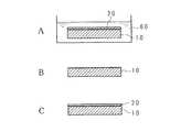
石英ガラス基材列には例えば、透明石英ガラスI又は透明石英ガラスIIが記載される。透明石英ガラスIは溶射しない側の表面(非溶射面)をラップ盤により研磨仕上げもしくは火炎処理により焼き仕上げすることで滑面にした石英ガラス基材であり、透明石英ガラスIの両面の表面粗さRaは0.01μm程度である。透明石英ガラスIIは一面を滑面に研磨し、他面(非溶射面)をサンドブラストにより研削(粗面化)しスリガラス状にした石英ガラス基材であり、透明石英ガラスIIの他面の表面粗さRaは4.77μmである。 For example, transparent quartz glass I or transparent quartz glass II is described in the quartz glass substrate row. Transparent quartz glass I is a quartz glass base material with a non-sprayed surface (non-sprayed surface) polished by a lapping machine or baked by flame treatment to provide a rough surface on both sides of transparent quartz glass I. The thickness Ra is about 0.01 μm. Transparent quartz glass II is a quartz glass substrate with one surface polished to a smooth surface and the other surface (non-sprayed surface) ground (roughened) by sandblasting to form a ground glass. The surface of the other surface of transparent quartz glass II The roughness Ra is 4.77 μm.
図4は透明石英ガラスI及び透明石英ガラスIIの透過率を示すグラフである。図4に示すように、実線に示す厚さ5mmの透明石英ガラスI及び点線に示す厚さ5mmの透明石英ガラスIIを分光光度計(日立製U−3010)により測定した。縦軸は透過率を示し、単位は%である。横軸は波長を示し、単位はnmである。透明石英ガラスIは300nm〜900nmにかけて90〜95%の透過率であり、透明石英ガラスIIは300nm〜900nmにかけて5〜10%の透過率である。 FIG. 4 is a graph showing the transmittance of transparent quartz glass I and transparent quartz glass II. As shown in FIG. 4, a transparent quartz glass I having a thickness of 5 mm indicated by a solid line and a transparent quartz glass II having a thickness of 5 mm indicated by a dotted line were measured with a spectrophotometer (Hitachi U-3010). The vertical axis represents the transmittance, and the unit is%. The horizontal axis indicates the wavelength, and the unit is nm. Transparent quartz glass I has a transmittance of 90 to 95% from 300 nm to 900 nm, and transparent quartz glass II has a transmittance of 5 to 10% from 300 nm to 900 nm.
図5は加熱前の石英ガラス部品の透過率を示すグラフである。図6は加熱後の石英ガラス部品の透過率を示すグラフである。図5に示す夫々の石英ガラス部品の製造方法を以下に示す。透明石英ガラスIにより形成された厚さ5mmの石英ガラス基材10の一面を砥粒粒度#400〜600メタルボンドダイヤモンド砥石を備える研削盤により研削する。次に研削された石英ガラス基材10に実施の形態1と同じ条件によりエッチングを行い、石英ガラス基材10の表面粗さRaを3〜4.5μmにする。さらにD50%粒径が夫々21、28、32μmであるシリコン粉末を、エッチングされた石英ガラス基材10の表面に溶射することにより皮膜20を形成する。石英ガラス基材10の表面に形成される皮膜20は、平均膜厚が20〜30μmであり、気孔率が1〜4%である。 FIG. 5 is a graph showing the transmittance of the quartz glass part before heating. FIG. 6 is a graph showing the transmittance of the quartz glass part after heating. The manufacturing method of each quartz glass part shown in FIG. 5 is shown below. One surface of the
図5に示すように、点線で示す標準粉部品I、実線で示す粗粉部品I及び一点鎖線で示す微粉部品Iを分光光度計(日立製U−3010)により測定した。なお標準粉部品IはD50%粒径が28μmであるシリコン粉末を用いて製造された石英ガラス部品を示す。粗粉部品IはD50%粒径が32μmであるシリコン粉末を用いて製造された石英ガラス部品を示す。微粉部品IはD50%粒径が21μmであるシリコン粉末を用いて製造された石英ガラス部品を示す。 As shown in FIG. 5, a standard powder component I indicated by a dotted line, a coarse powder component I indicated by a solid line, and a fine powder component I indicated by an alternate long and short dash line were measured with a spectrophotometer (Hitachi U-3010). The standard powder part I is a quartz glass part manufactured using silicon powder having a D50% particle size of 28 μm. Coarse powder component I is a quartz glass component manufactured using silicon powder having a D50% particle size of 32 μm. The fine powder component I is a quartz glass component manufactured using silicon powder having a D50% particle size of 21 μm.
図6に示すように、点線で示す標準粉部品II、実線で示す粗粉部品II、一点鎖線で示す微粉部品IIを分光光度計(日立製U−3010)により測定した。標準粉部品II、粗粉部品II、微粉部品IIは標準粉部品I、粗粉部品I、微粉部品Iを夫々1200度で加熱処理を行った石英ガラス部品である。 As shown in FIG. 6, a standard powder component II indicated by a dotted line, a coarse powder component II indicated by a solid line, and a fine powder component II indicated by a one-dot chain line were measured with a spectrophotometer (Hitachi U-3010). The standard powder part II, the coarse powder part II, and the fine powder part II are quartz glass parts obtained by heating the standard powder part I, the coarse powder part I, and the fine powder part I at 1200 degrees.
図5及び図6の縦軸は透過率を示し、単位は%である。図5及び図6の横軸は波長を示し、単位はnmである。 The vertical axis in FIGS. 5 and 6 represents the transmittance, and the unit is%. The horizontal axis of FIG.5 and FIG.6 shows a wavelength and a unit is nm.
図5に示すように、200nm〜900nmにかけて透過率は、標準粉部品Iが0.1〜0.2%であり、粗粉部品Iが0〜0.6%であり、微粉部品Iが0%である。 As shown in FIG. 5, the transmittance from 200 nm to 900 nm is 0.1 to 0.2% for the standard powder component I, 0 to 0.6% for the coarse powder component I, and 0 for the fine powder component I. %.
図6に示すように、200nm〜900nmにかけて透過率は、標準粉部品IIが0.1〜0.2%であり、粗粉部品IIが0.2〜0.8%であり、微粉部品IIが0〜0.1%である。 As shown in FIG. 6, the transmittance from 200 nm to 900 nm is 0.1 to 0.2% for the standard powder component II, 0.2 to 0.8% for the coarse powder component II, and the fine powder component II. Is 0 to 0.1%.
製造例37に基づいて製造された石英ガラス部品の製造方法を以下に示す。透明石英Iにより形成された石英ガラス基材10の一面を砥粒粒度#400〜600のメタルボンドダイヤモンド砥石を備える研削盤により研削する。次に研削された石英ガラス基材10に深さ10±2μmのエッチングを行い、石英ガラス基材10の表面粗さRaを1〜3μmにする。さらにD50%粒径が25〜35μmであり、100μm以上の粒径の存在比率が0%であるシリコン粉末を、エッチングされた石英ガラス基材10の表面に溶射することにより皮膜20を形成する。石英ガラス基材10の表面に形成される皮膜20は、平均膜厚が20±5μmであり、気孔率が1〜4%である。 A method for manufacturing a quartz glass part manufactured based on Manufacturing Example 37 will be described below. One surface of the
製造例38〜44に基づいて製造された石英ガラス部品は、皮膜の平均膜厚を夫々、30±5μm、40±5μm、50±5μm、60±5μm、70±5μm、80±5μm、90±5μmとし、他の条件は製造例37と同条件で製造した。 Quartz glass parts manufactured according to Production Examples 38 to 44 have average film thicknesses of 30 ± 5 μm, 40 ± 5 μm, 50 ± 5 μm, 60 ± 5 μm, 70 ± 5 μm, 80 ± 5 μm, 90 ±, respectively. The other conditions were manufactured under the same conditions as in Production Example 37.
製造例45に基づいて製造された石英ガラス部品の製造方法を以下に示す。透明石英ガラスIIにより形成された石英ガラス基材10の一面を砥粒粒度#400〜600メタルボンドダイヤモンド砥石を備える研削盤により研削する。次に研削された石英ガラス基材10に深さ10±2μmのエッチングを行い、石英ガラス基材10の表面粗さRaを1〜3μmにする。さらにD50%粒径が25〜35μmであり、100μm以上の粒径の存在比率が0%であるシリコン粉末を、エッチングされた石英ガラス基材10の表面に溶射することにより皮膜20を形成する。石英ガラス基材10の表面に形成される皮膜20は、平均膜厚が30±5μmであり、気孔率が1〜4%である。 A method for manufacturing a quartz glass part manufactured based on Manufacturing Example 45 will be described below. One surface of the
製造例46〜49に基づいて製造された石英ガラス部品は、皮膜の平均膜厚を夫々、40±5μm、50±5μm、60±5μm、70±5μmとし、他の条件は製造例45と同条件で製造した。 The quartz glass parts manufactured based on the manufacturing examples 46 to 49 have the average film thicknesses of 40 ± 5 μm, 50 ± 5 μm, 60 ± 5 μm, and 70 ± 5 μm, respectively, and other conditions are the same as those of the manufacturing example 45. Manufactured under conditions.
本実施の形態に係る石英ガラス部品を遮光性能及び耐熱性能に着目して検討する。遮光性能又は耐熱性能が◎であり、遮光性能及び耐熱性能が×でない石英ガラス部品は製造例41、46〜48により製造された石英ガラス部品である。このため、遮光性及び耐熱性を備える石英ガラス部品は製造例41、46〜48により製造されることが望ましい。 The quartz glass component according to the present embodiment will be examined by paying attention to light shielding performance and heat resistance performance. Quartz glass parts having a light shielding performance or heat resistance performance of ◎ and having neither light shielding performance nor heat resistance performance are quartz glass parts produced by Production Examples 41 and 46 to 48. For this reason, it is desirable that quartz glass parts having light-shielding properties and heat resistance are produced according to Production Examples 41 and 46 to 48.
さらに本実施の形態に係る石英ガラス部品を平均膜厚に着目して検討する。製造例41、48に基づいて製造された石英ガラス部品は、平均膜厚が60±5μmであり、遮光性能が◎であり、耐熱性能が○である。また製造例46に基づいて製造された石英ガラス部品は、平均膜厚が40±5μmであり、遮光性能が○であり、耐熱性能が◎である。さらに製造例47に基づいて製造された石英ガラス部品は、平均膜厚が50±5μmであり、遮光性能が◎であり、耐熱性能が○である。 Further, the quartz glass part according to the present embodiment will be examined by paying attention to the average film thickness. The quartz glass parts manufactured based on the manufacturing examples 41 and 48 have an average film thickness of 60 ± 5 μm, a light shielding performance of ◎, and a heat resistance performance of ◯. Further, the quartz glass part manufactured based on the manufacturing example 46 has an average film thickness of 40 ± 5 μm, a light shielding performance of ◯, and a heat resistance performance of ◎. Furthermore, the quartz glass part manufactured based on Manufacturing Example 47 has an average film thickness of 50 ± 5 μm, a light shielding performance of ◎, and a heat resistance performance of ◯.
このため、遮光性能及び耐熱性能を備えた石英ガラス部品は透光性がある石英ガラス基材10を用い、シリコン粉末における100μm以上の粒径の比率は0%であり、シリコン粉末における個数基準によるD50%粒径は25〜35μmであり、皮膜20の平均膜厚は40±5〜60±5μmであることが望ましく、皮膜20の平均膜厚が60±5μmであることがさらに好ましい。このことにより、石英ガラス部品は遮光性及び耐熱性を向上させることができる。 For this reason, quartz glass parts having light-shielding performance and heat resistance performance use a
また、本実施の形態に係る石英ガラス部品は、透明石英ガラスIIを用いた場合、平均膜厚が40±5〜50±5μmでも遮光性能又は耐熱性能が◎であり、遮光性能及び耐熱性能が×でない石英ガラス部品を製造できる。このため、本実施の形態に係る石英ガラス部品は、石英ガラス基材10の他面が粗面であることにより、粗面が光を散乱させることにより石英ガラス部品の遮光性をさらに向上させることができる。 Further, the quartz glass component according to the present embodiment, when transparent quartz glass II is used, has light shielding performance or heat resistance performance even when the average film thickness is 40 ± 5 ± 5 ± 5 μm, and the light shielding performance and heat resistance performance are excellent. Quartz glass parts that are not x can be manufactured. For this reason, in the quartz glass component according to the present embodiment, the other surface of the
実施の形態3
以下本発明の実施の形態3をその実施の形態を示す図面に基づいて詳述する。以下、特に説明する構成、作用以外の構成及び作用は実施の形態1又は2と同等であり、簡潔のため同様の符号を付して記載を省略する。Embodiment 3
Embodiment 3 of the present invention will be described below in detail with reference to the drawings showing the embodiment. Hereinafter, the configuration and operation other than those specifically described and the operation are the same as those of the first or second embodiment, and the same reference numerals are given for the sake of brevity and description thereof is omitted.
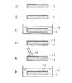
図7は実施の形態3に係る石英ガラス部品の製造方法を簡略的に示す模式図である。図7A〜図7Dの工程は実施の形態1と略同様であるため、記載を省略する。実施の形態3に係る石英ガラス部品の製造方法は石英ガラス基材10に形成された皮膜20にドライアイス50を噴射することにより洗浄する。ドライアイス50は平均粒径が数十〜数百μm程度の粒子であり、図示しないコンプレッサから排出された圧縮空気とともにノズルから皮膜20に噴射される。噴射されたドライアイス50は皮膜20の表面に高速で衝突し、付着した不純物又はパーティクル要因となる不安定粒子を表面温度の低下による熱収縮及び昇華による体積膨張で除去する。図7Eはドライアイス50の噴射工程における石英ガラス部品の断面図を示している。 FIG. 7 is a schematic diagram schematically showing the method for manufacturing the quartz glass part according to the third embodiment. Since the processes of FIGS. 7A to 7D are substantially the same as those in
ドライアイス50を噴射した皮膜20に対してエッチングを行う。例えば、石英ガラス部品を濃度1%、液温20度のHF溶液40に1分間浸漬することにより数十〜数百nm酸化膜をエッチングする。図4Fはエッチングの工程における石英ガラス部品の断面図を示している。 Etching is performed on the
エッチングを行った石英ガラス部品、ドライアイス50を噴射した石英ガラス部品並びにドライアイス50を噴射した後にエッチングを行った石英ガラス部品における表面のパーティクル量の評価を行った。パーティクル量の評価方法は、石英ガラス部品をパーティクルカウンター (PENTAGON TECHNOLOGIES社製QIIIMax)にて0.3〜5μmのパーティクル総数を測定した。なお、パーティクル総数の単位は個/cm2 である。パーティクルカウント総数が30個/cm2 以上である場合、パーティクル量が多いと評価し、パーティクルカウント総数が30個/cm2 以下である場合、パーティクル量が少ないと評価した。Evaluation was made on the amount of particles on the surface of the etched quartz glass part, the quartz glass part sprayed with
その結果、エッチングを行った石英ガラス部品及びドライアイス50を噴射した石英ガラス部品はパーティクルの量が多いと評価され、エッチングを行い、かつドライアイス50を噴射した後エッチングを行った石英ガラス部品はパーティクルの量が少ないと評価された。 As a result, quartz glass parts that have been etched and quartz glass parts that have been sprayed with
本実施の形態3に係る石英ガラス部品は、石英ガラス基材10に形成した皮膜20に対してドライアイス50の粒子を噴射する噴射工程及び皮膜20に対してHF溶液30でエッチングするエッチング工程を行うため、溶射膜表面のパーティクル源となり得る付着物を効果的に除去することができる。 The quartz glass component according to the third embodiment includes an injection process for injecting particles of
実施の形態4
以下本発明の実施の形態4をその実施の形態を示す図面に基づいて詳述する。以下、特に説明する構成、作用以外の構成及び作用は実施の形態1から3と同等であり、簡潔のため同様の符号を付して記載を省略する。
Hereinafter, a fourth embodiment of the present invention will be described in detail with reference to the drawings showing the embodiment. In the following, the configuration and operation other than those specifically described are the same as those of the first to third embodiments, and the same reference numerals are given for the sake of brevity and description thereof is omitted.
図8は石英ガラス部品の皮膜20の再形成方法を簡略的に示す模式図である。以下では石英ガラス部品の皮膜20の再形成方法について説明する。皮膜20を形成した石英ガラス基材10をアルカリ溶液60に浸漬することにより皮膜20が剥離するまでエッチングを行う。アルカリ溶液60は例えばTMAH溶液又はKOH溶液等である。図8Aはエッチングの工程における皮膜20を形成した石英ガラス基材10の断面図を示している。図8Bはエッチングにより皮膜20を剥離した石英ガラス基材10の断面図を示している。このことにより、皮膜20を溶解し、石英ガラス基材を溶解することのないアルカリ溶液を使用することにより、皮膜20を融解し剥離して、石英ガラス基材を再利用できる。さらに、石英ガラス基材10の溶射面の表面形状が変化しないため、皮膜20の剥離後に再度石英ガラス基材10の表面加工を必要とせずに溶射することが可能となる。 FIG. 8 is a schematic view schematically showing a method for re-forming the
皮膜20を剥離させた石英ガラス基材10にプラズマ溶射装置4からシリコン粉末を溶射することにより遮光又は遮熱が必要な部分に皮膜20を形成する。図8Cは皮膜20を形成した石英ガラス基材10の断面図を示している。 By spraying silicon powder from the
本実施の形態4に係る石英ガラス部品は、石英ガラス基材10に形成した皮膜20に対してエッチングするエッチング工程及び皮膜20を剥離させた石英ガラス基材10にシリコン粉末を溶射する再溶射工程を行う。このことにより石英ガラス部品をリサイクルすることができる。 The quartz glass component according to the fourth embodiment includes an etching process for etching the
今回開示された実施の形態はすべての点で例示であって、制限的なものではないと考えられるべきである。本発明の範囲は、上記した意味ではなく、特許請求の範囲によって示され、特許請求の範囲と均等の意味及び範囲内でのすべての変更が含まれることが意図される。 The embodiment disclosed this time is to be considered as illustrative in all points and not restrictive. The scope of the present invention is defined by the terms of the claims, rather than the meanings described above, and is intended to include any modifications within the scope and meaning equivalent to the terms of the claims.
10 石英ガラス基材
20 皮膜(シリコン溶射膜)
30 HF溶液(フッ酸系の薬液)
50 ドライアイス10
30 HF solution (chemical solution of hydrofluoric acid)
50 dry ice
Claims (14)
Translated fromJapanese前記石英ガラス基材は不透明石英ガラスから成り、
前記シリコン粉末における100μm以上の粒径の比率は3%以下であり、
前記皮膜が形成された不透明石英ガラスは、光の透過率が波長300〜900nmにかけて0.1%以下である
ことを特徴とする石英ガラス部品。A quartz glass part formed by forming a film for improving light shielding and heat resistance by plasma spraying silicon powder on the surface of a quartz glass substrate,
The quartz glass substrateis made ofopaque quartz glass,
The ratio of the particle size of 100 μm or more in the silicon powder is 3% or less,
The opaque quartz glass on which the film is formed has a light transmittance of 0.1% or less over a wavelength range of 300 to 900 nm.
前記シリコン粉末におけるD50%粒径は25〜35μmである
ことを特徴とする請求項1に記載の石英ガラス部品。The ratio of the particle diameter of 100 μm or more in the silicon powder is 0%,
The quartz glass component according to claim 1, wherein the D50% particle size of the silicon powder is 25 to 35 μm.
前記不透明石英ガラス基材の表面に100μm以上の粒径の比率が3%以下であるシリコン粉末を溶射することにより、前記不透明石英ガラス基材を含めた光の透過率が波長300〜900nmにかけて0.1%以下である皮膜を形成することを特徴とする石英ガラス部品の製造方法。A method for producing a quartz glass part formed by forming a film for improving light shielding and heat resistance on an opaque quartz glass substrate,
Wherein by spraying silicon powder ratio is 3% or less opaque particle size of at least 100μm on the surface of the quartz glass substrate, the transmittance of light, including the opaque quartz glass substrate is subjected to wavelength 300 to 900 nm 0 A method for producing a quartz glass part, characterized by forming a film of 1% or less.
D50%粒径が25〜35μmであるシリコン粉末により皮膜を形成することを特徴とする請求項6に記載の石英ガラス部品の製造方法。The ratio of particle diameters of 100 μm or more is 0%,
The method for producing a quartz glass part according to claim 6, wherein the film is formed of silicon powder having a D50% particle size of 25 to 35 µm.
該粒子を噴射した皮膜に対してフッ酸系の薬液でエッチングする
ことを特徴とする請求項6又は請求項7に記載の石英ガラス部品の製造方法。Injecting dry ice particles against the film formed on the quartz glass substrate,
The method for producing a quartz glass part according to claim 6 or 7, wherein the coating film on which the particles are sprayed is etched with a hydrofluoric acid chemical solution.
前記石英ガラス基材は透明石英ガラスから成り、
前記シリコン粉末における100μm以上の粒径の比率は0%であり、
前記シリコン粉末におけるD50%粒径は25〜35μmであり、
前記皮膜の平均膜厚は40〜60μmであり、
前記石英ガラス基材の表面粗さRaは1〜3μmであり、
前記皮膜が形成された透明石英ガラスは、光の透過率が波長300〜900nmにかけて0.1%以下である
ことを特徴とする石英ガラス部品。A quartz glass part formed by spraying silicon powder on a quartz glass substrate to form a film for improving light shielding and heat resistance on the surface,
The quartz glass substrateis made fromToru Ei Akashi glass,
The ratio of the particle diameter of 100 μm or more in the silicon powder is 0%,
The D50% particle size in the silicon powder is 25 to 35 μm,
The average film thickness of the film is 40-60 μm,
The surface roughness Ra of the quartz glass substrate is 1 to 3 μm,
The quartz glass part, wherein the transparent quartz glass on which the film is formed has a light transmittance of 0.1% or less over a wavelength range of 300 to 900 nm.
表面粗さRaが1〜3μmである石英ガラス基材の表面に、100μm以上の粒径の比率が0%であり、且つD50%粒径が25〜35μmであるシリコン粉末を溶射することにより、前記透明石英ガラス基材を含めた光の透過率が波長300〜900nmにかけて0.1%以下であり、且つ平均膜厚が40〜60μmである皮膜を形成することを特徴とする石英ガラス部品の製造方法。A method for producing a quartz glass part, comprising forming a coating for improving light shielding and heat resistance on a quartz glass substrate made of transparent quartz glass,
The surface roughness Ra of the surface of the 1~3μmder Ru quartz glass substrate, the ratio of the particle size of more than 100μm is 0% and D50% particle size by spraying the silicon powder is 25~35μm A quartz glass component comprising a film having a light transmittance of 0.1% or less over a wavelength of 300 to 900 nm and an average film thickness of 40 to 60 μm including the transparent quartz glass substrate. Manufacturing method.
該粒子を噴射した皮膜に対してフッ酸系の薬液でエッチングする
ことを特徴とする請求項12または請求項13に記載の石英ガラス部品の製造方法。Injecting dry ice particles against the film formed on the quartz glass substrate,
The method for producing a quartz glass part according to claim 12 or 13, wherein the coating film sprayed with the particles is etched with a hydrofluoric acid chemical solution.
Priority Applications (5)
| Application Number | Priority Date | Filing Date | Title |
|---|---|---|---|
| JP2013205494AJP6326210B2 (en) | 2013-09-30 | 2013-09-30 | Quartz glass part and method for producing quartz glass part |
| TW107124236ATWI662001B (en) | 2013-09-30 | 2014-08-27 | Quartz glass element and manufacturing method of quartz glass element |
| TW103129470ATWI640488B (en) | 2013-09-30 | 2014-08-27 | Quartz glass element and manufacturing method of quartz glass element |
| PCT/JP2014/075596WO2015046412A1 (en) | 2013-09-30 | 2014-09-26 | Quartz glass component and method for producing quartz glass component |
| US15/025,828US20160244358A1 (en) | 2013-09-30 | 2014-09-26 | Quartz Glass Part and Fabrication Method for Quartz Glass Part |
Applications Claiming Priority (1)
| Application Number | Priority Date | Filing Date | Title |
|---|---|---|---|
| JP2013205494AJP6326210B2 (en) | 2013-09-30 | 2013-09-30 | Quartz glass part and method for producing quartz glass part |
Publications (2)
| Publication Number | Publication Date |
|---|---|
| JP2015067524A JP2015067524A (en) | 2015-04-13 |
| JP6326210B2true JP6326210B2 (en) | 2018-05-16 |
Family
ID=52743538
Family Applications (1)
| Application Number | Title | Priority Date | Filing Date |
|---|---|---|---|
| JP2013205494AActiveJP6326210B2 (en) | 2013-09-30 | 2013-09-30 | Quartz glass part and method for producing quartz glass part |
Country Status (4)
| Country | Link |
|---|---|
| US (1) | US20160244358A1 (en) |
| JP (1) | JP6326210B2 (en) |
| TW (2) | TWI640488B (en) |
| WO (1) | WO2015046412A1 (en) |
Families Citing this family (9)
| Publication number | Priority date | Publication date | Assignee | Title |
|---|---|---|---|---|
| CN106467355B (en)* | 2016-09-26 | 2017-10-27 | 京东方科技集团股份有限公司 | Manufacturing method and manufacturing equipment of quartz glass substrate |
| JP6471764B2 (en)* | 2017-03-31 | 2019-02-20 | 日亜化学工業株式会社 | Method for manufacturing light emitting device |
| CN108517511A (en)* | 2018-05-18 | 2018-09-11 | 山东国晶新材料有限公司 | A kind of preparation method of the hot bending die for the anti-pyrolysis equadag coating aliquation solving oxidation |
| CN108545914B (en)* | 2018-05-18 | 2022-09-06 | 山东国晶新材料有限公司 | Preparation method of anti-peeling pyrolytic boron nitride coating hot bending die for solving oxidation problem |
| CN109485270A (en)* | 2018-11-28 | 2019-03-19 | 东莞泰升玻璃有限公司 | A kind of processing method of high rigidity marble glass |
| JP7283222B2 (en)* | 2019-05-17 | 2023-05-30 | Agc株式会社 | Glass substrate and in-vehicle display device |
| CN113840810A (en)* | 2019-05-17 | 2021-12-24 | 康宁股份有限公司 | Method of modifying textured glass substrates having regions under compressive stress to increase glass substrate strength |
| CN111061089B (en)* | 2019-12-13 | 2021-04-27 | 武汉华星光电技术有限公司 | Display device |
| JP7162153B1 (en) | 2022-04-01 | 2022-10-27 | テクノクオーツ株式会社 | Quartz glass base material with improved adhesion of thermal spray coating, method for producing same, and method for producing quartz glass parts having thermal spray coating |
Family Cites Families (12)
| Publication number | Priority date | Publication date | Assignee | Title |
|---|---|---|---|---|
| US4427516A (en)* | 1981-08-24 | 1984-01-24 | Bell Telephone Laboratories, Incorporated | Apparatus and method for plasma-assisted etching of wafers |
| US4599270A (en)* | 1984-05-02 | 1986-07-08 | The Perkin-Elmer Corporation | Zirconium oxide powder containing cerium oxide and yttrium oxide |
| US4788077A (en)* | 1987-06-22 | 1988-11-29 | Union Carbide Corporation | Thermal spray coating having improved addherence, low residual stress and improved resistance to spalling and methods for producing same |
| DE4429825C1 (en)* | 1994-08-23 | 1995-11-09 | Heraeus Quarzglas | Coated component made of quartz glass |
| JPH11199252A (en)* | 1998-01-07 | 1999-07-27 | Sumikin Sekiei Kk | Opaque quartz glass |
| JP4475581B2 (en)* | 2002-12-03 | 2010-06-09 | 株式会社福井信越石英 | Manufacturing method of silica glass jig |
| US20050098107A1 (en)* | 2003-09-24 | 2005-05-12 | Du Bois Dale R. | Thermal processing system with cross-flow liner |
| JP2005350685A (en)* | 2004-06-08 | 2005-12-22 | Tosoh Corp | Parts of substrate processing apparatus and manufacturing method thereof |
| CN101120245B (en)* | 2005-02-18 | 2012-02-15 | Hoya株式会社 | Inspection method of translucent articles |
| JP2009054984A (en)* | 2007-08-01 | 2009-03-12 | Tosoh Corp | Deposition apparatus parts and manufacturing method thereof |
| JP5618505B2 (en)* | 2009-07-30 | 2014-11-05 | テクノクオーツ株式会社 | Recycling method of quartz glass member |
| JP5835985B2 (en)* | 2010-09-16 | 2015-12-24 | 東京エレクトロン株式会社 | Plasma processing apparatus and plasma processing method |
- 2013
- 2013-09-30JPJP2013205494Apatent/JP6326210B2/enactiveActive
- 2014
- 2014-08-27TWTW103129470Apatent/TWI640488B/enactive
- 2014-08-27TWTW107124236Apatent/TWI662001B/enactive
- 2014-09-26WOPCT/JP2014/075596patent/WO2015046412A1/enactiveApplication Filing
- 2014-09-26USUS15/025,828patent/US20160244358A1/ennot_activeAbandoned
Also Published As
| Publication number | Publication date |
|---|---|
| US20160244358A1 (en) | 2016-08-25 |
| TW201834988A (en) | 2018-10-01 |
| JP2015067524A (en) | 2015-04-13 |
| TWI640488B (en) | 2018-11-11 |
| TW201527243A (en) | 2015-07-16 |
| WO2015046412A1 (en) | 2015-04-02 |
| TWI662001B (en) | 2019-06-11 |
Similar Documents
| Publication | Publication Date | Title |
|---|---|---|
| JP6326210B2 (en) | Quartz glass part and method for producing quartz glass part | |
| JP6117195B2 (en) | Parts for plasma processing apparatus and method for manufacturing parts for plasma processing apparatus | |
| TWI487024B (en) | Resistant parts | |
| KR100851833B1 (en) | Quartz glass parts, ceramic parts and manufacturing method thereof | |
| TWI414634B (en) | Extending lifetime of yttrium oxide as a plasma chamber material | |
| JP6378389B2 (en) | Manufacturing method of parts for plasma processing apparatus | |
| JP4970887B2 (en) | Method for recycling equipment components | |
| KR101563130B1 (en) | Parts of semiconductor and display equipments with improved anti-plasma corrosion and method improving anti-plasma corrosion of parts | |
| JPWO2012073954A1 (en) | Plasma etching apparatus component and method for manufacturing plasma etching apparatus component | |
| JP6526568B2 (en) | Parts for plasma apparatus and method for manufacturing the same | |
| JP2009054984A (en) | Deposition apparatus parts and manufacturing method thereof | |
| CN110931427A (en) | Method for manufacturing semiconductor device | |
| JP2018164103A (en) | Plasma resistant member | |
| JP5849083B2 (en) | Method for producing porous structure and porous self-supporting membrane | |
| JP4981294B2 (en) | Thermal spray coating | |
| JP7752558B2 (en) | Plasma treatment equipment components | |
| JP4487764B2 (en) | Translucent body for plasma processing apparatus and plasma processing apparatus | |
| KR102071944B1 (en) | Plasma resistant dense ceramic coating film and manufacturing method thereof | |
| JP2023145143A (en) | Member for plasma processing device | |
| CN118326314A (en) | Method for preparing thermal spraying coating and yttrium-based thermal spraying coating prepared by using same | |
| JP2009021701A (en) | Method of manufacturing piezoelectric substrate | |
| JP2007100142A (en) | Thermal spray coating |
Legal Events
| Date | Code | Title | Description |
|---|---|---|---|
| A621 | Written request for application examination | Free format text:JAPANESE INTERMEDIATE CODE: A621 Effective date:20160629 | |
| A131 | Notification of reasons for refusal | Free format text:JAPANESE INTERMEDIATE CODE: A131 Effective date:20170404 | |
| A521 | Request for written amendment filed | Free format text:JAPANESE INTERMEDIATE CODE: A523 Effective date:20170530 | |
| A131 | Notification of reasons for refusal | Free format text:JAPANESE INTERMEDIATE CODE: A131 Effective date:20171010 | |
| A521 | Request for written amendment filed | Free format text:JAPANESE INTERMEDIATE CODE: A523 Effective date:20171208 | |
| TRDD | Decision of grant or rejection written | ||
| A01 | Written decision to grant a patent or to grant a registration (utility model) | Free format text:JAPANESE INTERMEDIATE CODE: A01 Effective date:20180403 | |
| A61 | First payment of annual fees (during grant procedure) | Free format text:JAPANESE INTERMEDIATE CODE: A61 Effective date:20180416 | |
| R150 | Certificate of patent or registration of utility model | Ref document number:6326210 Country of ref document:JP Free format text:JAPANESE INTERMEDIATE CODE: R150 | |
| R250 | Receipt of annual fees | Free format text:JAPANESE INTERMEDIATE CODE: R250 | |
| R250 | Receipt of annual fees | Free format text:JAPANESE INTERMEDIATE CODE: R250 | |
| R250 | Receipt of annual fees | Free format text:JAPANESE INTERMEDIATE CODE: R250 | |
| R250 | Receipt of annual fees | Free format text:JAPANESE INTERMEDIATE CODE: R250 | |
| R250 | Receipt of annual fees | Free format text:JAPANESE INTERMEDIATE CODE: R250 |