JP6323089B2 - Level adjusting method and level adjusting device - Google Patents
Level adjusting method and level adjusting deviceDownload PDFInfo
- Publication number
- JP6323089B2 JP6323089B2JP2014051426AJP2014051426AJP6323089B2JP 6323089 B2JP6323089 B2JP 6323089B2JP 2014051426 AJP2014051426 AJP 2014051426AJP 2014051426 AJP2014051426 AJP 2014051426AJP 6323089 B2JP6323089 B2JP 6323089B2
- Authority
- JP
- Japan
- Prior art keywords
- level
- signal
- gain
- input
- detection unit
- Prior art date
- Legal status (The legal status is an assumption and is not a legal conclusion. Google has not performed a legal analysis and makes no representation as to the accuracy of the status listed.)
- Active
Links
- 238000000034methodMethods0.000titleclaimsdescription46
- 238000001514detection methodMethods0.000claimsdescription69
- 230000000737periodic effectEffects0.000description19
- 238000009499grossingMethods0.000description7
- 229920000122acrylonitrile butadiene styrenePolymers0.000description6
- 238000010586diagramMethods0.000description6
- 230000005236sound signalEffects0.000description6
- 230000007423decreaseEffects0.000description5
- 230000007774longtermEffects0.000description3
- 101100074846Caenorhabditis elegans lin-2 geneProteins0.000description2
- 101100497386Mus musculus Cask geneProteins0.000description2
- 238000006243chemical reactionMethods0.000description2
- 230000003111delayed effectEffects0.000description2
- 230000002123temporal effectEffects0.000description2
- 230000001154acute effectEffects0.000description1
- 230000002238attenuated effectEffects0.000description1
- 238000007796conventional methodMethods0.000description1
- 125000004122cyclic groupChemical group0.000description1
- 238000004880explosionMethods0.000description1
- 239000000284extractSubstances0.000description1
- 230000006870functionEffects0.000description1
Images


Classifications
- H—ELECTRICITY
- H03—ELECTRONIC CIRCUITRY
- H03G—CONTROL OF AMPLIFICATION
- H03G3/00—Gain control in amplifiers or frequency changers
- H03G3/20—Automatic control
- H03G3/30—Automatic control in amplifiers having semiconductor devices
- H03G3/3005—Automatic control in amplifiers having semiconductor devices in amplifiers suitable for low-frequencies, e.g. audio amplifiers
- H03G3/301—Automatic control in amplifiers having semiconductor devices in amplifiers suitable for low-frequencies, e.g. audio amplifiers the gain being continuously variable
- H—ELECTRICITY
- H03—ELECTRONIC CIRCUITRY
- H03G—CONTROL OF AMPLIFICATION
- H03G3/00—Gain control in amplifiers or frequency changers
- H03G3/20—Automatic control
- H03G3/30—Automatic control in amplifiers having semiconductor devices
- H03G3/3089—Control of digital or coded signals
- H—ELECTRICITY
- H03—ELECTRONIC CIRCUITRY
- H03G—CONTROL OF AMPLIFICATION
- H03G7/00—Volume compression or expansion in amplifiers
- H03G7/002—Volume compression or expansion in amplifiers in untuned or low-frequency amplifiers, e.g. audio amplifiers
- H—ELECTRICITY
- H03—ELECTRONIC CIRCUITRY
- H03G—CONTROL OF AMPLIFICATION
- H03G7/00—Volume compression or expansion in amplifiers
- H03G7/007—Volume compression or expansion in amplifiers of digital or coded signals
- H—ELECTRICITY
- H04—ELECTRIC COMMUNICATION TECHNIQUE
- H04R—LOUDSPEAKERS, MICROPHONES, GRAMOPHONE PICK-UPS OR LIKE ACOUSTIC ELECTROMECHANICAL TRANSDUCERS; DEAF-AID SETS; PUBLIC ADDRESS SYSTEMS
- H04R2430/00—Signal processing covered by H04R, not provided for in its groups
- H04R2430/01—Aspects of volume control, not necessarily automatic, in sound systems
- H—ELECTRICITY
- H04—ELECTRIC COMMUNICATION TECHNIQUE
- H04S—STEREOPHONIC SYSTEMS
- H04S2400/00—Details of stereophonic systems covered by H04S but not provided for in its groups
- H04S2400/13—Aspects of volume control, not necessarily automatic, in stereophonic sound systems
Landscapes
- Engineering & Computer Science (AREA)
- Multimedia (AREA)
- Control Of Amplification And Gain Control (AREA)
- Circuit For Audible Band Transducer (AREA)
Description
Translated fromJapaneseこの発明は、違う曲などになっても適切な音量に自動的に調整することができるレベル調整方法およびレベル調整装置に関する。 The present invention relates to a level adjusting method and a level adjusting apparatus that can automatically adjust to an appropriate volume even if different music is used.
BGM等の演奏音をスピーカで再生して聴取する場合は、曲毎に音量が変化していることがあり、ちゃんと聞こえるが、うるさすぎない音量への調整が望まれる。そのため、入力信号のレベルに応じて、その信号のレベル変化を抑えるようにゲイン調整を行い、ゲイン調整された出力信号を出力するレベル調整装置が知られている。このようなレベル調整装置においては、入力信号のレベルを検出するレベル検出部を備えている。このレベル検出部は、入力信号の変化していくレベルに追随してレベル検出するのであるが、その追随速度はレベル検出部に設定された時定数に応じて決まるようになる。そして、時定数を大きく設定して追随速度を遅くすると、演奏音のレベルが速い速度で変化する区間ではレベル検出が追いつかないことから、その区間において出力される演奏音のレベルが大きくなりすぎるようになる。また、時定数を小さく設定して追随速度を速くすると、演奏音のレベルの変動に素早く追随してレベル調整されることから、リスナがゲインの変動に気が付いてしまうようになる。
そこで、追随速度の遅い長期ゲインと追随速度の速い短期ゲインとを算出し、算出された長期ゲインと短期ゲインとに基づいて信号レベルを調整するようにしたレベル調整装置も開発されている(特許文献1参照)。When playing and listening to performance sounds such as BGM with a speaker, the volume may vary from song to song, and sound may be heard properly, but adjustment to a volume that is not too loud is desired. For this reason, there is known a level adjusting device that performs gain adjustment so as to suppress a change in the level of the signal according to the level of the input signal, and outputs an output signal that has been gain-adjusted. Such a level adjusting device includes a level detection unit that detects the level of the input signal. The level detection unit detects the level following the changing level of the input signal, and the tracking speed is determined according to a time constant set in the level detection unit. And if you set a large time constant and slow down the follow-up speed, the level detection cannot catch up in the section where the level of the performance sound changes at a fast speed, so the level of the performance sound output in that section seems to be too high. become. Also, if the time constant is set to be small and the follow-up speed is increased, the level is adjusted by quickly following the change in the level of the performance sound, so that the listener becomes aware of the gain change.
Therefore, a level adjustment device has been developed that calculates a long-term gain with a slow following speed and a short-term gain with a fast following speed and adjusts the signal level based on the calculated long-term gain and short-term gain (patent) Reference 1).
聴者の立場に立つと、曲の途中でゲインの変動に気が付くことは、音楽鑑賞の妨げとなり好ましくない。つまり、基本的には、ゲインの変化速度を遅くすることが望ましい。しかし、長期ゲインと短期ゲインの両方を算出する従来の方式は、信号処理の構成が複雑であり、かつ、ゲイン調整後の信号のレベルがどのように変化するのか予測がしにくい。
そこで、本発明は、リスナにゲイン変動を余り感じさせず、レベル変化の速い信号にも対処でき、かつ、制御の容易な単純な構成のレベル調整方法およびレベル調整装置を提供することを目的としている。From the standpoint of a listener, noticing gain fluctuations in the middle of a song is not desirable because it hinders music appreciation. That is, basically, it is desirable to slow down the gain change rate. However, the conventional method for calculating both the long-term gain and the short-term gain has a complicated signal processing configuration, and it is difficult to predict how the level of the signal after gain adjustment will change.
Accordingly, an object of the present invention is to provide a level adjusting method and a level adjusting apparatus with a simple configuration that can easily deal with a signal whose level change is fast and does not cause a listener to feel much gain fluctuation, and that is easy to control. Yes.
上記目的を達成するために、本発明のレベル調整装置は、入力信号のレベルを調整して出力するレベル調整装置であって、前記入力信号のレベルを、相対的に速い追随速度で検出し、第1レベル信号を出力する第1レベル検出部と、前記入力信号のレベルを、前記第1レベル検出部より遅い追随速度で検出し、第2レベル信号を出力する第2レベル検出部と、前記第1レベル信号の前記第2レベル信号に対するレベル比が、1以上の所定レベル比を超える場合、または、該所定レベル比以上の場合は、前記第1レベル信号に基づいてゲイン値を決定し、前記レベル比が該所定レベル比以下の場合、または、該所定レベル比未満の場合は、前記第2レベル信号に基づいてゲイン値を決定し、該決定したゲイン値に応じた制御信号を出力する制御部と、該制御部から出力される前記制御信号に基づいて、前記入力信号のレベルを調整する調整部とを備え、前記第1レベル検出部および前記第2レベル検出部におけるアタックレートがリリースレートより速く設定されていることを最も主要な特徴としている。In order to achieve the above object, a level adjusting apparatus of the present invention is a level adjusting apparatus that adjusts and outputs the level of an input signal, and detects the level of the input signal at a relatively fast following speed. A first level detection unit that outputs a first level signal; a second level detection unit that detects a level of the input signal at a slower tracking speed than the first level detection unit and outputs a second level signal; When the level ratio of the first level signal to the second level signal exceeds a predetermined level ratio of 1 or more, or when the level ratio is higher than the predetermined level ratio, a gain value is determined based on the first level signal; When the level ratio is less than or equal to the predetermined level ratio or less than the predetermined level ratio, a gain value is determined based on the second level signal, and a control signal corresponding to the determined gain value is output. control If, on the basis of the control signal outputted from the control unit, an adjusting unit for adjusting the level of said inputsignal, said first level detector and the attack rate in the second level detector is the release rate The main featureis thatit is set quickly .
本発明のレベル調整装置は、リスナにゲイン変動を余り感じさせず、かつ、レベル変化の速い信号にも対処することができるレベル調整装置であって、単純な構成であり、かつ、制御の容易なレベル調整装置を提供できる。 The level adjustment device of the present invention is a level adjustment device that does not make the listener feel much gain fluctuation and can deal with a signal with a fast level change, and has a simple configuration and easy control. A level adjusting device can be provided.
本発明の実施例のレベル調整装置1を備えるオーディオ装置50の構成を示すブロック図を図1に示す。なお、本発明の実施例のレベル調整装置1は、本発明の実施例のレベル調整方法を具現化したデジタルの音響信号処理装置であるが、同方法をアナログの音響信号装置として具現化してもよい。
図1に示すオーディオ装置50において、サウンドソース51は、スピーカ53で再生すべき音響信号の供給源となる装置であり、有線放送、音楽サーバ端末、長時間レコーダやミキサ等とされる。このサウンドソース51からデジタルの音響信号が、本発明にかかるレベル調整装置1に入力され、レベル調整装置1において、その音響信号のレベルが、その音響信号の入力レベルに応じて自動調整される。レベル調整装置1でレベルが自動調整されたデジタルの音響信号はパワーアンプ52でアナログ信号に変換され、電力増幅されてスピーカ53から放音される。レベル調整装置1は、それ自体を1つの独立した装置としてもよいが、サウンドソース51の筐体に内蔵したり、パワーアンプ52の筐体に内蔵したり、スピーカ53の筐体に内蔵したりしても良い。FIG. 1 is a block diagram showing a configuration of an audio apparatus 50 including the
In the audio device 50 shown in FIG. 1, a
本発明の第1実施例にかかるレベル調整装置1の構成を示すブロック図を図2に示す。以下に追随速度として使用する「アタックレート」、「リリースレート」は、それぞれ、入力信号の各周期のピークレベルに追随する速さを示す「時定数」である。
図2に示す第1実施例のレベル調整装置1において、サウンドソース51からの音響信号は入力端子INから入力されて、第1レベル検出部10および第2レベル検出部11と調整部13とに入力される。第1レベル検出部10は、入力された音響信号のレベルを第2レベル検出部11と比較して相対的に速い追随速度(アタックレートがリリースレートより速く、例えば、アタックレートが数ミリ秒〜数十ミリ秒、リリースレートが数百ミリ秒〜数秒)で検出し、その検出されたレベルを示す第1レベル信号LV1を出力する。また、第2レベル検出部11は、入力された音響信号のレベルを第1レベル検出部10より遅い追随速度(アタックレートがリリースレートより速く、例えば、アタックレートが数100ミリ秒〜数秒、リリースレートが数秒〜数十秒)で検出し、その検出されたレベルを示す第2レベル信号LV2を出力する。第1レベル信号LV1と第2レベル信号LV2とは制御部12に供給され、制御部12は、第1レベル信号LV1の第2レベル信号LV2に対する比(レベル比)に基づいて、いずれか一方のレベル信号を選択し、ゲインカーブに基づいて、その選択されたレベル信号に対応するゲイン値GVを決定して、調整部13に供給する。第1レベル信号LV1の第2レベル信号LV2に対する比が、1以上の所定値を超える場合、または、該所定値以上の場合は、速い追随速度の第1レベル信号LV1が選択され、該所定値以下の場合、または、該所定値未満の場合は、追随速度の遅い第2レベル信号LV2が選択される。そして、調整部13が、サウンドソース51からの音響信号を、供給されたゲイン値GVに対応するゲインで増幅することによりレベル調整装置1から出力される音響信号のレベルが均一化される。ここでの「均一化」は、音響信号に含まれる長いフレーズ同士や、曲同士で、リスナが感じる音量を比較したときに、それらが同じ位の音量に感じるように、音響信号のレベルを調整するものである。入力レベルが急激に増加する緊急の場合を除いて、制御部12がゲイン値GVをゆっくりと変化させるよう構成されており、サウンドソース51からの音響信号における演奏された個別の音符音の立上りから立下りまでの音量変化(所謂エンベロープ)の形状や、連続する音符音の強弱関係は基本的に維持される。調整部13は、増幅器あるいは減衰器により構成することができる。FIG. 2 is a block diagram showing the configuration of the
In the
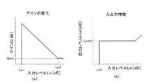
図3(a)に示すゲインの変化特性は、入出力がデシベルスケールの「ゲインカーブ」である。制御部12は、このゲインカーブに基づいて、入力レベルLin(=レベル信号LV1またはLV2)に応じたゲインG(=ゲイン値GV)を決定する。これにより、レベル調整装置1の入出力特性は、デシベルスケールで、図3(b)に示すようになる。
図3(a)に示したように、入力レベルLinが−∞(dB)からLin1(dB)の範囲では、ゲインGは−∞(dB)である。これにより、音響信号はミュートされ、レベル調整装置1からは無音信号が出力される。入力レベルLinがLin1(dB)以上の範囲では、入力レベルLinの増減を打ち消すように、入力レベルLinが増加すればゲインGが減少し、Linが減少すればゲインGが増加する。これにより、レベル調整装置1からは、レベルが均一化された音響信号が出力される。ただし、ゲインGには、ハードウェア都合等による下限Gminがある。入力レベルLinが所定値Lin2より大の範囲では、前記打ち消しのために下限値Gminより小さな値が必要となるが、ゲインGをその値まで下げることはできないので、代わりに、下限値Gminに保持される。この範囲では、入力レベルLinに応じてレベルが増減する音響信号が出力される。
なお、Lin2が入力レベルLinの上限値より大になるように、入力側で入力レベルLinの上限を制限したり、小さな下限値Gminを取れるハードウェアを採用してもよい。The gain change characteristic shown in FIG. 3A is a “gain curve” whose input / output is a decibel scale. Based on the gain curve, the
As shown in FIG. 3A, the gain G is −∞ (dB) when the input level Lin is in the range of −∞ (dB) to Lin1 (dB). As a result, the acoustic signal is muted and a silent signal is output from the
Note that hardware that can limit the upper limit of the input level Lin on the input side or take a small lower limit value Gmin may be adopted so that Lin2 becomes larger than the upper limit value of the input level Lin.
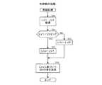
レベル調整装置1の制御部12で実行される周期処理のフローチャートを図4に示す。図4に示す周期処理は、動作期間中、繰り返し行われている処理である。制御部12は、所定ないし可変の時間ごとにこの周期処理を実行する。まず、ステップS10にて、制御部12は第1レベル検出部10からの第1レベル信号LV1と、第2レベル検出部11からの第2レベル信号LV2とを取得する。制御部12で取得された第1レベル信号LV1と第2レベル信号LV2とはリニアスケールの値とされており、ステップS11にて、制御部12は、第1レベル信号LV1を第2レベル信号LV2で除算した値(レベル比)が閾値Tを超えるか否かを判定する。ここで、閾値Tは値が1以上の定数であってそのレベル比が閾値Tを超える場合は、制御部12はステップS11にてYESと判定しステップS12に進む。ステップS12では、LVxレジスタに第1レベル信号LV1を格納する。そして、ステップS14において、制御部12は、図3(a)と同特性のリニアスケールのゲインカーブに基づいて、LVxレジスタに格納した第1レベル信号LV1に対応するゲイン値GVを決定して、周期処理を終了する。また、そのレベル比が閾値T以下の場合は、制御部12は、ステップS11にてNOと判定してステップS13に分岐する。ステップS13では、LVxレジスタに第2レベル信号LV2を格納する。そして、ステップS14において、制御部12は、図3(a)と同特性のリニアスケールのゲインカーブに基づいて、LVxレジスタに格納した第2レベル信号LV2に対応するゲイン値GVを決定して、周期処理を終了する。ここでは、この周期処理で決定したゲイン値GVを平滑化して時間的に滑らかに変化するゲイン値GVに替えてから調整部13に供給する構成とするのがよい。その平滑化処理は調整部13にて行ってもよいが、制御部12が周期処理におけるステップS14にてローパスフィルタ処理や補間等の平滑化処理を行うことが好ましい。平滑化処理によって、制御部12から調整部13に供給されるゲイン値GVは、ステップS11での判定が変化しても、時間的に滑らかに変化する。そして、調整部13が、入力する音響信号を、ゲイン値GVに対応するゲインで増幅して出力することにより、レベル調整装置1からは、レベルが均一化された音響信号が出力される。
なお、ステップS14で用いるゲインカーブは、レベル信号で参照されるゲイン値GVを記憶したゲインテーブルとして実現してもよいし、レベル信号に適用することによりゲイン値GVを算出する算術演算として実現してもよい。また、ステップS11における判定条件の不等号は、「を超える」を示す「>」ではなく、「以上」を示す「≧」であってもよい。FIG. 4 shows a flowchart of periodic processing executed by the
The gain curve used in step S14 may be realized as a gain table that stores the gain value GV referred to by the level signal, or may be realized as an arithmetic operation for calculating the gain value GV by applying it to the level signal. May be. Further, the inequality sign of the determination condition in step S11 may be “≧” indicating “above” instead of “>” indicating “exceeding”.
上記した周期処理が制御部12で実行されることから、本発明の第1実施例にかかるレベル調整装置1においては、第1レベル信号LV1の第2レベル信号LV2に対する比が閾値Tを超える場合は、入力する音響信号のレベル変化が速い場合であり、その音響信号のレベル変化に相対的に速い追随速度で追随する第1レベル信号LV1に基づいて音響信号のレベルが制御される。このことから、レベル変化の速い信号に対処してレベル制御を行うことができる。また、第1レベル信号LV1の第2レベル信号LV2に対する比が閾値T以下の場合は、入力する音響信号のレベル変化が遅い場合であり、第1レベル検出部10より遅い追随速度でその音響信号のレベル変化に追随する第2レベル信号LV2に基づいて音響信号のレベルが制御される。このことから、リスナにゲイン変動を余り感じさせることなくレベル制御を行うことができる。これらのレベル制御は、2つのレベル検出部10,11で検出した2つのレベルに基づき、制御部12で1つのゲインカーブを用いてゲインを決定するといった、制御が容易な単純な構成で実現されている。第1レベル信号の選択条件は、1以上とされている閾値Tの値によって適宜調整できる。閾値Tを1に近い値にすると、LV1が選択される時間が増えて音響信号の速い立ち上がりを確実に抑えられるようになるが、反面、ユーザが時間的なゲイン変動を感じやすくなる。閾値Tが1から離れるに従って、LV2が選択される時間が増えて、ユーザが時間的なゲイン変動を感じにくくなるが、音響信号の速い立ち上がりを抑え切れない場合が出てくる。なお、以上の説明では閾値Tは1以上の値としたが、1より小さい値であっても閾値Tとして採用することは可能である。ただし、1より小さい値を閾値Tを採用すると、ゲインの変化に鋭角的な不連続を生じ、ユーザにゲイン変動を感じさせるので、それは避けたほうがよい。
周期処理のステップS11では、判定処理をリニアスケールで行っているが、デシベルスケールで行うようにしてもよい。その場合、制御部12が、ステップS11の実行に先立って、第1レベル信号LV1および第2レベル信号LV2をデシベルスケールに変換し、ステップS11において、判定式(LV1−LV2)>T’(ただし、T’は閾値Tをデシベルスケールに変換した正の閾値。また、判定式中の「>」は「≧」であってもよい。)の判定を行うようにするとよい。これにより、上述した周期処理と同様に、リニアスケールにおける第1レベル信号LV1の第2レベル信号LV2に対する比(レベル比)が閾値Tを超えるか否かを判定できる。また、この場合、ステップS14におけるレベル値に対するゲインカーブの適用は、後述する第2実施例と同様に、デシベルスケールで行ってもよい。Since the periodic processing described above is executed by the
In step S11 of the periodic process, the determination process is performed on the linear scale, but may be performed on the decibel scale. In that case, the
次に、本発明の第2実施例にかかるレベル調整装置1の構成を示すブロック図を図5に示す。以下に追随速度として使用する「アタックレート」、「リリースレート」、「アタックリリースレート」は、それぞれ、整流された信号に追随する速さを示す「時定数」である。
図5に示す第2実施例のレベル調整装置1においては、サウンドソース51からステレオの音響信号が入力される。このステレオの音響信号の左信号(L)は入力端子LINに入力され、右信号(R)は入力端子RINに入力されて、それぞれディレイ部24,25を介して調整部13に入力される。また、入力端子LINに入力された左信号と入力端子RINに入力された右信号とは加算部20により加算されて、BPF21およびABS23に入力される。BPF21は、入力された音響信号から人間の聴感上の音量への寄与が大きい主帯域(例えば、200Hz〜10kHz)を抽出するバンドパスフィルタである。このフィルタは、バンドパスフィルタに限ることはなく、逆ラウドネスに準じる周波数特性であればどのようなタイプのフィルタでもよい。ABS22,23は、それぞれ入力されたデジタル音響信号の各サンプル値の絶対値を出力する整流部である。ABS22で整流された音響信号は、第1レベル検出部A1および第2レベル検出部A2に入力される。第1および第2レベル検出部A1,A2は、それぞれ、アタックレートとリリースレートで特定される追随速度で入力された音響信号のレベルを検出し、その検出されたレベルを示す各レベル信号LA1,LA2を出力する。出力される各レベル信号LA1,LA2の値は、入力した音響信号サンプル値がレベル信号LA1,LA2より大きい場合は、アタックレートの示す追随速度で上昇し、小さい場合は、リリースレートに対応する追随速度で下降する。第1レベル検出部A1のアタックレートは、例えば数ミリ秒〜数十ミリ秒とされ、リリースレートは、例えば数百ミリ秒〜数秒とされる。また、第2レベル検出部A2のアタックレートは、例えば数百ミリ秒〜数秒とされ、リリースレートは、例えば数秒〜数十秒とされる。これにより、この第1レベル検出部A1は、相対的に速い追随速度で、音響信号の音符毎のエンベロープ(短時間毎のピークレベルに相当)を遅れることなく検出する。また、第2レベル検出部A2は、第1レベル検出部A1より数倍ないし数十倍遅い追随速度で、音響信号の全体的なレベル変動(実効値に相当)を検出する。Next, FIG. 5 is a block diagram showing the configuration of the
In the
ABS23で整流された音響信号は、第3レベル検出部B1および第4レベル検出部B2に入力される。第3レベル検出部B1は、演奏が終了して、音響信号に含まれる演奏音が減衰して残留ノイズだけになるタイミング、すなわち、音響信号のミュートを開始してもよいタイミングを、制御部12において検出するために設けられている。そのため、第3レベル検出部B1は、アタックとリリースとで追随速度の区別のない単なるLPFとして構成されており、そのレート(つまりアタックとリリースのレート)は、例えば数秒〜数十秒に設定される。これにより、第3レベル検出部B1は、1乃至複数小節に相当する期間でのゆっくりとしたレベル変動を検出し、その検出されたレベルを示す第3レベル信号LB1を出力する。また、第4レベル検出部B2は、演奏が始まり、音響信号に含まれる演奏音が立ち上がるタイミング、すなわち音響信号のミュートを解除すべきタイミングを、制御部12において遅延なく開始するために設けられたレベル検出器であって、入力する音響信号の絶対値を、追随遅延なしで、そのまま第4レベル信号LB2として出力する。 The acoustic signal rectified by the
4つのレベル検出部A1,A2,B1,B2から出力される4つのレベル信号LA1,LA2,LB1,LB2は、それぞれ、制御部12に入力される。制御部12は、ミュートをオンするかオフするかを判定する「MUTE判定処理」と、調整部13に供給されるゲイン値GVを決定するためのレベル信号LVxを決定する「LVx決定処理」とを行う判定/決定部30を備えている。MUTE判定処理でミュートをオンすると判定された場合は、判定/決定部30は、LVx決定処理で、ゼロレベル(−∞dB)をレベル信号LVxとして決定し出力する。また、MUTE判定処理でミュートをオフすると判定された場合は、LVx決定処理で、第1レベル信号LA1と第2レベル信号LA2の大きさに基づき、いずれか一方のレベル信号をレベル信号LVxとして決定し出力する。 The four level signals LA1, LA2, LB1, LB2 output from the four level detection units A1, A2, B1, B2 are input to the
リニア−ログ変換部31は、判定/決定部30からのレベル信号LVxを、デシベルスケールのレベル信号LVxに変換する。制御部12は、このデシベルスケールのレベル信号LVxにゲインカーブ32を適用し、そのレベル信号LVxに対応するデシベルスケールのゲイン値GVを求める。ここで、ゲインカーブ32は、図3(a)と同じものを用いてもよいし、Lin1の値がよりゼロレベル(つまり−∞dB)に近いカーブを用いてもよい。ログ−リニア変換部33は、そのデシベルスケールのゲイン値GVを、リニアスケールのゲイン値GVに変換する。平滑化部34は、レベル信号LVxが第1レベル信号LA1と第2レベル信号LA2との間で切り替えられた際に、ゲイン値GVがステップ状に変化することなく滑らかに変化するよう、リニアスケールのゲイン値GVに対して、ローパスフィルタ処理や補間等からなる平滑化処理を施して調整部13に出力する。そして、調整部13は、平滑化されたゲイン値GVに対応するゲインで、サウンドソース51からのステレオの音響信号を増幅して出力する。 The linear-
上述したように、第1レベル検出部A1のアタックレートは、速い立ち上がりにも追従できる、短めの時定数とされており、また、第4レベル検出部B2の遅延はゼロとされている。しかしながら、実際に音響信号の立ち上がりに応じて、ミュートを解除しゲイン値GVを変化させるまでには、その制御経路に入る各ブロック(21、22、23、A1、B2、12)に起因する遅れが生じる。ディレイ部24、25は、その遅れを補償するものであって、入力する音響信号を、一定時間(数十ミリ〜数百ミリ秒)遅延して調整部13に供給する。これにより、音響信号の立ち上がり時に、ミュートの解除が遅れたり、ゲイン値GVの減衰が遅れたりすることを防止できる。
本発明の第2実施例にかかるレベル調整装置1は、第1実施例と同じく、図3(a)に示すゲインカーブを用いてレベル制御を行い、その入出力特性は、音響信号に含まれる演奏音が残っている場合、図3(b)に示す特性となる。このレベル調整装置1では、演奏が終了して、第3レベル検出部B1から出力される第3レベル信号LB1が示すレベルが残留ノイズと見なせるレベルより小さくなると、制御部12によりミュートがオンと判定されゲインGVがゼロレベルとされて、音響信号がミュートされる。その後、演奏が再開され、制御部12において、第4レベル検出部B2の第4レベル信号LB2から演奏音の開始が検出されミュートがオフと判定されると、ミュートが解除され、音響信号のレベルを均一化するレベル調整が再開される。このように、第1実施例と同様のレベルの均一化に加え、第3レベル検出部B1および第4レベル検出部B2と制御部12とにより、残留ノイズの出力を防止するノイズゲートも実現されている。As described above, the attack rate of the first level detection unit A1 is set to a short time constant that can follow a fast rise, and the delay of the fourth level detection unit B2 is set to zero. However, the delay caused by each block (21, 22, 23, A1, B2, 12) entering the control path until the mute is canceled and the gain value GV is changed according to the rise of the acoustic signal. Occurs. The
The
第2実施例にかかるレベル調整装置1の制御部12で実行される周期処理のフローチャートを図6(a)に示す。図6(a)に示す周期処理は、動作期間中、繰り返し行われている処理である。制御部12は、所定ないし可変時間ごとに周期処理を実行する。まず、ステップS20にて第1レベル検出部A1〜第4レベル検出部B2から、リニアスケールの第1レベル信号LA1〜第4レベル信号LB2を取得する。ステップS20に続き、制御部12はミュート判定処理を行う。このミュート判定処理では、まず、ステップS21にて、現在ミュートがオフとなっているか否かをMUTEレジスタの値から判定する。ここで、ミュートがオフ(MUTE=0)である場合は、制御部12はYESと判定してステップS22に進み、第3レベル信号LB1がミュートをスタートさせる閾値TMSより小さいか否かを判定する。ここで、第3レベル検出部B1が楽曲の演奏における1乃至複数小節に相当する期間でのレベル変化の遅いレベル変動に追従する速度で入力信号の全帯域のレベルを検出していることから、もし、第3レベル信号LB1が閾値TMSより小さければ、それは、レベル調整装置1に入力された音響信号が残留ノイズ(演奏音が終了した状態)のみとなっており、ミュートしてよい状態になったことを示している。そこで、制御部12は、ステップS22でYESと判定した場合は、ステップS23に進みMUTEレジスタに、ミュートをオンするという判定結果を示す「1」を格納する。また、ミュートがオンであった(MUTE=1)場合は、制御部12は、ステップS21でNOと判定してステップS24に分岐し、第4レベル信号LB2がミュートを終了させる閾値TMEより大きいか否かを判定する。ここで、第4レベル検出部B2が遅延なしで入力信号のレベルを検出していることから、もし、第4レベル信号LB2が閾値TMEを超えていれば、レベル調整装置1に入力された音響信号中で演奏音が開始され、ミュートを解除すべき状態になったことを示している。そこで、制御部12は、ステップS24でYESと判定した場合は、ステップS25に進み第3レベル検出部B1の第3レベル信号LB1に閾値TMSより大きいレベルの定数である初期値LB1oを設定する。これにより、一旦ミュートをオフすると判定した場合、少なくとも、第3レベル検出部B1において第3レベル信号LB1が初期値LB1oから閾値TMSまで減衰する時間は、ミュートオフの判定が継続するようになる。次いで、ステップS26にて、MUTEレジスタにミュートをオフするという判定結果を示す「0」を格納する。 FIG. 6A shows a flowchart of periodic processing executed by the
制御部12は、ミュート判定処理を、ステップS23を終了した時、ステップS22で第3レベル信号LB1が閾値TMSより小さくないと判定した時、ステップS26を終了した時、あるいは、ステップS24で第4レベル信号LB2が閾値TMEより大きくないと判定した時に終了し、続けて、LVx決定処理を開始する。
LVx決定処理では、まず、ステップS30にて、直前のミュート判定処理が終了した段階でミュートオフが判定されている(MUTE=0)か否かを判定する。ここで、ミュートオフが判定されている場合は、制御部12は、YESと判定してステップS31に進み、第1レベル信号LA1の第2レベル信号LA2に対する比(レベル比)が閾値TAを超えるか否かを判定する。ここで、閾値TAは1以上の定数であって、そのレベル比が閾値TAを超える場合は、制御部12は、ステップS31にてYESと判定してステップS32に進み、LVxレジスタに第1レベル信号LA1を格納する。そして、制御部12は、ステップS35にて、図3(a)のゲインカーブに基づき、LVxレジスタに格納した第1レベル信号LA1に対するゲイン値GVを決定する。このステップをより詳細に説明すると、まず、リニアスケールの第1レベル信号LA1をデシベルスケールに変換する(LIN→LOG31)。次に、デシベルスケールの第1レベル信号LA1に、図3(a)に示されるデシベルスケールのゲインカーブを適用し、デシベルスケールのゲイン値GVを得る(ゲインカーブ32)。次に、そのデシベルスケールのゲイン値GVをリニアスケールに変換する(LOG→LIN33)。さらに、リニアスケールのゲイン値GVに平滑化処理を施し(平滑化部34)、平滑化されたリニアスケールのゲイン値GVを調整部13に供給する。以上でステップS35の処理が終了して、制御部12は、この周期処理を終了する。そして、調整部13が、入力する音響信号を、ゲイン値GVに対応するゲインで増幅して出力することにより、レベル調整装置1からは、速い追随速度でのレベル制御によりレベルが均一化された音響信号が出力される。この場合は、第1レベル信号LA1の第2レベル信号LA2に対する比が、閾値TAを超えることから、一時的に、入力された音響信号のレベルが比較的速い速度で上昇しており、レベル調整装置1では、その音響信号のレベルを相対的に速い追随速度で検出した第1レベル信号LA1に基づいてその音響信号がレベル制御される。このように、演奏音の立ち上がりが速い時には、一時的に、レベル変化の速い信号に追随する出力レベルの均一化が行われる。The
In the LVx determination process, first, in step S30, it is determined whether or not mute-off is determined (MUTE = 0) when the previous mute determination process is completed. If the mute-off is determined, the
また、第1レベル信号LA1の第2レベル信号LA2に対する比が、閾値TA以下の場合は、制御部12はステップS31にてNOと判定してステップS34に分岐し、LVxレジスタに第2レベル信号LA2を格納する。そして、上述した第1レベル信号LA1の場合と同様に、制御部12は、ステップS35にて、図3(a)のゲインカーブに基づき、LVxレジスタに格納した第2レベル信号LA2に対応するゲイン値GVを決定し、そのゲイン値GVを調整部13に供給して周期処理を終了する。そして、調整部13が、入力する音響信号を、ゲイン値GVに対応するゲインで増幅して出力することにより、レベル調整装置1からは、遅い追随速度でのレベル制御によりレベルが均一化された音響信号が出力される。この場合は、入力された音響信号のレベル変化が遅い場合であり、入力された音響信号のレベルを第1レベル検出部A1より相対的に遅い追随速度で検出した第2レベル信号LA2に基づいて音響信号がレベル制御される。
このように、演奏音が入力している間、基本的には、リスナにゲイン変動を余り感じさせることのない出力レベルの均一化が行われる。
さらに、ミュートオンが判定されている(MUTE=1)場合は、制御部12は、ステップS30でNOと判定してステップS33に分岐し、LVxレジスタにゼロレベル「0」(−∞dB)を格納する。そして、上述した第1レベル信号LA1の場合と同様の処理により、制御部12は、ステップS35にて、図3(a)のゲインカーブに基づき、LVxレジスタに格納したゼロレベルに対応するゼロレベル(−∞dB)のゲイン値GVを決定し、そのゲイン値GVを調整部13に供給して周期処理を終了する。この場合、調整部13は、サウンドソース51からの音響信号を、そのゲイン値GVが示すゼロレベルのゲインで増幅するので、結果的に、その音響信号はミュートされる。If the ratio of the first level signal LA1 to the second level signal LA2 is equal to or less than the threshold TA, the
In this way, while the performance sound is being input, the output level is basically made uniform without causing the listener to feel much gain fluctuation.
Further, when mute-on is determined (MUTE = 1), the
上記した周期処理を制御部12が実行することから、本発明の第2実施例にかかるレベル調整装置1においては、入力する音響信号に対し、基本的には、ゆっくりとした追随速度でのレベル制御を施すことにより、リスナにゲイン変動を余り感じさせることなく音響信号のレベルを制御でき、また、レベルの立ち上がりが速い信号が入力した際には、その信号に対し、一時的に、速い追随速度でのレベル制御を施すことにより、その速いレベル変化に追従して音響信号のレベルを制御できる。さらに、曲間等で演奏音がある程度継続的に途切れた際には音響信号をミュートすることにより、スピーカ53からの残留ノイズがリスナの耳につくのを防止できる。以上の機能を備えているにも関わらず、このレベル調整装置1は、1つの検出レベルに1つのゲインカーブを適用して1つのゲイン値を決定する簡単な構成であり、レベル制御にかかる特性の調整が容易である。また、デシベルスケールのゲインカーブを採用することにより、そのカーブを折れ線形状に近づけて簡単な算術演算でも実現できるようにした。また、レベル信号やゲイン値のデータ長が同じであっても、リニアスケールのゲインカーブと比較して、制御可能なレベル範囲(ダイナミックレンジ)が広くなる。
なお、以上に説明した第2実施例の周期処理では、ステップS22、S24、S31の判定処理をリニアスケールで行っていたが、それぞれ、デシベルスケールで行うようにしてもよい。あるステップの判定処理をデシベルスケールで行いたければ、その判定にかかるレベル信号を、ステップS20から当該ステップまでの任意の時点で、リニアスケールからデシベルスケールに変換すればよい。そして、ステップS22またはS24の判定処理をデシベルスケールで行う場合、その判定条件には、閾値TMSまたはTMEをデシベルスケールに変換した閾値TMS’またはTME’を用いればよい。また、ステップS31の判定処理をデシベルスケールで行う場合、閾値TAをデシベルスケールに変換した閾値TA’を用いて、判定式(LA1−LA2)>TA’の判定を行えばよい。この判定は、デシベルスケールにおける、第1レベル信号LA1の第2レベル信号LA2に対するレベル差が、閾値TA’を超えるか否かの判定であるが、第1実施例で説明した、リニアスケールにおける、第1レベル信号LA1の第2レベル信号LA2に対するレベル比が閾値TAを超えるか否かの判定と、実質的に等価である。また、ステップS33に関しては、LVxレジスタにデシベルスケールのゼロレベル(つまり−∞dB)を設定するよう変更すれば、ステップS35におけるリニアスケールからデシベルスケールへの変換(LIN→LOG31)を省略できる。
また、第2実施例の周期処理では、ミュートオンが判定されている場合(ステップS30のNO判定)にもゲインカーブを適用しているが、このゲインカーブの適用は省略可能である。すなわち、ステップS30でNO判定の場合に、ステップS33でゼロレベル(−∞dB)を直接ゲイン値GVとして格納し、ステップS35では、そのゲイン値GVの平滑化処理のみを行って調整部13に供給するようにしてもよい。
また、ステップS22、S24、S31における判定条件の不等号は、それぞれ、「<」、「>」、「>」ではなく、等号付きの「≦」、「≧」、「≧」であってもよい。Since the
In the cyclic processing of the second embodiment described above, the determination processing of steps S22, S24, and S31 is performed on a linear scale, but each may be performed on a decibel scale. If a determination process at a certain step is desired to be performed on a decibel scale, the level signal for the determination may be converted from a linear scale to a decibel scale at any time from step S20 to the step. Then, when the determination process of step S22 or S24 is performed in a decibel scale, a threshold value TMS ′ or TME ′ obtained by converting the threshold value TMS or TME into a decibel scale may be used as the determination condition. Further, when the determination process of step S31 is performed in the decibel scale, the determination formula (LA1-LA2)> TA ′ may be determined using the threshold TA ′ obtained by converting the threshold TA into the decibel scale. This determination is a determination as to whether or not the level difference between the first level signal LA1 and the second level signal LA2 in the decibel scale exceeds the threshold TA ′. In the linear scale described in the first embodiment, This is substantially equivalent to the determination of whether the level ratio of the first level signal LA1 to the second level signal LA2 exceeds the threshold TA. As for step S33, if the LVx register is changed to set the zero level of the decibel scale (that is, −∞ dB), the conversion from the linear scale to the decibel scale (LIN → LOG31) in step S35 can be omitted.
Further, in the periodic processing of the second embodiment, the gain curve is applied even when mute-on is determined (NO determination in step S30), but the application of the gain curve can be omitted. That is, in the case of NO determination in step S30, the zero level (−∞ dB) is directly stored as the gain value GV in step S33, and in step S35, only the gain value GV is smoothed and the
Further, the inequality signs of the determination conditions in steps S22, S24, and S31 may be “≦”, “≧”, and “≧” with an equal sign instead of “<”, “>”, and “>”, respectively. Good.
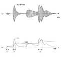
第2実施例にかかるレベル調整装置1では、上記説明したように第1レベル信号LA1に基づいてサウンドソース51からの音響信号が均一化される時間区間と第2レベル信号LA2に基づいてサウンドソース51からの音響信号が均一化される時間区間とがある。横軸を時間として、2つのレベル検出部A1,A2に供給される音響信号を図7(a)に示し、第1レベル検出部A1で検出された第1レベル信号LA1と、第2レベル検出部A2で検出された第2レベル信号LA2と、第2レベル信号LA2に代えて第1レベル信号LA1が選択される区間T1,T2,T3とを図7(b)に示す。
図7(a)に示す入力信号40は、サウンドソース51からの音響信号がBPF21を通過した波形である。この入力信号40から検出された第1レベル信号LA1と、第2レベル信号LA2とが図7(b)に示されている。第1レベル検出部A1は相対的に速い追随速度でレベルのピークを検出していることから、第1レベル信号LA1は図示するように入力信号40のエンベロープにほぼ追従するレベル信号となる。また、第2レベル検出部A2はゆっくりしたレベル変動に追従する速度でレベルを検出していることから、第2レベル信号LA2はそのエンベロープに遅れてゆっくり変化するレベル信号となる。時間軸上の特定区間T1,T2,T3では、第1レベル信号LA1が第2レベル信号LA2より、リニアスケールで所定レベル比(デシベルスケールで所定差)をつけて、大きくなっている。これらの区間では、ステップS31にてYESと判定されて、レベル信号LVxとして一時的に第1レベル信号LA1が選択され、調整部13における音響信号のレベル制御を、入力信号の立ち上がりに遅れることなく行うことができる。そして、区間T1,T2,T3以外の通常区間では、ステップS31にてNOと判定されて、レベル信号LVxとして第2レベル信号LA2が選択され、調整部13における通常のレベル制御を、リスナにゲイン変動を感じさせることなく行うことができる。この第2レベル検出信号LA2の値は、その他のレベル信号の影響を受けることはなく、リスナが感じるゲインの継続性が保たれる。In the
An
次に、第2実施例にかかるレベル調整装置1は、図6(a)の周期処理のうちのLVx決定処理を、図6(b)のように変更することにより、単なるノイズゲートとして動作させることもできる。この場合、ステップS20にて取得するデータは、第3レベル信号LB1と第4レベル信号LB2だけでよい。ステップS40で、ミュートオフが判定されていた(MUTE=0)場合、ステップS41にてLVxレジスタに基準レベルを示す「1」が格納され、それに応じて、ステップS35ではゲイン値GVが基準レベル(0dB)に決定される。ミュートオンが判定されていた(MUTE=1)場合、ステップS42にてLVxレジスタにゼロレベルを示す「0」が格納され、それに応じて、ステップS35ではゲイン値GVがゼロレベル(−∞dB)に決定される。 Next, the
また、以下の説明において、「レベル変化が速い」とは、第1レベル検出部が出力する入力信号のレベル変化に鋭敏に追従した第1レベル信号と、第2レベル検出部が出力する入力信号のレベル変化に鈍く追従した第2レベル信号との比が、第1レベル信号>第2レベル信号である状態を指し、この状態は、例えば静寂状態から楽曲の演奏が始まったときや、破裂音や爆発音などが発生したとき等、入力信号のレベルが急激に増加するといった状況である。
以上説明した本発明の実施例にかかるレベル調整装置では、サウンドソースからの音響信号に応じて、楽曲の途中のレベル変化があまり速くない通常区間では、遅い追随速度とされゲイン変動が目立ちにくい第2レベル検出部のレベル信号を用いて、ゲインの制御を行い、強い演奏音の頭等のレベルが急激に立ち上がる一部区間(上記特定区間)では、速いレベル変動に対応できる第1レベル検出部のレベル信号を用いて、ゲインの制御を行っている。そして、これら両ゲイン制御を、共通のゲインカーブ特性に基づいて行っているため、レベル調整装置の構成がシンプルであり、かつ、レベル変化特性の制御が容易となる。
また、本発明の実施例にかかるレベル調整装置では、追随する速さの異なる2つのレベル検出部の1つの出力を選択していたが、速さの異なる3つ以上のレベル検出部を設けて、そのうちの1つの出力を選択し、その選択された出力に基づいてゲインを決定するようにしてもよい。
さらに、本発明の実施例にかかるレベル調整装置は、信号処理をプログラム可能なデジタル信号処理プロセッサ(DSP)やパーソナルコンピュータ(PC)で構成してもよいし、アナログ演算回路で構成してもよい。Further, in the following description, “the level change is fast” means that the first level signal that sharply follows the level change of the input signal output from the first level detection unit and the input signal output from the second level detection unit The ratio between the second level signal and the second level signal that followed the level change slowly indicates that the first level signal is greater than the second level signal. In such a situation, the level of the input signal suddenly increases, such as when an explosion sound is generated.
In the level adjusting apparatus according to the embodiment of the present invention described above, in the normal section where the level change in the middle of the music is not so fast according to the acoustic signal from the sound source, the follow-up speed is slow and the gain fluctuation is not noticeable. The first level detection unit that controls the gain using the level signal of the two-level detection unit and can cope with a fast level fluctuation in a certain section (the specific section described above) where the level of a strong performance sound head suddenly rises. The gain is controlled using the level signal. Since both of these gain controls are performed based on a common gain curve characteristic, the configuration of the level adjusting device is simple, and the level change characteristic can be easily controlled.
Further, in the level adjusting apparatus according to the embodiment of the present invention, one output of two level detecting units having different following speeds is selected, but three or more level detecting units having different speeds are provided. Alternatively, one of the outputs may be selected, and the gain may be determined based on the selected output.
Furthermore, the level adjusting apparatus according to the embodiment of the present invention may be configured by a digital signal processor (DSP) or a personal computer (PC) that can program signal processing, or may be configured by an analog arithmetic circuit. .
1 レベル調整装置、10 第1レベル検出部、11 第2レベル検出部、12 制御部、13 調整部、20 加算回路、21 BPF、22 ABS回路、23 ABS回路、24,25 ディレイ部、30 判定/決定部、31 リニア−ログ変換部、32 ゲインカーブ、33 ログ−リニア変換部、34 平滑部、40 入力信号、50 オーディオ装置、51 サウンドソース、52 パワーアンプ、53 スピーカ、A1 第1レベル検出部、A2 第2レベル検出部、B1 第3レベル検出部、B2 第4レベル検出部DESCRIPTION OF
Claims (5)
Translated fromJapanese前記入力信号のレベルを、相対的に速い追随速度で検出し、第1レベル信号を出力する第1レベル検出部と、
前記入力信号のレベルを、前記第1レベル検出部より遅い追随速度で検出し、第2レベル信号を出力する第2レベル検出部と、
前記第1レベル信号の前記第2レベル信号に対するレベル比が、1以上の所定レベル比を超える場合、または、以上の場合は、前記第1レベル信号に基づいてゲイン値を決定し、前記レベル比が前記所定レベル比以下の場合、または、未満の場合は、前記第2レベル信号に基づいてゲイン値を決定し、該決定したゲイン値に応じた制御信号を出力する制御部と、
該制御部から出力される前記制御信号に基づいて、前記入力信号のレベルを調整する調整部と、
を備え、前記第1レベル検出部および前記第2レベル検出部におけるアタックレートがリリースレートより速く設定されていることを特徴とするレベル調整装置。A level adjusting device for adjusting and outputting the level of an input signal,
A first level detector that detects the level of the input signal at a relatively fast following speed and outputs a first level signal;
A second level detector that detects the level of the input signal at a slower tracking speed than the first level detector and outputs a second level signal;
When the level ratio of the first level signal to the second level signal exceeds a predetermined level ratio of 1 or more, or in the above case, a gain value is determined based on the first level signal, and the level ratio A control unit that determines a gain value based on the second level signal and outputs a control signal in accordance with the determined gain value when is less than or equal to the predetermined level ratio;
An adjustment unit that adjusts the level of the input signal based on the control signal output from the control unit;
The level adjustment device is characterized in that anattack rate in the first level detection unit and the second level detection unit is set faster than a release rate .
前記第1レベル検出部及び前記第2レベル検出部は、それぞれ、前記フィルタ手段でフィルタ処理された信号のレベルを検出することを特徴とする請求項1または2に記載のレベル調整装置。Furthermore, it comprises a filter means for extracting a component of a band that has a large influence on the audible volume from the input signal,
3. The level adjustment apparatus according to claim 1, wherein each of the first level detection unit and the second level detection unit detects a level of a signal filtered by the filter unit. 4.
前記入力信号のレベルを、相対的に速い追随速度で検出し、第1レベル信号を出力する第1レベル信号生成過程と、
前記入力信号のレベルを、前記第1レベル検出手段より遅い追随速度で検出し、第2レベル信号を出力する第2レベル信号生成過程と、
前記第1レベル信号の前記第2レベル信号に対するレベル比が、1以上の所定レベル比を超える場合、または、以上の場合は、前記第1レベル信号に基づいてゲイン値を決定し、前記レベル比が前記所定レベル比以下の場合、または、未満の場合は、前記第2レベル信号に基づいてゲイン値を決定し、該決定したゲイン値に応じた制御信号を出力するゲイン値生成過程と、
前記制御信号に基づいて、前記入力信号のレベルを調整するレベル調整過程と、
を備え、前記第1レベル検出部および前記第2レベル検出部におけるアタックレートがリリースレートより速く設定されていることを特徴とするレベル調整方法。A level adjustment method for adjusting and outputting an input signal level,
A first level signal generating step of detecting the level of the input signal at a relatively fast following speed and outputting a first level signal;
A second level signal generating step of detecting the level of the input signal at a tracking speed slower than the first level detecting means and outputting a second level signal;
When the level ratio of the first level signal to the second level signal exceeds a predetermined level ratio of 1 or more, or in the above case, a gain value is determined based on the first level signal, and the level ratio A gain value generating step of determining a gain value based on the second level signal and outputting a control signal in accordance with the determined gain value when is less than or equal to the predetermined level ratio;
A level adjustment process for adjusting the level of the input signal based on the control signal;
The level adjustment method is characterized in that anattack rate in the first level detection unit and the second level detection unit is set faster than a release rate .
Priority Applications (4)
| Application Number | Priority Date | Filing Date | Title |
|---|---|---|---|
| JP2014051426AJP6323089B2 (en) | 2014-03-14 | 2014-03-14 | Level adjusting method and level adjusting device |
| EP15158754.0AEP2928076B1 (en) | 2014-03-14 | 2015-03-12 | Level adjustment device and method |
| US14/657,331US9571055B2 (en) | 2014-03-14 | 2015-03-13 | Level adjustment device and method |
| CN201510114108.8ACN104918181B (en) | 2014-03-14 | 2015-03-16 | Level adjustment apparatus and method |
Applications Claiming Priority (1)
| Application Number | Priority Date | Filing Date | Title |
|---|---|---|---|
| JP2014051426AJP6323089B2 (en) | 2014-03-14 | 2014-03-14 | Level adjusting method and level adjusting device |
Publications (2)
| Publication Number | Publication Date |
|---|---|
| JP2015177290A JP2015177290A (en) | 2015-10-05 |
| JP6323089B2true JP6323089B2 (en) | 2018-05-16 |
Family
ID=52726971
Family Applications (1)
| Application Number | Title | Priority Date | Filing Date |
|---|---|---|---|
| JP2014051426AActiveJP6323089B2 (en) | 2014-03-14 | 2014-03-14 | Level adjusting method and level adjusting device |
Country Status (4)
| Country | Link |
|---|---|
| US (1) | US9571055B2 (en) |
| EP (1) | EP2928076B1 (en) |
| JP (1) | JP6323089B2 (en) |
| CN (1) | CN104918181B (en) |
Families Citing this family (9)
| Publication number | Priority date | Publication date | Assignee | Title |
|---|---|---|---|---|
| JP6903884B2 (en)* | 2016-09-15 | 2021-07-14 | 沖電気工業株式会社 | Signal processing equipment, programs and methods, and communication equipment |
| ES2684315B1 (en)* | 2017-03-31 | 2019-03-28 | Albala Ingenieros S A | AUTOMATIC CONTROL OF TRANSIENT COMPENSATION FOR AUDIO STANDARDIZATION SYSTEMS |
| US9860644B1 (en) | 2017-04-05 | 2018-01-02 | Sonos, Inc. | Limiter for bass enhancement |
| EP3634009A4 (en)* | 2017-05-29 | 2021-02-24 | Audio-Technica Corporation | SIGNAL PROCESSING DEVICE |
| US10373659B2 (en)* | 2017-12-21 | 2019-08-06 | Micron Technology, Inc. | Voltage reference computations for memory decision feedback equalizers |
| JP7193772B2 (en)* | 2018-03-23 | 2022-12-21 | ヤマハ株式会社 | Dynamics processing method |
| US10755722B2 (en)* | 2018-08-29 | 2020-08-25 | Guoguang Electric Company Limited | Multiband audio signal dynamic range compression with overshoot suppression |
| JP7247582B2 (en)* | 2018-12-28 | 2023-03-29 | ヤマハ株式会社 | AUDIO SIGNAL CONTROL CIRCUIT AND AUDIO SIGNAL CONTROL METHOD |
| DE102019100551B3 (en) | 2019-01-10 | 2020-07-16 | Kronoton Gmbh | Device with an input and with an output and with an effects device with volume-controlled audio signals of an audio file |
Family Cites Families (14)
| Publication number | Priority date | Publication date | Assignee | Title |
|---|---|---|---|---|
| JPH10284964A (en)* | 1997-01-09 | 1998-10-23 | Sony Corp | Sound volume adjusting device |
| JP3986390B2 (en)* | 2002-08-08 | 2007-10-03 | 新日本無線株式会社 | AGC device |
| US7613312B2 (en)* | 2003-05-30 | 2009-11-03 | Panasonic Corporation | Audio processing apparatus for implementing level corrections of audio data |
| JP4349123B2 (en)* | 2003-12-25 | 2009-10-21 | ヤマハ株式会社 | Audio output device |
| US8275153B2 (en)* | 2007-04-16 | 2012-09-25 | Evertz Microsystems Ltd. | System and method for generating an audio gain control signal |
| US8705751B2 (en)* | 2008-06-02 | 2014-04-22 | Starkey Laboratories, Inc. | Compression and mixing for hearing assistance devices |
| US8687824B2 (en)* | 2008-07-11 | 2014-04-01 | Clarion Co., Ltd. | Acoustic processing device |
| WO2010013939A2 (en)* | 2008-07-29 | 2010-02-04 | Lg Electronics Inc. | An apparatus for processing an audio signal and method thereof |
| US8218790B2 (en)* | 2008-08-26 | 2012-07-10 | Apple Inc. | Techniques for customizing control of volume level in device playback |
| WO2010028683A1 (en)* | 2008-09-10 | 2010-03-18 | Widex A/S | Method for sound processing in a hearing aid and a hearing aid |
| JP5236006B2 (en) | 2008-10-17 | 2013-07-17 | シャープ株式会社 | Audio signal adjustment apparatus and audio signal adjustment method |
| JP2011234076A (en)* | 2010-04-27 | 2011-11-17 | Fujitsu Ten Ltd | Acoustic apparatus and signal control method |
| EP2512157B1 (en)* | 2011-04-13 | 2013-11-20 | Oticon A/s | Hearing device with automatic clipping prevention and corresponding method |
| WO2013075848A1 (en)* | 2011-11-21 | 2013-05-30 | Jacoti Bvba | System and method for signal level detection |
- 2014
- 2014-03-14JPJP2014051426Apatent/JP6323089B2/enactiveActive
- 2015
- 2015-03-12EPEP15158754.0Apatent/EP2928076B1/enactiveActive
- 2015-03-13USUS14/657,331patent/US9571055B2/enactiveActive
- 2015-03-16CNCN201510114108.8Apatent/CN104918181B/enactiveActive
Also Published As
| Publication number | Publication date |
|---|---|
| CN104918181B (en) | 2019-12-13 |
| CN104918181A (en) | 2015-09-16 |
| EP2928076A1 (en) | 2015-10-07 |
| JP2015177290A (en) | 2015-10-05 |
| EP2928076B1 (en) | 2018-01-03 |
| US9571055B2 (en) | 2017-02-14 |
| US20150263690A1 (en) | 2015-09-17 |
Similar Documents
| Publication | Publication Date | Title |
|---|---|---|
| JP6323089B2 (en) | Level adjusting method and level adjusting device | |
| CN104798301B (en) | audio loudness control system | |
| JP6652978B2 (en) | Sports headphones with situational awareness | |
| JP5898534B2 (en) | Acoustic signal processing apparatus and acoustic signal processing method | |
| JP6439261B2 (en) | Audio signal processing device | |
| US20120288121A1 (en) | Acoustic control device | |
| JP2016131404A (en) | Acoustic device, volume control method, volume control program, and recording medium | |
| US9628907B2 (en) | Audio device and method having bypass function for effect change | |
| JP4983694B2 (en) | Audio playback device | |
| CN103580630B (en) | automatic loudness control | |
| US9219455B2 (en) | Peak detection when adapting a signal gain based on signal loudness | |
| JP5958378B2 (en) | Audio signal processing apparatus, control method and program for audio signal processing apparatus | |
| US9666196B2 (en) | Recording apparatus with mastering function | |
| JP6205758B2 (en) | SOUND DEVICE, SOUND DEVICE CONTROL METHOD AND PROGRAM | |
| JP2012100117A (en) | Acoustic processing apparatus and method | |
| JP4803193B2 (en) | Audio signal gain control apparatus and gain control method | |
| JP5957964B2 (en) | Sound processing apparatus and sound processing method | |
| EP2466917B1 (en) | Audio-signal processing apparatus and method, and program | |
| JPH03237899A (en) | Howling suppression device | |
| JP5998357B2 (en) | In-vehicle sound playback device | |
| JP2011066604A (en) | Sound volume control device | |
| JP6807769B2 (en) | Sound equipment and sound quality adjustment method | |
| JP2020080509A (en) | Hearing characteristics detection device, hearing aid, hearing characteristics detection program, and hearing aid program | |
| JP2006148609A (en) | SOUND QUALITY ADJUSTMENT DEVICE, BROADCAST RECEIVER, PROGRAM, AND RECORDING MEDIUM | |
| KR20050018427A (en) | volume stabilizing devices of digital audio players |
Legal Events
| Date | Code | Title | Description |
|---|---|---|---|
| A621 | Written request for application examination | Free format text:JAPANESE INTERMEDIATE CODE: A621 Effective date:20170120 | |
| A977 | Report on retrieval | Free format text:JAPANESE INTERMEDIATE CODE: A971007 Effective date:20171129 | |
| A131 | Notification of reasons for refusal | Free format text:JAPANESE INTERMEDIATE CODE: A131 Effective date:20171212 | |
| A521 | Request for written amendment filed | Free format text:JAPANESE INTERMEDIATE CODE: A523 Effective date:20180206 | |
| TRDD | Decision of grant or rejection written | ||
| A01 | Written decision to grant a patent or to grant a registration (utility model) | Free format text:JAPANESE INTERMEDIATE CODE: A01 Effective date:20180313 | |
| A61 | First payment of annual fees (during grant procedure) | Free format text:JAPANESE INTERMEDIATE CODE: A61 Effective date:20180326 | |
| R151 | Written notification of patent or utility model registration | Ref document number:6323089 Country of ref document:JP Free format text:JAPANESE INTERMEDIATE CODE: R151 | |
| S531 | Written request for registration of change of domicile | Free format text:JAPANESE INTERMEDIATE CODE: R313532 | |
| R350 | Written notification of registration of transfer | Free format text:JAPANESE INTERMEDIATE CODE: R350 |