JP6322061B2 - Moore - Google Patents
MooreDownload PDFInfo
- Publication number
- JP6322061B2 JP6322061B2JP2014123822AJP2014123822AJP6322061B2JP 6322061 B2JP6322061 B2JP 6322061B2JP 2014123822 AJP2014123822 AJP 2014123822AJP 2014123822 AJP2014123822 AJP 2014123822AJP 6322061 B2JP6322061 B2JP 6322061B2
- Authority
- JP
- Japan
- Prior art keywords
- motor
- mower
- guide member
- deck
- shroud
- Prior art date
- Legal status (The legal status is an assumption and is not a legal conclusion. Google has not performed a legal analysis and makes no representation as to the accuracy of the status listed.)
- Active
Links
Images


Classifications
- A—HUMAN NECESSITIES
- A01—AGRICULTURE; FORESTRY; ANIMAL HUSBANDRY; HUNTING; TRAPPING; FISHING
- A01D—HARVESTING; MOWING
- A01D34/00—Mowers; Mowing apparatus of harvesters
- A01D34/01—Mowers; Mowing apparatus of harvesters characterised by features relating to the type of cutting apparatus
- A01D34/412—Mowers; Mowing apparatus of harvesters characterised by features relating to the type of cutting apparatus having rotating cutters
- A01D34/63—Mowers; Mowing apparatus of harvesters characterised by features relating to the type of cutting apparatus having rotating cutters having cutters rotating about a vertical axis
- A01D34/76—Driving mechanisms for the cutters
- A01D34/78—Driving mechanisms for the cutters electric
- A—HUMAN NECESSITIES
- A01—AGRICULTURE; FORESTRY; ANIMAL HUSBANDRY; HUNTING; TRAPPING; FISHING
- A01D—HARVESTING; MOWING
- A01D34/00—Mowers; Mowing apparatus of harvesters
- A01D34/01—Mowers; Mowing apparatus of harvesters characterised by features relating to the type of cutting apparatus
- A01D34/412—Mowers; Mowing apparatus of harvesters characterised by features relating to the type of cutting apparatus having rotating cutters
- A01D34/63—Mowers; Mowing apparatus of harvesters characterised by features relating to the type of cutting apparatus having rotating cutters having cutters rotating about a vertical axis
- A01D34/81—Casings; Housings
- A—HUMAN NECESSITIES
- A01—AGRICULTURE; FORESTRY; ANIMAL HUSBANDRY; HUNTING; TRAPPING; FISHING
- A01D—HARVESTING; MOWING
- A01D2101/00—Lawn-mowers
Landscapes
- Life Sciences & Earth Sciences (AREA)
- Environmental Sciences (AREA)
- Harvester Elements (AREA)
Description
Translated fromJapanese本発明は、回転ブレードを回転駆動させるモータを具備するモーアの技術に関する。 The present invention relates to a mower technique including a motor that rotationally drives a rotating blade.
従来、回転ブレードを回転駆動させるモータを具備するモーアの技術は公知となっている。例えば、特許文献1に記載の如くである。 2. Description of the Related Art Conventionally, a mower technique having a motor for rotating a rotary blade is known. For example, as described in
特許文献1には、回転ブレード(モアブレード)を内部に収容するモーアデッキ(モアデッキ)と、回転ブレードを回転駆動させるモータ(モアモータ)を具備するモーア(モアデッキユニット)が記載されている。モータは、ボルトによってモーアデッキの上面に固定される。このように構成されたモーアにおいて、モータを駆動させて回転ブレードを回転駆動させることで、草(芝)を刈り取ることができる。
このように構成されたモーアにおいては、回転ブレードを回転駆動させると、モータから熱が発生する。このため、発熱したモータを効率よく冷却することが可能なモーアが望まれている。 In the mower configured as described above, when the rotary blade is driven to rotate, heat is generated from the motor. For this reason, a mower capable of efficiently cooling the generated motor is desired.
本発明は以上の如き状況に鑑みてなされたものであり、その解決しようとする課題は、モータを効率よく冷却することが可能なモーアを提供することである。 The present invention has been made in view of the above situation, and a problem to be solved is to provide a mower capable of efficiently cooling a motor.
本発明の解決しようとする課題は以上の如くであり、次にこの課題を解決するための手段を説明する。 The problem to be solved by the present invention is as described above. Next, means for solving the problem will be described.
即ち、請求項1においては、回転駆動されることで草を刈り取る回転ブレードと、前記回転ブレードを回転駆動させるモータと、前記回転ブレードを内部に収容するモーアデッキと、前記モータに沿うように前記モーアデッキの内部と外部とを連通する空気の流路を形成する案内部材と、を具備し、前記案内部材は、第一案内部材及び第二案内部材を含み、前記第一案内部材は、前記モーアデッキの上面に載置され、前記モータの側面を外側から囲むような円筒状、かつ前記モータの側面の上端と同じ高さに上端が位置するように形成され、前記モータの側面との間に、上方に向かって開口されると共に前記モータの側面に沿って空気を下方へと案内する前記空気の流路を形成し、前記第二案内部材は、前記モーアデッキの内部において前記上面に当接され、平面視において前記モータを外側から囲むような円筒状に形成され、前記第一案内部材及び前記第二案内部材は、前記上面を介して互いに固定されることによって、前記モーアデッキに固定されるものである。
That is, according to
請求項2においては、前記案内部材は、前記モータの底面と対向するように配置され、前記空気の流路を介して前記モーアデッキの外部から内部へと空気を送るファンを含み、前記ファンは、板部及び前記板部の底面に固定された羽根を有し、前記板部及び前記モータの底面との間に前記空気の流路を形成しているものである。According to a second aspect of the presentinvention, the guide member includes a fan that is disposed so as to face the bottom surface of the motor and that sends air from the outside to the inside of the mower deck via the air flow path. It has blades fixed to the bottom surface of the plate portion and the plate portion, and the air flow path is formed between the plate portion and the bottom surface of the motor .
請求項3においては、前記ファンは、前記モータによって駆動されるものである。According to a third aspect of the presentinvention, the fan is driven by the motor .
請求項4においては、前記モータは、側面から外側に向かって延びるように形成されると共に、外側の端部が前記第一案内部材と接触するように形成される少なくとも1つのフィンを具備するものである。According to a fourthaspect of the presentinvention, the motor includes at least one fin formed so as to extend outward from a side surface and having an outer end portion in contact with the first guide member. It is.
本発明の効果として、以下に示すような効果を奏する。 As effects of the present invention, the following effects can be obtained.
本発明は、モーアデッキの外部から内部へと(又は、内部から外部へと)流通する空気によって、モータを効率よく冷却することができる。
また、モータの側面を効率よく冷却することができる。The present invention can efficiently cool a motor by air flowing from the outside to the inside of the moor deck (or from the inside to the outside).
In addition, the side surface of the motor can be efficiently cooled.
以下では、図中の矢印U、矢印D、矢印F、矢印B、矢印L及び矢印Rで示した方向を、それぞれ上方向、下方向、前方向、後方向、左方向及び右方向と定義して説明を行う。 In the following, the directions indicated by arrow U, arrow D, arrow F, arrow B, arrow L and arrow R in the figure are defined as upward, downward, forward, backward, leftward and rightward, respectively. To explain.
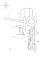
まず、図1及び図2を用いて、モーア100を具備する草刈機1の全体構成について説明する。 First, the overall configuration of the
草刈機1は、走行しながら草(芝)を刈り取ることが可能な作業車両である。草刈機1は、主として走行機体2、前輪3、駆動輪4、走行用モータ5、運転座席6、保護フレーム7、走行レバー8、リンク機構9及びモーア100を具備する。 The
走行機体2の前部は、従動輪(非駆動輪)である左右一対の前輪3・3に支持される。走行機体2の後部は、左右一対の駆動輪4・4に支持される。左右一対の駆動輪4・4の内側には、左右一対の走行用モータ5・5が配置される。左側の走行用モータ5は左側の駆動輪4に、右側の走行用モータ5は右側の駆動輪4に、それぞれ連結される。 The front part of the traveling machine body 2 is supported by a pair of left and right
走行機体2の前後中途部には、作業者が着座する運転座席6が設けられる。運転座席6の後方には、作業者を保護するための保護フレーム7が設けられる。運転座席6の左右には、左右一対の走行レバー8・8が設けられる。走行機体2の下部(前輪3と駆動輪4との間)には、リンク機構9を介してモーア100が設けられる。 A driver's seat 6 on which an operator sits is provided in the middle part of the traveling machine body 2 before and after. A protective frame 7 for protecting the operator is provided behind the driver seat 6. A pair of left and right traveling levers 8 and 8 are provided on the left and right sides of the driver seat 6. A lower 100 (between the
作業者は、走行レバー8・8を操作することによって、左右一対の走行用モータ5・5の回転をそれぞれ制御することができる。これによって、作業者は左右一対の駆動輪4・4をそれぞれ独立して任意に駆動させることができる。このように、作業者は走行レバー8・8を操作することによって、草刈機1を前後進させたり旋回させたりすることができる。また作業者は、モーア100を駆動させることで、草刈作業(芝刈作業)を行うことができる。 The operator can control the rotation of the pair of left and right traveling
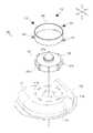
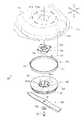
次に、図3から図9までを用いて、本発明の第一実施形態に係るモーア100の構成(特に、後述する作業用モータ120に関する構成)について説明する。 Next, the configuration of the
モーア100は、その下方に生えた草を、所定の長さ(高さ)になるように刈り取る作業機である。モーア100は、主としてモーアデッキ110、作業用モータ120、スペーサ130、ファン140、回転ブレード150、第一シュラウド160及び第二シュラウド170を具備する。 The
なお、以下では説明の便宜上、主にモーア100の左端部近傍の構成についてのみ説明する。より具体的には、本実施形態に係るモーア100は複数(3個)の作業用モータ120を備えているが(図2参照)、以下では最も左側に配置された作業用モータ120及びその周辺の構成についてのみ説明する。 In the following, for convenience of explanation, only the configuration near the left end portion of the
図3から図8までに示すモーアデッキ110は、モーア100の主たる構造体を成すものである。モーアデッキ110は、主として上面111及び側面112を具備する。 The
上面111は、略水平に形成される板状の部分である。上面111は、長手方向が左右方向を向くように形成される。側面112は、上面111の外周端部から下方に向かって延びるように形成される部分である。上面111と側面112は一体的に形成される。上面111と側面112との接続部分は、滑らかな曲面状になるように形成される。モーアデッキ110の内部には、上面111及び側面112によって上方及び側方から覆われた空間が形成される。上面111には、主として中心孔111a及び連通孔111bが形成される。 The
中心孔111aは、上面111を上下に貫通するように形成される孔である。中心孔111aは、平面視円形状に形成される。 The
連通孔111bは、上面111を上下に貫通するように形成される孔である。連通孔111bは、中心孔111aの周囲に複数(本実施形態においては、8個)形成される。連通孔111bは、中心孔111aを中心とする円周上に沿って、等間隔に形成される。 The
図3、図5、図7及び図8に示す作業用モータ120は、電力を用いて後述する回転ブレード150を回転駆動させるものである。作業用モータ120は、主としてハウジング121、シャフト122、ロータ123及びステータ124を具備する。 The working
ハウジング121は、作業用モータ120の主たる構造体を成すものである。ハウジング121は、主として本体部121a、上部121b及び下部121cを具備する。 The
本体部121aは、軸線を上下方向に向けた略円柱状に形成される。本体部121aの直径は、モーアデッキ110の連通孔111bが形成された円周の直径よりも小さくなるように形成される。 The
上部121b及び下部121cは、軸線を上下方向に向けた略円柱状に形成される。上部121bは、本体部121aの上面に一体的に形成される。下部121cは、本体部121aの底面に一体的に形成される。上部121b及び下部121cは、本体部121aの軸線上に形成される。下部121cの直径は、モーアデッキ110の中心孔111aの直径と略同一となるように形成される。 The
このように形成された筐体であるハウジング121の内部には、各種の部材を配置するための空間が形成される。ハウジング121には、フィン121dが形成される。 A space for arranging various members is formed inside the
フィン121dは、略矩形板状に形成される部分である。フィン121dは、本体部121aの上端から下端に亘るように形成される。フィン121dは、本体部121aの側面に複数(本実施形態においては、8個)形成される。フィン121dは、本体部121aの側面から外側に向かって放射状に延びるように形成される。フィン121dを形成することによって、ハウジング121の表面積を増加させることができる。 The
図5及び図8に示すシャフト122は、作業用モータ120の回転動力を出力するための部材である。シャフト122は、軸線を上下方向に向けた状態でハウジング121の中心(ハウジング121の軸線上)に配置される。シャフト122の下端部は、ハウジング121の底面から下方に向かって突出するように配置される。シャフト122は、ハウジング121の内部に配置された上下一対のベアリング122aによって回転可能に支持される。 The
図8に示すロータ123は、シャフト122と共に回転可能な界磁(又は、電機子)である。ロータ123は、ハウジング121内に配置される。ロータ123は、シャフト122の上下中途部に固定され、当該シャフト122と共に回転することができる。 The
ステータ124は、ハウジング121内に固定される電機子(又は、界磁)である。ステータ124は、ハウジング121内において、ロータ123を側方から囲むように配置される。 The
このように構成された作業用モータ120は、モーアデッキ110の上面111上に載置される。作業用モータ120は、当該作業用モータ120の軸線が、モーアデッキ110の中心孔111aの中心と一致するように配置される。この際、ハウジング121の下部121cはモーアデッキ110の中心孔111aに挿通される。これによって、下部121cの下端はモーアデッキ110の内部(モーアデッキ110の上面111よりも下方)に位置する。作業用モータ120のシャフト122の下端部は、中心孔111aを介してモーアデッキ110の内部に向けて突出する。このような作業用モータ120において、ロータ123又はステータ124に電流を流して励磁することによって、シャフト122を回転させ、回転動力を得ることができる。 The
図4、図6及び図8に示すスペーサ130は、作業用モータ120のシャフト122から出力される回転動力を、当該シャフト122よりもさらに下方へと伝達するものである。スペーサ130は、主としてハウジング131、フランジ132、軸継手133及びシール部材134を具備する。 The
ハウジング131は、スペーサ130の主たる構造体を成すものである。ハウジング131は、軸線を上下方向に向けた略円筒状に形成される。 The
フランジ132は、略矩形板状の部分である。フランジ132は、略水平に配置される。フランジ132は、ハウジング131の上端部に固定される。 The
軸継手133は、作業用モータ120のシャフト122からの回転動力を伝達するものである。軸継手133は、軸線を上下方向に向けた略円筒状に形成される。軸継手133は、ハウジング131の中心(ハウジング131の軸線上)に配置される。軸継手133は、ハウジング131の内部に配置された上下一対のベアリング133aによって回転可能に支持される。 The
シール部材134は、ハウジング131の下端部を適宜閉塞するものである。シール部材134によってハウジング131の下端部を閉塞することで、当該ハウジング131内への異物の混入を防止することができる。 The
このように構成されたスペーサ130は、モーアデッキ110の内部に配置される。スペーサ130は、当該スペーサ130の軸線(軸継手133の軸線)が、モーアデッキ110の中心孔111aの中心と一致するように配置される。この状態で、スペーサ130のフランジ132は、モーアデッキ110の上面111にボルト等を用いて適宜固定される。この際、作業用モータ120のシャフト122の下端部は、スペーサ130の軸継手133の上端部に相対回転不能に連結される。これによって、軸継手133は、シャフト122と共に回転することができる。 The
ファン140は、内側から外側に向かって空気を送る(送風する)もの(遠心ファン)である。ファン140は、主として上板141、下板142及び羽根143を具備する。 The
上板141は、略円形板状に形成されるものである。上板141は、略水平に配置される。上板141には、中心孔141aが形成される。 The
中心孔141aは、上板141を上下に貫通するように形成される孔である。中心孔141aは、平面視円形状に形成される。中心孔141aは、上板141の中心に形成される。 The
下板142は、略円形板状に形成されるものである。下板142の直径は、上板141の直径よりも小さくなるように形成される。下板142は、上板141と平行(略水平)に配置される。下板142は、上板141から所定距離だけ離間した状態で、上板141の下方に配置される。下板142は、当該下板142の軸線が、上板141の軸線と一致するように配置される。下板142には、中心孔142a及びリブ142bが形成される。 The
中心孔142aは、下板142を上下に貫通するように形成される孔である。中心孔142aは、平面視円形状に形成される。中心孔142aは、下板142の中心に形成される。下板142の中心孔142aの直径は、上板141の中心孔141aの直径よりも小さくなるように形成される。 The
リブ142bは、下板142の下面から下方に向かって突出するように形成される。リブ142bは、底面視において中心孔142aを挟むように2つ形成される。当該2つのリブ142bは、底面視において互いに平行に延びるように形成される。 The
羽根143は、上板141と下板142との間で空気を移動させる(風を発生させる)ためのものである。羽根143は、略矩形板状の部材を適宜折り曲げて形成される。羽根143は、上板141と下板142とを連結するように、当該上板141及び下板142に固定される。羽根143は、上板141及び下板142の軸線の周囲に複数(本実施形態においては、8個)設けられる。 The
このように構成されたファン140は、モーアデッキ110の内部に配置される。ファン140は、当該ファン140の軸線がスペーサ130の軸線と一致するように配置される。この状態で、ファン140は、スペーサ130の下方から当該スペーサ130(軸継手133)に連結される。これによって、ファン140は、軸継手133と共に回転することができる。この際、スペーサ130のハウジング131の下部は、ファン140の上板141の中心孔141aに挿通される。また、スペーサ130の下端(シール部材134)は、ファン140の下板142に当接される。 The
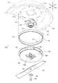
回転ブレード150は、回転駆動されることで草を刈り取るものである。回転ブレード150は、略矩形板状に形成される。回転ブレード150は、適宜折り曲げて形成され、回転する際に下から上に向かって空気を送る(送風する)ことができる。回転ブレード150の中心には、当該回転ブレード150を上下に貫通する貫通孔151が形成される。 The
このように構成された回転ブレード150は、モーアデッキ110の内部に配置される。回転ブレード150は、ファン140の下方から当該ファン140に形成された2つのリブ142bの間に嵌め込まれる。この状態で、回転ブレード150の下方から、座金136を介してボルト135がスペーサ130(軸継手133)に締結される。このようにして、作業用モータ120からの動力は、軸継手133を介してファン140及び回転ブレード150に伝達される。当該ファン140及び回転ブレード150は一体的に回転する。 The
図3、図5、図7及び図8に示す第一シュラウド160は、空気が流通する経路(空気の流路)を形成するものである。第一シュラウド160は、軸線を上下方向に向けた略円筒状に形成される。第一シュラウド160の内径は、作業用モータ120のハウジング121の直径よりも大きくなるように形成される。また第一シュラウド160の内径は、モーアデッキ110の連通孔111bが形成された円周の直径よりも大きくなるように形成される。第一シュラウド160の上下方向幅(高さ)は、作業用モータ120のハウジング121の上下方向幅と略同一となるように形成される。第一シュラウド160には、固定部161が形成される。 The
固定部161は、略矩形板状に形成される部分である。固定部161は、第一シュラウド160の下端に複数(本実施形態においては、3個)形成される。固定部161は、第一シュラウド160の下端から外側に向かって延びるように形成される。固定部161は、略水平に形成される。 The
このように構成された第一シュラウド160は、固定部161がモーアデッキ110の上面111に当接するようにして、当該上面111上に載置される。第一シュラウド160は、当該第一シュラウド160の軸線が作業用モータ120の軸線と一致するように配置される。これによって、第一シュラウド160は、作業用モータ120の側面との間に所定の間隔を空けた状態で配置される。すなわち、第一シュラウド160と作業用モータ120との間には、略円筒状の空間が形成される。この際、作業用モータ120のフィン121dの外側端部は、第一シュラウド160の内側面と接触するように配置される。 The
図4、図6、図7及び図8に示す第二シュラウド170は、空気の流路を形成するものである。第二シュラウド170は、軸線を上下方向に向けた略円筒状に形成される。第二シュラウド170の内径は、第一シュラウド160の内径よりも大きくなるように形成される。また、第二シュラウド170の外径は、ファン140の上板141の直径と略同一となるように形成される。第二シュラウド170の上下方向幅は、モーアデッキ110の上面111とファン140の上板141との間の距離と略同一となるように形成される。第二シュラウド170には、固定部171が設けられる。 The
固定部171は、軸線を上下方向に向けた略円柱状に形成される部材である。固定部171は、第二シュラウド170の外側面の上端に複数(本実施形態においては、3個)設けられる。固定部171は、平面視において第一シュラウド160の固定部161と重複する位置にそれぞれ設けられる。固定部171は、第二シュラウド170の上端から上方に向かって突出するように配置される。固定部171の上端部には、雄ネジ部(不図示)が形成される。 The fixed
このように構成された第二シュラウド170は、モーアデッキ110の内部に配置される。第二シュラウド170は、当該第二シュラウド170の軸線がスペーサ130の軸線と一致するように配置される。この状態で、第二シュラウド170は、モーアデッキ110の上面111に下方から当接される。この際、第二シュラウド170の固定部171の上端は、モーアデッキ110の上面111及び第一シュラウド160の固定部161にそれぞれ挿通される。当該固定部171には、第一シュラウド160の固定部161の上方からナット172が締結される。これによって、第一シュラウド160及び第二シュラウド170がモーアデッキ110に固定される。なお、第二シュラウド170がモーアデッキ110に固定された後に、ファン140及び回転ブレード150がスペーサ130に固定される。 The
このように構成されたモーア100においては、モーアデッキ110の内部と外部とを連通する空気の流路が形成される。以下では、当該流路を流通する空気の様子について説明する。 In the
作業用モータ120が駆動されると、当該作業用モータ120の回転動力によってファン140及び回転ブレード150が回転駆動される。当該ファン140及び回転ブレード150が回転することによって、モーアデッキ110の外部から内部へと空気が流通する。 When the
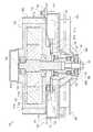
具体的には、図9に示すように、モーアデッキ110の外部(モーアデッキ110の上方)の空気は、作業用モータ120のハウジング121の側面と第一シュラウド160との間の空間を上方から下方に向かって流通する。この際、作業用モータ120のそばを流通する空気によって当該作業用モータ120(ハウジング121の側面)が冷却される。また、ハウジング121の側面にはフィン121d(図7等参照)が形成されているため、当該フィン121dが形成されない場合に比べてハウジング121の表面積が増加している。このため、流通する空気によって当該ハウジング121を効果的に冷却することができる。また、当該フィン121dは第一シュラウド160に接触している。このため、当該フィン121d及び第一シュラウド160を介してモーアデッキ110の外部へと作業用モータ120の熱を放熱することができ、ひいては当該作業用モータ120を効果的に冷却することができる。 Specifically, as shown in FIG. 9, the air outside the mower deck 110 (above the mower deck 110) moves the space between the side surface of the
ハウジング121の側面と第一シュラウド160との間の空間を下方へと流通した空気は、モーアデッキ110の連通孔111bを介して当該モーアデッキ110の内部へと流入する。当該空気は、モーアデッキ110の上面111、第二シュラウド170及びファン140の上板141によって囲まれた空間を、内側(作業用モータ120の軸線に近づく方向)に向かって流通する。この際、モーアデッキ110のそばを流通する空気が当該モーアデッキ110の上面111を介して作業用モータ120(ハウジング121の底面)を冷却する。特に本実施形態においては、作業用モータ120の一部(ハウジング121の下部121cの下端)がモーアデッキ110の内部に配置される。これによって、当該作業用モータ120を、モーアデッキ110の内部の風によって効果的に冷却することができる。 The air flowing downward through the space between the side surface of the
上面111、第二シュラウド170及び上板141によって囲まれた空間を内側へと流通した空気は、当該上板141の中心孔141aを介して当該上板141と下板142との間の空間へと流入する。当該空気は、回転するファン140の羽根143によって外側へと送られる。 The air that has flowed inward through the space surrounded by the
このように、モーア100においては、作業用モータ120の側面及び底面に沿うように空気の流路が形成されているため、当該作業用モータ120を効果的に冷却させることができる。また、モーアデッキ110の内部の空気に比べて、異物(刈り取られた草(芝)や粉塵等)が少ないモーアデッキ110の外部の空気を用いて作業用モータ120を冷却することができる。このため、空気の流路に前記異物が詰まりにくく、冷却性能の低下を抑制することができる。 Thus, in the
以上の如く、本実施形態に係るモーア100は、
回転駆動されることで草を刈り取る回転ブレード150と、
回転ブレード150を回転駆動させる作業用モータ120(モータ)と、
回転ブレード150を内部に収容するモーアデッキ110と、
作業用モータ120に沿うようにモーアデッキ110の内部と外部とを連通する空気の流路を形成する第一シュラウド160(案内部材)と、
を具備するものである。
このように構成することにより、モーアデッキ110の外部から内部へと流通する空気によって、作業用モータ120を効率よく冷却することができる。これによって、作業用モータ120の出力の低下を抑制することができる。As described above, the
A
A working motor 120 (motor) for rotationally driving the
A
A first shroud 160 (guide member) that forms an air flow path that communicates the interior and exterior of the
It comprises.
With such a configuration, the working
また、第一シュラウド160は、
作業用モータ120の側面と対向するように配置されるものである。
このように構成することにより、作業用モータ120の側面を効率よく冷却することができる。The
It is arranged to face the side surface of the
By comprising in this way, the side surface of the working
また、作業用モータ120は、
側面から外側に向かって延びるように形成されると共に、外側の端部が第一シュラウド160と接触するように形成される少なくとも1つのフィン121dを具備するものである。
このように構成することにより、作業用モータ120の表面積を増加させることができ、当該作業用モータ120を効率よく冷却することができる。また、フィン121d及び第一シュラウド160を介して放熱することができ、作業用モータ120をより効率よく冷却することができる。
また、フィン121dを第一シュラウド160に接触させることで、当該第一シュラウド160の変形や破損の発生を抑制することができる。The working
It has at least one
By comprising in this way, the surface area of the working
In addition, by bringing the
また、モーア100は、
モーアデッキ110の外部から内部へと空気を送るファン140をさらに具備するものである。
このように構成することにより、空気の流量を増加させることができ、作業用モータ120をより効率よく冷却することができる。In addition, the
A
By comprising in this way, the flow volume of air can be increased and the working
また、ファン140は、
作業用モータ120によって駆動されるものである。
このように構成することにより、ファン140を駆動するための駆動源を別途設ける必要がない。In addition, the
It is driven by the
With this configuration, it is not necessary to separately provide a drive source for driving the
なお、本実施形態に係るモーア100は本発明に係るモーアの実施の一形態であり、本発明の技術的思想の範囲内で、各部の具体的な構成を任意に変更することが可能である。 The
また、モーア100に設けられる作業用モータ120の個数は特に限定するものではない。また、1つの作業用モータ120で複数の回転ブレード150を回転駆動させる構成とすることも可能である。 Further, the number of
また、フィン121dの個数は特に限定するものではない。フィン121dの個数を増やすことで、作業用モータ120(ハウジング121)の表面積を増加させることができる。 Further, the number of
また、モーア100にファン140を設けない構成とすることも可能である。この場合、回転ブレード150の回転に伴って、空気を流通させることができる。 Further, the
また、ファン140は、作業用モータ120の下方に限らず、任意の位置に配置することが可能である。例えば、作業用モータ120の上方に配置し、下方(モーアデッキ110の内部)に向かって空気を送る構成とすることも可能である。Further, the
なお、本発明に係るモーアが設けられる草刈機の構成は、上述の草刈機1(図1及び図2参照)に限るものではない。すなわち、本発明に係るモーアは、乗用型(作業者が搭乗して草刈作業を行うもの)、非乗用型(作業者が搭乗せずに草刈作業を行うもの)に限らず、任意に構成された種々の草刈機に適用することが可能である。また、本発明に係るモーアは、電力によって走行する(電動の)草刈機にも、エンジンの動力によって走行する草刈機にも適用することが可能である。 The configuration of the mower provided with the mower according to the present invention is not limited to the
例えば、図10に示すように、作業者が着座することなく、立った状態で搭乗する草刈機10にモーア(図10においては、モーア100を例示している)を適用しても良い。当該草刈機10は、走行機体11、原動部12、駆動輪13、搭乗部14、従動輪15、ハンドル16及びモーア100を具備する。For example, as shown in FIG.10 , the mower (the
走行機体11は、左右一対の駆動輪13によって支持される。走行機体11には、左右一対の駆動輪13を駆動するための原動部12が設けられる。走行機体11の後部には、作業者が立った状態で搭乗する搭乗部14が連結される。搭乗部14の後部には、左右一対の従動輪15が設けられる。走行機体11の上部には、ハンドル16が上方に向かって延びるように設けられる。走行機体11の前部にはモーア100が連結される。 The traveling
このように構成された草刈機10において、作業者は搭乗部14に乗ってハンドル16を手で掴むことで、草刈機10に安定して搭乗することができる。作業者は、所定の操作(例えば、ハンドル16を前後又は左右に揺動させる、作業者自身の重心を移動させる等)を行うことで、左右一対の駆動輪13をそれぞれ独立して駆動させ、草刈機10を任意に走行させることができる。 In the
100 モーア
110 モーアデッキ
120 作業用モータ
121d フィン
140 ファン
150 回転ブレード
160 第一シュラウド
170 第二シュラウド100
Claims (4)
Translated fromJapanese前記回転ブレードを回転駆動させるモータと、
前記回転ブレードを内部に収容するモーアデッキと、
前記モータに沿うように前記モーアデッキの内部と外部とを連通する空気の流路を形成する案内部材と、
を具備し、
前記案内部材は、
第一案内部材及び第二案内部材を含み、
前記第一案内部材は、
前記モーアデッキの上面に載置され、前記モータの側面を外側から囲むような円筒状、かつ前記モータの側面の上端と同じ高さに上端が位置するように形成され、前記モータの側面との間に、上方に向かって開口されると共に前記モータの側面に沿って空気を下方へと案内する前記空気の流路を形成し、
前記第二案内部材は、
前記モーアデッキの内部において前記上面に当接され、平面視において前記モータを外側から囲むような円筒状に形成され、
前記第一案内部材及び前記第二案内部材は、
前記上面を介して互いに固定されることによって、前記モーアデッキに固定される、
モーア。A rotating blade that cuts grass by being driven to rotate;
A motor for rotating the rotary blade;
A moor deck that houses the rotating blades therein;
A guide member that forms an air flow path that communicates the inside and outside of the mower deck along the motor;
Comprising
The guide member is
Including a first guide member and a second guide member,
The first guide member is
It is mounted on the upper surface of the mower deck, is cylindrical so as to surround the sidesurface of the motor from the outside, and is formed so that the upper end is positioned at the same height as the upper end of the side surface of the motor, and between the side surfaces of the motor toform a flow path of the air guided downward air along the side of the motor while being open upward,
The second guide member is
It is in contact with the upper surface inside the mower deck, and is formed in a cylindrical shape surrounding the motor from the outside in plan view,
The first guide member and the second guide member are
Fixed to the moor deck by being fixed to each other via the upper surface;
Moore.
前記モータの底面と対向するように配置され、前記空気の流路を介して前記モーアデッキの外部から内部へと空気を送るファンを含み、
前記ファンは、
板部及び前記板部の底面に固定された羽根を有し、前記板部及び前記モータの底面との間に前記空気の流路を形成している、
請求項1に記載のモーア。The guide member is
A fan that is arranged to face the bottom surface of the motor and sends air from the outside to the inside of the mower deck through the air flow path;
The fan is
It has blades fixed to the bottom surface of the plate portion and the plate portion, and forms the air flow path between the plate portion and the bottom surface of the motor.
The moor of claim 1.
前記モータによって駆動される、
請求項2に記載のモーア。The fan is
Driven by the motor,
The mower according toclaim 2 .
側面から外側に向かって延びるように形成されると共に、外側の端部が前記第一案内部材と接触するように形成される少なくとも1つのフィンを具備する、
請求項1から請求項3までのいずれか一項に記載のモーア。The motor is
At least one fin formed to extend outward from the side surface and having an outer end in contact with the first guide member;
The mower according to any one of claims 1 to 3 .
Priority Applications (2)
| Application Number | Priority Date | Filing Date | Title |
|---|---|---|---|
| JP2014123822AJP6322061B2 (en) | 2014-06-16 | 2014-06-16 | Moore |
| US14/640,545US10188032B2 (en) | 2014-06-16 | 2015-03-06 | Mower with motor cooling |
Applications Claiming Priority (1)
| Application Number | Priority Date | Filing Date | Title |
|---|---|---|---|
| JP2014123822AJP6322061B2 (en) | 2014-06-16 | 2014-06-16 | Moore |
Related Child Applications (1)
| Application Number | Title | Priority Date | Filing Date |
|---|---|---|---|
| JP2017060090ADivisionJP6368816B2 (en) | 2017-03-24 | 2017-03-24 | Moore |
Publications (2)
| Publication Number | Publication Date |
|---|---|
| JP2016002029A JP2016002029A (en) | 2016-01-12 |
| JP6322061B2true JP6322061B2 (en) | 2018-05-09 |
Family
ID=54835026
Family Applications (1)
| Application Number | Title | Priority Date | Filing Date |
|---|---|---|---|
| JP2014123822AActiveJP6322061B2 (en) | 2014-06-16 | 2014-06-16 | Moore |
Country Status (2)
| Country | Link |
|---|---|
| US (1) | US10188032B2 (en) |
| JP (1) | JP6322061B2 (en) |
Families Citing this family (15)
| Publication number | Priority date | Publication date | Assignee | Title |
|---|---|---|---|---|
| AU2015101710A4 (en) | 2014-11-25 | 2015-12-24 | Nanjing Chervon Industry Co., Ltd. | Grass Trimmer |
| US10485165B2 (en)* | 2014-11-25 | 2019-11-26 | Chervon (Hk) Limited | Grass trimmer |
| FR3039355B1 (en)* | 2015-07-27 | 2017-07-14 | Pellenc Sa | ELECTRIC MOWER WITH MULTIPLE BLADES |
| WO2019035021A1 (en)* | 2017-08-16 | 2019-02-21 | Briggs & Stratton Corporation | Zero turn radius lawnmower having front and rear wheels related in rotation about a single pivot axis |
| US11382264B2 (en)* | 2017-11-02 | 2022-07-12 | Kubota Corporation | Mower unit for heat discharge and soundproofing |
| EP4570055A3 (en) | 2017-12-28 | 2025-08-27 | Nanjing Chervon Industry Co., Ltd. | Electric riding lawn mower |
| US12342761B2 (en) | 2017-12-28 | 2025-07-01 | Nanjing Chervon Industry Co., Ltd. | Outdoor moving device |
| US20200113133A1 (en)* | 2018-10-12 | 2020-04-16 | Briggs & Stratton Corporation | Electric stand-on mower |
| US11490566B2 (en)* | 2019-04-08 | 2022-11-08 | Honda Motor Co., Ltd. | Apparatus and method for cooling lawnmower components |
| CN114929009A (en)* | 2019-10-11 | 2022-08-19 | 艾瑞斯公司 | Electric motor and blade assembly for lawn mower |
| JP7390998B2 (en)* | 2020-09-16 | 2023-12-04 | 株式会社クボタ | grass cutting equipment |
| CN112673800B (en)* | 2020-12-22 | 2021-11-23 | 聊城市誉林工业设计有限公司 | Hand-push type mower |
| US12329063B2 (en) | 2021-02-12 | 2025-06-17 | Techtronic Cordless Gp | Handle assembly for a power tool |
| US11973396B2 (en)* | 2021-03-31 | 2024-04-30 | Honda Motor Co., Ltd. | Electric transmission for an electric lawnmower |
| CN218998877U (en)* | 2021-06-25 | 2023-05-12 | 南京泉峰科技有限公司 | riding lawn mower |
Family Cites Families (58)
| Publication number | Priority date | Publication date | Assignee | Title |
|---|---|---|---|---|
| US2791078A (en)* | 1953-08-12 | 1957-05-07 | Elmer C Kiekhaefer | Power mower with cutter blade fan for cooling and exhausting motor |
| US2762184A (en)* | 1954-05-11 | 1956-09-11 | Ray R Farrer | Blower attachment for lawn mowers |
| US2919756A (en)* | 1956-03-02 | 1960-01-05 | Earl A Knipe | Riding mower |
| US2891371A (en)* | 1957-03-11 | 1959-06-23 | William A Duncan | Lawn mower |
| US3044239A (en)* | 1960-09-09 | 1962-07-17 | Briggs & Stratton Corp | Rotary power lawn mower with improved engine |
| US3298163A (en)* | 1961-08-28 | 1967-01-17 | Sunbeam Corp | Rotary electric lawn mower |
| US3091906A (en)* | 1962-04-30 | 1963-06-04 | Russell V Hall | Power lawn mower |
| GB1034760A (en)* | 1965-05-29 | 1966-07-06 | Flymo Sa | Improvements in lawn mowers |
| US3468108A (en)* | 1966-07-05 | 1969-09-23 | Sunbeam Corp | Lawn mower |
| US3500620A (en)* | 1967-05-05 | 1970-03-17 | Black & Decker Mfg Co | Electric lawnmower construction |
| DE1582405A1 (en)* | 1967-07-13 | 1970-04-30 | Solo Kleinmotoren Gmbh | Mowing machine |
| US3593505A (en)* | 1968-09-04 | 1971-07-20 | Toro Mfg Corp | Mower motor cooling system |
| US3641749A (en)* | 1970-10-05 | 1972-02-15 | Black & Decker Mfg Co | Baffle for electric lawnmower |
| GB1448539A (en)* | 1974-11-29 | 1976-09-08 | Flymo Sa | Rotary-scythe lawn mower with means for generating a cushion of air |
| JPS51102980A (en)* | 1975-04-04 | 1976-09-10 | Hitachi Ltd | SHIBAKARIKI |
| CA1030774A (en)* | 1975-08-21 | 1978-05-09 | Canadian General Electric Company Limited | Rotary lawn mower with improved grass collector |
| CA1039514A (en)* | 1975-08-21 | 1978-10-03 | Edward Szymanis | Rotary lawn mower with separate grass pick up |
| CA1050094A (en)* | 1975-09-08 | 1979-03-06 | Leonard A. Scott | Ventilated mower motor |
| AU515003B2 (en) | 1977-07-12 | 1981-03-12 | Commonwealth Scientific And Industrial Research Organisation | Grass mower |
| SE7901767L (en)* | 1978-03-13 | 1979-09-14 | Flymo Sa | LAWNMOWER |
| CA1093312A (en)* | 1978-07-07 | 1981-01-13 | Edward Szymanis | Safety lawn mower and grass collector |
| US4232505A (en)* | 1978-08-09 | 1980-11-11 | The Toro Company | Dual element filament mower |
| ATE1729T1 (en)* | 1978-10-03 | 1982-11-15 | Black & Decker Inc. | MOWER. |
| FR2490451A2 (en)* | 1980-09-23 | 1982-03-26 | Bernard Moteurs | CARTER FOR LAWN MOWER |
| JPS58123701A (en) | 1982-01-19 | 1983-07-23 | 株式会社東芝 | Manufacturing method of resistor board |
| DE3204975C1 (en) | 1982-02-12 | 1983-05-19 | Echt & Co, Nachf. Schulte Kg, 5750 Menden | Double-leaf door with closing sequence control |
| DE3232895C2 (en)* | 1982-09-04 | 1986-02-13 | Gutbrod-Werke GmbH, 6601 Bübingen | Sickle lawn mower with electric drive |
| GB2140663B (en)* | 1983-05-31 | 1986-08-06 | Makita Electric Works Ltd | Lawn mower |
| US4514967A (en)* | 1983-08-03 | 1985-05-07 | Roper Corporation | Bridge support for securing sulky to walk-behind mower |
| US4718221A (en)* | 1986-05-21 | 1988-01-12 | Wessel Lloyd E | Lawnmower edger and trimmer |
| US4881361A (en)* | 1987-09-28 | 1989-11-21 | Cameron Constructors, Inc. | Wheeled vehicles for ground work |
| US4944142A (en)* | 1988-08-22 | 1990-07-31 | Honda Giken Kogyo Kabushiki Kaisha | Power lawnmower construction |
| JPH0628984Y2 (en)* | 1989-03-29 | 1994-08-10 | 本田技研工業株式会社 | Electric motor cooling structure of electric lawn mower |
| US5020309A (en)* | 1989-11-08 | 1991-06-04 | Textron, Inc. | Leaf shredder attachment for a mower bagging system |
| US5239810A (en)* | 1990-03-29 | 1993-08-31 | Gugel Leslie H | Centrally mounted driver carrier control unit |
| US5483788A (en)* | 1990-05-24 | 1996-01-16 | Fassauer; Arthur L. | Cutting apparatus mulch recycle system |
| US5819513A (en)* | 1993-09-22 | 1998-10-13 | Briggs & Stratton Corporation | Power head assembly for electric grass cutting device |
| JP3577964B2 (en)* | 1998-07-31 | 2004-10-20 | 株式会社トヨトミ | Mowing grass discharge structure of rotary lawn mower |
| JP3589170B2 (en) | 2000-09-26 | 2004-11-17 | 松下電工株式会社 | Lawn mower |
| JP3776773B2 (en)* | 2001-08-22 | 2006-05-17 | 本田技研工業株式会社 | Electric lawn mower |
| TWM278226U (en)* | 2001-08-22 | 2005-10-21 | Honda Motor Co Ltd | Electric lawn mower |
| US20040083701A1 (en)* | 2002-10-31 | 2004-05-06 | Brower David R. | Enclosed lawnmower engine with underdeck muffler |
| US6948299B2 (en)* | 2002-11-22 | 2005-09-27 | Honda Motor Company, Ltd. | Hybrid power equipment |
| US20060059879A1 (en) | 2004-09-20 | 2006-03-23 | Edmond Brian W | Multifunction electric tractor |
| WO2006044624A2 (en)* | 2004-10-18 | 2006-04-27 | North American Clutch Corporation | Clutch/brake assembly with eletrical generation system |
| US8429885B2 (en)* | 2008-04-25 | 2013-04-30 | Black & Decker Inc. | Cordless mower including cooling air flow arrangement |
| EP2346709B1 (en)* | 2008-10-23 | 2022-03-23 | Hydro-Gear Limited Partnership | Control systems and methods for electric motors of utility vehicles |
| US8227948B1 (en)* | 2009-01-09 | 2012-07-24 | Hydro-Gear Limited Partnership | Electric motor |
| US8191343B1 (en)* | 2009-06-26 | 2012-06-05 | Hydro-Gear Limited Partnership | Systems and methods for cooling a controller assembly |
| JP2011211980A (en)* | 2010-03-31 | 2011-10-27 | Hitachi Koki Co Ltd | Lawnmower |
| US8615976B1 (en)* | 2010-06-21 | 2013-12-31 | Hydro-Gear Limited Partnership | Electric motor clutch/brake assembly |
| JP5615730B2 (en)* | 2011-02-17 | 2014-10-29 | ヤンマー株式会社 | Electric riding mower |
| WO2013009324A1 (en)* | 2011-07-14 | 2013-01-17 | Husqvarna Ab | Riding lawn mower including battery powered cutting system |
| WO2013009325A1 (en)* | 2011-07-14 | 2013-01-17 | Husqvarna Ab | Riding lawn mower including battery powered drive system |
| JP5722716B2 (en)* | 2011-07-14 | 2015-05-27 | ヤンマー株式会社 | Electric working machine |
| CN103813918B (en)* | 2011-07-14 | 2018-04-13 | 胡斯华纳有限公司 | Straddle riding type grass trimmer including distributed battery systems |
| EP3011822A4 (en)* | 2013-06-19 | 2017-02-01 | Yanmar Co., Ltd. | Electric work vehicle |
| JP6211470B2 (en)* | 2014-06-16 | 2017-10-11 | 株式会社クボタ | Moore |
- 2014
- 2014-06-16JPJP2014123822Apatent/JP6322061B2/enactiveActive
- 2015
- 2015-03-06USUS14/640,545patent/US10188032B2/enactiveActive
Also Published As
| Publication number | Publication date |
|---|---|
| US10188032B2 (en) | 2019-01-29 |
| JP2016002029A (en) | 2016-01-12 |
| US20150359174A1 (en) | 2015-12-17 |
Similar Documents
| Publication | Publication Date | Title |
|---|---|---|
| JP6322061B2 (en) | Moore | |
| JP6211470B2 (en) | Moore | |
| JP6509060B2 (en) | Mowing machine | |
| JP5180675B2 (en) | Riding lawn mower | |
| JP6559113B2 (en) | Electric lawn mower | |
| JP5482291B2 (en) | Lawn mower | |
| EP3729946B1 (en) | Mower | |
| US11582909B2 (en) | Mower unit | |
| JP2017163871A (en) | Lawn mower | |
| JP6368816B2 (en) | Moore | |
| JP2017163872A (en) | Lawn mower | |
| JP2013123392A (en) | Lawn mower | |
| WO2019049045A1 (en) | Dual blade walk-behind mower | |
| JP2012228200A (en) | Mowing machine and mowing equipment | |
| AU2015377239B2 (en) | Cutting deck flow control assembly | |
| JP2022049458A (en) | Mowing device | |
| JP2021007358A (en) | Lawn mower | |
| JP2012157282A (en) | Lawn mower | |
| JP2007300897A (en) | Rotary lawn mower | |
| JP2024154551A (en) | Grass trimmer and grass cutting guide | |
| JP2007312638A (en) | Arrangement structure of electric motor of self-propelled lawn mower | |
| JP2017063627A (en) | Walking-type working machine | |
| NZ742829B2 (en) | Cutting deck flow control assembly |
Legal Events
| Date | Code | Title | Description |
|---|---|---|---|
| A621 | Written request for application examination | Free format text:JAPANESE INTERMEDIATE CODE: A621 Effective date:20160627 | |
| A977 | Report on retrieval | Free format text:JAPANESE INTERMEDIATE CODE: A971007 Effective date:20170209 | |
| A131 | Notification of reasons for refusal | Free format text:JAPANESE INTERMEDIATE CODE: A131 Effective date:20170214 | |
| A521 | Written amendment | Free format text:JAPANESE INTERMEDIATE CODE: A523 Effective date:20170324 | |
| A131 | Notification of reasons for refusal | Free format text:JAPANESE INTERMEDIATE CODE: A131 Effective date:20170905 | |
| A521 | Written amendment | Free format text:JAPANESE INTERMEDIATE CODE: A523 Effective date:20171005 | |
| TRDD | Decision of grant or rejection written | ||
| A01 | Written decision to grant a patent or to grant a registration (utility model) | Free format text:JAPANESE INTERMEDIATE CODE: A01 Effective date:20180327 | |
| A61 | First payment of annual fees (during grant procedure) | Free format text:JAPANESE INTERMEDIATE CODE: A61 Effective date:20180406 | |
| R150 | Certificate of patent or registration of utility model | Ref document number:6322061 Country of ref document:JP Free format text:JAPANESE INTERMEDIATE CODE: R150 |