JP6321192B2 - Light emitting module, lamp, luminaire, and method of irradiating an object - Google Patents
Light emitting module, lamp, luminaire, and method of irradiating an objectDownload PDFInfo
- Publication number
- JP6321192B2 JP6321192B2JP2016553018AJP2016553018AJP6321192B2JP 6321192 B2JP6321192 B2JP 6321192B2JP 2016553018 AJP2016553018 AJP 2016553018AJP 2016553018 AJP2016553018 AJP 2016553018AJP 6321192 B2JP6321192 B2JP 6321192B2
- Authority
- JP
- Japan
- Prior art keywords
- light
- light emitting
- emitting module
- peak
- nanometers
- Prior art date
- Legal status (The legal status is an assumption and is not a legal conclusion. Google has not performed a legal analysis and makes no representation as to the accuracy of the status listed.)
- Active
Links
Images


Classifications
- H—ELECTRICITY
- H01—ELECTRIC ELEMENTS
- H01L—SEMICONDUCTOR DEVICES NOT COVERED BY CLASS H10
- H01L25/00—Assemblies consisting of a plurality of semiconductor or other solid state devices
- H01L25/03—Assemblies consisting of a plurality of semiconductor or other solid state devices all the devices being of a type provided for in a single subclass of subclasses H10B, H10D, H10F, H10H, H10K or H10N, e.g. assemblies of rectifier diodes
- H01L25/04—Assemblies consisting of a plurality of semiconductor or other solid state devices all the devices being of a type provided for in a single subclass of subclasses H10B, H10D, H10F, H10H, H10K or H10N, e.g. assemblies of rectifier diodes the devices not having separate containers
- H01L25/075—Assemblies consisting of a plurality of semiconductor or other solid state devices all the devices being of a type provided for in a single subclass of subclasses H10B, H10D, H10F, H10H, H10K or H10N, e.g. assemblies of rectifier diodes the devices not having separate containers the devices being of a type provided for in group H10H20/00
- H01L25/0753—Assemblies consisting of a plurality of semiconductor or other solid state devices all the devices being of a type provided for in a single subclass of subclasses H10B, H10D, H10F, H10H, H10K or H10N, e.g. assemblies of rectifier diodes the devices not having separate containers the devices being of a type provided for in group H10H20/00 the devices being arranged next to each other
- C—CHEMISTRY; METALLURGY
- C09—DYES; PAINTS; POLISHES; NATURAL RESINS; ADHESIVES; COMPOSITIONS NOT OTHERWISE PROVIDED FOR; APPLICATIONS OF MATERIALS NOT OTHERWISE PROVIDED FOR
- C09K—MATERIALS FOR MISCELLANEOUS APPLICATIONS, NOT PROVIDED FOR ELSEWHERE
- C09K11/00—Luminescent, e.g. electroluminescent, chemiluminescent materials
- F—MECHANICAL ENGINEERING; LIGHTING; HEATING; WEAPONS; BLASTING
- F21—LIGHTING
- F21K—NON-ELECTRIC LIGHT SOURCES USING LUMINESCENCE; LIGHT SOURCES USING ELECTROCHEMILUMINESCENCE; LIGHT SOURCES USING CHARGES OF COMBUSTIBLE MATERIAL; LIGHT SOURCES USING SEMICONDUCTOR DEVICES AS LIGHT-GENERATING ELEMENTS; LIGHT SOURCES NOT OTHERWISE PROVIDED FOR
- F21K9/00—Light sources using semiconductor devices as light-generating elements, e.g. using light-emitting diodes [LED] or lasers
- F21K9/20—Light sources comprising attachment means
- F21K9/23—Retrofit light sources for lighting devices with a single fitting for each light source, e.g. for substitution of incandescent lamps with bayonet or threaded fittings
- F21K9/232—Retrofit light sources for lighting devices with a single fitting for each light source, e.g. for substitution of incandescent lamps with bayonet or threaded fittings specially adapted for generating an essentially omnidirectional light distribution, e.g. with a glass bulb
- F—MECHANICAL ENGINEERING; LIGHTING; HEATING; WEAPONS; BLASTING
- F21—LIGHTING
- F21K—NON-ELECTRIC LIGHT SOURCES USING LUMINESCENCE; LIGHT SOURCES USING ELECTROCHEMILUMINESCENCE; LIGHT SOURCES USING CHARGES OF COMBUSTIBLE MATERIAL; LIGHT SOURCES USING SEMICONDUCTOR DEVICES AS LIGHT-GENERATING ELEMENTS; LIGHT SOURCES NOT OTHERWISE PROVIDED FOR
- F21K9/00—Light sources using semiconductor devices as light-generating elements, e.g. using light-emitting diodes [LED] or lasers
- F21K9/60—Optical arrangements integrated in the light source, e.g. for improving the colour rendering index or the light extraction
- F21K9/64—Optical arrangements integrated in the light source, e.g. for improving the colour rendering index or the light extraction using wavelength conversion means distinct or spaced from the light-generating element, e.g. a remote phosphor layer
- F—MECHANICAL ENGINEERING; LIGHTING; HEATING; WEAPONS; BLASTING
- F21—LIGHTING
- F21S—NON-PORTABLE LIGHTING DEVICES; SYSTEMS THEREOF; VEHICLE LIGHTING DEVICES SPECIALLY ADAPTED FOR VEHICLE EXTERIORS
- F21S2/00—Systems of lighting devices, not provided for in main groups F21S4/00 - F21S10/00 or F21S19/00, e.g. of modular construction
- F21S2/005—Systems of lighting devices, not provided for in main groups F21S4/00 - F21S10/00 or F21S19/00, e.g. of modular construction of modular construction
- F—MECHANICAL ENGINEERING; LIGHTING; HEATING; WEAPONS; BLASTING
- F21—LIGHTING
- F21V—FUNCTIONAL FEATURES OR DETAILS OF LIGHTING DEVICES OR SYSTEMS THEREOF; STRUCTURAL COMBINATIONS OF LIGHTING DEVICES WITH OTHER ARTICLES, NOT OTHERWISE PROVIDED FOR
- F21V9/00—Elements for modifying spectral properties, polarisation or intensity of the light emitted, e.g. filters
- F21V9/08—Elements for modifying spectral properties, polarisation or intensity of the light emitted, e.g. filters for producing coloured light, e.g. monochromatic; for reducing intensity of light
- F—MECHANICAL ENGINEERING; LIGHTING; HEATING; WEAPONS; BLASTING
- F21—LIGHTING
- F21V—FUNCTIONAL FEATURES OR DETAILS OF LIGHTING DEVICES OR SYSTEMS THEREOF; STRUCTURAL COMBINATIONS OF LIGHTING DEVICES WITH OTHER ARTICLES, NOT OTHERWISE PROVIDED FOR
- F21V9/00—Elements for modifying spectral properties, polarisation or intensity of the light emitted, e.g. filters
- F21V9/30—Elements containing photoluminescent material distinct from or spaced from the light source
- F21V9/38—Combination of two or more photoluminescent elements of different materials
- F—MECHANICAL ENGINEERING; LIGHTING; HEATING; WEAPONS; BLASTING
- F21—LIGHTING
- F21V—FUNCTIONAL FEATURES OR DETAILS OF LIGHTING DEVICES OR SYSTEMS THEREOF; STRUCTURAL COMBINATIONS OF LIGHTING DEVICES WITH OTHER ARTICLES, NOT OTHERWISE PROVIDED FOR
- F21V9/00—Elements for modifying spectral properties, polarisation or intensity of the light emitted, e.g. filters
- F21V9/40—Elements for modifying spectral properties, polarisation or intensity of the light emitted, e.g. filters with provision for controlling spectral properties, e.g. colour, or intensity
- F21V9/45—Elements for modifying spectral properties, polarisation or intensity of the light emitted, e.g. filters with provision for controlling spectral properties, e.g. colour, or intensity by adjustment of photoluminescent elements
- H—ELECTRICITY
- H05—ELECTRIC TECHNIQUES NOT OTHERWISE PROVIDED FOR
- H05B—ELECTRIC HEATING; ELECTRIC LIGHT SOURCES NOT OTHERWISE PROVIDED FOR; CIRCUIT ARRANGEMENTS FOR ELECTRIC LIGHT SOURCES, IN GENERAL
- H05B45/00—Circuit arrangements for operating light-emitting diodes [LED]
- H05B45/20—Controlling the colour of the light
- H—ELECTRICITY
- H10—SEMICONDUCTOR DEVICES; ELECTRIC SOLID-STATE DEVICES NOT OTHERWISE PROVIDED FOR
- H10H—INORGANIC LIGHT-EMITTING SEMICONDUCTOR DEVICES HAVING POTENTIAL BARRIERS
- H10H20/00—Individual inorganic light-emitting semiconductor devices having potential barriers, e.g. light-emitting diodes [LED]
- H10H20/80—Constructional details
- H10H20/85—Packages
- H10H20/851—Wavelength conversion means
- H10H20/8511—Wavelength conversion means characterised by their material, e.g. binder
- H10H20/8512—Wavelength conversion materials
- H10H20/8513—Wavelength conversion materials having two or more wavelength conversion materials
- F—MECHANICAL ENGINEERING; LIGHTING; HEATING; WEAPONS; BLASTING
- F21—LIGHTING
- F21S—NON-PORTABLE LIGHTING DEVICES; SYSTEMS THEREOF; VEHICLE LIGHTING DEVICES SPECIALLY ADAPTED FOR VEHICLE EXTERIORS
- F21S8/00—Lighting devices intended for fixed installation
- F21S8/04—Lighting devices intended for fixed installation intended only for mounting on a ceiling or the like overhead structures
- F21S8/06—Lighting devices intended for fixed installation intended only for mounting on a ceiling or the like overhead structures by suspension
- F—MECHANICAL ENGINEERING; LIGHTING; HEATING; WEAPONS; BLASTING
- F21—LIGHTING
- F21V—FUNCTIONAL FEATURES OR DETAILS OF LIGHTING DEVICES OR SYSTEMS THEREOF; STRUCTURAL COMBINATIONS OF LIGHTING DEVICES WITH OTHER ARTICLES, NOT OTHERWISE PROVIDED FOR
- F21V33/00—Structural combinations of lighting devices with other articles, not otherwise provided for
- F21V33/006—General building constructions or finishing work for buildings, e.g. roofs, gutters, stairs or floors; Garden equipment; Sunshades or parasols
- F—MECHANICAL ENGINEERING; LIGHTING; HEATING; WEAPONS; BLASTING
- F21—LIGHTING
- F21Y—INDEXING SCHEME ASSOCIATED WITH SUBCLASSES F21K, F21L, F21S and F21V, RELATING TO THE FORM OR THE KIND OF THE LIGHT SOURCES OR OF THE COLOUR OF THE LIGHT EMITTED
- F21Y2113/00—Combination of light sources
- F21Y2113/10—Combination of light sources of different colours
- F21Y2113/13—Combination of light sources of different colours comprising an assembly of point-like light sources
- F—MECHANICAL ENGINEERING; LIGHTING; HEATING; WEAPONS; BLASTING
- F21—LIGHTING
- F21Y—INDEXING SCHEME ASSOCIATED WITH SUBCLASSES F21K, F21L, F21S and F21V, RELATING TO THE FORM OR THE KIND OF THE LIGHT SOURCES OR OF THE COLOUR OF THE LIGHT EMITTED
- F21Y2115/00—Light-generating elements of semiconductor light sources
- F21Y2115/10—Light-emitting diodes [LED]
- H—ELECTRICITY
- H01—ELECTRIC ELEMENTS
- H01L—SEMICONDUCTOR DEVICES NOT COVERED BY CLASS H10
- H01L2924/00—Indexing scheme for arrangements or methods for connecting or disconnecting semiconductor or solid-state bodies as covered by H01L24/00
- H01L2924/0001—Technical content checked by a classifier
- H01L2924/0002—Not covered by any one of groups H01L24/00, H01L24/00 and H01L2224/00
- H—ELECTRICITY
- H10—SEMICONDUCTOR DEVICES; ELECTRIC SOLID-STATE DEVICES NOT OTHERWISE PROVIDED FOR
- H10H—INORGANIC LIGHT-EMITTING SEMICONDUCTOR DEVICES HAVING POTENTIAL BARRIERS
- H10H20/00—Individual inorganic light-emitting semiconductor devices having potential barriers, e.g. light-emitting diodes [LED]
- H10H20/80—Constructional details
- H10H20/85—Packages
- H10H20/851—Wavelength conversion means
- Y—GENERAL TAGGING OF NEW TECHNOLOGICAL DEVELOPMENTS; GENERAL TAGGING OF CROSS-SECTIONAL TECHNOLOGIES SPANNING OVER SEVERAL SECTIONS OF THE IPC; TECHNICAL SUBJECTS COVERED BY FORMER USPC CROSS-REFERENCE ART COLLECTIONS [XRACs] AND DIGESTS
- Y02—TECHNOLOGIES OR APPLICATIONS FOR MITIGATION OR ADAPTATION AGAINST CLIMATE CHANGE
- Y02B—CLIMATE CHANGE MITIGATION TECHNOLOGIES RELATED TO BUILDINGS, e.g. HOUSING, HOUSE APPLIANCES OR RELATED END-USER APPLICATIONS
- Y02B20/00—Energy efficient lighting technologies, e.g. halogen lamps or gas discharge lamps
Landscapes
- Engineering & Computer Science (AREA)
- Physics & Mathematics (AREA)
- General Engineering & Computer Science (AREA)
- Microelectronics & Electronic Packaging (AREA)
- Spectroscopy & Molecular Physics (AREA)
- Power Engineering (AREA)
- Optics & Photonics (AREA)
- Chemical & Material Sciences (AREA)
- Computer Hardware Design (AREA)
- General Physics & Mathematics (AREA)
- Condensed Matter Physics & Semiconductors (AREA)
- Materials Engineering (AREA)
- Organic Chemistry (AREA)
- Led Device Packages (AREA)
- Non-Portable Lighting Devices Or Systems Thereof (AREA)
- Electroluminescent Light Sources (AREA)
Description
Translated fromJapanese本発明は、物体又は環境の照明を行うための発光モジュールの分野に関する。 The present invention relates to the field of light emitting modules for illuminating objects or environments.
本発明は更に、ランプ、照明器具、及び物体又は環境の照明を行う方法に関する。 The invention further relates to a lamp, a luminaire, and a method for illuminating an object or environment.
幾つかの製品で、所謂「増白剤」を使用することが知られている。増白剤は、増白剤に当たる光(例えばUV光)の一部を吸収し、且つ吸収された光を別の色の光へと変換する。この追加の別の色の光は、人の肉眼が物体の色をより魅力的な色として、より鮮明な色として感じるという事実をもたらす。例えば、増白剤は、紙が人の肉眼により白く見えるように白紙に添加される。白紙によって反射される光は、増白剤によって生成される光と共に、「鮮明な白色光(crispy white light)」としばしば呼ばれる。この増白剤を含む白紙が、100%反射する白色物体(増白剤なし)の横に置かれた場合、人の肉眼は、白紙をより白く感じ、100%反射する白色物体の白色を灰色がかった又は黄色/オレンジがかった物体として感じる。増白剤の効果は、自然の昼光及び例えば高圧白熱灯の下で十分に見ることができる。但し、殆どのLEDベースの光源は、増白剤の効果を示さず、具体的には紫外線(より具体的には、UVA光)又は紫色光が増白剤を励起することを研究が示している。LEDベースの光源は、一般的に、これらのUVA又は紫色スペクトル領域では、光をあまり放射しない。 It is known to use so-called “brighteners” in some products. The brightener absorbs a portion of the light that hits the brightener (eg, UV light) and converts the absorbed light into another color of light. This additional different color of light leads to the fact that the human eye perceives the color of the object as a more attractive color and a clearer color. For example, the brightener is added to the white paper so that the paper appears white to the human eye. The light reflected by the white paper, along with the light produced by the brightener, is often referred to as “crispy white light”. When a white paper containing this whitening agent is placed next to a white object that is 100% reflective (no whitening agent), the human eye feels the white paper whiter and the white color of the white object that reflects 100% is gray. Feels as a bluish or yellow / orange object. The effect of the brightener can be fully seen under natural daylight and for example under high pressure incandescent lamps. However, most LED-based light sources do not show the effect of brighteners, and research has shown that ultraviolet light (more specifically, UVA light) or violet light excites the brightener. Yes. LED-based light sources generally emit less light in these UVA or violet spectral regions.
参照により援用される公開特許出願の国際公開第2013/150470号は、殆どのLEDベースの光源が、増白剤による光の励起を引き起こさない光を放射するという問題の解決策を提供する。国際公開第2013/150470号によれば、蛍光体変換発光器(例えば白色光を放射するためのもの)を含む光源において、放射光が増白剤を含む物体に当たると、増白剤が紫色光を吸収し、且つ別の色の光を放射するように、400〜440ナノメートルのスペクトル領域の紫色光を放射する追加の発光器が設けられる。 Published patent application WO 2013/150470, incorporated by reference, provides a solution to the problem that most LED-based light sources emit light that does not cause light excitation by the brightener. According to WO 2013/150470, in a light source including a phosphor-converted light emitter (for example, for emitting white light), when the emitted light strikes an object containing a whitening agent, the whitening agent becomes purple light An additional light emitter that emits violet light in the spectral region of 400-440 nanometers is provided to absorb light and emit light of another color.
前述の特許出願の解決策を用いた場合、依然として、この特許出願の光源によって照明が行われる際に、より魅力的及び/又はより鮮明に見える必要のある製品に増白剤を添加する必要がある。 When using the solution of the aforementioned patent application, it is still necessary to add whitening agents to products that need to look more attractive and / or clearer when illuminated by the light source of this patent application. is there.
本発明の目的は、照明対象の物体を照射するため及び照明対象の物体に増白剤を実際に用いることなく増白剤の使用効果を得るための光源を提供することである。 An object of the present invention is to provide a light source for irradiating an object to be illuminated and for obtaining the effect of using the brightener without actually using the brightener on the object to be illuminated.
本発明の一態様は、発光モジュールを提供する。本発明の別の態様は、ランプを提供する。本発明の更なる態様は、照明器具を提供する。本発明のまた別の態様は、物体を照射する方法を提供する。有利な実施形態は、従属クレームに定義される。 One embodiment of the present invention provides a light emitting module. Another aspect of the present invention provides a lamp. A further aspect of the invention provides a luminaire. Yet another aspect of the invention provides a method for illuminating an object. Advantageous embodiments are defined in the dependent claims.
本発明の一態様による、物体を照射するための発光モジュールは、第1の発光素子及び第2の発光素子を含む。第1の発光素子は、第1の光を放射する。第1の光は、白色光のカラーポイントを有する。第2の発光素子は、青色光のピークを放射する。青色光のピークは、440ナノメートル〜470ナノメートルの範囲内のピーク波長を有し、且つ70ナノメートル未満の半値全幅値として表されるスペクトル幅を有する。 A light emitting module for irradiating an object according to one embodiment of the present invention includes a first light emitting element and a second light emitting element. The first light emitting element emits first light. The first light has a white light color point. The second light emitting element emits a blue light peak. The blue light peak has a peak wavelength in the range of 440 nanometers to 470 nanometers and a spectral width expressed as a full width at half maximum less than 70 nanometers.
本発明者らの洞察は、青色光のピークと共に白色光を放射する発光モジュールが提供されると、この光によって照明が行われる物体及び環境は、人の肉眼により鮮明に見えるというものである。特に、青色光のピークは、この効果をもたらす。照明物体は、白色光の一部の反射と共に、青色光のピークの一部を反射する。青色光のピークの反射された部分は、人の肉眼には、物体が増白剤を含むかのように感じられる。従って、本発光モジュールを用いて、増白剤なしの物体を照射することができ、物体は、人の肉眼には増白剤が添加されているかのように見える。従って、例えば100%白色反射面(増白剤なし)が、増白剤を含む一枚の白紙の横に配置されると、両方の面が人の肉眼には鮮明な白色に見える。 Our insight is that when a light emitting module that emits white light with a blue light peak is provided, the objects and environments illuminated by this light are clearly visible to the human eye. In particular, the blue light peak provides this effect. The illuminating object reflects part of the peak of blue light along with part of the reflection of white light. The reflected portion of the blue light peak is perceived by the human eye as if the object contained a brightener. Therefore, the light emitting module can be used to irradiate an object without a brightening agent, and the object appears to the human eye as if the brightening agent is added. Thus, for example, if a 100% white reflective surface (without whitening agent) is placed beside a blank sheet containing whitening agent, both surfaces will appear clear white to the human eye.
放射白色光は、実質的にBBL上にある、即ち、照明デバイスの動作中、BBLから15SDCM(「等色標準偏差」)内、特に10SDCM内、更に特に5SDCM内にあるカラーポイントを有する。 The radiant white light has a color point that is substantially on the BBL, i.e. within 15 SDCM ("color matching standard deviation") from the BBL, in particular within 10 SDCM, and more particularly within 5 SDCM during operation of the lighting device.
青色光のピークの半値全幅(FWHM:Full Width Half Maximum)値は、70ナノメートル未満でなければならない。ある実施形態では、FWHM値は、60ナノメートル未満、50ナノメートル未満、又は40ナノメートル未満である。ある実施形態では、青色光のピークのピーク波長は、445〜465ナノメートルの範囲内である。 The full width at half maximum (FWHM) value of the blue light peak must be less than 70 nanometers. In certain embodiments, the FWHM value is less than 60 nanometers, less than 50 nanometers, or less than 40 nanometers. In certain embodiments, the peak wavelength of the blue light peak is in the range of 445 to 465 nanometers.
なお、照明物体の視覚的鮮明さは、人の肉眼が照明物体から受け取る光の人の知覚に関係する。より多くの青色光が受け取られた場合、より具体的には440〜470ナノメートルの範囲内の青色光が照明物体からより多く受け取られた場合、照明物体は、人の肉眼にはより鮮明に見える。これは、特に白色面に当てはまる。人の肉眼が、白色面から440〜470ナノメートルの特定の波長範囲の青色光をより多く受け取ると、人間は、白色面をより良い/より白い面と見なし、多くの場合、これは、優れた白色再現と見なされる。白色再現とは、ある特定の発光モジュール又は特定の光源によって照明が行われる際の白色物体の白色外見の質を指す。 Note that the visual clarity of an illuminating object is related to the human perception of light that the human eye receives from the illuminating object. If more blue light is received, more specifically if more blue light in the range of 440 to 470 nanometers is received from the illuminating object, the illuminating object becomes clearer to the human eye. appear. This is especially true for the white surface. When the human naked eye receives more blue light in a specific wavelength range from 440 to 470 nanometers from the white surface, humans regard the white surface as a better / whiter surface, which is often superior It is considered as white reproduction. White reproduction refers to the white appearance quality of a white object when illuminated by a specific light emitting module or a specific light source.
任意選択的に、発光モジュールは、紫外線光を放射せず、紫色光を放射しない。 Optionally, the light emitting module does not emit ultraviolet light and does not emit violet light.
任意選択的に、第1の光のカラーポイントは黒体線上にあり、第1の光及び青色光のピークの合成は、合成カラーポイントを有する。従って、合成カラーポイントは、発光モジュール全体としてのカラーポイントである。第1の発光素子は、第1のエネルギー量の第1の光を放射し、第2の発光素子は、第2のエネルギー量の青色光のピークを放射し、第1のエネルギー量と第2のエネルギー量との比率は、黒体線及びy=0.328+0.13xによって定義される線によって囲まれた領域内において、CIEXYZ色空間の合成カラーポイントの座標を得るように選択される。任意選択的に、合成カラーポイントのx座標は、0.376〜0.445の範囲内にある。本発明者らは、本発光モジュールによって物体の照明が行われた場合に、鮮明な効果が、発光モジュールの発光のカラーポイントが上に定義された領域内にある時に十分に目に見え、x座標が上に定義された範囲内にある時に一層十分に目に見えることを発見した。 Optionally, the color point of the first light is on the black body line and the combination of the first light and blue light peaks has a composite color point. Therefore, the composite color point is the color point of the entire light emitting module. The first light emitting element emits a first light having a first energy amount, and the second light emitting element emits a blue light peak having a second energy amount. Is selected to obtain the coordinates of the composite color point in the CIEXYZ color space within the area bounded by the black body line and the line defined by y = 0.328 + 0.13x. Optionally, the x coordinate of the composite color point is in the range of 0.376 to 0.445. We find that when an object is illuminated by the light-emitting module, the sharp effect is fully visible when the light-emitting color point of the light-emitting module is in the region defined above, and x We have found that it is more fully visible when the coordinates are within the range defined above.
任意選択的に、第1の光は、少なくとも470ナノメートル〜700ナノメートルの実質的に連続したスペクトルである色分布を有する。CIEXYZ色空間では、青色光のピーク及び第1の光の合成は、第1の光のカラーポイントと比較して、僅かに左に及び下方向に移動されたカラーポイントを有する。440ナノメートル〜470ナノメートルにピークを含む実質的に連続したスペクトルを生じさせることなく、例えば、青色、赤色及び緑色光を混合させることによっても、このカラーポイントを得ることができる。連続スペクトルの利点は、光の色調指数が比較的高い点である。少なくとも470ナノメートル〜700ナノメートルの実質的に連続したスペクトルとは、この範囲内のほぼ各波長において光が放射されることを意味し、従って、このスペクトルを表す線は断続を含まない(断続は、約0の値である)。 Optionally, the first light has a color distribution that is a substantially continuous spectrum of at least 470 nanometers to 700 nanometers. In the CIEXYZ color space, the combination of the blue light peak and the first light has a color point moved slightly to the left and down compared to the color point of the first light. This color point can also be obtained, for example, by mixing blue, red and green light without producing a substantially continuous spectrum with a peak at 440 nanometers to 470 nanometers. The advantage of a continuous spectrum is that the color index of light is relatively high. A substantially continuous spectrum of at least 470 nanometers to 700 nanometers means that light is emitted at approximately each wavelength within this range, and thus the line representing this spectrum does not contain any intermittent (intermittent). Is a value of about 0).
任意選択的に、第1の光は、2000〜4000ケルビンの範囲内の色温度を有する。本発明者らは、青色光のピークが上記範囲内の色温度の白色光に付加された時に、照明物体が鮮明に見えるという効果が人の肉眼に十分に目に見えることを発見した。即ち、この色温度範囲においては、青色光のピークの光量は、発光モジュールによって照明が行われた時に照明物体がより「鮮明に」見えるという十分な効果を得るために非常に大きい必要がない。 Optionally, the first light has a color temperature in the range of 2000 to 4000 Kelvin. The present inventors have found that the effect that the illuminated object looks clear when the blue light peak is added to white light having a color temperature within the above range is sufficiently visible to the human eye. That is, in this color temperature range, the light intensity of the blue light peak need not be very large in order to obtain a sufficient effect that the illuminated object looks more “clear” when illuminated by the light emitting module.
任意選択的に、第1の光は、80〜100の範囲内の色調指数(CRI:color rendering index)を有する。ある実施形態では、第1の光の色調指数(CRI)は、90〜100の範囲内である。本発明者らは、青色光のピークが上記範囲のCRIの白色光に付加された時に、照明物体が鮮明に見えるという効果が人の肉眼に十分に目に見えることを発見した。即ち、このCRI範囲においては、青色光のピークの光量は、発光モジュールによって照明が行われた時に照明物体がより「鮮明に」見えるという十分な効果を得るために非常に大きい必要がない。 Optionally, the first light has a color rendering index (CRI) in the range of 80-100. In some embodiments, the first light color index (CRI) is in the range of 90-100. The inventors have discovered that the effect that the illuminating object looks sharp when the blue light peak is added to the CRI white light in the above range is sufficiently visible to the human eye. That is, in this CRI range, the light intensity of the blue light peak need not be very large in order to obtain a sufficient effect that the illuminating object looks more “clear” when illuminated by the light emitting module.
任意選択的に、第1の発光素子は、第1の発光器及び第1のルミネッセント素子を含む。第1の発光器は、440ナノメートル〜460ナノメートルのスペクトル領域内にピーク波長を有する第1の青色光を放射する。ルミネッセント素子は、ルミネッセント材料を含み、第1の青色光の一部を吸収し、且つ吸収された部分を別の色分布に変換するように構成される。別の色分布の放射された光及び第1の青色光の放射された非吸収部分は、第1の光を共に形成する。第2の発光素子は、第2の発光器を含む。従って、白色光は、例えば1つ又は複数の蛍光体を含む発光器を用いて生成される。任意選択的に、第2の発光器は、青色光のピークを放射するように構成される。従って、第2の発光器が例えば固体発光器である場合には、それは、青色光のピークを放射するダイを含み、特定の他の色変換が起こらない。任意選択的に、第2の発光素子は、ルミネッセント材料を含み、且つ第2の発光器によって放射された光を受け取るように配置された第2のルミネッセント素子を含む。第2のルミネッセント素子のルミネッセント材料は、第2の発光器によって放射された光を吸収し、且つ吸収された光を青色光のピークに変換するように構成される。即ち、第2の発光素子は、ルミネッセント材料による色変換を用いて、青色光のピークを得る。このルミネッセント材料は、具体的には、青色光のピークの特性を有する光を放射するように構成される。第2の発光器によって放射される光は、UV光、紫色光、又は440ナノメートル未満のピーク波長を有する青色光でもよいが、ある実施形態では、全てのUV光又は全ての紫色光が、発光モジュールによって吸収され、発光モジュールの周囲に放射されないことに留意されたい。ある実施形態では、全てのUV光又は全ての紫色光が、青色光のピークの光に変換される。上述の通り、第2の発光器は、発光ダイオード等の固体発光器でもよい。但し、第2の発光器は、440ナノメートル〜470ナノメートルのスペクトル領域内の波長を有する青色光を放射するレーザダイオードでもよい。レーザダイオードは、一般的に、狭い光ビームを放射し、且つ任意選択的に、散乱素子及び/又は拡散素子が、狭い光ビームをより広い光ビームへと散乱させ、及び/又は拡散するように設けられ得る。任意選択的に、第1のルミネッセント素子に向けて光を放射する複数の第1の発光器が設けられ得る。任意選択的に、複数の第2の発光器が設けられ得る。第1の発光器の数及び第2の発光器の数の比率は、少なくとも2、ある実施形態では少なくとも3、又は更なる実施形態では少なくとも4である。 Optionally, the first light emitting element includes a first light emitter and a first luminescent element. The first light emitter emits a first blue light having a peak wavelength in the spectral region of 440 nanometers to 460 nanometers. The luminescent element includes a luminescent material and is configured to absorb a portion of the first blue light and convert the absorbed portion to another color distribution. The emitted light of another color distribution and the emitted non-absorbing portion of the first blue light together form the first light. The second light emitting element includes a second light emitter. Thus, white light is generated using a light emitter that includes, for example, one or more phosphors. Optionally, the second light emitter is configured to emit a peak of blue light. Thus, if the second light emitter is, for example, a solid state light emitter, it includes a die that emits blue light peaks and no other color conversion occurs. Optionally, the second light emitting element comprises a second luminescent element comprising a luminescent material and arranged to receive light emitted by the second light emitter. The luminescent material of the second luminescent element is configured to absorb light emitted by the second light emitter and convert the absorbed light into a blue light peak. That is, the second light-emitting element obtains a blue light peak by using color conversion using a luminescent material. This luminescent material is specifically configured to emit light having the characteristics of a blue light peak. The light emitted by the second light emitter may be UV light, violet light, or blue light having a peak wavelength of less than 440 nanometers, but in some embodiments all UV light or all violet light is Note that it is absorbed by the light emitting module and is not emitted around the light emitting module. In some embodiments, all UV light or all violet light is converted to blue light peak light. As described above, the second light emitter may be a solid light emitter such as a light emitting diode. However, the second light emitter may be a laser diode that emits blue light having a wavelength in the spectral region of 440 to 470 nanometers. Laser diodes generally emit a narrow light beam, and optionally so that the scattering and / or diffusing elements scatter and / or diffuse the narrow light beam into a wider light beam. Can be provided. Optionally, a plurality of first light emitters may be provided that emit light toward the first luminescent element. Optionally, a plurality of second light emitters may be provided. The ratio of the number of first light emitters and the number of second light emitters is at least 2, in some embodiments at least 3, or in further embodiments at least 4.
任意選択的に、発光モジュールは、第1の光の放射のオフ及びオンの切り替えとは無関係に、青色光のピークの放射のオン及びオフの切り替えを可能にするように構成される。例えば、第1の発光素子が上述の第1の発光器を含み、第2の発光素子が上述の第2の発光器を含む場合、第1の発光器及び第2の発光器は、駆動回路が第1の発光器から切り離して第2の発光器を駆動できるように電力を受け取る別々の電気コネクタを有する。この最後の任意選択的な実施形態では、発光モジュールは、電力を受け取る幾つかのピンを有することができ、例えば、接地ピンが第1及び第2の発光器によって共有され、2つの駆動ピンは、第1の発光器を駆動するための第1の駆動電圧を受け取るためのものであり、且つ第2の発光器を駆動するための第2の駆動電圧を受け取るためのものである。 Optionally, the light emitting module is configured to allow the blue light peak emission to be turned on and off independently of the first light emission being turned off and on. For example, when the first light-emitting element includes the above-described first light emitter and the second light-emitting element includes the above-described second light emitter, the first light-emitting element and the second light-emitting element include a driving circuit. Has a separate electrical connector that receives power so that the second light emitter can be driven separately from the first light emitter. In this last optional embodiment, the light emitting module can have several pins that receive power, for example, a ground pin is shared by the first and second light emitters, and the two drive pins are , For receiving a first drive voltage for driving the first light emitter and for receiving a second drive voltage for driving the second light emitter.
任意選択的に、発光モジュールは、第3のルミネッセント素子及び第3の発光器を含む。第3のルミネッセント素子及び第3の発光器は、共に第1の発光素子を形成し、且つ共に第2の発光素子を形成する。即ち、第1の発光素子及び第2の発光素子は、第3のルミネッセント素子を共有し、且つ第3の発光器を共有する。発光器は、任意選択的に440ナノメートル〜460ナノメートルにピーク波長を有する第2の青色光を放射する。第3のルミネッセント素子は、第2の青色光の一部を吸収し、且つ吸収された青色光を更なる色分布に変換するように構成されたルミネッセント材料を含む。発光モジュールは、更なる色分布及び任意選択的に第2の青色光の非吸収部分(全ての第2の青色光が吸収されるとは限らない場合)の混合を放射する。放射された光の混合は、青色光のピークを含み、且つ青色光のピークが考慮されなければ白色光に対応するスペクトル分布を有する。この任意選択的な実施形態によれば、比較的少量の異なる構成要素を用いることによって、青色光のピークを有する白色光を放射することが可能である。例えば、第1の発光素子及び第2の発光素子において異なる種類の発光器を使用する代わりに、1種類のみの第3の発光器が設けられる必要がある。任意選択的に、第3のルミネッセント素子のルミネッセント材料は、青色光のピークを放射するように構成された特定のルミネッセント材料を含む。任意選択的に、第3のルミネッセント素子のルミネッセント材料は、更なるルミネッセント材料の混合を更に含む。更なるルミネッセント材料の量及び更なるルミネッセント材料の混合の組成は、この更なるルミネッセント材料の混合が吸収された青色光を第2の青色光の任意選択的な非吸収部分と共に第1の光を形成する光へと変換するように選択される。ある実施形態では、特定のルミネッセント材料は、量子閉じ込めを示し、且つ少なくとも一次元においてナノメートル領域のサイズを有する粒子である。このような粒子の例は、量子ドット、量子ロッド及び量子テトラポッドである。 Optionally, the light emitting module includes a third luminescent element and a third light emitter. The third luminescent element and the third light emitter together form a first light emitting element and together form a second light emitting element. That is, the first light-emitting element and the second light-emitting element share the third luminescent element and share the third light emitter. The light emitter optionally emits a second blue light having a peak wavelength between 440 nanometers and 460 nanometers. The third luminescent element includes a luminescent material configured to absorb a portion of the second blue light and convert the absorbed blue light into a further color distribution. The light emitting module emits a further color distribution and optionally a mixture of non-absorbing portions of the second blue light (if not all second blue light is absorbed). The mixture of emitted light includes a blue light peak and has a spectral distribution corresponding to white light if the blue light peak is not considered. According to this optional embodiment, it is possible to emit white light with a blue light peak by using a relatively small amount of different components. For example, instead of using different types of light emitters in the first light emitting element and the second light emitting element, only one type of third light emitter needs to be provided. Optionally, the luminescent material of the third luminescent element comprises a specific luminescent material configured to emit a peak of blue light. Optionally, the luminescent material of the third luminescent element further comprises a mixture of further luminescent materials. The amount of further luminescent material and the composition of the mixture of further luminescent materials is such that the mixture of this further luminescent material causes the absorbed blue light to pass through the first light together with an optional non-absorbing portion of the second blue light. It is selected to convert into light to form. In certain embodiments, the particular luminescent material is a particle that exhibits quantum confinement and has a size in the nanometer region in at least one dimension. Examples of such particles are quantum dots, quantum rods and quantum tetrapods.
任意選択的に、更なるルミネッセント材料の混合は、量子閉じ込めを示し、且つ少なくとも一次元においてナノメートル領域のサイズを有する複数の異なる種類の粒子を含む。各種類の粒子は、励起される際に異なる発光を放射するように構成され、異なる種類の粒子は、少なくとも470ナノメートル〜約700ナノメートルの実質的に連続したスペクトル分布を共に形成する異なる発光の合成を得るように選択される。 Optionally, the further mixture of luminescent materials includes a plurality of different types of particles that exhibit quantum confinement and have a size in the nanometer region in at least one dimension. Each type of particle is configured to emit a different emission when excited, the different types of particles having a different emission that together form a substantially continuous spectral distribution of at least 470 nanometers to about 700 nanometers. Is selected to obtain a synthesis of
本発明の別の態様によれば、発光モジュールの上記実施形態のいずれか1つによる発光モジュールを含むランプが提供される。 According to another aspect of the invention, there is provided a lamp comprising a light emitting module according to any one of the above embodiments of the light emitting module.
本発明の更なる態様によれば、発光モジュールの上記実施形態のいずれか1つによる発光モジュールを含むか、又は本発明の上記別の態様によるランプを含む照明器具が提供される。 According to a further aspect of the present invention there is provided a luminaire comprising a light emitting module according to any one of the above embodiments of the light emitting module or comprising a lamp according to said another aspect of the present invention.
本発明の更にまた別の態様によれば、物体を照射する方法が提供される。この方法は、i)白色光のカラーポイントを有する第1の光を放射するステップと、ii)440ナノメートル〜470ナノメートルの範囲内のピーク波長を有し、且つ70ナノメートル未満の半値全幅値として表されるスペクトル幅を有する青色光のピークを放射するステップとを含む。 According to yet another aspect of the invention, a method for illuminating an object is provided. The method includes: i) emitting a first light having a white light color point; and ii) a full width at half maximum having a peak wavelength in the range of 440 nanometers to 470 nanometers and less than 70 nanometers. Emitting a peak of blue light having a spectral width expressed as a value.
本発明の上記態様によるランプ、照明器具及び方法は、本発明の第1の態様による発光モジュールと同じ利点を提供し、システムの対応する実施形態と同様の効果を有する同様の実施形態を有する。 The lamp, luminaire and method according to the above aspects of the present invention have similar embodiments that provide the same advantages as the light emitting modules according to the first aspect of the present invention and have similar effects as the corresponding embodiments of the system.
本発明のこれら及び他の態様は、以下に記載される実施形態から明白であり、それらを参照して解明されるであろう。 These and other aspects of the invention are apparent from and will be elucidated with reference to the embodiments described hereinafter.
本発明の上記の選択肢、実装形態、及び/又は態様の2つ以上を有益であると思われる態様で組み合わせ得ることが当業者には理解されるであろう。 Those skilled in the art will appreciate that two or more of the above options, implementations, and / or aspects of the present invention may be combined in any manner deemed beneficial.
発光モジュールの上記変更形態及び変形形態に対応するランプ、照明器具及び方法の変更形態及び変形形態は、本明細書に基づいて当業者によって実施することができる。 Modifications and variations of lamps, lighting fixtures and methods corresponding to the above variations and variations of light emitting modules can be implemented by those skilled in the art based on the present specification.
異なる図面において同じ参照符号で示されたアイテムは、同じ構造的特徴及び同じ機能を有するか、又は同じ信号であることに留意されたい。そのようなアイテムの機能及び/又は構造が既に説明されている場合には、詳細な説明において、それの繰り返しの説明は必要ない。 It should be noted that items denoted by the same reference numerals in different figures have the same structural features and the same function, or are the same signal. Where the function and / or structure of such an item has already been described, a repeated description thereof is not necessary in the detailed description.
図面は単なる概略であり、一定の縮尺で描かれていない。特に明確にするために、一部の寸法は強く誇張される。 The drawings are only schematic and are not drawn to scale. Some dimensions are strongly exaggerated for clarity.
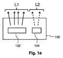
第1の実施形態が図1aに示される。図1aは、発光モジュール100の一実施形態を概略的に示す。発光モジュール100は、第1の光L1を放射可能な第1の発光素子102を含む。第1の光L1は、色空間内の実質的に黒体線上にあるか、又は黒体線に近いカラーポイントを有する。即ち、第1の光L1は、白色光である。白色光のカラーポイントは、発光素子の動作中、黒体線から15SDCM(「等色標準偏差」)内、特に10SDCM内、更に特に黒体線から5SDCM内にある。発光モジュール100は、青色光のピークL2を放射するように構成された第2の発光素子104を更に含む。青色光のピークL2は、440ナノメートル〜470ナノメートルの範囲内にあるピーク波長を有し、このピークは、70ナノメートル(半値全幅(FWHM)値として表された場合)未満のスペクトル幅を有する。任意選択的に、青色光のピークL2のピーク波長は、445〜465ナノメートルの範囲内である。任意選択的に、FWHM値は、60ナノメートル未満、50ナノメートル未満、又は40ナノメートル未満である。発光モジュール100は、白色光L1及び青色光のピークL2の混合を放射する。 A first embodiment is shown in FIG. FIG. 1 a schematically illustrates an embodiment of a
図1bは、「鮮明な」見かけを得るために、どのように発光モジュール100において発光スペクトル152、154が合成されて、物体を照射するための発光スペクトル156を得るかを概略的に示す。発光スペクトル152は、第1の発光素子102による発光を表す。発光スペクトル154は、第2の発光素子104による発光を表す。見て分かるように、発光スペクトル154は、ピーク波長λpとして440ナノメートル〜470ナノメートルの範囲内の値を有する光の比較的小さなピークである。ピークの半値全幅(FWHM)値(ピーク強度Imの最大強度の半値Im/2で測定)は、70ナノメートル未満である。FIG. 1b schematically shows how the
本発明者らの洞察は、白色光の放射スペクトル152が青色光のピークL2(発光スペクトル154に示されるような)と合成された場合に、得られた発光スペクトル156の光を用いて、物体がより鮮明に、より明るく、より魅力的に見えるように、又は、白色の物体に関する場合、それが人の肉眼にとってより白く見えるように物体を照射することができるというものである。より鮮明に又はより白く見える物体というこの効果は、物体に増白剤を導入することなく得られる。 Our insight is that when the white
図2は、図1の発光モジュール100の幾つかの代替実施形態を示す。 FIG. 2 shows several alternative embodiments of the
発光モジュール200は、第1のルミネッセント素子203を備えた第1の発光器202を含む。第1の発光器202及び第1のルミネッセント素子203の組み合わせによって生成される光は、第1の光L1(白色光のカラーポイントを有する)である。第1の発光器202は、例えば、第1のルミネッセント素子203のルミネッセント材料によって、1つ又は複数の他の色の光へと部分的に又は完全に変換される青色光を放射することができる。全ての青色光(第1の発光器202によって放射された)が別の色の光に変換されるとは限らない場合、第1の発光器202によって放射された青色光の残りの部分は、発光モジュール200の周囲に放射され得る。青色光のこの任意選択的な残りの部分及び第1のルミネッセント素子のルミネッセント材料によって放射された光の合成は、白色光のカラーポイントを有する第1の光L1を形成する。発光モジュール200は、青色光のピークL2を放射するように構成された第2の発光器204を更に含む − 即ち、第2の発光器204は、特定の光の変換を何ら用いることなく、青色光のピークL2を直接放射する。第1の発光器202及び第2の発光器204は、支持層209上に設けられ得る。支持層209は、第1の発光器202及び第2の発光器204から熱を奪う良好な熱伝導体でもよい。第1のルミネッセント素子203は、図2において、第1の発光器202の上に直接設けられた素子として描かれているが、第1のルミネッセント素子203と第1の発光器202との間に(エア)ギャップが存在し得る(ギャップの幅に応じて第1のルミネッセント素子203が近接構成又は遠隔構成で配置され、この幅は、それぞれ0.1〜0.5mm又は1cmを超え得る)。 The
発光モジュール210は、発光モジュール200と類似しているが、それは、第2のルミネッセント素子215を備えた別の第2の発光器214を含む。別の第2の発光器214は、第2のルミネッセント素子215に向けて光を放射し、第2のルミネッセント素子215に設けられたルミネッセント材料は、別の第2の発光器214によって放射された光を青色光のピークL2に変換する。第2の発光器214によって放射された光は、紫外線(UV:Ultraviolet)光でもよく、紫色光でもよく、又は青色光のピークL2のピーク波長未満のピーク波長を有する青色光でもよい。ある実施形態では、第2のルミネッセント素子215及び第2の発光器214の組み合わせは、UV又は紫色光が発光モジュール210の周囲に放射されないように配置される。 The
発光モジュール220は、発光モジュール200と類似しているが、支持層209の代わりに、少なくとも1つの面に光出射窓222を含む箱型支持部材221が設けられる。箱型支持部材221の内面223は、内面223に当たる光が十分に反射され、吸収されず、発光モジュール220によってより良く混合されるように、反射性の白色でもよい。 The
発光モジュール230は、発光モジュール220と類似しているが、箱型支持部材221の光出射窓に、追加の光拡散素子236が設けられる。拡散素子236は、ガラス又はその上に若しくはその中に散乱粒子が設けられた光透過合成材料の層でもよい。光の拡散は、より均質な光出力をもたらす。 The
発光モジュール240は、発光モジュール220と類似しているが、発光モジュール240によって放射される光ビームを特定の形状に成形するための反射体を含む別の箱型支持部材241が設けられる。 The
発光モジュール250は、発光モジュール240と類似しており、発光器202、204の各々に対して、発光器202、204の各々に別々に電力を供給するための別個の電源コネクタ258、259を含む。電源コネクタ258、259は、例えば、発光モジュール250の光出射窓とは反対側の発光モジュール250の外面に設けられる。電源コネクタ258、259は、第1の発光器202及び第2の発光器204の別々の駆動を可能にし、その結果、例えば、照明物体の「鮮明な見かけ」が必要とされない場合には、第2の発光器204をオフにし得るように実施することができる。 The
第1の発光器202、第2の発光器204及び別の第2の発光器214は、固体発光器でもよい。固体発光器の一例は、発光ダイオードである。他の例は、有機発光ダイオード又はレーザダイオードである。レーザダイオードは、青色光のピークL2を生成するために使用され得る。レーザダイオードが使用される場合、発光モジュールは、好ましくは、光拡散素子236等の光拡散素子を含む。 The
ある実施形態では、第1のルミネッセント素子203は、複数のルミネッセント材料によって放射される光の合成(任意選択的に、第1の発光器202によって放射された光の残りの非吸収部分と合成される)が第1の光L1であるような複数のルミネッセント材料を含むことに更に留意されたい。 In some embodiments, the first
上記では、1つの第1の発光器202及び1つの第2の発光器204(又は1つの別の第2の発光器214)が描かれている。これらの実施形態は、そのような少ない数の発光器に限定されない。発光モジュール200、210、220、230、240、250は、各々が第1のルミネッセント素子203を備えた複数の第1の発光器202を含み得る。発光モジュール200、210、220、230、240、250は、複数の第2の発光器204を含み得る。発光モジュール200、210、220、230、240、250は、各々が第2のルミネッセント素子215を備えた複数の別の第2の発光器214を含み得る。ある実施形態では、第1の発光器202の数及び第2の発光器204(又は、代替的に、別の第2の発光器214)の数の比率は、少なくとも1、少なくとも2、又は少なくとも3である。一般的に、青色光のピークで放射される光の量よりも多くの白色光が放射される場合に有利であり、これは、そうでなければ「鮮明な」効果を提供する光の代わりに青色光で物体を照射する結果になり得るからである。 In the above, one
第1のルミネッセント素子203及び第2のルミネッセント素子215は、以下の種類のルミネッセント材料:無機蛍光体、例えばペリレン誘導体系の有機蛍光体、又は量子閉じ込めを示し、且つ少なくとも一次元においてナノメートル領域のサイズを有する粒子の少なくとも1つを含み得る。量子閉じ込めを示すとは、粒子が粒子のサイズに依存した光学特性を有することを意味する。このような材料の例は、量子ドット、量子ロッド及び量子テトラポッドである。第1のルミネッセント素子203及び第2のルミネッセント素子215は、上述の材料の混合も含み得る。 The first
図3aは、発光モジュール300の更なる実施形態を概略的に示す。発光モジュール300は、第3の光L3を放射するある種類の発光器302を含む。任意選択的に、第3の光L3は、青色光であり、且つ440ナノメートル〜460ナノメートルの範囲内のピーク波長を有する。図3では、単一の第3の発光器302のみが設けられて描かれているが、より大量の第3の光L3を放射するように、複数の第3の発光器302が設けられ得る。第3の光L3は、第3のルミネッセント素子304に向けて放射される。第3のルミネッセント素子304は、第3の光L3の一部を吸収し、且つ吸収された光を青色光のピークL2に変換する、ある特定のルミネッセント材料308を含む。第3のルミネッセント素子304は、第1の光L1(従って白色光)に対応する発光を共に放射する(任意選択的に、第3の光L3の非吸収部分と一緒に)他のルミネッセント材料306の混合を更に含む。前の実施形態と比較して、複数のルミネッセント材料306、308は、第1の光L1及び青色光のピークL2を生成する。これは、図3bに示される。図3bは、照明物体の「鮮明な」見かけを得るために、どのように発光モジュール300において発光スペクトル352、354が合成されて、発光スペクトル356を得るかを概略的に示す。例えば、第3のルミネッセント素子304が、全てが僅かに異なるサイズを有する(及び/又は異なる材料から成る)異なる種類の量子ドットを含む場合、それらはそれぞれ僅かにシフトされた光のピークを放射し、光の隣接したピーク同士は、ほぼ連続した発光が得られるように(発光スペクトル352に示されるように)僅かに重なり合い得る。同様に、特定のサイズ及び発光スペクトル354に示されるように青色光のピークを放射するように構成された特定の材料を有する別の量子ドットが付加され得る。発光352及び354は一緒に、発光スペクトル356をもたらす。発光スペクトル356によって物体の照明が行われる場合、物体は、人の肉眼で見られた場合に、「鮮明な」、より「明るい」、より白い外見を有する。 FIG. 3 a schematically shows a further embodiment of the
発光スペクトル352は、他のルミネッセント材料306の混合によって生成することができるスペクトルの一例である(任意選択的に、発光スペクトル352は、第3の光L3の非吸収部分も含む)。上述の通り、このような発光スペクトル352は、幾つかの僅かに異なる量子ドットを組み合わせることによって得ることができる。上述の通り、量子ドットは、量子閉じ込めを示し、且つ少なくとも一次元においてナノメートル領域のサイズを有する粒子であり、これは、粒子が、粒子のサイズに依存した光学特性を有することを意味する。従って、他のルミネッセント材料306の混合は、異なるサイズの幾つかの量子ドットを含み得る。量子閉じ込めを示す他の粒子は、量子ロッド又は量子テトラポッドであること、及び量子ドットの代わりに又は量子ドットに加えて、これらの材料が他のルミネッセント材料306の混合中に存在し得ることに留意されたい。他の実施形態では、第1の(白色)光L1を生成するために(任意選択的に、第3の光L3の放射された比吸収部分と共に)、ルミネッセント材料の他の混合が用いられ得ることに留意されたい。例えば、他のルミネッセント材料306の混合は、無機蛍光体、又は有機蛍光体(例えばペリレン誘導体等)の1つを含み得る。 The
ルミネッセント材料の例は、量子閉じ込めを示し、且つ少なくとも一次元においてナノメートル領域のサイズを有する粒子を含む。これは、例えば粒子が実質的に球状である場合に、それらの直径がナノメートル領域にあることを意味する。又は、これは、例えばそれらがワイヤ状である場合に、ワイヤの断面のサイズが一次元においてナノメートル領域にあることを意味する。ナノメートル領域のサイズとは、それらのサイズが少なくとも1マイクロメートル未満、従って、500ナノメートル未満及び0.5ナノメートル以上であることを意味する。ある実施形態では、一次元におけるサイズは、50ナノメートル未満である。別の実施形態では、一次元におけるサイズは、2〜30ナノメートルの範囲内にある。本発明の実施形態では、ルミネッセント材料は、量子ドットを含み得る。量子ドットは、一般的に僅か数ナノメートルの幅又は直径を有する半導体材料の小結晶である。入射光によって励起されると、量子ドットは、結晶のサイズ及び材料によって決定される色の光を放射する。従って、ある特定の色の光は、ドットのサイズを適応させることによって作り出すことができる。可視領域の放射を有する最もよく知られている量子ドットは、硫化カドミウム(CdS)及び硫化亜鉛(ZnS)等の殻を有するセレン化カドミウム(CdSe)に基づく。リン化インジウム(InP)、並びに硫化銅インジウム(CuInS2)及び/又は硫化銀インジウム(AgInS2)等のカドミウムが含まれない量子ドットを用いることもできる。量子ドットは、非常に狭い発光帯を示し、従ってそれらは飽和色を示す。更に、発光色は、量子ドットのサイズを適応させることによって簡単に調整することができる。当該技術分野で知られている任意の種類の量子ドットを、それが適切な波長変換特性を有している場合、本発明に用いることができる。但し、環境の安全性及び環境への懸念から、カドミウムが含まれない量子ドット、又は少なくとも非常に低いカドミウム含有量の量子ドットを用いることが望ましい場合がある。Examples of luminescent materials include particles that exhibit quantum confinement and have a size in the nanometer region in at least one dimension. This means that their diameter is in the nanometer range, for example when the particles are substantially spherical. Or this means that the size of the cross-section of the wires is in the nanometer region in one dimension, for example when they are wire-like. The size of the nanometer region means that their size is at least less than 1 micrometer and thus less than 500 nanometers and 0.5 nanometers or more. In certain embodiments, the size in one dimension is less than 50 nanometers. In another embodiment, the size in one dimension is in the range of 2-30 nanometers. In embodiments of the present invention, the luminescent material can include quantum dots. Quantum dots are small crystals of semiconductor material that generally have a width or diameter of only a few nanometers. When excited by incident light, the quantum dots emit light of a color determined by the crystal size and material. Thus, a particular color of light can be created by adapting the dot size. The best known quantum dots with visible range radiation are based on cadmium selenide (CdSe) with shells such as cadmium sulfide (CdS) and zinc sulfide (ZnS). Quantum dots that do not contain cadmium such as indium phosphide (InP) and copper indium sulfide (CuInS2 ) and / or silver indium sulfide (AgInS2 ) can also be used. Quantum dots exhibit a very narrow emission band and thus they exhibit a saturated color. Furthermore, the emission color can be easily adjusted by adapting the size of the quantum dots. Any type of quantum dot known in the art can be used in the present invention if it has suitable wavelength conversion properties. However, it may be desirable to use quantum dots that do not contain cadmium, or at least very low cadmium content quantum dots because of environmental safety and environmental concerns.
図4aは、ランプ400の一実施形態を概略的に示す。ランプ400は、例えば、従来の白熱灯の形状を有し、そのためにレトロフィット白熱灯である。ランプは、例えば、発光モジュールの前述の実施形態による1つ又は複数の発光モジュール(不図示)を含み得る。 FIG. 4 a schematically illustrates one embodiment of a
図4bは、照明器具450の一実施形態を概略的に示す。照明器具450は、例えば、発光モジュールの前述の実施形態による1つ又は複数の発光モジュール(不図示)を含む。別の実施形態では、照明器具450は、図4aの実施形態による1つ又は複数のランプ(不図示)を含む。 FIG. 4 b schematically illustrates one embodiment of a
図5は、物体を照射する方法500の一実施形態を概略的に示す。方法500は、i)白色光のカラーポイントを有する第1の光を放射するステップ(502)と、ii)440ナノメートル〜470ナノメートルの範囲内のピーク波長を有し、半値全幅値として表された場合に70ナノメートル未満のスペクトル幅を有する青色光のピークを放射するステップ(504)とを含む。 FIG. 5 schematically illustrates one embodiment of a
ランプ、照明器具、及び上述の物体を照射する方法は、発光モジュールの実施形態と同様の効果を有する類似の実施形態を有する。 The lamp, the luminaire, and the method of illuminating the object described above have similar embodiments that have similar effects as the embodiment of the light emitting module.
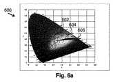
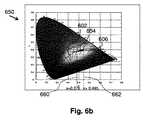
図6a及び図6bは、CIEXYZ色空間における、発光モジュールの発光の合成カラーポイントの領域を概略的に示す。図6aでは、CIEXYZ色空間の第1のチャート600が示される。CIEXYZ色空間において、黒体線602が描かれている。第1の発光素子は、黒体線上にカラーポイントを有する第1の光を放射する。第1の光及び青色光のピークの合成は、合成カラーポイントを有する。従って、合成カラーポイントは、発光モジュール全体としてのカラーポイントである。第1の発光素子は、第1のエネルギー量の第1の光を放射し、第2の発光素子は、第2のエネルギー量の青色光のピークを放射し、第1のエネルギー量と第2のエネルギー量との比率は、黒体線602及びy=0.328+0.13xによって定義される線606によって囲まれた領域604内において、CIEXYZ色空間の合成カラーポイントの座標を得るように選択される。領域604内において、鮮明な効果が十分に人の肉眼で見える。領域604は、鮮明な効果がより十分に目に見えるように更に限定され得る。これは、図6bのチャート650に示される。図6bでは、合成カラーポイントが配置され得る領域654は、x座標0.376によって定義される第1の線660及びx座標0.445によって定義される第2の線662によって更に限定される。従って、領域654は、黒体線602、y=0.328+0.13xによって定義される線606、x=0.376によって定義される線660、及びx=0.445によって定義される線662の間の領域である。 6a and 6b schematically show the region of the combined color point of the light emission module emission in the CIEXYZ color space. In FIG. 6a, a
上述の実施形態は、本発明を限定するのではなく例示すること、及び当業者が添付のクレームの範囲から逸脱することなく多くの代替実施形態を設計できるであろうことに留意されたい。 It should be noted that the above-described embodiments are illustrative rather than limiting, and that many alternative embodiments can be designed by those skilled in the art without departing from the scope of the appended claims.
クレームにおいて、丸括弧内に配置される何れの参照符号も、クレームを限定するものと解釈されるものではない。「含む(comprise)」という動詞及びその活用の使用は、クレームに記載された要素又はステップ以外の要素又はステップの存在を排除しない。要素に先行する冠詞「1つの(a)」又は「1つの(an)」は、複数のそのような要素の存在を排除しない。幾つかの手段を列挙する装置クレームにおいて、これらの手段の幾つかは、同一のハードウェアアイテムによって実施され得る。特定の手段が互いに異なる従属クレームに記載されているという事実のみでは、これらの手段の組み合わせを有利に使用できないことを意味しない。 In the claims, any reference signs placed between parentheses shall not be construed as limiting the claim. Use of the verb “comprise” and its conjugations does not exclude the presence of elements or steps other than those stated in a claim. The article “a” or “an” preceding an element does not exclude the presence of a plurality of such elements. In the device claim enumerating several means, several of these means can be embodied by one and the same item of hardware. The mere fact that certain measures are recited in mutually different dependent claims does not indicate that a combination of these measured cannot be used to advantage.
Claims (15)
Translated fromJapanese− 白色光のカラーポイントを有する第1の光を放射する第1の発光素子であって、第1の発光器及び第1のルミネッセント素子を含む第1の発光素子と、
− 440ナノメートル〜470ナノメートルの範囲内のピーク波長を有し、且つ70ナノメートル未満の半値全幅値として表されるスペクトル幅を有する青色光のピークを放射する第2の発光素子であって、第2の発光器を含む第2の発光素子と、
を含む、発光モジュール。A light emitting module for illuminating an object,
A first light emitting element that emits a first light having a white light color point, the first light emitting elementincluding a first light emitter and a first luminescent element ;
A second light emitting device emitting a peak of blue light having a peak wavelength in the range of 440 nanometers to 470 nanometers and having a spectral width expressed as a full width at half maximum less than 70 nanometers, A second light emitting element including a second light emitter;
Including a light emitting module.
− 前記第1の光及び前記青色光のピークの合成は、合成カラーポイントを有し、
− 前記第1の発光素子は、第1のエネルギー量の前記第1の光を放射し、前記第2の発光素子は、第2のエネルギー量の前記青色光のピークを放射し、且つ前記第1のエネルギー量と前記第2のエネルギー量との比率は、CIEXYZ色空間において、前記黒体線及びy=0.328+0.13xによって定義される線によって囲まれた領域内に前記合成カラーポイントの座標を得るように選択され、
− 前記合成カラーポイントのx座標は、0.376〜0.445の範囲内にある、請求項1に記載の発光モジュール。The color point of the first light is substantially on the black body line;
The synthesis of the peak of the first light and the blue light has a synthesis color point;
The first light emitting element emits the first light of a first energy amount, the second light emitting element emits a peak of the blue light of a second energy amount, and the first light emitting element emits a peak of the blue light of a second energy amount; The ratio between the energy amount of 1 and the second energy amount is the ratio of the composite color point in a region surrounded by the black body line and a line defined by y = 0.328 + 0.13x in the CIEXYZ color space. Selected to get coordinates,
The light emitting module according to claim 1, wherein an x coordinate of the composite color point is in a range of 0.376 to 0.445.
− 2000ケルビン〜4000ケルビンの範囲内の色温度、及び
− 80〜100の範囲内の色調指数
の少なくとも1つを有する、請求項1に記載の発光モジュール。The first light has the following characteristics:
The light emitting module according to claim 1, having at least one of a color temperature in the range of 2000 Kelvin to 4000 Kelvin, and a color index in the range of −80 to 100.
−第1の発光器及び第1のルミネッセント素子を含む第1の発光素子により、前記物体に向けて白色光のカラーポイントを有する第1の光を放射するステップと、
− 440ナノメートル〜470ナノメートルの範囲内のピーク波長を有し、且つ70ナノメートル未満の半値全幅値として表されるスペクトル幅を有する青色光のピークを、第2の発光器を含む第2の発光素子により前記物体に向けて放射するステップと
を含む、方法。A method of irradiating an object,
Emitting a first light having a white light color point towards the objectby a first light emitting element comprising a first light emitter and a first luminescent element ;
A blue light peak having a peak wavelength in the range of 440 nanometers to 470 nanometers and having a spectral width expressed as a full width at half maximum of less than 70 nanometers, including a second light emitter; Radiating toward the object witha light emitting element .
Applications Claiming Priority (3)
| Application Number | Priority Date | Filing Date | Title |
|---|---|---|---|
| EP14156148.0 | 2014-02-21 | ||
| EP14156148 | 2014-02-21 | ||
| PCT/EP2015/053671WO2015124755A1 (en) | 2014-02-21 | 2015-02-23 | A light emitting module, a lamp, a luminaire and a method of illuminating an object |
Publications (2)
| Publication Number | Publication Date |
|---|---|
| JP2017507491A JP2017507491A (en) | 2017-03-16 |
| JP6321192B2true JP6321192B2 (en) | 2018-05-09 |
Family
ID=50230859
Family Applications (1)
| Application Number | Title | Priority Date | Filing Date |
|---|---|---|---|
| JP2016553018AActiveJP6321192B2 (en) | 2014-02-21 | 2015-02-23 | Light emitting module, lamp, luminaire, and method of irradiating an object |
Country Status (8)
| Country | Link |
|---|---|
| US (1) | US10334686B2 (en) |
| EP (1) | EP3061320B1 (en) |
| JP (1) | JP6321192B2 (en) |
| CN (1) | CN105830216B (en) |
| ES (1) | ES2629579T3 (en) |
| PL (1) | PL3061320T3 (en) |
| RU (1) | RU2634699C1 (en) |
| WO (1) | WO2015124755A1 (en) |
Families Citing this family (20)
| Publication number | Priority date | Publication date | Assignee | Title |
|---|---|---|---|---|
| US10918747B2 (en) | 2015-07-30 | 2021-02-16 | Vital Vio, Inc. | Disinfecting lighting device |
| WO2017162548A1 (en)* | 2016-03-24 | 2017-09-28 | Philips Lighting Holding B.V. | Lighting device and lamp and luminaire comprising the lighting device |
| WO2018016047A1 (en)* | 2016-07-21 | 2018-01-25 | サンケン電気株式会社 | Light-emitting device |
| US20180185533A1 (en) | 2016-12-29 | 2018-07-05 | Vital Vio, Inc. | Control systems for disinfecting light systems and methods of regulating operations of disinfecting light systems |
| US11215339B2 (en) | 2017-05-02 | 2022-01-04 | Signify Holding B.V. | Warm white LED spectrum especially for retail applications |
| KR102230459B1 (en) | 2017-09-06 | 2021-03-23 | 지엘비텍 주식회사 | D50, D65 Standard LED Light Emitting Module and Lighting Apparatus with High Color Rendering Index |
| CN109708026B (en)* | 2017-10-25 | 2021-12-31 | 苏州星烁纳米科技有限公司 | Lighting lamp |
| US10617774B2 (en) | 2017-12-01 | 2020-04-14 | Vital Vio, Inc. | Cover with disinfecting illuminated surface |
| US11217725B2 (en) | 2018-02-26 | 2022-01-04 | Biological Innovation And Optimization Systems, Llc | Light emitting apparatus with melanopic emission spectrum |
| EP3537853B1 (en)* | 2018-03-09 | 2021-05-05 | Samsung Electronics Co., Ltd. | Electroluminescent display device |
| US10413626B1 (en) | 2018-03-29 | 2019-09-17 | Vital Vio, Inc. | Multiple light emitter for inactivating microorganisms |
| RU2018115096A (en)* | 2018-04-24 | 2019-10-28 | Общество с ограниченной ответственностью "Экологический свет" | PLANE AUTO EMISSION LIGHT SOURCE |
| US12194168B2 (en) | 2018-12-19 | 2025-01-14 | Vyv, Inc. | Lighting and dissipation device |
| US11639897B2 (en) | 2019-03-29 | 2023-05-02 | Vyv, Inc. | Contamination load sensing device |
| WO2021030748A1 (en) | 2019-08-15 | 2021-02-18 | Vital Vio, Inc. | Devices configured to disinfect interiors |
| US11878084B2 (en) | 2019-09-20 | 2024-01-23 | Vyv, Inc. | Disinfecting light emitting subcomponent |
| WO2021089493A1 (en)* | 2019-11-07 | 2021-05-14 | Signify Holding B.V. | Light-emitting diode filament comprising three types of leds |
| CN113126361A (en)* | 2019-12-31 | 2021-07-16 | 华为技术有限公司 | Backlight module, electronic equipment and lamp strip |
| CN113552745A (en)* | 2020-04-23 | 2021-10-26 | 华为技术有限公司 | Display device and driving method thereof |
| US12222100B2 (en) | 2021-05-11 | 2025-02-11 | Solar Mission Co., Ltd. | Daylight LED light, daylight LED light apparatus, and daylight LED floodlight apparatus |
Family Cites Families (18)
| Publication number | Priority date | Publication date | Assignee | Title |
|---|---|---|---|---|
| JP3940596B2 (en) | 2001-05-24 | 2007-07-04 | 松下電器産業株式会社 | Illumination light source |
| US20030227022A1 (en)* | 2002-06-06 | 2003-12-11 | Hwang Chin-Mau James | White light source |
| JP5081370B2 (en)* | 2004-08-31 | 2012-11-28 | 日亜化学工業株式会社 | Light emitting device |
| KR101396588B1 (en)* | 2007-03-19 | 2014-05-20 | 서울반도체 주식회사 | Light emitting apparatus having various color temperature |
| JP2008235458A (en)* | 2007-03-19 | 2008-10-02 | Toshiba Corp | WHITE LIGHT EMITTING DEVICE, BACKLIGHT, DISPLAY DEVICE, AND LIGHTING DEVICE USING THE SAME |
| KR20100037163A (en)* | 2007-07-30 | 2010-04-08 | 샤프 가부시키가이샤 | Clean room with light emitting device, lighting device and lighting device |
| JP4989347B2 (en)* | 2007-07-30 | 2012-08-01 | シャープ株式会社 | Lighting device |
| US8651723B2 (en)* | 2008-02-21 | 2014-02-18 | Koninklijke Philips N.V. | LED light source with a luminescent layer |
| KR100924912B1 (en)* | 2008-07-29 | 2009-11-03 | 서울반도체 주식회사 | Warm white light emitting apparatus and back light module comprising the same |
| US8643038B2 (en) | 2010-03-09 | 2014-02-04 | Cree, Inc. | Warm white LEDs having high color rendering index values and related luminophoric mediums |
| JP4884561B1 (en) | 2011-04-19 | 2012-02-29 | Jx日鉱日石金属株式会社 | Indium target and manufacturing method thereof |
| CN103493226B (en)* | 2011-04-22 | 2016-09-28 | 株式会社东芝 | White light source and white light source system including said white light source |
| WO2012153212A1 (en) | 2011-05-06 | 2012-11-15 | Koninklijke Philips Electronics N.V. | Phosphor-enhanced lighting device, retrofit light bulb and light tube with reduced color appearance |
| US20130075769A1 (en) | 2011-09-22 | 2013-03-28 | Ledengin, Inc. | Selection of phosphors and leds in a multi-chip emitter for a single white color bin |
| US8884508B2 (en) | 2011-11-09 | 2014-11-11 | Cree, Inc. | Solid state lighting device including multiple wavelength conversion materials |
| US8906713B2 (en)* | 2012-03-30 | 2014-12-09 | Nthdegree Technologies Worldwide Inc. | LED lamp using blue and cyan LEDs and a phosphor |
| JP6363061B2 (en)* | 2012-04-06 | 2018-07-25 | フィリップス ライティング ホールディング ビー ヴィ | White light emitting module |
| PL2870831T3 (en) | 2012-07-05 | 2020-11-30 | Signify Holding B.V. | A stack of layers comprising luminescent material, a lamp, a luminaire and a method of manufacturing the stack of layers |
- 2015
- 2015-02-23CNCN201580003071.XApatent/CN105830216B/enactiveActive
- 2015-02-23PLPL15706017Tpatent/PL3061320T3/enunknown
- 2015-02-23JPJP2016553018Apatent/JP6321192B2/enactiveActive
- 2015-02-23ESES15706017.9Tpatent/ES2629579T3/enactiveActive
- 2015-02-23RURU2016125124Apatent/RU2634699C1/enactive
- 2015-02-23WOPCT/EP2015/053671patent/WO2015124755A1/enactiveApplication Filing
- 2015-02-23EPEP15706017.9Apatent/EP3061320B1/enactiveActive
- 2015-02-23USUS15/117,565patent/US10334686B2/enactiveActive
Also Published As
| Publication number | Publication date |
|---|---|
| CN105830216A (en) | 2016-08-03 |
| EP3061320B1 (en) | 2017-04-12 |
| PL3061320T3 (en) | 2017-09-29 |
| US20160366745A1 (en) | 2016-12-15 |
| ES2629579T3 (en) | 2017-08-11 |
| JP2017507491A (en) | 2017-03-16 |
| WO2015124755A1 (en) | 2015-08-27 |
| US10334686B2 (en) | 2019-06-25 |
| EP3061320A1 (en) | 2016-08-31 |
| RU2634699C1 (en) | 2017-11-03 |
| CN105830216B (en) | 2018-02-27 |
Similar Documents
| Publication | Publication Date | Title |
|---|---|---|
| JP6321192B2 (en) | Light emitting module, lamp, luminaire, and method of irradiating an object | |
| KR101758188B1 (en) | Solid state light source light bulb | |
| US9599293B2 (en) | Full spectrum light emitting arrangement | |
| KR102030538B1 (en) | A light conversion assembly, a lamp and a luminaire | |
| EP2835036B1 (en) | A light emitting assembly, a lamp and a luminaire | |
| EP2898548B1 (en) | A light emitting assembly, a lamp and a luminaire | |
| US8998433B2 (en) | Light emitting device utilizing remote wavelength conversion with improved color characteristics | |
| US20140264420A1 (en) | Photoluminescence wavelength conversion components | |
| US9755117B2 (en) | Phosphor-enhanced lighting device, retrofit light bulb and light tube with reduced color appearance | |
| US10240749B2 (en) | Light source, luminaire and surgical illumination unit | |
| WO2009083853A1 (en) | Lighting system | |
| CN114901988A (en) | LED Filament Unit | |
| Liu et al. | High-efficiency, low-speckle contrast white laser lighting via multi-stage scattering and photon recycling | |
| CN119957851A (en) | A blue sky lighting device based on quantum rods | |
| JP2014160549A (en) | Illumination device |
Legal Events
| Date | Code | Title | Description |
|---|---|---|---|
| A621 | Written request for application examination | Free format text:JAPANESE INTERMEDIATE CODE: A621 Effective date:20160818 | |
| A871 | Explanation of circumstances concerning accelerated examination | Free format text:JAPANESE INTERMEDIATE CODE: A871 Effective date:20160818 | |
| A975 | Report on accelerated examination | Free format text:JAPANESE INTERMEDIATE CODE: A971005 Effective date:20170119 | |
| A131 | Notification of reasons for refusal | Free format text:JAPANESE INTERMEDIATE CODE: A131 Effective date:20170202 | |
| A601 | Written request for extension of time | Free format text:JAPANESE INTERMEDIATE CODE: A601 Effective date:20170426 | |
| A521 | Request for written amendment filed | Free format text:JAPANESE INTERMEDIATE CODE: A523 Effective date:20170731 | |
| A02 | Decision of refusal | Free format text:JAPANESE INTERMEDIATE CODE: A02 Effective date:20170927 | |
| A521 | Request for written amendment filed | Free format text:JAPANESE INTERMEDIATE CODE: A523 Effective date:20180123 | |
| A911 | Transfer to examiner for re-examination before appeal (zenchi) | Free format text:JAPANESE INTERMEDIATE CODE: A911 Effective date:20180130 | |
| TRDD | Decision of grant or rejection written | ||
| A01 | Written decision to grant a patent or to grant a registration (utility model) | Free format text:JAPANESE INTERMEDIATE CODE: A01 Effective date:20180306 | |
| A61 | First payment of annual fees (during grant procedure) | Free format text:JAPANESE INTERMEDIATE CODE: A61 Effective date:20180404 | |
| R150 | Certificate of patent or registration of utility model | Ref document number:6321192 Country of ref document:JP Free format text:JAPANESE INTERMEDIATE CODE: R150 | |
| S531 | Written request for registration of change of domicile | Free format text:JAPANESE INTERMEDIATE CODE: R313531 | |
| S533 | Written request for registration of change of name | Free format text:JAPANESE INTERMEDIATE CODE: R313533 | |
| R350 | Written notification of registration of transfer | Free format text:JAPANESE INTERMEDIATE CODE: R350 | |
| R250 | Receipt of annual fees | Free format text:JAPANESE INTERMEDIATE CODE: R250 | |
| R250 | Receipt of annual fees | Free format text:JAPANESE INTERMEDIATE CODE: R250 | |
| R250 | Receipt of annual fees | Free format text:JAPANESE INTERMEDIATE CODE: R250 | |
| R250 | Receipt of annual fees | Free format text:JAPANESE INTERMEDIATE CODE: R250 |