JP6319327B2 - Game controller - Google Patents
Game controllerDownload PDFInfo
- Publication number
- JP6319327B2 JP6319327B2JP2015562636AJP2015562636AJP6319327B2JP 6319327 B2JP6319327 B2JP 6319327B2JP 2015562636 AJP2015562636 AJP 2015562636AJP 2015562636 AJP2015562636 AJP 2015562636AJP 6319327 B2JP6319327 B2JP 6319327B2
- Authority
- JP
- Japan
- Prior art keywords
- top panel
- vibration element
- operation input
- control unit
- vibration
- Prior art date
- Legal status (The legal status is an assumption and is not a legal conclusion. Google has not performed a legal analysis and makes no representation as to the accuracy of the status listed.)
- Expired - Fee Related
Links
Images


Classifications
- A—HUMAN NECESSITIES
- A63—SPORTS; GAMES; AMUSEMENTS
- A63F—CARD, BOARD, OR ROULETTE GAMES; INDOOR GAMES USING SMALL MOVING PLAYING BODIES; VIDEO GAMES; GAMES NOT OTHERWISE PROVIDED FOR
- A63F13/00—Video games, i.e. games using an electronically generated display having two or more dimensions
- A63F13/25—Output arrangements for video game devices
- A63F13/28—Output arrangements for video game devices responding to control signals received from the game device for affecting ambient conditions, e.g. for vibrating players' seats, activating scent dispensers or affecting temperature or light
- A63F13/285—Generating tactile feedback signals via the game input device, e.g. force feedback
- A—HUMAN NECESSITIES
- A63—SPORTS; GAMES; AMUSEMENTS
- A63F—CARD, BOARD, OR ROULETTE GAMES; INDOOR GAMES USING SMALL MOVING PLAYING BODIES; VIDEO GAMES; GAMES NOT OTHERWISE PROVIDED FOR
- A63F13/00—Video games, i.e. games using an electronically generated display having two or more dimensions
- A63F13/20—Input arrangements for video game devices
- A63F13/21—Input arrangements for video game devices characterised by their sensors, purposes or types
- A63F13/211—Input arrangements for video game devices characterised by their sensors, purposes or types using inertial sensors, e.g. accelerometers or gyroscopes
- A—HUMAN NECESSITIES
- A63—SPORTS; GAMES; AMUSEMENTS
- A63F—CARD, BOARD, OR ROULETTE GAMES; INDOOR GAMES USING SMALL MOVING PLAYING BODIES; VIDEO GAMES; GAMES NOT OTHERWISE PROVIDED FOR
- A63F13/00—Video games, i.e. games using an electronically generated display having two or more dimensions
- A63F13/20—Input arrangements for video game devices
- A63F13/21—Input arrangements for video game devices characterised by their sensors, purposes or types
- A63F13/214—Input arrangements for video game devices characterised by their sensors, purposes or types for locating contacts on a surface, e.g. floor mats or touch pads
- A63F13/2145—Input arrangements for video game devices characterised by their sensors, purposes or types for locating contacts on a surface, e.g. floor mats or touch pads the surface being also a display device, e.g. touch screens
- A—HUMAN NECESSITIES
- A63—SPORTS; GAMES; AMUSEMENTS
- A63F—CARD, BOARD, OR ROULETTE GAMES; INDOOR GAMES USING SMALL MOVING PLAYING BODIES; VIDEO GAMES; GAMES NOT OTHERWISE PROVIDED FOR
- A63F13/00—Video games, i.e. games using an electronically generated display having two or more dimensions
- A63F13/40—Processing input control signals of video game devices, e.g. signals generated by the player or derived from the environment
- A63F13/42—Processing input control signals of video game devices, e.g. signals generated by the player or derived from the environment by mapping the input signals into game commands, e.g. mapping the displacement of a stylus on a touch screen to the steering angle of a virtual vehicle
- A63F13/426—Processing input control signals of video game devices, e.g. signals generated by the player or derived from the environment by mapping the input signals into game commands, e.g. mapping the displacement of a stylus on a touch screen to the steering angle of a virtual vehicle involving on-screen location information, e.g. screen coordinates of an area at which the player is aiming with a light gun
- G—PHYSICS
- G06—COMPUTING OR CALCULATING; COUNTING
- G06F—ELECTRIC DIGITAL DATA PROCESSING
- G06F3/00—Input arrangements for transferring data to be processed into a form capable of being handled by the computer; Output arrangements for transferring data from processing unit to output unit, e.g. interface arrangements
- G06F3/01—Input arrangements or combined input and output arrangements for interaction between user and computer
- G06F3/016—Input arrangements with force or tactile feedback as computer generated output to the user
- G—PHYSICS
- G06—COMPUTING OR CALCULATING; COUNTING
- G06F—ELECTRIC DIGITAL DATA PROCESSING
- G06F3/00—Input arrangements for transferring data to be processed into a form capable of being handled by the computer; Output arrangements for transferring data from processing unit to output unit, e.g. interface arrangements
- G06F3/01—Input arrangements or combined input and output arrangements for interaction between user and computer
- G06F3/03—Arrangements for converting the position or the displacement of a member into a coded form
- G06F3/033—Pointing devices displaced or positioned by the user, e.g. mice, trackballs, pens or joysticks; Accessories therefor
- G06F3/0354—Pointing devices displaced or positioned by the user, e.g. mice, trackballs, pens or joysticks; Accessories therefor with detection of 2D relative movements between the device, or an operating part thereof, and a plane or surface, e.g. 2D mice, trackballs, pens or pucks
- G06F3/03547—Touch pads, in which fingers can move on a surface
- G—PHYSICS
- G06—COMPUTING OR CALCULATING; COUNTING
- G06F—ELECTRIC DIGITAL DATA PROCESSING
- G06F3/00—Input arrangements for transferring data to be processed into a form capable of being handled by the computer; Output arrangements for transferring data from processing unit to output unit, e.g. interface arrangements
- G06F3/01—Input arrangements or combined input and output arrangements for interaction between user and computer
- G06F3/048—Interaction techniques based on graphical user interfaces [GUI]
- G06F3/0487—Interaction techniques based on graphical user interfaces [GUI] using specific features provided by the input device, e.g. functions controlled by the rotation of a mouse with dual sensing arrangements, or of the nature of the input device, e.g. tap gestures based on pressure sensed by a digitiser
- G06F3/0488—Interaction techniques based on graphical user interfaces [GUI] using specific features provided by the input device, e.g. functions controlled by the rotation of a mouse with dual sensing arrangements, or of the nature of the input device, e.g. tap gestures based on pressure sensed by a digitiser using a touch-screen or digitiser, e.g. input of commands through traced gestures
- A—HUMAN NECESSITIES
- A63—SPORTS; GAMES; AMUSEMENTS
- A63F—CARD, BOARD, OR ROULETTE GAMES; INDOOR GAMES USING SMALL MOVING PLAYING BODIES; VIDEO GAMES; GAMES NOT OTHERWISE PROVIDED FOR
- A63F2300/00—Features of games using an electronically generated display having two or more dimensions, e.g. on a television screen, showing representations related to the game
- A63F2300/10—Features of games using an electronically generated display having two or more dimensions, e.g. on a television screen, showing representations related to the game characterized by input arrangements for converting player-generated signals into game device control signals
- A63F2300/105—Features of games using an electronically generated display having two or more dimensions, e.g. on a television screen, showing representations related to the game characterized by input arrangements for converting player-generated signals into game device control signals using inertial sensors, e.g. accelerometers, gyroscopes
- A—HUMAN NECESSITIES
- A63—SPORTS; GAMES; AMUSEMENTS
- A63F—CARD, BOARD, OR ROULETTE GAMES; INDOOR GAMES USING SMALL MOVING PLAYING BODIES; VIDEO GAMES; GAMES NOT OTHERWISE PROVIDED FOR
- A63F2300/00—Features of games using an electronically generated display having two or more dimensions, e.g. on a television screen, showing representations related to the game
- A63F2300/10—Features of games using an electronically generated display having two or more dimensions, e.g. on a television screen, showing representations related to the game characterized by input arrangements for converting player-generated signals into game device control signals
- A63F2300/1068—Features of games using an electronically generated display having two or more dimensions, e.g. on a television screen, showing representations related to the game characterized by input arrangements for converting player-generated signals into game device control signals being specially adapted to detect the point of contact of the player on a surface, e.g. floor mat, touch pad
- A—HUMAN NECESSITIES
- A63—SPORTS; GAMES; AMUSEMENTS
- A63F—CARD, BOARD, OR ROULETTE GAMES; INDOOR GAMES USING SMALL MOVING PLAYING BODIES; VIDEO GAMES; GAMES NOT OTHERWISE PROVIDED FOR
- A63F2300/00—Features of games using an electronically generated display having two or more dimensions, e.g. on a television screen, showing representations related to the game
- A63F2300/30—Features of games using an electronically generated display having two or more dimensions, e.g. on a television screen, showing representations related to the game characterized by output arrangements for receiving control signals generated by the game device
- A63F2300/308—Details of the user interface
Landscapes
- Engineering & Computer Science (AREA)
- Multimedia (AREA)
- Human Computer Interaction (AREA)
- General Engineering & Computer Science (AREA)
- Theoretical Computer Science (AREA)
- Physics & Mathematics (AREA)
- General Physics & Mathematics (AREA)
- User Interface Of Digital Computer (AREA)
Description
Translated fromJapanese本発明は、ゲームコントローラに関する。 The present invention relates to a game controller.
従来より、表示手段と、使用者の操作部位の前記表示手段への接触状態を検出する接触検出手段と、前記表示手段に接触している前記操作部位に対し、所定の触感を与える触感振動を発生させる触感振動発生手段とを備える触感呈示装置がある(例えば、特許文献1参照)。 Conventionally, display means, contact detection means for detecting a contact state of a user's operation part to the display means, and tactile vibration that gives a predetermined tactile sensation to the operation part in contact with the display means. There is a tactile sensation providing device including tactile sensation vibration generating means to be generated (for example, see Patent Document 1).
この触感呈示装置は、さらに、前記接触検出手段による検出結果に基づいて、前記触感振動を発生させるための波形データを生成する振動波形データ生成手段を備える。また、この触感呈示装置は、さらに、前記振動波形データ生成手段により生成された前記波形データに対し超音波を搬送波として変調処理を行い、該変調処理により生成された超音波変調信号を、前記触感振動を発生させるための信号として前記触感振動発生手段に出力する超音波変調手段とを備える。 The tactile sensation providing apparatus further includes vibration waveform data generation means for generating waveform data for generating the tactile vibration based on the detection result by the contact detection means. The tactile sensation providing apparatus further performs a modulation process on the waveform data generated by the vibration waveform data generation unit using an ultrasonic wave as a carrier wave, and converts the ultrasonic modulation signal generated by the modulation process into the tactile sensation. Ultrasonic modulation means for outputting to the tactile sensation vibration generating means as a signal for generating vibration.
また、前記超音波変調手段は、周波数変調又は位相変調のどちらか一方を行う。また、前記超音波変調手段は、更に振幅変調を行う。 Further, the ultrasonic modulation means performs either frequency modulation or phase modulation. The ultrasonic modulation means further performs amplitude modulation.
ところで、従来の触感呈示装置の超音波の周波数は、可聴帯域より高い周波数(およそ20kHz以上)であればよく、超音波の周波数自体に特に工夫はなされていないため、良好な触感の操作感を提供できないおそれがある。また、これは、従来の触感呈示装置をゲームコントローラに用いても同様である。 By the way, the ultrasonic frequency of the conventional tactile sensation presenting device only needs to be higher than the audible band (approximately 20 kHz or more), and the ultrasonic frequency itself is not particularly devised, so that a good tactile operation feeling can be obtained. May not be available. This is the same even when a conventional tactile sensation providing apparatus is used as a game controller.
そこで、良好な触感の操作感を提供できるゲームコントローラを提供することを目的とする。 Accordingly, it is an object of the present invention to provide a game controller that can provide a good tactile feeling.
本発明の実施の形態のゲームコントローラは、筐体と、前記筐体の開口部に配設されるタッチパネルと、前記タッチパネルに操作入力を行う操作面に振動を発生させる振動素子と、前記操作面に超音波帯の固有振動を発生させる駆動信号で前記振動素子を駆動する駆動制御部とを含む。 A game controller according to an embodiment of the present invention includes a housing, a touch panel disposed in an opening of the housing, a vibration element that generates vibration on an operation surface that performs operation input on the touch panel, and the operation surface. And a drive control unit for driving the vibration element with a drive signal for generating the natural vibration of the ultrasonic band.
良好な触感の操作感を提供できるゲームコントローラを提供することができる。 It is possible to provide a game controller that can provide a good tactile feeling.
本発明の実施の形態のゲームコントローラは、筐体と、前記筐体の開口部に配設され、操作面を有するトップパネルと、前記操作面に行われる操作入力の位置を検出する位置検出部と、前記操作面に振動を発生させる振動素子と、前記操作面に前記トップパネルの超音波帯の固有振動を発生させる駆動信号で前記振動素子を駆動する駆動制御部とを含む。A game controller according to an embodiment of the present invention includes a housing, a top panel that is disposed in an opening of the housingand has anoperation surface, and a position detection unit that detects a position of an operation input performed on the operation surface If, comprising a vibrating element for generating a vibration tothe operation surface, and a drive control unit for driving the vibrating element in the drive signal that causes the natural vibration of the ultrasonic bandof said top panel to said operation surface.
以下、本発明のゲームコントローラを適用した実施の形態について説明する。 Hereinafter, embodiments to which the game controller of the present invention is applied will be described.
<実施の形態>
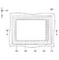
図1は、実施の形態のゲームコントローラ100を示す斜視図である。<Embodiment>
FIG. 1 is a perspective view showing a
ゲームコントローラ100は、筐体110及び2つのタッチパネル150を含む。ゲームコントローラ100は、有線又は無線によってゲーム機本体に接続される、所謂リモートコントローラである。 The
ゲームコントローラ100は、利用者がタッチパネル150に指先等で操作入力を行うことにより、ゲーム機本体の操作を行うものである。タッチパネル150は、2つあるため、利用者がゲームコントローラ100を両手で持った状態で、2つのタッチパネル150を左右の手で操作することができる。 The
なお、ゲームコントローラ100には、例えば、加速度センサ又はジャイロセンサが内蔵されいてもよい。この場合は、タッチパネル150を介してゲーム機本体を操作することに加えて、ゲームコントローラ100の角度を変えたり、ゲームコントローラ100を振ったりすることによっても、ゲーム機本体を操作することができる。 Note that the
また、ゲームコントローラ100には、ボタンが設けられていてもよい。 The
次に、図2を用いて、ゲームコントローラ100のタッチパネル150の周辺の具体的な構成について説明する。 Next, a specific configuration around the
図2は、実施の形態のゲームコントローラ100のタッチパネル150及びその周辺の構成を示す平面図であり、図3は、図2のA−A矢視断面を示す図である。図2に示すタッチパネル150及びその周辺の構成は、図1に示す2つのタッチパネル150のうちの一方と、その周辺の構成に対応する。なお、図2及び図3では、図示するように直交座標系であるXYZ座標系を定義する。 FIG. 2 is a plan view showing a configuration of the
ゲームコントローラ100は、筐体110、トップパネル120、両面テープ130、振動素子140、タッチパネル150、及び基板170を含む。 The
筐体110は、例えば、樹脂製であり、図3に示すように凹部110Aに基板170及びタッチパネル150が配設されるとともに、両面テープ130によってトップパネル120が接着されている。なお、筐体110に平面視で矩形状の凹部110Aを形成することにより、筐体110には凹部110Aによって形成される矩形状の開口が存在する。この開口は、図2では矩形環状の両面テープ130の矩形状の開口と略一致している。図2では、タッチパネル150は、凹部110Aの矩形状の開口の内側に位置している。 The
トップパネル120は、平面視で長方形の薄い平板状の部材であり、ガラス、又は、ポリカーボネートのような強化プラスティックで作製される。トップパネル120の表面(Z軸正方向側の面)は、ゲームコントローラ100の利用者が操作入力を行う操作面の一例である。 The
トップパネル120は、Z軸負方向側の面に振動素子140が接着され、平面視における四辺が両面テープ130によって筐体110に接着されている。なお、両面テープ130は、トップパネル120の四辺を筐体110に接着できればよく、図3に示すように矩形環状である必要はない。 In the
トップパネル120のZ軸負方向側にはタッチパネル150が配設される。トップパネル120は、タッチパネル150の表面を保護するために設けられている。なお、トップパネル120の表面に、さらに別なパネル又は保護膜等が設けられていてもよい。 A
トップパネル120は、Z軸負方向側の面に振動素子140が接着された状態で、振動素子140が駆動されることによって振動する。実施の形態では、トップパネル120の固有振動周波数でトップパネル120を振動させて、トップパネル120に定在波を生じさせる。ただし、トップパネル120には振動素子140が接着されているため、実際には、振動素子140の重さ等を考慮した上で、固有振動周波数を決めることが好ましい。 The
振動素子140は、トップパネル120のZ軸負方向側の面において、Y軸正方向側において、X軸方向に伸延する短辺に沿って接着されている。振動素子140は、超音波帯の振動を発生できる素子であればよく、例えば、ピエゾ素子のような圧電素子を含むものを用いることができる。 The
振動素子140は、後述する駆動制御部から出力される駆動信号によって駆動される。振動素子140が発生する振動の振幅(強度)及び周波数は駆動信号によって設定される。また、振動素子140のオン/オフは駆動信号によって制御される。 The
なお、超音波帯とは、例えば、約20kHz以上の周波数帯をいう。実施の形態のゲームコントローラ100では、振動素子140が振動する周波数は、トップパネル120の振動数と等しくなるため、振動素子140は、トップパネル120の固有振動数で振動するように駆動信号によって駆動される。 In addition, an ultrasonic band means a frequency band about 20 kHz or more, for example. In the
タッチパネル150は、基板170の上(Z軸正方向側)で、トップパネル120の下(Z軸負方向側)に配設されている。タッチパネル150は、ゲームコントローラ100の利用者がトップパネル120に触れる位置(以下、操作入力の位置と称す)を検出する座標検出部の一例である。 The
タッチパネル150は、利用者のトップパネル120への操作入力の位置を検出できる座標検出部であればよく、例えば、静電容量型又は抵抗膜型の座標検出部であればよい。ここでは、タッチパネル150が静電容量型の座標検出部である形態について説明する。タッチパネル150とトップパネル120との間に隙間があっても、静電容量型のタッチパネル150は、トップパネル120への操作入力を検出できる。 The
また、ここでは、タッチパネル150の入力面側にトップパネル120が配設される形態について説明するが、トップパネル120はタッチパネル150と一体的であってもよい。この場合、タッチパネル150の表面が図2及び図3に示すトップパネル120の表面になり、操作面を構築する。また、図2及び図3に示すトップパネル120を省いた構成であってもよい。この場合も、タッチパネル150の表面が操作面を構築する。また、この場合には、操作面を有する部材を、当該部材の固有振動で振動させればよい。 In addition, here, a form in which the
また、タッチパネル150が静電容量型の場合は、トップパネル120の上にタッチパネル150が配設されていてもよい。この場合も、タッチパネル150の表面が操作面を構築する。また、タッチパネル150が静電容量型の場合は、図2及び図3に示すトップパネル120を省いた構成であってもよい。この場合も、タッチパネル150の表面が操作面を構築する。また、この場合には、操作面を有する部材を、当該部材の固有振動で振動させればよい。 In the case where the
基板170は、筐体110の凹部110Aの内部に配設される。基板170の上にはタッチパネル150が配設される。タッチパネル150は、図示を省略するホルダ等によって基板170及び筐体110に固定されている。 The
基板170には、後述する駆動制御装置の他に、ゲームコントローラ100の駆動に必要な種々の回路等が実装される。 In addition to the drive control device described later, various circuits and the like necessary for driving the
以上のような構成のゲームコントローラ100は、トップパネル120に利用者の指が接触し、指先の移動を検出すると、基板170に実装される駆動制御部が振動素子140を駆動し、トップパネル120を超音波帯の周波数で振動させる。この超音波帯の周波数は、トップパネル120と振動素子140とを含む共振系の共振周波数であり、トップパネル120に定在波を発生させる。 In the
ゲームコントローラ100は、超音波帯の定在波を発生させることにより、トップパネル120を通じて利用者に触感を提供する。 The
次に、図4を用いて、トップパネル120に発生させる定在波について説明する。 Next, standing waves generated in the
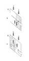
図4は、超音波帯の固有振動によってトップパネル120に生じる定在波のうち、トップパネル120の短辺に平行に形成される波頭を示す図であり、図4の(A)は側面図、(B)は斜視図である。図4の(A)、(B)では、図2及び図3と同様のXYZ座標を定義する。なお、図4の(A)、(B)では、理解しやすさのために、定在波の振幅を誇張して示す。また、図4の(A)、(B)では振動素子140を省略する。 FIG. 4 is a diagram showing a wave front formed in parallel to the short side of the
トップパネル120のヤング率E、密度ρ、ポアソン比δ、長辺寸法l、厚さtと、長辺方向に存在する定在波の周期数kとを用いると、トップパネル120の固有振動数(共振周波数)fは次式(1)、(2)で表される。定在波は1/2周期単位で同じ波形を有するため、周期数kは、0.5刻みの値を取り、0.5、1、1.5、2・・・となる。 When the Young's modulus E, density ρ, Poisson's ratio δ, long side dimension l, thickness t of the

図4の(A)、(B)に示す定在波は、一例として、周期数kが10の場合の波形である。例えば、トップパネル120として、長辺の長さlが140mm、短辺の長さが80mm、厚さtが0.7mmのGorilla(登録商標)ガラスを用いる場合には、周期数kが10の場合に、固有振動数fは33.5[kHz]となる。この場合は、周波数が33.5[kHz]の駆動信号を用いればよい。 The standing waves shown in FIGS. 4A and 4B are waveforms when the number of periods k is 10, as an example. For example, when the Gorilla (registered trademark) glass having a long side length l of 140 mm, a short side length of 80 mm, and a thickness t of 0.7 mm is used as the
トップパネル120は、平板状の部材であるが、振動素子140(図2及び図3参照)を駆動して超音波帯の固有振動を発生させると、図4の(A)、(B)に示すように撓むことにより、表面に定在波が生じる。 The
なお、ここでは、1つの振動素子140がトップパネル120のZ軸負方向側の面において、Y軸正方向側において、X軸方向に伸延する短辺に沿って接着される形態について説明するが、振動素子140を2つ用いてもよい。2つの振動素子140を用いる場合は、もう1つの振動素子140をトップパネル120のZ軸負方向側の面において、Y軸負方向側において、X軸方向に伸延する短辺に沿って接着すればよい。この場合に、2つの振動素子140は、トップパネル120の2つの短辺に平行な中心線に対して対称になるように配設すればよい。 Note that, here, a description will be given of a mode in which one
また、2つの振動素子140を駆動する場合は、周期数kが整数の場合は同一位相で駆動すればよく、周期数kが奇数の場合は逆位相で駆動すればよい。 In addition, when the two
次に、図5を用いて、ゲームコントローラ100のトップパネル120に生じさせる超音波帯の固有振動について説明する。 Next, the natural vibration of the ultrasonic band generated in the
図5は、ゲームコントローラ100のトップパネル120に生じさせる超音波帯の固有振動により、操作入力を行う指先に掛かる動摩擦力が変化する様子を説明する図である。図5の(A)、(B)では、利用者が指先でトップパネル120に触れながら、指をトップパネル120の奥側から手前側に矢印に沿って移動する操作入力を行っている。なお、振動のオン/オフは、振動素子140(図2及び図3参照)をオン/オフすることによって行われる。 FIG. 5 is a diagram illustrating a state in which the dynamic friction force applied to the fingertip that performs the operation input changes due to the natural vibration of the ultrasonic band generated on the
また、図5の(A)、(B)では、トップパネル120の奥行き方向において、振動がオフの間に指が触れる範囲をグレーで示し、振動がオンの間に指が触れる範囲を白く示す。 5A and 5B, in the depth direction of the
超音波帯の固有振動は、図4に示すようにトップパネル120の全体に生じるが、図5の(A)、(B)には、利用者の指がトップパネル120の奥側から手前側に移動する間に振動のオン/オフを切り替える動作パターンを示す。 The natural vibration of the ultrasonic band occurs in the entire
このため、図5の(A)、(B)では、トップパネル120の奥行き方向において、振動がオフの間に指が触れる範囲をグレーで示し、振動がオンの間に指が触れる範囲を白く示す。 For this reason, in FIGS. 5A and 5B, in the depth direction of the
図5の(A)に示す動作パターンでは、利用者の指がトップパネル120の奥側にあるときに振動がオフであり、指を手前側に移動させる途中で振動がオンになっている。 In the operation pattern shown in FIG. 5A, the vibration is turned off when the user's finger is on the back side of the
一方、図5の(B)に示す動作パターンでは、利用者の指がトップパネル120の奥側にあるときに振動がオンであり、指を手前側に移動させる途中で振動がオフになっている。 On the other hand, in the operation pattern shown in FIG. 5B, the vibration is turned on when the user's finger is on the back side of the
ここで、トップパネル120に超音波帯の固有振動を生じさせると、トップパネル120の表面と指との間にスクイーズ効果による空気層が介在し、指でトップパネル120の表面をなぞったときの動摩擦係数が低下する。 Here, when the natural vibration of the ultrasonic band is generated in the
従って、図5の(A)では、トップパネル120の奥側にグレーで示す範囲では、指先に掛かる動摩擦力は大きく、トップパネル120の手前側に白く示す範囲では、指先に掛かる動摩擦力は小さくなる。 Accordingly, in FIG. 5A, the dynamic frictional force applied to the fingertip is large in the range indicated in gray on the back side of the
このため、図5の(A)に示すようにトップパネル120に操作入力を行う利用者は、振動がオンになると、指先に掛かる動摩擦力の低下を感知し、指先の滑り易さを知覚することになる。このとき、利用者はトップパネル120の表面がより滑らかになることにより、動摩擦力が低下するときに、トップパネル120の表面に凹部が存在するように感じる。 For this reason, as shown in FIG. 5A, the user who performs an operation input to the
一方、図5の(B)では、トップパネル120の奥側に白く示す範囲では、指先に掛かる動摩擦力は小さく、トップパネル120の手前側にグレーで示す範囲では、指先に掛かる動摩擦力は大きくなる。 On the other hand, in FIG. 5B, the dynamic friction force applied to the fingertip is small in the range shown white on the back side of the
このため、図5の(B)に示すようにトップパネル120に操作入力を行う利用者は、振動がオフになると、指先に掛かる動摩擦力の増大を感知し、指先の滑り難さ、あるいは、引っ掛かる感じを知覚することになる。そして、指先が滑りにくくなることにより、動摩擦力が高くなるときに、トップパネル120の表面に凸部が存在するように感じる。 For this reason, as shown in FIG. 5B, the user who performs an operation input to the
以上より、図5の(A)と(B)の場合は、利用者は指先で凹凸を感じ取ることができる。このように人間が凹凸の知覚することは、例えば、"触感デザインのための印刷物転写法とSticky-band Illusion"(第11回計測自動制御学会システムインテグレーション部門講演会論文集 (SI2010, 仙台)____174-177, 2010-12)に記載されている。また、"Fishbone Tactile Illusion"(日本バーチャルリアリティ学会第10 回大会論文集(2005 年9 月))にも記載されている。 From the above, in the case of (A) and (B) in FIG. 5, the user can feel unevenness with the fingertip. Human perception of unevenness in this way is, for example, “Printed Transfer Method for Sticky Design and Sticky-band Illusion” (Proceedings of the 11th SICE System Integration Division Annual Conference (SI2010, Sendai) ___ 174 -177, 2010-12). It is also described in "Fishbone Tactile Illusion" (The 10th Annual Conference of the Virtual Reality Society of Japan (September 2005)).
なお、ここでは、振動のオン/オフを切り替える場合の動摩擦力の変化について説明したが、これは、振動素子140の振幅(強度)を変化させた場合も同様である。 Here, the change in the dynamic friction force when switching on / off the vibration has been described, but this is the same when the amplitude (intensity) of the
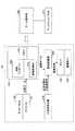
次に、図6を用いて、実施の形態のゲームコントローラ100の構成について説明する。 Next, the configuration of the
図6は、実施の形態のゲームコントローラ100の構成を示す図である。図6には、ゲームコントローラ100と有線又は無線で接続されるゲーム機本体500とディスプレイパネル510を示す。 FIG. 6 is a diagram illustrating a configuration of the
ゲームコントローラ100は、振動素子140、アンプ141、タッチパネル150、ドライバIC(Integrated Circuit)151、制御装置200、正弦波発生器310、及び振幅変調器320を含む。 The
制御装置200は、制御プロセッサ220、駆動制御部240、及びメモリ250を有する。制御装置200は、例えば、ICチップで実現される。 The
なお、ここでは、制御プロセッサ220、駆動制御部240、及びメモリ250が1つの制御装置200によって実現される形態について説明するが、駆動制御部240は、制御装置200の外部に別のICチップ又はプロセッサとして設けられていてもよい。この場合には、メモリ250に格納されているデータのうち、駆動制御部240の駆動制御に必要なデータは、メモリ250とは別のメモリに格納すればよい。 Here, a mode in which the
図6では、筐体110、トップパネル120、両面テープ130、及び基板170(図2参照)は省略する。また、ここでは、アンプ141、ドライバIC151、制御プロセッサ220、駆動制御部240、メモリ250、正弦波発生器310、及び振幅変調器320について説明する。 In FIG. 6, the
アンプ141は、振幅変調器320と振動素子140との間に配設されており、振幅変調器320から出力される駆動信号を増幅して振動素子140を駆動する。 The
ドライバIC151は、タッチパネル150に接続されており、タッチパネル150への操作入力があった位置を表す位置データを検出し、位置データを制御装置200に出力する。この結果、位置データは、制御プロセッサ220と駆動制御部240に入力される。 The
制御プロセッサ220は、ゲームコントローラ100の制御処理のうち、駆動制御部240が行う制御処理以外を行う。 The
駆動制御部240は、振幅を表す振幅データを振幅変調器320に出力する。振幅データは、振動素子140の駆動に用いる駆動信号の強度を調整するための振幅値を表すデータである。振幅を表す振幅データは、メモリ250に格納しておけばよい。 The
また、実施の形態のゲームコントローラ100は、利用者の指先がトップパネル120の表面に沿って移動したときに、指先に掛かる動摩擦力を変化させるためにトップパネル120を振動させる。 The
トップパネル120の表面に触れた指先を移動させる操作入力の種類としては、例えば、所謂フリック操作、スワイプ操作、及びドラッグ操作がある。 Examples of the operation input for moving the fingertip touching the surface of the
フリック操作は、指先をトップパネル120の表面に沿って、はじく(スナップする)ように比較的短い距離移動させる操作である。スワイプ操作は、指先をトップパネル120の表面に沿って掃くように比較的長い距離移動させる操作である。また、ドラッグ操作は、例えば、ディスプレイパネル510に表示されたボタン等をスライドさせる場合に、ボタン等を選択しながら指先をトップパネル120の表面に沿って移動させる操作である。 The flick operation is an operation of moving a fingertip along a surface of the
ここで一例として挙げるフリック操作、スワイプ操作、及びドラッグ操作のように、トップパネル120の表面に触れた指先を移動させる操作入力は、アプリケーションによる表示の種類によって使い分けられる。このため、操作入力を行う指先の位置が、振動を発生させるべき所定の領域内にあるかどうかを判定する際には、ゲームコントローラ100が起動しているアプリケーションの種類が関係することになる。 The operation input for moving the fingertip that touches the surface of the
メモリ250は、振幅を表す振幅データと、振動パターンを表すパターンデータとを格納する。また、メモリ250の内部では、これらのデータのうち、関連づけが必要なデータ同士については、例えば、識別子等を用いて関連付けてテーブル形式のデータにしておけばよい。 The
また、メモリ250は、制御プロセッサ220が制御処理の実行に必要とするデータ及びプログラム等を格納する。 In addition, the
正弦波発生器310は、トップパネル120を固有振動数で振動させるための駆動信号を生成するのに必要な正弦波を発生させる。例えば、トップパネル120を33.5[kHz]の固有振動数fで振動させる場合は、正弦波の周波数は、33.5[kHz]となる。正弦波発生器310は、超音波帯の正弦波信号を振幅変調器320に入力する。 The
振幅変調器320は、駆動制御部240から入力される振幅データを用いて、正弦波発生器310から入力される正弦波信号の振幅を変調して駆動信号を生成する。振幅変調器320は、正弦波発生器310から入力される超音波帯の正弦波信号の振幅のみを変調し、周波数及び位相は変調せずに、駆動信号を生成する。 The
このため、振幅変調器320が出力する駆動信号は、正弦波発生器310から入力される超音波帯の正弦波信号の振幅のみを変調した超音波帯の正弦波信号である。なお、振幅データがゼロの場合は、駆動信号の振幅はゼロになる。これは、振幅変調器320が駆動信号を出力しないことと等しい。 Therefore, the drive signal output from the
また、ゲームコントローラ100は、ケーブル等、又は、無線LAN(Local Area Network)あるいはBluetooth(登録商標)等によって無線でゲーム機本体500に接続される。ゲーム機本体500を動作させる利用者は、ゲームコントローラ100のトップパネル120に操作入力を行う。 The
ゲームコントローラ100は、トップパネル120の表面に行われる操作入力の内容を表す操作信号をゲーム機本体500に送信し、ゲーム機本体500は、ビデオゲームの進行に伴ってディスプレイパネル510に表示される画像の制御を行うとともに、ゲームコントローラ100から入力される操作信号に基づく制御を行う。 The
例えば、ディスプレイパネル510に表示される乗り物あるいは人のようなオブジェクト、又は、ポインタあるいはカーソル等を移動させる操作を行う場合には、トップパネル120の表面の任意の位置に対して行われる操作入力の始点は、オブジェクト、ポインタ、又はカーソル等の表示位置に対応する。 For example, when performing an operation of moving a vehicle or an object such as a person displayed on the
そして、トップパネル120に対して行われる操作入力の移動は、オブジェクト、ポインタ、又はカーソル等の移動に対応する。すなわち、操作入力の始点に対する移動は、ディスプレイパネル510の表示画面の中におけるオブジェクト、ポインタ、又はカーソル等の相対的な移動に対応する。 The movement of the operation input performed on the
また、ゲームコントローラ100には、ゲーム機本体500が行う画面の制御に必要なデータのうち、振動素子140の駆動に関係する画像の画面内における座標位置を表す座標データがゲーム機本体500から入力される。 Also, the
ゲームコントローラ100の駆動制御部240は、トップパネル120の表面への操作入力に応じて振動素子140を駆動するとともに、ゲーム機本体500から入力される座標データに応じて振動素子140を駆動する。 The
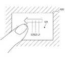
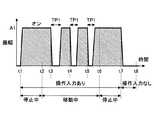
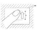
図7は、実施の形態のゲームコントローラ100のトップパネル120の表面に操作入力を行う状態を示す図である。なお、図7には図示しないが、トップパネル120の裏側には、タッチパネル150(図2及び3参照)が配設されている。 FIG. 7 is a diagram illustrating a state in which operation input is performed on the surface of the
図8は、実施の形態のゲームコントローラ100の動作例を示す図である。図8には、図7に示す操作入力に応じて振動素子140が駆動される駆動パターンを示す。図8では、横軸は時間軸を表し、縦軸は振幅データの振幅値を表す。 FIG. 8 is a diagram illustrating an operation example of the
図7に示すように、トップパネル120の表面に沿って矢印で示すように操作入力が行われた場合に、操作入力が始まった時点で振動素子140をオンにし、操作入力の始点121から移動量が所定の移動量に到達したときに、振動素子140をオフにする。 As shown in FIG. 7, when an operation input is performed along the surface of the
例えば、図7に示す始点121からドラッグ操作が行われると振動素子140をオンにして、操作入力の位置が3本の破線L1、L2、L3で示す位置を通過するときに、振動素子140をオフにする。 For example, when a drag operation is performed from the
なお、図7に示す3本の破線L1、L2、L3は、操作入力の移動方向における始点121からの移動量を示すために表したものであり、ここで判定する移動量は、始点121に対する相対的な移動量である。 Note that the three
図7に示す場合の振動素子140の動作は、図8に示すように、時刻t1で操作入力が行われることにより、駆動制御部240は振幅値がA1の振幅データを出力し、振動素子140がオンになる。 The operation of the
操作入力の位置は、時刻t1〜t2までは移動せずに停止している。時刻t1〜t2の間は、操作入力が行われているため、駆動制御部240は振幅値がA1の振幅データを出力し続け、振動素子140はオンの状態に保持される。 The position of the operation input is stopped without moving from time t1 to time t2. Since operation input is performed between times t1 and t2, the
時刻t2で操作入力の位置が移動し始めると、駆動制御部240は振幅値がA1の振幅データを出力し続け、振動素子140はオンの状態に保持される。利用者の指先にかかる動摩擦係数はスクイーズ効果によって低下するため、指先はトップパネル120の表面を移動しやすい状態になる。 When the position of the operation input starts to move at time t2, the
時刻t3で操作入力の移動量が始点121(図7参照)から1本目の破線L1までの長さに対応する所定の移動量に達すると、駆動制御部240は、振幅データの振幅値を0に設定する。これにより、振動素子140はオフにされる。 When the movement amount of the operation input reaches a predetermined movement amount corresponding to the length from the start point 121 (see FIG. 7) to the first broken line L1 at time t3, the
振動素子140がオフになると、利用者は指先に掛かる動摩擦力の増大を感知し、指先の滑り難さ、あるいは、引っ掛かる感じを知覚することになる。そして、指先が滑りにくくなることにより、動摩擦力が高くなるときに、トップパネル120の表面に凸部が存在するように感じる。 When the
振動素子140をオフにするのは、期間TP1の間だけである。期間TP1は、例えば、50ミリ秒程度である。期間TP1が過ぎると、駆動制御部240は振幅値がA1の振幅データを出力し、再び振動素子140はオンになる。 The
そして、時刻t4で操作入力の移動量が始点121(図7参照)から2本目の破線L2までの長さに対応する移動量に達すると、駆動制御部240は、振幅データの振幅値を0に設定する。これにより、振動素子140はオフにされ、利用者は指先に掛かる動摩擦力の増大により、トップパネル120の表面に凸部が存在するように感じる。 When the movement amount of the operation input reaches the movement amount corresponding to the length from the start point 121 (see FIG. 7) to the second broken line L2 at time t4, the
振動素子140をオフにするのは、期間TP1の間だけである。期間TP1が過ぎると、駆動制御部240は振幅値がA1の振幅データを出力し、再び振動素子140はオンになる。 The
そして、時刻t5で操作入力の移動量が始点121(図7参照)から3本目の破線L3までの長さに対応する移動量に達すると、駆動制御部240は、振幅データの振幅値を0に設定する。これにより、振動素子140はオフにされ、利用者は指先に掛かる動摩擦力の増大により、トップパネル120の表面に凸部が存在するように感じる。 When the movement amount of the operation input reaches the movement amount corresponding to the length from the start point 121 (see FIG. 7) to the third broken line L3 at time t5, the
振動素子140をオフにするのは、期間TP1の間だけである。期間TP1が過ぎると、駆動制御部240は振幅値がA1の振幅データを出力し、再び振動素子140はオンになる。 The
時刻t6で操作入力が移動しなくなり、時刻t7まで指先がトップパネル120の表面に触れて操作入力が行われるため、駆動制御部240は振幅値がA1の振幅データを出力し続け、振動素子140はオンの状態に保持される。 Since the operation input does not move at time t6 and the fingertip touches the surface of the
そして、時刻t7で指先がトップパネル120の表面から離れて操作入力が行われなくなると、駆動制御部240は、振幅データの振幅値を0に設定し、振動素子140はオフにされる。 When the fingertip moves away from the surface of the
図9は、実施の形態1のゲームコントローラ100の駆動制御部240が実行する処理を示すフローチャートである。 FIG. 9 is a flowchart illustrating processing executed by the
ゲームコントローラ100のOS(Operating System)は、所定の制御周期毎にゲームコントローラ100を駆動するための制御を実行する。このため、駆動制御部240は、図9に示すフローを所定の制御周期毎に繰り返し実行する。 An OS (Operating System) of the
まず、処理が開始される前の状態では、駆動制御部240は振幅データを出力しておらず、駆動素子140はオフにされている。 First, in a state before the processing is started, the
駆動制御部240は、ゲームコントローラ100の電源がオンにされることにより、処理をスタートさせる。 The
駆動制御部240は、操作入力があるかどうかを判定する(ステップS1)。操作入力の有無は、ドライバIC151(図6参照)から位置データが入力されるかどうかで判定すればよい。 The
駆動制御部240は、操作入力があったと判定すると(S1:YES)、振幅A1の駆動信号を用いて振動素子140を駆動する(ステップS2)。これにより、トップパネル120に超音波帯の固有振動が生じる。 If
なお、駆動制御部240は、操作入力があると判定すると、操作入力が開始された座標を始点として記憶する。操作入力が開始された座標としては、ドライバIC151(図6参照)から最初に入力される位置データを用いればよい。 If the
次いで、駆動制御部240は、操作入力があるかどうかを判定する(ステップS3)。操作入力が継続しているかどうかを判定するためである。 Next, the
駆動制御部240は、操作入力がある(S3:YES)と判定すると、操作入力の始点からの移動量が、いずれかの相対位置に到達したかどうかを判定する(ステップS4)。いずれかの相対位置とは、図7に示す始点121に対する3本の破線L1、L2、L3の位置であり、始点121から操作入力の移動方向における距離で決まる位置である。図7では、矢印で示す操作入力の移動方向における始点121と3本の破線L1、L2、L3の各々との間の距離によって、始点121に対する相対位置が決まる。 When it is determined that there is an operation input (S3: YES), the
駆動制御部240は、操作入力の始点からの移動量が、いずれかの相対位置に到達した(S4:YES)と判定すると、駆動信号を期間TP1にわたってオフにする(ステップS5)。これにより、トップパネル120の超音波帯の固有振動は期間TP1にわたってオフにされる。期間TP1は、上述したように、例えば50ミリ秒に設定される。 When the
駆動制御部240は、ステップS5の処理が終了すると、フローをステップS3にリターンする。 When the process of step S5 ends, the
なお、駆動制御部240は、ステップS1において、操作入力がないと判定すると(S1:NO)、ステップS1の処理を繰り返し実行する。図9に示す一連の処理は、操作入力が行われることによって始まる処理だからである。 In addition, if the
また、駆動制御部240は、ステップS3において操作入力がない(S3:NO)と判定すると、一連の処理を終了する(エンド)。一連の処理が終了すると、振動素子140はオフにされる。 If the
また、駆動制御部240は、ステップS4において、いずれの相対位置にも到達していない(S4:NO)と判定すると、フローをステップS3にリターンする。 If the
以上のような一連の処理は、ゲームコントローラ100の電源がオンにされている間は繰り返し実行される。 The series of processes as described above are repeatedly executed while the
ここで、図7及び図8に示したように、時刻t3で操作入力の位置が破線L1に達し、時刻t4で操作入力の位置が破線L2に達し、時刻t5で操作入力の位置が破線L3に達する場合は、次のようにフローが進む場合である。 Here, as shown in FIGS. 7 and 8, the position of the operation input reaches the broken line L1 at time t3, the position of the operation input reaches the broken line L2 at time t4, and the position of the operation input reaches the broken line L3 at time t5. Is reached when the flow proceeds as follows.
まず、時刻t1で操作入力が行われることにより、駆動制御部240はステップS1でYESと判定し、ステップS2で振動素子140がオンされる。 First, when an operation input is performed at time t1, the
次いで、時刻t1〜t2までは操作入力の位置が移動せずに停止するため、駆動制御部240はステップS3でYESと判定し、ステップS4ではNOと判定する。すなわち、時刻t1〜t2までは、ステップS3及びS4によるサブルーチンの処理が繰り返し実行される。なお、時刻t1〜t2までは、振動素子140はオンの状態に保持される。 Next, since the position of the operation input is stopped without moving from time t1 to time t2, the
そして、時刻t2で操作入力の位置が移動し始めて時刻t3で操作入力の位置が破線L1に達すると、駆動制御部240はステップS4でYESと判定し、ステップS5で振動素子140を期間TP1にわたってオフにする。なお、時刻t3から期間TP1が経過すると、駆動制御部240は振動素子140をオンにする。 When the position of the operation input starts to move at time t2 and the position of the operation input reaches the broken line L1 at time t3, the
その後、時刻t4で操作入力の位置が破線L2に達すると、駆動制御部240はステップS4でYESと判定し、ステップS5で振動素子140を期間TP1にわたってオフにする。時刻t4から期間TP1が経過すると、駆動制御部240は振動素子140をオンにする。 Thereafter, when the position of the operation input reaches the broken line L2 at time t4, the
さらに、その後、時刻t5で操作入力の位置が破線L3に達すると、駆動制御部240はステップS4でYESと判定し、ステップS5で振動素子140を期間TP1にわたってオフにする。時刻t5から期間TP1が経過すると、駆動制御部240は振動素子140をオンにする。 Further, after that, when the position of the operation input reaches the broken line L3 at time t5, the
時刻t6で操作入力の位置が停止すると、駆動制御部240はステップS4でNOと判定し、時刻t6〜t7までは、ステップS3及びS4によるサブルーチンの処理が繰り返し実行され、振動素子140はオンの状態に保持される。操作入力は引き続き行われているからである。 When the position of the operation input stops at time t6, the
そして、時刻t7で操作入力が行われなくなると、駆動制御部240はステップS3でNOと判定し、一連の処理が終了する(エンド)。これにより、振動素子140はオフにされる。 When no operation input is performed at time t7, the
なお、例えば、時刻t3で操作入力の位置が破線L1に達した時点で利用者の指がトップパネル120から離れて操作入力が行われなくなった場合は、時刻t3から期間TP1にわたって振動素子140がオフにされている間に、駆動制御部240がステップS3でNOと判定することにより、再度振動素子140がオンにされることなく、一連の処理が終了する(エンド)。このため、図9に示す一連の処理の制御周期を期間TP1より短く設定知れ置けばよい。 For example, when the position of the operation input reaches the broken line L1 at time t3 and the user's finger is separated from the
なお、図7に矢印で示す操作入力の移動方向における始点121と3本の破線L1、L2、L3の各々との間の距離は、例えば、利用者がビデオゲームをプレイする際の操作における単位操作量に設定しておけばよい。例えば、ビデオゲームが自動車を運転するゲームである場合には、単位操作量は、ハンドルを操作する量、アクセルの開度、ブレーキの強度等の一目盛り分に対応する量に設定することができる。 Note that the distance between the
このように単位操作量を設定すれば、操作量が単位操作量に達する度に、利用者の指先に凸部がある触感を提供でき、良好な操作感を実現できる。 By setting the unit operation amount in this way, every time the operation amount reaches the unit operation amount, it is possible to provide a tactile sensation having a convex portion on the user's fingertip, thereby realizing a good operation feeling.
図10は、実施の形態のゲームコントローラ100のトップパネル120の表面に操作入力を行う状態を示す図である。なお、トップパネル120の裏側には、タッチパネル150(図2及び3参照)が配設される。 FIG. 10 is a diagram illustrating a state in which operation input is performed on the surface of the
図11は、実施の形態のゲームコントローラ100の動作例を示す図である。図11には、図10に示す操作入力に応じて振動素子140が駆動される駆動パターンを示す。図11では、横軸は時間軸を表し、縦軸は振幅データの振幅値を表す。 FIG. 11 is a diagram illustrating an operation example of the
図10に示すように、トップパネル120の表面に沿って矢印で示すようにドラッグ操作による操作入力が行われており、ディスプレイパネル510に表示される乗り物又は人のようなオブジェクトを移動させているとする。 As shown in FIG. 10, an operation input by a drag operation is performed along the surface of the
そして、操作入力の位置がトップパネル120上の所定の位置P1、P2を通過するときに、ごく短い期間だけ駆動制御部240が振動素子140をオンにする。 Then, when the position of the operation input passes through the predetermined positions P1 and P2 on the
このように振動素子140を駆動すると、ごく短い期間だけ振動素子140がオンになる間に指先にかかる動摩擦力が低下し、オフにされると指先にかかる動摩擦力が増大するため、凸部が存在するような良好な感触を利用者の指先に提供できる。 When the
上述のような処理は、例えば、ディスプレイパネル510の表示画面に表示されるオブジェクトの現在の表示位置と、オブジェクトの進行方向における所定の地点との相対的な位置関係を表すデータに基づいて、トップパネル120の現在の操作入力の位置に対する所定の位置P1、P2の座標を演算することによって実現できる。 The processing as described above is performed based on, for example, data representing the relative positional relationship between the current display position of the object displayed on the display screen of the
このようにすれば、ゲームコントローラ100でビデオゲームをプレイしている利用者の操作入力によってディスプレイパネル510の表示画面中をオブジェクトが移動し、所定の地点を通過するときに、操作入力の位置はトップパネル120上の所定の位置P1、P2を通過することになる。 In this way, when the object moves on the display screen of the
従って、操作入力によって移動するオブジェクトがディスプレイパネル510の表示画面中の所定の地点を通過するときに、駆動制御部240がごく短い期間だけ振動素子140をオンにすることにより、オブジェクトが所定の地点を通過したことを触感を通じて利用者に知覚させることができる。 Therefore, when the object that moves by the operation input passes through a predetermined point on the display screen of the
ディスプレイパネル510の表示画面における所定の地点は、例えば、表示画面における領域同士の境界、又は、通過によってポイントを付与する地点等に設定すればよい。 The predetermined point on the display screen of the
図10に示す場合の振動素子140の動作は、図11を用いて説明すると次の通りである。 The operation of the
時刻t11で操作入力が行われることにより、駆動制御部240は振幅値が0の振幅データを出力し、振動素子140はオフである。 When an operation input is performed at time t11, the
操作入力の位置は、時刻t11〜t12までは移動せずに停止している。時刻t11〜t12の間は、振動素子140はオフの状態に保持される。 The position of the operation input is stopped without moving from time t11 to t12. Between the times t11 and t12, the
時刻t12で操作入力の位置が移動し始め、時刻t13で操作入力の位置が位置P1(図10参照)に達すると、駆動制御部240は、ごく短い期間TP11にわたって振幅データの振幅値をA1に設定する。これにより、振動素子140は期間TP11にわたってオンにされる。 When the position of the operation input starts to move at time t12 and the position of the operation input reaches position P1 (see FIG. 10) at time t13, the
振動素子140はオンにされると、利用者の指先にかかる動摩擦係数はスクイーズ効果によって低下するため、指先はトップパネル120の表面を移動しやすい状態になる。 When the
そして、時刻t14で期間TP11が終了すると、駆動制御部240は、振幅データの振幅値を0に設定する。これにより、振動素子140はオフにされ、利用者は指先に掛かる動摩擦力の増大により、トップパネル120の表面に凸部が存在するように感じる。 Then, when the period TP11 ends at time t14, the
なお、振動素子140をオンにする期間TP11は、例えば、100ミリ秒程度である。 The period TP11 for turning on the
そして、時刻t14から時刻t15まで操作入力の位置が移動し、時刻t15で操作入力の位置が位置P2(図10参照)に達すると、駆動制御部240は、ごく短い期間TP11にわたって振幅データの振幅値をA1に設定する。これにより、振動素子140は期間TP11にわたってオンにされる。 Then, when the position of the operation input moves from time t14 to time t15 and the position of the operation input reaches position P2 (see FIG. 10) at time t15, the
振動素子140はオンにされると、利用者の指先にかかる動摩擦係数はスクイーズ効果によって低下するため、指先はトップパネル120の表面を移動しやすい状態になる。 When the
そして、期間TP11が終了すると、駆動制御部240は、振幅データの振幅値を0に設定する。これにより、振動素子140はオフにされ、利用者は指先に掛かる動摩擦力の増大により、トップパネル120の表面に凸部が存在するように感じる。 Then, when the period TP11 ends, the
さらに、時刻t16で操作入力の位置が移動しなくなり、時刻t17まで指先がトップパネル120の表面に触れて操作入力が行われ、振動素子140はオフの状態に保持される。 Further, the position of the operation input does not move at time t16, the operation input is performed with the fingertip touching the surface of the
そして、時刻t17で指先がトップパネル120の表面から離れて操作入力が行われなくなる。 Then, at time t17, the fingertip moves away from the surface of the
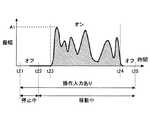
図12は、実施の形態のゲームコントローラ100のトップパネル120の表面に操作入力を行う状態を示す図である。なお、トップパネル120の裏側には、タッチパネル150(図2及び3参照)が配設される。 FIG. 12 is a diagram illustrating a state in which operation input is performed on the surface of the
図13は、実施の形態のゲームコントローラ100の動作例を示す図である。図13には、図12に示す操作入力に応じて振動素子140が駆動される駆動パターンを示す。図13では、横軸は時間軸を表し、縦軸は振幅データの振幅値を表す。 FIG. 13 is a diagram illustrating an operation example of the
図12に示すように、トップパネル120の表面に沿って矢印で示すようにドラッグ操作による操作入力が行われており、ディスプレイパネル510に表示される乗り物又は人のようなオブジェクトを移動させているとする。 As shown in FIG. 12, an operation input by a drag operation is performed along the surface of the
そして、操作入力の位置がトップパネル120上の所定の区間Sを通過する間に、駆動制御部240が振幅が時間的にランダムに変化する振幅データを用いて振動素子140をオンにする。 Then, while the position of the operation input passes through the predetermined section S on the
このように振動素子140を駆動すると、振幅データの時間的な変化に合わせて指先にかかる動摩擦力が変動する。振幅が大きいときは動摩擦力が比較的低くなり、振幅が小さいときは動摩擦力が比較的大きくなる。 When the
このような動摩擦力の時間的な変動により、トップパネル120の表面にランダムな高さの凹凸部が存在するような感触を利用者の指先に提供できる。利用者の指先には、トップパネル120の表面がざらざらしているような感触が提供される。 Due to such temporal variation of the dynamic frictional force, it is possible to provide the user's fingertip with a feeling that unevenness portions having a random height are present on the surface of the
例えば、ディスプレイパネル510の表示画面に表示される乗り物又は人のようなオブジェクトが、障害物の多い区間を通過するような場合に、上述のように振幅が時間的にランダムに変化する振幅データを用いて振動素子140を駆動すればよい。 For example, when an object such as a vehicle or a person displayed on the display screen of the
ディスプレイパネル510の表示画面に表示されるオブジェクトの現在の表示位置と、表示画面に表示される障害物の多い区間の始点及び終点の位置との相対的な位置関係を表すデータに基づいて、トップパネル120の現在の操作入力の位置に対する区間Sの始点及び終点の座標を演算することにより、トップパネル120における所定の位置P1、P2の座標を求めることができる。 Based on the data representing the relative positional relationship between the current display position of the object displayed on the display screen of the
また、振幅を時間的にランダムに変化させるには、例えば、乱数を用いて振幅値が時系列的に出力されるような振幅データを用いて振動素子140を駆動すればよく、このような振幅データはメモリ250(図6参照)に格納しておけばよい。 Further, in order to change the amplitude randomly in terms of time, for example, the
このようにすれば、ゲームコントローラ100でビデオゲームをプレイしている利用者の操作入力によってディスプレイパネル510の表示画面中をオブジェクトが移動し、障害物の多い区間を通過するときに、操作入力の位置はトップパネル120上の区間Sを通過することになる。 In this way, when the object moves on the display screen of the
従って、オブジェクトがディスプレイパネル510の表示画面中の障害物の多い区間を通過するときに、振幅が時間的にランダムに変化する振幅データを用いて駆動制御部240が振動素子140を駆動することにより、オブジェクトが障害物の多い区間を通過したことを触感を通じて利用者に知覚させることができる。 Therefore, when the object passes through a section with many obstacles on the display screen of the
図12に示す場合の振動素子140の動作は、図13を用いて説明すると次の通りである。 The operation of the
時刻t21で操作入力が行われることにより、駆動制御部240は振幅値が0の振幅データを出力し、振動素子140はオフである。 When an operation input is performed at time t21, the
操作入力の位置は、時刻t21〜t22までは移動せずに停止している。時刻t21〜t22の間は、振動素子140はオフの状態に保持される。 The position of the operation input does not move from time t21 to t22 and is stopped. Between the times t21 and t22, the
時刻t22で操作入力の位置が移動し始め、時刻t23で操作入力の位置が区間Sの始点(図12参照)に達すると、駆動制御部240は、振幅が時間的にランダムに変化する振幅データで振動素子140を駆動する。 When the position of the operation input starts to move at time t22, and when the position of the operation input reaches the start point of the section S (see FIG. 12) at time t23, the
振幅が時間的にランダムに変化する振幅データによる振動素子140の駆動は、時刻t23〜t24まで続く。そして、時刻t24で駆動制御部240は振動素子140をオフにする。 Driving of the
振動素子140はオンにされると、利用者の指先にかかる動摩擦係数はスクイーズ効果によって低下するため、指先はトップパネル120の表面を移動しやすい状態になる。 When the
また、時刻t23〜t24までの期間に、駆動制御部240は、振幅が時間的にランダムに変化する振幅データを用いるため、利用者の指先には、トップパネル120の表面がざらざらしているような感触が提供される。 In addition, during the period from time t23 to t24, the
時刻t24で振動素子140がオフにされた後は、時刻t25まで操作入力が行われ、駆動制御部240は、振幅データの振幅値を0に設定する。 After the
そして、時刻t25で操作入力が行われなくなる。 Then, no operation input is performed at time t25.
また、駆動制御部240は、上述のような処理に加えて、位置データの時間的変化度合に応じて振幅値を設定してもよい。 In addition to the processing as described above, the
ここで、位置データの時間的変化度合としては、利用者の指先がトップパネル120の表面に沿って移動する速度を用いる。利用者の指先の移動速度は、ドライバIC151から入力される位置データの時間的な変化度合に基づいて、駆動制御部240が算出すればよい。 Here, as the temporal change degree of the position data, a speed at which the user's fingertip moves along the surface of the
実施の形態のゲームコントローラ100は、一例として、指先の移動速度に関わらずに利用者が指先から感知する触感を一定にするために、移動速度が高いほど振幅値を小さくし、移動速度が低いほど振幅値を大きくする。 As an example, the
このような振幅値を表す振幅データと移動速度との関係を表すデータは、メモリ250に格納しておけばよい。 Data representing the relationship between the amplitude data representing the amplitude value and the moving speed may be stored in the
なお、ここでは、振幅値を表す振幅データと移動速度との関係を表すデータを用いて移動速度に応じた振幅値を設定する形態について説明するが、次式(3)を用いて振幅値Aを算出してもよい。式(3)で算出される振幅値Aは、移動速度が高いほど小さくなり、移動速度が低いほど大きくなる。 In addition, although the form which sets the amplitude value according to movement speed using the data showing the relationship between amplitude data showing an amplitude value and movement speed is demonstrated here, amplitude value A is used using following Formula (3). May be calculated. The amplitude value A calculated by Equation (3) decreases as the moving speed increases, and increases as the moving speed decreases.
駆動制御部240は、移動速度が所定の閾値速度以上になったときに、振動素子140を振動させる。 The
従って、駆動制御部240が出力する振幅データが表す振幅値は、移動速度が所定の閾値速度未満のときはゼロであり、移動速度が所定の閾値速度以上になると、移動速度に応じて所定の振幅値に設定される。移動速度が所定の閾値速度以上のときには、移動速度が高いほど振幅値は小さく設定され、移動速度が低いほど振幅値を大きく設定される。 Therefore, the amplitude value represented by the amplitude data output by the
駆動制御部240は、指先の移動速度が所定の閾値速度以上である場合に、移動速度に応じた振幅値を表す振幅データをメモリ250から読み出して、振幅変調器320に出力する。 When the moving speed of the fingertip is equal to or higher than a predetermined threshold speed, the
図14は、メモリ250に格納される振幅値を表す振幅データと移動速度との関係を表すデータを示す図である。 FIG. 14 is a diagram illustrating data representing the relationship between the amplitude data representing the amplitude value stored in the
図14に示すデータによれば、移動速度Vが0以上b1未満(0≦V<b1)のときは振幅値を0に設定し、移動速度Vがb1以上b2未満(b1≦V<b2)のときは振幅値をA1に設定し、移動速度Vがb2以上b3未満(b2≦V<b3)のときは、振幅値をA2に設定することになる。 According to the data shown in FIG. 14, when the moving speed V is 0 or more and less than b1 (0 ≦ V <b1), the amplitude value is set to 0, and the moving speed V is more than b1 and less than b2 (b1 ≦ V <b2). In this case, the amplitude value is set to A1, and when the moving speed V is not less than b2 and less than b3 (b2 ≦ V <b3), the amplitude value is set to A2.
例えば、図8及び図11に示す駆動パターンの振幅値を指先の移動速度に応じて、図14に示すデータのように設定することができる。 For example, the amplitude value of the drive pattern shown in FIGS. 8 and 11 can be set as the data shown in FIG. 14 according to the moving speed of the fingertip.
以上、実施の形態のゲームコントローラ100によれば、トップパネル120の超音波帯の固有振動を発生させて利用者の指先に掛かる動摩擦力を変化させるので、利用者に良好な触感を提供することができる。 As described above, according to the
また、実施の形態のゲームコントローラ100は、正弦波発生器310で発生される超音波帯の正弦波の振幅のみを振幅変調器320で変調することによって駆動信号を生成している。正弦波発生器310で発生される超音波帯の正弦波の周波数は、トップパネル120の固有振動数に等しく、また、この固有振動数は振動素子140を加味して設定している。 Further, the
すなわち、正弦波発生器310で発生される超音波帯の正弦波の周波数又は位相を変調することなく、振幅のみを振幅変調器320で変調することによって駆動信号を生成している。 That is, the drive signal is generated by modulating only the amplitude by the
従って、トップパネル120の超音波帯の固有振動をトップパネル120に発生させることができ、スクイーズ効果による空気層の介在を利用して、指でトップパネル120の表面をなぞったときの動摩擦係数を確実に低下させることができる。また、Sticky-band Illusion効果、又は、Fishbone Tactile Illusion効果により、トップパネル120の表面に凹凸が存在するような良好な触感を利用者に提供することができる。 Therefore, the natural vibration of the ultrasonic band of the
また、以上では、トップパネル120に凹凸が存在するような触感を利用者に提供するために、振動素子140のオン/オフを切り替える形態について説明した。振動素子140をオフにするとは、振動素子140を駆動する駆動信号が表す振幅値をゼロにすることである。 In the above description, the mode in which the
しかしながら、このような触感を提供するために、必ずしも振動素子140をオンからオフにする必要はない。例えば、振動素子140のオフの状態の代わりに、振幅を小さくして振動素子140を駆動する状態を用いてもよい。例えば、振幅を1/5程度に小さくすることにより、振動素子140をオンからオフにする場合と同様に、トップパネル120に凹凸が存在するような触感を利用者に提供してもよい。 However, in order to provide such a tactile sensation, the
この場合は、振動素子140の振動の強弱を切り替えるような駆動信号で振動素子140を駆動することになる。この結果、トップパネル120に発生する固有振動の強弱が切り替えられ、利用者の指先に凹凸が存在するような触感を提供することができる。 In this case, the
振動素子140の振動の強弱を切り替えるために、振動を弱くする際に振動素子140をオフにすると、振動素子140のオン/オフを切り替えることになる。振動素子140のオン/オフを切り替えることは、振動素子140を断続的に駆動することである。 If the
また、トップパネル120に凹凸が存在するような触感を提供する際に、指先の移動速度に応じて、振幅データの振幅値を小さくする度合を調整してもよい。 Further, when providing a tactile sensation such that the
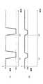
図15は、指先の移動速度によって振幅データの振幅値を小さくする度合を調整する駆動パターンを示す図である。 FIG. 15 is a diagram showing a driving pattern for adjusting the degree of decreasing the amplitude value of the amplitude data depending on the moving speed of the fingertip.
図15の(A)に示す駆動パターンは、振幅値をA1に設定して振動素子140をオンにしている状態から、指先にかかる動摩擦力を増大させるために振幅値を小さくする際に、時刻t31と時刻t32nにおいて、振幅値をA01まで低下させる。振幅値A01は、一例として、振幅値の1/5である。 The drive pattern shown in FIG. 15A shows the time when the amplitude value is reduced to increase the dynamic friction force applied to the fingertip from the state where the amplitude value is set to A1 and the
一方、図15の(B)に示す駆動パターンは、振幅値をA1に設定して振動素子140をオンにしている状態から、指先にかかる動摩擦力を増大させるために振幅値を小さくする際に、時刻t31と時刻t32nにおいて、振幅値をA02まで低下させる。振幅値A02は、一例として、振幅値の4/5である。 On the other hand, in the drive pattern shown in FIG. 15B, when the amplitude value is set to A1 and the
例えば、移動速度が高いときの方が、凹凸の触感が指先に伝わり易い傾向があるため、移動速度が所定値より高い場合は、図15の(A)の駆動パターンを用いて、指先にかかる動摩擦力を増大させるために振幅値を小さくする際に、振幅値をA01まで低下させる。 For example, since the tactile sensation of unevenness tends to be transmitted to the fingertip when the moving speed is high, if the moving speed is higher than a predetermined value, the driving pattern shown in FIG. 15A is applied to the fingertip. When the amplitude value is decreased to increase the dynamic friction force, the amplitude value is decreased to A01.
また、移動速度が所定値以下場合は、図15の(B)の駆動パターンを用いて、指先にかかる動摩擦力を増大させるために振幅値を小さくする際に、振幅値をA02まで低下させる。 Further, when the moving speed is equal to or lower than the predetermined value, the amplitude value is reduced to A02 when the amplitude value is decreased to increase the dynamic friction force applied to the fingertip by using the drive pattern shown in FIG.
以上のように指先の移動速度に応じて振幅データの振幅値を調整することにより、指先の移動速度に応じて異なる触感を利用者に提供することができる。 As described above, by adjusting the amplitude value of the amplitude data according to the moving speed of the fingertip, different tactile sensations according to the moving speed of the fingertip can be provided to the user.
また、以上では、図1に示すように、2つのタッチパネル150を含むゲームコントローラ100について説明したが、タッチパネル150は1つであってもよい。 In the above, the
図16は、実施の形態の変形例によるゲームコントローラ100Aを示す図である。ゲームコントローラ100Aは、筐体110Bの開口部に配設される1つのタッチパネル150を含む。筐体110Bには、ボタン111Aも設けられている。筐体110Bは縦長タイプであり、図中の下側を片方の手で持ち、上側に設けられたタッチパネル150を他方の手で操作すればよい。ゲームコントローラ100Aは、他方の手の人差し指で操作するのに特に適した形状である。 FIG. 16 is a diagram illustrating a
以上、本発明の例示的な実施の形態のゲームコントローラについて説明したが、本発明は、具体的に開示された実施の形態に限定されるものではなく、特許請求の範囲から逸脱することなく、種々の変形や変更が可能である。 The game controller according to the exemplary embodiment of the present invention has been described above, but the present invention is not limited to the specifically disclosed embodiment, and does not depart from the scope of the claims. Various modifications and changes are possible.
100、100A ゲームコントローラ
110、110B 筐体
120 トップパネル
130 両面テープ
140 振動素子
150 タッチパネル
170 基板
200 制御部
220 制御プロセッサ
240 駆動制御部
250 メモリ
310 正弦波発生器
320 振幅変調器100,
Claims (6)
Translated fromJapanese前記筐体の開口部に配設され、操作面を有するトップパネルと、
前記操作面に行われる操作入力の位置を検出する位置検出部と、
前記操作面に振動を発生させる振動素子と、
前記操作面に前記トップパネルの超音波帯の固有振動を発生させる駆動信号で前記振動素子を駆動する駆動制御部と
を含む、ゲームコントローラ。A housing,
A top panel disposed in the opening of the housingand having an operation surface ;
A position detection unit for detecting a position of an operation input performed on the operation surface;
A vibration element for generating a vibration tothe operation surface,
A game controller, comprising: a drive control unit that drives the vibration element with a drive signal that generates a natural vibration of an ultrasonic band of thetop panel on the operation surface.
Applications Claiming Priority (1)
| Application Number | Priority Date | Filing Date | Title |
|---|---|---|---|
| PCT/JP2014/053444WO2015121963A1 (en) | 2014-02-14 | 2014-02-14 | Game controller |
Publications (2)
| Publication Number | Publication Date |
|---|---|
| JPWO2015121963A1 JPWO2015121963A1 (en) | 2017-03-30 |
| JP6319327B2true JP6319327B2 (en) | 2018-05-09 |
Family
ID=53799730
Family Applications (1)
| Application Number | Title | Priority Date | Filing Date |
|---|---|---|---|
| JP2015562636AExpired - Fee RelatedJP6319327B2 (en) | 2014-02-14 | 2014-02-14 | Game controller |
Country Status (3)
| Country | Link |
|---|---|
| US (1) | US10576369B2 (en) |
| JP (1) | JP6319327B2 (en) |
| WO (1) | WO2015121963A1 (en) |
Families Citing this family (2)
| Publication number | Priority date | Publication date | Assignee | Title |
|---|---|---|---|---|
| WO2015121955A1 (en)* | 2014-02-14 | 2015-08-20 | 富士通株式会社 | Electronic device, input device, and drive control method |
| US10814222B2 (en) | 2018-09-21 | 2020-10-27 | Logitech Europe S.A. | Gaming controller with adaptable input configurations |
Family Cites Families (21)
| Publication number | Priority date | Publication date | Assignee | Title |
|---|---|---|---|---|
| JPH06285259A (en)* | 1993-03-31 | 1994-10-11 | Sega Enterp Ltd | Liquid crystal controller |
| JP3929672B2 (en)* | 2000-03-10 | 2007-06-13 | 独立行政法人科学技術振興機構 | Computer input / output device using elastic waves |
| JP3949912B2 (en)* | 2000-08-08 | 2007-07-25 | 株式会社エヌ・ティ・ティ・ドコモ | Portable electronic device, electronic device, vibration generator, notification method by vibration and notification control method |
| JP4473685B2 (en)* | 2004-09-01 | 2010-06-02 | 任天堂株式会社 | GAME DEVICE AND GAME PROGRAM |
| US8780053B2 (en)* | 2007-03-21 | 2014-07-15 | Northwestern University | Vibrating substrate for haptic interface |
| US8405618B2 (en)* | 2006-03-24 | 2013-03-26 | Northwestern University | Haptic device with indirect haptic feedback |
| US8525778B2 (en)* | 2007-03-21 | 2013-09-03 | Northwestern University | Haptic device with controlled traction forces |
| KR20080048837A (en)* | 2006-11-29 | 2008-06-03 | 삼성전자주식회사 | Apparatus and method for outputting tactile feedback |
| US20090102805A1 (en) | 2007-10-18 | 2009-04-23 | Microsoft Corporation | Three-dimensional object simulation using audio, visual, and tactile feedback |
| US9746923B2 (en)* | 2009-03-12 | 2017-08-29 | Immersion Corporation | Systems and methods for providing features in a friction display wherein a haptic effect is configured to vary the coefficient of friction |
| JP5343871B2 (en) | 2009-03-12 | 2013-11-13 | 株式会社リコー | Touch panel device, display device with touch panel including the same, and control method for touch panel device |
| JP2010231609A (en)* | 2009-03-27 | 2010-10-14 | Hitachi Maxell Ltd | Tactile sensation presentation apparatus and method |
| JP5630119B2 (en)* | 2010-07-26 | 2014-11-26 | 株式会社リコー | Touch panel device, display device with touch panel including the same, and control method for touch panel device |
| JP5697521B2 (en) | 2011-04-07 | 2015-04-08 | 京セラ株式会社 | Character input device, character input control method, and character input program |
| JP5689362B2 (en)* | 2011-05-23 | 2015-03-25 | 株式会社東海理化電機製作所 | Input device |
| JP2013097438A (en)* | 2011-10-28 | 2013-05-20 | Mitsubishi Electric Corp | Tactile sense presentation device |
| US20120223880A1 (en)* | 2012-02-15 | 2012-09-06 | Immersion Corporation | Method and apparatus for producing a dynamic haptic effect |
| US8711118B2 (en) | 2012-02-15 | 2014-04-29 | Immersion Corporation | Interactivity model for shared feedback on mobile devices |
| US9330544B2 (en)* | 2012-11-20 | 2016-05-03 | Immersion Corporation | System and method for simulated physical interactions with haptic effects |
| US9041647B2 (en)* | 2013-03-15 | 2015-05-26 | Immersion Corporation | User interface device provided with surface haptic sensations |
| US9588586B2 (en)* | 2014-06-09 | 2017-03-07 | Immersion Corporation | Programmable haptic devices and methods for modifying haptic strength based on perspective and/or proximity |
- 2014
- 2014-02-14JPJP2015562636Apatent/JP6319327B2/ennot_activeExpired - Fee Related
- 2014-02-14WOPCT/JP2014/053444patent/WO2015121963A1/ennot_activeCeased
- 2016
- 2016-08-03USUS15/227,460patent/US10576369B2/ennot_activeExpired - Fee Related
Also Published As
| Publication number | Publication date |
|---|---|
| US10576369B2 (en) | 2020-03-03 |
| US20160339339A1 (en) | 2016-11-24 |
| WO2015121963A1 (en) | 2015-08-20 |
| JPWO2015121963A1 (en) | 2017-03-30 |
Similar Documents
| Publication | Publication Date | Title |
|---|---|---|
| JP6351964B2 (en) | Input device | |
| KR101516926B1 (en) | Drive controlling apparatus, electronic device and drive controlling method | |
| JP5507760B2 (en) | Electronics | |
| JP6147656B2 (en) | Input device | |
| JP2019515370A (en) | Human computer interface system | |
| WO2015045063A1 (en) | Drive control apparatus, electronic device, and drive control method | |
| JP6332476B2 (en) | Drive control apparatus, electronic device, drive control program, and drive control method | |
| CN104156103A (en) | Drawing apparatus and drawing system | |
| JP6891971B2 (en) | Drive control device, electronic device, and drive control method | |
| EP3333674A1 (en) | Systems and methods for compliance simulation with haptics | |
| US20160349847A1 (en) | Electronic device, input apparatus, and drive controlling method | |
| JPWO2015121955A1 (en) | Electronic device, input device, and drive control method | |
| WO2016163000A1 (en) | Drive control device, electronic equipment, drive control program, and drive control method | |
| JP6319327B2 (en) | Game controller | |
| JP6123850B2 (en) | Drive control apparatus, electronic device, and drive control method | |
| US20180067559A1 (en) | Electronic apparatus and non-transitory recording medium having stored therein | |
| JP6589995B2 (en) | Electronic device and electronic device drive control method | |
| KR20110072211A (en) | Touch screen device | |
| JP2016057764A (en) | Tactile sense presentation device | |
| JP2019105969A (en) | Input device | |
| JP2017174211A (en) | Pen type input device, and electronic apparatus | |
| AU2015202408B2 (en) | Drive controlling apparatus, electronic device and drive controlling method | |
| JP2017199208A (en) | Pen type input device, and electronic apparatus | |
| JPWO2017029717A1 (en) | Drive control apparatus, electronic device, drive control program, and drive control method |
Legal Events
| Date | Code | Title | Description |
|---|---|---|---|
| A131 | Notification of reasons for refusal | Free format text:JAPANESE INTERMEDIATE CODE: A131 Effective date:20170704 | |
| A521 | Request for written amendment filed | Free format text:JAPANESE INTERMEDIATE CODE: A523 Effective date:20170901 | |
| TRDD | Decision of grant or rejection written | ||
| A01 | Written decision to grant a patent or to grant a registration (utility model) | Free format text:JAPANESE INTERMEDIATE CODE: A01 Effective date:20180306 | |
| A61 | First payment of annual fees (during grant procedure) | Free format text:JAPANESE INTERMEDIATE CODE: A61 Effective date:20180319 | |
| R150 | Certificate of patent or registration of utility model | Ref document number:6319327 Country of ref document:JP Free format text:JAPANESE INTERMEDIATE CODE: R150 | |
| LAPS | Cancellation because of no payment of annual fees |