JP6317341B2 - Portable magnetic resonance imaging system and method using rotating array permanent magnets - Google Patents
Portable magnetic resonance imaging system and method using rotating array permanent magnetsDownload PDFInfo
- Publication number
- JP6317341B2 JP6317341B2JP2015517228AJP2015517228AJP6317341B2JP 6317341 B2JP6317341 B2JP 6317341B2JP 2015517228 AJP2015517228 AJP 2015517228AJP 2015517228 AJP2015517228 AJP 2015517228AJP 6317341 B2JP6317341 B2JP 6317341B2
- Authority
- JP
- Japan
- Prior art keywords
- magnetic field
- magnet assembly
- mri system
- portable mri
- subject
- Prior art date
- Legal status (The legal status is an assumption and is not a legal conclusion. Google has not performed a legal analysis and makes no representation as to the accuracy of the status listed.)
- Active
Links
- 238000002595magnetic resonance imagingMethods0.000titleclaimsdescription76
- 238000000034methodMethods0.000titleclaimsdescription29
- 230000007246mechanismEffects0.000claimsdescription18
- 238000009826distributionMethods0.000claimsdescription10
- 230000005284excitationEffects0.000claimsdescription9
- 230000010363phase shiftEffects0.000claimsdescription5
- 230000008569processEffects0.000claimsdescription3
- 230000002093peripheral effectEffects0.000claimsdescription2
- 230000035945sensitivityEffects0.000claimsdescription2
- FGUUSXIOTUKUDN-IBGZPJMESA-NC1(=CC=CC=C1)N1C2=C(NC([C@H](C1)NC=1OC(=NN=1)C1=CC=CC=C1)=O)C=CC=C2Chemical compoundC1(=CC=CC=C1)N1C2=C(NC([C@H](C1)NC=1OC(=NN=1)C1=CC=CC=C1)=O)C=CC=C2FGUUSXIOTUKUDN-IBGZPJMESA-N0.000claims2
- 208000032843HemorrhageDiseases0.000description10
- 230000000740bleeding effectEffects0.000description10
- 238000001514detection methodMethods0.000description9
- 238000003384imaging methodMethods0.000description9
- 230000008859changeEffects0.000description8
- 230000008901benefitEffects0.000description7
- 230000003068static effectEffects0.000description6
- 239000000696magnetic materialSubstances0.000description4
- 208000006011StrokeDiseases0.000description3
- 230000005540biological transmissionEffects0.000description3
- 230000000694effectsEffects0.000description3
- 239000011159matrix materialSubstances0.000description3
- 238000005259measurementMethods0.000description3
- 229910001172neodymium magnetInorganic materials0.000description3
- 239000003507refrigerantSubstances0.000description3
- 241000234282AlliumSpecies0.000description2
- 235000002732Allium cepa var. cepaNutrition0.000description2
- 208000002667Subdural HematomaDiseases0.000description2
- 208000030886Traumatic Brain injuryDiseases0.000description2
- 210000004556brainAnatomy0.000description2
- 238000013461designMethods0.000description2
- 239000003365glass fiberSubstances0.000description2
- 230000005415magnetizationEffects0.000description2
- 239000000463materialSubstances0.000description2
- 230000010287polarizationEffects0.000description2
- 229910052761rare earth metalInorganic materials0.000description2
- 238000004088simulationMethods0.000description2
- 238000001356surgical procedureMethods0.000description2
- 230000009529traumatic brain injuryEffects0.000description2
- 206010019196Head injuryDiseases0.000description1
- 208000016988Hemorrhagic StrokeDiseases0.000description1
- 238000005481NMR spectroscopyMethods0.000description1
- 206010042364Subdural haemorrhageDiseases0.000description1
- 102000003978Tissue Plasminogen ActivatorHuman genes0.000description1
- 108090000373Tissue Plasminogen ActivatorProteins0.000description1
- 208000027418Wounds and injuryDiseases0.000description1
- QJVKUMXDEUEQLH-UHFFFAOYSA-N[B].[Fe].[Nd]Chemical compound[B].[Fe].[Nd]QJVKUMXDEUEQLH-UHFFFAOYSA-N0.000description1
- 229920000122acrylonitrile butadiene styrenePolymers0.000description1
- 238000013459approachMethods0.000description1
- 210000000576arachnoidAnatomy0.000description1
- 239000008280bloodSubstances0.000description1
- 210000004369bloodAnatomy0.000description1
- 230000006931brain damageEffects0.000description1
- 231100000874brain damageToxicity0.000description1
- 208000029028brain injuryDiseases0.000description1
- 239000003795chemical substances by applicationSubstances0.000description1
- 239000002131composite materialSubstances0.000description1
- 238000010276constructionMethods0.000description1
- 238000012937correctionMethods0.000description1
- 238000005520cutting processMethods0.000description1
- 230000006378damageEffects0.000description1
- 238000010586diagramMethods0.000description1
- 210000001951dura materAnatomy0.000description1
- 238000002592echocardiographyMethods0.000description1
- 239000003822epoxy resinSubstances0.000description1
- 239000003527fibrinolytic agentSubstances0.000description1
- 125000004435hydrogen atomChemical group[H]*0.000description1
- 208000014674injuryDiseases0.000description1
- 208000020658intracerebral hemorrhageDiseases0.000description1
- 238000004519manufacturing processMethods0.000description1
- 239000012528membraneSubstances0.000description1
- 239000007769metal materialSubstances0.000description1
- 238000012986modificationMethods0.000description1
- 230000004048modificationEffects0.000description1
- 238000001208nuclear magnetic resonance pulse sequenceMethods0.000description1
- 230000033885plasminogen activationEffects0.000description1
- 239000004033plasticSubstances0.000description1
- 229920003023plasticPolymers0.000description1
- 229920000647polyepoxidePolymers0.000description1
- 238000012545processingMethods0.000description1
- 150000002910rare earth metalsChemical class0.000description1
- 238000011160researchMethods0.000description1
- 238000012827research and developmentMethods0.000description1
- 238000005070samplingMethods0.000description1
- 230000001568sexual effectEffects0.000description1
- 230000002195synergetic effectEffects0.000description1
- 229960000103thrombolytic agentDrugs0.000description1
- 229960000187tissue plasminogen activatorDrugs0.000description1
- XLYOFNOQVPJJNP-UHFFFAOYSA-NwaterSubstancesOXLYOFNOQVPJJNP-UHFFFAOYSA-N0.000description1
Images


Classifications
- G—PHYSICS
- G01—MEASURING; TESTING
- G01R—MEASURING ELECTRIC VARIABLES; MEASURING MAGNETIC VARIABLES
- G01R33/00—Arrangements or instruments for measuring magnetic variables
- G01R33/20—Arrangements or instruments for measuring magnetic variables involving magnetic resonance
- G01R33/28—Details of apparatus provided for in groups G01R33/44 - G01R33/64
- G01R33/32—Excitation or detection systems, e.g. using radio frequency signals
- G01R33/34—Constructional details, e.g. resonators, specially adapted to MR
- G01R33/34092—RF coils specially adapted for NMR spectrometers
- A—HUMAN NECESSITIES
- A61—MEDICAL OR VETERINARY SCIENCE; HYGIENE
- A61B—DIAGNOSIS; SURGERY; IDENTIFICATION
- A61B5/00—Measuring for diagnostic purposes; Identification of persons
- A61B5/0033—Features or image-related aspects of imaging apparatus, e.g. for MRI, optical tomography or impedance tomography apparatus; Arrangements of imaging apparatus in a room
- A61B5/004—Features or image-related aspects of imaging apparatus, e.g. for MRI, optical tomography or impedance tomography apparatus; Arrangements of imaging apparatus in a room adapted for image acquisition of a particular organ or body part
- A61B5/0042—Features or image-related aspects of imaging apparatus, e.g. for MRI, optical tomography or impedance tomography apparatus; Arrangements of imaging apparatus in a room adapted for image acquisition of a particular organ or body part for the brain
- A—HUMAN NECESSITIES
- A61—MEDICAL OR VETERINARY SCIENCE; HYGIENE
- A61B—DIAGNOSIS; SURGERY; IDENTIFICATION
- A61B5/00—Measuring for diagnostic purposes; Identification of persons
- A61B5/05—Detecting, measuring or recording for diagnosis by means of electric currents or magnetic fields; Measuring using microwaves or radio waves
- A61B5/055—Detecting, measuring or recording for diagnosis by means of electric currents or magnetic fields; Measuring using microwaves or radio waves involving electronic [EMR] or nuclear [NMR] magnetic resonance, e.g. magnetic resonance imaging
- G—PHYSICS
- G01—MEASURING; TESTING
- G01R—MEASURING ELECTRIC VARIABLES; MEASURING MAGNETIC VARIABLES
- G01R33/00—Arrangements or instruments for measuring magnetic variables
- G01R33/20—Arrangements or instruments for measuring magnetic variables involving magnetic resonance
- G01R33/28—Details of apparatus provided for in groups G01R33/44 - G01R33/64
- G01R33/38—Systems for generation, homogenisation or stabilisation of the main or gradient magnetic field
- G01R33/383—Systems for generation, homogenisation or stabilisation of the main or gradient magnetic field using permanent magnets
- G—PHYSICS
- G01—MEASURING; TESTING
- G01R—MEASURING ELECTRIC VARIABLES; MEASURING MAGNETIC VARIABLES
- G01R33/00—Arrangements or instruments for measuring magnetic variables
- G01R33/20—Arrangements or instruments for measuring magnetic variables involving magnetic resonance
- G01R33/44—Arrangements or instruments for measuring magnetic variables involving magnetic resonance using nuclear magnetic resonance [NMR]
- G01R33/46—NMR spectroscopy
- G—PHYSICS
- G01—MEASURING; TESTING
- G01R—MEASURING ELECTRIC VARIABLES; MEASURING MAGNETIC VARIABLES
- G01R33/00—Arrangements or instruments for measuring magnetic variables
- G01R33/20—Arrangements or instruments for measuring magnetic variables involving magnetic resonance
- G01R33/28—Details of apparatus provided for in groups G01R33/44 - G01R33/64
- G01R33/38—Systems for generation, homogenisation or stabilisation of the main or gradient magnetic field
- G01R33/3802—Manufacture or installation of magnet assemblies; Additional hardware for transportation or installation of the magnet assembly or for providing mechanical support to components of the magnet assembly
- G—PHYSICS
- G01—MEASURING; TESTING
- G01R—MEASURING ELECTRIC VARIABLES; MEASURING MAGNETIC VARIABLES
- G01R33/00—Arrangements or instruments for measuring magnetic variables
- G01R33/20—Arrangements or instruments for measuring magnetic variables involving magnetic resonance
- G01R33/44—Arrangements or instruments for measuring magnetic variables involving magnetic resonance using nuclear magnetic resonance [NMR]
- G01R33/445—MR involving a non-standard magnetic field B0, e.g. of low magnitude as in the earth's magnetic field or in nanoTesla spectroscopy, comprising a polarizing magnetic field for pre-polarisation, B0 with a temporal variation of its magnitude or direction such as field cycling of B0 or rotation of the direction of B0, or spatially inhomogeneous B0 like in fringe-field MR or in stray-field imaging
- G—PHYSICS
- G01—MEASURING; TESTING
- G01R—MEASURING ELECTRIC VARIABLES; MEASURING MAGNETIC VARIABLES
- G01R33/00—Arrangements or instruments for measuring magnetic variables
- G01R33/20—Arrangements or instruments for measuring magnetic variables involving magnetic resonance
- G01R33/44—Arrangements or instruments for measuring magnetic variables involving magnetic resonance using nuclear magnetic resonance [NMR]
- G01R33/48—NMR imaging systems
- G01R33/4818—MR characterised by data acquisition along a specific k-space trajectory or by the temporal order of k-space coverage, e.g. centric or segmented coverage of k-space
- G01R33/4824—MR characterised by data acquisition along a specific k-space trajectory or by the temporal order of k-space coverage, e.g. centric or segmented coverage of k-space using a non-Cartesian trajectory
Landscapes
- Health & Medical Sciences (AREA)
- Physics & Mathematics (AREA)
- Life Sciences & Earth Sciences (AREA)
- Nuclear Medicine, Radiotherapy & Molecular Imaging (AREA)
- Radiology & Medical Imaging (AREA)
- Engineering & Computer Science (AREA)
- Public Health (AREA)
- Veterinary Medicine (AREA)
- Biophysics (AREA)
- Pathology (AREA)
- General Health & Medical Sciences (AREA)
- Biomedical Technology (AREA)
- Heart & Thoracic Surgery (AREA)
- Medical Informatics (AREA)
- Molecular Biology (AREA)
- Surgery (AREA)
- Animal Behavior & Ethology (AREA)
- Condensed Matter Physics & Semiconductors (AREA)
- General Physics & Mathematics (AREA)
- High Energy & Nuclear Physics (AREA)
- Neurology (AREA)
- Spectroscopy & Molecular Physics (AREA)
- Magnetic Resonance Imaging Apparatus (AREA)
Description
Translated fromJapanese関連出願の相互参照
本出願は、2012年6月15日に出願された「MRI Encoding with and Inhomogeneous Magnetic Field(不均一磁場を用いたMRI符号化、および不均一磁場)」と題する米国仮特許出願第61/660,278号の利益を主張するものである。CROSS REFERENCE TO RELATED APPLICATIONS This application is a US provisional patent application entitled "MRI Encoding with and Inhomogeneous Magnetic Field" filed June 15, 2012. Claims the benefit of 61 / 660,278.
連邦政府による資金提供を受けた研究開発の記載
本発明は、米陸軍医学研究司令部(U.S.Army Medical Research and Materiel Command)により授与された契約番号W81XWH−11−2−0076に基づき、政府による支援を受けて行われた。政府は、特定の権利を本発明において有する。DESCRIPTION OF FEDERALLY SPONSORED RESEARCH AND DEVELOPMENT The present invention is based on contract number W81XWH-11-2-0076 awarded by US Army Medical Research and Material Command, This was done with government support. The government has certain rights in the invention.
本発明の分野は、磁気共鳴イメージング(「MRI」)システムおよび方法である。更に詳細には、本発明は、不均一磁場を用いて空間符号化を行う携帯型MRI(磁気共鳴イメージング)システムおよび方法に関するものである。 The field of the invention is magnetic resonance imaging (“MRI”) systems and methods. More particularly, the present invention relates to a portable MRI (Magnetic Resonance Imaging) system and method for performing spatial encoding using a non-uniform magnetic field.
従来のMRIスキャナは、いくつかの異なる磁場を用いて画像を生成する。1つの磁場は、非常に均一な静磁場であり、この静磁場を用いて原子核を磁化させ、この静磁場では、自由誘導減衰(free−induction decay:「FID」)信号が読み出される。別の磁場は、FIDを引き起こす高周波(「RF」)パルス磁場である。また、1つ以上の傾斜磁場を用いて、FIDが発生する空間位置を符号化することにより、結果的に得られる画像を空間符号化する。これらの傾斜磁場は、空間的に変化する(例えば、位置とともに直線的に変化する)傾斜磁場であり、スピンの位相を位置に応じて変える。スピンの位相が変わる結果として、当該信号の位置が、検出信号のフーリェ変換として符号化される。場合によっては、不均一な前分極磁場を用いて初期磁化を強化し、この初期磁化が次に、より強度の低い均一磁場の信号として読み出される。 Conventional MRI scanners generate images using several different magnetic fields. One magnetic field is a very uniform static magnetic field. The static magnetic field is used to magnetize the nucleus, and in this static magnetic field, a free-induction decay (“FID”) signal is read out. Another magnetic field is a radio frequency (“RF”) pulsed magnetic field that causes FID. In addition, the spatial position where the FID occurs is encoded using one or more gradient magnetic fields, thereby spatially encoding the resulting image. These gradient magnetic fields are gradient magnetic fields that change spatially (for example, change linearly with position), and change the phase of the spin according to the position. As a result of the spin phase change, the position of the signal is encoded as a Fourier transform of the detection signal. In some cases, an inhomogeneous pre-polarized magnetic field is used to enhance the initial magnetization, which is then read out as a signal of a lower intensity uniform magnetic field.
MRIシステムの規模および複雑さの殆どは、通常の臨床MRIシステムが、非常に均一な静磁場、および非常に高強度の線形傾斜磁場を必要とするということに由来する。従って、現在のMRIシステムは、磁気的に極めて均一な超伝導磁石または永久磁石が重く、かつ壊れやすいことから、病院現場に限定されている。更に厄介なのは、数百アンペアの電流で傾斜磁場を発生させる必要があることである。携帯型MRIシステムを製造するためには、新規方式のMR符号化方法が必要である。単に現在の設計を「縮小する(shrink down)」だけでは十分ではない。 Most of the scale and complexity of MRI systems stems from the fact that typical clinical MRI systems require a very uniform static magnetic field and a very high intensity linear gradient field. Thus, current MRI systems are limited to hospital sites because magnetically very uniform superconducting magnets or permanent magnets are heavy and fragile. Even more troublesome is the need to generate a gradient magnetic field with a current of several hundred amperes. In order to manufacture a portable MRI system, a novel MR encoding method is required. It is not enough to simply “shrink down” the current design.
携帯型MRシステムは、脳損傷を損傷部位で即座に検出する可能性を有している。例えば、出血検出は、脳卒中患者および外傷性脳損傷患者の両方の患者にとって極めて重要である。脳卒中の場合、出血事象と非出血事象の違いを迅速に見分けると、病院に搬送する前に、多分、この一刻を争う処置に最大1時間先行して、tPA(tissue plasminogen activator:組織プラスミノゲン活性化因子)などの血栓溶解薬を応急処置として投与することができる。硬膜下出血(または、硬膜下血腫)は、血液が硬膜とくも膜との間に(髄膜層に)集まる外傷性脳損傷の一種であり、高解像度(例えば、5mm)のT1画像を撮影しながら可視化することができる。出血を現場で速やかに診断すると、「経過観察」を推奨することにより処置効果を極めて早くもたらすことができる。脳外科手術の後、数人の患者は、出血が進行するので即座に治療する必要がある。神経集中治療室(neuro−ICU)のベッドサイドに設置されたMRIは、このような出血の進行を頻繁にチェックすることができる。 Portable MR systems have the potential to detect brain damage immediately at the site of injury. For example, bleeding detection is crucial for both stroke patients and traumatic brain injury patients. In the case of stroke, quickly distinguishing between a bleeding event and a non-bleeding event, perhaps up to an hour ahead of this time-consuming treatment, may be preceded by tPA (tissue plasminogen activator: tissue plasminogen activation) before being delivered to the hospital. Thrombolytic agents such as factor) can be administered as an emergency treatment. Subdural hemorrhage (or subdural hematoma) is a type of traumatic brain injury where blood collects between the dura mater and the arachnoid membrane (in the meningeal layer) and is a high resolution (eg, 5 mm) T1 image. Can be visualized while shooting. By promptly diagnosing bleeding on site, the treatment effect can be brought about very quickly by recommending “follow-up”. After brain surgery, some patients need immediate treatment as bleeding progresses. MRI installed on the bedside of a neuro-intensive care unit (neuro-ICU) can frequently check the progress of such bleeding.
他者が、携帯型核磁気共鳴分光計を開示しているが、これらのシステムも依然として、傾斜磁場を必要とする従来の符号化方法を利用している。 Others have disclosed portable nuclear magnetic resonance spectrometers, but these systems still utilize conventional encoding methods that require gradient magnetic fields.
従って、傾斜磁場コイルを使用して磁気共鳴信号の空間符号化を行う必要がない携帯型MRIシステムを提供することが望まれる。 Accordingly, it would be desirable to provide a portable MRI system that does not require spatial encoding of magnetic resonance signals using gradient coils.
本発明は、前述の不具合を、携帯型磁気共鳴イメージング(「MRI」)システムを提供することにより解決し、この携帯型MRIシステムは、当該携帯型MRIシステムが元来持っている不均一磁場を利用して、磁気共鳴信号群を空間符号化する。 The present invention solves the aforementioned drawbacks by providing a portable magnetic resonance imaging (“MRI”) system, which uses the inhomogeneous magnetic field inherent in the portable MRI system. Utilizing this, the magnetic resonance signal group is spatially encoded.
本発明の1つの態様は、磁石アセンブリ、ローテータ、高周波(「RF」)コイル、およびコントローラを含む携帯型MRIシステムを提供することである。前記磁石アセンブリは、複数の永久磁石と、支持機構とを含む。前記複数の永久磁石の各永久磁石は、前記磁石アセンブリの近位端から遠位端に長軸方向に沿って延在する。前記支持機構は、前記複数の永久磁石を円環状配列に保持して、撮影対象の被検体を収容するように構成される領域を画定するように構成される。前記支持機構は更に、前記複数の永久磁石を保持して、前記永久磁石群から、前記磁石アセンブリの長軸方向と直交する平面にある空間位置とともに変化する磁場が発生するように構成される。前記ローテータは、前記磁石アセンブリに接続され、かつ前記磁石アセンブリを、該磁石アセンブリの長軸方向の回りに複数の異なる回転角だけ回転させるように構成される。前記RFコイルは、RFエネルギーを発生させ、かつ磁気共鳴信号群を前記磁石アセンブリ内に載置される被検体から受信するように構成される。前記コントローラは、前記ローテータに指示を出して、前記磁石アセンブリを前記複数の異なる回転角だけ回転させ、かつ前記RFコイルに指示を出して、RFエネルギーを発生させ、それに応答する磁気共鳴信号群を各回転角で受信するように構成される。 One aspect of the present invention is to provide a portable MRI system that includes a magnet assembly, a rotator, a radio frequency (“RF”) coil, and a controller. The magnet assembly includes a plurality of permanent magnets and a support mechanism. Each permanent magnet of the plurality of permanent magnets extends along the longitudinal direction from the proximal end to the distal end of the magnet assembly. The support mechanism is configured to define an area configured to hold the plurality of permanent magnets in an annular array and accommodate a subject to be imaged. The support mechanism is further configured to hold the plurality of permanent magnets and generate a magnetic field that varies with a spatial position in a plane perpendicular to the major axis direction of the magnet assembly from the group of permanent magnets. The rotator is connected to the magnet assembly and is configured to rotate the magnet assembly by a plurality of different rotation angles about the longitudinal direction of the magnet assembly. The RF coil is configured to generate RF energy and receive a group of magnetic resonance signals from a subject placed in the magnet assembly. The controller issues an instruction to the rotator to rotate the magnet assembly by the plurality of different rotation angles and to issue an instruction to the RF coil to generate RF energy and to respond to a group of magnetic resonance signals. It is configured to receive at each rotation angle.
本発明のこれまでの態様および利点、ならびに他の態様および利点は、以下の説明から明らかになる。この説明では、本明細書の一部を構成する添付の図面が参照され、これらの図面では、例示として、本発明の好適な実施形態が図示される。このような実施形態は、本発明の全範囲を必ずしも表している訳ではないが、請求項を本明細書において参照して本発明の範囲が解釈される。 The previous aspects and advantages of the invention, as well as other aspects and advantages, will become apparent from the following description. In this description, reference is made to the accompanying drawings that form a part hereof, and in which is shown by way of illustration a preferred embodiment of the present invention. Such embodiments do not necessarily represent the full scope of the invention, but the scope of the invention is construed with reference to the claims herein.
主磁石の静磁場の不均一性を利用して核スピンの空間位置を符号化する携帯型磁気共鳴イメージング(「MRI」)システムが提供される。更に提供されるのは、低磁場、低電力消費、軽量であり、かつ容易に移動可能なMRIシステムに用いられる空間符号化方法である。概括すると、本発明の携帯型MRIシステムは、傾斜磁場ではなく、分極磁場B0の空間不均一性を利用して、画像を空間符号化する。従って、本発明のシステムでは、不均一な静磁場を用いて、分極と被検体の画像の、読み出し、符号化を行う。空間符号化を行うために、磁石を被検体の周りで回転させて、いくつかの異なる符号化測定を行う。次に、画像は、被検体について、制約または既知の情報(磁場B0の空間マップ以外の)を用いて、または用いることなく、当該データに最も一致する、例えば最小二乗法の近似と一致する解を求めることにより再構成される。A portable magnetic resonance imaging (“MRI”) system is provided that encodes the spatial position of nuclear spins utilizing the inhomogeneity of the static magnetic field of the main magnet. Further provided are spatial coding methods used in MRI systems that are low magnetic field, low power consumption, lightweight, and easily movable. In summary, the portable MRI system of the present invention spatially encodes an image using the spatial non-uniformity of the polarization field B0 rather than the gradient field. Accordingly, in the system of the present invention, polarization and an image of the subject are read out and encoded using a non-uniform static magnetic field. To perform spatial encoding, the magnet is rotated around the subject and several different encoded measurements are made. The image then matches, for example, the least squares approximation that best matches the data for the subject, with or without constraints or known information (other than the spatial map of the magnetic field B0 ). Reconstructed by seeking a solution.
本発明の携帯型MRIシステムを用いて、出血を緊急事態において検出することができ、脳外科手術後の集中ケアユニット(「ICU」)における出血を、患者の病室で監視することができ、または出血性脳卒中を早期段階で検出することができる。後者の応用形態は、出血性脳卒中の早期検出によって抗血栓溶解剤を投与する時期を早めることができることにより、患者の臨床結果を改善することができるので極めて有用である。 With the portable MRI system of the present invention, bleeding can be detected in an emergency situation, bleeding in an intensive care unit (“ICU”) after brain surgery can be monitored in a patient's room, or bleeding Sexual stroke can be detected at an early stage. The latter application form is extremely useful because the early detection of hemorrhagic stroke can advance the timing of administration of the antithrombolytic agent, thereby improving the clinical outcome of the patient.
図1から分かるように、本発明の携帯型MRIシステム10は普通、磁石アセンブリ12、高周波(「RF」)システム14、およびコントローラ16を含む。コントローラ16は、例えばパルスシーケンスシステム18、データ取得システム20、データ処理システム22、および制御プロセッサ24を含むことができる。携帯型MRIシステム10は更に、携帯型MRIシステム10で取得される被験者28の画像を視覚化し、かつ術者とコントローラ16との間のユーザインターフェースとなるディスプレイ26を含むことができる。携帯型MRIシステム10は、傾斜磁場コイル群または高出力の傾斜磁場アンプ群を必要としない。従って、RFシステム14およびコントローラ16は、小信号用電子部品および低出力のRFパワーアンプにより構成することができ、これらの構成要素の全ては、救急車の後部に容易に格納することができる。 As can be seen from FIG. 1, the
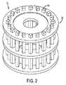
磁石アセンブリ12は普通、円環状ハルバッハ配列に配置される複数の永久磁石30を含む。これらの永久磁石30は、支持機構32により離間して配置される状態に保持されて、円環状ハルバッハ配列を形成する。一例として、支持機構32は、プラスチック、ガラス繊維、または好適には、別の適切な非磁性材料により形成することができる。磁石アセンブリ12は更に、永久磁石群30の端部に配置されるエンドリング永久磁石群34を含むことにより、磁石アセンブリ12の両端における磁場の低下を抑えることができる。 The
磁石アセンブリ12は、80キログラム以下の重量とすることにより、当該磁石アセンブリが比較的軽量となり、かつ持ち運び可能となるように構成することができる。臨床用MRIシステムとは異なり、本発明の磁石アセンブリ12は、永久磁石群により構成されるので、当該磁石アセンブリは冷媒を必要としない。軽量の超伝導磁石を使用することができる磁石アセンブリ12の他の構造では、冷媒が必要になる場合がある。しかしながら、磁場の均一性という要件は緩くすることができるので、このような超伝導磁石の重量は、従来の臨床用MRIシステムに使用される超伝導磁石と比較して、大幅に低減することができる。 By setting the
本発明の携帯型MRIシステム10の一部を構成することができる磁石アセンブリ12の例が、図2〜図5に図示されている。上述したように、磁石アセンブリ12は、ハルバッハ配列に配置される複数の永久磁石30を含む。ハルバッハ配列構造は、当該ハルバッハ配列構成が、非常に均一な磁場を、冷媒または電源を必要とすることなく発生させるので好ましい。いくつかの構成では、磁石アセンブリ12は、軽量の超伝導磁石を含むことができる。このような磁石の重量は、超伝導磁石の磁場が、従来の臨床用MRIシステムにおけるほど均一である必要がないので、かなり減らすことができる。この均一性の要件が緩くなるので、超伝導磁石の重量を大幅に減らすことができ、超伝導磁石を携帯型MRIシステム10の磁石アセンブリ12に使用することができる。 Examples of a
磁石アセンブリ12は、空間符号化を行う際の磁場の微小な変化を高い制御性で可能としながら、平均磁場強度を最大にするように設計される。COMSOLシミュレーションなどのシミュレーションを利用して、磁石アセンブリの磁場を、種々の1つ以上のパラメータに基づいて最適化することができる。磁石設計に際して変えることができるパラメータ群の例として、磁石群30のサイズおよび個数、磁石アセンブリ12のサイズ、ならびにエンドリング磁石群34などのより小型のリング型磁石を付加することによる周縁磁場補正を挙げることができる。 The
これらの永久磁石30は、磁性金属材料、複合磁性材料、または希土類磁性材料などの磁性材料により構成される。一例として、これらの永久磁石30は、ネオジミウム−鉄−ホウ素(「NdFeB」)などの希土類元素材料により構成することができる。これらの永久磁石30は、磁石アセンブリの近位端から遠位端に長軸方向に沿って延在するロッド群として形づくられることが好ましい。この例では、各永久磁石30は、多角形断面を有することが好ましい。例えば、これらの永久磁石30の断面は、方形、矩形、円形、六角形などとすることができる。 These
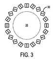
一例として、図2〜図5に示す磁石アセンブリ12は、方形断面を有するロッド状永久磁石群30を含む。ハルバッハ配列を形成するために、各永久磁石30を、当該永久磁石の長軸方向の回りに、他の隣接する永久磁石群30に対して回転させる。例えば、磁石アセンブリ12は、各永久磁石を隣接する永久磁石群30に対して回転させた状態の20個の永久磁石30を含むことができる。図3に示すように、この構成から磁化を空間的に回転させたパターンが得られ、これにより今度は、磁場を磁石アセンブリ12の中心36に発生させ、かつ磁場を磁石アセンブリ12の外側で打ち消してほぼゼロにすることができる。 As an example, the
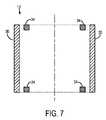
この例では、20個の永久磁石30の各永久磁石は、半径方向に磁化されるNdFeBのN42磁石であり、このN42磁石は、14インチ(35.56cm)の長さであり、かつ1インチ(2.54cm)×1インチ(2.54cm)平方である。これらの永久磁石30は、ガラス繊維スリーブなどのスリーブに収納することにより、これらの永久磁石を拘束することができる。これらの永久磁石30は、このようなスリーブに、押し込み治具を用いて押し込むことができ、所定の位置にエポキシ樹脂で接着させることができる。これらのスリーブの各スリーブは、正しい角度に向けることができ、かつ所定の位置に支持機構32で保持することができる。支持機構32は、ウォータージェット切断加工したABSプラスチックにより構成することができる。支持機構32は、2つのエンドリング、および中央リングを含むことができる。上に説明したように、更に別のループ状の1立方インチエンドリング磁石群34は、図6および図7に示すように、これらの永久磁石30の各端部に配置することができる。これらのエンドリング磁石34によって、磁石アセンブリ12の両端における磁場の減衰を抑えることにより、磁石アセンブリ12の長軸方向に沿った磁場の均一性を向上させることができる。 In this example, each of the 20
次に、図8および図9を参照するに、図2に示す携帯型MRIシステム10の磁石アセンブリ12の面内磁場分布の例が図示されている。この磁場は、磁石アセンブリ12の長軸方向と直交しているので、携帯型MRIシステム10を使用して患者の頭部を撮影する場合、磁石アセンブリ12は、頭部に近い位置から遠い位置に向かう方向に直交する平面における空間符号化に適切な空間的変化をする磁場、または直交平面に対して傾斜する傾斜平面における空間符号化に適切な空間的変化をする磁場を生成する。図8は、磁石アセンブリ12に沿った3つの異なる長軸方向位置における磁場分布を示している。これらの位置は、磁石アセンブリ12の中心、ならびに磁石アセンブリ12の中心よりも上方に4センチメートルの位置、および下方に4センチメートルの位置を含む。図9は、これらの同じ長軸方向位置における同じ磁石アセンブリ12の磁場分布を示しているが;図9に表示される磁場の隙間は、更に別の磁石群を、例えばエンドリング磁石群34を磁石アセンブリ12に追加することにより埋められている。 8 and 9, an example of in-plane magnetic field distribution of the
このようにして形成される磁石アセンブリ12が元来持っている不均一性によって、大きな2次流れが生じ、この不均一性は、異なる測定方向に撮影される被検体の回りに回転させる場合に、磁気共鳴信号を空間符号化するために非常に適している。更に、磁石アセンブリ12の磁場分布から、撮影に適する3.3MHzの水素プロトンの中心ラーモア周波数が得られる。磁石アセンブリ12により生成される磁場の均一性は、超伝導磁石群の磁場均一性よりもずっと低いが、磁場形状により、不均一性を画像符号化に使用することができる。 The non-uniformity inherent in the
磁石アセンブリ12の不均一磁場は、撮影対象の被検体を分極磁化させて磁気共鳴信号を読み出すように機能する。次に、読み出した磁気共鳴信号の空間位置を、磁石アセンブリ12を被検体の回りに異なる方向に回転させて複数回の測定を行うことにより符号化する。例えば、第1の検出値は、被検体内を左から右に横断する方向に向いた磁場B0を有することができる。次に、当該検出を、各検出値が1つの固有の磁場方向に対応する36個の異なる検出値が得られるまで、磁石アセンブリ12を10度ずつ増やして回転させることにより繰り返し行う。磁石アセンブリ12により生成される磁場の空間不均一性により、磁気共鳴信号位相が空間的に変化することにより、これらの信号が空間符号化され、これらの空間符号化信号を使用して、被検体の画像を再構成することができる。この画像再構成では、あらゆる方向を向いた磁場分布に関する詳細な事前情報が使用される。例えば、符号化行列に関する完全な情報が与えられる場合に、画像再構成は通常、未知画像の解を、反復アルゴリズムを用いて探査することにより行われる。The nonuniform magnetic field of the
磁石アセンブリ12の回転は、磁石アセンブリ12の支持機構32に接続されるローテータによって行われる。一例として、ローテータは、支持機構32に接続されるガントリーを含むことができる、またはローラ集合体を含むことができ、このローラ集合体の上に、磁石アセンブリ12を載置し、このローラ集合体の上で、磁石アセンブリ12を磁石アセンブリの長軸方向の回りに回転させることができる。 The rotation of the
空間位置を特定する磁気共鳴信号としての機能は、RF受信コイルの配列を使用することにより向上させることができる。次に、RF受信コイルの配列に関する情報を使用して信号群を、従来のMRIの同時撮像に類似するプロセスで検出することができる。再構成中、空間的に変化するコイルの感度分布を符号化行列に直接取り込む。更に、画像符号化は、使用するRF励起パルスの帯域幅を制限することにより行うこともできる。この場合、励起は、空間領域の拘束「オニオンシェル(onion shell):玉ねぎ多層構造)」に限定される。空間位置を特定する機能は、所謂「TRASE(送信コイル配列空間符号化)」の方法を使用することにより更に向上させることができ、この方法では、空間位相がz方向に異なる構成が、RF送信コイルまたはRF送信コイル群を使用して適用される。 The function as a magnetic resonance signal for specifying a spatial position can be improved by using an array of RF receiving coils. The signal group can then be detected using a process similar to conventional MRI simultaneous imaging using information about the arrangement of the RF receive coils. During reconstruction, the spatially varying coil sensitivity distribution is taken directly into the coding matrix. Furthermore, image coding can also be performed by limiting the bandwidth of the RF excitation pulse used. In this case, the excitation is limited to the spatial domain constraint “onion shell: onion multilayer structure”. The function of specifying the spatial position can be further improved by using a so-called “TRASE (Transmission Coil Array Spatial Coding)” method. Applied using coils or groups of RF transmit coils.
携帯型MRIシステムに関する困難な解決課題は、空間符号化を、傾斜磁場コイルを切り替えて使用することなく、どのようにして行うかということである。本発明は、傾斜磁場コイルを必要としないシステムを提供する。傾斜磁場コイルを設けない構成は、多数の利点をもたらし、電力消費が少なくなる、複雑さが低減される、低い均一性を使用することができるので、永久磁石または超伝導磁石が軽量になり、撮影中の動作が静かになるという利点をもたらす。本発明の携帯型MRIシステム10を用いた空間符号化についての詳細な説明が以下に提供される。 A difficult solution for a portable MRI system is how to perform spatial encoding without switching and using gradient coils. The present invention provides a system that does not require gradient coils. A configuration without a gradient coil provides a number of advantages, lower power consumption, reduced complexity, and lower uniformity can be used, thus making permanent or superconducting magnets lighter, This provides the advantage of quiet operation during shooting. A detailed description of spatial coding using the
体軸と直交する方向の符号化は以下の通りに行われる。磁石アセンブリ12のハルバッハ配列構造は元来、非線形磁場を発生し、この非線形磁場が持つラーモア周波数の変化(ラーモア周波数は、FOV(撮像視野)全体で約50〜100KHzの範囲で変化する)を利用して空間符号化を行うことができる。図2に示す磁石アセンブリ12が生成する磁場の近似形状は、Patloc符号化磁場と同様の四重極を持つ2次球面調和関数であり、Patloc符号化磁場は、MAGMA, 2008;21[1−2]:5−14に掲載されたJ.Hennigらによる「Parallel imaging in non−bijective, curvilinear magnetic field gradients:a concept study(全単射できない曲線の傾斜磁場印加による同時イメージング:構想検討)」と題する論文に記載されている。符号化のためのこれらの変化を利用するために、磁石アセンブリ12を、離散的かつ段階的に、または連続して回転させ、投影像を各回転角で取得する。読み出し方向は、πラジアンの相対位相ずれを磁石アセンブリ12の周面の近傍の隣接するボクセル群間で生じさせることができるように選択されることが好ましい。余りにも大きな位相ずれが生じることが許容されることにより、ボクセル内のディフェージングが生じる。従って、読み出し期間は、携帯型MRIシステム10で実現可能な再構成分解能に関連してくる。エイリアジングを防止するために、読み出し期間中のサンプリングレートは、撮像視野において最も高くなる絶対空間周波数の少なくとも2倍に設定される必要がある。 Encoding in the direction orthogonal to the body axis is performed as follows. The Halbach array structure of the
磁石アセンブリ12が、従って当該磁石アセンブリ12の磁場が、離散的かつ段階的に回転すると、IEEE Trans Med Imaging, 2011;30[12]:2134−2145に掲載されたG.Schultzらによる「Radial imaging with multipolar magnet encoding fields(多極電磁石の符号化磁場による半径方向イメージング)」と題する論文に記載されている取得情報と同様の取得情報が結果的に得られるので、Schultzが説明している高速直接再構成を適用して画像群を、このようにして取得されるk空間データに基づいて再構成することができる。しかしながら、Schultzが説明している方式は、当該方式が完全な四極電磁石の磁場を仮定しているのに対し、本発明の携帯型MRIシステム10に使用される磁石アセンブリ12は、いくつかの更に高い次数の線形磁場成分を生成することができる点で異なっていることに注目されたい。 When the
2次磁場で符号化を行う際の1つの不具合は、符号化が、磁場が空間的に平坦になる磁石の中心では行えないことである。この不具合を軽減するために、線形成分を磁場不均一性に発生させることができるようにする。これらの線形成分は、例えば磁石アセンブリ12に、次に次数の高いハルバッハ配列の第2永久磁石モードを設けることにより発生させることができ、この第2永久磁石モードは、主磁石アセンブリ12とは別に回転させることができる線形磁場を形成する。従来の線形傾斜磁場成分が第2永久磁石配列を用いて印加される場合、従来の半径方向MR符号化を用いることができることに注目されたい。この構成では、励起後、k空間軌跡は、アイソセンタ(3軸の傾斜磁場が交差する位置)を始点とする半径方向の軌跡である。180度パルスを印加すると、軌跡が反転して当該軌跡を、k空間の原点を通過させることができる。次に、データ取得では、線形傾斜磁場を実現する磁石配列の回転位置当たり1つの線形投影像を記録する。 One drawback when encoding with a secondary magnetic field is that encoding cannot be performed at the center of the magnet where the magnetic field is spatially flat. To alleviate this problem, linear components can be generated in the magnetic field inhomogeneity. These linear components may be generated, for example, by providing the
別の構成として、線形成分がない場合、磁場は、頭部のアイソセンタからずれてしまうので、磁石が回転するにつれて、「encoding hole(符号化した後の空き領域)」が、円弧状に頭部を貫通して移動する。オフセット磁場分布形状を回転させると、FOVの中心の「encoding hole(符号化した後の空き領域)」を取り除くことができる。 As another configuration, if there is no linear component, the magnetic field will deviate from the isocenter of the head, so as the magnet rotates, the “encoding hole (free space after encoding)” Move through. When the offset magnetic field distribution shape is rotated, the “encoding hole (free area after encoding)” at the center of the FOV can be removed.
体軸方向の符号化は以下の通りに行なわれる。1つの例では、送信配列空間符号化(transmit array spatial encoding:TRASE)として知られる方法を用いて体軸方向の符号化を行うことができる。TRASEは、Magn Reson Med,2010;63[1]:151−161に掲載されたJ.C.SharpおよびS.B.Kingによる「MRI using radiofrequency magnetic field phase gradients(位相傾斜高周波磁場を用いたMRI)」と題する論文、およびProc.ISMRM.2011;1813に掲載されたQ. Dengらによる「1D RF Phase Gradient Coil for TRASE RF Imaging(TRASE高周波イメージングに用いる1次元RF位相傾斜磁場コイル)」と題する論文に記載されている。TRASE(送信コイル配列空間符号化)方法では、線形位相をRFコイルによる磁化に励起中に与えると、体軸方向に沿った位相符号化が可能になる。線形位相は、例えば渦巻状バードケージコイルまたはMaxwell/Helmholtz(マクスウェル/ヘルムホルツ)ペアを使用して生じさせることにより、不可欠な180度位相シフトを所望の視野に亘って行うことができる。この線形位相は次の通りに定義することができる。 Coding in the body axis direction is performed as follows. In one example, encoding in the body axis direction can be performed using a method known as transmit array spatial encoding (TRASE). TRASE is described in J. Magna Reson Med, 2010; 63 [1]: 151-161. C. Sharp and S.M. B. King's paper entitled “MRI using radiofrequency magnetic field phase gradients”, and Proc. ISMRM. 2011; 1813. Described by Deng et al. In a paper entitled "1D RF Phase Gradient Coil for TRASE RF Imaging". In the TRASE (transmission coil array space coding) method, when a linear phase is applied to the magnetization by the RF coil during excitation, phase coding along the body axis direction becomes possible. The linear phase can be generated, for example, using a spiral birdcage coil or Maxwell / Helmholtz pair, so that an essential 180 degree phase shift can be made over the desired field of view. This linear phase can be defined as follows.

体軸方向に沿ったこの線形位相変化によって、RFパルス形状に依存しないk空間シフト量だけRF励起中にシフトさせることができる。このためには、位相が一定である従来のコイルまたはコイル配列を、信号受信に使用する必要がある。同じコイルが送信および受信に使用される場合、正味の位相符号化は行われない。180度パルス群を1つおきに1つのコイルで印加することができ、正常なエコートレインにおける場合のように、第2のコイルを使用してスピンが、180度パルス群の間で再び揃う現象を観測することができる。 This linear phase change along the body axis direction can be shifted during RF excitation by a k-space shift amount independent of the RF pulse shape. For this purpose, it is necessary to use a conventional coil or coil arrangement with a constant phase for signal reception. If the same coil is used for transmission and reception, no net phase encoding is performed. Every other 180 degree pulse group can be applied by one coil, and the spin is realigned between the 180 degree pulse groups using the second coil as in normal echo train. Can be observed.
TRASE方法は一般的に、多数のエコーからなるトレイン群が、各配列回転角において、十分高いSNRを実現する必要があるので、前述の体軸と直交する方向の符号化との相乗効果を有する。これらの同じ180度パルス群を使用してスライス選択をTRASE符号化方法により行うことができる。 The TRASE method generally has a synergistic effect with the encoding in the direction orthogonal to the body axis, because the train group consisting of a large number of echoes needs to realize a sufficiently high SNR at each rotation angle. . Using these same 180 degree pulse groups, slice selection can be performed by the TRASE encoding method.
別の体軸方向の符号化方法では、2次位相のRFパルス群を使用して、RF誘起位相変調特性の放物線の「頂点」からの信号群を分離するが、この符号化方法は、Magn Reson Med, 1995;33[1]:24−33に掲載されたJ.G.Pipeによる「Spatial encoding and reconstruction in MRI with quadratic phase profiles(2次位相分布を用いたMRIにおける空間符号化および再構成)」と題する論文、およびMagn Reson Med,2007;58[4]:794−799に掲載されたR.Chamberlainらによる「RASER: a new ultrafast magnetic resonance imaging method(RASER:新たな超高速磁気共鳴イメージング方法)」と題する論文に記載されている。磁場傾斜が存在する場合、放物線の頂点は、所定の方向で解釈することができる。放物線の頂点から離れると、スピンのディフェージング効果が現れて、スピンが取得信号に最小限の影響しか与えないようになる。 Another body-axis encoding method uses quadratic-phase RF pulses to separate the signals from the “vertex” of the parabola of the RF-induced phase modulation characteristic, but this encoding method uses Magn Reson Med, 1995; 33 [1]: 24-33. G. A paper entitled “Spatial encoding and restructuring in MRI with quadratic phase profiles” by Pipe, and Magn Reson Med, 2007; R. published in It is described in a paper entitled “Raser: a new ultrafast magnetic resonance imaging method (RASER: a new ultrafast magnetic resonance imaging method)” by Chamberlain et al. In the presence of a magnetic field gradient, the parabola apex can be interpreted in a predetermined direction. When moving away from the top of the parabola, a spin dephasing effect appears and the spin has a minimal effect on the acquired signal.
更に別の体軸方向の符号化方法では、磁石アセンブリ12の磁場が、当該磁石アセンブリの長軸方向に沿って元来有しているばらつきを利用する。撮影対象の被検体をハードパルスで励起することができ、3次元における周波数の等高線の不自然な傾斜を解消することができ、この場合、更に別の空間符号化が、受信コイル配列の表面コイル群によって行われる。 Yet another method of encoding in the body axis direction takes advantage of variations inherent in the magnetic field of the
本発明の携帯型MRIシステム10におけるRF励起は、殆どのスピンが、RF送信パルスが作用している状態を含むあらゆる時点で、大きなオフレゾナンス状態(核スピンの共鳴周波数とコイルでRF照射する回転磁場の周波数との差が大きい状態)になるということから複雑になっている。RFパルス印加中にオフレゾナンス状態にあるスピンの歳差運動に起因する位相のばらつき、およびフリップ角のばらつきを防止するために、RFパルスの期間を、十分広い帯域にわたる励起が行われるように設定する必要がある。RFパルスの期間を、利用可能なRF電力が小さいためにより長くする必要がある場合、合成パルスを設計して同じ励起位相を、被検体に印加される全ての周波数について実現することができる。別の手法では、準最適なRFパルスを使用し、次に結果的に得られる空間的に変化する位相を符号化行列に再構成中に取り込む。 The RF excitation in the
携帯型MRIシステムを提供してきた。携帯型MRIシステムの磁石アセンブリは、相当程度の均一性を実現しているのみならず、磁気共鳴信号の空間符号化を、傾斜磁場コイルシステムを必要とすることなく可能とするために利用される不均一性も提供する。携帯型MRIシステムは、約45〜80キログラムの重量となるように構成することができ、かつ磁場を維持するための電力を必要としない。更に、このような携帯型MRIシステムを構築するために要するコストは、ほんの数千ドルに過ぎないので、従来のMRIシステムに代わって、この携帯型MRIシステムを大幅に安価にしている。この携帯型MRIシステムは、利用が容易であることから、重要な頭部外傷検出能力および出血検出能力を広範囲の用途に提供する可能性を有している。 A portable MRI system has been provided. The magnet assembly of the portable MRI system is used not only to achieve a considerable degree of uniformity, but also to allow spatial encoding of magnetic resonance signals without the need for a gradient coil system. It also provides non-uniformity. A portable MRI system can be configured to weigh approximately 45-80 kilograms and does not require power to maintain a magnetic field. Furthermore, the cost required to build such a portable MRI system is only a few thousand dollars, making this portable MRI system much cheaper instead of the conventional MRI system. Because this portable MRI system is easy to use, it has the potential to provide important head trauma detection and bleeding detection capabilities for a wide range of applications.
本発明を1つ以上の好適な実施形態に関連して説明してきたが、明示的に記載されているこれらの実施形態とは別に、多くの均等物、代替物、および変形物が可能であり、かつ本発明の範囲に含まれることを理解されたい。 Although the present invention has been described in connection with one or more preferred embodiments, many equivalents, alternatives, and modifications are possible apart from those explicitly described. And should be understood to be within the scope of the present invention.
Claims (27)
Translated fromJapanese前記磁石アセンブリは長軸に沿って延在し、撮影対象の被検体を収容するように構成される領域を画定することにより、前記磁石アセンブリの長軸方向と直交する平面にある既知の空間不均一性を備えた磁場を発生させるように構成されており、
前記ローテータは、前記磁石アセンブリに接続され、かつ前記磁石アセンブリを、該磁石アセンブリの長軸の回りに、複数の異なる回転角だけ回転させるように構成されており、
前記高周波(RF)コイルは、RFエネルギーを発生させ、かつ磁気共鳴信号群を前記磁石アセンブリ内に載置される被検体から受信するものであり、
前記コントローラは、前記ローテータに指示を出して、前記磁石アセンブリを前記複数の異なる回転角に回転させ、かつ前記RFコイルに指示を出して、RFエネルギーを発生させ、それに応答する磁気共鳴信号群を各回転角で受信するように構成され、
前記磁石アセンブリが複数の異なる回転角のそれぞれにあるときに、磁気共鳴信号を読み出すことによって画像データを取得し、
前記磁石アセンブリによって発生された前記磁場の前記既知の空間不均一性と前記磁気共鳴信号の位相変調とを関連付けて、前記画像データ内の空間符号化情報を決定し、
前記画像データと前記空間符号化情報を用いて前記対象の画像を再構築する
携帯型MRIシステム。A portable magnetic resonance imaging ("MRI") system comprising a magnet assembly, a rotator, a radio frequency (RF) coil and a controller comprising:
The magnet assembly extends along a long axis and defines a region configured to receive a subject to be imaged, thereby defining a known spatial non-uniformity in a plane perpendicular to the long axis direction of the magnet assembly. It is configured to generate a magnetic field with uniformity,
The rotator is connected to the magnet assembly and configured to rotate the magnet assembly by a plurality of different rotation angles about a major axis of the magnet assembly;
The radio frequency (RF) coil generates RF energy and receives a group of magnetic resonance signals from a subject placed in the magnet assembly;
The controller issues an instruction to the rotator, rotates the magnet assembly to the plurality of different rotation angles, and issues an instruction to the RF coil to generate RF energy and generate a group of magnetic resonance signals in response. Configured to receive at each rotation angle,
Acquiring image data by reading a magnetic resonance signal when the magnet assembly is at each of a plurality of different rotation angles;
Correlating the known spatial inhomogeneity of the magnetic field generated by the magnet assembly with the phase modulation of the magnetic resonance signal to determine spatial encoding information in the image data;
A portable MRI system that reconstructs the target image using the image data and the spatial encoding information.
前記支持機構は、前記複数のエンドリング磁石を円環状構成に保持して、前記円環状構成が、前記長軸方向と同軸になるように構成される、請求項1に記載の携帯型MRIシステム。The magnet assembly further comprises a plurality of end ring magnets and a support mechanism;
The portable MRI system according to claim 1, wherein the support mechanism holds the plurality of end ring magnets in an annular configuration, and the annular configuration is configured to be coaxial with the major axis direction. .
別の複数の磁石であって、各磁石が、前記磁石アセンブリの近位端から遠位端に前記長軸に沿って延在する、別の複数の磁石と、
前記別の複数の磁石を円環状配列に保持して、前記円環状配列が、前記長軸方向と同軸になることにより、前記別の複数の磁石から、前記複数の磁石から発生する磁場を増大させる線形磁場が発生するように構成される別の支持機構と
を更に備える、請求項2に記載の携帯型MRIシステム。The magnet assembly includes:
Another plurality of magnets, each magnet extending along the major axis from a proximal end to a distal end of the magnet assembly;
The other plurality of magnets are held in an annular array, and the annular array is coaxial with the major axis direction, thereby increasing the magnetic field generated from the plurality of magnets from the other plurality of magnets. The portable MRI system of claim 2, further comprising: another support mechanism configured to generate a linear magnetic field to be generated.
前記別の支持機構に接続され、かつ前記別の複数の磁石を、前記長軸方向の回りに複数の異なる回転角だけ回転させるように構成される別のローテータを更に備える、請求項9に記載の携帯型MRIシステム。The another support mechanism is configured to rotate separately from the support mechanism,
The rotator according to claim 9, further comprising another rotator connected to the another support mechanism and configured to rotate the different magnets by a plurality of different rotation angles about the major axis. Portable MRI system.
a)被検体を不均一磁場内に回転角に応じて載置するステップと、
b)高周波(RF)磁場を前記被検体に生成して、前記被検体内のスピンを励起するステップと、
c)前記RF磁場が照射された前記被検体から磁気共鳴信号群を受信するステップと、
d)前記不均一磁場を、前記被検体の回りに異なる回転角となるように回転させ、前記被検体から受け取る前記磁気共鳴信号群の位相変調を生成するステップと、
e)ステップb)〜d)を複数回繰り返して、磁気共鳴信号群を前記被検体から複数の異なる回転角に応じて受信するステップと、
f)前記磁気共鳴信号群の位相変調を用いて前記磁気共鳴信号群の空間符号化を決定して、前記被検体の画像を、受信した前記磁気共鳴信号群に基づいて再構成するステップと、
を含む、方法。A method for acquiring magnetic resonance imaging data comprising:
a) placing the subject in a non-uniform magnetic field according to the rotation angle;
b) generating a radio frequency (RF) magnetic field in the subject to excite spins in the subject;
c) receiving a magnetic resonance signal group from the subject irradiated with the RF magnetic field;
d) rotating the inhomogeneous magnetic field at different rotation angles around the subject to generate phase modulation of the magnetic resonance signal group received from the subject;
e) repeating steps b) to d) a plurality of times to receive a group of magnetic resonance signals from the subject according to a plurality of different rotation angles;
f) determining spatial encoding of the magnetic resonance signal group using phase modulation of the magnetic resonance signal group, and reconstructing an image of the subject based on the received magnetic resonance signal group;
Including a method.
Applications Claiming Priority (3)
| Application Number | Priority Date | Filing Date | Title |
|---|---|---|---|
| US201261660278P | 2012-06-15 | 2012-06-15 | |
| US61/660,278 | 2012-06-15 | ||
| PCT/US2012/061341WO2013187924A1 (en) | 2012-06-15 | 2012-10-22 | System and method for portable magnetic resonance imaging using a rotating array of permanent magnets |
Related Child Applications (1)
| Application Number | Title | Priority Date | Filing Date |
|---|---|---|---|
| JP2017212406ADivisionJP6522079B2 (en) | 2012-06-15 | 2017-11-02 | Portable magnetic resonance imaging system using a rotating array permanent magnet |
Publications (2)
| Publication Number | Publication Date |
|---|---|
| JP2015519175A JP2015519175A (en) | 2015-07-09 |
| JP6317341B2true JP6317341B2 (en) | 2018-04-25 |
Family
ID=49758582
Family Applications (2)
| Application Number | Title | Priority Date | Filing Date |
|---|---|---|---|
| JP2015517228AActiveJP6317341B2 (en) | 2012-06-15 | 2012-10-22 | Portable magnetic resonance imaging system and method using rotating array permanent magnets |
| JP2017212406AActiveJP6522079B2 (en) | 2012-06-15 | 2017-11-02 | Portable magnetic resonance imaging system using a rotating array permanent magnet |
Family Applications After (1)
| Application Number | Title | Priority Date | Filing Date |
|---|---|---|---|
| JP2017212406AActiveJP6522079B2 (en) | 2012-06-15 | 2017-11-02 | Portable magnetic resonance imaging system using a rotating array permanent magnet |
Country Status (11)
| Country | Link |
|---|---|
| US (1) | US10359481B2 (en) |
| EP (2) | EP3933427A1 (en) |
| JP (2) | JP6317341B2 (en) |
| KR (1) | KR102020534B1 (en) |
| CN (1) | CN104507386B (en) |
| DK (1) | DK2861136T3 (en) |
| ES (1) | ES2885525T3 (en) |
| HU (1) | HUE055708T2 (en) |
| IN (1) | IN2014KN02928A (en) |
| PT (1) | PT2861136T (en) |
| WO (1) | WO2013187924A1 (en) |
Families Citing this family (42)
| Publication number | Priority date | Publication date | Assignee | Title |
|---|---|---|---|---|
| US10605884B2 (en) | 2014-04-15 | 2020-03-31 | Imperial College Of Science, Technology And Medicine | Transverse field MRI apparatus |
| GB2525209A (en)* | 2014-04-15 | 2015-10-21 | Imp Innovations Ltd | MRI Apparatus and methods |
| GB2527274A (en)* | 2014-04-15 | 2015-12-23 | Imp Innovations Ltd | MRI apparatus and methods |
| BR112017004353A2 (en) | 2014-09-05 | 2017-12-05 | Hyperfine Res Inc | ferromagnetic magnification for magnetic resonance imaging |
| WO2016077417A1 (en) | 2014-11-11 | 2016-05-19 | Hyperfine Research, Inc. | Low field magnetic resonance methods and apparatus |
| EP3302249A4 (en)* | 2015-06-04 | 2019-01-16 | The Research Foundation for The State University of New York | DIAGNOSIS OF LIGHT TRAUMATIC BRAIN INJURY |
| US10527565B2 (en)* | 2015-07-29 | 2020-01-07 | Chevron U.S.A. Inc. | NMR sensor for analyzing core or fluid samples from a subsurface formation |
| DE102015218122B3 (en) | 2015-09-21 | 2016-09-22 | Universität Zu Lübeck | Magnetic field generating device for Magnetic Particle Imaging |
| JP2019512083A (en)* | 2016-02-04 | 2019-05-09 | クリア−カット メディカル リミテッド | MRI imaging system using permanent magnet array |
| US10539637B2 (en) | 2016-11-22 | 2020-01-21 | Hyperfine Research, Inc. | Portable magnetic resonance imaging methods and apparatus |
| US10585153B2 (en) | 2016-11-22 | 2020-03-10 | Hyperfine Research, Inc. | Rotatable magnet methods and apparatus for a magnetic resonance imaging system |
| US10718842B2 (en) | 2016-11-22 | 2020-07-21 | Hyperfine Research, Inc. | Systems and methods for automated detection in magnetic resonance images |
| US10627464B2 (en)* | 2016-11-22 | 2020-04-21 | Hyperfine Research, Inc. | Low-field magnetic resonance imaging methods and apparatus |
| US10948557B2 (en) | 2017-03-31 | 2021-03-16 | Duke University | MRI RF coil assemblies with RF coil elements that allow wireless communication data transmission and related methods and systems |
| WO2018187826A1 (en)* | 2017-04-13 | 2018-10-18 | The University Of Queensland | Pre-polarisation magnet arrangement |
| WO2018187825A1 (en)* | 2017-04-13 | 2018-10-18 | The University Of Queensland | Measurement magnet arrangement |
| MX2020012537A (en) | 2018-05-21 | 2021-02-16 | Hyperfine Res Inc | B<sub>0</sub> MAGNET METHODS AND APPARATUS FOR A MAGNETIC RESONANCE IMAGING SYSTEM. |
| CN109009111A (en)* | 2018-07-16 | 2018-12-18 | 重庆大学 | Low-field nuclear magnetic resonance cerebral hemorrhage Holter Monitor control system |
| US12040131B2 (en) | 2018-11-05 | 2024-07-16 | Bionaut Labs Ltd. | Magnetic propulsion system for magnetic devices |
| CN109696642B (en)* | 2018-12-29 | 2024-06-04 | 佛山瑞加图医疗科技有限公司 | Radio frequency coil device and magnetic resonance imaging system |
| CN109738839B (en)* | 2018-12-29 | 2021-04-27 | 佛山瑞加图医疗科技有限公司 | Radio frequency coil system applied to rotating magnetic resonance |
| CN109932671A (en)* | 2019-04-02 | 2019-06-25 | 重庆大学产业技术研究院 | A kind of ultralow field nuclear magnetic resonance imaging device applied to cerebral apoplexy diagnosis |
| DE102019216041B4 (en) | 2019-10-17 | 2023-02-09 | Bruker Biospin Mri Gmbh | Hybrid imaging device, method for designing a magnet arrangement, method for the combined recording of MPI and/or CT data and/or MRI data by means of magnetic rings that can be mechanically coupled or decoupled and rotated |
| WO2021091931A2 (en) | 2019-11-06 | 2021-05-14 | Advanced Imaging Research, Inc. | Accessible magnetic resonance imaging system |
| EP4073530A1 (en)* | 2019-12-10 | 2022-10-19 | Hyperfine Operations, Inc. | Permanent magnet assembly for magnetic resonance imaging with non-ferromagnetic frame |
| CN111161937B (en)* | 2019-12-27 | 2021-04-27 | 浙江大学 | A magnetic field generation and control system based on a magnet array and its working method |
| DE102020200013A1 (en)* | 2020-01-03 | 2021-07-08 | Siemens Healthcare Gmbh | Magnetic resonance device and method for operating a magnetic resonance device, computer program and electronically readable data carrier |
| US11085890B1 (en) | 2020-01-31 | 2021-08-10 | Royal Biotech Inc | System for facilitating non-invasive in-situ imaging of metabolic processes of plants |
| DE102020202097B3 (en) | 2020-02-19 | 2021-04-08 | Bruker Biospin Mri Gmbh | MPI imaging device, method for generating a magnetic field with a gradient and a field-free line by means of an MPI imaging device |
| EP3896473A1 (en)* | 2020-04-17 | 2021-10-20 | Siemens Healthcare GmbH | Magnet system for a magnetic resonance imaging system |
| US12290323B2 (en) | 2020-04-24 | 2025-05-06 | The General Hospital Corporation | Point-of-care magnetic resonance imaging system for lumbar puncture guidance |
| US11707202B2 (en) | 2020-09-24 | 2023-07-25 | Electronics And Telecommunications Research Institute | Apparatus for generating field-free region, apparatus and method for nano magnetic particle image |
| CN112684390A (en)* | 2020-11-03 | 2021-04-20 | 成都易检医疗科技有限公司 | Low power magnetic resonance imaging apparatus, method, system and storage medium |
| CN114910844B (en)* | 2021-02-10 | 2024-04-19 | 清华大学 | Magnetic field enhancement components and magnetic field enhancement devices |
| CN113197566B (en)* | 2021-04-23 | 2022-07-08 | 无锡鸣石峻致医疗科技有限公司 | In-vivo positioning method and device of portable nuclear magnetic resonance detection system, computer equipment and nuclear magnetic resonance detection system |
| EP4148449A1 (en)* | 2021-09-13 | 2023-03-15 | Koninklijke Philips N.V. | Mechanical gradient magnetic field generator |
| FR3130391B1 (en)* | 2021-12-10 | 2023-11-03 | Multiwave Imaging | Magnetic resonance imaging device provided with a magnetic assembly |
| DE102022202399A1 (en) | 2022-03-10 | 2023-09-14 | Bruker Biospin Gmbh | NMR permanent magnet in Halbach arrangement based on segments with regular polyhedral geometry and manufacturing process |
| EP4290261A1 (en) | 2022-06-07 | 2023-12-13 | Siemens Healthcare GmbH | Magnetic resonance system and corresponding method |
| WO2025041086A1 (en)* | 2023-08-23 | 2025-02-27 | Wellumio Limited | A nuclear magnetic resonance device and method of use therefor |
| CN119642911A (en)* | 2023-09-15 | 2025-03-18 | 中国石油天然气股份有限公司 | Magnetic resonance flowmeter magnet assembly |
| WO2025122431A1 (en)* | 2023-12-06 | 2025-06-12 | Medtronic Navigation, Inc. | Systems and methods for updating surgical images using nuclear magnetic resonance (nmr) measurements |
Family Cites Families (12)
| Publication number | Priority date | Publication date | Assignee | Title |
|---|---|---|---|---|
| CA1198162A (en)* | 1982-09-23 | 1985-12-17 | Robert D. Hay | Nmr imaging apparatus |
| US4689566A (en) | 1985-07-17 | 1987-08-25 | Advanced Nmr Systems, Inc. | NMR phase encoding using phase varying rf pulses |
| JP2563283B2 (en) | 1986-11-21 | 1996-12-11 | 株式会社東芝 | Magnetic resonance diagnostic device |
| DE19912428C2 (en) | 1999-03-19 | 2001-01-11 | Siemens Ag | Nuclear magnetic resonance device |
| GB0007018D0 (en)* | 2000-03-22 | 2000-05-10 | Akguen Ali | Magnetic resonance imaging apparatus and method |
| GB2425842A (en)* | 2005-05-05 | 2006-11-08 | Plant Bioscience Ltd | Magnetic resonance sensor with rotatable magnetic rods placed around the sample |
| DE102005061558A1 (en)* | 2005-12-22 | 2007-07-05 | Siemens Ag | Magnetic resonance device with a patient support table and a main field magnet |
| GB2445759A (en)* | 2006-11-28 | 2008-07-23 | Inst Of Food Res | Magnetic resonance imaging scanner |
| WO2008134892A1 (en)* | 2007-05-03 | 2008-11-13 | National Research Council Of Canada | Method for radio-frequency nuclear magnetic resonance imaging |
| KR20100099054A (en)* | 2009-03-02 | 2010-09-10 | 신에쓰 가가꾸 고교 가부시끼가이샤 | Permanent magnet type magnetic field generating apparatus |
| US9910115B2 (en)* | 2012-10-22 | 2018-03-06 | The General Hospital Corporation | System and method for portable magnetic resonance imaging using a rotating array of magnets |
| US10605884B2 (en)* | 2014-04-15 | 2020-03-31 | Imperial College Of Science, Technology And Medicine | Transverse field MRI apparatus |
- 2012
- 2012-10-22JPJP2015517228Apatent/JP6317341B2/enactiveActive
- 2012-10-22ESES12878991Tpatent/ES2885525T3/enactiveActive
- 2012-10-22WOPCT/US2012/061341patent/WO2013187924A1/enactiveApplication Filing
- 2012-10-22USUS14/408,187patent/US10359481B2/enactiveActive
- 2012-10-22PTPT128789914Tpatent/PT2861136T/enunknown
- 2012-10-22KRKR1020157001102Apatent/KR102020534B1/enactiveActive
- 2012-10-22EPEP21175111.0Apatent/EP3933427A1/enactivePending
- 2012-10-22ININ2928KON2014patent/IN2014KN02928A/enunknown
- 2012-10-22CNCN201280075087.8Apatent/CN104507386B/enactiveActive
- 2012-10-22HUHUE12878991Apatent/HUE055708T2/enunknown
- 2012-10-22EPEP12878991.4Apatent/EP2861136B1/enactiveActive
- 2012-10-22DKDK12878991.4Tpatent/DK2861136T3/enactive
- 2017
- 2017-11-02JPJP2017212406Apatent/JP6522079B2/enactiveActive
Also Published As
| Publication number | Publication date |
|---|---|
| IN2014KN02928A (en) | 2015-05-08 |
| US10359481B2 (en) | 2019-07-23 |
| EP3933427A1 (en) | 2022-01-05 |
| JP2015519175A (en) | 2015-07-09 |
| DK2861136T3 (en) | 2021-09-06 |
| KR102020534B1 (en) | 2019-09-10 |
| KR20150023024A (en) | 2015-03-04 |
| JP2018038844A (en) | 2018-03-15 |
| EP2861136A1 (en) | 2015-04-22 |
| CN104507386A (en) | 2015-04-08 |
| EP2861136B1 (en) | 2021-06-09 |
| JP6522079B2 (en) | 2019-05-29 |
| HUE055708T2 (en) | 2021-12-28 |
| US20150177343A1 (en) | 2015-06-25 |
| CN104507386B (en) | 2019-04-19 |
| WO2013187924A1 (en) | 2013-12-19 |
| EP2861136A4 (en) | 2016-03-30 |
| ES2885525T3 (en) | 2021-12-14 |
| PT2861136T (en) | 2021-07-13 |
Similar Documents
| Publication | Publication Date | Title |
|---|---|---|
| JP6317341B2 (en) | Portable magnetic resonance imaging system and method using rotating array permanent magnets | |
| US9910115B2 (en) | System and method for portable magnetic resonance imaging using a rotating array of magnets | |
| Marques et al. | Low‐field MRI: an MR physics perspective | |
| US6377048B1 (en) | Magnetic resonance imaging device for operation in external static magnetic fields | |
| CN106232005B (en) | Systems and methods for reduced field of view magnetic resonance imaging | |
| US10746827B2 (en) | MRI imaging system using permanent magnet array | |
| JP2004523758A (en) | High-resolution magnetic resonance analysis using magic angle technology | |
| US9086446B2 (en) | Method and system for B1 field mapping in magnetic resonance imaging | |
| US8583213B2 (en) | Combined MR imaging and tracking | |
| JP2014502910A (en) | Interleaved spin locking imaging | |
| US20120153950A1 (en) | Rf shimmed mri slice excitation along a curved spoke k-space trajectory | |
| JPH09192117A (en) | Mri system | |
| US8143893B2 (en) | Thin extended-cavity RF coil for MRI | |
| US20140077809A1 (en) | Method and apparatus for producing a series of image data sets for an examination region located in a measurement volume of a magnetic resonance apparatus | |
| Cooley | Portable low-cost magnetic resonance imaging | |
| Bolas | Basic MRI principles | |
| US20120146638A1 (en) | System and method for reducing localized signal fluctuation | |
| US9625553B2 (en) | Method and apparatus for acquiring B1 magnetic field information | |
| HK40062714A (en) | Portable magnetic resonance imaging device and method for using same | |
| KR101480413B1 (en) | Method and apparatus for acquiring b1 information | |
| Karimi et al. | Spatial encoding using the nonlinear field perturbations from magnetic materials | |
| RU2785553C2 (en) | Magnetic resonance imaging with spiral data collection | |
| JPH0523314A (en) | Mri apparatus |
Legal Events
| Date | Code | Title | Description |
|---|---|---|---|
| A521 | Request for written amendment filed | Free format text:JAPANESE INTERMEDIATE CODE: A523 Effective date:20150217 | |
| A621 | Written request for application examination | Free format text:JAPANESE INTERMEDIATE CODE: A621 Effective date:20151019 | |
| A977 | Report on retrieval | Free format text:JAPANESE INTERMEDIATE CODE: A971007 Effective date:20160926 | |
| A131 | Notification of reasons for refusal | Free format text:JAPANESE INTERMEDIATE CODE: A131 Effective date:20161011 | |
| A601 | Written request for extension of time | Free format text:JAPANESE INTERMEDIATE CODE: A601 Effective date:20170111 | |
| A521 | Request for written amendment filed | Free format text:JAPANESE INTERMEDIATE CODE: A523 Effective date:20170210 | |
| A02 | Decision of refusal | Free format text:JAPANESE INTERMEDIATE CODE: A02 Effective date:20170704 | |
| A521 | Request for written amendment filed | Free format text:JAPANESE INTERMEDIATE CODE: A523 Effective date:20171102 | |
| RD04 | Notification of resignation of power of attorney | Free format text:JAPANESE INTERMEDIATE CODE: A7424 Effective date:20180125 | |
| A911 | Transfer to examiner for re-examination before appeal (zenchi) | Free format text:JAPANESE INTERMEDIATE CODE: A911 Effective date:20180130 | |
| TRDD | Decision of grant or rejection written | ||
| A01 | Written decision to grant a patent or to grant a registration (utility model) | Free format text:JAPANESE INTERMEDIATE CODE: A01 Effective date:20180313 | |
| A61 | First payment of annual fees (during grant procedure) | Free format text:JAPANESE INTERMEDIATE CODE: A61 Effective date:20180329 | |
| R150 | Certificate of patent or registration of utility model | Ref document number:6317341 Country of ref document:JP Free format text:JAPANESE INTERMEDIATE CODE: R150 | |
| R250 | Receipt of annual fees | Free format text:JAPANESE INTERMEDIATE CODE: R250 | |
| R250 | Receipt of annual fees | Free format text:JAPANESE INTERMEDIATE CODE: R250 | |
| R250 | Receipt of annual fees | Free format text:JAPANESE INTERMEDIATE CODE: R250 | |
| R250 | Receipt of annual fees | Free format text:JAPANESE INTERMEDIATE CODE: R250 | |
| R250 | Receipt of annual fees | Free format text:JAPANESE INTERMEDIATE CODE: R250 |