JP6316568B2 - Surveying system - Google Patents
Surveying systemDownload PDFInfo
- Publication number
- JP6316568B2 JP6316568B2JP2013227100AJP2013227100AJP6316568B2JP 6316568 B2JP6316568 B2JP 6316568B2JP 2013227100 AJP2013227100 AJP 2013227100AJP 2013227100 AJP2013227100 AJP 2013227100AJP 6316568 B2JP6316568 B2JP 6316568B2
- Authority
- JP
- Japan
- Prior art keywords
- measurement
- total station
- mobile measuring
- measuring device
- unit
- Prior art date
- Legal status (The legal status is an assumption and is not a legal conclusion. Google has not performed a legal analysis and makes no representation as to the accuracy of the status listed.)
- Active
Links
Images


Classifications
- G—PHYSICS
- G01—MEASURING; TESTING
- G01C—MEASURING DISTANCES, LEVELS OR BEARINGS; SURVEYING; NAVIGATION; GYROSCOPIC INSTRUMENTS; PHOTOGRAMMETRY OR VIDEOGRAMMETRY
- G01C15/00—Surveying instruments or accessories not provided for in groups G01C1/00 - G01C13/00
- G01C15/002—Active optical surveying means
- G—PHYSICS
- G01—MEASURING; TESTING
- G01C—MEASURING DISTANCES, LEVELS OR BEARINGS; SURVEYING; NAVIGATION; GYROSCOPIC INSTRUMENTS; PHOTOGRAMMETRY OR VIDEOGRAMMETRY
- G01C15/00—Surveying instruments or accessories not provided for in groups G01C1/00 - G01C13/00
- G—PHYSICS
- G01—MEASURING; TESTING
- G01S—RADIO DIRECTION-FINDING; RADIO NAVIGATION; DETERMINING DISTANCE OR VELOCITY BY USE OF RADIO WAVES; LOCATING OR PRESENCE-DETECTING BY USE OF THE REFLECTION OR RERADIATION OF RADIO WAVES; ANALOGOUS ARRANGEMENTS USING OTHER WAVES
- G01S17/00—Systems using the reflection or reradiation of electromagnetic waves other than radio waves, e.g. lidar systems
- G01S17/02—Systems using the reflection of electromagnetic waves other than radio waves
- G01S17/06—Systems determining position data of a target
- G01S17/42—Simultaneous measurement of distance and other co-ordinates
- G—PHYSICS
- G01—MEASURING; TESTING
- G01S—RADIO DIRECTION-FINDING; RADIO NAVIGATION; DETERMINING DISTANCE OR VELOCITY BY USE OF RADIO WAVES; LOCATING OR PRESENCE-DETECTING BY USE OF THE REFLECTION OR RERADIATION OF RADIO WAVES; ANALOGOUS ARRANGEMENTS USING OTHER WAVES
- G01S17/00—Systems using the reflection or reradiation of electromagnetic waves other than radio waves, e.g. lidar systems
- G01S17/66—Tracking systems using electromagnetic waves other than radio waves
Landscapes
- Physics & Mathematics (AREA)
- Engineering & Computer Science (AREA)
- General Physics & Mathematics (AREA)
- Radar, Positioning & Navigation (AREA)
- Remote Sensing (AREA)
- Electromagnetism (AREA)
- Computer Networks & Wireless Communication (AREA)
- Length Measuring Devices By Optical Means (AREA)
- Measurement Of Optical Distance (AREA)
Description
Translated fromJapanese本発明は、簡便な構成で広範囲の3次元測定が可能な3次元測定方法及び測量システムに関するものである。 The present invention relates to a three-dimensional measurement method and a survey system capable of performing a wide range of three-dimensional measurements with a simple configuration.
従来構造物の3次元(以下、3D)測定には、トータルステーションや3Dスキャナが用いられている。然し、これら測定機は測距光を照射し、測定対象物からの反射測距光を受光して測距を行っており、測定機の設置点から測定エリア全体が見渡せることが必要である。この為、設置場所には多くの制約があり、更に測定対象物の測定で死角が存在する場合では、設置替えも必要であった。 A total station or a 3D scanner is used for three-dimensional (hereinafter, 3D) measurement of a conventional structure. However, these measuring machines irradiate distance measuring light, receive reflected distance measuring light from the measurement object, and perform distance measurement, and it is necessary to be able to see the entire measurement area from the installation point of the measuring machine. For this reason, there are many restrictions on the installation location, and when there is a blind spot in the measurement of the measurement object, it is necessary to replace the installation.
又、測定対象物が複雑な構造物では、見通しの問題から、測定できない部分が多くなる。 In addition, in a structure having a complicated measurement object, there are many portions that cannot be measured due to the problem of line of sight.
この場合、色々な場所に測定機を設置して測定対象物を測定し、各設置位置(測定位置)で測定して得られた測定結果(3D座標)を合成して測定対象物の3Dモデルを作製しなければならない。一方、各場所で測定して得られた測定結果の基準座標は、各測定機の位置であり、3Dモデルを作製する場合、各場所で得られた測定結果を統一座標に座標変換しなければならない。 In this case, a measuring machine is installed in various places to measure the measurement object, and the measurement results (3D coordinates) obtained by measuring at each installation position (measurement position) are combined to form a 3D model of the measurement object. Must be made. On the other hand, the reference coordinates of the measurement results obtained by measuring at each location are the positions of the respective measuring machines. When producing a 3D model, the measurement results obtained at each location must be coordinate-converted to unified coordinates. Don't be.
更に、統一座標に座標変換する場合、各測定位置間の距離、角度を、測定位置を変更する度に測定して、統一座標に座標変換しなければならない。この為、複雑な構造物になればなる程、作業が煩雑になるという問題があった。 Furthermore, when converting the coordinates to unified coordinates, the distance and angle between the measurement positions must be measured each time the measurement positions are changed, and the coordinates must be converted to the unified coordinates. For this reason, there is a problem that the more complicated the structure is, the more complicated the work becomes.
又、測定位置間の距離や角度を測定する方法以外に基準点と呼ばれる既知点を3点以上使って合成する方法もあるが、座標が測定できないことや、煩雑な場合が多いという問題があった。 In addition to the method of measuring the distance and angle between measurement positions, there is a method of synthesizing using three or more known points called reference points. However, there are problems that the coordinates cannot be measured and are often complicated. It was.
本発明は斯かる実情に鑑み、簡便な構成で、複雑な構造物、測定環境が複雑な地形である等に拘らず、3次元測定を容易に行うことが可能な3次元測定方法及び測量システムを提供するものである。 In view of such circumstances, the present invention has a simple configuration, a three-dimensional measurement method and a survey system capable of easily performing three-dimensional measurement regardless of a complicated structure, a complicated terrain, or the like. Is to provide.
本発明は、追尾機能を有するトータルステーションと該トータルステーションから発せられる測距光、追尾光を再帰反射するプリズムを有し、移動可能であると共に測定対象物の3次元測定が可能である移動測定機とを具備し、前記トータルステーションは既知点に設置され、前記移動測定機は、前記トータルステーションから視準できる任意の位置から前記トータルステーションの方向を基準として測定対象物の3次元測定を行い、前記トータルステーションは前記移動測定機の3次元測定を行った測定位置を測定し、前記移動測定機の3次元測定結果と、前記トータルステーションが測定した前記移動測定機の測定位置に基づき前記トータルステーションを基準とする3次元測定を行う3次元測定方法に係るものである。 The present invention includes a total measuring station having a tracking function, ranging light emitted from the total station, and a prism that retroreflects the tracking light, and is movable and capable of three-dimensional measurement of a measurement object. The total station is installed at a known point, and the mobile measuring device performs a three-dimensional measurement of an object to be measured from an arbitrary position collimated from the total station with reference to the direction of the total station. 3D measurement based on the total station based on the 3D measurement result of the mobile measuring machine and the 3D measurement result of the mobile measuring machine and the measurement position of the mobile measuring machine measured by the total station This relates to a three-dimensional measurement method.
又本発明は、既知点に設けられ、追尾機能を有するトータルステーションと該トータルステーションから発せられる測距光、追尾光を再帰反射するプリズムを有し、移動可能であると共に測定対象物の3次元測定が可能である少なくとも1つの移動測定機と、演算制御部とを具備し、前記移動測定機は測定対象物の測距、測角が可能な副測定部と前記移動測定機の測定方向、傾斜、傾斜方向を検出可能な姿勢検出器とを有し、前記移動測定機が前記トータルステーションから視準可能な任意の測定位置で、前記副測定部の測定結果及び前記姿勢検出器の検出結果に基づき前記トータルステーションの方向を基準として測定対象物を3次元測定し、前記トータルステーションは前記測定位置を3次元測定し、前記演算制御部は、前記移動測定機で得られた3次元測定結果と前記トータルステーションの測定結果に基づき該トータルステーションを基準とした前記測定対象物の3次元測定を行う測量システムに係るものである。 The present invention also includes a total station provided at a known point and having a tracking function, a ranging light emitted from the total station, and a prism that retroreflects the tracking light, and is movable and can measure a three-dimensional object to be measured. Comprising at least one mobile measuring device that is possible, and an arithmetic control unit, wherein the mobile measuring device is capable of measuring the object to be measured, measuring a sub-measuring angle and measuring direction of the mobile measuring device, inclination, An attitude detector capable of detecting an inclination direction, and based on the measurement result of the sub-measurement unit and the detection result of the attitude detector at an arbitrary measurement position where the mobile measuring device can be collimated from the total station. The measurement object is three-dimensionally measured with reference to the direction of the total station, the total station measures the measurement position three-dimensionally, and the arithmetic control unit Those of the surveying system to perform three-dimensional measurement of the measurement object relative to the said total station 3D measurement results obtained and on the basis of the measurement result of the total station.
又本発明は、前記移動測定機の前記副測定部は撮像装置であり、任意の2箇所の測定位置から撮像した画像、及び前記姿勢検出器の検出結果に基づき測定対象物の3次元測定を行う測量システムに係るものである。 In the present invention, the sub-measurement unit of the mobile measuring device is an imaging device, and performs three-dimensional measurement of an object to be measured based on images taken from arbitrary two measurement positions and the detection result of the attitude detector. It relates to the surveying system to be performed.
又本発明は、前記移動測定機の前記副測定部はレーザ測距器である測量システムに係るものである。 The present invention also relates to a surveying system in which the sub-measurement unit of the mobile measuring machine is a laser range finder.
又本発明は、前記移動測定機の前記副測定部はレーザスキャナである測量システムに係るものである。 Further, the present invention relates to a surveying system in which the sub-measurement unit of the mobile measuring machine is a laser scanner.
更に又本発明は、前記移動測定機は、小型飛行体、該小型飛行体に搭載された撮像装置、追尾用プリズムから構成される測量システムに係るものである。 Furthermore, the present invention relates to a surveying system in which the mobile measuring device is composed of a small flying object, an imaging device mounted on the small flying object, and a tracking prism.
本発明によれば、追尾機能を有するトータルステーションと該トータルステーションから発せられる測距光、追尾光を再帰反射するプリズムを有し、移動可能であると共に測定対象物の3次元測定が可能である移動測定機とを具備し、前記トータルステーションは既知点に設置され、前記移動測定機は、前記トータルステーションから視準できる任意の位置から前記トータルステーションの方向を基準として測定対象物の3次元測定を行い、前記トータルステーションは前記移動測定機の3次元測定を行った測定位置を測定し、前記移動測定機の3次元測定結果と、前記トータルステーションが測定した前記移動測定機の測定位置に基づき前記トータルステーションを基準とする3次元測定を行うので、前記トータルステーションの死角となる等、測定できない範囲を前記トータルステーションの設置替えを行うことなく測定でき、又前記移動測定機の測定位置は前記トータルステーションから視準できればよく、任意の位置で容易に測定対象物の測定が行える。 According to the present invention, there is provided a total station having a tracking function, ranging light emitted from the total station, and a prism that retroreflects the tracking light, and is movable and capable of three-dimensional measurement of a measurement object. The total station is installed at a known point, and the mobile measuring device performs a three-dimensional measurement of a measurement object from an arbitrary position collimated from the total station with reference to the direction of the total station, and the
更に又本発明によれば、既知点に設けられ、追尾機能を有するトータルステーションと該トータルステーションから発せられる測距光、追尾光を再帰反射するプリズムを有し、移動可能であると共に測定対象物の3次元測定が可能である少なくとも1つの移動測定機と、演算制御部とを具備し、前記移動測定機は測定対象物の測距、測角が可能な副測定部と前記移動測定機の測定方向、傾斜、傾斜方向を検出可能な姿勢検出器とを有し、前記移動測定機が前記トータルステーションから視準可能な任意の測定位置で、前記副測定部の測定結果及び前記姿勢検出器の検出結果に基づき前記トータルステーションの方向を基準として測定対象物を3次元測定し、前記トータルステーションは前記測定位置を3次元測定し、前記演算制御部は、前記移動測定機で得られた3次元測定結果と前記トータルステーションの測定結果に基づき該トータルステーションを基準とした前記測定対象物の3次元測定を行うので、前記トータルステーションの死角となる等、測定できない範囲を前記トータルステーションの設置替えを行うことなく測定でき、又前記移動測定機の測定位置は前記トータルステーションから視準できればよく、任意の位置で容易に測定対象物の測定が行えるという優れた効果を発揮する。 Furthermore, according to the present invention, there is provided a total station provided at a known point and having a tracking function, a ranging light emitted from the total station, and a prism that retroreflects the tracking light. At least one mobile measuring device capable of measuring a dimension, and a calculation control unit, wherein the mobile measuring device is a sub-measuring unit capable of measuring a distance and an angle of an object to be measured, and a measuring direction of the mobile measuring device. A posture detector capable of detecting an inclination and a tilt direction, and the measurement result of the sub-measurement unit and the detection result of the posture detector at an arbitrary measurement position where the mobile measuring device can be collimated from the total station. The measurement object is three-dimensionally measured based on the direction of the total station, the total station three-dimensionally measures the measurement position, and the calculation control unit Based on the three-dimensional measurement result obtained by the dynamic measuring machine and the measurement result of the total station, the measurement object is three-dimensionally measured with reference to the total station. Measurement can be performed without replacing the total station, and the measurement position of the mobile measuring device is only required to be collimated from the total station, so that the measurement object can be easily measured at an arbitrary position.
以下、図面を参照しつつ本発明の実施例を説明する。 Embodiments of the present invention will be described below with reference to the drawings.
先ず、図1に於いて、本発明に係る実施例の概略を説明する。 First, referring to FIG. 1, an outline of an embodiment according to the present invention will be described.
図中、1は主測量装置としてのトータルステーション、2は副測量装置としての移動測定機、3は測定対象物を示している。尚、前記トータルステーション1は、測定点の測距、水平角、鉛直角を測定可能な測量機であり、本発明では更に追尾機能を有する。 In the figure, 1 is a total station as a main surveying device, 2 is a mobile measuring device as a sub-surveying device, and 3 is an object to be measured. The
前記トータルステーション1は、既知の位置に設置される。尚、前記トータルステーション1の設置位置は、絶対座標として既知であってもよく、或は前記測定対象物3に対して相対的な座標として既知であってもよい。又、前記トータルステーション1は、好ましくは、プリズム測定、ノンプリズム測定が可能であり、追尾機能を備えている。 The
前記トータルステーション1の概略の構成は、所定位置に3脚5が設置され、該3脚5に基台6が設けられ、該基台6に托架部7が設けられる。更に、該托架部7に望遠鏡部8が設けられる。 The general configuration of the
前記基台6は整準部を有し、又前記測定対象物3に対して前記托架部7を水平回転可能に支持する。前記托架部7は前記望遠鏡部8を鉛直回転可能に支持する。The
該望遠鏡部8には測距部(後述)、光学系(図示せず)が内蔵され、該測距部は前記光学系を介して測距光を測定対象物に射出し、該測定対象物からの反射測距光を受光して測距を行う。本実施例の場合、前記トータルステーション1の測定対象物は、前記移動測定機2となる。 The
又、前記望遠鏡部8には追尾部(後述)が内蔵され、該追尾部は前記光学系を介して追尾光を前記移動測定機2に対して射出し、該移動測定機2からの反射追尾光を受光し、前記移動測定機2が移動した場合に、該移動測定機2を追尾する。 The
前記移動測定機2は、測定対象物を測定する副測定部11、前記トータルステーション1からの測距光、追尾光を再帰反射する全周プリズム12、方向検出器及び傾斜検出器等から構成される姿勢検出器13を具備している。前記移動測定機2は、測定作業者が保持し、持運び可能となっている。 The
尚、前記移動測定機2はハンディタイプとしてもよく、或は簡易型の3脚等で設置可能としてもよい。 The
又、図1中、(X0,Y0,Z0)は前記トータルステーション1を基準とした基準座標系、(X,Y,Z)は前記移動測定機2を基準とした副座標系を示している。 In FIG. 1, (X0, Y0, Z0) indicates a reference coordinate system with the
図2により、前記トータルステーション1、前記移動測定機2の概略構成を更に説明する。 The schematic configuration of the
前記トータルステーション1は、主に、測距部15、追尾部16、水平角検出部17、鉛直角検出部18、主演算制御部19、主記憶部21、主通信部22、主表示部23、主操作部24を具備している。 The
前記測距部15は、測距光14aを射出し、測定対象物からの反射光を受光して測距を行い、前記追尾部16は追尾光14bを射出し、測定対象物からの反射光を受光し、受光結果に基づき測定対象物の追尾を行う。 The
前記水平角検出部17は、前記基台6の水平回転角を検出し、前記鉛直角検出部18は前記望遠鏡部8の高低角を検出し、前記水平角検出部17と前記鉛直角検出部18との検出結果により前記望遠鏡部8の視準方向、即ち水平角、鉛直角が検出される様になっている。 The
前記主記憶部21には、測定に必要な各種プログラム、前記移動測定機2とデータ通信を行う為に必要な通信プログラムが格納され、又前記トータルステーション1で測定した測定結果、前記移動測定機2で測定した測定結果等のデータが格納される様になっている。 The
前記主演算制御部19は、前記主記憶部21に格納されたプログラムに基づき、測定を実行し、取得したデータに基づく演算等を行う。 The main
前記主通信部22は、前記移動測定機2との間で画像データ、測定データ、同期データ等の各種データの授受を行う。 The
前記主表示部23は、測定状態、測定条件の表示、測定結果の表示等の各種表示を行う。又、前記主操作部24からは測定条件の入力、測定指令の入力等が入力される。 The
前記移動測定機2は、主に前記全周プリズム12、前記副測定部11、前記姿勢検出器13を有すると共に副演算制御部26、副記憶部27、副通信部28、副操作部29を具備している。 The
前記副測定部11は、測定対象物についての測定(測距、測角)を行う。前記副測定部11の測定対象物は、前記測定対象物3となる。尚、測角を行う場合は、前記副測定部11に対する前記トータルステーション1の方向が基準となる。 The
前記姿勢検出器13は、前記移動測定機2の傾斜、前記トータルステーション1に対する傾斜方向、前記副測定部11の測定方向(撮影方向)、或は前記トータルステーション1に対する方向角を検出し、例えば、傾斜センサ、加速度センサ、方位センサ等が挙げられる。尚、前記姿勢検出器13が方位センサを具備している場合は、前記姿勢検出器13の向きを方位として検出し、検出した方位から前記トータルステーション1に対する方向角を演算してもよい。 The
前記副記憶部27には、前記副測定部11が測定を行うに必要な各種プログラム、又前記トータルステーション1との間でデータの通信を行う為の通信プログラムが格納されている。又前記副記憶部27には、前記副測定部11が取得した測定結果、前記トータルステーション1から送信されたデータが格納される。 The
前記副演算制御部26は、前記副記憶部27に格納されたプログラムに基づき測定を実行し、又前記副演算制御部26は同期信号を発する様になっており、該同期信号に基づき前記副測定部11が実行する測定の同期制御等の制御を実行する。 The
前記副測定部11には種々の測定手段が用いられる。図1に示される副測定部11としては、デジタル画像を取得可能なデジタルカメラ(撮像装置)が用いられている。 Various measuring means are used for the
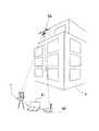
図3は、実施例に於ける測定作業を示している。該実施例では、前記副測定部11で取得した画像により写真測量が実行される。尚、前記副測定部11による測定では、該副測定部11が測定作業者に保持された状態で測定が実行される。又、前記副測定部11の測定位置は、前記トータルステーション1から前記移動測定機2(前記全周プリズム12)が視準できる位置とされる。 FIG. 3 shows the measurement operation in the embodiment. In this embodiment, photogrammetry is executed by the image acquired by the
測定点Aに前記副測定部11を設置し(即ち、測定点Aで測定作業者が前記副測定部11を保持し)、測定点Aから測定対象9を撮像し、該測定対象9の画像を取得する。画像取得時の、前記移動測定機2の姿勢(傾斜、傾斜方向、測定方向或は前記トータルステーション1に対する方向角、撮影方向)が前記姿勢検出器13によって検出され、検出された姿勢は取得された画像に関連付けられて画像と共に前記副記憶部27に格納される。ここで、前記測定対象9は、前記トータルステーション1からは死角となっており、直接測定することはできない。 The
次に、測定点Bに移動して前記測定対象9を撮像し、該測定対象9の画像を取得する。又、同様にして画像取得時の、前記移動測定機2の姿勢(傾斜、傾斜方向、測定方向或は前記トータルステーション1に対する方向角、撮影方向)が前記姿勢検出器13によって検出され、検出された姿勢は取得された画像に関連付けられて画像と共に前記副記憶部27に格納される。 Next, it moves to the measurement point B, images the
測定点A、測定点Bで取得した画像データ、画像データに関連付けられた姿勢データは、前記副通信部28より前記主通信部22に送信され、該主通信部22を介して前記主記憶部21に格納される。 Image data acquired at the measurement point A and measurement point B, and posture data associated with the image data are transmitted from the
前記トータルステーション1は、前記全周プリズム12を追尾して視準し、前記副測定部11の測距、測角を行い、測定点Aでの前記副測定部11の前記トータルステーション1を基準とした3次元座標、即ち基準座標系での3次元座標を取得する。同様にして、測定点Bでの前記副測定部11の3次元座標を取得する。 The
又、前記副測定部11から前記主通信部22、前記副通信部28を介して前記トータルステーション1に同期信号を発しており、前記トータルステーション1による測定点A、測定点Bの測定時と同時に、測定点A、測定点Bでの前記移動測定機2による測定が実行される様に、前記同期信号に基づき前記移動測定機2の測定タイミングを制御する。
In addition, a synchronization signal is transmitted from the
前記主演算制御部19は、測定点A、測定点Bのそれぞれの3次元座標から測定点A、測定点B間の距離D(基線長D)を演算し、該基線長Dと前記姿勢データに基づき測定点A、測定点Bで取得した画像の相互標定を実行し、前記移動測定機2を基準とした副座標系での前記測定対象9の3次元データが取得できる。 The main
更に、前記主演算制御部19は、前記トータルステーション1により測定した測定点A、測定点Bの座標に基づき前記測定対象9の3次元データを前記トータルステーション1を基準とした基準座標系のデータに変換することができ、更に基準座標系での3Dモデルを作製する。尚、基準座標系のデータに変換すること、3Dモデルを作製することについては、前記移動測定機2の前記副演算制御部26で実行させてもよく、或は別途用意した演算制御部で実行させてもよい。 Further, the main
図4は、測定対象物の複数の測定対象を測定する場合を示している。 FIG. 4 shows a case where a plurality of measurement objects of the measurement object are measured.
例えば、測定対象Sを測定する場合は、前記移動測定機2によりA地点、B地点から測定対象Sを撮影し、A地点、B地点で取得した画像から測定対象Sについて前記移動測定機2を基準とした3Dモデルを作製する。又、前記トータルステーション1は、A地点、B地点での前記移動測定機2の3次元座標を測定する。 For example, when measuring the measuring object S, the measuring object S is photographed from the A point and the B point by the
次に、測定対象Tを測定する場合は、前記移動測定機2をC地点に移動し、測定対象Tを撮影後、更にD地点に移動し測定対象Tを撮影する。 Next, when measuring the measurement target T, the
前記トータルステーション1は、前記移動測定機2の移動に伴い該移動測定機2(即ち、全周プリズム12)を追尾し、C地点、D地点での前記移動測定機2の3次元座標を測定する。C地点、D地点で取得した画像から測定対象Tについて前記移動測定機2を基準とした3Dモデルを作製する。同様にして、測定対象Uについては、E地点、F地点で取得した画像から測定対象Uについて前記移動測定機2を基準とした3Dモデルを作製する。 The
前記A地点、B地点、C地点、D地点、E地点、F地点の座標は、前記トータルステーション1で測定されており、該トータルステーション1で測定した結果に基づき測定対象S,T,Uの3Dモデルを合成することができ、基準座標系に於ける測定対象物3の3Dモデルを作製することができる。 The coordinates of the points A, B, C, D, E, and F are measured at the
上記した様に、前記移動測定機2で取得した3次元データを、固定設置したトータルステーション1の測定結果に基づき合成することで、複雑な形状の測定対象物の測定、複雑な地形での測定対象物の測定が、前記トータルステーション1の設置位置を変更することなく実行できる。 As described above, the three-dimensional data acquired by the
前記トータルステーション1を一箇所に設置するだけで、測定対象物全体の3Dモデルを簡便に作製することができる。又、携帯可能な前記移動測定機2を用いて測定を行うので、機動性の高い3次元測量システムを提供できる。 Only by installing the
尚、前記移動測定機2側に、前記トータルステーション1で測定した結果を送信し、前記副測定部11で、該副測定部11で取得した3次元データを基準座標系の3次元データに変換し、測定対象物全体の3Dモデルを作製してもよい。 The measurement result of the
更に、前記移動測定機2をデータ収集装置として機能させ、収集したデータを別途用意したPC等に入力し、該PCで前記移動測定機2を基準とした副座標系での前記測定対象9の3次元データを取得し、更に前記PCで測定対象物全体の3Dモデルを作製してもよい。又、前記移動測定機2を複数用いて更に広範囲を測定可能としてもよい。 Further, the
次に、前記移動測定機2としては、種々の形式のものを使用可能である。 Next, various types of
図5は、使用可能な複数の形式の移動測定機を例示している。 FIG. 5 illustrates several types of mobile measuring machines that can be used.
先ず図5(A)は、図1で示した副測定部11として撮像装置の代りにレーザ測距器31を用いた移動測定機51を示している。 First, FIG. 5A shows a
該移動測定機51では、携帯性、操作性をより向上させる為、取手部材30に前記レーザ測距器31、全周プリズム12、姿勢検出器13が一体に設けられている。 In the
前記レーザ測距器31を用いることで、測定点迄の距離が直ちに取得でき、更に前記姿勢検出器13の検出結果を加味することで前記レーザ測距器31を基準とした前記測定点の3次元座標が取得できる。尚、前記全周プリズム12は、前記トータルステーション1からの測距光14aを該トータルステーション1に向けて反射し、該トータルステーション1が前記移動測定機51の位置を測定する。従って、前記レーザ測距器31が測定した測定点の3次元座標は、前記トータルステーション1の基準座標系に座標変換できる。 By using the
図5(B)は、副測定部11としてレーザスキャナ32を用いた移動測定機52を示している。前記レーザスキャナ32を用いることで多数点を同時に測定でき、測定対象物の3次元点群データを取得することができる。該3次元点群データも、前記トータルステーション1の測定結果に基づき前記基準座標系の3次元点群データに座標変換できる。 FIG. 5B shows a moving measuring
図5(C)は、副測定部11としてレーザ測距器31及び撮像装置33を用いた移動測定機53を示している。該移動測定機53では、前記レーザ測距器31で測定対象物の距離測定を実行すると共に測定個所及び周囲の画像を取得でき、画像付の3次元データを取得することができる。 FIG. 5C shows a
図5(D)で示される移動測定機54は、遠隔操作される小型飛行体(UAV)35に撮像装置33が搭載された構成である。前記小型飛行体35には、更に追尾用のプリズム37が設けられ、前記撮像装置33と一体に設けられていると共に該撮像装置33との位置関係が既知となっている。前記撮像装置33、前記プリズム37はジンバル38を介して前記小型飛行体35に設けられており、前記撮像装置33、前記プリズム37は、常に一定の姿勢が保たれる様になっている。 The
又、前記移動測定機54には、姿勢検出器13(例えば、ジャイロ、方位センサ、傾斜センサ等)が設けられ、前記小型飛行体35の飛行姿勢が検出されると共に前記撮像装置33の光軸方向が検出される様になっている。前記移動測定機54は、複数箇所で測定対象物を撮像し、写真測量用に画像を取得する。 In addition, the
前記トータルステーション1からは追尾光14bが射出され、前記プリズム37によって反射された追尾光14bは、前記追尾部16(図2参照)によって受光され、前記トータルステーション1によって前記移動測定機54が追尾される。 The tracking light 14b is emitted from the
又、前記移動測定機54の位置(3次元座標)は、前記トータルステーション1で追尾されつつ測定される。前記トータルステーション1からは前記移動測定機54に同期信号が発せられ、該同期信号に基づき前記移動測定機54による撮像と前記トータルステーション1による測定が同期制御される。而して、前記移動測定機54で画像を取得した時点の、該移動測定機54の位置が前記トータルステーション1によって測定される。 Further, the position (three-dimensional coordinates) of the
前記移動測定機54による画像の取得位置、取得した画像に基づき、測定対象物の3次元データが取得され、該3次元データは前記トータルステーション1の基準座標系に座標変換され、測定対象物全体の3Dモデルが作製される。 Based on the acquisition position of the image by the
図6は、副測定部11として前記レーザ測距器31を用いた場合の測定作業を示している。 FIG. 6 shows measurement work when the laser
測定作業者は、前記移動測定機51を持ち、前記トータルステーション1から視準できる範囲内で、A地点、B地点、C地点、D地点と移動し、各地点で測距を行う。A地点、B地点、C地点、D地点の3次元座標は、前記トータルステーション1によって測定される。従って、前記移動測定機51で測定した測定結果は、前記トータルステーション1の基準座標系に座標変換可能である。尚、副測定部11として前記レーザスキャナ32を具備する前記移動測定機52を用いた場合も同様に測定作業が行える。 The measurement operator has the
図7は、前記移動測定機54を用いた測量システムの測定作業を示している。 FIG. 7 shows the measurement work of the surveying system using the mobile measuring
図7中、41は基地制御装置としてのPC、42は前記移動測定機54の飛行、及び撮像を制御する遠隔操縦装置を示している。 In FIG. 7,
前記トータルステーション1は、前記移動測定機54を追尾し、該移動測定機54の位置を測定し、測定された位置情報は前記基地制御装置41に送信される。又、前記移動測定機54は前記撮像装置33(図5(D)参照)により画像を取得し、画像は前記基地制御装置41に送信される。 The
前記基地制御装置41は、前記移動測定機54の飛行コースを設定し、該飛行コースに基づき前記移動測定機54の飛行を制御する。又、前記基地制御装置41は前記トータルステーション1による前記移動測定機54の位置測定と、該移動測定機54の写真撮影の同期制御を行っており、画像と画像が取得された位置とを関連付ける。 The
又、前記基地制御装置41は、画像に基づき前記移動測定機54を基準とした3Dモデルを作製し、更に前記トータルステーション1の測定結果に基づき基準座標系の3Dモデルを作製する。 The
前記移動測定機54を用いることで、上方から測定した3Dモデルを作製することができる。 By using the
図8は、前記移動測定機54及び他の任意な移動測定機を用いた測量システムの測定作業を示している。又、他の移動測定機として前記移動測定機53が用いられた例が示されている。 FIG. 8 shows the measurement work of the surveying system using the
尚、前記移動測定機54、前記移動測定機53による測定は、前記トータルステーション1が前記移動測定機54、又は前記移動測定機53を追尾することから、前記移動測定機54による測定と、前記移動測定機53による測定とを分離することが好ましい。尚、前記移動測定機54の測定と前記トータルステーション1による測定の同期が前記基地制御装置41によって実行され、同様に、前記移動測定機53による測定と前記トータルステーション1による測定の同期が前記基地制御装置41によって実行される。 Note that the measurement by the
例えば、前記移動測定機54により上方からの測定を実行し、測定データを取得した後、前記移動測定機53による測定を実行する。測定結果はそれぞれ、前記基地制御装置41に送信される。 For example, the
前記基地制御装置41に於いて、前記移動測定機54で得られた測定結果を基に、該移動測定機54を基準とした3Dモデルが作製され、前記移動測定機53で得られた測定結果を基に、該移動測定機53を基準とした3Dモデルが作製される。 In the
2つの3Dモデルは、前記トータルステーション1の測定結果に基づき、基準座標系に座標変換され、更に基準座標系の3Dモデルとして合成される。 The two 3D models are coordinate-transformed into a reference coordinate system based on the measurement result of the
前記移動測定機53の測定姿勢、該移動測定機53と前記トータルステーション1との相対的な位置、姿勢関係を検出する為に、前記移動測定機53は前記姿勢検出器13を具備している。 In order to detect the measurement posture of the
該姿勢検出器13の1例として、姿勢センサ、加速度センサ、傾斜センサ、方位センサの内から適宜選択されたもの或はその組合わせ等が考えられる。 As an example of the
更に他の例として、偏光光線を用いた傾斜センサ、画像を用いた姿勢センサがある。 As another example, there are an inclination sensor using polarized light and an attitude sensor using an image.
図9を参照し、偏光光線を用いた傾斜センサ44、画像を用いた姿勢センサ46を具備する姿勢検出器13の一例を説明する。尚、図9中、図1、図2中で示したものと同等のものには同符号を付してある。 With reference to FIG. 9, an example of the
先ず、前記傾斜センサ44について説明する。尚、後述する様に、該傾斜センサ44は、追尾光受光部45、タイミングパルス検出部62、信号処理部61、副演算制御部26を有している。 First, the
前記追尾部16は追尾光発生部56を有し、該追尾光発生部56は追尾光14bとしてパルス光を発する。前記追尾光発生部56は更に偏光回転部57を有し、該偏光回転部57は前記追尾光発生部56で発光された追尾光14bを回転偏光板58を通して射出し、前記追尾光14bを偏光光線とすると共に偏光面を所定の回転速度(定速回転)で回転する。 The
従って、前記追尾部16から発せられる前記追尾光14bは、パルス光であり、更に偏光面が定速で回転している偏光光線となる。 Therefore, the tracking light 14b emitted from the
又、前記追尾光発生部56は、前記回転偏光板58の回転角について基準位置を設定する。例えば、前記トータルステーション1が整準された状態で、偏光面が鉛直となった時の回転偏光板58の回転角を0゜と設定する。 The tracking
前記移動測定機2は、前記全周プリズム12の他に前記追尾光受光部45、前記姿勢センサ46を備えている。追尾光14bは前記全周プリズム12で反射されると共に前記追尾光受光部45及び前記姿勢センサ46で受光される。 The
該追尾光受光部45は固定偏光板59、受光センサ60を具備し、該受光センサ60は前記固定偏光板59を通して追尾光14bを受光する様になっている。又、該固定偏光板59の偏光面は、例えば前記移動測定機2が水平姿勢で、鉛直となる様に固定されている。 The tracking
前記受光センサ60が回転される偏光光線を受光することで、該受光センサ60が検出する受光光量は、前記回転偏光板58の180゜の回転で1周期となるsinカーブで変化する。 By receiving the polarized light beam rotated by the
上記した様な前記回転偏光板58と前記固定偏光板59との位置関係では、前記移動測定機2が水平姿勢で、光量が最大となり、前記移動測定機2が傾斜することで光量が減少する。従って、光量変化を基に前記サインカーブでの位相差を検出すれば、前記移動測定機2の傾き角が検出できる。 In the positional relationship between the rotating
前記追尾光受光部45からの受光信号は、前記信号処理部61に出力され、該信号処理部61で増幅、A/D変換等の信号処理がされて前記副演算制御部26に送出される。 The received light signal from the tracking
前記追尾光14bは、前記タイミングパルス検出部62で検出される。該タイミングパルス検出部62は、前記追尾光14bのパルス発光タイミングから、タイミング信号を生成する。又、前記追尾光14bには、前記回転偏光板58の基準回転位置を示す基準信号が重畳されており、前記タイミングパルス検出部62は基準信号も同時に検出する。尚、基準信号としては、前記回転偏光板58の基準回転位置である時に、光パルスの幅を広くする等がある。 The tracking
前記信号処理部61に於いて、前記タイミングパルス検出部62で生成されたタイミング信号、及び検出された基準信号は、前記姿勢センサ46からの受光信号に関連付けられ、前記信号処理部61から前記副演算制御部26に出力される。 In the
該副演算制御部26では、受光信号、タイミング信号に基づき前記サインカーブを演算し、又該サインカーブと基準信号に基づき前記回転偏光板58と前記固定偏光板59との位相差(回転角)演算する。 The
而して、前記トータルステーション1を基準とした前記移動測定機2の傾斜が測定できる。更に、前記トータルステーション1が整準されていれば、前記移動測定機2の鉛直に対する傾斜が測定できる。 Thus, the inclination of the
次に、画像を用いた姿勢センサ46について説明する。 Next, the
該姿勢センサ46は、前記傾斜センサ44と一体に構成され、該姿勢センサ46は追尾光14bを受光する様に構成されている。又、前記傾斜センサ44は、撮像部47、前記副演算制御部26、前記副記憶部27を具備している。 The
該姿勢センサ46は、デジタル画像を取得する前記撮像部47を有している。該撮像部47は受光素子(図示せず)を有し、該撮像部47が前記トータルステーション1と正対し、自身の光軸が該トータルステーション1の光軸(即ち追尾光光軸)と合致した時に前記受光素子上の受光位置が基準位置(例えば、受光素子の中心)となる様に設定されている。 The
従って、自身の光軸と追尾光光軸とがずれを生じると、前記受光素子上の受光位置も基準位置からずれる。ずれ量、ずれの方向は前記移動測定機2の傾き量、傾き方向に対応するので、ずれ量、ずれの方向に基づき前記移動測定機2の傾き量、傾き方向を検出することができる。 Accordingly, when the optical axis of the own device and the optical axis of the tracking light are displaced, the light receiving position on the light receiving element is also shifted from the reference position. Since the shift amount and the shift direction correspond to the tilt amount and tilt direction of the
更に、前記トータルステーション1と前記移動測定機2とはタイミング信号に基づき同期制御され、前記移動測定機2で測定した結果と測定した時に前記姿勢検出器13が検出した姿勢が関連付けられる。 Further, the
尚、前記トータルステーションが射出する測距光、追尾光の少なくともいずれか一方をパルスレーザとすればよく、測距光をパルス発光し、測距光からタイミング信号を生成してもよい。タイミング信号はパルス発光を駆動する側で駆動信号に基づき生成してもよく、或は受光側で受光信号に基づき生成してもよい。 Note that at least one of the ranging light and tracking light emitted from the total station may be a pulse laser, and the ranging light may be pulsed to generate a timing signal from the ranging light. The timing signal may be generated based on the driving signal on the side that drives pulsed light emission, or may be generated based on the light receiving signal on the light receiving side.
更に、別途タイミング信号発生器を設け、該タイミング信号発生器で発生させたタイミング信号に基づき姿勢検出、同期制御を行ってもよい。 Further, a separate timing signal generator may be provided, and attitude detection and synchronization control may be performed based on the timing signal generated by the timing signal generator.
1 トータルステーション
2 移動測定機
3 測定対象物
8 望遠鏡部
11 副測定部
12 全周プリズム
13 姿勢検出器
15 測距部
16 追尾部
17 水平角検出部
18 鉛直角検出部
19 主演算制御部
21 主記憶部
22 主通信部
26 副演算制御部
27 副記憶部
28 副通信部
30 取手部材
31 レーザ測距器
32 レーザスキャナ
33 撮像装置
44 傾斜センサ
45 追尾光受光部
46 姿勢センサ
47 撮像部
51 移動測定機
52 移動測定機
53 移動測定機
54 移動測定機
56 追尾光発生部
58 回転偏光板
59 固定偏光板DESCRIPTION OF
Claims (6)
Translated fromJapanese前記測距光又は前記追尾光はパルスレーザであり、
前記姿勢検出器は前記トータルステーションからの前記測距光、前記追尾光を受光するタイミングパルス検出部を有し、該タイミングパルス検出部は、前記測距光又は前記追尾光の検出結果に基づきタイミング信号を生成し、
前記移動測定機と前記トータルステーションとは前記タイミング信号により同期制御され、
前記移動測定機が前記トータルステーションから視準可能な任意の測定位置で、前記副測定部の測定結果及び前記姿勢検出器の検出結果に基づき前記トータルステーションの方向を基準として測定対象物を3次元測定し、前記トータルステーションは前記測定位置を3次元測定し、前記演算制御部は、前記移動測定機で得られた3次元測定結果と前記トータルステーションの測定結果に基づき該トータルステーションを基準とした前記測定対象物の3次元測定を行うことを特徴とする測量システム。A total station provided at a known point and having a tracking function, a ranging light emitted from the total station, and a prism that retroreflects the tracking light, and is movable and capable of three-dimensional measurement of an object to be measured Equipped with two mobile measuring machines and a calculation control unit, the mobile measuring machine can detect the measuring direction, tilt, and tilt direction of the sub-measurement unit that can measure and measure the measurement object and the mobile measuring machine An attitude detector,
The ranging light or the tracking light is a pulse laser,
The attitude detector includes a timing pulse detection unit that receives the ranging light and the tracking light from the total station, and the timing pulse detection unit is a timing signal based on a detection result of the ranging light or the tracking light. Produces
The mobile measuring device and the total station are synchronously controlled by the timing signal,
Three-dimensional measurement is performed on the measurement object based on the direction of the total station based on the measurement result of the sub-measurement unit and the detection result of the attitude detector at an arbitrary measurement position where the mobile measuring device can be collimated from the total station. The total station measures the measurement position in a three-dimensional manner, and the calculation control unit determines the measurement object based on the total station based on the three-dimensional measurement result obtained by the mobile measuring machine and the measurement result of the total station. A surveying system that performs three-dimensional measurement.
Priority Applications (5)
| Application Number | Priority Date | Filing Date | Title |
|---|---|---|---|
| JP2013227100AJP6316568B2 (en) | 2013-10-31 | 2013-10-31 | Surveying system |
| CA 2867562CA2867562A1 (en) | 2013-10-31 | 2014-10-16 | Three-dimensional measuring method and surveying system |
| EP14189220.8AEP2869024B1 (en) | 2013-10-31 | 2014-10-16 | Three-dimensional measuring method and surveying system |
| US14/518,479US9958268B2 (en) | 2013-10-31 | 2014-10-20 | Three-dimensional measuring method and surveying system |
| CN201410599555.2ACN104613946A (en) | 2013-10-31 | 2014-10-31 | Three-dimensional measuring method and surveying system |
Applications Claiming Priority (1)
| Application Number | Priority Date | Filing Date | Title |
|---|---|---|---|
| JP2013227100AJP6316568B2 (en) | 2013-10-31 | 2013-10-31 | Surveying system |
Publications (3)
| Publication Number | Publication Date |
|---|---|
| JP2015087307A JP2015087307A (en) | 2015-05-07 |
| JP2015087307A5 JP2015087307A5 (en) | 2016-12-01 |
| JP6316568B2true JP6316568B2 (en) | 2018-04-25 |
Family
ID=51862091
Family Applications (1)
| Application Number | Title | Priority Date | Filing Date |
|---|---|---|---|
| JP2013227100AActiveJP6316568B2 (en) | 2013-10-31 | 2013-10-31 | Surveying system |
Country Status (5)
| Country | Link |
|---|---|
| US (1) | US9958268B2 (en) |
| EP (1) | EP2869024B1 (en) |
| JP (1) | JP6316568B2 (en) |
| CN (1) | CN104613946A (en) |
| CA (1) | CA2867562A1 (en) |
Families Citing this family (59)
| Publication number | Priority date | Publication date | Assignee | Title |
|---|---|---|---|---|
| JP6367522B2 (en) | 2013-02-28 | 2018-08-01 | 株式会社トプコン | Aerial photography system |
| JP6062039B2 (en)* | 2013-04-04 | 2017-01-18 | 株式会社Amatel | Image processing system and image processing program |
| US9146106B2 (en)* | 2013-12-11 | 2015-09-29 | Trimble Navigation Limited | Laser receiver using a smart device |
| JP6326237B2 (en) | 2014-01-31 | 2018-05-16 | 株式会社トプコン | Measuring system |
| WO2016149513A1 (en)* | 2015-03-18 | 2016-09-22 | Izak Van Cruyningen | Flight planning for unmanned aerial tower inspection with long baseline positioning |
| US9989357B2 (en)* | 2015-09-09 | 2018-06-05 | Faro Technologies, Inc. | Aerial device that cooperates with an external projector to measure three-dimensional coordinates |
| JP6691721B2 (en)* | 2016-02-15 | 2020-05-13 | 株式会社トプコン | Flight planning method and flight guidance system |
| JP6615679B2 (en)* | 2016-04-08 | 2019-12-04 | 東亜建設工業株式会社 | Steel plate cell installation method and system |
| ES2899284T3 (en) | 2016-07-15 | 2022-03-10 | Fastbrick Ip Pty Ltd | Vehicle incorporating a brick laying machine |
| ES2899585T3 (en) | 2016-07-15 | 2022-03-14 | Fastbrick Ip Pty Ltd | Material transport boom |
| US20180025651A1 (en)* | 2016-07-19 | 2018-01-25 | Taoglas Group Holdings Limited | Systems and devices to control antenna azimuth orientation in an omni-directional unmanned aerial vehicle |
| JP7208708B2 (en)* | 2016-07-27 | 2023-01-19 | 株式会社エムアールサポート | Shape measurement method, apparatus, and program for three-dimensional measurement object |
| CN106197389A (en)* | 2016-08-25 | 2016-12-07 | 中国海洋石油总公司 | Total station instrument fixed support |
| JP6796975B2 (en)* | 2016-09-16 | 2020-12-09 | 株式会社トプコン | UAV measuring device and UAV measuring system |
| JP6782917B2 (en)* | 2016-09-27 | 2020-11-11 | 清水建設株式会社 | Construction accuracy calculation system and construction accuracy calculation method |
| JP6809131B2 (en)* | 2016-10-25 | 2021-01-06 | 中国電力株式会社 | Propagation path line-of-sight test system and propagation path line-of-sight test method using this |
| JP6826888B2 (en)* | 2017-01-11 | 2021-02-10 | 株式会社トプコン | Surveying equipment, unmanned aerial vehicle search methods, surveying systems and programs |
| CN106643700B (en)* | 2017-01-13 | 2018-05-15 | 中国人民解放军防空兵学院 | A kind of positioning and directing monitors system and method |
| JP6862194B2 (en)* | 2017-01-26 | 2021-04-21 | 株式会社トプコン | Photogrammetric camera |
| JP6850174B2 (en)* | 2017-03-24 | 2021-03-31 | 株式会社トプコン | Measuring device, surveying system |
| NL2018630B9 (en)* | 2017-03-31 | 2018-03-01 | Pliant Holding B V | Measuring attitude of constructions |
| JP7050425B2 (en)* | 2017-05-01 | 2022-04-08 | 株式会社トプコン | Surveying system |
| JP6855316B2 (en)* | 2017-05-10 | 2021-04-07 | 株式会社トプコン | Surveying system |
| WO2018216342A1 (en)* | 2017-05-24 | 2018-11-29 | ソニー株式会社 | Information processing apparatus, information processing method, and program |
| CN110730898B (en)* | 2017-06-21 | 2021-12-14 | 天宝公司 | Method implemented in a processing unit for controlling a surveying instrument, processing unit and surveying instrument |
| JP6867244B2 (en)* | 2017-06-28 | 2021-04-28 | 株式会社トプコン | Surveying instrument communication management system |
| WO2019006511A1 (en) | 2017-07-05 | 2019-01-10 | Fastbrick Ip Pty Ltd | Real time position and orientation tracker |
| WO2019033170A1 (en) | 2017-08-17 | 2019-02-21 | Fastbrick Ip Pty Ltd | Laser tracker with improved roll angle measurement |
| CN111213098B (en) | 2017-08-17 | 2024-03-15 | 快砖知识产权私人有限公司 | Communication systems for interactive systems |
| JP7152137B2 (en)* | 2017-08-28 | 2022-10-12 | 株式会社トプコン | Photogrammetry system and photogrammetry method |
| CN111212799B (en) | 2017-10-11 | 2023-04-14 | 快砖知识产权私人有限公司 | Machine for conveying objects and multi-compartment carousel for use therewith |
| JP7037860B2 (en)* | 2017-11-17 | 2022-03-17 | 株式会社トプコン | Surveying equipment and surveying equipment system |
| DE102018113244B3 (en)* | 2018-06-04 | 2019-11-07 | Deutsches Zentrum für Luft- und Raumfahrt e.V. | Method and apparatus for measuring vibrations of an object using a drone |
| US12214500B2 (en) | 2018-07-16 | 2025-02-04 | Fastbrick Ip Pty Ltd | Backup tracking for an interaction system |
| CN112689552A (en) | 2018-07-16 | 2021-04-20 | 快砖知识产权私人有限公司 | Active damping system |
| JP7138525B2 (en)* | 2018-09-25 | 2022-09-16 | 株式会社トプコン | Surveying instrument and surveying instrument system |
| JP6960895B2 (en)* | 2018-09-27 | 2021-11-05 | Kddi株式会社 | Propagation failure judgment device, propagation failure judgment system and propagation failure judgment method |
| JP7112929B2 (en)* | 2018-09-28 | 2022-08-04 | 株式会社トプコン | Point cloud data display system |
| CN109373978B (en)* | 2018-10-18 | 2020-04-07 | 西安科技大学 | Surrounding rock displacement monitoring method for roadway surrounding rock similar simulation |
| US10891769B2 (en)* | 2019-02-14 | 2021-01-12 | Faro Technologies, Inc | System and method of scanning two dimensional floorplans using multiple scanners concurrently |
| CN110241696B (en)* | 2019-04-01 | 2024-07-30 | 中建三局集团有限公司 | Mobile high-precision measurement robot system and measurement method thereof |
| JP7287820B2 (en)* | 2019-04-02 | 2023-06-06 | 株式会社トプコン | surveying equipment |
| JP7311342B2 (en)* | 2019-07-18 | 2023-07-19 | 株式会社トプコン | Three-dimensional surveying device, three-dimensional surveying method and three-dimensional surveying program |
| CN110645963A (en)* | 2019-09-10 | 2020-01-03 | 中铁大桥局第七工程有限公司 | Method and system for acquiring three-dimensional coordinates of unknown point at top of high tower |
| US12385265B2 (en) | 2020-04-22 | 2025-08-12 | Fastbrick Ip Pty Ltd | Block transfer apparatus and improved clamping assembly for use therewith |
| JP7491730B2 (en)* | 2020-04-30 | 2024-05-28 | 株式会社トプコン | Work management system, work management method, and work management program therefor |
| EP4179172A4 (en) | 2020-07-08 | 2024-08-07 | Fastbrick IP Pty Ltd | ADHESIVE APPLICATION SYSTEM |
| US11320124B1 (en) | 2020-10-29 | 2022-05-03 | Waymo Llc | Infrared light module uniformity rotational test module |
| JP2022089308A (en)* | 2020-12-04 | 2022-06-16 | 株式会社豊田自動織機 | Autonomous driving system |
| CN113310427B (en)* | 2021-05-18 | 2023-03-07 | 思看科技(杭州)股份有限公司 | Three-dimensional scanning system and three-dimensional scanning method |
| CN113610894B (en)* | 2021-08-06 | 2023-06-20 | 上海华测导航技术股份有限公司 | AI Algorithm Automatic Recognition and Tracking System and Method for Total Station Prism |
| CN113686328B (en)* | 2021-09-13 | 2024-06-07 | 上海市机械施工集团有限公司 | Device and method for controlling component to lift space posture |
| JP7296669B1 (en) | 2022-02-28 | 2023-06-23 | 株式会社イクシス | Surveying method, target marker, and surveying system |
| CN115752395B (en)* | 2022-10-31 | 2024-12-06 | 武汉大学 | A measuring prism with inertial autonomous positioning capability and a prism tracking method |
| EP4428490B1 (en)* | 2023-03-10 | 2025-07-02 | Trimble Inc. | Surveying target and method with light sector power optimization |
| JP2024139270A (en)* | 2023-03-27 | 2024-10-09 | 株式会社トプコン | Surveying equipment, surveying system, surveying method and surveying program |
| JP2025059988A (en)* | 2023-09-29 | 2025-04-10 | 株式会社トプコン | Three-dimensional data measurement system and three-dimensional data measurement method |
| JP2025059987A (en)* | 2023-09-29 | 2025-04-10 | 株式会社トプコン | Measurement module and three-dimensional data measurement system using same |
| CN118408525B (en)* | 2024-07-01 | 2024-10-22 | 北京中元浩业科技有限公司 | Spreading position continuous monitoring system |
Family Cites Families (46)
| Publication number | Priority date | Publication date | Assignee | Title |
|---|---|---|---|---|
| US4413907A (en) | 1980-11-07 | 1983-11-08 | Robert F. Deike | Remote control surveying |
| JP3148900B2 (en) | 1991-10-25 | 2001-03-26 | 清水建設株式会社 | 3D survey system using model helicopter |
| JPH08285588A (en) | 1995-04-13 | 1996-11-01 | Mitsui Constr Co Ltd | Photographing apparatus and flight photographing apparatus using the apparatus |
| US6369755B1 (en)* | 1995-10-23 | 2002-04-09 | Trimble Navigation Limited | Integrated SATPS total survey station |
| US6343254B1 (en) | 1998-10-22 | 2002-01-29 | Trimble Navigation Limited | Seamless surveying system |
| JP4332255B2 (en) | 1999-05-14 | 2009-09-16 | 株式会社トプコン | Distance measuring device |
| JP4276360B2 (en) | 2000-06-26 | 2009-06-10 | 株式会社トプコン | Stereo imaging system |
| JP4430789B2 (en)* | 2000-06-26 | 2010-03-10 | 株式会社トプコン | Stereo imaging system |
| WO2002063241A1 (en) | 2001-02-08 | 2002-08-15 | Nkk Corporation | Three-dimensional coordinate measuring method, three-dimensional coordinate measuring apparatus, and method for building large-sized structure |
| JP3937154B2 (en) | 2002-06-28 | 2007-06-27 | 株式会社トプコン | Position detection device |
| US7071970B2 (en) | 2003-03-10 | 2006-07-04 | Charles Benton | Video augmented orientation sensor |
| JP4301863B2 (en) | 2003-05-21 | 2009-07-22 | 株式会社トプコン | Ranging device |
| JP4488804B2 (en) | 2004-06-23 | 2010-06-23 | 株式会社トプコン | Stereo image association method and three-dimensional data creation apparatus |
| CN100334419C (en) | 2004-12-16 | 2007-08-29 | 上海宝钢工业检测公司 | Method for measuring roller shaft verticality in roller space position detection |
| ATE431584T1 (en) | 2005-05-27 | 2009-05-15 | Charles Machine Works | DETERMINING THE POSITION OF A REMOTE CONTROL USER |
| US7587258B2 (en)* | 2006-05-10 | 2009-09-08 | The Boeing Company | Merged laser and photogrammetry measurement using precise camera placement |
| JP2008014864A (en)* | 2006-07-07 | 2008-01-24 | Topcon Corp | Surveying instrument |
| JP5073256B2 (en) | 2006-09-22 | 2012-11-14 | 株式会社トプコン | POSITION MEASUREMENT DEVICE, POSITION MEASUREMENT METHOD, AND POSITION MEASUREMENT PROGRAM |
| US9747698B2 (en)* | 2006-10-21 | 2017-08-29 | Sam Stathis | System for accurately and precisely locating and marking a position in space using wireless communications and robotics |
| JP5007885B2 (en) | 2007-10-16 | 2012-08-22 | 株式会社トプコン | Three-dimensional survey system and electronic storage medium |
| CN101578591A (en) | 2007-10-19 | 2009-11-11 | 萨姆·斯塔西斯 | System for accurately and precisely locating and marking locations in space using wireless communication and robotics |
| US11159909B2 (en) | 2008-02-05 | 2021-10-26 | Victor Thomas Anderson | Wireless location establishing device |
| JP2009294128A (en)* | 2008-06-06 | 2009-12-17 | Visuatool Inc | Three-dimensional measuring system, measuring terminal, measuring method of three-dimensional shape, and total station |
| US8265817B2 (en) | 2008-07-10 | 2012-09-11 | Lockheed Martin Corporation | Inertial measurement with an imaging sensor and a digitized map |
| JP2010030340A (en)* | 2008-07-25 | 2010-02-12 | Arc Geo Support Co Ltd | Observation ship for measuring sound and sound measuring system |
| JP5227110B2 (en) | 2008-08-07 | 2013-07-03 | 株式会社トプコン | Omnidirectional camera with GPS and spatial data collection device |
| JP5019478B2 (en) | 2008-09-26 | 2012-09-05 | 独立行政法人日本原子力研究開発機構 | Marker automatic registration method and system |
| GB0920636D0 (en)* | 2009-11-25 | 2010-01-13 | Cyberhawk Innovations Ltd | Unmanned aerial vehicle |
| US20120114229A1 (en) | 2010-01-21 | 2012-05-10 | Guoqing Zhou | Orthorectification and mosaic of video flow |
| US8774982B2 (en) | 2010-08-26 | 2014-07-08 | Leptron Industrial Robotic Helicopters, Inc. | Helicopter with multi-rotors and wireless capability |
| JP5690541B2 (en) | 2010-09-30 | 2015-03-25 | 株式会社トプコン | Distance measuring device |
| EP2511658A1 (en) | 2011-04-14 | 2012-10-17 | Hexagon Technology Center GmbH | Measuring system and method for new point determination |
| US9758239B2 (en)* | 2011-04-14 | 2017-09-12 | Hexagon Technology Center Gmbh | System and method for controlling an unmanned air vehicle |
| EP2511656A1 (en)* | 2011-04-14 | 2012-10-17 | Hexagon Technology Center GmbH | Measuring system for determining the 3D coordinates of an object surface |
| EP2511781A1 (en)* | 2011-04-14 | 2012-10-17 | Hexagon Technology Center GmbH | Method and system for controlling an unmanned aircraft |
| JP5748566B2 (en)* | 2011-05-31 | 2015-07-15 | 東急建設株式会社 | Three-dimensional shape information acquisition device |
| CA2780419A1 (en) | 2011-06-17 | 2012-12-17 | National Cheng Kung University | Unmanned aerial vehicle image processing system and method |
| US9453914B2 (en)* | 2011-09-08 | 2016-09-27 | Continental Advanced Lidar Solutions Us, Inc. | Terrain mapping LADAR system |
| JP2013096745A (en)* | 2011-10-28 | 2013-05-20 | Hokuriku Kosoku Co Ltd | Three-dimensional model creation method |
| US8823938B2 (en) | 2012-01-11 | 2014-09-02 | The Aerospace Corporation | System, apparatus, and method for tracking atmospheric differential absorption |
| CN102980556B (en) | 2012-11-29 | 2015-08-12 | 小米科技有限责任公司 | A kind of distance-finding method and device |
| CN103090846B (en) | 2013-01-15 | 2016-08-10 | 广州市盛光微电子有限公司 | A kind of range unit, range-measurement system and distance-finding method thereof |
| JP6367522B2 (en) | 2013-02-28 | 2018-08-01 | 株式会社トプコン | Aerial photography system |
| US20140336928A1 (en)* | 2013-05-10 | 2014-11-13 | Michael L. Scott | System and Method of Automated Civil Infrastructure Metrology for Inspection, Analysis, and Information Modeling |
| JP5882951B2 (en) | 2013-06-14 | 2016-03-09 | 株式会社トプコン | Aircraft guidance system and aircraft guidance method |
| JP6326237B2 (en) | 2014-01-31 | 2018-05-16 | 株式会社トプコン | Measuring system |
- 2013
- 2013-10-31JPJP2013227100Apatent/JP6316568B2/enactiveActive
- 2014
- 2014-10-16EPEP14189220.8Apatent/EP2869024B1/enactiveActive
- 2014-10-16CACA 2867562patent/CA2867562A1/ennot_activeAbandoned
- 2014-10-20USUS14/518,479patent/US9958268B2/enactiveActive
- 2014-10-31CNCN201410599555.2Apatent/CN104613946A/enactivePending
Also Published As
| Publication number | Publication date |
|---|---|
| US9958268B2 (en) | 2018-05-01 |
| CA2867562A1 (en) | 2015-04-30 |
| CN104613946A (en) | 2015-05-13 |
| US20150116693A1 (en) | 2015-04-30 |
| EP2869024A1 (en) | 2015-05-06 |
| EP2869024B1 (en) | 2024-04-10 |
| JP2015087307A (en) | 2015-05-07 |
Similar Documents
| Publication | Publication Date | Title |
|---|---|---|
| JP6316568B2 (en) | Surveying system | |
| CN109556580B (en) | Surveying instrument, AR system and method for positioning an AR device relative to a reference frame | |
| US10665012B2 (en) | Augmented reality camera for use with 3D metrology equipment in forming 3D images from 2D camera images | |
| US10187567B2 (en) | Method and handheld distance measurement device for indirect distance measurement by means of image-assisted angle determination function | |
| US9658335B2 (en) | Measurement system with a measuring device and a scanning module | |
| CN103119396B (en) | Geodetic system with video camera integrated in remote control unit | |
| JP7313955B2 (en) | Surveying instrument, surveying method and surveying program | |
| JP6823482B2 (en) | 3D position measurement system, 3D position measurement method, and measurement module | |
| KR101807857B1 (en) | Inspection camera unit, method for inspecting interiors, and sensor unit | |
| KR20130109232A (en) | Measuring appliance comprising an automatic representation-changing functionality | |
| KR101308744B1 (en) | System for drawing digital map | |
| CN106716061A (en) | Survey information marking device and survey information marking method | |
| CN1789913B (en) | Stereoscopic image creation method and three-dimensional data creation device | |
| JP7161298B2 (en) | target device, surveying system | |
| JP6001914B2 (en) | Target position specifying device, target position specifying system, and target position specifying method | |
| JP2018146524A (en) | Survey system | |
| US10809379B2 (en) | Three-dimensional position measuring system, three-dimensional position measuring method, and measuring module | |
| US20240210563A1 (en) | Scanning project planning | |
| EP2848890B1 (en) | Direction detecting apparatus and surveying system | |
| Reulke et al. | Mobile panoramic mapping using CCD-line camera and laser scanner with integrated position and orientation system | |
| JP2020046239A (en) | Image processing method, image processing apparatus and underground radar device | |
| JP2023048409A (en) | surveying system | |
| JP2019174292A (en) | Surveying device and surveying method |
Legal Events
| Date | Code | Title | Description |
|---|---|---|---|
| A521 | Request for written amendment filed | Free format text:JAPANESE INTERMEDIATE CODE: A523 Effective date:20161017 | |
| A621 | Written request for application examination | Free format text:JAPANESE INTERMEDIATE CODE: A621 Effective date:20161017 | |
| A977 | Report on retrieval | Free format text:JAPANESE INTERMEDIATE CODE: A971007 Effective date:20170731 | |
| A131 | Notification of reasons for refusal | Free format text:JAPANESE INTERMEDIATE CODE: A131 Effective date:20170815 | |
| A521 | Request for written amendment filed | Free format text:JAPANESE INTERMEDIATE CODE: A523 Effective date:20171012 | |
| TRDD | Decision of grant or rejection written | ||
| A01 | Written decision to grant a patent or to grant a registration (utility model) | Free format text:JAPANESE INTERMEDIATE CODE: A01 Effective date:20180306 | |
| A61 | First payment of annual fees (during grant procedure) | Free format text:JAPANESE INTERMEDIATE CODE: A61 Effective date:20180328 | |
| R150 | Certificate of patent or registration of utility model | Ref document number:6316568 Country of ref document:JP Free format text:JAPANESE INTERMEDIATE CODE: R150 | |
| R250 | Receipt of annual fees | Free format text:JAPANESE INTERMEDIATE CODE: R250 | |
| R250 | Receipt of annual fees | Free format text:JAPANESE INTERMEDIATE CODE: R250 | |
| R250 | Receipt of annual fees | Free format text:JAPANESE INTERMEDIATE CODE: R250 | |
| R250 | Receipt of annual fees | Free format text:JAPANESE INTERMEDIATE CODE: R250 | |
| R250 | Receipt of annual fees | Free format text:JAPANESE INTERMEDIATE CODE: R250 |