JP6315541B2 - Brush cutter - Google Patents
Brush cutterDownload PDFInfo
- Publication number
- JP6315541B2 JP6315541B2JP2013018667AJP2013018667AJP6315541B2JP 6315541 B2JP6315541 B2JP 6315541B2JP 2013018667 AJP2013018667 AJP 2013018667AJP 2013018667 AJP2013018667 AJP 2013018667AJP 6315541 B2JP6315541 B2JP 6315541B2
- Authority
- JP
- Japan
- Prior art keywords
- brush cutter
- battery pack
- end housing
- rear end
- battery packs
- Prior art date
- Legal status (The legal status is an assumption and is not a legal conclusion. Google has not performed a legal analysis and makes no representation as to the accuracy of the status listed.)
- Active
Links
- 230000005484gravityEffects0.000claimsdescription26
- 238000004519manufacturing processMethods0.000claimsdescription3
- 230000004048modificationEffects0.000description62
- 238000012986modificationMethods0.000description62
- 230000000694effectsEffects0.000description22
- 238000003780insertionMethods0.000description6
- 230000037431insertionEffects0.000description6
- 244000025254Cannabis sativaSpecies0.000description5
- 238000001816coolingMethods0.000description4
- 230000001681protective effectEffects0.000description4
- 230000002093peripheral effectEffects0.000description2
- 125000002066L-histidyl groupChemical group[H]N1C([H])=NC(C([H])([H])[C@](C(=O)[*])([H])N([H])[H])=C1[H]0.000description1
- 230000004397blinkingEffects0.000description1
- 239000000463materialSubstances0.000description1
- 239000002184metalSubstances0.000description1
- 230000001105regulatory effectEffects0.000description1
Images


Classifications
- A—HUMAN NECESSITIES
- A01—AGRICULTURE; FORESTRY; ANIMAL HUSBANDRY; HUNTING; TRAPPING; FISHING
- A01D—HARVESTING; MOWING
- A01D34/00—Mowers; Mowing apparatus of harvesters
- A01D34/01—Mowers; Mowing apparatus of harvesters characterised by features relating to the type of cutting apparatus
- A01D34/412—Mowers; Mowing apparatus of harvesters characterised by features relating to the type of cutting apparatus having rotating cutters
- A01D34/63—Mowers; Mowing apparatus of harvesters characterised by features relating to the type of cutting apparatus having rotating cutters having cutters rotating about a vertical axis
- A01D34/81—Casings; Housings
- A—HUMAN NECESSITIES
- A01—AGRICULTURE; FORESTRY; ANIMAL HUSBANDRY; HUNTING; TRAPPING; FISHING
- A01D—HARVESTING; MOWING
- A01D34/00—Mowers; Mowing apparatus of harvesters
- A01D34/835—Mowers; Mowing apparatus of harvesters specially adapted for particular purposes
- A01D34/90—Mowers; Mowing apparatus of harvesters specially adapted for particular purposes for carrying by the operator
- A01D34/902—Ergonomic provisions
Landscapes
- Life Sciences & Earth Sciences (AREA)
- Environmental Sciences (AREA)
- Harvester Elements (AREA)
Description
Translated fromJapanese本発明は、草や芝等を刈り払う刈払機に関する。 The present invention relates to a brush cutter that cuts grass, turf, and the like.
特許文献1には、支持棹と、支持棹の前端部にカッタユニットと、支持棹の後端部にコントローラユニットとを備えた刈払機が開示されている。この刈払機のカッタユニットは、支持棹の前端部に固定された前端ハウジングと、前端ハウジングに収容した電動モータと、前端ハウジングに回転可能に支持されて電動モータにより回転する回転軸と、回転軸に取り付けた回転刃とを有している。また、コントローラユニットは、支持棹の後端部に固定された後端ハウジングと、後端ハウジング内に収容した制御回路とを備えている。また、刈払機には、後端ハウジングの後部にバッテリパックが着脱可能に取り付けられている。 Patent Document 1 discloses a brush cutter including a support rod, a cutter unit at the front end portion of the support rod, and a controller unit at the rear end portion of the support rod. The cutter unit of the brush cutter includes a front end housing fixed to a front end portion of a support rod, an electric motor housed in the front end housing, a rotary shaft rotatably supported by the front end housing and rotated by the electric motor, a rotary shaft And a rotary blade attached to. The controller unit also includes a rear end housing fixed to the rear end portion of the support rod and a control circuit accommodated in the rear end housing. In addition, a battery pack is detachably attached to the rear portion of the rear end housing.
上記の刈払機においては、後端ハウジングの後部には1つのバッテリパックを取り付けている。このような刈払機は、高出力の電動モータを駆動するために高電圧(例えば36V)の大型のバッテリパックを用いることが多い。この高電圧の大型のバッテリパックは高価であり汎用性が高くないので、所有している電動工具等の他の作業機の電源に適合しないことが多かった。そのために、このバッテリパックはこの刈払機にしか用いられないことが多かった。本発明は、大型で高価であるために汎用性の低いバッテリパックを用いることのない刈払機を提供することを目的とする。 In the brush cutter, one battery pack is attached to the rear portion of the rear end housing. Such a brush cutter often uses a large battery pack having a high voltage (for example, 36 V) in order to drive a high-output electric motor. Since this high voltage large battery pack is expensive and not highly versatile, it is often not suitable for the power supply of other working machines such as an owned electric tool. Therefore, this battery pack is often used only for this brush cutter. An object of this invention is to provide the brush cutter which does not use a battery pack with low versatility since it is large and expensive.
上記課題を解決するために、本発明は、前後方向に直線的に延びた前後の中間部に、作業者が把持するハンドルまたはグリップを備えた支持棹と、支持棹の前端部に固定した前端ハウジングと、前端ハウジングに回転可能に支持した回転軸に取り付けた回転刃と、支持棹の後端部に固定した後端ハウジングと、回転刃を回転させる電動モータと、電動モータに給電する電源とを備えた刈払機において、電源が、後端ハウジングに着脱可能、かつ、電動工具に使用可能な、充電可能な2つのバッテリパックよりなり、これら2つのバッテリパックが後端ハウジングの後部に取り付けられ、支持棹を倒して水平な支持面に載置した載置状態にて、刈払機の後側から見たときのハンドルまたはグリップを含まない構造での重心が後端ハウジングの後側から見たときにおける上下方向に延びる左右方向の中心線から左右両側に後端ハウジングの左右方向の長さの15%の長さ、好ましくは10%の長さ、より好ましくは5%の長さの範囲内(製造公差により通常発生する0%に近いオフセットを除く)にて中心線から左右方向にオフセットさせるように、2つのバッテリパックを配置したことを特徴とする刈払機を提供するものである。In order to solve the above-described problems, the present invention providesa support rodprovided with a handle or a grip gripped by an operator at a front and rear intermediate portion linearly extending in the front-rear direction, and a front end fixed to the front end portion of the support rod. A housing, a rotary blade attached to a rotary shaft rotatably supported by the front end housing, a rear end housing fixed to the rear end portion of the support rod, an electric motor that rotates the rotary blade, and a power source that supplies electric power to the electric motor; Inthe brush cutter having a power source, the power source iscomposed of two rechargeable battery packs that can be attached to and detached from the rear end housing and can be used for the power tool, and these two battery packs are attached to the rear portion of the rear end housing. at placement state placed on the horizontal support surface by tilting the support rod, afterthe centerof gravityof a structure does not include a handle or grip when viewed from the rear side of the bush cutter is
上記のように構成した刈払機においては、電動モータに給電する電源は電動工具に使用可能な、充電可能な2つのバッテリパックを用いたので、汎用性の高いバッテリパックを電動工具とともに共用して使用することができる。また、刈払機のハンドルまたはグリップを含まない構造での後側から見たときの重心が後端ハウジングの後側から見たときにおける上下方向に延びる左右方向の中心線から左右両側に後端ハウジングの左右方向の長さの15%の長さ、好ましくは10%の長さ、より好ましくは5%の長さの範囲内にて左右方向の中心線から製造公差により通常発生する0%に近いオフセットを除いた状態で左右方向にオフセットさせるように、2つのバッテリパックを配置したことで、刈払機が左右方向に僅かに傾くようになり、刈払機の操作性が良くなる。In the brush cutter configured as described above, since the power source for supplying power to the electric motor uses two rechargeable battery packs that can be used for the electric tool, a highly versatile battery pack is shared with the electric tool. Can be used. In addition, the rear end housing has astructure that does not include thehandle or grip of the brush cutter and the center of gravity when viewed from the rear side when viewed from the rear side of the rear end housing. 15% of the length in the left-right direction, preferably 10%, more preferably 5%,and close to 0%, which normally occurs due tomanufacturing tolerances from the center line in the left-right direction. as is offset in the lateral directionin astate excluding the offset, by providing the two battery packs, now brush cutter inclines slightly in the lateral direction, the operability of the bush cutter is improved.
上記のように構成した刈払機においては、前端ハウジングに電動モータを配置するのが好ましい。In the brush cutter configured as described above, itis preferable to dispose an electric motor in the front end housing.
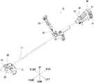
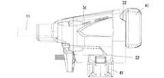
以下、本発明の刈払機の一実施形態を図面を参照して説明する。図1及び図2に示したように、刈払機10は、前後方向に延びる中空の棒状の支持棹11と、支持棹11の前端部にカッタユニット20と、支持棹11の後端部にコントローラユニット30とを備えている。 Hereinafter, an embodiment of a brush cutter according to the present invention will be described with reference to the drawings. As shown in FIGS. 1 and 2, the
図1〜図3に示したように、カッタユニット20は支持棹11の前端部に固定された前端ハウジング21を備えている。図3に示したように、前端ハウジング21内には電動モータ22が収容されており、電動モータ22の出力軸22aには減速ギヤ23が係合している。減速ギヤ23は軸受により回転可能に支持された回転軸24に一体的に固定されており、回転軸24の先端部には回転刃25が一体的に固定されている。 As shown in FIGS. 1 to 3, the
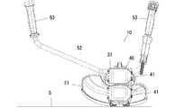
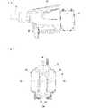
図1,図2及び図4に示したように、コントローラユニット30は、主として、後端ハウジング31と、電動モータ22の制御をするモータコントローラ(図示省略)とから構成される。後端ハウジング31は前側が細くなるように形成された略四角錐台形状をしており、支持棹11の後端部に固定されている。図1,図2,図4及び図6に示したように、後端ハウジング31の後部には電動モータ22に給電する電源40が着脱可能に取り付けられている。この実施形態の電源40は上下方向に並ぶ2つのバッテリパック41よりなる。 As shown in FIGS. 1, 2, and 4, the
図5はバッテリパック41を取り外した状態の後端ハウジング31の背面図であり、後端ハウジング31の後部には上下方向に並ぶ2つのバッテリパック41,41の取付部32,32が設けられている。取付部32はコネクタ部32aを備えており、コネクタ部32aはバッテリパック41の電気コネクタ44に接続されて電動モータ22とバッテリパック41とを電気的に接続する。コネクタ部32aの上下方向の両側には左右方向(横方向)に延びる上下一対のガイドレール32b,32bが設けられており、これらガイドレール32b,32bはバッテリパック41を左右方向にスライド移動可能に取り付けるためのものである。取付部32には内側に凹んで形成された係止部32cが形成されており、この係止部32cはバッテリパック41に設けたフック46に係止してバッテリパック41がガイドレール32b,32bに沿って摺動移動するのを規制する。 FIG. 5 is a rear view of the
後端ハウジング31の下部の前部には脚部33が一体的に形成されており、脚部33は支持棹11を倒して地面等の水平な支持面Sに載置した載置状態にて後端ハウジング31及び下側のバッテリパック41を地面等の水平な支持面Sから離間させるためのものである。 A
バッテリパック41は電動モータ22の電源として用いられ、図示しない充電器を用いて充電可能となっている。また、バッテリパック41は電動ドライバ、電動カッタ等の電動工具の電源として使用可能なものであり、この実施形態のバッテリパック41は公称電圧が18Vとなっている。2つのバッテリパック41,41は電動モータ22に対して直列接続されている。 The
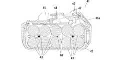
図7及び図8に示したように、バッテリパック41は略直方体形状のケーシング42を備えており、ケーシング42内には円柱形をした10本の電池セル43が収容されている。バッテリパック41はケーシング42の長手方向を取付部32にスライド移動させて取り付ける方向としており、電池セル43はその軸線方向を取付部32にスライド移動させて取り付ける方向と直交する方向にして収容されている。なお、このバッテリパック41はケーシング42の略中心位置が重心G1となっている。 As shown in FIGS. 7 and 8, the
ケーシング42の図7に示した上壁(周壁)は取付部32に対向する壁面であり、この上壁には電気コネクタ44が設けられている。電気コネクタ44は上述したように後端ハウジング31の取付部32のコネクタ部32aに着脱可能に接続される。ケーシング42の図7に示した上壁面には長手方向に延びる一対のレール45,45が一体的に形成されている。これらレール45,45はケーシング42の長手方向と直交する方向にて電気コネクタ44の両側に設けられている。ケーシング42の図7に示した上壁には取付部32に向けて突出するフック46が形成されており、このフック46は取付部32の係止部32cにばね部材47により付勢されている。フック46が取付部32の係止部32cに係止しているときには、バッテリパック41がガイドレール32b,32bに沿って摺動せず、バッテリパック41の電気コネクタ44が取付部32のコネクタ部32aに接続される。フック46を解除ボタン46aによりばね部材47の付勢力に抗して係止部32cから後退させると、バッテリパック41がガイドレール32b,32bに沿って摺動可能となる。この状態で、バッテリパック41をガイドレール32b,32bに沿ってスライド移動させると、バッテリパック41が取付部32から取り外される。このとき、バッテリパック41の電気コネクタ44は取付部32のコネクタ部32aから離脱する。 The upper wall (peripheral wall) shown in FIG. 7 of the
図1及び図2に示したように、支持棹11の前端部にはカバー51が設けられている。カバー51はカッタユニット20の回転刃25の後側を覆うものである。支持棹11の前後方向の中間部にはハンドル52が固定されている。ハンドル52は前後方向と交差する左右方向に延び、中間部から上側に湾曲している。ハンドル52の左右の両端部には作業者が把持するグリップ53,53が設けられている。 As shown in FIGS. 1 and 2, a
上記のように構成した刈払機10は、2つのバッテリパック41,41からの給電によりカッタユニット20の電動モータ22を作動させると、出力軸22aに係合した減速ギヤ23を介して回転軸24が回転し、回転軸24に固定された回転刃25が回転する。作業者は左右の手でハンドル52の両グリップ53,53を把持し、前端のカッタユニット20の回転刃25を地面から生える草や芝に当てることで、草や芝が刈り取られる。 When the
上記のように構成した刈払機10においては、電動モータ22に給電する電源40には電動工具に使用可能な、充電可能な2つ(複数)のバッテリパック41,41を用いている。このように、刈払機10の電源に電動工具にも使用可能な汎用性の高いバッテリパック41,41を用いたことで、ユーザは刈払機10と電動工具とともに多種のバッテリパックを所持する必要がなく、使い勝手を向上させることができた。 In the
また、この刈払機10においては、重量物であるバッテリパック41、41の取り付け位置が、刈払機10の操作性及びバッテリパック41の着脱作業の作業性に大きな影響を与える。そのために、図9に示したように、支持棹11を倒して水平な支持面Sに載置した載置状態にて、ハンドル52を除いた刈払機10の後側から見たときの重心Gが後端ハウジング31の後側から見たときにおける上下方向に延びる左右方向(横方向)の中心線Cwから左右両側に後端ハウジング31の左右方向の長さWの15%ずつの長さの範囲R(R1)に位置するように、2つのバッテリパック41,41を配置した。このようにしたときには、刈払機10を水平な支持面に載置した載置状態で、刈払機10が左右方向に傾くのを防ぐことができる。なお、刈払機10の後側から見たときの重心Gの範囲Rを中心線Cwから左右両側に後端ハウジング31の左右方向の長さの10%ずつ(10%の長さの範囲をR2とする)としたときには刈払機10が左右方向に傾くのをより防ぐことができ、さらに範囲Rを中心線Cwから左右両側に後端ハウジング31の左右方向の長さの5%ずつ(5%の長さの範囲をR3とする)としたときには、刈払機10が左右方向に傾くのを顕著に防ぐことができた。これにより、刈払機10を使用したときに、ハンドル52のグリップ53,53を強く把持する必要がなく、疲れにくくなった。 Further, in the
刈払機10の後側から見たときの重心Gを後端ハウジング31の後方視における上下方向に延びる左右方向の中心線Cwから上述した範囲R内にて左右方向にオフセットさせている。このようにしたときには、刈払機10を使用したときに左右方向に僅かに傾くようになり、刈払機10の回転刃25が僅かに傾いて草や芝に当てやすくなり、操作性を良くすることができる。また、この刈払機10においては、2つ(複数)のバッテリパック41,41の各々の重心G1,G1を上記の範囲R内に位置するようにした。これにより、さらに刈払機10が左右に傾くのを防ぐことができた。 The center of gravity G when viewed from the rear side of the
また、刈払機10においては、支持棹11を倒して水平な地面等の支持面Sに載置した載置状態にて、バッテリパック41,41を支持面Sに接地しない位置に配置した。これにより、刈払機10を支持面Sに置いたときに、バッテリパック41,41が支持面Sに当たって破損しにくくなる。 Further, in the
また、刈払機10においては、2つ(複数)のバッテリパック41,41を上下に並列した位置に配置した。これにより、バッテリパック41,41を互いに離間した位置に配置したときと比べ、ユーザによるバッテリパック41,41の着脱作業の作業性が向上した。また、バッテリパック41の体積は540cm3であり、バッテリパック41の体積が200cm3以上であるときには、並列した位置に配置した2つのバッテリパック41,41の互いに隣り合う壁面の間隔を15mm未満とするのが好ましく、この実施形態ではその間隔を5mmとした。このように、バッテリパック41の体積が200cm3以上であるときには、バッテリパック41,41の間隔を狭くすることで、バッテリパック41,41による占有空間を狭くすることができた。Further, in the
また、刈払機10においては、2つのバッテリパック41,41を取り付けるために後端ハウジング31の後部に2つの取付部32,32を備えた。バッテリパック41,41は電池セル43を内蔵したケーシング42の周壁に電気コネクタ44と、電気コネクタ44の両側に配置される一対のレール45,45を備え、取付部32は一対のレール45,45に摺動自在に係合する一対のガイドレール32b,32bを備えるようにした。これにより、バッテリパック41の一対のレール45,45を取付部32のガイドレール32b,32bに沿って摺動させて取り付けることになるので、バッテリパック41の取付部32に対する取付作業の作業性がよくなった。 Further, in the
また、バッテリパック41には取付部32に対して進退可能に突出するフック46と、取付部32にはフック46に係止する係止部32cとを備えている。フック46を係止部32cに係止させることで、バッテリパック41の一対のレール45,45が取付部32の一対のガイドレール32b,32bに対して摺動移動するのが規制されて、バッテリパック41が取付部32に固定される。これにより、バッテリパック41の取付部32に対する取付作業の作業性がよくなった。 In addition, the
次に、この刈払機において、2つのバッテリパックを用いた他の変形例について説明する。以下の説明においては、主として上述した実施形態の刈払機10と異なることについて説明し、別段の記載がない限り上述した作用効果の記載を省略している。 Next, another modification using two battery packs in this brush cutter will be described. In the following description, differences from the
(変形例1)
図10に示した変形例1では、後端ハウジング31には取付部32にバッテリパック41,41の周囲を覆うバッテリパック収容部34を設けた。バッテリパック収容部34はバッテリパック41,41に汚れが付着するのを防ぐためのものである。バッテリパック収容部34の一側面にはバッテリパック41の差込口34aが形成されており、差込口34aからバッテリパック41を挿入可能となっている。バッテリパック41を差込口34aから取付部32のガイドレール32b,32bに沿って奥まで摺動させると、フック46が取付部32の係止部32cに係止され、バッテリパック41が取付部32に取り付けられる。(Modification 1)
In the first modification shown in FIG. 10, the
また、取付部32にはバッテリパック収容部34内にてバッテリパック41を差込口34aから取り出す方向に付勢するばね部材(付勢部材)35が設けられている。バッテリパック収容部34内にて取付部32に取り付けたバッテリパック41を取り出すときには、解除ボタン46aを押動させることでフック46を係止部32cの係止から解除すると、図10(b)に示したように、バッテリパック41がばね部材35により差込口34aから取り出し方向に移動する。これにより、バッテリパック41の一部を掴んでバッテリパック収容部34から取り出しやすくなった。なお、バッテリパック収容部34は2つのバッテリパック41,41の両方を収容しているが、本発明はこれに限られるものでなく、バッテリパック収容部34に1つのバッテリパック41を収容し、バッテリパックの数に対応した複数のバッテリパック収容部34を設けるようにしてもよい。 The
(変形例2)
図11に示したように、この刈払機10は、バッテリパック41,41を後端ハウジング31の後部に左右方向に並べて配置したものである。後端ハウジング31の後部には左右方向に並ぶ2つの取付部32,32が設けられている。取付部32のコネクタ部32aの左右方向の両側には上下方向に延びる左右一対のガイドレール32b,32bが設けられている。バッテリパック41はこれらガイドレール32b,32bに沿って下方向にスライド移動させて取り付けられる。(Modification 2)
As shown in FIG. 11, the
このように構成した刈払機10においては、2つのバッテリパック41,41の各々の重心G1,G1を範囲R外に位置させる代わりに、バッテリパック41,41の各々の重心G1,G1を上下方向に延びる左右方向の中心線Cwの左右両側に分かれるように配置した。このようにしたときにも、刈払機10が左右方向にバランスがよくなった。この作用効果以外は、上述した作用効果と同様である。なお、この変形例2においても、変形例1に示したようにバッテリパック収容部34及びばね部材35を設けてもよい。 In the
(変形例3)
図12に示したように、この刈払機10は、変形例2にて示したバッテリパック41,41を後端ハウジング31の後部に左右方向に並べて配置したものにおいて、バッテリパック41,41が上側に向かうにつれて後方に傾斜するように取り付けられている。なお、取付部32及びこれのガイドレール32b,32bも同様に上側に向かうにつれて後方に傾斜させている。(Modification 3)
As shown in FIG. 12, the
このように構成した刈払機10においても、上述した変形例2と同様の作用効果を得ることができる。また、バッテリパック41,41を上側に向かうにつれて後方に傾斜するように取り付けたことから、バッテリパック41を前側に押しながら下側に押し込んで取り付けることができ、バッテリパック41を後側に引きながら上側に持ち上げて取り外すことができ、バッテリパック41,41の着脱作業の作業性がよくなった。なお、この変形例3においても、変形例1に示したようにバッテリパック収容部34及びばね部材35を設けてもよい。 Also in the
(変形例4)
図13に示したように、この刈払機10は、バッテリパック41,41の取付部32に対する取付側を互いに向き合うようにして、バッテリパック41,41を後端ハウジング31の後部に左右方向に並べて配置したものである。取付部32,32においては、各コネクタ部32a及び各ガイドレール32b,32bを外側を向くようにした。(Modification 4)
As shown in FIG. 13, the
このように構成した刈払機10においても、上述した変形例2と同様の作用効果を得ることができる。なお、この変形例4において、変形例1に示したようにバッテリパック収容部34及びばね部材35を設けてもよい。 Also in the
(変形例5)
図14に示したように、この刈払機10は、バッテリパック41,41の取付部32に対する取付側を互いに向き合うようにして、バッテリパック41,41を後端ハウジング31の後部に上下方向に並べて配置したものである。取付部32,32においては、各コネクタ部32a及び各ガイドレール32b,32bを上側及び下側を向くようにし、前後方向に延びる左右一対のガイドレール32b,32bをコネクタ部32aの左右両側に設けた。バッテリパック41はこれらガイドレール32b,32bに沿って前方向にスライド移動させて取り付けられる。2つのバッテリパック41,41は、後端ハウジング31の左右方向の中央部に取り付けられている。(Modification 5)
As shown in FIG. 14, the
このように構成した刈払機10においても、上述した実施形態と同様の作用効果を得ることができる。なお、この変形例5において、変形例1に示したようにバッテリパック収容部34及びばね部材35を設けてもよい。 Also in the
(変形例6)
図15に示したように、この刈払機10は、変形例2にて示したバッテリパック41,41を後端ハウジング31の後部に左右方向に並べて配置したものにおいて、バッテリパック41,41が後側に向かうにつれて互いに対向する壁面の間隔が広がるように配置したものである。すなわち、上方から見たときのバッテリパック41,41はハの字形に広がるように取り付けられている。(Modification 6)
As shown in FIG. 15, the
このようにしたときには、バッテリパック41,41の互いに隣り合う壁面の間隔を15mm(少なくとも前後方向の中間部から後部まで)以上とでき、各々のバッテリパック41,41を掴みやすくでき、バッテリパック41,41の着脱作業の作業性を向上させることができた。この作用効果以外についても、上述した変形例2と同様の作用効果を得ることができる。なお、この変形例6において、変形例1に示したようにバッテリパック収容部34及びばね部材35を追加で設けてもよい。 In this case, the interval between the wall surfaces adjacent to each other of the battery packs 41 and 41 can be set to 15 mm (at least from the middle part to the rear part in the front-rear direction) or more, and the battery packs 41 and 41 can be easily grasped. , 41 can be improved. In addition to this function and effect, the same function and effect as those of Modification 2 described above can be obtained. In the sixth modification, the battery
(変形例7)
図16に示したように、この刈払機10は、1つのバッテリパック41を後端ハウジング31の後部に取り付け、もう1つのバッテリパック41を後端ハウジング31の下部に取り付けたものである。後端ハウジング31の後部のバッテリパック41は下方向にスライド移動させて取り付けられ、後端ハウジング31の下部のバッテリパック41は前方向にスライド移動させて取り付けられる。2つのバッテリパック41,41は、後端ハウジング31の左右方向の中央部に取り付けられている。なお、後端ハウジング31の後部に取り付けたバッテリパック41を左右方向にスライド移動可能に取り付けたものであってよい。また、図17に示したように、後端ハウジング31の下部に取り付けたバッテリパック41を前後方向に代えて左右方向にスライド移動可能に取り付けたものであってよい。(Modification 7)
As shown in FIG. 16, the
このように構成した刈払機10においても、上述した実施形態と同様の作用効果を得ることができる。なお、この変形例7においても、変形例1に示したようにバッテリパック収容部34及びばね部材35を設けてもよい。 Also in the
(変形例8)
図18に示したように、この刈払機10は、バッテリパック41,41を後端ハウジング31の下部に前後方向に並べて配置したものである。後端ハウジング31の下部には前後方向に並ぶ2つの取付部32,32が設けられている。取付部32のコネクタ部32aの前後方向の両側には左右方向に延びる前後一対のガイドレール32b,32bが設けられている。バッテリパック41はこれらガイドレール32b,32bに沿って右方向にスライド移動させて取り付けられる。2つのバッテリパック41,41は、後端ハウジング31の左右方向の中央部に取り付けられている。(Modification 8)
As shown in FIG. 18, the
また、後端ハウジング31には、変形例1で示したように、取付部32を設けた位置にバッテリパック41の周囲を覆うバッテリパック収容部34を設けた。このバッテリパック収容部34は、上述したように、バッテリパック41の汚れが付着するのを防ぐとともに、支持棹11を倒して刈払機10を支持面Sに載置したときに、バッテリパック41の接地面を覆う保護部材としても機能している。バッテリパック収容部34をバッテリパック41の接地面を覆う保護部材としたことで、支持棹11を倒して刈払機10を支持面Sに載置したときに、バッテリパック41が支持面Sに当たらないようになり、バッテリパック41が支持面Sに当たって破損するのを防ぐことができた。なお、バッテリパック収容部34を保護部材としたときには、金属製の厚肉の板材を用いると強度が高くなって好ましい。なお、変形例8においても、変形例1に示したようにバッテリパック収容部34内にばね部材35を設けてもよい。 Further, as shown in the first modification, the
このように構成した刈払機10においては、支持棹11を水平な支持面に載置した状態にて、刈払機10の後側から見たときの重心Gを後端ハウジング31の後方から見たときの左右方向に延びる上下方向の高さHの中心線Chよりも下側とすることができ、刈払機10が左右方向にさらにバランスがよくなり、刈払機10が左右方向に傾くのを防ぐことができる。この作用効果以外は、上述した作用効果と同様である。 In the
(変形例9)
図19に示したように、この刈払機10は、バッテリパック41,41を後端ハウジングの下部に左右方向に並べて配置したものである。後端ハウジング31の下部には左右方向に並ぶ2つの取付部32,32が設けられている。取付部32のコネクタ部32aの左右方向の両側には前後方向に延びる左右一対のガイドレール32b,32bが設けられている。バッテリパック41はこれらガイドレール32b,32bに沿って前方向にスライド移動させて取り付けられる。(Modification 9)
As shown in FIG. 19, the
このように構成した刈払機10においても、支持棹11を水平な支持面に載置した状態にて、刈払機10の後側から見たときの重心Gを後端ハウジング31の後方から見たときの左右方向に延びる上下方向の高さHの中心線Chよりも下側とすることができ、刈払機10が左右方向にさらにバランスがよくなり、刈払機10が左右方向に傾くのを防ぐことができる。この作用効果以外は、上述した変形例2の作用効果と同様である。なお、この変形例9においても、変形例1に示したようにバッテリパック収容部34及びばね部材35を設けてもよい。 Also in the
(変形例10)
図20に示したように、この刈払機10は、バッテリパック41,41の取付部32に対する取付側を互いに向き合うようにして、バッテリパック41,41を後端ハウジングの下部に左右方向に並べて配置したものである。後端ハウジング31の下部には左右方向に並ぶ2つの取付部32,32が設けられている。取付部32のコネクタ部32aの上下方向の両側には前後方向に延びる左右一対のガイドレール32b,32bが設けられている。バッテリパック41はこれらガイドレール32b,32bに沿って前方向にスライド移動させて取り付けられる。(Modification 10)
As shown in FIG. 20, the
このように構成した刈払機10においても、支持棹11を水平な支持面に載置した状態にて、刈払機10の後側から見たときの重心Gを後端ハウジング31の後方から見たときの左右方向に延びる上下方向の中心線Chよりも下側とすることができ、刈払機10が左右方向にさらにバランスがよくなり、刈払機10が左右方向に傾くのを防ぐことができる。この作用効果以外は、上述した変形例2の作用効果と同様である。なお、この変形例10においても、変形例1に示したようにバッテリパック収容部34及びばね部材35を設けてもよい。 Also in the
(変形例11)
図21に示したように、この刈払機10は、バッテリパック41,41の取付部32に対する取付側を互いに向き合うようにして、バッテリパック41,41を後端ハウジングの左右両側部に分けて配置したものである。後端ハウジング31の左右両側部にはバッテリパック41,41の取付部32,32が設けられている。取付部32のコネクタ部32aの前後方向の両側には上下方向に延びる左右一対のガイドレール32b,32bが設けられている。バッテリパック41はこれらガイドレール32b,32bに沿って下方向にスライド移動させて取り付けられる。(Modification 11)
As shown in FIG. 21, the
このように構成した刈払機10においては、2つのバッテリパック41,41の各重心G1,G1を範囲R外に位置させる代わりに、バッテリパック41,41の各重心G1,G1を上下方向に延びる左右方向の中心線Cwの左右両側に分かれるように配置した。このようにしたときにも、刈払機10が左右方向にバランスがよくなった。この作用効果以外は、上述した変形例2の作用効果と同様である。なお、この変形例11においても、変形例1に示したようにバッテリパック収容部34及びばね部材35を設けてもよい。また、バッテリパック41,41を前後方向にスライド移動可能に取り付けるようにしてもよい。 In the
(変形例12)
図22に示したように、この刈払機10は、バッテリパック41,41の両方を後端ハウジングの左側部に配置したものである。後端ハウジング31の左側部にはバッテリパック41,41の取付部32,32が設けられている。取付部32のコネクタ部32aの前後方向の両側には上下方向に延びる左右一対のガイドレール32b,32bが設けられている。バッテリパック41はこれらガイドレール32b,32bに沿って下方向にスライド移動させて取り付けられる。(Modification 12)
As shown in FIG. 22, the
このように構成した刈払機10においては、上記の各変形例と異なり、2つのバッテリパック41,41の各重心G1,G1が範囲R内に位置せず、また、バッテリパック41,41の各々の重心G1,G1が上下方向に延びる左右方向の中心線Cwの左右両側に分かれないが、これら重心以外の作用効果は、上述した作用効果と同様である。なお、この変形例12においても、変形例1に示したようにバッテリパック収容部34及びばね部材35を設けてもよい。 In the
(変形例13)
図23に示したように、この刈払機10は、バッテリパック41,41を後端ハウジング31の上部に左右方向に並べて配置したものである。後端ハウジング31の上部には左右方向に並ぶ2つの取付部32,32が設けられている。取付部32のコネクタ部32aの左右方向の両側には前後方向に延びる左右一対のガイドレール32b,32bが設けられている。バッテリパック41はこれらガイドレール32b,32bに沿って前方向にスライド移動させて取り付けられる。(Modification 13)
As shown in FIG. 23, the
このように構成した刈払機10においては、2つのバッテリパック41,41の各々の重心G1,G1を範囲R外に位置させる代わりに、バッテリパック41,41の各々の重心G1,G1を上下方向に延びる左右方向の中心線Cwの左右両側に分かれるように配置した。このようにしたときにも、刈払機10が左右方向にバランスがよくなった。この作用効果以外は、上述した変形例2の作用効果と同様である。なお、この変形例13においても、変形例1に示したようにバッテリパック収容部34及びばね部材35を設けてもよい。 In the
(変形例14)
図24に示したように、この刈払機10は、バッテリパック41,41を後端ハウジング31の上部に前後方向に並べて配置したものである。後端ハウジング31の上部には前後方向に並ぶ2つの取付部32,32が設けられている。取付部32のコネクタ部32aの左右方向の両側には左右方向に延びる前後一対のガイドレール32b,32bが設けられている。バッテリパック41はこれらガイドレール32b,32bに沿って右方向にスライド移動させて取り付けられる。(Modification 14)
As shown in FIG. 24, the
このように構成した刈払機10においては、上述した実施形態と同様の作用効果を得ることができる。なお、この変形例14においても、変形例1に示したようにバッテリパック収容部34及びばね部材35を設けてもよい。 In the
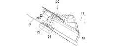
(変形例15)
図25に示したように、この刈払機10は、バッテリパック41,41を後端ハウジング31の上部に前後方向に並べて配置したものである。バッテリパック41,41は上側に向かうにつれて後方に傾斜するように取り付けられている。後端ハウジング31の上部には前後方向に並ぶ2つの取付部32,32が設けられている。なお、取付部32及びこれのガイドレール32b,32bも同様に上側に向かうにつれて後方に傾斜させている。(Modification 15)
As shown in FIG. 25, the
このように構成した刈払機10においては、上述した実施形態と同様の作用効果を得ることができる。なお、この変形例15においても、変形例1に示したようにバッテリパック収容部34及びばね部材35を設けてもよい。 In the
上記のように構成した刈払機10においては、電源40として2つバッテリパック41,41を用いた例について説明したが、本発明はこれに限られるものでなく、3つ以上のバッテリパックを用いたものであってもよい。 In the
上記のように構成した刈払機10においては、2つのバッテリパック41を電動モータ22に対して直列接続したものについて説明したが、本発明はこれに限られるものでない。2つ(複数)のバッテリパック41を電動モータ22に対して直列接続したときには、電動モータ22を高出力で使用することができ、これに対し、2つ(複数)のバッテリパック41を電動モータ22に対して並列接続したときには、電動モータ22を長時間使用することが可能となる。なお、この直列接続及び並列接続を制御回路により選択可能としてもよい。 In the
上記の実施形態のハンドル52は、後側から見た形状がU字形をしているが、本発明の刈払機10に用いるハンドルは支持棹11の長手方向の中間部にて上側に設けたループ形状をしたループハンドルであってもよい。同様に、ハンドルに代えて、支持棹11の長手方向の中間部に支持棹11の径より太いグリップを同軸的に取付けたものであってもよい。上述した実施形態での説明と同様に、本発明の刈払機10の重心Gは、これらのハンドル(またはグリップ)を含まない構造で適宜な位置となるように、複数のバッテリパック41を適宜な位置に取り付けている。 The
上記のように構成した刈払機10においては、2つのバッテリパック41を後端ハウジング31に取り付けたが、本発明はこれに限られるものでなく、例えば、支持棹11または前端ハウジング21に2つのバッテリパック41を取り付けたもの、または、前端ハウジング21と後端ハウジング31にバッテリパック41を1つずつ取り付けたものであってもよい。なお、支持棹11にバッテリパック41を取り付けたときには、作業者が把持するハンドル52より下側に取り付けた方が、操作性の点で好ましい。 In the
上記のように構成した刈払機10においては、公称電圧が18Vのバッテリパック41を用いて説明したが、本発明はこれに限られるものでなく、これよりも大型(高電圧)または小型(低電圧)のバッテリパックを用いたものであってもよい。また、上記の実施形態では、同一体積、同一重量のバッテリパック41を2つ用いたものについて説明したが、本発明はこれに限られるものでなく、異なる体積、異なる重量のバッテリパックを適宜組み合わせて用いたものであってもよい。 In the
また、複数のバッテリパック41を直列接続したときには、各バッテリパック41の電圧を制御するバッテリコントローラを備えるのが好ましい。バッテリコントローラを電動モータ22の作動を制御するモータコントローラとともに一体とし、同一のマイコンにより電動モータ22の作動を制御するとともにバッテリパック41の電圧を制御してもよく、また、バッテリコントローラを電動モータ22の作動を制御するモータコントローラと別体にし、各々のマイコンにより電動モータ22の作動の制御と、バッテリパック41の電圧の制御とをしてもよい。なお、バッテリコントローラをモータコントローラと一体とした方が、部品点数の削減、占有空間の減少及び必要な配線の削減等の点で好ましい。 In addition, when a plurality of battery packs 41 are connected in series, a battery controller that controls the voltage of each
また、図26に示したように、バッテリコントローラ(モータコントローラと一体または別体のときの両方)はバッテリパック41を取り付けた位置の近傍Aの位置に設けるのが好ましく、このようにしたときには、バッテリパック41に対する配線を短くできる。また、バッテリコントローラ(モータコントローラと一体または別体のときの両方)を後端ハウジング31の吸気口31aの近傍Bの位置に設けたときには、後端ハウジング31に導入される外気によりバッテリコントローラが冷却されるようになる。バッテリコントローラを冷却するときには、吸気口31aの近傍Bの位置に限られるものでなく、前端ハウジング21の電動モータ22に設けた冷却ファンによって生じる空気の通路、すなわち、後端ハウジング31の吸気口31aから支持棹11を通過して冷却ファンに至る経路及び冷却ファンから前端ハウジング21の外部に排出される経路にバッテリコントローラを設けるようにしてもよく、このようにしたときには、バッテリコントローラを通過する空気により冷却することができる。 In addition, as shown in FIG. 26, the battery controller (both integrated with the motor controller or separately) is preferably provided at a position in the vicinity A of the position where the
また、上記のように構成した刈払機10においては、電動モータ22を前端ハウジング21内に設けたが、本発明はこれに限られるものでなく、電動モータ22を後端ハウジング31内に設け、支持棹11内に介装した駆動シャフトを介して回転刃25を回転させるものであってもよい。 Further, in the
また、上記のように構成した刈払機10においては、モータコントローラを後端ハウジング31内に設けたが、本発明はこれに限られるものでなく、電動モータ22とともにモータコントローラ(バッテリコントローラと一体または別体のときの両方)を前端ハウジング21内に設けてもよい。 Further, in the
また、上記のように構成した刈払機10においては、2つ(複数)のバッテリパック41,41を直列接続したときには、2つのうちの1つのバッテリパック41が故障または放電したことに起因して電動モータ22を作動させることができないおそれがある。そのため、各バッテリパック41の残量を報知する報知手段(表示手段)を設けるのが好ましい。報知手段は例えば残量表示パネル60であり、残量表示パネル60は複数のバーの表示する数に応じてバッテリの残量を表示する。残量表示パネル60はユーザがバッテリパック41を取付け時、または、刈払機10の使用時に視認できる位置に設けるのが好ましい。ユーザがバッテリパック41を取付け時に視認できる位置として、図27(a)のようにバッテリパック41、41を後端ハウジング31の後部に上下方向に並べて取り付けたときには、後端ハウジング31の左側壁に各々のバッテリパック41,41の残量表示パネル60,60を上下方向に並べて配置するのが好ましい。また、図27(b)のようにバッテリパック41、41を後端ハウジング31の上部に前後方向に並べて取り付けたときには、後端ハウジング31の左側壁または上壁に各々のバッテリパック41,41の残量表示パネル60,60を前後方向に並べて配置するのが好ましい。このようにしたときには、ユーザは各々のバッテリパック41,41の残量を残量表示パネル60,60により直感的に視認できる。また、ユーザが刈払機10の使用時に視認できる位置としては、後端ハウジング31の上壁にバッテリパック41,41の並べた方向に対応して残量表示パネル60,60を設けるのが好ましい。また、報知手段として残量表示パネル60の複数のバーによりバッテリの残量を表示するようにしたが、これに限られるものでなく、ランプの色または点滅速度、報知音により報知させてもよい。 Further, in the
10…刈払機、11…支持棹、21…前端ハウジング、22…電動モータ、24…回転軸、25…回転刃、31…後端ハウジング、32…取付部、32a…コネクタ部、32b…ガイドレール、32c…係止部、34…バッテリパック収容部(保護部材)、34a…差込口、35…付勢部材(ばね部材)、40…電源、41…バッテリパック、42…ケーシング、43…電池セル、44…電気コネクタ、45…レール、46…フック、G…重心(刈払機を後側からみたときの重心)、G1…重心(バッテリパックの重心)、Cw…中心線(後端ハウジングを後側から見たときの上下方向に延びる左右方向の中心線)、Ch…中心線(後端ハウジングを後側から見たときの左右方向に延びる上下方向の中心線)、R(R1〜R3)…範囲、S…支持面。 DESCRIPTION OF
Claims (2)
Translated fromJapanese前記支持棹の前端部に固定した前端ハウジングと、
前記前端ハウジングに回転可能に支持した回転軸に取り付けた回転刃と、
前記支持棹の後端部に固定した後端ハウジングと、
前記回転刃を回転させる電動モータと、
前記電動モータに給電する電源とを備えた刈払機において、
前記電源が、前記後端ハウジングに着脱可能、かつ、電動工具に使用可能な、充電可能な2つのバッテリパックよりなり、これら2つのバッテリパックが前記後端ハウジングの後部に取り付けられ、
前記支持棹を倒して水平な支持面に載置した載置状態にて、前記刈払機の後側から見たときの前記ハンドルまたはグリップを含まない構造での重心が前記後端ハウジングの後側から見たときにおける上下方向に延びる左右方向の中心線から左右両側に前記後端ハウジングの左右方向の長さの15%の長さ、好ましくは10%の長さ、より好ましくは5%の長さの範囲内(製造公差により通常発生する0%に近いオフセットを除く)にて前記中心線から左右方向にオフセットさせるように、前記2つのバッテリパックを配置したことを特徴とする刈払機。A support rodprovided with a handle or grip gripped by an operator at the front and rear intermediate portions linearly extending in the front-rear direction ;
A front end housing fixed to the front end of the support rod;
A rotary blade attached to a rotary shaft rotatably supported by the front end housing;
A rear end housing fixed to a rear end portion of the support rod;
An electric motor for rotating the rotary blade;
Ina brush cutter comprising a power source for supplying power to the electric motor,
The power source is composed of two rechargeable battery packs that can be attached to and detached from the rear end housing and that can be used for a power tool, and these two battery packs are attached to the rear portion of the rear end housing,
The centerof gravity of thestructure that does not include the handle or grip when viewed from the rear side of the brush cutter when the support rod is tilted and placed on a horizontal support surface is the rear side of the rear housing. 15% of the length of the rear end housing in the left-right direction from the center line in the left-right direction extending in the up-down direction when viewed from the side, preferably 10%, more preferably 5% A brush cutter in which the two battery packs are arranged so as to be offset in the horizontal direction from the center line within a range(excluding an offset close to 0% that is normally generated due to manufacturing tolerances) .
前記前端ハウジングに前記電動モータを配置したことを特徴とする刈払機。The brush cutter according to claim1 ,
A brush cutter, wherein the electric motor is disposed in the front end housing.
Priority Applications (6)
| Application Number | Priority Date | Filing Date | Title |
|---|---|---|---|
| JP2013018667AJP6315541B2 (en) | 2013-02-01 | 2013-02-01 | Brush cutter |
| PCT/JP2014/052271WO2014119732A1 (en) | 2013-02-01 | 2014-01-31 | Mower |
| EP14745485.4AEP2952083B2 (en) | 2013-02-01 | 2014-01-31 | Brush cutter |
| DE202014011404.8UDE202014011404U1 (en) | 2013-02-01 | 2014-01-31 | Brush cutter |
| US14/764,627US9756783B2 (en) | 2013-02-01 | 2014-01-31 | Brush cutter |
| US15/938,588USRE48068E1 (en) | 2013-02-01 | 2014-01-31 | Brush cutter |
Applications Claiming Priority (1)
| Application Number | Priority Date | Filing Date | Title |
|---|---|---|---|
| JP2013018667AJP6315541B2 (en) | 2013-02-01 | 2013-02-01 | Brush cutter |
Publications (2)
| Publication Number | Publication Date |
|---|---|
| JP2014147349A JP2014147349A (en) | 2014-08-21 |
| JP6315541B2true JP6315541B2 (en) | 2018-04-25 |
Family
ID=51262429
Family Applications (1)
| Application Number | Title | Priority Date | Filing Date |
|---|---|---|---|
| JP2013018667AActiveJP6315541B2 (en) | 2013-02-01 | 2013-02-01 | Brush cutter |
Country Status (5)
| Country | Link |
|---|---|
| US (2) | USRE48068E1 (en) |
| EP (1) | EP2952083B2 (en) |
| JP (1) | JP6315541B2 (en) |
| DE (1) | DE202014011404U1 (en) |
| WO (1) | WO2014119732A1 (en) |
Families Citing this family (31)
| Publication number | Priority date | Publication date | Assignee | Title |
|---|---|---|---|---|
| US9844176B2 (en)* | 2012-10-22 | 2017-12-19 | Fournier And Grande Trust | Weed trimmer extension device |
| US20150328764A1 (en) | 2013-02-01 | 2015-11-19 | Makita Corporation | Power tool |
| WO2015061370A1 (en) | 2013-10-21 | 2015-04-30 | Milwaukee Electric Tool Corporation | Adapter for power tool devices |
| US9673738B2 (en) | 2014-05-16 | 2017-06-06 | Techtronic Power Tools Technology Limited | Multi-battery pack for power tools |
| JP6300271B2 (en) | 2014-07-22 | 2018-03-28 | 株式会社マキタ | Chainsaw |
| JP6345523B2 (en)* | 2014-07-23 | 2018-06-20 | 株式会社やまびこ | Battery powered work machine |
| JP6616938B2 (en)* | 2014-10-03 | 2019-12-04 | 株式会社マキタ | Self-propelled dust collection robot |
| US10463219B2 (en) | 2014-10-03 | 2019-11-05 | Makita Corporation | Self-propelled, dust-collecting robot |
| JP6907162B2 (en)* | 2014-10-03 | 2021-07-21 | 株式会社マキタ | Self-propelled dust collecting robot |
| JP6442222B2 (en)* | 2014-10-20 | 2018-12-19 | 株式会社マキタ | Working machine |
| JP6442223B2 (en)* | 2014-10-20 | 2018-12-19 | 株式会社マキタ | Working machine |
| WO2016194537A1 (en)* | 2015-05-29 | 2016-12-08 | 日立工機株式会社 | Electrical working machine |
| US10299429B2 (en)* | 2016-04-14 | 2019-05-28 | Transform Sr Brands Llc | Ergonomic gripping mechanisms of an electric cutting apparatus |
| JP2018088853A (en)* | 2016-11-30 | 2018-06-14 | 本田技研工業株式会社 | Electric working machine |
| US11084006B2 (en) | 2017-03-23 | 2021-08-10 | Milwaukee Electric Tool Corporation | Mud mixer |
| EP3595430B1 (en)* | 2017-09-27 | 2021-05-12 | Globe (Jiangsu) Co., Ltd. | Ergonomic trimmers having high operational safety |
| US11806858B2 (en)* | 2017-09-27 | 2023-11-07 | Globe (jiangsu) Co., Ltd. | Impact protecting member for a cutting tool |
| US11399461B2 (en)* | 2017-10-24 | 2022-08-02 | Suzhou Cleva Precision Machinery AND Technology Co., Ltd. | Handle assembly for garden tool and garden tool having same |
| JP2019201880A (en) | 2018-05-23 | 2019-11-28 | 株式会社マキタ | Robot dust collector |
| WO2020001634A1 (en)* | 2018-06-28 | 2020-01-02 | 南京德朔实业有限公司 | Long-pole gardening tool |
| JP7198104B2 (en) | 2019-02-06 | 2022-12-28 | 株式会社マキタ | Cleaner |
| JP7224967B2 (en) | 2019-03-05 | 2023-02-20 | 株式会社マキタ | upright dust collector |
| TWM612458U (en) | 2019-03-12 | 2021-06-01 | 美商米沃奇電子工具公司 | Power tool |
| IT201900004273A1 (en)* | 2019-03-25 | 2020-09-25 | Emak Spa | WORK TOOL EQUIPPED WITH A DAMPING ELEMENT |
| JP7231503B2 (en)* | 2019-06-28 | 2023-03-01 | 株式会社マキタ | Optical sensor and robot dust collector |
| JP2021083361A (en)* | 2019-11-27 | 2021-06-03 | 株式会社マキタ | Work machine |
| SE1951487A1 (en)* | 2019-12-18 | 2021-06-19 | Husqvarna Ab | Debris blower |
| US12376515B2 (en) | 2021-06-30 | 2025-08-05 | Milwaukee Electric Tool Corporation | String trimmer assembly and trimmer head for use with same |
| DE102023115832A1 (en)* | 2023-06-16 | 2024-12-19 | Andreas Stihl Ag & Co. Kg | BATTERY DEVICE |
| EP4483696B1 (en)* | 2023-06-29 | 2025-08-06 | Nanjing Chervon Industry Co., Ltd. | Lawn edger |
| DE102024202991A1 (en) | 2024-03-28 | 2025-10-02 | Robert Bosch Gesellschaft mit beschränkter Haftung | Battery-operated processing device |
Family Cites Families (37)
| Publication number | Priority date | Publication date | Assignee | Title |
|---|---|---|---|---|
| US4286675A (en) | 1979-06-25 | 1981-09-01 | Beaird-Poulan Division Of Emerson Electric Co. | Narrow profile power handle for line trimmer and the like |
| JPH0448664Y2 (en)* | 1987-05-28 | 1992-11-17 | ||
| DE3844093A1 (en)* | 1988-12-28 | 1990-07-05 | Metabowerke Kg | ELECTRIC HAND TOOL WITH INDEPENDENT POWER SUPPLY |
| DE69219592T2 (en) | 1991-03-01 | 1997-09-11 | Inertia Dynamics Corp., Chandler, Ariz. | BATTERY DRIVED THREAD CUTTING HEAD |
| JP2525820Y2 (en)* | 1991-06-26 | 1997-02-12 | 石川島芝浦機械株式会社 | Electric mower |
| US5589288A (en)* | 1995-07-31 | 1996-12-31 | Black & Decker, Inc. | Cordless power tool having a push button battery release arrangement |
| US5613354A (en)* | 1995-09-13 | 1997-03-25 | Foster; Thomas E. | Clearing apparatus and carriage for clearing apparatus |
| JPH1056845A (en)* | 1996-08-20 | 1998-03-03 | Honda Motor Co Ltd | Electric mower |
| JP3466843B2 (en)* | 1996-11-26 | 2003-11-17 | 株式会社共立 | Portable brush cutter |
| JP2001351592A (en)* | 2000-06-06 | 2001-12-21 | Makita Corp | Rechargeable power tool |
| JP2002034315A (en)* | 2000-07-19 | 2002-02-05 | Nikkari Co Ltd | Handle device of mower |
| DE10038903A1 (en) | 2000-08-09 | 2002-02-21 | Gardena Kress & Kastner Gmbh | Brush cutter powered by an electric motor |
| JP2002354921A (en)* | 2001-05-31 | 2002-12-10 | Masaaki Iwatani | Bush cutter |
| US6729413B2 (en)* | 2001-08-24 | 2004-05-04 | Black & Decker Inc. | Power tool with battery pack ejector |
| KR20050042716A (en)* | 2003-11-04 | 2005-05-10 | 오세훈 | A grass cutter |
| JP4566062B2 (en)* | 2005-05-09 | 2010-10-20 | 富士重工業株式会社 | Brush cutter |
| JP4993404B2 (en)* | 2006-06-21 | 2012-08-08 | 日立工機株式会社 | Portable power tools |
| JP4122484B2 (en) | 2006-06-22 | 2008-07-23 | 伊東電機株式会社 | Mower |
| JP5063970B2 (en) | 2006-10-02 | 2012-10-31 | 富士重工業株式会社 | Portable power work machine |
| US7739800B2 (en)* | 2006-10-24 | 2010-06-22 | Hurley Edward P | Combination blower, trimmer and edger for tending vegetation |
| JP4940090B2 (en)* | 2007-10-15 | 2012-05-30 | 本田技研工業株式会社 | Brush cutter |
| DE102008040061A1 (en)* | 2008-07-02 | 2010-01-07 | Robert Bosch Gmbh | Power tool |
| JP5138501B2 (en)* | 2008-08-11 | 2013-02-06 | 株式会社マキタ | Brush cutter with removable battery pack |
| JP5134467B2 (en)* | 2008-08-11 | 2013-01-30 | 株式会社マキタ | Brush cutter with stand |
| JP5535949B2 (en) | 2009-02-10 | 2014-07-02 | 株式会社マキタ | Power tool connection system |
| JP5570761B2 (en)* | 2009-06-18 | 2014-08-13 | 株式会社マキタ | Structure to prevent the protector fixture from falling off in garden tools |
| WO2011032574A1 (en) | 2009-09-19 | 2011-03-24 | Husqvarna Ab | Tools |
| JP5544143B2 (en)* | 2009-11-04 | 2014-07-09 | リョービ株式会社 | Battery powered electric brush cutter |
| JP5829006B2 (en) | 2010-01-14 | 2015-12-09 | 日立工機株式会社 | Electric working machine |
| JP5461221B2 (en) | 2010-02-12 | 2014-04-02 | 株式会社マキタ | Electric tool powered by multiple battery packs |
| JP5432761B2 (en)* | 2010-02-12 | 2014-03-05 | 株式会社マキタ | Electric tool powered by multiple battery packs |
| JP5553053B2 (en)* | 2011-04-11 | 2014-07-16 | マックス株式会社 | Battery pack, power tool and charger |
| US9496531B2 (en) | 2011-06-14 | 2016-11-15 | Makita Corporation | Battery devices |
| JP5841891B2 (en)* | 2012-04-18 | 2016-01-13 | 株式会社マキタ | Working machine |
| DE102013020427B4 (en)* | 2013-01-31 | 2018-04-05 | Makita Corporation | Working machine with operating staff |
| JP2014150687A (en)* | 2013-02-01 | 2014-08-21 | Makita Corp | Electric working machine and electric working machine system |
| JP6910840B2 (en)* | 2017-04-24 | 2021-07-28 | 株式会社マキタ | Electric tool |
- 2013
- 2013-02-01JPJP2013018667Apatent/JP6315541B2/enactiveActive
- 2014
- 2014-01-31EPEP14745485.4Apatent/EP2952083B2/enactiveActive
- 2014-01-31WOPCT/JP2014/052271patent/WO2014119732A1/enactiveApplication Filing
- 2014-01-31USUS15/938,588patent/USRE48068E1/enactiveActive
- 2014-01-31USUS14/764,627patent/US9756783B2/ennot_activeCeased
- 2014-01-31DEDE202014011404.8Upatent/DE202014011404U1/ennot_activeExpired - Lifetime
Also Published As
| Publication number | Publication date |
|---|---|
| DE202014011404U1 (en) | 2020-02-28 |
| EP2952083B1 (en) | 2020-03-25 |
| JP2014147349A (en) | 2014-08-21 |
| USRE48068E1 (en) | 2020-06-30 |
| WO2014119732A1 (en) | 2014-08-07 |
| US9756783B2 (en) | 2017-09-12 |
| US20150366133A1 (en) | 2015-12-24 |
| EP2952083A4 (en) | 2016-11-09 |
| EP2952083A1 (en) | 2015-12-09 |
| EP2952083B2 (en) | 2023-08-09 |
Similar Documents
| Publication | Publication Date | Title |
|---|---|---|
| JP6315541B2 (en) | Brush cutter | |
| WO2014119733A1 (en) | Chain saw | |
| JP6300271B2 (en) | Chainsaw | |
| JP6910840B2 (en) | Electric tool | |
| WO2014119115A1 (en) | Electric lawn mower | |
| JP5766547B2 (en) | Rechargeable tiller | |
| WO2014119174A1 (en) | Electric shearing device for gardening | |
| WO2014119175A1 (en) | Electric blower | |
| JP7042570B2 (en) | Rechargeable polisher | |
| JP6084474B2 (en) | Rechargeable cutting tool | |
| JP5251815B2 (en) | Walking type work machine | |
| EP2545756A1 (en) | Electric-power cultivator | |
| WO2014119116A1 (en) | Electric brush cutter | |
| JP2017105206A (en) | Chain saw | |
| CN103659752A (en) | Power tools | |
| JP5807652B2 (en) | Electric field cultivator | |
| JP2012000035A (en) | Electric tiller | |
| JP2021128860A (en) | Working equipment | |
| JP5977386B2 (en) | Battery powered power tools |
Legal Events
| Date | Code | Title | Description |
|---|---|---|---|
| A621 | Written request for application examination | Free format text:JAPANESE INTERMEDIATE CODE: A621 Effective date:20150825 | |
| A131 | Notification of reasons for refusal | Free format text:JAPANESE INTERMEDIATE CODE: A131 Effective date:20160524 | |
| A521 | Request for written amendment filed | Free format text:JAPANESE INTERMEDIATE CODE: A523 Effective date:20160721 | |
| A131 | Notification of reasons for refusal | Free format text:JAPANESE INTERMEDIATE CODE: A131 Effective date:20170110 | |
| A521 | Request for written amendment filed | Free format text:JAPANESE INTERMEDIATE CODE: A523 Effective date:20170309 | |
| A131 | Notification of reasons for refusal | Free format text:JAPANESE INTERMEDIATE CODE: A131 Effective date:20170808 | |
| A521 | Request for written amendment filed | Free format text:JAPANESE INTERMEDIATE CODE: A523 Effective date:20171005 | |
| A02 | Decision of refusal | Free format text:JAPANESE INTERMEDIATE CODE: A02 Effective date:20171128 | |
| A521 | Request for written amendment filed | Free format text:JAPANESE INTERMEDIATE CODE: A523 Effective date:20180221 | |
| RD02 | Notification of acceptance of power of attorney | Free format text:JAPANESE INTERMEDIATE CODE: A7422 Effective date:20180221 | |
| A911 | Transfer to examiner for re-examination before appeal (zenchi) | Free format text:JAPANESE INTERMEDIATE CODE: A911 Effective date:20180228 | |
| TRDD | Decision of grant or rejection written | ||
| A01 | Written decision to grant a patent or to grant a registration (utility model) | Free format text:JAPANESE INTERMEDIATE CODE: A01 Effective date:20180320 | |
| A61 | First payment of annual fees (during grant procedure) | Free format text:JAPANESE INTERMEDIATE CODE: A61 Effective date:20180322 | |
| R150 | Certificate of patent or registration of utility model | Ref document number:6315541 Country of ref document:JP Free format text:JAPANESE INTERMEDIATE CODE: R150 | |
| R250 | Receipt of annual fees | Free format text:JAPANESE INTERMEDIATE CODE: R250 | |
| R250 | Receipt of annual fees | Free format text:JAPANESE INTERMEDIATE CODE: R250 | |
| R250 | Receipt of annual fees | Free format text:JAPANESE INTERMEDIATE CODE: R250 | |
| R250 | Receipt of annual fees | Free format text:JAPANESE INTERMEDIATE CODE: R250 | |
| R250 | Receipt of annual fees | Free format text:JAPANESE INTERMEDIATE CODE: R250 |