JP6314541B2 - Image processing apparatus and image processing method - Google Patents
Image processing apparatus and image processing methodDownload PDFInfo
- Publication number
- JP6314541B2 JP6314541B2JP2014039877AJP2014039877AJP6314541B2JP 6314541 B2JP6314541 B2JP 6314541B2JP 2014039877 AJP2014039877 AJP 2014039877AJP 2014039877 AJP2014039877 AJP 2014039877AJP 6314541 B2JP6314541 B2JP 6314541B2
- Authority
- JP
- Japan
- Prior art keywords
- image
- photo
- adjustment
- user
- displayed
- Prior art date
- Legal status (The legal status is an assumption and is not a legal conclusion. Google has not performed a legal analysis and makes no representation as to the accuracy of the status listed.)
- Active
Links
Images


Landscapes
- Cameras Adapted For Combination With Other Photographic Or Optical Apparatuses (AREA)
Description
Translated fromJapanese本発明は、画像処理装置および画像処理方法に関し、特に、証明写真として用いることのできる画像を気軽に撮影することができるようにした画像処理装置および画像処理方法に関する。 The present invention relates to an image processing apparatus and an image processing method, and more particularly to an image processing apparatus and an image processing method that can easily take an image that can be used as an ID photo.
履歴書などに貼るための証明写真を用意するのにボックス型の証明写真機が用いられることが多い。 A box-type ID camera is often used to prepare ID photos for pasting on resumes and the like.
利用者は、電車の駅の構内などに設置されている証明写真機のブース内に入り、用意された椅子に座って、画面の案内に従って用途やサイズを選択したり、撮影を行ったりする。撮影した画像に対して画質の調整などを行った後、印刷の開始を指示し、光沢紙などに印刷された写真を受け取ることになる(例えば特許文献1)。 The user enters the booth of the ID camera installed in the premises of the train station, sits on a prepared chair, selects the application and size according to the guidance on the screen, and performs shooting. After adjusting the image quality of the photographed image, the start of printing is instructed, and a photograph printed on glossy paper or the like is received (for example, Patent Document 1).
証明写真は、通常1人で撮影するものであることにより、証明写真機には1人が入る分のスペースがあればよい。従って、どこにでも設置できるようにコンパクトな設計になっており、主に、コンビニエンスストアの外、駅構内の通路等に1台のみ設置される。 Since the ID photo is usually taken by one person, the ID camera needs only to have enough space for one person. Therefore, it has a compact design so that it can be installed anywhere. Mainly, only one unit is installed outside the convenience store or in a passage in the station.
1台の証明写真機に多くの利用者が並ぶといったこともないことから、筐体のコンパクト化のため、通常、利用者が入るブースは1人しか入ることができないようになっており、5分程度の時間とはいえ、そのような狭い空間で1人きりで一連の作業を行うことに対して抵抗感がある人もいる。 Since many users are not lined up on one ID camera, in order to make the case compact, it is usually possible for only one booth to enter the user booth. Some people are reluctant to do a series of work alone in such a narrow space, even though it takes only a minute.
本発明はこのような状況に鑑みてなされたものであり、証明写真として用いることのできる画像を気軽に撮影することができるようにするものである。 The present invention has been made in view of such a situation, and makes it possible to easily take an image that can be used as an ID photo.
本発明の画像処理装置は、複数の利用者のうちの少なくとも1人を被写体として証明写真用画像を撮影する撮影手段と、前記被写体として同じ利用者が写る前記証明写真用画像を、前記複数の利用者の人数分表示する表示手段と、前記複数の利用者が、前記表示手段に表示されたそれぞれの前記証明写真用画像を用いて、それぞれの操作に応じて前記証明写真用画像の調整を行う調整手段と、前記調整が行われることによって得られた、調整後の前記被写体として同じ利用者が写る複数の前記証明写真用画像のうちの少なくとも1枚を印刷媒体に印刷する印刷手段とを備える。The image processing apparatus of the present invention includes a photographing unit for photographing at least a proof photographic images one person as a subject of a plurality of users, the ID photo image of thesame a Subscriber objects appearas thesubject,the Display means for displaying the number of users for a plurality of users, and the plurality of users use the ID photograph images displayed on the display means, and display the ID photograph images according to respective operations. and adjusting meansfor adjusting,the adjustment is obtained by carried out, for printing at least one printing media of a pluralityof the ID photo image of thesame a Subscriber objects appearas the subject after adjustment Printing means.
前記撮影手段には、2人の前記利用者のうちの1人を被写体として前記証明写真用画像を撮影させることができる。 The photographing means can photograph the ID photograph image with one of the two users as a subject.
前記印刷手段には、前記証明写真用画像に写る一方の前記利用者による調整によって得られた調整後の前記証明写真用画像と、他方の前記利用者による調整によって得られた調整後の前記証明写真用画像のうちのいずれかを前記印刷媒体に印刷させることができる。 The printing means includes the adjusted ID photo image obtained by adjustment by one of the users in the ID photo image and the adjusted ID obtained by adjustment of the other user. Any of the photographic images can be printed on the print medium.
前記証明写真用画像に写る一方の前記利用者による調整に用いられる画面と、他方の前記利用者による調整に用いられる画面を並べて表示させる表示制御手段をさらに設けることができる。 Display control means for displaying side by side a screen used for adjustment by one of the users shown in the ID photo image and a screen used for adjustment by the other user can be further provided.
前記撮影手段には、さらに、複数の前記利用者を被写体として、あらかじめ用意される複数の合成用画像の中から選択された合成用画像を合成させる処理を含む編集の対象となる複数の撮影画像を撮影させることができる。この場合、複数の前記撮影画像に対して前記編集を行う編集手段をさらに設けることができる。 The photographing means further includes a plurality of photographed images to be edited, including a process of compositing a composition image selected from a plurality of composition images prepared in advance with the plurality of users as subjects. Can be taken. In this case, editing means for performing the editing on a plurality of the captured images can be further provided.
前記印刷手段には、前記証明写真用画像と、前記編集が施された複数の前記撮影画像を前記印刷媒体に印刷させることができる。 The printing unit may print the ID photograph image and the plurality of the photographed images subjected to the editing on the print medium.
前記証明写真用画像を1人の前記利用者が写る画像とし、前記撮影画像を複数の前記利用者が写る画像とすることができる。 The ID photograph image may be an image showing one user, and the photographed image may be an image showing a plurality of users.
本発明の画像処理方法は、複数の利用者のうちの少なくとも1人を被写体として証明写真用画像を撮影し、前記被写体として同じ利用者が写る前記証明写真用画像を、前記複数の利用者の人数分表示するとともに、前記複数の利用者が、表示されたそれぞれの前記証明写真用画像を用いて、複数の前記利用者のそれぞれの操作に応じて前記証明写真用画像の調整を行い、前記調整を行うことによって得られた、調整後の前記被写体として同じ利用者が写る複数の前記証明写真用画像のうちの少なくとも1枚を印刷媒体に印刷するステップを含む。The image processing method of the present invention, at least one of the plurality of users taking the identification photo image as a subject, the ID photo image for thesame user objects appearas thesubject,the plurality of users as well as number of people display, the plurality of users, using the ID photo image of each displayed,to adjustthe ID photo image in accordance with each operation of said plurality of users,the adjustment obtained by performing comprises the step of printing at least one printing media of a pluralityof the ID photo image of thesame a Subscriber objects appearas the subject after adjustment.
本発明によれば、証明写真として用いることのできる画像を気軽に撮影することができる。 According to the present invention, an image that can be used as an ID photo can be easily taken.
<写真シール作成装置の外観構成>
[全体の構成]
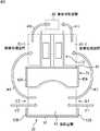
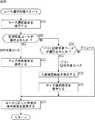
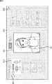
図1は、写真シール作成装置1の外観の構成例を示す斜視図である。<External structure of photo sticker creation device>
[Overall configuration]
FIG. 1 is a perspective view showing a configuration example of the appearance of the photographic
写真シール作成装置1は、撮影や編集等の作業を利用者にゲームとして行わせ、画像を提供するゲーム機である。画像の提供は、シール紙に印刷した形で行われるだけでなく、サーバに送信した画像を利用者の携帯端末上で閲覧可能にする形で行われることもある。写真シール作成装置1はゲームセンターなどの店舗に設置される。 The photo
写真シール作成装置1で遊ぶ利用者は、編集画像の提供を受けるため、自身が被写体となって好みのポーズをとって撮影を行い、撮影によって得られた撮影画像に手書きの文字やスタンプ画像などの合成用画像を合成させるなどして、撮影画像を彩り豊かな画像に編集する。利用者は、編集済みの撮影画像である編集画像が印刷されたシール紙を受け取って一連のゲームを終了させる。 The user who plays with the photo
また、写真シール作成装置1は、証明写真として用いるための画像である証明写真用画像を利用者に提供する機能をも有する。利用者は、写真シール作成装置1の利用を開始するとき、はじめに、編集画像の提供を受けるためのゲームを行うのか、証明写真用画像の提供を受けるためのゲームを行うのかを選択することになる。 The photo
証明写真用画像の提供を受ける利用者は、自身が被写体となって撮影を行い、撮影によって得られた撮影画像の写りを調整することにより、証明写真用画像を生成する。利用者は、証明写真用画像が印刷されたシール紙を受け取って一連のゲームを終了させる。 The user who receives the ID photo image takes a photo of himself / herself as a subject and adjusts the appearance of the captured image obtained by the shooting to generate the ID photo image. The user receives the sticker paper on which the ID photo image is printed and ends the series of games.
編集画像が印刷されたシール紙を受け取ろうとする利用者は、主に2人または3人等の複数人からなる利用者のグループである。証明写真用画像が印刷されたシール紙を受け取ることについても同様に、複数人からなるグループで行うことができる。 The user who wants to receive the sticker sheet on which the edited image is printed is a group of users mainly composed of two or three people. Similarly, receiving a sticker sheet on which an ID photo image is printed can be performed by a group of a plurality of persons.
以下、適宜、写真シール作成装置1に用意されたコースのうち、編集画像の提供を受けるためのコースをプリコース(プリントシールコース)といい、証明写真用画像の提供を受けるためのコースを証明写真コースという。また、編集画像と証明写真用画像の提供を受けるためのコースをプリ+証明写真コースという。 Hereinafter, of courses prepared in the photo
プリコースの一連の処理には、好みのポーズをとって行う撮影と、その撮影によって得られた撮影画像の編集と、編集によって得られた編集画像の印刷が含まれる。撮影画像の編集には、被写体の明るさや肌の色などの写りを調整する処理(画像補正処理)の他に、あらかじめ用意された編集ツールを用いた所定の合成用画像を、編集対象の撮影画像上の、タッチペンなどによって利用者により指示された位置に合成する処理が含まれる。 The series of pre-course processing includes shooting performed with a desired pose, editing of a captured image obtained by the shooting, and printing of an edited image obtained by editing. For editing the shot image, in addition to the process of adjusting the image of the subject's brightness, skin color, etc. (image correction process), a predetermined composite image using an editing tool prepared in advance is captured. A process of combining the image with a position designated by the user with a touch pen or the like is included.
以下、適宜、編集画像の元になる撮影画像をプリ画像という。編集画像は、プリ画像に編集を施すことによって生成される。 Hereinafter, the captured image that is the basis of the edited image is referred to as a pre-image as appropriate. The edited image is generated by editing the pre-image.
一方、証明写真コースの一連の処理には、証明写真のためにあらかじめ決められたポーズをとって行う撮影と、その撮影によって得られた証明写真用画像の調整と、調整後の証明写真用画像の印刷が含まれる。証明写真用画像の調整には、被写体として写る人物の位置と大きさを調整する処理、および/または肌の明るさや髪の色などの写りを調整する処理がある。 On the other hand, in the series of processes of the ID photo course, the photo taken with a predetermined pose for the ID photo, the adjustment of the ID photo image obtained by the shooting, and the ID photo image after adjustment Printing is included. The adjustment of the ID photo image includes a process of adjusting the position and size of a person shown as a subject and / or a process of adjusting the image of skin brightness, hair color, and the like.
プリ+証明写真コースには、プリコースの処理と証明写真コースの処理が含まれる。 The pre + ID photo course includes pre-course processing and ID photo course processing.
図1に示すように、写真シール作成装置1は、撮影ユニット11と画像処理ユニット12が接した状態で設置されることによって構成される。 As shown in FIG. 1, the photo
撮影ユニット11は、撮影部21と背景部22から構成される。撮影部21と背景部22は離して設置され、撮影部21と背景部22の間に設けられる空間が、利用者が撮影を行う撮影空間となる。 The photographing
撮影部21は、利用者を被写体とした撮影処理を行う装置である。撮影部21は、撮影空間に入った利用者が撮影処理を行うために向く方向である正面に位置する。撮影空間に臨む撮影部21の正面には、カメラや各種の操作に用いられるタッチパネルモニタなどが設けられる。撮影空間にいる利用者から見て右側の面を右側面、左側の面を左側面とすると、撮影部21の右側面が側面パネル42Aにより構成され、左側面が側面パネル42B(図3)により構成される。 The photographing
背景部22は、正面を向いて撮影を行っている利用者の背面側に位置する板状の部材である背面パネル51、背面パネル51の右端に取り付けられ、側面パネル42Aより横幅の狭い板状の部材である側面パネル52A、および、背面パネル51の左端に取り付けられ、側面パネル42Bより横幅の狭い板状の部材である側面パネル52B(図3)から構成される。 The
撮影部21の右側面を構成する側面パネル42Aと背景部22の側面パネル52Aは、ほぼ同一平面に設けられる。側面パネル42Aと側面パネル52Aは、上部が板状の部材である連結部23Aによって連結され、下部が、床面に設けた例えば金属製の部材である連結部23A’によって連結される。撮影部21の左側面を構成する側面パネル42Bと背景部22の側面パネル52Bも同様に、ほぼ同一平面に設けられ、上部において連結部23Bによって連結され、下部において、床面に設けた金属製の部材である連結部23B’(図示せず)によって連結される。 The
撮影部21の側面パネル42A、連結部23A、および背景部22の側面パネル52Aに囲まれることによって形成される開口が撮影空間の出入り口となる。また、撮影部21の側面パネル42B、連結部23B、および背景部22の側面パネル52Bに囲まれることによって形成される開口も撮影空間の出入り口となる。撮影空間の内部には床材27が設置される。利用者は、撮影空間に入り、床材27の上に立って撮影を行うことになる。 An opening formed by being surrounded by the
背景部22の上部には、背面パネル51、側面パネル52A、および側面パネル52Bに支持される形で背景カーテンユニット25が設けられる。背景カーテンユニット25には、クロマキー用の緑色の背景に利用される巻き取り式の背景カーテンが収納される。背景カーテンユニット25は、撮影部21に設けられたカメラ等による撮影と連動して動作し、撮影の際に、カーテンを下ろし、撮影が終了したらカーテンを巻き取る。なお、前記背景カーテンの代わりに、または、前記背景カーテンに加え、色または模様の異なる、背景に利用される巻き取り式の背景カーテンが複数収納されるようにし、背景カーテンユニット25が、撮影部21に設けられたカメラ等による撮影と連動して動作し、撮影の際に、例えば利用者により選択された色のカーテンを下ろし、その他のカーテンを巻き取るようにしてもよい。なお、カーテンを背面パネル51に貼り付けてもよい。 The
背面パネル51の上方には、LED表示灯やLCDなどよりなる表示灯53が設けられる。表示灯53には、撮影空間でいま行われている撮影が、プリ画像の撮影であるのか、証明写真用画像の撮影であるのかを表す情報が表示される。なお、表示灯53の設置場所は、背面パネル51の上方に限らず、利用しようとする顧客あるいは店舗の従業員から見える位置であればどの場所であってもよい。 Above the
「証明写真撮影中」などのような、証明写真用画像の撮影が行われていることを表す情報が表示されることにより、証明写真用画像の撮影機能が写真シール作成装置1に搭載されていることをアピールすることができる。 By displaying information indicating that the ID photo image is being taken, such as “ID photo is being taken”, the photo sticker image shooting function is installed in the photo
撮影空間の上方には、撮影部21の正面、連結部23A、連結部23B、および背景カーテンユニット25に囲まれる開口が形成され、その開口の一部を覆うように天井ストロボユニット24が設けられる。天井ストロボユニット24の一端が連結部23Aに固定され、他端が連結部23Bに固定される。天井ストロボユニット24は、撮影に合わせて撮影空間内に向けて光を照射するストロボを内蔵する。天井ストロボユニット24の内部には、ストロボの他に蛍光灯が設けられており、撮影空間の照明としても機能する。 Above the photographing space, an opening surrounded by the front of the photographing
画像処理ユニット12は、プリ画像の編集処理、および証明写真用画像の調整処理を行う装置である。以下、適宜、プリ画像の編集と証明写真用画像の調整を区別する必要がない場合、まとめて画像処理という。 The
画像処理ユニット12は、一方の側面が撮影部21の背面に接するように撮影ユニット11に連結して設けられる。画像処理ユニット12には、画像処理時に利用者により用いられるタブレット内蔵モニタなどの構成が設けられる。 The
図1に一部が見える画像処理ユニット12の構成を正面側の構成とすると、2組の利用者が同時に画像処理を行うことができるように、画像処理ユニット12の正面側と背面側には画像処理に用いられる構成がそれぞれ設けられる。 If the configuration of the
画像処理ユニット12の正面側は、床面に対して垂直な面であり、側面パネル42Aとほぼ平行な面である面71と、面71の上方に形成された斜面72から構成される。斜面72には、画像処理の作業に用いられる構成が設けられる。斜面72の右側には、照明装置74(図2)の一端を支持する柱状の支持部73Aが設けられる。斜面72の左側にも、照明装置74の他端を支持する柱状の支持部73B(図2)が設けられる。支持部73Aの右側には、画像処理ユニット12の側面を構成する板状のパネル73Cが設けられる。パネル73Cの上面にはカーテンレール26を支持する支持部75が設けられる。 The front side of the
画像処理ユニット12の上方にはカーテンレール26が取り付けられる。カーテンレール26は、3本のレール26A乃至26Cを、上から見たときの形状がコの字状となるように組み合わせることによって構成される。平行に設けられるレール26Aとレール26Bの一端は、連結部23Aと連結部23Bにそれぞれ固定され、他端にレール26Cの両端が接合される。 A
カーテンレール26には、画像処理ユニット12の正面前方の空間と背面前方の空間の内部が外から見えないようにカーテンが取り付けられる。カーテンレール26に取り付けられたカーテンにより囲まれる画像処理ユニット12の正面前方の空間と背面前方の空間が、利用者がプリ画像の編集を行ったり、証明写真用画像の調整を行ったりする画像処理空間となる。 A curtain is attached to the
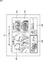
図2は、写真シール作成装置1を別の角度から見た斜視図である。 FIG. 2 is a perspective view of the photo
後述するように、画像処理ユニット12の右側面には、タブレット内蔵モニタや、印刷済みのシール紙が排出されるシール紙排出口などが設けられる。画像処理ユニット12の側面に設けられるタブレット内蔵モニタは、画像の印刷が終わるのを待っている利用者が事後接客機能を利用するときに用いられる。事後接客機能には、編集画像や証明写真用画像をサーバに送信する機能などが含まれる。画像処理ユニット12の右側面前方の空間が、利用者が事後接客機能を利用する事後接客空間となる。 As will be described later, the right side surface of the
ここで、写真シール作成ゲームの流れと、それに伴う利用者の移動について説明する。いずれのコースの場合も、利用者の移動は同じである。 Here, the flow of the photo sticker creation game and the accompanying movement of the user will be described. In any course, the movement of the user is the same.
図3は、写真シール作成装置1を上から見た平面図である。 FIG. 3 is a plan view of the photo
写真シール作成装置1の利用者は、白抜き矢印#1で示すように出入り口G1から、または白抜き矢印#2で示すように出入り口G2から、撮影部21と背景部22の間に形成された撮影空間A1に入り、コースを選択した後、撮影部21に設けられたカメラやタッチパネルモニタなど利用してコースに応じた撮影を行う。 The user of the photo
撮影を終えた利用者は、白抜き矢印#3で示すように出入り口G1を使って撮影空間A1から出て画像処理空間A2−1に移動するか、白抜き矢印#4で示すように出入り口G2を使って撮影空間A1から出て画像処理空間A2−2に移動する。 The user who has finished shooting uses the doorway G1 to move out of the shooting space A1 as indicated by the
画像処理空間A2−1は、画像処理ユニット12の正面側の画像処理空間であり、画像処理空間A2−2は、画像処理ユニット12の背面側の画像処理空間である。画像処理空間A2−1と画像処理空間A2−2のいずれの空間に移動するのかが、撮影部21のタッチパネルモニタの画面表示などによって案内される。例えば2つの画像処理空間のうちの空いている方の空間が移動先として案内される。 The image processing space A2-1 is an image processing space on the front side of the
画像処理空間A2−1または画像処理空間A2−2に移動した利用者は、プリコースを選択している場合にはプリ画像の編集を開始し、証明写真コースを選択している場合には証明写真用画像の調整を開始する。プリ+証明写真コースを選択している場合にはその両方を行う。画像処理空間A2−1の利用者と、画像処理空間A2−2の利用者は同時に画像処理を行うことができる。 The user who has moved to the image processing space A2-1 or the image processing space A2-2 starts editing the pre-image when the pre-course is selected, and proves when the ID photo course is selected. Start adjusting the photo image. If you have selected the pre + ID photo course, do both. A user of the image processing space A2-1 and a user of the image processing space A2-2 can perform image processing at the same time.
画像処理が終了した後、編集画像や証明写真用画像の印刷が開始される。画像の印刷中、画像処理空間A2−1での画像処理を終えた利用者は、白抜き矢印#5で示すように画像処理空間A2−1から事後接客空間A3に移動して事後接客機能を利用する。また、画像処理空間A2−2での画像処理を終えた利用者は、白抜き矢印#6で示すように画像処理空間A2−2から事後接客空間A3に移動して事後接客機能を利用する。 After the image processing is finished, printing of the edited image and the ID photo image is started. During image printing, the user who has finished the image processing in the image processing space A2-1 moves from the image processing space A2-1 to the post-service space A3 as shown by the
画像の印刷が終了したとき、利用者は、シール紙排出口からシール紙を受け取り、一連の写真シール作成ゲームを終えることになる。 When the printing of the image is finished, the user receives the sticker paper from the sticker paper outlet and finishes a series of photo sticker creation games.
[撮影部の構成]
図4は、撮影部21の正面の構成例を示す図である。[Configuration of shooting section]
FIG. 4 is a diagram illustrating a configuration example of the front of the photographing
撮影部21は、正面パネル41、側面パネル42A、および側面パネル42Bが、箱状の形状を有するベース部43に取り付けられることによって構成される。 The photographing
正面パネル41の中央からやや上側には撮影・表示ユニット81が設けられる。撮影・表示ユニット81は、カメラ91、タッチパネルモニタ92、および正面ストロボ93から構成される。 A photographing /
カメラ91は、例えば一眼レフカメラであり、レンズが露出するように撮影・表示ユニット81の内部に取り付けられる。カメラ91はCCD(Charge Coupled Device)などの撮像素子を有し、撮影空間A1にいる利用者を撮影する。カメラ91により取り込まれた動画は、タッチパネルモニタ92にリアルタイムで表示される。 The
カメラ91の下に設けられたタッチパネルモニタ92は、LCD(Liquid Crystal Display)などのモニタと、それに積層されたタッチパネルにより構成される。タッチパネルモニタ92は、カメラ91により取り込まれた動画の少なくとも一部を表示するライブビューモニタとしての機能と、各種のGUI(Graphical User Interface)画像を表示し、利用者の選択操作をタッチパネルにより受け付ける機能とを備えている。タッチパネルモニタ92には、適宜、カメラ91により取り込まれた動画(ライブビュー)や撮影画像が表示される。 A touch panel monitor 92 provided under the
カメラ91の上側および左右を半円状の乳白アクリル板よりなる発光面で囲む正面ストロボ93は、カメラ91による撮影に合わせて発光し、被写体としての利用者の顔付近を正面から照射する。 A
撮影・表示ユニット81の上方には、曲面の発光面を利用者に向けた右上ストロボ82および左上ストロボ83が設置される。右上ストロボ82および左上ストロボ83は、カメラ91による撮影に合わせて発光することで、上方から利用者を照射する。 Above the photographing /
ベース部43の正面には利用者の足元を照射する足元ストロボ84が設けられる。足元ストロボ84の右側には、利用者が硬貨を入れる硬貨投入返却口85が設けられる。 A
ベース部43の上面には、足元ストロボ84の上面を挟んでスペース43Aおよび43Bが左右に形成される。スペース43Aおよび43Bは、撮影を行う利用者が手荷物等を置くための荷物置き場として用いられる。正面パネル41の例えば天井付近には、撮影処理の案内音声、BGM(Back Ground Music)、効果音等の音を出力するスピーカも設けられる。 On the upper surface of the
[背景部の構成]
図5は、背景部22の撮影空間A1側の構成例を示す図である。[Configuration of the background]
FIG. 5 is a diagram illustrating a configuration example of the
背面パネル51の上方には背景カーテンユニット25が設けられる。背景カーテンユニット25のほぼ中央には、撮影空間A1内で撮影処理を行っている利用者を後方中央から照射する背面中央ストロボ101が取り付けられる。 A
背面パネル51の出入り口G1側の位置には、撮影空間A1内で撮影処理を行っている利用者を右後方から照射する背面右ストロボ102が取り付けられる。また、背面パネル51の出入り口G2側の位置には、撮影空間A1内で撮影処理を行っている利用者を左後方から照射する背面左ストロボ103が取り付けられる。 A rear
[撮影空間の区画構成]
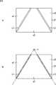
図6は、床材27の平面図である。図6の上方が撮影部21の方向となり、下方が背景部22の方向となる。[Section space configuration]
FIG. 6 is a plan view of the
図6Aに示すように、床材27には太線L1,L2がプリントされ、太線L1,L2によって、略直角三角形状の区画である区画a1,a2と、略台形状の区画である区画a3が床材27に形成される。 As shown in FIG. 6A, thick lines L1 and L2 are printed on the
図6Bの位置Pをカメラ91の位置とすると、太線L1,L2は、例えば、カメラ91の最大の撮影範囲(画角)の水平方向の両端を示す線である。太線L1より左側にある区画a1内の位置と太線L2より右側にある区画a2内の位置は、カメラ91に映らない位置である。 When the position P in FIG. 6B is the position of the
例えば、利用者が複数人であり、証明写真用画像の撮影が1人ずつ順番に行われる場合、撮影を行っている利用者以外の利用者に対しては、区画a1か区画a2にいることが案内される。すなわち、区画a1と区画a2は、証明写真用画像の撮影を行う利用者以外の待機エリアとなる。床にシート材を敷き、これらの区画をシート材に明示するようにしてもよい。 For example, when there are a plurality of users and the ID photo images are taken one by one in order, the user other than the user who is taking the photo must be in the zone a1 or the zone a2. Will be guided. That is, the sections a1 and a2 are standby areas other than the user who takes the ID photograph image. A sheet material may be laid on the floor, and these sections may be clearly indicated on the sheet material.
これにより、ある利用者の証明写真用画像に他の利用者が写ってしまうことを防ぐことが可能になる。 As a result, it is possible to prevent other users from appearing in the ID photograph image of a certain user.
撮影を行う利用者が入る区画である区画a3内に、証明写真用画像を撮影するときの立ち位置を誘導する表示が設けられるようにしてもよい。立ち位置を誘導する表示は、例えば、足型のマークを床材27に印刷することにより構成される。また、印刷ではなく、LEDなどの発光部材を床材27に設け、それを発光させることによって立ち位置を誘導するようにしてもよい。タッチパネルモニタ92に表示されるライブビューによって立ち位置を誘導することも可能である。 You may make it provide the display which guide | induces the standing position when image | photographing an image for ID photographs in the area a3 which is a area where the user who performs imaging | photography enters. The display for guiding the standing position is configured, for example, by printing a foot-shaped mark on the
[画像処理ユニットの構成]
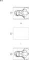
図7は、画像処理ユニット12の背面側(画像処理空間A2−2側)の構成例を示す図である。[Image processing unit configuration]
FIG. 7 is a diagram illustrating a configuration example of the back side (image processing space A2-2 side) of the
斜面72のほぼ中央には、タブレット内蔵モニタ131が設けられる。タブレット内蔵モニタ131を挟んで左側にタッチペン132Aが設けられ、右側にタッチペン132Bが設けられる。 A tablet built-in
タブレット内蔵モニタ131は、タッチペン132Aまたは132Bを用いて操作入力が可能なタブレットがLCDなどのモニタに重畳して設けられることによって構成される。タブレット内蔵モニタ131には、プリコース時には例えば編集画面が表示される。編集画面は、プリ画像の編集に用いられる画面である。2人で同時に編集を行う場合、タッチペン132Aはタブレット内蔵モニタ131に向かって左側にいる利用者により用いられ、タッチペン132Bはタブレット内蔵モニタ131に向かって右側にいる利用者により用いられる。 The tablet built-in
また、タブレット内蔵モニタ131には、証明写真コース時には例えば調整画面が表示される。調整画面は、証明写真用画像の調整に用いられる画面である。 The tablet built-in
図8は、画像処理ユニット12の右側面の構成例を示す図である。 FIG. 8 is a diagram illustrating a configuration example of the right side surface of the
画像処理ユニット12の側面にはタブレット内蔵モニタ161が設けられる。タブレット内蔵モニタ161には、事後接客機能を利用するときに用いられる画面が表示される。 A tablet built-in
タブレット内蔵モニタ161の下には、事後接客機能の案内音声、BGM、効果音等などを出力するスピーカ162が設けられる。スピーカ162の下にはシール紙排出口163が設けられる。画像処理ユニット12の内部にはプリンタが設けられており、編集画像や証明写真用画像が所定のレイアウトでシール紙に印刷され、シール紙排出口163から排出される。 Below the tablet built-in
<シール紙の例>
図9は、編集画像が印刷されたシール紙の例を示す図である。<Example of sticker paper>
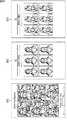
FIG. 9 is a diagram illustrating an example of a sticker sheet on which an edited image is printed.
図9Aは、6枚の編集画像が2行3列のレイアウトに配置されて印刷されたシール紙を示し、図9Bは、6枚の編集画像が3行2列のレイアウトに配置されて印刷されたシール紙を示す。 FIG. 9A shows a sticker sheet in which six edited images are arranged and printed in a layout of 2 rows and 3 columns, and FIG. 9B is a printed sheet of 6 edited images arranged in a layout of 3 rows and 2 columns. Shows sticker paper.
6枚の編集画像は、それぞれ、2人の利用者が異なる構図で写る6種類の画像である。プリコース時には、例えば静止画であるプリ画像の撮影が6回行われ、6枚のプリ画像に対してそれぞれ編集が施された後、シール紙に印刷される。図9の例においては、それぞれの編集画像は若干傾いて印刷されている。 Each of the six edited images is six types of images in which two users are captured in different compositions. During the pre-course, for example, a pre-image that is a still image is shot six times, and each of the six pre-images is edited and then printed on a sticker sheet. In the example of FIG. 9, each edited image is printed with a slight inclination.
プリ画像に写る利用者の背景には所定の色や模様の画像である背景画像が合成され、前景には、手書きの文字やスタンプ画像などの合成用画像が合成される。例えば図9Aの6枚のうちの上段左端の編集画像に含まれる「Love my friend」の文字は手書きの文字であり、下段中央の編集画像に含まれるハート型の画像はスタンプ画像である。 A background image, which is an image of a predetermined color or pattern, is synthesized with the background of the user shown in the pre-image, and a synthesis image such as a handwritten character or a stamp image is synthesized with the foreground. For example, the letters “Love my friend” included in the upper leftmost edited image of the six images in FIG. 9A are handwritten characters, and the heart-shaped image included in the lower middle image is a stamp image.
シール紙の縁の余白領域には、機種名、撮影日の他に、メールアドレスとIDが印刷される。余白領域に印刷されたメールアドレスとIDは、サーバに送信された編集画像を携帯電話機などの携帯端末で閲覧するときに利用される。 In the margin area at the edge of the sticker paper, the e-mail address and ID are printed in addition to the model name and shooting date. The mail address and ID printed in the blank area are used when viewing the edited image transmitted to the server on a portable terminal such as a cellular phone.
図10は、シール紙に印刷される編集画像のレイヤ構造の例を示す図である。 FIG. 10 is a diagram illustrating an example of a layer structure of an edited image printed on sticker paper.
編集画像P1は、背景画像P11、撮影画像P12、前景画像P13の各レイヤから構成される。図10の背景画像P11は、所定の色の地にハートや星などの模様が表された画像であり、前景画像P13は、落書きによって入力された「Love my friend」の手書き文字を含む画像である。 The edited image P1 is composed of layers of a background image P11, a captured image P12, and a foreground image P13. The background image P11 in FIG. 10 is an image in which a pattern such as a heart or a star is represented on a ground of a predetermined color, and the foreground image P13 is an image including a handwritten character “Love my friend” input by graffiti. is there.
編集画像P1は、撮影画像P12の被写体の領域を背景画像P11に重ね、その上に前景画像P13を重ねることによって生成される。 The edited image P1 is generated by superimposing the subject area of the photographed image P12 on the background image P11 and overlaying the foreground image P13 thereon.
図11は、証明写真用画像が印刷されたシール紙の例を示す図である。 FIG. 11 is a diagram illustrating an example of sticker paper on which an ID photo image is printed.
図11のシール紙は、6枚の証明写真用画像が2行3列のレイアウトに配置されて印刷されたシール紙である。 The sticker sheet of FIG. 11 is a sticker sheet on which six ID photo images are arranged and printed in a 2 × 3 layout.
6枚の証明写真用画像は、1人の利用者の、略胸から上、頭より若干上までの範囲がほぼ中央に写る、構図が同じ1種類の画像である。証明写真コース時には、例えば証明写真用画像の撮影が4回行われ、4枚の証明写真用画像の中から選択された1枚に対して調整が施され、シール紙に印刷される。 The six ID photograph images are one type of image having the same composition in which a range from approximately the chest to the top and slightly above the head of one user appears in the center. During the ID photo course, for example, ID photo images are taken four times, and one selected from the four ID photo images is adjusted and printed on sticker paper.
シール紙の左下には、金額、日にちなどからなる領収証が印刷され、右下には、証明写真用画像の使い方などに関する注意書きが印刷される。注意書きの下には、サーバに送信された証明写真用画像を携帯電話機で閲覧するときに利用されるメールアドレスとIDが印刷される。 A receipt including the amount and date is printed on the lower left of the sticker paper, and a cautionary note on how to use the ID photo image is printed on the lower right. Under the notice, the e-mail address and ID used to view the ID photo image sent to the server on the mobile phone are printed.
以下、適宜、編集画像または証明書用画像を携帯電話機で見ることができるようにサーバに送信する仕組みのことを「携帯送信」という。 Hereinafter, a mechanism for appropriately transmitting an edited image or certificate image to a server so that it can be viewed on a mobile phone is referred to as “portable transmission”.
利用者は、シール紙に印刷された証明写真用画像をはさみなどで切り取り、履歴書などの書類に貼り付けて使うことになる。印刷媒体がシール紙であるから、履歴書などに貼り付けるときに糊付けが不要となる。 The user cuts the ID photo image printed on the sticker paper with scissors and pastes it on a document such as a resume. Since the printing medium is sticker paper, no gluing is required when pasting on a resume or the like.
図12は、シール紙に印刷される証明写真用画像のレイヤ構造の例を示す図である。 FIG. 12 is a diagram illustrating an example of a layer structure of an ID photo image printed on a sticker sheet.
証明写真用画像P21は、背景画像P31と証明写真用画像P32の各レイヤから構成される。図12の背景画像P31は、所定の色の無地の画像であり、プリコース時に用いられる背景画像にあるような模様などは含まれない。 The ID photo image P21 includes layers of a background image P31 and an ID photo image P32. The background image P31 in FIG. 12 is a solid image of a predetermined color, and does not include a pattern or the like as in the background image used during pre-course.
証明写真用画像P21は、証明写真用画像P32の被写体の背景となる領域に背景画像P31を合成することによって生成される。 The ID photo image P21 is generated by synthesizing the background image P31 with an area that is the background of the subject of the ID photo image P32.
以上のような外観構成を有する写真シール作成装置1によっては、このような編集画像が印刷されたシール紙、あるいは証明写真用画像が印刷されたシール紙が生成される。また、プリ+証明写真コースが選択された場合、編集画像と証明写真用画像が混在して印刷されたシール紙が生成されることもある。なお、編集画像や証明写真用画像がシール紙に印刷されるものとしたが、特に、証明写真用画像が印刷される印刷媒体は、シール紙に限らず、写真が印刷可能な写真用紙とすることができる。 Depending on the photographic
<写真シール作成装置の内部構成>
[ハードウェア構成]
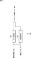
図13は、写真シール作成装置1の内部の構成例を示すブロック図である。上述した構成と同じ構成には同じ符号を付してある。重複する説明については適宜省略する。<Internal configuration of photo sticker creation device>
[Hardware configuration]
FIG. 13 is a block diagram illustrating an internal configuration example of the photo
制御部201はCPU(Central Processing Unit)などよりなり、ROM(Read Only Memory)206や記憶部202に記憶されているプログラムを実行し、写真シール作成装置1の全体の動作を制御する。制御部201には、記憶部202、通信部203、ドライブ204、ROM206、RAM(Random Access Memory)207が接続される。制御部201には、撮影部208、画像処理部209A、画像処理部209B、および事後接客部210の各構成も接続される。 The
記憶部202は、ハードディスクやフラッシュメモリなどの不揮発性の記憶媒体からなり、制御部201から供給された各種の設定情報等を記憶する。記憶部202に記憶されている情報は制御部201により適宜読み出される。 The
通信部203は、インターネットなどのネットワークのインタフェースであり、制御部201による制御に従って外部の装置と通信を行う。通信部203は、編集画像や証明写真用画像をサーバに送信する。 A
ドライブ204には、光ディスクや半導体メモリなどよりなるリムーバブルメディア205が適宜装着される。ドライブ204によりリムーバブルメディア205から読み出されたコンピュータプログラムやデータは、制御部201に供給され、記憶部202に記憶されたり、インストールされたりする。 A
ROM206には、制御部201において実行されるプログラムやデータが記憶されている。RAM207は、制御部201が処理するデータやプログラムを一時的に記憶する。 The
制御部201には表示灯53も接続される。制御部201は、利用者により選択されたコースに応じて表示灯53の表示を切り替える。 An
撮影部208は、撮影空間A1にいる利用者を対象とした撮影処理を行う。撮影部208は、硬貨処理部221、背景制御部222、照明装置223、カメラ91、タッチパネルモニタ92、およびスピーカ224から構成される。 The photographing
硬貨処理部221は、硬貨投入返却口85に対する硬貨の投入を検出する。硬貨処理部221は、400円などの所定の金額分の硬貨が投入されたことを検出した場合、そのことを表す起動信号を制御部201に出力する。 The
背景制御部222は、制御部201より供給される背景制御信号に従って背景カーテンユニット25を制御し、背景カーテンの上げ下げを行う。背景カーテンの上げ下げが利用者により手動で行われるようにしてもよい。 The
例えば、証明写真用画像の撮影時とプリ画像の撮影時とで、異なる背景カーテンが用いられる。 For example, different background curtains are used when the ID photograph image is taken and when the pre-image is taken.
照明装置223は、制御部201から供給される照明制御信号に従って、撮影空間A1内の各ストロボの発光を制御する。撮影空間A1には、天井ストロボユニット24のストロボの他に、撮影部21の右上ストロボ82、左上ストロボ83、足元ストロボ84、正面ストロボ93、背景部22の背面中央ストロボ101、背面右ストロボ102、背面左ストロボ103が設けられる。 The
カメラ91は、制御部201による制御に従って撮影を行い、撮影によって得られた画像を制御部201に出力する。 The
画像処理部209Aは、画像処理空間A2−1にいる利用者を対象とした画像処理を行う。画像処理部209Aは、タブレット内蔵モニタ131、タッチペン132A,132B、およびスピーカ231から構成される。画像処理部209Bは、画像処理部209Aと同一の構成を有しており、画像処理空間A2−2にいる利用者を対象とした画像処理を行う。 The
タブレット内蔵モニタ131は、制御部201による制御に従って編集画面または調整画面を表示し、画面に対する利用者の操作を検出する。利用者の操作の内容を表す信号は制御部201に供給され、利用者の操作に応じて画像処理が行われる。 The tablet built-in
事後接客部210は、事後接客空間A3にいる利用者を対象とした事後接客処理を行う。事後接客処理は、事後接客機能を利用者に提供する処理である。事後接客部210は、タブレット内蔵モニタ161、スピーカ162、およびプリンタ241から構成される。プリンタ241にはシール紙ユニット242が装着される。 The subsequent
プリンタ241は、制御部201から供給された印刷データに基づいて、編集画像や証明写真用画像をシール紙ユニット242に収納されているシール紙に印刷し、シール紙排出口163に排出する。制御部201からプリンタ241に対しては、各画像が配置されたイメージデータが印刷データとして供給される。 Based on the print data supplied from the
[制御部の構成]
図14は、図13の制御部201の機能構成例を示すブロック図である。図14に示す機能部のうちの少なくとも一部は、制御部201内のCPUにより所定のプログラムが実行されることによって実現される。[Configuration of control unit]
FIG. 14 is a block diagram illustrating a functional configuration example of the
制御部201においては、撮影管理部301、画像処理管理部302、印刷管理部303、事後接客管理部304、およびシーケンス管理部305が実現される。 In the
撮影管理部301は、撮影部208の各部を制御し、写真シール作成装置1の利用を始める利用者による各種の選択に関する処理や、撮影処理を行う。画像処理管理部302は、画像処理部209A、画像処理部209Bの各部を制御し、画像処理を行う。印刷管理部303は、事後接客部210のプリンタ241を制御し、印刷処理を行う。事後接客管理部304は、事後接客部210のタブレット内蔵モニタ161を制御するなどして事後接客処理を行う。シーケンス管理部305は、利用者が行うゲームの全体のシーケンスを管理する。 The imaging management unit 301 controls each unit of the
図15は、撮影管理部301の構成例を示すブロック図である。 FIG. 15 is a block diagram illustrating a configuration example of the imaging management unit 301.
撮影管理部301は、ガイダンス出力制御部321、表示制御部322、カメラ制御部323、および撮影画像記憶部324から構成される。 The shooting management unit 301 includes a guidance
ガイダンス出力制御部321は、撮影の進め方などを説明するガイダンスの出力を制御する。ガイダンス出力制御部321は、表示制御部322を制御し、撮影の進め方などを説明する画面を表示させたり、音声をスピーカ224から出力させたりする。 The guidance
表示制御部322は、タッチパネルモニタ92の表示を制御する。例えば、表示制御部322は、カメラ制御部323から供給された動画に基づいてライブビューをタッチパネルモニタ92に表示させる。 The
カメラ制御部323は、撮影処理が開始されたとき、カメラ91を制御して動画を撮影する。カメラ制御部323により撮影された動画はライブビューの表示に用いられる。また、カメラ制御部323は、所定のタイミングで静止画の撮影を行い、表示制御部322と撮影画像記憶部324に出力する。表示制御部322に出力された画像は撮影結果の確認に用いられる。 When the shooting process is started, the
撮影画像記憶部324は、カメラ制御部323から供給された画像を記憶する。撮影画像記憶部324にはプリ画像と証明写真用画像が記憶される。撮影画像記憶部324に記憶された画像は、編集処理の開始時、または調整処理の開始時に画像処理管理部302により読み出される。 The captured
図16は、画像処理管理部302の構成例を示すブロック図である。 FIG. 16 is a block diagram illustrating a configuration example of the image
画像処理管理部302は、ガイダンス出力制御部331、表示制御部332、編集部333、調整部334、および画像記憶部335から構成される。 The image
ガイダンス出力制御部331は、編集や調整の進め方などを説明するガイダンスの出力を制御する。ガイダンス出力制御部331は、表示制御部332を制御し、編集や調整の進め方などを説明する画面を表示させたり、音声をスピーカ231から出力させたりする。 The guidance
表示制御部332は、タブレット内蔵モニタ131の表示を制御する。例えば、表示制御部332は、プリコースを選択した利用者が撮影を終えた場合には編集画面をタブレット内蔵モニタ131に表示させ、証明写真コースを選択した利用者が撮影を終えた場合には調整画面をタブレット内蔵モニタ131に表示させる。 The
編集部333は、プリ画像の編集(落書き)を行う。プリ画像の編集は、利用者の操作に応じて、手書きの文字やスタンプ画像などの合成用画像をプリ画像に重ねるなどして進められる。タブレット内蔵モニタ131からは、利用者の操作の内容を表す信号が供給される。編集部333による処理の結果は表示制御部332に供給され、編集画面に表示される。編集部333は、編集済みのプリ画像である編集画像を画像記憶部335に出力する。 The
調整部334は、証明写真用画像の調整を行う。証明写真用画像の調整は、利用者の操作に応じて、被写体の位置、明るさ、背景画像の色を変えるなどして進められる。タブレット内蔵モニタ131からは、利用者の操作の内容を表す信号が供給される。調整部334による処理の結果は表示制御部332に供給され、調整画面に表示される。調整部334は、調整済みの証明写真用画像を画像記憶部335に出力する。 The
画像記憶部335は、編集部333から供給された編集画像、または調整部334から供給された証明写真用画像を記憶する。画像記憶部335に記憶された画像は、印刷処理の開始時に印刷管理部303により読み出される。 The
図17は、印刷管理部303の構成例を示すブロック図である。 FIG. 17 is a block diagram illustrating a configuration example of the
印刷管理部303は、印刷データ生成部341とプリンタ制御部342から構成される。 The
印刷データ生成部341は、プリコースの印刷処理の開始時、画像記憶部335に記憶されている編集画像を読み出し、所定のレイアウトに配置することによってイメージデータを生成する。また、印刷データ生成部341は、証明写真コースの印刷処理の開始時、画像記憶部335に記憶されている証明写真用画像を読み出し、所定のレイアウトに配置することによってイメージデータを生成する。 The print
印刷データ生成部341は、プリ+証明写真コースの印刷処理の開始時、画像記憶部335に記憶されている編集画像と証明写真用画像を読み出し、所定のレイアウトに配置することによってイメージデータを生成する。 The print
印刷データ生成部341は、生成したイメージデータを印刷データとしてプリンタ制御部342に出力する。 The print
プリンタ制御部342は、プリンタ241を制御し、印刷データ生成部341により生成された印刷データに基づいて画像をシール紙に印刷させる。 The
図18は、事後接客管理部304の構成例を示すブロック図である。 FIG. 18 is a block diagram illustrating a configuration example of the post-service
事後接客管理部304は、表示制御部351と通信制御部352から構成される。 The subsequent customer
表示制御部351は、タブレット内蔵モニタ161の表示を制御する。例えば、表示制御部351は、携帯送信の機能を利用することが選択された場合、利用者が使う携帯端末のメールアドレスの入力画面をタブレット内蔵モニタ161に表示させる。 The
通信制御部352は、通信部203を制御し、編集画像や証明写真用画像をサーバに送信する。また、通信制御部352は、利用者により入力されたメールアドレスをサーバに送信する。 The
<写真シール作成装置の動作>
次に、以上のような構成を有する写真シール作成装置1の動作について説明する。<Operation of photo sticker creation device>
Next, the operation of the photo
[シール作成ゲーム提供処理]
はじめに、図19のフローチャートを参照して、シール作成ゲームを提供する写真シール作成装置1の一連の処理について説明する。[Seal creation game provision processing]
First, a series of processing of the photo
ステップS1において、写真シール作成装置1の撮影管理部301は、コース選択処理を行う。コース選択処理においては、証明写真コース、プリコース、プリ+証明写真コースのうちのいずれかのコースが選択される。 In step S1, the photographing management unit 301 of the photo
ステップS2において、撮影管理部301は、ステップS1のコース選択処理によって証明写真コースが選択されたか否かを判定する。 In step S2, the photographing management unit 301 determines whether or not the ID photo course has been selected by the course selection process in step S1.
証明写真コースが選択されたとステップS2において判定した場合、ステップS3において、撮影管理部301は、証明写真コースの撮影処理を行う。 If it is determined in step S2 that the ID photo course has been selected, in step S3, the shooting management unit 301 performs the ID photo course shooting process.
ステップS4において、画像処理管理部302は、画像処理空間A2−1と画像処理空間A2−2のうち、撮影を終えた利用者の移動先とした方の画像処理空間に対応する画像処理部209Aまたは画像処理部209Bを制御して証明写真コースの調整処理を行う。 In step S4, the image
ステップS5において、印刷管理部303は、証明写真コースの印刷処理を行う。印刷処理により、調整後の証明写真用画像が所定のレイアウトに従ってシール紙に印刷される。 In step S <b> 5, the
ステップS6において、事後接客管理部304は、画像処理空間A2−1または画像処理空間A2−2から事後接客空間A3に移動してきた利用者に対する証明写真コースの事後接客処理を行う。事後接客管理部304は、証明写真用画像を携帯端末に送信する処理を事後接客処理として行う。 In step S6, the post-service
印刷が終了したとき、証明写真用画像が印刷されたシール紙はシール紙排出口163に排出される。事後接客処理を終えた利用者は、シール紙排出口163からシール紙を取り出して一連のゲームを終える。 When printing is completed, the sticker paper on which the ID photo image is printed is discharged to the sticker paper discharge port 163. The user who has completed the customer service process after taking out the sticker paper from the sticker paper outlet 163 finishes the series of games.
一方、証明写真コースが選択されていないとステップS2において判定した場合、ステップS7において、撮影管理部301は、プリ+証明写真コースが選択されたか否かを判定する。 On the other hand, if it is determined in step S2 that the ID photo course has not been selected, in step S7, the shooting management unit 301 determines whether or not the pre + ID photo course has been selected.
プリ+証明写真コースが選択されたとステップS7において判定した場合、ステップS8において、撮影管理部301は、プリ+証明写真コースの撮影処理を行う。プリ+証明写真コースの撮影処理においては、プリ画像と証明写真用画像の両方の画像が撮影される。 When it is determined in step S7 that the pre + certification photo course has been selected, in step S8, the photographing management unit 301 performs a photographing process for the pre + certification photo course. In the shooting process of the pre + ID photo course, both the pre image and the ID photo image are taken.
ステップS9において、画像処理管理部302は、プリ+証明写真コースを選択した1グループの利用者に、画像処理空間A2−1と画像処理空間A2−2の両方の画像処理空間を使って編集/調整処理を行わせるか否かを判定する。編集/調整処理においては、プリ画像の編集が行われるとともに、証明写真用画像の調整が行われる。 In step S9, the image
後述するように、プリ+証明写真コースにおいては、撮影処理を終えた利用者が複数人からなるグループであり、撮影処理が終わったタイミングなどの所定のタイミングで、画像処理空間A2−1と画像処理空間A2−2の両方の画像処理空間が空いている場合、画像処理空間A2−1と画像処理空間A2−2に分かれてそれぞれ別々に編集/調整処理を行うことができるようになされている。 As will be described later, in the pre + certification photo course, the user who has finished the shooting process is a group of a plurality of users, and the image processing space A2-1 and the image are at a predetermined timing such as the timing at which the shooting process is completed. When both image processing spaces of the processing space A2-2 are vacant, the image processing space A2-1 and the image processing space A2-2 are divided so that editing / adjustment processing can be performed separately. .
画像処理空間A2−1と画像処理空間A2−2の両方の画像処理空間を使って編集/調整処理を行わせないとステップS9において判定した場合、ステップS10において、画像処理管理部302は、画像処理空間A2−1と画像処理空間A2−2のうち、撮影を終えた利用者の移動先とした方の画像処理空間に対応する画像処理部209Aまたは画像処理部209Bを制御してプリ+証明写真コースの第1の編集/調整処理を行う。後述するように、プリ+証明写真コースの第1の編集/調整処理は、画像処理空間A2−1と画像処理空間A2−2のうちのいずれかの画像処理空間を使って、プリ画像の編集と証明写真用画像の調整を行う処理である。 When it is determined in step S9 that the editing / adjustment process is not performed using both the image processing spaces A2-1 and A2-2, in step S10, the image
ステップS11において、印刷管理部303は、プリ+証明写真コースの第1の印刷処理を行う。第1の印刷処理により、編集画像と調整後の証明写真用画像が所定のレイアウトに従ってシール紙に印刷される。 In step S <b> 11, the
一方、画像処理空間A2−1と画像処理空間A2−2の両方の画像処理空間を使って編集/調整処理を行わせるとステップS9において判定した場合、ステップS12において、画像処理管理部302は、撮影を終えた利用者の移動先とした両方の画像処理空間に対応する画像処理部209Aと画像処理部209Bを制御してプリ+証明写真コースの第2の編集/調整処理を行う。後述するように、プリ+証明写真コースの第2の編集/調整処理は、画像処理空間A2−1と画像処理空間A2−2の両方の画像処理空間を使ってプリ画像の編集と証明写真用画像の調整を行う処理である。 On the other hand, if it is determined in step S9 that the image processing space A2-1 and the image processing space A2-2 are used to perform editing / adjustment processing, in step S12, the image
ステップS13において、印刷管理部303は、プリ+証明写真コースの第2の印刷処理を行う。第2の印刷処理により、画像処理空間A2−1での作業によって生成された編集画像および調整後の証明写真用画像と、画像処理空間A2−2での作業によって生成された編集画像および調整後の証明写真用画像が、所定のレイアウトに従ってシール紙に印刷される。 In step S <b> 13, the
ステップS14において、事後接客管理部304は、画像処理空間A2−1と画像処理空間A2−2のうちの少なくともいずれかから事後接客空間A3に移動してきた利用者に対するプリ+証明写真コースの事後接客処理を行う。事後接客管理部304は、編集画像と証明写真用画像を携帯端末に送信する処理を事後接客処理として行う。 In step S14, the post-service
印刷が終了したとき、編集画像と証明写真用画像が印刷されたシール紙はシール紙排出口163に排出される。事後接客処理を終えた利用者は、シール紙排出口163からシール紙を取り出して一連のゲームを終える。 When printing is completed, the sticker paper on which the edited image and the ID photo image are printed is discharged to the sticker paper discharge port 163. The user who has completed the customer service process after taking out the sticker paper from the sticker paper outlet 163 finishes the series of games.
一方、プリ+証明写真コースが選択されていないとステップS7において判定された場合、すなわちプリコースが選択された場合、ステップS15において、撮影管理部301は、プリコースの撮影処理を行う。プリコースの撮影処理においてはプリ画像が撮影される。 On the other hand, if it is determined in step S7 that the pre + certification photo course is not selected, that is, if a precourse is selected, in step S15, the photographing management unit 301 performs precourse photographing processing. In the pre-course shooting process, a pre-image is shot.
ステップS16において、画像処理管理部302は、画像処理空間A2−1と画像処理空間A2−2のうち、撮影を終えた利用者の移動先とした方の画像処理空間に対応する画像処理部209Aまたは画像処理部209Bを制御してプリコースの編集処理を行う。編集処理においては、プリ画像の編集が行われる。 In step S <b> 16, the image
ステップS17において、印刷管理部303は、プリコースの印刷処理を行う。印刷処理により、編集画像が所定のレイアウトに従ってシール紙に印刷される。 In step S17, the
ステップS18において、事後接客管理部304は、画像処理空間A2−1または画像処理空間A2−2から事後接客空間A3に移動してきた利用者に対するプリコースの事後接客処理を行う。事後接客管理部304は、編集画像を携帯端末に送信する処理を事後接客処理として行う。 In step S18, the post-service
印刷が終了したとき、編集画像が印刷されたシール紙はシール紙排出口163に排出される。事後接客処理を終えた利用者は、シール紙排出口163からシール紙を取り出して一連のゲームを終える。 When printing is finished, the sticker paper on which the edited image is printed is discharged to the sticker paper discharge port 163. The user who has completed the customer service process after taking out the sticker paper from the sticker paper outlet 163 finishes the series of games.
各ステップの処理は、利用者のグループ数や各グループがゲームを始めたタイミングなどに応じて、適宜、他のステップの処理と並行して行われる。各処理のタイミングがシーケンス管理部305により制御される。 The processing of each step is performed in parallel with the processing of other steps as appropriate according to the number of groups of users, the timing at which each group starts a game, and the like. The sequence management unit 305 controls the timing of each process.
だれがどちらの画像処理空間に移動するのかを、利用者の名前を表示して案内するようにしてもよい。この場合、ステップS1のコース選択処理時などにおいて、利用者に名前を入力させる処理が行われ、証明写真用画像の撮影を行う利用者と名前の紐付けが行われる。撮影した画像と名前を紐付けし、名前だけでなく、利用者の顔の画像を移動の案内画面に表示させるようにしてもよい。 The user's name may be displayed and guided to which image processing space to move to. In this case, in the course selection process of step S1, etc., a process for allowing the user to input a name is performed, and the name is associated with the user who takes the ID photograph image. The captured image and the name may be linked, and not only the name but also the image of the user's face may be displayed on the movement guide screen.
以上のように、利用者は、ゲームセンターなどに設置される写真シール作成装置1を用いて、証明写真用画像の撮影を行うことができる。また、編集画像が印刷されたシール紙を受け取るためのゲームを行ったついでに証明写真用画像の撮影を行うことができるため、専用機が設置されている場所や写真スタジオにわざわざ行く必要がない。 As described above, the user can take an ID photo image using the photo
写真シール作成装置1の主な利用者は女子中高生であるが、女子中高生の中には、証明写真を撮影するための専用機に入りづらいなどの印象を持っている人もいる。ゲームセンターなどに設置される写真シール作成装置1を用いて証明写真用画像を撮影できるようにすることにより、証明写真用画像の撮影を気軽に行うことが可能になる。 The main users of the photo
さらに、編集画像が印刷されたシール紙を受け取るためのゲームに慣れている利用者にとっては、証明写真コースを選択することにより、そのゲームと同じように場所を移動しながら証明写真用画像の撮影や調整を行うことができるため、操作に迷うことなく、証明写真用画像の撮影などを進めることができる。撮影後の調整を、撮影空間A1とは異なる空間で行うことができるため、同じ空間に居続けることに対する抵抗感も少ない。 Furthermore, for users who are accustomed to the game for receiving the sticker paper on which the edited image is printed, by selecting the ID photo course, taking the ID photo image while moving the place in the same way as the game Since it is possible to make adjustments, it is possible to take an ID photo image without losing operation. Since the adjustment after shooting can be performed in a space different from the shooting space A1, there is little resistance to staying in the same space.
撮影空間A1は、複数人で入って撮影を行うことができるような広い空間である。そのような広い空間が確保されていることから、1人がぎりぎり入れるような狭い空間で撮影を行う場合に較べて、入ることに対する抵抗感も少ない。 The shooting space A1 is a large space where a plurality of people can enter and perform shooting. Since such a wide space is ensured, there is less resistance to entering than when shooting in a narrow space where one person can enter.
[コース選択処理]
次に、図20のフローチャートを参照して、図19のステップS1において行われるコース選択処理について説明する。[Course selection process]
Next, the course selection process performed in step S1 of FIG. 19 will be described with reference to the flowchart of FIG.
ステップS31において、撮影管理部301の表示制御部322は、コース選択画面をタッチパネルモニタ92に表示させる。 In step S <b> 31, the
図21は、コース選択画面の例を示す図である。 FIG. 21 is a diagram illustrating an example of a course selection screen.
コース選択画面の上方には「撮りたいコースを選んでね」のメッセージが表示される。メッセージの隣に表示される数字はコースの選択に設定された制限時間である。 A message “Please select the course you want to take” is displayed above the course selection screen. The number displayed next to the message is the time limit set for course selection.
コース選択画面の中央左側には、2人用のプリコースを選択するときに操作される2人用コース選択ボタン401が表示される。2人用コース選択ボタン401の内側には、2人用コースで撮影を行ったときに得られる画像のサンプルが表示される。 On the left side of the center of the course selection screen, a two-person
2人用コース選択ボタン401の右側には、3人用のプリコースを選択するときに操作される長方形のボタンである3人用コース選択ボタン402と、4人用のプリコースを選択するときに操作される長方形のボタンである4人用コース選択ボタン403が縦に並べて表示される。3人用コース選択ボタン402の内側には3人用コースで撮影を行ったときに得られる画像のサンプルが1枚表示され、4人用コース選択ボタン403の内側には4人用コースで撮影を行ったときに得られる画像のサンプルが1枚表示される。 On the right side of the two-person
サンプル画像が表示されることにより、利用者はそれぞれのコースによって得られる画像の画角を確認することができる。図21に示すように、少人数の撮影コースを選択したときに得られる画像より、大人数の撮影コースを選択したときに得られる画像の方が、垂直方向の長さに対する水平方向の長さが長い。 By displaying the sample image, the user can confirm the angle of view of the image obtained by each course. As shown in FIG. 21, the image obtained when the shooting course with a large number of people is selected is longer than the image obtained when the shooting course with a small number of people is selected. Is long.
コース選択画面の下方には、プリ+証明写真コースを選択するときに操作されるボタンであるプリ+証明写真コース選択ボタン404と、証明写真コースを選択するときに操作されるボタンである証明写真コース選択ボタン405が並べて表示される。プリ+証明写真コース選択ボタン404の内側には、証明写真用画像のサンプルと編集画像のサンプルがそれぞれ1枚表示され、証明写真コース選択ボタン405の内側には、証明写真用画像のサンプルが1枚表示される。 Below the course selection screen, a pre + ID photo
このようなコース選択画面を用いて選択されたコースを表す情報は、シーケンス管理部305に供給される。なお、いずれのコースも選択せずに制限時間が経過したとき、例えば2人用のプリコースが自動的に選択される。 Information representing the course selected using such a course selection screen is supplied to the sequence management unit 305. When the time limit has elapsed without selecting any course, for example, a pre-course for two people is automatically selected.
ステップS32において、シーケンス管理部305は、図21のコース選択画面から証明写真コースが選択されたか否かを判定する。 In step S32, the sequence management unit 305 determines whether or not an ID photo course has been selected from the course selection screen in FIG.
証明写真コースが選択されたとステップS32において判定された場合、ステップS33において、表示制御部322は、証明写真用画像のサイズの選択に用いられる画面であるサイズ選択画面をタッチパネルモニタ92に表示させる。 When it is determined in step S32 that the ID photo course has been selected, in step S33, the
図22は、サイズ選択画面の例を示す図である。 FIG. 22 is a diagram illustrating an example of a size selection screen.
サイズ選択画面の上方には「証明写真のサイズを選んでね。」のメッセージが表示され、その下に、証明写真のサイズとして、「履歴書・エントリーシート」用のサイズ(4.0cm×3.0cm)、「パスポート」用のサイズ(4.5cm×3.5cm)、「自動車運転免許」用のサイズ(3.0cm×2.4cm)が表示されている。 At the top of the size selection screen, the message “Choose the size of the ID photo.” Is displayed. Below that, the size of the ID photo, the size for the resume / entry sheet (4.0cm x 3.0cm) ), The size for "passport" (4.5cm x 3.5cm) and the size for "automobile driver's license" (3.0cm x 2.4cm) are displayed.
利用者は、いずれかのサイズを選択する。証明写真用画像の印刷などが、利用者により選択されたサイズに従って行われる。 The user selects one of the sizes. The ID photo image is printed according to the size selected by the user.
このような選択画面に対する利用者の選択内容を表す情報はシーケンス管理部305により管理され、各部に提供される。 Information representing the selection contents of the user for such a selection screen is managed by the sequence management unit 305 and provided to each unit.
一方、証明写真コースが選択されていないとステップS32において判定した場合、ステップS34において、シーケンス管理部305は、プリ+証明写真コースが選択されたか否かを判定する。 On the other hand, when it is determined in step S32 that the ID photo course has not been selected, in step S34, the sequence management unit 305 determines whether or not the pre + ID photo course has been selected.
プリ+証明写真コースが選択されたとステップS34において判定された場合、ステップS35において、表示制御部322は、証明写真用画像を必要とする人数の選択に用いられる人数確認画面をタッチパネルモニタ92に表示させる。 When it is determined in step S34 that the pre + ID photo course has been selected, in step S35, the
図23は、人数確認画面の例を示す図である。 FIG. 23 is a diagram illustrating an example of the number confirmation screen.
人数確認選択画面の上方には「プリ+証明写真コース 証明写真は何人分必要?」のメッセージが表示され、その下に、1人分だけでよいときに操作されるボタン411と、2人分必要であるときに操作されるボタン412が左右に並べて表示される。ボタン411が操作された場合、利用者が複数人いる場合であっても、そのうちの1人が写る証明写真用画像の撮影だけが行われる。 A message “Pre + ID photo course How many ID photos are needed?” Is displayed at the top of the number confirmation selection screen. Below that, a
このように、写真シール作成装置1においては、仮に2人で写真シール作成装置1を利用する場合であっても、そのうちの1人だけが証明写真用画像を受け取るといったような使い方が可能である。例えばプリコースで遊ぼうとして撮影空間A1に入った2人の利用者のうちの1人だけが証明写真用画像を用意する必要があるといったような要求に対応することができる。当然、3人以上の人数で証明写真用画像を撮影することができるようにしてもよい。 As described above, in the photo
図20の説明に戻り、証明写真用画像を必要とする人数が選択された場合、ステップS36において、表示制御部322は、証明写真用画像のサイズの選択に用いられる図22のサイズ選択画面をタッチパネルモニタ92に表示させる。 Returning to the description of FIG. 20, when the number of persons who require the ID photo image is selected, in step S36, the
ステップS33,S36において証明写真用画像のサイズが選択された後、または、プリ+証明写真コースが選択されていない、すなわちプリコースが選択されたとステップS34において判定された場合、ステップS37において、表示制御部322は、利用者が選択したコースに応じた料金の支払いを案内する画面をタッチパネルモニタ92に表示させる。 After the size of the ID photo image is selected in steps S33 and S36, or when it is determined in step S34 that the pre + ID photo course has not been selected, that is, the precourse has been selected, the display in step S37. The
例えば、利用者が選択したコースや人数に応じた料金があらかじめ決められている。表示制御部322は、シーケンス管理部305により管理されている情報に基づいて利用者の選択内容を特定し、特定した内容に応じた料金をタッチパネルモニタ92に表示してその支払いを案内する。証明写真コース、プリコース、およびプリ+証明写真コースの各コースの間で金額を変えることが可能である。 For example, a fee according to the course selected by the user and the number of people is determined in advance. The
シーケンス管理部305は、証明写真コースに応じた所定の料金分の硬貨が投入されたか否かを硬貨処理部221から供給される信号に基づいて判定し、投入されたと判定した場合、コース選択処理を終了させる。その後、図19のステップS1に戻り、それ以降の処理が行われる。 The sequence management unit 305 determines whether or not a predetermined amount of coins according to the ID photo course has been inserted based on a signal supplied from the
証明写真コース、プリコース、およびプリ+証明写真コースのうちのどのコースを選択可能とするのかを写真シール作成装置1のメンテナンス時などに管理者が設定することができるようにしてもよい。 The administrator may be able to set which of the ID photo course, pre-course, and pre + ID photo course can be selected during maintenance of the photo
写真シール作成装置1の設置場所によっては、証明写真コースを選択する利用者がほとんどいないようなこともある。そのような場合に証明写真コースを選択できないようにすることにより、コース選択画面の表示をよりシンプルなものにすることができ、コースを迅速に選択させることが可能になる。 Depending on the installation location of the photo
<証明写真コースの処理>
[証明写真コースの撮影処理]
次に、図24のフローチャートを参照して、図19のステップS3において行われる証明写真コースの撮影処理について説明する。ここでは、証明写真コースが1人用のコースであるものとする。<Processing of ID photo course>
[Photographing process for ID photo course]
Next, the ID photo course shooting process performed in step S3 of FIG. 19 will be described with reference to the flowchart of FIG. Here, it is assumed that the ID photo course is a course for one person.
ステップS51において、撮影管理部301のガイダンス出力制御部321は、表示制御部322を制御し、撮影の仕方を説明する画面をタッチパネルモニタ92に表示させるなどして撮影前ガイダンスを出力する。 In step S51, the guidance
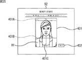
図25は、撮影前ガイダンス画面の例を示す図である。 FIG. 25 is a diagram illustrating an example of a pre-shooting guidance screen.
撮影前ガイダンス画面の略中央には、縦長長方形の領域である画像表示領域431が設けられる。画像表示領域431の横:縦の比は、例えば、図22のサイズ選択画面において選択された証明写真用画像のサイズに応じて切り替わる。 An
撮影前ガイダンス画面の画像表示領域431には、はじめに、モデルとなる人物H1が映る動画が表示される。図25の例においては、人物H1の略胸より上、頭より若干上までの範囲が映っている。画像表示領域431に表示される動画は、人物H1が身だしなみを整える様子の動画である。 In the
動画の表示に合わせて、ガイダンス出力制御部321により、例えば「まずは身だしなみの確認です。前髪は目にかからないように整え、髪型のチェックをしましょう。襟元までしっかり確認し、衣服をまっすぐに整えましょう。」などの音声がスピーカ224から出力される。 In accordance with the video display, the guidance
また、画像表示領域431には、身だしなみを整える様子の動画に続けて、人物H1の略胸より上、頭より若干上までの範囲の静止画が表示される。静止画ではなく、頭の位置などを調整する様子の人物H1の動画が表示されるようにしてもよい。 In addition, in the
図25に示すように、人物H1の静止画に重ねて、顔の位置と大きさの目安を表すガイドラインが表示される。ガイドラインは、頭の一番上(てっぺん)の位置の目安となる高さを表す水平線431A、あごの位置の目安となる高さを表す水平線431B、および、顔の中心の水平方向の目安となる位置を表す垂直線431Cから構成される。 As shown in FIG. 25, a guideline indicating a guide for the position and size of the face is displayed over the still image of the person H1. The guideline is a
画像表示領域431に表示される静止画は、垂直線431Cが顔の中心を通るとともに、水平線431Aの近くに頭の一番上の位置を合わせ、水平線431Bの近くにあごの一番下の位置を合わせた人物H1の静止画である。 In the still image displayed in the
静止画の表示に合わせて、ガイダンス出力制御部321により、例えば「次に頭のてっぺんとあごの先を赤いガイドラインに合わせてください。背筋を伸ばし、肩を水平にしましょう。中心がずれないように注意してください。あごを少し引いてください。口角を上げて目をぱっちり開き、リラックスしてカメラを見てください。」などの音声がスピーカ224から出力される。 In accordance with the display of the still image, the guidance
画像表示領域431の右下には、撮影前ガイダンスを終えるときに操作されるSKIPボタン432が表示される。 In the lower right of the
SKIPボタン432が操作されたとき、または、撮影前ガイダンスが最後まで終わったとき、ステップS52において、表示制御部322は、ライブビューの表示を開始する。カメラ91による動画の撮影が開始され、撮影によって得られた、利用者が映る動画がカメラ制御部323から表示制御部322に供給される。 When the
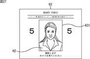
図26は、ライブビュー表示画面の例を示す図である。 FIG. 26 is a diagram illustrating an example of a live view display screen.
ライブビュー表示画面の略中央に設けられた画像表示領域431には、人物H2が写る動画がリアルタイムで表示される。人物H2は利用者自身である。利用者は、画像表示領域431に表示される自分の写りを見て、身だしなみの確認などを行うことができる。 In the
画像表示領域431には、撮影前ガイダンス画面に表示されていたものと同じ、水平線431A、水平線431B、および垂直線431Cからなるガイドラインが利用者の動画に重ねて表示される。利用者は、立ち位置を前後左右に変えるなどして、垂直線431Cが中心を通るように顔の位置を合わせるとともに、水平線431Aに頭の一番上の位置を合わせ、水平線431Bにあごの一番下の位置を合わせることになる。 In the
ガイドラインが顔の位置と大きさの目安としてライブビューに重ねて表示されるため、利用者は、立ち位置をどこにして撮影を行えばいいのかを確認することができる。 Since the guideline is displayed on the live view as an indication of the position and size of the face, the user can check where to stand and take a picture.
顔の位置と大きさの目安を表す線がガイドラインとして表示されるものとしたが、顔の位置と大きさの目安を表す画像は直線画像に限られるものではない。例えば、顔の位置と大きさの目安を曲線の画像によって表すようにしてもよいし、楕円形などの所定の形状の画像によって表すようにしてもよい。 Although the line indicating the standard of the position and size of the face is displayed as a guideline, the image indicating the standard of the position and size of the face is not limited to a straight line image. For example, the standard position and size of the face may be represented by a curved image, or may be represented by an image having a predetermined shape such as an ellipse.
また、顔の位置と大きさの目安を表す画像が表示されるものとしたが、人物の、顔以外の部分の位置と大きさを表す画像が表示されるようにしてもよい。例えば、肩の位置と大きさ、目の位置と大きさ、鼻の位置と大きさを表す画像を表示するようにしてもよい In addition, although an image representing the face position and size guide is displayed, an image representing the position and size of the person other than the face may be displayed. For example, an image representing the position and size of the shoulder, the position and size of the eyes, and the position and size of the nose may be displayed.
撮影が立った状態で行うものであるため、図26に示すようなライブビューを見たとしても、人物(利用者自身)の位置と大きさを正確に調整することは困難である。後述するように、人物の位置と大きさの調整は、証明写真用画像の調整時にも行われ、そのときの調整によって最終的に決定されるようになされている。 Since shooting is performed in a standing state, it is difficult to accurately adjust the position and size of a person (user himself) even when viewing a live view as shown in FIG. As will be described later, the position and size of the person are adjusted at the time of adjusting the ID photo image, and finally determined by the adjustment at that time.
撮影時にライブビューを見ながら行われる人物の位置と大きさの一段階目の調整が、立った状態で行う粗い調整となり、証明写真用画像の調整時に行われる二段階目の調整が、最終的な微調整となる。利用者は、撮影時には、大体の大きさで、大体の位置に写るように自分の立ち位置を調整すればよいことになる。 The first-stage adjustment of the person's position and size that is performed while viewing the live view during shooting is a coarse adjustment that is performed while standing, and the second-stage adjustment that is performed when adjusting the ID photo image is the final adjustment. Fine adjustment. At the time of shooting, the user has only to adjust his / her standing position so that it is approximately the size and appears in the approximate position.
なお、カメラ91の撮影範囲(画角)は、画像表示領域431に表示される範囲よりも広いものとされる。カメラ91により撮影された動画のうち、所定の範囲が切り出され、画像表示領域431の表示に用いられる。 Note that the shooting range (view angle) of the
ライブビューの表示に合わせて、身だしなみを整えたり、顔の位置を合わせたりすることを促す音声のガイダンスも出力される。このようなライブビューが所定の時間表示された後、撮影前のカウントダウンが開始される。カウントダウンは、例えば撮影タイミングの10秒前から開始される。 Along with the live view display, voice guidance that prompts you to adjust your appearance and position your face is also output. After such a live view is displayed for a predetermined time, a countdown before photographing is started. The countdown is started, for example, 10 seconds before the shooting timing.
図27は、カウントダウンの表示を含むライブビュー表示画面の例を示す図である。 FIG. 27 is a diagram illustrating an example of a live view display screen including a countdown display.
カウントダウンが開始されたとき、図27に示すように、ガイドラインの表示が消え、画像表示領域431の左右には、撮影までの秒数を表す数字が音声によるカウントダウンに合わせて表示される。画像表示領域431の下には、「撮影します。カメラを見てください。」のメッセージが表示される。 When the countdown is started, as shown in FIG. 27, the guideline display disappears, and numbers indicating the number of seconds until photographing are displayed on the left and right sides of the
このようなライブビュー表示画面が表示された状態で撮影のタイミングになったとき、ステップS53において、カメラ制御部323は1回目の撮影を行う。 When the shooting timing comes with such a live view display screen displayed, the
カメラ制御部323は、1回目の撮影によって得られた静止画である証明写真用画像を表示制御部322に出力するとともに、撮影画像記憶部324に出力し、記憶させる。 The
ステップS56において、表示制御部322は、1回目の撮影結果をタッチパネルモニタ92に表示させる。 In step S56, the
図28は、撮影結果確認画面の例を示す図である。 FIG. 28 is a diagram illustrating an example of a shooting result confirmation screen.
撮影結果確認画面の画像表示領域431には、直前の撮影によって得られた証明写真用画像が表示される。画像表示領域431の下には「撮影結果です。」のメッセージが表示される。利用者は、このような撮影結果確認画面から、直前に撮影された画像を確認することができる。 In the
撮影結果確認画面が所定の時間だけ表示された後、ライブビューの表示が再開され、2回目以降の撮影が行われる。 After the shooting result confirmation screen is displayed for a predetermined time, the live view display is resumed, and the second and subsequent shootings are performed.
すなわち、図26、図27のライブビュー表示画面が表示制御部322により表示され、2回目の撮影タイミングになったとき、ステップS55において、カメラ制御部323は2回目の撮影を行う。カメラ制御部323は、撮影によって得られた証明写真用画像を表示制御部322に出力するとともに、撮影画像記憶部324に出力し、記憶させる。 That is, when the live view display screens of FIGS. 26 and 27 are displayed by the
ステップS56において、表示制御部322は、2回目の撮影によって得られた証明写真用画像を表示する撮影結果確認画面をタッチパネルモニタ92に表示させる。 In step S <b> 56, the
以上の処理が、あらかじめ設定されている撮影回数だけ繰り返される。撮影回数が例えば4回として設定されている場合、ステップS57において、カメラ制御部323は3回目の撮影を行い、ステップS58において、表示制御部322は、3回目の撮影によって得られた証明写真用画像を含む撮影結果確認画面をタッチパネルモニタ92に表示させる。 The above process is repeated for a preset number of times. If the number of times of photographing is set to four times, for example, in step S57, the
ステップS59において、カメラ制御部323は4回目の撮影を行い、ステップS60において、表示制御部322は、4回目の撮影によって得られた証明写真用画像を含む撮影結果確認画面をタッチパネルモニタ92に表示させる。 In step S59, the
あらかじめ決められた回数の撮影が終了した場合、ステップS61において、表示制御部322は、撮影を終えた利用者に対して、画像処理空間A2−1または画像処理空間A2−2への移動を案内する。画像処理空間A2−1または画像処理空間A2−2への移動の案内は、タッチパネルモニタ92に画面を表示させることによって、または、スピーカ224から音声を出力することによって行われる。 When the predetermined number of times of shooting is completed, in step S61, the
その後、図19のステップS3に戻り、それ以降の処理が行われる。利用者は、撮影空間A1から出て、案内された方の画像処理空間に移動して証明写真用画像の調整を行うことになる。 Thereafter, the process returns to step S3 in FIG. 19, and the subsequent processing is performed. The user goes out of the shooting space A1, moves to the guided image processing space, and adjusts the ID photo image.
[証明写真コースの調整処理]
次に、図29のフローチャートを参照して、図19のステップS4において行われる証明写真用画像の調整処理について説明する。[Adjustment process of ID photo course]
Next, the ID photo image adjustment process performed in step S4 of FIG. 19 will be described with reference to the flowchart of FIG.
ステップS71において、画像処理管理部302の表示制御部332は、撮影処理によって得られた例えば4枚の証明写真用画像を撮影画像記憶部324から読み出して取得し、画像選択画面をタブレット内蔵モニタ131に表示させる。画像選択画面は、4枚の証明写真用画像の中から調整対象とする1枚の証明写真用画像を選択するのに用いられる画面である。 In step S <b> 71, the
図30は、画像選択画面の例を示す図である。 FIG. 30 is a diagram illustrating an example of an image selection screen.
画像選択画面の上方中央には、画像の選択を促す「プリントしたい画像を1枚選んでください。」のメッセージが表示され、その下に、4枚の証明写真用画像451−1乃至451−4が撮影順に並べて表示される。証明写真用画像451−1乃至451−4は、4回の撮影によって得られた4種類の静止画である。 In the upper center of the image selection screen, a message “Please select one image you want to print” prompting you to select an image is displayed. Below that, four ID photo images 451-1 to 451-4 are displayed. Are displayed in order of shooting. The ID photograph images 451-1 to 451-4 are four types of still images obtained by four shootings.
利用者は、タッチペン132Aまたはタッチペン132Bで触れることによって好みの証明写真用画像を選択する。図30の例においては証明写真用画像451−1が選択中とされており、証明写真用画像451−1の枠がカーソルCによって強調表示されている。 The user selects a desired ID photo image by touching with the
証明写真用画像451−1乃至451−4の下には、調整対象の証明写真用画像を決定するときに操作されるOKボタン452が表示される。調整の対象とする証明写真用画像の枚数は1枚に限られるものではなく、複数枚の証明写真用画像を選択することができるようにしてもよい。 Below the ID photo images 451-1 to 451-4, an
1枚の証明写真用画像が選択され、OKボタン452が操作された場合、ステップS72において、ガイダンス出力制御部331は、表示制御部322を制御し、証明写真用画像の調整の仕方を説明する画面をタブレット内蔵モニタ131に表示させるなどして、調整前ガイダンスを出力する。 When one ID photo image is selected and the
図31は、調整前ガイダンス画面の例を示す図である。 FIG. 31 is a diagram illustrating an example of the pre-adjustment guidance screen.
調整前ガイダンス画面は、調整画面全体のうち、説明の対象となっている機能に関する部分だけをカラー表示とし、それ以外の部分をグレーアウト表示とさせた画面である。 The pre-adjustment guidance screen is a screen in which only the portion related to the function to be explained is displayed in color in the entire adjustment screen, and the other portions are displayed in gray out.
図31の例においては、調整画像表示領域511とボタン領域512がカラー表示になっている。調整画像表示領域511は、調整対象となる証明写真用画像の表示領域であり、ボタン領域512は、人物の位置の調整に用いられるボタンが表示される領域である。調整前のガイダンス中であるから、調整画像表示領域511には、モデルの人物H1が写る静止画が表示される。 In the example of FIG. 31, the adjusted
また、図31の例においては、ボタン領域512に表示されるボタンを用いて行う位置の調整機能の説明中であることが、ボタン領域512を指す矢印画像501により表されている。「1番 人物の位置を調整」などの音声が、図31の表示に合わせてガイダンス出力制御部331によりスピーカ231から出力される。例えば、証明写真用画像の調整は、人物の位置の調整、人物の大きさの調整、背景の色の調整、写りの調整の順に行われる。これらの4種類の調整の全てが行われるのではなく、4種類の調整のうちの少なくともいずれかが行われるようにしてもよい。また、証明写真用画像に写る人物の傾きの調整などの他の調整が行われるようにしてもよい。 In the example of FIG. 31, an explanation of the position adjustment function performed using the buttons displayed in the
調整前ガイダンス画面においては、矢印画像501が説明中の機能に合わせて移動するとともに、カラー表示の部分が、人物の大きさの調整に用いられるボタンが表示される領域、背景の色の調整に用いられるボタンが表示される領域、写りの調整に用いられるボタンが表示される領域の順に切り替わる。 On the pre-adjustment guidance screen, the
カラー表示の部分が切り替わることに応じて、「2番 人物の大きさを調整」、「3番 背景カラーを選択」、「4番 写りを調整」などの音声がスピーカ231から出力される。調整前ガイダンス画面の右上には、調整前ガイダンスを終了させるときに操作されるSKIPボタン502も表示される。 In response to the switching of the color display portion, sounds such as “adjust the size of the 2nd person”, “select the 3rd background color”, and “adjust the 4th image” are output from the
SKIPボタン502が操作されたとき、または調整前ガイダンスが終わったとき、ステップS73において、表示制御部332は、調整画面をタブレット内蔵モニタ131に表示させる。SKIPボタン502を用いずに、調整前ガイダンス画面上をタッチペン132A、タッチペン132Bで押す操作が行われたときにも調整前ガイダンスは終了となる。 When the
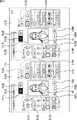
図32は、調整画面の例を示す図である。 FIG. 32 is a diagram illustrating an example of the adjustment screen.
調整画面の略中央の調整画像表示領域511には、利用者(人物H2)が写る証明写真用画像が表示される。調整画像表示領域511に表示される証明写真用画像は、画像選択画面において4枚の証明写真用画像の中から選択された画像である。調整画像表示領域511の証明写真用画像の表示には、調整画面の各種のボタンを用いて行われた調整の内容がリアルタイムで反映される。 In the adjustment
調整画像表示領域511の左側には、ボタン領域512、人物の大きさの調整に用いられるボタンが表示される領域であるボタン領域513、および、背景の色の調整に用いられるボタンが表示される領域であるボタン領域514が設けられる。 On the left side of the adjustment
一方、調整画像表示領域511の右側には、一発レタッチに用いられるボタンが表示される領域であるボタン領域515と、こだわりレタッチに用いられるボタンが表示される領域であるボタン領域516が設けられる。ボタン領域515とボタン領域516が、写りの調整に用いられるボタンが表示される領域である。 On the other hand, on the right side of the adjustment
図33は、図32のボタン領域512、ボタン領域513、およびボタン領域514を拡大して示す図である。 FIG. 33 is an enlarged view of the
ボタン領域512には、左ボタン512A、右ボタン512B、上ボタン512C、および下ボタン512Dが表示される。左ボタン512Aは、人物の位置を左方向に移動させるときに操作されるボタンであり、右ボタン512Bは、人物の位置を右方向に移動させるときに操作されるボタンである。また、上ボタン512Cは、人物の位置を上方向に移動させるときに操作されるボタンであり、下ボタン512Dは、人物の位置を下方向に移動させるときに操作されるボタンである。ボタン領域512に表示されているボタンを押すごとに、人物の位置が所定の量だけ移動する。 In the
ボタン領域513には、マイナスボタン513Aとプラスボタン513Bが表示される。マイナスボタン513Aは、人物の大きさを小さくするときに操作されるボタンであり、プラスボタン513Bは、人物の大きさを大きくするときに操作されるボタンである。ボタン領域513に表示されているボタンを押すごとに、人物の大きさが所定の量だけ変化する。 In the
ボタン領域512に表示されるボタンとボタン領域513に表示されるボタンを用いた調整が、人物の位置と大きさの二段階目の調整となる。 The adjustment using the button displayed in the
図34は、人物の位置と大きさの二段階目の調整時の調整画面の表示例を示す図である。 FIG. 34 is a diagram showing a display example of an adjustment screen at the time of the second stage adjustment of the position and size of a person.
人物の位置と大きさの調整時、ライブビュー表示時と同様に、調整画像表示領域511には、証明写真用画像に重ねて、水平線511A、511B、および垂直線511Cからなるガイドラインが表示される。水平線511Aは、頭の一番上の位置の目安となる高さを表し、水平線511Bは、あごの位置の目安となる高さを表す。また、垂直線511Cは、顔の中心の水平方向の目安となる位置を表す。 When adjusting the position and size of a person, as in live view display, the adjustment
例えば、人物の位置の調整時、「人物の位置を調整します。ガイドラインの位置に合わせて調整してください。」などの音声がガイダンス出力制御部331によりスピーカ231から出力される。また、人物の大きさの調整時、「人物の大きさを調整します。ガイドラインの大きさに合わせて調整してください。」などの音声がガイダンス出力制御部331によりスピーカ231から出力される。 For example, when adjusting the position of the person, a voice such as “Adjust the position of the person. Adjust according to the position of the guideline” is output from the
利用者は、ボタン領域512とボタン領域513に表示されているボタンを操作して、垂直線511Cが中心を通るように顔の位置を合わせるとともに、水平線511Aに頭の一番上の位置を合わせ、水平線511Bにあごの一番下の位置を合わせることになる。 The user operates the buttons displayed in the
このように、撮影時には粗い調整のみを行い、その後、証明写真用画像の調整時にタッチペン132A、132Bを用いて細かい調整を行うようにすることにより、証明写真用画像における人物の位置と大きさを正確に調整することが可能になる。 In this way, only the rough adjustment is performed at the time of photographing, and then the fine adjustment is performed using the touch pens 132A and 132B at the time of adjustment of the ID photo image, so that the position and size of the person in the ID photo image can be adjusted. It becomes possible to adjust accurately.
撮影時の一段階目の調整と同様に、顔の位置と大きさの目安を表す画像は直線画像に限られるものではない。また、人物の、顔以外の部分の位置と大きさを表す画像が表示されるようにしてもよい。さらに、顔の位置と大きさのうちのいずれかの目安となる画像が表示されるようにしてもよい。 Similar to the first-stage adjustment at the time of shooting, the image representing the standard position and size of the face is not limited to a straight line image. In addition, an image representing the position and size of a part of a person other than the face may be displayed. Furthermore, an image that serves as an indication of either the position or size of the face may be displayed.
撮影時の一段階目の調整時は粗い調整であるから、顔の位置と大きさのうちのいずれかの目安となる画像のみが表示され、細かい調整である二段階目の調整時に、顔の位置と大きさの両方の目安となる画像が表示されるようにすることも可能である。 Since the adjustment at the first stage during shooting is a coarse adjustment, only an image that is one of the approximate positions and sizes of the face is displayed, and at the second adjustment, which is a fine adjustment, the face is adjusted. It is also possible to display an image that serves as an indication of both the position and size.
ライブビュー表示時には、利用者はライブビューを見て身だしなみの確認なども行う必要がある。ライブビューに重ねて表示する情報を減らすことにより、利用者が自分の様子をより確認しやすくなる。 When displaying the live view, the user needs to check the appearance by looking at the live view. By reducing the information to be displayed over the live view, it becomes easier for the user to confirm his / her appearance.
図35A,Bは、人物の位置と大きさの調整時の画像処理の例を示す図である。 FIGS. 35A and 35B are diagrams illustrating an example of image processing when adjusting the position and size of a person.
図35A,Bの画像P41は、証明写真用画像の全体の画像であり、枠F1で示す範囲が、調整画像表示領域511に表示される範囲である。撮影においては、タブレット内蔵モニタ131に表示される範囲より広い範囲のデータが取得されており、取得された画像上で、枠F1に収める範囲を変えるようにして人物の位置と大きさの調整が行われる。 35A and 35B is an entire image of the ID photograph image, and the range indicated by the frame F1 is the range displayed in the adjusted
例えば、調整部334は、ボタン領域512の左ボタン512Aが操作される毎に、図35Aの白抜き矢印#11に示すように枠F1の範囲を所定の量だけ右方向に移動させ、これにより、枠F1内における人物の位置を左方向に移動させる。また、調整部334は、右ボタン512Bが操作される毎に、白抜き矢印#12に示すように枠F1の範囲を所定の量だけ左方向に移動させ、枠F1内における人物の位置を右方向に移動させる。 For example, every time the
調整部334は、ボタン領域512の上ボタン512C、下ボタン512Dが操作されたときも同様に、それぞれ、白抜き矢印#13,#14に示すように枠F1の範囲を所定の量だけ下方向または上方向に移動させ、枠F1内における人物の位置を移動させる。 Similarly, when the upper button 512C and the
また、調整部334は、ボタン領域513のマイナスボタン513Aが操作される毎に、図35Bの外向きの白抜き矢印#21に示すように枠F1に収める範囲を、枠F11に収まる範囲のように所定の量だけ広くし、枠F1に対する人物の相対的な大きさを小さくする。これにより、調整画像表示領域511に表示される人物は小さくなる。また、調整部334は、プラスボタン513Bが操作される毎に、内向きの白抜き矢印#22で示すように枠F1に収める範囲を、枠F12に収まる範囲のように所定の量だけ狭くさせ、枠F1に対する人物の相対的な大きさを大きくする。これにより、調整画像表示領域511に表示される人物は大きくなる。 Further, every time the
調整が終わったとき、枠F1内の範囲がトリミングにより画像P41から切り出され、証明写真用画像として用いられる。 When the adjustment is completed, the range within the frame F1 is cut out from the image P41 by trimming and used as an ID photo image.
なお、人物の位置を調整する際、例えば人物の位置を下にずらしすぎたときには、図35Aの枠F1の上辺の位置が画像P41の上辺の位置より上の位置となり、枠F1に、画像P41の領域外の範囲が含まれることがある(撮影画像のデータとして、人物の上方の領域のデータがないことがある)。その場合、調整画像表示領域511に表示される人物の上方に余白が生じないようにするために、画像P41の上の、枠F1に含まれる範囲に背景領域(透明な背景領域)を加える処理が行われる。 When adjusting the position of the person, for example, if the position of the person is shifted too much downward, the position of the upper side of the frame F1 in FIG. 35A becomes a position above the position of the upper side of the image P41, and the image P41 is displayed in the frame F1. May be included (there may be no data in the area above the person as the captured image data). In that case, a process of adding a background region (transparent background region) to the range included in the frame F1 on the image P41 in order to prevent a margin from being generated above the person displayed in the adjusted
人物の大きさを調整する際において人物を小さくしすぎたときも同様に、図35Bの枠F11が画像P41より大きくなり、枠F11に、画像P41の領域外の範囲が含まれることがある(撮影画像のデータとして、人物の周りの領域のデータがないことがある)。その場合、調整画像表示領域511に表示される人物の周りに余白が生じないようにするために、枠F1に含まれる画像P41の領域外の範囲に背景領域(透明な背景領域)を加える処理が行われる。 Similarly, when adjusting the size of the person, the frame F11 in FIG. 35B becomes larger than the image P41, and the frame F11 may include a range outside the area of the image P41 (when the size of the person is too small). There may be no data in the area around the person as the data of the photographed image). In that case, a process of adding a background area (transparent background area) to a range outside the area of the image P41 included in the frame F1 in order to prevent a margin from being generated around the person displayed in the adjusted
なお、これらの処理は、利用者が撮影前ガイダンスに従わずに撮影を行った場合に行われるものである。利用者が撮影前ガイダンスに従って撮影を行っていることを前提とする場合には、枠F1に、画像P41の領域外の範囲が含まれないように、人物の位置や大きさの調整が制限されるようにしてもよい。 These processes are performed when the user performs shooting without following the pre-shooting guidance. If it is assumed that the user is shooting according to the pre-shooting guidance, the adjustment of the position and size of the person is restricted so that the frame F1 does not include the range outside the area of the image P41. You may make it do.
図33のボタン領域514には、背景画像の色の選択に用いられる背景カラー選択ボタン514A乃至514Fが表示される。背景カラー選択ボタン514A乃至514Fはそれぞれ異なる色のボタンである。図12を参照して説明したように、証明写真用画像は、被写体の背景として背景画像を合成することによって構成される。 In the
調整部334は、背景カラー選択ボタン514A乃至514Fが操作されることに応じて、証明写真用画像の被写体に合成する背景画像を変え、色の調整を行う。例えば、背景の調整時、「背景を選択します。ご提出先の規定に背景の色指定がある場合、規定に沿ってお選びください。」などの音声がスピーカ231から出力される。 The
図36は、図32のボタン領域515とボタン領域516を拡大して示す図である。 FIG. 36 is an enlarged view of the
ボタン領域515には、一発レタッチの機能を利用して写りの調整を行うときに操作されるモード選択ボタン515A乃至515Cが表示される。一発レタッチの機能は、証明写真用画像に写る利用者の肌の明るさ、肌質、目の印象、および髪色のそれぞれの写りを、1回の操作で一括して調整する機能である。 In the
例えば、肌の明るさには、「健康的」(少し日焼けしたような肌の明るさを表す)、「おすすめ(ナチュラル)」、「明るめ」の名称が設定された3種類の明るさが用意され、肌質には、「マット」、「おすすめ(ナチュラル)」、「ふんわり」の名称が設定された3種類の肌質が用意される。目の印象には、「優しい」(目の輪郭をぼかした優しい雰囲気の印象を表す)、「おすすめ(ナチュラル)」、「はっきり」の名称が設定された3種類の印象が用意され、髪色には、「暗め」、「おすすめ(ナチュラル)」、「明るめ」の名称が設定された3種類の髪色が用意される。 For example, three types of brightness are available for the skin brightness: “Healthy” (represents skin brightness that is slightly tanned), “Recommended (natural)”, and “Brighter” As the skin quality, three types of skin quality with names “mat”, “recommended (natural)”, and “soft” are prepared. There are three types of impressions with the names “gentle” (representing the impression of a gentle atmosphere with blurred outlines), “recommended (natural)”, and “clear”. Three types of hair colors having names “dark”, “recommended (natural)”, and “light” are prepared.
モード選択ボタン515A乃至515Cは、それぞれ、「清潔感」、「健康的」、「華やか」の名称が設定されたモードで写りを一括して調整するときに操作されるボタンである。 The
図37は、一発レタッチの各モードを選択したときに用いられる写りの組み合わせの例を示す図である。 FIG. 37 is a diagram illustrating an example of a combination of images used when each mode of one-shot retouch is selected.
「清潔感」のモードは、肌の明るさを「おすすめ(ナチュラル)」、肌質を「おすすめ(ナチュラル)」、目の印象を「優しい」、髪色を「暗め」として設定するモードである。「健康的」のモードは、肌の明るさを「健康的」、肌質を「マット」、目の印象を「おすすめ(ナチュラル)」、髪色を「おすすめ(ナチュラル)」として設定するモードである。「華やか」のモードは、肌の明るさを「明るめ」、肌質を「ふんわり」、目の印象を「はっきり」、髪色を「明るめ」として設定するモードである。当然、各モードと写りの組み合わせは図37に示すものに限られるものではなく、他の組み合わせであってもよい。 “Cleanliness” mode is a mode in which the skin brightness is set to “Recommended (Natural)”, the skin quality is set to “Recommended (Natural)”, the eye impression is set to “Gentle”, and the hair color is set to “Dark”. . The “healthy” mode is a mode in which the skin brightness is set to “healthy”, the skin quality is set to “mat”, the eye impression is set to “recommended (natural)”, and the hair color is set to “recommended (natural)”. is there. The “gorgeous” mode is a mode in which the skin brightness is set to “bright”, the skin quality is set to “soft”, the eye impression is set to “clear”, and the hair color is set to “bright”. Naturally, the combination of each mode and the image is not limited to that shown in FIG. 37, and other combinations may be used.
ボタン領域516には、一発レタッチの機能を利用しないで、肌の明るさ、肌質、目の印象、および髪色をそれぞれ個別に調整する機能であるこだわりレタッチに操作されるボタンが表示される。ボタン領域516には領域531乃至534が設けられる。 In the
領域531には、「健康的」、「おすすめ(ナチュラル)」、「明るめ」の3種類の中から好みの肌の明るさを選択するときに操作される写り選択ボタン531A乃至531Cが表示される。「健康的」、「おすすめ(ナチュラル)」、「明るめ」のそれぞれの明るさには、色相、彩度、明度などの肌の色に関する各パラメータが対応付けられている。 In the
写り選択ボタン531A乃至531Cの中からいずれかのボタンが操作された場合、調整部334は、被写体の肌の領域を検出し、選択された種類の明るさに応じたパラメータを設定することによって肌の明るさを調整する。 When any one of the
領域532には、「マット」、「おすすめ(ナチュラル)」、「ふんわり」の3種類の中から好みの肌質を選択するときに操作される写り選択ボタン532A乃至532Cが表示される。「マット」、「おすすめ(ナチュラル)」、「ふんわり」のそれぞれの肌質には、色相、彩度、明度などの色に関する各パラメータや、シャープネスなどのパラメータが対応付けられている。 In the
写り選択ボタン532A乃至532Cの中からいずれかのボタンが操作された場合、調整部334は、被写体の肌の領域を検出し、選択された種類の肌質に応じたパラメータを設定することによって肌質を調整する。 When any one of the
領域533には、「優しい」、「おすすめ(ナチュラル)」、「はっきり」の3種類の中から好みの目の印象を選択するときに操作される写り選択ボタン533A乃至533Cが表示される。「優しい」、「おすすめ(ナチュラル)」、「はっきり」のそれぞれの目の印象には、シャープネスなどのパラメータが対応付けられている。 In the
写り選択ボタン533A乃至533Cの中からいずれかのボタンが操作された場合、調整部334は、被写体の目を検出し、選択された種類の印象に応じたパラメータを設定することによって目の印象を調整する。 When any one of the
領域534には、「暗め」、「おすすめ(ナチュラル)」、「明るめ」の3種類の中から好みの髪色を選択するときに操作される写り選択ボタン534A乃至534Cが表示される。「暗め」、「おすすめ(ナチュラル)」、「明るめ」のそれぞれの髪色には、色相、彩度、明度などの髪の色に関する各パラメータが対応付けられている。 In the
写り選択ボタン534A乃至534Cの中からいずれかのボタンが操作された場合、調整部334は、被写体の髪領域を検出し、選択された種類の色に応じたパラメータを設定することによって髪色を調整する。 When any one of the
図32の調整画像表示領域511の上には、調整中ボタン541と調整前ボタン542が表示される。調整中ボタン541は、調整中の証明写真用画像を調整画像表示領域511に表示させるときに操作されるボタンであり、調整前ボタン542は、調整前の証明写真用画像を調整画像表示領域511に表示させるときに操作されるボタンである。調整中ボタン541と調整前ボタン542のうちのいずれかが操作可能とされる。 An in-
調整部334においては、調整前の証明写真用画像と調整中の証明写真用画像の2種類の証明写真用画像のデータが管理される。調整中ボタン541と調整前ボタン542に対する操作が行われることに応じて、調整部334により管理されるデータに基づいて調整画像表示領域511の表示が切り替えられる。 The
利用者は、調整中ボタン541と調整前ボタン542を交互に操作することによって、各ボタンを用いて調整している調整中の証明写真用画像と、調整前、すなわち無調整の証明写真用画像を見比べることができる。なお、調整中の証明写真用画像と、調整前(無調整)の証明写真用画像とが並んで表示されるようにしてもよい。 The user operates the
調整画面においては、人物の位置、人物の大きさ、背景の色、および写りの4種類の調整が行われるが、調整前ボタン542を操作したときに調整前の証明写真用画像として表示される画像を、人物の位置や大きさの調整すらも行っていない無調整の証明写真用画像としてもよいし、人物の位置、人物の大きさ、および背景の色のうちの少なくともいずれかの調整については調整済みの証明写真用画像としてもよい。 On the adjustment screen, four types of adjustments are performed: the position of the person, the size of the person, the background color, and the image, but when the
例えば、調整前の証明写真用画像として、人物の位置、人物の大きさ、および背景の色の調整済みの画像が表示されるようにすることにより、利用者は、調整中の証明写真用画像と、写りの調整前の証明写真用画像とを比較することができ、単に、写りが気に入っているか否かを判断することが可能になる。 For example, by displaying an adjusted image of the position of the person, the size of the person, and the background color as the ID photo image before adjustment, the user can adjust the ID photo image being adjusted. Can be compared with the ID photo image before adjustment of the image, and it is possible to simply determine whether the image is liked.
また、調整済みの証明写真用画像が1枚以上記憶されるようにし、その記憶された調整済みの証明写真用画像と、調整中の証明写真用画像とを比較することができるようにしてもよい。また、調整済みの証明写真用画像が複数記憶されるようにした場合には、複数の調整済みの証明写真用画像の中から、最終的に印刷される証明写真用画像を選択させるようにしてもよい。これにより、利用者の好みの証明写真用画像が印刷されたシール紙を提供することができる。 Further, at least one adjusted ID photo image is stored, and the stored adjusted ID photo image can be compared with the ID photo image being adjusted. Good. In addition, when a plurality of adjusted ID photo images are stored, an ID photo image to be finally printed is selected from a plurality of adjusted ID photo images. Also good. Accordingly, it is possible to provide a sticker paper on which an ID photo image desired by the user is printed.
調整画像表示領域511の下には、各調整機能の説明を表示するときに操作される説明ボタン543、調整を最初からやり直すときに操作されるやり直しボタン544、および証明写真用画像の調整を終えるときに操作される終了ボタン545が表示される。 Below the adjustment
調整画面の表示中、調整中ボタン541と調整前ボタン542を用いて行うことのできる内容を説明する「調整中・調整前ボタンを切り替えることで元の画像と見比べることができます。」などの音声や、説明ボタン543を用いて行うことのできる内容を説明する「困ったときは説明ボタンを押してください。」などの音声が所定のタイミングで出力される。また、やり直しボタン544を用いて行うことのできる内容を説明する「最初からやり直したい場合は、最初からやり直すボタンを押してください。」などの音声や、終了ボタン545を用いて行うことのできる内容を説明する「調整を終わらせたい場合は、調整終了ボタンを押してください。」などの音声が所定のタイミングで出力される。 Explaining what can be done using the
図29の説明に戻り、ステップS74において、調整部334は、調整画面のボタン領域512に表示されているボタンに対する利用者の操作に応じて、証明写真用画像における被写体の位置を調整する。被写体の位置の調整は図35Aを参照して説明したようにして行われる。 Returning to FIG. 29, in step S74, the
ステップS75において、調整部334は、ボタン領域513に表示されているボタンに対する利用者の操作に応じて、証明写真用画像における被写体の大きさを調整する。被写体の大きさの調整は図35Bを参照して説明したようにして行われる。 In step S <b> 75, the
ステップS76において、調整部334は、ボタン領域514に表示されているボタンに対する利用者の操作に応じて、証明写真用画像における被写体の背景の色を調整する。 In step S <b> 76, the
ステップS77において、調整部334は、ボタン領域515とボタン領域516に表示されているボタンに対する利用者の操作に応じて、証明写真用画像における被写体の写りを調整する。 In step S <b> 77, the
すなわち、調整部334は、ボタン領域515に表示されているボタンが操作されたとき、利用者の肌の明るさ、肌質、目の印象、および髪色のそれぞれの写りに関するパラメータを一括して調整する。また、調整部334は、ボタン領域516に表示されているボタンが操作されたとき、利用者の肌の明るさ、肌質、目の印象、および髪色に関するパラメータを、それぞれ調整する。 That is, when the button displayed in the
ボタン領域512乃至516のボタンが操作される毎に証明写真用画像の調整が行われ、調整後の証明写真用画像のデータが調整部334から表示制御部332に供給される。調整部334から供給されたデータに基づいて、調整画像表示領域511には、調整後の証明写真用画像が表示される。 Each time the buttons in the
ステップS78において、調整部334は、調整終了か否かを判定し、調整終了ではないと判定した場合、ステップS74に戻り、以上の処理を繰り返す。ステップS74乃至S77の各処理については、必要な処理だけが、任意の順序で行われるようにしてもよい。 In step S78, the
一方、終了ボタン545が操作されたことから、証明写真用画像の調整が終了したと判定された場合、調整後の証明写真用画像が画像記憶部335に供給され、記憶される。なお、あらかじめ設定された制限時間が経過した場合も調整終了であると判定される。証明写真用画像の調整にも制限時間が設定されている。事後接客空間A3の空き状況や印刷の状況に応じて、適宜、制限時間が延長されるようにしてもよい。 On the other hand, when it is determined that the adjustment of the ID photo image is completed because the
ステップS79において、表示制御部332は、証明写真用画像の調整を終えた利用者に対して事後接客空間A3への移動を案内する。事後接客空間A3への移動の案内は、タブレット内蔵モニタ131に画面を表示させることによって、またはスピーカ231から音声を出力させることによって行われる。その後、図19のステップS4に戻り、それ以降の処理が行われる。 In step S79, the
[証明写真コースの印刷処理]
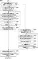
次に、図38のフローチャートを参照して、図19のステップS5において行われる証明写真用画像の印刷処理について説明する。[Printing process of ID photo course]
Next, the ID photo image printing process performed in step S5 in FIG. 19 will be described with reference to the flowchart in FIG.
ステップS91において、印刷管理部303の印刷データ生成部341(図17)は、画像記憶部335に記憶されている調整後の証明写真用画像を読み出して取得する。 In step S91, the print data generation unit 341 (FIG. 17) of the
ステップS92において、印刷データ生成部341は、調整後の証明写真用画像を所定のレイアウトに配置することによって印刷データを生成し、プリンタ制御部342に出力する。証明写真用画像のレイアウトは、例えば、履歴書用、パスポート用などの利用者により選択された証明写真用画像のサイズに応じて自動的に選択される。 In step S <b> 92, the print
ステップS93において、プリンタ制御部342は、プリンタ241を制御し、印刷データ生成部341により生成された印刷データに基づいて、証明写真用画像をシール紙に印刷させる。これにより、証明写真用画像が印刷された図11に示すようなシール紙が生成される。証明写真用画像が印刷されたシール紙はシール紙排出口163に排出される。その後、図19のステップS5に戻り、それ以降の処理が行われる。 In step S93, the
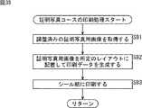
[証明写真コースの事後接客処理]
次に、図39のフローチャートを参照して、図19のステップS6において行われる事後接客処理について説明する。[Post-processing of ID Photo Course]
Next, the subsequent customer service process performed in step S6 of FIG. 19 will be described with reference to the flowchart of FIG.
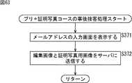
ステップS111において、事後接客管理部304の表示制御部351は、メールアドレスの入力画面をタブレット内蔵モニタ161に表示させる。この入力画面を用いて、利用者が持つ携帯電話機などの携帯端末のメールアドレスが入力される。 In step S <b> 111, the
写真シール作成装置1において生成された証明写真用画像は、写真シール作成装置1からサーバに送信され、所定の記憶領域が割り当てられて保存される。サーバは、例えば写真シール作成装置1のメーカーが管理するサーバである。利用者により入力されたメールアドレスは、その記憶領域を表すURLを利用者に通知するために用いられる。サーバから利用者の携帯端末に対して送信される電子メールには証明写真用画像の記憶領域を表すURLが含まれており、そのURLへのアクセスを指示することによって、利用者は携帯端末の画面上に証明写真用画像を表示させることができる。 The ID photo image generated in the photo
携帯送信機能は、このような仕組みによって、携帯端末の画面上で証明写真用画像を閲覧することができるようにするための機能である。 The portable transmission function is a function for enabling the ID photo image to be browsed on the screen of the portable terminal by such a mechanism.
例えば、写真シール作成装置1のメーカーが開設するWebページなどから有料会員に登録することにより、証明写真用画像のデータを携帯端末にダウンロードすることができるようになされている。携帯端末にダウンロードされた証明写真用画像のデータは、電子履歴書の作成や証明写真用画像の焼き増しに用いることが可能とされる。 For example, by registering as a paying member from a Web page or the like established by the manufacturer of the photo
入力画面に対してメールアドレスが入力されたとき、ステップS112において、通信制御部352は、画像記憶部335から読み出した調整後の証明写真用画像のデータとメールアドレスをサーバに送信する。その後、図19のステップS6に戻り、証明写真コースの一連の処理が終了される。 When a mail address is input on the input screen, in step S112, the
以上のように、利用者は、証明写真コースを選択することによって、履歴書などに貼り付けるのに用いる証明写真用画像が印刷されたシール紙を得ることができる。 As described above, the user can obtain sticker paper on which an ID photo image used for pasting on a resume or the like is selected by selecting the ID photo course.
<プリ+証明写真コース>
[プリ+証明写真コースの撮影処理]
次に、図40および図41のフローチャートを参照して、図19のステップS8において行われるプリ+証明写真コースの撮影処理について説明する。<Pre + ID Photo Course>
[Pre + ID photo course shooting process]
Next, with reference to the flowcharts of FIGS. 40 and 41, the pre + certification photo course shooting process performed in step S8 of FIG. 19 will be described.
図40および図41の撮影処理は、プリ画像の撮影を先に行い、その後、証明写真用画像の撮影を行う処理である。 40 and 41 is a process in which a pre-image is taken first, and then an ID photo image is taken.
ステップS201において、撮影管理部301のガイダンス出力制御部321は、表示制御部322を制御し、プリ画像の撮影の仕方を説明する画面をタッチパネルモニタ92に表示させるなどして撮影前ガイダンスを出力する。利用者は、タッチパネルモニタ92に表示される画面を見て、撮影の仕方などを確認することになる。 In step S201, the guidance
撮影前ガイダンスが終了したとき、ステップS202において、シーケンス管理部305は、証明写真用画像を必要とする人数が1人であるか否かを、図23の人数選択画面に対する利用者の選択内容に基づいて判定する。 When the pre-photographing guidance is completed, in step S202, the sequence management unit 305 determines whether or not the number of people who require the ID photograph image is one in the selection contents of the user on the number selection screen of FIG. Judgment based on.
証明写真用画像を必要とする人数が1人であるとステップS202において判定した場合、ステップS203において、表示制御部322は、ライブビューの表示を開始する。カメラ91による動画の撮影が開始され、撮影によって得られた、利用者が映る動画がカメラ制御部323から表示制御部322に供給される。 When it is determined in step S202 that the number of persons who require the ID photo image is one, in step S203, the
図42は、ライブビュー表示画面の例を示す図である。 FIG. 42 is a diagram illustrating an example of a live view display screen.
ライブビュー表示画面の中央上方には「撮影するよ!」のメッセージが表示され、その下に設けられた矩形の領域であるライブビュー表示領域701には、撮影空間A1にいる利用者を撮影して得られた動画が表示される。図42の例においては、プリ+証明写真コースを選択した2人の利用者が撮影を行っているものとされている。 A message “I will shoot!” Is displayed at the upper center of the live view display screen, and a user in the shooting space A1 is shot in a live
ライブビュー表示領域701の左には、ライブビュー表示領域701の上辺に沿うように頭の位置を調整することを案内するメッセージが表示される。ライブビュー表示領域701の下には、ライブビュー表示領域701より小さい矩形の領域である撮影結果表示領域702−1乃至702−6が2行3列に並べて配置される。 On the left of the live
プリコースの場合と同様に、プリ+証明写真コースの撮影処理においても、プリ画像の撮影は例えば6回行われる。 As in the case of the pre-course, the pre-image is also photographed six times in the pre-certification photo course photographing process, for example.
撮影結果表示領域702−1乃至702−6には、それぞれ、撮影が行われる毎に、撮影によって得られたプリ画像が撮影順に表示される。図42の例においてはまだ撮影が行われていないことから、撮影結果表示領域702−1乃至702−6にはなにも表示されていない。 In the photographing result display areas 702-1 to 702-6, pre-images obtained by photographing are displayed in the photographing order every time photographing is performed. In the example of FIG. 42, since no shooting has been performed yet, nothing is displayed in the shooting result display areas 702-1 to 702-6.
利用者は、このようなライブビュー表示画面を見て、自分の顔の位置を調整して撮影を行いながら、撮影結果を確認することができる。図42に示すようなライブビュー表示画面の表示は、プリ画像の撮影が終了するまで続けられる。 The user can check the shooting result while performing shooting while adjusting the position of his / her face while viewing such a live view display screen. The display of the live view display screen as shown in FIG. 42 is continued until the pre-image shooting is completed.
ライブビュー表示画面が表示された状態で撮影のタイミングになったとき、ステップS204において、カメラ制御部323は、プリ画像の1回目の撮影を行う。カメラ制御部323は、撮影によって得られたプリ画像を表示制御部322に出力するとともに、撮影画像記憶部324に出力し、記憶させる。 When it is time to shoot with the live view display screen displayed, in step S204, the
表示制御部322に出力されたプリ画像は、ライブビュー表示画面の撮影結果表示領域702−1に縮小して表示される。利用者は、直前の撮影結果を確認しながら、次の撮影の準備を行うことができる。このようなプリ画像の撮影が例えば6回繰り返される。 The pre-image output to the
プリ画像の撮影が行われた後、次に、1人分の証明写真用画像の撮影が行われる。 After the pre-image is photographed, the ID photograph image for one person is photographed next.
ステップS205において、表示制御部322は、案内画面を表示するなどして、待機エリアである区画a1か区画a2で待つことを、証明写真用画像が不要な利用者に対して案内する。 In step S205, the
証明写真を必要とする利用者の撮影中、もう1人の利用者が区画a1か区画a2で待っていることにより、証明写真が不要な利用者が証明写真用画像に写り込んでしまうことを防ぐことができる。 While a user who needs an ID photo is being photographed, a user who does not need an ID photo appears in the ID photo image because another user is waiting in the zone a1 or the zone a2. Can be prevented.
ステップS206において、表示制御部322は、ライブビューの表示を開始する。ここで表示されるライブビュー表示画面は、図26、図27の画面と同じ画面である。証明写真用画像を必要とする利用者は、ライブビューを見て立ち位置の調整などを行う。 In step S206, the
ライブビューが表示された状態で撮影のタイミングになったとき、ステップS207において、カメラ制御部323は、証明写真用画像の撮影を行う。カメラ制御部323は、撮影によって得られた撮影写真用画像を表示制御部322に出力するとともに、撮影画像記憶部324に出力し、記憶させる。 When it is time to shoot with the live view displayed, in step S207, the
ステップS208において、表示制御部322は、撮影結果をタッチパネルモニタ92に表示させる。ここで表示される撮影結果確認画面は、図28の画面と同じ画面である。 In step S208, the
タッチパネルモニタ92に表示されたシャッターボタンが押されてからカウントダウンを開始し、その後、撮影を行うといったように、証明写真用画像の撮影時においては、その撮影タイミングを利用者が手動操作で決めることができるようにしてもよい。 When the ID photograph image is taken, such as when the countdown starts after the shutter button displayed on the touch panel monitor 92 is pressed and then taken, the user decides the shooting timing manually. You may be able to.
また、撮影空間A1に用意されたリモートコントローラを操作したり、ジェスチャー操作を行ったりして証明写真用画像の撮影タイミングを任意に決めることができるようにしてもよい。ジェスチャー操作による撮影は、カメラ91により撮影された画像を解析し、手を左右に振るなどの所定の動作を利用者が行ったことが例えばカメラ制御部323により検出された場合に行われる。 Further, it may be possible to arbitrarily determine the timing of taking the ID photo image by operating a remote controller prepared in the shooting space A1 or performing a gesture operation. Shooting by a gesture operation is performed when, for example, the
さらに、利用者の音声による指示に応じて証明写真用画像の撮影タイミングが指定されるようにしてもよい。 Furthermore, the photographing timing of the ID photo image may be designated in accordance with the user's voice instruction.
証明写真用画像の撮影時には、できるだけ正しい位置に顔を移動させて撮影を行う必要がある。証明写真用画像の撮影時にジェスチャー操作などで撮影タイミングを指示することができるようにすることにより、利用者は、自身のペースで顔の位置を調整することができる。 When taking an ID photo image, it is necessary to move the face to the correct position as much as possible. The user can adjust the position of the face at his / her own pace by enabling the shooting timing to be instructed by a gesture operation or the like when shooting the ID photo image.
仮に、撮影タイミングの指定を、タッチパネルモニタ92に表示されたシャッターボタンを押すことによって行われるとした場合、シャッターボタンを押してから急いで立ち位置に戻り、顔の位置を調整する必要があるが、リモートコントローラの操作やジェスチャー操作により撮影を行うことができるようにすることにより、撮影までに顔の位置の調整などが間に合わなくなるといったことを防ぐことができる。 If the shooting timing is specified by pressing the shutter button displayed on the touch panel monitor 92, it is necessary to quickly return to the standing position after pressing the shutter button and adjust the face position. By making it possible to take a picture by operating a remote controller or a gesture, it is possible to prevent the face position from being adjusted in time before taking a picture.
ステップS209において、表示制御部322は、撮影を終えた利用者に対して、空いている方の画像処理空間である画像処理空間A2−1または画像処理空間A2−2に移動することを案内する。画像処理空間A2−1または画像処理空間A2−2への移動の案内は、タッチパネルモニタ92に画面を表示させることによって、または、スピーカ224から音声を出力することによって行われる。 In step S209, the
このように、証明写真用画像を必要とする利用者が1人である場合、画像処理空間A2−1と画像処理空間A2−2に分かれて編集/調整処理を行うことはない。 As described above, when only one user needs the ID photograph image, the image processing space A2-1 and the image processing space A2-2 are not divided and edited / adjusted.
その後、図19のステップS8に戻り、それ以降の処理が行われる。プリ画像の撮影と1人分の証明写真用画像の撮影を終えた2人の利用者は、撮影空間A1から出て、案内された方の画像処理空間に移動してプリ画像の編集と証明写真用画像の調整を行うことになる。 Thereafter, the process returns to step S8 in FIG. 19, and the subsequent processing is performed. The two users who have finished taking the pre-image and taking the proof image for one person exit the shooting space A1 and move to the guided image processing space to edit and prove the pre-image. Adjustment of the photographic image is performed.
一方、ステップS202において、証明写真用画像を必要とする人数が1人ではなく、2人であると判定された場合、ステップS210(図41)において、表示制御部322は、ライブビューの表示を開始する。タッチパネルモニタ92には、カメラ91により撮影された動画に基づいて、図42を参照して説明したライブビュー表示画面が表示される。 On the other hand, if it is determined in step S202 that the number of people who need the ID photo image is two instead of one, in step S210 (FIG. 41), the
ライブビュー表示画面が表示された状態で撮影のタイミングになったとき、ステップS211において、カメラ制御部323は、プリ画像の撮影を行う。カメラ制御部323は、撮影によって得られたプリ画像を表示制御部322に出力するとともに、撮影画像記憶部324に出力し、記憶させる。このようなプリ画像の撮影が例えば6回繰り返される。 When it is time to shoot with the live view display screen displayed, in step S211, the
プリ画像の撮影が例えば6回行われた後、次に、2人分の証明写真用画像の撮影が行われる。 After the pre-images have been taken, for example, six times, next, two ID photograph images are taken.
ステップS212において、表示制御部322は、案内画面を表示するなどして、待機エリアである区画a1か区画a2で待つことを2人目の利用者に対して案内する。図41の処理においては、証明写真用画像の撮影を行う2人(証明写真用画像を必要とする2人)のうち、1人目の利用者の撮影が先に行われ、その後、2人目の利用者の撮影が行われるようになされている。 In step S212, the
1人目の利用者の撮影中、2人目の利用者が区画a1か区画a2で待っていることにより、1人目の利用者の証明写真用画像に2人目の利用者が写り込んでしまうことを防ぐことができる。 During shooting of the first user, when the second user is waiting in the block a1 or the block a2, the second user is reflected in the ID photograph image of the first user. Can be prevented.
ステップS213において、表示制御部322は、カメラ91により撮影された動画に基づいて、ライブビューの表示を開始する。タッチパネルモニタ92には、1人目の利用者が映る図26に示すようなライブビュー表示画面が表示される。1人目の利用者は、ライブビューを見て立ち位置の調整などを行う。 In step S <b> 213, the
ライブビューが表示された状態で撮影のタイミングになったとき、ステップS214において、カメラ制御部323は、証明写真用画像の撮影を行う。カメラ制御部323は、撮影によって得られた証明写真用画像を表示制御部322に出力するとともに、撮影画像記憶部324に出力し、記憶させる。 When it is time to shoot with the live view displayed, in step S214, the
ステップS215において、表示制御部322は、撮影結果をタッチパネルモニタ92に表示させる。 In step S215, the
ステップS216において、表示制御部332は、案内画面を表示するなどして、待機エリアで待っている2人目の利用者と入れ替わることを1人目の利用者に対して案内する。証明写真用画像の撮影を終えた1人目の利用者は、この案内を見て区画a1か区画a2に移動し、区画a1か区画a2で待っていた2人目の利用者は、区画a3に入って撮影を始める。 In step S216, the
ステップS217において、表示制御部322は、カメラ91により撮影された動画に基づいて、ライブビューの表示を開始する。タッチパネルモニタ92には、2人目の利用者が映るライブビューが表示される。 In step S217, the
図43は、2人目の利用者が写るライブビュー表示画面の例を示す図である。 FIG. 43 is a diagram illustrating an example of a live view display screen in which a second user is captured.
図43に示すように、画像表示領域431には、証明写真用画像を必要とする2人目の利用者である人物H3の動画が表示される。2人目の利用者は、ライブビューを見て立ち位置の調整などを行う。 As shown in FIG. 43, in the
ライブビューが表示された状態で撮影のタイミングになったとき、ステップS218において、カメラ制御部323は、証明写真用画像の撮影を行う。カメラ制御部323は、撮影によって得られた証明写真用画像を表示制御部322に出力するとともに、撮影画像記憶部324に出力し、記憶させる。 When it is time to shoot with the live view displayed, in step S218, the
ステップS219において、表示制御部322は、撮影結果をタッチパネルモニタ92に表示させる。 In step S219, the
ステップS220において、シーケンス管理部305は、画像処理空間A2−1と画像処理空間A2−2の両方の画像処理空間が空いているか否かを判定する。 In step S220, the sequence management unit 305 determines whether or not both image processing spaces A2-1 and A2-2 are free.
両方の画像処理空間が空いているとステップS220において判定された場合、ステップS221において、表示制御部322は、タッチパネルモニタ92に案内画面を表示するなどして、プリ画像と証明写真用画像の撮影を終えた2人の利用者に対してそれぞれ異なる画像処理空間に移動することを案内する。 If it is determined in step S220 that both image processing spaces are free, in step S221, the
図44は、ステップS221において表示される案内画面の例を示す図である。 FIG. 44 is a diagram showing an example of a guidance screen displayed in step S221.
図44の案内画面には、証明写真用画像を先に撮影した1人目の利用者に対して画像処理空間A2−1に移動することを案内し、証明写真用画像を後に撮影した2人目の利用者に対して画像処理空間A2−2に移動することを案内するメッセージが表示されている。 The guidance screen of FIG. 44 guides the first user who has taken the ID photo image first to move to the image processing space A2-1, and the second user who later took the ID photo image. A message for guiding the user to move to the image processing space A2-2 is displayed.
1人目の利用者は出入り口G1から出て画像処理空間A2−1に移動し、2人目の利用者は出入り口G2から出て画像処理空間A2−2に移動するといったように、2人の利用者は、この案内を見て、それぞれ別の画像処理空間に移動することになる。 The first user exits from the entrance G1 and moves to the image processing space A2-1, and the second user exits from the entrance G2 and moves to the image processing space A2-2. Seeing this guidance, each moves to a different image processing space.
一方、両方の画像処理空間が空いていないとステップS220において判定された場合、ステップS222において、表示制御部322は、空いている方の画像処理空間である画像処理空間A2−1または画像処理空間A2−2に移動することを案内する。 On the other hand, when it is determined in step S220 that both the image processing spaces are not free, in step S222, the
ステップS221またはステップS222において案内が行われた後、図19のステップS8に戻り、それ以降の処理が行われる。 After guidance is provided in step S221 or step S222, the process returns to step S8 in FIG. 19, and the subsequent processing is performed.
プリ+証明写真コースにおいても、証明写真用画像の撮影が複数回行われるようにしてもよい。この場合、証明写真用画像の調整前、調整対象とする証明写真用画像の選択が行われる。 Also in the pre + ID photo course, ID photo images may be taken a plurality of times. In this case, before the adjustment of the ID photo image, the ID photo image to be adjusted is selected.
証明写真用画像の撮影が複数回行われる場合、撮影回数ごとにカメラ91の画角が変更され、図26に示すような上半身が写る画像の他に、全身が写る画像の撮影が行われるようにしてもよい。上半身が写る画像と全身が写る画像を1枚の画像に合成し、その1枚の画像を証明写真用画像として調整などが施されるようにしてもよい。 When the ID photo image is taken a plurality of times, the angle of view of the
証明写真用画像を必要とする利用者の人数を選択できるだけでなく、利用者ごとに、証明写真用画像の撮影回数を選択することができるようにしてもよい。 In addition to selecting the number of users who need the ID photo image, the number of times the ID photo image is taken may be selected for each user.
[プリ+証明写真コースの第1の編集/調整処理]
次に、図45および図46のフローチャートを参照して、図19のステップS10において行われる第1の編集/調整処理について説明する。[First editing / adjustment processing for pre-ID photo course]
Next, the first editing / adjustment process performed in step S10 of FIG. 19 will be described with reference to the flowcharts of FIGS.
第1の編集/調整処理においては、同じ画像処理空間にいる複数の利用者によりプリ画像の編集が先に行われ、その後、1人分の、または2人分の証明写真用画像の調整が行われる。 In the first editing / adjustment process, a pre-image is edited first by a plurality of users in the same image processing space, and then the ID photograph image for one or two people is adjusted. Done.
ステップS271において、画像処理管理部302の表示制御部332は、名前入力画面をタブレット内蔵モニタ131に表示させる。名前入力画面に入力された利用者の名前に応じて、編集画面に用意される編集ツールの内容が変化する。例えば、利用者の名前を表すスタンプ画像などが編集ツールとして用意される。 In step S271, the
ステップS272において、表示制御部332は、撮影処理によって得られた例えば6枚のプリ画像を撮影画像記憶部324から読み出して取得し、目&顔サイズ調整画面をタブレット内蔵モニタ131に表示させる。目&顔サイズ調整画面は、プリ画像に写る利用者の目と顔の大きさの調整に用いられる画面である。 In step S272, the
図47は、目&顔サイズ調整画面の例を示す図である。 FIG. 47 is a diagram illustrating an example of an eye & face size adjustment screen.
目&顔サイズ調整画面の中央上方には「1人ずつ目の大きさと顔の大きさを選んでね」のメッセージが表示され、その下に、顔画像表示領域721Lと顔画像表示領域721Rが離れて設けられる。顔画像表示領域721Lは、2人の利用者が写るプリ画像からトリミングによって切り出された、左側に写る人物の顔が拡大して表示される領域であり、顔画像表示領域721Rは、右側に写る人物の顔が拡大して表示される領域である。例えば、1枚目の撮影画像から切り出された人物の顔の領域が顔画像表示領域721Lと顔画像表示領域721Rに表示される。 In the upper center of the eye & face size adjustment screen, a message “Please select eye size and face size for each person” is displayed, and below that, a face
顔画像表示領域721Lの下にはボタン領域722Lが設けられ、顔画像表示領域721Rの下にはボタン領域722Rが設けられる。タブレット内蔵モニタ131に向かって左側に立つ利用者は、タブレット内蔵モニタ131の左側に用意されたタッチペン132Aを使ってボタン領域722Lに表示されるボタンを操作し、ボタン領域722Lに表示された自分の画像の目と顔の大きさを調整することになる。一方、タブレット内蔵モニタ131に向かって右側に立つ利用者は、タブレット内蔵モニタ131の右側に用意されたタッチペン132Bを使ってボタン領域722Rに表示されるボタンを操作し、ボタン領域722Rに表示された自分の画像の目と顔の大きさを調整することになる。 A
ボタン領域722Lの上段には、目の大きさの調整に用いられるボタンである目サイズ選択ボタン731−1L乃至731−3Lが表示される。目サイズ選択ボタン731−1L乃至731−3Lには、それぞれ、撮影画像からトリミングによって切り出された、大きさの異なる目の画像が表示される。 In the upper part of the
目サイズ選択ボタン731−1Lは、目の大きさとして、撮影画像に写るそのままの大きさを選択するときに操作されるボタンであり、目サイズ選択ボタン731−2Lは、若干大きいサイズを選択するときに操作されるボタンである。目サイズ選択ボタン731−3Lは、大きいサイズを選択するときに操作されるボタンである。 The eye size selection button 731-1L is a button that is operated when selecting the size of the captured image as it is as the eye size, and the eye size selection button 731-2L selects a slightly larger size. This button is sometimes operated. The eye size selection button 731-3L is a button operated when selecting a large size.
ボタン領域722Lの下段には、顔の大きさの調整に用いられるボタンである顔サイズ選択ボタン732−1L乃至732−3Lが表示される。顔サイズ選択ボタン732−1L乃至732−3Lには、それぞれ、プリ画像からトリミングによって切り出した、大きさの異なる顔の画像が表示される。 In the lower part of the
顔サイズ選択ボタン732−1Lは、顔の大きさとして、プリ画像に写るそのままの大きさを選択するときに操作されるボタンであり、顔サイズ選択ボタン732−2Lは、若干小さいサイズを選択するときに操作されるボタンである。顔サイズ選択ボタン732−3Lは、小さいサイズを選択するときに操作されるボタンである。 The face size selection button 732-1L is a button operated when selecting the size of the face as it appears in the pre-image, and the face size selection button 732-2L selects a slightly smaller size. This button is sometimes operated. The face size selection button 732-3L is a button operated when a small size is selected.
ボタン領域722Lの右下には、目と顔の大きさの調整を終えるときに操作されるOKボタン733Lが表示される。 An
ボタン領域722Lに表示されるボタンと同じボタンがボタン領域722Rにも表示される。ボタン領域722Rの上段には、目の大きさの調整に用いられるボタンである目サイズ選択ボタン731−1R乃至731−3Rが表示され、下段には、顔の大きさの調整に用いられるボタンである顔サイズ選択ボタン732−1R乃至732−3Rが表示される。ボタン領域722Rの右下には、目と顔の大きさの調整を終えるときに操作されるOKボタン733Rが表示される。 The same button as that displayed in the
目サイズ選択ボタン731−1L乃至731−3Lのうちのいずれかのボタンが操作された場合、ステップS273において、調整部334は、それぞれのプリ画像から、顔画像表示領域721Lに表示されている人物と同じ人物の目の領域を検出し、検出した領域に含まれる目の大きさを、選択された大きさに応じて調整する。 When any one of the eye size selection buttons 731-1L to 731-3L is operated, in step S273, the
また、調整部334は、顔サイズ選択ボタン732−1L乃至732−3Lのうちのいずれかのボタンが操作された場合、それぞれのプリ画像から、顔画像表示領域721Lに表示されている人物と同じ人物の顔の領域を検出し、検出した領域に含まれる顔の大きさを、選択された大きさに応じて調整する。 In addition, when any one of the face size selection buttons 732-1L to 732-3L is operated, the
目サイズ選択ボタン731−1R乃至731−3Rが操作された場合、または顔サイズ選択ボタン732−1R乃至732−3Rが操作された場合も同様に、調整部334は、それぞれのプリ画像に写る、顔画像表示領域721Rに表示されている人物と同じ人物の目と顔の大きさを調整する。OKボタン733LとOKボタン733Rが操作された場合、目と顔の大きさの調整が終了される。 Similarly, when the eye size selection buttons 731-1R to 731-3R are operated, or when the face size selection buttons 732-1R to 732-3R are operated, the
このように、証明写真用画像の調整時には行われない顔の大きさの調整が、プリ画像の編集時には可能とされる。証明写真用画像に写る利用者の顔の大きさを本人が好みに応じて調整することができるとした場合、証明写真用画像の信ぴょう性が損なわれることから好ましくない。プリ画像の編集時には調整できるが証明写真用画像の調整時には調整できないような内容を設定することにより、証明写真用画像の信ぴょう性が損なわれるのを防ぐことができる。 In this way, the face size adjustment that is not performed when the ID photo image is adjusted is enabled when the pre-image is edited. If the user can adjust the size of the user's face in the ID photo image according to his / her preference, the authenticity of the ID photo image is impaired, which is not preferable. By setting contents that can be adjusted when editing the pre-image but not when adjusting the ID photo image, it is possible to prevent the authenticity of the ID photo image from being impaired.
プリ画像の編集時には化粧風の画像処理を施したり顔の形を細くしたりすることができるが、それらの調整を証明写真用画像の調整時には行うことができなくするといったように、他の処理の内容について、プリ画像の編集時と証明写真用画像の調整時とで差を設定することも可能である。 You can apply makeup-like image processing or make the face shape narrower when editing the pre-image, but you can't make those adjustments when adjusting the ID photo image. Regarding the contents, it is possible to set a difference between the editing of the pre-image and the adjustment of the ID photo image.
ステップS274において、表示制御部322は、プリ画像に写る利用者の肌の明るさの調整に用いられる画面である明るさ調整画面をタブレット内蔵モニタ131に表示させる。 In step S274, the
図48は、明るさ調整画面の例を示す図である。 FIG. 48 is a diagram illustrating an example of a brightness adjustment screen.
明るさ調整画面の中央上方には「明るさを選んでね」のメッセージが表示され、その下に表示領域741が設けられる。表示領域741には、6枚のプリ画像の中から選択された例えば1枚目のプリ画像が表示される。 A message “Please select brightness” is displayed at the upper center of the brightness adjustment screen, and a
表示領域741の下のボタン領域742には、肌の明るさの調整に用いられるボタンである明るさ選択ボタン751−1乃至751−5が表示される。より左側に表示されるボタンが、より暗い色の肌を選択するときに操作されるボタンであり、より右側に表示されるボタンが、より明るい色の肌を選択するときに操作されるボタンである。表示領域741に表示されているプリ画像に写る人物の肌の色を変えた画像が、明るさ選択ボタン751−1乃至751−5として用いられる。 In a
明るさ選択ボタン751−5の右側には、明るさの調整を終えるときに操作されるOKボタン752が表示される。 On the right side of the brightness selection button 751-5, an
明るさ選択ボタン751−1乃至751−5のうちのいずれかのボタンが操作された場合、ステップS275において、調整部334は、それぞれのプリ画像から人物の肌の領域を検出し、検出した領域を、選択された明るさに応じて調整する。OKボタン752が操作された場合、明るさの調整が終了される。 When any one of the brightness selection buttons 751-1 to 751-5 is operated, in step S275, the
ステップS276において、表示制御部322は、プリ画像に写る利用者の背景の選択に用いられる画面である背景選択画面をタブレット内蔵モニタ131に表示させる。 In step S276, the
図49は、背景選択画面の例を示す図である。 FIG. 49 is a diagram showing an example of the background selection screen.
背景選択画面の上方中央には、「好きなセット背景を選択してね」のメッセージが表示され、その下に、4枚のプリ画像が2行3列の枠内に配置して表示される。セット背景は、あらかじめ設定された背景画像のセットであり、所定のテーマに沿って選択された複数の背景画像から構成される。利用者は、プリ画像771−1乃至771−6に合成するセット背景を図49の背景選択画面から選択することができる。 In the upper center of the background selection screen, a message “Please select your favorite set background” is displayed, and below that, four pre-images are displayed in a 2-by-3 frame. . The set background is a set of background images set in advance, and includes a plurality of background images selected along a predetermined theme. The user can select a set background to be combined with the pre-images 771-1 to 771-6 from the background selection screen in FIG.
上段には、左から順にプリ画像771−1乃至771−3が配置され、下段には、左から順にプリ画像774−1乃至771−6が配置される。6回の撮影によって得られた6枚のプリ画像771−1乃至771−6は例えば撮影順に配置される。 Pre-images 771-1 to 771-3 are arranged in order from the left in the upper stage, and pre-images 774-1 to 771-6 are arranged in order from the left in the lower stage. The six pre-images 771-1 to 771-6 obtained by the six shootings are arranged in the shooting order, for example.
プリ画像771−1乃至771−6は、目の大きさや顔の大きさの調整などが施された画像であり、被写体として写る2人の利用者の背景には、撮影空間A1の内側の白色無地の壁面(背面パネル51の内側)が写っている。プリ画像771−1乃至771−6に写る利用者の背景は、背景画像が選択されることに応じてリアルタイムで変更される。 The pre-images 771-1 to 771-6 are images that have been subjected to adjustment of the size of the eyes and the size of the face. The background of the two users captured as subjects is white inside the shooting space A1. A solid wall (inside the back panel 51) is shown. The background of the user shown in the pre-images 771-1 to 771-6 is changed in real time according to the selection of the background image.
プリ画像771−1乃至771−6の下には、選択肢としてのセット背景や背景画像のサンプル画像が表示される横長の領域である背景画像パレット772が表示される。背景画像パレット772は、表示領域781の左側にタブ791L乃至794Lが縦に並べて表示され、右側にタブ791R乃至794Rが縦に並べて表示されることによって構成される。 Below the pre-images 771-1 to 771-6, a
各タブには名称が設定されており、選択されたタブのグループに属するセット背景のサンプル画像が表示領域781に表示される。図49の例においては、タブ791Lとタブ791Rが選択状態となっており、他のタブより大きく表示されている。 A name is set for each tab, and a set background sample image belonging to the selected tab group is displayed in the
表示領域781には、8種類のセット背景(セット背景のサンプル画像)であるセット背景801−1乃至801−8が上段に4枚、下段に4枚ずつ並べて表示されている。セット背景801−1乃至801−8は、所定の色の背景画像からなるセット背景とされている。それぞれのセット背景を構成する6枚の背景画像は、それぞれ、対応する位置に配置されているプリ画像の合成に用いられる。 In the
セット背景801−8の右側に表示されているボタン802とボタン803は、セット背景801−1乃至801−8上に人物(プリ画像に写る利用者)を表示させるか、表示させないかを選択するときに操作されるボタンである。 A
プリ画像771−1乃至771−6の右側には、背景の選択を終了するときに操作されるOKボタン773が表示される。例えばセット背景801−2を選択した状態でOKボタン773が押された場合、背景の選択が終了し、セット背景801−2を構成する背景画像がプリ画像に合成される。 On the right side of the pre-images 771-1 to 771-6, an
背景選択画面のOKボタン773が押された場合、ステップS277において、調整部334は、利用者により選択された背景画像(背景セットを構成する背景画像)を合成することによってプリ画像の背景を調整し、編集対象となるプリ画像を生成する。編集対象となるプリ画像は、プリ画像に写る利用者の目と顔の大きさ、肌の明るさ、および背景が調整された画像となる。 When the
背景画像の選択が終了したとき、ステップS278において、表示制御部332は、プリ画像の編集画面をタブレット内蔵モニタ131に表示させる。 When the selection of the background image is completed, in step S278, the
図50は、編集画面の例を示す図である。 FIG. 50 is a diagram illustrating an example of an edit screen.
編集画面は、主な構成が左右対称に設けられることによって構成される。左半分の領域である領域812Lは、タブレット内蔵モニタ131に向かって左側にいる利用者により用いられる領域であり、右半分の領域である領域812Rは、タブレット内蔵モニタ131に向かって右側にいる利用者により用いられる領域である。中央上方の領域811には編集処理の残り時間などが表示される。なお、図50の各領域を囲む一点鎖線と破線は画面に実際に表示されるものではない。 The editing screen is configured by providing main configurations symmetrically. The
領域812Lの中央上方のサムネイル画像表示領域821Lは、プリ画像を表すサムネイル画像の表示領域である。利用者は、サムネイル画像表示領域821Lに表示されているサムネイル画像を選択することによって、編集対象とするプリ画像を選択する。 A thumbnail
図50の例においては、6枚のプリ画像を表すサムネイル画像P51乃至P56が撮影順に並べて表示され、左端のサムネイル画像P51が選択されることによって、1枚目のプリ画像が編集対象とされている。 In the example of FIG. 50, thumbnail images P51 to P56 representing six pre-images are displayed side by side in the shooting order, and the left-most thumbnail image P51 is selected, so that the first pre-image is selected for editing. Yes.
領域812Lの略中央に設けられた比較的大きな編集領域822Lは、編集対象として選択されたプリ画像の表示領域である。利用者は、編集用パレット831Lにサンプルが表示されるものの中から好みの編集ツールをタッチペン132Aを用いて選択し、続けて、編集領域822Lに表示されたプリ画像上の位置を指定することにより、指定した位置に、手書きの文字やスタンプ画像などの合成用画像をプリ画像に合成させて編集を行うことができる。 A relatively
編集領域822Lの下の編集用パレット表示領域823Lは、スタンプ画像などの各種の編集ツールの選択に用いられる編集用パレット831Lの表示領域である。編集用パレットに表示される編集ツールはカテゴリ毎に分かれており、タブを選択することによって、編集用パレット831Lに表示させる編集ツールを切り替えることができるようになされている。 An editing
編集用パレット表示領域823Lの上の修正ツール選択領域824Lは、入力した編集を消すときに用いられるツールである消しゴムツールの選択に用いられるボタンや、1つ前または1つ後の作業に戻るときに操作されるボタンが並べて表示される領域である。 The correction
編集領域822Lの右側の一発落書きボタン825Lは、一発落書き機能を使って編集を行うときに操作されるボタンである。一発落書き機能は、複数種類の編集ツールを組み合わせることによってあらかじめ設定された内容の編集を一括して編集対象のプリ画像に合成する機能である。 The one-
一発落書きボタン825Lの上には、編集処理を終了するときに操作される終了ボタン826Lが表示される。 An
領域812Rには、領域812Lの構成と同じ構成が位置を対称にして配置される。図50の例においては、サムネイル画像表示領域821Rからサムネイル画像P54を選択することによって、4枚目のプリ画像が編集対象とされている。 In the
図45の説明に戻り、ステップS279において、編集部333は、編集画面に対する利用者の操作に応じてプリ画像の編集を行う。編集が行われることによって生成された編集画像は編集部333から画像記憶部335に供給され、記憶される。プリ画像の編集は、例えば、あらかじめ設定された所定の時間が経過するまで、または、編集画面に用意された終了ボタン826L,826Rが操作されるまで続けられる。 Returning to the description of FIG. 45, in step S279, the
ステップS280において、編集部333は、編集終了か否かを判定し、終了ではないと判定した場合、ステップS278以降の処理を繰り返す。 In step S280, the
制限時間が経過したことから、または編集画面の終了ボタン826L,826Rが操作されたことから編集終了であるとステップS280において判定された場合、次に、証明写真用画像の調整が行われる。 If it is determined in step S280 that the editing has ended because the time limit has elapsed or the editing
ステップS281(図46)において、表示制御部332は、証明写真用画像を撮影したのが1人の利用者だけか否かを判定する。ここでの判定は、例えば、シーケンス管理部305により管理されている、図23の人数選択画面に対する選択結果を表す情報に基づいて行われる。また、撮影画像記憶部324に記憶されている証明写真用画像の数に基づいて行われる。 In step S281 (FIG. 46), the
証明写真用画像を撮影したのが1人の利用者だけであるとステップS281において判定した場合、ステップS282において、表示制御部332は、1人の証明写真用画像を2人で調整するのに用いる調整画面をタブレット内蔵モニタ131に表示させる。証明写真用画像の調整は、プリ画像の編集に用いられる編集画面とは異なる画面を用いて行われる。 If it is determined in step S281 that only one user has taken the ID photo image, in step S282, the
図51は、ステップS282において表示される調整画面の例を示す図である。 FIG. 51 is a diagram showing an example of the adjustment screen displayed in step S282.
図51の例においては、タブレット内蔵モニタ131全体が画面131Aと画面131Bの左右に分割され、それぞれに、図32の調整画面と同様の画面が表示される。画面131Aの調整画像表示領域511Lと画面131Bの調整画像表示領域511Rには、それぞれ、調整対象の証明写真用画像として、撮影処理において1人だけ撮影を行った利用者である人物H2の証明写真用画像が表示されている。 In the example of FIG. 51, the entire tablet built-in
調整対象の証明写真用画像に写る利用者(人物H2)がタブレット内蔵モニタ131に向かって左側に立っている場合、人物H2は、画面131Aの表示を用いて、証明写真用画像に写る自分の位置と大きさの調整、および写りの調整を行う。 When the user (person H2) that appears in the ID photo image to be adjusted is standing on the left side of the tablet built-in
一方、右側に立つ利用者(人物H3)は、画面131Bの表示を用いて、証明写真用画像に写る、プリ+証明写真コースのゲームを一緒に遊んでいる人物H2の位置と大きさの調整、および写りの調整を行う。 On the other hand, the user (person H3) standing on the right side uses the display on the
このように、写真シール作成装置1においては、2人の利用者のうちの1人だけが証明写真用画像の撮影を行っている場合、その1人が写る証明写真用画像を2人で並行して調整することができるようになっている。画面131Aと画面131Bの左上には、そのことを表す「1人の画像を2人で調整してね」のメッセージが表示されている。 As described above, in the photo
ステップS283において、調整部334は、図51の調整画面に対する2人の利用者の入力に応じて、調整の対象になっている証明写真用画像における被写体の位置を調整し、ステップS284において被写体の大きさを調整する。 In step S283, the
ステップS285において、調整部334は、被写体の背景の色を調整し、ステップS286において、証明写真用画像における被写体の写りを調整する。 In step S285, the
ステップS287において、調整部334は、調整終了か否かを判定し、調整終了ではないと判定した場合、ステップS283に戻り、以上の処理を繰り返す。 In step S287, the
一方、図51の調整画面を用いた調整が終了したとステップS287において判定された場合、ステップS288において、表示制御部332は、印刷する証明写真用画像の選択に用いられる画面である選択画面をタブレット内蔵モニタ131に表示させる。 On the other hand, when it is determined in step S287 that the adjustment using the adjustment screen of FIG. 51 has been completed, in step S288, the
図52は、印刷する証明写真用画像の選択画面の例を示す図である。 FIG. 52 is a diagram showing an example of a screen for selecting an ID photo image to be printed.
選択画面の上方中央には、印刷する証明写真用画像の選択を促す「どっちの画像を印刷する?」のメッセージが表示され、その下に、図51の画面131Aの表示を用いて左側の利用者(人物H2)自身により調整が施された証明写真用画像841Lと、画面131Bの表示を用いて右側の利用者(人物H3)により調整が施された、人物H2の証明写真用画像841Rが並べて表示されている。 In the upper center of the selection screen, a message “Which image should be printed?” Prompting the user to select an ID photo image to be printed is displayed, and the display on the left side of the
証明写真用画像841Lの上には、証明写真用画像841Lが左側の利用者により調整された画像であることを表す情報が表示され、証明写真用画像841Rの上には、証明写真用画像841Rが右側の利用者により調整された画像であることを表す情報が表示される。 Information indicating that the
例えば、左側の利用者(人物H2)は、自分が調整した証明写真用画像841Lと友達に調整してもらった証明写真用画像841Rを見比べ、証明写真用画像841Lと証明写真用画像841Rのうちのいずれかを選択してOKボタン842を押すことによって、いずれの画像を印刷するのかを選択する。 For example, the user (person H2) on the left compares the
利用者により選択された証明写真用画像は画像記憶部335に記憶され、印刷処理時に、印刷対象の画像として読み出される。 The ID photo image selected by the user is stored in the
このように、2人の利用者のうちの1人だけが証明写真用画像の撮影を行っている場合に同じ証明写真用画像を2人で調整できるようにすることにより、証明写真用画像の撮影を行っていない利用者が退屈しないで済む。すなわち、証明写真用画像を撮影した利用者が1人で調整を行うとした場合、その間、もう一人の利用者はただ待つことになるが、そのようなことを防ぐことが可能になる。 As described above, when only one of the two users is taking the ID photo image, the same ID photo image can be adjusted by two people. Users who are not filming will not be bored. In other words, when one user who has taken the ID photo image makes adjustments, the other user just waits during that time, but this can be prevented.
また、2人の調整結果を見比べていずれかを選択することができるようになされていることから、調整が上手な方の証明写真用画像を容易に得ることができる。 In addition, since it is possible to compare the adjustment results of the two persons and select one of them, it is possible to easily obtain an ID photo image with better adjustment.
図46の説明に戻り、証明写真用画像を撮影したのが1人だけではなく、2人であるとステップS281において判定した場合、ステップS289において、表示制御部332は、2人の証明写真用画像を2人がそれぞれ調整するのに用いる調整画面をタブレット内蔵モニタ131に表示させる。 Returning to the description of FIG. 46, when it is determined in step S281 that not only one person has taken the ID photograph image but also two persons, in step S289, the
図53は、ステップS289において表示される調整画面の例を示す図である。 FIG. 53 is a diagram showing an example of the adjustment screen displayed in step S289.
図53の例においても、画面131Aと画面131Bのそれぞれに図32の調整画面と同様の画面が表示される。画面131Aの調整画像表示領域511Lには、撮影処理において先に撮影を行った利用者である人物H2の証明写真用画像が表示され、画面131Bの調整画像表示領域511Rには、後から撮影を行った利用者である人物H3の証明写真用画像が表示されている。 Also in the example of FIG. 53, a screen similar to the adjustment screen of FIG. 32 is displayed on each of the
調整対象の証明写真用画像に写る利用者(人物H2)がタブレット内蔵モニタ131に向かって左側に立っている場合、人物H2は、画面131Aの表示を用いて、証明写真用画像に写る自分の位置と大きさの調整、および写りの調整を行う。 When the user (person H2) that appears in the ID photo image to be adjusted is standing on the left side of the tablet built-in
一方、右側に立つ利用者(人物H3)も、画面131Bの表示を用いて、証明写真用画像に写る自分の位置と大きさの調整、および写りの調整を行う。 On the other hand, the user (person H3) standing on the right side also adjusts his / her position and size in the ID photo image and the image using the display on the
このように、2人の利用者のうちの2人とも証明写真用画像の撮影を行っている場合、それぞれの証明写真用画像を2人で並行して調整することができるようになっている。画面131Aの左上には「1人目の画像を調整してね」のメッセージが表示され、画面131Bの左上には「2人目の画像を調整してね」のメッセージが表示されている。 Thus, when two of the two users are taking ID photo images, the ID photo images can be adjusted in parallel by two people. . A message “Please adjust the first image” is displayed on the upper left of the
ステップS290において、調整部334は、図53の調整画面に対する2人の利用者の入力に応じて、調整の対象になっている証明写真用画像における被写体の位置を調整し、ステップS291において被写体の大きさを調整する。 In step S290, the
ステップS292において、調整部334は、被写体の背景の色を調整し、ステップS293において、証明写真用画像における被写体の写りを調整する。 In step S292, the
ステップS294において、調整部334は、調整終了か否かを判定し、調整終了ではないと判定した場合、ステップS290に戻り、以上の処理を繰り返す。 In step S294, the
図52の選択画面を用いて印刷する証明写真用画像が選択された場合、または、図53の調整画面を用いた調整が終了したとステップS294において判定された場合、ステップS295において、表示制御部332は、分割数選択画面をタブレット内蔵モニタ131に表示させる。分割数選択画面は、編集画像や証明写真用画像をシール紙に印刷するときのレイアウトの選択に用いられる画面であり、選択可能なレイアウトが、証明写真用画像の必要枚数に応じて切り替えられる。 If the ID photo image to be printed is selected using the selection screen of FIG. 52, or if it is determined in step S294 that the adjustment using the adjustment screen of FIG. 53 has been completed, the display control unit in
分割数選択画面から所定のレイアウトが選択されたとき、ステップS296において、表示制御部332は、プリ画像の編集と証明写真用画像の調整を終えた利用者に対して事後接客空間A3への移動を案内する。事後接客空間A3への移動の案内は、タブレット内蔵モニタ131に画面を表示させることによって、またはスピーカ231から音声を出力させることによって行われる。その後、図19のステップS10に戻り、それ以降の処理が行われる。 When a predetermined layout is selected from the division number selection screen, in step S296, the
以上のように、一方の画像処理空間にいる利用者を対象としたプリ+証明写真コースの第1の編集/調整処理においては、プリ画像の編集後に証明写真用画像の調整が行われる。また、1人だけが証明写真用画像の撮影を行っている場合には、1人が写る同じ証明写真用画像を2人で調整し、2人ともが証明写真用画像の撮影を行っている場合には、それぞれが自身の証明写真用画像を調整するようになされている。 As described above, in the first editing / adjustment process of the pre + certification photo course for the user in one image processing space, the ID photo image is adjusted after the pre-image is edited. Also, when only one person is taking an ID photo image, the same ID photo image taken by one person is adjusted by two people, and both of them take ID photo images. In some cases, each is adapted to adjust its own ID photo image.
2人ともが証明写真用画像の撮影を行っている場合、図53の調整画面を用いて証明写真用画像の調整を2人で並行して行うのではなく、1人目の利用者の証明写真用画像の調整を行った後に2人目の利用者の証明写真用画像の調整を行うといったように、証明写真用画像の調整を利用者ごとに順に行うようにしてもよい。この場合、タブレット内蔵モニタ131には、先に、1人目の利用者の証明写真用画像を調整対象とする図32の調整画面と同様の画面が表示され、その後、2人目の利用者の証明写真用画像を調整対象とする図32の調整画面と同様の画面が表示される。 If both of them are taking an ID photo image, the ID photo of the first user is used instead of adjusting the ID photo image in parallel using the adjustment screen of FIG. The adjustment of the ID photo image may be performed in order for each user, such as the adjustment of the ID photo image of the second user after the adjustment of the ID image. In this case, on the tablet built-in
[プリ+証明写真コースの第1の印刷処理]
次に、図54のフローチャートを参照して、図19のステップS11において行われるプリ+証明写真コースの第1の印刷処理について説明する。[First printing process for pre + ID photo course]
Next, with reference to the flowchart of FIG. 54, the first printing process of the pre + certification photo course performed in step S11 of FIG. 19 will be described.
ステップS311において、印刷管理部303の印刷データ生成部341は、画像記憶部335に記憶されている編集画像と証明写真用画像を読み出して取得する。ここで読み出される編集画像と証明写真用画像は、画像処理空間A2−1と画像処理空間A2−2のうちの一方の作業によって得られた画像である。 In step S <b> 311, the print
編集/調整処理が行われることにより、画像処理管理部302の画像記憶部335には、1人の利用者だけが証明写真用画像の撮影を行っている場合には、6枚の編集画像と1枚の調整後の証明写真用画像が記憶されており、2人の利用者が証明写真用画像の撮影を行っている場合には、6枚の編集画像と2枚の調整後の証明写真用画像が記憶されている。 As a result of the editing / adjustment processing, the
ステップS312において、印刷データ生成部341は、利用者により選択されたレイアウトに従って編集画像と証明写真用画像を配置し、印刷データを生成する。印刷データ生成部341は、生成した印刷データをプリンタ制御部342に出力する。 In step S312, the print
ステップS313において、プリンタ制御部342は、プリンタ241を制御し、印刷データ生成部341により生成された印刷データに基づいて、編集画像と証明写真用画像をシール紙に印刷させる。 In step S313, the
編集画像と証明写真用画像が印刷されることによって生成されたシール紙はシール紙排出口163に排出される。その後、図19のステップS10に戻り、それ以降の処理が行われる。 The sticker paper generated by printing the edited image and the ID photo image is discharged to the sticker paper discharge port 163. Thereafter, the process returns to step S10 in FIG. 19, and the subsequent processing is performed.
図55は、1人の利用者だけが証明写真用画像の撮影を行っている場合に生成されるシール紙の第1の例を示す図である。 FIG. 55 is a diagram illustrating a first example of sticker paper generated when only one user is taking an ID photo image.
シール紙851には、2人の利用者が写る6枚の編集画像が印刷され、右下に、証明写真用画像の撮影を行った1人の利用者が写る1枚の証明写真用画像が印刷されている。例えば、2人の利用者は、はさみなどを使って各画像を切り取り、編集画像を2人で分ける。また、証明写真用画像の撮影を行った利用者は、自分が写る証明写真用画像を受け取る。 On the
図56は、1人の利用者だけが証明写真用画像の撮影を行っている場合に生成されるシール紙の第2の例を示す図である。 FIG. 56 is a diagram showing a second example of sticker paper generated when only one user is taking an ID photo image.
図56の例においては、2枚のシール紙852,853が生成されている。シール紙852には、2人の利用者が写る6枚の編集画像が印刷され、シール紙853には、証明写真用画像の撮影を行った1人の利用者が写る6枚の証明写真用画像が印刷されている。2人の利用者は、はさみなどを使って、シール紙852に印刷された各画像を切り取り、編集画像を2人で分ける。また、証明写真用画像の撮影を行った利用者は、自分が写る証明写真用画像をシール紙853ごと受け取る。 In the example of FIG. 56, two
図57は、2人の利用者が証明写真用画像の撮影を行っている場合に生成されるシール紙の第1の例を示す図である。 FIG. 57 is a diagram illustrating a first example of sticker paper generated when two users are taking an ID photo image.
シール紙854には、2人の利用者が写る6枚の編集画像が印刷され、その下に、証明写真用画像の撮影を行った1人目の利用者が写る1枚の証明写真用画像と2人目の利用者が写る1枚の証明写真用画像が並べて印刷されている。例えば、2人の利用者は、はさみなどを使って各画像を切り取り、編集画像を2人で分ける。また、2人の利用者は、それぞれ、自分が写る証明写真用画像を受け取る。 On the
図58は、2人の利用者が証明写真用画像の撮影を行っている場合に生成されるシール紙の第2の例を示す図である。 FIG. 58 is a diagram showing a second example of sticker paper generated when two users are taking an ID photo image.
図58の例においては、3枚のシール紙853,855,856が生成されている。シール紙855には、2人の利用者が写る6枚の編集画像が印刷されている。シール紙853には、図56を参照して説明したように、証明写真用画像の撮影を行った1人目の利用者が写る6枚の証明写真用画像が印刷され、シール紙856には、証明写真用画像の撮影を行った2人目の利用者が写る6枚の証明写真用画像が印刷されている。2人の利用者は、はさみなどを使って、シール紙855に印刷された各画像を切り取り、編集画像を2人で分ける。また、証明写真用画像の撮影を行った1人目の利用者はシール紙853を受け取り、2人目の利用者はシール紙856を受け取る。 In the example of FIG. 58, three
図59は、2人の利用者が証明写真用画像の撮影を行っている場合に生成されるシール紙の第3の例を示す図である。 FIG. 59 is a diagram showing a third example of sticker paper generated when two users are taking an ID photo image.
図59の例においては、2枚のシール紙855,857が生成されている。シール紙855には、図58を参照して説明したように、2人の利用者が写る6枚の編集画像が印刷されている。シール紙857には、証明写真用画像の撮影を行った1人目の利用者が写る3枚の証明写真用画像と、2人目の利用者が写る3枚の証明写真用画像が印刷されている。2人の利用者は、はさみなどを使って、シール紙855に印刷された各画像を切り取り、編集画像を2人で分ける。また、2人の利用者は、シール紙857に印刷された各画像を切り取り、それぞれ、自分が写る証明写真用画像を受け取る。 In the example of FIG. 59, two
このように、編集画像と証明写真用画像を同じシール紙に混在させて印刷することも可能であるし、それぞれ異なるシール紙に印刷することも可能である。また、1人目の利用者が写る証明写真用画像と2人目の利用者が写る証明写真用画像を同じシール紙に混在させて印刷することも可能であるし、それぞれ異なるシール紙に印刷することも可能である。 As described above, the edited image and the ID photo image can be mixed and printed on the same sticker sheet, or can be printed on different sticker sheets. It is also possible to print the ID photo image showing the first user and the ID photo image showing the second user on the same sticker paper, and printing them on different sticker papers. Is also possible.
どのような形で各画像を印刷するのかを、図19のステップS1において行われるコース選択処理時などの所定のタイミングで選択できるようにしてもよい。例えば、印刷するシール紙の数によって、写真シール作成装置1の利用開始時に支払う料金を変えるようにすることも可能である。撮影の開始前に支払う料金がシートの枚数に応じて決まる場合、例えば図57に示すように1枚のシートにまとめて印刷することにより、2人の利用者は料金の額を抑えることが可能になる。 It may be possible to select in what form each image is printed at a predetermined timing such as during the course selection process performed in step S1 of FIG. For example, it is possible to change the fee paid at the start of use of the photo
[プリ+証明写真コースの第2の編集/調整処理]
次に、図60および図61のフローチャートを参照して、図19のステップS12において行われる第2の編集/調整処理について説明する。[Second editing / adjustment process for pre + ID photo course]
Next, the second editing / adjustment process performed in step S12 of FIG. 19 will be described with reference to the flowcharts of FIGS.
第2の編集/調整処理は、撮影処理において2人の利用者が証明写真用画像の撮影を行っており、撮影処理が終わったタイミングで画像処理空間A2−1と画像処理空間A2−2の両方が空いている場合に行われる処理である。第2の編集/調整処理においては、それぞれ別々の画像処理空間にいる利用者によりプリ画像の編集が先に行われ、その後、1人分の証明写真用画像の調整が行われる。 In the second editing / adjustment process, two users have taken ID photo images in the shooting process, and the image processing space A2-1 and the image processing space A2-2 are taken when the shooting process is completed. This process is performed when both are free. In the second editing / adjustment process, the pre-image editing is performed first by the users in the respective image processing spaces, and then the ID photograph image for one person is adjusted.
ステップS321において、画像処理管理部302の表示制御部322は、画像処理空間A2−1のタブレット内蔵モニタ131と画像処理空間A2−2のタブレット内蔵モニタ131に対する画面表示を開始する。 In step S321, the
上述したように、証明写真用画像の撮影を行った2人のうちの1人目の利用者が画像処理空間A2−1に移動し、2人目の利用者が画像処理空間A2−2に移動している場合、表示制御部322は、撮影画像記憶部324に記憶されている6枚のプリ画像と1人目の利用者が写る証明写真用画像を用いて、画像処理空間A2−1のタブレット内蔵モニタ131に各種の画面を表示させる。また、表示制御部322は、撮影画像記憶部324に記憶されている同じ6枚のプリ画像と2人目の利用者が写る証明写真用画像を用いて、画像処理空間A2−2のタブレット内蔵モニタ131に各種の画面を表示させる。 As described above, the first user out of the two persons who have taken the ID photo images moves to the image processing space A2-1, and the second user moves to the image processing space A2-2. The
ステップS322において、表示制御部332は、両方の画像処理空間のタブレット内蔵モニタ131に名前入力画面を表示させる。画像処理空間A2−1のタブレット内蔵モニタ131には1人目の利用者の名前の入力に用いられる画面が表示され、画像処理空間A2−2のタブレット内蔵モニタ131には2人目の利用者の名前の入力に用いられる画面が表示される。 In step S322, the
ステップS323において、表示制御部332は、両方の画像処理空間のタブレット内蔵モニタ131に目&顔サイズ調整画面を表示させる。画像処理空間A2−1のタブレット内蔵モニタ131には1人目の利用者の目と顔の大きさの調整に用いられる画面が表示され、画像処理空間A2−2のタブレット内蔵モニタ131には2人目の利用者の目と顔の大きさの調整に用いられる画面が表示される。 In step S323, the
ステップS324において、調整部334は、画像処理空間A2−1のタブレット内蔵モニタ131に表示させた目&顔サイズ調整画面に対する操作に応じて、プリ画像に写る1人目の利用者の目の大きさと顔の大きさを調整し、画像処理空間A2−2のタブレット内蔵モニタ131に表示させた目&顔サイズ調整画面に対する操作に応じて、プリ画像に写る2人目の利用者の目の大きさと顔の大きさを調整する。 In step S324, the
ステップS325において、表示制御部332は、両方の画像処理空間のタブレット内蔵モニタ131に明るさ調整画面を表示させる。例えば、画像処理空間A2−1のタブレット内蔵モニタ131には1人目の利用者の肌色領域の明るさの調整に用いられる画面が表示され、画像処理空間A2−2のタブレット内蔵モニタ131には2人目の利用者の肌色領域の明るさの調整に用いられる画面が表示される。 In step S325, the
ステップS326において、調整部334は、画像処理空間A2−1のタブレット内蔵モニタ131に表示させた明るさ調整画面に対する操作に応じて、プリ画像に写る1人目の利用者の肌色領域の明るさを調整し、画像処理空間A2−2のタブレット内蔵モニタ131に表示させた明るさ調整画面に対する操作に応じて、プリ画像に写る2人目の利用者の肌色領域の明るさを調整する。 In step S326, the
ステップS327において、表示制御部332は、両方の画像処理空間のタブレット内蔵モニタ131に背景選択画面を表示させる。 In step S327, the
ステップS328において、調整部334は、画像処理空間A2−1のタブレット内蔵モニタ131に表示させた背景選択画面に対する操作に応じてプリ画像の背景を調整し、編集対象となるプリ画像を生成する。また、調整部334は、画像処理空間A2−2のタブレット内蔵モニタ131に表示させた背景選択画面に対する操作に応じてプリ画像の背景を調整し、編集対象となるプリ画像を生成する。 In step S328, the
ステップS329において、表示制御部332は、両方の画像処理空間のタブレット内蔵モニタ131に編集画面を表示させる。例えば、画像処理空間A2−1のタブレット内蔵モニタ131には、図50の編集画面の領域812Lと同じ内容の情報が表示され、画像処理空間A2−2のタブレット内蔵モニタ131には、領域812Rと同じ内容の情報が表示される。2人の利用者は、それぞれ異なる画像処理空間においてプリ画像を別々に編集することができる。 In step S329, the
ステップS330において、編集部333は、画像処理空間A2−1のタブレット内蔵モニタ131に表示させた編集画面に対する操作に応じてプリ画像を編集するとともに、画像処理空間A2−2のタブレット内蔵モニタ131に表示させた編集画面に対する操作に応じてプリ画像を編集する。 In step S330, the
ステップS331において、編集部333は、編集終了か否かを判定し、終了ではないと判定した場合、ステップS329以降の処理を繰り返す。 In step S331, the
制限時間が経過したことから、または編集画面の終了ボタン826L,826Rが操作されたことから編集終了であるとステップS331において判定された場合、次に、それぞれの画像処理空間において証明写真用画像の調整が行われる。 If it is determined in step S331 that the editing has ended because the time limit has elapsed or the editing
ステップS332において、表示制御部332は、両方の画像処理空間のタブレット内蔵モニタ131に調整画面を表示させる。例えば、画像処理空間A2−1のタブレット内蔵モニタ131には、1人目の利用者の証明写真用画像を調整対象とする図32の調整画面と同様の画面が表示され、画像処理空間A2−2のタブレット内蔵モニタ131には、2人目の利用者の証明写真用画像を調整対象とする図32の調整画面と同様の画面が表示される。2人の利用者は、それぞれ異なる画像処理空間において自身が写る証明写真用画像を別々に調整することができる。 In step S332, the
調整部334は、画像処理空間A2−1のタブレット内蔵モニタ131に表示させた調整画面に対する操作に応じて1人目の利用者の証明写真用画像を調整するとともに、画像処理空間A2−2のタブレット内蔵モニタ131に表示させた調整画面に対する操作に応じて2人目の利用者の証明写真用画像を調整する。 The
すなわち、ステップS333において、調整部334は、利用者の入力に応じて、調整の対象になっている証明写真用画像における被写体の位置を調整し、ステップS334において被写体の大きさを調整する。 That is, in step S333, the
ステップS335において、調整部334は、被写体の背景の色を調整し、ステップS336において、証明写真用画像における被写体の写りを調整する。 In step S335, the
ステップS337において、調整部334は、調整終了か否かを判定し、調整終了ではないと判定した場合、ステップS333に戻り、以上の処理を繰り返す。 In step S337, the
一方、調整が終了したとステップS337において判定された場合、ステップS338において、表示制御部332は、両方の画像処理空間のタブレット内蔵モニタ131に分割数選択画面を表示させる。例えば、6枚の編集画像および1人目の利用者の証明写真用画像と6枚の編集画像および2人目の利用者の証明写真用画像はそれぞれ異なるレイアウトでシール紙に印刷される。 On the other hand, if it is determined in step S337 that the adjustment has been completed, in step S338, the
ステップS339において、表示制御部332は、プリ画像の編集と証明写真用画像の調整を終えた利用者に対して事後接客空間A3への移動を案内する。事後接客空間A3への移動の案内は、両方のタブレット内蔵モニタ131に画面を表示させることによって、またはスピーカ231から音声を出力させることによって行われる。その後、図19のステップS12に戻り、それ以降の処理が行われる。 In step S339, the
以上のように、プリ+証明写真コースの第2の編集/調整処理においては、それぞれの画像処理空間において別々に、それぞれの利用者によりプリ画像の編集と証明写真用画像の調整が行われる。 As described above, in the second editing / adjustment process of the pre + ID photo course, the pre-image editing and the ID photo image adjustment are performed by each user separately in each image processing space.
6枚のプリ画像の編集を行った後、同じ画像処理空間で1人目の証明写真用画像の調整と2人目の証明写真用画像の調整を順に行うとした場合、編集/調整処理に時間がかかってしまう。画像処理空間が空いているときにはそれぞれ異なる画像処理空間を使って1人目の証明写真用画像の調整と2人目の証明写真用画像の調整を並行して行うようにすることにより、1つの画像処理空間で1人目の証明写真用画像の調整と2人目の証明写真用画像の調整を順に行う場合に較べて、編集/調整処理の時間を短縮することが可能になる。また、調整画面を広く使うことができるから、調整を効率的に行うことができる。 After editing six pre-images, if the first ID photo image adjustment and the second ID photo image adjustment are sequentially performed in the same image processing space, the editing / adjustment processing takes time. It will take. When the image processing space is available, one image processing is performed by adjusting the first ID photo image and the second ID photo image in parallel using different image processing spaces. Compared with the case where the adjustment of the first ID photograph image and the adjustment of the second ID photograph image are sequentially performed in the space, the editing / adjustment processing time can be shortened. Further, since the adjustment screen can be widely used, the adjustment can be performed efficiently.
[プリ+証明写真コースの第2の印刷処理]
次に、図62のフローチャートを参照して、図19のステップS13において行われるプリ+証明写真コースの第2の印刷処理について説明する。[Second printing process for pre + ID photo course]
Next, with reference to the flowchart of FIG. 62, the second printing process of the pre + ID photo course performed in step S13 of FIG. 19 will be described.
ステップS351において、印刷管理部303の印刷データ生成部341は、それぞれの画像処理空間での作業によって得られた編集画像と証明写真用画像を画像記憶部335から読み出して取得する。すなわち、別々の画像処理空間での編集によって生成された編集画像、1人目の利用者により調整された1人目の利用者の証明写真用画像、および、2人目の利用者により調整された2人目の利用者の証明写真用画像が取得される。 In step S <b> 351, the print
ステップS352において、印刷データ生成部341は、利用者により選択されたレイアウトに従って編集画像と証明写真用画像を配置し、印刷データを生成する。印刷データ生成部341は、生成した印刷データをプリンタ制御部342に出力する。 In step S352, the print
ステップS353において、プリンタ制御部342は、プリンタ241を制御し、印刷データ生成部341により生成された印刷データに基づいて、編集画像と証明写真用画像をシール紙に印刷させる。 In step S353, the
編集画像と証明写真用画像が印刷されることによって生成されたシール紙はシール紙排出口163に排出される。その後、図19のステップS13に戻り、それ以降の処理が行われる。 The sticker paper generated by printing the edited image and the ID photo image is discharged to the sticker paper discharge port 163. Thereafter, the process returns to step S13 in FIG. 19, and the subsequent processing is performed.
このように、それぞれの画像処理空間での作業によって得られた編集画像と証明写真用画像は、印刷処理時にまとめられ、同じシール紙に、または異なるシール紙に印刷される。図55に示すように1枚のシール紙に編集画像と1人の証明写真用画像を印刷するようにしてもよいし、図57に示すように1枚のシール紙に編集画像と2人の証明写真用画像を印刷するようにしてもよい。 In this way, the edited image and the ID photo image obtained by the operations in the respective image processing spaces are collected at the time of the printing process and printed on the same sticker paper or different sticker papers. As shown in FIG. 55, the edited image and one ID photograph image may be printed on one sticker sheet, or the edited image and two persons are printed on one sticker sheet as shown in FIG. An ID photo image may be printed.
[プリ+証明写真コースの事後接客処理]
次に、図63のフローチャートを参照して、図19のステップS14において行われるプリ+証明写真コースの事後接客処理について説明する。[Pre-post + ID photo course post-service processing]
Next, with reference to the flowchart of FIG. 63, the post-customer service process of the pre + certification photo course performed in step S14 of FIG.
ステップS371において、事後接客管理部304の表示制御部351は、メールアドレスの入力画面をタブレット内蔵モニタ161に表示させる。 In step S <b> 371, the
メールアドレスが入力されたとき、ステップS372において、通信制御部352は、画像記憶部335から読み出した編集画像と証明写真用画像のデータとメールアドレスをサーバに送信する。例えば、編集画像と証明写真用画像がそれぞれ1枚ずつサーバに送信される。その後、図19のステップS14に戻り、プリ+証明写真コースの一連の処理が終了される。 When the e-mail address is input, in step S372, the
このように、利用者は、プリ+証明写真コースを選択することにより、編集画像と証明写真用画像の両方の画像を得ることができる。これにより、編集画像を得るためのゲームと証明写真用画像を得るためのゲームをそれぞれ行う必要がない。 In this way, the user can obtain both the edited image and the ID photo image by selecting the pre + ID photo course. This eliminates the need for a game for obtaining an edited image and a game for obtaining an ID photo image.
<プリコース>
[プリコースの撮影処理]
次に、図64のフローチャートを参照して、図19のステップS15において行われるプリコースの撮影処理について説明する。<Pre-course>
[Pre-course shooting process]
Next, the pre-course shooting process performed in step S15 in FIG. 19 will be described with reference to the flowchart in FIG.
ステップS501において、撮影管理部301のガイダンス出力制御部321は、表示制御部322を制御し、撮影の仕方を説明する画面をタッチパネルモニタ92に表示させるなどして撮影前ガイダンスを出力する。 In step S501, the guidance
撮影前ガイダンスが終了したとき、ステップS502において、表示制御部322は、ライブビューの表示を開始する。タッチパネルモニタ92には、図42のライブビュー表示画面と同様の画面が表示される。 When the pre-shooting guidance is finished, in step S502, the
ライブビュー表示画面が表示された状態で撮影のタイミングになったとき、ステップS503において、カメラ制御部323は1回目のプリ画像の撮影を行う。カメラ制御部323は、撮影によって得られたプリ画像を表示制御部322に出力するとともに、撮影画像記憶部324に出力し、記憶させる。 When it is time to shoot with the live view display screen displayed, in step S503, the
表示制御部322に出力されたプリ画像は、ライブビュー表示画面の撮影結果表示領域702−1に縮小して表示される。利用者は、1回目の撮影結果を確認しながら、次の撮影の準備を行うことができる。 The pre-image output to the
その後、2回目以降の撮影が行われる。すなわち、2回目の撮影タイミングになったとき、ステップS504において、カメラ制御部323は、2回目のプリ画像の撮影を行う。カメラ制御部323は、撮影によって得られたプリ画像を表示制御部322に出力してライブビュー表示画面の撮影結果表示領域702−2に表示させるとともに、撮影画像記憶部324に出力し、記憶させる。 Thereafter, the second and subsequent shootings are performed. That is, when the second shooting timing is reached, in step S504, the
ステップS505乃至S508において、カメラ制御部323は、それぞれ、3〜6回目のプリ画像の撮影を行う。カメラ制御部323は、撮影によって得られたプリ画像を表示制御部322に出力してライブビュー表示画面に表示させるとともに、撮影画像記憶部324に出力し、記憶させる。 In steps S <b> 505 to S <b> 508, the
ステップS509において、表示制御部322は、撮影を終えた利用者に対して、画像処理空間A2−1または画像処理空間A2−2への移動を案内する。画像処理空間A2−1または画像処理空間A2−2への移動の案内は、タッチパネルモニタ92に画面を表示させることによって、または、スピーカ224から音声を出力することによって行われる。 In step S509, the
その後、図19のステップS15に戻り、それ以降の処理が行われる。利用者は、撮影空間A1から出て、案内された方の画像処理空間に移動してプリ画像の編集を行うことになる。 Thereafter, the process returns to step S15 in FIG. 19, and the subsequent processing is performed. The user exits the shooting space A1, moves to the guided image processing space, and edits the pre-image.
[プリコースの編集処理]
次に、図65のフローチャートを参照して、図19のステップS16において行われるプリ画像の編集処理について説明する。[Pre-course editing process]
Next, the pre-image editing process performed in step S16 in FIG. 19 will be described with reference to the flowchart in FIG.
図65のステップS521乃至S529の処理は、図45のステップS271乃至S279の処理と同様の処理である。すなわち、ステップS521において、画像処理管理部302の表示制御部332は、名前入力画面をタブレット内蔵モニタ131に表示させ、利用者の名前を入力させる。 The processing in steps S521 through S529 in FIG. 65 is the same as the processing in steps S271 through S279 in FIG. That is, in step S521, the
ステップS522において、表示制御部332は、撮影処理によって得られた例えば6枚のプリ画像を撮影画像記憶部324から読み出して取得し、目&顔サイズ調整画面をタブレット内蔵モニタ131に表示させる。 In step S522, the
ステップS523において、調整部334は、それぞれのプリ画像に写る人物の目と顔の大きさを利用者の操作に応じて調整する。 In step S523, the
ステップS524において、表示制御部322は、プリ画像に写る利用者の肌の明るさの調整に用いられる画面である明るさ調整画面をタブレット内蔵モニタ131に表示させる。 In step S524, the
ステップS525において、調整部334は、それぞれのプリ画像から人物の肌の領域を検出し、検出した領域を、選択された明るさに応じて調整する。 In step S525, the
ステップS526において、表示制御部322は、プリ画像に写る利用者の背景の選択に用いられる画面である背景選択画面をタブレット内蔵モニタ131に表示させる。 In step S526, the
背景画像の選択が終了したとき、ステップS527において、調整部334は、利用者により選択された背景画像を合成することによってプリ画像の背景を調整し、編集対象となるプリ画像を生成する。 When the selection of the background image is completed, in step S527, the
ステップS528において、表示制御部332は、編集画面をタブレット内蔵モニタ131に表示させる。ここで表示される編集画面は、図50の編集画面と同様の画面である。 In step S528, the
ステップS529において、編集部333は、編集画面に対する利用者の操作に応じてプリ画像の編集を行う。編集が行われることによって生成された編集画像は編集部333から画像記憶部335に供給され、記憶される。プリ画像の編集は、例えば、あらかじめ設定された所定の時間が経過するまで、または、編集画面に用意された終了ボタン826L,826Rが操作されるまで続けられる。 In step S529, the
ステップS530において、編集部333は、編集終了か否かを判定し、終了ではないと判定した場合、ステップS528以降の処理を繰り返す。 In step S530, the
制限時間が経過したことから、または編集画面の終了ボタン826L,826Rが操作されたことから編集終了であるとステップS530において判定された場合、ステップS531において、表示制御部332は、分割数選択画面をタブレット内蔵モニタ131に表示させる。 If it is determined in step S530 that the editing has ended because the time limit has elapsed or the editing
ここで表示される分割数選択画面には、レイアウトを表す画像として、プリ画像が配置された画像だけが表示され、証明写真用画像が配置された画像を表示されない。 In the division number selection screen displayed here, only the image in which the pre-image is arranged is displayed as the image representing the layout, and the image in which the ID photo image is arranged is not displayed.
分割数選択画面から所定のレイアウトが選択されたとき、ステップS532において、表示制御部332は、プリ画像の編集を終えた利用者に対して事後接客空間A3への移動を案内する。事後接客空間A3への移動の案内は、タブレット内蔵モニタ131に画面を表示させることによって、またはスピーカ231から音声を出力させることによって行われる。その後、図19のステップS16に戻り、それ以降の処理が行われる。 When a predetermined layout is selected from the division number selection screen, in step S532, the
[プリコースの印刷処理]
次に、図66のフローチャートを参照して、図19のステップS17において行われるプリコースの印刷処理について説明する。[Pre-course printing]
Next, the pre-course printing process performed in step S17 in FIG. 19 will be described with reference to the flowchart in FIG.
ステップS541において、印刷管理部303の印刷データ生成部341は、画像記憶部335に記憶されている編集画像を読み出して取得する。 In step S541, the print
ステップS542において、印刷データ生成部341は、分割数選択画面を用いて利用者により選択されたレイアウトに従って編集画像を配置し、印刷データを生成する。印刷データ生成部341は、生成した印刷データをプリンタ制御部342に出力する。 In step S542, the print
ステップS543において、プリンタ制御部342は、プリンタ241を制御し、印刷データ生成部341により生成された印刷データに基づいて、編集画像をシール紙に印刷させる。これにより、図9を参照して説明したようなシール紙が生成され、シール紙排出口163に排出される。その後、図19のステップS17に戻り、それ以降の処理が行われる。 In step S <b> 543, the
[プリコースの事後接客処理]
次に、図67のフローチャートを参照して、図19のステップS18において行われる事後接客処理について説明する。[Pre-course after-sales service]
Next, the subsequent customer service process performed in step S18 of FIG. 19 will be described with reference to the flowchart of FIG.
ステップS551において、事後接客管理部304の表示制御部351は、メールアドレスの入力画面をタブレット内蔵モニタ161に表示させる。 In step S551, the
メールアドレスが入力されたとき、ステップS552において、通信制御部352は、画像記憶部335から読み出した編集画像のデータとメールアドレスをサーバに送信する。表示制御部351は、写真シール作成装置1の紹介画面をタブレット内蔵モニタ161に表示させ、処理を終了させる。その後、図19のステップS18に戻り、プリコースの一連の処理が終了される。 When the mail address is input, in step S552, the
以上のように、利用者は、プリコースを選択し、友達などと一緒に撮影や編集などで遊ぶことによって、編集画像が印刷されたシール紙を得ることができる。 As described above, the user can obtain a sticker sheet on which an edited image is printed by selecting a pre-course and playing with a friend by shooting or editing.
<変形例>
・1人の証明写真用画像を2人で調整する場合の変形例
以上においては、プリ+証明写真コースにおいて証明写真の撮影を行った利用者が1人である場合、1人の証明写真用画像を2人で調整するものとしたが、同様の調整を証明写真コースにおいて行うことができるようにしてもよい。<Modification>
・ Modification example of adjusting one ID photo image by two people In the above, when only one user takes ID photo in the pre-ID photo course, it is for one ID photo The image is adjusted by two people, but the same adjustment may be made in the ID photo course.
例えば、証明写真コースの調整処理時、証明写真用画像を撮影した利用者の他に友達などがいるか否かの問い合わせが行われ、友達などの他の人がいる場合、1人の証明写真用画像を2人で調整するための、図51を参照して説明した調整画面が表示される。 For example, during the adjustment process of the ID photo course, an inquiry is made as to whether there is a friend other than the user who took the ID photo image, and if there is another person such as a friend, for one ID photo The adjustment screen described with reference to FIG. 51 for adjusting the image by two persons is displayed.
図68は、2人以上の利用者がいるか否かの問い合わせに用いられる確認画面の例を示す図である。 FIG. 68 is a diagram showing an example of a confirmation screen used for inquiring whether there are two or more users.
図68の例においては「そこにお友達もいる?」のメッセージが表示され、その下に、友達がいるときに操作されるYESボタン901と、1人で証明写真用画像の撮影を行っているときに操作されるNOボタン902が表示される。 In the example of FIG. 68, a message “Is there a friend there?” Is displayed, and below that, a
YESボタン901が操作された場合、タブレット内蔵モニタ131には図51の調整画面が表示され、証明写真用画像を撮影した利用者と、その友達の2人によって並行して証明写真用画像の調整が行われる。2人によって調整された2枚の証明写真用画像のうちのいずれかが選択され、シール紙に印刷される。 When the
証明写真コースを選択し、証明写真用画像を撮影しようとする1人の利用者に付き添いの友達がいる場合がある。この場合に友達が証明写真用画像の調整に協力することができるようにすることにより、付き添いの友達が退屈するのを防ぐことが可能になる。 There may be a case where there is a friend who is accompanied by one user who selects an ID photo course and wants to take an image for ID photo. In this case, by allowing the friend to cooperate with the adjustment of the ID photo image, it becomes possible to prevent the accompanying friend from being bored.
同じ証明写真用画像を2人で調整することを、2人の利用者が証明写真用画像を撮影している場合に行うようにしてもよい。この場合、先に、1人目の証明写真用画像を2人で調整し、その後、2人目の証明写真用画像を2人で調整することになる。 The adjustment of the same ID photo image by two people may be performed when two users are taking ID photo images. In this case, the first ID photo image is adjusted by two people first, and then the second ID photo image is adjusted by two people.
利用者の人数は2人に限られるものではなく、3人以上の利用者のうちの少なくとも1人によって証明写真用画像の撮影が行われていればよい。 The number of users is not limited to two as long as at least one of the three or more users has taken the ID photo image.
また、1人の利用者が写る同じ証明写真用画像を2人の利用者で調整し、調整後の2枚の証明写真用画像の中からいずれか1枚を選択するものとしたが、例えば3人の利用者によってそれぞれ調整された3枚の証明写真用画像の中から選択した2枚を印刷対象とするといったように、調整を行う人数が3人以上であってもよいし、印刷対象として選択する証明写真用画像の枚数が複数枚であってもよい。 Also, the same ID photo image showing one user is adjusted by two users, and one of the two ID photo images after adjustment is selected. The number of persons to be adjusted may be three or more, such as two images selected from three ID photograph images adjusted by three users, respectively. A plurality of ID photo images may be selected.
・両方の画像処理空間を使う場合の変形例
以上においては、証明写真コースが1人用のコースであるとして説明したが、証明写真コースのゲームを2人で行うことができるようにしてもよい。この場合において、2人目の証明写真用画像の撮影が終了したタイミングなどの所定のタイミングで画像処理空間A2−1と画像処理空間A2−2の両方の画像処理空間が空いているとき、それぞれの利用者を別々の画像処理空間に移動させ、別々の画像処理空間で証明写真用画像の調整を行わせることも可能である。-Modifications in the case of using both image processing spaces In the above description, the ID photo course has been described as a one-person course, but the ID photo course game may be played by two people. . In this case, when the image processing space A2-1 and the image processing space A2-2 are both vacant at a predetermined timing such as the timing when the second ID photograph image is captured, It is also possible to move the user to different image processing spaces and adjust the ID photo images in different image processing spaces.
また、画像処理空間A2−1と画像処理空間A2−2の両方の画像処理空間を、証明写真用画像の撮影を行った利用者が1人である場合に用いるようにしてもよい。例えば、画像処理空間A2−1と画像処理空間A2−2のうちの一方の画像処理空間を使ってプリ画像の編集を行い、他方の画像処理空間を使って証明写真用画像の調整を行うようにすることが可能である。 Further, both the image processing space A2-1 and the image processing space A2-2 may be used when only one user has taken the ID photo image. For example, the pre-image editing is performed using one of the image processing space A2-1 and the image processing space A2-2, and the ID photo image is adjusted using the other image processing space. It is possible to
図69は、プリ+証明写真コースの編集/調整処理について説明するフローチャートである。 FIG. 69 is a flowchart for explaining the editing / adjustment process of the pre + certification photo course.
図69の処理は、例えば、図40の撮影処理が行われ、証明写真用画像の撮影を行った1人の利用者を含む複数の利用者が、案内に従って画像処理空間A2−1と画像処理空間A2−2のうちの一方の画像処理空間に移動した後に行われる。 The processing of FIG. 69 is performed by, for example, the image processing space A2-1 and the image processing in accordance with the guidance of a plurality of users including one user who has performed the image capturing processing of FIG. This is performed after moving to one of the image processing spaces in the space A2-2.
ステップS601において、画像処理管理部302はプリ画像の編集を開始する。すなわち、画像処理管理部302の表示制御部332が各種の画面をタブレット内蔵モニタ131に表示するなどの、図45のステップS271乃至S280の処理と同様の処理が、ステップS602以降の処理と並行して行われる。 In step S601, the image
ステップS271乃至S280の処理が開始され、名前入力が終了したタイミングなどの所定のタイミングになったとき、ステップS602において、シーケンス管理部305は、もう一方の画像処理空間が空いているか否かを判定する。 When the processing of steps S271 to S280 is started and a predetermined timing such as the end of the name input comes, in step S602, the sequence management unit 305 determines whether the other image processing space is free. To do.
もう一方の画像処理空間が空いているとステップS602において判定された場合、ステップS603において、表示制御部332は、空いているもう一方の画像処理空間で証明写真用画像の調整を行うことができることを案内する案内画面をタブレット内蔵モニタ131に表示させる。 If it is determined in step S602 that the other image processing space is vacant, in step S603, the
すなわち、プリ画像の編集が画像処理空間A2−1で行われている場合において画像処理空間A2−2が空いているときには、画像処理空間A2−1でのプリ画像の編集と並行して、画像処理空間A2−2で証明写真用画像の調整を行うことができることを案内する画面が表示される。また、プリ画像の編集が画像処理空間A2−2で行われている場合において画像処理空間A2−1が空いているときには、画像処理空間A2−2でのプリ画像の編集と並行して、画像処理空間A2−1で証明写真用画像の調整を行うことができることを案内する画面が表示される。 That is, when the pre-image editing is performed in the image processing space A2-1, when the image processing space A2-2 is vacant, the image is processed in parallel with the pre-image editing in the image processing space A2-1. A screen for guiding that the ID photo image can be adjusted in the processing space A2-2 is displayed. In addition, when the pre-image editing is performed in the image processing space A2-2, when the image processing space A2-1 is empty, in parallel with the pre-image editing in the image processing space A2-2, A screen for guiding that the ID photo image can be adjusted in the processing space A2-1 is displayed.
図70は、ステップS603において表示される案内画面の例を示す図である。 FIG. 70 is a diagram showing an example of a guidance screen displayed in step S603.
図70の案内画面の中央上方には「証明写真の調整を反対側のブースですることもできるよ。」のメッセージが表示され、その下に、空いているもう一方の画像処理空間を使って証明写真用画像の調整を行うときに操作されるYESボタン911と、もう一方の画像処理空間を使わないときに操作されるNOボタン912が表示される。YESボタン911またはNOボタン912の操作は、例えば証明写真用画像の撮影を行った1人の利用者により行われる。 In the upper center of the guide screen in FIG. 70, a message “You can also adjust the ID photo at the booth on the other side.” Is displayed, and below that, using the other available image processing space
ステップS604において、画像処理管理部302は、移動することが選択されたか否かを利用者の操作に基づいて判定する。 In step S604, the image
NOボタン912が操作されたことから移動することが選択されていないとステップS604において判定した場合、ステップS605において、画像処理管理部302は、プリ画像の編集が終了したか否かを判定する。画像処理管理部302は、プリ画像の編集が終了したと判定するまで待機する。この間、プリ画像の編集が続けられる。 If it is determined in step S604 that movement is not selected because the
もう一方の画像処理空間が空いていないとステップS602において判定された場合も同様に、ステップS605においてプリ画像の編集が終了したか否かの判定が行われる。この場合、ステップS603およびS604の処理はスキップされる。 Similarly, if it is determined in step S602 that the other image processing space is not free, it is determined in step S605 whether or not the pre-image editing has been completed. In this case, the processes of steps S603 and S604 are skipped.
プリ画像の編集が終了したとステップS605において判定した場合、ステップS606において、画像処理管理部302は証明写真用画像の調整を開始する。すなわち、画像処理管理部302の表示制御部332が調整画面をタブレット内蔵モニタ131に表示するなどの、図46のステップS282乃至S288の処理と同様の処理が行われる。 If it is determined in step S605 that the editing of the pre-image has been completed, in step S606, the image
利用者は、タブレット内蔵モニタ131に表示される調整画面に対して各種の操作を行い、証明写真用画像の調整を行う。 The user performs various operations on the adjustment screen displayed on the tablet built-in
ステップS607において、画像処理管理部302は、証明写真用画像の調整が終了したか否かを判定し、終了したと判定するまで待機する。この間、証明写真用画像の調整が続けられる。 In step S <b> 607, the image
証明写真用画像の調整が終了したとステップS607において判定した場合、ステップS608において、表示制御部332は分割数選択画面を表示する。 If it is determined in step S607 that the adjustment of the ID photo image has been completed, in step S608, the
分割数が選択されたとき、ステップS609において、表示制御部332は、案内画面を表示するなどして事後接客空間A3への移動を案内する。その後、図19のステップS10に戻り、それ以降の処理が行われる。 When the division number is selected, in step S609, the
一方、図70の案内画面のYESボタン911が操作されたことから、空いているもう一方の画像処理空間に移動することが選択されたとステップS604において判定した場合、ステップS610において、画像処理管理部302は、もう一方の画像処理空間のタブレット内蔵モニタ131に調整画面を表示させ、証明写真用画像の調整を開始する。 On the other hand, if it is determined in step S604 that it has been selected to move to another vacant image processing space because the
例えば、画像処理空間A2−1にいてYESボタン911を操作した利用者は画像処理空間A2−2に移動し、画像処理空間A2−2のタブレット内蔵モニタ131に表示される調整画面を用いて、自分が写る証明写真用画像の調整を行う。このとき、反対側の画像処理空間(移動元の画像処理空間A2−1)においては、プリ画像の編集が並行して行われる。 For example, the user who operates the
ステップS611において、画像処理管理部302は、移動先で行われている証明写真用画像の調整が終了したか否かを判定し、終了したと判定するまで待機する。この間、証明写真用画像の調整が続けられる。 In step S611, the image
証明写真用画像の調整が終了したとステップS611において判定した場合、ステップS612において、表示制御部332は、証明写真用画像の調整画面に代えて、プリ画像の編集に合流することを案内する案内画面を表示する。 If it is determined in step S611 that the adjustment of the ID photo image has been completed, in step S612, the
図71は、ステップS612において表示される案内画面の例を示す図である。 FIG. 71 is a diagram showing an example of a guidance screen displayed in step S612.
図71の案内画面の中央上方には「プリ画像の編集に合流してね。」のメッセージが表示されている。証明写真用画像の調整を終えた利用者は、この案内画面の表示に従って移動元の画像処理空間に戻り、プリ画像の編集を行っていた利用者とともにプリ画像の編集を行う。 In the upper center of the guide screen of FIG. 71, a message “Please join the pre-image editing.” Is displayed. The user who has finished adjusting the ID photo image returns to the movement source image processing space according to the display of the guidance screen, and edits the pre-image together with the user who has been editing the pre-image.
ステップS613において、画像処理管理部302は、プリ画像の編集が終了したか否かを判定し、終了したと判定するまで待機する。この間、プリ画像の編集が続けられる。 In step S613, the image
プリ画像の編集が終了したとステップS613において判定した場合、ステップS608以降の処理が行われ、分割数の選択が行われた後、事後接客空間A3への移動が案内される。 If it is determined in step S613 that the editing of the pre-image has been completed, the processing from step S608 is performed, and after the number of divisions is selected, movement to the post-service space A3 is guided.
このように、2つの画像処理空間の使い方として、画像処理空間A2−1と画像処理空間A2−2のうちの一方でプリ画像の編集を行い、他方で証明写真用画像の調整を行うといったような使い方も可能である。これにより、1つの画像処理空間においてプリ画像の編集を先に行い、その後、証明写真用画像の調整を行う場合に較べて、画像処理にかかる時間を短縮することができる。 As described above, as the usage of the two image processing spaces, one of the image processing space A2-1 and the image processing space A2-2 edits the pre-image and the other adjusts the ID photo image. Can also be used. As a result, the time required for image processing can be shortened as compared with the case where the pre-image editing is performed first in one image processing space and then the ID photo image is adjusted.
図69の処理においては、プリ画像の編集の途中に、空いているもう一方の画像処理空間に移動させて証明写真用画像の調整を行わせるものとしたが、最初から、一方の画像処理空間においてプリ画像の編集を行わせるとともに他方の画像処理空間において証明写真用画像の調整を行わせ、証明写真用画像の調整を終えたときに、証明写真用画像の調整を行っていた利用者にプリ画像の編集が行われている画像処理空間に移動させて、プリ画像の編集に合流させるようにしてもよい。 In the process of FIG. 69, during the editing of the pre-image, the ID photograph image is adjusted by moving to another vacant image processing space. To the user who has adjusted the ID photo image when the ID photo image adjustment is completed in the other image processing space. It may be moved to the image processing space where the pre-image editing is performed, and merged with the pre-image editing.
また、以上においては、プリ画像の編集を行い、その後、証明写真用画像の調整を行うものとしたが、証明写真用画像の調整を先に行い、その後、プリ画像の編集を行うようにしてもよい。 In the above, the pre-image is edited and then the ID photo image is adjusted. However, the ID photo image is adjusted first, and then the pre-image is edited. Also good.
・印刷の変形例
1人目の利用者の証明写真用画像を1枚のシール紙に印刷し、2人目の利用者の証明写真用画像を別の1枚のシール紙に印刷するといったように、利用者毎に異なるシール紙に証明写真用画像を印刷するだけでなく、1枚のシール紙を2分割し、1人目の利用者の証明写真用画像と2人目の利用者の証明写真用画像を分けて印刷するようにしてもよい。・ Printing variation: The first user's ID photo image is printed on one sticker sheet, and the second user's ID photo image is printed on another sticker sheet. In addition to printing the ID photo image on a different sticker paper for each user, one sticker paper is divided into two, and the ID photo image of the first user and the ID photo image of the second user You may make it print separately.
それぞれの利用者の証明写真用画像が印刷されたシール紙毎に、画像以外の余白部分の地色を例えば白色と黒色で印刷し、違いを分かりやすくしてもよい。 For each sticker sheet on which the ID photograph image of each user is printed, the background color of the blank portion other than the image may be printed in, for example, white and black, so that the difference can be easily understood.
また、以上においては、証明写真用画像の背景を利用者が自由に選択することができるものとしたが、証明写真用画像の用途に応じて、選択できる背景の色を制限したり、変更したりしてもよい。例えば、利用者が証明写真用画像の用途として自動車運転免許を選択した場合、背景は、灰色、茶色、および青色のいずれかしか選択できないような制限が設定される。 In the above, the background of the ID photo image can be freely selected by the user, but the background color that can be selected is limited or changed according to the use of the ID photo image. Or you may. For example, when the user selects an automobile driving license as an application for an ID photo image, a restriction is set such that only one of gray, brown, and blue can be selected as the background.
本発明の実施の形態は、上述した実施の形態に限定されるものではなく、本発明の要旨を逸脱しない範囲において種々の変更が可能である。 The embodiments of the present invention are not limited to the above-described embodiments, and various modifications can be made without departing from the scope of the present invention.
1 写真シール作成装置, 11 撮影ユニット, 12 画像処理ユニット, 201 制御部, 301 撮影管理部, 302 画像処理管理部, 303 印刷管理部, 304 事後接客管理部, 305 シーケンス管理部 DESCRIPTION OF
Claims (8)
Translated fromJapanese前記被写体として同じ利用者が写る前記証明写真用画像を、前記複数の利用者の人数分表示する表示手段と、
前記複数の利用者が、前記表示手段に表示されたそれぞれの前記証明写真用画像を用いて、それぞれの操作に応じて前記証明写真用画像の調整を行う調整手段と、
前記調整が行われることによって得られた、調整後の前記被写体として同じ利用者が写る複数の前記証明写真用画像のうちの少なくとも1枚を印刷媒体に印刷する印刷手段と
を備える画像処理装置。Photographing means for photographing an image for ID photograph using at least one of a plurality of users as a subject;
The ID photo image forsame a Subscriber objects appearas thesubject,a display means for displaying the number of people of the plurality of users,
Wherein the plurality of users, with each of the ID photo image displayed on the display means, and adjusting meansfor adjustingthe said proof photographic images in accordance with each operation,
The adjustment is obtained by carried out, image processing and a printing means for printing on the print medium at least one of the pluralityof the ID photo image of thesame a Subscriber objects appearas the subject after adjustment apparatus.
請求項1に記載の画像処理装置。The imaging unit, an image processing apparatus according to one of thetwo a Subscriber to claim 1 for photographing the identification photo image asthe subject.
請求項2に記載の画像処理装置。Said printing means, said certificationbefore Symbol proof photographic imagesobtained bythe adjustment by oneof a Subscriber caught on photographic images,the otherpre-Symbol proof photographic imageobtained bythe adjustment bya Subscriber The image processing apparatus according to claim 2, wherein any one of the above is printed on the print medium.
請求項2または3に記載の画像処理装置。According to the certification photographic and the screen used forthe adjustment by oneof a Subscriber caught on the image, claim 2 or 3 further comprising a display control means for displaying side by side screens used forthe adjustment bythe othera Subscriber Image processing apparatus.
複数の前記撮影画像に対して前記編集を行う編集手段をさらに備える
請求項1乃至4のいずれかに記載の画像処理装置。Said imaging means further asthesaid plurality of user object, the plurality to be edited including a process for synthesizing a plurality of combined images selected from among the combined images to be prepared in advance photographed image Shoot
The image processing apparatus according to claim 1, further comprising an editing unit that performs the editing on a plurality of the captured images.
請求項5に記載の画像処理装置。The image processing apparatus according to claim 5, wherein the printing unit prints the ID photograph image and the plurality of the photographed images subjected to the editing on the print medium.
請求項5または6に記載の画像処理装置。The ID photo image is an image'ssingle interest objects appear, the captured image is an image processing apparatus according to claim 5 or 6 is an imagein which the pluralityof a Subscriber objects appear.
前記被写体として同じ利用者が写る前記証明写真用画像を、前記複数の利用者の人数分表示するとともに、前記複数の利用者が、表示されたそれぞれの前記証明写真用画像を用いて、それぞれの操作に応じて前記証明写真用画像の調整を行い、
前記調整を行うことによって得られた、調整後の前記被写体として同じ利用者が写る複数の前記証明写真用画像のうちの少なくとも1枚を印刷媒体に印刷する
ステップを含む画像処理方法。Taking an ID photo image with at least one of a plurality of users as a subject,
Wherein the proof photographic imagessame user objects appearas asubject,and displays the number of people of the plurality of users, the plurality of users, using the ID photo image of each displayed, respectivelyto adjustthe ID photo image in accordance with the operation,
The adjustment obtained by performing an image processing method comprising the step of printing at least one printing media of a pluralityof the ID photo image of thesame a Subscriber objects appearas the subject after adjustment.
Priority Applications (1)
| Application Number | Priority Date | Filing Date | Title |
|---|---|---|---|
| JP2014039877AJP6314541B2 (en) | 2014-02-28 | 2014-02-28 | Image processing apparatus and image processing method |
Applications Claiming Priority (1)
| Application Number | Priority Date | Filing Date | Title |
|---|---|---|---|
| JP2014039877AJP6314541B2 (en) | 2014-02-28 | 2014-02-28 | Image processing apparatus and image processing method |
Publications (2)
| Publication Number | Publication Date |
|---|---|
| JP2015165257A JP2015165257A (en) | 2015-09-17 |
| JP6314541B2true JP6314541B2 (en) | 2018-04-25 |
Family
ID=54187771
Family Applications (1)
| Application Number | Title | Priority Date | Filing Date |
|---|---|---|---|
| JP2014039877AActiveJP6314541B2 (en) | 2014-02-28 | 2014-02-28 | Image processing apparatus and image processing method |
Country Status (1)
| Country | Link |
|---|---|
| JP (1) | JP6314541B2 (en) |
Families Citing this family (1)
| Publication number | Priority date | Publication date | Assignee | Title |
|---|---|---|---|---|
| JP6889365B2 (en)* | 2017-02-02 | 2021-06-18 | フリュー株式会社 | Image processing device and image processing method |
Family Cites Families (9)
| Publication number | Priority date | Publication date | Assignee | Title |
|---|---|---|---|---|
| CA2404286A1 (en)* | 2000-03-24 | 2002-09-24 | Sanae Sakamoto | Processing apparatus and method for electronic document |
| JP3534740B2 (en)* | 2001-06-29 | 2004-06-07 | 株式会社メイクソフトウェア | Photography equipment |
| JP3716814B2 (en)* | 2002-05-24 | 2005-11-16 | オムロンエンタテインメント株式会社 | Image printing apparatus and method |
| JP2004226779A (en)* | 2003-01-24 | 2004-08-12 | Make Softwear:Kk | Photographic print supply device and print paper unit used for the same |
| JP2005303800A (en)* | 2004-04-14 | 2005-10-27 | Konica Minolta Photo Imaging Inc | Photographing apparatus |
| JP2005006342A (en)* | 2004-06-22 | 2005-01-06 | Konami Co Ltd | Automatic photographing apparatus and method |
| JP4470637B2 (en)* | 2004-08-06 | 2010-06-02 | フリュー株式会社 | Photo sticker creation apparatus and method, and program |
| JP2006304159A (en)* | 2005-04-25 | 2006-11-02 | Konica Minolta Photo Imaging Inc | Photographing apparatus |
| JP5477177B2 (en)* | 2010-06-08 | 2014-04-23 | 大日本印刷株式会社 | ID photo shooting device, ID photo shooting method |
- 2014
- 2014-02-28JPJP2014039877Apatent/JP6314541B2/enactiveActive
Also Published As
| Publication number | Publication date |
|---|---|
| JP2015165257A (en) | 2015-09-17 |
Similar Documents
| Publication | Publication Date | Title |
|---|---|---|
| JP5928839B2 (en) | Image processing apparatus and image processing method | |
| JP6358458B2 (en) | Image processing apparatus and image processing method | |
| JP6614465B2 (en) | Image processing apparatus and image processing method | |
| JP6357800B2 (en) | Image processing apparatus and image processing method | |
| JP2016114793A (en) | Imaging device and image processing method | |
| JP6183654B2 (en) | Image processing apparatus and image processing method | |
| JP6249222B2 (en) | Image processing apparatus and image processing method | |
| JP6044844B2 (en) | Image processing apparatus and image processing method | |
| JP6314541B2 (en) | Image processing apparatus and image processing method | |
| JP6303561B2 (en) | Image processing apparatus and photographing method | |
| JP6237298B2 (en) | ID photo creation apparatus and ID photo creation method | |
| JP6357803B2 (en) | Image processing apparatus and image processing method | |
| JP6364799B2 (en) | ID photo creation apparatus and ID photo creation method | |
| JP6048391B2 (en) | Image processing apparatus and image processing method | |
| JP2018023069A (en) | Game player for creating photograph and display method | |
| JP6357801B2 (en) | Image processing apparatus and control method | |
| JP6421969B2 (en) | Image processing apparatus and control method | |
| JP6357802B2 (en) | Image processing apparatus and control method | |
| JP7417036B2 (en) | Photo creation game machine, control method, and program | |
| JP6465333B2 (en) | Image processing apparatus and image processing method | |
| JP2017116872A (en) | Image provision device and image provision method | |
| JP6237297B2 (en) | ID photo creation apparatus and ID photo creation method | |
| JP5991546B2 (en) | Image processing apparatus and image processing method | |
| JP2015163924A (en) | Photo sticker making apparatus and photo sticker making method | |
| JP5725245B2 (en) | Image printing apparatus and image printing method |
Legal Events
| Date | Code | Title | Description |
|---|---|---|---|
| A621 | Written request for application examination | Free format text:JAPANESE INTERMEDIATE CODE: A621 Effective date:20170206 | |
| A977 | Report on retrieval | Free format text:JAPANESE INTERMEDIATE CODE: A971007 Effective date:20171013 | |
| A131 | Notification of reasons for refusal | Free format text:JAPANESE INTERMEDIATE CODE: A131 Effective date:20171031 | |
| A521 | Request for written amendment filed | Free format text:JAPANESE INTERMEDIATE CODE: A523 Effective date:20171226 | |
| TRDD | Decision of grant or rejection written | ||
| A01 | Written decision to grant a patent or to grant a registration (utility model) | Free format text:JAPANESE INTERMEDIATE CODE: A01 Effective date:20180227 | |
| A61 | First payment of annual fees (during grant procedure) | Free format text:JAPANESE INTERMEDIATE CODE: A61 Effective date:20180312 | |
| R150 | Certificate of patent or registration of utility model | Ref document number:6314541 Country of ref document:JP Free format text:JAPANESE INTERMEDIATE CODE: R150 | |
| R250 | Receipt of annual fees | Free format text:JAPANESE INTERMEDIATE CODE: R250 | |
| R250 | Receipt of annual fees | Free format text:JAPANESE INTERMEDIATE CODE: R250 | |
| R250 | Receipt of annual fees | Free format text:JAPANESE INTERMEDIATE CODE: R250 | |
| R250 | Receipt of annual fees | Free format text:JAPANESE INTERMEDIATE CODE: R250 | |
| R250 | Receipt of annual fees | Free format text:JAPANESE INTERMEDIATE CODE: R250 |