JP6308209B2 - Control system and receiving apparatus - Google Patents
Control system and receiving apparatusDownload PDFInfo
- Publication number
- JP6308209B2 JP6308209B2JP2015502890AJP2015502890AJP6308209B2JP 6308209 B2JP6308209 B2JP 6308209B2JP 2015502890 AJP2015502890 AJP 2015502890AJP 2015502890 AJP2015502890 AJP 2015502890AJP 6308209 B2JP6308209 B2JP 6308209B2
- Authority
- JP
- Japan
- Prior art keywords
- transmitter
- control
- unit
- distance
- radio wave
- Prior art date
- Legal status (The legal status is an assumption and is not a legal conclusion. Google has not performed a legal analysis and makes no representation as to the accuracy of the status listed.)
- Active
Links
Images


Classifications
- G—PHYSICS
- G05—CONTROLLING; REGULATING
- G05B—CONTROL OR REGULATING SYSTEMS IN GENERAL; FUNCTIONAL ELEMENTS OF SUCH SYSTEMS; MONITORING OR TESTING ARRANGEMENTS FOR SUCH SYSTEMS OR ELEMENTS
- G05B15/00—Systems controlled by a computer
- G05B15/02—Systems controlled by a computer electric
- F—MECHANICAL ENGINEERING; LIGHTING; HEATING; WEAPONS; BLASTING
- F24—HEATING; RANGES; VENTILATING
- F24C—DOMESTIC STOVES OR RANGES ; DETAILS OF DOMESTIC STOVES OR RANGES, OF GENERAL APPLICATION
- F24C7/00—Stoves or ranges heated by electric energy
- F24C7/08—Arrangement or mounting of control or safety devices
- G—PHYSICS
- G01—MEASURING; TESTING
- G01S—RADIO DIRECTION-FINDING; RADIO NAVIGATION; DETERMINING DISTANCE OR VELOCITY BY USE OF RADIO WAVES; LOCATING OR PRESENCE-DETECTING BY USE OF THE REFLECTION OR RERADIATION OF RADIO WAVES; ANALOGOUS ARRANGEMENTS USING OTHER WAVES
- G01S11/00—Systems for determining distance or velocity not using reflection or reradiation
- G01S11/02—Systems for determining distance or velocity not using reflection or reradiation using radio waves
- G01S11/06—Systems for determining distance or velocity not using reflection or reradiation using radio waves using intensity measurements
- G—PHYSICS
- G06—COMPUTING OR CALCULATING; COUNTING
- G06Q—INFORMATION AND COMMUNICATION TECHNOLOGY [ICT] SPECIALLY ADAPTED FOR ADMINISTRATIVE, COMMERCIAL, FINANCIAL, MANAGERIAL OR SUPERVISORY PURPOSES; SYSTEMS OR METHODS SPECIALLY ADAPTED FOR ADMINISTRATIVE, COMMERCIAL, FINANCIAL, MANAGERIAL OR SUPERVISORY PURPOSES, NOT OTHERWISE PROVIDED FOR
- G06Q50/00—Information and communication technology [ICT] specially adapted for implementation of business processes of specific business sectors, e.g. utilities or tourism
- G06Q50/10—Services
- G06Q50/26—Government or public services
- G06Q50/265—Personal security, identity or safety
- G—PHYSICS
- G08—SIGNALLING
- G08C—TRANSMISSION SYSTEMS FOR MEASURED VALUES, CONTROL OR SIMILAR SIGNALS
- G08C17/00—Arrangements for transmitting signals characterised by the use of a wireless electrical link
- G08C17/02—Arrangements for transmitting signals characterised by the use of a wireless electrical link using a radio link
- H—ELECTRICITY
- H04—ELECTRIC COMMUNICATION TECHNIQUE
- H04W—WIRELESS COMMUNICATION NETWORKS
- H04W4/00—Services specially adapted for wireless communication networks; Facilities therefor
- H04W4/70—Services for machine-to-machine communication [M2M] or machine type communication [MTC]
- G—PHYSICS
- G08—SIGNALLING
- G08C—TRANSMISSION SYSTEMS FOR MEASURED VALUES, CONTROL OR SIMILAR SIGNALS
- G08C2201/00—Transmission systems of control signals via wireless link
- G08C2201/90—Additional features
- G08C2201/91—Remote control based on location and proximity
Landscapes
- Engineering & Computer Science (AREA)
- Business, Economics & Management (AREA)
- General Physics & Mathematics (AREA)
- Physics & Mathematics (AREA)
- Tourism & Hospitality (AREA)
- Computer Networks & Wireless Communication (AREA)
- General Engineering & Computer Science (AREA)
- Health & Medical Sciences (AREA)
- General Business, Economics & Management (AREA)
- Development Economics (AREA)
- Educational Administration (AREA)
- Theoretical Computer Science (AREA)
- Computer Security & Cryptography (AREA)
- Economics (AREA)
- General Health & Medical Sciences (AREA)
- Human Resources & Organizations (AREA)
- Marketing (AREA)
- Primary Health Care (AREA)
- Strategic Management (AREA)
- Chemical & Material Sciences (AREA)
- Combustion & Propulsion (AREA)
- Signal Processing (AREA)
- Mechanical Engineering (AREA)
- Radar, Positioning & Navigation (AREA)
- Remote Sensing (AREA)
- Automation & Control Theory (AREA)
- Selective Calling Equipment (AREA)
Description
Translated fromJapanese 本発明は、機器の制御システム及び受信装置に関する。
本願は、2013年2月27日に出願された特願2013−36930号に基づき優先権を主張し、その内容をここに援用する。The present invention relates to a device control system and a receiving apparatus.
This application claims priority based on Japanese Patent Application No. 2013-36930 for which it applied on February 27, 2013, and uses the content here.
従来、暖房機やファンヒーターなどの機器を制御し、子供の安全性を高めるチャイルドガードセンサーが提案されている(例えば、特許文献1参照)。特許文献1のチャイルドガードセンサーは、人感センサーを用いて、近づいてきた人物を検出する。そして、チャイルドガードセンサーは、人物を検出すると自装置(チャイルドガードセンサー)を備えた機器(暖房機やファンヒーター)の運転を停止させたり、アラーム報知により周囲の人に子供の接近を知らせる。その結果、子供の安全性を高めることができる。 Conventionally, a child guard sensor that controls devices such as a heater and a fan heater to improve the safety of a child has been proposed (see, for example, Patent Document 1). The child guard sensor of Patent Document 1 detects a person approaching using a human sensor. Then, when the child guard sensor detects a person, the child guard sensor stops the operation of a device (a heater or a fan heater) provided with its own device (child guard sensor), or notifies the surrounding people of the approach of the child by an alarm notification. As a result, the safety of the child can be improved.
しかしながら、従来の技術では、チャイルドカードセンサーの接近に基づいて暖房機やファンヒーターなどの電子機器を制御している。そのため、例えば、大人が子供の近くにいて子供の行動を監視していても、チャイルドガードセンサーの接近によって電子機器の運転が不必要に停止してしまう場合があった。 However, in the conventional technology, electronic devices such as a heater and a fan heater are controlled based on the approach of the child card sensor. For this reason, for example, even when an adult is near a child and is monitoring the behavior of the child, the operation of the electronic device may be stopped unnecessarily due to the approach of the child guard sensor.
本発明の態様は、安全性を有し、利便性の向上された機器の制御システム及び受信装置を提供することを目的とする。 An object of an aspect of the present invention is to provide a device control system and a reception device that have safety and improved convenience.
本発明の一態様は、第一の発信機と、第二の発信機と、前記第一の発信機及び前記第二の発信機から送信される電波に基づいて自装置の制御を行う受信装置とを備えた制御システムであって、前記第一の発信機は、前記受信装置に対して電波を送信する送信部を備え、前記第二の発信機は、前記受信装置に対して電波を送信する送信部を備え、前記受信装置は、前記第一の発信機及び前記第二の発信機から送信される電波を受信する受信部と、前記受信部が受信した電波に基づいて、前記電波の送信元が前記第一の発信機であるか前記第二の発信機であるかを識別する識別部と、自装置と、前記識別部が識別した前記電波の送信元との距離を計測する計測部と、前記計測部が計測した、自装置と、前記電波の送信元との距離に基づいて、自装置に制限をかける第一の制御、又は自装置に制限をかけない第二の制御を行う制御部と、を備え、前記制御部は、自装置と前記第一の発信機との距離が所定の距離以内であり、かつ、自装置と前記第二の発信機との距離が所定の距離より長い場合、前記第一の制御を行う、制御システムである。One embodiment of the present invention includes a first transmitter, a second transmitter, and a receiver that controls the device based on radio waves transmitted from the first transmitter and the second transmitter. The first transmitter includes a transmitting unit that transmits radio waves to the receiving device, and the second transmitter transmits radio waves to the receiving device. A receiving unit that receives radio waves transmitted from the first transmitter and the second transmitter, and based on the radio waves received by the receiving unit, Measurement for measuring the distance between the identification unit for identifying whether the transmission source is the first transmitter or the second transmitter, the own device, and the transmission source of the radio wave identified by the identification unit Based on the distance between the device and the device measured by the measuring unit and the transmission source of the radio wave. First control applying restrictions on, or a control unit that performs a second control that does not put a limit to the own device,wherein the control unit includes a distance between the own apparatus and the first transmitter is given The control systemperforms the first control when the distance is within a distance and the distance between the own device and the second transmitter is longer than a predetermined distance .
本発明の一態様は、第一の発信機及び第二の発信機から送信される電波を受信する受信部と、前記受信部が受信した電波に基づいて、前記電波の送信元が前記第一の発信機であるか前記第二の発信機であるかを識別する識別部と、自装置と、前記識別部が識別した前記電波の送信元との距離を計測する計測部と、前記計測部が計測した、自装置と、前記電波の送信元との距離に基づいて、自装置に制限をかける第一の制御、又は自装置に制限をかけない第二の制御を行う制御部と、を備え、前記制御部は、自装置と前記第一の発信機との距離が所定の距離以内であり、かつ、自装置と前記第二の発信機との距離が所定の距離より長い場合、前記第一の制御を行う、受信装置である。
In one embodiment of the present invention, a reception unit that receives radio waves transmitted from a first transmitter and a second transmitter, and a transmission source of the radio wave is based on the radio waves received by the reception unit. An identification unit that identifies whether the transmitter is the transmitter or the second transmitter; a measurement unit that measures a distance between the device itself and the transmission source of the radio wave identified by the identification unit; and the measurement unit A control unit that performs a first control that restricts the own device or a second control that does not restrict the own device based on the distance between the own device and the transmission source of the radio wave measured by Provided, the control unit, when the distance between the device and the first transmitter is within a predetermined distance, and the distance between the device and the second transmitter is longer than a predetermined distance, A receiving apparatusthat performs the first control .
本発明の態様により、安全性を有し、利便性の向上された機器の制御システム及び受信装置を提供することが可能となる。 According to the aspects of the present invention, it is possible to provide a device control system and a receiving device that have safety and improved convenience.
以下、本発明の実施形態について、図面を参照しながら説明する。
[第一実施形態]
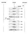
図1は、制御システムの第一実施形態におけるシステム構成を示すブロック図である。
第一実施形態の制御システムは、発信機10a、発信機20a及び電子機器30a(受信装置、装置、機器)を備える。なお、以下の説明では、発信機10aを制御用発信機10aといい、発信機20aを解除用発信機20aという。Hereinafter, embodiments of the present invention will be described with reference to the drawings.
[First embodiment]
FIG. 1 is a block diagram showing a system configuration in the first embodiment of the control system.
The control system of the first embodiment includes a
制御用発信機(第一の発信機)10aは、電子機器30aに対して識別情報を含む無線信号を電波で送信する。
解除用発信機(第二の発信機)20aは、電子機器30aに対して識別情報を含む無線信号を電波で送信する。
なお、制御用発信機10a及び解除用発信機20aは、一定の時間毎に電波を送信するようにしても良いし、常に電波を送信し続けるようにしても良い。
電子機器30aは、制御用発信機10a及び解除用発信機20aから送信される各電波に基づいて自装置(電子機器30a、本体)の制御を行う。電子機器とは、電気回路を含んで構成される機器を表す。電子機器は、例えば、家電、ストーブなどの暖房機器などである。
なお、制御用発信機10a及び解除用発信機20aと、電子機器30aとの無線通信は、例えば、Wi−Fi(登録商標)やBluetooth(登録商標)等の手段により行うようにしても良い。The control transmitter (first transmitter) 10a transmits a radio signal including identification information to the
The canceling transmitter (second transmitter) 20a transmits a radio signal including identification information to the
Note that the
The
The wireless communication between the
以下、電子機器30aの具体的な構成について説明する。電子機器30aは、バスで接続されたCPU(Central Processing Unit)やメモリや補助記憶装置などを備え、制御プログラムを実行する。制御プログラムの実行によって、電子機器30aは、受信部31、識別部32、距離計測部33、判定部34、制御部35、入力部36を備える装置として機能する。なお、電子機器30aの各機能の全て又は一部は、ASIC(ApplicationSpecific Integrated Circuit)やPLD(Programmable Logic Device)やFPGA(Field Programmable Gate Array)等のハードウェアを用いて実現されても良い。また、制御プログラムは、コンピュータ読み取り可能な記録媒体に記録されても良い。コンピュータ読み取り可能な記録媒体とは、例えばフレキシブルディスク、光磁気ディスク、ROM、CD−ROM等の可搬媒体、コンピュータシステムに内蔵されるハードディスク等の記憶装置である。また、制御プログラムは、電気通信回線を介して送受信されても良い。 Hereinafter, a specific configuration of the
受信部31は、制御用発信機10a及び解除用発信機20aから送信される各電波を受信する。
識別部32は、受信部31によって受信された電波に基づいて電波の送信元を識別する。具体的には、識別部32は、受信部31によって受信された電波に含まれる識別情報から電波の送信元が制御用発信機10aであるか解除用発信機20aであるかを識別する。
識別部32は、識別した結果が含まれる識別結果を距離計測部33及び制御部35に出力する。The
The
The
距離計測部33は、自装置(電子機器30a)から電波の送信元までの距離を計測する。また、距離計測部33は、受信した電波の強度(電波強度)に対応する推定距離を予め複数記憶している。そして、距離計測部33は、受信部31が受信した電波の強度を測定し、測定した電波強度の値に対応する推定距離を、自装置から電波の送信元までの距離とする。電波強度は、電子機器30aによって受信された電波の強さである。 The distance measuring unit 33 measures the distance from the own device (
判定部34は、距離計測部33が計測した距離が所定の距離以内であるか否かを判定する。距離計測部33が計測した距離が所定の距離以内である場合、判定部34は制御部35に自装置の制御を行うように通知する。一方、距離計測部33が計測した距離が所定の距離以上である場合、判定部34は処理を行わない。所定の距離とは、例えば、判定部34によって出荷時に記憶されている距離であっても良いし、ユーザ(例えば、大人)によって任意に決定されても良い。 The
制御部35は、各機能部を制御する。また、制御部35は、判定部34が判定した結果及び識別部32から出力された識別結果に基づいて制御を行う。例えば、距離計測部33が計測した距離が所定の距離以内であり、識別部32が識別した電波の送信元が制御用発信機10aである場合、制御部35は自装置に制限をかける(第一の制御)。具体的には、制御部35は、子供に対して危害が加わらない程度に自装置の動作を制御する。 The
以下、子供に対して危害が加わらない程度の動作制御について、具体例を二つ挙げて説明する。一つ目の具体例として、扇風機の動作制御について説明する。扇風機のようにモーターによってファンを回転させ、風を発生させる動作の場合、制御部35はファンの回転数を落とすように制御する。このように制御することによって、子供が扇風機のファンに接触した場合などに生じる可能性のある子供のけがを未然に防ぐことができる。 Hereinafter, two specific examples will be described with respect to operation control that does not cause harm to children. As a first specific example, the operation control of the electric fan will be described. In the case of the operation of rotating a fan by a motor and generating wind as in an electric fan, the
また、二つ目の具体例として、暖房機器の動作制御について説明する。暖房機器とは、熱を発生させる電子機器である。例えば、暖房機器は、暖房機やストーブなどである。暖房機器のように熱を発生させる動作の場合、制御部35は温度を制御する。具体的には、制御部35は、制御用発信機10aとの距離に基づいて暖房機器の温度を下げる。あるいは、制御部35は、暖房機器の運転を停止しても良い。このように制御することによって、子供が暖房機器に接触した場合などに生じる可能性のある子供の火傷などを未然に防ぐことができる。 As a second specific example, operation control of the heating device will be described. A heating device is an electronic device that generates heat. For example, the heating device is a heater or a stove. In the case of an operation that generates heat as in a heating device, the
また、制御部35は、入力部36の動作を制御して入力部36からの入力を受け付けないようにしても良いし、自装置の電源を落として運転を停止させても良い。また、受信部31が一定期間(例えば、5秒、10秒など)の間、制御用発信機10aから電波を受信しない場合、制御部35は自装置の制限を解除するように構成されても良い。また、距離計測部33で計測される距離が所定の距離以上となった場合に、制御部35は自装置の制限を解除するように構成されても良い。 Moreover, the
また、距離計測部33が計測した距離が所定の距離以内であり、識別部32が識別した電波の送信元が解除用発信機20aである場合、制御部35は自装置の制限を解除する(第二の制御)。具体的には、制御部35は、自装置を制限がかけられる前の状態に戻すことによって自装置の制限を解除する。制御部35は、解除用発信機20aから送信された電波が所定の距離以内に存在する間、制御用発信機10aから送信された電波が所定の距離以内であっても自装置に制限をかけない。 When the distance measured by the distance measuring unit 33 is within a predetermined distance and the transmission source of the radio wave identified by the identifying
入力部36は、キーボード、ポインティングデバイス(マウス、タブレット等)、ボタン、タッチパネル等の既存の入力装置を用いて構成される。入力部36は、ユーザの指示を電子機器30aに入力する際にユーザによって操作される。入力部36は、入力装置を電子機器30aに接続するためのインタフェースであっても良い。この場合、入力部36は、入力装置においてユーザの入力に応じ生成された入力信号を電子機器30aに入力する。入力部36は、外部(例えば、大人や子供)からの入力を受け付ける。例えば、入力部36は、電源ボタンや自装置の設定に使用される設定ボタンなどである。 The
図2は、第一実施形態における電子機器30aの制御処理の流れの具体例を示すフローチャートである。
電子機器30aの受信部31は、制御用発信機10aまたは解除用発信機20aから送信された電波を受信する(ステップS101)。識別部32は、受信した電波が制御用発信機10aの電波であるか否かを識別する(ステップS102)。具体的には、識別部32は、受信した電波に含まれている識別情報を参照して、受信した電波が制御用発信機10aの電波であるか否かを識別する。FIG. 2 is a flowchart showing a specific example of the flow of control processing of the
The receiving
識別部32が、受信した電波が制御用発信機10aの電波であると判定した場合(ステップS102−YES)、距離計測部33は自装置(電子機器30a)から電波の送信元である制御用発信機10aまでの距離(以下、「自装置−制御用発信機10a間距離」という。)を計測する(ステップS103)。具体的には、まず、距離計測部33は、受信した制御用発信機10aの電波の強度(電波強度)を測定する。そして、距離計測部33は、測定した電波強度の値に対応する推定距離を、自装置から電波の送信元までの距離とする。 When the
判定部34は、距離計測部33が計測した自装置−制御用発信機10a間距離が所定の距離以内であるか否かを判定する(ステップS104)。判定部34が自装置−制御用発信機10a間距離が所定の距離以内であると判定した場合(ステップS104−YES)、判定部34は自装置が制限を受け付けない状態であるか否かを判定する(ステップS105)。制限を受け付けない状態とは、具体的には、解除用発信機20aが電子機器30aの所定の距離以内に存在する状態である。自装置が制限を受け付けない状態である場合(ステップS105−YES)、制御部35は自装置の動作の制限を行わない。その後、図2の処理は終了する。 The
また、ステップS102の処理において、識別部32が、受信した電波が制御用発信機10aの電波ではないと判定した場合(ステップS102−NO)、識別部32は受信した電波が解除用発信機20aの電波であるか否かを識別する(ステップS106)。識別部32が、受信した電波が解除用発信機20aの電波であると判定した場合(ステップS106−YES)、距離計測部33は自装置から電波の送信元である解除用発信機20aまでの距離(以下、「自装置−解除用発信機20a間距離」という。)を計測する(ステップS107)。 In the process of step S102, when the
判定部34は、距離計測部33が計測した自装置−解除用発信機20a間距離が所定の距離以内であるか否かを判定する(ステップS108)。判定部34が自装置−解除用発信機20a間距離が所定の距離以内であると判定した場合(ステップS108−YES)、判定部34は自装置に制限がかけられているか否かを判定する(ステップS109)。
判定部34が自装置に制限がかけられていると判定した場合(ステップS109−YES)、制御部35は自装置の制限を解除する(ステップS110)。具体的には、制御部35は、自装置を制限がかけられる前の状態(例えば、初期状態)に戻すことによって制限を解除する。その後、図2の処理は終了する。The
When the
また、ステップS104の処理において、判定部34が自装置−制御用発信機10a間距離が所定の距離以内ではないと判定した場合(ステップS104−NO)、電子機器30aは処理を終了する。
また、ステップS105の処理において、自装置が制限を受け付けない状態ではない場合(ステップS105−NO)、制御部35は自装置に制限をかける(ステップS111)。具体的には、制御部35は、子供に対して危害が加わらない程度に自装置の運転を制御する。その後、図2の処理は終了する。Further, in the process of step S104, when the
Further, in the process of step S105, when the own device is not in a state of not accepting the restriction (step S105-NO), the
また、ステップS106の処理において、識別部32が、受信した電波が解除用発信機20aの電波ではないと判定した場合(ステップS106−NO)、電子機器30aは処理を終了する。なお、制御用発信機10a及び解除用発信機20a以外の電波とは、例えば、リモコン等による入力部36への操作信号である。
また、ステップS108の処理において、判定部34が自装置−解除用発信機20a間距離が所定の距離以内ではないと判定した場合(ステップS108−NO)、電子機器30aは処理を終了する。In the process of step S106, when the
In the process of step S108, when the
また、ステップS109の処理において、判定部34が自装置に制限がかけられていないと判定した場合(ステップS109−NO)、制御部35は自装置が制限を受け付けない状態にする(ステップS112)。具体的には、ステップS112以降の処理において、解除用発信機20aが所定の距離以内に存在する間、制御用発信機10aが所定の距離以内に存在する場合であっても、制御部35は自装置の動作を制限しない。その後、電子機器30aは処理を終了する。 Further, in the process of step S109, when the
図3は、第一実施形態における制御処理の具体的な動作を示すシーケンス図である。
解除用発信機20aは、解除用発信機20aの識別情報を含む無線信号を電波で送信する(ステップS201)。電子機器30aの受信部31は、解除用発信機20aから送信された電波を受信する(ステップS202)。識別部32は、受信した電波に含まれている識別情報に基づいて電波の送信元を識別する(ステップS203)。その後、識別部32は、識別した結果を距離計測部33及び制御部35に出力する。距離計測部33は、自装置−解除用発信機20a間距離を計測する(ステップS204)。その後、制御部35は、計測された自装置−解除用発信機20a間距離に基づいて自装置が制限を受け付けない状態にする(ステップS205)。具体的には、解除用発信機20aが所定の距離以内に存在する間、以後の処理では、制御用発信機10aが所定の距離以内に存在する場合であっても、制御部35は自装置の動作を制限しない。FIG. 3 is a sequence diagram showing a specific operation of the control process in the first embodiment.
The canceling
制御用発信機10aは、制御用発信機10aの識別情報を含む無線信号を電波で送信する(ステップS206)。電子機器30aの受信部31は、制御用発信機10aから送信された電波を受信する(ステップS207)。識別部32は、受信した電波に含まれている識別情報に基づいて電波の送信元を識別する(ステップS208)。その後、識別した結果を距離計測部33及び制御部35に出力する。距離計測部33は、自装置−制御用発信機10a間距離を計測する(ステップS209)。その後、制御部35は、計測された自装置−制御用発信機10a間距離が所定の距離以内であっても、自装置の動作を制限しない(ステップS210)。その後、図3の処理は終了する。
なお、自装置が制限を受け付けない状態になっている間、ステップS209の処理が行われなくても良い。具体的には、自装置が制限を受け付けない状態になっている間、自装置−制御用発信機10a間距離にかかわらず、制御部35は自装置の動作を制限しないように構成されても良い。The
Note that the process of step S209 does not have to be performed while the own apparatus is in a state of not accepting the restriction. Specifically, the
図4は、第一実施形態における制御の解除処理の具体的な動作を示すシーケンス図である。
制御用発信機10aは、制御用発信機10aの識別情報を含む無線信号を電波で送信する(ステップS301)。電子機器30aの受信部31は、制御用発信機10aから送信された電波を受信する(ステップS302)。識別部32は、受信した電波に含まれている識別情報に基づいて電波の送信元を識別する(ステップS303)。その後、識別部32は、識別した結果を距離計測部33及び制御部35に出力する。距離計測部33は、自装置−制御用発信機10a間距離を計測する(ステップS304)。その後、制御部35は、計測された自装置−制御用発信機10a間距離に基づいて自装置に制限をかける(ステップS305)。FIG. 4 is a sequence diagram showing a specific operation of the control release processing in the first embodiment.
The
解除用発信機20aは、解除用発信機20aの識別情報を含む無線信号を電波で送信する(ステップS306)。電子機器30aの受信部31は、解除用発信機20aから送信された電波を受信する(ステップS307)。識別部32は、受信した電波に含まれている識別情報に基づいて電波の送信元を識別する(ステップS308)。その後、識別した結果を距離計測部33及び制御部35に出力する。距離計測部33は、自装置−解除用発信機20a間距離を計測する(ステップS309)。その後、制御部35は距離計測部33が計測した自装置−解除用発信機20a間距離に基づいて自装置の制限を解除する(ステップS310)。その後、図4の処理は終了する。 The canceling
以上のように構成された制御システムによれば、制御用発信機10a及び解除用発信機20aによって電子機器30aの制御が行われる。具体的には、電子機器30aに制御用発信機10aを身に着けた子供が電子機器30aの所定の距離以内に近付いた場合、制御用発信機10aによって電子機器30aの運転に制限をかける。その結果、例えば子供が電子機器30aに接触した場合などに生じる可能性のある子供のけがを未然に防ぐことができる。また、解除用発信機20aを身に付けた大人が電子機器30aの所定の距離以内に近づいた場合、電子機器30aの制限が解除される。したがって、解除用発信機20aを身に付けた大人が子供の近い位置にいる場合に電子機器30aの制限が解除される。その結果、解除用発信機20aを身に付けた大人が子供から遠い位置にいる場合に電子機器30aの制限が解除されることが無い。また、電子機器30aの制御を行うために設定を切り替えるなど煩わしい作業を行う必要がない。そのため、本発明の制御システムは、安全性を有し、利便性を向上させることができる。 According to the control system configured as described above, the
また、制御用発信機10a及び解除用発信機20aは、同じ発信機で構成されても良い。この場合、発信機は、制御用モードと解除用モードとの両方のモードを有する。そして、使用者(例えば、大人)は、発信機の使用時に発信機のモードを、制御用モード又は解除用モードの何れかに選択する。例えば、子供が発信機を使用する場合、使用者(例えば、大人)は発信機のモードを制御用モードに設定する。また、例えば、大人が発信機を使用する場合、使用者は発信機のモードを解除用モードに設定する。このように構成されることによって、一つの発信機で用途に応じて使い分けることが可能になる。
なお、制御用発信機10a及び解除用発信機20aは、電波を発信できる形状であればどのような形状であっても良い。例えば、制御用発信機10a及び解除用発信機20aは、バッチ、ワッペン、ペンダント、腕章、腕時計、ベルト等の子供や大人が身に着けられる形状であっても良い。Moreover, the
The
なお、上記実施形態では、制御用発信機10a及び解除用発信機20aと、電子機器30aとの距離を、電子機器30aが受信した制御用発信機10a及び解除用発信機20aの電波の強度に基づいて計測する例について説明したがこれに限らない。例えば、距離計測部33が、レーザーレーダー、超音波センサー、赤外線センサー等の公知の距離計測装置を備え、その距離計測装置により制御用発信機10a及び解除用発信機20aと、電子機器30aとの距離を計測するようにしてもよい。 In the above embodiment, the distance between the
[第二実施形態]
図5は、制御システムの第二実施形態におけるシステム構成を示すブロック図である。
第二実施形態の制御システムは、制御用発信機10b、解除用発信機20b及び電子機器30bを備える。なお、第二実施形態における制御用発信機10b及び解除用発信機20bは、電波の送信距離が予め設定される。電波の送信距離は、例えば、3m、5mなどである。以下の説明では、制御用発信機10b及び解除用発信機20bの電波の送信距離は、同じ送信距離として説明する。[Second Embodiment]
FIG. 5 is a block diagram showing a system configuration in the second embodiment of the control system.
The control system of the second embodiment includes a
以下、電子機器30bの機能構成について説明する。電子機器30bは、バスで接続されたCPUやメモリや補助記憶装置などを備え、制御プログラムを実行する。制御プログラムの実行によって、電子機器30bは、受信部31、識別部32、制御部35、入力部36を備える装置として機能する。なお、電子機器30bの各機能の全て又は一部は、ASICやPLDやFPGA等のハードウェアを用いて実現されても良い。また、制御プログラムは、コンピュータ読み取り可能な記録媒体に記録されても良い。コンピュータ読み取り可能な記録媒体とは、例えばフレキシブルディスク、光磁気ディスク、ROM、CD−ROM等の可搬媒体、コンピュータシステムに内蔵されるハードディスク等の記憶装置である。また、制御プログラムは、電気通信回線を介して送受信されても良い。 Hereinafter, the functional configuration of the
電子機器30bは、距離計測部33及び判定部34を備えていない点で電子機器30aと構成が異なる。電子機器30bは、他の構成については電子機器30aと同様である。
そのため、電子機器30aと共通する構成については、同様の符号を付けて説明を省略する。
なお、制御用発信機10b及び解除用発信機20bと、電子機器30bとの無線通信は、例えば、Wi−Fi(登録商標)やBluetooth(登録商標)等の手段により行うようにしても良い。The
Therefore, about the structure which is common in the
Note that wireless communication between the
図6は、第二実施形態における電子機器30bの制御処理の流れの具体例を示すフローチャートである。
電子機器30bの受信部31は、制御用発信機10bまたは解除用発信機20bから送信された電波を受信する(ステップS401)。識別部32は、受信した電波が制御用発信機10bの電波であるか否かを識別する(ステップS402)。具体的には、識別部32は、受信した電波に含まれている識別情報を参照して、受信した電波が制御用発信機10bの電波であるか否かを識別する。FIG. 6 is a flowchart illustrating a specific example of the flow of control processing of the
The receiving
識別部32が、受信した電波が制御用発信機10bの電波であると判定した場合(ステップS402−YES)、判定部34は自装置が制限を受け付けない状態であるか否かを判定する(ステップS403)。自装置が制限を受け付けない状態である場合(ステップS403−YES)、制御部35は自装置の動作の制限を行わない。その後、図6の処理は終了する。 When the
また、ステップS402の処理において、識別部32が、受信した電波が制御用発信機10bの電波ではないと判定した場合(ステップS402−NO)、識別部32は受信した電波が解除用発信機20bの電波であるか否かを識別する(ステップS404)。識別部32が、受信した電波が解除用発信機20bの電波であると判定した場合(ステップS404−YES)、判定部34は自装置に制限がかけられているか否かを判定する(ステップS405)。判定部34が自装置に制限がかけられていると判定した場合(ステップS405−YES)、制御部35は自装置の制限を解除する(ステップS406)。具体的には、制御部35は、自装置を制限がかけられる前の状態に戻すことによって制限を解除する。その後、図6の処理は終了する。 In the process of step S402, when the
また、ステップS403の処理において、自装置が制限を受け付けない状態ではない場合(ステップS403−NO)、制御部35は自装置(電子機器30b)に制限をかける(ステップS407)。具体的には、制御部35は、子供に対して危害が加わらない程度に自装置の運転を制御する。その後、図6の処理は終了する。
また、ステップS404の処理において、識別部32が、受信した電波が解除用発信機20bの電波ではないと判定した場合(ステップS404−NO)、電子機器30bは処理を終了する。Further, in the process of step S403, when the own device is not in a state of not accepting the restriction (step S403-NO), the
Also, in the process of step S404, when the
また、ステップS405の処理において、判定部34が自装置に制限がかけられていないと判定した場合(ステップS405−NO)、制御部35は制限を受け付けない状態にする(ステップS408)。具体的には、ステップS408以降の処理では、解除用発信機20bが所定の距離以内に存在する間、制御用発信機10bが所定の距離以内に存在する場合であっても、制御部35は自装置の動作を制限しない。その後、電子機器30bは処理を終了する。 Further, in the process of step S405, when the
以上のように構成された制御システムによれば、制御用発信機10b及び解除用発信機20bによって電子機器30bの制御が行われる。具体的には、電子機器30bは、子供が身に着けている制御用発信機10bから電波を受信した場合に自装置の運転を制限する。その結果、例えば子供が電子機器30bに接触した場合などに生じる可能性のある子供のけがを未然に防ぐことができる。そして、大人が身に着けている解除用発信機20bから電波を受信した場合に自装置の制限を解除する。この場合、解除用発信機20bを身に着けた大人は、電子機器30bの近くに存在する。したがって、子供と大人とが互いに近い位置にいるため、大人は子供の様子を伺うことができる。そして、電子機器30bの制御を行うために設定を切り替えるなど煩わしい作業を行う必要がない。
そのため、本発明の制御システムは、安全性を有し、利便性を向上させることができる。According to the control system configured as described above, the
Therefore, the control system of the present invention has safety and can improve convenience.
また、制御用発信機10b及び解除用発信機20bは、同じ発信機で構成されても良い。この場合、発信機は、制御用モードと解除用モードとの両方のモードを有する。そして、使用者(例えば、大人)は、発信機の使用時に発信機のモードを、制御用モード又は解除用モードの何れかに選択する。例えば、子供が発信機を使用する場合、使用者(例えば、大人)は発信機のモードを制御用モードに設定する。また、例えば、大人が発信機を使用する場合、使用者は発信機のモードを解除用モードに設定する。このように構成されることによって、一つの発信機で用途に応じて使い分けることが可能になる。
なお、制御用発信機10b及び解除用発信機20bは、電波を発信できる形状であればどのような形状であっても良い。例えば、制御用発信機10b及び解除用発信機20bは、バッチ、ワッペン、ペンダント、腕章、腕時計、ベルト等の子供や大人が身に着けられる形状であっても良い。Further, the
The
また、制御用発信機10b及び解除用発信機20bの電波の送信距離は、上述の構成に限定される必要はない。例えば、制御用発信機10b及び解除用発信機20bの電波の送信距離が異なるように構成されても良い。具体的には、制御用発信機10bの電波の送信距離を長く(例えば、5m)し、解除用発信機20bの電波の送信距離を短く(例えば、3m)する。このように構成されることによって、制御用発信機10bを身に着けた子供より解除用発信機20bを身に着けた大人の方が電子機器30bに近い位置に存在する場合に、電子機器30bの制限が解除される。したがって、電子機器30bの制限が解除された場合であっても、大人の方が子供より電子機器30bに近い。そのため、大人が子供に注意を払うことによって、子供の安全性を高めることができる。 Further, the transmission distance of the radio waves of the
以上、この発明の実施形態について図面を参照して詳述してきたが、具体的な構成はこの実施形態に限られるものではなく、この発明の要旨を逸脱しない範囲の設計等も含まれる。 The embodiment of the present invention has been described in detail with reference to the drawings. However, the specific configuration is not limited to this embodiment, and includes designs and the like that do not depart from the gist of the present invention.
10(10a及び10b)…発信機(制御用発信機), 20(20a及び20b)…発信機(解除用発信機), 30(30a及び30b)…電子機器, 31…受信部, 32…識別部, 33…距離計測部(計測部), 35…制御部。 10 (10a and 10b) ... Transmitter (control transmitter), 20 (20a and 20b) ... Transmitter (transmitter for release), 30 (30a and 30b) ... Electronic equipment, 31 ... Receiver, 32 ... Identification Part, 33 ... distance measurement part (measurement part), 35 ... control part.
Claims (6)
Translated fromJapanese前記第一の発信機は、
前記受信装置に対して電波を送信する送信部を備え、
前記第二の発信機は、
前記受信装置に対して電波を送信する送信部を備え、
前記受信装置は、
前記第一の発信機及び前記第二の発信機から送信される電波を受信する受信部と、
前記受信部が受信した電波に基づいて、前記電波の送信元が前記第一の発信機であるか前記第二の発信機であるかを識別する識別部と、
自装置と、前記識別部が識別した前記電波の送信元との距離を計測する計測部と、
前記計測部が計測した、自装置と、前記電波の送信元との距離に基づいて、自装置に制限をかける第一の制御、又は自装置に制限をかけない第二の制御を行う制御部と、
を備え、
前記制御部は、自装置と前記第一の発信機との距離が所定の距離以内であり、かつ、自装置と前記第二の発信機との距離が所定の距離より長い場合、前記第一の制御を行う、
制御システム。A control system comprising a first transmitter, a second transmitter, and a receiver that controls the device based on radio waves transmitted from the first transmitter and the second transmitter. There,
The first transmitter is
A transmission unit for transmitting radio waves to the receiving device;
The second transmitter is
A transmission unit for transmitting radio waves to the receiving device;
The receiving device is:
A receiver for receiving radio waves transmitted from the first transmitter and the second transmitter;
Based on the radio wave received by the reception unit, an identification unit for identifying whether the transmission source of the radio wave is the first transmitter or the second transmitter;
A measuring unit for measuring a distance between the own device and the transmission source of the radio wave identified by the identifying unit;
A control unit that performs the first control that restricts the own device or the second control that does not restrict the own device based on the distance between the own device and the radio wave transmission source measured by the measurement unit. When,
Equipped witha,
When the distance between the own device and the first transmitter is within a predetermined distance and the distance between the own device and the second transmitter is longer than a predetermined distance, the control unit Control
Control system.
前記制御部は、前記第一の制御が行われている状態で、自装置と前記第二の発信機との距離が所定の距離以内となった場合、前記第二の制御によって、前記第一の制御を解除する制御システム。The control system according to claim1 ,
When the distance between the own device and the second transmitter is within a predetermined distance in a state where the first control is performed, the control unit performs the first control by the second control. Control system to release the control of.
前記制御部は、前記第二の発信機が所定の距離以内に存在する間、前記第一の制御を行わない制御システム。The control system according toclaim 1or 2 ,
The control unit is a control system that does not perform the first control while the second transmitter exists within a predetermined distance.
前記受信部が受信した電波に基づいて、前記電波の送信元が前記第一の発信機であるか前記第二の発信機であるかを識別する識別部と、
自装置と、前記識別部が識別した前記電波の送信元との距離を計測する計測部と、
前記計測部が計測した、自装置と、前記電波の送信元との距離に基づいて、自装置に制限をかける第一の制御、又は自装置に制限をかけない第二の制御を行う制御部と、
を備え、
前記制御部は、自装置と前記第一の発信機との距離が所定の距離以内であり、かつ、自装置と前記第二の発信機との距離が所定の距離より長い場合、前記第一の制御を行う、
受信装置。A receiver for receiving radio waves transmitted from the first transmitter and the second transmitter;
Based on the radio wave received by the reception unit, an identification unit for identifying whether the transmission source of the radio wave is the first transmitter or the second transmitter;
A measuring unit for measuring a distance between the own device and the transmission source of the radio wave identified by the identifying unit;
A control unit that performs the first control that restricts the own device or the second control that does not restrict the own device based on the distance between the own device and the radio wave transmission source measured by the measurement unit. When,
Equipped witha,
When the distance between the own device and the first transmitter is within a predetermined distance and the distance between the own device and the second transmitter is longer than a predetermined distance, the control unit Control
Receiver device.
前記制御部は、前記第一の制御が行われている状態で、自装置と前記第二の発信機との距離が所定の距離以内となった場合、前記第二の制御によって、前記第一の制御を解除する受信装置。The receiving device according to claim4 ,
When the distance between the own device and the second transmitter is within a predetermined distance in a state where the first control is performed, the control unit performs the first control by the second control. Receiver that releases control.
前記制御部は、前記第二の発信機が所定の距離以内に存在する間、前記第一の制御を行わない受信装置。In the receiving device according toclaim 4 or 5 ,
The control unit is a receiving device that does not perform the first control while the second transmitter exists within a predetermined distance.
Applications Claiming Priority (3)
| Application Number | Priority Date | Filing Date | Title |
|---|---|---|---|
| JP2013036930 | 2013-02-27 | ||
| JP2013036930 | 2013-02-27 | ||
| PCT/JP2014/054007WO2014132873A1 (en) | 2013-02-27 | 2014-02-20 | Control system and reception device |
Publications (2)
| Publication Number | Publication Date |
|---|---|
| JPWO2014132873A1 JPWO2014132873A1 (en) | 2017-02-02 |
| JP6308209B2true JP6308209B2 (en) | 2018-04-11 |
Family
ID=51428144
Family Applications (1)
| Application Number | Title | Priority Date | Filing Date |
|---|---|---|---|
| JP2015502890AActiveJP6308209B2 (en) | 2013-02-27 | 2014-02-20 | Control system and receiving apparatus |
Country Status (3)
| Country | Link |
|---|---|
| US (1) | US10429805B2 (en) |
| JP (1) | JP6308209B2 (en) |
| WO (1) | WO2014132873A1 (en) |
Families Citing this family (2)
| Publication number | Priority date | Publication date | Assignee | Title |
|---|---|---|---|---|
| JP2020106441A (en)* | 2018-12-28 | 2020-07-09 | 株式会社オートネットワーク技術研究所 | Distance measuring device, communication device, communication system |
| JP2024063658A (en) | 2022-10-26 | 2024-05-13 | アークレイ株式会社 | Analysis device, function restriction method, and function restriction program |
Family Cites Families (17)
| Publication number | Priority date | Publication date | Assignee | Title |
|---|---|---|---|---|
| US5525967A (en)* | 1993-11-01 | 1996-06-11 | Azizi; S. Massoud | System and method for tracking and locating an object |
| US5510771A (en)* | 1994-01-10 | 1996-04-23 | Marshall; Burpee W. | Alarm system for precluding a child from straying |
| US5521652A (en)* | 1994-04-28 | 1996-05-28 | Shalvi; Ilan | Proximity controlled safety device for a video monitor |
| US5589821A (en)* | 1994-12-13 | 1996-12-31 | Secure Technologies, Inc. | Distance determination and alarm system |
| US6302438B1 (en)* | 1998-04-21 | 2001-10-16 | Automotive Systems Laboratory, Inc. | Occupant detection system |
| US20020186135A1 (en)* | 2001-05-30 | 2002-12-12 | Colleen Wagner | Device for locating an individual |
| GB2392032B (en)* | 2002-08-15 | 2006-08-23 | Kiddielink Ltd | Locating system, device and method |
| GB2405276B (en)* | 2003-08-21 | 2005-10-12 | Motorola Inc | Measuring distance using wireless communication |
| US7385513B2 (en)* | 2005-01-27 | 2008-06-10 | Everest A Wallace | Device for monitoring and measuring distance |
| EP1903412B1 (en)* | 2006-09-22 | 2011-11-02 | Siemens Aktiengesellschaft | Method for releasing the operation of automation components of a technical installation via a mobile control and visualisation apparatus |
| US20100064532A1 (en)* | 2007-07-31 | 2010-03-18 | Edward Raymond Wittke | Chain saw 3D relative positional monitoring and anti-kickback actuation system |
| US7890743B2 (en)* | 2007-09-28 | 2011-02-15 | Avaya Inc. | Method and apparatus for configuring a device based on proximity to another device |
| CA2617976A1 (en)* | 2008-01-11 | 2009-07-11 | John Dasilva | Personnel safety system utilizing time variable frequencies |
| US7966641B2 (en)* | 2008-10-23 | 2011-06-21 | Sony Corporation | User identification using Bluetooth and audio ranging |
| JP2010109410A (en)* | 2008-10-28 | 2010-05-13 | Panasonic Corp | Home control system, and control method and program therefor |
| US8688376B2 (en)* | 2009-05-11 | 2014-04-01 | Continental Automotive Gmbh | Vehicle-to-X communication by means of radio key |
| JP2012117707A (en)* | 2010-11-30 | 2012-06-21 | Denkosha Co Ltd | Child guard sensor |
- 2014
- 2014-02-20JPJP2015502890Apatent/JP6308209B2/enactiveActive
- 2014-02-20WOPCT/JP2014/054007patent/WO2014132873A1/enactiveApplication Filing
- 2015
- 2015-08-14USUS14/826,550patent/US10429805B2/enactiveActive
Also Published As
| Publication number | Publication date |
|---|---|
| US10429805B2 (en) | 2019-10-01 |
| WO2014132873A1 (en) | 2014-09-04 |
| US20150355614A1 (en) | 2015-12-10 |
| JPWO2014132873A1 (en) | 2017-02-02 |
Similar Documents
| Publication | Publication Date | Title |
|---|---|---|
| CN104110874B (en) | Water heater control system and the bathing reminding method based on water heater | |
| JP6306417B2 (en) | Vehicle communication system | |
| CN104050402A (en) | Mobile terminal security certification method and system and mobile terminal | |
| JP2017193884A (en) | Key security device | |
| JP6308209B2 (en) | Control system and receiving apparatus | |
| EP2793401A1 (en) | Tracking exposure to electomagnetic fields | |
| KR20130088568A (en) | Access alarm apparatus and method | |
| CN109559487A (en) | Vehicle status prompting system, vehicle, terminal device, and vehicle status prompting method | |
| TWI756213B (en) | Garage door opener with touch sensor authentication and method of remotely controlling a garage door having a garage door opener | |
| US20190019393A1 (en) | Apparatus And Method For Detection Of Movement Behind Wearer Of Wearable Device And Signal | |
| JP6459114B2 (en) | Electric lock system | |
| JP6614999B2 (en) | Electronic key system | |
| JP2014057472A (en) | Non-contact power transmission device and power transmitter using the same and power receiver | |
| CN106256155B (en) | Methods, wireless communication devices, and peripherals that are identified as being within a predetermined distance | |
| JP2018157360A (en) | Vehicle control system and vehicle control method | |
| JP2018011232A5 (en) | ||
| KR102171863B1 (en) | Wake up alarm system and wake up alarm methods using the same | |
| CN106468596A (en) | In-ear temperature monitoring device, system and monitoring method | |
| KR20200078786A (en) | Smart guide stick system | |
| JP4028540B2 (en) | Portable terminal device and power activation control device | |
| KR20060099991A (en) | Access warning device and access safety device and control method | |
| CN116700022A (en) | Electric shock prevention prompting method and device for intelligent home system and intelligent home system | |
| JP2017002492A (en) | Door lock control system | |
| JP2016019259A (en) | Remote operation system | |
| KR102369650B1 (en) | Non-contact button |
Legal Events
| Date | Code | Title | Description |
|---|---|---|---|
| A131 | Notification of reasons for refusal | Free format text:JAPANESE INTERMEDIATE CODE: A131 Effective date:20170905 | |
| A02 | Decision of refusal | Free format text:JAPANESE INTERMEDIATE CODE: A02 Effective date:20171219 | |
| A521 | Request for written amendment filed | Free format text:JAPANESE INTERMEDIATE CODE: A523 Effective date:20171227 | |
| A911 | Transfer to examiner for re-examination before appeal (zenchi) | Free format text:JAPANESE INTERMEDIATE CODE: A911 Effective date:20180109 | |
| TRDD | Decision of grant or rejection written | ||
| A01 | Written decision to grant a patent or to grant a registration (utility model) | Free format text:JAPANESE INTERMEDIATE CODE: A01 Effective date:20180213 | |
| A61 | First payment of annual fees (during grant procedure) | Free format text:JAPANESE INTERMEDIATE CODE: A61 Effective date:20180226 | |
| R150 | Certificate of patent or registration of utility model | Ref document number:6308209 Country of ref document:JP Free format text:JAPANESE INTERMEDIATE CODE: R150 | |
| R250 | Receipt of annual fees | Free format text:JAPANESE INTERMEDIATE CODE: R250 | |
| R250 | Receipt of annual fees | Free format text:JAPANESE INTERMEDIATE CODE: R250 | |
| R250 | Receipt of annual fees | Free format text:JAPANESE INTERMEDIATE CODE: R250 | |
| R250 | Receipt of annual fees | Free format text:JAPANESE INTERMEDIATE CODE: R250 |