JP6308192B2 - Reciprocating engine - Google Patents
Reciprocating engineDownload PDFInfo
- Publication number
- JP6308192B2 JP6308192B2JP2015183731AJP2015183731AJP6308192B2JP 6308192 B2JP6308192 B2JP 6308192B2JP 2015183731 AJP2015183731 AJP 2015183731AJP 2015183731 AJP2015183731 AJP 2015183731AJP 6308192 B2JP6308192 B2JP 6308192B2
- Authority
- JP
- Japan
- Prior art keywords
- cylinder
- cylinder block
- spacer
- reciprocating engine
- intermediate body
- Prior art date
- Legal status (The legal status is an assumption and is not a legal conclusion. Google has not performed a legal analysis and makes no representation as to the accuracy of the status listed.)
- Expired - Fee Related
Links
- 125000006850spacer groupChemical group0.000claimsdescription58
- 238000002485combustion reactionMethods0.000claimsdescription28
- 239000000463materialSubstances0.000claimsdescription22
- 230000002093peripheral effectEffects0.000claimsdescription12
- XLYOFNOQVPJJNP-UHFFFAOYSA-NwaterSubstancesOXLYOFNOQVPJJNP-UHFFFAOYSA-N0.000claimsdescription12
- 239000000446fuelSubstances0.000description7
- 238000000034methodMethods0.000description6
- 239000011324beadSubstances0.000description5
- 238000005336crackingMethods0.000description4
- 239000007789gasSubstances0.000description4
- 238000003780insertionMethods0.000description4
- 230000037431insertionEffects0.000description4
- 239000003507refrigerantSubstances0.000description4
- 238000005266castingMethods0.000description3
- 238000010586diagramMethods0.000description3
- 238000006073displacement reactionMethods0.000description3
- 239000003921oilSubstances0.000description3
- 238000012545processingMethods0.000description3
- 229910001018Cast ironInorganic materials0.000description2
- 229910000737DuraluminInorganic materials0.000description2
- 229910000831SteelInorganic materials0.000description2
- 229910052782aluminiumInorganic materials0.000description2
- XAGFODPZIPBFFR-UHFFFAOYSA-NaluminiumChemical compound[Al]XAGFODPZIPBFFR-UHFFFAOYSA-N0.000description2
- 230000006835compressionEffects0.000description2
- 238000007906compressionMethods0.000description2
- 239000000498cooling waterSubstances0.000description2
- 238000002474experimental methodMethods0.000description2
- 238000010030laminatingMethods0.000description2
- 239000010959steelSubstances0.000description2
- 229910000838Al alloyInorganic materials0.000description1
- YCKRFDGAMUMZLT-UHFFFAOYSA-NFluorine atomChemical compound[F]YCKRFDGAMUMZLT-UHFFFAOYSA-N0.000description1
- 230000002159abnormal effectEffects0.000description1
- 239000011248coating agentSubstances0.000description1
- 238000000576coating methodMethods0.000description1
- 239000000567combustion gasSubstances0.000description1
- 238000001816coolingMethods0.000description1
- 238000005520cutting processMethods0.000description1
- 230000003247decreasing effectEffects0.000description1
- 230000006866deteriorationEffects0.000description1
- 238000011161developmentMethods0.000description1
- 230000018109developmental processEffects0.000description1
- 239000013013elastic materialSubstances0.000description1
- 239000011737fluorineSubstances0.000description1
- 229910052731fluorineInorganic materials0.000description1
- 238000005242forgingMethods0.000description1
- 239000002783friction materialSubstances0.000description1
- 239000010687lubricating oilSubstances0.000description1
- 238000004519manufacturing processMethods0.000description1
- 229910052751metalInorganic materials0.000description1
- 239000002184metalSubstances0.000description1
- 238000005555metalworkingMethods0.000description1
- 239000010705motor oilSubstances0.000description1
- 238000003825pressingMethods0.000description1
- 238000003672processing methodMethods0.000description1
- 238000004080punchingMethods0.000description1
- 230000002787reinforcementEffects0.000description1
- 238000007789sealingMethods0.000description1
- 239000007779soft materialSubstances0.000description1
- 239000010935stainless steelSubstances0.000description1
- 229910001220stainless steelInorganic materials0.000description1
- 230000003746surface roughnessEffects0.000description1
Images


Landscapes
- Cylinder Crankcases Of Internal Combustion Engines (AREA)
Description
Translated fromJapanese本発明は、シリンダブロック、シリンダヘッド、ピストン、および、シリンダブロックとシリンダヘッドとの間に介在する中間体と、を備えたレシプロ式エンジンに関する。 The present invention relates to a reciprocating engine including a cylinder block, a cylinder head, a piston, and an intermediate body interposed between the cylinder block and the cylinder head.
現在、一般的なレシプロエンジンでは、シリンダヘッドとシリンダブロックは、燃焼ガスや冷却水、潤滑油等のシールを目的とした薄いガスケットを介してボルト締結されている。この場合、シリンダ内の圧力、すなわち、筒内圧力は、シリンダの内壁により受け持たれる。 Currently, in a general reciprocating engine, a cylinder head and a cylinder block are bolted via a thin gasket for the purpose of sealing a combustion gas, cooling water, lubricating oil, or the like. In this case, the pressure in the cylinder, that is, the in-cylinder pressure is received by the inner wall of the cylinder.
ここで、近年のエンジンの低燃費化開発において、機関の軽量化と機械損失(ポンプ損失、摩擦損失)の低減による燃費向上効果を狙ってエンジンの排気量を小さくする傾向がある。このとき、少なくなった排気量による出力の低下を、過給によるエンジンの比出力(排気量あたりのエンジン出力)増加により補うことになる。過給を行なった場合には、燃焼による筒内圧力が増大する。こうした高い筒内圧力によりシリンダの変形や、シリンダブロックの割れが生じるおそれがあった。シリンダの変形が生じると、摩擦損失の増加や、ピストン−シリンダの異常摩耗や焼きつき等が生じるおそれがあった。 Here, in recent developments to reduce fuel consumption of engines, there is a tendency to reduce engine displacement for the purpose of improving fuel efficiency by reducing engine weight and reducing mechanical loss (pump loss, friction loss). At this time, the decrease in the output due to the reduced displacement is compensated by the increase in the specific output of the engine (engine output per displacement) due to supercharging. When supercharging is performed, the in-cylinder pressure due to combustion increases. Such high in-cylinder pressure may cause deformation of the cylinder or cracking of the cylinder block. When the cylinder is deformed, there is a risk that an increase in friction loss, abnormal wear or seizure of the piston-cylinder, and the like may occur.
ここで、シリンダブロックの構造としては、シリンダとブロック外壁がほぼ一体に成型されたクローズドデッキ構造と、シリンダとブロック外壁がウォータジャケットによって中州状態になっているオープンデッキ構造と、が知られている。オープンデッキ構造は、生産性に優れており、また、軽量であるという利点を有する一方で、上述した高い筒内圧力に耐えにくく、シリンダの変形が生じやすいという問題があった。 Here, as the structure of the cylinder block, there are known a closed deck structure in which the cylinder and the outer wall of the block are formed integrally, and an open deck structure in which the cylinder and the outer wall of the block are in a state of the middle by a water jacket. . The open deck structure is excellent in productivity and has the advantage of being lightweight, but has a problem that it is difficult to withstand the high in-cylinder pressure described above and the cylinder is likely to be deformed.
クローズドデッキ構造は、オープンデッキ構造に比べて高い強度を有し、シリンダが変形しにくいという利点を有する一方で、生産性の悪化や製造コストおよび重量の増加という問題を招いていた。さらに、将来的に現状を大きく上回る高筒内圧力化が必要となった場合、クローズドデッキのシリンダブロックでもシリンダ変形が過大となり、シリンダ変形に起因する上述の問題が発生する恐れがあった。 The closed deck structure has a higher strength than the open deck structure and has an advantage that the cylinder is not easily deformed. On the other hand, the closed deck structure causes a problem of deterioration in productivity and an increase in manufacturing cost and weight. Furthermore, when a higher in-cylinder pressure is required in the future, the cylinder deformation of the closed deck cylinder block becomes excessive, and the above-described problem due to cylinder deformation may occur.
なお、特許文献1には、ピストンの一部を積極的に変形させて、圧縮比を変化可能にしたエンジン構造が開示されている。この特許文献1では、高負荷運転時には、ピストンの一部を、ガス圧により、燃焼室体積が増加する方向に変形させることで、圧縮比を低減している。したがって、この技術によれば、筒内圧力が高い場合には、ピストンの一部が体積拡大、ひいては、筒内圧力低下の方向に変形するため、シリンダの変形を多少は防止できる。しかし、特許文献1の技術は、そもそも、シリンダの変形防止を目的とした技術ではなく、特許文献1の技術のみで上述したシリンダの変形等の問題を効果的に防止することは困難であった。
そこで、本発明では、シリンダの変形をより効果的に防止できるレシプロ式エンジンを提供することを目的とする。 Therefore, an object of the present invention is to provide a reciprocating engine that can more effectively prevent cylinder deformation.
本発明のレシプロ式エンジンは、1以上のシリンダが設けられたシリンダブロックと、前記シリンダブロックに連結されるシリンダヘッドと、前記シリンダ内を進退可能なピストンであって、周面にピストンリングが取り付けられたピストンと、前記シリンダブロックと前記シリンダヘッドとの間に介在する中間体であって、内周面が燃焼室内に露出して燃焼圧力を受けるボア孔が1以上設けられた中間体と、を備え、前記中間体は、前記シリンダ内を気密にシールする一対のガスケットと、前記ガスケットよりも肉厚で前記一対のガスケットの間に介在するスペーサと、を含み、前記中間体は、前記ピストンが前記シリンダヘッドに最も近づく最上位置にあるときの前記ピストンリングの上端から前記シリンダヘッドの下端までの距離である基準距離以下の厚みを有しており、前記一対のガスケットのうち少なくとも前記シリンダブロック側に配されるガスケットの少なくとも片面は、前記スペーサの変形に伴う、前記シリンダブロックに対する前記スペーサの滑りを許容する表面性状を有する、ことを特徴とする。The reciprocating engine of the present invention is a cylinder block provided with one or more cylinders, a cylinder head connected to the cylinder block, and a piston capable of advancing and retreating in the cylinder. An intermediate body interposed between the piston and the cylinder block and the cylinder head, the intermediate body having one or more bore holes that are exposed in the combustion chamber and receive combustion pressure; The intermediate body includes a pair of gaskets that hermetically seal the inside of the cylinder, and a spacer that is thicker than the gasket and interposed between the pair of gaskets, and the intermediate body includes the piston. Is the distance from the upper end of the piston ring to the lower end of the cylinder head when it is at the uppermost position closest to the cylinder head.It has a reference distance or less inthickness, at least one surface of the gasket which is arranged at least on the cylinder block side of the pair of gasket caused by deformation of the spacer, allowing the sliding of the spacer relative to the cylinder block It has a surface texture .
他の好適な態様では、前記中間体は、前記基準距離の2割以上の厚みを有する。さらに、前記中間体は、前記基準距離の5割以上の厚みを有する、ことがより望ましい。 In another preferred aspect, the intermediate has a thickness of 20% or more of the reference distance. Furthermore, it is more desirable that the intermediate has a thickness of 50% or more of the reference distance.
他の好適な態様では、前記スペーサの強度は、前記シリンダブロックの強度とほぼ同じである、ことが望ましい。In another preferredembodiment, the strength of theprevious SL spacer is substantially the same as the strength of the cylinder block, it is desirable.
他の好適な態様では、前記シリンダブロックは、前記シリンダと離間した位置に、当該シリンダブロックの上端面に開口するウォータジャケットを有しており、前記スペーサは、前記ウォータジャケットの開口部に嵌り込む凸部を有する。この場合、前記スペーサの強度は、前記シリンダブロックの強度よりも高い、ことが望ましい。他の好適な態様では、前記スペーサは、2以上の板材を積層した構成を含む。In another preferredembodiment, prior Symbol cylinder block, at a position spaced with the cylinder, has a water jacket which is open on the upper end face of the cylinder block, the spacer is fitted into the opening portion of the water jacket It has a convex part to be inserted. In this case, it is preferable that the strength of the spacer is higher than the strength of the cylinder block. In another preferred aspect, the spacer includes a configuration in which two or more plate materials are laminated.
本発明によれば、燃焼により生じる力の一部を中間体が受けるため、シリンダにかかる負荷を低減でき、ひいては、シリンダの変形を効果的に防止できる。 According to the present invention, since the intermediate receives a part of the force generated by the combustion, it is possible to reduce the load applied to the cylinder, and effectively prevent the cylinder from being deformed.
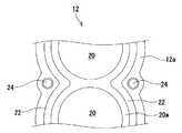
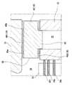
以下、本発明の実施形態について図面を参照して説明する。図1は、本発明の実施形態であるレシプロ式エンジン10(以下、単に「エンジン10」という)の概略構成を示す図である。また、図2は、シリンダブロック12の一部平面図であり、図3は、中間体18の一部平面図である。また、図4は、図1のA部拡大図である。 Embodiments of the present invention will be described below with reference to the drawings. FIG. 1 is a diagram showing a schematic configuration of a reciprocating engine 10 (hereinafter simply referred to as “
エンジン10は、1以上のシリンダ20が形成されたシリンダブロック12と、当該シリンダブロック12の上側に取り付けられるシリンダヘッド14と、シリンダ20内で進退するピストン16と、シリンダヘッド14およびシリンダブロック12の間に介在する中間体18と、を備えている。シリンダブロック12は、アルミダイキャスト(鋳物用アルミニウム合金)や、鋳鉄等からなる鋳造部品である。このシリンダブロック12には、複数のシリンダ20が設けられており、各シリンダ20の周囲には、ウォータジャケット22が形成されている。ウォータジャケット22は、シリンダブロック12の上端面において開口した穴であり、各シリンダ20の全周囲を囲むような形状となっている。つまり、本実施形態のシリンダブロック12は、シリンダ20の外壁20aと、シリンダブロック12の外壁12aとが分離した、いわゆるオープンデッキ構造となっている。また、シリンダブロック12の上端面には、シリンダヘッド14を締結するための締結ボルト(図示せず)が螺合するボルト穴24が形成されている。 The
シリンダヘッド14も、シリンダブロック12と同様に、アルミダイキャストや鋳鉄等からなる鋳造部品である。このシリンダヘッド14には、吸気ポート28および排気ポート30が設けられている。このシリンダヘッド14のうち、ボルト穴24に対応する位置には、締結ボルトが挿通する挿通孔(図示せず)が形成されている。 Similarly to the
ピストン16は、シリンダ20内を進退する円柱体で、コネクティングロッド32を介してクランクシャフト(図示せず)に接続されている。ピストン16は、シリンダ20の内径より僅かに小さい外径を有している。このピストン16よりも上側の空間が、燃料が燃焼(爆発)する燃焼室26となる。 The
ピストン16の外周囲には、三つのピストンリング34、すなわち、上から順に、トップリング34t、セカンドリング34s、オイルリング34oが装着されている。トップリング34tおよびセカンドリング34sは、シリンダ20の内周面(シリンダライナ)に気密に密着して摺動し、主に、燃焼室26からクランクケース側へと圧縮ガスが抜けることを防ぐ。オイルリング34oは、シリンダ20の内周面についている余分なエンジンオイルをかき落とし、適度な油膜を形成してピストン16の焼きつきを防止する。ここで、以下の説明では、ピストン16がシリンダヘッド14に最も近づく最上位置(一般に上死点位置)にあるときのトップリング34tの上端から、シリンダヘッド14の下端までの距離を、「基準距離D」と呼ぶ。 Around the outer periphery of the
中間体18は、シリンダブロック12とシリンダヘッド14との間に介在する部材である。中間体18は、図3に示す通り、複数のボア孔36を有しており、この複数のボア孔36は、シリンダブロック12に形成されたシリンダ20の位置に合わせて形成されている。ボア孔36の内径は、シリンダ20の内径とほぼ同じか、僅かに大きくなっている。このボア孔36の内周面は、燃焼室26内に露出しており、燃焼室26の内周面の一部として機能する。また、中間体18には、複数の挿通孔38も形成されており、この複数の挿通孔38は、シリンダブロック12に形成されたボルト穴24の位置に合わせて形成されている。こうした中間体18は、シリンダブロック12とシリンダヘッド14との間に配された状態で、締結ボルトにより、シリンダヘッド14とともにシリンダブロック12に共締めされる。 The
中間体18は、スペーサ42と、当該スペーサ42とシリンダヘッド14との間に介在する上側ガスケット40tと、当該スペーサ42とシリンダブロック12との間に介在する下側ガスケット40dと、を有した積層構造となっている。なお、以下では、上側ガスケット40tと下側ガスケット40dとを特に区別しない場合は、添え字のアルファベットを省略し、単に、「ガスケット40」という。 The
ガスケット40は、周知の通り、燃焼室26内の高圧ガスをシールする部材である。ガスケット40は、図5に示すように、ステンレス鋼板等の基材46の両面を耐熱ゴム等のゴム状弾性材料からなる弾性層44でコーティングした多層板材からなる。ガスケット40は、この多層板材を、所定形状にプレス加工して構成される。ガスケット40には、ボア孔36を取り囲むボアシールドビード40aと、ウォータジャケット22の周縁に沿って延びるハーフビード40bが形成されている。ボアシールドビード40aおよびハーフビード40bは、それぞれ、スペーサ42とは反対側に突出する突起および段差である。この二種類のビード40a,40bは、いずれも、シリンダブロック12の上面またはシリンダヘッド14の底面に接触して、高圧ガスや冷却水の漏れを防止する。 As is well known, the
スペーサ42は、燃焼室26内での燃料燃焼で生じた力の少なくとも一部を受けるために設けられた板材である。このスペーサ42は、ガスケット40よりも十分に肉厚な板材からなるため、通常、一般的なプレス加工(いわゆる板金加工)での成形は難しく、板鍛造と呼ばれる特殊なプレス加工や、切削加工、鋳造等で成形される。スペーサ42の材質は、十分な耐熱性を有しているのであれば、特に限定されないが、望ましくは、シリンダブロック12よりも強度が高い材料、例えば、鋼材やジュラルミン等からなることが望ましい。ここで、「強度」としては、種々の定義があるが、本実施形態で言う「強度」とは、圧力に対する変形や破壊のしにくさの意味であり、ヤング率(縦弾性係数)や、じん性、降伏応力が高い場合に「強度が高い」としている。 The
こうしたスペーサ42および一対のガスケット40からなる中間体18の厚みは、基準距離D未満となっている。中間体18の厚みを基準距離D未満とするのは、トップリング34tと中間体18との干渉を防止するためである。また、中間体18の厚みの下限は、特に限定されないが、少なくとも基準距離Dの2割以上であることが望ましく、より望ましくは、5割以上、より望ましくは、7割以上である。 The thickness of the
ここで、既述した通り、中間体18の厚みを基準距離Dの2割以上とした場合、通常、スペーサ42は、数ミリ以上の厚みとなり、一般的なプレス加工(板金加工)での成形は困難となる。その結果、本実施形態のスペーサ42は、板鍛造や、切削加工、鋳造など、一般的なプレス加工に比べてコストの高い加工方法で成形される。このように、高コストであっても、中間体18をD/5以上という肉厚な構造にするのは、シリンダ20の変形を低減するためである。すなわち、周知の通り、エンジン10においては、燃料をシリンダ20内で燃焼(爆発)させるが、この燃焼時にシリンダ20内には、高い燃焼圧力が生じる。従来、この燃焼により生じた大きな力の大部分を、シリンダ20の内面で受けていた。この大きな力を受けて、シリンダ20の変形や、割れが生じることがあった。特に、本実施形態のように、オープンデッキ構造のシリンダブロック12の場合、シリンダ20の外壁20aとシリンダブロック12の外壁12aとの間にウォータジャケット22が介在しており、シリンダ20の上部外側に、シリンダブロック12の外壁12aによる支持が無いため、シリンダ20の変形や割れが生じやすかった。 Here, as described above, when the thickness of the intermediate 18 is 20% or more of the reference distance D, the
本実施形態では、こうしたシリンダ20の変形や割れを防止するために、通常のガスケット40よりも十分に肉厚な中間体18をシリンダブロック12とシリンダヘッド14との間に配置している。かかる構成とすることで、燃料の燃焼で生じた力の一部を、中間体18が受けることになり、シリンダ20の内周面が受ける力が低下する。結果として、シリンダ20の変形や割れが効果的に防止される。 In the present embodiment, in order to prevent such deformation and cracking of the
図6は、中間体18の有無によるシリンダ20の変形量の違いについての実験結果を示す図である。また、図7は、二つの実験条件A,Bを示す図である。この実験では、基準距離D=20mmの燃焼室26内に、10MPaの圧力をかけた際のシリンダ20上端における変形量を測定した。条件Aでは、シリンダブロック12とシリンダヘッド14との間に厚さ10mm(=1/2D)の中間体18を配した。つまり、条件Aでは、燃焼室26の内周面の1/2が中間体18であり、燃焼室26の内周面の1/2がシリンダ20となっている。条件Bでは、シリンダブロック12とシリンダヘッド14との間に厚さ0.5mmのガスケットを配しており、燃焼室26の内周面の大部分は、シリンダ20で構成されている。条件A,Bともに、シリンダヘッド14の下端から15mmの位置での変形を測定している。 FIG. 6 is a diagram illustrating experimental results regarding the difference in deformation amount of the
図6において、円S1は、シリンダ変形量が0のラインであり、破線は、条件Bでのシリンダ変形量のラインであり、太実線は、条件Aでのシリンダ変形量のラインである。この図6から明らかな通り、スペーサを有さない薄いガスケットのみを有する条件Bでは、シリンダ20が大きく変形していることが分かる。一方、中間体18を設けた条件Aでは、条件Bに比べて、シリンダ変形量が、1/2以下に低減していることが分かる。これは、1/2Dの厚みを有する中間体18を設けることにより、シリンダ20の筒内圧力を受ける面積が条件Bと比べて、大幅に低減したためと考えられる。以上の実験からも明らかな通り、シリンダブロック12とシリンダヘッド14との間に十分に厚い中間体18を配することにより、シリンダ20の内周面が受ける力を大幅に低減することができ、ひいては、シリンダ20の変形や割れを効果的に防止できる。 In FIG. 6, a circle S <b> 1 is a line where the cylinder deformation amount is 0, a broken line is a cylinder deformation amount line under the condition B, and a thick solid line is a cylinder deformation amount line under the condition A. As apparent from FIG. 6, it can be seen that the
なお、こうした中間体18の厚みは、既述した通り、基準距離D未満であれば特に限定されないが、シリンダ20の変形を防止するためには、極力厚いことが望ましい。一方で、厚みが大きいほど、中間体18のコストが増加する。そこで、現実的には、中間体18の厚みは、シリンダブロック12の強度や、想定される筒内圧力(燃焼圧力)等に基づいて決定され、一般的には、基準距離Dの2割以上であれば、シリンダ20の変形をある程度抑制できると考えられる。 The thickness of the
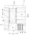
なお、これまでの説明は、一例であり、スペーサ42と、一対のガスケット40と、を備えた中間体18をシリンダヘッド14とシリンダブロック12との間に配するのであれば、その他の構成は適宜、変更されてもよい。例えば、下側ガスケット40dに、シリンダブロック12に対するスペーサ42の面方向への滑り変形を許容する表面性状を付与してもよい。より具体的には、下側ガスケット40dの少なくとも片面に、低摩擦材料のコーティング(例えばフッ素系コーティング等)を施したり、柔質材料を塗布したりしてもよい。かかる構成とすることで、スペーサ42がシリンダブロック12に対して面方向に滑りやすくなり、筒内圧力を受けた際に面方向に変形しやすくなる。そして、スペーサ42が面方向に変形することで、筒内圧力が吸収され、スペーサ42の破損等が効果的に防止される。結果として、中間体18の寿命低下を防止できる。かかる構成は、スペーサ42の強度が、シリンダブロック12の強度とほぼ同じである場合(例えば、スペーサ42とシリンダブロック12が同じ材料からなる場合)に、特に有効である。 The above description is only an example, and the other configuration is provided as long as the
また、別の形態として、下側ガスケット40dに、シリンダブロック12に対するスペーサ42の面方向への滑りを阻害する表面性状を付与してもよい。より具体的には、下側ガスケット40dの両面に、微小な凹凸を形成し、面粗さを付与したりしてもよい。かかる構成とすることで、スペーサ42がシリンダブロック12に対して面方向に滑りにくくなり、意図しない燃焼室26の体積変動を確実に防止できる。なお、この場合、スペーサ42が面方向に変形しにくくなるため、スペーサ42の端面は、高い筒内圧力に耐えなければならない。そのため、この場合、スペーサ42の強度は、シリンダブロック12の強度よりも高いことが望ましく、スペーサ42は、例えば、鋼材やジュラルミン等からなることが望ましい。 As another form, the
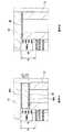
また、別の形態として、図8に示すように、下側ガスケット40dに、スペーサ42側およびシリンダブロック12側に突出する凸部48を設けるとともに、スペーサ42およびシリンダブロック12に、当該凸部48が嵌り込む凹部を設けてもよい。かかる構成とすることで、スペーサ42のシリンダブロック12に対する滑りがより確実に防止される。そして、結果として、意図しない燃焼室26の体積変動を確実に防止できる。なお、この場合も、スペーサ42の強度は、シリンダブロック12の強度よりも高いことが望ましい。 As another form, as shown in FIG. 8, the
また、別の形態として、図9に示すように、スペーサ42のうちウォータジャケット22に対応する位置に、シリンダブロック12側に突出する凸部50を設け、当該凸部50をウォータジャケット22に嵌め込む構成としてもよい。かかる構成とすることで、スペーサ42のシリンダブロック12に対する滑りがより確実に防止される。そして、結果として、意図しない燃焼室26の体積変動を確実に防止できる。なお、この場合も、スペーサ42の強度は、シリンダブロック12の強度よりも高いことが望ましい。 As another form, as shown in FIG. 9, a
このように、スペーサ42のシリンダブロック12に対する滑りを阻害する構成を設けるとともに、スペーサ42の強度をシリンダブロック12の強度よりも高くすることにより、スペーサ42が、シリンダブロック12の補強材として作用する。その結果、シリンダ20の変形がより確実に防止される。 Thus, while providing the structure which inhibits the sliding with respect to the
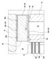
また、これまでの説明では、スペーサ42を一枚の板材で構成する例を挙げたが、スペーサ42は、図10に示すように、2以上の板材42aを積層して構成されてもよい。かかる構成とした場合、スペーサ42の内部に冷媒流路等の空洞52を容易に形成できる。すなわち、中間体18を肉厚にした場合、当該中間体18の内部にエンジン10を冷却するための冷媒流路を形成することも考えられる。この場合、スペーサ42が一枚の板材の場合、当該一枚の板材の内部に流路用の空洞を形成するためには、くり貫き加工等、比較的、複雑な加工が必要となる。一方、複数の板材42aでスペーサ42を構成した場合、貫通孔や溝等が形成した板材を積層することで、冷媒流路用の空洞52を構成することができ、比較的簡易な構成で、冷媒流路を構成できる。なお、複数の板材42aを積層してスペーサ42を構成する場合には、ボア孔36の端面を、グロメット54等で被覆し、ボア孔36の内周面を平滑面にしておくことが望ましい。また、複数の板材42aは、全て同じ材質で構成される必要はなく、部位によって異なる材料で構成されてもよい。 In the description so far, the example in which the
また、これまでの説明では、オープンデッキ構造のシリンダブロック12を用いる場合を例示したが、シリンダ20外壁とシリンダブロック12の外壁がほぼ一体に成型されたクローズドデッキ構造のシリンダブロック12を用いてもよい。また、これまで説明したガスケット40の構成は、一例であり、スペーサ42とシリンダブロック12、スペーサ42とシリンダヘッド14との間をガスシールできるのであれば、公知の他の構造のガスケットを用いてもよい。 In the above description, the case where the
いずれにしろ、従来のガスケットと比べて肉厚な中間体18を、シリンダヘッド14とシリンダブロック12との間に配し、燃料燃焼により生じる力の一部を中間体18で受ける構成とすることで、シリンダヘッド14の変形を効果的に抑制できる。 In any case, the
10 レシプロ式エンジン、12 シリンダブロック、14 シリンダヘッド、16 ピストン、18 中間体、20 シリンダ、22 ウォータジャケット、24 ボルト穴、26 燃焼室、28 吸気ポート、30 排気ポート、32 コネクティングロッド、34 ピストンリング、36 ボア孔、38 挿通孔、40 ガスケット、42 スペーサ、44 弾性層、46 基材、48,50 凸部、52 空洞、54 グロメット。 10 Reciprocating Engine, 12 Cylinder Block, 14 Cylinder Head, 16 Piston, 18 Intermediate, 20 Cylinder, 22 Water Jacket, 24 Bolt Hole, 26 Combustion Chamber, 28 Intake Port, 30 Exhaust Port, 32 Connecting Rod, 34 Piston Ring , 36 bore hole, 38 insertion hole, 40 gasket, 42 spacer, 44 elastic layer, 46 base material, 48, 50 convex part, 52 cavity, 54 grommet.
Claims (7)
Translated fromJapanese前記シリンダブロックに連結されるシリンダヘッドと、
前記シリンダ内を進退可能なピストンであって、周面にピストンリングが取り付けられたピストンと、
前記シリンダブロックと前記シリンダヘッドとの間に介在する中間体であって、内周面が燃焼室内に露出して燃焼圧力を受けるボア孔が1以上設けられた中間体と、
を備え、
前記中間体は、前記シリンダ内を気密にシールする一対のガスケットと、前記ガスケットよりも肉厚で前記一対のガスケットの間に介在するスペーサと、を含み、
前記中間体は、前記ピストンが前記シリンダヘッドに最も近づく最上位置にあるときの前記ピストンリングの上端から前記シリンダヘッドの下端までの距離である基準距離以下の厚みを有しており、
前記一対のガスケットのうち少なくとも前記シリンダブロック側に配されるガスケットの少なくとも片面は、前記スペーサの変形に伴う、前記シリンダブロックに対する前記スペーサの滑りを許容する表面性状を有する、
ことを特徴とするレシプロ式エンジン。A cylinder block provided with one or more cylinders;
A cylinder head coupled to the cylinder block;
A piston capable of advancing and retreating in the cylinder, wherein a piston ring is attached to a peripheral surface;
An intermediate body interposed between the cylinder block and the cylinder head, the intermediate body having an inner peripheral surface exposed to the combustion chamber and having one or more bore holes for receiving combustion pressure;
With
The intermediate body includes a pair of gaskets that hermetically seal the inside of the cylinder, and a spacer that is thicker than the gasket and interposed between the pair of gaskets,
The intermediate body has a thickness equal to or less than a reference distance that is a distance from an upper end of the piston ring to a lower end of the cylinder head when the piston is at an uppermost position closest to the cylinder head.
At least one surface of the gasket arranged on at least the cylinder block side of the pair of gaskets has a surface property that allows the spacer to slide with respect to the cylinder block due to deformation of the spacer.
This is a reciprocating engine.
前記中間体は、前記基準距離の2割以上の厚みを有する、ことを特徴とするレシプロ式エンジン。The reciprocating engine according to claim 1,
The reciprocating engine characterized in that the intermediate body has a thickness of 20% or more of the reference distance.
前記中間体は、前記基準距離の5割以上の厚みを有する、ことを特徴とするレシプロ式エンジン。The reciprocating engine according to claim 2,
The reciprocating engine according to claim 1, wherein the intermediate body has a thickness of 50% or more of the reference distance.
前記スペーサの強度は、前記シリンダブロックの強度とほぼ同じである、ことを特徴とするレシプロ式エンジン。A reciprocating engine according toany one of claims1 to 3 ,
The reciprocating engine according to claim 1, wherein the spacer has substantially the same strength as the cylinder block.
前記シリンダブロックは、前記シリンダと離間した位置に、当該シリンダブロックの上端面に開口するウォータジャケットを有しており、
前記スペーサは、前記ウォータジャケットの開口部に嵌り込む凸部を有する、
ことを特徴とするレシプロ式エンジン。A reciprocating engine according to any one of claims 1 to4 ,
The cylinder block has a water jacket that opens at an upper end surface of the cylinder block at a position separated from the cylinder.
The spacer has a convex portion that fits into an opening of the water jacket.
This is a reciprocating engine.
前記スペーサの強度は、前記シリンダブロックの強度よりも高い、ことを特徴とするレシプロ式エンジン。A reciprocating engine according toany one of claims1 to 3 ,
A reciprocating engine characterized in that the spacer has a strength higher than that of the cylinder block.
前記スペーサは、2以上の板材を積層した構成を含む、ことを特徴とするレシプロ式エンジン。A reciprocating engine according to any one of claims 1 to6 ,
The reciprocating engine characterized in that the spacer includes a configuration in which two or more plate materials are laminated.
Priority Applications (1)
| Application Number | Priority Date | Filing Date | Title |
|---|---|---|---|
| JP2015183731AJP6308192B2 (en) | 2015-09-17 | 2015-09-17 | Reciprocating engine |
Applications Claiming Priority (1)
| Application Number | Priority Date | Filing Date | Title |
|---|---|---|---|
| JP2015183731AJP6308192B2 (en) | 2015-09-17 | 2015-09-17 | Reciprocating engine |
Publications (2)
| Publication Number | Publication Date |
|---|---|
| JP2017057800A JP2017057800A (en) | 2017-03-23 |
| JP6308192B2true JP6308192B2 (en) | 2018-04-11 |
Family
ID=58391515
Family Applications (1)
| Application Number | Title | Priority Date | Filing Date |
|---|---|---|---|
| JP2015183731AExpired - Fee RelatedJP6308192B2 (en) | 2015-09-17 | 2015-09-17 | Reciprocating engine |
Country Status (1)
| Country | Link |
|---|---|
| JP (1) | JP6308192B2 (en) |
Family Cites Families (5)
| Publication number | Priority date | Publication date | Assignee | Title |
|---|---|---|---|---|
| JPS6249642U (en)* | 1985-09-17 | 1987-03-27 | ||
| JPH03123958U (en)* | 1990-03-30 | 1991-12-17 | ||
| JP2561487Y2 (en)* | 1992-04-27 | 1998-01-28 | 国産部品工業株式会社 | Cylinder head gasket |
| JP2006233773A (en)* | 2005-02-22 | 2006-09-07 | Toyota Industries Corp | Cylinder head gasket and multiple cylinder engine |
| JP2014077365A (en)* | 2012-10-09 | 2014-05-01 | Mitsubishi Motors Corp | Gasket |
- 2015
- 2015-09-17JPJP2015183731Apatent/JP6308192B2/ennot_activeExpired - Fee Related
Also Published As
| Publication number | Publication date |
|---|---|
| JP2017057800A (en) | 2017-03-23 |
Similar Documents
| Publication | Publication Date | Title |
|---|---|---|
| US8256389B2 (en) | Cylinder block | |
| CN1842648A (en) | Piston for internal combustion engine | |
| WO2019203358A1 (en) | Piston ring | |
| CN107237702A (en) | For explosive motor and its Piston volume tube of system and method | |
| US9567940B2 (en) | Engine arrangement for enhanced cooling | |
| US10927790B2 (en) | Cylinder head gasket | |
| US12241405B2 (en) | Internal combustion engine and cylinder block | |
| JP6308192B2 (en) | Reciprocating engine | |
| JP6337058B2 (en) | Top piston ring for crosshead turbocharged large two-stroke compression ignition internal combustion engine | |
| KR20130029821A (en) | Cooling structure for internal combustion engine | |
| JP6991223B2 (en) | Copper-nickel-tin alloy piston compression ring | |
| JP2009185865A (en) | Piston ring, and piston and engine using the same | |
| EP1448918B1 (en) | Piston for an internal combustion engine | |
| EP1288464A2 (en) | Piston assembly for free piston internal combustion engine | |
| US20200191269A1 (en) | Piston ring, piston assembly including piston ring, and methods of manufacturing | |
| US6886504B2 (en) | Engine of reciprocating piston type | |
| US20200284344A1 (en) | Piston ring with inlaid dlc coating and method of manufacturing | |
| JP6387237B2 (en) | Piston ring and engine including the piston ring | |
| JP2016536548A (en) | Piston ring grooves, especially pistons with compression grooves | |
| JP4889975B2 (en) | Piston device | |
| US20240376849A1 (en) | Piston for an internal combustion engine | |
| KR100916453B1 (en) | Piston ring structure of internal combustion engine | |
| JP2009275751A (en) | Piston ring structure | |
| RU34673U1 (en) | PISTON SEAL | |
| US2982589A (en) | Means to reduce piston ring groove wear and minimize cylinder scuffing |
Legal Events
| Date | Code | Title | Description |
|---|---|---|---|
| A977 | Report on retrieval | Free format text:JAPANESE INTERMEDIATE CODE: A971007 Effective date:20170628 | |
| A131 | Notification of reasons for refusal | Free format text:JAPANESE INTERMEDIATE CODE: A131 Effective date:20170801 | |
| A521 | Written amendment | Free format text:JAPANESE INTERMEDIATE CODE: A523 Effective date:20170912 | |
| TRDD | Decision of grant or rejection written | ||
| A01 | Written decision to grant a patent or to grant a registration (utility model) | Free format text:JAPANESE INTERMEDIATE CODE: A01 Effective date:20180213 | |
| A61 | First payment of annual fees (during grant procedure) | Free format text:JAPANESE INTERMEDIATE CODE: A61 Effective date:20180226 | |
| R150 | Certificate of patent or registration of utility model | Ref document number:6308192 Country of ref document:JP Free format text:JAPANESE INTERMEDIATE CODE: R150 | |
| LAPS | Cancellation because of no payment of annual fees |