JP6305694B2 - Signal processing apparatus and signal processing method - Google Patents
Signal processing apparatus and signal processing methodDownload PDFInfo
- Publication number
- JP6305694B2 JP6305694B2JP2013116004AJP2013116004AJP6305694B2JP 6305694 B2JP6305694 B2JP 6305694B2JP 2013116004 AJP2013116004 AJP 2013116004AJP 2013116004 AJP2013116004 AJP 2013116004AJP 6305694 B2JP6305694 B2JP 6305694B2
- Authority
- JP
- Japan
- Prior art keywords
- frequency
- signal
- reference signal
- band
- interpolation
- Prior art date
- Legal status (The legal status is an assumption and is not a legal conclusion. Google has not performed a legal analysis and makes no representation as to the accuracy of the status listed.)
- Expired - Fee Related
Links
- 238000003672processing methodMethods0.000titleclaimsdescription14
- 230000005236sound signalEffects0.000claimsdescription80
- 238000001514detection methodMethods0.000claimsdescription36
- 238000000611regression analysisMethods0.000claimsdescription31
- 230000007274generation of a signal involved in cell-cell signalingEffects0.000claimsdescription28
- 230000008859changeEffects0.000claimsdescription10
- 230000002194synthesizing effectEffects0.000claimsdescription7
- 230000015572biosynthetic processEffects0.000claimsdescription3
- 238000003786synthesis reactionMethods0.000claimsdescription3
- 238000001228spectrumMethods0.000description59
- 230000002238attenuated effectEffects0.000description10
- 238000000034methodMethods0.000description10
- 230000008569processEffects0.000description10
- 230000006835compressionEffects0.000description9
- 238000007906compressionMethods0.000description9
- 238000000605extractionMethods0.000description9
- 238000010586diagramMethods0.000description8
- 230000006872improvementEffects0.000description7
- 230000006866deteriorationEffects0.000description4
- 230000015556catabolic processEffects0.000description3
- 238000006731degradation reactionMethods0.000description3
- 230000006870functionEffects0.000description3
- 238000006243chemical reactionMethods0.000description2
- 239000000284extractSubstances0.000description2
- 230000003321amplificationEffects0.000description1
- 230000007423decreaseEffects0.000description1
- 238000009499grossingMethods0.000description1
- 230000002427irreversible effectEffects0.000description1
- 238000012986modificationMethods0.000description1
- 230000004048modificationEffects0.000description1
- 238000003199nucleic acid amplification methodMethods0.000description1
- 230000008447perceptionEffects0.000description1
- 230000004044responseEffects0.000description1
- 238000005070samplingMethods0.000description1
Images


Classifications
- G—PHYSICS
- G10—MUSICAL INSTRUMENTS; ACOUSTICS
- G10L—SPEECH ANALYSIS TECHNIQUES OR SPEECH SYNTHESIS; SPEECH RECOGNITION; SPEECH OR VOICE PROCESSING TECHNIQUES; SPEECH OR AUDIO CODING OR DECODING
- G10L19/00—Speech or audio signals analysis-synthesis techniques for redundancy reduction, e.g. in vocoders; Coding or decoding of speech or audio signals, using source filter models or psychoacoustic analysis
- G10L19/02—Speech or audio signals analysis-synthesis techniques for redundancy reduction, e.g. in vocoders; Coding or decoding of speech or audio signals, using source filter models or psychoacoustic analysis using spectral analysis, e.g. transform vocoders or subband vocoders
- G10L19/0204—Speech or audio signals analysis-synthesis techniques for redundancy reduction, e.g. in vocoders; Coding or decoding of speech or audio signals, using source filter models or psychoacoustic analysis using spectral analysis, e.g. transform vocoders or subband vocoders using subband decomposition
- G—PHYSICS
- G10—MUSICAL INSTRUMENTS; ACOUSTICS
- G10L—SPEECH ANALYSIS TECHNIQUES OR SPEECH SYNTHESIS; SPEECH RECOGNITION; SPEECH OR VOICE PROCESSING TECHNIQUES; SPEECH OR AUDIO CODING OR DECODING
- G10L19/00—Speech or audio signals analysis-synthesis techniques for redundancy reduction, e.g. in vocoders; Coding or decoding of speech or audio signals, using source filter models or psychoacoustic analysis
- G10L19/02—Speech or audio signals analysis-synthesis techniques for redundancy reduction, e.g. in vocoders; Coding or decoding of speech or audio signals, using source filter models or psychoacoustic analysis using spectral analysis, e.g. transform vocoders or subband vocoders
- G10L19/032—Quantisation or dequantisation of spectral components
- G—PHYSICS
- G10—MUSICAL INSTRUMENTS; ACOUSTICS
- G10L—SPEECH ANALYSIS TECHNIQUES OR SPEECH SYNTHESIS; SPEECH RECOGNITION; SPEECH OR VOICE PROCESSING TECHNIQUES; SPEECH OR AUDIO CODING OR DECODING
- G10L21/00—Speech or voice signal processing techniques to produce another audible or non-audible signal, e.g. visual or tactile, in order to modify its quality or its intelligibility
- G10L21/02—Speech enhancement, e.g. noise reduction or echo cancellation
- G10L21/038—Speech enhancement, e.g. noise reduction or echo cancellation using band spreading techniques
- G10L21/0388—Details of processing therefor
- G—PHYSICS
- G10—MUSICAL INSTRUMENTS; ACOUSTICS
- G10L—SPEECH ANALYSIS TECHNIQUES OR SPEECH SYNTHESIS; SPEECH RECOGNITION; SPEECH OR VOICE PROCESSING TECHNIQUES; SPEECH OR AUDIO CODING OR DECODING
- G10L25/00—Speech or voice analysis techniques not restricted to a single one of groups G10L15/00 - G10L21/00
- G10L25/03—Speech or voice analysis techniques not restricted to a single one of groups G10L15/00 - G10L21/00 characterised by the type of extracted parameters
- G10L25/18—Speech or voice analysis techniques not restricted to a single one of groups G10L15/00 - G10L21/00 characterised by the type of extracted parameters the extracted parameters being spectral information of each sub-band
Landscapes
- Engineering & Computer Science (AREA)
- Physics & Mathematics (AREA)
- Audiology, Speech & Language Pathology (AREA)
- Computational Linguistics (AREA)
- Signal Processing (AREA)
- Health & Medical Sciences (AREA)
- Human Computer Interaction (AREA)
- Acoustics & Sound (AREA)
- Multimedia (AREA)
- Spectroscopy & Molecular Physics (AREA)
- Quality & Reliability (AREA)
- Tone Control, Compression And Expansion, Limiting Amplitude (AREA)
- Circuit For Audible Band Transducer (AREA)
Description
Translated fromJapanese本発明は、補間信号を生成してオーディオ信号と合成することにより、オーディオ信号の高域成分を補間する信号処理装置及び信号処理方法に関する。 The present invention relates to a signal processing apparatus and a signal processing method for interpolating high frequency components of an audio signal by generating an interpolation signal and synthesizing it with the audio signal.
オーディオ信号を圧縮するフォーマットとして、MP3(MPEG Audio Layer-3)、WMA(Windows Media Audio、登録商標)、AAC(Advanced Audio Coding)等の非可逆圧縮フォーマットが知られている。非可逆圧縮フォーマットでは、可聴域の上限に近い又は上限を超える高域の周波数成分を大幅にカットすることにより、高圧縮率を達成する。この種の技術が開発された当初は、高域の周波数成分を大幅にカットした場合であっても聴感上の音質劣化が生じないと考えられていたが、近年では、高域の周波数成分を大幅にカットすることによって音質に微妙な変化が生じ、オリジナルの音源に比べて聴感上の音質が劣化するという考えが主流となっている。そこで、非可逆圧縮されたオーディオ信号に対して高域補間を行うことにより音質改善を行う高域補間装置が提案されている。この種の高域補間装置の具体的構成は、例えば特許文献1や特許文献2に記載されている。 As formats for compressing audio signals, lossy compression formats such as MP3 (MPEG Audio Layer-3), WMA (Windows Media Audio, registered trademark), and AAC (Advanced Audio Coding) are known. In the lossy compression format, a high compression rate is achieved by significantly cutting high frequency components close to or exceeding the upper limit of the audible range. When this type of technology was developed, it was thought that sound quality degradation would not occur even if the high frequency components were cut significantly. The idea is that the sound quality is subtly changed due to the significant cut, and the sound quality in terms of audibility deteriorates compared to the original sound source. In view of this, there has been proposed a high-frequency interpolation device that improves sound quality by performing high-frequency interpolation on an irreversibly compressed audio signal. The specific configuration of this type of high-frequency interpolation device is described in, for example,
特許文献1に記載の高域補間装置は、オーディオ信号(原信号)を解析することによって得た信号の実部及び虚部を算出し、算出された実部及び虚部から原信号の包絡成分を形成し、形成された包絡成分の高調波成分を抽出する。特許文献1に記載の高域補間装置は、抽出された高調波成分を原信号に合成することによって原信号の高域補間を行う。 The high-frequency interpolation apparatus described in
特許文献2に記載の高域補間装置は、オーディオ信号をスペクトル反転し、スペクトル反転された信号をアップサンプリングし、アップサンプリングされた信号からベースバンド信号の高域とほぼ同一の周波数を低域端とする拡張帯域成分を抽出する。特許文献2に記載の高域補間装置は、抽出された拡張帯域成分をベースバンド信号に合成することによってベースバンド信号の高域補間を行う。 The high-frequency interpolating device described in Patent Document 2 spectrally inverts an audio signal, up-samples the spectrum-inverted signal, and uses the up-sampled signal to generate a frequency that is substantially the same as the high frequency of the baseband signal. The extended band component is extracted. The high-frequency interpolation apparatus described in Patent Literature 2 performs high-frequency interpolation of a baseband signal by synthesizing the extracted extension band component with the baseband signal.
非可逆圧縮されたオーディオ信号の周波数帯域は、圧縮符号化フォーマットやサンプリングレート、圧縮符号化後のビットレートに応じて変わる。そのため、特許文献1に記載されているように、オーディオ信号に対して固定の周波数帯域の補間信号を合成することによって高域補間を行うと、高域補間前のオーディオ信号の周波数帯域によっては、高域補間後のオーディオ信号の周波数スペクトルが不連続となる。このように、特許文献1に記載の高域補間装置では、オーディオ信号に高域補間を施すことによって却って聴感上の音質劣化を生じさせることがある。 The frequency band of the irreversibly compressed audio signal varies depending on the compression encoding format, sampling rate, and bit rate after compression encoding. Therefore, as described in
また、オーディオ信号は一般的特性として高域ほど減衰するが、瞬間的には高域側でレベルが増幅することがある。しかし、特許文献2では、装置に入力されるオーディオ信号の特性として前者の一般的特性しか考慮されていない。そのため、レベルが高域側で増幅する特性のオーディオ信号が入力した直後は、オーディオ信号の周波数スペクトルが不連続になり、高域を過度に強調するものとなる。このように、特許文献2に記載の高域補間装置においても特許文献1に記載の高域補間装置と同様に、オーディオ信号に高域補間を施すことによって却って聴感上の音質劣化を生じさせることがある。 Moreover, although the audio signal is attenuated as a general characteristic as the frequency is high, the level may be instantaneously amplified on the high frequency side. However, in Patent Document 2, only the former general characteristic is considered as the characteristic of the audio signal input to the apparatus. For this reason, immediately after an audio signal whose level is amplified on the high frequency side is input, the frequency spectrum of the audio signal becomes discontinuous, and the high frequency is excessively emphasized. As described above, in the high frequency interpolating device described in Patent Literature 2, similarly to the high frequency interpolating device described in
本発明は上記の事情に鑑みてなされたものであり、その目的とするところは、非可逆圧縮されたオーディオ信号の周波数特性に拘わらず高域補間による音質の向上を達成することが可能な信号処理装置及び信号処理方法を提供することである。 The present invention has been made in view of the above circumstances, and an object of the present invention is to provide a signal that can achieve an improvement in sound quality by high-frequency interpolation regardless of the frequency characteristics of an irreversibly compressed audio signal. A processing apparatus and a signal processing method are provided.
本発明の実施形態の信号処理装置は、オーディオ信号から所定の条件を満たす周波数帯域を検出する帯域検出手段と、帯域検出手段による検出帯域に応じた参照信号を生成する参照信号生成手段と、生成された参照信号自体の周波数特性に基づいて参照信号を補正する参照信号補正手段と、補正された参照信号を検出帯域より高い周波数帯域まで拡張する周波数帯域拡張手段と、拡張された周波数帯域内の各周波数成分に対してオーディオ信号の周波数特性に応じた重み付けを行うことにより補間信号を生成する補間信号生成手段と、生成された補間信号をオーディオ信号と合成する信号合成手段とを備える。 A signal processing apparatus according to an embodiment of the present invention includes: a band detection unit that detects a frequency band that satisfies a predetermined condition from an audio signal; a reference signal generation unit that generates a reference signal corresponding to a detection band by the band detection unit; Reference signal correcting means for correcting the reference signal based on the frequency characteristics of the reference signal itself, frequency band extending means for extending the corrected reference signal to a frequency band higher than the detection band, and within the expanded frequency band Interpolation signal generation means for generating an interpolation signal by weighting each frequency component in accordance with the frequency characteristics of the audio signal, and signal synthesis means for combining the generated interpolation signal with the audio signal.
本発明の実施形態では、オーディオ信号の周波数特性に応じた値で参照信号が補正され、補正された参照信号を基に補間信号が生成されてオーディオ信号に合成されるため、オーディオ信号の周波数特性に拘わらず高域補間による音質の向上が達成される。 In the embodiment of the present invention, the reference signal is corrected with a value corresponding to the frequency characteristic of the audio signal, and an interpolation signal is generated based on the corrected reference signal and synthesized with the audio signal. Regardless of this, improvement in sound quality by high-frequency interpolation is achieved.
参照信号補正手段は、例えば、参照信号生成手段により生成された参照信号をフラットな周波数特性に補正する。 For example, the reference signal correction unit corrects the reference signal generated by the reference signal generation unit to a flat frequency characteristic.
また、参照信号補正手段は、参照信号生成手段により生成された参照信号について第1の回帰分析を行い、第1の回帰分析によって得た周波数特性の情報に基づいて参照信号に対する周波数毎の参照信号用重み量を計算し、計算された周波数毎の参照信号用重み量と参照信号とを乗算することにより、参照信号を補正する構成としてもよい。 The reference signal correction means performs a first regression analysis on the reference signal generated by the reference signal generation means, and a reference signal for each frequency with respect to the reference signal based on the information on the frequency characteristics obtained by the first regression analysis. The reference signal may be corrected by calculating the reference weight amount and multiplying the calculated reference signal weight amount for each frequency by the reference signal.
参照信号生成手段は、例えば、検出帯域全体のうち高域側のn%の範囲を抽出し、抽出された成分を参照信号とする。 For example, the reference signal generation unit extracts an n% range on the high frequency side of the entire detection band, and uses the extracted component as a reference signal.
帯域検出手段は、オーディオ信号内の第1の周波数領域及び第1の周波数領域よりも高い第2の周波数領域のレベルを計算し、計算された第1及び第2の周波数領域のレベルに基づいてスレッシュホールドを設定し、設定されたスレッシュホールドに基づいてオーディオ信号から周波数帯域を検出する構成としてもよい。 The band detecting means calculates the first frequency region in the audio signal and the level of the second frequency region higher than the first frequency region, and based on the calculated first and second frequency region levels. The threshold may be set, and the frequency band may be detected from the audio signal based on the set threshold.
また、帯域検出手段は、例えば、スレッシュホールドを下回る少なくとも1つの周波数ポイントのうち最も高域側の周波数ポイントの周波数を上限とした周波数帯域をオーディオ信号から検出する。 Further, the band detecting means detects, from the audio signal, a frequency band whose upper limit is the frequency of the highest frequency point among at least one frequency point below the threshold, for example.
補間信号生成手段は、オーディオ信号の少なくとも一部について第2の回帰分析を行い、第2の回帰分析によって得た周波数特性の情報に基づき、周波数帯域拡張手段により拡張された周波数帯域内の各周波数成分に対する周波数毎の補間信号用重み量を計算し、計算された周波数毎の補間信号用重み量と上記拡張された周波数帯域内の各周波数成分とを乗算することにより、補間信号を生成する構成としてもよい。 The interpolation signal generating means performs the second regression analysis on at least a part of the audio signal, and based on the frequency characteristic information obtained by the second regression analysis, each frequency within the frequency band expanded by the frequency band extending means. An interpolation signal weight amount for each frequency for the component is calculated, and an interpolation signal is generated by multiplying the calculated interpolation signal weight amount for each frequency by each frequency component in the expanded frequency band. It is good.
第2の回帰分析によって得た周波数特性の情報は、例えば、周波数帯域拡張手段により拡張された周波数帯域内の周波数成分の変化率を含む。この場合、補間信号生成手段は、変化率がマイナス側に大きくなるほど補間信号用重み量を大きくする。 The frequency characteristic information obtained by the second regression analysis includes, for example, the rate of change of the frequency component in the frequency band expanded by the frequency band extending means. In this case, the interpolation signal generation means increases the interpolation signal weight amount as the change rate increases to the minus side.
また、補間信号生成手段は、例えば、第2の回帰分析を行う範囲の上限側の周波数が高いほど補間信号用重み量を小さくする。In addition, the interpolation signal generation means, for example,decreases the interpolation signal weight amount as the frequency on the upper limit side of the range for performing the second regression analysis is higher.
また、信号処理装置は、次の条件(1)〜(3)
(1)検出帯域が所定の周波数帯域以下
(2)第2の周波数領域のレベルが所定値以下、
(3)第1の周波数領域のレベルと第2の周波数領域のレベルとの差が所定値以下
の少なくとも1つが満たされるとき、補間信号生成手段による補間信号の生成を行わない構成としてもよい。Further, the signal processing apparatus has the following conditions (1) to (3):
(1) The detection band is below a predetermined frequency band (2) The level of the second frequency region is below a predetermined value,
(3) The interpolation signal generation unit may not generate the interpolation signal when the difference between the level of the first frequency region and the level of the second frequency region satisfies at least one of a predetermined value or less.
また、本発明の実施形態の信号処理方法は、オーディオ信号から所定の条件を満たす周波数帯域を検出する帯域検出ステップと、帯域検出ステップにて検出された検出帯域に応じた参照信号を生成する参照信号生成ステップと、生成された参照信号自体の周波数特性に基づいて参照信号を補正する参照信号補正ステップと、補正された参照信号を検出帯域より高い周波数帯域まで拡張する周波数帯域拡張ステップと、拡張された周波数帯域内の各周波数成分に対してオーディオ信号の周波数特性に応じた重み付けを行うことにより補間信号を生成する補間信号生成ステップと、生成された補間信号をオーディオ信号と合成する信号合成ステップとを含む。 The signal processing method according to the embodiment of the present invention includes a band detection step for detecting a frequency band satisfying a predetermined condition from an audio signal, and a reference for generating a reference signal corresponding to the detection band detected in the band detection step. A signal generation step, a reference signal correction step for correcting the reference signal based on the frequency characteristics of the generated reference signal itself, a frequency band extension step for extending the corrected reference signal to a frequency band higher than the detection band, and an extension An interpolation signal generation step for generating an interpolation signal by weighting each frequency component in the frequency band according to the frequency characteristic of the audio signal, and a signal synthesis step for combining the generated interpolation signal with the audio signal Including.
本発明の実施形態によれば、非可逆圧縮されたオーディオ信号の周波数特性に拘わらず高域補間による音質の向上を達成することが可能な信号処理装置及び信号処理方法が提供される。 According to the embodiment of the present invention, there is provided a signal processing apparatus and a signal processing method capable of achieving improvement in sound quality by high-frequency interpolation regardless of frequency characteristics of an irreversibly compressed audio signal.
以下、図面を参照して、本発明の実施形態の音響処理装置について説明する。 Hereinafter, a sound processing apparatus according to an embodiment of the present invention will be described with reference to the drawings.
[音響処理装置1全体の構成]
図1は、本実施形態の音響処理装置1の構成を示すブロック図である。図1に示されるように、音響処理装置1は、FFT(Fast Fourier Transform)部10、高域補間処理部20及びIFFT(Inverse FFT)部30を備えている。[Configuration of the entire sound processing apparatus 1]
FIG. 1 is a block diagram showing the configuration of the
FFT部10には、音源部より非可逆圧縮フォーマットの符号化信号を復号化したオーディオ信号が入力される。ここで、非可逆圧縮フォーマットとは、例えばMP3、WMA、AAC等である。FFT部10は、入力されたオーディオ信号についてオーバラップ処理及び窓関数による重み付けを行った後、STFT(Short-Term Fourier Transform)により時間領域から周波数領域への変換を行い、実数及び虚数の周波数スペクトルを得る。FFT部10は、周波数変換によって得た周波数スペクトルを振幅スペクトル及び位相スペクトルに変換する。FFT部10は、振幅スペクトルを高域補間処理部20に出力し、位相スペクトルをIFFT部30に出力する。高域補間処理部20は、FFT部10より入力された振幅スペクトルの高域を補間してIFFT部30に出力する。高域補間処理部20によって補間される帯域は、例えば、非可逆圧縮時に大幅にカットされた可聴域の上限に近い又は上限を超える周波数帯域である。IFFT部30は、高域補間処理部20により高域補間された振幅スペクトル及びFFT部10の出力がそのまま保持された位相スペクトルに基づいて実数及び虚数の周波数スペクトルを求め、窓関数による重み付けを行う。IFFT部30は、重み付けされた信号に対してSTFTとオーバラップ加算とを行うことにより、周波数領域から時間領域に信号を変換し、高域補間されたオーディオ信号を生成して出力する。 An audio signal obtained by decoding an irreversible compression format encoded signal is input to the
[高域補間処理部20の構成]
図2は、高域補間処理部20の構成を示すブロック図である。図2に示されるように、高域補間処理部20は、帯域検出部210、参照信号抽出部220、参照信号補正部230、補間信号生成部240、補間信号補正部250及び加算部260を備えている。なお、以下、説明の便宜上、高域補間処理部20内の各部に対する入力信号・出力信号に符号を付す。[Configuration of High Frequency Interpolation Processing Unit 20]
FIG. 2 is a block diagram showing the configuration of the high-frequency
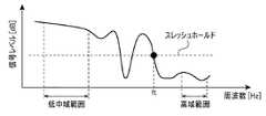
図3は、帯域検出部210の動作説明を補助する図であり、FFT部10から帯域検出部210に入力される振幅スペクトルSの例を示す。図3中、縦軸(y軸)は、信号レベル(単位:dB)を示し、横軸(x軸)は、周波数(単位:Hz)を示す。 FIG. 3 is a diagram for assisting the explanation of the operation of the
帯域検出部210は、FFT部10より入力されたオーディオ信号の振幅スペクトルS(リニアスケール)をデシベルスケールに変換する。帯域検出部210は、デシベルスケールに変換された振幅スペクトルSについて所定の低中域範囲及び所定の高域範囲の信号レベルを計算し、計算された低中域範囲及び高域範囲の信号レベルに基づいてスレッシュホールドを設定する。スレッシュホールドは、例えば、図3に示されるように、低中域範囲の信号レベル(平均値)と高域範囲の信号レベル(平均値)との中間レベルである。 The
帯域検出部210は、FFT部10より入力した振幅スペクトルS(リニアスケール)から、スレッシュホールドを下回る周波数ポイントの周波数を上限とした周波数帯域のオーディオ信号(振幅スペクトルSa)を検出する。図3に示されるように、スレッシュホールドを下回る周波数ポイントが複数存在する場合は、より高域側の周波数(図3の例では周波数ft)を上限とした範囲の振幅スペクトルSaが検出される。帯域検出部210は、検出された振幅スペクトルSaに含まれる局所的なバラツキを抑えるため、振幅スペクトルSaをスムージングにより平滑化する。なお、帯域検出部210は、不要な補間信号の生成を抑えるため、次の条件(1)〜(3)
(1)検出された振幅スペクトルSaが所定の周波数領域以下
(2)高域範囲の信号レベルが所定値以上
(3)低中域範囲と高域範囲との信号レベル差が所定値以下
の少なくとも1つが満たされるとき、補間信号の生成が不要と判定する。補間信号の生成が不要と判定された振幅スペクトルに対しては、高域補間が行われない。The
(1) The detected amplitude spectrum Sa is equal to or lower than a predetermined frequency range. (2) The signal level of the high frequency range is equal to or higher than a predetermined value. When one is satisfied, it is determined that the generation of the interpolation signal is unnecessary. High-frequency interpolation is not performed on an amplitude spectrum that is determined to require no interpolation signal generation.
図4(a)〜図4(h)は、帯域検出部210にて検出された振幅スペクトルSaを用いて高域補間するまでの一連の処理を説明するための動作波形図である。図4(a)〜図4(h)の各図中、縦軸(y軸)は、信号レベル(単位:dB)を示し、横軸(x軸)は、周波数(単位:Hz)を示す。 FIGS. 4A to 4H are operation waveform diagrams for explaining a series of processes until high-frequency interpolation is performed using the amplitude spectrum Sa detected by the
参照信号抽出部220には、帯域検出部210にて検出された振幅スペクトルSaが入力される。参照信号抽出部220は、振幅スペクトルSaの周波数帯域に応じて振幅スペクトルSaから参照信号Sbを抽出する(図4(a)参照)。例えば、振幅スペクトルSa全体のうち高域側のn(0<n)%の範囲の振幅スペクトルが参照信号Sbとして抽出される。ここで、音声帯域(例えば肉声)の信号を基に生成された補間信号によって高域補間を行うと、聴感上違和感を与えやすい音質に劣化するという問題がある。これに対し、上記の例では、振幅スペクトルSaの周波数帯域が狭いほど参照信号Sbの周波数帯域も狭くなるため、音質劣化の原因となる音声帯域の抽出が抑えられる。 The amplitude spectrum Sa detected by the
参照信号抽出部220は、振幅スペクトルSaから抽出した参照信号Sbを低域側(DC側)へ周波数シフトし(図4(b)参照)、周波数シフトされた参照信号Sbを参照信号補正部230に出力する。Reference
参照信号補正部230は、参照信号抽出部220より入力された参照信号Sb(リニアスケール)をデジベルスケールに変換し、変換されたデシベルスケールの参照信号Sbについて一次の回帰分析により周波数スロープを検出する。参照信号補正部230は、一次の回帰分析により検出された周波数スロープの逆特性(参照信号Sbに対する周波数毎の重み量)を計算する。具体的には、参照信号補正部230は、参照信号Sbに対する周波数毎の重み量をp1(x)と定義し、横軸(x軸)上の周波数領域のFFTのサンプル位置をxと定義し、一次の回帰分析にて検出された参照信号Sbの周波数スロープの値をα1と定義し、参照信号Sbの周波数帯域に相当するFFTのサンプル数の1/2をβ1と定義した場合に、次式(1)により、周波数スロープの逆特性(参照信号Sbに対する周波数毎の重み量p1(x))を計算する。
[式(1)]
p1(x)=−α1x+β1Reference
[Formula (1)]
p1 (x) = − α1 x + β1
図4(c)に示されるように、参照信号Sbに対する周波数毎の重み量p1(x)はデシベルスケールで求められる。参照信号補正部230は、デシベルスケールの重み量p1(x)をリニアスケールに変換する。参照信号補正部230は、リニアスケールに変換された重み量p1(x)と、参照信号抽出部220より入力された参照信号Sb(リニアスケール)とを乗算することにより、参照信号Sbを補正する。具体的には、参照信号Sbは、フラットな周波数特性を持つ信号(参照信号Sb’)に補正される(図4(d)参照)。As shown in FIG. 4C, the weight amount p1 (x) for each frequency with respect to the reference signal Sb is obtained on a decibel scale. The reference
補間信号生成部240には、参照信号補正部230にて補正された参照信号Sb’が入力される。補間信号生成部240は、参照信号Sb’を振幅スペクトルSaの周波数帯域より高い周波数帯域まで拡張(言い換えると、参照信号Sb’を振幅スペクトルSaの周波数帯域より高い周波数帯域に達するまで複数複製)することにより、高域を含む補間信号Scを生成する(図4(e)参照)。補間信号Scはフラットな周波数特性を持つ。また、参照信号Sb’の拡張範囲は、例えば、振幅スペクトルSaの周波数帯域全域と、振幅スペクトルSaの周波数帯域より高い所定範囲の周波数帯域(可聴域の上限に近い帯域や可聴域の上限を超える帯域等)を含む。 The reference signal Sb ′ corrected by the reference
補間信号補正部250には、補間信号生成部240にて生成された補間信号Scが入力される。補間信号補正部250は、FFT部10より入力された振幅スペクトルS(リニアスケール)をデジベルスケールに変換し、変換されたデシベルスケールの振幅スペクトルSについて一次の回帰分析により周波数スロープを検出する。なお、振幅スペクトルSに代えて、帯域検出部210より入力される振幅スペクトルSaの周波数スロープを検出してもよい。回帰分析範囲は任意に設定することができるが、典型的には、オーディオ信号の高域側と補間信号とを滑らかにつなぐため、低域成分を除く所定の周波数帯域に対応する範囲である。補間信号補正部250は、検出された周波数スロープ及び回帰分析範囲に対応する周波数帯域に応じた重み量を周波数毎に計算する。具体的には、補間信号補正部250は、補間信号Scに対する周波数毎の重み量をp2(x)と定義し、横軸(x軸)上の周波数領域のFFTのサンプル位置をxと定義し、回帰分析範囲の上限の周波数をbと定義し、FFTのサンプル長をsと定義し、回帰分析範囲に対応する周波数帯域のスロープの値をα2と定義し、所定の補正係数をkと定義した場合に、次式(2)により、補間信号Scに対する周波数毎の重み量p2(x)を計算する。
[式(2)]
p2(x)=−α’x+β2
但し、
α’=α2−[1−(b/s)]/k
β2=−α’b
x<bのとき、p2(x)=−∞The interpolation signal Sc generated by the interpolation
[Formula (2)]
p2 (x) = − α′x + β2
However,
α ′ = α2 − [1- (b / s)] / k
β2 = −α′b
When x <b, p2 (x) = − ∞
図4(f)に示されるように、補間信号Scに対する周波数毎の重み量p2(x)はデシベルスケールで求められる。補間信号補正部250は、デシベルスケールの重み量p2(x)をリニアスケールに変換する。補間信号補正部250は、リニアスケールに変換された重み量p2(x)と、補間信号生成部240にて生成された補間信号Sc(リニアスケール)とを乗算することにより、補間信号Scを補正する。補正後の補間信号Sc’は、例えば図4(g)に示されるように、周波数bより高域の信号であり、周波数が高いほど減衰する特性を持つ。As shown in FIG. 4F, the weight amount p2 (x) for each frequency with respect to the interpolation signal Sc is obtained on a decibel scale. The interpolation
加算部260には、FFT部10より振幅スペクトルSが入力されると共に、補間信号補正部250より補間信号Sc’が入力される。振幅スペクトルSは、高域成分が大幅にカットされたオーディオ信号の振幅スペクトルであり、補間信号Sc’は、オーディオ信号の周波数帯域より高い周波数領域の振幅スペクトルである。加算部260は、振幅スペクトルSと補間信号Sc’とを合成することにより、高域が補間されたオーディオ信号の振幅スペクトルS’を生成し(図4(h)参照)、生成されたオーディオ信号の振幅スペクトルS’をIFFT部30に出力する。 The
本実施形態では、振幅スペクトルSaの周波数帯域に応じて参照信号Sbを抽出し、抽出された参照信号Sbを補正することによって得た参照信号Sb’を基に補間信号Sc’を生成して振幅スペクトルS(オーディオ信号)に合成する。これにより、FFT部10に入力されるオーディオ信号の周波数特性に拘わらず(例えば、オーディオ信号の周波数帯域が圧縮符号化フォーマット等に応じて変わった場合であっても、また、レベルが高域側で増幅する特性のオーディオ信号が入力された場合であっても)、オーディオ信号に対して連続的変化で減衰する自然な特性のスペクトルで高域が補間される。そのため、高域補間による聴感上の音質向上が達成される。 In the present embodiment, the reference signal Sb is extracted in accordance with the frequency band of the amplitude spectrum Sa, and the interpolation signal Sc ′ is generated based on the reference signal Sb ′ obtained by correcting the extracted reference signal Sb to generate an amplitude. It is synthesized with the spectrum S (audio signal). Thereby, regardless of the frequency characteristics of the audio signal input to the FFT unit 10 (for example, even when the frequency band of the audio signal changes according to the compression encoding format, the level is higher) (Even when an audio signal having the characteristic of amplifying in (a) is input), the high frequency band is interpolated with a spectrum having a natural characteristic that attenuates with a continuous change. Therefore, the sound quality improvement in the auditory sense by high frequency interpolation is achieved.
図5及び図6に、参照信号の補正を行わない場合に生成される補間信号を例示する。図5、図6の各図中、縦軸(y軸)は、信号レベル(単位:dB)を示し、横軸(x軸)は、周波数(単位:Hz)を示す。図5は、高域ほど減衰する特性のオーディオ信号を例に取り、図6は、高域ほど増幅する特性のオーディオ信号を例に取る。図5(a)、図6(a)の各図は、オーディオ信号より抽出される参照信号を示す。図5(b)、図6(b)の各図は、抽出された参照信号をオーディオ信号の周波数帯域より高い周波数帯域まで拡張することによって生成される補間信号を示す。図5(b)、図6(b)の各図に示されるように、参照信号を補正しない場合は、補間信号のスペクトルが不連続になることが判る。そのため、図5及び図6の例では、高域補間を行うことにより却って聴感上の音質劣化が生じる。 5 and 6 illustrate an interpolation signal generated when the reference signal is not corrected. 5 and 6, the vertical axis (y-axis) indicates the signal level (unit: dB), and the horizontal axis (x-axis) indicates the frequency (unit: Hz). FIG. 5 shows an example of an audio signal having a characteristic of being attenuated as the frequency is higher, and FIG. Each of FIGS. 5A and 6A shows a reference signal extracted from an audio signal. Each of FIGS. 5B and 6B shows an interpolation signal generated by extending the extracted reference signal to a frequency band higher than the frequency band of the audio signal. As shown in FIGS. 5B and 6B, it can be seen that the spectrum of the interpolation signal becomes discontinuous when the reference signal is not corrected. Therefore, in the examples of FIGS. 5 and 6, sound quality degradation in terms of audibility occurs by performing high-frequency interpolation.
次に、本実施形態の音響処理装置1の動作パラメータ例を示す。
(FFT部10/IFFT部30)
サンプル長 :8,192サンプル
窓関数 :ハニング
オーバラップ長 :50%
(帯域検出部210)
最小制御周波数 :7kHz
低中域範囲 :2kHz〜6kHz
高域範囲 :20kHz〜22kHz
高域レベル判定 :−20dB
信号レベル差 :20dB
スレッシュホールド :0.5
(参照信号抽出部220)
参照帯域幅 :2.756kHz
(補間信号補正部250)
下限周波数 :500Hz
補正係数k :0.01Next, an example of operation parameters of the
(
Sample length: 8,192 sample window function: Hanning overlap length: 50%
(Bandwidth detection unit 210)
Minimum control frequency: 7 kHz
Low and mid range: 2 kHz to 6 kHz
High frequency range: 20 kHz to 22 kHz
High frequency level judgment: -20 dB
Signal level difference: 20 dB
Threshold: 0.5
(Reference signal extraction unit 220)
Reference bandwidth: 2.756 kHz
(Interpolation signal correction unit 250)
Lower limit frequency: 500Hz
Correction coefficient k: 0.01
「最小制御周波数(=7kHz)」は、帯域検出部210にて検出される振幅スペクトルSaが7kHz未満の場合、高域補間を行わないことを示す。「高域レベル判定(=−20dB)」は、高域範囲の信号レベルが−20dB以上の場合、高域補間を行わないことを示す。「信号レベル差(=20dB)」は、低中域範囲と高域範囲との信号レベル差が20dB以下の場合、高域補間を行わないことを示す。「スレッシュホールド(=0.5)」は、振幅スペクトルSaを検出するためのスレッシュホールドが低中域範囲の信号レベル(平均値)と高域範囲の信号レベル(平均値)との中間値であることを示す。「参照帯域幅(=2.756kHz)」は、「最小制御周波数(=7kHz)」に対応する参照信号Sbの帯域幅である。「下限周波数(=500Hz)」は、補間信号補正部250による回帰分析の範囲下限を示す(すなわち、500Hz未満は回帰分析の範囲に含まれない。)。 “Minimum control frequency (= 7 kHz)” indicates that high-frequency interpolation is not performed when the amplitude spectrum Sa detected by the
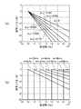
図7(a)は、上記動作パラメータ例において、周波数bを8kHzに固定し、周波数スロープ値α2を0〜−0.010の範囲で−0.002刻みで変化させたときの夫々の重み量p2(x)を示す。図7(b)は、上記動作パラメータ例において、周波数スロープ値α2を0(フラットな周波数特性)に固定し、周波数bを8kHz〜20kHzの範囲で2kHz刻みで変化させたときの夫々の重み量p2(x)を示す。図7(a)、図7(b)の各図中、縦軸(y軸)は、信号レベル(単位:dB)を示し、横軸(x軸)は、周波数(単位:Hz)を示す。なお、図7(a)及び図7(b)の例では、FFTのサンプル位置を周波数に変換して示している。7 (a) is in the operating parameters Example, the weight of each of when the frequency b is fixed to 8 kHz, was changed -0.002 increments a frequency slope value alpha2 in a range of 0 - 0.010 The quantity p2 (x) is indicated. 7 (b) is in the operating parameters Example, the weight of each of when the frequency slope value alpha2 is fixed to 0 (flat frequency response), and the frequency b in the range of 8kHz~20kHz varied 2kHz increments The quantity p2 (x) is indicated. In each of FIGS. 7A and 7B, the vertical axis (y axis) indicates the signal level (unit: dB), and the horizontal axis (x axis) indicates the frequency (unit: Hz). . In the example of FIGS. 7A and 7B, the FFT sample position is converted into a frequency.
図7(a)及び図7(b)を参照すると、周波数スロープ値α2や周波数bに応じて重み量p2(x)が変化していることが判る。具体的には、図7(a)に示されるように、周波数スロープ値α2がマイナス側に大きくなるほど(すなわち高域での減衰が大きいオーディオ信号ほど)重み量p2(x)が大きくなり、補間信号Sc’の高域の減衰量が大きくなる。また、図7(b)に示されるように、周波数bが高いほど重み量p2(x)が小さくなり、補間信号Sc’の高域の減衰量が小さくなる。このように、オーディオ信号の周波数スロープや回帰分析範囲に応じて補間信号Sc’のスロープを変化させることにより、オーディオ信号に対して連続的変化で減衰する自然な特性のスペクトルで可聴域の上限に近い又は上限を超える高域が補間される。そのため、高域補間による聴感上の音質向上が達成される。また、オーディオ信号の周波数帯域が狭いほど参照信号の周波数帯域が狭くなるため、音質劣化の原因となる音声帯域の抽出が抑えられる。また、オーディオ信号の周波数帯域が狭いほど補間信号のレベルが小さくなるため、例えば周波数帯域の狭いオーディオ信号に対して過剰な補間信号が合成されることがない。Referring to FIGS. 7A and 7B, it can be seen that the weight amount p2 (x) changes according to the frequency slope value α2 and the frequency b. Specifically, as shown in FIG. 7A, the weight amount p2 (x) increases as the frequency slope value α2 increases toward the minus side (that is, the audio signal is attenuated at higher frequencies). As a result, the high-frequency attenuation of the interpolation signal Sc ′ increases. Further, as shown in FIG. 7B, the higher the frequency b, the smaller the weight amount p2 (x), and the lower the attenuation amount of the interpolation signal Sc ′. Thus, by changing the slope of the interpolated signal Sc ′ in accordance with the frequency slope of the audio signal and the regression analysis range, the audio signal has a natural spectrum that attenuates with a continuous change, and reaches the upper limit of the audible range. High frequencies that are close or above the upper limit are interpolated. Therefore, the sound quality improvement in the auditory sense by high frequency interpolation is achieved. In addition, the narrower the frequency band of the audio signal is, the narrower the frequency band of the reference signal is, so that the extraction of the voice band that causes the sound quality deterioration can be suppressed. Further, since the level of the interpolation signal becomes smaller as the frequency band of the audio signal is narrower, for example, an excessive interpolation signal is not synthesized with an audio signal having a narrow frequency band.
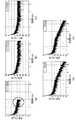
図8(a)は、高域ほど減衰する特性のオーディオ信号(周波数帯域:10kHz)を示す。図8(b)〜図8(e)の各図は、上記動作パラメータ例において、図8(a)のオーディオ信号の高域を補間することによって得られる信号を示す。但し、図8(b)〜図8(e)の各図では動作条件が夫々異なる。なお、図8(a)〜図8(e)の各図中、縦軸(y軸)は、信号レベル(単位:dB)を示し、横軸(x軸)は、周波数(単位:Hz)を示す。 FIG. 8A shows an audio signal (frequency band: 10 kHz) having a characteristic of being attenuated as the frequency increases. FIGS. 8B to 8E show signals obtained by interpolating the high frequency range of the audio signal shown in FIG. 8A in the above operation parameter example. However, the operation conditions are different in each of FIGS. 8B to 8E. 8A to 8E, the vertical axis (y axis) indicates the signal level (unit: dB), and the horizontal axis (x axis) indicates the frequency (unit: Hz). Indicates.
図8(b)は、高域補間処理から参照信号の補正処理及び補間信号の補正処理を省いた例を示す。また、図8(c)は、高域補間処理から補間信号の補正処理を省いた例を示す。図8(b)及び図8(c)の例では、図8(a)のオーディオ信号に対して周波数フラットな補間信号が合成される。図8(b)及び図8(c)の例では、過剰な高域成分が補間されることによって周波数バランスが崩れるため、聴感上の音質劣化が生じる。 FIG. 8B shows an example in which the reference signal correction processing and the interpolation signal correction processing are omitted from the high-frequency interpolation processing. FIG. 8C shows an example in which the interpolation signal correction process is omitted from the high-frequency interpolation process. In the examples of FIGS. 8B and 8C, a frequency flat interpolation signal is synthesized with the audio signal of FIG. 8A. In the examples of FIGS. 8B and 8C, the frequency balance is lost by interpolating an excessive high frequency component, resulting in a deterioration in sound quality.
図8(d)は、高域補間処理から参照信号の補正処理を省いた例を示す。また、図8(e)は、高域補間処理から何れの処理も省かない例を示す。図8(d)の例では、高域補間後のオーディオ信号は、高域ほど減衰する特性となっているが、スペクトルが連続的変化で減衰しているとまではいえない。図8(d)の例では、スペクトル内に残存する不連続領域が聴感上の違和感をユーザに与える虞がある。これに対し、図8(e)の例では、高域補間後のオーディオ信号は、スペクトルが連続的変化で高域ほど減衰する自然な特性となっている。図8(d)と図8(e)とを比較すると、補間信号の補正だけでなく参照信号の補正も行うことにより、高域補間による聴感上の音質向上が達成されることが判る。 FIG. 8D shows an example in which the reference signal correction process is omitted from the high-frequency interpolation process. FIG. 8E shows an example in which no processing is omitted from the high-frequency interpolation processing. In the example of FIG. 8D, the audio signal after high-frequency interpolation has a characteristic of attenuation as the frequency increases, but it cannot be said that the spectrum is attenuated due to continuous change. In the example of FIG. 8D, the discontinuous region remaining in the spectrum may give the user a sense of discomfort in hearing. On the other hand, in the example of FIG. 8 (e), the audio signal after high-frequency interpolation has a natural characteristic that the spectrum is attenuated as the frequency increases continuously. Comparing FIG. 8D and FIG. 8E, it can be seen that not only the correction of the interpolation signal but also the correction of the reference signal makes it possible to achieve an improvement in sound quality by the high-frequency interpolation.
図9(a)は、高域側で増幅する特性のオーディオ信号(周波数帯域:10kHz)を示す。図9(b)〜図9(e)の各図は、上記動作パラメータ例において、図9(a)のオーディオ信号の高域を補間することによって得られる信号を示す。図9(b)〜図9(e)の各図の例の動作条件は夫々、図8(b)〜図8(e)の各図の例の動作条件と同じである。 FIG. 9A shows an audio signal (frequency band: 10 kHz) having a characteristic of being amplified on the high frequency side. FIGS. 9B to 9E show signals obtained by interpolating the high frequency range of the audio signal of FIG. 9A in the above operation parameter example. The operating conditions of the examples of FIGS. 9B to 9E are the same as the operating conditions of the examples of FIGS. 8B to 8E, respectively.
図9(b)の例では、図9(a)のオーディオ信号に対して不連続なスペクトルを持つ補間信号が合成される。図9(c)の例では、図9(a)のオーディオ信号に対して周波数フラットな補間信号が合成される。図9(b)及び図9(c)の例では、不連続な特性を持つスペクトルが合成されたり、過剰な高域成分が補間されることによって周波数バランスが崩れたりするため、聴感上の音質劣化が生じる。 In the example of FIG. 9B, an interpolated signal having a discontinuous spectrum is synthesized with the audio signal of FIG. 9A. In the example of FIG. 9C, a frequency flat interpolation signal is synthesized with the audio signal of FIG. In the examples of FIGS. 9B and 9C, the spectrum having discontinuous characteristics is synthesized, or the frequency balance is lost by interpolating an excessive high frequency component. Deterioration occurs.
図9(d)の例では、高域補間後のオーディオ信号は、高域ほど減衰する特性となっているが、スペクトルの変化が不連続である。図9(d)の例では、この不連続な領域が聴感上の違和感をユーザに与える虞がある。これに対し、図9(e)の例では、高域補間後のオーディオ信号は、スペクトルが連続的変化で高域ほど減衰する自然な特性となっている。図9(d)と図9(e)とを比較すると、補間信号の補正だけでなく参照信号の補正も行うことにより、高域補間による聴感上の音質向上が達成されることが判る。 In the example of FIG. 9 (d), the audio signal after high-frequency interpolation has a characteristic of being attenuated as the frequency increases, but the spectrum change is discontinuous. In the example of FIG. 9D, this discontinuous region may give the user a sense of incongruity on hearing. On the other hand, in the example of FIG. 9 (e), the audio signal after high-frequency interpolation has a natural characteristic that the spectrum is attenuated as the frequency increases continuously. Comparing FIG. 9D and FIG. 9E, it can be seen that not only the correction of the interpolation signal but also the correction of the reference signal achieves an improvement in sound quality on the perception by high-frequency interpolation.
以上が本発明の例示的な実施形態の説明である。本発明の実施形態は、上記に説明したものに限定されず、本発明の技術的思想の範囲において様々な変形が可能である。例えば明細書中に例示的に明示される実施例等又は自明な実施例等を適宜組み合わせた内容も本願の実施形態に含まれる。例えば、本実施形態では、参照信号補正部230は、周波数帯域内で単調に増幅又は減衰する特性の参照信号Sbを補正するため、一次の回帰分析を用いている。しかし、参照信号Sbの特性は線形に限らず、場合によっては非線形となる。、周波数帯域内で増幅と減衰とを繰り返す特性の参照信号Sbを補正する場合を考える。この場合、参照信号補正部230は、次数を増加して回帰分析を行って逆特性を算出し、算出された逆特性により参照信号Sbを補正する。 The above is the description of the exemplary embodiments of the present invention. Embodiments of the present invention are not limited to those described above, and various modifications are possible within the scope of the technical idea of the present invention. For example, the embodiment of the present application also includes contents appropriately combined with examples and the like clearly shown in the specification or obvious examples. For example, in the present embodiment, the reference
1 音響処理装置
10 FFT部
20 高域補間処理部
30 IFFT部
210 帯域検出部
220 参照信号抽出部
230 参照信号補正部
240 補間信号生成部
250 補間信号補正部DESCRIPTION OF
Claims (18)
Translated fromJapanese前記帯域検出手段による検出帯域に応じた参照信号を生成する参照信号生成手段と、
生成された参照信号自体の周波数特性に基づいて該参照信号を補正する参照信号補正手段と、
補正された参照信号を前記検出帯域より高い周波数帯域まで拡張する周波数帯域拡張手段と、
拡張された周波数帯域内の各周波数成分に対して前記オーディオ信号の周波数特性に応じた重み付けを行うことにより補間信号を生成する補間信号生成手段と、
生成された補間信号を前記オーディオ信号と合成する信号合成手段と、
を備え、
前記帯域検出手段は、
前記オーディオ信号内の第1の周波数領域及び該第1の周波数領域よりも高い第2の周波数領域のレベルを計算し、
計算された第1及び第2の周波数領域のレベルに基づいてスレッシュホールドを設定し、
設定されたスレッシュホールドに基づいて前記オーディオ信号から周波数帯域を検出する、
信号処理装置。Band detecting means for detecting a frequency band satisfying a predetermined condition from the audio signal;
Reference signal generating means for generating a reference signal corresponding to a detection band by the band detecting means;
Reference signal correcting means for correcting the reference signal based on the frequency characteristics of the generated reference signal itself;
Frequency band extending means for extending the corrected reference signal to a frequency band higher than the detection band;
Interpolation signal generating means for generating an interpolation signal by weighting each frequency component in the expanded frequency band according to the frequency characteristics of the audio signal;
Signal synthesizing means for synthesizing the generated interpolation signal with the audio signal;
Equipped witha,
The band detecting means includes
Calculating a first frequency domain and a second frequency domain level higher than the first frequency domain in the audio signal;
Setting a threshold based on the calculated first and second frequency domain levels;
You detect a frequency band from the audio signal based on the set threshold,
Signal processing device.
前記参照信号生成手段により生成された参照信号をフラットな周波数特性に補正する、
請求項1に記載の信号処理装置。The reference signal correcting means includes
Correcting the reference signal generated by the reference signal generating means to a flat frequency characteristic;
The signal processing apparatus according to claim 1.
前記参照信号生成手段により生成された参照信号について第1の回帰分析を行い、
前記第1の回帰分析によって得た周波数特性の情報に基づいて前記参照信号に対する周波数毎の参照信号用重み量を計算し、
計算された周波数毎の参照信号用重み量と前記参照信号とを乗算することにより、該参照信号を補正する、
請求項1又は請求項2に記載の信号処理装置。The reference signal correcting means includes
Performing a first regression analysis on the reference signal generated by the reference signal generating means;
Calculating a reference signal weight amount for each frequency with respect to the reference signal based on the frequency characteristic information obtained by the first regression analysis;
Correcting the reference signal by multiplying the calculated reference signal weight amount for each frequency by the reference signal;
The signal processing apparatus according to claim 1 or 2.
前記検出帯域全体のうち高域側のn%の範囲を抽出し、抽出された成分を前記参照信号とする、
請求項1から請求項3の何れか一項に記載の信号処理装置。The reference signal generation means includes
Extracting n% range on the high frequency side of the entire detection band, and using the extracted component as the reference signal,
The signal processing apparatus according to any one of claims 1 to 3.
前記スレッシュホールドを下回る少なくとも1つの周波数ポイントのうち最も高域側の周波数ポイントの周波数を上限とした周波数帯域を前記オーディオ信号から検出する、
請求項1から請求項4の何れか一項に記載の信号処理装置。The band detecting means includes
Detecting from the audio signal a frequency band whose upper limit is the frequency of the highest frequency point among at least one frequency point below the threshold;
The signal processing device according toany one of claims 1 to 4 .
前記オーディオ信号の少なくとも一部について第2の回帰分析を行い、
前記第2の回帰分析によって得た周波数特性の情報に基づき、前記拡張された周波数帯域内の各周波数成分に対する周波数毎の補間信号用重み量を計算し、
計算された周波数毎の補間信号用重み量と前記拡張された周波数帯域内の各周波数成分とを乗算することにより、前記補間信号を生成する、
請求項1から請求項5の何れか一項に記載の信号処理装置。The interpolation signal generating means includes
Performing a second regression analysis on at least a portion of the audio signal;
Based on the frequency characteristic information obtained by the second regression analysis, a weight amount for the interpolation signal for each frequency for each frequency component in the expanded frequency band is calculated,
The interpolation signal is generated by multiplying the calculated weight for interpolation signal for each frequency by each frequency component in the expanded frequency band.
The signal processing device according to any one of claims 1 to5 .
前記拡張された周波数帯域内の周波数成分の変化率を含み、
前記補間信号生成手段は、
前記変化率がマイナス側に大きくなるほど前記補間信号用重み量を大きくする、
請求項6に記載の信号処理装置。The frequency characteristic information obtained by the second regression analysis is
Including a rate of change of frequency components within the expanded frequency band;
The interpolation signal generating means includes
The interpolation signal weight amount is increased as the rate of change increases on the negative side.
The signal processing apparatus according to claim6 .
前記第2の回帰分析を行う範囲の上限側の周波数が高いほど前記補間信号用重み量を小さくする、
請求項6又は請求項7に記載の信号処理装置。The interpolation signal generating means includes
The higher the frequency on the upper limit side of the range in which the second regression analysis is performed, thesmaller the interpolation signal weight amount,
The signal processing device according to claim6 or7 .
(1)前記検出帯域が所定の周波数帯域以下
(2)前記第2の周波数領域のレベルが所定値以下、
(3)前記第1の周波数領域のレベルと前記第2の周波数領域のレベルとの差が所定値以下
の少なくとも1つが満たされるとき、前記補間信号生成手段による前記補間信号の生成を行わない、
請求項1から請求項8の何れか一項に記載の信号処理装置。The following conditions (1) to (3)
(1) The detection band is a predetermined frequency band or less (2) The level of the second frequency region is a predetermined value or less,
(3) When the difference between the level of the first frequency region and the level of the second frequency region satisfies at least one of a predetermined value or less, the interpolation signal generation unit does not generate the interpolation signal.
The signal processing apparatus according to any one ofclaims 1 to 8 .
前記帯域検出ステップにて検出された検出帯域に応じた参照信号を生成する参照信号生成ステップと、
生成された参照信号自体の周波数特性に基づいて該参照信号を補正する参照信号補正ステップと、
補正された参照信号を前記検出帯域より高い周波数帯域まで拡張する周波数帯域拡張ステップと、
拡張された周波数帯域内の各周波数成分に対して前記オーディオ信号の周波数特性に応じた重み付けを行うことにより補間信号を生成する補間信号生成ステップと、
生成された補間信号を前記オーディオ信号と合成する信号合成ステップと、
を含み、
前記帯域検出ステップでは、
前記オーディオ信号内の第1の周波数領域及び該第1の周波数領域よりも高い第2の周波数領域のレベルを計算し、
計算された第1及び第2の周波数領域のレベルに基づいてスレッシュホールドを設定し、
設定されたスレッシュホールドに基づいて前記オーディオ信号から周波数帯域を検出する、
信号処理方法。A band detection step for detecting a frequency band satisfying a predetermined condition from the audio signal;
A reference signal generation step for generating a reference signal corresponding to the detection band detected in the band detection step;
A reference signal correcting step for correcting the reference signal based on the frequency characteristic of the generated reference signal itself;
A frequency band extending step of extending the corrected reference signal to a frequency band higher than the detection band;
An interpolation signal generation step of generating an interpolation signal by weighting each frequency component in the expanded frequency band according to the frequency characteristic of the audio signal;
A signal synthesis step of synthesizing the generated interpolation signal with the audio signal;
Only including,
In the band detection step,
Calculating a first frequency domain and a second frequency domain level higher than the first frequency domain in the audio signal;
Setting a threshold based on the calculated first and second frequency domain levels;
Detecting a frequency band from the audio signal based on a set threshold ;
Signal processing method.
前記参照信号生成ステップにて生成された参照信号をフラットな周波数特性に補正する、
請求項10に記載の信号処理方法。In the reference signal correction step,
Correcting the reference signal generated in the reference signal generation step to a flat frequency characteristic;
The signal processing method according to claim10 .
前記参照信号生成ステップにて生成された参照信号について第1の回帰分析を行い、
前記第1の回帰分析によって得た周波数特性の情報に基づいて前記参照信号に対する周波数毎の参照信号用重み量を計算し、
計算された周波数毎の参照信号用重み量と前記参照信号とを乗算することにより、該参照信号を補正する、
請求項10又は請求項11に記載の信号処理方法。In the reference signal correction step,
Performing a first regression analysis on the reference signal generated in the reference signal generation step;
Calculating a reference signal weight amount for each frequency with respect to the reference signal based on the frequency characteristic information obtained by the first regression analysis;
Correcting the reference signal by multiplying the calculated reference signal weight amount for each frequency by the reference signal;
The signal processing method according to claim10 or11 .
前記検出帯域全体のうち高域側のn%の範囲を抽出し、抽出された成分を前記参照信号とする、
請求項10から請求項12の何れか一項に記載の信号処理方法。In the reference signal generation step,
Extracting n% range on the high frequency side of the entire detection band, and using the extracted component as the reference signal,
The signal processing method according to any one of claims10 to12 .
前記スレッシュホールドを下回る少なくとも1つの周波数ポイントのうち最も高域側の周波数ポイントの周波数を上限とした周波数帯域を前記オーディオ信号から検出する、
請求項10から請求項13の何れか一項に記載の信号処理方法。In the band detection step,
Detecting from the audio signal a frequency band whose upper limit is the frequency of the highest frequency point among at least one frequency point below the threshold;
The signal processing method according toany one of claims 10 to 13 .
前記オーディオ信号の少なくとも一部について第2の回帰分析を行い、
前記第2の回帰分析によって得た周波数特性の情報に基づき、前記拡張された周波数帯域内の各周波数成分に対する周波数毎の補間信号用重み量を計算し、
計算された周波数毎の補間信号用重み量と前記拡張された周波数帯域内の各周波数成分とを乗算することにより、前記補間信号を生成する、
請求項10から請求項14の何れか一項に記載の信号処理方法。In the interpolation signal generation step,
Performing a second regression analysis on at least a portion of the audio signal;
Based on the frequency characteristic information obtained by the second regression analysis, a weight amount for the interpolation signal for each frequency for each frequency component in the expanded frequency band is calculated,
The interpolation signal is generated by multiplying the calculated weight for interpolation signal for each frequency by each frequency component in the expanded frequency band.
The signal processing method according to any one of claims10 to14 .
前記拡張された周波数帯域内の周波数成分の変化率を含み、
前記補間信号生成ステップでは、
前記変化率がマイナス側に大きくなるほど前記補間信号用重み量を大きくする、
請求項15に記載の信号処理方法。The frequency characteristic information obtained by the second regression analysis is
Including a rate of change of frequency components within the expanded frequency band;
In the interpolation signal generation step,
The interpolation signal weight amount is increased as the rate of change increases on the negative side.
The signal processing method according to claim15 .
前記第2の回帰分析を行う範囲の上限側の周波数が高いほど前記補間信号用重み量を小さくする、
請求項15又は請求項16に記載の信号処理方法。In the interpolation signal generation step,
The higher the frequency on the upper limit side of the range in which the second regression analysis is performed, thesmaller the interpolation signal weight amount,
The signal processing method according to claim15 or16 .
(1)前記検出帯域が所定の周波数帯域以下
(2)前記第2の周波数領域のレベルが所定値以下、
(3)前記第1の周波数領域のレベルと前記第2の周波数領域のレベルとの差が所定値以下
の少なくとも1つが満たされるとき、前記補間信号生成ステップでの前記補間信号の生成を行わない、
請求項10から請求項17の何れか一項に記載の信号処理方法。The following conditions (1) to (3)
(1) The detection band is a predetermined frequency band or less (2) The level of the second frequency region is a predetermined value or less,
(3) When the difference between the level of the first frequency domain and the level of the second frequency domain satisfies at least one of a predetermined value or less, the interpolation signal is not generated in the interpolation signal generation step. ,
The signal processing method according to any one ofclaims 10 to 17 .
Priority Applications (5)
| Application Number | Priority Date | Filing Date | Title |
|---|---|---|---|
| JP2013116004AJP6305694B2 (en) | 2013-05-31 | 2013-05-31 | Signal processing apparatus and signal processing method |
| EP14804912.5AEP3007171B1 (en) | 2013-05-31 | 2014-05-26 | Signal processing device and signal processing method |
| US14/894,579US10147434B2 (en) | 2013-05-31 | 2014-05-26 | Signal processing device and signal processing method |
| CN201480031036.4ACN105324815B (en) | 2013-05-31 | 2014-05-26 | Signal processing apparatus and signal processing method |
| PCT/JP2014/063789WO2014192675A1 (en) | 2013-05-31 | 2014-05-26 | Signal processing device and signal processing method |
Applications Claiming Priority (1)
| Application Number | Priority Date | Filing Date | Title |
|---|---|---|---|
| JP2013116004AJP6305694B2 (en) | 2013-05-31 | 2013-05-31 | Signal processing apparatus and signal processing method |
Publications (3)
| Publication Number | Publication Date |
|---|---|
| JP2014235274A JP2014235274A (en) | 2014-12-15 |
| JP2014235274A5 JP2014235274A5 (en) | 2016-01-21 |
| JP6305694B2true JP6305694B2 (en) | 2018-04-04 |
Family
ID=51988707
Family Applications (1)
| Application Number | Title | Priority Date | Filing Date |
|---|---|---|---|
| JP2013116004AExpired - Fee RelatedJP6305694B2 (en) | 2013-05-31 | 2013-05-31 | Signal processing apparatus and signal processing method |
Country Status (5)
| Country | Link |
|---|---|
| US (1) | US10147434B2 (en) |
| EP (1) | EP3007171B1 (en) |
| JP (1) | JP6305694B2 (en) |
| CN (1) | CN105324815B (en) |
| WO (1) | WO2014192675A1 (en) |
Families Citing this family (4)
| Publication number | Priority date | Publication date | Assignee | Title |
|---|---|---|---|---|
| JP6401521B2 (en)* | 2014-07-04 | 2018-10-10 | クラリオン株式会社 | Signal processing apparatus and signal processing method |
| US9495974B1 (en)* | 2015-08-07 | 2016-11-15 | Tain-Tzu Chang | Method of processing sound track |
| CN109557509B (en)* | 2018-11-23 | 2020-08-11 | 安徽四创电子股份有限公司 | Double-pulse signal synthesizer for improving inter-pulse interference |
| WO2021102247A1 (en)* | 2019-11-20 | 2021-05-27 | Andro Computational Solutions | Real time spectrum access policy based governance |
Family Cites Families (50)
| Publication number | Priority date | Publication date | Assignee | Title |
|---|---|---|---|---|
| US5596658A (en)* | 1993-06-01 | 1997-01-21 | Lucent Technologies Inc. | Method for data compression |
| US7072832B1 (en)* | 1998-08-24 | 2006-07-04 | Mindspeed Technologies, Inc. | System for speech encoding having an adaptive encoding arrangement |
| DE1298643T1 (en)* | 2000-06-14 | 2003-11-27 | Kabushiki Kaisha Kenwood, Tokio/Tokyo | FREQUENCY INTERPOLATION DEVICE AND FREQUENCY INTERPOLATION METHOD |
| SE0004187D0 (en) | 2000-11-15 | 2000-11-15 | Coding Technologies Sweden Ab | Enhancing the performance of coding systems that use high frequency reconstruction methods |
| US7400651B2 (en)* | 2001-06-29 | 2008-07-15 | Kabushiki Kaisha Kenwood | Device and method for interpolating frequency components of signal |
| US6988066B2 (en)* | 2001-10-04 | 2006-01-17 | At&T Corp. | Method of bandwidth extension for narrow-band speech |
| US6895375B2 (en)* | 2001-10-04 | 2005-05-17 | At&T Corp. | System for bandwidth extension of Narrow-band speech |
| CA2359771A1 (en)* | 2001-10-22 | 2003-04-22 | Dspfactory Ltd. | Low-resource real-time audio synthesis system and method |
| US20040002856A1 (en)* | 2002-03-08 | 2004-01-01 | Udaya Bhaskar | Multi-rate frequency domain interpolative speech CODEC system |
| KR100554680B1 (en)* | 2003-08-20 | 2006-02-24 | 한국전자통신연구원 | Apparatus and Method for Quantization-Based Audio Watermarking Robust to Variation in Size |
| EP1721312B1 (en)* | 2004-03-01 | 2008-03-26 | Dolby Laboratories Licensing Corporation | Multichannel audio coding |
| DE102004033564B3 (en) | 2004-07-09 | 2006-03-02 | Siemens Ag | Sorting device for flat items |
| JP4701392B2 (en) | 2005-07-20 | 2011-06-15 | 国立大学法人九州工業大学 | High-frequency signal interpolation method and high-frequency signal interpolation device |
| US8396717B2 (en)* | 2005-09-30 | 2013-03-12 | Panasonic Corporation | Speech encoding apparatus and speech encoding method |
| US8255207B2 (en)* | 2005-12-28 | 2012-08-28 | Voiceage Corporation | Method and device for efficient frame erasure concealment in speech codecs |
| US7930173B2 (en)* | 2006-06-19 | 2011-04-19 | Sharp Kabushiki Kaisha | Signal processing method, signal processing apparatus and recording medium |
| DE102006047197B3 (en)* | 2006-07-31 | 2008-01-31 | Fraunhofer-Gesellschaft zur Förderung der angewandten Forschung e.V. | Device for processing realistic sub-band signal of multiple realistic sub-band signals, has weigher for weighing sub-band signal with weighing factor that is specified for sub-band signal around subband-signal to hold weight |
| US20080046236A1 (en)* | 2006-08-15 | 2008-02-21 | Broadcom Corporation | Constrained and Controlled Decoding After Packet Loss |
| JP2008058470A (en)* | 2006-08-30 | 2008-03-13 | Hitachi Maxell Ltd | Audio signal processing apparatus and audio signal reproduction system |
| US8295507B2 (en)* | 2006-11-09 | 2012-10-23 | Sony Corporation | Frequency band extending apparatus, frequency band extending method, player apparatus, playing method, program and recording medium |
| EP2209116B8 (en)* | 2007-10-23 | 2014-08-06 | Clarion Co., Ltd. | Device and method for high-frequency range interpolation of an audio signal |
| BRPI0818927A2 (en)* | 2007-11-02 | 2015-06-16 | Huawei Tech Co Ltd | Method and apparatus for audio decoding |
| US8594343B2 (en)* | 2008-05-01 | 2013-11-26 | Japan Science And Technology Agency | Sound processing apparatus and sound processing method |
| EP2306453B1 (en)* | 2008-06-26 | 2015-10-07 | Japan Science and Technology Agency | Audio signal compression device, audio signal compression method, audio signal decoding device, and audio signal decoding method |
| JP5295238B2 (en)* | 2008-07-11 | 2013-09-18 | クラリオン株式会社 | Sound processor |
| JP2010079275A (en)* | 2008-08-29 | 2010-04-08 | Sony Corp | Device and method for expanding frequency band, device and method for encoding, device and method for decoding, and program |
| CN101983402B (en)* | 2008-09-16 | 2012-06-27 | 松下电器产业株式会社 | Speech analyzing apparatus, speech analyzing/synthesizing apparatus, correction rule information generating apparatus, speech analyzing system, speech analyzing method, correction rule information and generating method |
| EP2214165A3 (en)* | 2009-01-30 | 2010-09-15 | Fraunhofer-Gesellschaft zur Förderung der angewandten Forschung e.V. | Apparatus, method and computer program for manipulating an audio signal comprising a transient event |
| TWI597939B (en)* | 2009-02-18 | 2017-09-01 | 杜比國際公司 | Complex-valued synthesis filter bank with phase shift |
| EP2239732A1 (en)* | 2009-04-09 | 2010-10-13 | Fraunhofer-Gesellschaft zur Förderung der Angewandten Forschung e.V. | Apparatus and method for generating a synthesis audio signal and for encoding an audio signal |
| JP4932917B2 (en)* | 2009-04-03 | 2012-05-16 | 株式会社エヌ・ティ・ティ・ドコモ | Speech decoding apparatus, speech decoding method, and speech decoding program |
| CO6440537A2 (en)* | 2009-04-09 | 2012-05-15 | Fraunhofer Ges Forschung | APPARATUS AND METHOD TO GENERATE A SYNTHESIS AUDIO SIGNAL AND TO CODIFY AN AUDIO SIGNAL |
| TWI643187B (en)* | 2009-05-27 | 2018-12-01 | 瑞典商杜比國際公司 | System and method for generating high frequency components of the signal from low frequency components of the signal, and its set top box, computer program product, software program and storage medium |
| JP5754899B2 (en)* | 2009-10-07 | 2015-07-29 | ソニー株式会社 | Decoding apparatus and method, and program |
| US8484020B2 (en)* | 2009-10-23 | 2013-07-09 | Qualcomm Incorporated | Determining an upperband signal from a narrowband signal |
| JP5565914B2 (en) | 2009-10-23 | 2014-08-06 | パナソニック インテレクチュアル プロパティ コーポレーション オブ アメリカ | Encoding device, decoding device and methods thereof |
| ES3010370T3 (en)* | 2010-03-09 | 2025-04-02 | Fraunhofer Ges Forschung | Apparatus for downsampling an audio signal |
| JP5850216B2 (en)* | 2010-04-13 | 2016-02-03 | ソニー株式会社 | Signal processing apparatus and method, encoding apparatus and method, decoding apparatus and method, and program |
| JP5652658B2 (en)* | 2010-04-13 | 2015-01-14 | ソニー株式会社 | Signal processing apparatus and method, encoding apparatus and method, decoding apparatus and method, and program |
| JP5609737B2 (en)* | 2010-04-13 | 2014-10-22 | ソニー株式会社 | Signal processing apparatus and method, encoding apparatus and method, decoding apparatus and method, and program |
| TR201904117T4 (en) | 2010-04-16 | 2019-05-21 | Fraunhofer Ges Forschung | Apparatus, method and computer program for generating a broadband signal using guided bandwidth extension and blind bandwidth extension. |
| US9047875B2 (en)* | 2010-07-19 | 2015-06-02 | Futurewei Technologies, Inc. | Spectrum flatness control for bandwidth extension |
| EP3544009B1 (en)* | 2010-07-19 | 2020-05-27 | Dolby International AB | Processing of audio signals during high frequency reconstruction |
| JP5665987B2 (en)* | 2010-08-12 | 2015-02-04 | フラウンホッファー−ゲゼルシャフト ツァ フェルダールング デァ アンゲヴァンテン フォアシュンク エー.ファオ | Resampling the output signal of a QMF-based audio codec |
| US9532059B2 (en)* | 2010-10-05 | 2016-12-27 | Google Technology Holdings LLC | Method and apparatus for spatial scalability for video coding |
| JP5707842B2 (en)* | 2010-10-15 | 2015-04-30 | ソニー株式会社 | Encoding apparatus and method, decoding apparatus and method, and program |
| EP2803137B1 (en)* | 2012-01-10 | 2016-11-23 | Cirrus Logic International Semiconductor Limited | Multi-rate filter system |
| US9154353B2 (en)* | 2012-03-07 | 2015-10-06 | Hobbit Wave, Inc. | Devices and methods using the hermetic transform for transmitting and receiving signals using OFDM |
| US9728200B2 (en)* | 2013-01-29 | 2017-08-08 | Qualcomm Incorporated | Systems, methods, apparatus, and computer-readable media for adaptive formant sharpening in linear prediction coding |
| JP2016035501A (en)* | 2014-08-01 | 2016-03-17 | 富士通株式会社 | Speech coding apparatus, speech coding method, speech coding computer program, speech decoding apparatus, speech decoding method, and speech decoding computer program |
- 2013
- 2013-05-31JPJP2013116004Apatent/JP6305694B2/ennot_activeExpired - Fee Related
- 2014
- 2014-05-26WOPCT/JP2014/063789patent/WO2014192675A1/enactiveApplication Filing
- 2014-05-26USUS14/894,579patent/US10147434B2/enactiveActive
- 2014-05-26EPEP14804912.5Apatent/EP3007171B1/enactiveActive
- 2014-05-26CNCN201480031036.4Apatent/CN105324815B/ennot_activeExpired - Fee Related
Also Published As
| Publication number | Publication date |
|---|---|
| EP3007171A4 (en) | 2017-03-08 |
| EP3007171B1 (en) | 2019-09-25 |
| CN105324815B (en) | 2019-03-19 |
| EP3007171A1 (en) | 2016-04-13 |
| JP2014235274A (en) | 2014-12-15 |
| US10147434B2 (en) | 2018-12-04 |
| US20160104499A1 (en) | 2016-04-14 |
| CN105324815A (en) | 2016-02-10 |
| WO2014192675A1 (en) | 2014-12-04 |
Similar Documents
| Publication | Publication Date | Title |
|---|---|---|
| JP6401521B2 (en) | Signal processing apparatus and signal processing method | |
| JP5898534B2 (en) | Acoustic signal processing apparatus and acoustic signal processing method | |
| JP5453740B2 (en) | Speech enhancement device | |
| KR101837331B1 (en) | Method of operating a hearing aid system and a hearing aid system | |
| US20100217606A1 (en) | Signal bandwidth expanding apparatus | |
| JP2008513848A (en) | Method and apparatus for artificially expanding the bandwidth of an audio signal | |
| JP5326465B2 (en) | Audio decoding method, apparatus, and program | |
| JPWO2006075563A1 (en) | Audio encoding apparatus, audio encoding method, and audio encoding program | |
| JP2015050685A (en) | Audio signal processor and method and program | |
| EP3171362B1 (en) | Bass enhancement and separation of an audio signal into a harmonic and transient signal component | |
| JP6305694B2 (en) | Signal processing apparatus and signal processing method | |
| JP6162254B2 (en) | Apparatus and method for improving speech intelligibility in background noise by amplification and compression | |
| JP2008076636A (en) | Audio signal interpolation method and audio signal interpolation apparatus | |
| JP5589631B2 (en) | Voice processing apparatus, voice processing method, and telephone apparatus | |
| JP5232121B2 (en) | Signal processing device | |
| JP5777041B2 (en) | Band expansion device and program, and voice communication device | |
| JP7316093B2 (en) | Audio noise elimination device and program | |
| JP5949379B2 (en) | Bandwidth expansion apparatus and method | |
| KR20170080387A (en) | Apparatus and method for extending bandwidth of earset with in-ear microphone | |
| JP6065488B2 (en) | Bandwidth expansion apparatus and method | |
| WO2019009204A1 (en) | Signal processing device, control method, program and storage medium | |
| JP2011035573A (en) | Sound signal processing apparatus and sound signal processing method | |
| JP2007251676A (en) | Audio processing apparatus, method thereof, program, and recording medium recording the program |
Legal Events
| Date | Code | Title | Description |
|---|---|---|---|
| A521 | Request for written amendment filed | Free format text:JAPANESE INTERMEDIATE CODE: A523 Effective date:20151126 | |
| A621 | Written request for application examination | Free format text:JAPANESE INTERMEDIATE CODE: A621 Effective date:20160511 | |
| RD04 | Notification of resignation of power of attorney | Free format text:JAPANESE INTERMEDIATE CODE: A7424 Effective date:20170717 | |
| A131 | Notification of reasons for refusal | Free format text:JAPANESE INTERMEDIATE CODE: A131 Effective date:20170721 | |
| A521 | Request for written amendment filed | Free format text:JAPANESE INTERMEDIATE CODE: A523 Effective date:20170912 | |
| TRDD | Decision of grant or rejection written | ||
| A01 | Written decision to grant a patent or to grant a registration (utility model) | Free format text:JAPANESE INTERMEDIATE CODE: A01 Effective date:20180222 | |
| A61 | First payment of annual fees (during grant procedure) | Free format text:JAPANESE INTERMEDIATE CODE: A61 Effective date:20180307 | |
| R150 | Certificate of patent or registration of utility model | Ref document number:6305694 Country of ref document:JP Free format text:JAPANESE INTERMEDIATE CODE: R150 | |
| LAPS | Cancellation because of no payment of annual fees |