JP6304604B2 - Door phone system, door phone master unit, communication method and program - Google Patents
Door phone system, door phone master unit, communication method and programDownload PDFInfo
- Publication number
- JP6304604B2 JP6304604B2JP2015190077AJP2015190077AJP6304604B2JP 6304604 B2JP6304604 B2JP 6304604B2JP 2015190077 AJP2015190077 AJP 2015190077AJP 2015190077 AJP2015190077 AJP 2015190077AJP 6304604 B2JP6304604 B2JP 6304604B2
- Authority
- JP
- Japan
- Prior art keywords
- terminal
- entrance
- unlocking
- communication terminal
- unit
- Prior art date
- Legal status (The legal status is an assumption and is not a legal conclusion. Google has not performed a legal analysis and makes no representation as to the accuracy of the status listed.)
- Active
Links
Images


Classifications
- G—PHYSICS
- G07—CHECKING-DEVICES
- G07C—TIME OR ATTENDANCE REGISTERS; REGISTERING OR INDICATING THE WORKING OF MACHINES; GENERATING RANDOM NUMBERS; VOTING OR LOTTERY APPARATUS; ARRANGEMENTS, SYSTEMS OR APPARATUS FOR CHECKING NOT PROVIDED FOR ELSEWHERE
- G07C9/00—Individual registration on entry or exit
- G07C9/30—Individual registration on entry or exit not involving the use of a pass
- G07C9/38—Individual registration on entry or exit not involving the use of a pass with central registration
- H—ELECTRICITY
- H04—ELECTRIC COMMUNICATION TECHNIQUE
- H04M—TELEPHONIC COMMUNICATION
- H04M11/00—Telephonic communication systems specially adapted for combination with other electrical systems
- H04M11/02—Telephonic communication systems specially adapted for combination with other electrical systems with bell or annunciator systems
- H04M11/025—Door telephones
Landscapes
- Physics & Mathematics (AREA)
- General Physics & Mathematics (AREA)
- Interconnected Communication Systems, Intercoms, And Interphones (AREA)
- Lock And Its Accessories (AREA)
- Selective Calling Equipment (AREA)
- Telephonic Communication Services (AREA)
Description
Translated fromJapanese本開示は、ドアホンシステム、ドアホン親機、通信方法およびプログラムに関する。The present disclosure relates to a door phone system, a door phone parent device, acommunication method, and a program .
従来、玄関への来訪者の確認や玄関扉の開錠を室内のドアホン親機から行う事ができるドアホンシステムは、広く普及している。近年、このような来訪者確認や扉開錠操作を、スマートフォン等の携帯可能な通信端末から行う事を可能にする技術が注目されている(例えば、特許文献1参照)。 2. Description of the Related Art Conventionally, a door phone system that can confirm a visitor to an entrance and unlock the entrance door from a door phone main unit in a room has been widely used. In recent years, attention has been paid to a technology that enables such visitor confirmation and door unlocking operations to be performed from a portable communication terminal such as a smartphone (for example, see Patent Document 1).
特許文献1に記載の技術(以下「従来技術」という)において、サービスセンタ―装置は、通信端末からドア開錠指令を受信すると通信端末に対する認証処理を行い、認証が成功した場合、通信端末に予め対応付けられた玄関扉に対してドアの開錠を指示する。このような従来技術によれば、例えば、子供の帰宅時に、仕事中の親が子供と通話を行い、子供を家に入れるために遠隔操作により玄関扉を開錠するといった事が可能となる。 In the technology described in Patent Document 1 (hereinafter referred to as “prior art”), the service center device performs authentication processing on the communication terminal when receiving a door unlocking command from the communication terminal, and if the authentication is successful, An instruction to unlock the door is given to the entrance door associated in advance. According to such a conventional technique, for example, when a child returns home, a parent working can talk with the child, and the entrance door can be unlocked by remote operation in order to bring the child into the house.
しかしながら、従来技術には、安全性の面で改善の余地がある。例えば、外出先で通信端末が第三者に取得された場合や、真正の通信端末の端末情報を模倣したドア開錠指令が第三者の通信端末から送信された場合、玄関扉が不正に開錠される可能性がある。また、特に、インターネット等の公共網を使用して外出先からの操作が行われる場合、このような可能性は更に高くなる。 However, the prior art has room for improvement in terms of safety. For example, when a communication terminal is acquired by a third party while away from home, or when a door unlocking instruction imitating the terminal information of a genuine communication terminal is transmitted from a third party communication terminal, the entrance door is illegally There is a possibility of being unlocked. In particular, such a possibility is further increased when an operation is performed from a destination using a public network such as the Internet.
本開示の目的は、より高い安全性を確保した状態で、通信端末からの玄関扉の開錠操作を行う事ができるドアホンシステム、ドアホン親機、通信方法およびプログラムを提供する事である。An object of the present disclosure is to provide a door phone system, a door phone parent device, acommunication method, and a program capable of performing an unlocking operation of an entrance door from a communication terminal while ensuring higher safety.
本開示のドアホンシステムは、建物の玄関扉に設けられる電子錠と、前記玄関扉の近傍に配置される玄関子機と、前記建物の内部に配置され、前記建物の外部に持ち出し可能な通信端末と通信可能なドアホン親機と、を含むドアホンシステムであって、前記玄関子機は、前記玄関扉に人が来た事を検知した時、前記ドアホン親機に対して来訪通知を送信し、前記ドアホン親機は、前記通信端末による前記電子錠に対する開錠操作を許可するか否かの情報が設定され、前記来訪通知を受信した時、前記通信端末に対して来訪端末通知を送信し、前記来訪端末通知を送信した後、前記通信端末に対して前記玄関子機からの映像を転送し、前記玄関子機からの映像を転送中に、前記通信端末から、前記通信端末において開錠指示操作が行われた事を示す開錠端末指示を受信した時、開錠操作を許可する設定となっている場合のみ、前記電子錠を開錠させ、前記電子錠の開錠が完了すると、前記通信端末に対する前記玄関子機からの映像の転送を継続しつつ、前記通信端末に前記電子錠の開錠が完了した旨を示す情報を送信する。The door phone system of the present disclosure includes an electronic lock provided on a front door of a building, an entrance cordless handset disposed in the vicinity of the front door, and a communication terminal that is disposed inside the building and can be taken out of the building. A door phone system that can communicate with the door phone system, wherein the entrance handset detects that a person has come to the entrance door, and sends a visit notice to the door phone base unit, The doorphone base unit is set with information on whether or not to allow the unlocking operation for the electronic lock by the communication terminal, and when receiving the visit notification, transmits the visit terminal notification to the communication terminal, After transmitting the visit terminal notification, the video from the entrance slave unit is transferred to the communication terminal, and the unlocking instruction is given from the communication terminal to the communication terminal while the video from the entrance slave unit is being transferred. That the operation was done When receiving the to unlocking terminal instruction, only if it is a setting that allows the unlocking operation, the electronic lockwas unlocked, the unlocking of the electronic lock is completed, the entrance door station for the communication terminal Information indicating that the unlocking of the electronic lock has been completed is transmitted to the communication terminal .
本開示のドアホン親機は、建物の玄関扉に設けられる電子錠と、前記玄関扉の近傍に配置される玄関子機と、前記建物の内部に配置され、前記建物の外部に持ち出し可能な通信端末と通信可能なドアホン親機と、を含むドアホンシステムに使用されるドアホン親機であって、前記通信端末による前記電子錠に対する開錠操作を許可するか否かの情報が設定され、前記玄関子機から、前記玄関扉に人が来た事を示す来訪通知を受信した時、前記通信端末に対して来訪端末通知を送信し、前記来訪端末通知を送信した後、前記通信端末に対して前記玄関子機からの映像を転送し、前記玄関子機からの映像を転送中に、前記通信端末から、前記通信端末において開錠指示操作が行われた事を示す開錠端末指示を受信した時、開錠操作を許可する設定となっている場合のみ、前記電子錠を開錠させ、前記電子錠の開錠が完了すると、前記通信端末に対する前記玄関子機からの映像の転送を継続しつつ、前記通信端末に前記電子錠の開錠が完了した旨を示す情報を送信する。The doorphone master unit of the present disclosure includes an electronic lock provided on a front door of a building, an entrance cordless handset disposed in the vicinity of the entrance door, and communication that is disposed inside the building and can be taken out of the building. A doorphone master unit used in an intercom system including a doorphone master unit capable of communicating with a terminal, wherein information indicating whether or not to permit an unlocking operation on the electronic lock by the communication terminal is set, and the entrance When a visit notification indicating that a person has come to the entrance door is received from the slave unit, the visit terminal notification is transmitted to the communication terminal, and the visit terminal notification is transmitted to the communication terminal. An image of the unlocking terminal is received indicating that an unlocking instruction operation has been performed on the communication terminal from the communication terminal while transferring the image from the entrance child machine and transferring the image from the entrance child machine. To allow unlocking operation If going on onlyto unlock the electroniclock, the unlocking of the electronic lock is completed, while continuing the transfer of the image from the entrance door station for the communication terminal, wherein the electronic lock to said communication terminal Information indicating that unlocking is completed is transmitted .
本開示の通信方法は、建物の玄関扉に設けられる電子錠と、前記玄関扉の近傍に配置される玄関子機と、前記建物の内部に配置され、前記建物の外部に持ち出し可能な通信端末と通信可能なドアホン親機と、を含むドアホンシステムにおける通信方法であって、前記通信端末による前記電子錠に対する開錠操作を許可するか否かの情報が設定され、前記玄関子機が、前記玄関扉に人が来た事を検知した時、前記ドアホン親機に対して来訪通知を送信し、前記ドアホン親機が、前記来訪通知を受信した時、前記通信端末に対して来訪端末通知を送信し、前記来訪端末通知を送信した後、前記通信端末に対して前記玄関子機からの映像を転送し、前記玄関子機からの映像を転送中に、前記通信端末から、前記通信端末において開錠指示操作が行われた事を示す開錠端末指示を受信した時、開錠操作を許可する設定となっている場合のみ、前記電子錠を開錠させ、前記電子錠の開錠が完了すると、前記通信端末に対する前記玄関子機からの映像の転送を継続しつつ、前記通信端末に前記電子錠の開錠が完了した旨を示す情報を送信する。The communication method according to the present disclosure includes an electronic lock provided on a front door of a building, an entrance cordless handset disposed in the vicinity of the front door, and a communication terminal that is disposed inside the building and can be taken out of the building. A communication method in an intercom system including an intercom, wherein information indicating whether or not to permit an unlocking operation for the electronic lock by the communication terminal is set. When it is detected that a person has come to the entrance door, a visit notice is transmitted to the doorphone master unit. When the doorphone master unit receives the visit notice, the visit terminal notice is sent to the communication terminal. After transmitting the visiting terminal notification, the video from the entrance slave unit is transferred to the communication terminal, and the video from the entrance slave unit is being transferred from the communication terminal to the communication terminal. Unlocking instruction operation is performed When it has received the unlock terminal indication was, only if it is a setting that allows the unlocking operation,to unlock the electroniclock, the unlocking of the electronic lock is completed, the for said communication terminal Information indicating that the unlocking of the electronic lock has been completed is transmitted to the communication terminal while continuing to transfer the video from the entrance unit .
本開示によれば、より高い安全性を確保した状態で、通信端末からの玄関扉の開錠操作を行う事ができる。 According to the present disclosure, the unlocking operation of the entrance door from the communication terminal can be performed in a state in which higher safety is ensured.
以下、本開示の一実施の形態について、図面を参照して詳細に説明する。 Hereinafter, an embodiment of the present disclosure will be described in detail with reference to the drawings.
<システムの概要>
まず、本開示の一実施の形態に係るドアホンシステムの概要について説明する。<System overview>
First, an outline of a door phone system according to an embodiment of the present disclosure will be described.
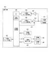
図1は、本実施の形態に係るドアホンシステムの構成の一例を示すシステム構成図である。ここでは、システム構成の周辺の環境についても併せて図示している。 FIG. 1 is a system configuration diagram showing an example of a configuration of a door phone system according to the present embodiment. Here, the surrounding environment of the system configuration is also illustrated.
図1に示すように、ドアホンシステム100は、例えば、ユーザ220の自宅である建物200の玄関扉210に設けられる電子錠300と、玄関扉210の近傍に配置される玄関子機400と、建物200の室内に配置されるドアホン親機500とを有する。 As illustrated in FIG. 1, the
電子錠300は、玄関扉210の開錠/施錠を、鍵穴に対する通常の鍵操作に加えて、電気信号である開錠要求/施錠要求に応じて行う鍵装置である。電子錠300とドアホン親機500との間には、JEM−A規格コードである電子錠コード301が敷設されている。電子錠300は、ドアホン親機500からの制御を受けて開錠/施錠を行う事が可能となっている。 The
玄関子機400は、呼出ボタン、スピーカ、マイクロフォン、およびデジタルカメラを備えている。玄関子機400とドアホン親機500との間には、1対の銅線から成る2線ケーブル401が敷設されている。玄関子機400は、呼出および通話の機能に加えて、玄関周辺の映像を撮影してドアホン親機500へ送信する機能を有している。なお、2線ケーブル401は、例えば、過去に建物200に設置されていた、映像信号の伝送を行わない古いタイプのドアホンシステムで使用されていた通信ケーブルである。 The
ドアホン親機500は、スピーカ、タッチパネル付き液晶ディスプレイ、モニターボタン、通話ボタン、マイクロフォン、および施錠/開錠ボタンを備えている。ドアホン親機500は、呼出に対する応答(通話の開始)の機能に加えて、玄関子機400から送られてきた玄関周辺の映像を表示する機能と、玄関扉210の電子錠300の開錠/施錠操作を受け付ける機能とを有している。 Door
また、ドアホンシステム100は、建物200の室内に配置される無線通信ルータ610と、インターネット等の公共網620に接続された認証サーバ600と、建物200の外部に持ち出し可能なスマートフォン等の無線端末(通信端末)700とを有する。 In addition, the
無線通信ルータ610は、無線通信回線611、612により、ドアホン親機500および公共網620のそれぞれと接続し、ドアホン親機500と公共網620との間で通信の中継を行う。無線通信回線611は、例えば、Wi−Fi(登録商標)の回線であり、無線通信回線612は、例えば、LTE(Long Term Evolution)回線である。
認証サーバ600は、公共網620を介して無線通信ルータ610と接続し、無線通信ルータ610を介してドアホン親機500と通信を行う。また、認証サーバ600は、ドアホン親機500にアクセスしようとする無線端末(例えば無線端末700)に対して認証処理を行い、認証が成功した場合、その無線端末とドアホン親機500との間で通信の中継を行う。 The
無線端末700は、無線通信回線701により、公共網620と接続し、認証サーバ600を介してドアホン親機500にアクセスする。無線通信回線701は、例えば、LTE回線である。無線端末700は、公共網620、認証サーバ600、および無線通信ルータ610を介して、建物200の内部および外部から、ドアホン親機500と接続可能となっている。 The
また、無線端末700は、スピーカ、タッチパネル付き液晶ディスプレイ、マイクロフォン、端末モニターボタン、端末通話ボタン、端末開錠ボタン、および端末施錠ボタンを備えている。なお、これらのボタンは、例えば、タッチパネル付き液晶ディスプレイに表示される画像ボタンである。 The
そして、上述のドアホン親機500は、玄関子機400と無線端末700との間で、映像、音声、および各種制御情報の転送を行うと共に、無線端末700からの開錠端末指示を受けて、電子錠300を開錠させる。すなわち、上述のドアホン親機500は、呼出に対する応答(通話の開始)、玄関周辺の映像の表示、電子錠300の開錠/施錠操作を、無線端末700においても可能にする機能を有している。 And the above-mentioned door
なお、図1では、無線端末700を1台のみ図示しているが、ドアホンシステム100においてドアホン親機500と接続可能な無線端末700は、例えば、複数存在している。 In FIG. 1, only one
なお、玄関子機400およびドアホン親機500は、例えば、特許文献2に記載の技術をベースとして、相手への送信の対象となる各種データを、パケット化した上で符号化を行い、ベースバンド伝送により相手に送信する。この際、玄関子機400およびドアホン親機500は、それぞれのベースバンド伝送を、時分割複信(時分割双方向伝送)によって行う。すなわち、玄関子機400およびドアホン親機500は、送信と受信とを時間の経過に応じて交互に切り替え、相手が送信を行っていない区間にのみ送信を行う。 The
これにより、ドアホンシステム100は、既存の2線ケーブル401を有効活用して、玄関子機400からドアホン親機500への高品質な映像音声信号送信を実現する事ができる。但し、玄関子機400とドアホン親機500との間の通信方式は、かかる例に限定されるものではなく、公知の各種通信方式を採用する事ができる。 As a result, the
このようなドアホンシステム100は、ユーザ220に対し、建物200の中に居る時のみならず、建物200の外に居る時においても、玄関に来訪者230があった時に、その旨を知る事を可能にする。そして、ドアホンシステム100は、ユーザ220に対し、ドアホン映像を確認しながら来訪者230と会話をし、来訪者230がユーザ220の子供である事等を確認した場合に、玄関扉210の開錠操作を遠隔で行う事を可能にする。 Such a
ところが、無線端末700から公共網620を介して遠隔で開錠の指示を行う場合、上述の通り、安全性の面において改善の余地があった。そこで、ドアホン親機500は、開錠端末指示による電子錠300の開錠を許可するか否かを設定する操作を受け付け、設定内容に従って無線端末700からの開錠を制限する事により、安全性の向上を図る。 However, when the unlocking instruction is issued remotely from the
例えば、無線端末700が第三者に取得された場合や、不正な開錠端末指示が第三者の通信端末から送信されている場合、無線端末700からの開錠を許可しないように設定する事により、玄関扉210が不正に開錠されるのを防止する事ができる。また、子供が所持する無線端末700からの開錠を許可しないように設定する事により、玄関扉210が不適切なタイミングで開錠されるのを防止する事ができる。したがって、ドアホンシステム100は、玄関扉210が不適切に開錠される可能性を低く抑えた状態で、無線端末700からの開錠操作を実現する事ができる。 For example, when the
<各装置の構成>
ここで、ドアホンシステム100の主要な装置の構成について説明する。なお、ドアホンシステム100を構成する各装置は、例えば、図示しないが、CPU(Central Processing Unit)、制御プログラムを格納したROM(Read Only Memory)等の記憶媒体、RAM(Random Access Memory)等の作業用メモリ、および通信回路をそれぞれ有する。この場合、以下に説明する各部の機能は、CPUが制御プログラムを実行する事により実現される。<Configuration of each device>
Here, a configuration of main devices of the
<電子錠の構成>
電子錠300の構成としては、公知の電子錠の構成を採用する事ができる。例えば、電子錠300は、電子錠コード301の一端が接続されるJEM−A標準HA端子−Aを備えたJEM−Aアダプタを含み、端子への入力信号に応じて開錠/施錠の状態を切り替えるように構成されている。<Structure of electronic lock>
As the configuration of the
このような構成により、電子錠300は、ドアホン親機500からの制御を受けて、玄関扉210の開錠/施錠を行う事ができる。 With such a configuration, the
<玄関子機の構成>
図2は、玄関子機400の構成の一例を示すブロック図である。<Configuration of entrance cordless handset>
FIG. 2 is a block diagram illustrating an example of the configuration of the
図2において、玄関子機400は、子機側ケーブル接続部410、子機側キー入力部420、子機側スピーカ402、子機側マイク403、子機側音声I/F(インターフェイス)部430、および子機側カメラ部440を有する。また、玄関子機400は、子機側制御部450、子機側パケット構成部460、子機側送信ドライバ470、子機側受信ドライバ480、および子機側データ抽出部490を有する。 In FIG. 2, an
子機側ケーブル接続部410は、例えば2線ケーブル用の接続端子を含み、2線ケーブル401の玄関側の一端と、子機側送信ドライバ470および子機側受信ドライバ480との間を、信号を伝送可能な状態で接続する。 The slave unit side
子機側キー入力部420は、上述の呼出ボタンを含み、呼出ボタンが操作された時、その旨を示す信号を子機側制御部450へ出力する。 The handset side
子機側スピーカ402は、子機側音声I/F部430から出力されたアナログ音声データを、音声に変換して出力する。 The
子機側マイク403は、周囲の音声を集音してアナログ音声データに変換し、子機側音声I/F部430へ出力する。 The
子機側音声I/F部430は、子機側制御部450から出力されたデジタル音声データを、アナログ音声データに変換し、信号レベルを調整して、子機側スピーカ402へ出力する。また、子機側音声I/F部430は、子機側マイク403から出力されたアナログ音声データを、信号レベルを調整し、デジタル音声データに変換して、子機側制御部450へ出力する。かかるアナログ/デジタル変換は、A/D,D/A変換器(図示せず)により行われる。 The slave unit side audio I /
なお、子機側音声I/F部430は、子機側マイク403から出力されたアナログ音声データをデジタル変換したデータに対して、所定の音声圧縮処理を行って得られるデータを、デジタル音声データとして子機側制御部450へ出力してもよい。また、子機側音声I/F部430は、子機側制御部450から出力されたデジタル音声データが所定の音声圧縮処理を行って得られたデータである場合、当該データに対して所定の音声伸張処理を行ってから、デジタル/アナログ変換を行う。 The handset side audio I /
子機側カメラ部440は、上述のデジタルカメラを含み、玄関の映像を撮影し、デジタル映像データを生成して、子機側制御部450へ出力する。なお、子機側カメラ部440は、エンコーダモジュールを搭載していてもよい。すなわち、子機側カメラ部440は、デジタルカメラから出力された映像データに対してH.264等の所定の動画圧縮処理を行って得られるデータを、デジタル映像データとして子機側制御部450へ出力してもよい。 The slave unit
子機側制御部450の来訪通知部451は、玄関扉210に来訪者230があった時、その旨を示す来訪通知をドアホン親機500へ送信する。例えば、来訪通知部451は、呼出ボタンが操作された旨を示す信号が子機側キー入力部420から出力された時、来訪通知をドアホン親機500へ送信する。 When there is a
なお、来訪通知部451は、玄関扉210への来訪者230の有無を、玄関扉210の近傍に配置された人感センサの出力信号や、子機側カメラ部440の画像に対する人検出処理等に基づいて判定してもよい。 The
また、子機側制御部450は、玄関扉210に来訪者230があった時、あるいは、ドアホン親機500から音声映像送信指示を受信した時、玄関周辺のモニタリングおよび映像付き通話を実現するための所定の制御処理を開始する。かかる制御処理は、子機側音声I/F部430および子機側カメラ部440から出力されたデジタル音声データおよびデジタル映像データを、ドアホン親機500へ送信する事により行われる。また、かかる制御処理は、ドアホン親機500から受信したデジタル音声データを、子機側音声I/F部430へ出力する事により行われる。 In addition, when the
なお、子機側制御部450は、来訪通知を送信した時、あるいは、音声映像送信指示を受信した時に、子機側スピーカ402、子機側マイク403、子機側音声I/F部430、および子機側カメラ部440の動作を開始させるように制御してもよい。 The slave unit
また、子機側制御部450は、玄関子機400の動作あるいはドアホン親機500の動作に関する各種制御データを、ドアホン親機500へ送信してもよい。かかる制御データは、例えば、玄関子機400に備えられた気温センサ、照度センサ、および人感センサ等の各種センサデバイス(図示せず)のセンシング情報を含む。 Moreover, the subunit | mobile_unit
子機側パケット構成部460は、子機側制御部450から出力されたデジタル音声データおよびデジタル映像データ(並びに制御データ)を、適宜分割してパケット化し、生成されたパケットデータを符号化して、ドアホン親機500への上り信号を生成する。そして、子機側パケット構成部460は、生成された上り信号を、子機側送信ドライバ470へ出力する。 The slave unit side
子機側送信ドライバ470は、子機側パケット構成部460から出力された上り信号をバッファし、信号レベルの調整を行い、子機側ケーブル接続部410を介してドアホン親機500へ送信する。 The slave unit
子機側受信ドライバ480は、子機側ケーブル接続部410を介してドアホン親機500から送られてくる下り信号を、信号レベルの調整を行ってバッファし、子機側データ抽出部490へ出力する。 The slave unit
子機側データ抽出部490は、子機側受信ドライバ480から出力された下り信号から、下り信号に含まれるドアホン親機500のデジタル音声データを抽出し、子機側制御部450へ出力する。 Slave unit side
なお、上述の子機側制御部450によるドアホン親機500との間の各種情報の送受信は、子機側パケット構成部460、子機側送信ドライバ470、子機側ケーブル接続部410、子機側受信ドライバ480、および子機側データ抽出部490を介して行われる。 In addition, transmission / reception of various information between the above-mentioned subunit | mobile_unit
但し、子機側制御部450は、ドアホン親機500との間で予め共有(保持)している送信制御情報に基づいて、上り信号の送信と下り信号の受信とが時分割で行われるように、子機側送信ドライバ470および子機側受信ドライバ480の動作を制御する。送信制御情報は、玄関子機400とドアホン親機500との間の時分割複信における、それぞれの送信タイミングおよび受信タイミングを規定する情報である。子機側送信ドライバ470の動作の制御は、例えば、送信制御情報に従って、子機側送信ドライバ470の動作(信号のドライブ)を制御するイネーブル信号471等を出力する事により行われる。 However, the slave unit
また、玄関子機400の上記各部の間のデータの受け渡しは、子機側スピーカ402および子機側マイク403と子機側音声I/F部430との間を除き、デジタル伝送により行われる。 In addition, data exchange between the above-described units of the
このような構成により、玄関子機400は、玄関扉210に来訪者230があった時、ドアホン親機500に対して来訪通知を送信する事ができる。 With such a configuration, the
<ドアホン親機の構成>
図3は、ドアホン親機500の構成の一例を示すブロック図である。<Configuration of doorphone master unit>
FIG. 3 is a block diagram illustrating an example of the configuration of the door
図3において、ドアホン親機500は、親機側ケーブル接続部510、親機側キー入力部520、親機側スピーカ502、親機側マイク503、親機側音声I/F部530、および親機側ディスプレイ部540を有する。また、ドアホン親機500は、情報格納部541、親機無線部542、親機側制御部550、親機側パケット構成部560、親機側送信ドライバ570、親機側受信ドライバ580、親機側データ抽出部590、および電子錠コード接続部595を有する。 In FIG. 3, door
親機側ケーブル接続部510は、例えば2線ケーブル用の接続端子を含み、2線ケーブル401の室内側の一端と、親機側送信ドライバ570および親機側受信ドライバ580との間を、信号を伝送可能な状態で接続する。 The base unit side
親機側キー入力部520は、上述のモニターボタンおよび通話ボタンを含み、これらのボタンが操作された時、その旨を示す信号を親機側制御部550へ出力する。 Base unit side
親機側スピーカ502は、親機側音声I/F部530から出力されたアナログ音声データを、音声に変換して出力する。 Base
親機側マイク503は、周囲の音声を集音してアナログ音声データに変換し、親機側音声I/F部530へ出力する。 Base
親機側音声I/F部530は、親機側制御部550から出力されたデジタル音声データを、アナログ音声データに変換し、信号レベルを調整して、親機側スピーカ502へ出力する。また、親機側音声I/F部530は、親機側マイク503から出力されたアナログ音声データを、信号レベルを調整し、デジタル音声データに変換して、親機側制御部550へ出力する。かかるアナログ/デジタル変換は、A/D,D/A変換器(図示せず)により行われる。 Base unit side sound I /
なお、親機側音声I/F部530は、親機側マイク503から出力されたアナログ音声データをデジタル変換したデータに対して、所定の音声圧縮処理を行って得られるデータを、デジタル音声データとして親機側制御部550へ出力してもよい。また、親機側音声I/F部530は、親機側制御部550から出力されたデジタル音声データが所定の音声圧縮処理を行って得られたデータである場合、当該データに対して所定の音声伸張処理を行ってから、デジタル/アナログ変換を行ってもよい。 The base-side audio I /
親機側ディスプレイ部540は、上述の液晶ディスプレイを含み、親機側制御部550から出力されたデジタル映像データを再生し、玄関の映像を表示する。なお、親機側制御部550から出力されたデジタル映像データが所定の動画圧縮処理を行って得られたデータである場合、当該データに対して所定の動画伸張処理を行って、映像表示を行う。 Base unit
情報格納部541は、玄関子機400との通話および電子錠300の開錠/施錠操作を行う権限を有する無線端末700に関する情報を記述した、端末情報テーブルを格納する。 The
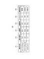
図4は、端末情報テーブルの一例を示す図である。 FIG. 4 is a diagram illustrating an example of the terminal information table.
図4に示すように、端末情報テーブル910は、ドアホン親機500と接続可能な無線端末700毎に、端末名称911、端末種別912、ID(IDentifier)情報913、鍵情報914、パスワード915、および開錠設定916を、対応付けて記述している。 As shown in FIG. 4, the terminal information table 910 includes a
端末名称911は、無線端末700の名称である。端末種別912は、無線端末700の端末種別である。ID情報913は、MAC(Media Access Control)アドレス等の通信において用いられる無線端末700の識別情報である。鍵情報914は、ドアホン親機500と無線端末700との間での通信の暗号化および復号化に使用される情報である。パスワード915は、ドアホン親機500の無線端末700に対する認証処理に用いられる情報である。開錠設定916は、無線端末700による電子錠300に対する開錠操作を許可するか否かを示す情報である。 The
端末名称911〜パスワード915は、例えば、ドアホン親機500に対する情報入力操作や、公知技術による近・中距離無線通信を用いたドアホン親機500と無線端末700との間での情報交換により、予め登録される。開錠設定916は、後述の端末登録部553により、適宜、「許可」と「不許可」との間で切り替えて設定される。なお、開錠設定916は、初期状態において「不許可」となっている事が望ましい。 The
例えば、「スマートフォン1」という端末名称911に対応付けて、「許可」という開錠設定916が記述されている。これは、「スマートフォン1」という名称の無線端末700については、電子錠300に対する開錠操作が許可されているという事を示す。また、「スマートフォン2」という端末名称911に対応付けて、「不許可」という開錠設定916が記述されている。これは、「スマートフォン2」という名称の無線端末700については、電子錠300に対する開錠操作が許可されていないという事を示す。 For example, an unlock setting 916 “permitted” is described in association with the
なお、上述の情報交換は、例えば、同一LAN(Local Area Network)内における、コマンド通信により行われる。具体的には、無線端末700は、近・中距離無線通信機能のオンオフの切り替えが可能となっており、無線通信ルータ610の通信圏内に位置し、かつ、かかる機能がオンとなっている時、無線通信ルータ610に直接接続する(配下となる)。そして、ドアホン親機500は、例えば、ドアホン親機500と同様に無線端末700が無線通信ルータ610の配下となっている事を条件として、無線端末700から無線通信ルータ610を介して端末名称911〜パスワード915の設定を受け付ける。ドアホン親機500および無線端末700は、例えば、HTTP(HyperText Transfer Protocol)のCGI(Common Gateway Interface)コマンドを用いて、情報をやり取りする。但し、かかる情報は、AES(Advanced Encryption Standard)等の技術により暗号化された状態で送信されることが望ましい。 Note that the information exchange described above is performed, for example, by command communication within the same LAN (Local Area Network). Specifically, the
図3の親機無線部542は、無線通信回路およびアンテナを含み、上述の無線通信回線611、612により無線通信ルータ610と通信可能に接続する。そして、親機無線部542は、無線通信ルータ610、公共網620、および認証サーバ600を介して、無線端末700と通信可能に接続する。 3 includes a wireless communication circuit and an antenna, and is connected to the
親機側制御部550は、玄関子機400から上述の来訪通知を受信した時、親機側スピーカ502から、所定の呼出音を出力させる。呼出音の出力は、例えば、親機側制御部550が、所定の呼出音のデジタル音声信号を親機側音声I/F部530へ出力する事により行われる。 When receiving the above-mentioned visit notification from the
更に、親機側制御部550は、玄関周辺のモニター、および、玄関子機400とドアホン親機500との間の映像付き通話を実現するための所定の制御処理を開始する。かかる制御処理は、親機側音声I/F部530から出力されたデジタル音声データを、玄関子機400へ送信し、玄関子機400から受信したデジタル音声データおよびデジタル映像データを、子機側音声I/F部430および親機側ディスプレイ部540へ出力する事により行われる。但し、親機側制御部550は、親機側キー入力部520から、通話ボタンが操作された旨を示す信号が出力されるまでは、デジタル音声データの玄関子機400への送信を行わない。 Furthermore, the base-
なお、親機側制御部550は、来訪通知を受信した時に、親機側スピーカ502、親機側マイク503、親機側音声I/F部530、および親機側ディスプレイ部540の動作を開始させるように制御してもよい。 Note that, when the base unit
また、親機側制御部550は、ドアホン親機500の動作あるいは玄関子機400の動作に関する制御データを、玄関子機400へ送信してもよい。かかる制御データは、例えば、ドアホン親機500から玄関子機400のカメラ動作(データレート、パン、チルト、ライト、シャッタ、およびフィルター等の動作)や、玄関子機400に備えられた各種センサデバイスの動作を制御するための制御信号を含む。また、かかる制御データは、玄関子機400に備えられた無線通信回路等(図示せず)を介して屋外に配置されたデバイス(門の電子鍵等)の動作を制御するための制御信号を含む。 Further, base unit
更に、親機側制御部550は、認証サーバ600を介して無線端末700からログイン要求を受信した時、情報格納部541に格納されたログイン情報(例えば、図4のID情報913およびパスワード915)に基づいて無線端末700に対する認証処理を行う。すなわち、親機側制御部550は、例えば、ログイン要求に含まれる暗号化されたID情報およびパスワードを、鍵情報で復号し、ログイン情報の内容と照合する。そして、通話中継部552は、認証が成功した場合、認証サーバ600を介して無線端末700と接続する。 Furthermore, when the base unit
そして、親機側制御部550は、無線端末700と接続している状態において、玄関子機400から上述の来訪通知を受信した時、上述の処理と共に、端末通知部551において、無線端末700に対する来訪端末通知の送信を行う。また、端末通知部551は、来訪通知を受信する毎に、その旨を、後述の電子錠制御部554へ通知する。 When the base unit
親機側制御部550の通話中継部552は、無線端末700からピア・ツー・ピアの通信(以下「P2P通信」と表記する)の開始の要求が送信されたとき、これを受理するか否かを決定する。通話中継部552は、かかる要求を受理する場合、その旨の応答を無線端末700に送信すると共に、玄関子機400から送られてくる映像の無線端末700への転送を開始する。 Whether or not the
また、通話中継部552は、無線端末700から通話開始指示を受信すると、玄関子機400と無線端末700との間で映像付き通話を実現するための通話中継処理を開始する。かかる通話中継処理は、無線端末700から受信したデジタル音声データを、玄関子機400へ送信し、玄関子機400から受信したデジタル音声データおよびデジタル映像データを、無線端末700へ送信する事により行われる。 In addition, when the
また、通話中継部552は、無線端末700から、玄関周辺の映像の送信を要求する映像送信要求を受信した時、上述の音声映像送信指示を玄関子機400へ送信する。そして、通話中継部552は、玄関子機400から受信したデジタル映像データを、無線端末700へ送信する。 In addition, when receiving a video transmission request for requesting transmission of video around the entrance from the
親機側制御部550の端末登録部553は、無線端末700による電子錠300に対する開錠操作を許可するか否かを設定する操作を受け付ける。例えば、端末登録部553は、ドアホン親機500のタッチパネル付き液晶ディスプレイに、端末設定画面を表示する。端末設定画面は、ドアホンシステム100のユーザ(例えばユーザ220)から、無線端末700毎に開錠許可/不許可の設定を受け付けるためのユーザインタフェースである。そして、端末登録部553は、端末設定画面に対する操作に応じて、端末情報テーブル910の開錠設定916(図4参照)を書き換える。端末設定画面の詳細については、後述する。
親機側制御部550の電子錠制御部554は、無線端末700から親機無線部542を介して開錠端末指示を受信した時、開錠要求を玄関扉210の電子錠300へ送信し、電子錠300を開錠させる。但し、電子錠制御部554は、開錠端末指示を受信した時、端末情報テーブル910(図4参照)を参照し、開錠端末指示の送信元の無線端末700について、開錠操作を許可する設定がされているか否かを判定する。そして、電子錠制御部554は、開錠操作を許可する設定となっている事を条件として、電子錠300を開錠させる。また、電子錠制御部554は、開錠要求により電子錠300を開錠させた場合、20秒等の所定の時間が経過した時に、施錠要求を玄関扉210の電子錠300へ送信して、電子錠300を施錠させる事が望ましい。 When receiving an unlocking terminal instruction from the
親機側パケット構成部560は、親機側制御部550から出力されたデジタル音声データ(および制御データ)を、適宜分割してパケット化し、生成されたパケットデータを符号化して、下り信号を生成する。そして、親機側パケット構成部560は、生成された下り信号を、親機側送信ドライバ570へ出力する。 Base unit
親機側送信ドライバ570は、親機側パケット構成部560から出力された下り信号をバッファしてゲイン調整を行い、親機側ケーブル接続部510を介して玄関子機400へと送信する。 The base unit
親機側受信ドライバ580は、親機側ケーブル接続部510を介して玄関子機400から送られてくる上り信号を、ゲイン調整を行ってバッファし、親機側データ抽出部590へ出力する。 The base-
親機側データ抽出部590は、親機側受信ドライバ580から出力された下り信号から、上り信号に含まれる玄関子機400のデジタル音声データおよびデジタル映像データを抽出し、親機側制御部550へ出力する。 Base unit side
電子錠コード接続部595は、例えば、JEMA標準HA端子−Aを備えたJEM−Aアダプタを含み、電子錠コード301の一端と、親機側制御部550との間を、信号を伝送可能な状態で接続する。 The electronic lock
なお、上述の親機側制御部550による玄関子機400との間の各種情報の送受信は、子親機側パケット構成部560、親機側送信ドライバ570、親機側ケーブル接続部510、親機側受信ドライバ580、および親機側データ抽出部590を介して行われる。 It should be noted that transmission / reception of various information to / from the
但し、親機側制御部550は、上述の送信制御情報を予め保持しており、下り信号の送信と上り信号の受信とが時分割で行われるように、親機側送信ドライバ570の動作を制御する。かかる制御は、例えば、送信制御情報に従って、親機側送信ドライバ570の動作(信号のドライブ)を制御するイネーブル信号571等を出力する事により行われる。 However, base unit
また、上述の親機側制御部550による無線端末700との間の各種情報の送受信は、親機無線部542を介して行われる。そして、上述の親機側制御部550による電子錠300との間の各種情報の送受信は、電子錠コード接続部595を介して行われる。 In addition, transmission / reception of various types of information to / from the
また、ドアホン親機500の上記各部の間のデータの受け渡しは、親機側スピーカ502および親機側マイク503と親機側音声I/F部530との間を除き、デジタル伝送により行われる。 In addition, data is exchanged between the above-described units of the
このような構成により、ドアホン親機500は、無線端末700による電子錠300の開錠操作を許可するか否かを設定する操作を、ユーザから受け付ける事ができる。そして、ドアホン親機500は、玄関子機400から来訪通知を受信した時、無線端末700に対して来訪端末通知を送信し、無線端末700から開錠端末指示を受信した時、開錠操作を許可する設定となっている事を条件として、電子錠300を開錠させる事ができる。 With such a configuration, door
<無線通信ルータの構成>
無線通信ルータ610の構成としては、無線により通信を中継する公知の無線通信ルータの構成を採用する事ができる。<Configuration of wireless communication router>
As a configuration of the
<認証サーバの構成>
認証サーバ600の構成としては、通信を中継する公知の無線通信ルータおよび認証サーバの構成を採用する事ができる。<Configuration of authentication server>
As the configuration of the
認証サーバ600は、例えば、ドアホン親機500へのアクセスを要求してきた無線端末(例えば無線端末700)に対して、無線端末700との間で予め交換された認証情報に基づいて、認証処理を行う、認証処理部(図示せず)を有する。かかる認証処理としては、例えば、SSL(Secure Sockets Later)認証や、認証サーバ600と無線端末700との間で予め取り交わしたパスワードによる認証等を採用する事ができる。 For example, the
そして、認証サーバ600は、無線端末700に対する認証が成功した事を条件として、無線端末700との接続を確立し、無線端末700と(無線通信ルータ610を介した)ドアホン親機500との間の通信の中継を行う、端末通信中継部(図示せず)を有する。 Then, the
なお、認証サーバ600は、ドアホン親機500から来訪端末通知を受信した時、かかる通知を無線端末700へ転送するが、かかる転送は、無線端末700とドアホン親機500との間の通信が確立される前であってもよいし、後であってもよい。 When the
<無線端末の構成>
図5は、無線端末700の構成の一例を示すブロック図である。<Configuration of wireless terminal>
FIG. 5 is a block diagram illustrating an example of the configuration of the
図5において、無線端末700は、端末無線部710、端末スピーカ720、端末マイク730、端末音声I/F部740、端末ディスプレイ部750、タッチパネル部760、および端末制御部770を有する。 In FIG. 5, the
端末無線部710は、無線通信回路およびアンテナを含み、上述の無線通信回線701により公共網620に接続された無線基地局(図示せず)と通信可能に接続する。そして、端末無線部710は、無線基地局および公共網620を介して認証サーバ600と通信可能に接続する。更に、端末無線部710は、認証サーバ600により通信の中継が行われている間、認証サーバ600、公共網620、および無線通信ルータ610を介して、ドアホン親機500と通信可能に接続する。 The
端末スピーカ720は、端末音声I/F部740から出力されたアナログ音声データを、音声に変換して出力する。 The
端末マイク730は、周囲の音声を集音してアナログ音声データに変換し、端末音声I/F部740へ出力する。 The
端末音声I/F部740は、端末制御部770から出力されたデジタル音声データを、アナログ音声データに変換し、信号レベルを調整して、端末スピーカ720へ出力する。また、端末音声I/F部740は、端末マイク730から出力されたアナログ音声データを、信号レベルを調整し、デジタル音声データに変換して、端末制御部770へ出力する。かかるアナログ/デジタル変換は、A/D,D/A変換器(図示せず)により行われる。 The terminal audio I /
なお、端末音声I/F部740は、端末マイク730から出力されたアナログ音声データをデジタル変換したデータに対して、所定の音声圧縮処理を行って得られるデータを、デジタル音声データとして端末制御部770へ出力してもよい。また、端末音声I/F部740は、端末制御部770から出力されたデジタル音声データが所定の音声圧縮処理を行って得られたデータである場合、当該データに対して所定の音声伸張処理を行ってから、デジタル/アナログ変換を行ってもよい。 Note that the terminal voice I /
端末ディスプレイ部750は、上述のタッチパネル付液晶ディスプレイの液晶ディスプレイ部分を含み、端末制御部770から出力されたデジタル映像データを再生する。なお、端末制御部770から出力されたデジタル映像データが所定の動画圧縮処理を行って得られたデータである場合、当該データに対して所定の動画伸張処理を行って、映像表示を行う。また、端末ディスプレイ部750は、端末制御部770からの制御に従って、上述の端末モニターボタン、端末通話ボタン、端末開錠ボタン、および端末施錠ボタンを表示する。 The
タッチパネル部760は、無線端末700に対する各種操作を受け付ける。例えば、タッチパネル部760は、端末ディスプレイ部750に端末モニターボタン、端末通話ボタン、端末開錠ボタン、あるいは端末施錠ボタンが表示されている時、これらに対するクリック操作を受け付け、かかる操作が行われた時、その旨を端末制御部770へ通知する。
端末制御部770は、タッチパネル部760においてドアホン親機500に対する接続の開始を要求する操作があった時、認証サーバ600による認証処理を受ける。認証サーバ600による認証が成功すると、認証サーバ600による無線端末700とドアホン親機500との間の通信の中継が開始される。端末制御部770は、かかる通信の中継が開始されると、次に、端末制御部770は、ドアホン親機500に対してログイン要求を送信する。 The
端末制御部770の端末情報出力部771は、ドアホン親機500から来訪端末通知を受信した時、玄関扉210に人が来た事を示す呼出音を端末スピーカ720から出力させる。これにより、端末情報出力部771は、玄関扉210に来訪者230が居る旨を、ユーザ220に通知する。また、端末情報出力部771は、端末ディスプレイ部750に、上述の端末モニターボタン、端末通話ボタン、および端末開錠ボタンを表示させる。 The terminal
端末制御部770の通話制御部772は、無線端末700において端末モニターボタンをクリックする等の確認操作が行われた時、ドアホン親機500に対してP2P通信の開始の要求を送信する。これにより、ドアホン親機500との間のP2P通信が開始され、通話制御部772は、ドアホン親機500から送られてくる玄関周辺の映像の出力を開始する。音声出力は、例えば、端末情報出力部771が、呼出音のデジタル音声信号を、端末音声I/F部740へ出力する事により行われる。また、映像出力は、例えば、端末情報出力部771が、ドアホン親機500からのデジタル映像データを、親機側ディスプレイ部540へ出力する事により行われる。 The
また、端末制御部770の通話制御部772は、無線端末700において端末通話ボタンをクリックする等の応答操作が行われた時、ドアホン親機500に対して上述の通話開始指示を送信し、ドアホン親機500を介して無線端末700と玄関子機400との間の通話を開始させる。すなわち、通話制御部772は、ドアホン親機500から送られてくる玄関周辺の映像および音声を、端末ディスプレイ部750および端末スピーカ720から出力させると共に、端末マイク730が入力した無線端末700周辺の音声を、ドアホン親機500へ送信する。 In addition, when a response operation such as clicking a terminal call button is performed in the
なお、通話制御部772は、来訪端末通知を受信していない状態において、端末モニターボタンをクリックする等の確認操作が行われた時、上述の映像送信要求をドアホン親機500へ送信する。そして、かかる要求に対応してドアホン親機500から送られてくる玄関周辺の映像を、端末ディスプレイ部750から出力させる。 Note that the
端末制御部770の操作通知部773は、無線端末700において上述の端末開錠ボタンをクリックする等の開錠指示操作が行われた時、ドアホン親機500に対して上述の開錠端末指示を送信する。 The
また、端末制御部770の操作通知部773は、無線端末700において施錠指示操作が行われた時、ドアホン親機500に対して上述の施錠端末指示を送信する。施錠指示操作は、例えば、端末ディスプレイ部750に表示された端末施錠ボタンに対するクリック操作である。 Further, the
なお、端末制御部770のこれらの機能部は、例えば、無線端末700に予めインストールされたアプリケーションソフトウェアにより実現される。また、上述の端末制御部770による認証サーバ600およびドアホン親機500との間の各種情報の送受信は、端末無線部710を介して行われる。 Note that these functional units of the
このような構成により、無線端末700は、ドアホン親機500から来訪端末通知を受信した時、玄関扉210に人が来た事を示す情報を出力し、無線端末700において開錠指示操作が行われた時、ドアホン親機500に対して開錠端末指示を送信する事ができる。 With such a configuration, when the
<ドアホン親機の動作>
次に、ドアホン親機500の動作について説明する。なお、ここでは、無線端末700との通信に関連する主要な動作に着目して説明を行う。<Operation of doorphone master unit>
Next, the operation of door
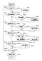
図6は、ドアホン親機500の動作の一例を示すフローチャートである。 FIG. 6 is a flowchart showing an example of the operation of door
ステップS1001において、端末登録部553は、端末設定操作が行われたか否かを判定する。端末設定操作は、例えば、ドアホン親機500のタッチパネル付きディスプレイに端末登録部553が表示する端末設定画面において、いずれかの無線端末700に対し、開錠操作の許可/不許可を選択する操作である。なお、端末登録部553は、例えば、ドアホン親機500のタッチパネル付きディスプレイに表示された所定のアイコンがクリックされた時、端末設定画面を表示させる。 In step S1001, the
端末設定画面は、例えば、操作の対象となる無線端末700を選択するための端末選択画面と、選択された無線端末700に対して開錠操作の許可/不許可を選択するための設定選択画面とを含む。 The terminal setting screen includes, for example, a terminal selection screen for selecting the
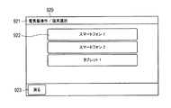
図7は、端末設定画面のうちの端末選択画面の一例を示す平面図である。 FIG. 7 is a plan view showing an example of a terminal selection screen in the terminal setting screen.
図7に示すように、端末選択画面920は、操作の対象となる無線端末700を選択するための画面である事を示す画面情報921と、ドアホン親機500と接続可能な複数の無線端末700のそれぞれの端末名称が付されたアイコン922とを含む。また、端末選択画面920は、端末選択画面920から通常時画面に戻るためのアイコン923を含む。 As illustrated in FIG. 7, the
端末登録部553は、例えば、端末情報テーブル910の端末名称911(図4参照)を参照して、端末選択画面920を生成する。端末登録部553は、無線端末700の端末名称が付されたアイコン922のいずれかがクリック(選択)されたとき、これを検出し、対応する無線端末700についての設定選択画面を生成して表示させる。 The
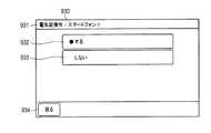
図8は、「スマートフォン1」のアイコン922が選択された場合に表示される、設定選択画面の一例を示す平面図である。 FIG. 8 is a plan view illustrating an example of a setting selection screen displayed when the
図8に示すように、設定選択画面930は、どの無線端末700に対して開錠操作の許可/不許可を選択するための画面であるかを示す画面情報931を含む。また、設定選択画面930は、選択中の無線端末700に対して開錠操作を許可する事を決定するためのアイコン932と、選択中の無線端末700に対して開錠操作を許可しない事を決定するためのアイコン933とを含む。更に、設定選択画面930から端末選択画面920に戻るためのアイコン934を含む。 As illustrated in FIG. 8, the
端末登録部553は、端末設定操作が行われた場合、つまり、アイコン932、933がクリックされた場合(図6のS1001:YES)、処理をステップS1002へ進める。また、端末登録部553は、端末設定操作が行われていない場合(S1001:NO)、処理を後述のステップS1003へ進める。 When the terminal setting operation is performed, that is, when the
ステップS1002において、端末登録部553は、行われた端末設定操作に従って、開錠許可/不許可を設定する。 In step S1002, the
すなわち、端末登録部553は、開錠操作の許可を決定するためのアイコン932(図8参照)がクリック(選択)されたとき、端末情報テーブル910のうち、選択中の無線端末700に対応する開錠設定916を、「許可」に書き換える(あるいは維持する)。また、端末登録部553は、開錠操作の不許可を決定するためのアイコン933(図8参照)がクリック(選択)されたとき、端末情報テーブル910のうち、選択中の無線端末700に対応する開錠設定916を、「不許可」に書き換える(あるいは維持する)。 That is, when the icon 932 (see FIG. 8) for determining permission of the unlocking operation is clicked (selected), the
なお、端末登録部553は、端末設定操作を行おうとする人に対して、予め定められたパスワードの入力を求める等、所定の認証処理を行ってもよい。これにより、端末設定操作を、その権限を有する人(例えば、建物200の居住者のうち大人)に制限する事ができる。 Note that the
ステップS1003において、通話中継部552は、無線端末700からのログイン要求を受信したか否かを判定する。通話中継部552は、ログイン要求を受信した場合(S1003:YES)、処理をステップS1004へ進める。また、通話中継部552は、ログイン要求を受信していない場合(S1003:NO)、処理を後述のステップS1006へ進める。 In step S1003, the
ステップS1004において、通話中継部552は、無線端末700に対する認証処理を行う。ここでは、認証が成功した場合を想定して説明を行う。通話中継部552は、無線端末700に対してログイン応答を送信し、無線端末700と接続する。なお、認証が失敗した場合、ドアホン親機500は、例えば、認証失敗を示す応答を無線端末700へ送信して、処理を後述のステップS1006へ進める。 In step S1004, the
ステップS1005において、ドアホン親機500は、無線端末700による玄関周辺のモニタリングおよび玄関子機400との映像付き通話を実現するための接続中処理を実施する。接続中処理の詳細については後述する。 In step S <b> 1005, the
なお、ドアホン親機500は、ステップS1003〜S1005の処理を、無線端末700毎に行う。 Door
そして、ステップS1006において、ドアホン親機500は、ユーザ操作等により処理の終了を指示されたか否かを判定する。ドアホン親機500は、処理の終了を指示されていない場合(S1006:NO)、処理をステップS1001へ進める。また、ドアホン親機500は、処理の終了を指示された場合(S1006:YES)、一連の処理を終了する。 In step S1006,
図9は、接続中処理(図6のステップS1005)の一例を示すフローチャートである。 FIG. 9 is a flowchart showing an example of the connection process (step S1005 in FIG. 6).
ステップS1010において、端末通知部551は、玄関子機400から来訪通知を受信したか否かを判定する。端末通知部551は、来訪通知を受信した場合(S1010:YES)、処理をステップS1020へ進める。また、端末通知部551は、来訪通知を受信していない場合(S1010:NO)、処理を後述のステップS1030へ進める。 In step S1010, the
ステップS1020において、端末通知部551は、来訪端末通知を、認証サーバ600を介して無線端末700へ送信する。 In step S <b> 1020, the
ステップS1030において、通話中継部552は、無線端末700からP2P通信の開始を要求するP2P開始要求を受信したか否かを判定する。通話中継部552は、P2P開始要求を受信した場合(S1030:YES)、処理をステップS1040へ進める。また、通話中継部552は、P2P開始要求を受信していない場合(S1030:NO)、処理を後述のステップS1060へ進める。 In step S1030, the
ステップS1040において、通話中継部552は、無線端末700とのP2P通信を開始するか否かを判定する。通話中継部552は、P2P通信を開始する場合(S1040:YES)、処理をステップS1050へ進める。また、通話中継部552は、P2P通信を開始しない場合(S1040:NO)、処理を後述のステップS1060へ進める。なお、通話中継部552は、P2P通信を開始しない場合、後述のステップS1120と同様に操作拒否通知を無線端末700へ送信してもよい。 In step S1040, the
ステップS1050において、通話中継部552は、P2P通信を開始すると共に、玄関子機400から送られてくる音声映像の無線端末700への転送を開始する。但し、通話中継部552は、音声の転送については、必ずしも開始しなくてもよい。 In step S1050, the
ステップS1060において、通話中継部552は、無線端末700から通話開始指示を受信したか否かを判定する。通話中継部552は、通話開始指示を受信した場合(S1060:YES)、処理をステップS1070へ進める。また、通話中継部552は、通話開始指示を受信していない場合(S1060:NO)、処理を後述のステップS1090へ進める。 In step S1060, call
ステップS1070において、通話中継部552は、無線端末700とのP2P通信が開始されているか否かを判断する。通話中継部552は、P2P通信が開始されている場合(S1070:YES)、処理をステップS1080へ進める。また、通話中継部552は、P2P通信が開始されていない場合(S1070:NO)、処理を後述のステップS1090へ進める。なお、通話中継部552は、P2P通信が開始されていない場合、後述のステップS1120と同様に操作拒否通知を無線端末700へ送信してもよい。 In step S1070, the
ステップS1080において、通話中継部552は、玄関子機400と無線端末700との間の通話中継(音声データおよび映像データの転送)を開始する。 In step S1080, the
ステップS1090において、電子錠制御部554は、無線端末700から開錠端末指示を受信したか否かを判定する。電子錠制御部554は、開錠端末指示を受信した場合(S1090:YES)、処理をステップS1103へ進める。また、電子錠制御部554は、開錠端末指示を受信していない場合(S1090:NO)、処理を後述のステップS1130へ進める。 In step S <b> 1090, the electronic
ステップS1103において、電子錠制御部554は、端末情報テーブル910(図4参照)を参照し、開錠端末指示の送信元の無線端末700に対して、電子錠300の開錠操作の許可が設定されているか否かを判定する。なお、電子錠制御部554は、例えば、開錠端末指示に含まれる送信元のID情報に基づいて、開錠端末指示の送信元を特定する。電子錠制御部554は、開錠操作の許可が設定されている場合(S1103:YES)、処理をステップS1110へ進める。また、電子錠制御部554は、開錠操作の許可が設定されていない場合(S1103:NO)、処理を後述のステップS1120へ進める。 In step S1103, the electronic
ステップS1110において、電子錠制御部554は、電子錠300を開錠させると共に、開錠端末通知を無線端末700へ送信する。なお、電子錠制御部554は、電子錠300に対して開錠要求を送信し、電子錠300から開錠が行われた事を示す開錠応答が返信された事をもって、開錠が行われたと判定してもよい。 In step S1110, the electronic
ステップS1120において、電子錠制御部554は、電子錠300を開錠させる事なく、操作拒否通知を無線端末700へ送信する。 In step S1120, the electronic
ステップS1130において、通話中継部552は、通話終了通知を受信したか否かを判定する。通話終了通知は、例えば、無線端末700において、通話を終了する操作が行われた場合に、無線端末700から送信される。通話中継部552は、通話終了通知を受信した場合(S1130:YES)、処理をステップS1140へ進める。また、通話中継部552は、通話終了通知を受信していない場合(S1130:NO)、処理を後述のステップS1150へ進める。 In step S1130, call
ステップS1140において、通話中継部552は、玄関子機400と無線端末700との間の通話中継を終了する。 In step S1140, the
ステップS1150において、親機側制御部550は、ログアウト要求を受信したか否かを判定する。ログアウト要求は、例えば、無線端末700において、ログアウト操作が行われた場合に、無線端末700から送信される。親機側制御部550は、ログアウト要求を受信していない場合(S1150:NO)、処理をステップS1010へ戻す。また、親機側制御部550は、ログアウト要求を受信した場合(S1150:YES)、処理をステップS1160へ進める。 In step S1150, base unit
ステップS1160において、親機側制御部550は、無線端末700との接続を切断して、処理を図6のS1006の処理へ戻す。 In step S1160, base unit
このような動作により、ドアホン親機500は、建物200の外部に持ち出された無線端末700と通信可能に接続し、無線端末700からの、玄関扉210への来訪者230の確認、来訪者230との通話、および玄関扉210の開錠操作を可能にする。また、ドアホン親機500は、かかる開錠操作を許可するか否かの設定操作を、無線端末700毎に受け付け、設定内容に従って開錠操作を制限する事ができる。 By such an operation, door
<システムの動作>
最後に、ドアホンシステム100の動作について説明する。<System operation>
Finally, the operation of the
図10は、ドアホンシステム100の動作の一例を示すシーケンス図であり、開錠許可が設定されている無線端末700によって開錠操作が行われる場合の例である。 FIG. 10 is a sequence diagram illustrating an example of the operation of the
ドアホン親機500において、ある無線端末700に対して、電子錠300の開錠操作を許可する設定が行われる(S2001)。そして、当該無線端末700において、玄関周辺の確認および玄関扉210の電子錠300の操作を行うためのアプリケーションソフトウェアが起動されると、接続開始要求が無線端末700から認証サーバ600へ送信される(S2010)。そして、認証サーバ600による無線端末700に対する認証が成功すると、認証サーバ600から接続開始応答が返信される(S2020)。これにより、認証サーバ600による通信の中継が可能な状態となる。 In the door
なお、図示しないが、ドアホン親機500も、電源投入時等に認証サーバ600に対して同様の接続要求を行い、認証サーバ600から認証処理を受けている。 Although not shown, the door
更に、無線端末700からドアホン親機500へログイン要求が送信され(S2030)、ドアホン親機500による無線端末700に対する認証が成功すると、ドアホン親機500から認証成功を示すログイン応答が返信される(S2040)。 Furthermore, a login request is transmitted from the
この状態で玄関子機400の呼出ボタンが操作されると(S2050)、来訪通知がドアホン親機500へ送信され(S2060)、これを受信したドアホン親機500から、来訪端末通知が無線端末700へ送信される(S2070)。なお、これらの通知と共に、玄関子機400で取得された音声付き映像のドアホン親機500への送信も開始される。来訪端末通知を受信した無線端末700では、玄関扉210に来訪者230があった事を示す情報が出力される(S2090)。 In this state, when the call button of the front
来訪者を通知する情報出力を受けたユーザ220により、上述の確認操作が行われると(S2100)、P2P開始要求が無線端末700からドアホン親機500へ送信される(S2110)。そして、ドアホン親機500からP2P開始応答が返信されると共に(S2120)、玄関子機400からの音声および映像の無線端末700への転送が開始される(S2130)。この結果、無線端末700において、玄関周辺の映像等の出力が開始される(S2140)。 When the above-described confirmation operation is performed by the
なお、この段階では、ドアホン親機500は、玄関周辺の音声を出力しない事が望ましい。音声データは、ドアホン親機500において無線端末700に転送されないように制御されてもよいし、無線端末700において音声出力されないように制御されてもよい。 At this stage, it is desirable that
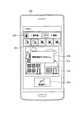
図11は、来訪端末通知を受信し、確認操作が行われた時の、無線端末700の表示状態の一例を示す平面図である。 FIG. 11 is a plan view illustrating an example of a display state of the
図11に示すように、無線端末700のタッチパネル付き液晶ディスプレイ751は、玄関子機400で撮影された映像811と、映像の送信元である玄関子機400を示す場所アイコン812とを表示する。また、タッチパネル付き液晶ディスプレイ751は、端末モニターボタンであるモニターアイコン813と、端末通話ボタンである通話アイコン814と、端末施錠ボタン兼端末開錠ボタンである電子錠アイコン815とを表示する。 As shown in FIG. 11, the
かかる情報出力を受けて、ユーザ220により無線端末700において応答操作(通話アイコン814のクリック)が行われると(図10のS2150)、無線端末700からドアホン親機500へと通話開始指示が送信される(S2160)。その結果、ドアホン親機500により、無線端末700から玄関子機400への音声の転送が開始され、無線端末700と玄関子機400との間の通話の中継が開始される(S2170)。 When the
図12は、玄関子機400との通話が開始された時の、無線端末700の表示状態の一例を示す平面図であり、図11に対応するものである。 FIG. 12 is a plan view illustrating an example of a display state of the
図12に示すように、無線端末700のタッチパネル付き液晶ディスプレイ751は、図11のモニターアイコン813および通話アイコン814に代えて、通話を終了する操作を受け付けるための通話終了アイコン816を表示する。 As shown in FIG. 12, the
来訪者230を確認したユーザ220により、無線端末700において開錠指示操作(電子錠アイコン815のクリック)が行われると(図10のS2180)、無線端末700からドアホン親機500へと開錠端末指示が送信される(S2190)。なお、無線端末700は、誤って開錠指示操作が行われるのを防ぐため、開錠指示操作があった時に、ユーザ220に対して当該操作を再確認するためのポップ画面を表示してもよい。 When the
図13は、開錠指示操作が行われた時の、無線端末700の表示状態の一例を示す平面図であり、図11および図12に対応するものである。 FIG. 13 is a plan view illustrating an example of a display state of the
図13に示すように、無線端末700のタッチパネル付き液晶ディスプレイ751は、開錠指示操作を確認するポップ画面817を表示する。そして、無線端末700の操作通知部773は、開錠の意思がある旨を示す操作(OKボタンのクリック)がポップ画面817で行われた事を条件として、開錠端末指示をドアホン親機500へ送信する。 As shown in FIG. 13, the
開錠端末指示を送信した無線端末700には、開錠操作を許可する設定が行われているため、ドアホン親機500における開錠可否判定は、開錠を許可する判定結果(OK)となり(図10のS2200)、ドアホン親機500から電子錠300へと開錠要求が送信される(S2210)。 Since the
かかる開錠要求を受信した電子錠300では、玄関扉210の開錠が行われ、開錠が完了した事を示す開錠応答がドアホン親機500へと返信される(S2220)。そして、ドアホン親機500から無線端末700へと開錠端末通知が送信され(S2230)、開錠操作が成功した事を示す情報が、無線端末700から出力される(S2240)。 In the
図14は、開錠操作が成功した時の、無線端末700の表示状態の一例を示す平面図であり、図11〜図13に対応するものである。 FIG. 14 is a plan view illustrating an example of a display state of the
図14に示すように、無線端末700のタッチパネル付き液晶ディスプレイ751は、電子錠300の開錠が成功した事を示すポップ画面818を表示する。また、タッチパネル付き液晶ディスプレイ751は、図11〜図13の電子錠アイコン815を、電子錠300が施錠されている事を示す外観から、電子錠300が開錠されている事を示す外観に変化させる。 As shown in FIG. 14, the
このような動作により、ドアホンシステム100は、開錠許可が設定されている無線端末700におけるユーザ220の操作に応じて、玄関扉210の電子錠300を開錠させる事ができる。 By such an operation, the
図15は、ドアホンシステム100の動作の一例を示すシーケンス図であり、開錠許可が設定されていない無線端末700によって開錠操作が行われる場合の例である。図10と同一部分には同一ステップ番号を付し、これについての説明を省略する。 FIG. 15 is a sequence diagram illustrating an example of the operation of the
ドアホン親機500において、ある無線端末700に対して、電子錠300の開錠操作を許可しない設定が行われる(S2002)。そして、当該無線端末700において、その使用者(例えばユーザ220)により開錠指示操作が行われると(S2180)、上述の通り、開錠端末指示無線端末700からドアホン親機500へと送信される(S2190)。ところが、この無線端末700には開錠許可が設定されていないため、ドアホン親機500における開錠可否判定は、開錠を許可しない判定結果(NG)となる(S4010)。そして、ドアホン親機500から無線端末700へと操作拒否通知が送信され(S4020)、開錠が失敗した旨(操作エラー)を示す情報が無線端末700から出力される(S4030)。 In the door
図16は、開錠操作が失敗した時の、無線端末700の表示状態の一例を示す平面図であり、図11〜図14に対応するものである。 FIG. 16 is a plan view illustrating an example of a display state of the
図16に示すように、無線端末700のタッチパネル付き液晶ディスプレイ751は、電子錠300の開錠が失敗した事を示すポップ画面819を表示する。 As shown in FIG. 16, the
このような動作により、ドアホンシステム100は、開錠許可が設定されていない無線端末700の操作に基づく玄関扉210の電子錠300の開錠を、禁止する事ができる。 By such an operation, the
<本実施の形態の効果>
以上説明したように、本開示のドアホンシステム100は、建物200の玄関扉210に設けられる電子錠300と、玄関扉210の近傍に配置される玄関子機400と、建物200の内部に配置されるドアホン親機500と、建物200の外部に持ち出し可能な無線端末(通信端末)700とを含む。<Effects of the present embodiment>
As described above, the
玄関子機400は、玄関扉210に人が来た事を検知した時、ドアホン親機500に対して来訪通知を送信し、ドアホン親機500は、来訪通知を受信した時、無線端末700に対して来訪端末通知を送信する。無線端末700は、来訪端末通知を受信した時、玄関扉210に人が来た事を示す情報を出力し、無線端末700において開錠指示操作が行われた時、ドアホン親機500に対して開錠端末指示を送信する。そして、ドアホン親機500は、無線端末700による電子錠300に対する開錠操作を許可するか否かを設定する操作を受け付け、開錠端末指示を受信した時、開錠操作を許可する設定となっている事を条件として、電子錠300を開錠させる。すなわち、ドアホン親機500は、開錠端末指示を受信したとしても、開錠端末指示の送信元の無線端末700に対して開錠許可が設定されていない場合には、玄関扉210を開錠させない。 When detecting that a person has arrived at the
これにより、本開示のドアホンシステム100は、無線端末700からの操作による玄関扉210の開錠を可能にしつつ、このような開錠を可能にするか否かの設定を受け付ける事ができる。したがって、ドアホンシステム100は、従来技術に比べて、より高い安全性を確保した状態で、通信端末からの玄関扉の開錠操作を行う事ができる。 Accordingly, the
<本実施の形態の変形例>
なお、各装置が通信可能に接続するための構成は、上述の例に限定されない。例えば、無線端末700は、ドアホン親機500あるいは無線通信ルータ610と、Wifi(登録商標)や無線LAN等の近・中距離無線通信により、直接に通信を行ってもよい。<Modification of the present embodiment>
In addition, the structure for connecting each apparatus so that communication is possible is not limited to the above-mentioned example. For example, the
また、ドアホン親機500は、施錠操作についても、開錠操作と同様の処理を行ってもよい。すなわち、ドアホン親機500は、無線端末700による電子錠300の施錠操作を許可するか否かを設定する操作を受け付け、施錠端末指示を受信した時、施錠操作を許可する設定となっている事を条件として、電子錠300を施錠させてもよい。 In addition, door
また。ドアホン親機500は、開錠不許可の設定がされている無線端末700に対して、来訪端末通知を送信しないようにしてもよい。 Also. Door
また、玄関子機400から来訪端末通知を受信して情報出力を行い、開錠指示操作が行われた時にドアホン親機500へ開錠端末指示を送信する通信端末は、上述の例に限定されるものではない。かかる通信端末は、例えば、タブレット型情報端末やノートパソコンであってもよいし、建物200の外部に配置されるデスクトップ型パソコン等であってもよい。 In addition, the communication terminal that receives the visiting terminal notification from the
また、無線端末700による電子錠300に対する開錠操作を許可するか否かを設定する操作を受け付ける装置は、以上説明した実施の形態においてはドアホン親機500としたが、これに限定されない。例えば、認証サーバ600、無線通信ルータ610、あるいは無線端末700において、上記設定操作を受け付け、行われた設定内容を示す情報を、ドアホン親機500へ送信してもよい。この場合においても、ドアホン親機500は、結果的に、無線端末700による電子錠300に対する開錠操作を許可するか否かを設定する操作を、他の装置を介して間接的に受け付ける事になる。 Moreover, although the apparatus which receives operation which sets whether unlocking operation with respect to the
また、開錠操作を許可する設定となっているか否かに応じた開錠の制限を行う装置は、以上説明した実施の形態においてはドアホン親機500としたが、これに限定されない。例えば、認証サーバ600、無線通信ルータ610、あるいは無線端末700において、開錠端末指示の送信元に対して開錠許可が設定されている事を条件として、当該開錠端末指示をドアホン親機500へ送信あるいは転送するようにしてもよい。これらの場合においても、ドアホン親機500は、結果的に、開錠操作を許可する設定となっている無線端末700から指示を受けた事を条件として電子錠300を開錠させる動作を行う事になる。但し、開錠の制限を行う装置は、上記設定操作を自ら受け付けるか、他の装置を介して間接的に受け付ける必要がある。 In addition, although the device for performing the unlocking restriction according to whether or not the setting for permitting the unlocking operation is performed is the
また、以上説明した各装置の構成の一部は、当該装置の構成の他の部分と物理的に離隔していてもよい。この場合、それらの構成は、互いに通信を行うための通信部をそれぞれ備える必要がある。また、例えば、電子錠300と玄関子機400とが1つの装置に纏まっている等、複数の装置が一体的に構成されていてもよい。 In addition, a part of the configuration of each device described above may be physically separated from other parts of the configuration of the device. In this case, those configurations need to include communication units for communicating with each other. Further, for example, a plurality of devices may be integrally configured such that the
<本開示のまとめ>
本開示のドアホンシステムは、建物の玄関扉に設けられる電子錠と、前記玄関扉の近傍に配置される玄関子機と、前記建物の内部に配置されるドアホン親機と、前記建物の外部に持ち出し可能な、または、前記外部に配置される通信端末と、を含むドアホンシステムであって、前記玄関子機は、前記玄関扉に人が来た事を検知した時、前記ドアホン親機に対して来訪通知を送信し、前記ドアホン親機は、前記来訪通知を受信した時、前記通信端末に対して来訪端末通知を送信し、前記通信端末は、前記来訪端末通知を受信した時、前記玄関扉に人が来た事を示す情報を出力し、前記通信端末において開錠指示操作が行われた時、前記ドアホン親機へ前記開錠端末指示を送信し、前記ドアホン親機は、前記通信端末による前記電子錠に対する開錠操作を許可するか否かを設定する操作を受け付け、前記開錠端末指示を受信した時、前記開錠操作を許可する設定となっている事を条件として、前記電子錠を開錠させる。<Summary of this disclosure>
The door phone system of the present disclosure includes an electronic lock provided at a front door of a building, an entrance cordless handset disposed in the vicinity of the entrance door, a door phone parent device disposed inside the building, and an exterior of the building. A door phone system including a communication terminal that can be taken out or arranged outside, and the entrance cordless handset detects when a person comes to the entrance door, When the doorphone main unit receives the visit notification, the doorphone master transmits a visit terminal notification to the communication terminal. When the communication terminal receives the visit terminal notification, Information indicating that a person has come to the door is output, and when the unlocking instruction operation is performed at the communication terminal, the unlocking terminal instruction is transmitted to the doorphone master unit. Opening the electronic lock by the terminal Receiving an operation to set whether to permit operation, upon receiving the unlock terminal indicated, as a condition that has a setting to allow the unlocking operation, to unlock the electronic lock.
なお、上記ドアホンシステムにおいて、前記ドアホン親機は、前記開錠端末指示を受信し、かつ、前記電子錠を開錠させない時、前記通信端末に対して操作拒否通知を送信し、前記通信端末は、前記操作拒否通知を受信した時、操作エラーを示す情報を出力してもよい。 In the door phone system, when the door phone master unit receives the unlocking terminal instruction and does not unlock the electronic lock, the door phone main unit transmits an operation rejection notification to the communication terminal, and the communication terminal When the operation rejection notification is received, information indicating an operation error may be output.
また、上記ドアホンシステムにおいて、前記ドアホン親機は、複数の前記通信端末について個別に、前記開錠操作を許可するか否かの設定を受け付け、前記開錠端末指示を受信し、前記電子錠を開錠させるか否かを判定してもよい。 Further, in the door phone system, the door phone master unit receives a setting as to whether or not to permit the unlocking operation individually for the plurality of communication terminals, receives the unlocking terminal instruction, and holds the electronic lock. It may be determined whether or not to unlock.
また、上記ドアホンシステムにおいて、前記通信端末は、前記建物の外部に持ち出し可能な無線端末であってもよい。 In the door phone system, the communication terminal may be a wireless terminal that can be taken out of the building.
本開示のドアホン親機は、建物の玄関扉に設けられる電子錠と、前記玄関扉の近傍に配置される玄関子機と、前記建物の内部に配置されるドアホン親機と、前記建物の外部に持ち出し可能な、または、前記外部に配置される通信端末と、を含むドアホンシステムに使用される前記ドアホン親機であって、前記通信端末による前記電子錠に対する開錠操作を許可するか否かを設定する操作を受け付ける端末登録部と、前記玄関子機から、前記玄関扉に人が来た事を示す来訪通知を受信した時、前記通信端末に対して来訪端末通知を送信する端末通知部と、前記通信端末から、前記通信端末において開錠指示操作が行われた事を示す開錠端末指示を受信した時、前記開錠操作を許可する設定となっている事を条件として、前記電子錠を開錠させる電子錠制御部と、を有する。 The doorphone master unit of the present disclosure includes an electronic lock provided at a front door of a building, an entrance slave unit disposed in the vicinity of the entrance door, a doorphone master unit disposed inside the building, and an exterior of the building The doorphone master unit used in a doorphone system including a communication terminal that can be taken out to the outside or disposed outside, and whether or not to allow the communication terminal to unlock the electronic lock. A terminal registration unit that accepts an operation to set a terminal, and a terminal notification unit that transmits a visit terminal notification to the communication terminal when receiving a visit notification indicating that a person has come to the entrance door from the entrance cordless handset And when the unlocking terminal instruction indicating that the unlocking instruction operation has been performed in the communication terminal is received from the communication terminal, on the condition that the unlocking operation is permitted. Unlock the lock Having a child lock control unit.
本開示の通信方法は、建物の玄関扉に設けられる電子錠と、前記玄関扉の近傍に配置される玄関子機と、前記建物の内部に配置されるドアホン親機と、前記建物の外部に持ち出し可能な、または、前記外部に配置される通信端末と、を含むドアホンシステムにおける通信方法であって、前記ドアホン親機が、前記通信端末による前記電子錠に対する開錠操作を許可するか否かを設定する操作を受け付けるステップと、前記玄関子機が、前記玄関扉に人が来た事を検知した時、前記ドアホン親機に対して来訪通知を送信するステップと、前記ドアホン親機が、前記来訪通知を受信した時、前記通信端末に対して来訪端末通知を送信するステップと、前記通信端末が、前記来訪端末通知を受信した時、前記玄関扉に人が来た事を示す情報を出力するステップと、前記通信端末が、前記通信端末において開錠指示操作が行われた時、前記ドアホン親機に対して開錠端末指示を送信するステップと、前記ドアホン親機が、前記通信端末から前記開錠端末指示を受信した時、前記開錠操作を許可する設定となっている事を条件として、前記電子錠を開錠させるステップと、を有する。 A communication method according to the present disclosure includes an electronic lock provided on a front door of a building, an entrance cordless handset arranged in the vicinity of the entrance door, a doorphone master unit arranged inside the building, and an outside of the building. A communication method in a door phone system including a communication terminal that can be taken out or disposed outside, and whether or not the door phone parent device permits an unlocking operation on the electronic lock by the communication terminal. A step of accepting an operation for setting, a step of transmitting a visit notice to the doorphone master when the entrance slave detects that a person has come to the entrance door, and the doorphone master A step of transmitting a visit terminal notification to the communication terminal when the visit notification is received, and information indicating that a person has arrived at the entrance door when the communication terminal receives the visit terminal notification. Output And when the communication terminal performs an unlocking instruction operation on the communication terminal, transmitting the unlocking terminal instruction to the doorphone master unit; and the doorphone master unit from the communication terminal And a step of unlocking the electronic lock on condition that the unlocking operation is set when the unlocking terminal instruction is received.
本開示は、より高い安全性を確保した状態で、通信端末からの玄関扉の開錠操作を行う事ができるドアホンシステム、ドアホン親機、通信方法およびプログラムとして有用である。MotoHirakushown in a state that ensures a higher safety, doorphone system that can perform the unlocking operation of the front door from the communication terminal, the doorphone master station, is useful as acommunication method, and a program.
100 ドアホンシステム
200 建物
210 玄関扉
220 ユーザ
230 来訪者
300 電子錠
301 電子錠コード
400 玄関子機
401 2線ケーブル
402 子機側スピーカ
403 子機側マイク
410 子機側ケーブル接続部
420 子機側キー入力部
430 子機側音声I/F部
440 子機側カメラ部
450 子機側制御部
451 来訪通知部
460 子機側パケット構成部
470 子機側送信ドライバ
480 子機側受信ドライバ
490 子機側データ抽出部
500 ドアホン親機
502 親機側スピーカ
503 親機側マイク
510 親機側ケーブル接続部
520 親機側キー入力部
530 親機側音声I/F部
540 親機側ディスプレイ部
541 情報格納部
542 親機無線部
550 親機側制御部
551 端末通知部
552 通話中継部
553 端末登録部
554 電子錠制御部
560 親機側パケット構成部
570 親機側送信ドライバ
580 親機側受信ドライバ
590 親機側データ抽出部
595 電子錠コード接続部
600 認証サーバ
610 無線通信ルータ
611、612、701 無線通信回線
620 公共網
700 無線端末
710 端末無線部
720 端末スピーカ
730 端末マイク
740 端末音声I/F部
750 端末ディスプレイ部
751 タッチパネル付き液晶ディスプレイ
760 タッチパネル部
770 端末制御部
771 端末情報出力部
772 通話制御部
773 操作通知部DESCRIPTION OF SYMBOLS 100 Door phone system 200 Building 210 Entrance door 220 User 230 Visitor 300 Electronic lock 301 Electronic lock code 400 Entrance cordless device 401 Two-wire cable 402 Child device side speaker 403 Child device side microphone 410 Child device side cable connection part 420 Child device side key Input unit 430 Child unit side audio I / F unit 440 Child unit side camera unit 450 Child unit side control unit 451 Visit notification unit 460 Child unit side packet configuration unit 470 Child unit side transmission driver 480 Child unit side reception driver 490 Child unit side Data extraction unit 500 Door phone master unit 502 Master unit side speaker 503 Master unit side microphone 510 Master unit side cable connection unit 520 Master unit side key input unit 530 Master unit side audio I / F unit 540 Master unit side display unit 541 Information storage unit 542 Base unit radio unit 550 Base unit side control unit 551 Terminal notification unit 552 Call Connection unit 553 Terminal registration unit 554 Electronic lock control unit 560 Base unit side packet configuration unit 570 Base unit side transmission driver 580 Base unit side reception driver 590 Base unit side data extraction unit 595 Electronic lock code connection unit 600 Authentication server 610 Wireless communication router 611, 612, 701 Wireless communication line 620 Public network 700 Wireless terminal 710 Terminal wireless unit 720 Terminal speaker 730 Terminal microphone 740 Terminal voice I / F unit 750 Terminal display unit 751 Liquid crystal display with touch panel 760 Touch panel unit 770 Terminal control unit 771 Terminal information Output unit 772 Call control unit 773 Operation notification unit
Claims (6)
Translated fromJapanese前記玄関子機は、
前記玄関扉に人が来た事を検知した時、前記ドアホン親機に対して来訪通知を送信し、
前記ドアホン親機は、
前記通信端末による前記電子錠に対する開錠操作を許可するか否かの情報が設定され、
前記来訪通知を受信した時、前記通信端末に対して来訪端末通知を送信し、
前記来訪端末通知を送信した後、前記通信端末に対して前記玄関子機からの映像を転送し、
前記玄関子機からの映像を転送中に、前記通信端末から、前記通信端末において開錠指示操作が行われた事を示す開錠端末指示を受信した時、開錠操作を許可する設定となっている場合のみ、前記電子錠を開錠させ、
前記電子錠の開錠が完了すると、前記通信端末に対する前記玄関子機からの映像の転送を継続しつつ、前記通信端末に前記電子錠の開錠が完了した旨を示す情報を送信する、
ドアホンシステム。Electronic lock provided on the entrance door of the building, entrance cordless handset arranged in the vicinity of the entrance door, door phone master unit that can be communicated with the communication terminal that is arranged inside the building and can be taken out of the building A door phone system including:
The entrance cordless handset is
When it is detected that a person has come to the entrance door, a visit notice is sent to the doorphone master unit,
The doorphone master unit is
Information is set whether or not to allow the unlocking operation for the electronic lock by the communication terminal,
When receiving the visit notification, send a visit terminal notification to the communication terminal,
After sending the visiting terminal notification, transfer the video from the entrance terminal to the communication terminal,
When the unlocking terminal instruction indicating that the unlocking instruction operation has been performed at the communication terminal is received from the communication terminal while transferring the video from the entrance cordless handset, the unlocking operation is permitted. Only when the electronic lock is unlocked,
When the unlocking of the electronic lock is completed, information indicating that the unlocking of the electronic lock has been completed is transmitted to the communication terminal while continuing to transfer the video from the entrance terminal to the communication terminal.
Door phone system.
前記玄関子機は、
前記玄関扉に人が来た事を検知した時、前記ドアホン親機に対して来訪通知を送信し、
前記ドアホン親機は、
前記通信端末による前記電子錠に対する開錠操作を許可するか否かの情報が設定され、
前記来訪通知を受信した時、前記通信端末に対して来訪端末通知を送信し、
前記来訪端末通知を送信した後、前記通信端末に対して前記玄関子機からの映像を転送し、
前記玄関子機からの映像を転送中に、前記通信端末から、前記通信端末において応答操作が行われた事を示す通話開始指示を受信した時、前記玄関子機と前記通信端末との通話を中継し、
前記映像の転送中かつ前記通話の中継中に、前記通信端末から、前記通信端末において開錠指示操作が行われた事を示す開錠端末指示を受信した時、開錠操作を許可する設定となっている場合のみ、前記電子錠を開錠させ、
前記電子錠の開錠が完了すると、前記通信端末に対する前記玄関子機からの映像の転送を継続しつつ、前記通信端末に前記電子錠の開錠が完了した旨を示す情報を送信する、
ドアホンシステム。Electronic lock provided on the entrance door of the building, entrance cordless handset arranged in the vicinity of the entrance door, door phone master unit that can be communicated with the communication terminal that is arranged inside the building and can be taken out of the building A door phone system including:
The entrance cordless handset is
When it is detected that a person has come to the entrance door, a visit notice is sent to the doorphone master unit,
The doorphone master unit is
Information is set whether or not to allow the unlocking operation for the electronic lock by the communication terminal,
When receiving the visit notification, send a visit terminal notification to the communication terminal,
After sending the visiting terminal notification, transfer the video from the entrance terminal to the communication terminal,
When a call start instruction indicating that a response operation has been performed at the communication terminal is received from the communication terminal while transferring the video from the entrance slave, a call between the entrance slave and the communication terminal is performed. Relay,
A setting to permit the unlocking operation when receiving an unlocking terminal instruction indicating that an unlocking instruction operation has been performed at the communication terminal from the communication terminal during the transfer of the video and the relay of the call; Only when the electronic lock is unlocked,
When the unlocking of the electronic lock is completed, information indicating that the unlocking of the electronic lock has been completed is transmitted to the communication terminal while continuing to transfer the video from the entrance terminal to the communication terminal.
Door phone system.
前記開錠端末指示を受信した時、開錠操作を許可する設定となっていない場合、前記通信端末に対して操作拒否通知を送信する、
請求項1または2に記載のドアホンシステム。The doorphone master unit is
When the unlocking terminal instruction is received, if it is not set to permit the unlocking operation, an operation rejection notification is transmitted to the communication terminal.
The door phone system according to claim 1 or 2.
前記通信端末による前記電子錠に対する開錠操作を許可するか否かの情報が設定され、
前記玄関子機から、前記玄関扉に人が来た事を示す来訪通知を受信した時、前記通信端末に対して来訪端末通知を送信し、
前記来訪端末通知を送信した後、前記通信端末に対して前記玄関子機からの映像を転送し、
前記玄関子機からの映像を転送中に、前記通信端末から、前記通信端末において開錠指示操作が行われた事を示す開錠端末指示を受信した時、開錠操作を許可する設定となっている場合のみ、前記電子錠を開錠させ、
前記電子錠の開錠が完了すると、前記通信端末に対する前記玄関子機からの映像の転送を継続しつつ、前記通信端末に前記電子錠の開錠が完了した旨を示す情報を送信する、
ドアホン親機。Electronic lock provided on the entrance door of the building, entrance cordless handset arranged in the vicinity of the entrance door, door phone master unit that can be communicated with the communication terminal that is arranged inside the building and can be taken out of the building A door phone master unit used in a door phone system including
Information is set whether or not to allow the unlocking operation for the electronic lock by the communication terminal,
When receiving a visit notification indicating that a person has come to the entrance door from the entrance cordless handset, sending a visit terminal notification to the communication terminal,
After sending the visiting terminal notification, transfer the video from the entrance terminal to the communication terminal,
When the unlocking terminal instruction indicating that the unlocking instruction operation has been performed at the communication terminal is received from the communication terminal while transferring the video from the entrance cordless handset, the unlocking operation is permitted. Only when the electronic lock is unlocked,
When the unlocking of the electronic lock is completed, information indicating that the unlocking of the electronic lock has been completed is transmitted to the communication terminal while continuing to transfer the video from the entrance terminal to the communication terminal.
Door phone master unit.
前記通信端末による前記電子錠に対する開錠操作を許可するか否かの情報が設定され、
前記玄関子機が、
前記玄関扉に人が来た事を検知した時、前記ドアホン親機に対して来訪通知を送信し、
前記ドアホン親機が、
前記来訪通知を受信した時、前記通信端末に対して来訪端末通知を送信し、
前記来訪端末通知を送信した後、前記通信端末に対して前記玄関子機からの映像を転送し、
前記玄関子機からの映像を転送中に、前記通信端末から、前記通信端末において開錠指示操作が行われた事を示す開錠端末指示を受信した時、開錠操作を許可する設定となっている場合のみ、前記電子錠を開錠させ、
前記電子錠の開錠が完了すると、前記通信端末に対する前記玄関子機からの映像の転送を継続しつつ、前記通信端末に前記電子錠の開錠が完了した旨を示す情報を送信する、
通信方法。Electronic lock provided on the entrance door of the building, entrance cordless handset arranged in the vicinity of the entrance door, door phone master unit that can be communicated with the communication terminal that is arranged inside the building and can be taken out of the building A communication method in a door phone system including:
Information is set whether or not to allow the unlocking operation for the electronic lock by the communication terminal,
The entrance cordless handset is
When it is detected that a person has come to the entrance door, a visit notice is sent to the doorphone master unit,
The door phone main unit is
When receiving the visit notification, send a visit terminal notification to the communication terminal,
After sending the visiting terminal notification, transfer the video from the entrance terminal to the communication terminal,
When the unlocking terminal instruction indicating that the unlocking instruction operation has been performed at the communication terminal is received from the communication terminal while transferring the video from the entrance cordless handset, the unlocking operation is permitted. Only when the electronic lock is unlocked,
When the unlocking of the electronic lock is completed, information indicating that the unlocking of the electronic lock has been completed is transmitted to the communication terminal while continuing to transfer the video from the entrance terminal to the communication terminal.
Communication method.
前記ドアホン親機には、前記通信端末による前記電子錠に対する開錠操作を許可するか否かの情報が設定されており、In the door phone master unit, information on whether or not to allow the unlocking operation for the electronic lock by the communication terminal is set,
前記玄関子機から、前記玄関扉に人が来た事を示す来訪通知を受信した時、前記通信端末に対して来訪端末通知を送信する処理と、When receiving a visit notification indicating that a person has come to the entrance door from the entrance cordless handset, a process of sending a visit terminal notification to the communication terminal;
前記来訪端末通知を送信した後、前記通信端末に対して前記玄関子機からの映像を転送する処理と、After transmitting the visiting terminal notification, processing to transfer the video from the entrance terminal to the communication terminal;
前記玄関子機からの映像を転送中に、前記通信端末から、前記通信端末において開錠指示操作が行われた事を示す開錠端末指示を受信した時、開錠操作を許可する設定となっている場合のみ、前記電子錠を開錠させる処理と、When the unlocking terminal instruction indicating that the unlocking instruction operation has been performed at the communication terminal is received from the communication terminal while transferring the video from the entrance cordless handset, the unlocking operation is permitted. Only when the electronic lock is unlocked,
前記電子錠の開錠が完了すると、前記通信端末に対する前記玄関子機からの映像の転送を継続しつつ、前記通信端末に前記電子錠の開錠が完了した旨を示す情報を送信する処理と、When the unlocking of the electronic lock is completed, a process of transmitting information indicating that the unlocking of the electronic lock is completed to the communication terminal while continuing to transfer the video from the entrance terminal to the communication terminal; ,
を前記ドアホン親機に実行させるプログラム。Is a program that causes the doorphone master unit to execute.
Priority Applications (2)
| Application Number | Priority Date | Filing Date | Title |
|---|---|---|---|
| JP2015190077AJP6304604B2 (en) | 2015-09-28 | 2015-09-28 | Door phone system, door phone master unit, communication method and program |
| EP16188920.9AEP3147872B1 (en) | 2015-09-28 | 2016-09-15 | Intercom system, intercom master device, and communication method |
Applications Claiming Priority (1)
| Application Number | Priority Date | Filing Date | Title |
|---|---|---|---|
| JP2015190077AJP6304604B2 (en) | 2015-09-28 | 2015-09-28 | Door phone system, door phone master unit, communication method and program |
Publications (2)
| Publication Number | Publication Date |
|---|---|
| JP2017069634A JP2017069634A (en) | 2017-04-06 |
| JP6304604B2true JP6304604B2 (en) | 2018-04-04 |
Family
ID=57121012
Family Applications (1)
| Application Number | Title | Priority Date | Filing Date |
|---|---|---|---|
| JP2015190077AActiveJP6304604B2 (en) | 2015-09-28 | 2015-09-28 | Door phone system, door phone master unit, communication method and program |
Country Status (2)
| Country | Link |
|---|---|
| EP (1) | EP3147872B1 (en) |
| JP (1) | JP6304604B2 (en) |
Families Citing this family (13)
| Publication number | Priority date | Publication date | Assignee | Title |
|---|---|---|---|---|
| KR102478098B1 (en)* | 2015-07-31 | 2022-12-16 | 삼성전자주식회사 | Method and apparatus for controlling visitor calling in home network system |
| JP6967740B2 (en)* | 2017-11-30 | 2021-11-17 | パナソニックIpマネジメント株式会社 | Notification system and notification program |
| CN108279595B (en)* | 2018-01-22 | 2019-07-09 | 珠海格力电器股份有限公司 | Method, apparatus and equipment group for controlling the state of an equipment group |
| JP7129656B2 (en)* | 2018-06-29 | 2022-09-02 | パナソニックIpマネジメント株式会社 | INTERCOM DEVICE, INTERCOM DEVICE CONTROL METHOD, INTERCOM DEVICE CONTROL METHOD, INFORMATION TERMINAL PROGRAM |
| CN109347660A (en)* | 2018-09-20 | 2019-02-15 | Tcl-罗格朗国际电工(惠州)有限公司 | Building talkback equipment configuration method, device, computer equipment and storage medium |
| CN109389720B (en)* | 2018-09-30 | 2021-04-09 | 珠海格力电器股份有限公司 | Intelligent door lock permission processing method and device |
| CN111354112A (en)* | 2019-02-18 | 2020-06-30 | 杭州海康威视数字技术股份有限公司 | Access control system, access method and device of access control equipment and gateway equipment |
| WO2020213125A1 (en)* | 2019-04-18 | 2020-10-22 | 三菱電機株式会社 | Entry/exit management system, entry/exit management system authentication device, entry/exit management system management device, entry/exit management system portable terminal, data structure of entry/exit management data, entry/exit management program, and entry/exit management system building method |
| EP3739816A1 (en)* | 2019-05-17 | 2020-11-18 | GIRA GIERSIEPEN GmbH & Co. KG | Door communication system with an apartment or door unit |
| CN111563983B (en)* | 2020-05-27 | 2020-10-13 | 南京东屋电气有限公司 | Multi-lock unlocking authorization control method and system based on dynamic password and lockset |
| CN112650089A (en)* | 2020-09-03 | 2021-04-13 | 上海明厦物联网科技有限公司 | Design circuit integrating two-bus short circuit detection and isolation and detection method |
| FR3139847B1 (en) | 2022-09-21 | 2025-05-23 | Cogelec | Access control system |
| FR3139848B1 (en) | 2022-09-21 | 2025-05-23 | Cogelec | Access control system |
Family Cites Families (17)
| Publication number | Priority date | Publication date | Assignee | Title |
|---|---|---|---|---|
| JP2001132292A (en)* | 1999-11-05 | 2001-05-15 | Systec:Kk | Lock control method and lock control apparatus |
| JP2001140516A (en)* | 1999-11-16 | 2001-05-22 | L'espace Vision Kk | Automatic unlocking system and recording medium |
| JP2001339521A (en)* | 2000-05-26 | 2001-12-07 | Matsushita Electric Works Ltd | Video interphone system utilizing communication network |
| KR100375857B1 (en)* | 2000-09-08 | 2003-03-15 | 주식회사 카이노스 | The door control device of a no touch non-contact charge method |
| JP4200347B2 (en)* | 2001-03-29 | 2008-12-24 | 日本電気株式会社 | Lock control system |
| JP2002344643A (en)* | 2001-05-17 | 2002-11-29 | Akesesu:Kk | Locking and unlocking method and device |
| JP2003115935A (en)* | 2001-08-01 | 2003-04-18 | Kuriki Shoji:Kk | Visitor response system |
| JP4086142B2 (en)* | 2002-12-12 | 2008-05-14 | 株式会社リコー | Home security system and method |
| JP2004260735A (en)* | 2003-02-27 | 2004-09-16 | Aiphone Co Ltd | Interphone system |
| JP4312523B2 (en) | 2003-07-04 | 2009-08-12 | ソフトバンクモバイル株式会社 | Door locking and unlocking system |
| JP4124049B2 (en)* | 2003-07-28 | 2008-07-23 | 松下電工株式会社 | Electric lock / unlock control system |
| JP2005278102A (en)* | 2004-03-26 | 2005-10-06 | Aiphone Co Ltd | Collective housing intercom system |
| JP2005341040A (en)* | 2004-05-25 | 2005-12-08 | Mitsubishi Electric Corp | COMMUNICATION DEVICE, COMMUNICATION SYSTEM, COMMUNICATION METHOD, AND PROGRAM |
| JP4742702B2 (en)* | 2005-06-30 | 2011-08-10 | 株式会社豊田自動織機 | Door unlock control device |
| KR101268432B1 (en)* | 2006-01-09 | 2013-05-28 | 삼성전자주식회사 | Smart door open and close certification System using Smart Communicator and Method thereof |
| WO2007126299A1 (en)* | 2006-05-02 | 2007-11-08 | Jang-Ho Park | Multi digital door |
| JP5869449B2 (en)* | 2012-08-27 | 2016-02-24 | アイホン株式会社 | Intercom system and apartment house intercom system |
- 2015
- 2015-09-28JPJP2015190077Apatent/JP6304604B2/enactiveActive
- 2016
- 2016-09-15EPEP16188920.9Apatent/EP3147872B1/enactiveActive
Also Published As
| Publication number | Publication date |
|---|---|
| EP3147872B1 (en) | 2019-05-01 |
| EP3147872A1 (en) | 2017-03-29 |
| JP2017069634A (en) | 2017-04-06 |
Similar Documents
| Publication | Publication Date | Title |
|---|---|---|
| JP6304604B2 (en) | Door phone system, door phone master unit, communication method and program | |
| JP6210420B2 (en) | Doorphone system, doorphone master unit, and communication method | |
| JP7122586B2 (en) | Door phone system and its communication method | |
| US20140329489A1 (en) | Multimedia emergency services | |
| CN100477585C (en) | Communication system and method for switching communication service | |
| JP6607362B2 (en) | Doorphone system, doorphone master unit, and communication method | |
| JP4668120B2 (en) | COMMUNICATION DEVICE, COMMUNICATION DEVICE CONTROL PROGRAM, AND RECORDING MEDIUM CONTAINING COMMUNICATION DEVICE CONTROL PROGRAM | |
| JP2017117182A (en) | Doorphone system, doorphone master unit, and security management method | |
| JP5302023B2 (en) | Intercom system | |
| JP5332928B2 (en) | Wireless communication apparatus and wireless communication method | |
| JP6573202B2 (en) | Doorphone system, doorphone master unit, and communication method | |
| JP6704380B2 (en) | External server, communication system and communication method | |
| JP6213883B2 (en) | Doorphone system, doorphone master unit, and communication method | |
| JP6187882B2 (en) | Door phone system, server device, and program | |
| JP6278279B2 (en) | Doorphone system, doorphone master unit, and communication method | |
| JP5679287B2 (en) | Communication device | |
| JP6621071B2 (en) | Portable terminal device and program for portable terminal device | |
| JP5775999B2 (en) | Network-compatible intercom system for apartment houses | |
| JP4061239B2 (en) | Communication apparatus and communication establishment method | |
| JP7716085B2 (en) | Intercom device and control method for the intercom device | |
| JP6583833B2 (en) | Server apparatus and communication method | |
| JP2017085317A (en) | Door phone system, door phone parent device, server device, and communication method | |
| KR101725163B1 (en) | Access control method, device and system using access control terminal | |
| JP2022039272A (en) | Communication control device | |
| WO2018042687A1 (en) | Camera system and communication method |
Legal Events
| Date | Code | Title | Description |
|---|---|---|---|
| A621 | Written request for application examination | Free format text:JAPANESE INTERMEDIATE CODE: A621 Effective date:20170222 | |
| A871 | Explanation of circumstances concerning accelerated examination | Free format text:JAPANESE INTERMEDIATE CODE: A871 Effective date:20170222 | |
| A975 | Report on accelerated examination | Free format text:JAPANESE INTERMEDIATE CODE: A971005 Effective date:20170301 | |
| A131 | Notification of reasons for refusal | Free format text:JAPANESE INTERMEDIATE CODE: A131 Effective date:20170523 | |
| A521 | Written amendment | Free format text:JAPANESE INTERMEDIATE CODE: A523 Effective date:20170721 | |
| A131 | Notification of reasons for refusal | Free format text:JAPANESE INTERMEDIATE CODE: A131 Effective date:20171017 | |
| A521 | Written amendment | Free format text:JAPANESE INTERMEDIATE CODE: A523 Effective date:20171127 | |
| TRDD | Decision of grant or rejection written | ||
| A01 | Written decision to grant a patent or to grant a registration (utility model) | Free format text:JAPANESE INTERMEDIATE CODE: A01 Effective date:20180220 | |
| A61 | First payment of annual fees (during grant procedure) | Free format text:JAPANESE INTERMEDIATE CODE: A61 Effective date:20180222 | |
| R151 | Written notification of patent or utility model registration | Ref document number:6304604 Country of ref document:JP Free format text:JAPANESE INTERMEDIATE CODE: R151 |