Movatterモバイル変換


[0]ホーム

URL:


JP6303921B2 - Media transaction equipment - Google Patents

Media transaction equipment
Download PDF

Info

Publication number
JP6303921B2
JP6303921B2JP2014170529AJP2014170529AJP6303921B2JP 6303921 B2JP6303921 B2JP 6303921B2JP 2014170529 AJP2014170529 AJP 2014170529AJP 2014170529 AJP2014170529 AJP 2014170529AJP 6303921 B2JP6303921 B2JP 6303921B2
Authority
JP
Japan
Prior art keywords
shutter
processor
medium
processing machine
detection sensor
Prior art date
Legal status (The legal status is an assumption and is not a legal conclusion. Google has not performed a legal analysis and makes no representation as to the accuracy of the status listed.)
Expired - Fee Related
Application number
JP2014170529A
Other languages
Japanese (ja)
Other versions
JP2016045773A (en
JP2016045773A5 (en
Inventor
裕太 飯塚
裕太 飯塚
高田 敦
敦 高田
直人 近藤
直人 近藤
太田 裕二
裕二 太田
Current Assignee (The listed assignees may be inaccurate. Google has not performed a legal analysis and makes no representation or warranty as to the accuracy of the list.)
Oki Electric Industry Co Ltd
Original Assignee
Oki Electric Industry Co Ltd
Priority date (The priority date is an assumption and is not a legal conclusion. Google has not performed a legal analysis and makes no representation as to the accuracy of the date listed.)
Filing date
Publication date
Application filed by Oki Electric Industry Co LtdfiledCriticalOki Electric Industry Co Ltd
Priority to JP2014170529ApriorityCriticalpatent/JP6303921B2/en
Priority to US15/329,245prioritypatent/US10297099B2/en
Priority to CN201580038959.7Aprioritypatent/CN106537469B/en
Priority to PCT/JP2015/065937prioritypatent/WO2016031333A1/en
Publication of JP2016045773ApublicationCriticalpatent/JP2016045773A/en
Publication of JP2016045773A5publicationCriticalpatent/JP2016045773A5/ja
Application grantedgrantedCritical
Publication of JP6303921B2publicationCriticalpatent/JP6303921B2/en
Expired - Fee Relatedlegal-statusCriticalCurrent
Anticipated expirationlegal-statusCritical

Links

Images

Classifications

Landscapes

Description

Translated fromJapanese

本発明は媒体取引装置に関し、例えば紙幣等の媒体を投入して所望の取引を行う現金自動取引装置(ATM:Automatic Teller Machine)等に適用して好適なものである。  The present invention relates to a medium transaction apparatus, and is suitable for application to, for example, an automatic teller machine (ATM) that performs a desired transaction by inserting a medium such as banknotes.

従来、金融機関や店舗等で使用される現金自動取引装置等においては、顧客との取引内容に応じて、例えば顧客に紙幣や硬貨等の現金を入金させ、また顧客へ現金を出金する。現金自動取引装置としては、例えば顧客との間で紙幣の授受を行う入出金部と、投入された紙幣の金種及び真偽を鑑別すると共に紙幣の記番号を識別する鑑別部と、投入された紙幣を一時的に保留する一時保留部と、紙幣を搬送する搬送部と、金種毎に紙幣を格納するリサイクル庫とを有するものがある。  2. Description of the Related Art Conventionally, in an automatic cash transaction apparatus or the like used in a financial institution or a store, for example, a customer deposits cash such as banknotes or coins according to transaction details with a customer, and cash is withdrawn to a customer. As an automatic teller machine, for example, a depositing / withdrawing unit that exchanges bills with customers, a discrimination unit that discriminates the denomination and authenticity of the inserted bills and identifies the serial number of the bills, are inserted Some have a temporary storage unit for temporarily storing banknotes, a transport unit for transporting banknotes, and a recycle box for storing banknotes for each denomination.

この現金自動取引装置においては、入出金部において、現金自動取引装置を形成する装置筐体に穿設された装置入出金口を開閉する装置シャッタと、装置筐体内部に配された紙幣処理機を形成する処理機筐体に穿設された処理機入出金口を開閉する処理機シャッタとの2枚のシャッタを有するものがある(例えば、特許文献1参照)。  In this automatic teller machine, in a deposit / withdrawal unit, a device shutter that opens and closes a device deposit / withdrawal port formed in a device casing forming the automatic teller machine, and a banknote handling machine arranged inside the device casing There is one that has two shutters, a processing machine shutter that opens and closes a processing machine deposit / withdrawal port formed in a processing machine casing that forms a shape (see, for example, Patent Document 1).

そのような現金自動取引装置には、装置シャッタよりも装置筐体の内側に設けられた、利用者の指等の異物を検知する装置異物検知センサと、処理機シャッタよりも処理機筐体の内側に設けられた、利用者の指等の異物を検知する処理機異物検知センサとの2つの異物検知センサを有するものがある。  In such an automatic teller machine, a device foreign matter detection sensor for detecting a foreign matter such as a user's finger provided inside the device housing with respect to the device shutter, and a processing device housing with respect to the processing device shutter. Some have two foreign matter detection sensors provided inside, such as a processing machine foreign matter detection sensor that detects foreign matter such as a user's finger.

特開2003−67808号公報JP 2003-67808 A

このような現金自動取引装置においては、入出金部の構成をより簡素化することが望まれている。  In such an automatic teller machine, it is desired to further simplify the configuration of the deposit / withdrawal unit.

本発明は以上の点を考慮してなされたもので、構成を簡素化し得る媒体取引装置を提案しようとするものである。  The present invention has been made in view of the above points, and intends to propose a medium transaction apparatus capable of simplifying the configuration.

かかる課題を解決するため本発明の媒体取引装置においては、紙葉状の媒体に関する操作を受け付ける接客部と、当該媒体を入出させる装置入出口と、当該装置入出口を開閉する装置シャッタとが設けられた装置筐体と、装置筐体の内部に設けられ、装置入出口に対向して配され媒体を入出させる処理機入出口と、当該処理機入出口を開閉する処理機シャッタとを備え、媒体に関する処理を行う媒体処理機と、媒体処理機の内部に設けられ装置シャッタ及び処理機シャッタの開閉により装置入出口及び処理機入出口を介して外部に対し開放又は遮断される媒体収容部と、装置筐体の内部における媒体処理機の外部に設けられ接客部を制御する接客制御部と、媒体処理機の内部に設けられ媒体処理機を制御する処理機制御部と、処理機シャッタよりも媒体処理機の内側に設けられ、媒体収容部における異物の有無を検出する異物検知センサとを設け、接客制御部又は処理機制御部の何れか一方が、異物検知センサの検知結果を取得すると共に装置シャッタ及び処理機シャッタを制御するようにした。  In order to solve such a problem, the medium transaction apparatus of the present invention is provided with a customer service unit that receives operations relating to a sheet-like medium, an apparatus entrance / exit for entering / extracting the medium, and an apparatus shutter for opening / closing the apparatus entrance / exit. An apparatus casing, a processing unit inlet / outlet provided inside the apparatus casing and opposed to the apparatus inlet / outlet for entering / exiting a medium, and a processor shutter for opening / closing the processing unit inlet / outlet. A medium processing machine that performs processing related to the medium, and a medium container that is provided inside the medium processing machine and that is opened or closed to the outside via the apparatus entrance and exit and the processing machine entrance and exit by opening and closing the apparatus shutter and the processor shutter, A customer service control unit for controlling the customer service unit provided outside the medium processing machine inside the apparatus housing, a processor control unit for controlling the medium processing machine provided inside the medium processing machine, and a processor shutter. A foreign matter detection sensor that detects the presence or absence of foreign matter in the medium storage unit is provided inside the media processing machine, and either the customer service control unit or the processing unit control unit acquires the detection result of the foreign matter detection sensor. In addition, the apparatus shutter and the processor shutter are controlled.

この媒体取引装置は、装置シャッタ及び処理機シャッタそれぞれに異物検知センサを設けることなく、接客制御部又は処理機制御部の何れか一方で異物検知センサの検知結果を取得し装置シャッタ及び処理機シャッタを制御できる。  The medium transaction apparatus acquires the detection result of the foreign object detection sensor in either the customer service control unit or the processing machine control unit without providing the foreign object detection sensor in each of the apparatus shutter and the processing machine shutter, and acquires the detection result of the apparatus shutter and the processing machine shutter. Can be controlled.

本発明によれば、装置シャッタ及び処理機シャッタそれぞれに異物検知センサを設けることなく、接客制御部又は処理機制御部の何れか一方で異物検知センサの検知結果を取得し装置シャッタ及び処理機シャッタを制御できる。かくして本発明は、構成を簡素化し得る媒体取引装置を実現できる。  According to the present invention, the detection result of the foreign matter detection sensor is acquired by either the customer service control unit or the processing unit control unit without providing the foreign matter detection sensor in each of the apparatus shutter and the processing unit shutter, and the apparatus shutter and the processing unit shutter are obtained. Can be controlled. Thus, the present invention can realize a medium transaction apparatus capable of simplifying the configuration.

現金自動取引装置の構成を示す斜視図である。It is a perspective view which shows the structure of an automatic teller machine.紙幣処理機の構成を示す左側面図である。It is a left view which shows the structure of a banknote processing machine.第1の実施の形態によるフロントパネル閉鎖状態の現金自動取引装置の構成を示す左側面図である。It is a left view which shows the structure of the automatic teller machine of the front panel closed state by 1st Embodiment.第1の実施の形態によるフロントパネル開放状態の現金自動取引装置の構成を示す左側面図である。It is a left view which shows the structure of the automatic teller machine of the front panel open state by 1st Embodiment.入出金部の構成(1)を示す左側面図である。It is a left view which shows the structure (1) of a deposit or withdrawal part.入出金部の構成(2)を示し、図5における矢視断面図である。FIG. 6 shows a configuration (2) of the deposit / withdrawal unit and is a cross-sectional view taken along the lineA -A in FIG. 5.第2の実施の形態によるフロントパネル閉鎖状態の現金自動取引装置の構成を示す左側面図である。It is a left view which shows the structure of the automatic teller machine of the front panel closed state by 2nd Embodiment.第2の実施の形態によるフロントパネル開放状態の現金自動取引装置の構成を示す左側面図である。It is a left view which shows the structure of the automatic teller machine of the front panel open | release state by 2nd Embodiment.第3の実施の形態によるフロントパネル閉鎖状態の現金自動取引装置の構成を示す左側面図である。It is a left view which shows the structure of the automatic teller machine of the front panel closed state by 3rd Embodiment.第3の実施の形態によるフロントパネル開放状態の現金自動取引装置の構成を示す左側面図である。It is a left view which shows the structure of the automatic teller machine of the front panel open state by 3rd Embodiment.他の実施の形態による現金自動取引装置の構成を示す左側面図である。It is a left view which shows the structure of the automatic teller machine by other embodiment.他の実施の形態による入出金部の構成(1)を示す断面図である。It is sectional drawing which shows the structure (1) of the deposit or withdrawal part by other embodiment.他の実施の形態による入出金部の構成(2)を示す断面図である。It is sectional drawing which shows the structure (2) of the deposit or withdrawal part by other embodiment.従来の現金自動取引装置の構成を示す左側面図である。It is a left view which shows the structure of the conventional automatic teller machine.従来の入出金部の構成を示す左側面図である。It is a left view which shows the structure of the conventional deposit or withdrawal part.

以下、発明を実施するための形態(以下実施の形態とする)について、図面を用いて説明する。  Hereinafter, modes for carrying out the invention (hereinafter referred to as embodiments) will be described with reference to the drawings.

[1.第1の実施の形態]
[1−1.現金自動取引装置の構成]
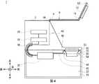
図1に外観を示すように、現金自動取引装置1は、箱状の装置筐体2を中心に構成されており、例えば金融機関等に設置され、顧客との間で入金取引や出金取引等の現金に関する取引を行う。装置筐体2は、前側上部であり顧客が対峙した状態で紙幣の投入やタッチパネルによる操作等をしやすい箇所に、図3に示すように所定の厚みを有し側面視で略L字形状のフロントパネル4が設けられている。
[1. First Embodiment]
[1-1. Configuration of automatic teller machine]
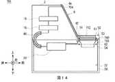
As shown in FIG. 1, theautomatic teller machine 1 is configured around a box-like device housing 2, and is installed in, for example, a financial institution, for example, a deposit transaction or a withdrawal transaction with a customer. Transactions related to cash such as Thedevice housing 2 has a predetermined thickness as shown in FIG. 3 and is substantially L-shaped in a side view at a location where it is easy to insert a bill or operate with a touch panel in a state where the customer is facing the front side. Afront panel 4 is provided.

フロントパネル4は、上端部に設けられた接客部支点としてのフロントパネル支点4A(図3)を軸に回動することにより開閉可能に構成されている。このフロントパネル4は、装置筐体2に対しフロントパネル支点4Aを軸として、後述する処理機シャッタ40に対し装置シャッタ12が離接するよう回動する。すなわち装置筐体2は、顧客との間で現金に関する取引を行う取引動作時には、図3に示すようにフロントパネル4を閉塞することによりフロントパネル閉鎖状態とし、内部の各種機構を保護する。一方、装置筐体2は、金融機関の係員や保守員等が内部の各種機構の保守作業等を行う作業時において、必要に応じて図4に示すようにフロントパネル4を開放することによりフロントパネル開放状態とし、内部の各部に対する作業を容易に行わせ得る。  Thefront panel 4 is configured to be openable and closable by rotating around afront panel fulcrum 4A (FIG. 3) as a customer service fulcrum provided at the upper end. Thefront panel 4 rotates relative to theapparatus housing 2 with thefront panel fulcrum 4A as an axis so that theapparatus shutter 12 comes into contact with and separates from aprocessor shutter 40 described later. That is, at the time of a transaction operation in which a transaction relating to cash is performed with a customer, thedevice casing 2 closes thefront panel 4 to close thefront panel 4 as shown in FIG. 3 to protect various internal mechanisms. On the other hand, thedevice housing 2 is opened by opening thefront panel 4 as necessary as shown in FIG. 4 when an employee or maintenance staff of a financial institution performs maintenance work of various internal mechanisms. The panel can be opened, and the work for each part inside can be easily performed.

フロントパネル4には接客部6が設けられており、接客部6は、カード入出口7、装置入出金口8、操作表示部9、テンキー10及びレシート発行口11が設けられており、顧客との間で現金や通帳等を直接やり取りすると共に、取引に関する情報の通知や操作指示の受付を行う。カード入出口7は、キャッシュカード等の各種カードが挿入又は排出される部分である。カード入出口7の奥側には、各種カードに磁気記録された口座番号等の読み取りを行うカード処理部(図示せず)が設けられている。装置入出金口8は、顧客が入金する紙幣が投入される際及び顧客へ出金する紙幣が排出される際に当該紙幣が通過する開口である。また装置入出金口8は、フロントパネル4に設けられた装置シャッタ12(図3)を駆動することにより開放又は閉塞する。  Thefront panel 4 is provided with acustomer service section 6, which includes a card slot 7, a device deposit /withdrawal slot 8, anoperation display section 9, anumeric keypad 10 and areceipt issuing slot 11. Exchange cash and bankbooks directly between them, and receive notifications of transactions and operation instructions. The card entry / exit 7 is a portion into which various cards such as a cash card are inserted or ejected. A card processing unit (not shown) for reading account numbers and the like magnetically recorded on various cards is provided on the back side of the card slot 7. The device deposit /withdrawal port 8 is an opening through which a bill passes when a bill to be deposited by a customer is inserted and when a bill to be dispensed to the customer is discharged. The device deposit /withdrawal port 8 is opened or closed by driving a device shutter 12 (FIG. 3) provided on thefront panel 4.

操作表示部9は、取引に際して操作画面を表示するLCD(Liquid Crystal Display)と、取引の種類の選択、暗証番号や取引金額等を入力するタッチパネルとが一体化されている。テンキー10は、「0」〜「9」の数字等の入力を受け付ける物理的なキーであり、暗証番号や取引金額等の入力操作時に用いられる。レシート発行口11は、取引処理の終了時に取引内容等を印字したレシートを発行する部分である。因みにレシート発行口11の奥側には、レシートに取引内容等を印字するレシート処理部(図示せず)が設けられている。  Theoperation display unit 9 is integrated with an LCD (Liquid Crystal Display) that displays an operation screen during a transaction and a touch panel for selecting a transaction type, inputting a personal identification number, a transaction amount, and the like. Thenumeric keypad 10 is a physical key that accepts input of numbers such as “0” to “9”, and is used when an input operation such as a password or transaction amount is performed. Thereceipt issuing port 11 is a part that issues a receipt on which transaction details are printed at the end of transaction processing. Incidentally, a receipt processing section (not shown) for printing transaction contents and the like on the receipt is provided on the back side of thereceipt issuing port 11.

図3に示すように、フロントパネル4における装置シャッタ12の後方には、当該装置シャッタ12を駆動する装置シャッタモータ14が設けられている。また装置シャッタ12の近傍には、当該装置シャッタ12の位置を検出する図示しない装置シャッタ位置検出センサが設けられている。この装置シャッタ位置検出センサは、装置シャッタ12の位置を検出し、その検出結果を後述する処理機制御部20に通知する。  As shown in FIG. 3, adevice shutter motor 14 for driving thedevice shutter 12 is provided behind thedevice shutter 12 in thefront panel 4. A device shutter position detection sensor (not shown) that detects the position of thedevice shutter 12 is provided in the vicinity of thedevice shutter 12. The apparatus shutter position detection sensor detects the position of theapparatus shutter 12 and notifies theprocessor control unit 20 described later of the detection result.

装置筐体2内には、後述する接客制御部18と処理機制御部20とに配線ケーブルで接続され現金自動取引装置1全体を統括制御する統括制御部16や、装置筐体2内部の下側に設けられ紙幣に関する種々の処理を行う紙幣処理機22等が設けられている。統括制御部16は、図示しないCPU(Central Processing Unit)を中心に構成されており、ROM(Read Only Memory)、RAM(Random Access Memory)、ハードディスクドライブやフラッシュメモリ等でなる記憶部(図示せず)から所定のプログラムを読み出して実行することにより、各部を制御して入金取引や出金取引等の種々の処理を行う。接客制御部18は、所定の接客制御部基板に搭載され、装置筐体2内部であって紙幣処理機22の外側に配され、接客部6を制御する。  In theapparatus housing 2, there is ageneral control section 16 that is connected to a customerservice control section 18 and a processingmachine control section 20, which will be described later, by a wiring cable, and controls the cashautomatic transaction apparatus 1 as a whole. Abill processing machine 22 that is provided on the side and performs various processes related to bills is provided. Theoverall control unit 16 is mainly configured by a CPU (Central Processing Unit) (not shown), and a storage unit (not shown) including a ROM (Read Only Memory), a RAM (Random Access Memory), a hard disk drive, a flash memory, and the like. ) To read out and execute a predetermined program to control each unit to perform various processes such as deposit transactions and withdrawal transactions. The customerservice control unit 18 is mounted on a predetermined customer service control unit board, and is disposed inside theapparatus housing 2 and outside thebanknote handling machine 22 to control thecustomer service unit 6.

以下では、現金自動取引装置1のうち利用者が対峙する側を前側とし、その反対を後側とし、当該前側に対峙した利用者から見て左及び右をそれぞれ左側及び右側とし、さらに上側及び下側を定義して説明する。  In the following, the side facing the user of theautomatic teller machine 1 is the front side, the opposite is the rear side, the left and right are the left side and the right side as viewed from the user facing the front side, respectively, and the upper side and The lower side is defined and described.

[1−2.紙幣処理機の内部構成]
紙幣処理機22は、図2に示すように、箱状の処理機筐体24を中心に構成されており、当該処理機筐体24の内部には、所定の接客制御部基板に搭載され、処理機筐体24内部の各部(入出金部26、搬送部28、鑑別部30、一時保留部32、リサイクル庫34、リジェクト庫36及び取忘れ庫38)を制御する処理機制御部20が設けられている。
[1-2. Internal configuration of banknote handling machine]
As shown in FIG. 2, thebanknote processing machine 22 is configured around a box-shapedprocessing machine casing 24, and is mounted on a predetermined customer service control unit board inside the processingmachine casing 24. Aprocessor control unit 20 is provided for controlling each part (the deposit /withdrawal unit 26, thetransport unit 28, thediscrimination unit 30, thetemporary storage unit 32, therecycle store 34, thereject store 36, and the forgotten store 38) inside theprocessor case 24. It has been.

処理機制御部20は、図示しないCPUを中心に構成されており、ROM、RAM、ハードディスクドライブやフラッシュメモリ等でなる記憶部50から所定のプログラムを読み出して実行することにより、各部を制御して入金取引や出金取引等の種々の処理を行う。  Theprocessor control unit 20 is configured around a CPU (not shown), and controls each unit by reading and executing a predetermined program from astorage unit 50 such as a ROM, a RAM, a hard disk drive, or a flash memory. Various processes such as deposit transactions and withdrawal transactions are performed.

処理機筐体24は、装置筐体2の前面に設けられた図示しない前面扉が開放された状態において保守員が例えば前方へ向かってスライドさせて装置筐体2の外部へ引き出し可能に構成されている。図3に示すように、処理機筐体24に設けられた処理機シャッタ40の後方には、当該処理機シャッタ40を駆動する処理機シャッタモータ42が設けられている。また処理機シャッタ40の近傍には、当該処理機シャッタ40の位置を検出する図示しない処理機シャッタ位置検出センサが設けられている。この処理機シャッタ位置検出センサは、処理機シャッタ40の位置を検出し、その検出結果を処理機制御部20に通知する。  Theprocessor housing 24 is configured such that a maintenance staff can slide forward, for example, and pull it out of thedevice housing 2 in a state where a front door (not shown) provided on the front surface of thedevice housing 2 is opened. ing. As shown in FIG. 3, aprocessor shutter motor 42 for driving theprocessor shutter 40 is provided behind theprocessor shutter 40 provided in theprocessor housing 24. A processor shutter position detection sensor (not shown) that detects the position of theprocessor shutter 40 is provided in the vicinity of theprocessor shutter 40. The processor shutter position detection sensor detects the position of theprocessor shutter 40 and notifies theprocessor controller 20 of the detection result.

処理機制御部20は、処理機シャッタモータ42及び処理機シャッタ位置検出センサ(図示せず)に入出金機シャッタモータ配線としての配線ケーブル44が、利用者の指等を検知する手検知センサ60に異物検知センサ配線としての配線ケーブル45がそれぞれ接続されており、当該処理機シャッタ位置検出センサから処理機シャッタ40の検出結果を取得すると共に、処理機シャッタモータ42を駆動することにより処理機シャッタ40を開閉させる。また処理機制御部20からは、プラチェーン46を介し、処理機筐体24の内部から装置筐体2内部へ装置配線としての配線ケーブル48が引き回され、統括制御部16及び接客制御部18を介さずにフロントパネル支点4A近傍及び操作表示部9の側方を通過し処理機シャッタモータ42と処理機シャッタ位置検出センサ(図示せず)とに接続されている。処理機制御部20は、装置シャッタ位置検出センサから装置シャッタ12の検出結果を取得すると共に、装置シャッタモータ14を駆動することにより装置シャッタ12を開閉させる。  The processingmachine control unit 20 includes a processingmachine shutter motor 42 and a processing machine shutter position detection sensor (not shown), and ahand detection sensor 60 in which awiring cable 44 serving as a depositing / dispensing machine shutter motor wiring detects a finger of a user.Wiring cables 45 as foreign matter detection sensor wirings are respectively connected to the processing machine shutter position detection sensor to acquire the detection result of theprocessing machine shutter 40 and drive the processingmachine shutter motor 42 to drive the processing machine shutter. 40 is opened and closed. Further, awiring cable 48 as a device wiring is routed from the inside of theprocessor housing 24 to the inside of thedevice housing 2 via theplastic chain 46 from theprocessor control unit 20, and theoverall control unit 16 and the customerservice control unit 18. Without passing through thefront panel fulcrum 4A and the side of theoperation display unit 9, it is connected to aprocessor shutter motor 42 and a processor shutter position detection sensor (not shown). Theprocessor control unit 20 acquires the detection result of theapparatus shutter 12 from the apparatus shutter position detection sensor, and opens and closes theapparatus shutter 12 by driving theapparatus shutter motor 14.

現金自動取引装置1は、フロントパネル閉鎖状態とフロントパネル開放状態との何れにおいても位置が殆ど移動しないフロントパネル支点4A近傍を通過するように配線ケーブル48を設けるため、フロントパネル閉鎖状態からフロントパネル開放状態に移行した際にも配線ケーブル48が装置筐体2の外部に大きく露出してしまったり、配線ケーブル48に大きな負荷を掛けてしまったりすることを防止できる。  Theautomatic teller machine 1 is provided with thewiring cable 48 so as to pass through the vicinity of thefront panel fulcrum 4A where the position hardly moves in either the front panel closed state or the front panel open state. It is possible to prevent thewiring cable 48 from being largely exposed to the outside of theapparatus housing 2 or applying a large load to thewiring cable 48 even when the state is shifted to the open state.

紙幣処理機22の内部には、上側に入出金部26、紙幣の金種や真偽を判定する鑑別部30及び入金紙幣等を一時的に保留する一時保留部32等が設けられている。  Inside thebanknote handling machine 22, a deposit /withdrawal unit 26, adiscrimination unit 30 that determines the denomination and authenticity of the banknote, atemporary storage unit 32 that temporarily holds deposited banknotes, and the like are provided.

入出金部26は、顧客から投入された紙幣を1枚ずつ分離し搬送部28へ繰り出す。また入出金部26は、当該入出金部26内部において、搬送部28へ繰り出す紙幣が存在するか否かを検出する図示しない紙幣検知センサが設けられている。  The deposit /withdrawal unit 26 separates banknotes input from the customer one by one and feeds them to thetransport unit 28. In addition, the deposit /withdrawal unit 26 is provided with a bill detection sensor (not shown) that detects whether or not there is a bill to be fed to thetransport unit 28 inside the deposit /withdrawal unit 26.

搬送部28は、図示しないローラやベルト等により、図中太線で示す搬送路に沿って長方形の紙幣を短手方向に搬送する。搬送部28は、鑑別部30を前後方向に挿通させるように紙幣を搬送し、当該鑑別部30の後側と一時保留部32及び入出金部26とをそれぞれ接続している。また搬送部28は、鑑別部30の前側と入出金部26、リサイクル庫34、リジェクト庫36及び取忘れ庫38とを接続している。搬送部28の分岐点には、セレクタ(図示せず)が設けられており、処理機制御部20の制御に基づき回動することにより、紙幣の搬送先を切り替える。  Theconveyance unit 28 conveys rectangular banknotes in the short direction along a conveyance path indicated by a thick line in the drawing by a roller, a belt, or the like (not shown). Theconveyance part 28 conveys a banknote so that thediscrimination part 30 may be penetrated in the front-back direction, and has connected the back side of the saiddiscrimination part 30, thetemporary storage part 32, and the deposit orwithdrawal part 26, respectively. In addition, thetransport unit 28 connects the front side of thediscrimination unit 30 to the deposit /withdrawal unit 26, therecycle store 34, thereject store 36, and the forgottenstore 38. A selector (not shown) is provided at a branch point of thetransport unit 28, and the banknote transport destination is switched by rotating based on the control of theprocessor control unit 20.

鑑別部30は、その内部で紙幣を搬送しながら、光学素子や磁気検出素子等を用いて当該紙幣の金種及び真偽、並びに損傷の程度等(正損)を鑑別し、その鑑別結果を処理機制御部20へ通知する。これに応じて処理機制御部20は、取得した鑑別結果及び識別結果に基づいて紙幣の搬送先を決定する。  The discriminatingunit 30 discriminates the denomination and authenticity of the banknote and the degree of damage (loss), etc., using an optical element, a magnetic detection element or the like while conveying the banknote inside the banknote. Theprocessor control unit 20 is notified. In response to this, theprocessor control unit 20 determines a banknote transport destination based on the acquired discrimination result and identification result.

一時保留部32は、入金時に顧客が入出金部26へ投入した紙幣を一時的に保留し、鑑別部30で入金可能と鑑別された入金可能紙幣を入金が確定するまで一時的に保留する。一方、入金不可と鑑別された入金リジェクト紙幣は入出金部26へ排出される。また一時保留部32は、出金時において鑑別部30で出金不可能と鑑別された出金リジェクト紙幣を、出金可能な紙幣が出金されるまで一時的に保留し、その後当該出金リジェクト紙幣をリジェクト庫36へ排出する。  Thetemporary holding unit 32 temporarily holds banknotes inserted by the customer into the depositing / withdrawingunit 26 at the time of depositing, and temporarily holds the depositable banknotes identified as depositable by thediscrimination unit 30 until the deposit is confirmed. On the other hand, the deposit reject banknotes identified as being non-payable are discharged to the deposit /withdrawal unit 26. In addition, thetemporary holding unit 32 temporarily holds the withdrawal reject banknote identified as being impossible to withdraw at the time of withdrawal until the bankable banknote is withdrawn, and then the withdrawal The reject banknote is discharged to thereject store 36.

また紙幣処理機22の内部には、下側に金種別のリサイクル庫34と、鑑別部30において破損した紙幣(いわゆる損券)と鑑別された紙幣、偽造券と判別された紙幣及び5千券や2千券等の還流されない金種の紙幣を格納するリジェクト庫36と、取引時に顧客が入出金部26から取り忘れた紙幣を回収して格納する取忘れ庫38とが設けられている。リサイクル庫34は、収納排出機構により、搬送部28から搬送されてきた紙幣を取り込んで収納すると共に、収納されている紙幣を排出して搬送部28へ供給する。  Further, inside thebanknote processing machine 22, a denomination-type recycling box 34, a banknote discriminated from a banknote (so-called damaged banknote) damaged in thediscrimination section 30, a banknote discriminated as a forged ticket, and 5,000 tickets And arejection store 36 for storing banknotes of denominations such as 2,000 tickets that are not returned, and a forgottenstorage 38 for collecting and storing banknotes that the customer forgot to collect from the deposit /withdrawal unit 26 during transactions. Therecycle box 34 takes in and stores the banknotes transported from thetransport unit 28 by the storage and discharge mechanism, and discharges the stored banknotes and supplies them to thetransport unit 28.

かかる構成において現金自動取引装置1は、鑑別部30による紙幣の鑑別結果及び識別結果等をもとに統括制御部16及び処理機制御部20が各部を制御して、紙幣の入金処理及び出金処理等を行う。  In such a configuration, in theautomatic teller machine 1, theoverall control unit 16 and theprocessor control unit 20 control each unit based on the banknote discrimination result and the identification result by thediscrimination unit 30, and the banknote depositing process and withdrawal process are performed. Perform processing.

すなわち現金自動取引装置1は、入金取引時、顧客により操作表示部9を介して入金取引が選択され、さらに入出金部26に紙幣が投入されると、投入された紙幣を入出金部26から1枚ずつ鑑別部30に搬送する。ここで現金自動取引装置1は、鑑別部30の鑑別結果及び識別結果に基づき入金可能と判定された入金可能紙幣については一時保留部32に搬送して一時的に収納する。一方で現金自動取引装置1は、入金に適さないと判定された入金リジェクト紙幣については入出金部26へ戻して、装置シャッタ12及び処理機シャッタ40を開くことで顧客に返却する。その後顧客により入金金額が確定されると、現金自動取引装置1は、一時保留部32に収納している紙幣を鑑別部30に搬送して鑑別結果及び記番号の識別結果を得る。ここで現金自動取引装置1は、鑑別部30の鑑別結果及び識別結果に基づき収納可能と判定された紙幣については、その金種に応じて各リサイクル庫34へ搬送して保管する。一方で現金自動取引装置1は、収納に適さないと判定された紙幣については、リジェクト庫36へ搬送する。  That is, in theautomatic teller machine 1, when a deposit transaction is selected by the customer via theoperation display unit 9 at the time of deposit transaction and a bill is inserted into the deposit /withdrawal unit 26, the inserted bill is transferred from the deposit /withdrawal unit 26. One by one is conveyed to thediscrimination unit 30. Here, theautomatic teller machine 1 transports the temporarily depositable banknotes determined to be depositable based on the discrimination result and the identification result of thediscrimination unit 30 to thetemporary storage unit 32 and temporarily stores them. On the other hand, theautomatic teller machine 1 returns the deposit reject banknote determined to be unsuitable for depositing to the deposit /withdrawal unit 26 and returns it to the customer by opening theapparatus shutter 12 and theprocessor shutter 40. Thereafter, when the deposit amount is confirmed by the customer, theautomatic teller machine 1 conveys the banknotes stored in thetemporary holding unit 32 to thediscrimination unit 30 to obtain the discrimination result and the identification result of the serial number. Here, theautomatic teller machine 1 transports and stores the banknotes determined to be storable based on the discrimination result and the identification result of thediscrimination unit 30 to eachrecycle box 34 according to the denomination. On the other hand, theautomatic teller machine 1 conveys the banknote determined to be unsuitable for storage to therejection store 36.

一方出金取引時、現金自動取引装置1は、顧客により操作表示部9を介して出金取引が選択され出金金額が入力されると、要求金額に応じて必要な金種毎の紙幣枚数を認識し、この金種毎の紙幣枚数に応じて各リサイクル庫34から紙幣を繰り出して鑑別部30に搬送して鑑別結果及び記番号の識別結果を得る。ここで現金自動取引装置1は、鑑別部30の鑑別結果及び識別結果に基づき出金可能と判定された出金可能紙幣については入出金部26に搬送する。一方で現金自動取引装置1は、出金に適さないと判定された出金リジェクト紙幣については一時保留部32に搬送して一時的に収納する。そして要求金額分の紙幣が入出金部26へ集積されると、現金自動取引装置1は、装置シャッタ12及び処理機シャッタ40を開ける。これにより入出金部26内に集積されている紙幣の受け取りが可能な状態となり、顧客がこの紙幣を受け取る。その後現金自動取引装置1は、一時保留部32に収納している出金リジェクト紙幣をリジェクト庫36へと搬送して保管する。  On the other hand, at the time of withdrawal transaction, when the withdrawal transaction is selected by the customer via theoperation display unit 9 and the withdrawal amount is input by the customer, the number of banknotes for each denomination required according to the requested amount The banknotes are fed out from therespective recycling boxes 34 according to the number of banknotes for each denomination and conveyed to thediscrimination unit 30 to obtain a discrimination result and a serial number identification result. Here, theautomatic teller machine 1 conveys to the depositing / withdrawingunit 26 with regard to banknotes that can be withdrawn based on the discrimination result and the identification result of thediscrimination unit 30. On the other hand, theautomatic teller machine 1 transports the withdrawal reject banknote determined to be unsuitable for withdrawal to thetemporary storage unit 32 and temporarily stores it. When the bills for the requested amount are accumulated in the deposit /withdrawal unit 26, theautomatic teller machine 1 opens thedevice shutter 12 and theprocessor shutter 40. As a result, the banknotes accumulated in the deposit /withdrawal unit 26 can be received, and the customer receives the banknotes. Thereafter, theautomatic teller machine 1 conveys and stores the withdrawal reject banknotes stored in thetemporary storage unit 32 to thereject store 36.

[1−3.入出金部の構成]
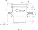
図5及び図6に示すように、入出金部26は主に、装置入出金口枠52、装置シャッタ12、処理機シャッタ40、処理機入出金口枠53及び紙幣収容部54により構成されている。
[1-3. Composition of deposit / withdrawal department]
As shown in FIGS. 5 and 6, the deposit /withdrawal unit 26 mainly includes an apparatus deposit /withdrawal port frame 52, anapparatus shutter 12, aprocessing machine shutter 40, a processing machine deposit /withdrawal port frame 53, and abill storage unit 54. Yes.

フロントパネル4において装置入出金口8を囲む枠である装置入出金口枠52は、所定の厚みを有しほぼ水平方向に伸びる板状でなり、紙幣処理機22の内部構造を外部から視認できないよう構成されている。装置入出金口枠52には、平面視において長方形状の装置入出金口8が穿設されている。装置入出金口8の下部には、断面略コ字形状でなる紙幣収容部54が設けられている。  The device deposit /withdrawal port frame 52 which is a frame surrounding the device deposit /withdrawal port 8 in thefront panel 4 is a plate having a predetermined thickness and extending in a substantially horizontal direction, and the internal structure of thebanknote handling machine 22 cannot be visually recognized from the outside. It is configured as follows. The apparatus deposit /withdrawal port frame 52 is formed with a rectangular apparatus deposit /withdrawal port 8 in plan view. Abill accommodating portion 54 having a substantially U-shaped cross section is provided at the lower portion of the apparatus deposit /withdrawal port 8.

処理機筐体24における、装置入出金口8と対向する位置には、平面視において長方形状の処理機入出金口56が穿設されている。この装置入出金口8と処理機入出金口56とにより、紙幣収容部54を外部と連通させる入出金口58が形成されている。処理機筐体24において処理機入出金口56を囲む枠である処理機入出金口枠53は、所定の厚みを有しほぼ水平方向に伸びる板状に構成されている。現金自動取引装置1の外部と紙幣収容部54との間には、処理機筐体24に設けられた処理機シャッタ40と、フロントパネル4に設けられ処理機シャッタ40の上側に位置する装置シャッタ12とが、いわゆる2重シャッタとなって設けられている。装置シャッタ12及び処理機シャッタ40は所定の厚みを有する金属板が板金加工された形状を有し、前後方向に移動することにより、紙幣収容部54を現金自動取引装置1の外部に対し開放又は閉塞させる。  A processing machine deposit /withdrawal port 56 having a rectangular shape in a plan view is formed at a position facing the apparatus deposit /withdrawal port 8 in theprocessor case 24. The apparatus deposit /withdrawal port 8 and the processing machine deposit /withdrawal port 56 form a deposit /withdrawal port 58 that allows thebill storage portion 54 to communicate with the outside. The processing machine deposit /withdrawal port frame 53 which is a frame surrounding the processing machine deposit /withdrawal port 56 in theprocessing machine casing 24 is configured in a plate shape having a predetermined thickness and extending substantially in the horizontal direction. Between the outside of theautomatic teller machine 1 and thebill storage portion 54, aprocessing machine shutter 40 provided in theprocessing machine casing 24 and a device shutter provided on thefront panel 4 and positioned above the processingmachine shutter 40. 12 are provided as a so-called double shutter. Theapparatus shutter 12 and theprocessing machine shutter 40 have a shape in which a metal plate having a predetermined thickness is processed into a sheet metal, and are moved in the front-rear direction to open thebanknote storage part 54 to the outside of theautomatic teller machine 1 or Occlude.

図6に示すように、装置シャッタ12は、前後左右方向に伸びる平板形状の装置シャッタ板部12Aの上面から、前端から後端まで前後方向に沿って装置入出金口枠52に向かって突設された装置シャッタ上側突起部12USが、左右方向に所定間隔を空けて複数本設けられている。これにより隣り合う装置シャッタ上側突起部12US同士の間には、当該装置シャッタ上側突起部12USの高さよりも低い装置シャッタ上側溝部12UCが形成されている。また装置シャッタ12は、装置シャッタ上側突起部12USと左右方向の位置がずれ装置シャッタ上側溝部12UCと一致する箇所における装置シャッタ板部12Aの下面から、前端から後端まで前後方向に沿って装置シャッタ12に向かって突設された装置シャッタ下側突起部12DSが、左右方向に所定間隔を空けて複数本設けられている。これにより隣り合う装置シャッタ下側突起部12DS同士の間には、当該装置シャッタ下側突起部12DSの高さよりも低い装置シャッタ下側溝部12DCが形成されている。  As shown in FIG. 6, thedevice shutter 12 projects from the upper surface of a flat plate-like deviceshutter plate portion 12A extending in the front-rear and left-right directions toward the device deposit /withdrawal port frame 52 along the front-rear direction from the front end to the rear end. A plurality of device shutter upper protrusions 12US are provided at predetermined intervals in the left-right direction. As a result, an apparatus shutter upper groove 12UC that is lower than the height of the apparatus shutter upper protrusion 12US is formed between adjacent apparatus shutter upper protrusions 12US. Further, thedevice shutter 12 is located along the front-rear direction from the lower surface of the deviceshutter plate portion 12A at the position where the position in the left-right direction is shifted from the device shutter upper protrusion 12US and coincides with the device shutter upper groove 12UC, from the front end to the rear end. A plurality of apparatus shutter lower protrusions 12DS projecting toward theshutter 12 are provided at predetermined intervals in the left-right direction. Thus, a device shutter lower groove 12DC lower than the height of the device shutter lower protrusion 12DS is formed between the adjacent device shutter lower protrusions 12DS.

装置入出金口枠52は、前後左右方向に伸びる平板形状の装置入出金口枠板部52Aにおける、装置シャッタ12の装置シャッタ上側突起部12USと対向する箇所において、前端から後端まで前後方向に沿って上方へ装置入出金口枠溝部52Cが凹設されている。  The device deposit /withdrawal port frame 52 extends in the front / rear direction from the front end to the rear end at a location facing the device shutter upper protrusion 12US of thedevice shutter 12 in the flat plate-shaped device deposit / withdrawal portframe plate portion 52A extending in the front / rear / left / right direction. An apparatus deposit / withdrawal port frame groove 52C is recessed upward.

装置入出金口枠52と装置シャッタ12とは、装置入出金口枠溝部52Cに装置シャッタ上側突起部12USが入り込むことにより非接触状態で噛み合い、いわゆる入れ子構造が幅方向(左右方向)に亘って形成されている。これにより装置シャッタ12は、装置入出金口枠52に接触することなく前後方向に移動すると共に、装置シャッタ12と装置入出金口枠52との間に紙幣が侵入することを防止している。  The apparatus deposit /withdrawal port frame 52 and theapparatus shutter 12 mesh with each other in a non-contact state when the apparatus shutter upper protrusion 12US enters the apparatus deposit / withdrawal slot frame groove 52C, and a so-called nested structure extends in the width direction (left-right direction). Is formed. Thereby, theapparatus shutter 12 moves in the front-rear direction without contacting the apparatus deposit /withdrawal slot frame 52, and prevents bills from entering between theapparatus shutter 12 and the apparatus deposit /withdrawal slot frame 52.

処理機シャッタ40は、前後左右方向に伸びる平板形状の処理機シャッタ板部40Aの上面における、装置シャッタ12の装置シャッタ下側溝部12DCと対向する箇所において、前端から後端まで前後方向に沿って装置シャッタ12に向かって処理機シャッタ上側突起部40USが突設されている。これにより隣り合う処理機シャッタ上側突起部40US同士の間には、当該処理機シャッタ上側突起部40USの高さよりも低い処理機シャッタ上側溝部40UCが形成されている。また処理機シャッタ40は、処理機シャッタ上側突起部40USと左右方向の位置がずれ処理機シャッタ上側溝部40UCと一致する箇所における処理機シャッタ板部40Aの下面から、前端から後端まで前後方向に沿って処理機入出金口枠53に向かって突設された処理機シャッタ下側突起部40DSが、左右方向に所定間隔を空けて複数本設けられている。  Theprocessor shutter 40 extends along the front-rear direction from the front end to the rear end at a position facing the apparatus shutter lower groove 12DC of theapparatus shutter 12 on the upper surface of the flat processor-shaped shutter plate part 40A extending in the front-rear and left-right directions. A processor shutter upper protrusion 40US is projected toward theapparatus shutter 12. As a result, a processor shutter upper groove 40UC that is lower than the height of the processor shutter upper protrusion 40US is formed between the adjacent processor shutter upper protrusions 40US. Further, theprocessor shutter 40 is displaced from the processor shutter upper protrusion 40US in the left-right direction, and is moved in the front-rear direction from the lower surface of the processor shutter plate portion 40A at the position where the processor shutter upper groove 40UC coincides with the processor shutter upper groove 40UC. A plurality of processing machine shutter lower protrusions 40DS projecting toward the processing machine deposit /withdrawal port frame 53 are provided at predetermined intervals in the left-right direction.

処理機入出金口枠53は、前後左右方向に伸びる平板形状の処理機入出金口枠板部53Aにおける、処理機シャッタ40の処理機シャッタ下側突起部40DSと対向する箇所において、前端から後端まで前後方向に沿って下方へ処理機入出金口枠溝部53Cが凹設されている。  The processing machine deposit /withdrawal port frame 53 is located from the front end to the rear at a position facing the processing machine shutter lower projection 40DS of theprocessing machine shutter 40 in the flat-plate shaped processing machine deposit / withdrawal portframe plate portion 53A extending in the front / rear / left / right direction. The processing machine deposit / withdrawal port frame groove 53C is recessed downward along the front-rear direction to the end.

処理機入出金口枠53と処理機シャッタ40とは、処理機入出金口枠溝部53Cに処理機シャッタ下側突起部40DSが入り込むことにより非接触状態で噛み合い、いわゆる入れ子構造が幅方向に亘って形成されている。これにより処理機シャッタ40は、処理機入出金口枠53に接触することなく前後方向に移動すると共に、処理機シャッタ40と処理機入出金口枠53との間に紙幣が侵入することを防止している。  The processing machine deposit /withdrawal port frame 53 and theprocessing machine shutter 40 are meshed in a non-contact state when the processing machine shutter lower projection 40DS enters the processing machine deposit / withdrawal port frame groove 53C, and a so-called nested structure extends in the width direction. Is formed. As a result, the processingmachine shutter 40 moves in the front-rear direction without contacting the processing machine deposit /withdrawal slot frame 53 and prevents banknotes from entering between the processingmachine shutter 40 and the processing machine deposit /withdrawal slot frame 53. doing.

装置シャッタ12と処理機シャッタ40とは、装置シャッタ下側溝部12DCに処理機シャッタ上側突起部40USが、処理機シャッタ上側溝部40UCに装置シャッタ下側突起部12DSが入り込むことにより非接触状態で噛み合い、いわゆる入れ子構造が幅方向に亘って形成されている。これにより装置シャッタ12と処理機シャッタ40とは、互いに接触することなく前後方向に移動すると共に、装置シャッタ12と処理機シャッタ40との間に紙幣が侵入することを防止している。  Theapparatus shutter 12 and theprocessor shutter 40 are in a non-contact state when the processor shutter upper protrusion 40US enters the apparatus shutter lower groove 12DC and the apparatus shutter lower protrusion 12DS enters the processor shutter upper groove 40UC. Engagement, a so-called nested structure is formed across the width direction. As a result, theapparatus shutter 12 and theprocessor shutter 40 move in the front-rear direction without contacting each other, and banknotes are prevented from entering between theapparatus shutter 12 and theprocessor shutter 40.

処理機筐体24には、光軸が処理機シャッタ40の下側近傍に位置するよう、異物検知センサとしての手検知センサ60が設けられている。この手検知センサ60は、光軸が物体等で遮られたか否かにより利用者の指等の異物を検知し、その検知結果を処理機制御部20に通知する。このように手検知センサ60は、装置シャッタ12及び処理機シャッタ40の下側(すなわち装置シャッタ12及び処理機シャッタ40よりも処理機筐体24の内側)に設けられることにより、利用者により外部から光軸が故意に遮られないようになっている。  The processingmachine casing 24 is provided with ahand detection sensor 60 as a foreign matter detection sensor so that the optical axis is positioned near the lower side of theprocessing machine shutter 40. Thehand detection sensor 60 detects a foreign object such as a user's finger depending on whether the optical axis is blocked by an object or the like, and notifies theprocessor control unit 20 of the detection result. As described above, thehand detection sensor 60 is provided on the lower side of theapparatus shutter 12 and the processor shutter 40 (that is, inside theprocessor casing 24 with respect to theapparatus shutter 12 and the processor shutter 40). The optical axis is intentionally unobstructed.

[1−4.効果]
図14に示すように従来の現金自動取引装置701は、光軸を故意に遮られないように手挟みを検知するセンサをシャッタの内側(利用者から離隔する側)に設ける必要があり、且つ、装置シャッタ712がフロントパネル704と共に可動するために装置手検知センサ61は装置シャッタ712近傍に配されることが望ましいため、フロントパネル704における装置シャッタ712の下に装置手検知センサ61を、処理機シャッタ740の下に処理機手検知センサ62を設けていた。
[1-4. effect]
As shown in FIG. 14, the conventionalautomatic teller machine 701 needs to provide a sensor for detecting hand pinching on the inner side of the shutter (side away from the user) so that the optical axis is not intentionally blocked, and Since thedevice shutter 712 is movable together with thefront panel 704, the devicehand detection sensor 61 is preferably arranged in the vicinity of thedevice shutter 712. Therefore, the devicehand detection sensor 61 is processed under thedevice shutter 712 on thefront panel 704. A processing machinehand detection sensor 62 is provided under themachine shutter 740.

これに対し現金自動取引装置1は、従来の現金自動取引装置701と比べて、装置シャッタ712と処理機シャッタ740との間に設けられていた装置手検知センサ61を省略するようにした。これにより現金自動取引装置1は、部品点数を削減し構成を簡素化することができる。  On the other hand, compared with the conventionalautomatic teller machine 701, theautomatic teller machine 1 omits the apparatushand detection sensor 61 provided between theapparatus shutter 712 and theprocessor shutter 740. Thereby, theautomatic teller machine 1 can reduce a number of parts and can simplify a structure.

また現金自動取引装置1は、処理機筐体24の内部に設けられた処理機制御部20により、当該処理機筐体24に設けられた手検知センサ60からの検出結果を取得し、当該処理機筐体24に設けられた処理機シャッタ40と、当該処理機筐体24の外部であるフロントパネル4に設けられた装置シャッタ12との両方を制御するようにした。  Moreover, theautomatic teller machine 1 acquires the detection result from thehand detection sensor 60 provided in the said processing machine housing | casing 24 by the processingmachine control part 20 provided in the inside of the processing machine housing | casing 24, and performs the said process Both theprocessor shutter 40 provided in themachine casing 24 and theapparatus shutter 12 provided on thefront panel 4 outside theprocessor casing 24 are controlled.

図14に示すように従来の現金自動取引装置701においては、接客制御部18と処理機制御部20とで互いに独立して入出金部726を制御していた。すなわち従来の現金自動取引装置701は、装置筐体2の内部であり処理機筐体24の外部に設けられた接客制御部18により、フロントパネル4に設けられた装置手検知センサ61からの検出結果を取得して当該フロントパネル4に設けられた装置シャッタ712を制御し、処理機筐体24の内部に設けられた処理機制御部20により、当該処理機筐体24に設けられた処理機手検知センサからの検出結果を取得して当該処理機筐体24に設けられた処理機シャッタ740を制御していた。このため従来の現金自動取引装置701は、処理機手検知センサ62に加えて装置手検知センサ61を設ける必要があり、この手検知センサ61を配置するために装置シャッタ712と処理機シャッタ740との間に図6に示すセンサ用空間SPを設けていた。しかしながらこの場合、このセンサ用空間SPに紙幣BLが残留して、次の取引を行う顧客に現金が渡ってしまい、現金違算が発生する可能性があった。  As shown in FIG. 14, in the conventionalautomatic teller machine 701, the customerservice control unit 18 and theprocessor control unit 20 control the deposit /withdrawal unit 726 independently of each other. That is, the conventionalautomatic teller machine 701 is detected from the devicehand detection sensor 61 provided on thefront panel 4 by the customerservice control unit 18 provided inside thedevice housing 2 and outside theprocessor housing 24. The processing unit provided in theprocessor case 24 is obtained by acquiring the result and controlling theapparatus shutter 712 provided in thefront panel 4 and by theprocessor control unit 20 provided in theprocessor case 24. The detection result from the hand detection sensor is acquired and theprocessor shutter 740 provided in theprocessor housing 24 is controlled. For this reason, the conventionalautomatic teller machine 701 needs to provide an apparatushand detection sensor 61 in addition to the processing machinehand detection sensor 62. In order to arrange thehand detection sensor 61, anapparatus shutter 712 and aprocessing machine shutter 740 are provided. The sensor space SP shown in FIG. However, in this case, the bills BL remain in the sensor space SP, and the cash is transferred to the customer who performs the next transaction, which may cause a cash miscalculation.

これに対し本実施の形態による現金自動取引装置1は、1つのみの手検知センサ60を処理機シャッタ40の内側に設けるようにした。これにより現金自動取引装置1は、装置シャッタ12と処理機シャッタ40との間にセンサ用空間SPを形成する必要をなくすことができ、紙幣が装置シャッタ12と処理機シャッタ40との間に残留しにくくすることができる。  On the other hand, in theautomatic teller machine 1 according to the present embodiment, only onehand detection sensor 60 is provided inside theprocessor shutter 40. Thereby, theautomatic teller machine 1 can eliminate the necessity of forming the sensor space SP between theapparatus shutter 12 and theprocessing machine shutter 40, and the banknote remains between theapparatus shutter 12 and theprocessing machine shutter 40. Can be difficult.

さらに現金自動取引装置1は、装置シャッタ12と処理機シャッタ40とを入れ子構造にするようにした。これにより現金自動取引装置1は、装置シャッタ12と処理機シャッタ40との間に紙幣をより一層残留しにくくすることができる。  Furthermore, in theautomatic teller machine 1, theapparatus shutter 12 and theprocessor shutter 40 are nested. Thereby, theautomatic teller machine 1 can make it difficult to remain a banknote between theapparatus shutter 12 and theprocessing machine shutter 40. FIG.

また、従来の現金自動取引装置701においては、接客制御部18と処理機制御部20とは互いに独立して動作しており、統括制御部16を介して互いにデータをやりとりしていた。このため従来の現金自動取引装置701は、互いの手検知センサ(手検知センサ61及び手検知センサ62)の状態をリアルタイムに把握することが困難であった。このため従来の現金自動取引装置701は、装置シャッタ712には装置手検知センサ61を、処理機シャッタ740には処理機手検知センサ62をそれぞれ設け、接客制御部18と処理機制御部20とにより互いに独立してそれぞれ制御していた。  In the conventionalautomatic teller machine 701, the customerservice control unit 18 and theprocessor control unit 20 operate independently of each other, and exchange data with each other via theoverall control unit 16. For this reason, it is difficult for the conventionalautomatic teller machine 701 to grasp the state of each other's hand detection sensor (hand detection sensor 61 and hand detection sensor 62) in real time. For this reason, the conventionalautomatic teller machine 701 is provided with an apparatushand detection sensor 61 in theapparatus shutter 712 and a processing machinehand detection sensor 62 in theprocessing machine shutter 740, respectively, and the customerservice control unit 18, the processingmachine control unit 20 and the like. Were controlled independently of each other.

これに対し現金自動取引装置1は、手検知センサ60を1つのみ設け、従来接客制御部18が行っていた装置シャッタ712の制御を処理機制御部20に移譲するようにした。これにより現金自動取引装置1は、処理機制御部20のみで、装置シャッタ12及び処理機シャッタ40の両方を制御することができ、処理機制御部20と接客制御部18との間でシャッタの制御に関するデータをやりとりする必要もなく、制御をシンプルにすることができる。  On the other hand, theautomatic teller machine 1 is provided with only onehand detection sensor 60, and transfers the control of thedevice shutter 712, which has been conventionally performed by the customerservice control unit 18, to theprocessor control unit 20. Thereby, theautomatic teller machine 1 can control both theapparatus shutter 12 and theprocessing machine shutter 40 only by the processingmachine control unit 20, and the shutter of the shutter between the processingmachine control unit 20 and the customerservice control unit 18 can be controlled. There is no need to exchange control data, and control can be simplified.

以上の構成によれば現金自動取引装置1は、紙葉状の媒体である紙幣に関する操作を受け付ける接客部6と、当該紙幣を入出させる装置入出口としての装置入出金口8と、当該装置入出金口8を開閉する装置シャッタ12とが設けられた装置筐体2と、装置筐体2の内部に設けられ、装置入出金口8に対向して配され紙幣を入出させる処理機入出口としての処理機入出金口56と、当該処理機入出金口56を開閉する処理機シャッタ40とを備え、紙幣に関する処理を行う媒体処理機としての紙幣処理機22と、紙幣処理機22の内部に設けられ装置シャッタ12及び処理機シャッタ40の開閉により装置入出金口8及び処理機入出金口56を介して外部に対し開放又は遮断される紙幣収容部54と、装置筐体2の内部における紙幣処理機22の外部に設けられ接客部6を制御する接客制御部18と、紙幣処理機22の内部に設けられ紙幣処理機22を制御する処理機制御部20と、処理機シャッタ40よりも紙幣処理機22の内側に設けられ、紙幣収容部54における異物の有無を検出する手検知センサ60とを設け、接客制御部18又は処理機制御部20の何れか一方が、手検知センサ60の検知結果を取得すると共に装置シャッタ12及び処理機シャッタ40を制御するようにした。  According to the above configuration, theautomatic teller machine 1 includes acustomer service unit 6 that receives operations related to banknotes that are paper-like media, a device deposit /withdrawal port 8 as a device deposit / withdrawal port for depositing / dispensing the bills, and the device deposit / withdrawal. Anapparatus housing 2 provided with anapparatus shutter 12 that opens and closes themouth 8, and an inside / outside of theapparatus housing 2, which is arranged opposite to the apparatus deposit /withdrawal port 8 and serves as a processing machine entrance / exit Abanknote handling machine 22 as a medium processing machine that includes a processing machine deposit /withdrawal port 56 and aprocessor shutter 40 that opens and closes the processing machine deposit /withdrawal port 56, and is provided inside thebanknote handling machine 22. Abill storage part 54 that is opened or closed to the outside via the device depositing / dispensingport 8 and the processing unit depositing / dispensingport 56 by opening / closing theapparatus shutter 12 and theprocessing machine shutter 40, and banknote processing inside theapparatus housing 2.Machine 2 The customerservice control unit 18 that controls thecustomer service unit 6 provided outside the machine, the processingmachine control unit 20 that controls thebanknote processing machine 22 provided inside thebanknote processing machine 22, and thebanknote processing machine 22 than the processingmachine shutter 40. And ahand detection sensor 60 that detects the presence or absence of foreign matter in thebanknote storage 54, and either the customerservice control unit 18 or theprocessor control unit 20 acquires the detection result of thehand detection sensor 60. In addition, theapparatus shutter 12 and theprocessor shutter 40 are controlled.

これにより現金自動取引装置1は、装置シャッタ12及び処理機シャッタ40それぞれに手検知センサ60を設けることなく、接客制御部18又は処理機制御部20の何れか一方で手検知センサ60の検知結果を取得し装置シャッタ12及び処理機シャッタ40を制御できる。  Thereby, theautomatic teller machine 1 does not provide thehand detection sensor 60 in each of theapparatus shutter 12 and theprocessing machine shutter 40, and the detection result of thehand detection sensor 60 on either the customerservice control unit 18 or the processingmachine control unit 20. And theapparatus shutter 12 and theprocessor shutter 40 can be controlled.

[2.第2の実施の形態]
[2−1.現金自動取引装置及び紙幣処理機の構成]
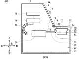
図1及び図7に示すように、第2の実施の形態による現金自動取引装置101は、第1の実施の形態による現金自動取引装置1と比べて、配線ケーブル48が省略され、配線ケーブル64及びジャック68並びに配線ケーブル66及びプラグ70が追加されているものの、それ以外は同様に構成されている。
[2. Second Embodiment]
[2-1. Configuration of automatic cash transaction apparatus and banknote handling machine]
As shown in FIG.1 and FIG.7, compared with theautomatic teller machine 1 by 1st Embodiment, the automaticcash transaction apparatus 101 by 2nd Embodiment abbreviate | omits thewiring cable 48, and thedistribution cable 64 Thejack 68, thewiring cable 66, and theplug 70 are added, but the other configurations are the same.

処理機制御部20からは、処理機筐体24の内部から装置筐体2内部における装置シャッタ12の後方における操作表示部9の下方へ配線ケーブル64が引き回され、当該配線ケーブル64の先端にはジャック68が接続されている。装置シャッタモータ14及び装置シャッタ位置検出センサ(図示せず)からは後方に向かって配線ケーブル66が引き回され、当該配線ケーブル66の先端にはジャック68と着脱可能なプラグ70が接続されている。図7に示すフロントパネル閉鎖状態においては、ジャック68とプラグ70とが嵌合し配線ケーブル64と配線ケーブル66とが導通することにより、処理機制御部20は、装置シャッタ位置検出センサから装置シャッタ12の検出結果を取得すると共に、装置シャッタモータ14を駆動することにより装置シャッタ12を開閉させる。一方図8に示すフロントパネル開放状態においては、プラグ70がジャック68から離隔して外れることにより、配線ケーブル64と配線ケーブル66とが絶縁される。  From theprocessor control unit 20, thewiring cable 64 is routed from the inside of theprocessor housing 24 to the lower side of theoperation display unit 9 behind thedevice shutter 12 inside thedevice housing 2, and is connected to the tip of thewiring cable 64. Is connected to ajack 68. Awiring cable 66 is routed backward from thedevice shutter motor 14 and a device shutter position detection sensor (not shown), and ajack 68 and adetachable plug 70 are connected to the tip of thewiring cable 66. . In the closed state of the front panel shown in FIG. 7, when thejack 68 and theplug 70 are fitted and thewiring cable 64 and thewiring cable 66 are electrically connected, theprocessor control unit 20 causes the apparatus shutter to detect the apparatus shutter. 12 is obtained, and thedevice shutter 12 is opened and closed by driving thedevice shutter motor 14. On the other hand, in the open state of the front panel shown in FIG. 8, theplug 70 is separated from thejack 68 so that thewiring cable 64 and thewiring cable 66 are insulated.

第1の実施の形態による現金自動取引装置1は、配線ケーブル48が処理機制御部20から装置筐体2内部へ引き回されフロントパネル支点4A近傍を通過して装置シャッタモータ14及び装置シャッタ位置検出センサに接続されているため、配線ケーブルの引き回しが長くなってしまい、ノイズ等が乗り、通信品質が確保できない可能性があった。  In theautomatic teller machine 1 according to the first embodiment, thewiring cable 48 is routed from theprocessor control unit 20 to the inside of theapparatus housing 2 and passes through the vicinity of thefront panel fulcrum 4A so that theapparatus shutter motor 14 and the apparatus shutter position. Since it is connected to the detection sensor, the routing of the wiring cable becomes long, and noise and the like may ride on it, so that communication quality may not be ensured.

これに対し現金自動取引装置101は、配線ケーブル64を、フロントパネル支点4A近傍は通過させずに処理機制御部20から装置シャッタモータ14に向かって這わせ、フロントパネル閉鎖状態においてジャック68とプラグ70を嵌合させ配線ケーブル64と配線ケーブル66とを導通させるようにした。これにより現金自動取引装置101は、配線ケーブルを引き回す長さを現金自動取引装置1よりも短くすることができ、通信品質を保ち、処理機制御部20で装置シャッタ12を確実に制御することができる。  In contrast, theautomatic teller machine 101 causes thewiring cable 64 to pass from theprocessor control unit 20 toward thedevice shutter motor 14 without passing the vicinity of thefront panel fulcrum 4A, and thejack 68 and the plug are plugged in the front panel closed state. 70 is fitted to make thewiring cable 64 and thewiring cable 66 conductive. Thereby, theautomatic teller machine 101 can make the length which draws a wiring cable shorter than theautomatic teller machine 1, maintains communication quality, and can control theapparatus shutter 12 reliably by theprocessor control part 20. it can.

またフロントパネル開放状態においては、装置シャッタ12を開閉することはないため、プラグ70がジャック68から外れて処理機制御部20では装置シャッタ12を制御できなくなったとしても、実用上は問題がない。  Further, when the front panel is open, theapparatus shutter 12 is not opened or closed, so that there is no practical problem even if theplug 70 is detached from thejack 68 and theprocessor control unit 20 cannot control theapparatus shutter 12. .

その他第2の実施の形態による現金自動取引装置101は、第1の実施の形態による現金自動取引装置1とほぼ同等の作用効果を奏する。  In addition, theautomatic teller machine 101 by 2nd Embodiment has an effect substantially the same as theautomatic teller machine 1 by 1st Embodiment.

[3.第3の実施の形態]
[3−1.現金自動取引装置及び紙幣処理機の構成]
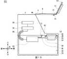
図1及び図9に示すように、第3の実施の形態による現金自動取引装置201は、第1の実施の形態による現金自動取引装置1と比べて、配線ケーブル48が省略され、処理機通信機72及び装置通信機74が追加されているものの、それ以外は同様に構成されている。
[3. Third Embodiment]
[3-1. Configuration of automatic cash transaction apparatus and banknote handling machine]
As shown in FIG.1 and FIG.9, theautomatic teller machine 201 by 3rd Embodiment is compared with theautomatic teller machine 1 by 1st Embodiment, thewiring cable 48 is abbreviate | omitted, and processor communication Although themachine 72 and theapparatus communication machine 74 are added, it is comprised similarly except that.

処理機制御部20には、電波により無線通信を行う処理機通信機72が接続されている。装置シャッタモータ14及び装置シャッタ位置検出センサ(図示せず)には、電波により処理機通信機72と無線通信を行う装置通信機74が接続されている。フロントパネル閉鎖状態においては、処理機制御部20は、装置シャッタ位置検出センサから装置シャッタ12の検出結果を無線通信で取得すると共に、装置シャッタモータ14を駆動する制御命令を無線通信で送信することにより装置シャッタ12を開閉させる。  Theprocessor control unit 20 is connected to aprocessor communicator 72 that performs radio communication using radio waves. Thedevice shutter motor 14 and the device shutter position detection sensor (not shown) are connected to adevice communication device 74 that performs radio communication with theprocessor communication device 72 using radio waves. In the front panel closed state, theprocessor control unit 20 acquires the detection result of thedevice shutter 12 from the device shutter position detection sensor by wireless communication and transmits a control command for driving thedevice shutter motor 14 by wireless communication. Thus, thedevice shutter 12 is opened and closed.

第1の実施の形態による現金自動取引装置1は、配線ケーブル48が処理機制御部20から装置筐体2内部へ引き回されフロントパネル支点4A近傍を通過して装置シャッタモータ14及び装置シャッタ位置検出センサに接続されているため、配線ケーブルの引き回しが長くなってしまい、ノイズ等が乗り、通信品質が確保できない可能性があった。  In theautomatic teller machine 1 according to the first embodiment, thewiring cable 48 is routed from theprocessor control unit 20 to the inside of theapparatus housing 2 and passes through the vicinity of thefront panel fulcrum 4A so that theapparatus shutter motor 14 and the apparatus shutter position. Since it is connected to the detection sensor, the routing of the wiring cable becomes long, and noise and the like may ride on it, so that communication quality may not be ensured.

これに対し現金自動取引装置201は、処理機制御部20から装置シャッタモータ14及び装置シャッタ位置検出センサまで引き回される配線ケーブル48を省略し、無線通信により処理機制御部20が装置シャッタモータ14を制御するようにした。これにより現金自動取引装置201は、処理機制御部20から装置シャッタモータ14及び装置シャッタ位置検出センサまで引き回される配線ケーブル48をなくすことができ、通信品質を保ち、処理機制御部20で装置シャッタ12を確実に制御することができる。  On the other hand, theautomatic teller machine 201 omits thewiring cable 48 routed from theprocessor control unit 20 to thedevice shutter motor 14 and the device shutter position detection sensor, and theprocessor control unit 20 transmits the device shutter motor by wireless communication. 14 was controlled. As a result, theautomatic teller machine 201 can eliminate thewiring cable 48 routed from theprocessor control unit 20 to thedevice shutter motor 14 and the device shutter position detection sensor, maintain communication quality, and theprocessor control unit 20 Thedevice shutter 12 can be reliably controlled.

また図10に示すフロントパネル開放状態においては、装置シャッタ12を開閉することはないため、フロントパネル閉鎖状態よりも装置通信機74が処理機通信機72から離隔し、仮に処理機通信機72の電波を装置通信機74が受信できなかったとしても、実用上は問題がない。また、そのようにフロントパネル開放状態では処理機通信機72と装置通信機74とが無線通信する必要がないため、電波を発信させないようにすることにより、処理機通信機72から発信した電波が現金自動取引装置201内の各種機構や他の装置等に干渉したり、影響したりする可能性を低くできる。  In the open state of the front panel shown in FIG. 10, theapparatus shutter 12 is not opened and closed. Therefore, theapparatus communicator 74 is separated from theprocessor communicator 72 than the front panel closed state. Even if thedevice communication device 74 cannot receive the radio wave, there is no practical problem. In addition, since theprocessor communicator 72 and thedevice communicator 74 do not need to communicate wirelessly in such a state where the front panel is open, the radio wave transmitted from theprocessor communicator 72 is prevented from being transmitted. The possibility of interfering with or affecting various mechanisms in theautomatic teller machine 201 or other devices can be reduced.

その他第3の実施の形態による現金自動取引装置201は、第1の実施の形態による現金自動取引装置1とほぼ同等の作用効果を奏する。  In addition, theautomatic teller machine 201 by 3rd Embodiment has an effect substantially the same as theautomatic teller machine 1 by 1st Embodiment.

[4.他の実施の形態]
なお上述した第1の実施の形態においては、装置シャッタ12と処理機シャッタ40とをいわゆる入れ子構造とする場合について述べた。本発明はこれに限らず、装置シャッタ12と処理機シャッタ40とは入れ子構造としなくても良い。また装置シャッタ12に装置シャッタ上側突起部12US及び装置シャッタ下側突起部12DSを形成せず、処理機シャッタ40に処理機シャッタ上側突起部40US及び処理機シャッタ下側突起部40DSを形成しないようにしても良い。この場合、処理機シャッタと装置シャッタとは、互いに接触しない程度に可能な限り近接している方が、処理機シャッタと装置シャッタとの間に紙幣が混入する可能性を低減できる。第2及び第3の実施の形態においても同様である。
[4. Other Embodiments]
In the above-described first embodiment, the case where theapparatus shutter 12 and theprocessor shutter 40 are so-called nested structures has been described. The present invention is not limited to this, and theapparatus shutter 12 and theprocessor shutter 40 need not be nested. Further, the apparatus shutter upper protrusion 12US and the apparatus shutter lower protrusion 12DS are not formed on theapparatus shutter 12, and the processor shutter upper protrusion 40US and the processor shutter lower protrusion 40DS are not formed on theprocessor shutter 40. May be. In this case, the possibility that bills are mixed between the processing machine shutter and the apparatus shutter can be reduced when the processing machine shutter and the apparatus shutter are as close as possible so as not to contact each other. The same applies to the second and third embodiments.

また上述した第2の実施の形態においては、処理機筐体24の内部から装置筐体2内部における装置シャッタ12の後方における操作表示部9の下方へ配線ケーブル64を引き回す場合について述べた。本発明はこれに限らず、配線ケーブル64を操作表示部9の左右何れかの側方や装置シャッタ12の前側等へ引き回しても良く、要は配線ケーブル64が可能な限りフロントパネル支点4A近傍よりも下側を通過し、引き回す距離が可能な限り短くなれば良い。  Further, in the second embodiment described above, the case where thewiring cable 64 is routed from the inside of theprocessor housing 24 to the lower side of theoperation display unit 9 behind thedevice shutter 12 inside thedevice housing 2 has been described. The present invention is not limited to this, and thewiring cable 64 may be routed to either the left or right side of theoperation display unit 9 or the front side of theapparatus shutter 12. In short, thewiring cable 64 is as close to thefront panel fulcrum 4A as possible. It is sufficient that the distance to be routed through the lower side is as short as possible.

さらに上述した第2の実施の形態においては、配線ケーブル64にジャック68を接続し、配線ケーブル66に当該ジャック68と嵌合するプラグ70を接続する場合について述べた。本発明はこれに限らず、配線ケーブル64と配線ケーブル66とを電気に接続可能し、且つ容易に脱着可能なコネクタ等の種々の配線接続部材を用いても良い。  Further, in the above-described second embodiment, the case where thejack 68 is connected to thewiring cable 64 and theplug 70 that fits thejack 68 is connected to thewiring cable 66 has been described. The present invention is not limited to this, and various wiring connection members such as a connector that can electrically connect thewiring cable 64 and thewiring cable 66 and can be easily detached may be used.

さらに上述した第3の実施の形態においては、電波により処理機通信機72と装置通信機74とで無線通信を行う場合について述べた。本発明はこれに限らず、光や音等の搬送波等、種々の無線通信技術を用いて無線通信を行っても良い。  Furthermore, in the above-described third embodiment, the case where wireless communication is performed between theprocessor communication device 72 and thedevice communication device 74 using radio waves has been described. The present invention is not limited to this, and wireless communication may be performed using various wireless communication technologies such as light and sound carriers.

さらに上述した実施の形態においては、処理機制御部20により装置シャッタ12及び処理機シャッタ40を制御する場合について述べた。本発明はこれに限らず、図11に示す現金自動取引装置301のように、装置筐体2の内部の接客制御部18からフロントパネル支点4A近傍を通過して操作表示部9の側方を通過し装置シャッタモータ14と装置シャッタ位置検出センサ(図示せず)とに配線ケーブル78を引き回すと共に、統括制御部16を介さずに処理機筐体24内部へ配線ケーブル76を引き回し、処理機制御部20を介さずに処理機シャッタモータ42と処理機シャッタ位置検出センサとに接続することにより、接客制御部18で装置シャッタ12及び処理機シャッタ40を制御しても良い。但し、手検知センサ60は処理機シャッタ40の下方に設けられているため、処理機制御部20により装置シャッタ12及び処理機シャッタ40を制御する方が、処理機シャッタ40を制御する際の配線ケーブルの引き回しを短く構成することができる。また、現金自動取引装置301においても、現金自動取引装置101のように、接客制御部18から、先端にジャックが接続された配線ケーブルを処理機シャッタモータ42に向かって引き回し、処理機シャッタモータ42から、先端にプラグが接続された配線ケーブルを引き回し、シャッタ閉鎖状態において当該ジャックとプラグとが嵌合するようにしても良い。さらに現金自動取引装置301においても、現金自動取引装置201のように、接客制御部18に接続された装置通信機と、処理機シャッタモータ42及び処理機シャッタ位置検出センサに接続された処理機通信機とで無線通信を行っても良い。Further, in the above-described embodiment, the case where theprocessor shutter 12 and theprocessor shutter 40 are controlled by theprocessor controller 20 has been described. The present invention is not limited to this, and, like anautomatic teller machine 301 shown in FIG. 11, the side of theoperation display unit 9 passes through the vicinity of thefront panel fulcrum 4A from the customerservice control unit 18 inside thedevice housing 2. Thewiring cable 78 is routed through theapparatus shutter motor 14 and the apparatus shutter position detection sensor (not shown), and thewiring cable 76 is routed into theprocessing unit casing 24 without passing through theoverall control unit 16 tocontrol theprocessing unit. Theservice control unit 18 may control theapparatus shutter 12 and theprocessor shutter 40 by connecting to theprocessor shutter motor 42 and the processor shutter position detection sensor without going through theunit 20 . However, since thehand detection sensor 60 is provided below theprocessor shutter 40, the wiring for controlling theprocessor shutter 40 is more controlled when theprocessor shutter 12 and theprocessor shutter 40 are controlled by theprocessor controller 20. The cable routing can be shortened. Also in theautomatic teller machine 301, like theautomatic teller machine 101, a wiring cable having a jack connected to the tip is routed toward the processingmachine shutter motor 42 from the customerservice control unit 18, and the processingmachine shutter motor 42. Then, a wiring cable having a plug connected to the tip may be routed so that the jack and the plug are fitted in the shutter closed state. Furthermore, also in theautomatic teller machine 301, like theautomatic teller machine 201, the apparatus communicator connected to the customerservice control unit 18, the processor communication connected to theprocessor shutter motor 42 and the processor shutter position detection sensor. Wireless communication may be performed with the machine.

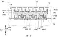
さらに上述した実施の形態においては、光軸が処理機シャッタ40の下側近傍に位置するよう、手検知センサ60を設ける場合について述べた。本発明はこれに限らず、図12に示す入出金部426のように、光軸が処理機シャッタ440の移動軌跡と被る位置に手検知センサ60を設けるようにしても良い。  Further, in the above-described embodiment, the case where thehand detection sensor 60 is provided so that the optical axis is positioned near the lower side of theprocessor shutter 40 has been described. The present invention is not limited to this, and ahand detection sensor 60 may be provided at a position where the optical axis is covered with the movement trajectory of theprocessor shutter 440, as in the deposit /withdrawal unit 426 shown in FIG. 12.

図12に示すように、装置シャッタ412は、装置シャッタ下側突起部412DSの高さが装置シャッタ下側突起部12DS(図6)よりも長くなっている。また処理機入出金口枠453は、処理機入出金口枠溝部453Cの左右方向の幅が処理機入出金口枠溝部53Cよりも広がっており、隣り合う処理機入出金口枠溝部453C同士の間には、当該処理機入出金口枠溝部453C同士よりも処理機シャッタ440に向かって突出する処理機入出金口枠突起部453Sが形成されている。  As shown in FIG. 12, in the apparatus shutter 412, the height of the apparatus shutter lower protrusion 412DS is longer than that of the apparatus shutter lower protrusion 12DS (FIG. 6). The processing machine deposit /withdrawal slot frame 453 has a width in the left-right direction of the processing machine deposit / withdrawal slot frame groove 453C wider than the processing machine deposit / withdrawal slot frame groove 53C. A processing machine deposit / withdrawalport frame projection 453 </ b> S is formed between the processing machine deposit / withdrawalport frame groove 453 </ b> C so as to protrude toward theprocessing machine shutter 440.

処理機シャッタ440は、S字形状の断面が左右方向に連続した形状となっている。また処理機シャッタ440は、装置シャッタ412の装置シャッタ下側溝部412DCと対向する箇所において、前端から後端まで前後方向に沿って装置シャッタ412に向かって突出する断面コ字形状の処理機シャッタ上側凸部440USが形成されている。これにより隣り合う処理機シャッタ上側凸部440US同士の間には、当該処理機シャッタ上側凸部440USよりも装置シャッタ412から離隔する処理機シャッタ上側凹部440UCが形成されている。また処理機シャッタ440は、処理機入出金口枠453の処理機入出金口枠溝部453Cと対向する箇所において、前端から後端まで前後方向に沿って処理機入出金口枠453に向かって突出する断面コ字形状の処理機シャッタ下側凸部440DSが形成されている。これにより隣り合う処理機シャッタ下側凸部440DS同士の間には、当該処理機シャッタ下側凸部440DSよりも処理機入出金口枠453から離隔する処理機シャッタ下側凹部440DCが形成されている。  Theprocessor shutter 440 has an S-shaped cross section that is continuous in the left-right direction. In addition, theprocessor shutter 440 has an upper U-shaped processor shutter projecting from the front end to the rear end in the front-rear direction toward the apparatus shutter 412 at a position facing the apparatus shutter lower groove 412DC of the apparatus shutter 412. A convex portion 440US is formed. Thus, a processor shutter upper concave portion 440UC that is further away from the apparatus shutter 412 than the processor shutter upper convex portion 440US is formed between the adjacent processor shutter upper convex portions 440US. Further, theprocessor shutter 440 projects toward the processor inlet /outlet port frame 453 along the front-rear direction from the front end to the rear end at a position facing the processor inlet / outlet port groove groove 453C of the processor inlet /outlet port frame 453. A processing unit shutter lower projection 440DS having a U-shaped cross section is formed. As a result, a processor shutter lower concave portion 440DC is formed between the adjacent processor shutter lower convex portions 440DS so as to be farther from the processor input /output port frame 453 than the processor shutter lower convex portion 440DS. Yes.

手検知センサ60は、光軸が処理機シャッタ440の処理機シャッタ下側凹部440DCの内側であり且つ処理機入出金口枠突起部453Sの上側に位置するよう設けられている。  Thehand detection sensor 60 is provided so that the optical axis is inside the processor shutter lower side recess 440DC of theprocessor shutter 440 and above the processor inlet /outlet port projection 453S.

ここで、第1の実施の形態による入出金部26は、従来の入出金部726のように装置シャッタ712と処理機シャッタ740との間に手検知センサが設けられていた場合と比べて、装置シャッタ12と手検知センサ60との間に処理機シャッタ40が存在するため、装置シャッタ712から装置手検知センサ61までの距離よりも、装置シャッタ12から手検知センサ60までの距離の方が遠くなる。このため、例えば装置シャッタ12の移動軌跡上に利用者の指が存在した場合であっても手検知センサ60の光軸までは指が到達していない場合、手検知センサ60は利用者の指を検知できないため、現金自動取引装置1は、閉鎖しようとする装置シャッタ12を止めることができない可能性ある。  Here, the deposit /withdrawal unit 26 according to the first embodiment is compared to a case in which a hand detection sensor is provided between theapparatus shutter 712 and theprocessor shutter 740 as in the conventional deposit /withdrawal unit 726. Since theprocessor shutter 40 exists between theapparatus shutter 12 and thehand detection sensor 60, the distance from theapparatus shutter 12 to thehand detection sensor 60 is greater than the distance from theapparatus shutter 712 to the apparatushand detection sensor 61. It will be far away. For this reason, for example, even when the user's finger is present on the movement path of theapparatus shutter 12, if the finger has not reached the optical axis of thehand detection sensor 60, thehand detection sensor 60 is Therefore, theautomatic teller machine 1 may not be able to stop thedevice shutter 12 to be closed.

これに対し入出金部426は、処理機シャッタ440の上端部(処理機シャッタ上側凸部440USの上面)と下端部(処理機シャッタ下側凸部440DSの下面)の間に手検知センサ60の光軸が位置するようにした。これにより入出金部426は、予め設定された処理機入出金口枠453と装置入出金口枠52との距離を変化させることなく、処理機入出金口枠453及び処理機シャッタ440の入れ子構造と、処理機シャッタ440及び装置シャッタ412の入れ子構造を維持しながら、入出金部26と比べて手検知センサ60の光軸を装置シャッタ412に近接させることができるため、装置シャッタ412の移動軌跡上に利用者の指が存在するものの手検知センサ60までは当該指が到達していないという状態を発生しにくくすることができ、安全性をより向上させることができる。  On the other hand, the deposit /withdrawal unit 426 is provided between the upper end portion of the processor shutter 440 (upper surface of the processor shutter upper convex portion 440US) and the lower end portion (lower surface of the processor shutter lower convex portion 440DS). The optical axis was positioned. As a result, the deposit /withdrawal unit 426 allows the processing unit deposit /withdrawal port frame 453 and theprocessing unit shutter 440 to be nested without changing the distance between the processing unit deposit /withdrawal port frame 453 and the apparatus deposit /withdrawal port frame 52. Since the optical axis of thehand detection sensor 60 can be brought closer to the apparatus shutter 412 as compared with the deposit /withdrawal unit 26 while maintaining the nested structure of theprocessor shutter 440 and the apparatus shutter 412, the movement locus of the apparatus shutter 412 Although the user's finger exists above, it is possible to make it difficult for thefinger detection sensor 60 to reach thehand detection sensor 60, and safety can be further improved.

また手検知センサ60の光軸は処理機シャッタ40の移動軌跡と被る位置に配置するようにしたため、入出金部426は、処理機シャッタ440の移動軌跡上に利用者の指が存在するものの手検知センサ60までは当該指が到達していないという状態を発生しにくくすることができ、安全性をより向上させることができる。  Further, since the optical axis of thehand detection sensor 60 is arranged at a position that is covered with the movement locus of theprocessor shutter 40, the deposit /withdrawal unit 426 has a user's finger on the movement locus of theprocessor shutter 440. It is possible to make it difficult for thedetection sensor 60 to reach the state where the finger has not reached, and to improve safety.

また装置シャッタ512及び処理機シャッタ540は、図13に示すものでも良い。装置シャッタ512は、前後左右方向に伸びる平板形状の装置シャッタ板部512Aの上面から、前端から後端まで前後方向に沿って装置入出金口枠52に向かって突設された装置シャッタ上側突起部512USが、左右方向に所定間隔を空けて複数本設けられている。これにより隣り合う装置シャッタ上側突起部512US同士の間には、当該装置シャッタ上側突起部512USの高さよりも低い装置シャッタ上側溝部512UCが形成されている。また装置シャッタ512は、装置シャッタ上側突起部512USと左右方向の位置が一致する箇所における装置シャッタ板部512Aの下面から、前端から後端まで前後方向に沿って処理機シャッタ540に向かって突設された装置シャッタ下側突起部512DSが、左右方向に所定間隔を空けて複数本設けられている。これにより隣り合う装置シャッタ下側突起部512DS同士の間には、当該装置シャッタ下側突起部512DSの高さよりも低い装置シャッタ下側溝部512DCが形成されている。  The apparatus shutter 512 and theprocessor shutter 540 may be those shown in FIG. The device shutter 512 is a device shutter upper protrusion that protrudes from the upper surface of a flat plate-shaped deviceshutter plate portion 512A extending in the front-rear and left-right directions toward the device deposit /withdrawal port frame 52 along the front-rear direction from the front end to the rear end. A plurality of 512 USs are provided at predetermined intervals in the left-right direction. As a result, an apparatus shutter upper groove 512UC that is lower than the height of the apparatus shutter upper protrusion 512US is formed between adjacent apparatus shutter upper protrusions 512US. The apparatus shutter 512 protrudes from the lower surface of the apparatusshutter plate part 512A at the position where the position in the left-right direction coincides with the apparatus shutter upper protrusion part 512US from the front end to the rear end in the front-rear direction toward theprocessor shutter 540. A plurality of apparatus shutter lower protrusions 512DS are provided at predetermined intervals in the left-right direction. Thus, a device shutter lower groove portion 512DC that is lower than the height of the device shutter lower projection portion 512DS is formed between the adjacent device shutter lower projection portions 512DS.

処理機シャッタ540は、前後左右方向に伸びる平板形状の処理機シャッタ板部540Aの上面における、装置シャッタ512の装置シャッタ下側溝部512DCと対向する箇所において、前端から後端まで前後方向に沿って装置シャッタ512に向かって処理機シャッタ上側突起部540USが突設されている。これにより隣り合う処理機シャッタ上側突起部540US同士の間には、当該処理機シャッタ上側突起部540USの高さよりも低い処理機シャッタ上側溝部540UCが形成されている。また処理機シャッタ540は、処理機シャッタ上側突起部540USと左右方向の位置が一致する箇所における処理機シャッタ板部540Aの下面から、前端から後端まで前後方向に沿って処理機入出金口枠53に向かって突設された処理機シャッタ下側突起部540DSが、左右方向に所定間隔を空けて複数本設けられている。  Theprocessor shutter 540 extends along the front-rear direction from the front end to the rear end at a location facing the apparatus shutter lower groove 512DC of the apparatus shutter 512 on the upper surface of the flat-plate-type processorshutter plate part 540A extending in the front-rear, left-right direction. A processor shutter upper protrusion 540US projects toward the apparatus shutter 512. As a result, a processor shutter upper groove 540UC that is lower than the height of the processor shutter upper protrusion 540US is formed between the adjacent processor shutter upper protrusions 540US. In addition, theprocessor shutter 540 has a processor inlet / outlet port frame along the front-rear direction from the lower surface of the processorshutter plate portion 540A at the position where the position in the left-right direction coincides with the processor shutter upper protrusion 540US. A plurality of processing machine shutter lower projections 540DS projecting toward 53 are provided at predetermined intervals in the left-right direction.

装置シャッタ512と処理機シャッタ540とは、装置シャッタ下側溝部512DCに処理機シャッタ上側突起部540USが、処理機シャッタ上側溝部540UCに装置シャッタ下側突起部512DSが入り込むことにより非接触状態で噛み合い、いわゆる入れ子構造が幅方向に亘って形成されている。  The apparatus shutter 512 and theprocessor shutter 540 are in a non-contact state when the processor shutter upper protrusion 540US enters the apparatus shutter lower groove 512DC and the apparatus shutter lower protrusion 512DS enters the processor shutter upper groove 540UC. Engagement, a so-called nested structure is formed across the width direction.

さらに上述した実施の形態においては、処理機シャッタ40の下側に手検知センサ60を配置する場合について述べた。本発明はこれに限らず、装置シャッタ12と処理機シャッタ40との間に手検知センサ60の光軸が位置していても良い。要は、処理機シャッタ40の下側か、装置シャッタ12と処理機シャッタ40との間かの何れかに1個の手検知センサ60を設ければ良い。  Further, in the above-described embodiment, the case where thehand detection sensor 60 is arranged below theprocessor shutter 40 has been described. The present invention is not limited to this, and the optical axis of thehand detection sensor 60 may be positioned between theapparatus shutter 12 and theprocessor shutter 40. In short, onehand detection sensor 60 may be provided either below theprocessor shutter 40 or between theapparatus shutter 12 and theprocessor shutter 40.

さらに上述した実施の形態においては、1本の光軸を有する1個の手検知センサ60を設ける場合について述べた。本発明はこれに限らず、例えば左右方向に平行となる位置に3本の光軸を有する1組の手検知センサ60を設けても良い。  Further, in the above-described embodiment, the case where onehand detection sensor 60 having one optical axis is provided has been described. The present invention is not limited to this. For example, a set ofhand detection sensors 60 having three optical axes may be provided at positions parallel to the left-right direction.

さらに上述した第1の実施の形態においては、装置筐体2の上端部近傍に設けられたフロントパネル支点4Aを軸として装置筐体2に対しフロントパネル4を回動可能に形成する場合について述べた。本発明はこれに限らず、フロントパネル4の下端部、右端部や左端部等、種々の箇所に設けられた支点を軸にフロントパネルを回動させるようにしても良い。その場合も、軸の近傍に配線ケーブル48を這わせれば良い。また、装置筐体2に対し、フロントパネルをスライドさせる等、種々の動作により開閉させるようにしても良い。  Further, in the first embodiment described above, a case where thefront panel 4 is formed to be rotatable with respect to theapparatus housing 2 around thefront panel fulcrum 4A provided in the vicinity of the upper end portion of theapparatus housing 2 is described. It was. The present invention is not limited to this, and the front panel may be rotated around a fulcrum provided at various locations such as the lower end, the right end, and the left end of thefront panel 4. Even in that case, thewiring cable 48 may be placed near the shaft. Further, theapparatus housing 2 may be opened and closed by various operations such as sliding the front panel.

さらに上述した実施の形態においては、紙幣処理機22は、紙幣に関する処理を行う入出金部26、搬送部28、鑑別部30、一時保留部32、リサイクル庫34、リジェクト庫36及び取忘れ庫38等の各種機構が処理機筐体24により囲まれて構成され、装置筐体2に収まる場合について述べた。本発明はこれに限らず、紙幣処理機は、処理機筐体を有さず、入出金部26、搬送部28、鑑別部30、一時保留部32、リサイクル庫34、リジェクト庫36及び取忘れ庫38等のユニットが装置筐体2内部に収まる構成であっても良い。その場合、処理機シャッタは入出金部26に設けるようにすれば良い。  Furthermore, in embodiment mentioned above, thebanknote processing machine 22 is the deposit /withdrawal part 26 which performs the process regarding a banknote, theconveyance part 28, thediscrimination part 30, thetemporary storage part 32, the recycle store | warehouse |chamber 34, the reject store | warehouse |chamber 36, and the forgottenstorehouse 38. A case has been described in which various mechanisms such as are surrounded by theprocessor casing 24 and fit in theapparatus casing 2. The present invention is not limited to this, and the banknote processing machine does not have a processing machine housing, and is a deposit /withdrawal unit 26, atransport unit 28, adiscrimination unit 30, atemporary storage unit 32, arecycle store 34, areject store 36, and forgetting to collect it. A configuration in which units such as thestorage 38 can be accommodated in theapparatus housing 2 may be adopted. In that case, the processor shutter may be provided in the deposit /withdrawal unit 26.

さらに上述した実施の形態においては、現金を取引する現金自動取引装置1に本発明を適用する場合について述べた。本発明はこれに限らず、例えば商品券や金券、入場券等のような薄い紙状の媒体を処理する種々の装置に本発明を適用しても良い。また、例えば紙幣を入出する紙幣処理機や紙幣を所定枚数毎に施封する施封小束支払機等、紙幣や硬貨の取引に関する種々の処理を行う複数種類の装置の組み合わせにより構成された現金処理装置に本発明を適用してもよい。  Furthermore, in embodiment mentioned above, the case where this invention was applied to the cashautomatic transaction apparatus 1 which trades cash was described. The present invention is not limited to this. For example, the present invention may be applied to various apparatuses that process thin paper-like media such as gift certificates, cash vouchers, and admission tickets. In addition, for example, a cash constituted by a combination of a plurality of types of devices that perform various processes related to transactions of banknotes and coins, such as a banknote processing machine for entering and exiting banknotes and a sealed small bundle payment machine for sealing banknotes every predetermined number The present invention may be applied to a processing apparatus.

さらに上述した実施の形態においては、装置筐体としての装置筐体2と、媒体処理機としての紙幣処理機22と、媒体収容部としての紙幣収容部54と、接客制御部としての接客制御部18と、処理機制御部としての処理機制御部20と、異物検知センサとしての手検知センサ60とによって、媒体取引装置としての現金自動取引装置1を構成する場合について述べた。本発明はこれに限らず、その他種々の構成でなる装置筐体と、処理機筐体と、媒体収容部と、接客制御部と、処理機制御部と、異物検知センサとによって、媒体取引装置を構成しても良い。  Furthermore, in embodiment mentioned above, the apparatus housing | casing 2 as an apparatus housing | casing, thebanknote processing machine 22 as a medium processing machine, thebanknote accommodating part 54 as a medium accommodating part, and the customer service control part as a customerservice control part 18, the case where theautomatic transaction machine 1 as a medium transaction apparatus is comprised by the processingmachine control part 20 as a processing machine control part, and thehand detection sensor 60 as a foreign material detection sensor was described. The present invention is not limited to this, and a medium transaction apparatus includes an apparatus casing, a processing machine casing, a medium storage unit, a customer service control unit, a processing unit control unit, and a foreign object detection sensor having various other configurations. May be configured.

本発明は、2枚のシャッタを開閉し媒体を入出金する種々の装置でも利用できる。  The present invention can also be used in various devices that open and close two shutters to deposit and withdraw media.

1、101、201、301、701……現金自動取引装置、2……装置筐体、4、704……フロントパネル、4A……フロントパネル支点、6……接客部、7……カード入出口、8……装置入出金口、9……操作表示部、10……テンキー、11……レシート発行口、12、112、412、512、712……装置シャッタ、12A、412A、512A……装置シャッタ板部、12US、412US、512US……装置シャッタ上側突起部、12DS、412DS、512DS……装置シャッタ下側突起部、12UC、412UC、512UC……装置シャッタ上側溝部、12DC、412DC、512DC……装置シャッタ下側溝部、14……装置シャッタモータ、16……統括制御部、18……接客制御部、20……処理機制御部、22……紙幣処理機、24……処理機筐体、26、426、726……入出金部、28……搬送部、30……鑑別部、32……一時保留部、34……リサイクル庫、36……リジェクト庫、38……取忘れ庫、40、140、440、540、740……処理機シャッタ、40A、540A……処理機シャッタ板部、40US、540US……処理機シャッタ上側突起部、40DS、540DS……処理機シャッタ下側突起部、40UC、540UC……処理機シャッタ上側溝部、440US……処理機シャッタ上側凸部、440UC……処理機シャッタ上側凹部、440DS……処理機シャッタ下側凸部、440DC……処理機シャッタ下側凹部、42……処理機シャッタモータ、44、45、48、64、66、76、78……配線ケーブル、46……プラチェーン、50……記憶部、52……装置入出金口枠、52A……装置入出金口枠板部、52C……装置入出金口枠溝部、53、453……処理機入出金口枠、53A、453A……処理機入出金口枠板部53C、453C……処理機入出金口枠溝部、453S……処理機入出金口枠突起部、54……紙幣収容部、56……処理機入出金口、58……入出金口、60……手検知センサ、61……装置手検知センサ、62……処理機手検知センサ、68……ジャック、70……プラグ、72……処理機通信機、74……装置通信機。  DESCRIPTION OF SYMBOLS 1,101,201,301,701 ... automatic teller machine, 2 ... device housing, 4,704 ... front panel, 4A ... front panel fulcrum, 6 ... customer service part, 7 ... card entrance / exit , 8... Device deposit / withdrawal port, 9... Operation display section, 10... Numeric keypad, 11 .. receipt issue port, 12, 112, 412, 512, 712 ...... device shutter, 12 A, 412 A, 512 A. Shutter plate, 12US, 412US, 512US ... Upper projection on device shutter, 12DS, 412DS, 512DS ... Lower projection on device shutter, 12UC, 412UC, 512UC ... Upper groove on device shutter, 12DC, 412DC, 512DC ... ... device shutter lower groove, 14 ... device shutter motor, 16 ... general control unit, 18 ... customer service control unit, 20 ... processing mechanism , 22... Banknote processing machine, 24... Processing machine casing, 26, 426, 726... Depositing / withdrawing part, 28 .. conveying part, 30. Recycle box, 36 ... Reject box, 38 ... Forgotten box, 40, 140, 440, 540, 740 ... Processor shutter, 40A, 540A ... Processor shutter plate, 40US, 540US ... Processor shutter Upper projection, 40DS, 540DS ... Processor shutter lower projection, 40UC, 540UC ... Processor shutter upper groove, 440US ... Processor shutter upper projection, 440UC ... Processor shutter upper recess, 440DS ... ... Processor shutter lower convex part, 440DC ... Processor shutter lower concave part, 42 ... Processor shutter motor, 44, 45, 48, 64, 66, 76, 78 ... Cable, 46 ...... Plastic chain, 50 ... Storage unit, 52 ... Device deposit / withdrawal port frame, 52A ... Device deposit / withdrawal port frame plate, 52C ... Device deposit / withdrawal port frame groove, 53,453 ... Process Machine deposit / withdrawal slot frame, 53A, 453A ... Processing machine deposit / withdrawal slot frame plate 53C, 453C ... Processing machine deposit / withdrawal slot frame groove, 453S ... Processing machine deposit / withdrawal slot frame projection, 54 ...Banknote storage 56 …… Processing machine deposit / withdrawal port, 58 …… Insertion / withdrawal port, 60 …… Hand detection sensor, 61 …… Device hand detection sensor, 62 …… Processing machine hand detection sensor, 68 …… Jack, 70 ……Plug 72 …… Processor communication device, 74 …… Device communication device.

Claims (13)

Translated fromJapanese
紙葉状の媒体に関する操作を受け付ける接客部と、当該媒体を入出させる装置入出口と、当該装置入出口を開閉する装置シャッタとが設けられた装置筐体と、
前記装置筐体の内部に設けられ、前記装置入出口に対向して配され前記媒体を入出させる処理機入出口と、当該処理機入出口を開閉する処理機シャッタとを備え、前記媒体に関する処理を行う媒体処理機と、
前記媒体処理機の内部に設けられ前記装置シャッタ及び前記処理機シャッタの開閉により前記装置入出口及び前記処理機入出口を介して外部に対し開放又は遮断される媒体収容部と、
前記装置筐体の内部における前記媒体処理機の外部に設けられ前記接客部を制御する接客制御部と、
前記媒体処理機の内部に設けられ前記媒体処理機を制御する処理機制御部と、
前記処理機シャッタよりも前記媒体処理機の内側に設けられ、前記媒体収容部における異物の有無を検出する異物検知センサと
を有し、
前記接客制御部又は前記処理機制御部の何れか一方が、前記異物検知センサの検知結果を取得すると共に前記装置シャッタ及び前記処理機シャッタを制御する
媒体取引装置。
An apparatus housing provided with a customer service section for receiving operations relating to a paper-like medium, an apparatus entrance / exit for entering / exiting the medium, and an apparatus shutter for opening / closing the apparatus entrance / exit;
A processing unit related to the medium, comprising a processing unit inlet / outlet provided inside the apparatus casing and arranged to face the apparatus inlet / outlet for allowing the medium to enter / exit, and a processing unit shutter for opening / closing the processing unit input / output port. A media processor for performing
A medium container provided inside the medium processing machine and opened or shut off to the outside through the apparatus entrance and the processing machine entrance and exit by opening and closing of the apparatus shutter and the processor shutter; and
A customer service control unit for controlling the customer service unit provided outside the medium processing machine inside the apparatus housing;
A processor controller provided in the medium processor for controlling the medium processor;
A foreign matter detection sensor provided on the inside of the medium processing device with respect to the processing device shutter and detecting the presence or absence of foreign matter in the medium accommodating portion;
A medium transaction apparatus in which either the customer service control unit or the processing machine control unit acquires the detection result of the foreign matter detection sensor and controls the apparatus shutter and the processing machine shutter.
前記接客部は、前記装置筐体に対し接客部支点を軸として前記処理機シャッタに対し前記装置シャッタが離接するよう回動可能に形成される
請求項1に記載の媒体取引装置。
The medium transaction apparatus according to claim 1, wherein the customer service section is formed so as to be rotatable with respect to the apparatus housing so that the apparatus shutter is separated from and connected to the processor shutter with a customer service section fulcrum as an axis.
前記処理機制御部が、前記異物検知センサの検知結果を取得すると共に前記装置シャッタ及び前記処理機シャッタを制御する
請求項2に記載の媒体取引装置。
The medium transaction apparatus according to claim 2, wherein the processor control unit acquires a detection result of the foreign object detection sensor and controls the apparatus shutter and the processor shutter.
前記媒体処理機は、前記装置筐体の内部における下側に設けられ、
前記接客部支点は、前記装置筐体における上端部近傍に設けられる
請求項3に記載の媒体取引装置。
The medium processing machine is provided on the lower side inside the apparatus housing,
The medium transaction apparatus according to claim 3, wherein the customer service fulcrum is provided in the vicinity of an upper end of the apparatus housing.
前記処理機制御部から、前記処理機シャッタを駆動する処理機シャッタモータに接続される入出金機シャッタモータ配線を有する
請求項4に記載の媒体取引装置。
The medium transaction apparatus according to claim 4, further comprising a deposit / withdrawal machine shutter motor wiring connected to a processing machine shutter motor that drives the processing machine shutter from the processing machine control unit.
前記処理機制御部から前記異物検知センサに接続される異物検知センサ配線を有する
請求項5に記載の媒体取引装置。
The medium transaction apparatus according to claim 5, further comprising a foreign matter detection sensor wiring connected to the foreign matter detection sensor from the processor control unit.
前記処理機制御部から、前記接客部支点近傍を通過し、前記装置シャッタを駆動する装置シャッタモータに接続される装置配線を有する
請求項6に記載の媒体取引装置。
The medium transaction apparatus according to claim 6, further comprising an apparatus wiring connected to an apparatus shutter motor that passes through the vicinity of the customer service section fulcrum and drives the apparatus shutter from the processor control unit.
前記処理機制御部と、前記装置シャッタを駆動する装置シャッタモータとは、前記処理機シャッタと前記装置シャッタとが近接する状態である前記接客部の閉鎖状態において互いに着脱可能な配線接続部材が嵌合することにより導通し、一方、前記処理機シャッタと前記装置シャッタとが離隔する状態である前記接客部の開放状態において前記配線接続部材が外れることにより絶縁される
請求項6に記載の媒体取引装置。
The processor controller and the apparatus shutter motor that drives the apparatus shutter are fitted with wiring connection members that can be attached to and detached from each other in the closed state of the service section where the processor shutter and the apparatus shutter are close to each other. 7. The medium transaction according to claim 6, wherein electrical connection is established, and insulation is achieved by disconnecting the wiring connection member in an open state of the customer service portion in which the processing machine shutter and the apparatus shutter are separated from each other. apparatus.
前記処理機制御部と、前記装置シャッタを駆動する装置シャッタモータとは、無線通信により接続される
請求項6に記載の媒体取引装置。
The medium transaction apparatus according to claim 6, wherein the processor control unit and the apparatus shutter motor that drives the apparatus shutter are connected by wireless communication.
前記装置シャッタと前記処理機シャッタとは、互いに非接触で噛み合うよう対向する
請求項1に記載の媒体取引装置。
The medium transaction apparatus according to claim 1, wherein the apparatus shutter and the processor shutter face each other so as to mesh with each other in a non-contact manner.
前記処理機シャッタの上端部から下端部までの間に前記異物検知センサの光軸が位置する
請求項10に記載の媒体取引装置。
The medium transaction apparatus of Claim 10. The optical axis of the said foreign material detection sensor is located between the upper end part of the said processor shutter from a lower end part.
前記処理機シャッタの下端部よりも前記媒体処理機の内側に前記異物検知センサの光軸が位置する
請求項10に記載の媒体取引装置。
The medium transaction apparatus of Claim 10. The optical axis of the said foreign material detection sensor is located inside the said medium processing machine rather than the lower end part of the said processing machine shutter.
前記異物検知センサは、利用者の手の有無を検出する手検知センサである
請求項1に記載の媒体取引装置。
The medium transaction apparatus according to claim 1, wherein the foreign object detection sensor is a hand detection sensor that detects presence or absence of a user's hand.
JP2014170529A2014-08-252014-08-25 Media transaction equipmentExpired - Fee RelatedJP6303921B2 (en)

Priority Applications (4)

Application NumberPriority DateFiling DateTitle
JP2014170529AJP6303921B2 (en)2014-08-252014-08-25 Media transaction equipment
US15/329,245US10297099B2 (en)2014-08-252015-06-02Media transaction device
CN201580038959.7ACN106537469B (en)2014-08-252015-06-02Medium transaction device
PCT/JP2015/065937WO2016031333A1 (en)2014-08-252015-06-02Media transaction device

Applications Claiming Priority (1)

Application NumberPriority DateFiling DateTitle
JP2014170529AJP6303921B2 (en)2014-08-252014-08-25 Media transaction equipment

Publications (3)

Publication NumberPublication Date
JP2016045773A JP2016045773A (en)2016-04-04
JP2016045773A5 JP2016045773A5 (en)2017-05-25
JP6303921B2true JP6303921B2 (en)2018-04-04

Family

ID=55399238

Family Applications (1)

Application NumberTitlePriority DateFiling Date
JP2014170529AExpired - Fee RelatedJP6303921B2 (en)2014-08-252014-08-25 Media transaction equipment

Country Status (4)

CountryLink
US (1)US10297099B2 (en)
JP (1)JP6303921B2 (en)
CN (1)CN106537469B (en)
WO (1)WO2016031333A1 (en)

Families Citing this family (7)

* Cited by examiner, † Cited by third party
Publication numberPriority datePublication dateAssigneeTitle
CN107680251B (en)*2017-10-172021-05-18深圳怡化电脑股份有限公司Paper-like medium detection apparatus and control method of gate device
CN108416898B (en)*2018-04-252024-07-02中电金融设备系统(深圳)有限公司Finance self-service equipment
US10726655B2 (en)*2018-04-272020-07-28Ncr CorporationShutter assembly for a self-service terminal
JP7322587B2 (en)*2019-08-162023-08-08沖電気工業株式会社 medium transaction device
CN115136213B (en)*2020-02-212024-10-01富士通先端科技株式会社Paper sheet handling device
CN113496566B (en)*2020-03-192023-09-15光荣株式会社currency processing system
IT202200025095A1 (en)*2022-12-062024-06-06M C M S R L ANTI-THEFT DEVICE FOR AUTOMATIC BANKNOTE AND/OR VALUABLES DISPENSING SYSTEMS

Family Cites Families (17)

* Cited by examiner, † Cited by third party
Publication numberPriority datePublication dateAssigneeTitle
US5259576A (en)*1992-05-181993-11-09Howard D UExternal sliding aircraft door
JP2003067808A (en)2001-08-272003-03-07Oki Electric Ind Co LtdAutomatic transaction machine
JP3996831B2 (en)*2002-09-272007-10-24日立オムロンターミナルソリューションズ株式会社 Media handling device
US7856401B2 (en)*2003-07-112010-12-21Ncr CorporationSelf-service terminal
JP4353970B2 (en)*2006-08-082009-10-28日立オムロンターミナルソリューションズ株式会社 Foreign object detection device
US7810715B2 (en)*2008-01-312010-10-12Ncr CorporationSelf-service terminal
JP5471366B2 (en)*2009-11-302014-04-16沖電気工業株式会社 Media processing device
JP5454155B2 (en)*2010-01-132014-03-26沖電気工業株式会社 Shutter structure and automatic transaction apparatus
JP5780925B2 (en)*2011-01-212015-09-16レシップ株式会社 Fare box
JP5779433B2 (en)*2011-07-152015-09-16日立オムロンターミナルソリューションズ株式会社 Bill handling apparatus and bill deposit method using the same
JP5349569B2 (en)*2011-11-242013-11-20日立オムロンターミナルソリューションズ株式会社 Bill deposit / withdrawal apparatus and bill deposit / withdrawal apparatus control method
US8960404B2 (en)*2012-10-012015-02-24Jcm American CorporationBezel assembly for data reception
JP5859945B2 (en)*2012-10-262016-02-16日立オムロンターミナルソリューションズ株式会社 Bill handling apparatus and bill detection method
JP5971119B2 (en)*2012-12-282016-08-17沖電気工業株式会社 Shutter device and medium transaction device
JP2014029736A (en)*2013-11-132014-02-13Oki Electric Ind Co LtdAutomated transaction device
US10319171B2 (en)*2014-03-282019-06-11Ncr CorporationMedia escape prevention for self-service terminal
JP2016099677A (en)*2014-11-182016-05-30グローリー株式会社Banknote handling device

Also Published As

Publication numberPublication date
CN106537469A (en)2017-03-22
JP2016045773A (en)2016-04-04
WO2016031333A1 (en)2016-03-03
US20170221293A1 (en)2017-08-03
CN106537469B (en)2019-06-21
US10297099B2 (en)2019-05-21

Similar Documents

PublicationPublication DateTitle
JP6303921B2 (en) Media transaction equipment
KR101413893B1 (en)Paper money deposit/withdrawal machine
JP6369196B2 (en) Medium processing apparatus and medium transaction apparatus
JP5500190B2 (en) Media transaction equipment
JP2012256271A (en)Medium processor
JP2013202290A (en)Drawer device and medium transaction apparatus
JP2010123091A (en)Automatic teller machine and method for controlling automatic teller machine
JPWO2008078382A1 (en) Banknote handling equipment
JP5553134B2 (en) Media transaction equipment
JP6413688B2 (en) Automatic transaction equipment
JP2015060456A (en)Medium conveyance device and medium transaction device
WO2014065305A1 (en)Bank note handling device and bank note detection method
WO2014155644A1 (en)Paper sheet handling device and automatic transaction device
JP5789562B2 (en) Paper sheet handling equipment and automatic transaction equipment
JP6237911B2 (en) Medium transport identification apparatus and medium transaction apparatus
JP2014191447A (en)Medium storage device and medium transaction device
JP6927820B2 (en) Banknote processing system and storage
CN106056755B (en)Bill handling device and automatic trading apparatus
JP2013200790A (en)Medium processor
JP6863186B2 (en) Media processing equipment and automated teller machines
WO2018008265A1 (en)Medium storage vault and medium handling device
JP2018032265A (en)Medium processing device and medium transaction device
WO2021033409A1 (en)Medium transaction device
JP6623830B2 (en) Small bundle processing equipment
CN105741409B (en)Medium transaction device

Legal Events

DateCodeTitleDescription
A521Request for written amendment filed

Free format text:JAPANESE INTERMEDIATE CODE: A523

Effective date:20170406

A621Written request for application examination

Free format text:JAPANESE INTERMEDIATE CODE: A621

Effective date:20170406

TRDDDecision of grant or rejection written
A01Written decision to grant a patent or to grant a registration (utility model)

Free format text:JAPANESE INTERMEDIATE CODE: A01

Effective date:20180206

A61First payment of annual fees (during grant procedure)

Free format text:JAPANESE INTERMEDIATE CODE: A61

Effective date:20180219

R150Certificate of patent or registration of utility model

Ref document number:6303921

Country of ref document:JP

Free format text:JAPANESE INTERMEDIATE CODE: R150

LAPSCancellation because of no payment of annual fees

[8]ページ先頭

©2009-2025 Movatter.jp