JP6301240B2 - Battery charger for vehicle - Google Patents
Battery charger for vehicleDownload PDFInfo
- Publication number
- JP6301240B2 JP6301240B2JP2014238129AJP2014238129AJP6301240B2JP 6301240 B2JP6301240 B2JP 6301240B2JP 2014238129 AJP2014238129 AJP 2014238129AJP 2014238129 AJP2014238129 AJP 2014238129AJP 6301240 B2JP6301240 B2JP 6301240B2
- Authority
- JP
- Japan
- Prior art keywords
- energization
- period
- detection signal
- phase
- position detection
- Prior art date
- Legal status (The legal status is an assumption and is not a legal conclusion. Google has not performed a legal analysis and makes no representation as to the accuracy of the status listed.)
- Active
Links
Images


Classifications
- H—ELECTRICITY
- H02—GENERATION; CONVERSION OR DISTRIBUTION OF ELECTRIC POWER
- H02J—CIRCUIT ARRANGEMENTS OR SYSTEMS FOR SUPPLYING OR DISTRIBUTING ELECTRIC POWER; SYSTEMS FOR STORING ELECTRIC ENERGY
- H02J7/00—Circuit arrangements for charging or depolarising batteries or for supplying loads from batteries
- H02J7/14—Circuit arrangements for charging or depolarising batteries or for supplying loads from batteries for charging batteries from dynamo-electric generators driven at varying speed, e.g. on vehicle
- H02J7/1469—Regulation of the charging current or voltage otherwise than by variation of field
- H02J7/1484—Regulation of the charging current or voltage otherwise than by variation of field by commutation of the output windings of the generator
- H—ELECTRICITY
- H02—GENERATION; CONVERSION OR DISTRIBUTION OF ELECTRIC POWER
- H02J—CIRCUIT ARRANGEMENTS OR SYSTEMS FOR SUPPLYING OR DISTRIBUTING ELECTRIC POWER; SYSTEMS FOR STORING ELECTRIC ENERGY
- H02J7/00—Circuit arrangements for charging or depolarising batteries or for supplying loads from batteries
- H02J7/14—Circuit arrangements for charging or depolarising batteries or for supplying loads from batteries for charging batteries from dynamo-electric generators driven at varying speed, e.g. on vehicle
- H02J7/1469—Regulation of the charging current or voltage otherwise than by variation of field
- H02J7/1492—Regulation of the charging current or voltage otherwise than by variation of field by means of controlling devices between the generator output and the battery
- H—ELECTRICITY
- H02—GENERATION; CONVERSION OR DISTRIBUTION OF ELECTRIC POWER
- H02P—CONTROL OR REGULATION OF ELECTRIC MOTORS, ELECTRIC GENERATORS OR DYNAMO-ELECTRIC CONVERTERS; CONTROLLING TRANSFORMERS, REACTORS OR CHOKE COILS
- H02P9/00—Arrangements for controlling electric generators for the purpose of obtaining a desired output
- H02P9/04—Control effected upon non-electric prime mover and dependent upon electric output value of the generator
- Y—GENERAL TAGGING OF NEW TECHNOLOGICAL DEVELOPMENTS; GENERAL TAGGING OF CROSS-SECTIONAL TECHNOLOGIES SPANNING OVER SEVERAL SECTIONS OF THE IPC; TECHNICAL SUBJECTS COVERED BY FORMER USPC CROSS-REFERENCE ART COLLECTIONS [XRACs] AND DIGESTS
- Y02—TECHNOLOGIES OR APPLICATIONS FOR MITIGATION OR ADAPTATION AGAINST CLIMATE CHANGE
- Y02T—CLIMATE CHANGE MITIGATION TECHNOLOGIES RELATED TO TRANSPORTATION
- Y02T10/00—Road transport of goods or passengers
- Y02T10/60—Other road transportation technologies with climate change mitigation effect
- Y02T10/70—Energy storage systems for electromobility, e.g. batteries
- Y—GENERAL TAGGING OF NEW TECHNOLOGICAL DEVELOPMENTS; GENERAL TAGGING OF CROSS-SECTIONAL TECHNOLOGIES SPANNING OVER SEVERAL SECTIONS OF THE IPC; TECHNICAL SUBJECTS COVERED BY FORMER USPC CROSS-REFERENCE ART COLLECTIONS [XRACs] AND DIGESTS
- Y02—TECHNOLOGIES OR APPLICATIONS FOR MITIGATION OR ADAPTATION AGAINST CLIMATE CHANGE
- Y02T—CLIMATE CHANGE MITIGATION TECHNOLOGIES RELATED TO TRANSPORTATION
- Y02T10/00—Road transport of goods or passengers
- Y02T10/80—Technologies aiming to reduce greenhouse gasses emissions common to all road transportation technologies
- Y02T10/92—Energy efficient charging or discharging systems for batteries, ultracapacitors, supercapacitors or double-layer capacitors specially adapted for vehicles
Landscapes
- Engineering & Computer Science (AREA)
- Power Engineering (AREA)
- Control Of Eletrric Generators (AREA)
- Control Of Charge By Means Of Generators (AREA)
Description
Translated fromJapanese本発明は、車両用のバッテリを充電する充電装置に関する。 The present invention relates to a charging device for charging a vehicle battery.
三相交流発電機のロータの位置を検出する位置検出センサの出力信号を基に、三相交流発電機の各相に対応するスイッチング素子の通電タイミングを決めて発電し、バッテリを充電する車両用バッテリ充電装置が知られている(例えば、特許文献1)。 Based on the output signal of the position detection sensor that detects the position of the rotor of the three-phase alternator, it determines the energization timing of the switching element corresponding to each phase of the three-phase alternator and generates power, and the battery is charged A battery charger is known (for example, Patent Document 1).
上記のバッテリ充電装置において、スイッチング素子の通電タイミングは、現在の通電周期よりも過去の通電周期における位置検出センサの出力信号、つまり過去のデータを基に決める必要がある。しかし、車両の加減速などにより、急に発電機に回転変動が生じて発電周期の変化が生じると、発電周期と通電周期の間にずれが生じて、バッテリの充電効率が低下する。 In the battery charging device described above, the energization timing of the switching element needs to be determined based on the output signal of the position detection sensor in the past energization cycle rather than the current energization cycle, that is, past data. However, if the generator suddenly fluctuates due to acceleration / deceleration of the vehicle and the power generation cycle changes, a deviation occurs between the power generation cycle and the energization cycle, and the charging efficiency of the battery decreases.
なお、「通電周期」は複数のスイッチング素子の通電状態と非通電状態を示す通電パターンの繰り返しの一回分(電気角360度)に相当する。また、「発電周期」は電気角360度に対応する発電機の出力周期に相当する。 The “energization cycle” corresponds to one repetition of the energization pattern indicating the energized state and the non-energized state of the plurality of switching elements (electrical angle 360 degrees). The “power generation cycle” corresponds to the output cycle of the generator corresponding to an electrical angle of 360 degrees.
本発明は、発電周期と通電周期の間にずれが生じた場合のバッテリの充電効率の低下を抑制することを目的とする。 An object of this invention is to suppress the fall of the charging efficiency of a battery when the shift | offset | difference arises between an electric power generation period and an electricity supply period.
本発明は、前記の目的を達成する一手段として、以下の構成を備える。 The present invention has the following configuration as one means for achieving the above object.
請求項1の発明によれば、三相交流発電機(11)のステータ(13)の各相の巻線から出力される三相交流電力を複数のスイッチング素子(QU1, …, QW2)で直流電力に変換し、前記直流電力をバッテリ(15)に供給するドライバ部(14)と、前記複数のスイッチング素子それぞれについて通電状態または非通電状態の切り替えを制御する制御部(16)と、前記三相交流発電機のロータ(12)の位置を表す位置検出信号(Tp)を出力する位置検出部(17)を備え、前記制御部は、過去の前記位置検出信号を基に前記三相交流発電機の次の予測発電周期(TE)を求め、前記予測発電周期に基づき前記複数のスイッチング素子の次の通電周期を決定する車両用バッテリ充電装置において、前記制御部は、前記位置検出信号の入力に基づき前記通電周期の開始を判定し、次に前記位置検出信号が入力されるまでの期間が前記通電周期を超えた場合、次に前記位置検出信号が入力されるまでの間、前記複数のスイッチング素子を、前記通電周期を超える直前の前記通電状態または前記非通電状態に維持する維持期間をもつ。According to the invention of
請求項2の発明によれば、前記維持期間の最大は所定期間(Tmax)に制限される。 According to the invention of
請求項3の発明によれば、前記位置検出信号の入力周期は、前記位置検出信号の立ち下がりまたは立ち上がりの間隔で決まり、前記制御部は、前記位置検出信号の過去の入力周期とその変化量(ΔP)に基づき前記予測発電周期を求める。 According to the invention of
請求項4の発明によれば、前記所定期間を超えて次の前記位置検出信号が入力されない場合、前記制御部は、次の前記位置検出信号が入力されるまでの間、前記複数のスイッチング素子を全相ショート状態に切り替える。 According to the invention of
請求項5の発明によれば、前記所定期間は、前記予測発電周期に比例して変化する。 According to the invention of
請求項6の発明によれば、前記所定期間は、前記予測発電周期の所定の位相角の期間である。 According to the invention of
請求項7の発明によれば、前記制御部は、前記通電周期における前記複数のスイッチング素子それぞれの前記通電状態および前記非通電状態の切り替え順序を予め定めた通電パターンを備え、前記制御部は、前記位置検出信号が入力されるごとに、前記通電パターンによって前記複数のスイッチング素子の次の通電タイミングを決定する。 According to the invention of claim 7, the control unit includes an energization pattern that predetermines a switching order of the energized state and the non-energized state of each of the plurality of switching elements in the energization cycle, and the control unit includes: Each time the position detection signal is input, the next energization timing of the plurality of switching elements is determined by the energization pattern.
請求項8の発明によれば、前記通電パターンは前記三相交流発電機の各相に接続されたスイッチング素子の通電タイミングを定め、前記制御部は、前記位置検出信号が入力されるごとに前記各相に接続されたスイッチング素子の次の通電タイミングを同時に決定および更新する。 According to the invention of claim 8, the energization pattern determines the energization timing of the switching element connected to each phase of the three-phase AC generator, and the controller is configured to input the position detection signal each time the position detection signal is input. The next energization timing of the switching element connected to each phase is simultaneously determined and updated.
請求項9の発明によれば、前記制御部は、前記バッテリの電圧(VB)を検出して、前記バッテリの電圧が所定電圧(VT)となるように、前記通電タイミングを進角側または遅角側に制御し、前記通電パターンには進角パターンおよび遅角パターンが含まれ、前記制御部は、前記進角パターンまたは前記遅角パターンによって前記スイッチング素子の通電タイミングを決定する。According to the invention of claim 9, the control unit detects the voltage (VB ) of the battery and sets the energization timing to an advance side so that the voltage of the battery becomes a predetermined voltage (VT ). Alternatively, control is performed on the retard side, and the energization pattern includes an advance angle pattern and a retard angle pattern, and the control unit determines energization timing of the switching element based on the advance angle pattern or the retard angle pattern.
請求項10の発明によれば、前記ロータは内燃機関(21)の回転を基に回転し、前記内燃機関のスロットル開度を検出するスロットル開度検出部(28)を備え、前記制御部は、前記スロットル開度の変化量に基づき前記予測発電周期を補正する。 According to the invention of
請求項11の発明によれば、前記内燃機関と前記車両の駆動輪(25)の間に配置された変速装置(22)の変速位置を検出する変速位置検出部(24)を備え、前記制御部は、前記スロットル開度の変化量と前記変速位置に基づき前記予測発電周期を補正する。 According to the invention of
請求項12の発明によれば、前記制御部は、前記スロットル開度の変化量と前記変速位置に基づいて予め定められた前記内燃機関の回転数の変化量をマップデータ(29)として備え、前記マップデータに基づき前記予測発電周期の補正を行う。 According to the invention of
請求項1の発明によれば、回転変動が生じて予測発電周期に対して実際の発電周期が延びても発電される電力を効率的にバッテリに蓄えることができる。 According to the invention of
請求項2の発明によれば、スイッチング素子に過大な電流がながれることを防止することができる。 According to the invention of
請求項3の発明によれば、発電周期の予測精度が向上し、発電される電力を効率的にバッテリに蓄えることができる。 According to the invention of
請求項4の発明によれば、スイッチング素子に過剰な電流が流れることを防ぐことができる。 According to the invention of
請求項5の発明によれば、スイッチング素子を通電状態または非通電状態に維持する時間を回転変動に応じた時間にすることができる。 According to the invention of
請求項6の発明によれば、予測発電周期に合わせて所定期間を変化させることができる。 According to the invention of
請求項7の発明によれば、予め準備された通電パターンによって通電タイミングを決定することができ、制御負荷が軽く応答性がよい。 According to the invention of claim 7, the energization timing can be determined by the energization pattern prepared in advance, the control load is light, and the responsiveness is good.
請求項8、9の発明によれば、予め準備された通電パターンによって各相に接続されたスイッチング素子の通電タイミングを同時に決定し更新することができ、制御負荷が軽く応答性がよい。 According to the inventions of claims 8 and 9, the energization timing of the switching elements connected to each phase can be simultaneously determined and updated by the energization pattern prepared in advance, and the control load is light and the responsiveness is good.
請求項10から12の発明によれば、内燃機関の回転に変動が生じて、予測発電周期に対して実際の発電周期が変化した場合も、発電される電力を効率的にバッテリに蓄えることができる。 According to the inventions of
以下、本発明にかかる実施例の車両用バッテリ充電装置を図面を参照して詳細に説明する。 DESCRIPTION OF EMBODIMENTS Hereinafter, a vehicle battery charger according to an embodiment of the present invention will be described in detail with reference to the drawings.
[バッテリ充電装置]
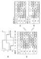
図1は三相交流発電機とバッテリ充電装置の電気的な接続を説明する図である。[Battery charger]
FIG. 1 is a diagram illustrating electrical connection between a three-phase AC generator and a battery charger.
図1に示す三相発電機(以下、発電機)11は、内燃機関のような原動機により駆動される磁石発電機である。磁石発電機は、ヨークに永久磁石を取り付けて界磁を構成するロータ(回転子)12、および、電機子鉄心と当該鉄心に巻回された電機子巻線からなるステータ(固定子)13を有する。ロータ12は原動機の回転軸に取り付けられ、ステータ13は原動機のケースやカバーなどに取り付けられた取付部に固定される。 A three-phase generator (hereinafter referred to as a generator) 11 shown in FIG. 1 is a magnet generator driven by a prime mover such as an internal combustion engine. The magnet generator includes a rotor (rotor) 12 that forms a field by attaching a permanent magnet to a yoke, and a stator (stator) 13 composed of an armature core and an armature winding wound around the iron core. Have. The
発電機11の電機子巻線が出力する三相交流電力は、全波整流器を備えるドライバ14により直流電力に変換され、二次電池であるバッテリ15に供給され、バッテリ15を充電する。なお、図1には電機子巻線をデルタ結線した例を示すが、スター結線にしてもよい。 The three-phase AC power output from the armature winding of the
バッテリ15の充電において、制御回路16は、ドライバ14の各ダイオードに並列に配置されたスイッチング素子を通電状態または非通電状態に制御して電機子巻線に制御電圧を印加し、バッテリ15の充電電圧として適切な電圧が得られるように発電機11の出力電圧を制御する。つまり、制御回路16は、バッテリ15の端子電圧VBを検出して、端子電圧VBが所定電圧VTとなるように、ドライバ14の複数のスイッチング素子を通電状態または非通電状態に制御する。In charging the
位置検出部17は、発電機11のロータ12に固定されたリラクタと、リラクタに対向するように例えば発電機11の取付部に固定されたパルス発生器を備え、ロータ12と伴に回転するリラクタがパルス発生器の近傍を通過する度にリラクタの検知を表す位置検出信号Tpを発生する。 The
制御回路16のCPU161は、RAM162をワークメモリとして、ROM163に格納された各種制御プログラムを実行し、車両の各部の制御を実行する。制御プログラムには、実施例の充電制御に関するプログラムが含まれる。制御回路16は、バッテリ15の端子電圧VBを検出するためのアナログディジタル変換器(ADC)165を有する。さらに、制御回路16は、ドライバ14の各スイッチング素子を通電状態または非通電状態に制御するための駆動信号を出力し、位置検出部17が出力する位置検出信号Tpを入力するための入出力ポート(IO)164を有する。The
[充電制御の概要]
図2はバッテリ充電装置による充電制御の概要を説明するためのタイミングチャートである。[Overview of charge control]
FIG. 2 is a timing chart for explaining the outline of the charging control by the battery charging device.
図2(a)は、原動機の回転数Neが安定状態にある場合の位置検出信号Tpと例えばU相の通電周期の関係を示している。図2(a)において、位置検出信号Tpは電気角360度ごとに立ち下がり、位置検出信号Tpが立ち下がった後、電気角が所定角度進むとU相の通電周期が開始され、さらに電気角が180度進むとU相の通電周期が終了する状態を示している。 FIG. 2 (a) shows the relationship between the position detection signal Tp and the energization cycle of the U phase, for example, when the rotational speed Ne of the prime mover is in a stable state. In FIG. 2 (a), the position detection signal Tp falls every 360 degrees of electrical angle, and after the position detection signal Tp falls, when the electrical angle advances by a predetermined angle, the U-phase energization cycle starts, and the electrical angle Shows a state in which the energization cycle of the U phase ends when the angle advances 180 degrees.
CPU161は、位置検出信号Tpの立ち下がりを検出し、位置検出信号Tpの立ち下がりの間隔を測ることによって発電機11の発電周期を測定して、その測定結果から続く発電周期を予測する。なお、以下では、CPU161が位置検出信号Tpの立ち下がりを検出したことを単に「Tpの検出」「Tpの入力」などと記載する。また、予測発電周期を「予測周期」と記載する。 The
図2(a)に示す周期測定M0の結果から当該発電周期に続く発電周期(図2(a)に示す予測周期TE-2)を予測してもよいが、回転数Neの変動を考慮して、過去の発電周期の測定結果を含めて発電周期を予測する。つまり、例えば過去の発電周期の測定結果から回転数Neが増加傾向にあるのか減少傾向にあるのかを判定し、その判定結果を加味した発電周期を予測する。例えば、図2(a)において、周期測定M0からM2の測定結果から予測周期TE0が予測される。2 may be predicted to result from subsequent to the power generation cycle power generation period of the periodic measurement M0 as shown in (a) (estimated cycle TE-2 shown in FIG. 2 (a)), but considering the variation of the rotational speed Ne Then, the power generation cycle is predicted including the measurement result of the past power generation cycle. That is, for example, it is determined whether the rotational speed Ne tends to increase or decrease from the measurement results of the past power generation cycle, and the power generation cycle that takes into account the determination result is predicted. For example, in FIG. 2 (a), the estimated cycle TE0 from the measurement result of M2 from the cycle measurement M0 is predicted.
通電周期を開始する基準は、例えばU相の誘起電圧が負電圧から正電圧へ反転(以下、負→正反転)するタイミングである。図2(a)には、Tpの検出タイミングとU相の負→正反転タイミングに相当する通電周期の開始基準の間に若干の差がある例を示す。このタイミング差は位置検出部17の配置に関連し、タイミング差に相当する電気角は常に一定である。また、このタイミングは通電周期を進角/遅角制御することで変化する。進角/遅角制御については後述する。従って、予測周期TEが得られれば、Tpの検出後、どのタイミングでU相が負→正反転するかを予測可能である。例えば、タイミング差に相当する電気角をΔ度とすると、Tpの検出から時間をカウントしてTE・Δ/360秒が経過した時点を通電周期の開始基準とすればよい。 The reference for starting the energization cycle is, for example, the timing at which the induced voltage of the U phase is inverted from a negative voltage to a positive voltage (hereinafter, negative → positive inversion). FIG. 2 (a) shows an example in which there is a slight difference between the Tp detection timing and the energization cycle start reference corresponding to the negative-> positive inversion timing of the U phase. This timing difference is related to the arrangement of the
図3はドライバ14のスイッチング素子の通電パターンを示す図である。図3は一通電周期分の通電パターンを示し、「ON」はスイッチング素子の閉状態(オン、通電状態)を、「OFF」はスイッチング素子の開状態(オフ、非通電状態)を意味する。 FIG. 3 is a diagram showing an energization pattern of the switching element of the
図3(a)にはU相、V相、W相の誘起電圧を模式的に示すが、U相の誘起電圧が負→正反転するタイミングを電気角0度とすると、V相の誘起電圧は120度において、W相の誘起電圧は240度において、それぞれ負→正反転する。 Fig. 3 (a) schematically shows the induced voltages of the U phase, V phase, and W phase. If the electrical angle of the U phase is negative → positive, the electrical angle is 0 degree, the induced voltage of the V phase Is 120 °, and the W-phase induced voltage is 240 °, and negative to positive inversion.
誘起電圧の正負の反転に基づきスイッチング素子の通電を制御する必要があり、各スイッチング素子の開閉の関係をまとめると図3(b)に示す通電パターンになる。図3(b)に示すように、通電パターンは、各相の一周期の六等分に当る電気角60度の位相区分ごとに第一から第六のステージを規定する。CPU161は、Tpの検出を基準として第一から第六のステージをその順に移行させながら、各スイッチング素子の駆動信号を生成する。なお、各ステージの期間は、予測周期TEに対してTE/6(=TE・60/360)と算出される。なお、ステージの位相区分は、60度に限らず、例えば30度など60度以下の電気角でもよい。 It is necessary to control the energization of the switching elements based on whether the induced voltage is positive or negative, and the energization pattern shown in FIG. As shown in FIG. 3 (b), the energization pattern defines the first to sixth stages for each phase section having an electrical angle of 60 degrees corresponding to six equal parts of one phase of each phase. The
このように、通電パターンによって、通電周期における複数のスイッチング素子それぞれの通電状態および非通電状態の切り替え順序が定まる。 Thus, the switching order of the energized state and the non-energized state of each of the plurality of switching elements in the energization cycle is determined by the energization pattern.
図3(b)に示す通電パターンは基準の通電パターンである。一方、図3(c)(d)は、発電量を制御する場合に設定可能な進角パターンと遅角パターンを示す。なお、スイッチング素子QU2、QV2、QW2の通電パターンは、プシュプルペアを組むスイッチング素子QU1、QV1、QW1の通電パターンを反転したパターンであり、図3(c)(d)においてはスイッチング素子QU2、QV2、QW2の通電パターンの記載を省略する。The energization pattern shown in FIG. 3 (b) is a standard energization pattern. On the other hand, FIGS. 3C and 3D show an advance angle pattern and a retard angle pattern that can be set when the power generation amount is controlled. The energization pattern of switching elements QU2 , QV2 , and QW2 is a pattern obtained by inverting the energization pattern of switching elements QU1 , QV1 , and QW1 that form a push-pull pair.Omits the description of the energization pattern of the switching elements QU2 , QV2 , and QW2 .
進角/遅角制御とは、発電周期に対して、スイッチング素子の通電周期を進角側または遅角側に移動させることで、発電機11の発電量の増加、減少を制御するものである。 The advance / retard angle control is to control the increase or decrease of the power generation amount of the
バッテリ電圧VBが所定電圧VT以上であった場合、CPU161は、バッテリ15への充電が過剰であると判断する。そして、続く予測周期TEi+1を決定するとともに通電パターンとして、第二のステージから始まり、第六のステージを経て第一のステージで終わる進角パターン(図3(c))を設定して発電量を減少させることでバッテリ15への過剰な充電を抑制することができる。When the battery voltage VB is equal to or higher than the predetermined voltage VT , the
他方、バッテリ電圧VBが所定電圧VT未満であった場合、CPU161は、バッテリ15への充電が不足であると判断する。そして、続く予測周期TEi+1を決定するとともに通電パターンとして、第六のステージから始まり、第一のステージに移行して、第五のステージで終わる遅角パターン(図3(d))を設定して発電量を増加させることでバッテリ15への充電量を増やすことができる。On the other hand, when the battery voltage VB is less than the predetermined voltage VT , the
このように、制御回路16は、バッテリ電圧VBの状態によって、基準パターン、進角パターン、遅角パターンを切り替え、バッテリ電圧VBが所定電圧VTとなるように進角/遅角制御を行う。Thus, the
次に、図2(b)に戻り、原動機の回転変動が発生した場合の充電制御を説明する。図2(b)は原動機の回転変動により発電周期が長くなった場合の、Tpと各相の通電周期の関係を示している。ただし、説明を容易にするために、図2(b)においては、上記のタイミング差を零(Δ=0)として記載する。 Next, returning to FIG. 2 (b), the charging control when the rotational fluctuation of the prime mover occurs will be described. FIG. 2 (b) shows the relationship between Tp and the energization cycle of each phase when the power generation cycle becomes longer due to the rotational fluctuation of the prime mover. However, for ease of explanation, the timing difference is described as zero (Δ = 0) in FIG.
予測周期TE2においては、当該予測周期の終わりまでにTpが検出されず、さらに期間t1が経過した後、Tpが検出される。この場合、CPU161は、予測周期TE2の終了後、当該予測周期の終了時における各スイッチング素子の通電状態または非通電状態を維持するとともに、当該予測周期の終了から時間tのカウントを開始する。なお、以下では、各スイッチング素子の通電状態または非通電状態を維持することを「状態維持」と呼ぶ。The prediction period TE2 is not detected Tp is the end of the prediction period, after further period t1 has elapsed, Tp is detected. In this case,
時間tのカウントが所定の制限期間Tmaxに達する前にTpが検出された場合、CPU161は、続く予測周期TE3を決定し、次の通電周期を開始する。つまり、予測周期TE2の終了後のカウント時間t1は、制限期間Tmaxに達せず(t1<Tmax)、期間t1において状態維持が行われる。If the count time t is Tp before reaching the predetermined limit period Tmax is detected,
次の予測周期TE3においては、再び、当該予測周期の終わりまでにTpが検出されず、さらに期間t2+t3が経過した後、Tpが検出される。この場合も、CPU161は、予測周期TE3の終了後、当該予測周期の終了時に対応する状態維持を行うとともに、当該予測周期の終了から時間tのカウントを開始する。In the next prediction period TE3 , Tp is not detected again by the end of the prediction period, and Tp is detected after a period t2 + t3 has elapsed. Again,
Tpが検出されずに、時間tのカウントが制限期間Tmaxに達した場合、CPU161は、スイッチング素子QU1、QV1、QW2を開状態にし、スイッチング素子QU2、QV2、QW2を閉状態にする全相ショート状態(全相短絡)を設定し、時間tのカウントを継続する。その後、t2+t3のタイミングでTpが検出されると、CPU161は、続く予測周期TE4を決定し、次の通電周期を開始する。つまり、予測周期TE3の終了後のカウント時間t2は制限期間Tmaxに達するため、次にTpが検出されるまでの期間(t2からt3に至る期間)は全相ショート状態が設定される。Tp is not detected, if the counting of the time t has reached the limit time Tmax,
状態維持期間の上限である制限期間Tmaxは、例えば、当該予測周期TEに比例して設定される。つまり、予測周期TEに対する制限期間Tmaxの割合をk1として、制限期間Tmax=k1・TEと計算される。また、状態維持期間は、予測周期TEの所定の位相角として制御してもよい。 For example, the limit period Tmax that is the upper limit of the state maintenance period is set in proportion to the prediction cycle TE. That is, the limit period Tmax = k1 · TE is calculated with the ratio of the limit period Tmax to the prediction period TE as k1. Further, the state maintaining period may be controlled as a predetermined phase angle of the prediction cycle TE.
[充電制御]
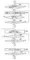
図4Aと図4Bは通電制御の一例を示すフローチャートである。通電制御は、CPU161によって実行され、PI制御によりバッテリ電圧VBを目標電圧VTに収束させる処理である。CPU161は、位置検出信号Tpを常時監視し、Tpを検出すると、ステップS11から始まる処理を開始する。[Charge control]
4A and 4B are flowcharts showing an example of energization control. The energization control is a process that is executed by the
CPU161は、直前のTpの検出タイミングと、一つ前のTpの検出タイミングから発電周期Piを算出し(S11)、下式により、例えば電気角720度前に予測した発電周期の変化量ΔPを考慮した予測周期TEiを算出する(S12)。
TEi = Pi + ΔP・k2 …(1)
ここで、k2は所定の係数。CPU161 includes a detection timing immediately before the Tp, calculate the power cycle Pi from the detection timing of the previous Tp (S11), by the following equation, for example the change amount ΔP of the power generation period predicted electrical angle of 720 degrees before the The prediction cycle TEi taking into account is calculated (S12).
TEi = Pi + ΔP ・ k2 (1)
Here, k2 is a predetermined coefficient.
例えば、図2に示す予測周期TE0を算出する場合、直前のTpの検出タイミングはT0に、一つ前のTpの検出タイミングはT-1に、変化量ΔPの予測タイミングはT-2にそれぞれ相当する。For example, when calculating the prediction cycle TE0 shown in FIG. 2, the detection timing of the previous Tp is T0 , the detection timing of the previous Tp is T−1 , and the prediction timing of the change amount ΔP is T−2 Respectively.
次に、CPU161は、Tpの検出間隔から発電周期に対応する進角側と遅角側の通電位相角制限値θLを決定する(S13)。そして、現在のバッテリ電圧VBを取得し(S14)、バッテリ電圧VBと目標電圧VTの差である現在の電圧偏差ΔViを算出する(S15)。Next,
次に、CPU161は、電圧偏差ΔViの値を基に通電位相角θiを算出し(S16)、算出した通電位相角θiが許容範囲にあるか否かを判定する(S17)。通電位相角θiが許容範囲外の場合は、通電位相角θiを通電位相角制限値θLに変更する(S18)。そして、通電位相角θiを基に、基準パターン、進角パターンおよび遅角パターンの中から通電パターンを決定し、決定した通電パターンに基づき各スイッチング素子の通電タイミングを決定する(S19)。Next, the
次に、CPU161は、予測周期TEiに基づき制限期間Tmaxを算出する(S20)。Next, the
次に、CPU161は、上述したタイミング差TEi・Δ/360秒をカウントし、通電周期の開始基準のタイミングをTpの検出により判定する(S21)。開始基準のタイミングになると、ステップS19で決定した通電タイミングに従い各スイッチング素子を駆動する駆動信号を出力する(S22)。そして、予測周期TEiが終了したか否かを判定し(S23)、未了の場合はTpを検出したか否かを判定し(S24)、未検出の場合は処理をステップS22に戻して駆動信号の出力を継続する。また、ステップS24でTpが検出されると、CPU161は、処理をステップS11に戻し、ステップS11以降の処理を繰り返す。Next, the
Tpの検出前に予測周期TEiが終了した場合、CPU161は、状態維持を行い、時間tのカウントを開始する(S25)。そして、時間tが制限期間Tmaxに達したか否かを判定し(S26)、t<Tmaxの場合はTpを検出したか否かを判定し(S27)、未検出の場合は処理をステップS26に戻して制限時間の判定を繰り返す。また、ステップS27でTpが検出されると、CPU161は、処理をステップS11に戻し、ステップS11以降の処理を繰り返す。If the prediction cycle TEi ends before the detection of Tp, the
Tpの検出前に時間tが制限期間Tmaxに達すると、CPU161は、全相ショート状態を設定する(S28)。そして、Tpを検出したか否かを判定し(S29)、Tpを検出すると処理をステップS11に戻し、ステップS11以降の処理を繰り返す。 When the time t reaches the limit period Tmax before the detection of Tp, the
なお、図4に示すフローは一例であり、進角/遅角制御によるバッテリ電圧VBの制御、状態維持期間における制御、状態維持期間が終わった後の全相ショート状態の設定などの処理が実現されるフローであれば、どのようなフローでも構わない。Note that the flow shown in FIG. 4 is an example, and processing such as control of the battery voltage VB by advance / retard control, control during the state maintenance period, and setting of the all-phase short state after the state maintenance period ends are performed. Any flow may be used as long as the flow is realized.
このように、予測周期が実際の発電周期よりも短かった場合、予測周期が終了した後に状態維持を行って発電機11から充電用の電力を取り出す。これにより、発電周期と通電周期の間にずれが生じた場合のバッテリ15の充電効率の低下を抑制することができる。ただし、発電周期が長い場合、それに合わせて状態維持期間が長くなると、スイッチング素子に過大な電流が流れる虞がある。これを防ぐために、状態維持期間の上限である制限期間Tmaxを設け、状態維持期間が制限期間Tmaxに達した場合は全相ショート状態を設定する。 As described above, when the prediction cycle is shorter than the actual power generation cycle, the state is maintained after the prediction cycle is completed, and the power for charging is taken out from the
上記では、位置検出信号Tpの立ち下がりを基準として通電周期を開始する例を説明したが、位置検出信号Tpの立ち上がりを基準として通電周期を開始してもよい。その場合、「Tpの検出」「Tpの入力」は、CPU161が位置検出信号Tpの立ち上がりを検出したことに相当する。 In the above description, the energization cycle is started based on the falling edge of the position detection signal Tp. However, the energization cycle may be started based on the rising edge of the position detection signal Tp. In this case, “Tp detection” and “Tp input” correspond to the
[回転変動に対する追従]
図5は内燃機関の実回転数と予測回転数の関係例を示す図であり、予測回転数は1/予測周期に相当する。なお、発電機の極数が複数の場合、予測回転数は1/(予測回転数×発電機極数)になる。図5において、実線のカーブは内燃機関の実回転数を表し、破線のカーブは予測回転数を示す。また、矢印↑はスロットル開度を表す。[Following rotation fluctuation]
FIG. 5 is a diagram showing an example of the relationship between the actual rotational speed and the predicted rotational speed of the internal combustion engine, and the predicted rotational speed corresponds to 1 / predicted cycle. When the number of poles of the generator is plural, the predicted rotation speed is 1 / (predicted rotation speed × generator pole number). In FIG. 5, the solid curve represents the actual rotational speed of the internal combustion engine, and the broken curve represents the predicted rotational speed. An arrow ↑ represents the throttle opening.
タイミングt1におけるスロットル開度とタイミングt2におけるスロットル開度の間にはスロットル開度の大きな変化はなく、実回転数の変動が比較的小さいため、位置検出部17が出力する位置検出信号Tpに基づき予測される回転数は実回転数と略一致する。しかし、タイミングt2の後、スロットルグリップが回されて、タイミングt2におけるスロットル開度とタイミングt3におけるスロットル開度の間には大きな変化が生じる。その結果、実回転数の増加により、予測される回転数は実回転数よりも低くなり、実回転数と予測回転数の間にずれが生じる。 There is no significant change in the throttle opening between the throttle opening at the timing t1 and the throttle opening at the timing t2, and the actual rotational speed fluctuation is relatively small. The predicted number of revolutions is substantially the same as the actual number of revolutions. However, after the timing t2, the throttle grip is turned, and a large change occurs between the throttle opening at the timing t2 and the throttle opening at the timing t3. As a result, due to the increase in the actual rotational speed, the predicted rotational speed becomes lower than the actual rotational speed, and a deviation occurs between the actual rotational speed and the predicted rotational speed.
言い替えれば、位置検出部17が出力する位置検出信号Tpに基づき発電周期を予測する場合、内燃機関の回転に変動が生じると、予測発電周期に対して実際の発電周期が変化して、発電される電力を効率的にバッテリ15に蓄えることができない期間が発生する。 In other words, when the power generation cycle is predicted based on the position detection signal Tp output from the
以下では、予測発電周期と実際の発電周期が一致しなくなるスロットル開度の変化量を「開度変化閾値」と呼ぶ。図5において、タイミングt2におけるスロットル開度に対する、タイミングt3におけるスロットル開度の変化量は、開度変化閾値を超えていることになる。 Hereinafter, the amount of change in the throttle opening at which the predicted power generation cycle does not match the actual power generation cycle is referred to as an “opening change threshold”. In FIG. 5, the amount of change in the throttle opening at timing t3 with respect to the throttle opening at timing t2 exceeds the opening change threshold.
図6は回転変動に追従してバッテリ15を効率的に充電する場合の接続例を示すブロック図である。なお、図1に示す構成と同様の構成には同一符号を付して、その詳細説明を省略する。また、図1に示した制御回路16は電子制御ユニット(ECU)26内に存在するとして、制御回路16の記載を省略する。 FIG. 6 is a block diagram showing a connection example in the case where the
図6において、発電機11のロータ12は、ギヤ、チェイン、ベルトなどを介して内燃機関21に結合され、内燃機関25の回転を基に回転する。内燃機関21と車両の駆動輪25の間には変速装置22が配置され、内燃機関21の回転は変速装置22により減速されて駆動輪25に伝達される。変速装置22の変速位置(変速段)は、車両の側面に配置されたシフトペダル23によって操作される。 In FIG. 6, the
ECU26は、変速装置22に配置された検出器24を介して変速装置22の変速位置を検出することができる。また、ECU26は、車両のハンドルに配置されたスロットルグリップ27の操作状態(回転角度)を検出器28を介してスロットル開度として検出し、スロットル開度に応じて内燃機関21の回転を制御する。 The
図6には、乗員がシフトペダル23によって変速位置を操作する変速装置22を例示した。しかし、車両のハンドルに配置されたシフトアップダウンスイッチの操作に応じて、あるいは、車両の速度と内燃機関21の回転数などに基づき、ECU26によって変速位置が制御される変速装置22でもよい。 FIG. 6 illustrates the
図7は予測発電周期を補正する処理の一例を示すフローチャートである。当該補正処理は、図4Aに示す予測周期TEiの算出(S12)後、制限時間Tmaxの算出(S20)前に、制御部16のCPU161によって実行される。FIG. 7 is a flowchart showing an example of a process for correcting the predicted power generation cycle. The correction process is executed by the
CPU161は、スロットル開度の変動量ΔTHを検出する(S101)。なお、当該変動量ΔTHは、例えば、1ミリ秒当りのスロットルグリップ27の回転角度として検出される。そして、変動量ΔTHが上記の開度変化閾値thを超えているか否かを判定し(S102)、変動量が開度変化閾値以下(ΔTH≦th)の場合は補正処理を終了する。 The
一方、変動量が開度変化閾値を超える(ΔTH>th)場合、CPU161は、次式により、ステップS12で算出した予測周期TEiから内燃機関21の回転数に相当する回転数Neを算出する(S103)。
Ne = k3/TEi …(2)
ここで、k3は予測周期の逆数(ロータ12の回転数)を内燃機関21の回転数に変換する係数。On the other hand, when the fluctuation amount exceeds the opening change threshold (ΔTH> th), the
Ne = k3 / TEi (2)
Here, k3 is a coefficient for converting the reciprocal number of the prediction cycle (the rotational speed of the rotor 12) into the rotational speed of the
次に、CPU161は、変速装置22の変速位置を示す情報を取得する(S104)。そして、マップデータ29を用いて内燃機関21の回転数の増加分ΔNeを予測する(S105)。 Next, the
図8はマップデータ29の一例を示す図である。マップデータ29は変速装置22の変速位置をパラメータとして、スロットル開度の変動量ΔTH[度/ms]に対する内燃機関21の回転数の増加分ΔNe[rpm/ms]を表すデータである。なお、マップデータ29は、予め測定されてROM163などに格納されている。つまり、CPU161は、ステップS105における予測として、変速装置22の変速位置に対応するマップデータ29のカーブを参照して、変動量ΔTHに対応する回転数の増加分ΔNeを取得する。 FIG. 8 is a view showing an example of the
次に、CPU161は、次式により、ステップS103で算出した回転数NeとステップS105で取得した回転数の増加分ΔNeから補正後の予測周期TEiを算出し(S106)、補正処理を終了する。
TEi = k3/(Ne + ΔNe) …(3)Next, the
TEi = k3 / (Ne + ΔNe)… (3)
このように、スロットル開度の変動量ΔTHが開度変化閾値thを超える場合、図4Aと図4Bに示す通電制御におけるステップS20以降の処理は、補正された予測周期TEiに基づき実行されることになる。その結果、内燃機関の回転に生じる変動に対応する補正が予測発電周期に施され、予測発電周期と実際の発電周期のずれが抑制されて、発電される電力を効率的にバッテリ15に蓄えることができる。As described above, when the fluctuation amount ΔTH of the throttle opening exceeds the opening change threshold th, the processing after step S20 in the energization control shown in FIGS. 4A and 4B is executed based on the corrected prediction cycle TEi. It will be. As a result, correction corresponding to fluctuations that occur in the rotation of the internal combustion engine is applied to the predicted power generation cycle, and a deviation between the predicted power generation cycle and the actual power generation cycle is suppressed, so that the generated power can be efficiently stored in the
Claims (12)
Translated fromJapanese前記複数のスイッチング素子それぞれについて通電状態または非通電状態の切り替えを制御する制御部(16)と、
前記三相交流発電機のロータ(12)の位置を表す位置検出信号(Tp)を出力する位置検出部(17)を備え、
前記制御部は、過去の前記位置検出信号を基に前記三相交流発電機の次の予測発電周期(TE)を求め、前記予測発電周期に基づき前記複数のスイッチング素子の次の通電周期を決定する車両用バッテリ充電装置において、
前記制御部は、前記位置検出信号の入力に基づき前記通電周期の開始を判定し、次に前記位置検出信号が入力されるまでの期間が前記通電周期を超えた場合、次に前記位置検出信号が入力されるまでの間、前記複数のスイッチング素子を、前記通電周期を超える直前の前記通電状態または前記非通電状態に維持する維持期間をもつことを特徴とする車両用バッテリ充電装置。The three-phase AC power output from each phase winding of the stator (13) of the three-phase AC generator (11) is converted into DC power by a plurality of switching elements (QU1 , ..., QW2 ), and the DC A driver section (14) for supplying power to the battery (15);
A control unit (16) for controlling switching of the energized state or the non-energized state for each of the plurality of switching elements;
A position detector (17) that outputs a position detection signal (Tp) indicating the position of the rotor (12) of the three-phase AC generator,
The control unit obtains a next predicted power generation period (TE) of the three-phase AC generator based on the past position detection signal, and determines a next power supply period of the plurality of switching elements based on the predicted power generation period. In the vehicle battery charging device,
The control unit determines the start of the energization cycle based on the input of the position detection signal, and if the period until the next position detection signal is input exceeds the energization cycle, then the position detection signal The battery charging device for a vehicle has a maintenance period in which the plurality of switching elements are maintained in the energized state or the non-energized state immediately before exceeding the energization period until is input.
前記制御部は、前記位置検出信号が入力されるごとに、前記通電パターンによって前記複数のスイッチング素子の次の通電タイミングを決定することを特徴とする請求項1から請求項6の何れか一項に記載された車両用バッテリ充電装置。The control unit includes an energization pattern that predetermines a switching order of the energized state and the non-energized state of each of the plurality of switching elements in the energization cycle,
7. The control unit according to claim 1, wherein the controller determines a next energization timing of the plurality of switching elements according to the energization pattern every time the position detection signal is input. The battery charger for vehicles described in 2.
前記制御部は、前記位置検出信号が入力されるごとに前記各相に接続されたスイッチング素子の次の通電タイミングを同時に決定および更新することを特徴とする請求項7に記載された車両用バッテリ充電装置。The energization pattern determines the energization timing of the switching element connected to each phase of the three-phase AC generator,
8. The vehicle battery according to claim 7, wherein the control unit simultaneously determines and updates the next energization timing of the switching element connected to each phase each time the position detection signal is input. Charging device.
前記通電パターンには進角パターンおよび遅角パターンが含まれ、前記制御部は、前記進角パターンまたは前記遅角パターンによって前記スイッチング素子の通電タイミングを決定することを特徴とする請求項7または請求項8に記載された車両用バッテリ充電装置。The control unit detects the battery voltage (VB ) and controls the energization timing to the advance side or the retard side so that the battery voltage becomes a predetermined voltage (VT ),
8. The energization pattern includes an advance angle pattern and a retard angle pattern, and the control unit determines an energization timing of the switching element based on the advance angle pattern or the retard angle pattern. Item 9. The vehicle battery charger according to Item 8.
前記内燃機関のスロットル開度を検出するスロットル開度検出部(28)を備え、
前記制御部は、前記スロットル開度の変化量に基づき前記予測発電周期を補正することを特徴とする請求項1から請求項9の何れか一項に記載された車両用バッテリ充電装置。The rotor rotates based on the rotation of the internal combustion engine (21),
A throttle opening detection unit (28) for detecting the throttle opening of the internal combustion engine,
10. The vehicle battery charging device according to claim 1, wherein the control unit corrects the predicted power generation cycle based on a change amount of the throttle opening.
前記制御部は、前記スロットル開度の変化量と前記変速位置に基づき前記予測発電周期を補正することを特徴とする請求項10に記載された車両用バッテリ充電装置。A shift position detector (24) for detecting a shift position of a transmission (22) disposed between the internal combustion engine and the drive wheel (25) of the vehicle;
11. The vehicle battery charging device according to claim 10, wherein the control unit corrects the predicted power generation cycle based on a change amount of the throttle opening and the shift position.
Priority Applications (5)
| Application Number | Priority Date | Filing Date | Title |
|---|---|---|---|
| JP2014238129AJP6301240B2 (en) | 2014-02-07 | 2014-11-25 | Battery charger for vehicle |
| CA2880580ACA2880580C (en) | 2014-02-07 | 2015-01-28 | Battery charging apparatus for vehicle |
| DE102015201509.2ADE102015201509B4 (en) | 2014-02-07 | 2015-01-29 | Battery charging device for vehicles |
| FR1550798AFR3017499A1 (en) | 2014-02-07 | 2015-02-02 | BATTERY CHARGING APPARATUS FOR VEHICLE |
| US14/613,358US9614397B2 (en) | 2014-02-07 | 2015-02-04 | Battery charging apparatus for vehicle |
Applications Claiming Priority (3)
| Application Number | Priority Date | Filing Date | Title |
|---|---|---|---|
| JP2014022752 | 2014-02-07 | ||
| JP2014022752 | 2014-02-07 | ||
| JP2014238129AJP6301240B2 (en) | 2014-02-07 | 2014-11-25 | Battery charger for vehicle |
Publications (2)
| Publication Number | Publication Date |
|---|---|
| JP2015165763A JP2015165763A (en) | 2015-09-17 |
| JP6301240B2true JP6301240B2 (en) | 2018-03-28 |
Family
ID=53677032
Family Applications (1)
| Application Number | Title | Priority Date | Filing Date |
|---|---|---|---|
| JP2014238129AActiveJP6301240B2 (en) | 2014-02-07 | 2014-11-25 | Battery charger for vehicle |
Country Status (5)
| Country | Link |
|---|---|
| US (1) | US9614397B2 (en) |
| JP (1) | JP6301240B2 (en) |
| CA (1) | CA2880580C (en) |
| DE (1) | DE102015201509B4 (en) |
| FR (1) | FR3017499A1 (en) |
Families Citing this family (6)
| Publication number | Priority date | Publication date | Assignee | Title |
|---|---|---|---|---|
| KR102398884B1 (en)* | 2017-06-09 | 2022-05-18 | 현대자동차주식회사 | Charging system for wound rotor synchronous motor |
| US10473081B1 (en)* | 2018-04-24 | 2019-11-12 | GM Global Technology Operations LLC | Powertrain with AC brushless starter and sensor/sensorless control method |
| US10958082B2 (en)* | 2018-04-25 | 2021-03-23 | Microsoft Technology Licensing, Llc | Intelligent battery cycling for lifetime longevity |
| JP2021160665A (en)* | 2020-04-02 | 2021-10-11 | ヤマハ発動機株式会社 | Device and method of controlling vessel battery, and vessel |
| JP7525289B2 (en)* | 2020-04-16 | 2024-07-30 | ヤマハ発動機株式会社 | Outboard motor, outboard motor control method and ship |
| FR3124599B1 (en)* | 2021-06-29 | 2023-06-23 | Sagemcom Energy & Telecom Sas | Estimation, despite fraud, of the power consumed on a phase |
Family Cites Families (123)
| Publication number | Priority date | Publication date | Assignee | Title |
|---|---|---|---|---|
| GB1604066A (en)* | 1978-05-26 | 1981-12-02 | Chloride Group Ltd | Battery charges in variable reluctance electric motor systems |
| JPS5584858A (en)* | 1978-12-18 | 1980-06-26 | Nippon Denso Co Ltd | Engine control |
| DE68918321T2 (en)* | 1988-04-19 | 1995-01-19 | Shinko Electric Co Ltd | Generator driven by a motor. |
| US5115183A (en)* | 1989-11-13 | 1992-05-19 | Fuji Jukogyo Kabushiki Kaisha | Battery charging system for motor-generator |
| JP2528995B2 (en)* | 1990-03-19 | 1996-08-28 | 株式会社日立製作所 | In-vehicle generator control system |
| JPH04172986A (en)* | 1990-11-07 | 1992-06-19 | Secoh Giken Inc | High speed 3-phase dc motor |
| US5083039B1 (en)* | 1991-02-01 | 1999-11-16 | Zond Energy Systems Inc | Variable speed wind turbine |
| DE4406064B4 (en)* | 1993-02-24 | 2006-07-13 | Hitachi, Ltd. | A vehicle AC generator control system |
| JP3506457B2 (en)* | 1993-04-23 | 2004-03-15 | 東芝キヤリア株式会社 | Startup control method of compressor in air conditioner |
| JP3374491B2 (en)* | 1993-12-24 | 2003-02-04 | 株式会社デンソー | Electric generator for vehicle |
| JP3178503B2 (en)* | 1994-07-01 | 2001-06-18 | 株式会社デンソー | Hybrid vehicle control device |
| JPH0898305A (en)* | 1994-09-29 | 1996-04-12 | Seiko Epson Corp | Travelling device of electric car |
| KR100426140B1 (en)* | 1995-01-10 | 2004-06-26 | 가부시키 가이샤 히다치 카 엔지니어링 | Power source system for a vehicle |
| JPH08336238A (en)* | 1995-06-06 | 1996-12-17 | Nippondenso Co Ltd | Power supply system for vehicle |
| US5648705A (en)* | 1995-09-05 | 1997-07-15 | Ford Motor Company | Motor vehicle alternator and methods of operation |
| US5929577A (en)* | 1995-10-13 | 1999-07-27 | Unitrode Corporation | Brushless DC motor controller |
| JP3052844B2 (en)* | 1995-11-14 | 2000-06-19 | トヨタ自動車株式会社 | Power output device, control method therefor, and drive device |
| FR2747521B1 (en)* | 1996-04-12 | 1998-06-26 | Sgs Thomson Microelectronics | CONTROL OF A MOTOR WITHOUT MANIFOLD |
| JP3304777B2 (en)* | 1996-08-22 | 2002-07-22 | トヨタ自動車株式会社 | Electric vehicle |
| JP3211699B2 (en)* | 1996-09-17 | 2001-09-25 | トヨタ自動車株式会社 | Power output device |
| JP3216589B2 (en)* | 1996-10-29 | 2001-10-09 | トヨタ自動車株式会社 | Power output device, motor control device, and control method thereof |
| KR20000069290A (en)* | 1996-12-03 | 2000-11-25 | 번함.더글라스 알. | Electrical system for turbine/alternator on common shaft |
| JP3099769B2 (en)* | 1997-03-24 | 2000-10-16 | トヨタ自動車株式会社 | Power output device and control method thereof |
| JP3710602B2 (en)* | 1997-07-25 | 2005-10-26 | 国産電機株式会社 | Power generator |
| JP3628855B2 (en)* | 1997-11-18 | 2005-03-16 | 三菱電機株式会社 | Control method and control device for engine intake air amount |
| JP3905219B2 (en)* | 1998-04-09 | 2007-04-18 | トヨタ自動車株式会社 | CHARGE CONTROL DEVICE, CONTROL METHOD, AND POWER OUTPUT DEVICE |
| JP3622529B2 (en)* | 1998-09-11 | 2005-02-23 | トヨタ自動車株式会社 | POWER OUTPUT DEVICE, HYBRID VEHICLE HAVING SAME, AND MOTOR POINT CONTROL METHOD |
| JP4194005B2 (en)* | 1998-12-28 | 2008-12-10 | 本田技研工業株式会社 | Vehicle equipped with engine stop / start control device |
| US6215271B1 (en)* | 1999-05-11 | 2001-04-10 | Satcon Technology Corporation | Charging system having a controlled rectifier bridge and a single voltage sensor |
| US7905813B2 (en)* | 1999-09-28 | 2011-03-15 | Borealis Technical Limited | Electronically controlled engine generator set |
| US6825575B1 (en)* | 1999-09-28 | 2004-11-30 | Borealis Technical Limited | Electronically controlled engine generator set |
| US6239582B1 (en)* | 1999-11-04 | 2001-05-29 | Satcon Technology Corporation | Motor vehicle alternator having a single voltage sensor and a half-wave controlled rectifier bridge for increasing output |
| US6489692B1 (en)* | 1999-12-13 | 2002-12-03 | Capstone Turbine Corporation | Method and apparatus for controlling rotation of magnetic rotor |
| JP4290346B2 (en)* | 2001-02-01 | 2009-07-01 | 本田技研工業株式会社 | Car charging system |
| JP4158363B2 (en)* | 2001-08-01 | 2008-10-01 | アイシン・エィ・ダブリュ株式会社 | Hybrid vehicle drive control device |
| JP4147756B2 (en)* | 2001-08-10 | 2008-09-10 | アイシン・エィ・ダブリュ株式会社 | Electric vehicle drive control device, electric vehicle drive control method, and program |
| JP2003102181A (en)* | 2001-09-25 | 2003-04-04 | Toyota Motor Corp | Power supply system and power supply method |
| JP3918552B2 (en)* | 2001-12-26 | 2007-05-23 | アイシン・エィ・ダブリュ株式会社 | Electric vehicle drive control device, electric vehicle drive control method, and program thereof |
| US6693403B2 (en)* | 2002-02-05 | 2004-02-17 | Delphi Technologies, Inc. | Power failure tolerant motor drives for dual voltage systems |
| JP2004015892A (en)* | 2002-06-05 | 2004-01-15 | Toshiba Corp | Inverter control device and electric vehicle |
| US7989969B2 (en)* | 2002-06-06 | 2011-08-02 | Black & Decker Inc. | Universal power tool battery pack coupled to a portable internal combustion engine |
| WO2004012964A1 (en)* | 2002-08-01 | 2004-02-12 | Japan Storage Battery Co., Ltd. | Vehicle power source device and vehicle using the power source device |
| JP4196637B2 (en)* | 2002-10-17 | 2008-12-17 | 国産電機株式会社 | Internal combustion engine drive power generator |
| JP2004173482A (en)* | 2002-11-05 | 2004-06-17 | Kokusan Denki Co Ltd | Power generating device provided with magnet generator |
| US7102331B2 (en)* | 2003-01-17 | 2006-09-05 | Black & Decker Inc. | Generator with dual cycloconverter for 120/240 VAC operation |
| JP2004248432A (en)* | 2003-02-14 | 2004-09-02 | Toyota Motor Corp | Driving device and automobile equipped with the same |
| JP4124447B2 (en)* | 2003-02-28 | 2008-07-23 | 本田技研工業株式会社 | Engine driven work machine |
| JP2004340055A (en)* | 2003-05-16 | 2004-12-02 | Honda Motor Co Ltd | Hybrid drive system |
| JP3933106B2 (en)* | 2003-07-30 | 2007-06-20 | トヨタ自動車株式会社 | POWER OUTPUT DEVICE, ITS CONTROL METHOD, AND AUTOMOBILE |
| JP3958274B2 (en)* | 2003-10-10 | 2007-08-15 | アイシン・エィ・ダブリュ株式会社 | Discharge control device, discharge control method and program thereof |
| JP4270445B2 (en)* | 2003-10-17 | 2009-06-03 | 本田技研工業株式会社 | Output generator for synchronous generator |
| US7218118B1 (en)* | 2004-04-12 | 2007-05-15 | Brunswick Corporation | Method for monitoring a condition of a battery |
| JP4263656B2 (en)* | 2004-04-23 | 2009-05-13 | トヨタ自動車株式会社 | Engine starter |
| JP4581544B2 (en)* | 2004-08-02 | 2010-11-17 | 国産電機株式会社 | Rotor electric machine rotor position determination method, rotor position determination device, and rotary electric machine control device |
| US7009311B1 (en)* | 2004-08-24 | 2006-03-07 | Delphi Technologies, Inc. | Method for minimizing generator load on internal combustion engine |
| JP4254693B2 (en)* | 2004-11-08 | 2009-04-15 | トヨタ自動車株式会社 | Driving device and automobile equipped with the same |
| JP2006230169A (en)* | 2005-02-21 | 2006-08-31 | Toshiba Corp | Control device for synchronous machine |
| US7215035B2 (en)* | 2005-02-22 | 2007-05-08 | Xantrex Technology, Inc. | Method and apparatus for converting wind generated electricity to constant frequency electricity for a utility grid |
| JP2006344447A (en)* | 2005-06-08 | 2006-12-21 | Kokusan Denki Co Ltd | Vehicular battery/electric unit combined structure |
| JP4561518B2 (en)* | 2005-07-27 | 2010-10-13 | 株式会社日立製作所 | A power generation apparatus using an AC excitation synchronous generator and a control method thereof. |
| JP2007037275A (en)* | 2005-07-27 | 2007-02-08 | Hitachi Ltd | Motor drive device also serving as a charge control device |
| JP4501812B2 (en)* | 2005-08-09 | 2010-07-14 | トヨタ自動車株式会社 | Maximum output setting device, drive device including the same, power output device including the same, automobile equipped with the same, maximum output setting method |
| JP3927584B2 (en)* | 2005-10-26 | 2007-06-13 | 三菱電機株式会社 | Power control device for automobile |
| DE602006012350D1 (en)* | 2005-11-09 | 2010-04-01 | Toyota Motor Co Ltd | BATTERY CONDITION DIAGNOSTIC DEVICE |
| JP4379412B2 (en)* | 2005-12-05 | 2009-12-09 | トヨタ自動車株式会社 | Power steering power control device |
| JP4756590B2 (en)* | 2005-12-28 | 2011-08-24 | 本田技研工業株式会社 | Vehicle power supply device |
| US7425771B2 (en)* | 2006-03-17 | 2008-09-16 | Ingeteam S.A. | Variable speed wind turbine having an exciter machine and a power converter not connected to the grid |
| US8159179B2 (en)* | 2006-03-30 | 2012-04-17 | Shindengen Electric Manufacturing Co., Ltd. | Battery charging device, three-phase voltage generating circuit, three-phase voltage generation method and delay angle control method |
| JP4952031B2 (en)* | 2006-04-14 | 2012-06-13 | トヨタ自動車株式会社 | Power supply device, input / output restriction setting method in power supply device, vehicle and control method thereof |
| JP4135748B2 (en)* | 2006-04-27 | 2008-08-20 | 国産電機株式会社 | Engine control device |
| JP2008005659A (en)* | 2006-06-23 | 2008-01-10 | Toyota Motor Corp | Electric vehicle |
| JP2008125246A (en)* | 2006-11-13 | 2008-05-29 | Matsushita Electric Ind Co Ltd | Motor control device |
| JP4275704B2 (en)* | 2007-03-13 | 2009-06-10 | 三菱電機株式会社 | Power converter for vehicle |
| JP4172523B1 (en)* | 2007-04-24 | 2008-10-29 | トヨタ自動車株式会社 | Vehicle and control method thereof |
| JP4172524B1 (en)* | 2007-04-24 | 2008-10-29 | トヨタ自動車株式会社 | Vehicle and control method thereof |
| US7999496B2 (en)* | 2007-05-03 | 2011-08-16 | GM Global Technology Operations LLC | Method and apparatus to determine rotational position of an electrical machine |
| JP4771176B2 (en)* | 2007-08-27 | 2011-09-14 | 株式会社デンソー | Battery charge / discharge control device |
| JP5158682B2 (en)* | 2007-09-25 | 2013-03-06 | 本田技研工業株式会社 | Power generation control device |
| JP5035895B2 (en)* | 2007-09-27 | 2012-09-26 | 本田技研工業株式会社 | Power generation control device |
| US8098041B2 (en)* | 2007-11-04 | 2012-01-17 | GM Global Technology Operations LLC | Method of charging a powertrain |
| US8248023B2 (en)* | 2007-11-04 | 2012-08-21 | GM Global Technology Operations LLC | Method of externally charging a powertrain |
| KR100957144B1 (en)* | 2007-11-07 | 2010-05-11 | 현대자동차주식회사 | Vehicle generation control device and method |
| FR2924857B1 (en)* | 2007-12-06 | 2014-06-06 | Valeo Equip Electr Moteur | ELECTRICAL SUPPLY DEVICE COMPRISING A RECEPTION UNIT FOR ULTRA CAPACITY STORAGE UNITS |
| JP2009148073A (en)* | 2007-12-14 | 2009-07-02 | Mazda Motor Corp | Method and device for charging battery |
| US20100283242A1 (en)* | 2007-12-26 | 2010-11-11 | Dooley Kevin A | High Voltage Start of an Engine from a Low Voltage Battery |
| JP2009232652A (en)* | 2008-03-25 | 2009-10-08 | Aisin Aw Co Ltd | Rotating electrical machine control system and vehicle driving system including the rotating electrical machine control system |
| US8159078B2 (en)* | 2008-04-21 | 2012-04-17 | Black & Decker Inc. | Portable power driven equipment with internal combustion engine combined battery charging and starting circuit where the battery is a removable battery pack |
| JP4356792B1 (en)* | 2008-05-13 | 2009-11-04 | トヨタ自動車株式会社 | Secondary battery discharge control device |
| JP2010011575A (en)* | 2008-06-25 | 2010-01-14 | Mitsubishi Electric Corp | Vehicle motor control apparatus |
| JP4930482B2 (en)* | 2008-09-30 | 2012-05-16 | 株式会社デンソー | Battery charge / discharge control device |
| JP5245141B2 (en)* | 2008-12-22 | 2013-07-24 | 新電元工業株式会社 | Three-phase AC generator rectification system and battery charger using the same |
| EP2394837B8 (en)* | 2009-02-09 | 2016-12-21 | Toyota Jidosha Kabushiki Kaisha | Power supply system and electric vehicle using the same |
| JP2010200455A (en)* | 2009-02-24 | 2010-09-09 | Toyota Motor Corp | Automobile and discharging method of smoothing capacitor |
| JP5206873B2 (en)* | 2009-06-05 | 2013-06-12 | トヨタ自動車株式会社 | Electric vehicle and method for setting total allowable discharge energy in electric vehicle |
| JP4877382B2 (en)* | 2009-11-20 | 2012-02-15 | トヨタ自動車株式会社 | Hybrid vehicle and control method thereof |
| JP5320311B2 (en)* | 2010-01-18 | 2013-10-23 | 三菱重工業株式会社 | Variable speed generator and control method thereof |
| JP5353725B2 (en)* | 2010-01-20 | 2013-11-27 | 株式会社デンソー | Vehicle generator |
| EP2528189B1 (en)* | 2010-01-22 | 2018-11-28 | Toyota Jidosha Kabushiki Kaisha | Battery charging control system |
| DE112010005527T5 (en)* | 2010-04-28 | 2013-01-31 | Toyota Jidosha Kabushiki Kaisha | Control device for electrical energy storage device and equipped with this vehicle |
| JP5524731B2 (en) | 2010-06-17 | 2014-06-18 | 新電元工業株式会社 | Charge control device |
| JP5469000B2 (en)* | 2010-06-17 | 2014-04-09 | 株式会社マキタ | Electric tool, lock state occurrence determination device, and program |
| JP5439298B2 (en)* | 2010-06-30 | 2014-03-12 | 本田技研工業株式会社 | Discharge control device for electric vehicle |
| JP5464367B2 (en)* | 2010-09-17 | 2014-04-09 | 株式会社デンソー | Rotating electric machine for vehicles |
| JP5549505B2 (en)* | 2010-09-28 | 2014-07-16 | 日産自動車株式会社 | Temperature protection device, motor control device, and temperature protection method |
| JP5564391B2 (en)* | 2010-09-30 | 2014-07-30 | 本田技研工業株式会社 | Control device for battery-assisted bicycle |
| WO2012063287A1 (en)* | 2010-11-10 | 2012-05-18 | 国産電機株式会社 | Control device of rotating electrical machine |
| JP2012139072A (en)* | 2010-12-27 | 2012-07-19 | Mitsubishi Heavy Ind Ltd | Turbocharger power generator |
| CN103518320B (en)* | 2011-05-06 | 2016-04-20 | 新电元工业株式会社 | brushless motor control device and brushless motor control method |
| RU2540416C2 (en)* | 2011-05-17 | 2015-02-10 | Хонда Мотор Ко., Лтд. | Inverter generator |
| JP2012244691A (en)* | 2011-05-17 | 2012-12-10 | Honda Motor Co Ltd | Control device for inverter generator |
| JP5728320B2 (en)* | 2011-07-21 | 2015-06-03 | 川崎重工業株式会社 | Discharge capability estimation device, vehicle control system including the same, and discharge capability estimation method |
| CN104221277B (en)* | 2011-11-22 | 2018-09-18 | 昆腾燃料系统有限责任公司 | Combined charging device and power plant |
| CN103946058B (en)* | 2011-11-25 | 2016-06-22 | 株式会社Ihi | Mobile vehicle and non-contact power transmission device |
| JP2013145616A (en) | 2012-01-13 | 2013-07-25 | Hitachi High-Technologies Corp | Stamper, imprinting device and processed product, as well as processed product manufacturing device and processed product manufacturing method |
| KR101387717B1 (en)* | 2012-02-06 | 2014-04-24 | 엘지전자 주식회사 | Battery charger and electric vehicle having the same |
| JP5452653B2 (en)* | 2012-04-05 | 2014-03-26 | 三菱電機株式会社 | Electric vehicle and charging control method for electric vehicle |
| AU2013308938A1 (en)* | 2012-08-27 | 2015-03-12 | Aerovironment, Inc. | Portable electric vehicle supply equipment |
| JP2014050129A (en)* | 2012-08-29 | 2014-03-17 | Toyota Motor Corp | Power unit |
| JP6050100B2 (en)* | 2012-11-22 | 2016-12-21 | 株式会社デンソー | AC power generation system |
| US9376025B2 (en)* | 2013-02-06 | 2016-06-28 | Lg Electronics Inc. | Charging apparatus and electric vehicle including the same |
| JP6117599B2 (en)* | 2013-04-08 | 2017-04-19 | 本田技研工業株式会社 | Battery charger for vehicle |
| CN108616154B (en)* | 2014-05-18 | 2021-09-14 | 百得有限公司 | Electric tool system |
| JP6359924B2 (en)* | 2014-09-17 | 2018-07-18 | トヨタ自動車株式会社 | Non-contact power transmission / reception system |
- 2014
- 2014-11-25JPJP2014238129Apatent/JP6301240B2/enactiveActive
- 2015
- 2015-01-28CACA2880580Apatent/CA2880580C/ennot_activeExpired - Fee Related
- 2015-01-29DEDE102015201509.2Apatent/DE102015201509B4/enactiveActive
- 2015-02-02FRFR1550798Apatent/FR3017499A1/ennot_activeWithdrawn
- 2015-02-04USUS14/613,358patent/US9614397B2/enactiveActive
Also Published As
| Publication number | Publication date |
|---|---|
| DE102015201509B4 (en) | 2024-02-22 |
| CA2880580A1 (en) | 2015-08-07 |
| JP2015165763A (en) | 2015-09-17 |
| US20150229159A1 (en) | 2015-08-13 |
| FR3017499A1 (en) | 2015-08-14 |
| US9614397B2 (en) | 2017-04-04 |
| DE102015201509A1 (en) | 2015-08-13 |
| CA2880580C (en) | 2017-12-12 |
Similar Documents
| Publication | Publication Date | Title |
|---|---|---|
| JP6301240B2 (en) | Battery charger for vehicle | |
| WO2012090677A1 (en) | Hybrid vehicle system and control method thereof | |
| US9065379B2 (en) | Control device for vehicle generator-motor and control method therefor | |
| EP2704307A1 (en) | Brushless motor control device and brushless motor control method | |
| TW201517504A (en) | Power generation device, mobile object and power generation control method | |
| EP2789494B1 (en) | Battery charging apparatus for vehicle | |
| JP2011173574A (en) | Abnormal condition detecting device for vehicle | |
| KR20090031809A (en) | Power generation controller | |
| JP2009284564A (en) | Power conversion device for vehicle | |
| JP6068192B2 (en) | Battery state estimation device and vehicle control system | |
| JP5151174B2 (en) | Engine power generation control device | |
| JP2012228017A (en) | Controller of generator-motor | |
| JP2013090453A (en) | Control arrangement and control method for power converter | |
| JP6053788B2 (en) | Control device for vehicle alternator | |
| CN111434024B (en) | Method for operating a charge controller for an electrical energy store in a motor vehicle | |
| CN112640294B (en) | Control device | |
| AU2017378158B2 (en) | Adjustable pulse injection in electric machine control | |
| JP6398865B2 (en) | Motor control device | |
| WO2018097014A1 (en) | Fault detection device for rotation sensor | |
| JP6948844B2 (en) | Engine starter | |
| JP6948845B2 (en) | Electronic control device | |
| CN111434025A (en) | Method for determining the rotor angle of an electric machine in a motor vehicle | |
| WO2015181884A1 (en) | Battery charging device | |
| JP2018204553A (en) | Electronic control unit | |
| JP2018204552A (en) | Electronic control unit |
Legal Events
| Date | Code | Title | Description |
|---|---|---|---|
| A621 | Written request for application examination | Free format text:JAPANESE INTERMEDIATE CODE: A621 Effective date:20161129 | |
| A977 | Report on retrieval | Free format text:JAPANESE INTERMEDIATE CODE: A971007 Effective date:20170831 | |
| A131 | Notification of reasons for refusal | Free format text:JAPANESE INTERMEDIATE CODE: A131 Effective date:20170911 | |
| A521 | Request for written amendment filed | Free format text:JAPANESE INTERMEDIATE CODE: A523 Effective date:20171026 | |
| TRDD | Decision of grant or rejection written | ||
| A01 | Written decision to grant a patent or to grant a registration (utility model) | Free format text:JAPANESE INTERMEDIATE CODE: A01 Effective date:20180205 | |
| A61 | First payment of annual fees (during grant procedure) | Free format text:JAPANESE INTERMEDIATE CODE: A61 Effective date:20180228 | |
| R150 | Certificate of patent or registration of utility model | Ref document number:6301240 Country of ref document:JP Free format text:JAPANESE INTERMEDIATE CODE: R150 |