JP6300465B2 - Power receiving device, power receiving device control method, and program - Google Patents
Power receiving device, power receiving device control method, and programDownload PDFInfo
- Publication number
- JP6300465B2 JP6300465B2JP2013166398AJP2013166398AJP6300465B2JP 6300465 B2JP6300465 B2JP 6300465B2JP 2013166398 AJP2013166398 AJP 2013166398AJP 2013166398 AJP2013166398 AJP 2013166398AJP 6300465 B2JP6300465 B2JP 6300465B2
- Authority
- JP
- Japan
- Prior art keywords
- power
- power transmission
- unit
- state
- power receiving
- Prior art date
- Legal status (The legal status is an assumption and is not a legal conclusion. Google has not performed a legal analysis and makes no representation as to the accuracy of the status listed.)
- Active
Links
Images


Classifications
- H—ELECTRICITY
- H02—GENERATION; CONVERSION OR DISTRIBUTION OF ELECTRIC POWER
- H02J—CIRCUIT ARRANGEMENTS OR SYSTEMS FOR SUPPLYING OR DISTRIBUTING ELECTRIC POWER; SYSTEMS FOR STORING ELECTRIC ENERGY
- H02J50/00—Circuit arrangements or systems for wireless supply or distribution of electric power
- H02J50/10—Circuit arrangements or systems for wireless supply or distribution of electric power using inductive coupling
- H—ELECTRICITY
- H02—GENERATION; CONVERSION OR DISTRIBUTION OF ELECTRIC POWER
- H02J—CIRCUIT ARRANGEMENTS OR SYSTEMS FOR SUPPLYING OR DISTRIBUTING ELECTRIC POWER; SYSTEMS FOR STORING ELECTRIC ENERGY
- H02J50/00—Circuit arrangements or systems for wireless supply or distribution of electric power
- H02J50/80—Circuit arrangements or systems for wireless supply or distribution of electric power involving the exchange of data, concerning supply or distribution of electric power, between transmitting devices and receiving devices
- H02J7/025—
- H—ELECTRICITY
- H02—GENERATION; CONVERSION OR DISTRIBUTION OF ELECTRIC POWER
- H02J—CIRCUIT ARRANGEMENTS OR SYSTEMS FOR SUPPLYING OR DISTRIBUTING ELECTRIC POWER; SYSTEMS FOR STORING ELECTRIC ENERGY
- H02J50/00—Circuit arrangements or systems for wireless supply or distribution of electric power
- H02J50/10—Circuit arrangements or systems for wireless supply or distribution of electric power using inductive coupling
- H02J50/12—Circuit arrangements or systems for wireless supply or distribution of electric power using inductive coupling of the resonant type
- H—ELECTRICITY
- H02—GENERATION; CONVERSION OR DISTRIBUTION OF ELECTRIC POWER
- H02J—CIRCUIT ARRANGEMENTS OR SYSTEMS FOR SUPPLYING OR DISTRIBUTING ELECTRIC POWER; SYSTEMS FOR STORING ELECTRIC ENERGY
- H02J7/00—Circuit arrangements for charging or depolarising batteries or for supplying loads from batteries
- H02J7/00032—Circuit arrangements for charging or depolarising batteries or for supplying loads from batteries characterised by data exchange
- H02J7/00034—Charger exchanging data with an electronic device, i.e. telephone, whose internal battery is under charge
Landscapes
- Engineering & Computer Science (AREA)
- Power Engineering (AREA)
- Computer Networks & Wireless Communication (AREA)
- Charge And Discharge Circuits For Batteries Or The Like (AREA)
Description
Translated fromJapanese本発明は、無線電力伝送技術に関する。 The present invention relates to a wireless power transmission technique.
近年、コネクタで接続することなく無線(非接触)で電力を送信する送電装置と、送電装置から供給された電力を受電する受電装置とを含む無線電力伝送システムが知られている。特許文献1の送電装置は、突発的に過剰な電力を消費する場合や、受電装置側において過大な電力を要する場合等に、過電流状態となった場合、送電部への電流を制限することにより無線電力伝送の安全性を向上する技術を記載している。 In recent years, a wireless power transmission system including a power transmission device that transmits power wirelessly (contactlessly) without being connected by a connector and a power reception device that receives power supplied from the power transmission device is known. The power transmission device of Patent Document 1 limits the current to the power transmission unit when an excessive current is suddenly consumed or when excessive power is required on the power receiving device side. Describes a technique for improving the safety of wireless power transmission.
送電装置が第1受電装置に送電中に、ユーザが第2受電装置を送電装置の送電範囲に置き、送電装置が送電出力を変更する前に第2受電装置が受電を開始すると、少なくとも一時的に送電装置が過電流状態となる場合がある。この場合、特許文献1のように送電装置が送電部への入力電流を制限すると、第1受電装置は所望の電力において受電できなくなり、システム全体として送電効率が低下してしまうという問題がある。 If the user places the second power receiving device in the power transmission range of the power transmitting device while the power transmitting device is transmitting power to the first power receiving device, and the second power receiving device starts receiving power before the power transmitting device changes the power transmission output, at least temporarily In some cases, the power transmission device may be in an overcurrent state. In this case, when the power transmission device limits the input current to the power transmission unit as in Patent Document 1, the first power reception device cannot receive power at a desired power, and there is a problem that the power transmission efficiency of the entire system decreases.
本発明は、上述の課題に鑑みてなされた発明であって、無線電力伝送において送電効率と安全性を両立することを目的とする。 The present invention has been made in view of the above-described problems, and an object thereof is to achieve both power transmission efficiency and safety in wireless power transmission.
本発明に係る受電装置は、送電装置に対して無線による電力の伝送を要求する要求手段と、前記送電装置から無線で伝送される電力を受信するためのアンテナと、前記アンテナにおいて受信される電力により動作する負荷手段と、前記要求手段による無線による電力の伝送の要求を行ってから、前記送電装置と予め共有されている所定時間であって、前記要求手段による無線による電力の伝送の要求に基づく無線による電力の伝送を前記送電装置が開始するまでの所定時間の経過後に、前記アンテナを用いて受信された電力を前記負荷手段に供給しない第1状態から前記アンテナを用いて受信された電力を前記負荷手段に供給する第2状態に切り替えるための制御を実行する制御手段と、を有することを特徴とする。A power receiving device according to the present invention includes a request unit that requests wireless transmission of power from a power transmission device, an antenna for receiving power transmitted wirelessly from the power transmission device, and power received by the antenna A request forwireless power transmission by the requesting means, and a predetermined time shared in advance with the power transmission apparatus after the requesting means for requestingwireless power transmission by the requesting means. the radio according to power transmission based on after a predetermined time until the power transmitting device is started, the received power received with theprevious SL antenna from a first state in which no supply to said load means using said antenna Control means for executing control for switching to a second state in which power is supplied to the load means.
本発明によれば、無線電力伝送において送電効率と安全性を両立することができる。 According to the present invention, it is possible to achieve both power transmission efficiency and safety in wireless power transmission.
(実施例1)
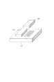
図1は、本実施形態における無線電力伝送システムの構成を示す図である。なお、本実施例に係る無線電力伝送システムは、磁界共鳴方式を用いて無線電力伝送を行うとする。磁界共鳴方式は送電装置の共振器(共鳴素子)と、受電装置の共振器(共鳴素子)との間の磁場の共鳴(共振)による結合によって電力を伝送する方式である。なお、本実施例において、磁界共鳴方式を用いた無線電力伝送システムを例にして説明するが、無線電力伝送方式(非接触電力伝送方法)はこれに限られたものではなく、電磁誘導、電界共鳴、マイクロ波、レーザ(光)等を利用した電力伝送方式を用いてもよい。Example 1
FIG. 1 is a diagram illustrating a configuration of a wireless power transmission system according to the present embodiment. Note that the wireless power transmission system according to the present embodiment performs wireless power transmission using a magnetic field resonance method. The magnetic field resonance method is a method in which electric power is transmitted by coupling by resonance (resonance) of a magnetic field between a resonator (resonance element) of a power transmission device and a resonator (resonance element) of a power reception device. In this embodiment, a wireless power transmission system using a magnetic field resonance system will be described as an example. However, the wireless power transmission system (non-contact power transmission method) is not limited to this, and electromagnetic induction, electric field, A power transmission method using resonance, microwave, laser (light), or the like may be used.
図1において、101は送電装置、102は第一の受電装置、103は第二の受電装置を示す。送電装置101の構成を図2に示す。図2において、201は送電装置101のバッテリまたは外部電源と接続し装置全体に電力を供給する電源部である。202は送電装置101の送信電力の上限を設定する設定部である。設定部202は、送電部203への入力電圧を設定した送信電力の上限を超えないように制限する。203は設定部202から入力される直流又は交流電力を伝送帯の交流周波数電力に変換し、送電アンテナ204を介して受電装置に対して送電を行う送電部である。 In FIG. 1, 101 denotes a power transmission device, 102 denotes a first power reception device, and 103 denotes a second power reception device. The configuration of the
205は送電装置101の各部を制御する制御部である。制御部205は、CPU(Central Processing Unit)により構成され、記憶している制御プログラムを実行することで各ハードウェアを制御して送電処理を実行する。206は無線通信するための通信部である。通信部206は、受電装置と無線電力伝送の制御信号をやり取りする。通信部206は、例えばBluetooth(登録商標)4.0規格に準拠する通信機能を有する。なお、通信部206は、他の通信規格を用いてもよい。例えば、無線LAN(IEEE802.11シリーズ)、NFC(Near Field Communication)などであってもよい。207は制御部205と設定部202との制御信号をやり取りするための制御線である。208は制御部205と送電部203との制御信号をやり取りするための制御線である。209は制御部205と通信部206との制御信号をやり取りするための制御線である。
続いて、第一の受電装置102及び第二の受電装置103の構成を図3に示す。同図において、301は送電装置101から無線で電力を受け取るための受電アンテナである。302は受電アンテナ301で受けた交流電力を直流に整流するための整流回路である。303は、受電した電力で動作する負荷部である。負荷部303は、例えばバッテリであってよい。304は整流回路302と負荷部303の間の接続のオン、オフを切り替えるスイッチ部である。スイッチ部304は受電アンテナと負荷部303とを切断状態から接続状態に切替える。スイッチ部304により接続行う整流回路302と負荷部303が接続されている場合、負荷部303に対して電力供給が行われる。切断状態において、負荷部303は電力供給が断たれるため動作を行えない。接続状態において、負荷部303はアンテナを介して受電した電力を用いて動作することができる。305は整流回路302とスイッチ部304の間の電圧を検出する検出部である。Subsequently, showing the configuration of the first
306は受電装置の各部を制御する制御部である。制御部306は受電アンテナ301を介して受電した電力を用いて動作する。制御部306は、CPUにより構成され、記憶している制御プログラムを実行することで各ハードウェアを制御して受電処理を実行する。307は無線通信するための通信部である。通信部307は、送電装置と無線電力伝送の制御信号をやり取りする。通信部307は、要求する電力値を含めて送電を要求するメッセージを送電装置に送信する。通信部307は、受電アンテナ301を介して受電した電力を用いて動作する。通信部307は、例えばBluetooth(登録商標)4.0規格に準拠する通信機能を有する。なお、通信部307は、他の通信規格を用いてもよい。例えば、無線LAN(IEEE802.11シリーズ)、NFC(Near Field Communication)などであってもよい。整流回路302の出力を308は制御部306と通信部307を動作させるための電圧に変換する直流―直流電圧変換部である。309は制御部306とスイッチ部304との制御信号、310は制御部306と検出部305との制御信号をやり取りするための制御線である。311は制御部306と通信部307との制御信号をやり取りするための制御線である。306 is a control unit for controllingeach partof the power receiving device. The
306は受電装置の各部を制御する制御部である。制御部306は受電アンテナ301を介して受電した電力を用いて動作する。制御部306は、CPUにより構成され、記憶している制御プログラムを実行することで各ハードウェアを制御して受電処理を実行する。307は無線通信するための通信部である。通信部307は、送電装置と無線電力伝送の制御信号をやり取りする。通信部307は、要求する電力値を含めて送電を要求するメッセージを送電装置に送信する。通信部307は、受電アンテナ301を介して受電した電力を用いて動作する。通信部307は、例えばBluetooth(登録商標)4.0規格に準拠する通信機能を有する。なお、通信部307は、他の通信規格を用いてもよい。例えば、無線LAN(IEEE802.11シリーズ)、NFC(Near Field Communication)などであってもよい。整流回路302の出力を308は制御部306と通信部307を動作させるための電圧に変換する直流―直流電圧変換部である。309は制御部306とスイッチ部304との制御信号、310は制御部306と検出部305との制御信号をやり取りするための制御線である。311は制御部306と通信部307との制御信号をやり取りするための制御線である。306 is a control unit for controllingeach partof the power receiving device. The
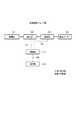
まず、送電装置101は、動作開始後、初期設定の送信電力にセットする(S401)。説明のため、初期設定の送信電力を6Wとする。送電装置101の制御部205は、設定部202に対し、6Wをセットする。そして、送電部203は、受電装置の制御部306および通信部311が動作するための認証用電力の送電を開始する(S403)。第一の受電装置102は、動作開始後、スイッチ部304を切断し、整流回路302と負荷部303との接続を切り離す(S402)。第一の受電装置102は、送電装置101上に置かれると、認証用電力を受電し、制御部306および通信部311に受電した電力を供給する。 First, after starting the operation, the
第一の受電装置102は送電装置101に通信部307を用いて認証要求を通知する(S404)。認証要求は送電装置に対して送電を要求するメッセージということができる。また。認証要求には送電を要求する電力値が含まれている。なお、認証要求と同時に必要な電力を通知してもよいし、認証終了後に通知してもよい。説明のため、第一の受電装置102の要求電力を5Wとし、認証要求と同時に要求電力を通知するものとする。 The first
送電装置101の制御部205は、通信部206を介して受電装置から認証要求を受信すると、認証を行う。この認証は、例えば送受電装置間で対応する無線電力伝送の規格があるか否かを判定するために互いに対応する無線電力伝送の規格に関する情報を通信し、該通信した情報に基づいて認証を行う。また、例えば、送受電装置間で送受可能な電力が互いに対応するか否かを判定するために互いに送受可能な電力に関する情報を通信し、該通信した情報に基づいて認証を行う。また、例えば、送受電装置間で送受する電力のネゴシエーションのための情報を通信し、該通信した情報に基づいて認証を行う。 When the
また、送電装置101は、現在の出力上限の設定で受信した要求電力に応じた送電を行えるかの判断を行う。この例では、出力上限6Wに対し、第一の受電装置102から5W要求された場合、現在の出力上限の設定で受信した要求電力に応じた送電を行えると判断する。現在の出力上限の設定で受信した要求電力に応じた送電を行えないと判定した場合は、出力上限を再設定する。なお、受信した受電装置の要求電力が送電装置の能力を超える場合は、認証拒否を受電装置に送信する。 In addition, the
送電装置101の制御部205は認証の可否を判断し、認証が成功されると認証要求に対する応答として受電許可通知を通信部206を介して第1の受電装置102に送信する(S405)。なお、送電装置101は認証が失敗した場合は、認証要求に対する応答として認証拒否通知を送信する。 The
第一の受電装置102は認証要求に対する応答として受電許可通知を受信すると、要求した電力に応じた送電装置の送電出力の変更を検出したとして、スイッチ部304を接続状態にする(S405)。受電許可通知は、スイッチ部304を接続状態に切替える指示するための情報ということができる。そして、送電装置101から送電された電力を第1の受電装置102は受電し、受電した電力を負荷部303に供給する(S406)。 When the first
送電装置101が第1の受電装置102に送電中に、第二の受電装置103が受電動作を開始したとする。第2の受電装置102は、動作開始後、スイッチ部304を切断し、整流回路302と負荷部303を切り離す(S407)。第二の受電装置103は、送電装置101上に置かれると、送電装置101が送電中の電力の一部を受電し、制御部306および通信部311に受電した電力を供給する。第二の受電装置102は送電装置101に通信部307を用いて認証要求を通知する(S408)。説明のため、第二の受電装置103の要求電力を5Wとし、該要求電力を通知するものとする。認証要求を受信した送電装置101は、第二の受電装置103の認証の可否を判断する。また、送電装置101は、現在の出力上限の設定で受信した要求電力に応じた送電を行えるかの判断を行う。この例では、出力上限6Wに対し、第一の受電装置102へ5W送電しているので、第二の受電装置103の要求電力5Wを加えると、出力上限を超える。送電装置101は、現在の出力上限の設定で受信した要求電力に応じた送電を行えないと判断した場合、出力上限の再設定を行う(S410)。この場合、送電装置101の制御部306は、設定部202を合計10Wが送電出来る値(例えば12W)に変更する。なお、第二の受電装置103に受電停止を通知する(S410)。なお、現在の出力上限の設定で受信した要求電力に応じた送電を行えないと判断した場合、送電装置101は受電を要求した受電装置にスイッチ部304を接続状態に切替える制御を待機することを通知するメッセージを送信するようにしてよい。 Assume that the second
送電装置101の制御部205は、設定部202を再設定して要求された電力を送電可能になった場合、通信部307を介して第二の受電装置103に受電許可通知を通信部206を介して送信する。(S411)。第二の受電装置102は受電許可通知を受信すると、スイッチ部304を接続状態にする(S412)。そして、送電装置101は、第二の受電装置102に対しても送電を開始し、第二の受電装置102は送電装置101から5Wの受電を開始する(S413)。なお、送電装置101は、定期的に送電出力をモニタし、設定した出力上限が適切かを判定する。出力上限に応じた閾値以下に送電出力となった場合通信部206を用いて受電装置の存在を確認する。そして、確認できた受電装置に合わせて出力上限を下げるように再設定を行う。この処理はユーザによって受電装置を不意に持ち去られるようなケースに対応するためのものである 。なお、送電装置は受電装置から受電を終了するメッセージを受信した場合に出力上限を下げるように再設定を行うようにしてよい。 When the
このように本実施例における受電装置は、送電装置から受電許可通知を受信したタイミング受電アンテナと負荷部とを接続する。即ち、送電装置が新たな受電装置に対する送電を考慮した出力の開始と同期して新たな受電装置が消費電力を増加させるので、送電装置において過電流状態となることが低減される。したがって、送電装置において過電流状態となることがないので、送電を停止したり、出力電力を制限したりすることが低減され、既に受電中の受電装置に対する送電効率が低下することが低減される。このように、本実施形態の無線電力伝送システムによれば、送電装置が過電流状態となることが低減されることにより安全性を向上することができると共に送電を停止したり、出力電力を制限したりすることが低減されるので送電効率を損なうことも低減される。As described above, the power receiving device in the present embodiment connects the timing power receiving antenna that has received the power reception permission notification from the power transmitting device and the load unit. That is, sincea new power receiving apparatus increases the power consumption in synchronization with the start of output of the power transmitting device considering transmission for a new power receiving apparatus, it is reduced as the overcurrent state in the power transmitting apparatus. Therefore, since an overcurrent state does not occur in the power transmission device, stopping power transmission or limiting output power is reduced, and reduction in power transmission efficiency for a power reception device that is already receiving power is reduced. . As described above, according to the wireless power transmission system of the present embodiment, it is possible to improve the safety by reducing the overcurrent state of the power transmission device, and stop power transmission or limit the output power. Therefore, the loss of transmission efficiency is also reduced.
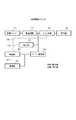
続いて第一の受電装置102及び第二の受電装置103の動作を図5に示すフローチャートを用いて説明する。受電装置は、動作開始後(S601)、スイッチ部304を切断し、整流回路302と負荷部303を切り離す(S602)。そして、受電アンテナ301を介して電力を受電すると、受電した電力を制御部306および通信部307に供給する。そして、制御部306は、通信部307を介して送電装置に要求する電力を含む認証要求を送信する(S603)。制御部306は、通信部307を介して許可通知または認証不可通知の受信に基づいて、送電装置による認証の可否を判断する(S604)。認証が失敗した場合は、処理を終了する。認証が成功した場合は、制御部306は、スイッチ部307を制御し、整流回路302と負荷部303とを接続し、負荷部303へ受電した電力の供給を開始する(S605、S606)。制御部306は、受電を終了するかを判定する(S607)受電を終了すると判定した場合は、終了通知を送電装置に送信し、処理を終了する(S608、S609)。また、処理を終了する前に、スイッチ部304を切断状態にするようにしてよい。このようにすると、次回の受電処理においてS602の処理を省略することができる。 Next, operations of the first
なお、上述の説明では、送電装置からのメッセージの受信に応じて受電装置がスイッチを切替えたが、受電装置が、送電装置の送電出力の変更を検知して受電を開始するようにしてよい。例えば、第二の受電装置103の検出部305による検出結果に基づいてスイッチ部304を接続するようにしてよい。図6において701は、時間と検出部305の検出結果を示している。図6において702は受電装置からの要求に応じて送電装置101が送電出力を上げ始めるタイミングである。検出部305は電圧が上がり始めたことを検知する。そして703点に示すように、検出部305は電圧が上昇し、安定する。検出部305で電圧の上昇と、安定を確認することで、送電装置101が出力上限を変更したことが検知できる。第二の受電装置103の制御部306と通信部307が5V、20mAで動作するケースを一例として説明する。第二の受電装置103の制御部306と通信部307は20mA消費するため、送電装置101が出力を5W増やすと、検出部305の電圧は250Vまで上昇する。検出部305の電圧が250Vとなると、送電装置101で出力上限の変更が終了したものと判断し、スイッチ部304を制御し、接続状態にし、送電装置101から5Wの受電を開始するようにしてよい。 In the above description, the power receiving device switches the switch in response to the reception of the message from the power transmitting device. However, the power receiving device may detect a change in the power transmission output of the power transmitting device and start receiving power. For example, the
また、送電装置101が出力上限を変更するまでの時間を決めておき、所定時間経過後、第二の受電装置103が受電を開始するようにしてよい。 Alternatively, a time until the
(その他の実施例)
また、本発明は、以下の処理を実行することによっても実現される。即ち、上述した実施形態の機能を実現するソフトウェア(プログラム)を、ネットワーク又は各種記憶媒体を介してシステム或いは装置に供給し、そのシステム或いは装置のコンピュータ(またはCPUやMPU等)がプログラムを読み出して実行する処理である。(Other examples)
The present invention can also be realized by executing the following processing. That is, software (program) that realizes the functions of the above-described embodiments is supplied to a system or apparatus via a network or various storage media, and a computer (or CPU, MPU, or the like) of the system or apparatus reads the program. It is a process to be executed.
Claims (13)
Translated fromJapanese送電装置に対して無線による電力の伝送を要求する要求手段と、
前記送電装置から無線で伝送される電力を受信するためのアンテナと、
前記アンテナにおいて受信される電力により動作する負荷手段と、
前記要求手段による無線による電力の伝送の要求を行ってから、前記送電装置と予め共有されている所定時間であって、前記要求手段による無線による電力の伝送の要求に基づく無線による電力の伝送を前記送電装置が開始するまでの所定時間の経過後に、前記アンテナを用いて受信された電力を前記負荷手段に供給しない第1状態から前記アンテナを用いて受信された電力を前記負荷手段に供給する第2状態に切り替えるための制御を実行する制御手段と、
を有することを特徴とする受電装置。A power receiving device,
Request means for requesting the power transmission device to transmit power wirelessly;
An antenna for receiving power transmitted wirelessly from the power transmission device;
Load means operating with power received at the antenna;
After performing a requestfor power transmission by radio by the request means, the power transmission device with a predetermined time which is previously shared, the power transmission by radio based on requirementsof the power transmission of the wireless by said request means After the elapse of a predetermined time until the power transmission apparatus starts, the power received using the antenna is supplied to the load unit from the first state where the power received using the antenna is not supplied to the load unit. Control means for executing control for switching to the second state;
A power receiving device comprising:
前記制御手段は、前記検出手段による送電電力の変化の検出に応じたタイミングで、前記第1状態から前記第2状態に切り替えることが可能であることを特徴とする請求項1に記載の受電装置。Detecting means for detecting a change in transmitted power of the power transmission device;
2. The power receiving device according to claim 1, wherein the control unit is capable of switching from the first state to the second state at a timing according to detection of a change in transmission power by the detection unit. .
前記制御手段は、前記検出手段による受電電力の変化の検出に応じたタイミングで、前記第1状態から前記第2状態に切り替えることが可能であることを特徴とする請求項1に記載の受電装置。Detecting means for detecting a change in received power of the power receiving device;
2. The power receiving device according to claim 1, wherein the control unit is capable of switching from the first state to the second state at a timing according to detection of a change in received power by the detecting unit. .
送電装置に対して無線による電力の伝送を要求する要求工程と、
前記要求工程における無線による電力の伝送の要求を行ってから、前記送電装置と予め共有されている所定時間であって、前記要求工程における無線による電力の伝送の要求に基づく無線による電力の伝送を前記送電装置が開始するまでの所定時間の経過後に、前記アンテナを用いて受信された電力を負荷手段に供給しない第1状態から前記アンテナを用いて受信された電力を前記負荷手段に供給する第2状態に切り替えるための制御を実行する制御工程と、
を有することを特徴とする受電装置の制御方法。A method for controlling a power receiving apparatus having an antenna for receiving power transmitted wirelessly from a power transmitting apparatus,
A requesting process for requesting the power transmission device to transmit power wirelessly;
After performing a requestfor power transmission by radio in the request step, the power transmission device with a predetermined time which is previously shared, the power transmission by radio based on requirementsof the power transmission of the wireless in said request step After the elapse of a predetermined time until the power transmission device starts, a first state in which the power received using the antenna is supplied to the load means from the first state where the power received using the antenna is not supplied to the load means. A control process for executing control for switching to two states;
A method for controlling a power receiving apparatus.
Priority Applications (5)
| Application Number | Priority Date | Filing Date | Title |
|---|---|---|---|
| JP2013166398AJP6300465B2 (en) | 2013-08-09 | 2013-08-09 | Power receiving device, power receiving device control method, and program |
| GB1603753.3AGB2532401A (en) | 2013-08-09 | 2014-07-18 | Power receiving apparatus |
| US14/910,239US20160190871A1 (en) | 2013-08-09 | 2014-07-18 | Power receiving apparatus, method of controlling power receiving apparatus, and program |
| PCT/JP2014/003833WO2015019560A1 (en) | 2013-08-09 | 2014-07-18 | Power receiving apparatus |
| CN201480045114.6ACN105453378B (en) | 2013-08-09 | 2014-07-18 | Power receiving equipment |
Applications Claiming Priority (1)
| Application Number | Priority Date | Filing Date | Title |
|---|---|---|---|
| JP2013166398AJP6300465B2 (en) | 2013-08-09 | 2013-08-09 | Power receiving device, power receiving device control method, and program |
Publications (3)
| Publication Number | Publication Date |
|---|---|
| JP2015035911A JP2015035911A (en) | 2015-02-19 |
| JP2015035911A5 JP2015035911A5 (en) | 2016-09-15 |
| JP6300465B2true JP6300465B2 (en) | 2018-03-28 |
Family
ID=51453786
Family Applications (1)
| Application Number | Title | Priority Date | Filing Date |
|---|---|---|---|
| JP2013166398AActiveJP6300465B2 (en) | 2013-08-09 | 2013-08-09 | Power receiving device, power receiving device control method, and program |
Country Status (5)
| Country | Link |
|---|---|
| US (1) | US20160190871A1 (en) |
| JP (1) | JP6300465B2 (en) |
| CN (1) | CN105453378B (en) |
| GB (1) | GB2532401A (en) |
| WO (1) | WO2015019560A1 (en) |
Families Citing this family (9)
| Publication number | Priority date | Publication date | Assignee | Title |
|---|---|---|---|---|
| JP6590497B2 (en) | 2015-03-18 | 2019-10-16 | キヤノン株式会社 | Power transmission device, control method performed by power transmission device, power reception device, control method performed by power reception device, and program |
| JP6648497B2 (en)* | 2015-11-16 | 2020-02-14 | 船井電機株式会社 | Power supply device and power supply method |
| CN106487106B (en)* | 2015-08-25 | 2020-05-08 | 船井电机株式会社 | Power supply device |
| MX372938B (en) | 2016-01-13 | 2020-04-03 | Koninklijke Philips Nv | WIRELESS INDUCTIVE POWER TRANSFER. |
| JP6953143B2 (en)* | 2017-02-23 | 2021-10-27 | キヤノン株式会社 | Wireless power receiving and power supply systems, power supply devices, electronic devices, control methods and programs |
| JP7121521B2 (en)* | 2018-04-06 | 2022-08-18 | キヤノン株式会社 | Power receiving device, power transmitting device, wireless power transmission system, and control method thereof |
| JP7005423B2 (en)* | 2018-04-27 | 2022-02-04 | キヤノン株式会社 | Power receiving device, power transmission device, wireless power transmission system, power receiving device control method, power transmission device control method and program |
| JP7141238B2 (en)* | 2018-04-27 | 2022-09-22 | キヤノン株式会社 | Power transmission device, control method, and program |
| CN112910112B (en)* | 2019-11-19 | 2024-08-16 | 青岛海尔智能技术研发有限公司 | Method and device for wireless power supply and wireless power supply system |
Family Cites Families (17)
| Publication number | Priority date | Publication date | Assignee | Title |
|---|---|---|---|---|
| KR100736053B1 (en)* | 2005-10-24 | 2007-07-06 | 삼성전자주식회사 | Apparatus and method for sharing power wirelessly by induction |
| EP2086085B1 (en)* | 2006-11-08 | 2015-04-15 | Panasonic Corporation | Non-contact charger and non-contact charge system |
| JP4308858B2 (en)* | 2007-02-16 | 2009-08-05 | セイコーエプソン株式会社 | Power transmission control device, power reception control device, non-contact power transmission system, power transmission device, power reception device, and electronic equipment |
| JP4743173B2 (en)* | 2007-06-29 | 2011-08-10 | セイコーエプソン株式会社 | Power transmission control device, power transmission device, non-contact power transmission system, and electronic device |
| JP4725664B2 (en)* | 2008-06-25 | 2011-07-13 | セイコーエプソン株式会社 | Power transmission control device, power transmission device, power reception control device, power reception device, electronic device, power transmission control method, and power reception control method |
| JP2010104203A (en)* | 2008-10-27 | 2010-05-06 | Seiko Epson Corp | Power feed control apparatus, power feed apparatus, electric power-receiving control apparatus, electric power-receiving apparatus, electronic equipment, and contactless power transmission system |
| CN102823109B (en)* | 2010-04-13 | 2015-01-28 | 富士通株式会社 | Power supply system, power transmitter, and power receiver |
| WO2012042902A1 (en)* | 2010-10-01 | 2012-04-05 | パナソニック株式会社 | Electricity supply system for electric automobile, and electric automobile and power supply device used in said system |
| US9219378B2 (en)* | 2010-11-01 | 2015-12-22 | Qualcomm Incorporated | Wireless charging of devices |
| JP5869759B2 (en)* | 2010-11-04 | 2016-02-24 | キヤノン株式会社 | Wireless power transmission system, wireless power transmission system control method, wireless power transmission device, wireless power transmission device control method, and program |
| WO2012111271A1 (en)* | 2011-02-17 | 2012-08-23 | パナソニック株式会社 | Power transmitting apparatus, power receiving apparatus, and power transmitting method |
| KR20130006326A (en)* | 2011-07-07 | 2013-01-16 | 삼성전자주식회사 | Wireless power transmission and charging system, power control and communication method of wireless power transmission and charging system |
| KR101817194B1 (en)* | 2011-08-31 | 2018-01-10 | 삼성전자주식회사 | Wireless power transmission system using solar cell module |
| JP6003172B2 (en) | 2011-10-21 | 2016-10-05 | ソニー株式会社 | Power supply device and power supply system |
| JP2013132120A (en)* | 2011-12-21 | 2013-07-04 | Nakayo Telecommun Inc | Beyond wall wireless power supply adapter |
| JP6032900B2 (en)* | 2012-02-06 | 2016-11-30 | キヤノン株式会社 | Electronics |
| KR20140031780A (en)* | 2012-09-05 | 2014-03-13 | 삼성전자주식회사 | Wireless power transmitter for excluding cross connected wireless power receiver and method for controlling thereof |
- 2013
- 2013-08-09JPJP2013166398Apatent/JP6300465B2/enactiveActive
- 2014
- 2014-07-18USUS14/910,239patent/US20160190871A1/ennot_activeAbandoned
- 2014-07-18GBGB1603753.3Apatent/GB2532401A/ennot_activeWithdrawn
- 2014-07-18CNCN201480045114.6Apatent/CN105453378B/enactiveActive
- 2014-07-18WOPCT/JP2014/003833patent/WO2015019560A1/enactiveApplication Filing
Also Published As
| Publication number | Publication date |
|---|---|
| JP2015035911A (en) | 2015-02-19 |
| US20160190871A1 (en) | 2016-06-30 |
| GB201603753D0 (en) | 2016-04-20 |
| WO2015019560A1 (en) | 2015-02-12 |
| CN105453378A (en) | 2016-03-30 |
| GB2532401A (en) | 2016-05-18 |
| CN105453378B (en) | 2018-10-26 |
Similar Documents
| Publication | Publication Date | Title |
|---|---|---|
| JP6300465B2 (en) | Power receiving device, power receiving device control method, and program | |
| CN112421801B (en) | Wireless power transmitter and control method thereof | |
| JP6588455B2 (en) | How to prevent abnormalities during wireless charging | |
| CN109247039B (en) | Wireless charging method and device and system | |
| JP6942585B2 (en) | Power supply equipment, control method of power supply equipment, program | |
| KR20180002999A (en) | Wireless power transmission coil arranging method and the coil | |
| TW201108552A (en) | Contactless power receiving apparatus, power receiving method for contactless power receiving apparatus and contactless power supplying system | |
| KR20160144190A (en) | Method for managing power using wireless charging system and apparatus and system therefor | |
| JP2016100922A (en) | Power transmission device, control method for power transmission device and program | |
| US11011932B2 (en) | Mouse pad comprising wireless power transmission apparatus and mouse | |
| CN108575101A (en) | Wireless power control method and device thereof | |
| KR102496136B1 (en) | Method and apparatus for controlling wireless power | |
| EP3961858A1 (en) | Power receiving device, power transmitting device, method for controlling said power receiving device and said power transmitting device, and wireless power transmission system | |
| JP6425528B2 (en) | Power transmission device, control method of power transmission device, program | |
| JP2015035911A5 (en) | ||
| CN108668523A (en) | Wireless power supply method and device thereof | |
| JP2016111792A (en) | Power reception device, power reception device control method, and program | |
| JP2015008619A (en) | Wireless power transmission and reception device | |
| JP6370805B2 (en) | Wireless power transmitter, wireless power receiver, and control method thereof | |
| KR20180056181A (en) | Method and apparatus for transmitting wireless power using multiple coils | |
| KR102439256B1 (en) | Wireless power transceiver and control method therefor | |
| KR20160144173A (en) | Method for displaying expected wireless charge time and apparatus therefor | |
| KR20170130974A (en) | Method of Operating Apparatus for Receiving Wireless Power in Multi-mode | |
| JP6512765B2 (en) | Power reception device, power transmission device, control method performed by the power reception device, control method performed by the power transmission device, and program | |
| KR20170130166A (en) | Wireless power transmission mode switching method and apparatus |
Legal Events
| Date | Code | Title | Description |
|---|---|---|---|
| A521 | Request for written amendment filed | Free format text:JAPANESE INTERMEDIATE CODE: A523 Effective date:20160801 | |
| A621 | Written request for application examination | Free format text:JAPANESE INTERMEDIATE CODE: A621 Effective date:20160801 | |
| A977 | Report on retrieval | Free format text:JAPANESE INTERMEDIATE CODE: A971007 Effective date:20170515 | |
| A131 | Notification of reasons for refusal | Free format text:JAPANESE INTERMEDIATE CODE: A131 Effective date:20170523 | |
| A521 | Request for written amendment filed | Free format text:JAPANESE INTERMEDIATE CODE: A523 Effective date:20170720 | |
| A131 | Notification of reasons for refusal | Free format text:JAPANESE INTERMEDIATE CODE: A131 Effective date:20171114 | |
| A521 | Request for written amendment filed | Free format text:JAPANESE INTERMEDIATE CODE: A523 Effective date:20171225 | |
| TRDD | Decision of grant or rejection written | ||
| A01 | Written decision to grant a patent or to grant a registration (utility model) | Free format text:JAPANESE INTERMEDIATE CODE: A01 Effective date:20180130 | |
| A61 | First payment of annual fees (during grant procedure) | Free format text:JAPANESE INTERMEDIATE CODE: A61 Effective date:20180227 | |
| R151 | Written notification of patent or utility model registration | Ref document number:6300465 Country of ref document:JP Free format text:JAPANESE INTERMEDIATE CODE: R151 |