JP6300241B2 - Medical drape with ultra-thin drape film and thick adhesive coating - Google Patents
Medical drape with ultra-thin drape film and thick adhesive coatingDownload PDFInfo
- Publication number
- JP6300241B2 JP6300241B2JP2015550385AJP2015550385AJP6300241B2JP 6300241 B2JP6300241 B2JP 6300241B2JP 2015550385 AJP2015550385 AJP 2015550385AJP 2015550385 AJP2015550385 AJP 2015550385AJP 6300241 B2JP6300241 B2JP 6300241B2
- Authority
- JP
- Japan
- Prior art keywords
- adhesive
- microns
- film layer
- thickness
- drape
- Prior art date
- Legal status (The legal status is an assumption and is not a legal conclusion. Google has not performed a legal analysis and makes no representation as to the accuracy of the status listed.)
- Expired - Fee Related
Links
- 239000000853adhesiveSubstances0.000titleclaimsdescription77
- 230000001070adhesive effectEffects0.000titleclaimsdescription77
- 238000000576coating methodMethods0.000titleclaimsdescription10
- 239000011248coating agentSubstances0.000titleclaimsdescription9
- 239000010410layerSubstances0.000claimsdescription85
- 229920006264polyurethane filmPolymers0.000claimsdescription47
- 239000012790adhesive layerSubstances0.000claimsdescription37
- 239000012530fluidSubstances0.000claimsdescription22
- 238000000034methodMethods0.000claimsdescription20
- 239000003522acrylic cementSubstances0.000claimsdescription12
- 238000004519manufacturing processMethods0.000claimsdescription11
- 239000007788liquidSubstances0.000claimsdescription8
- 239000003795chemical substances by applicationSubstances0.000claimsdescription6
- 239000013464silicone adhesiveSubstances0.000claimsdescription6
- 238000004891communicationMethods0.000claimsdescription5
- 238000001816coolingMethods0.000claims1
- 238000002844meltingMethods0.000claims1
- 230000008018meltingEffects0.000claims1
- 239000007787solidSubstances0.000claims1
- 210000001519tissueAnatomy0.000description59
- 239000010408filmSubstances0.000description44
- 210000002615epidermisAnatomy0.000description18
- 238000002560therapeutic procedureMethods0.000description15
- 239000000463materialSubstances0.000description13
- 208000027418Wounds and injuryDiseases0.000description12
- 206010052428WoundDiseases0.000description11
- 230000015572biosynthetic processEffects0.000description8
- 238000005755formation reactionMethods0.000description8
- 230000008901benefitEffects0.000description7
- 239000006260foamSubstances0.000description7
- 230000006837decompressionEffects0.000description6
- 239000004814polyurethaneSubstances0.000description6
- 210000003491skinAnatomy0.000description6
- 230000007423decreaseEffects0.000description5
- 229920002635polyurethanePolymers0.000description5
- 230000008569processEffects0.000description5
- 230000001965increasing effectEffects0.000description4
- 230000037303wrinklesEffects0.000description4
- NIXOWILDQLNWCW-UHFFFAOYSA-Nacrylic acid groupChemical groupC(C=C)(=O)ONIXOWILDQLNWCW-UHFFFAOYSA-N0.000description3
- 230000007547defectEffects0.000description3
- 238000012986modificationMethods0.000description3
- 230000004048modificationEffects0.000description3
- 230000008961swellingEffects0.000description3
- 239000010409thin filmSubstances0.000description3
- 208000025865UlcerDiseases0.000description2
- 230000004888barrier functionEffects0.000description2
- 238000007664blowingMethods0.000description2
- 230000001684chronic effectEffects0.000description2
- 210000000416exudates and transudateAnatomy0.000description2
- 230000035876healingEffects0.000description2
- 239000012943hotmeltSubstances0.000description2
- 239000011148porous materialSubstances0.000description2
- 229910001220stainless steelInorganic materials0.000description2
- 239000010935stainless steelSubstances0.000description2
- 239000000126substanceSubstances0.000description2
- 231100000397ulcerToxicity0.000description2
- 206010003445AscitesDiseases0.000description1
- 206010063560Excessive granulation tissueDiseases0.000description1
- 239000004952PolyamideSubstances0.000description1
- 239000004372Polyvinyl alcoholSubstances0.000description1
- 208000004210Pressure UlcerDiseases0.000description1
- 239000004820Pressure-sensitive adhesiveSubstances0.000description1
- 229920001247Reticulated foamPolymers0.000description1
- 230000001133accelerationEffects0.000description1
- 230000001154acute effectEffects0.000description1
- 210000000577adipose tissueAnatomy0.000description1
- 230000002411adverseEffects0.000description1
- 239000012615aggregateSubstances0.000description1
- 239000004599antimicrobialSubstances0.000description1
- 230000009286beneficial effectEffects0.000description1
- 239000000560biocompatible materialSubstances0.000description1
- 238000009835boilingMethods0.000description1
- 210000000988bone and boneAnatomy0.000description1
- 210000000845cartilageAnatomy0.000description1
- 230000001413cellular effectEffects0.000description1
- 210000002808connective tissueAnatomy0.000description1
- 229920001577copolymerPolymers0.000description1
- 238000012937correctionMethods0.000description1
- 230000008878couplingEffects0.000description1
- 238000010168coupling processMethods0.000description1
- 238000005859coupling reactionMethods0.000description1
- 230000006378damageEffects0.000description1
- 230000023753dehiscenceEffects0.000description1
- 230000003111delayed effectEffects0.000description1
- 210000004207dermisAnatomy0.000description1
- 206010012601diabetes mellitusDiseases0.000description1
- 238000010586diagramMethods0.000description1
- 239000003814drugSubstances0.000description1
- 229940079593drugDrugs0.000description1
- 230000002708enhancing effectEffects0.000description1
- 238000001125extrusionMethods0.000description1
- 238000005187foamingMethods0.000description1
- 239000000499gelSubstances0.000description1
- 210000001126granulation tissueAnatomy0.000description1
- 230000012010growthEffects0.000description1
- 239000003102growth factorSubstances0.000description1
- 239000000416hydrocolloidSubstances0.000description1
- 230000002706hydrostatic effectEffects0.000description1
- 239000012678infectious agentSubstances0.000description1
- 208000014674injuryDiseases0.000description1
- 210000003041ligamentAnatomy0.000description1
- 238000002803macerationMethods0.000description1
- 239000000155meltSubstances0.000description1
- 244000005700microbiomeSpecies0.000description1
- 210000003205muscleAnatomy0.000description1
- 206010033675panniculitisDiseases0.000description1
- 230000035699permeabilityEffects0.000description1
- 229920002647polyamidePolymers0.000description1
- 229920002451polyvinyl alcoholPolymers0.000description1
- 229920000036polyvinylpyrrolidonePolymers0.000description1
- 239000001267polyvinylpyrrolidoneSubstances0.000description1
- 235000013855polyvinylpyrrolidoneNutrition0.000description1
- 230000004044responseEffects0.000description1
- 238000007789sealingMethods0.000description1
- 229920002379silicone rubberPolymers0.000description1
- 239000002904solventSubstances0.000description1
- 210000004304subcutaneous tissueAnatomy0.000description1
- 238000006467substitution reactionMethods0.000description1
- 239000000758substrateSubstances0.000description1
- 210000002435tendonAnatomy0.000description1
- 238000012360testing methodMethods0.000description1
- 230000001225therapeutic effectEffects0.000description1
- 230000008467tissue growthEffects0.000description1
- 230000000472traumatic effectEffects0.000description1
- 238000011144upstream manufacturingMethods0.000description1
- 230000002792vascularEffects0.000description1
- 201000002282venous insufficiencyDiseases0.000description1
- 239000011800void materialSubstances0.000description1
Images


Classifications
- A—HUMAN NECESSITIES
- A61—MEDICAL OR VETERINARY SCIENCE; HYGIENE
- A61F—FILTERS IMPLANTABLE INTO BLOOD VESSELS; PROSTHESES; DEVICES PROVIDING PATENCY TO, OR PREVENTING COLLAPSING OF, TUBULAR STRUCTURES OF THE BODY, e.g. STENTS; ORTHOPAEDIC, NURSING OR CONTRACEPTIVE DEVICES; FOMENTATION; TREATMENT OR PROTECTION OF EYES OR EARS; BANDAGES, DRESSINGS OR ABSORBENT PADS; FIRST-AID KITS
- A61F13/00—Bandages or dressings; Absorbent pads
- A61F13/02—Adhesive bandages or dressings
- A61F13/0246—Adhesive bandages or dressings characterised by the skin-adhering layer
- A—HUMAN NECESSITIES
- A61—MEDICAL OR VETERINARY SCIENCE; HYGIENE
- A61F—FILTERS IMPLANTABLE INTO BLOOD VESSELS; PROSTHESES; DEVICES PROVIDING PATENCY TO, OR PREVENTING COLLAPSING OF, TUBULAR STRUCTURES OF THE BODY, e.g. STENTS; ORTHOPAEDIC, NURSING OR CONTRACEPTIVE DEVICES; FOMENTATION; TREATMENT OR PROTECTION OF EYES OR EARS; BANDAGES, DRESSINGS OR ABSORBENT PADS; FIRST-AID KITS
- A61F13/00—Bandages or dressings; Absorbent pads
- A61F13/02—Adhesive bandages or dressings
- A61F13/023—Adhesive bandages or dressings wound covering film layers without a fluid retention layer
- A61F13/0233—Adhesive bandages or dressings wound covering film layers without a fluid retention layer characterised by the oclusive layer skin contacting layer
- A—HUMAN NECESSITIES
- A61—MEDICAL OR VETERINARY SCIENCE; HYGIENE
- A61F—FILTERS IMPLANTABLE INTO BLOOD VESSELS; PROSTHESES; DEVICES PROVIDING PATENCY TO, OR PREVENTING COLLAPSING OF, TUBULAR STRUCTURES OF THE BODY, e.g. STENTS; ORTHOPAEDIC, NURSING OR CONTRACEPTIVE DEVICES; FOMENTATION; TREATMENT OR PROTECTION OF EYES OR EARS; BANDAGES, DRESSINGS OR ABSORBENT PADS; FIRST-AID KITS
- A61F13/00—Bandages or dressings; Absorbent pads
- A61F13/02—Adhesive bandages or dressings
- A61F13/0276—Apparatus or processes for manufacturing adhesive dressings or bandages
- A61F13/0289—Apparatus or processes for manufacturing adhesive dressings or bandages manufacturing of adhesive dressings
- A—HUMAN NECESSITIES
- A61—MEDICAL OR VETERINARY SCIENCE; HYGIENE
- A61F—FILTERS IMPLANTABLE INTO BLOOD VESSELS; PROSTHESES; DEVICES PROVIDING PATENCY TO, OR PREVENTING COLLAPSING OF, TUBULAR STRUCTURES OF THE BODY, e.g. STENTS; ORTHOPAEDIC, NURSING OR CONTRACEPTIVE DEVICES; FOMENTATION; TREATMENT OR PROTECTION OF EYES OR EARS; BANDAGES, DRESSINGS OR ABSORBENT PADS; FIRST-AID KITS
- A61F13/00—Bandages or dressings; Absorbent pads
- A61F13/05—Bandages or dressings; Absorbent pads specially adapted for use with sub-pressure or over-pressure therapy, wound drainage or wound irrigation, e.g. for use with negative-pressure wound therapy [NPWT]
- A—HUMAN NECESSITIES
- A61—MEDICAL OR VETERINARY SCIENCE; HYGIENE
- A61M—DEVICES FOR INTRODUCING MEDIA INTO, OR ONTO, THE BODY; DEVICES FOR TRANSDUCING BODY MEDIA OR FOR TAKING MEDIA FROM THE BODY; DEVICES FOR PRODUCING OR ENDING SLEEP OR STUPOR
- A61M1/00—Suction or pumping devices for medical purposes; Devices for carrying-off, for treatment of, or for carrying-over, body-liquids; Drainage systems
- A61M1/90—Negative pressure wound therapy devices, i.e. devices for applying suction to a wound to promote healing, e.g. including a vacuum dressing
- A61M1/91—Suction aspects of the dressing
- A61M1/915—Constructional details of the pressure distribution manifold
- A—HUMAN NECESSITIES
- A61—MEDICAL OR VETERINARY SCIENCE; HYGIENE
- A61M—DEVICES FOR INTRODUCING MEDIA INTO, OR ONTO, THE BODY; DEVICES FOR TRANSDUCING BODY MEDIA OR FOR TAKING MEDIA FROM THE BODY; DEVICES FOR PRODUCING OR ENDING SLEEP OR STUPOR
- A61M1/00—Suction or pumping devices for medical purposes; Devices for carrying-off, for treatment of, or for carrying-over, body-liquids; Drainage systems
- A61M1/90—Negative pressure wound therapy devices, i.e. devices for applying suction to a wound to promote healing, e.g. including a vacuum dressing
- A61M1/91—Suction aspects of the dressing
- A61M1/912—Connectors between dressing and drainage tube
- A—HUMAN NECESSITIES
- A61—MEDICAL OR VETERINARY SCIENCE; HYGIENE
- A61M—DEVICES FOR INTRODUCING MEDIA INTO, OR ONTO, THE BODY; DEVICES FOR TRANSDUCING BODY MEDIA OR FOR TAKING MEDIA FROM THE BODY; DEVICES FOR PRODUCING OR ENDING SLEEP OR STUPOR
- A61M1/00—Suction or pumping devices for medical purposes; Devices for carrying-off, for treatment of, or for carrying-over, body-liquids; Drainage systems
- A61M1/90—Negative pressure wound therapy devices, i.e. devices for applying suction to a wound to promote healing, e.g. including a vacuum dressing
- A61M1/92—Negative pressure wound therapy devices, i.e. devices for applying suction to a wound to promote healing, e.g. including a vacuum dressing with liquid supply means
- A—HUMAN NECESSITIES
- A61—MEDICAL OR VETERINARY SCIENCE; HYGIENE
- A61M—DEVICES FOR INTRODUCING MEDIA INTO, OR ONTO, THE BODY; DEVICES FOR TRANSDUCING BODY MEDIA OR FOR TAKING MEDIA FROM THE BODY; DEVICES FOR PRODUCING OR ENDING SLEEP OR STUPOR
- A61M1/00—Suction or pumping devices for medical purposes; Devices for carrying-off, for treatment of, or for carrying-over, body-liquids; Drainage systems
- A61M1/90—Negative pressure wound therapy devices, i.e. devices for applying suction to a wound to promote healing, e.g. including a vacuum dressing
- A61M1/96—Suction control thereof
- A61M1/962—Suction control thereof having pumping means on the suction site, e.g. miniature pump on dressing or dressing capable of exerting suction
Landscapes
- Health & Medical Sciences (AREA)
- Heart & Thoracic Surgery (AREA)
- Engineering & Computer Science (AREA)
- Life Sciences & Earth Sciences (AREA)
- Biomedical Technology (AREA)
- Vascular Medicine (AREA)
- Animal Behavior & Ethology (AREA)
- General Health & Medical Sciences (AREA)
- Public Health (AREA)
- Veterinary Medicine (AREA)
- Dermatology (AREA)
- Anesthesiology (AREA)
- Hematology (AREA)
- Manufacturing & Machinery (AREA)
- Media Introduction/Drainage Providing Device (AREA)
Description
Translated fromJapanese本発明は、35USC§119(e)下において、Lockeらによる2013年1月2日出願の米国仮特許出願第61/748,400号明細書(名称「A Medical Drape having an Ultra−Thin Drape Film and a Thick Adhesive Coating」)の出願の利益を主張し、これを、あらゆる目的において参照により本明細書に援用する。 The present invention is under 35 USC §119 (e), US Provisional Patent Application No. 61 / 748,400, filed January 2, 2013 (named “A Medical Drape having an Ultra-Thin Drape Film” by Locke et al. and a Thick Adhesive Coating ”), which is incorporated herein by reference for all purposes.
本開示は、概して、患者に接着するためのドレッシングに関し、より詳細には、限定されるものではないが、厚い接着剤コーティングを備える、医療用ドレープの超薄ドレープフィルムに関する。 The present disclosure relates generally to dressings for adhering to a patient, and more particularly to an ultra-thin drape film for medical drapes, including but not limited to a thick adhesive coating.
臨床試験および診療から、組織部位に近接して減圧をもたらすことによって、組織部位における新しい組織の成長を増強および加速することが示されている。この現象の適用例は多数あるが、減圧を行うことは、創傷の治療においてかなり成功している。この治療(医学界では「陰圧閉鎖療法」、「減圧療法」、または「真空療法」と呼ばれることが多い)はいくつもの利点を提供し、それら利点には、迅速な治癒および肉芽組織の形成加速化が含まれ得る。減圧療法を行う際には、一般に、創傷の近くに発泡体パッドまたは他のマニホールドが配置され、ドレープによって被覆されて密閉空間を形成し、その密閉空間に対して減圧を行う。ドレープに漏れがある場合、漏れに打ち勝って減圧の治療レベルを維持するためには、エネルギーがさらに必要とされ得る。 Clinical trials and practice have shown that enhancing and accelerating the growth of new tissue at a tissue site by providing a reduced pressure in proximity to the tissue site. Although there are many applications of this phenomenon, reducing the pressure has been quite successful in treating wounds. This treatment (often referred to in the medical community as “negative pressure closure therapy”, “vacuum therapy”, or “vacuum therapy”) offers a number of advantages, including rapid healing and formation of granulation tissue Acceleration can be included. In performing decompression therapy, a foam pad or other manifold is generally placed near the wound and covered by drape to form a sealed space, and the sealed space is depressurized. If there is a leak in the drape, more energy may be needed to overcome the leak and maintain the reduced pressure treatment level.
超薄ドレープ層と厚い接着剤コーティングとから形成された医療用ドレープを提供する実施形態により、上記の問題および他の問題は概して解決または回避され、および技術的優位性が概して達成される。 The above and other problems are generally solved or avoided and technical advantages are generally achieved by embodiments that provide medical drapes formed from ultra-thin drape layers and thick adhesive coatings.
説明に役立つ非限定的な実施形態によれば、組織部位を治療するためのシステムが説明されている。システムは、減圧を適用するように構成された減圧源と、減圧源と流体連通し、かつ組織部位に減圧を分配するように構成されたマニホールドとを含む。システムはまた、ドレープを含み得る。ドレープは、約15ミクロン未満の厚さのポリウレタンフィルム層と、約80ミクロンを上回る厚さの接着剤層とを含み得る。接着剤層は、第1の面および第2の面を有し、第1の面はポリウレタンフィルム層に結合され得る。接着剤層の第2の面は、少なくとも組織部位に接着し、かつマニホールドを被覆して、組織部位内のマニホールドの上側を覆う密閉空間を生じるように構成される。 According to an illustrative non-limiting embodiment, a system for treating a tissue site is described. The system includes a reduced pressure source configured to apply reduced pressure, and a manifold configured to be in fluid communication with the reduced pressure source and to distribute the reduced pressure to a tissue site. The system can also include a drape. The drape can include a polyurethane film layer less than about 15 microns thick and an adhesive layer greater than about 80 microns thick. The adhesive layer has a first side and a second side, and the first side can be bonded to the polyurethane film layer. The second side of the adhesive layer is configured to adhere at least to the tissue site and cover the manifold to create a sealed space over the top of the manifold within the tissue site.
別の説明に役立つ実施形態によれば、組織部位を治療するためのドレッシングが開示される。ドレッシングは、減圧源から減圧を受けかつ組織部位に減圧を適用するように構成されたコネクタを含む。ドレッシングはまた、コネクタに流体的に結合されて減圧を受けるように構成されたマニホールドと、ドレープとを含み得る。マニホールドは、減圧を組織部位に分配する複数の流路を有し得る。ドレープは、約15ミクロン未満の厚さのポリウレタンフィルム層を含み得る。ドレープはまた、約80ミクロンを上回る厚さの接着剤層を含み得る。接着剤層は、第1の面および第2の面を有し、第1の面はポリウレタンフィルム層に結合され得る。接着剤層の第2の面は、少なくとも組織部位に接着しかつマニホールドを被覆して、組織部位内のマニホールドの上側を覆う密閉空間を生じるように構成される。 According to another illustrative embodiment, a dressing for treating a tissue site is disclosed. The dressing includes a connector configured to receive reduced pressure from a reduced pressure source and apply reduced pressure to the tissue site. The dressing may also include a manifold that is fluidly coupled to the connector and configured to receive reduced pressure, and a drape. The manifold may have a plurality of channels that distribute the reduced pressure to the tissue site. The drape can include a polyurethane film layer having a thickness of less than about 15 microns. The drape can also include an adhesive layer with a thickness greater than about 80 microns. The adhesive layer has a first side and a second side, and the first side can be bonded to the polyurethane film layer. The second side of the adhesive layer is configured to adhere to at least the tissue site and cover the manifold, creating a sealed space that covers the upper side of the manifold within the tissue site.
さらに別の説明に役立つ実施形態によれば、医療用ドレープの製造方法が開示される。この方法では、約15ミクロン未満の厚さのポリウレタンフィルム層を提供し得る。この方法では、ポリウレタンフィルム層の片側に接着剤を適用し得る。この方法では、接着剤を硬化させて、約80ミクロンを上回る厚さの接着剤層をフィルム層の片側に形成し得る。 According to yet another illustrative embodiment, a method for manufacturing a medical drape is disclosed. This method can provide a polyurethane film layer having a thickness of less than about 15 microns. In this method, an adhesive can be applied to one side of the polyurethane film layer. In this method, the adhesive can be cured to form an adhesive layer having a thickness greater than about 80 microns on one side of the film layer.
さらに別の説明に役立つ実施形態によれば、フィルム層と、フィルム層に結合された接着剤とを有する医療用ドレープが説明されている。医療用ドレープは、約15ミクロン未満の厚さのポリウレタンフィルム層を提供するステップを含むプロセスによって生産され得る。このプロセスでは、ポリウレタンフィルム層の片側に接着剤を適用し、および接着剤を硬化させて、ポリウレタンフィルム層の片側に、約80ミクロンを上回る厚さの接着剤を形成する。 According to yet another illustrative embodiment, a medical drape having a film layer and an adhesive bonded to the film layer is described. The medical drape can be produced by a process that includes providing a polyurethane film layer having a thickness of less than about 15 microns. In this process, an adhesive is applied to one side of the polyurethane film layer and the adhesive is cured to form an adhesive having a thickness greater than about 80 microns on one side of the polyurethane film layer.
別の説明に役立つ実施形態によれば、フィルム層と、フィルム層に結合された接着剤とを有する医療用ドレープが説明される。ポリウレタンフィルム層の厚さは、約15ミクロン未満とし得る。接着剤層の厚さは、約80ミクロンを上回るとし得る。接着剤層は、第1の面および第2の面を有し得る。第1の面はポリウレタンフィルム層に結合される。接着剤層の第2の面は、少なくとも組織部位に接着しかつマニホールドを被覆して、組織部位内のマニホールドの上側を覆う密閉空間を生じるように構成される。 According to another illustrative embodiment, a medical drape having a film layer and an adhesive bonded to the film layer is described. The thickness of the polyurethane film layer may be less than about 15 microns. The thickness of the adhesive layer can be greater than about 80 microns. The adhesive layer can have a first side and a second side. The first surface is bonded to the polyurethane film layer. The second side of the adhesive layer is configured to adhere to at least the tissue site and cover the manifold, creating a sealed space that covers the upper side of the manifold within the tissue site.
説明に役立つ実施形態の他の態様、特徴、および利点は、下記の図面および詳細な説明を参照することにより、明らかとなる。 Other aspects, features, and advantages of the illustrative embodiments will become apparent with reference to the drawings and detailed description that follow.
参照により本明細書に組み込まれる添付の図面を参照して、説明に役立つ実施形態を下記で詳細に説明する。 Illustrative embodiments are described in detail below with reference to the accompanying drawings, which are incorporated herein by reference.
減圧治療システムと一緒に使用され得る医療用ドレープに関連する、新しくかつ有用なシステム、方法、および装置が、添付の特許請求の範囲において記載される。システム、方法、および装置を作製および使用する目的、利益、および好ましい態様は、添付図面と併せて、以下の詳細な説明を参照することにより、最もよく理解され得る。説明は、当業者が、特許請求する主題を作製および使用できるようにする情報を提供するが、当技術分野で既に周知のいくつかの詳細な情報については省略し得る。さらに、文脈により明白に指定されない限り、「または」などの用語を使用する様々な代替形態の説明は、必ずしも相互排他性である必要はない。特許請求する主題はまた、具体的に詳細には説明されない代替的な実施形態、変形形態、および均等物を含んでもよい。それゆえ、以下の詳細な説明は、説明のためのものであり、限定であるとみなされるべきではない。 New and useful systems, methods, and devices related to medical drapes that can be used with a reduced pressure treatment system are set forth in the appended claims. The purpose, benefit, and preferred aspects of making and using the systems, methods, and apparatus can be best understood by referring to the following detailed description in conjunction with the accompanying drawings. The description provides information that enables one of ordinary skill in the art to make and use the claimed subject matter, but may omit some detailed information already known in the art. Further, unless expressly specified by context, descriptions of various alternative forms using terms such as “or” need not necessarily be mutually exclusive. The claimed subject matter may also include alternative embodiments, variations, and equivalents not specifically described in detail. The following detailed description is, therefore, illustrative and should not be considered limiting.
図1は、一部の実施形態に関連付けられ得る詳細を示す、組織部位102を治療する減圧治療システム100の概略図である。用語「組織部位」は、これに関連して、骨組織、脂肪組織、筋組織、神経組織、皮膚組織、脈管組織、結合組織、軟骨、腱、または靭帯を含むがこれらに限定されない組織にあるまたはその内部の創傷または欠損を広く指す。創傷は、例えば、慢性の、急性の、外傷性の、亜急性の、および離開した創傷、中間層熱傷、潰瘍(例えば糖尿病潰瘍、圧迫潰瘍、または静脈不全潰瘍)、弁(flap)、およびグラフトを含み得る。用語「組織部位」はまた、必ずしも傷ついても欠損してもいない組織領域であるが、その代わりに、追加的な組織の成長を支援または促進することが望ましいとし得る領域を指し得る。例えば、いくつかの組織領域において陰圧療法を使用して、追加的な組織を成長させ、それら組織を採取し、別の組織の箇所に移植してもよい。組織部位102は、表皮112を通り、真皮116を通り、および皮下組織118まで延びる創傷とし得る。組織部位102は、傷がない、組織部位102を取り囲み得る表皮112の一部分を含み得る。組織部位102の治療には、滲出液または腹水などの流体の除去を含み得る。 FIG. 1 is a schematic diagram of a reduced
減圧治療システム100は、ドレープ106、マニホールド122、およびコネクタ128を含み得る。ドレープ106は、フィルム層108と接着剤層110とを有し、およびマニホールド122と、組織部位102を取り囲む表皮112の部分との上側を覆って配置されて、密閉治療空間124を形成し得る。ドレープ106は、ドレープ106を通って密閉治療空間124と流体連通できるようにするアパーチャを有し得る。マニホールド122は、組織部位102に近接した密閉治療空間124内に配置され得る。コネクタ128は、ドレープ106に結合され、かつドレープ106を通して密閉治療空間124への流体連通をもたらすように構成され得る。減圧治療システム100は、さらに、減圧源126と、コネクタ128に流体的に結合された、チューブ130などの陰圧導管とを含み得る。 The reduced
マニホールド122は、組織部位102に対して減圧を行ったり、または減圧を分配したり、かつまた組織部位102から流体を除去したりするために設けられ得る物体または構造であり得る。マニホールド122は、複数の流路または流れ経路を含みことができ、これら複数の流路または流れ経路は、減圧の適用に応答して、組織部位102に提供されかつそこから除去される流体を分配し得る。説明に役立つ一実施形態では、流路または流れ経路は相互に接続されて、組織部位102に提供されるまたはそこから除去される流体の分配を改善し得る。マニホールド122は、組織部位102と接触して配置されかつ組織部位102に減圧を分配することができる生体適合性材料を含み得る。マニホールド122はまた、流路を形成するように配置された構造要素を有する1つ以上の装置とし得る。一部の説明に役立つ例では、構造要素は、気泡質の発泡体、連続気泡発泡体、多孔性組織集合体、流路を含むまたは硬化して流路を含み得る液体、ゲルおよび他の発泡体とし得る。マニホールド122はまた、発泡体、ガーゼ、フェルトのマット、または特定の生物学的応用に好適な他の材料などの多孔質材を含んでもよい。マニホールド122は、さらに、流路の機能を果たす複数の連続気泡または細孔を有し得る多孔質発泡体を含み得る。マニホールド122の多孔質発泡体は、ポリウレタン製の連続気泡の網状発泡体、例えばKinetic Concepts,Incorporated(San Antonio、Texas)製のGranuFoam(登録商標)材とし得る。他の説明に役立つ実施形態では、マニホールド122は、生体再吸収性材料または足場材料で形成され得る。場合によっては、マニホールド122はまた、薬剤、抗菌薬、成長因子、および様々な溶液などの流体を組織部位102に分配するためにも使用し得る。 Manifold 122 may be an object or structure that may be provided to apply a reduced pressure to or distribute reduced pressure to
減圧源126は減圧をもたらす。「減圧」は、一般的に、密閉治療空間124によってもたらされた密閉された治療環境の外側にある局所環境における周囲圧力などの局所的な周囲圧力を下回る圧力を指す。多くの場合、局所的な周囲圧力はまた、患者がいる場所の大気圧とし得る。あるいは、圧力は、組織部位における組織に関連する静水圧を下回り得る。他に指定のない限り、本明細書で述べる圧力の値はゲージ圧である。同様に、減圧の上昇への言及は、一般に絶対圧の低下を指す一方、減圧の低下は、一般に絶対圧の上昇を指す。 The reduced
密閉された治療環境内などの別の構成要素または場所における圧力を低下させるために陰圧源を使用する流体力学は、数学的に複雑となり得る。しかしながら、減圧療法に適用できる流体力学の基本原理は、一般的に当業者によく知られており、および圧力を低下させるプロセスは、例えば減圧の「送達」、「分配」、または「生成」として、本明細書で説明的に記載され得る。 Fluid dynamics using a negative pressure source to reduce the pressure at another component or location, such as within an enclosed therapeutic environment, can be mathematically complex. However, the basic principles of hydrodynamics applicable to reduced pressure therapy are generally well known to those skilled in the art, and the process of reducing pressure is for example as “delivery”, “distribution”, or “generation” of reduced pressure. Can be described illustratively herein.
減圧源126は、真空ポンプ、壁面吸い込み具、マイクロポンプ、または他の減圧源などの減圧を供給するために好適な装置とし得る。説明に役立つ実施形態では、減圧源126は電動真空ポンプとし得る。別の説明に役立つ実施形態では、減圧源126は、電力を必要としない、手動によって作動されるかまたは手動で充電されるポンプとし得る。減圧はまた、例えば、ドレープ106に直接結合されたマイクロポンプなどの装置によって生成され得る。減圧源126は、他のタイプの減圧ポンプとしてもよいし、または病院および他の医療施設で利用可能なものなどの壁面吸い込みポートとしてもよい。組織部位102に行われる減圧の量および性質は、適用に従って変化し得るが、減圧は、−5mm Hg(−667Pa)〜−500mm Hg(−66.7kPa)、およびより典型的には−75mm Hg(−9.9kPa)〜−200mm Hg(−26.66kPa)とし得る。 The reduced
概して、減圧治療システム100の構成要素は、直接または間接的に結合され得る。例えば、減圧源126は、コネクタ128には直接結合され、かつマニホールド122には、コネクタ128を通して間接的に結合され得る。構成要素は、互いに流体的に結合されて、構成要素間で流体(すなわち、液体および/または気体)を移送する経路を提供し得る。コネクタ128はまた、チューブ130とコネクタ128との間を流体結合させるためにチューブ130を受け入れるポートを有し得る。説明に役立つ一実施形態では、コネクタ128は、KCI(San Antonio、Texas)から入手可能なT.R.A.C.(登録商標)PadまたはSensa T.R.A.C.(登録商標)Padとし得る。コネクタ128は、密閉治療空間124に減圧を送達できるようにし得る。他の説明に役立つ実施形態では、コネクタ128はまた、ドレープ106を通して挿入される導管とし得る。 In general, the components of the reduced
本明細書では「チューブ」は、チューブ、パイプ、ホース、導管、または2つの端部間で流体を運ぶように適合された、1つ以上のルーメンを備える他の構造体を広く指す。一般に、チューブは、ある程度可撓性のある、細長いシリンダー状の構造体であり得るが、幾何学的形状および剛性は様々とし得る。それに加えてまたはその代わりに、一部の実施形態では、構成要素は、単一の構造に一体化されているかまたは同じ材料部片から形成される物理的近接によって、結合され得る。結合はまた、いくつかの状況において、機械的、空気圧的、熱的、電気的、または化学的な結合(ケミカルボンドなど)を含み得る。例えば、チューブ130は、主ルーメンおよび副ルーメンを有するマルチルーメン導管とし得る。説明に役立つ実施形態では、チューブ130は、主ルーメンを通して減圧を供給し、および副ルーメンを通して圧力を感知し得る。チューブ130は、様々な形状を有し、かつ複数の主および副ルーメンを含んでもよい。チューブ130は、コネクタ128を通して密閉治療空間124と流体的に連通し、密閉治療空間124に減圧を供給し、かつ組織部位102における圧力を感知し得る。減圧源126によって生じた減圧は、チューブ130を通してコネクタ128まで送達され得る。 As used herein, “tube” broadly refers to a tube, pipe, hose, conduit, or other structure comprising one or more lumens adapted to carry fluid between two ends. In general, the tube may be an elongated cylindrical structure that is somewhat flexible, but may vary in geometry and stiffness. In addition or alternatively, in some embodiments, the components can be combined by physical proximity that is integrated into a single structure or formed from the same piece of material. Bonding may also include mechanical, pneumatic, thermal, electrical, or chemical bonds (such as chemical bonds) in some situations. For example, the
概して、滲出液および他の流体は、流体流路に沿って、より低い圧力の方へ流れ、この現象は、「吸込み」または「吸引」と呼ばれることが多い。この定位は、一般的に、本明細書の減圧治療システムの様々な特徴および構成要素を説明するために想定され得る。それゆえ、用語「下流」は、一般に、流体流路において、陰圧源の比較的近くにあるものを意味し、逆に、用語「上流」は、陰圧源から比較的離れているものを意味する。同様に、そのような基準系における流体の「入口」または「出口」に関して、いくつかの特徴を説明するのに好都合とし得る。しかしながら、流体流路はまた、一部の適用例では逆にされてもよく(陽圧源を陰圧源の代わりにすることによってなど)、この説明の慣例は、限定的な慣例であるとみなされるべきではない。 In general, exudates and other fluids flow along the fluid flow path towards lower pressures, a phenomenon often referred to as “suction” or “suction”. This orientation can generally be envisioned to describe various features and components of the reduced pressure treatment system herein. Therefore, the term “downstream” generally means that the fluid flow path is relatively close to the negative pressure source, and conversely, the term “upstream” is what is relatively far from the negative pressure source. means. Similarly, it may be convenient to describe some features regarding the “inlet” or “outlet” of a fluid in such a reference system. However, the fluid flow path may also be reversed in some applications (such as by substituting a positive pressure source for a negative pressure source), and the convention in this description is a limited convention Should not be considered.
概して、陰圧療法は、全ての重症度の創傷に有益とし得るが、陰圧療法システムのコストおよび複雑さが、救急または慢性的な処置を受けている患者に存在する大きくて滲出が多い創傷、ならびに減圧を行わないと簡単には治癒しにくい他の重傷への、減圧療法の適用を制限することが多い。例えば、従来の陰圧療法システムの複雑さは、ほとんどまたは全く専門知識のない人が陰圧療法を実施することを制限し得る。 In general, negative pressure therapy may be beneficial for wounds of all severity, but the cost and complexity of negative pressure therapy systems are large and exudative wounds present in patients undergoing emergency or chronic treatment Often, the application of decompression therapy to other serious injuries that are difficult to heal without decompression is often limited. For example, the complexity of conventional negative pressure therapy systems can limit the ability of people with little or no expertise to perform negative pressure therapy.
しばしば、陰圧療法の有効性は、ドレープ106と表皮112との間を密封している間にドレープ106が組織部位102に適合できないことに起因して、制限され得る。多くの場合、ドレープ106のフィルム層108を形成するために、ポリウレタンフィルムが使用され得る。これは、ポリウレタンが、通気性であり、可撓性であり、堅固であり、印刷または着色され、および様々な範囲の厚みで提供されることができるためである。ポリウレタンフィルム層はまた、ほとんどの接着剤にしっかりと結合する。医療用ドレープの適用例にポリウレタンフィルムを使用することにおける課題は、適合性、接着性、密封性、通気性、堅固さ、およびコストのバランスを取ることである。現在のところ、ほとんどの医療用ドレープは、厚さが少なくとも約15ミクロン〜約50ミクロンの範囲のフィルム層を有する。そのような医療用ドレープは、厚さ約5ミクロンのポリウレタンフィルム層から始めることによって、製造され得る。厚さ約5ミクロンのポリウレタンフィルムは、医療グレードの材料とはみなされないことがある。一般に、製造プロセスの中間段階として、厚さ約5ミクロンのポリウレタンフィルムを使用し得る。ポリウレタンフィルム層は、さらに、他のポリウレタン溶液が適用されて、15ミクロン以上の最終的な厚さを達成し得る。5ミクロンのフィルム層は、現在のところ、下記で説明する様々な理由で、医学的応用では利用できないが、製造プロセスにおいてのみ使用されている。 Often, the effectiveness of negative pressure therapy can be limited due to the inability of the
医療用ドレープは、創傷を囲んで保護し、創傷内に湿潤環境を維持し、感染性病原体(infectious agent)に対するバリアとしての役目を果たし、および特に減圧療法が用いられる箇所にシールを提供するように機能する。漏れの少ないまたは漏れのない減圧療法を使用するとき、組織部位を密封し、かつ減圧を所望のレベルに維持する医療用ドレープの能力は、より重要になる。医療用ドレープの密封性を改善するために、より厚い接着剤が必要とされ得る。一般的にアクリルベースの接着剤は、コーティング被覆率が約15g/m2(gsm)〜最大約65gsmとし、これは、医学的応用のための約15ミクロン〜約65ミクロンの範囲のコーティング厚さと同等とみなし得る。厚い接着剤、すなわち、標準的な厚さ15ミクロン以上のポリウレタンフィルム層と組み合わされて医療用ドレープを形成する、厚さが約65ミクロンに近い接着剤は、そのような漏れの少ないまたは漏れのない減圧の適用例に有用とし得ることが理解される。Medical drapes surround and protect the wound, maintain a moist environment within the wound, serve as a barrier to infectious agents, and provide a seal, particularly where reduced pressure therapy is used To work. When using reduced or non-leaking decompression therapy, the ability of the medical drape to seal the tissue site and maintain the decompression at the desired level becomes more important. A thicker adhesive may be required to improve the sealability of the medical drape. In general, acrylic-based adhesives have a coating coverage of about 15 g / m2 (gsm) up to about 65 gsm, with coating thicknesses ranging from about 15 microns to about 65 microns for medical applications. Can be considered equivalent. A thick adhesive, i.e., an adhesive close to about 65 microns, which is combined with a standard polyurethane film layer of 15 microns or more to form a medical drape, is less leaky or less leaky. It will be appreciated that it may be useful in non-vacuum applications.
しかしながら、厚い接着剤層を有する医療用ドレープは、サイズが大きくなり、および構造の複雑性が増し、製造コストを増加させ得る。厚い接着剤を有する医療用ドレープはまた、適合性および通気性に悪影響を及ぼし得る。これらの問題を克服するために、医療用ドレープは、薄いポリウレタンフィルム層を有し得る。例えば、約10ミクロン以下のポリウレタンフィルム層が使用され得る。しかしながら、厚さ約10ミクロン以下のポリウレタンフィルムは、製造中、伸張したり、折り目またはしわを作ったり、および裂けたりしやすいとし得る。折り目またはしわは、漏れの問題を生じ得る。例えば、図4Aは、薄いポリウレタンフィルム層と、標準よりも厚い接着剤層とを有する医療用ドレープの追加的な詳細を示す、ドレープ206の断面図である。ドレープ206は、約15ミクロン超の厚さのポリウレタンフィルム層208から形成されてもよく、約80ミクロン未満の接着剤210が示されている。ドレープ206がマニホールド112の上側を覆って組織部位102に位置決めされると、折り目244が形成され、間隙245を密封するには接着剤210が薄すぎるため、間隙245を残す。 However, medical drapes with thick adhesive layers can be large in size and increase in structural complexity and increase manufacturing costs. Medical drapes with thick adhesives can also adversely affect compatibility and breathability. To overcome these problems, medical drapes can have a thin polyurethane film layer. For example, a polyurethane film layer of about 10 microns or less can be used. However, polyurethane films having a thickness of about 10 microns or less may be prone to stretch, crease or wrinkle, and tear during manufacture. Creases or wrinkles can cause leakage problems. For example, FIG. 4A is a cross-sectional view of
約15ミクロン未満の薄いポリウレタンフィルムを使用しようとする努力も、そのようなフィルム層、特に厚さが約5ミクロンのフィルムはピンホール形成欠陥の危険性の影響を受けやすくあり得るため、問題を解決していない。ピンホール形成は、可撓性フィルムにおける微小開口部または裂けの形成であり、これは、フィルム層、それゆえ医療用ドレープを機能しなくさせ得る。さらに、薄いポリウレタンフィルムは、医療用ドレープの適用をより困難にし得るため、ポリウレタンフィルムの厚さは、医療用ドレープの取り扱いを支援するように維持される必要がある。アクリル接着剤などの一部の接着剤は、接着剤層の厚さが増すにつれて医療用ドレープの透湿度(MVTR)を著しく低下させることも公知である。これらの問題ゆえに、厚さ5ミクロンのポリウレタンフィルム層は、医療用ドレープの適用には、特に減圧療法の漏れの少ないまたは漏れのない適用例には、利用可能ではなかった。そのような薄いフィルム層のポリウレタンを利用できないため、接着剤層は、約15ミクロン〜約65ミクロンと比較的薄いままであり、容認できるMVTRを維持している。 Efforts to use thin polyurethane films less than about 15 microns can also be problematic because such film layers, especially films with a thickness of about 5 microns, can be susceptible to the risk of pinhole formation defects. It has not been solved. Pinhole formation is the formation of micro-openings or tears in the flexible film, which can cause the film layer and hence medical drape to fail. Furthermore, since thin polyurethane films can make the application of medical drapes more difficult, the thickness of the polyurethane film needs to be maintained to assist in handling the medical drapes. Some adhesives, such as acrylic adhesives, are also known to significantly reduce the moisture permeability (MVTR) of medical drapes as the thickness of the adhesive layer increases. Because of these problems, a 5 micron thick polyurethane film layer has not been available for medical drape applications, especially for low pressure leak-free applications. Because such a thin film layer of polyurethane is not available, the adhesive layer remains relatively thin from about 15 microns to about 65 microns, maintaining an acceptable MVTR.
本明細書で開示するように、システム100は、薄いフィルム層108と厚い接着剤110とを有するドレープ106を提供することによって、これらおよび他の課題を克服する。さらに、ドレープ106は、通気性または適合性を損なうことなく、厚い接着剤を提供し得る。さらに、薄いフィルム層を有するドレープ106は、ピンホール形成欠陥の影響を受けにくいとし得る。 As disclosed herein, the
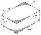
図2は、一部の実施形態に関連付けられ得る追加的な詳細を示す、ドレープ106の分解斜視図である。ドレープ106は、フィルム層108および接着剤層110を含み得る。接着剤110は、フィルム層108に隣接して位置決めされるように構成され得る。フィルム層108は、第1の側面132および第2の側面134を有し得る。第1の側面132は、非粘着性であるように構成され得るため、第1の側面132は、第1の側面132と接触するように配置された物体に一般的に接着しないとし得る。フィルム層108はまた、ドレープ106の外部または上部にあるように構成され得るため、第1の側面132は、組織部位102に位置決めされるときには周囲環境にさらされ得る。接着剤110は、フィルム層108に結合されるように構成された第1の側面136と、表皮112に結合されるように構成された第2の側面138とを有し得る。接着剤110は、ドレープ106のフィルム層108を、組織部位102を取り囲む表皮112の一部分に結合および密封の双方を行う材料としてもよく、それにより、ドレープ106は、組織部位102の上に配置されるときに密閉空間124を形成する。 FIG. 2 is an exploded perspective view of the
ドレープ106は、例えば、ドレープ106と組織部位102との間の空間を通って、実質的に流体が漏れないようにする一方、ドレープ106を通って蒸気が出ることができるようにする。ドレープ106は、接着剤110が表皮112に接触する箇所で好適なMVTRを維持し、組織部位102の治癒を支援し、かつドレープ106が密封される表皮112の浸軟を制限し得る。ドレープ106はまた、減圧療法を組織部位102に行うとき、組織部位102を取り囲む表皮112との密封式の接触を維持し得る。ドレープ106はまた、表皮112から好適に剥離可能な材料から形成され、組織部位102からドレープ106を除去することによって生じる患者への痛みを最小限にし得るかまたは軽減し得る。ドレープ106は剥離可能とし得るが、ドレープ106は、接着剤110の結合特性に応じて、組織部位102への適度に強力な機械的接続を維持する。 The
フィルム層108は、通気性でありかつ典型的に高透湿度(high moisture−vapor−transfer−rate)(MVTR)を有し得る可撓性フィルムとし得る。フィルム層108は、厚さ約5ミクロン未満の範囲の、医学的に承認されたフィルムの範囲から形成され得る。フィルム層108は、親水性ポリウレタン(PU)、セルロース系材料、親水性ポリアミド、ポリビニルアルコール、ポリビニルピロリドン、親水性アクリル、親水性シリコーンエラストマー、およびこれらのコポリマーなどの好適な1つまたは複数の材料を含み得る。高MVTRのフィルム層108は、蒸気が出ることができるようにし、かつ液体が出ることは抑制する。説明に役立つ実施形態では、フィルム層108はまた、液体および微生物に対するバリアとして機能し得る。 The
接着剤110は、医療的に容認できる感圧接着剤とし得る。説明に役立つ実施形態では、接着剤110は、高い結合強さのアクリル接着剤、高粘着性シリコーン接着剤、ポリウレタン、または他の物質とし得る。一部の実施形態では、接着剤110の結合強さは、米国試験材料協会(「ASTM」)標準ASTM D3330に基づいて、23℃、50%の相対湿度で、ステンレス鋼基材上で約6N/25mm〜約10N/25mmのステンレス鋼材料からの引きはがし粘着力または耐剥離性を有し得る。説明に役立つ実施形態では、接着剤110は、塗布量約80gsm〜約400gsmでアクリル接着剤を含む。約80gsm〜約400gsmの塗布量は、約80ミクロン〜約400ミクロンの厚さに対応し得る。他の実施形態では、接着剤110は、600gsmまでの塗布量のシリコーン接着剤とし得る。さらに他の実施形態では、接着剤110は、1000gsmまでの塗布量の親水コロイド接着剤とし得る。 Adhesive 110 may be a medically acceptable pressure sensitive adhesive. In illustrative embodiments, the adhesive 110 may be a high bond strength acrylic adhesive, a high tack silicone adhesive, a polyurethane, or other material. In some embodiments, the bond strength of the adhesive 110 is about 6 N on a stainless steel substrate at 23 ° C. and 50% relative humidity, based on the American Society for Testing and Materials (“ASTM”) standard ASTM D3330. It can have a peel adhesion or peel resistance from a stainless steel material of / 25 mm to about 10 N / 25 mm. In an illustrative embodiment, the adhesive 110 comprises an acrylic adhesive at a coating weight of about 80 gsm to about 400 gsm. A coating amount of about 80 gsm to about 400 gsm may correspond to a thickness of about 80 microns to about 400 microns. In other embodiments, the adhesive 110 may be a silicone adhesive with an application amount of up to 600 gsm. In still other embodiments, the adhesive 110 may be a hydrocolloid adhesive with an application amount of up to 1000 gsm.
接着剤110を有するドレープ106は、ホットメルト製造システムを使用して製造し得る。ドレープ106はまた、当技術分野で現在公知のような溶剤コーティングシステムを使用しない製造プロセスを使用して製造し得る。ホットメルト製造システムは、接着剤110の接着剤を溶融するため、接着剤の粘着性が弱くなる。その後、溶融された接着剤は、フィルム層108に適用され、かつ冷却されて、接着剤110を形成する。説明に役立つ実施形態では、厚さ約15ミクロン未満のフィルム層が提供され得る。接着剤110のアクリル接着剤は、約120℃まで加熱されて、接着剤110のアクリル接着剤を溶融し得る。他の接着剤は、それよりも高温または低温まで加熱されて、特定の接着剤をフィルム層108に適用するための好適な粘度を達成し得る。溶融された接着剤は、フィルム層108に適用され、かつ硬化されて、接着剤110を形成する。説明に役立つ実施形態では、溶融された接着剤は、フィルム層108に塗布され、かつ冷却されて、接着剤110を形成する。ドレープ106はまた、押出法において、接着剤110によってフィルム層108を模様塗りするように製造され得るため、接着剤110は、ドレープ106の異なる部分において異なる厚さを有し得る。 The
ドレープ106は、フィルム層108を15ミクロン未満の厚さに制限するときには、予期されるよりもピンホール形成の発生数が少なくなり得る。接着剤110の厚さを増すと、フィルム層108に形成されるピンホールを埋めることによって、ピンホールの形成の発生数を減らす。さらに、ドレープ106の全体的な通気性は、フィルム層108のMVTRが改善されるために、他の医療用ドレープよりも増し得る。接着剤110の接着剤の厚さが増すと、接着剤110のMVTRが低下し得るが、フィルム層108の厚さが薄くなると、フィルム層108のMVTRが増して、接着剤110の低MVTRを相殺する。接着剤110とフィルム層108とを対にすることによって、ドレープ106の全体的なMVTRを上昇させるか、または少なくとも全体的なMVTRを許与可能なレベルに維持し、組織部位102に隣接した表皮112を健康な状態に維持するのを支援し得る。 The
上述の通り、図4Aは、約25ミクロン〜約45ミクロンのフィルム層208と接着剤210とを有する共通の医療用ドレープ206を使用する、図1のシステム100の一部分の断面図である。医療用ドレープ206が組織部位102に適用されるとき、医療用ドレープ206は伸張されて、医療用ドレープ206を組織部位102に適合させ、かつ医療用ドレープ206が、組織部位102を取り囲む傷のない表皮112を確実に密封するようにする。適用中に医療用ドレープ206を伸張させる力が解放されると、医療用ドレープ206は収縮し、医療用ドレープ206が表皮112に結合される個所にしわまたは折り目244を形成し得る。折り目244は、表皮112から離れるようにフィルム層208および接着剤210の双方を引っ張り、かつフィルム層208の厚さに起因して、接着剤210は、医療用ドレープ206と表皮112との間の間隙を閉鎖するのに、十分に強力ではないかまたは十分な厚さがない。それゆえ、折り目244は、システム100の効率を低下させる漏れを生じる。 As described above, FIG. 4A is a cross-sectional view of a portion of the
図4Bは、一部の実施形態に関連付けられ得るドレープ106の追加的な詳細を示す、図1のシステム100の一部分の断面図である。ドレープ106は、約15ミクロン未満とし得るが、依然としてしわまたは折り目144を含み得る。折り目144は、上述の通り、ドレープ106の一部分が、表皮112から離れるように引っ張られるようにし得る。しかしながら、接着剤110は、約80ミクロン〜400ミクロンとより厚みがあり得るため、接着剤110は、破線で示すような間隙145を形成するように、表皮112から離れるように引っ張られないとし得る。接着剤110は、折り目144の下側のボイド全体を埋めて、漏れを防止し得る。接着剤110は、フィルム層108と表皮112との間の開口部を埋め、それにより、システム100の適切な動作を妨げ得る漏れの形成を制限し得る。それゆえ、ドレープ106は、ドレープ106と組織部位102との間の空間を通る流体の漏れを実質的に防止する一方、高MVTRおよび向上した適合性を維持し得る。 FIG. 4B is a cross-sectional view of a portion of the
他の実施形態では、接着剤は、例えば有機および無機の低温沸点の液体の発泡剤または膨張剤と混合され得る。発泡剤または膨張剤は、熱または光の適用下で接着剤が膨張でき、上述のプロセスのうちの1つによって堆積した後に、接着剤の厚さを増すことを可能にする。発泡剤または膨張剤は、接着剤の必要量を減らし、かつ生産コストおよび得られる医療用ドレープのコストを削減し得る。一部の実施形態では、表皮との接触によって接着剤が暖められる可能性があるとき、表皮との接触領域が大きくなるようにするために、熱または光の適用は、医療用ドレープを表皮に適用するまで遅らされてもよい。表皮への医療用ドレープの適用に続く熱または光の適用は、表皮への医療用ドレープの良好なシールをもたらす一方、強力な結合特性を維持し得る。 In other embodiments, the adhesive may be mixed with, for example, organic and inorganic cold boiling liquid blowing or swelling agents. The blowing or swelling agent allows the adhesive to expand under the application of heat or light and allows the thickness of the adhesive to increase after being deposited by one of the processes described above. Foaming or swelling agents can reduce the amount of adhesive required and reduce the cost of production and the resulting medical drape. In some embodiments, application of heat or light may cause the medical drape to be applied to the epidermis so that the contact area with the epidermis is increased when contact with the epidermis can cause the adhesive to warm. May be delayed until application. Application of heat or light following the application of the medical drape to the epidermis can provide a good seal of the medical drape to the epidermis while maintaining strong bonding properties.
上述のような医療用ドレープおよびそれらの均等物は、標準的なドレープよりも薄くすることができ、高MVTRを有することができ、かつ非常に適合性であることができる。さらに、それらは、接着剤の厚さが増すゆえに、漏れの発生回数が少ないとし得る。さらに、本明細書で説明する医療用ドレープおよびそれらの均等物は、生産コストが低いとし得る。本明細書の医療用ドレープおよびそれらの均等物はまた、より単純な適用および高通気性にさらされ得る。 Medical drapes and their equivalents as described above can be thinner than standard drapes, can have a high MVTR, and can be very compatible. Furthermore, they may be less likely to leak due to the increased thickness of the adhesive. Further, the medical drapes described herein and their equivalents may be low in production costs. The medical drapes herein and their equivalents can also be exposed to simpler applications and high breathability.
いくつかの実施形態およびそれらの利点を、いくつかの説明に役立つ非限定的な実施形態に照らして開示したが、添付の特許請求の範囲で定義するような本発明の範囲から逸脱せずに、様々な変更形態、代替形態、置換形態、および修正形態をなし得ることを理解されたい。一つの実施形態に関連して説明され得る特徴はまた、他の実施形態にも適用可能であり得ることを理解されたい。上述の利益および利点は、一実施形態に関連し得ること、またはいくつかの実施形態に関連し得ることも理解されたい。「1つの(an)」品目への言及は、1つ以上のそれら品目を指すことをさらに理解されたい。 Several embodiments and their advantages have been disclosed in the context of some illustrative, non-limiting embodiments, but without departing from the scope of the invention as defined in the appended claims. It should be understood that various modifications, alternatives, substitutions, and modifications can be made. It should be understood that features that may be described in connection with one embodiment may also be applicable to other embodiments. It should also be appreciated that the benefits and advantages described above may relate to one embodiment or may relate to several embodiments. It should be further understood that reference to “an” item refers to one or more of those items.
本明細書で説明した方法のステップは、好適な順序で、または適切な場合、および当業者に理解される他の場合には、同時に実施し得る。 The method steps described herein may be performed in any suitable order, or where appropriate, and where appropriate, as otherwise understood by those skilled in the art.
適切な場合には、上述の実施形態の態様を、説明する他の実施形態の態様と組み合わせて、類似のまたは異なる特性を有しかつ同じまたは異なる問題に対処する別の例を形成し得る。 Where appropriate, aspects of the above-described embodiments may be combined with aspects of other described embodiments to form another example having similar or different characteristics and addressing the same or different issues.
上述の実施形態は例示にすぎず、当業者は様々な修正形態をなし得ることを理解されたい。上述の明細書、例、およびデータは、例示的な実施形態の構造および使用の完全な説明を提供する。様々な実施形態を、ある程度詳細に、または1つ以上の個々の図を参照して上記で説明したが、当業者は、特許請求の範囲から逸脱せずに、例示的な実施形態に多数の修正をなすことができる。 It should be understood that the above-described embodiments are merely examples, and those skilled in the art can make various modifications. The above specification, examples and data provide a complete description of the structure and use of the exemplary embodiments. Although various embodiments have been described above in some detail or with reference to one or more individual figures, those skilled in the art will recognize that many examples can be made without departing from the scope of the claims. Corrections can be made.
Claims (23)
Translated fromJapanese減圧を適用するように構成された減圧源と;
前記減圧源と流体連通し、かつ前記組織部位に減圧を分配するように構成されたマニホールドと;
ドレープであって、
15ミクロン未満の厚さのポリウレタンフィルム層、
80ミクロンを上回る厚さの接着剤層であって、前記接着剤層は第1の面および第2の面を有し、前記第1の面は前記ポリウレタンフィルム層に結合されている、接着剤層 を含み、
前記接着剤層の前記第2の面が、少なくとも前記組織部位に接着し、かつ前記マニホールドを被覆して、前記組織部位内の前記マニホールドの上側を覆う密閉空間を生じるように構成されている、ドレープと、
を含むことを特徴とする、システム。In a system for treating a tissue site,
A reduced pressure source configured to apply reduced pressure;
A manifold in fluid communication with the reduced pressure source and configured to distribute reduced pressure to the tissue site;
Drape,
1 of less than5 micron thick polyurethane film layer,
An adhesive layer having a thickness greater than80 microns, wherein the adhesive layer has a first side and a second side, the first side being bonded to the polyurethane film layer; Including agent layer
The second surface of the adhesive layer is configured to adhere to at least the tissue site and cover the manifold to create a sealed space that covers the upper side of the manifold within the tissue site; With drape,
A system characterized by comprising:
減圧源から減圧を受けかつ前記組織部位に前記減圧を適用するように構成されたコネクタと;
前記コネクタに流体的に結合されて前記減圧を受けるように構成されたマニホールドであって、前記減圧を前記組織部位に分配する複数の流路を有するマニホールドと;
ドレープであって、
15ミクロン未満の厚さのポリウレタンフィルム層、
80ミクロンを上回る厚さの接着剤層であって、前記接着剤層が第1の面および第2の面を有し、前記第1の面は前記ポリウレタンフィルム層に結合されている、接着剤層 を含み、
前記接着剤層の前記第2の面は、少なくとも前記組織部位に接着しかつ前記マニホールドを被覆して、前記組織部位内の前記マニホールドの上側を覆う密閉空間を生じるように構成されている、ドレープと
を含むことを特徴とする、ドレッシング。In dressing for treating tissue sites,
A connector configured to receive reduced pressure from a reduced pressure source and apply the reduced pressure to the tissue site;
A manifold that is fluidly coupled to the connector and configured to receive the reduced pressure, the manifold having a plurality of channels that distribute the reduced pressure to the tissue site;
Drape,
1 of less than5 micron thick polyurethane film layer,
An adhesive layer having a thickness greater than80 microns, wherein the adhesive layer has a first surface and a second surface, the first surface being bonded to the polyurethane film layer; Including agent layer
The drape is configured such that the second surface of the adhesive layer adheres to at least the tissue site and covers the manifold to create a sealed space over the manifold in the tissue site. A dressing characterized by comprising:
(a)15ミクロン未満の厚さのポリウレタンフィルム層を提供するステップと;
(b)前記ポリウレタンフィルム層の片側に接着剤を適用するステップと;
(c)前記接着剤を硬化させて、80ミクロンを上回る厚さの接着剤層を前記ポリウレタンフィルム層の前記片側に形成するステップと
を含むことを特徴とする、方法。A method for producing a medical drape, comprising:
(A) providing a polyurethane film layer having a thickness of less than 15 microns;
(B) applying an adhesive to one side of the polyurethane film layer;
(C) curing the adhesive to form an adhesive layer having a thickness greater than80 microns on the one side of thepolyurethane film layer.
前記接着剤を溶融して、前記接着剤を液体状態に変質することと;
前記ポリウレタンフィルム層を、液体状態の前記接着剤でコーティングすることと
を含むことを特徴とする、方法。The method of claim 11, wherein step (b) comprises:
Melting the adhesive to transform the adhesive into a liquid state;
Coating the polyurethane film layer with the adhesive in a liquid state.
15ミクロン未満の厚さのポリウレタンフィルム層と、
80ミクロンを上回る厚さの接着剤層であって、前記接着剤層が第1の面および第2の面を有し、前記第1の面は前記ポリウレタンフィルム層に結合されている、接着剤層と
を含み、
前記接着剤層の前記第2の面は、少なくとも組織部位に接着しかつマニホールドを被覆して、前記組織部位内の前記マニホールドの上側を覆う密閉空間を生じるように構成されていることを特徴とする、医療用ドレープ。In medical drapes
The thickness polyurethane film layer of less than1 5 microns,
An adhesive layer having a thickness greater than80 microns, wherein the adhesive layer has a first surface and a second surface, the first surface being bonded to the polyurethane film layer; Including the agent layer,
The second surface of the adhesive layer is configured to adhere at least to a tissue site and to cover a manifold to create a sealed space that covers the upper side of the manifold in the tissue site. A medical drape.
Applications Claiming Priority (3)
| Application Number | Priority Date | Filing Date | Title |
|---|---|---|---|
| US201361748400P | 2013-01-02 | 2013-01-02 | |
| US61/748,400 | 2013-01-02 | ||
| PCT/US2013/070090WO2014107233A1 (en) | 2013-01-02 | 2013-11-14 | A medical drape having an ultra-thin drape film and a thick adhesive coating |
Publications (2)
| Publication Number | Publication Date |
|---|---|
| JP2016508047A JP2016508047A (en) | 2016-03-17 |
| JP6300241B2true JP6300241B2 (en) | 2018-03-28 |
Family
ID=49726860
Family Applications (1)
| Application Number | Title | Priority Date | Filing Date |
|---|---|---|---|
| JP2015550385AExpired - Fee RelatedJP6300241B2 (en) | 2013-01-02 | 2013-11-14 | Medical drape with ultra-thin drape film and thick adhesive coating |
Country Status (7)
| Country | Link |
|---|---|
| US (2) | US9937079B2 (en) |
| EP (1) | EP2941231B1 (en) |
| JP (1) | JP6300241B2 (en) |
| CN (1) | CN104869952B (en) |
| AU (1) | AU2013371582B2 (en) |
| CA (1) | CA2893632A1 (en) |
| WO (1) | WO2014107233A1 (en) |
Families Citing this family (14)
| Publication number | Priority date | Publication date | Assignee | Title |
|---|---|---|---|---|
| US11253399B2 (en) | 2007-12-06 | 2022-02-22 | Smith & Nephew Plc | Wound filling apparatuses and methods |
| US20130096518A1 (en) | 2007-12-06 | 2013-04-18 | Smith & Nephew Plc | Wound filling apparatuses and methods |
| WO2013066426A2 (en) | 2011-06-24 | 2013-05-10 | Kci Licensing, Inc. | Reduced-pressure dressings employing tissue-fixation elements |
| DK3481349T3 (en) | 2016-07-08 | 2021-07-12 | Convatec Technologies Inc | Flexible vacuum system |
| JP7204685B2 (en) | 2017-06-07 | 2023-01-16 | スリーエム イノベイティブ プロパティズ カンパニー | A composite dressing that promotes granulation formation and reduces maceration in negative pressure therapy |
| WO2018226707A1 (en) | 2017-06-07 | 2018-12-13 | Kci Licensing, Inc. | Composite dressings for improved granulation reduced maceration with negative-pressure treatment |
| US10695227B2 (en) | 2017-06-07 | 2020-06-30 | Kci Licensing, Inc. | Methods for manufacturing and assembling dual material tissue interface for negative-pressure therapy |
| WO2018226744A1 (en) | 2017-06-07 | 2018-12-13 | Kci Licensing, Inc. | Peel and place dressing for negative -pressure treatment |
| WO2018226650A1 (en) | 2017-06-07 | 2018-12-13 | Kci Licensing, Inc. | Systems, apparatuses, and methods for negative-pressure treatment with reduced tissue in-growth |
| EP3634334B1 (en) | 2017-06-07 | 2023-05-24 | 3M Innovative Properties Company | Multi-layer wound filler for extended wear time |
| AU2018282188A1 (en) | 2017-06-07 | 2019-12-19 | 3M Innovative Properties Company | Tissue contact interface |
| AU2018282159A1 (en) | 2017-06-07 | 2019-12-19 | 3M Innovative Properties Company | Composite dressings for improved granulation and reduced maceration with negative-pressure treatment |
| WO2018226691A1 (en) | 2017-06-07 | 2018-12-13 | Kci Licensing, Inc. | Methods for manufacturing and assembling dual material tissue interface for negative-pressure therapy |
| CA3171933A1 (en) | 2020-02-20 | 2021-08-26 | Convatec Limited | A wound dressing and a wound therapy apparatus |
Family Cites Families (195)
| Publication number | Priority date | Publication date | Assignee | Title |
|---|---|---|---|---|
| US1355846A (en) | 1920-02-06 | 1920-10-19 | David A Rannells | Medical appliance |
| US2547758A (en) | 1949-01-05 | 1951-04-03 | Wilmer B Keeling | Instrument for treating the male urethra |
| US2632443A (en) | 1949-04-18 | 1953-03-24 | Eleanor P Lesher | Surgical dressing |
| GB692578A (en) | 1949-09-13 | 1953-06-10 | Minnesota Mining & Mfg | Improvements in or relating to drape sheets for surgical use |
| US2682873A (en) | 1952-07-30 | 1954-07-06 | Johnson & Johnson | General purpose protective dressing |
| NL189176B (en) | 1956-07-13 | 1900-01-01 | Hisamitsu Pharmaceutical Co | PLASTER BASED ON A SYNTHETIC RUBBER. |
| US2969057A (en) | 1957-11-04 | 1961-01-24 | Brady Co W H | Nematodic swab |
| US3066672A (en) | 1960-09-27 | 1962-12-04 | Jr William H Crosby | Method and apparatus for serial sampling of intestinal juice |
| US3367332A (en) | 1965-08-27 | 1968-02-06 | Gen Electric | Product and process for establishing a sterile area of skin |
| US3520300A (en) | 1967-03-15 | 1970-07-14 | Amp Inc | Surgical sponge and suction device |
| US3568675A (en) | 1968-08-30 | 1971-03-09 | Clyde B Harvey | Fistula and penetrating wound dressing |
| US3682180A (en) | 1970-06-08 | 1972-08-08 | Coilform Co Inc | Drain clip for surgical drain |
| BE789293Q (en) | 1970-12-07 | 1973-01-15 | Parke Davis & Co | MEDICO-SURGICAL DRESSING FOR BURNS AND SIMILAR LESIONS |
| US3826254A (en) | 1973-02-26 | 1974-07-30 | Verco Ind | Needle or catheter retaining appliance |
| DE2527706A1 (en) | 1975-06-21 | 1976-12-30 | Hanfried Dr Med Weigand | DEVICE FOR THE INTRODUCTION OF CONTRAST AGENTS INTO AN ARTIFICIAL INTESTINAL OUTLET |
| DE2640413C3 (en) | 1976-09-08 | 1980-03-27 | Richard Wolf Gmbh, 7134 Knittlingen | Catheter monitor |
| NL7710909A (en) | 1976-10-08 | 1978-04-11 | Smith & Nephew | COMPOSITE STRAPS. |
| GB1562244A (en) | 1976-11-11 | 1980-03-05 | Lock P M | Wound dressing materials |
| US4080970A (en) | 1976-11-17 | 1978-03-28 | Miller Thomas J | Post-operative combination dressing and internal drain tube with external shield and tube connector |
| US4139004A (en) | 1977-02-17 | 1979-02-13 | Gonzalez Jr Harry | Bandage apparatus for treating burns |
| US4184510A (en) | 1977-03-15 | 1980-01-22 | Fibra-Sonics, Inc. | Valued device for controlling vacuum in surgery |
| US4165748A (en) | 1977-11-07 | 1979-08-28 | Johnson Melissa C | Catheter tube holder |
| US4245637A (en) | 1978-07-10 | 1981-01-20 | Nichols Robert L | Shutoff valve sleeve |
| SE414994B (en) | 1978-11-28 | 1980-09-01 | Landstingens Inkopscentral | VENKATETERFORBAND |
| GB2047543B (en) | 1978-12-06 | 1983-04-20 | Svedman Paul | Device for treating tissues for example skin |
| US4266545A (en) | 1979-04-06 | 1981-05-12 | Moss James P | Portable suction device for collecting fluids from a closed wound |
| US4284079A (en) | 1979-06-28 | 1981-08-18 | Adair Edwin Lloyd | Method for applying a male incontinence device |
| US4261363A (en) | 1979-11-09 | 1981-04-14 | C. R. Bard, Inc. | Retention clips for body fluid drains |
| US4569348A (en) | 1980-02-22 | 1986-02-11 | Velcro Usa Inc. | Catheter tube holder strap |
| WO1981002516A1 (en) | 1980-03-11 | 1981-09-17 | E Schmid | Cushion for holding an element of grafted skin |
| US4297995A (en) | 1980-06-03 | 1981-11-03 | Key Pharmaceuticals, Inc. | Bandage containing attachment post |
| US4333468A (en) | 1980-08-18 | 1982-06-08 | Geist Robert W | Mesentery tube holder apparatus |
| US4465485A (en) | 1981-03-06 | 1984-08-14 | Becton, Dickinson And Company | Suction canister with unitary shut-off valve and filter features |
| US4392853A (en) | 1981-03-16 | 1983-07-12 | Rudolph Muto | Sterile assembly for protecting and fastening an indwelling device |
| US4373519A (en) | 1981-06-26 | 1983-02-15 | Minnesota Mining And Manufacturing Company | Composite wound dressing |
| US4392858A (en) | 1981-07-16 | 1983-07-12 | Sherwood Medical Company | Wound drainage device |
| US4419097A (en) | 1981-07-31 | 1983-12-06 | Rexar Industries, Inc. | Attachment for catheter tube |
| AU550575B2 (en) | 1981-08-07 | 1986-03-27 | Richard Christian Wright | Wound drainage device |
| SE429197B (en) | 1981-10-14 | 1983-08-22 | Frese Nielsen | SAR TREATMENT DEVICE |
| DE3146266A1 (en) | 1981-11-21 | 1983-06-01 | B. Braun Melsungen Ag, 3508 Melsungen | COMBINED DEVICE FOR A MEDICAL SUCTION DRAINAGE |
| US4551139A (en) | 1982-02-08 | 1985-11-05 | Marion Laboratories, Inc. | Method and apparatus for burn wound treatment |
| US4475909A (en) | 1982-05-06 | 1984-10-09 | Eisenberg Melvin I | Male urinary device and method for applying the device |
| EP0100148B1 (en) | 1982-07-06 | 1986-01-08 | Dow Corning Limited | Medical-surgical dressing and a process for the production thereof |
| NZ206837A (en) | 1983-01-27 | 1986-08-08 | Johnson & Johnson Prod Inc | Thin film adhesive dressing:backing material in three sections |
| US4548202A (en) | 1983-06-20 | 1985-10-22 | Ethicon, Inc. | Mesh tissue fasteners |
| US4540412A (en) | 1983-07-14 | 1985-09-10 | The Kendall Company | Device for moist heat therapy |
| US4543100A (en) | 1983-11-01 | 1985-09-24 | Brodsky Stuart A | Catheter and drain tube retainer |
| US4525374A (en) | 1984-02-27 | 1985-06-25 | Manresa, Inc. | Treating hydrophobic filters to render them hydrophilic |
| CA1286177C (en) | 1984-05-03 | 1991-07-16 | Smith And Nephew Associated Companies Plc | Adhesive wound dressing |
| US4897081A (en) | 1984-05-25 | 1990-01-30 | Thermedics Inc. | Percutaneous access device |
| US5215522A (en) | 1984-07-23 | 1993-06-01 | Ballard Medical Products | Single use medical aspirating device and method |
| GB8419745D0 (en) | 1984-08-02 | 1984-09-05 | Smith & Nephew Ass | Wound dressing |
| US4872450A (en) | 1984-08-17 | 1989-10-10 | Austad Eric D | Wound dressing and method of forming same |
| US4826494A (en) | 1984-11-09 | 1989-05-02 | Stryker Corporation | Vacuum wound drainage system |
| US4655754A (en) | 1984-11-09 | 1987-04-07 | Stryker Corporation | Vacuum wound drainage system and lipids baffle therefor |
| US4605399A (en) | 1984-12-04 | 1986-08-12 | Complex, Inc. | Transdermal infusion device |
| US5037397A (en) | 1985-05-03 | 1991-08-06 | Medical Distributors, Inc. | Universal clamp |
| US4640688A (en) | 1985-08-23 | 1987-02-03 | Mentor Corporation | Urine collection catheter |
| US4710165A (en) | 1985-09-16 | 1987-12-01 | Mcneil Charles B | Wearable, variable rate suction/collection device |
| US4758220A (en) | 1985-09-26 | 1988-07-19 | Alcon Laboratories, Inc. | Surgical cassette proximity sensing and latching apparatus |
| US4733659A (en) | 1986-01-17 | 1988-03-29 | Seton Company | Foam bandage |
| EP0256060A1 (en) | 1986-01-31 | 1988-02-24 | OSMOND, Roger L. W. | Suction system for wound and gastro-intestinal drainage |
| US4838883A (en) | 1986-03-07 | 1989-06-13 | Nissho Corporation | Urine-collecting device |
| JPS62281965A (en) | 1986-05-29 | 1987-12-07 | テルモ株式会社 | Catheter and catheter fixing member |
| GB8621884D0 (en) | 1986-09-11 | 1986-10-15 | Bard Ltd | Catheter applicator |
| GB2195255B (en) | 1986-09-30 | 1991-05-01 | Vacutec Uk Limited | Apparatus for vacuum treatment of an epidermal surface |
| US4743232A (en) | 1986-10-06 | 1988-05-10 | The Clinipad Corporation | Package assembly for plastic film bandage |
| DE3634569A1 (en) | 1986-10-10 | 1988-04-21 | Sachse Hans E | CONDOM CATHETER, A URINE TUBE CATHETER FOR PREVENTING RISING INFECTIONS |
| JPS63135179A (en) | 1986-11-26 | 1988-06-07 | 立花 俊郎 | Subcataneous drug administration set |
| GB8628564D0 (en) | 1986-11-28 | 1987-01-07 | Smiths Industries Plc | Anti-foaming agent suction apparatus |
| GB8706116D0 (en) | 1987-03-14 | 1987-04-15 | Smith & Nephew Ass | Adhesive dressings |
| US4787888A (en) | 1987-06-01 | 1988-11-29 | University Of Connecticut | Disposable piezoelectric polymer bandage for percutaneous delivery of drugs and method for such percutaneous delivery (a) |
| US4863449A (en) | 1987-07-06 | 1989-09-05 | Hollister Incorporated | Adhesive-lined elastic condom cathether |
| US5176663A (en) | 1987-12-02 | 1993-01-05 | Pal Svedman | Dressing having pad with compressibility limiting elements |
| US4906240A (en) | 1988-02-01 | 1990-03-06 | Matrix Medica, Inc. | Adhesive-faced porous absorbent sheet and method of making same |
| US5474783A (en)* | 1988-03-04 | 1995-12-12 | Noven Pharmaceuticals, Inc. | Solubility parameter based drug delivery system and method for altering drug saturation concentration |
| US4985019A (en) | 1988-03-11 | 1991-01-15 | Michelson Gary K | X-ray marker |
| GB8812803D0 (en) | 1988-05-28 | 1988-06-29 | Smiths Industries Plc | Medico-surgical containers |
| US4919654A (en) | 1988-08-03 | 1990-04-24 | Kalt Medical Corporation | IV clamp with membrane |
| US5000741A (en) | 1988-08-22 | 1991-03-19 | Kalt Medical Corporation | Transparent tracheostomy tube dressing |
| US5059596A (en) | 1989-01-16 | 1991-10-22 | Roussel Uclaf | Azabicyclo compounds |
| GB8906100D0 (en) | 1989-03-16 | 1989-04-26 | Smith & Nephew | Laminates |
| US4969880A (en) | 1989-04-03 | 1990-11-13 | Zamierowski David S | Wound dressing and treatment method |
| US5100396A (en) | 1989-04-03 | 1992-03-31 | Zamierowski David S | Fluidic connection system and method |
| US5527293A (en) | 1989-04-03 | 1996-06-18 | Kinetic Concepts, Inc. | Fastening system and method |
| US5261893A (en) | 1989-04-03 | 1993-11-16 | Zamierowski David S | Fastening system and method |
| JP2719671B2 (en) | 1989-07-11 | 1998-02-25 | 日本ゼオン株式会社 | Wound dressing |
| US5358494A (en) | 1989-07-11 | 1994-10-25 | Svedman Paul | Irrigation dressing |
| US5232453A (en) | 1989-07-14 | 1993-08-03 | E. R. Squibb & Sons, Inc. | Catheter holder |
| GB2235877A (en) | 1989-09-18 | 1991-03-20 | Antonio Talluri | Closed wound suction apparatus |
| US6680113B1 (en)* | 1989-12-29 | 2004-01-20 | 3M Innovative Properties Company | Multi-layered dressing |
| US5134994A (en) | 1990-02-12 | 1992-08-04 | Say Sam L | Field aspirator in a soft pack with externally mounted container |
| US5092858A (en) | 1990-03-20 | 1992-03-03 | Becton, Dickinson And Company | Liquid gelling agent distributor device |
| JP2941918B2 (en) | 1990-09-19 | 1999-08-30 | テルモ株式会社 | Weighing device |
| US5163448A (en)* | 1991-04-30 | 1992-11-17 | Family Health International | Condom comprising dispensing structure, and method of making and using the same |
| US5149331A (en) | 1991-05-03 | 1992-09-22 | Ariel Ferdman | Method and device for wound closure |
| WO1992019194A1 (en)* | 1991-05-07 | 1992-11-12 | Kotec Limited | Wound covering material |
| US5278100A (en) | 1991-11-08 | 1994-01-11 | Micron Technology, Inc. | Chemical vapor deposition technique for depositing titanium silicide on semiconductor wafers |
| US5645081A (en) | 1991-11-14 | 1997-07-08 | Wake Forest University | Method of treating tissue damage and apparatus for same |
| US5636643A (en) | 1991-11-14 | 1997-06-10 | Wake Forest University | Wound treatment employing reduced pressure |
| US5279550A (en) | 1991-12-19 | 1994-01-18 | Gish Biomedical, Inc. | Orthopedic autotransfusion system |
| US5167613A (en) | 1992-03-23 | 1992-12-01 | The Kendall Company | Composite vented wound dressing |
| FR2690617B1 (en) | 1992-04-29 | 1994-06-24 | Cbh Textile | TRANSPARENT ADHESIVE DRESSING. |
| DE4306478A1 (en) | 1993-03-02 | 1994-09-08 | Wolfgang Dr Wagner | Drainage device, in particular pleural drainage device, and drainage method |
| DE4308649C2 (en) | 1993-03-18 | 1995-11-16 | Lohmann Gmbh & Co Kg | Medical plaster material and process for its production and its use |
| US5342376A (en) | 1993-05-03 | 1994-08-30 | Dermagraphics, Inc. | Inserting device for a barbed tissue connector |
| US6241747B1 (en) | 1993-05-03 | 2001-06-05 | Quill Medical, Inc. | Barbed Bodily tissue connector |
| US5344415A (en) | 1993-06-15 | 1994-09-06 | Deroyal Industries, Inc. | Sterile system for dressing vascular access site |
| US5469863A (en)* | 1993-08-11 | 1995-11-28 | Polygenex International, Inc. | Polyurethane condom of welded polyurethane film |
| CA2117546A1 (en)* | 1993-08-27 | 1995-02-28 | Takateru Muraoka | Medical adhesive sheet |
| US5437651A (en) | 1993-09-01 | 1995-08-01 | Research Medical, Inc. | Medical suction apparatus |
| US5549584A (en) | 1994-02-14 | 1996-08-27 | The Kendall Company | Apparatus for removing fluid from a wound |
| US5556375A (en) | 1994-06-16 | 1996-09-17 | Hercules Incorporated | Wound dressing having a fenestrated base layer |
| US5607388A (en) | 1994-06-16 | 1997-03-04 | Hercules Incorporated | Multi-purpose wound dressing |
| US5664270A (en) | 1994-07-19 | 1997-09-09 | Kinetic Concepts, Inc. | Patient interface system |
| DE69505545T2 (en) | 1994-08-22 | 1999-03-11 | Kinetic Concepts Inc | WOUND DRAINAGE DEVICE |
| DE29504378U1 (en) | 1995-03-15 | 1995-09-14 | MTG Medizinisch, technische Gerätebau GmbH, 66299 Friedrichsthal | Electronically controlled low-vacuum pump for chest and wound drainage |
| GB9523253D0 (en) | 1995-11-14 | 1996-01-17 | Mediscus Prod Ltd | Portable wound treatment apparatus |
| JPH09299396A (en)* | 1996-05-17 | 1997-11-25 | Johnson & Johnson Kk | Heat seal method for adhesive tape and adhesive tape manufactured by the method |
| US5730994A (en)* | 1997-01-10 | 1998-03-24 | Medlogic Global Corporation | Methods for draping surgical incision sites |
| DE19727032A1 (en)* | 1997-06-25 | 1999-01-07 | Hartmann Paul Ag | band Aid |
| US6135116A (en) | 1997-07-28 | 2000-10-24 | Kci Licensing, Inc. | Therapeutic method for treating ulcers |
| GB9719520D0 (en) | 1997-09-12 | 1997-11-19 | Kci Medical Ltd | Surgical drape and suction heads for wound treatment |
| AU755496B2 (en) | 1997-09-12 | 2002-12-12 | Kci Licensing, Inc. | Surgical drape and suction head for wound treatment |
| US6071267A (en) | 1998-02-06 | 2000-06-06 | Kinetic Concepts, Inc. | Medical patient fluid management interface system and method |
| US6488643B1 (en) | 1998-10-08 | 2002-12-03 | Kci Licensing, Inc. | Wound healing foot wrap |
| JP4236751B2 (en)* | 1999-01-27 | 2009-03-11 | 日東電工株式会社 | Medical adhesive tape or sheet, and emergency bandage |
| US6287316B1 (en) | 1999-03-26 | 2001-09-11 | Ethicon, Inc. | Knitted surgical mesh |
| US7799004B2 (en) | 2001-03-05 | 2010-09-21 | Kci Licensing, Inc. | Negative pressure wound treatment apparatus and infection identification system and method |
| US6856821B2 (en) | 2000-05-26 | 2005-02-15 | Kci Licensing, Inc. | System for combined transcutaneous blood gas monitoring and vacuum assisted wound closure |
| US6991643B2 (en) | 2000-12-20 | 2006-01-31 | Usgi Medical Inc. | Multi-barbed device for retaining tissue in apposition and methods of use |
| US20030208112A1 (en)* | 1999-12-23 | 2003-11-06 | Mattias Schmidt | Hygiene article comprising a membrane containing interface device and body adhesives |
| ES2220734T3 (en) | 2000-02-24 | 2004-12-16 | Venetec International, Inc. | UNIVERSAL FIXING SYSTEM FOR CATETER. |
| US20020106959A1 (en)* | 2000-09-01 | 2002-08-08 | Huffines Prentice Lee | Composite sheet material |
| US6540705B2 (en) | 2001-02-22 | 2003-04-01 | Core Products International, Inc. | Ankle brace providing upper and lower ankle adjustment |
| EP1374812A1 (en)* | 2002-06-28 | 2004-01-02 | Biopol Co., Ltd. | Multilayered microporous foam dressing and method for manufacturing the same |
| US7846141B2 (en) | 2002-09-03 | 2010-12-07 | Bluesky Medical Group Incorporated | Reduced pressure treatment system |
| GB0224986D0 (en) | 2002-10-28 | 2002-12-04 | Smith & Nephew | Apparatus |
| ES2537299T3 (en)* | 2002-11-26 | 2015-06-05 | Coloplast A/S | Bandages |
| US7976519B2 (en) | 2002-12-31 | 2011-07-12 | Kci Licensing, Inc. | Externally-applied patient interface system and method |
| WO2004103415A2 (en)* | 2003-05-20 | 2004-12-02 | Avery Dennison Corporation | Multi-dressing system for managing skin wounds |
| US20050080155A1 (en)* | 2003-10-14 | 2005-04-14 | Fattman George F. | Ostomy pouch attachment adhesives resistant to stomal effluent |
| GB0518826D0 (en)* | 2005-09-15 | 2005-10-26 | Smith & Nephew | Apparatus with actives from tissue - exudialysis |
| GB0325120D0 (en)* | 2003-10-28 | 2003-12-03 | Smith & Nephew | Apparatus with actives |
| GB0325126D0 (en) | 2003-10-28 | 2003-12-03 | Smith & Nephew | Apparatus with heat |
| US8758313B2 (en)* | 2003-10-28 | 2014-06-24 | Smith & Nephew Plc | Apparatus and method for wound cleansing with actives |
| US7909805B2 (en) | 2004-04-05 | 2011-03-22 | Bluesky Medical Group Incorporated | Flexible reduced pressure treatment appliance |
| US8529548B2 (en) | 2004-04-27 | 2013-09-10 | Smith & Nephew Plc | Wound treatment apparatus and method |
| JP4562070B2 (en)* | 2004-05-14 | 2010-10-13 | 日東電工株式会社 | Adhesive composition, adhesive sheet, and surface protective film |
| JP4531628B2 (en)* | 2004-09-16 | 2010-08-25 | 日東電工株式会社 | Adhesive composition, adhesive sheet, and surface protective film |
| JP5415661B2 (en)* | 2004-10-18 | 2014-02-12 | 日東電工株式会社 | Adhesive sheets |
| CA2949821C (en)* | 2005-09-06 | 2021-05-18 | Smith & Nephew, Inc. | Self contained wound dressing with micropump |
| WO2007089602A2 (en) | 2006-01-27 | 2007-08-09 | World Properties, Inc. | Low friction coatings for adhesive dressings and method of manufacture thereof |
| US20080097368A1 (en)* | 2006-10-24 | 2008-04-24 | The Procter & Gamble Company | Release tape-free fasteners and disposable absorbent articles utilizing the same |
| EP2164437B1 (en)* | 2007-06-04 | 2016-04-13 | Coloplast A/S | A method for manufacturing a net patterned adhesive layer |
| SE531259C2 (en)* | 2007-06-27 | 2009-02-03 | Moelnlycke Health Care Ab | Device for treating reduced pressure ulcers |
| BRPI0817020A2 (en)* | 2007-09-28 | 2014-10-07 | Kazuko Uchida | AUXILIARY PLASTER FOR MACHINING, AND METHOD FOR MAKE UP. |
| AU2008317164A1 (en)* | 2007-10-23 | 2009-04-30 | Boehringer Technologies, L.P. | Thin film wound cover andsuction assisted wound treatment system using the same |
| JP5235384B2 (en)* | 2007-11-08 | 2013-07-10 | リンテック株式会社 | Attached sheet |
| US8021347B2 (en) | 2008-07-21 | 2011-09-20 | Tyco Healthcare Group Lp | Thin film wound dressing |
| US8152785B2 (en) | 2008-03-13 | 2012-04-10 | Tyco Healthcare Group Lp | Vacuum port for vacuum wound therapy |
| US8007481B2 (en) | 2008-07-17 | 2011-08-30 | Tyco Healthcare Group Lp | Subatmospheric pressure mechanism for wound therapy system |
| JP5570706B2 (en)* | 2008-05-29 | 2014-08-13 | 日東電工株式会社 | Acrylic pressure sensitive adhesive tape or sheet |
| CN102036699B (en)* | 2008-05-30 | 2013-08-21 | 凯希特许有限公司 | Decompression Linear Wound Therapy System |
| US20110088624A1 (en)* | 2008-06-19 | 2011-04-21 | Jochen Kenndoff | Method for the protection of skin regions of a teat during the milking process, and film for such a method |
| US8216198B2 (en) | 2009-01-09 | 2012-07-10 | Tyco Healthcare Group Lp | Canister for receiving wound exudate in a negative pressure therapy system |
| US8251979B2 (en) | 2009-05-11 | 2012-08-28 | Tyco Healthcare Group Lp | Orientation independent canister for a negative pressure wound therapy device |
| US8425478B2 (en)* | 2008-09-18 | 2013-04-23 | Kci Licensing, Inc. | Multi-layer dressings, systems, and methods for applying reduced pressure at a tissue site |
| EP2373270B8 (en)* | 2009-01-07 | 2023-04-12 | entrotech life sciences, inc. | Chlorhexidine-containing antimicrobial laminates |
| US20100210987A1 (en)* | 2009-02-17 | 2010-08-19 | Hsin-Kai Lu | Breathable medical adhesive tape and manufacturing method thereof |
| SE0950362A1 (en) | 2009-05-20 | 2010-11-21 | Moelnlycke Health Care Ab | Method of making a film joint |
| US8394067B2 (en)* | 2009-05-21 | 2013-03-12 | C.R. Bard, Inc. | Medical device securement system |
| BR112012003740A2 (en)* | 2009-08-21 | 2020-08-11 | 3M Innovantive Properties Company | voltage distribution kits and composites |
| EP2316395B1 (en)* | 2009-10-27 | 2016-06-01 | Nitto Denko Corporation | Medical pressure-sensitive adhesive tape |
| JP5568290B2 (en)* | 2009-11-30 | 2014-08-06 | 日東電工株式会社 | Adhesive tape |
| EP2506815B1 (en)* | 2009-12-03 | 2019-07-24 | Pharmaplast SAE | A wound dressing, and method and production line of producing the wound dressing |
| EP2335661B1 (en)* | 2009-12-18 | 2012-12-12 | Paul Hartmann AG | Cutting aid for wound dressing for suppression therapy |
| JP5139410B2 (en)* | 2009-12-18 | 2013-02-06 | 日東電工株式会社 | Adhesive tape and method for producing adhesive tape |
| US20110282260A1 (en)* | 2010-04-12 | 2011-11-17 | Genewel Co., Ltd. | Polyurethane Foam Dressing Having Excellent Adhesive Properties and Manufacturing Method Thereof |
| US9061095B2 (en)* | 2010-04-27 | 2015-06-23 | Smith & Nephew Plc | Wound dressing and method of use |
| FR2959418B1 (en)* | 2010-04-28 | 2012-08-31 | Urgo Lab | BANDOVER COMPRISING AN ADHESIVE HYDROCOLLOID MASS |
| FR2959417B1 (en)* | 2010-04-28 | 2012-07-13 | Urgo Lab | BANDWASHING COMPRISING AT LEAST TWO TACKIFIING RESINS |
| WO2011157278A1 (en)* | 2010-06-18 | 2011-12-22 | Coloplast A/S | A permeable pressure sensitive adhesive |
| AU2011213886B2 (en)* | 2010-08-26 | 2014-06-19 | First Water Ramsbury Limited | Wound dressing |
| US9416221B2 (en)* | 2010-08-30 | 2016-08-16 | Surmodics, Inc. | Biodegradable terpolymers and terpolymer blends as pressure-sensitive adhesives |
| US20180126031A9 (en)* | 2010-09-02 | 2018-05-10 | Avery Dennison Corporation | Fluid Absorbent Adhesive Articles |
| JP5528286B2 (en)* | 2010-10-01 | 2014-06-25 | 日東電工株式会社 | Adhesive sheet |
| BR112013013278B1 (en)* | 2010-12-22 | 2020-07-07 | Coloplast A/S | ostomy device |
| US9278166B2 (en)* | 2011-03-02 | 2016-03-08 | Medline Industries, Inc. | Method and apparatus pertaining to a medical drape having a suction port |
| US10639118B2 (en)* | 2011-04-06 | 2020-05-05 | Entrotech Life Sciences, Inc. | Surgical incise drapes and methods for their application |
| WO2013013405A1 (en)* | 2011-07-28 | 2013-01-31 | 3M Innovative Properties Company | Wound dressing having grid pattern |
| ES2531442T3 (en)* | 2011-09-02 | 2015-03-16 | Rkw Se | Procedure for stretching a continuous sheet |
| JP5852427B2 (en)* | 2011-12-06 | 2016-02-03 | 日東電工株式会社 | Double-sided adhesive sheet |
| CN103987348B (en)* | 2011-12-16 | 2016-05-11 | 凯希特许有限公司 | Releasable Medical Drapes |
| US8969649B2 (en)* | 2012-08-10 | 2015-03-03 | Ethicon, Inc. | Integrated dressing device |
- 2013
- 2013-11-14JPJP2015550385Apatent/JP6300241B2/ennot_activeExpired - Fee Related
- 2013-11-14WOPCT/US2013/070090patent/WO2014107233A1/enactiveApplication Filing
- 2013-11-14CNCN201380067748.7Apatent/CN104869952B/ennot_activeExpired - Fee Related
- 2013-11-14CACA2893632Apatent/CA2893632A1/ennot_activeAbandoned
- 2013-11-14AUAU2013371582Apatent/AU2013371582B2/ennot_activeCeased
- 2013-11-14USUS14/080,285patent/US9937079B2/enactiveActive
- 2013-11-14EPEP13802472.4Apatent/EP2941231B1/enactiveActive
- 2018
- 2018-03-01USUS15/909,738patent/US10925774B2/ennot_activeExpired - Fee Related
Also Published As
| Publication number | Publication date |
|---|---|
| EP2941231B1 (en) | 2022-07-20 |
| US20180221212A1 (en) | 2018-08-09 |
| CA2893632A1 (en) | 2014-07-10 |
| US10925774B2 (en) | 2021-02-23 |
| US9937079B2 (en) | 2018-04-10 |
| CN104869952A (en) | 2015-08-26 |
| AU2013371582A1 (en) | 2015-06-04 |
| JP2016508047A (en) | 2016-03-17 |
| CN104869952B (en) | 2020-03-13 |
| EP2941231A1 (en) | 2015-11-11 |
| US20140188059A1 (en) | 2014-07-03 |
| AU2013371582B2 (en) | 2018-01-18 |
| WO2014107233A1 (en) | 2014-07-10 |
Similar Documents
| Publication | Publication Date | Title |
|---|---|---|
| JP6300241B2 (en) | Medical drape with ultra-thin drape film and thick adhesive coating | |
| US20230201042A1 (en) | Hybrid drape having a gel-coated perforated mesh | |
| JP6293786B2 (en) | Flexible and adhesive non-polyurethane film wound drape cover | |
| US20190192750A1 (en) | Hybrid Sealing Tape | |
| CN105050558B (en) | Medical drape with patterned adhesive layer and method of making the same |
Legal Events
| Date | Code | Title | Description |
|---|---|---|---|
| A621 | Written request for application examination | Free format text:JAPANESE INTERMEDIATE CODE: A621 Effective date:20161101 | |
| A977 | Report on retrieval | Free format text:JAPANESE INTERMEDIATE CODE: A971007 Effective date:20170925 | |
| A131 | Notification of reasons for refusal | Free format text:JAPANESE INTERMEDIATE CODE: A131 Effective date:20171003 | |
| A521 | Request for written amendment filed | Free format text:JAPANESE INTERMEDIATE CODE: A523 Effective date:20171225 | |
| TRDD | Decision of grant or rejection written | ||
| A01 | Written decision to grant a patent or to grant a registration (utility model) | Free format text:JAPANESE INTERMEDIATE CODE: A01 Effective date:20180123 | |
| A61 | First payment of annual fees (during grant procedure) | Free format text:JAPANESE INTERMEDIATE CODE: A61 Effective date:20180220 | |
| R150 | Certificate of patent or registration of utility model | Ref document number:6300241 Country of ref document:JP Free format text:JAPANESE INTERMEDIATE CODE: R150 | |
| R250 | Receipt of annual fees | Free format text:JAPANESE INTERMEDIATE CODE: R250 | |
| S111 | Request for change of ownership or part of ownership | Free format text:JAPANESE INTERMEDIATE CODE: R313113 | |
| R360 | Written notification for declining of transfer of rights | Free format text:JAPANESE INTERMEDIATE CODE: R360 | |
| R360 | Written notification for declining of transfer of rights | Free format text:JAPANESE INTERMEDIATE CODE: R360 | |
| R371 | Transfer withdrawn | Free format text:JAPANESE INTERMEDIATE CODE: R371 | |
| S111 | Request for change of ownership or part of ownership | Free format text:JAPANESE INTERMEDIATE CODE: R313113 | |
| R350 | Written notification of registration of transfer | Free format text:JAPANESE INTERMEDIATE CODE: R350 | |
| LAPS | Cancellation because of no payment of annual fees |