JP6298461B2 - Implantable prosthesis with hollow struts and passivating coating and method for making the same - Google Patents
Implantable prosthesis with hollow struts and passivating coating and method for making the sameDownload PDFInfo
- Publication number
- JP6298461B2 JP6298461B2JP2015520163AJP2015520163AJP6298461B2JP 6298461 B2JP6298461 B2JP 6298461B2JP 2015520163 AJP2015520163 AJP 2015520163AJP 2015520163 AJP2015520163 AJP 2015520163AJP 6298461 B2JP6298461 B2JP 6298461B2
- Authority
- JP
- Japan
- Prior art keywords
- lumen
- radiopaque particles
- poly
- metal layer
- passivating coating
- Prior art date
- Legal status (The legal status is an assumption and is not a legal conclusion. Google has not performed a legal analysis and makes no representation as to the accuracy of the status listed.)
- Expired - Fee Related
Links
- 238000000576coating methodMethods0.000titleclaimsdescription75
- 239000011248coating agentSubstances0.000titleclaimsdescription70
- 238000000034methodMethods0.000titleclaimsdescription29
- 239000002245particleSubstances0.000claimsdescription161
- 239000003814drugSubstances0.000claimsdescription103
- 229940124597therapeutic agentDrugs0.000claimsdescription74
- 229910052751metalInorganic materials0.000claimsdescription64
- 239000002184metalSubstances0.000claimsdescription64
- 239000000463materialSubstances0.000claimsdescription41
- 238000002161passivationMethods0.000claimsdescription21
- 239000008199coating compositionSubstances0.000claims2
- 229910010293ceramic materialInorganic materials0.000claims1
- 229920000642polymerPolymers0.000description42
- 239000000853adhesiveSubstances0.000description32
- 230000001070adhesive effectEffects0.000description32
- 229940079593drugDrugs0.000description29
- 238000005245sinteringMethods0.000description27
- 239000000203mixtureSubstances0.000description20
- 239000003795chemical substances by applicationSubstances0.000description19
- 238000002513implantationMethods0.000description18
- 229920001223polyethylene glycolPolymers0.000description14
- 230000008018meltingEffects0.000description11
- 238000002844meltingMethods0.000description11
- 229920000052poly(p-xylylene)Polymers0.000description11
- 229920002313fluoropolymerPolymers0.000description10
- 229910021645metal ionInorganic materials0.000description10
- -1rayon-triacetatePolymers0.000description10
- 239000000126substanceSubstances0.000description10
- 238000004873anchoringMethods0.000description9
- 238000009792diffusion processMethods0.000description9
- 239000000834fixativeSubstances0.000description9
- 229920001577copolymerPolymers0.000description8
- 201000010099diseaseDiseases0.000description8
- 208000037265diseases, disorders, signs and symptomsDiseases0.000description8
- 229920005596polymer binderPolymers0.000description8
- 239000002491polymer binding agentSubstances0.000description8
- 230000000717retained effectEffects0.000description8
- VRBFTYUMFJWSJY-UHFFFAOYSA-N28804-46-8Chemical compoundClC1CC(C=C2)=CC=C2C(Cl)CC2=CC=C1C=C2VRBFTYUMFJWSJY-UHFFFAOYSA-N0.000description7
- 239000000178monomerSubstances0.000description7
- GNSFRPWPOGYVLO-UHFFFAOYSA-N3-hydroxypropyl 2-methylprop-2-enoateChemical compoundCC(=C)C(=O)OCCCOGNSFRPWPOGYVLO-UHFFFAOYSA-N0.000description6
- BASFCYQUMIYNBI-UHFFFAOYSA-NplatinumSubstances[Pt]BASFCYQUMIYNBI-UHFFFAOYSA-N0.000description6
- 229920002981polyvinylidene fluoridePolymers0.000description6
- BQCIDUSAKPWEOX-UHFFFAOYSA-N1,1-DifluoroetheneChemical compoundFC(F)=CBQCIDUSAKPWEOX-UHFFFAOYSA-N0.000description5
- 229920000219Ethylene vinyl alcoholPolymers0.000description5
- 239000000654additiveSubstances0.000description5
- 239000012876carrier materialSubstances0.000description5
- 230000015556catabolic processEffects0.000description5
- 238000006731degradation reactionMethods0.000description5
- 239000002904solventSubstances0.000description5
- 229920002554vinyl polymerPolymers0.000description5
- 241001465754MetazoaSpecies0.000description4
- 230000000996additive effectEffects0.000description4
- 230000009286beneficial effectEffects0.000description4
- 230000015572biosynthetic processEffects0.000description4
- 230000036541healthEffects0.000description4
- 125000000391vinyl groupChemical group[H]C([*])=C([H])[H]0.000description4
- ZSZRUEAFVQITHH-UHFFFAOYSA-N2-(2-methylprop-2-enoyloxy)ethyl 2-(trimethylazaniumyl)ethyl phosphateChemical compoundCC(=C)C(=O)OCCOP([O-])(=O)OCC[N+](C)(C)CZSZRUEAFVQITHH-UHFFFAOYSA-N0.000description3
- XDLMVUHYZWKMMD-UHFFFAOYSA-N3-trimethoxysilylpropyl 2-methylprop-2-enoateChemical compoundCO[Si](OC)(OC)CCCOC(=O)C(C)=CXDLMVUHYZWKMMD-UHFFFAOYSA-N0.000description3
- JOYRKODLDBILNP-UHFFFAOYSA-NEthyl urethaneChemical compoundCCOC(N)=OJOYRKODLDBILNP-UHFFFAOYSA-N0.000description3
- 229920002683GlycosaminoglycanPolymers0.000description3
- 229920001244Poly(D,L-lactide)Polymers0.000description3
- 239000002202Polyethylene glycolSubstances0.000description3
- VYPSYNLAJGMNEJ-UHFFFAOYSA-NSilicium dioxideChemical compoundO=[Si]=OVYPSYNLAJGMNEJ-UHFFFAOYSA-N0.000description3
- GWEVSGVZZGPLCZ-UHFFFAOYSA-NTitan oxideChemical compoundO=[Ti]=OGWEVSGVZZGPLCZ-UHFFFAOYSA-N0.000description3
- 239000011230binding agentSubstances0.000description3
- 238000005137deposition processMethods0.000description3
- 238000010586diagramMethods0.000description3
- GMSCBRSQMRDRCD-UHFFFAOYSA-Ndodecyl 2-methylprop-2-enoateChemical compoundCCCCCCCCCCCCOC(=O)C(C)=CGMSCBRSQMRDRCD-UHFFFAOYSA-N0.000description3
- 239000005038ethylene vinyl acetateSubstances0.000description3
- 239000010931goldSubstances0.000description3
- 238000004519manufacturing processMethods0.000description3
- 239000011159matrix materialSubstances0.000description3
- 229920001432poly(L-lactide)Polymers0.000description3
- 229920001483poly(ethyl methacrylate) polymerPolymers0.000description3
- 229920001200poly(ethylene-vinyl acetate)Polymers0.000description3
- 229920001296polysiloxanePolymers0.000description3
- 229920000131polyvinylidenePolymers0.000description3
- 230000008569processEffects0.000description3
- 230000036642wellbeingEffects0.000description3
- ICGQLNMKJVHCIR-UHFFFAOYSA-N1,3,2-dioxazetidin-4-oneChemical compoundO=C1ONO1ICGQLNMKJVHCIR-UHFFFAOYSA-N0.000description2
- SMZOUWXMTYCWNB-UHFFFAOYSA-N2-(2-methoxy-5-methylphenyl)ethanamineChemical compoundCOC1=CC=C(C)C=C1CCNSMZOUWXMTYCWNB-UHFFFAOYSA-N0.000description2
- NIXOWILDQLNWCW-UHFFFAOYSA-N2-Propenoic acidNatural productsOC(=O)C=CNIXOWILDQLNWCW-UHFFFAOYSA-N0.000description2
- REKYPYSUBKSCAT-UHFFFAOYSA-N3-hydroxypentanoic acidChemical compoundCCC(O)CC(O)=OREKYPYSUBKSCAT-UHFFFAOYSA-N0.000description2
- FHVDTGUDJYJELY-UHFFFAOYSA-N6-{[2-carboxy-4,5-dihydroxy-6-(phosphanyloxy)oxan-3-yl]oxy}-4,5-dihydroxy-3-phosphanyloxane-2-carboxylic acidChemical compoundO1C(C(O)=O)C(P)C(O)C(O)C1OC1C(C(O)=O)OC(OP)C(O)C1OFHVDTGUDJYJELY-UHFFFAOYSA-N0.000description2
- SOGAXMICEFXMKE-UHFFFAOYSA-NButylmethacrylateChemical compoundCCCCOC(=O)C(C)=CSOGAXMICEFXMKE-UHFFFAOYSA-N0.000description2
- 229920001661ChitosanPolymers0.000description2
- HTTJABKRGRZYRN-UHFFFAOYSA-NHeparinChemical compoundOC1C(NC(=O)C)C(O)OC(COS(O)(=O)=O)C1OC1C(OS(O)(=O)=O)C(O)C(OC2C(C(OS(O)(=O)=O)C(OC3C(C(O)C(O)C(O3)C(O)=O)OS(O)(=O)=O)C(CO)O2)NS(O)(=O)=O)C(C(O)=O)O1HTTJABKRGRZYRN-UHFFFAOYSA-N0.000description2
- WOBHKFSMXKNTIM-UHFFFAOYSA-NHydroxyethyl methacrylateChemical compoundCC(=C)C(=O)OCCOWOBHKFSMXKNTIM-UHFFFAOYSA-N0.000description2
- 229920006370KynarPolymers0.000description2
- CERQOIWHTDAKMF-UHFFFAOYSA-MMethacrylateChemical compoundCC(=C)C([O-])=OCERQOIWHTDAKMF-UHFFFAOYSA-M0.000description2
- CERQOIWHTDAKMF-UHFFFAOYSA-NMethacrylic acidChemical compoundCC(=C)C(O)=OCERQOIWHTDAKMF-UHFFFAOYSA-N0.000description2
- PXHVJJICTQNCMI-UHFFFAOYSA-NNickelChemical compound[Ni]PXHVJJICTQNCMI-UHFFFAOYSA-N0.000description2
- 229920002292Nylon 6Polymers0.000description2
- 229920002302Nylon 6,6Polymers0.000description2
- KDLHZDBZIXYQEI-UHFFFAOYSA-NPalladiumChemical compound[Pd]KDLHZDBZIXYQEI-UHFFFAOYSA-N0.000description2
- 229930040373ParaformaldehydeNatural products0.000description2
- 229920003171Poly (ethylene oxide)Polymers0.000description2
- 239000004952PolyamideSubstances0.000description2
- 239000004642PolyimideSubstances0.000description2
- 229920002367PolyisobutenePolymers0.000description2
- 239000004793PolystyreneSubstances0.000description2
- 229920001328Polyvinylidene chloridePolymers0.000description2
- XUIMIQQOPSSXEZ-UHFFFAOYSA-NSiliconChemical compound[Si]XUIMIQQOPSSXEZ-UHFFFAOYSA-N0.000description2
- 229920006373SolefPolymers0.000description2
- 229920006362Teflon®Polymers0.000description2
- MCMNRKCIXSYSNV-UHFFFAOYSA-NZirconium dioxideChemical compoundO=[Zr]=OMCMNRKCIXSYSNV-UHFFFAOYSA-N0.000description2
- 229920006243acrylic copolymerPolymers0.000description2
- 229920000122acrylonitrile butadiene styrenePolymers0.000description2
- 229920001893acrylonitrile styrenePolymers0.000description2
- 229940072056alginateDrugs0.000description2
- 229920000615alginic acidPolymers0.000description2
- 235000010443alginic acidNutrition0.000description2
- 150000001336alkenesChemical class0.000description2
- 229920000180alkydPolymers0.000description2
- 229910045601alloyInorganic materials0.000description2
- 239000000956alloySubstances0.000description2
- 150000001491aromatic compoundsChemical class0.000description2
- 230000004888barrier functionEffects0.000description2
- 239000008280bloodSubstances0.000description2
- 210000004369bloodAnatomy0.000description2
- 210000001124body fluidAnatomy0.000description2
- WERYXYBDKMZEQL-UHFFFAOYSA-Nbutane-1,4-diolChemical compoundOCCCCOWERYXYBDKMZEQL-UHFFFAOYSA-N0.000description2
- 239000000919ceramicSubstances0.000description2
- 150000001875compoundsChemical class0.000description2
- 238000002788crimpingMethods0.000description2
- 229910003460diamondInorganic materials0.000description2
- 239000010432diamondSubstances0.000description2
- 238000005553drillingMethods0.000description2
- 239000003822epoxy resinSubstances0.000description2
- UFRKOOWSQGXVKV-UHFFFAOYSA-Nethene;ethenolChemical compoundC=C.OC=CUFRKOOWSQGXVKV-UHFFFAOYSA-N0.000description2
- FKIRSCKRJJUCNI-UHFFFAOYSA-Nethyl 7-bromo-1h-indole-2-carboxylateChemical compoundC1=CC(Br)=C2NC(C(=O)OCC)=CC2=C1FKIRSCKRJJUCNI-UHFFFAOYSA-N0.000description2
- 239000004715ethylene vinyl alcoholSubstances0.000description2
- 229920005680ethylene-methyl methacrylate copolymerPolymers0.000description2
- 239000012634fragmentSubstances0.000description2
- 239000011521glassSubstances0.000description2
- 125000002887hydroxy groupChemical group[H]O*0.000description2
- 230000033001locomotionEffects0.000description2
- GRPIQKZLNSCFTB-UHFFFAOYSA-Nn-[bis(dimethylamino)-fluoroimino-$l^{5}-phosphanyl]-n-methylmethanamineChemical compoundCN(C)P(=NF)(N(C)C)N(C)CGRPIQKZLNSCFTB-UHFFFAOYSA-N0.000description2
- 229950004354phosphorylcholineDrugs0.000description2
- PYJNAPOPMIJKJZ-UHFFFAOYSA-Nphosphorylcholine chlorideChemical compound[Cl-].C[N+](C)(C)CCOP(O)(O)=OPYJNAPOPMIJKJZ-UHFFFAOYSA-N0.000description2
- 229910052697platinumInorganic materials0.000description2
- 229920001490poly(butyl methacrylate) polymerPolymers0.000description2
- 229920001982poly(ester urethane)Polymers0.000description2
- 229920001691poly(ether urethane)Polymers0.000description2
- 229920000205poly(isobutyl methacrylate)Polymers0.000description2
- 229920000747poly(lactic acid)Polymers0.000description2
- 229920003229poly(methyl methacrylate)Polymers0.000description2
- 229920000162poly(ureaurethane)Polymers0.000description2
- 229920002037poly(vinyl butyral) polymerPolymers0.000description2
- 229920002432poly(vinyl methyl ether) polymerPolymers0.000description2
- 229920005569poly(vinylidene fluoride-co-hexafluoropropylene)Polymers0.000description2
- 229920000058polyacrylatePolymers0.000description2
- 229920002239polyacrylonitrilePolymers0.000description2
- 229920002647polyamidePolymers0.000description2
- 229920000515polycarbonatePolymers0.000description2
- 239000004417polycarbonateSubstances0.000description2
- 229920000647polyepoxidePolymers0.000description2
- 229920000728polyesterPolymers0.000description2
- 229920000570polyetherPolymers0.000description2
- 229920001721polyimidePolymers0.000description2
- 239000004926polymethyl methacrylateSubstances0.000description2
- 229920000098polyolefinPolymers0.000description2
- 229920006324polyoxymethylenePolymers0.000description2
- 229920002223polystyrenePolymers0.000description2
- 229920002635polyurethanePolymers0.000description2
- 239000004814polyurethaneSubstances0.000description2
- 229920002689polyvinyl acetatePolymers0.000description2
- 239000011118polyvinyl acetateSubstances0.000description2
- 229920006216polyvinyl aromaticPolymers0.000description2
- 229920000915polyvinyl chloridePolymers0.000description2
- 239000004800polyvinyl chlorideSubstances0.000description2
- 229920001290polyvinyl esterPolymers0.000description2
- 229920001289polyvinyl etherPolymers0.000description2
- 229920006215polyvinyl ketonePolymers0.000description2
- 229920000036polyvinylpyrrolidonePolymers0.000description2
- 239000001267polyvinylpyrrolidoneSubstances0.000description2
- 235000013855polyvinylpyrrolidoneNutrition0.000description2
- SCUZVMOVTVSBLE-UHFFFAOYSA-Nprop-2-enenitrile;styreneChemical compoundC=CC#N.C=CC1=CC=CC=C1SCUZVMOVTVSBLE-UHFFFAOYSA-N0.000description2
- BOQSSGDQNWEFSX-UHFFFAOYSA-Npropan-2-yl 2-methylprop-2-enoateChemical compoundCC(C)OC(=O)C(C)=CBOQSSGDQNWEFSX-UHFFFAOYSA-N0.000description2
- NHARPDSAXCBDDR-UHFFFAOYSA-Npropyl 2-methylprop-2-enoateChemical compoundCCCOC(=O)C(C)=CNHARPDSAXCBDDR-UHFFFAOYSA-N0.000description2
- 230000002441reversible effectEffects0.000description2
- 229910052710siliconInorganic materials0.000description2
- 239000010703siliconSubstances0.000description2
- 239000007787solidSubstances0.000description2
- 238000007711solidificationMethods0.000description2
- 230000008023solidificationEffects0.000description2
- SJMYWORNLPSJQO-UHFFFAOYSA-Ntert-butyl 2-methylprop-2-enoateChemical compoundCC(=C)C(=O)OC(C)(C)CSJMYWORNLPSJQO-UHFFFAOYSA-N0.000description2
- 230000001225therapeutic effectEffects0.000description2
- 229920006163vinyl copolymerPolymers0.000description2
- KIUKXJAPPMFGSW-DNGZLQJQSA-N(2S,3S,4S,5R,6R)-6-[(2S,3R,4R,5S,6R)-3-Acetamido-2-[(2S,3S,4R,5R,6R)-6-[(2R,3R,4R,5S,6R)-3-acetamido-2,5-dihydroxy-6-(hydroxymethyl)oxan-4-yl]oxy-2-carboxy-4,5-dihydroxyoxan-3-yl]oxy-5-hydroxy-6-(hydroxymethyl)oxan-4-yl]oxy-3,4,5-trihydroxyoxane-2-carboxylic acidChemical classCC(=O)N[C@H]1[C@H](O)O[C@H](CO)[C@@H](O)[C@@H]1O[C@H]1[C@H](O)[C@@H](O)[C@H](O[C@H]2[C@@H]([C@@H](O[C@H]3[C@@H]([C@@H](O)[C@H](O)[C@H](O3)C(O)=O)O)[C@H](O)[C@@H](CO)O2)NC(C)=O)[C@@H](C(O)=O)O1KIUKXJAPPMFGSW-DNGZLQJQSA-N0.000description1
- UUUHXMGGBIUAPW-UHFFFAOYSA-N1-[1-[2-[[5-amino-2-[[1-[5-(diaminomethylideneamino)-2-[[1-[3-(1h-indol-3-yl)-2-[(5-oxopyrrolidine-2-carbonyl)amino]propanoyl]pyrrolidine-2-carbonyl]amino]pentanoyl]pyrrolidine-2-carbonyl]amino]-5-oxopentanoyl]amino]-3-methylpentanoyl]pyrrolidine-2-carbonChemical compoundC1CCC(C(=O)N2C(CCC2)C(O)=O)N1C(=O)C(C(C)CC)NC(=O)C(CCC(N)=O)NC(=O)C1CCCN1C(=O)C(CCCN=C(N)N)NC(=O)C1CCCN1C(=O)C(CC=1C2=CC=CC=C2NC=1)NC(=O)C1CCC(=O)N1UUUHXMGGBIUAPW-UHFFFAOYSA-N0.000description1
- ORZQTUZEWSLMLB-UHFFFAOYSA-N10-(2,3-dihydroxypropoxy)-10-oxodecanoic acidChemical compoundOCC(O)COC(=O)CCCCCCCCC(O)=OORZQTUZEWSLMLB-UHFFFAOYSA-N0.000description1
- VSKJLJHPAFKHBX-UHFFFAOYSA-N2-methylbuta-1,3-diene;styreneChemical compoundCC(=C)C=C.C=CC1=CC=CC=C1.C=CC1=CC=CC=C1VSKJLJHPAFKHBX-UHFFFAOYSA-N0.000description1
- UHKPXKGJFOKCGG-UHFFFAOYSA-N2-methylprop-1-ene;styreneChemical compoundCC(C)=C.C=CC1=CC=CC=C1.C=CC1=CC=CC=C1UHKPXKGJFOKCGG-UHFFFAOYSA-N0.000description1
- OXSSIXNFGTZQMZ-UHFFFAOYSA-N3-hydroxyheptanoic acidChemical compoundCCCCC(O)CC(O)=OOXSSIXNFGTZQMZ-UHFFFAOYSA-N0.000description1
- HPMGFDVTYHWBAG-UHFFFAOYSA-N3-hydroxyhexanoic acidChemical compoundCCCC(O)CC(O)=OHPMGFDVTYHWBAG-UHFFFAOYSA-N0.000description1
- NDPLAKGOSZHTPH-UHFFFAOYSA-N3-hydroxyoctanoic acidChemical compoundCCCCCC(O)CC(O)=ONDPLAKGOSZHTPH-UHFFFAOYSA-N0.000description1
- ALRHLSYJTWAHJZ-UHFFFAOYSA-M3-hydroxypropionateChemical compoundOCCC([O-])=OALRHLSYJTWAHJZ-UHFFFAOYSA-M0.000description1
- YFICSDVNKFLZRQ-UHFFFAOYSA-N3-trimethylsilylpropyl 2-methylprop-2-enoateChemical compoundCC(=C)C(=O)OCCC[Si](C)(C)CYFICSDVNKFLZRQ-UHFFFAOYSA-N0.000description1
- MYCCAWPBMVOJQF-UHFFFAOYSA-N4-Hydroxyenanthoic acidChemical compoundCCCC(O)CCC(O)=OMYCCAWPBMVOJQF-UHFFFAOYSA-N0.000description1
- FMHKPLXYWVCLME-UHFFFAOYSA-N4-hydroxy-valeric acidChemical compoundCC(O)CCC(O)=OFMHKPLXYWVCLME-UHFFFAOYSA-N0.000description1
- YSFGBPCBPNVLOK-UHFFFAOYSA-N6-hydroxy-2-methylhex-2-enamideChemical compoundNC(=O)C(C)=CCCCOYSFGBPCBPNVLOK-UHFFFAOYSA-N0.000description1
- NIXOWILDQLNWCW-UHFFFAOYSA-MAcrylateChemical compound[O-]C(=O)C=CNIXOWILDQLNWCW-UHFFFAOYSA-M0.000description1
- BSYNRYMUTXBXSQ-UHFFFAOYSA-NAspirinChemical compoundCC(=O)OC1=CC=CC=C1C(O)=OBSYNRYMUTXBXSQ-UHFFFAOYSA-N0.000description1
- BZSIWYJQHRXAHQ-UHFFFAOYSA-NC(C)C=C(C(=O)O)C.C(C(=C)C)(=O)OCChemical compoundC(C)C=C(C(=O)O)C.C(C(=C)C)(=O)OCBZSIWYJQHRXAHQ-UHFFFAOYSA-N0.000description1
- UXLOOIAJSRJWRL-UHFFFAOYSA-NC(C=CC(=O)O)(=O)O.C1=CC=C2C=CC3=CC=CC4=CC=C1C2=C34Chemical compoundC(C=CC(=O)O)(=O)O.C1=CC=C2C=CC3=CC=CC4=CC=C1C2=C34UXLOOIAJSRJWRL-UHFFFAOYSA-N0.000description1
- OYPRJOBELJOOCE-UHFFFAOYSA-NCalciumChemical compound[Ca]OYPRJOBELJOOCE-UHFFFAOYSA-N0.000description1
- 239000004215Carbon black (E152)Substances0.000description1
- 229920002134Carboxymethyl cellulosePolymers0.000description1
- 229920000298CellophanePolymers0.000description1
- DQEFEBPAPFSJLV-UHFFFAOYSA-NCellulose propionateChemical compoundCCC(=O)OCC1OC(OC(=O)CC)C(OC(=O)CC)C(OC(=O)CC)C1OC1C(OC(=O)CC)C(OC(=O)CC)C(OC(=O)CC)C(COC(=O)CC)O1DQEFEBPAPFSJLV-UHFFFAOYSA-N0.000description1
- 229910002441CoNiInorganic materials0.000description1
- 229910000684Cobalt-chromeInorganic materials0.000description1
- 229920002307DextranPolymers0.000description1
- 229920001353DextrinPolymers0.000description1
- 239000004375DextrinSubstances0.000description1
- IAYPIBMASNFSPL-UHFFFAOYSA-NEthylene oxideChemical compoundC1CO1IAYPIBMASNFSPL-UHFFFAOYSA-N0.000description1
- 102000009123FibrinHuman genes0.000description1
- 108010073385FibrinProteins0.000description1
- BWGVNKXGVNDBDI-UHFFFAOYSA-NFibrin monomerChemical compoundCNC(=O)CNC(=O)CNBWGVNKXGVNDBDI-UHFFFAOYSA-N0.000description1
- 102000008946FibrinogenHuman genes0.000description1
- 108010049003FibrinogenProteins0.000description1
- AEMRFAOFKBGASW-UHFFFAOYSA-NGlycolic acidPolymersOCC(O)=OAEMRFAOFKBGASW-UHFFFAOYSA-N0.000description1
- 102000003886GlycoproteinsHuman genes0.000description1
- 108090000288GlycoproteinsProteins0.000description1
- 241000282412HomoSpecies0.000description1
- 206010020751HypersensitivityDiseases0.000description1
- 206010061218InflammationDiseases0.000description1
- 229910000575Ir alloyInorganic materials0.000description1
- WHNWPMSKXPGLAX-UHFFFAOYSA-NN-Vinyl-2-pyrrolidoneChemical compoundC=CN1CCCC1=OWHNWPMSKXPGLAX-UHFFFAOYSA-N0.000description1
- 239000000020NitrocelluloseSubstances0.000description1
- SNIOPGDIGTZGOP-UHFFFAOYSA-NNitroglycerinChemical compound[O-][N+](=O)OCC(O[N+]([O-])=O)CO[N+]([O-])=OSNIOPGDIGTZGOP-UHFFFAOYSA-N0.000description1
- 239000000006NitroglycerinSubstances0.000description1
- MUBZPKHOEPUJKR-UHFFFAOYSA-NOxalic acidChemical compoundOC(=O)C(O)=OMUBZPKHOEPUJKR-UHFFFAOYSA-N0.000description1
- 229920005689PLLA-PGAPolymers0.000description1
- 102000004270Peptidyl-Dipeptidase AHuman genes0.000description1
- 108090000882Peptidyl-Dipeptidase AProteins0.000description1
- 229920000954PolyglycolidePolymers0.000description1
- 229920001710PolyorthoesterPolymers0.000description1
- 239000004721Polyphenylene oxideSubstances0.000description1
- 229920000297RayonPolymers0.000description1
- 229920002472StarchPolymers0.000description1
- NRTOMJZYCJJWKI-UHFFFAOYSA-NTitanium nitrideChemical compound[Ti]#NNRTOMJZYCJJWKI-UHFFFAOYSA-N0.000description1
- FJWGYAHXMCUOOM-QHOUIDNNSA-N[(2s,3r,4s,5r,6r)-2-[(2r,3r,4s,5r,6s)-4,5-dinitrooxy-2-(nitrooxymethyl)-6-[(2r,3r,4s,5r,6s)-4,5,6-trinitrooxy-2-(nitrooxymethyl)oxan-3-yl]oxyoxan-3-yl]oxy-3,5-dinitrooxy-6-(nitrooxymethyl)oxan-4-yl] nitrateChemical compoundO([C@@H]1O[C@@H]([C@H]([C@H](O[N+]([O-])=O)[C@H]1O[N+]([O-])=O)O[C@H]1[C@@H]([C@@H](O[N+]([O-])=O)[C@H](O[N+]([O-])=O)[C@@H](CO[N+]([O-])=O)O1)O[N+]([O-])=O)CO[N+](=O)[O-])[C@@H]1[C@@H](CO[N+]([O-])=O)O[C@@H](O[N+]([O-])=O)[C@H](O[N+]([O-])=O)[C@H]1O[N+]([O-])=OFJWGYAHXMCUOOM-QHOUIDNNSA-N0.000description1
- 238000010521absorption reactionMethods0.000description1
- 229960001138acetylsalicylic acidDrugs0.000description1
- 239000000556agonistSubstances0.000description1
- WYTGDNHDOZPMIW-RCBQFDQVSA-NalstonineNatural productsC1=CC2=C3C=CC=CC3=NC2=C2N1C[C@H]1[C@H](C)OC=C(C(=O)OC)[C@H]1C2WYTGDNHDOZPMIW-RCBQFDQVSA-N0.000description1
- UQZIWOQVLUASCR-UHFFFAOYSA-Nalumane;titaniumChemical compound[AlH3].[Ti]UQZIWOQVLUASCR-UHFFFAOYSA-N0.000description1
- PNEYBMLMFCGWSK-UHFFFAOYSA-Naluminium oxideInorganic materials[O-2].[O-2].[O-2].[Al+3].[Al+3]PNEYBMLMFCGWSK-UHFFFAOYSA-N0.000description1
- 150000001408amidesChemical class0.000description1
- 230000002491angiogenic effectEffects0.000description1
- 150000008064anhydridesChemical class0.000description1
- MWPLVEDNUUSJAV-UHFFFAOYSA-NanthraceneChemical compoundC1=CC=CC2=CC3=CC=CC=C3C=C21MWPLVEDNUUSJAV-UHFFFAOYSA-N0.000description1
- 239000003242anti bacterial agentSubstances0.000description1
- 239000002260anti-inflammatory agentSubstances0.000description1
- 229940121363anti-inflammatory agentDrugs0.000description1
- 230000001028anti-proliverative effectEffects0.000description1
- 229940088710antibiotic agentDrugs0.000description1
- 239000003146anticoagulant agentSubstances0.000description1
- 229940127219anticoagulant drugDrugs0.000description1
- 239000003080antimitotic agentSubstances0.000description1
- 239000002246antineoplastic agentSubstances0.000description1
- 229940034982antineoplastic agentDrugs0.000description1
- 239000003963antioxidant agentSubstances0.000description1
- 229940127218antiplatelet drugDrugs0.000description1
- 239000004019antithrombinSubstances0.000description1
- 239000002876beta blockerSubstances0.000description1
- 229940097320beta blocking agentDrugs0.000description1
- 210000004204blood vesselAnatomy0.000description1
- 239000010839body fluidSubstances0.000description1
- 125000000484butyl groupChemical group[H]C([*])([H])C([H])([H])C([H])([H])C([H])([H])[H]0.000description1
- 229910052791calciumInorganic materials0.000description1
- 239000011575calciumSubstances0.000description1
- 125000003178carboxy groupChemical group[H]OC(*)=O0.000description1
- 239000001768carboxy methyl celluloseSubstances0.000description1
- 235000010948carboxy methyl celluloseNutrition0.000description1
- 150000001732carboxylic acid derivativesChemical class0.000description1
- 239000008112carboxymethyl-celluloseSubstances0.000description1
- 230000003293cardioprotective effectEffects0.000description1
- 229920002678cellulosePolymers0.000description1
- 239000001913celluloseSubstances0.000description1
- 229920002301cellulose acetatePolymers0.000description1
- 229920006217cellulose acetate butyratePolymers0.000description1
- 229920001727cellulose butyratePolymers0.000description1
- 229920003086cellulose etherPolymers0.000description1
- 229920006218cellulose propionatePolymers0.000description1
- 238000003486chemical etchingMethods0.000description1
- 229940045110chitosanDrugs0.000description1
- 238000004140cleaningMethods0.000description1
- 229910017052cobaltInorganic materials0.000description1
- 239000010941cobaltSubstances0.000description1
- GUTLYIVDDKVIGB-UHFFFAOYSA-Ncobalt atomChemical compound[Co]GUTLYIVDDKVIGB-UHFFFAOYSA-N0.000description1
- 239000010952cobalt-chromeSubstances0.000description1
- 238000004891communicationMethods0.000description1
- 230000000295complement effectEffects0.000description1
- 238000013270controlled releaseMethods0.000description1
- 238000007796conventional methodMethods0.000description1
- PMHQVHHXPFUNSP-UHFFFAOYSA-Mcopper(1+);methylsulfanylmethane;bromideChemical compoundBr[Cu].CSCPMHQVHHXPFUNSP-UHFFFAOYSA-M0.000description1
- 230000001120cytoprotective effectEffects0.000description1
- 239000000824cytostatic agentSubstances0.000description1
- 230000008021depositionEffects0.000description1
- 230000006866deteriorationEffects0.000description1
- 235000019425dextrinNutrition0.000description1
- 238000003745diagnosisMethods0.000description1
- UGRPVKNKPUXYKL-UHFFFAOYSA-Ndimethyl-[2-(2-methylprop-2-enoyloxy)ethyl]-[(oxo-$l^{5}-phosphanylidyne)methyl]azaniumChemical compoundCC(=C)C(=O)OCC[N+](C)(C)C#P=OUGRPVKNKPUXYKL-UHFFFAOYSA-N0.000description1
- 238000007598dipping methodMethods0.000description1
- 230000007515enzymatic degradationEffects0.000description1
- 230000003628erosive effectEffects0.000description1
- 150000002148estersChemical class0.000description1
- 229920006213ethylene-alphaolefin copolymerPolymers0.000description1
- 230000029142excretionEffects0.000description1
- 229950003499fibrinDrugs0.000description1
- 229940012952fibrinogenDrugs0.000description1
- 238000011049fillingMethods0.000description1
- JBFHTYHTHYHCDJ-UHFFFAOYSA-Ngamma-caprolactoneChemical compoundCCC1CCC(=O)O1JBFHTYHTHYHCDJ-UHFFFAOYSA-N0.000description1
- 150000004676glycansChemical class0.000description1
- 229960003711glyceryl trinitrateDrugs0.000description1
- PCHJSUWPFVWCPO-UHFFFAOYSA-NgoldChemical compound[Au]PCHJSUWPFVWCPO-UHFFFAOYSA-N0.000description1
- 229910052737goldInorganic materials0.000description1
- 229920000669heparinPolymers0.000description1
- 229960002897heparinDrugs0.000description1
- LNCPIMCVTKXXOY-UHFFFAOYSA-Nhexyl 2-methylprop-2-enoateChemical compoundCCCCCCOC(=O)C(C)=CLNCPIMCVTKXXOY-UHFFFAOYSA-N0.000description1
- 150000004678hydridesChemical class0.000description1
- 229930195733hydrocarbonNatural products0.000description1
- 150000002430hydrocarbonsChemical class0.000description1
- 230000007062hydrolysisEffects0.000description1
- 238000006460hydrolysis reactionMethods0.000description1
- 230000002209hydrophobic effectEffects0.000description1
- 230000004054inflammatory processEffects0.000description1
- 239000003112inhibitorSubstances0.000description1
- 238000010884ion-beam techniqueMethods0.000description1
- 150000002500ionsChemical class0.000description1
- 229910052741iridiumInorganic materials0.000description1
- GKOZUEZYRPOHIO-UHFFFAOYSA-Niridium atomChemical compound[Ir]GKOZUEZYRPOHIO-UHFFFAOYSA-N0.000description1
- 230000000670limiting effectEffects0.000description1
- 238000011068loading methodMethods0.000description1
- 230000004060metabolic processEffects0.000description1
- 150000002739metalsChemical class0.000description1
- 238000003801millingMethods0.000description1
- 238000002156mixingMethods0.000description1
- 238000012986modificationMethods0.000description1
- 230000004048modificationEffects0.000description1
- 229910052759nickelInorganic materials0.000description1
- 229910052758niobiumInorganic materials0.000description1
- 239000010955niobiumSubstances0.000description1
- GUCVJGMIXFAOAE-UHFFFAOYSA-Nniobium atomChemical compound[Nb]GUCVJGMIXFAOAE-UHFFFAOYSA-N0.000description1
- 150000002823nitratesChemical class0.000description1
- 229920001220nitrocellulosPolymers0.000description1
- 239000011368organic materialSubstances0.000description1
- 230000003647oxidationEffects0.000description1
- 238000007254oxidation reactionMethods0.000description1
- TWNQGVIAIRXVLR-UHFFFAOYSA-Noxo(oxoalumanyloxy)alumaneChemical compoundO=[Al]O[Al]=OTWNQGVIAIRXVLR-UHFFFAOYSA-N0.000description1
- RVTZCBVAJQQJTK-UHFFFAOYSA-Noxygen(2-);zirconium(4+)Chemical compound[O-2].[O-2].[Zr+4]RVTZCBVAJQQJTK-UHFFFAOYSA-N0.000description1
- 229910052763palladiumInorganic materials0.000description1
- 230000037361pathwayEffects0.000description1
- 239000000106platelet aggregation inhibitorSubstances0.000description1
- 238000005498polishingMethods0.000description1
- 229920001983poloxamerPolymers0.000description1
- 229920000739poly(3-hydroxycarboxylic acid) polymerPolymers0.000description1
- 229920000071poly(4-hydroxybutyrate)Polymers0.000description1
- 229920000233poly(alkylene oxides)Polymers0.000description1
- 229920001308poly(aminoacid)Polymers0.000description1
- 229920000117poly(dioxanone)Polymers0.000description1
- 229920001693poly(ether-ester)Polymers0.000description1
- 229920006211poly(glycolic acid-co-trimethylene carbonate)Polymers0.000description1
- 229920006210poly(glycolide-co-caprolactone)Polymers0.000description1
- 239000005014poly(hydroxyalkanoate)Substances0.000description1
- 229920001306poly(lactide-co-caprolactone)Polymers0.000description1
- 239000002745poly(ortho ester)Substances0.000description1
- 229920002627poly(phosphazenes)Polymers0.000description1
- 229920001857poly(tyrosine carbonate)Polymers0.000description1
- 229920000070poly-3-hydroxybutyratePolymers0.000description1
- 229920001281polyalkylenePolymers0.000description1
- 229920001610polycaprolactonePolymers0.000description1
- 239000004632polycaprolactoneSubstances0.000description1
- 229920002721polycyanoacrylatePolymers0.000description1
- 238000012667polymer degradationMethods0.000description1
- 229920001451polypropylene glycolPolymers0.000description1
- 229920001282polysaccharidePolymers0.000description1
- 239000005017polysaccharideSubstances0.000description1
- 229920000166polytrimethylene carbonatePolymers0.000description1
- 229920002620polyvinyl fluoridePolymers0.000description1
- 239000000843powderSubstances0.000description1
- 230000003449preventive effectEffects0.000description1
- 230000002062proliferating effectEffects0.000description1
- 230000000069prophylactic effectEffects0.000description1
- HNJBEVLQSNELDL-UHFFFAOYSA-Npyrrolidin-2-oneChemical compoundO=C1CCCN1HNJBEVLQSNELDL-UHFFFAOYSA-N0.000description1
- 230000005855radiationEffects0.000description1
- 239000002964rayonSubstances0.000description1
- 239000000376reactantSubstances0.000description1
- 230000009467reductionEffects0.000description1
- 230000002829reductive effectEffects0.000description1
- 230000004044responseEffects0.000description1
- 208000037803restenosisDiseases0.000description1
- 150000003839saltsChemical class0.000description1
- 239000000377silicon dioxideSubstances0.000description1
- 229910052814silicon oxideInorganic materials0.000description1
- 239000010935stainless steelSubstances0.000description1
- 229910001220stainless steelInorganic materials0.000description1
- 239000008107starchSubstances0.000description1
- 235000019698starchNutrition0.000description1
- 230000001954sterilising effectEffects0.000description1
- 239000004094surface-active agentSubstances0.000description1
- 208000024891symptomDiseases0.000description1
- 229910052715tantalumInorganic materials0.000description1
- GUVRBAGPIYLISA-UHFFFAOYSA-Ntantalum atomChemical compound[Ta]GUVRBAGPIYLISA-UHFFFAOYSA-N0.000description1
- OGIDPMRJRNCKJF-UHFFFAOYSA-Ntitanium oxideInorganic materials[Ti]=OOGIDPMRJRNCKJF-UHFFFAOYSA-N0.000description1
- 229920000428triblock copolymerPolymers0.000description1
- UONOETXJSWQNOL-UHFFFAOYSA-Ntungsten carbideChemical compound[W+]#[C-]UONOETXJSWQNOL-UHFFFAOYSA-N0.000description1
- OUYCCCASQSFEME-UHFFFAOYSA-NtyrosineNatural productsOC(=O)C(N)CC1=CC=C(O)C=C1OUYCCCASQSFEME-UHFFFAOYSA-N0.000description1
- 210000005166vasculatureAnatomy0.000description1
- 238000007794visualization techniqueMethods0.000description1
- XLYOFNOQVPJJNP-UHFFFAOYSA-NwaterSubstancesOXLYOFNOQVPJJNP-UHFFFAOYSA-N0.000description1
- 229910001928zirconium oxideInorganic materials0.000description1
- 239000004711α-olefinSubstances0.000description1
Images


Classifications
- A—HUMAN NECESSITIES
- A61—MEDICAL OR VETERINARY SCIENCE; HYGIENE
- A61L—METHODS OR APPARATUS FOR STERILISING MATERIALS OR OBJECTS IN GENERAL; DISINFECTION, STERILISATION OR DEODORISATION OF AIR; CHEMICAL ASPECTS OF BANDAGES, DRESSINGS, ABSORBENT PADS OR SURGICAL ARTICLES; MATERIALS FOR BANDAGES, DRESSINGS, ABSORBENT PADS OR SURGICAL ARTICLES
- A61L31/00—Materials for other surgical articles, e.g. stents, stent-grafts, shunts, surgical drapes, guide wires, materials for adhesion prevention, occluding devices, surgical gloves, tissue fixation devices
- A61L31/02—Inorganic materials
- A61L31/022—Metals or alloys
- A—HUMAN NECESSITIES
- A61—MEDICAL OR VETERINARY SCIENCE; HYGIENE
- A61L—METHODS OR APPARATUS FOR STERILISING MATERIALS OR OBJECTS IN GENERAL; DISINFECTION, STERILISATION OR DEODORISATION OF AIR; CHEMICAL ASPECTS OF BANDAGES, DRESSINGS, ABSORBENT PADS OR SURGICAL ARTICLES; MATERIALS FOR BANDAGES, DRESSINGS, ABSORBENT PADS OR SURGICAL ARTICLES
- A61L31/00—Materials for other surgical articles, e.g. stents, stent-grafts, shunts, surgical drapes, guide wires, materials for adhesion prevention, occluding devices, surgical gloves, tissue fixation devices
- A61L31/08—Materials for coatings
- A61L31/082—Inorganic materials
- A—HUMAN NECESSITIES
- A61—MEDICAL OR VETERINARY SCIENCE; HYGIENE
- A61L—METHODS OR APPARATUS FOR STERILISING MATERIALS OR OBJECTS IN GENERAL; DISINFECTION, STERILISATION OR DEODORISATION OF AIR; CHEMICAL ASPECTS OF BANDAGES, DRESSINGS, ABSORBENT PADS OR SURGICAL ARTICLES; MATERIALS FOR BANDAGES, DRESSINGS, ABSORBENT PADS OR SURGICAL ARTICLES
- A61L31/00—Materials for other surgical articles, e.g. stents, stent-grafts, shunts, surgical drapes, guide wires, materials for adhesion prevention, occluding devices, surgical gloves, tissue fixation devices
- A61L31/08—Materials for coatings
- A61L31/10—Macromolecular materials
- A—HUMAN NECESSITIES
- A61—MEDICAL OR VETERINARY SCIENCE; HYGIENE
- A61L—METHODS OR APPARATUS FOR STERILISING MATERIALS OR OBJECTS IN GENERAL; DISINFECTION, STERILISATION OR DEODORISATION OF AIR; CHEMICAL ASPECTS OF BANDAGES, DRESSINGS, ABSORBENT PADS OR SURGICAL ARTICLES; MATERIALS FOR BANDAGES, DRESSINGS, ABSORBENT PADS OR SURGICAL ARTICLES
- A61L31/00—Materials for other surgical articles, e.g. stents, stent-grafts, shunts, surgical drapes, guide wires, materials for adhesion prevention, occluding devices, surgical gloves, tissue fixation devices
- A61L31/14—Materials characterised by their function or physical properties, e.g. injectable or lubricating compositions, shape-memory materials, surface modified materials
- A61L31/16—Biologically active materials, e.g. therapeutic substances
- A—HUMAN NECESSITIES
- A61—MEDICAL OR VETERINARY SCIENCE; HYGIENE
- A61L—METHODS OR APPARATUS FOR STERILISING MATERIALS OR OBJECTS IN GENERAL; DISINFECTION, STERILISATION OR DEODORISATION OF AIR; CHEMICAL ASPECTS OF BANDAGES, DRESSINGS, ABSORBENT PADS OR SURGICAL ARTICLES; MATERIALS FOR BANDAGES, DRESSINGS, ABSORBENT PADS OR SURGICAL ARTICLES
- A61L31/00—Materials for other surgical articles, e.g. stents, stent-grafts, shunts, surgical drapes, guide wires, materials for adhesion prevention, occluding devices, surgical gloves, tissue fixation devices
- A61L31/14—Materials characterised by their function or physical properties, e.g. injectable or lubricating compositions, shape-memory materials, surface modified materials
- A61L31/18—Materials at least partially X-ray or laser opaque
- A—HUMAN NECESSITIES
- A61—MEDICAL OR VETERINARY SCIENCE; HYGIENE
- A61L—METHODS OR APPARATUS FOR STERILISING MATERIALS OR OBJECTS IN GENERAL; DISINFECTION, STERILISATION OR DEODORISATION OF AIR; CHEMICAL ASPECTS OF BANDAGES, DRESSINGS, ABSORBENT PADS OR SURGICAL ARTICLES; MATERIALS FOR BANDAGES, DRESSINGS, ABSORBENT PADS OR SURGICAL ARTICLES
- A61L2400/00—Materials characterised by their function or physical properties
- A61L2400/18—Modification of implant surfaces in order to improve biocompatibility, cell growth, fixation of biomolecules, e.g. plasma treatment
Landscapes
- Health & Medical Sciences (AREA)
- Life Sciences & Earth Sciences (AREA)
- Public Health (AREA)
- Veterinary Medicine (AREA)
- Surgery (AREA)
- Vascular Medicine (AREA)
- Epidemiology (AREA)
- Heart & Thoracic Surgery (AREA)
- Animal Behavior & Ethology (AREA)
- General Health & Medical Sciences (AREA)
- Chemical & Material Sciences (AREA)
- Inorganic Chemistry (AREA)
- Engineering & Computer Science (AREA)
- Biomedical Technology (AREA)
- Medicinal Chemistry (AREA)
- Molecular Biology (AREA)
- Physics & Mathematics (AREA)
- Optics & Photonics (AREA)
- Materials For Medical Uses (AREA)
- Media Introduction/Drainage Providing Device (AREA)
- Prostheses (AREA)
Description
Translated fromJapanese本発明は、広く植え込み型医療デバイスに関し、特に、植え込み型プロテーゼ及び植え込み型プロテーゼの作製方法に関する。 The present invention relates generally to implantable medical devices, and more particularly to an implantable prosthesis and a method for making an implantable prosthesis.
薬剤−ポリマー又は薬剤のみのコーティングを有する従来の薬剤被覆ステントの代替物又は補完物として、薬剤を充填したステントが提案されている。薬剤を充填したステントでは、ステントストラットが薬剤を充填した中心部を有する。薬剤を充填した中心部を有するステントストラットの一例が、「Hollow Tubular Drug Eluting Medical Devices」と題した米国特許公報第2011/0008405号に記載されており、それはあらゆる意味で参照により全体が本明細書に組み込まれる。植え込み後、ステントのストラットに形成された穴から薬剤が放出される。ステントストラット内に含まれる薬剤は、ステントをバルーンカテーテルなどの搬送デバイス上にクリンプするとき、及び患者の脈管構造を通して標的治療部位へとステント及びカテーテルを位置決めするプロセスの間の損傷の可能性から保護される。 Drug-filled stents have been proposed as an alternative or complement to conventional drug-coated stents with drug-polymer or drug-only coatings. In a stent filled with a drug, the stent strut has a central part filled with the drug. An example of a stent strut having a drug-filled center is described in US Patent Publication No. 2011/0008405 entitled “Hollow Tubular Drug Eluting Medical Devices,” which is hereby incorporated by reference in its entirety in its entirety. Incorporated into. After implantation, the drug is released from a hole formed in the strut of the stent. Drugs contained within the stent struts can be damaged during crimping of the stent onto a delivery device such as a balloon catheter and during the process of positioning the stent and catheter through the patient's vasculature to the target treatment site. Protected.
多くの場合、ステントの放射線不透過性による可視化方法を使用して、ステントが標的治療部位に適切に配置されたか否か判定する。薬剤充填ステントのストラットは中空であるので、中空でない金属ワイヤストラットのみを有する従来の薬剤被覆ステントと比較して放射線不透過性が低いことがある。放射線不透過性の低下により、ステントの可視化が困難になることがある。したがって、薬剤充填ステントの放射線不透過性を改善する必要がある。 Often, visualization methods due to the radiopacity of the stent are used to determine whether the stent has been properly placed at the target treatment site. Because the drug-loaded stent struts are hollow, they may be less radiopaque compared to conventional drug-coated stents having only non-hollow metal wire struts. A reduction in radiopacity may make it difficult to visualize the stent. Therefore, there is a need to improve the radiopacity of drug-filled stents.
さらに、中空ストラットを有するベアメタルステントの所与の長さについて、中空でない金属ワイヤストラットのみを有する幾つかの薬剤被覆ステントと比較して、身体に曝露する金属表面積が増加する。表面積が増加した結果、患者に植え込んだ後の金属イオン放出が増加する。また、中空ストラットの内面の電解研磨は、ストラットの外面よりも実施が困難になる。その結果、中空ストラットの内側に「素地」表面が大きくなり、植え込み後に金属イオンを放出する際に反応性が高くなることがある。中空ストラットを薬剤のみで充填すると、潜在的に反応性がより高い金属の大きい表面積に薬剤が接触することになり、中空でない金属ワイヤストラットのみを有する幾つかの薬剤被覆ステントと比較して、さらなる薬剤の劣化につながることがある。したがって、中空ストラットを有する金属ステントで、金属イオンの放出及び薬剤劣化を減少させる必要がある。 Furthermore, for a given length of bare metal stent with hollow struts, the metal surface area exposed to the body is increased compared to some drug coated stents with only non-hollow metal wire struts. The increased surface area results in increased metal ion release after implantation in the patient. Also, the electropolishing of the inner surface of the hollow strut is more difficult to implement than the outer surface of the strut. As a result, the “base” surface becomes larger inside the hollow struts and may be more reactive when releasing metal ions after implantation. Filling hollow struts with drug alone will cause the drug to contact a large surface area of potentially more reactive metals, which is more in comparison with some drug-coated stents that have only metal wire struts that are not hollow. May lead to deterioration of the drug. Therefore, there is a need to reduce metal ion release and drug degradation in metal stents having hollow struts.
簡潔かつ全般的に言えば、本発明は植え込み型プロテーゼ及び植え込み型プロテーゼの作製方法を指向する。 Briefly and generally, the present invention is directed to an implantable prosthesis and a method of making an implantable prosthesis.
本発明の態様では、植え込み型プロテーゼは管腔及び管腔を囲む金属層を有するストラットと、管腔内で金属層の内面上にある不動態化コーティング(passivating coating)と、管腔内の治療薬とを含む。 In aspects of the invention, the implantable prosthesis includes a lumen having a lumen and a metal layer surrounding the lumen, a passivating coating on the inner surface of the metal layer within the lumen, and an intraluminal treatment. Including medicines.
本発明の態様では、方法は、植え込み型プロテーゼのストラットの管腔を囲む金属層の内面に不動態化コーティングを施すことと、その後に治療薬を管腔内に導入することとを含む。 In an aspect of the present invention, the method includes applying a passivation coating to the inner surface of the metal layer surrounding the lumen of the implantable prosthesis strut and then introducing a therapeutic agent into the lumen.
本発明の態様では、植え込み型プロテーゼは、管腔、及び管腔内に放射線不透過性粒子を有するストラットを含む。放射線不透過性粒子は相互に固着されている。 In aspects of the invention, an implantable prosthesis includes a lumen and struts having radiopaque particles within the lumen. The radiopaque particles are affixed to each other.
本発明の態様では、方法は、放射線不透過性粒子をストラットの管腔内に配置することと、その後に放射線不透過性粒子を相互に固着させることとを含む。 In an aspect of the present invention, the method includes placing radiopaque particles within the lumen of the strut and subsequently affixing the radiopaque particles to each other.
本発明の態様では、植え込み型プロテーゼは、管腔、管腔内の放射線不透過性粒子、及び管腔内のポリマー固着剤を有するストラットを含み、ポリマー固着剤は放射線不透過性粒子を囲み、放射線不透過性粒子を管腔内に保持する。 In aspects of the present invention, an implantable prosthesis includes a strut having a lumen, a radiopaque particle in the lumen, and a polymer anchor in the lumen, the polymer anchor surrounding the radiopaque particles; Radiopaque particles are retained in the lumen.
本発明の態様では、方法は、放射線不透過性粒子をストラットの管腔内に配置することと、管腔内のポリマー固着剤を使用して、放射線不透過性粒子を管腔内に保持することとを含む。 In an aspect of the invention, the method uses radiopaque particles to be placed in the lumen of the strut and a polymeric anchoring agent in the lumen is used to retain the radiopaque particles in the lumen. Including.
本発明の態様では、植え込み型プロテーゼは、管腔及び管腔から自身の外面へと延在する複数の側穴を有するストラットと、管腔内の放射線不透過性粒子とを含み、放射線不透過性粒子は、放射線不透過性粒子が側穴を通過するのを防止するサイズを有する。 In an aspect of the invention, an implantable prosthesis includes a lumen and a strut having a plurality of side holes extending from the lumen to its outer surface, and radiopaque particles within the lumen, wherein the radiopaque The conductive particles have a size that prevents the radiopaque particles from passing through the side holes.
本発明の態様では、方法は、管腔からストラットの外面へと延在する複数の側穴を有するストラットの管腔内に、放射線不透過性粒子を配置することを含む。放射線不透過性粒子は、放射線不透過性粒子が側穴を通過するのを防止するサイズを有する。 In an aspect of the invention, the method includes disposing radiopaque particles within the strut lumen having a plurality of side holes extending from the lumen to the outer surface of the strut. The radiopaque particles have a size that prevents the radiopaque particles from passing through the side holes.
本発明の特徴及び利点は、添付の図面を参照しながら以下の詳細な説明を読めば、より容易に理解することができるだろう。 The features and advantages of the present invention will be more readily understood from the following detailed description when read in conjunction with the accompanying drawings.
本明細書では、近い、ほぼ、約、実質的に、基本的になどの近似の用語は、これらに限定されないが、いずれも、約という用語で修飾された語又は句が厳密に書かれた通りである必要はなく、記述とはある程度変動してもよいことを意味する。記述が変動してよい程度は、いかに大きい変化を導入でき、当業者に修飾版をそれでも修飾された語又は句の特性、特徴及び能力を有すると認識させることができるかどうかによる。例えば、ある形態が第2の形態に「実質的に等しい」と記述されたとき、それらの形態が厳密に等しいことと、当業者が等しいと容易に認識するが、形態が厳密には等しくないこととを含むが、これらに限定されない。 As used herein, approximate terms such as near, approximately, substantially, substantially, fundamentally, etc., are not limited to these, but any word or phrase modified by the term approximately has been written exactly. It does not have to be street, and the description means that it may vary to some extent. The extent to which the description may vary depends on how large changes can be introduced and whether a person skilled in the art can perceive that the modified version still has the characteristics, features and capabilities of the modified word or phrase. For example, when a form is described as “substantially equal” to a second form, those skilled in the art readily recognize that the forms are exactly equal, but the forms are not exactly equal However, it is not limited to these.
本明細書で使用する「植え込み型プロテーゼ」は、患者の体内(動物及びヒト)に全体又は一部を外科的又は内科的に導入するデバイスである。植え込みの継続期間は基本的に永久とすることができる。すなわち患者の残りの寿命にわたって所定の位置に残るように意図されている。すなわちデバイスが生分解されるまで、又はデバイスが物理的に除去されるまでである。植え込み型プロテーゼの例には、自動拡張型ステント、バルーン拡張型ステント、グラフト、及びステントグラフトが含まれるが、これらに限定されない。 As used herein, an “implantable prosthesis” is a device that is surgically or medically introduced in whole or in part into a patient's body (animals and humans). The duration of implantation can be essentially permanent. That is, it is intended to remain in place over the remaining life of the patient. That is, until the device is biodegraded or until the device is physically removed. Examples of implantable prostheses include, but are not limited to, self-expanding stents, balloon expandable stents, grafts, and stent grafts.
本明細書で使用する「治療薬」は、疾患又は病状に悩んでいる患者に治療上有効な量で投与すると、患者(動物及びヒト)の健康及び安寧に治療上有益な効果を与える任意の物質を指す。患者の健康及び安寧に治療上有益な効果には、疾患又は病状の進行を遅らせる、疾患又は病状を後退させる、及び疾患又は病状の症状を軽減することが含まれるが、これらに限定されない。 As used herein, a “therapeutic agent” is any agent that, when administered in a therapeutically effective amount to a patient suffering from a disease or condition, provides a therapeutically beneficial effect on the health and well-being of the patient (animal and human). Refers to a substance. A patient's health and wellbeing therapeutically beneficial effect includes, but is not limited to, slowing the progression of the disease or condition, reversing the disease or condition, and alleviating the symptoms of the disease or condition.
本明細書で使用する「治療薬」には、ある疾患に特に罹患しやすいことが分かっている、又はその疑いがある患者に、予防的に有効な量を投与した場合、患者の健康及び安寧に予防上有益な効果を有する物質が含まれる。患者の健康及び安寧に対する予防上有益な効果には、(1)まず疾患又は病状の発症を防止又は遅延させること、(2)予防上有効な量で使用した物質と同じ、又は異なった物質の治療上有効な量によって、後退レベルが達成されたら、このようなレベルで疾患又は病状を維持すること、及び(3)予防上有効な量で使用した物質と同じ、又は異なってよい物質の治療上有効な量での治療過程が終了した後、疾患又は病状の再発を防止又は遅延させることが含まれるが、これらに限定されない。また、「治療薬」という句には、診断に有用な物質も含まれる。「治療薬」という句には本明細書で特に言及したこれらの作用物質の薬学的に許容可能で薬理学的に活性な誘導体が含まれ、それには、塩、エステル、アミドなどが含まれるが、これらに限定されない。 As used herein, a “therapeutic agent” refers to a patient's health and well-being when administered in a prophylactically effective amount to a patient known or suspected of being particularly susceptible to a disease. Include substances having a preventive beneficial effect. Prophylactic beneficial effects on patient health and wellness include: (1) first preventing or delaying the onset of the disease or condition; (2) using the same or different substance as used in a prophylactically effective amount. Once a regression level is achieved with a therapeutically effective amount, maintaining the disease or condition at such level, and (3) treatment of a substance that may be the same as or different from the substance used in a prophylactically effective amount It includes, but is not limited to, preventing or delaying the recurrence of the disease or condition after the course of treatment with the top effective amount is completed. The phrase “therapeutic agent” also includes substances useful for diagnosis. The phrase “therapeutic agent” includes pharmaceutically acceptable and pharmacologically active derivatives of these agents specifically mentioned herein, including salts, esters, amides and the like. However, it is not limited to these.
本明細書で使用する「不動態化コーティング」は、疎水性又は低い吸湿性を有することによって金属構造からの金属イオン放出を減少させるコーティングである。コーティングの疎水性又は低い吸湿性は、コーティングがイオンの運動に対するバリアになることに寄与する。不動態化コーティングの材料にはポリマー、ガラス、及びセラミックが含まれるが、これらに限定されない。 As used herein, a “passivating coating” is a coating that reduces metal ion release from metal structures by having hydrophobicity or low hygroscopicity. The hydrophobicity or low hygroscopicity of the coating contributes to the coating becoming a barrier to ionic motion. Passivating coating materials include, but are not limited to, polymers, glasses, and ceramics.
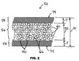
次に本発明の例示的実施形態を挙げる目的で例示的図面をさらに詳細に参照すると、同様の参照番号は幾つかの図で対応する又は同様の要素を指し、図1には例示的植え込み型プロテーゼ50の一部が図示されている。植え込み型プロテーゼは複数の相互接続したストラット52を含む。ストラット52は、相互に接続された波状環54を形成する。 Referring now more particularly to the exemplary drawings for purposes of illustrating exemplary embodiments of the invention, like reference numerals designate corresponding or similar elements in the several views, and FIG. A portion of the
図2に示すように、ストラット52の1つ又は複数は中空である。中空ストラット52は管腔56、及び管腔56を囲む金属層58を有する。放射線不透過性粒子60が管腔56内に配置される。 As shown in FIG. 2, one or more of the
幾つかの実施形態では、ストラット52は約0.06mm〜約0.3mmの外径D1を有する。 In some embodiments, the
幾つかの実施形態では、ストラット52は約0.01mm〜約0.25mmの内径D2を有する。内径D2は管腔56の直径に対応する。 In some embodiments, strut 52 has an inner diameter D2 of about 0.01 mm to about 0.25 mm. The inner diameter D2 corresponds to the diameter of the
幾つかの実施形態では、金属層58は約0.01mm以上の厚さTを有する。 In some embodiments, the
他の外径、内径、及び厚さを使用することができる。選択される寸法は、植え込み型プロテーゼのタイプ、及びプロテーゼを患者に植え込むよう意図されている場所によることがある。 Other outer diameters, inner diameters, and thicknesses can be used. The dimensions selected may depend on the type of implantable prosthesis and the location where the prosthesis is intended to be implanted in the patient.
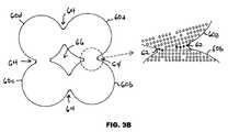
図3A及び図3Bに示すように、幾つかの実施形態では、放射線不透過性粒子60は、隣接する放射線不透過性粒子60a、60bからの原子62が、隣接する放射線不透過性粒子60a、60b間の接点64まで拡散することによって、相互に直接固着している。図3Aは、接点64までの原子62の拡散によって固着する前の放射線不透過性粒子60を示す。図3Bは、接点64までの原子62の拡散によって固着した後の放射線不透過性粒子60を示す。相対的に暗い影で図示された図3Bの原子62は、接点64まで拡散した原子である。接点64は、放射線不透過性粒子60間のギャップ66によって互いに分離される。 As shown in FIGS. 3A and 3B, in some embodiments, the
幾つかの実施形態では、相互に直接固着している放射線不透過性粒子60は、プロテーゼ50を患者に植え込んだ後に放射線不透過性粒子60から放出される金属イオンを減少させる不動態化コーティングで被覆されている。この場合、不動態化コーティングは、放射線不透過性粒子60が相互に直接固着した後に施すことができる。 In some embodiments, the
図4に示すように、幾つかの実施形態では、治療薬68は、放射線不透過性粒子60間のギャップ66(図2)内に含まれる。 As shown in FIG. 4, in some embodiments, the
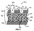
図5、図6A及び図6Bに示すように、幾つかの実施形態では、金属層58が、管腔56から治療薬68を放出するために側穴70を有する。側穴70は、金属層58の所定の位置にある。側穴70間の金属層58の表面区域72は、治療薬68に対して無孔性である。 As shown in FIGS. 5, 6A and 6B, in some embodiments, the
図6Bに示すように、幾つかの実施形態では、金属層58は内面69及び外面74を有する。不動態化コーティング76は、内面69及び外面74に配置する。不動態化コーティング76は、患者への植え込み後にストラット52からの金属イオンの放出を減少させ、管腔56内に保存された治療薬の劣化を軽減することができる。治療薬が管腔56内に保存されている場合、不動態化コーティング76は内面69と治療薬を分離するか、又はその間に配置される。 As shown in FIG. 6B, in some embodiments, the
幾つかの実施形態では、不動態化コーティング76は内面69に配置されるが、外面74には配置されない。幾つかの実施形態では、不動態化コーティング76は外面74に配置されるが、内面69には配置されない。幾つかの実施形態では、不動態化コーティング76は側穴70の内壁59(図7及び図8)に配置される。 In some embodiments, the
幾つかの実施形態では、側穴70は放射線不透過性粒子60の直径より大きい直径D3(図5)を有する。例えば、側穴70の直径は、放射線不透過性粒子が25マイクロメートル以下の直径を有する場合、25マイクロメートルより大きくすることができる。側穴70には他の直径を使用してもよい。放射線不透過性粒子60は、放射線不透過性粒子が(焼結などによって)相互に直接固着していることにより、放射線不透過性粒子を搬送する(ポリマー固着剤などの)外部固着剤により、又は放射線不透過性粒子が相互に直接固着していることと、放射線不透過性粒子を搬送する外部固着剤との両方により、管腔56内に保持される。 In some embodiments, the side holes 70 have a diameter D3 (FIG. 5) that is greater than the diameter of the
幾つかの実施形態では、側穴70は放射線不透過性粒子60の直径より小さい直径を有し、したがって放射線不透過性粒子60は患者への植え込み後の管腔56内に捕捉されたままである。放射線不透過性粒子60は側穴70を通過することができないので、ストラット52の端穴71を通して放射線不透過性粒子60を管腔56内に導入することができる。例えば、側穴70の直径は、放射線不透過性粒子が少なくとも20マイクロメートルの直径を有する場合、20マイクロメートル未満とすることができる。側穴70は他の直径を使用してもよい。 In some embodiments, the side holes 70 have a diameter that is smaller than the diameter of the
端穴71は管腔56と連通している。幾つかの実施形態では、管腔56はプロテーゼ50の複数のストラットを通して延在する。幾つかの実施形態では、管腔56はプロテーゼ50のすべてのストラットを通して延在する。 The end hole 71 is in communication with the
端穴71は、ストラット52の自由端に配置され、管腔56の中心軸と実質的に平行又は同軸の中心軸73を有する。側穴70はストラット52の自由端に配置されない。側穴70は、管腔56の中心軸と実質的に非平行である中心軸75を有する。図6A及び図6Bでは、中心軸75は管腔56の中心軸に対して実質的に直角である。中心軸75と管腔56の中心軸との間に他の非ゼロの角度を使用することができる。 The end hole 71 is disposed at the free end of the
幾つかの実施形態では、側穴70は細長いスロット又は楕円の形状であり、したがって側穴70は小径及び大径を有する。小径は放射線不透過性粒子60の直径より小さく、大径は放射線不透過性粒子60の直径より大きい。スロット形又は楕円形の側穴70は、放射線不透過性粒子60による側穴70の目詰まりを軽減又は防止することができる。 In some embodiments, the
幾つかの実施形態では、側穴70は、植え込み型プロテーゼ50の反管腔側表面に排他的に配置される。反管腔側表面は、プロテーゼの中心から半径方向外側に面し、血管などの解剖学的管腔内に植え込まれた場合、生物組織を支持するか、又はそれと接触する。例えば、反管腔側表面を通して配置された穴によって、治療薬68を内部に直接放出し、植え込み型プロテーゼ50に隣接する生物組織に治療効果を提供することができる。 In some embodiments, the side holes 70 are disposed exclusively on the abluminal surface of the
幾つかの実施形態では、側穴70は植え込み型プロテーゼ50の管腔表面に排他的に配置される。管腔側表面は、プロテーゼの中心に向かって半径方向内側に面し、解剖学的管腔の中心通路に面する。例えば、管腔側表面を通して配置された穴によって治療薬68を血流内に放出し、植え込み型プロテーゼ50の下流に治療効果を提供することができる。 In some embodiments, the side holes 70 are located exclusively on the luminal surface of the
幾つかの実施形態では、側穴70は植え込み型プロテーゼ50の反管腔側表面及び管腔側表面に配置される。 In some embodiments, the side holes 70 are disposed on the abluminal surface and the luminal surface of the
幾つかの実施形態では、放射線不透過性粒子60は金属層58に直接固着する。 In some embodiments, the
幾つかの実施形態では、直接固着は図3A及び図3Bに関連して上述した方法と同様の方法で達成され、したがって放射線不透過性粒子60は、放射線不透過性粒子60から放射線不透過性粒子60と金属層58の間の接点90(図2)への原子の拡散によって、金属層58に固着される。 In some embodiments, direct anchoring is achieved in a manner similar to that described above in connection with FIGS. 3A and 3B, so that the
幾つかの実施形態では、放射線不透過性粒子60は、外部固着剤、接着剤、又は同様の材料を必要とせずに相互に直接固着している。外部固着剤、接着剤、又は同様の材料は放射線不透過性粒子60の一部でもなく、それに含まれてもいず、放射線不透過性粒子60を管腔56内に捕捉した放射線不透過性粒子60を維持することを主目的として、放射線不透過性粒子60に添加されるか、又はそれと混合される材料である。 In some embodiments, the
幾つかの実施形態では、(図3B、図4及び図5でのように)相互に直接固着している放射線不透過性粒子60は、放射線不透過性粒子60間に配置された外部固着剤、接着剤、又は同様の材料を有していない。 In some embodiments, the
幾つかの実施形態では、相互に直接固着している放射線不透過性粒子60は、放射線不透過性粒子60を囲む外部固着剤、接着剤、又は同様の材料によっても共に保持される。外部固着剤、接着剤、又は同様の材料は、放射線不透過性粒子60間の相互接続に追加の強度を提供する。 In some embodiments, the
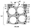
図7Aに示すように、幾つかの実施形態では、放射線不透過性粒子60は焼結又は原子拡散によって管腔56内に保持されない。放射線不透過性粒子60は、放射線不透過性粒子60を囲む外部固着剤、接着剤、又は同様の材料61によって管腔56の内側に保持される。例えば、ポリマー固着剤を外部固着剤として使用することができる。 As shown in FIG. 7A, in some embodiments, the
図8Aに示すように、幾つかの実施形態では、ポリマー固着剤61が治療薬68及び放射線不透過性粒子60を搬送する。幾つかの実施形態では、ポリマー固着剤61は治療薬68と組み合わされる。 As shown in FIG. 8A, in some embodiments, a
図7B及び図8Bでは、不動態化コーティング76が金属層58及び放射線不透過性粒子60に施される。不動態化コーティング76は、側穴70の内壁59に施される。代替実施形態では、不動態化コーティング76は金属層58に施されるが、放射線不透過性粒子60には施されない。 In FIGS. 7B and 8B, a
幾つかの実施形態では、不動態化コーティング76は内面69から側穴70の内壁59へ、さらに金属層58の外面74(図6B)へと連続的に延在する。 In some embodiments, the
図7Bに示すように、幾つかの実施形態では、放射線不透過性粒子60は焼結又は原子拡散によって管腔56内に保持されるのではない。放射線不透過性粒子60は、放射線不透過性粒子60を囲む外部固着剤、接着剤、又は同様の材料61によって管腔56の内側に保持される。例えば、ポリマー固着剤を外部固着剤として使用することができる。 As shown in FIG. 7B, in some embodiments, the
図8Bに示すように、幾つかの実施形態では、ポリマー固着剤61は治療薬68及び放射線不透過性粒子60を搬送する。 As shown in FIG. 8B, in some embodiments, the
幾つかの実施形態では、ポリマー固着剤61は、患者への植え込み後に放射線不透過性粒子60が管腔56から漏出しないようにし、植え込み後に治療薬68がポリマー固着剤61から拡散し、側穴70を通過することによって管腔56から漏出できるようにする。ポリマー固着剤61は、血液などの体液に曝露した場合に生体安定性及び耐久性があり、植え込み後に実質的に管腔56内に残る。 In some embodiments, the
幾つかの実施形態では、ポリマー固着剤61は生体吸収性、生分解性、又は生体浸食性(bioerodible)である。有意の期間の後、ポリマー固着剤61は管腔56内に残っていない。放射線不透過性粒子60は、放射線不透過性粒子60より小さいサイズである側穴70を有することによって、管腔56内に保持することができる。 In some embodiments, the polymeric sticking
「生分解性」、「生体吸収性」及び「生体浸食性」という用語は互換的に使用され、血液などの体液に曝露すると完全に分解及び/又は浸食することができ、身体によって徐々に再吸収、吸収及び/又は排出することができるポリマーを指す。ポリマーの分解及び最終的な吸収及び排出のプロセスは、例えば加水分解、代謝プロセス、酵素分解、酸化、塊又は表面浸食などによって引き起こされ得る。「生体安定性」という語は、生分解性ではないポリマーを指す。 The terms “biodegradable”, “bioabsorbable” and “bioerodible” are used interchangeably and can be completely degraded and / or eroded when exposed to bodily fluids such as blood and gradually re-appropriate by the body. Refers to a polymer that can be absorbed, absorbed and / or excreted. Polymer degradation and final absorption and excretion processes can be caused by, for example, hydrolysis, metabolic processes, enzymatic degradation, oxidation, lumps or surface erosion and the like. The term “biostable” refers to a polymer that is not biodegradable.
幾つかの実施形態では、治療薬68は、離散固体粒子又は離散半固体粒子としてポリマー固着剤61内で搬送することができる。治療薬68は粉末粒子の形態とすることができる。 In some embodiments, the
幾つかの実施形態では、治療薬68は、離散液滴としてポリマー固着剤61内で搬送することができる。 In some embodiments, the
幾つかの実施形態では、治療薬68はポリマー固着剤61内で搬送され、ポリマー固着剤61内で離散粒子又は離散液滴の形態ではない。 In some embodiments, the
幾つかの実施形態では、治療薬68はポリマー固着剤61中に溶解する。治療薬68及びポリマー固着剤61の溶液を、放射線不透過性粒子60間に配置する。 In some embodiments, the
幾つかの実施形態では、ポリマー固着剤61には、ホスホリルコリン系ポリマー、BioLinx(商標)ポリマー(ミネソタ州ミネアポリスのMedtronicから入手可能)、ポリ(n−ブチルメタクリレート)、ポリ(n−ヘキシルメタクリレート)、及びスチレン−イソブチレン−スチレントリブロックコポリマーからなる群から選択される固着剤材料が含まれる。ホスホリルコリン系ポリマーの例にはPC1036が含まれるが、これらに限定されない。PC1036はモノマー2−メタクリロイルオキシエチルホスホリルコリン(MPC)、ラウリルメタクリレート(LMA)、ヒドロキシプロピルメタクリレート(HPMA)、及びトリメトキシシリルプロピルメタクリレート(TSMA)で構成され、そのモル比はMPC23、LMA47、HPMA25、及びTSMA5である。BioLinx(商標)ポリマーは、親水性C19ポリマー、水溶性ポリビニルピロリドン(PVP)、及び親油性/疎水性C10ポリマーの混合物を含むことができる。In some embodiments, the
他の実施形態では、ポリマー固着剤61には、シリコン、ポリエステル、ポリオレフィン、ポリイソブチレン及びエチレン−アルファオレフィンコポリマー、アクリルポリマー及びコポリマー、ハロゲン化ビニルポリマー及びコポリマー、ポリ(塩化ビニル)、ポリ(フッ化ビニル)、ポリ(フッ化ビニリデン)(PVDF)、ポリ(塩化ビニリデン)、ポリ(フッ化ビニリデン−コ−ヘキサフルオロプロピレン)(PVDF−HFP)、ポリ(テトラフルオロエチレン−コ−フッ化ビニリデン−コ−ヘキサフルオロプロピレン)、ポリビニルエーテル、例えばポリビニルメチルエーテル、ポリアクリロニトリル、ポリビニルケトン、ポリビニル芳香族化合物、例えばポリスチレン、ポリビニルエステル、例えばポリ(酢酸ビニル)、ビニルモノマーと相互及びオレフィンとのコポリマー、例えばエチレン−メチルメタクリレートコポリマー、アクリロニトリル−スチレンコポリマー、ABS樹脂、及びポリ(エチレン−酢酸ビニル)コポリマー、ポリアミド、例えばナイロン66及びポリカプロラクタム、アルキド樹脂、ポリカーボネート、ポリオキシメチレン、ポリイミド、ポリエーテル、ポリ(セク−ブチルメタクリレート)ポリ(イソブチルメタクリレート)、ポリ(t−ブチルメタクリレート)、ポリ(n−プロピルメタクリレート)、ポリ(イソプロピルメタクリレート)、ポリ(エチルメタクリレート)、ポリ(メチルメタクリレート)、エポキシ樹脂、ポリ(ビニルブチラール)、ポリ(エーテルウレタン)、ポリ(エステルウレタン)、ポリ(尿素ウレタン)、ポリ(シリコーンウレタン)、ポリウレタン、レーヨン、レーヨン−トリアセテート、酢酸セルロース、酪酸セルロース、酢酸酪酸セルロース、セロハン、硝酸セルロース、プロピオン酸セルロース、セルロースエーテル、カルボキシメチルセルロース、ポリエーテル、例えばポリ(エチレングリコール)(PEG)、コポリ(エーテル−エステル)、(例えばポリ酸化アルキレン、例えばポリ(酸化エチレン)、ポリ(酸化プロピレン)、ポリ(エーテルエステル)、シュウ酸ポリアルキレン、ポリホスファゼン、ポリ(フルオロホスファゼン)、ポリ(ホスホリルコリンメタクリレート)、2−ヒドロキシエチルメタクリレート(HEMA)などのヒドロキシを有するモノマーの重合体及びコポリマー、ヒドロキシプロピルメタクリレート(HPMA)、ヒドロキシプロピルメタクリルアミド、PEGアクリレート(PEGA)、PEGメタクリレート、カルボン酸を有するモノマーを含有する重合体、例えばメタクリル酸(MA)、アクリル酸(AA)、アルコキシメタクリレート、アルコキシアクリレート、及び3−トリメチルシリルプロピルメタクリレート(TMSPMA)、ポリ(スチレン−イソプレン−スチレン)−PEG(SIS−PEG)、ポリスチレン−PEG、ポリイソブチレン−PEG、ポリ(メチルメタクリレート)−PEG(PMMA−PEG)、ポリジメチルシロキサン−コ−PEG(PDMS−PEG)、PLURONIC(商標)界面活性剤(酸化ポリプロピレン−コ−ポリエチレングリコール)、ポリ(テトラメチレングリコール)、及びヒドロキシ機能性ポリ(ビニルピロリドン)から選択される固着剤材料が含まれる。 In other embodiments, the
他の実施形態では、ポリマー固着剤61は、生分解性、生体吸収性、又は生体浸食性である材料でよい。このような固着剤の場合、放射線不透過性粒子は、そのサイズによって、又は相互に又は金属層58に固着することによって、管腔56内に保持される。このような生分解性固着剤には、ポリ(エステルアミド)、ポリヒドロキシアルカノエート(PHA)、ポリ(3−ヒドロキシアルカノエート)、例えばポリ(3−ヒドロキシプロパノエート)、ポリ(3−ヒドロキシブチル酸塩)、ポリ(3−ヒドロキシ吉草酸塩)、ポリ(3−ヒドロキシヘキサン酸塩)、ポリ(3−ヒドロキシヘプタン酸塩)及びポリ(3−ヒドロキシオクタン酸塩)、ポリ(4−ヒドロキシアルカノエート)、例えばポリ(4−ヒドロキシブチル酸塩)、ポリ(4−ヒドロキシ吉草酸塩)、ポリ(4−ヒドロキシヘキサン酸塩)、ポリ(4−ヒドロキシヘプタン酸塩)、ポリ(4−ヒドロキシオクタン酸塩)、及び本明細書で述べる3−ヒドロキシアルカノエート又は4−ヒドロキシアルカノエートモノマー又はそれらの混合物を含むコポリマー、ポリ(D,L−ラクチド)、ポリ(L−ラクチド)、ポリグリコリド、ポリ(D,L−ラクチド−コ−グリコリド)、ポリ(L−ラクチド−コ−グリコリド)、ポリカプロラクトン、ポリ(ラクチド−コ−カプロラクトン)、ポリ(グリコリド−コ−カプロラクトン)、ポリ(ジオキサノン)、ポリ(オルトエステル)、ポリ(無水物)、ポリ(チロシン炭酸塩)及びそれらの誘導体、ポリ(チロシンエステル)及びそれらの誘導体、ポリ(イミノ炭酸塩)、ポリ(グリコール酸−コ−トリメチレン炭酸塩)、ポリホスホエステル、ポリホスホエステルウレタン、ポリ(アミノ酸)、ポリシアノアクリレート、ポリ(トリメチレン炭酸塩)、ポリ(イミノ炭酸塩)、ポリ(グリセリルセバシン酸塩)、ポリ(プロピレンフマル酸塩)、ポリ(エチレン酸化物/ポリ(乳酸)(PEO/PLA)、ポリカプロラクトン−PEG(PCL−PEG)、PLA−PEG、生体分子、例えばキトサン、アルギン酸塩、フィブリン、フィブリノーゲン、セルロース、デンプン、デキストラン、デキストリン、ヒアルロン酸のフラグメント及び誘導体、ヘパリン、ヘパリンのフラグメント及び誘導体、グリコサミノグリカン(GAG)、GAG誘導体、多糖類、キトサン、アルギン酸塩、又はそれらの組み合わせが含まれる。幾つかの実施形態では、本明細書に記載するコポリマーは上記重合体の任意の1つ又は複数を除外することができる。 In other embodiments, the
本明細書で使用するポリ(D,L−ラクチド)、ポリ(L−ラクチド)、ポリ(D,L−ラクチド−コ−グリコリド)、及びポリ(L−ラクチド−コ−グリコリド)という用語はそれぞれ、ポリ(D,L−乳酸)、ポリ(L−乳酸)、ポリ(D,L−乳酸−コ−グリコール酸)、又はポリ(L−乳酸−コ−グリコール酸)という用語と互換的に使用することができる。 As used herein, the terms poly (D, L-lactide), poly (L-lactide), poly (D, L-lactide-co-glycolide), and poly (L-lactide-co-glycolide) are respectively , Poly (D, L-lactic acid), poly (L-lactic acid), poly (D, L-lactic acid-co-glycolic acid), or poly (L-lactic acid-co-glycolic acid) can do.
幾つかの実施形態では、ポリマー固着剤61の固着剤材料は、ポリマー固着剤から拡散するよう意図されている治療薬のタイプに基づいて選択される。 In some embodiments, the binder material of the
金属層58は、ヒト又は動物の体内に植え込むのに適切な任意の生分解性材料で作製することができる。幾つかの実施形態では、金属層58は、316Lステンレス鋼、CoNi MP35N、CoCr L−605、及びFePtCrからなる群から選択される母材を含む。他の母材も使用することができる。 The
幾つかの実施形態では、金属層58の母材は放射線不透過性粒子60より高いか、又はそれとほぼ同じである融点を有する。 In some embodiments, the matrix of the
幾つかの実施形態では、金属層58は母材の焼結粒子から形成されるのではなく、したがって金属層58は、焼結の結果となることがあるランダムにピットがある組織又は粒状組織を有さない。 In some embodiments, the
幾つかの実施形態では、金属層58の外面74(図2及び図5)は実質的に滑らかである。外面74は研磨仕上げを有することができる。 In some embodiments, the outer surface 74 (FIGS. 2 and 5) of the
幾つかの実施形態では、金属層58の外面74はベアメタル状態に維持される。ベアメタル状態にある場合は、外面74に非金属コーティングが存在しない。 In some embodiments, the
幾つかの実施形態では、金属層58の外面74には治療薬を含むコーティングが存在しない。 In some embodiments, the
放射線不透過性粒子60は、ヒト又は動物の体内に植え込むのに適切な任意の材料で作製することができる。放射線不透過性材料は、密度が高いか、又はX線放射を効率的に吸収する原子番号が大きい材料である。幾つかの実施形態では、放射線不透過性粒子60は、金、Au/Pt/Zn85/10/5の合金、Au/Ag/Pt/Zn73/12/0.5/15の合金、プラチナ、イリジウム、プラチナ/イリジウムの合金、パラジウム、タンタル、及びニオブからなる群から選択される放射線不透過性材料を含む。他の放射線不透過性材料も使用することができる。 The
幾つかの実施形態では、放射線不透過性粒子60は約10ナノメートル〜約25マイクロメートルの直径を有することができる。放射線不透過性粒子60には他の直径も使用することができる。 In some embodiments,
再び図1を参照すると、ストラット52はダイアモンド形のセルを形成する。図1に示した構成に加えて多くのストラットの構成が可能であることを理解されたい。例えば、本発明の植え込み型プロテーゼのストラットは、他のセル形状を形成することができる。ストラットの構成には、「Expandable Stents」と題したLau他の米国特許第5,514,154号に図示され、記載されているような構成が含まれ、それはあらゆる意味で参照によりその全体が本明細書に組み込まれる。さらなる例として、本発明の植え込み型プロテーゼのストラットはらせん形又はコイルにすることができる。らせん形又はコイル形の複数のストラットを共に溶接するか、他の方法で接合して、植え込み型プロテーゼを形成することができる。 Referring again to FIG. 1, struts 52 form a diamond shaped cell. It should be understood that many strut configurations are possible in addition to the configuration shown in FIG. For example, the implantable prosthesis struts of the present invention can form other cell shapes. Strut configurations include those illustrated and described in US Pat. No. 5,514,154 to Lau et al. Entitled “Expandable Stents”, which is hereby incorporated by reference in its entirety in its entirety. Incorporated in the description. As a further example, the struts of the implantable prosthesis of the present invention can be helical or coiled. A plurality of helical or coiled struts can be welded together or otherwise joined to form an implantable prosthesis.
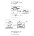
図9Aに示すように、植え込み型プロテーゼを作製する例示的方法は、放射線不透過性粒子60をストラット52の管腔56内に配置すること(ブロック80)と、任意選択でその後に放射線不透過性粒子60を相互に固着させること(ブロック82)とを含む。 As shown in FIG. 9A, an exemplary method of making an implantable prosthesis includes placing
幾つかの実施形態では、放射線不透過性粒子60は放射線不透過性材料及び内部固着剤を含む。内部固着剤は、放射線不透過性粒子60内に含まれ、その一部である。内部固着剤は、放射線不透過性粒子又は凝集塊を形成するように、放射線不透過性材料を共に保持する。幾つかの実施形態では、内部固着剤は有機材料を含む。 In some embodiments, the
幾つかの実施形態では、放射線不透過性粒子60を管腔56内に配置すること(ブロック80)は、放射線不透過性粒子60と外部固着剤、接着剤、又は同様の材料との混合物、又は放射線不透過性粒子60と治療薬68と外部固着剤、接着剤、又は同様の材料との混合物を配置することを含む。外部固着剤、接着剤、又は同様の材料61は、図7及び図8に関して上述した通りでよい。外部固着剤、接着剤、又は同様の材料61は、上述したようなポリマー固着剤でよい。幾つかの実施形態では、ストラット52の端穴71(図6A及び図6B)に混合物を通すことによって、混合物を管腔56内に導入する。混合物を導入した後、任意の治療薬が外部固着剤61から拡散できるように、ストラット52を通して側穴70を作製することができる。任意選択で、混合物を導入した後に端穴71を封止する。 In some embodiments, placing the
幾つかの実施形態では、ストラット52の側穴70(図6A及び図6B)に混合物を通すことによって、混合物を管腔56内に導入する。側穴70は、外部固着剤61を含有する混合物を管腔56に装填する目的で、及び任意の治療薬が外部固着剤61から拡散して管腔56から漏出できるという目的で作製される。 In some embodiments, the mixture is introduced into the
幾つかの実施形態では、放射線不透過性粒子60を管腔56内に配置した(ブロック80)後に、外部固着剤、接着剤、又は同様の材料61を管腔56内に付加する。外部固着剤、接着剤、又は同様の材料61を付加することは、ストラット52を材料61に浸漬する、又はストラット52の端穴又は側穴にある開口に材料61を注入することによって実行することができる。材料61は、図7及び図8に関して上述したようなポリマー固着剤でよい。 In some embodiments, after the
幾つかの実施形態では、材料(放射線不透過性粒子60を管腔56内に配置した(ブロック80)後に管腔56内に付加される)は、ポリマー固着剤と治療薬68の混合物である。 In some embodiments, the material (added into the
幾つかの実施形態では、材料(放射線不透過性粒子60を管腔56内に配置した(ブロック80)後に管腔56内に付加される)は、治療薬68を吸収することができるポリマー固着剤である。ポリマー固着剤が管腔56に入った後、植え込み前に治療薬68をポリマー固着剤に注入することができる。ストラット52は、治療薬68を含む容器内に浸漬することができる。植え込み後、治療薬68はポリマー固着剤から拡散し、管腔56から漏出することができる。 In some embodiments, the material (which is added into the
幾つかの実施形態では、放射線不透過性粒子60を管腔56内に配置すること(ブロック80)は、放射線不透過性粒子60と焼結添加剤の混合物を管腔56内に配置することを含む。焼結添加剤は、混合物を管腔56内に配置する前に、放射線不透過性粒子60と混合される。焼結添加剤は、その後の焼結を促進することができる。 In some embodiments, placing the
幾つかの実施形態では、焼結添加剤は放射線不透過性粒子60より低い融点を有する。 In some embodiments, the sintering additive has a lower melting point than the
幾つかの実施形態では、固着すること(ブロック82)は、放射線不透過性粒子を共に焼結することを含む。焼結中に、放射線不透過性粒子60を含むストラット52を、慎重に制御された内部温度を有する炉のチャンバ内に配置する。炉の内部温度を焼結温度まで上昇させる。 In some embodiments, securing (block 82) includes sintering the radiopaque particles together. During sintering, a
幾つかの実施形態では、焼結温度は約500℃〜約670℃である。他の焼結温度を使用してもよい。 In some embodiments, the sintering temperature is from about 500 ° C to about 670 ° C. Other sintering temperatures may be used.
幾つかの実施形態では、焼結温度は約20℃(68°F)より高く、金属層58の融点より低い。金属層58の融点の例には、表1に列挙する融点が含まれるが、これらに限定されない。
幾つかの実施形態では、焼結温度は20℃(68°F)より高く、金属層58の軟化温度以下である。金属層58の軟化温度の例には、表1に列挙した軟化温度が含まれるが、これらに限定されない。 In some embodiments, the sintering temperature is above 20 ° C. (68 ° F.) and below the softening temperature of the
幾つかの実施形態では、焼結温度は放射線不透過性粒子60の融点より低い。放射線不透過性粒子60の融点の例には、表2に列挙した融点が含まれるが、これらに限定されない。
幾つかの実施形態では、焼結温度は20℃(68°F)より高く、放射線不透過性粒子60の軟化温度以下である。放射線不透過性粒子60の軟化温度の例には、表2に列挙した軟化温度が含まれるが、これらに限定されない。 In some embodiments, the sintering temperature is higher than 20 ° C. (68 ° F.) and below the softening temperature of the
幾つかの実施形態では、焼結後、放射線不透過性粒子60は完全には相互に合体又は同化せず、相互から別個のままである(例えば図3B参照)。放射線不透過性粒子60は顆粒状及び多孔性構造を形成するが、これは表2の軟化温度のいずれかのように、放射線不透過性粒子60を完全には液化しない焼結温度を使用することによって達成することができる。 In some embodiments, after sintering, the
幾つかの実施形態では、焼結温度は放射線不透過性粒子60の融点より低く、管腔56内に含まれ、放射線不透過性粒子60と混合した焼結添加剤の融点以上である。 In some embodiments, the sintering temperature is below the melting point of the
なお図9Aを参照すると、幾つかの実施形態では、固着すること(ブロック82)は、隣接する放射線不透過性粒子からの原子を、隣接する放射線不透過性粒子間の接点まで拡散させることを含む。原子の拡散は、隣接する放射線不透過性粒子60a、60b(図3A)を20℃(68°F)より高い温度に曝露することによって促進することができる。高温の例には、上述したような焼結温度が含まれるが、これらに限定されない。 Still referring to FIG. 9A, in some embodiments, anchoring (block 82) may cause atoms from adjacent radiopaque particles to diffuse to the contacts between adjacent radiopaque particles. Including. Atom diffusion can be facilitated by exposing adjacent radiopaque particles 60a, 60b (FIG. 3A) to temperatures greater than 20 ° C. (68 ° F.). Examples of high temperatures include, but are not limited to, sintering temperatures as described above.
幾つかの実施形態では、固着すること(ブロック82)は、接点64を、放射線不透過性粒子60間のギャップ66(図3B)によって分離できるようにすることを含む。放射線不透過性粒子60間のギャップ66は、高温を放射線不透過性粒子60の融点より低く保った場合に、維持することができる。 In some embodiments, securing (block 82) includes allowing the
幾つかの実施形態では、放射線不透過性粒子60を管腔56内に配置すること(ブロック80)の前に、ストラット52を形成する(ブロック78)。 In some embodiments, the
幾つかの実施形態では、ストラット52は、蛇行させるか曲げて山形を形成した1本の連続したワイヤから作製する。所定の位置にある溶接部53(図1)を使用して、所望の位置に強度又は剛性を提供することができる。 In some embodiments, the
幾つかの実施形態では、ストラット52は当技術分野で知られている従来の方法により作製される。例えば、ストラット52は中空のワイヤとすることができ、ストラット52を形成することは、中空のワイヤを形成する従来のプロセスステップを含むことができる。さらなる例として、ストラット52は、「Hollow Tubular Drug Eluting Medical Devices」と題した上述の特許公開第US2011/0008405号に記載されたプロセスステップに従って作製することができる。 In some embodiments, struts 52 are made by conventional methods known in the art. For example, the
幾つかの実施形態では、ストラット52を形成すること(ブロック78)は、外面74に実質的に滑らかな仕上げを与えるために外面74(図2及び図5)を研磨することを含む。 In some embodiments, forming the struts 52 (block 78) includes polishing the outer surface 74 (FIGS. 2 and 5) to give the outer surface 74 a substantially smooth finish.
なお図9Aを参照すると、幾つかの実施形態では、固着させること(ブロック82)の後に、治療薬68を管腔56内及び放射線不透過性粒子60間に導入する(ブロック84)。放射線不透過性粒子60が高温で共に固着している場合、導入すること(ブロック84)は、放射線不透過性粒子60が高温より下に冷却した後に実行する。 Still referring to FIG. 9A, in some embodiments, after anchoring (block 82),
幾つかの実施形態では、治療薬68を管腔56内に導入すること(ブロック84)は、治療薬68を含む溶液又は混合物にストラット52を浸漬することと、ストラット52の端部又は側部にある開口を通して治療薬68が管腔56内に流入できるようにすることとを含む。 In some embodiments, introducing
幾つかの実施形態では、治療薬68を管腔56内に導入すること(ブロック84)は、治療薬68の溶液又は混合物を管腔56内に引き込むために管腔56に真空(負圧)を付与することを含む。代替的に、又は真空に加えて、溶液又は混合物を管腔56内に強制的に入れるために、ストラット52の外側から溶液又は混合物に正圧を加える。 In some embodiments, introducing
幾つかの実施形態では、治療薬68を管腔56内に導入すること(ブロック84)は、治療薬68と担体物質の混合物を導入することを含む。担体物質は溶剤、ポリマー、又はその組み合わせとすることができる。担体物質は、治療薬68の輸送、放射線不透過性粒子60間の治療薬68の移動及び/又は管腔56からの治療薬68の放出制御を促進することができる。担体物質の選択は、それが搬送するよう意図された治療薬のタイプに基づいて決定することができる。 In some embodiments, introducing
幾つかの実施形態では、担体物質はポリマー固着剤である。ポリマー固着剤は、図7及び図8に関して上述した通りでよい。ポリマー固着剤は、管腔56内に導入された後に固化又は硬化することができる。固化又は硬化後、治療薬68はポリマー固着剤から拡散又は溶離して、管腔56から漏出する。固化又は硬化後、ポリマー固着剤は、放射線不透過性粒子60が管腔56内で位置をシフトするのを防止し、放射線不透過性粒子60が放射線不透過性粒子60より大きい端穴71又は側穴70から漏出するのを防止する。 In some embodiments, the carrier material is a polymeric sticker. The polymer sticker may be as described above with respect to FIGS. The polymer binder can be solidified or cured after being introduced into the
幾つかの実施形態では、側穴70(図5〜図8)は、管腔56を囲む金属層58を通して所定の位置に形成することができる(ブロック86)。穴の形成は、治療薬68を管腔56内に導入すること(ブロック84)の前又は後に実行することができる。 In some embodiments, the side holes 70 (FIGS. 5-8) can be formed in place through the
幾つかの実施形態では、側穴70の形成(ブロック86)は、放射線不透過性粒子60をストラット52内に配置すること(ブロック80)の前に実行する。 In some embodiments, the formation of side holes 70 (block 86) is performed prior to placing
幾つかの実施形態では、ブロック86のうち1つ又は複数を図9Aから削除することができ、ブロック88のうち1つ又は複数を図9Aから削除することができる。 In some embodiments, one or more of the
側穴70は金属層58を貫通し、それによって治療薬68を、管腔56内に導入するか、植え込み後に管腔56から放出するか、又は管腔56内へ導入し、そこから放出することの両方を実行することができる。 The side holes 70 penetrate the
幾つかの実施形態では、側穴70が、側穴70を通した管腔56からの放射線不透過性粒子60の漏出を防止するようなサイズになるように、側穴70が形成される(ブロック86)。側穴70は、放射線不透過性粒子60をストラット52の管腔56内に配置すること(ブロック80)の前又は後に形成することができる(ブロック86)。 In some embodiments, the side holes 70 are formed such that the side holes 70 are sized to prevent leakage of the
幾つかの実施形態では、放射線不透過性粒子60を端穴71(図6A及び図6B)に通して管腔56内に配置した(ブロック80)後、端穴は、放射線不透過性粒子60を管腔56内に捕捉するために、クリンプする、塞栓する、又は封止することができる。側穴70は、放射線不透過性粒子60の直径より小さい直径D3(図5)を有し、それによって放射線不透過性粒子60が側穴70を通して管腔56から漏出するのを防止する。 In some embodiments, after the
幾つかの実施形態では、側穴70を放射線不透過性粒子60より小さいサイズにすることに加えて、放射線不透過性粒子60は、上述したように外部固着剤61によって相互に間接的に固着される、及び/又は上述したように焼結プロセスを使用した原子拡散によって相互に直接固着することができる。外部固着剤61及び/又は焼結は、放射線不透過性粒子60を管腔56内に保持するための追加の安全性を提供する。 In some embodiments, in addition to making the side holes 70 smaller in size than the
幾つかの実施形態では、ストラット52の形成(ブロック78)は、穴70間の金属層58の表面区域72(図5)が、治療薬68に対して無孔性になるように実行される。治療薬68は穴70を通過できるが、穴70間の表面区域72を通過することができない。穴70は、機械的穿孔、レーザ穿孔、イオンビームミリング、化学的エッチング、及びそれらの任意の組み合わせによって形成することができる。 In some embodiments, the formation of struts 52 (block 78) is performed such that the surface area 72 (FIG. 5) of the
幾つかの実施形態では、治療薬68が所定の位置で穴70を通過すると、治療薬68が管腔56から放出される。 In some embodiments,
幾つかの実施形態では、所定の位置は、穴70が相互から等間隔であるように選択される。穴70はランダムに分布しているのではない。 In some embodiments, the predetermined position is selected such that the
幾つかの実施形態では、所定の位置は、穴70が第1の領域及び第2の領域に配置され、第1の領域では第2の領域と比較して相互に近く分離されるように選択される。例えば、第1の領域及び第2の領域は、ストラット52の異なる区画に対応することができる。第1の領域及び第2の領域は、実質的に直線の区画52a(図1)及び湾曲した区画52b(図1)、又は逆の順序とすることができる。さらなる例として、第1の領域及び第2の領域は、植え込み型プロテーゼ50の異なる区画に対応することができる。第1の領域及び第2の領域は、端区画54a(図1)、及び端区画に隣接する中間区画54b(図1)、又は逆の順序とすることができる。 In some embodiments, the predetermined location is selected such that the
なお図9Aを参照すると、幾つかの実施形態では、方法はさらに、放射線不透過性粒子60を金属層58に固着させること(ブロック88)を含む。固着(ブロック88)は、管腔56からの放射線不透過性粒子60放出を回避するのに役立つことができる。 Still referring to FIG. 9A, in some embodiments, the method further includes securing
放射線不透過性粒子60の金属層58への固着(ブロック88)は、治療薬68を管腔56内に導入すること(ブロック84)の前に実行され、放射線不透過性粒子60を相互に固着すること(ブロック82)の前、その最中、又はその後に実行することができる。固着(ブロック88)は、放射線不透過性粒子60を金属層58に焼結することによって遂行することができる。 The fixation of
幾つかの実施形態では、放射線不透過性粒子60を金属層58に固着させること(ブロック88)は、放射線不透過性粒子60からの原子を放射線不透過性粒子60と金属層58の間の接点90(図2)まで拡散させることを含む。原子の拡散は、放射線不透過性粒子60及び金属層58を20℃(68°F)より高い高温に曝露することによって促進することができる。高温の例には、上述したような焼結温度が含まれるが、これらに限定されない。 In some embodiments, securing the
幾つかの実施形態では、その後の操作(ブロック90)は任意選択で、金属層58の外面を洗浄すること、金属層58の外面に外部コーティングを施すこと、ステントを送出カテーテル上にクリンプすること、及び植え込み型プロテーゼ50を殺菌することのうち任意の1つ又は複数を含む。 In some embodiments, subsequent operations (block 90) optionally include cleaning the outer surface of the
幾つかの実施形態では、金属層58の外部コーティングは、プライマ層、バリア層、及び治療薬を含むリザーバのうち任意の1つ又はその組み合わせを含むことができる。 In some embodiments, the outer coating of the
図9Bは、図9Aに図示されていない不動態化コーティングを施すことを示す。図9Aについて以上で記述したことは、図9Bに適用される。 FIG. 9B illustrates applying a passivating coating not shown in FIG. 9A. What has been described above for FIG. 9A applies to FIG. 9B.
図9Bに示すように、幾つかの実施形態では、不動態化コーティング76は、ストラットの形成(ブロック78)とストラットの管腔内への治療薬の導入(ブロック84)との間の任意の1つ又は複数の時点で、ストラット52の内面69及び/又は外面74に施される(ブロック92)。例えば、ブロック92はブロック80の後及び/又はブロック82の後に実行することができる。ブロック92は、ブロック88のいずれかの後及び/又はブロック86のいずれかの後に実行することができる。さらなる例として、ブロック92は、ブロック80の前及び/又はブロック82の前に実行することができる。ブロック92は、ブロック88のいずれかの前及び/又はブロック86のいずれかの前に実行することができる。 As shown in FIG. 9B, in some embodiments, the passivating
不動態化コーティング76は、患者に植え込んだ後のストラットからの金属イオン放出を減少させる。不動態化コーティング76は、ストラット内に保存された治療薬間の反応を減少させ、それにより治療薬の劣化を軽減することができる。不動態化コーティング76によって金属イオンの放出が減少すると、ステントの生体適合性も向上する。何故なら、ニッケル、コバルト、又は他の金属の放出イオンは、炎症又はアレルギー反応を引き起こすことがあるからである。 Passivating
不動態化コーティング76をストラット52の内面69に施す幾つかの実施形態では、不動態化コーティング76(又は不動態化コーティングを生成する組成物、蒸気、又はプラズマ)は、側穴70及び/又は端穴71を通して管腔56内に導入される。幾つかの実施形態では、不動態化コーティング76(又は不動態化コーティングを生成する組成物、蒸気、又はプラズマ)の導入は、治療薬68を管腔56内に導入する前に実行する。治療薬68が管腔56から漏出した後、不動態化コーティング76は内面69に残り、ストラット52からの金属イオン放出を減少させる。 In some embodiments in which the
図10を参照すると、幾つかの実施形態では、植え込み型プロテーゼを作製する方法は、ストラットを形成すること(ブロック78)、その後にストラット(ブロック86)に側穴70を形成すること、その後にストラットに不動態化コーティング76を施すこと(ブロック92)、その後に治療薬及び/又は放射線不透過性粒子をストラットに導入すること(ブロック94)を含む。ブロック94は、治療薬68と放射線不透過性粒子60の混合物をストラットの管腔56内に導入することを含むことができる。 Referring to FIG. 10, in some embodiments, a method of making an implantable prosthesis includes forming a strut (block 78) followed by forming a
代替実施形態では、ブロック94の一部としてブロック80を実行しない(図10)。ブロック80は、ブロック86とブロック92の間に実行する。不動態化コーティング76は、患者に植え込んだ後にストラット52及び放射線不透過性粒子60からの金属イオン放出を減少させ、ストラット52内の治療薬68の劣化を軽減するために、ストラット52及び放射線不透過性粒子60(図7及び図8)に施される。 In an alternative embodiment, block 80 is not executed as part of block 94 (FIG. 10).
幾つかの実施形態では、不動態化コーティングを施すこと(ブロック92)は、ブロック94の前にプラズマ重合したコーティングをストラットに施すことを含む。 In some embodiments, applying a passivating coating (block 92) includes applying a plasma polymerized coating to the struts prior to block 94.
幾つかの実施形態では、不動態化コーティングを施すこと(ブロック92)は、パリレンC又はパリレンDをストラットに塗布することを含む。パリレンC及びパリレンDは、蒸着したハイドロクロロカーボンポリマーである。パリレンC及びパリレンDは、熱補助蒸着プロセスでストラットに付着させる。 In some embodiments, applying a passivating coating (block 92) includes applying parylene C or parylene D to the struts. Parylene C and Parylene D are vapor deposited hydrochlorocarbon polymers. Parylene C and Parylene D are deposited on the struts in a heat assisted deposition process.
幾つかの実施形態では、不動態化コーティングを施すこと(ブロック92)は、パリレンNをストラットに塗布することを含む。パリレンNは蒸着した炭化水素ポリマーである。パリレンNも、熱補助蒸着プロセスで付着させる。 In some embodiments, applying a passivating coating (block 92) includes applying parylene N to the struts. Parylene N is a deposited hydrocarbon polymer. Parylene N is also deposited by a heat assisted deposition process.
幾つかの実施形態では、不動態化コーティングを施すこと(ブロック92)は、パリレンCのフッ化変種をストラットに塗布することを含む。パリレンAF4は、パリレンCのフッ化変種である。パリレンCとパリレンAF4との化学構造の比較を図11に示す。パリレンAF4はフッ化ポリマーである。パリレンAF4は、熱補助蒸着プロセスでストラットに付着させる。 In some embodiments, applying a passivating coating (block 92) includes applying a fluorinated variant of Parylene C to the struts. Parylene AF4 is a fluorinated variant of Parylene C. A comparison of the chemical structures of Parylene C and Parylene AF4 is shown in FIG. Parylene AF4 is a fluorinated polymer. Parylene AF4 is deposited on the struts in a heat assisted deposition process.
幾つかの実施形態では、不動態化コーティングを施すこと(ブロック92)は、溶媒可溶性のフッ化ポリマーコーティングをストラットに施すことを含む。ブロック92で、溶媒とフッ化ポリマーの溶液をストラットに被覆することができる。溶媒可溶性フッ化ポリマーの例にはポリ(フッ化ビニル)、ポリ(フッ化ビニリデン)(他にKYNAR(商標)として知られ、米国ペンシルベニア州フィラデルフィアのAtofina Chemicalsから入手可能)、ポリ(フッ化ビニリデン−コ−ヘキサフルオロプロピレン)(例えばSOLEF(登録商標)21508、米国ニュージャージー州ソロフェアのSolvay Solexis PVDFから入手可能)、ポリ(フッ化ビニリデン−コ−クロロトリフルオロエチレン)、ポリ(フッ化ビニリデン−コ−ヘキサフルオロプロピレン−コ−テトラフルオロエチレン)、及びポリ(フッ化ビニリデン−コ−塩化ビニリデン)が含まれるが、これらに限定されない。溶媒可溶性フッ化ポリマーの他の非限定的な例にはCytop(日本の東京のAGC Chemicalsから入手可能)及びTeflon(登録商標)AF(米国デラウェア州ウィルミントンのDuPont Fluoroproductsから入手可能)が含まれる。Cytop及びTeflon(登録商標)AFは非晶質フッ化ポリマーである。 In some embodiments, applying a passivating coating (block 92) includes applying a solvent soluble fluorinated polymer coating to the struts. At
上記例示的実施形態を含め、本発明の様々な実施形態で不動態化コーティングとして使用することができる他のポリマーの例には、エチレンビニルアルコールコポリマー(通常は一般名EVOH又は商品名EVAL(商標)で知られている)、シリコン、ポリエステル、ポリオレフィン、ポリイソブチレン及びエチレン−アルファオレフィンのコポリマー、アクリル性ポリマー及びコポリマー、ハロゲン化ビニルのポリマー及びコポリマー、ポリ(塩化ビニル)、ポリ(塩化ビニリデン)、ポリビニルエーテル、例えばポリビニルメチルエーテル、ポリアクリロニトリル、ポリビニルケトン、ポリビニル芳香族化合物、例えばポリスチレン、ポリビニルエステル、例えばポリ(酢酸ビニル)、ビニルモノマーと相互及びオレフィンとのコポリマー、例えばエチレン−メチルメタクリレートコポリマー、アクリロニトリル−スチレンコポリマー、ABS樹脂、及びポリ(エチレン−酢酸ビニルコポリマー)、ポリアミド、例えばナイロン66及びポリカプロラクタム、アルキド樹脂、ポリカーボネート、ポリオキシメチレン、ポリイミド、ポリ(セク−ブチルメタクリレート)、ポリ(イソブチルメタクリレート)、ポリ(t−ブチルメタクリレート)、ポリ(n−プロピルメタクリレート)、ポリ(イソプロピルメタクリレート)、ポリ(エチルメタクリレート)、ポリ(メチルメタクリレート)、エポキシ樹脂、ポリ(ビニルブチラール)、ポリ(エーテルウレタン)、ポリ(エステルウレタン)、ポリ(尿素ウレタン)、ポリ(シリコーンウレタン)、ポリウレタン、ポリホスファゼン、ポリ(フルオロホスファゼン)、2−ヒドロキシエチルメタクリレート(HEMA)及びヒドロキシプロピルメタクリレートなどのヒドロキシを有するモノマーのポリマー及びコポリマー、ポリ(アルコキシメタクリレート)、ポリ(アルコキシアクリレート)、ポリ(ビニルピロリジノン−コ−ヘキシルメタクリレート−コ−酢酸ビニル)、ポリ(ブチルメタクリレート−コ−酢酸ビニル)、及びそれらのコポリマー及び化合物が含まれるが、これらに限定されない。 Examples of other polymers that can be used as a passivation coating in various embodiments of the present invention, including the exemplary embodiments described above, include ethylene vinyl alcohol copolymers (usually the generic name EVOH or the trade name EVAL ™ ), Silicones, polyesters, polyolefins, copolymers of polyisobutylene and ethylene-alpha olefins, acrylic polymers and copolymers, polymers and copolymers of vinyl halides, poly (vinyl chloride), poly (vinylidene chloride), Polyvinyl ethers such as polyvinyl methyl ether, polyacrylonitrile, polyvinyl ketone, polyvinyl aromatic compounds such as polystyrene, polyvinyl esters such as poly (vinyl acetate), copolyols of vinyl monomers with each other and olefins -For example, ethylene-methyl methacrylate copolymer, acrylonitrile-styrene copolymer, ABS resin, and poly (ethylene-vinyl acetate copolymer), polyamide, such as nylon 66 and polycaprolactam, alkyd resin, polycarbonate, polyoxymethylene, polyimide, poly (sec -Butyl methacrylate), poly (isobutyl methacrylate), poly (t-butyl methacrylate), poly (n-propyl methacrylate), poly (isopropyl methacrylate), poly (ethyl methacrylate), poly (methyl methacrylate), epoxy resin, poly ( Vinyl butyral), poly (ether urethane), poly (ester urethane), poly (urea urethane), poly (silicone urethane), polyurethane, polyphos Polymers and copolymers of monomers having hydroxy, such as azen, poly (fluorophosphazene), 2-hydroxyethyl methacrylate (HEMA) and hydroxypropyl methacrylate, poly (alkoxy methacrylate), poly (alkoxy acrylate), poly (vinyl pyrrolidinone-co- Hexyl methacrylate-co-vinyl acetate), poly (butyl methacrylate-co-vinyl acetate), and copolymers and compounds thereof.
上記例示的実施形態を含め、本発明の様々な実施形態で不動態化コーティングとして使用することができるセラミック及びガラス材料の例にはアルミナ、酸化アルミニウム、ジルコニア、酸化ジルコニウム、チタニア、酸化チタニウム、シリコンカーバイド、酸化シリコン、シリカ、タングステンカーバイド、窒化チタニウム、窒化チタニウムアルミニウム、窒化アルミニウムCVDダイアモンドが含まれるが、これらに限定されない。これらの材料は、熱、プラズマ、又は気体状反応物のマイクロ波補助蒸着によって被覆することができる。これらの不動態化コーティングの特徴は、吸湿性が重量で約5%未満であることである。 Examples of ceramic and glass materials that can be used as a passivation coating in various embodiments of the present invention, including the exemplary embodiments described above, include alumina, aluminum oxide, zirconia, zirconium oxide, titania, titanium oxide, silicon Examples include, but are not limited to, carbide, silicon oxide, silica, tungsten carbide, titanium nitride, titanium aluminum nitride, and aluminum nitride CVD diamond. These materials can be coated by heat, plasma, or microwave assisted deposition of gaseous reactants. These passivating coatings are characterized by a hygroscopicity of less than about 5% by weight.
不動態化コーティング76は、不動態化コーティングについて以上で列挙した材料のいずれか1つ又はその組み合わせを含むか、又はそれで構成することができる。例えば、不動態化コーティング76はフッ化ポリマーを含むか、それで構成することができる。フッ化ポリマーは、以上で列挙した溶媒可溶性フッ化ポリマーの任意の1つ、又はその組み合わせでよいが、これらに限定されない。
幾つかの実施形態では、フッ化ポリマーを含む、又はそれで構成される不動態化コーティング76は、重量で約1%未満の吸湿性を有する。すなわち、不動態化コーティングは重量で約1%未満の湿気を吸収する。 In some embodiments, the
幾つかの実施形態では、不動態化コーティング76は重量で約5%未満の吸湿性を有する。吸湿性が約5%未満の不動態化コーティングの非限定的な例は、エチレンビニルアルコールコポリマーを含むか、又はそれで構成されるコーティングである。 In some embodiments, the
以上の方法の実施形態の記述では、図1〜図5の植え込み型プロテーゼ50の部品に言及してきたが、以上の方法の実施形態は、他のタイプ及び構成の植え込み型プロテーゼを作製するように実行できることを理解されたい。 While the above description of the method embodiment has referred to the components of the
上記例示的実施形態を含め、本発明の様々な実施形態で使用することができる治療薬の例には、抗再狭窄薬、抗増殖薬、抗炎症薬、抗新生物薬、抗有糸分裂薬、抗血小板薬、抗凝血薬、抗フィブリン薬、抗トロンビン薬、細胞増殖抑制薬、抗生物質、抗酵素薬、血管形成薬、細胞保護薬、心臓保護薬、増殖薬、ABC A1作動薬、抗酸化剤、コレステロール低下薬、アスピリン、アンギオテンシン転換酵素、β遮断薬、カルシウム経路遮断薬、ニトログリセリン、長時間作用性硝酸塩、糖タンパク質IIb−IIIa阻害薬又はそれらの任意の組み合わせが含まれるが、これらに限定されない。 Examples of therapeutic agents that can be used in various embodiments of the present invention, including the exemplary embodiments described above, include anti-restenosis agents, anti-proliferative agents, anti-inflammatory agents, anti-neoplastic agents, anti-mitotic agents. Drugs, antiplatelet drugs, anticoagulants, antifibrin drugs, antithrombin drugs, cytostatic drugs, antibiotics, antienzyme drugs, angiogenic drugs, cytoprotective drugs, cardioprotective drugs, proliferative drugs, ABC A1 agonists , Antioxidants, cholesterol-lowering drugs, aspirin, angiotensin converting enzyme, beta blockers, calcium pathway blockers, nitroglycerin, long acting nitrates, glycoprotein IIb-IIIa inhibitors or any combination thereof However, it is not limited to these.
上記例示的実施形態を含め、本発明の様々な実施形態で使用することができるポリマーの例には、エチレンビニルアルコールコポリマー(通常は一般名EVOH又は商品名EVAL(商標)で知られている)、ポリ(ブチルメタクリレート)、ポリ(フッ化ビニリデン−コ−ヘキサフルオロプロピレン)(例えばニュージャージー州ソロフェアのSolvay Solexis PVDFから入手可能なSOLEF(登録商標)21508)、ポリ(フッ化ビニリデン)(他にKYNAR(商標)として知られ、ペンシルバニア州フィラデルフィアのAtofina Chemicalsから入手可能)、ポリ(テトラフルオロエチレン−コ−ヘキサフルオロプロピレン−コ−フッ化ビニリデン)、エチレン−酢酸ビニルコポリマー、ポリ(ピロリジノン)、ポリ(ビニルピロリジノン−コ−ヘキシルメタクリレート−コ−酢酸ビニル)、ポリ(ブチルメタクリレート−コ−酢酸ビニル)、及びポリエチレングリコール、及びそれらのコポリマー及び化合物が含まれるが、これらに限定されない。 Examples of polymers that can be used in various embodiments of the present invention, including the exemplary embodiments described above, include ethylene vinyl alcohol copolymers (commonly known under the generic name EVOH or the trade name EVAL ™). , Poly (butyl methacrylate), poly (vinylidene fluoride-co-hexafluoropropylene) (eg, SOLEF® 21508 available from Solvay Solexis PVDF, Thorofare, NJ), poly (vinylidene fluoride) (otherwise KYNAR) (Trademark) and available from Atofina Chemicals, Philadelphia, PA), poly (tetrafluoroethylene-co-hexafluoropropylene-co-vinylidene fluoride), ethylene-vinyl acetate copolymer, poly (pyrrolidinone), poly (Vinylpyrrolidinone-co-he Sill methacrylate - co - vinyl acetate), poly (butyl methacrylate - co - vinyl acetate), and polyethylene glycol, and copolymers thereof and compounds, but is not limited thereto.
本発明の幾つかの特定の形態について図示し、説明してきたが、本発明の範囲から逸脱することなく、様々な修正ができることも明白である。本発明の様々なモードを形成するために、開示された実施形態の特定の特徴及び態様の様々な組み合わせ又は部分組み合わせを、相互に組み合わせるか置換できることも想定される。したがって、本発明は特許請求の範囲によるもの以外では限定されないものとする。 While several specific forms of the invention have been illustrated and described, it will also be apparent that various modifications can be made without departing from the scope of the invention. It is envisioned that various combinations or subcombinations of specific features and aspects of the disclosed embodiments can be combined with or substituted for each other to form various modes of the invention. Accordingly, the invention is not limited except as by the appended claims.
Claims (18)
Translated fromJapanese管腔及び前記管腔を囲む金属層を有するストラットと、
前記管腔内、及び前記金属層の内面上にある不動態化コーティングと、
前記管腔内の治療薬と、
前記管腔内の放射線不透過性粒子と、
を含み、前記不動態化コーティングが、前記放射線不透過性粒子上に配置される、植え込み型プロテーゼ。An implantable prosthesis,
A strut having a lumen and a metal layer surrounding the lumen;
A passivating coating in the lumen and on the inner surface of the metal layer;
A therapeutic agent in the lumen;
Radiopaque particles in the lumen;
An implantable prosthesis, wherein the passivating coating is disposed on the radiopaque particles.
植え込み型プロテーゼのストラットの管腔内に放射線不透過性粒子を配置することと、
前記管腔を囲む金属層の内面に不動態化コーティングを施すことと、その後に
治療薬を前記管腔内に導入することと、
を含み、前記不動態化コーティングは、前記放射線不透過性粒子上に配置される、方法。A method for making an implantable prosthesis,
Placing radiopaque particles within the lumen of the strut of the implantable prosthesis;
Applying a passivating coating to the inner surface of the metal layer surrounding the lumen, followed by introducing a therapeutic agent into the lumen;
Wherein the passivating coating is disposed on the radiopaque particles.
Applications Claiming Priority (7)
| Application Number | Priority Date | Filing Date | Title |
|---|---|---|---|
| US13/533,738US20130345793A1 (en) | 2012-06-26 | 2012-06-26 | Implantable prosthesis with hollow struts and passivating coating, and method of making same |
| US13/533,589US9149375B2 (en) | 2012-06-26 | 2012-06-26 | Radiopaque drug-filled prosthesis and method of making same |
| US13/533,728 | 2012-06-26 | ||
| US13/533,728US9155645B2 (en) | 2012-06-26 | 2012-06-26 | Implantable prosthesis with radiopaque particles and method of making same |
| US13/533,589 | 2012-06-26 | ||
| US13/533,738 | 2012-06-26 | ||
| PCT/US2013/031297WO2014003847A1 (en) | 2012-06-26 | 2013-03-14 | Implantable prosthesis with hollow struts and passivating coating, and method of making same |
Publications (3)
| Publication Number | Publication Date |
|---|---|
| JP2015521522A JP2015521522A (en) | 2015-07-30 |
| JP2015521522A5 JP2015521522A5 (en) | 2016-04-28 |
| JP6298461B2true JP6298461B2 (en) | 2018-03-20 |
Family
ID=47997963
Family Applications (1)
| Application Number | Title | Priority Date | Filing Date |
|---|---|---|---|
| JP2015520163AExpired - Fee RelatedJP6298461B2 (en) | 2012-06-26 | 2013-03-14 | Implantable prosthesis with hollow struts and passivating coating and method for making the same |
Country Status (5)
| Country | Link |
|---|---|
| EP (1) | EP2863963B1 (en) |
| JP (1) | JP6298461B2 (en) |
| CN (1) | CN104411343B (en) |
| HK (1) | HK1204456A1 (en) |
| WO (1) | WO2014003847A1 (en) |
Families Citing this family (2)
| Publication number | Priority date | Publication date | Assignee | Title |
|---|---|---|---|---|
| EP3366322B1 (en)* | 2017-02-22 | 2021-04-28 | Cook Medical Technologies LLC | Medical device with radiopaque metal particles dispersed in polymer |
| CN114533955B (en)* | 2022-02-16 | 2023-07-28 | 苏州英诺科医疗科技有限公司 | Medical magnesium alloy surface coating with strong binding force and preparation method thereof |
Family Cites Families (8)
| Publication number | Priority date | Publication date | Assignee | Title |
|---|---|---|---|---|
| CA2079417C (en) | 1991-10-28 | 2003-01-07 | Lilip Lau | Expandable stents and method of making same |
| US6638301B1 (en)* | 2002-10-02 | 2003-10-28 | Scimed Life Systems, Inc. | Medical device with radiopacity |
| EP1865882A4 (en)* | 2005-04-05 | 2013-05-08 | Elixir Medical Corp | Degradable implantable medical devices |
| ITMO20050283A1 (en)* | 2005-10-28 | 2007-04-29 | Aleardo Maresta | METHOD FOR THE REALIZATION OF A COATED STENT |
| WO2007144383A1 (en)* | 2006-06-13 | 2007-12-21 | Alchimedics | Drug eluting stent with a biodegradable release layer attached with an electro-grafted primer coating |
| US9283305B2 (en) | 2009-07-09 | 2016-03-15 | Medtronic Vascular, Inc. | Hollow tubular drug eluting medical devices |
| US8678046B2 (en)* | 2009-09-20 | 2014-03-25 | Medtronic Vascular, Inc. | Apparatus and methods for loading a drug eluting medical device |
| US8834560B2 (en)* | 2010-04-06 | 2014-09-16 | Boston Scientific Scimed, Inc. | Endoprosthesis |
- 2013
- 2013-03-14JPJP2015520163Apatent/JP6298461B2/ennot_activeExpired - Fee Related
- 2013-03-14CNCN201380034113.7Apatent/CN104411343B/ennot_activeExpired - Fee Related
- 2013-03-14WOPCT/US2013/031297patent/WO2014003847A1/enactiveApplication Filing
- 2013-03-14EPEP13712107.5Apatent/EP2863963B1/ennot_activeNot-in-force
- 2013-03-14HKHK15105066.1Apatent/HK1204456A1/enunknown
Also Published As
| Publication number | Publication date |
|---|---|
| CN104411343A (en) | 2015-03-11 |
| JP2015521522A (en) | 2015-07-30 |
| EP2863963A1 (en) | 2015-04-29 |
| WO2014003847A1 (en) | 2014-01-03 |
| CN104411343B (en) | 2018-05-08 |
| HK1204456A1 (en) | 2015-11-20 |
| EP2863963B1 (en) | 2019-02-20 |
Similar Documents
| Publication | Publication Date | Title |
|---|---|---|
| US9907682B2 (en) | Implantable prosthesis with radiopaque particles and method of making same | |
| US9770349B2 (en) | Nanoporous stents with enhanced cellular adhesion and reduced neointimal formation | |
| US7713573B2 (en) | Method for loading nanoporous layers with therapeutic agent | |
| EP2101839B1 (en) | Drug-delivery endovascular stent and method of use | |
| US20090043380A1 (en) | Coatings for promoting endothelization of medical devices | |
| JP2008509742A (en) | Medical device comprising a nanoporous layer and method for making the same | |
| WO2007143433A1 (en) | Nanoporous stents with enhanced cellular adhesion and reduced neointimal formation | |
| MXPA03002873A (en) | Coated medical devices and sterilization thereof. | |
| JP2010523273A (en) | Dissolution-related drug delivery for drug-eluting stents and coatings for medical devices | |
| US20130345793A1 (en) | Implantable prosthesis with hollow struts and passivating coating, and method of making same | |
| JP6298461B2 (en) | Implantable prosthesis with hollow struts and passivating coating and method for making the same | |
| US9149375B2 (en) | Radiopaque drug-filled prosthesis and method of making same | |
| HK1134792B (en) | Drug-delivery endovascular stent and method of use |
Legal Events
| Date | Code | Title | Description |
|---|---|---|---|
| A521 | Request for written amendment filed | Free format text:JAPANESE INTERMEDIATE CODE: A523 Effective date:20160308 | |
| A621 | Written request for application examination | Free format text:JAPANESE INTERMEDIATE CODE: A621 Effective date:20160308 | |
| A977 | Report on retrieval | Free format text:JAPANESE INTERMEDIATE CODE: A971007 Effective date:20170127 | |
| A131 | Notification of reasons for refusal | Free format text:JAPANESE INTERMEDIATE CODE: A131 Effective date:20170203 | |
| A521 | Request for written amendment filed | Free format text:JAPANESE INTERMEDIATE CODE: A523 Effective date:20170426 | |
| A131 | Notification of reasons for refusal | Free format text:JAPANESE INTERMEDIATE CODE: A131 Effective date:20170908 | |
| A601 | Written request for extension of time | Free format text:JAPANESE INTERMEDIATE CODE: A601 Effective date:20171205 | |
| A521 | Request for written amendment filed | Free format text:JAPANESE INTERMEDIATE CODE: A523 Effective date:20180118 | |
| TRDD | Decision of grant or rejection written | ||
| A01 | Written decision to grant a patent or to grant a registration (utility model) | Free format text:JAPANESE INTERMEDIATE CODE: A01 Effective date:20180131 | |
| A61 | First payment of annual fees (during grant procedure) | Free format text:JAPANESE INTERMEDIATE CODE: A61 Effective date:20180223 | |
| R150 | Certificate of patent or registration of utility model | Ref document number:6298461 Country of ref document:JP Free format text:JAPANESE INTERMEDIATE CODE: R150 | |
| LAPS | Cancellation because of no payment of annual fees |