JP6297666B2 - Irregularly uniform three-dimensional tissue scaffold of absorbent and non-absorbable materials - Google Patents
Irregularly uniform three-dimensional tissue scaffold of absorbent and non-absorbable materialsDownload PDFInfo
- Publication number
- JP6297666B2 JP6297666B2JP2016500483AJP2016500483AJP6297666B2JP 6297666 B2JP6297666 B2JP 6297666B2JP 2016500483 AJP2016500483 AJP 2016500483AJP 2016500483 AJP2016500483 AJP 2016500483AJP 6297666 B2JP6297666 B2JP 6297666B2
- Authority
- JP
- Japan
- Prior art keywords
- absorbent
- filament
- yarn
- initial
- absorbable
- Prior art date
- Legal status (The legal status is an assumption and is not a legal conclusion. Google has not performed a legal analysis and makes no representation as to the accuracy of the status listed.)
- Active
Links
- 239000002250absorbentSubstances0.000titleclaimsdescription321
- 230000002745absorbentEffects0.000titleclaimsdescription319
- 239000000463materialSubstances0.000titledescription242
- 239000002407tissue scaffoldSubstances0.000titledescription3
- 238000010438heat treatmentMethods0.000claimsdescription170
- 239000004744fabricSubstances0.000claimsdescription121
- 238000002844meltingMethods0.000claimsdescription87
- 230000008018meltingEffects0.000claimsdescription87
- 238000000034methodMethods0.000claimsdescription56
- -1polypropylenePolymers0.000claimsdescription44
- 239000004743PolypropyleneSubstances0.000claimsdescription35
- 229920001155polypropylenePolymers0.000claimsdescription35
- 238000005452bendingMethods0.000claimsdescription23
- 229920002463poly(p-dioxanone) polymerPolymers0.000claimsdescription21
- 239000000622polydioxanoneSubstances0.000claimsdescription13
- 238000001816coolingMethods0.000claimsdescription12
- 230000008569processEffects0.000claimsdescription8
- 239000004753textileSubstances0.000claimsdescription7
- 239000000835fiberSubstances0.000description321
- 210000001519tissueAnatomy0.000description123
- 238000002513implantationMethods0.000description52
- 239000007943implantSubstances0.000description45
- 239000010410layerSubstances0.000description45
- 238000010521absorption reactionMethods0.000description28
- 238000006460hydrolysis reactionMethods0.000description27
- 238000012360testing methodMethods0.000description27
- 230000007062hydrolysisEffects0.000description25
- 229920000117poly(dioxanone)Polymers0.000description22
- 230000008439repair processEffects0.000description21
- 239000011148porous materialSubstances0.000description19
- 239000000523sampleSubstances0.000description19
- 230000006835compressionEffects0.000description14
- 238000007906compressionMethods0.000description14
- 229920000642polymerPolymers0.000description13
- 210000003708urethraAnatomy0.000description13
- 239000000203mixtureSubstances0.000description12
- 230000001788irregularEffects0.000description11
- LCSKNASZPVZHEG-UHFFFAOYSA-N3,6-dimethyl-1,4-dioxane-2,5-dione;1,4-dioxane-2,5-dioneChemical compoundO=C1COC(=O)CO1.CC1OC(=O)C(C)OC1=OLCSKNASZPVZHEG-UHFFFAOYSA-N0.000description10
- 230000015556catabolic processEffects0.000description10
- 238000006731degradation reactionMethods0.000description10
- 230000017423tissue regenerationEffects0.000description10
- 239000000853adhesiveSubstances0.000description8
- 230000001070adhesive effectEffects0.000description8
- 230000000694effectsEffects0.000description8
- 238000005728strengtheningMethods0.000description8
- 238000004519manufacturing processMethods0.000description7
- AEMRFAOFKBGASW-UHFFFAOYSA-NGlycolic acidChemical compoundOCC(O)=OAEMRFAOFKBGASW-UHFFFAOYSA-N0.000description6
- 210000002950fibroblastAnatomy0.000description6
- 238000003780insertionMethods0.000description6
- 230000037431insertionEffects0.000description6
- JVTAAEKCZFNVCJ-UHFFFAOYSA-Nlactic acidChemical compoundCC(O)C(O)=OJVTAAEKCZFNVCJ-UHFFFAOYSA-N0.000description6
- 210000002435tendonAnatomy0.000description6
- 210000000481breastAnatomy0.000description5
- 229920001577copolymerPolymers0.000description5
- 238000011161developmentMethods0.000description5
- 230000018109developmental processEffects0.000description5
- 239000000945fillerSubstances0.000description5
- 238000011049fillingMethods0.000description5
- 230000012010growthEffects0.000description5
- 230000035876healingEffects0.000description5
- 210000003903pelvic floorAnatomy0.000description5
- 239000000047productSubstances0.000description5
- 239000000126substanceSubstances0.000description5
- 238000001356surgical procedureMethods0.000description5
- 230000007838tissue remodelingEffects0.000description5
- RKDVKSZUMVYZHH-UHFFFAOYSA-N1,4-dioxane-2,5-dioneChemical compoundO=C1COC(=O)CO1RKDVKSZUMVYZHH-UHFFFAOYSA-N0.000description4
- 206010019909HerniaDiseases0.000description4
- 241000283973Oryctolagus cuniculusSpecies0.000description4
- 229920000954PolyglycolidePolymers0.000description4
- 206010066218Stress Urinary IncontinenceDiseases0.000description4
- 230000008901benefitEffects0.000description4
- 238000002316cosmetic surgeryMethods0.000description4
- 238000002788crimpingMethods0.000description4
- 239000012467final productSubstances0.000description4
- 239000007789gasSubstances0.000description4
- 230000006872improvementEffects0.000description4
- 238000013508migrationMethods0.000description4
- 239000002245particleSubstances0.000description4
- 239000004633polyglycolic acidSubstances0.000description4
- 239000002356single layerSubstances0.000description4
- YFHICDDUDORKJB-UHFFFAOYSA-Ntrimethylene carbonateChemical compoundO=C1OCCCO1YFHICDDUDORKJB-UHFFFAOYSA-N0.000description4
- 108010073385FibrinProteins0.000description3
- 102000009123FibrinHuman genes0.000description3
- BWGVNKXGVNDBDI-UHFFFAOYSA-NFibrin monomerChemical compoundCNC(=O)CNC(=O)CNBWGVNKXGVNDBDI-UHFFFAOYSA-N0.000description3
- 241001465754MetazoaSpecies0.000description3
- 239000002033PVDF binderSubstances0.000description3
- 239000004480active ingredientSubstances0.000description3
- 230000003416augmentationEffects0.000description3
- 230000004888barrier functionEffects0.000description3
- 230000015572biosynthetic processEffects0.000description3
- 239000003086colorantSubstances0.000description3
- 210000002808connective tissueAnatomy0.000description3
- 230000008602contractionEffects0.000description3
- 238000010586diagramMethods0.000description3
- 201000010099diseaseDiseases0.000description3
- 208000037265diseases, disorders, signs and symptomsDiseases0.000description3
- 238000009826distributionMethods0.000description3
- 238000002474experimental methodMethods0.000description3
- 229950003499fibrinDrugs0.000description3
- 238000009998heat settingMethods0.000description3
- 238000009940knittingMethods0.000description3
- 235000014655lactic acidNutrition0.000description3
- 239000004310lactic acidSubstances0.000description3
- 238000005259measurementMethods0.000description3
- 230000005012migrationEffects0.000description3
- 210000003205muscleAnatomy0.000description3
- 238000004806packaging method and processMethods0.000description3
- 229920001610polycaprolactonePolymers0.000description3
- 229920000728polyesterPolymers0.000description3
- 229920002981polyvinylidene fluoridePolymers0.000description3
- 238000002360preparation methodMethods0.000description3
- 238000012545processingMethods0.000description3
- 230000005855radiationEffects0.000description3
- 238000011084recoveryMethods0.000description3
- 238000009864tensile testMethods0.000description3
- 230000001225therapeutic effectEffects0.000description3
- 230000008467tissue growthEffects0.000description3
- 230000005944tissue migrationEffects0.000description3
- PAPBSGBWRJIAAV-UHFFFAOYSA-Nε-CaprolactoneChemical compoundO=C1CCCCCO1PAPBSGBWRJIAAV-UHFFFAOYSA-N0.000description3
- YEJRWHAVMIAJKC-UHFFFAOYSA-N4-ButyrolactoneChemical compoundO=C1CCCO1YEJRWHAVMIAJKC-UHFFFAOYSA-N0.000description2
- JJTUDXZGHPGLLC-IMJSIDKUSA-N4511-42-6Chemical compoundC[C@@H]1OC(=O)[C@H](C)OC1=OJJTUDXZGHPGLLC-IMJSIDKUSA-N0.000description2
- OZJPLYNZGCXSJM-UHFFFAOYSA-N5-valerolactoneChemical compoundO=C1CCCCO1OZJPLYNZGCXSJM-UHFFFAOYSA-N0.000description2
- IJGRMHOSHXDMSA-UHFFFAOYSA-NAtomic nitrogenChemical compoundN#NIJGRMHOSHXDMSA-UHFFFAOYSA-N0.000description2
- 239000004677NylonSubstances0.000description2
- 239000004952PolyamideSubstances0.000description2
- 229920002732PolyanhydridePolymers0.000description2
- 239000004698PolyethyleneSubstances0.000description2
- 239000004372Polyvinyl alcoholSubstances0.000description2
- 239000004792ProleneSubstances0.000description2
- 206010046788Uterine haemorrhageDiseases0.000description2
- MCMNRKCIXSYSNV-UHFFFAOYSA-NZirconium dioxideChemical compoundO=[Zr]=OMCMNRKCIXSYSNV-UHFFFAOYSA-N0.000description2
- 239000002253acidSubstances0.000description2
- 229920003232aliphatic polyesterPolymers0.000description2
- 239000011324beadSubstances0.000description2
- OSGAYBCDTDRGGQ-UHFFFAOYSA-Lcalcium sulfateChemical compound[Ca+2].[O-]S([O-])(=O)=OOSGAYBCDTDRGGQ-UHFFFAOYSA-L0.000description2
- 239000013068control sampleSubstances0.000description2
- 239000002537cosmeticSubstances0.000description2
- 230000003247decreasing effectEffects0.000description2
- 230000007547defectEffects0.000description2
- 238000013461designMethods0.000description2
- 239000003814drugSubstances0.000description2
- 229940079593drugDrugs0.000description2
- 239000000975dyeSubstances0.000description2
- 239000012530fluidSubstances0.000description2
- 239000003292glueSubstances0.000description2
- 208000014674injuryDiseases0.000description2
- JJTUDXZGHPGLLC-UHFFFAOYSA-NlactideChemical compoundCC1OC(=O)C(C)OC1=OJJTUDXZGHPGLLC-UHFFFAOYSA-N0.000description2
- 230000000670limiting effectEffects0.000description2
- 239000007788liquidSubstances0.000description2
- 229920001778nylonPolymers0.000description2
- 229920002627poly(phosphazenes)Polymers0.000description2
- 229920001281polyalkylenePolymers0.000description2
- 229920002647polyamidePolymers0.000description2
- 239000004632polycaprolactoneSubstances0.000description2
- 229920000515polycarbonatePolymers0.000description2
- 239000004417polycarbonateSubstances0.000description2
- 229920000573polyethylenePolymers0.000description2
- 239000004626polylactic acidSubstances0.000description2
- 229920002959polymer blendPolymers0.000description2
- 229920001343polytetrafluoroethylenePolymers0.000description2
- 239000004810polytetrafluoroethyleneSubstances0.000description2
- 229920002635polyurethanePolymers0.000description2
- 239000004814polyurethaneSubstances0.000description2
- 229920002451polyvinyl alcoholPolymers0.000description2
- 210000003689pubic boneAnatomy0.000description2
- 239000002994raw materialSubstances0.000description2
- 238000007789sealingMethods0.000description2
- 210000001082somatic cellAnatomy0.000description2
- 239000007858starting materialSubstances0.000description2
- 230000008733traumaEffects0.000description2
- 210000004291uterusAnatomy0.000description2
- 210000001215vaginaAnatomy0.000description2
- KIUKXJAPPMFGSW-DNGZLQJQSA-N(2S,3S,4S,5R,6R)-6-[(2S,3R,4R,5S,6R)-3-Acetamido-2-[(2S,3S,4R,5R,6R)-6-[(2R,3R,4R,5S,6R)-3-acetamido-2,5-dihydroxy-6-(hydroxymethyl)oxan-4-yl]oxy-2-carboxy-4,5-dihydroxyoxan-3-yl]oxy-5-hydroxy-6-(hydroxymethyl)oxan-4-yl]oxy-3,4,5-trihydroxyoxane-2-carboxylic acidChemical compoundCC(=O)N[C@H]1[C@H](O)O[C@H](CO)[C@@H](O)[C@@H]1O[C@H]1[C@H](O)[C@@H](O)[C@H](O[C@H]2[C@@H]([C@@H](O[C@H]3[C@@H]([C@@H](O)[C@H](O)[C@H](O3)C(O)=O)O)[C@H](O)[C@@H](CO)O2)NC(C)=O)[C@@H](C(O)=O)O1KIUKXJAPPMFGSW-DNGZLQJQSA-N0.000description1
- JJTUDXZGHPGLLC-ZXZARUISSA-N(3r,6s)-3,6-dimethyl-1,4-dioxane-2,5-dioneChemical compoundC[C@H]1OC(=O)[C@H](C)OC1=OJJTUDXZGHPGLLC-ZXZARUISSA-N0.000description1
- ICGQLNMKJVHCIR-UHFFFAOYSA-N1,3,2-dioxazetidin-4-oneChemical compoundO=C1ONO1ICGQLNMKJVHCIR-UHFFFAOYSA-N0.000description1
- UJGHGRGFKZWGMS-UHFFFAOYSA-N1,3-dioxan-2-oneChemical compoundO=C1OCCCO1.O=C1OCCCO1UJGHGRGFKZWGMS-UHFFFAOYSA-N0.000description1
- ONGVCZCREZLCLD-UHFFFAOYSA-N1,4,8,11-tetraoxacyclotetradecane-2,9-dioneChemical compoundO=C1COCCCOC(=O)COCCCO1ONGVCZCREZLCLD-UHFFFAOYSA-N0.000description1
- KKGSHHDRPRINNY-UHFFFAOYSA-N1,4-dioxan-2-oneChemical compoundO=C1COCCO1.O=C1COCCO1KKGSHHDRPRINNY-UHFFFAOYSA-N0.000description1
- VPVXHAANQNHFSF-UHFFFAOYSA-N1,4-dioxan-2-oneChemical compoundO=C1COCCO1VPVXHAANQNHFSF-UHFFFAOYSA-N0.000description1
- ZNLAHAOCFKBYRH-UHFFFAOYSA-N1,4-dioxane-2,3-dioneChemical compoundO=C1OCCOC1=OZNLAHAOCFKBYRH-UHFFFAOYSA-N0.000description1
- SJDLIJNQXLJBBE-UHFFFAOYSA-N1,4-dioxepan-2-oneChemical compoundO=C1COCCCO1SJDLIJNQXLJBBE-UHFFFAOYSA-N0.000description1
- AOLNDUQWRUPYGE-UHFFFAOYSA-N1,4-dioxepan-5-oneChemical compoundO=C1CCOCCO1AOLNDUQWRUPYGE-UHFFFAOYSA-N0.000description1
- RBMHUYBJIYNRLY-UHFFFAOYSA-N2-[(1-carboxy-1-hydroxyethyl)-hydroxyphosphoryl]-2-hydroxypropanoic acidChemical compoundOC(=O)C(O)(C)P(O)(=O)C(C)(O)C(O)=ORBMHUYBJIYNRLY-UHFFFAOYSA-N0.000description1
- QMDUQRDPJXKZAO-UHFFFAOYSA-N3,3-diethyl-1,4-dioxane-2,5-dioneChemical compoundCCC1(CC)OC(=O)COC1=OQMDUQRDPJXKZAO-UHFFFAOYSA-N0.000description1
- ULKFLOVGORAZDI-UHFFFAOYSA-N3,3-dimethyloxetan-2-oneChemical compoundCC1(C)COC1=OULKFLOVGORAZDI-UHFFFAOYSA-N0.000description1
- MVXNGTMKSZHHCO-UHFFFAOYSA-N3-methyl-1,4-dioxane-2,5-dioneChemical compoundCC1OC(=O)COC1=OMVXNGTMKSZHHCO-UHFFFAOYSA-N0.000description1
- RXZIXXDJRBSCLK-UHFFFAOYSA-N4-cyclooctyl-1,3-dioxocan-2-oneChemical compoundO1C(=O)OCCCCC1C1CCCCCCC1RXZIXXDJRBSCLK-UHFFFAOYSA-N0.000description1
- SJZRECIVHVDYJC-UHFFFAOYSA-M4-hydroxybutyrateChemical compoundOCCCC([O-])=OSJZRECIVHVDYJC-UHFFFAOYSA-M0.000description1
- FXXZYZRHXUPAIE-UHFFFAOYSA-N6,6-dimethyl-1,4-dioxan-2-oneChemical compoundCC1(C)COCC(=O)O1FXXZYZRHXUPAIE-UHFFFAOYSA-N0.000description1
- YKVIWISPFDZYOW-UHFFFAOYSA-N6-DecanolideChemical compoundCCCCC1CCCCC(=O)O1YKVIWISPFDZYOW-UHFFFAOYSA-N0.000description1
- 206010063575Bladder perforationDiseases0.000description1
- 208000031872Body RemainsDiseases0.000description1
- 229920002101ChitinPolymers0.000description1
- 229920001661ChitosanPolymers0.000description1
- 229910000684Cobalt-chromeInorganic materials0.000description1
- 102000008186CollagenHuman genes0.000description1
- 108010035532CollagenProteins0.000description1
- 229920000742CottonPolymers0.000description1
- KMTRUDSVKNLOMY-UHFFFAOYSA-NEthylene carbonateChemical compoundO=C1OCCO1KMTRUDSVKNLOMY-UHFFFAOYSA-N0.000description1
- 108010080379Fibrin Tissue AdhesiveProteins0.000description1
- 108010010803GelatinProteins0.000description1
- 206010021639IncontinenceDiseases0.000description1
- 206010061218InflammationDiseases0.000description1
- OUYCCCASQSFEME-QMMMGPOBSA-NL-tyrosineChemical compoundOC(=O)[C@@H](N)CC1=CC=C(O)C=C1OUYCCCASQSFEME-QMMMGPOBSA-N0.000description1
- MUBZPKHOEPUJKR-UHFFFAOYSA-NOxalic acidChemical compoundOC(=O)C(O)=OMUBZPKHOEPUJKR-UHFFFAOYSA-N0.000description1
- 229920002201Oxidized cellulosePolymers0.000description1
- 229920001244Poly(D,L-lactide)Polymers0.000description1
- 229920001710PolyorthoesterPolymers0.000description1
- 239000004793PolystyreneSubstances0.000description1
- ONIBWKKTOPOVIA-UHFFFAOYSA-NProlineNatural productsOC(=O)C1CCCN1ONIBWKKTOPOVIA-UHFFFAOYSA-N0.000description1
- 229920002472StarchPolymers0.000description1
- 229910001069Ti alloyInorganic materials0.000description1
- RTAQQCXQSZGOHL-UHFFFAOYSA-NTitaniumChemical compound[Ti]RTAQQCXQSZGOHL-UHFFFAOYSA-N0.000description1
- 206010046814Uterine prolapseDiseases0.000description1
- 206010046940Vaginal prolapseDiseases0.000description1
- 208000027418Wounds and injuryDiseases0.000description1
- 230000003213activating effectEffects0.000description1
- 239000000654additiveSubstances0.000description1
- 230000002411adverseEffects0.000description1
- 239000000783alginic acidSubstances0.000description1
- 229920000615alginic acidPolymers0.000description1
- 235000010443alginic acidNutrition0.000description1
- 229960001126alginic acidDrugs0.000description1
- 150000004781alginic acidsChemical class0.000description1
- 125000001931aliphatic groupChemical group0.000description1
- 125000000217alkyl groupChemical group0.000description1
- PNEYBMLMFCGWSK-UHFFFAOYSA-Naluminium oxideInorganic materials[O-2].[O-2].[O-2].[Al+3].[Al+3]PNEYBMLMFCGWSK-UHFFFAOYSA-N0.000description1
- 125000003368amide groupChemical group0.000description1
- 150000001412aminesChemical class0.000description1
- 125000003277amino groupChemical group0.000description1
- 238000010171animal modelMethods0.000description1
- 230000004323axial lengthEffects0.000description1
- GSCLMSFRWBPUSK-UHFFFAOYSA-Nbeta-ButyrolactoneChemical compoundCC1CC(=O)O1GSCLMSFRWBPUSK-UHFFFAOYSA-N0.000description1
- 229920001222biopolymerPolymers0.000description1
- 210000000746body regionAnatomy0.000description1
- 210000000988bone and boneAnatomy0.000description1
- 210000001185bone marrowAnatomy0.000description1
- 125000003178carboxy groupChemical group[H]OC(*)=O0.000description1
- 210000000845cartilageAnatomy0.000description1
- 210000004027cellAnatomy0.000description1
- 229920002301cellulose acetatePolymers0.000description1
- 239000000919ceramicSubstances0.000description1
- 230000008859changeEffects0.000description1
- 210000000038chestAnatomy0.000description1
- 210000001612chondrocyteAnatomy0.000description1
- 239000000701coagulantSubstances0.000description1
- 239000010952cobalt-chromeSubstances0.000description1
- 229920001436collagenPolymers0.000description1
- 229960005188collagenDrugs0.000description1
- 230000008878couplingEffects0.000description1
- 238000010168coupling processMethods0.000description1
- 238000005859coupling reactionMethods0.000description1
- 238000005520cutting processMethods0.000description1
- 238000000354decomposition reactionMethods0.000description1
- 239000007857degradation productSubstances0.000description1
- 239000000539dimerSubstances0.000description1
- 238000002224dissectionMethods0.000description1
- 210000004696endometriumAnatomy0.000description1
- 210000002889endothelial cellAnatomy0.000description1
- 210000002919epithelial cellAnatomy0.000description1
- 230000003628erosive effectEffects0.000description1
- 150000002148estersChemical class0.000description1
- 238000013401experimental designMethods0.000description1
- 239000000499gelSubstances0.000description1
- 239000008273gelatinSubstances0.000description1
- 229920000159gelatinPolymers0.000description1
- 229940014259gelatinDrugs0.000description1
- 235000019322gelatineNutrition0.000description1
- 235000011852gelatine dessertsNutrition0.000description1
- 230000009477glass transitionEffects0.000description1
- 239000003102growth factorSubstances0.000description1
- 230000002439hemostatic effectEffects0.000description1
- 210000003494hepatocyteAnatomy0.000description1
- 229920001519homopolymerPolymers0.000description1
- 229920002674hyaluronanPolymers0.000description1
- 229960003160hyaluronic acidDrugs0.000description1
- 229960001438immunostimulant agentDrugs0.000description1
- 239000003022immunostimulating agentSubstances0.000description1
- 230000003308immunostimulating effectEffects0.000description1
- 238000000338in vitroMethods0.000description1
- 238000001727in vivoMethods0.000description1
- 238000010348incorporationMethods0.000description1
- 230000004054inflammatory processEffects0.000description1
- 239000004615ingredientSubstances0.000description1
- 239000003112inhibitorSubstances0.000description1
- 230000010354integrationEffects0.000description1
- 238000005304joiningMethods0.000description1
- 210000003041ligamentAnatomy0.000description1
- 230000007774longtermEffects0.000description1
- 210000004072lungAnatomy0.000description1
- 230000035800maturationEffects0.000description1
- 239000000155meltSubstances0.000description1
- 230000005906menstruationEffects0.000description1
- 230000037353metabolic pathwayEffects0.000description1
- 229910052751metalInorganic materials0.000description1
- 239000002184metalSubstances0.000description1
- 150000002739metalsChemical class0.000description1
- 239000000178monomerSubstances0.000description1
- JMRZMIFDYMSZCB-UHFFFAOYSA-Nmorpholine-2,5-dioneChemical compoundO=C1COC(=O)CN1JMRZMIFDYMSZCB-UHFFFAOYSA-N0.000description1
- 230000021332multicellular organism growthEffects0.000description1
- 210000000663muscle cellAnatomy0.000description1
- 229910052757nitrogenInorganic materials0.000description1
- 235000015097nutrientsNutrition0.000description1
- 210000000056organAnatomy0.000description1
- 230000008520organizationEffects0.000description1
- 210000000963osteoblastAnatomy0.000description1
- 150000003901oxalic acid estersChemical class0.000description1
- 229940107304oxidized celluloseDrugs0.000description1
- 239000001814pectinSubstances0.000description1
- 229920001277pectinPolymers0.000description1
- 235000010987pectinNutrition0.000description1
- 229960000292pectinDrugs0.000description1
- 230000000149penetrating effectEffects0.000description1
- UQGPCEVQKLOLLM-UHFFFAOYSA-Npentaneperoxoic acidChemical compoundCCCCC(=O)OOUQGPCEVQKLOLLM-UHFFFAOYSA-N0.000description1
- 230000004962physiological conditionEffects0.000description1
- 238000013001point bendingMethods0.000description1
- 229920001434poly(D-lactide)Polymers0.000description1
- 229920001432poly(L-lactide)Polymers0.000description1
- 229920002006poly(N-vinylimidazole) polymerPolymers0.000description1
- 229920001308poly(aminoacid)Polymers0.000description1
- 229920000747poly(lactic acid)Polymers0.000description1
- 229920000141poly(maleic anhydride)Polymers0.000description1
- 239000002745poly(ortho ester)Substances0.000description1
- 229920002432poly(vinyl methyl ether) polymerPolymers0.000description1
- 229920000058polyacrylatePolymers0.000description1
- 229920001855polyketalPolymers0.000description1
- 229920001444polymaleic acidPolymers0.000description1
- 229920000193polymethacrylatePolymers0.000description1
- 229920000098polyolefinPolymers0.000description1
- 229920006324polyoxymethylenePolymers0.000description1
- 229920001184polypeptidePolymers0.000description1
- 229920001282polysaccharidePolymers0.000description1
- 239000005017polysaccharideSubstances0.000description1
- 150000004804polysaccharidesChemical class0.000description1
- 229920002223polystyrenePolymers0.000description1
- 229920000915polyvinyl chloridePolymers0.000description1
- 239000004800polyvinyl chlorideSubstances0.000description1
- 229920002620polyvinyl fluoridePolymers0.000description1
- 229920000131polyvinylidenePolymers0.000description1
- 230000002980postoperative effectEffects0.000description1
- 230000002028prematureEffects0.000description1
- 238000003825pressingMethods0.000description1
- 102000004196processed proteins & peptidesHuman genes0.000description1
- 108090000765processed proteins & peptidesProteins0.000description1
- 108090000623proteins and genesProteins0.000description1
- 102000004169proteins and genesHuman genes0.000description1
- 238000007586pull-out testMethods0.000description1
- 230000002829reductive effectEffects0.000description1
- 230000002787reinforcementEffects0.000description1
- 238000007634remodelingMethods0.000description1
- 230000008521reorganizationEffects0.000description1
- 231100000241scarToxicity0.000description1
- 230000035807sensationEffects0.000description1
- 230000035945sensitivityEffects0.000description1
- 210000000717sertoli cellAnatomy0.000description1
- 229910052710siliconInorganic materials0.000description1
- 239000010703siliconSubstances0.000description1
- 210000003491skinAnatomy0.000description1
- 150000003384small moleculesChemical class0.000description1
- 210000000329smooth muscle myocyteAnatomy0.000description1
- 210000004872soft tissueAnatomy0.000description1
- 238000007711solidificationMethods0.000description1
- 230000008023solidificationEffects0.000description1
- 230000000087stabilizing effectEffects0.000description1
- 239000010935stainless steelSubstances0.000description1
- 229910001220stainless steelInorganic materials0.000description1
- 239000008107starchSubstances0.000description1
- 235000019698starchNutrition0.000description1
- 229940032147starchDrugs0.000description1
- 230000001954sterilising effectEffects0.000description1
- 238000004659sterilization and disinfectionMethods0.000description1
- 238000003860storageMethods0.000description1
- 230000003319supportive effectEffects0.000description1
- 238000011477surgical interventionMethods0.000description1
- 230000002459sustained effectEffects0.000description1
- 229920001059synthetic polymerPolymers0.000description1
- 230000009885systemic effectEffects0.000description1
- 238000004154testing of materialMethods0.000description1
- 239000010936titaniumSubstances0.000description1
- 229910052719titaniumInorganic materials0.000description1
- 230000000472traumatic effectEffects0.000description1
- 238000009966trimmingMethods0.000description1
- OUYCCCASQSFEME-UHFFFAOYSA-NtyrosineNatural productsOC(=O)C(N)CC1=CC=C(O)C=C1OUYCCCASQSFEME-UHFFFAOYSA-N0.000description1
- 210000003932urinary bladderAnatomy0.000description1
- 210000002700urineAnatomy0.000description1
- 239000011800void materialSubstances0.000description1
- 230000003313weakening effectEffects0.000description1
- 238000005303weighingMethods0.000description1
- 230000037303wrinklesEffects0.000description1
Images


Classifications
- A—HUMAN NECESSITIES
- A61—MEDICAL OR VETERINARY SCIENCE; HYGIENE
- A61L—METHODS OR APPARATUS FOR STERILISING MATERIALS OR OBJECTS IN GENERAL; DISINFECTION, STERILISATION OR DEODORISATION OF AIR; CHEMICAL ASPECTS OF BANDAGES, DRESSINGS, ABSORBENT PADS OR SURGICAL ARTICLES; MATERIALS FOR BANDAGES, DRESSINGS, ABSORBENT PADS OR SURGICAL ARTICLES
- A61L27/00—Materials for grafts or prostheses or for coating grafts or prostheses
- A61L27/14—Macromolecular materials
- A61L27/16—Macromolecular materials obtained by reactions only involving carbon-to-carbon unsaturated bonds
- A—HUMAN NECESSITIES
- A61—MEDICAL OR VETERINARY SCIENCE; HYGIENE
- A61L—METHODS OR APPARATUS FOR STERILISING MATERIALS OR OBJECTS IN GENERAL; DISINFECTION, STERILISATION OR DEODORISATION OF AIR; CHEMICAL ASPECTS OF BANDAGES, DRESSINGS, ABSORBENT PADS OR SURGICAL ARTICLES; MATERIALS FOR BANDAGES, DRESSINGS, ABSORBENT PADS OR SURGICAL ARTICLES
- A61L27/00—Materials for grafts or prostheses or for coating grafts or prostheses
- A61L27/14—Macromolecular materials
- A61L27/18—Macromolecular materials obtained otherwise than by reactions only involving carbon-to-carbon unsaturated bonds
- A—HUMAN NECESSITIES
- A61—MEDICAL OR VETERINARY SCIENCE; HYGIENE
- A61L—METHODS OR APPARATUS FOR STERILISING MATERIALS OR OBJECTS IN GENERAL; DISINFECTION, STERILISATION OR DEODORISATION OF AIR; CHEMICAL ASPECTS OF BANDAGES, DRESSINGS, ABSORBENT PADS OR SURGICAL ARTICLES; MATERIALS FOR BANDAGES, DRESSINGS, ABSORBENT PADS OR SURGICAL ARTICLES
- A61L27/00—Materials for grafts or prostheses or for coating grafts or prostheses
- A61L27/40—Composite materials, i.e. containing one material dispersed in a matrix of the same or different material
- A61L27/44—Composite materials, i.e. containing one material dispersed in a matrix of the same or different material having a macromolecular matrix
- A61L27/48—Composite materials, i.e. containing one material dispersed in a matrix of the same or different material having a macromolecular matrix with macromolecular fillers
- A—HUMAN NECESSITIES
- A61—MEDICAL OR VETERINARY SCIENCE; HYGIENE
- A61L—METHODS OR APPARATUS FOR STERILISING MATERIALS OR OBJECTS IN GENERAL; DISINFECTION, STERILISATION OR DEODORISATION OF AIR; CHEMICAL ASPECTS OF BANDAGES, DRESSINGS, ABSORBENT PADS OR SURGICAL ARTICLES; MATERIALS FOR BANDAGES, DRESSINGS, ABSORBENT PADS OR SURGICAL ARTICLES
- A61L27/00—Materials for grafts or prostheses or for coating grafts or prostheses
- A61L27/50—Materials characterised by their function or physical properties, e.g. injectable or lubricating compositions, shape-memory materials, surface modified materials
- A61L27/56—Porous materials, e.g. foams or sponges
- A—HUMAN NECESSITIES
- A61—MEDICAL OR VETERINARY SCIENCE; HYGIENE
- A61L—METHODS OR APPARATUS FOR STERILISING MATERIALS OR OBJECTS IN GENERAL; DISINFECTION, STERILISATION OR DEODORISATION OF AIR; CHEMICAL ASPECTS OF BANDAGES, DRESSINGS, ABSORBENT PADS OR SURGICAL ARTICLES; MATERIALS FOR BANDAGES, DRESSINGS, ABSORBENT PADS OR SURGICAL ARTICLES
- A61L27/00—Materials for grafts or prostheses or for coating grafts or prostheses
- A61L27/50—Materials characterised by their function or physical properties, e.g. injectable or lubricating compositions, shape-memory materials, surface modified materials
- A61L27/58—Materials at least partially resorbable by the body
- D—TEXTILES; PAPER
- D01—NATURAL OR MAN-MADE THREADS OR FIBRES; SPINNING
- D01F—CHEMICAL FEATURES IN THE MANUFACTURE OF ARTIFICIAL FILAMENTS, THREADS, FIBRES, BRISTLES OR RIBBONS; APPARATUS SPECIALLY ADAPTED FOR THE MANUFACTURE OF CARBON FILAMENTS
- D01F6/00—Monocomponent artificial filaments or the like of synthetic polymers; Manufacture thereof
- D01F6/58—Monocomponent artificial filaments or the like of synthetic polymers; Manufacture thereof from homopolycondensation products
- D01F6/62—Monocomponent artificial filaments or the like of synthetic polymers; Manufacture thereof from homopolycondensation products from polyesters
- D01F6/625—Monocomponent artificial filaments or the like of synthetic polymers; Manufacture thereof from homopolycondensation products from polyesters derived from hydroxy-carboxylic acids, e.g. lactones
- D—TEXTILES; PAPER
- D02—YARNS; MECHANICAL FINISHING OF YARNS OR ROPES; WARPING OR BEAMING
- D02G—CRIMPING OR CURLING FIBRES, FILAMENTS, THREADS, OR YARNS; YARNS OR THREADS
- D02G3/00—Yarns or threads, e.g. fancy yarns; Processes or apparatus for the production thereof, not otherwise provided for
- D02G3/02—Yarns or threads characterised by the material or by the materials from which they are made
- D02G3/04—Blended or other yarns or threads containing components made from different materials
- D02G3/045—Blended or other yarns or threads containing components made from different materials all components being made from artificial or synthetic material
- D—TEXTILES; PAPER
- D04—BRAIDING; LACE-MAKING; KNITTING; TRIMMINGS; NON-WOVEN FABRICS
- D04B—KNITTING
- D04B1/00—Weft knitting processes for the production of fabrics or articles not dependent on the use of particular machines; Fabrics or articles defined by such processes
- D04B1/14—Other fabrics or articles characterised primarily by the use of particular thread materials
- D04B1/16—Other fabrics or articles characterised primarily by the use of particular thread materials synthetic threads
- D—TEXTILES; PAPER
- D10—INDEXING SCHEME ASSOCIATED WITH SUBLASSES OF SECTION D, RELATING TO TEXTILES
- D10B—INDEXING SCHEME ASSOCIATED WITH SUBLASSES OF SECTION D, RELATING TO TEXTILES
- D10B2509/00—Medical; Hygiene
- D10B2509/08—Hernia repair mesh
Landscapes
- Health & Medical Sciences (AREA)
- Chemical & Material Sciences (AREA)
- Medicinal Chemistry (AREA)
- Veterinary Medicine (AREA)
- Oral & Maxillofacial Surgery (AREA)
- Transplantation (AREA)
- Epidemiology (AREA)
- Life Sciences & Earth Sciences (AREA)
- Animal Behavior & Ethology (AREA)
- General Health & Medical Sciences (AREA)
- Public Health (AREA)
- Dermatology (AREA)
- Engineering & Computer Science (AREA)
- Chemical Kinetics & Catalysis (AREA)
- Materials Engineering (AREA)
- Composite Materials (AREA)
- Textile Engineering (AREA)
- Dispersion Chemistry (AREA)
- General Chemical & Material Sciences (AREA)
- Mechanical Engineering (AREA)
- Materials For Medical Uses (AREA)
- Prostheses (AREA)
- Polymers & Plastics (AREA)
- Organic Chemistry (AREA)
- Woven Fabrics (AREA)
Description
Translated fromJapanese本発明は、組織の修復又は強化のための埋め込み可能なスカフォールドデバイスに関し、このデバイスは、吸収性及び非吸収性材料の独自の三次元配列を含む。使用される材料、デバイスの構造、及びデバイスの製造方法は全て、埋め込み可能なデバイスとしての向上した利益をもたらす。 The present invention relates to an implantable scaffold device for tissue repair or reinforcement, which includes a unique three-dimensional array of absorbable and non-absorbable materials. The materials used, device structures, and device fabrication methods all provide improved benefits as implantable devices.
埋め込み可能なスカフォールドを用いて、損傷した、若しくは外傷を受けた体内組織を修復することができ、又は、軟骨、皮膚、筋肉、硬骨、腱、及び靱帯などの体内組織の支持するのに役立つことができる。これらの埋め込み可能なスカフォールドは、体内で長期間修復が持続できるように、修復組織の支持体を提供するだけではなく、組織の内部成長を促進及び助長することも目的としている。しかし、典型的なスカフォールドは大量の非吸収性材料を含んでおり、極めて長期間体内に留まり、永遠に留まる場合もある。大量の非吸収性材料があると、ユーザーはスカフォールドに違和感を覚える場合があり、運動又は柔軟性を複雑にし得る。 The implantable scaffold can be used to repair damaged or traumatic body tissue or to support body tissue such as cartilage, skin, muscle, bone, tendon, and ligament Can do. These implantable scaffolds are intended not only to provide support for the repaired tissue, but also to promote and promote tissue ingrowth so that the repair can be sustained in the body for an extended period of time. However, a typical scaffold contains a large amount of non-absorbable material and can remain in the body for a very long time and may remain forever. With a large amount of non-absorbable material, the user may feel uncomfortable with the scaffold and may complicate exercise or flexibility.
組織スカフォールドは、例えば、腱修復、骨盤底修復、腹圧性尿失禁の回復、ヘルニア修復などの修復用途、膀胱埋め込み術若しくは豊胸術などの支持用途、組織膨張、組織強化、美容整形、治療的処置、又は一般には組織修復又は封鎖用デバイスなどを含む、様々な用途に使用されることがある。スカフォールドは、非吸収性材料のみで作製される場合があり、組織の内部成長中及びその後に、その埋め込み位置において残留する。このようなスカフォールドは、埋め込まれた本体の一部が残留する。一部のスカフォールドは、全体が生体吸収性の材料から作製され、時間と共に分解し、体内に吸収される。 Tissue scaffolds include, for example, tendon repair, pelvic floor repair, recovery of stress urinary incontinence, repair applications such as hernia repair, support applications such as bladder implantation or breast augmentation, tissue expansion, tissue strengthening, cosmetic surgery, therapeutic It may be used for a variety of applications including treatment, or generally a tissue repair or sealing device. The scaffold may be made of non-absorbable material only and remains at its implantation site during and after tissue ingrowth. In such a scaffold, a portion of the embedded body remains. Some scaffolds are made entirely from bioabsorbable materials, degrade over time and are absorbed into the body.
ある程度非吸収性である材料が望ましい場合があるが、非吸収性材料を含むスカフォールドデバイスは、埋め込みのずっと後にユーザーが違和感を覚える場合があり、又は、埋め込み後のユーザーの運動又は柔軟性を制限する場合がある。本発明は、望ましい特徴を保持し、埋め込み及び特定の構成要素の吸収後に、人が違和感を覚えることが少ない、埋め込み可能なデバイスの提供に努める。 While materials that are non-absorbable to some extent may be desirable, scaffold devices that include non-absorbable materials may make the user feel uncomfortable long after implantation, or limit the user's movement or flexibility after implantation There is a case. The present invention seeks to provide an implantable device that retains desirable characteristics and is less prone to human discomfort after implantation and absorption of certain components.
本発明は、組織の修復又は強化のための埋め込み可能なデバイス、並びに、デバイスの製造及び使用方法を目的とする。本発明の埋め込み可能なデバイスは、柔らかい又は硬い感触を有する可撓性三次元材料を形成するための、独自の三次元配列の吸収性及び非吸収性材料であり、これを様々な厚さ及び密度にすることができる。埋め込み可能なデバイスの設計は、初期は均一であるが、製造プロセスによって不規則性が現れ、このことによって多くの効果が提供され、吸収中及び吸収が完了した後に、より大きくかつ有利な組織内部成長を可能にする。 The present invention is directed to implantable devices for tissue repair or enhancement, and methods of making and using the devices. The implantable device of the present invention is a unique three-dimensional array of absorbent and non-absorbent materials to form a flexible three-dimensional material with a soft or hard feel, which has various thicknesses and Can be in density. The design of the implantable device is initially uniform, but irregularities are manifested by the manufacturing process, which provides a number of benefits, during and after the absorption is complete, a larger and more advantageous tissue interior. Enable growth.
本発明の一実施形態では、第1糸及び第2糸を形成する工程であって、第1糸及び第2糸のうち少なくとも1つが、第1非吸収性フィラメントを含み、第1糸及び第2糸のうち少なくとも1つが、第1吸収性フィラメントを含み、第1吸収性フィラメントの融点が第1非吸収性フィラメントより低い、工程と、第1糸と、第2糸と、を含む、初期織物構造体を形成する工程と、初期織物構造体に、第1吸収性フィラメントを収縮させるのに十分な第1温度で第1熱処理を行い、それによって少なくとも第2糸を曲げて、初期加熱構造体を形成する工程と、初期加熱構造体を第2温度まで加熱する工程であって、第2温度が第1温度より高く、少なくとも第1吸収性フィラメントの一部が融解する工程と、加熱された目が緩い編織物を冷却させて、結果として得られる埋め込み可能なデバイスを形成する工程と、を含む、埋め込み可能なデバイスを形成する方法が提供される。 In one embodiment of the present invention, a step of forming a first yarn and a second yarn, wherein at least one of the first yarn and the second yarn includes a first non-absorbable filament, and the first yarn and the second yarn At least one of the two yarns includes a first absorbent filament, the melting point of the first absorbent filament being lower than that of the first non-absorbent filament, and including an initial stage, a first yarn, and a second yarn Forming a woven structure, and subjecting the initial woven structure to a first heat treatment at a first temperature sufficient to cause the first absorbent filaments to contract, thereby bending at least the second yarn, thereby providing an initial heating structure. Forming a body, heating the initial heating structure to a second temperature, wherein the second temperature is higher than the first temperature and at least a portion of the first absorbent filament is melted; and Cool the loose knitted fabric , And forming a device implantable resulting, a method of forming a device implantable is provided.
別の実施形態では、第1糸及び第2糸を形成する工程であって、第1糸及び第2糸のうち少なくとも1つが、第1非吸収性フィラメントを含み、第1糸及び第2糸のうち少なくとも1つが、第1吸収性フィラメントを含み、第1吸収性フィラメントの融点が第1非吸収性フィラメントより低い、工程と、第1糸と、第2糸と、を含む、初期織物構造体を形成する工程と、初期織物構造体に、第1吸収性フィラメントを収縮させるのに十分な第1温度で第1熱処理を行い、それによって少なくとも第2糸を曲げて、初期加熱構造体を形成する工程と、初期加熱構造体を第2温度まで加熱する工程であって、第2温度が第1温度より高く、少なくとも第1吸収性フィラメントの一部が融解する工程と、加熱された目が緩い編織物を冷却させて、結果として得られる埋め込み可能なデバイスを形成する工程と、を含む、方法により形成された、不規則な方向の非吸収性フィラメントを有する埋め込み可能なデバイスが提供される。 In another embodiment, forming a first yarn and a second yarn, wherein at least one of the first yarn and the second yarn includes a first non-absorbable filament, and the first yarn and the second yarn An initial woven structure comprising: a first absorbent filament, wherein the first absorbent filament includes a first absorbent filament, the melting point of the first absorbent filament being lower than that of the first non-absorbent filament; and a first yarn and a second yarn. Forming a body, and subjecting the initial fabric structure to a first heat treatment at a first temperature sufficient to shrink the first absorbent filament, thereby bending at least the second yarn, Forming, heating the initial heating structure to a second temperature, wherein the second temperature is higher than the first temperature and at least a portion of the first absorbent filament melts, and the heated eyes Allow the loose knitted fabric to cool and And forming a device implantable obtained as was formed by the method, an implantable device having an irregular direction of nonabsorbable filaments is provided.
別の実施形態では、曲げた第1非吸収性フィラメントに近接した織目と、第1吸収性フィラメントと、を含み、吸収性フィラメントが、少なくとも2次元に収縮させられており、非吸収性フィラメントの不規則な方向をもたらす、埋め込み可能なデバイスが提供される。 In another embodiment, comprising a texture proximate to the bent first non-absorbent filament and a first absorbent filament, the absorbent filament being contracted in at least two dimensions, the non-absorbent filament An implantable device is provided that provides a random orientation of:
他の実施形態は、予め融解された第1吸収性フィラメントによって適所に保持される、少なくとも1つの不規則な方向の第1非吸収性フィラメントを含み、埋め込み可能な材料が、第1吸収性フィラメントの加水分解前の第1伸長度、及び、第1吸収性フィラメントの加水分解後の第2伸長度を有し、第2伸長度が第1伸長度より少なくとも5倍大きい、埋め込み可能な材料を提供する。 Another embodiment includes at least one irregularly oriented first non-absorbent filament held in place by a pre-melted first absorbent filament, wherein the implantable material is the first absorbent filament. An embeddable material having a first elongation before hydrolysis and a second elongation after hydrolysis of the first absorbent filament, wherein the second elongation is at least 5 times greater than the first elongation. provide.
本発明の更に他の実施形態では、第1糸及び第2糸を形成する工程であって、第1糸及び第2糸のうち少なくとも1つが、第1非吸収性フィラメントを含み、第1糸及び第2糸のうち少なくとも1つが、第1吸収性フィラメントを含み、第1吸収性フィラメントの融点が第1非吸収性フィラメントより低い、工程と、第1糸及び第2糸の初期織物構造体を形成する工程と、初期織物構造体に、第1吸収性フィラメントを収縮させるのに十分な第1温度で第1熱処理を行い、それによって第1糸又は第2糸のうち少なくとも1つを曲げて、初期加熱構造体を形成する工程と、初期加熱構造体に、第2温度で第2熱処理を行う工程であって、第2熱処理により、第1吸収性フィラメントを少なくとも部分的に融解し、第2加熱構造体を形成する工程と、第2加熱構造体を冷却させて、結果として得られる埋め込み可能なデバイスを形成する工程と、埋め込み可能なデバイスをヒトの体内に固定する工程と、組織をデバイス内に内部成長させる工程と、を含む、体組織を強化する方法が提供される。 In still another embodiment of the present invention, the step of forming a first yarn and a second yarn, wherein at least one of the first yarn and the second yarn includes a first non-absorbable filament, and the first yarn And at least one of the second yarn comprises a first absorbent filament, the melting point of the first absorbent filament being lower than that of the first non-absorbent filament, and an initial textile structure of the first yarn and the second yarn Forming a first heat treatment on the initial fabric structure at a first temperature sufficient to shrink the first absorbent filament, thereby bending at least one of the first yarn or the second yarn. A step of forming an initial heating structure, and a step of subjecting the initial heating structure to a second heat treatment at a second temperature, wherein the first heat absorbing filament is at least partially melted by the second heat treatment, Work to form the second heating structure Cooling the second heating structure to form the resulting implantable device; securing the implantable device within the human body; and ingrowth tissue within the device. A method for strengthening body tissue is provided.
このデバイスは、単一層、又は、層間に1つ以上の吸収性若しくは非吸収性要素を備える多層であってよい。 The device may be a single layer or multiple layers with one or more absorbent or non-absorbent elements between the layers.
本明細書に含まれる図面は例示目的であり、本発明の範囲を制限することを意図しない。
様々な組織を修復又は支持する処置では、スカフォールドを含めることが有用であることが多く、修復されている組織を支持するだけではなく、組織内部成長及び発生を可能として促進する手段を提供する働きができる。最も一般的なメッシュのスカフォールドの問題点は、通常は実質的に非吸収性材料から作られるため、埋め込み後、及び組織の内部成長後長い間、体内に存在し続けることである。本明細書で使用されるとき、用語「内部成長」又は「組織内部成長」は、時間と共に、埋め込まれたデバイスの内部及び周囲に成長する、様々な体細胞及び組織の発生及び発達を指す。埋め込み部位に応じて、例えば、数ある中でも、骨髄、軟骨細胞、骨芽細胞、線維芽細胞、血液芽細胞、平滑筋細胞、筋細胞、内皮細胞、上皮細胞、肝細胞、及びセルトリ細胞などの任意の体組織が発生し得る。本明細書で使用されるとき、用語「生体吸収性」及び「吸収性」は互換的に用いられ、分解されて体内に吸収され、ある期間にわたって、例えば、数分から少なくとも1年にわたって体内で代謝され得る、すなわち排泄され得る材料を指す。 In procedures that repair or support various tissues, it is often useful to include a scaffold, which not only supports the tissue being repaired, but also provides a means to facilitate and facilitate tissue ingrowth and development. Can do. The problem with the most common mesh scaffolds is that they are usually made from substantially non-absorbable materials and thus remain in the body for a long time after implantation and after tissue ingrowth. As used herein, the term “in-growth” or “tissue ingrowth” refers to the development and development of various somatic cells and tissues that grow in and around the implanted device over time. Depending on the implantation site, such as bone marrow, chondrocytes, osteoblasts, fibroblasts, hematoblasts, smooth muscle cells, muscle cells, endothelial cells, epithelial cells, hepatocytes, and Sertoli cells, among others Any body tissue can occur. As used herein, the terms “bioabsorbable” and “absorbable” are used interchangeably, are broken down and absorbed into the body, and are metabolized in the body over a period of time, eg, from a few minutes to at least a year. Refers to material that can be made, ie excreted.
本発明は、埋め込み前、及び組織内部成長が始まった後の両方において、三次元全てに好適な物理的特徴を有する、好適な埋め込み可能なデバイスを提供する。本発明は、低レベルの非吸収性要素を含むが、生体吸収性要素が吸収され、組織がデバイス内に成長した後に、望ましい特徴を維持するスカフォールドを提供する。結果として得られる埋め込み可能な材料は、当初は織物であるが、吸収性材料が加水分解された後は、定まった構造を持たない。更に、本発明の独自の構造及び組成が与えられると、デバイスは、吸収後の状態がより組織様であり、自然な組織の動きと、デバイスを埋め込まれた人の違和感が著しく少なくなることを可能にする。 The present invention provides a suitable implantable device having suitable physical characteristics in all three dimensions, both before implantation and after tissue ingrowth has begun. The present invention provides a scaffold that includes low levels of non-absorbable elements, but maintains desirable characteristics after the bioabsorbable elements are absorbed and tissue is grown in the device. The resulting implantable material is initially a fabric, but does not have a defined structure after the absorbent material has been hydrolyzed. Furthermore, given the unique structure and composition of the present invention, the device is more tissue-like after absorption, which significantly reduces natural tissue movements and the discomfort of the person who implanted the device. to enable.
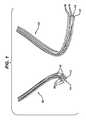
本発明は、埋め込み可能なデバイス、埋め込み可能なデバイスの製造方法、及び埋め込み可能なデバイスの使用方法を提供する。好ましい方法では、以下で詳細に説明されるように、デバイスは、フィラメントを形成するための、少なくとも1種類、より好ましくは、2種類以上の高分子繊維をまず選択することによって形成される。複数の繊維を含むフィラメント構造体の1つの例が図1に示される。続いて、1つ以上のフィラメントを用いて、一般には少なくとも1つのフィラメントをねじった束と言われる糸を形成できる。フィラメントを、使いやすいようにスプールにしてもよい。 The present invention provides implantable devices, methods of manufacturing implantable devices, and methods of using implantable devices. In a preferred method, as described in detail below, the device is formed by first selecting at least one, and more preferably, two or more polymeric fibers to form a filament. One example of a filament structure comprising a plurality of fibers is shown in FIG. Subsequently, one or more filaments can be used to form a yarn, commonly referred to as a bundle of at least one filament twisted. The filament may be spooled for ease of use.
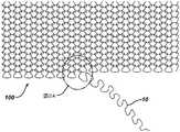
1つ以上のフィラメントを任意の方法でねじってよく、一方法では、フィラメントを用いて靴下形態又はシート形態のような固く編まれた構造体を形成する。固く編まれた構造体の例は、図2及び2Aに示されている。靴下形態又はシート形態を最初に形成する場合、靴下形態又はシート形態をその後ほどいて、靴下形態又はシート形態を作るのに使用された個々のフィラメントを含有する繊維をねじった束を得る。ねじれは、捲縮装置など、別の方法によっても達成できる。ねじれたフィラメントは、「糸」と呼ばれる。いくつかの実施形態では、フィラメントの各スプールをフィラメント束にして、それを糸にしてもよい。初期フィラメントは、単繊維又は多繊維フィラメントであってよく、得られた糸も同様に単フィラメント又は多フィラメントであってよい。最も望ましくは、糸は複数のフィラメントによって形成され、各フィラメントはねじられている、又は捲縮されている。あるいは、フィラメントが糸に形成された後、糸をねじり、又は捲縮してもよい。フィラメントのねじれ又は捲縮は、デバイス中の構成要素の体積増加をもたらす。 One or more filaments may be twisted in any manner, and in one method, the filaments are used to form a tightly knitted structure such as a sock or sheet form. An example of a tightly knitted structure is shown in FIGS. 2 and 2A. When the sock or sheet form is first formed, the sock or sheet form is then unwound to obtain a twisted bundle of fibers containing the individual filaments used to make the sock or sheet form. Twisting can also be achieved by other methods such as crimping devices. Twisted filaments are called “threads”. In some embodiments, each spool of filament may be a bundle of filaments that are made into yarns. The initial filaments can be single or multifilament filaments and the resulting yarns can be single or multifilaments as well. Most preferably, the yarn is formed by a plurality of filaments, each filament being twisted or crimped. Alternatively, the yarn may be twisted or crimped after the filament is formed into the yarn. Filament twisting or crimping results in an increase in the volume of components in the device.
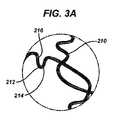
次の工程には、少なくとも1種類の糸、より望ましくは、2種類以上の糸を準備することと、これらの糸を共に編み、緩い織物構造体(「初期織物構造体」と称する)を形成することと、を含む。初期織物構造体の一例は、図3及び3Aに示される。次に、初期織物構造体を、以下で説明する1回以上の加熱プロセスにかけ、構造体中の少なくとも一部のフィラメントを収縮し、結果として得られる曲がった、埋め込み可能な構造体を形成して、後にヒートセットしてもよい。結果として得られる構造体は、「結果として得られる埋め込み可能なデバイス」としても知られ、1回以上の加熱工程にかけられ得た後の最終構造体を指す。結果として得られる埋め込み可能なデバイスの例は、図4及び4Aに示されている。当然のことながら、例えば、複数の加熱工程が使用される場合、又は加熱プロセス中に、初期織物構造体と結果として得られる埋め込み可能なデバイスとの間に1つ以上の中間構造体がある場合がある。初期織物構造体中の少なくとも一部の繊維が収縮する第1加熱工程の後、得られる構造体は「初期加熱構造体」と呼ばれる。続いて、初期加熱構造体を追加の加熱工程にかけ、繊維の一部を融解し、収縮し、かつ曲がった構造体を適所に固定してよい。これによって、「結果として得られる埋め込み可能なデバイス」を形成する。結果として得られる埋め込み可能なデバイスがユーザーの体内に埋め込まれた後は、「埋め込まれたデバイス」と呼ばれる。 In the next step, at least one type of yarn, more preferably two or more types of yarn, is prepared, and these yarns are knitted together to form a loose woven structure (referred to as "initial woven structure"). And including. An example of an initial fabric structure is shown in FIGS. 3 and 3A. The initial fabric structure is then subjected to one or more heating processes described below to shrink at least some of the filaments in the structure to form the resulting bent, embeddable structure. You may heat set later. The resulting structure, also known as the “resulting implantable device”, refers to the final structure after it has been subjected to one or more heating steps. An example of the resulting implantable device is shown in FIGS. 4 and 4A. Of course, if multiple heating steps are used, or if there are one or more intermediate structures between the initial fabric structure and the resulting implantable device during the heating process, for example. There is. After the first heating step in which at least some of the fibers in the initial fabric structure shrink, the resulting structure is referred to as an “initial heating structure”. Subsequently, the initial heating structure may be subjected to an additional heating step to melt some of the fibers, shrink, and fix the bent structure in place. This forms the “resulting implantable device”. After the resulting implantable device is implanted in the user's body, it is referred to as an “implanted device”.
本発明は、非吸収性繊維と吸収性繊維の組み合わせを含む埋め込み可能なデバイスに関する。以下に更に詳細に説明するように、本発明のデバイスは、多くの望ましい物理的特徴を有し、実行可能で向上された組織修復又は支持デバイスとしての機能を果たすことが可能である。例えば、デバイスは、使用される特定の用途に望ましい範囲の厚さを有する。内部成長が起こり、吸収性材料が体内に吸収されると、デバイスが内部成長した組織に近接するような厚さである。デバイスは更に、新しい組織の主な部分が発生した体内組織にできるような、十分なレベルの質量を有する。デバイスは、成長可能でありながらも支持体をもたらすのに好適な形状を提供することも必要であり、すなわち、デバイスは以下に記載する好適な多孔構造体を有する。加えて、埋め込み後に場合によって移動し得る繊維を有するデバイスの提供を避けるため、デバイスの少なくとも非吸収性部分が、十分に相互連結されていることも必要である。デバイスは、望ましい物理的強度を有することによって、内部成長を阻害せずに、埋め込み後にデバイスの一体性を維持してもよい。加えて、デバイスは、通常の体の動き中にデバイスが埋め込まれ、固定されたままであるように、十分に可撓性でなくてはならない。 The present invention relates to an implantable device comprising a combination of non-absorbable fibers and absorbent fibers. As described in further detail below, the device of the present invention has many desirable physical characteristics and can serve as a feasible and improved tissue repair or support device. For example, the device has a desired range of thicknesses for the particular application used. When ingrowth occurs and the absorbable material is absorbed into the body, the thickness is such that the device is in close proximity to the ingrowth tissue. The device further has a sufficient level of mass so that a major portion of the new tissue can occur in the generated body tissue. The device also needs to provide a suitable shape to provide a support while being able to grow, i.e., the device has a suitable porous structure as described below. In addition, it is also necessary that at least the non-absorbable portions of the device be sufficiently interconnected to avoid providing a device with fibers that can optionally migrate after implantation. The device may have the desired physical strength to maintain the integrity of the device after implantation without hindering ingrowth. In addition, the device must be sufficiently flexible so that it remains implanted and fixed during normal body movements.
本発明のデバイスは、三次元全ての独自の方向に形成している、三次元に連続した非吸収性及び吸収性繊維の織物である。デバイスが、不規則に均一な非構造アレイを有することが意図される。本明細書で使用されるとき、用語「不規則に均一な非構造アレイ」は、少なくとも2種類の異なる繊維(1つは他のものより低い融点を有する)の初期均一織物を準備し、その後三次元全てに共に延伸されることによって、得られる構造体が下層に織物構造体を有しているにも関わらず、不規則で無方向性の構造体の外観を生じさせることによって、形成される、最終生成物の方向を説明するのに使用される。共に延伸する工程は、以下で詳細に説明され、最低融点を超えるが、最高融点未満の程度まで温度を上昇させる工程を含んでよい。得られた構造体は、不規則で不均一な外観であるが、実際は、その不規則性が均一であり得る。言い換えれば、得られた構造体は、波状表面を有する均一に平坦で三次元に緊密なヒートセットされた編み織物であり得、フェルト材料の外観と感触を有する。得られた構造体は、得られた構造体の材料量、層形成、及び密度に応じて、剛性であってもよく、ある程度可撓性であってもよい。結果として得られる埋め込み可能なデバイスの詳細は、以下の説明によってより理解することができる。不規則に均一な非構造アレイの使用は、時間と共に、デバイスに沿った、かつデバイス内への線維芽細胞の成長及び発達を増強するデバイスの提供に重要である。加えて、結果として得られる埋め込み可能なデバイスを、従来の非吸収性スカフォールド又はメッシュよりも少ない労力で伸長できる。更に、本発明は、体内に吸収されるときに組織様修復をもたらし、構造性の非吸収性要素を含有する従来のスカフォールドよりも、自由な組織の動きを可能にする。 The device of the present invention is a three-dimensional continuous non-absorbent and absorbent fiber fabric, forming in all three dimensions in its own direction. It is contemplated that the device has an irregularly uniform unstructured array. As used herein, the term “irregularly uniform non-structural array” refers to the preparation of an initial uniform fabric of at least two different fibers (one having a lower melting point than the other) and then By stretching together in all three dimensions, it is formed by giving the appearance of an irregular, non-directional structure, even though the resulting structure has a woven structure underneath. Used to describe the direction of the final product. The steps of stretching together are described in detail below and may include the step of raising the temperature to a degree above the minimum melting point but below the maximum melting point. The resulting structure has an irregular and non-uniform appearance, but in practice the irregularity may be uniform. In other words, the resulting structure can be a uniformly flat, three-dimensional tight heatset knitted fabric with a wavy surface and has the appearance and feel of a felt material. The resulting structure may be rigid or flexible to some extent depending on the amount of material, layer formation, and density of the resulting structure. Details of the resulting implantable device can be better understood with the following description. The use of an irregularly uniform unstructured array is important in providing devices that enhance fibroblast growth and development along and into the device over time. In addition, the resulting implantable device can be stretched with less effort than conventional non-absorbable scaffolds or meshes. Furthermore, the present invention provides tissue-like repair when absorbed into the body and allows more freedom of tissue movement than conventional scaffolds containing structural non-absorbable elements.
好ましい実施形態では、デバイスは、非吸収性及び吸収性繊維の両方、少なくとも1種類の非吸収性繊維と、少なくとも1種類の吸収性繊維と、を含む、フィラメントの織目を含む。これらのフィラメントは、ねじれた糸に形成され、互いに織られて以下に記載する延伸工程にかけられる。本明細書で使用されるとき、フィラメントは、単繊維フィラメント材料又は多繊維フィラメント材料であってよく、例えば、編み組まれる、ないしは別の方法で絡まされてもよい。用語「フィラメント」は、単繊維又は多繊維フィラメントを含み得る。上で説明したように、「糸」は、ねじれた1つ以上のフィラメントから形成される。本明細書で説明される図面は多繊維フィラメントを示しているが、フィラメントが単繊維であり得ることが理解されるであろう。 In a preferred embodiment, the device comprises a filament texture comprising both non-absorbent and absorbent fibers, at least one non-absorbent fiber, and at least one absorbent fiber. These filaments are formed into twisted yarns, woven together and subjected to the drawing process described below. As used herein, a filament may be a single fiber filament material or a multifilament filament material, eg, braided or otherwise entangled. The term “filament” may include monofilament or multifilament filaments. As explained above, a “thread” is formed from one or more twisted filaments. Although the drawings described herein show multifilament filaments, it will be understood that the filaments can be monofilaments.
本発明の非吸収性繊維は、任意の好適な非吸収性材料で作製されてよい。好適な材料として、例えば、ポリプロピレン(例えば、Ethicon,Inc.(Somerville,NJ)から商標名PROLENE縫合糸で販売される)、PVDF/HFPブレンド(例えば、Ethicon,Inc.(Somerville,NJ)から商標名PRONOVA縫合糸で販売されるポリフッ化ビニリデンとポリフッ化ビニリデン−コ−ヘキサフルオロプロピレンのポリマーブレンド)、ポリエステル、ナイロン、ポリアクリレート、ポリメタクリレート、酢酸セルロース、非生分解性ポリウレタン、ポリスチレン、ポリ塩化ビニル、ポリフッ化ビニル、ポリビニルイミダゾール、ポリオレフィン、ポリテトラフルオロエチレン(PTFE)、シリコン、及び、スチレン−ブロック−ブタジエン、並びにこれらの組み合わせなどのポリマーが挙げられる。他の好適な非吸収性材料として、ステンレス鋼、コバルトクロム、チタン及びチタン合金、並びに、アルミナ、ジルコニア、及び硫酸カルシウムなどの生体不活性セラミックス、並びにこれらの組み合わせなどの金属が挙げられる。本発明の非吸収性フィラメントは、同一又は異なっていてよい、2つ以上の非吸収性繊維を含んでよい。本発明の好ましい非吸収性繊維として、ポリプロピレン、PVDF/HFPブレンド、ポリエステル、及びナイロンが挙げられる。本発明の非吸収性繊維は、埋め込み物としての機能を果たす任意の寸法であってよく、特に、約10デニール〜約100デニール、より好ましくは、約25デニール〜約60デニールの寸法を有するフィラメントを提供する。本明細書で使用されるとき、用語「デニール」は、測定単位として理解される意味を有し、フィラメント9000メートルにつき1グラムの重量のフィラメントの細さと等しい、フィラメント(単繊維又は多繊維フィラメントのいずれでも)の細さの単位を意図する。 The non-absorbable fibers of the present invention may be made of any suitable non-absorbable material. Suitable materials include, for example, polypropylene (e.g., sold by Ethicon, Inc. (Somerville, NJ) under the trade name PROLENE suture), PVDF / HFP blend (e.g., trademark from Ethicon, Inc. (Somerville, NJ)). (Polyvinylidene fluoride and polyvinylidene fluoride-co-hexafluoropropylene polymer blends sold under the name PRONOVA suture), polyester, nylon, polyacrylate, polymethacrylate, cellulose acetate, non-biodegradable polyurethane, polystyrene, polyvinyl chloride , Polyvinyl fluoride, polyvinyl imidazole, polyolefin, polytetrafluoroethylene (PTFE), silicon, and styrene-block-butadiene, and these They include polymers such as a suit look. Other suitable non-absorbable materials include metals such as stainless steel, cobalt chrome, titanium and titanium alloys, and bioinert ceramics such as alumina, zirconia, and calcium sulfate, and combinations thereof. The non-absorbent filaments of the present invention may comprise two or more non-absorbable fibers that may be the same or different. Preferred non-absorbable fibers of the present invention include polypropylene, PVDF / HFP blend, polyester, and nylon. The non-absorbable fibers of the present invention may be of any size that serves as an implant, in particular a filament having a size of from about 10 denier to about 100 denier, more preferably from about 25 denier to about 60 denier. I will provide a. As used herein, the term “denier” has the meaning understood as a unit of measure and is equivalent to a fineness of a filament weighing 1 gram per filament of 9000 meters of filament (monofilament or multifilament filament). Anyway) intended to be a unit of fineness.
同様に、本発明の吸収性繊維は、任意の望ましい生体吸収性材料で作製されてよい。これらの生体吸収性ポリマーとして、ポリエステルなどの合成ポリマー、並びに、ポリペプチド、ポリサッカライド、及びこれらの誘導体などのバイオポリマーの両方が挙げられる。好適な生体適合性生体吸収性ポリマーの例として、脂肪族ポリエステル、ポリ(アミノ酸)、コポリ(エーテル−エステル)、ポリアルキレンオキサレート、ポリアミド、ポリアセタール、ポリケタール、ポリカーボネート、ポリオルトカーボネート、ポリウレタン、ポリ(コハク酸アルキレン)、ポリ(マレイン酸)、ポリ(メチルビニルエーテル)、ポリ(無水マレイン酸)チロシン由来ポリカーボネート、ポリ(イミノカーボネート)、ポリオルトエステル、ポリオキサエステル、ポリアミドエステル、アミン基含有ポリオキサエステル、ポリ(無水物)、ポリホスファゼン、バイオポリマー(bioploymers)(例えば、コラーゲン、ゼラチン、アルギン酸、ペクチン、デンプン、フィブリン、酸化セルロース、キチン、キトサン、トロポエラスチン、ヒアルロン酸、及びこれらの混合物)、並びにこれらの混合物が挙げられるが、これらに限定されない。脂肪族ポリエステルとして、ラクチド(乳酸、D−、L−及びメソラクチドなど)、グリコリド(グリコール酸など)、ε−カプロラクトン、p−ジオキサノン(1,4−ジオキサン−2−オン)、トリメチレンカーボネート(1,3−ジオキサン−2−オン)、トリメチレンカーボネートのアルキル誘導体、δ−バレロラクトン、β−ブチロラクトン、γ−ブチロラクトン、ε−デカラクトン、ヒドロキシブチレート、ヒドロキシバレレート、1,4−ジオキセパン−2−オン(その二量体1,5,8,12−テトラオキサシクロテトラデカン−7,14−ジオンなど)、1,5−ジオキセパン−2−オン、6,6−ジメチル−1,4−ジオキサン−2−オン、2,5−ジケトモルホリン、ピバロラクトン、γ,γ−ジエチルプロピオラクトン、エチレンカーボネート、エチレンオキサレート、3−メチル−1,4−ジオキサン−2,5−ジオン、3,3−ジエチル−1,4−ジオキサン−2,5−ジオン、6,8−ジオキサビシクロオクタン−7−オンのホモポリマー及びコポリマー、並びにそれらのポリマーブレンドを挙げることができるが、これらに限定されないポリアルキレンオキサレートとして、それぞれ参考して本明細書に組み込まれる、米国特許第4,208,511号、同第4,141,087号、同第4,130,639号、同第4,140,678号、同第4,105,034号、及び同第4,205,399号に記載されるものが挙げられる。本発明に有用な生体吸収性材料として、更に、ポリグルコネート、ポリ(乳酸−コ−エチレンオキシド)コポリマー、ポリホスホエステル、ポリアミノ酸、ポリ乳酸(PLA)、ポリグリコール酸(PGA)、ポリカプロラクトン(PCL)、ポリジオキサノン(PDO)、炭酸トリメチレン(TMC)、ポリビニルアルコール(PVA)、これらのコポリマー又はブレンドが挙げられる。有用なものは更に、ポリホスファゼン、L−ラクチド、D,L−ラクチド、乳酸、グリコリド、グリコール酸、p−ジオキサノン、トリメチレンカーボネート、及びε−カプロラクトンから製造されるコ−、ター、及びそれ以上の混合モノマー系ポリマーであってよい。ポリ無水物としては、HOOC−−C6H4−−O−−(CH2)m−−O−−C6H4−−COOH(式中、mは2〜8の範囲内の整数である)の形態の二塩基酸から誘導されたもの、及び12個までの炭素からなる脂肪族α〜ω二塩基酸を有する、そのコポリマーが挙げられる。有用なポリオキサエステル、ポリオキサアミド、並びにアミン及び/又はアミド基を含有するポリオキサエステルは、米国特許第5,464,929号、同第5,595,751号、同第5,597,579号、同第5,607,687号、同第5,618,552号、同第5,620,698号、同第5,645,850号、同第5,648,088号、同第5,698,213号、同第5,700,583号、及び同第5,859,150号のうち、1つ以上に記載されており、そのそれぞれは本明細書に参考として組み込まれる。その他有用な材料として、ポリ(L−ラクチド)(「PLA」)、ポリ(d,l−ラクチド)(「PDLA」)、ポリ(グリコリド)(「PGA」)、ポリカプロラクトン、これらのコポリマー、ターポリマー、それ以上のポリモノマーポリマー、又はこれらの組み合わせ若しくは混合物が挙げられる。Similarly, the absorbent fibers of the present invention may be made of any desired bioabsorbable material. These bioabsorbable polymers include both synthetic polymers such as polyesters and biopolymers such as polypeptides, polysaccharides, and derivatives thereof. Examples of suitable biocompatible bioabsorbable polymers include aliphatic polyesters, poly (amino acids), copoly (ether-esters), polyalkylene oxalates, polyamides, polyacetals, polyketals, polycarbonates, polyorthocarbonates, polyurethanes, poly ( Alkylene succinate), poly (maleic acid), poly (methyl vinyl ether), polycarbonate derived from poly (maleic anhydride) tyrosine, poly (iminocarbonate), polyorthoester, polyoxaester, polyamide ester, amine group-containing polyoxaester , Poly (anhydrides), polyphosphazenes, bioploymers (eg collagen, gelatin, alginic acid, pectin, starch, fibrin, oxidized cellulose, chitin, chitosan, tropo Rasuchin, hyaluronic acid, and mixtures thereof), and mixtures thereof, without limitation. Examples of the aliphatic polyester include lactide (such as lactic acid, D-, L- and meso-lactide), glycolide (such as glycolic acid), ε-caprolactone, p-dioxanone (1,4-dioxane-2-one), trimethylene carbonate (1 , 3-dioxan-2-one), alkyl derivatives of trimethylene carbonate, δ-valerolactone, β-butyrolactone, γ-butyrolactone, ε-decalactone, hydroxybutyrate, hydroxyvalerate, 1,4-dioxepane-2- ON (its dimer 1,5,8,12-tetraoxacyclotetradecane-7,14-dione, etc.), 1,5-dioxepan-2-one, 6,6-dimethyl-1,4-dioxane-2 -One, 2,5-diketomorpholine, pivalolactone, γ, γ-diethylpropiolactone Ethylene carbonate, ethylene oxalate, 3-methyl-1,4-dioxane-2,5-dione, 3,3-diethyl-1,4-dioxane-2,5-dione, 6,8-dioxabicyclooctane- 7-one homopolymers and copolymers, and polymer blends thereof, including but not limited to, U.S. Pat. No. 4,208,511, each incorporated herein by reference as polyalkylene oxalate. No. 4,141,087, No. 4,130,639, No. 4,140,678, No. 4,105,034, and No. 4,205,399. Can be mentioned. As bioabsorbable materials useful in the present invention, polygluconate, poly (lactic acid-co-ethylene oxide) copolymer, polyphosphoester, polyamino acid, polylactic acid (PLA), polyglycolic acid (PGA), polycaprolactone ( PCL), polydioxanone (PDO), trimethylene carbonate (TMC), polyvinyl alcohol (PVA), copolymers or blends thereof. Also useful are co-, ter, and more made from polyphosphazene, L-lactide, D, L-lactide, lactic acid, glycolide, glycolic acid, p-dioxanone, trimethylene carbonate, and ε-caprolactone. The mixed monomer polymer may be used. Polyanhydrides include HOOC——C6 H4 —O —— (CH2 )m —O—C6 H4 —COOH, where m is an integer in the range of 2-8. And a copolymer thereof having an aliphatic α-ω dibasic acid consisting of up to 12 carbons. Useful polyoxaesters, polyoxaamides, and polyoxaesters containing amine and / or amide groups are described in U.S. Pat. Nos. 5,464,929, 5,595,751, 5,597, No. 579, No. 5,607,687, No. 5,618,552, No. 5,620,698, No. 5,645,850, No. 5,648,088, No. No. 5,698,213, 5,700,583, and 5,859,150, each of which is incorporated herein by reference. Other useful materials include poly (L-lactide) (“PLA”), poly (d, l-lactide) (“PDLA”), poly (glycolide) (“PGA”), polycaprolactone, copolymers thereof, tar Polymers, higher polymonomer polymers, or combinations or mixtures thereof.
繊維又はフィラメントは、生物的に安定な染料などによって着色されていてよく、又は無色であってよい。いくつかの実施形態では、結果として得られる埋め込み可能なデバイス中で使用される材料のうち少なくとも1つは、ユーザーがデバイス中の異なる繊維を視覚的に確認できるように、染料などを使用することによって着色して提供される。更に、材料に着色剤を加えることにより紫外線への感受性を低下させられることから、着色剤の使用は、製造上、及び/又は保管上の利益をもたらすことができる。例えば、デバイス中の1つの材料を、青色又は紫色の着色剤で染色してよい。 The fibers or filaments may be colored with biologically stable dyes or the like, or may be colorless. In some embodiments, at least one of the materials used in the resulting implantable device uses a dye or the like so that the user can visually identify the different fibers in the device. Colored and provided by. In addition, the use of colorants can provide manufacturing and / or storage benefits because the addition of colorants to the material can reduce the sensitivity to ultraviolet light. For example, one material in the device may be dyed with a blue or purple colorant.
最も望ましくは、吸収性繊維又は繊維として、グリコリド及び/又はラクチドから製造されるポリマー、ポリグラクチン910(Ethicon,Inc.(Somerville,NJ)から商標名VICRYL縫合糸で販売される)、ポリグリコール酸、ポリ(p−ジオキサノン)(例えば、Ethicon,Inc.(Somerville,NJ)から商標名PDS縫合糸で販売される)、カプロラクトン、トリメチレンカーボネートから製造されるポリマー、並びにこれらの組み合わせからなる群から選択される1つ以上のポリマーが挙げられる。合成吸収性ポリマーが使用される場合、所望のポリマーは生体適合性であり、乳酸及びグリコール酸などの、通常の代謝経路に入る低分子量化合物の分解産物を有さなくてはならない。本発明中の生体吸収性繊維を用いて、約10デニール〜約100デニール、更に具体的には、約28デニール〜約56デニールの寸法を有するフィラメントを調製できる。本発明において1つ又は2つ以上の生体吸収性繊維が存在してよく、複数の吸収性繊維を使用する場合、それらを同じ材料から調製してよく、又は、異なる材料から調製してよい。更に、各繊維は、本発明中の別の繊維とは異なる融点を有していてよい。 Most desirably, as absorbent fibers or fibers, a polymer made from glycolide and / or lactide, polyglactin 910 (sold under the trade name VICRYL suture from Ethicon, Inc. (Somerville, NJ), polyglycolic acid, Selected from the group consisting of poly (p-dioxanone) (for example, sold under the trade name PDS suture from Ethicon, Inc. (Somerville, NJ)), polymers made from caprolactone, trimethylene carbonate, and combinations thereof One or more polymers to be prepared. If a synthetic absorbable polymer is used, the desired polymer must be biocompatible and have degradation products of low molecular weight compounds that enter normal metabolic pathways, such as lactic acid and glycolic acid. The bioabsorbable fibers in the present invention can be used to prepare filaments having dimensions of about 10 denier to about 100 denier, and more specifically, about 28 denier to about 56 denier. There may be one or more bioabsorbable fibers in the present invention, and when using multiple absorbent fibers, they may be prepared from the same material or from different materials. Furthermore, each fiber may have a different melting point than the other fibers in the present invention.
一実施形態では、本発明は、少なくとも1つの非吸収性繊維と、少なくとも1つの吸収性繊維と、を含み、このとき繊維は、互いに異なる融点を有する。別の実施形態では、本発明は、少なくとも1つの非吸収性繊維と、少なくとも2つの吸収性繊維と、を含み、このとき繊維はそれぞれ、互いに異なる融点を有する。任意の吸収性繊維又は非吸収性繊維は、デバイス中で最低融点を有してよい。少なくとも1つの非吸収性繊維と、少なくとも1つの吸収性繊維と、を含む、実施形態では、総繊維重量に対する非吸収性繊維の重量パーセントは、約5重量%〜約50重量%、より望ましくは、約10重量%〜約25重量%である。好ましくは、デバイス中の吸収性繊維の濃度(重量による)は、非吸収性繊維より高い。 In one embodiment, the present invention includes at least one non-absorbent fiber and at least one absorbent fiber, where the fibers have different melting points. In another embodiment, the present invention includes at least one non-absorbent fiber and at least two absorbent fibers, wherein the fibers each have a different melting point. Any absorbent or non-absorbable fiber may have the lowest melting point in the device. In embodiments comprising at least one non-absorbent fiber and at least one absorbent fiber, the weight percent of non-absorbable fibers relative to the total fiber weight is from about 5 wt% to about 50 wt%, more desirably From about 10% to about 25% by weight. Preferably, the concentration (by weight) of the absorbent fibers in the device is higher than the non-absorbable fibers.
デバイスは、不規則に均一な非構造アレイを有し、これは、デバイス中のフィラメントの、特に三次元全てへの方向を説明している。デバイスは、任意の望ましい手段によって形成されてよく、一実施形態では、デバイス以下の方法によって形成される。最初に、デバイスを形成する繊維を選択し、これには吸収性及び非吸収性繊維の組み合わせを含めてよい。これらの繊維を用いて個々のフィラメントを形成するが、これには1種類のみの繊維(単繊維)を含めてよく、又は、複数の繊維(多繊維)を含めてよい。図1に示されるように、フィラメント10は、複数の個々の繊維12、14、16を含む。図1のフィラメントは、3種類の繊維(第1吸収性繊維(12)、第1非吸収性繊維(14)、及び第2吸収性繊維(16))を含む、フィラメントを示す。以下でより詳細に説明するように、フィラメント中には、任意の数の異なる種類の繊維が異なる割合で存在してよい。この図では、例えば、図1の左側のフィラメント10は、1本の第1吸収性繊維(12)、1本の第1非吸収性繊維(14)、及び5本の第2吸収性繊維(16)を有するフィラメントを示しているが、任意の種類及び数の繊維を必要に応じて使用してよい。図1の左側のフィラメント10は、4本の第2吸収性繊維16、1本の第1吸収性繊維12、及び1本の第1非吸収性繊維14を示す。その他様々な量の材料を使用でき、その量は、繊維ストランドの重量又は数によって測定されてよい。 The device has an irregularly uniform unstructured array, which describes the orientation of the filaments in the device, especially in all three dimensions. The device may be formed by any desired means, and in one embodiment is formed by the following device method. Initially, the fibers forming the device are selected, which may include a combination of absorbent and non-absorbable fibers. These fibers are used to form individual filaments, which may include only one type of fiber (single fiber) or may include multiple fibers (multi-fiber). As shown in FIG. 1, the
糸は、様々なフィラメントから形成され、上記で選択された非吸収性及び吸収性繊維を含んでよい。糸は、任意の望ましい糸形成手段によって形成されてよく、いくつかの実施形態では、糸は、靴下形態又はシート形態などの初期の固く編まれた構造体を形成することによって形成される。初期の固く編まれた構造体の実施例は、図2及び2Aに示されている。図2は、1本のフィラメント10を含む編構造体100を例示する。編構造体100は、必要に応じて任意の数の異なるフィラメント10を含んでよい。選択されたフィラメント10を固く編んで初期の固く編まれた構造体100を形成してよく、これは所望される任意の寸法及び形状であってよい。得られた構造体100を連続的な靴下形態又はシート形態に形成してよく、これは任意の望ましい長さ及び直径を有してよい。例えば、靴下形態は、約1.27センチメートル〜約25.4センチメートル(0.5インチ〜約10インチ)、より望ましくは、約3.81センチメートル〜約12.7センチメートル(1.5インチ〜約5インチ)の直径を有してよい。シート形態は、任意の所望の長さ及び幅を有する実質的に平坦な構造体であってよい。幅は、例えば、1.27センチメートル〜約91.44センチメートル(0.5インチ〜約36インチ)であってよく、長さは、規定してもよく(例えば、少なくとも約30.48センチメートル(12インチ))、又は、1.524メートル(5フィート)超、3.048メートル(10フィート)超、6.096メートル(20フィート)超、若しくは更に長く伸長して、連続シートにしてよい。靴下形態又はシート形態を最初に形成する場合、その後、靴下形態又はシート形態をほどき、ねじれた糸である材料を提供してよい。任意の数の糸を形成し、埋め込み可能なデバイスの形成に用いてよい。デバイスを所望の寸法及び形状に織るために、十分な糸が形成されなくてはならない。 The yarn is formed from various filaments and may include non-absorbent and absorbent fibers selected above. The yarn may be formed by any desired yarn forming means, and in some embodiments, the yarn is formed by forming an initial tightly knitted structure, such as a sock or sheet form. An example of an initial tightly knitted structure is shown in FIGS. 2 and 2A. FIG. 2 illustrates a
いくつかの実施形態では、初期繊維は、均質材料から押し出されて巻き取られた、繊維の出発スプールとして含まれていてよい。当然のことながら、1本の繊維は均質であってよく、又は、所望の場合複数の材料から製造されてよい。いくつかの実施形態では、細繊維束のストランドを作製する、非常に細かい繊維の束が存在してよい。繊維のスプールを用いてフィラメントを調製し、次にそれを用いて糸を調製してよい。所望の場合、同じ又は異なる繊維の複数のスプールを取ってよく、それをフィラメント又は一束の繊維束に形成してよい。糸は、任意の数のフィラメント(したがって、任意の数の繊維)から形成されてよく、単一の繊維から糸が形成されることも可能である。例えば、糸は、ポリグラクチン910などの第1吸収性材料、任意のPDSなどの第2吸収性繊維、及び少なくとも1つのポリプロピレンなどの非吸収性繊維からなる、複数(例えば、約3〜約7)の繊維から製造されるフィラメントから形成されてよい。様々な組み合わせを以下で説明する。繊維の組み合わせを用いて、初期の編まれた靴下形態若しくはシート形態を形成してよく、又は、その組み合わせを、任意の望ましい手段によって、束ねる、及び/若しくはねじる、及び/若しくは捲縮してよい。靴下形態又はシート形態を最初に形成する場合、編まれた靴下形態又はシート形態から複数の繊維を共に引っ張ると、得られた糸は、ねじれた繊維束のようである。所望により、2つの異なる編まれた靴下形態又はシート形態から1つ以上の糸を取り、緩い初期織物構造体を作製してよい。本明細書に記載するように、初期織物構造体中の各糸は、様々な割合の個々の吸収性及び非吸収性繊維を有する、様々な割合のフィラメントを含有してよく、少なくとも1つの糸が、非吸収性繊維のストランド束を含有し、少なくとも1つの糸が吸収性繊維のストランド束を含有していることが好ましい。 In some embodiments, the initial fiber may be included as a starting spool of fiber that has been extruded and wound from a homogeneous material. Of course, a single fiber may be homogeneous or may be made from multiple materials if desired. In some embodiments, there may be very fine fiber bundles that create strands of fine fiber bundles. A filament spool may be used to prepare a filament, which may then be used to prepare a yarn. If desired, multiple spools of the same or different fibers may be taken and formed into filaments or bundles of fibers. The yarn may be formed from any number of filaments (and thus any number of fibers), and the yarn may be formed from a single fiber. For example, the yarn comprises a plurality (eg, about 3 to about 7) of a first absorbent material such as polyglactin 910, a second absorbent fiber such as any PDS, and a non-absorbable fiber such as at least one polypropylene. It may be formed from filaments made from these fibers. Various combinations are described below. The combination of fibers may be used to form an initial knitted sock or sheet form, or the combination may be bundled and / or twisted and / or crimped by any desired means. . When initially forming a sock form or sheet form, pulling together a plurality of fibers from a knitted sock form or sheet form, the resulting yarn appears to be a twisted fiber bundle. If desired, one or more threads may be taken from two different knitted sock or sheet forms to create a loose initial fabric structure. As described herein, each yarn in the initial fabric structure may contain various proportions of filaments having various proportions of individual absorbent and non-absorbent fibers, and at least one yarn. However, it preferably contains a strand bundle of non-absorbable fibers, and at least one yarn contains a strand bundle of absorbent fibers.
糸が得られると、任意の既知の方法によって糸を緩く織り、その糸で織物構造体をまず形成する。初期の緩い織物構造体の図は図3及び3Aに示されている。この初期の緩い織物構造体を、本明細書では「初期織物構造体」と呼ぶ。図3に例示されるように、初期織物構造体200は、複数の個々の繊維212、214、216から作製され得る、少なくとも1つの糸210からなる織目で作製される。初期織物構造体200は、1種類の糸210から作製されてよく、又は、それぞれ同じ若しくは異なっていてよい、複数の糸210から作製されてもよい。図3は、多繊維糸210を示しているが、糸210が単繊維糸であってよいことが理解される。図3に示されるように、糸210は、ねじれた構造体を有する。 Once the yarn is obtained, the yarn is woven loosely by any known method, and the fabric structure is first formed from the yarn. An illustration of the initial loose fabric structure is shown in FIGS. 3 and 3A. This initial loose fabric structure is referred to herein as an “initial fabric structure”. As illustrated in FIG. 3, the
初期織物構造体200は、例えば、矩形、楕円形などの任意の所望の形状であってよく、又は更には管状形若しくは円錐形であってもよい。初期織物構造体200は、任意の望ましい厚さを有してよく、好ましくは、約0.1mm〜約5mm厚、より望ましくは、約2mm厚である。当然のことながら、厚さは、使用目的及び埋め込み部位に応じて変更され得る。初期織物構造体200は、所望の任意の長さ又は幅を有してよく、材料の大きいシートにできる。初期織物構造体200を大きいシートにする場合、それから作製される結果として得られる埋め込み可能なデバイスは、所望される長さ及び幅より大きい場合があり、ユーザーは、埋め込まれる寸法及び形状にデバイスを切り取ることができる。いくつかの実施形態では、初期織物構造体200自体を埋め込むことができる。初期織物構造体200は、その構造体全体に非吸収性及び吸収性繊維を分散し、望ましくは、構造体の各測定可能な区分に、一部の吸収性及び一部の非吸収性材料が存在している状態で提供する。初期織物構造体200は、三次元全てにおいて実質的に均一な外観を有する。本明細書で使用されるとき、「緩い織目」は、コース対ウェールの比が約8:1〜約1.5:1,より好ましくは、約5:1〜約2:1である、織物構造体を指すことを意図する。しかしながら、いくつかの実施形態では、ウェール対コースの比が、約5:1〜約1.5:1、より好ましくは、約5:1〜約2:1であってよい。 The
次に、構造体を収縮させ、構造体をヒートセットする目的で、初期織物構造体を、熱、放射線、振動、電流、高周波、又は他の種類のエネルギーを増加させるなどによる、増加したエネルギーに曝す。いくつかの実施形態では、初期織物構造体200を最初に加熱してよく、これは、他の異なるエネルギー、例えば振動又は放射線曝露と同時に実施されてよい。初期織物構造体を、加熱装置などの特定の加熱空間、又は初期織物構造体200に熱を提供するその他の空間に置くことなどによって、まず加熱する。いくつかの実施形態では、初期織物構造体200を加熱オーブン内に置き、又は他の実施形態では、第1及び第2の加熱面又はプレート間に置いてもよい。望ましくは、オーブン内に挿入される、又は加熱面間に置かれる、のいずれの場合であっても、初期織物構造体200全体が、加熱面(1つ又は複数)の空間内に含まれるが、初期織物構造体200の特定領域のみが加熱される場合、その領域を加熱空間に置くことができる。更に、いくつかの実施形態では、機械方向又は非機械方向に回転させることなどによって、初期織物構造体200を管状形に形成し、管状加熱空間内に置いてもよい。 The initial fabric structure is then subjected to increased energy, such as by increasing heat, radiation, vibration, current, high frequency, or other types of energy, for the purpose of shrinking the structure and heat setting the structure. Expose. In some embodiments, the
初期織物構造体200が特定の表面を有する熱源内に置かれる場合、初期織物構造体200全体の適切な加熱を確実にするために、これらの表面間の間隙が、初期織物構造体200の厚さより少なくとも少し大きいことが望ましい。望ましくは、表面間の間隙は、約0.5mm〜約5mm、より望ましくは、約1.5mm〜約3.0mmである。当然のことながら、加熱素子間の間隙寸法は、初期織物構造体200の厚さ及び密度、又は初期織物構造体200で使用した材料の種類に依存し得る。初期織物構造体200が約0.1mm〜約1.0mmの厚さを有する場合、例えば、間隙約1.5mm〜約3.0mmでなくてはならない。初期織物構造体200の厚さがより薄い場合、より小さい間隙を使用でき、逆の場合も同じである。間隙寸法は、初期織物構造体200の厚さより大きい、約0.1mm〜約2.0mmであってよい。 When the
埋め込み可能なデバイスを形成する本方法では、初期の緩い織物構造体200を少なくとも1つの温度に曝し、このとき温度は、構造体中で最低融点を有する材料の融点に関連する。最低融点を有する材料は、吸収性材料であってよく、又は、非吸収性材料であってよい。以下の説明では、最低融点を有する材料を吸収性材料として記載しているが、この最低融点を有する材料が非吸収性材料であってよいことは理解されよう。 In this method of forming an implantable device, the initial loose
初期織物構造体200の最初の加熱では、加熱装置の温度を、(1)初期織物構造体中の最低融点を有する材料(この材料をデバイス中の「第1繊維」と称する)の初期融解温度、(2)その少し上、又は(3)その少し下のレベルに設定する。この初期温度上昇は「初期加熱」である。本明細書で使用されるとき、用語「少し上」は、初期融解温度より約0.1℃〜約10℃高い、又は、初期融解温度より約0.1℃〜約5℃高い、より望ましくは、約0.1℃〜約2℃高いことである。同様に、本明細書で使用されるとき、用語「少し下」は、初期融解温度より約0.1℃〜約10℃低い、又は初期融解温度より約0.1℃〜約5℃低い、より望ましくは、約0.1℃〜約2℃低いことである。 For the initial heating of the
例として、初期織物構造体は、2種類の繊維を含んでよく、第1繊維は100℃の初期融点を有し、第2繊維は150℃の初期融点を有する。この実施形態では、初期織物構造体は、加熱装置内に置かれて、第1温度に曝されてよく、第1温度は約100℃(例えば、最低融点を有する繊維の融点)である。あるいは、第1温度は、約99.9℃〜約95℃、より望ましくは、約99.9℃〜約98℃(例えば、最低融点を有する繊維の融点の少し下)であってよい。又はあるいは、第1温度は、約100.1℃〜約105℃、より望ましくは、約100.1℃〜約102℃(例えば、最低融点を有する繊維の融点の少し上)であってよい。この第1温度は、収縮させることが目的である。初期織物構造体中の最低融点を有する繊維(例えば、「第1繊維」、又は繊維が吸収性繊維である場合、「第1吸収性繊維」と称してもよい)の融解はこの工程では意図されておらず、むしろ、第1材料の収縮が目的である。 By way of example, the initial fabric structure may include two types of fibers, the first fiber having an initial melting point of 100 ° C. and the second fiber having an initial melting point of 150 ° C. In this embodiment, the initial fabric structure may be placed in a heating device and exposed to a first temperature, the first temperature being about 100 ° C. (eg, the melting point of the fiber having the lowest melting point). Alternatively, the first temperature may be from about 99.9 ° C. to about 95 ° C., more desirably from about 99.9 ° C. to about 98 ° C. (eg, just below the melting point of the fiber having the lowest melting point). Alternatively, the first temperature may be from about 100.1 ° C. to about 105 ° C., more desirably from about 100.1 ° C. to about 102 ° C. (eg, slightly above the melting point of the fiber having the lowest melting point). The purpose of this first temperature is to shrink. Melting of the fiber with the lowest melting point in the initial fabric structure (eg, “first fiber” or, if the fiber is an absorbent fiber, may be referred to as “first absorbent fiber”) is intended in this process. Rather, the aim is to shrink the first material.
いくつかの実施形態では、第1繊維は吸収性繊維であり、約105℃の初期融点を有し、初期加熱段階は約100℃〜約103℃で行われる。 In some embodiments, the first fiber is an absorbent fiber, has an initial melting point of about 105 ° C, and the initial heating step is performed at about 100 ° C to about 103 ° C.
更に、第1繊維の最低融点は、初期織物構造体中の第2最低融点を有する材料の温度よりも、少なくとも10℃低いことが望ましい。つまり、第2繊維は、第1繊維より少なくとも10℃高い融点を有するべきである。 Furthermore, it is desirable that the lowest melting point of the first fibers be at least 10 ° C. lower than the temperature of the material having the second lowest melting point in the initial fabric structure. That is, the second fiber should have a melting point that is at least 10 ° C. higher than the first fiber.
本開示の目的において、第1繊維(例えば、デバイス中の最低融点を有する繊維)は、吸収性であるものとして説明され、第1吸収性繊維と称することができる。第1吸収性繊維(デバイス中で最低融点を有する)を収縮させるのに十分な時間、初期加熱を継続する。本明細書で使用されるとき、材料の収縮は、その材料中の分子の再構築を意味するが、材料を融解するのに十分ではない。収縮は、例えば、材料を、そのガラス転移温度で加熱することによって達成できる。第1吸収性繊維の融解は意図していないが、わずかな融解が起こる場合がある。むしろ、初期加熱段階は、第1吸収性繊維の初期収縮を起こすことを意図している。収縮(融解ではない)は、収縮によって、第1吸収性繊維が強度一部を保持し、デバイス中の他の繊維を引き寄せることができるため好ましいが、材料の融解は、材料の引張り強度を低下させる。典型的には、この初期加熱段階を約10〜約60秒間、更に具体的には、約20〜約45秒間継続させる必要があるが、初期織物構造体中に使用される材料(1種類又は複数種類)によって変わり得る。第1吸収性繊維の収縮によって、初期織物デバイス中の得られた繊維を曲げる。 For purposes of this disclosure, the first fiber (eg, the fiber having the lowest melting point in the device) is described as being absorbent and can be referred to as the first absorbent fiber. Continue the initial heating for a time sufficient to shrink the first absorbent fiber (having the lowest melting point in the device). As used herein, shrinkage of a material means the reorganization of molecules in that material, but not enough to melt the material. Shrinkage can be achieved, for example, by heating the material at its glass transition temperature. Although melting of the first absorbent fiber is not intended, slight melting may occur. Rather, the initial heating step is intended to cause initial shrinkage of the first absorbent fiber. Shrinkage (not melting) is preferred because the shrinkage allows the first absorbent fiber to retain some strength and draw other fibers in the device, but melting the material reduces the tensile strength of the material. Let Typically, this initial heating step should last from about 10 to about 60 seconds, and more specifically from about 20 to about 45 seconds, although the material used in the initial fabric structure (one type or It can vary depending on the type The resulting fibers in the initial fabric device are bent by shrinkage of the first absorbent fibers.
初期加熱段階後に得られた構造体は、少なくとも1つの糸の織物パターンを有するデバイスであり、より低い融点を有する繊維の収縮によって曲がっている繊維を有する。しかしながら、収縮の程度が不規則であるため、曲げによって、構造体は不均一アレイを有するように見える。この得られた材料を、「初期曲げ構造体」又は「初期加熱構造体」と称する。 The structure obtained after the initial heating stage is a device with a textile pattern of at least one yarn, having fibers that are bent by shrinkage of the fibers having a lower melting point. However, due to the irregular degree of shrinkage, bending causes the structure to appear to have a non-uniform array. This obtained material is referred to as “initial bending structure” or “initial heating structure”.
次に、初期曲げ構造体を、任意の更なるエネルギー増加、つまり加熱工程(「第2加熱」)に曝し、所望の場合、デバイスをヒートセットしてよい。第2加熱工程は好ましいが、必須ではない。この第2加熱は、上記と同じ加熱装置内で実施してもよく、又は、別の加熱装置内でもよく、振動若しくは放射線、若しくはその他上記エネルギー源などの追加のエネルギー増加源を含んでよい。第2加熱は、望ましくは、初期加熱の温度、又はそれ以上の温度であり、好ましくは、第1繊維(デバイス中で最低融点を有する)の融点より高い。第2加熱は、初期加熱の温度より約2℃〜約25℃高い温度であってよい。 The initial bending structure may then be exposed to any further energy increase, or heating step (“second heating”), and the device may be heat set if desired. The second heating step is preferred but not essential. This second heating may be performed in the same heating device as described above, or may be in a separate heating device, and may include additional sources of increased energy such as vibration or radiation, or other such energy sources. The second heating is desirably at or above the temperature of the initial heating and is preferably higher than the melting point of the first fiber (having the lowest melting point in the device). The second heating may be a temperature that is about 2 ° C. to about 25 ° C. higher than the temperature of the initial heating.
第2加熱工程は、構造体中で最低融点を有する第1繊維を融解させ、それによって、構造体及び初期曲げ構造体の寸法を安定化することを意図している。この第2加熱工程は、実質的に急速である必要があるが、初期加熱よりわずかに長く、例えば、約60秒間〜約120秒間、更に具体的には、約60秒間〜約90秒間であってよい。例えば、より厚いデバイスが望まれる場合、より長い第2加熱時間が必要とされ得る。所望により、第2加熱工程は、圧縮工程などの追加の工程を含んでよく、それによって、初期曲げ構造体は、加熱段階中に加熱素子間で圧縮される。例えば、最終の結果として得られる埋め込み可能なデバイスを形成するために、初期曲げ構造体の形状が変えられる場合、圧縮が望ましい場合がある。例えば、初期曲げデバイスを、その厚さの約25%〜約75%、より望ましくは、その厚さの約50%(例えば、約2mm厚〜約1mm厚)平らにすることが望ましい場合がある。加熱素子間の間隙の寸法は、所望の厚さに調節でき、所望の場合、圧力を追加的にかけることができる。 The second heating step is intended to melt the first fiber having the lowest melting point in the structure, thereby stabilizing the dimensions of the structure and the initial bending structure. This second heating step needs to be substantially rapid but is slightly longer than the initial heating, for example from about 60 seconds to about 120 seconds, more specifically from about 60 seconds to about 90 seconds. It's okay. For example, if a thicker device is desired, a longer second heating time may be required. If desired, the second heating step may include additional steps, such as a compression step, whereby the initial bending structure is compressed between the heating elements during the heating phase. For example, compression may be desirable if the shape of the initial bending structure is changed to form the final implantable device. For example, it may be desirable to flatten the initial bending device from about 25% to about 75% of its thickness, more desirably about 50% of its thickness (eg, about 2 mm to about 1 mm thick). . The size of the gap between the heating elements can be adjusted to the desired thickness, and additional pressure can be applied if desired.
第1加熱工程及び任意の第2加熱工程を経た後、初期曲げ構造体を加熱装置から取り出し、冷却させるが、これを室温で、又は温度制御環境(例えば、室温超又は室温未満)において実施してもよい。いくつかの実施形態では、冷却能を有する加熱装置を使用してよく、それによって加熱後の迅速な冷却ができる。得られる構造体は、凝固された、三次元の、織物の埋め込み可能なデバイスであり、一部のフィラメントの収縮によって、フィラメントの少なくとも一部が不規則に曲がっている。これを、「結果として得られる埋め込み可能なデバイス」と称する。結果として得られる埋め込み可能なデバイスは、一部の繊維の融解とその後の凝固によって結合点を形成し、最終形状を維持する。したがって、結果として得られる埋め込み可能な構造体は、三次元全てに不規則な方向を有するように見えるが、実際は、非融解フィラメントが初期均一織目を有する。結果として得られる埋め込み可能なデバイスは、織物/不織状態であり、フェルト状材料のような外観と感触を有する。したがって、結果として得られる埋め込み可能なデバイスは、厚さ、長さ、及び幅の三次元全てに「不規則に均一な非構造アレイ」を有する。更に、融解フィラメントが不規則に曲がっていると、結果として得られる埋め込み可能なデバイスは、繊維の非構造アレイを有するように見える。 After the first heating step and the optional second heating step, the initial bending structure is removed from the heating device and allowed to cool, but this is performed at room temperature or in a temperature controlled environment (eg, above or below room temperature). May be. In some embodiments, a heating device with cooling capability may be used, thereby allowing rapid cooling after heating. The resulting structure is a solidified, three-dimensional, fabric implantable device, where at least some of the filaments are irregularly bent due to shrinkage of some of the filaments. This is referred to as the “resulting implantable device”. The resulting implantable device forms a bond point by melting some fibers and subsequent solidification and maintains the final shape. Thus, the resulting implantable structure appears to have irregular directions in all three dimensions, but in practice the unmelted filament has an initial uniform texture. The resulting implantable device is woven / nonwoven and has a felt-like appearance and feel. Thus, the resulting implantable device has an “irregularly uniform unstructured array” in all three dimensions of thickness, length, and width. Furthermore, if the molten filaments are irregularly bent, the resulting implantable device appears to have an unstructured array of fibers.
最終の結果として得られる埋め込み可能なデバイスの実施形態は、結果として得られる埋め込み可能なデバイス300を示す図4及び4Aに見られる。結果として得られる埋め込み可能なデバイス300は、収縮した織目の糸310を含み、各糸310は、複数の繊維312、316で作製され得る。ねじれた糸310は、本質的に、図3の糸210のねじれて収縮したものである。上で説明したように、デバイス300中で2種類以上の糸310を使用してよく、各糸310は、単繊維又は多繊維であってよい。図4Aに示されるように、繊維の1つは融解され、デバイス300中に結合点314を形成している。融解は、第2加熱工程中に達成され、繊維を融解して、デバイス300中で確実に結合点314を形成するための十分な程度まで冷却する。したがって、結果として得られる埋め込み可能なデバイス300は、少なくとも2つの方向(例えば、長さ及び幅)に収縮し、結合点314によって適所に保持される。収縮によって厚さが大きくなってよく、又は、収縮が圧縮環境で行われる場合、厚さが小さくなるか、実質的に一定に維持される。望ましくは、結合点314を吸収性繊維、例えば、第1吸収性繊維から形成する。 The final implantable device embodiment can be seen in FIGS. 4 and 4A showing the resulting
所望の場合、埋め込まれる最終生成物は、2つ以上の層の結果として得られる埋め込み可能なデバイスを含んでよい。2つ以上の初期織物構造体又は初期曲げ構造体を互いの上面に層状にして、同時に加熱工程(1回又は複数回)にかけることによって、均一な交差パターンの不規則な方向の、互いに融合した複数層の結果として得られる埋め込み可能な材料を有することができる。あるいは、各層をそれぞれ別の加熱工程にかけ、複数の結果として得られる埋め込み可能なデバイスを形成してから、層状にして互いに結合してよい。層は、単純に、すなわち、介在要素を含まずに互いに直接固定してよく、又は、接着力を増強するために層間に材料を含んでよい。接着は、要素の熱融解など物理的手段によって達成されてよく、又は、接着剤などによって、若しくは層を互いに縫い合わせるなど、化学的若しくは物理的手段によって達成されてよい。所望の場合、デバイス中の最低融点を有する材料(あるいは、別の低融点吸収性材料)から作られたフィルムを、層間に置いてもよい。デバイスを層状にするのに用いられるフィルムは、吸収性であってよい。層を加熱装置中に置き、フィルムを融解させることによって、層間の結合力を増してもよい。所望の場合、層は互いに同じものであってよいが、デバイス中の様々な層が、同一である、又は同じ材料から作製されることが必要ではないことが重要である。各層は、類似する、又は、重複する材料を含んでよいが、各層の正確な組成は同じである必要はない。あるいは、各層中の材料は、重複する材料を含まず、全く異なっていてもよい。 If desired, the final product to be implanted may include an implantable device resulting from two or more layers. Two or more initial fabric structures or initial bending structures are layered on top of each other and simultaneously subjected to a heating process (one or more times), thereby fusing each other in an irregular direction with a uniform cross pattern The resulting implantable material can have multiple layers. Alternatively, each layer may be subjected to a separate heating step to form a plurality of resulting implantable devices that are then layered and bonded together. The layers may simply be fixed directly together, i.e. without intervening elements, or may include materials between the layers to enhance adhesion. Adhesion may be achieved by physical means such as thermal melting of the elements, or may be achieved by chemical or physical means such as by adhesive or by stitching the layers together. If desired, a film made from the material with the lowest melting point in the device (or another low melting point absorbent material) may be placed between the layers. The film used to layer the device may be absorbent. The bond between the layers may be increased by placing the layers in a heating device and melting the film. If desired, the layers may be the same as each other, but it is important that the various layers in the device need not be the same or made from the same material. Each layer may contain similar or overlapping materials, but the exact composition of each layer need not be the same. Alternatively, the materials in each layer do not include overlapping materials and may be quite different.
いくつかの実施形態では、メッシュ、又は非吸収性スカフォールド材料の層を挟んで、本発明の埋め込み可能なデバイスの複数の層があってよい。このような実施形態では、初期織物デバイスの第1層と初期織物デバイスの第2層との間に、メッシュ又はスカフォールド材料の層を置くことによって、層状材料を調製し、その後そのサンドイッチ構造体を上記のような加熱工程にかけてよい。接着剤材料又はフィルム層を任意の層間に置き、層状構造体の調製に役立たせてよい。次に、上で説明したようにサンドイッチ構造体を加熱工程にかけ、層状のヒートセットした埋め込み可能なデバイスを得てよい。いくつかの実施形態では、層は、当初は、初期曲げ構造体の第1層と初期曲げ構造体の第2層との間に配置されたメッシュ又はスカフォールド材料の層で作製されてよく、その後、サンドイッチ構造体を上記のように加熱してよい。任意の数の材料層を互いの上面に置き、所望の場合、層状デバイスを形成してよい。層の縁部は、互いに同一平面にあってよく、又は第1層の少なくとも1つの縁部は、第2層の縁部より延在していてよく、又はその逆としてよい。 In some embodiments, there may be multiple layers of the implantable device of the present invention sandwiching a layer of mesh or non-absorbable scaffold material. In such an embodiment, the layered material is prepared by placing a layer of mesh or scaffold material between the first layer of the initial fabric device and the second layer of the initial fabric device, after which the sandwich structure is It may be subjected to the heating step as described above. An adhesive material or film layer may be placed between any layers to aid in the preparation of the layered structure. The sandwich structure may then be subjected to a heating step as described above to obtain a layered heat-set implantable device. In some embodiments, the layer may initially be made of a layer of mesh or scaffold material disposed between the first layer of the initial bending structure and the second layer of the initial bending structure. The sandwich structure may be heated as described above. Any number of material layers may be placed on top of each other to form a layered device if desired. The edges of the layers may be coplanar with each other, or at least one edge of the first layer may extend from the edge of the second layer, or vice versa.
埋め込まれる最終デバイスは、複数の層の結果として得られる埋め込み可能なデバイスから作製されてよく、同一の、異なる、又は交互の方向に置かれていてよい。結果として得られる埋め込み可能なデバイスが垂直方向に異なる伸び特性を有するため、個々の得られたデバイス層の層状化によって、全ての方向に類似する伸び特性を有するデバイスをもたらすことができる。いくつかの実施形態では、層の方向に応じて、最終的な層状埋め込み可能なデバイスは、第1方向により伸長可能であり、第2方向により伸長できない。複数層化により、様々な用途、例えば、軟組織修復とは対照的に、腱修復に対して、非常に強い埋め込み可能なデバイスを得ることができる。得られた織物デバイス層間にフィルム層を加えると、上記のように、層の結合力を増すことができ、初期厚さより薄い厚さまで圧縮できる。 The final device to be implanted may be made from an implantable device resulting from multiple layers and may be placed in the same, different, or alternating directions. Since the resulting implantable device has different elongation characteristics in the vertical direction, layering of the individual resulting device layers can result in a device having similar elongation characteristics in all directions. In some embodiments, depending on the layer direction, the final layered implantable device can be stretched in the first direction and not stretched in the second direction. Multi-layering can result in a very strong implantable device for various applications, eg, tendon repair as opposed to soft tissue repair. Adding a film layer between the resulting fabric device layers can increase the bond strength of the layers as described above and can be compressed to a thickness less than the initial thickness.
いくつかの実施形態では、デバイス中の最低融点を有する材料(第1繊維)は吸収性繊維であり、ポリ(p−ジオキサノン)(Ethicon,Inc.(Somerville,NJ)から商標PDS縫合糸で販売されるものを含む)を含んでよい。このような実施形態では、初期加熱温度は約100〜103℃であってよく、第2加熱温度は約105℃〜約120℃であってよい。当然のことながら、デバイス中に使用される材料に応じて、第1及び第2加熱温度を変えてもよい。いくつかの実施形態では、より高い第2加熱温度によって、最終の得られたデバイスにおいて、可撓性がより高く、引張り強度がより低い結果となり得る。使用する場合、ポリ(p−ジオキサノン)を、別の非吸収性材料、及び任意に他の吸収性材料と組み合わせて使用してよい。 In some embodiments, the material with the lowest melting point in the device (first fiber) is an absorbent fiber and is sold under the trademark PDS suture from poly (p-dioxanone) (Ethicon, Inc. (Somerville, NJ)). May be included). In such an embodiment, the initial heating temperature may be about 100-103 ° C and the second heating temperature may be about 105 ° C to about 120 ° C. Of course, the first and second heating temperatures may be varied depending on the material used in the device. In some embodiments, a higher second heating temperature may result in higher flexibility and lower tensile strength in the final resulting device. If used, poly (p-dioxanone) may be used in combination with another non-absorbent material and optionally other absorbent materials.
一実施形態では、デバイスを、3種類の異なる繊維から製造してよい。第1繊維は、ポリプロピレンなどの非吸収性繊維であってよい。第2繊維は、ポリジオキサノンなどの第1吸収性繊維であってよく、第3繊維は、ポリグラクチン910などの第2吸収性繊維であってよい。各繊維を、複数の異なる繊維を含むフィラメントにする、つまり、束ねてフィラメントにしてよく、各繊維又はフィラメントは、特有のデニールを有してよい。例えば、ポリグラクチン繊維は最小デニールを有してよく、それは約28であってよい。ポリジオキサノン繊維は、約30などのわずかに大きいデニールを有してよい。非吸収性繊維は、約60などの最大デニールを有してよい。フィラメントは、多くの繊維から製造されてよく、得られたフィラメントは、所望のデニールを有してよい。最終的な埋め込み可能なデバイスのねじれ及び曲げ度は、フィラメントを形成する材料によって変化し得る。所望によりその他材料を含めてよく、つまり、様々な非吸収性及び/又は吸収性材料を使用してよい。望ましくは、デバイスは、少なくとも1つの非吸収性要素(繊維)、及び少なくとも1つの吸収性要素(繊維)から作られる。 In one embodiment, the device may be made from three different fibers. The first fiber may be a non-absorbable fiber such as polypropylene. The second fiber may be a first absorbent fiber such as polydioxanone, and the third fiber may be a second absorbent fiber such as polyglactin 910. Each fiber may be a filament comprising a plurality of different fibers, ie, bundled into a filament, and each fiber or filament may have a unique denier. For example, polyglactin fibers may have a minimum denier, which may be about 28. The polydioxanone fiber may have a slightly larger denier, such as about 30. Non-absorbent fibers may have a maximum denier, such as about 60. Filaments may be made from a number of fibers and the resulting filaments may have the desired denier. The twist and bend of the final implantable device can vary depending on the material forming the filament. Other materials may be included as desired, that is, various non-absorbable and / or absorbent materials may be used. Desirably, the device is made of at least one non-absorbent element (fiber) and at least one absorbent element (fiber).
多材料の実施形態では、各材料は、任意の望ましい量又は割合で含まれてよい。しかしながら、デバイス中で、吸収性繊維が非吸収性繊維よりも多い量で存在することが好ましい。例えば、一実施形態では、織物構造体は、第1吸収性繊維及び第1非吸収性繊維のフィラメントを含み、これらの材料は、約1〜7部(重量で)の第1吸収性繊維対約1部の第1非吸収性繊維、より望ましくは、約3〜5部(重量で)の第1吸収性繊維対約1部の第1非吸収性繊維の量で存在する。割合は重量によるものである必要はなく、繊維デニールにかかわらず、個々の繊維又は糸ストランドによるものであってよい。つまり、約1〜7ストランドの第1吸収性繊維対約1ストランドの第1非吸収性繊維であってよい。この実施形態では、第1吸収性繊維は、第1非吸収性繊維よりも低い融点を有してよく、融点の差は少なくとも約10℃である。本組成中において、例えば、第1吸収性繊維としてポリグラクチン910又はポリ(p−ジオキサノン)、第1非吸収性繊維としてポリプロピレンなど、任意の材料を使用してよい。 In multi-material embodiments, each material may be included in any desired amount or proportion. However, it is preferred that the absorbent fibers are present in the device in greater amounts than the non-absorbent fibers. For example, in one embodiment, the woven structure includes filaments of first absorbent fibers and first non-absorbent fibers, wherein these materials comprise about 1 to 7 parts (by weight) of first absorbent fiber pairs. It is present in an amount of about 1 part of the first non-absorbent fiber, more desirably from about 3 to 5 parts (by weight) of the first absorbent fiber to about 1 part of the first non-absorbent fiber. The proportion need not be by weight and can be by individual fibers or yarn strands, regardless of fiber denier. That is, there may be about 1-7 strands of first absorbent fibers versus about 1 strand of first nonabsorbent fibers. In this embodiment, the first absorbent fiber may have a lower melting point than the first non-absorbent fiber, the difference in melting point being at least about 10 ° C. In this composition, for example, any material such as polyglactin 910 or poly (p-dioxanone) may be used as the first absorbent fiber, and polypropylene may be used as the first non-absorbable fiber.
別の実施形態では、初期織物構造体は、第1吸収性繊維及び第2吸収性繊維のフィラメントを含んでよく、これらの材料は、約1〜7部(重量で)の第1吸収性繊維対約1部の第2吸収性繊維、より望ましくは、約3〜5部(重量で)の第1吸収性繊維対約1部の第2吸収性繊維の量で存在する。この場合でも、割合は重量によるものである必要はなく、繊維デニールにかかわらず、個々の繊維又は糸ストランドによるものであってよい。つまり、約1〜7ストランドの第1吸収性繊維対約1ストランドの第2吸収性繊維であってよい。この実施形態では、第1吸収性繊維は第2吸収性繊維より低い融点を有してよく、このとき第1吸収性繊維の融点は、第2吸収性繊維の融点より少なくとも約10℃低い。あるいは、デバイス中の第2吸収性繊維は、第1吸収性繊維より低い融点を有してよい。この第1吸収性繊維(例えば、より低い融点を有する材料)は第2吸収性繊維よりも多く存在してよく、又はその逆としてよい。この実施形態において、例えば、第1吸収性繊維としてのポリ(p−ジオキサノン)及び第2吸収性繊維としてのポリグラクチン910を含む、任意の材料を使用してよい。 In another embodiment, the initial fabric structure may include filaments of first and second absorbent fibers, the materials comprising about 1 to 7 parts (by weight) of the first absorbent fibers. It is present in an amount of about 1 part of the second absorbent fiber, more desirably about 3 to 5 parts (by weight) of the first absorbent fiber to about 1 part of the second absorbent fiber. Even in this case, the proportion need not be by weight and can be by individual fibers or yarn strands, regardless of fiber denier. That is, there may be about 1-7 strands of first absorbent fibers versus about 1 strand of second absorbent fibers. In this embodiment, the first absorbent fiber may have a lower melting point than the second absorbent fiber, wherein the first absorbent fiber has a melting point that is at least about 10 ° C. lower than the melting point of the second absorbent fiber. Alternatively, the second absorbent fiber in the device may have a lower melting point than the first absorbent fiber. This first absorbent fiber (eg, a material having a lower melting point) may be present more than the second absorbent fiber, or vice versa. In this embodiment, any material may be used including, for example, poly (p-dioxanone) as the first absorbent fiber and polyglactin 910 as the second absorbent fiber.
更に他の実施形態では、構造体は、3種類の繊維、例えば、第1吸収性繊維、第2吸収性繊維及び第1非吸収性繊維、あるいは、第1吸収性繊維、第1非吸収性繊維及び第2非吸収性繊維を含んでよい。この実施形態は、第1吸収性繊維を約1〜7部(重量で)の量で、第1非吸収性繊維を約1部(重量で)の量で、第2吸収性繊維又は第2非吸収性繊維を約1部(重量で)の量で含んでよい。この場合でも、割合は重量によるものである必要はなく、繊維デニールにかかわらず、個々の繊維又は糸ストランドによるものであってよい。つまり、約1〜7ストランドの第1吸収性繊維、約1ストランドの第1非吸収性繊維、及び約1ストランドの第2吸収性又は非吸収性繊維であってよい。 In still another embodiment, the structure has three types of fibers, for example, a first absorbent fiber, a second absorbent fiber, and a first non-absorbent fiber, or a first absorbent fiber, a first non-absorbent fiber. Fibers and second non-absorbable fibers may be included. This embodiment includes the first absorbent fiber in an amount of about 1-7 parts (by weight) and the first non-absorbent fiber in an amount of about 1 part (by weight), the second absorbent fiber or the second Non-absorbent fibers may be included in an amount of about 1 part (by weight). Even in this case, the proportion need not be by weight and can be by individual fibers or yarn strands, regardless of fiber denier. That is, there may be about 1-7 strands of first absorbent fibers, about 1 strand of first nonabsorbable fibers, and about 1 strand of second absorbent or nonabsorbable fibers.
上記3つの実施形態は、代表的なものであり、限定することを意図しない。埋め込み可能なデバイスは、所望により、代替又は追加の吸収性及び/又は非吸収性繊維を含んでよい。例えば、埋め込み可能なデバイス中に、吸収性及び非吸収性繊維の様々な組み合わせを含む、4種類以上の材料が存在してよい。出発材料を用いて単繊維フィラメント又は多繊維フィラメントを形成し、次にフィラメントを用いて糸を形成してよい。 The above three embodiments are representative and are not intended to be limiting. The implantable device may include alternative or additional absorbent and / or non-absorbable fibers as desired. For example, there may be four or more materials in the implantable device, including various combinations of absorbent and non-absorbable fibers. The starting material may be used to form monofilament filaments or multifilament filaments and then the filaments may be used to form yarns.
織物デバイスの製造に使用される個々の糸は、任意の上記繊維を含んでよく、任意の望ましい手段で調製されてよい。一実施形態では、糸は、選択したフィラメントの、靴下形態又はシート形態などの固い編み織物をまず作製することによって、又は、フィラメントの捲縮によって形成される。初期の固い編構造体は、第1吸収性繊維と、第1非吸収性繊維と、を含む、フィラメント、あるいは、第1吸収性繊維と、第2吸収性繊維と、を含む、フィラメント、あるいは、第1吸収性繊維と、第2吸収性繊維と、第1非吸収性繊維と、を含む、フィラメントを含んでよい。糸は、固く編まれた構造体をほどいて形成することができ、個々の繊維を含むねじれた束のフィラメントをもたらす。当然のことながら、2つ以上の靴下形態又はシート形態を形成でき、形成した靴下形態又はシート形態から2つ以上の糸を形成できる。糸は、吸収性繊維、非吸収性繊維、及びこれらの組み合わせを含んでよい。 Individual yarns used in the manufacture of textile devices may include any of the above fibers and may be prepared by any desired means. In one embodiment, the yarn is formed by first making a rigid knitted fabric, such as a sock or sheet form, of selected filaments, or by crimping the filaments. The initial hard knitted structure includes a filament containing a first absorbent fiber and a first non-absorbent fiber, or a filament containing a first absorbent fiber and a second absorbent fiber, or The filament may include a first absorbent fiber, a second absorbent fiber, and a first non-absorbable fiber. The yarn can be formed by unwinding a tightly knitted structure, resulting in a twisted bundle of filaments containing individual fibers. Of course, more than one sock form or sheet form can be formed, and more than one thread can be formed from the formed sock form or sheet form. The yarn may include absorbent fibers, non-absorbable fibers, and combinations thereof.
糸が形成されると、糸を用いて初期織物構造体を形成できる。初期織物構造体は、上記のものを含む、任意の糸の組み合わせの織目を含んでよい。一実施形態では、初期織物構造体は、1種類の糸のみ、例えば、第1吸収性繊維及び第1非吸収性繊維を有する1種類の糸、又は、第1吸収性繊維、第2吸収性繊維、及び第1非吸収性繊維を有する糸の織目を含んでよい。別の実施形態では、初期織物構造体は、少なくとも2種類の糸の織目を含んでよい。例えば、初期織物構造体は、第1糸及び第2糸の織目を含んでよく、第1及び第2糸は互いに異なっている。第1糸は、例えば、(a)第1吸収性繊維及び第1非吸収性繊維を有する糸、又は、(b)第1吸収性繊維及び第2吸収性繊維を有する糸、又は、(c)第1吸収性繊維、第2吸収性繊維、及び第1非吸収性繊維を有する糸であってよく、第2糸は、例えば、(a)第1吸収性繊維及び第1非吸収性繊維を有する糸、又は、(b)第1吸収性繊維及び第2吸収性繊維を有する糸、又は、(c)第1吸収性繊維、第2吸収性繊維、及び第1非吸収性繊維を有する糸であってよく、このとき第1及び第2糸は異なる繊維から作られる。初期織物デバイスが、少なくとも1つの吸収性繊維と、少なくとも1つの非吸収性繊維と、を含むことが望ましい。 Once the yarn is formed, the initial fabric structure can be formed using the yarn. The initial fabric structure may comprise any yarn combination weave, including those described above. In one embodiment, the initial fabric structure has only one type of yarn, for example, one type of yarn having a first absorbent fiber and a first non-absorbent fiber, or a first absorbent fiber, a second absorbent. Fibers and yarn weaves having first non-absorbable fibers may be included. In another embodiment, the initial fabric structure may include at least two yarn weaves. For example, the initial fabric structure may include a weft of first and second yarns, the first and second yarns being different from each other. The first yarn is, for example, (a) a yarn having a first absorbent fiber and a first non-absorbable fiber, or (b) a yarn having a first absorbent fiber and a second absorbent fiber, or (c ) It may be a yarn having a first absorbent fiber, a second absorbent fiber, and a first non-absorbable fiber. The second yarn is, for example, (a) a first absorbent fiber and a first non-absorbable fiber. Or (b) a yarn having a first absorbent fiber and a second absorbent fiber, or (c) a first absorbent fiber, a second absorbent fiber, and a first non-absorbent fiber. It may be a yarn, where the first and second yarns are made from different fibers. Desirably, the initial fabric device includes at least one absorbent fiber and at least one non-absorbable fiber.
例として、初期織物構造体は、第1糸及び第2糸の織目を含んでよく、このとき、第1糸は第1吸収性繊維及び第2吸収性繊維から作られ、第2糸は第1吸収性繊維、第2吸収性繊維、及び第1非吸収性繊維から作られる。各糸中の特定の吸収性及び非吸収性繊維は、同じであってもよく、異なっていてもよい。例えば、この実施形態では、第1糸は、ポリグラクチン910及びポリ(p−ジオキサノン)から作製されてよく、第2糸は、ポリグラクチン910、ポリ(p−ジオキサノン)及びポリプロピレンから作製されてよい。 As an example, the initial fabric structure may include a weft of first and second yarns, where the first yarn is made from the first and second absorbent fibers and the second yarn is Made from a first absorbent fiber, a second absorbent fiber, and a first non-absorbable fiber. The specific absorbent and non-absorbable fibers in each yarn may be the same or different. For example, in this embodiment, the first yarn may be made from polyglactin 910 and poly (p-dioxanone), and the second yarn may be made from polyglactin 910, poly (p-dioxanone) and polypropylene.
別の例は、第1糸及び第2糸の織目を含む初期織物構造体であり、このとき、第1糸は第1吸収性繊維及び第2吸収性繊維から作られ、第2糸は第1吸収性繊維及び第1非吸収性繊維から作られる。各糸中の特定の吸収性及び非吸収性繊維は、同じであってもよく、異なっていてもよい。例えば、この実施形態では、第1糸は、ポリグラクチン910及びポリ(p−ジオキサノン)から作製されてよく、第2糸は、ポリグラクチン910及びポリプロピレンから作製されてよい。 Another example is an initial fabric structure that includes a weft of first and second yarns, wherein the first yarn is made from first and second absorbent fibers, and the second yarn is Made from first absorbent fibers and first non-absorbent fibers. The specific absorbent and non-absorbable fibers in each yarn may be the same or different. For example, in this embodiment, the first yarn may be made from polyglactin 910 and poly (p-dioxanone), and the second yarn may be made from polyglactin 910 and polypropylene.
これらの実施形態は例示目的であって、様々な組み合わせが可能であり、上記で特定される任意の吸収性及び非吸収性繊維が使用できると理解される。結果として得られる埋め込み可能な構造体により長い又はより短い吸収特性を与えるため、所望の場合、例えば、様々な吸収性ポリマーのブレンドなどの別の材料を用いてよい。吸収特性を、製造後工程、例えばガンマ線照射などによる滅菌などによって調節し、吸収特性を低下させてよい。最終の埋め込み可能なデバイス中に非吸収性要素が存在すると、例えば、吸収性要素を吸収後に体内に存在し続けるために、有用である場合がある。しかしながら、完全な吸収が意図され、所望される場合、吸収性繊維のみを含むデバイスを使用できる。 It is understood that these embodiments are for illustrative purposes, and various combinations are possible, and any absorbent and non-absorbable fibers identified above can be used. Other materials, such as, for example, a blend of various absorbent polymers, may be used if desired to provide longer or shorter absorbent properties to the resulting implantable structure. Absorption characteristics may be adjusted by post-manufacturing processes, such as sterilization by gamma irradiation, etc. to reduce absorption characteristics. The presence of a non-absorbable element in the final implantable device may be useful, for example, to keep the absorbent element present in the body after absorption. However, if complete absorption is intended and desired, a device containing only absorbent fibers can be used.
任意の加熱工程にかける前の初期織物構造体の初期形状又は構造は、上記のような平坦な緩い織物構造体であってよい。例えば、球状、円錐状、円柱状などの他の形状も有用であり得る。ビーズ、又は吸収性又は非吸収性フィラメント材料によって連結され得る一連の、つまり糸状の連結ビーズの形態であってよい。好ましい実施形態は平坦構造体であって、この平坦構造体は、実質的に矩形又は楕円形を有する。所望の場合、初期織物構造体の角部は丸くなっていてよい。結果として得られる埋め込み可能なデバイスは、埋め込み前にユーザーによって切断又は切り取られてよい。上で説明したように、埋め込まれる最終デバイスは、所望の通りに任意の数の層の結果として得られる埋め込み可能なデバイスを含んでよいが、初期織物構造体は、典型的には単一層として形成される。多層化デバイスが望まれる場合、様々な加熱工程の前、加熱工程の途中、又は加熱工程の後のいずれかに、層間に物理的又は化学的取り付け手段を用いて、単一層を互いに組み合わせることができる。加えて、層化デバイスは、層間に挟まれた非吸収性メッシュ又はスカフォールドなどの追加の要素を含んでよい。 The initial shape or structure of the initial fabric structure prior to any heating step may be a flat loose fabric structure as described above. For example, other shapes such as spherical, conical, cylindrical, etc. may be useful. It may be in the form of beads, or a series of threaded connecting beads that can be connected by an absorbent or non-absorbable filament material. A preferred embodiment is a flat structure, which has a substantially rectangular or elliptical shape. If desired, the corners of the initial fabric structure may be rounded. The resulting implantable device may be cut or cut by the user prior to implantation. As explained above, the final device to be implanted may include an implantable device resulting from any number of layers as desired, but the initial fabric structure is typically as a single layer. It is formed. If a multi-layered device is desired, single layers can be combined with each other using physical or chemical attachment means between the layers, either before the various heating steps, during the heating step, or after the heating step. it can. In addition, the layering device may include additional elements such as a non-absorbable mesh or scaffold sandwiched between layers.
全ての加熱工程後、結果として得られる埋め込み可能なデバイスは、使用目的に応じて、任意の所望の長さ又は幅を有してよい。いくつかの実施形態では、結果として得られる埋め込み可能なデバイスは、シートの形態であってよく、埋め込み前にユーザーによって所望の寸法及び形状に切り取られ得る。いくつかの実施形態では、デバイスは、予め配置されたSUIスリングの挿入若しくは変更に使用できるものなどの、ストリップ材料の形態であってよく、又は他の実施形態では、正方形であってよい。デバイスは、0.0254センチメートル(0.01インチ)から30.48センチメートル(12インチ)を超える、任意の所望の長さ及び幅を有してよい。例えば、SUIスリングとして使用される場合、尿道下で測定されるとき、幅は、約0.762〜約1.778センチメートル(0.3〜約0.7インチ)であってよく、長さは、約5.08〜約10.16センチメートル(2〜約4インチ)であってよい。他の実施形態では、デバイスは、環状又は管状形状であってよく、約0.127センチメートル(0.05インチ)〜約25.4センチメートル(10インチ)の直径を有してよい。楕円形状では、デバイスは、約0.254センチメートル(.1インチ)〜約12.7センチメートル(5インチ)の長半径、約0.0254センチメートル(0.01インチ)〜約7.62センチメートル(3インチ)の短半径を有してよい。更に別の実施形態では、埋め込み可能なデバイスは、無定形又は綿球様の形状などの不定形状を有してよく、患者の組織除去によって形成された孔又は空隙を充填するなど、挿入材又は充填材として使用できる。 After all heating steps, the resulting implantable device may have any desired length or width depending on the intended use. In some embodiments, the resulting implantable device may be in the form of a sheet and may be cut to a desired size and shape by the user prior to implantation. In some embodiments, the device may be in the form of a strip material, such as one that can be used to insert or modify a pre-positioned SUI sling, or in other embodiments, may be square. The device may have any desired length and width, from 0.0254 centimeters (0.01 inches) to greater than 30.48 centimeters (12 inches). For example, when used as a SUI sling, the width may be from about 0.762 to about 1.778 centimeters (0.3 to about 0.7 inches) when measured under the urethra, and the length May be from about 5.08 to about 10.16 centimeters (2 to about 4 inches). In other embodiments, the device may be annular or tubular in shape and have a diameter of about 0.127 centimeters (0.05 inches) to about 25.4 centimeters (10 inches). In the oval shape, the device has a major radius from about 0.254 centimeters (.1 inches) to about 12.7 centimeters (5 inches), from about 0.0254 centimeters (0.01 inches) to about 7.62. It may have a short radius of 3 centimeters (3 inches). In yet another embodiment, the implantable device may have an indeterminate shape, such as an amorphous or cotton ball-like shape, such as filling a hole or void formed by patient tissue removal, such as an insert or Can be used as a filler.
初期織物構造体の初期厚さは、約0.127センチメートル(0.05インチ)〜約1.27センチメートル(0.5インチ)厚であってよく、一方、上記第1加熱工程後の初期曲げ構造体は、約0.0508センチメートル(0.02インチ)〜約0.635センチメートル(0.25インチ)厚であってよく、上記全ての加熱及び任意の圧縮工程後の最終の埋め込み可能なデバイスは、約0.0254センチメートル(0.01インチ)厚〜約0.3175センチメートル(0.125インチ)厚であってよい。いくつかの実施形態では、各加熱工程は、圧縮が用いられた場合など、デバイスの厚さを減少できる。 The initial thickness of the initial fabric structure may be from about 0.127 centimeters (0.05 inches) to about 1.27 centimeters (0.5 inches) thick, while after the first heating step. The initial bending structure may be from about 0.0508 centimeters (0.02 inches) to about 0.635 centimeters (0.25 inches) thick, with the final after all the heating and optional compression steps described above. The implantable device may be about 0.0254 centimeters (0.01 inches) thick to about 0.3175 centimeters (0.125 inches) thick. In some embodiments, each heating step can reduce the thickness of the device, such as when compression is used.
結果として得られる埋め込み可能なデバイスは、ユーザーが見たときに特徴的な外観を有する。結果として得られる埋め込み可能なデバイスは、構造体の厚さ及び密度に応じて、視覚的に見えない又はわずかに見える、密に構成された材料のマットである。結果として得られる埋め込み可能なデバイスの外部の質感は、元々フェルト様である。フェルト様材料は、互いにもつれた短繊維からなるが、本発明のデバイスは、最初に緩く織られてから、他の繊維全てと連結する初期繊維が収縮し(初期加熱によって)、材料が、連結されているが非構造アレイの非吸収性繊維という密な状態に縮んで曲がっている。しかしながら、収縮後加工(例えば、第2加熱工程)により、結果として得られる埋め込み可能なデバイス中の繊維の全アレイが、融解され凝固された少なくとも1つの吸収性繊維によって互いに固定される。これによって、結果として得られる埋め込み可能なデバイスに、三次元の表面質感がマイクロスケールで与えられる。結果として得られる埋め込み可能なデバイスは、材料及びその材料の密度よって決まる多孔度を有する、織物/不織構造体を有する。結果として得られる埋め込み可能なデバイスの多孔性は、ユーザーが肉眼で見ることができないが、典型的な緩い織目及びメッシュなどの他の実施形態では、ユーザーが肉眼でデバイスの多孔性を見れることが望ましい場合がある。孔径は、圧縮される場合、約4マイクロメートル〜約300マイクロメートルであってよいが、所望の場合、例えば、圧縮せずに、より大きくてもよい(例えば、300マイクロメートル超)。 The resulting implantable device has a characteristic appearance when viewed by the user. The resulting implantable device is a densely constructed mat of material that is not visually visible or slightly visible, depending on the thickness and density of the structure. The external texture of the resulting implantable device is inherently felt-like. Felt-like materials consist of short fibers entangled with each other, but the device of the present invention is initially loosely woven, then the initial fibers that connect with all the other fibers shrink (by initial heating), and the materials are connected However, it is bent into a dense state of non-absorbent fibers in a non-structural array. However, post-shrink processing (eg, a second heating step) secures the entire array of fibers in the resulting implantable device to each other with at least one absorbent fiber that has been melted and solidified. This gives the resulting implantable device a three-dimensional surface texture on a microscale. The resulting implantable device has a woven / non-woven structure with a porosity determined by the material and the density of the material. The resulting implantable device porosity is not visible to the user with the naked eye, but other embodiments, such as typical loose textures and meshes, allow the user to see the device porosity with the naked eye. May be desirable. The pore size may be from about 4 micrometers to about 300 micrometers when compressed, but may be larger (eg, greater than 300 micrometers) if desired, for example, without compression.
結果として得られる埋め込み可能なデバイスは、所望の剛性を有し得る。剛性は、以下の実施例に記載の曲げ試験など、既知の試験によって測定できる。本発明のデバイスを曲げるのに要する力は、約1N〜約1.5N、更に具体的には、約1.25N〜約1.50Nであってよい。結果として得られる埋め込み可能なデバイスは、約5N〜約4000N、より好ましくは、約50N〜500Nの引張り強度を有してよい。結果として得られる埋め込み可能なデバイスは、第1方向に引っ張ったとき、所望の伸長度を有してよい。結果として得られる埋め込み可能なデバイスの好ましい弾性率は、約100N/m〜約300N/m、更に具体的には、約150N/m〜約200N/mであってよい。 The resulting implantable device can have the desired stiffness. The stiffness can be measured by known tests such as the bending test described in the examples below. The force required to bend the device of the present invention may be from about 1N to about 1.5N, more specifically from about 1.25N to about 1.50N. The resulting implantable device may have a tensile strength of about 5N to about 4000N, more preferably about 50N to 500N. The resulting implantable device may have a desired degree of stretch when pulled in the first direction. The preferred modulus of the resulting implantable device may be from about 100 N / m to about 300 N / m, more specifically from about 150 N / m to about 200 N / m.
結果として得られる埋め込み可能なデバイスは調製された後、埋め込むことができる。そのうち、デバイスの吸収性繊維の加水分解によって、非吸収性繊維のみを含む最終の加水分解された構造体となる。加水分解された構造体の一実施形態は、図5及び5Aに見られ、ここでは非吸収性繊維410のみを含む加水分解された構造体400が示される。図6は、デバイスの2つの最終結果の仮説を示す断面図であり、部分[A]は、非吸収性繊維410のみを含むデバイスの加水分解された部分を示す。これは、例えば、実験的、つまり実験室での使用において、組織内部成長が見られない結果であり、この部分は、加水分解後に同じ圧縮状態で留まっているポリプロピレン構造体を表す。ポリプロピレン構造体は、加水分解後に圧縮度を部分的に失ったり、圧縮状態に見えない場合もあると理解される。図6の部分[B]は、組織内部成長後に加水分解された部分を示し、非吸収性繊維410と組織420が組み合わさっており、図6Aの拡大図中においてよくわかる。 The resulting implantable device can be prepared and then implanted. Of these, hydrolysis of the absorbent fibers of the device results in a final hydrolyzed structure containing only non-absorbable fibers. One embodiment of a hydrolyzed structure is seen in FIGS. 5 and 5A, where a hydrolyzed
当然のことながら、図6の部分[A]及び[B]は、両方が埋め込み後の最終結果になる可能性は低く、むしろ、これらの2つの部分は、[A]実験室、つまり実験的加水分解、及び[B]組織内部成長後の2つの有り得る結果の対照比較であると理解される。吸収性要素を体内に埋め込み、吸収された後、デバイス全体に組織内部成長を含む(例えば、図6の部分[B])ことが意図される。 Of course, the parts [A] and [B] in FIG. 6 are unlikely to both be the final result after implantation, rather, these two parts are [A] laboratory, experimental It is understood that this is a controlled comparison of two possible outcomes after hydrolysis and [B] tissue ingrowth. After the absorbent element is implanted in the body and absorbed, it is intended to include tissue ingrowth throughout the device (eg, portion [B] of FIG. 6).
本発明は、デバイスに複数の弾性度(要素の任意の加水分解前の第1の弾性度と、要素の加水分解後の第2の弾性度)をもたらすことができる。埋め込み可能なデバイス(例えば、300)は、デバイス中の吸収性材料の加水分解と、加水分解された構造体(例えば、400)の形成前に、第1の弾性度を有する。第1の弾性度は、1つ以上の方向への引張り試験など、任意の望ましい手段によって測定できる。当然のことながら、デバイスは、第2方向(例えば、幅に沿って)よりも第1方向(例えば、長さに沿って)により弾性であり得ることが理解される。デバイス中の吸収性材料加水分解後、例えば実験室での加水分解後、デバイス中の吸収性材料は、完全に、又は実質的に完全にデバイスから除かれ、非吸収性材料のみが残る(加水分解された構造体400)。この状態、つまり加水分解後は、デバイスは、加水分解前の埋め込み可能なデバイスの弾性度よりも大きい、第2の弾性度を有する。いくつかの実施形態では、加水分解後デバイスの弾性度は、加水分解前デバイスの弾性度の少なくとも2倍、より望ましくは、加水分解前デバイスの弾性度の少なくとも3倍、又は、弾性度の少なくとも5倍、又は弾性度の少なくとも10倍である。弾性を測定するため任意の方法を使用してよいが、使用する方法は、加水分解前と加水分解後の両方において同じでなくてはならない。患者の体内に埋め込み、その後デバイスの吸収性要素が吸収された後、デバイスの内部に組織内部成長があり、埋め込み後デバイスの弾性を制限し得る。組織内部成長を有する得られたデバイスは、構造化メッシュ又は構造化メッシュで作られたスカフォールドよりも弾性及び可撓性が高い。この可撓性及び弾性の増加は、構造化メッシュインプラントに勝る顕著な利益である。 The present invention can provide a device with multiple degrees of elasticity (a first elasticity before any hydrolysis of the element and a second elasticity after hydrolysis of the element). The implantable device (eg, 300) has a first elasticity prior to hydrolysis of the absorbent material in the device and formation of the hydrolyzed structure (eg, 400). The first elasticity can be measured by any desired means, such as a tensile test in one or more directions. Of course, it is understood that the device may be more elastic in the first direction (eg, along the length) than in the second direction (eg, along the width). After hydrolysis of the absorbent material in the device, eg after laboratory hydrolysis, the absorbent material in the device is completely or substantially completely removed from the device, leaving only the non-absorbable material (hydrolyzed). Disassembled structure 400). In this state, i.e. after hydrolysis, the device has a second elasticity that is greater than the elasticity of the implantable device before hydrolysis. In some embodiments, the elasticity of the post-hydrolysis device is at least twice the elasticity of the pre-hydrolysis device, more desirably at least three times the elasticity of the pre-hydrolysis device, or at least the elasticity. 5 times, or at least 10 times the elasticity. Any method for measuring elasticity may be used, but the method used must be the same both before and after hydrolysis. After implantation into the patient's body and subsequent absorption of the device's absorbent elements, there may be tissue ingrowth inside the device, which may limit the elasticity of the device after implantation. The resulting device with tissue ingrowth is more elastic and flexible than a structured mesh or a scaffold made of structured mesh. This increase in flexibility and elasticity is a significant advantage over structured mesh implants.
本発明は、体組織の支持又は処置における埋め込み可能なデバイスとして有用であり得る。埋め込み可能なデバイスは、組織スカフォールドインプラントとして使用でき、特定の体領域内での組織の体積を増やすため、組織構造の強化、又は、新たな組織内部成長の促進のために使用できる。いくつかの実施形態では、埋め込み可能なデバイスは、例えば、骨盤底、1つ以上の腱、膀胱、若しくは乳房などの特定の体組織表面に固定でき、又は、腹圧性尿失禁、ヘルニアなどの疾患、及び、裂傷を受けた若しくは易感染性の組織を含む、その他類似の疾患の治療の促進に使用できる。埋め込み可能なデバイスの埋め込みは、例えば、フィブリンなどの接着剤による取り付け、又は縫合糸若しくはステープルなどによる外科的取り付けの利用を含む、任意の標準的な所望の手段によって達成できる。いくつかの実施形態では、埋め込み可能なデバイスは、摩擦によってデバイスが適所に維持される、閉鎖空間又はポケット中で挿入材として使用されるときなどは、任意の外部取り付け手段を用いずに、部位に固定できる。埋め込み可能なデバイスは、組織がデバイス中に内部成長できるのに十分な時間、目的の部位で埋め込まれたままであるように十分固定されなくてはならず、ここでは組織内部成長が、デバイスの固定を補助し、固定をもたらす。取り付けは、埋め込み可能なデバイスが、少なくとも1週間、少なくとも2週間、少なくとも1ヶ月、少なくとも2ヶ月、少なくとも6ヶ月、又は少なくとも1年間、埋め込み部位に埋め込まれたまま維持されるのに十分なものでなくてはならない。 The present invention may be useful as an implantable device in the support or treatment of body tissue. The implantable device can be used as a tissue scaffold implant and can be used to increase tissue volume within a particular body region, strengthen tissue structure, or promote new tissue ingrowth. In some embodiments, the implantable device can be secured to a specific body tissue surface such as, for example, the pelvic floor, one or more tendons, bladder, or breast, or a disease such as stress urinary incontinence, hernia, etc. And can be used to facilitate the treatment of other similar diseases, including lacerated or susceptible tissues. Implantation of the implantable device can be achieved by any standard desired means including, for example, the use of adhesive attachment such as fibrin, or the use of surgical attachment such as sutures or staples. In some embodiments, the implantable device is a site without any external attachment means, such as when the device is held in place by friction, such as when used as an insert in a closed space or pocket. Can be fixed. The implantable device must be sufficiently fixed so that it remains implanted at the site of interest for a time sufficient for the tissue to be ingrowth into the device, where the tissue ingrowth is fixed to the device. Assists and brings fixation. The attachment is sufficient for the implantable device to remain implanted at the implantation site for at least 1 week, at least 2 weeks, at least 1 month, at least 2 months, at least 6 months, or at least 1 year. Must-have.
埋め込み後約7〜約14日以内に、フィブリン取り付け及び実際の線維芽細胞内部成長が始まり得る。そのうちに、吸収性要素は生分解し、体内に吸収されるようになり、これらの吸収性要素を含む領域は、新たな組織内部成長で満たされる。得られる非吸収性要素は識別可能な形状を持たず、吸収性要素が消失するとともに埋め込み可能なデバイス中に少量で存在するため、デバイス中に残る材料は、ユーザーから実質的には意識されない。この結果、支持部をもたらす埋め込まれたデバイスは、内部成長のための場所を提供するが、ユーザーにとって快適でもあり、より自然な組織様感覚をもたらす。 Within about 7 to about 14 days after implantation, fibrin attachment and actual fibroblast ingrowth can begin. Over time, the absorbent elements biodegrade and become absorbed by the body, and the area containing these absorbent elements is filled with new tissue ingrowth. The resulting non-absorbable element does not have an identifiable shape and the absorbent element disappears and is present in a small amount in the implantable device so that the material remaining in the device is substantially invisible to the user. As a result, the implanted device that provides the support provides a place for ingrowth, but is also comfortable for the user and provides a more natural tissue-like sensation.
埋め込み可能なデバイスの質量は、デバイス中に組織を内部成長させ、その結果、優位に存在するのが新たに成長した組織となるのに十分な任意の量であってよい。いくつかの実施形態では、埋め込み可能なデバイス中の吸収性材料の吸収前の面積重量は、約47g/m2〜約152g/m2であってよく、デバイス中の吸収性材料の吸収後に得られる面積重量は、約12g/m2〜約40g/m2であってよい。非吸収性材料より吸収性材料の量が多い(例えば、デバイス中において非吸収性材料より吸収性材料のほうが重量で約10倍多い)実施形態では、吸収後面積重量に対する吸収前面積重量の比率は顕著に上昇し得る。吸収後面積重量が、吸収前面積重量の約25%、又は25%未満であることが望ましい。これは、インプラント中の構造化非吸収性材料の量がより多い他のデバイスに比べて顕著な改善である。 The mass of the implantable device can be any amount sufficient to ingrow tissue into the device so that it is predominately newly grown tissue. In some embodiments, the area weight before absorption of the absorbent material in the implantable device can be from about 47 g / m 2 to about 152 g / m 2 and the area obtained after absorption of the absorbent material in the device. The weight may be from about 12 g / m2 to about 40 g / m2. In embodiments where the amount of absorbent material is greater than the non-absorbent material (eg, the absorbent material is about 10 times more by weight than the non-absorbent material in the device), the ratio of the pre-absorption area weight to the post-absorption area weight Can rise significantly. Desirably, the area weight after absorption is about 25% or less than 25% of the area weight before absorption. This is a significant improvement over other devices that have a greater amount of structured non-absorbable material in the implant.
埋め込み可能なデバイスは、埋め込み後の組織の初期内部成長を可能にするのに好適な多孔性も有さなくてはならず、埋め込み可能なデバイスは、その本体を気体が通過可能な「通気性材料」でなくてはならない。所望の場合、孔は、デバイスの厚さ全体に延在してよい。結果として得られる埋め込み可能な材料の多孔性は、出発材料の密度、及び初期織物構造体中の初期の織目の「緩さ」によって変更できる。一般には、初期の織目が緩い(例えば、コース又はウェール間の空間が大きい)と、結果として得られる埋め込み可能なデバイスの密度が小さくなる。吸収性材料が含まれた領域は、デバイス中の吸収性材料の吸収中及び吸収後、新たに成長した組織で少なくとも部分的に充填されることが意図される。 The implantable device must also have a suitable porosity to allow initial ingrowth of the tissue after implantation, and the implantable device is “breathable” through which gas can pass through its body. It must be “material”. If desired, the holes may extend the entire thickness of the device. The porosity of the resulting embeddable material can be altered by the density of the starting material and the “looseness” of the initial weave in the initial fabric structure. In general, a loose initial texture (eg, a large space between courses or wales) reduces the density of the resulting implantable device. It is contemplated that the region containing the absorbent material is at least partially filled with newly grown tissue during and after absorption of the absorbent material in the device.
埋め込み可能なデバイスは、デバイス上若しくはデバイス内に分散した有効成分などの追加の構成成分を含んでよく、又は、デバイスは、薬剤、血液凝固剤、若しくは細胞分配/成長のキャリアであってもよい。活性成分は、疾患の治療、又は全身性治癒のためのかかる活性成分の送達に有用であってよい。放射線不透過性要素又はマーカーを、埋め込み可能なデバイスの非吸収性要素に含め、埋め込み可能なデバイスの埋め込みと位置決めを補助してもよい。埋め込み可能なデバイスは、埋め込みを補助するため、着色部分又はその他しるしなど、1つ以上の識別マーカーを更に含んでよい。埋め込み可能なデバイスは、埋め込み可能なデバイス中の吸収性材料の分解及び吸収を速める、又は遅くする1つ以上の添加材を含んでよく、封入材料を含んでよい。例えば、栄養源、タンパク質、増殖因子、体細胞及び組織、免疫賦活剤、炎症阻害剤、退行因子、組織成長を増強又は制限する成分、及びその他薬剤を含む、他の有用かつ既知の要素を埋め込み可能なデバイスに含めてよい。 The implantable device may include additional components such as active ingredients dispersed on or within the device, or the device may be a drug, a blood coagulant, or a cell distribution / growth carrier. . The active ingredient may be useful for the treatment of disease or the delivery of such active ingredients for systemic healing. Radiopaque elements or markers may be included in the non-absorbable elements of the implantable device to assist in the implantation and positioning of the implantable device. The implantable device may further include one or more identification markers, such as colored portions or other indicia, to assist in the implantation. The implantable device may include one or more additives that speed or slow the degradation and absorption of the absorbent material in the implantable device, and may include an encapsulating material. Embed other useful and known elements including, for example, nutrient sources, proteins, growth factors, somatic cells and tissues, immunostimulants, inflammation inhibitors, regression factors, ingredients that enhance or limit tissue growth, and other drugs May be included in possible devices.
本発明は、上記埋め込み可能なデバイスの使用による、組織の修復又は強化方法にも関する。上記埋め込み可能なデバイスを調製し、その後ユーザーによって体内に埋め込むことができる。埋め込み部位は、腱修復、骨盤底修復、腹圧性尿失禁の回復、又はヘルニア修復のための部位が挙げられるが、これらに限定されない、体内の任意の望ましい部位である。埋め込み部位は、膀胱埋め込み術又は豊胸術などの支持用途をもたらす部位であってよい。あるいは、埋め込み部位は、組織膨張、組織強化、美容整形、治療的処置のうち任意のものをもたらす部位、つまり一般には組織封鎖又は支持デバイスであってよい。 The invention also relates to a method of repairing or strengthening tissue by using the implantable device. The implantable device can be prepared and then implanted in the body by the user. The implantation site is any desired site in the body including, but not limited to, a site for tendon repair, pelvic floor repair, recovery of stress urinary incontinence, or hernia repair. The implantation site may be a site that provides supportive use such as bladder implantation or breast augmentation. Alternatively, the implantation site may be a site that provides any of tissue expansion, tissue strengthening, cosmetic surgery, therapeutic treatment, i.e. generally a tissue seal or support device.
体組織の修復又は強化方法は、組織を修復又は強化するための外科手術中に達成できる。まず、埋め込み部位を決定し、その部位とその部位までのアクセスによって、埋め込み可能なデバイスの寸法と形状を決定できる。埋め込み可能なデバイスは、処置される組織部分の特定の形状及び寸法に適合する寸法及び形状であってよく、更に、外科的開口部又はその他体の開口部を通るアクセスが可能な寸法及び形状でなくてはならない。埋め込み可能なデバイスは、埋め込み前の埋め込み可能なデバイスを切断、折り畳み、ないしは別の方法で処置するなどによって、埋め込み前にユーザーによって任意の寸法及び形状にされてもよい。 A method of repairing or strengthening body tissue can be achieved during surgery to repair or strengthen tissue. First, an implant site is determined, and the size and shape of the implantable device can be determined based on the site and access to the site. The implantable device may be sized and shaped to match the particular shape and size of the tissue portion being treated, and may be sized and shaped to allow access through a surgical opening or other body opening. Must-have. The implantable device may be arbitrarily sized and shaped by the user prior to implantation, such as by cutting, folding, or otherwise treating the implantable device prior to implantation.
所望の解剖学的部位へのアクセスが作られると(外傷、外科的手技、又はアクセスを提供するための任意の他の手段のいずれかによって)、埋め込み可能なデバイスを所望の位置に固定できる。埋め込み可能なデバイスは、化学的締結手段又は機械的締結手段などの任意の望ましい手段によって固定できる。化学的手段として、フィブリン糊又はクロット又はその他生物学的に適合した接着剤などの接着剤を挙げてよい。機械的締結手段として、例えば、縫合糸、ステープル、組織タック、アンカー、ダート、ネジ、ピン、及びアローが挙げられる。所望の場合、化学的締結手段及び機械的締結手段の組み合わせを用いてもよい。場合によっては、埋め込み可能なデバイスは開口部内に適合し、摩擦を用いて埋め込まれたデバイスを適所に保持する。例えば、デバイスが、充填材などの無定形形状を有する実施形態では、デバイスは開口部を充填するために開口部内に適合できる。 Once access to the desired anatomical site has been created (either by trauma, a surgical procedure, or any other means for providing access), the implantable device can be secured in the desired location. The implantable device can be secured by any desired means such as chemical fastening means or mechanical fastening means. Chemical means may include adhesives such as fibrin glue or clots or other biologically compatible adhesives. Mechanical fastening means include, for example, sutures, staples, tissue tacks, anchors, dirt, screws, pins, and arrows. If desired, a combination of chemical fastening means and mechanical fastening means may be used. In some cases, the implantable device fits within the opening and friction is used to hold the implanted device in place. For example, in embodiments where the device has an amorphous shape, such as a filler, the device can fit within the opening to fill the opening.
しっかりと適切に埋め込まれると、閉鎖を必要とする場合は、外科的部位を閉鎖してよい。必要に応じて、例えば、埋め込み可能なデバイスが適切に埋め込まれなかったと判断された場合、埋め込み可能なデバイスを取り出して異なる部位に配置してもよい。部位内に埋め込まれ、体内で吸収が始まると、体の通常の治癒過程の結果、埋め込み可能なデバイス内及びその周りで体組織が成長し、最終的に元の組織と類似する機械的特性を有する組織に成熟する。埋め込み可能なデバイスの機械的性質は、埋め込み後の組織再生のガイドとしても役立つ。組織の強化方法において、例えば、埋め込み可能なデバイスが存在すると、新たな組織を成長及び発達位置に導く。新たな組織は埋め込み可能なデバイスの周辺部の周りに成長するが、埋め込み可能なデバイスの開いた孔の内部にも成長し、インプラントを完全に取り込む。 Once firmly and properly implanted, the surgical site may be closed if closure is required. If necessary, for example, if it is determined that the implantable device has not been properly implanted, the implantable device may be removed and placed at a different site. Once implanted within the site and beginning to absorb in the body, the body's normal healing process results in the body tissue growing in and around the implantable device and eventually having similar mechanical properties to the original tissue. Maturation into the organization that has. The mechanical properties of the implantable device also serve as a guide for tissue regeneration after implantation. In tissue strengthening methods, for example, the presence of an implantable device guides new tissue to a growth and development location. New tissue grows around the perimeter of the implantable device, but also grows inside the open hole of the implantable device and fully captures the implant.
埋め込み可能なデバイスが吸収性材料を含み、特に、非吸収性材料よりも吸収性材料をより含む(重量で)ことから、埋め込み後、埋め込み可能なデバイス中の吸収性材料は分解し始め、埋め込まれた体内で吸収される。吸収プロセスは埋め込み後すぐに始まるが、デバイス中の吸収性材料は、顕著に分解し始め、所望の時間後、例えば、約1日後、約1週間後、約2週間後、約1ヶ月後、約2ヶ月後、約6ヶ月後、又は約1年後に体内に吸収される。分解速度は、デバイス中に使用される材料、及び結果として得られる埋め込み可能なデバイス中のこれらの材料の量/密度によって決まる。放射線照射などの分解速度を高める方法を埋め込み後に用いて、吸収速度を上げてもよい。本明細書で使用されるとき、用語「顕著に分解する」は、分解の程度が検出可能である十分な量まで分解され吸収されている材料を指す。埋め込み可能なデバイスの分解速度及び程度は、実験室(ラボ)での加水分解試験で測定でき、又は、デバイスが埋め込まれた後の侵襲的又は非侵襲的手段によって測定できる。 Since the implantable device includes an absorbent material, and in particular includes more (by weight) of the absorbent material than the non-absorbable material, after implantation, the absorbent material in the implantable device begins to decompose and become embedded Absorbed in the body. Although the absorption process begins immediately after implantation, the absorbent material in the device begins to degrade significantly and after a desired time, eg, about 1 day, about 1 week, about 2 weeks, about 1 month, It is absorbed into the body after about 2 months, about 6 months, or about 1 year. The degradation rate depends on the materials used in the device and the amount / density of these materials in the resulting implantable device. A method of increasing the decomposition rate such as radiation irradiation may be used after embedding to increase the absorption rate. As used herein, the term “significantly degrades” refers to a material that has been degraded and absorbed to a sufficient amount such that the extent of degradation is detectable. The degradation rate and extent of an implantable device can be measured in a laboratory (lab) hydrolysis test, or by invasive or non-invasive means after the device is implanted.
所望の時間後、かつ、顕著な分解が起こった後、埋め込まれたデバイスは、ある程度の機械的構造と強度を依然として有しているが、吸収性材料の一部は新たな組織によって置換されている。上で開示される吸収性及び非吸収性繊維の独自の三次元の方向によって、顕著な分解及び吸収後、埋め込み可能なデバイスは、連続表面を有する材料となり、それによって線維芽細胞及び他の組織を、典型的なメッシュ構造体中とは異なるように成長させる。典型的な開放織目構造のメッシュ製品では、線維芽細胞は、各メッシュ繊維に沿って成長し、その後、メッシュの厚さ全体に成長する前にメッシュの孔を横切る。体組織が成長すると、短い距離を超えて到達でき、メッシュインプラントの両側に線維層を形成する。これは、7、14、又は21日といった早い時点で典型的なメッシュインプラントを取り出した動物実験において見られる。それに対して、本発明のデバイスでは、メッシュの孔及びメッシュの厚さ全体にわたる結合及び組織統合が時間が経つにつれ大きくなり、改善された組織内部成長及び持続可能性をもたらし、時間と共により効率的な埋め込みを可能にする。 After the desired time and after significant degradation has occurred, the implanted device still has some mechanical structure and strength, but some of the absorbent material has been replaced by new tissue. Yes. Due to the unique three-dimensional orientation of absorbent and non-absorbable fibers disclosed above, after significant degradation and absorption, the implantable device becomes a material with a continuous surface, thereby fibroblasts and other tissues Are grown differently than in a typical mesh structure. In a typical open-textured mesh product, fibroblasts grow along each mesh fiber and then traverse the pores of the mesh before growing to the full thickness of the mesh. As body tissue grows, it can reach beyond a short distance, forming a fibrous layer on both sides of the mesh implant. This is seen in animal experiments where typical mesh implants have been removed as early as 7, 14, or 21 days. In contrast, in the device of the present invention, bonding and tissue integration across the mesh pores and mesh thickness increases over time, resulting in improved tissue ingrowth and sustainability, more efficient over time. Enables easy embedding.
埋め込み時点では、埋め込み可能なデバイスは、少なくとも1つの非吸収性繊維及び少なくとも1つの吸収性繊維を含む糸の織目が近接しており、初期の近接した織目は3つの面全てに延在している。結果として得られる埋め込み可能なデバイスでは、非吸収性繊維を含む糸は第1方向を有し、不規則で均一な非構造アレイであると表現される。この第1方向は、融解された吸収性材料の曲がり及び収縮(及びヒートセット)によるものであり、そのため、不規則で無方向性の構造体の外観をもたらす。体の治癒が始まると、デバイス中及びその周囲に新たな組織が成長し始める。同時に、埋め込まれたデバイスの吸収性フィラメントが分解し、体内に吸収し始める。吸収性繊維の分解及び吸収の後、埋め込まれたデバイスは、分解及び吸収で作られた空隙による開放された隙間を生じる。同時に、治癒過程中に、吸収性材料で充填された隙間は、新たな組織で充填され始める。 At the time of implantation, the implantable device is in close proximity with a yarn texture comprising at least one non-absorbent fiber and at least one absorbent fiber, with the initial adjacent texture extending on all three sides. doing. In the resulting implantable device, the yarn containing non-absorbable fibers has a first direction and is described as an irregular and uniform non-structural array. This first direction is due to bending and shrinking (and heat setting) of the melted absorbent material, thus resulting in the appearance of an irregular, non-directional structure. As the body begins to heal, new tissue begins to grow in and around the device. At the same time, the absorbent filaments of the implanted device break down and begin to be absorbed into the body. After degradation and absorption of the absorbent fibers, the embedded device creates an open gap with voids created by degradation and absorption. At the same time, during the healing process, gaps filled with absorbent material begin to fill with new tissue.
組織内部成長及び吸収性繊維の初期吸収の開始段階中に、埋め込まれたデバイスは、非吸収性繊維第1方向を実質的に維持する。埋め込まれたデバイスは、少なくとも約1週間、2週間、1ヶ月、6ヶ月、又は1年間、非吸収性繊維の第1方向を実質的に維持する。いくつかの実施形態では、組織内部成長によって、埋め込まれたデバイスは、結果として得られる埋め込み可能なデバイスに存在していたように、非吸収性繊維の構造及び方向を永久に実質的に維持する。いくつかの実施形態では、組織の内部成長及び同時に起こる吸収性繊維の吸収によって、得られる非吸収性繊維の方向は不規則であってよく、新たな組織が付与する力によって圧縮されたり、広げられたりしてよい。 During the initial phase of tissue ingrowth and initial absorption of absorbable fibers, the implanted device substantially maintains the non-absorbable fiber first direction. The implanted device substantially maintains the first direction of non-absorbable fibers for at least about 1 week, 2 weeks, 1 month, 6 months, or 1 year. In some embodiments, tissue ingrowth causes the implanted device to substantially maintain the structure and orientation of the non-absorbable fibers permanently as was present in the resulting implantable device. . In some embodiments, due to tissue ingrowth and concomitant absorption of absorbent fibers, the resulting non-absorbable fiber orientation may be irregular and compressed or expanded by the force imparted by the new tissue. You may be.
組織内部成長が続き、吸収性繊維が吸収及び分解され続けると、新たな組織は移動し始める場合がある。この組織移動は、通常の生理的状態によるものである。この移動及び伸張によって、最初に加水分解された埋め込まれたデバイス(この時点では、加水分解及び吸収によって埋め込まれたときよりも吸収性繊維が少ない)は、第2方向を向くようになり得る。この第2方向は、組織の移動によるものであり、非吸収性繊維を移動させる。この第2方向では、非吸収性繊維の組織移動への抵抗が小さく、又はなく、これは、非構造性永久材料の不規則アレイによるものである。吸収性繊維が吸収され始めると、組織収縮又は組織再形成によって、埋め込まれたデバイスの潜在的再形成が起こる。組織収縮は治癒期間中に起こり、埋め込み部におけるインプラントの安定、又は、試験物質及び対照物品の両方において一部の実験動物で見られている、表面線維芽細胞の成長によるものである場合がある。組織再形成は長期間(例えば、約6ヶ月)において起こる。組織再形成は、弱体化、つまり、新たに形成された瘢痕組織を外傷又は外科的介入前と類似する状態に戻すことである。埋め込まれたデバイスが吸収性繊維のみを含む場合、組織再形成により、同領域における将来的な組織修復が必要になるだろう。しかしながら、本発明のデバイスに非吸収性材料を加えることによって、異物(すなわち、残った非吸収性繊維)の存在によって組織再形成は起こらない。この理由によって、本発明のデバイスは、少なくともある程度の非吸収性繊維を含むが、非吸収性繊維の濃度は最小限で、非構造性であって、所望の内部成長と可撓性を可能にする。 As tissue ingrowth continues and absorbable fibers continue to be absorbed and degraded, new tissue may begin to move. This tissue movement is due to normal physiological conditions. This migration and stretching can cause the implanted device that was initially hydrolyzed (at this point to have less absorbent fibers than when implanted by hydrolysis and absorption) to face the second direction. This second direction is due to the movement of the tissue and moves the non-absorbable fibers. In this second direction, the resistance of the non-absorbable fibers to tissue migration is low or absent, which is due to an irregular array of non-structural permanent materials. As the absorbable fibers begin to be absorbed, potential remodeling of the implanted device occurs due to tissue contraction or tissue remodeling. Tissue contraction occurs during the healing period and may be due to the stability of the implant in the implant, or the growth of surface fibroblasts seen in some laboratory animals in both the test article and the control article . Tissue remodeling occurs over a long period of time (eg, about 6 months). Tissue remodeling is weakening, that is, returning newly formed scar tissue to a state similar to that prior to trauma or surgical intervention. If the implanted device contains only absorbable fibers, tissue remodeling will require future tissue repair in the same area. However, by adding a non-absorbable material to the device of the present invention, tissue remodeling does not occur due to the presence of foreign material (ie, remaining non-absorbable fibers). For this reason, the device of the present invention contains at least some non-absorbable fibers, but the concentration of non-absorbable fibers is minimal and non-structural, allowing the desired ingrowth and flexibility. To do.
時間と共に、埋め込まれたデバイスは、引き続く新たな組織の成長、移動、及び伸張によって、組織の強度に依存して追加の方向を向くことがある。非吸収性メッシュ材料を本発明の埋め込み可能な材料と共に層状形態で使用する場合、吸収性材料の吸収後の可撓性が低い場合がある。追加のメッシュ材料がなく、インプラントが本明細書に記載する本発明の埋め込み可能なデバイスのみを含む場合、吸収後の可撓性がより高く、より大きく移動することによって、部位がより組織様になる。自然の体の成長及び移動は、本質的に組織移動及び組織成長をもたらすため、インプラント中の非吸収性繊維の不規則で整列していない非構造性曲がり方向は、メッシュ要素が最初に屈曲能を有していたとしても、非吸収性メッシュで作られた、又はメッシュを含有するインプラントよりも高い可撓性と、より組織様の環境を最終的にもたらす。つまり、本発明のデバイスは、時間と共に顕著に向上されるインプラントを提供し、強度及び改善された内部成長だけではなく、可撓性の追加及びより快適な感触を可能にする。 Over time, the implanted device may orient in additional directions depending on the strength of the tissue, with subsequent new tissue growth, migration, and stretching. When a non-absorbable mesh material is used in a layered form with an implantable material of the present invention, the absorbent material may have low flexibility after absorption. If there is no additional mesh material and the implant includes only the implantable device of the present invention described herein, the post-absorption flexibility is greater and the greater movement allows the site to be more tissue-like. Become. Since natural body growth and migration essentially results in tissue migration and tissue growth, the irregular and non-aligned bending direction of the non-absorbable fibers in the implant will cause the mesh element to bend flexibly first. , The end result is a higher flexibility and a more tissue-like environment than an implant made of or containing a mesh. That is, the device of the present invention provides an implant that is significantly improved over time, allowing not only strength and improved ingrowth, but also the added flexibility and a more comfortable feel.
埋め込み後の所望の期間(埋め込み可能なデバイス中で使用された特定の吸収性繊維によって決まる)、これは少なくとも約1週間、少なくとも約2週間、少なくとも約1ヶ月、少なくとも約2ヶ月、少なくとも約6ヶ月、少なくとも約9ヶ月、又は少なくとも約1年であり得、その後、埋め込まれたデバイス中の吸収性繊維は実質的に分解し、体内に吸収される。埋め込み後の所望の期間、例えば少なくとも3ヶ月又は少なくとも6ヶ月又は少なくとも1年後、埋め込まれたデバイスは、実質的に吸収性繊維を含まず、本質的に非吸収性繊維と内部で成長した新たな組織からなる。吸収性繊維の完全な吸収が望ましいものの、最低限度の吸収性繊維は残存してよい(例えば、初期量の約1%未満、初期量の約2%未満、又は初期量の約5%未満)が、デバイスは本質的に非吸収性材料と新たな組織からなる。 The desired period after implantation (depending on the particular absorbent fibers used in the implantable device), which is at least about 1 week, at least about 2 weeks, at least about 1 month, at least about 2 months, at least about 6 Months, at least about 9 months, or at least about 1 year, after which the absorbent fibers in the implanted device are substantially degraded and absorbed into the body. After a desired period of time after implantation, for example at least 3 months or at least 6 months or at least 1 year, the implanted device is substantially free of absorbent fibers and is essentially grown internally with non-absorbable fibers. It consists of various organizations. Although complete absorption of the absorbent fibers is desirable, a minimal amount of absorbent fibers may remain (eg, less than about 1% of the initial amount, less than about 2% of the initial amount, or less than about 5% of the initial amount). However, the device consists essentially of non-absorbable material and new tissue.
デバイスは、任意の望ましい期間体内に留まっていてよく、生涯ユーザーの体内に留まっていてよい。体内に留まって除去を不要にするのに十分な程度、デバイスの残存部分がユーザーの体内に組み込まれることが意図される。デバイスの非吸収性繊維中及びその周囲に新たに成長した組織は、埋め込み部位に所望の支持及び強度を提供する。 The device may remain in the body for any desired period and may remain in the user's body for a lifetime. It is contemplated that the remaining portion of the device is incorporated into the user's body sufficient to remain in the body and eliminate the need for removal. Newly grown tissue in and around the non-absorbable fibers of the device provides the desired support and strength at the implantation site.
要約すると、上で説明したように、一般には、埋め込み可能なデバイスは、不織特徴部を含む織物デバイスであり、フェルト様材料であることが独特の非メッシュデバイスである。本発明は、埋め込み時及び吸収性要素の分解前は極めて均一な外観を有する構造化デバイスを提供するが、最初に緩く織られた非吸収性要素が非構造性であり、デバイスの吸収性繊維が加水分解されると拡張可能である(生体外で)方法で作られる。しかしながら、吸収が完了し、組織がデバイス中及びその周囲で成長すると、非吸収性要素は組織様である。 In summary, as explained above, in general, implantable devices are woven devices that include non-woven features and are unique non-mesh devices that are felt-like materials. The present invention provides a structured device that has a very uniform appearance when implanted and before disassembly of the absorbent element, but the first loosely woven non-absorbent element is non-structural, and the absorbent fibers of the device Made in a way that is expandable (in vitro) when hydrolyzed. However, when absorption is complete and tissue grows in and around the device, the non-absorbable elements are tissue-like.
この独自のデバイスは、上記のプロセスによって作製することができ、1つの特定の実施形態では、その構成は多工程プロセスである。まず、ユーザーは、デバイス中のフィラメントを形成する、所望の吸収性及び非吸収性繊維のブレンドを選択する。フィラメントは、1種類のみの繊維を含んでもよく、又は、複数の結合繊維(各繊維が同じでも異なっていてもよい)を含んでもよい。デバイスを形成する個々の繊維が単独で吸収性又は非吸収性であってよいが、デバイスは、少なくとも1つの吸収性繊維と、少なくとも1つの非吸収性繊維と、を含まなくてはならない。例えば、有用な材料として、ポリプロピレン、PDS、及びポリグラクチン910の繊維が挙げられる。各糸で使用される特定の繊維の数又は重量、最終の得られたデバイスの製造に使用される糸の数は、所望により変更してよく、好ましい実施形態では、デバイスは、少なくとも1種類のポリプロピレン繊維と、少なくとも1種類のPDS繊維と、少なくとも1〜約15種類のポリグラクチン910繊維と、を含む。上で説明したように、材料及び比率の様々な組み合わせが使用できる。 This unique device can be made by the process described above, and in one particular embodiment, its configuration is a multi-step process. First, the user selects the desired blend of absorbent and non-absorbable fibers that forms the filaments in the device. The filament may include only one type of fiber or may include a plurality of bonded fibers (each fiber may be the same or different). While the individual fibers forming the device may be absorbent or non-absorbable alone, the device must contain at least one absorbent fiber and at least one non-absorbable fiber. For example, useful materials include polypropylene, PDS, and polyglactin 910 fibers. The number or weight of the specific fibers used in each yarn, the number of yarns used in the manufacture of the final resulting device may be varied as desired, and in a preferred embodiment the device comprises at least one type Polypropylene fibers, at least one PDS fiber, and at least 1 to about 15 polyglactin 910 fibers. As explained above, various combinations of materials and ratios can be used.
繊維を形成するポリマーが選択され、各繊維の量が選択されると、個々のフィラメント(単繊維又は多繊維)を、望ましくはねじれたフィラメントであり、ねじれた束の繊維でもよい、糸に形成する。糸は、単純な捲縮工程を含む任意の望ましい手段によって形成されてよく、あるいは、フィラメントを、円形編み操作を用いてきつく編まれた靴下形態又はシート形態に織り、その後、編まれた靴下形態又はシート形態をほどいてねじれたフィラメント(糸)を提供してよい。各糸は、上で説明したような様々な組み合わせの構成要素を含んでよく、例えば、各糸は、2種類以上のフィラメントを含んでよく、各フィラメントは、2種類以上の繊維を含んでよい。複数の靴下又はシート又は糸をデバイスの形成に用いてよく、各靴下形態又はシート形態又は糸は、吸収性及び非吸収性要素の組み合わせを含んでよい。少なくとも1つの糸を用いてデバイスを形成することが所望され、少なくとも1つの吸収性繊維及び少なくとも1つの非吸収性繊維を使用することが更に所望される。 Once the polymer that forms the fibers is selected and the amount of each fiber is selected, the individual filaments (monofilament or multifilament) are formed into yarns, which are preferably twisted filaments and may be twisted bundle fibers. To do. The yarn may be formed by any desired means including a simple crimping process, or the filaments are woven into a tight knitted sock or sheet form using a circular knitting operation and then knitted sock form Alternatively, the sheet form may be unwound to provide a twisted filament (yarn). Each yarn may include various combinations of components as described above, for example, each yarn may include two or more types of filaments, and each filament may include two or more types of fibers. . Multiple socks or sheets or threads may be used to form the device, and each sock or sheet form or thread may include a combination of absorbent and non-absorbent elements. It is desirable to form a device with at least one yarn, and it is further desirable to use at least one absorbent fiber and at least one non-absorbable fiber.
糸から、緩く編まれた、又は織られた初期構造体が作製される。これまでに説明したように、初期の緩い構造体は任意の寸法又は形状であってよい。次に、初期の緩い構造体を少なくとも1回の加熱工程に、より望ましくは、2回の加熱工程にかける。第1加熱工程は、デバイス中の最低融点を有する繊維(「第1繊維」又は「第1吸収性繊維」)の融点、又はその少し下の温度である。この第1加熱工程によって第1繊維が収縮し、残りの繊維を曲げて、初期曲げ構造体を形成する(例えば、熱収縮工程)。この初期加熱に続き、初期曲げ構造体を第2加熱工程にかけるが、これは、構造体中の第1繊維の融点又はそれを超える温度である。この第2加熱工程は上で詳細に説明されており、融解した部分を構造体中の残りの繊維に結合させるのに十分な程度まで、第1繊維を融解するのに十分(温度と長さの両方)なものである。構造体の加熱に用いたものと同じ装置中で、又は加熱構造体を取り出した後、得られた材料を冷却し、結果として得られる埋め込み可能なデバイスを形成する。結果として得られる埋め込み可能なデバイスは所望されるように埋め込まれてよい。 From the yarn, a loosely knitted or woven initial structure is made. As previously described, the initial loose structure may be any size or shape. The initial loose structure is then subjected to at least one heating step, more preferably two heating steps. The first heating step is the melting point of the fiber having the lowest melting point (“first fiber” or “first absorbent fiber”) in the device, or a temperature just below that. The first fibers shrink by the first heating step, and the remaining fibers are bent to form an initial bent structure (for example, a heat shrinking step). Following this initial heating, the initial bent structure is subjected to a second heating step, which is a temperature at or above the melting point of the first fibers in the structure. This second heating step is described in detail above and is sufficient (temperature and length) to melt the first fiber to a degree sufficient to bond the melted portion to the remaining fibers in the structure. Both). In the same apparatus used to heat the structure, or after removal of the heating structure, the resulting material is cooled to form the resulting implantable device. The resulting implantable device may be implanted as desired.
特に第1加熱工程中の画定された加熱空間の寸法は、緩い織目中で使用された吸収性繊維の種類、組み合わせた繊維の量又は数、及び繊維のデニールに関連する。画定された加熱空間の寸法は、得られる材料の最終密度、並びに得られる材料の可撓性を決める別の要因であり得る。一般には、画定された空間が大きいほど、自由な材料移動を可能にし、織目中に捕捉された収縮性繊維がより大きい収縮の可能性を有する(摩擦抵抗を低下する)ようにすることによって、より多くの量の吸収性及び非吸収性繊維を画定された加熱空間内に均一に引く。それに対して、規定された加熱空間が小さいほど、移動させるための摩擦抵抗が増し、それによって収縮を制限して内部に引かれる繊維が少なくなり、得られる材料密度を低下させる。したがって、第1加熱工程中の画定された加熱空間の寸法を変更し、異なる収縮レベルと、結果として得られる埋め込み可能なデバイスの最終的な密度及び可撓性の一貫性をもたらすことができる。 In particular, the size of the defined heating space during the first heating step is related to the type of absorbent fibers used in the loose weave, the amount or number of fibers combined, and the denier of the fibers. The dimensions of the defined heating space can be another factor that determines the final density of the resulting material, as well as the flexibility of the resulting material. In general, the larger the defined space, the more free material movement and by allowing the shrinkable fibers trapped in the weave to have a greater shrinkage potential (reducing frictional resistance). Pull a greater amount of absorbent and non-absorbent fibers evenly within the defined heating space. In contrast, the smaller the defined heating space, the greater the frictional resistance to move, thereby limiting the shrinkage and reducing the number of fibers drawn inside, reducing the resulting material density. Accordingly, the dimensions of the defined heating space during the first heating step can be altered to provide different shrinkage levels and the final density and flexibility consistency of the resulting implantable device.
第2加熱工程中に圧縮を適応することなどによって第2加熱工程を変更し、材料の強度特性を増加又は低下することができる、圧縮を用いないことで、より毛羽立った可撓性の半構造化材料をもたらすことができ、これは、最小の強度又は構造が必要とされる、体内の隙間への挿入又は充填に好適であり得る。しかしながら、第2加熱工程中の圧縮を用いて、ヒートセット段階中の材料を圧縮し、画定した構造及び方向を与えることができる。この圧縮によって、少なくとも2つの効果が達成されるが、1つ目は、これによって少なくとも1つの繊維又は束を融解し、融解及び圧力を包括することによって全ての隣接した繊維を連結すること、2つ目は、熱及び圧力下で規定の加熱及び/又は冷却サイクルにおいて、画定された空洞内に材料を圧縮することによって、任意の望ましい形状を作れることである。結果として得られる埋め込み可能なデバイスは、ある範囲の引張り強度及び曲げ強度、並びに、滅菌包装又は窒素下などの制御環境下で保管されるとき、材料特性を維持する画定した形状を有し得る。 The second heating step can be modified, for example by adapting the compression during the second heating step, and the strength properties of the material can be increased or decreased. Can be suitable for insertion or filling into interstitial spaces where minimal strength or structure is required. However, compression during the second heating step can be used to compress the material during the heat setting stage to give a defined structure and orientation. This compression achieves at least two effects, the first is to melt at least one fiber or bundle thereby joining all adjacent fibers by enclosing the melting and pressure, 2 The first is that any desired shape can be created by compressing the material into the defined cavities in a defined heating and / or cooling cycle under heat and pressure. The resulting implantable device may have a defined shape that maintains a range of tensile and flexural strengths and material properties when stored in a controlled environment such as sterile packaging or under nitrogen.
結果として得られる埋め込み可能なデバイスは、形成後すぐに使用でき、又は、滅菌環境下で保管できる。包装前、又は埋め込み前にデバイスを滅菌できる。更に、埋め込み可能なデバイスは、所望の寸法及び形状にしてよく、若しくは包装されてよく、又は、埋め込み可能なデバイスは、エンドユーザーが必要に応じたデバイスの寸法及び形状にできるように、より大きな寸法で包装されてよい。デバイス中の吸収性繊維の早期の加水分解を避けるため、滅菌された、実質的に気密及び流体密封包装が重要である。デバイスの埋め込み準備ができたとき、ユーザー、典型的には医師又は助手は、滅菌された流体密封包装を開封し、デバイスを上記で説明したように所定の寸法にし、及び/又は、埋め込む。デバイスがより毛羽立った可撓性の半構造化材料であり、最小の強度又は構造が必要とされる体内の隙間への挿入又は充填に好適であり得る実施形態では、ユーザーは、患者体内の空隙を充填するのに必要な量のみを取り出すことができる。 The resulting implantable device can be used immediately after formation or can be stored in a sterile environment. The device can be sterilized before packaging or implantation. Further, the implantable device may be in the desired size and shape, or may be packaged, or the implantable device may be larger so that the end user can have the device size and shape as desired. It may be packaged in dimensions. To avoid premature hydrolysis of the absorbent fibers in the device, sterilized, substantially airtight and fluid tight packaging is important. When the device is ready for implantation, a user, typically a physician or assistant, opens the sterilized fluid tight package, dimensions and / or implants the device as described above. In embodiments where the device is a more fluffy and flexible semi-structured material and may be suitable for insertion or filling into a body gap where minimal strength or structure is required, the user Only the amount necessary to fill the can be removed.
先に説明したように、本発明のデバイスは、例えば、腱修復、骨盤底修復、腹圧性尿失禁の回復、ヘルニア修復などの修復用途、膀胱埋め込み術若しくは豊胸術などの支持用途、組織膨張又は一般的な組織充填、組織強化、美容整形、治療的処置、子宮出血の制御デバイスとして、又は一般には組織修復又は封鎖用デバイスなどを含む、任意の用途で用いられ、任意の形状を取ることができる。 As described above, the device of the present invention can be used, for example, for tendon repair, pelvic floor repair, recovery of stress urinary incontinence, repair applications such as hernia repair, support applications such as bladder implantation or breast augmentation, tissue expansion, etc. Or used in any application and take any shape, including as a general tissue filling, tissue strengthening, cosmetic surgery, therapeutic treatment, uterine bleeding control device, or generally a tissue repair or sealing device, etc. Can do.
一実施形態では、デバイスを用いて子宮出血を制御できる。この用途では、子宮内で接着をもたらすことによって本発明を使用でき、その結果、子宮の下部を閉鎖し、月経を止める。この方法は、適切な径に増し、子宮内膜を活性化させるなど、埋め込み領域を整えるための器具を準備する工程を含む。この方法は、続いて、上頸部/子宮下部領域に埋め込み可能なデバイスの埋め込みをもたらす工程を含む。上で説明した非吸収性及び吸収性要素の組み合わせを含む本発明のデバイスは、インプラントとして使用でき、特に本発明のデバイスは、埋め込まれる頸部の寸法に関連する直径を有する円柱状に作製できる。円柱は、平坦なストリップの本発明の材料を丸め、次に圧縮し、必要な圧縮力が配置されているときに維持され、効果をもたらすような所望の密度を得ることによって、又は、単純に円柱状のデバイスを作製することによって形成できる。デバイスは、縫合糸又は円柱の軸長さを延在する縫合糸を含み、円柱は少なくとも1つのスリットを有し、2つのスリット、4つのスリット、又はそれ以上のスリットを含んでよく、埋め込み後にフィラメントを引くと、円柱が(例えば、第1端部を第2端部に向かって引くことによって)圧縮し、よりしっかりと適合する。上方移動に対抗するため、ディスク又はプレートを固定してよい。アプリケータを用いて、デバイスを埋め込んでよい。 In one embodiment, the device can be used to control uterine bleeding. In this application, the present invention can be used by providing adhesion within the uterus, thereby closing the lower part of the uterus and stopping menstruation. The method includes providing an instrument for trimming the implant area, such as increasing to an appropriate diameter and activating the endometrium. The method subsequently includes the step of effecting implantation of the implantable device in the upper cervical / lower uterine region. The device of the present invention comprising a combination of non-absorbable and absorbent elements as described above can be used as an implant, and in particular the device of the present invention can be made in a cylindrical shape with a diameter related to the size of the neck to be implanted. . Cylinders round the flat strip of the material of the invention and then compress it and maintain it when the required compressive force is in place, to obtain the desired density to effect, or simply It can be formed by fabricating a cylindrical device. The device includes a suture or suture that extends the axial length of the cylinder, the cylinder having at least one slit and may include two slits, four slits, or more slits after implantation. As the filament is pulled, the cylinder compresses (eg, by pulling the first end toward the second end) and fits more tightly. The disc or plate may be fixed to counter the upward movement. An applicator may be used to embed the device.
得られたデバイスを用いて、配置後すぐに効果を示し、それによって膀胱穿孔のリスクを低下させる尿道スリングを作製でき、これは後に残る異物が少ない。この実施形態では、インプラントを最初に強く固定するため、埋め込み可能なデバイスを尿生殖隔膜又は内閉鎖筋の結合組織に配置してよい。断面は環状又は矩形又は楕円形のいずれかであってよく、インプラントの長さに沿って変化してよい。尿道下部領域の埋め込み部分は平坦化されてよい。両末端の先端部は、フリース材料を加熱下で圧縮又は融解することによって剛化されてよい。縫合糸を融解した先端部の内側、フリース円柱部の内側に固定してよく、又は、挿入器具に固定してもよい。挿入用スティック、つまりアプリケータを用いて、デバイスを埋め込み部位に効率的に到達させてもよい。アプリケータは、様々な送達手段によって、デバイスを内部又は外部に維持できる。これによってインプラントを引き抜くこともできる。インプラントの末端部は、非常に剛く作製してよく、組織中での最初の固定を高めるため、孔が開けられても、任意の必要な形状に切り取られてもよい。インプラントは、尿生殖隔膜又は外閉鎖筋、内閉鎖筋、閉鎖膜を含む閉鎖複合体の結合組織のいずれかに挿入することが意図される。あるいは、恥骨のそばに、又は接触して位置してもよい。糊、接着剤、アンカーなどの固定手段の利用、又は、その領域の結合組織内への圧迫によって、固定が達成されてよい。接着剤の適用は、デバイス内の内腔を通って送達され、インプラントの開口部又は孔を通って適用又は排出できる。使用する場合、接着剤は永久的であっても吸収性であってもよい。 The resulting device can be used to create a urethral sling that is effective immediately after placement, thereby reducing the risk of bladder perforation, which leaves less foreign material behind. In this embodiment, an implantable device may be placed in the connective tissue of the urogenital diaphragm or internal obturator muscle to initially secure the implant. The cross section can be either annular or rectangular or elliptical and can vary along the length of the implant. The embedded portion of the lower urethral region may be planarized. The ends of both ends may be stiffened by compressing or melting the fleece material under heating. The suture thread may be fixed to the inner side of the melted tip, the inner side of the fleece cylinder, or may be fixed to the insertion instrument. An insertion stick or applicator may be used to efficiently reach the device at the implantation site. The applicator can maintain the device inside or outside by various delivery means. This also allows the implant to be withdrawn. The distal end of the implant may be made very rigid and may be perforated or cut into any required shape to enhance initial fixation in the tissue. The implant is intended to be inserted into either the urogenital septum or the connective tissue of the closed complex including the outer obturator, the inner obturator, the obturator. Alternatively, it may be located near or in contact with the pubic bone. Fixation may be achieved by the use of fixing means such as glue, adhesive, anchors, or by pressing the area into the connective tissue. Application of the adhesive is delivered through a lumen within the device and can be applied or drained through an opening or hole in the implant. When used, the adhesive may be permanent or absorbent.
例えば、SUIインプラントにおいて、又はメッシュインプラントを使用する任意のその他デバイスにおいて、デバイスを、メッシュインプラントと組織との間のバリアとして使用してよい。デバイスはこのとき、新たな組織層を発生させ、メッシュと膣壁との間のバリアとして働く。これによってメッシュの浸食又は露出が限定又は阻害され、将来的に疼痛や術後の矯正手術が減る。更に、尿道により高い圧力をかけられるように、メッシュ又は膣外壁と尿道との間に本発明の材料を埋め込むことが有用であり得る。これは、手で位置付けられる別個のデバイスであってよく、埋め込み前にメッシュデバイスに予め取り付けられていてよく、又は、単純に、メッシュを適所に縫合する前に組織下に鉗子で押しこむように適用してもよい。 For example, in a SUI implant or in any other device that uses a mesh implant, the device may be used as a barrier between the mesh implant and tissue. The device then generates a new tissue layer and acts as a barrier between the mesh and the vaginal wall. This limits or inhibits erosion or exposure of the mesh and reduces pain and postoperative corrective surgery in the future. In addition, it may be useful to implant the material of the present invention between the mesh or outer vaginal wall and the urethra so that higher pressure can be applied to the urethra. This may be a hand-positioned separate device that may be pre-attached to the mesh device prior to implantation, or simply applied with forceps under the tissue before suturing the mesh in place May be.
このデバイスを、外部バルキングなど、軽度SUI向けの埋め込み可能な予形成された外尿道用デバイスとして使用してもよい。この実施形態は、尿道筋の外部でバルキングを行い、事実上尿道中央部を圧迫する。インプラントを尿生殖隔膜に貫入せずに、その代わりに、屈曲、つまり外部バルキング効果を維持するための初期支持体として周囲組織のみを用いて、尿道中央部の下及び/又は周囲に配置するように使用できる。いくつかの実施形態では、本発明の材料をインプラントにでき、インプラントは、第1端部、第2端部、及び中央部を有し、第1又は第2端部又は中央部のうち任意のものが本発明の材料で作られてよい。この実施形態では、第1及び第2端部の寸法及び形状を、尿道を支持するため、尿道のいずれかの側に埋め込むのに好適にしてよい。SUIの即時の改善は、外尿道バルキングデバイスによって尿道が圧縮されることによってもたらされ、一方、最終的な組織内部成長が、尿道を支持する永久的構造をもたらす。この実施形態では、デバイスの両末端部を恥骨の下縁部に接触して配置又は固定し、SUIの長期改善のため、新たな永久的帯状組織をもたらすことができる。SUI向けの予形成された外尿道デバイスは、V字形又はU字形のいずれかに形成してよく、第1及び/又は第2端部は、滑らかな又は粗い表面を有していてよい。断面は環状、矩形又は楕円形であってよく、インプラントの長さに沿って変化してよい。更に、所望の場合、インプラントの中央部は平坦化されてよい。インプラントは、尿道中央部と膀胱頸部から約3分の1の距離との間に適用されてよい。 This device may be used as an implantable preformed external urethral device for mild SUI, such as external bulking. This embodiment performs bulking outside the urethral muscle, effectively compressing the central part of the urethra. Instead of penetrating the urogenital diaphragm, the implant should instead be placed under and / or around the central urethra, using only the surrounding tissue as an initial support to maintain the flexion or external bulking effect Can be used for In some embodiments, the material of the present invention can be an implant, the implant having a first end, a second end, and a central portion, any of the first or second end or central portion. May be made of the material of the present invention. In this embodiment, the dimensions and shape of the first and second ends may be suitable for implantation on either side of the urethra to support the urethra. An immediate improvement in SUI is brought about by the compression of the urethra by the external urethral bulking device, while the final tissue ingrowth results in a permanent structure that supports the urethra. In this embodiment, both ends of the device can be placed or fixed in contact with the lower edge of the pubic bone to provide new permanent zonal tissue for long-term improvement of the SUI. A pre-formed external urethral device for the SUI may be formed in either a V-shape or a U-shape, and the first and / or second end may have a smooth or rough surface. The cross section may be annular, rectangular or elliptical and may vary along the length of the implant. Further, if desired, the central portion of the implant may be planarized. The implant may be applied between the central urethra and a distance of about one third from the bladder neck.
いくつかの実施形態では、膣の前壁を切開する工程と、尿道の外側と膣管の外側表面との間の位置に本発明の材料を配置する工程と、を含んでよい、腹圧性尿失禁を治療する方法を提供してよい。このような実施形態では、材料は、折り畳まれた又は伸長された形状であってよく、又は、画定されていない無定形形状を有してよく、又は、挿入前又は挿入後にS字形状であってよい。切開は任意の望ましい位置に形成でき、尿道中央位置の近位であってよい。本発明の材料が配置される位置で、小規模の組織平面解剖を行ってよい。 In some embodiments, stress urine may comprise incising the anterior wall of the vagina and placing the material of the present invention at a location between the outside of the urethra and the outside surface of the vaginal duct. A method of treating incontinence may be provided. In such embodiments, the material may be in a folded or elongated shape, may have an undefined amorphous shape, or may be S-shaped before or after insertion. It's okay. The incision can be made at any desired location and can be proximal to the mid-urethral location. Small-scale tissue planar dissection may be performed at the location where the material of the present invention is placed.
埋め込み可能なデバイスを、例えば、組織の自然的又は外科的除去によって形成された皮膚下部の空洞などの欠損部の充填など、形成外科向けに使用できる。これによって、最初に欠損部を補正し、滑らかで自然な見た目が長期間続く永久的充填材がもたらされる。この実施形態は更に、頬を膨らませる、皺を除く、又はその他美容的ニーズのための美容整形として、ストリップ形、ボール形、ストリング形、プラグ形、又は粒子形での使用が考えられ、ここで粒子形は、本発明の得られた材料を小片に切り刻むことによって作られ、切り刻んだ材料が、インプラントの外形線が見えないように、皮膚下部で極端に形成可能であるようにする。粒子の乾燥した性質と材料の接着性のせいで、組織内部成長が粒子を互いに結合し、それによって、液体又はゲル状充填材でよく起こる充填材が配置位置を超えて広がることを減少させる。 The implantable device can be used for plastic surgery, for example filling a defect, such as a cavity under the skin formed by natural or surgical removal of tissue. This provides a permanent filler that first corrects the defect and lasts for a long time with a smooth and natural look. This embodiment is further contemplated for use in strips, balls, strings, plugs, or particles as cosmetics for inflating cheeks, removing wrinkles, or other cosmetic needs, where The particle shape is made by chopping the resulting material of the present invention into small pieces so that the chopped material can be extremely formed under the skin so that the outline of the implant is not visible. Because of the dry nature of the particles and the adhesion of the material, tissue ingrowth binds the particles together, thereby reducing the spread of fillers that often occur in liquid or gel fillers beyond the location.
埋め込み可能なデバイスをSUI治療に使用することができるが、ここでは、SUIの外科的スリング治療中、一部の患者の治癒ができずに完全に乾燥し、そのためバルキングなどの二次治療が必要である。本発明のデバイスを、バルキングの代わりの二次治療に用いて、尿道と事前に設置されたスリングとの間の領域に材料を挿入することによって、尿道に外部圧迫をかけることができる。材料の線形構成のため、移動の可能性が低い。適切な即効性のため、材料を組織内に挿入し、又は必要に応じて除去してよい。デバイスはストリップの形態であり、リール上で保存されてよい。デバイスは、手又は鉗子で所望の開口部内に押しこむことができる。 Implantable devices can be used for SUI treatment, but here, during SUI surgical sling treatment, some patients cannot be cured and are completely dry, thus requiring secondary treatment such as bulking It is. The device of the present invention can be used for secondary treatment instead of bulking to apply external compression to the urethra by inserting material into the area between the urethra and the pre-installed sling. The possibility of movement is low due to the linear composition of the material. Material may be inserted into the tissue or removed as necessary for proper immediate effect. The device is in the form of a strip and may be stored on a reel. The device can be pushed into the desired opening by hand or forceps.
デバイスが、例えば骨盤底修復に使用される場合、膣管を開き、本発明のデバイスを挿入してよい。膣脱では、本発明の材料を膣外壁と周囲構造との間に配置してよい。デバイスを、本発明の材料として、又はメッシュと共に使用できる。膣副子又は他の固定デバイスを用いて、十分な内部成長が起こるまで膣を解剖学的位置に維持することができる。 If the device is used, for example, for pelvic floor repair, the vaginal canal may be opened and the device of the present invention inserted. For vaginal prolapse, the material of the present invention may be placed between the vaginal outer wall and the surrounding structure. The device can be used as a material of the present invention or with a mesh. A vaginal splint or other fixation device can be used to maintain the vagina in an anatomical position until sufficient ingrowth has occurred.
乳房修復又は強化のために用いる場合、例えば、軽量可撓性バッグ様袋を作製して、インプラントの挿入を可能にできる。この効果は、治癒中、及びこの手術における通常の組織収縮相中に、胸部インプラントの移動を減らす、又はなくすことである。同様に、このような袋を用いて、膀胱などの軟器官を修復及び/又は支持することができる。更に、非吸収性の近接した繊維の非構造アレイによって、本発明のデバイスは、まだ完全に成長していない小児の組織修復に好適である場合がある。 When used for breast repair or strengthening, for example, a lightweight flexible bag-like bag can be made to allow insertion of the implant. The effect is to reduce or eliminate migration of the chest implant during healing and during the normal tissue contraction phase in this surgery. Similarly, such a bag can be used to repair and / or support soft organs such as the bladder. Furthermore, due to the non-structural array of non-absorbable adjacent fibers, the device of the present invention may be suitable for tissue repair in children who have not yet fully grown.
別の実施形態では、埋め込み可能なデバイスの片側に、PDSなどのフィルム又はバリアを適用すると、本発明を、止血制御用の生物製剤を含んで、若しくは含まずに使用でき、又は、修復部位の周囲組織への好ましくない癒着を避けるため、組織分離性を有する組織修復デバイスとして使用できる。デバイスは、様々な形状又は構成で形成され、周囲組織への望まれない癒着を避けるための組織分離材として作用できる。 In another embodiment, applying a film or barrier, such as PDS, to one side of the implantable device, the invention can be used with or without a hemostatic biologic, or at the repair site. It can be used as a tissue repair device with tissue separability to avoid unwanted adhesion to surrounding tissue. The device can be formed in a variety of shapes or configurations and act as a tissue separator to avoid unwanted adhesions to surrounding tissue.
他の実施形態として、埋め込み可能な材料を中心に内腔を有するストロー様形状にして使用することが挙げられ、これは、末端部を封鎖する、又は開口部を形成するために二次的に再形成できる。 Other embodiments include the use of an implantable material in a straw-like shape with a lumen in the center, which can be secondary to seal the end or form an opening. Can be reshaped.
実施例1−埋め込み7、14、及び28日後の材料の試験
ウサギへの埋め込み後の本発明の材料の引き抜き力を試験するため、この実験を実施した。本発明の材料(2.35mmの加熱間隙を用いて処理された、ポリプロピレン、ポリグラクチン910及びポリジオキサノンの繊維を含む)のサンプル及び対照材料(Gynemesh(登録商標)、非吸収性ポリプロピレンソフトメッシュインプラント)を、ウサギに埋め込んだ。本発明の材料及び対照のそれぞれについて、2種類の異なる大きさの埋め込み物を用いた。「小さい」埋め込み物は、1.0cm×1.4cmのポリエチレンシースで覆った1.5cm×1.0cmのシートであり、0.5cm×1.0cmの部分は覆われていなかった。「大きい」埋め込み物の大きさは、1.0cm×1.4cmのポリエチレンシースで覆った2.0cm×1.0cmであり、1.0cm×1.0cmの部分は覆われていなかった。シース及び埋め込み可能な材料を超音波で溶着させた。シースは、組織平面上の組織内部成長を阻害又は制限し、生体内曝露後の試験のための、構造物の握り部を提供した。3回の時間ポイントそれぞれに対し2例のウサギを割り当て、各ウサギについて脊椎の両側の傍脊椎筋系中に6つを埋め込んだ。対照埋め込み物を左側に、本発明の埋め込み物を右側に設置した。Example 1-Testing of material after 7, 14, and 28 days of implantation This experiment was performed to test the pulling power of the material of the present invention after implantation in rabbits. Samples of the material of the present invention (including polypropylene, polyglactin 910 and polydioxanone fibers treated with a 2.35 mm heated gap) and a control material (Gynemesh®, non-absorbable polypropylene soft mesh implant) Embedded in the rabbit. Two different sized implants were used for each of the materials of the present invention and the control. The “small” implant was a 1.5 cm × 1.0 cm sheet covered with a 1.0 cm × 1.4 cm polyethylene sheath and the 0.5 cm × 1.0 cm portion was uncovered. The size of the “large” implant was 2.0 cm × 1.0 cm covered with a 1.0 cm × 1.4 cm polyethylene sheath and the 1.0 cm × 1.0 cm portion was not covered. The sheath and implantable material were welded ultrasonically. The sheath inhibited or restricted tissue ingrowth on the tissue plane and provided a grip for the structure for testing after in vivo exposure. Two rabbits were assigned for each of the three time points, and six were embedded in the paravertebral musculature on each side of the spine for each rabbit. A control implant was placed on the left and an implant of the present invention on the right.
所望の埋め込み時間後、肺把持鉗子と50N(10ポンド)のフォースゲージを用いて、引き抜き試験を行った。結果を以下の表1に示す。I−大は、大型の本発明のサンプルであり、C−大は、大型の対照サンプルであり、I−小は、小型の本発明のサンプルであり、C−小は、小型の対照サンプルである。 After the desired implantation time, a pull-out test was performed using a lung grasping forceps and a 50 N (10 pound) force gauge. The results are shown in Table 1 below. I-large is a large inventive sample, C-large is a large control sample, I-small is a small inventive sample, and C-small is a small control sample. is there.

埋め込み後7日において、試験物品の引き抜きに耐える力が2倍以上あることから、本発明の材料は、両方の寸法において、対照と比較してより程度の大きい組織内部成長/固定を示した。試験中、試験した物品は全て、組織から完全に引き抜かれた。初期における引き抜き力/組織固定の違いは、本発明の材料の非平滑な輪郭と、対照の開放織目構造体のせいで、組織との表面接触面積が、本発明の材料のほうが対照よりも大きいことによって説明できる。加えて、本発明の材料と対照材料との間で、埋め込み時間における構造安定性が同等であることがわかっている(表1に示されていないが、別の引張り試験の結果より、設計による特性の類似性を示している)が、組織付着が2倍強く、7日における、「I」(大)と「C」(大)との間の運きに対する抵抗性をもたらす。 At 7 days after implantation, the material of the present invention exhibited a greater degree of tissue ingrowth / fixation in both dimensions compared to the control, as it was more than twice as resistant to withdrawal of the test article. During the test, all tested articles were completely withdrawn from the tissue. The initial pull-out force / tissue fixation difference is due to the non-smooth contours of the material of the present invention and the open texture structure of the control, so that the surface contact area with the tissue is greater for the material of the present invention than for the control. Explain by being big. In addition, it is known that the structural stability at the embedding time is comparable between the material of the present invention and the control material (not shown in Table 1, but according to the design from the results of another tensile test. Shows similarities in properties), but the tissue attachment is twice as strong, resulting in resistance to carrying between “I” (large) and “C” (large) at 7 days.
埋め込み後14日において、大きい物品及び小さい物品群で得られた力の値は、7日よりも互いに近かった。この明らかに同等の引っ張り抵抗性は、対照における組織内部成長の促進を示すことができる。しかしながら、試験中の異なる物品の挙動によって、この時点において、本発明の材料がより一体化されていたことが示される。本発明の材料は、試験中に引き延ばされ、又は、組織界面において完全に分離され、組織中に試験物品の内部成長部分を残す。対照物品は全て、同一の力で(ネッキング後)組織から完全に引き抜かれた。 At 14 days after implantation, the force values obtained for the large article group and the small article group were closer to each other than 7 days. This apparently equivalent tensile resistance can indicate enhanced tissue ingrowth in the control. However, the behavior of the different articles under test indicates that at this point the inventive material was more integrated. The material of the present invention is stretched during testing or completely separated at the tissue interface, leaving an in-growth portion of the test article in the tissue. All control articles were completely withdrawn from the tissue (after necking) with the same force.
埋め込み後14日から始めると、予想通り、内部成長の強度は吸収性試験材料の構造的一体性より強く、そのため試験中に材料は分離した。「引き抜き力」の観点は、この材料/デバイスが、組織からこの方法で決して「引き抜かれ」ないことから、性能の観点から引き抜き耐性を測定することよりも、組織内部成長の程度を測定することに対して用いられる。 Starting from 14 days after implantation, as expected, the strength of ingrowth was stronger than the structural integrity of the absorbent test material, so the material separated during the test. The "pull out force" aspect is to measure the degree of tissue ingrowth rather than measuring pull out resistance from a performance standpoint because this material / device is never "pulled" from the tissue in this way. Used for.
埋め込み後28日では、本発明の材料の繊維の全ての構造的要素が組織平面上で分解し、組織平面下部の組織内に組み込まれた。大きい対照物品は、14日における大きいI物品を分離する力に相当する平均力で引き裂かれ、14日における大きい対照物品を引き抜く力よりも実質的に有意に大きくなかった。両動物において、本発明の材料は全て、シース/組織界面で擦りきれ、又は分離し、14日よりも低い引き抜き値が得られた。試験の挙動は、シースを付けていない部分が良好に組織内に組み込まれたことを示す。 At 28 days after implantation, all structural elements of the fibers of the material of the present invention were broken down on the tissue plane and incorporated into the tissue below the tissue plane. The large control article was torn with an average force corresponding to the force separating the large I article at 14 days, and was not substantially significantly greater than the force to pull out the large control article at 14 days. In both animals, all of the materials of the present invention were scraped or separated at the sheath / tissue interface, yielding pull values lower than 14 days. The behavior of the test indicates that the part without the sheath has been successfully incorporated into the tissue.
本発明の材料(大)は、小の試験よりも代表的な試験モデルであると考えられた。表1に示されるように、材料I(大)は、7日対14日において、最終的な10.0N(2.25ポンド)の48%(4.85N(1.09ポンド))に達し、一方、メッシュの対照C(大)は、7日対14日において、最終的な9.83N(2.21ポンド)の24%(2.4N(0.53ポンド))に達しただけであった。一方、本発明の材料I(大)は、対照C(大)が28日に到達した10.5N(2.37ポンド)に対して、14日において98.2%(10.0N(2.25ポンド))の引き抜き力に達した。 The material (large) of the present invention was considered to be a more representative test model than a small test. As shown in Table 1, Material I (Large) reaches 48% (4.85 N (1.09 lb)) of the final 10.0 N (2.25 lb) on 7 days versus 14 days. On the other hand, Mesh Control C (Large) only reached 24% (2.4N (0.53 lb)) of the final 9.83 N (2.21 lb) on 7 vs 14 there were. On the other hand, material I (large) of the present invention had 98.2% (10.0 N (2.0.0 lb) on 14 days versus 10.5 N (2.37 pounds) that Control C (large) reached 28 days. 25 pounds)).
上記表に示されるように、本発明の材料(I大)の28日の引き抜き値が低下したことによって、引き抜き力の低下が示される。これは、28日後に吸収性繊維が分解された後の、埋め込み可能なデバイスの非構造的性質を示す。7日の対照(インプラントとしてGynameshを使用)は、引き抜き力が小さい又は同等である。このデータは、一旦分解が起こり、吸収性材料が組織繊維に置きかえられると、分解が組織組み込みがない状態で起こったとしてもインプラントは安定化し、インプラントが構造的一体性を有さず、得られた加水分解された材料が、初期の未加水分解状態の埋め込み可能なデバイスよりも、大きい拡張特性を有することを示す。このことによって更に、本発明の材料は、メッシュ自体が埋め込まれた領域の構造を提供するメッシュを使用又は組み込むデバイスと区別される。 As shown in the above table, the 28-day pull-out value of the material of the present invention (large I) decreased, indicating a decrease in pull-out force. This shows the non-structural nature of the implantable device after the absorbent fibers have been degraded after 28 days. The 7-day control (using Gynamesh as an implant) has a small or equivalent pull-out force. This data is obtained once degradation occurs and the absorbent material is replaced by tissue fibers, even if degradation occurs without tissue incorporation, the implant is stabilized and the implant does not have structural integrity. It shows that the hydrolyzed material has greater expansion properties than the initial unhydrolyzed implantable device. This further distinguishes the materials of the present invention from devices that use or incorporate meshes that provide the structure of the region in which the mesh itself is embedded.
実施例2−面積重量、非吸収性材料量、及び材料強度の試験
初期織物構造体の調製
それぞれ吸収性及び非吸収性材料の量を変えて、3種類の埋め込み可能な材料を調製した。実験前に決定し、以下に示される横編み用ループサイズを更新した以外は、全てAlveolar Tamponade加工パラメータを用いて編んだ。Alveolar Tamponadeでは、2つの同じ円形に編まれた管(靴下)を最初に作製した。次に、両方の管を同時にほどき、得られたねじれたフィラメント糸を初期の緩い織物構造体として横編みした。材料を作るのに使用したフィラメントには、紫色を呈すように染色したVicryl(登録商標)、PDS、及びポリプロピレンを含んだ。靴下Aは第1吸収性材料及び第2吸収性材料で作製した。靴下Bは第1吸収性材料、第2吸収性材料、及び第1非吸収性材料で作製した。靴下Cは第1吸収性材料及び第2非吸収性材料で作製した。各チューブは、以下の表2に示す3種類の割合の材料のうち1つを用いて作製した。Example 2 Test of Area Weight, Non-Absorbable Material, and Material Strength Preparation of Initial Fabric Structure Three types of implantable materials were prepared with varying amounts of absorbent and non-absorbable materials, respectively. All were knitted using the Alveolar Tamponade processing parameters, except that they were determined before the experiment and the weft knitting loop size shown below was updated. In the Alveolar Tamponade, two identical circular knitted tubes (socks) were first made. Both tubes were then unwound at the same time and the resulting twisted filament yarn was weft knitted as an initial loose woven structure. The filaments used to make the material included Vicryl®, PDS, and polypropylene that were stained to give a purple color. Socks A was made of a first absorbent material and a second absorbent material. The sock B was made of a first absorbent material, a second absorbent material, and a first non-absorbable material. Socks C were made of a first absorbent material and a second non-absorbent material. Each tube was made using one of the three proportions of materials shown in Table 2 below.
次に編まれた靴下形態をほどき、ねじれたフィラメントの糸を準備した。これらのフィラメントから糸を調製した。糸A、B及びCはそれぞれ、上記表2に示す材料及び割合を含んでいた。これら3種類の糸を用いて、3種類の異なる初期の緩い織目構造体(スカーフ)を作製した。初期織物構造体1、2、及び3の編みパラメータは以下の表3に示す。3種類の初期織物構造体の原材料の含量を以下の表4に示す。最後に、原材料の割合を以下の表5に示す。 The knitted socks were then unwound to prepare twisted filament yarns. Yarns were prepared from these filaments. Yarns A, B, and C each contained the materials and proportions shown in Table 2 above. Using these three types of yarns, three different types of initial loose textured structures (scarves) were produced. The knitting parameters of the initial woven structures 1, 2, and 3 are shown in Table 3 below. The raw material contents of the three initial fabric structures are shown in Table 4 below. Finally, the proportions of raw materials are shown in Table 5 below.
示されるように、初期織物構造体1は、糸A(第1及び第2吸収性材料)及び糸B(第1及び第2吸収性材料、並びに第1非吸収性材料)の、2種類の異なる糸の組み合わせを含む。初期織物構造体2は、糸B(第1及び第2吸収性材料、並びに第1非吸収性材料)である1種類の糸を含む。初期織物構造体3は、糸A(第1及び第2吸収性材料)及び糸C(第1吸収性材料及び第1非吸収性材料)の、2種類の異なる糸の組み合わせを含む。各材料の繊維数は可変であり、得られる吸収性対非吸収性材料の割合は上記に示される。初期織物構造体1は、非吸収性材料に対して吸収性材料を最も多く含み、初期織物構造体3に比べて、第1加熱工程において緩い編物を収縮/縮ませるのに使用されるPDSの割合は2倍であり、初期織物構造体2は、非吸収性材料に対して吸収性材料の量が最も低い。 As shown, the initial fabric structure 1 comprises two types of yarn A (first and second absorbent material) and yarn B (first and second absorbent material and first non-absorbent material). Includes different yarn combinations. The initial fabric structure 2 includes one type of yarn that is yarn B (first and second absorbent materials and first non-absorbent material). The initial fabric structure 3 includes a combination of two different yarns, yarn A (first and second absorbent material) and yarn C (first absorbent material and first non-absorbent material). The number of fibers in each material is variable and the resulting ratio of absorbent to non-absorbable material is shown above. The initial fabric structure 1 contains the most absorptive material relative to the non-absorbent material, and compared to the initial fabric structure 3, the PDS used for shrinking / shrinking loose knitted fabrics in the first heating step. The ratio is double and the initial fabric structure 2 has the lowest amount of absorbent material relative to non-absorbent material.
初期織物構造体の加熱
上記で調製された初期織物構造体を、3枚の130mm×130mmのシートにして103℃の第1加熱工程と105〜120℃の第2加熱工程にかけ、その後、各シート全体の密度の一貫性を試験するため、各シートを6枚のストリップに切断した。続いて各ストリップを実験計画書の通りに評価したが、これは、初期加熱を約103℃で約20秒間実施したときに、各ストリップの3箇所の位置で厚さを測定し、様々な初期加熱距離の間隙において、収縮の一貫性を評価することを含む。プレート間の間隙寸法を予め規定した2枚のプレート間に初期織物構造体のシートを置くことによって、収縮を達成した。2.35mm、1.85mm及び1.35mmの様々な間隙寸法で試験を実施した。得られた材料は「初期加熱構造体」と称する。続いて、収縮後、初期加熱構造体を第2加熱にかけた。第2加熱は、0.9mmの間隙距離において、約120秒間、105℃又は120℃のいずれかの温度で加熱プレートを用いることによって達成した。Heating of the initial fabric structure The initial fabric structure prepared above was made into three 130 mm × 130 mm sheets and subjected to a first heating step at 103 ° C. and a second heating step at 105 to 120 ° C., and then each sheet Each sheet was cut into 6 strips to test the consistency of the overall density. Each strip was then evaluated as per the experimental design, which measured the thickness at three locations on each strip when initial heating was performed at about 103 ° C. for about 20 seconds, and various initial It involves assessing the consistency of shrinkage in the heating distance gap. Shrinkage was achieved by placing a sheet of initial fabric structure between two plates that had predefined gap dimensions between the plates. Tests were performed with various gap sizes of 2.35 mm, 1.85 mm and 1.35 mm. The resulting material is referred to as the “initial heating structure”. Subsequently, after shrinkage, the initial heating structure was subjected to second heating. The second heating was achieved by using a heating plate at a temperature of either 105 ° C. or 120 ° C. for about 120 seconds at a gap distance of 0.9 mm.
得られた加熱した構造体の重量
最終の得られたストリップを用いて、各シートの平均重量を測定したが、これを以下の表6A、6B及び6Cに再現する。Weight of Heated Structure Obtained The final obtained strip was used to determine the average weight of each sheet, which is reproduced in Tables 6A, 6B and 6C below.
示されるように、材料の種類と加熱プレートの間隙寸法によって比較するとき、シート重量に統計学的差異があった。シートの重量は、得られる構造体2が最も小さく、次に得られる構造体3、最後に得られる構造体1が最も大きかった。これは、物理的材料含量及び成分の割合によるものと推測された。加えて、ストリップ重量は、間隙寸法が大きくなると大きくなり、収縮中に間隙内に適合するようにより多くの材料が許容されることを反映している。つまり、間隙が大きくなると、材料が蓄積する隙間が大きくなる。温度変化の影響により、構造体及び間隙寸法にわたって、一般的に有意な統計学的差異は示されなかった。 As shown, there was a statistical difference in sheet weight when compared by material type and heating plate gap size. As for the weight of the sheet, the structure 2 obtained was the smallest, the structure 3 obtained next, and the structure 1 obtained last were the largest. This was presumed to be due to physical material content and component proportions. In addition, the strip weight increases as the gap size increases, reflecting that more material is allowed to fit within the gap during shrinkage. That is, as the gap increases, the gap in which the material accumulates increases. Due to the effects of temperature changes, generally no significant statistical differences were shown across the structure and gap dimensions.
得られた加熱した構造体の厚さ
上記のように加熱したシートを用い、シートを6枚のストリップに切断して各ストリップを3箇所の位置で測定し、平均厚さを測定したが、これを以下の表7A、7B及び7Cに再現する。Thickness of the Heated Structure Obtained Using the sheet heated as described above, the sheet was cut into six strips and each strip was measured at three positions to measure the average thickness. Are reproduced in Tables 7A, 7B and 7C below.
示されるように、材料が変更され間隙寸法が変更されるとき、厚さに統計学的差異があった。一般には、材料の厚さは得られる構造体2で最も薄く、次に得られる構造体3で増し、得られる構造体1は最も厚い厚さを提供した。これは、物理的材料含量(質量)が増加するせいであり得る。間隙寸法が増すと厚さも増加したが、恐らくは、より大きい隙間があり、その隙間内に含まれる材料がより多くなるためである。温度による厚さにおける統計学的差異は、得られる構造体1においてのみ見られた。得られた測定値に基づくと、圧縮後に、取り扱われている材料の質量、収縮間隙、及び圧縮温度によって影響を受ける、わずかな反発が起こっていると考えられる。温度及び圧力は全てのサンプルにおいて同じであった。 As shown, there was a statistical difference in thickness when the material was changed and the gap size was changed. In general, the thickness of the material was the thinnest in the resulting structure 2, then increased in the resulting structure 3, and the resulting structure 1 provided the thickest thickness. This may be due to an increase in physical material content (mass). As the gap size increased, the thickness also increased, probably because there were larger gaps and more material contained within the gaps. Statistical differences in thickness due to temperature were only seen in the resulting structure 1. Based on the measurements obtained, it is believed that after compression, there is a slight repulsion that is affected by the mass of material being handled, the shrinkage gap, and the compression temperature. Temperature and pressure were the same in all samples.
得られる構造体中の非吸収性材料の面積重量及び量
上記のように形成された3種類の得られる加熱した構造体のそれぞれについて、構造体の面積重量を得て、ポリプロピレン(PP)含量を得た。各測定値は、異なる加工パラメータ、例えば、間隙寸法の変更及び第2加熱の105℃から120℃への変更において取得した。結果を以下の表8に示す。Area weight and amount of non-absorbent material in the resulting structure For each of the three resulting heated structures formed as described above, obtain the area weight of the structure to determine the polypropylene (PP) content. Obtained. Each measurement was obtained at different processing parameters, such as changing the gap size and changing the second heating from 105 ° C to 120 ° C. The results are shown in Table 8 below.
上記構造体のそれぞれについてVicryl及びPDSの量も測定し、材料比を特定した。得られる構造体1では、約70% Vicryl、約15% PDS、及び約15%ポリプロピレンであることがわかった。得られる構造体2では、約60.9% Vicryl、約13% PDS、及び約26.1%ポリプロピレンであることがわかった。得られる構造体3では、約75.7% Vicryl、約8.1% PDS、及び約16.2%ポリプロピレンであることがわかった。 The amount of Vicryl and PDS was also measured for each of the above structures to identify the material ratio. The resulting structure 1 was found to be about 70% Vicryl, about 15% PDS, and about 15% polypropylene. The resulting structure 2 was found to be about 60.9% Vicryl, about 13% PDS, and about 26.1% polypropylene. The resulting Structure 3 was found to be about 75.7% Vicryl, about 8.1% PDS, and about 16.2% polypropylene.
示されるように、面積重量は得られる構造体2で最も小さく、次に得られる構造体3で大きくなり、最も大きい面積重量は得られる構造体1において見られる。全ての得られる構造体において、間隙寸法が増すとポリプロピレン量が増加した。最も低いポリプロピレン量を有する構造体は得られる構造体3であった。これは、得られる構造体1に含有される多くのVicryl対1本のPDSストランドを有する構造体による可能性が高い。全てのストランドが一緒になっていることから、初期加熱間隙に引き込まれるPPは少ない。同様に、得られる構造体2及び得られる構造体1は同割合の材料(Vicryl及びPDS)を有するため、PPの割合も概して同等であった。 As shown, the area weight is the smallest in the resulting structure 2 and is then increased in the resulting structure 3, with the largest area weight being found in the resulting structure 1. In all the resulting structures, the amount of polypropylene increased as the gap size increased. The structure having the lowest amount of polypropylene was the structure 3 obtained. This is likely due to the structure having many Vicryl to 1 PDS strands contained in the resulting structure 1. Since all strands are together, less PP is drawn into the initial heating gap. Similarly, since the resulting structure 2 and the resulting structure 1 have the same proportions of materials (Vicryl and PDS), the proportion of PP was generally similar.
得られる構造体の引張り強度
上で説明したように3種類の得られる構造体を作製したが、それぞれ間隙寸法2.35mm、1.85mm、又は1.35mm、第2加熱温度を105℃又は120℃のいずれかで作製した。各得られたストリップをZWICKテスターで測定し、引張り強度の違いを評価した。1%ひずみ及び10%ひずみにおける負荷レベル(N)を測定した。Tensile strength of the resulting structure Three types of resulting structures were prepared as described above, with a gap size of 2.35 mm, 1.85 mm, or 1.35 mm, respectively, and a second heating temperature of 105 ° C. or 120 ° C. It was produced at either ° C. Each obtained strip was measured with a ZWICK tester to evaluate the difference in tensile strength. The load level (N) at 1% strain and 10% strain was measured.
温度を変更すると、間隙寸法に関係なく、3種類の材料全てにおいて引張り強度に統計学的差異があることが判明した。一般には、第2加熱の温度を低くすると、各間隙寸法において、引張り強度が大きく、信頼水準(標準偏差)が小さくなることが見られた。より高温でPDSを追加的に融解すると、結果に影響する場合がある。120℃の第2加熱において形成された得られる構造体においてのみ、間隙寸法による引張り強度に統計学的差異があった。一般には、第2加熱が120℃であったとき、間隙寸法が増加すると、引張り強度が増加した。低い第2加熱(105℃)を用いて形成された得られる構造体は、間隙寸法の変化によって、引張り強度に有意な変化を示さなかった。得られる構造体1は、同じ加熱温度で、同じ間隙寸法を用いて形成された得られる構造体2及び3の両方よりも、有意に大きい引張り強度を有することが判明した。PDS含量とPDSの融解の程度は、得られる材料の引張り強度を高め得る。追加のPDSは、加熱段階中の収縮効率を増すことができ、そのため、引張り強度を増加させる。実際に、PDSは、材料を互いに結合するため「糊」として作用する。しかしながら、温度が上がったときの引張り強度の低下は、PDSの融解が増えることで悪影響を与え得ることを示す。 When the temperature was changed, it was found that there was a statistical difference in tensile strength in all three types of materials regardless of the gap size. Generally, when the temperature of the second heating was lowered, it was found that the tensile strength was large and the confidence level (standard deviation) was small in each gap size. Additional melting of PDS at higher temperatures may affect the results. Only in the resulting structure formed in the second heating at 120 ° C., there was a statistical difference in tensile strength due to gap size. In general, when the second heating was 120 ° C., the tensile strength increased as the gap size increased. The resulting structure formed using low second heating (105 ° C.) showed no significant change in tensile strength due to changes in gap size. The resulting structure 1 was found to have significantly greater tensile strength than both of the resulting structures 2 and 3 formed using the same gap dimensions at the same heating temperature. The PDS content and the extent of PDS melting can increase the tensile strength of the resulting material. Additional PDS can increase the shrinkage efficiency during the heating phase, thus increasing the tensile strength. In fact, PDS acts as a “glue” to bond materials together. However, a decrease in tensile strength when the temperature is increased indicates that the increased melting of PDS can be adversely affected.
つまり、得られる構造体1は、得られる構造体2及び3とは顕著に異なる最終生成物をもたらすようである。存在する材料の種類及び割合に加えて、加熱中の間隙寸法が、最終の得られた生成物の重量、強度、及び厚さに統計的効果をもたらし得るとも言える。温度上昇は、最も注目すべきは引張り強度に、ある程度の効果があった。 That is, the resulting structure 1 appears to yield a final product that is significantly different from the resulting structures 2 and 3. In addition to the type and proportion of material present, it can also be said that the gap size during heating can have a statistical effect on the weight, strength, and thickness of the final product obtained. The most notable increase in temperature had some effect on tensile strength.
実施例3−多孔性及び剛性試験
本発明の構造体を作製し、多孔性、及び曲げ強度又は剛性について試験した。この実施例に用いた本発明の構造体は、vicryl、ポリプロピレン及びPDSを、5部(重量で)のvicryl、1部のポリプロピレン(重量で)、及び1部のPDS(重量で)で含んでいた。初期の緩い織物構造体を作製し、1.5mm間隙において103℃の初期加熱にかけた。次に、初期加熱構造体を、0.9mm間隙における105℃の第2加熱にかけ、最終の得られたデバイスを得た。得られたデバイスは、実質的に平坦で、板様形状を有していた。Example 3 Porosity and Stiffness Test A structure of the present invention was made and tested for porosity and bending strength or stiffness. The structure of the invention used in this example comprises vicryl, polypropylene and PDS in 5 parts (by weight) vicryl, 1 part polypropylene (by weight), and 1 part PDS (by weight). It was. An initial loose woven structure was made and subjected to initial heating at 103 ° C. in a 1.5 mm gap. The initial heating structure was then subjected to a second heating of 105 ° C. in a 0.9 mm gap to obtain the final device obtained. The resulting device was substantially flat and had a plate-like shape.
デバイスの剛性は、具体的にはZwick Roell引張り試験を用いる、3点曲げ剛性試験を用いて測定した。この試験では、台形状の圧子を、約50mm×50mmの本発明のデバイスの試験部分に押し付け、そこでデバイスを12.5mm間隙で配置した。間隙によって、サンプルが間隙に入り始める前に耐えることができる最大力を調べるのに必要なところまで、試験部分が圧子によって押し下げられた。本発明のデバイスの4つのサンプルを試験した。比較として、同じパラメータを用いて、2種類の既知の製品(Ultrapro Mod(登録商標)、ポリプロピレン/ポリグレカプレロン25デバイス、及びProlene Softmesh(登録商標)、ポリプロピレンメッシュ)を試験した。4つのサンプルをそれぞれ両方向に試験し、再現性を確認するために3回繰り返して測定した。剛性試験では、本発明のデバイスで1.351Nの最大力(標準偏差0.2789)という結果となった。これは、他の既知の製品(Ultrapro、0.38N;Prolene Softmesh、0.25N)について試験をした剛性よりも有意に高い。 The device stiffness was measured using a three-point bending stiffness test, specifically using the Zwick Roell tensile test. In this test, a trapezoidal indenter was pressed against the test portion of the device of the present invention, approximately 50 mm x 50 mm, where the device was placed with a 12.5 mm gap. Due to the gap, the test part was pushed down by the indenter to the point where it was necessary to determine the maximum force that could be withstood before the sample began to enter the gap. Four samples of the device of the present invention were tested. As a comparison, two known products (Ultrapro Mod®, Polypropylene / Polygrecaprelon 25 device, and Prolene Softmesh®, polypropylene mesh) were tested using the same parameters. Four samples were each tested in both directions and measured three times to confirm reproducibility. The stiffness test resulted in a maximum force of 1.351 N (standard deviation 0.2789) with the device of the present invention. This is significantly higher than the stiffness tested for other known products (Ultrapro, 0.38N; Proline Software, 0.25N).
孔径分布を示す多孔性は、POROLUX 1000装置を用いて測定した。多孔性を測定するため、直径約18mmの本発明のデバイスの環状部分をSilpore(高密度液体)に浸した。その後サンプルに気体を押し通し、その間気体流及び圧力を機械で記録した。表面張力によって、最も大きい孔が最初に開放し、その次に小さい孔、最も小さい孔と続いた。結果は、気体流対孔径のグラフで計算する。 The porosity indicating the pore size distribution was measured using a POROLUX 1000 apparatus. To measure porosity, an annular portion of the device of the present invention having a diameter of about 18 mm was immersed in Silpore (a high density liquid). The gas was then forced through the sample while the gas flow and pressure were recorded by the machine. Due to surface tension, the largest holes opened first, followed by the smallest and smallest holes. Results are calculated with a graph of gas flow versus pore size.
本発明のデバイスの5つのサンプルを試験して、最も大きい孔径及び最も小さい孔径を測定した。サンプル1の最も大きい孔径は218.1マイクロメートルであり、サンプル1の最も小さい孔径は10.49マイクロメートルであった。サンプル2の最も大きい孔径は254.2マイクロメートルであり、サンプル2の最も小さい孔径は10.78マイクロメートルであった。サンプル3の最も大きい孔径は246.0マイクロメートルであり、サンプル3の最も小さい孔径は5.24マイクロメートルであった。サンプル4の最も大きい孔径は21.38マイクロメートルであり、サンプル4の最も小さい孔径は4.18マイクロメートルであった。サンプル5の最も大きい孔径は236.1マイクロメートルであり、サンプル5の最も小さい孔径は4.29マイクロメートルであった。 Five samples of the device of the present invention were tested to determine the largest and smallest pore sizes. The largest pore size of sample 1 was 218.1 micrometers, and the smallest pore size of sample 1 was 10.49 micrometers. The largest pore size of sample 2 was 254.2 micrometers, and the smallest pore size of sample 2 was 10.78 micrometers. The largest pore size of sample 3 was 246.0 micrometers, and the smallest pore size of sample 3 was 5.24 micrometers. The largest pore size of sample 4 was 21.38 micrometers, and the smallest pore size of sample 4 was 4.18 micrometers. The largest pore size of sample 5 was 236.1 micrometers, and the smallest pore size of sample 5 was 4.29 micrometers.
示されるように、平均で、最も大きい孔径の直径は233マイクロメートルであり、最も小さい孔径の直径は約6マイクロメートルであった。孔径分布は、試験した5つのサンプルを通してかなり均質であった。 As shown, on average, the largest pore diameter was 233 micrometers, and the smallest pore diameter was about 6 micrometers. The pore size distribution was fairly homogeneous throughout the five samples tested.
実施例4−加水分解後伸長試験
本発明の構造体を含む、様々な構造体の伸び特性を試験した。伸長を得るために、本発明の構造体の様々なサンプル(埋め込み可能な状態及び加水分解が起こった後の両方)、加水分解されたVYPRO(登録商標)(約1.5cm長さ×2cm幅)、加水分解されたUltrapro(登録商標)(約5cm長さ×1cm幅)、及び非吸収性ポリプロピレンメッシュ製品(Gynemesh(登録商標))(約5cm長さ×2cm幅)を準備した。埋め込み前の埋め込み可能なデバイスの1サンプル(約5cm長さ×2cm幅)、本発明のデバイスの加水分解された単一層2サンプル(約5cm長さ×2cm幅;約1.5cm長さ×2cm幅)、本発明のデバイスの加水分解された2層1サンプル(互いに90°で置かれた層)(約1.5cm長さ×2cm幅)、及び本発明のデバイスの加水分解された4層1サンプル(2つの層が別の2つの層と90°で置かれたもの)(約1.5cm長さ×2cm幅)について、測定値を得た。種々おもりを製品から吊り下げ、得られる長さを測定した。一部のサンプルでは、サンプルの入手の関係から、1つ又は2つのおもりのみを測定した。それぞれの場合において、最も軽いおもり(10グラム)を比較目的で使用した。結果は以下の表9で示される。Example 4 Post-Hydrolysis Elongation Test Elongation properties of various structures, including the structures of the present invention, were tested. To obtain elongation, various samples of the structure of the present invention (both implantable and after hydrolysis has occurred), hydrolyzed VYPRO® (approximately 1.5 cm long x 2 cm wide) ), Hydrolyzed Ultrapro® (approximately 5 cm length × 1 cm width), and non-absorbable polypropylene mesh product (Gynemesh®) (approximately 5 cm length × 2 cm width). 1 sample of implantable device before implantation (about 5 cm length x 2 cm width), hydrolyzed single layer 2 sample of the device of the present invention (about 5 cm length x 2 cm width; about 1.5 cm length x 2 cm) Width), hydrolyzed two-layer sample of the device of the invention (layers placed at 90 ° to each other) (approximately 1.5 cm length × 2 cm width), and hydrolyzed four layers of the device of the invention Measurements were obtained for one sample (two layers placed at 90 ° with two other layers) (approximately 1.5 cm long x 2 cm wide). Various weights were suspended from the product and the lengths obtained were measured. For some samples, only one or two weights were measured due to sample availability. In each case, the lightest weight (10 grams) was used for comparison purposes. The results are shown in Table 9 below.
上記試験から多くの結果が示されるが、具体的には、埋め込み可能な状態(加水分解前)の本発明の材料は、著しい強度を有し、非吸収性ポリプロピレン材料に相当する。しかしながら、加水分解後は、軽いおもり(例えば、10〜20グラム)を負荷する場合でも、本発明の材料は約5〜6倍弾性が増す。更に重いおもりでは、200グラムのおもりで7.5×伸長を示すように、伸長度はより大きくなる。加水分解後の伸長度は、他の加水分解された材料より本発明の材料で大きく、本発明の材料の有効性と改善を示している。 Although many results are shown from the above test, specifically, the material of the present invention in an implantable state (before hydrolysis) has significant strength and corresponds to a non-absorbable polypropylene material. However, after hydrolysis, the material of the present invention is about 5-6 times more elastic, even when loaded with a light weight (eg, 10-20 grams). For heavier weights, the stretch is greater, with a 200 gram weight showing 7.5 × elongation. The degree of elongation after hydrolysis is greater for the material of the present invention than for other hydrolyzed materials, indicating the effectiveness and improvement of the material of the present invention.
〔実施の態様〕
(1) 埋め込み可能なデバイスを形成する方法であって、
a.第1糸及び第2糸を形成する工程であって、前記第1糸及び第2糸の少なくとも1つが、第1非吸収性フィラメントを含み、前記第1糸及び第2糸の少なくとも1つが、第1吸収性フィラメントを含み、前記第1吸収性フィラメントが、前記第1非吸収性フィラメントより低い融点を有する、工程と、
b.前記第1糸と、前記第2糸と、を含む、初期織物構造体を形成する工程と、
c.前記初期織物構造体を、前記第1吸収性フィラメントを収縮させるのに十分な第1温度で第1熱処理にかけ、それによって少なくとも前記第2糸を曲げて初期加熱構造体を形成する工程と、
d.前記初期加熱構造体を第2温度まで加熱する工程であって、前記第2温度が前記第1温度より高く、前記第1吸収性フィラメントの少なくとも一部が融解される、工程と、
e.前記加熱構造体を冷却し、結果として得られる埋め込み可能なデバイスを形成する工程と、を含む、方法。
(2) 前記第1糸又は第2糸を形成する前に、前記第1吸収性フィラメント及び前記第1非吸収性フィラメントのうち少なくとも1つをねじる工程を更に含む、実施態様1に記載の方法。
(3) 前記初期加熱構造体を第2温度で加熱する前記工程中に、前記初期織物構造体を圧縮する工程を更に含む、実施態様1に記載の方法。
(4) 前記第1糸が、第1非吸収性フィラメントと、第1吸収性フィラメントと、を含み、前記第2糸が、第2非吸収性フィラメントと、第2吸収性フィラメントと、を含む、実施態様1に記載の方法。
(5) 前記第1吸収性フィラメントがポリジオキサノンであり、前記第1非吸収性フィラメントがポリプロピレンである、実施態様4に記載の方法。Embodiment
(1) A method of forming an implantable device comprising:
a. Forming a first yarn and a second yarn, wherein at least one of the first yarn and the second yarn includes a first non-absorbable filament, and at least one of the first yarn and the second yarn is, Including a first absorbent filament, wherein the first absorbent filament has a lower melting point than the first non-absorbable filament;
b. Forming an initial fabric structure comprising the first yarn and the second yarn;
c. Subjecting the initial fabric structure to a first heat treatment at a first temperature sufficient to shrink the first absorbent filament, thereby bending at least the second yarn to form an initial heating structure;
d. Heating the initial heating structure to a second temperature, wherein the second temperature is higher than the first temperature and at least a portion of the first absorbent filament is melted;
e. Cooling the heating structure to form a resulting implantable device.
(2) The method according to embodiment 1, further comprising twisting at least one of the first absorbent filament and the first non-absorbent filament before forming the first yarn or the second yarn. .
(3) The method of embodiment 1, further comprising the step of compressing the initial fabric structure during the step of heating the initial heating structure at a second temperature.
(4) The first yarn includes a first non-absorbable filament and a first absorbent filament, and the second yarn includes a second non-absorbable filament and a second absorbent filament. Embodiment 2. The method of embodiment 1.
(5) The method according to embodiment 4, wherein the first absorbent filament is polydioxanone and the first non-absorbable filament is polypropylene.
(6) 前記第1糸が、第1非吸収性フィラメントと、第1吸収性フィラメントと、第2吸収性フィラメントと、を含み、前記第2糸が、第2非吸収性フィラメントと、第3吸収性フィラメントと、を含む、実施態様1に記載の方法。
(7) 前記第1吸収性フィラメントがポリグラクチンであり、前記第2吸収性フィラメントがポリジオキサノンであり、前記第1非吸収性フィラメントがポリプロピレンである、実施態様6に記載の方法。
(8) 前記結果として得られる埋め込み可能なデバイスが、前記冷却工程後に約0.1〜2mmの厚さを有する、実施態様1に記載の方法。
(9) 前記初期織物構造体を第1熱処理にかける前記工程が、前記初期織物構造体の前記厚さと少なくとも同じ幅である間隙を有する熱源中に前記初期織物構造体を置くことを含む、実施態様1に記載の方法。
(10) 前記初期織物構造体を第1熱処理にかける前記工程が、前記初期織物構造体中の最低融点を有する吸収性フィラメントの融点よりも約0.1〜約2℃低い第1温度に、前記初期織物構造体を曝すことを含む、実施態様1に記載の方法。(6) The first yarn includes a first non-absorbable filament, a first absorbent filament, and a second absorbent filament, and the second yarn is a second non-absorbable filament, and a third The method of embodiment 1, comprising an absorbent filament.
(7) The method according to embodiment 6, wherein the first absorbent filament is polyglactin, the second absorbent filament is polydioxanone, and the first non-absorbable filament is polypropylene.
8. The method of embodiment 1, wherein the resulting implantable device has a thickness of about 0.1-2 mm after the cooling step.
(9) The step of subjecting the initial fabric structure to a first heat treatment comprises placing the initial fabric structure in a heat source having a gap that is at least as wide as the thickness of the initial fabric structure. A method according to aspect 1.
(10) The step of subjecting the initial fabric structure to a first heat treatment to a first temperature that is about 0.1 to about 2 ° C. lower than the melting point of the absorbent filament having the lowest melting point in the initial fabric structure; Embodiment 2. The method of embodiment 1 comprising exposing the initial textile structure.
(11) 前記第2温度が、前記初期織物構造体中の最低融点を有する吸収性フィラメントの融点よりも約0.1℃〜約20℃高い温度である、実施態様1に記載の方法。
(12) 不規則な方向の非吸収性フィラメントを有する埋め込み可能なデバイスであって、
a.第1糸及び第2糸を形成する工程であって、前記第1糸及び第2糸の少なくとも1つが、第1非吸収性フィラメントを含み、前記第1糸及び第2糸の少なくとも1つが、第1吸収性フィラメントを含み、前記第1吸収性フィラメントが、前記第1非吸収性フィラメントより低い融点を有する、工程と、
b.前記第1糸と、前記第2糸と、を含む、初期織物構造体を形成する工程と、
c.前記初期織物構造体を、前記第1吸収性フィラメントを収縮させるのに十分な第1温度で第1熱処理にかけ、それによって少なくとも前記第2糸を曲げて初期加熱構造体を形成する工程と、
d.前記初期加熱構造体を第2温度まで加熱する工程であって、前記第2温度が前記第1温度より高く、前記第1吸収性フィラメントの少なくとも一部が融解される、工程と、
e.前記加熱構造体を冷却し、結果として得られる埋め込み可能なデバイスを形成する工程と、を含む、方法によって形成される、埋め込み可能なデバイス。
(13) 前記第1糸又は第2糸を形成する前に、前記第1吸収性フィラメント及び前記第1非吸収性フィラメントのうち少なくとも1つをねじる工程を更に含む、実施態様12に記載の埋め込み可能なデバイス。
(14) 前記初期加熱構造体を第2温度で加熱する前記工程中に、前記初期織物構造体を圧縮する工程を更に含む、実施態様12に記載の埋め込み可能なデバイス。
(15) 前記第1糸が、第1非吸収性フィラメントと、第1吸収性フィラメントと、を含み、前記第2糸が、第2非吸収性フィラメントと、第2吸収性フィラメントと、を含む、実施態様12に記載の埋め込み可能なデバイス。(11) The method of embodiment 1, wherein the second temperature is about 0.1 ° C. to about 20 ° C. higher than the melting point of the absorbent filament having the lowest melting point in the initial fabric structure.
(12) An implantable device having irregularly oriented non-absorbable filaments,
a. Forming a first yarn and a second yarn, wherein at least one of the first yarn and the second yarn includes a first non-absorbable filament, and at least one of the first yarn and the second yarn is, Including a first absorbent filament, wherein the first absorbent filament has a lower melting point than the first non-absorbable filament;
b. Forming an initial fabric structure comprising the first yarn and the second yarn;
c. Subjecting the initial fabric structure to a first heat treatment at a first temperature sufficient to shrink the first absorbent filament, thereby bending at least the second yarn to form an initial heating structure;
d. Heating the initial heating structure to a second temperature, wherein the second temperature is higher than the first temperature and at least a portion of the first absorbent filament is melted;
e. Cooling the heating structure to form a resulting implantable device. The implantable device formed by the method.
The embedding according to claim 12, further comprising the step of twisting at least one of the first absorbent filament and the first non-absorbent filament before forming the first yarn or the second yarn. Possible devices.
14. The implantable device of embodiment 12, further comprising compressing the initial fabric structure during the step of heating the initial heating structure at a second temperature.
(15) The first yarn includes a first non-absorbable filament and a first absorbent filament, and the second yarn includes a second non-absorbable filament and a second absorbent filament. The implantable device of embodiment 12, wherein:
(16) 前記第1吸収性フィラメントがポリジオキサノンであり、前記第1非吸収性フィラメントがポリプロピレンである、実施態様15に記載の埋め込み可能なデバイス。
(17) 前記第1糸が、第1非吸収性フィラメントと、第1吸収性フィラメントと、第2吸収性フィラメントと、を含み、前記第2糸が、第2非吸収性フィラメントと、第3吸収性フィラメントと、を含む、実施態様12に記載の埋め込み可能なデバイス。
(18) 前記第1吸収性フィラメントがポリグラクチンであり、前記第2吸収性フィラメントがポリジオキサノンであり、前記第1非吸収性フィラメントがポリプロピレンである、実施態様17に記載の埋め込み可能なデバイス。
(19) 前記結果として得られる埋め込み可能なデバイスが、前記冷却工程後に約0.1〜2mmの厚さを有する、実施態様12に記載の埋め込み可能なデバイス。
(20) 前記初期織物構造体を第1熱処理にかける前記工程が、前記初期織物構造体の前記厚さと少なくとも同じ幅である間隙を有する熱源中に前記初期織物構造体を置くことを含む、実施態様12に記載の埋め込み可能なデバイス。16. The implantable device of embodiment 15, wherein the first absorbent filament is polydioxanone and the first non-absorbable filament is polypropylene.
(17) The first yarn includes a first non-absorbable filament, a first absorbent filament, and a second absorbent filament, and the second yarn is a second non-absorbable filament, and a third The implantable device of embodiment 12, comprising an absorbent filament.
18. The implantable device of embodiment 17, wherein the first absorbent filament is polyglactin, the second absorbent filament is polydioxanone, and the first non-absorbable filament is polypropylene.
19. The implantable device of embodiment 12, wherein the resulting implantable device has a thickness of about 0.1-2 mm after the cooling step.
(20) The step of subjecting the initial fabric structure to a first heat treatment comprises placing the initial fabric structure in a heat source having a gap that is at least as wide as the thickness of the initial fabric structure. The implantable device according to aspect 12.
(21) 前記初期織物構造体を第1熱処理にかける前記工程が、前記初期織物構造体中の最低融点を有する吸収性フィラメントの融点よりも約0.1〜約2℃低い第1温度に、前記初期織物構造体を曝すことを含む、実施態様12に記載の埋め込み可能なデバイス。
(22) 前記第2温度が、前記初期織物構造体中の最低融点を有する吸収性フィラメントの融点よりも約0.1℃〜約20℃高い温度である、実施態様12に記載の埋め込み可能なデバイス。(21) The step of subjecting the initial fabric structure to a first heat treatment to a first temperature that is about 0.1 to about 2 ° C. lower than the melting point of the absorbent filament having the lowest melting point in the initial fabric structure; The implantable device of embodiment 12, comprising exposing the initial fabric structure.
22. The implantable embodiment of embodiment 12, wherein the second temperature is a temperature that is about 0.1 ° C. to about 20 ° C. higher than the melting point of the absorbent filament having the lowest melting point in the initial fabric structure. device.
Claims (22)
Translated fromJapanesea.第1糸及び第2糸を形成する工程であって、前記第1糸及び第2糸の少なくとも1つが、第1非吸収性フィラメントを含み、前記第1糸及び第2糸の少なくとも1つが、第1吸収性フィラメントを含み、前記第1吸収性フィラメントが、前記第1非吸収性フィラメントより低い融点を有する、工程と、
b.前記第1糸と、前記第2糸と、を含む、初期織物構造体を形成する工程と、
c.前記初期織物構造体を、前記第1吸収性フィラメントを収縮させるのに十分な第1温度で第1熱処理にかけ、それによって少なくとも前記第2糸を曲げて初期加熱構造体を形成する工程と、
d.前記初期加熱構造体を第2温度まで加熱する工程であって、前記第2温度が前記第1温度より高く、前記第1吸収性フィラメントの少なくとも一部が融解され、第2加熱構造体が形成される、工程と、
e.前記第2加熱構造体を冷却する工程であって、結果として得られる埋め込み可能なデバイスを形成する、工程と、を含む、方法。A method of forming an implantable device comprising:
a. Forming a first yarn and a second yarn, wherein at least one of the first yarn and the second yarn includes a first non-absorbable filament, and at least one of the first yarn and the second yarn is, Including a first absorbent filament, wherein the first absorbent filament has a lower melting point than the first non-absorbable filament;
b. Forming an initial fabric structure comprising the first yarn and the second yarn;
c. Subjecting the initial fabric structure to a first heat treatment at a first temperature sufficient to shrink the first absorbent filament, thereby bending at least the second yarn to form an initial heating structure;
d. Heating the initial heating structure to a second temperature, wherein the second temperature is higher than the first temperature and at least a portion of the first absorbent filament is melted toform a second heating structure; A process,
e. Thesecondcomprising the steps of cooling the heated structure to form a device implantableresulting, and a step, the method.
a.第1糸及び第2糸を形成する工程であって、前記第1糸及び第2糸の少なくとも1つが、第1非吸収性フィラメントを含み、前記第1糸及び第2糸の少なくとも1つが、第1吸収性フィラメントを含み、前記第1吸収性フィラメントが、前記第1非吸収性フィラメントより低い融点を有する、工程と、
b.前記第1糸と、前記第2糸と、を含む、初期織物構造体を形成する工程と、
c.前記初期織物構造体を、前記第1吸収性フィラメントを収縮させるのに十分な第1温度で第1熱処理にかけ、それによって少なくとも前記第2糸を曲げて初期加熱構造体を形成する工程と、
d.前記初期加熱構造体を第2温度まで加熱する工程であって、前記第2温度が前記第1温度より高く、前記第1吸収性フィラメントの少なくとも一部が融解され、第2加熱構造体が形成される、工程と、
e.前記第2加熱構造体を冷却する工程であって、結果として得られる埋め込み可能なデバイスを形成する、工程と、を含む、方法によって形成される、埋め込み可能なデバイス。An implantable device having irregularly oriented non-absorbing filaments,
a. Forming a first yarn and a second yarn, wherein at least one of the first yarn and the second yarn includes a first non-absorbable filament, and at least one of the first yarn and the second yarn is, Including a first absorbent filament, wherein the first absorbent filament has a lower melting point than the first non-absorbable filament;
b. Forming an initial fabric structure comprising the first yarn and the second yarn;
c. Subjecting the initial fabric structure to a first heat treatment at a first temperature sufficient to shrink the first absorbent filament, thereby bending at least the second yarn to form an initial heating structure;
d. Heating the initial heating structure to a second temperature, wherein the second temperature is higher than the first temperature and at least a portion of the first absorbent filament is melted toform a second heating structure; A process,
e. Thesecondcomprising the steps of cooling the heated structure to form a device implantable resultingincludes a step, formed by the method, an implantable device.
Applications Claiming Priority (3)
| Application Number | Priority Date | Filing Date | Title |
|---|---|---|---|
| US13/803,119 | 2013-03-14 | ||
| US13/803,119US9352071B2 (en) | 2013-03-14 | 2013-03-14 | Method of forming an implantable device |
| PCT/US2014/019197WO2014143562A1 (en) | 2013-03-14 | 2014-02-28 | Randomly uniform three dimensional tissue scaffold of absorbable and non-absorbable materials |
Publications (2)
| Publication Number | Publication Date |
|---|---|
| JP2016510666A JP2016510666A (en) | 2016-04-11 |
| JP6297666B2true JP6297666B2 (en) | 2018-03-20 |
Family
ID=50391377
Family Applications (1)
| Application Number | Title | Priority Date | Filing Date |
|---|---|---|---|
| JP2016500483AActiveJP6297666B2 (en) | 2013-03-14 | 2014-02-28 | Irregularly uniform three-dimensional tissue scaffold of absorbent and non-absorbable materials |
Country Status (12)
| Country | Link |
|---|---|
| US (2) | US9352071B2 (en) |
| EP (1) | EP2968665B1 (en) |
| JP (1) | JP6297666B2 (en) |
| KR (1) | KR102239418B1 (en) |
| CN (1) | CN105188784B (en) |
| AU (1) | AU2014228575B2 (en) |
| BR (1) | BR112015022772B1 (en) |
| CA (1) | CA2904842A1 (en) |
| ES (1) | ES2656907T3 (en) |
| MX (1) | MX363713B (en) |
| RU (1) | RU2662557C2 (en) |
| WO (1) | WO2014143562A1 (en) |
Families Citing this family (352)
| Publication number | Priority date | Publication date | Assignee | Title |
|---|---|---|---|---|
| US20070084897A1 (en) | 2003-05-20 | 2007-04-19 | Shelton Frederick E Iv | Articulating surgical stapling instrument incorporating a two-piece e-beam firing mechanism |
| US9060770B2 (en) | 2003-05-20 | 2015-06-23 | Ethicon Endo-Surgery, Inc. | Robotically-driven surgical instrument with E-beam driver |
| US11890012B2 (en) | 2004-07-28 | 2024-02-06 | Cilag Gmbh International | Staple cartridge comprising cartridge body and attached support |
| US8215531B2 (en) | 2004-07-28 | 2012-07-10 | Ethicon Endo-Surgery, Inc. | Surgical stapling instrument having a medical substance dispenser |
| US11998198B2 (en) | 2004-07-28 | 2024-06-04 | Cilag Gmbh International | Surgical stapling instrument incorporating a two-piece E-beam firing mechanism |
| US9072535B2 (en) | 2011-05-27 | 2015-07-07 | Ethicon Endo-Surgery, Inc. | Surgical stapling instruments with rotatable staple deployment arrangements |
| US7934630B2 (en) | 2005-08-31 | 2011-05-03 | Ethicon Endo-Surgery, Inc. | Staple cartridges for forming staples having differing formed staple heights |
| US10159482B2 (en) | 2005-08-31 | 2018-12-25 | Ethicon Llc | Fastener cartridge assembly comprising a fixed anvil and different staple heights |
| US11484312B2 (en) | 2005-08-31 | 2022-11-01 | Cilag Gmbh International | Staple cartridge comprising a staple driver arrangement |
| US11246590B2 (en) | 2005-08-31 | 2022-02-15 | Cilag Gmbh International | Staple cartridge including staple drivers having different unfired heights |
| US9237891B2 (en) | 2005-08-31 | 2016-01-19 | Ethicon Endo-Surgery, Inc. | Robotically-controlled surgical stapling devices that produce formed staples having different lengths |
| US7669746B2 (en) | 2005-08-31 | 2010-03-02 | Ethicon Endo-Surgery, Inc. | Staple cartridges for forming staples having differing formed staple heights |
| US20070106317A1 (en) | 2005-11-09 | 2007-05-10 | Shelton Frederick E Iv | Hydraulically and electrically actuated articulation joints for surgical instruments |
| US11793518B2 (en) | 2006-01-31 | 2023-10-24 | Cilag Gmbh International | Powered surgical instruments with firing system lockout arrangements |
| US7753904B2 (en) | 2006-01-31 | 2010-07-13 | Ethicon Endo-Surgery, Inc. | Endoscopic surgical instrument with a handle that can articulate with respect to the shaft |
| US20110295295A1 (en) | 2006-01-31 | 2011-12-01 | Ethicon Endo-Surgery, Inc. | Robotically-controlled surgical instrument having recording capabilities |
| US8820603B2 (en) | 2006-01-31 | 2014-09-02 | Ethicon Endo-Surgery, Inc. | Accessing data stored in a memory of a surgical instrument |
| US11278279B2 (en) | 2006-01-31 | 2022-03-22 | Cilag Gmbh International | Surgical instrument assembly |
| US8708213B2 (en) | 2006-01-31 | 2014-04-29 | Ethicon Endo-Surgery, Inc. | Surgical instrument having a feedback system |
| US11224427B2 (en) | 2006-01-31 | 2022-01-18 | Cilag Gmbh International | Surgical stapling system including a console and retraction assembly |
| US7845537B2 (en) | 2006-01-31 | 2010-12-07 | Ethicon Endo-Surgery, Inc. | Surgical instrument having recording capabilities |
| US20120292367A1 (en) | 2006-01-31 | 2012-11-22 | Ethicon Endo-Surgery, Inc. | Robotically-controlled end effector |
| US8186555B2 (en) | 2006-01-31 | 2012-05-29 | Ethicon Endo-Surgery, Inc. | Motor-driven surgical cutting and fastening instrument with mechanical closure system |
| US8992422B2 (en) | 2006-03-23 | 2015-03-31 | Ethicon Endo-Surgery, Inc. | Robotically-controlled endoscopic accessory channel |
| US8322455B2 (en) | 2006-06-27 | 2012-12-04 | Ethicon Endo-Surgery, Inc. | Manually driven surgical cutting and fastening instrument |
| US10568652B2 (en) | 2006-09-29 | 2020-02-25 | Ethicon Llc | Surgical staples having attached drivers of different heights and stapling instruments for deploying the same |
| US11980366B2 (en) | 2006-10-03 | 2024-05-14 | Cilag Gmbh International | Surgical instrument |
| US11291441B2 (en) | 2007-01-10 | 2022-04-05 | Cilag Gmbh International | Surgical instrument with wireless communication between control unit and remote sensor |
| US8684253B2 (en) | 2007-01-10 | 2014-04-01 | Ethicon Endo-Surgery, Inc. | Surgical instrument with wireless communication between a control unit of a robotic system and remote sensor |
| US8632535B2 (en) | 2007-01-10 | 2014-01-21 | Ethicon Endo-Surgery, Inc. | Interlock and surgical instrument including same |
| US11039836B2 (en) | 2007-01-11 | 2021-06-22 | Cilag Gmbh International | Staple cartridge for use with a surgical stapling instrument |
| US20080169333A1 (en) | 2007-01-11 | 2008-07-17 | Shelton Frederick E | Surgical stapler end effector with tapered distal end |
| US7673782B2 (en) | 2007-03-15 | 2010-03-09 | Ethicon Endo-Surgery, Inc. | Surgical stapling instrument having a releasable buttress material |
| US11564682B2 (en) | 2007-06-04 | 2023-01-31 | Cilag Gmbh International | Surgical stapler device |
| US8931682B2 (en) | 2007-06-04 | 2015-01-13 | Ethicon Endo-Surgery, Inc. | Robotically-controlled shaft based rotary drive systems for surgical instruments |
| US7753245B2 (en) | 2007-06-22 | 2010-07-13 | Ethicon Endo-Surgery, Inc. | Surgical stapling instruments |
| US11849941B2 (en) | 2007-06-29 | 2023-12-26 | Cilag Gmbh International | Staple cartridge having staple cavities extending at a transverse angle relative to a longitudinal cartridge axis |
| US7819298B2 (en) | 2008-02-14 | 2010-10-26 | Ethicon Endo-Surgery, Inc. | Surgical stapling apparatus with control features operable with one hand |
| US8636736B2 (en) | 2008-02-14 | 2014-01-28 | Ethicon Endo-Surgery, Inc. | Motorized surgical cutting and fastening instrument |
| US9179912B2 (en) | 2008-02-14 | 2015-11-10 | Ethicon Endo-Surgery, Inc. | Robotically-controlled motorized surgical cutting and fastening instrument |
| JP5410110B2 (en) | 2008-02-14 | 2014-02-05 | エシコン・エンド−サージェリィ・インコーポレイテッド | Surgical cutting / fixing instrument with RF electrode |
| US11986183B2 (en) | 2008-02-14 | 2024-05-21 | Cilag Gmbh International | Surgical cutting and fastening instrument comprising a plurality of sensors to measure an electrical parameter |
| US8573465B2 (en) | 2008-02-14 | 2013-11-05 | Ethicon Endo-Surgery, Inc. | Robotically-controlled surgical end effector system with rotary actuated closure systems |
| US7866527B2 (en) | 2008-02-14 | 2011-01-11 | Ethicon Endo-Surgery, Inc. | Surgical stapling apparatus with interlockable firing system |
| US9585657B2 (en) | 2008-02-15 | 2017-03-07 | Ethicon Endo-Surgery, Llc | Actuator for releasing a layer of material from a surgical end effector |
| US9005230B2 (en) | 2008-09-23 | 2015-04-14 | Ethicon Endo-Surgery, Inc. | Motorized surgical instrument |
| US9386983B2 (en) | 2008-09-23 | 2016-07-12 | Ethicon Endo-Surgery, Llc | Robotically-controlled motorized surgical instrument |
| US11648005B2 (en) | 2008-09-23 | 2023-05-16 | Cilag Gmbh International | Robotically-controlled motorized surgical instrument with an end effector |
| US8210411B2 (en) | 2008-09-23 | 2012-07-03 | Ethicon Endo-Surgery, Inc. | Motor-driven surgical cutting instrument |
| US8608045B2 (en) | 2008-10-10 | 2013-12-17 | Ethicon Endo-Sugery, Inc. | Powered surgical cutting and stapling apparatus with manually retractable firing system |
| US8517239B2 (en) | 2009-02-05 | 2013-08-27 | Ethicon Endo-Surgery, Inc. | Surgical stapling instrument comprising a magnetic element driver |
| RU2525225C2 (en) | 2009-02-06 | 2014-08-10 | Этикон Эндо-Серджери, Инк. | Improvement of drive surgical suturing instrument |
| US8851354B2 (en) | 2009-12-24 | 2014-10-07 | Ethicon Endo-Surgery, Inc. | Surgical cutting instrument that analyzes tissue thickness |
| US8220688B2 (en) | 2009-12-24 | 2012-07-17 | Ethicon Endo-Surgery, Inc. | Motor-driven surgical cutting instrument with electric actuator directional control assembly |
| US8783543B2 (en) | 2010-07-30 | 2014-07-22 | Ethicon Endo-Surgery, Inc. | Tissue acquisition arrangements and methods for surgical stapling devices |
| US9351730B2 (en) | 2011-04-29 | 2016-05-31 | Ethicon Endo-Surgery, Llc | Tissue thickness compensator comprising channels |
| US10945731B2 (en) | 2010-09-30 | 2021-03-16 | Ethicon Llc | Tissue thickness compensator comprising controlled release and expansion |
| US9629814B2 (en) | 2010-09-30 | 2017-04-25 | Ethicon Endo-Surgery, Llc | Tissue thickness compensator configured to redistribute compressive forces |
| US9386988B2 (en) | 2010-09-30 | 2016-07-12 | Ethicon End-Surgery, LLC | Retainer assembly including a tissue thickness compensator |
| US9016542B2 (en) | 2010-09-30 | 2015-04-28 | Ethicon Endo-Surgery, Inc. | Staple cartridge comprising compressible distortion resistant components |
| US11298125B2 (en) | 2010-09-30 | 2022-04-12 | Cilag Gmbh International | Tissue stapler having a thickness compensator |
| US12213666B2 (en) | 2010-09-30 | 2025-02-04 | Cilag Gmbh International | Tissue thickness compensator comprising layers |
| US9788834B2 (en) | 2010-09-30 | 2017-10-17 | Ethicon Llc | Layer comprising deployable attachment members |
| US11925354B2 (en) | 2010-09-30 | 2024-03-12 | Cilag Gmbh International | Staple cartridge comprising staples positioned within a compressible portion thereof |
| US11812965B2 (en) | 2010-09-30 | 2023-11-14 | Cilag Gmbh International | Layer of material for a surgical end effector |
| US8695866B2 (en) | 2010-10-01 | 2014-04-15 | Ethicon Endo-Surgery, Inc. | Surgical instrument having a power control circuit |
| AU2012250197B2 (en) | 2011-04-29 | 2017-08-10 | Ethicon Endo-Surgery, Inc. | Staple cartridge comprising staples positioned within a compressible portion thereof |
| US11207064B2 (en) | 2011-05-27 | 2021-12-28 | Cilag Gmbh International | Automated end effector component reloading system for use with a robotic system |
| JP6224070B2 (en) | 2012-03-28 | 2017-11-01 | エシコン・エンド−サージェリィ・インコーポレイテッドEthicon Endo−Surgery,Inc. | Retainer assembly including tissue thickness compensator |
| BR112014024098B1 (en) | 2012-03-28 | 2021-05-25 | Ethicon Endo-Surgery, Inc. | staple cartridge |
| MX358135B (en) | 2012-03-28 | 2018-08-06 | Ethicon Endo Surgery Inc | Tissue thickness compensator comprising a plurality of layers. |
| US9101358B2 (en) | 2012-06-15 | 2015-08-11 | Ethicon Endo-Surgery, Inc. | Articulatable surgical instrument comprising a firing drive |
| US11278284B2 (en) | 2012-06-28 | 2022-03-22 | Cilag Gmbh International | Rotary drive arrangements for surgical instruments |
| US20140001231A1 (en) | 2012-06-28 | 2014-01-02 | Ethicon Endo-Surgery, Inc. | Firing system lockout arrangements for surgical instruments |
| US9282974B2 (en) | 2012-06-28 | 2016-03-15 | Ethicon Endo-Surgery, Llc | Empty clip cartridge lockout |
| US9408606B2 (en) | 2012-06-28 | 2016-08-09 | Ethicon Endo-Surgery, Llc | Robotically powered surgical device with manually-actuatable reversing system |
| BR112014032776B1 (en) | 2012-06-28 | 2021-09-08 | Ethicon Endo-Surgery, Inc | SURGICAL INSTRUMENT SYSTEM AND SURGICAL KIT FOR USE WITH A SURGICAL INSTRUMENT SYSTEM |
| US12383267B2 (en) | 2012-06-28 | 2025-08-12 | Cilag Gmbh International | Robotically powered surgical device with manually-actuatable reversing system |
| US9289256B2 (en) | 2012-06-28 | 2016-03-22 | Ethicon Endo-Surgery, Llc | Surgical end effectors having angled tissue-contacting surfaces |
| JP6290201B2 (en) | 2012-06-28 | 2018-03-07 | エシコン・エンド−サージェリィ・インコーポレイテッドEthicon Endo−Surgery,Inc. | Lockout for empty clip cartridge |
| RU2672520C2 (en) | 2013-03-01 | 2018-11-15 | Этикон Эндо-Серджери, Инк. | Hingedly turnable surgical instruments with conducting ways for signal transfer |
| BR112015021082B1 (en) | 2013-03-01 | 2022-05-10 | Ethicon Endo-Surgery, Inc | surgical instrument |
| US9629629B2 (en) | 2013-03-14 | 2017-04-25 | Ethicon Endo-Surgey, LLC | Control systems for surgical instruments |
| BR112015026109B1 (en) | 2013-04-16 | 2022-02-22 | Ethicon Endo-Surgery, Inc | surgical instrument |
| US9826976B2 (en) | 2013-04-16 | 2017-11-28 | Ethicon Llc | Motor driven surgical instruments with lockable dual drive shafts |
| US9775609B2 (en) | 2013-08-23 | 2017-10-03 | Ethicon Llc | Tamper proof circuit for surgical instrument battery pack |
| MX369362B (en) | 2013-08-23 | 2019-11-06 | Ethicon Endo Surgery Llc | Firing member retraction devices for powered surgical instruments. |
| DE102014202578A1 (en)* | 2014-02-12 | 2015-08-13 | Aesculap Ag | Medical product and process for its preparation |
| BR112016021943B1 (en) | 2014-03-26 | 2022-06-14 | Ethicon Endo-Surgery, Llc | SURGICAL INSTRUMENT FOR USE BY AN OPERATOR IN A SURGICAL PROCEDURE |
| US20150272580A1 (en) | 2014-03-26 | 2015-10-01 | Ethicon Endo-Surgery, Inc. | Verification of number of battery exchanges/procedure count |
| US12232723B2 (en) | 2014-03-26 | 2025-02-25 | Cilag Gmbh International | Systems and methods for controlling a segmented circuit |
| US10013049B2 (en) | 2014-03-26 | 2018-07-03 | Ethicon Llc | Power management through sleep options of segmented circuit and wake up control |
| BR112016023825B1 (en) | 2014-04-16 | 2022-08-02 | Ethicon Endo-Surgery, Llc | STAPLE CARTRIDGE FOR USE WITH A SURGICAL STAPLER AND STAPLE CARTRIDGE FOR USE WITH A SURGICAL INSTRUMENT |
| US20150297225A1 (en) | 2014-04-16 | 2015-10-22 | Ethicon Endo-Surgery, Inc. | Fastener cartridges including extensions having different configurations |
| CN106456176B (en) | 2014-04-16 | 2019-06-28 | 伊西康内外科有限责任公司 | Fastener Cartridge Including Extensions With Different Configurations |
| US10327764B2 (en) | 2014-09-26 | 2019-06-25 | Ethicon Llc | Method for creating a flexible staple line |
| CN106456159B (en) | 2014-04-16 | 2019-03-08 | 伊西康内外科有限责任公司 | Fastener Cartridge Assembly and Nail Retainer Cover Arrangement |
| US10172611B2 (en) | 2014-06-10 | 2019-01-08 | Ethicon Llc | Adjunct materials and methods of using same in surgical methods for tissue sealing |
| EP3180040B1 (en) | 2014-08-15 | 2020-05-13 | Tepha, Inc. | Self-retaining sutures of poly-4-hydroxybutyrate and copolymers thereof |
| US11311294B2 (en) | 2014-09-05 | 2022-04-26 | Cilag Gmbh International | Powered medical device including measurement of closure state of jaws |
| BR112017004361B1 (en) | 2014-09-05 | 2023-04-11 | Ethicon Llc | ELECTRONIC SYSTEM FOR A SURGICAL INSTRUMENT |
| US10135242B2 (en) | 2014-09-05 | 2018-11-20 | Ethicon Llc | Smart cartridge wake up operation and data retention |
| US10105142B2 (en) | 2014-09-18 | 2018-10-23 | Ethicon Llc | Surgical stapler with plurality of cutting elements |
| CN107427300B (en) | 2014-09-26 | 2020-12-04 | 伊西康有限责任公司 | Surgical suture buttresses and auxiliary materials |
| US11523821B2 (en) | 2014-09-26 | 2022-12-13 | Cilag Gmbh International | Method for creating a flexible staple line |
| US9924944B2 (en) | 2014-10-16 | 2018-03-27 | Ethicon Llc | Staple cartridge comprising an adjunct material |
| US10517594B2 (en) | 2014-10-29 | 2019-12-31 | Ethicon Llc | Cartridge assemblies for surgical staplers |
| US11141153B2 (en) | 2014-10-29 | 2021-10-12 | Cilag Gmbh International | Staple cartridges comprising driver arrangements |
| US9844376B2 (en) | 2014-11-06 | 2017-12-19 | Ethicon Llc | Staple cartridge comprising a releasable adjunct material |
| US10736636B2 (en) | 2014-12-10 | 2020-08-11 | Ethicon Llc | Articulatable surgical instrument system |
| US9943309B2 (en) | 2014-12-18 | 2018-04-17 | Ethicon Llc | Surgical instruments with articulatable end effectors and movable firing beam support arrangements |
| US9987000B2 (en) | 2014-12-18 | 2018-06-05 | Ethicon Llc | Surgical instrument assembly comprising a flexible articulation system |
| US9844375B2 (en) | 2014-12-18 | 2017-12-19 | Ethicon Llc | Drive arrangements for articulatable surgical instruments |
| US9844374B2 (en) | 2014-12-18 | 2017-12-19 | Ethicon Llc | Surgical instrument systems comprising an articulatable end effector and means for adjusting the firing stroke of a firing member |
| MX389118B (en) | 2014-12-18 | 2025-03-20 | Ethicon Llc | SURGICAL INSTRUMENT WITH AN ANVIL THAT CAN BE SELECTIVELY MOVED ON A DISCRETE, NON-MOBILE AXIS RELATIVE TO A STAPLE CARTRIDGE. |
| US10085748B2 (en) | 2014-12-18 | 2018-10-02 | Ethicon Llc | Locking arrangements for detachable shaft assemblies with articulatable surgical end effectors |
| US11154301B2 (en) | 2015-02-27 | 2021-10-26 | Cilag Gmbh International | Modular stapling assembly |
| US9993248B2 (en) | 2015-03-06 | 2018-06-12 | Ethicon Endo-Surgery, Llc | Smart sensors with local signal processing |
| US10245033B2 (en) | 2015-03-06 | 2019-04-02 | Ethicon Llc | Surgical instrument comprising a lockable battery housing |
| JP2020121162A (en) | 2015-03-06 | 2020-08-13 | エシコン エルエルシーEthicon LLC | Time dependent evaluation of sensor data to determine stability element, creep element and viscoelastic element of measurement |
| US10548504B2 (en) | 2015-03-06 | 2020-02-04 | Ethicon Llc | Overlaid multi sensor radio frequency (RF) electrode system to measure tissue compression |
| US10441279B2 (en) | 2015-03-06 | 2019-10-15 | Ethicon Llc | Multiple level thresholds to modify operation of powered surgical instruments |
| US10568621B2 (en)* | 2015-03-25 | 2020-02-25 | Ethicon Llc | Surgical staple buttress with integral adhesive for releasably attaching to a surgical stapler |
| US10433844B2 (en) | 2015-03-31 | 2019-10-08 | Ethicon Llc | Surgical instrument with selectively disengageable threaded drive systems |
| AU2016267051A1 (en) | 2015-05-22 | 2017-12-14 | Stryker European Operations Limited | Joint or segmental bone implant for deformity correction |
| US10238386B2 (en) | 2015-09-23 | 2019-03-26 | Ethicon Llc | Surgical stapler having motor control based on an electrical parameter related to a motor current |
| US10105139B2 (en) | 2015-09-23 | 2018-10-23 | Ethicon Llc | Surgical stapler having downstream current-based motor control |
| US10299878B2 (en) | 2015-09-25 | 2019-05-28 | Ethicon Llc | Implantable adjunct systems for determining adjunct skew |
| US10433846B2 (en) | 2015-09-30 | 2019-10-08 | Ethicon Llc | Compressible adjunct with crossing spacer fibers |
| US10980539B2 (en)* | 2015-09-30 | 2021-04-20 | Ethicon Llc | Implantable adjunct comprising bonded layers |
| US11890015B2 (en) | 2015-09-30 | 2024-02-06 | Cilag Gmbh International | Compressible adjunct with crossing spacer fibers |
| US10478188B2 (en) | 2015-09-30 | 2019-11-19 | Ethicon Llc | Implantable layer comprising a constricted configuration |
| US10292704B2 (en) | 2015-12-30 | 2019-05-21 | Ethicon Llc | Mechanisms for compensating for battery pack failure in powered surgical instruments |
| US10368865B2 (en) | 2015-12-30 | 2019-08-06 | Ethicon Llc | Mechanisms for compensating for drivetrain failure in powered surgical instruments |
| US10265068B2 (en) | 2015-12-30 | 2019-04-23 | Ethicon Llc | Surgical instruments with separable motors and motor control circuits |
| US11213293B2 (en) | 2016-02-09 | 2022-01-04 | Cilag Gmbh International | Articulatable surgical instruments with single articulation link arrangements |
| BR112018016098B1 (en) | 2016-02-09 | 2023-02-23 | Ethicon Llc | SURGICAL INSTRUMENT |
| US10448948B2 (en) | 2016-02-12 | 2019-10-22 | Ethicon Llc | Mechanisms for compensating for drivetrain failure in powered surgical instruments |
| US11224426B2 (en) | 2016-02-12 | 2022-01-18 | Cilag Gmbh International | Mechanisms for compensating for drivetrain failure in powered surgical instruments |
| US10426467B2 (en) | 2016-04-15 | 2019-10-01 | Ethicon Llc | Surgical instrument with detection sensors |
| US10456137B2 (en) | 2016-04-15 | 2019-10-29 | Ethicon Llc | Staple formation detection mechanisms |
| US10492783B2 (en) | 2016-04-15 | 2019-12-03 | Ethicon, Llc | Surgical instrument with improved stop/start control during a firing motion |
| US10335145B2 (en) | 2016-04-15 | 2019-07-02 | Ethicon Llc | Modular surgical instrument with configurable operating mode |
| US10828028B2 (en) | 2016-04-15 | 2020-11-10 | Ethicon Llc | Surgical instrument with multiple program responses during a firing motion |
| US10357247B2 (en) | 2016-04-15 | 2019-07-23 | Ethicon Llc | Surgical instrument with multiple program responses during a firing motion |
| US11179150B2 (en) | 2016-04-15 | 2021-11-23 | Cilag Gmbh International | Systems and methods for controlling a surgical stapling and cutting instrument |
| US11607239B2 (en) | 2016-04-15 | 2023-03-21 | Cilag Gmbh International | Systems and methods for controlling a surgical stapling and cutting instrument |
| US20170296173A1 (en) | 2016-04-18 | 2017-10-19 | Ethicon Endo-Surgery, Llc | Method for operating a surgical instrument |
| US11317917B2 (en) | 2016-04-18 | 2022-05-03 | Cilag Gmbh International | Surgical stapling system comprising a lockable firing assembly |
| US10363037B2 (en) | 2016-04-18 | 2019-07-30 | Ethicon Llc | Surgical instrument system comprising a magnetic lockout |
| US10500000B2 (en) | 2016-08-16 | 2019-12-10 | Ethicon Llc | Surgical tool with manual control of end effector jaws |
| JP7010956B2 (en) | 2016-12-21 | 2022-01-26 | エシコン エルエルシー | How to staple tissue |
| US11419606B2 (en) | 2016-12-21 | 2022-08-23 | Cilag Gmbh International | Shaft assembly comprising a clutch configured to adapt the output of a rotary firing member to two different systems |
| US10973516B2 (en) | 2016-12-21 | 2021-04-13 | Ethicon Llc | Surgical end effectors and adaptable firing members therefor |
| JP2020501815A (en) | 2016-12-21 | 2020-01-23 | エシコン エルエルシーEthicon LLC | Surgical stapling system |
| US10813638B2 (en) | 2016-12-21 | 2020-10-27 | Ethicon Llc | Surgical end effectors with expandable tissue stop arrangements |
| US11090048B2 (en) | 2016-12-21 | 2021-08-17 | Cilag Gmbh International | Method for resetting a fuse of a surgical instrument shaft |
| JP6983893B2 (en) | 2016-12-21 | 2021-12-17 | エシコン エルエルシーEthicon LLC | Lockout configuration for surgical end effectors and replaceable tool assemblies |
| CN110087565A (en) | 2016-12-21 | 2019-08-02 | 爱惜康有限责任公司 | Surgical stapling system |
| US10582928B2 (en) | 2016-12-21 | 2020-03-10 | Ethicon Llc | Articulation lock arrangements for locking an end effector in an articulated position in response to actuation of a jaw closure system |
| US10980536B2 (en) | 2016-12-21 | 2021-04-20 | Ethicon Llc | No-cartridge and spent cartridge lockout arrangements for surgical staplers |
| US20180168625A1 (en) | 2016-12-21 | 2018-06-21 | Ethicon Endo-Surgery, Llc | Surgical stapling instruments with smart staple cartridges |
| JP7010957B2 (en) | 2016-12-21 | 2022-01-26 | エシコン エルエルシー | Shaft assembly with lockout |
| US11134942B2 (en) | 2016-12-21 | 2021-10-05 | Cilag Gmbh International | Surgical stapling instruments and staple-forming anvils |
| US20180168615A1 (en) | 2016-12-21 | 2018-06-21 | Ethicon Endo-Surgery, Llc | Method of deforming staples from two different types of staple cartridges with the same surgical stapling instrument |
| US10542982B2 (en) | 2016-12-21 | 2020-01-28 | Ethicon Llc | Shaft assembly comprising first and second articulation lockouts |
| MX2019007295A (en) | 2016-12-21 | 2019-10-15 | Ethicon Llc | Surgical instrument system comprising an end effector lockout and a firing assembly lockout. |
| US10779820B2 (en) | 2017-06-20 | 2020-09-22 | Ethicon Llc | Systems and methods for controlling motor speed according to user input for a surgical instrument |
| US10307170B2 (en) | 2017-06-20 | 2019-06-04 | Ethicon Llc | Method for closed loop control of motor velocity of a surgical stapling and cutting instrument |
| US11653914B2 (en) | 2017-06-20 | 2023-05-23 | Cilag Gmbh International | Systems and methods for controlling motor velocity of a surgical stapling and cutting instrument according to articulation angle of end effector |
| US11382638B2 (en) | 2017-06-20 | 2022-07-12 | Cilag Gmbh International | Closed loop feedback control of motor velocity of a surgical stapling and cutting instrument based on measured time over a specified displacement distance |
| US10881399B2 (en) | 2017-06-20 | 2021-01-05 | Ethicon Llc | Techniques for adaptive control of motor velocity of a surgical stapling and cutting instrument |
| US11071554B2 (en) | 2017-06-20 | 2021-07-27 | Cilag Gmbh International | Closed loop feedback control of motor velocity of a surgical stapling and cutting instrument based on magnitude of velocity error measurements |
| US11517325B2 (en) | 2017-06-20 | 2022-12-06 | Cilag Gmbh International | Closed loop feedback control of motor velocity of a surgical stapling and cutting instrument based on measured displacement distance traveled over a specified time interval |
| US11090046B2 (en) | 2017-06-20 | 2021-08-17 | Cilag Gmbh International | Systems and methods for controlling displacement member motion of a surgical stapling and cutting instrument |
| US11324503B2 (en) | 2017-06-27 | 2022-05-10 | Cilag Gmbh International | Surgical firing member arrangements |
| US11266405B2 (en) | 2017-06-27 | 2022-03-08 | Cilag Gmbh International | Surgical anvil manufacturing methods |
| US11090049B2 (en) | 2017-06-27 | 2021-08-17 | Cilag Gmbh International | Staple forming pocket arrangements |
| US10993716B2 (en) | 2017-06-27 | 2021-05-04 | Ethicon Llc | Surgical anvil arrangements |
| US11484310B2 (en) | 2017-06-28 | 2022-11-01 | Cilag Gmbh International | Surgical instrument comprising a shaft including a closure tube profile |
| US11564686B2 (en) | 2017-06-28 | 2023-01-31 | Cilag Gmbh International | Surgical shaft assemblies with flexible interfaces |
| US10765427B2 (en) | 2017-06-28 | 2020-09-08 | Ethicon Llc | Method for articulating a surgical instrument |
| USD906355S1 (en) | 2017-06-28 | 2020-12-29 | Ethicon Llc | Display screen or portion thereof with a graphical user interface for a surgical instrument |
| EP3420947B1 (en) | 2017-06-28 | 2022-05-25 | Cilag GmbH International | Surgical instrument comprising selectively actuatable rotatable couplers |
| US11246592B2 (en) | 2017-06-28 | 2022-02-15 | Cilag Gmbh International | Surgical instrument comprising an articulation system lockable to a frame |
| US11259805B2 (en) | 2017-06-28 | 2022-03-01 | Cilag Gmbh International | Surgical instrument comprising firing member supports |
| US10758232B2 (en) | 2017-06-28 | 2020-09-01 | Ethicon Llc | Surgical instrument with positive jaw opening features |
| US10932772B2 (en) | 2017-06-29 | 2021-03-02 | Ethicon Llc | Methods for closed loop velocity control for robotic surgical instrument |
| US11471155B2 (en) | 2017-08-03 | 2022-10-18 | Cilag Gmbh International | Surgical system bailout |
| US11304695B2 (en) | 2017-08-03 | 2022-04-19 | Cilag Gmbh International | Surgical system shaft interconnection |
| US11944300B2 (en) | 2017-08-03 | 2024-04-02 | Cilag Gmbh International | Method for operating a surgical system bailout |
| US11974742B2 (en) | 2017-08-03 | 2024-05-07 | Cilag Gmbh International | Surgical system comprising an articulation bailout |
| US11399829B2 (en) | 2017-09-29 | 2022-08-02 | Cilag Gmbh International | Systems and methods of initiating a power shutdown mode for a surgical instrument |
| US10743872B2 (en) | 2017-09-29 | 2020-08-18 | Ethicon Llc | System and methods for controlling a display of a surgical instrument |
| US11090075B2 (en) | 2017-10-30 | 2021-08-17 | Cilag Gmbh International | Articulation features for surgical end effector |
| US11134944B2 (en) | 2017-10-30 | 2021-10-05 | Cilag Gmbh International | Surgical stapler knife motion controls |
| US10842490B2 (en) | 2017-10-31 | 2020-11-24 | Ethicon Llc | Cartridge body design with force reduction based on firing completion |
| KR102233499B1 (en)* | 2017-12-05 | 2021-03-29 | 한국생산기술연구원 | 3-Dimensional fibrous scaffold |
| US10779826B2 (en) | 2017-12-15 | 2020-09-22 | Ethicon Llc | Methods of operating surgical end effectors |
| US11071543B2 (en) | 2017-12-15 | 2021-07-27 | Cilag Gmbh International | Surgical end effectors with clamping assemblies configured to increase jaw aperture ranges |
| US11197670B2 (en) | 2017-12-15 | 2021-12-14 | Cilag Gmbh International | Surgical end effectors with pivotal jaws configured to touch at their respective distal ends when fully closed |
| US10835330B2 (en) | 2017-12-19 | 2020-11-17 | Ethicon Llc | Method for determining the position of a rotatable jaw of a surgical instrument attachment assembly |
| US11179151B2 (en) | 2017-12-21 | 2021-11-23 | Cilag Gmbh International | Surgical instrument comprising a display |
| US11311290B2 (en) | 2017-12-21 | 2022-04-26 | Cilag Gmbh International | Surgical instrument comprising an end effector dampener |
| US12336705B2 (en) | 2017-12-21 | 2025-06-24 | Cilag Gmbh International | Continuous use self-propelled stapling instrument |
| US11076853B2 (en) | 2017-12-21 | 2021-08-03 | Cilag Gmbh International | Systems and methods of displaying a knife position during transection for a surgical instrument |
| US10695061B2 (en) | 2018-02-21 | 2020-06-30 | Ethicon Llc | Knitted tissue scaffolds |
| USD885574S1 (en) | 2018-02-21 | 2020-05-26 | Ethicon Llc | Knitted tissue scaffold |
| CN112040884A (en) | 2018-02-21 | 2020-12-04 | 爱惜康有限责任公司 | Knitted tissue scaffold |
| US11207065B2 (en) | 2018-08-20 | 2021-12-28 | Cilag Gmbh International | Method for fabricating surgical stapler anvils |
| US11291440B2 (en) | 2018-08-20 | 2022-04-05 | Cilag Gmbh International | Method for operating a powered articulatable surgical instrument |
| US11045192B2 (en) | 2018-08-20 | 2021-06-29 | Cilag Gmbh International | Fabricating techniques for surgical stapler anvils |
| US11324501B2 (en) | 2018-08-20 | 2022-05-10 | Cilag Gmbh International | Surgical stapling devices with improved closure members |
| US11039834B2 (en) | 2018-08-20 | 2021-06-22 | Cilag Gmbh International | Surgical stapler anvils with staple directing protrusions and tissue stability features |
| US11083458B2 (en) | 2018-08-20 | 2021-08-10 | Cilag Gmbh International | Powered surgical instruments with clutching arrangements to convert linear drive motions to rotary drive motions |
| US11253256B2 (en) | 2018-08-20 | 2022-02-22 | Cilag Gmbh International | Articulatable motor powered surgical instruments with dedicated articulation motor arrangements |
| US20200054321A1 (en) | 2018-08-20 | 2020-02-20 | Ethicon Llc | Surgical instruments with progressive jaw closure arrangements |
| KR102265451B1 (en)* | 2018-11-30 | 2021-06-15 | 한국생산기술연구원 | 3-Dimensional fibrous scaffold, and method for preparing the same |
| CN109700581B (en)* | 2018-12-29 | 2021-12-03 | 元心科技(深圳)有限公司 | Stent and stent system |
| CN113544187B (en)* | 2019-03-06 | 2023-10-27 | 聚合-医药有限公司 | Polymers suitable for additive manufacturing |
| US11147553B2 (en) | 2019-03-25 | 2021-10-19 | Cilag Gmbh International | Firing drive arrangements for surgical systems |
| US11172929B2 (en) | 2019-03-25 | 2021-11-16 | Cilag Gmbh International | Articulation drive arrangements for surgical systems |
| US11147551B2 (en) | 2019-03-25 | 2021-10-19 | Cilag Gmbh International | Firing drive arrangements for surgical systems |
| US11696761B2 (en) | 2019-03-25 | 2023-07-11 | Cilag Gmbh International | Firing drive arrangements for surgical systems |
| US11452528B2 (en) | 2019-04-30 | 2022-09-27 | Cilag Gmbh International | Articulation actuators for a surgical instrument |
| US11432816B2 (en) | 2019-04-30 | 2022-09-06 | Cilag Gmbh International | Articulation pin for a surgical instrument |
| US11648009B2 (en) | 2019-04-30 | 2023-05-16 | Cilag Gmbh International | Rotatable jaw tip for a surgical instrument |
| US11471157B2 (en) | 2019-04-30 | 2022-10-18 | Cilag Gmbh International | Articulation control mapping for a surgical instrument |
| US11903581B2 (en) | 2019-04-30 | 2024-02-20 | Cilag Gmbh International | Methods for stapling tissue using a surgical instrument |
| US11426251B2 (en) | 2019-04-30 | 2022-08-30 | Cilag Gmbh International | Articulation directional lights on a surgical instrument |
| US11253254B2 (en) | 2019-04-30 | 2022-02-22 | Cilag Gmbh International | Shaft rotation actuator on a surgical instrument |
| US11224497B2 (en) | 2019-06-28 | 2022-01-18 | Cilag Gmbh International | Surgical systems with multiple RFID tags |
| US11376098B2 (en) | 2019-06-28 | 2022-07-05 | Cilag Gmbh International | Surgical instrument system comprising an RFID system |
| US11771419B2 (en) | 2019-06-28 | 2023-10-03 | Cilag Gmbh International | Packaging for a replaceable component of a surgical stapling system |
| US11426167B2 (en) | 2019-06-28 | 2022-08-30 | Cilag Gmbh International | Mechanisms for proper anvil attachment surgical stapling head assembly |
| US11660163B2 (en) | 2019-06-28 | 2023-05-30 | Cilag Gmbh International | Surgical system with RFID tags for updating motor assembly parameters |
| US11219455B2 (en) | 2019-06-28 | 2022-01-11 | Cilag Gmbh International | Surgical instrument including a lockout key |
| US11497492B2 (en) | 2019-06-28 | 2022-11-15 | Cilag Gmbh International | Surgical instrument including an articulation lock |
| US11259803B2 (en) | 2019-06-28 | 2022-03-01 | Cilag Gmbh International | Surgical stapling system having an information encryption protocol |
| US11684434B2 (en) | 2019-06-28 | 2023-06-27 | Cilag Gmbh International | Surgical RFID assemblies for instrument operational setting control |
| US11298132B2 (en) | 2019-06-28 | 2022-04-12 | Cilag GmbH Inlernational | Staple cartridge including a honeycomb extension |
| US11638587B2 (en) | 2019-06-28 | 2023-05-02 | Cilag Gmbh International | RFID identification systems for surgical instruments |
| US11478241B2 (en) | 2019-06-28 | 2022-10-25 | Cilag Gmbh International | Staple cartridge including projections |
| US11298127B2 (en) | 2019-06-28 | 2022-04-12 | Cilag GmbH Interational | Surgical stapling system having a lockout mechanism for an incompatible cartridge |
| US11051807B2 (en) | 2019-06-28 | 2021-07-06 | Cilag Gmbh International | Packaging assembly including a particulate trap |
| US11523822B2 (en) | 2019-06-28 | 2022-12-13 | Cilag Gmbh International | Battery pack including a circuit interrupter |
| US11464601B2 (en) | 2019-06-28 | 2022-10-11 | Cilag Gmbh International | Surgical instrument comprising an RFID system for tracking a movable component |
| US12004740B2 (en) | 2019-06-28 | 2024-06-11 | Cilag Gmbh International | Surgical stapling system having an information decryption protocol |
| US11553971B2 (en) | 2019-06-28 | 2023-01-17 | Cilag Gmbh International | Surgical RFID assemblies for display and communication |
| US11291451B2 (en) | 2019-06-28 | 2022-04-05 | Cilag Gmbh International | Surgical instrument with battery compatibility verification functionality |
| US11853835B2 (en) | 2019-06-28 | 2023-12-26 | Cilag Gmbh International | RFID identification systems for surgical instruments |
| US11627959B2 (en) | 2019-06-28 | 2023-04-18 | Cilag Gmbh International | Surgical instruments including manual and powered system lockouts |
| US11399837B2 (en) | 2019-06-28 | 2022-08-02 | Cilag Gmbh International | Mechanisms for motor control adjustments of a motorized surgical instrument |
| US11246678B2 (en) | 2019-06-28 | 2022-02-15 | Cilag Gmbh International | Surgical stapling system having a frangible RFID tag |
| US11241235B2 (en) | 2019-06-28 | 2022-02-08 | Cilag Gmbh International | Method of using multiple RFID chips with a surgical assembly |
| US11406489B2 (en) | 2019-10-07 | 2022-08-09 | Cornell University | Implant with fiducial markers |
| US11529139B2 (en) | 2019-12-19 | 2022-12-20 | Cilag Gmbh International | Motor driven surgical instrument |
| US11529137B2 (en) | 2019-12-19 | 2022-12-20 | Cilag Gmbh International | Staple cartridge comprising driver retention members |
| US11504122B2 (en) | 2019-12-19 | 2022-11-22 | Cilag Gmbh International | Surgical instrument comprising a nested firing member |
| US11559304B2 (en) | 2019-12-19 | 2023-01-24 | Cilag Gmbh International | Surgical instrument comprising a rapid closure mechanism |
| US11446029B2 (en) | 2019-12-19 | 2022-09-20 | Cilag Gmbh International | Staple cartridge comprising projections extending from a curved deck surface |
| US11844520B2 (en) | 2019-12-19 | 2023-12-19 | Cilag Gmbh International | Staple cartridge comprising driver retention members |
| US11701111B2 (en) | 2019-12-19 | 2023-07-18 | Cilag Gmbh International | Method for operating a surgical stapling instrument |
| US11464512B2 (en) | 2019-12-19 | 2022-10-11 | Cilag Gmbh International | Staple cartridge comprising a curved deck surface |
| US11911032B2 (en) | 2019-12-19 | 2024-02-27 | Cilag Gmbh International | Staple cartridge comprising a seating cam |
| US11607219B2 (en) | 2019-12-19 | 2023-03-21 | Cilag Gmbh International | Staple cartridge comprising a detachable tissue cutting knife |
| US11304696B2 (en) | 2019-12-19 | 2022-04-19 | Cilag Gmbh International | Surgical instrument comprising a powered articulation system |
| US11931033B2 (en) | 2019-12-19 | 2024-03-19 | Cilag Gmbh International | Staple cartridge comprising a latch lockout |
| US11291447B2 (en) | 2019-12-19 | 2022-04-05 | Cilag Gmbh International | Stapling instrument comprising independent jaw closing and staple firing systems |
| US12035913B2 (en) | 2019-12-19 | 2024-07-16 | Cilag Gmbh International | Staple cartridge comprising a deployable knife |
| US11234698B2 (en) | 2019-12-19 | 2022-02-01 | Cilag Gmbh International | Stapling system comprising a clamp lockout and a firing lockout |
| US11576672B2 (en) | 2019-12-19 | 2023-02-14 | Cilag Gmbh International | Surgical instrument comprising a closure system including a closure member and an opening member driven by a drive screw |
| USD976401S1 (en) | 2020-06-02 | 2023-01-24 | Cilag Gmbh International | Staple cartridge |
| USD975851S1 (en) | 2020-06-02 | 2023-01-17 | Cilag Gmbh International | Staple cartridge |
| USD974560S1 (en) | 2020-06-02 | 2023-01-03 | Cilag Gmbh International | Staple cartridge |
| USD966512S1 (en) | 2020-06-02 | 2022-10-11 | Cilag Gmbh International | Staple cartridge |
| USD967421S1 (en) | 2020-06-02 | 2022-10-18 | Cilag Gmbh International | Staple cartridge |
| USD975850S1 (en) | 2020-06-02 | 2023-01-17 | Cilag Gmbh International | Staple cartridge |
| USD975278S1 (en) | 2020-06-02 | 2023-01-10 | Cilag Gmbh International | Staple cartridge |
| US11871925B2 (en) | 2020-07-28 | 2024-01-16 | Cilag Gmbh International | Surgical instruments with dual spherical articulation joint arrangements |
| US11779330B2 (en) | 2020-10-29 | 2023-10-10 | Cilag Gmbh International | Surgical instrument comprising a jaw alignment system |
| US12053175B2 (en) | 2020-10-29 | 2024-08-06 | Cilag Gmbh International | Surgical instrument comprising a stowed closure actuator stop |
| USD980425S1 (en) | 2020-10-29 | 2023-03-07 | Cilag Gmbh International | Surgical instrument assembly |
| US11452526B2 (en) | 2020-10-29 | 2022-09-27 | Cilag Gmbh International | Surgical instrument comprising a staged voltage regulation start-up system |
| US11844518B2 (en) | 2020-10-29 | 2023-12-19 | Cilag Gmbh International | Method for operating a surgical instrument |
| US11717289B2 (en) | 2020-10-29 | 2023-08-08 | Cilag Gmbh International | Surgical instrument comprising an indicator which indicates that an articulation drive is actuatable |
| US11617577B2 (en) | 2020-10-29 | 2023-04-04 | Cilag Gmbh International | Surgical instrument comprising a sensor configured to sense whether an articulation drive of the surgical instrument is actuatable |
| US11534259B2 (en) | 2020-10-29 | 2022-12-27 | Cilag Gmbh International | Surgical instrument comprising an articulation indicator |
| USD1013170S1 (en) | 2020-10-29 | 2024-01-30 | Cilag Gmbh International | Surgical instrument assembly |
| US11931025B2 (en) | 2020-10-29 | 2024-03-19 | Cilag Gmbh International | Surgical instrument comprising a releasable closure drive lock |
| US11517390B2 (en) | 2020-10-29 | 2022-12-06 | Cilag Gmbh International | Surgical instrument comprising a limited travel switch |
| US11896217B2 (en) | 2020-10-29 | 2024-02-13 | Cilag Gmbh International | Surgical instrument comprising an articulation lock |
| US11678883B2 (en) | 2020-11-25 | 2023-06-20 | Cilag Gmbh International | Compressible knitted adjuncts with varying interconnections |
| US11446027B2 (en) | 2020-11-25 | 2022-09-20 | Cilag Gmbh International | Compressible knitted adjuncts with surface features |
| US11690617B2 (en)* | 2020-11-25 | 2023-07-04 | Cilag Gmbh International | Compressible knitted adjuncts with finished edges |
| US11707279B2 (en) | 2020-11-25 | 2023-07-25 | Cilag Gmbh International | Compressible knitted adjuncts with finished edges |
| US11648007B2 (en) | 2020-11-25 | 2023-05-16 | Cilag Gmbh International | Compressible knitted adjuncts with varying fiber features |
| US11678882B2 (en) | 2020-12-02 | 2023-06-20 | Cilag Gmbh International | Surgical instruments with interactive features to remedy incidental sled movements |
| US11653920B2 (en) | 2020-12-02 | 2023-05-23 | Cilag Gmbh International | Powered surgical instruments with communication interfaces through sterile barrier |
| US11627960B2 (en) | 2020-12-02 | 2023-04-18 | Cilag Gmbh International | Powered surgical instruments with smart reload with separately attachable exteriorly mounted wiring connections |
| US11890010B2 (en) | 2020-12-02 | 2024-02-06 | Cllag GmbH International | Dual-sided reinforced reload for surgical instruments |
| US11737751B2 (en) | 2020-12-02 | 2023-08-29 | Cilag Gmbh International | Devices and methods of managing energy dissipated within sterile barriers of surgical instrument housings |
| US11653915B2 (en) | 2020-12-02 | 2023-05-23 | Cilag Gmbh International | Surgical instruments with sled location detection and adjustment features |
| US11744581B2 (en) | 2020-12-02 | 2023-09-05 | Cilag Gmbh International | Powered surgical instruments with multi-phase tissue treatment |
| US11944296B2 (en) | 2020-12-02 | 2024-04-02 | Cilag Gmbh International | Powered surgical instruments with external connectors |
| US11849943B2 (en) | 2020-12-02 | 2023-12-26 | Cilag Gmbh International | Surgical instrument with cartridge release mechanisms |
| US11793514B2 (en) | 2021-02-26 | 2023-10-24 | Cilag Gmbh International | Staple cartridge comprising sensor array which may be embedded in cartridge body |
| US12324580B2 (en) | 2021-02-26 | 2025-06-10 | Cilag Gmbh International | Method of powering and communicating with a staple cartridge |
| US11701113B2 (en) | 2021-02-26 | 2023-07-18 | Cilag Gmbh International | Stapling instrument comprising a separate power antenna and a data transfer antenna |
| US11925349B2 (en) | 2021-02-26 | 2024-03-12 | Cilag Gmbh International | Adjustment to transfer parameters to improve available power |
| US11730473B2 (en) | 2021-02-26 | 2023-08-22 | Cilag Gmbh International | Monitoring of manufacturing life-cycle |
| US11751869B2 (en) | 2021-02-26 | 2023-09-12 | Cilag Gmbh International | Monitoring of multiple sensors over time to detect moving characteristics of tissue |
| US11696757B2 (en) | 2021-02-26 | 2023-07-11 | Cilag Gmbh International | Monitoring of internal systems to detect and track cartridge motion status |
| US11723657B2 (en) | 2021-02-26 | 2023-08-15 | Cilag Gmbh International | Adjustable communication based on available bandwidth and power capacity |
| US11749877B2 (en) | 2021-02-26 | 2023-09-05 | Cilag Gmbh International | Stapling instrument comprising a signal antenna |
| US11980362B2 (en) | 2021-02-26 | 2024-05-14 | Cilag Gmbh International | Surgical instrument system comprising a power transfer coil |
| US11812964B2 (en) | 2021-02-26 | 2023-11-14 | Cilag Gmbh International | Staple cartridge comprising a power management circuit |
| US11744583B2 (en) | 2021-02-26 | 2023-09-05 | Cilag Gmbh International | Distal communication array to tune frequency of RF systems |
| US11950777B2 (en) | 2021-02-26 | 2024-04-09 | Cilag Gmbh International | Staple cartridge comprising an information access control system |
| US11950779B2 (en) | 2021-02-26 | 2024-04-09 | Cilag Gmbh International | Method of powering and communicating with a staple cartridge |
| US12108951B2 (en) | 2021-02-26 | 2024-10-08 | Cilag Gmbh International | Staple cartridge comprising a sensing array and a temperature control system |
| US11826012B2 (en) | 2021-03-22 | 2023-11-28 | Cilag Gmbh International | Stapling instrument comprising a pulsed motor-driven firing rack |
| US11723658B2 (en) | 2021-03-22 | 2023-08-15 | Cilag Gmbh International | Staple cartridge comprising a firing lockout |
| US11737749B2 (en) | 2021-03-22 | 2023-08-29 | Cilag Gmbh International | Surgical stapling instrument comprising a retraction system |
| US11759202B2 (en) | 2021-03-22 | 2023-09-19 | Cilag Gmbh International | Staple cartridge comprising an implantable layer |
| US11826042B2 (en) | 2021-03-22 | 2023-11-28 | Cilag Gmbh International | Surgical instrument comprising a firing drive including a selectable leverage mechanism |
| US11806011B2 (en) | 2021-03-22 | 2023-11-07 | Cilag Gmbh International | Stapling instrument comprising tissue compression systems |
| US11717291B2 (en) | 2021-03-22 | 2023-08-08 | Cilag Gmbh International | Staple cartridge comprising staples configured to apply different tissue compression |
| US11793516B2 (en) | 2021-03-24 | 2023-10-24 | Cilag Gmbh International | Surgical staple cartridge comprising longitudinal support beam |
| US11849945B2 (en) | 2021-03-24 | 2023-12-26 | Cilag Gmbh International | Rotary-driven surgical stapling assembly comprising eccentrically driven firing member |
| US11903582B2 (en) | 2021-03-24 | 2024-02-20 | Cilag Gmbh International | Leveraging surfaces for cartridge installation |
| US11832816B2 (en) | 2021-03-24 | 2023-12-05 | Cilag Gmbh International | Surgical stapling assembly comprising nonplanar staples and planar staples |
| US11896219B2 (en) | 2021-03-24 | 2024-02-13 | Cilag Gmbh International | Mating features between drivers and underside of a cartridge deck |
| US11896218B2 (en) | 2021-03-24 | 2024-02-13 | Cilag Gmbh International | Method of using a powered stapling device |
| US12102323B2 (en) | 2021-03-24 | 2024-10-01 | Cilag Gmbh International | Rotary-driven surgical stapling assembly comprising a floatable component |
| US11786243B2 (en) | 2021-03-24 | 2023-10-17 | Cilag Gmbh International | Firing members having flexible portions for adapting to a load during a surgical firing stroke |
| US11944336B2 (en) | 2021-03-24 | 2024-04-02 | Cilag Gmbh International | Joint arrangements for multi-planar alignment and support of operational drive shafts in articulatable surgical instruments |
| US11786239B2 (en) | 2021-03-24 | 2023-10-17 | Cilag Gmbh International | Surgical instrument articulation joint arrangements comprising multiple moving linkage features |
| US11857183B2 (en) | 2021-03-24 | 2024-01-02 | Cilag Gmbh International | Stapling assembly components having metal substrates and plastic bodies |
| US11744603B2 (en) | 2021-03-24 | 2023-09-05 | Cilag Gmbh International | Multi-axis pivot joints for surgical instruments and methods for manufacturing same |
| US11849944B2 (en) | 2021-03-24 | 2023-12-26 | Cilag Gmbh International | Drivers for fastener cartridge assemblies having rotary drive screws |
| CN113201222B (en)* | 2021-05-24 | 2022-08-19 | 中国科学院西北高原生物研究所 | Yak skin gel/PMVE-MA composite material and preparation method and application thereof |
| US11826047B2 (en) | 2021-05-28 | 2023-11-28 | Cilag Gmbh International | Stapling instrument comprising jaw mounts |
| CN113274624B (en)* | 2021-07-06 | 2023-05-12 | 中南大学湘雅医院 | Visual urethra dilatation postoperative therapeutic instrument |
| US11980363B2 (en) | 2021-10-18 | 2024-05-14 | Cilag Gmbh International | Row-to-row staple array variations |
| US11957337B2 (en) | 2021-10-18 | 2024-04-16 | Cilag Gmbh International | Surgical stapling assembly with offset ramped drive surfaces |
| US12239317B2 (en) | 2021-10-18 | 2025-03-04 | Cilag Gmbh International | Anvil comprising an arrangement of forming pockets proximal to tissue stop |
| US11877745B2 (en) | 2021-10-18 | 2024-01-23 | Cilag Gmbh International | Surgical stapling assembly having longitudinally-repeating staple leg clusters |
| US11937816B2 (en) | 2021-10-28 | 2024-03-26 | Cilag Gmbh International | Electrical lead arrangements for surgical instruments |
| US12089841B2 (en) | 2021-10-28 | 2024-09-17 | Cilag CmbH International | Staple cartridge identification systems |
| US12432790B2 (en) | 2021-10-28 | 2025-09-30 | Cilag Gmbh International | Method and device for transmitting UART communications over a security short range wireless communication |
| WO2024071510A1 (en)* | 2022-09-30 | 2024-04-04 | 신라대학교 산학협력단 | Medical tube, and method for manufacturing same |
Family Cites Families (61)
| Publication number | Priority date | Publication date | Assignee | Title |
|---|---|---|---|---|
| GB1097787A (en) | 1966-09-22 | 1968-01-03 | Ethicon Inc | Surgical prosthesis |
| US4141087A (en) | 1977-01-19 | 1979-02-27 | Ethicon, Inc. | Isomorphic copolyoxalates and sutures thereof |
| US4208511A (en) | 1977-01-19 | 1980-06-17 | Ethicon, Inc. | Isomorphic copolyoxalates and sutures thereof |
| US4105034A (en) | 1977-06-10 | 1978-08-08 | Ethicon, Inc. | Poly(alkylene oxalate) absorbable coating for sutures |
| US4205399A (en) | 1977-06-13 | 1980-06-03 | Ethicon, Inc. | Synthetic absorbable surgical devices of poly(alkylene oxalates) |
| US4140678A (en) | 1977-06-13 | 1979-02-20 | Ethicon, Inc. | Synthetic absorbable surgical devices of poly(alkylene oxalates) |
| US4130639A (en) | 1977-09-28 | 1978-12-19 | Ethicon, Inc. | Absorbable pharmaceutical compositions based on isomorphic copolyoxalates |
| US4792336A (en)* | 1986-03-03 | 1988-12-20 | American Cyanamid Company | Flat braided ligament or tendon implant device having texturized yarns |
| DE3619197A1 (en) | 1986-06-07 | 1987-12-10 | Ethicon Gmbh | UPHOLSTERY IMPLANT |
| DE3801426A1 (en) | 1988-01-20 | 1989-08-03 | Ethicon Gmbh | FELTY IMPLANT |
| DE3830481A1 (en) | 1988-09-08 | 1990-03-22 | Ethicon Gmbh | Tubular implant and method of producing it |
| DE3830005C1 (en) | 1988-08-31 | 1989-11-02 | Ethicon Gmbh & Co Kg, 2000 Norderstedt, De | Sheet-like implant |
| GB2222954B (en) | 1988-08-31 | 1991-11-13 | Ethicon Inc | Tubular implant and process for the production thereof |
| US5545208A (en)* | 1990-02-28 | 1996-08-13 | Medtronic, Inc. | Intralumenal drug eluting prosthesis |
| IE71172B1 (en)* | 1991-03-25 | 1997-01-29 | Meadow Medicals Inc | Vascular prosthesis |
| DE4306850C1 (en) | 1993-03-01 | 1994-08-18 | Ethicon Gmbh | Implant, especially for sealing trocar insertion points |
| US5370682A (en)* | 1993-04-26 | 1994-12-06 | Meadox Medicals, Inc. | Solid woven tubular prosthesis |
| DE4316673C1 (en) | 1993-05-12 | 1995-01-12 | Ethicon Gmbh | Flexible implant |
| WO1995008354A1 (en) | 1993-09-24 | 1995-03-30 | Takiron Co., Ltd. | Implantation material |
| US5698213A (en) | 1995-03-06 | 1997-12-16 | Ethicon, Inc. | Hydrogels of absorbable polyoxaesters |
| US5648088A (en) | 1995-03-06 | 1997-07-15 | Ethicon, Inc. | Blends of absorbable polyoxaesters containing amines and/or amide groups |
| US5597579A (en) | 1995-03-06 | 1997-01-28 | Ethicon, Inc. | Blends of absorbable polyoxaamides |
| US5607687A (en) | 1995-03-06 | 1997-03-04 | Ethicon, Inc. | Polymer blends containing absorbable polyoxaesters |
| US5618552A (en) | 1995-03-06 | 1997-04-08 | Ethicon, Inc. | Absorbable polyoxaesters |
| US5464929A (en) | 1995-03-06 | 1995-11-07 | Ethicon, Inc. | Absorbable polyoxaesters |
| US5859150A (en) | 1995-03-06 | 1999-01-12 | Ethicon, Inc. | Prepolymers of absorbable polyoxaesters |
| US5700583A (en) | 1995-03-06 | 1997-12-23 | Ethicon, Inc. | Hydrogels of absorbable polyoxaesters containing amines or amido groups |
| US5595751A (en) | 1995-03-06 | 1997-01-21 | Ethicon, Inc. | Absorbable polyoxaesters containing amines and/or amido groups |
| DE19544162C1 (en) | 1995-11-17 | 1997-04-24 | Ethicon Gmbh | Implant for suspension of the bladder in urinary incontinence in women |
| US6120539A (en) | 1997-05-01 | 2000-09-19 | C. R. Bard Inc. | Prosthetic repair fabric |
| DE19721876A1 (en) | 1997-05-16 | 1998-11-19 | Ethicon Gmbh | Implant and method of making an implant |
| US6626939B1 (en) | 1997-12-18 | 2003-09-30 | Boston Scientific Scimed, Inc. | Stent-graft with bioabsorbable structural support |
| US6319264B1 (en) | 1998-04-03 | 2001-11-20 | Bionx Implants Oy | Hernia mesh |
| US20040171323A1 (en) | 1999-02-17 | 2004-09-02 | Shalaby Shalaby W. | Antimicrobial, synthetic, fibrous, and tubular medical divices |
| DE10019604C2 (en) | 2000-04-20 | 2002-06-27 | Ethicon Gmbh | implant |
| US20020128670A1 (en) | 2000-11-22 | 2002-09-12 | Ulf Ulmsten | Surgical instrument and method for treating female urinary incontinence |
| US7229453B2 (en) | 2001-01-23 | 2007-06-12 | Ams Research Corporation | Pelvic floor implant system and method of assembly |
| DE10107521A1 (en) | 2001-02-17 | 2002-09-05 | Inst Textil & Faserforschung | Tensile elastic band |
| DE10219860A1 (en) | 2002-05-03 | 2003-11-20 | Ethicon Gmbh | Surgical thread and surgical implant with such a thread |
| US20060106419A1 (en) | 2002-08-23 | 2006-05-18 | Peter Gingras | Three dimensional implant |
| ITRM20030210A1 (en) | 2003-04-30 | 2004-11-01 | Mauro Cervigni | PROSTHESIS TO BE USED IN THE PROLASSO SURGICAL THERAPY |
| US20050070930A1 (en) | 2003-09-30 | 2005-03-31 | Gene W. Kammerer | Implantable surgical mesh |
| US20050234291A1 (en) | 2004-03-30 | 2005-10-20 | Peter Gingras | Medical device |
| EP1744796B1 (en) | 2004-04-20 | 2015-03-18 | Genzyme Corporation | Surgical mesh-like implant |
| US7846171B2 (en) | 2004-05-27 | 2010-12-07 | C.R. Bard, Inc. | Method and apparatus for delivering a prosthetic fabric into a patient |
| US20050288797A1 (en) | 2004-06-23 | 2005-12-29 | Warwick Mills, Inc. | Controlled absorption biograft material for autologous tissue support |
| US8481074B2 (en) | 2004-07-16 | 2013-07-09 | Poly-Med, Inc. | Hemostatic microfibrous constructs |
| AU2005269338B2 (en) | 2004-07-28 | 2012-02-02 | Ethicon, Inc. | Minimally invasive medical implant and insertion device and method for using the same |
| US20060058890A1 (en) | 2004-09-16 | 2006-03-16 | Lesh Michael D | Methods for soft tissue augmentation |
| DE102004051487A1 (en) | 2004-10-21 | 2006-04-27 | Ethicon Gmbh | Surgical implant, useful for closing and covering soft tissue defects, e.g. for hernia repair, comprises a flat base having projections able to absorb body fluids |
| JP2008534065A (en) | 2005-03-22 | 2008-08-28 | タイコ ヘルスケア グループ リミテッド パートナーシップ | Mesh implant |
| US20060233852A1 (en) | 2005-04-19 | 2006-10-19 | Promethean Surgical Devices | Prosthetic for tissue reinforcement |
| US20070038290A1 (en)* | 2005-08-15 | 2007-02-15 | Bin Huang | Fiber reinforced composite stents |
| US8083755B2 (en) | 2006-06-22 | 2011-12-27 | Novus Scientific Pte. Ltd. | Mesh implant for use in reconstruction of soft tissue defects |
| US9011439B2 (en) | 2006-11-20 | 2015-04-21 | Poly-Med, Inc. | Selectively absorbable/biodegradable, fibrous composite constructs and applications thereof |
| US20090275963A1 (en)* | 2008-05-01 | 2009-11-05 | May Thomas C | High-Strength Suture With Absorbable Components |
| ITMI20081186A1 (en)* | 2008-06-27 | 2009-12-28 | Herniamesh S R L | LIGHTWEIGHT SURGICAL MESH. |
| US20100152530A1 (en) | 2008-12-15 | 2010-06-17 | Mark Timmer | Biocompatible Fiber Based Device for Guided Tissue Regeneration |
| US9345473B2 (en) | 2009-12-30 | 2016-05-24 | Astora Women's Health, Llc | Implantable sling systems and methods |
| EP2536445A1 (en) | 2010-02-16 | 2012-12-26 | AMS Research Corporation | Bioabsorbable mesh for surgical implants |
| US9011745B2 (en)* | 2010-06-10 | 2015-04-21 | Kaneka Corporation | Method for manufacturing a medical tube |
- 2013
- 2013-03-14USUS13/803,119patent/US9352071B2/enactiveActive
- 2014
- 2014-02-28RURU2015143938Apatent/RU2662557C2/enactive
- 2014-02-28JPJP2016500483Apatent/JP6297666B2/enactiveActive
- 2014-02-28WOPCT/US2014/019197patent/WO2014143562A1/enactiveApplication Filing
- 2014-02-28KRKR1020157028902Apatent/KR102239418B1/enactiveActive
- 2014-02-28CNCN201480015228.6Apatent/CN105188784B/enactiveActive
- 2014-02-28ESES14713966.1Tpatent/ES2656907T3/enactiveActive
- 2014-02-28CACA2904842Apatent/CA2904842A1/ennot_activeAbandoned
- 2014-02-28AUAU2014228575Apatent/AU2014228575B2/enactiveActive
- 2014-02-28BRBR112015022772Apatent/BR112015022772B1/enactiveIP Right Grant
- 2014-02-28EPEP14713966.1Apatent/EP2968665B1/enactiveActive
- 2014-02-28MXMX2015012101Apatent/MX363713B/enunknown
- 2016
- 2016-04-29USUS15/142,168patent/US10279074B2/enactiveActive
Also Published As
| Publication number | Publication date |
|---|---|
| US20140277575A1 (en) | 2014-09-18 |
| CN105188784B (en) | 2017-10-10 |
| ES2656907T3 (en) | 2018-02-28 |
| US10279074B2 (en) | 2019-05-07 |
| EP2968665B1 (en) | 2017-11-22 |
| BR112015022772B1 (en) | 2020-05-19 |
| MX363713B (en) | 2019-03-29 |
| WO2014143562A1 (en) | 2014-09-18 |
| HK1218632A1 (en) | 2017-03-03 |
| US20160243278A1 (en) | 2016-08-25 |
| JP2016510666A (en) | 2016-04-11 |
| MX2015012101A (en) | 2016-05-05 |
| BR112015022772A8 (en) | 2019-11-26 |
| AU2014228575A1 (en) | 2015-10-29 |
| AU2014228575B2 (en) | 2017-07-27 |
| KR20150127262A (en) | 2015-11-16 |
| CA2904842A1 (en) | 2014-09-18 |
| BR112015022772A2 (en) | 2017-07-18 |
| CN105188784A (en) | 2015-12-23 |
| EP2968665A1 (en) | 2016-01-20 |
| KR102239418B1 (en) | 2021-04-14 |
| US9352071B2 (en) | 2016-05-31 |
| RU2015143938A (en) | 2017-04-19 |
| RU2662557C2 (en) | 2018-07-26 |
Similar Documents
| Publication | Publication Date | Title |
|---|---|---|
| JP6297666B2 (en) | Irregularly uniform three-dimensional tissue scaffold of absorbent and non-absorbable materials | |
| JP6411445B2 (en) | Irregularly uniform three-dimensional tissue scaffold of absorbent and non-absorbable materials | |
| FI88259C (en) | Surgical repair device | |
| JP7196253B2 (en) | Time-dependent tissue scaffold | |
| US20120150194A1 (en) | Thread having coated anchoring structures for anchoring in biological tissues and process for production thereof | |
| WO2014075388A1 (en) | Fiber membranes for repairing tissue and products and preparation method thereof | |
| JP2001025477A (en) | Surgical mesh | |
| JP2008539003A (en) | Absorbable / biodegradable composite yarn and property-adjusting surgical implant formed therefrom | |
| JP2023512211A (en) | braided surgical implant | |
| CN110946672B (en) | Bioresorbable knit for hernia repair and method of making same | |
| HK1218633B (en) | Randomly uniform three dimensional tissue scaffold of absorbable and non-absorbable materials | |
| HK1218632B (en) | Randomly uniform three dimensional tissue scaffold of absorbable and non-absorbable materials |
Legal Events
| Date | Code | Title | Description |
|---|---|---|---|
| A621 | Written request for application examination | Free format text:JAPANESE INTERMEDIATE CODE: A621 Effective date:20170116 | |
| A131 | Notification of reasons for refusal | Free format text:JAPANESE INTERMEDIATE CODE: A131 Effective date:20171010 | |
| A977 | Report on retrieval | Free format text:JAPANESE INTERMEDIATE CODE: A971007 Effective date:20171013 | |
| A521 | Request for written amendment filed | Free format text:JAPANESE INTERMEDIATE CODE: A523 Effective date:20180110 | |
| TRDD | Decision of grant or rejection written | ||
| A01 | Written decision to grant a patent or to grant a registration (utility model) | Free format text:JAPANESE INTERMEDIATE CODE: A01 Effective date:20180123 | |
| A61 | First payment of annual fees (during grant procedure) | Free format text:JAPANESE INTERMEDIATE CODE: A61 Effective date:20180221 | |
| R150 | Certificate of patent or registration of utility model | Ref document number:6297666 Country of ref document:JP Free format text:JAPANESE INTERMEDIATE CODE: R150 | |
| R250 | Receipt of annual fees | Free format text:JAPANESE INTERMEDIATE CODE: R250 | |
| R250 | Receipt of annual fees | Free format text:JAPANESE INTERMEDIATE CODE: R250 | |
| R250 | Receipt of annual fees | Free format text:JAPANESE INTERMEDIATE CODE: R250 | |
| R250 | Receipt of annual fees | Free format text:JAPANESE INTERMEDIATE CODE: R250 | |
| R250 | Receipt of annual fees | Free format text:JAPANESE INTERMEDIATE CODE: R250 |