JP6288903B2 - Systems and methods for fluid delivery - Google Patents
Systems and methods for fluid deliveryDownload PDFInfo
- Publication number
- JP6288903B2 JP6288903B2JP2011527048AJP2011527048AJP6288903B2JP 6288903 B2JP6288903 B2JP 6288903B2JP 2011527048 AJP2011527048 AJP 2011527048AJP 2011527048 AJP2011527048 AJP 2011527048AJP 6288903 B2JP6288903 B2JP 6288903B2
- Authority
- JP
- Japan
- Prior art keywords
- volume
- assembly
- user
- delivery
- fluid
- Prior art date
- Legal status (The legal status is an assumption and is not a legal conclusion. Google has not performed a legal analysis and makes no representation as to the accuracy of the status listed.)
- Active
Links
Images


Classifications
- A—HUMAN NECESSITIES
- A61—MEDICAL OR VETERINARY SCIENCE; HYGIENE
- A61M—DEVICES FOR INTRODUCING MEDIA INTO, OR ONTO, THE BODY; DEVICES FOR TRANSDUCING BODY MEDIA OR FOR TAKING MEDIA FROM THE BODY; DEVICES FOR PRODUCING OR ENDING SLEEP OR STUPOR
- A61M5/00—Devices for bringing media into the body in a subcutaneous, intra-vascular or intramuscular way; Accessories therefor, e.g. filling or cleaning devices, arm-rests
- A61M5/14—Infusion devices, e.g. infusing by gravity; Blood infusion; Accessories therefor
- A61M5/142—Pressure infusion, e.g. using pumps
- A61M5/14244—Pressure infusion, e.g. using pumps adapted to be carried by the patient, e.g. portable on the body
- A—HUMAN NECESSITIES
- A61—MEDICAL OR VETERINARY SCIENCE; HYGIENE
- A61M—DEVICES FOR INTRODUCING MEDIA INTO, OR ONTO, THE BODY; DEVICES FOR TRANSDUCING BODY MEDIA OR FOR TAKING MEDIA FROM THE BODY; DEVICES FOR PRODUCING OR ENDING SLEEP OR STUPOR
- A61M5/00—Devices for bringing media into the body in a subcutaneous, intra-vascular or intramuscular way; Accessories therefor, e.g. filling or cleaning devices, arm-rests
- A61M5/14—Infusion devices, e.g. infusing by gravity; Blood infusion; Accessories therefor
- A61M5/142—Pressure infusion, e.g. using pumps
- A61M5/14212—Pumping with an aspiration and an expulsion action
- A61M5/14224—Diaphragm type
- A—HUMAN NECESSITIES
- A61—MEDICAL OR VETERINARY SCIENCE; HYGIENE
- A61M—DEVICES FOR INTRODUCING MEDIA INTO, OR ONTO, THE BODY; DEVICES FOR TRANSDUCING BODY MEDIA OR FOR TAKING MEDIA FROM THE BODY; DEVICES FOR PRODUCING OR ENDING SLEEP OR STUPOR
- A61M5/00—Devices for bringing media into the body in a subcutaneous, intra-vascular or intramuscular way; Accessories therefor, e.g. filling or cleaning devices, arm-rests
- A61M5/14—Infusion devices, e.g. infusing by gravity; Blood infusion; Accessories therefor
- A61M5/142—Pressure infusion, e.g. using pumps
- A61M5/14244—Pressure infusion, e.g. using pumps adapted to be carried by the patient, e.g. portable on the body
- A61M5/14248—Pressure infusion, e.g. using pumps adapted to be carried by the patient, e.g. portable on the body of the skin patch type
- A—HUMAN NECESSITIES
- A61—MEDICAL OR VETERINARY SCIENCE; HYGIENE
- A61M—DEVICES FOR INTRODUCING MEDIA INTO, OR ONTO, THE BODY; DEVICES FOR TRANSDUCING BODY MEDIA OR FOR TAKING MEDIA FROM THE BODY; DEVICES FOR PRODUCING OR ENDING SLEEP OR STUPOR
- A61M5/00—Devices for bringing media into the body in a subcutaneous, intra-vascular or intramuscular way; Accessories therefor, e.g. filling or cleaning devices, arm-rests
- A61M5/14—Infusion devices, e.g. infusing by gravity; Blood infusion; Accessories therefor
- A61M5/142—Pressure infusion, e.g. using pumps
- A61M5/145—Pressure infusion, e.g. using pumps using pressurised reservoirs, e.g. pressurised by means of pistons
- A61M5/14586—Pressure infusion, e.g. using pumps using pressurised reservoirs, e.g. pressurised by means of pistons pressurised by means of a flexible diaphragm
- A—HUMAN NECESSITIES
- A61—MEDICAL OR VETERINARY SCIENCE; HYGIENE
- A61M—DEVICES FOR INTRODUCING MEDIA INTO, OR ONTO, THE BODY; DEVICES FOR TRANSDUCING BODY MEDIA OR FOR TAKING MEDIA FROM THE BODY; DEVICES FOR PRODUCING OR ENDING SLEEP OR STUPOR
- A61M5/00—Devices for bringing media into the body in a subcutaneous, intra-vascular or intramuscular way; Accessories therefor, e.g. filling or cleaning devices, arm-rests
- A61M5/14—Infusion devices, e.g. infusing by gravity; Blood infusion; Accessories therefor
- A61M5/168—Means for controlling media flow to the body or for metering media to the body, e.g. drip meters, counters ; Monitoring media flow to the body
- A61M5/16804—Flow controllers
- A61M5/16809—Flow controllers by repeated filling and emptying of an intermediate volume
- A—HUMAN NECESSITIES
- A61—MEDICAL OR VETERINARY SCIENCE; HYGIENE
- A61M—DEVICES FOR INTRODUCING MEDIA INTO, OR ONTO, THE BODY; DEVICES FOR TRANSDUCING BODY MEDIA OR FOR TAKING MEDIA FROM THE BODY; DEVICES FOR PRODUCING OR ENDING SLEEP OR STUPOR
- A61M5/00—Devices for bringing media into the body in a subcutaneous, intra-vascular or intramuscular way; Accessories therefor, e.g. filling or cleaning devices, arm-rests
- A61M5/14—Infusion devices, e.g. infusing by gravity; Blood infusion; Accessories therefor
- A61M5/168—Means for controlling media flow to the body or for metering media to the body, e.g. drip meters, counters ; Monitoring media flow to the body
- A61M5/16886—Means for controlling media flow to the body or for metering media to the body, e.g. drip meters, counters ; Monitoring media flow to the body for measuring fluid flow rate, i.e. flowmeters
- A—HUMAN NECESSITIES
- A61—MEDICAL OR VETERINARY SCIENCE; HYGIENE
- A61M—DEVICES FOR INTRODUCING MEDIA INTO, OR ONTO, THE BODY; DEVICES FOR TRANSDUCING BODY MEDIA OR FOR TAKING MEDIA FROM THE BODY; DEVICES FOR PRODUCING OR ENDING SLEEP OR STUPOR
- A61M5/00—Devices for bringing media into the body in a subcutaneous, intra-vascular or intramuscular way; Accessories therefor, e.g. filling or cleaning devices, arm-rests
- A61M5/14—Infusion devices, e.g. infusing by gravity; Blood infusion; Accessories therefor
- A61M5/168—Means for controlling media flow to the body or for metering media to the body, e.g. drip meters, counters ; Monitoring media flow to the body
- A61M5/172—Means for controlling media flow to the body or for metering media to the body, e.g. drip meters, counters ; Monitoring media flow to the body electrical or electronic
- A61M5/1723—Means for controlling media flow to the body or for metering media to the body, e.g. drip meters, counters ; Monitoring media flow to the body electrical or electronic using feedback of body parameters, e.g. blood-sugar, pressure
- G—PHYSICS
- G01—MEASURING; TESTING
- G01F—MEASURING VOLUME, VOLUME FLOW, MASS FLOW OR LIQUID LEVEL; METERING BY VOLUME
- G01F11/00—Apparatus requiring external operation adapted at each repeated and identical operation to measure and separate a predetermined volume of fluid or fluent solid material from a supply or container, without regard to weight, and to deliver it
- G01F11/02—Apparatus requiring external operation adapted at each repeated and identical operation to measure and separate a predetermined volume of fluid or fluent solid material from a supply or container, without regard to weight, and to deliver it with measuring chambers which expand or contract during measurement
- G01F11/08—Apparatus requiring external operation adapted at each repeated and identical operation to measure and separate a predetermined volume of fluid or fluent solid material from a supply or container, without regard to weight, and to deliver it with measuring chambers which expand or contract during measurement of the diaphragm or bellows type
- G01F11/086—Apparatus requiring external operation adapted at each repeated and identical operation to measure and separate a predetermined volume of fluid or fluent solid material from a supply or container, without regard to weight, and to deliver it with measuring chambers which expand or contract during measurement of the diaphragm or bellows type using an auxiliary pressure to cooperate with the diaphragm or bellows
- G—PHYSICS
- G05—CONTROLLING; REGULATING
- G05D—SYSTEMS FOR CONTROLLING OR REGULATING NON-ELECTRIC VARIABLES
- G05D7/00—Control of flow
- G05D7/06—Control of flow characterised by the use of electric means
- G05D7/0617—Control of flow characterised by the use of electric means specially adapted for fluid materials
- G05D7/0629—Control of flow characterised by the use of electric means specially adapted for fluid materials characterised by the type of regulator means
- G05D7/0635—Control of flow characterised by the use of electric means specially adapted for fluid materials characterised by the type of regulator means by action on throttling means
- G05D7/0641—Control of flow characterised by the use of electric means specially adapted for fluid materials characterised by the type of regulator means by action on throttling means using a plurality of throttling means
- G05D7/0647—Control of flow characterised by the use of electric means specially adapted for fluid materials characterised by the type of regulator means by action on throttling means using a plurality of throttling means the plurality of throttling means being arranged in series
- G—PHYSICS
- G05—CONTROLLING; REGULATING
- G05D—SYSTEMS FOR CONTROLLING OR REGULATING NON-ELECTRIC VARIABLES
- G05D7/00—Control of flow
- G05D7/06—Control of flow characterised by the use of electric means
- G05D7/0617—Control of flow characterised by the use of electric means specially adapted for fluid materials
- G05D7/0629—Control of flow characterised by the use of electric means specially adapted for fluid materials characterised by the type of regulator means
- G05D7/0676—Control of flow characterised by the use of electric means specially adapted for fluid materials characterised by the type of regulator means by action on flow sources
- G—PHYSICS
- G08—SIGNALLING
- G08C—TRANSMISSION SYSTEMS FOR MEASURED VALUES, CONTROL OR SIMILAR SIGNALS
- G08C17/00—Arrangements for transmitting signals characterised by the use of a wireless electrical link
- G08C17/02—Arrangements for transmitting signals characterised by the use of a wireless electrical link using a radio link
- H—ELECTRICITY
- H04—ELECTRIC COMMUNICATION TECHNIQUE
- H04B—TRANSMISSION
- H04B7/00—Radio transmission systems, i.e. using radiation field
- H04B7/24—Radio transmission systems, i.e. using radiation field for communication between two or more posts
- H04B7/26—Radio transmission systems, i.e. using radiation field for communication between two or more posts at least one of which is mobile
- H04B7/2603—Arrangements for wireless physical layer control
- H04B7/2609—Arrangements for range control, e.g. by using remote antennas
- A—HUMAN NECESSITIES
- A61—MEDICAL OR VETERINARY SCIENCE; HYGIENE
- A61M—DEVICES FOR INTRODUCING MEDIA INTO, OR ONTO, THE BODY; DEVICES FOR TRANSDUCING BODY MEDIA OR FOR TAKING MEDIA FROM THE BODY; DEVICES FOR PRODUCING OR ENDING SLEEP OR STUPOR
- A61M5/00—Devices for bringing media into the body in a subcutaneous, intra-vascular or intramuscular way; Accessories therefor, e.g. filling or cleaning devices, arm-rests
- A61M5/14—Infusion devices, e.g. infusing by gravity; Blood infusion; Accessories therefor
- A61M5/142—Pressure infusion, e.g. using pumps
- A61M5/14244—Pressure infusion, e.g. using pumps adapted to be carried by the patient, e.g. portable on the body
- A61M2005/14268—Pressure infusion, e.g. using pumps adapted to be carried by the patient, e.g. portable on the body with a reusable and a disposable component
- A—HUMAN NECESSITIES
- A61—MEDICAL OR VETERINARY SCIENCE; HYGIENE
- A61M—DEVICES FOR INTRODUCING MEDIA INTO, OR ONTO, THE BODY; DEVICES FOR TRANSDUCING BODY MEDIA OR FOR TAKING MEDIA FROM THE BODY; DEVICES FOR PRODUCING OR ENDING SLEEP OR STUPOR
- A61M5/00—Devices for bringing media into the body in a subcutaneous, intra-vascular or intramuscular way; Accessories therefor, e.g. filling or cleaning devices, arm-rests
- A61M5/14—Infusion devices, e.g. infusing by gravity; Blood infusion; Accessories therefor
- A61M5/168—Means for controlling media flow to the body or for metering media to the body, e.g. drip meters, counters ; Monitoring media flow to the body
- A61M5/16831—Monitoring, detecting, signalling or eliminating infusion flow anomalies
- A61M2005/16863—Occlusion detection
- A—HUMAN NECESSITIES
- A61—MEDICAL OR VETERINARY SCIENCE; HYGIENE
- A61M—DEVICES FOR INTRODUCING MEDIA INTO, OR ONTO, THE BODY; DEVICES FOR TRANSDUCING BODY MEDIA OR FOR TAKING MEDIA FROM THE BODY; DEVICES FOR PRODUCING OR ENDING SLEEP OR STUPOR
- A61M2205/00—General characteristics of the apparatus
- A61M2205/02—General characteristics of the apparatus characterised by a particular materials
- A61M2205/0266—Shape memory materials
- A—HUMAN NECESSITIES
- A61—MEDICAL OR VETERINARY SCIENCE; HYGIENE
- A61M—DEVICES FOR INTRODUCING MEDIA INTO, OR ONTO, THE BODY; DEVICES FOR TRANSDUCING BODY MEDIA OR FOR TAKING MEDIA FROM THE BODY; DEVICES FOR PRODUCING OR ENDING SLEEP OR STUPOR
- A61M2205/00—General characteristics of the apparatus
- A61M2205/02—General characteristics of the apparatus characterised by a particular materials
- A61M2205/0272—Electro-active or magneto-active materials
- A61M2205/0294—Piezoelectric materials
- A—HUMAN NECESSITIES
- A61—MEDICAL OR VETERINARY SCIENCE; HYGIENE
- A61M—DEVICES FOR INTRODUCING MEDIA INTO, OR ONTO, THE BODY; DEVICES FOR TRANSDUCING BODY MEDIA OR FOR TAKING MEDIA FROM THE BODY; DEVICES FOR PRODUCING OR ENDING SLEEP OR STUPOR
- A61M2205/00—General characteristics of the apparatus
- A61M2205/18—General characteristics of the apparatus with alarm
- A—HUMAN NECESSITIES
- A61—MEDICAL OR VETERINARY SCIENCE; HYGIENE
- A61M—DEVICES FOR INTRODUCING MEDIA INTO, OR ONTO, THE BODY; DEVICES FOR TRANSDUCING BODY MEDIA OR FOR TAKING MEDIA FROM THE BODY; DEVICES FOR PRODUCING OR ENDING SLEEP OR STUPOR
- A61M2205/00—General characteristics of the apparatus
- A61M2205/33—Controlling, regulating or measuring
- A61M2205/332—Force measuring means
- A—HUMAN NECESSITIES
- A61—MEDICAL OR VETERINARY SCIENCE; HYGIENE
- A61M—DEVICES FOR INTRODUCING MEDIA INTO, OR ONTO, THE BODY; DEVICES FOR TRANSDUCING BODY MEDIA OR FOR TAKING MEDIA FROM THE BODY; DEVICES FOR PRODUCING OR ENDING SLEEP OR STUPOR
- A61M2205/00—General characteristics of the apparatus
- A61M2205/33—Controlling, regulating or measuring
- A61M2205/3331—Pressure; Flow
- A—HUMAN NECESSITIES
- A61—MEDICAL OR VETERINARY SCIENCE; HYGIENE
- A61M—DEVICES FOR INTRODUCING MEDIA INTO, OR ONTO, THE BODY; DEVICES FOR TRANSDUCING BODY MEDIA OR FOR TAKING MEDIA FROM THE BODY; DEVICES FOR PRODUCING OR ENDING SLEEP OR STUPOR
- A61M2205/00—General characteristics of the apparatus
- A61M2205/33—Controlling, regulating or measuring
- A61M2205/3368—Temperature
- A—HUMAN NECESSITIES
- A61—MEDICAL OR VETERINARY SCIENCE; HYGIENE
- A61M—DEVICES FOR INTRODUCING MEDIA INTO, OR ONTO, THE BODY; DEVICES FOR TRANSDUCING BODY MEDIA OR FOR TAKING MEDIA FROM THE BODY; DEVICES FOR PRODUCING OR ENDING SLEEP OR STUPOR
- A61M2205/00—General characteristics of the apparatus
- A61M2205/33—Controlling, regulating or measuring
- A61M2205/3375—Acoustical, e.g. ultrasonic, measuring means
- A—HUMAN NECESSITIES
- A61—MEDICAL OR VETERINARY SCIENCE; HYGIENE
- A61M—DEVICES FOR INTRODUCING MEDIA INTO, OR ONTO, THE BODY; DEVICES FOR TRANSDUCING BODY MEDIA OR FOR TAKING MEDIA FROM THE BODY; DEVICES FOR PRODUCING OR ENDING SLEEP OR STUPOR
- A61M2205/00—General characteristics of the apparatus
- A61M2205/35—Communication
- A61M2205/3546—Range
- A—HUMAN NECESSITIES
- A61—MEDICAL OR VETERINARY SCIENCE; HYGIENE
- A61M—DEVICES FOR INTRODUCING MEDIA INTO, OR ONTO, THE BODY; DEVICES FOR TRANSDUCING BODY MEDIA OR FOR TAKING MEDIA FROM THE BODY; DEVICES FOR PRODUCING OR ENDING SLEEP OR STUPOR
- A61M2205/00—General characteristics of the apparatus
- A61M2205/35—Communication
- A61M2205/3576—Communication with non implanted data transmission devices, e.g. using external transmitter or receiver
- A—HUMAN NECESSITIES
- A61—MEDICAL OR VETERINARY SCIENCE; HYGIENE
- A61M—DEVICES FOR INTRODUCING MEDIA INTO, OR ONTO, THE BODY; DEVICES FOR TRANSDUCING BODY MEDIA OR FOR TAKING MEDIA FROM THE BODY; DEVICES FOR PRODUCING OR ENDING SLEEP OR STUPOR
- A61M2205/00—General characteristics of the apparatus
- A61M2205/50—General characteristics of the apparatus with microprocessors or computers
- A61M2205/52—General characteristics of the apparatus with microprocessors or computers with memories providing a history of measured variating parameters of apparatus or patient
- A—HUMAN NECESSITIES
- A61—MEDICAL OR VETERINARY SCIENCE; HYGIENE
- A61M—DEVICES FOR INTRODUCING MEDIA INTO, OR ONTO, THE BODY; DEVICES FOR TRANSDUCING BODY MEDIA OR FOR TAKING MEDIA FROM THE BODY; DEVICES FOR PRODUCING OR ENDING SLEEP OR STUPOR
- A61M2205/00—General characteristics of the apparatus
- A61M2205/82—Internal energy supply devices
- A61M2205/8237—Charging means
- A—HUMAN NECESSITIES
- A61—MEDICAL OR VETERINARY SCIENCE; HYGIENE
- A61M—DEVICES FOR INTRODUCING MEDIA INTO, OR ONTO, THE BODY; DEVICES FOR TRANSDUCING BODY MEDIA OR FOR TAKING MEDIA FROM THE BODY; DEVICES FOR PRODUCING OR ENDING SLEEP OR STUPOR
- A61M2206/00—Characteristics of a physical parameter; associated device therefor
- A61M2206/10—Flow characteristics
- A61M2206/22—Flow characteristics eliminating pulsatile flows, e.g. by the provision of a dampening chamber
- A—HUMAN NECESSITIES
- A61—MEDICAL OR VETERINARY SCIENCE; HYGIENE
- A61M—DEVICES FOR INTRODUCING MEDIA INTO, OR ONTO, THE BODY; DEVICES FOR TRANSDUCING BODY MEDIA OR FOR TAKING MEDIA FROM THE BODY; DEVICES FOR PRODUCING OR ENDING SLEEP OR STUPOR
- A61M2209/00—Ancillary equipment
- A61M2209/04—Tools for specific apparatus
- A61M2209/045—Tools for specific apparatus for filling, e.g. for filling reservoirs
- A—HUMAN NECESSITIES
- A61—MEDICAL OR VETERINARY SCIENCE; HYGIENE
- A61M—DEVICES FOR INTRODUCING MEDIA INTO, OR ONTO, THE BODY; DEVICES FOR TRANSDUCING BODY MEDIA OR FOR TAKING MEDIA FROM THE BODY; DEVICES FOR PRODUCING OR ENDING SLEEP OR STUPOR
- A61M2230/00—Measuring parameters of the user
- A61M2230/20—Blood composition characteristics
- A61M2230/201—Glucose concentration
- Y—GENERAL TAGGING OF NEW TECHNOLOGICAL DEVELOPMENTS; GENERAL TAGGING OF CROSS-SECTIONAL TECHNOLOGIES SPANNING OVER SEVERAL SECTIONS OF THE IPC; TECHNICAL SUBJECTS COVERED BY FORMER USPC CROSS-REFERENCE ART COLLECTIONS [XRACs] AND DIGESTS
- Y10—TECHNICAL SUBJECTS COVERED BY FORMER USPC
- Y10T—TECHNICAL SUBJECTS COVERED BY FORMER US CLASSIFICATION
- Y10T29/00—Metal working
- Y10T29/49—Method of mechanical manufacture
- Y10T29/49229—Prime mover or fluid pump making
- Y10T29/49236—Fluid pump or compressor making
- Y—GENERAL TAGGING OF NEW TECHNOLOGICAL DEVELOPMENTS; GENERAL TAGGING OF CROSS-SECTIONAL TECHNOLOGIES SPANNING OVER SEVERAL SECTIONS OF THE IPC; TECHNICAL SUBJECTS COVERED BY FORMER USPC CROSS-REFERENCE ART COLLECTIONS [XRACs] AND DIGESTS
- Y10—TECHNICAL SUBJECTS COVERED BY FORMER USPC
- Y10T—TECHNICAL SUBJECTS COVERED BY FORMER US CLASSIFICATION
- Y10T29/00—Metal working
- Y10T29/49—Method of mechanical manufacture
- Y10T29/494—Fluidic or fluid actuated device making
- Y—GENERAL TAGGING OF NEW TECHNOLOGICAL DEVELOPMENTS; GENERAL TAGGING OF CROSS-SECTIONAL TECHNOLOGIES SPANNING OVER SEVERAL SECTIONS OF THE IPC; TECHNICAL SUBJECTS COVERED BY FORMER USPC CROSS-REFERENCE ART COLLECTIONS [XRACs] AND DIGESTS
- Y10—TECHNICAL SUBJECTS COVERED BY FORMER USPC
- Y10T—TECHNICAL SUBJECTS COVERED BY FORMER US CLASSIFICATION
- Y10T29/00—Metal working
- Y10T29/49—Method of mechanical manufacture
- Y10T29/49405—Valve or choke making
- Y10T29/49412—Valve or choke making with assembly, disassembly or composite article making
- Y—GENERAL TAGGING OF NEW TECHNOLOGICAL DEVELOPMENTS; GENERAL TAGGING OF CROSS-SECTIONAL TECHNOLOGIES SPANNING OVER SEVERAL SECTIONS OF THE IPC; TECHNICAL SUBJECTS COVERED BY FORMER USPC CROSS-REFERENCE ART COLLECTIONS [XRACs] AND DIGESTS
- Y10—TECHNICAL SUBJECTS COVERED BY FORMER USPC
- Y10T—TECHNICAL SUBJECTS COVERED BY FORMER US CLASSIFICATION
- Y10T29/00—Metal working
- Y10T29/49—Method of mechanical manufacture
- Y10T29/49826—Assembling or joining
- Y10T29/49828—Progressively advancing of work assembly station or assembled portion of work
Landscapes
- Health & Medical Sciences (AREA)
- Engineering & Computer Science (AREA)
- Life Sciences & Earth Sciences (AREA)
- Animal Behavior & Ethology (AREA)
- Veterinary Medicine (AREA)
- Vascular Medicine (AREA)
- Anesthesiology (AREA)
- Biomedical Technology (AREA)
- Heart & Thoracic Surgery (AREA)
- Hematology (AREA)
- Public Health (AREA)
- General Health & Medical Sciences (AREA)
- Physics & Mathematics (AREA)
- General Physics & Mathematics (AREA)
- Automation & Control Theory (AREA)
- Fluid Mechanics (AREA)
- Computer Networks & Wireless Communication (AREA)
- Dermatology (AREA)
- Diabetes (AREA)
- Signal Processing (AREA)
- Infusion, Injection, And Reservoir Apparatuses (AREA)
- External Artificial Organs (AREA)
Description
Translated fromJapanese (関連出願の相互参照)
本願は、米国仮特許出願第61/097,021号(名称「Systems and Methods for Fluid Delivery(F72)」、2008年9月15日出願)、米国仮特許出願第61/101,053号(名称「Infusion Pump Assembly with a Switch Assembly(F73)」、2008年9月29日出願)、米国仮特許出願第61/101,077号(名称「Infusion Pump Assembly with Tubing Storage(F74)」、2008年9月29日出願)、米国仮特許出願第61/101,105号(名称「Improved Infusion Pump Assembly (F75)」、2008年9月29日出願)、米国仮特許出願第61/101,115号(名称「Filling Apparatus and Methods for an Infusion Pump Assembly(G08)」、2008年9月28日出願)米国仮特許出願第61/141,996号(名称「Acoustic Volume Sensing Methods,Systems and Apparatus (G07)」、2008年12月31日出願)および米国仮特許出願第61/141,781号(名称「Split Ring Resonator Antenna Adapted for Use in Wirelessly Controlled Medical Device(G81)」、2008年12月31日出願)の優先権を主張する非仮特許出願であり、これらの出願のすべてはその全体が本明細書に参考として援用される。(Cross-reference of related applications)
This application is based on US Provisional Patent Application No. 61 / 097,021 (named “Systems and Methods for Fluid Delivery (F72)”, filed on September 15, 2008), US Provisional Patent Application No. 61 / 101,053 (Name) "Infusion Pump Assembly with a Switch Assembly (F73)", filed September 29, 2008, US Provisional Patent Application No. 61 / 101,077 (named "Infusion Pump Assembly with Tubing 9F", 74 years) US Provisional Patent Application No. 61 / 101,105 (named “Improved Infusion Pump Assembly (F75)”, filed September 29, 2008), US Provisional Patent Application No. 6 No. 101,115 (named “Filling Apparatus and Methods for an Infusion Pump Assembly (G08)”, filed on Sep. 28, 2008) US Provisional Patent Application No. 61 / 141,996 (named “Acoustic Volume SensationsMedSensingSensMessingSensM and Apparatus (G07) ", filed December 31, 2008) and US Provisional Patent Application No. 61 / 141,781 (named" Split Ring Resonator Antenna Adapted for Wireless Controlled Medic 8 "). Non-provisional patent applications claiming priority) and all of these applications Its entirety is incorporated by reference herein.
(技術分野)
本発明は、流体の送達に関し、より具体的には、流体送達のためのシステムおよび方法に関する。(Technical field)
The present invention relates to fluid delivery and, more particularly, to systems and methods for fluid delivery.
何百万人もの人々が糖尿病とともに生きている。これらの患者はさらに、1型および2型といった、2種類の糖尿病のうちの1つに一般的に分類される。歴史的に若年性糖尿病と呼ばれている、1型は、自己免疫疾患であり、インスリンを分泌できないことによって特徴付けられる。2型は、インスリンに反応する、および/または十分なインスリンを産生する能力を低下させる疾患である。両方の種類の糖尿病は、高血糖症によって特徴付けられる。1型糖尿病とともに生きている患者は、生存するために、血糖値を低下させるホルモンであるインスリンの注射を毎日必要とする。しかしながら、長期的健康を維持するために、糖尿病とともに生きている人々は、可能な限り「非糖尿病」血糖値の近くに維持しようと努めている。しかしながら、健康な血糖値を維持することは、達成することが非常に困難な目標である。 Millions of people live with diabetes. These patients are further generally classified into one of two types of diabetes,
この目的を達成するために、インスリンの制御された放出のための携帯用デバイス、例えば、インスリンポンプを設計する努力があった。利用可能な多くの異なる形態のインスリンがある。インスリンポンプを使用している大部分の患者は、現在、ポンプにおいてU−100インスリン即効型インスリン(例えば、HUMALOGインスリンリスプロ注射または同等物)を使用している。インスリンポンプデバイスは、カートリッジ、シリンジ、またはバッグ等の貯留部を有すること、および電子的に制御されることが知られている。しかしながら、送達速度は、糖尿病とともに生きている個人またはその個人の介護者によって手動で入力されなければならない。したがって、糖尿病患者は、患者に利用可能な情報または因子、例えば、血糖測定器を使用して判定された血糖測定値、類似状況からの過去のデータ、摂食する意向である、または摂食した食物、予測される、または以前に完了した運動、および/またはストレスあるいは疾病を使用して、所与の時間/期間にわたって送達されるインスリンの量(すなわち、「基礎」および「ボーラス」速度/量)を判定/決定する。 In order to achieve this goal, there has been an effort to design a portable device for the controlled release of insulin, for example an insulin pump. There are many different forms of insulin available. Most patients using insulin pumps currently use U-100 insulin fast acting insulin (eg, HUMALOG insulin lispro injection or equivalent) in the pump. Insulin pump devices are known to have a reservoir, such as a cartridge, syringe, or bag, and to be electronically controlled. However, the delivery rate must be manually entered by the individual living with diabetes or the caregiver of that individual. Thus, a diabetic patient has information or factors available to the patient, such as blood glucose measurements determined using a blood glucose meter, historical data from similar situations, willingness to eat, or have eaten The amount of insulin delivered over a given time / period using food, predicted or previously completed exercise, and / or stress or disease (ie, “basal” and “bolus” rates / amounts) ) Is determined / determined.
しかしながら、糖尿病患者が、これらの因子(または付加的な因子)のうちの1つ以上に基づいて速度/量を判定するとはいえ、糖尿病の管理は精密科学ではない。これには、インスリンの送達の不正確な方法、不正確な血糖測定器、炭水化物摂取量を正確に計数できないこと、迫る疾病を判定できないこと、運動の正確な効果を予想できないこと、および体内の多くの付加的なホルモンまたは過程の効果を予測または予期できないことを含むが、それらに限定されない、多くの理由がある。 However, although diabetes patients determine rate / amount based on one or more of these factors (or additional factors), managing diabetes is not a precision science. This includes inaccurate methods of insulin delivery, inaccurate blood glucose meters, inability to accurately count carbohydrate intake, inability to determine an impending disease, inability to predict the exact effect of exercise, and There are many reasons including, but not limited to, the effects of many additional hormones or processes, including those that cannot be predicted or anticipated.
糖尿病の管理の性質は、致命的となる場合がある低血糖症の危険性によって、さらに複雑になる。さらに、必要とされるインスリンの量を過剰計算することは、生命を脅かす場合がある。高血糖症の短期的効果は致命的ではないが、長期的高血糖症による合併症が知られており、より短い寿命、心臓麻痺または発作、腎不全、成人失明、神経損傷、および非外傷性切断の増加した危険性を含む。したがって、必要とされるインスリンの量を過小計算することは、長期的に、生活の質に大幅に影響を及ぼし、ならびに、致命的合併症につながる場合がある。 The nature of managing diabetes is further complicated by the risk of hypoglycemia, which can be fatal. Furthermore, overcalculating the amount of insulin needed can be life threatening. The short-term effects of hyperglycemia are not fatal, but complications from long-term hyperglycemia are known, shorter life span, heart failure or stroke, renal failure, adult blindness, nerve damage, and atraumatic Includes increased risk of cutting. Thus, undercalculating the amount of insulin required can have a significant impact on quality of life in the long term and lead to fatal complications.
したがって、安全かつ効果的に、適切なときにインスリンの適切な量(すなわち、所望の血糖値を維持するために必要とされるインスリンの量)を送達するためのシステムおよび方法の必要性がある。 Thus, there is a need for a system and method for delivering a proper amount of insulin (ie, the amount of insulin needed to maintain a desired blood glucose level) at the right time, safely and effectively. .
本発明の一側面によれば、医療的状態の少なくとも部分的な閉ループ制御のためのシステムである。システムは、少なくとも1つの医療用流体ポンプを含む。医療用流体ポンプは、ポンプによって送出される流体の容量を判定するためのセンサを含む。また、少なくとも1つの連続検体モニタ、およびコントローラである。コントローラは、医療用流体ポンプおよび少なくとも1つの連続検体モニタと通信している。コントローラは、プロセッサを含む。プロセッサは、少なくとも1つの連続検体モニタから受信されるデータに少なくとも基づく、医療用流体の送達のための命令を含む。 According to one aspect of the invention, a system for at least partial closed loop control of a medical condition. The system includes at least one medical fluid pump. The medical fluid pump includes a sensor for determining the volume of fluid delivered by the pump. Also, at least one continuous sample monitor and a controller. The controller is in communication with the medical fluid pump and at least one continuous analyte monitor. The controller includes a processor. The processor includes instructions for delivery of the medical fluid based at least on data received from the at least one continuous analyte monitor.
本発明のこの側面のいくつかの実施形態は、以下のうちの1つ以上を含む。センサはさらに、音響容量センサを含む。システムはさらに、ネットワーク操作センターであって、プロセッサと通信しているネットワーク操作センターを含む。ポンプはさらに、流体源との流体連通を提供するように接続可能な入口、およびポンプ出口を有する、送出チャンバと、送出チャンバに圧縮ストロークを提供するように適合される、加力アセンブリとを含み、圧縮ストロークは、送出チャンバからポンプ出口に流体を押し進めながら、送出チャンバから入口を通る流体の逆流の制限を引き起こす。ポンプアクチュエータが、送出チャンバからポンプ出口に流体を押し進めさせると、圧縮ストロークが、入口と流体源との間に連結された入口弁を作動させて弁を閉鎖するように、加力アセンブリは、入口弁アクチュエータおよびポンプアクチュエータに連結される。加力アセンブリは、弁アクチュエータおよびポンプアクチュエータの協調動作に対するモニタを備え、モニタは、少なくとも1つの形状記憶アクチュエータを含む。連続検体モニタのうちの少なくとも1つは、連続グルコースモニタである。システムは、少なくとも1つの加速度計を含む。システムは、少なくとも1つの血中酸素センサを含む。システムはさらに、少なくとも1つの加速度計と、少なくとも1つのジャイロスコープとを備える、少なくとも1つの慣性計測装置を含む。システムは、少なくとも1つの温度センサを含む。 Some embodiments of this aspect of the invention include one or more of the following. The sensor further includes an acoustic capacitive sensor. The system further includes a network operations center that is in communication with the processor. The pump further includes a delivery chamber having an inlet connectable to provide fluid communication with a fluid source, and a pump outlet, and a force assembly adapted to provide a compression stroke to the delivery chamber. The compression stroke causes restriction of back flow of fluid from the delivery chamber through the inlet while pushing fluid from the delivery chamber to the pump outlet. As the pump actuator pushes fluid from the delivery chamber to the pump outlet, the force assembly activates the inlet valve connected between the inlet and the fluid source to close the valve so that the inlet assembly Connected to the valve actuator and the pump actuator. The force assembly includes a monitor for cooperative operation of the valve actuator and the pump actuator, the monitor including at least one shape memory actuator. At least one of the continuous analyte monitors is a continuous glucose monitor. The system includes at least one accelerometer. The system includes at least one blood oxygen sensor. The system further includes at least one inertial measurement device comprising at least one accelerometer and at least one gyroscope. The system includes at least one temperature sensor.
本発明の一側面によれば、医療的状態の少なくとも部分的な閉ループ制御のための方法が開示される。方法は、時間枠または事象中のグルコースデータを受信するステップと、グルコースデータを、以前の同様な時間枠または事象と比較するステップと、時間枠または事象中の予期しない結果を判定するステップと、予期しない結果を示すように警告信号を送信するステップとを含む。 According to one aspect of the invention, a method for at least partial closed-loop control of a medical condition is disclosed. The method includes receiving glucose data during a time frame or event, comparing the glucose data to a previous similar time frame or event, determining an unexpected result during the time frame or event; Sending a warning signal to indicate an unexpected result.
本発明のこの側面のいくつかの実施形態は、以下のうちの1つ以上を含む。警告信号を送信するステップは、予期しない結果についてユーザに警告するステップを含む。方法はさらに、予期しない結果に関する情報を入力するようにユーザを促すステップを含む。システムは、ユーザから予期しない結果に関する情報を受信せず、システムをシャットダウンする。システムをシャットダウンするステップは、一連のアラームを通して、シャットダウンについてユーザに警告するステップを含む。一連のアラームを通して、シャットダウンについてユーザに警告するステップは、一連の増大するアラームを通して、シャットダウンについてユーザに警告するステップを含む。 Some embodiments of this aspect of the invention include one or more of the following. Sending the warning signal includes warning the user about unexpected results. The method further includes prompting the user to enter information regarding unexpected results. The system does not receive information about unexpected results from the user and shuts down the system. Shutting down the system includes alerting the user about shutdown through a series of alarms. Warning the user about shutdown through a series of alarms includes warning the user about shutdown through a series of increasing alarms.
本発明の一側面によれば、医療的状態の少なくとも部分的な閉ループ制御のための方法である。方法は、時間枠または事象中の医療用流体送達データを受信するステップと、医療用流体送達データを、以前の同様な時間枠または事象と比較するステップと、時間枠または事象中の予期しない結果を判定するステップと、予期しない結果を示すように警告信号を送信するステップとを含む。 According to one aspect of the invention, a method for at least partial closed-loop control of a medical condition. The method includes receiving medical fluid delivery data during a time frame or event, comparing the medical fluid delivery data with a previous similar time frame or event, and an unexpected result during the time frame or event. And transmitting a warning signal to indicate an unexpected result.
本発明のこの側面のいくつかの実施形態は、以下のうちの1つ以上を含む。警告信号を送信するステップは、予期しない結果についてユーザに警告するステップを含む。方法はさらに、予期しない結果に関する情報を入力するようにユーザを促すステップを含む。システムは、ユーザから予期しない結果に関する情報を受信せず、システムをシャットダウンする。システムをシャットダウンするステップは、一連のアラームを通して、シャットダウンについてユーザに警告するステップを含む。一連のアラームを通して、シャットダウンについてユーザに警告するステップは、一連の増大するアラームを通して、シャットダウンについてユーザに警告するステップを含む。 Some embodiments of this aspect of the invention include one or more of the following. Sending the warning signal includes warning the user about unexpected results. The method further includes prompting the user to enter information regarding unexpected results. The system does not receive information about unexpected results from the user and shuts down the system. Shutting down the system includes alerting the user about shutdown through a series of alarms. Warning the user about shutdown through a series of alarms includes warning the user about shutdown through a series of increasing alarms.
本発明の一側面によれば、検体センサの完全性を監視するための方法である。方法は、検体に対する連続検体センサにごく近接して、所定の濃度を有する検体の容量を注射するステップと、連続検体センサからデータを受信するステップと、検体センサが検体の注射容量に応答するか否かを判定するように、データを分析するステップとを含む。 According to one aspect of the invention, a method for monitoring the integrity of an analyte sensor. The method includes the steps of injecting a volume of a sample having a predetermined concentration in close proximity to a continuous sample sensor for the sample, receiving data from the continuous sample sensor, and whether the sample sensor responds to the injection volume of the sample. Analyzing the data to determine whether or not.
本発明のこの側面のいくつかの実施形態は、検体がグルコースであることを含む。 Some embodiments of this aspect of the invention include the analyte being glucose.
本発明は、例えば、以下の項目も提供する。
(項目1)
医療的状態の少なくとも部分的な閉ループ制御のためのシステムであって、該システムは、
少なくとも1つの医療用流体ポンプであって、該医療用流体ポンプは、該ポンプによって送出される流体の体積を決定するセンサを備える、医療用流体ポンプと、
少なくとも1つの連続的検体モニタと、
コントローラであって、該コントローラは、該医療用流体ポンプおよび該少なくとも1つの連続的検体モニタと通信しており、該コントローラは、プロセッサを備え、該プロセッサは、該少なくとも1つの連続的検体モニタから受信されるデータに少なくとも基づく医療用流体の送達のための命令を備える、コントローラと
を備える、システム。
(項目2)
前記センサは、音響体積センサをさらに備える、項目1に記載のシステム。
(項目3)
ネットワーク操作センターであって、前記プロセッサと通信しているネットワーク操作センターをさらに備える、項目1に記載のシステム。
(項目4)
前記ポンプは、
流体源との流体連通を提供するように接続可能な入口、およびポンプ出口を有する送出チャンバと、
該送出チャンバに圧縮ストロークを提供するように適合される加力アセンブリと
をさらに備え、
該圧縮ストロークは、該送出チャンバからポンプ出口に流体を押し進めながら、該送出チャンバから該入口を通る流体の逆流の制限を引き起こす、項目1に記載のシステム。
(項目5)
前記加力アセンブリは、入口弁アクチュエータおよびポンプアクチュエータに連結され、それにより、該ポンプアクチュエータが、流体を前記送出チャンバから前記ポンプ出口まで押し進めるようにすると、前記圧縮ストロークが、前記入口と前記流体源との間に連結された入口弁を作動させて該弁を閉鎖する、項目4に記載のシステム。
(項目6)
前記加力アセンブリは、前記弁アクチュエータおよび前記ポンプアクチュエータの協調動作のためのモータをさらに備え、該モータは、少なくとも1つの形状記憶アクチュエータを含む、項目5に記載のシステム。
(項目7)
前記連続的検体モニタのうちの少なくとも1つは、連続的グルコースモニタである、項目1に記載のシステム。
(項目8)
少なくとも1つの加速度計をさらに備える、項目1に記載のシステム。
(項目9)
少なくとも1つの血中酸素センサをさらに備える、項目1に記載のシステム。
(項目10)
少なくとも1つの加速度計と、少なくとも1つのジャイロスコープとを備える、少なくとも1つの慣性計測装置をさらに備える、項目1に記載のシステム。
(項目11)
少なくとも1つの温度センサをさらに備える、項目1に記載のシステム。
(項目12)
医療的状態の少なくとも部分的な閉ループ制御のための方法であって、該方法は、
時間枠または事象中のグルコースデータを受信することと、
該グルコースデータを以前の同様の時間枠または事象と比較することと、
該時間枠または該事象中の予期しない結果を決定することと、
予期しない結果を示すために警告信号を送信することと
を含む、方法。
(項目13)
前記警告信号を送信することは、前記予期しない結果についてユーザに警告することをさらに含む、項目12に記載の方法。
(項目14)
前記予期しない結果に関する情報を入力するように前記ユーザを促すことをさらに含む、項目13に記載の方法。
(項目15)
前記システムは、前記ユーザから前記予期しない結果に関する情報を受信せず、該システムをシャットダウンすることをさらに含む、項目14に記載の方法。
(項目16)
前記システムをシャットダウンすることは、一連のアラームを介して、該シャットダウンについて前記ユーザに警告することをさらに含む、項目15に記載の方法。
(項目17)
一連のアラームを介して、前記シャットダウンについて前記ユーザに警告することは、一連の増大するアラームを介して、該シャットダウンについて該ユーザに警告することをさらに含む、項目16に記載の方法。
(項目18)
医療的状態の少なくとも部分的な閉ループ制御のための方法であって、該方法は、
時間枠または事象中の医療用流体送達データを受信することと、
該医療用流体送達データを以前の同様の時間枠または事象と比較することと、
該時間枠または該事象中の予期しない結果を決定することと、
予期しない結果を示すために警告信号を送信することと
を含む、方法。
(項目19)
警告信号を送信することは、前記予期しない結果についてユーザに警告することをさらに含む、項目18に記載の方法。
(項目20)
前記予期しない結果に関する情報を入力するように前記ユーザを促すことをさらに含む、項目19に記載の方法。
(項目21)
前記システムは、前記ユーザから前記予期しない結果に関する情報を受信せず、該システムをシャットダウンすることをさらに含む、項目20に記載の方法。
(項目22)
前記システムをシャットダウンすることは、一連のアラームを介して、該シャットダウンについて前記ユーザに警告することをさらに含む、項目21に記載の方法。
(項目23)
一連のアラームを介して、前記シャットダウンについて前記ユーザに警告することは、一連の増大するアラームを介して、該シャットダウンについて該ユーザに警告することをさらに含む、項目22に記載の方法。
(項目24)
検体センサの完全性を監視するための方法であって、該方法は、
検体に対する連続的検体センサにごく近接して、所定の濃度を有する該検体の体積を注射することと、
該連続的検体センサからデータを受信することと、
該検体センサが該検体の注射体積に応答するか否かを決定するために、該データを分析することと
を含む、方法。
(項目25)
さらに、前記検体は、グルコースである、項目24に記載の方法。
本発明のこれらの側面は、排他的となるように意図されておらず、添付の請求項および添付図面と併せて読むと、本発明の他の特徴、側面、および利点が、当業者にとって容易に明白となるであろう。The present invention also provides the following items, for example.
(Item 1)
A system for at least partial closed-loop control of a medical condition, the system comprising:
At least one medical fluid pump, the medical fluid pump comprising a sensor that determines a volume of fluid delivered by the pump;
At least one continuous analyte monitor;
A controller in communication with the medical fluid pump and the at least one continuous analyte monitor, the controller comprising a processor, the processor from the at least one continuous analyte monitor; A controller comprising instructions for delivery of a medical fluid based at least on received data;
A system comprising:
(Item 2)
The system of
(Item 3)
The system according to
(Item 4)
The pump is
A delivery chamber having an inlet connectable to provide fluid communication with a fluid source, and a pump outlet;
A force assembly adapted to provide a compression stroke to the delivery chamber;
Further comprising
The system of
(Item 5)
The force assembly is coupled to an inlet valve actuator and a pump actuator such that when the pump actuator forces fluid from the delivery chamber to the pump outlet, the compression stroke is applied to the inlet and the fluid source. 5. The system according to item 4, wherein an inlet valve connected between the two is operated to close the valve.
(Item 6)
6. The system of
(Item 7)
The system of
(Item 8)
The system of
(Item 9)
The system of
(Item 10)
The system of
(Item 11)
The system of
(Item 12)
A method for at least partial closed-loop control of a medical condition, the method comprising:
Receiving glucose data during a time frame or event;
Comparing the glucose data to a previous similar time frame or event;
Determining an unexpected outcome during the time frame or the event;
Sending warning signals to indicate unexpected results;
Including a method.
(Item 13)
13. The method of
(Item 14)
14. The method of
(Item 15)
15. The method of
(Item 16)
16. The method of
(Item 17)
The method of
(Item 18)
A method for at least partial closed-loop control of a medical condition, the method comprising:
Receiving medical fluid delivery data during a time frame or event;
Comparing the medical fluid delivery data to a previous similar time frame or event;
Determining an unexpected outcome during the time frame or the event;
Sending warning signals to indicate unexpected results;
Including a method.
(Item 19)
19. The method of
(Item 20)
20. The method of item 19, further comprising prompting the user to enter information regarding the unexpected result.
(Item 21)
21. The method of
(Item 22)
24. The method of item 21, wherein shutting down the system further comprises alerting the user about the shutdown via a series of alarms.
(Item 23)
24. The method of
(Item 24)
A method for monitoring the integrity of an analyte sensor, the method comprising:
Injecting a volume of the analyte having a predetermined concentration in close proximity to a continuous analyte sensor for the analyte;
Receiving data from the continuous analyte sensor;
Analyzing the data to determine whether the analyte sensor responds to the injection volume of the analyte;
Including a method.
(Item 25)
25. A method according to item 24, wherein the specimen is glucose.
These aspects of the invention are not intended to be exclusive, and other features, aspects, and advantages of the invention will be readily apparent to those of skill in the art when read in conjunction with the appended claims and accompanying drawings. It will be obvious.
本発明のこれらおよび他の特徴および利点は、図面とともに解釈される、以下の発明を実施するための形態を読むことによって、より良く理解されるであろう。
種々の図面中の類似参照記号は、類似要素を示す。 Like reference symbols in the various drawings indicate like elements.
インスリンおよび糖尿病が本明細書で論議されているが、本開示は、糖尿病の治療のためのシステムおよび方法の使用に限定されない。開示された方法およびシステムは、糖尿病を含むがそれに限定されない医療的状態の治療のための、インスリンを含むがそれに限定されない、任意の医療用または治療用流体の送達のために使用されてもよい。 Although insulin and diabetes are discussed herein, the present disclosure is not limited to the use of systems and methods for the treatment of diabetes. The disclosed methods and systems may be used for the delivery of any medical or therapeutic fluid, including but not limited to insulin, for the treatment of medical conditions including but not limited to diabetes. .
本明細書では、糖尿病の閉ループまたは部分的閉ループ制御のための方法およびシステムを開示する。上記で説明されるように、多くの因子が、適切な血糖値を維持するために患者またはユーザが必要とするインスリンの量に影響を及ぼす。「適切な」という用語は、患者にとって健康的であるものとして、患者および/または医療介護提供者によって選択されている血糖値を意味するために、本明細書で提供される。各患者にとって適切な血糖値は、所与の患者にとっての所与のときの適切な血糖値のように変化する場合がある。一般に、多くの医療介護提供者は、血糖値を90〜140mm/dlの間で維持することを推奨している。しかしながら、状況に応じて、範囲が変化する場合がある。例えば、患者が、就寝前に150mg/dlの血糖値を適切と見なす場合があるが、食事時間の前には同じ測定値を不適切と見なす。 Disclosed herein are methods and systems for closed-loop or partial closed-loop control of diabetes. As explained above, many factors affect the amount of insulin a patient or user needs to maintain an appropriate blood glucose level. The term “appropriate” is provided herein to mean a blood glucose level that has been selected by the patient and / or health care provider as being healthy for the patient. The appropriate blood glucose level for each patient may vary like the appropriate blood glucose level for a given patient at a given time. In general, many health care providers recommend maintaining blood glucose levels between 90-140 mm / dl. However, the range may change depending on the situation. For example, a patient may consider a 150 mg / dl blood glucose level appropriate before going to bed, but consider the same measurement inappropriate before mealtime.
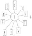
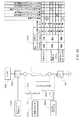
まず図1を参照すると、糖尿病管理で使用される変数の非限定的チャートが描写されている。これらの示された変数は、糖尿病とともに生きている患者によって現在考慮されているものである。これらの変数は、血糖値、運動、疾病、食物、睡眠、およびストレスを含む。 Referring first to FIG. 1, a non-limiting chart of variables used in diabetes management is depicted. These indicated variables are those currently considered by patients living with diabetes. These variables include blood glucose levels, exercise, illness, food, sleep, and stress.
血糖値は、少なくとも1つの血糖測定器、例えば、Abbott Diabetes Care(Alameda,California)によるFREESTYLE血糖測定器を使用することによって、判定されてもよい。いくつかの血糖測定器は、測定値をポンプに無線で伝送してもよい。しかしながら、加えて、血糖値は、少なくとも1つの連続グルコースモニタ(「CGM」)を使用して判定されてもよい。種々の実施形態では、任意のCGM、例えば、Abbott Diabetes Care(Alameda,California)からのFREESTYLE NAVIGATOR連続グルコース監視システム、または同様のデバイスが使用されてもよい。種々のCGMは、間質液グルコースレベル測定値に相関する電気信号を、所定の間隔で手持ち式デバイスまたは他のデバイスに伝送する、患者によって装着される検体センサを含む。 The blood glucose level may be determined by using at least one blood glucose meter, such as a FREESTYLE LE blood glucose meter by Abbott Diabetes Care (Alameda, Calif.). Some blood glucose meters may wirelessly transmit measurements to the pump. In addition, however, blood glucose levels may be determined using at least one continuous glucose monitor (“CGM”). In various embodiments, any CGM may be used, such as the FREESTYLE NAVIGATOR continuous glucose monitoring system from Abbott Diabetes Care (Alameda, Calif.), Or similar devices. Various CGMs include an analyte sensor worn by a patient that transmits electrical signals correlated with interstitial glucose level measurements to a handheld device or other device at predetermined intervals.
さらに、CGM用のセンサは、その全体で参照することにより本明細書に組み込まれる、2009年4月16日に公開され、Microneedle Systems and Apparatus(G34)と題された米国出願公開第US−2009−0099522号で説明されているようないずれかであってもよい。 In addition, a sensor for CGM is published on Apr. 16, 2009, and is incorporated herein by reference in its entirety, U.S. Application Publication No. US-2009 entitled Microneedle Systems and Apparatus (G34). Any of those described in Japanese Patent No. -00099522 may be used.
運動は、糖尿病のある人々に異なる影響を及ぼす。また、運動の厳しさ、運動の種類(すなわち、有酸素または無酸素)、および持続時間に応じて、所与の患者は、運動中および運動後の両方で異なる効果を経験する。状況によっては、血糖値が運動中に増加するが、運動後に減少する場合がある。状況によっては、持続時間および血糖値低下効果が変化する場合がある。 Exercise has different effects on people with diabetes. Also, depending on the severity of exercise, the type of exercise (ie, aerobic or anaerobic), and duration, a given patient will experience different effects both during and after exercise. In some situations, blood glucose levels increase during exercise but may decrease after exercise. Depending on the situation, the duration and blood glucose level lowering effect may change.
ストレスが上昇した血糖値を引き起こす場合がある。ストレスの持続時間および強度は、異なる結果を生じる場合がある。同様に、疾病が上昇した血糖値を引き起こす場合があり、疾病の持続時間および強度が種々の結果を生じる。 Stress can cause elevated blood sugar levels. The duration and intensity of stress can produce different results. Similarly, the disease can cause elevated blood glucose levels, and the duration and intensity of the disease produce various results.
食物は、固体および液体を含むが、それらに限定されない、患者によって摂取される任意の項目を含む。脂肪、タンパク質、および炭水化物を含む食物組成は、結果として生じる血糖値ならびに食物の吸収速度に多大な影響を及ぼす。吸収速度は、血糖値の増加率に変換してもよい。例えば、脂肪および炭水化物の高い食事は、より低い速度で吸収してもよく、したがって、増加した血糖値が、脂肪の低い食事と比較して、後になって見られる場合がある。加えて、炭水化物に関して、食物の血糖インデックスが、血糖値の変化率に多大な影響を及ぼす。 Food includes any item consumed by a patient, including but not limited to solids and liquids. Food compositions containing fats, proteins, and carbohydrates have a profound effect on the resulting blood glucose level as well as the rate of food absorption. The absorption rate may be converted into an increase rate of blood glucose level. For example, a high fat and carbohydrate diet may be absorbed at a lower rate, and thus increased blood glucose levels may be seen later compared to a low fat diet. In addition, with respect to carbohydrates, the glycemic index of food has a great influence on the rate of change of blood glucose level.
種々の種類のインスリンが、一緒に、または個別に使用されてもよい。長時間作用型、中間時間作用型、短時間作用型、および即効型インスリンが使用されてもよい。実施例は、Eli LillyによるNPHである通常のHUMALOG、およびNovo NordiskによるNOVALOGを含んでもよいが、任意のインスリンが使用されてもよい。インスリンはまた、種々の濃度で利用可能である。例えば、U−100およびU−400である。システムおよび方法の種々の実施形態は、インスリンの種々の濃度を使用してもよい。 Different types of insulin may be used together or individually. Long acting, intermediate acting, short acting, and fast acting insulins may be used. Examples may include normal HUMALOG, which is NPH by Eli Lilly, and NOVALOG, by Novo Nordisk, but any insulin may be used. Insulin is also available in various concentrations. For example, U-100 and U-400. Various embodiments of the system and method may use different concentrations of insulin.
インスリンおよび他の生物製剤/治療用および/または医療用流体化合物は、不良な吸収、肝代謝、または他の薬物動態因子により、経口で活性ではない。加えて、いくつかの治療用化合物は、経口で吸収されてもよいが、頻繁に投与される必要があることがあり、患者が所望のスケジュールを維持することが困難である。これらの場合に応じて、非経口送達がしばしば採用され、または採用することができる。 Insulin and other biologics / therapeutic and / or medical fluid compounds are not orally active due to poor absorption, hepatic metabolism, or other pharmacokinetic factors. In addition, some therapeutic compounds may be absorbed orally but may need to be administered frequently, making it difficult for the patient to maintain the desired schedule. Depending on these cases, parenteral delivery is often or can be employed.
インスリンおよび他の流体薬剤送達の効果的な非経口経路は、針またはスタイレットによる皮膚の穿刺を含む、皮下注射、筋肉内注射、および静脈内(IV)投与を含む。多くの糖尿病患者は、インスリンポンプの使用を通して可能である、インスリンの自動送達を好む。これらのポンプは、他の流体の皮下送達でも使用されてもよい。 Effective parenteral routes of insulin and other fluid drug delivery include subcutaneous injection, intramuscular injection, and intravenous (IV) administration, including puncture of the skin with a needle or stylet. Many diabetics prefer automatic delivery of insulin, which is possible through the use of insulin pumps. These pumps may also be used for subcutaneous delivery of other fluids.
ポンプは、皮膚の皮下領域に導入され、事前承認された期間、典型的には、わずか3日間にわたって皮膚中にとどまる管または針である、カニューレを使用して、治療用流体を皮下に送達する。カニューレは、治療用流体の貯留部に流体的に接続される。ポンプは、患者に送達するために、貯留部からカニューレに流体を送出する。 The pump is introduced into the subcutaneous area of the skin and delivers the therapeutic fluid subcutaneously using a cannula, a tube or needle that stays in the skin for a pre-approved period, typically only 3 days . The cannula is fluidly connected to a reservoir of therapeutic fluid. The pump delivers fluid from the reservoir to the cannula for delivery to the patient.
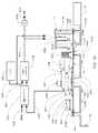
ポンプの実施例は、それらの全体で参照することによって本明細書に組み込まれる、2007年9月20日に公開され、Patch−Sized Fluid Delivery Systems and Methods(E72)と題された米国出願公開第US−2007−0219480号、2007年12月11日に発行され、Loading Mechanism for Infusion Pump(C54)と題された米国特許第7,306,578号、2009年3月3日に発行され、Optical Displacement Sensor for Infusion Devices(D78)と題された米国特許第7,498,563号、または2007年10月4日に公開され、Fluid Delivery Systems and Methods(E70)と題された米国出願公開第US−2007−0228071号を含むが、それらに限定されない公知の任意のポンプ、または他の流体送達ポンプを含む。 Examples of pumps are published on Sep. 20, 2007, which is incorporated herein by reference in its entirety, and is published in US Application Publication No. Patch-Sized Fluid Delivery Systems and Methods (E72). US-2007-0219480, issued December 11, 2007, US Patent No. 7,306,578 entitled Loading Mechanical for Infusion Pump (C54), issued March 3, 2009, Optical U.S. Patent No. 7,498,563 entitled Displacement Sensor for Infusion Devices (D78), or published on 4 October 2007, Fluid Delivery Sys Including ems and Methods (E70) entitled U.S. Application Publication No. US-2007-0228071, including any known pump not limited to, or other fluid delivery pump.
加えて、いくつかの実施形態では、2種類以上の流体を送達する流体送達ポンプが使用されてもよい。2007年9月20日に公開され、Patch−Sized Fluid Delivery Systems and Methods(E72)と題された前述の米国出願公開第US−2007−0219480号、2007年12月11日に発行され、Loading Mechanism for Infusion Pump(C54)と題された前述の米国特許第7,306,578号、2009年3月3日に発行され、Optical Displacement Sensor for Infusion Devices(D78)と題された前述の米国特許第7,498,563号、または2007年10月4日に公開され、Fluid Delivery Systems and Methods(E70)と題された前述の米国出願公開第US−2007−0228071号で説明されているポンプは、1つ以上の付加的な貯留部を組み込むようにわずかに改変されてもよい。これらの貯留部は、同じカニューレ、または別個のカニューレに流体的に接続されてもよい。加えて、上記のカニューレの全てについては、その全体で参照することにより本明細書に組み込まれる、2009年4月16日に公開され、Microneedle Systems and Apparatus(G34)と題された米国出願公開第US−2009−0099522号で説明されているもの等のカニューレである。 In addition, in some embodiments, fluid delivery pumps that deliver more than one type of fluid may be used. Published on September 20, 2007, published in the aforementioned US Application Publication No. US-2007-0219480 entitled Patch-Sized Fluid Delivery Systems and Methods (E72), December 11, 2007, Loading Machinery. US Patent No. 7,306,578, entitled "For Infusion Pump (C54)," issued on March 3, 2009 and entitled "Optical Displacement Sensor for Infusion Devices (D78)" No. 7,498,563, or the aforementioned rice published on October 4, 2007 and entitled Fluid Delivery Systems and Methods (E70) Pump described in Application Publication No. US-2007-0228071 may be slightly modified to incorporate one or more additional reservoir. These reservoirs may be fluidly connected to the same cannula or separate cannulas. In addition, all of the above-described cannulas are disclosed in US Application Publication No. 16/2009, entitled Microneedle Systems and Apparatus (G34), which is incorporated herein by reference in its entirety. A cannula such as that described in US-2009-0099522.
例示的実施形態は、少なくとも、それらの全体で参照することによって本明細書に組み込まれる、2007年9月20日に公開され、Patch−Sized Fluid Delivery Systems and Methods(E72)と題された米国出願公開第US−2007−0219480号、2007年10月4日に公開され、Fluid Delivery Systems and Methods(E70)と題された米国出願公開第US−2007−0228071号、2007年9月20日に公開され、Pumping Fluid Delivery Systems and Methods Using Force Application Assembly(E71)と題された米国出願公開第US−2007−0219496号、2007年9月20日に公開され、Adhesive and Peripheral Systems and Methods for Medical Devices(E73)と題された米国出願公開第US−2007−0219597号、2008年12月31日に公開され、Infusion Pump Assembly(G75)と題された米国出願公開第12/347,985号、2008年12月31日に公開され、Wearable Pump Assembly(G76)と題された米国特許出願第12/347,982号、2008年12月31日に公開され、Infusion Pump Assembly(G77)と題された米国特許出願第12/347,981号、および2008年12月31日に公開され、Pump Assembly With Switch(G79)と題された米国特許出願第12/347,984号で説明され、示されているものと同様である、少なくとも1つのポンプの使用を含む。 An exemplary embodiment, published at 20 September 2007, entitled at least Patch-Sized Fluid Delivery Systems and Methods (E72), incorporated herein by reference in their entirety. Publication No. US-2007-0219480, published Oct. 4, 2007, published in US application publication No. US-2007-0228071 entitled Fluid Delivery Systems and Methods (E70), published Sep. 20, 2007. US Application Publication No. US-2007 entitled, Pumping Fluid Delivery Systems and Methods Using Force Application Assembly (E71) No. 0219496, published on Sep. 20, 2007, published in US Application Publication No. US-2007-0219597, December 31, 2008, entitled Adhesive and Peripheral Systems and Methods for Medical Devices (E73), U.S. Application Publication No. 12 / 347,985 entitled Infusion Pump Assembly (G75), U.S. Patent Application No. 12 / 347,982, published December 31, 2008, entitled Wearable Pump Assembly (G76) No. 12 / 347,981, published December 31, 2008 and entitled Infusion Pump Assembly (G77), and December 2008 Published a day, is described in U.S. Patent Application Serial No. 12 / 347,984, entitled Pump Assembly With Switch (G79), which is similar to that shown, the use of at least one pump.
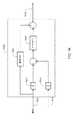
具体的には、例示的実施形態は、ポンプによって送出される流体の容量を測定することが可能な音響容量センサ装置を有する、ポンプを含む。 Specifically, the exemplary embodiment includes a pump having an acoustic capacitive sensor device capable of measuring the volume of fluid delivered by the pump.
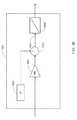
種々の実施形態では、システムは、少なくとも1つの連続検体センサを含み、いくつかの実施形態では、少なくとも1つの連続グルコースモニタ(「CGM」)、注入ポンプ、少なくとも1つの医療用流体,例えば、インスリンを送出する、流体ポンプまたは医療用流体ポンプ、およびコントローラを含む。いくつかの実施形態では、システムは、加えて、検体であろうとその他であろうと、1つ以上の付加的な連続センサを含む。システム構成要素は、データを伝送する、またはコントローラによって制御される。 In various embodiments, the system includes at least one continuous analyte sensor, and in some embodiments, at least one continuous glucose monitor (“CGM”), an infusion pump, at least one medical fluid, such as insulin. A fluid pump or medical fluid pump, and a controller. In some embodiments, the system additionally includes one or more additional continuous sensors, whether analytes or otherwise. System components transmit data or are controlled by a controller.
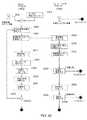
ここで図2を参照すると、システムコントローラ、または流体送達容量およびタイミングを判定する方法は、分注流体のタイミング容量を判定するときに、いくつかの因子を考慮する。図2に提示された、これらの因子は、コントローラが考慮してもよい、因子の非排他的リストである。システムおよび方法は、データを考慮して、インスリンを送達する、または、インスリンを逆調節して、所望の血糖値を維持することを目指す。 Referring now to FIG. 2, the system controller, or method for determining fluid delivery volume and timing, considers several factors when determining the timing volume of dispense fluid. These factors presented in FIG. 2 are a non-exclusive list of factors that the controller may consider. The systems and methods aim to deliver the insulin or reverse-regulate the insulin in view of the data to maintain the desired blood glucose level.
システムは、少なくとも1つのCGMを使用してもよい。CGMは、グルコースセンサ(「センサ」または「検体センサ」と呼ばれる)を含む。種々の実施形態では、CGMセンサが導入され、身体上、例えば、腹部上に位置する、ユーザの間質液の中にとどまる。CGMは、電気信号を所定の間隔で受信機またはコントローラに送信する。受信機またはコントローラは、これらの電気信号をグルコース値に相関する。いくつかの実施形態では、安全性の懸念のために、所与の測定時間に2つ以上の間質グルコース測定値を提供するために、冗長CGMが使用される。いくつかの実施形態では、冗長CGMは、患者の異なる部分に位置する、1つ以上の付加的なCGM(同じCGM)であってもよい。他の実施形態では、冗長性は、センサの全てが患者の上の同様の場所に導入される、単一CGM装置上に統合される1つ以上のセンサによって提供されてもよく、いくつかの実施形態では、同じ自動挿入器を使用する。いくつかの実施形態では、1つ以上の冗長センサは、患者に異なる深度で導入されるセンサであってもよく、例えば、4つの冗長センサがある場合、各センサは、患者に異なる深度で導入される。 The system may use at least one CGM. The CGM includes a glucose sensor (referred to as a “sensor” or “analyte sensor”). In various embodiments, a CGM sensor is introduced and stays in the user's interstitial fluid located on the body, eg, on the abdomen. The CGM sends electrical signals to the receiver or controller at predetermined intervals. The receiver or controller correlates these electrical signals with the glucose value. In some embodiments, redundant CGM is used to provide more than one interstitial glucose measurement at a given measurement time due to safety concerns. In some embodiments, the redundant CGM may be one or more additional CGMs (same CGM) located in different parts of the patient. In other embodiments, redundancy may be provided by one or more sensors integrated on a single CGM device, where all of the sensors are introduced at similar locations on the patient, In the embodiment, the same automatic inserter is used. In some embodiments, one or more redundant sensors may be sensors that are introduced at different depths into the patient, eg, if there are four redundant sensors, each sensor is introduced at a different depth into the patient. Is done.
冗長センサは、付加的な安全性を提供する。センサ測定値は、送達するインスリンの量を判定する際に使用するために、システムが測定値を受け入れるべきか否か、またはどの測定値をシステムが受け入れるべきかを判定するために種々の方法を使用してもよい、プロセッサに送信されてもよい。例えば、プロセッサは、値が例えば6%以上変化するか否かを判定してもよく(他の実施形態では、異なる割合は、異なってもよく、1つ以上の較正技法に基づいて判定および/または特定されてもよい)次いで、測定値は、送達に使用されなくてもよく、再較正(すなわち、指先穿刺による)が必要とされる。プロセッサが1つのセンサから信号を受信しなければ、プロセッサは、そのセンサを無視するようにプログラムされてもよい。全ての冗長センサが同一または同様の値(再度、事前にプログラムされてもよい、または所定であってもよい割合以内)を読み取る場合には、システムに確信があるほど、値が正確に近い。 Redundant sensors provide additional safety. Sensor measurements are used in determining the amount of insulin to deliver, and various methods are used to determine whether the system should accept a measurement or which measurement the system should accept. It may be used and sent to the processor. For example, the processor may determine whether the value changes by, for example, 6% or more (in other embodiments, the different percentages may be different and may be determined and / or based on one or more calibration techniques. The measurements may then not be used for delivery and recalibration (ie by fingertip puncture) is required. If the processor does not receive a signal from one sensor, the processor may be programmed to ignore that sensor. If all redundant sensors read the same or similar values (again within a rate that may be pre-programmed or predetermined), the values are closer to accuracy, the more certain the system is.
いくつかの実施形態では、冗長センサは、異なる方法で較正されてもよい。例えば、1つのセンサが、他のセンサよりも感受性が高くなるように較正されてもよい。いくつかの実施形態では、種々のセンサが、異なるダイナミックレンジに同調される。例えば、2つのセンサが使用される場合、2つのセンサのそれぞれが異なる範囲に同調され、一方は低血糖値に対して感受性が非常に高くなるように同調され、他方は高血糖値に同調される。例えば、低く同調されたセンサが60mg/dlを読み取っている場合、システムは、センサが患者の中にあって読み取っていることを認識する。高く同調されたセンサが250mg/dlを読み取っている場合、システムは、センサが患者の中にあって読み取っていることを確認してもよい。他の実施形態では、冗長センサは、時定数に基づいて同調されてもよく、すなわち、1つのセンサが次のセンサよりも速く読み取る等である。 In some embodiments, redundant sensors may be calibrated in different ways. For example, one sensor may be calibrated to be more sensitive than the other sensor. In some embodiments, the various sensors are tuned to different dynamic ranges. For example, if two sensors are used, each of the two sensors is tuned to a different range, one is tuned to be very sensitive to low blood sugar levels, and the other is tuned to high blood sugar levels. The For example, if the low tuned sensor is reading 60 mg / dl, the system recognizes that the sensor is in the patient and reading. If the highly tuned sensor is reading 250 mg / dl, the system may verify that the sensor is in the patient and reading. In other embodiments, redundant sensors may be tuned based on a time constant, i.e., one sensor reads faster than the next sensor, and so forth.
いくつかの実施形態では、患者は、所与の日に、データをコントローラ/システムに提供する較正センサが常にあるように、1つ以上のCGMの導入を交互交代にしてもよい。いくつかの実施形態では、1つ以上のCGMは、埋込型CGMである。 In some embodiments, the patient may alternate between the introduction of one or more CGMs so that there is always a calibration sensor that provides data to the controller / system on a given day. In some embodiments, the one or more CGMs are embedded CGMs.
種々の実施形態では、システムは、患者の種々の症状/健康または他の検体を感知する、1つ以上の付加的なセンサを含んでもよい。感知された症状は、例示的実施形態では、患者のインスリン必要量に影響を及ぼす、検体または他の健康指標である。付加的なセンサは、以下のうちの1つ以上を含んでもよいが、それらに限定されない。 In various embodiments, the system may include one or more additional sensors that sense various symptoms / health or other analytes of the patient. The sensed symptom is, in the exemplary embodiment, an analyte or other health indicator that affects the patient's insulin requirements. Additional sensors may include, but are not limited to, one or more of the following.
心拍数センサ、
1つ以上のホルモンに対する検体センサ、
患者体温を監視するサーミスタ、
医療用流体温度を監視する温度センサ
加速度計、
ジャイロスコープ、
慣性計測装置(「IMU」)、
呼吸数モニタ、
カルボックスシメトリセンサ、
ガルバニック皮膚、
アドレナリンセンサ、
酸素飽和センサ、
水和センサ、
白血球数センサ、および/または
信号伝達ホルモンセンサ。Heart rate sensor,
An analyte sensor for one or more hormones,
A thermistor that monitors patient temperature,
Temperature sensor to monitor medical fluid temperature accelerometer,
Gyroscope,
Inertial measurement device (“IMU”),
Respiratory rate monitor,
Calbox sensor sensor,
Galvanic skin,
Adrenaline sensor,
Oxygen saturation sensor,
Hydration sensor,
A white blood cell count sensor and / or a signaling hormone sensor.
加えて、センサのうちの1つ以上は、いくつかの実施形態では、その全体で参照することにより本明細書に組み込まれる、2009年4月16日に公開され、Microneedle Systems and Apparatus(G34)と題された、米国出願公開第US−2009−0099522号で説明されているものと同様の極小針センサとして具現化されてもよい。 In addition, one or more of the sensors, in some embodiments, published April 16, 2009, incorporated herein by reference in its entirety, Microneedle Systems and Apparatus (G34). May be embodied as a microneedle sensor similar to that described in US Application Publication No. US-2009-0099522.
いくつかの実施形態では、システムは、少なくとも1つの慣性計測装置(「IMU」)を含んでもよい。種々の実施形態では、任意の種類のIMUが使用されてもよい。いくつかの実施形態では、IMUは、センサの組み合わせを使用して、運動を感知することが可能なデバイスである。種々のIMUは、例えば、加速度計および/またはジャイロスコープの組み合わせを使用して、感知の種類、速度、および方向を含むが、それらに限定されない、重力に対する配向を測定するように、1つ以上の加速度計および/または1つ以上のジャイロスコープを含んでもよい。少なくとも1つのIMUから収集されたデータは、ユーザが動いているか否かを判定するために使用されてもよい。いくつかの実施形態では、収集されたデータは、ユーザが眠っているか、または倒れたかを判定するために使用されてもよい。他の実施形態では、IMUは、ユーザが行っている活動の種類、例えば、走ること、スキーをすること、テニスをすること等を示してもよい、ユーザの速度および方向変化を判定するために使用されてもよい。したがって、少なくとも1つのIMUは、ユーザの運動を判定するために使用されてもよく、データは、コントローラによって制御され、プロセッサによって使用されてもよい。 In some embodiments, the system may include at least one inertial measurement unit (“IMU”). In various embodiments, any type of IMU may be used. In some embodiments, an IMU is a device that can sense motion using a combination of sensors. Various IMUs may use one or more to measure orientation relative to gravity, including but not limited to, sensing type, velocity, and direction, for example using a combination of accelerometers and / or gyroscopes. Accelerometers and / or one or more gyroscopes. Data collected from at least one IMU may be used to determine whether the user is moving. In some embodiments, the collected data may be used to determine if the user is asleep or collapsed. In other embodiments, the IMU may determine the user's speed and direction changes that may indicate the type of activity the user is performing, eg, running, skiing, playing tennis, etc. May be used. Thus, at least one IMU may be used to determine a user's movement and the data may be controlled by a controller and used by a processor.
ユーザの運動を判定するための少なくとも1つのIMUの使用が本明細書で説明されているが、少なくとも1つのIMUは、血中酸素センサを含むがそれに限定されない、ユーザの運動または活動を判定する、任意の1つ以上の種々のデバイスおよびセンサと併せて使用されてもよいことを理解されたい。いくつかの実施形態では、IMUは、Microstrain,Inc.,Williston,VTによるMICROSTRAIN(登録商標)3DM−GX1(登録商標)であってもよい。いくつかの実施形態では、IMUは、ポンプの中またはコントローラの中に位置してもよく、ユーザによって、またはユーザ上で装着される別個のデバイスであってもよい。いくつかの実施形態では、使用されるIMUは、加速度計およびジャイロスコープを含む、3軸IMUであってもよい。いくつかの実施形態では、IMUは、3つの加速度計および3つのジャイロスコープを含んでもよい。これらのIMUは、ピッチ、ロール、およびヨーに関する出力を含む。しかしながら、これらのデバイスは、大きい、および/または重くてもよく、および/または大量の所要電力を有してもよい。したがって、いくつかの実施形態では、少なくとも1つの加速度計および少なくとも1つのジャイロスコープを含む、IMUを使用することが望ましくてもよい。 Although use of at least one IMU to determine a user's exercise is described herein, at least one IMU determines a user's exercise or activity, including but not limited to a blood oxygen sensor. It should be understood that it may be used in conjunction with any one or more of various devices and sensors. In some embodiments, the IMU is a Microstrain, Inc. , Williston, VT, MICROSTRAIN® 3DM-GX1®. In some embodiments, the IMU may be located in the pump or in the controller and may be a separate device worn by or on the user. In some embodiments, the IMU used may be a 3-axis IMU including an accelerometer and a gyroscope. In some embodiments, the IMU may include three accelerometers and three gyroscopes. These IMUs include outputs related to pitch, roll, and yaw. However, these devices may be large and / or heavy and / or have a large amount of power requirements. Thus, in some embodiments, it may be desirable to use an IMU that includes at least one accelerometer and at least one gyroscope.
いくつかの実施形態では、ユーザが運動をしているか、または別様にストレスを受けているか、あるいは、インスリン感度またはインスリン必要量を変化させる場合がある状況を経験しているかを判定するために、心拍数モニタ、呼吸数モニタ、アドレナリンセンサ、サーミスタ、および/または水和センサのうちの1つ以上が使用されてもよいが、それらに限定されない。いくつかの実施形態では、予期しないグルコースデータに寄与する場合がある、ユーザが脱水状態となり得るか否かを判定するために、水和センサが使用される。いくつかの実施形態では、予期しない結果を予測する、および/または温度が推奨されるよりも高い、あるいは低いときに、ユーザに注意/警告するために使用されてもよい、インスリンを含んでもよい医療用流体の温度を監視するために、温度センサが使用されてもよい。種々の他の実施形態では、付加的なセンサが使用されてもよい。種々の実施形態では、1つ以上のセンサが使用されてもよく、これらのセンサは、ユーザの上、ポンプの中、および/またはコントローラの中で、および/または別個のデバイスとして、あるいはそれらの組み合わせで使用されてもよい。 In some embodiments, to determine if the user is exercising or otherwise stressed or experiencing a situation that may change insulin sensitivity or insulin requirements. One or more of, a heart rate monitor, a respiratory rate monitor, an adrenergic sensor, a thermistor, and / or a hydration sensor may be used, but are not limited thereto. In some embodiments, a hydration sensor is used to determine whether a user can become dehydrated, which may contribute to unexpected glucose data. Some embodiments may include insulin, which may be used to predict unexpected results and / or to alert / warn the user when the temperature is higher or lower than recommended. A temperature sensor may be used to monitor the temperature of the medical fluid. In various other embodiments, additional sensors may be used. In various embodiments, one or more sensors may be used, these sensors being on the user, in the pump, and / or in the controller, and / or as a separate device, or their May be used in combination.
コントローラは、少なくとも1つのユーザインターフェースとして、また、CGM/センサ、ポンプ、および制御システムを伴う患者/ユーザのインターフェース用の中央ユーザインターフェースとしての機能も果たす。本明細書の目的で、コントローラは、患者、「ユーザ」、介護者、医療介護提供者、またはそれらの組み合わせによってプログラムされてもよい。しかしながら、この説明の目的で、「患者」または「患者/ユーザ」あるいは「ユーザ」という用語は、コントローラに情報を入力する、または患者に介護を提供するためにコントローラを利用する誰かを指す。例示的実施形態では、システムコントローラは、無線、例えば、無線周波数(「RF」)通信および/または他の種類の遠隔通信を介して、種々のシステム構成要素と通信する。例示的実施形態では、コントローラは、グラフィカルユーザインターフェース(「GUI」)および1つ以上の入力デバイス、例えば、ボタン、容量性スライダ、ジョグホイール、タッチスクリーン、キーパッド、電子キーパッド、および任意の他の入力デバイスを含む。コントローラはまた、少なくとも1つのプロセッサも含むが、例示的実施形態では、コントローラは、少なくとも2つのプロセッサ、制御プロセッサ、および安全性プロセッサを含む。これらのプロセッサは、冗長プロセッサ、または、冗長処理を提供する、あるいは相互の処理をチェックする2つの異なるプロセッサであってもよい。 The controller also serves as at least one user interface and as a central user interface for a patient / user interface with CGM / sensors, pumps, and control systems. For purposes herein, the controller may be programmed by a patient, a “user”, a caregiver, a medical care provider, or a combination thereof. However, for purposes of this description, the term “patient” or “patient / user” or “user” refers to someone who uses the controller to enter information into the controller or provide care to the patient. In an exemplary embodiment, the system controller communicates with various system components via wireless, eg, radio frequency (“RF”) communication and / or other types of remote communication. In an exemplary embodiment, the controller includes a graphical user interface (“GUI”) and one or more input devices such as buttons, capacitive sliders, jog wheels, touch screens, keypads, electronic keypads, and any other Including input devices. The controller also includes at least one processor, but in the exemplary embodiment, the controller includes at least two processors, a control processor, and a safety processor. These processors may be redundant processors or two different processors that provide redundant processing or check each other's processing.
コントローラのいくつかの実施形態は、少なくとも1つの「事象」または特殊ボタン、例えば、「食事」ボタン、「運動」ボタン、および「ボーラス」ボタンを含んでもよい。いくつかの実施形態では、コントローラは、単一の「事象」ボタンを含有してもよい。このボタンを押す、または作動させることにより、潜在的な事象のリストを含んでもよい、事象メニューをユーザにもたらしてもよく、そのうちの1つ以上は、ユーザにとってカスタマイズ可能であってもよい。 Some embodiments of the controller may include at least one “event” or special button, such as a “meal” button, an “exercise” button, and a “bolus” button. In some embodiments, the controller may contain a single “event” button. Pressing or activating this button may provide the user with an event menu that may include a list of potential events, one or more of which may be customizable for the user.
全ての事象ボタンに関して、これらのボタンは、押されると、例えば、運動、食事、またはボーラスに対する処理論理に、患者/ユーザが直接入力することを可能にする、メニューまたは処理論理を患者/ユーザにもたらす。次いで、論理は、付加的な情報、例えば、どれだけ長く運動が続くことが予期されるか、どれだけ厳しいか、どれだけ多くの食物か(すなわち、どれだけ多くの炭水化物か)、血糖インデックス、食物の脂肪含有量およびタンパク質含有量を入力するように、患者/ユーザに問い合せを行ってもよい。ボーラスに関して、患者/ユーザは、一連のボタン押下を使用することによって、または、インスリンの要求された容量、すなわち、インスリンの単位を入力するために、別の入力デバイス、すなわち、ジョグホイール、ボタン、またはスライダを使用することによって、ボーラスの容量を入力することが可能となる。いくつかの実施形態では、ユーザインターフェースは、当技術分野で公知であるインスリンポンプおよびポンプコントローラ上で見出されるのと同じ特徴のうちの多くを含む。 For all event buttons, these buttons, when pressed, provide a menu or processing logic to the patient / user that allows the patient / user to directly enter processing logic for, for example, exercise, meal, or bolus. Bring. The logic then adds additional information such as how long exercise is expected to continue, how severe it is, how much food (ie how many carbohydrates), blood glucose index, The patient / user may be queried to enter the fat content and protein content of the food. With respect to the bolus, the patient / user can use another input device, i.e., jog wheel, button, to enter the requested volume of insulin, i.e. the unit of insulin, by using a series of button presses. Alternatively, the volume of the bolus can be input by using a slider. In some embodiments, the user interface includes many of the same features found on insulin pumps and pump controllers known in the art.
例示的実施形態では、コントローラはまた、「細片読取機」、例えば、「指先の穿刺」または「指先穿刺」の測定値で使用するためのグルコース試験細片を受け入れる空間も含み、例えば、患者が指を指し、「指先穿刺」に塗布するために指からの血液を使用する。「細片読取機」は、電気化学試験を使用して、血液の血糖値を判定する。細片読取機は、予期しない、または異常な測定値を二重にチェックするように、あるいは、CGM故障の場合にCGMへのバックアップとして、CGMを較正するために使用されてもよい。いくつかの実施形態では、細片読取機は、グルコース測定器等の別個のデバイスであってもよい。これらの実施形態では、グルコース測定器が指先穿刺測定値を無線で受信してもよく、または、ユーザが測定値をコントローラに手動で入力してもよい。 In an exemplary embodiment, the controller also includes a space for receiving a “strip reader”, eg, a glucose test strip for use with “fingertip puncture” or “fingertip puncture” measurements, eg, a patient Points to the finger and uses the blood from the finger to apply to the “fingertip puncture”. A “strip reader” uses an electrochemical test to determine blood glucose levels. The strip reader may be used to calibrate the CGM to double check for unexpected or abnormal measurements or as a backup to the CGM in case of CGM failure. In some embodiments, the strip reader may be a separate device such as a glucose meter. In these embodiments, the glucose meter may receive fingertip puncture measurements wirelessly, or the user may manually enter the measurements into the controller.
GUIは、カラーGUI、ブラックオングレイスクリーン、および/またはタッチスクリーン、あるいはその他であってもよい。GUIは、加えて、音声コマンドを受け入れる、および/または与え、および/または要求に応じて拡大を提供してもよい。 The GUI may be a color GUI, a black on gray screen, and / or a touch screen, or others. The GUI may additionally accept and / or give voice commands and / or provide expansion upon request.
コントローラは、加えて、少なくとも1つのスピーカを含み、いくつかの実施形態では、少なくとも1つの振動モータを含む。いくつかの実施形態では、コントローラは、その全体で参照することにより本明細書に組み込まれる、2008年8月21日に公開され、Device and Method for Food Management(F21)と題された、米国出願公開第US−2008−0198012号で説明されている特徴のうちのいずれか1つ以上を含んでもよい。 The controller additionally includes at least one speaker, and in some embodiments includes at least one vibration motor. In some embodiments, the controller is a US application published on August 21, 2008, entitled Device and Method for Food Management (F21), which is incorporated herein by reference in its entirety. Any one or more of the features described in Publication No. US-2008-0198012 may be included.
コントローラは、いくつかの実施形態では、少なくとも1つのCGMを含むがそれに限定されない、少なくとも1つセンサ用の受信機としての機能を果たす。そのようなものとして、ユーザは、新しいセンサが体内に導入されたときをコントローラに示す。いくつかの実施形態では、ユーザは、加えて、例えば、右腹部、左腹部、右腕、左腕、右臀部、左臀部、右足、左足等を含むが、それらに限定されない、ユーザの身体上のセンサの場所を入力してもよい。これは、センサが身体上の異なる領域中で異なって機能してもよいように、望ましくてもよい。コントローラがこのデータを記録し、処理するにつれて、コントローラは、身体の同じ領域からの「ラグ」および/または「ドリフト」情報を示す、過去のプロファイル情報に基づいて、センサを較正してもよい。 The controller, in some embodiments, serves as a receiver for at least one sensor, including but not limited to at least one CGM. As such, the user indicates to the controller when a new sensor has been introduced into the body. In some embodiments, the user may additionally include sensors on the user's body, including but not limited to, for example, but not limited to, the right abdomen, left abdomen, right arm, left arm, starboard, portside, right foot, left foot, etc. You may enter the location. This may be desirable so that the sensor may function differently in different areas on the body. As the controller records and processes this data, the controller may calibrate the sensor based on past profile information indicating “lag” and / or “drift” information from the same region of the body.
種々の実施形態における医療用流体ポンプ/注入ポンプ/インスリンポンプ/流体ポンプは、インスリンを含む医療用流体を送達するために使用され、1つ以上の流体を送達するための1つ以上の貯留部を含んでもよい(したがって、種々の貯留部が、同じ流体、または異なる流体を含有してもよい)。いくつかの実施形態では、医療用ポンプは、2つ以上の種類のインスリン(例えば、上記で説明される種類のうちの1つ以上)を送達してもよい。しかしながら、いくつかの実施形態では、2つ以上の貯留部を含む医療用ポンプが、インスリンおよび少なくとも1つの逆調節ホルモン、例えば、グルカゴンを送達するために使用されてもよい。医療用ポンプは、それらの全体で参照することにより本明細書に組み込まれる、2007年9月20日に公開され、Patch−Sized Fluid Delivery Systems and Methods(E72)と題された米国出願公開第US−2007−0219480号、2007年12月11日に発行され、Loading Mechanism for Infusion Pump(C54)と題された米国特許第7,306,578号、2009年3月3日に発行され、Optical Displacement Sensor for Infusion Devices(D78)と題された米国特許第7,498,563号、2007年10月4日に公開され、Fluid Delivery Systems and Methods(E70)と題された米国出願公開第US−2007−0228071号、2007年9月20日に公開され、Pumping Fluid Delivery Systems and Methods Using Force Application Assembly(E71)と題された米国出願公開第US−2007−0219496号、2007年9月20日に公開され、Adhesive and Peripheral Systems and Methods for Medical Devices(E73)と題された米国出願公開第US−2007−0219597号、2008年12月31日に公開され、Infusion Pump Assembly(G75)と題された米国出願公開第12/347,985号、2008年12月31日に公開され、Wearable Pump Assembly(G76)と題された米国特許出願第12/347,982号、2008年12月31日に公開され、Infusion Pump Assembly(G77)と題された米国特許出願第12/347,981号、2008年12月31日に公開され、Pump Assembly With Switch(G79)と題された米国特許出願第12/347,984号、2009年4月16日に公開され、Microneedle Systems and Apparatus(G34)と題された、米国出願公開第US−2009−0099522号、および2009年4月16日に公開され、Infusion Pump Assembly(G46)と題された、米国出願公開第US−2009−0099523号で説明されているポンプのうちのいずれか、または複数の貯留部を収容する、その修正であってもよい。 The medical fluid pump / infusion pump / insulin pump / fluid pump in various embodiments is used to deliver medical fluid including insulin and one or more reservoirs for delivering one or more fluids (Thus, the various reservoirs may contain the same fluid or different fluids). In some embodiments, the medical pump may deliver more than one type of insulin (eg, one or more of the types described above). However, in some embodiments, a medical pump that includes two or more reservoirs may be used to deliver insulin and at least one counter-regulating hormone, such as glucagon. Medical pumps are published on Sep. 20, 2007, and are incorporated herein by reference in their entirety, US Application Publication No. US entitled Patch-Sized Fluid Delivery Systems and Methods (E72). -2007-0219480, issued on Dec. 11, 2007, entitled Loading Mechanical for Infusion Pump (C54), U.S. Pat. No. 7,306,578, issued on Mar. 3, 2009, Optical Displacement US Patent No. 7,498,563, entitled Sensor for Infusion Devices (D78), published on Oct. 4, 2007, Fluid Delivery Systems a United States Application Publication No. US-2007-0228071 entitled nd Methods (E70), published on September 20, 2007, and published as Pumping Fluid Delivery Systems and Methods Usage Application Application (71) US Application Publication No. US-2007-0219597, December 31, 2008, published on September 20, 2007 and entitled Adhesive and Peripheral Systems and Methods for Medical Devices (E73). U.S. Published Application No. 12 published on the day and entitled Infusion Pump Assembly (G75) US Patent Application No. 12 / 347,982, published December 31, 2008, entitled Wearable Pump Assembly (G76), published December 31, 2008, and Infusion Pump Assembly U.S. Patent Application No. 12 / 347,981, entitled (G77), U.S. Patent Application No. 12 / 347,984, published 31 December 2008 and entitled Pump Assembly With Switch (G79); US Application Publication No. US-2009-0099522, published April 16, 2009 and entitled Microneedle Systems and Apparatus (G34), and Infusion Pump Ass. Entitled mbly (G46), one of the pumps described in US Application Publication No. US-2009-0099523, or to accommodate a plurality of reservoir may be its modification.
システムは、コントローラ上の1つ以上の振動モータおよび/または1つ以上のススピーカ、ならびにいくつかの実施形態では、医療用ポンプ上の1つ以上の振動および/またはスピーカモータを含むが、それらに限定されない、1つ以上のアラームを含んでもよい。いくつかのアラームは、いくつかの実施形態では、進行性アラームであってもよく、すなわち、アラームの種類に応じて、アラームが次第により大きく、または活発になる。アラームは、高血糖、低下する血糖または低い血糖、閉塞、空またはほぼ空の貯留部、取り外されたカニューレ、取り外されたセンサ、または患者が認識することを希望し得る任意の他の状態を含むが、それらに限定されない、無数の状態のうちのいずれかを示すために使用されてもよい。 The system includes one or more vibration motors and / or one or more loudspeakers on the controller, and in some embodiments, one or more vibration and / or speaker motors on a medical pump, to which One or more alarms may be included, without limitation. Some alarms may be progressive alarms in some embodiments, i.e., depending on the type of alarm, the alarm becomes progressively larger or more active. Alarms include high blood sugar, low or low blood sugar, obstruction, empty or near empty reservoir, removed cannula, removed sensor, or any other condition that the patient may wish to recognize May be used to indicate any of a myriad of conditions, but not limited to them.
いくつかの実施形態では、アラームシステムは、さらにポンプおよびコントローラとは別の信号増幅器を含んでもよい。増幅器は、アラーム信号を受信し、アラームを増幅してもよい。信号増幅器は、いくつかの実施形態では、ポンプおよび/またはコントローラから無線伝送を受信してもよい、別個のデバイスであってもよい。いくつかの実施形態では、信号増幅器は、例えば、別のデバイスに信号伝達して、テレビまたはステレオをオンにし、電話が鳴るように自動的に誘起してもよく、または、いくつかの実施形態では、アラームが患者/ユーザによって確認されない場合、信号増幅器は、患者/ユーザによって事前にプログラムされる緊急サービスまたは緊急連絡番号に電話をしてもよい。 In some embodiments, the alarm system may further include a signal amplifier separate from the pump and controller. The amplifier may receive the alarm signal and amplify the alarm. The signal amplifier, in some embodiments, may be a separate device that may receive wireless transmissions from the pump and / or controller. In some embodiments, the signal amplifier may, for example, signal to another device to turn on the television or stereo and automatically trigger the phone to ring, or in some embodiments Then, if the alarm is not acknowledged by the patient / user, the signal amplifier may call an emergency service or emergency contact number that is preprogrammed by the patient / user.
いくつかの実施形態では、患者/ユーザは、異なる事象/時刻に対して異なる種類のアラームを選択してもよい。これらの選択は、事前にプログラムされてもよく(例えば、午後6時から午前6時までの毎晩、アラーム状態が感知された場合に夜間アラームシーケンスが使用される)、または所望される時に選択されてもよい(例えば、水泳前に、メニューを使用して、患者/ユーザが、例えば、振動のみであってもよい「水泳アラーム」を選択してもよい)。コントローラは、例示的実施形態では、患者/ユーザが、いくつかの状況に対して漸増または進行性アラームを選択し、他の状況に対して振動を選択してもよいように、アラームに関して完全にプログラム可能であってもよい。患者/ユーザによってプログラムされてもよい付加的なアラーム状態は、アラームを無音にするために必要な状態を含むが、それに限定されない(例えば、夜間アラーム無音状態は、患者が状態を確認することなく睡眠中にアラームをオフにしないことを確実にするために、一連の入力を必要としてもよい)。 In some embodiments, the patient / user may select different types of alarms for different events / times. These selections may be pre-programmed (eg, every night from 6 pm to 6 am, a night alarm sequence is used if an alarm condition is detected) or selected when desired. (E.g., prior to swimming, using the menu, the patient / user may select "Swimming Alarm", which may be, for example, only vibration). The controller, in the exemplary embodiment, is completely in alarms so that the patient / user may select incremental or progressive alarms for some situations and vibrations for other situations. It may be programmable. Additional alarm conditions that may be programmed by the patient / user include, but are not limited to, the conditions required to silence the alarm (eg, night alarm silence conditions may be without the patient confirming the condition). A series of inputs may be required to ensure that the alarm is not turned off during sleep).
システムは、1つ以上のカニューレが患者から取り外されたときを判定するために、1つ以上の指標を使用してもよい。いくつかの実施形態では、カニューレが患者から取り外されたか否かを判定するために、伝導性センサが使用されてもよい。いくつかの実施形態では、カニューレは、カニューレの周囲の伝導パッド、例えば、中央プロセッサに電気的に連結された2つの電極を含むパッドを含んでもよい。カニューレが取り外された場合、インスリンがパッドの中へ送達され、したがって、パッドの伝導性を変化させる。 The system may use one or more indicators to determine when one or more cannulas have been removed from the patient. In some embodiments, a conductivity sensor may be used to determine if the cannula has been removed from the patient. In some embodiments, the cannula may include a conductive pad around the cannula, eg, a pad that includes two electrodes that are electrically coupled to a central processor. When the cannula is removed, insulin is delivered into the pad, thus changing the conductivity of the pad.
ここで図3を参照すると、いくつかの実施形態では、システムで使用されるカニューレは、抜去の視覚的指標として機能する2つ以上の管類の色を含むカニューレであってもよい。例示目的で、管類の色は、異なるハッチマークで表される。例えば、カニューレの先端は赤であってもよく、中央は青であってもよく、端は透明の管類であってもよい。したがって、患者は、目視検査を介してカニューレが患者から取り外されているか否かを判定してもよい。 Referring now to FIG. 3, in some embodiments, the cannula used in the system may be a cannula that includes two or more tubing colors that serve as a visual indicator of removal. For illustrative purposes, the color of the tubing is represented by different hatch marks. For example, the tip of the cannula may be red, the center may be blue, and the end may be transparent tubing. Thus, the patient may determine whether the cannula has been removed from the patient via visual inspection.
システムは、1つ以上のCGMセンサが故障したか、または、誤ったか、あるいは不正確な情報を提供しているか否かを判定するように、1つ以上の完全性試験を含んでもよい。「誤った」または「不正確な」情報という用語は、CGM測定値と指先穿刺測定値との間の差異率として定義されてもよい。差異率は、CGM測定値が指先穿刺測定値よりも高い割合または低い割合であるときを指してもよい。いくつかの実施形態では、例えば、指先穿刺とCGMとの間の30%差異より高い任意の数が、「誤った情報」または「不正確な情報」と称されてもよい。他の実施形態では、この割合は、30%よりも高い、または低くてもよい。いくつかの実施形態では、この割合は、ユーザとCGMシステムとの間で変化してもよい。 The system may include one or more integrity tests to determine whether one or more CGM sensors have failed or are incorrect or providing inaccurate information. The term “incorrect” or “inaccurate” information may be defined as the percentage difference between a CGM measurement and a fingertip puncture measurement. The difference rate may indicate when the CGM measurement value is higher or lower than the fingertip puncture measurement value. In some embodiments, for example, any number higher than the 30% difference between fingertip puncture and CGM may be referred to as “false information” or “inaccurate information”. In other embodiments, this percentage may be higher or lower than 30%. In some embodiments, this ratio may vary between the user and the CGM system.
いくつかの実施形態では、温度完全性試験が使用されてもよい。いくつかのCGMセンサは、温度偏移の程度ごとにドリフトを経験する場合がある。これらのCGMセンサについて、いくつかの実施形態では、温度がより高く、または低く変調される場合、システムは、CGM値の同様の割合および/または比例ドリフトを予期する。いくつかの実施形態では、システムは、最初に指先穿刺を行うようにユーザを促し、次いで、温度偏移に遭遇し、第2の指先穿刺測定値を採取し、ならびにCGM測定値に注目してもよい。これは、CGMの完全性試験を提供してもよい。いくつかの実施形態では、システムは、このようにユーザを促してもよく、かつ温度偏移(ポンプまたはコントローラの中の温度センサによって判定され得る)を待ち、次いで、第2の指先穿刺を行うようにユーザを促してもよい。次いで、システムは、温度偏移の前および後に、指先穿刺測定値をCGM測定値と比較してもよい。温度による偏移を経験することが予期される、特定のCGMが偏移しない場合には、これは、CGMシステムの完全性が低下しているという指標であってもよい。これらの場合において、システムは、このエラーについてユーザに通知し、制御の半閉または閉ループシステムの継続を中止する。 In some embodiments, a temperature integrity test may be used. Some CGM sensors may experience drift for each degree of temperature deviation. For these CGM sensors, in some embodiments, if the temperature is modulated higher or lower, the system expects a similar percentage and / or proportional drift of the CGM value. In some embodiments, the system first prompts the user to perform a fingertip puncture, then encounters a temperature shift, takes a second fingertip puncture measurement, and looks at the CGM measurement. Also good. This may provide CGM integrity testing. In some embodiments, the system may prompt the user in this manner and wait for a temperature deviation (which can be determined by a temperature sensor in the pump or controller) and then perform a second fingertip puncture The user may be prompted to do so. The system may then compare the fingertip puncture measurement with the CGM measurement before and after the temperature shift. If a particular CGM that is expected to experience a temperature shift does not shift, this may be an indication that the integrity of the CGM system has been reduced. In these cases, the system notifies the user about this error and stops continuation of the semi-closed or closed loop system of control.
いくつかの実施形態では、システムは、CGMセンサにごく近接する領域中で、皮膚の下の領域の中へ少量のグルコースを注射するようにユーザに促してもよい。少量のグルコースは、特定の濃度のグルコースを含有する溶液であってもよい。システムは、注射後の短時間にCGMからグルコース測定値の増加を予期してもよい。いくつかの実施形態では、この同じ試験が同じユーザで実施される場合、および溶液が以前に使用されたものと同一である場合、および注射が同じ方式で、かつセンサに関して以前と同じ領域で実施された場合、ユーザの反応の結果およびプロファイルは、システムの中にあってもよく、したがって、システムは、新しい結果を古い結果または古い結果の平均と比較してもよい。CGM測定値がグルコースの割合を示さない、または古い結果あるいは限界内の古い結果の平均に一致しない場合には、これは、CGMシステムの完全性が低下しているという指標であってもよい。これらの場合において、システムは、このエラーについてユーザに通知し、制御の半閉または閉ループシステムの継続を中止する。 In some embodiments, the system may prompt the user to inject a small amount of glucose into the area under the skin in an area in close proximity to the CGM sensor. A small amount of glucose may be a solution containing a specific concentration of glucose. The system may expect an increase in glucose readings from the CGM in a short time after injection. In some embodiments, if this same test is performed with the same user, and if the solution is the same as previously used, and the injection is performed in the same manner and in the same area as before with respect to the sensor If so, the user response results and profile may be in the system, and therefore the system may compare the new results to the old results or the average of the old results. If the CGM measurement does not indicate the percentage of glucose or does not match the average of old results or old results within limits, this may be an indication that the integrity of the CGM system has been reduced. In these cases, the system notifies the user about this error and stops continuation of the semi-closed or closed loop system of control.
いくつかの実施形態では、システムは、要求に応じて指先穿刺測定値を採取するようにユーザに促してもよい。この測定値は、システム完全性チェックとして、および/または1つ以上のCGMセンサを較正するために使用されてもよい。完全性チェックとしての要求に応じた指先穿刺に関して、指先穿刺測定値が、ある割合以内のCGM測定値を確認しない場には、これは、CGMシステムの完全性が低下しているという指標であってもよい。これらの場合において、システムは、このエラーについてユーザに通知し、制御の半閉または閉ループシステムの継続を中止する。較正としての要求に応じた指先穿刺に関して、指先穿刺測定値が、ある割合以内のCGM測定値を確認しない場には、これは、CGMシステムの完全性が低下しているかもしれないという指標であってもよい。システムは、第2の指先穿刺を入力して、第1の指先穿刺測定値を確認するようにユーザに要求してもよい。第2の指先穿刺測定値の後に、第2の測定値が第1の測定値を確認する場合、システムが再開してもよく(測定値がCGM完全性を確認する場合)、または完全性が低下される場合があることを測定値が確認する場合、システムは、エラーについてユーザに通知し、制御の半閉または閉ループシステムの継続を中止してもよい。 In some embodiments, the system may prompt the user to collect fingertip puncture measurements on demand. This measurement may be used as a system integrity check and / or to calibrate one or more CGM sensors. For fingertip puncture in response to a request for integrity check, if the fingertip puncture measurement value does not confirm a CGM measurement value within a certain percentage, this is an indicator that the integrity of the CGM system has decreased. May be. In these cases, the system notifies the user about this error and stops continuation of the semi-closed or closed loop system of control. For fingertip punctures as required for calibration, if the fingertip puncture measurement does not confirm a CGM measurement within a certain percentage, this is an indicator that the integrity of the CGM system may be reduced. There may be. The system may request the user to enter a second fingertip puncture and confirm the first fingertip puncture measurement. If the second measurement confirms the first measurement after the second fingertip puncture measurement, the system may resume (if the measurement confirms CGM integrity) or the integrity is If the measurement confirms that it may be degraded, the system may notify the user about the error and stop continuation of the control semi-closed or closed-loop system.
いくつかの実施形態では、要求に応じた指先穿刺に関して、システムが指先穿刺を要求し、システムが、所定の時間量、例えば、5分または10分以内に指先穿刺測定値を受信しない場合、システムは、デフォルトで閉ループまたは半閉ループモードを終了してもよい。これは、付加的な安全性を提供し、また、いくつかの実施形態では、システムが、信頼性のあるCGM測定値を確保するために頻繁な較正を必要としてもよいため、CGM測定値の精度を増加させてもよい。 In some embodiments, for a fingertip puncture on demand, if the system requests a fingertip puncture and the system does not receive a fingertip puncture measurement within a predetermined amount of time, eg, 5 minutes or 10 minutes, the system May exit closed loop or semi-closed loop mode by default. This provides additional safety and, in some embodiments, the system may require frequent calibration to ensure reliable CGM measurements, so The accuracy may be increased.
本明細書で説明される種々の完全性試験に関して、いくつかの実施形態では、システムエラーまたはアラートを送信するよりもむしろ、いくつかの実施形態では、かつ場合によっては、完全性チェックのうちのいずれかを用いて、システムは、予期されるそこからのCGM測定値の差異率を判定し、それに応じて測定値を調整してもよい。 With respect to the various integrity tests described herein, in some embodiments, rather than sending a system error or alert, in some embodiments, and in some cases, of the integrity check With either, the system may determine the expected rate of difference of CGM measurements therefrom and adjust the measurements accordingly.
いくつかの実施形態では、CGMは、ユーザがセンサに圧力を印加している、例えば、睡眠中にセンサに寝返りを打ったときに、異なる、または「不良」データを提供してもよい。いくつかの実施形態では、システムは、これらの時間の間にセンサをオフにしてもよく、加えて、コントローラ画面上に指標アラートを含んでもよい。いくつかの実施形態では、ユーザが睡眠時であることをコントローラが感知すると、システムがシャットダウンしてもよく、ある経過時間量、例えば、30分後に、システムがセンサをオンにしてもよい。問題/圧力が自ら訂正した場合には、システムが再開してもよい。これは、夜間に目を覚ますよりもむしろ、ユーザが睡眠を継続し、おそらく、自らセンサから圧力を取り除くことを可能にするために望ましくてもよい。いくつかの実施形態では、シャットダウン中に、インスリンの送達も停止する。 In some embodiments, the CGM may provide different or “bad” data when a user is applying pressure to the sensor, eg, when the sensor is turned over during sleep. In some embodiments, the system may turn off the sensor during these times and may also include an indicator alert on the controller screen. In some embodiments, when the controller senses that the user is sleeping, the system may shut down, and after a certain amount of time, eg, 30 minutes, the system may turn on the sensor. If the problem / pressure corrects itself, the system may resume. Rather than waking up at night, this may be desirable to allow the user to continue sleeping and possibly remove pressure from the sensor himself. In some embodiments, delivery of insulin also stops during shutdown.
いくつかの実施形態では、経過時間後に、システムが自ら訂正しなければ、システムが警報を鳴らし、システムがシャットダウンをしたことをユーザに警告する。 In some embodiments, after the elapsed time, if the system does not correct itself, the system will sound an alarm and alert the user that the system has shut down.
少なくとも部分的閉ループ方法を使用して糖尿病を管理するために、説明されたシステムの構成要素は、そのうちのいくつかが本明細書で説明される、種々の方法に従って、インスリン、およびいくつかの実施形態では、逆調節ホルモン、例えば、グルカゴンの制御された容量を送達するために使用されてもよい。例示的実施形態では、制御方法は、(ユーザによって要求される、または送達されるようにユーザによって事前にプログラムされる、インスリンの容量を測定することとは対照的に)患者に実際に送達されるインスリンまたは他の流体の容量を積極的に測定する能力を含むシステムの使用、少なくとも1つのCGMおよびユーザインターフェース、ならびに少なくとも部分的な閉ループアルゴリズムに対する命令を含有する過程に依存する。上記でさらに詳細に説明されるように、他のセンサおよびデータ入力モデルも含まれてもよい。しかしながら、いくつかの実施形態では、ポンプが実際に患者に送達しているインスリンまたは他の流体の容量を積極的に測定しないポンプも、使用されてもよい。これらの実施形態では、(機械的誤動作または閉塞が検出されない限り、または検出されるまで)患者に送達される容量がプロセッサによって要求された容量であるという仮定が立てられる。 In order to manage diabetes using at least a partial closed-loop method, the components of the described system include insulin, and some implementations according to various methods, some of which are described herein. In form, it may be used to deliver a controlled volume of counter-regulatory hormones, such as glucagon. In an exemplary embodiment, the control method is actually delivered to the patient (as opposed to measuring the volume of insulin required by the user or preprogrammed by the user to be delivered). Depends on the use of the system including the ability to actively measure the volume of insulin or other fluids, at least one CGM and user interface, and a process that contains instructions for at least a partial closed-loop algorithm. Other sensors and data input models may also be included as described in more detail above. However, in some embodiments, pumps that do not actively measure the volume of insulin or other fluid that the pump is actually delivering to the patient may also be used. In these embodiments, the assumption is made that the volume delivered to the patient is the volume requested by the processor (unless or until a mechanical malfunction or occlusion is detected).
図6を参照すると、患者12が、医療用流体ポンプ14、センサ装置16を装着し、コントローラ18を保持して示されている。センサ装置16は、1つ以上のCGM、および1つ以上の付加的なセンサを含有してもよい。センサは、データをコントローラ18に伝送する。医療用流体ポンプ14は、それらの全体で参照することにより本明細書に組み込まれる、2007年9月20日に公開され、Patch−Sized Fluid Delivery Systems and Methods(E72)と題された米国出願公開第US−2007−0219480号、2007年10月4日に公開され、Fluid Delivery Systems and Methods(E70)と題された米国出願公開第US−2007−0228071号、2007年9月20日に公開され、Pumping Fluid Delivery Systems and Methods Using Force Application Assembly(E71)と題された米国出願公開第US−2007−0219496号、2007年9月20日に公開され、Adhesive and Peripheral Systems and Methods for Medical Devices(E73)と題された米国出願公開第US−2007−0219597号、2008年12月31日に公開され、Infusion Pump Assembly(G75)と題された米国出願公開第12/347,985号、2008年12月31日に公開され、Wearable Pump Assembly(G76)と題された米国特許出願第12/347,982号、2008年12月31日に公開され、Infusion Pump Assembly(G77)と題された米国特許出願第12/347,981号、2008年12月31日に公開され、Pump Assembly With Switch(G79)と題された米国特許出願第12/347,984号、2009年4月16日に公開され、Microneedle Systems and Apparatus(G34)と題された、米国出願公開第US−2009−0099522号、および2009年4月16日に公開され、Infusion Pump Assembly(G46)と題された、米国出願公開第US−2009−0099523号で示され、説明されているパッチポンプのうちのいずれか1つと同様のパッチポンプとして示されている。パッチポンプ14は、(いくつかの実施形態では、患者/ユーザによる制御を可能にするユーザインターフェースも含んでもよいが)コントローラによって制御され、情報をコントローラ18に伝送する。したがって、コントローラは、1つ以上のセンサおよびポンプに関する情報を受信する。加えて、コントローラは、ユーザからの入力、例えば、事象を受信し、かつ指先穿刺測定値または指先穿刺データの手動入力を受信してもよい。加えて、コントローラは、いくつかの実施形態では、食物またはグルコース測定値等に関する情報を無線で受信してもよい。いくつかの実施形態では、コントローラは、音声認識を含み、したがって、これらの実施形態では、コントローラは、音声を介してコマンドを受信してもよい。 Referring to FIG. 6, a
本明細書で説明される制御方法は、例示的実施形態では、システムに対するユーザ較正を含んでもよい。ユーザ較正とは、ユーザに対してシステムを較正することを指す。これは、規定の事象の間または後に、規定のときにCGMデータを収集することを含んでもよいが、それに限定されない。これらは、本明細書で挙げられる実施例のうちの1つ以上を含んでもよいが、それらに限定されない。 The control methods described herein may include user calibration for the system in an exemplary embodiment. User calibration refers to calibrating the system to the user. This may include, but is not limited to, collecting CGM data at a specified time during or after a specified event. These may include, but are not limited to, one or more of the examples listed herein.
規定の事象は、システムが要求する任意の事象、例えば、絶食事象、運動事象、食事事象、および/または睡眠事象を含んでもよい。システムは、ユーザが「絶食事象」を受けることを規定してもよい。いくつかの実施形態では、これは、ある期間中に絶食するようにユーザに促すことを含んでもよい。例えば、絶食時間は、午前0時から午前10時の間、午前9時から午後2時の間、午後2時から午後7時の間、および午後7時から午前0時の間を含んでもよいが、それらに限定されない。これらは、朝の絶食、昼食の絶食、夕食の絶食、および一晩の絶食に相関してもよい。システムは、この時間中に周期的測定値を採取して、ユーザを特性化またはプロファイルしてもよい。いくつかの実施形態では、システムは、この時にCGMの検証として、ある間隔で指先穿刺を実施するように、ユーザに要求し、促してもよい。これらの結果として生じるプロファイルは、基礎設定変更を推奨すること、異常を識別すること、および/または基礎境界の変更を推奨することを含むが、それらに限定されない、多くの方法で使用されてもよい。いくつかの実施形態では、システムは、絶食プロファイルを1年に数回完成させるようにユーザに推奨する、または促してもよく、または、システムがインスリン必要量またはCGMデータの異常を識別すると、システムは、ポンプ、CGM、またはコントローラシステム完全性に関連する潜在的な問題を識別する、または、ユーザが境界および/または軌道あるいは速度等を再考慮することを希望し得る時刻または事象を識別するよう、絶食プロファイルを完成させるようにユーザを促してもよい。 The predefined event may include any event required by the system, such as a fasting event, an exercise event, a meal event, and / or a sleep event. The system may define that the user receives a “fasting event”. In some embodiments, this may include prompting the user to fast during a period of time. For example, fasting times may include, but are not limited to, between midnight and 10 am, between 9 am and 2 pm, between 2 pm and 7 pm, and between 7 pm and midnight. These may correlate with morning fast, lunch fast, dinner fast, and overnight fast. The system may take periodic measurements during this time to characterize or profile the user. In some embodiments, the system may request and prompt the user to perform a fingertip puncture at certain intervals at this time as CGM validation. These resulting profiles may be used in a number of ways including, but not limited to, recommending a base setting change, identifying an anomaly, and / or recommending a base boundary change. Good. In some embodiments, the system may recommend or prompt the user to complete a fasting profile several times a year, or when the system identifies an abnormality in insulin requirements or CGM data To identify potential problems related to pump, CGM, or controller system integrity, or to identify times or events that a user may wish to re-consider bounds and / or trajectories or speeds, etc. The user may be prompted to complete a fasting profile.
他の規定の事象は、1つ以上の運動事象を含んでもよい。これらの事象中、ユーザは、行われている運動の種類を入力してもよい。システムは、定期的なCGM測定値を採取し、事象中に指先穿刺検証を促してもよい。再度、絶食事象と同様に、システムは、運動プロファイルを1年に数回完成させるようにユーザに推奨する、または促してもよく、または、システムがインスリン必要量またはCGMデータの異常を識別すると、システムは、ポンプ、CGM、またはコントローラシステム完全性に関連する潜在的な問題を識別する、または、ユーザが境界および/または軌道あるいは速度等を再考慮することを希望し得る時刻または事象を識別するよう、運動プロファイルを完成させるようにユーザを促してもよい。いくつかの実施形態では、システムが促してもよく、またはユーザがこれらの事象を要求してもよい。また、いくつかの実施形態では、例えば、無酸素事象、長時間の有酸素事象、短時間の無酸素事象、長時間の無酸素事象等を含むが、それらに限定されない、多くの異なる種類の運動事象が行われてもよい。このように、ユーザは、これらの事象のうちのいずれかに着手している時をシステムに入力してもよく、したがって、システムは、これらの事象中に異常および/または境界および/または軌道を考慮する推奨を識別するために使用されてもよい、付加的なデータを収集してもよい。 Other predefined events may include one or more exercise events. During these events, the user may enter the type of exercise being performed. The system may take periodic CGM measurements and prompt fingertip puncture verification during the event. Again, like a fasting event, the system may recommend or prompt the user to complete the exercise profile several times a year, or once the system identifies an abnormality in insulin requirements or CGM data, The system identifies potential problems related to pump, CGM, or controller system integrity, or identifies times or events that the user may wish to re-consider bounds and / or trajectories or speeds, etc. The user may be prompted to complete the exercise profile. In some embodiments, the system may prompt or the user may request these events. Also, in some embodiments, many different types of, including but not limited to, anoxic events, long-term aerobic events, short-term anoxic events, long-term anoxic events, etc. An exercise event may be performed. In this way, the user may enter into the system when they are undertaking any of these events, and thus the system will detect anomalies and / or boundaries and / or trajectories during these events. Additional data may be collected that may be used to identify recommendations to consider.
摂食事象が、システムまたはユーザからの要求によって実施されてもよい。摂食事象は、摂食事象を識別するのにユーザおよび/またはシステムに役立ってもよい(ユーザがシステムに事象を入力できなかった場合、システム自体がパターンを認識し、例えば、「食事をしていますか?」という質問でユーザを促してもよい)。いくつかの実施形態では、2種類以上の摂食事象が捕捉されてもよく、例えば、これらは、朝食、昼食、夕食、午前の間食、午後の間食、および夜の間食を含むが、それらに限定されない。いくつかの実施形態では、システムは、例えば、「キャンディバーを食べる」ことをユーザに要求してもよい。これらの実施形態では、ユーザが、キャンディバーを選択し、入力を通して、キャンディバーに関する情報をコントローラに入力してもよい。次いで、ユーザは、要求された較正を開始することを選択してもよい。ユーザは、キャンディバーを食べてもよく、コントローラは、この時間の間に、種々のグルコースまたは他の種類のデータを収集してもよい。したがって、システムは、同じキャンディバーに対して、および/または同一または同様の状況下で、その特定の時間におけるキャンディバーに対して、後に使用されてもよい、このキャンディバーの「プロファイル」を収集する。いくつかの実施形態では、システムは、較正日の間に、非運動較正に対して「運動なし」を特定してもよい。いくつかの実施形態では、システムは、ユーザが「運動し」、次いで、特定の食事を食べることを特定してもよい。それぞれの場合において、ユーザは、コントローラと相互作用し、食事の種類および持続時間、および/または、運動の種類および/または持続時間を含むが、それらに限定されない、種々の情報を入力してもよい。 Eating events may be performed on request from the system or user. Eating events may help the user and / or system to identify eating events (if the user fails to enter the event into the system, the system itself will recognize the pattern, eg, “eating "Do you have a question?" In some embodiments, more than one type of eating event may be captured, including, for example, breakfast, lunch, dinner, morning snack, afternoon snack, and evening snack, It is not limited. In some embodiments, the system may require the user to “eat a candy bar”, for example. In these embodiments, the user may select a candy bar and input information about the candy bar to the controller through the input. The user may then choose to initiate the requested calibration. The user may eat a candy bar and the controller may collect various glucose or other types of data during this time. Thus, the system collects a “profile” of this candy bar that may be used later for the same candy bar and / or for the candy bar at that particular time under the same or similar circumstances To do. In some embodiments, the system may specify “no motion” for non-motion calibration during the calibration date. In some embodiments, the system may specify that the user “exercise” and then eat a particular meal. In each case, the user may interact with the controller and enter various information including, but not limited to, meal type and duration, and / or exercise type and / or duration. Good.
一般に、患者較正とは、患者のインスリン感受性、患者における所与のインスリンの全反応時間(および動態プロファイル)、体脂肪指数、特定の食物または食物の種類に対する血糖プロファイル、特定の運動に対する血糖プロファイル(種類/厳しさおよび持続時間の両方)、現在の薬剤、他の疾患、および、夜間/睡眠、疾病、就業日、授業日、試験期間、週末、旅行、および同等物、すなわち、システムがその経験/状況に対する血糖プロファイルを習得するために患者(または介護者、医療介護提供者)が役立たせるのに十分頻繁に患者が経験し得る、任意の生活状況のうちの1つ以上であるが、それらに限定されないものに対する血糖プロファイルのうちのいずれか1つ以上であるが、それらに限定されないものに対して、システムを較正することを指す。 In general, patient calibration refers to the patient's insulin sensitivity, the total response time (and kinetic profile) of a given insulin in the patient, body fat index, blood glucose profile for a specific food or food type, blood glucose profile for a specific exercise ( Type / severity and duration), current medications, other illnesses, and night / sleep, illness, work days, school days, exam periods, weekends, travel, and the like, ie the system experience / Any one or more of any living situations that the patient (or caregiver, health care provider) may experience frequently enough to help them learn a blood glucose profile for the situation For any one or more of the blood glucose profiles for, but not limited to: It refers to calibrate.
いったん上記のうちのいずれか(またはその他)に対する患者較正が完了すると、システムは、較正の種類のうちのいずれかに対する予期しない結果(すなわち、予期しない血糖プロファイル)を識別することが可能であってもおい。いくつかの実施形態では、システムは、予期しない結果により、1つ以上の較正が反復されなければならない、または反復されるべきであることを患者に警告してもよい。 Once the patient calibration for any (or other) of the above is complete, the system can identify an unexpected result (ie, an unexpected blood glucose profile) for any of the calibration types Mooi. In some embodiments, the system may alert the patient that one or more calibrations must or should be repeated due to unexpected results.
患者/ユーザは、これらの警告のときに対する選好をプログラムし、例えば、警告または所与の較正を誘起する、予期された割合から外れた割合を事前にプログラムしてもよい。したがって、患者/ユーザは、特定/事前設定の逸脱に基づいて警告および再較正を制限してもよい。また、患者/ユーザは、警告を無効にしてもよい。さらに、患者/ユーザは、逸脱が夜間に3%である場合に警告が誘起されることを選好してもよい一方で、ストレスを受けている間には10%を選好してもよい。 The patient / user may program preferences for these warning times, for example, pre-programmed rates that deviate from the expected rate that would trigger a warning or a given calibration. Thus, the patient / user may limit warnings and recalibration based on specific / preset deviations. The patient / user may also disable the warning. Further, the patient / user may prefer to be alerted if the deviation is 3% at night, while preferring 10% while under stress.
いくつかの実施形態では、コントローラは、種々の状況に対する較正のメニューを含んでもよい。いくつかの実施形態では、患者は、較正メニューに追加する、および/またはメニューをカスタマイズする能力を有してもよい。患者が状況のうちのいずれかを経験している場合、患者は、この情報をコントローラに入力してもよく、したがって、プロセッサ/コントローラは、測定値およびインスリン送達を較正と比較することを知る。また、プロセッサは、各状況に対するデータを記憶し、データから習得する、すなわち、このデータに基づいて送達を調整してもよい。 In some embodiments, the controller may include a menu of calibrations for various situations. In some embodiments, the patient may have the ability to add to the calibration menu and / or customize the menu. If the patient is experiencing any of the situations, the patient may enter this information into the controller, so the processor / controller knows to compare the measurements and insulin delivery with the calibration. The processor may also store data for each situation and learn from the data, i.e., adjust delivery based on this data.
いくつかの実施形態では、予期しない結果がある場合、ユーザは、逸脱/予期しない結果を説明する機会を有してもよい。例えば、患者が食事をする意向であり、この情報をシステムに入力したが食べられなかった、例えば、気が変わった、または忘れた場合、システムは、血糖測定値を見直す際に、患者の血糖値が予期されるように上昇しておらず、したがって、これが予期される値からの逸脱として適格であってもよいと見なしてもよい。システムは、逸脱について患者に警告してもよく、患者は、意図された食事が行われなかったことを入力する(メニューまたはその他を通して)。 In some embodiments, if there are unexpected results, the user may have an opportunity to explain the deviation / unexpected results. For example, if the patient intends to eat and has entered this information into the system but has not eaten it, for example, if he changes his mind or forgets, the system will review the patient's blood glucose It may be assumed that the value has not risen as expected and therefore this may qualify as a deviation from the expected value. The system may alert the patient about the deviation, and the patient enters (through a menu or otherwise) that the intended meal has not occurred.
他の実施形態では、ユーザが事象をシステムに入力しておらず、システムが、CGMまたは指先穿刺データを通して、事象と同様のプロファイルを感知する、または予期しない結果を示すプロファイルが、CGM故障、カニューレ故障、インスリン機能不全(例えば、閉塞、温度または加齢による減少した活性等)によるものであり得る場合、システムは、インスリンの送達の容量またはスケジュールを変更しなくてもよく、むしろ、システムは、インスリン送達のスケジュールを変更する前に、付加的な情報、例えば、事象を入力するようにユーザに促してもよい。例えば、ユーザが食事事象をシステムに入力せず、システムが、CGMまたは指先穿刺データを通して、時刻にとって特徴的ではない血糖値を感知する、および/または事前にプログラムされた基礎境界を超えることをシステムに要求する場合、システムは、その時刻に許容されるよりも多量のインスリンが送達されることが要求されてもよい、すなわち、容量が事前にプログラムされた境界を超えてもよい、または、送達が1日の最大容量を超えるという指標があることを、ユーザに警告してもよい。いくつかの実施形態では、ユーザは、警告から事前にプログラムされた時間以内、例えば、5分以内に、事象または付加的な情報を入力する機会を有してもよい。入力された情報は、例えば、所定のプロファイルに基づいて、血糖データを確認してもよく、または情報が血糖データを確認しなければ、予期しない血糖データは、予期および予想されないことが発生したという指標であってもよく、ユーザに警告し、閉ループまたは半閉ループシステムをシャットダウンしてもよい。これらの実施形態では、ユーザが、予期しない血糖データを説明する情報を提供できなかった場合、閉ループまたは半閉ループシステムはシャットダウンしてもよい。 In other embodiments, the user has not entered the event into the system, and the system senses a profile similar to the event through CGM or fingertip puncture data, or a profile that shows an unexpected result is a CGM failure, cannula If it can be due to a failure, insulin dysfunction (eg, obstruction, decreased activity due to temperature or aging, etc.), the system may not change the capacity or schedule of insulin delivery; Prior to changing the schedule for insulin delivery, the user may be prompted to enter additional information, eg, an event. For example, a system in which a user does not enter a meal event into the system and the system senses blood glucose levels that are not characteristic of time through CGM or fingertip puncture data and / or exceeds pre-programmed baseline boundaries The system may be required to deliver more insulin than is allowed at that time, i.e., the volume may exceed pre-programmed boundaries, or delivery The user may be warned that there is an indicator that exceeds the maximum daily capacity. In some embodiments, the user may have the opportunity to enter the event or additional information within a pre-programmed time from the alert, eg, within 5 minutes. The information entered may confirm blood glucose data, for example, based on a predetermined profile, or if the information does not confirm blood glucose data, unexpected blood glucose data may have been expected and unexpected It may be an indicator, alerting the user and shutting down the closed loop or semi-closed loop system. In these embodiments, the closed loop or semi-closed loop system may shut down if the user fails to provide information describing unexpected blood glucose data.
種々の実施形態では、閉ループおよび/または半閉ループシステムは、最初にユーザに通知せずにシャットダウンしなくてもよく、すなわち、システムは、無音シャットダウン、例えば、シャットダウンする前にユーザに通知することがないシャットダウンを行わない。 In various embodiments, the closed loop and / or semi-closed loop system may not shut down without first notifying the user, i.e., the system may notify the user before silent shutdown, e.g., before shutting down. No shutdown.
いくつかの実施形態では、上記で論議されるように、システムは、CGMセンサにごく近接する領域中で、皮膚の下の領域の中へ少量のグルコースを注射するようにユーザに促してもよい。少量のグルコースは、特定の濃度のグルコースを含有する溶液であってもよい。システムは、注射後の短時間にCGMからグルコース測定値の増加を予期してもよい。システムは、注射後の短時間にCGMからグルコース測定値の増加を予期してもよい。いくつかの実施形態では、この同じ試験が同じユーザで実施された場合、および溶液が以前に使用されたものと同一である場合、および注射が同じ方式で、かつセンサに関して以前と同じ領域で実施された場合、ユーザの反応の結果およびプロファイルは、システムの中にあってもよく、したがって、システムは、新しい結果を古い結果または古い結果の平均と比較してもよい。しかしながら、この手順は、加えて、ユーザ較正過程で使用されてもよく、その場合、ユーザの結果として生じるグルコースプロファイルは、ユーザにおけるXグラムの即効炭水化物からの予期された反応の参照として、システムによって使用されてもよい。このプロファイルは、いくつかの実施形態では、予測または感知された低血糖発作を治療するように、ある種類の間食をユーザに推奨するために使用されてもよい。 In some embodiments, as discussed above, the system may prompt the user to inject a small amount of glucose into the area under the skin in an area in close proximity to the CGM sensor. . A small amount of glucose may be a solution containing a specific concentration of glucose. The system may expect an increase in glucose readings from the CGM in a short time after injection. The system may expect an increase in glucose readings from the CGM in a short time after injection. In some embodiments, if this same test is performed with the same user, and if the solution is the same as previously used, and the injection is performed in the same manner and in the same area as before with respect to the sensor If so, the user response results and profile may be in the system, and therefore the system may compare the new results to the old results or the average of the old results. However, this procedure may additionally be used in the user calibration process, in which case the resulting glucose profile is determined by the system as a reference to the expected response from the X-gram immediate-acting carbohydrate in the user. May be used. This profile may be used in some embodiments to recommend a type of snack to the user to treat a predicted or sensed hypoglycemic attack.
種々の制御アルゴリズムが、少なくとも部分的閉ループシステムに適用されてもよい。いくつかの実施形態では、適用される制御アルゴリズムは、患者/ユーザ選択される。いくつかの実施形態では、種々の制御アルゴリズムは、患者選択されるパラメータを含む。 Various control algorithms may be applied to at least partially closed loop systems. In some embodiments, the applied control algorithm is patient / user selected. In some embodiments, the various control algorithms include patient-selected parameters.
制御アルゴリズムは、患者/ユーザによって、いつでもオンまたはオフにされてもよい。種々のアルゴリズムが、異なるときに使用されてもよく、患者駆動される。したがって、例示的実施形態では、患者/ユーザが、所与のアルゴリズムの使用に対する制御を維持し、そのアルゴリズムは、いつでも無効にされてもよい。 The control algorithm may be turned on or off at any time by the patient / user. Various algorithms may be used at different times and are patient driven. Thus, in an exemplary embodiment, the patient / user maintains control over the use of a given algorithm, which may be disabled at any time.
以下で説明されるアルゴリズムのうちのいずれか1つ以上は、いつでも使用されてもよい。アルゴリズムのいくつかの実施例が以下で論議されるが、上記で説明されるシステムの種々の実施形態は、患者/ユーザが所望する任意の制御アルゴリズムと併せて使用されてもよい。したがって、少なくとも部分的にインスリンの送達を制御するために使用されるコントローラ上に容易に統合される、付加的なアルゴリズムが開発されてもよい。 Any one or more of the algorithms described below may be used at any time. Although several examples of algorithms are discussed below, various embodiments of the system described above may be used in conjunction with any control algorithm desired by the patient / user. Thus, additional algorithms may be developed that are easily integrated on a controller that is used to at least partially control the delivery of insulin.
制御アルゴリズムは、例示的実施形態では、コントローラ上に存在する。しかしながら、いくつかの実施形態では、制御アルゴリズムは、コントローラに加えて、またはコントローラの代わりに、ポンプ上に存在してもよい。無数の制御アルゴリズムが制御システムによってアクセスされてもよい。制御システムは、任意の制御アルゴリズムによって利用されてもよい、いくつかの患者特有の入力を受信してもよい。これらの入力は、患者較正を含む。 The control algorithm is present on the controller in the exemplary embodiment. However, in some embodiments, the control algorithm may reside on the pump in addition to or instead of the controller. A myriad of control algorithms may be accessed by the control system. The control system may receive a number of patient specific inputs that may be utilized by any control algorithm. These inputs include patient calibration.
いくつかの実施形態では、システムは、ネットワーク操作センター(「NOC」)を含む。NOCは、活動およびリソースを協調させるために使用されてもよい。NOCは、ネットワーク接続を介して、または無線で、コントローラおよび/またはポンプと通信してもよい。コントローラ/ポンプから遠隔にあるNOCは、コントローラまたはポンプよりも優れた処理能力を含んでもよく、したがって、適応型ソフトウェアを含んでもよい。いくつかの実施形態では、NOCは、人工知能および/または臨床ソフトウェアを含んでもよい。したがって、これらの実施形態では、ポンプまたはコントローラ(あるいは、ユーザのパーソナルコンピュータまたは「PC」)よりもむしろ、NOCが、臨床ソフトウェアのホストになる。これは、ソフトウェア改ざんを防止し、また、ソフトウェア更新のための中心点を提供するためにも望ましくてもよい。これらの更新は、ネットワークを介して、ポンプおよび/またはコントローラおよび/またはユーザのPC上にダウンロードされてもよい。 In some embodiments, the system includes a network operations center (“NOC”). The NOC may be used to coordinate activities and resources. The NOC may communicate with the controller and / or pump via a network connection or wirelessly. A NOC that is remote from the controller / pump may include better processing power than the controller or pump, and thus may include adaptive software. In some embodiments, the NOC may include artificial intelligence and / or clinical software. Thus, in these embodiments, rather than a pump or controller (or a user's personal computer or “PC”), the NOC is the host of clinical software. This may be desirable to prevent software tampering and also provide a central point for software updates. These updates may be downloaded over the network onto the pump and / or controller and / or the user's PC.
いくつかの実施形態では、患者/ユーザは、時間範囲または他の特性化された経験に対する「標的血糖値」または「標的血糖範囲」を特定し、すなわち、運動、疾病、夜間、食事前、食事後、食事中等に対する標的範囲のうちの1つ以上を含むが、それらに限定されない。これらの標的値は、与えられる許可に基づいて、患者/ユーザによっていつでも変更されてもよい(すなわち、いくつかの実施形態では、特定のユーザ、すなわち、患者および介護者のみが、標的値を変更する許可またはアクセスを有する)。 In some embodiments, the patient / user identifies a “target blood glucose level” or “target blood glucose range” for a time range or other characterized experience, ie, exercise, illness, night, pre-meal, meal Later, including but not limited to one or more of the target ranges for during a meal or the like. These target values may be changed at any time by the patient / user based on the permissions granted (ie, in some embodiments, only certain users, ie patients and caregivers, will change the target value). Have permission or access to).
患者較正データとともに、1つ以上のセンサからのデータを使用して、制御アルゴリズムは、患者へのインスリンの送達を制御するための方法としての機能を果たす。 Using data from one or more sensors along with patient calibration data, the control algorithm serves as a method for controlling delivery of insulin to the patient.
利用されてもよい1つのアルゴリズムは、部分的閉ループアルゴリズムである。これは、インスリンの送達の閉ループ制御を提供するが、「範囲」または「一式の許可」以内のアルゴリズムを指す。例えば、ここで図4を参照すると、「有界ボーラス」アルゴリズムの実施形態が示されている。この実施形態では、「ボーラス」インスリンがコントローラによって送達するために要求されてもよい時間である、「ボーラスウィンドウ」をユーザが特定する。特定されたボーラスウィンドウ内で、コントローラは、インスリンの特定の「有界」容量を送達することのみが可能となるか、または送達する許可のみを有する。異なる解釈をすると、有界ボーラスアルゴリズムは、特定のボーラスウィンドウ中に特定の容量を超えるインスリンの送達を防止する。 One algorithm that may be utilized is a partially closed loop algorithm. This refers to an algorithm that provides closed loop control of insulin delivery, but within a “range” or “set of permissions”. For example, referring now to FIG. 4, an embodiment of a “bounded bolus” algorithm is shown. In this embodiment, the user identifies a “bolus window”, which is the time that “bolus” insulin may be required to be delivered by the controller. Within the identified bolus window, the controller can only deliver or have permission to deliver a specific “bounded” volume of insulin. With a different interpretation, the bounded bolus algorithm prevents delivery of insulin that exceeds a certain volume during a particular bolus window.
いくつかの実施形態では、ボーラスが必要とされると患者/ユーザが判定する場合、患者/ユーザは、「有界ボーラス」アルゴリズムを要求し、持続時間および容量の許可を入力してもよい。 In some embodiments, if the patient / user determines that a bolus is needed, the patient / user may request a “bounded bolus” algorithm and enter duration and capacity permissions.
いくつかの実施形態では、ユーザは、例えば、15単位といった、コントローラが送達してもよい最大ボーラス容量である、「ボーラス最大値」を特定してもよい。いくつかの実施形態では、ユーザは、例えば、40単位といった、24時間の期間中に送達されるボーラスインスリンの全容量を制限する「24時間ボーラス最大値」を特定してもよい。 In some embodiments, the user may specify a “bolus maximum”, which is the maximum bolus capacity that the controller may deliver, eg, 15 units. In some embodiments, the user may specify a “24 hour bolus maximum” that limits the total volume of bolus insulin delivered during a 24 hour period, eg, 40 units.
種々の実施形態では、これらの境界のうちの1つ以上は、ユーザによって特定され、事前にプログラムされてもよい。種々の実施形態では、特定の容量が送達されるべきであるが、特定の容量が1つ以上の境界を超えることをコントローラが血糖値から判定する場合、コントローラは、付加的な情報を入力するようにユーザを促してもよく、または1つ以上の境界が満たされていることをユーザに警告した後にシャットダウンしてもよい。利用されてもよい別のアルゴリズムは、閉ループボーラスアルゴリズムである。これは、アルゴリズムによって判定される時間および容量において、患者較正ならびに事象および標的に関する情報に基づいて、インスリンを送達するコントローラの能力を指す。したがって、閉ループアルゴリズムは、無数のセンサまたは他の入力からのデータを使用し、インスリンの送達のための適切な時間および容量を判定する。 In various embodiments, one or more of these boundaries may be identified and pre-programmed by the user. In various embodiments, a specific volume should be delivered, but if the controller determines from the blood glucose level that the specific volume exceeds one or more boundaries, the controller inputs additional information. The user may be prompted, or may be shut down after alerting the user that one or more boundaries are met. Another algorithm that may be utilized is a closed loop bolus algorithm. This refers to the controller's ability to deliver insulin based on patient calibration and information about events and targets at the time and volume determined by the algorithm. Thus, the closed loop algorithm uses data from a myriad of sensors or other inputs to determine the appropriate time and capacity for insulin delivery.
上記で説明される部分的閉ループボーラスアルゴリズムと同様に、部分的閉ループ基礎とは、インスリンの送達の閉ループ制御を提供するが、「範囲」または「一式の許可」以内のアルゴリズムを指す。例えば、ここで図5を参照すると、「有界ボーラス」アルゴリズムの実施形態が示されている。この実施形態では、「基礎」インスリンがコントローラによって送達するために要求されてもよい時間である、「基礎ウィンドウ」をユーザが特定する。特定された基礎ウィンドウ内で、コントローラは、インスリンの特定の「有界」容量を送達することのみが可能となるか、または送達する許可のみを有する。異なる解釈をすると、有界基礎アルゴリズムは、特定の基礎ウィンドウ中に特定の容量を超えるインスリンの送達を防止する。いくつかの実施形態では、患者/ユーザは、事前にプログラムされた基礎速度を有してもよい。いくつかの実施形態では、事前にプログラムされた速度の数は、1〜100であってもよい。有界基礎アルゴリズムを使用して、患者/ユーザは、コントローラが、事前にプログラムされたパラメータ以内であるが、特定の要求時間枠にわたって基礎速度を変更する/変化させることを可能にする。例えば、システムは、事前選択された期間中に基礎速度を増加または減少できるようになってもよいが、速度は「有界」となり、すなわち、システムは、事前選択された有界範囲内のみであるが、期間中に基礎速度を自由に変化させることができる。システムは、事前選択された期間にわたって、有界速度よりも高い、または低い速度で送達できるようにはならない。 Similar to the partial closed-loop bolus algorithm described above, a partial closed-loop basis refers to an algorithm that provides closed-loop control of insulin delivery but within a “range” or “set of permissions”. For example, referring now to FIG. 5, an embodiment of a “bounded bolus” algorithm is shown. In this embodiment, the user identifies a “basal window”, which is the time that “basal” insulin may be required to be delivered by the controller. Within the identified basal window, the controller can only deliver or have permission to deliver a specific “bounded” volume of insulin. With a different interpretation, the bounded basal algorithm prevents delivery of insulin beyond a certain volume during a certain basal window. In some embodiments, the patient / user may have a pre-programmed basal rate. In some embodiments, the number of pre-programmed speeds may be 1-100. Using a bounded basal algorithm, the patient / user allows the controller to change / change the basal rate over a specific required time frame, but within pre-programmed parameters. For example, the system may be able to increase or decrease the base speed during a preselected period, but the speed will be "bounded", i.e. the system will only be within a preselected bounded range. Yes, the basal speed can be changed freely during the period. The system will not be able to deliver at a rate higher or lower than the bounded rate over a preselected period.
「有界」アルゴリズムのいくつかの実施形態では、システムは、有界範囲が延長されることを患者/ユーザに推奨してもよい。これらの実施形態では、患者/ユーザは、システムが有界範囲を超えて送達するために合意する/許可を与える必要がある。いくつかの実施形態では、システムは、1回の送達のための有界範囲外で送達する許可を推奨してもよい。他の実施形態では、システムは、推奨された期間にわたって有界範囲外で送達する許可を推奨してもよい。 In some embodiments of the “bounded” algorithm, the system may recommend to the patient / user that the bounded range be extended. In these embodiments, the patient / user needs to agree / grant for the system to deliver beyond the bounded range. In some embodiments, the system may recommend permission to deliver out of bounds for a single delivery. In other embodiments, the system may recommend permission to deliver out of bounds for a recommended period of time.
いくつかの実施形態では、ユーザは、例えば、毎時間2単位といった、コントローラが送達してもよい基礎速度である、「基礎速度最大値」を特定してもよい。いくつかの実施形態では、ユーザは、例えば、40単位といった、24時間の期間中に送達されるボーラスインスリンの全容量を制限する、「24時間基礎最大値」を特定してもよい。 In some embodiments, the user may specify a “basic rate maximum”, which is a basal rate that the controller may deliver, eg, 2 units per hour. In some embodiments, the user may specify a “24 hour basal maximum” that limits the total volume of bolus insulin delivered during a 24 hour period, eg, 40 units.
種々の実施形態では、これらの境界のうちの1つ以上は、ユーザによって特定され、事前にプログラムされてもよい。種々の実施形態では、特定の容量が送達されるべきであるが、特定の容量が1つ以上の境界を超えることを、コントローラが血糖値から判定する場合、コントローラは、付加的な情報を入力するようにユーザを促してもよく、または1つ以上の境界が満たされていることをユーザに警告した後にシャットダウンしてもよい。利用されてもよい別のアルゴリズムは、閉ループ基礎アルゴリズムである。これは、アルゴリズムによって判定される時間および容量において、患者較正ならびに事象および標的に関する情報に基づいて、インスリンを送達するコントローラの能力を指す。したがって、閉ループアルゴリズムは、無数のセンサまたは他の入力からのデータを使用し、インスリンの送達のための適切な時間および容量を判定する。 In various embodiments, one or more of these boundaries may be identified and pre-programmed by the user. In various embodiments, when a specific volume is to be delivered, but the controller determines from the blood glucose level that the specific volume exceeds one or more boundaries, the controller inputs additional information. The user may be prompted to do so, or may be shut down after warning the user that one or more boundaries are met. Another algorithm that may be utilized is a closed-loop basis algorithm. This refers to the controller's ability to deliver insulin based on patient calibration and information about events and targets at the time and volume determined by the algorithm. Thus, the closed loop algorithm uses data from a myriad of sensors or other inputs to determine the appropriate time and capacity for insulin delivery.
別のアルゴリズムは、完全閉ループアルゴリズムである。したがって、システムには、「基礎」および「ボーラス」送達の両方に対して、インスリン送達の時間および容量を判定するための完全制御が与えられる。したがって、このアルゴリズムのいくつかの実施形態では、システムは、「基礎」および「ボーラス」送達を区別しなくてもよく、むしろ、システムは、患者較正および無数の患者センサから受信されたデータに基づいてインスリンを送達する。閉ループアルゴリズムのいくつかの実施形態では、システムはまた、事象/経験に関するユーザ入力を受け入れ、送達時間および容量を計算する時に、これらの入力を考慮してもよい。 Another algorithm is a fully closed loop algorithm. Thus, the system is given full control to determine the time and volume of insulin delivery for both “basic” and “bolus” delivery. Thus, in some embodiments of this algorithm, the system may not distinguish between “basic” and “bolus” delivery; rather, the system is based on patient calibration and data received from countless patient sensors. To deliver insulin. In some embodiments of the closed loop algorithm, the system may also accept user inputs regarding events / experience and consider these inputs when calculating delivery time and capacity.
本明細書で説明されるシステムおよび方法の例示的実施形態では、システムによって使用される任意のアルゴリズムについて、予期しない結果が発生した場合、システムは自動的にシャットダウンしてもよい。いくつかの実施形態では、システムは、自動シャットダウンを推奨してもよいが、患者/ユーザ確認を要求する。他の実施形態では、システムは、一連の増大するアラームを使用して患者/ユーザに通知することを含む、自動シャットダウンの方法を採用してもよく、システムが確認を受信しない場合は、自動的にシャットダウンする。 In exemplary embodiments of the systems and methods described herein, the system may automatically shut down if an unexpected result occurs for any algorithm used by the system. In some embodiments, the system may recommend automatic shutdown but requires patient / user confirmation. In other embodiments, the system may employ an automatic shutdown method that includes notifying the patient / user using a series of incremental alarms, and automatically if the system does not receive confirmation. Shut down to
システムの例示的実施形態では、ユーザは、所定の間隔にわたってシステムがユーザからいずれの入力も受信しなかった場合に、自動シャットダウン手順を事前にプログラムしてもよい。例えば、患者が午前6時から午前10時までの間に指先穿刺測定値を採取していない場合、システムは、自動シャットダウン手順を経験してもよい。例示的実施形態では、これらの事前にプログラムされた自動シャットダウン手順および時間枠は、患者/ユーザによって特定されてもよい。 In an exemplary embodiment of the system, the user may pre-program an automatic shutdown procedure if the system has not received any input from the user for a predetermined interval. For example, if the patient has not taken a fingertip puncture measurement between 6 am and 10 am, the system may experience an automatic shutdown procedure. In an exemplary embodiment, these pre-programmed automatic shutdown procedures and time frames may be specified by the patient / user.
いくつかの実施形態では、指先穿刺測定値およびCGM測定値が、システムによって許容可能であるか、または患者/ユーザによって事前にプログラムされるよりも高い割合だけ変化する場合に、自動シャットダウン手順が誘起されてもよい。いくつかの実施形態では、同様に、自動シャットダウン手順は、システムで使用されるセンサのうちのいずれか1つ以上から受信されたデータに基づいて誘起されてもよい。 In some embodiments, an automatic shutdown procedure is triggered when fingertip puncture measurements and CGM measurements change by a higher rate than is acceptable by the system or preprogrammed by the patient / user. May be. In some embodiments, similarly, an automatic shutdown procedure may be triggered based on data received from any one or more of the sensors used in the system.
種々の実施形態では、閉ループおよび/または半閉ループシステムは、予期されないグルコースデータおよび/または予期されないインスリン必要量を含んでもよいが、それらに限定されない異常を検出する。いずれか一方は、システム構成要素のうちのいずれか1つ以上が故障している、または故障したという、および/または、ユーザが、例えば、高炭水化物食、長時間の食事、長時間の運動、新しい運動、および/またはストレスのうちの1つ以上を含むが、それらに限定されない、予期しない事象および/または事象からの予期しない結果を体験または経験しているという指標であってもよい。本明細書で開示される半閉および/または閉ループシステムの例示的実施形態では、システムが異常を検出すると、システムがシャットダウンしてもよい。 In various embodiments, the closed loop and / or semi-closed loop system detects abnormalities that may include, but are not limited to, unexpected glucose data and / or unexpected insulin requirements. Either one or more of the system components have failed or have failed and / or the user has, for example, a high carbohydrate diet, a long meal, a long exercise, It may be an indication that an unexpected event and / or an unexpected result from the event is experienced or experienced, including but not limited to one or more of new exercise and / or stress. In exemplary embodiments of the semi-closed and / or closed loop systems disclosed herein, the system may shut down when the system detects an anomaly.
いくつかの実施形態では、異常は、「良好な」制御であってもよい。例えば、いくつかの実施形態では、血糖データが複数の測定値と比べて一貫および/または安定した血糖測定値を示す場合、これは、1つ以上のCGMセンサが故障した、または故障していること、および/または血糖測定器が故障したことを示してもよい。したがって、予期しないグルコースデータは、予想外に「高い」または予想外に「低い」を指すだけでなく、むしろ予想外に一貫していることを指してもよい。 In some embodiments, the anomaly may be “good” control. For example, in some embodiments, if the blood glucose data indicates a consistent and / or stable blood glucose measurement compared to multiple measurements, this may indicate that one or more CGM sensors have failed or have failed. And / or that the blood glucose meter has failed. Thus, unexpected glucose data may not only indicate unexpectedly “high” or unexpectedly “low”, but rather may indicate that it is unexpectedly consistent.
さらに、いくつかの実施形態では、グルコースデータが予期しない低血糖事象を示す場合、これは、インスリンポンプが故障を経験しているという、またはユーザが予期しない事象を体験している(その場合、上記で論議されるように、システムは、シャットダウンする前にさらなる情報についてユーザを促してもよい)という指標であってもよい。 Further, in some embodiments, if the glucose data indicates an unexpected hypoglycemic event, this means that the insulin pump is experiencing a failure or the user is experiencing an unexpected event (in which case As discussed above, the system may prompt the user for further information before shutting down.
いくつかの実施形態では、1つ以上のセンサが、ユーザによって示されるような、またはグルコースデータによって示されるような「事象」を確認しない場合、これは1つ以上のセンサが故障したという指標であってもよい。したがって、これが検出された異常であると、システムがシャットダウンしてもよい。 In some embodiments, if one or more sensors do not confirm an “event” as indicated by the user or as indicated by glucose data, this is an indication that one or more sensors have failed. There may be. Therefore, the system may shut down if this is a detected abnormality.
いくつかの実施形態では、異常が検出された場合、コントローラは、例えば、「大丈夫ですか?」といった質問でユーザを促してもよい。ユーザが「はい」と応答する場合、システムは、故障があることを確認し、シャットダウンしてもよい。代替として、ユーザが「いいえ」と応答した場合、これは、ユーザに発生している予期しない事象、例えば、ストレスまたは疾病があることを示してもよく、システムがシャットダウンしてもよい。いくつかの実施形態では、システムは、指先穿刺を入力するようにユーザを促してCGMデータを確認してもよく、いくつかの実施形態では、CGMセンサを較正するために指先穿刺データを使用してもよい。 In some embodiments, if an anomaly is detected, the controller may prompt the user with a question such as “Are you okay?”. If the user responds “Yes”, the system may confirm that there is a failure and shut down. Alternatively, if the user responds “No”, this may indicate that the user has an unexpected event, such as stress or illness, and the system may shut down. In some embodiments, the system may prompt the user to enter a fingertip puncture and confirm the CGM data, and in some embodiments, use the fingertip puncture data to calibrate the CGM sensor. May be.
いくつかの実施形態では、完全性試験として、または較正として、システムは、1つ以上の基礎送達を意図的に送達せず、結果として生じるセンサおよび/またはグルコースデータを記録してもよい。これは、治療法を最適化するために使用されてもよい、各基礎送達のグルコースデータへの影響を示すデータを提供してもよい。例えば、システムは、意図的に送達されない送達からの較正データに基づいて、より良好に基礎を調整してもよい。この情報はまた、インスリン感受性を判定するために使用されてもよい。 In some embodiments, as an integrity test or as a calibration, the system may intentionally not deliver one or more basal deliveries and record the resulting sensor and / or glucose data. This may provide data indicating the impact of each basal delivery on glucose data that may be used to optimize therapy. For example, the system may better adjust the basis based on calibration data from a delivery that is not intentionally delivered. This information may also be used to determine insulin sensitivity.
例示的実施形態では、コントローラが意図的に送達されない送達を制定する場合、ユーザは、送達されない送達の前に通知されてもよく、いくつかの実施形態では、ユーザは、この較正を容認または拒否するように促されてもよい。いくつかの実施形態では、ユーザが所定の時間領内に応答できなかった場合、システムは較正を進めなくてもよい。 In an exemplary embodiment, if the controller establishes a delivery that is not intentionally delivered, the user may be notified before the delivery that is not delivered, and in some embodiments, the user accepts or rejects this calibration. You may be prompted to do so. In some embodiments, the system may not proceed with calibration if the user fails to respond within a predetermined time period.
いくつかの実施形態では、システムは、(アルゴリズムまたは軌道に基づいて)要求された基礎の割合を加算または減算することによって、インスリン感受性試験を実施してもよい。例えば、いくつかの実施形態では、システムは、ある持続時間にわたって10%基礎を減算または加算し、少なくとも1つのセンサデータを記録してもよい。これは、定期的に、例えば、毎月、または種々の事象、例えば、睡眠、運動等の間に実施されてもよい。これらの較正は保存され、システムは、インスリン感受性を判定するか、または、いくつかの実施形態では、再び実施される較正を要求するようにシステムを促してもよい、インスリン感受性の変化を識別するように、それらを再度参照してもよい。したがって、システムは、別の較正を促してもよい、考えられる予期しないデータを識別するために使用されてもよい、プロファイルを日常的に作成する。これらの実施形態では、システムは、インスリン感受性因子および基礎速度を日常的に最適化している。 In some embodiments, the system may perform an insulin sensitivity test by adding or subtracting the requested basal percentage (based on an algorithm or trajectory). For example, in some embodiments, the system may subtract or add a 10% basis over a duration and record at least one sensor data. This may be performed periodically, for example, monthly, or during various events, such as sleep, exercise, etc. These calibrations are saved and the system determines insulin sensitivity or, in some embodiments, identifies changes in insulin sensitivity that may prompt the system to request a calibration to be performed again. As such, they may be referenced again. Thus, the system routinely creates a profile that may be used to identify possible unexpected data that may prompt another calibration. In these embodiments, the system routinely optimizes insulin sensitivity factors and basal rates.
いくつかの実施形態では、閉ループ制御であろうと半閉ループ制御であろうと、システムは、開ループシステムとして初期化してもよく、いくつかの実施形態では、徐々に閉ループまたは半閉ループシステムに変換してもよい。いくつかの実施形態では、開ループ起動は、閉ループまたは半閉ループシステムに遷移する前に、所定の時間量、例えば、3時間にわたって実施することを要求されてもよい。いくつかの実施形態では、システムは、遷移前の起動時に最小数の較正を実施することを要求されてもよい。 In some embodiments, whether closed loop control or semi-closed loop control, the system may be initialized as an open loop system, and in some embodiments, gradually converted to a closed loop or semi-closed loop system. Also good. In some embodiments, open loop activation may be required to be performed for a predetermined amount of time, eg, 3 hours, before transitioning to a closed or semi-closed loop system. In some embodiments, the system may be required to perform a minimum number of calibrations at startup before transition.
いったんシステムに遷移の準備ができると、いくつかの実施形態では、遷移は段階的であってもよい。いくつかの実施形態では、システムは、事前設定された基礎送達による送達であってもよい。いくつかの実施形態では、事前設定された基礎送達は、そのときのそのユーザに対する平均または要求より少ない割合、例えば、10%、20%等であってもよい。いくつかの実施形態では、事前設定された基礎送達は、要求よりも50%少なく開始してもよく、次いで、0%少ない比率に到達するまで、40%、次いで30%に進んでもよい。したがって、各ステップで、システムは、少なくとも1つのグルコースセンサからのデータ、いくつかの実施形態では付加的なセンサからのデータ、および/または指先穿刺データに基づいて、次のセットに進むことが安全であるか否かを判定してもよい。 Once the system is ready for transition, in some embodiments the transition may be gradual. In some embodiments, the system may be delivery with a pre-set basal delivery. In some embodiments, the preset basal delivery may be less than the average or demand for that user at that time, eg, 10%, 20%, etc. In some embodiments, the pre-set basal delivery may start 50% less than requested, and then proceed to 40% and then 30% until a ratio of 0% is reached. Thus, at each step, the system is safe to proceed to the next set based on data from at least one glucose sensor, in some embodiments data from additional sensors, and / or fingertip puncture data. It may be determined whether or not.
いくつかの実施形態では、システムは、グルコースデータを分析し、偏位が発生したときを判定する。偏位は、事前にプログラムされた標的範囲外にあるグルコース測定値として定義されてもよい。システムのいくつかの実施形態では、多くの異なる標的が、時間または事象によって事前にプログラムされてもよい。偏位は、「時間」または「事象」に対して定義されてもよい。例えば、食事事象中に、ユーザのグルコースが食事前の標的グルコース値を上回って上昇し、次いで、標的内の値に戻ることが予期されてもよい。したがって、システムは、食事ボーラス後の最初の120分間の1つの標的定義と、食事ボーラス後の120〜180分間の別の定義とを含んでもよい。 In some embodiments, the system analyzes glucose data to determine when a deviation has occurred. Deviation may be defined as a glucose measurement that is outside the pre-programmed target range. In some embodiments of the system, many different targets may be preprogrammed by time or event. Deviation may be defined for “time” or “event”. For example, during a meal event, it may be expected that the user's glucose will rise above the target glucose value before the meal and then return to a value within the target. Thus, the system may include one target definition for the first 120 minutes after a meal bolus and another definition for 120-180 minutes after a meal bolus.
いずれの場合でも、システムは、ユーザが「偏位」に費やした1日あたりの全時間量を判定してもよい。これは、インスリン感受性、炭水化物比、標的、および/または境界を含むが、それらに限定されない、1つ以上の事前にプログラムされた値のうちの1つ以上をユーザが再評価するために、付加的なデータを提供してもよい。いくつかの実施形態では、システムは、ユーザの血糖値の「等級」または「格付け」を含んでもよい。等級または格付けは、平均血糖値、標的内で費やされた全時間量、偏位に費やされた全時間量、血糖値が所定の割合よりも大きい割合で変化していた全時間量、および/または標的を下回って費やされた全時間量を含むが、それらに限定されない、1つ以上を考慮することによって判定されてもよい。いくつかの実施形態では、これらの因子のうちの1つ以上は、格付け方法でより重視されてもよく、例えば、偏位に費やされた全時間量は、標的を下回って費やされた全時間量よりも重視されてもよい。いくつかの実施形態では、等級または格付けは、標的を上回って、または下回って費やされた全時間量をより重視することによって判定されてもよい。いくつかの実施形態では、血糖値が所定の割合よりも大きい割合で変化していた全時間量が、他の因子よりも重視されてもよい。 In any case, the system may determine the total amount of time per day that the user has spent on “deviation”. This may be added to allow a user to re-evaluate one or more of one or more pre-programmed values, including but not limited to insulin sensitivity, carbohydrate ratio, target, and / or boundary. Data may be provided. In some embodiments, the system may include a “grade” or “rating” of the user's blood glucose level. The grade or rating is the average blood glucose level, the total amount of time spent within the target, the total amount of time spent in excursion, the total amount of time that the blood glucose level was changing at a rate greater than a predetermined percentage, And / or may be determined by considering one or more including, but not limited to, the total amount of time spent below the target. In some embodiments, one or more of these factors may be more emphasized in the rating method, for example, the total amount of time spent in excursion was spent below the target It may be more important than the total amount of time. In some embodiments, the grade or rating may be determined by placing more emphasis on the total amount of time spent above or below the target. In some embodiments, the total amount of time that the blood glucose level has changed at a rate greater than a predetermined rate may be more important than other factors.
いくつかの実施形態では、平均血糖値は、「予測された」A1Cレベルと相関があってもよい。例えば、ユーザが過去90日間で135mg/dlの平均血糖値を有する場合、システムは、これが6.0%のA1Cレベルに変換する見込みであることをユーザに示してもよい。 In some embodiments, mean blood glucose levels may be correlated with “predicted” A1C levels. For example, if the user has an average blood glucose level of 135 mg / dl in the last 90 days, the system may indicate to the user that this is likely to convert to an A1C level of 6.0%.
上記で論議されるように、システムの種々の実施形態は、参照することにより本明細書に組み込まれる、種々の注入ポンプのうちの1つ以上を含んでもよい。以下は、システムのいくつかの実施形態で使用されてもよい、注入ポンプのいくつかの実施形態の説明である。 As discussed above, various embodiments of the system may include one or more of various infusion pumps, which are incorporated herein by reference. The following is a description of some embodiments of the infusion pump that may be used in some embodiments of the system.
図7〜9を参照すると、注入ポンプアセンブリ100は、再利用可能な筐体アセンブリ102を含んでもよい。再利用可能な筐体アセンブリ102は、圧縮に抵抗する、硬質または剛性プラスチック等の任意の好適な材料から構築されてもよい。例えば、耐久性材料および部品の使用は、より長く持続し、より耐久性のある再利用可能な部分を提供し、その中に配置された構成要素にさらに優れた保護を提供することによって、品質を向上させ、費用を削減する。 With reference to FIGS. 7-9,
再利用可能な筐体アセンブリ102は、ポンプアセンブリ106および少なくとも1つの弁アセンブリ108を有する、機械制御アセンブリ104を含んでもよい。再利用可能な筐体アセンブリ102はまた、1つ以上の制御信号を機械制御アセンブリ104に提供し、ユーザへの注入可能な流体の基礎および/またはボーラス送達を達成するように構成される、電気制御アセンブリ110を含んでもよい。使い捨て筐体アセンブリ114は、流体経路を通る注入可能な流体の流動を制御するように構成されてもよい、弁アセンブリ108を含んでもよい。再利用可能な筐体アセンブリ102はまた、流体経路からユーザに注入可能な流体を送出するように構成されてもよい、ポンプアセンブリ106を含んでもよい。 The
電気制御アセンブリ110は、送出された、および/または送出されている注入可能な流体の量を監視し、制御してもよい。例えば、電気制御アセンブリ110は、容量センサアセンブリ148から信号を受信し、分注された注入可能な流体の量を計算し、ユーザによって必要とされる投与量に基づいて、十分な注入可能な流体が分注されたか否かを判定してもよい。十分な注入可能な流体が分注されていない場合、電気制御アセンブリ110は、より多くの十分な注入可能な流体が送出されるべきであると判定してもよい。付加的な必要投与量が送出されてもよいように、電気制御アセンブリ110は、適切な信号を機械制御アセンブリ104に提供してもよく、または付加的な投与量が次の投与量とともに分注されてもよいように、電気制御アセンブリ110は、適切な信号を機械制御アセンブリ104に提供してもよい。代替として、過剰な量の注入可能な流体が分注された場合、より少ない注入可能な流体が次の投与量で分注されてもよいように、電気制御アセンブリ110は、適切な信号を機械制御アセンブリ104に提供してもよい。 The
機械制御アセンブリ104は、少なくとも1つの形状記憶アクチュエータ112を含んでもよい。ポンプアセンブリ106および/または機械制御アセンブリ104の弁アセンブリ108は、少なくとも1つの形状記憶アクチュエータ、例えば、ワイヤまたはバネ構成の形状記憶ワイヤであってもよい、形状記憶アクチュエータ112によって作動させられてもよい。形状記憶アクチュエータ112は、機械制御アセンブリ104を作動させるために使用される熱および/または電気エネルギーのタイミングおよび量を制御してもよい、電気制御アセンブリ110に動作可能に接続され、かつそれによって起動されてもよい。形状記憶アクチュエータ112は、例えば、温度とともに形状を変化させる、伝導性形状記憶合金ワイヤであってもよい。形状記憶アクチュエータ112の温度は、加熱器により、またはより便宜的には、電気エネルギーの印加によって変化させられてもよい。形状記憶アクチュエータ112は、NITINOLTMまたはFLEXINOL(登録商標)等の、ニッケル/チタン合金で構築された形状記憶ワイヤであってもよい。The
注入ポンプアセンブリ100は、注入ポンプアセンブリ100によって注入される流体の量を監視するように構成される、容量センサアセンブリ148を含んでもよい。例えば、容量センサアセンブリ148は、例えば、音響容量感知を採用してもよい。音響容量測定技術は、その全ての開示全体が参照することによって本明細書に組み込まれるDEKA Products Limited Partnershipに譲渡された米国特許第5,575,310号および第5,755,683号、ならびに米国特許出願公開第US2007/0228071A1号、第US2007/0219496A1号、第US2007/0219480A1号、第US2007/0219597A1の主題である。例えば、ドップラーベースの方法、羽根またはフラッパ弁と組み合わせたホール効果センサの使用、ひずみビームの使用(例えば、可撓性部材の偏向を感知するように、流体貯留部上の可撓性部材に関係付けられる)、プレートを用いた容量性感知の使用、または熱的飛行時間方法といった、流体流量を測定するための他の代替技法も使用されてもよい。1つのそのような代替技法は、その開示全体が参照することによって本明細書に組み込まれる、2007年2月9日出願のFluid Delivery Systems and Methodsと題された米国特許出願第11/704,899で開示されている。注入ポンプアセンブリ100は、容量センサアセンブリ148によって生成される容量測定が、フィードバックループを通して、ユーザに注入される注入可能な流体の量を測定するために使用されてもよいように、構成されてもよい。
注入ポンプアセンブリ100はさらに、使い捨て筐体アセンブリ114を含んでもよい。例えば、使い捨て筐体アセンブリ114は、単回使用のために、または、特定された期間、例えば、3日間または任意の他の時間量にわたる使用のために構成されてもよい。使い捨て筐体アセンブリ114は、注入可能な流体と接触する注入ポンプアセンブリ100の中の任意の構成要素が、使い捨て筐体アセンブリ114上および/または内に配置されるように、構成されてもよい。例えば、貯留部を含む流体経路またはチャネルが、使い捨て筐体アセンブリ114内に位置付けられてもよく、単回使用のために、または廃棄前の特定された使用回数のために構成されてもよい。使い捨て筐体アセンブリ114の使い捨ての性質は、注入ポンプアセンブリ100の衛生を向上させてもよい。
図10も参照すると、使い捨て筐体アセンブリ114は、再利用可能な筐体アセンブリ102に解放可能に係合するように構成されてもよく、注入可能な流体(図示せず)、例えば、インスリンを受容するための貯留部118を有する、空洞116を含む。そのような解放可能な係合は、例えば、ネジ式、ツイストロック、または圧縮嵌合構成によって達成されてもよい。使い捨て筐体アセンブリ114および/または再利用可能な筐体アセンブリ102は、特定配向での係合のために、使い捨て筐体アセンブリ114および再利用可能な筐体アセンブリ102を整合させるのを支援するように構成される、整合アセンブリを含んでもよい。同様に、基部結節120および最上部結節122が、整合および完全係合の指標として使用されてもよい。 Referring also to FIG. 10, the
空洞116は、使い捨て筐体アセンブリ114によって少なくとも部分的に形成され、それと一体化してもよい。空洞116は、貯留部118を少なくとも部分的に画定するための膜アセンブリ124を含んでもよい。貯留部118はさらに、使い捨て筐体アセンブリ114によって、例えば、使い捨て筐体アセンブリ114の基礎部分128に形成される陥凹126によって画定されてもよい。例えば、膜アセンブリ124は、陥凹126上に配置され、基礎部分128に取り付けられ、それにより、貯留部118を形成してもよい。膜アセンブリ124は、シール130が膜アセンブリ124と基礎部分128との間に形成されるように、接着、熱融着、および/または圧縮嵌合等の従来の手段によって、基礎部分128に取り付けられてもよい。膜アセンブリ124は、可撓性であってもよく、膜アセンブリ124と基礎部分128の陥凹126との間に形成される空間は、貯留部118を画定してもよい。貯留部118は、加圧されず、流体経路(図示せず)と流体連通してもよい。膜アセンブリ124は、少なくとも部分的に折り畳み式であってもよく、空洞116は、通気アセンブリを含み、それにより、注入可能な流体が貯留部118から流体経路に送達されるにつれて、貯留部118の中の真空の蓄積を有利に防止してもよい。好ましい実施形態では、膜アセンブリ124は、完全に折り畳み式であり、したがって、注入可能な流体の完全な送達を可能にする。空洞116は、貯留部118が注入可能な流体で充填されたときでさえも、常にいくらかの空隙があることを確実にするのに十分な空間を提供するように構成されてもよい。 The
本明細書で説明される膜および貯留部は、シリコーン、NITRILE、および、本明細書で説明されるように機能するための所望の弾力性および特性を有する、任意の他の材料を含むが、それらに限定されない材料から作られてもよい。加えて、他の構造が同じ目的を果たすことができる。 The membranes and reservoirs described herein include silicone, NITRILE, and any other material that has the desired elasticity and properties to function as described herein, It may be made from materials that are not so limited. In addition, other structures can serve the same purpose.
部分的に折り畳み式の非加圧貯留部の使用は、貯留部の中の流体が枯渇するにつれて、貯留部の中の空気の蓄積を有利に防止してもよい。通気された貯留部の中の空気の蓄積は、エアポケットが貯留部に含有された流体と貯留部の隔壁との間に介在するように、特にシステムが傾転された場合に、貯留部からの流体の流出を防止することができる。システムの傾転は、装着型デバイスとしての正常な動作中に予期される。 The use of a partially foldable non-pressurized reservoir may advantageously prevent air accumulation in the reservoir as the fluid in the reservoir is depleted. Accumulation of air in the vented reservoir begins with the reservoir, especially when the system is tilted so that the air pocket is interposed between the fluid contained in the reservoir and the reservoir partition. The outflow of the fluid can be prevented. System tilt is expected during normal operation as a wearable device.
貯留部118は、従来、1日以上にわたる送達に十分なインスリン供給を保持するようにサイズ決定されてもよい。例えば、貯留部118は、約1.00〜3.00mlのインスリンを保持してもよい。3.00mlインスリン貯留部は、潜在的ユーザの約90%に対する3日間供給にほぼ対応してもよい。他の実施形態では、貯留部118は、任意のサイズまたは形状であってもよく、任意の量のインスリンまたは他の注入可能な流体を保持するように適合されてもよい。いくつかの実施形態では、空洞116および貯留部118のサイズおよび形状は、空洞116および貯留部118が保持するように適合される、注入可能な流体の種類に関係する。 The
使い捨て筐体アセンブリ114は、貯留部118の偶発的な圧縮を防止するように構成される支持部材132(図9)を含んでもよい。貯留部118の圧縮は、経路流体を通ってユーザに押し進められている注入可能な流体の意図しない投与量をもたらしてもよい。好ましい実施形態では、再利用可能な筐体アセンブリ102および使い捨て筐体アセンブリ114は、容易に圧縮可能ではない剛性材料で構築されてもよい。しかしながら、追加予防策として、支持部材132は、注入ポンプアセンブリ100およびその中の空洞116の圧縮を防止するように、使い捨て筐体アセンブリ114内に含まれてもよい。支持部材132は、基礎部分128からの剛性突起であってもよい。例えば、支持部材132は、空洞116内に配置されてもよく、貯留部118の圧縮を防止してもよい。 The
上記で論議されるように、空洞116は、貯留部118が注入可能な流体で充填されたときでさえも、常にいくらかの空隙があることを確実にするのに十分な空間を提供するように構成されてもよい。したがって、注入ポンプアセンブリ100が偶発的に圧縮された場合、注入可能な流体は、カニューレアセンブリ136を通して押し進められてなくてもよい。 As discussed above, the
空洞116は、貯留部118が注入可能な流体で充填されることを可能にするように構成される、隔壁アセンブリ146(図9)を含んでもよい。隔壁アセンブリ146は、ゴムまたはプラスチックでできた従来の隔壁であってもよく、ユーザがシリンジまたは他の充填デバイスから貯留部118を充填することを可能にするように構成される、1方向流体弁を有してもよい。いくつかの実施形態では、隔壁146は、膜アセンブリ124の最上部に位置してもよい。これらの実施形態では、空洞116は、針が空洞116に注入可能な流体を導入しているときに隔壁シールの完全性を維持するように、隔壁の裏面の周囲の領域を支持するための支持構造(例えば、図9の支持部材132)を含んでもよい。支持構造は、空洞116に注入可能な流体を導入するための針の導入を依然として可能にしながら、隔壁を支持するように構成されてもよい。 The
注入ポンプアセンブリ100は、例えば、空洞116の中へ突出してもよく、例えば、貯留部118の過剰充填を防止してもよい、過剰充填防止アセンブリ(図示せず)を含んでもよい。
図11〜13も参照すると、代替実施形態の注入ポンプアセンブリ500が示されている。ポンプアセンブリ100、100’と同様に、注入ポンプアセンブリ500は、再利用可能な筐体アセンブリ502と、使い捨て筐体アセンブリ504とを含んでもよい。 Referring also to FIGS. 11-13, an alternative embodiment
再利用可能な筐体アセンブリ402と同様に、再利用可能な筐体アセンブリ502は、機械制御アセンブリ(少なくとも1つのポンプアセンブリと、少なくとも1つの弁アセンブリとを含む)を含む。再利用可能な筐体アセンブリ502はまた、制御信号を機械制御アセンブリに提供し、ユーザへの注入可能な流体の送達を達成するように構成される、電気制御アセンブリを含んでもよい。弁アセンブリは、流体経路を通る注入可能な流体の流動を制御するように構成されてもよく、ポンプアセンブリは、流体経路からユーザに注入可能な流体を送出するように構成されてもよい。 Similar to the reusable housing assembly 402, the
使い捨て筐体アセンブリ404と同様に、使い捨て筐体アセンブリ504は、単回使用のために、または、特定された期間、例えば、3日間または任意の他の時間量にわたる使用のために構成されてもよい。使い捨て筐体アセンブリ504は、注入可能な流体と接触する注入ポンプアセンブリ500の中の任意の構成要素が、使い捨て筐体アセンブリ504上および/または内に配置されるように、構成されてもよい。 Similar to the disposable housing assembly 404, the
この注入ポンプアセンブリの特定の実施形態では、注入ポンプアセンブリ500は、注入ポンプアセンブリ500の周囲に位置付けられるスイッチアセンブリ506を含んでもよい。例えば、スイッチアセンブリ506は、注入ポンプアセンブリ500の半径方向縁に沿って位置付けられてもよく、それは、ユーザによる、より容易な使用を可能にしてもよい。スイッチアセンブリ506は、防水膜で覆われてもよく、および/または注入ポンプアセンブリ500の中への水の浸透を防止するように構成されるOリングあるいは他の密閉機構が、スイッチアセンブリ506の柄部507上に含まれてもよい。しかしながら、いくつかの実施形態では、スイッチアセンブリ506は、外側被覆したゴムのボタンを含み、したがって、防水膜またはOリングを使用せずに防水シールとしての機能性を提供してもよい。しかしながら、さらに他の実施形態では、外側被覆したゴムのボタンは、加えて、防水膜で覆われてもよく、および/またはOリングを含んでもよい。再利用可能な筐体アセンブリ502は、主要本体部分508(上記の機械および電気制御アセンブリを収納する)と、(矢印512の方向に)主要本体部分508の周りを回転するように構成されてもよい、係止リングアセンブリ510とを含んでもよい。 In this particular embodiment of the infusion pump assembly, the
再利用可能な筐体アセンブリ402および使い捨て筐体アセンブリ404と同様に、再利用可能な筐体アセンブリ502は、使い捨て筐体アセンブリ504に解放可能に係合するように構成されてもよい。そのような解放可能な係合は、例えば、ネジ式、ツイストロック、または圧縮嵌合構成によって、達成されてもよい。ツイストロック構成が利用される実施形態では、注入ポンプアセンブリ500のユーザは、最初に、使い捨て筐体アセンブリ504に対して再利用可能な筐体アセンブリ502を適正に位置付けてもよく、次いで、(矢印512の方向に)係止リングアセンブリ510を回転させて、再利用可能な筐体アセンブリ502を使い捨て筐体アセンブリ404と解放可能に係合させてもよい。 Similar to reusable housing assembly 402 and disposable housing assembly 404,
注入ポンプアセンブリ500内に含まれる係止リングアセンブリ510が、係止リングアセンブリ410よりも高くてもよいため(すなわち、矢印514によって示されるように)、係止リングアセンブリ510は、ボタン506が通過してもよい通路516を含んでもよい。したがって、再利用可能な筐体アセンブリ502を組み立てるときに、係止リングアセンブリ510は、(矢印518の方向に)主要本体部分508の上に設置されてもよい。いったん係止リングアセンブリ510が主要本体部分508の上に設置されると、1つ以上の係止タブ(図示せず)は、係止リングアセンブリ510が主要本体部分508から除去されることを防止してもよい。次いで、通路516を通って突出するスイッチアセンブリ506の部分が、(矢印520の方向に)主要本体部分508に押込まれ、したがって、スイッチアセンブリ506の設置を完了してもよい。 Because the locking
ボタン506が、注入ポンプアセンブリ500上の種々の場所で示されているが、ボタン506は、他の実施形態では、注入ポンプアセンブリ500上の望ましいどの場所に位置してもよい。 Although the
係止リングアセンブリ510の使用を通して、再利用可能な筐体アセンブリ502は、使い捨て筐体アセンブリ504に対して適正に位置付けられ、次いで、係止リングアセンブリ510を回転させることによって解放可能に係合され、したがって、使い捨て筐体アセンブリ504に対して再利用可能な筐体アセンブリ502を回転させる必要性を排除してもよい。したがって、再利用可能な筐体アセンブリ502は、係合前に使い捨て筐体アセンブリ504と適正に整列させられてもよく、そのような整列は、係合過程中に乱されてはいけない。係止リングアセンブリ510は、再利用可能な筐体アセンブリ502および使い捨て筐体アセンブリ504が相互に対して適正に位置付けられるまで、係止リングアセンブリ510の回転を防止する、掛け金機構(図示せず)を含んでもよい。通路516は、スイッチアセンブリ506の周囲での係止リング510の移動を可能にするように、細長くてもよい。 Through use of the locking
図14A−14Bおよび15−16も参照すると、再利用可能な筐体アセンブリ502と、スイッチアセンブリ506と、主要本体部分508とを含むことが示される、注入ポンプアセンブリ500の種々の図が示されている。上記で論議されるように、主要本体部分508は、複数の構成要素を含んでもよく、その実施例は、容量センサアセンブリ148、プリント回路基板600、振動モータアセンブリ602、形状記憶アクチュエータアンカ604、スイッチアセンブリ506、バッテリ606、アンテナアセンブリ608、ポンプアセンブリ106、測定弁アセンブリ610、容量センサ弁アセンブリ612、および貯留部弁アセンブリ614を含むが、それらに限定されない。明確性を向上させるために、プリント回路基板600は、プリント回路基板600の下に位置付けられた種々の構成要素の視認を可能にするように、図14Bから除去されている。 Referring also to FIGS. 14A-14B and 15-16, various views of an
プリント回路基板600と電気的に連結されてもよい、種々の電気的構成要素は、接続をはんだ付けする必要なしで、電気的連結を可能にする、バネ付勢された端子を含んでもよい。例えば、振動モータアセンブリ602は、振動モータアセンブリ602がプリント回路基板600上に位置付けられると、プリント回路基板600上の対応する伝導性パッドを圧迫するように構成される、1対のバネ付勢された端子(1つの正端子および1つの負端子)を利用してもよい。しかしながら、例示的実施形態では、振動モータアセンブリ602は、プリント回路基板に直接はんだ付けされる。 Various electrical components that may be electrically coupled to the printed
上記で論議されるように、容量センサアセンブリ148は、注入ポンプアセンブリ500によって注入される流体の量を監視するように構成されてもよい。例えば、容量センサアセンブリ148は、その全ての開示全体が参照することにより本明細書に組み込まれる、DEKA Products Limited Partnershipに譲渡された米国特許第5,575,310号および第5,755,683号、ならびに、米国特許公開第US2007/0228071A1号、第US2007/0219496A1号、第US2007/0219480A1号、第US2007/0219597A1の主題である音響容量感知を採用してもよい。 As discussed above, the
振動モータアセンブリ602は、注入ポンプアセンブリ500のユーザに振動に基づいた信号を提供するように構成されてもよい。例えば、バッテリ606(注入ポンプアセンブリ500に電力供給する)の電圧が最小許容電圧を下回る場合、振動モータアセンブリ602は、注入ポンプアセンブリ500を振動させて、注入ポンプアセンブリ500のユーザに振動に基づいた信号を提供してもよい。形状記憶アクチュエータアンカ604は、上記の形状記憶アクチュエータ(例えば、形状記憶アクチュエータ112)に対する載置点を提供してもよい。上記で論議されるように、形状記憶アクチュエータ112は、例えば、温度とともに形状を変化させる、伝導性形状記憶合金ワイヤであってもよい。形状記憶アクチュエータ112の温度は、加熱器により、またはより便宜的には、電気エネルギーの印加によって、変化させられてもよい。したがって、形状記憶アクチュエータ112の一方の端は、形状記憶アクチュエータアンカ604に強固に付加(すなわち、固着)されてもよく、形状記憶アクチュエータ112の他方の端は、例えば、弁アセンブリおよび/またはポンプアクチュエータに適用されてもよい。したがって、形状記憶アクチュエータ112に電気エネルギーを印加することによって、形状記憶アクチュエータ112の長さが制御されてもよく、したがって、それが取り付けられる弁アセンブリおよびポンプアクチュエータが操作されてもよい。
アンテナアセンブリ608は、例えば、注入ポンプアセンブリ500と遠隔制御アセンブリとの間で、無線通信を可能にするように構成されてもよい。上記で論議されるように、遠隔制御アセンブリは、ユーザが、注入ポンプアセンブリ500をプログラムし、例えば、ボーラス注入事象を構成することを可能にしてもよい。上記で論議されるように、注入ポンプアセンブリ500は、(注入ポンプアセンブリ500内の)流体経路を通る注入可能な流体の流量を制御するように構成される、1つ以上の弁アセンブリを含んでもよく、ポンプアセンブリ106は、流体経路からユーザに注入可能な流体を送出するように構成されてもよい。この注入ポンプアセンブリ500の特定の実施形態では、注入ポンプアセンブリ500は、3つの弁アセンブリ、すなわち、測定弁アセンブリ610、容量センサ弁アセンブリ612、および貯留部弁アセンブリ614を含むことが示されている。 The
上記で論議されるように、図16も参照すると、注入可能な流体は、貯留部118内に貯蔵されてもよい。ユーザへの注入可能な流体の送達を達成するために、注入ポンプアセンブリ500内に含まれる処理論理(図示せず)が、形状記憶アクチュエータアンカ604を使用して一方の端の上に固着されてもよい、形状記憶アクチュエータ112に通電してもよい。図17Aも参照すると、形状記憶アクチュエータ112は、ポンプアセンブリ106および貯留部弁アセンブリ614の起動をもたらしてもよい。貯留部弁アセンブリ614は、貯留部弁アクチュエータ614Aと、貯留部弁614Bとを含んでもよく、貯留部弁アセンブリ614の起動は、貯留部弁アクチュエータ614Aの下向きの変位、および貯留部弁614Bの閉鎖をもたらし、貯留部118の効果的な隔離をもたらしてもよい。さらに、ポンプアセンブリ106は、ポンププランジャ106Aと、ポンプチャンバ106Bとを含んでもよく、ポンプアセンブリ106の起動は、ポンププランジャ106Aをポンプチャンバ106Bの中へ下向きに変位させ、(矢印616の方向に)注入可能な流体の変位をもたらしてもよい。 As discussed above, referring also to FIG. 16, infusible fluid may be stored in
容量センサ弁アセンブリ612は、容量センサ弁アクチュエータ612Aと、容量センサ弁612Bとを含んでもよい。図17Bも参照すると、容量センサ弁アクチュエータ612Aは、機械力を提供して容量センサ弁612Bを密閉する、バネアセンブリを介して、閉鎖されてもよい。しかしながら、ポンプアセンブリ106が起動されるときに、変位された注入可能な流体が、容量センサ弁アセンブリ612の機械的密閉力を克服するのに十分な圧力であれば、注入可能な流体の変位は、矢印618の方向に発生する。これは、容量センサアセンブリ148内に含まれる容量センサチャンバ620の充填をもたらしてもよい。スピーカアセンブリ622、ポートアセンブリ624、参照マイクロホン626、バネダイヤフラム628、不変容量マイクロホン630の使用を通して、容量センサアセンブリ148は、容量センサチャンバ620内に含まれる注入可能な流体の容量を判定してもよい。 The volume
図17Cも参照すると、いったん容量センサチャンバ620内に含まれる注入可能な流体の容量が計算されると、形状記憶アクチュエータ632が通電され、測定弁アクチュエータ610Aおよび測定弁610Bを含んでもよい、測定弁アセンブリ610の起動をもたらしてもよい。いったん起動されると、かつバネダイヤフラム628によって容量センサチャンバ620内の注入可能な流体に及ぼされる機械エネルギーにより、容量センサチャンバ620内の注入可能な流体は、使い捨てカニューレ138を通してユーザの体内へ(矢印634の方向に)変位されてもよい。 Referring also to FIG. 17C, once the volume of injectable fluid contained within the
図18も参照すると、注入ポンプアセンブリ500の分解図が示されている。形状記憶アクチュエータ632は、(第1端上で)形状記憶アクチュエータアンカ636に固着されてもよい。加えて、形状記憶アクチュエータ632の他方の端が、弁アセンブリ638に機械エネルギーを提供するために使用されてもよく、それは、測定弁アセンブリ610を起動してもよい。容量センサアセンブリバネ保持器642は、注入ポンプアセンブリ500の種々の他の構成要素に対して容量センサアセンブリ148を適正に位置付けてもよい。弁アセンブリ638は、ポンププランジャ106Aを起動するために、形状記憶アクチュエータ112と併せて使用されてもよい。測定弁610B、容量センサ弁612B、および/または貯留部弁614Bは、主要本体部分508の下面に弁を上向きに押し込むことによって、注入ポンプアセンブリ500の組立中に設置を可能にするように構成される、内蔵型弁であってもよい。 Referring also to FIG. 18, an exploded view of the
上記で論議されるように、注入ポンプアセンブリ100は、注入ポンプアセンブリ100によって注入される流体の量を監視するように構成される、容量センサアセンブリ148を含んでもよい。さらに、上記で論議されるように、注入ポンプアセンブリ100は、容量センサアセンブリ148によって生成される容量測定値が、フィードバックループを介して、ユーザに注入される注入可能な流体の量を制御するために使用されてもよいように、構成されてもよい。 As discussed above,
以下の論議は、容量センサアセンブリ148(図19に簡略化形態で示される)の設計および動作に関する。以下の論議について、以下の名称が使用されてもよい。 The following discussion relates to the design and operation of capacitive sensor assembly 148 (shown in simplified form in FIG. 19). For the following discussion, the following names may be used:

(音響容量のモデル化)
理想的な断熱ガスの圧力および容量は、以下によって関係付けられてもよい。
(Modeling of acoustic capacity)
The ideal adiabatic gas pressure and volume may be related by:
PVγ=K[EQ#1]
式中、Kは、システムの初期条件によって定義される定数である。PVγ = K [EQ # 1]
Where K is a constant defined by the initial conditions of the system.
EQ#1は、以下のように、平均圧力P、および容量V、これらの圧力に加えて、わずかな時間依存性擾乱p(t)、v(t)に関して記述され得る。
(P+p(t))(V+v(t))γ=K[EQ#2]
この方程式を微分することにより、以下の式をもたらし得る。(P + p (t)) (V + v (t))γ = K [EQ # 2]
Differentiating this equation can yield the following equation:
理想気体の法則P=ρRTを適用し、圧力に代入することにより、以下の式をもたらし得る。 Applying the ideal gas law P = ρRT and substituting for pressure can yield the following equation:
音響ポートは、剛体シリンダが軸方向に往復運動するにつれて、ポートの中の流体の全てが本質的に移動することを仮定して、モデル化されてもよい。チャネルの中の流体の全てが同じ速度で移動すると仮定され、チャネルが一定の断面であると仮定され、チャネルに進入し、退出する流体に起因する「末端効果」が無視される。
The acoustic port may be modeled assuming that essentially all of the fluid in the port moves as the rigid cylinder reciprocates in the axial direction. All of the fluid in the channel is assumed to move at the same speed, the channel is assumed to have a constant cross-section, and “end effects” due to fluid entering and exiting the channel are ignored.
形式 format
上記で定義される容量およびポート動態を使用して、容量センサアセンブリ148は、以下の連立方程式によって表され得る(k=スピーカ、r=共振器)。
Using the capacitance and port dynamics defined above, the
スピーカ音量と可変容量との間の関係は、システム間伝達関数と呼ばれてもよい。この伝達関数は、上記の方程式から導出されてもよく、以下の通りである。
The relationship between speaker volume and variable capacitance may be referred to as an intersystem transfer function. This transfer function may be derived from the above equation and is as follows:
この関係の難点は、複素極が可変容量V2および参照容量V1に依存することである。スピーカの平均位置の変化は、推定容量の誤差をもたらす場合がある。The difficulty with this relationship is that the complex pole depends on the variable capacitor V2 and the reference capacitor V1 . Changes in the average position of the speakers may result in an estimated capacity error.
(ポート間伝達関数)
音響ポートの両側の2つの容量の間の関係は、ポート間伝達関数と呼ばれてもよい。この関係は、以下の通りであり、(Transport function between ports)
The relationship between the two capacities on either side of the acoustic port may be referred to as the interport transfer function. This relationship is as follows:
この関係には、極が可変容量のみに依存し、参照容量に依存しないという利点がある。しかしながら、共振ピークが、実際は、参照容量圧力に応じたゼロの反転によるものであるという困難がある。したがって、参照チャンバ中の圧力測定値は、共振の付近で低い振幅を有し、潜在的に測定値の雑音を増加させる。 This relationship has the advantage that the pole depends only on the variable capacitance and not on the reference capacitance. However, there is a difficulty that the resonance peak is actually due to a zero inversion depending on the reference capacity pressure. Thus, the pressure measurement in the reference chamber has a low amplitude near resonance, potentially increasing the noise of the measurement.
(スピーカ間伝達関数)
圧力は、スピーカの両側からも測定されてもよい。これは、スピーカ間伝達関数と呼ばれ、(Transfer function between speakers)
The pressure may also be measured from both sides of the speaker. This is called the inter-speaker transfer function,
この伝達関数には、一式の複素極に加えて、一式の複素ゼロ点がある。 This transfer function has a set of complex zeros in addition to a set of complex poles.
この伝達関数の極限を見ると、 Looking at the limit of this transfer function,
(共振品質係数およびピーク応答)
共振の質は、共振周波数によって増加させられる電力損失に対する貯蔵されるエネルギーの比である。純粋な二次系について、品質係数は、減衰比の関数として表され得る。(Resonance quality factor and peak response)
The quality of resonance is the ratio of stored energy to power loss that is increased by the resonant frequency. For pure secondary systems, the quality factor can be expressed as a function of the damping ratio.
(容量推定)
(ポート間位相を使用する容量推定)
可変容量(すなわち、容量センサチャンバ620内)もまた、ポート間位相を使用して推定されてもよい。共振ポートにわたる圧力比の伝達関数は、以下の通りであってもよい。(Capacity estimation)
(Capacity estimation using phase between ports)
A variable volume (ie, within volume sensor chamber 620) may also be estimated using inter-port phase. The transfer function of the pressure ratio across the resonant port may be as follows:
共振周波数は、多数の方法を使用して、物理的システム上で求められてもよい。90°の位相点を求めるために、位相ロックループが採用されてもよく、この周波数は、システムの固有周波数に対応し得る。代替として、共振周波数は、任意の2つの周波数における位相を使用して計算されてもよい。 The resonant frequency may be determined on the physical system using a number of methods. A phase lock loop may be employed to determine the 90 ° phase point, and this frequency may correspond to the natural frequency of the system. Alternatively, the resonant frequency may be calculated using the phase at any two frequencies.
所与の周波数における位相φは、以下の関係式 The phase φ at a given frequency is given by
V2の値を求めると、以下の式をもたらす。When determining the value of V2, resulting in the following equation.
計算効率のために、実際に位相が計算される必要はない。共振(tanφ)の実数部と虚数部との比があれば十分である。 For computational efficiency, the phase need not actually be calculated. A ratio of the real part to the imaginary part of the resonance (tan φ) is sufficient.
可変容量に関してEQ#33を書き直すと、以下の式をもたらす。 Rewriting EQ # 33 for the variable capacitance yields the following equation:
システムの共振周波数は、掃引正弦波系識別を使用して推定されてもよい。この方法では、正弦波圧力変動へのシステムの応答が、多数の異なる周波数において求められてもよい。次いで、この周波数応答データは、線形回帰を使用してシステム伝達関数を推定するために使用され得る。
The resonant frequency of the system may be estimated using swept sine wave system identification. In this way, the response of the system to sinusoidal pressure fluctuations may be determined at a number of different frequencies. This frequency response data can then be used to estimate the system transfer function using linear regression.
システムの伝達関数は、sの有理関数として表されてもよい。一般的場合を、n次分子およびm次分母を伴う伝達関数について以下に表す。NおよびDは、それぞれ、分子および分母の係数である。方程式は、分母の首位係数が1であるように正規化されている。 The transfer function of the system may be expressed as a rational function of s. The general case is described below for a transfer function with an nth order numerator and mth order denominator. N and D are the numerator and denominator coefficients, respectively. The equations are normalized so that the denominator leading coefficient is 1.
y=Xc[EQ#39]
式中、yはk×1であり、xはk×(m+n−1)であり、cは(m+n−1)×1である。次いで、係数は、最小二乗法を使用して求められてもよい。誤差関数は、以下のように書かれてもよい。y = Xc [EQ # 39]
In the formula, y is k × 1, x is k × (m + n−1), and c is (m + n−1) × 1. The coefficients may then be determined using a least square method. The error function may be written as:
e=y−Xc[EQ#40]
最小化される関数は、誤差関数の加重二乗である。Wはk×k対角行列である。e = y−Xc [EQ # 40]
The function to be minimized is the weighted square of the error function. W is a k × k diagonal matrix.
伝達関数で示されるような、0次分子および2次分母を伴うシステムについて、
For a system with a zeroth-order numerator and a second-order denominator, as shown by the transfer function:
この伝達関数の係数は、以前のセクションで求められる式に基づいて求められ得、 The coefficient of this transfer function can be found based on the formula found in the previous section,
アルゴリズムを簡略化するために、項のうちのいくつかを組み合わせ得、 To simplify the algorithm, some of the terms can be combined,
複素応答ベクトルGおよび固有周波数s=jωに関してDの式を求めるために、Xは、その実数部および虚数部に分けられ得る。 To find the expression for D with respect to the complex response vector G and natural frequency s = jω, X can be divided into its real and imaginary parts.
次いで、元の配列の中の零元を利用して、随伴行列に関して行列式が計算され得る。 A determinant can then be computed for the adjoint matrix using the zero elements in the original array.
モデル適合誤差は、センサ故障を検出するためにも使用され得る。 Model fitting error can also be used to detect sensor failures.
(二次系の代替解決法) (Secondary system alternative solution)
この伝達関数の係数は、以前のセクションで求められた式に基づいて求められ得、 The coefficient of this transfer function can be found based on the formula found in the previous section,
アルゴリズムを簡略化するために、いくつかの項を組み合わせてもよく、 To simplify the algorithm, several terms may be combined,
複素応答ベクトルGおよび固有周波数s=jωに関してDの式を求めるために、分割したXは、その実数部および虚数部に分けられ得る。 In order to find the expression for D with respect to the complex response vector G and natural frequency s = jω, the divided X can be divided into its real and imaginary parts.
(周波数応答データの収集および複素応答の計算)
容量センサアセンブリ148を実装するために、容量センサアセンブリ148は、スピーカアセンブリ622によって設定される音波に対する参照マイクロホン626および不変容量マイクロホン630の相対応答を判定するべきである。これは、既知の周波数における正弦波出力でスピーカアセンブリ622を駆動することによって達成されてもよい。次いで、マイクロホン626、630の複素応答が、その駆動周波数において見出されてもよい。最終的に、マイクロホン626、630の相対応答が見出され、例えば、アナログ/デジタル変換器(すなわち、ADC)によって、交互サンプリングのために補正されてもよい。
(Frequency response data collection and complex response calculation)
In order to implement the
加えて、総信号分散が計算され、離散フーリエ変換(すなわち、DFT)を使用して抽出される純音の分散と比較され得る。これは、信号電力のうちのどれだけ多くが雑音源またはひずみに由来するのかという尺度をもたらし得る。次いで、この値は、不良な測定値を拒絶し、反復するために使用されてもよい。 In addition, the total signal variance can be calculated and compared to the pure tone variance extracted using a discrete Fourier transform (ie, DFT). This can provide a measure of how much of the signal power comes from noise sources or distortions. This value may then be used to reject and repeat bad measurements.
(離散フーリエ変換の計算)
マイクロホンからの信号は、1つの波長について固定数の点Nが取られるように、スピーカアセンブリ622への出力と同期してサンプリングされてもよい。波長の各点における測定された信号は、整数の数の波長Mにわたって合計され、その周波数に対する全てのデータが収集された後に処理するために、ISRによって配列xに記憶されてもよい。(Calculation of discrete Fourier transform)
The signal from the microphone may be sampled synchronously with the output to the
DFTは、スピーカの駆動周波数に対応する整数値において、データに対して実行されてもよい。DFTの第1の高調波の一般式は、以下の通りである。 DFT may be performed on the data at an integer value corresponding to the driving frequency of the speaker. The general formula for the first harmonic of the DFT is:
これは、以下のように表され得る。 This can be expressed as:
(信号分散の計算)
信号の疑似分散は、以下の関係式を使用して計算されてもよい。(Signal variance calculation)
The pseudo variance of the signal may be calculated using the following relation:
総和は、12ビットADCについて、およそ The sum is approximately for a 12-bit ADC.
(相対マイクロホン応答の計算)
マイクロホン626、630の相対応答(G)は、個々のマイクロホンの複素応答から計算され得る。(Calculation of relative microphone response)
The relative response (G) of the
マイクロホン626、630からの信号は、同時にサンプリングされなくてもよい。A/D ISRは、マイクロホン626、630を繰り返し、マイクロホン626、630のそれぞれに対する波長について合計N個のサンプルを取る。結果は、
The signals from the
(二次および高次モデル)
容量センサチャンバ620のシール(例えば、シールアセンブリ1404)を通る漏出は、外部容量(例えば、外部容量1506、図23)に接続される第2の共振ポート(例えば、ポート1504、図23)としてモデル化され得る。
(Secondary and higher order models)
Leakage through the seal (eg, seal assembly 1404) of
3チャンバ構成を表す連立方程式は、以下の通りであり得る。 The simultaneous equations representing the three-chamber configuration can be as follows:
上記で導出される、容量センサアセンブリ148の方程式は、圧力が音響容量中のいずれの場所においても同じであると仮定する。容量を通る音波の伝搬と関連する時間遅延があるため、これは近似式にすぎない。この状況は、マイクロホンおよびスピーカの相対位置に基づく、時間遅延または時間前進のように見える場合がある。
The equation for
時間遅延は、以下のようにラプラス領域で表され得る。 The time delay can be expressed in the Laplace region as follows:
(3チャンバ容量推定)
容量センサアセンブリ148はまた、別個の共振ポート(例えば、ポート1510、図26)に接続される第3の参照容量(例えば、参照容量1508、図26)を使用して、構成されてもよい。この構成は、温度非依存性容量推定を可能にし得る。(3 chamber capacity estimation)
The
3チャンバ構成を表す連立方程式は、以下の通りであり得る。 The simultaneous equations representing the three-chamber configuration can be as follows:
容量センサチャンバ620の容量は、以下のように、2つの共振ポートの固有周波数の比を使用して推定され得る。 The volume of the
(指数容量モデル)
流動抵抗を通る流出が、以下の形態であると仮定する。(Exponential capacity model)
Assume that the outflow through the flow resistance is of the form:
モデル適合は、ポートの共振周波数が正弦波掃引データから抽出されることを可能にする。次のステップは、この値を送達容量に関連付けることである。共振周波数と送達容量との間の理想的な関係は、以下のように表される。
Model fitting allows the resonant frequency of the port to be extracted from sinusoidal sweep data. The next step is to associate this value with the delivery volume. The ideal relationship between resonant frequency and delivery volume is expressed as:
(実装の詳細)
(末端効果)
ポート(例えば、ポートアセンブリ624)の中で共振する空気は、各振動の終わりにおいて、音響容量の中まで延在し得る。空気が延在する距離は、基本容量センサアセンブリ方程式に基づいて推定され得る。所与の音響容量について、空気が容量の中へ延在する距離は、圧力およびポート断面積の関数として表され得る。(Implementation details)
(End effect)
Air resonating in a port (eg, port assembly 624) may extend into the acoustic volume at the end of each vibration. The distance that the air extends can be estimated based on the basic capacitive sensor assembly equation. For a given acoustic volume, the distance that air extends into the volume can be expressed as a function of pressure and port cross-sectional area.
したがって、空気は、音響チャンバの中へ約1.9mm延在する。 Thus, the air extends about 1.9 mm into the acoustic chamber.
(V2(すなわち、可変容量)に対するV1(すなわち、固定容量)のサイズ決定)
V1(例えば、固定容量1500)のサイズ決定は、極の相対位置および伝達関数におけるゼロとの、音響容量のトレードオフを必要とし得る。V1およびV2(例えば、可変容量1502)の両方の伝達関数を、スピーカアセンブリ622の容量変位に対して以下に示す。(Sizing of V1 (ie fixed capacity) relative to V2 (ie variable capacity))
Sizing V1 (eg, fixed capacitance 1500) may require an acoustic capacitance trade-off with the relative position of the poles and zero in the transfer function. The transfer function for both V1 and V2 (eg, variable capacitance 1502) is shown below for the capacitive displacement of the
V1が増加させられるにつれて、利得が減少し得、同じ音圧レベルを得るようにスピーカがより高い振幅で駆動され得る。しかしながら、V1を増加させることにも、複素極に向かってp1伝達関数における複素ゼロを移動させる便益があってもよい。V1→∞、α→1である限定的な場合においては、極零点相殺および平坦応答がある。したがって、V1を増加させることには、p1伝達関数における共振およびノッチの両方を低減させ、ωnに向かってp2極を移動させるという便益があってもよく、p2/p1の伝達関数を計算するときの測定誤差に対する低い感受性をもたらす。As V1 is increased, the gain can decrease and the loudspeaker can be driven with higher amplitude to obtain the same sound pressure level. However, increasing V1 may also have the benefit of moving the complex zero in the p1 transfer function toward the complex pole. In the limited case of V1 → ∞, α → 1, there is pole-zero cancellation and flat response. Thus, increasing V1 may have the benefit of reducing both resonance and notch in the p1 transfer function and moving the p2 pole towards ωn , where p2 / p1 Provides low sensitivity to measurement errors when calculating the transfer function.
図27は、以下の式のグラフ表示である。 FIG. 27 is a graphical representation of the following equation.
より高い周波数は、関心の周波数まで下方にエイリアシングしてもよく、エイリアシングされた周波数は、以下のように表され得る。
The higher frequency may alias down to the frequency of interest, and the aliased frequency may be expressed as:
復調ルーチンは、復調の特定の周波数を除いて、効果的に雑音を除去し得る。サンプル周波数が復調周波数の固定倍数となるように動的に設定される場合は、復調周波数まで下方にエイリアシングすることができる雑音の周波数が、その基本周波数の固定された一式の高調波であり得る。 The demodulation routine can effectively remove noise except for certain frequencies of demodulation. If the sample frequency is dynamically set to be a fixed multiple of the demodulation frequency, the frequency of the noise that can be aliased down to the demodulation frequency can be a fixed set of harmonics of its fundamental frequency .
例えば、サンプリング周波数が復調周波数の8倍である場合は、その周波数まで下方にエイリアシングすることができる雑音周波数は、以下の通りである。 For example, when the sampling frequency is 8 times the demodulation frequency, the noise frequencies that can be aliased down to that frequency are as follows.
(温度に対する感受性)
温度に対する感受性は、利得変化および雑音変化に分けられてもよい。温度がdTの因数によって外れた場合、結果として生じる利得誤差は、以下の式となり得る。
(Sensitivity to temperature)
Sensitivity to temperature may be divided into gain changes and noise changes. If the temperature deviates by a factor of dT, the resulting gain error can be:
しかしながら、測定は、温度測定の雑音の影響をより受けやすい場合がある。微分正弦波掃引中の温度変化は、利得変化よりもむしろオフセットのように見える誤差をもたらす場合がある。 However, the measurement may be more susceptible to temperature measurement noise. Temperature changes during a differential sine wave sweep may lead to errors that appear to be offset rather than gain changes.
LM73温度センサは、+/−1℃の公表精度および0.03Cの分解能を有し得る。さらに、LM73温度センサは、(図31に示されるように)水平になるために約5回の正弦波掃引を要する、約0.3℃の開始過渡状態を一貫して有するように思われる。 The LM73 temperature sensor may have a published accuracy of +/− 1 ° C. and a resolution of 0.03C. Furthermore, the LM73 temperature sensor appears to consistently have an onset transient of about 0.3 ° C., which requires about 5 sinusoidal sweeps to become horizontal (as shown in FIG. 31).
上記の注入ポンプアセンブリ(例えば、注入ポンプアセンブリ100、100’、400、500)は、注入可能な流体の離散送達を提供するため、上記の注入ポンプアセンブリは、(図32に示される方式で)完全に離散領域中でモデル化されてもよく、これは以下の式に要約され得る。 Since the infusion pump assembly (eg,
マイクロホン626(すなわち、固定容量1500に近接して位置付けられたマイクロホン)が音響応答を示し、マイクロホン630(すなわち、可変容量1502に近接して位置付けられたマイクロホン)が音響応答を示さない場合は、使い捨て筐体アセンブリ114が再利用可能な筐体アセンブリ102に取り付けられていないことが合理的に断定されてもよい。可変容量マイクロホン630の故障は、使い捨て筐体アセンブリ114が取り付けられていないときに予期されるマイクロホン応答からほぼ区別ができない中域測定値をもたらす場合があるため、可変容量マイクロホン630の故障は、取り付けられていない使い捨て筐体アセンブリ114も示すと考えられてもよいことに留意されたい。 If microphone 626 (i.e., a microphone positioned in proximity to fixed capacitance 1500) exhibits an acoustic response and microphone 630 (i.e., a microphone positioned in proximity to variable capacitance 1502) does not exhibit an acoustic response, it is disposable. It may be reasonably determined that the
以下の論議について、以下の名称が使用されてもよい。 For the following discussion, the following names may be used:
上記のアルゴリズムに対する閾値化は、完全に数値的証拠に基づいてもよい。例えば、典型的な最小/最大応答差の調査は、いずれの個別差も、500ADCカウント未満ではないことを示し得る。したがって、使い捨て筐体アセンブリ114が再利用可能な筐体アセンブリ102から脱離されている間に調査される全てのデータは、十分に500ADCカウント未満であるものとして、全ての最小/最大応答差を示し得る。したがって、δの閾値は、T=500に設定されてもよい。 Thresholding for the above algorithm may be based entirely on numerical evidence. For example, a typical minimum / maximum response difference study may indicate that any individual difference is not less than 500 ADC counts. Thus, all data examined while the
容量センサアセンブリ148は、注入ポンプアセンブリ(例えば、注入ポンプアセンブリ100)内で利用されるものとして上記で説明されているが、他の構成が可能であり、本開示の範囲内であると見なされるため、これは例示目的にすぎず、本開示の制限となることを目的としない。例えば、容量センサアセンブリ148は、例えば、一緒に混合された化学物質の分量を制御するために、過程制御環境内で使用されてもよい。代替として、容量センサアセンブリ148は、例えば、一緒に混合された原料の分量を制御するために、飲料分注システム内で使用されてもよい。 While the
容量センサアセンブリ148は、共振器としてポート(例えば、ポートアセンブリ624)を利用するものとして上記で説明されているが、他の構成が可能であり、本開示の範囲内であると見なされるため、これは例示目的にすぎない。例えば、固体塊(図示せず)が、ポートアセンブリ624内で浮遊させられてもよく、かつ容量センサアセンブリ148に対する共振器として機能してもよい。具体的には、共振器用の塊(図示せず)は、ポートアセンブリ624にまたがるダイヤフラム(図示せず)上で浮遊させられてもよい。代替として、ダイヤフラム自体(図示せず)が、共振器用の塊の役割を果たし得る。容量センサアセンブリ148の固有周波数は、可変容量1502の容量の関数であってもよい。したがって、容量センサアセンブリ148の固有周波数を測定することができれば、可変容量1502の容量が計算されてもよい。 Although
容量センサアセンブリ148の固有周波数は、多数の異なる方法で測定されてもよい。例えば、時間変動力が、ダイヤフラム(図示せず)に印加されてもよく、力とダイヤフラム(図示せず)の運動との間の関係が、容量センサアセンブリ148の固有周波数を推定するために使用されてもよい。代替として、塊(図示せず)が摂動を受け、次いで、振動させられてもよい。次いで、塊(図示せず)の非強制的運動が、容量センサアセンブリ148の固有周波数を計算するために使用されてもよい。 The natural frequency of the
共振塊(図示せず)に印加される力は、種々の方法で達成されてもよく、その例は、以下を含んでもよいが、それらに限定されない。
・スピーカアセンブリ622が、固定容量1500内で時間変動圧力を生成してもよい。
・共振塊(図示せず)が、時間変動電圧/電流に反応する圧電材料であってもよい。
・共振塊(図示せず)が、時間変動電圧/電流に反応する音声コイルであってもよい。The force applied to the resonant mass (not shown) may be achieved in various ways, examples of which may include, but are not limited to:
The
A resonant mass (not shown) may be a piezoelectric material that responds to time-varying voltage / current.
A resonant mass (not shown) may be a voice coil that reacts to time-varying voltage / current.
共振塊に印加される力は、種々の方法で測定されてもよく、その例は、以下を含んでもよいが、それらに限定されない。
・固定容量中の圧力を測定する。
・共振塊(図示せず)が、圧電材料であってもよい。
・ひずみゲージが、ダイヤフラム(図示せず)、または共振塊(図示せず)を支持する他の構造部材に接続されてもよい。The force applied to the resonant mass may be measured in various ways, examples of which may include, but are not limited to:
・ Measure the pressure in the fixed volume.
The resonance mass (not shown) may be a piezoelectric material.
A strain gauge may be connected to a diaphragm (not shown) or other structural member that supports a resonant mass (not shown).
同様に、共振塊(図示せず)の変位は、可変容量中の圧力を測定することによって測定されるか、または種々の方法で直接測定されてもよく、その例は、以下を含んでもよいが、それらに限定されない。
・圧電センサを介する。
・容量センサを介する。
・光学センサを介する。
・ホール効果センサを介する。
・電位差計(時間変動インピーダンス)センサを介する。
・誘導型センサを介する。
・線形可変差動変圧器(LVDT)を介する。Similarly, the displacement of a resonant mass (not shown) may be measured by measuring the pressure in a variable volume or may be measured directly in various ways, examples of which may include: However, it is not limited to them.
-Via a piezoelectric sensor.
• Via a capacitance sensor.
-Via an optical sensor.
• Through a Hall effect sensor.
• Via a potentiometer (time-varying impedance) sensor.
• Via an inductive sensor.
• Through a linear variable differential transformer (LVDT).
さらに、共振塊(図示せず)は、力型センサまたは変位型センサのいずれか一方と一体であってもよい(すなわち、共振塊(図示せず)は、圧電材料でできていてもよい)。 Furthermore, the resonant mass (not shown) may be integral with either the force sensor or the displacement sensor (ie, the resonant mass (not shown) may be made of a piezoelectric material). .
力の印加および変位の測定は、単一のデバイスによって達成されてもよい。例えば、圧電材料が共振塊(図示せず)に使用されてもよく、時間変動力を生成するように、時間変動電圧/電流が圧電材料に印加されてもよい。圧電材料に印加される、結果として生じる電圧/電流が、測定されてもよく、2つの間の伝達関数が、容量センサアセンブリ148の固有周波数を推定するために使用されてもよい。 Application of force and measurement of displacement may be accomplished by a single device. For example, a piezoelectric material may be used for a resonant mass (not shown) and a time varying voltage / current may be applied to the piezoelectric material to generate a time varying force. The resulting voltage / current applied to the piezoelectric material may be measured and the transfer function between the two may be used to estimate the natural frequency of the
上記で論議されるように、容量センサアセンブリ148の共振周波数は、掃引正弦波系識別を使用して推定され得る。具体的には、上記のモデル適合は、ポートアセンブリの共振周波数が正弦波掃引データから抽出されることを可能にしてもよく、それは次いで、送達容量を判定するために使用され得る。共振周波数と送達容量との間の理想的な関係は、以下のように表され得る。 As discussed above, the resonant frequency of
次いで、注入ポンプアセンブリ100は、この計算された容量V2(すなわち、ユーザに送達された注入可能な流体の実際の容量を表す)を、標的容量(すなわち、ユーザに送達されるはずだった流体の分量を表す)と比較し得る。例えば、注入ポンプアセンブリ100は、30分ごとに、ユーザに注入可能な流体の0.100単位基礎用量を送達するものであったと仮定する。さらに、そのような送達を達成すると、容量センサアセンブリ148が、0.095単位の注入可能な流体の計算された容量V2(すなわち、ユーザに送達された注入可能な流体の実際の容量を表す)を示すと仮定する。The
容量V2を計算するときに、注入ポンプアセンブリ100は、最初に、注入可能な流体の用量の投与前の容量センサチャンバ620内の流体の容量を判定し得、後に、注入可能な流体の用量の投与後の容量センサチャンバ620内の流体の容量を判定し得、これら2つの測定値の差は、容量V2(すなわち、ユーザに送達された注入可能な流体の実際の容量)を示す。したがって、V2は、示差測定値である。When calculating the volume V2 , the
V2は、可変容量チャンバの中のダイヤフラムを覆う全空隙であってもよい。患者への実際の流体送達は、チャンバが満杯であったときから、測定弁が開放されてチャンバが空にされた後までの、V2の差であってもよい。V2は、直接的に送達容量でなくてもよい。例えば、空気容量が測定されてもよく、一連の示差測定値が採取されてもよい。閉塞については、虚無測定値が採取されてもよく、チャンバが充填されてもよく、完全測定値が採取されてもよく、次いで、出口弁が開いた後に最終測定値が採取されてもよい。したがって、第1の測定値と第2の測定値との間の差は、送出された量であってもよく、第2の測定値と第3の測定値との間の差は、患者に送達された量である。 V2 may be the entire gap that covers the diaphragm in the variable volume chamber. The actual fluid delivery to the patient may be the difference in V2 from when the chamber is full until after the measurement valve is opened and the chamber is emptied. V2 may not be directly a delivery volume. For example, the air volume may be measured and a series of differential measurements may be taken. For an occlusion, a null measurement may be taken, the chamber may be filled, a full measurement may be taken, and then a final measurement may be taken after the outlet valve is opened. Thus, the difference between the first measurement value and the second measurement value may be the amount delivered, and the difference between the second measurement value and the third measurement value is The amount delivered.
したがって、電気制御アセンブリ110は、送達された注入可能な流体が、求められたものより少ない0.005単位であることを判定してもよい。この判定に応じて、電気制御アセンブリ110は、任意の追加必要投与量が送出されてもよいように、適切な信号を機械制御アセンブリ104に提供してもよい。代替として、電気制御アセンブリ110は、追加投与量が次の投与量とともに分注されてもよいように、適切な信号を機械制御アセンブリ104に提供してもよい。したがって、注入可能な流体の次の0.100単位用量の投与中に、標的と送達された量との間の差に基づいて、ポンプに対する出力コマンドが修正されてもよい。 Thus, the
図33をも参照すると、以前に投与された注入可能な流体の分量に少なくとも部分的に基づいて、現在注入されている注入可能な流体の分量を制御するための制御システムの1つの特定の実装が示されている。具体的には、上記の実施例を続けると、例示目的で、電気制御アセンブリ110が、ユーザへの注入可能な流体の0.100単位用量の送達を要求すると仮定する。したがって、電気制御アセンブリ110は、容量コントローラ1602に、標的示差容量信号1600(形状記憶アクチュエータ112のサイクルにつき、注入可能な流体の0.010単位の部分的基礎用量を識別する)を提供してもよい。したがって、この特定の実施例では、形状記憶アクチュエータ112は、注入可能な流体の0.100単位の所望基礎用量を達成するために、10回循環させられる必要があってもよい(すなわち、10サイクル×(1サイクルにつき0.010単位)=0.100単位)。順に、容量コントローラ1602は、SMA(すなわち、形状記憶アクチュエータ)コントローラ1608に「オンタイム」信号1606を提供してもよい。また、バッテリ電圧信号1610もSMAコントローラ1608に提供される。 Referring also to FIG. 33, one particular implementation of a control system for controlling the amount of infusible fluid that is currently being infused based at least in part on the amount of infusible fluid that was previously administered. It is shown. Specifically, continuing the above example, for illustrative purposes, assume that the
具体的には、形状記憶アクチュエータ112は、形状記憶アクチュエータ112に印加される熱エネルギーの量(例えば、ジュール)を変動させることによって、制御されてもよい。したがって、バッテリ606の電圧レベルが低減された場合、形状記憶アクチュエータ112に印加されるジュールの分量もまた、定義された期間にわたって低減されてもよい。逆に、バッテリ606の電圧レベルが増加させられた場合、形状記憶アクチュエータ112に印加されるジュールの分量もまた、定義された期間にわたって増加させられてもよい。したがって、(バッテリ電圧信号1610を介して)バッテリ606の電圧レベルを監視することによって、バッテリ電圧レベルにかかわらず、適切な分量の熱エネルギーが形状記憶アクチュエータ112に印加されることを確実にするように、形状記憶アクチュエータ112に印加される信号の種類が変化させられてもよい。 Specifically, the
SMAコントローラ1608は、「オンタイム」信号1606およびバッテリ電圧信号1610を処理して、形状記憶アクチュエータ112に印加する適切なSMA駆動信号1612を判定してもよい。SMA駆動信号1612の一実施例は、SMA駆動信号1612の振幅が形状記憶アクチュエータ112(したがって、ポンプアセンブリ106)のストローク長さを本質的に制御し、SMA駆動信号1612の負荷サイクルが形状記憶アクチュエータ112(したがって、ポンプアセンブリ106)のストローク率を本質的に制御する、一連のバイナリパルスであってもよい。さらに、SMA駆動信号1612が示差容量(すなわち、形状記憶アクチュエータ112の各サイクル中に注入される容量)を示すため、SMA駆動信号1612は、形状記憶アクチュエータ112の複数のサイクル中に注入される注入可能な流体の総分量を示してもよい、容量信号1616を生成するように、離散時間積分器1614によって積分されてもよい。例えば、(上記で論議されるように)0.100単位の注入可能な流体を注入するために、(1サイクルにつき0.010単位で)形状記憶アクチュエータ112の10サイクルを要してもよいため、離散時間積分器1614は、これらの10サイクルにわたってSMA駆動信号1612を積分して、(容量信号1616によって表されるような)注入可能な流体の注入された総分量を判定してもよい。 The
SMA駆動信号1612は、例えば、1サイクルにわたって、ポンプアセンブリ106を作動させ、容量センサアセンブリ148内に含まれる容量センサチャンバ620の充填をもたらしてもよい。次いで、注入ポンプアセンブリ100は、(上記で論議されるように)容量センサチャンバ620内に含まれる流体の分量の第1の測定を行ってもよい。さらに、上記で論議されるように、測定弁アセンブリ610が後に通電され、容量センサチャンバ620内の流体の全てまたは一部分をユーザに送達させてもよい。次いで、注入ポンプアセンブリ100は、(上記で説明されるように)容量センサチャンバ620内に含まれる流体の分量の測定を行い、V2(すなわち、形状記憶アクチュエータ112の現在のサイクル中にユーザに送達された注入可能な流体の実際の容量)を判定するために、これら2つの測定値を使用してもよい。いったん判定されると、V2(すなわち、信号1618によって表されるような)は、以前に受信した標的示差容量との比較のために、容量コントローラ1602に提供(すなわち、フィードバック)されてもよい。The
示差標的容量が0.010単位の注入可能な流体であった、上記の実施例を続けると、V2(すなわち、信号1618によって表されるような)が、ユーザに送達されたものとして0.009単位の注入可能な流体を識別すると仮定する。したがって、注入ポンプアセンブリ100は、次の示差標的容量を0.011単位まで増加させて、前の0.001単位貯蔵を相殺してもよい。したがって、上記で論議されるように、SMA駆動信号1612の振幅および/または負荷サイクルは、ユーザに注入可能な流体の次の基礎用量を送達するときに増加させられてもよい。この過程は、(上記で論議されるように)形状記憶アクチュエータ112の残りの9サイクルにわたって反復されてもよく、離散時間積分器1614は、ユーザに送達された注入可能な流体の総分量を定義してもよい、SMA駆動信号1612を(容量信号1616を生成するために)積分してもよい。Continuing the above example, where the differential target volume was 0.010 units of infusible fluid, V2 (ie, as represented by signal 1618) is assumed to be 0. Suppose we identify 009 units of injectable fluid. Thus,
図34も参照すると、容量コントローラ1602の1つの可能な実施形態が示されている。この特定の実装では、容量コントローラ1602は、PI(比例積分器)コントローラ1650を含んでもよい。容量コントローラ1602は、「オンタイム」信号1606に関する初期「推測」を設定するための順方向送りコントローラ1652を含んでもよい。例えば、標的示差容量信号1600が、形状記憶アクチュエータ112の1サイクルにつき注入可能な流体の0.010単位の部分基礎用量を識別する、上記で説明される状況について、順方向送りコントローラ1652は、例えば、1ミリ秒の初期「オンタイム」を定義してもよい。順方向送りコントローラ1652は、例えば、標的示差容量信号1600に少なくとも部分的に基づく、初期「オンタイム」を定義する、参照テーブルを含んでもよい。容量コントローラ1602はさらに、標的示差容量信号1600を積分するための離散時間積分器1654と、V2(すなわち、信号1618によって表されるような)を積分するための離散時間積分器1656とを含んでもよい。Referring also to FIG. 34, one possible embodiment of the
図35も参照すると、順方向送りコントローラ1652の1つの可能な実施形態が示されている。この特定の実装では、順方向送りコントローラ1652は、定値信号1658を定義してもよく、かつ増幅器1660(例えば、統一利得増幅器)を含んでもよく、その出力は、加算ノード1662において定値信号1658と合計されてもよい。結果として生じる合計信号(すなわち、信号1664)は、例えば、参照テーブル1666に、入力信号として提供されてもよく、それは、順方向送りコントローラ1652の出力信号を生成するように処理されてもよい。 Referring also to FIG. 35, one possible embodiment of the
上記で論議されるように、ポンプアセンブリ106は、形状記憶アクチュエータ112によって制御されてもよい。さらに、上記で論議されるように、SMAコントローラ1608は、「オンタイム」信号1606およびバッテリ電圧信号1610を処理して、形状記憶アクチュエータ112に印加する適切なSMA駆動信号1612を判定してもよい。 As discussed above,
図36−37も参照すると、SMAコントローラ1608の1つの特定の実装が示されている。上記で論議されるように、SMAコントローラ1608は、「オンタイム」信号1606およびバッテリ電圧信号1610に応答してもよく、SMA駆動信号1612を形状記憶アクチュエータ112に提供してもよい。SMAコントローラ1608は、フィードバックループ(単位遅延1700を含む)を含んでもよく、その出力は、乗算器1702においてバッテリ電圧信号1610で乗じられてもよい。乗算器1702の出力は、例えば、統一利得増幅器1704で増幅されてもよい。増幅器1704の出力は、(「オンタイム」信号1606が印加される)加算ノード1706の負の入力に印加されてもよい。加算ノード1706の出力は、(例えば、統一利得増幅器1708を介して)増幅されてもよい。SMAコントローラはまた、(容量コントローラ1602の順方向送りコントローラ1652と同様に、図35参照)SMA駆動信号1612の初期値を提供するように、順方向送りコントローラ1710を含んでもよい。順方向送りコントローラ1710の出力は、SMA駆動信号1612を形成するように、加算ノード1712において、増幅器1708の出力および増幅器1708の出力の積分表現(すなわち、信号1714)と合計されてもよい。 Referring also to FIGS. 36-37, one particular implementation of the
SMA駆動信号1612は、形状記憶アクチュエータ112への電力の印加を達成する制御回路に提供されてもよい。例えば、SMA駆動信号1612は、形状記憶アクチュエータに電流信号1718(バッテリ606から供給される)および/または固定信号1720を選択的に印加してもよい、切替アセンブリ1716に印加されてもよい。例えば、SMA駆動信号1612は、SMA駆動信号1612によって定義される負荷サイクルを達成する方式で、切替アセンブリ1716を介したエネルギー(電流信号1718を介してバッテリ606から供給される)の印加を達成してもよい。単位遅延1722は、バッテリ電圧信号1610(SMAコントローラ1608に印加されてもよい)を形成するように、形状記憶アクチュエータ112に印加される信号の遅延バージョンを生成してもよい。 The
形状記憶アクチュエータ112に電力を印加するとき、電圧は、固定時間量にわたって、a)未調節の電圧を伴う固定負荷サイクルにおいて、b)調節された電圧を伴う固定負荷サイクルにおいて、c)測定された電流値に基づく可変負荷サイクルにおいて、d)測定された電圧値に基づく可変負荷サイクルにおいて、およびe)測定された電圧値の二乗に基づく可変負荷サイクルにおいて、印加されてもよい。代替として、電圧は、測定されたインピーダンスに基づいて、可変時間量にわたって形状記憶アクチュエータ112に印加されてもよい。 When applying power to the
固定負荷サイクルにおいて固定時間量にわたって未調節の電圧を印加するとき、内側ループフィードバックが使用されてもよく、固定負荷サイクルにおいて、かつ外側容量ループによって判定されるオンタイムで、形状記憶アクチュエータが駆動されてもよい。 When applying an unregulated voltage over a fixed amount of time in a fixed duty cycle, inner loop feedback may be used and the shape memory actuator is driven in the fixed duty cycle and on-time as determined by the outer capacitive loop. May be.
固定負荷サイクルにおいて固定時間量にわたって調節された電圧を印加するとき、内側ループフィードバックが使用されなくてもよく、固定負荷サイクルにおいて、かつ外側容量ループによって判定されるオンタイムで、形状記憶アクチュエータ112が駆動されてもよい。 When applying a regulated voltage over a fixed amount of time in a fixed duty cycle, the inner loop feedback may not be used, and the
測定された電流値に基づく可変定負荷サイクルにおいて、未調節の電圧を印加するとき、形状記憶アクチュエータ112に印加される実際の電流が測定されてもよく、正しい平均電流を維持するように、形状記憶アクチュエータ112の作動中に負荷サイクルが調整されてもよい。 In a variable constant duty cycle based on the measured current value, when applying an unregulated voltage, the actual current applied to the
測定された電圧値に基づく可変定負荷サイクルにおいて、未調節の電圧を印加するとき、形状記憶アクチュエータ112に印加される実際の電圧が測定されてもよく、正しい平均電圧を維持するように、形状記憶アクチュエータ112の作動中に負荷サイクルが調整されてもよい。 When applying an unregulated voltage in a variable constant duty cycle based on the measured voltage value, the actual voltage applied to the
測定された電圧値の二乗に基づく可変定負荷サイクルにおいて、未調節の電圧を印加するとき、形状記憶アクチュエータ112に印加される実際の電圧が測定されてもよく、(形状記憶アクチュエータ112のインピーダンスに基づいて)形状記憶アクチュエータ112に所望レベルの電力を提供するために必要なレベルで、電圧の二乗を維持するように、形状記憶アクチュエータ112の作動中に負荷サイクルが調整されてもよい。 In a variable constant duty cycle based on the square of the measured voltage value, when applying an unregulated voltage, the actual voltage applied to the
図38A−38Bも参照すると、SMAコントローラ1608の他の実装が示されている。具体的には、図38Aは、スイッチアセンブリを開閉してもよいPWM信号を提供するように構成されてもよい、マイクロプロセッサおよび種々の制御ループを含んでもよい、電気回路図である。スイッチアセンブリは、形状記憶アクチュエータを通って流れることが可能になる電流を制御してもよい。バッテリは、形状記憶アクチュエータに電流を提供してもよい。さらに、114Bは、容量コントローラおよび内部形状記憶アクチュエータコントローラを開示する。形状記憶アクチュエータコントローラは、PWM信号をポンプに提供してもよく、それはバッテリ電圧に基づいて修正されてもよい。これは、固定オンタイムに発生してもよく、結果として、容量が容量センサアセンブリ148によって測定され、容量コントローラにフィードバックされてもよい。 Referring also to FIGS. 38A-38B, another implementation of the
好ましい実施形態では、ほぼ一貫した電力を与えるように、測定されたバッテリ電圧に基づいて負荷サイクルを変化させる。負荷サイクルを調整して、より低いバッテリ電圧を補う。バッテリ電圧は、1)バッテリが放電されるにつれて、電圧がゆっくりと減少する、および2)バッテリに負荷を印加すると、内部インピーダンスがあるため、その電圧が徐々に低下する、といった2つの理由で変化してもよい。これは、任意の種類のシステムで発生するものであり、負荷サイクルを調整し、したがって、より低い、または変化するバッテリ電圧を軽減することによって、これを補う。バッテリ電圧は、マイクロプロセッサによって測定されてもよい。他のシステムでは、1)電圧が調節されてもよく(安定した電圧で電圧を維持するように調節器を入れる)、2)フィードバックが他のもの(すなわち、必ずしもバッテリ電圧を測定するわけではない、モータの速度または位置)に基づいてもよい。 In the preferred embodiment, the duty cycle is varied based on the measured battery voltage to provide approximately consistent power. Adjust the duty cycle to compensate for the lower battery voltage. The battery voltage changes for two reasons: 1) the voltage slowly decreases as the battery is discharged, and 2) when a load is applied to the battery, there is an internal impedance and the voltage gradually decreases. May be. This occurs in any type of system and compensates for this by adjusting the duty cycle and thus mitigating the lower or changing battery voltage. The battery voltage may be measured by a microprocessor. In other systems, 1) the voltage may be adjusted (put the regulator to maintain the voltage at a stable voltage), 2) the feedback is something else (ie, not necessarily measuring the battery voltage) , Motor speed or position).
形状記憶アクチュエータを制御するために、他の構成が利用されてもよい。例えば、A)形状記憶アクチュエータは、未調節の電圧を伴う固定負荷サイクルにおいて制御されてもよい。電圧が変化するにつれて、形状記憶アクチュエータの加熱の再現性が低減される。B)バッテリ電圧の変化を補う、調節された電圧の固定負荷サイクルが利用されてもよい。しかしながら、電圧を下方に調節することは、エネルギーにより、あまり効率的ではない。C)負荷サイクルは、電流の変化に基づいて変動させられてもよい(これは、より複雑な測定回路を必要としてもよい)。D)負荷サイクルは、測定された電圧に基づいて変化させられてもよい。E)負荷サイクルは、電流の二乗、または抵抗で割られた電圧の二乗に基づいて変化させられてもよい。F)電圧は、測定されたインピーダンスに基づいて、可変時間量にわたって印加されてもよい(例えば、ホイートストンゲージ(図示せず)を使用して、インピーダンスを測定してもよい)。形状記憶アクチュエータのインピーダンスは、ひずみと相関があってもよい(すなわち、そのインピーダンスに基づいて、SMAがどれだけ移動するかを相関させてもよい)。 Other configurations may be utilized to control the shape memory actuator. For example, A) the shape memory actuator may be controlled in a fixed duty cycle with an unregulated voltage. As the voltage changes, the reproducibility of heating of the shape memory actuator is reduced. B) A regulated voltage fixed duty cycle that compensates for changes in battery voltage may be utilized. However, adjusting the voltage downwards is not very efficient due to energy. C) The duty cycle may be varied based on the change in current (this may require more complex measurement circuits). D) The duty cycle may be varied based on the measured voltage. E) The duty cycle may be varied based on the square of the current or the square of the voltage divided by the resistance. F) The voltage may be applied over a variable amount of time based on the measured impedance (eg, impedance may be measured using a Wheatstone gauge (not shown)). The impedance of the shape memory actuator may be correlated with strain (ie, how much the SMA moves based on the impedance).
図39も参照して、上記で論議されるように、注入ポンプアセンブリ100の安全性を向上させるために、電気制御アセンブリ110は、2つの別個かつ個別のマイクロプロセッサ、すなわち、スーパーバイザプロセッサ1800およびコマンドプロセッサ1802を含んでもよい。具体的には、コマンドプロセッサ1802は、上記で論議される機能(例えば、SMA駆動信号1612を生成する)を果たしてもよく、(この実施例では)形状記憶アクチュエータ112、632(それぞれ)の機能性を制御する、中継/スイッチアセンブリ1804、1806を制御してもよい。コマンドプロセッサ1802は、形状記憶アクチュエータ112、632に印加される電圧信号の状態(例えば、電圧レベル)に関して、信号調整器1808からフィードバックを受信してもよい。コマンドプロセッサ1800は、中継/スイッチアセンブリ1804、1806とは無関係に、中継/スイッチアセンブリ1810を制御してもよい。したがって、注入事象が所望されるときに、注入事象が適正であることを、スーパーバイザプロセッサ1800およびコマンドプロセッサ1802の両方が同意しなければならず、両方がそれぞれの継電器/スイッチを作動させなければならない。スーパーバイザプロセッサ1800およびコマンドプロセッサ1802のいずれか一方が、それぞれの継電器/スイッチを作動させられなかった場合は、注入事象が発生しない。したがって、スーパーバイザプロセッサ1800およびコマンドプロセッサ1802、ならびに発生しなければならない協働および同時発生を通して、注入ポンプアセンブリ100の安全性が向上させられる。 As also discussed above with reference to FIG. 39, to improve the safety of
スーパーバイザプロセッサは、コマンドプロセッサが送達するべきではないときに送達することを防止してもよく、また、コマンドプロセッサが送達しているはずであるときに送達しなければ、警報を鳴らしてもよい。スーパーバイザプロセッサは、コマンドプロセッサが間違ったスイッチを作動させた場合、またはコマンドプロセッサが過剰に長く電力を印加しようとした場合に、継電器/スイッチアセンブリを動作停止状態にしてもよい。 The supervisor processor may prevent the command processor from delivering when it should not deliver, and may sound an alarm if it does not deliver when the command processor should be delivering. The supervisor processor may deactivate the relay / switch assembly if the command processor activates the wrong switch or if the command processor attempts to apply power too long.
スーパーバイザプロセッサは、どれだけ多くのインスリンが送達されるべきかについて、冗長的に計算を行ってもよい(すなわち、コマンドプロセッサの計算を二重にチェックする)。コマンドプロセッサは、送達スケジュールを決定してもよく、スーパーバイザプロセッサは、これらの計算を冗長的にチェックしてもよい。 The supervisor processor may make a redundant calculation as to how much insulin is to be delivered (ie, double check the command processor's calculation). The command processor may determine the delivery schedule and the supervisor processor may check these calculations redundantly.
スーパーバイザはまた、RAMでプロファイル(送達プロファイル)を冗長的に保持してもよいため、コマンドプロセッサが正しい計算を行っていてもよいが、不良なRAMがある場合は、コマンドに間違った結果を出させる。スーパーバイザは、例えば、二重にチェックするために、基礎プロファイルのローカルコピーを使用する。 The supervisor may also keep the profile (delivery profile) in RAM redundantly, so the command processor may be doing the right calculations, but if there is bad RAM, it will give an incorrect result to the command. Let The supervisor uses a local copy of the base profile, for example, to double check.
スーパーバイザは、AVS測定を二重にチェックすることができ、AVS計算を見て、安全性チェックを適用する。AVS測定値が採取されるたびに、二重にチェックを行う。 The supervisor can double check the AVS measurement, see the AVS calculation and apply the safety check. Each time an AVS measurement is taken, a double check is made.
図40も参照すると、スーパーバイザプロセッサ1800およびコマンドプロセッサ1802のうちの1つ以上は、注入ポンプアセンブリ100の種々の部分に診断を行ってもよい。例えば、分圧器1812、1814は、例えば、形状記憶アクチュエータ112の遠位端において感知される、電圧(それぞれ、V1およびV2)を監視するように構成されてもよい。継電器/スイッチアセンブリ1804、1810に印加される信号を知った上で、電圧V1およびV2の値は、(例示的な診断表1816に示されるのと同様に)図40に示される回路の種々の構成要素に診断が行われることを可能にする。 Referring also to FIG. 40, one or more of
上記で論議されるように、図39−40に図示されるように、注入ポンプアセンブリ100の安全性を向上させるために、電気制御アセンブリ110は、複数のマイクロプロセッサ(例えば、スーパーバイザプロセッサ1800およびコマンドプロセッサ1802)を含んでもよく、そのそれぞれは、注入可能な流体の用量の送達を達成するために、相互作用し、同時動作することが要求されてもよい。マイクロプロセッサが相互作用/同時動作できなかった場合は、注入可能な流体の用量の送達が失敗する場合があり、1つ以上のアラームが誘起されてもよく、したがって、注入ポンプアセンブリ100の安全性および信頼性を向上させる。 As discussed above, as illustrated in FIGS. 39-40, to improve the safety of the
容量誤差を経時的に追跡する、マスタアラームが利用されてもよい。したがって、誤差の合計が大きくなりすぎれば、マスタアラームが起動され、システムに異常があり得ることを示してもよい。したがって、マスタアラームは、実施されている総容量比較および留意されている相違を示してもよい。マスタアラームを起動するために必要とされる相違の典型的な値は、1.00ミリリットルであってもよい。マスタアラームは、漏洩様式で合計を監視してもよい(すなわち、不正確性が時間の水平軸を有する)。 A master alarm that tracks capacity error over time may be utilized. Thus, if the sum of errors becomes too large, a master alarm may be activated to indicate that there may be an abnormality in the system. Thus, the master alarm may indicate the total capacity comparison being performed and the differences noted. A typical value of the difference required to trigger a master alarm may be 1.00 milliliters. The master alarm may monitor the sum in a leaky manner (ie, inaccuracy has a horizontal axis of time).
図41A−41Bも参照すると、注入可能な流体の用量の送達中の、複数のマイクロプロセッサ間のそのような相互作用の1つのそのような例示的実施例が示されている。具体的には、コマンドプロセッサ1802が、最初に、容量センサチャンバ620内の注入可能な流体の初期容量を判定してもよい1900。次いで、コマンドプロセッサ1802は、スーパーバイザプロセッサ1800に「ポンプ電力要求」メッセージを提供してもよい1902。「ポンプ電力要求」メッセージを受信すると1904、スーパーバイザプロセッサ1800が、例えば、継電器/スイッチ1810に通電してもよく1906(したがって、形状記憶アクチュエータ112に通電する)、コマンドプロセッサ1802に「ポンプ電力オン」メッセージを送信してもよい1908。「ポンプ電力オン」メッセージを受信すると1910、コマンドプロセッサ1802が、例えば、(継電器/スイッチ1804に通電することによって)ポンプアセンブリ106を作動させてもよく1912、その間に、スーパーバイザプロセッサ1800が、例えば、ポンプアセンブリ106の作動を監視してもよい1914。 Referring also to FIGS. 41A-41B, one such exemplary embodiment of such interaction between multiple microprocessors during delivery of a dose of infusible fluid is shown. Specifically, the
いったんポンプアセンブリ106の作動が完了すると、コマンドプロセッサ1802が、スーパーバイザプロセッサ1800に「ポンプ電力オフ」メッセージを提供してもよい1914。「ポンプ電力オフ」メッセージを受信すると1916、スーパーバイザプロセッサ1800が、継電器/スイッチ1810の電源を切り1918、コマンドプロセッサ1802に「ポンプ電力オフ」メッセージを提供してもよい1920。「ポンプ電力オフ」メッセージを受信すると1922、コマンドプロセッサ1802が、ポンプアセンブリ106によって送出された注入可能な流体の分量を測定してもよい1924。これは、容量センサチャンバ620内の流体の現在の分量を測定し、それを上記で(ステップ1900で)判定された分量と比較することによって、達成されてもよい。いったん判定されると1924、コマンドプロセッサ1802が、スーパーバイザプロセッサ1800に「弁開放電力要求」メッセージを提供してもよい1926。「弁開放電力要求」メッセージを受信すると1928、スーパーバイザプロセッサ1800が、継電器/スイッチ1810に通電してもよく1930(したがって、形状記憶アクチュエータ632に通電する)、コマンドプロセッサ1802に「弁開放電力オン」メッセージを送信してもよい1932。「弁開放電力オン」メッセージを受信すると1934、コマンドプロセッサ1802が、例えば、(継電器/スイッチ1806に通電することによって)測定弁アセンブリ610を作動させてもよく1936、その間に、スーパーバイザプロセッサ1800が、例えば、測定弁アセンブリ610の作動を監視してもよい1938。 Once the
いったん測定弁アセンブリ610の作動が完了すると、コマンドプロセッサ1802が、スーパーバイザプロセッサ1800に「弁電力オフ」メッセージを提供してもよい1940。「弁電力オフ」メッセージを受信すると1942、スーパーバイザプロセッサ1800が、継電器/スイッチ1810の電源を切り1944、コマンドプロセッサ1802に「弁電力オフ」メッセージを提供してもよい1946。 Once the operation of the
「弁電力オフ」メッセージを受信すると1948、コマンドプロセッサ1802が、スーパーバイザプロセッサ1800に「弁閉鎖電力要求」メッセージを提供してもよい1950。「弁閉鎖電力要求」メッセージを受信すると1952、スーパーバイザプロセッサ1800が、継電器/スイッチ1810に通電してもよく1954(したがって、形状記憶アクチュエータ652に通電する)、コマンドプロセッサ1802に「電力オン」メッセージを送信してもよい1956。「電力オン」メッセージを受信すると1958、コマンドプロセッサ1802が、形状記憶アクチュエータ652に通電するように構成される通電継電器/スイッチ(図示せず)を作動させてもよく1960、その間に、スーパーバイザプロセッサ1800が、例えば、形状記憶アクチュエータ652の作動を監視してもよい1962。 Upon receipt of the “valve power off”
形状記憶アクチュエータ652は、電気接点654を使用して第1端に固着されてもよい。形状記憶アクチュエータ652の他方の端は、ブラケットアセンブリ656に接続されてもよい。形状記憶アクチュエータ652が起動されると、形状記憶アクチュエータ652は、ブラケットアセンブリ656を前方に引き、弁アセンブリ634を解放してもよい。そのようなものとして、測定弁アセンブリ610は、形状記憶アクチュエータ632を介して起動されてもよい。いったん測定弁アセンブリ610が起動されると、ブラケットアセンブリ656は、起動位置で弁アセンブリ610に手動で掛け金を掛けてもよい。形状記憶アクチュエータ652を作動させることにより、ブラケットアセンブリ656を前方に引き、弁アセンブリ634を解放してもよい。形状記憶アクチュエータ632がもはや起動されないと仮定して、いったんブラケットアセンブリ656が弁アセンブリ634を解放すると、測定弁アセンブリ610が動作停止状態になってもよい。したがって、形状記憶アクチュエータ652を作動させることによって、測定弁アセンブリ610が動作停止状態になってもよい。 Shape memory actuator 652 may be secured to the first end using electrical contact 654. The other end of shape memory actuator 652 may be connected to bracket assembly 656. When shape memory actuator 652 is activated, shape memory actuator 652 may pull bracket assembly 656 forward and release
いったん形状記憶アクチュエータ652の作動が完了すると、コマンドプロセッサ1802が、スーパーバイザプロセッサ1800に「電力オフ」メッセージを提供してもよい1964。「電力オフ」メッセージを受信すると1966、スーパーバイザプロセッサ1800が、継電器/スイッチ1810の電源を切り1968、コマンドプロセッサ1802に「電力オフ」メッセージを提供してもよい1970。「電力オフ」メッセージを受信すると1972、コマンドプロセッサ1802が、容量センサチャンバ620内の注入可能な流体の分量を判定してもよく、したがって、コマンドプロセッサ1802が、この測定された分量を、上記で(ステップ1924で)判定された分量と比較して、ユーザに送達された注入可能な流体の分量を判定することを可能にする1974。 Once the operation of shape memory actuator 652 is complete,
ユーザに送達された注入可能な流体の分量1974が、基礎/ボーラス注入事象に対して特定される注入可能な流体の分量より少ない場合は、(ループ1976を介して)上記の手順が反復されてもよい。 If the volume of infusible fluid delivered to the
図42を参照すると、今回は、注入可能な流体の用量のスケジューリング中の、プロセッサ1800、1802間の相互作用の別の例示的実施例が示されている。コマンドプロセッサ1802は、(それぞれ)基礎スケジューリングメッセージまたはボーラス要求メッセージの受信について監視してもよい2000、2002。これらのメッセージのうちのいずれか一方を受信すると2000、2002、コマンドプロセッサ1802が、所望の送達容量を設定してもよく2004、スーパーバイザプロセッサ1800に「送達要求」メッセージを提供してもよい2006。「送達要求」メッセージを受信すると2008、スーパーバイザプロセッサ1800が、コマンドプロセッサ1802によって定義される容量2004を検証してもよい2010。いったん検証されると2010、スーパーバイザプロセッサ1800が、コマンドプロセッサ1802に「送達容認」メッセージを提供してもよい2012。「送達容認」メッセージを受信すると2014、コマンドプロセッサ1802は、コントローラ(例えば、上記で論議され、図33に図示されるコントローラ)を更新し2016、注入可能な流体の基礎/ボーラス用量の送達を実行してもよい2018。コマンドプロセッサ1808は、(上記で論議され、かつ図41A−41Bに図示されるように)ユーザに送達された注入可能な流体の総分量を監視し、更新してもよい2022。いったん適切な分量の注入可能な流体がユーザに送達されると、コマンドプロセッサ1802が、スーパーバイザプロセッサ1800に「送達終了」メッセージを提供してもよい2024。「送達終了」メッセージを受信すると2026、スーパーバイザプロセッサ1800が、ユーザに送達された注入可能な流体の総分量を更新してもよい2028。ユーザに送達された注入可能な流体の総分量2018が、上記で(ステップ2004で)定義された分量より少ない場合は、(ループ2030を介して)上記で論議される注入過程が反復されてもよい。 Referring now to FIG. 42, this time another exemplary embodiment of the interaction between the
図43も参照すると、(上記で説明されるように)容量センサアセンブリ148を介した容量測定を達成しながら、スーパーバイザプロセッサ1800およびコマンドプロセッサ1802が相互作用してもよい方式の実施例が示されている。 Referring also to FIG. 43, there is shown an example of a manner in which the
具体的には、コマンドプロセッサ1802が、容量センサアセンブリ148を初期化し2050、容量センサアセンブリ148からデータを収集し始めてもよく2052、その過程は、上記の正弦波掃引で利用される各周波数について反復されてもよい。データが特定の掃引周波数について収集されるたびに、データ点メッセージがコマンドプロセッサ1802から提供されてもよく2054、それは、スーパーバイザプロセッサ1800によって受信されてもよい2056。 Specifically, the
いったん正弦波掃引全体についてデータ収集2052が完了すると、コマンドプロセッサ1802が、注入ポンプアセンブリ100によって送達される注入可能な流体の容量を推定してもよい2058。コマンドプロセッサ1802は、スーパーバイザプロセッサ1800に容量推定メッセージを提供してもよい2060。この容量推定メッセージを受信すると2062、スーパーバイザプロセッサ1800が、容量推定メッセージをチェック(すなわち、確認)してもよい2064。いったんチェック(すなわち、確認)されると、スーパーバイザプロセッサ1800が、コマンドプロセッサ1802に検証メッセージを提供してもよい2066。いったんスーパーバイザプロセッサ1800から受信されると2068、コマンドプロセッサ1802が、容量センサアセンブリ148によって送達された注入可能な流体の用量に対する測定状態を設定してもよい。 Once
注入ポンプアセンブリ100の流体送達経路に沿ってどこでも、閉塞および/漏出が発生する場合がある。 Occlusion and / or leakage can occur anywhere along the fluid delivery path of
例えば、図44を参照すると、閉塞/漏出は、貯留部118と貯留部弁アセンブリ614との間の流体経路で、貯留部弁アセンブリ614とポンプアセンブリ106との間の流体経路で、ポンプアセンブリ106と容量センサ弁アセンブリ612との間の流体経路で、容量センサ弁アセンブリ612と容量センサチャンバ620との間の流体経路で、容量センサチャンバ620と測定弁アセンブリ610との間の流体経路で、測定弁アセンブリ610と使い捨てカニューレ138の先端との間の流体経路で、発生する場合がある。注入ポンプアセンブリ100は、そのような閉塞/漏出を検出して場所を特定し、注入ポンプアセンブリ100の安全性/信頼性を向上させる、1つ以上の閉塞/漏出検出アルゴリズムを実行するように構成されてもよい。 For example, referring to FIG. 44, the occlusion / leakage may occur in the fluid path between the
上記で論議されるように、注入可能な流体を投与するときに、注入ポンプアセンブリ100は、最初に、注入可能な流体の用量の投与前の容量センサチャンバ620内の注入可能な流体の容量を判定してもよく、後に、注入可能な流体の用量の投与後の容量センサチャンバ620内の注入可能な流体の容量を判定してもよい。これらの値を監視することによって、閉塞/漏出の発生が検出されてもよい。 As discussed above, when administering an infusible fluid,
閉塞型・完全:完全閉塞が発生しているとき、注入可能な流体の用量の投与前の初期測定値と、注入可能な流体の用量の投与後の最終測定値との間の差は、ゼロ(または本質的にゼロ)となり、容量センサチャンバ620内の多量に残留した注入可能な流体を示す。したがって、容量センサチャンバ620から流体が全く退出していなくてもよい。 Occlusion type / complete: When complete occlusion occurs, the difference between the initial measurement before administration of the infusible fluid dose and the final measurement after administration of the infusible fluid dose is zero (Or essentially zero), indicating a large amount of infusible fluid remaining in the
具体的には、使い捨てカニューラの先端が閉塞された場合、容量センサチャンバ620の下流の流体経路が流体で充填し、最終的に、バネダイヤフラム628によって及ぼされる機械的圧力と同等のレベルまで加圧される。したがって、測定弁アセンブリ610が開くと、ゼロ(または本質的にゼロ)の流体が分注され、したがって、初期および最終測定(容量センサアセンブリ148によって行われるような)の値は、本質的に等しくなる。 Specifically, when the tip of the disposable cannula is occluded, the fluid path downstream of the
そのような状態の発生を検出すると、完全閉塞フラグが設定されてもよく、注入ポンプアセンブリ100が、例えば、アラームを誘起し、したがって、ユーザが治療法を受容するための代替的手段を求める必要があることを示してもよい。 Upon detecting the occurrence of such a condition, a complete occlusion flag may be set and
閉塞型・部分:部分閉塞が発生しているとき、注入可能な流体の用量の投与前の初期測定値と、注入可能な流体の用量の投与後の最終測定値との間の差は、注入可能な流体の完全より少ない用量が送達されたことを示す。例えば、特定のポンプサイクルの終わりに、0.10マイクロリットルの注入可能な流体が容量センサチャンバ620の中に存在したことを、容量センサアセンブリ148が示したと仮定する。さらに、後に測定弁アセンブリ610が閉鎖され、後にポンプアセンブリ106が作動させられ、容量センサチャンバ620が注入可能な流体で充填されると仮定する。さらに、容量センサチャンバ620が現在1.00マイクロリットルの注入可能な流体で充填されている(0.90マイクロリットルの送出容量を示す)ことを、容量センサアセンブリ148が判定すると仮定する。 Occlusion type / partial: When partial occlusion occurs, the difference between the initial measurement before administration of the infusible fluid dose and the final measurement after administration of the infusible fluid dose is the infusion Indicates that a less than full dose of possible fluid has been delivered. For example, assume that
したがって、測定弁アセンブリ610の開放時に、容量センサチャンバ内に含まれる注入可能な流体の分量は、0.10マイクロリットル(または合理的にその近く)まで低下するとことが予期される。しかしながら、部分閉塞の場合、容量センサチャンバ620からの通常よりも遅い流速により、容量センサチャンバ620内の注入可能な流体の分量は、0.40マイクロリットルまでしか低減されない場合がある(0.60マイクロリットルの送達容量を示す)。したがって、送出容量(0.90マイクロリットル)と送達容量(0.60マイクロリットル)との間の差を監視することによって、残留容量が定義されてもよく、部分閉塞の発生が検出されてもよい。 Thus, upon opening of the
そのような状態の発生を検出すると、部分閉塞フラグが設定されてもよく、注入ポンプアセンブリ100が、例えば、アラームを誘起してもよく、したがって、ユーザが治療法を受容するための代替的手段を求める必要があることを示す。しかしながら、これは(完全閉塞とは対照的に)部分閉塞を示すため、部分閉塞が自ら解消する場合があると、アラームの発行が遅延する場合がある。 Upon detecting the occurrence of such a condition, a partial occlusion flag may be set and the
代替として、注入ポンプアセンブリ100は、ポンプオンタイム対送達容量の比を計算し、それを時間とともに追跡し、ポンプオンタイムの高速移動および低速移動指数平均値を使用することによって追跡してもよい。指数平均値は、漏洩合計積分器と同様に、追跡されてもよい。注入ポンプアセンブリ100は、信号をフィルタにかけ、高速変化を探してもよい。流体流出速度および/または残留容量が監視されてもよい。残留容量が変化しない場合は、完全閉塞があってもよい。残留容量が変化した場合は、部分閉塞があってもよい。さらに代替として、残留値が合計されてもよい。弁作動の数または掛け金の時間が変化させられている場合、たとえ容量センサアセンブリ148の中で圧力を蓄積しても、流体流速が調査されてもよい。 Alternatively,
完全/部分的に空の貯留部:貯留部118が空になりつつあるときは、容量センサチャンバ620を所望のレベルまで充填することがさらに困難となる。典型的に、ポンプアセンブリ106は、1ミリ秒につき1.0マイクロリットルを送出することが可能である。例えば、容量センサチャンバ620の「空」の状態が0.10マイクロリットルであり、容量センサチャンバ620の「満杯」状態が1.00マイクロリットルであると仮定する。しかしながら、貯留部118が空になり始めると、ポンプアセンブリ106が容量センサチャンバ620を「満杯」状態まで充填することがさらに困難となる場合があり、一貫して目標達成に失敗する場合がある。したがって、正常動作中に、ポンプアセンブリ106が容量センサチャンバ620を「満杯」の状態まで充填するのに1秒かかってもよく、貯留部118が空になるにつれて、容量センサチャンバ620を「満杯」状態まで充填するのに3秒かかってもよい。最終的に、貯留部118が完全に空になった場合、容量センサチャンバ620は、決して「満杯状態」を達成することができなくてもよい。したがって、ポンプアセンブリ106が容量センサチャンバ620を「満杯」の状態まで充填できないことは、貯留部118が空であることを示してもよい。代替として、そのような状態の発生は、他の状況を示してもよい(例えば、ポンプアセンブリ106の故障、容量センサチャンバ620の前の流体経路の閉塞)。注入ポンプアセンブリ100は、「満杯」状態と実際に送出された量との間の差を判定してもよい。これらの差は、合計され、次いで、いったん貯留部の状態に対処したときのために構成されてもよい。 Full / partially empty reservoir: When the
そのような状態の発生を検出すると、空のフラグが設定されてもよく、注入ポンプアセンブリ100が、例えば、アラームを誘起し、したがって、ユーザが、例えば、使い捨て筐体アセンブリ114を交換する必要があることを示してもよい。 Upon detecting the occurrence of such a condition, an empty flag may be set, and
加えて、貯留部118が空になるにつれて、貯留部118が最終的に「真空」状態をもたらし、ポンプアセンブリ106が容量センサチャンバ620に流体を送達する能力が損なわれる場合がある。上記で論議されるように、容量コントローラ1602は、「オンタイム」信号1606に関して初期「推測」を設定するために、順方向送りコントローラ1652を含んでもよく、この初期推測は、ポンプ較正曲線に基づく。例えば、ポンプアセンブリ106が0.010単位の注入可能な流体を送達するために、順方向送りコントローラ1652は、例えば、1ミリ秒の初期「オンタイム」を定義してもよい。しかしながら、貯留部118が空になり始めると、損なわれたポンプ条件により、0.010単位の注入可能な流体を送達するのに2ミリ秒かかってもよい。さらに、貯留部118が完全に空の状態に近づくにつれて、0.010単位の注入可能な流体を送達するのに10ミリ秒かかってもよい。したがって、空の状態に近づいている貯留部118の発生は、ポンプアセンブリ106の実際の動作(例えば、0.010単位の注入可能な流体を送達するための2秒)が、ポンプアセンブリ106の予期された動作(例えば、0.010単位の注入可能な流体を送達するための1秒)とは異なるレベルを監視することによって、検出されてもよい。 In addition, as the
そのような状態の発生を検出すると、留保フラグが設定されてもよく、注入ポンプアセンブリ100が、例えば、アラームを誘起し、したがって、ユーザが、例えば、使い捨て筐体アセンブリ114をすぐに交換する必要があることを示してもよい。 Upon detection of the occurrence of such a condition, a retention flag may be set, and
漏出検出:流体経路内の漏出(例えば、漏出弁または破裂/穿孔)の場合には、流体経路が流圧を保持する能力が損なわれる場合がある。したがって、流体経路内の漏出についてチェックするために、ポンプアセンブリ106が容量センサチャンバ620を加圧するために使用される、流出試験が行われてもよい。次いで、容量センサアセンブリ148は、(上記で説明されるような)第1の容量測定を行って、容量センサチャンバ620内の注入可能な流体の容量を判定してもよい。次いで、注入ポンプアセンブリ100は、漏出の場合に、流出を可能にする定義された期間を待ってもよい。例えば、60秒の流出期間後、容量センサアセンブリ148は、(上記で説明されるような)第2の容量測定を行って、容量センサチャンバ620内の注入可能な流体の容量を判定してもよい。漏出がなければ、2つの容量測定値は本質的に同じはずである。しかしながら、漏出の場合には、第2の測定値が第1の測定値より少なくてもよい。加えて、漏出の重篤性に応じて、ポンプアセンブリ106は、容量センサチャンバ620を充填できなくてもよい。典型的に、漏出チェックは、注入可能な流体の送達の一部として実施されてもよい。 Leakage detection: In the case of a leak in the fluid path (eg, a leak valve or rupture / piercing), the ability of the fluid path to maintain fluid pressure may be impaired. Accordingly, an outflow test may be performed in which the
第1の容量測定値と第2の容量測定値との間の差が許容閾値を超える場合には、漏出フラグが設定されてもよく、注入ポンプアセンブリ100が、例えば、アラームを誘起し、したがって、ユーザが治療法を受容するための代替的手段を求める必要があることを示してもよい。 If the difference between the first volume measurement and the second volume measurement exceeds an acceptable threshold, a leak flag may be set and the
図45および図46を参照すると、無線制御された医療デバイスで使用するために適合され、注入ポンプアセンブリの例示的実施形態で使用される、分割リング共振器アンテナの例示的実施形態は、少なくとも1つの分割リング共振器アンテナ(以降、「SRRアンテナ」)2508、アンテナに電力供給することが可能である、無線制御された医療注入装置(以降、「注入装置」)2514等の装着型電気回路、および制御ユニット2522を含む。 45 and 46, an exemplary embodiment of a split ring resonator antenna adapted for use in a wirelessly controlled medical device and used in an exemplary embodiment of an infusion pump assembly is at least 1 A wearable electrical circuit such as two split ring resonator antennas (hereinafter “SRR antennas”) 2508, a wirelessly controlled medical infusion device (hereinafter “injection device”) 2514 capable of powering the antenna; And a
種々の実施形態では、SRRアンテナ2508は、非導電性基板2500の表面上に存在し、1つ(または複数の)金属層が所定の周波数で共振することを可能にしてもよい。基板2500は、難燃材2(FR−2)、FR−3、FR−4、FR−5、FR−6、G−10、CEM−1、CEM−2、CEM−3、CEM−4、CEM−5、ポリイミド、Teflon、セラミック、または可撓性Mylar等の、標準プリント回路基板材料から構成されてもよい。SRRアンテナ2508を備える金属共振体は、例えば、プラチナ、イリジウム、銅、ニッケル、ステンレス鋼、銀、または他の導電性材料でできている、2つの長方形の金属層2502、2504でできていてもよい。他の種々の実施形態では、SRRアンテナ2508は、1つだけの金属共振体を含有してもよい。 In various embodiments, the
例示的実施形態では、金めっきを施した銅の外層2502が、物理的に接触することなく、金めっきを施した銅の内側リング2504を包囲する。つまり、内側リング2504が、外層2502によって形成される空洞2510(または開口)の中に存在する。内側リング2504は、その表面に沿って間隙または分割2506を含有し、材料を完全に分断して不完全なリング形状を形成してもよい。両方の金属共振体2502、2504が、基板2500の同じ平面上に存在してもよい。そのような構成では、外層2502は、例えば、外層2502に連結される伝送ライン2512を介して、駆動されてもよい。加えて、種々の他の実施形態では、伝送ライン2512は、内側リング2504に連結されてもよい。 In the exemplary embodiment, a gold plated
アンテナ性能等の電磁幾何学形状をシミュレートすることが可能である、AWR Microwave Office等のアンテナ設計ソフトウェアは、アンテナを物理的に製造し、試験することと比較して、満足のいく寸法を生成するために必要な時間を有意に短縮してもよい。したがって、そのようなソフトウェアを用いて、SRRアンテナ2508は、共振体2502、2504の幾何学寸法が2.4GHzの動作周波数を促進するように設計されてもよい。図50は、内側リング2504および外層2502の例示的寸法、および内側リング2504が存在する空洞2510の位置付けを描写する。外層2502と内側リング2504との間の距離は、空洞2510の周囲に沿って、一定の0.005インチである。しかしながら、他の実施形態では、外層と内側リングとの間の距離が変化してもよく、いくつかの実施形態では、動作周波数が変化してもよい。 Antenna design software, such as AWR Microwave Office, which can simulate electromagnetic geometries such as antenna performance, produces satisfactory dimensions compared to physically manufacturing and testing the antenna The time required to do so may be significantly reduced. Thus, using such software, the
種々の実施形態では、SRRアンテナ2508は、電気的に小さいと分類することができるように寸法を有してもよく、つまり、アンテナの最大寸法が動作周波数における1つの波長よりもはるかに小さくなる。 In various embodiments, the
種々の他の実施形態では、SRRアンテナ2508は、同様の形状の1つ以上の金属内層を包囲する、円形、五角形、八角形、または六角形等の、1つ以上の代替的形状の金属外層から構成されてもよい。さらに、種々の他の実施形態では、SRRアンテナ2508の1つ以上の金属層は、材料に間隙を含有し、不完全な形状を形成してもよい。 In various other embodiments, the
図48を参照すると、例示的幾何学形状を有するSRRアンテナ2508は、ヒトの皮膚と接触して配置されると、許容反射減衰量および周波数値を示す。図48に示されるように、グラフ上のマーカー1および2によって表される関心の帯域に注目すると、2.44GHzを中心とする周波数帯域を監視している間に、ヒトの皮膚と接触する前の反射減衰量は、ほぼ−15dBである。ヒトの皮膚と接触中の反射減衰量は、図48Aに示されるように、同じ周波数でほぼ−25dBの好適な値のままであり、約97%伝送電力を生じる。 Referring to FIG. 48, an
これらの結果は、特に、Inverted−F等の非分割リング共振器アンテナ型と比較すると有利である。Inverted−Fアンテナの反射減衰量は、アンテナがヒトの皮膚に接触するときに差異を示し、アンテナから外向きに伝送される電力の低い割合をもたらしてもよい。一例として、図51に示されるように、グラフ上のマーカー1および2によって表される関心の帯域に再度注目すると、ヒトの皮膚と接触する前のInverted−Fアンテナの反射減衰量は、2.44GHzを中心とする周波数において、ほぼ−25dBである。ヒトの皮膚と接触中の反射減衰量は、同じ周波数でほぼ−2dBであり、約37%伝送電力を生じる。 These results are particularly advantageous when compared with a non-split ring resonator antenna type such as inverted-F. The return loss of inverted-F antennas shows a difference when the antenna contacts human skin and may result in a low percentage of power transmitted outward from the antenna. As an example, as shown in FIG. 51, looking again at the bands of interest represented by
(無線医療デバイスとの統合)
例示的実施形態において、図50および図46を参照すると、SRRアンテナ2508の1つの用途は、ユーザ/患者2524に流体薬剤を送達することが可能な装着型注入装置2514への統合であってもよい。そのような用途において、ユーザ/患者の安全性は、これらの電気構成要素間の流体動作に依存し、したがって、制御ユニット2522を往復する確実な無線伝送が大いに重要である。(Integration with wireless medical devices)
In the exemplary embodiment and referring to FIGS. 50 and 46, one use of the
注入装置2514は、人体に直接装着されてもよい。一例として、そのようなデバイスは、ヒトの皮膚と直接接触して、股関節の上または上側に取り付けられてもよく、電気動作における周波数偏移を引き起こす、意図しない誘電体装荷の危険性にSRRアンテナ2508をさらす。しかしながら、そのような用途では、近くの寄生オブジェクトに対してアンテナの感受性を低下させる、SRRアンテナ2508の電気特性が、性能の劣化を低減または排除するのに有益である。制御ユニット2522(概して図49に示される)等の制御構成要素は、注入装置2514と対合されてもよく、2.4GHz等の所定の周波数で注入装置2514に無線信号を伝送し、そこから無線信号を受信するように設計されてもよい。例示的実施形態では、制御ユニット2522は、それを通して患者または第三者がインスリン送達を管理してもよい、主要ユーザインターフェースとしての機能を果たす。他の実施形態では、注入装置2514は、1つ以上の制御ユニット2522と通信するためにSRRアンテナ2508を利用してもよい。 The
種々の実施形態では、プロトコルおよび転送されるデータ型がアンテナの電気特性と無関係であるため、多数の異なる無線通信プロトコルが、SRRアンテナ2508と併せて使用されてもよい。しかしながら、例示的実施形態では、通信の双方向性マスタ/スレーブ手段が、SRRアンテナ2508を通してデータ転送を組織化する。制御ユニット2522は、情報について注入装置2514またはスレーブに周期的にポーリングすることによって、マスタの役割を果たしてもよい。例示的実施形態では、スレーブがポーリングされたときのみ、スレーブが制御ユニット2522に信号を送信してもよい。しかしながら、他の実施形態では、スレーブは、ポーリングされる前に信号を送信してもよい。このシステムを通して送信される信号は、制御、アラーム、状態、患者治療プロファイル、治療ログ、チャネル選択およびネゴシエーション、ハンドシェイキング、暗号化、およびチェックサムを含んでもよいが、それらに限定されない。いくつかの実施形態では、SRRアンテナ2508を通した伝送はまた、患者へのインスリンの投与の電気的途絶に対する追加予防策として、ある注入動作中に停止させられてもよい。 In various embodiments, a number of different wireless communication protocols may be used in conjunction with the
例示的実施形態では、SRRアンテナ2508は、伝送ライン2512上の1つ以上のピン2516を介して、電源回路に連結されてもよい。種々の他の実施形態では、伝送ラインは、それによってSRRアンテナ2508がある周波数で共振することができる、チャネルを提供する、ワイヤ、複数対のワイヤ、または他の制御されたインピーダンス方法を備えてもよい。伝送ライン2512は、基板2500の表面上に存在してもよく、金めっきを施した銅等のSRRアンテナ2508と同じ材料から構成されてもよい。加えて、グラウンド面が、伝送ライン2512の反対側の基板の表面に取り付けられてもよい。 In the exemplary embodiment,
SRRアンテナ2508に連結される電気回路は、回路に最も近い伝送ライン2512の端にRF信号を印加し、SRRアンテナ2508の全体を通して電磁場を生成し、SRRアンテナ2508から伝搬してもよい。SRRアンテナ2508に連結される電気回路は、2.4GHz等の所定の周波数における共振を促進する。好ましくは、伝送ライン2512およびSRRアンテナ2508の両方は、回路シミュレーションおよび特性化を簡略化するように、50オームのインピーダンスを有する。しかしながら、他の種々の実施形態では、伝送ラインおよび分割リング共振器アンテナは、他のインピーダンス値、または異なる共振周波数を有してもよい。 An electrical circuit coupled to the
図47を参照すると、フィルタ、増幅器、またはスイッチ等の信号処理構成要素2518は、伝送ライン2512に統合されるか、または、信号源接続ピン2516とSRRアンテナ2508との間のある点にあってもよい。例示的実施形態では、信号処理構成要素2518は、例示的周波数のみがアンテナに伝送されることを可能にする、およびその範囲外の周波数を拒絶する等の、所望の信号処理を促進する帯域通過フィルタである。例示的実施形態では、くし形帯域通過フィルタ2518が、アンテナと信号源との間の伝送ライン2512に含まれてもよい。しかしながら、他の実施形態では、例えば、フィルタ、増幅器、または当技術分野で公知の任意の他の信号処理デバイスであるが、それらに限定されない、任意の他の信号処理デバイスが含まれてもよい。 Referring to FIG. 47, a
種々の実施形態では、SRRアンテナ2508は、可撓性または剛性基板上で共振することが可能な金属体から構成されてもよい。図46に示されるように、例示的実施形態は、可撓性ポリイミド基板2520上の湾曲SRRアンテナを組み込む。ポリイミドは、代替的基板よりも可撓性となる傾向があるため、例示的な材料であってもよい。この構成は、円形デバイス(無線制御された医療注入装置2514等)、不規則な形状の外部筐体を伴うデバイス、または空間の節約が最重要であるデバイスへの簡略化した統合を可能にしてもよい。 In various embodiments, the
種々の実施形態では、制御ユニット2522および基礎ユニット2514の両方が、分割SRRアンテナ2508を組み込んでもよい。この構成は、制御ユニットがヒトの皮膚にごく近接した手持ち式になるように意図されているか、または、様々な誘電率を伴う様々な数の材料にごく近接する可能性がある場合に、有益となってもよい。 In various embodiments, both
種々の実施形態では、SRRアンテナ2508は、人体内で動作する1つ以上の埋込型医療デバイスが、手持ち式、身体載置型、または遠隔の制御ユニットに無線通信する、医療構成要素の構成に統合されてもよい。ある実施形態では、身体載置型および体内無線デバイスの両方が、無線通信にSRRアンテナ2508を利用してもよい。加えて、SRRアンテナ2508を利用する構成要素のうちの1つ以上が、ヒトの皮膚、組織、または他の誘電材料によって完全に包囲されてもよい。一例として、そのような構成は、無線データ伝送の安定性および一貫性が基本的な関心事である、心臓監視/制御システムと併せて使用されてもよい。 In various embodiments, the
種々の他の実施形態では、SRRアンテナ2508は、注入ポンプアセンブリの実施形態に統合されてもよい。医療構成要素の構成では、人体上に位置付けられた、または人体に取り付けられた1つ以上の電気センサが、遠隔送受信ユニットに無線通信する。一例として、身体上に位置付けられた複数の電極は、遠隔に位置する心電図機械への無線伝送用のSRRアンテナ2508を採用する、無線ユニットに連結されてもよい。一例として、ヒトの皮膚と接触している無線温度センサは、センサが存在する部屋の温度調節のために、コントローラユニットへの無線通信用のSRRアンテナ2508を採用してもよい。 In various other embodiments, the
本明細書で説明される注入ポンプは、NITINOL、または形状記憶合金の作動バイナリ弁(測定弁)を含有する。この弁は、ワイヤに位相を変化させ、収縮させ、弁を作動させる、NITINOLワイヤに電流を印加することによって作動させられる。1)電力消費を最小化するため、2)サイクル時間を最小化するため、および3)NITINOLのサイクル寿命を最大化するためといった理由を含むが、それらに限定されない、多くの理由で、電流がNITINOLに印加される時間を最小化することが望ましい。電力消費を最小化することにより、バッテリ寿命を延長し、したがって、再充電間のポンプのより長い機能性を提供してもよい。NITINOLのサイクル寿命を最大化することにより、注入ポンプの再利用可能な部分の寿命を延長し、ポンプのより長い性能を提供する。これらの両方は、閉ループまたは半閉ループシステムで、ならびに開ループシステムで望ましくてもよい。 The infusion pumps described herein contain NITINOL, or a shape memory alloy actuated binary valve (measuring valve). This valve is actuated by applying a current to the NITINOL wire that causes the wire to change phase, contract, and actuate the valve. For many reasons, including but not limited to: 1) to minimize power consumption, 2) to minimize cycle time, and 3) to maximize the cycle life of NITINOL It is desirable to minimize the time applied to NITINOL. By minimizing power consumption, battery life may be extended, thus providing longer functionality of the pump during recharging. By maximizing the cycle life of NITINOL, it extends the life of the reusable part of the infusion pump and provides longer pump performance. Both of these may be desirable in closed loop or semi-closed loop systems as well as in open loop systems.
ポンプの通常の動作は、とりわけ、以下のステップを伴う。最初に、音響容量センサ(AVS)を使用して、音響容量センサチャンバの初期容量測定値が採取される。次に、パルスポンプを使用して、流体が貯留部からAVSチャンバに送出される。次いで、満杯のAVSチャンバの別の測定値が採取される。次に、測定弁が作動させられ、流体が管類セットを通してAVSチャンバからユーザ/患者へ解放される。最終的に、最終AVS測定値が採取される。 The normal operation of the pump involves, among other things, the following steps. Initially, an acoustic volume sensor (AVS) is used to take an initial volume measurement of the acoustic volume sensor chamber. The fluid is then delivered from the reservoir to the AVS chamber using a pulse pump. Then another measurement of the full AVS chamber is taken. The measurement valve is then activated and fluid is released from the AVS chamber to the user / patient through the tubing set. Finally, a final AVS measurement is taken.
種々の実施形態では、第2および第1のAVS測定値の間の差は、送出容量であり、これはAVSチャンバの中へ送出された容量である。第2および第3のAVS測定値の間の差は、送達容量であり、これはユーザ/患者に送達された容量である。送出容量と送達容量との間の差は、残留容量であり、これは測定弁の作動後にAVSチャンバの中に残留している容量である。 In various embodiments, the difference between the second and first AVS measurements is the delivery volume, which is the volume delivered into the AVS chamber. The difference between the second and third AVS measurements is the delivery volume, which is the volume delivered to the user / patient. The difference between the delivery volume and the delivery volume is the residual volume, which is the volume remaining in the AVS chamber after the measurement valve is activated.
測定弁は、所与の負荷サイクルおよびオンタイムで、電流が弁NITINOLワイヤを通って流れることを可能にすることによって作動させられる。例示的実施形態では、弁は、供給電圧の変動を補うように調整される、公称8%負荷サイクルで駆動されてもよい。例示的実施形態では、電力を最小化するように変化させられるオンタイムは、弁を作動させるために使用される。しかしながら、他の実施形態では、例えば、オンタイムの代わりに負荷サイクルを変化させることによって、または2つの組み合わせを使用することによって、同様の結果が達成されてもよい。オンタイムは、以下で説明されるアルゴリズムを使用して変化させられる。 The measuring valve is activated by allowing current to flow through the valve NITINOL wire at a given duty cycle and on-time. In an exemplary embodiment, the valve may be driven with a nominal 8% duty cycle that is adjusted to compensate for supply voltage variations. In the exemplary embodiment, on-time that is varied to minimize power is used to actuate the valve. However, in other embodiments, similar results may be achieved, for example, by changing the duty cycle instead of on-time, or by using a combination of the two. The on-time is varied using the algorithm described below.
コントローラが初期化されると、弁オンタイムtonは、最初に、弁を作動させるために必要な最小オンタイム(いくつかの実施形態では約200ms)を下回る低い値に設定される。上記で説明されるステップ#1から#5を使用して、送達が行われる。これらのステップが完了すると、次の付加的なステップが取られる。残留容量が計算され、残留容量が0に近くなければ、弁が開かなかった可能性が高い。この場合、tonが増加させられ(例示的実施形態では、tonは反復ごとに固定の20msだけ増加させられるが、他の実施形態では、増加オンタイムが変化してもよい)、弁が開き、残留容量がゼロに近くなるか、または最大許容弁オンタイムに到達するまで、ステップ#4から#7が繰り返される。When the controller is initialized, the valve on-time ton is initially set to a low value below the minimum on-time required to operate the valve (in some embodiments about 200 ms). Delivery takes place using
このアルゴリズムは、弁を開くのに十分なだけ(オンタイム増分内まで)弁オンタイムを効果的に増加させる。しかしながら、必要なオンタイムが経時的に減少する場合があるか、または所与の送達中に以上に高くなる場合があることが考えられる。この場合、弁オンタイムは、補うように増加するが、次いで、コントローラ/アルゴリズムがリセットされるまで高いままとなる。 This algorithm effectively increases the valve on-time enough to open the valve (to within an on-time increment). However, it is possible that the required on-time may decrease over time, or may be higher during a given delivery. In this case, the valve on-time increases to compensate but then remains high until the controller / algorithm is reset.
例示的実施形態では、AVS弁が必要よりも長く作動させられたか否かを判定することが完了されなくてもよい。したがって、いくつかの実施形態では、この未判定を補うために、いったん弁が開くと、余分な開放時間にかかわらず、残留容量がゼロに近くなる。次いで、弁コントローラは、送達ごとに弁オンタイムを減少させる(例示的実施形態では、減少は2msであるが、しかしながら、他の実施形態では、この減少量が異なってもよい)。これは、弁を開くのに不十分となるまで、弁オンタイムが徐々に減少することを可能にする。その時点で、上記で説明されるアルゴリズムは、より大きい増分(例えば、20ms)で弁オンタイムを増加させ、過程が継続する。結果は、弁を開くために必要な最小値に近い弁オンタイムの制御プロファイルである。これらの実施形態では、システムは、測定弁を作動させるために、最小量の電力を使用する。例示的実施形態では、上記で説明されるコントローラを参照すると、容量センサアセンブリは、注入ポンプアセンブリによって注入される流体の量を監視する。したがって、容量センサチャンバからの流体の注入後に、コントローラは、注入された容量が、そのパルスに対する所望の容量または予定容量よりも少ないか、または多いかを判定する。その後、コントローラは、パルスで、または一連のパルスにわたって送達される容量を増加または減少させてもよい。これは、コントローラが、所与の期間にわたる今度の予定送達容量の1つ以上のパルスから、ある容量を加算または減算することを含むが、それに限定されない。したがって、流体送達システムの実施形態は、送達される注入可能な流体の容量を計算するとともに、また、必要に応じて、所与のパルスで送達された容量に基づいて今度の送達容量を再計算する、コントローラを含む。これは、所望の容量が、所与のパルスから短期間内に送達されることを確実にする。 In an exemplary embodiment, determining whether the AVS valve has been activated longer than necessary may not be completed. Thus, in some embodiments, once the valve is opened to make up for this undetermined, the residual volume is close to zero, regardless of the extra opening time. The valve controller then decreases the valve on-time for each delivery (in the exemplary embodiment, the decrease is 2 ms, however, in other embodiments, the amount of decrease may be different). This allows the valve on-time to gradually decrease until it is insufficient to open the valve. At that point, the algorithm described above increases the valve on-time in larger increments (eg, 20 ms) and the process continues. The result is a valve on-time control profile that is close to the minimum required to open the valve. In these embodiments, the system uses a minimum amount of power to actuate the measurement valve. In an exemplary embodiment, referring to the controller described above, the volume sensor assembly monitors the amount of fluid infused by the infusion pump assembly. Thus, after injecting fluid from the volume sensor chamber, the controller determines whether the injected volume is less than or greater than the desired or planned volume for the pulse. The controller may then increase or decrease the volume delivered in pulses or over a series of pulses. This includes, but is not limited to, the controller adding or subtracting a volume from one or more pulses of the upcoming scheduled delivery volume over a given period of time. Thus, embodiments of the fluid delivery system calculate the volume of infusible fluid to be delivered and, if necessary, recalculate the next delivery volume based on the volume delivered in a given pulse. Including a controller. This ensures that the desired volume is delivered within a short period of time from a given pulse.
上記で論議されるように、例示の目的でインスリンの送達を参照すると、種々の送達容量は、所与のときにプログラムまたは要求されてもよい。これらは、通常ボーラス、長期ボーラス、複合ボーラス(すなわち、通常ボーラスとして送達される一定の割合の長期ボーラス、その後に続いて、残りの割合が所望/要求または所定の期間にわたって送達される)、および基礎速度(多くの実施形態では、24時間の期間につき1つ以上の事前にプログラムされた基礎速度を含んでもよい)を含むが、それらに限定されない。 As discussed above, referring to delivery of insulin for exemplary purposes, various delivery volumes may be programmed or required at a given time. These are normal boluses, long-term boluses, compound boluses (ie, a percentage of long-term boluses delivered as normal boluses, followed by the remaining percentage delivered over the desired / requested or predetermined time period), and Including, but not limited to, basal rates (which in many embodiments may include one or more pre-programmed basal rates per 24 hour period).
注入可能な流体の送達を制御するためのシステムは、送達軌道、すなわち、基礎、通常ボーラス、長期ボーラス、および/または複合ボーラスであろうと、送達される流体の容量、ならびにスケジュール、すなわち、種々の容量が送達されるときを含む。上記で論議されるように、例示的実施形態では、コントローラは、フィードバック機構を含む。したがって、いくつかの実施形態では、軌道および送達のスケジュールは、容量センサアセンブリ測定容量に基づいて変化してもよい。 A system for controlling the delivery of infusible fluids, whether a delivery trajectory, ie, a basic, normal bolus, long bolus, and / or compound bolus, and volume of fluid to be delivered, and a schedule, ie, various Including when the volume is delivered. As discussed above, in an exemplary embodiment, the controller includes a feedback mechanism. Thus, in some embodiments, trajectories and delivery schedules may vary based on the capacitive sensor assembly measured capacity.
例示的実施形態では、一定またはほぼ一定の軌道が有益であってもよい。一定の軌道は、過渡を排除または軽減するように一定の軌道を維持することを含むが、それに限定されない多くの理由で、望ましくてもよい。過渡は、形状記憶アクチュエータに印加されるジュールのマッピング、および容量センサアセンブリによって送達または測定される、結果として生じる容量に基づいて、システムに導入されてもよい。経時的に、マッピングは変化してもよい。マッピングを変化させてもよい寄与因子は、温度、貯留部容量、および/または形状記憶アクチュエータの時間および使用を含むが、それに限定されない。したがって、導入されてもよい、および/またはシステムに影響を及ぼしてもよい、変数の影響を排除するために、一定に近い軌道を維持することが望ましくてもよい。加えて、一定の軌道は、コントローラが容量センサアセンブリ測定に応じて送達容量を調整するためのさらなる機会を生じさせる。 In an exemplary embodiment, a constant or near constant trajectory may be beneficial. A constant trajectory may be desirable for a number of reasons including, but not limited to, maintaining a constant trajectory to eliminate or reduce transients. Transients may be introduced into the system based on the mapping of joules applied to the shape memory actuator and the resulting capacitance delivered or measured by the capacitive sensor assembly. Over time, the mapping may change. Contributing factors that may change the mapping include, but are not limited to, temperature, reservoir capacity, and / or time and use of shape memory actuators. Thus, it may be desirable to maintain a near constant trajectory to eliminate the effects of variables that may be introduced and / or affect the system. In addition, the constant trajectory creates an additional opportunity for the controller to adjust the delivery volume in response to the volume sensor assembly measurement.
この送達方法およびシステムの種々の実施形態では、例えば、ボーラス、長期ボーラス、複合ボーラス、および基礎を含んでもよい、システムが受信する送達コマンドに基づいて、軌道が計算される。送達の間隔は、1)最大パルス容量、2)最小パルス容量、3)電力消費、および/または4)最小パルス間隔といった因子のうちの1つ以上に基づいて判定されてもよい。例示的実施形態では、1つ以上の因子が考慮されてもよい。種々の実施形態では、システムが軌道を判定し、間隔因子の境界内で稼働して、いくつかの実施形態では、各送達が同等容量であるという、および(容量の調整を可能にするように)可能な限り多くの同等容量送達で送達が完了するという選好で、所望の軌道を満たす流体送達の間隔および容量を判定する。したがって、間隔は変化してもよいが、例示的実施形態では、間隔ごとに送達される容量は一定に、または一定に近くなる。 In various embodiments of this delivery method and system, trajectories are calculated based on delivery commands received by the system, which may include, for example, boluses, long-term boluses, compound boluses, and foundations. The interval of delivery may be determined based on one or more of the following factors: 1) maximum pulse capacity, 2) minimum pulse capacity, 3) power consumption, and / or 4) minimum pulse interval. In an exemplary embodiment, one or more factors may be considered. In various embodiments, the system determines the trajectory and operates within the boundaries of the spacing factor, and in some embodiments, each delivery is of equal volume, and (to allow volume adjustment) ) Determining the interval and volume of fluid delivery that meets the desired trajectory, with the preference of completing delivery with as much equivalent volume delivery as possible. Thus, although the intervals may vary, in the exemplary embodiment, the volume delivered per interval will be constant or close to constant.
例示的実施形態では、ボーラス送達に関して、ボーラス容量の送達のための間隔を判定するときに、システムは、システム選好(すなわち、システム性能を最適化してもよい値)および/またはシステム制約(すなわち、最小および最大パルスならびに最小および最大間隔)内で、ボーラス容量が可能な限り迅速に送達されるための送達スケジュールを判定してもよい。例えば、例示的実施形態では、システムは、2.0マイクロリットルの最大パルス送達容量と、0.5マイクロリットルの最小パルス送達容量とを含んでもよい。さらに、いくつかの実施形態では、最小パルス間隔が6分であることが好ましくてもよい。したがって、最小間隔とともに、最大および最小パルス容量を考慮すると、システムは、送達の最適スケジュール、すなわち、各送達の容量(選好は各予定容量が等しいことである)および各送達間の間隔を判定してもよい。 In an exemplary embodiment, with respect to bolus delivery, when determining an interval for delivery of bolus volume, the system may determine system preferences (ie, values that may optimize system performance) and / or system constraints (ie, Within a minimum and maximum pulse and minimum and maximum intervals), a delivery schedule for delivering bolus volume as quickly as possible may be determined. For example, in an exemplary embodiment, the system may include a maximum pulse delivery volume of 2.0 microliters and a minimum pulse delivery volume of 0.5 microliters. Further, in some embodiments, it may be preferred that the minimum pulse interval is 6 minutes. Thus, considering the maximum and minimum pulse volumes as well as the minimum interval, the system determines the optimal schedule of delivery, i.e., the volume of each delivery (preference is that each scheduled volume is equal) and the interval between each delivery. May be.
いくつかの実施形態では、ボーラス容量に対する送達数を判定する際に、システムは、ボーラス送達に対する各予定パルスが等しいことを考慮して、可能な限り迅速にボーラス容量を送達することに従ってもよい。しかしながら、いくつかの実施形態では、システムは、一式のパルス数、例えば、10に従うことによって、ボーラス容量に対する送達数を判定してもよい。次いで、この服従を考慮すると、システムは、ボーラス容量を10で割ることによって、各パルスの間隔および容量を判定してもよい。その後、結果として生じる送達容量が、最小送達容量、例えば、0.5マイクロリットル未満である場合、システムは、10未満のパルスに基づいてスケジュールを判定してもよい。結果として生じる送達容量が、最大送達容量、例えば、2.0マイクロリットルより多い場合、システムは、10より多いパルスに基づいてスケジュールを判定してもよい。したがって、例示的実施形態では、システムは、要求容量を送達するように所与の数のパルスに従ってもよいが、容量が最小パルス容量よりも少ない、または最大パルス容量よりも多い場合に、システムは、その所与の数のパルスを減少または増加させてもよい。例示的実施形態が説明されているが、これは例示目的のためにすぎないことに留意されたい。他の実施形態では、システムは、パルス数に対する異なる服従数、および/または、最小および最大パルス容量に対する差分値を有してもよい。さらに、例示的間隔も変化してもよく、したがって、いくつかの実施形態では、好ましい間隔は、6分未満であるか、または6分を上回ってもよい。 In some embodiments, in determining the number of deliveries for the bolus volume, the system may follow delivering the bolus volume as quickly as possible, considering that each scheduled pulse for bolus delivery is equal. However, in some embodiments, the system may determine the delivery number for a bolus volume by following a set of pulse numbers, eg, 10. Then, considering this submission, the system may determine the interval and capacity of each pulse by dividing the bolus capacity by ten. Thereafter, if the resulting delivery volume is a minimum delivery volume, eg, less than 0.5 microliters, the system may determine a schedule based on less than 10 pulses. If the resulting delivery volume is greater than the maximum delivery volume, eg, 2.0 microliters, the system may determine a schedule based on more than 10 pulses. Thus, in an exemplary embodiment, the system may follow a given number of pulses to deliver the requested volume, but if the volume is less than the minimum pulse capacity or greater than the maximum pulse capacity, the system The given number of pulses may be reduced or increased. Note that although exemplary embodiments have been described, this is for illustrative purposes only. In other embodiments, the system may have different submission numbers for pulse numbers and / or differential values for minimum and maximum pulse capacities. In addition, the exemplary interval may also vary, and thus in some embodiments, the preferred interval may be less than 6 minutes or greater than 6 minutes.
上記で論議されるように、ボーラススケジューリングに加えて、他の送達間隔、例えば、長期ボーラス、複合ボーラス、および基礎もまた、各パルス容量が等しいという所望で判定されてもよい。したがって、間隔は変化してもよいが、上記で論議されるように、システムは、最小間隔、例えば、6分を含んでもよい。基礎送達のスケジューリングに関して、例示的実施形態では、所与の基礎速度送達のスケジュールは、最初に、毎時間の速度を好ましい間隔(例えば、6分)で割ることによって判定されてもよい。例えば、毎時間1単位の速度(すなわち、U−100インスリンに関して、10マイクロリットル)では、スケジュールは、6分毎に1.0マイクロリットルの1回の送達であってもよく、1時間に1.0マイクロリットルの10回の送達と同じである。上記で論議されるように、種々の実施形態では、システムは、パルス最大値および最小値ごとの容量を含んでもよく、したがって、ボーラス速度スケジューリングに関して上記で挙げられる実施例と同様に、容量最小値または最大値に到達した場合、それに応じて、パルスごとに同等容量を維持するために、パルス数が増加または減少させられてもよい。基礎速度軌道の実施例、ならびにその軌道に対する送達スケジュールの実施例が、図53A−53Bに示されている。 As discussed above, in addition to bolus scheduling, other delivery intervals such as long-term boluses, composite boluses, and foundations may also be determined with the desire that each pulse capacity is equal. Thus, although the interval may vary, as discussed above, the system may include a minimum interval, eg, 6 minutes. With respect to basal delivery scheduling, in an exemplary embodiment, a given basal rate delivery schedule may be determined by first dividing the hourly rate by a preferred interval (eg, 6 minutes). For example, at a rate of 1 unit per hour (ie, 10 microliters for U-100 insulin), the schedule may be a single delivery of 1.0 microliter every 6 minutes. Same as 10 microliters of 10 deliveries. As discussed above, in various embodiments, the system may include a capacity per pulse maximum and minimum, and thus, as in the example given above for bolus rate scheduling, a capacity minimum. Alternatively, when the maximum value is reached, the number of pulses may be increased or decreased accordingly to maintain an equivalent capacity per pulse. An example of a basal velocity trajectory, as well as an example of a delivery schedule for that trajectory, is shown in FIGS. 53A-53B.
本明細書で説明される送達システムおよび方法の実施形態に加えて、所与の時間間隔にわたって、すなわち、通常の基礎送達中に、1つ以上の送達事象が所望される場合、ボーラスが要求され、このスケジューリングの実施形態は、他の計算、例えば、「インスリンオンボード」計算の目的で、基礎に起因する容量およびボーラスに起因する容量を判定することを含むが、それらに限定されない多くの理由で有益である。この例示的実施形態のいくつかの実施形態に関して、基礎軌道および予定送達が進行中であり、ボーラスが要求されると、システムは、ボーラススケジュールを計算し、次いで、基礎スケジュールを再計算してもよい。例えば、場合によっては、単一については、パルス容量の一部分が「ボーラス」に起因し、一部分が「基礎」に起因してもよく、進行中の基礎とともに、所与のボーラス送達については、パルスは同等容量を送達してもよい。基礎速度とともに、送達される長期ボーラスに関して、同様の送達スケジュールが計算されてもよい。ここで図54A−54Bを参照すると、基礎および長期ボーラス軌道ならびにその軌道に対する送達スケジュールの実施例が示されている。基礎および長期ボーラス送達スケジュールは、長期ボーラスに対する時間枠、および任意の基礎に対する重複率を考慮することによって判定されてもよい。通常ボーラスと違って、例示的実施形態では、システム制約を考慮して、長期ボーラスを「可能な限り迅速に」送達することが、システムの目標ではなくてもよいが、むしろ、所与の期間にわたって送達される。したがって、送達スケジュールは、最初に、長期ボーラスの送達に対する最適なスケジュールを計算し、次いで、基礎および長期ボーラスが、長期ボーラスに対する時間枠にわたって同等容量パルスで送達されてもよいように、長期ボーラスの時間枠の基礎送達を再計算することによって、判定されてもよい。 In addition to the delivery system and method embodiments described herein, a bolus is required if one or more delivery events are desired over a given time interval, ie during normal basal delivery. This scheduling embodiment includes a number of reasons including, but not limited to, determining the volume due to the basis and the volume due to the bolus for purposes of other calculations, eg, “insulin on board” calculations. Is beneficial. For some embodiments of this exemplary embodiment, if a basic trajectory and scheduled delivery is in progress and a bolus is requested, the system may calculate a bolus schedule and then recalculate the basic schedule. Good. For example, in some cases, for a single, a portion of the pulse volume may be attributed to a “bolus” and a portion may be attributed to a “basal”, along with an ongoing basis, for a given bolus delivery, the pulse May deliver an equivalent volume. A similar delivery schedule may be calculated for the delivered long bolus along with the basal rate. 54A-54B, examples of basic and long-term bolus trajectories and delivery schedules for the trajectories are shown. Basal and long-term bolus delivery schedules may be determined by considering the time frame for long-term boluses and the overlap rate for any basal. Unlike regular boluses, in the exemplary embodiment, taking into account system constraints, delivering a long-term bolus “as quickly as possible” may not be the goal of the system, but rather a given period of time. Delivered over. Thus, the delivery schedule first calculates the optimal schedule for the delivery of the long-term bolus, then the long-term bolus so that the basal and long-term boluses may be delivered in equal volume pulses over the time frame for the long-term bolus. It may be determined by recalculating the basal delivery of the time frame.
ここで図55A−55Bを参照すると、基礎、長期ボーラス、および通常ボーラス軌道、ならびにその軌道に対する送達スケジュールの実施例が示されている。基礎、通常ボーラス、および長期ボーラスの送達のスケジューリングに関する上記の考察を組み合わせて、3つ全てが重複期間中に送達されるものであるときに、図55A−55Bは、例示的実施形態による、結果として生じるスケジュールの実施例である。しめされるように、基礎および長期ボーラスが第1の間隔で送達されてもよい一方で、通常ボーラスは第2の間隔で送達されてもよいが、第1および第2の間隔のそれぞれは、同等の送達容量を含む。 Referring now to FIGS. 55A-55B, examples of basic, long-term bolus, and normal bolus trajectories and delivery schedules for the trajectories are shown. Combining the above considerations for scheduling delivery of basic, normal, and long-term boluses, FIGS. 55A-55B show results according to an exemplary embodiment when all three are delivered during the overlap period. Is an example of a schedule that occurs as follows. As shown, basal and long-term boluses may be delivered at a first interval, while normal boluses may be delivered at a second interval, but each of the first and second intervals is: Includes equivalent delivery volume.
図54A−54Bおよび図55A−55Bを再び参照すると、複合容量が、重複時間枠にわたって同等容量の単一パルスで送達されるときでさえも、システムは、「基礎」として送達される容量と、「ボーラス」(長期ボーラスを含む)として送達される容量とを区別してもよいことが理解されてもよい。この区別は、「オンボード」のボーラスまたは基礎の量を計算するのに有益であってもよく、すなわち、インスリンオンボードが、送達の時間および容量を含む多くの因子に依存する計算であるため、「ボーラス」の特定の容量とは対照的な「基礎」の特定の容量が図54Bおよび55Bで送達された時間は、インスリンオンボードのより正確な計算を可能にする。 Referring again to FIGS. 54A-54B and FIGS. 55A-55B, even when the composite volume is delivered in a single pulse of equivalent volume over the overlapping time frame, the system will It may be understood that a volume delivered as a “bolus” (including a long-term bolus) may be distinguished. This distinction may be beneficial in calculating an “on-board” bolus or basal amount, ie, because insulin on-board is a calculation that depends on many factors including time and volume of delivery. The time that the “basic” specific volume was delivered in FIGS. 54B and 55B, as opposed to the “bolus” specific volume, allows for a more accurate calculation of insulin onboard.
システムの種々の実施形態は、閉ループまたは半閉ループ制御方法に対する種々の制御ループアルゴリズムを含んでもよい。いくつかの実施形態では、システムは、規準軌道を含む。上記で論議されるように、システムは、軌道が変化してもよいことを1つ以上のセンサデータが決定するまで、この軌道を辿る。いくつかの実施形態では、軌道の変更は、ユーザ/介護者によって事前にプログラムされてもよい、境界によって管理されてもよい。上記で論議されるように、軌道の変更は、いくつかの実施形態では、ユーザへの通知時に行われてもよく、いくつかの実施形態では、通知時に行われ、その後にユーザによる確認が続く。いくつかの実施形態では、軌道変化が予期しない結果に応じてもよい場合、システムは、システムをシャットダウンする前にユーザに通知してもよい。 Various embodiments of the system may include various control loop algorithms for closed loop or semi-closed loop control methods. In some embodiments, the system includes a reference trajectory. As discussed above, the system follows this trajectory until one or more sensor data determines that the trajectory may change. In some embodiments, trajectory changes may be managed by boundaries, which may be pre-programmed by the user / caregiver. As discussed above, trajectory changes may be made upon notification to the user in some embodiments, and in some embodiments, made upon notification followed by confirmation by the user. . In some embodiments, if the trajectory change may be in response to an unexpected result, the system may notify the user before shutting down the system.
したがって、種々の実施形態では、制御ループアルゴリズムは、生理学的モデル(規準モデルからの適応型であってもよい)、少なくとも1つのセンサ、例えば、CGMシステムからのデータ、すなわち、間質液血糖値を表すデータ、および医療用流体、例えば、送達されるインスリンの容量、ならびに、すなわち血糖値を表す指先穿刺を考慮する。 Thus, in various embodiments, the control loop algorithm may include a physiological model (which may be adaptive from a reference model), data from at least one sensor, eg, a CGM system, ie, interstitial blood glucose level. As well as medical fluid, eg, the volume of insulin delivered, and the fingertip puncture representing blood glucose level.
種々の実施形態では、推定器がコントローラとともに稼働する。コントローラは、推定器の予想に基づいて、送達する医療用流体またはインスリンの量を判定する。したがって、推定器の誤差は、コントローラからの間違った送達要求を提供する。 In various embodiments, the estimator operates with a controller. The controller determines the amount of medical fluid or insulin to deliver based on the estimator expectations. Thus, the estimator error provides an incorrect delivery request from the controller.
より重要なことには、コントローラから送達される間違った量(すなわち、コントローラが0.250単位の送達を要求し、実際には0.20または0.30、あるいは、要求された容量よりも高い、または低い別の容量を送達する)が、推定器の効果を改変する。 More importantly, the wrong amount delivered from the controller (i.e., the controller requires a delivery of 0.250 units, actually 0.20 or 0.30, or higher than the requested capacity , Or deliver another low volume) modifies the effect of the estimator.
種々の実施形態では、推定器は、「軌道」を確立するように生理機能と連動する。軌道は、いくつかの因子に基づいてもよく、かつ継続的に更新/変更されてもよい。軌道は、1)グルコース値を予想し、2)送達容量およびスケジュールを判定するために、CGMデータ(本明細書で論議されるような指先穿刺によってチェックまたは較正されてもよい)、およびいくつかの実施形態では、確立された正規化または「規準」基礎送達スケジュールを使用する。 In various embodiments, the estimator works with physiology to establish an “orbit”. The trajectory may be based on several factors and may be continuously updated / changed. The trajectory 1) predicts glucose values, 2) CGM data (may be checked or calibrated by fingertip puncture as discussed herein) to determine delivery volume and schedule, and several In an embodiment, an established normalization or “standard” basal delivery schedule is used.
上記で論議されるように、軌道は、実際のCGMまたは指先穿刺データ(指先穿刺データは、CGMデータを確認するか、またはCGMデータを較正するために使用されてもよい)、および送達されたインスリンの実際の容量に基づいて、常に更新または変更されてもよい。したがって、制御ループまたは半制御ループシステムでは、CGM/指先穿刺からのデータおよび送達されたインスリンの実際の容量の両方が、システムにとって重要な構成要素である。これらの値の一方または両方が不正確である場合、システムは、所望されるほど効果的に機能しない場合がある。 As discussed above, the trajectory was delivered with actual CGM or fingertip puncture data (fingertip puncture data may be used to verify CGM data or calibrate CGM data), and It may be constantly updated or changed based on the actual volume of insulin. Thus, in a control loop or semi-control loop system, both the data from the CGM / fingertip puncture and the actual volume of insulin delivered are important components for the system. If one or both of these values are inaccurate, the system may not function as effectively as desired.
事前に確立された、または「規準」送達軌道を使用する、いくつかの実施形態では、軌道が基本的な「規準」送達スケジュール(送達の容量および時間)を含んでもよいため、事前に確立された軌道は「外側ループ」と呼ばれてもよい。軌道は、ポンプの最小および/または最大ストローク、最適な送達パターン、および/またはエネルギー効率、すなわち、バッテリ寿命を含むが、それらに限定されない、ハードウェアの1つ以上の制限を使用して確立されてもよい。 In some embodiments that use a pre-established or “standard” delivery trajectory, the trajectory may include a basic “standard” delivery schedule (delivery capacity and time), so that the pre-established The trajectory may be referred to as an “outer loop”. The trajectory is established using one or more hardware limitations, including but not limited to pump minimum and / or maximum stroke, optimal delivery pattern, and / or energy efficiency, i.e., battery life. May be.
実際の軌道は、検出された食事、または、運動(持続時間およびレベルまたは種類を含む)、疾病、脱水、睡眠、月経、および/またはストレスを示す1つ以上の入力(手動ユーザ入力またはセンサデータを介する)を含むが、それらに限定されない、インスリン感受性に影響を及ぼす場合がある因子または「事象」の存在を示す入力に応じて、修正されてもよい。加えて、ユーザによって消費されている食事または炭水化物も、軌道に影響を及ぼす、または軌道を改変する場合がある事象である。上記で論議されるように、較正およびプロファイル記録を通して、および/またはセンサデータを通して、システムは、これらの事象のうちの1つ以上を予想してもよい。 The actual trajectory is one or more inputs (manual user input or sensor data) indicating detected diet or exercise (including duration and level or type), illness, dehydration, sleep, menstruation, and / or stress. May be modified in response to an input indicating the presence of a factor or “event” that may affect insulin sensitivity, including but not limited to. In addition, meals or carbohydrates consumed by the user are events that may affect or alter the trajectory. As discussed above, through calibration and profile recording and / or through sensor data, the system may anticipate one or more of these events.
推定器への入力として、送達された実際の容量を使用することにより、正確に満たされた軌道を達成してもよい。加えて、送達された実際の容量を使用することにより、より正確かつ精密な予測アルゴリズムをもたらしてもよい。例えば、コントローラがインスリン送達を要求し、送達された実際の容量が、要求された容量または送達される仮定容量とは異なる場合には、予測アルゴリズムが不正確な場合がある。したがって、軌道または外側ループ自体が、その持続時間にわたって可能な限り正確に近いことが望ましいが、軌道が正しい場合でさえも、ポンプが所望の容量または所望の時間に送達できない場合は、軌道が満たされない。これは、要求された軌道または外側ループと異なる実際の軌道の実施例である。 By using the actual volume delivered as input to the estimator, a precisely filled trajectory may be achieved. In addition, using the actual volume delivered may result in a more accurate and precise prediction algorithm. For example, the prediction algorithm may be inaccurate if the controller requires insulin delivery and the actual volume delivered is different from the requested volume or the assumed volume delivered. Thus, it is desirable that the trajectory or outer loop itself be as close as possible over its duration, but even if the trajectory is correct, the trajectory will fill if the pump cannot deliver at the desired volume or time. Not. This is an example of an actual trajectory that differs from the required trajectory or outer loop.
したがって、ポンプによって送達された容量が不正確であるか、または要求と異なる場合に、軌道と対比した実際の送達は、非常に異なる場合がある。不正確な送達は、ポンプエラー、閉塞、および/または流体ライン中の気泡、またはその他という結果であってもよい。例示的実施形態では、システムは、ポンプによって送達されるインスリンの容量を正確かつ精密に測定するために、AVSセンサおよび本明細書で説明される方法を使用する。 Thus, the actual delivery relative to the trajectory can be very different if the volume delivered by the pump is inaccurate or different from the requirement. Inaccurate delivery may be the result of pump errors, blockages, and / or bubbles in the fluid line, or otherwise. In an exemplary embodiment, the system uses the AVS sensor and the methods described herein to accurately and accurately measure the volume of insulin delivered by the pump.
送達されるインスリンの容量を正確かつ精密に判定する能力は、制御ループシステムの多くの側面を達成する。非限定的な実施例として、送達されるインスリンの容量の精密かつ正確な判定は、インスリンオンボードまたは「IOB」の精密かつ正確な判定に投入する。IOBの精密な推定または判定は、1)送達を計上すること、および2)正確な送達に関する因子である。 The ability to accurately and accurately determine the volume of insulin delivered accomplishes many aspects of the control loop system. As a non-limiting example, a precise and accurate determination of the volume of insulin delivered is put into a precise and accurate determination of insulin on board or “IOB”. Accurate estimation or determination of IOB is a factor in 1) accounting for delivery and 2) accurate delivery.
また、本明細書で説明される種々の実施形態では、送達される医療用流体/インスリンの容量の正確な測定はまた、センサ故障または1つ以上のセンサの完全性不具合のより正確かつ精密な認識を可能にしてもよい。例えば、1つ以上のCGMセンサに関して、例えば、インスリンの2単位送達が要求され、ポンプが2単位を送達したことを制御システムが仮定し、その後、上記で論議されるような予期しない結果を示すグルコースデータを受信した場合、システムは、いくつかの実施形態では、デフォルトシャットダウンを引き起こしてもよい。したがって、システムは、「予期しない」CGMデータに基づいてシャットダウンする。しかしながら、ポンプが、2単位よりもむしろ1単位を実際に送達したと仮定し、かつグルコースデータが1単位送達と一致することを仮定すると、CGMセンサは、実際の予期しない結果を生じておらず、むしろ、送達されているインスリンの、予期されるよりも低い容量に基づく、知覚された予期しない結果であった。したがって、送達されるインスリン(または他の医療用流体)の容量の精密かつ正確な判定は、医療用流体療法の送達のための、より正確かつ安全な制御ループシステムを提供してもよい。 Also, in the various embodiments described herein, an accurate measurement of the volume of medical fluid / insulin delivered is also more accurate and precise of sensor failure or one or more sensor integrity failures. Recognition may be possible. For example, for one or more CGM sensors, the control system assumes, for example, that 2 unit delivery of insulin is required and the pump has delivered 2 units, and then shows unexpected results as discussed above. If glucose data is received, the system may cause a default shutdown in some embodiments. Thus, the system shuts down based on “unexpected” CGM data. However, assuming that the pump actually delivered 1 unit rather than 2 units, and assuming that the glucose data is consistent with 1 unit delivery, the CGM sensor has not produced any actual unexpected results. Rather, it was a perceived unexpected result based on a lower than expected amount of insulin being delivered. Thus, precise and accurate determination of the volume of insulin (or other medical fluid) delivered may provide a more accurate and safe control loop system for delivery of medical fluid therapy.
さらに、AVS測定センサを使用する、本明細書で説明される種々の実施形態に関して、閉塞、気泡、および空または部分的に空の貯留部の存在が、迅速かつ正確に判定されてもよい。再度、これは、送達されるインスリンの実際の容量のより正確な判定、また、空の貯留部、閉塞、または気泡の正確な検出も提供する。したがって、AVS測定センサは、医療用流体療法の送達のための、より安全かつ正確な制御ループシステムを提供する。さらに、閉塞、気泡、および空または部分的に空の貯留部の存在を判定することは、ユーザの治療法および安全にとって極めて有益であってもよい。 Further, for various embodiments described herein using AVS measurement sensors, the presence of occlusions, bubbles, and empty or partially empty reservoirs may be determined quickly and accurately. Again, this provides a more accurate determination of the actual volume of insulin delivered and also an accurate detection of empty reservoirs, occlusions or bubbles. The AVS measurement sensor thus provides a safer and more accurate control loop system for the delivery of medical fluid therapy. Further, determining the presence of occlusions, bubbles, and empty or partially empty reservoirs may be extremely beneficial to the user's therapy and safety.
送達されるインスリンの容量の精密な判定はまた、システムの較正も達成する。したがって、精密な測定を有して、システムは、より正確に較正してもよく、したがって、完全性不具合という予期しない結果をより早く判定してもよい。 A precise determination of the volume of insulin delivered also achieves system calibration. Thus, with precise measurements, the system may be calibrated more accurately, and therefore determine unexpected results of integrity failures earlier.
したがって、制御ループの種々の実施形態は、実際の容量および軌道容量を含む。システムが軌道容量に最も近い実際の容量を含む場合、血漿およびISGの推定値は、より真に近い。これは、より正確なインスリン感受性の判定および計算、ならびにより正確な予測アルゴリズムにつながってもよい。 Thus, various embodiments of the control loop include actual capacity and trajectory capacity. If the system includes an actual volume that is closest to the orbital volume, plasma and ISG estimates are closer to true. This may lead to a more accurate determination and calculation of insulin sensitivity and a more accurate prediction algorithm.
本発明の原則を本明細書で説明したが、この説明は、本発明の範囲に関して制限としてではなく一例のみとして行われていることが、当業者によって理解される。本明細書で示され、説明される例示的実施形態に加えて、他の実施形態が本発明の範囲内で検討される。当業者による修正および置換は、本発明の範囲内であると見なされる。 Although the principles of the present invention have been described herein, it will be understood by those skilled in the art that this description is made by way of example only and not as a limitation on the scope of the invention. In addition to the exemplary embodiments shown and described herein, other embodiments are contemplated within the scope of the present invention. Modifications and substitutions by those skilled in the art are considered to be within the scope of the present invention.
Claims (11)
Translated fromJapanese少なくとも1つのインスリンポンプであって、該インスリンポンプは、該ポンプによって送出されるインスリンの体積を決定するセンサを備える、インスリンポンプと、
少なくとも1つの連続的検体モニタと、
コントローラであって、該コントローラは、該インスリンポンプおよび該少なくとも1つの連続的検体モニタと通信しており、該コントローラは、プロセッサを備え、該プロセッサは、該少なくとも1つの連続的検体モニタから受信されるデータと、該センサから受信される該ポンプによって送出されるインスリンの該決定された体積とに少なくとも基づく該インスリンの送達のための命令と、絶食事象と運動事象と食事事象と睡眠事象とのうちの少なくとも1つである規定の事象に基づく該インスリンの送達のための命令と、該少なくとも1つの連続的検体モニタから受信される該データを以前の規定の事象と比較し、予期しない結果を示すように警告信号をユーザに送信するための命令とを備え、予期しない結果の場合に、該ユーザは、該予期しない結果に関する情報を入力するように促されるか、または、該ユーザは、該予期しない結果を説明する機会を有する、コントローラと
を備える、システム。A system for closed loop control of the volume ofinsulin delivered to a patient comprising:
And at least oneinsulin pump, saidinsulin pump includes a sensor for determining the volume ofinsulin delivered by the pump, andan insulin pump,
At least one continuous analyte monitor;
A controller in communication with theinsulin pump and the at least one continuous analyte monitor, the controller comprising a processor, wherein the processor is received from the at least one continuous analyte monitor; that data and, instructions for the delivery of at least based theinsulin and the volume that is the determination ofinsulin delivered by the pump to be received from the sensor, the fasting event and exercise event and diet events and sleep events Comparing the data received from the at least one continuous analyte monitor with an instruction for delivery of theinsulin based on a defined event that is at least one of the Instructions to send a warning signal to the user as shown, and in the event of an unexpected result, the userOr unexpected results prompted to enter informationabout, or, the user has the opportunity to explain the results not life該予, and a controller, the system.
流体源との流体連通を提供するように接続可能な入口、およびポンプ出口を有する送出チャンバと、
該送出チャンバに圧縮ストロークを提供するように適合される加力アセンブリと
をさらに備え、
該圧縮ストロークは、該送出チャンバから該ポンプ出口に流体を押し進めながら、該送出チャンバから該入口を通る流体の逆流の制限を引き起こす、請求項1に記載のシステム。The pump is
A delivery chamber having an inlet connectable to provide fluid communication with a fluid source, and a pump outlet;
A force assembly adapted to provide a compression stroke to the delivery chamber;
The system of claim 1, wherein the compression stroke causes a back flow restriction from the delivery chamber through the inlet while pushing fluid from the delivery chamber to the pump outlet.
Applications Claiming Priority (15)
| Application Number | Priority Date | Filing Date | Title |
|---|---|---|---|
| US9702108P | 2008-09-15 | 2008-09-15 | |
| US61/097,021 | 2008-09-15 | ||
| US10105308P | 2008-09-29 | 2008-09-29 | |
| US10110508P | 2008-09-29 | 2008-09-29 | |
| US10107708P | 2008-09-29 | 2008-09-29 | |
| US10111508P | 2008-09-29 | 2008-09-29 | |
| US61/101,105 | 2008-09-29 | ||
| US61/101,115 | 2008-09-29 | ||
| US61/101,077 | 2008-09-29 | ||
| US61/101,053 | 2008-09-29 | ||
| US14199608P | 2008-12-31 | 2008-12-31 | |
| US14178108P | 2008-12-31 | 2008-12-31 | |
| US61/141,996 | 2008-12-31 | ||
| US61/141,781 | 2008-12-31 | ||
| PCT/US2009/056999WO2010031059A2 (en) | 2008-09-15 | 2009-09-15 | Systems and methods for fluid delivery |
Related Child Applications (2)
| Application Number | Title | Priority Date | Filing Date |
|---|---|---|---|
| JP2014038655ADivisionJP6054899B2 (en) | 2008-09-15 | 2014-02-28 | Systems and methods for fluid delivery |
| JP2017078017ADivisionJP2017136435A (en) | 2008-09-15 | 2017-04-11 | Systems and methods for fluid delivery |
Publications (3)
| Publication Number | Publication Date |
|---|---|
| JP2012502693A JP2012502693A (en) | 2012-02-02 |
| JP2012502693A5 JP2012502693A5 (en) | 2012-11-01 |
| JP6288903B2true JP6288903B2 (en) | 2018-03-07 |
Family
ID=42005821
Family Applications (9)
| Application Number | Title | Priority Date | Filing Date |
|---|---|---|---|
| JP2011527048AActiveJP6288903B2 (en) | 2008-09-15 | 2009-09-15 | Systems and methods for fluid delivery |
| JP2014038655AActiveJP6054899B2 (en) | 2008-09-15 | 2014-02-28 | Systems and methods for fluid delivery |
| JP2015135831APendingJP2015198972A (en) | 2008-09-15 | 2015-07-07 | system and method for fluid delivery |
| JP2017078017AWithdrawnJP2017136435A (en) | 2008-09-15 | 2017-04-11 | Systems and methods for fluid delivery |
| JP2018078564AActiveJP7032220B2 (en) | 2008-09-15 | 2018-04-16 | Systems and methods for fluid delivery |
| JP2018207182AWithdrawnJP2019030735A (en) | 2008-09-15 | 2018-11-02 | Systems and methods for fluid delivery |
| JP2020102345AWithdrawnJP2020142153A (en) | 2008-09-15 | 2020-06-12 | Systems and methods for fluid delivery |
| JP2022105839AWithdrawnJP2022126862A (en) | 2008-09-15 | 2022-06-30 | Systems and methods for fluid delivery |
| JP2024095044APendingJP2024113186A (en) | 2008-09-15 | 2024-06-12 | Systems and methods for fluid delivery - Patents.com |
Family Applications After (8)
| Application Number | Title | Priority Date | Filing Date |
|---|---|---|---|
| JP2014038655AActiveJP6054899B2 (en) | 2008-09-15 | 2014-02-28 | Systems and methods for fluid delivery |
| JP2015135831APendingJP2015198972A (en) | 2008-09-15 | 2015-07-07 | system and method for fluid delivery |
| JP2017078017AWithdrawnJP2017136435A (en) | 2008-09-15 | 2017-04-11 | Systems and methods for fluid delivery |
| JP2018078564AActiveJP7032220B2 (en) | 2008-09-15 | 2018-04-16 | Systems and methods for fluid delivery |
| JP2018207182AWithdrawnJP2019030735A (en) | 2008-09-15 | 2018-11-02 | Systems and methods for fluid delivery |
| JP2020102345AWithdrawnJP2020142153A (en) | 2008-09-15 | 2020-06-12 | Systems and methods for fluid delivery |
| JP2022105839AWithdrawnJP2022126862A (en) | 2008-09-15 | 2022-06-30 | Systems and methods for fluid delivery |
| JP2024095044APendingJP2024113186A (en) | 2008-09-15 | 2024-06-12 | Systems and methods for fluid delivery - Patents.com |
Country Status (5)
| Country | Link |
|---|---|
| US (8) | US10010669B2 (en) |
| EP (2) | EP3881874A1 (en) |
| JP (9) | JP6288903B2 (en) |
| CA (5) | CA3037726C (en) |
| WO (1) | WO2010031059A2 (en) |
Families Citing this family (249)
| Publication number | Priority date | Publication date | Assignee | Title |
|---|---|---|---|---|
| US20080172026A1 (en) | 2006-10-17 | 2008-07-17 | Blomquist Michael L | Insulin pump having a suspension bolus |
| US7811231B2 (en) | 2002-12-31 | 2010-10-12 | Abbott Diabetes Care Inc. | Continuous glucose monitoring system and methods of use |
| US8066639B2 (en) | 2003-06-10 | 2011-11-29 | Abbott Diabetes Care Inc. | Glucose measuring device for use in personal area network |
| WO2005089103A2 (en) | 2004-02-17 | 2005-09-29 | Therasense, Inc. | Method and system for providing data communication in continuous glucose monitoring and management system |
| US7697967B2 (en) | 2005-12-28 | 2010-04-13 | Abbott Diabetes Care Inc. | Method and apparatus for providing analyte sensor insertion |
| US8211060B2 (en) | 2005-05-10 | 2012-07-03 | Palyon Medical (Bvi) Limited | Reduced size implantable pump |
| US8915893B2 (en) | 2005-05-10 | 2014-12-23 | Palyon Medical (Bvi) Limited | Variable flow infusion pump system |
| EP1762259B2 (en) | 2005-09-12 | 2025-01-01 | Unomedical A/S | Inserter for an infusion set with a first and second spring units |
| US7766829B2 (en) | 2005-11-04 | 2010-08-03 | Abbott Diabetes Care Inc. | Method and system for providing basal profile modification in analyte monitoring and management systems |
| US11298058B2 (en) | 2005-12-28 | 2022-04-12 | Abbott Diabetes Care Inc. | Method and apparatus for providing analyte sensor insertion |
| US7736310B2 (en) | 2006-01-30 | 2010-06-15 | Abbott Diabetes Care Inc. | On-body medical device securement |
| EP3165247B1 (en)* | 2006-02-09 | 2020-10-28 | DEKA Products Limited Partnership | Pumping fluid delivery systems and methods using force application assembley |
| US11318249B2 (en)* | 2006-02-09 | 2022-05-03 | Deka Products Limited Partnership | Infusion pump assembly |
| US10010669B2 (en) | 2006-02-09 | 2018-07-03 | Deka Products Limited Partnership | Systems and methods for fluid delivery |
| US7885698B2 (en) | 2006-02-28 | 2011-02-08 | Abbott Diabetes Care Inc. | Method and system for providing continuous calibration of implantable analyte sensors |
| US7981034B2 (en) | 2006-02-28 | 2011-07-19 | Abbott Diabetes Care Inc. | Smart messages and alerts for an infusion delivery and management system |
| US9392969B2 (en) | 2008-08-31 | 2016-07-19 | Abbott Diabetes Care Inc. | Closed loop control and signal attenuation detection |
| US8226891B2 (en) | 2006-03-31 | 2012-07-24 | Abbott Diabetes Care Inc. | Analyte monitoring devices and methods therefor |
| US8140312B2 (en) | 2007-05-14 | 2012-03-20 | Abbott Diabetes Care Inc. | Method and system for determining analyte levels |
| US8346335B2 (en) | 2008-03-28 | 2013-01-01 | Abbott Diabetes Care Inc. | Analyte sensor calibration management |
| US8374668B1 (en) | 2007-10-23 | 2013-02-12 | Abbott Diabetes Care Inc. | Analyte sensor with lag compensation |
| US8478557B2 (en) | 2009-07-31 | 2013-07-02 | Abbott Diabetes Care Inc. | Method and apparatus for providing analyte monitoring system calibration accuracy |
| US7653425B2 (en) | 2006-08-09 | 2010-01-26 | Abbott Diabetes Care Inc. | Method and system for providing calibration of an analyte sensor in an analyte monitoring system |
| US8473022B2 (en) | 2008-01-31 | 2013-06-25 | Abbott Diabetes Care Inc. | Analyte sensor with time lag compensation |
| US7618369B2 (en) | 2006-10-02 | 2009-11-17 | Abbott Diabetes Care Inc. | Method and system for dynamically updating calibration parameters for an analyte sensor |
| US7620438B2 (en) | 2006-03-31 | 2009-11-17 | Abbott Diabetes Care Inc. | Method and system for powering an electronic device |
| US8206296B2 (en) | 2006-08-07 | 2012-06-26 | Abbott Diabetes Care Inc. | Method and system for providing integrated analyte monitoring and infusion system therapy management |
| US8932216B2 (en) | 2006-08-07 | 2015-01-13 | Abbott Diabetes Care Inc. | Method and system for providing data management in integrated analyte monitoring and infusion system |
| CN101578607B (en)* | 2006-12-04 | 2013-07-17 | 德卡产品有限公司 | Medical device including a slider assembly |
| US20080199894A1 (en) | 2007-02-15 | 2008-08-21 | Abbott Diabetes Care, Inc. | Device and method for automatic data acquisition and/or detection |
| US8930203B2 (en) | 2007-02-18 | 2015-01-06 | Abbott Diabetes Care Inc. | Multi-function analyte test device and methods therefor |
| US8732188B2 (en) | 2007-02-18 | 2014-05-20 | Abbott Diabetes Care Inc. | Method and system for providing contextual based medication dosage determination |
| US8123686B2 (en) | 2007-03-01 | 2012-02-28 | Abbott Diabetes Care Inc. | Method and apparatus for providing rolling data in communication systems |
| US20080228056A1 (en) | 2007-03-13 | 2008-09-18 | Michael Blomquist | Basal rate testing using frequent blood glucose input |
| WO2008130898A1 (en) | 2007-04-14 | 2008-10-30 | Abbott Diabetes Care, Inc. | Method and apparatus for providing data processing and control in medical communication system |
| WO2008130897A2 (en) | 2007-04-14 | 2008-10-30 | Abbott Diabetes Care, Inc. | Method and apparatus for providing data processing and control in medical communication system |
| US10111608B2 (en) | 2007-04-14 | 2018-10-30 | Abbott Diabetes Care Inc. | Method and apparatus for providing data processing and control in medical communication system |
| WO2008130895A2 (en) | 2007-04-14 | 2008-10-30 | Abbott Diabetes Care, Inc. | Method and apparatus for providing dynamic multi-stage signal amplification in a medical device |
| CA2683953C (en) | 2007-04-14 | 2016-08-02 | Abbott Diabetes Care Inc. | Method and apparatus for providing data processing and control in medical communication system |
| US8456301B2 (en) | 2007-05-08 | 2013-06-04 | Abbott Diabetes Care Inc. | Analyte monitoring system and methods |
| US8665091B2 (en) | 2007-05-08 | 2014-03-04 | Abbott Diabetes Care Inc. | Method and device for determining elapsed sensor life |
| US8461985B2 (en) | 2007-05-08 | 2013-06-11 | Abbott Diabetes Care Inc. | Analyte monitoring system and methods |
| US7928850B2 (en) | 2007-05-08 | 2011-04-19 | Abbott Diabetes Care Inc. | Analyte monitoring system and methods |
| US8260558B2 (en) | 2007-05-14 | 2012-09-04 | Abbott Diabetes Care Inc. | Method and apparatus for providing data processing and control in a medical communication system |
| US8600681B2 (en) | 2007-05-14 | 2013-12-03 | Abbott Diabetes Care Inc. | Method and apparatus for providing data processing and control in a medical communication system |
| US8103471B2 (en) | 2007-05-14 | 2012-01-24 | Abbott Diabetes Care Inc. | Method and apparatus for providing data processing and control in a medical communication system |
| US8444560B2 (en) | 2007-05-14 | 2013-05-21 | Abbott Diabetes Care Inc. | Method and apparatus for providing data processing and control in a medical communication system |
| US8239166B2 (en) | 2007-05-14 | 2012-08-07 | Abbott Diabetes Care Inc. | Method and apparatus for providing data processing and control in a medical communication system |
| US10002233B2 (en) | 2007-05-14 | 2018-06-19 | Abbott Diabetes Care Inc. | Method and apparatus for providing data processing and control in a medical communication system |
| US8560038B2 (en) | 2007-05-14 | 2013-10-15 | Abbott Diabetes Care Inc. | Method and apparatus for providing data processing and control in a medical communication system |
| US9125548B2 (en) | 2007-05-14 | 2015-09-08 | Abbott Diabetes Care Inc. | Method and apparatus for providing data processing and control in a medical communication system |
| US7751907B2 (en) | 2007-05-24 | 2010-07-06 | Smiths Medical Asd, Inc. | Expert system for insulin pump therapy |
| US8221345B2 (en) | 2007-05-30 | 2012-07-17 | Smiths Medical Asd, Inc. | Insulin pump based expert system |
| US8160900B2 (en) | 2007-06-29 | 2012-04-17 | Abbott Diabetes Care Inc. | Analyte monitoring and management device and method to analyze the frequency of user interaction with the device |
| US8834366B2 (en) | 2007-07-31 | 2014-09-16 | Abbott Diabetes Care Inc. | Method and apparatus for providing analyte sensor calibration |
| US8409093B2 (en) | 2007-10-23 | 2013-04-02 | Abbott Diabetes Care Inc. | Assessing measures of glycemic variability |
| US8377031B2 (en) | 2007-10-23 | 2013-02-19 | Abbott Diabetes Care Inc. | Closed loop control system with safety parameters and methods |
| US9026370B2 (en) | 2007-12-18 | 2015-05-05 | Hospira, Inc. | User interface improvements for medical devices |
| US20090164239A1 (en) | 2007-12-19 | 2009-06-25 | Abbott Diabetes Care, Inc. | Dynamic Display Of Glucose Information |
| US20090177147A1 (en) | 2008-01-07 | 2009-07-09 | Michael Blomquist | Insulin pump with insulin therapy coaching |
| US8924159B2 (en) | 2008-05-30 | 2014-12-30 | Abbott Diabetes Care Inc. | Method and apparatus for providing glycemic control |
| US8591410B2 (en) | 2008-05-30 | 2013-11-26 | Abbott Diabetes Care Inc. | Method and apparatus for providing glycemic control |
| US7959598B2 (en) | 2008-08-20 | 2011-06-14 | Asante Solutions, Inc. | Infusion pump systems and methods |
| US20100057040A1 (en) | 2008-08-31 | 2010-03-04 | Abbott Diabetes Care, Inc. | Robust Closed Loop Control And Methods |
| US8734422B2 (en) | 2008-08-31 | 2014-05-27 | Abbott Diabetes Care Inc. | Closed loop control with improved alarm functions |
| US9943644B2 (en) | 2008-08-31 | 2018-04-17 | Abbott Diabetes Care Inc. | Closed loop control with reference measurement and methods thereof |
| US8986208B2 (en) | 2008-09-30 | 2015-03-24 | Abbott Diabetes Care Inc. | Analyte sensor sensitivity attenuation mitigation |
| US8103456B2 (en) | 2009-01-29 | 2012-01-24 | Abbott Diabetes Care Inc. | Method and device for early signal attenuation detection using blood glucose measurements |
| US8608699B2 (en) | 2009-03-31 | 2013-12-17 | Tandem Diabetes Care, Inc. | Systems and methods to address air, leaks and occlusions in an insulin pump system |
| US8497777B2 (en) | 2009-04-15 | 2013-07-30 | Abbott Diabetes Care Inc. | Analyte monitoring system having an alert |
| WO2010127050A1 (en)* | 2009-04-28 | 2010-11-04 | Abbott Diabetes Care Inc. | Error detection in critical repeating data in a wireless sensor system |
| EP2425209A4 (en) | 2009-04-29 | 2013-01-09 | Abbott Diabetes Care Inc | METHOD AND SYSTEM FOR PROVIDING REAL-TIME ANALYTE SENSOR CALIBRATION WITH RETROSPECTIVE FILLING |
| WO2010135646A1 (en) | 2009-05-22 | 2010-11-25 | Abbott Diabetes Care Inc. | Usability features for integrated insulin delivery system |
| WO2010138856A1 (en) | 2009-05-29 | 2010-12-02 | Abbott Diabetes Care Inc. | Medical device antenna systems having external antenna configurations |
| WO2010142045A1 (en) | 2009-06-11 | 2010-12-16 | Ao Technology Ag | Device for processing and transmitting measured signals for monitoring and/or controlling medical implants, diagnostic devices or biological processes |
| US8798934B2 (en) | 2009-07-23 | 2014-08-05 | Abbott Diabetes Care Inc. | Real time management of data relating to physiological control of glucose levels |
| DK3689237T3 (en) | 2009-07-23 | 2021-08-16 | Abbott Diabetes Care Inc | Method of preparation and system for continuous analyte measurement |
| EP2724739B1 (en) | 2009-07-30 | 2015-07-01 | Tandem Diabetes Care, Inc. | Portable infusion pump system |
| LT4147999T (en) | 2009-08-31 | 2024-10-10 | Abbott Diabetes Care, Inc. | MEDICAL DEVICE DISPLAYS |
| US8993331B2 (en) | 2009-08-31 | 2015-03-31 | Abbott Diabetes Care Inc. | Analyte monitoring system and methods for managing power and noise |
| US9314195B2 (en) | 2009-08-31 | 2016-04-19 | Abbott Diabetes Care Inc. | Analyte signal processing device and methods |
| US9320461B2 (en) | 2009-09-29 | 2016-04-26 | Abbott Diabetes Care Inc. | Method and apparatus for providing notification function in analyte monitoring systems |
| US8882701B2 (en) | 2009-12-04 | 2014-11-11 | Smiths Medical Asd, Inc. | Advanced step therapy delivery for an ambulatory infusion pump and system |
| EP2519288B1 (en) | 2009-12-31 | 2016-04-13 | DEKA Products Limited Partnership | Infusion pump assembley |
| US10911515B2 (en) | 2012-05-24 | 2021-02-02 | Deka Products Limited Partnership | System, method, and apparatus for electronic patient care |
| US9636455B2 (en) | 2011-12-21 | 2017-05-02 | Deka Products Limited Partnership | System, method, and apparatus for estimating liquid delivery |
| JP6150523B2 (en) | 2010-02-05 | 2017-06-21 | デカ・プロダクツ・リミテッド・パートナーシップ | Infusion pump apparatus, method and system |
| US9662438B2 (en) | 2010-02-05 | 2017-05-30 | Deka Products Limited Partnership | Devices, methods and systems for wireless control of medical devices |
| JP5671824B2 (en) | 2010-03-25 | 2015-02-18 | セイコーエプソン株式会社 | Fluid injection system |
| KR20130018783A (en) | 2010-03-30 | 2013-02-25 | 우노메디컬 에이/에스 | Medical device |
| US9215995B2 (en) | 2010-06-23 | 2015-12-22 | Medtronic Minimed, Inc. | Sensor systems having multiple probes and electrode arrays |
| US9554725B2 (en) | 2010-08-03 | 2017-01-31 | Medtronic Monitoring, Inc. | Medical device and methods of monitoring a patient with renal dysfunction |
| US10136845B2 (en) | 2011-02-28 | 2018-11-27 | Abbott Diabetes Care Inc. | Devices, systems, and methods associated with analyte monitoring devices and devices incorporating the same |
| WO2012123274A1 (en) | 2011-03-14 | 2012-09-20 | Unomedical A/S | Inserter system with transport protection |
| WO2012152703A1 (en)* | 2011-05-06 | 2012-11-15 | Sanofi-Aventis Deutschland Gmbh | Valve element |
| US9974472B2 (en) | 2011-06-16 | 2018-05-22 | Abbott Diabetes Care Inc. | Temperature-compensated analyte monitoring devices, systems, and methods thereof |
| WO2012178134A2 (en) | 2011-06-23 | 2012-12-27 | University Of Virginia Patent Foundation | Unified platform for monitoring and control of blood glucose levels in diabetic patients |
| WO2013023014A1 (en)* | 2011-08-11 | 2013-02-14 | Scherb Cliff | System and method for determining an amount of insulin to administer to a diabetic patient |
| AU2012299169B2 (en) | 2011-08-19 | 2017-08-24 | Icu Medical, Inc. | Systems and methods for a graphical interface including a graphical representation of medical data |
| WO2013050277A1 (en) | 2011-10-05 | 2013-04-11 | Unomedical A/S | Inserter for simultaneous insertion of multiple transcutaneous parts |
| EP2583715A1 (en) | 2011-10-19 | 2013-04-24 | Unomedical A/S | Infusion tube system and method for manufacture |
| EP2768390A4 (en)* | 2011-10-21 | 2015-09-23 | Incube Labs Llc | IMPLANTABLE OXYMMETRIC MEASURING APPARATUS AND METHOD OF USE |
| US9317656B2 (en) | 2011-11-23 | 2016-04-19 | Abbott Diabetes Care Inc. | Compatibility mechanisms for devices in a continuous analyte monitoring system and methods thereof |
| US8710993B2 (en) | 2011-11-23 | 2014-04-29 | Abbott Diabetes Care Inc. | Mitigating single point failure of devices in an analyte monitoring system and methods thereof |
| WO2013078426A2 (en) | 2011-11-25 | 2013-05-30 | Abbott Diabetes Care Inc. | Analyte monitoring system and methods of use |
| JP6441679B2 (en) | 2011-12-09 | 2018-12-19 | メタベンション インコーポレイテッド | Therapeutic neuromodulation of the liver system |
| EP2713879B1 (en)* | 2011-12-11 | 2017-07-26 | Abbott Diabetes Care, Inc. | Analyte sensor devices, connections, and methods |
| US10022498B2 (en) | 2011-12-16 | 2018-07-17 | Icu Medical, Inc. | System for monitoring and delivering medication to a patient and method of using the same to minimize the risks associated with automated therapy |
| US10563681B2 (en) | 2011-12-21 | 2020-02-18 | Deka Products Limited Partnership | System, method, and apparatus for clamping |
| TW201333870A (en)* | 2011-12-21 | 2013-08-16 | 艾登工具股份有限公司 | Systems and methods for determining insulin therapy for a patient |
| US8568360B2 (en) | 2011-12-28 | 2013-10-29 | Palyon Medical (Bvi) Limited | Programmable implantable pump design |
| EP3662965B1 (en)* | 2011-12-30 | 2024-05-01 | Abbott Diabetes Care Inc. | Method and apparatus for determining medication dose information |
| US9128717B2 (en)* | 2012-03-02 | 2015-09-08 | Avago Technologies General Ip (Singapore) Pte. Ltd. | Data processing system with thermal control |
| MY177292A (en) | 2012-03-07 | 2020-09-10 | Deka Products Lp | Infusion pump assembly |
| AU2013237095B2 (en)* | 2012-03-20 | 2017-10-05 | Smith & Nephew Plc | Controlling operation of a reduced pressure therapy system based on dynamic duty cycle threshold determination |
| JP6306566B2 (en) | 2012-03-30 | 2018-04-04 | アイシーユー・メディカル・インコーポレーテッド | Air detection system and method for detecting air in an infusion system pump |
| US9180242B2 (en) | 2012-05-17 | 2015-11-10 | Tandem Diabetes Care, Inc. | Methods and devices for multiple fluid transfer |
| US9555186B2 (en) | 2012-06-05 | 2017-01-31 | Tandem Diabetes Care, Inc. | Infusion pump system with disposable cartridge having pressure venting and pressure feedback |
| US9715327B2 (en) | 2012-06-07 | 2017-07-25 | Tandem Diabetes Care, Inc. | Preventing inadvertent changes in ambulatory medical devices |
| US9238100B2 (en) | 2012-06-07 | 2016-01-19 | Tandem Diabetes Care, Inc. | Device and method for training users of ambulatory medical devices |
| US20140012118A1 (en)* | 2012-07-09 | 2014-01-09 | Dexcom, Inc. | Systems and methods for leveraging smartphone features in continuous glucose monitoring |
| AU2013296555B2 (en) | 2012-07-31 | 2017-10-19 | Icu Medical, Inc. | Patient care system for critical medications |
| US9504411B2 (en) | 2012-08-28 | 2016-11-29 | Roche Diabetes Care, Inc. | Diabetes manager for glucose testing and continuous glucose monitoring |
| US9623179B2 (en) | 2012-08-30 | 2017-04-18 | Medtronic Minimed, Inc. | Safeguarding techniques for a closed-loop insulin infusion system |
| US9878096B2 (en) | 2012-08-30 | 2018-01-30 | Medtronic Minimed, Inc. | Generation of target glucose values for a closed-loop operating mode of an insulin infusion system |
| WO2014036177A1 (en)* | 2012-08-30 | 2014-03-06 | Abbott Diabetes Care Inc. | Optimizing medication dosage based on analyte sensor data |
| US10496797B2 (en) | 2012-08-30 | 2019-12-03 | Medtronic Minimed, Inc. | Blood glucose validation for a closed-loop operating mode of an insulin infusion system |
| US10132793B2 (en) | 2012-08-30 | 2018-11-20 | Abbott Diabetes Care Inc. | Dropout detection in continuous analyte monitoring data during data excursions |
| US9662445B2 (en) | 2012-08-30 | 2017-05-30 | Medtronic Minimed, Inc. | Regulating entry into a closed-loop operating mode of an insulin infusion system |
| US20140066884A1 (en) | 2012-08-30 | 2014-03-06 | Medtronic Minimed, Inc. | Sensor model supervisor for a closed-loop insulin infusion system |
| US10130767B2 (en) | 2012-08-30 | 2018-11-20 | Medtronic Minimed, Inc. | Sensor model supervisor for a closed-loop insulin infusion system |
| US9849239B2 (en) | 2012-08-30 | 2017-12-26 | Medtronic Minimed, Inc. | Generation and application of an insulin limit for a closed-loop operating mode of an insulin infusion system |
| CN105046042B (en)* | 2012-08-30 | 2018-10-09 | 美敦力泌力美公司 | Guard technology for closed-loop insulin infusion system |
| US9968306B2 (en) | 2012-09-17 | 2018-05-15 | Abbott Diabetes Care Inc. | Methods and apparatuses for providing adverse condition notification with enhanced wireless communication range in analyte monitoring systems |
| WO2014052136A1 (en) | 2012-09-26 | 2014-04-03 | Abbott Diabetes Care Inc. | Method and apparatus for improving lag correction during in vivo measurement of analyte concentration with analyte concentration variability and range data |
| KR102216949B1 (en) | 2012-12-14 | 2021-02-22 | 민데라 코포레이션 | Methods and devices for detection and acquisition of biomarkers |
| KR102212020B1 (en)* | 2013-01-14 | 2021-02-05 | 더 리전트 오브 더 유니버시티 오브 캘리포니아 | Daily periodic target-zone modulation in the model predictive control problem for artificial pancreas for type i diabetes applications |
| CA2900205C (en) | 2013-02-05 | 2023-03-28 | Deka Products Limited Partnership | Devices, methods and systems for wireless control of medical devices |
| US9446186B2 (en)* | 2013-03-01 | 2016-09-20 | Bigfoot Biomedical, Inc. | Operating an infusion pump system |
| US10201656B2 (en) | 2013-03-13 | 2019-02-12 | Tandem Diabetes Care, Inc. | Simplified insulin pump for type II diabetics |
| US10357606B2 (en) | 2013-03-13 | 2019-07-23 | Tandem Diabetes Care, Inc. | System and method for integration of insulin pumps and continuous glucose monitoring |
| US9173998B2 (en) | 2013-03-14 | 2015-11-03 | Tandem Diabetes Care, Inc. | System and method for detecting occlusions in an infusion pump |
| US10016561B2 (en) | 2013-03-15 | 2018-07-10 | Tandem Diabetes Care, Inc. | Clinical variable determination |
| US9421329B2 (en) | 2013-03-15 | 2016-08-23 | Tandem Diabetes Care, Inc. | Infusion device occlusion detection system |
| AU2014268355B2 (en)* | 2013-05-24 | 2018-06-14 | Icu Medical, Inc. | Multi-sensor infusion system for detecting air or an occlusion in the infusion system |
| WO2014194065A1 (en) | 2013-05-29 | 2014-12-04 | Hospira, Inc. | Infusion system and method of use which prevents over-saturation of an analog-to-digital converter |
| US10166328B2 (en) | 2013-05-29 | 2019-01-01 | Icu Medical, Inc. | Infusion system which utilizes one or more sensors and additional information to make an air determination regarding the infusion system |
| MX376285B (en) | 2013-07-03 | 2025-03-07 | Deka Products Lp | FLUID CONNECTOR ASSEMBLY. |
| JP2015016200A (en)* | 2013-07-12 | 2015-01-29 | ニプロ株式会社 | Infusion device |
| US9561324B2 (en) | 2013-07-19 | 2017-02-07 | Bigfoot Biomedical, Inc. | Infusion pump system and method |
| WO2015017275A1 (en) | 2013-07-31 | 2015-02-05 | Deka Products Limited Partnership | System, method, and apparatus for bubble detection in a fluid line using a split-ring resonator |
| US9402949B2 (en) | 2013-08-13 | 2016-08-02 | Medtronic Minimed, Inc. | Detecting conditions associated with medical device operations using matched filters |
| US20150105731A1 (en)* | 2013-10-14 | 2015-04-16 | Medtronic Minimed, Inc. | Therapeutic Agent Injection Device and Body |
| JP7051293B2 (en) | 2013-10-24 | 2022-04-11 | アムジエン・インコーポレーテツド | Drug delivery system with temperature sensing control |
| US20150130634A1 (en)* | 2013-11-14 | 2015-05-14 | Dexcom, Inc. | Indicator and analytics for sensor insertion in a continuous analyte monitoring system and related methods |
| US10569015B2 (en) | 2013-12-02 | 2020-02-25 | Bigfoot Biomedical, Inc. | Infusion pump system and method |
| GB2525149A (en)* | 2014-01-30 | 2015-10-21 | Cellnovo Ltd | Therapeutic product delivery device |
| EP3110474B1 (en) | 2014-02-28 | 2019-12-18 | ICU Medical, Inc. | Infusion system and method which utilizes dual wavelength optical air-in-line detection |
| US10441717B2 (en) | 2014-04-15 | 2019-10-15 | Insulet Corporation | Monitoring a physiological parameter associated with tissue of a host to confirm delivery of medication |
| EP2932945A1 (en)* | 2014-04-17 | 2015-10-21 | seiratherm GmbH | Apparatus, system and method for controlling a temperature of a patient |
| US10279106B1 (en) | 2014-05-08 | 2019-05-07 | Tandem Diabetes Care, Inc. | Insulin patch pump |
| US11344673B2 (en) | 2014-05-29 | 2022-05-31 | Icu Medical, Inc. | Infusion system and pump with configurable closed loop delivery rate catch-up |
| CN106470717B (en) | 2014-06-03 | 2020-09-11 | 安姆根有限公司 | Drug delivery system and method of use |
| JP5971283B2 (en)* | 2014-06-10 | 2016-08-17 | セイコーエプソン株式会社 | Fluid injection system |
| WO2016004329A1 (en) | 2014-07-03 | 2016-01-07 | Deka Products Limited Partnership | Infusion pump assembly |
| US9669160B2 (en) | 2014-07-30 | 2017-06-06 | Tandem Diabetes Care, Inc. | Temporary suspension for closed-loop medicament therapy |
| US20160030670A1 (en)* | 2014-08-01 | 2016-02-04 | The General Hospital Corporation | Blood Glucose and Insulin Control Systems and Methods |
| US11344668B2 (en) | 2014-12-19 | 2022-05-31 | Icu Medical, Inc. | Infusion system with concurrent TPN/insulin infusion |
| US10850024B2 (en) | 2015-03-02 | 2020-12-01 | Icu Medical, Inc. | Infusion system, device, and method having advanced infusion features |
| US10603429B2 (en)* | 2015-04-27 | 2020-03-31 | Capsule Technologies, Inc. | Subcutaneous injection system with adhesive injection site indicator |
| US9878097B2 (en) | 2015-04-29 | 2018-01-30 | Bigfoot Biomedical, Inc. | Operating an infusion pump system |
| US9993595B2 (en) | 2015-05-18 | 2018-06-12 | Tandem Diabetes Care, Inc. | Patch pump cartridge attachment |
| EP3103505A1 (en)* | 2015-06-12 | 2016-12-14 | Nokia Technologies Oy | Joining unit for detecting needle disconnection |
| USD794801S1 (en)* | 2015-07-09 | 2017-08-15 | Dexcom, Inc. | Base for medical device electronic module |
| USD794201S1 (en)* | 2015-07-09 | 2017-08-08 | Dexcom, Inc. | Medical device electronic module |
| USD794800S1 (en) | 2015-07-09 | 2017-08-15 | Dexcom, Inc. | Medical device inserter |
| DE202016009220U1 (en) | 2015-07-10 | 2024-07-09 | Abbott Diabetes Care, Inc. | Device and system for dynamic glucose profile response to physiological parameters |
| US10279107B2 (en) | 2015-08-20 | 2019-05-07 | Tandem Diabetes Care, Inc. | Drive mechanism for infusion pump |
| US10201657B2 (en) | 2015-08-21 | 2019-02-12 | Medtronic Minimed, Inc. | Methods for providing sensor site rotation feedback and related infusion devices and systems |
| US10317875B2 (en)* | 2015-09-30 | 2019-06-11 | Bj Services, Llc | Pump integrity detection, monitoring and alarm generation |
| US11065381B2 (en) | 2015-10-05 | 2021-07-20 | E3D A.C.A.L. | Infusion pump device and method for use thereof |
| AU2016371351B2 (en)* | 2015-12-17 | 2021-10-21 | Coloplast A/S | Emergency stop for a system and a method for anal and/or stomal irrigation |
| US10569016B2 (en) | 2015-12-29 | 2020-02-25 | Tandem Diabetes Care, Inc. | System and method for switching between closed loop and open loop control of an ambulatory infusion pump |
| AU2016385454B2 (en) | 2016-01-05 | 2021-12-16 | Bigfoot Biomedical, Inc. | Operating multi-modal medicine delivery systems |
| US10449294B1 (en) | 2016-01-05 | 2019-10-22 | Bigfoot Biomedical, Inc. | Operating an infusion pump system |
| US10806859B2 (en) | 2016-01-14 | 2020-10-20 | Bigfoot Biomedical, Inc. | Adjusting insulin delivery rates |
| HK1256995A1 (en) | 2016-01-14 | 2019-10-11 | Bigfoot Biomedical, Inc. | Occlusion resolution in medication delivery devices, systems, and methods |
| CN108778370B (en) | 2016-01-19 | 2021-10-08 | 优诺医疗有限公司 | Cannula and infusion set |
| US20170224224A1 (en)* | 2016-02-04 | 2017-08-10 | Chu-Yih Yu | Method of obtaining symmetric temperature change |
| JP6683518B2 (en)* | 2016-03-25 | 2020-04-22 | テルモ株式会社 | Chemical liquid administration device and image display program |
| CA3023658C (en) | 2016-05-13 | 2023-03-07 | Icu Medical, Inc. | Infusion pump system and method with common line auto flush |
| US12383166B2 (en) | 2016-05-23 | 2025-08-12 | Insulet Corporation | Insulin delivery system and methods with risk-based set points |
| WO2017214441A1 (en) | 2016-06-10 | 2017-12-14 | Icu Medical, Inc. | Acoustic flow sensor for continuous medication flow measurements and feedback control of infusion |
| CN109564776B (en) | 2016-08-17 | 2023-09-26 | 诺和诺德股份有限公司 | Systems and methods for adjusting basal/prandial ratios in insulin regimens |
| CN109640920B (en) | 2016-08-22 | 2022-06-07 | 伊莱利利公司 | Safe drug transfer system |
| EP3329847A1 (en)* | 2016-11-30 | 2018-06-06 | Inreda Diabetic B.V. | Apparatus for regulating the concentration of glucose in the blood of a person |
| EP3558073A4 (en)* | 2016-12-20 | 2020-12-09 | Teango Technologies, Inc. | PORTABLE DEVICES AND SYSTEMS FOR BEVERAGE BREWING AND BEVERAGE ANALYTE TRACKING |
| US10500334B2 (en) | 2017-01-13 | 2019-12-10 | Bigfoot Biomedical, Inc. | System and method for adjusting insulin delivery |
| US10610644B2 (en) | 2017-01-13 | 2020-04-07 | Bigfoot Biomedical, Inc. | Insulin delivery methods, systems and devices |
| EP3568859A1 (en) | 2017-01-13 | 2019-11-20 | Bigfoot Biomedical, Inc. | Insulin delivery methods, systems and devices |
| US10881792B2 (en) | 2017-01-13 | 2021-01-05 | Bigfoot Biomedical, Inc. | System and method for adjusting insulin delivery |
| US10758675B2 (en) | 2017-01-13 | 2020-09-01 | Bigfoot Biomedical, Inc. | System and method for adjusting insulin delivery |
| US10583250B2 (en) | 2017-01-13 | 2020-03-10 | Bigfoot Biomedical, Inc. | System and method for adjusting insulin delivery |
| WO2018175489A1 (en) | 2017-03-21 | 2018-09-27 | Abbott Diabetes Care Inc. | Methods, devices and system for providing diabetic condition diagnosis and therapy |
| WO2018173496A1 (en) | 2017-03-23 | 2018-09-27 | テルモ株式会社 | Portable medical appliance and method for controlling portable medical appliance |
| US11497851B2 (en)* | 2017-03-31 | 2022-11-15 | Lifescan Ip Holdings, Llc | Maintaining maximum dosing limits for closed loop insulin management systems |
| EP3438858A1 (en) | 2017-08-02 | 2019-02-06 | Diabeloop | Closed-loop blood glucose control systems and methods |
| US10554069B2 (en)* | 2017-12-15 | 2020-02-04 | Medtronic, Inc. | Medical device temperature estimation |
| US10089055B1 (en) | 2017-12-27 | 2018-10-02 | Icu Medical, Inc. | Synchronized display of screen content on networked devices |
| CN111936182B (en) | 2018-02-05 | 2022-08-23 | 坦德姆糖尿病护理股份有限公司 | Method and system for detecting the condition of an infusion pump |
| USD907193S1 (en) | 2018-02-21 | 2021-01-05 | Eli Lilly And Company | Secured medication transfer set |
| CN108378831A (en)* | 2018-03-08 | 2018-08-10 | 马挺 | It is a kind of that there are raising blood oxygen, the method and system of heart rate monitoring and alarm feedback accuracy |
| JP7485656B2 (en) | 2018-05-18 | 2024-05-16 | リプリーヴ カーディオヴァスキュラー インコーポレイテッド | Method and system for treating acute decompensated heart failure |
| FR3081315B1 (en)* | 2018-05-22 | 2022-12-02 | Commissariat Energie Atomique | AUTOMATED PATIENT GLYCEMIA MONITORING SYSTEM |
| CN112188905B (en) | 2018-05-25 | 2022-12-20 | 施曼信医疗Asd公司 | Systems and methods for improving operation of infusion pumps |
| USD926325S1 (en)* | 2018-06-22 | 2021-07-27 | Dexcom, Inc. | Wearable medical monitoring device |
| US11174852B2 (en) | 2018-07-20 | 2021-11-16 | Becton, Dickinson And Company | Reciprocating pump |
| US11241532B2 (en) | 2018-08-29 | 2022-02-08 | Insulet Corporation | Drug delivery system with sensor having optimized communication and infusion site |
| US11565039B2 (en)* | 2018-10-11 | 2023-01-31 | Insulet Corporation | Event detection for drug delivery system |
| WO2020084456A1 (en)* | 2018-10-24 | 2020-04-30 | Radient Technologies Innovations Inc. | Smart patch |
| US11458292B2 (en) | 2019-05-20 | 2022-10-04 | Unomedical A/S | Rotatable infusion device and methods thereof |
| US12128214B2 (en) | 2019-10-04 | 2024-10-29 | Arnold Chase | Intelligent drug delivery system |
| US12059553B2 (en) | 2019-10-04 | 2024-08-13 | Arnold Chase | Intelligent drug delivery system |
| US11000647B2 (en)* | 2019-10-04 | 2021-05-11 | Arnold Chase | Controller based on lifestyle event detection |
| US11278671B2 (en) | 2019-12-04 | 2022-03-22 | Icu Medical, Inc. | Infusion pump with safety sequence keypad |
| EP4076584A1 (en)* | 2019-12-19 | 2022-10-26 | Janssen Biotech, Inc. | Liquid drug pumps including user feedback indicating pump orientation |
| US11911595B2 (en) | 2020-05-18 | 2024-02-27 | Tandem Diabetes Care, Inc. | Systems and methods for automated insulin delivery response to meal announcements |
| CA3189781A1 (en) | 2020-07-21 | 2022-01-27 | Icu Medical, Inc. | Fluid transfer devices and methods of use |
| US11684716B2 (en)* | 2020-07-31 | 2023-06-27 | Insulet Corporation | Techniques to reduce risk of occlusions in drug delivery systems |
| US11951284B2 (en) | 2020-08-27 | 2024-04-09 | Tandem Diabetes Care, Inc. | Transitioning to other modes in automated insulin delivery |
| CA3188510A1 (en) | 2020-08-31 | 2022-03-03 | Vivek S. RAO | Systems, devices, and methods for analyte sensor insertion |
| US11752355B2 (en) | 2020-10-30 | 2023-09-12 | Medtronic, Inc. | Estimating the temperature of a housing of a device |
| US11135360B1 (en) | 2020-12-07 | 2021-10-05 | Icu Medical, Inc. | Concurrent infusion with common line auto flush |
| DE102020133395A1 (en)* | 2020-12-14 | 2022-06-15 | Lts Lohmann Therapie-Systeme Ag. | drug delivery system |
| WO2022133218A1 (en) | 2020-12-18 | 2022-06-23 | Insulet Corporation | Adhesive pad with a metallic coil for securing an on-body medical device |
| US11992657B2 (en) | 2021-02-02 | 2024-05-28 | Medtronic Minimed, Inc. | Detection of audible alerts |
| US11705763B2 (en) | 2021-02-24 | 2023-07-18 | Medtronic, Inc. | Implant location detection and adaptive temperature control |
| JP7563229B2 (en)* | 2021-02-25 | 2024-10-08 | 富士通株式会社 | Control program, device, and method |
| US12357804B2 (en) | 2021-03-01 | 2025-07-15 | Deka Products Limited Partnership | Medical agent dispensing systems, methods, and apparatuses |
| CA3217836A1 (en)* | 2021-05-07 | 2022-11-10 | Arnold CHASE | Intelligent drug delivery system |
| EP4346945A1 (en) | 2021-05-28 | 2024-04-10 | Insulet Corporation | Spring-based status sensors |
| US11529464B1 (en)* | 2021-06-01 | 2022-12-20 | Amf Medical Sa | Systems and methods for monitoring delivery of microdoses of medication |
| EP4101482A1 (en) | 2021-06-07 | 2022-12-14 | Insulet Corporation | Exercise safety prediction based on physiological conditions |
| USD1091564S1 (en) | 2021-10-13 | 2025-09-02 | Icu Medical, Inc. | Display screen or portion thereof with graphical user interface for a medical device |
| DE102021127113A1 (en)* | 2021-10-19 | 2023-04-20 | B. Braun Melsungen Aktiengesellschaft | Wireless communication module for medical fluid pump |
| CA3241894A1 (en) | 2021-12-10 | 2023-06-15 | Icu Medical, Inc. | Medical fluid compounding systems with coordinated flow control |
| EP4460235A4 (en) | 2022-01-07 | 2025-03-19 | Laxmi Therapeutic Devices, Inc. | CUSTOM CALIBRATION FOR GLUCOSE DETECTION |
| JP2025502323A (en)* | 2022-01-18 | 2025-01-24 | インスレット コーポレイション | SYSTEM AND METHOD FOR ENSURING ADEQUATE BOLUS DELIVERY FOR MEAL REPLACEMENT - Patent application |
| US20250082264A1 (en)* | 2023-09-12 | 2025-03-13 | Reprieve Cardiovascular, Inc. | Fluid therapy based on adjusted urine output rate, and associated systems, devices, and methods |
Family Cites Families (707)
| Publication number | Priority date | Publication date | Assignee | Title |
|---|---|---|---|---|
| US5338157B1 (en) | 1992-09-09 | 1999-11-02 | Sims Deltec Inc | Systems and methods for communicating with ambulat |
| US6241704B1 (en) | 1901-11-22 | 2001-06-05 | Sims Deltec, Inc. | Drug pump systems and methods |
| US2122722A (en) | 1936-07-17 | 1938-07-05 | John A O'neill | Insulin bottle holder |
| US2308974A (en) | 1939-11-01 | 1943-01-19 | Lyndus E Harper | Positive displacement pump |
| US2677372A (en) | 1952-06-13 | 1954-05-04 | Jr Andrew William Barnish | Bottle holder |
| US3075382A (en) | 1958-09-09 | 1963-01-29 | Owens Illinois Glass Co | Apparatus for acoustically measuring volume |
| US3261330A (en) | 1962-11-07 | 1966-07-19 | Clayton Manufacturing Co | Interlocked water and fuel system for steam cleaners and the like |
| US3631847A (en) | 1966-03-04 | 1972-01-04 | James C Hobbs | Method and apparatus for injecting fluid into the vascular system |
| US3722557A (en) | 1971-03-03 | 1973-03-27 | Baxter Laboratories Inc | Apparatus for adding medicaments to a sealed expandable parenteral fluid container |
| US3752510A (en) | 1971-10-07 | 1973-08-14 | Sherwood Medical Ind Inc | Structure for connecting a flexible tube to a syringe |
| US3762673A (en) | 1971-11-23 | 1973-10-02 | H Koslovsky | Medicant withdrawal unit |
| US3837339A (en) | 1972-02-03 | 1974-09-24 | Whittaker Corp | Blood glucose level monitoring-alarm system and method therefor |
| US3811122A (en) | 1972-06-23 | 1974-05-14 | Baker Ind Inc | Supervised battery power supply |
| US3811121A (en) | 1972-06-23 | 1974-05-14 | Baker Ind Inc | Supervised battery power supply |
| US3887393A (en) | 1972-12-15 | 1975-06-03 | Bell & Howell Co | Battery holder assembly |
| US3833030A (en) | 1973-03-05 | 1974-09-03 | E Flippo | Device for withdrawing or adding fluids to hypodermic syringes |
| US3965946A (en) | 1975-03-06 | 1976-06-29 | Abbott Laboratories | Vacuum device for an expandable container |
| US3951147A (en) | 1975-04-07 | 1976-04-20 | Metal Bellows Company | Implantable infusate pump |
| USD248873S (en) | 1976-07-01 | 1978-08-08 | Concord Laboratories | Blood gas syringe stopper |
| US4123631A (en) | 1977-02-16 | 1978-10-31 | Owens-Illinois, Inc. | Touch switch |
| NL7714233A (en) | 1977-12-22 | 1979-06-26 | Philips Nv | BATTERY HOLDER. |
| US4559037A (en) | 1977-12-28 | 1985-12-17 | Siemens Aktiengesellschaft | Device for the pre-programmable infusion of liquids |
| DE2758467C2 (en) | 1977-12-28 | 1985-04-04 | Siemens AG, 1000 Berlin und 8000 München | Device for the pre-programmable infusion of liquids |
| DE2758368C2 (en) | 1977-12-28 | 1985-10-17 | Siemens AG, 1000 Berlin und 8000 München | Device for the pre-programmable infusion of liquids |
| US4273121A (en) | 1978-02-17 | 1981-06-16 | Andros Incorporated | Medical infusion system |
| US4331262A (en) | 1978-04-07 | 1982-05-25 | New Brunswick Scientific Co., Inc. | Calibratable automatic fluid dispenser |
| USD254446S (en) | 1978-04-14 | 1980-03-11 | Concord Laboratories | Blood gas syringe stopper |
| US4215701A (en) | 1978-08-21 | 1980-08-05 | Concord Laboratories, Inc. | Elastomeric plunger tip for a syringe |
| DE7831842U1 (en) | 1978-10-26 | 1979-03-08 | Braun Ag, 6000 Frankfurt | Pocket calculator with a chamber for holding batteries |
| SE430377B (en) | 1978-12-06 | 1983-11-14 | Ilon B E | DEVICE WHICH HAS STANDED SHOWING A WHEEL-SUPPORTED SUPER |
| US4258711A (en) | 1979-02-05 | 1981-03-31 | Metal Bellows Corporation | Infusion apparatus and method |
| US4265241A (en) | 1979-02-28 | 1981-05-05 | Andros Incorporated | Implantable infusion device |
| US4360019A (en) | 1979-02-28 | 1982-11-23 | Andros Incorporated | Implantable infusion device |
| US4525165A (en)* | 1979-04-27 | 1985-06-25 | The Johns Hopkins University | Fluid handling system for medication infusion system |
| US4731051A (en) | 1979-04-27 | 1988-03-15 | The Johns Hopkins University | Programmable control means for providing safe and controlled medication infusion |
| US4373527B1 (en) | 1979-04-27 | 1995-06-27 | Univ Johns Hopkins | Implantable programmable medication infusion system |
| US4533346A (en) | 1979-06-26 | 1985-08-06 | Pharmacontrol Corporation | System for automatic feedback-controlled administration of drugs |
| US4265251A (en)* | 1979-06-28 | 1981-05-05 | Rasor Associates, Inc. | Method of determining pressure within liquid containing vessel |
| US4303376A (en) | 1979-07-09 | 1981-12-01 | Baxter Travenol Laboratories, Inc. | Flow metering cassette and controller |
| US4296949A (en) | 1979-08-06 | 1981-10-27 | Abbott Laboratories | Rotatable connecting device for I.V. administration set |
| US4278225A (en) | 1979-09-04 | 1981-07-14 | Phelps Dennis B | Inclined vial holder |
| US4452532A (en) | 1980-06-18 | 1984-06-05 | Philip Morris Incorporated | Beam alignment tool and method |
| AU546785B2 (en) | 1980-07-23 | 1985-09-19 | Commonwealth Of Australia, The | Open-loop controlled infusion of diabetics |
| DE3035670A1 (en) | 1980-09-22 | 1982-04-29 | Siemens AG, 1000 Berlin und 8000 München | DEVICE FOR INFUSING LIQUIDS IN HUMAN OR ANIMAL BODIES |
| US4371594A (en) | 1980-10-03 | 1983-02-01 | Canon Kabushiki Kaisha | Battery accommodating device |
| JPS57211361A (en) | 1981-06-23 | 1982-12-25 | Terumo Corp | Liquid injecting apparatus |
| US4392849A (en) | 1981-07-27 | 1983-07-12 | The Cleveland Clinic Foundation | Infusion pump controller |
| US4437859A (en) | 1981-08-03 | 1984-03-20 | Drs Infusion Systems, Inc. | Hydraulic syringe drive |
| US4391883A (en) | 1981-09-28 | 1983-07-05 | Motorola, Inc. | Housing arrangement with breakaway battery access door |
| US4474061A (en) | 1981-11-27 | 1984-10-02 | Motorola, Inc. | Sonic pressure volume measuring device |
| US4494950A (en) | 1982-01-19 | 1985-01-22 | The Johns Hopkins University | Plural module medication delivery system |
| US4453523A (en)* | 1982-03-08 | 1984-06-12 | Outboard Marine Corporation | Pressure balanced flow regulator for gaseous fuel engine |
| US4498843A (en) | 1982-08-02 | 1985-02-12 | Schneider Philip H | Insulin infusion pump |
| US4443218A (en) | 1982-09-09 | 1984-04-17 | Infusaid Corporation | Programmable implantable infusate pump |
| US4464170A (en) | 1982-09-29 | 1984-08-07 | Miles Laboratories, Inc. | Blood glucose control apparatus and method |
| US4465472A (en) | 1982-11-22 | 1984-08-14 | American Hospital Supply Corp. | Syringe cartridge and method |
| US4645489A (en)* | 1982-11-30 | 1987-02-24 | Beta Phase, Inc. | Fluid delivery apparatus with shape-memory flow control element |
| US4543093A (en) | 1982-12-20 | 1985-09-24 | Becton, Dickinson And Company | Variable sealing pressure plunger rod assembly |
| US4486190A (en)* | 1982-12-27 | 1984-12-04 | Consolidated Controls Corporation | Precision medication dispensing system and method |
| IT1170375B (en) | 1983-04-19 | 1987-06-03 | Giuseppe Bombardieri | Implantable device for measuring body fluid parameters |
| SU1131285A1 (en) | 1983-05-18 | 1995-04-20 | Всесоюзный научно-исследовательский институт нефтепромысловой геофизики | Sampler for formation tester |
| IL69431A (en) | 1983-08-04 | 1987-12-31 | Omikron Scient Ltd | Liquid delivery system particularly useful as an implantable micro-pump for delivering insulin or other drugs |
| US4604090A (en) | 1983-11-22 | 1986-08-05 | Consolidated Controls Corporation | Compact implantable medication infusion device |
| US4826810A (en) | 1983-12-16 | 1989-05-02 | Aoki Thomas T | System and method for treating animal body tissues to improve the dietary fuel processing capabilities thereof |
| US4562751A (en) | 1984-01-06 | 1986-01-07 | Nason Clyde K | Solenoid drive apparatus for an external infusion pump |
| US4685903A (en) | 1984-01-06 | 1987-08-11 | Pacesetter Infusion, Ltd. | External infusion pump apparatus |
| US4678408A (en) | 1984-01-06 | 1987-07-07 | Pacesetter Infusion, Ltd. | Solenoid drive apparatus for an external infusion pump |
| IL74236A (en) | 1984-02-08 | 1990-07-12 | Omni Flow Inc | Infusion system having plural fluid input ports and at least one patient output port |
| US5100380A (en) | 1984-02-08 | 1992-03-31 | Abbott Laboratories | Remotely programmable infusion system |
| US4550731A (en) | 1984-03-07 | 1985-11-05 | Cordis Corporation | Acquisition circuit for cardiac pacer |
| US4542532A (en) | 1984-03-09 | 1985-09-17 | Medtronic, Inc. | Dual-antenna transceiver |
| GB8408847D0 (en) | 1984-04-05 | 1984-05-16 | Ti Group Services Ltd | Electrical switches |
| DE3577039D1 (en)* | 1984-06-21 | 1990-05-17 | David R Fischell | FINGER-ACTUATED INFUSION SYSTEM FOR THE MEDICAL SUPPLY. |
| CA1254091A (en) | 1984-09-28 | 1989-05-16 | Vladimir Feingold | Implantable medication infusion system |
| US4559038A (en) | 1984-10-19 | 1985-12-17 | Deltec Systems, Inc. | Drug delivery system |
| US5314642A (en)* | 1984-11-27 | 1994-05-24 | Igen, Inc. | Interaction system comprising a surfactant-stabilized aqueous phase containing an antibody fragment |
| US4704902A (en) | 1984-12-04 | 1987-11-10 | Doshi Navin H | Acoustical volume/pressure measurement device |
| US4657490A (en) | 1985-03-27 | 1987-04-14 | Quest Medical, Inc. | Infusion pump with disposable cassette |
| US4735441A (en) | 1985-06-03 | 1988-04-05 | Hewlett-Packard Company | Non-loosening luer nut |
| US4626243A (en) | 1985-06-21 | 1986-12-02 | Applied Biomedical Corporation | Gravity-independent infusion system |
| US4690878A (en) | 1985-08-23 | 1987-09-01 | Minolta Camera Kabukishi Kaisha | Battery power detector for sensing presence of batteries |
| US5364346A (en) | 1985-12-20 | 1994-11-15 | Schrezenmeir Juergen | Process for the continuous and discontinuous administration of insulin to the human body |
| US4741731A (en) | 1986-02-19 | 1988-05-03 | Fibra-Sonics, Inc. | Vented ultrasonic transducer for surgical handpiece |
| US5575310A (en) | 1986-03-04 | 1996-11-19 | Deka Products Limited Partnership | Flow control system with volume-measuring system using a resonatable mass |
| US4976162A (en) | 1987-09-03 | 1990-12-11 | Kamen Dean L | Enhanced pressure measurement flow control system |
| US5211201A (en) | 1986-03-04 | 1993-05-18 | Deka Products Limited Partnership | Intravenous fluid delivery system with air elimination |
| US5349852A (en) | 1986-03-04 | 1994-09-27 | Deka Products Limited Partnership | Pump controller using acoustic spectral analysis |
| US5222946A (en) | 1986-03-04 | 1993-06-29 | Deka Products Limited Partnership | Compact intravenous fluid delivery system |
| US4723947A (en)* | 1986-04-09 | 1988-02-09 | Pacesetter Infusion, Ltd. | Insulin compatible infusion set |
| US4731726A (en) | 1986-05-19 | 1988-03-15 | Healthware Corporation | Patient-operated glucose monitor and diabetes management system |
| US4803625A (en) | 1986-06-30 | 1989-02-07 | Buddy Systems, Inc. | Personal health monitor |
| US4790028A (en) | 1986-09-12 | 1988-12-06 | Westinghouse Electric Corp. | Method and apparatus for generating variably scaled displays |
| JPH0747045B2 (en) | 1986-10-15 | 1995-05-24 | 株式会社大協精工 | Stacked syringe stopper |
| US4804368A (en) | 1986-12-05 | 1989-02-14 | C. R. Bard, Inc. | Battery operated miniature syringe infusion pump and improved halfnut therefor |
| US4747828A (en) | 1986-12-09 | 1988-05-31 | Fisher Scientific Group | IV fluid line occlusion detector |
| US4919650A (en) | 1987-03-30 | 1990-04-24 | Bionica Pty. Limited | Infusion pump |
| US4811595A (en) | 1987-04-06 | 1989-03-14 | Applied Acoustic Research, Inc. | System for monitoring fluent material within a container |
| EP0290683A3 (en) | 1987-05-01 | 1988-12-14 | Diva Medical Systems B.V. | Diabetes management system and apparatus |
| US5216597A (en) | 1987-05-01 | 1993-06-01 | Diva Medical Systems Bv | Diabetes therapy management system, apparatus and method |
| US5211626A (en) | 1987-05-01 | 1993-05-18 | Product Innovation Holdings Ltd. | Medical infusion apparatus |
| EP0434672B1 (en) | 1987-06-19 | 1994-12-14 | The University Of Melbourne | Infusion pump |
| US4809697A (en) | 1987-10-14 | 1989-03-07 | Siemens-Pacesetter, Inc. | Interactive programming and diagnostic system for use with implantable pacemaker |
| US4856340A (en) | 1987-12-01 | 1989-08-15 | Minimed Technologies | Pressure diaphragm for a medication infusion system |
| US5025374A (en) | 1987-12-09 | 1991-06-18 | Arch Development Corp. | Portable system for choosing pre-operative patient test |
| US4898578A (en) | 1988-01-26 | 1990-02-06 | Baxter International Inc. | Drug infusion system with calculator |
| US4930494A (en) | 1988-03-09 | 1990-06-05 | Olympus Optical Co., Ltd. | Apparatus for bending an insertion section of an endoscope using a shape memory alloy |
| JPH0534669Y2 (en) | 1988-03-16 | 1993-09-02 | ||
| GB2218831A (en) | 1988-05-17 | 1989-11-22 | Mark John Newland | Personal medical apparatus |
| US5078454A (en)* | 1988-07-19 | 1992-01-07 | Altrack Limited | Wheel or endless track |
| JP2717808B2 (en) | 1988-08-10 | 1998-02-25 | テルモ株式会社 | Syringe pump |
| IE62637B1 (en) | 1988-09-22 | 1995-02-22 | Eolas Irish Science & Tech | Apparatus for filling tubes |
| US4849852A (en) | 1988-09-30 | 1989-07-18 | Alps Electric (U.S.A.), Inc. | Variable capacitance push-button switch |
| US5153827A (en) | 1989-01-30 | 1992-10-06 | Omni-Flow, Inc. | An infusion management and pumping system having an alarm handling system |
| US4881063A (en) | 1989-01-30 | 1989-11-14 | Ei Company, Ltd. | Battery removal indicator |
| US4880712A (en) | 1989-03-08 | 1989-11-14 | Motorola, Inc. | Battery housing |
| US4959640A (en) | 1989-03-09 | 1990-09-25 | Pioneer Manufacturing, Inc. | Apparatus for detect missing battery in smoke detector |
| US5087245A (en)* | 1989-03-13 | 1992-02-11 | Ivac Corporation | System and method for detecting abnormalities in intravascular infusion |
| JP2733621B2 (en) | 1989-05-03 | 1998-03-30 | 日本特殊陶業株式会社 | Frequency adjustment method for three-conductor filter |
| US5103216A (en) | 1989-06-12 | 1992-04-07 | Pittway Corporation | Improperly inserted battery detector |
| US5055830A (en) | 1989-06-12 | 1991-10-08 | Pittway Corporation | Battery sensing mechanism |
| US5150314A (en) | 1989-06-23 | 1992-09-22 | Rank Taylor Hobson Limited | Metrological apparatus and calibration method therefor |
| GB8914417D0 (en) | 1989-06-23 | 1989-08-09 | Rank Taylor Hobson Ltd | Interpolator |
| US5101814A (en) | 1989-08-11 | 1992-04-07 | Palti Yoram Prof | System for monitoring and controlling blood glucose |
| US4972508A (en) | 1989-08-28 | 1990-11-20 | Motorola, Inc. | Housing for a battery powered device |
| US5050612A (en) | 1989-09-12 | 1991-09-24 | Matsumura Kenneth N | Device for computer-assisted monitoring of the body |
| US5067943A (en) | 1989-09-26 | 1991-11-26 | Infusaid, Inc. | Pressure regulator for implantable pump |
| US5104374A (en) | 1990-01-16 | 1992-04-14 | Bishko Jay R | Electronic fluid flow rate controller for controlling the infusion of intravenous drugs into a patient |
| US5254093A (en) | 1990-02-12 | 1993-10-19 | Medical Appliances, Inc. | Non-reusable hypodermic syringe |
| US5191855A (en) | 1990-02-26 | 1993-03-09 | Pittway Corporation | Battery missing indicator |
| US5055001A (en) | 1990-03-15 | 1991-10-08 | Abbott Laboratories | Volumetric pump with spring-biased cracking valves |
| FR2659856B1 (en) | 1990-03-23 | 1992-06-05 | Asulab Sa | PORTABLE PUMP FOR ADMINISTERING A LIQUID THERAPEUTIC SUBSTANCE. |
| US5080653A (en) | 1990-04-16 | 1992-01-14 | Pacesetter Infusion, Ltd. | Infusion pump with dual position syringe locator |
| US5165407A (en) | 1990-04-19 | 1992-11-24 | The University Of Kansas | Implantable glucose sensor |
| US5176502A (en) | 1990-04-25 | 1993-01-05 | Becton, Dickinson And Company | Syringe pump and the like for delivering medication |
| US5049141A (en) | 1990-04-25 | 1991-09-17 | Infusaid, Inc. | Programmable valve pump |
| US5078683A (en) | 1990-05-04 | 1992-01-07 | Block Medical, Inc. | Programmable infusion system |
| US5270702A (en) | 1990-06-04 | 1993-12-14 | Motorola, Inc. | Battery door for a selective call receiver |
| US5174716A (en) | 1990-07-23 | 1992-12-29 | General Electric Company | Pitch change mechanism |
| US5176662A (en) | 1990-08-23 | 1993-01-05 | Minimed Technologies, Ltd. | Subcutaneous injection set with improved cannula mounting arrangement |
| US5165406A (en)* | 1990-09-13 | 1992-11-24 | Via Medical Corporation | Electrochemical sensor apparatus and method |
| US5217442A (en) | 1990-09-28 | 1993-06-08 | Minimed Technologies | Aspiration and refill kit for a medication infusion pump |
| ATE162621T1 (en) | 1990-11-19 | 1998-02-15 | Deka Products Lp | PUMP CONTROL DEVICE WITH ACOUSTIC SPECTRAL ANALYSIS |
| JPH089891Y2 (en) | 1990-11-27 | 1996-03-21 | リオン株式会社 | Hearing aid battery storage |
| US5056744A (en) | 1990-11-29 | 1991-10-15 | Ludwig John G | Syringe bottle support apparatus |
| US5176644A (en) | 1990-11-29 | 1993-01-05 | Minimed Technologies, Ltd. | Medication infusion pump with improved liquid-vapor pressure reservoir |
| US5197322A (en) | 1990-11-29 | 1993-03-30 | Minimed Technologies, Ltd. | Pressure reservoir filling process for an implantable medication infusion pump |
| US5163909A (en) | 1991-01-28 | 1992-11-17 | Alan E. Jordan | Medical fluid delivery system |
| US5197895A (en) | 1991-05-10 | 1993-03-30 | Bicore Monitoring Systems | Disposable electro-fluidic connector with data storage |
| EP0514907B1 (en) | 1991-05-23 | 1996-07-10 | Ivac Corporation | Syringe plunger driver system |
| US5102388A (en) | 1991-07-15 | 1992-04-07 | Richmond John E | Sequential delivery syringe |
| US5303585A (en) | 1991-10-31 | 1994-04-19 | Jtl Medical Corporation | Fluid volume sensor |
| US5755683A (en) | 1995-06-07 | 1998-05-26 | Deka Products Limited Partnership | Stopcock valve |
| US5641892A (en) | 1995-06-07 | 1997-06-24 | Deka Products Limited Partnership | Intravenous-line air-detection system |
| US5713865A (en) | 1991-11-15 | 1998-02-03 | Deka Products Limited Partnership | Intravenous-line air-elimination system |
| US5772637A (en) | 1995-06-07 | 1998-06-30 | Deka Products Limited Partnership | Intravenous-line flow-control system |
| CA2060131C (en) | 1992-01-28 | 1995-06-27 | John Mallory | Battery socket for smoke detector |
| US5279585A (en) | 1992-02-04 | 1994-01-18 | Becton, Dickinson And Company | Medication delivery pen having improved dose delivery features |
| NL9200207A (en) | 1992-02-05 | 1993-09-01 | Nedap Nv | IMPLANTABLE BIOMEDICAL SENSOR DEVICE, IN PARTICULAR FOR MEASUREMENT OF THE GLUCOSE CONCENTRATION. |
| FI100314B (en)* | 1992-02-06 | 1997-11-14 | Valmet Paper Machinery Inc | Coating of a roller in a paper machine and roller coating |
| JPH08275927A (en) | 1992-02-13 | 1996-10-22 | Seta:Kk | Homestay medical care system and medical device used in this system |
| GB9209362D0 (en) | 1992-04-30 | 1992-06-17 | Varitronix Ltd | A contact sensitive substrate |
| US5543588A (en) | 1992-06-08 | 1996-08-06 | Synaptics, Incorporated | Touch pad driven handheld computing device |
| US5314416A (en) | 1992-06-22 | 1994-05-24 | Sherwood Medical Company | Low friction syring assembly |
| US5337215A (en) | 1992-07-10 | 1994-08-09 | Sherwood Medical Company | Pivoting battery compartment and door |
| US5248569A (en) | 1992-07-30 | 1993-09-28 | Motorola, Inc. | Battery door having integrated locking mechanism |
| DE4228958A1 (en) | 1992-08-31 | 1994-03-03 | Vorwerk Co Interholding | Spacer fabric |
| US5254096A (en) | 1992-09-23 | 1993-10-19 | Becton, Dickinson And Company | Syringe pump with graphical display or error conditions |
| US5376070A (en) | 1992-09-29 | 1994-12-27 | Minimed Inc. | Data transfer system for an infusion pump |
| ATE200431T1 (en)* | 1992-10-15 | 2001-04-15 | Health Care Tech Australia | INTRAVENOUS DELIVERY SYSTEM |
| JP3660678B2 (en) | 1992-10-15 | 2005-06-15 | ザ ゼネラル ホスピタル コーポレーション | Infusion pump with electronically loadable drug library |
| US5391157A (en) | 1992-10-20 | 1995-02-21 | Eli Lilly And Company | End of dose indicator |
| US5411482A (en) | 1992-11-02 | 1995-05-02 | Infusion Technologies Corporation | Valve system and method for control of an infusion pump |
| US5940801A (en) | 1994-04-26 | 1999-08-17 | Health Hero Network, Inc. | Modular microprocessor-based diagnostic measurement apparatus and method for psychological conditions |
| US5918603A (en) | 1994-05-23 | 1999-07-06 | Health Hero Network, Inc. | Method for treating medical conditions using a microprocessor-based video game |
| US5933136A (en) | 1996-12-23 | 1999-08-03 | Health Hero Network, Inc. | Network media access control system for encouraging patient compliance with a treatment plan |
| US5960403A (en) | 1992-11-17 | 1999-09-28 | Health Hero Network | Health management process control system |
| US5997476A (en) | 1997-03-28 | 1999-12-07 | Health Hero Network, Inc. | Networked system for interactive communication and remote monitoring of individuals |
| US5913310A (en) | 1994-05-23 | 1999-06-22 | Health Hero Network, Inc. | Method for diagnosis and treatment of psychological and emotional disorders using a microprocessor-based video game |
| US5899855A (en) | 1992-11-17 | 1999-05-04 | Health Hero Network, Inc. | Modular microprocessor-based health monitoring system |
| US5832448A (en) | 1996-10-16 | 1998-11-03 | Health Hero Network | Multiple patient monitoring system for proactive health management |
| US5897493A (en) | 1997-03-28 | 1999-04-27 | Health Hero Network, Inc. | Monitoring system for remotely querying individuals |
| US5956501A (en) | 1997-01-10 | 1999-09-21 | Health Hero Network, Inc. | Disease simulation system and method |
| US5879163A (en) | 1996-06-24 | 1999-03-09 | Health Hero Network, Inc. | On-line health education and feedback system using motivational driver profile coding and automated content fulfillment |
| US5307263A (en) | 1992-11-17 | 1994-04-26 | Raya Systems, Inc. | Modular microprocessor-based health monitoring system |
| US6101478A (en) | 1997-04-30 | 2000-08-08 | Health Hero Network | Multi-user remote health monitoring system |
| CA2083555A1 (en)* | 1992-11-23 | 1994-05-24 | David H. Laing | Portable infusion device |
| US5383865A (en) | 1993-03-15 | 1995-01-24 | Eli Lilly And Company | Medication dispensing device |
| US5357427A (en) | 1993-03-15 | 1994-10-18 | Digital Equipment Corporation | Remote monitoring of high-risk patients using artificial intelligence |
| US5257971A (en) | 1993-03-16 | 1993-11-02 | Minimed Technologies, Ltd. | Recondition process for a medication infusion pump |
| US5433710A (en) | 1993-03-16 | 1995-07-18 | Minimed, Inc. | Medication infusion pump with fluoropolymer valve seat |
| US5426602A (en) | 1993-03-31 | 1995-06-20 | Mentor Graphics Corporation | Detection of multiple hits within a device having multiple sense outputs |
| US5257980A (en) | 1993-04-05 | 1993-11-02 | Minimed Technologies, Ltd. | Subcutaneous injection set with crimp-free soft cannula |
| US5350411A (en) | 1993-06-28 | 1994-09-27 | Medtronic, Inc. | Pacemaker telemetry system |
| US5678568A (en) | 1993-07-27 | 1997-10-21 | Olympus Optical Co., Ltd. | System control apparatus, medical system control apparatus and image-plane display method of medical system control apparatus |
| JP3298250B2 (en) | 1993-07-30 | 2002-07-02 | ソニー株式会社 | Automatic inspection method and automatic inspection device |
| US5368562A (en) | 1993-07-30 | 1994-11-29 | Pharmacia Deltec, Inc. | Systems and methods for operating ambulatory medical devices such as drug delivery devices |
| CA2168554A1 (en)* | 1993-08-11 | 1995-02-16 | Thomas John Berrigan | Implantable drug delivery means |
| DE4329229A1 (en) | 1993-08-25 | 1995-03-09 | Meditech Medizintechnik Gmbh | Adaptive controlled pump control, in particular for adaptive patient-controlled analgesia (APCA) |
| RU2141306C1 (en) | 1993-09-07 | 1999-11-20 | Дебиотек С.А. | Syringe device for mixing of two components |
| US5380173A (en) | 1993-09-20 | 1995-01-10 | Cole-Parmer Instrument Company | Peristaltic pump |
| US5399823A (en) | 1993-11-10 | 1995-03-21 | Minimed Inc. | Membrane dome switch with tactile feel regulator shim |
| US5497772A (en)* | 1993-11-19 | 1996-03-12 | Alfred E. Mann Foundation For Scientific Research | Glucose monitoring system |
| US5791344A (en)* | 1993-11-19 | 1998-08-11 | Alfred E. Mann Foundation For Scientific Research | Patient monitoring system |
| DE4422710C1 (en) | 1994-06-29 | 1995-09-14 | Boehringer Ingelheim Kg | Inhaler with storage container for aerosol |
| US5594638A (en) | 1993-12-29 | 1997-01-14 | First Opinion Corporation | Computerized medical diagnostic system including re-enter function and sensitivity factors |
| US5660176A (en) | 1993-12-29 | 1997-08-26 | First Opinion Corporation | Computerized medical diagnostic and treatment advice system |
| EP0664137B1 (en) | 1994-01-25 | 1999-03-31 | Becton, Dickinson and Company | Syringe and method for lyophilizing and reconstituting injectable medication |
| US5795337A (en) | 1994-02-14 | 1998-08-18 | Becton Dickinson And Company | Syringe assembly and syringe stopper |
| FR2716286A1 (en) | 1994-02-16 | 1995-08-18 | Debiotech Sa | Installation of remote monitoring of controllable equipment. |
| US5482438A (en) | 1994-03-09 | 1996-01-09 | Anderson; Robert L. | Magnetic detent and position detector for fluid pump motor |
| US5536249A (en) | 1994-03-09 | 1996-07-16 | Visionary Medical Products, Inc. | Pen-type injector with a microprocessor and blood characteristic monitor |
| US5482446A (en) | 1994-03-09 | 1996-01-09 | Baxter International Inc. | Ambulatory infusion pump |
| US5478211A (en) | 1994-03-09 | 1995-12-26 | Baxter International Inc. | Ambulatory infusion pump |
| US5658133A (en) | 1994-03-09 | 1997-08-19 | Baxter International Inc. | Pump chamber back pressure dissipation apparatus and method |
| US5630710A (en) | 1994-03-09 | 1997-05-20 | Baxter International Inc. | Ambulatory infusion pump |
| US5390671A (en) | 1994-03-15 | 1995-02-21 | Minimed Inc. | Transcutaneous sensor insertion set |
| EP0672427A1 (en) | 1994-03-17 | 1995-09-20 | Siemens-Elema AB | System for infusion of medicine into the body of a patient |
| US5456940A (en) | 1994-03-28 | 1995-10-10 | Minimed Inc. | System for lubricating a syringe barrel |
| US5505713A (en) | 1994-04-01 | 1996-04-09 | Minimed Inc. | Indwelling catheter with stable enzyme coating |
| US5527307A (en) | 1994-04-01 | 1996-06-18 | Minimed Inc. | Implantable medication infusion pump with discharge side port |
| US5609575A (en) | 1994-04-11 | 1997-03-11 | Graseby Medical Limited | Infusion pump and method with dose-rate calculation |
| US7033339B1 (en) | 1998-05-29 | 2006-04-25 | Becton Dickinson And Company (Part Interest) | Self sealing luer receiving stopcock |
| US5569186A (en) | 1994-04-25 | 1996-10-29 | Minimed Inc. | Closed loop infusion pump system with removable glucose sensor |
| US5370622A (en) | 1994-04-28 | 1994-12-06 | Minimed Inc. | Proctective case for a medication infusion pump |
| US5476460A (en) | 1994-04-29 | 1995-12-19 | Minimed Inc. | Implantable infusion port with reduced internal volume |
| ATE245040T1 (en) | 1994-05-13 | 2003-08-15 | Abbott Lab | DISPOSABLE INFUSION CASSETTE WITH A PUSH-BUTTON OPERATED APSOCKET VALVE |
| US5704366A (en) | 1994-05-23 | 1998-01-06 | Enact Health Management Systems | System for monitoring and reporting medical measurements |
| US5472317A (en) | 1994-06-03 | 1995-12-05 | Minimed Inc. | Mounting clip for a medication infusion pump |
| US5533381A (en)* | 1994-06-10 | 1996-07-09 | Seale; Joseph B. | Conversion of liquid volume, density, and viscosity to frequency signals |
| US5462525A (en) | 1994-06-14 | 1995-10-31 | Minimed, Inc., A Delaware Corporation | Flow sensor for an infusion pump |
| US5514103A (en) | 1994-06-14 | 1996-05-07 | Minimed Inc. | Medication infusion pump with improved pressure reservoir |
| US5460618A (en) | 1994-06-20 | 1995-10-24 | Minimed Inc. | Side slit catheter |
| US6321158B1 (en) | 1994-06-24 | 2001-11-20 | Delorme Publishing Company | Integrated routing/mapping information |
| US5569187A (en) | 1994-08-16 | 1996-10-29 | Texas Instruments Incorporated | Method and apparatus for wireless chemical supplying |
| US5505709A (en) | 1994-09-15 | 1996-04-09 | Minimed, Inc., A Delaware Corporation | Mated infusion pump and syringe |
| US5840026A (en) | 1994-09-21 | 1998-11-24 | Medrad, Inc. | Patient specific dosing contrast delivery systems and methods |
| US5687734A (en) | 1994-10-20 | 1997-11-18 | Hewlett-Packard Company | Flexible patient monitoring system featuring a multiport transmitter |
| US5545152A (en) | 1994-10-28 | 1996-08-13 | Minimed Inc. | Quick-connect coupling for a medication infusion system |
| AUPM922394A0 (en) | 1994-11-03 | 1994-11-24 | Astra Pharmaceuticals Pty Ltd | Plastic syringe with overcap |
| IE72524B1 (en) | 1994-11-04 | 1997-04-23 | Elan Med Tech | Analyte-controlled liquid delivery device and analyte monitor |
| US6749586B2 (en) | 1994-11-25 | 2004-06-15 | I-Flow Corporation | Remotely programmable infusion system |
| US5573506A (en) | 1994-11-25 | 1996-11-12 | Block Medical, Inc. | Remotely programmable infusion system |
| US5660529A (en) | 1994-12-06 | 1997-08-26 | Mcgaw, Inc. | Linear peristaltic pump with reshaping fingers interdigitated with pumping elements |
| US5685844A (en) | 1995-01-06 | 1997-11-11 | Abbott Laboratories | Medicinal fluid pump having multiple stored protocols |
| US5637095A (en) | 1995-01-13 | 1997-06-10 | Minimed Inc. | Medication infusion pump with flexible drive plunger |
| US5814015A (en) | 1995-02-24 | 1998-09-29 | Harvard Clinical Technology, Inc. | Infusion pump for at least one syringe |
| US5647853A (en) | 1995-03-03 | 1997-07-15 | Minimed Inc. | Rapid response occlusion detector for a medication infusion pump |
| US5620312A (en) | 1995-03-06 | 1997-04-15 | Sabratek Corporation | Infusion pump with dual-latching mechanism |
| US5487738A (en) | 1995-03-31 | 1996-01-30 | Sciulli; Eugene B. | Apparatus for drawing fluids into a hypodermic syringe |
| US6099502A (en) | 1995-04-20 | 2000-08-08 | Acist Medical Systems, Inc. | Dual port syringe |
| US5609060A (en) | 1995-04-28 | 1997-03-11 | Dentsleeve Pty Limited | Multiple channel perfused manometry apparatus and a method of operation of such a device |
| US6293159B1 (en) | 1995-05-01 | 2001-09-25 | Science Incorporated | Fluid delivery apparatus with reservoir fill assembly |
| RU2111018C1 (en) | 1995-05-06 | 1998-05-20 | Центральный научно-исследовательский институт точного машиностроения | Peristaltic apparatus with continuously adjustable medication feeding system |
| US5772635A (en) | 1995-05-15 | 1998-06-30 | Alaris Medical Systems, Inc. | Automated infusion system with dose rate calculator |
| US5665065A (en) | 1995-05-26 | 1997-09-09 | Minimed Inc. | Medication infusion device with blood glucose data input |
| US5788673A (en) | 1995-06-05 | 1998-08-04 | Atrion Medical Products, Inc. | Drug infusion system |
| US5584813A (en) | 1995-06-07 | 1996-12-17 | Minimed Inc. | Subcutaneous injection set |
| US6165154A (en) | 1995-06-07 | 2000-12-26 | Deka Products Limited Partnership | Cassette for intravenous-line flow-control system |
| US5733673A (en) | 1995-06-07 | 1998-03-31 | Norand Corporation | Method and apparatus to detect imminent battery removal in a portable electronic device |
| US6018289A (en) | 1995-06-15 | 2000-01-25 | Sekura; Ronald D. | Prescription compliance device and method of using device |
| US6083248A (en) | 1995-06-23 | 2000-07-04 | Medtronic, Inc. | World wide patient location and data telemetry system for implantable medical devices |
| US5651775A (en) | 1995-07-12 | 1997-07-29 | Walker; Richard Bradley | Medication delivery and monitoring system and methods |
| US5607418A (en) | 1995-08-22 | 1997-03-04 | Illinois Institute Of Technology | Implantable drug delivery apparatus |
| US5637420A (en) | 1995-09-01 | 1997-06-10 | Globe-Union Inc. | Self-latching handle for storage batteries |
| KR100197580B1 (en) | 1995-09-13 | 1999-06-15 | 이민화 | A living body monitoring system making use of wireless netwokk |
| DE19534417A1 (en) | 1995-09-16 | 1997-03-20 | Fresenius Ag | Method for checking at least one filter arranged in the dialysis fluid system of a device for extracorporeal blood treatment |
| CA2190901A1 (en) | 1995-11-24 | 1997-05-25 | John B. Shaw | Electro-convulsive therapy (ect) system with enhanced safety features |
| AUPN707195A0 (en) | 1995-12-12 | 1996-01-11 | University Of Melbourne, The | Field programmable intravenous infusion system |
| JPH09197531A (en) | 1996-01-24 | 1997-07-31 | Nikon Corp | Photographic lens, camera body and camera system |
| FI118509B (en) | 1996-02-12 | 2007-12-14 | Nokia Oyj | Method and apparatus for predicting glucose levels in the blood of a patient |
| US5575631A (en) | 1996-03-12 | 1996-11-19 | Ahmad-Maher Moubayed | Curvilinear peristaltic pump |
| US5713310A (en)* | 1996-04-22 | 1998-02-03 | Clarke Industries, Inc. | Heat exchanger for pressure washer |
| US5669887A (en) | 1996-04-22 | 1997-09-23 | Cooper; William L. | Retractable non-reusable needle |
| WO1997040482A1 (en) | 1996-04-24 | 1997-10-30 | Logitech, Inc. | Touch and pressure sensing method and apparatus |
| FR2748588B1 (en) | 1996-05-07 | 1998-08-07 | Soc Et Tech Set | DEVICE COMPRISING AT LEAST ONE ARRAY OF NEURONES FOR DETERMINING THE QUANTITY OF A SUBSTANCE TO BE ADMINISTERED TO A PATIENT, IN PARTICULAR INSULIN |
| US5861018A (en) | 1996-05-28 | 1999-01-19 | Telecom Medical Inc. | Ultrasound transdermal communication system and method |
| US5716725A (en) | 1996-06-06 | 1998-02-10 | Motorola, Inc. | Method apparatus for indicating improper coupling of a power source to an electronic device |
| US5713857A (en) | 1996-06-28 | 1998-02-03 | Becton Dickinson France, S.A. | Sequential stopper |
| DE19627619A1 (en) | 1996-07-09 | 1998-01-15 | Orlita Prozesstechnik Orlita G | Drive for diaphragm or piston pump for dosing of media, e.g. medicine into body |
| US5807336A (en) | 1996-08-02 | 1998-09-15 | Sabratek Corporation | Apparatus for monitoring and/or controlling a medical device |
| US6689091B2 (en) | 1996-08-02 | 2004-02-10 | Tuan Bui | Medical apparatus with remote control |
| US5885245A (en) | 1996-08-02 | 1999-03-23 | Sabratek Corporation | Medical apparatus with remote virtual input device |
| EP0763368B1 (en) | 1996-08-26 | 2001-02-28 | Fluidsense Corporation | Variable-pulse dynamic fluid flow controller |
| HU227021B1 (en) | 1996-08-30 | 2010-05-28 | Novo Nordisk As | Glp-1 derivatives |
| US5800387A (en) | 1996-10-04 | 1998-09-01 | Alaris Medical Systems, Inc. | Safety monitoring apparatus for a patient care system |
| WO1998020439A1 (en) | 1996-11-08 | 1998-05-14 | Roman Linda L | System for providing comprehensive health care and support |
| AU5461298A (en) | 1996-12-04 | 1998-06-29 | Enact Health Management Systems | System for downloading and reporting medical information |
| JP3025652B2 (en) | 1996-12-20 | 2000-03-27 | 芳記 高柳 | Intraocular balloon, insertion guide and carrier used therefor |
| US6032119A (en) | 1997-01-16 | 2000-02-29 | Health Hero Network, Inc. | Personalized display of health information |
| ES2124186B1 (en) | 1997-01-20 | 1999-08-01 | Carpe Diem Salud S L | SECTION AND TELEMATIC CONTROL SYSTEM OF PHYSIOLOGICAL PARAMETERS OF PATIENTS. |
| US6607509B2 (en) | 1997-12-31 | 2003-08-19 | Medtronic Minimed, Inc. | Insertion device for an insertion set and method of using the same |
| US6093172A (en) | 1997-02-05 | 2000-07-25 | Minimed Inc. | Injector for a subcutaneous insertion set |
| US5851197A (en) | 1997-02-05 | 1998-12-22 | Minimed Inc. | Injector for a subcutaneous infusion set |
| US5785681A (en) | 1997-02-25 | 1998-07-28 | Minimed Inc. | Flow rate controller for a medication infusion pump |
| US6009339A (en) | 1997-02-27 | 1999-12-28 | Terumo Cardiovascular Systems Corporation | Blood parameter measurement device |
| WO1998042407A1 (en) | 1997-03-27 | 1998-10-01 | Medtronic, Inc. | Concepts to implement medconnect |
| US6270455B1 (en) | 1997-03-28 | 2001-08-07 | Health Hero Network, Inc. | Networked system for interactive communications and remote monitoring of drug delivery |
| US6073036A (en) | 1997-04-28 | 2000-06-06 | Nokia Mobile Phones Limited | Mobile station with touch input having automatic symbol magnification function |
| US5851692A (en) | 1997-05-01 | 1998-12-22 | Motorola, Inc. | Electronic device having a concealed battery latch door |
| US5779665A (en) | 1997-05-08 | 1998-07-14 | Minimed Inc. | Transdermal introducer assembly |
| JP3387775B2 (en) | 1997-05-22 | 2003-03-17 | 株式会社大協精工 | Sealing stopper for syringe and prefilled syringe |
| US5927351A (en) | 1997-05-30 | 1999-07-27 | Syncor International Corp. | Drawing station system for radioactive material |
| US5882256A (en) | 1997-06-09 | 1999-03-16 | Shropshire; Maurice C. | Fragrance dispenser |
| US5957890A (en) | 1997-06-09 | 1999-09-28 | Minimed Inc. | Constant flow medication infusion pump |
| US6558351B1 (en)* | 1999-06-03 | 2003-05-06 | Medtronic Minimed, Inc. | Closed loop system for controlling insulin infusion |
| AU8165498A (en) | 1997-06-23 | 1999-01-04 | Enact Health Management Systems | Improved system for downloading and reporting medical information |
| US6484012B1 (en) | 1997-08-04 | 2002-11-19 | Wireless Facilities, Inc. | Inter-band communication repeater system |
| US6130620A (en) | 1997-08-11 | 2000-10-10 | Electronic Monitoring Systems, Inc. | Remote monitoring system |
| AU8826498A (en) | 1997-08-22 | 1999-03-16 | Apex Inc. | Remote computer control system |
| US6183444B1 (en) | 1998-05-16 | 2001-02-06 | Microheart, Inc. | Drug delivery module |
| US5855509A (en) | 1997-10-09 | 1999-01-05 | White; William H. | Paint spray booth and air supply arrangement |
| US6088608A (en)* | 1997-10-20 | 2000-07-11 | Alfred E. Mann Foundation | Electrochemical sensor and integrity tests therefor |
| US5973623A (en) | 1997-10-21 | 1999-10-26 | Stmicroelectronics, Inc. | Solid state capacitive switch |
| US5928202A (en) | 1997-10-23 | 1999-07-27 | Bristol-Myers Sauibb Company | Preloadable syringe for automated dispensing device |
| FI107080B (en) | 1997-10-27 | 2001-05-31 | Nokia Mobile Phones Ltd | measuring device |
| US5931791A (en) | 1997-11-05 | 1999-08-03 | Instromedix, Inc. | Medical patient vital signs-monitoring apparatus |
| WO1999033504A1 (en) | 1997-12-31 | 1999-07-08 | Minimed Inc. | Insertion device for an insertion set and method of using the same |
| US6110152A (en) | 1998-01-13 | 2000-08-29 | Minimed Inc. | Medication cartridge for an electronic pen-type injector, infusion pump, electronic delivery device, or the like, and method of making the same |
| US5954700A (en) | 1998-01-13 | 1999-09-21 | Minimed Inc. | Medication cartridge for an electronic pen-type injector, or the like, and method of making the same |
| US8479122B2 (en) | 2004-07-30 | 2013-07-02 | Apple Inc. | Gestures for touch sensitive input devices |
| US7663607B2 (en) | 2004-05-06 | 2010-02-16 | Apple Inc. | Multipoint touchscreen |
| US5957895A (en) | 1998-02-20 | 1999-09-28 | Becton Dickinson And Company | Low-profile automatic injection device with self-emptying reservoir |
| US5954697A (en) | 1998-03-02 | 1999-09-21 | Srisathapat; Chad | Threaded nut syringe plunger for use with a medication infusion pump |
| US6056718A (en) | 1998-03-04 | 2000-05-02 | Minimed Inc. | Medication infusion set |
| JP4425465B2 (en) | 1998-03-23 | 2010-03-03 | エラン コーポレーション ピーエルシー | Drug delivery device |
| US6311868B1 (en) | 1998-04-06 | 2001-11-06 | New Sensations, L.L.C. | Dispenser which incrementally heats fluids with substantial non-volatile constituent parts |
| US6200289B1 (en) | 1998-04-10 | 2001-03-13 | Milestone Scientific, Inc. | Pressure/force computer controlled drug delivery system and the like |
| US6211856B1 (en) | 1998-04-17 | 2001-04-03 | Sung M. Choi | Graphical user interface touch screen with an auto zoom feature |
| US7647237B2 (en) | 1998-04-29 | 2010-01-12 | Minimed, Inc. | Communication station and software for interfacing with an infusion pump, analyte monitor, analyte meter, or the like |
| US6175752B1 (en)* | 1998-04-30 | 2001-01-16 | Therasense, Inc. | Analyte monitoring device and methods of use |
| WO1999061093A1 (en) | 1998-05-29 | 1999-12-02 | Lynn Lawrence A | Luer receiver and method for fluid transfer |
| US6475183B1 (en) | 1998-06-03 | 2002-11-05 | Baxter International Inc. | Direct dual filling device for sealing agents |
| US6364859B1 (en) | 1998-06-16 | 2002-04-02 | Robbins Scientific Corporation | Locking cap for replaceable needle assembly |
| EP1087807B1 (en) | 1998-06-18 | 2003-04-02 | Medical Research Group, Inc. | Medical infusion device with a source of controlled compliance |
| US6007941A (en) | 1998-06-19 | 1999-12-28 | Abbott Laboratories | Watertight battery compartment cover with latch actuated o-ring seal |
| US6554798B1 (en) | 1998-08-18 | 2003-04-29 | Medtronic Minimed, Inc. | External infusion device with remote programming, bolus estimator and/or vibration alarm capabilities |
| US6558320B1 (en) | 2000-01-20 | 2003-05-06 | Medtronic Minimed, Inc. | Handheld personal data assistant (PDA) with a medical device and method of using the same |
| US6254586B1 (en) | 1998-09-25 | 2001-07-03 | Minimed Inc. | Method and kit for supplying a fluid to a subcutaneous placement site |
| US5951521A (en) | 1998-09-25 | 1999-09-14 | Minimed Inc. | Subcutaneous implantable sensor set having the capability to remove deliver fluids to an insertion site |
| WO2000018449A2 (en) | 1998-09-30 | 2000-04-06 | Minimed Inc. | Communication station and software for interfacing with an infusion pump, analyte monitor, analyte meter, or the like |
| CA2345043C (en) | 1998-10-08 | 2009-08-11 | Minimed, Inc. | Telemetered characteristic monitor system |
| US6800071B1 (en) | 1998-10-29 | 2004-10-05 | Medtronic Minimed, Inc. | Fluid reservoir piston |
| US7621893B2 (en) | 1998-10-29 | 2009-11-24 | Medtronic Minimed, Inc. | Methods and apparatuses for detecting occlusions in an ambulatory infusion pump |
| CA2345439C (en) | 1998-10-29 | 2005-08-09 | Minimed, Inc. | Compact pump drive system |
| US6817990B2 (en) | 1998-10-29 | 2004-11-16 | Medtronic Minimed, Inc. | Fluid reservoir piston |
| US20020173748A1 (en) | 1998-10-29 | 2002-11-21 | Mcconnell Susan | Reservoir connector |
| US6248093B1 (en) | 1998-10-29 | 2001-06-19 | Minimed Inc. | Compact pump drive system |
| CA2349382C (en) | 1998-10-30 | 2007-12-11 | Immunex Corporation | Method and apparatus for operating a syringe and vial for injections |
| US6156013A (en) | 1998-11-04 | 2000-12-05 | Mahurkar; Sakharam D. | Safety syringe |
| US6164921A (en) | 1998-11-09 | 2000-12-26 | Moubayed; Ahmad Maher | Curvilinear peristaltic pump having insertable tubing assembly |
| US6964643B2 (en) | 1998-11-18 | 2005-11-15 | Nugyn, Inc. | Devices and methods for treatment of incontinence |
| IL143121A0 (en) | 1998-11-30 | 2002-04-21 | Novo Nordisk As | A medical system and a method of controlling the system for use by a patient for medical self treatment |
| US20040158193A1 (en) | 1999-02-10 | 2004-08-12 | Baxter International Inc. | Medical apparatus using selective graphical interface |
| US6375638B2 (en) | 1999-02-12 | 2002-04-23 | Medtronic Minimed, Inc. | Incremental motion pump mechanisms powered by shape memory alloy wire or the like |
| US6866881B2 (en) | 1999-02-19 | 2005-03-15 | Speedline Technologies, Inc. | Dispensing system and method |
| US6283943B1 (en) | 1999-02-19 | 2001-09-04 | Minimed Inc. | Negative pressure pump |
| US6280416B1 (en) | 1999-02-19 | 2001-08-28 | Minimed Inc. | Constant flow medication infusion pump |
| US6669663B1 (en) | 1999-04-30 | 2003-12-30 | Medtronic, Inc. | Closed loop medicament pump |
| GB9910985D0 (en) | 1999-05-12 | 1999-07-14 | Smiths Industries Plc | Syringe pumps |
| US6461331B1 (en) | 1999-05-21 | 2002-10-08 | Minimed Inc. | Device and method for infusion of small molecule insulin mimetic materials |
| US6458102B1 (en) | 1999-05-28 | 2002-10-01 | Medtronic Minimed, Inc. | External gas powered programmable infusion device |
| US7806886B2 (en) | 1999-06-03 | 2010-10-05 | Medtronic Minimed, Inc. | Apparatus and method for controlling insulin infusion with state variable feedback |
| US6752787B1 (en) | 1999-06-08 | 2004-06-22 | Medtronic Minimed, Inc., | Cost-sensitive application infusion device |
| US6259587B1 (en) | 1999-06-17 | 2001-07-10 | Minimed Inc. | Direct current motor safety circuits for fluid delivery systems |
| US6423035B1 (en) | 1999-06-18 | 2002-07-23 | Animas Corporation | Infusion pump with a sealed drive mechanism and improved method of occlusion detection |
| WO2001000261A1 (en) | 1999-06-30 | 2001-01-04 | Baxter International Inc. | Syringe for transfer of medication from a prefilled medication container |
| GB9915525D0 (en) | 1999-07-03 | 1999-09-01 | Smiths Industries Plc | Syringe pumps |
| US7181505B2 (en) | 1999-07-07 | 2007-02-20 | Medtronic, Inc. | System and method for remote programming of an implantable medical device |
| US20020052539A1 (en) | 1999-07-07 | 2002-05-02 | Markus Haller | System and method for emergency communication between an implantable medical device and a remote computer system or health care provider |
| US6804558B2 (en) | 1999-07-07 | 2004-10-12 | Medtronic, Inc. | System and method of communicating between an implantable medical device and a remote computer system or health care provider |
| US6416293B1 (en) | 1999-07-20 | 2002-07-09 | Deka Products Limited Partnership | Pumping cartridge including a bypass valve and method for directing flow in a pumping cartridge |
| US6877713B1 (en) | 1999-07-20 | 2005-04-12 | Deka Products Limited Partnership | Tube occluder and method for occluding collapsible tubes |
| US6428509B1 (en) | 1999-07-29 | 2002-08-06 | Alaris Medical Systems, Inc. | Syringe plunger driver system and method |
| WO2001008727A1 (en) | 1999-07-30 | 2001-02-08 | Medrad, Inc. | Injector systems and syringe adapters for use therewith |
| US6459424B1 (en) | 1999-08-10 | 2002-10-01 | Hewlett-Packard Company | Touch-sensitive input screen having regional sensitivity and resolution properties |
| US6574958B1 (en) | 1999-08-12 | 2003-06-10 | Nanomuscle, Inc. | Shape memory alloy actuators and control methods |
| US7933780B2 (en) | 1999-10-22 | 2011-04-26 | Telaric, Llc | Method and apparatus for controlling an infusion pump or the like |
| US7063684B2 (en) | 1999-10-28 | 2006-06-20 | Medtronic Minimed, Inc. | Drive system seal |
| US6585698B1 (en) | 1999-11-01 | 2003-07-01 | Becton, Dickinson & Company | Electronic medical delivery pen having a multifunction actuator |
| US6453956B2 (en) | 1999-11-05 | 2002-09-24 | Medtronic Minimed, Inc. | Needle safe transfer guard |
| US6253804B1 (en) | 1999-11-05 | 2001-07-03 | Minimed Inc. | Needle safe transfer guard |
| CA2401777A1 (en) | 1999-12-21 | 2001-06-28 | Bozidar Ferek-Petric | System for dynamic remote networking with implantable medical devices |
| US6213354B1 (en)* | 1999-12-29 | 2001-04-10 | Elite Engineering Corporation | System and method for dispensing fluid droplets of known volume and generating very low fluid flow rates |
| US8002700B2 (en) | 1999-12-30 | 2011-08-23 | Medtronic, Inc. | Communications system for an implantable medical device and a delivery device |
| US6577899B2 (en) | 2000-01-21 | 2003-06-10 | Medtronic Minimed, Inc. | Microprocessor controlled ambulatory medical apparatus with hand held communication device |
| EP1266338A2 (en) | 2000-02-14 | 2002-12-18 | First Opinion Corporation | Automated diagnostic system and method |
| US20030060765A1 (en) | 2000-02-16 | 2003-03-27 | Arthur Campbell | Infusion device menu structure and method of using the same |
| US7890295B2 (en)* | 2000-02-23 | 2011-02-15 | Medtronic Minimed, Inc. | Real time self-adjusting calibration algorithm |
| US20010027384A1 (en) | 2000-03-01 | 2001-10-04 | Schulze Arthur E. | Wireless internet bio-telemetry monitoring system and method |
| US6572542B1 (en) | 2000-03-03 | 2003-06-03 | Medtronic, Inc. | System and method for monitoring and controlling the glycemic state of a patient |
| US6461329B1 (en) | 2000-03-13 | 2002-10-08 | Medtronic Minimed, Inc. | Infusion site leak detection system and method of using the same |
| EP1265659A4 (en) | 2000-03-22 | 2006-12-13 | Docusys Inc | A drug delivery and monitoring system |
| US20010041869A1 (en) | 2000-03-23 | 2001-11-15 | Causey James D. | Control tabs for infusion devices and methods of using the same |
| US6485465B2 (en) | 2000-03-29 | 2002-11-26 | Medtronic Minimed, Inc. | Methods, apparatuses, and uses for infusion pump fluid pressure and force detection |
| US6485461B1 (en) | 2000-04-04 | 2002-11-26 | Insulet, Inc. | Disposable infusion device |
| US6699230B2 (en) | 2000-05-10 | 2004-03-02 | Minnesota Medical Physics, Llc | Apparatus and method for out-of-hospital thrombolytic therapy |
| US20020056114A1 (en) | 2000-06-16 | 2002-05-09 | Fillebrown Lisa A. | Transmitter for a personal wireless network |
| US6577901B2 (en) | 2000-06-23 | 2003-06-10 | Medtronic, Inc. | Network compatible RF wireless link for medical device data management |
| AU2001279282A1 (en) | 2000-07-07 | 2002-01-21 | Fluidsense Corporation | Pump cassette with controlled pump force |
| ATE551085T1 (en) | 2000-07-20 | 2012-04-15 | Acist Medical Sys Inc | SYRINGE Plunger LOCKING MECHANISM |
| DE10036830A1 (en) | 2000-07-28 | 2002-02-21 | Schott Glas | dosing |
| US6685668B1 (en)* | 2000-07-31 | 2004-02-03 | Abbott Laboratories | Closed-loop IV fluid flow control |
| US6642936B1 (en) | 2000-08-08 | 2003-11-04 | Tektronix, Inc. | Touch zoom in/out for a graphics display |
| US6554800B1 (en) | 2000-08-09 | 2003-04-29 | Medtronic Minimed, Inc. | Compact pump motor system and dispensing process |
| DE60126782T2 (en) | 2000-08-10 | 2007-12-06 | Novo Nordisk A/S | DEVICE FOR ADMINISTERING MEDICAMENTS WITH A CASSETTE HOLDER |
| US6475196B1 (en) | 2000-08-18 | 2002-11-05 | Minimed Inc. | Subcutaneous infusion cannula |
| US20040260233A1 (en)* | 2000-09-08 | 2004-12-23 | Garibotto John T. | Data collection assembly for patient infusion system |
| US6669669B2 (en) | 2001-10-12 | 2003-12-30 | Insulet Corporation | Laminated patient infusion device |
| CA2421133C (en) | 2000-09-08 | 2012-06-26 | Insulet Corporation | Devices, systems and methods for patient infusion |
| US6704034B1 (en) | 2000-09-28 | 2004-03-09 | International Business Machines Corporation | Method and apparatus for providing accessibility through a context sensitive magnifying glass |
| EP1332440B1 (en) | 2000-10-04 | 2012-04-11 | Insulet Corporation | Data collection assembly for patient infusion system |
| WO2002034331A2 (en) | 2000-10-26 | 2002-05-02 | Medtronic, Inc. | Externally worn transceiver for use with an implantable medical device |
| US6585675B1 (en)* | 2000-11-02 | 2003-07-01 | Chf Solutions, Inc. | Method and apparatus for blood withdrawal and infusion using a pressure controller |
| ES2281457T3 (en) | 2000-11-09 | 2007-10-01 | Insulet Corporation | TRANSCUTANEOUS SUPPLY MEDIA. |
| US20020072720A1 (en)* | 2000-12-11 | 2002-06-13 | Hague Clifford W. | Rigid soluble materials for use with needle-less infusion sets, sensor sets and injection devices and methods of making the same |
| AU2002239709B2 (en) | 2000-12-21 | 2007-02-15 | Insulet Corporation | Medical apparatus remote control and method |
| US6560471B1 (en)* | 2001-01-02 | 2003-05-06 | Therasense, Inc. | Analyte monitoring device and methods of use |
| US6666821B2 (en)* | 2001-01-08 | 2003-12-23 | Medtronic, Inc. | Sensor system |
| JP4245350B2 (en) | 2001-01-18 | 2009-03-25 | メドラッド インコーポレーテッド | Syringe interface and syringe adapter for use in medical injectors |
| WO2002070049A1 (en) | 2001-02-08 | 2002-09-12 | Medrad, Inc. | Syringe loading devices for use with syringes and medical injectors |
| US6819247B2 (en) | 2001-02-16 | 2004-11-16 | Locast Corporation | Apparatus, method, and system for remote monitoring of need for assistance based on change in velocity |
| DE60235964D1 (en) | 2001-02-22 | 2010-05-27 | Terumo Corp | SYRINGE PUMP |
| EP1381408A4 (en)* | 2001-02-22 | 2007-06-13 | Insulet Corp | Modular infusion device and method |
| JP2004529754A (en) | 2001-03-14 | 2004-09-30 | ペンジェット・コーポレーション | System and method for removing dissolved gases from a solution |
| US6879930B2 (en) | 2001-03-30 | 2005-04-12 | Microsoft Corporation | Capacitance touch slider |
| WO2002083209A1 (en) | 2001-04-13 | 2002-10-24 | Nipro Diabetes Systems | Drive system for an infusion pump |
| US20020071225A1 (en) | 2001-04-19 | 2002-06-13 | Minimed Inc. | Direct current motor safety circuits for fluid delivery systems |
| US7088343B2 (en) | 2001-04-30 | 2006-08-08 | Lenovo (Singapore) Pte., Ltd. | Edge touchpad input device |
| EP1385570B1 (en) | 2001-04-30 | 2006-09-13 | Medtronic, Inc. | Implantable medical device and patch system |
| CN1518427A (en) | 2001-05-07 | 2004-08-04 | ���లȫ���ʹɷݹ�˾ | patient monitor |
| US8034026B2 (en) | 2001-05-18 | 2011-10-11 | Deka Products Limited Partnership | Infusion pump assembly |
| US7306578B2 (en) | 2002-01-04 | 2007-12-11 | Deka Products Limited Partnership | Loading mechanism for infusion pump |
| EP1815879A3 (en) | 2001-05-18 | 2007-11-14 | Deka Products Limited Partnership | Infusion set for a fluid pump |
| US6623470B2 (en)* | 2001-06-27 | 2003-09-23 | Cleveland Clinic Foundation | Method and apparatus for controlling blood volume and hydration and for indicating resuscitation status of a patient using peripheral venous pressure as a hemodynamic parameter |
| ATE333260T1 (en) | 2001-08-27 | 2006-08-15 | Novo Nordisk As | A CARTRIDGE AND A MEDICAL DELIVERY SYSTEM THAT ACCOMMODATE SUCH A CARTRIDGE |
| US6691043B2 (en) | 2001-08-28 | 2004-02-10 | Maxi-Med, Llc | Bolus calculator |
| EP1291659A3 (en) | 2001-09-06 | 2008-05-21 | Sysmex Corporation | Automatic sample analyzer and its components |
| US6997921B2 (en) | 2001-09-07 | 2006-02-14 | Medtronic Minimed, Inc. | Infusion device and driving mechanism for same |
| US6652510B2 (en) | 2001-09-07 | 2003-11-25 | Medtronic Minimed, Inc. | Implantable infusion device and reservoir for same |
| US6827702B2 (en) | 2001-09-07 | 2004-12-07 | Medtronic Minimed, Inc. | Safety limits for closed-loop infusion pump control |
| US6595756B2 (en) | 2001-09-07 | 2003-07-22 | Medtronic Minimed, Inc. | Electronic control system and process for electromagnetic pump |
| US6770067B2 (en) | 2001-09-07 | 2004-08-03 | Medtronic Minimed, Inc. | Infusion device and driving mechanism for same |
| US6740072B2 (en)* | 2001-09-07 | 2004-05-25 | Medtronic Minimed, Inc. | System and method for providing closed loop infusion formulation delivery |
| US7045361B2 (en) | 2001-09-12 | 2006-05-16 | Medtronic Minimed, Inc. | Analyte sensing via acridine-based boronate biosensors |
| US6845465B2 (en) | 2001-09-17 | 2005-01-18 | Sun Microsystems, Inc. | Method and system for leveraging spares in a data storage system including a plurality of disk drives |
| US20030055380A1 (en) | 2001-09-19 | 2003-03-20 | Flaherty J. Christopher | Plunger for patient infusion device |
| US20060122577A1 (en) | 2001-09-26 | 2006-06-08 | Poulsen Jens U | Modular drug delivery system |
| US20030088238A1 (en) | 2001-09-26 | 2003-05-08 | Poulsen Jens Ulrik | Modular drug delivery system |
| US7011608B2 (en) | 2001-10-19 | 2006-03-14 | Spencer Bruce L | Pneumatic pogo stick |
| US7046230B2 (en) | 2001-10-22 | 2006-05-16 | Apple Computer, Inc. | Touch pad handheld device |
| US20040078028A1 (en) | 2001-11-09 | 2004-04-22 | Flaherty J. Christopher | Plunger assembly for patient infusion device |
| US6549423B1 (en) | 2001-11-15 | 2003-04-15 | Ge Medical Systems Information Technologies, Inc. | Medical device having a side loading battery compartment |
| US6752299B2 (en) | 2001-12-07 | 2004-06-22 | Medtronic Minimed, Inc. | Rotational holster for an electronic device |
| US6665909B2 (en) | 2001-12-14 | 2003-12-23 | Medtronic Minimed, Inc. | Low-profile mounting clip for personal device |
| US7204823B2 (en) | 2001-12-19 | 2007-04-17 | Medtronic Minimed, Inc. | Medication delivery system and monitor |
| AU2002351753A1 (en) | 2001-12-29 | 2003-07-30 | Novo Nordisk A/S | Combined use of a glp-1 compound and a modulator of diabetic late complications |
| US20030132922A1 (en) | 2002-01-17 | 2003-07-17 | Harald Philipp | Touch screen detection apparatus |
| US7107837B2 (en) | 2002-01-22 | 2006-09-19 | Baxter International Inc. | Capacitance fluid volume measurement |
| US8489427B2 (en) | 2002-01-29 | 2013-07-16 | Baxter International Inc. | Wireless medical data communication system and method |
| US20030140929A1 (en) | 2002-01-29 | 2003-07-31 | Wilkes Gordon J. | Infusion therapy bar coding system and method |
| US20030141981A1 (en) | 2002-01-29 | 2003-07-31 | Tuan Bui | System and method for operating medical devices |
| US7075512B1 (en) | 2002-02-07 | 2006-07-11 | Palmsource, Inc. | Method and system for navigating a display screen for locating a desired item of information |
| US20030212379A1 (en) | 2002-02-26 | 2003-11-13 | Bylund Adam David | Systems and methods for remotely controlling medication infusion and analyte monitoring |
| US20030163089A1 (en) | 2002-02-28 | 2003-08-28 | Bynum Gail Beth | Child safety cap for syringe pump |
| US7041082B2 (en) | 2002-02-28 | 2006-05-09 | Smiths Medical Md, Inc. | Syringe pump control systems and methods |
| US6852104B2 (en) | 2002-02-28 | 2005-02-08 | Smiths Medical Md, Inc. | Programmable insulin pump |
| US6744350B2 (en) | 2002-02-28 | 2004-06-01 | Smiths Medical Md, Inc. | Insulin pump having missed meal bolus alarm |
| US7033338B2 (en) | 2002-02-28 | 2006-04-25 | Smiths Medical Md, Inc. | Cartridge and rod for axially loading medication pump |
| US6692457B2 (en) | 2002-03-01 | 2004-02-17 | Insulet Corporation | Flow condition sensor assembly for patient infusion device |
| US6830558B2 (en) | 2002-03-01 | 2004-12-14 | Insulet Corporation | Flow condition sensor assembly for patient infusion device |
| US7108680B2 (en)* | 2002-03-06 | 2006-09-19 | Codman & Shurtleff, Inc. | Closed-loop drug delivery system |
| US7052251B2 (en) | 2002-04-22 | 2006-05-30 | Medtronic Minimed, Inc. | Shape memory alloy wire driven positive displacement micropump with pulsatile output |
| US6656158B2 (en) | 2002-04-23 | 2003-12-02 | Insulet Corporation | Dispenser for patient infusion device |
| US6960192B1 (en) | 2002-04-23 | 2005-11-01 | Insulet Corporation | Transcutaneous fluid delivery system |
| US6656159B2 (en) | 2002-04-23 | 2003-12-02 | Insulet Corporation | Dispenser for patient infusion device |
| US20050238507A1 (en) | 2002-04-23 | 2005-10-27 | Insulet Corporation | Fluid delivery device |
| US20040172301A1 (en) | 2002-04-30 | 2004-09-02 | Mihai Dan M. | Remote multi-purpose user interface for a healthcare system |
| US20050065817A1 (en) | 2002-04-30 | 2005-03-24 | Mihai Dan M. | Separation of validated information and functions in a healthcare system |
| US20050055242A1 (en) | 2002-04-30 | 2005-03-10 | Bryan Bello | System and method for medical data tracking, analysis and reporting for healthcare system |
| US20040167465A1 (en) | 2002-04-30 | 2004-08-26 | Mihai Dan M. | System and method for medical device authentication |
| US8234128B2 (en) | 2002-04-30 | 2012-07-31 | Baxter International, Inc. | System and method for verifying medical device operational parameters |
| US20040176667A1 (en) | 2002-04-30 | 2004-09-09 | Mihai Dan M. | Method and system for medical device connectivity |
| US6902207B2 (en) | 2002-05-01 | 2005-06-07 | Medtronic Minimed, Inc. | Self sealing disconnect device |
| US6825767B2 (en)* | 2002-05-08 | 2004-11-30 | Charles Humbard | Subscription system for monitoring user well being |
| EP1509278B1 (en) | 2002-05-22 | 2014-03-12 | Alfred E. Mann Foundation for Scientific Research | Implantable medication delivery device |
| US7153286B2 (en)* | 2002-05-24 | 2006-12-26 | Baxter International Inc. | Automated dialysis system |
| US7150724B2 (en) | 2002-06-05 | 2006-12-19 | Cardinal Health 303, Inc. | Syringe plunger driver system |
| US6723072B2 (en) | 2002-06-06 | 2004-04-20 | Insulet Corporation | Plunger assembly for patient infusion device |
| US20080132842A1 (en) | 2002-06-06 | 2008-06-05 | Flaherty J Christopher | Plunger assembly for patient infusion device |
| US7018361B2 (en) | 2002-06-14 | 2006-03-28 | Baxter International Inc. | Infusion pump |
| US6997905B2 (en) | 2002-06-14 | 2006-02-14 | Baxter International Inc. | Dual orientation display for a medical device |
| JP2004024699A (en)* | 2002-06-27 | 2004-01-29 | Asahi Medical Co Ltd | Blood sugar management system, blood sugar management program, wearing system, and blood sugar management method |
| US20040010207A1 (en) | 2002-07-15 | 2004-01-15 | Flaherty J. Christopher | Self-contained, automatic transcutaneous physiologic sensing system |
| US7018360B2 (en) | 2002-07-16 | 2006-03-28 | Insulet Corporation | Flow restriction system and method for patient infusion device |
| US7238164B2 (en) | 2002-07-19 | 2007-07-03 | Baxter International Inc. | Systems, methods and apparatuses for pumping cassette-based therapies |
| USD480477S1 (en) | 2002-07-19 | 2003-10-07 | Becton Dickinson And Co. | Stopper for a syringe plunger rod |
| DE60336724D1 (en)* | 2002-07-19 | 2011-05-26 | Baxter Healthcare Sa | SYSTEM FOR PERITONEAL DIALYSIS |
| US20040068230A1 (en) | 2002-07-24 | 2004-04-08 | Medtronic Minimed, Inc. | System for providing blood glucose measurements to an infusion device |
| DE60310233T2 (en) | 2002-07-24 | 2007-09-13 | Deka Products Ltd. Partnership | OPTICAL SHIFT SENSOR FOR INFUSION DEVICES |
| US8512276B2 (en) | 2002-07-24 | 2013-08-20 | Medtronic Minimed, Inc. | System for providing blood glucose measurements to an infusion device |
| AU2003245872A1 (en) | 2002-07-24 | 2004-02-09 | M 2 Medical A/S | An infusion pump system, an infusion pump unit and an infusion pump |
| US20040059316A1 (en) | 2002-07-31 | 2004-03-25 | Smedegaard Jorgen K. | Medical delivery device |
| US20040116905A1 (en) | 2002-09-09 | 2004-06-17 | Pedersen Per Elgard | Flow restrictor with safety feature |
| WO2004022136A2 (en) | 2002-09-09 | 2004-03-18 | Novo Nordisk A/S | Flow restrictor |
| US7404796B2 (en) | 2004-03-01 | 2008-07-29 | Becton Dickinson And Company | System for determining insulin dose using carbohydrate to insulin ratio and insulin sensitivity factor |
| US7150741B2 (en) | 2002-09-20 | 2006-12-19 | Advanced Neuromodulation Systems, Inc. | Programmable dose control module |
| EP1403519A1 (en) | 2002-09-27 | 2004-03-31 | Novo Nordisk A/S | Membrane pump with stretchable pump membrane |
| WO2004028596A1 (en) | 2002-09-30 | 2004-04-08 | Novo Nordisk A/S | Indicating device with estimating feature |
| US7144384B2 (en) | 2002-09-30 | 2006-12-05 | Insulet Corporation | Dispenser components and methods for patient infusion device |
| US7128727B2 (en) | 2002-09-30 | 2006-10-31 | Flaherty J Christopher | Components and methods for patient infusion device |
| EP1556103A1 (en) | 2002-10-07 | 2005-07-27 | Novo Nordisk A/S | Needle device comprising a plurality of needles |
| US7993108B2 (en) | 2002-10-09 | 2011-08-09 | Abbott Diabetes Care Inc. | Variable volume, shape memory actuated insulin dispensing pump |
| DE60336834D1 (en) | 2002-10-09 | 2011-06-01 | Abbott Diabetes Care Inc | FUEL FEEDING DEVICE, SYSTEM AND METHOD |
| ES2803379T3 (en) | 2002-10-11 | 2021-01-26 | Becton Dickinson Co | Compressible Plunger Wash Syringe |
| WO2004035116A1 (en) | 2002-10-16 | 2004-04-29 | Abbott Laboratories | Medical cassette pump with single force sensor to determine the operating status |
| WO2004056412A2 (en) | 2002-12-23 | 2004-07-08 | M2 Medical A/S | A disposable, wearable insulin dispensing device, a combination of such a device and a programming controller and a method of controlling the operation of such a device |
| CN1726059A (en) | 2002-11-05 | 2006-01-25 | M2医药有限公司 | Disposable wearable insulin dispensing device, combination of the device and a program controller and method for controlling the operation of the device |
| US20040133166A1 (en) | 2002-11-22 | 2004-07-08 | Minimed Inc. | Methods, apparatuses, and uses for infusion pump fluid pressure and force detection |
| US20040116866A1 (en) | 2002-12-17 | 2004-06-17 | William Gorman | Skin attachment apparatus and method for patient infusion device |
| US7270648B2 (en) | 2002-12-23 | 2007-09-18 | Farhad Kazemzadeh | Drug delivery apparatus |
| US6932584B2 (en) | 2002-12-26 | 2005-08-23 | Medtronic Minimed, Inc. | Infusion device and driving mechanism and process for same with actuator for multiple infusion uses |
| US6978182B2 (en) | 2002-12-27 | 2005-12-20 | Cardiac Pacemakers, Inc. | Advanced patient management system including interrogator/transceiver unit |
| US20040140304A1 (en) | 2003-01-22 | 2004-07-22 | Leyendecker Kurt Philip | Baby bottle chiller/warmer and method of use |
| JP2004234118A (en)* | 2003-01-28 | 2004-08-19 | Seiko Epson Corp | Health management support system, information management server, health management support method, and computer program |
| TWI236611B (en) | 2003-02-01 | 2005-07-21 | Baxter Int | Medical data communication notification and messaging system and method |
| IL154243A0 (en)* | 2003-02-02 | 2003-09-17 | Silex Projectors Ltd | Stable infusion device |
| US7329241B2 (en) | 2003-02-14 | 2008-02-12 | Valeant Pharmaceuticals North America | Drug delivery system for administering an adjustable preset dose |
| US7806166B1 (en) | 2003-02-18 | 2010-10-05 | Parker-Hannifin Corporation | Insulated spray cooling system for extreme environments |
| US6994619B2 (en) | 2003-03-04 | 2006-02-07 | Triatek, Inc. | Optical sash sensing system for fume hoods |
| US7390314B2 (en) | 2003-03-05 | 2008-06-24 | Medtronic Minimed, Inc. | Lead screw driven reservoir with integral plunger nut and method of using the same |
| US7061140B2 (en) | 2003-04-16 | 2006-06-13 | General Instrument Corportion | Power supply, and apparatus and method for operating a power supply |
| US20050182366A1 (en) | 2003-04-18 | 2005-08-18 | Insulet Corporation | Method For Visual Output Verification |
| WO2004093648A2 (en) | 2003-04-18 | 2004-11-04 | Insulet Corporation | User interface for infusion pump remote controller and method of using the same |
| US6930602B2 (en) | 2003-04-25 | 2005-08-16 | Medtronic, Inc. | Coaxial cable antenna for communication with implanted medical devices |
| WO2004098390A2 (en) | 2003-04-30 | 2004-11-18 | Insulet Corporation | Rf medical device |
| US20040220551A1 (en) | 2003-04-30 | 2004-11-04 | Flaherty J. Christopher | Low profile components for patient infusion device |
| ATE392223T1 (en) | 2003-05-08 | 2008-05-15 | Novo Nordisk As | INTERNAL NEEDLE INTRODUCER |
| JP4509100B2 (en) | 2003-05-08 | 2010-07-21 | ノボ・ノルデイスク・エー/エス | Infusion device attachable to skin with removable needle insertion actuation |
| EP1633250A2 (en) | 2003-06-04 | 2006-03-15 | Georgia Tech Research Corporation | Drilling microneedle device |
| MXPA05013437A (en) | 2003-06-09 | 2007-08-24 | Nipro Diabetes Systems Inc | Coupling system for an infusion pump. |
| DE602004005597T2 (en) | 2003-07-08 | 2008-02-14 | Novo Nordisk A/S | PORTABLE MEDICAMENT DISPENSER WITH AN ENCAPSULATED NEEDLE |
| US20050055244A1 (en) | 2003-07-18 | 2005-03-10 | Janet Mullan | Wireless medical communication system and method |
| US7591801B2 (en)* | 2004-02-26 | 2009-09-22 | Dexcom, Inc. | Integrated delivery device for continuous glucose sensor |
| US7311879B2 (en) | 2003-08-14 | 2007-12-25 | Hodson Steve J | Syringe pump |
| US7499040B2 (en) | 2003-08-18 | 2009-03-03 | Apple Inc. | Movable touch pad with added functionality |
| JP4638694B2 (en)* | 2003-08-21 | 2011-02-23 | テルモ株式会社 | Infusion device |
| DE212004000044U1 (en) | 2003-08-21 | 2006-06-01 | Philipp, Harald, Hamble | Capacitive position sensor |
| US20050063857A1 (en) | 2003-09-23 | 2005-03-24 | Alheidt Thomas A. | Flush syringe having anti-reflux stopper |
| US7066029B2 (en) | 2003-09-25 | 2006-06-27 | Deka Products Limited Partnership | System and method for improved volume measurement |
| US7342660B2 (en) | 2003-09-25 | 2008-03-11 | Deka Products Limited Partnership | Detection system and method for aerosol delivery |
| US7029456B2 (en) | 2003-10-15 | 2006-04-18 | Baxter International Inc. | Medical fluid therapy flow balancing and synchronization system |
| US6946217B2 (en) | 2003-12-05 | 2005-09-20 | D & K Group, Inc. | Battery lock |
| EP2301428B1 (en)* | 2003-12-09 | 2016-11-30 | Dexcom, Inc. | Signal processing for continuous analyte sensor |
| WO2005058385A2 (en) | 2003-12-12 | 2005-06-30 | Philometron, Inc. | Multiple section parenteral drug delivery apparatus |
| US20050137573A1 (en) | 2003-12-19 | 2005-06-23 | Animas Corporation | System, method, and communication hub for controlling external infusion device |
| CN2673404Y (en) | 2004-01-09 | 2005-01-26 | 成都中医药大学附属医院针灸学校 | Multifunction transfusion safety alarming device |
| US20050177111A1 (en) | 2004-02-06 | 2005-08-11 | Shaul Ozeri | Miniature infusion pump |
| US20050187515A1 (en)* | 2004-02-19 | 2005-08-25 | Advanced Neuromodulation Systems, Inc. | Reduced size programmable drug pump |
| US20050187593A1 (en) | 2004-02-23 | 2005-08-25 | Medtronic, Inc. | Implantable medical device system with communication link to home appliances |
| US8313308B2 (en) | 2004-03-26 | 2012-11-20 | Hospira, Inc. | Medical infusion pump with closed loop stroke feedback system and method |
| CN100586495C (en) | 2004-03-30 | 2010-02-03 | 诺和诺德公司 | Actuator system comprising lever mechanism |
| US20050222631A1 (en) | 2004-04-06 | 2005-10-06 | Nirav Dalal | Hierarchical data storage and analysis system for implantable medical devices |
| US20060009727A1 (en)* | 2004-04-08 | 2006-01-12 | Chf Solutions Inc. | Method and apparatus for an extracorporeal control of blood glucose |
| US7211782B2 (en) | 2004-04-09 | 2007-05-01 | Mitutoyo Corporation | Precision measuring gauges with optical fiber output channels |
| CA2556841C (en) | 2004-04-12 | 2015-01-06 | Baxter International Inc. | System and method for medical data tracking, analysis and reporting for a healthcare system |
| US7556619B2 (en) | 2004-04-16 | 2009-07-07 | Medrad, Inc. | Fluid delivery system having a fluid level sensor and a fluid control device for isolating a patient from a pump device |
| WO2005102416A1 (en) | 2004-04-27 | 2005-11-03 | Rodney Brian Savage | Medical fluid injector |
| US6997910B2 (en) | 2004-05-03 | 2006-02-14 | Infusive Technologies, Llc | Multi-chamber, sequential dose dispensing syringe |
| EP1593354B1 (en) | 2004-05-03 | 2006-07-26 | C.R.F. Società Consortile per Azioni | Shape memory shutter device |
| CN100547213C (en) | 2004-05-12 | 2009-10-07 | 朱韵成 | Electromechanical lock using memory wire and method of use thereof |
| US20050273080A1 (en) | 2004-05-20 | 2005-12-08 | Paul Patrick J | Methods and systems for providing an interface between an ambulatory medical device and a display device |
| US20050261660A1 (en) | 2004-05-24 | 2005-11-24 | Choi Soo B | Method for controlling insulin pump using Bluetooth protocol |
| US8961461B2 (en)* | 2004-05-27 | 2015-02-24 | Baxter International Inc. | Multi-state alarm system for a medical pump |
| US20050267550A1 (en) | 2004-05-28 | 2005-12-01 | Medtronic Minimed, Inc. | System and method for medical communication device and communication protocol for same |
| US6999854B2 (en) | 2004-05-28 | 2006-02-14 | International Business Machines Corporation | Medical infusion pump capable of learning bolus time patterns and providing bolus alerts |
| US8251981B2 (en) | 2004-06-07 | 2012-08-28 | Medtronic, Inc. | Regulator |
| US7766885B2 (en)* | 2004-06-07 | 2010-08-03 | Medtronic, Inc. | Drug delivery system |
| GB0412787D0 (en) | 2004-06-09 | 2004-07-14 | Koninkl Philips Electronics Nv | Input system |
| US20050285880A1 (en) | 2004-06-23 | 2005-12-29 | Inventec Appliances Corporation | Method of magnifying a portion of display |
| US20080242961A1 (en)* | 2004-07-13 | 2008-10-02 | Dexcom, Inc. | Transcutaneous analyte sensor |
| JP4870075B2 (en) | 2004-07-13 | 2012-02-08 | デックスコム・インコーポレーテッド | Transcutaneous analyte sensor |
| JP4379240B2 (en) | 2004-07-20 | 2009-12-09 | サクサ株式会社 | IP telephone terminal setting device and program |
| US8017890B2 (en) | 2004-07-20 | 2011-09-13 | Massachusetts Institute Of Technology | Continuous capacitive slider controller for a smooth surfaced cooktop |
| US7344500B2 (en) | 2004-07-27 | 2008-03-18 | Medtronic Minimed, Inc. | Sensing system with auxiliary display |
| US7653883B2 (en) | 2004-07-30 | 2010-01-26 | Apple Inc. | Proximity detector in handheld device |
| CN101026994A (en) | 2004-08-10 | 2007-08-29 | 诺和诺德公司 | A method of forming a sterilised sensor package and a sterilised sensor package |
| US7620452B1 (en) | 2004-08-10 | 2009-11-17 | Cardiac Pacemakers, Inc. | Systems and methods for managing the longevity of an implantable medical device battery |
| EP1784249A2 (en) | 2004-08-16 | 2007-05-16 | Novo Nordisk A/S | Multiphase biocompatible semi-permeable membrane for biosensors |
| US7737953B2 (en) | 2004-08-19 | 2010-06-15 | Synaptics Incorporated | Capacitive sensing apparatus having varying depth sensing elements |
| JP2008510506A (en) | 2004-08-20 | 2008-04-10 | ノボ・ノルデイスク・エー/エス | Manufacturing process for forming narrow sensors |
| US7522744B2 (en) | 2004-08-31 | 2009-04-21 | University Of Iowa Research Foundation | System and method for adaptive bolus chasing computed tomography (CT) angiography |
| EP1788931A1 (en) | 2004-09-03 | 2007-05-30 | Novo Nordisk A/S | System and method for estimating the glucose concentration in blood |
| US20080312859A1 (en) | 2004-09-03 | 2008-12-18 | Novo Nordisk A/S | Method of Calibrating a System for Measuring the Concentration of Substances in Body and an Apparatus for Exercising the Method |
| US7758562B2 (en)* | 2004-09-09 | 2010-07-20 | Plc Medical Systems, Inc. | Patient hydration system with a redundant monitoring of hydration fluid infusion |
| ES2827179T3 (en) | 2004-09-10 | 2021-05-20 | Becton Dickinson Co | Infusion reconstitution device |
| US20080114299A1 (en) | 2004-09-23 | 2008-05-15 | Camilla Damgaard-Sorensen | Remote Commander To Be Used With A Drug Delivery Device |
| US7394458B2 (en) | 2004-09-24 | 2008-07-01 | Apple Inc. | Low EMI capacitive trackpad |
| EP1827208A2 (en) | 2004-10-18 | 2007-09-05 | Novo Nordisk A/S | A sensor film for transcutaneous insertion and a method for making the sensor film |
| EP1824536B1 (en) | 2004-12-06 | 2009-08-26 | Novo Nordisk A/S | Ventilated skin mountable device |
| WO2006072416A2 (en) | 2005-01-06 | 2006-07-13 | Novo Nordisk A/S | A system for analysing data and for assisting a person in navigating the data |
| CN101107025A (en) | 2005-01-17 | 2008-01-16 | 诺和诺德公司 | Fluid delivery device with integrated monitoring of physiological characteristics |
| US8167841B2 (en) | 2005-01-24 | 2012-05-01 | Novo Nordisk A/S | Transcutaneous device assembly |
| US7547281B2 (en) | 2005-02-01 | 2009-06-16 | Medtronic Minimed, Inc. | Algorithm sensor augmented bolus estimator for semi-closed loop infusion system |
| EP1688085A1 (en) | 2005-02-02 | 2006-08-09 | Disetronic Licensing AG | Ambulatory medical device and method of communication between medical devices |
| US20060178633A1 (en) | 2005-02-03 | 2006-08-10 | Insulet Corporation | Chassis for fluid delivery device |
| WO2006084464A1 (en) | 2005-02-08 | 2006-08-17 | Novo Nordisk A/S | A medical apparatus with a code reader and a method for operating such apparatus |
| US20070103678A1 (en)* | 2005-02-14 | 2007-05-10 | Sterling Bernhard B | Analyte detection system with interferent identification and correction |
| US20060189926A1 (en)* | 2005-02-14 | 2006-08-24 | Hall W D | Apparatus and methods for analyzing body fluid samples |
| US20070083160A1 (en)* | 2005-10-06 | 2007-04-12 | Hall W D | System and method for assessing measurements made by a body fluid analyzing device |
| US20060189925A1 (en)* | 2005-02-14 | 2006-08-24 | Gable Jennifer H | Methods and apparatus for extracting and analyzing a component of a bodily fluid |
| WO2006086980A1 (en) | 2005-02-21 | 2006-08-24 | Novo Nordisk A/S | A method for ensuring constant speed of a motor in an injection device |
| JP2008531093A (en) | 2005-02-23 | 2008-08-14 | ノボ・ノルデイスク・エー/エス | Method and apparatus for reversing a piston rod in an injection device |
| US20080157774A1 (en) | 2005-02-23 | 2008-07-03 | Novo Nordisk A/S | Method For Testing An Electronic Circuit For Driving A Dc-Motor |
| EP1866010A1 (en) | 2005-02-28 | 2007-12-19 | Novo Nordisk A/S | Device for providing a change in a drug delivery rate |
| DE102005009795A1 (en) | 2005-03-03 | 2006-09-14 | Wago Verwaltungsgesellschaft Mbh | Microprocessor system for machine control in safety certifiable applications |
| WO2006096746A1 (en) | 2005-03-11 | 2006-09-14 | Becton, Dickinson And Company | Entrapped binding protein as biosensors |
| WO2006097453A1 (en) | 2005-03-17 | 2006-09-21 | Novo Nordisk A/S | Securing pairing of electronic devices |
| US20060227117A1 (en) | 2005-04-07 | 2006-10-12 | Microsoft Corporation | Circular touch sensor |
| WO2006108775A2 (en) | 2005-04-08 | 2006-10-19 | Novo Nordisk A/S | Pump assembly with active and passive valve |
| US7945452B2 (en) | 2005-04-11 | 2011-05-17 | Hospira, Inc. | User interface improvements for medical devices |
| WO2006108809A1 (en) | 2005-04-13 | 2006-10-19 | Novo Nordisk A/S | Medical skin mountable device and system |
| WO2006110859A2 (en)* | 2005-04-13 | 2006-10-19 | Glucolight Corporation | Method for data reduction and calibration of an oct-based blood glucose monitor |
| US20060232554A1 (en) | 2005-04-14 | 2006-10-19 | Creative Technology Ltd. | Scrolling interface for media player |
| US7471284B2 (en) | 2005-04-15 | 2008-12-30 | Microsoft Corporation | Tactile scroll bar with illuminated document position indicator |
| US7355595B2 (en) | 2005-04-15 | 2008-04-08 | Microsoft Corporation | Tactile device for scrolling |
| WO2006116997A1 (en) | 2005-04-29 | 2006-11-09 | Novo Nordisk A/S | Handheld injection device with integrated force sensor |
| US20060253085A1 (en) | 2005-05-06 | 2006-11-09 | Medtronic Minimed, Inc. | Dual insertion set |
| US7699833B2 (en) | 2005-05-06 | 2010-04-20 | Moberg Sheldon B | Pump assembly and method for infusion device |
| US8137314B2 (en) | 2006-08-23 | 2012-03-20 | Medtronic Minimed, Inc. | Infusion medium delivery device and method with compressible or curved reservoir or conduit |
| US7905868B2 (en) | 2006-08-23 | 2011-03-15 | Medtronic Minimed, Inc. | Infusion medium delivery device and method with drive device for driving plunger in reservoir |
| US20080097291A1 (en) | 2006-08-23 | 2008-04-24 | Hanson Ian B | Infusion pumps and methods and delivery devices and methods with same |
| CN101175516B (en) | 2005-05-13 | 2011-02-16 | 诺和诺德公司 | Medical device suitable for detecting detachment of a percutaneous device |
| WO2006125692A1 (en) | 2005-05-26 | 2006-11-30 | Novo Nordisk A/S | A dosing operation in a medical device |
| US7387607B2 (en) | 2005-06-06 | 2008-06-17 | Intel Corporation | Wireless medical sensor system |
| EP1904943A1 (en) | 2005-06-27 | 2008-04-02 | Novo Nordisk A/S | User interface for delivery system providing dual setting of parameters |
| JP2008546496A (en) | 2005-06-27 | 2008-12-25 | ノボ・ノルデイスク・エー/エス | User interface of delivery system with shortcut navigation function |
| US20080287922A1 (en) | 2005-06-27 | 2008-11-20 | Novo Nordisk A/S | User Interface for Delivery System Providing Graphical Programming of Profile |
| US7363809B2 (en) | 2005-07-29 | 2008-04-29 | Honeywell International Inc. | Methods and systems for providing air data parameters using mass flow and pressure sensors |
| US20070066940A1 (en)* | 2005-09-19 | 2007-03-22 | Lifescan, Inc. | Systems and Methods for Detecting a Partition Position in an Infusion Pump |
| WO2007035654A2 (en)* | 2005-09-19 | 2007-03-29 | Lifescan, Inc. | Systems and methods for detecting a partition position in an infusion pump |
| US20070093753A1 (en)* | 2005-09-19 | 2007-04-26 | Lifescan, Inc. | Malfunction Detection Via Pressure Pulsation |
| US8409142B2 (en) | 2005-09-26 | 2013-04-02 | Asante Solutions, Inc. | Operating an infusion pump system |
| US20070197957A1 (en)* | 2005-10-03 | 2007-08-23 | Hunter William L | Implantable sensors, implantable pumps and anti-scarring drug combinations |
| MX2008004520A (en)* | 2005-10-06 | 2008-09-04 | Optiscan Biomedical Corp | Fluid handling cassette system for body fluid analyzer. |
| US7787678B2 (en) | 2005-10-07 | 2010-08-31 | Siemens Corporation | Devices, systems, and methods for processing images |
| US20070088333A1 (en)* | 2005-10-13 | 2007-04-19 | G&L Consulting, Llc | Method and system for infusing an osmotic solute into a patient and providing feedback control of the infusing rate |
| US8211088B2 (en)* | 2005-10-14 | 2012-07-03 | Boston Scientific Scimed, Inc. | Catheter with controlled lumen recovery |
| US20070133736A1 (en) | 2005-10-17 | 2007-06-14 | Siemens Corporate Research Inc | Devices, systems, and methods for imaging |
| US7935104B2 (en) | 2005-11-07 | 2011-05-03 | Medingo, Ltd. | Systems and methods for sustained medical infusion and devices related thereto |
| EP1954175B1 (en)* | 2005-11-10 | 2016-07-13 | Biovotion AG | Device for determining the glucose level in body tissue |
| EP1960018A1 (en)* | 2005-12-08 | 2008-08-27 | Novo Nordisk A/S | Medical system comprising a sensor device |
| JP5199118B2 (en)* | 2005-12-22 | 2013-05-15 | ザ・トラスティーズ・オブ・コロンビア・ユニバーシティ・イン・ザ・シティ・オブ・ニューヨーク | Intravascular cooling system and method |
| US8353881B2 (en)* | 2005-12-28 | 2013-01-15 | Abbott Diabetes Care Inc. | Infusion sets for the delivery of a therapeutic substance to a patient |
| US10010669B2 (en)* | 2006-02-09 | 2018-07-03 | Deka Products Limited Partnership | Systems and methods for fluid delivery |
| EP3165247B1 (en) | 2006-02-09 | 2020-10-28 | DEKA Products Limited Partnership | Pumping fluid delivery systems and methods using force application assembley |
| US8579884B2 (en)* | 2006-02-09 | 2013-11-12 | Deka Products Limited Partnership | Infusion pump assembly |
| WO2007093981A2 (en) | 2006-02-15 | 2007-08-23 | Medingo Ltd. | Systems and methods for sensing analyte and dispensing therapeutic fluid |
| WO2007102842A2 (en)* | 2006-03-09 | 2007-09-13 | Dexcom, Inc. | Systems and methods for processing analyte sensor data |
| CN101401314B (en) | 2006-03-13 | 2013-04-24 | 诺沃-诺迪斯克有限公司 | Medical system with dual purpose communication device comprising first and second units |
| US7539532B2 (en) | 2006-05-12 | 2009-05-26 | Bao Tran | Cuffless blood pressure monitoring appliance |
| WO2007143225A2 (en)* | 2006-06-07 | 2007-12-13 | Abbott Diabetes Care, Inc. | Analyte monitoring system and method |
| US8548544B2 (en)* | 2006-06-19 | 2013-10-01 | Dose Safety | System, method and article for controlling the dispensing of insulin |
| US20080160492A1 (en) | 2006-08-08 | 2008-07-03 | Insulet Corporation | Interactive training system and method |
| US8439837B2 (en)* | 2006-10-31 | 2013-05-14 | Lifescan, Inc. | Systems and methods for detecting hypoglycemic events having a reduced incidence of false alarms |
| US20110009720A1 (en)* | 2006-11-02 | 2011-01-13 | Kislaya Kunjan | Continuous whole blood glucose monitor |
| US8585593B2 (en) | 2006-11-27 | 2013-11-19 | University Of Virginia Patent Foundation | Method, system, and computer program product for the detection of physical activity by changes in heart rate, assessment of fast changing metabolic states, and applications of closed and open control loop in diabetes |
| US8352041B2 (en) | 2006-11-28 | 2013-01-08 | The Alfred E. Mann Foundation For Scientific Research | Remote controls and ambulatory medical systems including the same |
| US20080154513A1 (en)* | 2006-12-21 | 2008-06-26 | University Of Virginia Patent Foundation | Systems, Methods and Computer Program Codes for Recognition of Patterns of Hyperglycemia and Hypoglycemia, Increased Glucose Variability, and Ineffective Self-Monitoring in Diabetes |
| US7946985B2 (en) | 2006-12-29 | 2011-05-24 | Medtronic Minimed, Inc. | Method and system for providing sensor redundancy |
| US7699803B2 (en) | 2007-01-03 | 2010-04-20 | Medtronic Vascular, Inc. | Devices and methods for injection of multiple-component therapies |
| US7999674B2 (en) | 2007-01-15 | 2011-08-16 | Deka Products Limited Partnership | Device and method for food management |
| US10154804B2 (en) | 2007-01-31 | 2018-12-18 | Medtronic Minimed, Inc. | Model predictive method and system for controlling and supervising insulin infusion |
| US20080269723A1 (en) | 2007-04-25 | 2008-10-30 | Medtronic Minimed, Inc. | Closed loop/semi-closed loop therapy modification system |
| US20080269714A1 (en) | 2007-04-25 | 2008-10-30 | Medtronic Minimed, Inc. | Closed loop/semi-closed loop therapy modification system |
| JP5102350B2 (en) | 2007-04-30 | 2012-12-19 | メドトロニック ミニメド インコーポレイテッド | Reservoir filling / bubble management / infusion medium delivery system and method using the system |
| WO2008135329A1 (en) | 2007-05-03 | 2008-11-13 | Novo Nordisk A/S | Safety system for insulin delivery advisory algoritms |
| WO2009056981A2 (en)* | 2007-05-07 | 2009-05-07 | Medingo Ltd. | Reciprocating delivery of fluids to the body with analyte concentration monitoring |
| US7928850B2 (en)* | 2007-05-08 | 2011-04-19 | Abbott Diabetes Care Inc. | Analyte monitoring system and methods |
| US8412293B2 (en)* | 2007-07-16 | 2013-04-02 | Optiscan Biomedical Corporation | Systems and methods for determining physiological parameters using measured analyte values |
| US7892199B2 (en)* | 2007-05-21 | 2011-02-22 | Asante Solutions, Inc. | Occlusion sensing for an infusion pump |
| US7981102B2 (en) | 2007-05-21 | 2011-07-19 | Asante Solutions, Inc. | Removable controller for an infusion pump |
| WO2008154312A1 (en) | 2007-06-08 | 2008-12-18 | Dexcom, Inc. | Integrated medicament delivery device for use with continuous analyte sensor |
| US8932250B2 (en) | 2007-06-15 | 2015-01-13 | Animas Corporation | Systems and methods to pair a medical device and a remote controller for such medical device |
| US8449523B2 (en) | 2007-06-15 | 2013-05-28 | Animas Corporation | Method of operating a medical device and at least a remote controller for such medical device |
| US8170609B2 (en)* | 2007-06-20 | 2012-05-01 | Qualcomm Incorporated | Personal virtual assistant providing advice to a user regarding physiological information received about the user |
| EP2203112B1 (en) | 2007-06-21 | 2020-03-11 | University Of Virginia Patent Foundation | Method, system and computer simulation environment for testing of monitoring and control strategies in diabetes |
| ES2845400T3 (en) | 2007-06-27 | 2021-07-26 | Hoffmann La Roche | System for determining an insulin delivery and reporting a dose in an automated pancreas computer program |
| BRPI0813708A2 (en) | 2007-07-09 | 2014-12-30 | Univ Virginia Patent Found | COMPUTER PROGRAM METHOD, SYSTEM AND PRODUCT FOR INSULIN SENSITIVITY ASSESSMENT, INSULIN / CARBOHYDRATE COEFFICIENT, AND DAILY INSULIN CORRECTION FACTORS FROM SELF-MONITORING DATA |
| WO2009029572A1 (en) | 2007-08-24 | 2009-03-05 | Deka Products Limited Partnership | Microneedle systems and apparatus |
| US8377031B2 (en) | 2007-10-23 | 2013-02-19 | Abbott Diabetes Care Inc. | Closed loop control system with safety parameters and methods |
| US20100262117A1 (en) | 2007-11-02 | 2010-10-14 | University Of Virginia Patent Foundation | Predictive control based system and method for control of insulin delivery in diabetes using glucose sensing |
| US9415150B2 (en)* | 2007-11-09 | 2016-08-16 | Baxter Healthcare S.A. | Balanced flow dialysis machine |
| US8290559B2 (en) | 2007-12-17 | 2012-10-16 | Dexcom, Inc. | Systems and methods for processing sensor data |
| US20090163855A1 (en)* | 2007-12-24 | 2009-06-25 | Medtronic Minimed, Inc. | Infusion system with adaptive user interface |
| CA2919786C (en)* | 2007-12-31 | 2019-10-22 | Deka Products Limited Partnership | Infusion pump assembly |
| US9526830B2 (en)* | 2007-12-31 | 2016-12-27 | Deka Products Limited Partnership | Wearable pump assembly |
| US20090177147A1 (en) | 2008-01-07 | 2009-07-09 | Michael Blomquist | Insulin pump with insulin therapy coaching |
| US20090177142A1 (en) | 2008-01-09 | 2009-07-09 | Smiths Medical Md, Inc | Insulin pump with add-on modules |
| EP2252196A4 (en)* | 2008-02-21 | 2013-05-15 | Dexcom Inc | Systems and methods for processing, transmitting and displaying sensor data |
| EP2271384B1 (en) | 2008-03-10 | 2018-04-18 | Roche Diabetes Care GmbH | Portable infusion and sensing device with battery charging and data transferring mechanisms |
| MX2010012212A (en) | 2008-05-08 | 2011-09-27 | Minipumps Llc | Implantable drug-delivery devices, and apparatus and methods for filling the devices. |
| US8622988B2 (en)* | 2008-08-31 | 2014-01-07 | Abbott Diabetes Care Inc. | Variable rate closed loop control and methods |
| JP5815181B2 (en) | 2008-09-09 | 2015-11-17 | バクスター・インターナショナル・インコーポレイテッドBaxter International Incorp0Rated | Device for indicating the priming of the injection line |
| US8348844B2 (en)* | 2008-12-02 | 2013-01-08 | Kislaya Kunjan | Automated blood sampler and analyzer |
| EP2724739B1 (en) | 2009-07-30 | 2015-07-01 | Tandem Diabetes Care, Inc. | Portable infusion pump system |
| JP3155758U (en) | 2009-08-24 | 2009-12-03 | 株式会社 ミクロ | Golf and baseball swing exercise equipment |
| EP2519288B1 (en) | 2009-12-31 | 2016-04-13 | DEKA Products Limited Partnership | Infusion pump assembley |
- 2009
- 2009-09-15USUS12/560,102patent/US10010669B2/enactiveActive
- 2009-09-15CACA3037726Apatent/CA3037726C/enactiveActive
- 2009-09-15WOPCT/US2009/056999patent/WO2010031059A2/ennot_activeCeased
- 2009-09-15EPEP21169964.0Apatent/EP3881874A1/enactivePending
- 2009-09-15CACA2738389Apatent/CA2738389C/enactiveActive
- 2009-09-15CACA2954728Apatent/CA2954728C/enactiveActive
- 2009-09-15EPEP09809046.7Apatent/EP2361105B1/enactiveActive
- 2009-09-15JPJP2011527048Apatent/JP6288903B2/enactiveActive
- 2009-09-15USUS12/560,106patent/US8784364B2/enactiveActive
- 2009-09-15CACA3236573Apatent/CA3236573A1/enactivePending
- 2009-09-15CACA3132517Apatent/CA3132517C/enactiveActive
- 2014
- 2014-02-28JPJP2014038655Apatent/JP6054899B2/enactiveActive
- 2014-07-21USUS14/336,530patent/US9867930B2/enactiveActive
- 2015
- 2015-07-07JPJP2015135831Apatent/JP2015198972A/enactivePending
- 2015-10-19USUS14/886,865patent/US10272195B2/enactiveActive
- 2017
- 2017-04-11JPJP2017078017Apatent/JP2017136435A/ennot_activeWithdrawn
- 2018
- 2018-01-15USUS15/871,571patent/US10751467B2/enactiveActive
- 2018-04-16JPJP2018078564Apatent/JP7032220B2/enactiveActive
- 2018-07-02USUS16/025,591patent/US11395877B2/enactiveActive
- 2018-11-02JPJP2018207182Apatent/JP2019030735A/ennot_activeWithdrawn
- 2020
- 2020-06-12JPJP2020102345Apatent/JP2020142153A/ennot_activeWithdrawn
- 2020-08-20USUS16/998,741patent/US11707567B2/enactiveActive
- 2022
- 2022-06-30JPJP2022105839Apatent/JP2022126862A/ennot_activeWithdrawn
- 2023
- 2023-07-24USUS18/225,229patent/US12433993B2/enactiveActive
- 2024
- 2024-06-12JPJP2024095044Apatent/JP2024113186A/enactivePending
Also Published As
Similar Documents
| Publication | Publication Date | Title |
|---|---|---|
| US12433993B2 (en) | Systems and methods for fluid delivery | |
| CN110913930B (en) | Diabetes management system with automatic basal and manual bolus insulin control | |
| US20170274144A1 (en) | Robust closed loop control and methods | |
| US20150165119A1 (en) | Data modification for predictive operations and devices incorporating same | |
| CN108136116B (en) | Method for providing sensor site rotation feedback and related infusion device and system | |
| WO2010025433A1 (en) | Variable rate closed loop control and methods | |
| WO2010025429A1 (en) | Closed loop control with reference measurement and methods thereof | |
| US20220379013A1 (en) | Systems and methods for fluid delivery | |
| KR20220152985A (en) | Method, apparatus and computer program product for determining the inactivity time of the drug infusion calculator | |
| US20120249294A1 (en) | Biometric pairing for insulin infusion system |
Legal Events
| Date | Code | Title | Description |
|---|---|---|---|
| A521 | Request for written amendment filed | Free format text:JAPANESE INTERMEDIATE CODE: A523 Effective date:20120914 | |
| A621 | Written request for application examination | Free format text:JAPANESE INTERMEDIATE CODE: A621 Effective date:20120914 | |
| A977 | Report on retrieval | Free format text:JAPANESE INTERMEDIATE CODE: A971007 Effective date:20130816 | |
| A131 | Notification of reasons for refusal | Free format text:JAPANESE INTERMEDIATE CODE: A131 Effective date:20130829 | |
| A601 | Written request for extension of time | Free format text:JAPANESE INTERMEDIATE CODE: A601 Effective date:20131121 | |
| A602 | Written permission of extension of time | Free format text:JAPANESE INTERMEDIATE CODE: A602 Effective date:20131128 | |
| A601 | Written request for extension of time | Free format text:JAPANESE INTERMEDIATE CODE: A601 Effective date:20131220 | |
| A602 | Written permission of extension of time | Free format text:JAPANESE INTERMEDIATE CODE: A602 Effective date:20140106 | |
| A601 | Written request for extension of time | Free format text:JAPANESE INTERMEDIATE CODE: A601 Effective date:20140128 | |
| A602 | Written permission of extension of time | Free format text:JAPANESE INTERMEDIATE CODE: A602 Effective date:20140204 | |
| A521 | Request for written amendment filed | Free format text:JAPANESE INTERMEDIATE CODE: A523 Effective date:20140228 | |
| A131 | Notification of reasons for refusal | Free format text:JAPANESE INTERMEDIATE CODE: A131 Effective date:20140731 | |
| A601 | Written request for extension of time | Free format text:JAPANESE INTERMEDIATE CODE: A601 Effective date:20141030 | |
| A602 | Written permission of extension of time | Free format text:JAPANESE INTERMEDIATE CODE: A602 Effective date:20141107 | |
| A601 | Written request for extension of time | Free format text:JAPANESE INTERMEDIATE CODE: A601 Effective date:20141128 | |
| A602 | Written permission of extension of time | Free format text:JAPANESE INTERMEDIATE CODE: A602 Effective date:20141205 | |
| A601 | Written request for extension of time | Free format text:JAPANESE INTERMEDIATE CODE: A601 Effective date:20141226 | |
| A521 | Request for written amendment filed | Free format text:JAPANESE INTERMEDIATE CODE: A523 Effective date:20150202 | |
| A02 | Decision of refusal | Free format text:JAPANESE INTERMEDIATE CODE: A02 Effective date:20150831 | |
| A521 | Request for written amendment filed | Free format text:JAPANESE INTERMEDIATE CODE: A523 Effective date:20160104 | |
| A911 | Transfer to examiner for re-examination before appeal (zenchi) | Free format text:JAPANESE INTERMEDIATE CODE: A911 Effective date:20160118 | |
| A912 | Re-examination (zenchi) completed and case transferred to appeal board | Free format text:JAPANESE INTERMEDIATE CODE: A912 Effective date:20160318 | |
| A601 | Written request for extension of time | Free format text:JAPANESE INTERMEDIATE CODE: A601 Effective date:20170111 | |
| A601 | Written request for extension of time | Free format text:JAPANESE INTERMEDIATE CODE: A601 Effective date:20170210 | |
| A601 | Written request for extension of time | Free format text:JAPANESE INTERMEDIATE CODE: A601 Effective date:20170310 | |
| A521 | Request for written amendment filed | Free format text:JAPANESE INTERMEDIATE CODE: A523 Effective date:20170411 | |
| A601 | Written request for extension of time | Free format text:JAPANESE INTERMEDIATE CODE: A601 Effective date:20170801 | |
| A601 | Written request for extension of time | Free format text:JAPANESE INTERMEDIATE CODE: A601 Effective date:20170901 | |
| A601 | Written request for extension of time | Free format text:JAPANESE INTERMEDIATE CODE: A601 Effective date:20170929 | |
| A521 | Request for written amendment filed | Free format text:JAPANESE INTERMEDIATE CODE: A523 Effective date:20171030 | |
| A601 | Written request for extension of time | Free format text:JAPANESE INTERMEDIATE CODE: A601 Effective date:20180109 | |
| R155 | Notification before disposition of declining of application | Free format text:JAPANESE INTERMEDIATE CODE: R155 | |
| A61 | First payment of annual fees (during grant procedure) | Free format text:JAPANESE INTERMEDIATE CODE: A61 Effective date:20180206 | |
| R150 | Certificate of patent or registration of utility model | Ref document number:6288903 Country of ref document:JP Free format text:JAPANESE INTERMEDIATE CODE: R150 | |
| R250 | Receipt of annual fees | Free format text:JAPANESE INTERMEDIATE CODE: R250 | |
| R250 | Receipt of annual fees | Free format text:JAPANESE INTERMEDIATE CODE: R250 | |
| R250 | Receipt of annual fees | Free format text:JAPANESE INTERMEDIATE CODE: R250 | |
| R250 | Receipt of annual fees | Free format text:JAPANESE INTERMEDIATE CODE: R250 | |
| R250 | Receipt of annual fees | Free format text:JAPANESE INTERMEDIATE CODE: R250 |