JP6287350B2 - Information processing apparatus, resource allocation method, and program - Google Patents
Information processing apparatus, resource allocation method, and programDownload PDFInfo
- Publication number
- JP6287350B2 JP6287350B2JP2014041225AJP2014041225AJP6287350B2JP 6287350 B2JP6287350 B2JP 6287350B2JP 2014041225 AJP2014041225 AJP 2014041225AJP 2014041225 AJP2014041225 AJP 2014041225AJP 6287350 B2JP6287350 B2JP 6287350B2
- Authority
- JP
- Japan
- Prior art keywords
- bridge
- resource amount
- information processing
- resource
- processing apparatus
- Prior art date
- Legal status (The legal status is an assumption and is not a legal conclusion. Google has not performed a legal analysis and makes no representation as to the accuracy of the status listed.)
- Active
Links
Images


Classifications
- G—PHYSICS
- G06—COMPUTING OR CALCULATING; COUNTING
- G06F—ELECTRIC DIGITAL DATA PROCESSING
- G06F9/00—Arrangements for program control, e.g. control units
- G06F9/06—Arrangements for program control, e.g. control units using stored programs, i.e. using an internal store of processing equipment to receive or retain programs
- G06F9/46—Multiprogramming arrangements
- G06F9/50—Allocation of resources, e.g. of the central processing unit [CPU]
- G06F9/5005—Allocation of resources, e.g. of the central processing unit [CPU] to service a request
- G06F9/5011—Allocation of resources, e.g. of the central processing unit [CPU] to service a request the resources being hardware resources other than CPUs, Servers and Terminals
- G—PHYSICS
- G06—COMPUTING OR CALCULATING; COUNTING
- G06F—ELECTRIC DIGITAL DATA PROCESSING
- G06F2209/00—Indexing scheme relating to G06F9/00
- G06F2209/50—Indexing scheme relating to G06F9/50
- G06F2209/5014—Reservation
Landscapes
- Engineering & Computer Science (AREA)
- Theoretical Computer Science (AREA)
- Software Systems (AREA)
- General Engineering & Computer Science (AREA)
- Physics & Mathematics (AREA)
- General Physics & Mathematics (AREA)
- Stored Programmes (AREA)
- Computer Hardware Design (AREA)
Description
Translated fromJapanese本発明は、ネットワークに分散配置された装置に関し、特に、リソースの割当てに関する。 The present invention relates to devices distributed in a network, and more particularly to resource allocation.
ネットワーク上に、CPU(Central Processing Unit)とメモリとチップセットとを含む情報処理装置(例えば、CPUデバイス群)と、IO(Input Output)デバイス群とを分散配置させた分散システムを構築する技術がある(例えば、特許文献1を参照)。この技術は、ネットワーク上でのデバイス群の分散配置に基づき、デバイス間を自由に接続できる。そのため、この技術は、距離の制約及び筺体の制約を開放し、情報処理システムの拡張性を向上できる。また、この技術は、IOデバイス群のグループ識別子(ID:Identifier)を、所属させたいCPUデバイス群のグループIDと同じグループIDに設定することを用いて、CPUデバイス群を含むグループにIOデバイス群を所属させることができる。このように、この技術は、システム構築の自由度を向上させることができる。 There is a technology for constructing a distributed system in which information processing apparatuses (for example, a CPU device group) including a CPU (Central Processing Unit), a memory, and a chip set and an IO (Input Output) device group are distributed on a network. Yes (see, for example, Patent Document 1). This technology can freely connect devices based on a distributed arrangement of devices on a network. Therefore, this technology can release the distance restriction and the body restriction and improve the expandability of the information processing system. In addition, this technique uses a group identifier (ID: Identifier) of an IO device group set to the same group ID as the group ID of the CPU device group to which the IO device group is to belong. Can belong. Thus, this technique can improve the degree of freedom of system construction.
また、上記の技術で使用されるCPU側ブリッジとIO側ブリッジとの構成におけるリソース予約の技術がある(例えば、特許文献2を参照)。この技術は、活線挿抜(Hot Plug)を実現するため、仮想PCI(Peripheral Components Interconnect)ブリッジを用いて、メモリ空間及びIO空間を含むリソース空間のリソースを予約する。 Further, there is a resource reservation technique in the configuration of the CPU side bridge and the IO side bridge used in the above technique (see, for example, Patent Document 2). This technology reserves resources in a resource space including a memory space and an IO space using a virtual PCI (Peripheral Components Interconnect) bridge in order to realize hot plugging.
しかし、情報処理システムを構築するに当たり、固定的に占有されるリソースがある。このようなリソースは、例えば、情報処理システムに固定的に接続されるコンピュータのマザーボード上のデバイスに占有されるリソース、及び、周辺機器に占有されるリソースである。 However, in constructing an information processing system, there are fixedly occupied resources. Such resources are, for example, resources occupied by devices on the motherboard of a computer that is fixedly connected to the information processing system, and resources occupied by peripheral devices.
このような固定的に占有されるリソースのため、上述した特許文献2に記載の技術は、仮想PCIブリッジを用いたリソース予約において、リソース不足が発生する場合がある。リソース不足が発生した場合、情報処理システムは、デバイス群に適切なリソースを割り当てることができない。その結果、情報処理システム、並びに、システムに含まれる情報処理装置(CPUデバイス群)及びIOデバイス群は、正常に動作ができなくなる。 Due to such fixedly occupied resources, the technique described in
このように、特許文献1及び特許文献2に記載の技術は、リソースを適切に割り当てることができないという問題点があった。 As described above, the techniques described in Patent Literature 1 and
本発明の目的は、上記問題点を解決する情報処理装置、リソース割当て方法、及び、プログラムを提供することにある。 The objective of this invention is providing the information processing apparatus, the resource allocation method, and program which solve the said problem.
本発明の一形態のおける情報処理装置は、ネットワークを介して1つ又は複数のIOデバイス群と接続するブリッジ手段と、前記ブリッジ手段における接続を管理する接続管理手段と、リソースの割当てに対する優先条件の指示又は固定値を記憶する割当て優先指示手段と、前記IOデバイス群に含まれるIOデバイスを含むシステム全体のIOデバイスが使用するリソースを調査するリソース量調査手段と、最大リソース量から前記IOデバイスが使用するリソース量を減算した残りリソース量を計算する残りリソース計算手段と、前記残りリソース量と前記優先条件の指示又は固定値とを基に、仮想PCIブリッジ数及び予約リソース量を計算して出力する予約リソース量出力手段と、前記仮想PCIブリッジ数及び予約リソース量を基に前記ブリッジ手段を設定する仮想ブリッジリソース設定手段とを含む。 An information processing apparatus according to an aspect of the present invention includes a bridge unit that connects to one or a plurality of IO device groups via a network, a connection management unit that manages connection in the bridge unit, and a priority condition for resource allocation Allocation priority instruction means for storing an instruction or a fixed value, resource amount investigation means for investigating resources used by IO devices of the entire system including IO devices included in the IO device group, and the IO device from the maximum resource quantity The number of virtual PCI bridges and the amount of reserved resources are calculated based on the remaining resource calculation means for calculating the remaining resource amount obtained by subtracting the resource amount to be used, and the remaining resource amount and the priority condition instruction or fixed value. Based on the reserved resource amount output means to output, the number of virtual PCI bridges and the reserved resource amount And a virtual bridge resource setting means for setting said bridge means.
本発明の一形態のおけるリソース割当て方法は、ネットワークを介して1つ又は複数のIOデバイス群と接続する情報処理装置に、前記接続を管理し、リソースの割当てに対する優先条件の指示又は固定値を記憶し、前記IOデバイス群に含まれるIOデバイスを含むシステム全体のIOデバイスが使用するリソースを調査し、最大リソース量から前記IOデバイスが使用するリソース量を減算した残りリソース量を計算し、前記残りリソース量と前記優先条件の指示又は固定値とを基に、仮想PCIブリッジ数及び予約リソース量を計算して出力し、前記仮想PCIブリッジ数及び予約リソース量を基に前記IOデバイス群との接続を設定する。 According to one aspect of the present invention, a resource allocation method manages the connection to an information processing apparatus connected to one or a plurality of IO device groups via a network, and gives a priority condition instruction or fixed value for resource allocation. Storing, investigating resources used by IO devices of the entire system including IO devices included in the IO device group, calculating a remaining resource amount by subtracting a resource amount used by the IO device from a maximum resource amount, Calculate and output the number of virtual PCI bridges and the amount of reserved resources based on the remaining resource amount and the priority condition instruction or fixed value, and with the IO device group based on the number of virtual PCI bridges and the reserved resource amount Set up the connection.
本発明の一形態のおけるプログラムは、前記接続を管理する処理と、リソースの割当てに対する優先条件の指示又は固定値を記憶する処理と、前記IOデバイス群に含まれるIOデバイスを含むシステム全体のIOデバイスが使用するリソースを調査する処理と、最大リソース量から前記IOデバイスが使用するリソース量を減算した残りリソース量を計算する処理と、前記残りリソース量と前記優先条件の指示又は固定値とを基に、仮想PCIブリッジ数及び予約リソース量を計算して出力する処理と、前記仮想PCIブリッジ数及び予約リソース量を基に前記IOデバイス群との接続を設定する処理とをネットワークを介して1つ又は複数のIOデバイス群と接続するコンピュータに実行させる。 The program according to an aspect of the present invention includes a process for managing the connection, a process for storing an instruction or a fixed value of a priority condition for resource allocation, and an IO for the entire system including the IO devices included in the IO device group. A process of investigating resources used by the device, a process of calculating a remaining resource amount by subtracting a resource amount used by the IO device from a maximum resource amount, and an instruction or fixed value of the remaining resource amount and the priority condition. A process for calculating and outputting the number of virtual PCI bridges and the amount of reserved resources and a process for setting a connection with the IO device group based on the number of virtual PCI bridges and the amount of reserved resources are set to 1 through the network. A computer connected to one or a plurality of IO device groups is executed.
本発明に基づけば、リソースを適切に割り当てることができるとの効果を提供できる。 According to the present invention, it is possible to provide an effect that resources can be appropriately allocated.
次に、本発明における実施形態について図面を参照して説明する。 Next, embodiments of the present invention will be described with reference to the drawings.
なお、各図面は、本発明の実施形態を説明するものである。そのため、本発明は、各図面の記載に限られるわけではない。また、各図面の同様の構成には、同じ番号を付し、その繰り返しの説明を、省略する場合がある。 Each drawing explains an embodiment of the present invention. Therefore, the present invention is not limited to the description of each drawing. Moreover, the same number is attached | subjected to the same structure of each drawing, and the repeated description may be abbreviate | omitted.
また、以下の説明に用いる図面において、本発明の説明に関係しない部分の構成については、記載を省略し、図示しない場合もある。 Further, in the drawings used for the following description, the description of the configuration of the part not related to the description of the present invention is omitted, and there are cases where it is not illustrated.
(第1の実施形態)
[1−1]構成の説明
<情報処理システム8の全体構成>
図1は、本実施形態に係る情報処理装置1を含む情報処理システム8の全体構成の一例を示すブロック図である。本実施形態の情報処理システム8は、1つ又は複数の情報処理装置1と、1つ又は複数のIOデバイス群2と、ネットワーク3とを含む。情報処理システム8において、情報処理装置1及びIOデバイス群2は、ネットワーク3を介して接続している。(First embodiment)
[1-1] Description of Configuration <Overall Configuration of
FIG. 1 is a block diagram illustrating an example of the overall configuration of an
ここで、ネットワーク3は、情報処理装置1とIOデバイス群2とを接続する通信網である。ネットワーク3は、特に制限はない。例えば、ネットワーク3は、LAN(Local Area Network)又は電話回線網でも良い。あるいは、ネットワーク3は、インターネットのような複数の通信網を含んでも良い。そのため、ネットワーク3の詳細な説明を省略する。 Here, the network 3 is a communication network that connects the information processing apparatus 1 and the
情報処理装置1は、情報処理システム8における処理を実施する。さらに、情報処理装置1は、後ほど説明する通り、リソースの割当てを実施する。 The information processing apparatus 1 performs processing in the
IOデバイス群2は、情報処理装置1とネットワーク3を介して接続し、IOデバイスとしての機能を実現する装置又は装置群である。 The
<情報処理装置1の構成>
図2は、情報処理装置1の構成の一例を示すブロック図である。情報処理装置1は、1つ又は複数のCPU11と、メモリ12と、チップセット13と、CPU側ブリッジ14と、記録デバイス15とを含む。情報処理装置1は、これらの構成を含むコンピュータ装置として実現されても良い。<Configuration of information processing apparatus 1>
FIG. 2 is a block diagram illustrating an example of the configuration of the information processing apparatus 1. The information processing apparatus 1 includes one or
CPU11は、記録デバイス15が記憶するプログラムを基に動作し、情報処理装置1を制御する。なお、CPU11は、コンピュータで取り可能にプログラムを記憶した図示しない記憶媒体から、図示しない記憶媒体読み取り装置を介して、プログラムを読み込んでも良い。あるいは、CPU11は、CPU側ブリッジ14を介して、図示しない装置からプログラムを受信しても良い。 The
メモリ12は、例えば、D−RAM(Dynamic Random Access Memory)等の記憶素子又は回路である。メモリ12は、CPU11の一時記憶として動作しても良い。 The
チップセット13は、CPU11と接続して所定の機能(例えば、他の回路との接続)を実現する1つチップ(例えば、集積回路(IC:Integrated Circuit))又は複数のチップの組合せである。なお、チップセット13は、CPU11の機能を補助しても良い。例えば、チップセット13は、補助CPU(コプロセッサ)を含んでも良い。 The chip set 13 is one chip (for example, an integrated circuit (IC)) or a combination of a plurality of chips that is connected to the
CPU側ブリッジ14は、後ほど詳細に説明するように、情報処理装置1とネットワーク3とを接続する。さらに、CPU側ブリッジ14は、後ほど説明するとおり、IOデバイス群2との接続を処理する。CPU側ブリッジ14は、例えば、LANカードのようなNIC(Network Interface Circuit)を用いて実現しても良い。 The
記録デバイス15は、ROM(Read Only Memory)又はFlashメモリ等の記憶装置又は回路である。記録デバイス15は、CPU11用のプログラム又はデータを記憶する。記録デバイス15は、後ほど説明するBIOS(Basic Input Output System)4のプログラムを記録している。BIOS4のプログラムは、情報処理装置1の起動時に、メモリ12等に読み込まれる。CPU11は、読み込まれたBIOS4のプログラムを実行し、BIOS4としての機能を実現する。なお、記録デバイス15は、ハードディスク装置、光磁気ディスク装置、SSD(Solid State Drive)又はディスクアレイ装置などの装置でも良い。 The
情報処理装置1に含まれる各構成は、所定のバスを介して接続している。本実施形態の各構成を接続するバスは、特に制限はない。以下、一例として、次のようなバスを用いて説明する。 Each component included in the information processing apparatus 1 is connected via a predetermined bus. There is no particular limitation on the bus connecting the components of this embodiment. Hereinafter, an example will be described using the following bus.
CPU11とメモリ12は、メモリバスを介して、接続する。CPU11とチップセット13は、CPUバス又はPCI Express(以下、「PCIe」とする)バスを介して、接続する。 The
CPU側ブリッジ14は、CPU11又はチップセット13と、PCIeバスを介して、接続する。さらに、CPU側ブリッジ14は、ネットワーク3と、ネットワーク3のプロトコル(例えば、Ethernet(登録商標))に沿って接続する。 The
記録デバイス15は、CPU11又はチップセット13と、記録デバイス15の仕様に沿ったバス(例えば、S−ATA(Serial Advanced Technology Attachment))を用いて接続する。 The
なお、CPU11とチップセット13は、図示しないチップセット13の内部又はCPU側ブリッジ14の経由以外で接続されるIOデバイスと接続しても良い。 Note that the
<IOデバイス群2の構成>
図3は、IOデバイス群2の構成の一例を示すブロック図である。IOデバイス群2は、1つ又は複数のIO側ブリッジ21と、1つ又は複数のIOデバイス22とを含む。<Configuration of
FIG. 3 is a block diagram illustrating an example of the configuration of the
IO側ブリッジ21は、ネットワーク3と、ネットワーク3のプロトコル(例えば、Ethernet(登録商標))に沿って接続する。また、IO側ブリッジ21は、IOデバイス22と、所定のバス(例えば、PCIeバス)を介して接続する。 The
<CPU側ブリッジ14及びIO側ブリッジ21の構成>
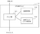
図4は、CPU側ブリッジ14の構成の一例を示すブロック図である。CPU側ブリッジ14は、ブリッジ部141と、接続管理部142と、仮想ブリッジリソース設定部143とを含む。<Configuration of
FIG. 4 is a block diagram showing an example of the configuration of the
図5は、IO側ブリッジ21の構成の一例を示すブロック図である。IO側ブリッジ21は、ブリッジ部211と、接続管理部212とを含む。 FIG. 5 is a block diagram illustrating an example of the configuration of the
ブリッジ部141及びブリッジ部211は、装置の内部(CPU11又はIOデバイス22)のバス(例えば、PCIeバス)とネットワーク3(例えば、Ethernet(登録商標))との間を中継(ブリッジ:bridge)する。 The
なお、本実施形態の装置の内部のバス及びネットワーク3は、特に制限はない。ただし、以下の説明では、一例として、装置の内部のバス及びネットワーク3として、PCIe及びEthernet(登録商標)を用いて説明する。 Note that the internal bus and the network 3 of the apparatus according to the present embodiment are not particularly limited. However, in the following description, as an example, the description will be made using PCIe and Ethernet (registered trademark) as the internal bus and network 3 of the apparatus.
次に、ブリッジ部141及びブリッジ部211のより詳細な動作を説明する。 Next, more detailed operations of the
例えば、CPU11側からネットワーク3側へ、又は、IOデバイス22側からネットワーク3側にデータを転送する場合、ブリッジ部141及びブリッジ部211は、次のように動作する。ここでは、上記のとおり、一例として、PCIe側からEthernet(登録商標)側にデータを転送する場合について説明する。 For example, when transferring data from the
まず、ブリッジ部141及びブリッジ部211は、データを含むPCIeパケットに、宛先に応じたEthernet(登録商標)フレームヘッダを付加する。つまり、ブリッジ部141及びブリッジ部211は、PCIeパケットをEthernet(登録商標)でカプセル化する。そして、ブリッジ部141及びブリッジ部211は、カプセル化したパケットをネットワーク3に送信する。 First, the
逆に、ネットワーク3側からCPU11側又はネットワーク3側からIOデバイス22側にデータを転送する場合、ブリッジ部141及びブリッジ部211は、次のように動作する。ここでも、一例として、Ethernet(登録商標)側からPCIe側にデータを転送する場合について説明する。 Conversely, when transferring data from the network 3 side to the
まず、ブリッジ部141及びブリッジ部211は、ネットワーク3からカプセル化されたパケットを受信する。ブリッジ部141及びブリッジ部211は、カプセル化されたパケットからEthernet(登録商標)フレームヘッダを取り外し、PCIeパケットを取得する。そして、ブリッジ部141及びブリッジ部211は、PCIeパケットをPCIe側に送信する。 First, the
なお、ブリッジ部141及びブリッジ部211は、PCIeデバイスとして動作する場合、PCIコンフィグレーションレジスタを有する。ここで、PCIコンフィグレーションレジスタは、PCIコンフィグレーションを保持する。 The
接続管理部142及び接続管理部212は、CPU側ブリッジ14とIO側ブリッジ21との間の相互接続を管理する機能を有する。CPU側ブリッジ14とIO側ブリッジ21とは、それぞれ、グルーピング用のID(グループID)を設定できる。そして、同一のグループIDを有するCPU側ブリッジ14及びIO側ブリッジ21が、相互に接続する。そして、接続したCPU側ブリッジ14は、PCIeスイッチの上流方向のポート(Upstream Port)として動作する。同様に、IO側ブリッジ21は、PCIeスイッチの下流方向のポート(Downstream Port)として動作する。このように、相互の接続したCPU側ブリッジ14及びIO側ブリッジ21は、仮想的なPCIeスイッチとして動作する。また、CPU側ブリッジ14及びIO側ブリッジ21は、予め、グループIDを登録できる。つまり、CPU側ブリッジ54及びIO側ブリッジ61は、予め、接続相手を登録できる接続管理テーブルを有している。 The
仮想ブリッジリソース設定部143は、仮想PCIブリッジ及びリソース量を設定する。また、仮想ブリッジリソース設定部143は、設定した仮想PCIブリッジの存在数、及び、リソース量の設定値を記憶する。 The virtual bridge
<BIOS4>
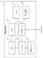
図6は、本実施形態のBIOS4の機能の主要部分の構成の一例を示すブロック図である。BIOS4は、BIOS基本機能部41と、リソース量調査部42と、割当て優先指示部43と、残りリソース計算部44と、予約リソース量出力部45とを含む。<BIOS4>
FIG. 6 is a block diagram showing an example of the configuration of the main part of the function of the
なお、既に説明した通り、情報処理装置1に含まれるCPU11が、メモリ12等に読み込まれるBIOS4のプログラムを実行し、BIOS4としての機能を実現する。 As described above, the
BIOS基本機能部41は、BIOS4の基本機能を実行する部分である。つまり、BIOS基本機能部41は、以下で説明する各構成の機能を実現するための処理を実行する。例えば、BIOS基本機能部41は、通常のBIOS4の起動プロセスの機能を実行する。そのため、以下では、BIOS基本機能部41の詳細な説明を省略する。 The BIOS
リソース量調査部42は、CPU側ブリッジ14を含むコンピュータのマザーボード上のデバイス及び周辺機器のリソース量を調査する。 The resource
割当て優先指示部43は、次に示すユーザーからの指示、又は、固定値を記録する。 The allocation
(1)ユーザーからの指示:多数のデバイスを接続できることを優先する、又は、使用リソース量の多いものが接続できることを優先する
(2)固定値:必要追加接続デバイス数、又は、必要予約リソース量
これらは、BIOS4に設定された、リソース割当てに対するに優先条件の一例である。つまり、BIOS4は、上記条件を満たすようにリソースを割り当てる。(1) Instruction from the user: Give priority to being able to connect a large number of devices, or give priority to being able to connect a device with a large amount of used resources (2) Fixed value: Number of necessary additional connected devices or amount of necessary reserved resources These are examples of priority conditions for resource allocation set in the
残りリソース計算部44は、システムの上限のリソース量からリソース量調査部42が調査したリソース量を減算し、残りリソース量を計算する。 The remaining
予約リソース量出力部45は、割当て優先指示部43及び残りリソース計算部44からの情報を基に、仮想PCIブリッジ数及び予約リソース量を計算する。そして、予約リソース量出力部45は、仮想PCIブリッジ数及び予約リソース量を、CPU側ブリッジ14に出力(通知)する。 The reserved resource
[1−2]動作の説明
次に本実施形態の動作について、図7及び図8を参照して説明する。[1-2] Description of Operation Next, the operation of this embodiment will be described with reference to FIGS.
図7は、以下の動作の説明に関連する、本実施形態の情報処理装置1の要部の一例を示すブロック図である。図7において、図4及び図6と同じ構成には、同じ符号を付してある。そのため、構成の説明を省略する。なお、図7に示す構成は、本実施形態の最小構成の一例である。 FIG. 7 is a block diagram illustrating an example of a main part of the information processing apparatus 1 according to the present embodiment, related to the description of the following operation. 7, the same components as those in FIGS. 4 and 6 are denoted by the same reference numerals. Therefore, the description of the configuration is omitted. Note that the configuration shown in FIG. 7 is an example of the minimum configuration of the present embodiment.
図8は、本実施形態の情報処理装置1の動作の一例を示すフローチャートである。 FIG. 8 is a flowchart illustrating an example of the operation of the information processing apparatus 1 according to the present embodiment.
まず、情報処理装置1は、予め、例えば、システム全体を起動する前に、ユーザーからの指示又は固定値を、割当て優先指示部43に記憶させておく(ステップS100)。 First, the information processing apparatus 1 stores an instruction or a fixed value from a user in the allocation
ここで、記憶させる情報は、既に説明した通り、次に示すユーザーからの指示又は固定値である。 Here, as described above, the information to be stored is an instruction or a fixed value from the user shown below.
(1)ユーザーからの指示:多数のデバイスを接続できることを優先する、又は、使用リソース量の多いものが接続できることを優先する
(2)固定値:必要追加接続デバイス数、又は、必要予約リソース量
ここで、割当て優先指示部43への上記情報の記憶のタイミングには、制限はない。例えば、固定値の場合、情報処理装置1の製造者が、工場出荷時に固定値を設定しても良い。あるいは、利用者が、起動に先立ち、情報処理装置1に上記の指示を設定しても良い。(1) Instruction from the user: Give priority to being able to connect a large number of devices, or give priority to being able to connect a device with a large amount of used resources (2) Fixed value: Number of necessary additional connected devices or amount of necessary reserved resources Here, there is no restriction on the timing of storing the information in the allocation
そして、本実施形態の情報処理システム8に電源が投入され、起動が開始する(ステップS110)。すると、CPU側ブリッジ14及びIO側ブリッジ21は、それぞれ、接続管理部142、接続管理部212の管理に従い、相互接続を確立する(ステップS120)。その結果、CPU側ブリッジ14は、IO側ブリッジ21の先に接続されたIOデバイス22を、システムの周辺機器として認識できる状態となる。 Then, the
その後、BIOS4のリソース量調査部42は、周辺機器として認識できるIOデバイス22含む情報処理システム8の全体のIOデバイスが使用するリソース量を調査する(ステップS130)。BIOS4のリソース量調査部42は、例えば、PCIコンフィグレーションレジスタに記憶されているPCIコンフィグレーションを基に、リソース量を調査しても良い。 Thereafter, the resource
残りリソース計算部44は、BIOS4が認識できる最大リソース量からリソース量調査部42が調査したIOデバイス使用リソース量を減算し、残りリソース量を算出する(ステップS140)。 The remaining
この計算は、数式を用いて表すと、次に示す数式となる。 This calculation is represented by the following mathematical expression.
残りリソース量=BIOS4で認識できる最大リソース量−リソース量調査部42が調査したIOデバイス使用リソース量
次に、予約リソース量出力部45は、残りリソース計算部44が計算した残りリソース量と、割当て優先指示部43が記録するユーザーからの指示又は固定値とを基に、仮想PCIブリッジ数及び予約リソース量を計算する(ステップS150)。既に説明した通り、ユーザーからの指示又は固定値は、リソース割当てに対する優先条件である。Remaining resource amount = maximum resource amount that can be recognized by the
各場合における計算式は、次に示す数式となる。 The calculation formula in each case is the following formula.
<多数のデバイスを接続できることを優先する場合>
仮想PCIブリッジ数=残りリソース量÷予約リソース量の最低値
ここで、予約リソース量の最低値は、予め、ユーザーが指定する値である。ただし、ユーザーが指定する値がない場合、予約リソース量出力部45は、予約リソース量の最低値として、予め決めた基本値を使用すればよい。<When priority is given to being able to connect many devices>
The number of virtual PCI bridges = the remaining resource amount / the minimum value of the reserved resource amount Here, the minimum value of the reserved resource amount is a value designated by the user in advance. However, if there is no value designated by the user, the reserved resource
<使用リソース量の多いものが接続できることを優先する場合>
仮想PCIブリッジ数当たりの予約リソース量=残りリソース量÷仮想PCIブリッジ数の最低値
ここで、仮想PCIブリッジ数の最低値は、予め、ユーザーが指定する値である。ただし、ユーザーの指定した値がない場合、予約リソース量出力部45は、仮想PCIブリッジ数の最低値として、予め決めた基本値を使用すれば良い。<When priority is given to the ability to connect a large amount of resources used>
Reserved resource amount per number of virtual PCI bridges = remaining resource amount / minimum value of virtual PCI bridge number Here, the minimum value of the number of virtual PCI bridges is a value designated by the user in advance. However, if there is no value designated by the user, the reserved resource
<固定値(必要追加接続デバイス数)が設定された場合>
仮想PCIブリッジ数当たりの予約リソース量=残りリソース量÷必要追加接続デバイス数
<固定値(必要予約リソース量)が設定された場合>
仮想PCIブリッジ数=残りリソース量÷必要予約リソース量
予約リソース量出力部45は、上記の計算の結果を、CPU側ブリッジ14の仮想ブリッジリソース設定部143に通知する(ステップS160)。<When a fixed value (required number of additional connected devices) is set>
Reserved resource amount per number of virtual PCI bridges = remaining resource amount ÷ number of required additional connected devices <When fixed value (required reserved resource amount) is set>
Number of virtual PCI bridges = remaining resource amount / required reserved resource amount The reserved resource
仮想ブリッジリソース設定部143は、予約リソース量出力部45からの通知に従い、仮想PCIブリッジ数及び予約リソース量を設定する。つまり、仮想ブリッジリソース設定部143は、ブリッジ部141の構成を変更(設定)する(ステップS170)。 The virtual bridge
ブリッジ部141の構成変更の完了後、CPU側ブリッジ14は、BIOS4に完了を通知する(ステップS180)。 After completing the configuration change of the
完了の通知を受け取ったBIOS4は、一般的な機能の動作を開始する。例えば、BIOS基本機能部41が、通常の起動プロセスが実施する。つまり、BIOS4は、デバイスの設定を開始する(ステップS190)。 The
このように構成された、第1の実施形態の効果について説明する。 The effect of 1st Embodiment comprised in this way is demonstrated.
第1の実施形態に係る情報処理装置1は、適切にリソースを割り当てるとの効果を得ることができる。 The information processing apparatus 1 according to the first embodiment can obtain an effect of appropriately allocating resources.
その理由は、次のとおりである。 The reason is as follows.
情報処理装置1とIOデバイス群2との相互接続後、情報処理装置1に含まれるBIOS4が、システム全体のリソース量を調査する。ここで、BIOS4は、情報処理装置1に含まれるCPU11が実現する機能である。 After the information processing apparatus 1 and the
そして、BIOS4が、認識できる最大リソース量における、残りリソース量を計算する。 Then, the
そして、BIOS4は、リソース割当てに対する優先条件を満たすように、仮想PCIブリッジ数及び予約リソース量を計算する。 Then, the
そして、情報処理装置1のCPU側ブリッジ14が、仮想PCIブリッジ数及び予約リソース量を基に、CPU側ブリッジ14のブリッジ部141の構成を設定する。 Then, the
このように、情報処理装置1は、システム全体のリソース量を考慮し、仮想PCIブリッジ数及び予約リソース量を適切にCPU側ブリッジ14に設定できるためである。 As described above, the information processing apparatus 1 can appropriately set the number of virtual PCI bridges and the reserved resource amount in the
さらに、本実施形態は、適切にリソースを割り当てることができるため、リソース不足に伴う異常動作を防止できるとの効果を得ることができる。 Furthermore, since this embodiment can allocate resources appropriately, it is possible to obtain an effect that abnormal operation due to resource shortage can be prevented.
(第2の実施の形態)
次に、本発明に係る第2の実施形態について、図面を参照して説明する。(Second Embodiment)
Next, a second embodiment according to the present invention will be described with reference to the drawings.
[2−1]構成の説明
<情報処理システム9の全体構成>
図9は、本実施形態に係る情報処理装置5を含む情報処理システム9の全体構成の一例を示すブロック図である。本実施形態の情報処理システム9は、1つ又は複数の情報処理装置5と、1つ又は複数のIOデバイス群6と、ネットワーク3とを含む。情報処理システム9において、情報処理装置5及びIOデバイス群6は、ネットワーク3を介して接続する。[2-1] Description of Configuration <Overall Configuration of
FIG. 9 is a block diagram illustrating an example of the overall configuration of the
ここで、ネットワーク3は、第1の実施形態と同様である。そのため、ネットワーク3の詳細な説明を省略する
情報処理装置5は、情報処理システム9における処理を実施する。さらに、情報処理装置5は、後ほど説明する通り、リソースの割当てを実施する。Here, the network 3 is the same as in the first embodiment. Therefore, the detailed description of the network 3 is omitted. The
IOデバイス群6は、情報処理装置5とネットワーク3を介して接続し、IOデバイスとしての機能を実現する装置又は装置群である。 The
<情報処理装置5の構成>
図10は、情報処理装置5の構成の一例を示すブロック図である。情報処理装置5は、1つ又は複数のCPU51と、メモリ52と、チップセット53と、CPU側ブリッジ54と、記録デバイス55と、モード切替えスイッチ56と、リセット57とを含む。<Configuration of
FIG. 10 is a block diagram illustrating an example of the configuration of the
CPU51は、記録デバイス55が記憶するプログラムを基に動作し、情報処理装置5を制御する。なお、CPU51は、CPU11と同様に、コンピュータで取り可能にプログラムを記憶した図示しない記憶媒体からプログラムを読み込んでも良い。あるいは、CPU51は、CPU側ブリッジ54を介して、図示しない装置からプログラムを受信しても良い。 The
メモリ52は、例えば、D−RAM等の記憶素子又は回路である。メモリ52は、CPU11の一時記憶として動作しても良い。 The
チップセット53は、CPU51と接続して所定の機能(例えば、他の回路とを接続)を実現する1つチップ又は複数のチップの組合せである。なお、チップセット53は、CPU51の機能を補助しても良い。例えば、チップセット53は、補助CPU(コプロセッサ)を含んでも良い。 The chip set 53 is one chip or a combination of a plurality of chips that realizes a predetermined function (for example, connection with other circuits) by connecting to the
CPU側ブリッジ54は、後ほど詳細に説明するように、情報処理装置5とネットワーク3とを接続する。さらに、CPU側ブリッジ54は、後ほど説明するとおり、IOデバイス群6との接続を処理する。CPU側ブリッジ54は、例えば、LANカードのようなNICを用いて実現しても良い。 The
記録デバイス55は、ROM又はFlashメモリ等の記憶装置又は回路である。記録デバイス55は、CPU51用のプログラム又はデータを記憶する。記録デバイス55は、第1の実施形態と同様にBIOS4のプログラムを記録している。BIOS4のプログラムは、情報処理装置5の起動時に、メモリ52等に読み込まれる。CPU51は、読み込まれたBIOS4のプログラムを実行し、BIOS4としての機能を実現する。なお、記録デバイス55は、ハードディスク装置、光磁気ディスク装置、SSD(Solid State Drive)又はディスクアレイ装置などの装置でも良い。 The
モード切替えスイッチ56は、後ほど説明する情報処理装置5のモードを切り替えるスイッチである。モード切替えスイッチ56は、機械式(ハードウェア)のスイッチでも良い。あるいは、モード切替えスイッチ56は、ソフトウェア(メモリ上の設定値)でも良い。 The
リセット57は、情報処理装置5を再起動(リセット)を指示する。リセット57は、機械式(ハードウェア)のスイッチでも良い。あるいは、リセット57は、再起動命令など、ソフトウェアの指示でも良い。 The
情報処理装置5に含まれる各構成は、所定のバスを介して接続している。本実施形態の各構成を接続するバスは、特に制限はない。以下、一例として、次のようなバスを用いて説明する。 Each component included in the
CPU51とメモリ52とは、メモリバスを介して、接続する。CPU51とチップセット53とは、CPUバス又はPCIeバスを介して接続する。 The
CPU側ブリッジ54は、CPU51又はチップセット53と、PCIeバスを介して、接続する。CPU側ブリッジ54は、ネットワーク3と、ネットワーク3のプロトコル(例えば、Ethernet(登録商標))に沿って接続する。さらに、CPU側ブリッジ54は、モード切替えスイッチ56、及び、リセット57と接続する。 The
記録デバイス55は、CPU51又はチップセット53と、記録デバイス55のインターフェースに合わせたバスを介して接続する。 The
なお、CPU51とチップセット53は、図示しないチップ内又はCPU側ブリッジ54の経由以外で接続されるIOデバイスと接続しても良い。 The
<IOデバイス群6の構成>
図11は、IOデバイス群6の構成の一例を示すブロック図である。IOデバイス群6は、1つ又は複数のIO側ブリッジ61と、1つ又は複数のIOデバイス62とを含む。<Configuration of
FIG. 11 is a block diagram illustrating an example of the configuration of the
IO側ブリッジ61は、ネットワーク3とネットワーク3のプロトコル(例えば、Ethernet(登録商標))に沿って接続する。また、IO側ブリッジ61は、IOデバイス62と所定のバス(例えば、PCIeバス)介して接続する。 The IO-
<CPU側ブリッジ54及びIO側ブリッジ61の構成>
図12は、CPU側ブリッジ54の構成の一例を示すブロック図である。CPU側ブリッジ54は、ブリッジ部541と、接続管理部542と、仮想ブリッジリソース設定部543と、割当て優先指示部544と含む。なお、割当て優先指示部544は、第1の実施形態と同様に、BIOS4に含まれても良い。<Configuration of
FIG. 12 is a block diagram illustrating an example of the configuration of the
図13は、IO側ブリッジ61の構成の一例を示すブロック図である。IO側ブリッジ61は、ブリッジ部611と、接続管理部612とを含む。 FIG. 13 is a block diagram illustrating an example of the configuration of the
なお、本実施形態の装置の内部のバス及びネットワーク3は、特に制限はない。ただし、以下の説明では、一例として、装置の内部のバス及びネットワーク3として、PCIe及びEthernet(登録商標)を用いて説明する。 Note that the internal bus and the network 3 of the apparatus according to the present embodiment are not particularly limited. However, in the following description, as an example, the description will be made using PCIe and Ethernet (registered trademark) as the internal bus and network 3 of the apparatus.
ブリッジ部541及びブリッジ部611は、装置の内部(CPU51又はIOデバイス62)のバス(例えば、PCIe)とネットワーク3(例えば、Ethernet(登録商標))との間を中継(ブリッジ)する。 The
例えば、CPU51側からネットワーク3側へ、又は、IOデバイス62側からネットワーク3側にデータを転送する場合、ブリッジ部541及びブリッジ部611は、次のように動作する。ここでは、上記のとおり、一例として、PCIe側からEthernet(登録商標)側にデータを転送する場合について説明する。 For example, when transferring data from the
まず、ブリッジ部541及びブリッジ部611は、データを含むPCIeパケットに宛先に応じたEthernet(登録商標)フレームヘッダを付加する。つまり、ブリッジ部541及びブリッジ部611は、PCIeパケットをEthernet(登録商標)でカプセル化する。そして、ブリッジ部541及びブリッジ部611は、カプセル化したパケットをネットワーク3に送信する。 First, the
逆に、ネットワーク3側からCPU51側又はネットワーク3側からIOデバイス62側にデータを転送する場合、ブリッジ部541及びブリッジ部611は、次のように動作する。ここでも、一例として、Ethernet(登録商標)側からPCIe側にデータを転送する場合について説明する。 Conversely, when data is transferred from the network 3 side to the
まず、ブリッジ部541及びブリッジ部611は、ネットワーク3からカプセル化されたパケットを受信する。ブリッジ部541及びブリッジ部611は、カプセル化されたパケットからEthernet(登録商標)フレームヘッダを取り外し、PCIeパケットを取得する。そして、ブリッジ部541及びブリッジ部611は、PCIeパケットをPCIe側に送信する。 First, the
なお、ブリッジ部541及びブリッジ部611は、PCIeデバイスとして動作する場合、PCIコンフィグレーションレジスタを有する。 Note that the
接続管理部542及び接続管理部612は、CPU側ブリッジ54とIO側ブリッジ61との間の相互接続を管理する機能を有する。CPU側ブリッジ54とIO側ブリッジ61とは、それぞれ、グループIDを設定できる。そして、グループIDが同じCPU側ブリッジ54及びIO側ブリッジ61が、相互に接続する。そして、接続したCPU側ブリッジ54は、PCIeスイッチの上流方向のポート(Upstream Port)として動作する。同様に、IO側ブリッジ61は、PCIeスイッチの下流方向のポート(Downstream Port)として動作する。このように、相互に接続したCPU側ブリッジ54及びIO側ブリッジ61は、仮想的なPCIeスイッチとして動作する。また、CPU側ブリッジ54及びIO側ブリッジ61は、予め、グループIDを登録できる。つまり、CPU側ブリッジ54及びIO側ブリッジ61は、予め、接続相手を登録できる接続管理テーブルを有している。 The
仮想ブリッジリソース設定部543は、仮想PCIブリッジの存在数、リソース空間量の設定、及び、リソース空間量の設定値を記憶する。 The virtual bridge
割当て優先指示部544は、次に示すユーザーからの指示、又は、固定値を記憶する。 The allocation
(1)ユーザーからの指示:多数のデバイスを接続できることを優先する、又は、使用リソース量の多いものが接続できることを優先する
(2)固定値:必要追加接続デバイス数、又は、必要予約使用リソース量
[2−2]動作の説明
次に、本実施形態の動作について、図14及び図15を参照して説明する。(1) Instruction from the user: Prioritize that a large number of devices can be connected, or prioritize that a device with a large amount of used resources can be connected (2) Fixed value: Number of required additional connected devices or necessary reserved use resources Quantity [2-2] Explanation of Operation Next, the operation of the present embodiment will be described with reference to FIGS. 14 and 15.
本実施形態は、第1の実施形態の動作に相当する通常モードに加え、テストモードを備える点が、第1の実施形態と異なる。そのため、本実施形態に特有のテストモードの動作を説明する。なお、第1の実施形態の動作に相当する通常モードの説明については、適宜省略する場合もある。 The present embodiment is different from the first embodiment in that a test mode is provided in addition to the normal mode corresponding to the operation of the first embodiment. Therefore, the operation of the test mode unique to this embodiment will be described. Note that description of the normal mode corresponding to the operation of the first embodiment may be omitted as appropriate.
最初に、図14を参照してテストモードの動作について説明する。 First, the operation in the test mode will be described with reference to FIG.
図14は、本実施形態のテストモードの動作の一例を示すフローチャートである。 FIG. 14 is a flowchart showing an example of the operation in the test mode of the present embodiment.
まず、システム全体を起動する前に、割当て優先指示部544は、ユーザーの指示を基に、最低仮想PCIブリッジ数(PCIeスイッチのポート数に相当)又は最低予約リソース量(予約メモリ空間量及び予約IO空間量)を記録する(ステップS200)。なお、割当て優先指示部544は、既に説明した通り、固定値を記録しても良い。また、割当て優先指示部544が情報を記録するタイミングは、特に制限はない。 First, before starting the entire system, the allocation
そして、情報処理装置5は、モード切替えスイッチ56をテストモードに設定する(ステップS210)。ここで、情報処理装置5は、図示しない外部の装置(例えば、保守端末装置)からの指示を基に、テストモードを設定しても良い。 Then, the
あるいは、モード切替えスイッチ56が、機械的なスイッチの場合、ユーザーが、モード切替えスイッチ56を切り替えても良い。この場合、情報処理装置5は、モード切替えスイッチ56の状態を検出し、以下で説明する動作を実行すれば良い。 Alternatively, when the
次に、情報処理装置5は、仮想PCIブリッジを設定する。 Next, the
情報処理装置5は、仮想PCIブリッジの設定を、次の手順で実行する。 The
仮想ブリッジリソース設定部543は、仮想PCIブリッジ数、及び、予約リソース量(予約メモリ空間量、及び、予約IO空間量)を、所定の最大値に、設定する(ステップS220)。ここで、所定の最大値は、仮想ブリッジリソース設定部543に、予め設定されている値である。 The virtual bridge
情報処理装置5は、起動テストを実施する(ステップS230)。 The
起動テストが成功した場合、情報処理装置5は、テストモードを終了する(ステップ230で「成功」)。 If the activation test is successful, the
起動テストが失敗した場合、仮想ブリッジリソース設定部543は、割当て優先指示部544が記憶しているユーザーの指示に従い、次回起動時の仮想PCIブリッジ数、予約メモリ空間量、及び、予約IO空間量を設定する。 When the activation test fails, the virtual bridge
この動作を、より詳細に説明する。 This operation will be described in more detail.
まず、仮想ブリッジリソース設定部543は、設定されている仮想PCIブリッジ数、予約メモリ空間量、及び、予約IO空間量が、割当て優先指示部544に記録された最低値か否か判断する(ステップS240)。 First, the virtual bridge
最低値でない場合(ステップS240で「異なる」)、仮想ブリッジリソース設定部543は、仮想PCIブリッジ数、予約メモリ空間量、及び、予約IO空間量を、最低値に設定する(ステップS270)。そして、情報処理装置5は、ステップS260に進む。 When it is not the minimum value ("different" in step S240), the virtual bridge
最低値の場合(ステップS240で「一致」)、仮想ブリッジリソース設定部543は、仮想PCIブリッジ数、予約メモリ空間量、及び、予約IO空間量のいずれかの設定値を、所定の固定値を減算した値に設定する。ただし、仮想ブリッジリソース設定部543は、前回設定した値と異なるリソースの値を減算し、減算した値を設定する(ステップS250)。そして、情報処理装置5は、ステップS260に進む。なお、ここで、所定の固定値は、予め、仮想ブリッジリソース設定部543が保持している値である。後ほど説明するように、仮想ブリッジリソース設定部543は、設定するリソースに対応する固定値を保持すれば良い。また、後ほど説明する通り、所定の固定値は、割当て優先指示部544が記憶する値に関連する。そのため、仮想ブリッジリソース設定部543は、割当て優先指示部544が、ユーザーからの指示、又は、固定値を記憶するときに、上記の固定値を保持しても良い。あるいは、割当て優先指示部544が、ユーザーからの指示、又は、固定値を記憶するときに、上記の固定値を記憶し、仮想ブリッジリソース設定部543が、割当て優先指示部544から固定値を読み出しても良い。 In the case of the minimum value (“match” in step S240), the virtual bridge
ここで、仮想ブリッジリソース設定部543は、異なる値の設定として、例えば、次のように値を設定すれば良い。 Here, the virtual bridge
<割当て優先指示部544が、最低仮想PCIブリッジ数を記憶している場合>
仮想ブリッジリソース設定部543は、最初、IO空間に設定されている値を減らす。そして、仮想ブリッジリソース設定部543は、次の設定機会において、メモリ空間に設定されている値を減らす。そして、仮想ブリッジリソース設定部543は、その次の設定機会において、IO空間に設定されている値を減らす。このように、仮想ブリッジリソース設定部543は、予約リソース量(予約リソース空間)を変更していく。<When the allocation
The virtual bridge
なお、前回設定した側の値は、IO空間又はメモリ空間に設定されている。 Note that the previously set value is set in the IO space or the memory space.
<割当て優先指示部544が、最低メモリ空間量を記憶している場合>
仮想ブリッジリソース設定部543は、最初、IO空間に設定されている値を減らす。そして、仮想ブリッジリソース設定部543は、次の設定機会において、仮想PCIブリッジ数に設定されている値を減らす。そして、仮想ブリッジリソース設定部543は、その次の設定機会において、IO空間に設定されている値を減らす。このように仮想ブリッジリソース設定部543は、設定する仮想PCIブリッジ数及び予約リソース量(ただし、IO空間)を変更していく。<When the allocation
The virtual bridge
なお、前回設定した側の値は、IO空間又は仮想PCIブリッジ数に設定されている。 Note that the previously set value is set to the IO space or the number of virtual PCI bridges.
<割当て優先指示部544が、最低IO空間量を記憶している場合>
仮想ブリッジリソース設定部543は、最初、メモリ空間に設定されている値を減らす。そして、仮想ブリッジリソース設定部543は、次の設定機会において、仮想PCIブリッジ数に設定されている値を減らす。そして、仮想ブリッジリソース設定部543は、その次の設定機会において、メモリ空間に設定されている値を減らす。このように、仮想ブリッジリソース設定部543は、設定する仮想PCIブリッジ数及び予約リソース量(ただし、メモリ空間)を変更していく。<When the allocation
The virtual bridge
なお、前回設定した側の値は、メモリ空間又は仮想PCIブリッジ数に設定されている。 Note that the previously set value is set to the memory space or the number of virtual PCI bridges.
仮想ブリッジリソース設定部543が、設定(ステップS270)又は減算(ステップS250)すると、情報処理装置5は、リセット57を用いてリセットを実行する(ステップS260)。 When the virtual bridge
情報処理装置5は、ステップS260の後、ステップ230に戻り、起動テストを実施する。 After step S260, the
情報処理装置5は、起動テストが成功するまで、上記の動作を繰り返す。 The
起動テストが成功すると、情報処理装置5は、テストモードを終了する。 If the activation test is successful, the
次に、テストモード後の通常モードの動作について、図面を参照して説明する。 Next, the operation in the normal mode after the test mode will be described with reference to the drawings.
図15は、本実施形態の通常モードの動作の一例を示すフローチャートである。 FIG. 15 is a flowchart illustrating an example of the operation in the normal mode of the present embodiment.
テストモードが終了すると、情報処理装置5は、モード切替えスイッチ56を、通常モードに切り替える(ステップS300)。なお、情報処理装置5のユーザーが、モード切替えスイッチ56を切り替え、情報処理装置5が、モード切替えスイッチ56の切替えを検出しても良い。 When the test mode ends, the
通常モードに設定後、本実施形態発明の情報処理システム9に電源が投入されると、CPU側ブリッジ54及びIO側ブリッジ61は、それぞれ、接続管理部542及び接続管理部612の管理に従い、相互接続を確立する(ステップS310)。そして、CPU側ブリッジ54は、IO側ブリッジ61に接続されたIOデバイス62をシステムの周辺機器として認識できる状態となる。ここで、仮想PCIブリッジは、IOデバイス62に置き換わる。 When the
CPU側ブリッジ54は、この置き換わり際に、仮想PCIブリッジの予約リソース量とIOデバイス62が実際に使用するリソース量とを比較する(ステップS320)。 The
ここで、IOデバイス62の使用リソース量が、予約リソース量より少ない場合(ステップS330でNO)、情報処理装置5は、予約リソース量を変更せず、そのまま通常システムの動作(起動)を続ける。 Here, when the used resource amount of the
一方、IOデバイス62の使用リソース量が、予約リソース量より多い場合(ステップS330でYES)、情報処理装置5の仮想ブリッジリソース設定部543は、予約リソース量を以下のように変更する。 On the other hand, when the used resource amount of the
情報処理装置5は、下記の計算式を用いて、変更後の予約リソース量を算出する。そして、情報処理装置5は、予約リソース量を算出したリソース量に変更する。 The
変更後の予約リソース量=予約リソース量−(使用リソース量−予約リソース量)÷仮想PCIブリッジ数
つまり、情報処理装置5は、仮想PCIブリッジ当たりの使用リソース量の超過分を減算する。Reserved resource amount after change = reserved resource amount− (used resource amount−reserved resource amount) ÷ number of virtual PCI bridges In other words, the
そして、情報処理装置5は、変更したことを記憶するため、仮想PCIブリッジの接続されているポートにフラグを立てる。そして、情報処理装置5は、リセット57を用いて再起動(リセット)する。 Then, the
なお、変更フラグが立てられたポートは、リソース量の比較の対象から外される。 Note that the port for which the change flag is set is excluded from the resource amount comparison target.
つまり、上記で変更したリソース量は、比較の対象から外される。 That is, the resource amount changed as described above is excluded from comparison targets.
再起動後、情報処理装置5は、変更された設定を用いて起動し、以降、通常のシステム動作に移行する。 After the restart, the
本発明に基づけば、第1の実施形態の効果に加え、より詳細なリソース空間の有効活用が可能となる効果を得ることができる。 Based on the present invention, in addition to the effect of the first embodiment, it is possible to obtain an effect that enables more effective use of the resource space.
その理由は、次のとおりである。 The reason is as follows.
本実施形態は、モード切替えスイッチ56を用いて、テストモードを実行する。テストモードにおいて、仮想ブリッジリソース設定部543が、起動テストが成功する適切な値を割当て優先指示部544に設定する。そして、情報処理装置5が、適切に設定された割当て優先指示部544の設定値を用いてリソースを割り当てるためである。 In the present embodiment, the test mode is executed using the
以上、実施形態を参照して本願発明を説明したが、本願発明は上記実施形態に限定されるものではない。本願発明の構成及び詳細には、本願発明のスコープ内で当業者が理解し得る様々な変更をすることができる。 While the present invention has been described with reference to the embodiments, the present invention is not limited to the above embodiments. Various changes that can be understood by those skilled in the art can be made to the configuration and details of the present invention within the scope of the present invention.
1 情報処理装置
2 IOデバイス群
3 ネットワーク
4 BIOS
5 情報処理装置
6 IOデバイス群
8 情報処理システム
9 情報処理システム
11 CPU
12 メモリ
13 チップセット
14 CPU側ブリッジ
15 記録デバイス
21 IO側ブリッジ
22 IOデバイス
41 BIOS基本機能部
42 リソース量調査部
43 割当て優先指示部
44 残りリソース計算部
45 予約リソース量出力部
51 CPU
52 メモリ
53 チップセット
54 CPU側ブリッジ
55 記録デバイス
56 モード切替えスイッチ
57 リセット
61 IO側ブリッジ
62 IOデバイス
141 ブリッジ部
142 接続管理部
143 仮想ブリッジリソース設定部
211 ブリッジ部
212 接続管理部
541 ブリッジ部
542 接続管理部
543 仮想ブリッジリソース設定部
544 割当て優先指示部
611 ブリッジ部
612 接続管理部1
5
DESCRIPTION OF
52
Claims (9)
Translated fromJapanese前記ブリッジ手段における接続を管理する接続管理手段と、
リソースの割当てに対する優先条件の指示又は固定値を記憶する割当て優先指示手段と、
前記IOデバイス群に含まれるIOデバイスが使用するリソースを調査するリソース量調査手段と、
最大リソース量から前記IOデバイスが使用するリソース量を減算した残りリソース量を計算する残りリソース計算手段と、
前記残りリソース量と前記優先条件の指示又は固定値とを基に、仮想PCIブリッジ数及び予約リソース量を計算して出力する予約リソース量出力手段と、
前記仮想PCIブリッジ数及び予約リソース量を基に前記ブリッジ手段を設定する仮想ブリッジリソース設定手段と
を含む情報処理装置。Bridge means for connecting to one or more IO device groups via a network;
Connection management means for managing connections in the bridge means;
An allocation priority instruction means for storing an instruction of a priority condition for resource allocation or a fixed value;
A resource amount investigating means for investigating resources used byIO devices included in the IO device group ;
A remaining resource calculating means for calculating a remaining resource amount obtained by subtracting a resource amount used by the IO device from a maximum resource amount;
Reservation resource amount output means for calculating and outputting the number of virtual PCI bridges and reservation resource amount based on the remaining resource amount and the priority condition instruction or fixed value;
An information processing apparatus comprising: virtual bridge resource setting means for setting the bridge means based on the number of virtual PCI bridges and a reserved resource amount.
多数のデバイスを接続できることを優先する指示、使用リソース量の多いものが接続できることを優先する指示、追加接続デバイス数、又は、予約リソース量の少なくとも1つを記憶する
請求項1に記載の情報処理装置。The allocation priority instruction means
The information processing according to claim 1, wherein at least one of an instruction giving priority to being able to connect a large number of devices, an instruction giving priority to being able to connect a device having a large amount of used resources, thenumber of additional connected devices, or an amount ofreserved resources is stored. apparatus.
前記モード切替え手段がテストモードの場合、
前記仮想ブリッジリソース設定手段が、
前記仮想PCIブリッジ数及び予約リソース量に所定の最大値を設定後に装置の起動テストを実施する
請求項1又は2に記載の情報処理装置。It further includes mode switching means for switching between the test mode and the normal mode,
When the mode switching means is a test mode,
The virtual bridge resource setting means is
The information processing apparatus according to claim 1, wherein an apparatus activation test is performedafter setting a predetermined maximum value for the number of virtual PCI bridges and the reserved resource amount .
前記仮想ブリッジリソース設定手段が、
仮想PCIブリッジ数及び予約リソース量と前記割当て優先指示手段が記憶している最低値とを比較し、最低値でない場合に仮想PCIブリッジ数及び予約リソース量を最低値に設定し起動テストを実施する。
請求項3に記載の情報処理装置。If the startup test fails,
The virtual bridge resource setting means is
The number of virtual PCI bridges and the amount of reserved resources are compared with the minimum value stored in the allocation priority instructing means. .
The information processing apparatus according to claim 3.
前記仮想ブリッジリソース設定手段が、
仮想PCIブリッジ数又は予約リソース量のいずれかの設定値を減算して設定し、起動テストを実施する
請求項4に記載の情報処理装置。If the startup test fails after setting the minimum value,
The virtual bridge resource setting means is
The information processing apparatus according to claim 4, wherein a setting value of either the number of virtual PCI bridges or the reserved resource amount is subtracted and set, and an activation test is performed.
前記仮想ブリッジリソース設定手段が、
前回仮想PCIブリッジ数を減算した場合は予約リソース量を減算し、前記予約リソース量を減算した場合は仮想PCIブリッジ数を減算して、起動テストを実施する
請求項5に記載の情報処理装置。If the startup test after subtraction fails,
The virtual bridge resource setting means is
The information processing apparatus according to claim 5, wherein when the virtual PCI bridge number is subtracted last time, the reservation resource amount is subtracted, and when the reservation resource amount is subtracted, the virtual PCI bridge number is subtracted to perform the activation test.
前記仮想ブリッジリソース設定手段が、
予約リソース量を変更する
請求項6に記載の情報処理装置。After the startup test is successful, if the reserved resource amount is less than the used resource amount,
The virtual bridge resource setting means is
The information processing apparatus according to claim 6, wherein the reservation resource amount is changed.
前記接続を管理し、
リソースの割当てに対する優先条件の指示又は固定値を記憶し、
前記IOデバイス群に含まれるIOデバイスが使用するリソースを調査し、
最大リソース量から前記IOデバイスが使用するリソース量を減算した残りリソース量を計算し、
前記残りリソース量と前記優先条件の指示又は固定値とを基に、仮想PCIブリッジ数及び予約リソース量を計算して出力し、
前記仮想PCIブリッジ数及び予約リソース量を基に前記IOデバイス群との接続を設定する
リソース割当て方法。In an information processing apparatus connected to one or a plurality of IO device groups via a network,
Manage the connection,
Store priority indication or fixed value for resource allocation,
Investigate resources used byIO devices included in the IO device group ,
Calculate the remaining resource amount by subtracting the resource amount used by the IO device from the maximum resource amount,
Based on the remaining resource amount and the priority condition instruction or fixed value, calculate and output the number of virtual PCI bridges and the reserved resource amount,
A resource allocation method for setting a connection with the IO device group based on the number of virtual PCI bridges and a reserved resource amount.
前記接続を管理する処理と、
リソースの割当てに対する優先条件の指示又は固定値を記憶する処理と、
前記IOデバイス群に含まれるIOデバイスが使用するリソースを調査する処理と、
最大リソース量から前記IOデバイスが使用するリソース量を減算した残りリソース量を計算する処理と、
前記残りリソース量と前記優先条件の指示又は固定値とを基に、仮想PCIブリッジ数及び予約リソース量を計算して出力する処理と、
前記仮想PCIブリッジ数及び予約リソース量を基に前記IOデバイス群との接続を設定する処理と
をコンピュータに実行させるプログラム。In an information processing apparatus connected to one or a plurality of IO device groups via a network,
A process for managing the connection;
Processing for storing an indication of a priority condition for resource allocation or a fixed value;
A process of investigating resources used byIO devices included in the IO device group ;
A process of calculating a remaining resource amount by subtracting a resource amount used by the IO device from a maximum resource amount;
A process of calculating and outputting the number of virtual PCI bridges and the reserved resource amount based on the remaining resource amount and the priority condition instruction or fixed value;
A program for causing a computer to execute a process of setting a connection with the IO device group based on the number of virtual PCI bridges and a reserved resource amount.
Priority Applications (2)
| Application Number | Priority Date | Filing Date | Title |
|---|---|---|---|
| JP2014041225AJP6287350B2 (en) | 2014-03-04 | 2014-03-04 | Information processing apparatus, resource allocation method, and program |
| US14/636,832US9921876B2 (en) | 2014-03-04 | 2015-03-03 | Information processing device, resource allocation method, and computer-readable recording medium |
Applications Claiming Priority (1)
| Application Number | Priority Date | Filing Date | Title |
|---|---|---|---|
| JP2014041225AJP6287350B2 (en) | 2014-03-04 | 2014-03-04 | Information processing apparatus, resource allocation method, and program |
Publications (2)
| Publication Number | Publication Date |
|---|---|
| JP2015166959A JP2015166959A (en) | 2015-09-24 |
| JP6287350B2true JP6287350B2 (en) | 2018-03-07 |
Family
ID=54017511
Family Applications (1)
| Application Number | Title | Priority Date | Filing Date |
|---|---|---|---|
| JP2014041225AActiveJP6287350B2 (en) | 2014-03-04 | 2014-03-04 | Information processing apparatus, resource allocation method, and program |
Country Status (2)
| Country | Link |
|---|---|
| US (1) | US9921876B2 (en) |
| JP (1) | JP6287350B2 (en) |
Families Citing this family (7)
| Publication number | Priority date | Publication date | Assignee | Title |
|---|---|---|---|---|
| US9779050B2 (en)* | 2015-04-27 | 2017-10-03 | Red Hat Israel, Ltd. | Allocating virtual resources to root PCI bus |
| KR102433765B1 (en)* | 2016-04-21 | 2022-08-18 | 삼성에스디에스 주식회사 | Apparatus and method for managing computing resources in network function virtualization system |
| JP2019211889A (en)* | 2018-06-01 | 2019-12-12 | 日本電信電話株式会社 | Device and method for managing resource reservations |
| CN110581869B (en)* | 2018-06-07 | 2022-04-08 | 中兴通讯股份有限公司 | Resource allocation method, TLP packet processing method, equipment and storage medium |
| US11611517B2 (en)* | 2020-05-29 | 2023-03-21 | Equinix, Inc. | Tenant-driven dynamic resource allocation for virtual network functions |
| CN117130763A (en)* | 2022-05-19 | 2023-11-28 | 华为技术有限公司 | Circuit board resource allocation method and device, circuit board and storage medium |
| CN119201253B (en)* | 2024-11-26 | 2025-03-18 | 苏州元脑智能科技有限公司 | Bus resource configuration method and device |
Family Cites Families (14)
| Publication number | Priority date | Publication date | Assignee | Title |
|---|---|---|---|---|
| US5710703A (en)* | 1995-06-07 | 1998-01-20 | Chrysler Corporation | Method and system for sharing a hardware resource |
| JP2002288104A (en)* | 2001-03-28 | 2002-10-04 | Nec Corp | Computer system, and method and program for its resource assigning |
| US7406674B1 (en)* | 2001-10-24 | 2008-07-29 | Cypress Semiconductor Corporation | Method and apparatus for generating microcontroller configuration information |
| US7243167B2 (en)* | 2003-09-19 | 2007-07-10 | Intel Corporation | Managing peripheral device address space resources using a tunable bin-packing/knapsack algorithm |
| JP4810349B2 (en)* | 2006-08-11 | 2011-11-09 | 日本電気株式会社 | I/O device and method |
| US20090077297A1 (en)* | 2007-09-14 | 2009-03-19 | Hongxiao Zhao | Method and system for dynamically reconfiguring PCIe-cardbus controllers |
| US8255496B2 (en)* | 2008-12-30 | 2012-08-28 | Juniper Networks, Inc. | Method and apparatus for determining a network topology during network provisioning |
| US8695079B1 (en)* | 2010-09-29 | 2014-04-08 | Amazon Technologies, Inc. | Allocating shared resources |
| JP5664250B2 (en) | 2011-01-11 | 2015-02-04 | 日本電気株式会社 | Communication control system, apparatus, method and program |
| US8731590B2 (en)* | 2011-05-24 | 2014-05-20 | Broadcom Corporation | Resource allocation control |
| US8863022B2 (en)* | 2011-09-07 | 2014-10-14 | Microsoft Corporation | Process management views |
| US20130159572A1 (en)* | 2011-12-16 | 2013-06-20 | International Business Machines Corporation | Managing configuration and system operations of a non-shared virtualized input/output adapter as virtual peripheral component interconnect root to multi-function hierarchies |
| US9311127B2 (en)* | 2011-12-16 | 2016-04-12 | International Business Machines Corporation | Managing configuration and system operations of a shared virtualized input/output adapter as virtual peripheral component interconnect root to single function hierarchies |
| US9779050B2 (en)* | 2015-04-27 | 2017-10-03 | Red Hat Israel, Ltd. | Allocating virtual resources to root PCI bus |
- 2014
- 2014-03-04JPJP2014041225Apatent/JP6287350B2/enactiveActive
- 2015
- 2015-03-03USUS14/636,832patent/US9921876B2/enactiveActive
Also Published As
| Publication number | Publication date |
|---|---|
| US9921876B2 (en) | 2018-03-20 |
| JP2015166959A (en) | 2015-09-24 |
| US20150254203A1 (en) | 2015-09-10 |
Similar Documents
| Publication | Publication Date | Title |
|---|---|---|
| JP6287350B2 (en) | Information processing apparatus, resource allocation method, and program | |
| JP5953573B2 (en) | Computer system, method and apparatus for accessing a peripheral component interconnect express endpoint device | |
| CN114546913B (en) | Method and device for high-speed data interaction between multiple hosts based on PCIE interface | |
| CN114185829A (en) | Shared resources for multiple communication services | |
| CN104202197A (en) | Method and device for equipment management | |
| TW201342215A (en) | Boot strap processor assignment for a multi-core processing unit | |
| US9063929B2 (en) | Information processing apparatus, information processing method, computer-readable recording medium having stored therein program | |
| JPWO2012160641A1 (en) | Management apparatus, information processing apparatus, information processing system, and data transfer method | |
| CN104123188B (en) | A kind of resource allocation methods and relevant apparatus | |
| WO2021120754A1 (en) | Instruction writing method and apparatus, and network device | |
| CN110311843B (en) | Communication method and device based on PCIe link, electronic equipment and storage medium | |
| CN111092817A (en) | A data transmission method and device | |
| EP2750030A1 (en) | Method, apparatus and processor for reading BIOS | |
| US20130219095A1 (en) | Circuit and method for pipe arbitration using available state information and arbitration | |
| CN105528199B (en) | A node processing method and device | |
| TWI479323B (en) | Advanced programmable interrupt controller identifier (apic id) assignment for a multi-core processing unit | |
| JP5728043B2 (en) | Gateway device | |
| CN102841836B (en) | Testing method and programmable processor | |
| CN105022707B (en) | Interface unit device | |
| CN113688091A (en) | Method and system for realizing RapidIO dynamic enumeration process based on Tsi721 | |
| CN115941776B (en) | Dynamic adjustment method, device, electronic device and storage medium for port arbitration | |
| CN119415450B (en) | Base address register resource management method, electronic equipment and medium | |
| JP2008258763A (en) | SERIAL COMMUNICATION DEVICE, ITS TEST DEVICE, AND SERIAL COMMUNICATION DEVICE TEST METHOD | |
| JP2015011357A (en) | Information processing system and control method of information processing system | |
| EP3971721A1 (en) | Information processing device |
Legal Events
| Date | Code | Title | Description |
|---|---|---|---|
| A621 | Written request for application examination | Free format text:JAPANESE INTERMEDIATE CODE: A621 Effective date:20170215 | |
| A977 | Report on retrieval | Free format text:JAPANESE INTERMEDIATE CODE: A971007 Effective date:20171025 | |
| A131 | Notification of reasons for refusal | Free format text:JAPANESE INTERMEDIATE CODE: A131 Effective date:20171107 | |
| A521 | Written amendment | Free format text:JAPANESE INTERMEDIATE CODE: A523 Effective date:20171219 | |
| TRDD | Decision of grant or rejection written | ||
| A01 | Written decision to grant a patent or to grant a registration (utility model) | Free format text:JAPANESE INTERMEDIATE CODE: A01 Effective date:20180109 | |
| A61 | First payment of annual fees (during grant procedure) | Free format text:JAPANESE INTERMEDIATE CODE: A61 Effective date:20180122 | |
| R150 | Certificate of patent or registration of utility model | Ref document number:6287350 Country of ref document:JP Free format text:JAPANESE INTERMEDIATE CODE: R150 |