JP6286458B2 - vehicle - Google Patents
vehicleDownload PDFInfo
- Publication number
- JP6286458B2 JP6286458B2JP2016024979AJP2016024979AJP6286458B2JP 6286458 B2JP6286458 B2JP 6286458B2JP 2016024979 AJP2016024979 AJP 2016024979AJP 2016024979 AJP2016024979 AJP 2016024979AJP 6286458 B2JP6286458 B2JP 6286458B2
- Authority
- JP
- Japan
- Prior art keywords
- power conversion
- vehicle
- voltage
- motor
- conversion device
- Prior art date
- Legal status (The legal status is an assumption and is not a legal conclusion. Google has not performed a legal analysis and makes no representation as to the accuracy of the status listed.)
- Active
Links
Images


Classifications
- B—PERFORMING OPERATIONS; TRANSPORTING
- B60—VEHICLES IN GENERAL
- B60K—ARRANGEMENT OR MOUNTING OF PROPULSION UNITS OR OF TRANSMISSIONS IN VEHICLES; ARRANGEMENT OR MOUNTING OF PLURAL DIVERSE PRIME-MOVERS IN VEHICLES; AUXILIARY DRIVES FOR VEHICLES; INSTRUMENTATION OR DASHBOARDS FOR VEHICLES; ARRANGEMENTS IN CONNECTION WITH COOLING, AIR INTAKE, GAS EXHAUST OR FUEL SUPPLY OF PROPULSION UNITS IN VEHICLES
- B60K1/00—Arrangement or mounting of electrical propulsion units
- B60K1/04—Arrangement or mounting of electrical propulsion units of the electric storage means for propulsion
- B—PERFORMING OPERATIONS; TRANSPORTING
- B60—VEHICLES IN GENERAL
- B60K—ARRANGEMENT OR MOUNTING OF PROPULSION UNITS OR OF TRANSMISSIONS IN VEHICLES; ARRANGEMENT OR MOUNTING OF PLURAL DIVERSE PRIME-MOVERS IN VEHICLES; AUXILIARY DRIVES FOR VEHICLES; INSTRUMENTATION OR DASHBOARDS FOR VEHICLES; ARRANGEMENTS IN CONNECTION WITH COOLING, AIR INTAKE, GAS EXHAUST OR FUEL SUPPLY OF PROPULSION UNITS IN VEHICLES
- B60K1/00—Arrangement or mounting of electrical propulsion units
- B—PERFORMING OPERATIONS; TRANSPORTING
- B60—VEHICLES IN GENERAL
- B60K—ARRANGEMENT OR MOUNTING OF PROPULSION UNITS OR OF TRANSMISSIONS IN VEHICLES; ARRANGEMENT OR MOUNTING OF PLURAL DIVERSE PRIME-MOVERS IN VEHICLES; AUXILIARY DRIVES FOR VEHICLES; INSTRUMENTATION OR DASHBOARDS FOR VEHICLES; ARRANGEMENTS IN CONNECTION WITH COOLING, AIR INTAKE, GAS EXHAUST OR FUEL SUPPLY OF PROPULSION UNITS IN VEHICLES
- B60K6/00—Arrangement or mounting of plural diverse prime-movers for mutual or common propulsion, e.g. hybrid propulsion systems comprising electric motors and internal combustion engines
- B60K6/20—Arrangement or mounting of plural diverse prime-movers for mutual or common propulsion, e.g. hybrid propulsion systems comprising electric motors and internal combustion engines the prime-movers consisting of electric motors and internal combustion engines, e.g. HEVs
- B60K6/22—Arrangement or mounting of plural diverse prime-movers for mutual or common propulsion, e.g. hybrid propulsion systems comprising electric motors and internal combustion engines the prime-movers consisting of electric motors and internal combustion engines, e.g. HEVs characterised by apparatus, components or means specially adapted for HEVs
- B60K6/26—Arrangement or mounting of plural diverse prime-movers for mutual or common propulsion, e.g. hybrid propulsion systems comprising electric motors and internal combustion engines the prime-movers consisting of electric motors and internal combustion engines, e.g. HEVs characterised by apparatus, components or means specially adapted for HEVs characterised by the motors or the generators
- B—PERFORMING OPERATIONS; TRANSPORTING
- B60—VEHICLES IN GENERAL
- B60K—ARRANGEMENT OR MOUNTING OF PROPULSION UNITS OR OF TRANSMISSIONS IN VEHICLES; ARRANGEMENT OR MOUNTING OF PLURAL DIVERSE PRIME-MOVERS IN VEHICLES; AUXILIARY DRIVES FOR VEHICLES; INSTRUMENTATION OR DASHBOARDS FOR VEHICLES; ARRANGEMENTS IN CONNECTION WITH COOLING, AIR INTAKE, GAS EXHAUST OR FUEL SUPPLY OF PROPULSION UNITS IN VEHICLES
- B60K6/00—Arrangement or mounting of plural diverse prime-movers for mutual or common propulsion, e.g. hybrid propulsion systems comprising electric motors and internal combustion engines
- B60K6/20—Arrangement or mounting of plural diverse prime-movers for mutual or common propulsion, e.g. hybrid propulsion systems comprising electric motors and internal combustion engines the prime-movers consisting of electric motors and internal combustion engines, e.g. HEVs
- B60K6/22—Arrangement or mounting of plural diverse prime-movers for mutual or common propulsion, e.g. hybrid propulsion systems comprising electric motors and internal combustion engines the prime-movers consisting of electric motors and internal combustion engines, e.g. HEVs characterised by apparatus, components or means specially adapted for HEVs
- B60K6/28—Arrangement or mounting of plural diverse prime-movers for mutual or common propulsion, e.g. hybrid propulsion systems comprising electric motors and internal combustion engines the prime-movers consisting of electric motors and internal combustion engines, e.g. HEVs characterised by apparatus, components or means specially adapted for HEVs characterised by the electric energy storing means, e.g. batteries or capacitors
- B—PERFORMING OPERATIONS; TRANSPORTING
- B60—VEHICLES IN GENERAL
- B60L—PROPULSION OF ELECTRICALLY-PROPELLED VEHICLES; SUPPLYING ELECTRIC POWER FOR AUXILIARY EQUIPMENT OF ELECTRICALLY-PROPELLED VEHICLES; ELECTRODYNAMIC BRAKE SYSTEMS FOR VEHICLES IN GENERAL; MAGNETIC SUSPENSION OR LEVITATION FOR VEHICLES; MONITORING OPERATING VARIABLES OF ELECTRICALLY-PROPELLED VEHICLES; ELECTRIC SAFETY DEVICES FOR ELECTRICALLY-PROPELLED VEHICLES
- B60L3/00—Electric devices on electrically-propelled vehicles for safety purposes; Monitoring operating variables, e.g. speed, deceleration or energy consumption
- B60L3/0007—Measures or means for preventing or attenuating collisions
- B—PERFORMING OPERATIONS; TRANSPORTING
- B60—VEHICLES IN GENERAL
- B60L—PROPULSION OF ELECTRICALLY-PROPELLED VEHICLES; SUPPLYING ELECTRIC POWER FOR AUXILIARY EQUIPMENT OF ELECTRICALLY-PROPELLED VEHICLES; ELECTRODYNAMIC BRAKE SYSTEMS FOR VEHICLES IN GENERAL; MAGNETIC SUSPENSION OR LEVITATION FOR VEHICLES; MONITORING OPERATING VARIABLES OF ELECTRICALLY-PROPELLED VEHICLES; ELECTRIC SAFETY DEVICES FOR ELECTRICALLY-PROPELLED VEHICLES
- B60L3/00—Electric devices on electrically-propelled vehicles for safety purposes; Monitoring operating variables, e.g. speed, deceleration or energy consumption
- B60L3/0023—Detecting, eliminating, remedying or compensating for drive train abnormalities, e.g. failures within the drive train
- B60L3/0046—Detecting, eliminating, remedying or compensating for drive train abnormalities, e.g. failures within the drive train relating to electric energy storage systems, e.g. batteries or capacitors
- B—PERFORMING OPERATIONS; TRANSPORTING
- B60—VEHICLES IN GENERAL
- B60L—PROPULSION OF ELECTRICALLY-PROPELLED VEHICLES; SUPPLYING ELECTRIC POWER FOR AUXILIARY EQUIPMENT OF ELECTRICALLY-PROPELLED VEHICLES; ELECTRODYNAMIC BRAKE SYSTEMS FOR VEHICLES IN GENERAL; MAGNETIC SUSPENSION OR LEVITATION FOR VEHICLES; MONITORING OPERATING VARIABLES OF ELECTRICALLY-PROPELLED VEHICLES; ELECTRIC SAFETY DEVICES FOR ELECTRICALLY-PROPELLED VEHICLES
- B60L50/00—Electric propulsion with power supplied within the vehicle
- B60L50/50—Electric propulsion with power supplied within the vehicle using propulsion power supplied by batteries or fuel cells
- B60L50/60—Electric propulsion with power supplied within the vehicle using propulsion power supplied by batteries or fuel cells using power supplied by batteries
- B60L50/66—Arrangements of batteries
- H—ELECTRICITY
- H05—ELECTRIC TECHNIQUES NOT OTHERWISE PROVIDED FOR
- H05K—PRINTED CIRCUITS; CASINGS OR CONSTRUCTIONAL DETAILS OF ELECTRIC APPARATUS; MANUFACTURE OF ASSEMBLAGES OF ELECTRICAL COMPONENTS
- H05K7/00—Constructional details common to different types of electric apparatus
- H05K7/20—Modifications to facilitate cooling, ventilating, or heating
- H05K7/20845—Modifications to facilitate cooling, ventilating, or heating for automotive electronic casings
- B—PERFORMING OPERATIONS; TRANSPORTING
- B60—VEHICLES IN GENERAL
- B60K—ARRANGEMENT OR MOUNTING OF PROPULSION UNITS OR OF TRANSMISSIONS IN VEHICLES; ARRANGEMENT OR MOUNTING OF PLURAL DIVERSE PRIME-MOVERS IN VEHICLES; AUXILIARY DRIVES FOR VEHICLES; INSTRUMENTATION OR DASHBOARDS FOR VEHICLES; ARRANGEMENTS IN CONNECTION WITH COOLING, AIR INTAKE, GAS EXHAUST OR FUEL SUPPLY OF PROPULSION UNITS IN VEHICLES
- B60K11/00—Arrangement in connection with cooling of propulsion units
- B60K11/02—Arrangement in connection with cooling of propulsion units with liquid cooling
- B—PERFORMING OPERATIONS; TRANSPORTING
- B60—VEHICLES IN GENERAL
- B60K—ARRANGEMENT OR MOUNTING OF PROPULSION UNITS OR OF TRANSMISSIONS IN VEHICLES; ARRANGEMENT OR MOUNTING OF PLURAL DIVERSE PRIME-MOVERS IN VEHICLES; AUXILIARY DRIVES FOR VEHICLES; INSTRUMENTATION OR DASHBOARDS FOR VEHICLES; ARRANGEMENTS IN CONNECTION WITH COOLING, AIR INTAKE, GAS EXHAUST OR FUEL SUPPLY OF PROPULSION UNITS IN VEHICLES
- B60K11/00—Arrangement in connection with cooling of propulsion units
- B60K11/06—Arrangement in connection with cooling of propulsion units with air cooling
- B—PERFORMING OPERATIONS; TRANSPORTING
- B60—VEHICLES IN GENERAL
- B60K—ARRANGEMENT OR MOUNTING OF PROPULSION UNITS OR OF TRANSMISSIONS IN VEHICLES; ARRANGEMENT OR MOUNTING OF PLURAL DIVERSE PRIME-MOVERS IN VEHICLES; AUXILIARY DRIVES FOR VEHICLES; INSTRUMENTATION OR DASHBOARDS FOR VEHICLES; ARRANGEMENTS IN CONNECTION WITH COOLING, AIR INTAKE, GAS EXHAUST OR FUEL SUPPLY OF PROPULSION UNITS IN VEHICLES
- B60K17/00—Arrangement or mounting of transmissions in vehicles
- B60K17/34—Arrangement or mounting of transmissions in vehicles for driving both front and rear wheels, e.g. four wheel drive vehicles
- B60K17/356—Arrangement or mounting of transmissions in vehicles for driving both front and rear wheels, e.g. four wheel drive vehicles having fluid or electric motor, for driving one or more wheels
- B—PERFORMING OPERATIONS; TRANSPORTING
- B60—VEHICLES IN GENERAL
- B60K—ARRANGEMENT OR MOUNTING OF PROPULSION UNITS OR OF TRANSMISSIONS IN VEHICLES; ARRANGEMENT OR MOUNTING OF PLURAL DIVERSE PRIME-MOVERS IN VEHICLES; AUXILIARY DRIVES FOR VEHICLES; INSTRUMENTATION OR DASHBOARDS FOR VEHICLES; ARRANGEMENTS IN CONNECTION WITH COOLING, AIR INTAKE, GAS EXHAUST OR FUEL SUPPLY OF PROPULSION UNITS IN VEHICLES
- B60K1/00—Arrangement or mounting of electrical propulsion units
- B60K2001/003—Arrangement or mounting of electrical propulsion units with means for cooling the electrical propulsion units
- B60K2001/005—Arrangement or mounting of electrical propulsion units with means for cooling the electrical propulsion units the electric storage means
- B—PERFORMING OPERATIONS; TRANSPORTING
- B60—VEHICLES IN GENERAL
- B60K—ARRANGEMENT OR MOUNTING OF PROPULSION UNITS OR OF TRANSMISSIONS IN VEHICLES; ARRANGEMENT OR MOUNTING OF PLURAL DIVERSE PRIME-MOVERS IN VEHICLES; AUXILIARY DRIVES FOR VEHICLES; INSTRUMENTATION OR DASHBOARDS FOR VEHICLES; ARRANGEMENTS IN CONNECTION WITH COOLING, AIR INTAKE, GAS EXHAUST OR FUEL SUPPLY OF PROPULSION UNITS IN VEHICLES
- B60K1/00—Arrangement or mounting of electrical propulsion units
- B60K1/04—Arrangement or mounting of electrical propulsion units of the electric storage means for propulsion
- B60K2001/0405—Arrangement or mounting of electrical propulsion units of the electric storage means for propulsion characterised by their position
- B60K2001/0438—Arrangement under the floor
- B—PERFORMING OPERATIONS; TRANSPORTING
- B60—VEHICLES IN GENERAL
- B60K—ARRANGEMENT OR MOUNTING OF PROPULSION UNITS OR OF TRANSMISSIONS IN VEHICLES; ARRANGEMENT OR MOUNTING OF PLURAL DIVERSE PRIME-MOVERS IN VEHICLES; AUXILIARY DRIVES FOR VEHICLES; INSTRUMENTATION OR DASHBOARDS FOR VEHICLES; ARRANGEMENTS IN CONNECTION WITH COOLING, AIR INTAKE, GAS EXHAUST OR FUEL SUPPLY OF PROPULSION UNITS IN VEHICLES
- B60K6/00—Arrangement or mounting of plural diverse prime-movers for mutual or common propulsion, e.g. hybrid propulsion systems comprising electric motors and internal combustion engines
- B60K6/20—Arrangement or mounting of plural diverse prime-movers for mutual or common propulsion, e.g. hybrid propulsion systems comprising electric motors and internal combustion engines the prime-movers consisting of electric motors and internal combustion engines, e.g. HEVs
- B—PERFORMING OPERATIONS; TRANSPORTING
- B60—VEHICLES IN GENERAL
- B60K—ARRANGEMENT OR MOUNTING OF PROPULSION UNITS OR OF TRANSMISSIONS IN VEHICLES; ARRANGEMENT OR MOUNTING OF PLURAL DIVERSE PRIME-MOVERS IN VEHICLES; AUXILIARY DRIVES FOR VEHICLES; INSTRUMENTATION OR DASHBOARDS FOR VEHICLES; ARRANGEMENTS IN CONNECTION WITH COOLING, AIR INTAKE, GAS EXHAUST OR FUEL SUPPLY OF PROPULSION UNITS IN VEHICLES
- B60K7/00—Disposition of motor in, or adjacent to, traction wheel
- B60K7/0007—Disposition of motor in, or adjacent to, traction wheel the motor being electric
- B—PERFORMING OPERATIONS; TRANSPORTING
- B60—VEHICLES IN GENERAL
- B60L—PROPULSION OF ELECTRICALLY-PROPELLED VEHICLES; SUPPLYING ELECTRIC POWER FOR AUXILIARY EQUIPMENT OF ELECTRICALLY-PROPELLED VEHICLES; ELECTRODYNAMIC BRAKE SYSTEMS FOR VEHICLES IN GENERAL; MAGNETIC SUSPENSION OR LEVITATION FOR VEHICLES; MONITORING OPERATING VARIABLES OF ELECTRICALLY-PROPELLED VEHICLES; ELECTRIC SAFETY DEVICES FOR ELECTRICALLY-PROPELLED VEHICLES
- B60L2240/00—Control parameters of input or output; Target parameters
- B60L2240/40—Drive Train control parameters
- B60L2240/54—Drive Train control parameters related to batteries
- B60L2240/545—Temperature
- B—PERFORMING OPERATIONS; TRANSPORTING
- B60—VEHICLES IN GENERAL
- B60L—PROPULSION OF ELECTRICALLY-PROPELLED VEHICLES; SUPPLYING ELECTRIC POWER FOR AUXILIARY EQUIPMENT OF ELECTRICALLY-PROPELLED VEHICLES; ELECTRODYNAMIC BRAKE SYSTEMS FOR VEHICLES IN GENERAL; MAGNETIC SUSPENSION OR LEVITATION FOR VEHICLES; MONITORING OPERATING VARIABLES OF ELECTRICALLY-PROPELLED VEHICLES; ELECTRIC SAFETY DEVICES FOR ELECTRICALLY-PROPELLED VEHICLES
- B60L58/00—Methods or circuit arrangements for monitoring or controlling batteries or fuel cells, specially adapted for electric vehicles
- B60L58/10—Methods or circuit arrangements for monitoring or controlling batteries or fuel cells, specially adapted for electric vehicles for monitoring or controlling batteries
- B60L58/24—Methods or circuit arrangements for monitoring or controlling batteries or fuel cells, specially adapted for electric vehicles for monitoring or controlling batteries for controlling the temperature of batteries
- B60L58/26—Methods or circuit arrangements for monitoring or controlling batteries or fuel cells, specially adapted for electric vehicles for monitoring or controlling batteries for controlling the temperature of batteries by cooling
- B—PERFORMING OPERATIONS; TRANSPORTING
- B60—VEHICLES IN GENERAL
- B60Y—INDEXING SCHEME RELATING TO ASPECTS CROSS-CUTTING VEHICLE TECHNOLOGY
- B60Y2200/00—Type of vehicle
- B60Y2200/90—Vehicles comprising electric prime movers
- B60Y2200/92—Hybrid vehicles
- B—PERFORMING OPERATIONS; TRANSPORTING
- B60—VEHICLES IN GENERAL
- B60Y—INDEXING SCHEME RELATING TO ASPECTS CROSS-CUTTING VEHICLE TECHNOLOGY
- B60Y2400/00—Special features of vehicle units
- B60Y2400/61—Arrangements of controllers for electric machines, e.g. inverters
- B—PERFORMING OPERATIONS; TRANSPORTING
- B60—VEHICLES IN GENERAL
- B60Y—INDEXING SCHEME RELATING TO ASPECTS CROSS-CUTTING VEHICLE TECHNOLOGY
- B60Y2410/00—Constructional features of vehicle sub-units
- B60Y2410/10—Housings
- B—PERFORMING OPERATIONS; TRANSPORTING
- B60—VEHICLES IN GENERAL
- B60Y—INDEXING SCHEME RELATING TO ASPECTS CROSS-CUTTING VEHICLE TECHNOLOGY
- B60Y2410/00—Constructional features of vehicle sub-units
- B60Y2410/115—Electric wiring; Electric connectors
- Y—GENERAL TAGGING OF NEW TECHNOLOGICAL DEVELOPMENTS; GENERAL TAGGING OF CROSS-SECTIONAL TECHNOLOGIES SPANNING OVER SEVERAL SECTIONS OF THE IPC; TECHNICAL SUBJECTS COVERED BY FORMER USPC CROSS-REFERENCE ART COLLECTIONS [XRACs] AND DIGESTS
- Y02—TECHNOLOGIES OR APPLICATIONS FOR MITIGATION OR ADAPTATION AGAINST CLIMATE CHANGE
- Y02T—CLIMATE CHANGE MITIGATION TECHNOLOGIES RELATED TO TRANSPORTATION
- Y02T10/00—Road transport of goods or passengers
- Y02T10/60—Other road transportation technologies with climate change mitigation effect
- Y02T10/62—Hybrid vehicles
- Y—GENERAL TAGGING OF NEW TECHNOLOGICAL DEVELOPMENTS; GENERAL TAGGING OF CROSS-SECTIONAL TECHNOLOGIES SPANNING OVER SEVERAL SECTIONS OF THE IPC; TECHNICAL SUBJECTS COVERED BY FORMER USPC CROSS-REFERENCE ART COLLECTIONS [XRACs] AND DIGESTS
- Y02—TECHNOLOGIES OR APPLICATIONS FOR MITIGATION OR ADAPTATION AGAINST CLIMATE CHANGE
- Y02T—CLIMATE CHANGE MITIGATION TECHNOLOGIES RELATED TO TRANSPORTATION
- Y02T10/00—Road transport of goods or passengers
- Y02T10/60—Other road transportation technologies with climate change mitigation effect
- Y02T10/64—Electric machine technologies in electromobility
- Y—GENERAL TAGGING OF NEW TECHNOLOGICAL DEVELOPMENTS; GENERAL TAGGING OF CROSS-SECTIONAL TECHNOLOGIES SPANNING OVER SEVERAL SECTIONS OF THE IPC; TECHNICAL SUBJECTS COVERED BY FORMER USPC CROSS-REFERENCE ART COLLECTIONS [XRACs] AND DIGESTS
- Y02—TECHNOLOGIES OR APPLICATIONS FOR MITIGATION OR ADAPTATION AGAINST CLIMATE CHANGE
- Y02T—CLIMATE CHANGE MITIGATION TECHNOLOGIES RELATED TO TRANSPORTATION
- Y02T10/00—Road transport of goods or passengers
- Y02T10/60—Other road transportation technologies with climate change mitigation effect
- Y02T10/70—Energy storage systems for electromobility, e.g. batteries
- Y—GENERAL TAGGING OF NEW TECHNOLOGICAL DEVELOPMENTS; GENERAL TAGGING OF CROSS-SECTIONAL TECHNOLOGIES SPANNING OVER SEVERAL SECTIONS OF THE IPC; TECHNICAL SUBJECTS COVERED BY FORMER USPC CROSS-REFERENCE ART COLLECTIONS [XRACs] AND DIGESTS
- Y10—TECHNICAL SUBJECTS COVERED BY FORMER USPC
- Y10S—TECHNICAL SUBJECTS COVERED BY FORMER USPC CROSS-REFERENCE ART COLLECTIONS [XRACs] AND DIGESTS
- Y10S903/00—Hybrid electric vehicles, HEVS
- Y10S903/902—Prime movers comprising electrical and internal combustion motors
- Y10S903/903—Prime movers comprising electrical and internal combustion motors having energy storing means, e.g. battery, capacitor
- Y10S903/904—Component specially adapted for hev
- Y10S903/906—Motor or generator
- Y—GENERAL TAGGING OF NEW TECHNOLOGICAL DEVELOPMENTS; GENERAL TAGGING OF CROSS-SECTIONAL TECHNOLOGIES SPANNING OVER SEVERAL SECTIONS OF THE IPC; TECHNICAL SUBJECTS COVERED BY FORMER USPC CROSS-REFERENCE ART COLLECTIONS [XRACs] AND DIGESTS
- Y10—TECHNICAL SUBJECTS COVERED BY FORMER USPC
- Y10S—TECHNICAL SUBJECTS COVERED BY FORMER USPC CROSS-REFERENCE ART COLLECTIONS [XRACs] AND DIGESTS
- Y10S903/00—Hybrid electric vehicles, HEVS
- Y10S903/902—Prime movers comprising electrical and internal combustion motors
- Y10S903/903—Prime movers comprising electrical and internal combustion motors having energy storing means, e.g. battery, capacitor
- Y10S903/904—Component specially adapted for hev
- Y10S903/907—Electricity storage, e.g. battery, capacitor
- Y—GENERAL TAGGING OF NEW TECHNOLOGICAL DEVELOPMENTS; GENERAL TAGGING OF CROSS-SECTIONAL TECHNOLOGIES SPANNING OVER SEVERAL SECTIONS OF THE IPC; TECHNICAL SUBJECTS COVERED BY FORMER USPC CROSS-REFERENCE ART COLLECTIONS [XRACs] AND DIGESTS
- Y10—TECHNICAL SUBJECTS COVERED BY FORMER USPC
- Y10S—TECHNICAL SUBJECTS COVERED BY FORMER USPC CROSS-REFERENCE ART COLLECTIONS [XRACs] AND DIGESTS
- Y10S903/00—Hybrid electric vehicles, HEVS
- Y10S903/902—Prime movers comprising electrical and internal combustion motors
- Y10S903/903—Prime movers comprising electrical and internal combustion motors having energy storing means, e.g. battery, capacitor
- Y10S903/951—Assembly or relative location of components
Landscapes
- Engineering & Computer Science (AREA)
- Transportation (AREA)
- Mechanical Engineering (AREA)
- Power Engineering (AREA)
- Combustion & Propulsion (AREA)
- Chemical & Material Sciences (AREA)
- Life Sciences & Earth Sciences (AREA)
- Sustainable Development (AREA)
- Sustainable Energy (AREA)
- Thermal Sciences (AREA)
- Physics & Mathematics (AREA)
- Microelectronics & Electronic Packaging (AREA)
- Arrangement Or Mounting Of Propulsion Units For Vehicles (AREA)
- Electric Propulsion And Braking For Vehicles (AREA)
- Cooling, Air Intake And Gas Exhaust, And Fuel Tank Arrangements In Propulsion Units (AREA)
- Hybrid Electric Vehicles (AREA)
- Body Structure For Vehicles (AREA)
Description
Translated fromJapanese本発明は、モータ動力で走行する車両に関する。 The present invention relates to a vehicle that travels with motor power.
モータ動力で走行するハイブリッド車両、電気自動車などの車両は、通常、モータへ電力を供給する高電圧装置(例えば、高圧バッテリ)と、該高電圧装置の電力をモータへ供給する際に電力を変換する電力変換機器(例えば、インバータ)と、を備えている。そして、この種の車両としては、高電圧装置及び電力変換機器を車室内(フロアパネル上)に配置したものと、高電圧装置及び電力変換機器を車室外(フロアパネル下)に配置したもの(例えば、特許文献2参照)と、が知られている。 A vehicle such as a hybrid vehicle or an electric vehicle that runs on motor power usually converts a high voltage device (for example, a high voltage battery) that supplies power to the motor and power when the power of the high voltage device is supplied to the motor. Power conversion equipment (for example, an inverter). As this type of vehicle, a high-voltage device and a power conversion device are arranged in the vehicle interior (on the floor panel), and a high-voltage device and a power conversion device are arranged outside the vehicle interior (below the floor panel) ( For example, see Patent Document 2).
しかしながら、高電圧装置及び電力変換機器を車室内に配置した車両では、高電圧装置及び電力変換機器によって車室内スペースが圧迫され、車室内スペースを広く確保することが困難になる虞があった。一方、高電圧装置及び電力変換機器を車室外に配置した車両では、高電圧装置及び電力変換機器を車室内に配置する場合に比べ、車室内スペースを広く確保することが可能であるが、外気温の影響を受け易い高電圧装置が車室外に配置されることになるので、外気温の影響で高電圧装置の出力が低下したり、高電圧装置が劣化する虞があった。また、外部からの衝撃に対する対策も十分考慮する必要があった。 However, in the vehicle in which the high voltage device and the power conversion device are arranged in the vehicle interior, the vehicle interior space is compressed by the high voltage device and the power conversion device, and it may be difficult to ensure a wide vehicle interior space. On the other hand, in a vehicle in which the high voltage device and the power conversion device are arranged outside the vehicle compartment, it is possible to secure a wider vehicle interior space than in the case where the high voltage device and the power conversion device are arranged in the vehicle interior. Since the high voltage device that is easily affected by the air temperature is disposed outside the passenger compartment, the output of the high voltage device may be reduced or the high voltage device may be deteriorated due to the outside air temperature. In addition, it was necessary to fully consider measures against external impacts.
本発明の目的は、車室内スペースを広く確保しつつ、外気温の影響による高電圧装置の出力低下や劣化を抑制でき、さらに外部からの衝撃から高電圧装置を保護することができる車両を提供することである。 An object of the present invention is to provide a vehicle capable of suppressing a decrease in output and deterioration of a high-voltage device due to the influence of outside air temperature, and protecting the high-voltage device from an external impact while ensuring a wide vehicle interior space. It is to be.
上記の目的を達成するために、請求項1に記載の発明は、
モータ(例えば、後述の実施形態の前輪駆動用モータ5及び後輪駆動用モータ6L、6R)と、
該モータへ電力を供給する高電圧装置(例えば、後述の実施形態の高圧バッテリ22、バッテリユニット20)と、
該高電圧装置の電力を前記モータへ供給する際に電力を変換する電力変換機器(例えば、後述の実施形態のインバータ32、電力変換ユニット30)と、を備える、車両(例えば、後述の実施形態の車両1)であって、
前記高電圧装置は、車室(例えば、後述の実施形態の車室11)内に配置され、
前記電力変換機器は、車室外に配置され、
前記高電圧装置と前記電力変換機器とは、クロスメンバ(例えば、後述の実施形態のセンタクロスメンバ13)を挟んで前後方向に隣り合うように、且つ、該クロスメンバの近傍で略等距離に配置されている。In order to achieve the above object, the invention described in claim 1
Motors (for example, front
A high-voltage device (for example, a high-
A vehicle (for example, a later-described embodiment) including a power conversion device (for example, an
The high voltage device is disposed in a passenger compartment (for example, a
The power conversion device is disposed outside the passenger compartment,
The high-voltage device and the power conversion device are adjacent to each otherin the front-rear directionacross across member (for example, a
請求項2に記載の発明は、
請求項1に記載の車両であって、
前記高電圧装置は、フロアパネル(例えば、後述の実施形態のフロアパネル12)に設けられた凹部(例えば、後述の実施形態の凹部12a)に収納され、
前記高電圧装置と前記電力変換機器とは、高さ方向にオーバーラップするように配置されている。The invention described in
The vehicle according to claim 1,
The high voltage device is housed in a recess (for example, a
The high voltage device and the power conversion device are arranged so as to overlap in the height direction.
請求項3に記載の発明は、
請求項1又は2に記載の車両であって、
前記高電圧装置は、空冷され、
前記電力変換機器は、水冷される。The invention according to
The vehicle according to
The high voltage device is air cooled;
The power conversion device is water-cooled.
請求項4に記載の発明は、
請求項3に記載の車両であって、
前記高電圧装置の電力を補機若しくは低圧系機器へ供給するために電圧を変換する電圧変換機器(例えば、後述の実施形態のDC−DCコンバータ33)をさらに備え、
前記電圧変換機器は、前記電力変換機器とともに車室外に配置され、
前記電圧変換機器は、前記電力変換機器とともに水冷される。The invention according to
The vehicle according to
A voltage conversion device (for example, a DC-
The voltage conversion device is disposed outside the passenger compartment together with the power conversion device,
The voltage conversion device is water-cooled together with the power conversion device.
請求項5に記載の発明は、
請求項4に記載の車両であって、
前記電力変換機器と前記電圧変換機器は、筐体(例えば、後述の実施形態の筐体31)に収納されている。The invention described in
The vehicle according to
The power conversion device and the voltage conversion device are housed in a housing (for example, a
請求項6に記載の発明は、
請求項1〜5のいずれか1項に記載の車両であって、
前記車両は、前記モータとして、第1モータ(例えば、後述の実施形態の前輪駆動用モータ5)と第2モータ(例えば、後述の実施形態の後輪駆動用モータ6L、6R)とを含み、
前記第1モータは、前記車両の前部に配置され、
前記第2モータは、前記車両の後部に配置され、
前記高電圧装置と前記電力変換機器とは、前後方向において前記第1モータと前記第2モータとの間に配置されている。
請求項7に記載の発明は、
請求項2に記載の車両であって、
前記凹部は、前記フロアパネルのフロア面よりも下方に窪むように形成され、
前記高電圧装置の上面の高さは、前記フロア面の高さ略等しい。The invention described in claim 6
The vehicle according to any one of claims 1 to 5,
The vehicle includes, as the motor, a first motor (for example, a front
The first motor is disposed at a front portion of the vehicle;
The second motor is disposed at a rear portion of the vehicle;
The high voltage device and the power conversion device are disposed between the first motor and the second motor in the front-rear direction.
The invention described in
The vehicle according to
The recess is formed to be recessed below the floor surface of the floor panel,
The height of the upper surface of the high voltage device is substantially equal to the height of the floor surface.
請求項1に記載の発明によれば、電力変換機器は車室外に配置されるので、高電圧装置及び電力変換機器を車室内に配置する場合に比べ、車室内スペースを広く確保できるだけでなく、高周波ノイズの対策が不要となる。また、高電圧装置は車室内に配置されるので、外気温の影響による高電圧装置の出力低下や劣化を抑制でき、さらに外部からの衝撃から高電圧装置を保護することができる。また、高電圧装置と電力変換機器とを前後方向に隣り合うように配置することで、衝突対策を一箇所に集約できるので、これら高電圧装置と電力変換機器とを離間して配置する場合に比べて、車両構造を簡素化できるだけでなく、高電圧装置と電力変換機器とを繋ぐ高圧線を最短化できる。 According to the first aspect of the present invention, since the power conversion device is disposed outside the vehicle interior, not only can the high-voltage device and the power conversion device be disposed in the vehicle interior, the vehicle interior space can be secured widely, No measures against high frequency noise are required. In addition, since the high voltage device is disposed in the passenger compartment, it is possible to suppress the output reduction and deterioration of the high voltage device due to the influence of the outside air temperature, and it is possible to protect the high voltage device from external impacts. In addition, by arranging the high voltage device and the power conversion device so as to be adjacent to each other in the front-rear direction, it is possible to consolidate countermeasures against collisions, so when these high voltage devices and the power conversion device are arranged separately. In comparison, not only can the vehicle structure be simplified, but the high-voltage line connecting the high-voltage device and the power conversion device can be minimized.
請求項2に記載の発明によれば、高電圧装置と電力変換機器とが高さ方向にオーバーラップするように配置されているので、車室内スペースを高さ方向に広く確保できる。また、高電圧装置と電力変換機器とをフロアパネル近辺に集中的に配置することにより、車両の重心が下がり操向性が向上する。 According to the second aspect of the present invention, since the high voltage device and the power conversion device are arranged so as to overlap in the height direction, a vehicle interior space can be secured widely in the height direction. Further, by intensively arranging the high voltage device and the power conversion device in the vicinity of the floor panel, the center of gravity of the vehicle is lowered and the steering performance is improved.
請求項3に記載の発明によれば、車室内に配置された高電圧装置が空冷され、車室外に配置された電力変換機器が水冷されるので、互いに最適な冷却構造を採用することができる。 According to the third aspect of the present invention, since the high voltage device arranged in the passenger compartment is air-cooled and the power conversion device arranged outside the passenger compartment is water-cooled, an optimal cooling structure can be adopted. .
請求項4に記載の発明によれば、高電圧装置に比べて管理温度の高い電圧変換機器及び電力変換機器がともに車室外に配置され水冷されるので、高電圧装置の冷却を高電圧装置都合により最適化でき、その結果、高電圧装置の使用領域を拡大し、燃費、動力性能を向上できる。 According to the fourth aspect of the present invention, since both the voltage conversion device and the power conversion device, which have a higher management temperature than the high voltage device, are arranged outside the passenger compartment and are water-cooled, the high voltage device can be cooled by the convenience of the high voltage device. As a result, the use area of the high-voltage device can be expanded, and the fuel consumption and power performance can be improved.
請求項5に記載の発明によれば、電力変換機器と電圧変換機器とが筐体に収納されてユニット化されることで、水冷構造を簡略化できる。 According to the fifth aspect of the present invention, the water cooling structure can be simplified by storing the power conversion device and the voltage conversion device in the casing and unitizing them.
請求項6に記載の発明によれば、高電圧装置と電力変換機器とが、前後方向において第1モータと第2モータとの間に配置されるので、電力変換機器から第1モータ及び第2モータへ延びる三相線を短縮できる。さらに、高電圧装置と電力変換機器とが、車両中心部に配置されるので、車両に発生するモーメントが小さくなり、フレームを軽量化できる。 According to the sixth aspect of the invention, since the high voltage device and the power conversion device are disposed between the first motor and the second motor in the front-rear direction, the first motor and the second motor from the power conversion device. The three-phase wire extending to the motor can be shortened. Furthermore, since the high voltage device and the power conversion device are disposed in the center of the vehicle, the moment generated in the vehicle is reduced, and the frame can be reduced in weight.
<車両>
以下、本発明の一実施形態の車両について、図面を参照して説明する。なお、図面は符号の向きに見るものとし、以下の説明において、前後、左右、上下は、運転者から見た方向に従い、図面に車両の前方をFr、後方をRr、左側をL、右側をR、上方をU、下方をD、として示す。<Vehicle>
Hereinafter, a vehicle according to an embodiment of the present invention will be described with reference to the drawings. It should be noted that the drawings are viewed in the direction of the reference numerals, and in the following description, front, rear, left and right, and top and bottom are in accordance with the direction seen from the driver, and the front of the vehicle is Fr, rear is Rr, left is L, and right is R, upper is shown as U, and lower is shown as D.
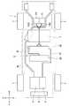
図1〜図3に示すように、本実施形態の車両1は、前輪2及び後輪3を駆動させるための構成として、前輪2を駆動させるエンジン4及び前輪駆動用モータ5と、左側の後輪3を駆動させる左後輪駆動用モータ6Lと、右側の後輪3を駆動させる右後輪駆動用モータ6Rと、モータ5、6L、6Rに電力を供給するバッテリユニット20と、バッテリユニット20の電力をモータ5、6L、6Rに供給する際に電力を変換する電力変換ユニット30と、エンジン4の燃料を貯留する燃料タンク7と、エンジン4の排気を車両1の後部まで導く排気パイプ4aと、を備える。エンジン4及び前輪駆動用モータ5は車両前方のエンジンルームに配置され、後輪駆動用モータ6L、6R及び燃料タンク7は車両後方のフロアパネル12下に配置され、排気パイプ4aがエンジン4から後方に燃料タンク7の右側を通った後分岐して、後輪駆動用モータ6L、6Rの左右を通ってさらに後方に延びている。 As shown in FIGS. 1 to 3, the vehicle 1 according to the present embodiment includes, as a configuration for driving the
バッテリユニット20は、平面視で左右方向に長い直方体形状の筐体21と、筐体21に収容され、モータ5、6L、6Rに電力を供給する複数の高圧バッテリ22と、高圧バッテリ22を冷却する冷却機構(図示せず)と、を備える。 The
高圧バッテリ22は、管理温度が低い被冷却機器であり、外気温(排気パイプ4aによる温度上昇を含む)の影響を受け易い。バッテリユニット20の冷却機構は、管理温度が低い被冷却機器の冷却に適した空冷式であり、車室11内の空気(本実施形態では、車室11内の空気を調和させる空調装置8の吐出冷気)で高圧バッテリ22を冷却させる。 The high-
電力変換ユニット30は、平面視で左右方向に長い直方体形状の筐体31と、筐体31に収容され、バッテリユニット20の電力をモータ5、6L、6Rに供給する際に電力を変換する複数のインバータ32と、バッテリユニット20の電力を空調装置8、低圧バッテリ(図示せず)などへ供給するために電圧を変換するDC−DCコンバータ33と、インバータ32及びDC−DCコンバータ33を冷却する冷却機構(図示せず)と、を備える。 The
インバータ32及びDC−DCコンバータ33は、高圧バッテリ22に比べて管理温度が高い被冷却機器であり、外気温の影響は小さい。電力変換ユニット30の冷却機構は、管理温度が高い被冷却機器の冷却に適した水冷式であり、ラジエータ9から供給される冷却水でインバータ32及びDC−DCコンバータ33を冷却させる。 The
図1及び図2に示すように、バッテリユニット20及び電力変換ユニット30は、車両1の中心部に確保された高圧系機器配設部Sに集中配置されている。具体的には、前後方向において前輪駆動用モータ5と後輪駆動用モータ6L、6Rとの間に高圧系機器配設部Sを確保し、ここにバッテリユニット20と電力変換ユニット30とを前後方向に隣り合うように配置している。高圧系機器配設部Sと後輪駆動用モータ6L、6Rとの間には、燃料タンク7が設けられている。 As shown in FIGS. 1 and 2, the
図2に示すように、バッテリユニット20は、車室11内に配置されている。具体的には、バッテリユニット20が、フロアパネル12の車室11側に設けられる凹部12aに収納されている。車室11内に配置されたバッテリユニット20は、車室11内の空気を調和する空調装置8の吐出冷気でバッテリユニット20内の高圧バッテリ22が冷却される。 As shown in FIG. 2, the
一方、電力変換ユニット30は、車室11外に配置されている。具体的には、電力変換ユニット30が、バッテリユニット20の後方、且つ、フロアパネル12の下方に配置されている。車室11外に配置された電力変換ユニット30は、ラジエータ9から車室11外を経由して供給される冷却水で電力変換ユニット30内のインバータ32及びDC−DCコンバータ33が冷却される。 On the other hand, the
フロアパネル12には、車室11外側にフロアパネル12を補強するセンタクロスメンバ13とリアクロスメンバ14とが設けられ、それぞれフロアパネル12とともに閉断面を形成することでフロアパネル12の剛性が確保されている。センタクロスメンバ13は、バッテリユニット20と電力変換ユニット30との間に位置し、リアクロスメンバ14は電力変換ユニット30と燃料タンク7との間に位置している。 The
バッテリユニット20と電力変換ユニット30とは、フロアパネル12を挟んで車室11内と車室11外にそれぞれ配置されるとともに、高さ方向にオーバーラップするように配置されている。バッテリユニット20と電力変換ユニット30の上面は、略同じ高さであり、後方に配置される燃料タンク7の上面よりも低くなっている。したがって、バッテリユニット20を車室11内に配置しても、バッテリユニット20が車室11内に張り出すことが抑制される。また、バッテリユニット20と電力変換ユニット30の底面も、略同じ高さであり、後方に配置される燃料タンク7の底面とも略同じ高さとなっており、下方への張り出しも抑制されている。 The
<電力変換ユニットのコネクタ配置>
つぎに、電力変換ユニット30のコネクタ配置について、図3〜図6を参照して説明する。<Connector layout of power conversion unit>
Next, the connector arrangement of the
図3〜図6に示すように、電力変換ユニット30と他の機器との電気的な接続は、すべてコネクタを介して行われる。電力変換ユニット30が備えるコネクタには、直流ケーブルコネクタ34、前部三相ケーブルコネクタ35、後部三相ケーブルコネクタ36L、36R、空調用ケーブルコネクタ37及び制御用ハーネスコネクタ38が含まれる。 As shown in FIGS. 3 to 6, all electrical connections between the
直流ケーブルコネクタ34は、直流ケーブル51を介してバッテリユニット20に接続され、バッテリユニット20から供給される直流の高圧電力を複数のインバータ32及びDC−DCコンバータ33に入力する。電力変換ユニット30の筐体31は、その右側面30cからさらに右方に延出する突出部31aを有しており、該突出部31aの前面30dに直流ケーブルコネクタ34が配置されている。そして、直流ケーブルコネクタ34に接続された直流ケーブル51は、1回目の曲げで電力変換ユニット30の前面に沿ってセンタクロスメンバ13の下方に配索され、2回目の曲げでセンタクロスメンバ13の貫通孔13a及びフロアパネル12の貫通孔12bを下方から貫通して車室11内に至り、バッテリユニット20に接続される。なお、センタクロスメンバ13の貫通孔13aとフロアパネル12の貫通孔12bとは、平面視でオーバーラップしている。 The
本実施形態の直流ケーブルコネクタ34は、DC−DCコンバータ33が変換した低圧の電力を低圧バッテリなどの低圧系機器に供給する低圧出力ケーブルコネクタと一体化されている。つまり、本実施形態の直流ケーブル51には、バッテリユニット20に接続される高圧直流線と、低圧系機器に接続される低圧直流線とが含まれており、直流ケーブルコネクタ34に対する接続により、バッテリユニット20の電力を電力変換ユニット30に入力できるだけでなく、DC−DCコンバータ33が変換した低圧の電力を低圧バッテリなどの低圧系機器に出力することができる。 The
前部三相ケーブルコネクタ35は、前部三相ケーブル52を介して前輪駆動用モータ5に接続され、インバータ32が変換した三相の電力を前輪駆動用モータ5に供給する。本実施形態の前部三相ケーブルコネクタ35は、電力変換ユニット30の左側面30bに配置されている。そして、前部三相ケーブルコネクタ35に接続された前部三相ケーブル52は、1回目の曲げで前方を向きバッテリユニット20の側方を通って車両1の前部に至り、2回目の曲げでバッテリユニット20の前面に沿い、3回目の曲げで前輪駆動用モータ5に接続される。 The front three-
後部三相ケーブルコネクタ36L、36Rは、一対の後部三相ケーブル53L、53Rを介して左右の後輪駆動用モータ6L、6Rに接続され、インバータ32が変換した三相の電力を左右の後輪駆動用モータ6L、6Rに供給する。本実施形態の後部三相ケーブルコネクタ36L、36Rは、電力変換ユニット30の後面30aの左右中央部に左右に並んで配置されている。そして、後部三相ケーブルコネクタ36L、36Rに接続された後部三相ケーブル53L、53Rは、後述する燃料タンク7の凹部7aを通って車両1の後部に至り、後輪駆動用モータ6L、6Rに接続される。 The rear three-
空調用ケーブルコネクタ37は、空調用ケーブル(図示せず)を介して空調装置8に接続され、DC−DCコンバータ33によって電圧が変換された電力を空調装置8に供給する。また、制御用ハーネスコネクタ38は、制御用ハーネス(図示せず)を介してECU(図示せず)に接続され、ECUとインバータ32との間で制御信号の受け渡しを行う。本実施形態の空調用ケーブルコネクタ37及び制御用ハーネスコネクタ38は、電力変換ユニット30の左側面30bに前部三相ケーブルコネクタ35とともに配置されており、コネクタ35、37、38の集約によってケーブル類の配索作業が簡易化される。 The air
<後部三相ケーブルの配索>
つぎに、一対の後部三相ケーブル53L、53Rの配索について、図3を参照して説明する。<Rail of rear three-phase cable>
Next, the routing of the pair of rear three-
図3に示すように、電力変換ユニット30は、後輪駆動用モータ6L、6Rと対向する後面30aに左右の後部三相ケーブルコネクタ36L、36Rを備え、後輪駆動用モータ6L、6Rは、電力変換ユニット30と対向する前面6cに左右の後部三相ケーブルコネクタ6a、6bを備える。電力変換ユニット30の後部三相ケーブルコネクタ36L、36Rと、後輪駆動用モータ6L、6Rの後部三相ケーブルコネクタ6a、6bとを接続する一対の後部三相ケーブル53L、53Rは、電力変換ユニット30と後輪駆動用モータ6L、6Rとの間に配置される燃料タンク7と底面視でオーバーラップしている。 As shown in FIG. 3, the
燃料タンク7の底面には、上方に窪む凹部7aが前後方向に沿って形成されている。一対の後部三相ケーブル53L、53Rの中間部は、燃料タンク7の凹部7a内に配置されることで、直線状に配索されるとともに燃料タンク7を利用して保護される。また、本実施形態では、燃料タンク7の車幅方向中央に凹部7aを設けることで、側突時に後部三相ケーブル53L、53Rが受ける影響を低減している。 On the bottom surface of the
一対の後部三相ケーブル53L、53Rの中間部は、凹部7a内で高さ方向に並ぶように配置されるとともに、凹部7a内に設けられるブラケット7bで保持される。ブラケット7bは、一対の後部三相ケーブル53L、53Rを下側(裏側)から保持するケーブル保持部7cを有しており、仮に後部三相ケーブル53L、53Rが接地しそうになっても先にケーブル保持部7cが接地することで、後部三相ケーブル53L、53Rの損傷が抑制される。 An intermediate portion of the pair of rear three-
電力変換ユニット30に設けられる左右の後部三相ケーブルコネクタ36L、36Rと、後輪駆動用モータ6L、6Rに設けられる左右の後部三相ケーブルコネクタ6a、6bとは、いずれも凹部7aに対し車幅方向に左右対称に配置されている。これにより、一対の後部三相ケーブル53L、53Rを同一構成とすることが可能となる。 The left and right rear three-
<後部三相ケーブル構造>
つぎに、後部三相ケーブル53L、53Rの構造について、図7及び図8を参照して説明する。<Rear three-phase cable structure>
Next, the structure of the rear three-
図7及び図8に示すように、後部三相ケーブル53L、53Rは、防水機能を有するコネクタケーブルであり、それぞれが、電力変換ユニット30の後部三相ケーブルコネクタ36L、36Rに接続される電力変換側コネクタ53aと、後輪駆動用モータ6L、6Rの後部三相ケーブルコネクタ6a、6bに接続されるモータ側コネクタ53bと、電力変換側コネクタ53aとモータ側コネクタ53bとを電気的に接続させる三相線53cと、三相線53cを覆うコルゲートチューブ53dと、コネクタ53a、53bとコルゲートチューブ53dとを気密的に接続するシール用グロメット53eと、を備える。 As shown in FIG. 7 and FIG. 8, the rear three-
このような防水機能を有する後部三相ケーブル53L、53Rでは、環境温度の変化や自己発熱によるコルゲートチューブ53d内の空気の膨張・圧縮によりコルゲートチューブ53dやシール用グロメット53eが損傷することを回避するために、コルゲートチューブ53d内の空間を呼吸可能に構成することが要求される。例えば、コルゲートチューブ53dに呼吸用チューブ接続部53fを設け、該呼吸用チューブ接続部53fを介してコルゲートチューブ53d内の空間を呼吸可能に構成する。 In the rear three-
本実施形態では、一対の後部三相ケーブル53L、53Rを呼吸可能に構成するにあたり、一対の後部三相ケーブル53L、53Rの呼吸構造を一体化することで、構造の簡略化を可能にしている。具体的には、一方の後部三相ケーブル53Lのコルゲートチューブ53d内の空間と他方の後部三相ケーブル53Rのコルゲートチューブ53d内の空間とを連通させるとともに、一方の後部三相ケーブル53Lのコルゲートチューブ53dに呼吸用チューブ接続部53fを設け、該呼吸用チューブ接続部53fを介して、両後部三相ケーブル53L、53Rのコルゲートチューブ53d内の空間を呼吸可能に構成している。 In this embodiment, when the pair of rear three-
本実施形態では、一対の後部三相ケーブル53L、53Rのコルゲートチューブ53d内の空間を連通させるにあたり、一対の後部三相ケーブル53L、53Rのコルゲートチューブ53d同士を接続状態で保持する接続グロメット61を利用している。接続グロメット61は、一方の後部三相ケーブル53Lのコルゲートチューブ53dを気密的に外嵌状態で保持する第1保持部61aと、他方の後部三相ケーブル53Rのコルゲートチューブ53dを気密的に外嵌状態で保持する第2保持部61bと、第1保持部61aと第2保持部61bとを連結し、第1保持部61aの内部と第2保持部61bの内部を連通させる連通部61cと、を備える。一対の後部三相ケーブル53L、53Rのコルゲートチューブ53dには、コルゲートチューブ53d内の空間を接続グロメット61の連通部61cに連通させる連通孔53gが形成されており、接続グロメット61を介して一対の後部三相ケーブル53L、53Rのコルゲートチューブ53d内の空間が連通されている。 In the present embodiment, the
<電力変換ユニットの呼吸構造>
つぎに、電力変換ユニット30の呼吸構造について、図4を参照して説明する。<Breathing structure of power conversion unit>
Next, the breathing structure of the
図4に示すように、電力変換ユニット30には、電力変換ユニット30内の電子機器収容空間を呼吸可能に構成するためのブリーザ室40が設けられている。ブリーザ室40は、ベントプラグ(図示せず)を介して電力変換ユニット30内の電子機器収容空間に連通するとともに、呼吸ノズル41を介して電力変換ユニット30外の空間に連通している。 As shown in FIG. 4, the
本実施形態では、車室11の内外に亘って配索される直流ケーブル51を利用してブリーザ室40を車室11内の空間に連通させている。直流ケーブル51は、電力変換ユニット30の直流ケーブルコネクタ34に接続される電力変換側コネクタ51aと、バッテリユニット20側に接続されるバッテリ側端子51baと、低圧系機器側に接続される低圧系機器側端子51bbと、電力変換側コネクタ51aとバッテリ側端子51b及び電力変換側コネクタ51aと低圧系機器側端子51bbを電気的に接続させる直流線51cと、直流線51cを覆うコルゲートチューブ51dと、電力変換側コネクタ51aとコルゲートチューブ51dとを気密的に接続するシール用グロメット51eと、電力変換側コネクタ51aの近傍に設けられ、コルゲートチューブ53d内の空間に連通する呼吸用チューブ接続部51fと、を備えており、呼吸用チューブ接続部51fが、呼吸用チューブ42を介してブリーザ室40の呼吸ノズル41に接続される。これにより、ブリーザ室40は、呼吸用チューブ42及び直流ケーブル51内の空間を介して車室11内の空間に連通される。 In the present embodiment, the
さらに、本実施形態では、電力変換ユニット30のブリーザ室40を利用して後部三相ケーブル53L、53Rのコルゲートチューブ53d内の空間を呼吸可能に構成している。具体的には、ブリーザ室40に設けられる予備呼吸ノズル43に対し呼吸用チューブ44を介して後部三相ケーブル53L、53Rの呼吸用チューブ接続部53fを接続し、後部三相ケーブル53L、53Rのコルゲートチューブ53d内の空間をブリーザ室40、呼吸用チューブ42及び直流ケーブル51内の空間を介して車室11内の空間に連通させている。 Furthermore, in the present embodiment, the
以上説明したように、本実施形態の車両1によれば、電力変換ユニット30は車室11外に配置されるので、バッテリユニット20及び電力変換ユニット30を車室11内に配置する場合に比べ、車室11内のスペースを広く確保できるだけでなく、高周波ノイズの対策が不要となる。また、バッテリユニット20は車室11内に配置されるので、外気温の影響による高圧バッテリ22の出力低下や劣化を抑制でき、さらに外部からの衝撃から高電圧装置を保護することができる。 As described above, according to the vehicle 1 of the present embodiment, since the
また、バッテリユニット20と電力変換ユニット30とを前後方向に隣り合うように配置することで、衝突対策を一箇所に集約できるので、これらバッテリユニット20と電力変換ユニット30とを離間して配置する場合に比べて、車両構造を簡素化できるだけでなく、バッテリユニット20と電力変換ユニット30とを繋ぐ直流ケーブル51を最短化できる。 Further, by arranging the
また、バッテリユニット20と電力変換ユニット30とは、高さ方向にオーバーラップするように配置されているので、車室11内のスペースを高さ方向に広く確保できる。また、バッテリユニット20と電力変換ユニット30とをフロアパネル12近辺に集中的に配置することにより、車両1の重心が下がり操向性が向上する。 In addition, since the
また、車室11内に配置されたバッテリユニット20は空冷され、車室11外に配置された電力変換ユニット30は水冷されるので、互いに最適な冷却構造を採用することができる。 Moreover, since the
また、高圧バッテリ22に比べて管理温度の高いインバータ32及びDC−DCコンバータ33がともに車室11外に配置され水冷されるので、高圧バッテリ22の冷却を高圧バッテリ22都合により最適化でき、その結果、高圧バッテリ22の使用領域を拡大し、燃費、動力性能を向上できる。 In addition, since the
また、インバータ32とDC−DCコンバータ33は、同じ筐体31に収納されてユニット化されることで、水冷構造を簡略化できる。 Further, the
また、バッテリユニット20と電力変換ユニット30とは、前後方向において前輪駆動用モータ5と後輪駆動用モータ6L、6Rとの間に配置されるので、電力変換ユニット30から前輪駆動用モータ5及び後輪駆動用モータ6L、6Rへ延びる三相ケーブル52、53L、53Rを短縮できる。さらに、バッテリユニット20と電力変換ユニット30とは、車両1の中心部に配置されるので、車両1に発生するモーメントが小さくなり、フレームを軽量化できる。 Further, since the
なお、本発明は、前述した実施形態に限定されるものではなく、適宜、変形、改良、等が可能である。例えば、前述した実施形態の車両は、モータとして、前輪駆動用モータと後輪駆動用モータを備えるが、いずれか一方でもよい。また、前輪及び後輪の駆動に兼用されるモータであってもよい。 In addition, this invention is not limited to embodiment mentioned above, A deformation | transformation, improvement, etc. are possible suitably. For example, the vehicle of the above-described embodiment includes a front wheel driving motor and a rear wheel driving motor as motors, but either one may be used. Further, it may be a motor that is also used for driving the front wheels and the rear wheels.
1 車両
11 車室
12 フロアパネル
12a 凹部
20 バッテリユニット(高電圧装置)
22 高圧バッテリ(高電圧装置)
30 電力変換ユニット(電力変換機器)
31 筐体
32 インバータ(電力変換機器)
33 DC−DCコンバータ(電圧変換器機)
5 前輪駆動用モータ(第1モータ)
6L 左後輪駆動用モータ(第2モータ)
6R 右後輪駆動用モータ(第2モータ)DESCRIPTION OF SYMBOLS 1
22 High voltage battery (high voltage device)
30 Power conversion unit (power conversion equipment)
31
33 DC-DC converter (voltage converter machine)
5 Front-wheel drive motor (first motor)
6L Left rear wheel drive motor (second motor)
6R Right rear wheel drive motor (second motor)
Claims (7)
Translated fromJapanese該モータへ電力を供給する高電圧装置と、
該高電圧装置の電力を前記モータへ供給する際に電力を変換する電力変換機器と、を備える、車両であって、
前記高電圧装置は、車室内に配置され、
前記電力変換機器は、車室外に配置され、
前記高電圧装置と前記電力変換機器とは、クロスメンバを挟んで前後方向に隣り合うように、且つ、該クロスメンバの近傍で略等距離に配置されている、車両。A motor,
A high voltage device for supplying power to the motor;
A power conversion device that converts power when supplying electric power of the high-voltage device to the motor,
The high voltage device is disposed in a vehicle interior,
The power conversion device is disposed outside the passenger compartment,
The vehicle, wherein the high-voltage device and the power conversion device are disposed adjacent to each otherin the front-rear directionwith across member interposed therebetween andat substantially equal distances in the vicinity of the cross member .
前記高電圧装置は、フロアパネルに設けられた凹部に収納され、
前記高電圧装置と前記電力変換機器とは、高さ方向にオーバーラップするように配置されている、車両。The vehicle according to claim 1,
The high voltage device is housed in a recess provided in the floor panel,
The vehicle, wherein the high voltage device and the power conversion device are arranged to overlap in a height direction.
前記高電圧装置は、空冷され、
前記電力変換機器は、水冷される、車両。The vehicle according to claim 1 or 2,
The high voltage device is air cooled;
The power conversion device is a vehicle that is water-cooled.
前記高電圧装置の電力を補機若しくは低圧系機器へ供給するために電圧を変換する電圧変換機器をさらに備え、
前記電圧変換機器は、前記電力変換機器とともに車室外に配置され、
前記電圧変換機器は、前記電力変換機器とともに水冷される、車両。The vehicle according to claim 3,
A voltage conversion device that converts a voltage to supply power of the high-voltage device to an auxiliary device or a low-voltage device;
The voltage conversion device is disposed outside the passenger compartment together with the power conversion device,
The voltage conversion device is a vehicle that is water-cooled together with the power conversion device.
前記電力変換機器と前記電圧変換機器は、筐体に収納されている、車両。The vehicle according to claim 4,
The power conversion device and the voltage conversion device are vehicles housed in a housing.
前記車両は、前記モータとして、第1モータと第2モータとを含み、
前記第1モータは、前記車両の前部に配置され、
前記第2モータは、前記車両の後部に配置され、
前記高電圧装置と前記電力変換機器とは、前後方向において前記第1モータと前記第2モータとの間に配置されている、車両。The vehicle according to any one of claims 1 to 5,
The vehicle includes a first motor and a second motor as the motor,
The first motor is disposed at a front portion of the vehicle;
The second motor is disposed at a rear portion of the vehicle;
The high-voltage device and the power conversion device are vehicles arranged between the first motor and the second motor in the front-rear direction.
前記凹部は、前記フロアパネルのフロア面よりも下方に窪むように形成され、 The recess is formed to be recessed below the floor surface of the floor panel,
前記高電圧装置の上面の高さは、前記フロア面の高さ略等しい、車両。 The height of the upper surface of the high voltage device is substantially the same as the height of the floor surface.
Priority Applications (3)
| Application Number | Priority Date | Filing Date | Title |
|---|---|---|---|
| JP2016024979AJP6286458B2 (en) | 2016-02-12 | 2016-02-12 | vehicle |
| CN201710063162.3ACN107082012B (en) | 2016-02-12 | 2017-02-03 | vehicle |
| US15/426,970US10632830B2 (en) | 2016-02-12 | 2017-02-07 | Vehicle |
Applications Claiming Priority (1)
| Application Number | Priority Date | Filing Date | Title |
|---|---|---|---|
| JP2016024979AJP6286458B2 (en) | 2016-02-12 | 2016-02-12 | vehicle |
Publications (2)
| Publication Number | Publication Date |
|---|---|
| JP2017140990A JP2017140990A (en) | 2017-08-17 |
| JP6286458B2true JP6286458B2 (en) | 2018-02-28 |
Family
ID=59559501
Family Applications (1)
| Application Number | Title | Priority Date | Filing Date |
|---|---|---|---|
| JP2016024979AActiveJP6286458B2 (en) | 2016-02-12 | 2016-02-12 | vehicle |
Country Status (3)
| Country | Link |
|---|---|
| US (1) | US10632830B2 (en) |
| JP (1) | JP6286458B2 (en) |
| CN (1) | CN107082012B (en) |
Families Citing this family (21)
| Publication number | Priority date | Publication date | Assignee | Title |
|---|---|---|---|---|
| CN107599825A (en)* | 2017-08-22 | 2018-01-19 | 张振勇 | Hybrid power system electric car |
| DE102017215113B4 (en)* | 2017-08-30 | 2019-06-19 | Ford Global Technologies, Llc | motor vehicle |
| DE102018201666A1 (en)* | 2018-02-05 | 2019-08-08 | Ford Global Technologies, Llc | Storage arrangement for a hybrid vehicle |
| IT201800006208A1 (en) | 2018-06-11 | 2019-12-11 | ROAD VEHICLE WITH ELECTRIC PROPULSION AND POWER WIRING COOLING | |
| JP7056468B2 (en) | 2018-08-24 | 2022-04-19 | トヨタ自動車株式会社 | Vehicle underfloor structure |
| JP7091936B2 (en)* | 2018-08-24 | 2022-06-28 | トヨタ自動車株式会社 | Vehicle underfloor structure |
| CN112638762B (en)* | 2018-08-28 | 2022-06-24 | 本田技研工业株式会社 | Saddle-ride type vehicle |
| JP7119819B2 (en)* | 2018-09-18 | 2022-08-17 | トヨタ自動車株式会社 | electric vehicle |
| JP7047729B2 (en)* | 2018-11-29 | 2022-04-05 | トヨタ自動車株式会社 | Self-driving vehicle |
| US11370266B2 (en) | 2019-05-16 | 2022-06-28 | Polaris Industries Inc. | Hybrid utility vehicle |
| KR102842792B1 (en)* | 2019-08-08 | 2025-08-05 | 현대자동차 주식회사 | Battery and fuel tank arrangement structure of hybrid vehicle |
| JP7374550B2 (en)* | 2019-10-31 | 2023-11-07 | ダイハツ工業株式会社 | electric vehicle |
| JP7435313B2 (en)* | 2020-07-01 | 2024-02-21 | マツダ株式会社 | vehicle |
| JP7559645B2 (en)* | 2021-03-26 | 2024-10-02 | マツダ株式会社 | Electric vehicle undercarriage |
| JP7687050B2 (en)* | 2021-05-25 | 2025-06-03 | マツダ株式会社 | Vehicle undercarriage |
| IT202100015452A1 (en)* | 2021-06-14 | 2022-12-14 | Iveco Spa | IMPROVED HEAVY VEHICLE CROSSBEAM ASSEMBLY |
| JP2023002363A (en)* | 2021-06-22 | 2023-01-10 | トヨタ自動車株式会社 | vehicle front structure |
| JP7677029B2 (en)* | 2021-07-26 | 2025-05-15 | マツダ株式会社 | Hybrid vehicle undercarriage |
| JP7519983B2 (en)* | 2021-12-24 | 2024-07-22 | 株式会社クボタ | Electric work vehicle |
| JP2025027834A (en)* | 2023-08-17 | 2025-02-28 | 株式会社クボタ | Work vehicle |
| JP2025106750A (en)* | 2024-01-04 | 2025-07-16 | トヨタ自動車株式会社 | Plug-in hybrid vehicle |
Family Cites Families (19)
| Publication number | Priority date | Publication date | Assignee | Title |
|---|---|---|---|---|
| US5960901A (en)* | 1997-09-04 | 1999-10-05 | Corbin Pacific, Inc. | Battery-powered vehicle |
| JP4561189B2 (en)* | 2004-06-09 | 2010-10-13 | 日産自動車株式会社 | Vehicle motion control device |
| JP4285405B2 (en)* | 2004-12-17 | 2009-06-24 | 日産自動車株式会社 | Hybrid car |
| US7740092B2 (en)* | 2005-09-23 | 2010-06-22 | Afs Trinity Power Corporation | Method and apparatus for power electronics and control of plug-in hybrid propulsion with fast energy storage |
| US8453770B2 (en)* | 2009-01-29 | 2013-06-04 | Tesla Motors, Inc. | Dual motor drive and control system for an electric vehicle |
| JP5382553B2 (en)* | 2009-05-28 | 2014-01-08 | トヨタ自動車株式会社 | Fuel cell assembly |
| US8916993B2 (en)* | 2009-08-11 | 2014-12-23 | General Electric Company | System for multiple energy storage and management and method of making same |
| JP5198497B2 (en)* | 2010-03-09 | 2013-05-15 | トヨタ自動車株式会社 | Power equipment |
| JP6094852B2 (en)* | 2012-09-15 | 2017-03-15 | スズキ株式会社 | High voltage cable routing structure for vehicles |
| JP5696729B2 (en)* | 2013-02-05 | 2015-04-08 | トヨタ自動車株式会社 | Vehicle control device |
| JP2015137001A (en)* | 2014-01-22 | 2015-07-30 | トヨタ自動車株式会社 | electric vehicle |
| US9783144B2 (en)* | 2015-08-18 | 2017-10-10 | Sti Holdings, Inc. | Trailer with rear impact guard |
| US10518688B2 (en)* | 2016-01-28 | 2019-12-31 | Trail King Industries, Inc. | Glass transport trailer |
| JP6315622B2 (en)* | 2016-03-04 | 2018-04-25 | 本田技研工業株式会社 | vehicle |
| US10518828B2 (en)* | 2016-06-03 | 2019-12-31 | Oren Technologies, Llc | Trailer assembly for transport of containers of proppant material |
| JP6460068B2 (en)* | 2016-09-05 | 2019-01-30 | トヨタ自動車株式会社 | vehicle |
| US20180065492A1 (en)* | 2016-09-07 | 2018-03-08 | Thunder Power New Energy Vehicle Development Company Limited | Electric vehicle system |
| JP6439177B2 (en)* | 2016-09-27 | 2018-12-19 | 本田技研工業株式会社 | Lower body structure |
| JP6471133B2 (en)* | 2016-10-25 | 2019-02-13 | 本田技研工業株式会社 | Vehicle power supply |
- 2016
- 2016-02-12JPJP2016024979Apatent/JP6286458B2/enactiveActive
- 2017
- 2017-02-03CNCN201710063162.3Apatent/CN107082012B/enactiveActive
- 2017-02-07USUS15/426,970patent/US10632830B2/enactiveActive
Also Published As
| Publication number | Publication date |
|---|---|
| US10632830B2 (en) | 2020-04-28 |
| US20170232866A1 (en) | 2017-08-17 |
| CN107082012B (en) | 2019-06-18 |
| CN107082012A (en) | 2017-08-22 |
| JP2017140990A (en) | 2017-08-17 |
Similar Documents
| Publication | Publication Date | Title |
|---|---|---|
| JP6286458B2 (en) | vehicle | |
| JP6271615B2 (en) | Cable structure and vehicle | |
| JP6286459B2 (en) | vehicle | |
| JP6706507B2 (en) | vehicle | |
| JP6471134B2 (en) | vehicle | |
| JP5829706B2 (en) | Automotive battery | |
| JP6626903B2 (en) | Mounting structure of high voltage control equipment unit | |
| US8205700B2 (en) | Power storage device | |
| JP5656020B2 (en) | High-voltage cable routing structure for electric vehicles | |
| CN103842194A (en) | Electric vehicle | |
| JP2011020625A (en) | Mounting structure for electric vehicle | |
| JP6688851B2 (en) | vehicle | |
| JP6944972B2 (en) | Vehicle battery unit | |
| JP2017077789A (en) | vehicle | |
| JP2017077786A (en) | vehicle | |
| JP6431827B2 (en) | vehicle | |
| JP6525657B2 (en) | Automotive battery | |
| US20240227583A1 (en) | Vehicle | |
| US12246662B2 (en) | Vehicle | |
| US20250282208A1 (en) | Power unit mounting structure | |
| US20240262213A1 (en) | Motor unit | |
| JP2025025467A (en) | Vehicle chassis frame | |
| JP6086609B2 (en) | vehicle |
Legal Events
| Date | Code | Title | Description |
|---|---|---|---|
| A131 | Notification of reasons for refusal | Free format text:JAPANESE INTERMEDIATE CODE: A131 Effective date:20170822 | |
| A521 | Written amendment | Free format text:JAPANESE INTERMEDIATE CODE: A523 Effective date:20171017 | |
| TRDD | Decision of grant or rejection written | ||
| A01 | Written decision to grant a patent or to grant a registration (utility model) | Free format text:JAPANESE INTERMEDIATE CODE: A01 Effective date:20180109 | |
| A61 | First payment of annual fees (during grant procedure) | Free format text:JAPANESE INTERMEDIATE CODE: A61 Effective date:20180205 | |
| R150 | Certificate of patent or registration of utility model | Ref document number:6286458 Country of ref document:JP Free format text:JAPANESE INTERMEDIATE CODE: R150 |